W17 Page 1 of 35 IACS Req. 1986/Rev.6 2021 Approval of consumables for welding normal and higher strength hull structural steels 1. General 1.1 Scope 1.1.1 These requirements give the conditions of approval and inspection of welding consumables used for hull structural steel according to UR W11as follows: - normal strength steels Grades A, B, D and E, - higher strength steels Grades A32, D32, E32, A36, D36 and E36, - higher strength steels with minimum yield strength 390 N/mm 2 : Grades A40, D40 and E40, - higher strength steels for low temperature application: Grades F32, F36 and F40. Welding consumables for high strength steels for welded structures are to comply with the requirements of UR W23. These requirements are not applicable for welding procedure qualification tests at the shipyard. 1.1.2 Categories of products The concerned welding consumables are divided into several categories as follows: - covered electrodes for manual welding and gravity welding, - wire/flux combinations for two run or multi-run submerged arc welding, - solid wire/gas combinations for arc welding, - flux cored wires with or without gas for arc welding, - consumables for use in electroslag and electrogas vertical welding Note: 1. The requirements of UR W17 Rev.4 are to be uniformly implemented by IACS Members from 1 July 2017. 2. Rev.5 of this UR is to be uniformly implemented by IACS Societies when an application for approval is dated on after 1 July 2019. 3. Rev.6 of this UR is to be uniformly implemented by IACS Societies when an application for approval is dated on after 1 January 2023. W17 (1986) (Rev.1 1993) (Rev.2 May 2004) (Rev.3 June 2005) (Rev.4 Jan 2016) (Rev.5 Mar 2018) (Rev.6 Sep 2021)

Welcome message from author
This document is posted to help you gain knowledge. Please leave a comment to let me know what you think about it! Share it to your friends and learn new things together.
Transcript

W17
Page 1 of 35 IACS Req. 1986/Rev.6 2021
W17 (cont)
Approval of consumables for welding normal and higher strength hull structural steels 1. General 1.1 Scope 1.1.1 These requirements give the conditions of approval and inspection of welding consumables used for hull structural steel according to UR W11as follows: - normal strength steels Grades A, B, D and E, - higher strength steels Grades A32, D32, E32, A36, D36 and E36, - higher strength steels with minimum yield strength 390 N/mm2: Grades A40, D40 and
E40, - higher strength steels for low temperature application: Grades F32, F36 and F40. Welding consumables for high strength steels for welded structures are to comply with the requirements of UR W23. These requirements are not applicable for welding procedure qualification tests at the shipyard. 1.1.2 Categories of products The concerned welding consumables are divided into several categories as follows: - covered electrodes for manual welding and gravity welding, - wire/flux combinations for two run or multi-run submerged arc welding, - solid wire/gas combinations for arc welding, - flux cored wires with or without gas for arc welding, - consumables for use in electroslag and electrogas vertical welding Note: 1. The requirements of UR W17 Rev.4 are to be uniformly implemented by IACS Members
from 1 July 2017. 2. Rev.5 of this UR is to be uniformly implemented by IACS Societies when an application
for approval is dated on after 1 July 2019. 3. Rev.6 of this UR is to be uniformly implemented by IACS Societies when an application
for approval is dated on after 1 January 2023.
W17 (1986) (Rev.1 1993) (Rev.2 May 2004) (Rev.3 June 2005) (Rev.4 Jan 2016) (Rev.5 Mar 2018) (Rev.6 Sep 2021)

W17
Page 2 of 35 IACS Req. 1986/Rev.6 2021
W17 (cont)
1.2 Grading 1.2.1 Basic groups and grades Filler metals are divided into three groups: - normal strength filler metals for welding normal strength hull structural steels, - higher strength filler metals for welding normal and higher strength hull structural steels
with minimum yield strength up to 355 N/mm2, - higher strength filler metals for welding normal and higher strength hull structural steels
with minimum yield strength up to 390 N/mm2. Each of the three groups is based on corresponding tensile strength requirements. Each filler metal group is further divided into several grades: - Grades 1, 2 and 3 for ordinary-strength filler metals, - Grades 1Y, 2Y, 3Y and 4Y for higher strength filler metals for steels up to 355 N/mm2
yield strength, - Grades 2Y40, 3Y40, 4Y40 and 5Y40 for higher strength filler metals for steels up to 390
N/mm2 yield strength. The Grade assignment is given in respect of Charpy V-notch impact test requirements.
For each strength basic group, welding consumables, which have satisfied the requirements for a higher toughness grade are considered as complying with the requirements for a lower toughness grade.
1.2.2 Correlation of welding consumables to hull structural steel grades. The correlation between the hull steel grades and the welding consumables grades that must be used for the hull steel welding, is stated in the following Table 1:

W17
Page 3 of 35 IACS Req. 1986/Rev.6 2021
W17 (cont)
Table 1 Correlation of welding consumables to hull structural steels Grades of welding Hull structural steel grades
consumables (see notes) A B D E A32/36 D32/36 E32/36 F32/36 A40 D40 E40 F40
1, 1S, 1T, 1M, 1TM, IV X
1YS, 1YT, 1YM, 1YTM, 1YV
X 2)
2, 2S, 2T, 2M, 2TM, 2V X X X
2Y, 2YS, 2YT, 2YM, 2YTM, 2YV
X X X X X
2Y40, 2Y40S, 2Y40T, 2Y40M, 2Y40TM, 2Y40V
1) 1) 1) X X X X
3, 3S, 3T, 3M, 3TM, 3V X X X X
3Y, 3YS, 3YT, 3YM, 3YTM, 3YV
X X X X X X X
3Y40, 3Y40S, 3Y40T, 3Y40M, 3Y40TM, 3Y40V
1) 1) 1) 1) X X X X X X
4Y, 4YS, 4YT, 4YM, 4YTM, 4YV
X X X X X X X X
4Y40, 4Y40S, 4Y40T, 4Y40M, 4Y40TM, 4Y40V
1) 1) 1) 1) X X X X X X X X
5Y40, 5Y40S, 5Y40T, 5Y40M, 5Y40TM, 5Y40V
1) 1) 1) 1) X X X X X X X X
1) see note d) 2) see note e)
W17
Page 4 of 35 IACS Req. 1986/Rev.6 2021
W17 (cont)
NOTES: (a) When joining normal to higher strength structural steel, consumables of the lowest
acceptable grade for either material being joined may be used. (b) When joining steels of the same strength level but of different toughness grade,
consumables of the lowest acceptable grade for either material being joined may be used.
(c) It is recommended that controlled low hydrogen type consumables are to be used when
joining higher strength structural steel to the same or lower strength level, except that other consumables may be used at the discretion of the Society when the carbon equivalent is below or equal to 0.41%.When other than controlled low hydrogen type electrodes are used appropriate procedure tests for hydrogen cracking may be conducted at the discretion of the Society.
(d) The welding consumables approved for steel Grades A40, D40, E40 and/or F40 may
also be used for welding of the corresponding grades of normal strength steels subject to the special agreement with the Classification Society.
(e) When joining higher strength steels using Grade 1Y welding consumables, the material thicknesses should not exceed 25 mm. 1.2.3 Hydrogen marks Welding consumables of Grades 2 and 3 and Grades 2Y, 3Y and 4Y and of Grades 2Y40, 3Y40, 4Y40 and 5Y40, for which the hydrogen content has been controlled in accordance with paragraph 4.5.3 are identified by the mark H15, H10 or H5. 1.3 Manufacture 1.3.1 The manufacturer's plant, methods of production and quality control of welding consumables are to be such as to ensure reasonable uniformity in manufacture. 2. Approval procedure 2.1 Plant inspection 2.1.1 The Surveyor is to be satisfied that the manufacturer's plant, methods of production and quality control of welding consumables are to be such as to ensure a reasonable uniformity in manufacture, as mentioned in 1.3.1 above. 2.2 Test assemblies 2.2.1 Preparation The test assemblies are to be prepared under the supervision of the Surveyor, and all tests are to be carried out in his presence. When a welded joint is performed, the edges of the plates are to be bevelled either by mechanical machining or by oxygen cutting; in the later case, a de-scaling of the bevelled edges is necessary.
W17
Page 5 of 35 IACS Req. 1986/Rev.6 2021
W17 (cont)
2.2.2 Welding conditions The welding conditions used such as amperage, voltage, travel speed, etc are to be within the range recommended by the manufacturer for normal good welding practice. Where a filler material is stated to be suitable for both alternating current (AC) and direct current (DC), AC is to be used for the preparation of the test assemblies. 2.3 Firms with several factories - sister firms When a filler product is manufactured in several factories of the same company, the complete series of approval tests should be carried out in one of the works only. In the other factories, a reduced test programme at least equivalent to annual tests is permitted if the manufacturer can certify that the materials used and the fabrication process are identical with those used in the main works. This requirement is applicable to all manufacturers of filler products under license (sister firms). However, should there be any doubt, complete test-series may be required. NOTE: Wire flux combination for submerged arc welding. If a unique powder flux is combined with different wires coming from several factories belonging to the same firm, it may be admitted to perform only one test-series if the different wires are conformable to the same technical specification, after approval of the relevant Classification Society. 2.4 Annual inspection and tests The production techniques and associated quality control procedures at all establishments approved for the manufacture of welding consumables are to be subjected to an annual re-appraisal. On these occasions, samples of the approved consumable are to be selected by the Surveyor and subjected to the tests detailed in subsequent sections of these Requirements. These are to be completed and reported within the one year period beginning at the initial approval date, and repeated annually so as to provide at least an average of one annual test per year. Equivalent alternative arrangements may be accepted subject to special agreement with the Classification Society. 2.5 Alterations to approved consumables Any alteration proposed by the manufacturer to the approved consumable which may result in a change in the chemical composition and the mechanical properties of the deposited metal, must be immediately notified to the Society. Additional tests may be necessary. 2.6 Upgrading and uprating Upgrading and uprating of welding consumables will be considered only at manufacturer's request, preferably at the time of annual testing. Generally, for this purpose, tests from butt weld assemblies will be required in addition to the normal annual approval tests. 2.7 Additional tests The classification societies may request, in a particular case, additional tests or requirements as may be considered necessary.
W17
Page 6 of 35 IACS Req. 1986/Rev.6 2021
W17 (cont)
3. Mechanical testing procedure 3.1 Test specimens 3.1.1 Specimens dimensions Deposited metal and butt weld tensile, butt weld bend and Charpy V-notch impact test specimens are to be machined to the dimensions given in UR W2. 3.1.2 Specimens location and preparation .1 Deposited metal tensile The longitudinal axis must coincide with the centre of the weld and: (i) the mid thickness of the weld in the deposited metal test assemblies; (ii) the mid thickness of the 2nd run in the two-run welded test assemblies. The specimens may be heated to a temperature not exceeding 250°C for a period not exceeding 16 hours for hydrogen removal prior to testing. .2. Butt weld tensile
The upper and lower surfaces of the weld are to be filed, ground or machined flush with the surface of the plate.
.3 Butt weld bend
The upper and lower surfaces of the weld are to be filed, ground or machined flush with the Surface of the plate and the sharp corners of the specimens rounded to a radius not exceeding 2 mm.
.4 Charpy V-notch impact
The test specimens shall be cut with their longitudinal axes transverse to the weld length and:
(i) at mid thickness of the weld in the deposit metal and butt weld test assemblies
with multi-run technique; (ii) on the 2nd run side, 2 mm maximum below the surface in the two-run welded
test assemblies; (iii) 2 mm maximum below one surface in the electroslag or electrogas welded test
assemblies. The notch shall be cut in the face of the test piece perpendicular to the surface of the plate and shall be positioned in the centre of the weld and, for electroslag and electrogas welded test assemblies, also at 2 mm from the fusion line in the deposited metal. 3.2 Testing procedures 3.2.1 Tensile Tensile tests are to be carried out on an approved tensile testing machine. On deposited metal test specimens, the values of yield stress, tensile strength and elongation are to be recorded. On butt weld specimens, the values of tensile strength are to be recorded together with the position of fracture.

W17
Page 7 of 35 IACS Req. 1986/Rev.6 2021
W17 (cont)
3.2.2 Bend The test specimens are to be capable of withstanding, without fracture or crack, being bent through an angle of 120° over a former having a diameter three times the thickness of the specimen. However, superficial cracks of less than 3 mm long on the outer surface should not be taken into consideration. For each set of bend tests one specimen is to be tested with the face of the weld in tension and the other with the root of the weld in tension except in the electroslag or electrogas welded test assemblies, where side bend tests are carried out in lieu of face and root bend tests. 3.2.3 Charpy V-notch impact Impact tests are to be carried out on a Charpy impact machine of an approved type. A set of three test specimens is to be prepared and tested. The average absorbed energy value is to comply with the requirements of subsequent sections. One individual value may be less than the required average value provided that it is not less than 70% of this value. The test temperature for Grades 2, 2Y, 2Y40, 3, 3Y, 3Y40, 4Y, 4Y40 and 5Y40 test pieces is to be controlled to within ±2°C of the prescribed temperature. 3.3 Re-test procedures 3.3.1 Tensile and bend Where the result of a tensile or bend test does not comply with the requirements, duplicate test specimens of the same type are to be prepared and satisfactorily tested. Where insufficient original welded assembly is available, a new assembly is to be prepared using welding consumables from the same batch. If the new assembly is made with the same procedure (particularly the number of runs) as the original assembly, only the duplicate re-test specimens needs to be prepared and tested. Otherwise, all test specimens should be prepared as for re-testing. 3.3.2 Charpy V-notch impact Re-test requirements for Charpy impact tests are to be in accordance with UR W2. Further re-tests may be made at the Surveyor's discretion, but these must be made on a new welded assembly and must include all tests required for the original assembly, even those which were previously satisfactory. 4. Covered electrodes for manual arc welding 4.1 General 4.1.1 Grades Depending on the results of the Charpy V-notch impact tests, electrodes are divided into the following grades - for normal strength steel: Grades 1, 2 and 3 - for higher strength steel with minimum yield strength up to 355 N/mm2: Grades 2Y and
3Y and 4Y (Grade 1Y not applicable for manual welding).
W17
Page 8 of 35 IACS Req. 1986/Rev.6 2021
W17 (cont)
- for higher strength steels with minimum yield strength up to 390 N/mm2: Grades 2Y40, 3Y40, 4Y40 and 5Y40.
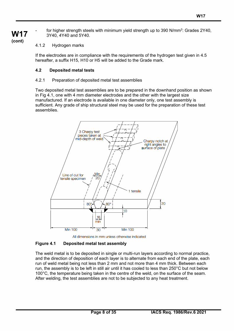
4.1.2 Hydrogen marks If the electrodes are in compliance with the requirements of the hydrogen test given in 4.5 hereafter, a suffix H15, H10 or H5 will be added to the Grade mark. 4.2 Deposited metal tests 4.2.1 Preparation of deposited metal test assemblies Two deposited metal test assemblies are to be prepared in the downhand position as shown in Fig 4.1, one with 4 mm diameter electrodes and the other with the largest size manufactured. If an electrode is available in one diameter only, one test assembly is sufficient. Any grade of ship structural steel may be used for the preparation of these test assemblies.
Figure 4.1 Deposited metal test assembly The weld metal is to be deposited in single or multi-run layers according to normal practice, and the direction of deposition of each layer is to alternate from each end of the plate, each run of weld metal being not less than 2 mm and not more than 4 mm thick. Between each run, the assembly is to be left in still air until it has cooled to less than 250°C but not below 100°C, the temperature being taken in the centre of the weld, on the surface of the seam. After welding, the test assemblies are not to be subjected to any heat treatment.

W17
Page 9 of 35 IACS Req. 1986/Rev.6 2021
W17 (cont)
4.2.2 Chemical analysis At the discretion of each individual Society, the chemical analysis of the deposited weld metal in each test assembly is to be supplied by the manufacturer and is to include the content of all significant alloying element. 4.2.3 Execution of tests One tensile and three impact test specimens are to be taken from each test assembly as shown in Figure 4.1. Care is to be taken that the axis of the tensile test specimen coincides with the centre of the weld and the mid-thickness of the plates. Tests are to be performed according to Section 3 of these requirements. 4.2.4 Results of tests and requirements The results of all tests are to comply with the requirements of Table 4a as appropriate. Table 4a Requirements for deposited metal tests (covered manual electrodes)
Grade Yield stress
N/mm2 minimum
Tensile strength N/mm2
Elongation on 50 mm gauge length
(L0=5 d) % minimum
Charpy V-notch impact tests
Test Temperature
°C
Average Energy
J minimum 1 2 3
305 400-560 22 20 0
-20
47 47 47
2Y 3Y 4Y
375 490-660 22 0
-20 -40
47 47 47
2Y40 3Y40 4Y40 5Y40
400 510-690 22
0 -20 -40 -60
47 47 47 47
4.3 Butt weld tests 4.3.1 Preparation of butt weld test assemblies Butt weld assemblies as shown in Fig 4.2 are to be prepared for each welding position (downhand, horizontal-vertical, vertical-upward, vertical-downward and overhead) for which the electrode is recommended by the manufacturer, except that electrodes satisfying the requirements for downhand and vertical-upward positions will be considered as also complying with the requirements for the horizontal-vertical position subject to the agreement of the Classification Society. Where the electrode is to be approved only in the downhand position, an additional test assembly is to be prepared in that position. For the preparation of the test assemblies one of the steel grades as listed below for the individual electrode grades shall be used: - Grade 1 electrodes : A - Grade 2 electrodes : A, B, D

W17
Page 10 of 35 IACS Req. 1986/Rev.6 2021
W17 (cont)
- Grade 3 electrodes : A, B, D, E - Grade 2Y electrodes : A32, A36, D32, D36 - Grade 3Y electrodes : A32, A36, D32, D36, E32, E36 - Grade 4Y electrodes : A32, A36, D32, D36, E32, E36, F32, F36 - Grade 2Y40 electrodes : A40, D40 - Grade 3Y40 electrodes : A40, D40, E40 - Grade 4Y40 electrodes : A40, D40, E40, F40 - Grade 5Y40 electrodes : A40, D40, E40, F40 Where higher strength steel with minimum yield strength 315 N/mm2 is used for grade 2Y, 3Y and 4Y electrodes, the actual tensile strength of the steel is to be not less than 490 N/mm2. The chemical composition including the content of grain refining elements is to be reported.
Figure 4.2 Butt weld test assembly

W17
Page 11 of 35 IACS Req. 1986/Rev.6 2021
W17 (cont)
4.3.2 Sequence of welding The following welding procedure is to be adopted in making test assemblies: Downhand (a). The first run with 4 mm diameter electrode. Remaining runs (except the last two layers) with 5 mm diameter electrodes or above according to the normal welding practice with the electrodes. The runs of the last two layers with the largest diameter of electrode manufactured. Downhand (b). (Where a second downhand test is required). First run with 4 mm diameter electrode. Next run with an electrode of intermediate diameter of 5 mm or 6 mm, and the remaining runs with the largest diameter of electrode manufactured. Horizontal-vertical. First run with 4 mm or 5 mm diameter electrode. Subsequent runs with 5 mm diameter electrodes. Vertical-upward and overhead. First run with 3.25 mm diameter electrode. Remaining runs with 4 mm diameter electrodes or possibly with 5 mm if this is recommended by the manufacturer for the positions concerned. Vertical-downward. If the electrode tested is intended for vertical welding in the downward direction, this technique is to be adopted for the preparation of the test assembly using electrode diameters as recommended by the manufacturer. For all assemblies the back sealing runs are to be made with 4 mm diameter electrodes in the welding position appropriate to each test sample, after cutting out the root run to clean metal. For electrodes suitable for downhand welding only, the test assemblies may be turned over to carry out the back sealing run. Normal welding practice is to be used, and between each run the assembly is to be left in still air until it has cooled to less than 250°C but not below 100°C, the temperature being taken in the centre of the weld, on the surface of the seam. After welding, the test assemblies are not to be subjected to any heat treatment. 4.3.3 Radiographic examination It is recommended that the welded assemblies be subjected to a radiographic examination to ascertain if there are any defects in the weld prior to the preparation of test specimens. 4.3.4 Execution of tests The test specimens as shown in Figure 4.2 are to be prepared from each test assembly. Tests are to be performed according to Section 3 requirements. 4.3.5 Result of tests and requirements The results of all tensile and impact tests are to comply with the requirements of table 4b as appropriate. The position of fracture in the transverse tensile test is to be reported. The bend test specimens can be considered as complying with the requirements if, after bending, no crack or defect having any dimensions exceeding 3 mm can be seen on the outer surface of the test specimen.

W17
Page 12 of 35 IACS Req. 1986/Rev.6 2021
W17 (cont)
Table 4b Requirements for butt weld test (covered manual electrodes)
Grade Tensile strength (transverse test)
N/mm2
Charpy V-notch impact tests
Test Temperature
oC
Average energy - J minimum
Downhand, horizontal-vertical, overhead
Vertical (upward and downward)
1 20 47 34 2 400 0 47 34 3 -20 47 34
2Y 0 47 34 3Y 490 -20 47 34 4Y -40 47 34
2Y40 0 47 39 3Y40 510 -20 47 39 4Y40 -40 47 39 5Y40 -60 47 39
4.4 Hot cracking test 4.4.1 Hot cracking test may be required at the discretion of each individual Society. 4.5 Hydrogen test 4.5.1 Hydrogen marks At the request of the manufacturer, electrodes may be submitted to a hydrogen test. A suffix H15, H10 or H 5 will be added to the grade number to indicate compliance with the requirements of this test. 4.5.2 Execution of hydrogen test The mercury method or thermal conductivity detector method according to standard ISO 3690:2018 is to be used. Four weld assemblies are to be prepared. The temperature of the specimens and minimum holding time are to be complied with following, according to the measuring method respectively:
Measuring Method Test Temperature (oC)
Minimum Holding Time (h)
Thermal Conductivity
Detector Method (1)
Gas Chromatography
45
72
150 6
Note (1) The use of hot carrier gas extraction method may be considered subject to verification of the testing procedure to confirm that collection and measurement of the hydrogen occurs continuously until all of the diffusible hydrogen is quantified. The use of the glycerine method may be admitted at the Classification Society discretion. This method is described hereafter.
W17
Page 13 of 35 IACS Req. 1986/Rev.6 2021
W17 (cont)
Four test specimens are to be prepared, measuring 12 mm by 25 mm in cross section by about 125 mm in length. The parent metal may be any grade of ship structural steel and, before welding, the specimens are to be weighed to the nearest 0.1 gram. On the 25 mm surface of each test specimen, a single bead of welding is to be deposited, about 100 mm in length by a 4 mm electrode, fusing 150 mm of the electrode. The welding is to be carried out with an arc as short as possible and with a current of about 150 amp. The electrodes, prior to welding, can be submitted to the normal drying process recommended by the manufacturer. Within 30 seconds of the completion of the welding of each specimen the slag is to be removed and the specimen quenched in water at approximately 20°C. After 30 seconds in the water, the specimen is to be cleaned and dried, and then placed in an apparatus suitable for the collection of hydrogen by displacement of glycerine. The glycerine is to be kept at a temperature of 45°C during the test. All four specimens are to be welded and placed in individual hydrogen collecting apparatus within a period of time which will limit any variation in hydrogen content due to variation in exposure to moisture absorption following any drying treatment. This should not exceed 30 minutes. The specimens are to be kept immersed in the glycerine for a period of 48 hours and, after removal, are to be cleaned in water and spirit dried and weighed to the nearest 0.1 gram to determine the amount of weld deposit. The amount of gas involved is to be measured to the nearest 0.05 cm3 and corrected for temperature and pressure to 0°C and 760 mm Hg. 4.5.3 Results to be obtained The individual and average diffusible hydrogen contents of the four specimens are to be reported, and the average value in cm3 per 100 grams is not to exceed the following:
Mark Diffusible Hydrogen Contents Measuring Method H 15 151 Mercury Method
Thermal Conductivity Detector Method Glycerine Method
H 10 102
H 5 5 Mercury Method Thermal Conductivity Detector Method
1 10 cm3 per 100 grams where the glycerine method is used. 2 5 cm3 per 100 grams where the glycerine method is used. Note: The glycerine method is not to be used for the welding consumables with H 5 mark. 4.6 Covered electrodes for manual fillet welding 4.6.1 General Where an electrode is submitted only to approval for fillet welding and to which the butt weld test provided in 4.3 is not considered applicable, the first approval tests are to consist of the fillet weld tests given in 4.6.2, and deposited metal tests similar to those indicated in 4.2. Where an electrode is submitted to approval for both butt and fillet welding, the first approval tests may, at the discretion of the Classification Society, include one fillet weld test as detailed hereunder and welded in the horizontal-vertical position.

W17
Page 14 of 35 IACS Req. 1986/Rev.6 2021
W17 (cont)
4.6.2 Fillet weld test assemblies When the electrode is proposed only for fillet welding, fillet weld assemblies as shown in figure 4.3, are to be prepared for each welding position (horizontal-vertical, vertical upwards, vertical downwards or overhead) for which the electrode is recommended by the manufacturer. The length of the test assemblies L is to be sufficient to allow at least the deposition of the entire length of the electrode being tested. The grade of steel used for the test assemblies is to be as detailed in 4.3.1. The first side is to be welded using the maximum size of electrode manufactured and the second side is to be welded using the minimum size of electrode manufactured and recommended for fillet welding. The fillet size will in general be determined by the electrode size and the welding current employed during testing. 4.6.3 Tests on fillet weld assemblies .1 Macrographs Each test assembly is to be sectioned to form three macro-sections each about 25mm thick. They are to be examined for root penetration, satisfactory profile, freedom from cracking and reasonable freedom from porosities and slag inclusions. .2 Hardness At the discretion of each Classification Society, the hardness of the weld, of the heat affected zone (HAZ) and of parent metal may be determined, and reported for information (see figure 4.4). .3 Fracture One of the remaining sections of the fillet weld is to have the weld on the first side gouged or machined to facilitate breaking the fillet weld, on the second side by closing the two plates together, submitting the root of the weld to tension. On the other remaining section, the weld on the second side is to be gouged or machined and the section fractured using the same procedure. The fractured surfaces are to be examined and there should be no evidence of incomplete penetration, or internal cracking and they should be reasonably free from porosity.
Figure 4.3 Fillet weld test assembly

W17
Page 15 of 35 IACS Req. 1986/Rev.6 2021
W17 (cont)
Figure 4.4 Hardness readings 4.7 Covered electrodes for gravity or contact welding Where an electrode is submitted solely to approval for use in contact welding using automatic gravity or similar welding devices, deposited metal tests, fillet weld tests (see 4-6) and, where appropriate, but weld tests similar to those for normal manual electrodes are to be carried out using the process for which the electrode is recommended by the manufacturer. Where a covered electrode is submitted to approval for use in contact welding using automatic gravity or similar welding devices in addition to normal manual welding, fillet weld and, where appropriate, butt weld tests, using the gravity of other contact device as recommended by the manufacturer, are to be carried out in addition to the normal approval tests. In the case of a fillet welding electrode using automatic gravity or similar contact welding devices, the fillet welding should be carried out using the welding process recommended by the manufacturer, with the longest size of the electrode manufactured. The manufacturer's recommended current range is to be reported for each electrode size. Where approval is requested for the welding of both normal strength and higher strength steel, the assemblies are to be prepared using higher strength steel. 4.8 Annual tests and upgrading 4.8.1 Annual tests and periodical inspection of manufacturer's plant All establishments where approved electrodes are manufactured shall be subject to annual inspection. The annual tests are to consist of at least the following: .1 Covered electrode for normal manual arc welding Two deposited metal test assemblies are to be prepared in accordance with 4.2. The mechanical properties (one tensile test, 3 Charpy-V impact tests on each assembly) are to be

W17
Page 16 of 35 IACS Req. 1986/Rev.6 2021
W17 (cont)
in accordance with Table 4.a. This also applies to electrodes which are approved only for fillet welding. At the discretion of the Society a butt weld test to be welded in down-hand or in vertical position, can be required in lieu of the deposited metal test 4 mm electrodes. Three Charpy V-notch impact test specimens are to be taken from the butt weld assembly. For Mark H 10 and Mark H 5 covered electrodes, a hydrogen test following 4.5 can also be required for each annual test at the discretion of the Society. .2 Covered electrodes for gravity or contact welding Where an electrode is approved solely for gravity or contact welding, the annual test is to consist of one deposited metal test assembly using the gravity or other contact device as recommended by the manufacturer. If this electrode is approved also for normal manual arc welding the annual test is to be performed according to 4.8.1.1. 4.8.2 Upgrading and uprating of electrodes .1 Upgrading and uprating will be considered only at the manufacturer's request, preferably at the time of annual testing. Generally, for this purpose, tests on butt-weld assemblies will be required in addition to the normal reapproval tests. .2 Upgrading refers to notch toughness and consequently, only Charpy V impact tests are required from the respective butt-weld assemblies as required by 4-3 (downhand, horizontal vertical, vertical up or/and down, overhead, as applicable), and have to be performed at the upgraded temperature. These butt-weld tests are to be made in addition to the normal requirements for annual deposited metal tests (which have, of course, to take into consideration the upgraded temperature for Charpy V specimens). .3 Uprating refers to the extension of approval in order to cover the welding of higher strength steels; of course, welding of normal strength steels continue to be covered by the extended approval, as stated in 1.2.1. For this purpose all butt-weld tests are to be made again, as required in 4.3 and using higher strength steel, as parent metal. 5. Wire flux combinations for submerged arc welding 5.1 General 5.1.1 Categories Wire flux combinations for single electrode submerged arc automatic welding are divided into the following two categories: - For use with the multi-run technique - For use with the two run technique Where particular wire-flux combinations are intended for welding with both techniques, tests are to be carried out for each technique.

W17
Page 17 of 35 IACS Req. 1986/Rev.6 2021
W17 (cont)
5.1.2 Grades Depending on the results of impact tests, wire-flux combinations are divided into the following grades: - For normal strength steel: Grades 1, 2 or 3 - For higher strength steels with minimum yield strength up to 355 N/mm2: Grades 1Y,
2Y, 3Y or 4Y. - For higher strength steels with minimum yield strength up to 390 N/mm2: Grades 2Y40,
3Y40, 4Y40 or 5Y40. The suffixes T, M or TM will be added after the grade mark to indicate approval for the two-run technique, multi-run technique or both techniques, respectively. 5.1.3 Multiple electrode submerged arc welding Wire-flux combinations for multiple electrode submerged arc welding will be subject to separate approval tests. They are to be carried out generally in accordance with the requirements of this section. 5.1.4 Mechanical tests on assemblies Mechanical tests on assemblies with submerged arc welding for wire/flux approval are given in Table 5a. 5.2 Approval tests for multi-run technique 5.2.1 Grades of steel Where approval for use with the multi-run technique is requested, deposited metal and butt weld tests are to be carried out. For deposited metal test assembly any grade of ship structural steel may be used. For butt weld test assembly one of the grades of steel as listed below for the individual grades of wire-flux combinations shall be used: - Grade 1 wire-flux combinations: A - Grade 2 wire-flux combinations: A, B, D - Grade 3 wire-flux combinations: A, B, D, E - Grade 1Y wire-flux combinations: A32, A36 - Grade 2Y wire-flux combinations: A32, A36, D32, D36 - Grade 3Y wire-flux combinations: A32, A36, D32, D36, E32, E36 - Grade 4Y wire-flux combinations: A32, A36, D32, D36, E32, E36, F32, F36 - Grade 2Y40 wire-flux combinations: A40, D40 - Grade 3Y40 wire-flux combinations: A40, D40, E40 - Grade 4Y40 wire-flux combinations: A40, D40, E40, F40 - Grade 5Y40 wire-flux combinations: A40, D40, E40, F40

W17
Page 18 of 35 IACS Req. 1986/Rev.6 2021
W17 (cont)
5.2.2 Deposited metal test assembly .1 Preparation One deposited metal test assembly is to be prepared as shown in Figure 5.1
All dimensions in mm unless otherwise indicated
All dimensions in mm unless otherwise indicated
Figure 5.1

W17
Page 19 of 35 IACS Req. 1986/Rev.6 2021
W17 (cont)
Table 5a General table giving the mechanical tests on assemblies with submerged arc welding for wire/flux approval
M
(multi-run technique) T
(two-run technique) TM
(two-run and multi-run technique)
Deposited metal
assembly
Butt weld assembly
Butt weld assembly (minimum thickness)
Butt weld assembly (maximum thickness)
Deposited metal
assembly
Butt Weld Assembly
Multi-run technique
Two-run technique
(Minimum thickness)
(Maximum thickness)
2 TT 2 TT 2 TT 2 TT 2 TT 2 TT 4 TB 2 TB 2 TB 4 TB 2 TB 2 TB
3 CV 3 CV 3 CV 3 CV 3 CV 3 CV 3 CV 3 CV 2 LT 1LT 1 LT 1 LT
Symbol Definition: TT: Transverse Tensile Test on the butt weld assembly TB: Transverse Bend Test on the butt weld assembly CV: Charpy-V Impact Test in the axis of the weld LT: Longitudinal Tensile Test in the weld Welding is to be carried out in the downhand position, and the direction of deposition of each run is to alternate from each end of the plate. After completion of each run, the flux and welding slag is to be removed. Between each run the assembly is to be left in still air until it has cooled to less than 250 °C, but not below 100 °C, the temperature being taken in the centre of the weld, on the surface of the seam. The thickness of the layer is to be not less than the diameter of the wire nor less than 4 mm. The weld conditions, including amperage, voltage and rate of travel speed are to be in accordance with the recommendations of the manufacturer and are to conform with normal good welding practice for multi-run welding. .2 Chemical analysis At the discretion of each individual Society, the chemical analysis of the deposited weld metal in this test assembly is to be supplied by the manufacturer and is to include the content of all significant alloying elements. .3 Execution of tests In accordance with Table 5a, the test specimens as shown in Figure 5.1 are to be prepared from each test assembly. Tests are to be performed according to Section 3 requirements. .4 Results and requirements The results of all tests are to comply with the requirements of Table 5b, as appropriate.

W17
Page 20 of 35 IACS Req. 1986/Rev.6 2021
W17 (cont)
Table 5b Requirements for deposited metal tests (wire-flux combinations)
Grade Yield stress N/mm2 minimum
Tensile Strength N/mm2
Elongation on 50 mm gauge
length (Lo = 5 d) % minimum
Charpy V-notch impact tests
Test Temperature
oC
Average Energy J minimum
1 20 34 2 305 400-560 22 0 34 3 -20 34
1Y 20 34 2Y 0 34 3Y 375 490-660 22 -20 34 4Y -40 34
2Y40 0 39 3Y40 400 510-690 22 -20 39 4Y40 -40 39 5Y40 -60 39
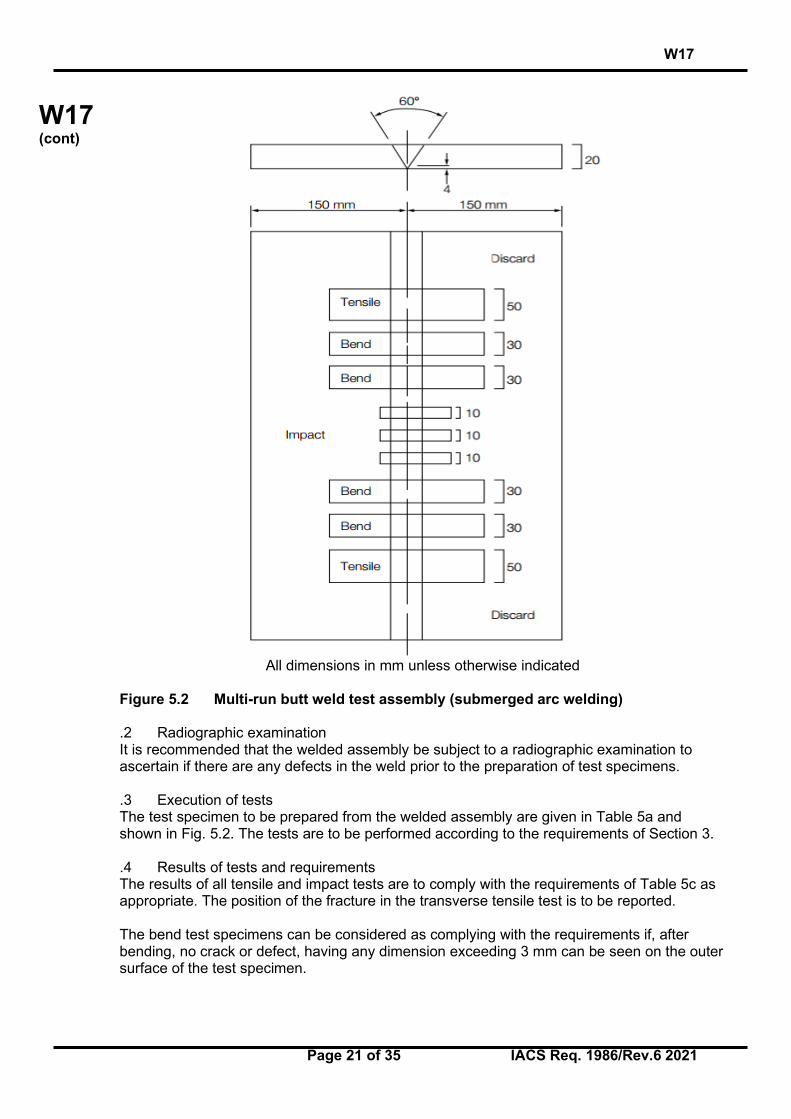
5.2.3 Butt Weld Test Assembly .1 Preparation One butt weld test assembly is to be prepared as shown in Figure 5.2 in the downhand position by welding together two plates (20 to 25 mm thick), each not less than 150 mm in width and sufficient length to allow the cutting out of test specimens of the prescribed number and size. The plate edges are to be prepared to form a single vee joint, the included angle between the fusion faces being 60° and the root face being 4 mm. The welding is to be carried out by the multi-run technique and the welding conditions are to be the same as those adopted for the deposited metal test assembly. The back sealing run is to be applied in the downhand position after cutting out the root run to clean metal. After welding the test assembly is not to be subject to any heat treatment.
W17
Page 21 of 35 IACS Req. 1986/Rev.6 2021
W17 (cont)
All dimensions in mm unless otherwise indicated
Figure 5.2 Multi-run butt weld test assembly (submerged arc welding) .2 Radiographic examination It is recommended that the welded assembly be subject to a radiographic examination to ascertain if there are any defects in the weld prior to the preparation of test specimens. .3 Execution of tests The test specimen to be prepared from the welded assembly are given in Table 5a and shown in Fig. 5.2. The tests are to be performed according to the requirements of Section 3. .4 Results of tests and requirements The results of all tensile and impact tests are to comply with the requirements of Table 5c as appropriate. The position of the fracture in the transverse tensile test is to be reported. The bend test specimens can be considered as complying with the requirements if, after bending, no crack or defect, having any dimension exceeding 3 mm can be seen on the outer surface of the test specimen.

W17
Page 22 of 35 IACS Req. 1986/Rev.6 2021
W17 (cont)
Table 5c Requirements for butt weld tests (wire-flux combinations)
Grade Tensile strength (transverse test)
N/mm2
Charpy V-notch impact tests
Test temperature oC Average energy J minimum
1 20 34 2 400 0 34 3 -20 34
1Y 20 34 2Y 0 34 3Y 490 -20 34 4Y -40 34
2Y40 0 39 3Y40 510 -20 39 4Y40 -40 39 5Y40 -60 39
5.3 Approval tests for two run techniques 5.3.1 Number of test assemblies Where approval for use with the two-run technique is requested, two butt weld test assemblies are to be prepared using the following thicknesses: - For grades 1 and 1Y: 12 to 15 mm and 20 to 25 mm - For Grades 2, 2Y, 3, 3Y and 4Y: 20 to 25 mm and 30 to 35 mm - For Grades 2Y40, 3Y40, 4Y40 and 5Y40: 20 to 25 mm and 30 to 35 mm A limitation of the approval to the medium range (up to the maximum welded plate thickness) may be agreed to by the Society. Test assemblies shall then be welded using plates of 12 to 15mm and 20 to 25mm irrespective of the grade for which the approval is requested. When a wire-flux combination is offered to approval for use with the two-run technique only, it is reminded that no deposited metal test assemblies have to be done. In this case approval tests are limited to the butt welds on two-run assemblies described in 5.3.2 hereafter. Where approval is requested for welding of both normal strength and higher strength steel two assemblies are to be prepared using higher strength steel. Two assemblies prepared using normal strength steel may also be required at the discretion of each Classification Society.
W17
Page 23 of 35 IACS Req. 1986/Rev.6 2021
W17 (cont)
5.3.2 Butt weld test assemblies .1 Preparation of assemblies The maximum diameter of wire, grades of steel plate and edge preparation to be used are to be in accordance with Fig. 5.3. Small deviations in the edge preparation may be allowed if requested by the manufacturer. The root gap should not exceed 1 mm. Each butt weld is to be welded in two runs, one from each side, using amperages, voltages and travel speeds in accordance with the recommendations of manufacturer and normal good welding practice. After completion of the first run, the flux and welding slag are to be removed and the assembly is to be left in still air until it has cooled to 100°C, the temperature being taken in the centre of the weld, on the surface of the seam. After welding, the test assemblies are not to be subjected to any heat treatment.

W17
Page 24 of 35 IACS Req. 1986/Rev.6 2021
W17 (cont)
Plate thickness
[mm]
Recommended preparation
[mm]
Maximum diameter of wire [mm]
Grade wire-flux
combination
Grade of normal
strength steel
Grade of higher strength steel
about 12-15
1 A 5 1Y - A32, A36
about 20-25
1 A - 1Y - A32, A36 2 A, B or D -
2Y - A32, A36, D32, D36
2Y40 - A40, D40
6 3 A, B, D or E -
3Y - A32, A36, D32 D36, E32, E36
3Y40 - A40, D40, E40
4Y - A32, A36, D32, D36, E32, E36,
F32, F36
4Y40 - A40, D40, E40, F40
5Y40 - A40, D40, E40, F40
about 30-35
2 A, B or D -
2Y - A32, A36, D32, D36
2Y40 - A40, D40
3 A, B, D or E -
7 3Y - A32, A36, D32, D36, E32, E36
3Y40 - A40, D40, E40 A32, A36, D32,
D36
4Y - E32, E36, F32, F36
4Y40 - A40, D40, E40, F40
5Y40 - A40, D40, E40, F40
Figure 5.3 Butt weld test assemblies (two-run technique) .2 Radiographic examination It is recommended that the welded assemblies are subjected to radiographic examination to ascertain if there are any defects in the weld prior to the preparation of test specimens. .3 Execution of tests

W17
Page 25 of 35 IACS Req. 1986/Rev.6 2021
W17 (cont)
The test specimens indicated in Table 5a and shown in Figure 5.4 are to be prepared from each test assembly. Tests are to be performed according to Section 3 requirements. The Charpy V-notch impact test specimens are to be machined from each welded assembly from the positions and with the orientations shown in Fig. 5.5.
All dimensions in mm otherwise indicated
Figure 5.4
All dimensions in mm otherwise indicated
Figure 5.5

W17
Page 26 of 35 IACS Req. 1986/Rev.6 2021
W17 (cont)
.4 Results of tests and requirements The results of all tensile and impact tests are to comply with the requirements of table 5b and 5c as appropriate. The position of fracture in the transverse tensile test is to be reported. The bend test specimens can be considered as complying with the requirements if, after bending, no crack or defect having any dimensions exceeding 3 mm can be seen on the outer surface of the test specimen. .5 Chemical analysis The chemical analysis of the weld metal is to be supplied by the manufacturer, and is to include the content of all significant alloying elements. 5.4 Annual tests – upgrading 5.4.1 Annual tests All establishments where approved wire/flux combinations are manufactured shall be subject to annual inspection. Annual tests are to consist of at least the following: a) multi-run technique: on deposited metal assembly and tests: 1 tensile and 3 impact tests. b) two-run technique: one butt weld assembly with 20 mm minimum thickness plate and
tests: 1 transverse tensile, 2 transverse bends and 3 impact tests. One longitudinal tensile test specimen is also to be prepared where the wire-flux combination is approved solely for the two-run technique.
The assemblies are to be prepared and tested in accordance with the requirements for initial approval. Where a wire-flux combination is approved for welding both normal strength and higher strength steel, the latter steel is to be used for the preparation of the butt weld assembly required by 5.4.1 b). 5.4.2 Upgrading and rating 5.4.2.1 Upgrading of wire-flux combinations in connection with the impact properties will be considered as detailed in 4.8.2.2, and for wire-flux combinations approved for two runs welding, a butt-weld in the maximum thickness approved is to be made and sampled for Charpy-V testing in accordance with 5.3.2.3. 5.4.2.2 Uprating of wire-flux combinations in connection with the tensile properties will be considered as detailed in 4.6.2.3.

W17
Page 27 of 35 IACS Req. 1986/Rev.6 2021
W17 (cont)
6. Wires and wire-gas combinations for metal arc welding 6.1 General 6.1.1 Categories Wire-gas combinations and flux-cored or flux-coated wires (for use with or without a shielding gas) are divided into the following categories for the purposes of approval testing: a) For use in semi-automatic multi-run welding. b) For use in single electrode automatic multi-run welding. c) For use in single electrode automatic two-run welding. NOTE: The term semi-automatic is used to describe processes in which the weld is made manually by a welder holding a gun through which the electrode wire is continuously fed. 6.1.2 Grades and suffixes .1 Depending on the results of impact tests, wires and wire-gas combinations are divided
into the following grades: - For normal strength steel Grades 1, 2 and 3; - For higher strength steels with minimum yield strength up to 355 N/mm2: Grades 1Y,
2Y, 3Y and 4Y. - For higher strength steels with minimum yield strength up to 390 N/mm2: Grades 2Y40,
3Y40, 4Y40 and 5Y40. .2 A suffix "S" will be added after the grade mark to indicate approval for semi-automatic
multi-run welding. .3 For wires intended for automatic welding, the suffixes "T", "M" or "TM" will be added
after the grade mark to indicate approval for two-run, multi-run, or both welding techniques, respectively.
.4 For wires intended for both semi-automatic and automatic welding, the suffixes will be
added in combination. 6.1.3 Composition of shielding gas .1 Where applicable, the composition of the shielding gas is to be reported. Unless otherwise agreed by the Society, additional approval tests are required when a shielding gas is used other than that used for the original approval tests. .2 The approval of a wire in combination with any particular gas can be applied or transferred to any combination of the same wire and any gas in the same numbered group as defined in Table 6a, subject to the agreement of the Classification Society.

W17
Page 28 of 35 IACS Req. 1986/Rev.6 2021
W17 (cont)
Table 6a Compositional limits of designated groups of gas types and mixtures.
Group Gas composition (Vol. %) Co2 O2 H2 Ar
M1 1 > 0 to 5 - > 0 to 5 Rest 1) 2) 2 > 0 to 5 - - Rest 1) 2) 3 - > 0 to 3 - Rest 1) 2) 4 > 0 to 5 > 0 to 3 - Rest 1) 2)
M2 1 > 5 to 25 - - Rest 1) 2) 2 - > 3 to 10 - Rest 1) 2) 3 > 5 to 25 > 0 to 8 - Rest 1) 2)
M3 1 > 25 to 50 - - Rest 1) 2) 2 - > 10 to 15 - Rest 1) 2) 3 > 5 to 50 > 8 to 15 - Rest 1) 2)
C 1 100 - - - 2 Rest > 0 to 30 - -
1) 2)
Argon may be substituted by Helium up to 95% of the Argon content. Approval covers gas mixtures with equal or higher Helium contents only.
6.1.4 Low hydrogen approval .1 Flux-cored or flux-coated wires which have satisfied the requirements for Grades 2, 2Y, 2Y40, 3, 3Y, 3Y40, 4Y, 4Y40 and 5Y40 may, at manufacturer's option, be submitted to the hydrogen test as detailed in 4.5, using the manufacturer's recommended welding conditions and adjusting the deposition rate to give a weight of weld deposit per sample similar to that deposited when using manual electrodes. .2 A suffix H15, H10 or H5 will be added to the grade mark, in the same conditions as for manual arc welding electrodes (see 4.5.3 above) to indicate compliance with the requirements of the test. 6.2 Approval for semi-automatic multi-run welding 6.2.1 General Approval tests for semi-automatic multi-run welding are to be carried out generally in accordance with Section 4, except as required by 6.2, using the semi-automatic multi-run technique for the preparation of all test assemblies. 6.2.2 Preparation of deposited metal assemblies .1 Two deposited metal test assemblies are to be prepared in the downhand position as shown in Fig. 4.1, one using the smallest diameter, and the other using the largest diameter of wire intended for the welding of ship structures. Where only one diameter is manufactured, only one deposited metal assembly is to be prepared. .2 The weld metal is to be deposited according to the practice recommended by the manufacturer, and the thickness of each layer of weld metal is to be between 2 and 6 mm. 6.2.3 Chemical analysis The chemical analysis of the deposited weld metal in each test assembly is to be supplied by the manufacturer, and is to include the content of all significant alloying elements.

W17
Page 29 of 35 IACS Req. 1986/Rev.6 2021
W17 (cont)
6.2.4 Mechanical tests On each assembly, tests are to be made in accordance with 4.2.3, and the results are to comply with the requirements of 4.2.4, appropriate to the required grade. 6.2.5 Preparation of butt weld assemblies .1 Butt weld assemblies as shown in Fig. 4.2 are to be prepared for each welding position (downhand, horizontal-vertical, vertical upwards, vertical downwards and overhead) for which the wire or wire-gas combination is recommended by the manufacturer. .2 The downhand assembly is to be welded using, for the first run, wire of the smallest diameter to be approved and, for the remaining runs, wire of the largest diameter to be approved. .3 Where approval is requested only in the downhand position, an additional butt weld assembly is to be prepared in that position using wires of different diameter from those required by 6.2.5.2. Where only one diameter is manufactured, only one downhand butt weld assembly is to be prepared. .4 The butt weld assemblies in positions other than downhand, are to be welded using, for the first run, wire of the smallest diameter to be approved, and, for the remaining runs, the largest diameter of wire recommended by the manufacturer for the position concerned. 6.2.6 Radiographic examination It is recommended that the welded assemblies are subjected to radiographic examination to ascertain if there are any defects in the welds prior to the preparation of test specimens. 6.2.7 On each assembly, tests are to be made in accordance with 4.3.4, and the results are to comply with the requirements of 4.3.5. 6.2.8 Fillet weld tests Fillet weld test assemblies are required to be made in accordance with 4.6.1 and 4.6.2, and tested in accordance with 4.6.3. 6.3 Approval for automatic multi-run welding 6.3.1 General Approval tests for automatic multi-run welding are to be carried out generally in accordance with section 5 multi-run approval, except as required by 5.2, using the automatic multi-run technique for the preparation of all test assemblies. 6.3.2 Preparation of deposited metal assembly One deposited metal assembly is to be prepared as shown in Fig. 5.1. Welding is to be as detailed in 5.2.2.1, except that the thickness of each layer is to be not less than 3 mm. 6.3.3 Chemical analysis The chemical analysis of the deposited weld metal in this test assembly is to be supplied by the manufacturer, and is to include the content of all significant alloying elements.

W17
Page 30 of 35 IACS Req. 1986/Rev.6 2021
W17 (cont)
6.3.4 Mechanical tests Tests on this assembly are to be made in accordance with 5.2.2.3, and the results are to comply with the requirements of 5.2.2.4. 6.3.5 Preparation of butt weld assemblies One butt weld assembly is to be prepared in each welding position which is to be approved. Generally, this will be the downhand position only, in which case only one assembly is required. Preparation of the assembly is to be in accordance with 5.2.3.1. 6.3.6 Radiographic examination It is recommended that each assembly be subjected to a radiographic examination to ascertain any defect in the weld prior to testing. 6.3.7 Mechanical tests Tests are to be made on each assembly in accordance with 5.2.3.3 and the results are to comply with the requirements of Table 5c. Where more than one assembly is prepared and tested, the number of transverse tensile and bend test specimens from each assembly may be halved. 6.3.8 Discretionary approval At the discretion of each individual Classification Society, wires or wire-gas combinations approved for semi-automatic multi-run welding may also be approved, without additional tests, for automatic multi-run welding approval. This is generally the case when automatic multi-run welding is performed in the same conditions of welding current and energy as semi-automatic welding with the concerned wire-gas combination. The only difference between the two welding processes in this case is that the welding gun is held by an automatic device instead of the welder's hand. 6.4 Approval for automatic two-run welding 6.4.1 General Approval tests for automatic two-run welding are to be carried out generally in accordance with the requirements of Section 5.3, except as required by 6.4, using the automatic two-run welding technique for the preparation of all test assemblies. 6.4.2 Preparation of butt weld assemblies .1 Two butt weld test assemblies are to be prepared, generally as detailed in 5.3.1 and 5.3.2, using plates 12-15 mm and 20-25 mm in thickness. If approval is requested for welding plate thicker than 25 mm, one assembly is to be prepared using plates approximately 20 mm in thickness and the other using plates of the maximum thickness for which approval is requested. .2 The plate preparation of the test assemblies is to be as shown in Fig. 6.1. Small deviations in the edge preparation may be allowed, if requested by the manufacturer. For assemblies using plates over 25 mm in thickness, the edge preparation is to be reported for

W17
Page 31 of 35 IACS Req. 1986/Rev.6 2021
W17 (cont)
information. Deviations or variations will be expected to form part of the manufacturer's standard recommended procedure for this technique and thickness range.
All dimensions in mm unless otherwise indicated
Figure 6.1 Recommended edge preparation for two-run butt weld test assemblies .3 The diameters of wires used are to be in accordance with the recommendations of the manufacturer and are to be reported. 6.4.3 Radiographic examination It is recommended that the welded assemblies be subjected to radiographic examination to ascertain any defect in the weld prior to testing, and to confirm full penetration continuously along the major part of the welded length of each assembly. 6.4.4 Mechanical tests Tests are to be made on each assembly in accordance with 5.3.2.3 to 5.3.2.6 and the results are to comply with the requirements of 5.2.2.4 and Table 5c. 6.4.5 Chemical analysis The chemical analysis of the deposited weld metal on the second side welded, is to be reported for each assembly.

W17
Page 32 of 35 IACS Req. 1986/Rev.6 2021
W17 (cont)
6.5 Annual tests and up-grading 6.5.1 Annual tests .1 Annual tests are to consist of at least: a) Wires approved for semi-automatic or both semi-automatic and automatic multi-run
welding : one deposited metal test assembly prepared in accordance with 6.2.2 using a wire of diameter within the range approved for the semi-automatic multi-run welding of ship structures.
b) Wires approved for automatic multi-run welding: one deposited metal test assembly
prepared in accordance with 6.3.2 using a wire of diameter within the range approved for automatic multi-run welding of ship structures.
c) Wires approved for automatic two-run welding: one butt weld test assembly prepared in
accordance with 6.4.2 using plates of 20-25 mm in thickness. The wire diameter used is to be reported.
.2 The test specimens are to be prepared and tested in accordance with the requirements of this Section, except that only the following tests are required: a) For deposited metal assemblies (semi-automatic and automatic multi-run): one tensile
and three impact tests. b) For butt weld assemblies (automatic two-run): one transverse tensile, two bend and
three impact tests. One longitudinal tensile test is also required where the wire is approved solely for automatic two-run welding.
Note: At the discretion of each individual Classification Society, hydrogen test can be carried out following 4.5. 6.5.2 Up-grading and up-rating .1 Up-grading of flux cored wires and wire-gas combinations in connection with the impact properties will be considered as detailed in 4.8.2.2. .2 Up-rating of flux cored wires and wire-gas combinations with the tensile properties will be considered as detailed in 4.8.2.3.

W17
Page 33 of 35 IACS Req. 1986/Rev.6 2021
W17 (cont)
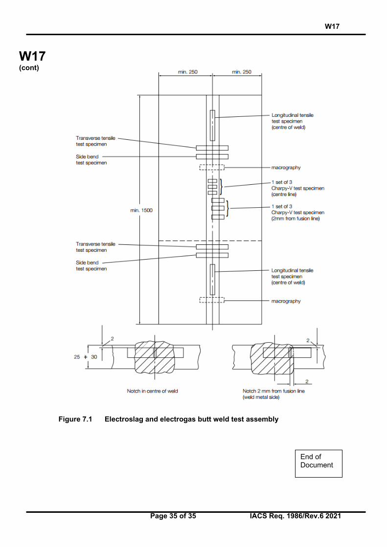
7. Consumables for use in eletroslag and electrogas vertical welding 7.1 General 7.1.1 The requirements for the two-run technique as detailed in Section 5 are applicable for the approval of special consumables used in electro-slag and electro-gas vertical welding with or without consumable nozzles except as otherwise required by the following requirements especially as regards the number and kind of the test-pieces used for the mechanical tests and taken from the butt welded assemblies. 7.1.2 For Grades 1Y, 2Y, 3Y, 4Y, 2Y40, 3Y40, 4Y40 and 5Y40 approval of the consumables may be restricted for use only with specific types of higher strength steel. This is in respect of the content of grain refining elements, and if general approval is required, a niobium treated steel is to be used for the approval tests. 7.1.3 For these special welding consumables, the prescription 1.2.1 may not be entirely applicable for technical reasons. Where approval is requested for welding of both normal strength and higher strength steel two assemblies are to be prepared using higher strength steel. Two assemblies prepared using normal strength steel may also be required at the discretion of each Classification Society. 7.2 Butt weld tests 7.2.1 Preparation of test assemblies Two butt weld test assemblies are to be prepared, one of them with plates 20/25 mm thick, the other with plates 35/40 mm thick or more. The grade of the steel to be used for each one of these assemblies must be selected according to the requirements given in the figure 5.3 for two-run submerged arc welding. The chemical composition of the plate, including the content of grain refining elements is to be reported. The welding conditions and the edge preparation are to be those recommended by the welding consumable manufacturer and are to be reported. 7.2.2 Radiographic examination It is recommended that the welded assemblies be subjected to a radiographic examination to ascertain if there are any defects in the weld prior to the preparation of test specimens. 7.2.3 Test series Each assembly shall be cut to give test specimens according to Figure 7.1. The length of the assembly should be sufficient to allow the selection of all the test specimens: - 2 longitudinal tensile test specimens with their axis at the centre of the weld. - 2 transverse tensile test specimens. - 2 side bend test specimens. - 2 sets of 3 Charpy-V notch impact test specimens in accordance with Figure 7.1: .1 set with the notch in the axes of the weld,

W17
Page 34 of 35 IACS Req. 1986/Rev.6 2021
W17 (cont)
.1 set with the notch at 2 mm from the fusion line in the deposited metal. - 2 macro-sections to the weld (towards the middle of the weld and towards one end). 7.2.4 Results to be obtained The results of the tensile, bend and impact tests are to comply with the requirements of paragraph 5.3 (two-run welding) for the class of filler product in question. 7.3 Annual tests and up-grading 7.3.1 All factories which manufacture approved consumables for use in electroslag and electrogas welding must be subject to an annual inspection and tests in accordance with 2.4. 7.3.2 One test assembly must be prepared from plates 20/25 mm thick, and tested as indicated in 7.2. The following specimens are to be selected: - 1 longitudinal tensile specimen from the axis of the weld, - 1 transverse tensile specimen, - 2 side bend specimens, - 3 Charpy-V specimens notched at the centre of the weld (position 1 Fig. 7.1), - 3 Charpy-V specimens cut out transverse to the weld with their notches at 2 mm from
the fusion line, in the weld, - macro section. 7.3.3 The results to be obtained should meet the requirements given in 5.3 (two-run welding) for the class of the consumables in question. 7.3.4 Upgrading and uprating Upgrading and uprating will be considered only at the manufacturers’ request, at the time of annual testing. Generally, for this purpose, full tests from butt weld assemblies as indicated in 7.2 will be required, irrespective of the other tests requested if the concerned consumable is also approved (and possibly upgraded or uprated) according to Section 5 or Section 6.
W17
Page 35 of 35 IACS Req. 1986/Rev.6 2021
W17 (cont)
Figure 7.1 Electroslag and electrogas butt weld test assembly
End of Document
Related Documents