W SA /MAI MANUFACTURING APPLICATIONS TEAM (NASA-CR'-150626) HANOFACTUBING" PROCESS N78-2iI011 APPLICATIONS TEAM (MATEA) Yearly-Eeport, 1977 (IIT Research Inst.) 75 p HC A0Q/MF A01 . 4CSCLi 05A "Unclas S- . -. . G3/85 .11887 1977 YEARLY REPORT CONTRACT NO. NAS8-32229 SOLVING MANUFACTURING PROBLEMS THROUGH AEROSPACE TECHNOLOGY / APR1B7 \

Welcome message from author
This document is posted to help you gain knowledge. Please leave a comment to let me know what you think about it! Share it to your friends and learn new things together.
Transcript
W SA /MAI MANUFACTURING APPLICATIONS TEAM
(NASA-CR'-150626) HANOFACTUBING" PROCESS N78-2iI011 APPLICATIONS TEAM (MATEA) Yearly-Eeport, 1977 (IIT Research Inst.) 75 p HC A0Q/MF A01 . 4CSCLi 05A "Unclas S- . -. . G3/85 .11887
1977 YEARLY REPORT CONTRACT NO. NAS8-32229
SOLVING MANUFACTURING PROBLEMS THROUGH AEROSPACE TECHNOLOGY / APR1B7 \
REPORT NO. IITRI-H6056 - YEARLY REPORT
MANUFACTURING PROCESS APPLICATIONS TEAM
(MATeam)
Attention:
Mr. James H. Ehl, Chief Tooling Applications Branch Materials and Processes Lab. (EH44)
Prepared by:
E. R. Bangs and J. D. Meyer lIT RESEARCH INSTITUTE 10 W. 35th Street Chicago, III. 60616
January 1978
YEARLY REPORT FOR 1977
TABLE OF CONTENTS
Page
Foreword -------------------------------------------------- i
1. Summary --------------------------------------------------- 1
2. Introduction ------------------------------------------- 2
2.1 Objectives ------------------------------------------- 2
2.2 Program Approach ------------------------------
2.3 Team Organization ---------------------------------- 9
3. Industry Contacts ------------------------------------- 11
4. Manufacturing Problem/Opportunities Statements --------------- 14
5. Potential Technology Transfers 17
5.1 Concentration of Waste Heat Recovered from Stack Gas and/or Waste Waters (MAT-16) -------------------------20
5.2 Power Factor Control System for AC Induction Motors (MAT-19) -------------------------------------------- 21
5.3 Improved Voice Communication in High Noise Environment (MAT-22) ---------------------------------------- 22
5.4 Testing Bearings While in Use (MAT-28)---------------- 23
5.5 Tool Wear Sensing Using Vibration Analysis (MAT-46) --- 24
5.6 Nondestructive Testing of Spot.Welds (MAT-54)---------- 25
5.7 Non-Contacting 3-D Inspection Pr6be (MAT-55) ---------- 26 5.8 Ultraclean, Ultrafine Rapidly Cooled Nickel Alloy
Powder (MAT-59) ---------------------------------- 27
5.9 Improving Mold and Die Design Through Simulation of Casting Processes (MAT-71) ---------------------------28
5.10 Nickel Based X-Ray Film Process (MAT-72)-------------- 30 5,11 Controlling the Thickness of Conformal Coatings
for Printed Circuit Boards (MAT-74)------------------ 31
5.12 Automated Laser Inspection of Printed Circuit Boards (MAT-82) --------------------------------------------- 32
5.13 Adhesive Bonding of Aluminum (MAT-83)----------------- 33
TABLE OF CONTENTS (continued)
Page 5.14 Adaptively Controlled Weld Skate (MAT-86)---------------- 34
5.15 Low-Intensity Portable X-Ray Device (MAT-87) ------------ 35
5.16 High Temperature Plastic (MAT-IO0)---------------------- 36
5.17 New Cutting Tool Material (MAT-117)--------------------- 37
5.18 Protective Coating for Die Casting Dies (MAT-118)--------- 38 5.19 Reliable, Economical, Fast Manipulator Arms (MAT-131) ---- 39
5.20 Single-Fill-Point Battery Reservoir (MAT-143)------------ 40
6. Conclusions and Recommendations ------------------------------- 41
APPENDICES
A. Guidelines for Preparation of Problem Statements ---------- 43
B. Initial Screening Form ----------------------------------- 53
C. Press Release --------------------------------------------58
D. MATeam Problem Statements and Status ---------------------- 61

LIST OF TABLES AND FIGURES
Table No. Page
3-1 - APPROXIMATE NUMBER OF MATEAM CONTACTS ................... 12
3-2 - MATEAM PRESENTATIONS .................................... 13
4-1 - TECHNICAL CATEGORIES OF MATEAM PROBLEM STATEMENTS ....... 15
4-2 - SUMMARY OF MATEAM ACTIVITIES (1YEAR).................... 16
5-1 - POTENTIAL TECHNOLOGY TRANSFERS .......................... 18
Figures
2-1 - MATEAM TECHNOLOGY TRANSFER PROCESS...................... 6
2-2 - MANUFACTURING APPLICATIONS TEAM ORGANIZATION ............ 10
liT RESEARCH INSTITUTE

FOREWORD
This report describes the activities of lIT Research Institute's
Manufacturing Applications Team (MATeam) during the first program year,
February 1, 1977 to January 19, 1978. The purpose of the team is to
effect widespread transfer of NASA technology to aid in the solution of
manufacturing problems in the industrial sector of the economy.
During the first year of the program, the team has focused on:
identifying manufacturing problems, or technology opportunities; seeking
out relevant NASA technology in order to help solve the problems;
assessing the technical and economic merits of the potential solutions;
developing strategies for commercialization; and initiating industry
implementation. To date, the team has had contact with more than
450 companies, industry associations and government agencies, documented
150 manufacturing problems, and identified 20 potential technology
transfers. Although none of the technology transfers have been completed
(i.e., have been commercialized and are being used), several are currently
in the applications engineering phase, while others are in early stages of
implementation and should be completed during the next program year.
In addition to the authors, the following staff have made significant
contributions to the program: J. Dylik, P. Grinstead, M. Hill, T. Jacobius,
J. O'Connor, M. Ross, and Y. Shikari. The report was typed by D. Schuh
and M. Wroblewski.
The work described herein was conducted under NASA Contract NAS8-32229.
Mr. James Ehl, Marshall Space Flight Center, served as the Contracting
Officer's Representative.
Respectfully submitted,
d3 n 0. MeyerAPPROVED:/ ,l Aam Director
Dr. Irvine J. Solomon
Director of Research
JDM:ds

1. SUMMARY
During the first year of its operation, the MATeam has made
significant progress transferring aerospace technology to the manufacturing
sector of the economy.
The MATeam program has been well received by industry. During the
past year, the team members have had contact with over 450 companies,
industry associations and other government agencies. Thirteen presenta
tions on the MATeam have been given at various conferences and meetings.
The presentations to the National Machine Tool Builders Association and
the Industrial Perforators Association were particularly noteworthy in
that these organizations are considering the formation of committees to
interface with the team on a regular basis.
To date 150 manufacturing problems on technology opportunities have
been identified and documented. Thirteen of these problems have been
screened and 20 potential technology transfers have been identified.
Most notable of the potential transfers include, An A-C Motor
Power Factor Control that reduces the energy required to operate small
motors; a Computerized Tracking and Torch Manipulation Welding System
(Weld Skate); Computer Aided Design of Sand Casting Molds; Automatic Laser
Inspection of Printed Circuit Boards; and Tool Wear Sensing Using
Vibrational Analysis. Although none of the technology transfers have been
completed (e.g,, commercialized and implemented), several are entering
the applications engineering phase and should reach completion during the
next year or two.
In summary, the MATeam has been well received by industry; strong
communications channels have been established between the team, NASA,
individual companies, industry associations and other government agencies.
JiT RESEARCH INSTITUTE
1
2. INTRODUCTION
2.1 Objectives
The objective of the MATeam is to successfully transfer aerospace
technology to solve key problems in the manufacturing sector of the
economy. The underlying purpose for the team is to increase the return
on the nation's investment in aerospace research by fostering wide
implementation and use of NASA technology and expertise. The function
of the team in accomplishing this objective is to provide an important
intermediary role between technology sources and technology users in
order to: improve the communication process; assist in the movement of
new technology across organizational and disciplinary boundaries; and
shorten the time between technological development and its broad and
effective implementation.
NASA's decision to sponsor an applications team to effect technology
transfer in manufacturing was both timely and appropriate. The United
States, while still ahead of other industrialized nations in terms of
overall manufacturing capabilities, productivity and state of technology,
is finding its leadership position diminishing. The problem is becoming
increasingly severe because of the continual rise in the cost of energy,
raw material and labor and the need to maintain our competitive position
in the world market. Clearly, a way to combat this growing national
problem and maintain our competitive advantage is to capitalize upon and
speed up adaptation of new manufacturing technologies and equipment into
the industrial sector. The appropriateness of NASA's decision is
underscored by the fact that the areas of science and technology in which
they have been actively advancing the state-of-the-art correspond closely
to those needed by the industrial sector of the economy to improve
manufacturing productivity.
IIT RESEARCH INSTITUTE
2
2.2 Program Approach
Achieving significant technology transfer,-widespread implementation,
usage of new products, and processes is not something that occurs
quickly. To bring about successful technology transfer, industry problem
areas, or market needs, must be matched with solutions that are both
technically sound and economically feasible. This matching of needs with
solutions does not, however, guarantee technology transfer; it is also
necessary to establish effective means for commercializing the new product
or process. Thus the MATeam's task is somewhat analogous to that of
identifying and implementing new business opportunities and carries with
it the many pitfalls normally associated with-new venturedevelopmefit groups.
The approach used by the MATeam is structured to insure that the
team's efforts are focused on bringing about successful technology
transfer and that common pitfalls are avoided. Key elements of the approach
are described below.
2.2.1 Industry Interaction
Effective communication channels between the team, industry associations, individual companies, NASA personnel and other government
agencies is necessary to coordinate the teams efforts throughout all
phases of the technology transfer process, from identification of
technology opportunities to commercialization and implementation of new
processes and equipment. The MATeam provides this interaction through
numerous presentations to industry groups, visits to companies for in-plant
discussions of problems andpotential solutions, and extensive consultation
by phone and mail. To help foster this type of interaction, there is no
fee charged to industry for the team's services.
As an added means of increasing the team's effectiveness, it is
concentrating on four target industries. In this way, the team can
develop a close working relationship with the target industries and not
IIT RESEARCH INSTITUTE
3
dilute its efforts by trying to cover all industry types. This does not
mean, however, that the team has not or will not work with companies
outside the target categories if it appears that meaningful technology
transfer can be achieved. The four target industries are:
& Machine tool builders
* Light fabrication and assembly
* Heavy equipment manufacturers
* Electronics assembly
2.2.2 MATeam Technology Transfer Process
There are two basic approaches which can be used to effect technology
transfer: 1) to use the technology available as a basis for initiating
the transfer process and then seek out applications for that technology,
or 2) to begin the transfer process by identifying the technology needs
of the target industry sector and then determine if relevant technology
is available to satisfy those needs. The latter approach is the one used
by the MATeam.
Starting the technology transfer process with identification of
industry needs rather than the aerospace technology available provides
several distinct advantages. First, it helps insure that the team is
responsive to the needs of industry. Second, it provides a ready market
for the aerospace technology if it can be found, thus helping to insure
rapid commercialization and implementation. Additionally, by documenting
the technology opportunities and circulating them to appropriate NASA
personnel, the effectiveness of the search for relevant technology is
increased and, in some cases, may even result in innovative solutions
to problems because of the unique technical expertise of NASA personnel.
Last, starting with industry problems rather than the available technology
helps insure that the team's efforts are spent on areas of greatest need
and payback and not in trying to bring about solutions for which there
is no real problem.
[IT RESEARCH INSTITUTE
4

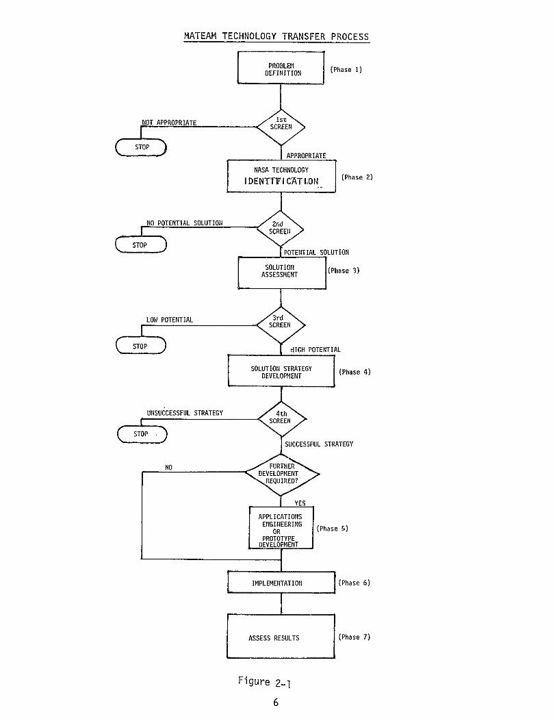
An overview of the MATeam technology transfer process is shown in
Figure 2-1 on the next page. It represents a logical sequence of steps,
beginning with the identification and documentation of industry technology
opportunities, or problem areas, and ending in successful technology
transfer.
The MATeam identifies manufacturing problems, or technology
opportunities, by working with professional societies, industry associa
tions, various government agencies and individual companies. Once
identified, problems are documented in the form of problem statements,
which are used by the MATeam throughout the technology transfer process.
Problem statements play a key role in the MATeam's activities. They
serve as a means of communicating information about the problem so that
team members can:
e Seek out potential solutions
* Evaluate the likelihood of successfully solving a problem and
implementing a solution, and
* Compare problems and concentrate on those which have the highest
likelihood of solution and potential benefit.
Inaddition to its internal use, the MATeam circulates edited copies
of the problem statements to technical personnel in the NASA field centers
and laboratories. This helps insure that every effort is made to identify
appropriate technology if it exists. The problem statements are edited
prior to circulation to NASA personnel to reserve the name of the problem
originator and any information of a proprietary nature.
Copies of the problem statement are not circulated outside of NASA
or the MATeam until a potential solution has been identified. If a
potential solution has been identified, other organizations may be contacted
to assess the magnitude of the problem and the suitability of the potential
solution, Unedited problem statements are not circulated under any
circumstances. Additional information on the content and format of
problem statements is contained in Appendix A.
[IT RESEARCH INSTITUTE
5
MATEAM TECHNOLOGY TRANSFER PROCESS
PROBLEM DEFINITION (Phase 1)
APR
C- APORIATE
S NASA TECHNOLOGY
NOT APPROPRIATE
2)IDENT'rVI CAT LON (Phase
NOPOTENTIAL SOLUTION SLISCREEN!
SOLUTION (Phase 3)ASSESSMENT
LOW POTENTIAL3r: m~IS POTENTIALLTO
STOP OIHPOTENTIAL
SOLUTIO STRATEGY (PhaseDEVELOPMENT )
UNSUCCESSFUL STRATEGY 4th SREIED?
:SUCCESSFUL STRATEGY
IMPEETAIN(Phase 6)DEVELOPMIENT
SAPPLICATIONS
(Phase )
PROTOYPErE
DEVELOFMENlT
I(Phaseo6)[ IMPLEMENTATION 1
ASSESS RESULTS (Phase 7)
Figure 2-1
6

Problems which the MATeam will work on must meet three criteria:
@ The problem must be manufacturing related.
e The problem must apply to more than one company.
* Solutions to problems must be based on NASA technology.
The problem statements are screened at several stages during the technology transfer process. The questions asked during the screening are:
* Do satisfactory commercial solutions already exist for this problem?
* What is the likelihood of identifying relevant NASA technology? * What is the magnitude of the benefits to be gained by solving
the problem?
* Can the problem be solved technically?
* Can a solution be implemented?
The answers to these questions are used to select those problems
which the MATeam can most effectively solve. Criteria used for the
initial screening are contained inAppendix B. In those instances where
a problem statement does not pass the screening process, the problem
originator isnotified and told the reason for the decision.
Those problem statements which survive the preliminary screening
(i.e., are deemed suitable for the team) then enter the next phase of the
technology transfer process:1 identification of relevant NASA technology
which could provide wholly or inpart, a solution. This isaccomplished
through data and literature searches utilizing NASA's Scientific and
Technical Information Facility, annual STAR indices, review of NASA Tech
Briefs and by contacting individual NASA personnel with the necessary
expertise for further discussions of the technology involved.
Following the identification of relevant NASA technology, each
potential solution isgiven a more in-depth analysis. The solutions are
assessed in terms of impact of solving the problem, likelihood of
fIT RESEARCH INSTITUTE
7

successful solution and implementation, resources required to effect
commercialization and organizations which should be involved.
If the solution still appears valid after this assessment, the team
then develops an implementation strategy to bring about commercialization.
Such factors as applications engineering and implementation costs and
the proper time phasing of the implementation are taken into consideration
when developing the implementation strategies. Inputs from the problem
originator and NASA personnel are solicited in devising these strategies.
The particular implementation strategy that is developed will depend on
the individual case in point, but in general, the strategy will be one of
the following types:
e Direct transfer of the solution information and immediate
implementation by the user.
* Applications engineering followed by test and implementation
totally funded by the user or someone in a position to
commercialize the process or product.
s Applications engineering jointly funded by the user/commercializer
and NASA with subsequent test and implementation by the user/
commercializer.
Once an implementation strategy is agreed upon between the MATeam,
NASA, the problem originator and a commercializer, implementation is initiated. It should be pointed out that successful technology transfer
and implementation takes varying amounts of time to come to fruition,
depending on the specific case. Some can occur fairly rapidly, while
others will take more time because of applications engineering and the
type of industry and technology involved.
In order to achieve the maximum possible implementation, the team
widely disseminates data pertaining to successful technology transfers.
This dissemination of information is accomplished through press releases
and articles in appropriate trade journals, magazines, etc., and presentations
at conferences and other meetings.
lIT RESEARCH INSTITUTE
8
2.3 Team Organization
Responsibility for the MATeam resides in the Technology Transfer and Market Research Section at IITRI. The team organization is shown
in Figure 2-2. The team members possess a unique mix of capabilities and experience inmanufacturing technology and technology transfer for a
variety of industries. Inaddition to the individuals listed in Figure 2-2, the team also relies extensively on staff members within other IITRI research divisions for their expertise inspecialized areas relating to
manufacturing processes and equipment.
The remainder of this report presents the MATeam's activities and progress during its first program year. Chapter 3 describes the contacts
that have been made with industry. The technology opportunities which have been identified are highlighted inChapter 4. The 20 potential technology transfers which the team is currently pursuing are discussed
inChapter 5,along with their status, and last, the conclusions and recommendations resulting from the first program year are covered in
Chapter 6.
lIT RESEARCH INSTITUTE
9

MANUFACTURING APPLICATIONS TEAM ORGANIZATION
I DR. MORTON J. KLEIN
Vice President Research Operations
MR. JOHN MEYER
MATeam Director
consultant Consultant
,MR. EUD BANGS
M.J M R. JACKIN WILLIAMS EIs. R I CHAELRSDR Asst. iMAemDrector
= UU IAIM.JHtMU I
Manufacturing Advisor Part-Time Evaluation Analyst Part-Time Evaluation Analyst Evaluation Analyst
Figue 2-2

3. INDUSTRY CONTACTS
The MATeam was well received by industry duting its first year.
Approximately 467 contacts have been made with individual companies,
industry associations and interested government agencies. A breakdown
of the contacts by industry and type of contact is contained in Table 3-1.
Much of the industry interest was generated by a press release
describing the MATeam program which was mailed to appropriate trade
journals in April, 1977. A copy of the press release is contained in
Appendix C. A similar press release was issued by NASA in April, 1977.
A few of the publications which contained notices or articles on the
team include:,
* American Machinist
* Metalworking News
* Electronics Packaging and Production
9' Mechanical Engineering (published by ASME)
v ALERT (published by Research Institute of America)
s iKiplinger Newsletter
Industry interest in the program was also increased by numerous
presentations given by the team members at conferences and other meetings.
The presentations given by the team members during the first year are
listed in Table 3-2. The presentations given to the National Machine
Tool Builders Association and the Industrial Perforators Association are
particularly noteworthy in that both organizations are considering
forming committees to interface with the MATeam. These committees would
assist in identifying industry problems and evaluating potential solutions.
[IT RESEARCH INSTITUTE
11

APPROXIMATE NUMBER OF MATEAM CONTACTS
Industry
Machine Tool Builders
Heavy Equipment Manufacturers
Electronics Assembly
Light Fabrication and Assembly
Associations and Societies
Publications
Government
Agencies
Other
Mail/Phone Visit To
20
20
50
100
10
10
15
200
10
3
4
4
5
0
2
0
TABLE 3-1
Total Visit From Contacts
1 31
0 23
2 56
3 107
0 15
1 11
0 17
4 207
467
[IT RESEARCH INSTITUTE
12

February 10, 1977
March 31, 1977
April 5, 1977
May 10, 1977
June 16, 1977
June 22, 1977
August 18, 1977
September 15, 1977
September 20, 1977
October 19, 1977
October 5, 1977
October 24, 1977
November 15, 1977
December 6, 1977
February 9, 1978*
* April 9-12, 1978
April 26-28, 1978
* Planned
MATEAM PRESENTATIONS
NASA-MSFC Contractors Technology Utilization Workshop, Chicago, IL
NASA Technology Utilization Meeting, Chicago, IL
NASA-MSFC Contractors Technology Utilization Workshop, Redondo Beach, CA
Advanced Manufacturing Methods Technical Meeting, Chicago, IL
Robot Institute of America, Dearborn, MI
REAPS Technical Meeting, New Orleans, LA
EIA Manufacturing Technology Committee, Hopkins, MN
National Machine Tool Builders
Association, Chicago, IL
SME Chapter, Gary, IN
SME Chapter, Chicago, IL
DOD Manufacturing Technology Conference Orlando, FL
Industrial Perforators Assn. Hilton Head, SC
National Machine Tool Builders Assn. Chicago, IL
AIIE Conference Washington, D.C.
American Society for Metals (Calumet Ill. Chapter)
Numerical Control Society Annual Meeting Chicago,.IL
15th Space Congress
Cocoa Beach, Fla.
TABLE 3-2
IIT RESEARCH INSTITUTE
13

4. MANUFACTURING PROBLEM OPPORTUNITY STATEMENTS
As mentioned in Section 2-2 of this report, the starting point for
the MATeam technology transfer process is the identification and documentation
of manufacturing problems or technology opportunities. During the past
year, the team has. prepared 150 such problem statements. The majority
of these problem statements were a direct result of the industry contacts
which had been made by the team, while others were generated by reviewing
publications which describe current manufacturing technology needs. A
breakdown of the problem statements by technical category is contained in
Table 4-1. A list of the problem statement titles and their status is
contained inAppendix D.
The status of the presentations, visits, contacts and problem statements
is summarized in Table 4-2. (See Figure 2-1 for a description of the transfer
process phases). Of the 150 problem statements, 51 have been inactivated for various reasons and 89 are still under consideration by the team.
Twenty potential technology transfers have been identified and are
currently being pursued. The definition used for "potential technology
transfer" is that the problem statement has, as a minimum, successfully
passed the second screening stage and that relevant NASA technology has
been identified. In addition to the 20 active potential technology
transfers, another 4 potential transfers have been inactivated during
the past year.
The 20 potential technology transfers and their status are presented
in Chapter 5.
IIT RESEARCH INSTITUTE
14
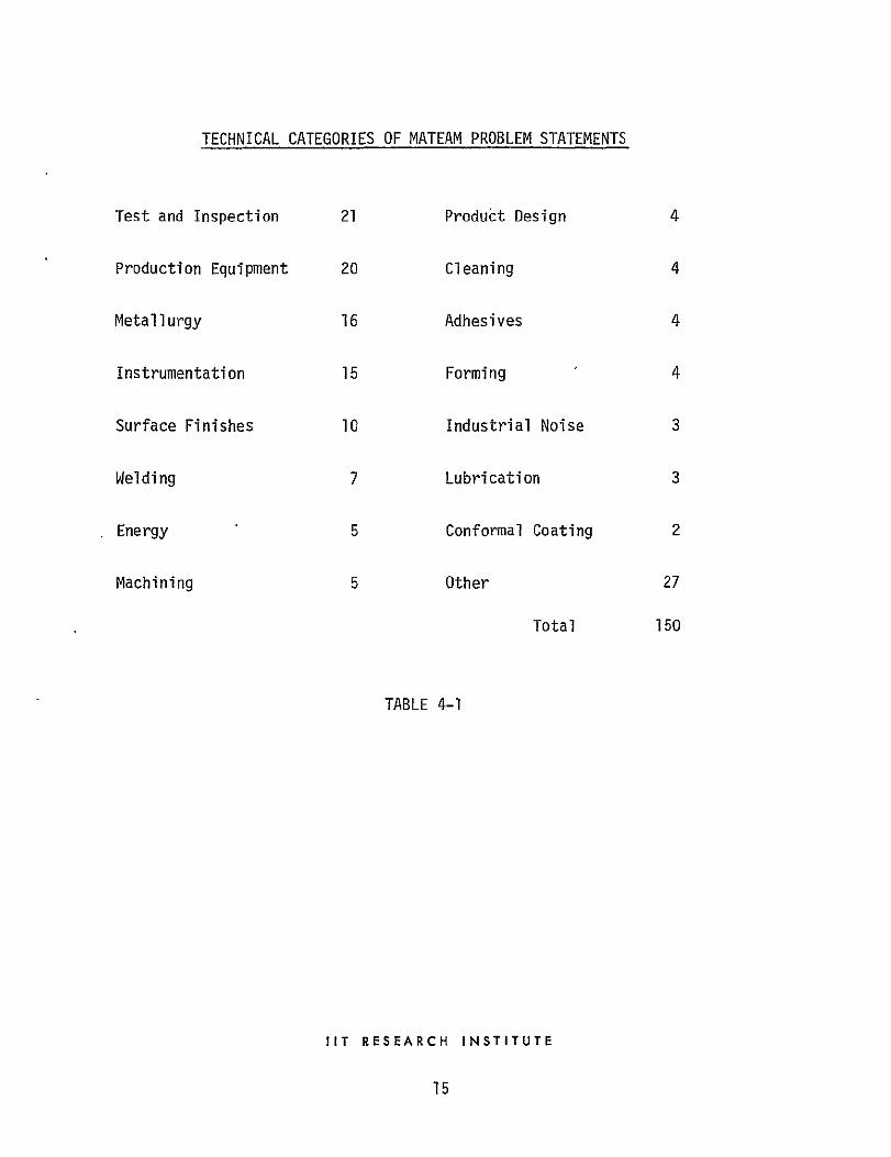
TECHNICAL CATEGORIES OF MATEAM PROBLEM STATEMENTS
Test and Inspection 21 Product Design 4
Production Equipment 20 Cleaning 4
Metallurgy 16 Adhesives 4
Instrumentation 15 Forming 4
Surface Finishes 10 Industrial Noise 3
Welding 7 Lubrication 3
Energy 5 Conformal Coating 2
Machining 5 Other 27
Total 150
TABLE 4-1
IIT RESEARCH INSTITUTE
15

SUMMARY OF MATEAM ACTIVITIES (YEAR 1)
Activity Number
Industry Presentations 14
Company Visits 31
Other Contacts (Phone, Mail, etc.) 467
Problems Identified 150
Problem Statements Prepared 150
1st Screening Completed 140
(Problems Failed Ist Screening) (19)
NASA Technologies Identified 24
(Problems Failed 2nd Screening) (28)
Solutions Assessed 8
(Solutions Failed 3rd Screening) (4)
Solution Strategies Developed 4
(Solutions Failed 4th Screening) 0
Applications Projects Completed 0
Implementations Completed 0
Results Assessed 0
TABLE 4-2
IIT RESEARCH INSTITUTE
16

5. POTENTIAL TECHNOLOGY TRANSFERS
The 20 potential technology transfers which are actively being
pursued by the MATeam at the end of the first program year are listed in
Table 5-1 on the following page. Descriptions of each of the transfers
and their status are contained in the following sections of this chapter.
Most notable of the potential transfers are discussed below:
o MAT-86, The Adaptively Controlled Weld Skate, may be considered the
technology closest to transfer. The industry source, a major supplier of
welding equipment, has-made several visits to IITRI and has visited the
Marshall Space Flight Center to see the prototype device in operation. He
is very interested in the system and has forwarded a proposal for the
additional development that will be required to assist in its eventual
commercialization. An RTOP is being prepared;upon its approval development
work will commence. The manufacturer is well respected in the welding
community and has a good reputation in providing reliable well designed
equipment and products.
v MAT-71, Computer Aided Design of Sand Casting, has received considerable
industrial attraction and is presently being further developed under Army
Sponsored Project TARADCOM-(4785014), "Improved Foundry Casting Processes
Utilizing Computer Aided Fluid Flow and Thermal Analysis". Major casting
manufacturers have expressed an interest in the process and have made
frequent contacts to the MATeam inquiring as to its status.
m MAT-19, The Power Factor Control System for AC Induction Motors, has
the potential to transfer rapidly since it has the capability of reducing
the electrical energy required to operate small electric motors. The
MATeam is in the process of contacting selected manufacturers in the small
electric motor industry.
IIT RESEARCH INSTITUTE
17

POTENTIAL TECHNOLOGY TRANSFERS
No. Status
MAT-16 A2U The Concentration of Waste Heat Recovered from Stack Gas and/or Waste Waters
MAT-19 A4U Power Factor Control System for AC Induction Motors
MAT-22 A3U Improved Voice Communications in High Noise Level Environment
MAT-28 A3U Testing Bearings While In Use
MAT-46 A3U Tool Wear Sensing Using Vibration Analysis
MAT-54 A3U Non Destructive Testing of Spot Welds
MAT-55 A3U Non-Contracting 3-D Inspection Probe
MAT-59 A2U High Quality Nickel Alloy Powder
MAT-71 A4C Computer Aided Design of Sand Casting Molds
MAT-72 A3U Nickel Based X-Ray Film Process
MAT-74 A3U Controlling the Thickness of Conformal Coating for Printed Circuit Boards
MAT-82 A3U Automatic Laser Inspection of Printed Circuit Boards
MAT-83 A2U Adhesive Bonding of Aluminum
MAT-86 A4C Adaptively Controlled Weld Skate
MAT-87 A3U Low-Intensity Portable X-Ray Device
MAT-1O0 A5U High Temperature Plastic
MAT-117 A3U New Cutting Tool Material
MAT-118 A3U Protective Coating for Die Casting Dies
MAT-131 A3U Reliable, Economical, Fast Manipulator Arm
MAT-143 A3U Single Fill Point Battery Reservoir
Table 5- 1
18

* MAT-100, High Temperature Plastic. A supplier of food processing
equipment is using NASA developed (Tech Brief 71-10441) Polyimide plastic
as a cover for trays and portions of trays. In the application of the
new plastic it is being exposed to temperatures as high as 500DF.
Preliminary test results show that the material works well and enables
a 20% reduction of energy to heat the contents of the tray. Additional
testing is underway but the source is optimistic that it will perform
successfully. The MATeam is presently exploring additional applications
of the plastic.
lIT RESEARCH INSTITUTE
19
5.1 - Concentration of Waste Heat Recovered from Stack Gas and/or Waste Waters (MAT-16)
A large textile manufacturer wishes to recover the heat and latent
heat from the moist flue gas effluent of textile drying ovens. This
recovery can be made in several phases. First, the sensible heat from
the flue gas can be transferred by a heat exchanger to heat-the oven inlet
air, which reduces the oven fuel consumption. Next the latent heat from
the moisture in the flue gas can be recovered by condensing the flue gas.
Third, the large volume of low temperature water could have the heat
withdrawn and concentrated to form-a small quantity of higher temperature
fluid suitable for processing or heating. For this last process some form
of heat pump would be required, possibly based on vapor absorption
principles since the cost of mechanical compressors is high. /
For the heat transfer function, heat pipe technology (as outlined in
Tech Brief 71-10109) appears to be a possible solution. Isothermics, Inc.
(New Jersey) was founded to exploit heat pipe technology under license
from NASA. The company has equipment ranging from 100 CFM to 100,000 CFM at efficiencies varying between 20 and 80%. A heat design computer program
enables a system to be designed to recover the moisture, heat and latent heat,
from flue gases. Waste heat recovery using this technology is considered
to have a high transfer potential.
No alternative to costly heat pump technology has been found yet.
Since up to 80% of recovery efficiency can be attained very considerable
fuel savings accrue from heat pipe technology alone. The textile company
representative was very interested in the information on heat pipe heat
exchangers when informed in mid-January. Evaluation continues on their
part in an effort to review the process equipment redesign implications.
IIT RESEARCH INSTITUTE
20
5.2 Power Factor Control System for AC Induction Motors (MAT-19)
AC induction motors are one of the most commonly used in industry. In
many applications they are relatively inefficient especially when operating
at less than full load. The motor runs at essentially a constant speed which,
within limits, is independent of load or applied voltage. Thus, inmany
instances, the power factor for the motor is higher than necessary.
Typically, a 115 volt motor would be designed to deliver its rated load
plus a safety margin at an under voltage condition of 105 to 110 volts. In
actual operation the motor seldom runs at full load and the line voltage is
generally 120 to 125 volts. Hence the power factor is less than optimum and
the copper loss within the motor is higher than optimum. The design of the
motor is to be compatible with the constant voltage, constant frequency power
distribution systems available.
What is needed is a relatively simple and inexpensive electronic circuit
which would connect directly to the power lines of the motor, improve the power
factor and significantly reduce the power dissipated in the motor at loads less
than full load.
The solution to this problem was found in a NASA Tech Brief entitled,
"Save Power in AC Induction Motors," by Mr. Frank J. Nola. The circuitry
which was developed at Marshall Space Flight Center, is in essence an
electronic control loop which varies the voltage applied to the induction motor.
The benefits of such a device would be energy savings, less heat generated
by the motor and a better power factor which reduces power distribution costs.
Investigation into this high potential technology transfer has taken
three major directions. First, Auburn University is currently doing
theoretical analysis and testing of the device. Second, Marshall Space Flight
Center has submitted an RTOP to NASA Headquarters for commercialization of
the solution and a market study has been completed by IITRI. Finally, the
MATeam is contacting key organizations in industry regarding commercialization.
lIT RESEARCH INSTITUTE
21
5.3 Improved Voice Communication in High Noise Environment (MAT-22)
The ambient noise level is very high in some industries. Noise level reaches 105 dbA in textile mills and stamping plants and 120 dbA in casting
cleanup shops. As a result verbal communication in such areas is very difficult. A representative of the textile industry requested that MATeam
investigate the problem.
MATeam is in the process of making a second comprehensive computer
literature search in the area of adoptive filtering techniques and poor signal to noise ratios. NASA technology such as MSC-12223-1 on "Audio
Signal Processing Which Removes High Level Noise Burst" and 75A 34875* on,
"A New VOX Technique for Reducing Noise inVoice Communication Systems" by P.E. Shock of Johnson Space Center are to be investigated for application
to this problem. Briefly, narrow band limited spectra from the original
voice signal are individually amplitude clipped and then recombined. If
this technique does not suffice, then adaptive filtering techniques will
have to be used such as one described in NASA-TM-X66080. The benefits of
this technology will be that the staff will be able to communicate with one
another in the noisy work areas which will improve their work efficiency.
The information has recently been forwarded to the problem/opportunity
statement originator.
lIT RESEARCH INSTITUTE
22
5.4 - Testing Bearings While in Use (MAT-28)
As a result of MATeam contacts with the engine and pump industries,
there is interest in detecting incipient bearing failure before catastrophic
damage can occur in very expensive machinery. Such machinery would be
turbines of all types where bearing failure leads to immediate destruction
of the whole turbine. Other machinery would be high speed machining centers
where considerable damage could occur during the slow down period.
NASA has sponsored development of an Incipient Failure Detector
described in NASA-MSC-16587. This detector has successfully checked motors,
fans,and pumps for bearing integrity. This detector instrument performs
vibration analysis on signals picked off accelerometer type sensors attached
to the detector case. Since initial testing .conditions are set into the
detector, a wide range of conditions can be accommodated.
The benefits of such an instrument are that incipient failure can be
detected and corrected before possibly catastrophic damage can occur. Such
a bearing failure detector has high transfer potential to industry. A
number of companies have been identified as being interested in the
manufacture of these instruments and communication with them is in progress.
[IT RESEARCH INSTITUTE
23
5.5 Tool Wear Sensing Using Vibration Analysis (MAT-46)
A large internal combustion engine manufacturer is interested in a
detector that can sense metal cutting tool wear. The damage that results
from tool failure inparts nearing the finished machine stage is costly
and of great concern. The detector must be capable of monitoring wear on
a continuous basis so that symptoms of tool failure may be identified
prior to actual failure so replacements can be made.
The NASA sponsored Incipient Bearing Failure Detector uses vibration
analysis methods in its detection scheme. This detector (reported in
MSC-16587) can have initial parameters for the spectrum analysis inserted
so that a wide variety of machining conditions can be monitored. The
ability to detect a potential tool failure prior to its occurrence will have
a major impact at reducing machining costs and losses incurred in the damage
of parts that have neared final assembly or machining stages,. The detection
system has high application potential inthe metal cutting industry.
The MATeam is in the process of contacting machine tool builders and
cutting tool material manufacturers.
lIT RESEARCH INSTITUTE
24

5.6 - Nondestructive Testing of Spot Welds (MAT-54)
Sheet metal fabricating industries have for several years voiced a
distinct need for technology which will enable the nondestructive testing
of spot welds.
The MATeam has identified, and is evaluating two ultrasonic inspection
sSstems which have the potential to measure spot weld quality.
Among the most promising of these is a hand-held ultrasonic inspection
device developed at Marshall Space Flight Center (NASA Tech Brief 66-10289).
The system enables rapid scanning of spot welds for detection of a weld
nugget. Its portability allows for the scanning of weldments in areas
inaccessible to larger equipment.
Another nondestructive testing device currently being evaluated is a
weld quality monitor (NASA Tech Book TND-5304) developed at Goddard Space
Flight Center. This device was expressly designed to evaluate cross-wire
resistance-welded joints used in electronic packaging.
Particular interest has been shown in these two testing devices by
not only metal fabricating industries, but also key members of the non
destructive testing equipment industry. MATeam members are in contact with
selected industry companies.
JIT RESEARCH INSTITUTE
25

5.7 Non-Contacting 3-D Inspection Probe (MAT-55)
Current techniques for automatically inspecting 3-diminsional surfaces
of complex parts rely on contacting probes. These probes must be frequently calibrated and are not suitable for inspection on non-rigid parts.
Additionally, use of a contacting probe istime consuming and subject to damage if it collides with the part or fixturing.
Non-contacting inspection techniques exist for measuring 1-and 2-dimensional attributes of parts (e.g., size, location of features, and
thickness). These are usually based on optical, electronic or magnetic
sensors.
Although a non-contacting inspection technique would be of interest to many industries, our present target industry isshipbuilding. At present
the shipyards use large wooden structures for alignment purposes. The
structures are cumbersome to use and time consuming to fabricate. What
isneeded is a faster and more flexible method of controlling shipbuilding alignment operations.
A high potential transferable technology isthe Optical Profilometer
which was developed at Langley Research Center. The Optical Profilometer
provides non-contact measurement of surface areas, absolute depth, and
point-to-point distance using optical and electronic means. (NASA Ref.) The benefits of the solution will be a faster and more accurate system
for shipbuilding construction operations.
The Optical Profilometer iscurrently being reviewed by a major shipbuilding manufacturer to determine how its capabilities can be applied
to their alignment processes.
IIT RESEARCH INSTITUTE
26
5.8 - Ultraclean, Ultrafine Rapidly Cooled Nickel Alloy Powder (MAT-59)
The aircraft turbine industry during-the past ten years has been
attempting to manufacture blades, discs, spacers and rotors from powdered
alloys. The ability to obtain a high quality powder that after forging
produces properties equivalent to wrought material has been a problem.
Powders commercially available after being forged into parts produce micro
structures containing high inclusion levels. The high inclusion levels
promote low cycle fatigue failure when the parts are exposed to the rigorous
high temperature and high stress environment.
NASA (Tech Briefs 66-10606, 69-10293, 70-10331, 70-10468, 72-10344)
has produced a series of high quality nickel base alloy powders that have
been produced using atomizing techniques and prealloyed powder. NASA test
results have shown that the tensile strength properties of parts made from
the powder are 1.5 to 2 times better than cast properties. In addition, the
alloy has shown improved ductility at elevated temperature.
The major benefit in the availability of powdered parts is the cost
saving obtained in the machining operation and the ability to produce a
part with more closely controlled properties.
The problem originator and other key manufacturers in the aircraft
turbine industry have demonstrated interest in the data and communications
with them are underway.
lIT RESEARCH INSTITUTE
27
5.9 - Improving Mold and Die Design Through Simulation of Casting Processes (MAT-71)
Casting processes (e.g., sand casting, permanent mold casting and die
casting) are used to produce parts of complex shape inmany metals and alloys.
Cast metal parts are used in almost every product, from automobiles to
household appliances. In 1971, the value of casting produced in the U.S.
exceeded $13 billion.
A major problem in the metal casting industry is product quality.
Approximately 5 to 10 percent of the cost of all castings manufactured
represent parts which are either scrapped at the foundry or rejected by the
customer.
Much of the casting quality problem is attributable to the lack of
readily available analytical techniques which can be used by foundry engineers
to design casting systems. The design of the mold, gates and risers, and
the selection of mold materials, the mold preheat temperatures, the temperature
of the molten metal prior to pouring and rates at which the metal is injected
into the mold all have a major impact on the quality of the casting produced.
At best, techniques available to the foundry engineer make the design
process and selection of casting parameters an art rather than a science.
Additionally, because of cost and time constraints, the foundry engineer is
not afforded the luxury of fine tuning his design and process parameters.
Computer aided design techniques which would enable the foundry engineer
to design better casting systems at reduced costs and in shorter times are
needed. An interactive computer system which would let the foundry engineer
assess the impact of changes in casting system design would substantially
improve product quality and reduce costs.
An interactive computer program can be usedhby foundry engipeers
to improve mold and die designs by simulating the solidification of metal
which takes place during casting processes. NASA technology such as the "SINDA
Systems Improved Numerical Differencing Analyzer", described in NASA Tech
Brief B72-10736,and "Cosmic Program Abstract" MSC-13805,appear to be valuable
bases for the technology required. IIT RESEARCH INSTITUTE
28

MAT 71 (continued)
The technical feasibility of such a computer system has been
demonstrated by Mr. William Erickson of Los Alamos Scientific Laboratory
and it is anticipated that the Army sponsored project TARADCOM-(4785014)
titled, "Improved Foundry Casting Processes Utilizing Computer Aided Fluid
Flow and thermal Analysis - CAM (Phase Ii)"will demonstrate further technical
feasibility.
Major companies in the sand casting indus4y have been notified of
the available technology and have responded with enthusiastic interest.
Communications with selected industry representatives are in progress.
lIT RESEARCH INSTITUTE
29
5.10 Nickel Based X-Ray Film Process (MAT-72)
The inspection industry each year in the radiography of pressure
vessels, large valves and castings use x-ray film containing costly silver
emulsion that must be contained in light proof and radiation proof cassettes.
The cost of the film is a major percentage of the price passed on to the
industrial consumer.
The ability to reduce radiograph film costs is of interest to the
industry.
NASA as described in Tech Brief B72-10456 has developed a new, less
expensive nickel hypophosphite emulsion. The new emulsion is less sensitive
to visible light. It has been determined that a new emulsion is
(approximately 103) times less sensitive than required for industrial
applications. Increased sensitivity (approx 105) is required for medical
applications.
The benefits anticipated include reduced inspection and equipment
costs. Improved radiograph quality is also envisioned.
The MATeam and The University of Wisconsin BATeam are presently
contacting companies involved in the use and manufacture of film used in
radiography.
lIT RESEARCH INSTITUTE
30
5;11 - Controlling the Thickness of Conformal Coatings for Printed
Circuit Boards (MAT-74)
One of the problems encountered during conformal coating of printed
circuit boards is controlling the thickness of the coating during application.
Ifthe coating is too thin, sufficient environmental protection may not
be achieved. Too thick of a coating on the other hand results in excessive
production costs and may restrict cooling of the boards.
Current methods for controlling coating thickness depend on the type
of coating used (dipping or vapor deposition). Dipped coatings are generally controlled by varying the viscosity of the coating and through the use of
multiple coats. Vapor deposited coatings, such as parylene, are usually
controlled by monitoring the deposition time. Parylene coatings can take
several hours to achieve a thickness of 2 to 3 mils.
Other techniques for the control of thickness of conformal coatings
are needed, particularly for the vapor deposition coatings.
The techniques should be low cost, provide an accuracy of less than
1 mil, be as free from human error as possible, and have an output which can
be used for automatically controlling the process.
NASA, Lewis Research Center, has developed a technique for monitoring
the thickness of parylene conformal coatings during deposition. The
technique relys on the use of air-gap capacitors within the deposition
chamber. The capacitance of these devices vary during the deposition process, and can be used in conjunction with an electronic circuit to automatically
stop the process. The concept is simple, inexpensive and reliable. The
benefits of this technology are reduced conformal coating cost, reduced
scrap and rework costs and improved environmental performance.
Upon receipt of the technical brief, contacts will be made with potential
users as well as potential equipment suppliers.
lIT RESEARCH INSTITUTE
31
5.12 Automated Laser Inspection of Printed Circuit Boards (MAT-82)
During production at a large printed circuit board manufacturer, printed
circuit boards are checked at several stages of manufacture in order that
defects can be detected as early as possible so as to minimize corrections
that must be made and to avoid discarding finished or near finished boards
wherein errors are caught too late for easy, and thus inexpensive, correction.
This, of course, requires considerable effort often involving both visual and
electrical inspection. Presently most of this inspection is performed
manually by a team of inspectors located at various points throughout the
production line. Because of the time factor, such activity and expense,
using the visual inspection team for high production rates of PC boards is
unsatisfactory.
A company founded by ex-NASA employees has developed a laser scanning
device based on experience with NASA laser holography and electornics in
related projects (e.g., NASA-CR-123530). The NASA-based technology has
resulted in inspection machines for detecting damaged holes, solder bridges,
and miscrimped components at each stage of manufacture.
The benefit foreseen in the laser inspection system is in the reduction
of inspection costs with the in line adaptability of the system and elimina
tion of the labor involved in the present inspection technique. Equally
important is the inspection technique will be more reliable and do a better
job than visual inspection.
Contacts have been made by the MATeam with a major supplier of
electronic controllers serving the industrial market and the team is
currently waiting for data on the system's performance requirements and
configuration desired.
[IT RESEARCH INSTITUTE
32
5.13 - Adhesive Bonding of Aluminum (MAT-83)
An aluminum boat manufacturer constructs boats from sheet aluminum
riveted to prefabricated stringers and bulkheads. The manufacturer is
experiencing difficulty in meeting OSHA noise standards of 90 dbA. He is
interested in an adhesive bonding method for joining the boat shells to
the bulkheads and stringers Using methods similar to those of aerospace
industry.
NASA has tested Hysol 934. They found that lap joints prepared with solvent cleaning and mild abrasion yielded joints of 95% of the strength
of those etched with acid preparation. This is described in TK-X-71128.
The benefits of this technology will be a quieter working environment.
The problem originator, the manufacturer of small sport fishing boats
has been notified of the technology uncovered and has expressed interest in
studying its applicability to his present fabrication practices.
Contact will be expanded to other sources in the boating industry to
identify additional fabricators with similar problems.
lIT RESEARCH INSTITUTE
33

5.14 - Adaptively Controlled.Weld Skate (MAT-86)
The ability of a gas tungsten Arc GTA welding head to follow the
irregular surface of a weld joint without a feeler probe and automatically
adjust torch angle is a need of the welding industry. Welding equipment
commercially available is not computerized and does not have the ability to
automatically adjust torch angle. Further, a feeler probe is required to
contact the joint surface to signal torch Y and Z position adjustment.
Frequently the probes are damaged due to the heat of welding or give false
direction as a result of rough contact surface.
NASA, in Technical Memorandum TMX-73328 developed a Computerized
Adaptive Controls Weld Skate with Closed Circuit Television Weld Guidance.
The system has the unique capability of tracking the weld joint in the
transverse and longitudinal directions by computerized reflective light
sensors. Torch angle is also adjusted to maintain a perpendicular relation
ship with the weld joint by a computerized system that initiates changes in
torch angle by sensing increasing arc length.
The benefits anticipated in use of the system include reduced welding
costs, reduced rework costs, and improved weld quality.
A major supplier of welding equipment has been located by the MATeam and
has expressed interest inmarketing the system after some additional develop
ment has been completed. The equipment manufacturer has forwarded a
proposal to NASA for the additional development work and an R T 0 P is being
prepared. The MATeam will continue to follow the program until successful
implementation and assessment of results has been completed.
lIT RESEARCH INSTITUTE
34
5.15 - Low-Intensity Portable X-Ray Device (MAT-87)
Fluoroscopic inspection devices are used to detect voids, porosity,
inclusions and cracks in such items as castings, forgings, weldments and
assemblies. Commercially available equipment is ordinarilly large and
bulky and requires that the work be taken to the test device.
A major drawback in the utilization of these devices is the need for
a relatively high level source of x-rays. These x-ray sources are expensive
and require the use of protective barriers. What is needed is a portable
fluoroscopic inspection device which is sensitive to low level x-rays and
can be taken to the work with relative ease.
NASA's Goddard Space Flight Center has developed a low-intensity
portable x-ray device which addresses this problem. A patent is currently
being filed on the device which is referred to as the Lixiscope.
Benefits anticipated in the availability of a portable device include
reduced radiography costs, expanded non-destructive testing capability, good
sensitivity at low energy x-ray levels, and will have wide application in
the medical and dental field.
A market survey has been performed by IITRI under NASA Contract
'NASW02837 to identify the market potential of the device.
The MATeam will follow up on interested industrial sources identified
as part of the market survey.
IIT RESEARCH INSTITUTE
35
5.16 High Temperature Plastic (MAT-lO0)
A food processing equipment manufacturer isdeveloping a new system
for heating individual portions of food in institutions such as hospitals
and prisons. The system utilizes induction coils which heat metal plates
within the individual serving dishes, thereby-warming the food. The
serving dishes are ceramic and have metal bonded to the inside or outside,
or totally embedded within the ceramic. Inorder to heat relatively large
food items (e.g., steaks) itis necessary to have a cover on the serving
dish which contains its own metal heating element. To prevent breakage and
reduce weight, the covers should be plastic.
The temperature within the serving dish may reach as high as 5000F.
The plastic cover itself may be exposed to higher temperatures than this
because of the large heatingelement in the cover. This company has been
unable to identify a commercially available plastic which can withstand the
heat. The plastic covers should be capable of withstanding heats inexcess
of 600°F without outgassing. Such a plastic must be identified before the
item can enter production.
NASA Lewis Research Center recommended Tech Brief 71-10441 on "Thermally
Stable Polyimides from Solutions of Monomeric Reactants", Tech Brief 75-10137
on "Tailor Making High Performance Graphite Fiber Reinforced PMR Polyimides",
and some suppliers of PMR polyimides they had tested. Lewis also recommended
TMX 71894, "Second Generation PMR Polyimides".
The benefits of this technology will be 20% less energy required to
process the food if cooked inthe plastic lidded containers. Additionally
inaddition there will be less labor required to prepare the meals.
First and second generation resins were referred to the food processing
equipment manufacturer who isin the process of testing them. Samples have
been sent by the manufacturer to the National Sanitation Foundation to
check their safety for food use. The preliminary findings are good.
Ifthe Foundations additional testing issatisfactory, they will use the
suggested polyimide.
36
5.17 New Cutting Tool Material (MAT-117)
The metal removal industry is constantly searching for improved
cutting tool materials. The application of new super alloys, alloys
containing high hardness levels, and alloys containing hard coatings have
created serious wear problems with cutting tools when machining has been
required. In recent years the industry has had to rely on ceramic and
cermet material cutting tools for difficult machining operations.
A cermet cutting tool material referred to as "Sialon" has been
developed under NASA contract (patent No. 3,990,860). The material by
JPL consists of 19% Si3N4, 42% A1203 and 40% AlN and has been used
effectively on Austenitic stainless steel and tungsten materials. It has
performed better on these materials than some commercially available
carbides.
The benefit to be gained in use of the material is principally lower
machining costs as a result of less tool wear.
A major supplier of ceramic and cermet cutting tools contacted by
the MATeam is presently performing machining tests using the Sialon
cutting tool material.
lIT RESEARCH INSTITUTE
37

5.18 Protective Coating For Die Casting Dies (MAT-118)
The die casting industry is concerned with the problem that molten
aluminum alloys used in pressure die casting production are prone to "solder" or "weld" to the mold surfaces. When this occurs production is
interrupted, die maintenance costs increase, casting surfaces are damaged
and may be distorted or fractured during opening of the die halves or
during ejection. What is needed is a coating or surface treatment that will
prevent molten aluminum from attaching "welding" to the steel die components
and facilitate release of the casting from the dies. Various commercial
solutions have been tried but with limited success.
A promising solution is the Sputter Plating of a Solid Lubricant
Tantalum Disizicide recommended by a coating specialist at Lewis Research
Center. This technology was formerly tested by NASA as a protective coating
under simulated reentry conditions and may have application.
Successful application of this solution would be of significant dollar
cost benefit to the producers of aluminum die castings. There are an
estimated 5,000 aluminum die casting machines in the United States. It has
been conservatively estimated that the profit improvement that might
from the elimination of the "soldering" problem could amount to over a
dollar per machine hour. This adds up to over $10,000,000 increased profit
per year for the industry.
Presently the potential solution is being assessed by the user.
Preparation of the testing set-up which will be used to evaluate its
technical feasibility is in progress.
lIT RESEARCH INSTITUTE
38
5.19 - Reliable, Economical, Fast Manipulator Arms (MAT-131)
The need for remote controlled robots and manipulator arms continues
to grow with advancing technology in nuclear waste disposal, munitions
deactivation and second generation mass production techniques. Industries
involved in nuclear waste disposal, and munitions deactivation cannot risk
exposure of personnel to the hazards of radiation exposure or explosives.
NASA has developed a manipulator arm described in MFS-22707 and
patent 3,922,950 possessing small size, uniform motion control elements,
and a counterbalanced power source. The design is simplified and the arm
is of relatively low cost. The benefits of this technology are removal
of humans from hazardous environments and mass production cost savings.
Subsequent benefits include improved quality and elimination of the human
error factor.
The MATeam is in the process of contacting manufacturers of remote
controlled robots and industries in which they are widely used.
[IT RESEARCH INSTITUTE
39
5.20 Single-Fill-Point Battery Reservoir (MAT-143)
The availability of a single-fill-point snap-on reservoir that can
automatically restore the electrolyte solution in all cells of a storage
battery is of interest to battery manufacturers. Existing storage batteries
require that each cell be filled individually. This also necessitates
individual maintenance and monitoring of these cells in certain cases, this
is time consuming and not highly reliable. Although sealed automotive
batteries have solved this problem, there are many storage battery
applications which do not use sealed batteries.
Rockwell International, under contract to the Marshall Space Flight
Center has developed a concept for a Snap-In Single-Fill-Point Battery
reservoir as described in NASA Tech Brief MFS-16801.
The benefits to be obtained include low battery maintenance costs, its
ease in adaptability to present battery design, and the ability to be
visually monitored.
The MATeam has been in contact with battery manufacturers and a strong
interest has been expressed by one company. The Tech Brief and other
related technical data are or have been provided to the interested company.
[IT RESEARCH INSTITUTE
40
6. CONCLUSIONS AND RECOMMENDATIONS
Conclusions
a. The response of industry to participation in the program is far
greater than anticipated. A valuable promotional technique in soliciting
the response has been the use of press releases and announcements in
selected trade journals.
b. The use of the problem/opportunity statement as a means to
initially define and document a problem or opportunity is an effective,
simplified method in which the screening and assessment system can function.
c. The technology transfer process appears to be an operational
system that combines a critical assessment of the engineering and economic
factors to be considered in the transfer of technology. The system provides
a comprehensive analysis by engineering personnel with a wide range of
industrial expertise that have the capability to identify transferable
technology in situations that involve a problem and equally effective in
the identification of NASA technology heretofore undetected that may adapt
to areas of process improvement.
d.. The screening of problem/opportunity statements is a slow process
when considering the many assessment factors involved. The definition of
the problem details, the search for relevant NASA technology that might
solve the problem and assessment of the technical and economic factors
are time consuming phases. It is estimated that the screening and assess
ment process for one statement takes eight weeks to perform.
Recommendations
a. It is suggested that timely press releases and published
announcements continue in the trade journals. When a potential transfer
has reached the level of Applications Engineering or Prototype Development
an announcement or press release should be published in industry related
trade journals. lIT RESEARC H INSTITUTE
41

b. In promotion of the MATeam Program it is suggested that emphasis
be placed in giving presentations before societies and associations
representing a wide range of particular industries.
IIT RESEARCH INSTITUTE
42

APPENDIX A
GUIDELINES FOR PREPARATION OF PROBLEM STATEMENTS
43

GUIDELINES FOR PREPARATION
OF
PROBLEM STATEMENTS
August, 1977
Manufacturing Applications Team Engineering Research Division
lIT Research Institute 10 West 35th Street
Chicago, Illinois 60616 (312/567-4609)
44

INTRODUCTION
The objective of the Manufacturing Applications Team (MATeam) is to
successfully transfer aerospace technology to solve manufacturing problems in
other industries. The MATeam begins with identification of problems and then
seeks relevant technology which may provide solutions. Starting with the pro
blems rather than available'technology helps to insure that the MATeam's
efforts are responsive to industry needs and that the amount of time spent in
"finding problems for solutions" isminimized.
The MATeam identifies manufacturing problems by working with professional
societies, industry associations, various government agencies and individual
companies. Once identified, problems are documented in the form of problem
statements, which are used by the MATeam throughout the technology transfer
process.
This document has been prepared as a guide for individuals preparing pro
blem statements for submission to the IATeam. It contains a description of how
the problem statement is used by the team, the format employed and several
examples.
FUNCTION OF THE PROBLEM STATEMENT
Problem statements play a key role in the MATeam's activities. They serve
as a means of communicating information about the problem so that team members
can:
a. seek out potential solutions
b. evaluate the likelihood of successfully solving a problem and
implementing a solution and
c. compare problems and concentrate on those which have the highest
likelihood of solution and potential benefit.
In addition to its internal use, the MATeam circulates edited copies of the
problem statements to technical personnel in the NASA field centers and labora
tories. This helps insure that every effort ismade to identify appropriate
45

technology if it exists. On occasion, this has resulted in innovative problem solutions based on the technical expertise of NASA personnel rather than on past NASA research and development. The problem statements are edited prior to circulation to NASA personnel to reserve the name of the problem originator and any information of a proprietary nature.
Copies of the problem statement are not circulated outside of NASA or the
MATeam until a potential solution has been identified. If a potential solution has been identified, other organizations may be contacted to assess the magnitude of the problem and the suitability of the potential solution. Unedited problem
statements are not circulated under any circumstances.
Problems which the MATeam will work on must meet three criteria:
1. The problem must be manufacturing related. This is very broad and could include materials, processes, inspection techniques, equipment, tooling, management techniques, energy conservation and product design as it re
lates to manufacturing.
2. The problem must apply to more than one company. The MATeam will focus
on widespread problems and does not solve those problems which would benefit only one company. This would rule out the redesign of specific
products or processes unless it involved an innovation which would be used by others, The MATeam will also not pursue problems for which there are acceptable commercially available solutions.
3. Solutions to problems must be based on NASA technology. Although NASA research and development has advanced the state-of-the-art inmany areas, there will be many problems which cannot be solved using NASA technology.
The problem originator is not expected to know in advance whether or not relevant NASA technology exists; this will be determined by the MATeam.
If the MATeam identifies potential solutions involving technology from
other sources, this information will be passed on to the problem originator.
As mentioned earlier, the problem statements are screened at several stages
during the technology transfer process. The questions asked during the screening
are:
1. Do satisfactory commercial solutions already exist for this problem?
46

2. What is the likelihood of identifying relevant NASA technology?
3. How widespread is the problem in industry?
4. What is the magnitude of the benefits to be gained by solving the
problem?
5. Can the problem be solved technically?
6. Can a solution be implemented?
The answers to these questions are used to select those problems which the
MATeam can most effectively solve. In those instances where a problem statement
does not pass the screening process, the problem originator is notified and told
the reason for the decision.
PROBLEM STATEMENT FORMAT
Problem statements are usually one to two pages in length and contain enough detailed information on which the MATeam can intelligently base a decision during
their evaluation. Because of the large numbet of problem statements the MATeam
reviews (several hundred per year), it is important that the problem statement be
as concise and factual as possible. Additionally, because the problem statements will also be reviewed by NASA personnel who may not be familiar with manufacturing
jargon, they should be written in layman's terms.
The problem statement format is shown in Figure 1. The problem statement should be typed doubled-spaced on plain bond paper. Additional information, such
as reports and drawings, should be enclosed with the problem statement. Examples of completed problem statements are contained in Figures 2 and 3.
47

FIGURE 1. MATeam Problem Statement Format
TITLE:
ORIGINATOR: (Names of individual and company, DATE:
company address, and individual's telephone number)
WHAT'S NEEDED: (Brief one or two sentence description of solution
desired.)
BACKGROUND: (Description of product, current methods being used, and why there is a problem. Also describe other approaches
which have been tried but have proven unsuccessful, and
why.)
SOLUTION CRITERIA: CDescription of key factors, such as cost, performance,
material and production rates, which would determine
a successful solution.)
BENEFITS: (Description of what would be gained by solving the problem. This could include such factors as cost savings, improved quality, im
proved safety, etc. Also, the magnitude of the benefits for your industry and other industries which may also use the solution
should be indicated, ifpossible.)
COMMENTS: (Optional, but may be used to describe NASA technology you are aware of that may provide a solution or other approaches that should be investigated. Any additional information concerning the problem or solution which you feel isimportant should also be included in
this section.)
48
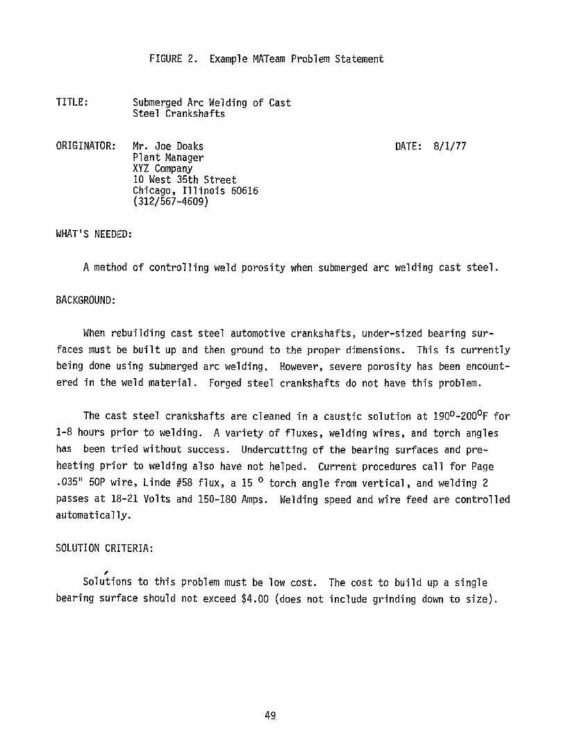
FIGURE 2. Example MATeam Problem Statement
TITLE: Submerged Arc Welding of Cast Steel Crankshafts
ORIGINATOR: Mr. Joe Doaks DATE: 8/1/77 Plant Manager XYZ Company 10 West 35th Street Chicago, Illinois 60616 (312/567-4609)
WHAT'S NEEDED:
A method of controlling weld porosity when submerged arc welding cast steel.
BACKGROUND:
When rebuilding cast steel automotive crankshafts, under-sized bearing surfaces must be built up and then ground to the proper dimensions. This is currently being done using submerged arc welding, However, severe porosity has been encount
ered in the weld material. Forged steel crankshafts do not have this problem.
The cast steel crankshafts are cleaned in a caustic solution at 1900-200°F for
1-8 hours prior to welding. A variety of fluxes, welding wires, and torch angles
has been tried without success. Undercutting of the bearing surfaces and preheating prior to welding also have not helped. Current procedures call for Page
.035" 50P wire, Linde #58 flux, a 15 0 torch angle from vertical, and welding 2 passes at 18-21 Volts and 150-180 Amps. Welding speed and wire feed are controlled
automatically.
SOLUTION CRITERIA:
Solutions to this problem must be low cost. The cost to build up a single bearing surface should not exceed $4.00 (does not include grinding down to size).
49

Additional criteria include:
1) Production rates in excess of 250 bearing surfaces per day.
2) A process which is either automatic or well defined so that
unskilled labor can be used.
3) Hardness of the built-up material should be less than 35 Rc so that it can be easily ground to size.
BENEFITS:
Solutions to this problem would reduce rebuilding costs (approximately $50
per crankshaft) by about 3% because of the current need to rework porous welds.
Additionally, product quality would be improved and the cost of shipping defective
units returned by customers would be eliminated. This is an industry-wide problem,
and a solution would benefit many companies which weld cast steel.
COMMENTS:
None
50
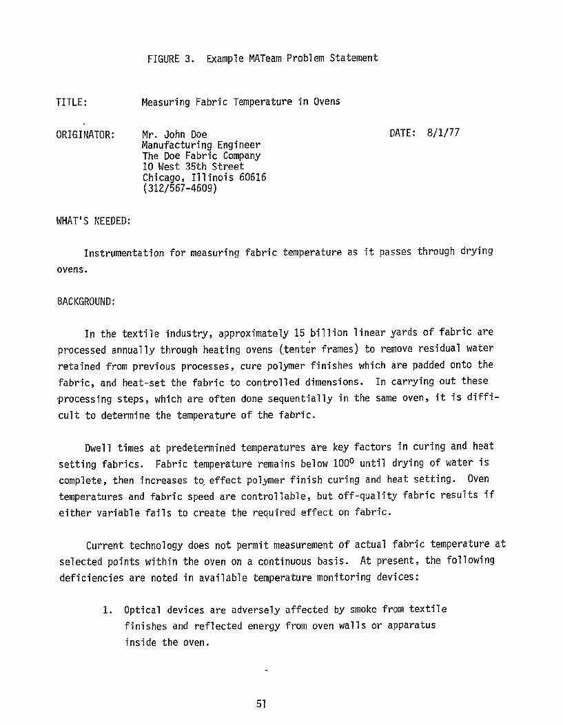
FIGURE 3. Example MATeam Problem Statement
TITLE: Measuring Fabric Temperature in Ovens
ORIGINATOR: Mr. John Doe DATE: 8/1/77 Manufacturing Engineer The Doe Fabric Company 10 West 35th Street Chicago, Illinois 60616 (312/567-4609)
WHAT'S NEEDED:
Instrumentation for measuring fabric temperature as it passes through drying
ovens.
BACKGROUND:
In the textile industry, approximately 15 billion linear yards of fabric are
processed annually through heating ovens (tenter frames) to remove residual water
retained from previous processes, cure polymer finishes which are padded onto the
fabric, and heat-set the fabric to controlled dimensions. Incarrying out these
-processing steps, which are often done sequentially in the same oven, it is diffi
cult to determine the temperature of the fabric.
Dwell times at predetermined temperatures are key factors in curing and heat
setting fabrics. Fabric temperature remains below 1000 until drying of water is
complete, then increases to effect polymer finish curing and heat setting. Oven
temperatures and fabric speed are controllable, but off-quality fabric results if
either variable fails to create the required effect on fabric.
Current technology does not permit measurement of actual fabric temperature at
selected points within the oven on a continuous basis. At present, the following
deficiencies are noted in available temperature monitoring devices:
1. Optical devices are adversely affected by smoke from textile
finishes and reflected energy from oven walls or apparatus
inside the oven.
51

2. Optical units have to be located outside ovens or provided
with special air or water cooling.
3. Contact type units create errors due to heat from friction.
SOLUTION CRITERIA:
Oven temperature is as high as 2700C, while fabric temperature varies from
300C at entrance to oven up to 2500C at point of heat setting. Fabric linear
speed through the oven varies from 40 yds/min. to 125 yds/min. depending upon
fabric type and results required. The temperature sensing instrument should:
I. Have an accuracy of less than 1% error
2. Preferably not contact the fabric
3. Preferably not sense surface temperature, but rather average
temperature
4. Withstand contaminated environment consisting of by-products
from burning natural gas and smoke from fabric finish materials
5. Possess long-range reliability without continuous maintenance.
BENEFITS:
Monitoring and control of fabric temperatures will reduce off-quality fabric
and increase throughput. Estimated annual value to the industry of a satisfactory
solution is about $25 million.
COMMENTS:
None
52

APPENDIX B
INITIAL SCREENING FORM
53
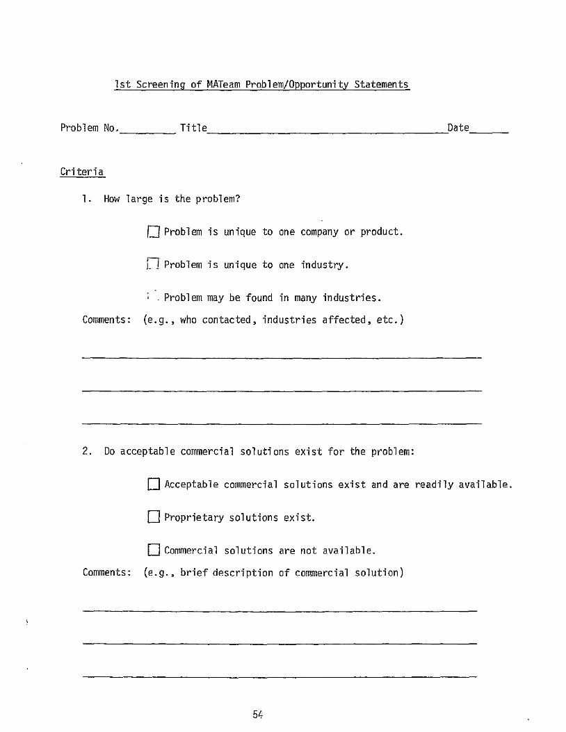
Ist Screening of MATeam Problem/Opportunity Statements
Problem No. Title Date
Criteria
1. How large is the problem?
[] Problem is unique to one company or product.
K!Problem is unique to one industry.
Problem may be found in many industries.
Comments: (e.g., who contacted, industries affected, etc.)
2. Do acceptable commercial solutions exist for the problem:
H Acceptable commercial solutions exist and are readily available.
fl Proprietary solutions exist.
L]Commercial solutions are not available. Comments: (e.g., brief description of commercial solution)
54

3. What is the magnitude of potential benefits if this problem
is solved:
[] Small economic benefit ( $50,000)
F Medium economic benefit ($50,000 - $250,000)
fl Large economic benefit (>$250,000)
Significant intangible benefits (e.g., improved L[safety, better international competitive position, etc.)
Comments: .
4. What degree of public visibility is associated with this problem:
F1 Low public visibility.
F-I High public visibility.
Comments:
55
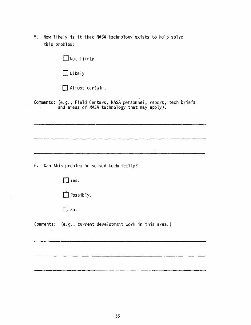
5. How likely is it that NASA technology exists to help solve
this problem:
-Not likely.
ELikely
E-Almost certain.
Comments: (e.g., Field Centers, NASA personnel, report, tech briefs and areas of NASA technology that may apply).
6. Can this problem be solved technically?
flYes.
r Possibly.
r1No.
Comments: (e.g., current development work in this area.)
56

7. If a technical solution is achieved, can it be implemented?
fl Implementation would be straightforward and could take place almost immediately.
[ Implementation would require applications engineering and could take several years to achieve.
r7 Implementation would be difficult, if not impossible to achieve.
Comments:
xxxxxxxxxxxxxxxxxxxxxxxxxxxxxxxxxxxxxxxxxxxxxxxxxxxxxxxxxxxxxxxxxxxxxxxxxxxx
Based on this assessment, do you recommend:
[JProblem be pursued further by the MATeam
H Problem be inactivated (Code I 1 )
Comments:
57

APPENDIX C
PRESS RELEASE
58
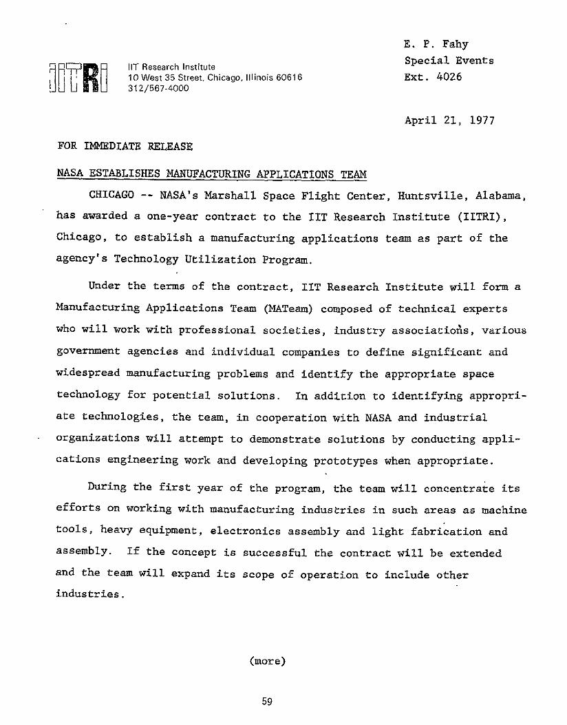
E. P. Fahy
Special EventsiT Research Institute I0 West 35 Street, Chicago, Illinois 60616 4026312/567-4000 EXt.
April 21, 1977
FOR IMMEDIATE RELEASE
NASA ESTABLISHES MANUFACTURING APPLICATIONS TEAM
CHICAGO -- NASA's Marshall Space Flight Center, Huntsville, Alabama,
has awarded a one-year contract to the IIT Research Institute (IITRI),
Chicago, to establish a manufacturing applications team as part of the
agency's Technology Utilization Program.
Under the terms of the contract, IIT Research Institute will form a
Manufacturing Applications Team (MATeam) composed of technical experts
who will work with professional societies, industry associatioAs, various
government agencies and individual companies to define significant and
widespread manufacturing problems and identify the appropriate space
technology for potential solutions. In addition to identifying appropri
ate technologies, the team, in cooperation with NASA and industrial
organizations will attempt to demonstrate solutions by conducting appli
cations engineering work and developing prototypes when appropriate.
During the first year of the program, the team will concentrate its
efforts on working with manufacturing industries in such areas as machine
tools, heavy equipment, electronics assembly and light fabrication and
assembly. If the concept is successful the contract will be extended
and the team will expand its scope of operation to include other
industries.
(more)
59

ADD ONE --NASA ESTABLISHES MANUFACTURING APPLICATIONS TEAM
The MATeam is being funded as part of NASA's Technology Utilization
Program which is aimed at increasing the nations's return on investment
in aerospace research by assuring that the benefits of this technology
are made available to all sectors of the economy. The NASA Technology
Utilization Office already operates applications teams in the medical,
transportation, environment and local and state government areas.
Organizations are encouraged to participate in this program and if
interested should contact the MATeam Director, Mr. John D. Meyer, IIT
Research Institute, 10 West 35th Street, Chicago, Illinois 60616,
telephone 312/567-4609.
60

APPENDIX D
MATEAM PROBLEM STATEMENTS AND STATUS
61
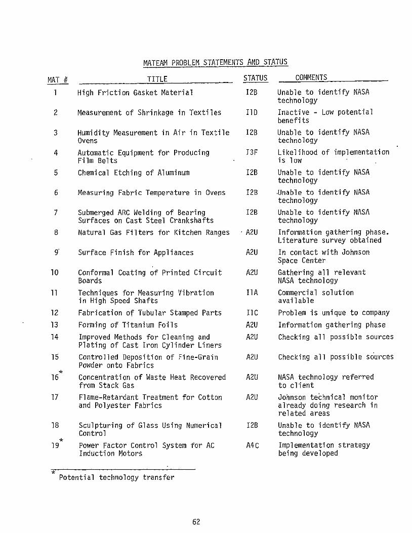
MATEAM PROBLEM STATEMENTS AND STATUS
MAT # TITLE
1 High Friction Gasket Material
2 Measurement of Shrinkage in Textiles
3 Humidity Measurement in Air in Textile Ovens
4 Automatic Equipment for Producing Film Belts
5 Chemical Etching of Aluminum
6 Measuring Fabric Temperature in Ovens
7 Submerged ARC Welding of Bearing Surfaces on Cast Steel Crankshafts
8 Natural Gas Filters for Kitchen Ranges
9 Surface Finish for Appliances
10 Conformal Coating of Printed Circuit Boards
11 Techniques for Measuring Vibration in High Speed Shafts
12 Fabrication of Tubular Stamped Parts
13 Forming of Titanium Foils
14 Improved Methods for Cleaning and Plating of Cast Iron Cylinder Liners
15 Controlled Deposition of Fine-Grain Powder onto Fabrics
16 Concentration of Waste Heat Recovered from Stack Gas
17 Flame-Retardant Treatment for Cotton and Polyester Fabrics
18 Sculpturing of Glass Using Numerical Control
19 Power Factor Control System for AC Induction Motors
STATUS
12B
liD
12B
T3F
12B
12B
12B
A2U
A2U
A2U
IIA
IIC
A2U
A2U
A2U
A2U
A2U
12B
A4C
COMMENTS
Unable to identify NASA technology
Inactive - Low potential benefits
Unable to identify NASA technology
Likelihood of implementation is low
Unable to identify NASA technology
Unable to identify NASA technology
Unable to identify NASA technology
Information gathering phase. Literature survey obtained
In contact with Johnson Space Center
Gathering all relevant NASA technology
Commercial solution available
Problem is unique to company
Information gathering phase
Checking all possible sources
Checking all possible sources
NASA technology referred to client
Johnson te~hnical monitor already doing research in related areas
Unable to identify NASA technology
Implementation strategybeing developed
Potential technology transfer
62

MATEAM PROBLEM STATEMENTS AND STATUS
MAT # TITLE
20 Evaluation and Control of Stresses, in Super-Alloys, Resulting from Metal Working Processes
21 Permanent Treatments to Modify Surface Friction of Fibers.
22 lIproved Voice Communications in High Noise Level Environment
23 Durable Anti-Reflective Treatment for Fabric Surfaces
24 Recovery of Sand from Shell Molding Process
25 High Temperature Binder for Sand Molds
26 Bonding of Brass to Aluminum
27 Automated Techniques for Assembling Clock Faces
28 Testing Bearings While in Use
29 Improved Switches for Portable Electric Tools
30 Predicting Model for Relating Super-Alloy Microstructure/Properties to Machinability of Isotatically Forged Powder Metallurgy Components
31 Evaluation of the Machinability of Scales Resulting from Metalworking Processes
32 Metallurgical Variables Affecting the Machinability of Sintered Steel
33 Relating Variabilities in Work and Tool Materials to Machining Productivity
34 The Role of Inclusions in the Machinability of Commercial Alloys
35 Economic Evaluation of Isothermal Forging of Transage Alloys
36 Powder Metallurgy Engine Bearings
37 Automatic Feed System for Hand-Held Bland Rivet Gun
STATUS
12D
12B
A3U
12B
12B
A2U
12A
IIC
A3U
AlU
12B
A2U
A2U
A2U
A2U
A2U
A2U
12B
COMMENTS
Inacti-vated, potential benefits are low
Unable to identify NASA technology
Gathering information
Unable to identify NASA technology
Inactivated, no relevant NASA technology
Gathering data
NASA suggested commercial processes
Too specialized
Gathering information
Gathering data
No relevant NASA technology
Information gathering phase Literature survey obtained
Information gathering phase Literature survey obtained Information gathering phase Literature survey obtained
Information gathering phase Literature survey obtained
Information gathering phase Literature survey obtained
Checking NASA sources; Originator to be contacted for more information
No NASA technology available
Potential technology transfer
63
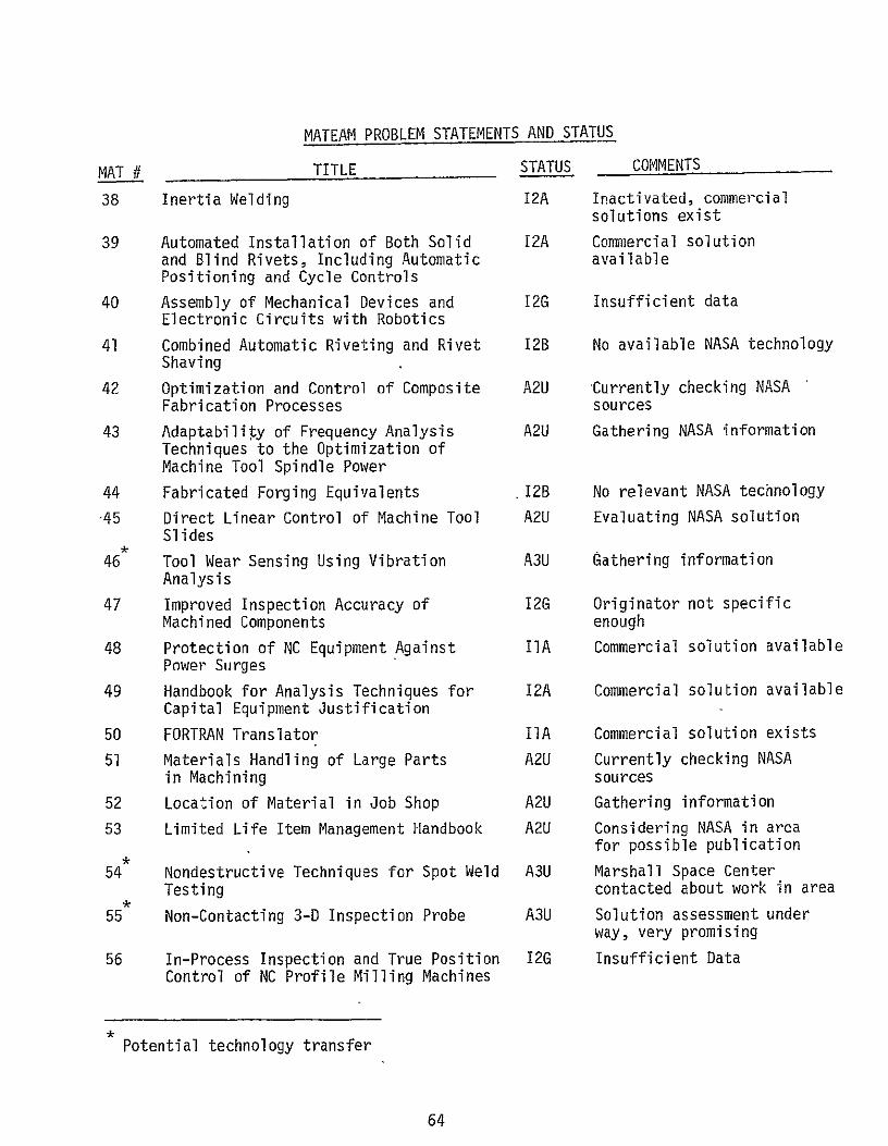
MATEAM PROBLEM STATEMENTS AND STATUS
MAT # TITLE
38 Inertia Welding
39 Automated Installation of Both Solid and Blind Rivets, Including Automatic Positioning and Cycle Controls
40 Assembly of Mechanical Devices and Electronic Circuits with Robotics
41 Combined Automatic Riveting and Rivet Shaving
42 Optimization and Control of Composite Fabrication Processes
43 Adaptability of Frequency Analysis Techniques to the Optimization of Machine Tool Spindle Power
44 Fabricated Forging Equivalents
-45 Direct Linear Control of Machine Tool Slides
46 Tool Wear Sensing Using Vibration Analysis
47 Improved Inspection Accuracy of Machined Components
48 Protection of NC Equipment Against Power Surges
49 Handbook for Analysis Techniques for Capital Equipment Justification
50 FORTRAN Translator
51 Materials Handling of Large Parts in Machining
52 Location of Material in Job Shop
53 Limited Life Item Management Handbook
54 Nondestructive Techniques for Spot Weld Testing
55 Non-Contacting 3-D Inspection Probe
56 In-Process Inspection and True Position Control of NC Profile Milling Machines
STATUS
12A
12A
12G
12B
A2U
A2U
12B
A2U
A3U
12G
IIA
12A
IIA
A2U
A2U
A2U
A3U
A3U
12G
COMMENTS
Inactivated, commercial solutions exist
Commercial solution available
Insufficient data
No available NASA technology
Currently checking NASA sources
Gathering NASA information
No relevant NASA technology
Evaluating NASA solution
Gathering information
Originator not specific enough
Commercial solution available
Commercial solution available
Commercial solution exists
Currently checking NASA sources
Gathering information
Considering NASA in area for possible publication
Marshall Space Center contacted about work in area
Solution assessment under way, very promising
Insufficient Data
Potential technology transfer
64

MATEAM PROBLEM STATEMENTS AND STATUS
MAT # TITLE
57 Ultra High Speed Spindle N/C Multiple Axis Machining Centey
58 Pulsed Laser Machining
59 Ultraclean, Ultrafine, Rapidly Cooled Nickel Alloy Powder
60 Nontraditional Machining Guide Books
61 Reduction of Machining Costs by Valve Engineering Approach
62 Applicatton of CAM to Organization, Layout, and Sequence of Operations for Machine Tools and Auxiliary Equipment
63 Integration of Engineering and Manufacturing CAD/CAM Systems
64 Alternate Materials/Production Process for Fabrication of Microwave Components
65 Diagnostic Testing of N/C Controllers
66 Atr Conditioning for N/C Control Units
67 Material Handling of Precision Components
68 Precision Grinding Techniques
69 Precision Surface Finish Inspection Techniques
70 Cleaning of Lapped Parts
71 Computer Aided Design of Die Casting Dies
72 Nickel Based X-Ray Film Process
73 Friction Reduction Between Contacting Surfaces
74 Controlling the Thickness of Conformal Coatings for Printed Circuit Boards
STATUS
A2U
A2U
A2U
IIA
IIA
A2U
A2U
12B
12E
IIA
IlD
A2U
A2U
12B
A4C
A3U
A2U
A3U
COMMENTS
Currently corresponding with interested parties, a very desirable transfer
Lewis Research Center is likely source of solution, promising
Checking NASA sources; originator needs to supply more input
Inactivated, commercial solutions exist
Commercially available solutions
Second literature search in progress
Second literature search in progress
No available NASA technology
Unable to identify acceptable technical solution
Commercial solution available
Low potential
Checking NASA sources
Checking NASA sources
Unable to locate NASA technology
Army to fund project
Contacts with industry in process
Will send possible NASA solution to user
Solution being assessed
Potential technology transfer
65
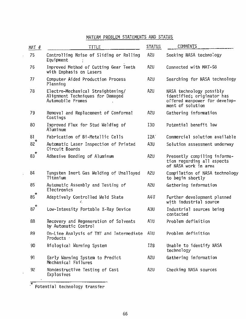
MATEAM PROBLEM STATEMENTS AND STATUS
MAT # TITLE
75 Controlling Noise of Sliding or Rolling Equipment
76 Improved Method of Cutting Gear Teeth with Emphasis on Lasers
77 Computer Aided Production Process Planning
78 Electro-Mechanical Straightening/ Alignment Techniques for Damaged Automobile Frames
79 Removal and Replacement of Conformal Coatings
80 Improved Flux for Stud Welding of Aluminum
81 Fabrication of Bi-Metallic Cells
82 Automatic Laser Inspection of Printed Circuit Boards
83 Adhesive Bonding of Aluminum
84 Tungsten Inert Gas Welding of Unalloyed Titanium
85 Automatic Assembly and Testing of Electronics
85 Adaptively Controlled Weld Skate
, 87 Low-Intensity Portable X-Ray Device
88 Recovery and Regeneration of Solvents by Automatic Control
89 On-Line Analysis of TNT and Intermediate Products "
90 Biological Warning System
91 Early Warning System to Predict Mechanical Failures
92 Nondestructive Testing of Cast Explosives
STATUS
A2U
A2U
A2U
A2U
A2U
13D
12A
A3U
A2U
A2U
A2U
A4U
A3U
AlU
AlU
12B
A2U
A2U
COMMENTS
Seeking NASA technology
Connected with MAT-58
Searching for NASA technology
NASA technology possibly identified; originator has offered manpower for development of solution
Gathering information
Potential benefit low
Commercial solution available
Solution assessment underway
Presently compiling inFormation regarding all aspects of NASA work in area
Compilation of NASA technology to begin shortly
Gathering information
Further development planned with industrial source
Industrial sources being contacted
Problem definition
Problem definition
Unable to identify NASA technology
Gathering information
Checking NASA sources
Potential technology transfer
66

MATEAM PROBLEM STATEMENTS AND STATUS
MAT # TITLE 93 Detection of Surface Flaws Using
Laser Holography
94 Nondestructive Hardness Testing Using X-Ray Diffraction Techniques
95 Polymer Finishes for Magnesium Alloy Parts
96 Thermographic Inspection of Optical Bonds
97 RF Curing of Adhesive Bonded Components
98 Electromagnetic Forming of Weapon Components
99 Bonding of Metal to Ceramic
100 High Temperature Plastic
101 Co-Deposition of Solid Lubricants During Anodizing
102 Preventing Hydrogen Embrittlement
103 Co-Deposition of Solid Lubricants During Plating
104 Plasmwa Arc Assisted Machining
105 In Process Technique for Balancing Drive Shafts
106 Inspection of Lamination in Thin Sheet Steel
107 Stable Thin Film Resistors
108 Reduction of Noise Levels from Portable Handgrinding Operations
109 Balancing Drive Shafts Economic Method of Selecting Bearings to Ensure Perfect Fit
STATUS
A2U
A2U
IlC
A2U
12B
A2U
13F
A5U
A2U
AIC
A2U
A2U
A2U
A2U
12E
A2U
A2U
COMMENTS
Checking NASA sources
Checking NASA sources
Problem seems too unique
Gathering information
Unable to identify relevant NASA technology
Information gathering under way; literature survey obtained
NASA techniques found to be unsatisfactory
Applications engineering underway by user
Promising, probable source for solution is Lewis Research Center
Statement preparation complete
Promising, probable source of solution is Lewis Research Center
Promising, probable source of solution is Lewis Research Center
Currently reviewing literature search
Checking NASA sources
NASA techniques found, so far proved inadequate
No NASA techniques found yet
Currently seeking a solution, not promising
Potential technology-transfer
67
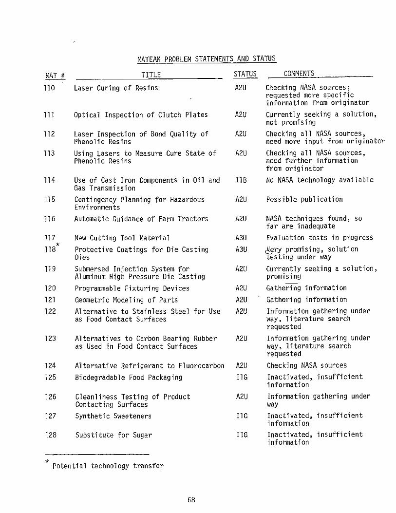
MATEAM PROBLEM STATEMENTS AND STATUS
MAT # TITLE
110 Laser Curing of Resins
ilII Optical Inspection of Clutch Plates
112 Laser Inspection of Bond Quality of Phenolic Resins
113 Using Lasers to Measure Cure State of Phenolic Resins
114 Use of Cast Iron Components in Oil and Gas Transmission
115 Contingency Planning for Hazardous Environments
116 Automatic Guidance of Farm Tractors
117 New Cutting Tool Material
118 Protective Coatings for Die Casting Dies
119 Submersed Injection System for Aluminum High Pressure Die Casting
120 Programmable Fixturing Devices
121 Geometric Modeling of Parts
122 Alternative to Stainless Steel for Use as Food Contact Surfaces
123 Alternatives to Carbon Bearing Rubber as Used in Food Contact Surfaces
124 Alternative Refrigerant to Fluorocarbon
125 Biodegradable Food Packaging
126 Cleanliness Testing of Product Contacting Surfaces
127 Synthetic Sweeteners
128 Substitute for Sugar
STATUS
A2U
A2U
A2U
A2U
IlB
A2U
A2U
A3U
A3U
A2U
A2U
A2U
A2U
A2U
A2U
IIG
A2U
IIG
IIG
COMMENTS
Checking NASA sources; requested more specific information from originator
Currently seeking a solution, not promising
Checking all NASA sources, need more input from originator
Checking all NASA sources, need further information from originator
No NASA technology available
Possible publication
NASA techniques found, so far are inadequate
Evaluation tests in progress
Very promising, solution testing under way
Currently seeking a solution, promising
Gathering information
Gathering information
Information gathering under way, literature search requested
Information gathering under way, literature search requested
Checking NASA sources
Inactivated, insufficient information
Information gathering under way
Inactivated, insufficient information
Inactivated, insufficient information
Potential technology transfer
68

MATEAM PROBLEM STATEMENTS AND STATUS
MAT # TITLE
129 Synthesis of Food from Atmospheric Elements
130 Programmable Parts Handling Equipment
131 Reliable, Economical, Fast Manipulator Arms
132 Improved Welding Procedures for Aluminum Alloys
133 Technique for Determining Strip Width for Forming Welded Steel Tubing
134 Design of One Piece Nut Rings
135 Improved Press Fitting Methods
136 Tantalum Capacitor Positive Lead Attachment
137 Tantalum Capacitor Negative Lead Attachment
138 Small Permanent Magnets to Attach Mailbox Signals to Mail Boxes
139 Photographic Image Intensification
140 Manipulator Arm Bin Picking
141 Improved Arc Shield Machining
142 The Recycling of Water Used in Paint Pretreatment System
143 Single Fill Point Battery Reservoir
144 Low Friction Surfaces for Machine Slideway System
145 Shock Absorbing Hydraulic Fluid
146 Chrome Plating Long Shafts
147 Bearings for High Speed Machine Spindle Heads
148 Composite Materials for Machine Bases and Structures
149 Hot Machining
150 Measuring the Case Hardened Depth Using N.D.T.
STATUS
IIG
A2U
A3U
A2U
AIU
IlC
AIC
A2U
A2U
IIC
13E
IlA
A2U
AlU
A3U
AlU
AlU
AlU
AlU
A2U
AlU
AlU
COMMENTS
Inactivated, insufficier information
Information gathering ph
Solution Assessment unde
Checking NASA sources
Problem Definition
Problem is unique to. company
Problem definition compl
Information gathering ph
Information gathering ph
Inactivated, insufficien information
Unable to identify relev NASA technology
Inactivated, commercial solutions exist
Information gathering ph,
Statement being prepared
Contacting potential manufacturer
Statement being prepared
Statement being prepared
Statement being prepared
Statement being prepared
Information gathering sti
Statement being prepared
Statement being prepared
69
Related Documents