| HMI Sitrad VEE Power HMI 2 | HMI (B) 1 | HMI (A) SITRAD 11 | SITRAD (A) 12 | SITRAD (B) RELAYS 13-14 | fans 15-16 | compressor 17-18 | defrost Line SENS. PRESS. 3 | 4~20mA (green) 4 | 12Vdc (brown) Power Supply 12Vdc - 1.3A vx-950 plus SENS. TEMP. / DIG. IN 9-10 | sens. ambient temp. 8-9 | sens. evap. temp. 6-7 | sens. suction temp. 5-6 | digital input (door) 3. TECHNICAL SPECIFICATIONS - Power: ± 12 Vdc 1.3A - Control temperature: -50 to 60° C / -58 to 140° F - Operating temperature: 0 to 50° C / 32 to 122° F - Control pressure: 0 to 500 psi / 0 to 34.4 bar - Sensors available for acquisition: 0 to 200 psi / 0 to 13.8 bar (using SB69-200A transducer *) 0 to 500 psi / 0 to 34.4 bar (using SB69-500A transducer *) * Sensors sold separately - Pressure resolution: 0.1 bar / 1 psi - Operating humidity: 10 to 90% RH (non-condensing) - Maximum current: REFR: 1 HP: 230 Vac-compressor output FANS: 3(2)A / 250 Vac 1/10 HP-fan output DEFR: 7A/250 V/1750 W-defrost output - Sensors: S1: Room sensor S2: Evaporator sensor S3: Suction line temperature sensor P1: Pressure sensor - Dimensions: 84x120x40 mm (WXHxD) - Electronic expansion valve : Item sold separately WARNING: In order to select the right electronic expansion valve (EEV) see the attachment at the end of the manual. (EEV) DIGITAL CONTROLLER FOR REFRIGERATION WITH ELECTRONIC EXPANSION VALVE MODULE VX950PLV01-03T-15029 Ver.01 VX-950 plus Supervisory system Electronic expansion valve VX-950 HMI 4. PRESENTATION OF VX-950 plus PANEL 1. DESCRIPTION Designed to control temperature, defrost and Electronic Expansion Valve (EEV). VX-950 plus provides excellent energy savings and safety through precise control of superheat & freely selectable MOP points. It is equipped with 4 outputs (Comp, Defrost, Fan & EEV) , 3 temperature sensors (Room, Coil & Suction), 1 suction pressure transducer, 1 digital input and RS485 serial communication ports for Sitrad real-time monitoring and management. VX-950 plus can be monitored and controlled in three different ways: 1) only with Sitrad, 2) only with the or 3) with both at independent RS485 networks. If installed, one can control up to 32 VX-950 plus controllers. Other salient features include economy set point, MOP and LOP alarms. • chiller, plug in, frigorific transportation, cabinets, and display freezers. VX-950 HMI VX-950 HMI 2. APPLICATION 5. FIRST STEPS STEP 1: STEP 2: Install the electronic expansion valve according to the installation guideline supplied with product. After completing the first load of cooling fluid, power up one VX-950 plus controller and the The ultracapacitor module is initialized even if the module is not being used. Upon switching on the VX-950 plus, the leds will light as shown below: VX-950 HMI, if there is one. HMI Sitrad VEE Power HMI Sitrad VEE Power HMI Sitrad VEE Power HMI Sitrad VEE Power DISCHARGED CHARGING CHARGED Add the controllers to the (see manual) while the ultracapacitors are being charged. VX-950 HMI HMI Sitrad VEE Power HMI 2 | HMI (B) 1 | HMI (A) SITRAD 11 | SITRAD (A) 12 | SITRAD (B) RELAYS 13-14 | fans 15-16 | compressor 17-18 | defrost Line SENS. PRESS. 3 | 4~20mA (green) 4 | 12Vdc (brown) | Power Supply 12Vdc - 1.3A vx-950 plus SENS. TEMP. / DIG. IN 9-10 | sens. ambient temp. 8-9 | sens. evap. temp. 6-7 | sens. suction temp. 5-6 | digital input (door) A A B B AB B B A HMI Sitrad VEE Power HMI 2 | HMI (B) 1 | HMI (A) SITRAD 11 | SITRAD (A) 12 | SITRAD (B) RELAYS 13-14 | fans 15-16 | compressor 17-18 | defrost Line SENS. PRESS. 3 | 4~20mA (green) 4 | 12Vdc (brown) | Power Supply 12Vdc - 1.3A vx-950 plus SENS. TEMP. / DIG. IN 9-10 | sens. ambient temp. 8-9 | sens. evap. temp. 6-7 | sens. suction temp. 5-6 | digital input (door) A A A B B AB AB STEP 3: Set up the basic functions: VX-950 HMI (communication LED) Sitrad (communication LED) Power (instrument ON indication) Electronic Expansion Valve (activity LED) 6. PARAMETERS TABLE Description Fun Min Max Default [,F01] [,F02] [,F03] [,F04] [,F05] [,F06] [,F07] [,F08] [,F09] [,F10] [,F11] Pressure offset (P1) Pressure transducer range Low pressure alarm (LOP) High pressure alarm (MOP) Static gain (Kp) Integral time (Ti) Derivative time (Td) Cooling fluid type Total number of valve steps Operating speed (steps per second) Initial valve opening value (%) Unit Min Max Default Unit psi bar -5 1 -1 -1 0 0 0 0 1 1 0 5 5 500 500 999 999 999 5 9999 120 100 0 2 0 65 2 25 0 3 480 30 25 -0.3 1 -1 -1 0 0 0 0 1 1 0 0.3 5 34.4 34.4 999 999 999 5 9999 120 100 0 2 0 4.5 1 25 0 3 480 30 25 psi - - sec. sec. - - pas/s % psi psi bar - - sec. sec. - - pas/s % bar bar F04 F08 F11 F18 F21 F28 F30 F37 Maximum operating pressure Cooling fluid type Initial EEV opening Operating setpoint Hysteresis Type of defrost Cooling time Defrost time WARNING IT IS ESSENTIAL TO USE A SOLENOID VALVE INSTALLED IN THE LIQUID LINE AS CLOSE AS POSSIBLE TO THE ELECTRONIC EXPANSION VALVE (EEV). SOLENOID ELECTRONIC EXPANSION VALVE (EEV) IN CASE OF A POWER FAULT, THE LACK OF THE SOLENOID VALVE CAN CAUSE DAMAGE TO THE COMPRESSOR, AS THE HYDROLOCK. WARNING ACCESSORIES: Only use original Full Gauge Controls accessories. If you have any questions, please contact technical support. AUTHORIZED SERVICE: The installation or maintenance of the product must be performed by qualified professionals only; BEFORE INSTALLING THE CONTROLLER, WE RECOMMEND READING THROUGH THE ENTIRE INSTRUCTION MANUAL IN ORDER TO AVOID POSSIBLE DAMAGE TO THE PRODUCT. PRECAUTIONS WHEN INSTALLING THE PRODUCT: Before performing any procedure on this instrument, disconnect it from the mains; Ensure that the instrument has adequate ventilation and avoid installation in panels containing devices that may cause it to operate outside the specified temperature limits; Install the product away from sources that may generate electromagnetic disturbances such as: motors, contactors, relays, solenoid valves, etc; DUE TO YOUR CONSTANT EVOLUTION, THE FULL GAUGE CONTROLS RESERVES THE RIGHT TO CHANGE THE INFORMATION CONTAINED IN THIS MANUAL AT ANY TIME WITHOUT NOTICE. Have this manual in the palm of your hand by FG Finder application.

Welcome message from author
This document is posted to help you gain knowledge. Please leave a comment to let me know what you think about it! Share it to your friends and learn new things together.
Transcript

|
HMI
Sitrad
VEE
Power
HMI
2 | HMI (B)
1 | HMI (A)
SITRAD
11 | SITRAD (A)
12 | SITRAD (B)
RELAYS
13-14 | fans
15-16 | compressor
17-18 | defrost
Lin
e
SENS. PRESS.
3 |
4~20mA (green)4 |
12Vdc (brown)
Power Supply 12Vdc - 1.3A
vx-950 plusSENS. TEMP. / DIG. IN
9-10 | sens. ambient temp.
8-9 | sens. evap. temp.
6-7 | sens. suction temp.
5-6 | digital input (door)
3. TECHNICAL SPECIFICATIONS- Power: ± 12 Vdc 1.3A- Control temperature: -50 to 60° C / -58 to 140° F- Operating temperature: 0 to 50° C / 32 to 122° F- Control pressure: 0 to 500 psi / 0 to 34.4 bar- Sensors available for acquisition: 0 to 200 psi / 0 to 13.8 bar (using SB69-200A transducer *)
0 to 500 psi / 0 to 34.4 bar (using SB69-500A transducer *)* Sensors sold separately
- Pressure resolution: 0.1 bar / 1 psi- Operating humidity: 10 to 90% RH (non-condensing)- Maximum current: REFR: 1 HP: 230 Vac-compressor output
FANS: 3(2)A / 250 Vac 1/10 HP-fan outputDEFR: 7A/250 V/1750 W-defrost output
- Sensors: S1: Room sensorS2: Evaporator sensorS3: Suction line temperature sensorP1: Pressure sensor
- Dimensions: 84x120x40 mm (WXHxD)- Electronic expansion valve : Item sold separately
WARNING: In order to select the right electronic expansion valve (EEV) see the attachment at the end of the manual.
(EEV)
DIGITAL CONTROLLER FOR REFRIGERATIONWITH ELECTRONIC EXPANSION VALVE MODULE
VX950PLV
01-03T-15029
Ver
.01VX-950 plus
Supervisory system
Electronic expansion
valve
VX-950 HMI
4. PRESENTATION OF VX-950 plus PANEL
1. DESCRIPTION
Designed to control temperature, defrost and Electronic Expansion Valve (EEV). VX-950 plus provides excellent energy savings and safety through precise control of superheat & freely selectable MOP points. It is equipped with 4 outputs (Comp, Defrost, Fan & EEV) , 3 temperature sensors (Room, Coil & Suction), 1 suction pressure transducer, 1 digital input and RS485 serial communication ports for Sitrad real-time monitoring and management. VX-950 plus can be monitored and controlled in three different ways: 1) only with Sitrad, 2) only with the or 3) with both at independent RS485 networks. If installed, one can control up to 32 VX-950 plus controllers. Other salient features include economy set point, MOP and LOP alarms.
• chiller, plug in, frigorific transportation, cabinets, and display freezers.
VX-950 HMIVX-950 HMI
2. APPLICATION
5. FIRST STEPS
STEP 1:
STEP 2:
Install the electronic expansion valve according to the installation guideline supplied with product.
After completing the first load of cooling fluid, power up one VX-950 plus controller and the
The ultracapacitor module is initialized even if the module is not being used. Upon switching on the VX-950 plus, the leds will light as shown below:
VX-950 HMI, if there is one.
HMI
Sitrad
VEE
Power
HMI
Sitrad
VEE
Power
HMI
Sitrad
VEE
Power
HMI
Sitrad
VEE
Power
DISCHARGED CHARGING CHARGED
Add the controllers to the (see manual) while the ultracapacitors are being charged.VX-950 HMI
HMI
Sitrad
VEE
Power
HMI
2 | HMI (B)
1 | HMI (A)
SITRAD
11 | SITRAD (A)
12 | SITRAD (B)
RELAYS
13-14 | fans
15-16 | compressor
17-18 | defrost
Lin
e
SENS. PRESS.
3 |
4~20mA (green)4 |
12Vdc (brown)
|Power Supply 12Vdc - 1.3A
vx-950 plusSENS. TEMP. / DIG. IN
9-10 | sens. ambient temp.
8-9 | sens. evap. temp.
6-7 | sens. suction temp.
5-6 | digital input (door)
A AB B
A BB
VX-950 HMI
B
A
HMI
Sitrad
VEE
Power
HMI
2 | HMI (B)
1 | HMI (A)
SITRAD
11 | SITRAD (A)
12 | SITRAD (B)
RELAYS
13-14 | fans
15-16 | compressor
17-18 | defrost
Lin
e
SENS. PRESS.
3 |
4~20mA (green)4 |
12Vdc (brown)
|Power Supply 12Vdc - 1.3A
vx-950 plusSENS. TEMP. / DIG. IN
9-10 | sens. ambient temp.
8-9 | sens. evap. temp.
6-7 | sens. suction temp.
5-6 | digital input (door)
A
A AB B
A B
A B
STEP 3: Set up the basic functions:
VX-950 HMI (communication LED)
Sitrad (communication LED)
Power (instrument ON indication)
Electronic Expansion Valve (activity LED)
6. PARAMETERS TABLE
DescriptionFun Min Max Default
[,F01]
[,F02]
[,F03]
[,F04]
[,F05]
[,F06]
[,F07]
[,F08]
[,F09]
[,F10]
[,F11]
Pressure offset (P1)
Pressure transducer range
Low pressure alarm (LOP)
High pressure alarm (MOP)
Static gain (Kp)
Integral time (Ti)
Derivative time (Td)
Cooling fluid type
Total number of valve steps
Operating speed (steps per second)
Initial valve opening value (%)
Unit Min Max DefaultUnit
psi bar
-5
1
-1
-1
0
0
0
0
1
1
0
5
5
500
500
999
999
999
5
9999
120
100
0
2
0
65
2
25
0
3
480
30
25
-0.3
1
-1
-1
0
0
0
0
1
1
0
0.3
5
34.4
34.4
999
999
999
5
9999
120
100
0
2
0
4.5
1
25
0
3
480
30
25
psi
-
-
sec.
sec.
-
-
pas/s
%
psi
psi
bar
-
-
sec.
sec.
-
-
pas/s
%
bar
bar
F04
F08
F11
F18
F21
F28
F30
F37
Maximum operating pressure
Cooling fluid type
Initial EEV opening
Operating setpoint
Hysteresis
Type of defrost
Cooling time
Defrost time
WARNING
IT IS ESSENTIAL TO USE A SOLENOID VALVE INSTALLED IN THE LIQUID LINE AS CLOSE AS POSSIBLE TO THE ELECTRONIC EXPANSION VALVE (EEV).
SOLENOID
ELECTRONICEXPANSION VALVE (EEV) IN CASE OF A POWER FAULT, THE LACK OF THE SOLENOID
VALVE CAN CAUSE DAMAGE TO THE COMPRESSOR, AS THE HYDROLOCK.
WARNING
ACCESSORIES:Only use original Full Gauge Controls accessories. If you have any questions, please contact technical support.
AUTHORIZED SERVICE:The installation or maintenance of the product must be performed by qualified professionals only;
BEFORE INSTALLING THE CONTROLLER, WE RECOMMEND READING THROUGH THE ENTIRE INSTRUCTION MANUAL IN ORDER TO AVOID POSSIBLE DAMAGE TO THE PRODUCT.
PRECAUTIONS WHEN INSTALLING THE PRODUCT:Before performing any procedure on this instrument, disconnect it from the mains;Ensure that the instrument has adequate ventilation and avoid installation in panels containing devices that may cause it to operate outside the specified temperature limits;Install the product away from sources that may generate electromagnetic disturbances such as: motors, contactors, relays, solenoid valves, etc;
DUE TO YOUR CONSTANT EVOLUTION, THE FULL GAUGE CONTROLS RESERVES THE RIGHT TO CHANGE THE INFORMATION CONTAINED IN THIS MANUAL AT ANY TIME WITHOUT NOTICE.
Have this manual in the palm of your hand by FG Finder application.

[,F30]
[,F31]
[,f32]
[,F33]
[,f34]
[,F35]
[,f36]
[,F37]
[,F38]
[,F39]
[,F40]
[,F41]
[,F42]
[,F43]
[,f44]
[,f45]
[,f46]
[,f47]
[,f48]
[,F49]
[,f50]
[,f51]
[,F52]
[,f53]
[,F54]
[,F55]
[,F56]
[,F57]
[,f58]
[,f59]
[,f60]
[,F61]
[,F62]
[,F63]
[,F64]
[,f65]
1
-50.0
0
0
-50.0
-50.0
1
1
-1
0
0
0
0
1
1
0
-50.0
-50.0
0
0
0
0
0
0
0
0
0
0
-50.0
-50.0
0
0
0
0
0
1
999
60.0
999
999
60.0
60.0
999
999
999
1
999
2
2
999
999
1
60.0
60.0
999
999
999
999
999
999
999
999
999
999
60.0
60.0
999
999
999
1
1
247
4
-50.0
10
0
8.0
6.0
12
20
15
0
10
2
2
1
99
0
35.0
2.0
1
30
5
3
0
0
20
10
0
24
-50.0
60.0
5
0
10
1
0
247
1
-58
0
0
-58
-58
1
1
-1
0
0
0
0
1
1
0
-58
-58
0
0
0
0
0
0
0
0
0
0
-58
-58
0
0
0
0
0
1
999
140
999
999
140
140
999
999
999
1
999
2
2
999
999
1
140
140
999
999
999
999
999
999
999
999
999
999
999
999
999
999
999
1
1
247
4
23
10
0
46
42
12
20
15
0
10
2
2
1
99
0
95
36
1
30
5
3
0
0
20
10
0
24
58
140
5
0
10
1
0
247
H
H
min.
min.
-
min.
-
-
min.
min.
-
ºC
ºC
min.
ºC
ºC
ºC
ºC
min.
min.
min.
H
min.
min.
min.
min.
min.
H
ºC
ºC
min.
min.
min.
-
-
-
H
H
min.
min.
-
min.
-
-
min.
min.
-
ºF
ºF
min.
ºF
ºF
ºF
ºF
min.
min.
min.
H
min.
min.
min.
min.
min.
H
ºF
ºF
min.
min.
min.
-
-
-
Superheating temperature
Superheatingsetpoint
time
steady state error
F06 - Integral time (Ti):This is the action time to correct the difference between the read and the corresponding setpoint is with constant value.High integral time values: slower action.Low integral time values: faster action.
superheating
F01 - Pressure offset (P1):Allows adjusting any deviations in the pressure measurement.
F02 - :Pressure transducer range
(EEV)
(EEV)
(EEV)superheating
superheating Superheating
F03 - Low pressure alarm (LOP):When the evaporation pressure falls below this value the electronic expansion valve gradually opens to increase the pressure in the system. This process will happen until the pressure reaches the value set in this function.
F04 - High pressure alarm (MOP):When the evaporation pressure rises above the value configured in this function, the controller gradually closes the electronic expansion valve to keep the pressure below the established value. This protection is intended to avoid the superheating with an extremely low value causing the return of liquid to the compressor.
F05 - Static gain (Kp):Proportional Gain: Acts directly by opening or closing the electronic expansion valve in relation to the variation of the temperature in a proportional way. The value is a multiplying factor that establishes the relationship between “Valve steps / oC“.Proportional Action: Proportional Gain x (Read - setpoint).
6.1. DESCRIPTION OF THE PARAMETERS
1
2
3
4
5
100 PSI / 6.9BAR
200 PSI / 13.8BAR
300 PSI / 20.7BAR
400 PSI / 27.6BAR
500 PSI / 34.4BAR
Fun Min Max Default
[,F12]
[,F13]
[,F14]
[,F15]
[,F16]
[,f17]
[,F18]
[,F19]
[,F20]
[,F21]
[,F22]
[,F23]
[,F24]
[,F25]
[,F26]
[,F27]
[,F28]
[,f29]
Delay time for superheating control
Superheating setpoint
Critical superheating alarm
Low superheating alarm
High superheating alarm
Operating setpoint
Economy setpoint
Minimum setpoint allowed for the user
Maximum setpoint allowed for the user
Differential control (operating setpoint)
Differential control (economy setpoint)
Digital input operating mode
Intensity of the digital filter applied to the room sensor (S1)
Room temperature offset (S1)
Evaporator temperature offset (S2)
Suction line temperature offset (S3)
Type of defrost (0= resistance / 1= hot gas / 2= natural)
Condition to start the defrost (0= time / 1= temperature)
Interval between defrosts
Evaporator temperature to start the defrost if F29=1
Time to confirm a low temperature (S2) to start the pre-defrosting if F29=1
Time to collect the gas before starting the defrost
Evaporator temperature to end the defrost
Room temperature to end the defrost
Maximum time without defrost if F29=1
Maximum defrost time
Temperature indication locked during defrost
Defrost when the instrument is powered on
Draining time
Fan operating mode - normal mode
Fan operating mode - economy mode
Fan on time if F42/F43=0
Fan off time if F42/F43=0
Fan on when the door is opened
Fan stop due to high temperature in the evaporator
Evaporator temperature for the fan to return after draining
Maximum time for the fan to return after draining (fan-delay)
Maximum open door time for instantaneous defrost if F23=1
Door open time to switch off COMP. and FAN if F23=1
Door closed time for activating the economy mode if F23=1
Minimum compressor off time
Minimum compressor on time
Compressor on time in case of error in S1
Compressor off time in case of error in S1
Compressor delay after powering up the controller
Maximum compressor on time without reaching the setpoint
Low room temperature alarm
High room temperature alarm
Door open time for audible alarm
Inhibit time audible alarm by temperature
Inhibit time audible alarm upon power up
Defrost end alarm by time
Turning off the control functions
Address in the RS-485 network
Unit Min Max DefaultUnit
CELSIUS FAHRENHEIT
1
0
0
0
0
-50.0
-50.0
-50.0
-50.0
0.1
0.1
0
0
-5.0
-5.0
-5.0
0
0
999
99
99
99
99
60.0
60.0
60.0
60.0
20.0
20.0
2
9
5.0
5.0
5.0
2
1
1
9.0
2.0
4.0
15.0
-15.0
-10.0
-50.0
60.0
2.0
2.0
1
0
0
0
0
0
1
1
0
0
0
0
-58
-58
-58
-58
1
1
0
0
-9
-9
-9
0
0
999
140
140
140
140
140
140
140
140
40
40
2
9
9
9
9
2
1
1
16
2
7
27
5
14
-58
140
4
4
1
0
0
0
0
0
1
min.
ºC
ºC
ºC
ºC
ºC
ºC
ºC
ºC
ºC
ºC
-
-
ºC
ºC
ºC
-
-
min.
ºF
ºF
ºF
ºF
ºF
ºF
ºF
ºF
ºF
ºF
-
-
ºF
ºF
ºF
-
-
Example: F05 = 10, F13=8, Read = 4EEV Action = 10 x (4 - 8) = -40This way the valve will close 40 steps.
superheating
Description
time
Superheating setpoint
Superheating temperature
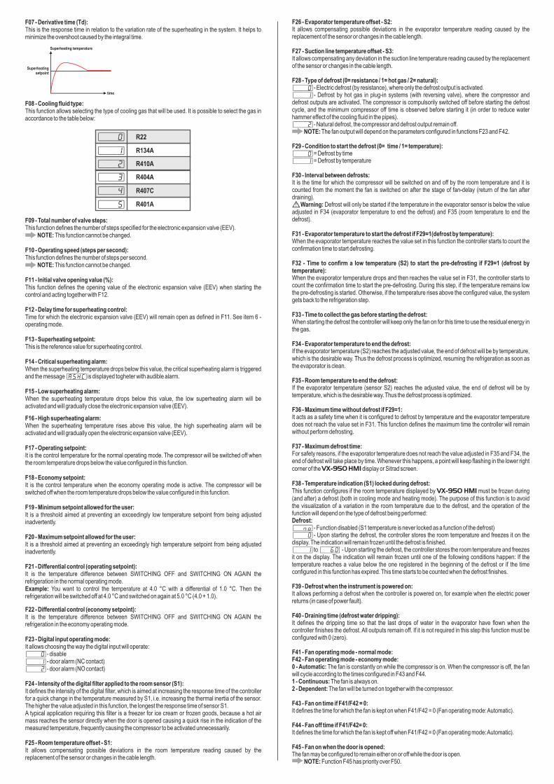
F07 - Derivative time (Td):This is the response time in relation to the variation rate of the superheating in the system. It helps to minimize the overshoot caused by the integral time.
F08 - Cooling fluid type:This function allows selecting the type of cooling gas that will be used. It is possible to select the gas in accordance to the table below:
F09 - Total number of valve steps:This function defines the number of steps specified for the electronic expansion valve (EEV).
NOTE: This function cannot be changed.
F10 - Operating speed (steps per second):This function defines the number of steps per second.
NOTE: This function cannot be changed.
F11 - Initial valve opening value (%):This function defines the opening value of the electronic expansion valve when starting the control and acting together with F12.
F12 - Delay time for superheating control:Time for which the electronic expansion valve will remain open as defined in F11. See item 6 - operating mode.
F13 - setpoint:This is the reference value for superheating control.
F14 - Critical alarm:When the temperature drops below this value, the critical alarm is triggered and the message [ASHC] .
F15 - Low alarm:When the temperature drops below this value, the low alarm will be activated and will gradually close the electronic expansion valve .
(EEV)
(EEV)
Superheating
superheatingsuperheating superheating
is displayed togheter with audible alarm
superheatingsuperheating superheating
(EEV)
R134A
[,,,0]
[,,,1]
[,,,2]
R407C
R404A
R401A
[,,,3]
[,,,4]
[,,,5]
R410A
R22
F16 - High alarm:When the temperature rises above this value, the high alarm will be activated and will gradually open the electronic expansion valve .
F17 - Operating setpoint:It is the control temperature for the normal operating mode. The compressor will be switched off when the room temperature drops below the value configured in this function.
F18 - Economy setpoint:It is the control temperature when the economy operating mode is active. The compressor will be switched off when the room temperature drops below the value configured in this function.
F19 - Minimum setpoint allowed for the user:It is a threshold aimed at preventing an exceedingly low temperature setpoint from being adjusted inadvertently.
F20 - Maximum setpoint allowed for the user:It is a threshold aimed at preventing an exceedingly high temperature setpoint from being adjusted inadvertently.
F21 - Differential control (operating setpoint):It is the temperature difference between SWITCHING OFF and SWITCHING ON AGAIN the refrigeration in the normal operating mode.Example: You want to control the temperature at 4.0 °C with a differential of 1.0 °C. Then the refrigeration will be switched off at 4.0 °C and switched on again at 5.0 °C (4.0 + 1.0).
superheatingsuperheating superheating
(EEV)
F22 - It is the temperature difference between SWITCHING OFF and SWITCHING ON AGAIN the refrigeration in the economy operating mode.
F23 - Digital input operating mode:It allows choosing the way the digital input will operate:[,,,0]- disable[,,,1]- door alarm (NC contact)[,,,2]- (NO contact)
F24 - Intensity of the digital filter applied to the room sensor (S1):It defines the intensity of the digital filter, which is aimed at increasing the response time of the controller for a quick change in the temperature measured by S1, i.e. increasing the thermal inertia of the sensor. The higher the value adjusted in this function, the longest the response time of sensor S1.A typical application requiring this filter is a freezer for ice cream or frozen goods, because a hot air mass reaches the sensor directly when the door is opened causing a quick rise in the indication of the measured temperature, frequently causing the compressor to be activated unnecessarily.
F25 - Room temperature offset - S1:It allows compensating possible deviations in the room temperature reading caused by the replacement of the sensor or changes in the cable length.
Differential control (economy setpoint):
door alarm
F26 - Evaporator temperature offset - S2:It allows compensating possible deviations in the evaporator temperature reading caused by the replacement of the sensor or changes in the cable length.
F27 - Suction line temperature offset - S3:It allows compensating any deviation in the suction line temperature reading caused by the replacement of the sensor or changes in the cable length.
F28 - Type of defrost (0= resistance / 1= hot gas / 2= natural):[,,,0]- Electric defrost (by resistance), where only the defrost output is activated.[,,,1]- Defrost by hot gas in plug-in systems (with reversing valve), where the compressor and defrost outputs are activated. The compressor is compulsorily switched off before starting the defrost cycle, and the minimum compressor off time is observed before starting it (in order to reduce water hammer effect of the cooling fluid in the pipes).[,,,2]- Natural defrost, the compressor and defrost output remain off.
NOTE: The fan output will depend on the parameters configured in functions F23 and F42.
F29 - Condition to start the defrost (0= time / 1= temperature):[,,,0]= Defrost by time[,,,1]= Defrost by temperature
F30 - Interval between defrosts:It is the time for which the compressor will be switched on and off by the room temperature and it is counted from the moment the fan is switched on after the stage of fan-delay (return of the fan after draining).
Warning: Defrost will only be started if the temperature in the evaporator sensor is below the value adjusted in F34 (evaporator temperature to end the defrost) and F35 (room temperature to end the defrost).
F31 - Evaporator temperature to start the defrost if F29=1(defrost by temperature): When the evaporator temperature reaches the value set in this function the controller starts to count the confirmation time to start defrosting.
F32 - Time to confirm a low temperature (S2) to start the pre-defrosting if F29=1 (defrost by temperature):When the evaporator temperature drops and then reaches the value set in F31, the controller starts to count the confirmation time to start the pre-defrosting. During this step, if the temperature remains low the pre-defrosting is started. Otherwise, if the temperature rises above the configured value, the system gets back to the refrigeration step.
F33 - Time to collect the gas before starting the defrost:When starting the defrost the controller will keep only the fan on for this time to use the residual energy in the gas.
F34 - Evaporator temperature to end the defrost:If the evaporator temperature (S2) reaches the adjusted value, the end of defrost will be by temperature, which is the desirable way. Thus the defrost process is optimized, resuming the refrigeration as soon as the evaporator is clean.
F35 - Room temperature to end the defrost:If the evaporator temperature (sensor S2) reaches the adjusted value, the end of defrost will be by temperature, which is the desirable way. Thus the defrost process is optimized.
F36 - Maximum time without defrost if F29=1:It acts as a safety time when it is configured to defrost by temperature and the evaporator temperature does not reach the value set in F31. This function defines the maximum time the controller will remain without perform defrosting.
F37 - Maximum defrost time:For safety reasons, if the evaporator temperature does not reach the value adjusted in F35 and F34, the end of defrost will take place by time. Whenever this happens, a point will keep flashing in the lower right corner of the display or Sitrad screen.
F38 - Temperature indication (S1) locked during defrost:This function configures if the room temperature displayed by must be frozen during (and after) a defrost (both in cooling mode and heating mode). The purpose of this function is to avoid the visualization of a variation in the room temperature due to the defrost, and the operation of the function will depend on the type of defrost being performed:Defrost:[,,no]- Function disabled (S1 temperature is never locked as a function of the defrost)[,,,0]- Upon starting the defrost, the controller stores the room temperature and freezes it on the display. The indication will remain frozen until the defrost is finished.[,,,1]to [,,60] - Upon starting the defrost, the controller stores the room temperature and freezes it on the display. The indication will remain frozen until one of the following conditions happen: If the temperature reaches a value below the one registered in the beginning of the defrost or if the time configured in this function has expired. This time starts to be counted when the defrost finishes.
F39 - Defrost when the instrument is powered on:It allows performing a defrost when the controller is powered on, for example when the electric power returns (in case of power fault).
F40 - Draining time (defrost water dripping):It defines the dripping time so that the last drops of water in the evaporator have flown when the controller finishes the defrost. All outputs remain off. If it is not required in this step this function must be configured with 0 (zero).
F41 - Fan operating mode - normal mode:F42 - Fan operating mode - economy mode:0 - Automatic: The fan is constantly on while the compressor is on. When the compressor is off, the fan will cycle according to the times configured in F43 and F44.1 - Continuous: The fan is always on.2 - Dependent: The fan will be turned on together with the compressor.
F43 - Fan on time if F41/F42 = 0:It defines the time for which the fan is kept on when F41/F42 = 0 (Fan operating mode: Automatic).
F44 - Fan off time if F41/F42= 0:It defines the time for which the fan is kept off when F41/F42 = 0 (Fan operating mode: Automatic).
F45 - Fan on when the door is opened:The fan may be configured to remain either on or off while the door is open.
NOTE: Function F45 has priority over F50.
VX-950 HMI
VX-950 HMI
Superheating temperature
Superheating setpoint
time

F60 - Door open time for audible alarm:If the digital input is configured as door (F23) in this function the time to sound the alarm (buzzer) will be counted.
F61 - Inhibit time alarm by temperature:The purpose of this function is to inhibit the alarm for some time due to an occasional temperature rise. The alarm is disabled during the defrost, draining and fan-delay operations.
F62 - Inhibit time alarm upon power up:The audible alarm remains off during this time waiting for the system to achieve its steady state.
F63 - Defrost end alarm:When the defrost operation is ended by time instead of by temperature, the user can be warned by a flashing point in the lower right corner of the display ( ).
F64 - Turning off the control functions:It allows switching off the refrigeration, fan, and defrost outputs after the electronic expansion valve is fully closed.
F65 - Equipment's address in the RS-485 network (serial communication):Each device connected to the RS-485 network must have a unique address different from the others such that the computer can identify the equipment.
Warning: Make sure that there are no devices with the same address to avoid communication problems.
VX-950 HMI
7. OPERATING MODE (MANUAL / AUTOMATIC)
A calibration of the step motor of the electronic expansion valve (EEV) is performed when the is initialized. Thus the Sitrad will indicate it is initializing in the status field. Then the
controller will open the electronic expansion valve according to the value specified in function F11 (initial valve opening value) and remain in that position for the time specified in F12 (delay time for superheating control). After this procedure the controller adjusts the control according to the manual mode (F5=0, F6=0, and F7= 0) or automatic mode (PID control).
Note 1: In manual mode the electronic expansion valve keeps the value of function F11 (initial opening value of the electronic expansion valve ) fixed during the cooling process. The valve is closed during the other processes.
Note 2: The electronic expansion valve acts together with the compressor. Upon shutdown the valve is closed independently of the superheating value.
When the compressor is switched on again the electronic expansion valve will open until the value specified in function F11 (initial opening value of the electronic expansion valve ) so the cooling fluid is allowed to expand as soon as the compressor is back in operation, also observing the time configured in function F53 (minimum compressor off time).
VX-950 plus(EEV)
(EEV)(EEV)
(EEV)
(EEV)(EEV)
FAN-DELAY COOLING
MAX. F48 IF F29=0F38
F47Indication enabled
100%
0%
EEV OPENING
COMPRESSOR OUTPUT
F11F12
8. POWER MODULE FASTENING
8.1. FASTENING BY DIN RAIL
1 32Panel
DIN rail
Power module
1
2
1
2
PanelDIN rail
8.2. FASTENING WITH SCREWS
Screws
F46 - Fan stop due to high temperature in the evaporator:This aims at switching off the ventilation of the evaporator until the room temperature approaches the temperature provided for in the cold storage installation design, thereby avoiding high temperatures and discharge pressures that can damage the compressor. If the evaporator temperature exceeds the adjusted value, the fan is switched off, being switched on again with a fixed hysteresis of 2 °C below this value. It is a valuable resource when, for example, a cold storage installation is started up after several days of inactivity, or when a walk-in chamber or display is replenished with warm goods.
F47 - Evaporator temperature (S2) for the fan to return after draining (fan-delay): The fan-delay cycle is started after the draining phase. The refrigeration (REFR) is activated immediately because the room temperature is high but the fan is activated only after the temperature on the evaporator drops below the adjusted value. This process is required to remove the heat that already exists on the evaporator as a result of the defrost to avoid throwing it in the environment.
F48 - Maximum time for the fan to return after draining (fan-delay):For safety reasons, if the evaporator does not reach the value adjusted in F47 or if the defrost sensor (S2) is disconnected, the fan will return in the time adjusted in this function.
F49 - Maximum open door time for instantaneous defrost if F23 0:If the door is kept open longer than the time defined in this function, an instantaneous defrost will be performed provided that the evaporator temperature (sensor S2) is lower than F34 (evaporator temperature to end the defrost) and the room temperature (sensor S1) is lower than F35 (room temperature to end the defrost).
F50 - Door open time to switch off COMP. and FAN if F23 0:For safety reasons, if the door is kept open longer than the time defined in this function, the compressor and fan will be switched off.
NOTE: Function F45 has priority over F50.
F51 - Door closed time for activating the economy mode if F23 0:If the digital input is configured as door, the economy mode is activated if the door remains closed longer than the time set in this function.
F52 -
F53 -
F54 - Compressor on time in case of error in S1:If the room sensor (sensor S1) is disconnected or out of range, the compressor will be switched on according to the time configured in this function.
F55 - Compressor off time in case of error in S1:If the room sensor (sensor S1) is disconnected or out of range, the compressor will be switched off according to the time configured in this function.
F56 - Compressor delay after powering up the controller:When the instrument is switched on it will remain with its control disabled, delaying the beginning of the process. During this time the controller only works as a temperature indicator. The purpose is to avoid peaks of electric power demand after a power fault when many devices are connected to the mains. To do this, simply set different times for each device. This delay may be either for the compressor or the defrost (when the defrost on startup is configured).
F57 - Maximum compressor on time without reaching the setpoint:The message [Alrc] is displayed when the compressor remains on longer than the time set in this function without reaching the setpoint.
F58 - Low room temperature alarm:It is the room temperature (S1) below which the instrument will activate the low temperature alarm. The indication can be visual and audible in ([Alo,]and Buzzer), or even through Sitrad (temperature out of range).
F59 - High room temperature alarm:It is the room temperature (S1) above which the instrument will activate the high temperature alarm. The indication can be visual and audible in ( and Buzzer), or even through Sitrad (temperature out of range).
≠
≠
≠
Minimum compressor off time:It is the minimum time the compressor will remain off, i.e. the length of time between the last stop and the next start up. It is aimed at relieving the discharge pressure and increase the service life of the compressor.
Minimum compressor on time:It is the minimum time for which the compressor remains switched on, i.e. the length of time between the last start up and the next stop. It is aimed at avoiding high voltage surges in the power lines.
[AHi,]
VX-950 HMI
VX-950 HMI
PRE-DEFROST
F30 F33
IF F29=1F31
Lock indication if enabled in F38
DEFROST DRAINING
MAX. F37 F40
F34
F12
Panel
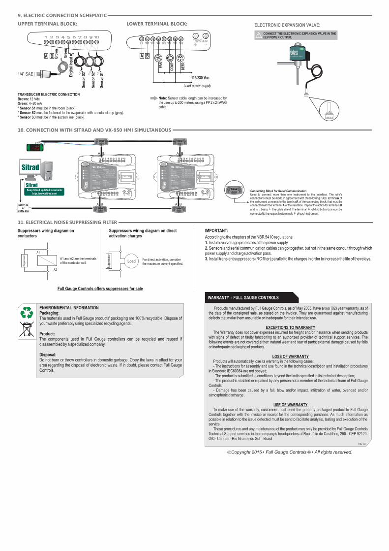
10. CONNECTION WITH SITRAD AND SIMULTANEOUSVX-950 HMI
11. ELECTRICAL NOISE SUPPRESSING FILTER
Full Gauge Controls offers suppressors for sale
IMPORTANT:
According to the chapters of the NBR 5410 regulations:1. Install overvoltage protectors at the power supply2. Sensors and serial communication cables can go together, but not in the same conduit through which power supply and charge activation pass.3. Install transient suppressors (RC filter) parallel to the charges in order to increase the life of the relays.
ENVIRONMENTAL INFORMATIONPackaging:The materials used in Full Gauge products' packaging are 100% recyclable. Dispose of your waste preferably using specialized recycling agents.
Product:The components used in Full Gauge controllers can be recycled and reused if disassembled by a specialized company.
Disposal:Do not burn or throw controllers in domestic garbage. Obey the laws in effect for your area regarding the disposal of electronic waste. If in doubt, please contact Full Gauge Controls.
Products manufactured by Full Gauge Controls, as of May 2005, have a two (02) year warranty, as of the date of the consigned sale, as stated on the invoice. They are guaranteed against manufacturing defects that make them unsuitable or inadequate for their intended use.
EXCEPTIONS TO WARRANTYThe Warranty does not cover expenses incurred for freight and/or insurance when sending products
with signs of defect or faulty functioning to an authorized provider of technical support services. The following events are not covered either: natural wear and tear of parts; external damage caused by falls or inadequate packaging of products.
LOSS OF WARRANTYProducts will automatically lose its warranty in the following cases:- The instructions for assembly and use found in the technical description and installation procedures
in Standard IEC60364 are not obeyed;- The product is submitted to conditions beyond the limits specified in its technical description;- The product is violated or repaired by any person not a member of the technical team of Full Gauge
Controls;- Damage has been caused by a fall, blow and/or impact, infiltration of water, overload and/or
atmospheric discharge.
USE OF WARRANTYTo make use of the warranty, customers must send the properly packaged product to Full Gauge
Controls together with the invoice or receipt for the corresponding purchase. As much information as possible in relation to the issue detected must be sent to facilitate analysis, testing and execution of the service.
These procedures and any maintenance of the product may only be provided by Full Gauge Controls Technical Support services in the company's headquarters at Rua Júlio de Castilhos, 250 - CEP 92120-030 - Canoas - Rio Grande do Sul – Brasil
WARRANTY - FULL GAUGE CONTROLS
9. ELECTRIC CONNECTION SCHEMATIC
Rev. 03
Copyright 2015
Suppressors wiring diagram on contactors
Sup
pres
sor
A1
A2
A1 and A2 are the terminalsof the contactor coil.
Suppressors wiring diagram on direct activation charges
Load
Sup
pres
sor
For direct activation, consider the maximum current specified.
Connecting Block for Serial CommunicationUsed to connect more than one instrument to the Interface. The wire's connections must be made in agreement with the following rules: terminal A of the instrument connects to the terminal A of the c , that must be connected with the terminal A of the Interface. Repeat the action for terminals B
and , being the cable shield.
onnecting block
The terminal of distribution box must be
connected to the respective terminals of each instrument.
Keep Sitrad updated in website: http://www.sitrad.com
®
HMI
Sitrad
VEE
Power
HMI
2 | HMI (B)
1 | HMI (A)
SITRAD
11 | SITRAD (A)
12 | SITRAD (B)
RELAYS
13-14 | fans
15-16 | compressor
17-18 | defrost
Lin
e
SENS. PRESS.
3 |
4~20mA (green)4 |
12Vdc (brown)
|Power Supply 12Vdc - 1.3A
vx-950 plusSENS. TEMP. / DIG. IN
9-10 | sens. ambient temp.
8-9 | sens. evap. temp.
6-7 | sens. suction temp.
5-6 | digital input (door)
A AB B
A B
A AB B
A BB
VX-950 HMI
®
A AB B
A B
B
A AB B
A BA
A B
A AB B
A B
A B
HMI
Sitrad
VEE
Power
HMI
2 | HMI (B)
1 | HMI (A)
SITRAD
11 | SITRAD (A)
12 | SITRAD (B)
RELAYS
13-14 | fans
15-16 | compressor
17-18 | defrost
Lin
e
SENS. PRESS.
3 |
4~20mA (green)4 |
12Vdc (brown)
|Power Supply 12Vdc - 1.3A
vx-950 plusSENS. TEMP. / DIG. IN
9-10 | sens. ambient temp.
8-9 | sens. evap. temp.
6-7 | sens. suction temp.
5-6 | digital input (door)
A
A BCONV. 32 or
CONV. 256
Note: Sensor cable length can be increased by the user up to 200 meters, using a PP 2 x 24 AWG cable.
CO
MP
DEF
R
FAN
115/230 Vac
Sen
sor
S1*
TRANSDUCER ELECTRIC CONNECTIONBrown: 12 VdcGreen: 4~20 mA* Sensor S1 must be in the room (black).* Sensor S2 must be fastened to the evaporator with a metal clamp (grey).* Sensor S3 must be in the suction line (black).
BABA
Sen
sor
S2*
Sen
sor
S3*
Dig
ital i
nput
1/4” SAE
Bro
wn
Gre
en
UPPER TERMINAL BLOCK: LOWER TERMINAL BLOCK:
Load power supply
ELECTRONIC EXPANSION VALVE:
Line
Electronic Expansion Valve
CONNECT THE ELECTRONIC EXPANSION VALVE IN THE EEV POWER OUTPUT.

Line
Electronic Expansion Valve
IMPORTANT
READ CAREFULLY THE PRACTICAL GUIDE THAT COMES WITH THE ELECTRONIC EXPANSION VALVE (EEV) AND FOLLOW THE INSTALLATIONINSTRUCTIONS PROPERLY.
•APPLICATION: - Refrigeration equipment
• TYPES OF COOLING FLUID:- R22- R134a- R404a- R407C- R410A
• BI-FLOW CAPABILITY:- Two-way flow in the EEV
• COMMON SPECIFICATIONS:- Maximum operating pressure: 600 psi- Operating range: 0 to 480 steps
EEV DIMENSIONSUnit: mm
EEV GENERAL DESCRIPTION
ATTENTIONTHE VEE CABLE EXTENSION MUST HAVE THE MAXIMUM LENGTH OF 15 METERS AND GAUGE THICKNESS EQUAL TO OR GREATER THAN THE CABLE WIRES.
http://www.fullgauge.com/veeselector
IMPORTANT
To find out which valve is best for your application, visit the site or QR code below:
ORIFICE(mm) A
(mm)
MODEL
SB88
SB89
SB90
SB91
SB92
SB93
MAX.REVERSE
PRESSURE(bar)
CONNECTION (SOLDER)
B(mm)
1,0
1,4
1,8
2,5
3,0
3,2
7.94
7.94
7.94
7.94
7.94
6.35
7.94
7.94
7.94
7.94
7.94
6.35
35
20
28
22
15
12
47
43
32
47
50
99
A
B
Side B
Side A
• UKV:TYPE

BROCHURE
EVAPORATION
TEMP.[°C]
REFRIGERATING CAPACITY [kW]
CONDENSATION TEMP. [°C]
10
5
0
-5
-10
-20
-30
10
5
0
-5
-10
-20
-30
10
5
0
-5
-10
-20
-30
10
5
0
-5
-10
-20
-30
20 30 38 40 50 20 30 38 40 50 20 30 38 40 50 20 30 38 40 50 20 30 38 40 50
R22 R134a R404A R407C R410A
6.83
8.08
8.99
9.69
10.22
10.93
11.29
9.36
10.11
10.69
11.13
11.47
11.90
12.07
10.70
11.23
11.64
11.95
12.18
12.43
12.47
10.97
11.45
11.82
12.11
12.31
12.52
12.54
11.94
12.25
12.48
12.63
12.73
12.78
12.66
5.46
6.39
7.05
7.51
7.84
8.22
8.32
7.44
7.95
8.32
8.57
8.74
8.87
8.81
8.46
8.78
9.00
9.13
9.20
9.18
9.00
8.65
8.93
9.12
9.23
9.28
9.23
9.02
9.33
9.45
9.51
9.51
9.46
9.25
8.93
5.36
6.29
7.43
7.77
6.95
8.16
8.27
6.98
7.47
7.83
8.08
8.24
8.37
8.28
7.62
7.92
8.12
8.24
8.30
8.25
8.04
7.67
7.93
8.10
8.20
8.23
8.15
7.91
7.63
7.72
7.75
7.73
7.66
7.41
7.04
7.19
8.45
9.37
10.04
10.54
11.15
11.40
9.75
10.48
11.02
11.42
11.71
12.01
12.05
11.04
11.52
11.88
12.13
12.29
12.40
12.30
11.28
11.72
12.03
12.25
12.38
12.45
12.32
12.06
12.29
12.44
12.52
12.54
12.42
12.13
8.47
10.04
11.21
12.10
12.79
13.71
14.19
11.29
12.22
12.95
13.52
13.96
14.51
14.73
12.54
13.20
13.71
14.10
14.39
14.71
14.73
12.75
13.35
13.81
14.17
14.42
14.70
14.71
13.16
13.53
13.80
13.99
14.11
14.17
14.01
11.95
14.12
15.73
16.94
17.87
19.11
19.74
16.36
17.67
18.69
19.47
20.06
20.81
21.11
18.7119.63
20.35
20.89
21.29
21.73
21.81
19.17
20.02
20.67
21.17
21.52
21.89
21.92
20.88
21.42
21.81
22.09
22.26
22.34
22.14
9.55
11.17
12.32
13.13
13.72
14.37
14.54
13.01
13.90
14.55
14.99
15.29
15.52
15.40
14.79
15.35
15.73
15.97
16.09
16.05
15.74
15.13
15.62
15.95
16.14
16.23
16.13
15.78
16.31
16.52
16.62
16.62
16.54
16.18
15.61
9.37
10.99
12.15
12.99
13.59
14.27
14.46
12.20
13.06
13.69
14.13
14.42
14.63
14.48
13.32
13.84
14.20
14.41
14.51
14.43
14.06
13.42
14.17
14.33
14.39
14.24
13.82
13.87
13.33
13.50
13.55
13.51
13.39
12.95
12.30
12.57
14.78
16.38
17.56
18.43
19.50
19.94
17.05
18.32
19.28
19.98
20.48
21.01
21.07
19.31
20.15
20.77
21.21
21.49
21.68
21.50
19.73
20.49
21.04
21.42
21.65
21.77
21.53
21.08
21.49
21.76
21.90
21.93
21.71
21.21
14.81
17.55
19.60
21.16
22.37
23.98
24.82
19.73
21.37
22.65
23.64
24.41
25.37
25.76
21.93
23.08
23.97
24.65
25.16
25.72
25.82
22.29
23.34
24.15
24.77
25.22
25.70
25.73
23.00
23.65
24.13
24.47
24.68
24.77
24.50
16.30
19.26
21.45
23.11
24.38
26.06
26.93
22.32
24.11
25.49
26.56
27.37
28.39
28.79
25.53
26.78
27.76
28.50
29.04
29.64
29.75
26.16
27.31
28.20
28.88
29.36
29.87
29.91
28.49
29.22
29.76
30.14
30.37
30.47
30.20
13.03
15.24
16.80
17.92
18.71
19.60
19.84
17.75
18.96
19.84
20.45
20.85
21.17
21.01
20.18
20.94
21.46
21.78
21.95
21.90
21.48
20.64
21.31
21.76
22.02
22.14
22.01
21.52
22.24
22.54
22.67
22.68
22.56
22.07
21.29
12.78
14.99
16.58
17.72
18.54
19.47
19.72
16.64
17.82
18.68
19.28
19.67
19.95
19.75
18.17
18.88
19.37
19.66
19.80
19.69
19.18
18.31
18.92
19.33
19.55
19.63
19.43
18.86
18.19
18.41
18.48
18.43
18.27
17.67
16.78
17.15
20.17
22.35
23.95
25.14
26.60
27.20
23.26
25.00
26.30
27.25
27.93
28.66
28.75
26.34
27.49
28.34
28.93
29.32
29.58
29.33
26.92
27.95
28.71
29.22
29.54
29.70
29.38
28.76
29.32
29.68
29.87
29.91
29.62
29.94
20.21
23.95
26.74
28.86
30.51
32.71
33.86
26.92
29.15
30.90
32.25
33.30
34.61
35.14
29.92
31.48
32.70
33.63
34.32
35.09
35.22
30.41
31.84
32.95
33.79
34.41
35.06
35.10
31.38
32.26
32.92
33.38
33.66
33.79
33.43
17.55
20.75
23.10
24.89
26.26
28.07
29.01
24.04
25.26
27.45
28.60
29.47
30.57
31.01
27.49
28.84
29.90
30.69
31.28
31.93
32.04
28.17
29.41
30.37
31.10
31.62
32.17
32.21
30.68
31.47
32.05
32.46
32.71
32.82
32.53
14.04
16.41
18.10
19.30
20.15
21.11
21.37
19.11
20.42
21.37
22.02
22.46
22.80
22.63
21.73
22.55
23.11
23.46
23.64
23.59
23.13
22.23
22.95
23.43
23.72
23.84
23.70
23.18
23.95
24.27
24.42
24.42
24.30
23.76
22.93
13.76
16.15
17.85
19.08
19.97
20.97
21.24
17.92
19.19
20.12
20.76
21.18
21.49
21.27
19.57
20.33
20.86
21.17
21.32
21.20
20.66
19.71
20.38
20.81
21.06
21.14
20.93
20.31
19.59
19.83
19.91
19.85
19.67
19.03
18.07
18.47
21.72
24.07
25.79
27.08
28.65
29.29
25.05
26.92
28.32
29.35
30.08
30.86
30.96
28.36
29.60
30.52
31.15
31.57
31.86
31.59
28.99
30.10
30.91
31.47
31.81
31.99
31.64
30.97
31.58
31.97
32.17
32.21
31.89
31.16
21.77
25.79
28.80
31.09
32.86
35.26
36.46
28.99
31.39
33.28
34.74
35.86
37.28
37.85
32.22
33.90
35.22
36.22
36.96
37.79
37.93
32.75
34.29
35.49
36.39
37.05
37.75
37.80
33.79
34.74
35.45
35.95
36.25
36.39
36.00
10
5
0
-5
-10
-20
-30
10
5
0
-5
-10
-20
-30
1.57
1.85
2.06
2.22
2.34
2.51
2.59
2.15
2.32
2.45
2.55
2.63
2.73
2.77
2.45
2.58
2.67
2.74
2.79
2.85
2.86
2.52
2.63
2.71
2.78
2.82
2.87
2.88
2.74
2.81
2.86
2.90
2.92
2.93
2.90
2.32
2.74
3.05
3.29
3.47
3.71
3.83
3.18
3.43
3.63
3.78
3.89
4.04
4.10
3.63
3.81
3.95
4.06
4.13
4.22
4.23
3.72
3.89
4.01
4.11
4.18
4.25
4.26
4.05
4.16
4.24
4.29
4.32
4.34
4.30
1.25
1.47
1.62
1.72
1.80
1.88
1.91
1.85
2.17
2.39
2.55
2.66
2.79
2.82
1.71
1.82
1.91
1.97
2.01
2.04
2.02
2.53
2.70
2.82
2.91
2.97
3.01
2.99
1.94
2.01
2.06
2.09
2.11
2.11
2.07
2.87
2.98
3.05
3.10
3.12
3.12
3.06
1.98
2.05
2.09
2.12
2.13
2.12
2.07
2.94
3.03
3.10
3.13
3.15
3.13
3.06
2.14
2.17
2.18
2.18
2.17
2.12
2.05
3.17
3.21
3.23
3.23
3.21
3.14
3.03
1.23
1.44
1.59
1.70
1.78
1.87
1.90
1.82
2.13
2.36
2.52
2.64
2.77
2.81
1.60
1.71
1.80
1.85
1.89
1.92
1.90
2.37
2.54
2.66
2.74
2.80
2.84
2.81
1.75
1.82
1.86
1.89
1.90
1.89
1.84
2.59
2.69
2.76
2.80
2.82
2.80
2.73
1.76
1.82
1.86
1.88
1.89
1.87
1.81
2.61
2.69
2.75
2.78
2.79
2.77
2.68
1.75
1.77
1.78
1.77
1.76
1.70
1.61
2.59
2.62
2.63
2.62
2.60
2.51
2.39
1.65
1.94
2.15
2.30
2.42
2.56
2.62
2.44
2.87
3.18
3.41
3.58
3.79
3.87
2.24
2.40
2.53
2.62
2.69
2.76
2.76
2.53
2.64
2.72
2.78
2.82
2.84
2.82
3.31
3.56
3.74
3.88
3.98
4.08
4.09
3.75
3.91
4.03
4.12
4.17
4.21
4.17
2.59
2.69
2.76
2.81
2.84
2.86
2.82
3.83
3.98
4.09
4.16
4.20
4.23
4.18
2.77
2.82
2.85
2.87
2.88
2.85
2.78
4.09
4.17
4.22
4.25
4.26
4.21
4.12
1.94
2.30
2.57
2.78
2.93
3.15
3.26
2.88
3.41
3.81
4.11
4.34
4.66
4.82
2.59
2.80
2.97
3.10
3.20
3.33
3.38
3.83
4.15
4.40
4.74
4.93
5.00
4.59
2.88
3.03
3.14
3.23
3.30
3.37
3.39
4.26
4.48
4.65
4.79
4.88
4.99
5.01
2.92 3.02
3.06 3.10
3.17 3.17
3.25 3.21
3.31 3.24
3.37 3.25
3.37 3.21
4.33 4.47
4.53 4.59
4.69 4.69
4.81 4.75
4.90 4.79
4.99 4.81
4.99 4.76
SB88
SB89
SB90
SB91
SB92
SB93
CAPACITY TABLE
Related Documents


