VSS/VSM compressor unit Installation, operation & maintenance manual FOR UNITS BUILT AFTER JANUARY 1, 2015

Welcome message from author
This document is posted to help you gain knowledge. Please leave a comment to let me know what you think about it! Share it to your friends and learn new things together.
Transcript

VSS/VSM compressor unitInstallation, operation & maintenance manualFOR UNITS BUILT AFTER JANUARY 1, 2015


iVSS/VSM • Installation, Operation and Maintenance Manual • Emerson Climate Technologies • 35391SD
READ CAREFULLY BEFORE INSTALLING AND STARTING YOUR COMPRESSOR.
The following instructions have been prepared to assist in installation, operation and removal of Vilter Single Screw Compressors. Following these instructions will result in a long life of the compressor with satisfactory operation.
The entire manual should be reviewed before attempting to install, operate, service or repair the compressor.
A compressor is a positive displacement machine. It is designed to compress gas. The compressor must not be subjected to liquid carry over. Care must be exercised in properly designing and maintaining the system to prevent conditions that could lead to liquid carry over. Vilter Manufacturing is not responsible for the system or the controls needed to prevent liquid carry over and as such Vilter Manufacturing cannot warrant equipment damaged by improperly protected or operating systems.
Vilter screw compressor components are thoroughly inspected at the factory. However, damage can occur in shipment. For this reason, the equipment should be thoroughly inspected upon arrival. Any damage noted should be reported immediately to the Transportation Company. This way, an authorized agent can examine the unit, determine the extent of damage and take necessary steps to rectify the claim with no serious or costly delays. At the same time, the local Vilter representative or the home office should be notified of any claim made.
All inquires should include the Vilter sales order number, compressor serial and model number. These can be found on the compressor name plate on the compressor.
All requests for information, services or parts should be directed to:
Vilter Manufacturing LLCCustomer Service Department
5555 South Packard AveCudahy, WI 53110 USA
Telephone: 1-414-744-0111Fax:1-414-744-3483
E-mail: [email protected]
Equipment Identification Numbers:
Vilter Order Number: _______________________Compressor Serial Number: _________________Vilter Order Number: _______________________Compressor Serial Number: _________________Vilter Order Number: _______________________Compressor Serial Number: _________________Vilter Order Number: _______________________Compressor Serial Number: _________________
Important Message

ii / Blank VSS/VSM • Installation, Operation and Maintenance Manual • Emerson Climate Technologies • 35391SD

TOC - 1VSS/VSM • Installation, Operation and Maintenance Manual • Emerson Climate Technologies • 35391SD
Important Message................................................................................................................................ i
Section 1 • General Information
How To Use This Manual ......................................................................................................................... 1-1Refrigeration Compressor Unit Model Designations ............................................................................... 1-2System Unit Identification ..................................................................................................................... 1-3Compressor Unit Component Identification ........................................................................................... 1-4Instrument Identification Letters ............................................................................................................ 1-7Symbols Identification ........................................................................................................................... 1-8Major Component Identification ............................................................................................................ 1-9Control and Instrument Identification .................................................................................................... 1-10Line Type Designations .......................................................................................................................... 1-10Valve and Instrument Tagging ................................................................................................................ 1-11
Section 2 • Theory of Operation
Refrigerant Flow .................................................................................................................................... 2-1Oil Life and Oil Flow ................................................................................................................................ 2-1Oil Cooling ............................................................................................................................................. 2-2 Water Cooled Oil Cooling ........................................................................................................... 2-2 Liquid Injection Oil Cooling ........................................................................................................ 2-2 V-PLUS Oil Cooling ..................................................................................................................... 2-2 Thermosyphon Oil Cooling ........................................................................................................ 2-2Control System ...................................................................................................................................... 2-3 Temperature Elements and Pressure Transmitters and Indicators ............................................... 2-3
Section 3 • Installation
Delivery Inspection ................................................................................................................................ 3-1Rigging and Lifting of Compressor Unit .................................................................................................. 3-1Long Term Storage Recommendations ................................................................................................... 3-2 Compressor Motor ..................................................................................................................... 3-2Compressor Unit Inspections Prior to Storage or Installation ..................................................................3-3Recommended On-site Tools ................................................................................................................. 3-3Long Term Storage Log .......................................................................................................................... 3-4Foundation ............................................................................................................................................ 3-5Stop/Check Valve Installation ................................................................................................................. 3-11Piping .................................................................................................................................................. 3-12Electrical Connections ........................................................................................................................... 3-13Field Wiring Instructions ........................................................................................................................ 3-13Testing Refrigeration System for Leaks ................................................................................................... 3-16 Ammonia Systems ..................................................................................................................... 3-16 Halocarbon Refrigerant Systems ................................................................................................ 3-16 Evacuating the System ............................................................................................................... 3-17 Using Non-Vilter Oils .............................................................................................................................. 3-18Unit Oil Charging and Priming ................................................................................................................ 3-18System Refrigerant Charging ................................................................................................................. 3-21
Table of Contents
Section Title Section Number

TOC - 2 VSS/VSM • Installation, Operation and Maintenance Manual • Emerson Climate Technologies • 35391SD
Section 4 • Operation
Oil Inspection ........................................................................................................................................ 4-1Dual Oil Filters........................................................................................................................................ 4-1Control System Calibration .................................................................................................................... 4-2Starting, Stopping and Restarting the Compressor ................................................................................ 4-2Emergency Shutdown ............................................................................................................................ 4-2Calibrate Slide Valve Actuators ............................................................................................................... 4-3Coalescing Oil Return Line Setup ............................................................................................................ 4-8Suction Equalizing Line Setup ................................................................................................................ 4-9Dual Oil Filter Setup for Oil Filters with Filter Head Assemblies ............................................................... 4-10Stop/Check Valve Operation .................................................................................................................. 4-11
Section 5 • Maintenance/Service
Maintenance and Service Schedule ........................................................................................................ 5-1 Preventative Maintenance, Checks and Services ..................................................................................... 5-2 Compressor Unit Isolation for Maintenance/Service ............................................................................... 5-3Compressor Unit Leak Check .................................................................................................................. 5-3Oil System Components ......................................................................................................................... 5-4
Oil Sampling............................................................................................................................... 5-4Oil Draining ................................................................................................................................ 5-5Oil Charging ............................................................................................................................... 5-6Filter Element Replacement (Single Oil Filter Assembly) and Oil Pump Strainer ........................... 5-7Filter Element Replacement (Duplex Oil Filter Assembly) ............................................................ 5-10Filter Element Replacement (Dual Oil Filter Assembly) ................................................................ 5-12Coalescing Filter Replacement .................................................................................................... 5-16Oil Separator Heater Cartridge Replacement .............................................................................. 5-18
Drive Coupling Hub (Form-Flex BPU) Installation .................................................................................... 5-20Drive Center Member Installation and Alignment ................................................................................... 5-21Drive Coupling Hub (Form-Flex BPU) and Center Member Removal ........................................................ 5-23Drive Coupling (Type C Sure-Flex) Replacement ..................................................................................... 5-23Coupling Guard Replacement ................................................................................................................. 5-25Compressor Replacement ...................................................................................................................... 5-26Bare Shaft Compressor Lifting Points and Weights ................................................................................. 5-28Bare Shaft Compressor Center of Gravity (Models 291-2101) ................................................................. 5-29Bare Shaft Compressor Center of Gravity (Models 2401-3001) ............................................................... 5-30Compressor Shaft Bearing Float Inspections........................................................................................... 5-32 Bearing Axial Float Inspections ................................................................................................... 5-32 Bearing Radial Float Inspections ................................................................................................. 5-32Gate Rotor Float and Gate Rotor Bearing Float Inspection ....................................................................... 5-33Gate Rotor and Support Clearance ......................................................................................................... 5-35Gate Rotor Assembly Replacement (All VSS & VSM Compressors Except VSM 301-701 Compressors) ..... 5-37Gate Rotor Assembly Replacement (VSM 301-701 Compressors ONLY) .................................................. 5-40Gate Rotor Disassembly ......................................................................................................................... 5-42
Gate Rotor Blade Removal/Installation ....................................................................................... 5-42Gate Rotor Thrust Bearing Removal/Installation ......................................................................... 5-43Gate Rotor Roller Bearing Removal/Installation ........................................................................... 5-43
Slide Valve Actuator Assembly Replacement .......................................................................................... 5-44Command Shaft Assembly Replacement ................................................................................................ 5-45 Compressor Shaft Seal Replacement ...................................................................................................... 5-45Liquid Injection Control Valve Station ..................................................................................................... 5-47
Table of Contents
Section Title Section Number

TOC - 3VSS/VSM • Installation, Operation and Maintenance Manual • Emerson Climate Technologies • 35391SD
Table of Contents
Section Title Section Number
Section 6 • Troubleshooting
Table 6-1. Slide Valve Actuator Troubleshooting Guide ........................................................................... 6-1Table 6-2. Slide Valve Actuator LED Blink Codes ...................................................................................... 6-3Table 6-3. Troubleshooting Guide - General Problems & Solutions .......................................................... 6-5
Section 7 • Warranty and Parts
Warranty Claim Processing .................................................................................................................... 7-1On Site Service Support ......................................................................................................................... 7-1Remanufactured Bare Shaft Single Screw Compressor Process ............................................................... 7-2 Explanation of Rebuild Levels ..................................................................................................... 7-2 Bare Shaft Compressor Description ............................................................................................7-2
Appendices
Appendix A Torque Specifications ...................................................................................................... AAppendix B Oil Analysis Report .......................................................................................................... BAppendix C Danfoss ICM/ICAD Motorized Valve Quick Start Guide .................................................... CAppendix D Danfoss ICM/ICAD Valve Setup Instructions .................................................................... DAppendix E Danfoss Valve Station ICF 20-40 Installation Guide .......................................................... E

TOC - 4 VSS/VSM • Installation, Operation and Maintenance Manual • Emerson Climate Technologies • 35391SD
Tables
Table 3-1. Maximum Allowable Flange Loads ......................................................................................... 3-12Table 4-1. Command Shaft Rotation Specifications ................................................................................ 4-6Table 4-2. Stop/Check Valve Open Positions ........................................................................................... 4-10Table 5-1. Maintenance/Service Schedule .............................................................................................. 5-1Table 5-2. Shaft and Hub Distances ........................................................................................................ 5-20Table 5-3. Hub Clamp Bolt and Set Screw Torque Specifications ............................................................. 5-22Table 5-4. Disc Pack Installation Torque Specifications ............................................................................ 5-22Table 5-5. Clamping Bolts and Set Screw Torque Specifications .............................................................. 5-24Table 5-6. Torque Requirements for Motor / Compressor Mounting ....................................................... 5-27Table 5-7. Bare Shaft Compressor Component Weights .......................................................................... 5-28Table 5-8. Bare Shaft Compressor Component Lifting Hole Sizes ............................................................ 5-28Table 5-9. Maximum Bearing Float (Compressor Shaft) .......................................................................... 5-33Table 5-10. Gate Rotor Float ................................................................................................................... 5-34Table 5-11. Gate Rotor Tool Sets ............................................................................................................. 5-37Table 5-12. Coils for Solenoid Valves (ICFE) ............................................................................................. 5-48Table 5-13. Parts for Motorized Valve Station (ICF) ................................................................................. 5-48Table 6-1. Slide Valve Actuator Troubleshooting Guide (1 of 2) ............................................................... 6-1Table 6-2. Slide Valve Actuator LED Blink Codes* (1 of 2) ........................................................................ 6-3Table 6-3. Troubleshooting Guide - General Problems & Solutions (1 of 3) .............................................. 6-5
Figures
Figure 1-1. Refrigeration Compressor Unit Model Designation .............................................................. 1-2Figure 1-2. Refrigeration Compressor Unit Components ........................................................................ 1-4Figure 2-1. Refrigeration Compressor Unit P&ID ..................................................................................... 2-1Figure 3-1. Rigging and Lifting Points (VSS-2101 Compressor Unit Shown) ............................................ 3-1Figure 3-2. Concrete Pad with Compressor Unit Dimensions - Side View ................................................ 3-6Figure 3-3. Concrete Pad with Compressor Unit Dimensions - Front View ............................................... 3-7Figure 3-4. Interior Foundation Isolation ................................................................................................ 3-7Figure 3-5. Foundation with Housekeeping Pads Dimensions - Top View ................................................ 3-8Figure 3-6. Housekeeping Pad Dimension Detail - Top View ................................................................... 3-9Figure 3-7. Level Compressor Unit Using Top Surface of Spherical Washers ............................................ 3-9Figure 3-8. Concrete Pad Housekeeping Detail ....................................................................................... 3-10Figure 3-9. Stop/Check Valve Orientation ............................................................................................... 3-11Figure 3-10. Maximum Allowable Flange Loads ...................................................................................... 3-12Figure 3-11. Example - Vission 20/20 Wiring Diagram ............................................................................ 3-14Figure 3-12. Example - Interconnect Wiring Diagram ............................................................................. 3-15Figure 3-13. Example - V-PLUS Wiring Diagram ...................................................................................... 3-15Figure 3-14. Oil Operating Levels ........................................................................................................... 3-19Figure 3-15. Oil Drain Valve .................................................................................................................... 3-19Figure 3-16. Priming Oil Lines and Compressor ...................................................................................... 3-20Figure 4-1. Oil Operating Levels ............................................................................................................. 4-1Figure 4-2. Actuator Assembly ............................................................................................................... 4-3Figure 4-3. Menu Screen and Slide Calibraiton Button (Vission 20/20) .................................................... 4-4Figure 4-4. Slide Valve Calibraiton Screen (Vission 20/20) ...................................................................... 4-5Figure 4-5. Photo-chopper ..................................................................................................................... 4-5Figure 4-6. Wire Connections for Capacity and Volume Actuators .......................................................... 4-7Figure 4-7. Coalescing Oil Return Line .................................................................................................... 4-8Figure 4-8. Suction Equalizing Line and Valve ......................................................................................... 4-9Figure 4-9. Dual Oil Filter Setup for Oil Filters with Manifold Heads ......................................................... 4-10Figure 5-1. Discharge Bleed Valve, Suction Equalizing Line and Valve ..................................................... 5-3Figure 5-2. Oil Analysis Kit ...................................................................................................................... 5-5
Table/Figure Section Number
List of Tables and Figures
TOC - 5VSS/VSM • Installation, Operation and Maintenance Manual • Emerson Climate Technologies • 35391SD
Figure 5-3. Oil Strainer Drain Valve and Oil Separator Drain Valve ........................................................... 5-5Figure 5-4. Suction Oil Charging Valve ................................................................................................... 5-6Figure 5-5. Filter Assembly and Oil Strainer Drain Valve (VPN 3111A Oil Filter Housing Shown) .............. 5-8Figure 5-6. Filter Assembly (VPN 3112A Oil Filter Housing Shown) ......................................................... 5-9Figure 5-7. Duplex Oil Filter Assembly (VPN 3110A Double Oil Filter Housing Shown) ............................ 5-11Figure 5-8. Dual Oil Filter (3111A Oil Filter Housings Shown) .................................................................. 5-13Figure 5-9. Filter Assembly and Oil Strainer Drain Valve (VPN 3111A Oil Filter Housing Shown) .............. 5-14Figure 5-10. Filter Assembly (VPN 3112A Oil Filter Housing Shown) ....................................................... 5-15Figure 5-11. Oil Separator Manhole Cover and Coalescing Filter Assembly .............................................. 5-17Figure 5-12. Heater Cartridges ............................................................................................................... 5-19Figure 5-13. Hub Distance (Axial Spacing) .............................................................................................. 5-21Figure 5-14. Angular Alignment and Parallel Offset ................................................................................ 5-22Figure 5-15. Coupling Guard Assembly (VPN A27435C shown) .............................................................. 5-25Figure 5-16. Compressor Replacement and Hardware Assembly (VSS 2401-3001 Shown) ...................... 5-26Figure 5-17. Bare Shaft Compressor Lifting Points and Component Weights .......................................... 5-28Figure 5-18. Bare Shaft Compressor Assembly Center of Gravity (Models 291-2101) .............................. 5-29Figure 5-19. Bare Shaft Compressor Center of Gravity - Discharge Manifold and MainCompressor Assembly (Models 291-2101) ............................................................................................. 5-29Figure 5-20. Bare Shaft Compressor Assembly Center of Gravity (Models 2401-3001) ............................ 5-30Figure 5-21. Bare Shaft Compressor Center of Gravity - Discharge Manifold and MainCompressor Assembly (Models 2401-3001) ........................................................................................... 5-30Figure 5-22. Bearing Axial Float Inspection ............................................................................................. 5-32Figure 5-23. Bearing Radial Float Inspection ........................................................................................... 5-33Figure 5-24. Gate Rotor Float ................................................................................................................. 5-33Figure 5-25. Gate Rotor Bearing Float ..................................................................................................... 5-34Figure 5-26. Gate Rotor and Support Clearance - Minimum Clearances .................................................. 5-35Figure 5-27. Gate Rotor and Support Clearance - Measuring ................................................................... 5-36Figure 5-28. Gate Rotor Assembly Removal and Tools.............................................................................5-38Figure 5-29. Gate Rotor Assembly Removal ............................................................................................ 5-38Figure 5-30. Gate Rotor Assembly and Tools ........................................................................................... 5-39Figure 5-31. Gate Rotor and Shelf Clearance ........................................................................................... 5-39Figure 5-32. Gate Rotor Assembly Breakdown ........................................................................................ 5-40Figure 5-33. Gate Rotor Thrust Bearing .................................................................................................. 5-41Figure 5-34. Gate Rotor and Shelf Clearance ........................................................................................... 5-41Figure 5-35. Gate Rotor Blade Assembly ................................................................................................. 5-42Figure 5-36. Gate Rotor Blade Installation .............................................................................................. 5-42Figure 5-37. Gate Rotor Thrust Bearing .................................................................................................. 5-43Figure 5-38. Thrust Bearing Installation .................................................................................................. 5-43Figure 5-39. Roller Bearing Assembly ..................................................................................................... 5-44Figure 5-40. Compressor Shaft Seal Assembly ........................................................................................ 5-45Figure 5-41. Compressor Shaft Seal Installation...................................................................................... 5-46Figure 5-42. Danfoss ICF 20-40 Valve Station (Liquid Injection Control ) ................................................. 5-47
List of Tables and Figures
Table/Figure Section Number

Blank / TOC VSS/VSM • Installation, Operation and Maintenance Manual • Emerson Climate Technologies • 35391SD

1 – 1VSS/VSM • Installation, Operation and Maintenance Manual • Emerson Climate Technologies • 35391SD
How To Use This Manual
This manual contains instructions for refrigeration com-pressor units. It has been divided into eight sections:
Section 1: General Information
Section 2: Theory of Operation
Section 3: Installation
Section 4: Operation
Section 5: Maintenance & Service
Section 6: Troubleshooting
Section 7: Warranty and Parts
Appendices
It is highly recommended that the manual be reviewed prior to servicing system parts.
Figures and tables are included to illustrate key concepts.
Safety precautions are shown throughout the manual. They are defi ned as the following:
NOTICE - Notice statements are shown when there are important information that shall be followed. Not fol-lowing such notices may result in void of warranty, seri-ous fi nes, serious injury and/or death.
WARNING - Warning statements are shown when there are hazardous situations, if not avoided, will result in se-rious injury and/or death.
CAUTION - Caution statements are shown when there are potentially hazardous situations, if not avoided, will result in damage to equipment.
NOTE - Notes are shown when there are additional infor-mation pertaining to the instructions explained.
ADDITIONAL IMPORTANT NOTES
• Additional installation, operation and maintenance instructions can be found in the Vission 20/20 manual (35391SC).
• Due to continuing changes and unit updates, always refer to the Vilter.com website to make sure you have the latest manual.
• Any suggestions of manual improvements can be made to Vilter Manufacturing at the contact informa-tion on page i.
Section 1 • General Information

1 – 2 VSS/VSM • Installation, Operation and Maintenance Manual • Emerson Climate Technologies • 35391SD
1. Compressor Model
VSM = Vilter Single Mini-Screw
VSS = Vilter Single Screw
VRS = Vilter Twin Screw
VRSH = Vilter Single Screw Heat Pump
2. Size
CFM - Nominal CFM displacement of the compressor at 3600 rpm
3. Slide Arrangement
VVR = Variable Volume Ratio; Parallex™
FR = Fixed Ratio, Single Capcity Slide
4. Refrigerant Service
A = R-717 (Ammonia) M = R-22
E = R-134a P = R-290 (Propane)
H = R-404A R = R1270 (Propylene)
J = R-410A Z = R-507
C = R-744 (CO2)
5. Application
HP = High Stage with Oil Pump
HN = High Stage no Oil Pump (SOI - Suction Oil Injection)
B = Booster
S = Swing
6. Driver
VFD = Variable Frequency Drive
EMD = Electric Motor Drive
ENG = Engine Drive
7. Separator Type
16 = 16 inch diameter 36 = 36 inch diameter
20 = 20 inch diameter 42 = 42 inch diameter
24 = 24 inch diameter 48 = 48 inch diameter
30 = 30 inch diameter 54 = 54 inch diameter
H = Horizontal V = Vertical
SH = Special Horizontal SV = Special Vertical
8. Economizer
NEC = No Economizer, Economizer Ports Plugged
ECC = Economizer Connection, Ports Piped to Single Flange
ECF = Economizer Flanges, Flanged Port Covers (piping by others)
9. Oil Cooler
PLT = Plate PLS = V-Plus Pumped Liquid
ST = Shell and Tube CC = Cool Compression
LI = Liquid Injection REM = Remote
10. Oil Cooling Medium
REF = Refrigerant AIR = Air
WTR = Water GL = Glycol
Refrigeration Compressor Unit Model Designations
The compressor unit model designation can be found on the nameplate. For nameplate location, see Component Identifi cation on section page 1-4.
VSM-301-VVR-A-HP-EMD-16H-NEC-PLT-REF
1 2 3 4 5 6 7 8 9 10
Figure 1-1. Refrigeration Compressor Unit Model Designation
Section 1 • General Information
1 – 3VSS/VSM • Installation, Operation and Maintenance Manual • Emerson Climate Technologies • 35391SD
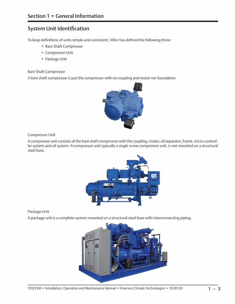
System Unit Identifi cation
To keep defi nitions of units simple and consistent, Vilter has defi ned the following three:
• Bare Shaft Compressor
• Compressor Unit
• Package Unit
Bare Shaft Compressor
A bare shaft compressor is just the compressor with no coupling and motor nor foundation.
Compressor Unit
A compressor unit consists of the bare shaft compressor with the coupling, motor, oil separator, frame, micro-control-ler system and oil system. A compressor unit typically a single screw compressor unit, is not mounted on a structural steel base.
Package Unit
A package unit is a complete system mounted on a structural steel base with interconnecting piping.
Section 1 • General Information

1 – 4 VSS/VSM • Installation, Operation and Maintenance Manual • Emerson Climate Technologies • 35391SD
1 - Motor
2 - Motor Conduit Box
3 - Coupling and Guard
4 - Suction Oil Charging Valve
5 - Thermometer
6 - Suction Strainer
7 - Suction Check Valve
8 - Suction Stop Valve
9 - Compressor
10 - Discharge Pipe
11 - Vission 20/20 HMI
12 - Block & Bleed Assembly
13 - Oil Drain/Fill Valve
14 - Oil Pressure Regulator
15 - Oil Heater
16 - Frame
17a - Oil Filter, Single (Vertical)
17b - Oil Filter, Dual (Horizontal)
18 - Oil Pump Motor
19 - Oil Pump
20 - Oil Sight Glass
21 - Oil Pump Strainer
22 - Oil Pressure Relief Valve
23 - Oil Temperature Control Valve (Oil Mixing Valve)
24 - Oil Cooler (Plate Heat Exchanger)
25 - Oil Separator
26 - Discharge Connection
27 - Coalescing Oil Return Line
28 - Heater Wiring Panel
29 - Economizer Connection Flange
30 - Nameplate
31 - Suction Equalizing Line
32 - Oil Separator Certifi cation Plate
3
6 7 8
9
11
1317a24
1
25
12
10
1416182021
Compressor Unit Component Identifi cation
Each refrigeration compressor unit may differ, but below are typical components that can be found on each unit.
Figure 1-2. Refrigeration Compressor Unit Components (1 of 3)
Section 1 • General Information
192223
4 5
15 15
2

1 – 5VSS/VSM • Installation, Operation and Maintenance Manual • Emerson Climate Technologies • 35391SD
26
21
29
28
2
Figure 1-2. Refrigeration Compressor Unit Components (2 of 3)
Section 1 • General Information
57
27
1
1918
30
30
3217b
31

1 – 6 VSS/VSM • Installation, Operation and Maintenance Manual • Emerson Climate Technologies • 35391SD
33 - Temperature Element (Suction)
34 - Pressure Transducer (Filter Inlet)
35 - Pressure Transducer (Oil Pressure)
36 - Pressure Transducer (Suction Pressure)
37 - Pressure Transducer (Discharge Pressure)
38 - Temperature Element (Oil Separator)
39 - Temperature Element (Oil Injection)
Component Identifi cation (Continued)
40 - Capacity Slide Valve Actuator
41 - Volume Slide Valve Actuator
42 - Temperature Element (Discharge)
Figure 1-2. Refrigeration Compressor Unit Components (3 of 3)
Section 1 • General Information
42
33 34 35 36 37
38
39
41
40
36
1 – 7VSS/VSM • Installation, Operation and Maintenance Manual • Emerson Climate Technologies • 35391SD
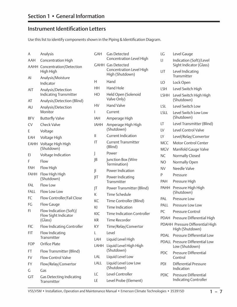
Instrument Identifi cation Letters
Use this list to identify components shown in the Piping & Identifi cation Diagram.
A Analysis
AAH Concentration High
AAHH Concentration/Detection High High
AI Analysis/Moisture Indicator
AIT Analysis/Detection Indicating Transmitter
AT Analysis/Detection (Blind)
AU Analysis/Detection Monitor
BFV Butterfl y Valve
CV Check Valve
E Voltage
EAH Voltage High
EAHH Voltage High High (Shutdown)
EI Voltage Indication
F Flow
FAH Flow High
FAHH Flow High High (Shutdown)
FAL Flow Low
FALL Flow Low Low
FC Flow Controller/Fail Close
FG Flow Gauge
FI Flow Indication (Soft)/Flow Sight Indicator (Glass)
FIC Flow Indicating Controller
FIT Flow Indicating Transmitter
FOP Orifi ce Plate
FT Flow Transmitter (Blind)
FV Flow Control Valve
FY Flow/Relay/Convertor
G Gas
GIT Gas Detecting Indicating Transmitter
GAH Gas Detected Concentration Level High
GAHH Gas Detected Concentration Level High High (Shutdown)
H Hand
HH Hand Hole
HO Held Open (Solenoid Valve Only)
HV Hand Valve
I Current
IAH Amperage High
IAHH Amperage High High (Shutdown)
II Current Indication
IT Current Transmitter (Blind)
J Power
JB Junction Box (Wire Termination)
JI Power Indication
JIT Power Indicating Transmitter
JT Power Transmitter (Blind)
K Time Schedule
KC Time Controller (Blind)
KI Time Indication
KIC Time Indication Controller
KR Time Recorder
KY Time/Relay/Convertor
L Level
LAH Liquid Level High
LAHH Liquid Level High High (Shutdown)
LAL Liquid Level Low
LALL Liquid Level Low Low (Shutdown)
LC Level Controller
LE Level Probe (Element)
LG Level Gauge
LI Indication (Soft)/Level Sight Indicator (Glass)
LIT Level Indicating Transmitter
LO Lock Open
LSH Level Switch High
LSHH Level Switch High High (Shutdown)
LSL Level Switch Low
LSLL Level Switch Low Low (Shutdown)
LT Level Transmitter (Blind)
LV Level Control Valve
LY Level/Relay/Convertor
MCC Motor Control Center
MGV Manifold Gauge Valve
NC Normally Closed
NO Normally Open
NV Needle Valve
P Pressure
PAH Pressure High
PAHH Pressure High High (Shutdown)
PAL Pressure Low
PALL Pressure Low Low
PC Pressure Control
PDAH Pressure Differential High
PDAHH Pressure Differential High High (Shutdown)
PDAL Pressure Differential Low
PDALL Pressure Differential Low Low (Shutdown)
PDC Pressure Differential Control
PDI Differential Pressure Indication
PDIC Pressure Differential Indicating Controller
Section 1 • General Information

1 – 8 VSS/VSM • Installation, Operation and Maintenance Manual • Emerson Climate Technologies • 35391SD
PDIT Pressure Differential Indicating Transmitter
PDSH Pressure Differential Switch High
PDSHH Pressure Differential Switch High High (Shutdown)
PDSL Pressure Differential Switch Low
PDSLL Pressure Differential Switch Low Low (Shutdown)
PDT Differential Pressure Transmitter (Blind)
PDV Pressure Differential Control Valve (Pneumatic Actuator)
PFY Pressure Ratio Convertor/Relay
PFC Pressure Ratio Controller
PG Pressure Gauge
PI Pressure Indication (Soft)
PIC Pressure Indicating Controller
PIT Pressure Indicating Transmitter
PSE Pressure Rupture Disk
PSH Pressure Switch High
PSHH Pressure Switch High High (Shutdown)
PSL Pressure Switch Low
PSLL Pressure Switch Low Low (Shutdown)
PSV Pressure Safety Relief Valve
PT Pressure Transmitter (Blind)
PV Pressure Control Valve
Q Quantity and Heat
QE Heater Element, Immersion, Tracing
R Radiation
S Speed, Frequency
SC Speed Control
SD Shutdown
SIC Speed Indicating Controller
T Temperature
TC Temperature Controller
TAH Temperature High
TAHH Temperature High High (Shutdown)
TAL Temperature Low
TALL Temperature Low Low (Shutdown)
TE Temperature Element (RTD, Thermocouple, etc.)
TG Temperature Gauge
TI Temperature Indication (Soft)
TIC Temperature Indicating Controller
TIT Temperature Indicating Transmitter
TRV Transfer Valve 3-Way
TSH Temperature Switch High
TSHH Temperature Switch High High (Shutdown)
TTSL Temperature Switch Low
TSLL Temperature Switch Low Low (Shutdown)
TT Temperature Transmitter (Blind)
TV Temperature Control Valve
TW Temperature Thermo-well
TY Temperature/Relay/Convertor
U Multi Variable
V Vibration, Mechanical Analysis
VE Vibration Probe
VFD Variable Frequency Drive
VG Block/Bleed, Gauge Valve
VSH Vibration Switch High
VSHH Vibration Switch High High (Shutdown)
VT Vibration Transmitter (Blind)
VU Vibration Monitoring System
W Weight
XA Status (Stopping/Not Running) Alarm/Common Alarm
XC State Controller
XI Running Indication
XV Solenoid Valve
XY State Relay/Convertor
Y Event, State, Presence
YAH Fire Alarm
YE Fire Detecting Sensor
YIT Fire Indicate and Transmit
YK Fire Control Station
Z Position, Dimension
ZC Position Controller
ZE Position Element
ZI Position Indicator
ZIT Position Indicating Transmitter
ZT Position Transmitter (Blind)
ZY Position Transmitter (Blind)
ZZ Position Actuator (Capacity or Volume)
Section 1 • General Information

1 – 9VSS/VSM • Installation, Operation and Maintenance Manual • Emerson Climate Technologies • 35391SD
Symbol Identifi cation
Use this list to identify symbols shown in the Piping & Identifi cation Diagram.
3-Way ValveS
3-Way Solenoid Valve
Angle Valve
Ball Valve
Basket Strainer
Block/Bleed Gauge Valve
Butterfl y Valve
Check Valve
Diaphragm Actuator
Diaphragm Spring-Opposed
Diaphragm Pressure-Balanced
Differential Pressure Regulating Valve
Drive Coupling
Flange Set
FGFlow/Sight Glass
Gate Valve
Globe Valve
Hand Expansion Valve
QE Heater
Heat Trace
Insulation
MW Man-Way Cover
Manifold Gauge ValveM
Motorized Ball Valve
Needle Valve
Orifi ce Plate
G Pilot Light
Pipe Plug
Pipe Reducer
Pneumatic Actuator Control Valve
Relief Valve
Regulating Valve Inlet Pressure
Regulating Valve Outlet Pressure
Rotary Valve
Rupture Disc
Schroder ValveS
Solenoid Valve
Spring-Closing Drain Valve
Stop/Check Valve
Strainer
T Thermostatic Valve 3-Way
Thermowell (SW or NPT)
Thermowell (SW or NPT)
Venturi Injector Nozzle
Vibration Absorber
BY VILTER BY OTHERS
Scope of Supply
Section 1 • General Information
A Air Drive
Compressor
Damper or Louver
Engine Drive
Filter
Finned Tube Heat Exchanger
Heat Exchanger
Motor
Shell and Tube
Heat Exchanger
Fan
Tank/Drum Vessel
Positive Displacement Pump
Major Component Identifi cation
Use this list to identify major components shown in the Piping & Identifi cation Diagram.

1 – 10 VSS/VSM • Installation, Operation and Maintenance Manual • Emerson Climate Technologies • 35391SD
Section 1 • General Information
Centrifugal Pump
Rotary Pump
Plate & Frame Heat Exchanger
Turbine
Major Component Identifi cation (Continued)
Discrete Instrument, Field Mounted
Discrete Instrument, Remote, Mount, Normally Accessible to Operator
Discrete Instrument, Local Rack Mounted, Normally Accessible to Operator
Shared Display/Control, Field Mounted
Shared Display/Control, DCS or Remote Control Panel Normally Accessible to Operator
Shared Display/Control, Local Control Panel Normally Accessible to Operator
Programmable Logic Control, Field Mounted
SD Safety Instrumented System, Field Mounted
Programmable Logic Control, DCS or Remote Control Panel, Normally Accessible to Operator
SD Safety Instrumented System Main Control Panel or DCS
Programmable Logic Control, Auxiliary (Local) Control Panel, Normally Accessible to Operator
SD Safety Instrumented System Auxiliary (Local) Control Panel
Computer Function, Field Mounted
Computer Function, DCS or Remote Control Panel, Normally Accessible to Operator
Computer Function, Local Operator Panel, Normally Accessible to Operator
I Interlock
P Permissive
Pneumatic Signal
X X X X X Capillary Tube
Electrical Signal
Internal System Link (Software or Data Link)
Mechanical Link
L L L L L Hydraulic Signal
Customer Field Piping
Insulation
Control and Instrument Identifi cation
Line Type Designations

1 – 11VSS/VSM • Installation, Operation and Maintenance Manual • Emerson Climate Technologies • 35391SD
Section 1 • General Information
a-bc-yz = ABC-DEFGH-IJKL
a = ABC, b = DE, c = FGH, y = IJK, z = L
A - Process cell or stage of compressor
B - Unit number in process cell or stage of compression
C - Service in process cell or stage of compression
1 - Gas lines
2 - Coolant lines
3 - Oil lube lines
4 - Refrigerant lines
5 - Condensate lines
6 - Air lines
Valve and Instrument Tagging
D - Measured variable
E - Variable Modifi ers
F - Readout or passive function
G - Output or active function
H - Function modifi er
I - Loop number or sequential number
J - Loop number or sequential number
K - Loop number or sequential number
L - Suffi x
SAMPLE TAG
105-LSH-300-A
1 - First process cell or stage of compression
0 - First unit number in process cell or stage of compression
5 - Condensate service
L - Level
S - Switch
H - High
3 - Loop number or sequential number
0 - Loop number or sequential number
0 - Loop number or sequential number
A - Another exactly the same device in the same loop as 105-LSH-300
Equipment Number Identifi cation
101-V-300
Process Cell/Compression Stage Number
Equipment Type
Series Number
EQUIPMENT TYPE
A - Agitator, Mechanical Mixers, Aerators
B - Blowers
C - Compressors
D - Drivers
E - Heat Exchangers
F - Fans
P - Pumps
R - Reactors
U - Filters, Strainers
V - Vessels, Tanks, Separators, Scrubbers

1 – 12 VSS/VSM • Installation, Operation and Maintenance Manual • Emerson Climate Technologies • 35391SD
Section 1 • General Information
AB - C - D - E - F 20-LFG-001-10-STD
X - Y - Z PS-1-ET
A - Process cell or stage of compression
1 - Process cell fi rst stage of compression
2 - Process cell fi rst stage of compression
3 - Process cell fi rst stage of compression
4 - Process cell fi rst stage of compression
5 - Process cell low pressure refrigeration (booster)
6 - Process cell high pressure refrigeration (high stage)
7 - Open
8 - Open
9 - Open
B - Unit number in process cell or stage of compression
C - Service
AR - Process Air
BD - Blowdown
BRR - Brine
CHWS - Chilled Water Supply
CHWR - Chilled Water Return
CWR - Cooling Water Return
CWS - Cooling Water Supply
DR - Drain
ER - Ethylene Refrigerant
GLR - Glycol Return
GLS - Glycol Supply
H - Hydrogen
HR - Hydrocarbon Refrigerant
Pipe Line Data Identifi cation
IAS - Instrument Air Supply
LFG - Land Fill Gas
LO - Lube Oil
N - Nitrogen
NG - Natural Gas
NH - Ammonia
PC - Process Condensate
PG - Process Gas
PR - Propylene Refrigerant/Propane
SV - Safety Relief
SO - Seal Oil
VC - Vacuum Condensate
D - Numerical Sequence Number
E - Size
#” - Nominal Pipe Size (Inches)
F - Standard/Other Standard
STD -Vilter
0 - Other Standard (Not Vilter)
X - Insulation
AC -Acoustic Control
CC - Cold Service
CP - Condensation Control
N - Not Required
PP - Personnel Protection
PS - Process Stability
TR - Traced (See Tracing Type)
Y - Insulation Thickness
BO - By Others
#” - Nominal Thickness (Inches)
0 - Insulation Not Required
Z - Heat Tracing
ET - Electrical Heat Trace
N - None

2 – 1VSS/VSM • Installation, Operation and Maintenance Manual • Emerson Climate Technologies • 35391SD
Section 2 • Theory of Operation
The refrigeration and oil systems work in unison, but each one will be explained separately. Reference Figure 2-1 for refrigerant and oil fl ow descriptions. This is a typi-cal refrigeration system with thermosyphon oil cooling.
Refrigerant Flow
The refrigeration compression process begins as refrig-erant vapor enters the suction inlet (12). The refrigerant vapor fl ows through a suction stop/check valve (11), then through a strainer (10) to the compressor (9). The refrigerant is then pressurized through the compressor and discharged as high pressure refrigerant vapor into the oil separator (1). In the oil separator, the oil is then separated from the discharged refrigerant by impinge-ment separation. The high pressure refrigerant fl ows out to the condenser for cooling while the oil is pumped or siphoned back to the compressor.
Moreover, suction stop/check valve (11) and discharge check valve (2) are provided between the oil separator to prevent refrigerant vapor or liquid from fl owing back to the compressor during shutdown periods.
Oil Life and Oil Flow
Oil in the refrigeration system serves three primary pur-poses. They are compressor lubrication, sealing clear-ances between moving parts, and heat removal result-ing from heat of compression and friction. Initially, oil fl ow is driven by a mechanical gear pump (3). Once the system reaches design conditions, the oil pump is shut off and oil fl ow is maintained by differential pressure.
As the oil is separated from the refrigerant in the oil separator (1), it is pumped or siphoned through an oil cooler (5), then through an oil fi lter (4) and back to the
Figure 2-1. Refrigeration Compressor Unit P&ID (Thermosyphon Oil Cooling with Single Oil Filter Shown)
LG001 LG
002
FG001
PI003
DRAIN
TW
BLEED
MW
BLEED
TW
D100
OIL CHARGE
BLEED
CAPACITY
TW750W
TW
250#
C100
V100
VOLUME
SUCTION
DISCHARGE STOP VALVE
STOP/CHECK
D101
P100
VALVE
TW750W
TW750W
DRAIN
DISCHARGE CHECK VALVE
PI002
PI001
TE001
TE004
QE003
TE005
PI004BLEED
PT004
PT003
PT002
D102
D103
TWTE002
QE001
QE002
OIL SEPARATOR
COAL
ESCIN
G OI
L RET
URN L
INE
HIGH PRESSURER717 VAPOR OUTLET
R717 VAPORTO ATMOSPHERE
LOW PRESSURER717 VAPOR INLET
PT001
COMPRESSOR
MOTOR
FILTE
R
MOTOR ANDOIL PUMP
T E100
R717 LIQUIDINLET
R717 LIQUID/VAPOROUTLET
100PSID
11 10
9
1
2
3
5
4
67
12
8

2 – 2 VSS/VSM • Installation, Operation and Maintenance Manual • Emerson Climate Technologies • 35391SD
injection port (6) of the compressor (9). For additional information on thermosyphon oil cooling, refer to Oil Cooling - Thermosyphon Oil Cooling.
Furthermore, to collect oil from the coalescing side of the oil separator (1), an oil return line (8) is installed be-tween the oil separator and the compressor (9). By open-ing the needle valve (7), this will allow oil dripping off the coalescing fi lters to be fed back to the compressor.
This is a continuous cycle.
Oil Cooling
There are different methods of oil cooling for Vilter re-frigeration compressor units. Oil cooling will depend on the type of application, below is an explanation of each method.
WATER COOLED OIL COOLING• In lieu of the three way oil temperature valve to con-
trol the temperature of the oil used for lubrication and cooling of the compressor, it is required to install a water regulating valve and solenoid valve combina-tion to control the water supply to the oil cooler. The water inlet connection should be made on the bot-tom and the outlet connection on the top. The water supply is controlled by the water regulating valve to maintain the oil temperature at approximately 120°F. The solenoid valve provides positive water shutoff when the compressor is not in operation. A tempera-ture of 150°F is considered high in most circumstanc-es and the compressor is protected by a safety con-trol to prevent operation of the compressor above this temperature. Unless otherwise specifi ed, the oil cooler is sized for an 85°F water inlet temperature and 10°F temperature rise.
LIQUID INJECTION OIL COOLING• This type of oil cooling system is designed to main-
tain compressor discharge gas temperature within acceptable limits. Cooling is accomplished via injec-tion of the liquid refrigerant into the compressor. For this purpose, a liquid injection control valve station is supplied and installed on the compressor unit. On this valve station is an electronically controlled motorized actuator valve assembly that controls the fl ow of liquid refrigerant being injected into the compressor.
• For additional information, refer to Section 5.
• Liquid injection cooling on booster compressors is handled in the following manner. Using high pressure liquid, the point of injection can be the discharge line and no horsepower penalty is paid by injecting liquid
into the compressor discharge line. The high pressure gas source normally used for the pressure regulator would be compressor discharge pressure. Since, on a booster unit, this intermediate pressure is very rarely as high as the nominal setting of 70 psig, high stage discharge gas is used. On high stage compressors, the liquid is injected directly into the compressor. However, there is a horsepower penalty when the liquid is injected into the compressor. This will vary with refrigerant and operating condition. The liquid is injected into the compressor at a point in the com-pressor cycle that minimizes the brake horsepower penalty.
V-PLUS OIL COOLING• This system consists of a liquid pump, shut-off valves,
motor, solid state variable speed controller and solid state temperature controller. This method of oil cool-ing is not available on the VSM compressor units. The pump and solenoid valve cycle on and off in parallel with the compressor drive motor. The temperature controller receives a temperature signal from the sensor located in the discharge and oil lines and in turn, sends a signal to the motor speed controller.
• As the oil and desuperheating load varies, the tem-perature controller adjusts the speed of the pump/motor combination to maintain a constant oil temperature.
• For additional V-Plus information, refer to V-Plus AC Drive manual (35391XA).
THERMOSYPHON OIL COOLING• Using a brazed plate or one pass shell and tube type
vessel, similar to the water cooled oil cooler, oil is circulated on the shell side and liquid refrigerant from the receiver is circulated through the tubes. Thermosyphon systems use a 3-way temperature sensing control valve to regulate oil at 120°F. Oil is bypassed around the thermosyphon oil cooler. When oil is higher than 120°F, the oil is passed through the thermosyphon oil cooler. A 1/4” tubing line with valve adds high pressure gas to the oil to quiet the sound of injection. Open this valve in small amounts, until noise subsides. The closed type cooling circuit is free from the fouling problems associated with open circuit water cooling. Since the oil cooling load is re-jected in the condenser, this type of cooling is prac-tical. The temperature limits here are the same as those regarding the water cooled oil coolers.
Section 2 • Theory of Operation

2 – 3VSS/VSM • Installation, Operation and Maintenance Manual • Emerson Climate Technologies • 35391SD
Control System
The compressor unit is controlled by the Vission 20/20 panel. This panel’s main function is to control the refrig-eration system from the data that it receives from the sensors around the unit. For additional information, re-fer to Vission 20/20 operating manual (35391SC).
TEMPERATURE ELEMENTS AND PRESSURE TRANSMITTERS AND INDICATORS
Temperature elements (TE), pressure transmitters (PT) and pressure indicators (PI) are instruments used to measure temperatures and pressures at specifi c loca-tions on the compressor unit. Temperature elements are typically mounted on the compressor, suction pipe, dis-charge pipe, oil separator, oil fi lter inlet and outlet pipe. Pressure transmitters are typically mounted on the block and bleed assembly. The pressure transmitters measure suction pressure, inlet and outlet oil pressure, and dis-charge pressure in the oil separator. Typically, pressure indicators are not mounted from the factory, except for a pressure indicator to show the nitrogen holding charge for shipping and storage purposes. If required, end us-ers have the ability to mount pressure indicators at the block and bleed assembly.
Section 2 • Theory of Operation

2 – 4 / Blank VSS/VSM • Installation, Operation and Maintenance Manual • Emerson Climate Technologies • 35391SD

3 – 1
Section 3 • Installation
VSS/VSM • Installation, Operation and Maintenance Manual • Emerson Climate Technologies • 35391SD
Only qualifi ed personnel shall operate rigging and lift-ing equipment. Ensure that the lifting device is capable of lifting the weight of the compressor unit, refer to the supplied Vilter General Assembly (GA) drawing.
To lift the compressor unit, use lifting points on com-pressor unit frame to attach the lifting device, see Figure 3-1. There are a few points to consider prior to moving the unit:
• Ensure that the weight is evenly distributed amongst the lifting device (i.e. lifting chains and spreader bar) prior to lifting.
• Ensure that the lifting device is not obstructed by any parts of the compressor unit to prevent damage to components.
• Use additional personnel as needed to spot and aid in maneuvering the compressor unit.
• Ensure there is plenty of space to maneuver the com-pressor unit and a clear path to its location.
Delivery Inspection
All equipment supplied by Vilter are thoroughly inspect-ed at the factory. However, damage can occur in ship-ment. For this reason, the units should be thoroughly inspected upon arrival, prior to off-loading. Any dam-age noted should be photographed and reported im-mediately to the transportation company. This way, an authorized agent can examine the unit, determine the extent of damage and take necessary steps to rectify the claim with no serious or costly delays. At the same time, the local Vilter representative or the home offi ce should be notifi ed of any claims made within ten (10) days after its discovery. Refer to long term storage for additional recommendations.
Rigging and Lifting of Compressor Unit
WARNINGWhen rigging and lifting a compressor unit, use properlifting device capable of lifting and maneuvering theweight and size of the compressor unit. Use onlyqualifi ed personnel and additional personnel andlifting equipment (i.e. spreader bar) as required.Failure to comply may result in death, serious injury
and/or damage to equipment.
Figure 3-1. Rigging and Lifting Points (VSS-2101 Compressor Unit Shown)
Lifting Point
Use lifting chains/straps and spreader bar. Evenly distribute weight. Keep lifting chains and spreader bar clear of components to prevent damage.
Lifting Point

3 – 2
Section 3 • Installation
VSS/VSM • Installation, Operation and Maintenance Manual • Emerson Climate Technologies • 35391SD
COMPRESSOR MOTOR
The following are general recommendations. Refer to specifi c motor manufacturer instructions for storage recommendations.
• Remove the condensation drain plugs from those units equipped with them and insert silica-gel into the openings. Insert one-half pound bags of silica-gel (or other desiccant material) into the air inlets and outlets of drip-proof type motors.
NOTEBags must remain visible and tagged, so they will be noticed and removed when the unit is prepared for
service.
• Cover the motor completely to exclude dirt, dust, moisture, and other foreign materials.
• If the motor can be moved, it is suggested that the entire motor be encased in a strong, transparent plas-tic bag. Before sealing this bag, a moisture indicator should be attached to the side of the motor and sev-eral bags of silica-gel desiccant be placed inside the bag around the motor. When the moisture indicator shows that the desiccant has lost its effectiveness, re-place desiccants.
• Whenever the motor cannot be sealed, space heat-ers must be installed to keep the motor at least 10°F above the ambient temperature.
• Rotate motor and compressor shafts several revolu-tions (approximately 6) per month to eliminate fl at spots on the bearing surfaces. For motors utilizing anti-friction bearings, the shaft should be rotated once every 30 days by hand at 30 RPM for 15 seconds in each direction. Bearings should also be re-lubricat-ed at 2-year intervals using the grease specifi ed on the motor lubrication nameplate.
• If the compressor unit is installed, wired and charged with oil, open all oil line valves and run the oil pump for 10 seconds prior to rotating the compressor shaft. Continue running the oil pump while the compressor shaft is being turned to help lubricate the surfaces of the shaft seal.
Long Term Storage Recommendations
The procedure described is a general recommendation for long term storage (over one month of no operation) of Vilter compressor units. It is the responsibility of the installation fi rm and end user to address any unusual conditions. Use the supplied long term storage log sheet to help with record keeping, see page 3-4.
Warranty of the system remains in effect as described at the beginning of this manual, section page i.
The following are recommendations regarding long term storage:
• If the unit is designed for indoor duty, it must be stored in a heated building.
• If the unit is designed for outdoor duty and is to be stored outdoors, a canvas tarp is recommended for protection until installation. Adequate drainage should be provided. Place wood blocks under the base skid so that water does not collect inside the base perimeter or low spots in the tarp.
• All compressor stop valves are to be closed to isolate the compressor from the remainder of the system. All other valves, except those venting to atmosphere, are to be open. The unit is shipped with dry nitrogen holding charge of approximately 5 psi above atmo-spheric pressure. It is essential that the nitrogen hold-ing charge be maintained.
• The nitrogen or clean dry gas holding charge in the system and compressor are to be monitored on a regular basis for leakage. If not already installed, it is required that a gauge is to be added to help moni-tor the nitrogen holding charge pressure. If a drop in pressure occurs, the source of leakage must be found and corrected. The system must be evacuated and recharged with dry nitrogen to maintain the package integrity.
• Cover all bare metal surfaces (coupling, fl ange faces, etc.) with rust inhibitor.
• Desiccant is to be placed in the control panel. If the panel is equipped with a space heater, it is to be ener-gized. Use an approved electrical spray-on corrosion inhibitor for panel components (relays, switches, etc.)
• All pneumatic controllers and valves (Fisher, Taylor, etc.) are to be covered with plastic bags and sealed with desiccant bags inside.

3 – 3
Section 3 • Installation
VSS/VSM • Installation, Operation and Maintenance Manual • Emerson Climate Technologies • 35391SD
Compressor Unit Inspections Prior to Storage or Installation
The compressor unit must be inspected prior to instal-lation since components could have come loose and/or damaged during shipment or moving.
• Check for loose bolts, particularly the compressor and motor mounting nuts.
• Check for bent or damaged components. The com-pressor unit should have also been inspected prior to off-loading, see Delivery Inspection.
• Check that the nitrogen pressure is still holding pres-sure. The pressure gauge is located at the discharge bleed valve on the block and bleed assembly. Any leaks must be fi xed and the system purged and re-charged with dry nitrogen.
Recommended On-site Tools
The tools recommended to have on site are important for troubleshooting, inspections and compressor unit operation. Besides general mechanic tools, these tools are recommended:
• Oil Pump (maximum of 2-3 GPM with motor ap-proved for Division 1 or Division 2 and with ability to overcome suction pressure)
• Infrared Heat Gun
• Torque Wrenches (with ranges from 0 to 600 ft-lbs)
• Sockets and wrenches up to 2-1/2” (63.5 mm)
• Voltmeter

3 – 4
Long Term Storage Log
Company: Sales Order Number:
Serial Number:
Name (Please Print): Initial:
Date (M/D/Y):
PSI Nitrogen Pressure - Current
PSI Nitrogen Pressure - Recharged (If pressure is low, identify and fi x leak prior to recharging, see Compressor Unit Leak Check procedure in Section 5)
Nitrogen Leak Location (Briefl y explain nature of leak):
Compressor Shaft (Rotate shafts at least 6 revolutions)
Motor Shaft (Rotate shafts at least 6 revolutions)
Motor Bearings Greased
Air Cooled Oil Cooler Rotated (If equipped)
Bare Metal Surfaces (Check all bare metal surfaces for rust and ensure they are covered with rust inhibitor)
Desiccants (Are desiccants still effective? If not, replace. Check control panel, motor, pneumatic controllers and valves)
Cover Bags/Tarp (Ensure bags and tarps are not torn and are sealed over components correctly, replace if damaged)
Valves (Stop valves are in closed position so the compressor unit is isolated. All other valves, except those venting and draining to atmo-sphere are to be open)
Space Heater & Panel Components (Ensure space heater is energized and panel components are rust-free)

3 – 5
Section 3 • Installation
VSS/VSM • Installation, Operation and Maintenance Manual • Emerson Climate Technologies • 35391SD
FoundationVilter Single Screw compressor units are low vibra-tion machines. Under most conditions, no elaborate foundation is necessary. However a sound foundation maintains motor alignment and proper elevation, and is therefore required. Provided are recommendations for the foundation and anchoring of the compressor unit. The Vilter foundation supports the entire operating weight of the unit and is suitable for years of continuous duty. Included are specifi cations for concrete, rebar, ag-gregate, anchors and grout.
Considerations Prior to StartingConsult professionals, such as building inspectors, structural engineers, geotechnical engineers and/or construction contractors prior to starting. Below are a few points to consider:
Site Characteristics: • Soil information
• Site drainage
• Wind data
• Seismic zone
• Ingress and egress
• Power and power lines
Site Layout:• Plant elevations, grading, drainage and erosion
• Accessibility to compressors for service
• Location of surrounding buildings
• Property lines and roadways
• Power
• Fire safety
Safety:NOTE
Always check with a safety engineer before proceeding.
• Arranging equipment with adequate access space for safe operation and maintenance
• Wherever possible, arrange equipment to be served by crane. If not feasible, consider other handling methods
• Make all valves and devices safely accessible
• Use special bright primary color schemes to differen-tiate service lines
• Lightening protection for outdoor installations
• Relief valve venting
Foundation MaterialsMaterials needed to build the foundation are forms, concrete, sand, rebar, wire, grout, anchor bolts, ex-pansion board and shims. A set of concrete forms will need to be acquired; generally, these can be rented or constructed from dimensional lumber. There should be enough 4,000 psi concrete with one inch aggregate to build the foundation. Also, there should be enough sand to provide a base of compacted sand four inches thick for the foundation to rest on, see Figure 1 - Con-crete Pad with Compressor Unit Dimensions - Side View. The rebar required is ASTM 615, grade 60, sizes #4 and #6. Wires will also be needed to tie the rebar together. The recommended grout is Masterfl ow 648CP high performance non-shirk grout to provide at least a 1” thick pad under each foot. The recommended an-chors are 5/8” Diameter HILTI HAS SS threaded rod for outdoor installations or HAS-E rods for indoor installa-tions. Anchor bolts shall have a fi ve inch projection and 12-3/8” embedment. The required adhesive is HIT-ICE/HIT/HY 150 anchoring system. There should be enough one inch expansion boards to go around the perimeter of the foundation. Finally there should be enough shim stock and extra anchor bolt nuts to level the compres-sor unit.
Building the FoundationUse the Vilter General Arrangement (GA) and founda-tion drawings to help secure a building permit and foundation construction. The Vilter GA drawing will have the necessary dimensions required to determine the overall foundation size and where to locate the compressor unit on the foundation. It will also show the dimensions required to form up the housekeeping piers that the compressor unit rests on. The Vilter foundation drawing lists the necessary information to construct a suitable foundation. It includes the rebar requirements and locations. It also shows anchor bolt locations, grouting and the concrete specifi cations. Using the Vilter GA drawing, Vilter foundation drawing and the information from site characteristics, site layout and safety studies will provide enough data to allow build-ing the foundation to proceed.
The foundation is to be cast and permanently exposed against the earth. Therefore, if constructing on an exist-ing fl oor, typically indoors, the fl oor will need to be bro-ken up to get to the earth. If starting from undisturbed soil, it must be also be prepared accordingly. In either case, these are some check points to consider:
• Check the depth of your frost line to ensure the foundation extends below it

3 – 6
Section 3 • Installation
VSS/VSM • Installation, Operation and Maintenance Manual • Emerson Climate Technologies • 35391SD
• Ensure the foundation rests entirely on natural rock or entirely on solid earth, but never on a combination of both
• Check the ability of the soil to carry the load
• Check wet season and dry season soil characteristics for static loading limits and elasticity
• Check local codes for Seismic Design requirements
CENTER LINE OF GAS COMPRESSION SYSTEM
EL. TOP OF GRADE
# 6 @ 12"EACH WAYTOP & BOTTOM
3" C
LR.
2" C
LR.
1'-0"
6"
COMPRESSOR UNIT
2" (T
YP.)
2" (T
YP.)
G.A.
G.A.
EXCAVATE TO FROST DEPTH AS REQ'D AND BACKFILL WITH CLSM OR NON-FROST SUSCEPTIBLE FILL
4" COMPACTED SAND
G.A.
CLEARANCE FOR REPLACING ELEMENTS
Figure 3-2. Concrete Pad with Compressor Unit Dimensions - Side View
Vilter foundation drawing. When all rebars are in place the concrete can be poured. The concrete must then be trolled level and a surface texture etched in place. Leave the concrete to cure for at least 28 days.
Compressor Unit InstallationOnce the foundation has cured, the compressor unit can be placed on the foundation, see Figure 3-5 and Figure 3-6. With the appropriate material handling
equipment, lift the compressor unit by locations shown on the Vilter GA drawing and slowly place it on the foundation housekeeping piers. As per the Vilter GA drawing, ensure the compressor unit is correctly placed on the foundation. Once placed, use the spherical wash-ers directly under the compressor as the surface to level the compressor unit, see Figure 3-7. Place shims under the feet of the compressor unit, as needed, until it is leveled, see Figure 3-8. Select the correct drill bit and drill thru the anchor bolt hole in the mounting feet of the compressor unit to the depth called for on the Vilter foundation drawing. Finally using the HILTI instructions, put your anchor bolts in place and wait for them to cure. Then place the nuts on the anchor bolts to fi nger tight and prepare to grout.
For examples of foundation diagrams, see to Figure 3-2 and Figure 3-3.
NOTEIn Figures 3-3 and 3-8, the recommended housekeeping height of 6” is to allow maintenance/
service of the oil strainer and oil pump.
Once the site has been excavated and prepared, place four inches of sand down on the bed where the founda-tion will rest. The sand must be compacted before plac-ing the forms and rebar. After the sand is compacted, use the Vilter GA drawing to construct the forms for the foundation. With forms in place, install expansion boards on the inside of the forms, for example, see Figure 3-4. Next, place your rebar in the forms as per the

3 – 7
Section 3 • Installation
VSS/VSM • Installation, Operation and Maintenance Manual • Emerson Climate Technologies • 35391SD
CONCRETESLAB INBUILDING
CHAMFER EDGECOMPRESSOR UNITFOUNDATION
ISOLATION JOINT,1" MINIMUMTHICKNESS
6”
Figure 3-4. Interior Foundation Isolation
Leveling and GroutingThe unit should be level in all directions. Wet the concrete pad according to the grout manufacturer’s directions. Mix a suffi cient amount of grout. The grout must be an expanding grout rather than shrinking to provide a tighter bond. Follow the manufacturer’s
recommendations for setting, precautions, mixing, and grout placement, fi nishing and curing. The grout must be worked under all areas of the feet with no bubbles or voids. If the grout is settled with a slight outside slope, oil and water can run off of the base. Once the grout has cured, torque the anchor bolts as per HILTI instructions.
Figure 3-3. Concrete Pad with Compressor Unit Dimensions - Front View
CENTER LINE OF GAS COMPRESSION SYSTEM
6"
# 6 @ 12"EACH WAYTOP & BOTTOM
COMPRESSOR UNIT
G.A.
G.A.
EL. TOP OF GRADE
EXCAVATE TO FROST DEPTH AS REQ'D AND BACKFILL WITH CLSM OR NON-FROST SUSCEPTIBLE FILL
G.A.
CLEARANCE FROM OBSTRUCTIONS AND
ELECTRICAL CONTROLLER EQUIPMENT

3 – 8
Section 3 • Installation
VSS/VSM • Installation, Operation and Maintenance Manual • Emerson Climate Technologies • 35391SD
Additional InformationCodes and StandardsVilter followed the following codes and standards when designing your foundation:
• ACI • ASTM• ASCE 7• IBC 2006
Operation and PerformanceThe foundation was designed for:• Outside environment severe exposure
• Ambient temperature -10 degrees F to 105 degrees F
• Unit weight 20,000 lbs
• RPM 3600
• Soil bearing capacity 1,500 lbs/sq.ft.
• Wind speed 120 MPH
• Exposure factor D
• Wind importance factor 1.15
• Concrete poured on and permanently cast against the earth
General Design Requirements The compressor foundation is designed to:• Maintain the compressor in alignment and at proper
elevation.
• Minimize vibration and prevents its transmission to other structures
• Provide a permanently rigid support
• Provide suffi cient depth to dampen vibrations.
CENTER LINE GAS COMPRESSION SYSTEM
10'-0
"
5'-0"
OVER ALL G.A. LENGTH + 4'-0"
Figure 3-5. Foundation with Housekeeping Pads Dimensions - Top View

3 – 9
Section 3 • Installation
VSS/VSM • Installation, Operation and Maintenance Manual • Emerson Climate Technologies • 35391SD
Figure 3-7. Level Compressor Unit Using Top Surface of Spherical Washers
SPHERICAL WASHERS
LEVEL
Figure 3-6. Housekeeping Pad Dimension Detail - Top View
5/8" DIA. HILTI HAS SS THREADED ROD (HAS-E RODS ARE ACCEPTABLE FOR INTERIOR INSTALLATIONS) INSTALLED USING HIT-ICE/HIT-HY 150 ADHESIVE ANCHORING SYSTEM.(5" PROJECTION, 12 3/8" EMBEDMENT.)HOLES TO BE INSTALLED WITH HAMMER DRILL. DO NOT DIAMOND CORE. (TYP.)
CENTER LINE
G.A.
G.A.
G.A.
G.A.
G.A.
+ 2"
G.A.G.A.
1" (TYP.)
(5) - # 6 VERT.WITH STD. 90° HOOK AT BOTTOM EACH FACE
(2) - # 4CLOSED TIES
COMPRESSOR UNIT
HOUSEKEEPING PADS
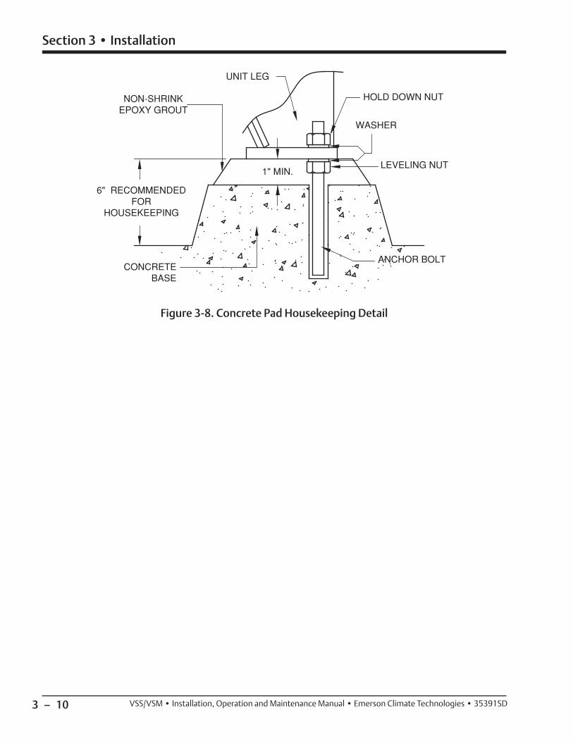
3 – 10
Section 3 • Installation
VSS/VSM • Installation, Operation and Maintenance Manual • Emerson Climate Technologies • 35391SD
Figure 3-8. Concrete Pad Housekeeping Detail

3 – 11
Section 3 • Installation
VSS/VSM • Installation, Operation and Maintenance Manual • Emerson Climate Technologies • 35391SD
Stop/Check Valve Installation
The new design will apply only to the 2” thru 4” stop valves. Retrofi tting a fi eld installation will require replac-ing the bonnet assembly.
The bonnet must be installed with the spring towards the bottom, see Figure. The drill fi xture is designed so
Correct
Wrong Wrong
Correct
Verify the location of the Spring and note the Vilter name.
that the hole for the spring will always be drilled on the opposite side from the cast-in Vilter name on the bon-net. From the outside of the valve, the casting numbers must always be towards the top of the valve.
For Stop/Check Valve Operation, refer to Section 4.
Figure 3-9. Stop/Check Valve Orientation

3 – 12
Section 3 • Installation
VSS/VSM • Installation, Operation and Maintenance Manual • Emerson Climate Technologies • 35391SD
Figure 3-10. Maximum Allowable Flange Loads
DISCHARGE LINE
5 PIPEDIAMETERS
CUSTOMERSUPPORT
3-4 PIPEDIAMETERS
SUCTIONLINE
X
Z
Z
Y
X
Y
CUSTOMERSUPPORT
HANGER
CHECKVALVE
CUSTOMER SUPPORTSWHEN CHECK VALVE IS MOUNTED HERE
5 PIPEDIAMETERS
5 PIPEDIAMETERS
Nozzle Dia. (in.) Fz (lbf) Fy (lbf) Fx (ft-lbf) Mzz (ft-lbf) Myy (ft-lbf) Mxx (ft-lbf)
4 400 400 400 300 300 300
6 600 600 600 500 500 500
8 900 900 900 1000 1000 1000
10 1200 1200 1200 1200 1200 1200
12 1500 1500 1500 1500 1500 1500
14 2000 2000 2000 2000 2000 2000
Table 3-1. Maximum Allowable Flange Loads
Piping
The ideal load applied to fl anges of the compressor unit is zero. However, it’s not practical to expect that no loads will be applied to unit connections. Thermal, dead, live, wind & seismic loads must be considered and even toler-ated. Well supported external piping connected to the compressor will still result in some loads applying forces and moments in three axes to unit fl anges.
The most important issue is the motor-compressor mis-alignment caused by external forces (F in lbf) and mo-ments (M in ft-lbf) imposed by plant piping. In Figure 3-10 and Table 3-1, are the maximum allowable forces and moments that can be applied to compressor fl anges when the compressor is mounted on an oil separator.
It must be noted that it is necessary to check for com-pressor shaft movement when the job is complete. In no case shall the attached piping be allowed to cause more than 0.002” movement at the compressor shaft. If more than 0.002” movement is detected the piping must be adjusted to reduce the compressor shaft move-ment to less than 0.002”. For example, the compressor shaft should not move more than 0.002” when piping is removed or connected to the compressor.
IMPORTANT – piping elements shall be supported per the requirements of ASME B31.5 / B31.3 as applicable. See guidelines below, particularly with concern to mini-mizing loads on check valves.

3 – 13
Section 3 • Installation
VSS/VSM • Installation, Operation and Maintenance Manual • Emerson Climate Technologies • 35391SD
Field Wiring Instructions
NOTEThis procedure defi nes steps required to wire Vission 20/20 micro-controller for the following items: Compressor Motor Starter Auxiliary Contact, High Level Shutdown, Oil Separator Heater(s), Oil Pump
Start and Compressor Starter.
Follow supplied wiring diagram for detailed wiring.
Reference Figure 3-11
1. Control power of 115 VAC 50/60 HZ must be wired to left side of terminal blocks inside the Vission 20/20 cabinet. Line power (1B) shall be connected to 15-amp circuit breaker, CB1. Neutral (1N) is con-nected to any N terminal blocks. Number of line power feeds required to panel is dependent upon number supplied on compressor, see Figure 3-10.
2. An auxiliary contact from compressor motor starter is required. Connect isolated contact to terminal blocks 1 and 31.
Electrical Connections
Single screw compressor units are shipped with all pack-age mounted controls wired. The standard control pow-er is 115 volts 60 Hertz, single phase. If a 115 volt supply is not available, a control transformer may be required. The power source must be connected to the control panel according to the electrical diagrams.
The units are shipped without the compressor mo-tor starter. Field wiring is required between the fi eld mounted starters and package mounted motors, see Field Wiring Instructions.
Additional control wiring in the fi eld is also required. Dry contacts are provided in the control panel for start-ing the screw compressor motor. These contacts are to be wired in series with the starter coils. A current trans-former is supplied along with the compressor unit, and is located in the motor junction box. This transformer is to be installed around one phase of the compressor mo-tor starter. A normally open auxiliary contact from the compressor motor starter is also required.
Terminal locations for this wiring can be found on the wiring diagram supplied with this unit. Additional as-pects of the electrical operation of the single screw units are covered in the start up and operation section of this manual.
3. A dry contact from control relay CR11 must be wired to compressor motor starter coil. This dry contact is wired to terminal blocks according to supplied draw-ing. Control power for this coil should come from a source, which will be de-energized with compressor disconnect.
4. A dry contact from control relay CR12 must be wired to oil pump motor starter coil. This dry contact is wired to two terminal blocks according to supplied drawing. Control power for this coil should come from a source, which will be de-energized with com-pressor disconnect.
5. An auxiliary safety cutout is available to shut down compressor package. A dry contact must be sup-plied and wired to terminal blocks 1 and 32. The jumper installed on terminal blocks must be re-moved to use this cutout. If contact is closed, it will allow compressor to run. If contact opens at any time, compressor will shut down.
6. Indication of compressor shutdown status is also available. There is an output on terminal blocks 18 and N where a relay coil can be wired. For output, an energized state represents a “safe” condition. A de-energized state indicates a loss of voltage to relay coil or a “failure” has occurred.
7. Line power for oil separator heaters are required to be wired from the starter panel, see Figure 3-11.
8. Units with V-PLUSTM oil cooling, L1 must connected to a fuse in V-PLUS panel, and L2 must be connected to a neutral terminal block, see Figure 3-12.
NOTE There is a dot on one side of the current transformer.
This dot must face away from the motor.
9. Current transformer supplied in compressor motor conduit box should be checked to ensure that mo-tor leads of one leg are pulled through the trans-former. Typically, a wye delta started motor should have leads 1 and 6 pulled through this transformer for a 6 lead motor. However, this should always be checked as different motors and starting methods will require different leads to be used.

3 – 14 VSS/VSM • Installation, Operation and Maintenance Manual • Emerson Climate Technologies • 35391SD
Figu
re 3
-11.
Exa
mpl
e - V
issi
on 2
0/20
Wir
ing
Dia
gram
1918171614 15139 1211108764 5321
504948474644 454342414032 33 3534 36 37 38 397069686765 666463 71 72 73 74 7675 77 78 79 80 81
GN
D
*SE
E N
OTE
10
TRIP
A
NN
UN
CIA
TIO
N(O
UTP
UT
DE
-EN
ER
GIZ
ES
ON
A
TRIP
CO
ND
ITIO
N)
OIL
SE
PAR
ATO
R
HE
ATE
R S
TAR
T
A1
A2
*SE
E N
OTE
10
BLA
CK
BLU
E
BR
OW
N
VO
LUM
E
INC
RE
AS
E/D
EC
RE
AS
E
AC
TUAT
OR
CA
PAC
ITY
INC
RE
AS
E/D
EC
RE
AS
E
AC
TUAT
OR
OIL
PU
MP
STA
RTE
R
CO
MP
RE
SS
OR
S
TAR
TER
N
DC
PO
WE
R
SU
PP
LIE
S
1A
BR
OW
N
BLU
E
BLA
CK
CA
PAC
ITY
CO
NTR
OL
SE
LEC
T 1/
2
RE
MO
TE S
TAR
T/S
TOP
RE
MO
TE C
APA
CIT
Y IN
CR
EA
SE
RE
MO
TE C
APA
PC
ITY
DE
CR
EA
SE
OIL
LE
VE
L FL
OAT
SW
ITC
H#2
/ O
IL F
ILL
LEV
EL
(CO
OL
CO
MP
RE
SS
ION
)
OIL
LE
VE
L FL
OAT
SW
ITC
H#1
/ L
OW
LE
VE
L TR
IP (C
OO
L C
OM
PR
ES
SIO
N)
HIG
H L
EV
EL
SH
UTD
OW
N
CO
MP
RE
SS
OR
MO
TOR
S
TAR
TER
AU
XIL
IAR
Y C
ON
TAC
T
FRO
M L
INE
31
FRO
M L
INE
31
TO D
C T
ER
MIN
AL
SU
BP
LATE
TO S
TAR
TER
TO S
TAR
TER
TO S
TAR
TER
TO C
US
TOM
ER
C
ON
TRO
L IF
RE
QU
IRE
D
CO
NTR
OL
PO
WE
RD
ISC
ON
NE
CT
AN
D B
RA
NC
H C
IRC
UIT
P
RO
TEC
TIO
N T
O B
E S
IZE
D P
ER
TH
E N
ATIO
NA
L E
LEC
TRIC
CO
DE
.IN
CO
MIN
G P
OW
ER
SU
PP
LIE
D F
RO
M R
EM
OTE
C
US
TOM
ER
SU
PP
LIE
D U
L LI
STE
D F
US
ED
D
ISC
ON
NE
CT
OR
BR
EA
KE
R
FLA
= X
.X A
MP
S11
5VA
C /
60H
Z
HL
SH
UTD
OW
N A
UX
11
INPUT
OUTPUT
RS
-50
-24
RD
-35
-A
GN
D1
1B
OU
TPU
TS
GN
D
HP
1
5/12
CO
M+1
2VD
C+5
VD
C
OUTPUT
21C
INPUT
DIGITAL OUTPUT: BOARD #1 PLUG X2
DIGITAL OUTPUT: BOARD #1 PLUG X1
181715 1614131211
OU
TPU
TS
TO C
PU
BA
SE
BO
AR
D
EM
I FIL
TER
LOA
DLI
NE
E-S
TOP
SW
1
CB
115
AM
PS
DO
OR
GN
D L
UG
11111111
INP
UTS
INP
UTS
RE
M. C
AP.
DE
CR
EA
SE
RE
M. C
AP.
INC
RE
AS
E
DIGITAL INPUT: BOARD #3 PLUG X2
DIGITAL INPUT: BOARD #3 PLUG X1
35 36 37 38
CA
P. C
TRL
SE
LEC
T
RE
MO
TE S
TAR
T/S
TOP
LOW
OIL
LE
VE
LLS
2
LOW
OIL
LE
VE
LLS
1
AU
X M
S1
34333231
+24V
DC
-24
CO
M-2
4 C
OM
+24V
DC
N4321 N 5 6 7 8
1 2 3 4 H 8765H
NNNNNNNN
N N N N N N
INTE
RN
AL
PAN
EL
WIR
ING
(FA
CTO
RY
)V
ILTE
R S
HO
P W
IRIN
GFI
ELD
WIR
ING
(BY
OTH
ER
S)
PAN
EL
HE
ATE
RO
PTI
ON
1HH
EAT
ER
150
WAT
TO
N 4
0 / O
FF 6
0
THE
RM
OS
TAT
OU
TPU
TS
DIGITAL INPUT/OUTPUT: BOARD #4 PLUG 1
1
CD
R
4C
ON
DE
NS
ER
S
TEP
#4
CD
R 1
CO
ND
EN
SE
R
STE
P #1
CD
R
2C
ON
DE
NS
ER
S
TEP
#24241
CO
ND
EN
SE
R
STE
P #3
CD
R
343 44
1 2 3 4 H
12
3&4
5
6
STEP

3 – 15
Section 3 • Installation
VSS/VSM • Installation, Operation and Maintenance Manual • Emerson Climate Technologies • 35391SD
JUNCTION BOX (COMPRESSOR SKID)
OIL PUMP MOTOR
OIL PUMP MOTOR480 VAC
OIL SEPARATOR HEATER120 VAC1000 WATT = 8.7 AMPS 750 WATT = 6.5 AMPS
OIL SEPARATOR HEATER120 VAC1000 WATT = 8.7 AMPS 750 WATT = 6.5 AMPS
OIL SEPARATOR HEATER120 VAC1000 WATT = 8.7 AMPS 750 WATT = 6.5 AMPS
OIL PUMP MOTOR FEED480 VAC
OIL SEPARATOR HEATER FEED120VAC
OIL SEPARATOR HEATER FEED120VAC
OIL SEPARATOR HEATER FEED120VAC
EQUIPMENT GROUND
1T1
1T2
1T3
NOIL
SEPARATOR HEATER
52
GND
NOIL
SEPARATOR HEATER
54
NOIL
SEPARATOR HEATER
56
GNDGND
T1
T2
T3
52
N
54
N
56
N
INTERNAL PANEL WIRING (FACTORY)VILTER SHOP WIRINGFIELD WIRING (BY OTHERS)
Figure 3-12. Example - Interconnect Wiring Diagram
Figure 3-13. Example - V-PLUS Wiring Diagram
7
8
3 – 16
Section 3 • Installation
VSS/VSM • Installation, Operation and Maintenance Manual • Emerson Climate Technologies • 35391SD
Testing Refrigeration System for Leaks
CAUTIONDo not hydro test compressor unit. Failure to comply
may result in damage to equipment.
CAUTIONThe compressor unit along with other system unitscontain many components with various pressureratings. Pressure relief protection provided considersthe design pressure of a system components.Before replacing a pressure relief valve with a reliefvalve having a higher pressure setting, all system
components must be evaluated for acceptability.
Vilter equipment is tested for leaks at the factory. One the most important steps in putting a refrigeration sys-tem into operation is fi eld testing for leaks. This must be done to assure a tight system that will operate without any appreciable loss of refrigerant. To test for leaks, the system pressure must be built up. Test pressures for vari-ous refrigerants are listed in ANSI B9.1-1971 code bro-chure entitle “Safety Code for Mechanical Refrigeration”. These pressures will usually suffi ce, however, it is advis-able to check local codes as they may differ. Before test-ing may proceed, several things must be done.
First, if test pressures exceed the settings of the system, relief valves or safety devices, they must be removed and the connection plugged during the test. Secondly, all valves should be opened except those leading to the atmosphere. Then, open all solenoids and pressure reg-ulators by the manual lifting stems. All bypass arrange-ments must also be opened. Because of differences in characteristics of the various refrigerants, two different testing methods are necessary.
AMMONIA SYSTEMS
Dry nitrogen may be used to raise the pressure in an am-monia system to the proper level for the test. The gas may be put into the system through the charging valve or any other suitable opening. Adjust the pressure regu-lator on the bottle to prevent over-pressurization. Do not exceed the pressure rating on the vessel with the lowest pressure rating.
Carbon Dioxide should NOT be used as a testing gas in a system where ammonia is already dissolved in any mois-ture remaining. This will cause ammonium carbonate to precipitate when the CO2 is added. If heavy enough, this precipitate may cause the machine to freeze and clog the strainer.
A mixture of four parts water to one part liquid soap, with a few drops of glycerin added, makes a good solu-tion. Apply this mixture with a one inch round brush at all fl anges, threaded joints, and welds. Repair all visible leaks. If possible, leave the pressure on over night. A small pressure drop of 5 lbs. Over this period indicates a very tight system.
Remember to note the ambient temperature, as a change in temperature will cause a change in pressure.
After the system is thoroughly tested, open all valves on the lowest part of the system so the gas will fl oat away from the compressor. This prevents any dirt or foreign particles from entering the compressor and contaminat-ing the working parts. The oil should then be charged into the compressor.
Charge a small amount of ammonia into the system and pressurize the system to its respective design pressure. Pass a lit sulfur stick around all joints and connections. Any leaks will be indicated by a heavy cloud of smoke. If any leaks are observed during this test, they must be repaired and rechecked before the system can be con-sidered tight and ready for evacuation.
HALOCARBON REFRIGERANT SYSTEMS
“Oil pumped” dry nitrogen, or anhydrous CO2 in this or-der of preference may be used to raise the pressure to the proper level for testing.
When the proper pressure is attained, test for leaks with the soap mixture previously described. After all leaks are found and marked, relieve the system pressure and re-pair the leaks. Never attempt to repair soldered or weld-ed joints while the system is under pressure. Soldered joints should be opened and re soldered.
Do not simply add more solder to the leaking joint. After all the joints have been repaired and the system is consid-ered “tight” the system may be tested with refrigerant.
Attach a drum of the refrigerant to be used in the sys-tem and allow the gas to enter until a pressure of 5 psig is reached.
Remove the refrigerant drum and bring the pressure to the recommended test level with oil pumped dry ni-trogen or CO2. Then check the entire system again for leaks, using a halide torch or electronic leak detector. Be sure to check all fl anged, welded, screwed and sol-dered joints, all gasketed joints, and all parting lines on castings. If any leaks are found, they must be repaired and rechecked before the system can be considered tight again, remembering that no repair should be made to welded or soldered joins while the system is under pressure.

3 – 17
Section 3 • Installation
VSS/VSM • Installation, Operation and Maintenance Manual • Emerson Climate Technologies • 35391SD
Evacuating The System
A refrigeration system operates best when only refrig-erant is present. Steps must be taken to remove all air, water, vapor, and all other non-condensables from the system before charging it with refrigerant. A combina-tion of moisture and refrigerant, along with any oxygen in the system, can form acids or other corrosive com-pounds that corrode internal parts of the system.
To properly evacuate the system, and to remove all non-condensables, air and water vapor, use a high vacuum pump capable of attaining a blanked off pressure of 50 microns or less. Attach this pump to the system and al-low it to operate until system pressure is reduced some-where below 1000 microns. Evacuation should not be done unless the room temperature is 60F or higher.
Attach vacuum gauge(s), reading in the 20 to 20,000 micron gauge range, to the refrigerant system. These gauge(s) should be used in conjunction with the high vacuum pump. The reading from the gauge(s) indicates when the system has reached the low absolute pressure required for complete system evacuation.
Connect the high vacuum pump into the refrigera-tion system by using the manufacturer’s instructions. Connect the pump both to the high side and low side of the system, to insure system evacuation. Attach the vacuum gauge to the system in accordance with the manufacturer’s instructions.
A single evacuation of the system does not satisfac-torily remove all of the non-condensable, air and wa-ter vapor. To do a complete job, a triple evacuation is recommended.
When the pump is fi rst turned on, bring system pressure to as low a vacuum level as possible, and continue opera-tion for 5 to 6 hours.
Stop the pump and isolate the system. Allow the unit to stand at this vacuum for another 5 to 6 hours. After this time, break, the vacuum and bring the system pressure up to 0 psig with dry nitrogen.
To begin the second evacuation, allow the pump to op-erate and reduce the pressure again to within 50 to 1000 microns. After this reading is reached, allow the pump to operate 2 or 3 hours. Stop the pump and let the sys-tem stand with this vacuum. Again using dry nitrogen, raise the system pressure to zero.
For the third evacuation, follow the previous procedure with the pump operating until system pressure is re-duced below the 1000 micron level. Run the pump an additional 6 hours and hold the system for approximate-ly 12 hours at low pressure. After this, again break the vacuum with dry nitrogen and allow the pressure in the system to rise slightly above zero pounds (psig). Install
new drier cartridges and moisture indicators. Charge the system once more below the 1000 micron level and use the refrigerant designed for the system.
When properly evacuating the system as outlined above, the system is dry, oxygen-free and free of non-condensables. The piping should not be insulated be-fore the evacuation process is started. If moisture is in the system before evacuating, it condenses in low places and freezes. If this happens, it can be removed by gently heating the trap farthest away from the vacuum pump. This causes the ice to melt and water to boil. Water va-por collects in the next trap towards the vacuum pump. This process should be repeated until all pockets of wa-ter have been boiled off, and the vacuum pump has had a chance to remove all the water vapor from the system.
3 – 18
Section 3 • Installation
VSS/VSM • Installation, Operation and Maintenance Manual • Emerson Climate Technologies • 35391SD
Using Non -Vilter Oils
CAUTIONDo not mix oils. Failure to comply may result in
damage to equipment.
NOTICEVilter does not approve non-Vilter oils for use withVilter compressors. Use of oils not specifi ed orsupplied by Vilter will void the compressor warranty.
Due to the need for adequate lubrication, Vilter recom-mends only the use of Vilter lubricants, designed spe-cifi cally for Vilter compressors. Use of oil not specifi ed or supplied by Vilter will void the compressor warranty.
Please contact your local Vilter representative or the Home Offi ce for further information.
Unit Initial Oil Charging and Priming
WARNINGAvoid skin contact with oil. Wear rubber gloves and aface shield when working with oil. Failure to comply
may result in serious injury or death.
NOTICEFailure to follow these instructions will result inbearing damage and compressor seizing and will void
any and all warranties that may apply.
Typically, the compressor unit is shipped from Vilter with no oil charge. The normal operating level is between the two sight glasses on the oil separator, see Figure 3-14. Refer to supplied GA drawing for unit specifi c oil charge requirement.
For regular oil charging and draining procedures, see Section 5.
Tool Required:• Oil Pump, Maximum 2-3 GPM with Motor approved
for Division 1 or Division 2 and with ability to over-come suction pressure.
UNIT INITIAL OIL CHARGING
(Reference Figure 3-16)1. At initial start up, compressor unit must be off and
depressurized prior to initial oil charging.
2. Using a properly selected oil pump, connect oil pump to oil separator drain valve (10). For oil sepa-rator drain valve location, see Figure 3-15.
3. Open oil separator drain valve (10) and fi ll oil separa-tor (1) to Maximum NON-Operating Level.
4. Once Maximum NON-Operating Level has been reached, shut off oil pump, close oil separator drain valve (10) and remove oil pump.
5. If equipped with remote oil cooler, refer to Priming Compressor Units Equipped with Remote Oil Cooler procedure.
PRIMING OIL LINES AND COMPRESSOR
Continue with the following steps to prime the oil lines and compressor:
6. Make sure valves on oil circuit are in the open posi-tion. In this case, make sure valves (2), (3), (5), (6) and (7) are in the open position.
7. Energize compressor unit.8. Run oil pump (4) for 15 seconds only.9. Wait minimum of 30 minutes to allow oil to drain
from compressor (8).10. If compressor unit is not being started right away,
repeat steps 6 to 9 prior to starting.

3 – 19
Section 3 • Installation
VSS/VSM • Installation, Operation and Maintenance Manual • Emerson Climate Technologies • 35391SD
Figure 3-14. Oil Operating Levels
Normal Operating Level
Maximum NON-Operating Level
Minimum Operating Level
Figure 3-15. Oil Drain Valve
Oil Drain Valve (Oil Separator)

3 – 20
Section 3 • Installation
VSS/VSM • Installation, Operation and Maintenance Manual • Emerson Climate Technologies • 35391SD
Figure 3-16. Priming Oil Lines and Compressor
LG001 LG
002
FG001
PI003
DRAIN
TW
BLEED
MW
BLEED
TW
D100
OIL CHARGE
BLEED
CAPACITY
TW750W
TW
250#
C100
V100
VOLUME
SUCTION
DISCHARGE STOP VALVE
STOP/CHECK
D101
P100
VALVE
TW750W
TW750W
DRAIN
DISCHARGE CHECK VALVE
PI002
PI001
TE001
TE004
QE003
TE005
PI004BLEED
PT004
PT003
PT002
D102
D103
TWTE002
QE001
QE002
OIL SEPARATOR
COAL
ESCIN
G OI
L RET
URN L
INE
HIGH PRESSURER717 VAPOR OUTLET
R717 VAPORTO ATMOSPHERE
LOW PRESSURER717 VAPOR INLET
PT001
COMPRESSOR
MOTOR
FILTE
R
MOTOR ANDOIL PUMP
T E100
R717 LIQUIDINLET
R717 LIQUID/VAPOROUTLET
100PSID
9
1
2
6
53
7
4
8
10

3 – 21
Section 3 • Installation
VSS/VSM • Installation, Operation and Maintenance Manual • Emerson Climate Technologies • 35391SD
System Refrigerant Charging
After the system is leak-free and evacuation has been completed, the entire operation of the refrigeration sys-tem should be inspected before charging.
A. LOW SIDE EQUIPMENT
1. Fans on air handling equipment running.2. Pumps on water cooling equipment running.3. Proper location and attachment of thermostatic ex-
pansion valve bulb to suction line.4. Correct fan and pump rotation.5. Evaporator pressure regulators and solenoid valves
open.6. Water pumps and motors correctly aligned.7. Belt drives correctly aligned and tensioned.8. Proper voltage to motors.
B. COMPRESSORS
1. Proper oil level.2. Voltage agrees with motor characteristics.3. Properly sized motor fuses and heaters.4. Direct drivers aligned and couplings tight.5. All suction and discharge valves open.6. All transducers and RTDs calibrated and reading
correctly.
C. CONDENSERS
1. Water available at water cooled condensers and sup-ply line valve open.
2. Water in receiver of evaporative condenser and makeup water available.
3. Correct rotation of pump and fan motors.4. Belt drives aligned and tensioned correctly.5. Pump, fans and motors lubricated.
D. CONTROLS
Controls should be at the initial set points. See micro-processor manual for further information.
INITIAL HIGH SIDE CHARGING
WARNINGWhen working with refrigerants, ensure there isadequate ventilation and refrigerant vapor detectorsas per ASHRAE standards. Failure to comply may
result in serious injury or death.
WARNINGAvoid skin contact with any liquid refridgerant or oil.Wear rubber gloves and a face shield when workingwith liquid refrigerant or oil. Failure to comply may
result in serious injury or death.
CAUTIONEnsure compressor unit has been charged with the correct amount of oil prior to initial refrigerantcharging. Failure to comply may result in damage to
equipment.
CAUTIONDo not apply fl ame or steam directly to drum, as thiscan produce dangerously high pressures inside drum.Failure to comply may result in damage to equipment.
There are two methods of charging refrigerant into the system, through the “high side” or through the “low side”. High side charging is usually used for initial charg-ing as fi lling of the system is much faster. Low side charg-ing is usually reserved for adding only small amounts of refrigerant after the system is in operation.
High side charging of refrigerant into the system is ac-complished as follows:
1. Connect a full drum of refrigerant to the liquid charging valve. This valve is generally located in the liquid line immediately after the king or liquid line valve. Purge the air from the charging line.
2. Invert the refrigerant drum if the drum is not equipped with “Liquid” and “Vapor” valves, and place in such a position so the liquid refrigerant only can enter the system. Close the liquid line or king valve, if it is not already closed. Open the “Liquid” charging valve slowly to allow refrigerant to enter the system. The vacuum in the system will draw in the refrigerant.
3. It is important that during this operation air handling units be running and water is circulating through the chillers. The low pressures on the system can cause the refrigerant to boil at low temperature and possibly freeze the water if it is not kept circulating. Water freezing in a chiller can rupture the tubes and cause extensive damage to the system. It would be desirable to charge the initial amount of refrigerant

3 – 22
Section 3 • Installation
VSS/VSM • Installation, Operation and Maintenance Manual • Emerson Climate Technologies • 35391SD
without water in the shell and tube equipment to eliminate the possibility of freeze up.
4. After some refrigerant has entered the system, the compressor unit starting procedure may be fol-lowed, see Starting procedure in Section 4.
5. Continue charging refrigerant into the system un-til the proper operating requirements are satisfi ed. Then, close the liquid charging connection and open the liquid line valve allowing the system to operate normally. To check that enough refrigerant has been added, the liquid sight glass should show no bubbles, and there will be a liquid seal in the re-ceiver. If these two conditions are not satisfi ed, ad-ditional refrigerant must be added.
6. When suffi cient refrigerant has been charged into the system, close the charging and drum valves. Then remove the drum from the system.
7. During the charging period, observe the gauge carefully to insure no operating diffi culties. Watch head pressures closely to make sure the condensers are functioning properly.
8. Since it is usually necessary to use several drums when charging a system, follow the procedures in steps 1 and 2 when attaching a new drum. After charging, the refrigerant drums should be kept nearby for several days as it is sometimes necessary to add more refrigerant as the system settles down.

4 – 1
Section 4 • Operation
VSS/VSM • Installation, Operation and Maintenance Manual • Emerson Climate Technologies • 35391SD
Operation
All operation (setpoint adjustments, calibrations, monitoring) of the compressor unit is done through the Vission 20/20. For additional procedural information, refer to Vission 20/20 Manual (35391SC).
Oil Inspection
WARNINGAvoid skin contact with any liquid refridgerant or oil.Wear rubber gloves and a face shield when workingwith liquid refrigerant or oil. Failure to comply may
result in serious injury or death.
WARNINGAvoid skin contact with oil. Wear rubber gloves and aface shield when working with oil. Failure to comply
may result in serious injury or death.
Inspect oil level through sight glasses on the oil separa-tor, see Figure 4-1. Oil Operating Levels. Drain or fi ll oil as required. For oil draining and fi lling procedure, see Oil Charging and Oil Draining in Section 5.
Figure 4-1. Oil Operating Levels
Normal Operating Level
Maximum NON-Operating Level
Minimum Operating Level
Dual Oil Filters
On compressor units equipped with dual oil fi lters, only one fi lter should be in operation at a time.
NOTE
During operation, both oil fi lter outlet shut-off valves should be open. This will help minimize the sudden loss
of oil pressure when switching between oil fi lters for servicing.
Refer to Oil Filter Replacement in Section 5 for further details.

4 – 2
Section 4 • Operation
VSS/VSM • Installation, Operation and Maintenance Manual • Emerson Climate Technologies • 35391SD
Starting, Stopping and Restarting the
Compressor
For additional control information, refer to the Vission 20/20 operating manual (35391SC).
STARTING
Before the screw compressor unit can start, certain conditions must be met. All of the safety setpoints must be in a normal condition, and the suction pressure must be above the low suction pressure setpoint to ensure a load is present. When the “ON/OFF” switch or “Manual-Auto” button is pressed, the oil pump will start. When suffi cient oil pressure has built up and the compressor capacity control and volume ratio slide valves are at or below 10%, the compressor unit will start.
NOTE
The amount of oil pressure that needs to be achieved before compressor start is at least 6 psig above the discharge pressure. For additional information on
Low Oil Pressure at Start, see Troubleshooting Guide - General Problems and Solutions in Section 6.
Control System Calibration
Equipped for automatic operation, the screw compres-sor unit has safety controls to protect it from irregular operating conditions, an automatic starting and stop-ping sequence, capacity and volume ratio control systems.
Check all pressure controls with a remote pressure source, to assure that all safety and operating control lim-its operate at the point indicated on the microprocessor.
The unit is equipped with block and bleed valves that are used to recalibrate the pressure transducers. To use the block and bleed valves to recalibrate the pressure transducers, the block valve is shut off at the unit and the pressure is allowed to bleed off by opening the bleed valve near the pressure transducer enclosure. The trans-ducer can then be calibrated at atmospheric pressure (0 psig), or an external pressure source with an accurate gauge may be attached at the bleed valve.
The discharge pressure transducer cannot be isolated from its pressure source, so it is equipped with only a valve to allow an accurate pressure gauge to be attached and the pressure transducer calibrated at unit pressure.
Recheck the transducers periodically for any drift of cali-bration, refer to maintenance/service interval table in Section 5.
If the compressor is in the automatic mode, it will now load and unload and vary the volume ratio in response to the system demands.
STOPPING/RESTARTING
Stopping the compressor unit can be accomplished a number of ways. Any of the safety setpoints will stop the compressor unit if an abnormal operating condition exists. The compressor unit “On-Off” or stop button will turn the compressor unit off as will the low pressure setpoint. If any of these conditions turns the compres-sor unit off, the slide valve motors will immediately energize to drive the slide valves back to 5% limit. The control motors will be de-energized when the respec-tive slide valve moves back below 5%. If there is a power failure, the compressor unit will stop. If the manual start on power failure option is selected, restarting from this condition is accomplished by pushing the reset button to ensure positive operator control. If the auto start on power failure option is selected, the com-pressor unit will start up after a waiting period. With both options, the compressor slide valves must return below their respective 5% limits before the compressor unit can be restarted.
NOTE
Wait a minimum of 20 minutes (to allow the compressor unit to equalize to suction pressure) between pre-lubing or pushing the start button.
Emergency Shutdown
Emergency shutdown is initiated by the following:
1. A shutdown or trip condition of a process variable while the system is in operation. If a process vari-able reaches a high-high or low-low shutdown set-point, the compressor unit will automatically stop. A shutdown alarm is also generated on the control panel HMI screen annunciating the specifi c process variable trip condition.
2. The Emergency Local Stop pushbutton located on the side of the control panel enclosure. When the Emergency Local Stop pushbutton is activated, the entire unit powers down. Also, the compressor ca-pacity and volume slide valve will stay in their last position until the unit is powered up. Once recov-ery has been accomplished and the unit is to be re-powered, the Emergency Local Stop pushbut-ton must be pulled out to power up the unit and controls.

4 – 3
Section 4 • Operation
VSS/VSM • Installation, Operation and Maintenance Manual • Emerson Climate Technologies • 35391SD
• An actuator does not unload below 5%, or an actua-tor that doesn’t move.
• Something is not working properly such as the actua-tors, RTDs or transducers.
To calibrate optical actuators, continue with the follow-ing steps:
NOTE
If the compressor unit is starting up for the fi rst time or a new actuator motor has been installed,
leave the power cable and position transmitter cable disconnected until step 6.
1. Stop compressor unit and allow to cool.
2. Remove screws securing actuator cover to actuator assembly. As a reference see Figure 4-2.
CAUTIONWires are attached to the connector on the actuatorcover. Handle actuator cover with care to preventdamage to wires. Failure to comply may result in
damage to equipment.
3. Carefully lift actuator cover from actuator assem-bly and tilt towards connectors. Raise cover high enough to be able to press the blue calibration but-ton and be able to see the red LED on the top of assembly.
Figure 4-2. Actuator Assembly
BlueCalibrate
Button
Red LED
Actuator Plastic Cover
Actuator Assembly
View Rotated 180°
Calibrate Slide Valve Actuators
Slide valve actuators must be installed prior to calibra-tion. Refer to Slide Valve Actuator Installation proce-dure. The following steps pertain to calibrating one slide valve actuator. Repeat procedure to calibrate other slide valve actuator.
WARNINGAfter stopping the compressor, allow the compressorand surrounding components to cool down prior to servicing. Failure to comply may result in serious
injury.
CAUTIONDo not calibrate in direct sunlight. Failure to comply
may result in damage to equipment.
Both the capacity and volume slide actuators should be calibrated when one or more of these have occurred:• Compressor unit starting up for the fi rst time.
• A new actuator motor has been installed.
• There is an error code fl ashing on the actuator’s circuit board - an attempt to recalibrate should be made.
• The range of travel is not correct and the command shaft travel is physically correct.
• The compressor is pulling high amperage, the cali-bration of the volume slide should be checked.
xeng.vang
Sticky Note
Marked set by xeng.vang
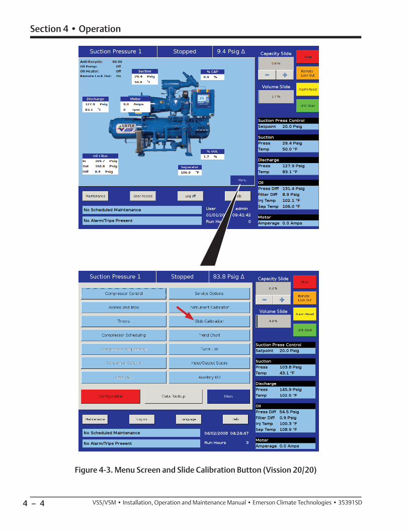
4 – 4
Section 4 • Operation
VSS/VSM • Installation, Operation and Maintenance Manual • Emerson Climate Technologies • 35391SD
Figure 4-3. Menu Screen and Slide Calibration Button (Vission 20/20)

4 – 5
Section 4 • Operation
VSS/VSM • Installation, Operation and Maintenance Manual • Emerson Climate Technologies • 35391SD
4. Logging on with high-level access will prompt the Calibration buttons to appear, see Figure 4-4.
5. On the main screen, press “Menu” then press the “Slide Calibration” button to enter the slide calibra-tion screen, see Figure 4-3.
6. If the compressor unit is starting for the fi rst time or a new actuator was installed, connect connec-tors of power cable and position transmitter cable to new actuator.
NOTE
If the “+” (increase) and “-” (decrease) buttons do not correspond to increase or decrease shaft rotation,
swap the blue and brown wires of the “power cable” in the control panel. This will reverse the rotation of the
actuator/command shaft, see Figure 4-6.
Capacity actuator wires are connected on terminals 13 & 14. Volume actuator wires are connected on
terminals 15 & 16.
7. Press “+” or “-” to move the slide valve and check for the correct rotation, see Table 4-1.
NOTE
When the actuator is in calibration mode, it outputs 0V when the actuator is running and 5V when it is
still. Thus, as stated earlier, the actuator voltage will
fl uctuate during calibration. After the actuator has been calibrated, 0V output will correspond to the minimum
position and 5V to the maximum position.
8. Quickly press and release the blue push button on the actuator one time. This places the actuator in calibration mode. The red LED will begin fl ashing rapidly.
Figure 4-4. Slide Valve Calibration Screen (Vission 20/20)
Press down on Photo-chopper to release tension from mo-tor mount.
Figure 4-5. Photo-chopper
Calibration Buttons

4 – 6
Section 4 • Operation
VSS/VSM • Installation, Operation and Maintenance Manual • Emerson Climate Technologies • 35391SD
Compressor Model
Command Shaft Rotation No. of Turns/Rotation Angle/Slide Travel
Capacity Volume Capacity Volume
INC DEC INC DEC Turns Degrees Travel Turns Degrees Travel
VSM 71
VSM 91
VSM 101
VSM 151
VSM 181
VSM 201
VSM 301
VSM 361
VSM 401
CW CCW CW CCW 0.80 288 3.141” 0.45 162 1.767”
VSM 501
VSM 601
VSM 701
CCW CW CCW CW 0.91 328 3.568” 0.52 187 2.045”
VSS 451
VSS 601CW CCW CW CCW 0.91 328 3.568” 0.52 187 2.045”
VSS 751
VSS 901CCW CW CCW CW 1.09 392 4.283” 0.63 227 2.473”
VSS 1051
VSS 1201
VSS 1301
CCW CW CCW CW 1.22 439 4.777” 0.74 266 2.889”
VSS 1501 CCW CW CCW CW 1.36 490 5.325” 0.82 295 3.200”
VSS 1551 CCW CW CCW CW 1.48 533 5.823” 0.87 313 3.433”
VSS 1801 CCW CW CCW CW 1.36 490 5.325” 0.82 295 3.200”
VSS 1851
VSS 2101CCW CW CCW CW 1.48 533 5.823” 0.87 313 3.433”
VSS 2401
VSS 2601
VSS 2801
VSS 3001
CCW CW CCW CW 1.80 648 7.072” 1.36 490 5.341”
Table 4-1. Command Shaft Rotation Specifi cations*
*The large gear on the command shaft has 50 teeth. The teeth are counted when moving the command shaft from the minimum stop position to the maximum stop position.
The manual operating shaft on the gear motor should be turned the opposite direction of the desired command shaft rotation.
The capacity and volume control motors are equipped with a brake, if it is necessary to operate the control motors manu-ally, the brake must be disengaged. The brake can be disengaged by pushing on the motor shaft on the cone end. The shaft should be centered in its travel. Do not use excessive force manually operating the motor or damage may result.

4 – 7
Section 4 • Operation
VSS/VSM • Installation, Operation and Maintenance Manual • Emerson Climate Technologies • 35391SD
CAUTIONDO NOT CONTINUE TO ENERGIZE THE ACTUATORMOTOR AFTER THE SLIDE HAS REACHED THEMECHANICAL STOP. Doing so may cause mechanicaldamage to the motor or shear the motor shaft key.When the slide has reached the mechanical stopposition, press the button in the center of the photo-chopper to release the brake, and thereby release the
tension on the actuator motor.
NOTE
The “Slide Calibration” screen on the Control Panel has a “Current” window, which displays twice the actuator
output voltage. This value, (the % volume and the % capacity) displayed in the “Current Vol” and Current Cap” Windows are meaningless until calibration has
been completed.
9. Use the “-” button on the Control panel to drive the slide valve to its minimum “mechanical stop” po-sition. Release the “-” button when the slowing of the motor rotation and a winding sound from the actuator motor is noted.
10. Press and hold down on the photo-chopper shaft to disengage the brake slowly, releasing tension from the motor mount, see Figure 4-5. Use the “+” but-ton to pulse the actuator to where the slide is just off of the mechanical stop and there is no tension on the motor shaft.
11. Quickly press and release the blue button on the ac-tuator again. The red LED will now fl ash at a slower rate, indication that the minimum slide valve posi-tion (zero position) has been set.
12. Use the “+” button on the Control panel to drive the slide to its maximum “mechanical stop” posi-tion. Release the “+” button when the slowing of the motor rotation and a winding sound from the actuator motor is noted.
NOTE
If the photo-chopper spins faster than 4800 rpm, the actuator will go into an overspeed fault and
recalibration will be required.
13. Press and hold down on the photo-chopper shaft to disengage the brake slowly, releasing tension from the motor mount. Use the “-” button to pulse the actuator to where the slide is just off of its mechani-cal stop and there is no tension on the motor shaft.
NOTE
After the blue button is pressed for the third time, a mV reading will be displayed in the Current fi eld. Make sure the mV value is at least 150 to 200 mV higher than the
max setpoint on the screen.
14. Quickly press and release the blue button on the actuator one more time. The red LED will stop fl ashing. The actuator is now calibrated and knows the minimum and maximum positions of the slide valve it controls.
Now the Capacity Channel is automatically calibrated based on the calibration settings made to the actuator.
CAUTIONDo not over tigten screws. Failure to comply may
result in damage to equipment.
15. Gently lower the plastic cover over the top of the actuator to where it contacts the base and O-ring seal. After making sure the cover is seated properly, gently tighten the four #10 screws.
16. Repeat procedure to calibrate other slide valve actuator.
Figure 4-6. Wire Connections for Capacity and Volume Actuators
Volume ActuatorWire connections
(15, 16)
Capacity ActuatorWire connections
(13, 14)

4 – 8
Section 4 • Operation
VSS/VSM • Installation, Operation and Maintenance Manual • Emerson Climate Technologies • 35391SD
Figure 4-7. Coalescing Oil Return Line
Coalescing Oil Return Line
Needle Valve
Sight-Glass
Shut-Off Valve
Check Valve
Coalescing Oil Return Line Setup
Over time, oil will accumulate on the coalescing side of the oil separator. As a result, an oil return line with a shut-off valve, sight-glass, check valve and needle valve are installed between the coalescing side and compres-sor to return this oil back to the compressor.
To adjust the return fl ow, proceed with the follow procedure:
NOTE
Do not fully open the needle valve unless directed by Vilter Customer Service. Leaving the needle valve fully
open will reduce effi ciency of the compressor unit.
1. Open shut-off valve on coalescing side of oil separa-tor, see Figure 4-7.
2. While the unit is in operation, crack open needle valve and observe oil fl ow through sight-glass.
3. Slowly open needle valve more until a small amount of oil is seen in the sight-glass.
NOTE
The sight-glass should never be full with oil.
4. Periodically check oil in the sight-glass and ensure that there is fl ow.

4 – 9
Section 4 • Operation
VSS/VSM • Installation, Operation and Maintenance Manual • Emerson Climate Technologies • 35391SD
Suction Equalizing Line Setup
The suction equalizing line allows system pressure to equalize to suction pressure during shutdown periods. The line is connected before the suction stop/check valve to after the suction strainer, see Figure 4-8.
NOTE
Valve adjustment depends on size of oil separator and how quickly system pressure should equalize to suction pressure. The larger the oil separator the longer system
pressure will take to equalize to suction pressure.
1. To open valve, turn counterclockwise. To close valve, turn clockwise.
2. Fully close valve to a stop.
3. Turn valve to fully open position while counting number of turns to fully open. Note total number of turns.
Figure 4-8. Suction Equalizing Line and Valve
Suction Equalizing Line
Suction Equalizing Valve
4. Adjust valve to be half open. Close valve to half of the number of total turns.
5. If suction pressure needs to equalize slower, turn valve towards closed position.
6. If suction pressure needs to equalize faster, turn valve towards open position.

4 – 10
Section 4 • Operation
VSS/VSM • Installation, Operation and Maintenance Manual • Emerson Climate Technologies • 35391SD
Dual Oil Filter Setup for Oil Filters with Filter Head Assemblies
It is very important to correctly setup units equipped with dual oil fi lters, especially for oil fi lters that have fi lter head assemblies. Otherwise, oil pressure readings will show incorrectly.
To setup dual oil fi lters, proceed with the following steps:
NOTE
Inlet Oil Pressure Transducer should only read oil pressure from active oil fi lter.
1. Decide which oil fi lter will be active/in use.
2. Open inlet and outlet oil fi lter shut-off valves to active oil fi lter.
Outlet Oil FilterShut-Off Valves
Inlet Oil Filter Shut-Off Valves
Inlet Oil PressureShut-Off Valves
3. Open inlet oil pressure shut-off valve for active oil fi lter.
4. Close outlet oil fi lter shut-off valve to inactive oil fi lter.
5. Close inlet oil pressure shut-off valve for inactive oil fi lter.
Figure 4-9. Dual Oil Filter Setup for Oil Filters with Manifold Heads

4 – 11
Section 4 • Operation
VSS/VSM • Installation, Operation and Maintenance Manual • Emerson Climate Technologies • 35391SD
CLOSED
In the manually “Closed Position”, the stop check is operat-ing as a conventional stop valve, not allowing fl ow in either direction.
Stop/Check Valve Operation
Valve Size 1.5” 2” 2.5” 3” 4” 5” 6” 8”
Number of Turns Open
(From Closed Position)2 2.25 2.75 3.25 4.5 3.75 5.75 7.75
AUTO
In the “Auto Position”, the stop valve is operating as a check valve, allowing fl ow in the directions of the arrows.
To set the valve to the automatic position, fully close the valve, and turn the stem out as indicated by the chart below.
OPEN
In the manually ” Open Position”, with the valve stem fully back seated, the valve disc is lifted slightly, allowing fl ow in either direction.
Table 4-2. Stop/Check Valve Open Positions

4 – 12 / Blank VSS/VSM • Installation, Operation and Maintenance Manual • Emerson Climate Technologies • 35391SD

5 – 1
Section 5 • M
aintenance/Service
VSS/V
SM •
Installation, Operation and M
aintenance Manual •
Emerson C
limate Technologies •
35391SD
GroupInspection/
Maintenance
Service Interval (Hours)
200
5,00
0
10,0
00
20,0
00
30,0
00
40,0
00
50,0
00
60,0
00
70,0
00
80,0
00
90,0
00
100,
000
110,
000
120,
000
Oil Circuit
Oil Change (1) - R - R - R - R - R - R - R
Oil Analysis (2) - S S S S S S S S S S S S S
Oil Filters (3) R R R R R R R R R R R R R R
Oil Strainers I I I I I I I I I I I I I I
Compressor Unit
Coalescing Filter - - - - R - - R - - R - - R
Coalescing Drain Line I I I I I I I I I I I I I I
Suction Screen I I I I I I I I I I I I I I
Coupling Alignment and Integrity
I I I I I I I I I I I I I I
Motor (Compressor) See Motor Manual for proper lubrication procedures and service intervals.
Control Calibration
Transducers I I I I I I I I I I I I I I
RTDs I I I I I I I I I I I I I I
Slide Valve MotorsSlide valve calibration should be inspected monthly. Inspections can be performed through the control panel. If a Non-Movement Alarm appears, calibrate immediately.
CompressorCompressor (4) - I - I - I - I - I - I - I
Bearings - - - - - - - - - - - - - I
I = Inspect S = Sampling R = Replace(1) The oil should be changed at these intervals, unless oil analysis results exceed the allowable limits. The frequency of changes will depend on the system cleanliness.(2) Oil analysis should be done at these intervals as a minimum; the frequency of analysis will depend on system cleanliness.(3) The oil fi lter(s) on a minimum must be changed at these intervals or annually if not run continuously. However, the oil fi lter(s) must be changed if the oil fi lter dif-ferential exceeds 12 psi or oil analysis requires it.(4) Inspections include: gate rotor inspection, backlash measurement, shelf clearance, end play measurement (main rotor & gate rotor), gate rotor fl oat, slide valve inspection.
Maintenance and Service Schedule
Follow this table for m
aintaining and servicing the compressor unit at hourly intervals.
Table 5-1. Maintenance/Service Schedule
5 – 2
Section 5 • Maintenance/Service
VSS/VSM • Installation, Operation and Maintenance Manual • Emerson Climate Technologies • 35391SD
Preventive Maintenance, Checks and Services
Careful checking of a refrigeration system for leaks and proper operation of all components upon installation will start the system on its way to a long life of satisfac-tory service. To ensure the desired trouble-free opera-tion, however, a systematic maintenance program is a prerequisite. The following PMCS is suggested in addi-tion to the Maintenance/Service Schedule.
DAILY
1. Check oil levels.
2. Check all pressure and temperature readings.
3. Check micronic oil fi lter inlet and outlet pressures for excessive pressure drop. Change fi lter when pressure drop exceeds 45 psi or every six months, whichever occurs fi rst. For proper procedure for changing micronic oil fi lter and for charging oil into the system, see Operation Section.
4. Clean strainers each time fi lter cartridge if replaced.
5. Check compressor sound for abnormal noises.
6. Check shaft seals for excessive oil leakage. A small amount of oil leakage (approximately 10 drops/min) is normal. This allows lubrication of the seal faces.
WEEKLY
(Items 1 thru 6 above plus 7 thru 9)
7. Check the refrigeration system for leaks with a suit-able leak detector.
8. Check oil pressures and review microprocessor log and log sheets.
9. Check refrigerant levels in vessels.
MONTHLY
(Items 1 thru 8 above plus 9 thru 13)
10. Oil all motors and bearings. Follow manufacturer’s instructions on lubrication.
11. Check calibration and operation of all controls, par-ticularly safety controls.
12. Check oil cooler for any evidence of corrosion, scal-ing or other fouling.
13. Operate compressor capacity and volume ratio controls through their range both automatically and manually.
TRIMONTHLY
(Approximately 2000 operating hours)
Check movement of compressor rotor at drive coupling end to determine bearing fl oat, see Compressor Shaft Bearing Float Inspections.
ANNUALLY
(Items 1 thru 13 and “D” above plus 14 thru 28)
14. Check entire system thoroughly for leaks.
15. Remove all rust from equipment, clean and paint.
16. Grease valve stems and threads for the valve caps.
17. Flush out sediment, etc. from water circuits.
18. Clean all oil strainers.
19. Clean suction strainer – compressors.
20. Check motors and fans for shaft wear and end play.
21. Check operation and general condition of micro-processor and other electrical controls.
• Check fuses in the Vission 20/20 panel.
• Check for loose wiring connections in the Vission 20/20 panel.
• Check relay and contact operation for relays in the Vission 20/20 panel.
• Verify set points in the Vission 20/20.
22. Clean all water strainers.
23. Check drains to make sure water will fl ow away from equipment.
24. Drain and clean entire oil system at receiver drain. Recharge with new clean moisture free oil. For proper procedure for changing micronic oil fi lter and charging oil into the system, see Start-Up and Operation section.
25. Check compressor coupling. For integrity and alignment.
26. Check oil pump for wear.
27. Check the calibration of the microprocessor pres-sure transducers and RTD’s for accuracy.
28. Check mounting bolts for compressor and motor.
29. Verify the operation of the suction and discharge check valves.
30. Check setup of soft starts and VFDs.
31. Check oil heater operation.
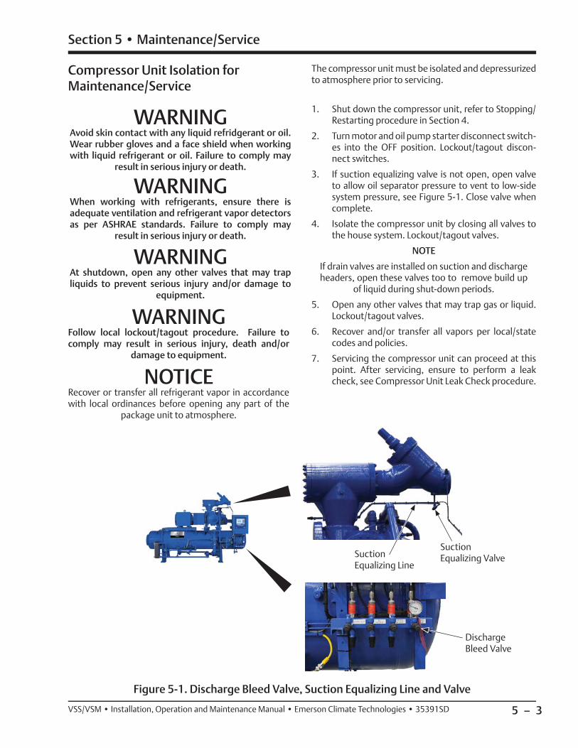
5 – 3
Section 5 • Maintenance/Service
VSS/VSM • Installation, Operation and Maintenance Manual • Emerson Climate Technologies • 35391SD
Compressor Unit Isolation for Maintenance/Service
WARNINGAvoid skin contact with any liquid refridgerant or oil.Wear rubber gloves and a face shield when workingwith liquid refrigerant or oil. Failure to comply may
result in serious injury or death.
WARNINGWhen working with refrigerants, ensure there isadequate ventilation and refrigerant vapor detectorsas per ASHRAE standards. Failure to comply may
result in serious injury or death.
WARNINGAt shutdown, open any other valves that may trapliquids to prevent serious injury and/or damage to
equipment.
WARNINGFollow local lockout/tagout procedure. Failure tocomply may result in serious injury, death and/or
damage to equipment.
NOTICERecover or transfer all refrigerant vapor in accordancewith local ordinances before opening any part of the
package unit to atmosphere.
The compressor unit must be isolated and depressurized to atmosphere prior to servicing.
1. Shut down the compressor unit, refer to Stopping/Restarting procedure in Section 4.
2. Turn motor and oil pump starter disconnect switch-es into the OFF position. Lockout/tagout discon-nect switches.
3. If suction equalizing valve is not open, open valve to allow oil separator pressure to vent to low-side system pressure, see Figure 5-1. Close valve when complete.
4. Isolate the compressor unit by closing all valves to the house system. Lockout/tagout valves.
NOTE
If drain valves are installed on suction and discharge headers, open these valves too to remove build up
of liquid during shut-down periods.
5. Open any other valves that may trap gas or liquid. Lockout/tagout valves.
6. Recover and/or transfer all vapors per local/state codes and policies.
7. Servicing the compressor unit can proceed at this point. After servicing, ensure to perform a leak check, see Compressor Unit Leak Check procedure.
Figure 5-1. Discharge Bleed Valve, Suction Equalizing Line and Valve
Suction Equalizing Line
Suction Equalizing Valve
Discharge Bleed Valve

5 – 4
Section 5 • Maintenance/Service
VSS/VSM • Installation, Operation and Maintenance Manual • Emerson Climate Technologies • 35391SD
Compressor Unit Leak Check After Servicing
The compressor unit must be checked for leaks after servicing to ensure a tight system. For additional leak testing information, refer to Chapter VI of ASME B31.3 Process Piping Code.
CAUTIONDo not hydro test compressor unit. Failure to comply
may result in damage to equipment.
1. If servicing the compressor unit was completed, proceed to step 2. Otherwise, isolate the compres-sor unit from the house system, see Compressor Unit Isolation procedure.
2. Open all shut-off valves, check valves, control valves and solenoid valves in the system to be tested.
3. Slowly pressurize compressor unit through suction oil charging port with dry nitrogen.
4. Using appropriate soap solution, check for leaks on joints and connections of the serviced component.
5. If leaks are found, depressurize system and fi x leaks. Repeat steps 3 and 4 until all leaks are fi xed.
6. Evacuate from suction oil charging port.
7. Close all valves previously opened in the sys-tem. Remove tags as per the local lockout/tagout procedure.
8. Turn the motor and oil pump disconnect switches to the ON position.
9. Return compressor unit to service.
Oil System Components
Oil Sampling
WARNINGAvoid skin contact with any liquid refridgerant or oil.Wear rubber gloves and a face shield when workingwith liquid refrigerant or oil. Failure to comply may
result in serious injury or death.
WARNINGWhen working with refrigerants, ensure there isadequate ventilation and refrigerant vapor detectorsas per ASHRAE standards. Failure to comply may
result in serious injury or death.
Use Vilter Oil Analysis Kit (VPN 3097A) to collect an oil sample for analysis. For an example, see Figure 5-2. Fill out label for bottle. Place in mailing tube and seal with the preaddressed mailing label. Below are a few points to remember when taking a sample:
• Sample running compressor units, not cold units.
• Sample upstream of the oil fi lter.
• Create specifi c written procedures for sampling.
• Ensure sampling valves and devices are thoroughly fl ushed prior to taking a sample.
• Ensure samples are taken as scheduled in the Maintenance and Service Schedule.
• Send samples immediately to the oil analysis lab after sampling, do not wait 24 hours.
NOTE
A copy of the oil analysis report is also sent to Vilter. See Appendices for a sample of the oil analysis report.
An oil analysis report will show the physical properties of the oil, such as:
• Water content
• Viscosity
• Acid number
• Particle count
• Antioxidant level
• Wear metals
• Contaminate/additive metals

5 – 5
Section 5 • Maintenance/Service
VSS/VSM • Installation, Operation and Maintenance Manual • Emerson Climate Technologies • 35391SD
Figure 5-2. Oil Analysis Kit
Oil Draining
WARNINGAvoid skin contact with any liquid refridgerant or oil.Wear rubber gloves and a face shield when workingwith liquid refrigerant or oil. Failure to comply may
result in serious injury or death.
WARNINGWhen working with refrigerants, ensure there isadequate ventilation and refrigerant vapor detectorsas per ASHRAE standards. Failure to comply may
result in serious injury or death.
WARNINGDo not drain oil from drain valve while the compressorunit is running. Shutdown the unit and allow pressures to equalize to suction pressure prior to draining.
Failure to comply may result in serious injury.
The compressor unit must be shut down prior to draining due to high pressures in the oil system, see Compressor Unit Isolation procedure.
Figure 5-3. Oil Strainer Drain Valve and Oil Separator Drain Valve
Oil Separator Drain Valve
Draining can be performed through the drain valve lo-cated underneath the oil separator, see Figure 5-3.
Draining of the remote oil cooler can be performed at the remote oil cooler drain valves. If equipped with lower level drains on the supply and return lines, these too can be utilized for draining.

5 – 6
Section 5 • Maintenance/Service
VSS/VSM • Installation, Operation and Maintenance Manual • Emerson Climate Technologies • 35391SD
Oil Charging
WARNINGAvoid skin contact with oil. Wear rubber gloves and aface shield when working with oil. Failure to comply
may result in serious injury or death.
CAUTIONDo not add oil to the coalescent side of the oilseparator. Failure to comply may result in damage to
equipment.
Normal oil level operating range must be maintained for optimum performance and to prevent damage to equip-ment. See Figure 4-1 for normal operating levels. There are a couple of ways to maintain oil, while the compres-sor unit is in operation and during shutdown.
Tool Required:• Oil Pump, Maximum 2-3 GPM with Motor approved
for Division 1 or Division 2 and with ability to over-come suction pressure.
Charging During Operation:
During operation, if the oil level is low, add oil to the operating compressor through the suction oil charging valve, see Figure 5-4. Pump oil into the compressor until the oil level reaches the normal operating level. Watch this level carefully to maintain proper operation. Never allow the oil to reach a level higher than the Maximum Operating Level, since this may impair the operation and effi ciency.
1. Using a properly selected oil pump, connect oil pump to suction oil charging valve.
2. Open suction oil charging valve and fi ll oil separator to Normal Operating Level.
3. Once the Normal Operating Level has been reached, shut off the oil pump and close the valve. Disconnect and remove oil pump.
Charging During Shutdown:
During shutdown, if oil is to be added, charging can be performed through the drain valve located underneath the oil separator, see Figure 5-3. During shutdown, oil can be added to the Maximum Non-Operating Level. For shutdown procedure, see Compressor Unit Isolation procedure.
1. Using a properly selected oil pump, connect oil pump to oil separator drain valve.
2. Open oil separator drain valve and fi ll oil separator to Maximum NON-Operating Level.
3. Once Maximum NON-Operating Level has been reached, shut off oil pump, close oil separator drain valve and remove oil pump.
Figure 5-4. Suction Oil Charging Valve
Suction Oil Charging Valve

5 – 7
Section 5 • Maintenance/Service
VSS/VSM • Installation, Operation and Maintenance Manual • Emerson Climate Technologies • 35391SD
Filter Element Replacement (Single Oil Filter Assembly) and Oil Pump Strainer Servicing
WARNINGWhen working with refrigerants, ensure there isadequate ventilation and refrigerant vapor detectorsas per ASHRAE standards. Failure to comply may
result in serious injury or death.
WARNINGAvoid skin contact with oil. Wear rubber gloves and aface shield when working with oil. Failure to comply
may result in serious injury or death.
Change the oil fi lter as outlined in the Maintenance and Service Interval, see Table 5-1. Maintenance & Service Interval.
NOTE
Ensure to check the oil pressure drop and record it daily.
This procedure is for a compressor unit equipped with a single oil fi lter assembly only, but can be used for units equipped with dual oil fi lters. The compressor unit must be shut down prior to servicing, see Stopping/Restarting procedure in Section 4.
To replace an oil fi lter element, continue with the follow-ing steps:
PARTS REQUIRED
• Oil Filter Element (VPN KT 773)
• Supplied on all VSM mini screw compressor units since 4-1-2000
• Supplied on VSS451-1201 Single Screw compres-sor units since 3-1-2000
• Oil Filter Element (VPN KT 774)
• Supplied on VSS 1501-1801 Single Screw com-pressor units
• O-ring, Drain Plug (VPN 3111AB)
• For Filter Housings with Drain Plugs ONLY
NOTE
For fi lter housings with drain plugs only, replace with O-ring (VPN 3111AB) after removing drain plug. Drain plug and O-ring are not shown in this
procedure.
DRAIN OIL FROM ISOLATED OIL LINE
1. Isolate the compressor unit, see Compressor Unit Isolation procedure.
2. Close oil supply valve and oil fi lter outlet valve to isolate oil fi lter assembly and oil pump strainer for servicing.
3. Remove plug from drain valve on oil pump strainer.
4. If needed, attach a hose with 1/4” male adapter to drain valve to aid in controlling discharged oil.
5. Using a drain pan, slowly open drain valve to reduce pressure and allow oil to completely drain from oil lines and oil pump strainer.
6. Remove plug from bleed valve on oil fi lter housing.
7. If needed, attach a hose with 1/4” male adapter to bleed port to aid in controlling discharged oil.
8. Using a drain pan, slowly open bleed valve and al-low oil to completely drain from fi lter housing. Remove plug from oil fi lter head assembly to aid in oil removal.
OIL FILTER ELEMENT REMOVAL
(FOR 3111A OIL FILTER HOUSING - See Figure 5-5)
NOTICEDispose of used oil in an appropriate manner following
all Local, State and Federal laws and ordinances.
9. Remove locking ring and fi lter housing from head assembly.
10. Remove fi lter element from internal port of head assembly.
11. Clean fi lter element connection area of head as-sembly and interior of fi lter housing.
12. Remove (head-to-housing) O-ring from inside of fi lter head. Discard O-ring.
OIL FILTER ELEMENT REMOVAL
(FOR 3110A OR 3112A OIL FILTER HOUSING -
See Figure 5-6)
13. Remove oil fi lter housing cover and O-ring from oil fi lter housing. Discard O-ring.
14. Remove fi lter element from internal port of head assembly.
15. Clean fi lter element connection area of head as-sembly and interior of fi lter housing and cover.

5 – 8
Section 5 • Maintenance/Service
VSS/VSM • Installation, Operation and Maintenance Manual • Emerson Climate Technologies • 35391SD
OIL PUMP STRAINER SCREEN REMOVAL AND SERVICE
16. Remove four bolts and strainer cover from strainer body.
17. Remove screen from strainer body.
18. Clean screen and interior of strainer body
19. Inspect screen for damage, replace if required.
OIL PUMP STRAINER SCREEN INSTALLATION
20. Install screen in strainer body.
21. Install four bolts to secure strainer cover on strainer body.
22. Tighten bolts, see Appendix A.
23. Close drain valve on oil pump strainer.
24. Install plug on drain valve.
OIL FILTER ELEMENT INSTALLATION
(FOR 3111A OIL FILTER HOUSING - See Figure 5-5)
25. Lubricate new O-ring with clean system oil.
26. Install O-ring on inside of fi lter head.
27. Install new fi lter element on internal port of head assembly. Make sure fi lter element is fully seated.
28. Lubricate threads of locking ring with clean system oil.
29. Hand tighten locking ring only. Install locking ring and fi lter housing on head assembly until fi lter housing bottoms. Do not overtighten locking ring.
30. Using dry nitrogen gas, pressurize isolated oil line through bleed valve of fi lter housing. Check for leaks on replaced components.
31. Evacuate isolated oil line to 29.88” Hg (1000 mi-crons) and close bleed valve.
32. Install plug on bleed valve of fi lter housing.
33. Slowly open oil supply valve and allow oil to fi ll oil line.
34. Open fi lter outlet valve.
35. Check oil level and fi ll oil separator to non-operat-ing level, see Oil Charging procedure.
Figure 5-5. Filter Assembly and Oil Strainer Drain Valve (VPN 3111A Oil Filter Housing Shown)
View Rotated 180˚
Oil Strainer Drain Valve
Oil Filter Outlet Valve
Temperature Gauge
OIL INLET FROM OIL COOLER
OIL OUTLET TO COMPRESSOR
Temperature Element
Oil Filter Head Assembly
Oil Filter Mounting Bracket
Oil Filter Drain Valve
Oil Filter Element
Locking RingOil Inlet
Connection
Oil Outlet Connection
Oil Filter Housing
Plug

5 – 9
Section 5 • Maintenance/Service
VSS/VSM • Installation, Operation and Maintenance Manual • Emerson Climate Technologies • 35391SD
Figure 5-6. Filter Assembly (VPN 3112A Oil Filter Housing Shown)
Oil Filter Head Assembly
Oil Filter Element
Oil Outlet Connection
Oil Filter Housing
O-ring
Oil Filter Housing
Cover
Oil Filter Drain Valve
with Plug
Oil Inlet Connection
OIL FILTER ELEMENT INSTALLATION
(FOR 3110A OR 3112A OIL FILTER HOUSING -
See Figure 5-6)
36. Install new fi lter element on internal port of head assembly. Make sure fi lter element is fully seated.
37. Lubricate new O-ring with clean system oil.
38. Hand tighten oil fi lter housing cover only. Install O-ring and oil fi lter housing cover on oil fi lter housing.
39. Using dry nitrogen gas, pressurize isolated oil line through bleed valve of fi lter housing. Check for leaks on replaced components.
40. Evacuate isolated oil line to 29.88” Hg (1000 mi-crons) and close bleed valve.
41. Install plug on bleed valve of fi lter housing.
42. Slowly open oil supply valve and allow oil to fi ll oil line.
43. Open fi lter outlet valve.
44. Check oil level and fi ll oil separator to non-operat-ing level, see Oil Charging procedure.
Plug

5 – 10
Section 5 • Maintenance/Service
VSS/VSM • Installation, Operation and Maintenance Manual • Emerson Climate Technologies • 35391SD
REMOVAL
(Reference Figure 5-7)
NOTICEDispose of used oil in an appropriate manner following
all Local, State and Federal laws and ordinances.
1. Pull switch lever and switch over to second fi lter.
2. Remove plug from bleed valve.
3. If needed, attach a hose with 1/4” male adapter to bleed port to aid in controlling the fl ow of dis-charged oil.
4. Using a drain pan, slowly open bleed valve to re-duce pressure and allow oil to completely drain from fi lter housing.
5. Remove oil fi lter housing cover and O-ring from oil fi lter housing. Discard O-ring.
6. Remove fi lter element from internal port of head assembly.
7. Clean fi lter element connection area of head as-sembly and interior of fi lter housing.
INSTALLATION
8. Install new fi lter element on internal port of head assembly. Make sure fi lter element is fully seated.
9. Lubricate new O-ring with clean system oil.
10. Hand tighten oil fi lter housing cover only. Install O-ring and oil fi lter housing cover on oil fi lter housing.
11. Using dry nitrogen gas, pressurize fi lter housing through bleed valve and check for leaks.
12. Evacuate fi lter housing to 29.88” Hg (1000 mi-crons) and close bleed valve.
13. Install plug on bleed valve.
14. Pull switch lever and slowly rotate lever to middle position to allow oil to fi ll fi lter housing. Allow a minimum of 5 seconds to fi ll housing, then rotate lever back to second fi lter.
15. Repeat for second oil fi lter, as required.
Filter Element Replacement (Duplex Oil Filter Assembly)
WARNINGWhen working with refrigerants, ensure there isadequate ventilation and refrigerant vapor detectorsas per ASHRAE standards. Failure to comply may
result in serious injury or death.
WARNINGAvoid skin contact with oil. Wear rubber gloves and aface shield when working with oil. Failure to comply
may result in serious injury or death.
Change the oil fi lter as outlined in the Maintenance and Service Interval, see Table 5-1. Maintenance & Service Interval.
NOTE
Ensure to check the oil pressure drop and record it daily.
This procedure is for a compressor unit equipped with a duplex oil fi lter assembly only (VPN 3109A and 3110A oil fi lter housings). One oil fi lter can be isolated and ser-viced one at a time during operation. Note that there is one oil fi lter head assembly for both oil fi lters. This is different from dual oil fi lters, where each oil fi lter has its own oil fi lter head assembly.
To replace an oil fi lter element, continue with the follow-ing steps:
PARTS REQUIRED
• Oil Filter Element (VPN KT 773)
• Supplied on all VSM mini screw compressor units since 4-1-2000
• Supplied on VSS 451-1201 Single Screw compres-sor units since 3-1-2000
• Oil Filter Element (VPN KT 774)
• Supplied on VSS 1501-1801 Single Screw com-pressor units
• O-ring, Drain Plug (VPN 3111AB)
• For Filter Housings with Drain Plugs ONLY
NOTE
For fi lter housings with drain plugs only, replace with O-ring (VPN 3111AB) after removing drain plug. Drain plug and O-ring are not shown in this
procedure.

5 – 11
Section 5 • Maintenance/Service
VSS/VSM • Installation, Operation and Maintenance Manual • Emerson Climate Technologies • 35391SD
Figure 5-7. Duplex Oil Filter Assembly (VPN 3110A Double Oil Filter Housing Shown)
Oil Filter Duplex Head
Assembly
Oil Filter Switch Lever
Oil Filter Housing
O-ring
Oil Filter Housing
Cover
Oil Filter Drain Valve
Oil Filter Element

5 – 12
Section 5 • Maintenance/Service
VSS/VSM • Installation, Operation and Maintenance Manual • Emerson Climate Technologies • 35391SD
Filter Element Replacement (Dual Oil Filter Assembly)
WARNINGWhen working with refrigerants, ensure there isadequate ventilation and refrigerant vapor detectorsas per ASHRAE standards. Failure to comply may
result in serious injury or death.
WARNINGAvoid skin contact with oil. Wear rubber gloves and aface shield when working with oil. Failure to comply
may result in serious injury or death.
Change the oil fi lter as outlined in the Maintenance and Service Interval, see Table 5-1. Maintenance & Service Interval.
NOTE
Ensure to check the oil pressure drop and record it daily.
This procedure is for a compressor unit equipped with a dual oil fi lter assembly only. One oil fi lter can be isolated and serviced one at a time during operation. Note that there is one oil fi lter head assembly for each oil fi lter. This is different from duplex oil fi lters, where there is only one oil fi lter head assembly for both oil fi lters.
To replace an oil fi lter element, continue with the follow-ing steps:
PARTS REQUIRED
• Oil Filter Element (VPN KT 773)
• Supplied on all VSM mini screw compressor units since 4-1-2000
• Supplied on VSS 451-1201 Single Screw compres-sor units since 3-1-2000
• Oil Filter Element (VPN KT 774)
• Supplied on VSS 1501-1801 Single Screw com-pressor units
• O-ring, Drain Plug (VPN 3111AB)
• For Filter Housings with Drain Plugs ONLY
NOTE
For fi lter housings with drain plugs only, replace with O-ring (VPN 3111AB) after removing drain plug. Drain plug and O-ring are not shown in this
procedure.
SWITCHING OIL FILTERS FOR MAINTENANCE
(Reference Figure 5-8)
When switching oil fl ow from one fi lter to the other for maintenance, proceed with the following steps:
1. Slowly open inlet oil fi lter shut-off valve to oil fi lter that will be active.
2. Slowly open inlet oil pressure shut-off valve for oil fi lter to allow oil pressure to be read from oil fi lter that is now active.
3. Slowly open outlet oil fi lter shut-off valve to oil fi lter that is now active.
4. Slowly close inlet and outlet oil fi lter shut-off valves for oil fi lter that is to be serviced.
5. Slowly close oil pressure shut-off valve for oil fi lter that is to be serviced. Remove plug from oil fi lter head assembly to aid in oil removal.
DRAIN OIL FROM ISOLATED OIL FILTER
(Reference Figure 5-9)
6. Remove plug from bleed valve on oil fi lter housing.
7. If needed, attach a hose with 1/4” male adapter to bleed port to aid in controlling discharged oil.
8. Using a drain pan, slowly open bleed valve and al-low oil to completely drain from fi lter housing.
OIL FILTER ELEMENT REMOVAL
(FOR 3111A OIL FILTER HOUSING - See Figure 5-9)
NOTICEDispose of used oil in an appropriate manner following
all Local, State and Federal laws and ordinances.
9. Remove locking ring and fi lter housing from head assembly.
10. Remove fi lter element from internal port of head assembly.
11. Clean fi lter element connection area of head as-sembly and interior of fi lter housing.
12. Remove (head-to-housing) O-ring from inside of fi lter head. Discard O-ring.

5 – 13
Section 5 • Maintenance/Service
VSS/VSM • Installation, Operation and Maintenance Manual • Emerson Climate Technologies • 35391SD
Outlet Oil FilterShut-Off Valves
Inlet Oil Filter Shut-Off Valves
Inlet Oil PressureShut-Off Valves
Figure 5-8. Dual Oil Filter (3111A Oil Filter Housings Shown)
Oil Filters
Plugs and Bleed Valves
Plug
OIL FILTER ELEMENT REMOVAL
(FOR 3110A OR 3112A OIL FILTER HOUSING -
See Figure 5-10)
13. Remove oil fi lter housing cover and O-ring from oil fi lter housing. Discard O-ring.
14. Remove fi lter element from internal port of head assembly.
15. Clean fi lter element connection area of head as-sembly and interior of fi lter housing and cover.
16.
OIL FILTER ELEMENT INSTALLATION
(FOR 3111A OIL FILTER HOUSING - See Figure 5-9)
17. Lubricate new O-ring with clean system oil.
18. Install O-ring on inside of fi lter head.
19. Install new fi lter element on internal port of head assembly. Make sure fi lter element is fully seated.
20. Lubricate threads of locking ring with clean system oil.
21. Hand tighten locking ring only. Install locking ring and fi lter housing on head assembly until fi lter housing bottoms. Do not overtighten locking ring.
22. Using dry nitrogen gas, pressurize isolated oil line through bleed valve of fi lter housing. Check for leaks on replaced components.
23. Evacuate isolated oil line to 29.88” Hg (1000 mi-crons) and close bleed valve.
24. Install plug on bleed valve of fi lter housing.
25. Slowly open oil supply valve and allow oil to fi ll oil line.
26. Open fi lter outlet valve.
27. Check oil level and fi ll oil separator to non-operat-ing level, see Oil Charging procedure.
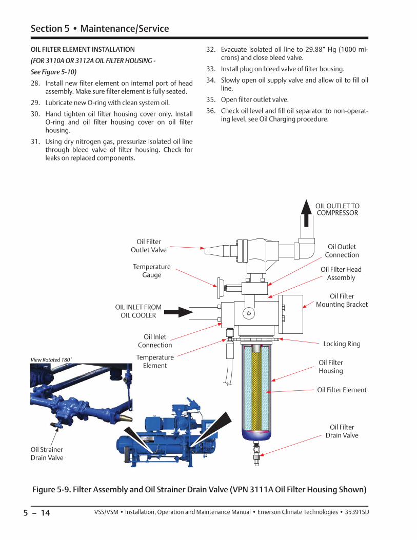
5 – 14
Section 5 • Maintenance/Service
VSS/VSM • Installation, Operation and Maintenance Manual • Emerson Climate Technologies • 35391SD
Figure 5-9. Filter Assembly and Oil Strainer Drain Valve (VPN 3111A Oil Filter Housing Shown)
View Rotated 180˚
Oil Strainer Drain Valve
Oil Filter Outlet Valve
Temperature Gauge
OIL INLET FROM OIL COOLER
OIL OUTLET TO COMPRESSOR
Temperature Element
Oil Filter Head Assembly
Oil Filter Mounting Bracket
Oil Filter Drain Valve
Oil Filter Element
Locking RingOil Inlet
Connection
Oil Outlet Connection
Oil Filter Housing
OIL FILTER ELEMENT INSTALLATION
(FOR 3110A OR 3112A OIL FILTER HOUSING -
See Figure 5-10)
28. Install new fi lter element on internal port of head assembly. Make sure fi lter element is fully seated.
29. Lubricate new O-ring with clean system oil.
30. Hand tighten oil fi lter housing cover only. Install O-ring and oil fi lter housing cover on oil fi lter housing.
31. Using dry nitrogen gas, pressurize isolated oil line through bleed valve of fi lter housing. Check for leaks on replaced components.
32. Evacuate isolated oil line to 29.88” Hg (1000 mi-crons) and close bleed valve.
33. Install plug on bleed valve of fi lter housing.
34. Slowly open oil supply valve and allow oil to fi ll oil line.
35. Open fi lter outlet valve.
36. Check oil level and fi ll oil separator to non-operat-ing level, see Oil Charging procedure.

5 – 15
Section 5 • Maintenance/Service
VSS/VSM • Installation, Operation and Maintenance Manual • Emerson Climate Technologies • 35391SD
Figure 5-10. Filter Assembly (VPN 3112A Oil Filter Housing Shown)
Oil Filter Head Assembly
Oil Filter Element
Oil Outlet Connection
Oil Filter Housing
O-ring
Oil Filter Housing
Cover
Oil Filter Drain Valve
with Plug
Oil Inlet Connection
Plug

5 – 16
Section 5 • Maintenance/Service
VSS/VSM • Installation, Operation and Maintenance Manual • Emerson Climate Technologies • 35391SD
Coalescing Filter Replacement
WARNINGWhen working with refrigerants, ensure there isadequate ventilation and refrigerant vapor detectorsas per ASHRAE standards. Failure to comply may
result in serious injury or death.
WARNINGAvoid skin contact with any condensate or oil. Wearrubber gloves and a face shield when working withcondensate or oil. Failure to comply may result in
serious injury or death.
WARNINGUse appropriate lifting devices and additionalpersonnel when lifting heavy components. Ensurelifting devices are capable of lifting the weight ofthe component. Use lifting points (i.e. bolt holesdesignated for lifting eye bolts) that are providedon the component. Failure to comply may result in
serious injury.
NOTE
For coalescing oil fi lters (11-7/8 in. O.D.), a tubing (3/4 in. O.D. x 6 ft. long ) can be used to aid in
removal and installation of the element.
REMOVAL
1. Isolate the compressor unit, see Compressor Unit Isolation procedure.
2. If required, install lifting eyes on oil separator man-hole cover, see Figure 5-11.
3. Secure appropriate lifting device to oil separator manhole cover.
4. Remove all bolts except top four bolts securing oil separator manhole cover to oil separator vessel.
5. Adjust lifting device as needed to hold weight of oil separator manhole cover.
6. Remove remaining four bolts and oil separator manhole cover from oil separator vessel.
7. Remove nuts, fl at washer and cover plate securing coalescing oil fi lter to hold-down rod.
8. With assistance of second person, remove coalesc-ing fi lter from oil separator vessel.
9. Repeat steps 7 and 8 to remove additional coalesc-ing fi lters, as required.
INSTALLATION
10. Install tubing over hold-down rod. Position tubing as far back as possible.
11. With assistance of second person, position coalesc-ing element over tubing and through hole of cen-tering strap.
12. Push coalescing fi lter into vessel until fully seated on pipe stub.
13. Remove tubing.
14. Position cover plate and fl at washer on hold-down rod on end of the coalescing fi lter.
15. Install nut to secure fl at washer and cover plate to coalescing fi lter. Tighten nut to 25 ft-lbs.
16. Install second nut to prevent fi rst nut from moving.
17. Repeat steps 10 to 16 for installing additional co-alescing fi lters.
18. Position oil separator manhole cover on oil separa-tor vessel.
19. Install bolts to secure oil separator manhole cover to oil separator vessel.
20. Tighten bolts, see Appendix A.
21. Perform Compressor Unit Leak Check procedure.

5 – 17
Section 5 • Maintenance/Service
VSS/VSM • Installation, Operation and Maintenance Manual • Emerson Climate Technologies • 35391SD
Oil Separator Manhole Cover
Figure 5-11. Oil Separator Manhole Cover and Coalescing Filter Assembly
Centering Strap
Nuts
Coalescing Filter Hold-Down Rod
3/4 in. O.D. Tubing, 6 ft. longFlat Washer
Flat Washer
Oil Separator Vessel
Pipe Stub
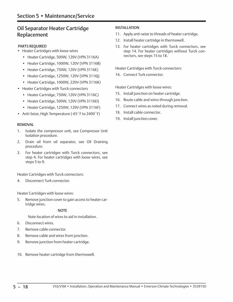
5 – 18
Section 5 • Maintenance/Service
VSS/VSM • Installation, Operation and Maintenance Manual • Emerson Climate Technologies • 35391SD
Oil Separator Heater Cartridge Replacement
PARTS REQUIRED• Heater Cartridges with loose wires
• Heater Cartridge, 500W, 120V (VPN 3116A)
• Heater Cartridge, 1000W, 120V (VPN 3116B)
• Heater Cartridge, 750W, 120V (VPN 3116E)
• Heater Cartridge, 1250W, 120V (VPN 3116J)
• Heater Cartridge, 1000W, 220V (VPN 3116K)
• Heater Cartridges with Turck connectors
• Heater Cartridge, 750W, 120V (VPN 3116C)
• Heater Cartridge, 500W, 120V (VPN 3116D)
• Heater Cartridge, 1250W, 120V (VPN 3116F)
• Anti-Seize, High Temperature (-65˚F to 2400˚F)
REMOVAL
1. Isolate the compressor unit, see Compressor Unit Isolation procedure.
2. Drain oil from oil separator, see Oil Draining procedure.
3. For heater cartridges with Turck connectors, see step 4. For heater cartridges with loose wires, see steps 5 to 9.
Heater Cartridges with Turck connectors:
4. Disconnect Turk connector.
Heater Cartridges with loose wires:
5. Remove junction cover to gain access to heater car-tridge wires.
NOTE
Note location of wires to aid in installation.
6. Disconnect wires.
7. Remove cable connector.
8. Remove cable and wires from junction.
9. Remove junction from heater cartridge.
10. Remove heater cartridge from thermowell.
INSTALLATION
11. Apply anti-seize to threads of heater cartridge.
12. Install heater cartridge in thermowell.
13. For heater cartridges with Turck connectors, see step 14. For heater cartridges without Turck con-nectors, see steps 15 to 18.
Heater Cartridges with Turck connectors:
14. Connect Turk connector.
Heater Cartridges with loose wires:
15. Install junction on heater cartridge.
16. Route cable and wires through junction.
17. Connect wires as noted during removal.
18. Install cable connector.
19. Install junction cover.

5 – 19
Section 5 • Maintenance/Service
VSS/VSM • Installation, Operation and Maintenance Manual • Emerson Climate Technologies • 35391SD
Figure 5-12. Heater Cartridges
Cable Connector
Cable
Junction
Heater Cartridge
Thermowell
TurckConnector
Heater CartridgeThermowell
Heater Cartridge WITHOUT Turck Connector Heater Cartridge WITH Turck Connector

5 – 20
Section 5 • Maintenance/Service
VSS/VSM • Installation, Operation and Maintenance Manual • Emerson Climate Technologies • 35391SD
with a small clearance over the top.
NOTE
If hub position on shaft does not allow enough room to install bolts, install bolts and disc pack before
mounting hub on shaft.
Hubs come in two different types, straight bore and tapered bore. Tapered bore hubs have additional hardware. Typically, a compressor will have a tapered shaft and therefore use a tapered bore hub.
STRAIGHT BORE HUBS
5. For straight bore hubs, install key in keyway of shaft.
6. Install hub on shaft. If installing straight bore hubs on motor and compressor shafts, allow 1/16” gap between the outer face of the hub to the outer face of the shaft for both hub installation. This will allow some play when installing the spacer. If installing a straight bore hub and a taper bore hub, allow a 1/8” gap between the outer face of the straight bore hub to the outer face of the straight shaft, see Table 5-2.
7. Install clamping bolts in hub.
8. Tighten clamping bolts, see Table 5-3.
9. Install set screw in hub to secure key.
10. Tighten set screw, see Table 5-3. Repeat steps for second straight bore hub.
TAPERED BORE HUBS
11. For taper bore hubs, install key in keyway of shaft.
12. Install hub on shaft.
13. If lock washers are being used, install hub cap, lock washers and bolt on shaft.
14. If locking tab is being used, install hub cap, locking tab and bolt on shaft.
15. Tighten bolt and draw hub up shaft to a stop.
Drive Coupling Hub (Form-Flex BPU) Installation
On all single screw units, the coupling assembly is shipped loose and will have to be installed and aligned on site. This is to allow a check of proper electrical phas-ing and direction of motor rotation. The motor and compressor have been aligned from the factory with the coupling hubs already installed. Using a dial indicator for aligning is recommended.
NOTE
Drive coupling type and size can be determined by the information on the compressor nameplate when ordering; Order Number and Compressor
Model Number.
To install the coupling, proceed with the following steps:
WARNINGFollow local lockout/tagout procedure. Failure tocomply may result in serious injury, death and/or
damage to equipment.
1. Ensure disconnect switches are in the OFF position for the compressor unit and oil pump motor start-er, if equipped.
2. If hubs are already installed on motor shaft and compressor shaft, proceed to Drive Center Member Installation and Alignment procedure.
3. If coupling assembly is already assembled, the lock nuts are not torqued. Remove lock nuts and bolts securing hubs to disc packs. Remove both hubs. Leave the disc packs attached to center member.
4. Clean hub bores and shafts. Remove any nicks or burrs. If bore is tapered, check for good con-tact pattern. If bore is straight, measure bore and shaft diameters to ensure proper fi tment. The keys should have a snug side-to-side fi t in the keyway
Coupling Size
Shaft Gap for Tapered Compressor &
Straight Motor Shaft Combination
Shaft Gap for Straight Compressor &
Straight Motor Shaft Combination
Distance Between Hub
Faces
BP38U
6.25” (158.75 mm)
5.125”(130.18 mm)
5.00”(127 mm)
BP41U
BP47U
BP54U
BP54U
BP56U
Table 5-2. Shaft and Hub Distances

5 – 21
Section 5 • Maintenance/Service
VSS/VSM • Installation, Operation and Maintenance Manual • Emerson Climate Technologies • 35391SD
16. If locking tab is being used, bend locking tabs in gap towards shaft and around bolt.
17. Install set screw in hub cap to secure key in keyway of shaft.
18. Tighten set screw, see Table 5-3.
Drive Center Member Installation and Alignment
NOTE
Always adjust motor to the compressor. The compressor is aligned to the frame.
19. Adjust motor position as needed to obtain a dis-tance of 5” between both hub faces.
20. Soft Foot. The motor must sit fl at on its base (+/- 0.002”). Any soft foot must be corrected prior to center member installation.
NOTE
If the driver or driven equipment alignment specifi cation is tighter than these recommendations, the specifi cation should be used. Also, be sure to compensate for thermal movement in the equipment. The coupling is capable of approximately four time the above shaft alignment tolerances. However, close alignment at installation will provide
longer service with smoother operation.
The fl ex disc pack is designed to an optimal thickness and is not to be used for axial adjustments.
21. Axial Spacing. The axial spacing of the shafts should be positioned so that the fl ex disc packs are fl at when the equipment is running under normal
operating conditions. This means there is a mini-mal amount of waviness in the fl ex disc pack when viewed from the side. This will result in a fl ex disc pack that is centered and parallel to its mating fl ange faces. Move the motor to obtain the correct axial spacing, see Table 5-3 and Figure 5-12.
22. Angular Alignment. Rigidly mount a dial indicator on one hub or shaft, reading the face of the other hub fl ange. Rotate both shafts together, making sure the shaft axial spacing remains constant. Adjust the motor by shimming and/or moving so that the indi-cator reading is within 0.002” per inch of coupling fl ange, see Figure 5-14.
23. Parallel Offset. Rigidly mount a dial indicator on one hub or shaft, reading the other hub fl ange outside diameter. Indicator set-up sag must be compen-sated for. Rotate both shafts together. Adjust the equipment by shimming and/or moving so that the indicator reading is within 0.002” per inch of the ax-ial length between fl ex disc packs, see Figure 5-14.
With the coupling in good alignment the bolts will fi t through the holes in the fl anges and the disc packs more easily.
NOTE
All bolt threads should be lubricated. A clean motor oil is recommended. On size 226 and larger, a link must be put on bolt fi rst. Remove the disc pack alignment bolt. Proceed to mount the second disc
pack to the other hub in the same way.
Ensure that the beveled part of the washer is against the disc pack.
24. Install bolts and locking nuts to secure both disc packs to center member.
Hub Distance
Figure 5-13. Hub Distance (Axial Spacing)

5 – 22
Section 5 • Maintenance/Service
VSS/VSM • Installation, Operation and Maintenance Manual • Emerson Climate Technologies • 35391SD
25. Tighten locking nuts.
26. If room is required to install center member, adjust hub position accordingly. If both the motor and compressor hubs are straight bores, adjust either hubs. If one hub is tapered and the other a straight, adjust the straight bore hub.
27. Using additional supports supporting center mem-ber. Install bolts and locking nuts to secure center member to compressor hub.
28. Tighten locking nuts.
29. Position hubs, ensure distance between face of both hubs is 5”.
NOTE
If there is waviness with the disc pack installed, adjust distance accordingly until disc pack is straight.
30. Install bolts and locking nuts to secure disc pack to motor hub.
31. Tighten locking nuts, see Table 5-3.
Coupling Size
Lock Nut Size
Tightening Torque
ft-lbs (Nm)
BP38U 5/16-24 22 (30)
BP41U 7/16-20 55 (75)
BP47U 9/16-18 120 (163)
BP54U 9/16-18 120 (163)
BP56U 9/16-18 120 (163)
Table 5-4. Disc Pack Installation Torque Specifi cations
32. Perform hot alignment. Run compressor unit and allow to warm up completely.
33. Power down compressor unit and re-check align-ments. Loosen motor mounting nuts to add shims or to adjust alignments as required.
34. Install coupling guard.
Table 5-3. Hub Clamp Bolt and Set Screw Torque Specifi cations
Coupling Series/Size
Clamping Bolt Set Screw
# Bolts Size-PitchTorque
ft-lbs (Nm)Size
Torque ft-lbs (Nm)
BH38U 4 1/4-28 12 (16) 3/8 10 (13)
BH41U 4 5/16-24 23 (31) 3/8 10 (13)
BH47U 4 3/8-24 49 (66) 1/2 20 (27)
BH54U 4 7/16-20 78 (106) 1/2 20 (27)
BH56U 4 1/2-20 120 (163) 5/8 40 (54)
DP42 4 1/2-20 120 (163) 1/2 20 (27)
Figure 5-14. Angular Alignment and Parallel Offset
Angular Alignment Parallel Offset

5 – 23
Section 5 • Maintenance/Service
VSS/VSM • Installation, Operation and Maintenance Manual • Emerson Climate Technologies • 35391SD
Drive Coupling Hub (Form-Flex BPU) and Center Member Removal
To remove coupling assembly, proceed with the follow-ing steps:
WARNINGAt shutdown, open any other valves that may trapliquids to prevent serious injury and/or damage to
equipment.
WARNINGFollow local lockout/tagout procedure. Failure tocomply may result in serious injury, death and/or
damage to equipment.
NOTE
Drive coupling type and size can be determined by the information on the compressor nameplate when ordering; Order Number and Compressor
Model Number.
1. Shut down the compressor unit, refer to Stopping/Restarting procedure in Section 4.
2. Turn disconnect switches to the OFF position for the compressor unit and oil pump motor starter, if equipped.
3. Allow compressor, motor and surrounding compo-nents to cool prior to servicing.
4. Remove coupling guard.
5. Remove lock nuts and bolts securing disc pack to hub on compressor shaft.
6. If additional room is required to remove the center member, loosen clamping bolts on straight bore hub(s).
7. Move straight bore hub on shaft as required to al-low center member removal.
8. Remove lock nuts and bolts securing disc pack to hub on motor shaft. Remove center member.
9. For straight bore hubs, remove clamping bolts and hub from shaft.
10. For tapered bore hubs, remove bolt, lock washers, large washer and hub from shaft.
Drive Coupling (Type C Sure-Flex) Replacement
Drive couplings that are the Type C Sure-Flex type, are always installed with a C-fl ange between the compres-sor and motor. The coupling assembly alignments are built into the design and therefore, should not require alignment.
NOTE
Drive coupling type and size can be determined by the information on the compressor nameplate when ordering; Order Number and Compressor
Model Number.
REMOVAL
To remove Type C Sure-Flex coupling, proceed with the following steps:
WARNINGAt shutdown, open any other valves that may trapliquids to prevent serious injury and/or damage to
equipment.
WARNINGFollow local lockout/tagout procedure. Failure tocomply may result in serious injury, death and/or
damage to equipment.
1. Shut down the compressor unit, refer to Stopping/Restarting procedure in Section 4.
2. Turn disconnect switches to the OFF position for the compressor unit and oil pump motor starter, if equipped.
3. Allow compressor, motor and surrounding compo-nents to cool prior to servicing.
4. Remove C-fl ange access cover.
NOTE
Mark locations of hubs prior to removal.
5. Loosen set screw in motor hub securing key in keyway.
6. Loosen clamping bolts securing hub to motor shaft.
7. Pry hub up motor shaft for space to remove cou-pling sleeve.
8. Remove coupling sleeve from hub.
9. Remove hub and key from motor shaft.
10. Loosen set screw in compressor hub securing key in keyway.

5 – 24
Section 5 • Maintenance/Service
VSS/VSM • Installation, Operation and Maintenance Manual • Emerson Climate Technologies • 35391SD
11. Loosen clamping bolts securing hub from compres-sor shaft.
12. Remove hub and key from compressor shaft.
INSTALLATION
13. Install key and hub on compressor shaft as noted during removal.
14. Install set screw in compressor hub to secure key in keyway, see Table 5-5,
15. Install clamping bolts to secure hub on compressor shaft. Tighten clamping bolts, see Table 5-5,
16. Install key and hub on motor shaft as noted during removal. Allow gap to install coupling sleeve.
17. Install coupling sleeve on hubs. Position hub on motor shaft on coupling sleeve as noted during removal.
18. Install set screw in compressor hub to secure key in keyway. Tighten set screw, see Table 5-5,
19. Install clamping bolts to secure hub to motor shaft. Tighten clamping bolts, see Table 5-5.
Coupling Size
Type C ft-lbs (Nm)
Clamping Bolts
Key Set Screw
6 13 (18)
13 (18)
7 13 (18)
8 23 (31)
9 23 (31)
10 50 (68)
11 50 (68)
Table 5-5. Clamping Bolts and Set Screw Torque Specifi cations

5 – 25
Section 5 • Maintenance/Service
VSS/VSM • Installation, Operation and Maintenance Manual • Emerson Climate Technologies • 35391SD
8. Remove four screws (9), lock washers (10) and fl at washers (11) securing support brackets (3) from compressor. Remove support brackets. Discard lock washers.
INSTALLATION
9. Install four fl at washers (11), new lock washers (10) and screws (9) to secure support brackets (3) to compressor. Do not fully tighten.
10. Install fi ve fasteners (6) to ring mounting guard (5).
11. Install four screws (1), fl at washers (2) and nuts (4) to secure ring mounting guard (5) to four support brackets (3).
12. Tighten nuts (4) and screws (9).
13. Install eight fasteners (6) to lower guard (8).
14. Install two fl at washers (2) and screws (1) to secure lower guard (8) to ring mounting guard (5).
15. Install three fl at washers (2) and screws (1) to se-cure upper guard (7) to ring mounting guard (5).
16. Install eight fl at washers (2) and screws (1) to se-cure upper guard (7) to lower guard (8).
17. Return compressor unit to service.
Coupling Guard Replacement
NOTE
Coupling guards may differ slightly but this replacement procedure can be used to remove and install them. The coupling guard assembly described
in this procedure is VPN A27435C.
REMOVAL
Reference Figure 5-15.
1. Shut down compressor unit, see Compressor Unit Isolation for Maintenance/Service procedure.
2. Remove eight screws (1) and fl at washers (2) secur-ing upper guard (7) to lower guard (8).
3. Remove three screws (1) and fl at washers (2) se-curing upper guard (7) to ring mounting guard (5). Remove upper guard.
4. Remove two screws (1) and fl at washers (2) secur-ing lower guard (8) to ring mounting guard (5). Remove lower guard.
5. Remove eight fasteners (6) from lower guard (8).
6. Remove four nuts (4), screws (1) and fl at washers (2) securing ring mounting guard (5) to four support brackets (3). Remove ring mounting guard.
7. Remove fi ve fasteners (6) from ring mounting guard (5).
Figure 5-15. Coupling Guard Assembly (VPN A27435C shown)
1 2
3 4
5621
7
2
1
8
219
1011

5 – 26
Section 5 • Maintenance/Service
VSS/VSM • Installation, Operation and Maintenance Manual • Emerson Climate Technologies • 35391SD
NOTE
Use appropriate supporting equipment to support and keep motor, C-fl ange and compressor leveled.
6. If equipped with C-fl ange, remove bolts securing C-fl ange to compressor.
7. Using appropriate drain pan, drain oil by removing drain plugs from under compressor housing and discharge manifold. Allow oil to completely drain.
8. Remove all oil lines from the compressor.
9. Support suction line with appropriate supporting equipment.
10. Remove nuts and bolts securing suction strainer/check valve assembly to suction stop valve and compressor.
11. Using appropriate lifting device, remove suction strainer/check valve assembly from compressor.
12. Remove nuts and bolts securing discharge pipe to compressor and oil separator, see Figure 5-16.
13. Remove discharge pipe and gaskets from compres-sor and oil separator.
14. Remove nuts, fl at washers, lock washers and studs securing compressor to frame.
15. Remove any additional lines and/or components to allow removal of compressor as required.
Figure 5-16. Compressor Replacement and Hardware Assembly (VSS 2401-3001 Shown)
NutLock WasherFlat Washer
Spherical Washer Assembly
StudFlat WasherLock WasherNut
ShimFrame
Compressor
Compressor Replacement
Notify Vilter prior to performing a compressor replace-ment. See Warranty instructions in Section 7.
REMOVAL
To replace a compressor on a unit, proceed with the fol-lowing steps:
NOTICEDispose of used oil in an appropriate manner following
all Local, State and Federal laws and ordinances.
1. Shut down and isolate the compressor unit, see Compressor Unit Isolation for Maintenance and Service procedure.
NOTE
Note location of cables to aid in installation.
2. Disconnect all cables from sensors on compressor and actuators.
3. Remove coupling guard, see Coupling Guard Replacement procedure.
4. Remove drive coupling, see appropriate Drive Coupling Replacement procedure.
5. Remove center member, see Drive Coupling Removal procedure.

5 – 27
Section 5 • Maintenance/Service
VSS/VSM • Installation, Operation and Maintenance Manual • Emerson Climate Technologies • 35391SD
16. Install appropriate lifting eyes on top of compressor.
17. Using appropriate lifting device and additional per-sonnel, remove compressor from frame.
18. Remove shims and spherical washers from com-pressor mounting locations.
19. Inspect shims and spherical washers for damage, replace as required.
INSTALLATION
20. Install shims and spherical washers on compressor mounting locations, see Figure 5-16.
21. Install appropriate lifting eyes on top of compressor.
22. Using appropriate lifting device, position compres-sor on compressor mounting locations on frame.
23. Loosely install studs, lock washers, fl at washers and nuts to secure compressor to frame until alignment is correct.
24. Check compressor for soft foot. Add or remove shims as required until measurements are within +/- 0.002”.
25. Tighten nuts to secure compressor to frame, refer to Appendix A.
26. If equipped with C-fl ange, install bolts to se-cure C-fl ange to compressor. Tighten bolts, see Appendix A.
27. Install drive coupling, see appropriate Drive Coupling Replacement procedure.
28. Install center member, see Drive Center Member Installation and Alignment procedure.
29. Install coupling guard, see Coupling Guard Replacement procedure.
30. Install nuts and bolts to secure discharge pipe to oil separator and compressor.
31. Tighten nuts on ‘discharge pipe-to-compressor fl ange’ fi rst, then tighten nuts on ‘discharge pipe-to-oil separator fl ange’, see Appendix A.
32. Install nuts to secure suction strainer/check valve assembly to compressor and suction stop valve.
33. Tighten nuts on ‘suction strainer/check valve as-sembly-to-compressor’ fi rst, then tighten nuts on ‘suction strainer/check valve assembly-to-suction stop valve’, refer to Appendix A.
34. Install all lines to compressor.
35. Install all cables to sensors on compressor and actuator.
36. Perform leak check, see Compressor Unit Leak Check procedure.

5 – 28
Section 5 • Maintenance/Service
VSS/VSM • Installation, Operation and Maintenance Manual • Emerson Climate Technologies • 35391SD
Bare Shaft Compressor Lifting Points and Weights
E
Models
Component Lifting Hole SizesA B C D E
Discharge Manifold
(Side)
Discharge Manifold
(Top)
Main Compressor Assembly ONLY
(Discharge)
Main Compressor Assembly ONLY
(Suction)
Gate RotorCover
291-601 5/8-11 UNC -2B 5/8-11 UNC -2B 5/8-11 UNC -2B 5/8-11 UNC -2B 3/8-16 UNC-2B
751-901 5/8-11 UNC -2B 5/8-11 UNC -2B 5/8-11 UNC -2B 5/8-11 UNC -2B -
1051-1301 5/8-11 UNC-2B 5/8-11 UNC -2B 3/4-10 UNC -2B 5/8-11 UNC -2B 3/8-16 UNC -2B
1551-2101 5/8-11 UNC -2B 5/8-11 UNC -2B 5/8-11 UNC -2B 5/8-11 UNC -2B 3/8-16 UNC -2B
2401-3001 5/8-11 UNC -2B 5/8-11 UNC -2B 5/8-11 UNC -2B 3/4-10 UNC -2B 5/8-11 UNC -2B
ModelsComponent Weights
Gate Rotor Bearing Housing
Gate Rotor Bearing Housing Cover
Discharge Manifold
Main Compressor Assembly ONLY
Gate Rotor Cover
291-601 19 lbs (9 kg) 11 lbs (5 kg) 125 lbs (57 kg) 1105 lbs (502 kg) 46 lbs (21 kg)
751-901 28 lbs (13 kg) 11 lbs (5 kg) 177 lbs (80 kg) 1450 lbs (658 kg) 33 lbs (15 kg)
1051-1301 37 lbs (17 kg) 13 lbs (6 kg) 274 lbs (125 kg) 2006 lbs (910 kg) 42 lbs (19 kg)
1551-2101 54 lbs (24 kg) 19 lbs (9 kg) 349 lbs (158 kg) 3151 lbs (1429 kg) 70 lbs (32 kg)
2401-3001 58 lbs (27 kg) 32 lbs (15 kg) 788 lbs (358 kg) 4152 lbs (1883 kg) 150 lbs (68 kg)
Table 5-7. Bare Shaft Compressor Component Lifting Hole Sizes
Table 5-6. Bare Shaft Compressor Component Weights
Figure 5-17. Bare Shaft Compressor Lifting Points and Component Weights
E
D
C
B
A
Discharge Manifold
Main Compressor Assembly
Gate Rotor Cover
Gate Rotor Bearing Housing Cover
Gate Rotor Bearing Housing
Model 1551-2101 Shown

5 – 29
Section 5 • Maintenance/Service
VSS/VSM • Installation, Operation and Maintenance Manual • Emerson Climate Technologies • 35391SD
Bare Shaft Compressor Center of Gravity (Models 291-2101)
Figure 5-18. Bare Shaft Compressor Assembly Center of Gravity (Models 291-2101)
Model 1551-2101 Shown
Center of Gravity
Main Lift Point
Lifting Eyes
Figure 5-19. Bare Shaft Compressor Center of Gravity - Discharge Manifold and Main Compressor Assembly (Models 291-2101)
Main Lift Point
Lifting Eyes
Discharge Manifold
Main Compressor Assembly
Center of Gravity Range
Center of gravity may differ slightly between models 291-2101. Adjust main lift point within the range to keep bare shaft compressor as leveled as possible when lifting.
Center of Gravity Range

5 – 30
Section 5 • Maintenance/Service
VSS/VSM • Installation, Operation and Maintenance Manual • Emerson Climate Technologies • 35391SD
Bare Shaft Compressor Center of Gravity (Models 2401-3001)
Figure 5-20. Bare Shaft Compressor Assembly Center of Gravity (Models 2401-3001)
Center of Gravity
Main Lift Point
Lifting Eyes
Figure 5-21. Bare Shaft Compressor Center of Gravity - Discharge Manifold and Main Compressor Assembly (Models 2401-3001)
Discharge Manifold
Main Compressor Assembly
Center of Gravity
Main Lift Point
Lifting Eyes

Blank / 5 – 31VSS/VSM • Installation, Operation and Maintenance Manual • Emerson Climate Technologies • 35391SD
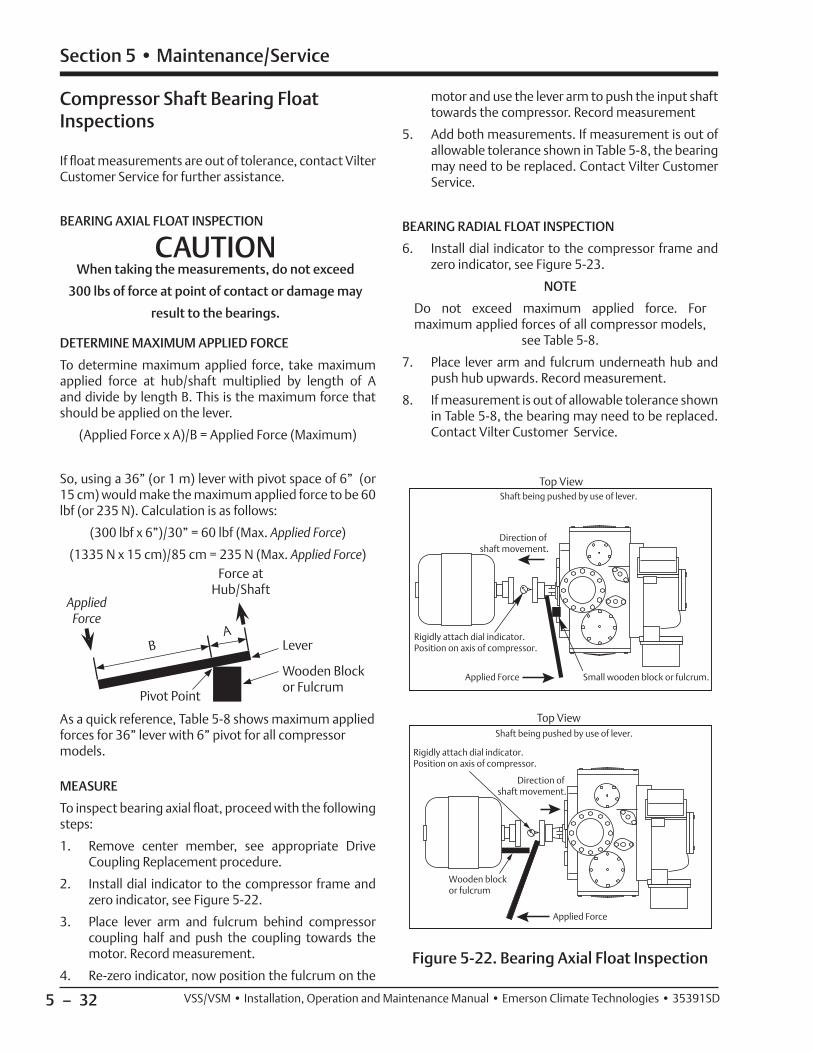
5 – 32
Section 5 • Maintenance/Service
VSS/VSM • Installation, Operation and Maintenance Manual • Emerson Climate Technologies • 35391SD
motor and use the lever arm to push the input shaft towards the compressor. Record measurement
5. Add both measurements. If measurement is out of allowable tolerance shown in Table 5-8, the bearing may need to be replaced. Contact Vilter Customer Service.
BEARING RADIAL FLOAT INSPECTION
6. Install dial indicator to the compressor frame and zero indicator, see Figure 5-23.
NOTE
Do not exceed maximum applied force. For maximum applied forces of all compressor models,
see Table 5-8.
7. Place lever arm and fulcrum underneath hub and push hub upwards. Record measurement.
8. If measurement is out of allowable tolerance shown in Table 5-8, the bearing may need to be replaced. Contact Vilter Customer Service.
Top View
Small wooden block or fulcrum.
Direction of shaft movement.
Shaft being pushed by use of lever.
Applied Force
Rigidly attach dial indicator.Position on axis of compressor.
Top View
Wooden block or fulcrum
Direction of shaft movement.
Rigidly attach dial indicator.Position on axis of compressor.
Applied Force
Shaft being pushed by use of lever.
Figure 5-22. Bearing Axial Float Inspection
Compressor Shaft Bearing Float Inspections
If fl oat measurements are out of tolerance, contact Vilter Customer Service for further assistance.
BEARING AXIAL FLOAT INSPECTION
CAUTIONWhen taking the measurements, do not exceed
300 lbs of force at point of contact or damage may
result to the bearings.
DETERMINE MAXIMUM APPLIED FORCE
To determine maximum applied force, take maximum applied force at hub/shaft multiplied by length of A and divide by length B. This is the maximum force that should be applied on the lever.
(Applied Force x A)/B = Applied Force (Maximum)
So, using a 36” (or 1 m) lever with pivot space of 6” (or 15 cm) would make the maximum applied force to be 60 lbf (or 235 N). Calculation is as follows:
(300 lbf x 6”)/30” = 60 lbf (Max. Applied Force)
(1335 N x 15 cm)/85 cm = 235 N (Max. Applied Force)
BA
Lever
Wooden Block or Fulcrum
Applied Force
Force at Hub/Shaft
Pivot Point
As a quick reference, Table 5-8 shows maximum applied forces for 36” lever with 6” pivot for all compressor models.
MEASURE
To inspect bearing axial fl oat, proceed with the following steps:
1. Remove center member, see appropriate Drive Coupling Replacement procedure.
2. Install dial indicator to the compressor frame and zero indicator, see Figure 5-22.
3. Place lever arm and fulcrum behind compressor coupling half and push the coupling towards the motor. Record measurement.
4. Re-zero indicator, now position the fulcrum on the

5 – 33
Section 5 • Maintenance/Service
VSS/VSM • Installation, Operation and Maintenance Manual • Emerson Climate Technologies • 35391SD
Gate Rotor Float and Gate Rotor Bearing Float Inspection
GATE ROTOR FLOAT INSPECTION
To inspect gate rotor fl oat and bearing fl oat, proceed with the following steps:
1. Isolate the compressor unit, see Compressor Unit Isolation procedure.
2. Remove the side covers from compressor.
3. Position gate rotor blade and damper pin at 90° to the main rotor, see Figure 5-24.
Figure 5-24. Gate Rotor Float
Dial Indicator
Gate Rotor Support
Gate Rotor Blade
Main Rotor
Float
Damper Pin and Bushing
Bushing
Damper Pin
Table 5-8. Maximum Bearing Float
Compressor Model
Max. Axial Float
in. (mm)
Max. Radial Float
in. (mm)
Max. Force
at Hub/Shaftlbf (N)
Max. Applied
Force (36” Lever, 6”
Pivot)
lbf (N)
All0.002
(0.051)-
300 (1335)
60(267)
151, 181, 201, 152, 182, 202, 301, 361, 401
-
0.006(0.152)
100(444)
20(89)
501, 601, 7010.007
(0.178)150
(667)30
(133)
291, 341, 451, 601
0.007(0.178)
150(667)
30(133)
751, 9010.006
(0.152)200
(890)40
(178)
791, 891, 1051, 1201,
1301
0.006(0.152)
300 (1335)
60(267)
1501, 1551, 1801, 1851,
2101
0.007(0.178)
400(1780)
80(356)
2401, 2601, 2801, 3001
0.006(0.152)
600(2670)
120(534)
Side View
Rigidly attach dial indicator.
Direction of shaftmovement.
Applied Force
Shaft being pushed by use of lever.
Figure 5-23. Bearing Radial Float Inspection

5 – 34
Section 5 • Maintenance/Service
VSS/VSM • Installation, Operation and Maintenance Manual • Emerson Climate Technologies • 35391SD
NOTE
Measurements can be an additional 0.020” higher than fl oat dimensions on Table 5-9. If measurement is an additional 0.030” greater than fl oat dimensions,
contact Vilter for further assistance.
Total movement of damper pin in bushing is the gate rotor fl oat.
4. Using dial indicator, take measurement of gate ro-tor fl oat. Measurement should not exceed values as noted above.
Table 5-9. Gate Rotor Float
ModelFloat
in. (mm)
VSM 71 - 401 0.045 (1.143)
VSM 501 - 701 0.045 (1.143)
VSS 451 - 601 0.045 (1.143)
VSS 751 - 901 0.055 (1.397)
VSS 1051 - 1301 0.060 (1.524)
VSS 1501 - 2101 0.060 (1.524)
VSS 2401-3001 0.060 (1.524)
NOTE
Some movement between blade and support is necessary to prevent damage to the compressor blade; however at no time should the blade uncover
the support.
5. Inspect main rotor and gate rotor for abnormal wear due to dirt or other contaminants. If dam-aged, replace gate rotor and/or main rotor.
GATE ROTOR BEARING FLOAT INSPECTION
6. Using dial indicator, position a dial indicator on the gate rotor, see Figure 5-25.
Side View
Wooden block to preventdamage to gate rotor blade.
Direction of rotor movement.Axial force at gate rotor to not exceed 100 lbs.
Gate rotor bearing float being measured.
Use bolt for fulcurm.
Rigidly attach dial indicator.
Applied Force
Figure 5-25. Gate Rotor Bearing Float
7. Use a lever arm pivoting on a bolt with a small block of wood against the gate rotor blade to protect the blade.
8. Gently apply pressure to lever and take measure-ment. Maximum amount of gate rotor bearing fl oat should not exceed 0.002” (0.051 mm).
9. Install gate rotor cover.
10. Install center member, see Drive Coupling Replacement procedure.
11. Perform compressor unit leak check, see Compressor Unit Leak Check procedure.

5 – 35
Section 5 • Maintenance/Service
VSS/VSM • Installation, Operation and Maintenance Manual • Emerson Climate Technologies • 35391SD
Gate Rotor and Support Clearance
When measuring, push the gate rotor against the pin to remove fl oat.
1. Place a straight edge along the side of the gate ro-tor, see Figure 5-27.
2. Measure the gap from the straight edge to the peak of the gate rotor support. For minimum distance, see Figure 5-26.
3. Repeat steps 1 to 2 to check gap along entire gate rotor edge on both sides.
Figure 5-26. Gate Rotor and Support Clearance - Minimum Clearances

5 – 36
Section 5 • Maintenance/Service
VSS/VSM • Installation, Operation and Maintenance Manual • Emerson Climate Technologies • 35391SD
Figure 5-27. Gate Rotor and Support Clearance - Measuring
Gate Rotor Support
Gate Rotor
Straight Edge
Gate Rotor Support
Gate Rotor
Straight Edge
Gate Rotor Support
Gate Rotor
Straight Edge
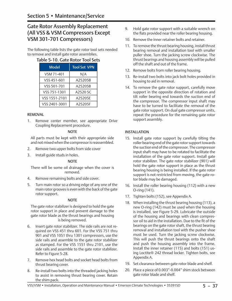
5 – 37
Section 5 • Maintenance/Service
VSS/VSM • Installation, Operation and Maintenance Manual • Emerson Climate Technologies • 35391SD
Gate Rotor Assembly Replacement (All VSS & VSM Compressors Except VSM 301-701 Compressors)
The following table lists the gate rotor tool sets needed to remove and install gate rotor assemblies.
Table 5-10. Gate Rotor Tool Sets
Model Tool Set VPN
VSM 71-401 N/A
VSS 451-601 A25205B
VSS 501-701 A25205B
VSS 751-1301 A2520 5C
VSS 1551-2101 A25205E
VSS 2401-3001 A25205F
REMOVAL
1. Remove center member, see appropriate Drive Coupling Replacement procedure.
NOTE
All parts must be kept with their appropriate side and not mixed when the compressor is reassembled.
2. Remove two upper bolts from side cover
3. Install guide studs in holes.
NOTE
There will be some oil drainage when the cover is removed.
4. Remove remaining bolts and side cover.
5. Turn main rotor so a driving edge of any one of the main rotor grooves is even with the back of the gate rotor support.
NOTE
The gate rotor stabilizer is designed to hold the gate rotor support in place and prevent damage to the gate rotor blade as the thrust bearings and housing
is being removed.
6. Insert gate rotor stabilizer. The side rails are not re-quired on VSS 451 thru 601. For the VSS 751 thru 901 and VSS 1051 thru 1301 compressors, use the side rails and assemble to the gate rotor stabilizer as stamped. For the VSS 1551 thru 2101, use the side rails and assemble to the gate rotor stabilizer. Refer to Figure 5-28.
7. Remove hex head bolts and socket head bolts from thrust bearing cover.
8. Re-install two bolts into the threaded jacking holes to assist in removing thrust bearing cover. Retain the shim pack.
9. Hold gate rotor support with a suitable wrench on the fl ats provided near the roller bearing housing.
10. Remove the inner retainer bolts and retainer.
11. To remove the thrust bearing housing, install thrust bearing removal and installation tool with smaller puller shoe. Turn the jacking screw clockwise. The thrust bearings and housing assembly will be pulled off the shaft and out of the frame.
12. Remove bolts from roller bearing housing.
13. Re-install two bolts into jack bolt holes provided in housing to aid in removal.
14. To remove the gate rotor support, carefully move support in the opposite direction of rotation and tilt roller bearing end towards the suction end of the compressor. The compressor input shaft may have to be turned to facilitate the removal of the gate rotor support. On dual gate compressor units, repeat the procedure for the remaining gate rotor support assembly.
INSTALLATION
15. Install gate rotor support by carefully tilting the roller bearing end of the gate rotor support towards the suction end of the compressor. The compressor input shaft may have to be rotated to facilitate the installation of the gate rotor support. Install gate rotor stabilizer. The gate rotor stabilizer (901) will hold the gate rotor support in place as the thrust bearing housing is being installed. If the gate rotor support is not restricted from moving, the gate ro-tor blade may be damaged.
16. Install the roller bearing housing (112) with a new O-ring (141).
17. Tighten bolts (152), see Appendix A.
18. When installing the thrust bearing housing (113), a new O-ring (142) must be used when the housing is installed, see Figure 5-29. Lubricate the outside of the housing and bearings with clean compres-sor oil to aid in the installation. Due to the fi t of the bearings on the gate rotor shaft, the thrust bearing removal and installation tool with the pusher shoe must be used. Turn the jacking screw clockwise. This will push the thrust bearings onto the shaft and push the housing assembly into the frame. Install the inner retainer (115) and bolts (151) us-ing Loctite® 242 thread locker. Tighten bolts, see Appendix A.
19. Set clearance between gate rotor blade and shelf.
20. Place a piece of 0.003”-0.004” shim stock between gate rotor blade and shelf.

5 – 38
Section 5 • Maintenance/Service
VSS/VSM • Installation, Operation and Maintenance Manual • Emerson Climate Technologies • 35391SD
NOTE
This measurement determines the amount of shims needed for the correct clearance.
21. Measure depth from top of compressor case to top of thrust bearing housing.
22. Use factory installed shim pack (106) and bearing housing cover (116) without the O-ring (143).
NOTE
Replacement blades are precisely the same dimensionally as blades installed originally at factory: Therefore, the same amount of shims will
be required for replacement blades.
90 1C
90 1B
90 1A
Figure 5-28. Gate Rotor Assembly Removal and Tools
Figure 5-29. Gate Rotor Assembly Removal
Use fl ats provided on gate rotor support to prevent rotation when removing bearing retainer.
For VSS 451-601 compressors, do not use side rails.
For VSS 751/901 and 1051-1301compressors, use side rails and assemble gate rotor stabilizer as stamped.
Position leading edge of main rotor groove fl ush with or slightly below back of gate rotor support.
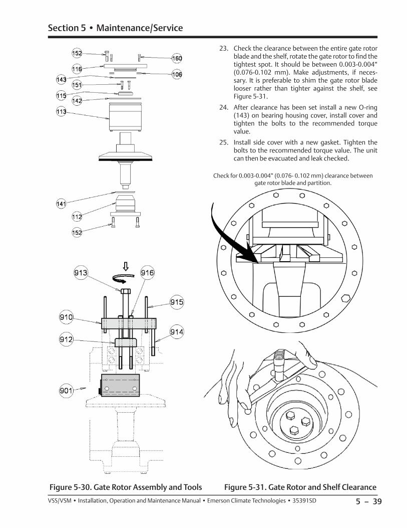
5 – 39
Section 5 • Maintenance/Service
VSS/VSM • Installation, Operation and Maintenance Manual • Emerson Climate Technologies • 35391SD
Figure 5-30. Gate Rotor Assembly and Tools Figure 5-31. Gate Rotor and Shelf Clearance
Check for 0.003-0.004” (0.076- 0.102 mm) clearance between gate rotor blade and partition.
23. Check the clearance between the entire gate rotor blade and the shelf, rotate the gate rotor to fi nd the tightest spot. It should be between 0.003-0.004“ (0.076-0.102 mm). Make adjustments, if neces-sary. It is preferable to shim the gate rotor blade looser rather than tighter against the shelf, see Figure 5-31.
24. After clearance has been set install a new O-ring (143) on bearing housing cover, install cover and tighten the bolts to the recommended torque value.
25. Install side cover with a new gasket. Tighten the bolts to the recommended torque value. The unit can then be evacuated and leak checked.

5 – 40
Section 5 • Maintenance/Service
VSS/VSM • Installation, Operation and Maintenance Manual • Emerson Climate Technologies • 35391SD
INSTALLATION
10. Install the gate rotor support. Carefully tilt the roll-er bearing end of the gate rotor support towards the suction end of the compressor. The compressor input shaft may have to be rotated to facilitate the installation of the gate rotor support.
11. Install the roller bearing housing with a new O-ring. Tighten the bolts to the recommended torque value.
12. Install the spindle with shims and O-ring, tighten bolts, see Appendix A. Measure the clearance be-tween the shelf and blade.
Figure 5-32. Gate Rotor Assembly Breakdown
Gate Rotor Assembly Replacement (VSM 301-701 Compressors ONLY)
REMOVAL
The removal of the gate rotor assembly for the VSM 301-701 compressors is similar for the VSS 901-3001 compressors except that the inner races are secured to the stationary bearing spindle.
1. Remove center member, see appropriate Drive Coupling Replacement procedure.
2. Remove the upper bolt from the side cover and in-stall a guide stud in the hole.
3. Remove remaining bolts and side cover. There will be some oil drainage when the cover is removed.
4. The side cover that contains the suction strainer should have the suction line properly supported before the bolts securing the line to the cover can be removed. After the line is removed, the cover can be removed per paragraph B.
5. Turn the main rotor so the driving edge of the groove is between the top of the shelf or slightly below the back of the gate rotor support. At this point install the gate rotor stabilizing tool.
6. Remove plug on the thrust bearing housing. Loosen the socket head cap screw that is located under-neath the plug. This secures the inner races of the thrust bearings to the spindle.
7. Remove bolts that hold the thrust bearing housing to the compressor. Insert two of the bolts into the threaded jacking holes to assist in removing the bearing housing from the compressor. When the housing is removed, there will be shims between the spindle and thrust bearings. These control the clearance between the shelf and gate rotor blades. These must be kept with their respective parts for that side of the compressor.
8. Remove the bolts from the roller bearing housing. After the bolts have been removed, the housing can be removed from the compressor.
9. To remove the gate rotor support, carefully move the support opposite the direction of rotation and tilt the roller bearing end towards the suction end of the compressor. The compressor input shaft may have to be turned to facilitate the removal of the gate rotor support. On dual gate versions, repeat the procedure for the remaining gate rotor support assembly.

5 – 41
Section 5 • Maintenance/Service
VSS/VSM • Installation, Operation and Maintenance Manual • Emerson Climate Technologies • 35391SD
Figure 5-33. Gate Rotor Thrust Bearing
13. Check the clearance between the entire gate rotor blade and the shelf, rotate the gate rotor to fi nd the tightest spot. It should be between 0.003-0.004“ (0.076-0.102 mm). Make adjustments, if neces-sary. It is preferable to shim the gate rotor blade looser rather than tighter against the shelf.
14. Once the clearance is set remove the spindle. Install new O-ring, apply Loctite 242 thread locker to the socket head cap screw clamping the thrust bearings to the spindle. Torque all bolts, see Appendix A.
15. Install side covers with new gaskets. Tighten bolts, see Appendix A. The unit can now be evacuated and leak checked.
Check for 0.003-0.004” (0.076- 0.102 mm) clearance between gate rotor blade and partition.
Figure 5-34. Gate Rotor and Shelf Clearance

5 – 42
Section 5 • Maintenance/Service
VSS/VSM • Installation, Operation and Maintenance Manual • Emerson Climate Technologies • 35391SD
3. Check damper pin and bushing for excessive wear. Replace if required.
GATE ROTOR BLADE INSTALLATION
4. Install damper pin bushing (120) in gate rotor blade (111) from the back side of the blade. Be sure bush-ing is fully seated.
5. Place blade assembly on gate rotor support. Locating damper over pin.
6. Install washer (119) and snap ring (130) on gate ro-tor assembly. The bevel on the snap ring must face away from the gate rotor blade. After the gate rotor blade and support are assembled, there should be a small amount of rotational movement between the gate rotor and support.
Figure 5-36. Gate Rotor Blade Installation
Gate Rotor Disassembly
1. To perform gate rotor disassembly, remove gate rotor from compressor, see appropriate Gate Rotor Assembly Replacement procedure.
GATE ROTOR BLADE REMOVAL
2. Remove the snap ring and washer from the gate ro-tor assembly. Lift gate rotor blade assembly off the gate rotor support, see Figure 5-35.
Figure 5-35. Gate Rotor Blade Assembly

5 – 43
Section 5 • Maintenance/Service
VSS/VSM • Installation, Operation and Maintenance Manual • Emerson Climate Technologies • 35391SD
GATE ROTOR THRUST BEARING REMOVAL
For removal of thrust bearings on VSM units:
7. Remove bolts (150) from the clamping ring (114), see Figure 5-36.
8. Remove thrust bearing clamping ring.
9. Remove thrust bearings (126) from housing (113).
For removal of thrust bearings on VSS units:
10. Remove retaining ring from gate rotor support.
11. Remove bearings from support.
12. Remove bearing retainer from inner race.
Figure 5-37. Gate Rotor Thrust Bearing
GATE ROTOR THRUST BEARING INSTALLATION
For installation of thrust bearings on VSS units:
13. Install thrust bearings (126) in the housing so the bearings are face to face. The larger sides of the in-ner races are placed together. A light application of clean compressor lubricating oil should be used to ease the installation of the bearings into the housing.
14. Center the bearing retainer ring on housing, use Loctite® 242-thread locker and evenly tighten the bolts to the recommended torque value, see Figure 5-38.
For installation of thrust bearings on VSM 301- 701 units:
15. Install retainer in the back of the inner race of one of the thrust bearings. The back of the inner race is the narrower of the two sides.
16. The bearing with the retainer should be placed in the housing fi rst, retainer towards the support. Install the second bearing. The bearings should be positioned face to face. This means that the larger
sides of the inner races are placed together. A light application of clean compressor lubricating oil should be used to ease the installation of the bear-ings into the gate rotor support.
17. Install the bearing retaining snap ring.
Figure 5-38. Thrust Bearing Installation
GATE ROTOR ROLLER BEARING REMOVAL
18. Remove the snap ring (131), which retains the roll-er bearing in the bearing housing, see Figure 5-38.
19. Remove the roller bearing (125) from the bearing housing (112).
20. Use a bearing puller to remove the roller bearing race (125) from the gate rotor support (110).
GATE ROTOR ROLLER BEARING INSTALLATION
21. Match up the part numbers on the inner race to the part numbers outer race. Press the bearing race (numbers visible) onto the gate rotor support.
22. Install the outer bearing into the bearing housing so the numbers match the numbers on the inner race. Install the snap ring retainer in the housing. The bevel on the snap ring must face away from the roller bearing.

5 – 44
Section 5 • Maintenance/Service
VSS/VSM • Installation, Operation and Maintenance Manual • Emerson Climate Technologies • 35391SD
Figure 5-39. Roller Bearing Assembly
Section 5 • Maintenance/Service
Slide Valve Actuator Assembly Replacement
To replace slide valve actuator assembly, proceed with the following steps:
REMOVAL
WARNINGAt shutdown, open any other valves that may trapliquids to prevent serious injury and/or damage to
equipment.
WARNINGFollow local lockout/tagout procedure. Failure tocomply may result in serious injury, death and/or
damage to equipment.
NOTE
This procedure is applicable to both capacity and volume slide valve actuator assemblies.
1. Shut down the compressor unit, refer to Stopping/Restarting procedure in Section 4.
2. Turn disconnect switches to the OFF position for the compressor unit and oil pump motor starter, if equipped.
3. Allow compressor, motor and surrounding compo-nents to cool prior to servicing.
4. Disconnect connectors from actuator.
NOTE
Note orientation of components to aid in installation.
5. Remove screws and lock washers securing actuator assembly to actuator mount.
6. Remove actuator assembly from actuator mount.
INSTALLATION
CAUTIONWhen installing the slide valve actuator assembly,loosen locking collar down the shaft. Do not use a
screwdriver to pry locking collar into position.
7. Position actuator assembly on mount as noted in removal.
8. Install lock washers and screws to secure actuator assembly to actuator mount.
9. Tighten screws, see Appendix A.
CAUTIONIf installing new actuator, do not connect connectors of power cable or position transmitter cable to newactuator once installed. Connecting connectors tonew actuator will occur during calibration procedure.Failure to comply may result in damage to equipment.
10. Leave connectors disconnected to actuator assembly.
11. Calibrate actuator assembly, see Slide Valve Calibration procedure in Section 4.

5 – 45
Section 5 • Maintenance/Service
VSS/VSM • Installation, Operation and Maintenance Manual • Emerson Climate Technologies • 35391SD
Command Shaft Assembly Replacement
REMOVAL
NOTE
The following steps can be used to remove or install either the capacity or volume command shaft
assemblies.
1. Shut down and isolate compressor unit, see Compressor Unit Shutdown and Isolation procedure.
2. Remove actuator, see Actuator Assembly Replacement procedure.
3. Remove four socket head cap screws (457) and Nord-Lock washers (477) securing mounting plate (415) to manifold.
4. The command shaft and mounting plate may now be removed from the compressor.
INSTALLATION
5. Install the command shaft assembly with a new O-ring (446) on the manifold. Make sure that the command shaft tongue is engaged in the cross shaft slot. Rotate the bearing housing so the vent holes point down, this will prevent water and dust from entering the vents.
6. Install the actuator mounting plate with the four socket head cap screws and Nord-Lock washers se-curing it with proper torque.
7. Perform leak check, see Compressor Unit Leak Check procedure.
Section 5 • Maintenance/Service
Compressor Shaft Seal Replacement
TOOLS
• 25455A - Shaft Seal Tool (VSM 152 - 401)
• 25455B - Shaft Seal Tool (VSS 451 - 601, VSM 501 - 701)
• 25455C - Shaft Seal Tool (VSS 751 - 1301)
• 25455D - Shaft Seal Tool (VSS 1551 - 2101)
REMOVAL
1. Remove bolts (281) securing shaft seal cover (218). to compressor.
NOTE
There will be a small amount of oil drainage as the shaft seal cover is removed.
2. Insert two of bolts (281) into threaded jacking holes to assist in removing shaft seal cover (218).
3. Remove mating ring (219C) from compressor shaft.
4. Remove oil seal (230) from shaft seal cover (218).
5. Using a brass drift and hammer, tap out cup as-sembly (219B) from the back side of shaft seal cover (218).
Figure 5-40. Compressor Shaft Seal Assembly
281 218
219B 219C
260 219
230
INSTALLATION
CAUTIONCare must be taken when handling the cup assemblyand mating ring when installing. Do not touch thecarbon component of the cup assembly or mirror faceon the mating ring as body oil and sweat will cause
corrosion.
Carbon Component
Mirror Face

5 – 46
Section 5 • Maintenance/Service
VSS/VSM • Installation, Operation and Maintenance Manual • Emerson Climate Technologies • 35391SD
NOTE
On VSS 451 and VSS 601 compressors equipped with a roll pin in the shaft seal cover, when replacing the cup assembly (219B) the roll pin in the cover
must be removed.
6. Clean inside shaft seal cover (218) where cup as-sembly (219B) meets inside shaft seal cover.
7. If applicable, remove protective plastic from cup assembly (219B). Do not wipe or touch carbon component of cup assembly.
8. If carbon component of cup assembly (219B) needs cleaning, use alcohol and a lint-free cloth to clean.
9. Apply clean compressor lubricating oil to O-ring on cup assembly (219B).
10. Using shaft seal tool or similar, install cup assembly (219B) in shaft seal cover (218).
11. Clean compressor shaft and shaft seal cavity in compressor housing.
12. Apply clean compressor lubricating oil to mating ring (219C) seating area on compressor shaft.
13. Apply clean compressor lubricating oil to inside area of mating ring (219C).
IMPORTANT
Do not wipe or touch the face of the mating ring (219C) where face meets the carbon component of
the cup assembly (219B).
CAUTIONEnsure the mating ring (219C) is fully seated againstthe shoulder of the compressor shaft. If the matingring is not fully seated against the shoulder, the carboncomponent of the cup assembly (219B) will be damaged
when the shaft seal cover (218) is installed.
14. Align slot in mating ring (219C) with roll pin on compressor shaft. Carefully push mating ring on while holding onto outside area of mating ring until mating ring is fully seated against shoulder on com-pressor shaft.
Figure 5-41. Compressor Shaft Seal Installation
218
O-ring
Remove Roll Pin (If Installed)
Align slot in mating ring (219C) with roll pin on compressor shaft.
O-ring219C
Shoulder on Compressor Shaft
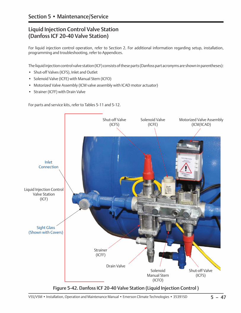
5 – 47
Section 5 • Maintenance/Service
VSS/VSM • Installation, Operation and Maintenance Manual • Emerson Climate Technologies • 35391SD
Figure 5-42. Danfoss ICF 20-40 Valve Station (Liquid Injection Control )
Shut-off Valve(ICFS)
Solenoid Valve(ICFE)
Motorized Valve Assembly(ICM/ICAD)
Strainer(ICFF)
Drain ValveSolenoid
Manual Stem(ICFO)
Shut-off Valve(ICFS)
Liquid Injection Control Valve Station(Danfoss ICF 20-40 Valve Station)
For liquid injection control operation, refer to Section 2. For additional information regarding setup, installation, programming and troubleshooting, refer to Appendices.
The liquid injection control valve station (ICF) consists of these parts (Danfoss part acronyms are shown in parentheses):
• Shut-off Valves (ICFS), Inlet and Outlet
• Solenoid Valve (ICFE) with Manual Stem (ICFO)
• Motorized Valve Assembly (ICM valve assembly with ICAD motor actuator)
• Strainer (ICFF) with Drain Valve
For parts and service kits, refer to Tables 5-11 and 5-12.
Liquid Injection Control Valve Station
(ICF)
Inlet Connection
Sight Glass(Shown with Covers)
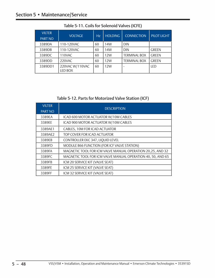
5 – 48
Section 5 • Maintenance/Service
VSS/VSM • Installation, Operation and Maintenance Manual • Emerson Climate Technologies • 35391SD
VILTER
PART NOVOLTAGE Hz HOLDING CONNECTION PILOT LIGHT
3389DA 110-120VAC 60 14W DIN
3389DB 110-120VAC 60 14W DIN GREEN
3389DC 110VAC 60 12W TERMINAL BOX GREEN
3389DD 220VAC 60 12W TERMINAL BOX GREEN
3389DD1 220VAC W/110VAC LED BOX
60 12W - LED
VILTER
PART NODESCRIPTION
3389EA ICAD 600 MOTOR ACTUATOR W/10M CABLES
3389EE ICAD 900 MOTOR ACTUATOR W/10M CABLES
3389AE1 CABLES, 10M FOR ICAD ACTUATOR
3389AE2 TOP COVER FOR ICAD ACTUATOR
3389EB CONTROLLER EKC 347, LIQUID LEVEL
3389FD MODULE B66 FUNCTION (FOR ICF VALVE STATION)
3389FA MAGNETIC TOOL FOR ICM VALVE MANUAL OPERATION 20,25, AND 32
3389FC MAGNETIC TOOL FOR ICM VALVE MANUAL OPERATION 40, 50, AND 65
3389FB ICM 20 SERVICE KIT (VALVE SEAT)
3389FE ICM 25 SERVICE KIT (VALVE SEAT)
3389FF ICM 32 SERVICE KIT (VALVE SEAT)
Table 5-11. Coils for Solenoid Valves (ICFE)
Table 5-12. Parts for Motorized Valve Station (ICF)
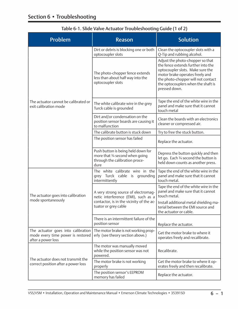
6 – 1VSS/VSM • Installation, Operation and Maintenance Manual • Emerson Climate Technologies • 35391SD
Table 6-1. Slide Valve Actuator Troubleshooting Guide (1 of 2)
Section 6 • Troubleshooting
Problem Reason Solution
The actuator cannot be calibrated or exit calibration mode
Dirt or debris is blocking one or both optocoupler slots
Clean the optocoupler slots with a Q-Tip and rubbing alcohol.
The photo-chopper fence extends less than about half way into the optocoupler slots
Adjust the photo-chopper so that the fence extends further into the optocoupler slots. Make sure the motor brake operates freely and the photo-chopper will not contact the optocouplers when the shaft is pressed down.
The white calibrate wire in the grey Turck cable is grounded
Tape the end of the white wire in the panel and make sure that it cannot touch metal
Dirt and/or condensation on the position sensor boards are causing it to malfunction
Clean the boards with an electronics cleaner or compressed air.
The calibrate button is stuck down Try to free the stuck button.
The position sensor has failed Replace the actuator.
Push button is being held down for more that ¾ second when going through the calibration proce-dure
Depress the button quickly and then let go. Each ¾ second the button is held down counts as another press.
The actuator goes into calibration mode spontaneously
The white calibrate wire in the grey Turck cable is grounding intermittently
Tape the end of the white wire in the panel and make sure that it cannot touch metal.
A very strong source of electromag-netic interference (EMI), such as a contactor, is in the vicinity of the ac-tuator or grey cable
Tape the end of the white wire in the panel and make sure that it cannot touch metal.
Install additional metal shielding ma-terial between the EMI source and the actuator or cable.
There is an intermittent failure of the position sensor Replace the actuator.
The actuator goes into calibration mode every time power is restored after a power loss
The motor brake is not working prop-erly (see theory section above.)
Get the motor brake to where it operates freely and recalibrate.
The actuator does not transmit the correct position after a power loss
The motor was manually moved while the position sensor was not powered.
Recalibrate.
The motor brake is not working properly
Get the motor brake to where it op-erates freely and then recalibrate.
The position sensor’s EEPROM memory has failed
Replace the actuator.

6 – 2 VSS/VSM • Installation, Operation and Maintenance Manual • Emerson Climate Technologies • 35391SD
Section 6 • Troubleshooting
Problem Reason Solution
The actuator does not transmit the correct position after a power loss
The motor was manually moved while the position sensor was not powered.
Recalibrate.
The motor brake is not working properly
Get the motor brake to where it op-erates freely and then recalibrate.
The position sensor’s EEPROM memory has failed
Replace the actuator.
There is a rapid clicking noise when the motor is operating
The photo-chopper is misaligned with the slotted optocouplers
Try to realign or replace the actuator.
The photo-chopper is positioned too low on the motor shaft.
Adjust the photo-chopper so that the fence extends further into the optocoupler slots.
A motor bearing has failed Replace the actuator.
The motor operates in one direction only
There is a loose connection in the screw terminal blocks
Tighten.
There is a loose or dirty connection in the yellow Turck cable
Clean and tighten.
The position sensor has failed Replace the actuator.
There is a broken motor lead or winding
Replace the actuator.
The motor will not move in either direction
The thermal switch has tripped be-cause the motor is overheated
The motor will resume operation when it cools. This could be caused by a malfunctioning control panel. Consult the factory.
Any of the reasons listed in “The mo-tor operates in one direction only”
See above.
The command shaft is jammed Free the command shaft.
Broken gears in the gearmotor Replace the actuator.
Blown relay or fuse.Check and replace blown relay and/or fuse.
The motor runs intermittently, sev-eral minutes on, several minutes off
Motor is overheating and the ther-mal switch is tripping
This could be caused by a malfunc-tioning control panel. Consult the factory.
The motor runs sporadically Bad thermal switch Replace the actuator.
Any of the reasons listed in “The mo-tor will not move in either direction”
See above.
The motor runs but output shaft will not turn
Stripped gears inside the gear motor or the armature has come un-pressed from the armature shaft
Replace the actuator.
Table 6-1. Slide Valve Actuator Troubleshooting Guide (2 of 2)
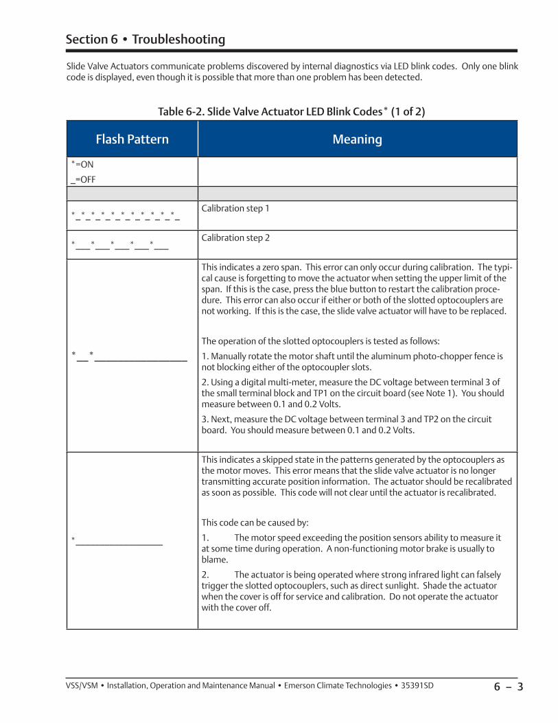
6 – 3VSS/VSM • Installation, Operation and Maintenance Manual • Emerson Climate Technologies • 35391SD
Slide Valve Actuators communicate problems discovered by internal diagnostics via LED blink codes. Only one blink code is displayed, even though it is possible that more than one problem has been detected.
Flash Pattern Meaning
*=ON
_=OFF
*_*_*_*_*_*_*_*_*_*_*_Calibration step 1
*___*___*___*___*___Calibration step 2
*__*________________
This indicates a zero span. This error can only occur during calibration. The typi-cal cause is forgetting to move the actuator when setting the upper limit of the span. If this is the case, press the blue button to restart the calibration proce-dure. This error can also occur if either or both of the slotted optocouplers are not working. If this is the case, the slide valve actuator will have to be replaced.
The operation of the slotted optocouplers is tested as follows:
1. Manually rotate the motor shaft until the aluminum photo-chopper fence is not blocking either of the optocoupler slots.
2. Using a digital multi-meter, measure the DC voltage between terminal 3 of the small terminal block and TP1 on the circuit board (see Note 1). You should measure between 0.1 and 0.2 Volts.
3. Next, measure the DC voltage between terminal 3 and TP2 on the circuit board. You should measure between 0.1 and 0.2 Volts.
*__________________
This indicates a skipped state in the patterns generated by the optocouplers as the motor moves. This error means that the slide valve actuator is no longer transmitting accurate position information. The actuator should be recalibrated as soon as possible. This code will not clear until the actuator is recalibrated.
This code can be caused by:
1. The motor speed exceeding the position sensors ability to measure it at some time during operation. A non-functioning motor brake is usually to blame.
2. The actuator is being operated where strong infrared light can falsely trigger the slotted optocouplers, such as direct sunlight. Shade the actuator when the cover is off for service and calibration. Do not operate the actuator with the cover off.
Section 6 • Troubleshooting
Table 6-2. Slide Valve Actuator LED Blink Codes* (1 of 2)

6 – 4 VSS/VSM • Installation, Operation and Maintenance Manual • Emerson Climate Technologies • 35391SD
*There are two versions of slide valve actuators, version A and B. Only version B is able to display LED blink codes. Slide valve actuator version B can be distinguished by only having a single circuit board as supposed to two circuit boards in version A.
Note 1: TP1 and TP2 are plated-thru holes located close to the slotted optocouplers on the board. They are clearly marked on the board silkscreen legend.
Note 2: The TS1 wire pads are where the motor thermal switch leads solder into the circuit board. They are clearly marked on the board silkscreen legend and are oriented at a 45 degree angle.
Flash Pattern Meaning
*__*__*____________
The motor has overheated. The actuator motor will not run until it cools. Once the motor cools, the actuator will resume normal operation.
Motor overheating is sometimes a problem in hot and humid environments when process conditions demand that the slide valve reposition often. Solutions are available; consult your Vilter authorized distributor for details.
Another possible cause for this error is a stuck motor thermal switch. The ther-mal switch can be tested by measuring the DC voltage with a digital multi-meter between the two TS1 wire pads (see Note 2). If the switch is closed (normal operation) you will measure 0 Volts.
********************
The 24V supply is voltage is low. This will occur momentarily when the actuator is powered up and on power down.
If the problem persists, measure the voltage using a digital multi-meter be-tween terminals 3 and 4 of the small terminal block. If the voltage is >= 24V, replace the actuator.
_*******************
The EEPROM data is bad. This is usually caused by loss of 24V pow-er before the calibration procedure was completed. The actuator will not move while this error code is displayed. To clear the error, calibrate the actuator. If this error has occurred and the cause was not the loss of 24V power during calibration, possible causes are:1. The EEPROM memory in the micro-controller is bad.2. The large blue capacitor is bad or has a cracked lead.
*****____*__________ Micro-controller program failure. Replace the actuator.
Section 6 • Troubleshooting
Table 6-2. Slide Valve Actuator LED Blink Codes (2 of 2)

6 – 5VSS/VSM • Installation, Operation and Maintenance Manual • Emerson Climate Technologies • 35391SD
Problem Solution
Low Oil Pressure at Start
• After failing to start compressor with “Prelube Oil Pump Inhibit”, fi rst allow Discharge pressure, Oil Filter In pressure and Out pressure to equalize. Then restart compressor. If compressor fails to start due to low oil pressure, contin-ue troubleshooting with items below.
• Reset Prelube Oil Pressure Setpoint in Alarms and Trip Setpoints screen to lowest recommended setpoints.
• Check calibration of oil manifold transducer, discharge pressure transducer, and suction transducer.
• Check for correct oil pump motor rotation and operation.
• Ensure transducer isolation valves are open.
• Verify that the correct transducer ranges are selected.
• Check to see all oil line valves are open except the oil dump valve used to fi ll the lines and oil cooler.
• Check oil strainer for dirt.
• Check oil fi lter pressure drop.
• Check “Prelube Oil Pressure Safety Changeover” setpoint is suffi cient in Timers Screen.
• Prelube Oil Pressure is Manifold Pressure minus Discharge Pressure.
Low Run Oil Pressure
• Check solutions in “Low Oil Pressure at Start”.
• Check that there is proper discharge pressure ratio to create differential pres-sure, otherwise oil pressure can’t be maintained. Oil pressure is manifold oil pressure minus the suction pressure. It is a net pressure.
Oil fl ow or oil pressure problems
• Clean oil strainer screen.
• Change oil fi lter, maybe plugged or collapsed.
• Oil pump gears worn internally, excessive end-clearance.
• Oil priming valve used on air-cooled cooler units is open.
• Relief in-line check valve stuck open.
• Pressure ratio too low, oil pump should be on.
Faulty pressure or temperature readings
• Check that the correct pressure or temperature range is selected in the Instrument Calibration menu.
• Check cable connections at device, terminal strips, and PLC input card for correct wiring and shielding (RF noise).
• Check calibration of RTDs and transducers.
Section 6 • Troubleshooting
Table 6-3. Troubleshooting Guide - General Problems & Solutions (1 of 3)

6 – 6 VSS/VSM • Installation, Operation and Maintenance Manual • Emerson Climate Technologies • 35391SD
Section 6 • Troubleshooting
Problem Solution
Oil Loss Issues
• Oil return line from coalescing side of oil separator to suction is closed, not open enough (3/4 turns should be suffi cient), or plugged with debris
• The check valve in the oil return line could be stuck closed or the fl ow is in the wrong direction
• There may be water in the oil affecting the coalescing elements
• Coalescent elements in need of replacement due to age or damage (water contamination)
• The operating conditions are not correct (too high of suction and/or too low discharge pressure) This creates increased gas fl ow which could make the oil separator too small
• The suction or discharge check valve is not working correctly causing oil to escape when the unit stops
• Viscosity of oil incorrect; send sample for testing
• There is an oil leak somewhere in the system
High oil temperature (liquid injection)
• Check for correct setting of all manual values.
• Check for correct operation of 3-way oil mixing valve.
• If your are controlling a step type oil cooler or a VFD oil cooler, verify the cor-rect one is selected in the Confi guration Screen and the amount of steps are entered in the Remote Oil Cooler Control Screen.
• Check the oil cooler and associated piping to make sure it is full of oil before starting.
• Check the oil strainer for debris and clean if necessary.
• Verify that the volume slide actuator is functioning correctly and that the correct compressor size (type) is selected.
• Check that all fans are working.
• Check for correct fan rotation on the oil cooler.
• Check that your operating conditions are within the “As Sold” design conditions.
Capacity/Volume Slide Actuator Alarms/Trips/Symptoms:
• Calibration method not correct
• Actuator or Gear motor not working, or off on overload
• Slide valve carriage assembly out of position, slides binding
• Cross-shaft gears, broken pins
• Command shaft broken
• Slide valve rack or rack shaft damaged
• Check balance piston movement
• Reference Slide Valve Actuator Troubleshooting Guide
• Check I/O fusing
Table 6-3. Troubleshooting Guide - General Problems & Solutions (2 of 3)

6 – 7VSS/VSM • Installation, Operation and Maintenance Manual • Emerson Climate Technologies • 35391SD
Problem Solution
High Amp Draw
• Check calibration at full load.
• Check CT ratio entered in Vission 20/20.
• Check slide valve calibration, especially volume slide.
Vibration
• Check that unit is leveled and secured to mounting pad or fl oor.
• Check supported pipes (i.e. suction and discharge pipe) and make sure they are adequately supported.
• Check for loose bolts and nuts.
• Check condition of compressor and motor (i.e. alignments)
Excessive Motor Backspin• If there is more than normal motor backspin at shutdown, check suction
check valve for proper operation.
Table 6-3. Troubleshooting Guide - General Problems & Solutions (3 of 3)
Section 6 • Troubleshooting

6 – 8 / Blank VSS/VSM • Installation, Operation and Maintenance Manual • Emerson Climate Technologies • 35391SD

7 – 1
Section 7 • Warranty and Parts
VSS/VSM • Installation, Operation and Maintenance Manual • Emerson Climate Technologies • 35391SD
Warranty Claim Processing
This section explains how the warranty claim is pro-cessed and to help clear any questions that may arise prior to contacting customer service. For additional war-ranty information, refer to the Terms and Conditions of your order. Vilter contact information can be found on page i.
1. The warranty process starts with contacting a Vilter Service and Warranty (S&W) department represen-tative. Ensure to have the original Vilter sales order number for the equipment available to better assist you.
2. Our Vilter S&W representative will confi rm if the equipment is within the warranty time frame as de-scribed in the warranty statement.
If the equipment (Part/Compressor/Compressor Motor) is within the warranty time frame, proceed to the follow-ing section regarding the type of equipment:
PART
1. Submit a Purchase Order (PO) to procure the re-placement part:
• The correct Vilter part number and the quantity.
• The original Vilter sales order for the equipment.
2. Request a Return Material Authorization (RMA) number:
• Please provide as much information describ-ing the mode of failure to be recorded on the RMA document. This will assist us with pro-viding a quicker review once we have received the warranty part (ex. Part does not calibrate, part does not read correct temperature, etc.).
• Any additional parts returned on the RMA that is not listed, will be returned freight col-lect or scrapped. The RMA is valid for 60 days from the RMA request date.
3. After replacing the warranty part:
• Ship the part to Vilter per the instructions on the RMA document.
• Please include a copy of the RMA document in the box for identifi cation purposes when the part is received.
4. Part to be evaluated.
5. Warranty Consideration:
• Acceptance – A credit will be provided for the customer part sales order.
• Denial – Notifi cation of denial will be provid-ed to the customer.
COMPRESSOR
Due to the site specifi c nature of compressor warranty, all warranty responses must be mitigated through a Vilter S&W department representative.
COMPRESSOR MOTOR
The warranty is a pass through warranty as stated in the equipment warranty and as such will be determined by the manufacturer. All expenses (i.e. shipping, removal/installation, alignment) are not covered by Vilter’s nor the manufacturer’s warranty.
1. The motor will need to be taken to the nearest Electrical Apparatus Service Association (EASA) re-pair facility or motor manufacturer approved repair facility.
2. The motor shop will provide the motor manufac-turer with the failure analysis.
3. The motor manufacturer will make the warranty disposition.
On Site Service Support
If on site support is required, contact a Vilter S&W de-partment representative to start this process.
Warranty does not cover labor or expenses.
1. A quote, a service rate sheet, and the service terms and conditions will be provided.
2. Submit a PO.
3. Schedule the service visit.

7 – 2
Section 7 • Warranty and Parts
VSS/VSM • Installation, Operation and Maintenance Manual • Emerson Climate Technologies • 35391SD
Remanufactured Bare Shaft Single Screw Compressor Process
These instructions are an overview of how the process works when a bare shaft compressor is in need of being remanufactured. This is to help clear any questions that may arise prior to contacting customer service.
The process begins by contacting Vilter’s Customer Service Department. Vilter contact information can be found on page i.
• Request a “VSS/VSM Single Screw Compressor Rebuild Form”.
• Submit the Rebuild Form and a Purchase Order (PO) for the inspection. A fee is required for the ini-tial inspection and teardown report; contact Vilter Customer Service representative for the latest fee.
• A Return Material Authorization (RMA) number will be provided.
• Send the compressor to Vilter in the condition as stated on the Rebuild Form (i.e. no oil in the compres-sor). Charges may apply if conditions are not met.
• A report will be sent to you after the inspection has been completed explaining what level of rebuild is necessary along with the cost.
NOTE
Inspection and rebuild times will vary, contact Vilter Customer Service representative for further details.
• Submit a new PO for the amount that will be needed for the rebuild. The inspection cost will be waived upon receipt of the new PO. Make sure to provide your “Ship to Address” and “Billing Address”.
EXPLANATION OF REBUILD LEVELS
Level 1
Compressor is in good condition. Replace bearings, gas-kets, shaft seal and O-rings. All hardware is intended to be re-used (when possible). Parts are organized in part kit form.
Level 2
Compressor is in good condition, but requires new gate rotor blades. Replace all items in Level 1 plus new gate rotor blades and bushings.
Level 3 - Current Reman Compressor requires complete rebuilding and re-conditioning to “as-new” condition. All the components listed in Level 2 are replaced plus all hardware, slide assemblies, pistons, and a main rotor (if damaged) and/or gate rotor supports.
NOTE
A Level 1 and Level 2 rebuild will include washing the housing and repainting over the current paint. A Level 3 rebuild will include blasting all the current
paint off before repainting.
BARE SHAFT COMPRESSOR DESCRIPTION
Single Screw Bare Shaft Compressor features include:
• Cast grey iron frame with cast ductile iron discharge manifold and gate rotor covers with discharge con-nection horizontal.
• Standard drive shaft is tapered.
• Standard slide assembly.
• Viton shaft seal O-rings.
• Crating with Purge & Gauge.
• Does not include handwheels or slide valve motors.
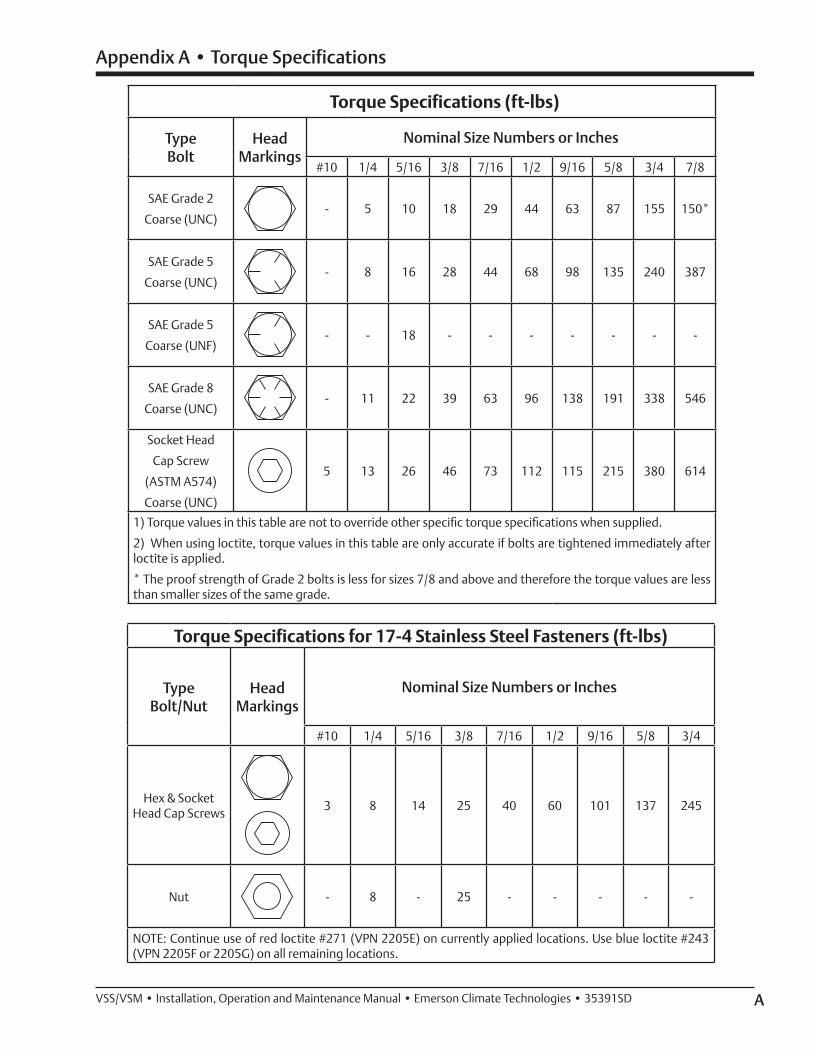
AVSS/VSM • Installation, Operation and Maintenance Manual • Emerson Climate Technologies • 35391SD
Torque Specifications (ft-lbs)
TypeBolt
HeadMarkings
Nominal Size Numbers or Inches
#10 1/4 5/16 3/8 7/16 1/2 9/16 5/8 3/4 7/8
SAE Grade 2
Coarse (UNC)- 5 10 18 29 44 63 87 155 150*
SAE Grade 5
Coarse (UNC)- 8 16 28 44 68 98 135 240 387
SAE Grade 5
Coarse (UNF)- - 18 - - - - - - -
SAE Grade 8
Coarse (UNC)- 11 22 39 63 96 138 191 338 546
Socket Head
Cap Screw
(ASTM A574)
Coarse (UNC)
5 13 26 46 73 112 115 215 380 614
1) Torque values in this table are not to override other specifi c torque specifi cations when supplied.
2) When using loctite, torque values in this table are only accurate if bolts are tightened immediately after loctite is applied.
* The proof strength of Grade 2 bolts is less for sizes 7/8 and above and therefore the torque values are less than smaller sizes of the same grade.
Torque Specifications for 17-4 Stainless Steel Fasteners (ft-lbs)
TypeBolt/Nut
HeadMarkings
Nominal Size Numbers or Inches
#10 1/4 5/16 3/8 7/16 1/2 9/16 5/8 3/4
Hex & Socket Head Cap Screws
3 8 14 25 40 60 101 137 245
Nut - 8 - 25 - - - - -
NOTE: Continue use of red loctite #271 (VPN 2205E) on currently applied locations. Use blue loctite #243 (VPN 2205F or 2205G) on all remaining locations.
Appendix A • Torque Specifications

B VSS/VSM • Installation, Operation and Maintenance Manual • Emerson Climate Technologies • 35391SD
Appendix B • Oil Analysis Report
I.D. # *********
Customer Name
Comp. Mfr. Vilter
Serial Number ****-***Model Number VSM-601Hrs. on Fluid 6049Hrs. on Machine 11239Sample Date Feb 21, 2013
Water by Karl Fischer (ppm)Viscosity 40 C (cSt)TAN Total Acid #ISO Code
Sample Date (Lube Hours)
Silver (Ag)Aluminum (Al)Chromium (Cr)Copper (Cu)Iron (Fe)Nickel (Ni)Lead (Pb)Tin (Sn)Titanium (Ti)Vanadium (V)
Barium (Ba)Calcium (Ca)Magnesium (Mg)Molybdenum (Mo)Sodium (Na)Phosphorus (P)Silicon (Si)Zinc (Zn)
The fluid is in good condition. Sample again in 6 months.
Customer Customer
Oil Type VILTER-717
Customer Address
PRODUCT ANALYSIS REPORT
Report Number: *********
Report Date: 3/4/2013
Evaluation:
Physical Properties Results *
Spectrochemical Analysis21/20/16
0.07764.23
19.5Feb 21, 2013 (6049)
0000000000
00
000000
Wear Metals (ppm)
Contaminant/Additive Metals (ppm)
21/19/160.10664.47147.7
Oct 19, 2012 (4809)
0000000000
00
000000
21/19/140.08066.00
41.4Jul 26, 2010 (5190)
0000000000
00
000000
Accuracy of recommendations is dependent on representative oil samples and complete correct data on both unit and oil
Thank you for this opportunity to provide technical assistance to your company. If you have any questions about this report, please contact us at 1-800-637-8628, or fax 1-989-496-2313 or email us at [email protected] CC List
* Property values should not be construed as specifications
No Action Required
Receive Date Mar 01, 2013

CVSS/VSM • Installation, Operation and Maintenance Manual • Emerson Climate Technologies • 35391SD
Appendix C • Danfoss ICM/ICAD Motorized Valve Quick Start Guide
Appendix C
Danfoss ICM/ICAD Motorized Valve
Quick Start Guide

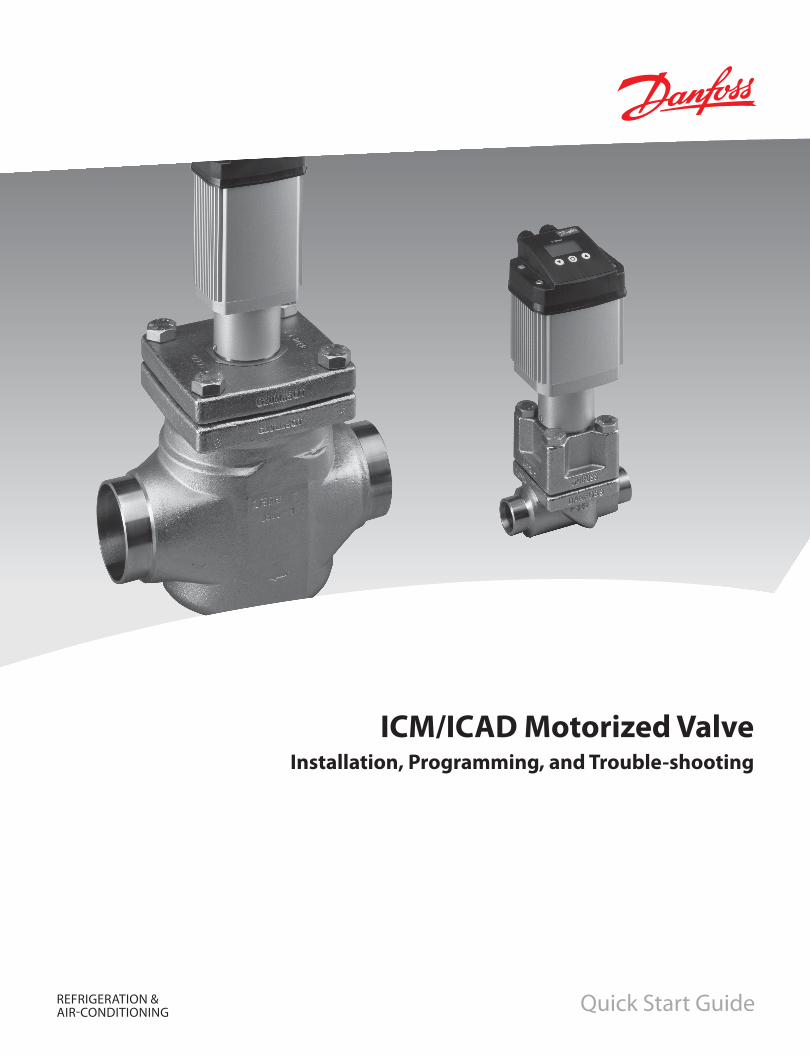
REFRIGERATION & AIR-CONDITIONING
ICM/ICAD Motorized ValveInstallation, Programming, and Trouble-shooting
Quick Start Guide

ICM/ICAD Motorized Valve Installation, Programming, and Troubleshooting
� DKRCI.EI.HT0.A1.�� / 5�0H1639 Danfoss (USCO / MKS), 11- �006
Contents PageInstallation . . . . . . . . . . . . . . . . . . . . . . . . . . . . . . . . . . . . . . . . . . . . . . . . . . . . . . . . . . . . . . . . . . . . . . . . . . . . . . . . . . . . . . . . . . . . . . .3Wiring the ICAD . . . . . . . . . . . . . . . . . . . . . . . . . . . . . . . . . . . . . . . . . . . . . . . . . . . . . . . . . . . . . . . . . . . . . . . . . . . . . . . . . . . . . . . . . .5ICAD Overview . . . . . . . . . . . . . . . . . . . . . . . . . . . . . . . . . . . . . . . . . . . . . . . . . . . . . . . . . . . . . . . . . . . . . . . . . . . . . . . . . . . . . . . . . . .8ICAD Programming . . . . . . . . . . . . . . . . . . . . . . . . . . . . . . . . . . . . . . . . . . . . . . . . . . . . . . . . . . . . . . . . . . . . . . . . . . . . . . . . . . . . . . .9Troubleshooting
The Manual Tool . . . . . . . . . . . . . . . . . . . . . . . . . . . . . . . . . . . . . . . . . . . . . . . . . . . . . . . . . . . . . . . . . . . . . . . . . . . . . . . . . . . . 10Service parameters . . . . . . . . . . . . . . . . . . . . . . . . . . . . . . . . . . . . . . . . . . . . . . . . . . . . . . . . . . . . . . . . . . . . . . . . . . . . . . . . . 10Alarms . . . . . . . . . . . . . . . . . . . . . . . . . . . . . . . . . . . . . . . . . . . . . . . . . . . . . . . . . . . . . . . . . . . . . . . . . . . . . . . . . . . . . . . . . . . . . 11Tips . . . . . . . . . . . . . . . . . . . . . . . . . . . . . . . . . . . . . . . . . . . . . . . . . . . . . . . . . . . . . . . . . . . . . . . . . . . . . . . . . . . . . . . . . . . . . . . . 11Common questions. . . . . . . . . . . . . . . . . . . . . . . . . . . . . . . . . . . . . . . . . . . . . . . . . . . . . . . . . . . . . . . . . . . . . . . . . . . . . . . . . 1�
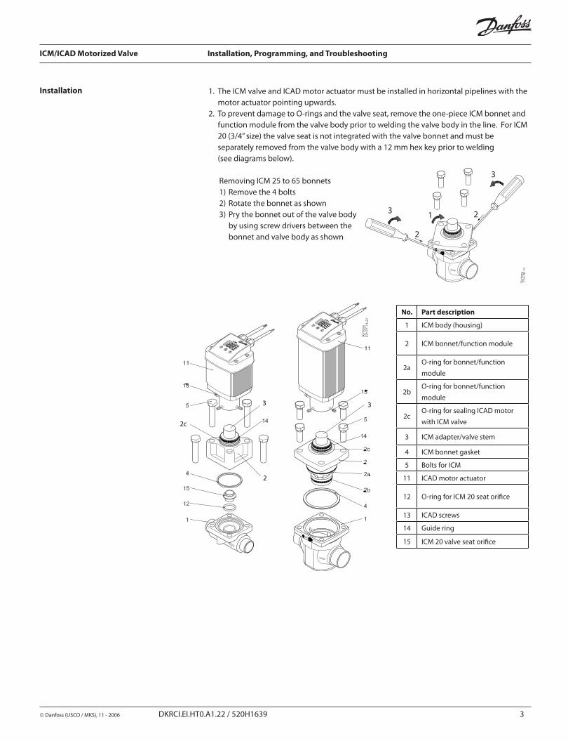
ICM/ICAD Motorized Valve Installation, Programming, and Troubleshooting
Danfoss (USCO / MKS), 11 - �006 DKRCI.EI.HT0.A1.�� / 5�0H1639 3
1. The ICM valve and ICAD motor actuator must be installed in horizontal pipelines with the motor actuator pointing upwards.
�. To prevent damage to O-rings and the valve seat, remove the one-piece ICM bonnet and function module from the valve body prior to welding the valve body in the line. For ICM �0 (3/4” size) the valve seat is not integrated with the valve bonnet and must be separately removed from the valve body with a 1� mm hex key prior to welding
(see diagrams below).
Removing ICM �5 to 65 bonnets1) Remove the 4 bolts�) Rotate the bonnet as shown3) Pry the bonnet out of the valve body
by using screw drivers between the bonnet and valve body as shown
Installation
3
3 1
�
�
2c
3
2
3
No. Part description
1 ICM body (housing)
� ICM bonnet/function module
�aO-ring for bonnet/function module
�bO-ring for bonnet/function module
�cO-ring for sealing ICAD motor with ICM valve
3 ICM adapter/valve stem
4 ICM bonnet gasket
5 Bolts for ICM
11 ICAD motor actuator
1� O-ring for ICM �0 seat orifice
13 ICAD screws
14 Guide ring
15 ICM �0 valve seat orifice

ICM/ICAD Motorized Valve Installation, Programming, and Troubleshooting
4 DKRCI.EI.HT0.A1.�� / 5�0H1639 Danfoss (USCO / MKS), 11- �006
Care should be taken to protect the ICM function module while it is removed from the valve body.
3. Weld the valve body in line making sure the arrow on the valve body is pointing in the direction of flow.4. Remove all debris from the valve body before re-installing the bonnet.5. Install the bonnet/function module into the valve body. a. For ICM �0, make sure that the removable orifice seat is installed in the valve body
with the small O-ring between the orifice seat and body. Make sure the bonnet gasket is installed and in good condition.
b. For ICM �5 through ICM 65, check that the two O-rings on the bonnet and gasket located between the bonnet and valve body are installed and in good condition. A light coating of refrigerant oil on the bonnet O-rings will facilitate installation of the bonnet.
6. Install the four bolts and torque to the following specifications:
Valve body Nm ft lbs
ICM �0 50 37
ICM �5 80 59
ICM 3� 80 59
ICM 40 90 66
ICM 50 100 74
ICM 65 110 81
7. Install the ICAD motor actuator on the ICM valve: a. The ICM valve must not be in its fully opened position while the ICAD motor is
calibrated with the valve at a later step. Therefore, if the opening degree of the ICM valve was changed from the factory setting, it should be set to an opening degree between 0% and 75% using the manual magnet tool. To easily ensure correct positioning, turn the manual tool counter-clockwise until it is clear that it cannot be turned further.
b. Make sure that the ICM adapter/valve stem and inner ICAD motor magnets are completely dry and free from any debris.
c. For applications below freezing, the ICM adapter O-ring (position �c in the diagram on page 3) must be removed, and Molycote G 4500 grease (supplied with ICAD motor) needs to be applied in the O-ring groove on the adapter and on the O-ring before it is re-installed on the ICM adapter. The Molycote grease ensures a good seal between the ICAD motor and the ICM adapter to prevent moisture from entering the ICAD magnets.
d. Place the ICAD motor on the valve stem. e. Push the ICAD motor completely down to the identification ring on the valve stem
and use a �.5 mm hex key to tighten the set screws evenly so the ICAD motor is centered on the ICM adapter (torque: 3 Nm/ �.5 lb-ft).

ICM/ICAD Motorized Valve Installation, Programming, and Troubleshooting
Danfoss (USCO / MKS), 11 - �006 DKRCI.EI.HT0.A1.�� / 5�0H1639 5
Wiring the ICAD Note: The ICAD is powered by a 24 Volt DC power source.
There are two cables pre-mounted and connected to the ICAD motor actuator. Never try to open the ICAD motor because the special moisture seal will be damaged.
The power cable consists of 3 wires:Green: (–) common (ground)Brown: (+) positive from �4VDC power sourceWhite: (+) positive from UPS/battery backup (optional)
The control cable consists of 7 wires:Yellow: (–) common (ground)Gray: (+) positive 4-�0mA or 0-�0mA input to control ICAD motorBlue: (+) positive 4-�0mA or 0-�0mA output from ICAD for valve position feedbackPink: (+) positive �-10V or 0-10V input to control ICAD motor. Also used as a digital input with the yellow wire for on/off solenoid valve operation.White: common alarm (digital NPN transistor output when combined with yellow wire)Brown: indicates ICM is fully open (digital NPN transistor output when combined with yellow wire)Green: indicates ICM is fully closed (digital NPN transistor output when combined with yellow wire)
Supply voltage is galvanically isolated from input and output wires.
Supply voltage�4 V d.c., +10% / -15%Load ICAD 600: 1.� A ICAD 900: �.0 A
Fail safe supplyMin. 19 V d.c.Load ICAD 600: 1.� A ICAD 900: �.0 A
Anolog input - Current or VoltageCurrent
0/4 - �0 mALoad: �00 W
Voltage0/� - 10 V d.c.Load: 10 kW
Analog output 0/4 - �0 mA Load: ≤ �50 W
Digital input - Digital ON/OFF input by means of voltfree contact (Signal/Telecom relays with gold-plated contacts recommended) – Voltage input usedON: contact impedance < 50 W)OFF: contact impedance > 100 kW
Digital output - 3 pcs. NPN transistor outputExternal supply: 5 - �4 V d.c. (same supply as for ICAD can be used, but please note that the
galvanically isolated system will then be spoiled).Output load: 50 WLoad: Max. 50 mA
•••
•••
•
•
•
•
Electrical Data

ICM/ICAD Motorized Valve Installation, Programming, and Troubleshooting
6 DKRCI.EI.HT0.A1.�� / 5�0H1639 Danfoss (USCO / MKS), 11- �006
24 V d.cPower Supply
CUSTOMER SUPPLIED
BrownGreen
Gray
Yellow
PLC
Blue
Active 4-20 mA PLC output to control ICAD
Active 4-20 mA PLC output to control ICAD
Passive 4-20 mA PLC inputfor valve position feedback
Passive 4-20 mA PLC inputfor valve position feedback
White Optional UPS/battery back up
+
+
+
-
-
+
-
Wiring diagram showing ICAD wired with a PLC or other type of third-party electronics
Note: The ICAD supplies the power for the 4-20 mA feedback signal.
Wiring diagram with Danfoss EKC controllers
Note: For instructions on completely wiring an EKC controller, please see the relevant EKC controller manual.
Terminal box is customer supplied.
Yellow (ground)Gray
Blue (+ 4-20 mA)
BrownGreen
Optional position feedbackOnly possible with EKC 347
24 V d.cPower Supply
(+ 4-20 mA)
White
+-
Optional UPS/battery back up+
CUSTOMER SUPPLIED
Terminal box is customer supplied.
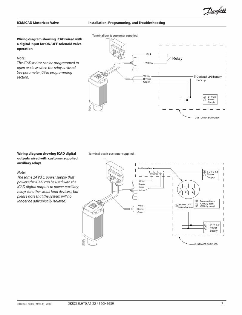
ICM/ICAD Motorized Valve Installation, Programming, and Troubleshooting
Danfoss (USCO / MKS), 11 - �006 DKRCI.EI.HT0.A1.�� / 5�0H1639 7
CUSTOMER SUPPLIED
BrownGreen
Pink
Yellow
Relay
White Optional UPS/battery back up
+
24 V d.cPower Supply
+-
Wiring diagram showing ICAD wired with a digital input for ON/OFF solenoid valve operation
Note:The ICAD motor can be programmed to open or close when the relay is closed. See parameter ¡09 in programming section.
Wiring diagram showing ICAD digital outputs wired with customer supplied auxiliary relays
Note:The same 24 Vd.c. power supply that powers the ICAD can be used with the ICAD digital outputs to power auxiliary relays (or other small load devices), but please note that the system will no longer be galvanically isolated.
CUSTOMER SUPPLIED
5-24 V d.cK 1 K 2 K 3
K 2K 1 K 3K 2K 1 K 3
K1 : Common AlarmK2 : ICM fully openK3 : ICM fully closed
Auxillary relays
WhiteBrownGreenYellow
BrownGreen
Terminal Box
24 V d.cPower Supply
+-
Power Supply
+-
WhiteOptional UPS/battery back up+
Terminal box is customer supplied.
Terminal box is customer supplied.

ICM/ICAD Motorized Valve Installation, Programming, and Troubleshooting
8 DKRCI.EI.HT0.A1.�� / 5�0H1639 Danfoss (USCO / MKS), 11- �006
ICAD Overview Before programming it is important to understand the functionality of the ICAD actuator:
1. The ICAD is a digital stepper motor. As such, it will count steps up and down from the position it believes it is in. Every time, the ICAD is powered on, it will drive itself to the closed position in order to re-establish its base point of reference. It will then move back to the position corresponding to the signal it is receiving from the control wiring.
�. The ICAD can be put into manual mode to move it (using the up and arrows) to a location different from the location that the signal is telling it to be in (see parameter ¡01, p. 6). When in the manual mode, the display screen will be flashing and will continue to flash flashing the % opening of the valve until the ICAD is taken out of the manual mode.
3. The ICAD can be operated in analog mode (for modulating operation) or in digital mode for solenoid operation. The ICAD can receive a variety of control signals (see parameter ¡03, p. 6) and can send a valve position output signal to modulate another ICAD or to a PC or PLC for monitoring. (see parameter ¡06, p. 6)
4. Because the ICAD is employs a digital stepper motor, its speed can be adjusted to any percentage of full speed through the parameter menu. (see parameter ¡04, p. 6)
5. The ICAD can be connected to a �4 VDC UPS (Uninterruptible Power Supply) and can be programmed for actions when the normal power has been cut and the ICAD is operating off of the UPS power. (see parameter ¡07 and ¡12 , p. 6)
1. In order to access the menu, PRESS and HOLD the middle button (�) until the menu screen appears.
�. Once you are in the menu, use the up (3) and down (1) arrow keys to move through the list of parameters.3. To display the current setting of a parameter press the middle button. a. To change the value of a parameter setting, use the up or down arrow to establish
the new setting while in that particular parameter’s display mode. b. Once the new setting for a parameter has been selected, push the center button to
save the charge and return to the menu.4. Repeat this procedure for all parameters. 5. Exit from the parameter list by pressing and holding the middle button for � seconds. The ICAD will automatically exit if no buttons are pushed for �0 seconds.
Operating the ICAD Menu
1. Down arrow push button�. Enter3. Up arrow push button4. Display

ICM/ICAD Motorized Valve Installation, Programming, and Troubleshooting
Danfoss (USCO / MKS), 11 - �006 DKRCI.EI.HT0.A1.�� / 5�0H1639 9
ICAD Parameters
Description Display name Min. Max. Factory
setting Unit Comments
ICM OD (Opening Degree) - 0 100 - % ICM valve Opening Degree is displayed during normal operation.
Running display value (see ¡01, ¡05).
Main Switch ¡01 1 � 1 -
Internal main switch1: Normal operation�: Manual operation. Valve Opening Degree will be flashing. With the down arrow
and the up arrow push buttons the OD can be entered manually.
Mode ¡02 1 � 1 -
Operation mode1: Modulating – ICM positioning according to Analog Input (see ¡03)�: ON/OFF - operating the ICM valve like an ON/OFF solenoid valve controlled via
Digital Input. See also ¡09.
Analog Input signal ¡03 1 4 � -
Type of Analog Input signal from external controller1: 0 - �0 mA�: 4 - �0 mA3: 0 - 10 V4: � - 10 V
Speed at ON/OFF and Modulating Mode ¡04 1 100 100 %
Speed can be decreased. Max. speed is 100 %Not active when ¡01 = �If ¡02 = � the display will indicate speed in display. Low, Med and High also means ON/OFF operation.If ¡04 < = 33, Low is displayed33 < If ¡04 < = 66, Med is displayedIf ¡04 > = 67 High is displayed
Automatic calibration ¡05 0 1 0 -
Not active before ¡26 has been operated.Always auto reset to 0.CA” will flash in the display during calibration, if Enter push button has been activated for two seconds.
Analog Output signal ¡06 0 � � -
Type of A0 signal for ICM valve position0: No signal1: 0 - �0 mA�: 4 - �0 mA
Fail safe ¡07 1 4 1 -
Define condition at power cut when fail safe is installed.1: Close valve�: Open valve3: Maintain valve position4: Go to OD given by ¡12
Digital Input function ¡09 1 � 1Define function when DI is ON (short circuited DI terminals) when ¡02 = �1: Open ICM valve (DI = OFF = > Close ICM valve)�: Close ICM valve (DI = OFF = > Open ICM valve)
Password ¡10 0 199 0 - Enter number to access password protected parameters: ¡26Password = 11
Old Alarms ¡11 A1 A99 - - Old alarms will be listed with the latest shown first. Alarm list can be reset by means of activating down arrow and up arrow at the same time for � seconds.
OD at powercut ¡12 0 100 50 - Only active if ¡07 = 4If fail safe supply is connected and powercut occurs ICM will go to entered OD.
ICM configuration ¡26 0 6 0
NB: Password protected. Password = 11At first start up A1 will flash in display. Enter valve type0: No valve selected. Alarm A1 will become active.1: ICM�0 with ICAD 600�: ICM�5 with ICAD 6003: ICM3� with ICAD 6004: ICM40 with ICAD 9005: ICM50 with ICAD 9006: ICM65 with ICAD 900
Programming the ICAD When the ICAD motor is first powered, the ICAD display will flash an A1 alarm. This means that the ICM valve size that is being used with the ICAD motor needs to be selected in parameter ¡26. Parameter ¡26 is password protected and will not appear in the parameter list until the user enters the password in parameter ¡10. The password is “11,” and will allow the user to access parameter ¡26 where the appropriate valve size is selected. When the ICM valve size is selected, the ICAD will calibrate itself to the ICM valve and will then be ready for control by a 4-�0mA signal. For most applications, this is the only programming that will need to be done if the ICAD is going to be controlled by a 4-�0mA input.
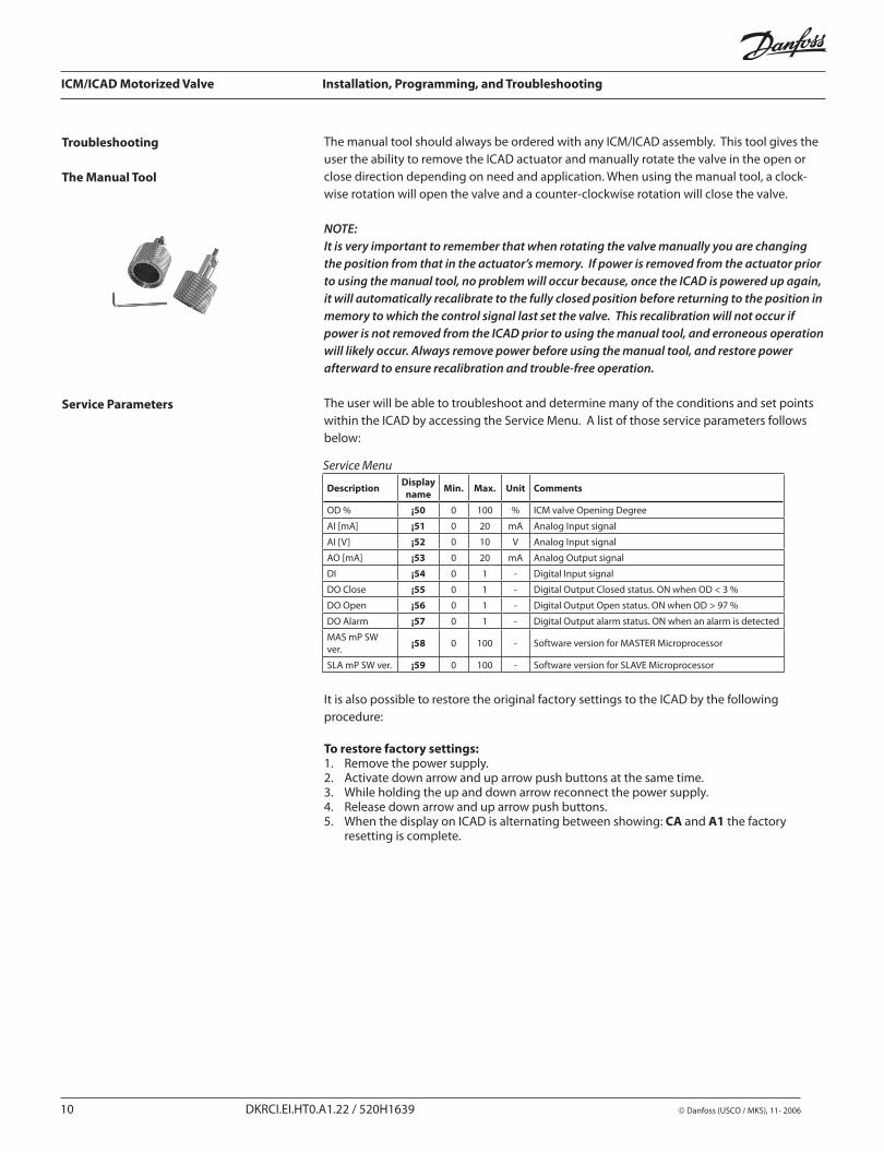
ICM/ICAD Motorized Valve Installation, Programming, and Troubleshooting
10 DKRCI.EI.HT0.A1.�� / 5�0H1639 Danfoss (USCO / MKS), 11- �006
Troubleshooting
The Manual Tool
The manual tool should always be ordered with any ICM/ICAD assembly. This tool gives the user the ability to remove the ICAD actuator and manually rotate the valve in the open or close direction depending on need and application. When using the manual tool, a clock-wise rotation will open the valve and a counter-clockwise rotation will close the valve.
NOTE:It is very important to remember that when rotating the valve manually you are changing the position from that in the actuator’s memory. If power is removed from the actuator prior to using the manual tool, no problem will occur because, once the ICAD is powered up again, it will automatically recalibrate to the fully closed position before returning to the position in memory to which the control signal last set the valve. This recalibration will not occur if power is not removed from the ICAD prior to using the manual tool, and erroneous operation will likely occur. Always remove power before using the manual tool, and restore power afterward to ensure recalibration and trouble-free operation.
The user will be able to troubleshoot and determine many of the conditions and set points within the ICAD by accessing the Service Menu. A list of those service parameters follows below:
It is also possible to restore the original factory settings to the ICAD by the following procedure:
To restore factory settings:1. Remove the power supply.�. Activate down arrow and up arrow push buttons at the same time.3. While holding the up and down arrow reconnect the power supply.4. Release down arrow and up arrow push buttons.5. When the display on ICAD is alternating between showing: CA and A1 the factory
resetting is complete.
Service Menu
Description Display name Min. Max. Unit Comments
OD % ¡50 0 100 % ICM valve Opening Degree
AI [mA] ¡51 0 �0 mA Analog Input signal
AI [V] ¡52 0 10 V Analog Input signal
AO [mA] ¡53 0 �0 mA Analog Output signal
DI ¡54 0 1 - Digital Input signal
DO Close ¡55 0 1 - Digital Output Closed status. ON when OD < 3 %
DO Open ¡56 0 1 - Digital Output Open status. ON when OD > 97 %
DO Alarm ¡57 0 1 - Digital Output alarm status. ON when an alarm is detected
MAS mP SW ver. ¡58 0 100 - Software version for MASTER Microprocessor
SLA mP SW ver. ¡59 0 100 - Software version for SLAVE Microprocessor
Service Parameters

ICM/ICAD Motorized Valve Installation, Programming, and Troubleshooting
Danfoss (USCO / MKS), 11 - �006 DKRCI.EI.HT0.A1.�� / 5�0H1639 11
Alarms There are a number of alarms which are excellent indicators of improper installation orset-up:
Description ICMalarm text Comments
No valve type selected A1 At start-up A1 and CA will be displayed
Controller fault A2 Internal fault inside electronics
Input error A3 Not applicable if ¡01 = � or ¡02 = �When ¡03 = 1 and AI > �� mAWhen ¡03 = � and AI > �� mA or AI < � mAWhen ¡03 = 3 and AI >1� VWhen ¡03 = 4 and AI >1� V or AI < 1 V
Low voltage of fail safe supply A4 If 5 V d.c. < Fail safe supply < 18 V d.c.
Check Supply to ICAD A5 If supply voltage < 18 V d.c.
Problem Possible cause and solution
The valve is not working and an A1 is flashing in the display.
The ICM valve size was not selected in parameter ¡26. See the programming section on page 9.
The valve does not appear to be opening or closing properly
The ICAD was not mounted properly on the valve stem. Solution: Check to make sure that the ICAD was mounted evenly on the ICM valveThe ICAD is not receiving a proper input signal. Solution: Use the service parameters (¡51 for a mA input or ¡52 for a voltage input) to check the input signal that the ICAD is receiving.
1.
�.
The valve position feedback signal is not working when using customer supplied controller/PLC
A power supply was installed in the 4-�0mA/0-�0mA feedback loop. The ICAD motor actuator supplies the power for the 4-�0mA/0-�0mA feedback loop. Solution: Remove any power source that may be supplied to the feedback loop. Wiring problem. Solution: Check the service parameter ¡53 to see what the ICAD is outputting. If this does not reveal anything, check the current output (yellow and blue wires in ICAD control cable) with an ammeter. The feedback output signal was turned off in parameter ¡06. Solution: Check to make sure the setting in parameter ¡06 is correct.
1.
�.
3.
For all other problems, contact Danfoss.
Troubleshooting Tips

ICM/ICAD Motorized Valve Installation, Programming, and Troubleshooting
1� DKRCI.EI.HT0.A1.�� / 5�0H1639 Danfoss (USCO / MKS), 11- �006
Danfoss · Refrigeration & Air-Conditioning Division · 7941 Corporate Drive · Baltimore, MD �1�36Ph 410-931-8�50 · Fax 410-931-8�56 · E-mail: [email protected] · Internet: www.danfoss.com/North_America
Common Questions What happens in the event of a power failure?
The ICAD will remain in the position it is in when power is lost. There are two ways to address this condition:
Add a UPS (Uninterruptible Power Supply) to the power wiring. This is easily accomplished with the green and white wires in the power cable. A UPS is available from Danfoss. The UPS can provide service for up to 9 ICAD 600’s or up to 6 ICAD 900’s.
Note: The UPS is not a continuous power supply. It is used to change the valve position (usually to close the valve) in the event of a power failure. Therefore, the system is not to be run in the UPS mode.
Add a solenoid valve in front of the ICM. This is a very simple solution provided that there is no issue associated with the additional pressure drop through the solenoid valve.
How much power do I need to supply to the ICAD?
The total power required depends on both the ICAD size and the number of ICAD’s powered by the DC power supply. The power for each ICAD is:
For the ICAD 600 (used on ICM �0, �5, and 3�), the power requirement is approximately 30 W For the ICAD 900 (used on ICM 40, 50, and 65), the power requirement is approximately 50 W
How can I monitor the valve position remotely?
The control wiring provides for a 4 to �0 mA or 0 to �0 mA signal output (blue and yellow wires). This signal can be sent to:
A remote displayA PLC or PCAnother ICAD motor to give the same opening position
•
•
•
•
•••

DVSS/VSM • Installation, Operation and Maintenance Manual • Emerson Climate Technologies • 35391SD
Appendix D
Danfoss ICM/ICAD Valve Setup Instructions
Appendix D • Danfoss Valve Station ICF 20-40 Installation Guide


D - 1
Appendix D • Danfoss ICM/ICAD Valve Setup Instructions
VSS/VSM • Installation, Operation and Maintenance Manual • Emerson Climate Technologies • 35391SD
Danfoss ICM/ICAD Valve Setup Instructions
The following items need to be setup in order for the valve to operate properly.
1. Press the “Circle” button on the valve. A value of “01” should be shown on the screen.
2. Press the “Circle” button. There should be a value of “1” shown. If not use the up/down arrows to change it to the correct value. Press the “Circle” button when done.
3. Press the “Up” arrow button. A value of”02” should be shown on the screen.
4. Press the “Circle” button. There should be a value of “1” shown. If not use the up/down arrow buttons to change it to the correct value. Press the “Circle” button when done.
5. Press the “Up” arrow button. A value of “03” should be shown on the screen.
6. Press the “Circle” button. There should be a value of “2” shown. If not, use the up/down arrow buttons to change it to the correct value. Press the “Circle” button when done.
7. Press the “Up” arrow button until a value of “04” is shown on the screen.
8. Press the “Circle” button. There should be a value of “50” shown. If not, use the up/down arrow buttons to change it to the correct value. Press the “Circle” button when done.
9. Press the “Up” arrow button until a value of “07” is shown on the screen.
10. Press the “Circle” button. There should be a value of “1” shown. If not, use the up/down arrow buttons to change it to the correct value. Press the “Circle” button when done.
11. Press the “Up” arrow button until a value of “10” is shown on the screen.
12. Press the “Circle” button. Press the up/down arrow button to change the value to “11”. Press the “Circle” button.
13. Press the “Up” arrow button until a value of “26” is shown on the screen.
14. Press the “Circle” button. Press the up/down arrow buttons to change the value to the correct valve that is on the unit. The value number is listed on the valve. The values and valves are as follows:
0: No valve selected. Alarm A1 will become active.
1: ICM20 with ICAD 600
2: ICM25 with ICAD 600
3: ICM32 with ICAD 600
4: ICM40 with ICAD 900
5: ICM50 with ICAD 900
6: ICM65 with ICAD 900
15. Press the “Circle” button.
The valve is now ready to be used.

Blank VSS/VSM • Installation, Operation and Maintenance Manual • Emerson Climate Technologies • 35391SD

EVSS/VSM • Installation, Operation and Maintenance Manual • Emerson Climate Technologies • 35391SD
Appendix E
Danfoss Valve Station ICF 20-40
Installation Guide
Appendix E • Danfoss Valve Station ICF 20-40 Installation Guide


Installation Guide
Valve StationICF 20-40
© Danfoss A/S (AC-MCI/MWA), 2012-12 DKRCI.PI.FT0.C4.02 / 520H5450 1
027R
9782
027R
9782
ICM
ICM
ICM
ICM
Direction and position
ICF xx-4 ICF xx-6 ICF xx-4 / ICF xx-6 with ICM
Welding
TIG/MIG/SMAW welding Other welding methods
Remove all parts before welding.When the valve is assembled make sure that some rust protective oil is supplied in the valve.Before commissioning inlet and outlet valves must be closed at all time.
Fig. 1a Fig. 1b Fig. 1c
Fig. 2 Fig. 3
Dan
foss
M27H
0049_1
Inlet and outlet stop valves must be closed all the time before commissioning of the installation in ordre to prevent rust formations in the valve. The stop valves are closed when delivered from the factory.ICF must be cooled during the welding (e.g. by means of a wet cloth).

2 DKRCI.PI.FT0.C4.02 / 520H5450 © Danfoss A/S (AC-MCI/MWA), 2012-12
Service and maintenance
Tightening torques
Fig. 4
Fig. 5
ICF 20: ICF 25-40:
50 Nm (36 ft lbs) 80 Nm (58 ft lbs)
50 Nm (36 ft lbs) 50 Nm (36 ft lbs)
For both ICF 20 and ICF 25-40 with ICM and ICFE 25-40Please Note:When used in CO2, the o-rings (see fig. 4) on the ICM and ICFE 25-40 modules can swell (grow).At service it is recommend that new o-rings are installed, before the ICM and ICFE 25-40 function modules are reinstalled in the ICV valve body.
2a
2b
4
12o-rings
For the 4 bolts in all ICF modules

© Danfoss A/S (AC-MCI/MWA), 2012-12 DKRCI.PI.FT0.C4.02 / 520H5450 3
ICF 20
ICFS - stop valve moduleICFR - manual regulating valve module
ICFN - stop/check valve module
ICF 25 - 40
ICFS - stop valve moduleICFR - manual regulating valve module
ICFN - stop/check valve module
ICFO - manual opening module
ICFE - solenoid valve module
Packing glandIf the packing gland is leaking, tighten it carefully with a wrench. Do not apply too much force. Danfoss recommends that you conduct a stepwise tightening of the packing gland. For each turn check for possible leaks.
Before remounting the cap on the modules ICFS (stop valve module), ICFR (manual regulating valve module) or ICFN (stop/check valve module) please ensure that the gasket is present in the cap. Then tighten the cap with 16 Nm (12 ft lbs).
Before remounting the cap on the modules ICFS (stop valve module), ICFR (manual regulating valve module) or ICFN (stop/check valve module) please ensure that the gasket is present in the cap. Then tighten the cap with 24 Nm (18 ft lbs).

4 DKRCI.PI.FT0.C4.02 / 520H5450 © Danfoss A/S (AC-MCI/MWA), 2012-12
Operating the manual opener on ICFE 20H solenoid valve module
Operating the manual opener on ICFE 25 solenoid module
To force open the solenoid by the manual stem turn it counter clockwise full way up. (Manual mode)To operate the solenoid in automatic mode, turn the manual stem clockwise until the locking ring stops. Do not force the spindle further. If the locking ring is damaged or removed the spindle will start to leak.The valve cannot be forced closed by the manual stem.
ICFE 25-40 solenoid valve module
Locking ring
Turn spindle counter clockwise to open
Remove the cap on the side of the ICFE 20HAt 9 o’clock position the manual opener is disabled (not active)To force the ICFE 20H solenoid to open use a 5 mm Allen key and turn it clockwise to 3 o’clock position.
Manual opener disabled Position for forced open

© Danfoss A/S (AC-MCI/MWA), 2012-12 DKRCI.PI.FT0.C4.02 / 520H5450 5
Module location
ICF 20-4
0, 2 or 4 optional side ports(up to 6 on request)
Fig. 6
In order to supply the ICF valve station best suited for liquid lines and hot gas lines certain function modules are dedicated to specific module ports.
Function M1 M2 M3 M4
ICFS 20 - Stop valve module
ICFR 20A - Manual regulating valve module
ICFF 20 - Filter module
ICFE 20 - Solenoid valve module
ICFE 20H - Solenoid valve module
ICFA 10 - Electronic expansion valve module
ICFO 20 - Manual opening module
ICFC 20 - Check valve module
ICFN 20 - Stop/check valve module
ICM 20-A, B or C - Motor valve module
ICFB 20 - Blank top cover
location not possible
ICF 20-6 In order to supply the ICF valve station best suited for liquid lines and hot gas lines certain function modules are dedicated to specific module ports.
Function M1 M2 M3 M4 M5 M6
ICFS 20 - Stop valve module
ICFR 20A - Manual regulating valve module
ICFF 20 - Filter module
ICFE 20 - Solenoid valve module
ICFE 20H - Solenoid valve module
ICFA 10 - Electronic expansion valve module
ICFO 20 - Manual opening module
ICFC 20 - Check valve module
ICFN 20 - Stop/check valve module
ICM 20-A, B or C - Motor valve module
ICFB 20 - Blank top cover
location not possible
0, 4 or 6 optional side ports(up to 10 on request)
Fig. 7

6 DKRCI.PI.FT0.C4.02 / 520H5450 © Danfoss A/S (AC-MCI/MWA), 2012-12
ICF 25-4 → 40-4
ICF 25-6 → 40-6
Module location
Function M1 M2 M3 M4 M5 M6
ICFS 25-40 - Stop valve module
ICFR 25-40 A or B - Manual regulating valve module
ICFF 25-40 - Filter module
ICFE 25-40 - Solenoid valve module
ICFC 25-40 - Check valve module
ICFN 25-40 - Stop/check valve module
ICM 25-A or C - Motor valve module
ICFB 25-40 - Blank top cover
ICFW 25-40 - Welding module, 25DIN
location not possible
In order to supply the ICF valve station best suited for liquid lines and hot gas lines certain function modules are dedicated to specific module ports.
Function M1 M2 M3 M4
ICFS 25-40 - Stop valve module
ICFR 25-40 A or B - Manual regulating valve module
ICFF 25-40 - Filter module
ICFE 25-40 - Solenoid valve module
ICFC 25-40 - Check valve module
ICFN 25-40 - Stop/check valve module
ICM 25-A or C - Motor valve module
ICFB 25-40 - Blank top cover
ICFW 25-40 - Welding module, 25DIN
location not possible
In order to supply the ICF valve station best suited for liquid lines and hot gas lines certain function modules are dedicated to specific module ports.
Fig. 8
Fig. 9
Dan
foss
M27
H00
04_1
0, 2 or 4 optional side ports(up to 6 on request)
0, 4 or 6 optional side ports(up to 10 on request)

© Danfoss A/S (AC-MCI/MWA), 2012-12 DKRCI.PI.FT0.C4.02 / 520H5450 7
ICFF 20 filter module
ICFS 20 stop valve module
1. Spindle2. Thread part3. AL-gasket4. Bonnet5. Hex-head bolt6. Flange7. Gasket
1. Gasket2. Bonnet3. Hex-head bolt4. Flange5. Gasket6. Filter element7. Plug8. Plug 1/4” RG or 3/8” NPT
ICFE 20 solenoid valve module
1. Armature tube2. Armature tube nut3. Flange4. Gasket5. Hex-head bolt6. Seat
ICFO 20 manual opening module
1. Seal cap2. Gland nut3. Seal cap gasket 4. Sealing ring5. Rubber gasket 6. Spindle7. Hex-head bolt 8. Flange
ICFR 20 manual regulating valve module
1. Spindle2. Thread part3. AL-gasket4. Bonnet5. Hex-head bolt6. Flange7. Gasket8. Seat
ICFC 20 check valve module
1. Bonnet2. Hex-head bolt3. Flange4. Gasket
ICM 20 A, 20 B or 20 C motor valve module
1. Adapter2. Hex-head bolt3. O-ring4. Bonnet5. Gasket6. Seat
The function modules - ICF 20
ICFE 20H solenoid valve module
1. Piston
3. Piston ring4. Bonnet cylindre5. Manual opener6. Armature tube7. Armature tube nut8. Gasket

8 DKRCI.PI.FT0.C4.02 / 520H5450 © Danfoss A/S (AC-MCI/MWA), 2012-12
ICFA 10 Electronic expansion valve
1. Armature tube2. Armature tube nut3. Hex-head bolt4. Flange5. Gasket6. Adaptor
ICFN 20 stop/check valve module
1. Spindle2. Thread part3. AL-gasket4. Bonnet5. Hex-head bolt6. Flange7. Gasket
ICFB 20 blank top cover module
1. Hex-head bolt2. Flange3. Gasket
ICFF 20E extended filter module
1. Dirt protection plug2. Bonnet3. Hex-head bolt M12x804. Flange5. Gasket6. Filter element7. Plug 3/8” NPT8. Filter adaptor
ICFS 25-40 stop valve module
1. Spindle2. Thread part3. O-ring4. Bonnet5. Hex-head bolt6. Flange7. Gasket
ICFR 25- 40 A or B manual regulating valve module
1. Spindle2. Thread part3. O-ring4. Bonnet5. Hex-head bolt6. Flange7. Gasket
The function modules - ICF 20

© Danfoss A/S (AC-MCI/MWA), 2012-12 DKRCI.PI.FT0.C4.02 / 520H5450 9
ICFF 25-40 filter module
1. Al gasket2. Bonnet3. Hex-head bolt4. Flange5. Gasket6. Filter element7. Plug 1/4” RG or 3/8” NPT
ICFE 25-40 solenoid valve module
1. Armature tube2. Armature tube nut3. Bonnet4. Gasket5. Hex-head bolt6. Seat
ICM 25 A or 20 B motor valve module
1. Adapter2. Hex-head bolt3. O-ring4. Bonnet5. Gasket6. Seat
ICFN 25-40 stop/check valve module
1. Spindle2. Thread part3. O-ring4. Bonnet5. Hex-head bolt6. Flange7. Gasket
ICFB 25-40 blank top cover module
1. Hex-head bolt2. Flange3. Gasket
ICFC 25-40 check valve module
1. Bonnet2. Hex-head bolt3. Flange4. Gasket
ICFW 25-40 Welding module 25 DIN
1. Hex-head bolt2. Flange3. Gasket4. Weld connection
1
2
3
4
5
6
The function modules - ICF 25-40
ICFF 25-40E extended filter module
1. Dirt protection plug 3/8” NPT2. Bonnet3. Hex-head bolt M12x1404. Flange5. Gasket6. Filter element7. Plug 3/8” NPT

10 DKRCI.PI.FT0.C4.02 / 520H5450 © Danfoss A/S (AC-MCI/MWA), 2012-12
ENGLISH
Installation
RefrigerantsApplicable to HCFC, non flammable HFC, R717 (Ammonia) and R744 (CO2).
The use of ICF valve stations with flammable hydrocarbons is not recommended.
The ICF is only recommended for use in closed circuits. For further information please contact Danfoss.
Temperature range–60/+120°C (–76/+248°F)
Pressure rangeThe ICF is designed for a max. working pressure of 52 bar g (754 psi g).
Technical dataThe ICF can be used in suction, liquid, hotgas and liquid/vapor lines. The ICF are available with 4 or 6 function modules. The ICF regulates the flow of the medium by modulation or on/off function, depending on function modules installed on the ICF.
Regulating rangeDependent on the chosen type and combination of modules installed in the valve.
InstallationThe ICF must be installed according to fig. 1. The ICF must be installed with the arrow in the direction of the flow).
The ICF will be delivered with all the function modules fully assembled. The modules can be taken off for service or inspection and may be rotated 4 x 90° in relation to the valve body upon installation.
The ICF may be fitted with a spindle for manual opening of the solenoid valve.
The ICF is designed to withstand a high internal pressure. However, the piping system should be designed to avoid liquid traps and reduce the risk of hydraulic pressure caused by thermal expansion.
It must be ensured that the ICF is protected from pressure transients like “liquid hammer” in the system.
Welding The ICF valve station can be welded by using either TIG/MIG/SMAW welding (fig. 2) or gas welding (fig. 3).
Attention!It is not necessary to remove any of the modules before TIG/MIG/SMAW welding; however, it must be ensured that the valve is cooled during the welding ( e. g. by wet cloth) and that the ICF is protected against weld splatter. Inlet and outlet stop valves must be closed all the time before commissioning in order to protect ICF against rust formations.
The ICF valves are delivered with closed stop valves.During Gas welding the modules must be removed.Avoid welding debris and dirt in the valve body and the function module. The housing must be free from stresses (external loads) after installation. The ICF must not be mounted in systems where the outlet side of the ICF is open to atmosphere. The outlet side of the ICF must always be connected to the system or properly capped off, for example with a welded-on end plate.
Surface protection and identificationThe external surface is zinc-chromated to provide corrosion protection according to EN 12284:2003 8.13. The Zinc-Chromatization does not cover the welding connections. After installation has been completed the external surface of the valve must be protected against corrosion with a suitable top coating.Protection of the ID label when painting the ICF is recommended.
Precise identification of the ICF is made via the ID label on each of the 4 or 6 function modules.
Maintenance ServiceThe ICF valve stations are easy to service. Do not open the ICF while the it is still under pressure.
Debris blocking the bolt hole will need cleaning. Upon opening and removal of the function modules:- Check that the O-rings on the function module has not been damaged. A valve with a damaged o-ring might not modulate according to the specification.
For both ICF 20 and ICF 25 - 40 with ICM
Please Note: When used in CO2, the o-rings (see fig.4) on the ICM and ICFE 25-40 modules can swell (grow). At service it is recommend that new o-rings are installed, before the ICM function module is reinstalled in the ICF valve body.
- Check that the piston and cylinder is free of scratches and look for wear marks. If the wear is excessive the function module should be replaced to prevent false pilot signal around the piston ring.- Check that the movement of the cylinder and valve seat is free and with low friction.- If the teflon valve plate has been damaged, the function module must be replaced.
- On ICM 20 motor valve modules check that the PEEK seat has not been damaged or scratched. If damaged or scratched; replace the PEEK seat.
AssemblyRemove any dirt from the housing before the ICF is assembled. - Check that all channels in the ICF are free of particles or similar debris. If possible, apply some refrigeration oil to ease the insertion of the modules and to protect the O-rings.
Tightening (fig. 5)Tighten the top cover with a torque wrench, to the values indicated in the table.Use only original Danfoss parts, including O-rings and gaskets for replacement.
Materials of new parts are certified for the relevant refrigerant.
In cases of doubt, please contact Danfoss.
Drawings are only for illustration, not for dimensioning or construction. Danfoss accepts no responsibility for errors and omissions.
Danfoss Industrial Refrigeration reserves the right to make changes to products and specifications without prior notice.


35391SD Rev. 0a (3/15) Emerson and Vilter are trademarks of Emerson Electric Co. or one of its affi liated companies. © 2014 Emerson Climate Technologies, Inc. All rights reserved. Printed in the USA.
Related Documents