INSTALLATION & SERVICE MANUAL VSS Sound Reception System A100K10874

Welcome message from author
This document is posted to help you gain knowledge. Please leave a comment to let me know what you think about it! Share it to your friends and learn new things together.
Transcript

INSTALLATION & SERVICE MANUAL
VSS Sound Reception System
A100K10874

Installation & Service manual VSS system
A100K10874 i
Contents
1. Introduction.............................................................................................1 2. General Description............................................................................2 3. Installation...............................................................................................3 3. 1 Main Unit VSS-111 .................................................................................................. 3 3.2. VSS-222 microphones .............................................................................................. 3 4. Setting & Adjustment .........................................................................4 4.1 General....................................................................................................................... 4 4.2 Microphone adjustment ............................................................................................. 4 4.3 Remote Muting when using own typhoon................................................................. 4 4.4 Adjustment of Squelch function ................................................................................ 4 5. Operation of the system ...................................................................5 6. Specifications ........................................................................................5 7. Datasheet, Electrical & Mechanical drawings........................6
Installation & Service manual VSS system
A100K10874 1
1. Introduction About this document This document is intended to give relevant information on the system features, available equipment, typical configurations, simplified wiring and technical data for the concept. Publication Log
Title: Sound Reception System VSS Installation & Service Manual Doc.no. VSS_is Author this revision Svend Egil Nilsen Verified By: Jan Thorsen
Revision Issued Changes / Comments V.1.1 1998. First release,Vingtor Marine Author Bjørn Holmer 01 2001.03.16 Second release, Stento Marine ID. From now on revision status
01,02…. 02 2002.07.01 Third release, Zenitel Marine ID Additional part;Introduction. Doc.
for new function; squelch. 03 2003.06.19 4th. release, with supplementary EMC and environmental-testing by
DNV. New rev. for circuit diagram and partlist From now on; VINGTOR brand.
03 2006.03.24 Simple change without new rev.no. Incorrect measurement on fastening bracket for microphone VSS-222. New rev. of datasheet VSS-222_ds rev.04 and drawing VSS-222_md rev.03
A100K10874 2010.08.27 New front and back pages. Doc.no. VSS_is rev.03 is replaced by this document no.
A100K10874 2011.02.01 Updating of IP rating
Zenitel Marine assumes no responsibility for any errors that may appear in this publication, or Zenitel Norway AS and its subsidiaries assume no responsibilities for any errors that may appear in this publication, or for damages arising from the information in it. No information in this publication should be regarded as a warranty made by Zenitel Norway AS.
The information in this publication may be updated or changed without notice. Product names mentioned in this publication may be trademarks, they are used only for identification.
Zenitel Norway AS, February 2011

Installation & Service manual VSS system
A100K10874 2
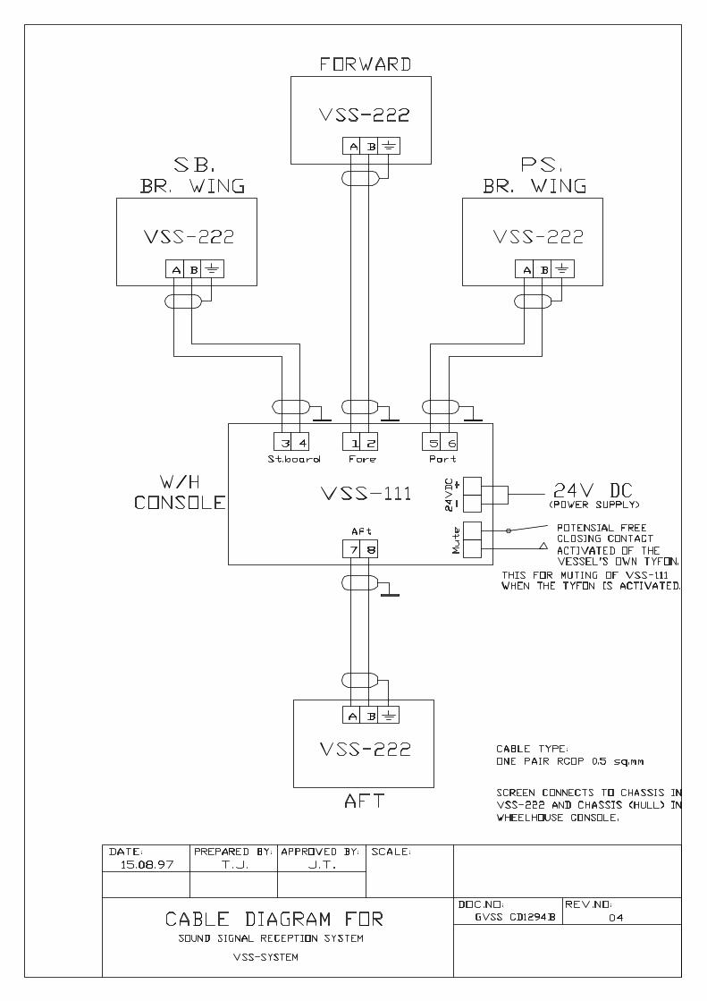
2. General Description The VSS system enable the navigator on a one man operated bridge to listen to the environmental sound signals from other ships or fog horns that are audible outside the ship when standing inside the enclosed bridge space. The system is monitoring, according to rules; Resolution MSC.86(70), frequencies between 70 and 820 Hz. Four (4) VSS-222 weatherproof microphones are mounted outside the wheelhouse and connected to the VSS-111 audio amplifier and loudspeaker within the bridge. The VSS system has «remote muting» of the amplifier circuit when the vessel’s own tyfon is activated. The VSS system has squelch function. Adjustable muting of undesirable sound sources. Microphone Direction Detector (MDD) By use of four microphones the MDD will detect the direction of the incoming signal and activate the corresponding LEDs at the VSS-111 front panel The four microphones operate in pair depending of the direction of the received sound signal. The microphone first detecting the sound will be registrated in MDD and it will lock against influence from the other microphone. This will repeat each time a signal is strong enough to trig the detector. The «bridgewing» pair of microphone will indicate if the sound is coming from the Sb or Ps direction, while the other pair tell if the sound signal is coming from «Fore» or «Aft». The combination of above will indicate the actual sector (see illustration above) The VSS «Sound Signal Reception System» has been EMC tested according to relevant CENELEC and IEC standards and type tested in order to qualify for Type Approval by Det Norske Veritas / Bureau Veritas / RINA Det Norske Veritas (DNV), Certification Notes no. 2.4.; «Environment test specification for Instrumentation
and Automation Equipment» Optional EMC requirements: Det Norske Veritas (DNV) Supplementary EMC and Environmental Testing.
Technical Report No.2003-3124 Revision No.01 IEC 60945, Fourth edition, 2002-08 EN50081-1 / EN50082-2 (CENELEC, Harmonized standards)
4 x VSS-222
ON
OFF
VOLUME
DIMMER
SQUELCH

Installation & Service manual VSS system
A100K10874 3
3. Installation 3. 1 Main Unit VSS-111 For physical dimensions, recommended panel cut-out, size of mounting holes etc. please see mechanical drawing VSS-111_dd. According to rules the system loudspeaker(s) should be installed so that incoming signals are audible at all positions inside the bridge. The reproduction of the sound signal inside the bridge is normally done by use of the VSS-111 built-in loudspeaker (8 ohm). If more than one loudspeaker required the built-in one can be disconnected (P2) and replacement loudspeakers can be connected. (total impedance = 8 ohm) 3.2. VSS-222 microphones The efficiency of the system depends upon the microphone installation. The location of the microphones outside the wheelhouse are critical due to ship speed, wind and vibrations. Normally the microphones are mounted outside on each side of the bridge bulkhead or top plus if wanted one in the bow and one aft. Precautions:
* Mount the microphones leeward due to wind and the ship's speed. * Do not mount the microphone too close to regularly opened doors or windows near the operator panel and loudspeaker. This prevent the system to start oscilliating due to acoustic feedback * When the microphone bracket is fastened on the bulkhead, let the cable do a one-turn service-loop before entering the micro-phone housing. The loop will ensure that the effect of the vibrations shock absorber is not impaired. This is necessary to reduce ship-born vibrations reaching the sensitive microphone elements.
NOTE! The cable screen is connected to the microphone housing. In the operators panel (VSS-111) the cable screens must all be proper terminated to the chassis in the W/H console. Above is important to avoid noise problems The panel should of course be suitable placed near the person operating it. On the VSS-111 main PC board Connect the microphone cables as shown in the figure.
1234
P1
Screen
5678
C1 C2
C3 C4
Mic
roph
one
inpu
ts Fore mic.
Aft mic.
Ps. mic.
Stb. mic.
All screens to chassisin W/H console
A
BA
BA
BA
B

Installation & Service manual VSS system
A100K10874 4
4. Setting & Adjustment 4.1 General The settings are factory adjusted and set to a level close to the real operation conditions as possible. But in order to optimise the performance of the system, may be the installation must be adjusted on site. 4.2 Microphone adjustment To prevent that the LEDs are activated by normal background noise, the microphone input sensitivity can be adjusted. The threshold level for the received sound signals, the amplifier input sensitivity, is individually adjusted by the four screwdriver potentiometers; RV1, RV2, RV3 and RV4. This level adjustments are necessary to limit the background noise trigging of the LED circuitry. VSS-111 main PC board 1. Power up the system. The surrounding noise level should be as close to the real operating
conditions as possible. 2. Adjust each of the four channel’s potentiometer anti clockwise until the corresponding
LED light up and clockwise until it turns off and then carefully anti clockwise until light up again.
3. NB! Avoid adjustments during unnatural noise situations. If necessary turn up the volume control on front and listen to separate the sounds.
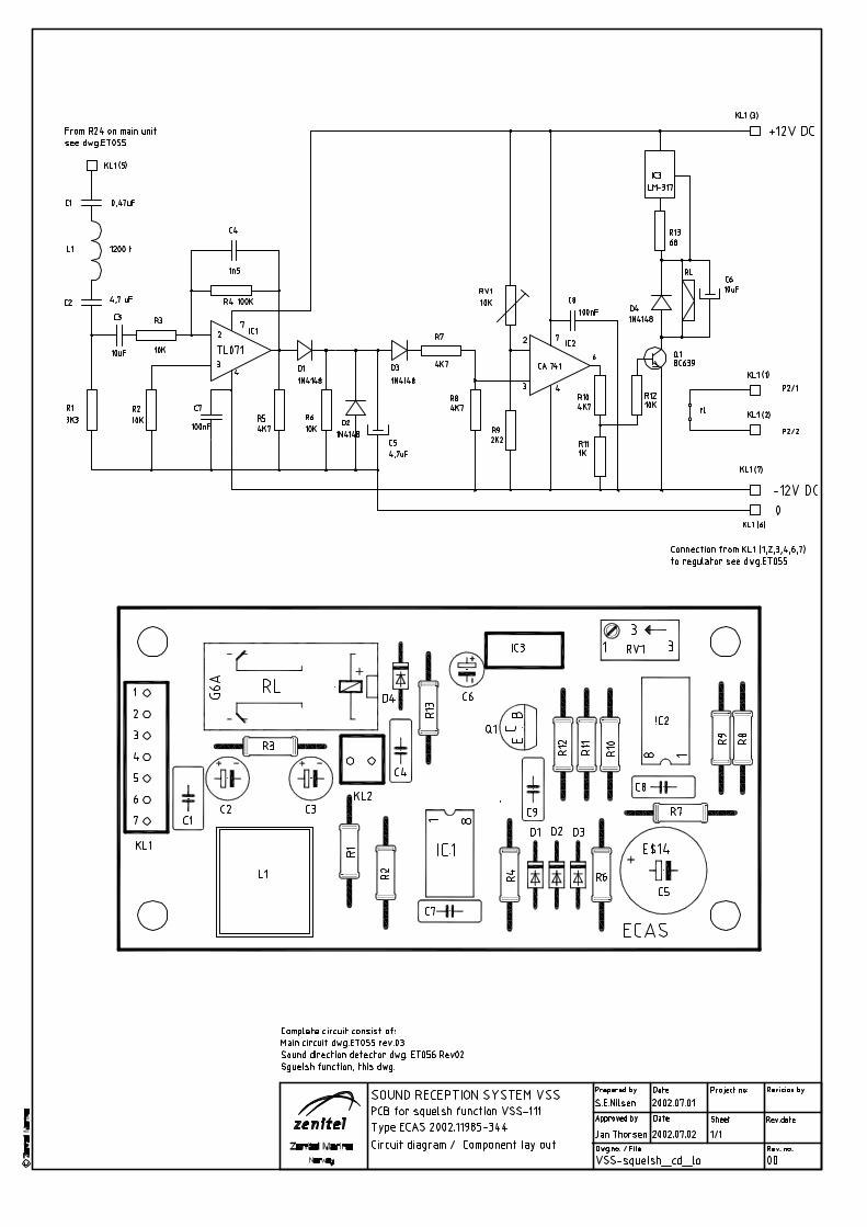
4.3 Remote Muting when using own typhoon VSS-111 is prepared for «remote muting» of the amplifier circuit when the vessel’s own typhoon is activated. The function is obtained by activating relay RL1. The relay is activated when the typhoon is activated. Connect a potential free closing contact to the P2 terminals 1 and 2 , marked "Mute" as shown in the figure. The closing contact to be in parallel with the operating of the vessels own typhoon. 4.4 Adjustment and setting of Squelch function Note! The squelch function is independent of the LED settings. The surrounding noise level is different and to avoid the system to be activated by undesirable sound sources as from other technical equipment and from arbitrary activity as waves and birds, the squelch setting may be adjusted on site. The sensitivity is factory adjusted and set to approx.3mV input signal. (Middle position for the squelch potentiometer) To change this level you will need a sound source near as the undesirable sound sources as possible. A radio can be used. Place the source min.1mtr. from one of the microphones.
4
1
2
3
RV1
RV2
RV3
RV4
P1
P2
Mute
+ _
24VDC
Speaker 8 ohm
P2
C38
D17
D16
RL1
F1

Installation & Service manual VSS system
A100K10874 5
1. Remove cover for access to the potentiometer marked squelch. Use a screwdriver. 2. In case of higher noise threshold level than factory adjusted.
Turn potentiometer clockwise until the undesirable sound source not activates the system. 3. Increase the signal from the sound source with approx.3 dB.(To simulate the real sound
source) and check if the system activates. If yes the setting is successful, replace the pot. cover.
4. In case of lower noise threshold level than factory adjusted. Turn anticlockwise until the undesirable sound source not activates the system.
5. Increase the signal from the sound source with approx.3dB.(To simulate the real sound source) and check if the system activates. If yes the setting is successful, replace the pot. cover.
5. Operation of the system Activate the system by the VSS-111 power ON/OFF switch. Adjust the listening level of the received sound by the VOLUME control. The sound pressure level shall at least be 10 dB(A) above the bridge noise level. The reproduction of the sound signal inside the bridge (Note. When windows and doors are left open, howling may result. The volume must then be turned down until the howling stops). Adjust the LED`s intensity level by use of the DIMMER control Sound signals outside the bridge will be heard in the loudspeaker and the approximate direction or sector for the incoming sound signal will be indicated by two of the front LED`s as illustrated below:
6. Specifications Order no: VSS-111 Order no: VSS-222 Main Unit Power: 24 VDC Freq.range: 70 - 820 Hz S/N ratio: > 60 dB THD-N: > 1 % Connection: Screw terminals Coulor/finish: Black Material: Anodized Al. IP: 44 Dimensions (mm): 280 x 140 x 90 260 x 122 panel cut-out Weight: 1.0 kg
Microphone Element: RE50 ElectroVoice. Type: Dynamic Freq.response: 80 - 13000 Hz Polar pattern: Omnidirectional Impedance: 150 ohms Coulor/finish: Grey Material: Anodized Al. IP: 56 Mounting: Bracket (stainless steel) Termination: Cable 1.5m Dimensions (mm): 110 x Ø40 150 x Ø40 w/bracket Weight: 1.0 kg

Installation & Service manual VSS system
A100K10874 6
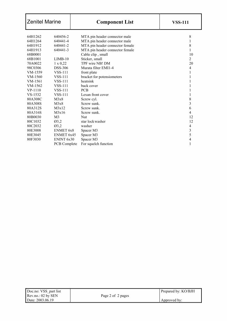
7. Datasheet, Electrical & Mechanical drawings Cable diagram ........................................ ..................................................................Doc.no.GVSS CD1294B rev.04 Datasheet.............................................................. VSS-111 ..................................................................A100K10520 Dimension, mounting details................................ VSS-111 ..........................................Doc.no.VSS-111_dd Rev.05 Datasheet.............................................................. VSS-222 ..................................................................A100K10521 Bracket for mounting VSS-222............................ Art.no.VM-1564 .............................. Doc.no.VSS-222_md rev.03 Circuit diagram Audio amplifier circuit ............... VSS-111 ..................................Doc.no.VSS-111_cd part 1 rev.04 Circuit diagram Sound reception detector............ VSS-111 ..................................Doc.no.VSS-111_cd part 2 rev.03 Component location ............................................. VSS-111 ............................................ Doc.no.VSS-111_lo rev.02 Circuit diagram & Component lay out ................. Squelch circuit ........................Doc.no.VSS-squelch_cd_lo rev.00 Part list ................................................................. Squelch circuit ............................. Doc.no.VSS-squelch_pl rev.00 Partlist, complete.................................................. VSS-111 ....................................Doc.no.VSS-111_part list rev.02 Sparepart kit ......................................................... VSS............................................Doc.no.VSS-sparepart kit rev.00

VINGTOR | DATASHEET
vSS-111 MAIN STATION
FEATurESSound Reception system main unit ▪ Built-in system amplifier ▪ Inputs for four (4) VSS-222 microphones ▪ Built-in loudspeaker with manual volume control ▪ LED dimmer control ▪ Remote muting of the amplifier circuitry when the vessel’s own typhone is activated ▪ Squelch function ▪
SpEcIFIcATIONS
Dimensions (WxHxD) 280 x 140 x 90 mm
Mounting Flush with six 4mm screws
Weight Approx 1.0 kg
Housing Anodized aluminium
colour Black
Ip-rating Ip-41
cable entry Without glands
connections Screw terminals
Operation voltage 24 vDc
Frequency range 70 - 820 Hz
S/N ratio > 60dB
THD-N > 1%
3006216001

www.vingtor.com
vINGTOr products are developed and marketed by Zenitel Norway AS. The company’s Quality Assurance System is certified to meet the requirements in NS-EN ISO 9001:2008. Zenitel Norway AS reserves the right to modify designs and alter specifications without prior notice, in pursuance of a policy of continuous improvement. © 2011 Zenitel Norway AS.
ORDER NUMBER DOC NO
Zenitel Norway AS
3006216001 A100K10520 03.02.2011
vSS-111 MAIN STATION
ORDER NUMBER DESCRIPTION SHIP WEIGHT
3006216001 vSS-111 Main station for 4 microphones 0.4 kg
related Items
3006216003 vSS-222 Microphone station waterproof 0.9 kg


VINGTOR products are developed and marketed by Zenitel Norway AS. The company’s Quality Assurance System is certified to meet the requirements in NS-EN ISO 9001:2008. Zenitel Norway AS reserves the right to modify designs and alter specifications without prior notice, in pursuance of a policy of continuous improvement. © 2011 Zenitel Norway AS.
ORDER NUMBER DOC NO
www.vingtor.com - [email protected]
VSS-222mIcROphONE STATION wATERpROOf
fEATuRESWaterproof microphone for bulkhead mounting outside the wheelhouse and connected to one of ▪four corresponding inputs in amplifier unit VSS-111
SpEcIfIcATIONS
Dimensions (wxhxD) See drawing
mounting Bracket (stainless steel)
weight Approx 0.9 kg
housing Anodized aluminium
colour Grey
Ip-rating Ip-56
cable entry Gland pG-7
connections cable 1.5m
Operation voltage 24 VDc
microphone element RE50 ElectroVoice dynamic
frequency response 80 - 13000 hz
polar pattern Omnidirectional
Omnidirectional impedance 150 ohms
ORDER NUMBER DESCRIPTION SHIP WEIGHT
3006216003 VSS-222 microphone station waterproof 0.9 kgRelated items3006216001 VSS-111 main station for 4 microphones 0.4 kg
3006216003 A100K10521 02.02.2011
Features
Document no.Article no.
VSS-222_ds rev.03 2004.09.06VSS-222
Technical data:
VSS-222Sound Signal Reception System
Description:
Ø44
104
10
PG7
17
40
3060
1.5
m
Mounting Bracketmounting holes diam. 6.5 mm
291540
35 10 20
Top view
VSS-222* Is a waterproof microphone for bulkhead mounting
outside the wheelhouse and connected to one of fourcorresponding inputs in amplifier unit VSS-111.
Dimensions (WxHxD): See drawingMounting: Bracket (stainless steel)Weight: Approx 0.9 KgHousing: Anodized aluminiumColour: GreyIP-rating: IP-65Cable entry: Gland PG-7Connections: Cable 1.5mOperation voltage: 24V DCMicrophone element: RE50 ElectroVoice
dynamic.Frequency response: 80 - 13000 HzPolar pattern: OmnidirectionalImpedance: 150 ohms
Related document: Datasheet VSS-111
www.zenitel.biz\Communication & Security Systems\Zenitel Marine


Zenitel Marine
Component List
VSS-111-squelsh
Doc.no: VSS-squelsh_pl
Rev.no.: 00
Date: 2002.06.20
Page 1 of 1 pages
Prepared by: Sen
Approved by:
Order no. Description ID Q,ty ECAS EP 2002.11985-344 PCB 1
3K3 1/4W Resistor R1 1
10K 1/4W Resistor R2,3,6,12 4
100k 1/4W Resistor R4 1
4K7 1/4W Resistor R5,7,8,10 4
2K2 1/4W Resistor R9 1
1k 1/4W Resistor R11 1
68 1/4W Resistor R13 1
10K Potensiometer RV1 1
0,47uF Capasitor C1 1
4,7uF Capasitor C2,5 2
10uF Capasitor C3,6 2
1n5 Capasitor C4 1
100nF Capasitor C7,8,9 3
BC 639 Transistor Q1 1
TL071 IC IC1 1
CA741 IC IC2 1
LM-317 Regulator G6A 12V IC3 1
G6A 12V Relay RL 1

Zenitel Marine
Component List
VSS-111
Doc.no: VSS_part list Rev.no.: 02 by SEN Date: 2003.06.19
Page 1 of 2 pages
Prepared by: KO/BJH Approved by:
Order no. Description ID Q’ty 02A1001 1k0 1/4W Resistor R1,2,3,4,7,8,11,12,24,25,98 11 02A1002 10k 1/4W Resistor R27,48-51 5 02A1003 100k 1/4W Resistor R22 1 02A1004 1M0 1/4W Resistor R40-43,52-55 8 02A2202 22k 1/4W Resistor R31-32 2 02A2209 22R 1/4W Resistor R28-29 2 02A3302 33k 1/4W Resistor R23 1 02A3303 330k 1/4W Resistor R14-17 4 02A4702 47k 1/4W Resistor R18-21,60-63,80-84,86-95,97 28 02A4708 4R7 1/4W Resistor R33 1 02A5600 560R 1/4W Resistor R30 1 02A6801 6k8 1/4W Resistor R44-47,56-59 8 02A6809 68R 1/4W Resistor R5,6,9,10 4 02F1800 180R 2W Resistor R96 1 240R 1/4W Resistor R72 1 06C1003 100k Var.resistor 3296W-1-104 RV1-4 4 08A0914 1N 4148 Diode D1-15 15 08A4004 1N 4002 Diode D17 1 08A0504 MR 504 Diode D16 1 10A5242 BZX79C 12V Zener Z1 1 12D4011 IC 14011 CMOS IC5 1 12E0071 IC TL 071 Op.amp. IC4 1 12E0833 IC LM 833 Op.amp. IC1,2 2 12E2876 IC LM 2876T Power amp. IC3 1 IC LM317 Regulator IC6. 1 16A1003 100n/63V Condensator MKT1826 C5-8,14-17,21-25,59-66, 70 22 16A2203 220n/63V Condensator MKT1826 C18,19,31-34,39 7 16A4703 470n/63V Condensator MKT1826 C27-30,39,67 6 16D047H 47pF Condensator Ceramic C55-58 4 16D1004 1n Condensator Ceramic C35 1 18A102Z 1n0/63V Condensator MKT1813 C43 1 18A113N 100n/250V Condensator MKT1813 C36 1 18A470Z 47pF Condensator Styroflex C9-12,26 5 18E105D 1uF/63V Condensator Elytt EL C1-4 4 18E106F 10uF/40V Condensator Elytt EB C20,40,51-54, 6 18E107D 100uF/25V Condensator Elytt EB C41 1 18E107H 100uF/63V Condensator Elytt EB C13,42,68 3 18E108F 1000uF/40V Condensator Elytt EB C69 1 18E477E 470uF/40V Condensator Elytt EB C37,38 2 22A0547 BC 547B Transistor T2-5 4 22A0556 BC 556C Transistor T9-6 4 22A0640 BC 640 Transistor T10-13 4 22C3055 2N 3055 Transistor T15 1 24A0033 V33ZA70 Varistor VAR1,2 2 40F0224 RY-24W Relay RL1 1 46A1000 1A T Fuse 5x20 F1 1 46H5201 PTF/15 Fuse holder 1 48E7012 10k L Potensiometer Piher RV7 1 48E6008 1k L Potensiometer Piher RV8 1 52B7101 7101 C&K Switch J51 1 58A0016 LED w/print VSS-111 4 60A0010 NPS 5060 8ohm Loudspeaker 1 64B1032 25.131.0253 Screw Terminals 1 64B1034 25.131.0453 Screw Terminals 3
Zenitel Marine
Component List
VSS-111
Doc.no: VSS_part list Rev.no.: 02 by SEN Date: 2003.06.19
Page 2 of 2 pages
Prepared by: KO/BJH Approved by:
64H1262 640456-2 MTA pin header connector male 8 64H1264 640441-4 MTA pin header connector male 1 64H1912 640441-2 MTA pin header connector female 8 64H1913 640441-3 MTA pin header connector female 1 68B0001 Cable clip , small 10 68B1001 LIMB-10 Sticker, small 2 70A0022 1 x 0,22 TPF wire NB! DM 20 98C0306 DSS-306 Murata filter EMI1-4 4 VM-1559 VSS-111 front plate 1 VM-1560 VSS-111 bracket for potensiometers 1 VM-1561 VSS-111 heatsink 1 VM-1562 VSS-111 back cover 1 VP-1110 VSS-111 PCB 1 VS-1532 VSS-111 Lexan front cover 1 80A308C M3x8 Screw cyl. 8 80A308S M3x8 Screw sunk. 3 80A312S M3x12 Screw sunk. 6 80A316S M3x16 Screw sunk. 4 80B0030 M3 Nut 12 80C1032 Ø3,2 star lock washer 12 80C2032 Ø3,2 washer 4 80E3008 ENMET 6x8 Spacer M3 3 80E3045 ENMET 6x45 Spacer M3 5 80F3030 ENINT 6x30 Spacer M3 4 PCB Complete For squelch function 1

Zenitel Marine
Doc.no.VSS_ sparepart kit rev.00 2001.09.26 Page 1of 1
SPAREPART-KIT For VSS – system. Part No. VSS111S
Parts No. Qty. Description 10A5242 1 BZX79C 12V ZENER DIODE 12D4011 1 IC 1411 CMOS 12E0071 1 IC TL 071 OP.AMP. 12E0833 1 IC LM 833 OP.AMP. 12E2876 1 IC LM 2876T POWER AMP. 22A0547 1 BC 547B TRANSISTOR 22A0557 1 BC 557B TRANSISTOR 22A0640 1 BC 640 TRANSISTOR 22C3055 1 2N 3055 TRANSISTOR 46A1000 10 1A T FUSE 5x20 Delivered in plastic box

www.vingtor.com Zenitel Norway AS
STENTOFON and VINGTOR products are developed and marketed by Zenitel Norway AS. The company’s Quality Assurance System is certified to meet the requirements in NS-EN ISO 9001:2008. Zenitel Norway AS reserves the right to modify designs and alter specifications without prior notice, in pursuance of a policy of continuous improvement. © 2009 Zenitel Norway AS.
DOC NO
A100K10874
Related Documents