VSL FLOATING CONCRETE STRUCTURES EXAMPLES FROM PRACTICE SECOND PRINTING JULY 1992 VSL INTERNATIONAL LTD. Berne / switzerland

Welcome message from author
This document is posted to help you gain knowledge. Please leave a comment to let me know what you think about it! Share it to your friends and learn new things together.
Transcript
VSL FLOATINGCONCRETE STRUCTURES
EXAMPLES FROM PRACTICE
SECOND PRINTINGJULY 1992
VSL INTERNATIONAL LTD.Berne / switzerland
Table of contentsPage
Preface 1
1. Introduction 1
2. VSL Systems and Service Range 4
2.1. VSL Systems 42.1.1. Introduction 42.1.2. VSL Post-tensioning 42.1.3. VSL Slipforming 52.1.4. VSL Heavy Lifting 52.1.5. Other VSL Systems 62.2. Services offered by VSL 6
3. Examples from Practice 7
3.1. Introduction 7
3.2. Temporarily floating structures 73.2.1. 'Condeep' offshore oil production platforms 73.2.2. Offshore oil production platform for the Dunlin Field 113.2.3. Field Control Station, North-East Frigg Field 123.2.4. Concrete Island Drilling System (CIDS) 123.2.5. Immersed shore approach concrete tunnel, Karmey,
Norway 133.2.6. Swedish lighthouses in the Baltic Sea 143.2.7. Caissons for harbour quay, Venice, Italy 163.2.8. Caissons for berth at Hay Point, Queensland, Australia 173.2.9. Caisson pile caps for Yokohama Bay Bridge, Japan 183.2.10. Floating concrete batcher plant, Japan 20
3.3. Permanently floating structures 213.3.1. Concrete barge 'C-Boat 500' 213.3.2. Floating Concourses, Brighton Marina, UK 213.3.3. Third Lake Washington Floating Bridge, Seattle, USA 23
4. Bibliography and References 24
4.1. Bibliography 24
4.2. References 24
Copyright 1987 byVSL INTERNATIONAL LTD., Berne, Switzerland
All rights reserved
Printed in Switzerland
FLOATING CONCRETE STRUCTURES - EXAMPLES FROM PRACTICE
Preface
1. Introduction
Two-thirds of the world's surface iscovered with water. It is, therefore, notsurprising that there has been much activity with concrete in the sea in recent decades.Numerous ideas and schemes have beenpromoted and many have been executed.Following the acceptance of concrete by theoil companies and the success of very largestructures in the North Sea, the use offloating concrete structures, i.e. mainlytemporarily floating structures, is continually growing.The advantages of floating concretestructures lie in the economy of the materials used (concrete is very well suited to a marineenvironment), in the fact that it is easy to make concrete structures buoyant in theconstruction stage as well as permanently and for towing, whereas they are or can be made heavy enough for a safe permanentinstallation, and in the fact that they canalso provide storage space.Although concrete has been extensivelyused since 1900 for marine and coastalstructures, post-tensioning has had a major, if not decisive, role in extending its fullexploitation in marine structures. Post-tensioning creates a favourable state ofstress.
Post-tensioned concrete is resistant tocorrosion since the prestressing keeps theconcrete in compression, thus limitingcrack width. The material is highly resistantto fire, and post-tensioning improveswatertightness and makes the structureswell-suited forwithstanding the heavy waveand ice loadings encountered (for examplein the North Sea and the Arctic). Finally, itdoes not suffer from the low-temperaturefracture problems inherent in steelstruc-tures.Large structures can be built of cast-in-placeconcrete or may be assembled from precastcomponents integrated by cast-in-placejoints or by match-cast joints and by post-tensioning. A combined application ofprecast and cast-in-place elements is, ofcourse, also possible. Precasting allows thinsections of high-strength concrete to beobtained. Post-tensioning can be providedin any desired direction to resist stressesfrom heavy and complex loads. Cyclicloading does not lead to fatigue failure.Cracks from overloading, for examplepossibly occurring during the deliveryvoyage, will close again after the loads areremoved as a result of the post-tensioning.
The present report has been prepared withthe objective of promoting floating concretestructures by illustrating their advantages, byproviding a summary of the various possibleapplications and by explaining which VSLSpecial Construction Systems can beemployed. Explanations of when, where andhow these systems may be used are alsogiven. The design of floating concrete structureswill, however, not be treated here; designcriteria for the determination of loads and
forces can be found in the Literature (seebibliography).
The VSL Organizations will be pleased toassist and advise you on questions relatingto the construction of floating concretestructures. These organizations hope thatthe present report will be helpful to you bystimulating new ideas, providing pointersand offering possible solutions. The VSLRepresentative in your country or VSLINTERNATIONAL LTD., Berne, Switzerland,will be glad to provide you with furtherinformation on the subject of floatingconcrete structures or the VSL SpecialConstruction Systems.
The history of concrete sea structures goesback to the Romans, who used pozzolaniccement concrete for the underwater piers oftheir river bridges. Some of these are stillstanding. In 1848 Lambot first used reinforcedconcrete for small boats; one of his laterboats is still afloat. As mentioned in thepreface, many marine structures have beenbuilt of concrete throughout the world sincethe early 1900's. In World Wars I and II,many hundreds of reinforced concrete shipswere built, but their designs proved to beuneconomical. In the late 1950's, a numberof prestressed concrete oceangoing bargeswere constructed in the Philippines.Concrete lighthouses were constructed ascaissons in the 1960's; some of them werefixed in the sea bed by ground anchors. Inthe 1970's construction of offshore platformsfor the exploration of oil started and by theend of 1986 eighteen concrete platformshave been installed in the North Sea.Floating concrete structures are economicalto build and maintain. To keep maintenancecosts low, quality assurance during constructionis very important. A quality assuranceprogramme is, therefore, normally set up.Furthermore, tolerances must be kept small;it is important to limit closely the variation ofthe unit weights of the materials used and toobserve rigorously the specified dimensions.A combination of maximum weight ofcomponents and maximum thicknesstolerance must be avoided at all costs.For cast-in-place structures, concrete with aminimum 28-day cube strength of 40 N/mm2
is used, whilst in precast structures astrength of 50 to 60 N/mm2 is the usualobjective. The water/cement ratio should below and good curing is of importance. Theratio can be minimized by using super
1
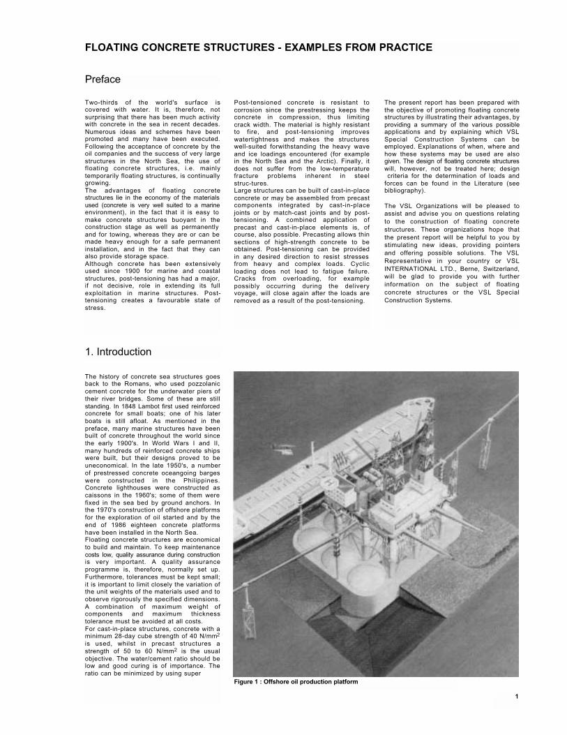
Figure 1 : Offshore oil production platform
plasticizers to make the fresh concreteworkable. Lightweight concrete is attractivebecause it permits better buoyancy. It shouldbe noted that the concrete strengthis slightly reduced by the saturation of the
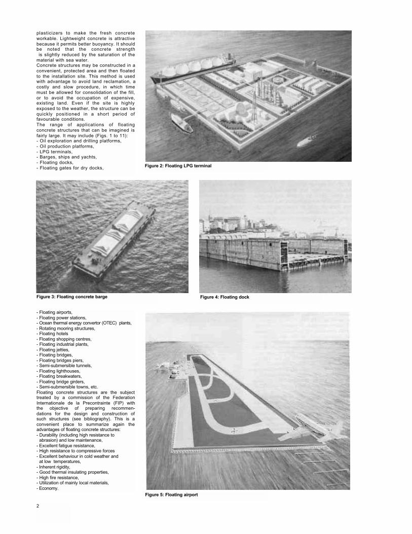
material with sea water.Concrete structures may be constructed in aconvenient, protected area and then floatedto the installation site. This method is usedwith advantage to avoid land reclamation, acostly and slow procedure, in which timemust be allowed for consolidation of the fill,or to avoid the occupation of expensive,existing land. Even if the site is highlyexposed to the weather, the structure can bequickly positioned in a short period offavourable conditions.The range of applications of floatingconcrete structures that can be imagined isfairly large. It may include (Figs. 1 to 11):- Oil exploration and drilling platforms,- Oil production platforms,- LPG terminals,- Barges, ships and yachts, - Floating docks,- Floating gates for dry docks, Figure 2: Floating LPG terminal
Figure 3: Floating concrete barge Figure 4: Floating dock
- Floating airports,- Floating power stations,- Ocean thermal energy convertor (OTEC) plants,- Rotating mooring structures, - Floating hotels- Floating shopping centres, - Floating industrial plants,- Floating jetties,- Floating bridges,- Floating bridges piers,- Semi-submersible tunnels, - Floating lighthouses, - Floating breakwaters, - Floating bridge girders, - Semi-submersible towns, etc.Floating concrete structures are the subjecttreated by a commission of the FederationInternationale de la Precontrainte (FIP) withthe objective of preparing recommen-dations for the design and construction ofsuch structures (see bibliography). This is aconvenient place to summarize again theadvantages of floating concrete structures:- Durability (including high resistance to
abrasion) and low maintenance,- Excellent fatigue resistance,- High resistance to compressive forces- Excellent behaviour in cold weather and
at low temperatures,- Inherent rigidity,- Good thermal insulating properties, - High fire resistance,- Utilization of mainly local materials, - Economy.
Figure 5: Floating airport
2
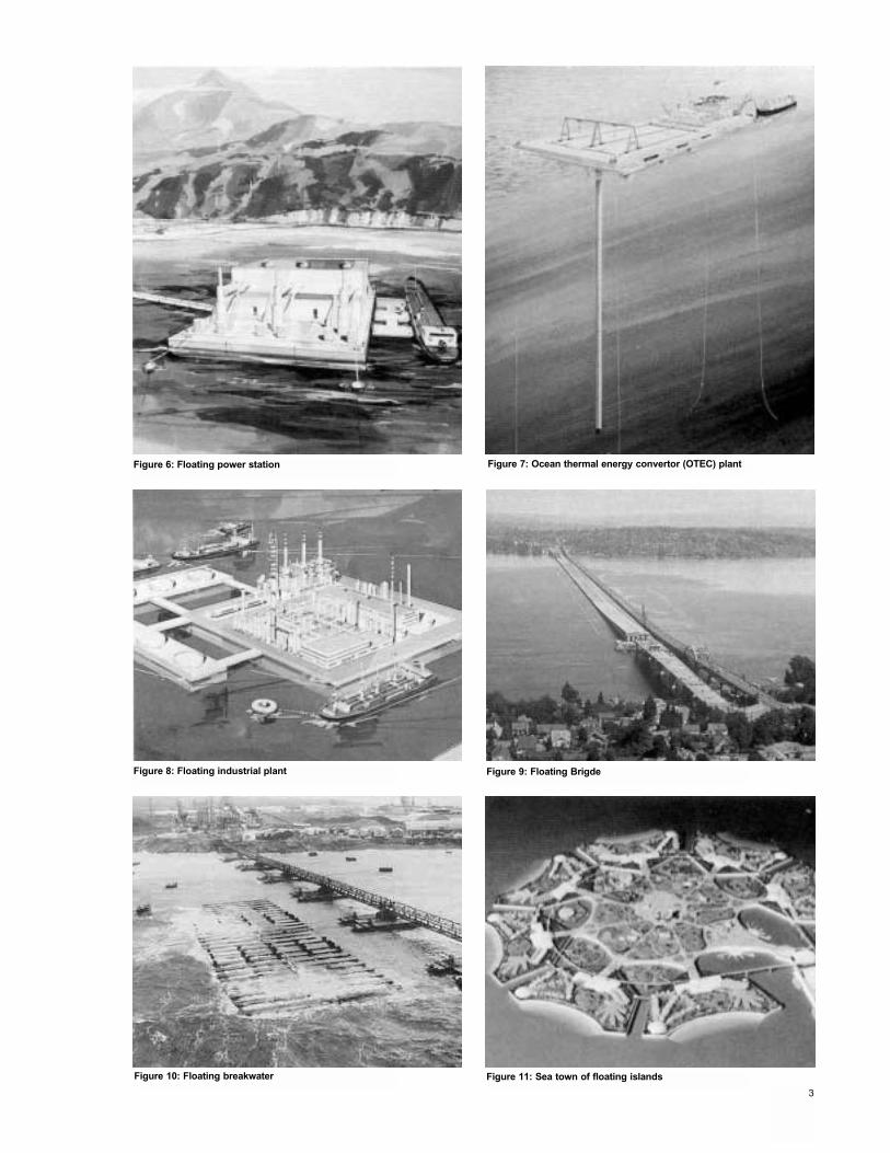
Figure 6: Floating power station Figure 7: Ocean thermal energy convertor (OTEC) plant
Figure 8: Floating industrial plant Figure 9: Floating Brigde
Figure 11: Sea town of floating islandsFigure 10: Floating breakwater
3
2.1.1. IntroductionIn building floating concrete structures, thefollowing VSL Special Construction Systemsare of particular importance:- VSL Post-tensioning,- VSL Slipforming,- VSL Heavy Rigging.In many cases, these systems will be usedseparately, but it is especially advantageousif VSL is chosen for all the systems. Bymaking use of the various VSL Systems incombination and by taking account of thesefacilities at an early stage in planning, theclient will obtain substantial advantages.These may, for example, include thefollowing:- Optimized preparatory work, progress
and use of personnel and materials,- Simultaneous execution of post-tensioning
and slipforming operations under coordinated control.
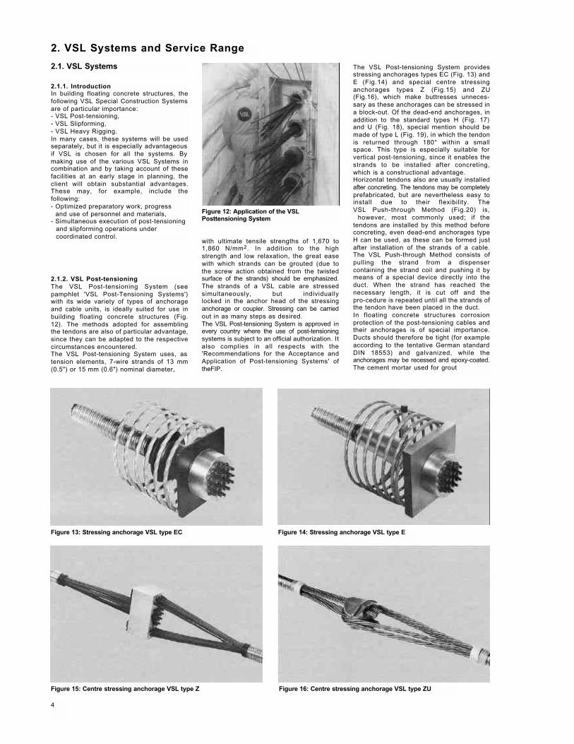
2.1.2. VSL Post-tensioningThe VSL Post-tensioning System (seepamphlet 'VSL Post-Tensioning Systems')with its wide variety of types of anchorageand cable units, is ideally suited for use inbuilding floating concrete structures (Fig.12). The methods adopted for assemblingthe tendons are also of particular advantage,since they can be adapted to the respectivecircumstances encountered.The VSL Post-tensioning System uses, astension elements, 7-wire strands of 13 mm(0.5") or 15 mm (0.6") nominal diameter,
2. VSL Systems and Service Range
2.1. VSL Systems
with ultimate tensile strengths of 1,670 to1,860 N/mm2. In addition to the highstrength and low relaxation, the great easewith which strands can be grouted (due tothe screw action obtained from the twistedsurface of the strands) should be emphasized.The strands of a VSL cable are stressedsimultaneously, but individuallylocked in the anchor head of the stressinganchorage or coupler. Stressing can be carriedout in as many steps as desired.The VSL Post-tensioning System is approved inevery country where the use of post-tensioningsystems is subject to an official authorization. Italso complies in all respects with the'Recommendations for the Acceptance andApplication of Post-tensioning Systems' oftheFIP.
The VSL Post-tensioning System providesstressing anchorages types EC (Fig. 13) andE (Fig.14) and special centre stressinganchorages types Z (Fig.15) and ZU(Fig.16), which make buttresses unneces-sary as these anchorages can be stressed ina block-out. Of the dead-end anchorages, inaddition to the standard types H (Fig. 17)and U (Fig. 18), special mention should bemade of type L (Fig. 19), in which the tendonis returned through 180° within a smallspace. This type is especially suitable forvertical post-tensioning, since it enables thestrands to be installed after concreting,which is a constructional advantage.Horizontal tendons also are usually installedafter concreting. The tendons may be completelyprefabricated, but are nevertheless easy toinstall due to their flexibility. TheVSL Push-through Method (Fig.20) is,
however, most commonly used; if thetendons are installed by this method beforeconcreting, even dead-end anchorages typeH can be used, as these can be formed justafter installation of the strands of a cable.The VSL Push-through Method consists ofpulling the strand from a dispensercontaining the strand coil and pushing it bymeans of a special device directly into theduct. When the strand has reached thenecessary length, it is cut off and thepro-cedure is repeated until all the strands ofthe tendon have been placed in the duct.In floating concrete structures corrosionprotection of the post-tensioning cables andtheir anchorages is of special importance.Ducts should therefore be tight (for exampleaccording to the tentative German standardDIN 18553) and galvanized, while theanchorages may be recessed and epoxy-coated.The cement mortar used for grout
Figure 12: Application of the VSLPosttensioning System
Figure 13: Stressing anchorage VSL type EC Figure 14: Stressing anchorage VSL type E
Figure 15: Centre stressing anchorage VSL type Z Figure 16: Centre stressing anchorage VSL type ZU
4
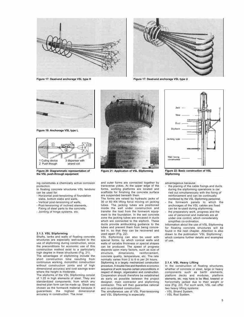
Figure 17: Dead-end anchorage VSL type H
Figure 19: Anchorage VSL type L
Figure 17: Dead-end anchorage VSL type U
Figure 21: Application of VSL SlipformingFigure 20: Diagrammatic representation of the VSL push-through equipment
Figure 22: Basic construction of VSLSlipforming
ing constitutes a chemically active corrosionprotection.In floating concrete structures VSL tendonscan be used for:- Horizontal post-tensioning of foundation
slabs, bottom slabs and walls,- Vertical post-tensioning of walls,- Post-tensioning of inclined elements,
Fixing of steel parts to the concrete,- Jointing of hinge systems, etc.
2.1.3. VSL SlipformingShafts, tanks and walls of floating concretestructures are especially well-suited to theuse of slipforming during construction, sincethe preconditions for economic use of thisconstruction method exist to a particularlyhigh degree in these structures (Fig. 21).The advantages of slipforming include theshort construction time resulting fromcontinuous working, monolithic constructionwithout construction joints and of highdimensional accuracy and cost savings evenwhere the height is moderate.The slipforms of the VSL Slipforming consistof 1.25 m high elements of steel. They arestandardized components, from which anydesired plan form can be made up. Steel waschosen as the formwork material because itguarantees the highest dimensionalaccuracy in construction. The inner
and outer forms are connected together bytransverse yokes. At the upper edge of theforms, working platforms are located andscaffolds for finishing the concrete surfaceare suspended beneath them.The forms are raised by hydraulic jacks of 30 or 60 KN lifting force moving on jackingtubes. The jacking tubes are positionedinside the wall under construction andtransfer the load from the formwork equip-ment to the foundation. In the wet concretezone the jacking tubes are encased in ductswhich are connected to the slipform. Theseducts provide antibuckling guidance to thetubes and prevent them from being concre-ted in, so that they can be recovered andused again (Fig. 22).VSL Sipforming can also be used withspecial forms, by which conical walls andwalls of variable thickness or special shapescan be produced. The speed of progressdepends upon many factors, such as size ofstructure, dimensions, reinforcement,concrete quality, temperature, etc. The rate normally varies from 2 to 6 m per 24 hours.Slipforming is a largely mechanized constructionprocedure. A trouble-free and therefore economicsequence of work requires certain preconditions inrespect of design, organization and construction.Cooperation should therefore be establishedas early as possible between the projectdesigner, main contractor and slipformingcontractor. This will then guarantee rationaland co-ordinated construction.The simultaneous use of VSL Post-tensioningand VSL Slipforming is especially
advantageous because:- the placing of the cable fixings and ducts
during the slipforming operations is carried out simultaneously with the fixing of reinforcement and can be continually monitored by the VSL Slipforming personnel,
- the formwork panels to which theanchorages of the VSL cables are fixed can be re-used during slipforming,
- the preparatory work, progress and the use of personnel and materials are all under one control, which considerably simplifies co-ordination.
Information about the use of VSL Slipformingfor floating concrete structures will befound in the next chapter. Attention is alsodrawn to the publication 'VSL Slipforming', which contains further details and examples of use.
2.1.4. VSL Heavy LiftingIn the construction of floating structures,whether of concrete or steel, large or heavycomponents such as berth elements,platform decks and modules, platformelements, etc. may have to be lifted, lowered orhorizontally jacked due to their weight orsize (Fig. 23). For such work, VSL can offertwo heavy lifting systems:- VSL Strand System,- VSL Rod System.
5
1 Cuting device 3 dispenser with2 Push-though strand coil
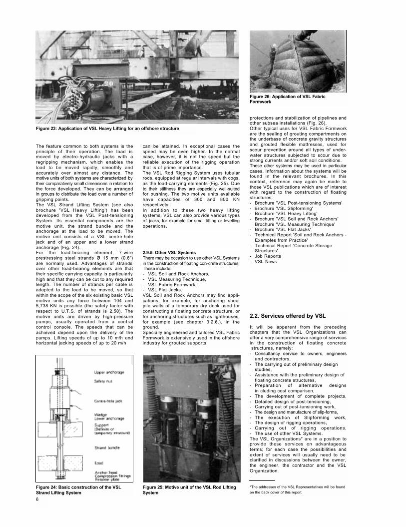
Figure 23: Application of VSL Heavy Lifting for an offshore structure
The feature common to both systems is theprinciple of their operation. The load ismoved by electro-hydraulic jacks with aregripping mechanism, which enables theload to be moved rapidly, smoothly andaccurately over almost any distance. Themotive units of both systems are characterized bytheir comparatively small dimensions in relation tothe force developed. They can be arrangedin groups to distribute the load over a number ofgripping points.The VSL Strand Lifting System (see alsobrochure 'VSL Heavy Lifting') has beendeveloped from the VSL Post-tensioningSystem. Its essential components are themotive unit, the strand bundle and theanchorage at the load to be moved. Themotive unit consists of a VSL centre-holejack and of an upper and a lower strandanchorage (Fig. 24).For the load-bearing element, 7-wireprestressing steel strands Ø 15 mm (0.6")are normally used. Advantages of strandsover other load-bearing elements are thattheir specific carrying capacity is particularlyhigh and that they can be cut to any requiredlength. The number of strands per cable isadapted to the load to be moved, so thatwithin the scope of the six existing basic VSLmotive units any force between 104 and5,738 KN is possible (the safety factor withrespect to U.T.S. of strands is 2.50). Themotive units are driven by high-pressurepumps, usually operated from a centralcontrol console. The speeds that can beachieved depend upon the delivery of thepumps. Lifting speeds of up to 10 m/h andhorizontal jacking speeds of up to 20 m/h
can be attained. In exceptional cases thespeed may be even higher. In the normalcase, however, it is not the speed but thereliable execution of the rigging operationthat is of prime importance.The VSL Rod Rigging System uses tubularrods, equipped at regular intervals with cogs,as the load-carrying elements (Fig. 25). Dueto their stiffness they are especially well-suitedfor pushing. The two motive units availablehave capacities of 300 and 800 KNrespectively.In addition to these two heavy liftingsystems, VSL can also provide various typesof jacks, for example for small lifting or levellingoperations.
protections and stabilization of pipelines andother subsea installations (Fig. 26).Other typical uses for VSL Fabric Formworkare the sealing of grouting compartments onthe underbase of concrete gravity structuresand grouted flexible mattresses, used forscour prevention around all types of under-water structures subjected to scour due tostrong currents and/or soft soil conditions.These other systems may be used in particularcases. Information about the systems will befound in the relevant brochures. In thiscontext, reference may again be made tothose VSL publications which are of interestwith regard to the construction of floatingstructures:- Brochure 'VSL Post-tensioning Systems'- Brochure 'VSL Slipforming'- Brochure 'VSL Heavy Lifting'- Brochure 'VSL Soil and Rock Anchors'
Brochure 'VSL Measuring Technique'- Brochure 'VSL Flat Jacks'- Technical Report 'Soil and Rock Anchors -
Examples from Practice'- Technical Report 'Concrete Storage
Structures'- Job Reports - VSL News
2.9.5. Other VSL SystemsThere may be occasion to use other VSL Systemsin the construction of floating con-crete structures.These include:- VSL Soil and Rock Anchors, - VSL Measuring Technique,- VSL Fabric Formwork,- VSL Flat Jacks.VSL Soil and Rock Anchors may find appli-cations, for example, for anchoring sheetpile walls of a temporary dry dock used forconstructing a floating concrete structure, orfor anchoring structures such as lighthouses,for example (see chapter 3.2.6.), in theground.Specially engineered and tailored VSL FabricFormwork is extensively used in the offshoreindustry for grouted supports,
Figure 24: Basic construction of the VSLStrand Lifting System
Figure 25: Motive unit of the VSL Rod LiftingSystem
Figure 26: Application of VSL FabricFormwork
2.2. Services offered by VSL
It will be apparent from the precedingchapters that the VSL Organizations canoffer a very comprehensive range of servicesin the construction of floating concretestructures, namely:
- Consultancy service to owners, engineersand contractors,
- The carrying out of preliminary designstudies,
- Assistance with the preliminary design offloating concrete structures,
- Preparation of alternative designsin cluding cost comparison,
- The development of complete projects,- Detailed design of post-tensioning,- Carrying out of post-tensioning work,- The design and manufacture of slip-forms,- The execution of Slipforming work,- The design of rigging operations,- Carrying out of rigging operations,- The use of other VSL Systems.The VSL Organizations* are in a position toprovide these services on advantageousterms; for each case the possibilities andextent of services will usually need to be clarified in discussions between the owner,the engineer, the contractor and the VSLOrganization.
*The addresses of the VSL Representatives will be found
on the back cover of this report.
6
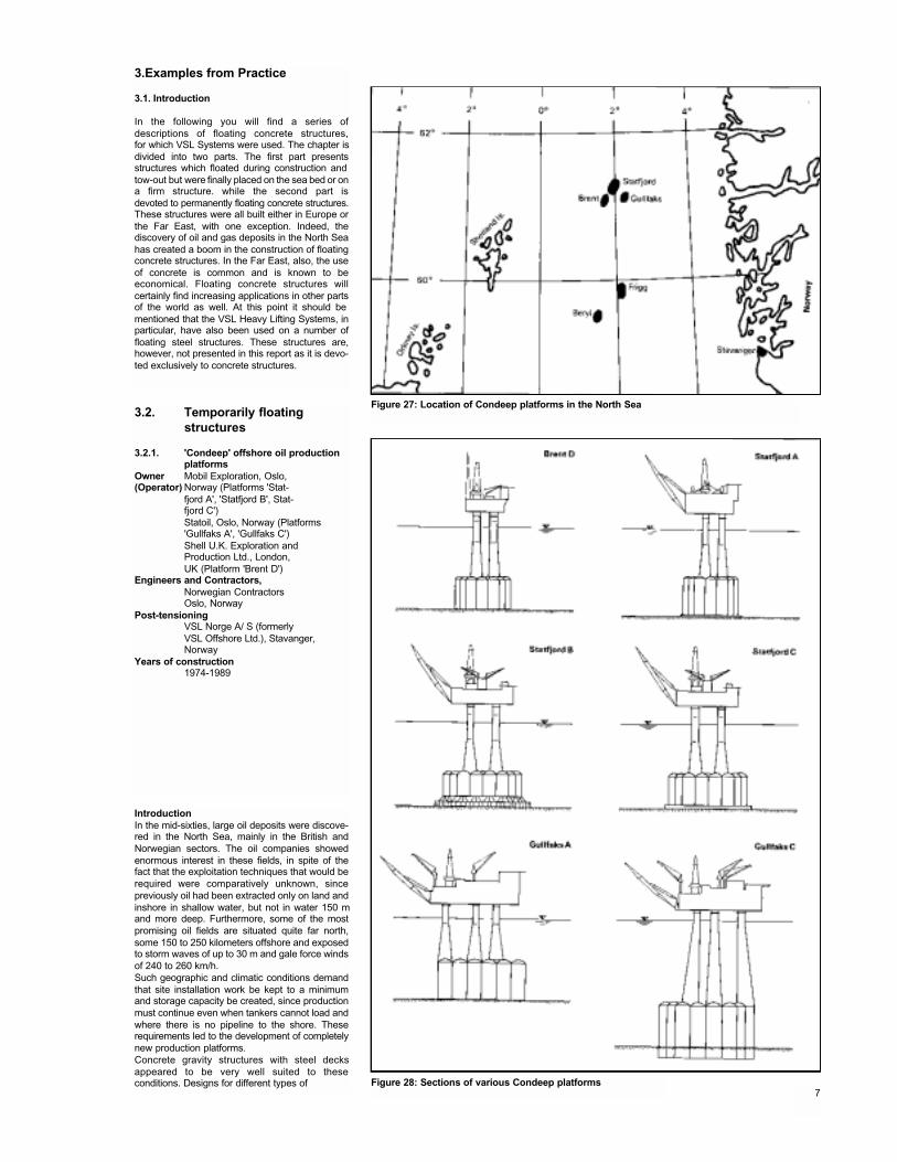
IntroductionIn the mid-sixties, large oil deposits were discove-red in the North Sea, mainly in the British andNorwegian sectors. The oil companies showedenormous interest in these fields, in spite of thefact that the exploitation techniques that would berequired were comparatively unknown, sincepreviously oil had been extracted only on land andinshore in shallow water, but not in water 150 mand more deep. Furthermore, some of the mostpromising oil fields are situated quite far north,some 150 to 250 kilometers offshore and exposedto storm waves of up to 30 m and gale force windsof 240 to 260 km/h.Such geographic and climatic conditions demandthat site installation work be kept to a minimumand storage capacity be created, since productionmust continue even when tankers cannot load andwhere there is no pipeline to the shore. Theserequirements led to the development of completelynew production platforms.Concrete gravity structures with steel decksappeared to be very well suited to theseconditions. Designs for different types of
3.Examples from Practice
3.1. Introduction
In the following you will find a series ofdescriptions of floating concrete structures,for which VSL Systems were used. The chapter isdivided into two parts. The first part presentsstructures which floated during construction and tow-out but were finally placed on the sea bed or ona firm structure. while the second part isdevoted to permanently floating concrete structures.These structures were all built either in Europe orthe Far East, with one exception. Indeed, thediscovery of oil and gas deposits in the North Seahas created a boom in the construction of floatingconcrete structures. In the Far East, also, the useof concrete is common and is known to beeconomical. Floating concrete structures willcertainly find increasing applications in other partsof the world as well. At this point it should be mentioned that the VSL Heavy Lifting Systems, inparticular, have also been used on a number offloating steel structures. These structures are,however, not presented in this report as it is devo-ted exclusively to concrete structures.
Figure 27: Location of Condeep platforms in the North Sea
Figure 28: Sections of various Condeep platforms
3.2. Temporarily floating structures
3.2.1. 'Condeep' offshore oil production platforms
Owner Mobil Exploration, Oslo,(Operator) Norway (Platforms 'Stat-
fjord A', 'Statfjord B', Stat-fjord C')Statoil, Oslo, Norway (Platforms 'Gullfaks A', 'Gullfaks C')Shell U.K. Exploration andProduction Ltd., London,UK (Platform 'Brent D')
Engineers and Contractors,Norwegian ContractorsOslo, Norway
Post-tensioningVSL Norge A/ S (formerlyVSL Offshore Ltd.), Stavanger, Norway
Years of construction1974-1989
7
platforms were rapidly prepared andsubmitted to theinterested oil companies.Most designs are similar in overall size andhave basically the same concept. Theycomprise a cellular concrete caisson, acting asfoundation and providing oil storage capacity,but also providing buoyancy duringconstruction and tow-out. The foundations
support one or more concrete towers, with asteel deck carrying the process plant andequipment spanning between them. Theplatform is used as a drilling platform, withderricks, storage for mud, cement and pipes,power generation and living quarters, and asa production unit providing cooling andseparation facilities and storage for thecrude oil, together with generators, pumps andre-injection equipment, living quarters, rescueand fire-fighting plant, communications, gasflare off and so on.
The Condeep designThe most successful type of gravity structureso far used is that known as the 'Condeep'design (concrete deepwater); this wasoriginally developed by A/S Hoyer-Ellefsen.Further development and construction of thefirst platforms was made in the CondeepGroup with Norwegian Contractors (Hoyer-Ellefsen, F. Selmer and T. FurUholmen) forcivil works and the Aker Group for mechanicalworks. The design is based upon model testsperformed in specialized laboratories anduniversities, to assess the effects of thenatural forces encountered in the North Sea.With the advanced state of mathematics andthe science of the strength of materials
available, the very complex calculationswere made in a short time, using extensivecomputer capacity (Fig. 27).A Condeep platform structure essentially consistsof three parts: the storage cells, the towers and thedeck structure. The cells and towers are ofreinforced and post-tensioned concrete, while thedeck is a steel structure. The first Condeepplatforms built had 16 cylindrical storage cells andthree towers. This design was subsequentlymodified, to
meet the clients' requirements for largerstructures. The next type had 20 storagetanks and four towers to carry the deck. Notall the structures built to this design wereidentical, since the foundation as well as thetower arrangements varied. Recently,construction of a new type with 26 cells andfour towers has started. The latest platform,'Gullfaks C', now under construction, is ofextraordinary size; its total height will beapprox. 380 m (Fig. 28).
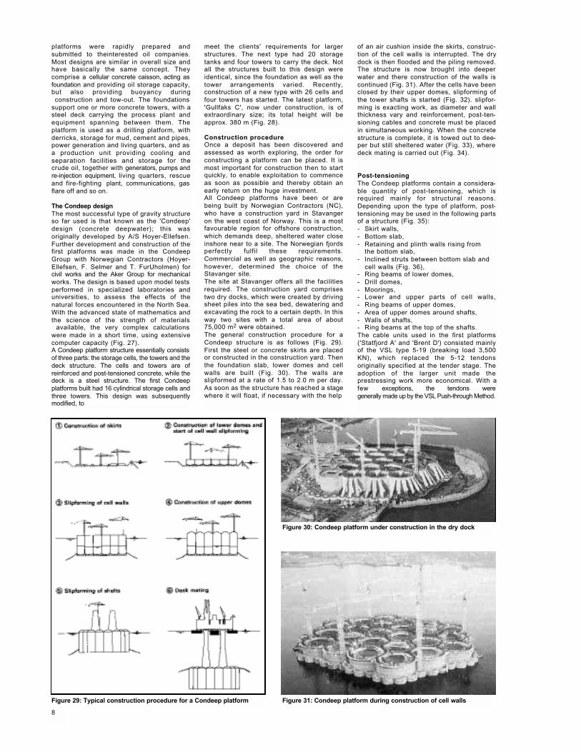
Construction procedureOnce a deposit has been discovered andassessed as worth exploring, the order forconstructing a platform can be placed. It ismost important for construction then to startquickly, to enable exploitation to commenceas soon as possible and thereby obtain anearly return on the huge investment.All Condeep platforms have been or arebeing built by Norwegian Contractors (NC),who have a construction yard in Stavangeron the west coast of Norway. This is a mostfavourable region for offshore construction,which demands deep, sheltered water closeinshore near to a site. The Norwegian fjordsperfectly fulfil these requirements.Commercial as well as geographic reasons,however, determined the choice of theStavanger site.The site at Stavanger offers all the facilitiesrequired. The construction yard comprisestwo dry docks, which were created by drivingsheet piles into the sea bed, dewatering andexcavating the rock to a certain depth. In thisway two sites with a total area of about75,000 m2 were obtained.The general construction procedure for aCondeep structure is as follows (Fig. 29).First the steel or concrete skirts are placedor constructed in the construction yard. Thenthe foundation slab, lower domes and cellwalls are built (Fig. 30). The walls areslipformed at a rate of 1.5 to 2.0 m per day.As soon as the structure has reached a stagewhere it will float, if necessary with the help
of an air cushion inside the skirts, construc-tion of the cell walls is interrupted. The drydock is then flooded and the piling removed.The structure is now brought into deeperwater and there construction of the walls iscontinued (Fig. 31). After the cells have beenclosed by their upper domes, slipforming ofthe tower shafts is started (Fig. 32). slipfor-ming is exacting work, as diameter and wallthickness vary and reinforcement, post-ten-sioning cables and concrete must be placedin simultaneous working. When the concretestructure is complete, it is towed out to dee-per but still sheltered water (Fig. 33), wheredeck mating is carried out (Fig. 34).
Post-tensioningThe Condeep platforms contain a considera-ble quantity of post-tensioning, which isrequired mainly for structural reasons.Depending upon the type of platform, post-tensioning may be used in the following partsof a structure (Fig. 35):- Skirt walls,- Bottom slab,- Retaining and plinth walls rising from
the bottom slab,- Inclined struts between bottom slab and
cell walls (Fig. 36),- Ring beams of lower domes, - Drill domes,- Moorings,- Lower and upper parts of cell walls,- Ring beams of upper domes,- Area of upper domes around shafts,- Walls of shafts,- Ring beams at the top of the shafts.The cable units used in the first platforms('Statfjord A' and 'Brent D') consisted mainlyof the VSL type 5-19 (breaking load 3,500KN), which replaced the 5-12 tendonsoriginally specified at the tender stage. Theadoption of the larger unit made theprestressing work more economical. With afew exceptions, the tendons weregenerally made up by the VSL Push-through Method.
Figure 29: Typical construction procedure for a Condeep platform Figure 31: Condeep platform during construction of cell walls
Figure 30: Condeep platform under construction in the dry dock
8
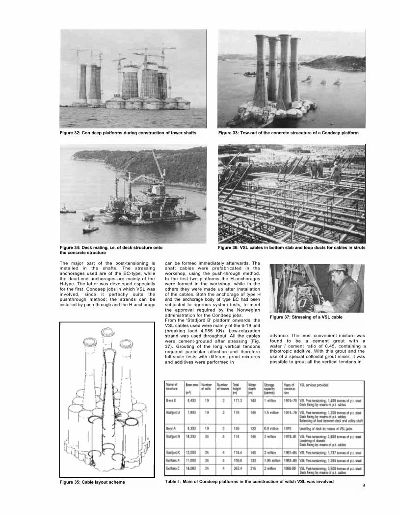
Figure 34: Deck mating, i.e. of deck structure onto the concrete structure
Figure 37: Stressing of a VSL cable
Figure 35: Cable layout scheme
Figure 32: Con deep platforms during construction of tower shafts Figure 33: Tow-out of the concrete strucuture of a Condeep platform
Figure 36: VSL cables in bottom slab and loop ducts for cables in struts
The major part of the post-tensioning isinstalled in the shafts. The stressinganchorages used are of the EC-type, whilethe dead-end anchorages are mainly of the H-type. The latter was developed especiallyfor the first Condeep jobs in which VSL wasinvolved, since it perfectly suits thepushthrough method; the strands can beinstalled by push-through and the H-anchorage
can be formed immediately afterwards. Theshaft cables were prefabricated in theworkshop, using the push-through method.In the first two platforms the H-anchorageswere formed in the workshop, while in theothers they were made up after installationof the cables. Both the anchorage of type Hand the anchorage body of type EC had beensubjected to rigorous system tests, to meetthe approval required by the Norwegianadministration for the Condeep jobs.From the 'Statfjord B' platform onwards, theVSL cables used were mainly of the 6-19 unit(breaking load 4,986 KN). Low-relaxationstrand was used throughout. All the cableswere cement-grouted after stressing (Fig.37). Grouting of the long vertical tendonsrequired particular attention and thereforefull-scale tests with different grout mixturesand additives were performed in
advance. The most convenient mixture wasfound to be a cement grout with awater / cement ratio of 0.45, containing athixotropic additive. With this grout and theuse of a special colloidal grout mixer, it waspossible to grout all the vertical tendons in
9Table I : Main of Condeep platforms in the construction of witch VSL was involved
one or two steps (according to length) andwithout bleeding occurring
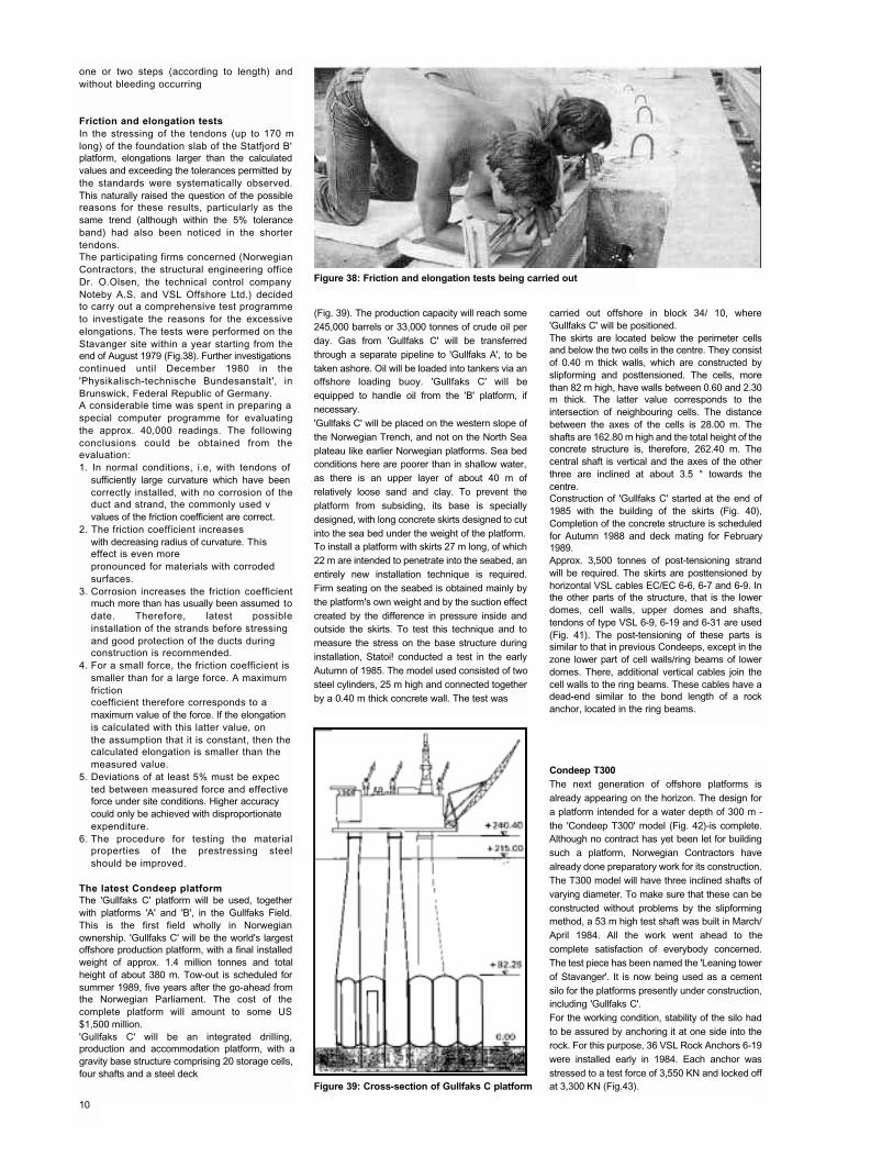
Friction and elongation testsIn the stressing of the tendons (up to 170 mlong) of the foundation slab of the Statfjord B'platform, elongations larger than the calculatedvalues and exceeding the tolerances permitted bythe standards were systematically observed.This naturally raised the question of the possiblereasons for these results, particularly as thesame trend (although within the 5% toleranceband) had also been noticed in the shortertendons.The participating firms concerned (NorwegianContractors, the structural engineering officeDr. O.Olsen, the technical control companyNoteby A.S. and VSL Offshore Ltd.) decidedto carry out a comprehensive test programmeto investigate the reasons for the excessiveelongations. The tests were performed on theStavanger site within a year starting from theend of August 1979 (Fig.38). Further investigationscontinued until December 1980 in the'Physikalisch-technische Bundesanstalt', inBrunswick, Federal Republic of Germany.A considerable time was spent in preparing a special computer programme for evaluatingthe approx. 40,000 readings. The followingconclusions could be obtained from theevaluation:1. In normal conditions, i.e, with tendons of
sufficiently large curvature which have been correctly installed, with no corrosion of theduct and strand, the commonly used vvalues of the friction coefficient are correct.
2. The friction coefficient increases with decreasing radius of curvature. Thiseffect is even more pronounced for materials with corroded surfaces.
3. Corrosion increases the friction coefficientmuch more than has usually been assumed todate. Therefore, latest possibleinstallation of the strands before stressing and good protection of the ducts during construction is recommended.
4. For a small force, the friction coefficient is smaller than for a large force. A maximum frictioncoefficient therefore corresponds to a maximum value of the force. If the elongationis calculated with this latter value, on the assumption that it is constant, then thecalculated elongation is smaller than the measured value.
5. Deviations of at least 5% must be expected between measured force and effective force under site conditions. Higher accuracycould only be achieved with disproportionate expenditure.
6. The procedure for testing the materialproperties of the prestressing steelshould be improved.
The latest Condeep platformThe 'Gullfaks C' platform will be used, togetherwith platforms 'A' and 'B', in the Gullfaks Field.This is the first field wholly in Norwegianownership. 'Gullfaks C' will be the world's largestoffshore production platform, with a final installedweight of approx. 1.4 million tonnes and totalheight of about 380 m. Tow-out is scheduled forsummer 1989, five years after the go-ahead fromthe Norwegian Parliament. The cost of thecomplete platform will amount to some US$1,500 million.'Gullfaks C' will be an integrated drilling,production and accommodation platform, with agravity base structure comprising 20 storage cells,four shafts and a steel deck
(Fig. 39). The production capacity will reach some245,000 barrels or 33,000 tonnes of crude oil perday. Gas from 'Gullfaks C' will be transferredthrough a separate pipeline to 'Gullfaks A', to betaken ashore. Oil will be loaded into tankers via anoffshore loading buoy. 'Gullfaks C' will beequipped to handle oil from the 'B' platform, ifnecessary.'Gullfaks C' will be placed on the western slope ofthe Norwegian Trench, and not on the North Seaplateau like earlier Norwegian platforms. Sea bedconditions here are poorer than in shallow water,as there is an upper layer of about 40 m ofrelatively loose sand and clay. To prevent theplatform from subsiding, its base is speciallydesigned, with long concrete skirts designed to cutinto the sea bed under the weight of the platform.To install a platform with skirts 27 m long, of which22 m are intended to penetrate into the seabed, anentirely new installation technique is required.Firm seating on the seabed is obtained mainly bythe platform's own weight and by the suction effectcreated by the difference in pressure inside andoutside the skirts. To test this technique and tomeasure the stress on the base structure duringinstallation, Statoi! conducted a test in the earlyAutumn of 1985. The model used consisted of twosteel cylinders, 25 m high and connected togetherby a 0.40 m thick concrete wall. The test was
carried out offshore in block 34/ 10, where'Gullfaks C' will be positioned.The skirts are located below the perimeter cellsand below the two cells in the centre. They consistof 0.40 m thick walls, which are constructed byslipforming and posttensioned. The cells, morethan 82 m high, have walls between 0.60 and 2.30m thick. The latter value corresponds to theintersection of neighbouring cells. The distancebetween the axes of the cells is 28.00 m. Theshafts are 162.80 m high and the total height of theconcrete structure is, therefore, 262.40 m. Thecentral shaft is vertical and the axes of the otherthree are inclined at about 3.5 ° towards thecentre.Construction of 'Gullfaks C' started at the end of1985 with the building of the skirts (Fig. 40),Completion of the concrete structure is scheduledfor Autumn 1988 and deck mating for February1989.Approx. 3,500 tonnes of post-tensioning strandwill be required. The skirts are posttensioned byhorizontal VSL cables EC/EC 6-6, 6-7 and 6-9. Inthe other parts of the structure, that is the lowerdomes, cell walls, upper domes and shafts,tendons of type VSL 6-9, 6-19 and 6-31 are used(Fig. 41). The post-tensioning of these parts issimilar to that in previous Condeeps, except in thezone lower part of cell walls/ring beams of lowerdomes. There, additional vertical cables join thecell walls to the ring beams. These cables have adead-end similar to the bond length of a rockanchor, located in the ring beams.
Condeep T300The next generation of offshore platforms isalready appearing on the horizon. The design fora platform intended for a water depth of 300 m -the 'Condeep T300' model (Fig. 42)-is complete.Although no contract has yet been let for buildingsuch a platform, Norwegian Contractors havealready done preparatory work for its construction.The T300 model will have three inclined shafts ofvarying diameter. To make sure that these can beconstructed without problems by the slipformingmethod, a 53 m high test shaft was built in March/April 1984. All the work went ahead to thecomplete satisfaction of everybody concerned.The test piece has been named the 'Leaning towerof Stavanger'. It is now being used as a cementsilo for the platforms presently under construction,including 'Gullfaks C'.For the working condition, stability of the silo hadto be assured by anchoring it at one side into therock. For this purpose, 36 VSL Rock Anchors 6-19were installed early in 1984. Each anchor wasstressed to a test force of 3,550 KN and locked offat 3,300 KN (Fig.43).
Figure 38: Friction and elongation tests being carried out
Figure 39: Cross-section of Gullfaks C platform
10
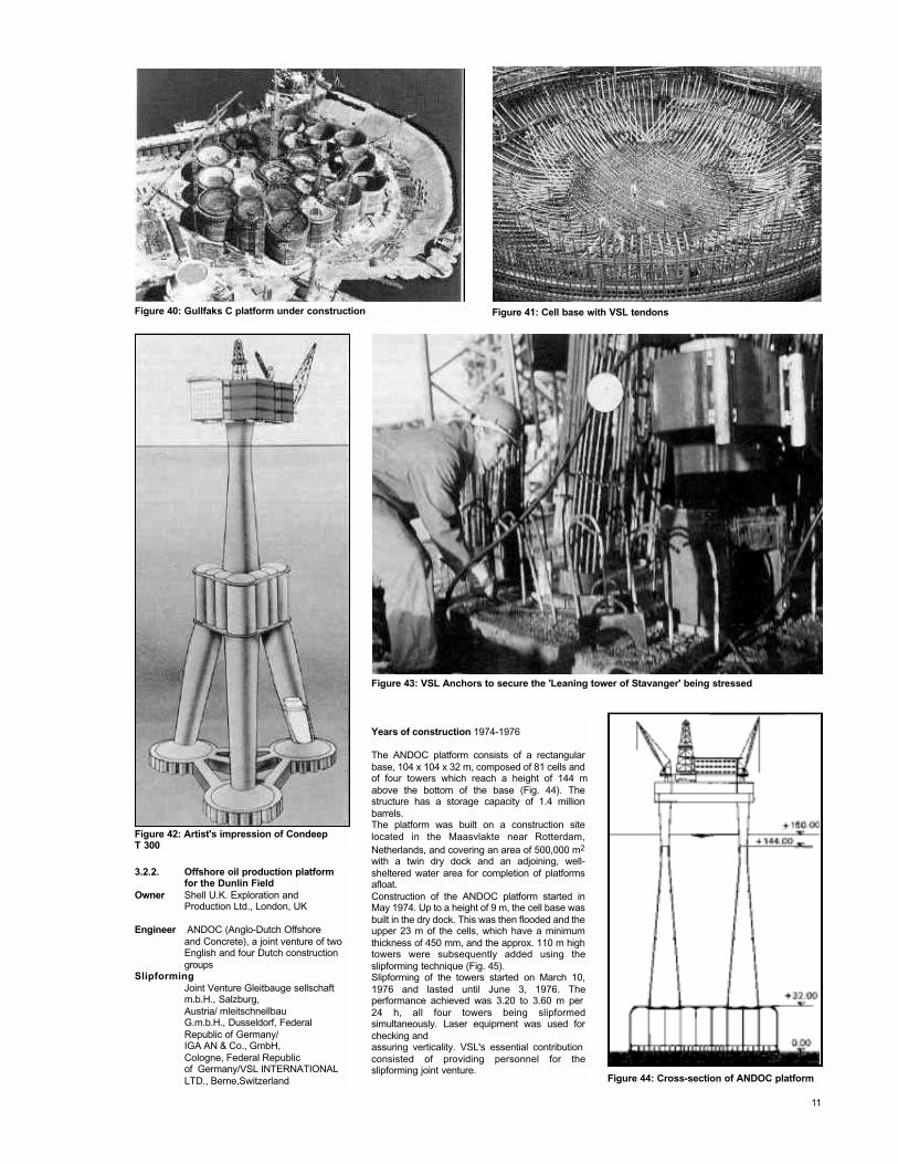
Figure 40: Gullfaks C platform under construction Figure 41: Cell base with VSL tendons
Figure 42: Artist's impression of CondeepT 300
Figure 43: VSL Anchors to secure the 'Leaning tower of Stavanger' being stressed
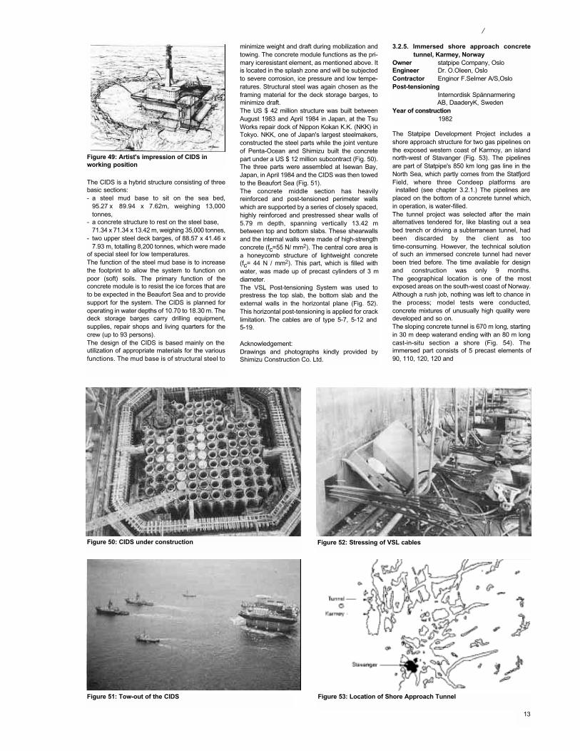
Years of construction 1974-1976
The ANDOC platform consists of a rectangularbase, 104 x 104 x 32 m, composed of 81 cells andof four towers which reach a height of 144 mabove the bottom of the base (Fig. 44). Thestructure has a storage capacity of 1.4 millionbarrels.The platform was built on a construction sitelocated in the Maasvlakte near Rotterdam,Netherlands, and covering an area of 500,000 m2
with a twin dry dock and an adjoining, well-sheltered water area for completion of platformsafloat.Construction of the ANDOC platform started inMay 1974. Up to a height of 9 m, the cell base wasbuilt in the dry dock. This was then flooded and theupper 23 m of the cells, which have a minimumthickness of 450 mm, and the approx. 110 m hightowers were subsequently added using theslipforming technique (Fig. 45).Slipforming of the towers started on March 10,1976 and lasted until June 3, 1976. Theperformance achieved was 3.20 to 3.60 m per 24 h, all four towers being slipformedsimultaneously. Laser equipment was used forchecking and assuring verticality. VSL's essential contribution consisted of providing personnel for theslipforming joint venture.
3.2.2. Offshore oil production platform for the Dunlin Field
Owner Shell U.K. Exploration andProduction Ltd., London, UK
Engineer ANDOC (Anglo-Dutch Offshoreand Concrete), a joint venture of two English and four Dutch construction groups
SlipformingJoint Venture Gleitbauge sellschaft m.b.H., Salzburg,Austria/ mleitschnellbauG.m.b.H., Dusseldorf, Federal Republic of Germany/IGA AN & Co., GmbH,Cologne, Federal Republicof Germany/VSL INTERNATIONAL LTD., Berne,Switzerland
11
Figure 44: Cross-section of ANDOC platform
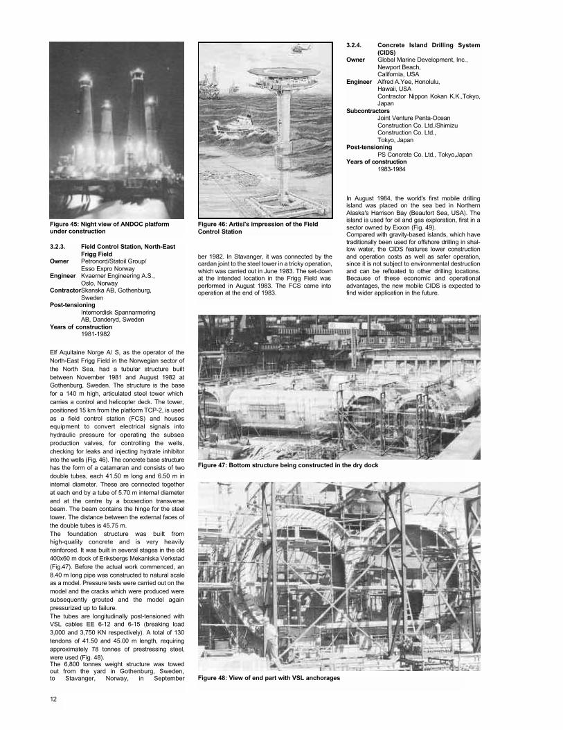
Figure 45: Night view of ANDOC platformunder construction
Figure 46: Artisi's impression of the FieldControl Station
3.2.4. Concrete Island Drilling System(CIDS)
Owner Global Marine Development, Inc., Newport Beach,California, USA
Engineer Alfred A.Yee, Honolulu,Hawaii, USAContractor Nippon Kokan K.K.,Tokyo,Japan
SubcontractorsJoint Venture Penta-OceanConstruction Co. Ltd./Shimizu Construction Co. Ltd.,Tokyo, Japan
Post-tensioningPS Concrete Co. Ltd., Tokyo,Japan
Years of construction1983-1984
In August 1984, the world's first mobile drillingisland was placed on the sea bed in NorthernAlaska's Harrison Bay (Beaufort Sea, USA). Theisland is used for oil and gas exploration, first in asector owned by Exxon (Fig. 49).Compared with gravity-based islands, which havetraditionally been used for offshore drilling in shal-low water, the CIDS features lower constructionand operation costs as well as safer operation,since it is not subject to environmental destructionand can be refloated to other drilling locations.Because of these economic and operationaladvantages, the new mobile CIDS is expected tofind wider application in the future.
ber 1982. In Stavanger, it was connected by thecardan joint to the steel tower in a tricky operation,which was carried out in June 1983. The set-downat the intended location in the Frigg Field was performed in August 1983. The FCS came into operation at the end of 1983.
Elf Aquitaine Norge A/ S, as the operator of theNorth-East Frigg Field in the Norwegian sector ofthe North Sea, had a tubular structure builtbetween November 1981 and August 1982 atGothenburg, Sweden. The structure is the basefor a 140 m high, articulated steel tower which carries a control and helicopter deck. The tower,positioned 15 km from the platform TCP-2, is usedas a field control station (FCS) and housesequipment to convert electrical signals intohydraulic pressure for operating the subseaproduction valves, for controlling the wells,checking for leaks and injecting hydrate inhibitorinto the wells (Fig. 46). The concrete base structurehas the form of a catamaran and consists of twodouble tubes, each 41.50 m long and 6.50 m ininternal diameter. These are connected togetherat each end by a tube of 5.70 m internal diameterand at the centre by a boxsection transversebeam. The beam contains the hinge for the steeltower. The distance between the external faces ofthe double tubes is 45.75 m.The foundation structure was built fromhigh-quality concrete and is very heavilyreinforced. It was built in several stages in the old400x60 m dock of Eriksbergs Mekaniska Verkstad(Fig.47). Before the actual work commenced, an8.40 m long pipe was constructed to natural scaleas a model. Pressure tests were carried out on themodel and the cracks which were produced weresubsequently grouted and the model againpressurized up to failure.The tubes are longitudinally post-tensioned withVSL cables EE 6-12 and 6-15 (breaking load3,000 and 3,750 KN respectively). A total of 130tendons of 41.50 and 45.00 m length, requiringapproximately 78 tonnes of prestressing steel,were used (Fig. 48).The 6,800 tonnes weight structure was towedout from the yard in Gothenburg, Sweden,to Stavanger, Norway, in September
3.2.3. Field Control Station, North-East Frigg Field
Owner Petronord/Statoil Group/Esso Expro Norway
Engineer Kvaerner Engineering A.S.,Oslo, Norway
ContractorSkanska AB, Gothenburg,Sweden
Post-tensioningInternordisk SpannarmeringAB, Danderyd, Sweden
Years of construction1981-1982
Figure 47: Bottom structure being constructed in the dry dock
Figure 48: View of end part with VSL anchorages
12
The CIDS is a hybrid structure consisting of threebasic sections:- a steel mud base to sit on the sea bed,
95.27 x 89.94 x 7.62m, weighing 13,000tonnes,
- a concrete structure to rest on the steel base, 71.34 x 71.34 x 13.42 m, weighing 35,000 tonnes,
- two upper steel deck barges, of 88.57 x 41.46 x7.93 m, totalling 8,200 tonnes, which were made
of special steel for low temperatures.The function of the steel mud base is to increasethe footprint to allow the system to function onpoor (soft) soils. The primary function of theconcrete module is to resist the ice forces that areto be expected in the Beaufort Sea and to providesupport for the system. The CIDS is planned foroperating in water depths of 10.70 to 18.30 m. Thedeck storage barges carry drilling equipment,supplies, repair shops and living quarters for thecrew (up to 93 persons).The design of the CIDS is based mainly on the utilization of appropriate materials for the variousfunctions. The mud base is of structural steel to
Figure 49: Artist's impression of CIDS in working position
minimize weight and draft during mobilization andtowing. The concrete module functions as the pri-mary iceresistant element, as mentioned above. Itis located in the splash zone and will be subjectedto severe corrosion, ice pressure and low tempe-ratures. Structural steel was again chosen as theframing material for the deck storage barges, tominimize draft.The US $ 42 million structure was built betweenAugust 1983 and April 1984 in Japan, at the TsuWorks repair dock of Nippon Kokan K.K. (NKK) inTokyo. NKK, one of Japan's largest steelmakers,constructed the steel parts while the joint ventureof Penta-Ocean and Shimizu built the concretepart under a US $ 12 million subcontract (Fig. 50).The three parts were assembled at Isewan Bay,Japan, in April 1984 and the CIDS was then towedto the Beaufort Sea (Fig. 51).The concrete middle section has heavilyreinforced and post-tensioned perimeter wallswhich are supported by a series of closely spaced,highly reinforced and prestressed shear walls of5.79 m depth, spanning vertically 13.42 mbetween top and bottom slabs. These shearwallsand the internal walls were made of high-strengthconcrete (fc=55 N/ mm2). The central core area isa honeycomb structure of lightweight concrete(fc= 44 N / mm2). This part, which is filled withwater, was made up of precast cylinders of 3 mdiameter.The VSL Post-tensioning System was used toprestress the top slab, the bottom slab and theexternal walls in the horizontal plane (Fig. 52).This horizontal post-tensioning is applied for cracklimitation. The cables are of type 5-7, 5-12 and 5-19.
Acknowledgement:Drawings and photographs kindly provided byShimizu Construction Co. Ltd.
The Statpipe Development Project includes ashore approach structure for two gas pipelines onthe exposed western coast of Karmoy, an islandnorth-west of Stavanger (Fig. 53). The pipelinesare part of Statpipe's 850 km long gas line in theNorth Sea, which partly comes from the StatfjordField, where three Condeep platforms areinstalled (see chapter 3.2.1.) The pipelines are
placed on the bottom of a concrete tunnel which,in operation, is water-filled.The tunnel project was selected after the mainalternatives tendered for, like blasting out a seabed trench or driving a subterranean tunnel, hadbeen discarded by the client as tootime-consuming. However, the technical solutionof such an immersed concrete tunnel had neverbeen tried before. The time available for designand construction was only 9 months.The geographical location is one of the mostexposed areas on the south-west coast of Norway.Although a rush job, nothing was left to chance inthe process; model tests were conducted,concrete mixtures of unusually high quality weredeveloped and so on.The sloping concrete tunnel is 670 m long, startingin 30 m deep waterand ending with an 80 m longcast-in-situ section a shore (Fig. 54). Theimmersed part consists of 5 precast elements of90, 110, 120, 120 and
3.2.5. Immersed shore approach concretetunnel, Karmey, Norway
Owner statpipe Company, OsloEngineer Dr. O.Oleen, OsloContractor Enginor F.SeImer A/S,OsloPost-tensioning
Internordisk SpännarmeringAB, DaaderyK, Sweden
Year of construction1982
Figure 50: CIDS under construction
Figure 51: Tow-out of the CIDS Figure 53: Location of Shore Approach Tunnel
Figure 52: Stressing of VSL cables
13
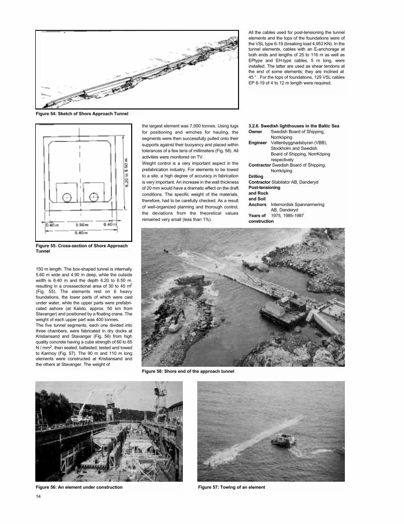
All the cables used for post-tensioning the tunnelelements and the tops of the foundations were ofthe VSL type 6-19 (breaking load 4,953 KN). In thetunnel elements, cables with an E-anchorage atboth ends and lengths of 25 to 116 m as well asEPtype and EH-type cables, 5 m long, wereinstalled. The latter are used as shear tendons atthe end of some elements; they are inclined at 45 ° . For the tops of foundations, 129 VSL cablesEP 6-19 of 4 to 12 m length were required.
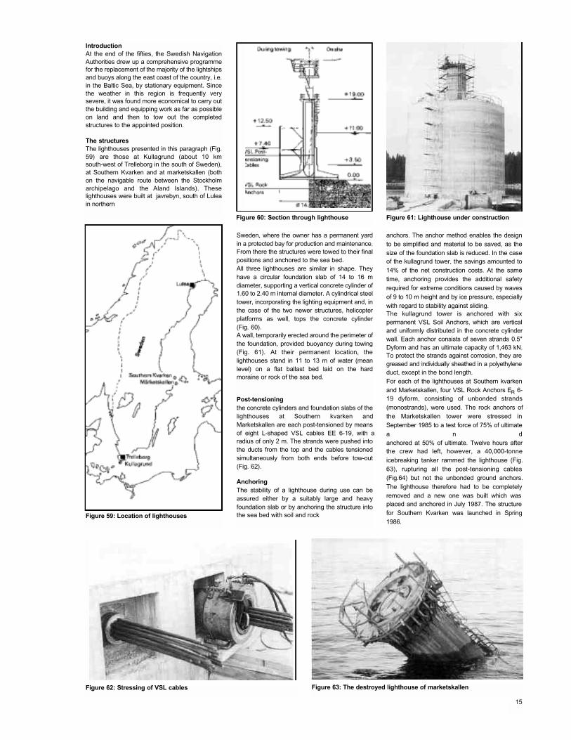
the largest element was 7,000 tonnes. Using tugsfor positioning and winches for hauling, thesegments were then successfully pulled onto theirsupports against their buoyancy and placed withintolerances of a few tens of millimeters (Fig. 58). Allactivities were monitored on TV.Weight control is a very important aspect in theprefabrication industry. For elements to be towedto a site, a high degree of accuracy in fabricationis very important. An increase in the wall thicknessof 20 mm would have a dramatic effect on the draftconditions. The specific weight of the materials,therefore, had to be carefully checked. As a resultof well-organized planning and thorough control,the deviations from the theoretical valuesremained very small (less than 1%).
3.2.6. Swedish lighthouses in the Baltic SeaOwner Swedish Board of Shipping,
NorrköpingEngineer Vattenbyggnadsbyran (VBB),
Stockholm and SwedishBoard of Shipping, NorrKöping respectively
Contractor Swedish Board of Shipping,Norrköping
DrillingContractor Stabilator AB, DanderydPost-tensioningand Rock and SoilAnchors Internordisk Spannarmering
AB, DanderydYears of 1975, 1985-1987construction
150 m length. The box-shaped tunnel is internally5.60 m wide and 4.90 m deep, while the outsidewidth is 6.40 m and the depth 6.20 to 6.50 m resulting in a crosssectional area of 30 to 45 m2
(Fig. 55). The elements rest on 6 heavyfoundations, the lower parts of which were castunder water, while the upper parts were prefabri-cated ashore (at Kalsto, approx. 50 km fromStavanger) and positioned by a floating crane. Theweight of each upper part was 400 tonnes.The five tunnel segments, each one divided intothree chambers, were fabricated in dry docks atKristiansand and Stavanger (Fig. 56) from highquality concrete having a cube strength of 60 to 65N / mm2, then sealed, ballasted, tested and towedto Karmoy (Fig. 57). The 90 m and 110 m longelements were constructed at Kristiansand andthe others at Stavanger. The weight of
Figure 54: Sketch of Shore Approach Tunnel
Figure 55: Cross-section of Shore ApproachTunnel
Figure 58: Shore end of the approach tunnel
Figure 57: Towing of an elementFigure 56: An element under construction
14
IntroductionAt the end of the fifties, the Swedish NavigationAuthorities drew up a comprehensive programmefor the replacement of the majority of the lightshipsand buoys along the east coast of the country, i.e.in the Baltic Sea, by stationary equipment. Sincethe weather in this region is frequently verysevere, it was found more economical to carry outthe building and equipping work as far as possibleon land and then to tow out the completedstructures to the appointed position.
The structuresThe lighthouses presented in this paragraph (Fig.59) are those at Kullagrund (about 10 kmsouth-west of Trelleborg in the south of Sweden),at Southern Kvarken and at marketskallen (bothon the navigable route between the Stockholmarchipelago and the Aland Islands). Theselighthouses were built at javrebyn, south of Luleain northern
Sweden, where the owner has a permanent yardin a protected bay for production and maintenance.From there the structures were towed to their finalpositions and anchored to the sea bed.All three lighthouses are similar in shape. Theyhave a circular foundation slab of 14 to 16 mdiameter, supporting a vertical concrete cylinder of1.60 to 2.40 m internal diameter. A cylindrical steeltower, incorporating the lighting equipment and, inthe case of the two newer structures, helicopterplatforms as well, tops the concrete cylinder(Fig. 60).A wall, temporarily erected around the perimeter ofthe foundation, provided buoyancy during towing(Fig. 61). At their permanent location, thelighthouses stand in 11 to 13 m of water (meanlevel) on a flat ballast bed laid on the hardmoraine or rock of the sea bed.
Post-tensioningthe concrete cylinders and foundation slabs of thelighthouses at Southern kvarken andMarketskallen are each post-tensioned by meansof eight L-shaped VSL cables EE 6-19, with aradius of only 2 m. The strands were pushed intothe ducts from the top and the cables tensionedsimultaneously from both ends before tow-out(Fig. 62).
AnchoringThe stability of a lighthouse during use can beassured either by a suitably large and heavyfoundation slab or by anchoring the structure intothe sea bed with soil and rock
anchors. The anchor method enables the designto be simplified and material to be saved, as thesize of the foundation slab is reduced. In the caseof the kullagrund tower, the savings amounted to14% of the net construction costs. At the sametime, anchoring provides the additional safetyrequired for extreme conditions caused by wavesof 9 to 10 m height and by ice pressure, especiallywith regard to stability against sliding.The kullagrund tower is anchored with sixpermanent VSL Soil Anchors, which are verticaland uniformly distributed in the concrete cylinderwall. Each anchor consists of seven strands 0.5"Dyform and has an ultimate capacity of 1,463 kN.To protect the strands against corrosion, they aregreased and individually sheathed in a polyethyleneduct, except in the bond length.For each of the lighthouses at Southern kvarkenand Marketskallen, four VSL Rock Anchors ER 6-19 dyform, consisting of unbonded strands(monostrands), were used. The rock anchors ofthe Marketskallen tower were stressed inSeptember 1985 to a test force of 75% of ultimatea n danchored at 50% of ultimate. Twelve hours afterthe crew had left, however, a 40,000-tonneicebreaking tanker rammed the lighthouse (Fig.63), rupturing all the post-tensioning cables(Fig.64) but not the unbonded ground anchors.The lighthouse therefore had to be completelyremoved and a new one was built which was placed and anchored in July 1987. The structurefor Southern Kvarken was launched in Spring1986.
Figure 59: Location of lighthouses
Figure 62: Stressing of VSL cables Figure 63: The destroyed lighthouse of marketskallen
Figure 61: Lighthouse under constructionFigure 60: Section through lighthouse
15
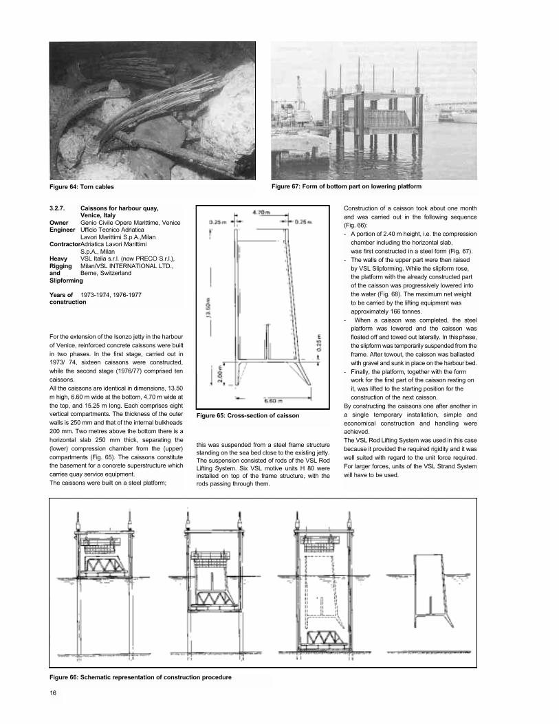
Figure 67: Form of bottom part on lowering platformFigure 64: Torn cables
3.2.7. Caissons for harbour quay,Venice, Italy
Owner Genio Civile Opere Marittime, VeniceEngineer Ufficio Tecnico Adriatica
Lavori Marittimi S.p.A.,MilanContractorAdriatica Lavori Marittimi
S.p.A., MilanHeavy VSL Italia s.r.l. (now PRECO S.r.l.),Rigging Milan/VSL INTERNATIONAL LTD., and Berne, SwitzerlandSlipforming
Years of 1973-1974, 1976-1977construction
For the extension of the Isonzo jetty in the harbourof Venice, reinforced concrete caissons were builtin two phases. In the first stage, carried out in1973/ 74, sixteen caissons were constructed,while the second stage (1976/77) comprised tencaissons.All the caissons are identical in dimensions, 13.50m high, 6.60 m wide at the bottom, 4.70 m wide atthe top, and 15.25 m long. Each comprises eightvertical compartments. The thickness of the outerwalls is 250 mm and that of the internal bulkheads200 mm. Two metres above the bottom there is ahorizontal slab 250 mm thick, separating the(lower) compression chamber from the (upper)compartments (Fig. 65). The caissons constitutethe basement for a concrete superstructure whichcarries quay service equipment.The caissons were built on a steel platform;
this was suspended from a steel frame structurestanding on the sea bed close to the existing jetty.The suspension consisted of rods of the VSL RodLifting System. Six VSL motive units H 80 wereinstalled on top of the frame structure, with therods passing through them.
Construction of a caisson took about one monthand was carried out in the following sequence(Fig. 66):- A portion of 2.40 m height, i.e. the compression
chamber including the horizontal slab, was first constructed in a steel form (Fig. 67).
- The walls of the upper part were then raised by VSL Slipforming. While the slipform rose, the platform with the already constructed part of the caisson was progressively lowered into the water (Fig. 68). The maximum net weight to be carried by the lifting equipment was approximately 166 tonnes.
- When a caisson was completed, the steelplatform was lowered and the caisson wasfloated off and towed out laterally. In this phase,the slipform was temporarily suspended from theframe. After towout, the caisson was ballasted with gravel and sunk in place on the harbour bed.
- Finally, the platform, together with the formwork for the first part of the caisson resting on it, was lifted to the starting position for the construction of the next caisson.
By constructing the caissons one after another ina single temporary installation, simple andeconomical construction and handling wereachieved.The VSL Rod Lifting System was used in this casebecause it provided the required rigidity and it waswell suited with regard to the unit force required.For larger forces, units of the VSL Strand Systemwill have to be used.
Figure 65: Cross-section of caisson
Figure 66: Schematic representation of construction procedure
16
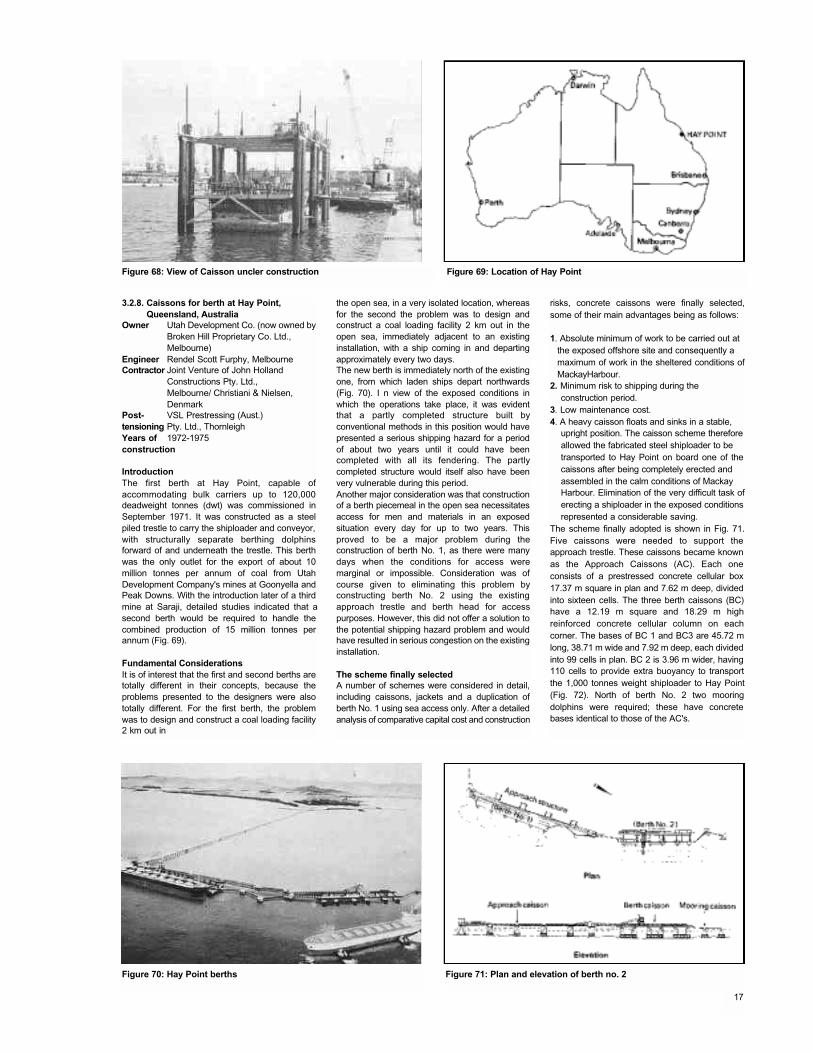
Figure 68: View of Caisson uncler construction Figure 69: Location of Hay Point
3.2.8. Caissons for berth at Hay Point,Queensland, Australia
Owner Utah Development Co. (now owned byBroken Hill Proprietary Co. Ltd., Melbourne)
Engineer Rendel Scott Furphy, MelbourneContractor Joint Venture of John Holland
Constructions Pty. Ltd.,Melbourne/ Christiani & Nielsen, Denmark
Post- VSL Prestressing (Aust.)tensioning Pty. Ltd., ThornleighYears of 1972-1975construction
IntroductionThe first berth at Hay Point, capable ofaccommodating bulk carriers up to 120,000deadweight tonnes (dwt) was commissioned inSeptember 1971. It was constructed as a steelpiled trestle to carry the shiploader and conveyor,with structurally separate berthing dolphinsforward of and underneath the trestle. This berthwas the only outlet for the export of about 10million tonnes per annum of coal from UtahDevelopment Company's mines at Goonyella andPeak Downs. With the introduction later of a thirdmine at Saraji, detailed studies indicated that asecond berth would be required to handle thecombined production of 15 million tonnes perannum (Fig. 69).
Fundamental ConsiderationsIt is of interest that the first and second berths aretotally different in their concepts, because theproblems presented to the designers were alsototally different. For the first berth, the problemwas to design and construct a coal loading facility2 km out in
the open sea, in a very isolated location, whereasfor the second the problem was to design andconstruct a coal loading facility 2 km out in theopen sea, immediately adjacent to an existinginstallation, with a ship coming in and departingapproximately every two days.The new berth is immediately north of the existingone, from which laden ships depart northwards(Fig. 70). I n view of the exposed conditions inwhich the operations take place, it was evidentthat a partly completed structure built byconventional methods in this position would havepresented a serious shipping hazard for a periodof about two years until it could have beencompleted with all its fendering. The partlycompleted structure would itself also have beenvery vulnerable during this period.Another major consideration was that constructionof a berth piecemeal in the open sea necessitatesaccess for men and materials in an exposedsituation every day for up to two years. Thisproved to be a major problem during theconstruction of berth No. 1, as there were manydays when the conditions for access weremarginal or impossible. Consideration was ofcourse given to eliminating this problem byconstructing berth No. 2 using the existingapproach trestle and berth head for accesspurposes. However, this did not offer a solution tothe potential shipping hazard problem and wouldhave resulted in serious congestion on the existinginstallation.
The scheme finally selectedA number of schemes were considered in detail,including caissons, jackets and a duplication ofberth No. 1 using sea access only. After a detailedanalysis of comparative capital cost and construction
risks, concrete caissons were finally selected,some of their main advantages being as follows:
1. Absolute minimum of work to be carried out at the exposed offshore site and consequently a maximum of work in the sheltered conditions ofMackayHarbour.
2. Minimum risk to shipping during the construction period.
3. Low maintenance cost.4. A heavy caisson floats and sinks in a stable,
upright position. The caisson scheme thereforeallowed the fabricated steel shiploader to be transported to Hay Point on board one of the caissons after being completely erected and assembled in the calm conditions of Mackay Harbour. Elimination of the very difficult task oferecting a shiploader in the exposed conditionsrepresented a considerable saving.
The scheme finally adopted is shown in Fig. 71.Five caissons were needed to support theapproach trestle. These caissons became knownas the Approach Caissons (AC). Each oneconsists of a prestressed concrete cellular box17.37 m square in plan and 7.62 m deep, dividedinto sixteen cells. The three berth caissons (BC)have a 12.19 m square and 18.29 m highreinforced concrete cellular column on eachcorner. The bases of BC 1 and BC3 are 45.72 mlong, 38.71 m wide and 7.92 m deep, each dividedinto 99 cells in plan. BC 2 is 3.96 m wider, having110 cells to provide extra buoyancy to transportthe 1,000 tonnes weight shiploader to Hay Point(Fig. 72). North of berth No. 2 two mooringdolphins were required; these have concretebases identical to those of the AC's.
Figure 70: Hay Point berths Figure 71: Plan and elevation of berth no. 2
17
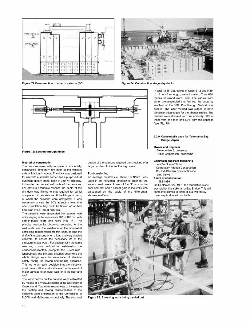
Figure 72:Cross-section of a berth caisson (BC) Figure 74: Construction stage (dry dock)
Figure 73: Section through hinge
Method of constructionThe caissons were partly completed in a speciallyconstructed temporary dry dock at the westernside of Mackay Harbour. The dock was designedfor use with a straddle carrier and a purpose-builtoverhead gantry crane, each of 350 KN capacity,to handle the precast wall units of the caissons.For obvious economic reasons the depth of thedry dock was limited to that required for partialcompletion of the caissons. At the fitting-out berth,at which the caissons were completed, it wasnecessary to seat the BC's at such a level thatafter completion they could be floated off at theirfinal draft (10.67 m) at high tide.The caissons were assembled from precast wallunits varying in thickness from 203 to 406 mm withcast-in-place floors and roofs (Fig. 74). Theprincipal reason for choosing precasting for thewall units was the existence of the somewhatconflicting requirements for thin units, to limit thedraft of the caissons when afloat, and very durableconcrete, to ensure the necessary life of thestructure in sea-water. For substantially the samereasons, it was decided to post-tension thecaissons horizontally, except for the BC columns.Undoubtedly the principal criterion underlying thewhole design was the assurance of absolutesafety during the towing and sinking operation.This led to an early decision that the caissonsmust remain afloat and stable even in the event ofmajor damage to an outer wall, or to the floor androof.The wave forces on the caisson were estimatedby means of a hydraulic model at the University ofQueensland. Two other model tests to investigatethe floating and towing characteristics of thecaissons were undertaken at the Universities ofN.S.W. and Melbourne respectively. The structural
design of the caissons required the checking of alarge number of different loading cases.
Post-tensioningAn average prestress of about 5.3 N/mm2 wasused in the horizontal direction to cater for thevarious load cases. A loss of 1.4 N/ mm2 in thefloor and roof and a similar gain in the walls wascalculated on the basis of the differentialshrinkage effects.
In total 1,885 VSL cables of types 5-12 and 5-19,of 18 to 45 m length, were installed. Thus 680 tonnes of strand were used. The cables wereeither pre-assembled and fed into the ducts bywinches or the VSL Pushthrough Method wasapplied. The latter method was judged to haveparticular advantages for the shorter cables. Thetendons were stressed from one end only, 50% ofthem from one face and 50% from the oppositeface (Fig. 75).
3.2.9. Caisson pile caps for Yokohama Bay Bridge, Japan
Owner and EngineerMetropolitan ExpresswayPublic Corporation, Yokohama
Contractor and Post-tensioningJoint Venture of Taisei Corporation /Maeda ConstructionCo. Ltd./Shimizu Construction Co. Ltd., Tokyo
Years of construction1982-1986
On September 27, 1981, the foundation stone was laid for the Yokohama Bay Bridge. This will come into service in 1989. It is a two-storey motorway bridge with six traffic
Figure 75: Stressing work being carried out
18
lanes on each level. The superstructure consistsof a steel lattice girder with spans of 3X116-200-460-200-3X100 m. The three main spans arecable-stayed (Fig. 76).
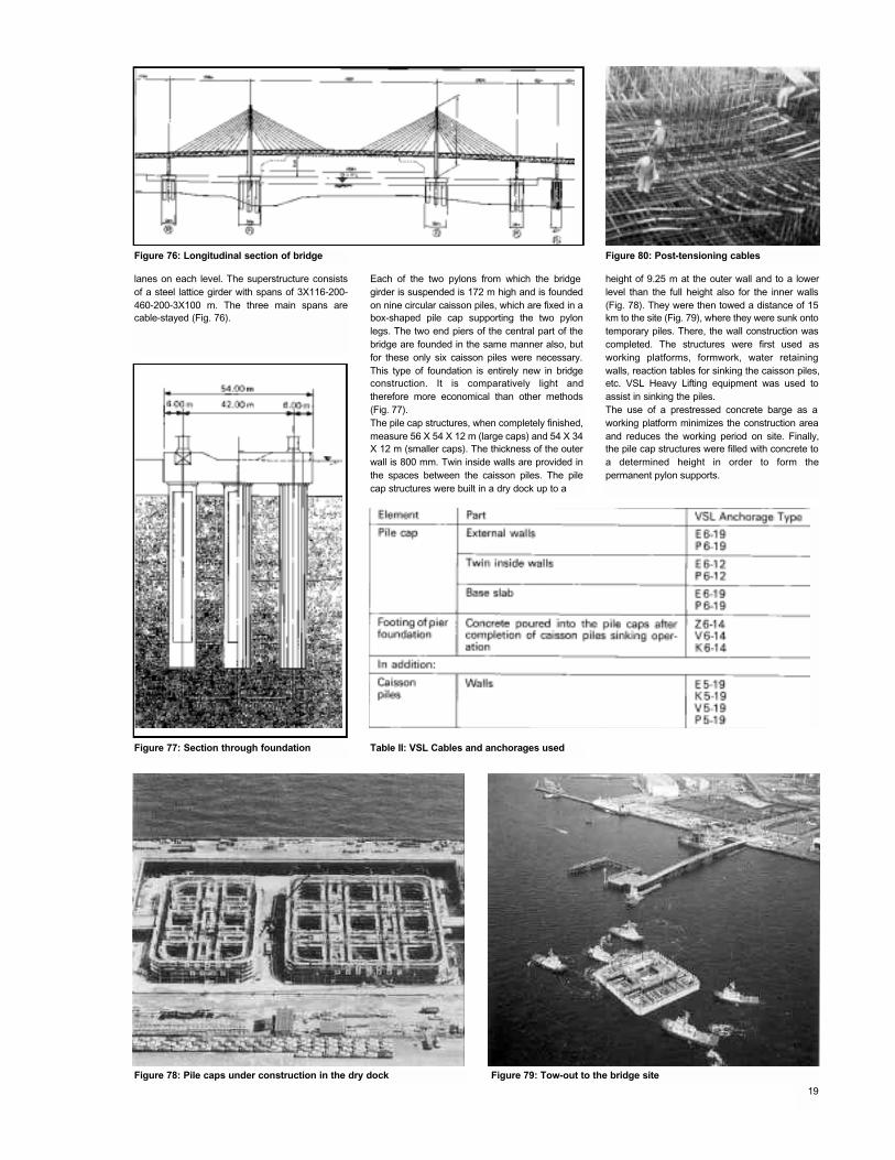
Each of the two pylons from which the bridge girder is suspended is 172 m high and is foundedon nine circular caisson piles, which are fixed in abox-shaped pile cap supporting the two pylonlegs. The two end piers of the central part of thebridge are founded in the same manner also, butfor these only six caisson piles were necessary.This type of foundation is entirely new in bridgeconstruction. It is comparatively light andtherefore more economical than other methods(Fig. 77).The pile cap structures, when completely finished,measure 56 X 54 X 12 m (large caps) and 54 X 34X 12 m (smaller caps). The thickness of the outerwall is 800 mm. Twin inside walls are provided inthe spaces between the caisson piles. The pilecap structures were built in a dry dock up to a
height of 9.25 m at the outer wall and to a lowerlevel than the full height also for the inner walls(Fig. 78). They were then towed a distance of 15km to the site (Fig. 79), where they were sunk ontotemporary piles. There, the wall construction wascompleted. The structures were first used asworking platforms, formwork, water retainingwalls, reaction tables for sinking the caisson piles,etc. VSL Heavy Lifting equipment was used toassist in sinking the piles.The use of a prestressed concrete barge as a working platform minimizes the construction areaand reduces the working period on site. Finally,the pile cap structures were filled with concrete toa determined height in order to form thepermanent pylon supports.
Figure 76: Longitudinal section of bridge Figure 80: Post-tensioning cables
Figure 78: Pile caps under construction in the dry dock
Figure 77: Section through foundation
Figure 79: Tow-out to the bridge site
19
Table II: VSL Cables and anchorages used
3.2.10. Floating concrete batching plant,Japan
Owner Honshu-Shikoku BridgeBisan Seto Ohashi Sub-structure Joint Venture Company
Engineer,Contractorand Post-tensioning Taisei Corporation, TokyoYears ofconstruction 1981-1982
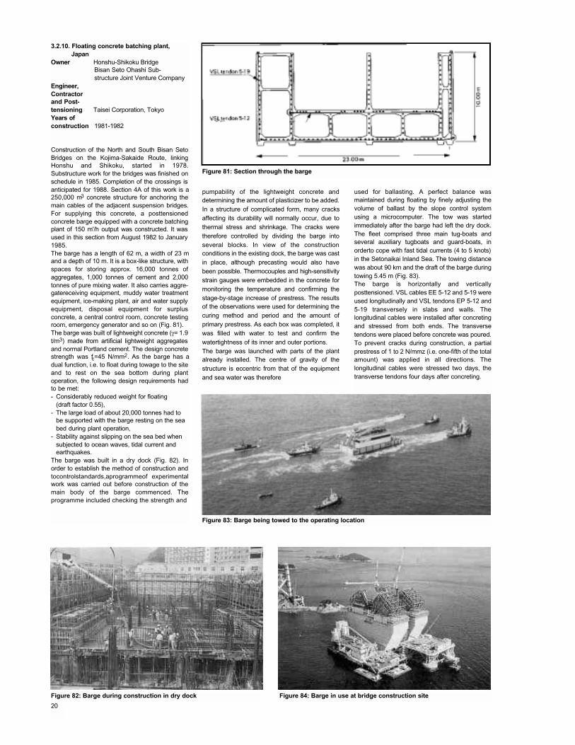
Construction of the North and South Bisan SetoBridges on the Kojima-Sakaide Route, linkingHonshu and Shikoku, started in 1978.Substructure work for the bridges was finished onschedule in 1985. Completion of the crossings isanticipated for 1988. Section 4A of this work is a250,000 m3 concrete structure for anchoring themain cables of the adjacent suspension bridges.For supplying this concrete, a posttensionedconcrete barge equipped with a concrete batchingplant of 150 m'/h output was constructed. It wasused in this section from August 1982 to January1985.The barge has a length of 62 m, a width of 23 mand a depth of 10 m. It is a box-like structure, withspaces for storing approx. 16,000 tonnes ofaggregates, 1,000 tonnes of cement and 2,000tonnes of pure mixing water. It also carries aggre-gatereceiving equipment, muddy water treatmentequipment, ice-making plant, air and water supplyequipment, disposal equipment for surplusconcrete, a central control room, concrete testingroom, emergency generator and so on (Fig. 81).The barge was built of lightweight concrete (γ= 1.9t/m3) made from artificial lightweight aggregatesand normal Portland cement. The design concretestrength was fc=45 N/mm2. As the barge has adual function, i.e. to float during towage to the siteand to rest on the sea bottom during plantoperation, the following design requirements hadto be met:- Considerably reduced weight for floating
(draft factor 0.55),- The large load of about 20,000 tonnes had to
be supported with the barge resting on the sea bed during plant operation,
- Stability against slipping on the sea bed when subjected to ocean waves, tidal current and earthquakes.
The barge was built in a dry dock (Fig. 82). Inorder to establish the method of construction andtocontrolstandards,aprogrammeof experimentalwork was carried out before construction of themain body of the barge commenced. Theprogramme included checking the strength and
pumpability of the lightweight concrete anddetermining the amount of plasticizer to be added.In a structure of complicated form, many cracksaffecting its durability will normally occur, due tothermal stress and shrinkage. The cracks weretherefore controlled by dividing the barge intoseveral blocks. In view of the constructionconditions in the existing dock, the barge was castin place, although precasting would also havebeen possible. Thermocouples and high-sensitivitystrain gauges were embedded in the concrete formonitoring the temperature and confirming thestage-by-stage increase of prestress. The resultsof the observations were used for determining thecuring method and period and the amount ofprimary prestress. As each box was completed, itwas filled with water to test and confirm thewatertightness of its inner and outer portions.The barge was launched with parts of the plantalready installed. The centre of gravity of thestructure is eccentric from that of the equipmentand sea water was therefore
used for ballasting. A perfect balance wasmaintained during floating by finely adjusting thevolume of ballast by the slope control systemusing a microcomputer. The tow was startedimmediately after the barge had left the dry dock.The fleet comprised three main tug-boats andseveral auxiliary tugboats and guard-boats, inorderto cope with fast tidal currents (4 to 5 knots)in the Setonaikai Inland Sea. The towing distancewas about 90 km and the draft of the barge duringtowing 5.45 m (Fig. 83).The barge is horizontally and verticallyposttensioned. VSL cables EE 5-12 and 5-19 wereused longitudinally and VSL tendons EP 5-12 and5-19 transversely in slabs and walls. Thelongitudinal cables were installed after concretingand stressed from both ends. The transversetendons were placed before concrete was poured.To prevent cracks during construction, a partialprestress of 1 to 2 N/mmz (i.e. one-fifth of the totalamount) was applied in all directions. Thelongitudinal cables were stressed two days, thetransverse tendons four days after concreting.
Figure 81: Section through the barge
Figure 83: Barge being towed to the operating location
Figure 84: Barge in use at bridge construction siteFigure 82: Barge during construction in dry dock
20
3.3. Permanently floatingstructures
3.3.1. Concrete barge 'C-Boat 500'Owner,Engineer,ContractorandPost-tensioning Taisei Corporation,
JapanYear ofconstruction 1982
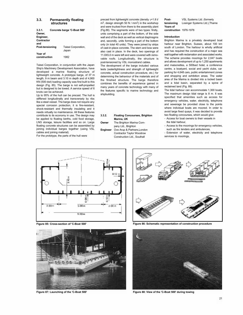
Taisei Corporation, in conjunction with the JapanShip's Machinery Development Association, havedeveloped a marine floating structure oflightweight concrete. A prototype barge, of 37 mlength, 9 m beam and 3.10 m depth and of 4,900KN (500 dwt) loading capacity was first built to thisdesign (Fig. 85). The barge is not self-propelledbut is designed to be towed. A service speed of 6knots can be achieved.Up to 95% of the hull can be precast. The hull isstiffened longitudinally and transversely by ribslike a steel vessel. The barge does not require anyspecial corrosion protection, it is fire-resistant,shock-resistant and thermally insulating and itneeds virtually no maintenance. All these featurescontribute to its economy in use. The design maybe applied to floating berths, cold food storage,LNG storage, leisure facilities and so on. Largefloating concrete structures can be assembled byjoining individual barges together (using VSLcables and joining material).For the prototype, the parts of the hull were
precast from lightweight concrete (density γ=1.8 t/m3, design strength 50 N / mm2) in the workshopand were trucked from there to the assembly plant(Fig.86). The segments were of two types: firstly,units comprising a part of the bottom, of the sidewall and of the deck as well as vertical diaphragmsand, secondly, units forming a part of the bottomonly (in total 40 units). They were joined by stripsof cast-in-place concrete. The stern and bow werealso cast in place. In the deck, two openings of11.0X5.0 m were left and were covered with remo-vable roofs. Longitudinally, the structure ispost-tensioned by VSL monostrand cables.The development of the barge included varioustests (watertightness and strength of lightweightconcrete, actual construction procedure, etc.) fordetermining the behaviour of the materials and ofthe finished structure. The barge thereforecombines the benefits of experience gained inmany years of concrete technology with many ofthe features specific to marine technology andshipbuilding.
3.3.2. Floating Concourses, BrightonMarina, UK
Owner The Brighton Marina Com-pany Ltd., Brighton
Engineer Ove Arup & Partners,LondonContractor Taylor Woodrow Construction Ltd., Southall
Post- VSL Systems Ltd. (formerlytensioning Losinger Systems Ltd.),ThameYears ofconstruction 1976-1978
IntroductionBrighton Marina is a privately developed boatharbour near Brighton, Sussex, about 100 kmsouth of London. The harbour is wholly artificialand has required the construction of a major seawall together with reclamation and associated works.The scheme provides moorings for 2,047 boatsand allows development of up to 1,250 apartmentsand maisonettes, a 500bed hotel, a conferencecentre, a boatyard, social and yacht clubs, car parking for 4,648 cars, public entertainment zonesand shopping and exhibition areas. The waterarea of the Marina is divided into a locked basinand a tidal basin, separated by a spine ofreclaimed land (Fig. 89).The tidal harbour can accommodate 1,300 boats.The maximum design tidal range is 8 m. It wasspecified that amenities such as access foremergency vehicles, water, electricity, telephoneand sewerage be provided close to the pointswhere individual boats are moored. In order toavoid large fixed quays, it was decided to providetwo floating concourses, which would give:- Access for boat owners to their vessels in
the tidal harbour,- Access to the moorings for emergency vehicles,
such as fire tenders and ambulances,- Extension of water, electricity and telephoneservices to moorings,
Figure 85: Cross-section of 'C-Boat 500' Figure 86: Schematic representation of construction procedure
Figure 87: Launching of the 'C-Boat 500' Figure 88: View of the 'C-Boat 500' during towing
21
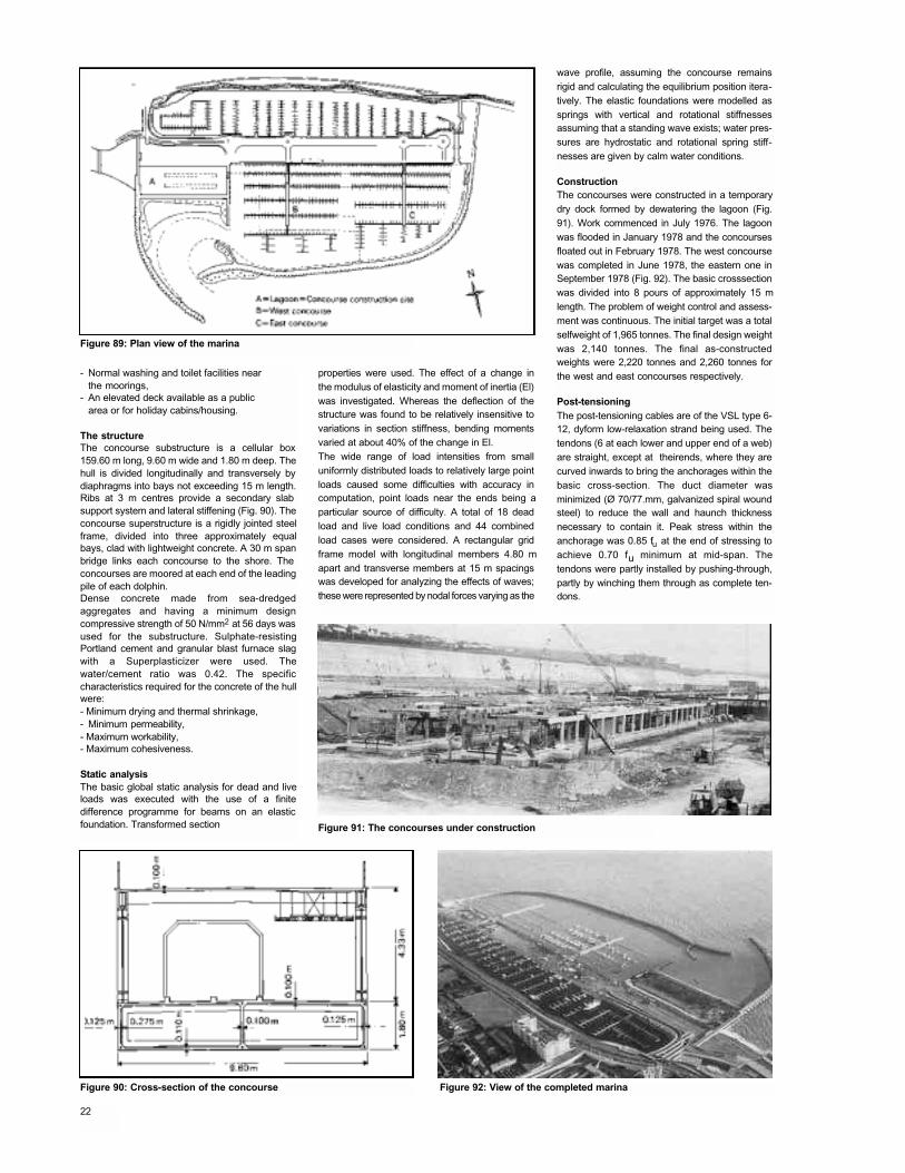
Figure 89: Plan view of the marina
Figure 91: The concourses under construction
Figure 90: Cross-section of the concourse Figure 92: View of the completed marina
- Normal washing and toilet facilities nearthe moorings,
- An elevated deck available as a publicarea or for holiday cabins/housing.
The structureThe concourse substructure is a cellular box159.60 m long, 9.60 m wide and 1.80 m deep. Thehull is divided longitudinally and transversely bydiaphragms into bays not exceeding 15 m length.Ribs at 3 m centres provide a secondary slab support system and lateral stiffening (Fig. 90). Theconcourse superstructure is a rigidly jointed steelframe, divided into three approximately equalbays, clad with lightweight concrete. A 30 m spanbridge links each concourse to the shore. The concourses are moored at each end of the leadingpile of each dolphin.Dense concrete made from sea-dredgedaggregates and having a minimum designcompressive strength of 50 N/mm2 at 56 days wasused for the substructure. Sulphate-resistingPortland cement and granular blast furnace slagwith a Superplasticizer were used. Thewater/cement ratio was 0.42. The specificcharacteristics required for the concrete of the hullwere:- Minimum drying and thermal shrinkage, - Minimum permeability,- Maximum workability,- Maximum cohesiveness.
Static analysisThe basic global static analysis for dead and liveloads was executed with the use of a finitedifference programme for beams on an elasticfoundation. Transformed section
properties were used. The effect of a change inthe modulus of elasticity and moment of inertia (El)was investigated. Whereas the deflection of thestructure was found to be relatively insensitive tovariations in section stiffness, bending momentsvaried at about 40% of the change in El.The wide range of load intensities from smalluniformly distributed loads to relatively large pointloads caused some difficulties with accuracy incomputation, point loads near the ends being aparticular source of difficulty. A total of 18 deadload and live load conditions and 44 combinedload cases were considered. A rectangular gridframe model with longitudinal members 4.80 mapart and transverse members at 15 m spacingswas developed for analyzing the effects of waves;these were represented by nodal forces varying as the
wave profile, assuming the concourse remainsrigid and calculating the equilibrium position itera-tively. The elastic foundations were modelled assprings with vertical and rotational stiffnessesassuming that a standing wave exists; water pres-sures are hydrostatic and rotational spring stiff-nesses are given by calm water conditions.
ConstructionThe concourses were constructed in a temporarydry dock formed by dewatering the lagoon (Fig.91). Work commenced in July 1976. The lagoonwas flooded in January 1978 and the concoursesfloated out in February 1978. The west concoursewas completed in June 1978, the eastern one inSeptember 1978 (Fig. 92). The basic crosssectionwas divided into 8 pours of approximately 15 mlength. The problem of weight control and assess-ment was continuous. The initial target was a totalselfweight of 1,965 tonnes. The final design weightwas 2,140 tonnes. The final as-constructedweights were 2,220 tonnes and 2,260 tonnes forthe west and east concourses respectively.
Post-tensioningThe post-tensioning cables are of the VSL type 6-12, dyform low-relaxation strand being used. Thetendons (6 at each lower and upper end of a web)are straight, except at theirends, where they arecurved inwards to bring the anchorages within thebasic cross-section. The duct diameter wasminimized (Ø 70/77.mm, galvanized spiral woundsteel) to reduce the wall and haunch thicknessnecessary to contain it. Peak stress within theanchorage was 0.85 fu at the end of stressing toachieve 0.70 fu minimum at mid-span. Thetendons were partly installed by pushing-through,partly by winching them through as complete ten-dons.
22
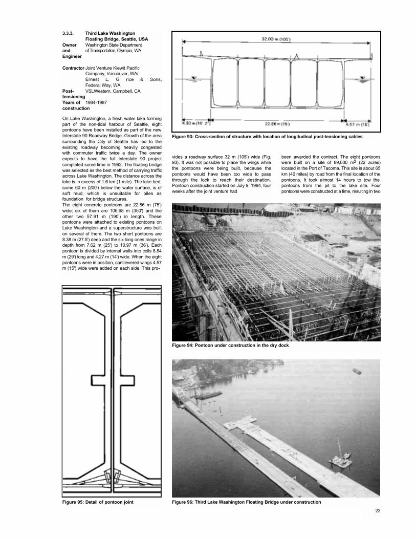
On Lake Washington, a fresh water lake formingpart of the non-tidal harbour of Seattle, eightpontoons have been installed as part of the newInterstate 90 Roadway Bridge. Growth of the areasurrounding the City of Seattle has led to theexisting roadway becoming heavily congestedwith commuter traffic twice a day. The ownerexpects to have the full Interstate 90 projectcompleted some time in 1992. The floating bridgewas selected as the best method of carrying trafficacross Lake Washington. The distance across thelake is in excess of 1.6 km (1 mile). The lake bed,some 60 m (200') below the water surface, is ofsoft mud, which is unsuitable for piles asfoundation for bridge structures.The eight concrete pontoons are 22.86 m (75')wide; six of them are 106.68 m (350') and theother two 57.91 m (190') in length. Thesepontoons were attached to existing pontoons onLake Washington and a superstructure was builton several of them. The two short pontoons are8.38 m (27.5') deep and the six long ones range indepth from 7.62 m (25') to 10.97 m (36'). Eachpontoon is divided by internal walls into cells 8.84m (29') long and 4.27 m (14') wide. When the eightpontoons were in position, cantilevered wings 4.57m (15') wide were added on each side. This pro-
vides a roadway surface 32 m (105') wide (Fig.93). It was not possible to place the wings whilethe pontoons were being built, because thepontoons would have been too wide to passthrough the lock to reach their destination.Pontoon construction started on July 9, 1984, fourweeks after the joint venture had
been awarded the contract. The eight pontoonswere built on a site of 89,000 m2 (22 acres)located in the Port of Tacoma. This site is about 65km (40 miles) by road from the final location of thepontoons. It took almost 14 hours to tow the pontoons from the pit to the lake site. Fourpontoons were constructed at a time, resulting in two
3.3.3. Third Lake Washington Floating Bridge, Seattle, USA
Owner Washington State Departmentand of Transportation, Olympia, WAEngineer
Contractor Joint Venture Kiewit PacificCompany, Vancouver, WA/Ernest L. G rice & Sons,Federal Way, WA
Post- VSLWestern, Campbell, CAtensioningYears of 1984-1987construction
Figure 93: Cross-section of structure with location of longitudinal post-tensioning cables
Figure 94: Pontoon under construction in the dry dock
Figure 96: Third Lake Washington Floating Bridge under constructionFigure 95: Detail of pontoon joint
23
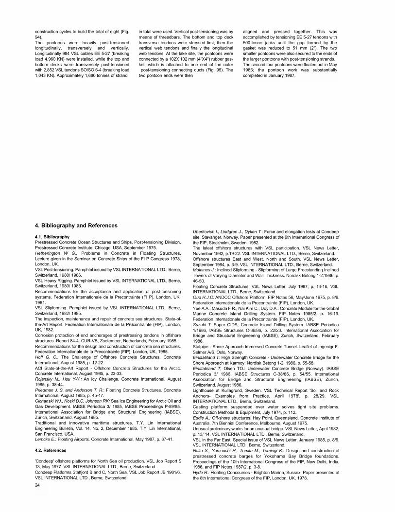
construction cycles to build the total of eight (Fig.94).The pontoons were heavily post-tensionedlongitudinally, transversely and vertically.Longitudinally 984 VSL cables EE 5-27 (breakingload 4,960 KN) were installed, while the top andbottom decks were transversely post-tensionedwith 2,852 VSL tendons SO/SO 6-4 (breaking load1,043 KN). Approximately 1,680 tonnes of strand
4. Bibliography and References
4.1. BibliographyPrestressed Concrete Ocean Structures and Ships. Post-tensioning Division,Prestressed Concrete Institute, Chicago, USA, September 1975.Hetherington W G.: Problems in Concrete in Floating Structures.Lecture given in the Seminar on Concrete Ships of the FI P Congress 1978,London, UK.VSL Post-tensioning. Pamphlet issued by VSL INTERNATIONAL LTD., Berne,Switzerland, 1980/ 1986.VSL Heavy Rigging. Pamphlet issued by VSL INTERNATIONAL LTD., Berne,Switzerland, 1980/ 1985.Recommendations for the acceptance and application of post-tensioningsystems. Federation Internationale de la Precontrainte (FI P), London, UK,1981.VSL Slipforming. Pamphlet issued by VSL INTERNATIONAL LTD., Berne,Switzerland, 1982/ 1985.The inspection, maintenance and repair of concrete sea structures. State-of-the-Art Report. Federation Internationale de la Pr6contrainte (FIP), London,UK, 1982.Corrosion protection of end anchorages of prestressing tendons in offshorestructures. Report 84-4. CUR-VB, Zoetemeer, Netherlands, February 1985.Recommendations for the design and construction of concrete sea structures.Federation Internationale de la Precontrainte (FIP), London, UK, 1985.Hoff G. C.: The Challenge of Offshore Concrete Structures. ConcreteInternational, August 1985, p. 12-22.ACI State-of-the-Art Report - Offshore Concrete Structures for the Arctic.Concrete International, August 1985, p. 23-33.Rojansky M., Hsu Y-Y.: An Icy Challenge. Concrete International, August1985, p. 38-44.Priedman J. S. and Anderson T. R.: Floating Concrete Structures. ConcreteInternational, August 1985, p. 45-47.Cichanski WJ., Koski D.C, Johnson RK: Sea Ice Engineering for Arctic Oil andGas Development. IABSE Periodica 3/ 1985, IABSE Proceedings P-89/85.International Association for Bridge and Structural Engineering (IABSE),Zurich, Switzerland, August 1985.Traditional and innovative maritime structures. T.Y. Lin InternationalEngineering Bulletin, Vol. 14, No. 2, December 1985. T.Y. Lin International,San Francisco, USA.Lemcke E.: Floating Airports. Concrete International, May 1987, p. 37-41.
4.2. References
'Condeep' offshore platforms for North Sea oil production. VSL Job Report S13, May 1977. VSL INTERNATIONAL LTD., Berne, Switzerland.Condeep Platforms Statfjord B and C, North Sea. VSL Job Report JB 1981/6.VSL INTERNATIONAL LTD., Berne, Switzerland.
Uherkovich l., Lindgren J., Dyken T : Force and elongation tests at Condeepsite, Stavanger, Norway. Paper presented at the 9th International Congress ofthe FIP, Stockholm, Sweden, 1982.The latest offshore structures with VSL participation. VSL News Letter,November 1982, p.19-22. VSL INTERNATIONAL LTD., Berne, Switzerland.Offshore structures East and West, North and South. VSL News Letter,September 1984, p. 3-9. VSL INTERNATIONAL LTD., Berne, Switzerland.Moksnes J.: Inclined Slipforming - Slipforming of Large Freestanding InclinedTowers of Varying Diameter and Wall Thickness. Nordisk Betong 1-2:1986, p.46-50.Floating Concrete Structures. VSL News Letter, July 1987, p. 14-16. VSLINTERNATIONAL LTD., Berne, Switzerland.Oud H.J.C: ANDOC Offshore Platform. FIP Notes 56, May/June 1975, p. 8/9.Federation Internationale de la Precontrainte (FIP), London, UK.Yee A.A., Masuda F R., Nai Kim C., Doy D.A.: Concrete Module for the GlobalMarine Concrete Island Drilling System. FIP Notes 1985/2, p. 16-19.Federation Internationale de la Precontrainte (FIP), London, UK.Suzuki T: Super CIDS, Concrete Island Drilling System. IABSE Periodica1/1986, IABSE Structures C-36/86, p. 22/23. International Association forBridge and Structural Engineering (IABSE), Zurich, Switzerland, February1986.Statpipe - Shore Approach Immersed Concrete Tunnel. Leaflet of Ingenigr F.Selmer A/S, Oslo, Norway.Einstabland T: High Strength Concrete - Underwater Concrete Bridge for theShore Approach at Karmoy. Nordisk Betong 1-2: 1986, p. 55-58.Einstab/and T, Olsen TO.: Underwater Concrete Bridge (Norway). IABSEPeriodica 3/ 1986, IABSE Structures C-38/86, p. 54/55. InternationalAssociation for Bridge and Structural Engineering (IABSE), Zurich,Switzerland, August 1986.Lighthouse at Kullagrund, Sweden. VSL Technical Report 'Soil and RockAnchors- Examples from Practice, April 1978', p. 28/29. VSLINTERNATIONAL LTD., Berne, Switzerland.Casting platform suspended over water solves tight site problems.Construction Methods & Equipment, July 1974, p. 112.Eddie A.: Off-shore structures, Hay Point, Queensland. Concrete Institute ofAustralia, 7th Biennial Conference, Melbourne, August 1975.Unusual preliminary works for an unusual bridge. VSL News Letter, April 1982,p. 13/ 14. VSL INTERNATIONAL LTD., Berne, Switzerland.VSL in the Far East. Special issue of VSL News Letter, January 1985, p. 8/9.VSL INTERNATIONAL LTD., Berne, Switzerland.Naito S., Yamauchi H., Tomita M., Tomiogi K.: Design and construction ofprestressed concrete barges for Yokohama Bay Bridge foundations.Proceedings of the 10th International Congress of the FIP, New Delhi, India,1986, and FIP Notes 1987/2, p. 3-8.Hyde R.: Floating Concourses - Brighton Marina, Sussex. Paper presented atthe 8th International Congress of the FIP, London, UK, 1978.
in total were used. Vertical post-tensioning was bymeans of threadbars. The bottom and top decktransverse tendons were stressed first, then thevertical web tendons and finally the longitudinalweb tendons. At the lake site, the pontoons wereconnected by a 102X 102 mm (4"X4") rubber gas-ket, which is attached to one end of the outerpost-tensioning connecting ducts (Fig. 95). The
two pontoon ends were then
aligned and pressed together. This wasaccomplished by tensioning EE 5-27 tendons with500-tonne jacks until the gap formed by thegasket was reduced to 51 mm (2"). The twosmaller pontoons were also secured to the ends ofthe larger pontoons with post-tensioning strands.The second four pontoons were floated out in May1986; the pontoon work was substantiallycompleted in January 1987.
24
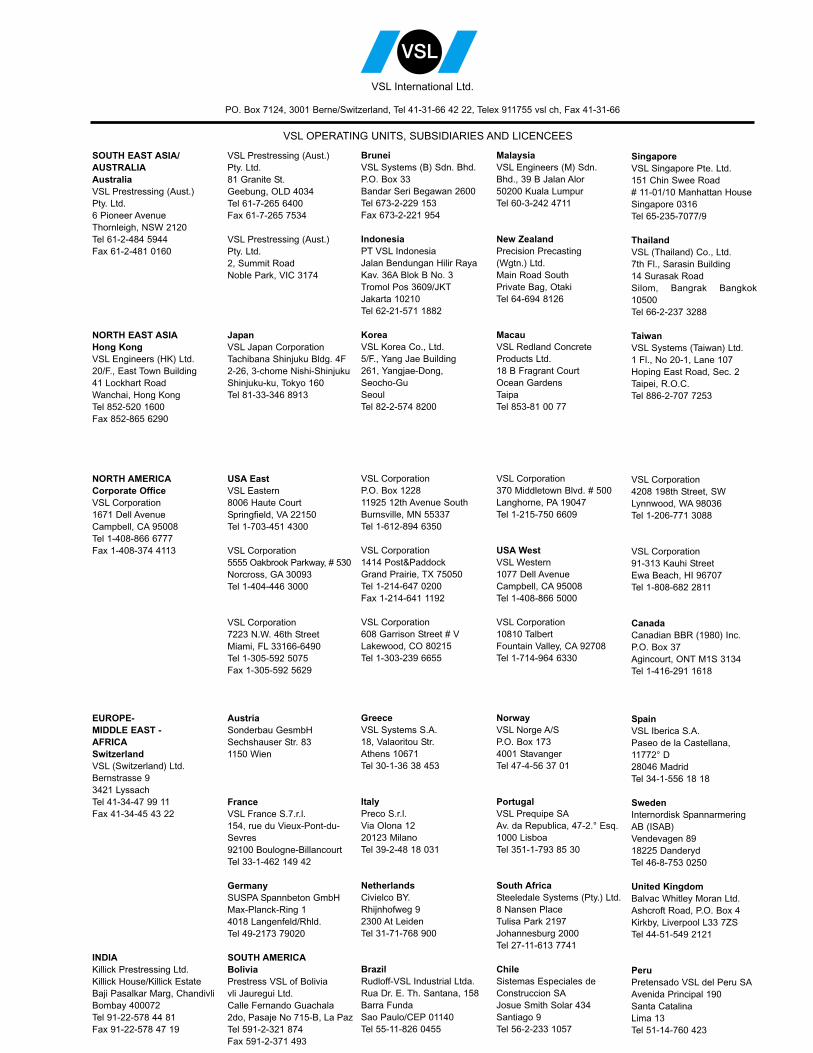
SOUTH EAST ASIA/AUSTRALIAAustraliaVSL Prestressing (Aust.)Pty. Ltd.6 Pioneer AvenueThornleigh, NSW 2120Tel 61-2-484 5944Fax 61-2-481 0160
NORTH EAST ASIAHong KongVSL Engineers (HK) Ltd.20/F., East Town Building41 Lockhart RoadWanchai, Hong KongTel 852-520 1600Fax 852-865 6290
NORTH AMERICACorporate OfficeVSL Corporation1671 Dell AvenueCampbell, CA 95008Tel 1-408-866 6777Fax 1-408-374 4113
EUROPE-MIDDLE EAST -AFRICASwitzerlandVSL (Switzerland) Ltd.Bernstrasse 93421 LyssachTel 41-34-47 99 11Fax 41-34-45 43 22
INDIAKillick Prestressing Ltd.Killick House/Killick EstateBaji Pasalkar Marg, ChandivliBombay 400072Tel 91-22-578 44 81Fax 91-22-578 47 19
VSL Prestressing (Aust.)Pty. Ltd.81 Granite St.Geebung, OLD 4034Tel 61-7-265 6400Fax 61-7-265 7534
VSL Prestressing (Aust.)Pty. Ltd.2, Summit RoadNoble Park, VIC 3174
JapanVSL Japan CorporationTachibana Shinjuku Bldg. 4F2-26, 3-chome Nishi-ShinjukuShinjuku-ku, Tokyo 160Tel 81-33-346 8913
USA EastVSL Eastern8006 Haute CourtSpringfield, VA 22150Tel 1-703-451 4300
VSL Corporation5555 Oakbrook Parkway, # 530Norcross, GA 30093Tel 1-404-446 3000
VSL Corporation7223 N.W. 46th StreetMiami, FL 33166-6490Tel 1-305-592 5075Fax 1-305-592 5629
AustriaSonderbau GesmbHSechshauser Str. 831150 Wien
FranceVSL France S.7.r.l.154, rue du Vieux-Pont-du-Sevres92100 Boulogne-BillancourtTel 33-1-462 149 42
GermanySUSPA Spannbeton GmbHMax-Planck-Ring 14018 Langenfeld/Rhld.Tel 49-2173 79020
SOUTH AMERICABoliviaPrestress VSL of Boliviavli Jauregui Ltd.Calle Fernando Guachala2do, Pasaje No 715-B, La PazTel 591-2-321 874Fax 591-2-371 493
BruneiVSL Systems (B) Sdn. Bhd.P.O. Box 33Bandar Seri Begawan 2600Tel 673-2-229 153Fax 673-2-221 954
IndonesiaPT VSL IndonesiaJalan Bendungan Hilir RayaKav. 36A Blok B No. 3Tromol Pos 3609/JKTJakarta 10210Tel 62-21-571 1882
KoreaVSL Korea Co., Ltd.5/F., Yang Jae Building261, Yangjae-Dong,Seocho-GuSeoulTel 82-2-574 8200
VSL CorporationP.O. Box 122811925 12th Avenue SouthBurnsville, MN 55337Tel 1-612-894 6350
VSL Corporation1414 Post&PaddockGrand Prairie, TX 75050Tel 1-214-647 0200Fax 1-214-641 1192
VSL Corporation608 Garrison Street # VLakewood, CO 80215Tel 1-303-239 6655
GreeceVSL Systems S.A.18, Valaoritou Str.Athens 10671Tel 30-1-36 38 453
ItalyPreco S.r.l.Via Olona 1220123 MilanoTel 39-2-48 18 031
NetherlandsCivielco BY.Rhijnhofweg 92300 At LeidenTel 31-71-768 900
BrazilRudloff-VSL Industrial Ltda.Rua Dr. E. Th. Santana, 158Barra FundaSao Paulo/CEP 01140Tel 55-11-826 0455
MalaysiaVSL Engineers (M) Sdn.Bhd., 39 B Jalan Alor50200 Kuala LumpurTel 60-3-242 4711
New ZealandPrecision Precasting(Wgtn.) Ltd.Main Road SouthPrivate Bag, OtakiTel 64-694 8126
MacauVSL Redland ConcreteProducts Ltd.18 B Fragrant CourtOcean GardensTaipaTel 853-81 00 77
VSL Corporation370 Middletown Blvd. # 500Langhorne, PA 19047Tel 1-215-750 6609
USA WestVSL Western1077 Dell AvenueCampbell, CA 95008Tel 1-408-866 5000
VSL Corporation10810 TalbertFountain Valley, CA 92708Tel 1-714-964 6330
NorwayVSL Norge A/SP.O. Box 1734001 StavangerTel 47-4-56 37 01
PortugalVSL Prequipe SAAv. da Republica, 47-2.° Esq.1000 LisboaTel 351-1-793 85 30
South AfricaSteeledale Systems (Pty.) Ltd.8 Nansen PlaceTulisa Park 2197Johannesburg 2000Tel 27-11-613 7741
ChileSistemas Especiales deConstruccion SAJosue Smith Solar 434Santiago 9Tel 56-2-233 1057
SingaporeVSL Singapore Pte. Ltd.151 Chin Swee Road# 11-01/10 Manhattan HouseSingapore 0316Tel 65-235-7077/9
ThailandVSL (Thailand) Co., Ltd.7th Fl., Sarasin Building14 Surasak RoadSilom, Bangrak Bangkok10500Tel 66-2-237 3288
TaiwanVSL Systems (Taiwan) Ltd.1 Fl., No 20-1, Lane 107Hoping East Road, Sec. 2Taipei, R.O.C.Tel 886-2-707 7253
VSL Corporation4208 198th Street, SWLynnwood, WA 98036Tel 1-206-771 3088
VSL Corporation91-313 Kauhi StreetEwa Beach, HI 96707Tel 1-808-682 2811
CanadaCanadian BBR (1980) Inc.P.O. Box 37Agincourt, ONT M1S 3134Tel 1-416-291 1618
SpainVSL Iberica S.A.Paseo de la Castellana,11772° D28046 MadridTel 34-1-556 18 18
SwedenInternordisk SpannarmeringAB (ISAB)Vendevagen 8918225 DanderydTel 46-8-753 0250
United KingdomBalvac Whitley Moran Ltd.Ashcroft Road, P.O. Box 4Kirkby, Liverpool L33 7ZSTel 44-51-549 2121
PeruPretensado VSL del Peru SAAvenida Principal 190Santa CatalinaLima 13Tel 51-14-760 423
VSL OPERATING UNITS, SUBSIDIARIES AND LICENCEES
PO. Box 7124, 3001 Berne/Switzerland, Tel 41-31-66 42 22, Telex 911755 vsl ch, Fax 41-31-66
VSL International Ltd.
Related Documents