V.S.B. Engineering College, Karur Department of Civil Engineering DEPARTMENT OF MATHEMATICS QUESTION BANK SUBJECT: NUMERICAL METHODS CODE: MA 6459 CLASS: II YEAR ------------------------------------------------------------------------------------------------------------------- UNIT-I SOLUTION OF EQUATIONS AND EIGEN VALUE PROBLEMS 1.State the order of convergence of Newton‟s Raphson method.[A/M 2017] Solution: The rate of convergence in Newton‘s Raphson method is of order 2. 2.What is the order of convergence for fixed point iteration? Solution: The convergence is linear and the convergence is of order 1. 3.Solvex+y = 2, 2x+3y = 5 by Gauss Elimination method. Solution: Given x+y = 2, 2x+3y=5 x+y = 2 x+1=2, ∴ x=1. 4.When Gauss-Elimination method fails? Solution: This method fails if the element in the top of the first column is zero. We can rectify this by interchanging the rows of the matrix. 5.Distinguish Gauss Elimination method and Gauss Jordan method. Solution: Gauss Elimination method Gauss Jordan method Co – efficient matrix A of the system Co – efficient matrix A of the system reduces into upper triangular matrix. reduces into diagonal of unit matrix Back substitution process gives Solution obtained directly solution. 6.Distinguish between direct and iterative (indirect) method of Solving for Simultaneous equations. Solution: S.No. Direct method Iterative method 1. We get exact solution Approximate solution. 2. Simple, take less time Time consuming laborious. 7.Write a sufficient condition for Gauss_seidal method to converge? Solution: The process of iteration by Gauss-Jacobi method will converge if in each equation of the system, the absolute value of the largest coefficient is greater than the sum of the absolute values of the remaining

Welcome message from author
This document is posted to help you gain knowledge. Please leave a comment to let me know what you think about it! Share it to your friends and learn new things together.
Transcript

V.S.B. Engineering College, Karur
Department of Civil Engineering
DEPARTMENT OF MATHEMATICS
QUESTION BANK
SUBJECT: NUMERICAL METHODS
CODE: MA 6459 CLASS: II YEAR
-------------------------------------------------------------------------------------------------------------------
UNIT-I
SOLUTION OF EQUATIONS AND EIGEN VALUE PROBLEMS
1.State the order of convergence of Newton‟s Raphson method.[A/M 2017]
Solution:
The rate of convergence in Newton‘s Raphson method is of order 2. 2.What is the order of convergence for fixed point iteration?
Solution:
The convergence is linear and the convergence is of order 1.
3.Solvex+y = 2, 2x+3y = 5 by Gauss Elimination method.
Solution:
Given x+y = 2,
2x+3y=5
x+y = 2
x+1=2, ∴ x=1.
4.When Gauss-Elimination method fails?
Solution: This method fails if the element in the top of the first column is zero. We can rectify this by interchanging
the rows of the matrix. 5.Distinguish Gauss Elimination method and Gauss Jordan method.
Solution:
Gauss Elimination method Gauss Jordan method
Co – efficient matrix A of the system Co – efficient matrix A of the system reduces into upper triangular matrix. reduces into diagonal of unit matrix
Back substitution process gives Solution obtained directly solution.
6.Distinguish between direct and iterative (indirect) method of Solving for Simultaneous equations.
Solution:
S.No. Direct method Iterative method
1. We get exact solution Approximate solution.
2. Simple, take less time Time consuming
laborious.
7.Write a sufficient condition for Gauss_seidal method to converge?
Solution: The process of iteration by Gauss-Jacobi method will converge if in each equation of the system, the
absolute value of the largest coefficient is greater than the sum of the absolute values of the remaining
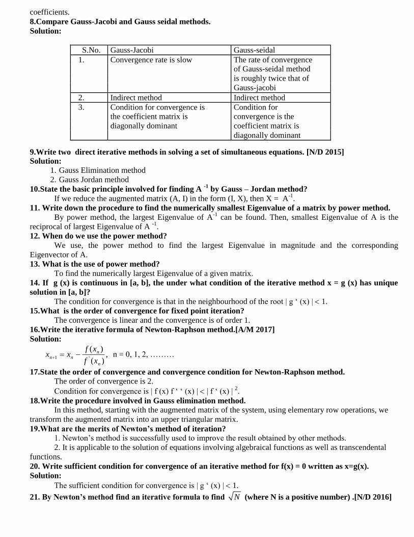
coefficients. 8.Compare Gauss-Jacobi and Gauss seidal methods.
Solution:
S.No. Gauss-Jacobi Gauss-seidal
1. Convergence rate is slow The rate of convergence of Gauss-seidal method
is roughly twice that of
Gauss-jacobi
2. Indirect method Indirect method
3. Condition for convergence is Condition for the coefficient matrix is convergence is the
diagonally dominant coefficient matrix is
diagonally dominant 9.Write two direct iterative methods in solving a set of simultaneous equations. [N/D 2015] Solution:
1. Gauss Elimination method
2. Gauss Jordan method
10.State the basic principle involved for finding A -1
by Gauss – Jordan method?
If we reduce the augmented matrix (A, I) in the form (I, X), then X = A-1
.
11. Write down the procedure to find the numerically smallest Eigenvalue of a matrix by power method.
By power method, the largest Eigenvalue of A-1
can be found. Then, smallest Eigenvalue of A is the
reciprocal of largest Eigenvalue of A -1
.
12. When do we use the power method?
We use, the power method to find the largest Eigenvalue in magnitude and the corresponding
Eigenvector of A.
13. What is the use of power method?
To find the numerically largest Eigenvalue of a given matrix.
14. If g (x) is continuous in [a, b], the under what condition of the iterative method x = g (x) has unique
solution in [a, b]?
The condition for convergence is that in the neighbourhood of the root | g ‗ (x) | 1.
15.What is the order of convergence for fixed point iteration?
The convergence is linear and the convergence is of order 1.
16.Write the iterative formula of Newton-Raphson method.[A/M 2017]
Solution:
,)(
)('1
n
n
nnxf
xfxx n = 0, 1, 2, ………
17.State the order of convergence and convergence condition for Newton-Raphson method.
The order of convergence is 2.
Condition for convergence is | f (x) f ‗ ‗ (x) | | f ‗ (x) | 2.
18.Write the procedure involved in Gauss elimination method.
In this method, starting with the augmented matrix of the system, using elementary row operations, we
transform the augmented matrix into an upper triangular matrix.
19.What are the merits of Newton‟s method of iteration?
1. Newton‘s method is successfully used to improve the result obtained by other methods.
2. It is applicable to the solution of equations involving algebraical functions as well as transcendental
functions.
20. Write sufficient condition for convergence of an iterative method for f(x) = 0 written as x=g(x).
Solution:
The sufficient condition for convergence is | g ‗ (x) | 1.
21. By Newton‟s method find an iterative formula to find N (where N is a positive number) .[N/D 2016]
Solution: Let x = N x2- N =0. Let f(x)=x
2- N 2
1
( ) 2
1
2 2
ii i i
i i
f x x
N N
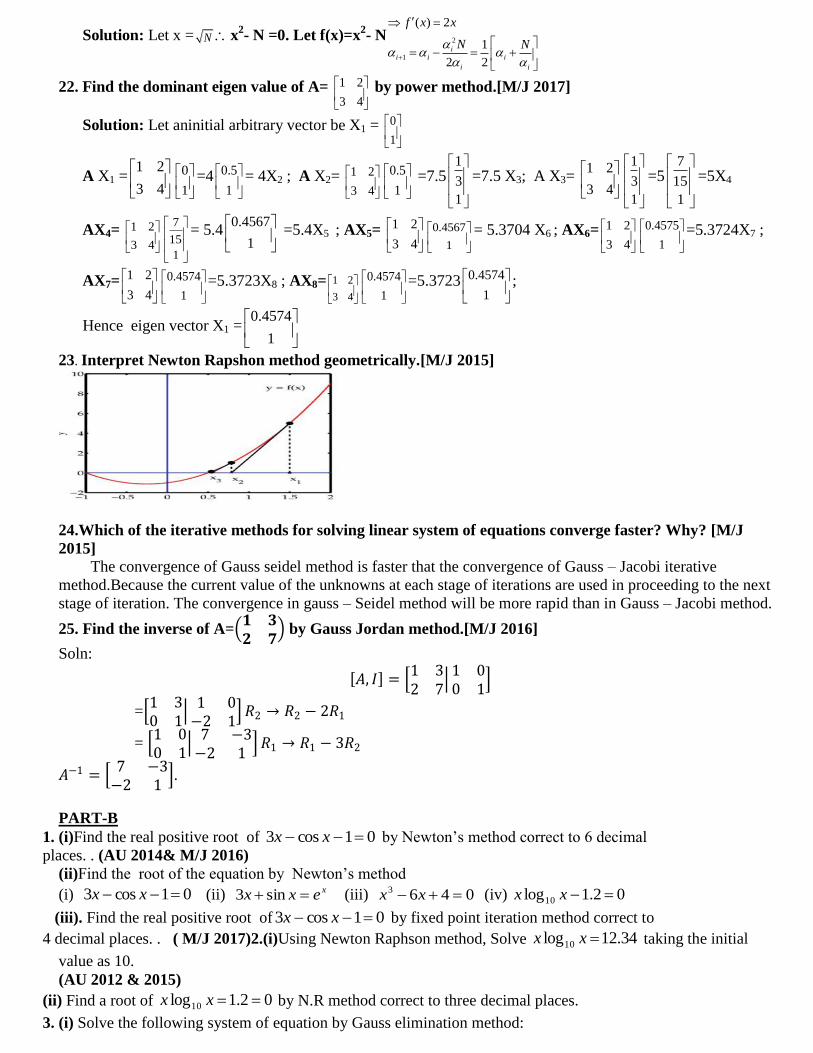
22. Find the dominant eigen value of A= 1 2
3 4
by power method.[M/J 2017]
Solution: Let aninitial arbitrary vector be X1 = 0
1
A X1 =1 2
3 4
0
1
=4 0.5
1
= 4X2 ; A X2= 1 2
3 4
0.5
1
=7.51
3
1
=7.5 X3; A X3= 1 2
3 4
1
3
1
=57
15
1
=5X4
AX4= 1 2
3 4
7
15
1
= 5.40.4567
1
=5.4X5 ; AX5= 1 2
3 4
0.4567
1
= 5.3704 X6 ; AX6=1 2
3 4
0.4575
1
=5.3724X7 ;
AX7=1 2
3 4
0.4574
1
=5.3723X8 ; AX8= 1 2
3 4
0.4574
1
=5.3723 0.4574
1
;
Hence eigen vector X1 =0.4574
1
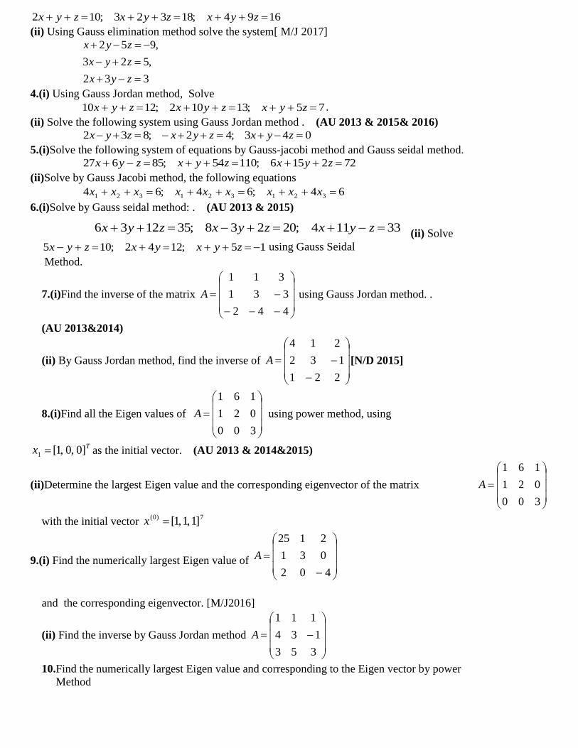
23. Interpret Newton Rapshon method geometrically.[M/J 2015]
24.Which of the iterative methods for solving linear system of equations converge faster? Why? [M/J
2015]
The convergence of Gauss seidel method is faster that the convergence of Gauss – Jacobi iterative
method.Because the current value of the unknowns at each stage of iterations are used in proceeding to the next
stage of iteration. The convergence in gauss – Seidel method will be more rapid than in Gauss – Jacobi method.
25. Find the inverse of A= 𝟏 𝟑𝟐 𝟕
by Gauss Jordan method.[M/J 2016]
Soln:
𝐴, 𝐼 = 1 32 7
1 00 1
= 1 30 1
1 0
−2 1 𝑅2 → 𝑅2 − 2𝑅1
= 1 00 1
7 −3
−2 1 𝑅1 → 𝑅1 − 3𝑅2
𝐴−1 = 7 −3
−2 1 .
PART-B
1. (i)Find the real positive root of 01cos3 xx by Newton‘s method correct to 6 decimal
places. . (AU 2014& M/J 2016)
(ii)Find the root of the equation by Newton‘s method
(i) 01cos3 xx (ii) xexx sin3 (iii) 0463 xx (iv) 02.1log10 xx
(iii). Find the real positive root of 01cos3 xx by fixed point iteration method correct to
4 decimal places. . ( M/J 2017)2.(i)Using Newton Raphson method, Solve 34.12log10 xx taking the initial
value as 10.
(AU 2012 & 2015)
(ii) Find a root of 02.1log10 xx by N.R method correct to three decimal places.
3. (i) Solve the following system of equation by Gauss elimination method:
1694;18323;102 zyxzyxzyx (ii) Using Gauss elimination method solve the system[ M/J 2017]
2 5 9,
3 2 5,
2 3 3
x y z
x y z
x y z
4.(i) Using Gauss Jordan method, Solve
75;13102;1210 zyxzyxzyx .
(ii) Solve the following system using Gauss Jordan method . (AU 2013 & 2015& 2016)
043;42;832 zyxzyxzyx 5.(i)Solve the following system of equations by Gauss-jacobi method and Gauss seidal method.
722156;11054;85627 zyxzyxzyx (ii)Solve by Gauss Jacobi method, the following equations
64;64;64 321321321 xxxxxxxxx
6.(i)Solve by Gauss seidal method: . (AU 2013 & 2015)
(ii) Solve
15;1242;105 zyxyxzyx using Gauss Seidal
Method.
7.(i)Find the inverse of the matrix
442
331
311
A using Gauss Jordan method. .
(AU 2013&2014)
(ii) By Gauss Jordan method, find the inverse of
221
132
214
A [N/D 2015]
8.(i)Find all the Eigen values of
300
021
161
A using power method, using
Tx ]0,0,1[1 as the initial vector. (AU 2013 & 2014&2015)
(ii)Determine the largest Eigen value and the corresponding eigenvector of the matrix
300
021
161
A
with the initial vector 7)0( ]1,1,1[x
9.(i) Find the numerically largest Eigen value of
402
031
2125
A
and the corresponding eigenvector. [M/J2016]
(ii) Find the inverse by Gauss Jordan method
353
134
111
A
10.Find the numerically largest Eigen value and corresponding to the Eigen vector by power
Method
33114;20238;351236 zyxzyxzyx
(i)
536
144
231
(ii)
300
021
161
(iii)
402
031
2125
(iv)
210
121
012
UNIT-II
INTERPOLATION AND APPROXIMATION
PART-A
1. What advantage has Lagrange‟s formula over Newton?
Lagrange‟s method Newton‟s method
1 We can apply both equally and unequally
spaced arguments.
The arguments are equally spaced.
2 Can be used to interpolate any where in
the range.
Newton‘s forward formula is suitable to
interpolate near the beginning. Newton‘s
backward formula is suitable to interpolate
near end of the value.
2. What is the Lagrange‘s formula to find y, if three sets of values (x0 , y0), (x1 , y1) and (x2 , y2) are given.
Solution:
2
1202
10
1
2101
20
0
2010
21
))((
))((
))((
))((
))((
))((y
xxxx
xxxxy
xxxx
xxxxy
xxxx
xxxxy
3. What is the assumption we make when Lagrange‟s formula is used?
Lagrange‘s interpolation formula can be used whether the values of x, the independent variable are
equally spaced or not whether the difference of y become smaller or not.
4. What is „inverse interpolation‟?
Suppose, we are given a table values of x and y direct interpolation is the process of finding the values of y
corresponding to a value of x, not present in the table. Inverse interpolation is the process of finding the
values of x corresponding to a value of y, not present in the table.
5. Give the Newton‟s divided difference interpolation formula:
Solution:
f(x) = f(x0) + (x – x0) f (x0,x1) + f (x0,x1,x2) + ………
+ (x-x0) (x-x1)…..(x-xn-1) f (x0,x1,…,xn)
6. What is the nature of nth
divided differences of a polynomial of nth
degree?
The nth
divided differences of a polynomial of degree n are constants.
7. Define cubic spline.
A cubic polynomial which has continuous slope and curvature is called a cubic spline.
8. What is a natural cubic spline?
A cubic spline fitted to the given data such that the end cubics approach linearity at their extremities is
called a natural cubic spline.
9. If y (xi) = yi, I = 0, 1, 2, …, n write down the formula for the cubic spline polynomial y(x), valid in
xi-1 ≤ x ≤ xi.
Solution:
Here, h = 1.
]6
1)[(]
6
1)[(])()[(
6
1)( 111
3
11
3
iiiiiiiiii MyxxMyxxMxxMxxxy
10. What are the advantages of cubic spline fitting?
Cubic splines provide better approximation to the behavior of functions that have abrupt local changes.
Further, splines perform is better than higher order polynomial approximations.
11. State Gregory-Newton forward difference interpolation formula.
Solution:
000 )()()( yExPEuhxPxPn u
n
u
n
0
3)1( y
...!3
)2)(1(
!2
)1(
!10
3
0
2
00
yuuu
yuu
yu
y
Where h
xxu 0
∅
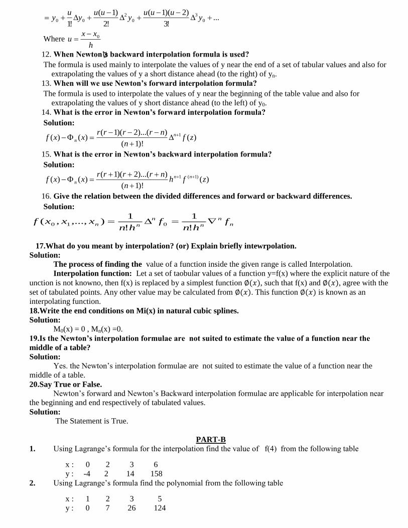
12. When Newton‟s backward interpolation formula is used?
The formula is used mainly to interpolate the values of y near the end of a set of tabular values and also for
extrapolating the values of y a short distance ahead (to the right) of yn.
13. When will we use Newton‟s forward interpolation formula?
The formula is used to interpolate the values of y near the beginning of the table value and also for
extrapolating the values of y short distance ahead (to the left) of y0.
14. What is the error in Newton‟s forward interpolation formula?
Solution:
)()!1(
))...(2)(1()()( 1 zf
n
nrrrrxxf n
n
15. What is the error in Newton‟s backward interpolation formula?
Solution:
)()!1(
))...(2)(1()()( )1(1 zfh
n
nrrrrxxf nn
n
16. Give the relation between the divided differences and forward or backward differences.
Solution:
n
n
n
n
nn fhn
fhn
xxxf !
1
!
1),...,,( 010
17.What do you meant by interpolation? (or) Explain briefly intewrpolation.
Solution:
The process of finding the value of a function inside the given range is called Interpolation.
Interpolation function: Let a set of taobular values of a function y=f(x) where the explicit nature of the
unction is not knowno, then f(x) is replaced by a simplest function ∅(𝑥), such that f(x) and ∅(𝑥), agree with the
set of tabulated points. Any other value may be calculated from ∅(𝑥). This function ∅(𝑥) is known as an
interpolating function.
18.Write the end conditions on Mi(x) in natural cubic splines.
Solution:
M0(x) = 0 , Mn(x) =0.
19.Is the Newton‟s interpolation formulae are not suited to estimate the value of a function near the
middle of a table?
Solution:
Yes. the Newton‘s interpolation formulae are not suited to estimate the value of a function near the
middle of a table.
20.Say True or False.
Newton‘s forward and Newton‘s Backward interpolation formulae are applicable for interpolation near
the beginning and end respectively of tabulated values.
Solution:
The Statement is True.
PART-B
1. Using Lagrange‘s formula for the interpolation find the value of f(4) from the following table
x : 0 2 3 6
y : -4 2 14 158
2. Using Lagrange‘s formula find the polynomial from the following table
x : 1 2 3 5
y : 0 7 26 124
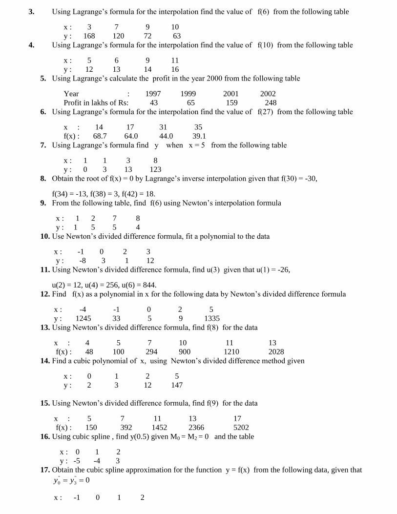
3. Using Lagrange‘s formula for the interpolation find the value of f(6) from the following table
x : 3 7 9 10
y : 168 120 72 63
4. Using Lagrange‘s formula for the interpolation find the value of f(10) from the following table
x : 5 6 9 11
y : 12 13 14 16
5. Using Lagrange‘s calculate the profit in the year 2000 from the following table
Year : 1997 1999 2001 2002
Profit in lakhs of Rs: 43 65 159 248
6. Using Lagrange‘s formula for the interpolation find the value of f(27) from the following table
x : 14 17 31 35
f(x) : 68.7 64.0 44.0 39.1
7. Using Lagrange‘s formula find y when x = 5 from the following table
x : 1 1 3 8
y : 0 3 13 123
8. Obtain the root of f(x) = 0 by Lagrange‘s inverse interpolation given that f(30) = -30,
f(34) = -13, f(38) = 3, f(42) = 18.
9. From the following table, find f(6) using Newton‘s interpolation formula
x : 1 2 7 8
y : 1 5 5 4
10. Use Newton‘s divided difference formula, fit a polynomial to the data
x : -1 0 2 3
y : -8 3 1 12
11. Using Newton‘s divided difference formula, find u(3) given that u(1) = -26,
u(2) = 12, u(4) = 256, u(6) = 844.
12. Find f(x) as a polynomial in x for the following data by Newton‘s divided difference formula
x : -4 -1 0 2 5
y : 1245 33 5 9 1335
13. Using Newton‘s divided difference formula, find f(8) for the data
x : 4 5 7 10 11 13
f(x) : 48 100 294 900 1210 2028
14. Find a cubic polynomial of x, using Newton‘s divided difference method given
x : 0 1 2 5
y : 2 3 12 147
15. Using Newton‘s divided difference formula, find f(9) for the data
x : 5 7 11 13 17
f(x) : 150 392 1452 2366 5202
16. Using cubic spline , find y(0.5) given M0 = M2 = 0 and the table
x : 0 1 2
y : -5 -4 3
17. Obtain the cubic spline approximation for the function y = f(x) from the following data, given that
0''
3
''
0 yy
x : -1 0 1 2
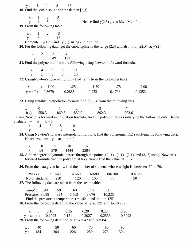
y : -1 1 3 35
18. Find the cubic spline for the data in [2,3]
x : 1 2 3
y : 1 5 11 Hence find y(2.5) given M0 = M2 = 0 .
19. From the following table
x : 1 2 3
y : -8 -1 18
Compute y(1.5) and y‘(1) using cubic spline
20. For the following data, get the cubic spline in the range [2,3] and also find y(2.5) & y‘(2)
x : 2 3 4
y : 11 49 123
21. Find the polynomial from the following using Newton‘s forward formula.
x : 4 6 8 10
y : 1 3 8 16
22. UsingNewton‘s forward formula find 1.1e from the following table
x : 1.00 1.25 1.50 1.75 2.00 xey : 0.3679 0.2865 0.2231 0.1738 0.1353
23. Using suitable interpolation formula find f(1.5) from the following data
x : 0 1 2 3 4
f(x) : 558.3 869.6 880.9 892.3 903.6
Using Newton‘s forward interpolation formula, find the polynomial f(x) satisfying the following data. Hence
evaluate y at x = 5
x : 4 6 8 10
y : 1 3 8 16
24. Using Newton‘s forward interpolation formula, find the polynomial f(x) satisfying the following data.
Hence evaluate y at x = 2
x : 0 5 10 15
y : 14 379 1444 3584
25. A third degree polynomial passes through the points (0,-1) , (1,1) , (2,1) and (3,-2) using Newton‘s
forward formula find the polynomial f(x). Hence find the value at 1.5
26. From the data given below find the number of students whose weight is between 60 to 70.
Wt (x) : 0-40 40-60 60-80 80-100 100-120
No of students : 250 120 100 70 50
27. The following data are taken from the steam table:
Temp0
c: 140 150 160 170 180
Pressure: 3.685 4.854 6.502 8.076 10.225
Find the pressure at temperature t = 1420
and at t = 1750
28. From the following data find the value of )12.0tan( and )28.0tan(
x : 0.10 0.15 0.20 0.25 0.30
y = tan x : 0.1003 0.1511 0.2027 0.2533 0.3093
29. From the following data find y at x = 43 and x = 84
x : 40 50 60 70 80 90
y : 184 204 226 250 276 304
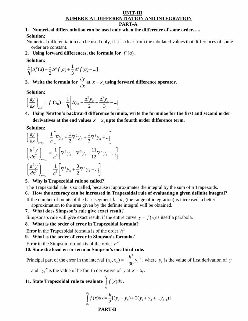
UNIT-III
NUMERICAL DIFFERENTIATION AND INTEGRATION
PART-A
1. Numerical differentiation can be used only when the difference of some order…..
Solution:
Numerical differentiation can be used only, if it is clear from the tabulated values that differences of some
order are constant.
2. Using forward differences, the formula for )(' af .
Solution:
...])(3
1)(
2
1)([
1 32 afafafh
3. Write the formula for dx
dyat 0xx using forward difference operator.
Solution:
...32
1)(' 0
3
0
2
00
0
yyy
hxf
dx
dy
x
4. Using Newton‟s backward difference formula, write the formulae for the first and second order
derivatives at the end values nxx upto the fourth order difference term.
Solution:
...3
1
2
11 32
nnn
xx
yyyhdx
dy
n
...12
111 432
22
2
nnn
xx
yyyhdx
yd
n
...2
31 43
33
3
nn
xx
yyhdx
yd
n
5. Why is Trapezoidal rule so called?
The Trapezoidal rule is so called, because it approximates the integral by the sum of n Trapezoids.
6. How the accuracy can be increased in Trapezoidal rule of evaluating a given definite integral?
If the number of points of the base segment ab , (the range of integration) is increased, a better
approximation to the area given by the definite integral will be obtained.
7. What does Simpson‟s rule give exact result?
Simpsons‘s rule will give exact result, if the entire curve )(xfy is itself a parabola.
8. What is the order of error in Trapezoidal formula?
Error in the Trapezoidal formula is of the order 2h .
9. What is the order of error in Simpson‟s formula?
Error in the Simpson formula is of the order 4h .
10. State the local error term in Simpson‟s one third rule.
Principal part of the error in the interval ,90
),( 1
5
31
ivy
hxx where 1y is the value of first derivation of y
and tiv
y1 is the value of he fourth derivative of y at 1xx .
11. State Trapezoidal rule to evaluate nx
x
dxxf
0
)( .
nx
x
nn yyyyyh
dxxf
0
)]...(2)[(2
)( 1210
PART-B
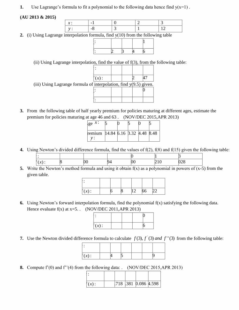
1. Use Lagrange‘s formula to fit a polynomial to the following data hence find y(x=1) .
(AU 2013 & 2015)
x : -1 0 2 3
y : -8 3 1 12
2. (i) Using Lagrange interpolation formula, find y(10) from the following table
X: 5 6 9 11
Y: 12 13 14 16
(ii) Using Lagrange interpolation, find the value of f(3), from the following table:
x : 0 1 2 5
)(xf : 2 3 12 147
(iii) Using Lagrange formula of interpolation, find y(9.5) given.
X: 7 8 9 10
Y: 3 1 1 9
3. From the following table of half yearly premium for policies maturing at different ages, estimate the
premium for policies maturing at age 46 and 63 . (NOV/DEC 2015,APR 2013)
Age :x 45 50 55 60 65
Premium :y
114.84 96.16 83.32 74.48 68.48
4. Using Newton‘s divided difference formula, find the values of f(2), f(8) and f(15) given the following table:
x : 4 5 7 10 11 13
)(xf : 48 100 294 900 1210 2028
5. Write the Newton‘s method formula and using it obtain f(x) as a polynomial in powers of (x-5) from the
given table.
x : 0 2 3 4 5 6
)(xf : 4 26 58 112 466 922
6. Using Newton‘s forward interpolation formula, find the polynomial f(x) satisfying the following data.
Hence evaluate f(x) at x=5. . (NOV/DEC 2011,APR 2013)
x : 4 6 8 10
)(xf : 1 3 8 16
7. Use the Newton divided difference formula to calculate )3('')3(),3( ' fandff from the following table:
x : 0 1 2 4 5 6
)(xf : 1 14 15 5 6 19
8. Compute f‘(0) and f‘‘(4) from the following data: . (NOV/DEC 2015,APR 2013)
x : 0 1 2 3 4
)(xf : 1 2.718 7.381 20.086 54.598
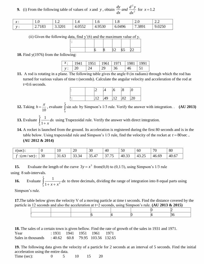
9. (i) From the following table of values of x and y , obtain 2
2
dx
ydand
dx
dy for 2.1x
x : 1.0 1.2 1.4 1.6 1.8 2.0 2.2
y : 2.7183 3.3201 4.0552 4.9530 6.0496 7.3891 9.0250
(ii) Given the following data, find y‘(6) and the maximum value of y.
x : 0 2 3 4 7 9
y: 4 26 58 112 465 922
10. Find y(1976) from the following:
x : 1941 1951 1961 1971 1981 1991
y : 20 24 29 36 46 51
11. A rod is rotating in a plane. The following table gives the angle θ (in radians) through which the rod has
turned for various values of time t (seconds). Calculate the angular velocity and acceleration of the rod at
t=0.6 seconds.
T: 0 0.2 0.4 0.6 0.8 1.0
: 0 0.12 0.49 1.12 2.02 3.20
12. Taking 10
h , evaluate
0
sin xdx by Simpson‘s 1/3 rule. Verify the answer with integration. . (AU 2013)
13. Evaluate
6
01
1dx
x using Trapezoidal rule. Verify the answer with direct integration.
14. A rocket is launched from the ground. Its acceleration is registered during the first 80 seconds and is in the
table below. Using trapezoidal rule and Simpson‘s 1/3 rule, find the velocity of the rocket at sec80t ..
(AU 2012 & 2014)
:(sec)t 0 10 20 30 40 50 60 70 80
:sec)/(: cmf 30 31.63 33.34 35.47 37.75 40.33 43.25 46.69 40.67
15. Evaluate the length of the curve 33 xy from(0,0) to (0,1/3), using Simpson‘s 1/3 rule
using 8 sub-intervals.
16. Evaluate
2
0
21
1dx
xx to three decimals, dividing the range of integration into 8 equal parts using
Simpson‘s rule.
17.The table below gives the velocity V of a moving particle at time t seconds. Find the distance covered by the
particle in 12 seconds and also the acceleration at t=2 seconds, using Simpson‘s rule. (AU 2013 & 2015)
t 0 2 4 6 8 10 12
V 4 6 16 34 60 94 136
18. The sales of a certain town is given bellow. Find the rate of growth of the sales in 1931 and 1971.
Year : 1931 1941 1951 1961 1971
Sales in thousands : 40.62 60.8 79.95 103.56 132.65
19. The following data gives the velocity of a particle for 2 seconds at an interval of 5 seconds. Find the initial
acceleration using the entire data.
Time (sec): 0 5 10 15 20
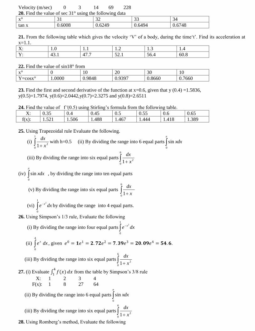
Velocity (m/sec) 0 3 14 69 228
20. Find the value of sec 31° using the following data
x° 31 32 33 34
tan x 0.6008 0.6249 0.6494 0.6748
21. From the following table which gives the velocity ‗V‘ of a body, during the time‗t‘. Find its acceleration at
x=1.1.
X: 1.0 1.1 1.2 1.3 1.4
Y: 43.1 47.7 52.1 56.4 60.8
22. Find the value of sin18° from
x° 0 10 20 30 10
Y=cosx° 1.0000 0.9848 0.9397 0.8660 0.7660
23. Find the first and second derivative of the function at x=0.6, given that y (0.4) =1.5836,
y(0.5)=1.7974, y(0.6)=2.0442,y(0.7)=2.3275 and y(0.8)=2.6511
24. Find the value of f '(0.5) using Stirling‘s formula from the following table.
X: 0.35 0.4 0.45 0.5 0.55 0.6 0.65
f(x): 1.521 1.506 1.488 1.467 1.444 1.418 1.389
25. Using Trapezoidal rule Evaluate the following.
(i)
1
0
21 x
dxwith h=0.5 (ii) By dividing the range into 6 equal parts
0
sin xdx
(iii) By dividing the range into six equal parts
6
0
21 x
dx
(iv)
0
sin xdx , by dividing the range into ten equal parts
(v) By dividing the range into six equal parts
6
01 x
dx
(vi)
1
0
2
dxe xby dividing the range into 4 equal parts.
26. Using Simpson‘s 1/3 rule, Evaluate the following
(i) By dividing the range into four equal parts
1
0
2
dxe x
(ii) 4
0
dxe x, given 𝑒0 = 𝟏𝑒1 = 𝟐.𝟕𝟐𝑒2 = 𝟕.𝟑𝟗𝑒3 = 𝟐𝟎.𝟎𝟗𝑒4 = 𝟓𝟒.𝟔.
(iii) By dividing the range into six equal parts
6
0
21 x
dx
27. (i) Evaluate 𝑓(𝑥)𝑑𝑥4
1 from the table by Simpson‘s 3/8 rule
X: 1 2 3 4
F(x): 1 8 27 64
(ii) By dividing the range into 6 equal parts
0
sin xdx
(iii) By dividing the range into six equal parts
6
0
21 x
dx
28. Using Romberg‘s method, Evaluate the following
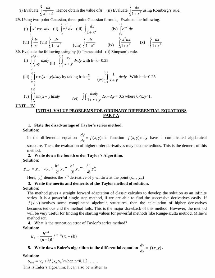
(i) Evaluate
2
0
2 4x
dx Hence obtain the value of𝜋 . (ii) Evaluate
1
0
21 x
dxusing Romberg‘s rule.
29. Using two-point Gaussian, three-point Gaussian formula, Evaluate the following.
(i) 3
0
2 cos xdxx (ii)
2
2
2
2
dxe
x
(iii)
1
1
21 x
dx
(iv) dxe x
5.1
2.0
2
(vi) 12
5x
dx (vii)
1
0
21 x
dx
(viii)
1
1
41 x
dx
(ix)
1
1
4
2
1 x
dxx (x)
7
3
21 x
dx
30. Evaluate the following using by (i) Trapezoidal (ii) Simpson‘s rule.
(i) 4.1
1
4.2
2
1dxdy
xy (ii)
2
1
2
1
dxdyyx
xywith h=k= 0.25
(iii) 2
0
2
)cos(
dxdyyx by taking h=k=𝜋
4 (iv)
2
1
2
1
1dxdy
yx With h=k=0.25
(v) 2
0
2
0
)sin(
dxdyyx (vi) yx
dxdy
1yx = 0.5 where 0<x,y<1.
UNIT – IV
INITIAL VALUE PROBLEMS FOR ORDINARY DIFFERENTIAL EQUATIONS
PART-A
1. State the disadvantage of Taylor‟s series method.
Solution:
In the differential equation ),( yxfdx
dy the function ),( yxf may have a complicated algebraical
structure. Then, the evaluation of higher order derivatives may become tedious. This is the demerit of this
method.
2. Write down the fourth order Taylor‟s Algorithm.
Solution:
iv
mmmmmm yh
yh
yh
hyyy!4
'''!3
''!2
'432
1
Here, n
my denotes the thr derivative of y w.r.to x at the point (xm , ym)
3. Write the merits and demerits of the Taylor method of solution.
Solution:
The method gives a straight forward adaptation of classic calculus to develop the solution as an infinite
series. It is a powerful single step method, if we are able to find the successive derivatives easily. If
),( yxf involves some complicated algebraic structures, then the calculation of higher derivatives
becomes tedious and the method fails. This is the major drawback of this method. However, the method
will be very useful for finding the starting values for powerful methods like Runge-Kutta method, Milne‘s
method etc.
4. What is the truncation error of Taylor‘s series method?
Solution:
)()!1(
)1(1
hxfn
hE i
nn
n
5. Write down Euler‟s algorithm to the differential equation ),( yxfdx
dy .
Solution:
)( ,1 nnnn yxhfyy when n=0,1,2,…….
This is Euler‘s algorithm. It can also be written as
),()()( yxhfxyhxy
6. State True or False.
In Euler‘s method, if h is small, the method is too slow and if h is large, it gives inaccurate value.
Solution:The statement is true.
7. Say True of False. The Modified Euler method is based on the average of points.
Solution:The statement is true.
8. State the special advantage of Runge-Kutta method orver Taylor‟s series method.
Solution:
Runge-Kutta methods do not require prior calculation of higher derivatives of y(x), as the Taylor‘s
method does. Since the differential equations using in applications are often complicated, the calculation
of derivatives may be difficult.
9. Say True of False. Modified Euler‟s method is the Runge-Kutta method of second order.
Solution:
The Statement is True.
10. Is Euler‟s formula, a particular case of second order Runge-Kutta method?
Solution:
Yes, Euler‘s modified formula is a particular case of second order ‗Runge-Kutta method‘.
11. What are the advantages of R-K method over Taylor‟s method.
Solution:
R-K methods do not require prior calculation fo higher derivative of y(x) as the Taylor method does.
Since, the differential equations using in applications often complicated, the calculation of derivatives
may be difficult.
Also the R-K formulae involve the computation of f(x,y) at various positions, instead of derivatives and
this function occurs in the given equation.
12. How many prior values are required to predict the next value in Milne‟s method?
Solution:
Four prior values.
13. What is the error term in Milen‟s corrector formula?
Solution:
The error term is - '90
0
4 yh
14. Say True or False.
Milne‘s method is a self starting method.
Solution:
The statement is false.
15. Say True or False.
Predictor – Corrector methods are single-step method.
Solution: The Statement if false.
16. Predictor corrector methods are ………………… starting methods.
Solution:
Not Self.
17. How many prior values are required to predict the next value in Adam‟s method?
Solution:
Four prior values.
18. Say True or false.
Adam‘s Bash forth method is a self starting method.
Solution:
The statement is false.
19. Give the multistep methods available for solving ordinary differential equation.
Solution:
1. Euler‘s method
2. R-K method
3. Milne‘s method
4. Adam‘s Bashforth method.
20. Say True or False.
Predictor-Corrector methods are single-step methods.
Solution:
The statement is false.
PART-B
1. Solve 1)0(,22 yyxdx
dy use Taylor‘s series method at x = 0.2 and x = 0.4.
2. Using Taylor‘s series method, find y(0.1), y(0.2) given 0)0(,32 yeydx
dy x
3. By Taylor‘s series method find y(1.1) ,y(1.2) given that 1)1(,3
1
yxydx
dy .
4. Using Taylor‘s series method find y at x = 0.1, if 12 yxdx
dy, y(0)=1.
5. Find the value of y(1.1) using Taylor‘s series method from 1)1(,32 yxyyy
6. Using Taylor‘s series method, find y(0.1) given 0)0(,1)0(, yyyxyy
7. Compute y at x=0.25 by Modified Euler‘s method given that 1)0(,2 yxyy .
8. Using Modified Euler‘s method, find y(0.2), y(0.4) given 0)0(,' yeyy x
9. Solve 1)0(,2 yyxdx
dy by Modified Euler‘s method for x=0.2 and x=0.4.
10. Compute y(0.1) given 1)0(, yydx
dy by using Runge kutta fourth order method.
11. By Runge kutta method to determine y(0.2) with h=0.1 from 1)0(,22 yyxdx
dy
12. Given xy
xy
dx
dy
2
2 2, y(0)=1 .Find y(0.2) using R.K fourth order method with h=0.2.
13. Using R.K method of fourth order solve 22
22
'xy
xyy
at x=0.2 given that 1)0( y .
14. Using R.K method of fourth order find y(0.2) from 2)0(,' yxyy taking h=0.1
15. Given ,0)0(,1)0(,0 yyyyxy find the value of y(0.1) by using R.K.method.
16. Solve int,22 2 Seyyy t with y(0) = -0.4, y‘(0)=-0.6 by R.K.Method , find y(0.2).
17. Given 0)0(,1' yyy , find (i) y(0.1) , y(0.2) by Euler‘s method (ii) y(0.3) by Modified Euler‘s
method (iii) y(0.4) by Milne‘s method.
18. By Milne‘s find y(4.4) given 5xy‘+y2-2=0,y(4)=1,y(4.1)=1.0049,y(4.2)=1.0097, y(4.3)=1.0143.
19. Find y(0.4) by Milne‘s method, given ,1)0(,' 2 yxxyy use Taylor‘s series to get y(0.1), y(0.2) ,
y(0.3).
20. Find y(0.4) using Milne‘s method given 1)0(,2 yyxydx
dy, use Taylor‘s series to get the value of y
at x = 0.1, Euler‘s method for y at x = 0.2 and RK 4th
order method for y at x=0.3.
21. Given 2xydx
dy , y(0)=1, y(0.2)=1.12186, y(0.4)=1.46820, y(0.6)=1.73790. Find y(0.8) by Milne‘s
predictor corrector formula.
22. Given 823516.3)6.0(,990578.2)4.0(,443214.2)2.0(,2)0(,3 yyyyyxdx
dy find y(0.8) by
Milne‘s predictor-corrector method taking h = 0.2.
23. Find y(0.1), y(0.2), y(0.3) using R.K Method and hence obtain y(0.4) using Adam‘s method from
1)0(,2 yyxydx
dy
24. Find (i) y(0.1), y(0.2) by Euler‘s method (ii) y(0.3) by R.K method (iii) y(0.4) by Adam‘s Bash forth
method, Given 0)0(,32 yeyy x
25. Find y(2) if y(x) is the solution of 2)0(),(2
1 yyx
dx
dy y(0.5)=2.636 , y(1)=3.595 ,y(1.5)=4.968
using Adam‘s Predictor-Corrector method.
26. Given )1(2 yxdx
dy , y(1) = 1, y(1.1) = 1.233, y(1.2) = 1.548, y(1.3)=1.979, evaluate y(1.4) by
Adam‘s- Bash forth method.
UNIT - V
BOUNDARY VALUE PROBLEMS IN ORDINARY AND PARTIAL DIFFERENTIAL EQUATIONS
PART – A 1. State the conditions for the equation. Auxx + Buyy + Cuxy +Dux +Euy + Fu =G where A, B, C, D, E,
F, G are function of x and y to be (i) elliptic (ii) parabolic
(iii) hyperbolic
Solution: The given equation is said to be
(i) Eliptic at a point (x,y) in the plane if B2-4AC<0
(ii) Parabolic if B2-4AC=0
(iii)Hyperbolic if B2-4AC>0
2.State the condition for the equation Auxx+2Buxy+Cuyy=f(ux,uy,x,y) to be (a)elliptic (b) parabolic(c) hyperbolic when A, B, C are functions of x and y.
Solution: The equation is elliptic if (2B
2)-4AC<0 i.e. B
2-AC<0. It is parabolic if B
2-4AC>0
. 3.What is the classification of fx-fyy=0? Solution:
Here A=0, B=0, C=-1 B
2-4AC=0-(4)(0)(-1)=0
Therefore the equation is parabolic.
4.Write the diagonal five-point formula to solve the Laplace‟s equation 0 yyxx uu .
Solution:
)(4
11,11,11,11,1, jijijijiji uuuuu
5.Write down the standard five point formula to solve Laplace‟s equation 0 yyxx uu .
Solution:
)(4
11,1,,1,1, jijijijiji uuuuu
6.Write the difference scheme for solving the Laplace‟s equation.
Solution:
The five point difference formula for 02 is
)(4
11,1,,1,1, jijijijiji uuuuu .
7.What is the number of conditions required to solve the Laplace‟s equation?
Solution:
The number of conditions required to solve the Laplace‘s equation is four.
8. What is the purpose of Leibmann‟s process?
Solution:
The purpose of Leibmann‘s process is to find the solution of the Laplace equation 0 yyxx uu by iteration.
9.If u satisfies Laplace‟s equation and u = 100 on the boundary of a square, what will be the value of u at
an interior grid point.
Solution:
Since, u satisfies Laplace equation and u = 100 on the boundary of a square
)100100100100(4
1, jiu
100.
10. Define a difference quotient.
Solution:
A difference quotient is the quotient obtained by dividing the difference between two values of a function by the
difference between two corresponding values of the independent variable.
11. Discuss diagonal five point formula and standard five point formula.
Solution:
These two formula‘s are used to solve elliptic equations.
SFPF is
)(4
11,1,,1,1, jijijijiji uuuuu
DFPF is
)(4
11,11,11,11,1, jijijijiji uuuuu
This formula uses for diagonal neighbouring values.
12 . What is Shooting method?
Solution: In this method, the given boundary value problem is first converted into an equivalent initial
value problem and then solved using any of the methods. This methods makes use of the techniques of solving initial value problems.
13.What is the procedure of shooting method?
Solution:
* Convert the problem into an initial value problem.
* Initialise the variables including two guesses at the initial slope. * Solve the equations with these guesses using either a one-step or a multistep method. * Interpolate from these results to find an improved value of the slopes obtained.
Repeat the process until a specified accuracy in the final function value is obtained.
14.Define Poisson‘s Equation.
Answer:
An equation is of the form 2u= f(x,y)is called as poisson‘s equation where f(x,y)is a function of x and y.
15. Which equation is useful to solve Bender-Schmidt recurrence scheme?
Answer:
Bender – Schmidt recurrence scheme is useful to solve one dimensional heat equation.
16. Give an example of a parabolic equation.
Answer:
The one dimensional heat equation 2
22
x
u
t
u
is parabolic.
17. Write an explicit formula to solve numerically the heat equation (parabolic equation) 0 txx auu
Answer:
jijijiji uuuu ,1,,11, )21(
Where ,ah
k2
(h is the space for the variable x and k is the space in the time direction).
18. What is the classification of fx – fyy = 0?
Solution:
Here A = 0, B = 0, C = -1.
B2 – 4AC = 0 – 4 x 0 x -1 = 0.
So, the equation is parabolic.
19. Which condition of the equation yuxx + uyy = 0 is hyperbolic in the region?
Solution:
Here, A = y, B = 0, C = 1
B2 – 4AC = 0 – 4y = -4y 0 (or) y 0
The equation is hyperbolic in the region (x,y), where B2 – 4AC 0
It is hyberbolic in the region y 0.
20.Mention any two single step methods for solving an ordinary differential equation, subject to initial condition.
Solution:
1. Bender – Schmidt
2. Crank - Nicholson
PART – B
1.Using finite differences solve the boundary value problem
2.01)1(,2)0(,3223 ''' withhyyxyyy
2.By iteration method solve the elliptic equation 0 yyxx uu over the square region of side 4, satisfying the
boundary conditions.
(i) u (0,y) = 0, 0 ≤ y ≤ 4.
(ii) u (4,y) = 8 + 2y, 0 ≤ y ≤ 4.
(iii)u(x,0) = x2/2, 0 ≤ x ≤ 4.
(iv) u(x,4) = x2, 0 ≤ x ≤ 4.
Compute the values at the interior points correct to one decimal with h = k = 1.
3. (i) Using Crank- Nicolson‘s scheme, solve 2
2
16x
u
t
u
0 x 1, t 0 subject to u (x,0) = 0, u (0, t) = 0, u
(1, t) = 100 t. Compute u for one step in t direction taking h = ¼.
(ii) Solve utt = uxx, 0 x 2, t 0 subject to u (x,0) = 0, ut (x, 0) = 100 (2x – x
2), u (0, t) = 0, u (2, t) = 0,
choosing h = ½ compute u for four time steps.
4. Solve the BVP u‖ = xu, u(0)+u‘(0)=1, u(1)=1, h=1/3, use the second order method 3.
5. Using finite difference method, find y(0.25), y(0.5) and y(0.75) satisfying the differential equation
xydx
yd
2
2
subject to the boundary conditions y(0)=0, y(1)=2.
6. Solve the equation 2
2
x
u
t
u
subject to the condition u(x,0)=sin πx, 0 ≤ x 1; u(0,t) = u(1,t) =0 using Crank-
Nicolson method.
7.(i) Evaluate the Pivotal values of the equation utt = 16uxx taking x = 1 upto t = 1.25. The boundary conditions
are u(0,t) = u(5,t) = ut(x,0) = 0 and u(x,0) = x2(5 - x).
(ii) Solve the Poisson‘s equation 2u = 8x
2y
2 for the square mesh of fig. with u(x,y) = 0 on the mesh length = 1.
Y
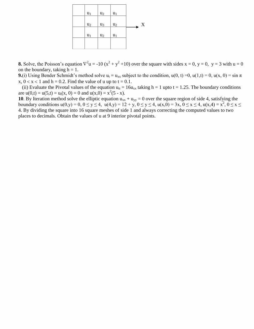
X
8. Solve, the Poisson‘s equation 2u = -10 (x
2 + y
2 +10) over the square with sides x = 0, y = 0, y = 3 with u = 0
on the boundary, taking h = 1.
9.(i) Using Bender Schmidt‘s method solve ut = uxx subject to the condition, u(0, t) =0, u(1,t) = 0, u(x, 0) = sin π
x, 0 x 1 and h = 0.2. Find the value of u up to t = 0.1.
(ii) Evaluate the Pivotal values of the equation utt = 16uxx taking h = 1 upto t = 1.25. The boundary conditions
are u(0,t) = u(5,t) = ut(x, 0) = 0 and u(x,0) = x2(5 - x).
10. By Iteration method solve the elliptic equation uxx + uyy = 0 over the square region of side 4, satisfying the
boundary conditions u(0,y) = 0, 0 ≤ y ≤ 4, u(4,y) = 12 + y, 0 ≤ y ≤ 4, u(x,0) = 3x, 0 ≤ x ≤ 4, u(x,4) = x2, 0 ≤ x ≤
4. By dividing the square into 16 square meshes of side 1 and always correcting the computed values to two
places to decimals. Obtain the values of u at 9 interior pivotal points.
u1 u2 u1
u2 u3 u2
u1 u2 u1
STRENGTH OF MATERAILS II
PART A
UNIT : I
1. Define: Strain Energy
When an elastic body is under the action of external forces the body deforms and work is done by these forces. If a strained, perfectly elastic body is allowed to recover slowly to its
unstrained state. It is capable of giving back all the work done by these external forces. This work done in straining such a body may be regarded as energy stored in a body and is called strain energy
or resilience.
2. Define: Proof Resilience.
The maximum energy stored in the body within the elastic limit is called Proof Resilience.
3. Write the formula to calculate the strain energy due to axial loads (tension).
U = ∫ P ² dx
limit 0 to
L
2AE
Where, P = Applied tensile load. L = Length of the member A = Area of the member
E = Young‟s modulus. 4. Write the formula to calculate the strain energy due to bending.
U = ∫ M ² dx
limit 0 to
L
2EI
Where, M = Bending moment due to applied loads. E = Young‟s modulus
I = Moment of inertia
5. Write the formula to calculate the strain energy due to torsion
U = ∫ T ² dx
limit 0 to
L
2GJ
T = Applied Torsion
Where,
G = Shear modulus or Modulus of rigidity
J = Polar moment of inertia
6. Write the formula to calculate the strain energy due to pure shear
U =K ∫ V ² dx
limit 0 to
L
2GA
Where,
V= Shear load
G = Shear modulus or Modulus of rigidity
A = Area of cross section.
K = Constant depends upon shape of cross section.
7. Write down the formula to calculate the strain energy due to pure shear, if shear stress is given.
U = τ ² V
2G
Where, τ = Shear Stress
G = Shear modulus or Modulus of rigidity V = Volume of the material.
8. Write down the formula to calculate the strain energy, if the moment value is given
M ² L
U = 2EI Where, M = Bending moment
L = Length of the beam E = Young‟s modulus
I = Moment of inertia
9. Write down the formula to calculate the strain energy , if the torsion moment value is given.
T ²L
U = 2GJ Where, T = Applied Torsion
L = Length of the beam
G = Shear modulus or Modulus of rigidity J = Polar moment of inertia
10. Write down the formula to calculate the strain energy, if the applied tension load is given.
P²L
U = 2AE Where,
P = Applied tensile load. L = Length of the member A = Area of the member
E = Young‟s modulus.
UNIT II
1. Explain with examples the statically indeterminate structures.
If the forces on the members of a structure cannot be determined by using conditions of
equilibrium (∑Fx =0, ∑Fy = 0, ∑M = 0 ), it is called statically indeterminate structures. Example: Fixed beam, continuous beam.
2. Define: Continuous beam.
A Continuous beam is one, which is supported on more than two supports. For usual loading on the beam hogging ( - ive ) moments causing convexity upwards at the supports and
sagging ( + ve ) moments causing concavity upwards occur at mid span.
3. What are the advantages of Continuous beam over simply supported beam?
1. The maximum bending moment in case of continuous beam is much less than in case of simply supported beam of same span carrying same loads.
2. In case of continuous beam, the average bending moment is lesser and hence lighter
materials of construction can be used to resist the bending moment
4. Give the procedure for analyzing the continuous beams with fixed ends using three moment equations?
The three moment equations, for the fixed end of the beam, can be modified by imagining a
span of length l 0 and moment of inertia, beyond the support the and applying the theorem of
three moments as usual.
5. Define Flexural Rigidity of Beams. The product of young‟s modulus (E) and moment of inertia (I) is called Flexural
2 Rigidity (EI) of Beams. The unit is N mm .
6. What is a fixed beam?
A beam whose both ends are fixed is known as a fixed beam. Fixed beam is also called as
built-in or encaster beam. Incase of fixed beam both its ends are rigidly fixed and the slope and deflection at the fixed ends are zero.
7. What are the advantages of fixed beams?
(i) For the same loading, the maximum deflection of a fixed beam is less than that of a simply supported beam.
(ii) For the same loading, the fixed beam is subjected to lesser maximum bending moment.
(iii) The slope at both ends of a fixed beam is zero.
(iv) The beam is more stable and stronger.
8. What are the disadvantages of a fixed beam?
(v) Large stresses are set up by temperature changes.
(vi) Special care has to be taken in aligning supports accurately at the same level.
(vii) Large stresses are set if a little sinking of one support takes place.
(viii) Frequent fluctuations in loading render the degree of fixity at the ends very
uncertain.
UNIT III
1. Define: Column and strut.
A column is a long vertical slender bar or vertical member, subjected to an axial compressive load and fixed rigidly at both ends.
A strut is a slender bar or a member in any position other than vertical, subjected to a compressive load and fixed rigidly or hinged or pin jointed at one or both the ends.
2. What are the types of column failure?
1. Crushing failure:
The column will reach a stage, when it will be subjected to the ultimate crushing stress, beyond this the column will fail by crushing The load corresponding to the crushing stress is
called crushing load. This type of failure occurs in short column.
2. Buckling failure:
This kind of failure is due to lateral deflection of the column. The load at which
the column just buckles is called buckling load or crippling load or critical load. This type of failure
occurs in long column.
3. What is slenderness ratio ( buckling factor)? What is its relevance in column?
It is the ratio of effective length of column to the least radius of gyration of the cross sectional ends of the column.
Slenderness ratio = l eff / r
l eff = effective length of column r = least radius of gyration
Slenderness ratio is used to differentiate the type of column. Strength of the column
depends upon the slenderness ratio, it is increased the compressive strength of the column decrease as the tendency to buckle is increased.
4. What are the factors affect the strength column? 1.Slenderness ratio
Strength of the column depends upon the slenderness ratio, it is increased the compressive strength of the column decrease as the tendency to buckle is increased.
2. End conditions: Strength of the column depends upon the end conditions also.
5. Define: Equivalent length of the column.
The distance between adjacent points of inflection is called equivalent length of the column. A point of inflection is found at every column end, that is free to rotate and every point
where there is a change of the axis. ie, there is no moment in the inflection points. (Or)
The equivalent length of the given column with given end conditions, is the length of an equivalent column of the same material and cross section with hinged ends , and having the value of
the crippling load equal to that of the given column.
6. What are the uses of south well plot? (column curve).
The relation between the buckling load and slenderness ratio of various column is known as south well plot.
UNIT IV
1. What are the types of failures?
1. Brittle failure:
Failure of a material represents direct separation of particles from each other, accompanied by considerable deformation.
2. Ductile failure:
Slipping of particles accompanied, by considerable plastic deformations.
2. List out different theories of failure
1. Maximum Principal Stress Theory. ( Rakine‟s theory)
2. Maximum Principal Strain Theory. ( St. Venant‟s theory)
3. Maximum Shear Stress Theory. ( Tresca‟s theory or Guest‟s theory )
4. Maximum Shear Strain Theory. (Von –Mises- Hencky theory or Distortion energy theory) 5. Maximum Strain Energy Theory. (Beltrami Theory or Haigh‟s theory)
3. Define: Maximum Principal Stress Theory. (Rakine‟s theory)
According to this theory, the failure of the material is assumed to take place when the
value of the maximum Principal Stress (σ 1) reaches a value to that of the elastic limit
stress( f y) of the material. σ 1 = f y.
4. Define: Maximum Principal Strain Theory. ( St. Venant‟s theory)
According to this theory, the failure of the material is assumed to take place when the value
of the maximum Principal Stain (e 1) reaches a value to that of the elastic limit strain( f y / E) of the material.
5. Define : Maximum Shear Stress Theory. ( Tresca‟s theory)
According to this theory, the failure of the material is assumed to take place when the maximum shear stress equal determined from the simple tensile test.
6. Define: Maximum Strain Energy Theory (Beltrami Theory)
According to this theory, the failure of the material is assumed to take place when the maximum strain energy exceeds the strain energy determined from the simple tensile test.
7. What are the theories used for ductile failures?
1. Maximum Principal Strain Theory. ( St. Venant‟s theory)
2. Maximum Shear Stress Theory. ( Tresca‟s theory)
3. Maximum Shear Strain Theory. ( Von –Mises- Hencky theory or Distortion energy theory)
8. Write the limitations of Maximum Principal Stress Theory. (Rakine‟s theory)
1. This theory disregards the effect of other principal stresses and effect of shearing stresses on other planes through the element.
2. Material in tension test piece slips along 450
to the axis of the test piece, where normal stress is neither maximum nor minimum, but the shear stress is maximum.
3. Failure is not a brittle, but it is a cleavage failure.
9. Write the limitations of Maximum Shear Stress Theory. ( Tresca‟s theory).
This theory does not give the accurate results for the state of stress of pure shear in which the maximum amount of shear is developed (in torsion test).
10. Write the limitations of Maximum Shear Strain Theory.(Von –Mises- Hencky theory or Distortion
energy theory).
It cannot be applied for the materials under hydrostatic pressure.
UNIT V
1. What are the assumptions made in the analysis of curved bars?
1.Plane sections remain plane during bending.
2. The material obeys Hooke‟s law.
3. Radial strain is negligible.
4. The fibres are free to expand or contract without any constraining effect from the adjacent fibres.
2. Define unsymmetrical bending.
If the plane of loading or that of bending, does not lie in (or parallel to) a plane that contains
the principal centroidal axis of the cross-section, the bending is called unsymmetrical bending.
3. What are the reasons for unsymmetrical bending?
1. The section is symmetrical but the load line is inclined to both the principal axes.
2.The section itself is unsymmetrical and the load line is along the centroidal axis.
4. How will you calculate the resultant stress in a curved bar subjected to direct stress and bending stress.
r = o + b
where o = Direct stress = P/A
b = Bending stress 5. What is shear centre or angle of twist?
The shear centre for any transverse section of the beam is the point of intersection of the bending axis and the plane of the transverse section.
6. Who postulated the theory of curved beam?
Winkler-Bach postulated the theory of curved beam.
7. What is the shape of distribution of bending stress in a curved beam?
The distribution of bending stress is hyperbolic in a curved beam.
8. Where does the neutral axis lie in a curved beam?
The neutral axis does not coincide with the geometric axis
PART B
UNIT – 1
ENERGY PRINCIPLES
1. A beam of 4 m length is simply supported at the ends and carries a uniformly distributed
load of 6 kN/m length. Determine the strain energy stored in the beam. Take E = 200 GPa and
I = 1440 cm4.
2. A beam simply supported over a span of 3 m carries an UDLof 20 kN/m over the entire
span. The flexural rigidity EI = 2.25 MNm2 Using Castigliano‟s theorem, determine the
deflection at the centre of the beam.
3. A cantilever beam of span 3 m carries a UDL of 5 kN/m for the entire span in addition to a
concentrated load of 20 kN at the free end. Using energy principle, calculate the deflection
under the concentrated load. Assume EI = 2 x 10⁴ kNmm2.
4. A simply supported beam of span 8 m carries two concentrated loads of 32 kN and 48 kN
at 3 m and 6 m from left support. Calculate the deflection at the centre by strain energy
principle.
5. A cantilever beam of span 3 m is carrying a point load of 50 kN at its free end. Compute
the strain energy in the beam due to bending and hence deflection under the load. Assum e EI
= 2 x 10⁵ kNm2.
6. A simply supported beam AB of span 5 m carries a UDL of 25 kN/m throughout its entire
span. Calculate the strain energy due to bending and deflection at its mid span. Assume EI = 2
x 104 kNm2.
7. A simply supported beam of 10 m span carries a uniformly distributed load of 2 kN/m
over the half of the span. Find the deflection at Mid-span using principle of virtual work. Take
EI = 30000 kNm2.
8. A beam of span 8 m carries UDL of 20 kN/m for a length of 4 m from left end. Find the
deflection and slope at the centre of the beam by strain energy method. EI is constant.
9. Calculate the strain energy stored in a cantilever beam of 4 m span, carrying a point load
of 10 kN at free end. Take EI = 25000 kNm2.
10. Find the deflection at mid span of a simply supported beam carrying a uniformly
distributed load of 2 kN/m over the entire span using principle of virtual work. Take span = 5
m; EI = 20000 kNm2.
11. A mild steel specimen of gauge length 50 mm has a cross sectional area of 145 mm2.
When it is subjected to a axial pull of 32 kN, it stretches by 0.054 mm. Calculate the strain
energy stored in the specimen. If the load at the elastic limit of the specimen is 58 kN,
calculate the elongation at elastic limit and proof resilience.
12. A rectangular beam of cross section 100 x 200 mm and length 2 m is simply supported at
its ends and carries a central load. If the maximum bending stress is 120 N/mm2. Find the
strain energy stored in the beam due to bending. Take E = 2X10⁵N/mm2
13. Using castigliano‟s theorem, obtain the deflection at the free end of a cantilever of length
2.5 m carrying a udl of 16.4 kN/m over the whole span. Assume uniform flexural rigidity.
14. Using castigliano‟s theorem, obtain the deflection under a single concentrated load applied
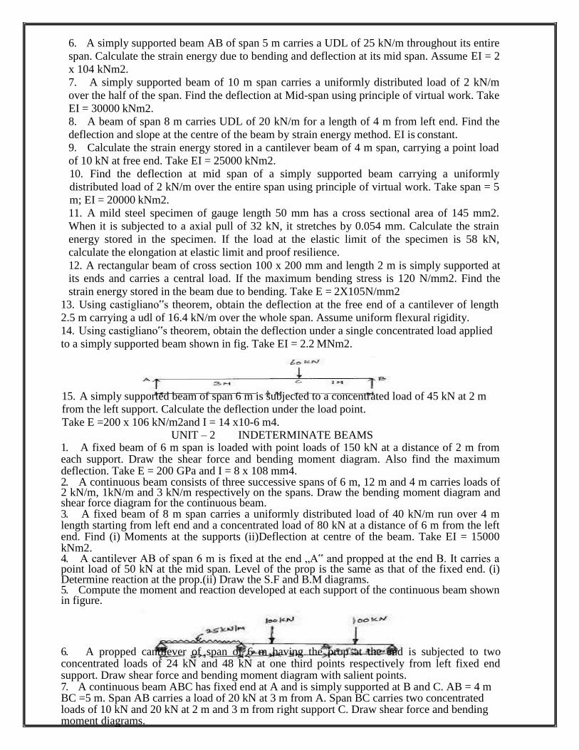
to a simply supported beam shown in fig. Take EI = 2.2 MNm2.
15. A simply supported beam of span 6 m is subjected to a concentrated load of 45 kN at 2 m
from the left support. Calculate the deflection under the load point.
Take E =200 x 106 kN/m2and I = 14 x10-6 m4. UNIT – 2 INDETERMINATE BEAMS
1. A fixed beam of 6 m span is loaded with point loads of 150 kN at a distance of 2 m from each support. Draw the shear force and bending moment diagram. Also find the maximum deflection. Take E = 200 GPa and I = 8 x 108 mm4. 2. A continuous beam consists of three successive spans of 6 m, 12 m and 4 m carries loads of 2 kN/m, 1kN/m and 3 kN/m respectively on the spans. Draw the bending moment diagram and shear force diagram for the continuous beam. 3. A fixed beam of 8 m span carries a uniformly distributed load of 40 kN/m run over 4 m length starting from left end and a concentrated load of 80 kN at a distance of 6 m from the left end. Find (i) Moments at the supports (ii)Deflection at centre of the beam. Take EI = 15000 kNm2. 4. A cantilever AB of span 6 m is fixed at the end „A‟ and propped at the end B. It carries a point load of 50 kN at the mid span. Level of the prop is the same as that of the fixed end. (i) Determine reaction at the prop.(ii) Draw the S.F and B.M diagrams. 5. Compute the moment and reaction developed at each support of the continuous beam shown in figure.
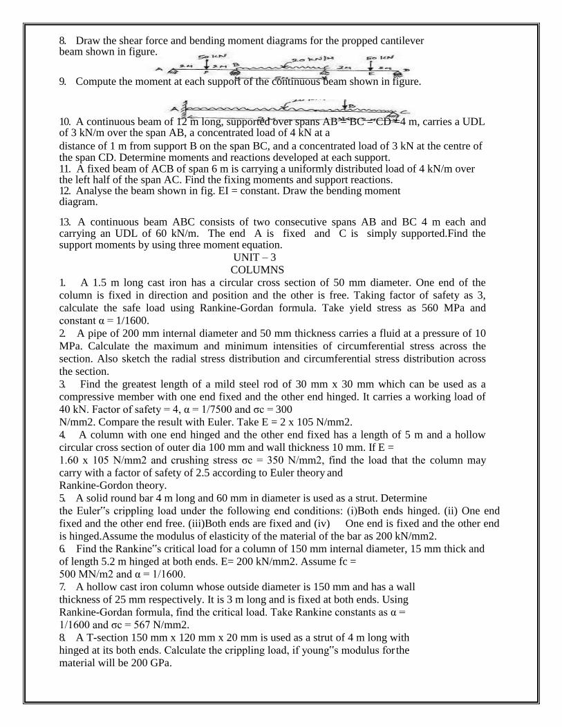
6. A propped cantilever of span of 6 m having the prop at the end is subjected to two concentrated loads of 24 kN and 48 kN at one third points respectively from left fixed end support. Draw shear force and bending moment diagram with salient points. 7. A continuous beam ABC has fixed end at A and is simply supported at B and C. AB = 4 m BC =5 m. Span AB carries a load of 20 kN at 3 m from A. Span BC carries two concentrated loads of 10 kN and 20 kN at 2 m and 3 m from right support C. Draw shear force and bending moment diagrams.
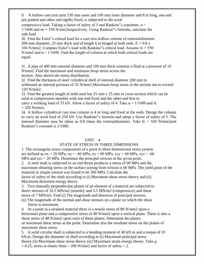
8. Draw the shear force and bending moment diagrams for the propped cantilever beam shown in figure.
9. Compute the moment at each support of the continuous beam shown in figure.
10. A continuous beam of 12 m long, supported over spans AB = BC = CD =4 m, carries a UDL of 3 kN/m over the span AB, a concentrated load of 4 kN at a
distance of 1 m from support B on the span BC, and a concentrated load of 3 kN at the centre of the span CD. Determine moments and reactions developed at each support. 11. A fixed beam of ACB of span 6 m is carrying a uniformly distributed load of 4 kN/m over the left half of the span AC. Find the fixing moments and support reactions. 12. Analyse the beam shown in fig. EI = constant. Draw the bending moment diagram.
13. A continuous beam ABC consists of two consecutive spans AB and BC 4 m each and carrying an UDL of 60 kN/m. The end A is fixed and C is simply supported.Find the support moments by using three moment equation.
UNIT – 3
COLUMNS
1. A 1.5 m long cast iron has a circular cross section of 50 mm diameter. One end of the
column is fixed in direction and position and the other is free. Taking factor of safety as 3,
calculate the safe load using Rankine-Gordan formula. Take yield stress as 560 MPa and
constant α = 1/1600.
2. A pipe of 200 mm internal diameter and 50 mm thickness carries a fluid at a pressure of 10
MPa. Calculate the maximum and minimum intensities of circumferential stress across the
section. Also sketch the radial stress distribution and circumferential stress distribution across
the section.
3. Find the greatest length of a mild steel rod of 30 mm x 30 mm which can be used as a
compressive member with one end fixed and the other end hinged. It carries a working load of
40 kN. Factor of safety = 4, α = 1/7500 and σc = 300
N/mm2. Compare the result with Euler. Take E = 2 x 10⁵ N/mm2.
4. A column with one end hinged and the other end fixed has a length of 5 m and a hollow
circular cross section of outer dia 100 mm and wall thickness 10 mm. If E =
1.60 x 10⁵ N/mm2 and crushing stress σc = 350 N/mm2, find the load that the column may
carry with a factor of safety of 2.5 according to Euler theory and
Rankine-Gordon theory.
5. A solid round bar 4 m long and 60 mm in diameter is used as a strut. Determine
the Euler‟s crippling load under the following end conditions: (i)Both ends hinged. (ii) One end
fixed and the other end free. (iii)Both ends are fixed and (iv) One end is fixed and the other end
is hinged.Assume the modulus of elasticity of the material of the bar as 200 kN/mm2.
6. Find the Rankine‟s critical load for a column of 150 mm internal diameter, 15 mm thick and
of length 5.2 m hinged at both ends. E= 200 kN/mm2. Assume fc =
500 MN/m2 and α = 1/1600.
7. A hollow cast iron column whose outside diameter is 150 mm and has a wall
thickness of 25 mm respectively. It is 3 m long and is fixed at both ends. Using
Rankine-Gordan formula, find the critical load. Take Rankine constants as α =
1/1600 and σc = 567 N/mm2.
8. A T-section 150 mm x 120 mm x 20 mm is used as a strut of 4 m long with
hinged at its both ends. Calculate the crippling load, if young‟s modulus for the
material will be 200 GPa.
9. A hollow cast iron strut 150 mm outer and 100 mm inner diameter and 8 m long, one end
pin jointed and other end rigidly fixed, is subjected to the axial
compressive load. Taking a factor of safety of 5 and Rankine‟s constants, α =
1/1600 and σc = 550 N/mm2respectively. Using Rankine‟s formula, calculate the
safe load.
10. Find the Euler‟s critical load for a cast iron hollow column of external diameter
200 mm diameter, 25 mm thick and of length 6 m hinged at both ends. E = 0.8 x
104 N/mm2. Compare Euler‟s load with Rankine‟s critical load. Assume fc = 550
N/mm2 and α = 1/1600. Find the length of column at which both critical loads are
equal.
11. A pipe of 400 mm internal diameter and 100 mm thick contains a fluid at a pressure of 10
N/mm2. Find the maximum and minimum hoop stress across the
section. Also sketch the stress distribution.
12. Find the thickness of steel cylindrical shell of internal diameter 200 mm to
withstand an internal pressure of 35 N/mm2.Maximum hoop stress in the section not to exceed
120 N/mm2.
13. Find the greatest length of mild steel bar 25 mm x 25 mm in cross-section which can be used as compression member with one end fixed and the other end free to
carry a working load of 35 kN. Allow a factor of safety of 4. Take α = 1/1600 and fc
= 320 N/mm2.
14. A hollow cylindrical cast iron column is 4 m long and fixed at the ends. Design the column
to carry an axial load of 250 kN. Use Rankine‟s formula and adopt a factor of safety of 5. The
internal diameter may be taken as 0.8 times the externaldiameter. Take fc = 550 N/mm2and
Rankine‟s constant is 1/1600.
UNIT – 4
STATE OF STRESS IN THREE DIMENSIONS
1. The rectangular stress components of a point in three dimensional stress system
are defined as σx = 20 MPa, σy = -40 MPa, σz = 80 MPa, τxy = 40 MPa, τyz = -60
MPa and τzx = 20 MPa. Determine the principal stresses at the given point.
2. A steel shaft is subjected to an end thrust produces a stress of 90 MPa and the
maximum shearing stress on the surface arising from torsion is 60 MPa. The yield point of the
material in simple tension was found to be 300 MPa. Calculate the
factor of safety of the shaft according to (i) Maximum shear stress theory and (ii)
Maximum distortion energy theory.
3. Two mutually perpendicular planes of an element of a material are subjected to
direct stresses of 10.5 MN/m2 (tensile); and 3.5 MN/m2 (compressive) and shear
stress of 7 MN/m2. Find (i) The magnitude and direction of principal stresses.
(ii) The magnitude of the normal and shear stresses on a plane on which the shear
Stress is maximum.
4. At a point in a strained material there is a tensile stress of 80 N/mm2 upon a
horizontal plane and a compressive stress of 40 N/mm2 upon a vertical plane. There is also a
shear stress of 48 N/mm2 upon each of these planes. Determine the planes
of maximum shear stress at the point. Determine also the resultant stress on the planes of maximum shear stress.
5. A solid circular shaft is subjected to a bending moment of 40 kN.m and a torque of 10 kN.m. Design the diameter of shaft according to (i) Maximum principal stress
theory (ii) Maximum shear stress theory (iii) Maximum strain energy theory. Take µ
= 0.25, stress at elastic limit = 200 N/mm2 and factor of safety = 2.
6. A solid circular shaft is subjected to a bending moment of 40 kN.m and a torque of 10
kN.m. Design the diameter of the shaft according to
(i) Maximum principal stress theory (ii) Maximum shear stress theory
(iii) Maximum strain energy theory.
7. The normal stress in two mutually perpendicular directions are 600 N/mm2 and
300 N/mm2 both tensile. The complimentary shear stresses in these directions are of
intensity 450 N/mm2. Find the normal and tangential stresses in the two planes which are
equally inclined to the planes carrying the normal stresses mentioned
above.
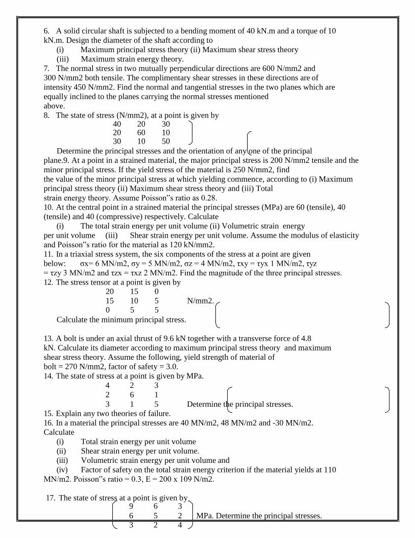
8. The state of stress (N/mm2), at a point is given by
Determine the principal stresses and the orientation of any one of the principal
plane.9. At a point in a strained material, the major principal stress is 200 N/mm2 tensile and the
minor principal stress. If the yield stress of the material is 250 N/mm2, find
the value of the minor principal stress at which yielding commence, according to (i) Maximum
principal stress theory (ii) Maximum shear stress theory and (iii) Total
strain energy theory. Assume Poisson‟s ratio as 0.28.
10. At the central point in a strained material the principal stresses (MPa) are 60 (tensile), 40
(tensile) and 40 (compressive) respectively. Calculate
(i) The total strain energy per unit volume (ii) Volumetric strain energy
per unit volume (iii) Shear strain energy per unit volume. Assume the modulus of elasticity
and Poisson‟s ratio for the material as 120 kN/mm2.
11. In a triaxial stress system, the six components of the stress at a point are given
below: σx= 6 MN/m2, σy = 5 MN/m2, σz = 4 MN/m2, τxy = τyx 1 MN/m2, τyz
= τzy 3 MN/m2 and τzx = τxz 2 MN/m2. Find the magnitude of the three principal stresses.
12. The stress tensor at a point is given by 20 15 0
15 10 5 N/mm2. 0 5 5
Calculate the minimum principal stress.
13. A bolt is under an axial thrust of 9.6 kN together with a transverse force of 4.8
kN. Calculate its diameter according to maximum principal stress theory and maximum
shear stress theory. Assume the following, yield strength of material of
bolt = 270 N/mm2, factor of safety = 3.0.
14. The state of stress at a point is given by MPa.
4 2 3
2 6 1
3 1 5
15. Explain any two theories of failure.
Determine the principal stresses.
16. In a material the principal stresses are 40 MN/m2, 48 MN/m2 and -30 MN/m2.
Calculate
(i) Total strain energy per unit volume
(ii) Shear strain energy per unit volume.
(iii) Volumetric strain energy per unit volume and
(iv) Factor of safety on the total strain energy criterion if the material yields at 110
MN/m2. Poisson‟s ratio = 0.3, E = 200 x 109 N/m2.
17. The state of stress at a point is given by
40 20 30 20 60 10 30 10 50
9 6 3
6 5 2 MPa. Determine the principal stresses. 3 2 4
UNIT – 5 ADVANCED TOPICS IN BENDING OF BEAMS
1. Find the centroidal principal moments of inertia of an equal angle section 30 mm x 30 mm x 10 mm. 2. A compound tube is composed of 250 mm internal diameter and 25 mm thick shrunk on tube of 250 mm external diameter and 25 mm thick. The radial pressure at the junction is 8 N/mm
2. Find the variation of hoop stress over the wall of the
compound tube. 3. Calculate the thickness of metal necessary for a steel cylindrical shell of internal diameter 100 mm to withstand an internal pressure of 40 N/mm
2, if the allowable tensile
stress is 120 N/mm2.
4. Explain with figure the conduct of Fatigue test for a material in the laboratory. 5. Find the thickness of metal necessary for a steel cylinder of internal diameter 200 mm to withstand an internal pressure of 50 N/mm
2. The maximum hoop stress in the
section is not to exceed 150 N/mm2. Assume thick cylinder.
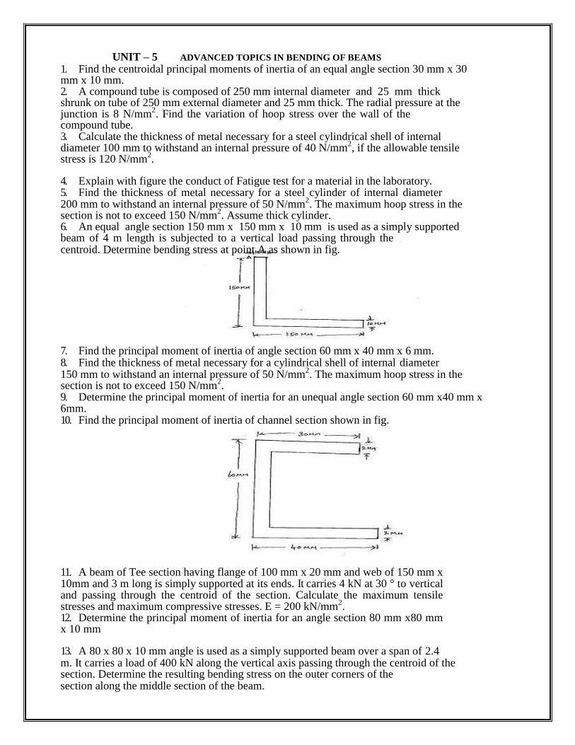
6. An equal angle section 150 mm x 150 mm x 10 mm is used as a simply supported beam of 4 m length is subjected to a vertical load passing through the centroid. Determine bending stress at point A as shown in fig.
7. Find the principal moment of inertia of angle section 60 mm x 40 mm x 6 mm. 8. Find the thickness of metal necessary for a cylindrical shell of internal diameter 150 mm to withstand an internal pressure of 50 N/mm
2. The maximum hoop stress in the
section is not to exceed 150 N/mm2.
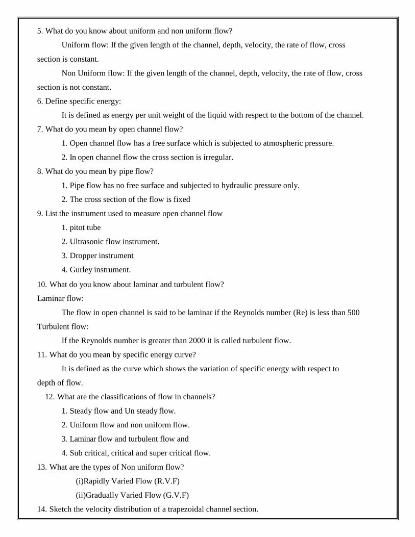
9. Determine the principal moment of inertia for an unequal angle section 60 mm x40 mm x 6mm. 10. Find the principal moment of inertia of channel section shown in fig.
11. A beam of Tee section having flange of 100 mm x 20 mm and web of 150 mm x 10mm and 3 m long is simply supported at its ends. It carries 4 kN at 30 ° to vertical and passing through the centroid of the section. Calculate the maximum tensile stresses and maximum compressive stresses. E = 200 kN/mm
2.
12. Determine the principal moment of inertia for an angle section 80 mm x80 mm x 10 mm
13. A 80 x 80 x 10 mm angle is used as a simply supported beam over a span of 2.4 m. It carries a load of 400 kN along the vertical axis passing through the centroid of the section. Determine the resulting bending stress on the outer corners of the section along the middle section of the beam.

V.S.B ENGINEERING COLLEGE, KARUR
DEPARTMENT OF CIVIL ENGINEERING
APPLIED HYDRAULICS ENGINEERING
TWO MARKS QUESTION AND ANSWES
1. Define sub critical flow:
UNIT - I
UNIFORM FLOW
If the Froude number is less than one then the flow is said to be sub critical flow.
2. Define critical flow:
If the froude number is less equal to one it is called as critical flow.
3. Define supercritical flow:
If the Froude number is greater than one it is called as super critical flow
4. What are the possible types of flow in open channel with respect to space and time?
A, steady and unsteady flow
B, uniform and non uniform flow
5. What do you know about uniform and non uniform flow?
Uniform flow: If the given length of the channel, depth, velocity, the rate of flow, cross
section is constant.
Non Uniform flow: If the given length of the channel, depth, velocity, the rate of flow, cross
section is not constant.
6. Define specific energy:
It is defined as energy per unit weight of the liquid with respect to the bottom of the channel.
7. What do you mean by open channel flow?
1. Open channel flow has a free surface which is subjected to atmospheric pressure.
2. In open channel flow the cross section is irregular.
8. What do you mean by pipe flow?
1. Pipe flow has no free surface and subjected to hydraulic pressure only.
2. The cross section of the flow is fixed
9. List the instrument used to measure open channel flow
1. pitot tube
2. Ultrasonic flow instrument.
3. Dropper instrument
4. Gurley instrument.
10. What do you know about laminar and turbulent flow?
Laminar flow:
The flow in open channel is said to be laminar if the Reynolds number (Re) is less than 500
Turbulent flow:
If the Reynolds number is greater than 2000 it is called turbulent flow.
11. What do you mean by specific energy curve?
It is defined as the curve which shows the variation of specific energy with respect to
depth of flow.
12. What are the classifications of flow in channels?
1. Steady flow and Un steady flow.
2. Uniform flow and non uniform flow.
3. Laminar flow and turbulent flow and
4. Sub critical, critical and super critical flow.
13. What are the types of Non uniform flow?
(i)Rapidly Varied Flow (R.V.F)
(ii)Gradually Varied Flow (G.V.F)
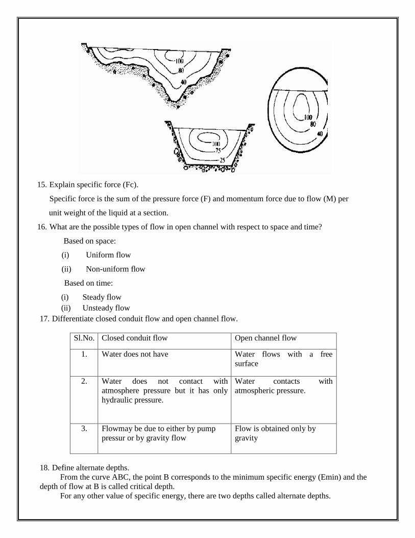
14. Sketch the velocity distribution of a trapezoidal channel section.
15. Explain specific force (Fc).
Specific force is the sum of the pressure force (F) and momentum force due to flow (M) per
unit weight of the liquid at a section.
16. What are the possible types of flow in open channel with respect to space and time?
Based on space:
(i) Uniform flow
(ii) Non-uniform flow
Based on time:
(i) Steady flow
(ii) Unsteady flow
17. Differentiate closed conduit flow and open channel flow.
Sl.No. Closed conduit flow Open channel flow
1. Water does not have Water flows with a free
surface
2. Water does not contact with
atmosphere pressure but it has only
hydraulic pressure.
Water contacts with
atmospheric pressure.
3. Flowmay be due to either by pump
pressur or by gravity flow
Flow is obtained only by
gravity
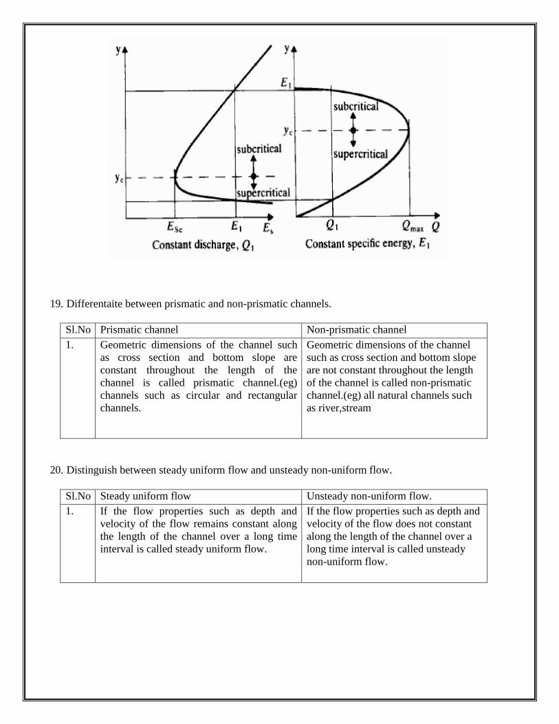
18. Define alternate depths.
From the curve ABC, the point B corresponds to the minimum specific energy (Emin) and the
depth of flow at B is called critical depth.
For any other value of specific energy, there are two depths called alternate depths.
19. Differentaite between prismatic and non-prismatic channels.
Sl.No Prismatic channel Non-prismatic channel
1. Geometric dimensions of the channel such
as cross section and bottom slope are
constant throughout the length of the
channel is called prismatic channel.(eg)
channels such as circular and rectangular
channels.
Geometric dimensions of the channel
such as cross section and bottom slope
are not constant throughout the length
of the channel is called non-prismatic
channel.(eg) all natural channels such
as river,stream
20. Distinguish between steady uniform flow and unsteady non-uniform flow.
Sl.No Steady uniform flow Unsteady non-uniform flow.
1. If the flow properties such as depth and
velocity of the flow remains constant along
the length of the channel over a long time
interval is called steady uniform flow.
If the flow properties such as depth and
velocity of the flow does not constant
along the length of the channel over a
long time interval is called unsteady
non-uniform flow.
UNIT-II
GRADUALLY VARIED FLOW
1. What is meant by wetted perimeter?
The wetted perimeter (p) is the length of the line of intersection of the channel wetted
surface with the cross section plan normal to the direction of flow.
2. Define critical depth:
It is defined as the depth of flow of water at which the specific energy is minimum.
3. Define critical velocity:
The velocity of flow at the critical depth is known as critical velocity.
4. Define the term most economical section of the channel:
A section of the channel is said to be most economical when the cost of construction of the
channel is minimum. But the cost of construction depend up on the excavation and lining to keep
the cost minimum The wetted perimeter for a given discharge should be minimum.
5. Differntiate pitot tube and pitot static tube.
Sl.No Pitot Tube Pitot Static Tube
1. Pitot tube gives kinetic
head of moving liquid
Pitot static tube is an
instrument which
records static pressure and stagnation
6. How can current meter be classified?
Current meters are classified, on the basis of revolving element, as
1. Cup type current meter
2. Screw or propeller type current meter.
7. What is cup type current meter?
In this type, series of conical cups called revolving element are mounted on a spindle
vertically at right angles to the direction of flow.
8. What is screw or propeller type current meter?
In a screw or propeller type current meter, the revolving element has of a shaft with its axis
parallel to the direction of flow. It has a number of curved vanes or propeller blades mounted
around the periphery of the shaft.
9. What is the working principle of float as a velocity measuring device?
It is operated on the principle that the times taken by the float to traverse for the known
distance is measured to compute velocity. Here, the mean velocity of flow is about 0.8 to 0.95 times
the surface velocity. The approximate value of mean velocity of flow is determined from the known
value of the surface. Floats are used to measure the velocity of flow of water in rivers and channels.
10. What are the pros and cons of laser Doppler anemometer?
It measures only the velocity.
1. Volume of sensing part is very small
2. There is no addition of physical object to avoid disturbances.
3. It has very high accuracy.
4. It has a high frequency response.
11. List the factors affecting manning‟s roughness coefficient.
The following factors affecting manning‟s roughness coefficient are:
1. Surface roughness
2. Vegetation growth
3. Channel irregularities
4. Sitting and scouring
5. Stage(water surface elevation) and discharge
12. Give some application of laser Doppler anemometer.
1. It is used for the flow between blades of a turbine.
2. It is used fin combustion and flame phenomena in gas turbine.
3. It is used in jet propulsion systems.
4. It is used for measuring the blood flow.
5. In remote sensing of wind velocities.
13. What are the factors considered for the derivation of chezy‟s equation?
1. Force resisting the flow per unit of wetted area is proportional to the square of the
velocity.
2. Force causing the flow must be equal to the force of resistance.
14. What is the condition for most economical rectangular channel section?
Hence the most economical cross section of a rectangular channel giving maximum
discharge would be when
(a) Depth of cross section is half of the width(Y=b/2) or
(b) Hydraulic radius is half the depth(R=y/2)
15. On what condition most economical trapezoidal channel section is derived?
The most economical section of a trapezoidal channel is
(a) Sloping side of cross section is equal to half the top width.
(b) Angle of channel sides make with horizontal is 600
(c) Hydraulic radius is equal to half the depth of water.
16. What are the condition for obtaining most economical circular channel section for maximum
velocity and discharge?
(i) Depth of flow is 0.81 times the diameter of the circular channel.
(ii) Hydraulic radius is equal to 03 times the diameter of channel.
(iii) Angle subtended by water surface from the centre,2ϴ=257º30‖
17. Define non-erodible channels.
Channels which are constructed from materials, such as concrete,masonry and metal can
withstand erosion under all including most extreme conditions are called as non-erodible
channels.
18. What are the factors considered while designing non-erodible channels?
1. Manning‖s constant n value of the material.
2. Channel slope
3. Free board
19. What is the significance of most economical section?
The most economical cross section of a channel is one which gives the maximum discharge
with constant cross sections.
20. Define hydraulic mean radius.
R=Wetted area/Wetted perimeter=A/P
UNIT - III
RAPIDLY VARIED FLOW
1. Define gradually varying flow
If the change in depth in a varying flow is gradual so that the curvature of the streaming
line is not excessive such flow is called gradually varying flow.
2. Define rapidly varying flow
If the curvature in a varied flow is large and depth changes appreciably over short length it is
called rapidly varying flow.
3. Define affux.
The maximum increase in water level due to obstruction in the path of flow is known as
affux.
4. Define length of backwater curve
The distance along the bed of the channel between the sections where water starts raising to
the section where water is having maximum height is known as the length of the back water curve
5. Define back water
The profile of the raising water on the upstream side of the dam is called as back water curve.
6. Define hydraulic jump
The raise of water level which takes place due to the transformation of the unstable
shooting flow ( super critical flow ) to the stable Streaming flow
(Sub critical flow) is called hydraulic jump.
7. Write down the expression for energy loss due to hydraulic jump?
HL = (d2-d1)3 / (4d1d2)
Where
HL – energy loss due to hydraulic jump
D2 - depth of flow after the jump
D1 -- depth of flow before the jump
8. What are the assumptions of gradually varying flow profile?
1. Pressure distribution at any section is assumed to be hydrostatic.
2. The velocity distribution at the channel section is fixed
3. The channel is prismatic
4. The roughness coefficient is independent of the depth of flow.
9. What the two cases where distance of the normal depth of flow does not exit? (a)
When the channel bed is horizontal
(b) When the channel bed has a adverse slope.
10. What are the methods used for finding gradually varying flow profile?
1. Direct integration method
2. Numerical method
3. Graphical representation method.
11. What do mean by M1 profile?
The most common of all gradually varying flow is of M1 type which is a subcritical flow
condition obstruction to flow such as wiers, dams etc…which produce M1profile.
12. What are the types of flow profile?
Mild slope profile
Steep slope profile
Critical slope profile
Horizontal bed profile
Adverse slope profile
13. What do you mean by M2 profile?
The M2 profile occurs at a sudden drop in the bed of the channel in to the ponds or pools
or lakes.
14. What is transition in open channel?
Transition means a change of channel cross section.
(i) Provision of a hump or depression along a depth and
(ii) Contraction or expansion of channel width in any combination.
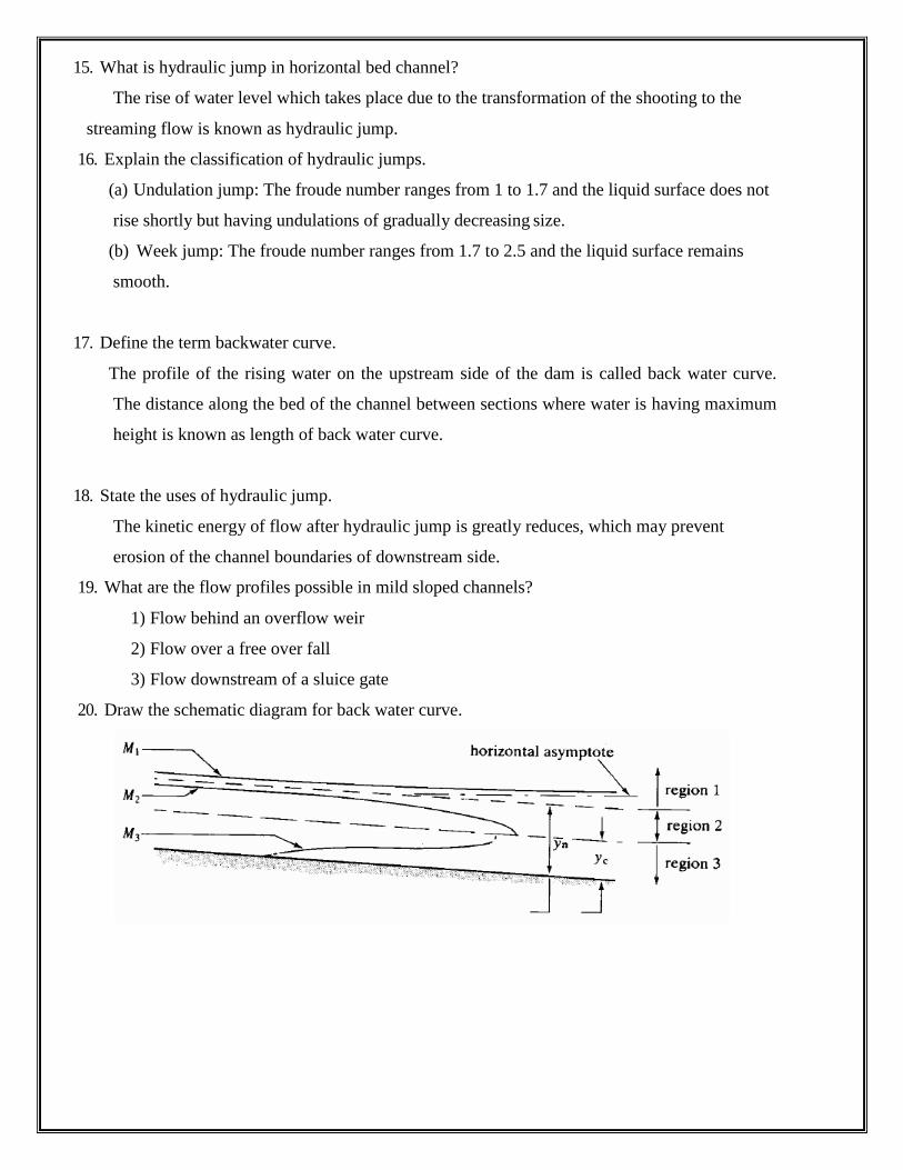
15. What is hydraulic jump in horizontal bed channel?
The rise of water level which takes place due to the transformation of the shooting to the
streaming flow is known as hydraulic jump.
16. Explain the classification of hydraulic jumps.
(a) Undulation jump: The froude number ranges from 1 to 1.7 and the liquid surface does not
rise shortly but having undulations of gradually decreasing size.
(b) Week jump: The froude number ranges from 1.7 to 2.5 and the liquid surface remains
smooth.
17. Define the term backwater curve.
The profile of the rising water on the upstream side of the dam is called back water curve.
The distance along the bed of the channel between sections where water is having maximum
height is known as length of back water curve.
18. State the uses of hydraulic jump.
The kinetic energy of flow after hydraulic jump is greatly reduces, which may prevent
erosion of the channel boundaries of downstream side.
19. What are the flow profiles possible in mild sloped channels?
1) Flow behind an overflow weir
2) Flow over a free over fall
3) Flow downstream of a sluice gate
20. Draw the schematic diagram for back water curve.
1. Explain Reaction turbine
UNIT- IV
TURBINES
If at the inlet of the turbine the water possesses kinetic energy as well as pressure energy
the turbine is known as reaction turbine.
2. Explian tangential flow turbine
If the water flows along the tangent of the runner, the turbine is known as the
tangential flow turbine.
3. Expain radial flow turbine
If the water flows in the radial direction through the runner the turbine is called radial
flow turbine.
4. Explain inward flow radial turbine
If the water flows from outwards to inwards radially the turbine is called radial flow
turbine.
5. Explain outward flow radial turbine
If the water flows radially from inwards to outwards the turbine is known sa
outward radial flow turbine.
6. Define axial flow turbine
If the water flows through the runner along the direction parallel to the axis of rotation
of the runner the turbine is called axial flow turbine.
7. What is Pelton wheel?
Pelton wheel or Pelton turbine is a tangential flow impulse turbine. The water strikes the
bucket along the tangent of the runner. The energy available at the inlet of the Turbine is only
kinetic energy. This turbine is used for high heads.
8. What is breaking jet?
When the nozzle is completely closed, the amount of water striking the runner reduces to
zero but the runner due to inertia goes on revolving for a long time to stop the runner in a short
time a small nozzle is provided which direct the jet of water on the back of vanes .This jet of
water is called breaking jet.
9. What is jet ratio?
It is the ratio of pitch diameter (D) to the diameter of jet (d).
10. What is Draft tube?
A tube or pipe of gradually increasing area is used for discharging water from the exit
of the turbine to the tail race is called draft tube.
11. Define Degree of Reaction (R)
It is defined as the ratio of change of pressure energy inside the runner to the change
of total energy outside the runner.
12. What is radial discharge?
This means the angle made by absolute velocity with the tangent on the wheel is 90 and
the component of whirl velocity is zero.
13. Define Francis turbine:
Inward flow reaction turbine having radial discharge at outlet is known as francis turbine
14. Define propeller turbine:
This is an example of axial flow reaction turbine. Here the vanes are fixed to the hub and
are not adjustable.
15. Define Kaplan turbine:
This is an example of axial flow reaction turbine. Here the vanes are not fixed to the hub
and are adjustable.
16. What is the use of draft tube?
1. The net head on the turbine increases.
2. Due to increase in net head the power and efficiency of the turbine also
increases.
3. The large amount of rejected kinetic energy is converted in to useful pressure energy
17. What are types of draft tube?
1. Conical draft tube
2. Simple elbow tube
3. Moody spreading tube
4. Draft tube with circular inlet and rectangular outlet.
18. Define cavitations
cavitations is defined as phenomenon of formation of vapour bubbles in a region of a
flowing liquid where the pressure in the liquid is falls below than vapour pressure and sudden
collapsing of these vapour bubbles in a region of higher pressure.
19. What is known by governing of a turbine?
Governing of a turbine is defined as the operation by which the speed of the turbine
is kept constant under all conditions of working. It is done by oil pressure generator.
20. Explain net head
It is defined as the head available at the inlet of turbine .If Hf is the loss due to friction
between water and penstock then net head
21. Define Hydraulic Efficiency:
It is defined as the ratio of power delivered to the runner to the power supplied at the
inlet.
22. Define mechanical efficiency
It is defined as the ratio of power at the shaft of the turbine to the power delivered by the
water to runner.
23. Define volumetric efficiency
It is defined as the ratio of volume of water actually striking the runner to the
Volume of water supplied to the runner.
24. Define overall efficiency
It is defined as the ratio of shaft power by water power.
1. Define pump:
UNIT-V
PUMPS
It is defined as the hydraulic machine which converts mechanical energy in to
hydraulic energy
2. What is Net Positive Suction Head (NPSH)?
NPSH is defined as the total head required making liquid flow through suction pipe to
pipe impeller.
3. Define slip of a reciprocating pump and negative slip:
Slip is defined as the difference between theoretical discharge and actual
discharge.
If actual discharge is greater than theoretical discharge negative value is found this
negative value is called negative slip.
4. What do you know coefficient of discharge?
It is defined as the ratio of actual discharge by theoretical discharge. It is denoted by Cd.
5. What do you know Drop down curve?
The water surface has a convex profile upwards this curve is called drop down curve.
6. What is separation of reciprocating pump?
If the pressure in the cylinder is below the vapour pressure, dissolved gasses will be
liberated from the liquid and cavitations will takes place. The continuous flow of liquid will not
exit which means separation of liquid takes place. The pressure at which separation takes place is
called separation pressure and head corresponding to the separation pressure is called separation
pressure head.
7. What is an indicator diagram?
Indicator diagram is the graph between the pressure head and distance traveled by the
piston from inner dead center for one complete revolution.
8. What is Air vessel?
Air vessel is a closed chamber containing compressed air in the top portion and liquid at
the bottom of the chamber. It is used to obtain a continuous supply of water at uniform rate to
save a considerable amount of work and to run the pump at high speed with out separation.
9. Write the manometric efficiency of the pump?
Manometric efficiency = (gHm)/(Vw2U2)
Where
Hm –manometric head
10. Write the expression for over all efficiency?
Overall efficiency = (ϑg QHm)/(1000 x P) Where
Hm – manometric head
P - Power
11. What is the minimum speed for starting the centrifugal pump?
Where
N=(120 ηmanVw2 D)/(π(D22-D
2) 1
ηman – efficiency
manom
etric Vw2 _- Whirl at out let of the turbine
D2 - diameter of impeller at out let
12. Write down the use of centrifugal pump?
1. Used in deep sump and basement
2. The high discharge capacity
3. It is driven by electric motors
13. What is centrifugal pump?
The hydraulic machine which convert mechanical energy in to pressure energy by means of
centrifugal force is called centrifugal pump.It acts a reverse of inward radial flow turbine.
14. What are the main parts of centrifugal pump?
1. Suction pipe with foot valve and strainer
2. Impeller
3. Casing
4. Delivery pipe
15. Define multistage pump:
If centrifugal pump consists of two or more impellers the pump is called multistage
pump. To produce a high head impellers are connected in series .To produce high
discharge impellers are connected in parallel.
16. What is the purpose of an air vessel fitted in the pump?
1. To obtain a continuous supply of liquid at a uniform rate.
2. To save a considerable amount of work in overcoming the frictional resistance in the
suction and delivery pipes, and3. To run the pump at a high speed without separation.
17. What is the work saved by fitting a air vessel in a single acting, double acting pump?
Work saved by fitting air vessels in a single acting pump is 84.87%, In a
double acting pump the work saved is 39.2%.
18. What is Discharge through a Reciprocating Pump in per sec?
For Single acting
Discharge (Q)=ALN/60
Where
A=Area of the Cylinder in m2
L=Length of Stroke in m.
N=Speed of Crank in RPM
For Double acting
Q=2ALN/60
19. What is the Workdone by Reciprocating Pump Per sec.?
Workdone = ρgALN(hs+hd)/60 (for single acting)
For Double acting:
Work done= 2ρgALN (hs+hd)/60
Where
ρ=Density of Water in kg/m3
A=Area of the Cylinder in m2
L=Length of Stroke in m
N=Speed in rpm
Hs, hd=Suction and Delivery head in m
v=Aω r/3.14a
Where
ω =Angular velocity in rad/sec
r =Radius of the crank in m
A and a =Area of cylinder and Pipe in m2
CE 6403 - APPLIED HYDRAULICS ENGINEERING
UNIT – I: UNIFORM FLOW
1. How do you classify open channels? Explain in detail. Also explain the velocity
distribution in open channel.
2. Write short notes on the following:
(i) Critical flow and its computations (ii) Channel Transition
3. (i) Define specific energy. How would you express the specific energy for a wide
rectangular channel with depth of flow „D‟ and velocity of flow „V‟? Draw the typical
specific energy diagram and explain its features.
(ii) Calculate the specific energy, critical depth and velocity for the flow of 10m3/s in a
cement lined rectangular channel 0.5m wide with 2m depth of water. Is the given flow
subcritical or supercritical?
4. (i) Define Froude number FR. Describe the flow for FR = , FR < and FR >1. Represent a
discharge versus depth curve for a constant specific energy and explain its features.
(ii) A trapezoidal channel has a bottom width of 6.1m and side slopes of 2H: 1V. When the
depth of flow is 1.07 m, the flow is 10.47 m3/s? What is the specific energy of flow? Is the
flow tranquil or rapid?
5. A trapezoidal channel with side slopes of 2 horizontal: 3 vertical has to carry 20 m3/sec.
Find the slope of the channel when the bottom width of the channel is m and the depth of
the water is 3 m. Take Manning‟s n = 0.03.
6. Calculate the specific energy of 12m3/sec of water flowing with a velocity of 1.5 m/s in
a rectangular channel 7.5m wide. Find the depth of water in the channel when the specific
energy would be minimum. What would be the value of critical velocity as well as
minimum specific energy?
7. (i) How are the flows classified under specific energy concepts?
(ii) A 8m wide channel conveys 15 cumecs of water at a depth of 1.2m. Determine (1) Specific Energy of the flowing water (2) Critical depth, critical velocity and minimum
specific energy (3) Froude number and state whether the flow is subcritical or supercritical.
8. (i) Explain the salient features of Specific Energy curve.
(ii) Determine the critical depth for a specific energy of 1.5 m in the following channels
(1) Rectangular channel
(2) Triangular channel
(3) Trapezoidal channel.
20. What is the Mean Velocity of Single acting reciprocating pump?
9. (i) Find the critical depth for a specific energy of 1.5 m in: (1) Rectangular channel of
bottom width 2m (2)Triangular channel of side slope 1:1.5 (3)Trapezoidal channel of
bottom width 2m and side slope 1:1?
(ii) What are the different types and states of flow in open channel?
10. (i) Prove that for critical flow specific is minimum. (ii) Calculate the width of a rectangular channel required to carry a discharge 15m3/s as
critical flow at a depth of 1.2m.
UNIT – II: GRADUALLY VARIED FLOW
1. A channel is designed to carry a discharge of 20 m3/s with Manning‟s n = 0.015 and bed
slope of 1 in 1000 (for trapezoidal channel side slope M = 1√3). Find the channel
dimensions of the most efficient section if the channel is (i) trapezoidal (ii) rectangular.
2. Explain the computation of uniform flow using Manning‟s and Chezy‟s method. 3. (i) A V – shaped open channel of included angle 90º conveys a discharge of 0.05 m3/s
when the depth of flow at the center is 0.225 m. Assuming that C = 50 m1/2/s in the
Chezy‟s equation, calculate the slope of the channel.
(ii) Calculate the dimensions of the rectangular cross-section of an open channel which
requires minimum area to convey 10 m3/s. The slope being in 1500. Take the Manning‟s
„N‟ as 0.013. 4. Derive the expressions for the most economical depths of flow of water in terms of the
diameter of the channel of circular cross-section:
(i) For maximum velocity and (ii) For maximum discharge.
5. (i) Derive the Chezy‟s equation for steady uniform flow.
(ii) Derive the relationship for most economical trapezoidal channel 6. A power canal of trapezoidal section has to be excavated through hard clay at the least
cost. Determine the dimensions of the channel given, discharge equal to 14 m3/s, bed slope
1/2500, Manning‟s n = 0.02.
7. (i) Show that the hydraulic radius is half the flow depth for the most economical
trapezoidal channel section.
(ii) Determine the most economical section of rectangular channel carrying water at the rate
of 0.6 cumecs. The bed slope is 1 in 2000. Assume Chezy‟s constant C = 50.
8. (i) How do you determine velocity of flow in open channel?
(ii)The bed width of a trapezoidal channel section is 40 m and the side slope is 2
horizontal to 1 vertical. The discharge in the canal is 60 cumecs. The Manning‟s „n‟ is
0.015 and the bed slope is 1 in 5000. Determine the normal depth
9. Derive the geometrical properties of a most economical triangular channel section.
10. (i) A rectangular channel of width 15m has abed slope of 0.00075 and Manning‟s n =
0.016. Compute the normal depth to carry a discharge of 50m3/s? (ii)Explain the graphical
method of determination of normal depth for a trapezoidal channel.
UNIT – III: RAPIDLY VARIED FLOW
1. How do you classify surface profiles? Briefly explain the various salient features of
various profiles. Also write a note on hydraulic jump.
2. A 50 m long laboratory flume has a rectangular section with a width of 2m and ends in a
free overall. The channel is made of glass and the bed drops by 5 cm in the entire length. At
a certain discharge, it was seen that the depth near the channel entrance was more or less
constant at 0.5 m. Use the direct step method to obtain the length of profile. Use two equal
depth increments.
3. (i) In a given channel, Yo and Yc are two fixed depths if Q, N and So are fixed. Also,
there are three possible relation between Yo and Yc. Further, there are two cases where
You does not exist. Based on these, how the channels are classified?
(ii)A river 100 m wide and 3m deep has an average bed slope of 0.0005. Estimate the
length of the GVF profile produced by a low weir which raises the water surface just
upstream of it by 1.5 m. Assume N = 0.035. Use direct step method with three steps.
4. (i) Explain the classification of hydraulic jumps. (ii) A spillway discharges a flood flow at a rate of 7.75 m3/s per meter width. At the
downstream horizontal apron the depth of flow was found to be 0.5 m. What tail water
depth is needed to form a hydraulic jump? If a jump is formed, find its type, length, head
loss and energy loss as a percentage of the initial energy.
5. In a rectangular channel of 0.5 m width, a hydraulic jump occurs at a point where depth
of water flow is 0.15 m and Froude number is 0.5. Determine
(i) The specific energy
(ii) The critical and subsequent depths
(iii) Loss of head and
(iv) Energy dissipated. 6. A river of 45 m wide has a normal depth of flow of 3 m and an average bed slope of in
10,000.A weir is build across the river raising the water surface level at the weir site to 5 m
above the bottom of the river. Assuming that the back water curve is an arc of circle;
calculate the approximate length of the curve. Manning‟s n = 0.025
7. (i) What are the assumptions made in the analysis of gradually varied flow? (ii)The bed
width of a rectangular channel is 24 m and the depth of flow is 6m. The discharge in the
canal is 86 cumecs. The bed slope of the channel is 1 in 4000. Assume Chezy‟s constant C
= 60. Determine the slope of the free water surface.
8. (i)What are the conditions for the formation of hydraulic jump? (ii)In a rectangular channel of bed width 0.5 m, a hydraulic jump occurs at a point where
depth of flow is 0.15 m and Froude‟s number is 2.5. Determine
(1) The specific energy (2) The critical depth (3) The subsequent depths (4) Loss of head
(5) Energy dissipated.
9. (i) A rectangular channel carries a flow with a velocity of 0.65m/s and depth of 1.4m. If
the discharge is abruptly increased three fold by sudden lifting of a gate on the upstream
side, estimate the velocity and height of the resulting surge?
(ii)With neat diagrams explain different types of channel transitions.
10. (i)Write the gradually varied flow equation in an open channel flow. Deduce the
equation for a wide rectangular channel using Manning‟s and Chezy‟s equation.
(ii)Explain with a neat diagram the surges produced when (i) a sluice gate is suddenly
raised (ii) sluice gate is suddenly lowered.
UNIT – IV: TURBINES
1. A Pelton wheel operates with a jet of jet of 150 mm diameter under the head of 500 m,
its mean runner diameter is 0.25 m and it rates with a speed of 375 rpm. The angle of
bucket tip at outlet as 15º, coefficient of velocity is 0.98, mechanical losses equal to 3% of
power supplied and the reduction in relative velocity of water while passing through bucket
is 15%. Find (i) the force of jet on the bucket (ii) the power developed (iii) bucket
efficiency and (iv) overall efficiency.
2. Derive the equation for power and work done for the impact of jets on moving curved
vanes. Explain the classification of turbines.
3. (i) Classify the turbines based on : (1) Action of water on turbine blades. (2) Head on
turbine. (3) Direction of flow through turbine runner. (4) Specific speed. (5) Disposition of
turbines shaft.
(ii) A Pelton turbine is required to develop 9000 kW when working under a head of 300 m.
The runner may rotate at 500 rpm. Assuming the jet ratio as 10, speed ratio as 0.46 and
overall efficiency as 85%, determine the following: (1) Quantity of water required (2)
Diameter of the wheel (3) Number of jets (4) Number of buckets.
4. (i) Draw the characteristics curves of turbines and explain. (ii) An inward flow reaction turbine operates under a head of 25 m running at 200 rpm. The
peripheral velocity at the runner is 20 m/s and the radial velocity at the runner exit is 5 m/s.
If the hydraulic losses are 20% of the available head, calculate: (1) The guide-vane exit
angle (2) The runner-vane angle (3) The runner diameter (4) The specific speed, if the
width of the runner at the periphery is 30 cm and (5) The power produced by the turbine.
5. A Pelton wheel generates 8000 kW under a net head of 130 m at a speed of 200 rpm.
Assuming the coefficient of velocity for the nozzle 0.98, hydraulic efficiency 87%, speed
ratio 0.46 and jet diameter to wheel diameter ratio 1/9, Determine, (i) Discharge required
(ii) Diameter of the wheel (iii) Diameter and number of jets required and (iv) Specific
speed of the turbine. Take Mechanical efficiency is 75%.
6. In an inward flow reaction turbine, head on turbine is 32 m. The external an internal
diameters are 0.44 m and 0.72 m respectively. The velocity of flow through the runner is
constant and equal to 3 m/s. The guide blade angle is 10º and runner vanes are rigid at inlet.
If the discharge at outlet is radial, determine (i) The speed of the turbine (ii) The vane angle
at outlet of the runner and (iii) Hydraulic efficiency.
7. (i) Distinguish between impulse and reaction turbines.
(ii) A Pelton wheel is required to develop 8825 kW when working under the head of 300 m.
The speed of the pelton wheel is 540 rpm. The coefficient of velocity is 0.98 and the speed
ratio is 0.46. Assuming jet ratio as 10 and overall efficiency as 84%. Determine: (1) The
number of jets (2) The diameter of the wheel (3) The quantity of water required
8. (i) What are the various types of draft tube?
(ii) A Francis turbine is to be designed to develop 360 kW under a head of 70 m and a
speed of 750 rpm. The ratio of width of runner to diameter of runner „n‟ is 0.1. The inner
diameter of the runner is half the outer diameter. The flow ratio is 0.15. The hydraulic
efficiency is 95% and the mechanical efficiency is 84%. Four percent of the circumferential
area of runner is to be occupied by the thickness of the vanes. The velocity of flow is
constant and the discharge is radial at exit. Determine: (1) The diameter of the wheel (2)
The quantity of water supplied (3) The guide vane angle at inlet and (4) Runner vane angles
at inlet and exit.
UNIT – V: PUMPS
1. A single acting reciprocating pump having a cylinder diameter of 150 mm and stroke of
300 mm is used to raise the water through a height of 20 m. Its crank rotates at 60 rpm.
Find the theoretical power required to run the pump and the theoretical discharge. If actual
discharge is 5 lit/s find the percentage of slip. If delivery pipe is 100 mm in diameter and is
15 m long, find the acceleration head at the beginning of the stroke.
2. Discuss in detail the working of Centrifugal pump. Also write a note on working of jet
pump.
3. (i) With the help of neat sketches, explain the features of a volute type and a diffusion
type centrifugal pump
(ii)A centrifugal pump delivers salt water against a head of 15 m at a speed of 100 rpm.
The vanes are curved backward at 30º with the periphery. Obtain the discharge for an
impeller diameter of 30 cm and outlet width of 5 cm at a manometric efficiency of 90%.
4. (i) Draw the indicator diagram of a reciprocating pump for the following cases : (1)
Without air vessels on both suction and delivery sides.(2) With air vessel only on suction
side.
(ii) For a hydraulic machine installed between A and B, the following data is available: At
A At B Diameter 20cm 30cm Elevation 105m 100m Pressure 100 kPa 200 kPa. The
direction of flow is from A to B and the discharge is 200 litres per second. Is the machine a
pump or a turbine?
5. The impeller of a centrifugal pump having external and internal diameters 500 mm and
250 mm respectively, width at outlet 50 mm and running at 1200rpm. Works against a head
of 48 m. The velocity of flow through the impeller is constant and equal to 3 m/s. The
vanes are set back at an angle of 40º at outlet. Determine
(i) Inlet Vane angle
(ii) Work –done by the impeller and Manometric efficiency. 6. A three throw pump has cylinders of 250 mm diameter and stroke of 500 mm each. The
pump is required to deliver 0.1 m3/sec at a head of 100 m. Friction losses are estimated to
be m in the suction pipe and 19 m in delivery pipe. Velocity of water in delivery pipe is
m/s, overall efficiency is 85% and the slip is 3% Determine
(i) Speed of the pump and (ii) Power required for running the pump.
7. (i) Define
(1) Manometric efficiency (2) Volumetric efficiency (3) Mechanical efficiency
(4) Overall Efficiency of Centrifugal pump.
(ii) The impeller of a centrifugal pump has an external diameter of 450 mm and internal
diameter of 200 mm. The speed of the pump is 1440 rpm. Assuming a constant radial flow
through the impeller at 2.5 m/s and that the vanes at exit are set back at an angle of 25º,
Determine:
(1) The inlet vane angle
(2) The angle, the absolute velocity of water at exit makes with the tangent and
(3) The work done per unit weight.
8. (i) Explain the working principle of double acting reciprocating pump with a neat sketch. (ii) Length of 350 mm. The speed of the pump is 60 rpm and the discharge is 0.02cumecs
of water. Determine (1) The theoretical discharge (2) Coefficient of discharge (3)
Percentage slip.
9. (i) Compare and contrast Centrifugal pump and reciprocating pump.
(ii)The cross sectional area of a plunger of reciprocating pump equals 1.5 times that of a
delivery pipe. The delivery pipe is 60m long and it rises upward at a slope of 1 in 6. If the
plunger has an acceleration of 2.4m/s2 at the end of the stroke and separation pressure is
2.5m of water find whether separation will take place.
10. (i)Explain the different types of Reciprocating pumps? (ii)Differentiate pumps and
turbines.
s
SOIL MECHANICS UNIT I
SOIL CLASSIFICATION AND COMPACTION
1. Define: Water Content (w)
Water content is defined as the ratio of weight of water to the weight of solids in a given mass of soil.
2. Density of Soil: Define
Density of soil is defined as the mass the soil per unit volume.
3. Bulk Density: Define ( ) Bulk density is the total mass M of the soil per unit of its total volume.
d 4. Dry Density: Define ( )
The dry density is mass of soils per unit of total volume of the soil mass.
sat
5. Define: Saturated Density ( ) When the soil mass is saturated, is bulk density is called saturated density
' 6. Define: Submerged Density ( )
The submerged density is the submerged mass of the soil solids per unit of total volume of the soil mass.
7. Define: Unit Weight of Soil Mass
The unit mass weight of a soil mass is defined as it s weight per unit volume.
8. Bulk Unit Weight: Define ( ) The bulk weight is the total weight of a soil mass per unit of its total volume.
d 9. Dry Unit Weight: Define ( )
The dry unit weight ifs ht weight of solids per unit of its total volume of the soil mass.
10. Unit Weight of Solids: Define ( ) .
The unit weight of soil solids is the weight of soil solids per unit volume of solids.
' 11. What Is Submerged Unit Weight ( )
The submerged unit weight is the submerged weight of soil solids per unit of the total volume of soils.
sat
12. What Is Saturated Unit Weight ( )
Saturated unit weight is the ratio of the total weight of a saturated soil sample to its total sample.
13. What Is Void Ratio? (e)
Void ratio of a given soil sample is the ratio of the volume of soil solids in the given soil mass.
14. What is Porosity? (n) The porosity of a given soil sample is the ratio of the volume of voids to the total
volume of the given soil mass.
15. Degree of saturation: Define (Sr)
The degree of saturation is defined as the ratio of the volume of water present in a
given soil mass to the total volume of voids on it.
16. Define: percentage of air voids (na)
Percentage of air voids is defined as the ratio of the volume of air voids to the total volume of soil mass.
17. Air content: Define (ac)
The air content is defined as the ratio of volume of air void to the volume of voids.
18 .Define: Density Index ( ID) or Relative Compactive The density index is defined as the ratio of the differences between the voids ratio of
the soil in the loosest state and its natural voids ratio ratio & to the differences between voids ratio in the loosest and densest states.
19. What is compaction?
Compaction is a process by which the soil particles are artificially rearranged and packed together into a closer strata of contact by mechanical means in order to decrease the porosity ( or voids ratio) of the soil and thus increase its dry density.
20. Aim of the compaction
To increase the shear strength soil
To improve stability and bearing capacity
To reduce the compressibility
To reduce the permeability of the soil.
21. What are the methods available for sieve analysis?
a) Dry sieve Analysis b) Wet sieve analysis
22. Atterberg limits: define
The limit at which the soil, changes from one state to another state, is termed as atterberg limits.
23. Liquid limit: define
Is the water content at which the soil, changes from liquid to plastic state liquid.
24. What is plastic limit?
The maximum water content at which, soil changes from plastic to semi-solid state.
25. Define: percentage of air voids (na)
Percentage of air voids is defined as the ratio of the volume of air voids to the total volume of soil mass.
UNIT II
SOIL WATER AND WATER FLOW
1. Define soil water.
Water present in the voids of a soil mass is called soil water.
2. State the types of soil water.
i. Free water (or) Gravitational water
ii. Held water a. Structural water
b. Absorbed water
c. Capillary water.
3. Define free water and held water.
Free water:
Water that is free to move through a soil mass under the influence of gravity is known as free water.
Held water: Held water is the part of water held in soil pores by some forces existing within the
pores: such water therefore is not free to move under gravitational forces.
4. Define structural, Adsorbed and capillary
water. Structural water:
Structural water is the water chemically combined in the crystal structure of the soil mineral and can be removed only by breaking the structure.
Adsorbed water:
Adsorbed water, also termed as the hygroscopic water (or) the contact moisture (or) surface bound moisture. It is the part which the soil particles freely adsorb from atmosphere by the physical forces of attraction and is hold by the force of adhesion.
Capillary water:
Water held in the interstices of soil due to capillary forces is called capillary water.
5. Draw the diagrammatic representation of water molecules.
The soil particles carry a net negative charge. Due to this charge, they attract water.
The water in the soil system that is not under significant forces of attraction from the soil particle is pore water.
6. Define capillary action (or) capillarity: It is the phenomenon of movement of water in the interstices of a soil due to capillary
forces. The capillary forces depend upon various factors depend upon various factors such as surface tension of water, pressure in water in relation to atmospheric pressure and thee size and conformation of soil pores.
7. Define contact moisture.
3
3 3
10
Water can also be held by surface tension round the point of contact of two particles (spheres) capillary water in this form is known as contact moisture (or) contact capillary water.
8. Compute the maximum capillary tension for a tube 0.05 mm in diameter.
Solution:
The maximum capillary height at 4o
C is given by
hcma
x
0.3084 0.3084
61.7cm 0.617m d 0.005
Capillary tension = (hc)max = 0.617 x 9.81
1 6.05 x KN/m3
9. Compute the height of capillary rise in a soil whose D10 is 0.1 mm and voids ratio is
0.60. Solution:
Let the average size of the void be d mm.
Volume of each sphere of solids maybe assumed proportional to D
10 . Since the voids
ratio is 0.6, the volume of rods space, corresponding to the unit of volume of solids, will be
proportional to 0.60 D10 . But volume of each void space is also proportional to d .
Hence d3
= 0.60 D 3
d 0.601 / 3
D10
= 0.845 x D10
= 0.845 x 0.1
d = 0.0845 mm = 0.00845 cm
0.3084 cm
10. Define Permeability.
Permeability is defined as the property of a porous material which permits the passage of water (or) other fluids through its interconnecting voids.
A material having continuous voids is called permeable. Grovels are highly permeable while stiff clay is a least permeable, and hence clay may be formed impermeable.
11. Define laminar and turbulent flow.
hc d at 4
o C.
hc 0.3084 36.5cm
0 .00845
In laminar flow, each fluid particle travels along a definite path which never crosses the path of any other particle.
In Turbulent flow, the paths are irregular and twisting, crossing and recrossing at
random.
12. What are the importances for the study of seepage of water?
1. Determination of rate of settlement of a saturated compressible soil layer.
2. Calculation of seepage through the body of earth dams, and stability of slopes.
3. Calculation of uplift pressure under hydraulic structure and there safety against piping.
4. Ground water flow towards well and drainage of soil
13. Define coefficient of permeability (or) permeability. It is defined as the average velocity of flow that will occur through the total cross-
sectional are of soil under unit hydraulic gradient. The coefficient of permeability is denoted as K. It is usually expressed as cm/sec (or) m/day (or) feet/day.
14. Define seepage velocity (or) Actual velocity.
The actual velocity (or) seepage velocity is defined as the rate of discharge of percolating water per unit cross-sectional area of voids perpendicular to the direction of flow.
15. State the factors affecting permeability.
i. Grain size
ii. Properties of the pore fluid iii. Voids ratio of the soil
iv. Structural arrangement of the soil particle
v. Entrapped air and foreign-matter.
vi. Adsorbed water in clayey soils.
16. Mention the methods to determine the coefficient of
permeability. Laboratory methods
Constant head permeability test
Falling head permeability test
Field methods Pumping – out tests
Pumping –in tests
Indirect methods Computation from grain size (or) specific surface
UNIT III
STRESS DISTRIBUTION AND SETTLEMENT
1. Write about the Pressure Distribution Diagrams Types.
By means of Boussinesq‟s stress distribution theory, the following vertical pressure distribution diagrams can be prepared.
1. Stress isobar (or) isobar diagram 2. Vertical pressure distribution on a horizontal plane
3. Vertical pressure distribution on a vertical line.
2. What Is Iso-Bar?
An Isobar is a curve or counter connecting all points below the ground surface of equal vertical pressure on a given horizontal plane is the some in all directions at points located at equal radial distances around the axis of loading
3. Define the pressure bulb..
The some in a loaded soil mass bounded by on isobar of given vertical pressure. intensity is called a ―pressure bulb‖.
4. Define Contact Pressure? Contact pressure defined as the vertical pressure acting at the the surface of contact
between the base of footing and the underlying soil mass.
5. What Is Compressibility? When the compressive load is applied to soil mass, a decrease in its volume takes
places. The decrease in the volume of soil mass under stress is known as compression and the property of soil mass compressibility.
6. What is consolidation?
Every process involving a decrease in the water content of a saturated soil without replacement of the water by air is called process of consolidation.
7. Define the Co-efficient of Compressibility.(av) The co-efficient of compressibility is defined as the decrease in voids per unit
increase of pressure.
a v
e
e0 e
1
1
01
8. Define of volume change (mv)
The co-efficient of volume change or the co-efficient of volume compressibility is defined as the change in volume of a soil mass per unit of initial volume due to a given increase in the pressure.
9. Write short notes on consolidation of undisturbed specimen? Soil deposits may be divided into three classes as regards to the consolidation history;
pre consolidation normally consolidated and under consolidated. Clay is said to be pre compressed pre consolidated or over consolidated.
If it has ever been subjected to a pressure in excess of it present overburden pressure the temporary overburden pressure to which a soil has been subjected and under which it got consolidated is known as pre-consolidation pressure.
A soil may have been subjected during metal away by other geologic over burden and structural level which to longer exist now. A soil which is not fully consolidated existing over burden called an under consolidation.
10. How do you determine the pre-consolidation pressure?
To find the pre consolidation pressure on disturbed sample of clay is consolidated in the laboratory and the pressure voids ratio relationship is plotted on a semi-log plot.
The initial portion of the curve is that and assembles the recompression curve of a
remoulded specimen. The lower portion of the curve which is a straight line is the laboratory. The approximate value of the pre-consolidation pressure may be determined by the
following empirical method of A casagrande. The point A of maximum curvature selected and horizontal line AB: is drawn. A tangent AC is drawn to the curve and bisector AD, bisecting angle BAC is drawn.
11. What are the assumption are made in the Terzaghi‟s theory of one-dimensional
consolidation. 1 soil homogenous and fully saturated 2 Soil particles and water are incompressible.
3 Deformation of the soil is due entirely to change in volume
4 Darcy‟s law for the velocity of flow of water thorough soil is perfectly valid.
5 Coefficient of permeability is constant during consolidation
6 Load is applied deformation occurs only in direction
7 The change in thickness of the layer during consolidation is insignificant.
12. What type of soil undergoes larger consolidation?
Clay soil will undergo larger consolidation.
13. Define pre-consolidation pressure.
The pre-consolidation stress is defined to be the max effective stress experienced by
the soil. This stress is identified in comparison with the effective stress in its present state.
14. What is the principal behind the construction of new marks influence chart?
The chart consists of number of circles and radiating lines is so prepared that the
influence of each area unit is the same at the centre of the circle.
15. Find the ultimate consolidation settlement undergo two way drainage?
The magnitude of the settlement is not influenced by the drainage condition. Hence
the ultimate consolidation for both the single and double drainage is 100mm only.
16. Define stress tensor.
The total stress field at appoint within a soil mass loaded at its boundary consist of
nine stress components are given by group of square matrix of stresses are the components of
a mathematical entity called stress tensor.
UNIT IV
SHEAR STRENGTH
1. What is cohesive strength of soil? Name the soil which has the maximum cohesive
strength.
Shear strength equation S = c + σ tanυ Where, C = cohesive strength of the soil clay has the maximum cohesive strength.
Φ = angle of internal friction.
2. Define angle of internal friction.
S = c + σ tanυ When two soil particles are in contact with each other, the frictional
resistance available is deponent upon the normal force between the two and an intrinsic
property.
3. What is meant by progressive shear strength failure?
In which test does it occur? The stress conditions across the soil sample are very
complex. The distribution of normal stresses over the potential surface of sliding is not
uniform. The stress is more at the edges and less in the center. Due to this there is progressive
failure of specimen.
4. What are the factors influencing the shear strength of soil?
The structural resistance to displacement of ther soil because of the interlocking of
particles. The frictional resistance to translocation between the individual soil particles at
their contact points. Cohesion or adhesion between the surface of the soil particles.
5. When the field and laboratory vane shear tests are preferred?
The vane shear test is particularly suited for softy clays and sensitive clays for which
cylindrical specimens cannot be easily prepared. It is a quick test used either in the lab or in
the field to determine the undrained shear strength of cohesive soil.
6. How will you find the shear strength of cohesive soil?
From the un confined compression test the sear strength of the cohesive soil can be
determined from the given relation. σ1= 2c tan (45°+ υ/2) From triaxial test σ1= σ3 tan2 α +
2c tanα
7. What are the advantages of Triaxial compression test?
The stress distribution on the failure plane is much more uniform than it is in direct
shear test Precise measurement of pore water pressure and volume changes during the test
are possible Complete control the drainage conditions is possible with the Triaxial
compression test, this would enable one to simulate the field conditions better.
8. What is stress path?
A stress Path is a curve or straight line which is the locus of a series of stress points
depicting the changes in stress in a test soecimen or in a soil element in-situ, during loading
or unloading, engineered as in a triaxial test in the former case or caused by forces of nature .
9. How liquefaction of sands can be prevented.
The prevention of liquefaction is acjived by installing gravel drains in sand deposits to
dissipate excess pore water pressure.
10. List the merits and demerits of tri axial test.
Merits: The stess distribution on the failure plane is much more uniform than it is in
the direct shear test Precise measurement of pore water and volume changes during the test
are possible Complete control of the drainage conditions is possible with the triaxial
compression test, this would enable to simulate the field conditions better. Demerits
The apparatus is elaborate, costly and bulky. The drain test takes longer period as
compared with that in a direct shear test.
11. Enumerate the type of laboratory tri axial test you would specify to be carried out in
connection with field problem of initial stability of a footing on saturated clay.
A footing on saturated clay will initially increase the pore pressure of the clay and
only gradually, as consolidation occurs, will the effective stresses increase. The appropriate
in this case, therefore, would be an un consolidated undrained triaxial test.
12. On which type of soil unconfined compression test is conducted?
Explain with the help of Mohr circle how shear strength are determined in this type of
test. The unconfined compression test is used to measure the shearing resistance of cohesive
soils which may be undisturbed or remoulded specimens. The unconfined compression test is
applicable only to coherent material such as saturated clays or cemented soil retain intrinsic
after removal of confining pressure.
13. Define shear strength of soil state different type of shear failure.
The shear strength of a soil is its resistance to shear stresses. It is a measure of the soil
resistance to deformation by continuous of its individual soil particles. Shear strength in soil
depends primarily on interactions between particles. Shear failure occurs when the stresses
between the particles are such that they slide or roll past each other.
14. For what type of soil vane shear test will be conducted and write the advantages of
test.
For undisturbed or remoulded soil vane shear test will be preferred. Advantages: Vane
shear is use full method to measuring the shear strength of clay. It is cheaper and quick
method.
15. Write down advantages of direct shear test.
Test is simple and convenient. Sample preparation is easy. Apparatus is relatively
cheap. Thickness is small.
16. Write down the expression to determine the shear strength of soil by vane shear test.
Shear strength at failure along the cylindrical surface = πd H Cu = T Πd2 ((H/2) +
(d/b))
17. Why triaxial shear test is considered better tha direct shear test?
Stress distribution on the failure plane is uniform. Complete control of the drainage
condition is possible. Special tests such as extension test are also possible to be conducted
in it the triaxial testing machine.
UNIT V
SLOPE STABILITY
1. Find the factor of safety of an infinite slope having an angle of 30°.
The slope consists of cohesion less soil with angle of friction 30°. FOS= tanυ/tani = 1.00
2. What are the three critical conditions for which the stability analysis of an earth dam
is carried out?
Steady seepage. Sudden drawdown. Immediately after construction.
3. What are the types of slope failure?
It is broadly classified into Base failure. Slope failure. Face failure &Toe failure.
4. Why the FOS of an infinite slope made of sandy soil is independent of the height of
the embankment?
Because it depends on the angle of internal friction and slope angle
5. Explain Finite and Infinite slope.
If a slope represent the boundary surface of semi infinite soil mass and the soil
properties for all identical depths below the surface are constant it is called an infinite slope.
If the slope is of limited extent it is called a finite slope.
6. Write down the expression foe factor of safety of an infinite slope in case of
cohesionless soils.
For dry and submerged slope FOS= tanυ/tani For steady seepage FOS= γ/ γ2
7. What are the different types of failure surfaces?
Planar failure surface. Circular failure surface. Non circular failure surface.
8. State some of the slope production measures.
Providing stone pitching Turfing Providing tail drains Soil nailing
Anchoring and grouting Using geotextiles.
9. What are the limitations of culmann‟s method of stability analysis?
It is only suitable for steep slopes. For planar failure surface. Slope homogeneous soil.
10. State the situations under which modified Bishop‟s method of slope stability analysis
is more suitable?
Consider the forces acting on the vertical sides of the slice For effective stress
analysis
11. What are the different types of slopes?
Infinite slope. Finite slope.
12. What is meant by base failure? When does it occur?
If the soil beneath the toe of the slope is weak the failure occurs along a surface that
passes at some distance below the toe of the slope, such a type of failure is called base failure.
13. State the two basic types of failure occurring in finite slope
Rotational failure. Translation failure.
14. Write down the Taylor‟s stability number.
A dimensionless parameter called stability number is often useful for analysis of slope
of C-Φ soil.
CE6504- Soil Mechanics
Sixteen Marks Questions
1. Writes notes on nature of soil?
2. Explain the problems related to soils.
3. A soil sample has a porosity of 40% .the specific gravity of solids 2.70, Calculate
a. Void ratio
b. Dry density
c. Unit weight if the soil is 50% saturated d. Unit weight if the soil is completely saturated
4. An undisturbed sample of soil has a volume of 100 cm3
and mass of 190.g. On
oven drying for 24 hrs, the mass is reduced to 160 g. If the specific gravity grain is 2.68, determine the water content, voids ratio and degree of saturation of the soil.
5. The in-situ density of an embankment, compacted at a water content of 12 % was determined with the help of core cutter. The empty mass of the cutter was 1286 g and the cutter full of soil had a mass of 3195 g, the volume of the cutter being 1000 cm3. Determine the bulk density, dry density and the degree of saturation of the embankment. If the embankment becomes fully saturated during rains, what would be its water content and saturated unit weight / assume no volume change in soil on saturation. Take the specific gravity of the soil as 2.70.
6. The in-situ percentage voids a sand deposit is 34 percent .for determining the
density index , dried sand from the stratum was first filled loosely in a 1000 cm3
mould and was then vibrated to give a maximum density . The loose dry mass in the mould was m1610 g and dense dry mass at maximum compaction was found to be 1980 g. Determine the density index if the specific gravity of the sand particles 2.67
7. The mass specific gravity (apparent gravity) of a soil equals 1.64. The specific
gravity of solids is 2.70. Determine the voids ratio under assumption that the soil is
perfectly dry. What would be the voids ratio, if the sample is assumed to have a
water content of 8 percent?
8. A natural soil deposit has a bilk unit weight of 18.44 KN/ m3
, water content of 5 %
.calculate the amount of water required to the added to 1 m3
of soil to raise the water content to 15 %. Assume the void ratio to remain content .What will then be the degree of saturation? Assume G= 2.67.
9. Calculate the unit weighs and specific gravities of solids of (a) soil composed of pure quartz and (b) a soil composed of 60 % quartz, 25% mica, and 15% iron oxide. Assume that both soils are saturated and have voids 0f 0.63. Take average and for iron oxide = 3.8
10. A soil has a bulk unit weight of 20.22 KN/ m
3 and water content of 15%.
Calculate the water content if the soil partially dries to a unit weight of 19.42 KN/ m
3.and voids ratio remains unchanged.
11. A cube of dried clay having sides 4 cm long has a mass of 110 g. The same cubes
of soil, when saturated at unchanged volume, has mass of 135 g. Draw the soil
element showing the volumes and weights of the constituents, and then determine
the specific gravity of soil solids and voids ratio.
12. a. Explain Dry sieve analysis
b. Explain wet sieve Analysis.
13. Explain the analysis of sedimentation by pipette method.
14. What are the limitations of sedimentation analysis?
15. Explain the soil classification
16. Explain the BIS classification for soil system
17. Different between consolidation and compaction
18. What are the factors affecting compaction? Explain in brief?
19. What are the different methods of compaction adopted in the field?
UNIT – II- SOIL WATER AND WATER FLOW.
1. Explain capillary rise?
2. Explain capillary tension, capillary potential and soil suction.
3. Define Non-uniform meniscus and explain stress condition in soil.
4. The water table in a certain area is at a depth of 4m below the ground surface. To a depth
of 12m, the soil consists of every fine sand having an average voids ratio of 0.7. Above the
water table the sand has an average degree of saturation of 50%. Calculate the effective
pressure on a horizontal plane at a depth 10 meters hollow the ground surface. What will be
the increase in the effective pressure if the soil gets saturated by capillarity up to a height of
1m above the water table? Assume G = 2.65
5. A 10m thick bed of sand is underlain by a layer of clay of 6 m thickness. The water table witch was originally at the ground surface is lowered by drainage to a depth of 4m , where upon the degree of saturation above the lowered water table reduces to 20%. Determine the increase in the magnitude of the vertical effective pressure at the middle of the day layer due to lowering of water table, the saturated unit weights of sand and clay are respectively 20.6 KN/m
3 and 17.6 KN/m
3 and the dry unit weight of sand is 16.7 KN/m
3.
6. The water table in a deposit of sand 8 m thick is at a depth of 3m below the surface. Above the water table, the sand is saturated with capillary water. The bulk density of sand is 19.62 KN/m
3. Calculate the effective pressure of 1m, 3m and 8m below the surface. Hence plot the
variation of total pressure, neutral pressure and effective pressure over the depth of 8 m. 7. Describe Poiseuille‟s Law of flow through capillary tube. 8. Calculate the co-efficient of permeability of a soil sample, 6 cm in height and 50 cm
2 in
cross-sectional area, if a quantity of water equal to 430 ml passed down under an effective constant head of 40 cm. On oven-drying, the test specimen has mass of 498 g. Take the specific gravity of soil solids as 2.65. calculate the seepage velocity of water during the test. 9. In a falling head permeameter test, the initial head (t = 0) is 40 cm. The head drops by 5 cm in 10 minutes. Calculate the time required to run the test for the final head to be at 20cm. If the sample is 6 cm is height and 50 cm
2 in cross-sectional area, calculate the coefficient of
permeability, taking area of stand pipe = 0.5 cm2
10. a) What is seepage force or seepage pressure? b) What is upward flow or Quick condition? Explain in brief?
11. Explain the Laplace equation for two dimensional flow.
12. a) Explain properties of flow nets.
b) Explain flow net By Electrical analogy.
13. Applications of flow net: Explain in brief
i. Determination of seepage
ii. Determination of hydrostatic pressure
iii. Determination of seepage pressure
iv. Determination of exit gradient
UNIT –III - STRESS DISTRIBUTION AND SETTLEMENT
1. Explain the Stresses Due To Self Weight of soil.
2. Explain The Concentrated Force By Boussinesq Equations:.
3. Write Notes on Iso-Bars:
4. Explain Vertical Pressure Distribution On A Horizontal Plane:
5. Explain The Vertical Pressure Distribution On Vertical Line: 6. Find the intensity of vertical pressure and horizontal shear stress at point 4m directly below a 20 KN point load acting at a horizontal ground surface what will be vertical pressure and shear stress at a point 2m horizontal away from the axis of loading but at the same depth of 4m. 7. Prove the maximum vertical stress n a vertical line at a constant radial distance r from the axis of a vertical load is induced at the pint of intersection of the vertical line with a radial line at = 39
o 15‟ from the point of application of concentrated load. What will be the value
of shear stress at the hence or otherwise find the maximum vertical stress on a line situated at r = 2 m from the axis of a concentrates load of value 20 KN. 8. Explain the Vertical Pressure under a uniformly loaded circular Area 9. Explain the Vertical Pressure Due To a Line Load. 10. Explain the Vertical Pressure under Strip Load.
11. Explain The Vertical Pressure Under A Uniformly Loaded Rectangular Area:
12. a. Explain the Equivalent Point Load Method
b Explain the Newmark‟s influence chart 13. A rectangular area 2m x 4m carries a uniform load of 80 KN/m
2 at the ground surface
find the vertical pressures at 5m below the centre and corner of the loaded area. 14. A rectangular area 2m x 4m carries a uniform load of 80 KN/m
2 at the ground surface
find the vertical pressures at 5m below the centre and corner of the loaded area.. Solve the problem by the equivalent load method.
15. A rectangular area 2m x 4m carries a uniform load of 80 KN/m2 at the ground surface
find the vertical pressures at 5m below the centre and corner of the loaded area. Using Newmark‟s influence chart. 16. Explain the Westergaard‟s Analysis? 17. Explain the Contact Pressure? 18. a. Explain The One Dimensional Consolidation:
b. Explain The Consolidation Process : Spring analogy
19. Explain the Consolidation of Laterally Confined Soil?
20. Explain the Terzaghi‟s Theory of One Dimensional Consolidation?
21. Explain The Solution Of The Consolidation Equation:
22. Explain the Laboratory Consolidation Test.
UNIT IV - SHEAR STRINGTH
1. Explain the mohr‟s stress circle 2. Explain the Mohr-coulomb failure theory
3. Explain the effective stress principle
4. Explain the direct shear test.
5. Explain the tri-axial compression test
6. Explain the Stress conditions in soil specimen during tri-axial testing.
7. Explain the un-confined compression test 8. a. Table, gives observations for normal load and maximum shear force for the specimens of sandy clay tested in the shear box, 36 cm
2 in area under un-drained
conditions. Plot the failure envelope for the soil and determine the value of apparent angles of shearing resistance and the apparent cohesion.
Normal load (N) Maximum shear force (N)
100 110
200 152
300 193
400 235
8.b. Samples of compacted, clean dry sand were tested in a shear box, 6 cm x 6 cm and the
following results were
obtained:
Normal load (N) : 100 200 300 400
Peak shear load (N) : 90 181 270 362
Ultimate shear load (N) : 55 152 277 300
state.
Determine the angle of shearing resistance of the sand in (a) the dense, and (b) the
loose
9. A cylindrical specimen of saturated clay, 4 cm in diameter and 9 cm in over all length
is tested in an unconfined compression tester. The specimen has coned ends and its
length between the apices of cones is 8 cm. Find the unconfined compressive strength of
clay, if the specimen fails under an axial load of 46.5 N. The change in the length of
specimen at failure is 1 cm.
10. A cylinder of soil fails under an axial vertical stress of 160 kN/m2, when it is
laterally unconfined. The failure plane makes an angle of 50° with the horizontal.
Calculate the value of cohesion and the angle of internal friction of the soil.
11. Two identical specimens, 4 cm in diameter and 8 cm high, of partly saturated compacted soil is tested in a triaxial cell under un-drained conditions. The first specimen failed at an additional axial load (i.e. deviator load) of 720 N under a cell pressure of 100 kN/m
2. The second specimen failed at an additional axial load of 915 N under a cell
pressure of 200 kN/m2. The increase in volume of the first specimen at failure is 1.2 ml
and it shortens by 0.6 cm, at failure. The increase in volume of the second specimen at failure is 1.6 ml, and it shortens by 0.8 cm at failure. Determine the value if apparent cohesion and the angle of shearing resistance (a) analytically, (b) graphically by Mohr‟s circle.
12.A saturated specimen of cohesion-less sand was tested in triaxial compression and
the sample failed at a deviator stress of 482 kN/m2 when the cell pressure was 100
kN/m2, under the drained conditions. Find the effective angle of shearing resistance of
sand. What would be the deviator stress and the major principal stress at failure for
another identical specimen of sand, if it is tested under cell pressure of 200 kN/m2?
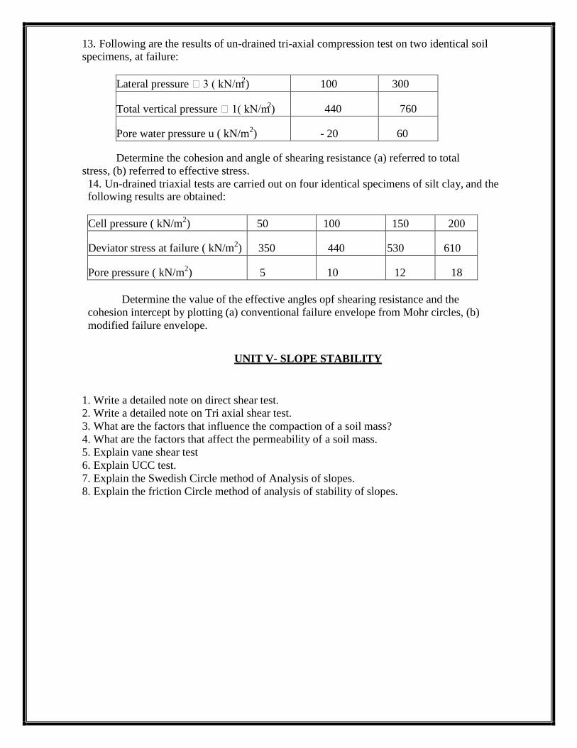
13. Following are the results of un-drained tri-axial compression test on two identical soil specimens, at failure:
Lateral pressure 3 ( kN/m2) 100 300
Total vertical pressure 1( kN/m2)
440
760
Pore water pressure u ( kN/m2) - 20 60
Determine the cohesion and angle of shearing resistance (a) referred to total stress, (b) referred to effective stress.
14. Un-drained triaxial tests are carried out on four identical specimens of silt clay, and the following results are obtained:
Cell pressure ( kN/m2) 50 100 150 200
Deviator stress at failure ( kN/m2) 350 440 530 610
Pore pressure ( kN/m2) 5 10 12 18
Determine the value of the effective angles opf shearing resistance and the
cohesion intercept by plotting (a) conventional failure envelope from Mohr circles, (b)
modified failure envelope.
UNIT V- SLOPE STABILITY
1. Write a detailed note on direct shear test.
2. Write a detailed note on Tri axial shear test.
3. What are the factors that influence the compaction of a soil mass?
4. What are the factors that affect the permeability of a soil mass.
5. Explain vane shear test
6. Explain UCC test.
7. Explain the Swedish Circle method of Analysis of slopes.
8. Explain the friction Circle method of analysis of stability of slopes.
V.S.B ENGINEERING COLLEGE, KARUR – 639 111
DEPARTMENT OF CIVIL ENGINEERING
CE8404 – CONCRETE TECHNOLOGY
TWO MARKS QUESTIONS WITH ANSWERS
Unit – I - Constituent Material
1. What is meant by heat of hydration?
Concrete generates heat during hardening as a result of internal chemical reactions. This heat
generated is referred to as heat of hydration. The amount of heat generated depends on various factors
such as ambient temperature, w/c ratio, characteristics of cement, use of chemical admixtures, size of
structural element and surrounding environment..
2. What are the raw materials used for the production of cement?
Calcium (CaO)
Silica (SiO2)
Alumina (Al2O 3)
Iron oxide (Fe2O3)
3. What is clinker and how is it produced?
The main raw material for the production of cement is clinker. Clinker is an artificial rock
made by heating limestone and other raw materials in specific quantities to a very high temperature in
a specially made kiln.
4. What are the Bouge‟s chemical compound compositions of Portland cement? (May/June 2016)
(April/May 2018)
Name of Compound Formula Abbreviated formula
Tricalcium silicate 3CaO.SiO2 C3S
Dicalcium silicate 2CaO.SiO2 C2S
Tricalcium aluminate 3Cao.Al2O3 C3A
Tetracalcium alumino ferrite 4CaO.Al2O3.Fe2O3 C4AF
5. State the general properties of cement.
It is an excellent building material
It attains early setting
It is easily workable
If offers good resistance to moisture
It possesses a good plasticity
6. List out the varieties of cement.
Ordinary Portland Cement (OPC)
Low Heat Cement
Oil Well Cement
Portland Pozzolana Cement (PPC)
Portland Slag Cement (PSC)
White Cement
Low – Alkali Cement
Rapid Hardening Cement
Quick Setting Cement
High Strength Cement (HSC)
7. Define setting of cement.
When water is added to cement, hydration takes place immediately as it continuous, cement
paste which is plastic becomes stiff and rigid known as setting of cement.
8. What are the advantages of Portland pozzolona cement? (Nov/Dec 2016)
It generates less heat of hydration at a low rate than ordinary Portland cement.
Reduction in permeability of PPC offers many other advantages, such as durability.
Portland pozzolana cement improves pore size distribution and also reduces the micro cracks in
the cement paste at the transition zone due to pozzolanic action and being finer than OPC.
A 50 kg bag of the Portland pozzolana cement gives more volume of mortar than ordinary
Portland cement as the fly ash is finer and of lower density.
9. What is the function of gypsum in the manufacture of cement?
In order to delay the setting action of cement, when mixed with water, a little percentage of
gypsum is added in the clinker before grinding them to fine powder.
10. What are the two methods of manufacture of cement?
Dry process
Wet process
11. What is meant by 53 grade cement? (Nov/Dec 2017)
Ordinary Portland Cement (OPC) is generally graded according to their strength. The grade
indicates the compression strength (N/mm2) of a concrete that will attain after 28 days of setting.53
Grade Cement means - compression strength of the cement concrete after 28 days of setting, it gives a
strength of 53 mpa.(or 53 N/mm2)
12. Define fineness modulus of aggregates.
The characterize the overall coarseness or fineness of an aggregate, a concept of fineness
modulus is developed. To calculate the fineness modulus, the sum of the cumulative percentages
retained on a definitely specified set of sieves needs to be determined, and the result is then divided by
100.
13. What are the factors affecting particle size distribution?
Workability
Mix proportioning
Freeze-thaw resistance
14. Mention the various types of gradation of aggregate.
a) Uniform grading
b) Continuous grading
c) Gap grading
15. Mention the classification of aggregate in accordance with size and shape. (April/May 2018)
Aggregates are classified into 2 types according to size:
Fine aggregate
Coarse aggregate
Coarse aggregate: Aggregates passing on 20 mm sieve and predominately retained on 4.75 mm sieve.
Fine aggregate (sand): Aggregates passing on 4.75 mm sieve and predominately retained on 75μm
sieve.
Aggregates are classified according to shape into the following types:
Rounded aggregates
Irregular or partly rounded aggregates
Angular aggregates
Flaky aggregates
Elongated aggregates
Flaky and elongated aggregates
16. What are the tests to be conducted to ensure the cement supplied at the site is good?
Open the bag and take a good look at the cement, there should not be any visible lumbs.
Thrust your hand into the cement bag should feel cool feeling.
Take a pinch of cement and feel between the fingers. It should give a smooth felling not a
gritty feeling.
Take a hand full of cement and throw it on a bucket full of water, the particle should float for
sometime before they sink
17. What should be the qualities of water to be used in concrete making? (May/June 2016)
The quality of water used must be checked for ensuring good quality concrete. Water used for
mixing and curing should be free from oil, acid and alkali, salts and organic material. It should be of
potable quality and generally purer than that required for drinking.
18. What is the purpose of water in concrete?
It distributes the cement evenly.
It reacts with cement chemically and produces calcium silicate hydrate gel.
It provide for workability, i.e., it lubricates the mix.
19. Mention the test adopted to test the quality of water.
Determination of acids and alkalis
Determination of total solids
20. What is a light weight aggregate?
Lightweight concrete contains aggregate that is natural or synthetic which weighs less than
1100 kg/m3. The lightweight is due to the cellular or high internal porous microstructure, which gives
this type of aggregate at low bulk specific gravity. The most important aspect of lightweight aggregate
is the porosity. They have high absorption values, which require a modified approach to concrete
proportioning.
21. What are the effects of alkali aggregate reaction?
A high moisture level, within the concrete
Cement with high alkali content or another source of alkali
Aggregate containing an alkali reactive constituent
22. Write any three advantages of Sulphate Resisting Cement. (April/May 2017)
1. The use of sulphate resisting cement provides excellent protection against the formation of
sulpho-aluminates and consequent resistance to concrete against sulphate attack.
2. Very high compressive strength by economic concrete mix design.
3. Very low heat of hydration helps to avoid shrinkage cracks.
4. Improves life and durability of structures under aggressive conditions.
5. Improves corrosion resistance of steel by preventing sulphate attack.
23. What are the various tests which are to be done on aggregates? (April/May 2017)
Various test which are done on aggregates are listed below
1. Sieve Analysis
2. Water Absorption
3. Aggregate Impact Value
4. Aggregate Abrasion Value
5. Aggregate Crushing Value
24. What is meant by grading of aggregates? (Nov/Dec 2017)
Grading refers to the determination of the particle-size distribution for aggregate. Grading
limits and maximum aggregate size are specified because these properties affect the amount of
aggregate used as well as cement and water requirements, workability, pumpability, and durability of
concrete.
25. What are the various tests which are to be done on cement? (Nov/Dec 2016)
The physical tests which are generally performed to determine the acceptability of cements are –
1. Fineness Test
2. Consistency Test
3. Setting time Test
4. Soundness Test
5. Strength Test
6. Heat of Hydration Test
7. Specific Gravity Test
26. What is the importance of grade of cement? (Nov/Dec 2018)
The grade of cement is generally differentiated in terms of indicates the strength of cement. It
is very important to check the grade of cement before using, it because it ultimately affects the
strength of your structure. If you do not use suitable grade of cement for the particular job, you never
get your desired strength.
27. Write any two advantages of quality of water used in concrete? (Nov/Dec 2018)
Reduced drying shrinkage and cracking.
Better bond between concrete and reinforcement.
Increased resistance to weathering.
Unit – II - Chemical and Mineral Admixtures
1. What are the various purpose for which admixtures are used in concrete?
Some chemical are mixed with concrete ingredients and spread throughout the body of
concrete to favorably modify the moulding and setting properties of the concrete mix. Such
chemical are generally known as chemical admixtures.
Some chemicals are applied on the surface of concrete mix. Such chemical are generally
known as chemical admixtures.
Some chemicals are applied on the surface of concrete to protect it during or after its setting.
Some chemical are applied to bond or repair broken or chipped concrete.
2. What is meant by Pozzolanic action? (May/June 2016)
The pozzolanic activity is a measure for the degree of reaction over time or the reaction
rate between a pozzolan and Ca2+
or Ca(OH)2 in the presence of water. The rate of the pozzolanic
reaction is dependent on the intrinsic characteristics of the pozzolan such as the specific surface area,
the chemical composition and the active phase content.
3. What is meant by artificial pozzolanas?
Pozzolanic materials are siliceous or siliceous and aluminous materials, which in themselves
possess little or no cementitious value, but will, in finely divided form and in the presence of moisture,
chemically react with calcium hydroxide liberated on hydration, at ordinary temperature, to form
compounds, possessing cementitious properties.
Artificial pozzolans
• Fly Ash
• Blast Furnace Slag
• Silica Fume
• Rice Husk Ash
• Metakoaline
• Surkhi
4. What are admixtures? (Nov/Dec 2017)
Admixtures are ingredients other than cement, fine aggregate and coarse aggregate to improve
the quality of concrete. The addition of an admixture may improve the concrete with respect to its
strength, hardness, workability, water resisting power etc.,
5. What are the types of Admixtures?
A. Chemical admixtures
• Accelerators
• Retarders
• Water-reducing agents
• Super plasticizers
• Air entraining agents, etc.
B. Mineral admixtures
• Fly-Ash
• Silica Fume
• GGBS
• Rice Husk Ash
• Metakaoline
6. Name any two chemical admixtures and their significances. (Nov/Dec 2017)
Chemicals mixed with concrete ingredients and spread throughout the body of concrete to
favourably modify the molding and setting properties of concrete mix is known as chemical
admixtures.
a. Accelerators:
Accelerators reduce the setting time and produce early removal of forms and speed up
hardening. They are helpful in cold weather concreting. The common accelerators are CaCl2, Al2Cl,
NaCl and Na2SO4.
b. Plasticizers:
Plasticizers for concrete increase the workability of the wet mix or reduce the water required to
achieve the desired workability and are usually not intended to affect the properties of the final
product after it hardens.
7. Define mineral admixtures.
It is the siliceous materials used to strengthen the durability properties that are classified as
pozzolanic or cementitious materials. It acts as by-product agent.
8. What are accelerators?
Accelerators reduce the setting time and produce early removal of forms and speed up
hardening. They are helpful in cold weather concreting. The common accelerators are CaCl2, Al2Cl,
NaCl and Na2SO4.
9. What is the importance of super plasticizers added in cement concrete? (Nov/Dec 2016)
Super Plasticizers for concrete increase the workability of the wet mix or reduce the water
required to achieve the desired workability and are usually not intended to affect the properties of the
final product after it hardens.
10. What are retarders? (Nov/Dec 2018)
Retarders increase the setting time of the concrete mix and reduce the w/c ratio. Usually up to
10% water reduction can be achieved. A wide range of water-reducing and set-retarding admixtures
are used in ready mixes concrete.
11. What is the purpose of adding admixture in concrete?
To improve the strength of concrete
To accelerate the initial setting of concrete
To retard the initial set
To improve workability
To inhibit the corrosion of concrete
To increase the durability of concrete
To increase the resistance to chemical attack.
12. What is fly ash?
The fly ash or pulverized fuel ash is the residue from the combustion of pulverized coal
collected by the mechanical dust collectors or electrostatic precipitous or separators from fuel gases of
thermal power plants.
13. What is Granulated blast furnace slag?
It is a waste industrial by-product obtained during the production of iron. The blast furnace
slag is non-metallic product having oxide composition similar to that of Portland cement clinker, it
consists essentially of silicates and aluminates of calcium and other bases but if contains lesser
calcium oxide.
14. Define metakaoline. (April/May 2017)
Metakaoline is refined kaolin clay that is fired (calcined) under carefully controlled conditions
to create an amorphous aluminosilicate that is reactive in concrete. Like other pozzolans (fly ash and
silica fume are two common pozzolans), metakaolin reacts with the calcium hydroxide (lime) by-
products produced during cement hydration.
15. What is the purpose of using accelerators?
a) To permit earlier removal of formwork
b) Reduce the required period of curing
c) Advance the time that a structure can be placed in service
d) In the emergency repair work partially compensate for the retarding effect of low temperature
during cold weather concreting
16. What are the desirable properties of silica fume? (April/May 2018)
Silica fume is an ultrafine material with spherical particles less than 1 μm in diameter, the
average being about 0.15 μm. This makes it approximately 100 times smaller than the average cement
particle.[1] The bulk density of silica fume depends on the degree of densification in the silo and
varies from 130 (undensified) to 600 kg/m3. The specific gravity of silica fume is generally in the
range of 2.2 to 2.3. The specific surface area of silica fume can be measured with the BET method or
nitrogen adsorption method. It typically ranges from 15,000 to 30,000 m2/kg.
17. How does metakaolin boost compressive strength?
Calcium hydroxide accounts for up to 25% of the hydrated Portland cement and calcium
hydroxide does not contribute to the concrete strength or durability. Metakaolin combines with the
calcium hydroxide to produce additional cementing compounds, the material responsible for holding
concrete together. Less calcium hydroxide and more cementing compounds means stronger concrete.
18. How does metakaolin reduce efflorescence?
Efflorescence which appears as a whitish haze on concrete is caused when calcium hydroxide
reacts with carbon dioxide in the atmosphere. Because metakaolin consumes calcium hydroxide, it
reduces efflorescence
19. How does metakaolin mitigate alkali-silica reaction?
Alkali-silica reaction is a reaction between calcium hydroxide (the alkali) and glass (the silica)
which can cause decorative glass embedment‘s in concrete to pop out. Because metakaolin consumes
calcium hydroxide, it takes away the alkali and the reaction does not occur.
20. What is Air Entrainment and write the purposes? (April/May 2018)
The production within the concrete mix of a large number of small bubbles of air. Normally
these bubbles are less than 1mm in diameter. The bubbles must be stable and remain in the concrete as
it is transported and placed so that they are still present in the hardened mass of concrete.
Purpose:
The main reason for using entrained air is to improve freeze-thaw and scaling resistance and so
prolong service life.
The improved cohesion and compaction can also enhance quality and durability.
21. What are the factors affecting the amount of air entrainment? (Nov/Dec 2016)
1. The first and the main factor is the time which it took during mixing with concrete. If mixing
with concrete takes longer time then as we know hydration starts at the same time when water
mix up with cement. So if longer mixing time then this air entrains will not being entrained in
hydrated product and then in severe condition there is not protection for that particular part.
2. Temperature also affects the amount of air entrained in concrete. If temperature is higher than
less will the amount of air entrained in fresh concrete.
3. Slump value also has a positive effect on amount of air entrained. If value of slump will be
higher than air content will be more as compared to normal slump value.
22. What is the importance of water proofers added in cement concrete? (April/May 2017)
The concrete is stronger
Concrete looks better
Prevent water damage
Reduced concrete maintenance costs
23. What are the advantages and disadvantages of super plasticizers? (May/June 2016)
Advantages:
Increases flow, making placing easier — even in heavily reinforced or difficult to access areas
— which allows you to focus your efforts on creating decorative concrete.
Makes your mix more workable without adding more water or changing the water-cement
ratio.
Reduces bleed water, resulting in fewer shrinkage cracks and more evenly colored surfaces.
Improves cohesiveness and reduces concrete segregation.
Allows for the option of adding less water, creating a stronger concrete overall.
Disadvantages:
High cost
Brief action
Need strong, Sealed forms
Unit – III - Proportioning of Concrete Mix
1. What are nominal mix and design mix? Which is better? Why? (Nov/Dec 2017) (May/June
2016) (April/May 2018)
Nominal mix: it is used for relatively unimportant and simpler concrete works. In this type of
mix, all the ingredients are prescribed and their proportions are specified. Therefore there is no scope
for any deviation by the designer. Nominal mix concrete may be used for concrete of M20 or lower.
Design mix: it is a performance based mix where choice of ingredients and proportioning are left to
the designer to be decided. The user has to specify only the requirements of concrete in fresh as well
as hardened state. The requirements in fresh concrete are workability and finishing characteristics
whereas in hardened concrete these are mainly the compressive strength and durability.
2. Define concrete.
Concrete is obtained by mixing cementing materials, water, aggregate and sometimes
admixtures in required proportions. This mixture when placed in forms and allowed to cure hardens
into rock like mass known as concrete.
3. List out the advantages of Design mix.
Properties of all materials are used.
Cement content is low and hence the mix design is economical.
4. List out the disadvantages of nominal mix.
Nominal mix does not say which type of sand, cement, aggregate to be used.
High cement is required which leads to high cost.
5. List the various methods of proportioning of concrete mix. (Nov/Dec 2016) (Nov/Dec 2018)
1. Arbitrary proportion
2. Fineness modulus method
3. Maximum density method
4. Surface area method
5. Indian Road Congress, IRC 44 method
6. High strength concrete mix design
7. Mix design based on flexural strength
8. ACI committee 211 method
9. DOE method
10. Indian standard recommended method IS:10262-2009
6. Differentiate average design strength and specified minimum strength.
In the design of concrete mixes the average design strength to be aimed at should be
appreciably higher than the minimum strength stipulated by the structural designer. The value of
average design strength to be aimed at will depend upon the quality control exercised at the time of
making concrete.
7. What is proportioning of concrete mix?
Proportioning of concrete mix is the art of obtaining a suitable ratio of the various ingredients
of concrete with the required properties at the lowest cost.
8. Define mix design.
Mix design can be defined as the process of selecting suitable ingredients of concrete and
determining their relative proportions with the object of producing concrete of certain minimum
strength and durability as economically as possible.
9. Define Standard mixes. (April/May 2017)
The nominal mixes of fixed cement-aggregate ratio (by volume) vary widely in strength and
may result in under or over-rich mixes. For this reason, the minimum compressive strength has been
included in many specifications. These mixes are termed standard mixes. IS 456-2000 has designated
the concrete mixes into a number of grades as M10, M15, M20, M25, M30, M35 and M40. In this
designation the letter M refers to the mix and the number to the specified 28 days cube strength of mix
in N/mm2. The mixes of grades M10, M15, M20 and M25 correspond approximately to the mix
proportions (1:3:6), (1:2:4), (1:1.5:3), and (1:1:2) respectively.
10. What are the variable factors to be considered in connection with specifying a concrete mix?
Water cement ratio
Cement content or cement-aggregate ratio
Gradation of the aggregates
Consistency
11. What are the factors affecting concrete properties? (Nov/Dec 2018)
Durability
Workability
Strength
Permeability
12. What is meant by statistical quality control?
The aim of quality control is to limit the variability as much as practicable. Statistical quality
control method provides a scientific approach to the concrete designer to understand the realistic
variability of the materials so as to lay down design specifications with proper tolerance to cater for
unavoidable variations. The acceptance criteria are based on statistical evaluation of the test result of
samples taken at random during execution.
13. What are the common terminologies used in the statistical quality control?
Mean strength
Variance
Standard deviation
Coefficient of variation
14. What are the steps are taken for choosing the appropriate w/c ratio?
Verify the types of cement and determine the seven-day cement strength.
Choose the corresponding w/c ratio versus strength curve.
For the required concrete strength on the Y-axis, read off the w/c ratio from the corresponding
curve.
15. What is the information required for grade of concrete?
Type of mix that is design mix or nominal mix
Grade designation
Type of cement
Maximum nominal size of aggregate
Minimum cement content
Maximum water-cement ratio
Workability
Mix proportion (for nominal mix)
Exposure condition as per IS 456
Maximum temperature of concrete at the time of placing
Method of placing
Degree of supervision
16. What are the requirements of concrete mix design?
The minimum compressive strength required from structural consideration
The adequate workability necessary for full compaction with the compacting equipment
available.
Maximum w/c ratio and/or maximum cement content to give adequate durability for the
particular site conditions.
Maximum cement content to avoid shrinkage cracking due to temperature cycle in mass
concrete.
17. Mention the types of mixes.
1. Nominal mixes
2. Standard mixes
3. Designed mixes
18. What are the factors affecting the choice of mix proportions?
1. Compressive strength
2. Workability
3. Durability
4. Maximum nominal size of aggregate
5. Grading and type of aggregate
6. Quality control
19. What are the factors to be considered for mix design?
The grade designation giving the characteristic strength requirement of concrete
The type of cement influences the rate of development of compressive strength of concrete
The cement content is to be limited from shrinkage, cracking and creep.
20. What are the methods used to concrete mix design for ordinary concrete?
1. Arbitrary proportion
2. Fineness modulus method
3. Maximum density method
4. Surface area method
5. Indian Road Congress, IRC 44 method
6. High strength concrete mix design
21. What is the minimum grade of concrete to be used as per IS 456 - 2000? (Nov/Dec 2017)
The nominal mixes of fixed cement-aggregate ratio (by volume) vary widely in strength and
may result in under or over-rich mixes. IS 456-2000 has designated the minimum concrete mixes into
a number of grades as M10. In this designation the letter M refers to the mix and the number to the
specified 28 days cube strength of mix in N/mm2. The mixes of grades M10 correspond approximately
to the mix proportions (1:3:6).
22. On what circumstances high grade concrete are utilized effectively? (April/May 2017)
(Nov/Dec 2016) Suitable grade of concrete can be selected based on structural requirements. Nominal mixes for
grades of concrete such as M15, M20, M25 are generally used for small scale construction.
Large structures have high strength requirements, thus they go for higher grades of concrete
such as M30 and above.
23. What are the objectives of Concrete mix design? (May/June 2016)
Two main objectives for concrete mix design:
To determine the proportions of concrete mix constituents of; Cement, Fine aggregate (or
normally Sand), Coarse aggregate, and Water.
To produce concrete of the specified properties.
To produce a satisfactory of end product, such as beam, column or slab as economically as
possible
Unit – IV - Fresh and Hardened Properties of Concrete
1. What is concrete slump? With example sketches show how a concrete can undergo slump?
The concrete slump test is an empirical test that measures the workability of fresh concrete.
More specifically it measures the consistency of the concrete in that specific batch. This test is
performed to check the consistency of freshly made concrete.
2. Enumerate the factors which affect the strength of concrete. (Nov/Dec 2017)
Quality of cement and chemical constituents
Quality of water to making water
Grade of aggregate
Degree of compaction
Curing temperature
Curing efficiency
3. Define gel/space ratio.
The gel/space ratio is the ratio of solid products of hydration to the space available for these
hydration products. Gel is the hydrated cement while space is volume occupied by hydrated cement
plus capillary pores. Hence gel/space ratio is the fraction of volume occupied by hydrated cement in
the total space occupied by hydrated cement and capillary pores.
4. What is batching of concrete?
Batching is the process of measuring concrete mix ingredients by either mass or volume and
introducing them into the mixer. To produce concrete of uniform quality, the ingredients must be
measured accurately for each batch.
5. Define weigh batching.
Weigh batching is defined as measuring the constituent materials for mortar or concrete by
weight.
6. What is volume batching?
Volume batching is defined as the measuring of the constituent materials for mortar or concrete
by volume.
7. Define Abram‟s water cement law.
According to Abram‘s water cement law, the strength of concrete depends on the w/c ratio
used.
8. Define bleeding. (April/May 2017) (Nov/Dec 2016)
The tendency of water to rise to the surface of freshly laid concrete is known as bleeding.
9. What are the steps adopted to control bleeding?
By adding more cement
By using more finely ground cement
By using little air entraining agent
By increasing finer part of fine aggregate
By properly designing the mix and using minimum quantity of water.
10. Write the factors influencing durability of concrete.
1) The environment
2) The cover to embedded steel
3) The type and quality of constituent materials
4) The cement content and w/c ratio of the concrete
5) Workmanship, to obtain full compaction and efficient curing
6) The size and shape of the member
11. Write the factors influencing consistency.
The consistency of fresh concrete depends on many factors, the main ones being:
Water content (kg/m3)
Water/cement ratio
Fineness modulus of the aggregate
Use of water reducers (plasticizers/super plasticizers)
Type and shape of aggregate
Entrained air content
12. Define segregation.
The tendency of separation of coarse aggregate grains from the concrete mass is called
segregation.
13. What are the methods adopted to avoid segregation of concrete?
Addition of little air entraining agents in the mix.
Restricting the amount of water to the smallest possible amount.
Concrete should be allowed to fall from larger heights.
14. Give the types of concrete mixes.
Nominal mixes
Standard mixes
Designed mixes
15. Define workability.
Workability is that property of concrete which determines the amount of internal work
necessary to produce full compaction. It is a measure with which concrete can be handled from the
mixer stage to its final fully compacted stage.
16. What are the factors affecting workability? (Nov/Dec 2017) (April/May 2018)
Quantity of water in the mix
Proper grading of the aggregate mix
Ratio of fine aggregate and coarse aggregate
Maximum size of coarse aggregate
Method of compaction of concrete
17. What are the factors affecting proportioning of concrete mixes?
Water cement ratio
Cement content
Temperature
Age of concrete
Size, shape and grading of aggregate
Curing
18. What are the tests to find the workability of concrete? (Nov/Dec 2018)
Workability of concrete can be determined by
1. Slump test
2. Compacting factor test
3. Flow test
4. Kelly ball test
5. Vee Bee test
19. List out the requirements of fresh concrete.
Mixability
Stability
Mobility
Compactability
Finishability
20. What are the methods adopted in compaction?
1. Hand compaction
- Rodding
- Ramming
- Tamping
2. Machine compaction
- Internal vibrator
- Formwork vibrator
- Table vibrator
- Platform vibrator
- Surface vibrator (screed vibrator)
- Vibratory roller
3. Compaction by pressure and jolting
4. Compaction by spinning
21. Define compaction factor.
Compaction factor is the ratio of the weight of partially compacted concrete to the weight of
the concrete when fully compacted in the same mould.
22. What is the purpose of compaction?
Compaction is done to eliminate air voids in concrete.
23. What is the importance of compaction factor test conducted in concrete? (Nov/Dec 2018) Compaction factor test is adopted to determine the workability of concrete. It is more sensitive and
precise than slump test and is particularly useful for concrete mixes of low workability. The compaction factor
(C.F.) test is able to indicate small variations in workability over a wide range.
24. Define curing of concrete.
Curing is the operation by which moist conditions are maintained on finished concrete surface,
to promote continued hydration of cement.
25. What are the characteristics of good concrete?
It should have high compressive strength.
On hardening, it should exhibit minimum shrinkage.
It must be adequately dense. The density of a good concrete should be about 24 kN/m3.
It should be adequately durable to resist the effects of weathering agencies.
It should have minimum creep.
26. List out the usage of slump values.
Slump 0 – 25 mm is used in road making.
10 – 40 mm is used for foundations with light reinforcement
50 – 90 mm for normal reinforced concrete placed with vibration
27. What is hardened concrete? And mention the factors influence its strength.
Hardened concrete gives an overall idea about the quality of concrete. It depends on
Water cement ratio
Degree of compaction
Age of aggregate
Richness of mix
Curing of concrete
Temperature of concrete
28. Define curing.
Curing is done to keep the concrete saturated until the water filled space in concrete is filled up
by the product of hydration.
Curing is done to prevent the loss of water by evaporation and to maintain the process of
hydration.
29. Define shrinkage.
Volume change due to loss of moisture affects durability and strength, causes cracks in
concrete at different stage due to alkali aggregate reaction, sulphate action and settlement of fresh
concrete is shrinkage.
30. Define creep.
When a concrete member is loaded it deforms to a certain extent as soon as the load is applied.
When the load is kept constant, the deformation increases with time. This increase in strain under
sustained stress is called creep of concrete.
31. Mention the test conducted to test the properties of hardened concrete.
1. Compression testing machine
2. Flexure strength testing machine
3. Lateral extensometer
4. Split tensile test
5. Shear strength
6. Bond strength
32. List out the factors affecting the results of strength test.
Size and shape of aggregate
Condition of casting
Moisture condition
Bearing condition
Rate of loading
33. What are the advantages of ring tension test? (April/May 2017) (Nov/Dec 2016)
Tensile test is a destructive testing, where sample is made in Standard size. It is done under
constant strain rate and constant temperature.
The main advantages of this test are to check yield strength, tensile strength and ductile
property of material.
35. How to improve the workability of concrete.
Increase water/cement ratio
Increase size of aggregate
Increase the mixing time
Increase the mixing temperature
Use non-porous and saturated aggregate
With addition of air entraining mixtures.
36. Name any four properties of hardened concrete. (April/May 2018)
Properties of hardened concrete:-
Strength
Creep
Durability
Shrinkage
Modulus of Elasticity
Water Tightness
Unit – V - Special Concretes
1. State the applications and advantages of light weight concrete. (April/May 2018) (Nov/Dec
2018)
Application
Thermal insulating and sound-proofing
Remodeling of existing buildings
Leveling of floors and paving stairs
Docks and floating platforms
Advantages
There are many advantages of having low density
Light weight concrete very economy
Low thermal conductivity
Low density
2. What do you understand by high performance concrete? How is it different from normal
concrete?
High performance concrete is used for concrete mixture which possess high workability, high
modulus of elasticity, high density, high dimensional, stability, low permeability and resistance to
chemical attack.
It may be recalled that in normal concrete, relatively low strength and elastic modulus are the
result of high heterogeneous nature of structure of the material, particularly the porous and week
transition zone, which exists at the cement paste-aggregate interface.
3. What is meant by high density concrete?
Density of normal concrete is in the order of about 2400 kg/m3. The density of light weight
concrete will be less than about density 1990 kg/m3. To call the concrete, as high density concrete, in
must have unit weight ranging from about 3360 kg/m3 to 3840 kg/m3, which is about 50% higher than
the unit weight of conventional concrete.
4. What are the applications of sulphur-infiltrated concrete?
Precast industry
Railway sleepers
Fencing post
Sewer pipes
5. Write a short note on sulphur infiltrated concrete.
Sulphur was made to impregnate (saturate) into lean porous concrete, to improve its strength
and other useful properties considerably. In this method, the quantity of sulphur used is also
comparatively less and thereby the process is made economical. It is reported that compressive
strength of about 100 MPa could be achieved in about 2 days time.
6. What is the main principle involved in geopolymer concrete? (Nov/Dec 2018)
‗Geopolymer cement concretes‘ (GPCC) are Inorganic polymer composites, which are
prospective concretes with the potential to form a substantial element of an environmentally
sustainable construction by replacing/supplementing the conventional concretes. GPCC have high
strength, with good resistance to chloride penetration, acid attack, etc.
7. Define light weight concrete. (Nov/Dec 2017)
The concrete is said to be light weight concrete whose density is between 300 to 1850 kg/m3.
8. Define high density concrete.
The concrete is said to be high weight concrete whose density is between 3360 to 3840 kg/m3.
9. Name some of the natural light weight aggregates.
Pumice
Volcanic cinders
Saw dust
Rice husk
Diatiomite
Scoria
10. Name some of the artificial light weight aggregate.
Brick bat
Sintered fly ash
Exfoliated vermiculite
Expanded perlite
Foamed slag
Cinder and clinker
11. What are the special methods of making high strength concrete?
Seeding
Re-vibration
High speed slurry mixing
Use of admixtures
Inhibition of cracks
Sulphur impregnation
Use of cementitious aggregates
12. Why high strength concrete is used for concrete repairs?
High strength concrete for concrete repair is used to provide a concrete with improved
resistance to chemical attack, better abrasion resistance, improved resistance to freezing and thawing
and reduced permeability
13. Define Flyash concrete. (Nov/Dec 2018)
Fly ash can be a cost-effective substitute for Portland cement in many markets. Fly ash is also
recognized as an environmentally friendly material because it is a byproduct and has low embodied
energy, the measure of how much energy is consumed in producing and shipping a building material.
By contrast, Portland cement has a very high embodied energy because its production requires a great
deal of heat. Fly ash requires less water than Portland cement and is easier to use in cold weather.
Other benefits include: Produces various set times
Cold weather resistance
High strength gains, depending on use
Can be used as an admixture
Considered a non-shrink material
14. What are the types of concrete?
1. Fibre reinforced concrete (FRC)
2. Light weight concrete (LWC)
3. High performance concrete (HPC)
4. High strength concrete (HSC)
5. Ferrocement
6. Ready mixed concrete (RMC)
7. Gunite or shotcrete
8. Polymer concrete
9. Geopolymer concrete
10. Slurry infiltrated fibrous reinforced concrete (SIFCON)
15. Define HPC. (May/June 2016)
HPC is a concrete made with appropriate materials combined as per selected mix design,
carefully mixed, transported, placed and cured so that the resultant concrete give excellent
performance in the structure in which it is used in the environment to which it is likely to be exposed
and with the load to which it is subject to design life.
16. What are the advantages of using high strength concrete?
Reduction in self weight and a consequent reduction in the foundation cost
Reduction in axial shortening effects in column
Reduction in floor thickness and beam height
Reduction in member size
Reduction in maintenance costs
Lower creep and shrinkage
17. What are the applications of polymer cement concrete?
Polymer cement concrete is made by mixing cement, aggregates, water and monomers, such
plastic mixture is cast in moulds, cured, dried and polymerized.
18. What is ready mix concrete?
Ready mix concrete has cement, aggregates, water and other ingredients which are weighing
batched at a centrally located plant. This is then delivered to the construction site in transit mixers and
can be used straight away without any further treatment.
19. What are the advantages of RMC over site mix concrete?
1. A centralized concrete batching plant can serve a wide area.
2. Better quality concrete is produced.
3. Elimination of storage space for basic materials at site.
4. Wastage of basic materials is avoided.
5. Time required is greatly reduced.
20. What is Shotcrete? (April/May 2018)
Shotcrete is a concrete conveyed through a hose and pneumatically projected at high velocity
onto a surface, as a construction technique. Shotcrete undergoes placement and compaction at the
same time due to the force with which it is projected from the nozzle. It can be impacted into any type
or shape of surface, including vertical or overhead areas.
21. What are the different types of polymers used in concrete?
Vinyl
Urethanes
Acrylics
Styrene butadiene
Epoxies
22. Define Guniting or shotcrete?
It is define as a mortar conveyed through a hose and pneumatically projected at a high velocity
on to a surface.
23. Enumerate SIFCON. (April/May 2017) (Nov/Dec 2016)
Slurry infiltrated fibre concrete (SIFCON) is one of the recently developed construction
material. SIFCON could be considered as a special type of fibre concrete with high fibre content. The
matrix consists of cement slurry or flowing cement mortar. This composite material has already been
used for structures subjected to blast loading, repair of pre-stressed concrete beams and safe vaults.
24. What is meant by Ferro-cement? (Nov/Dec 2017)
Ferro cement is defined as a thin-wall reinforced concrete spaced layers of continuous and
relatively small diameter mesh. The mesh may be made of a metallic or other suitable material. Ferro
cement is both a method and a material used in building or sculpture with cement, sand, and water and
wire mesh material, often called the thin shell.
25. Write any two advantages of Geo-polymer concrete. (April/May 2017) (Nov/Dec 2016)
Better Compressive strength
Fire proof
Low permeability
Eco-friendly
Excellent properties within both acid and salt environments.
V.S.B ENGINEERING COLLEGE, KARUR – 639 111
DEPARTMENT OF CIVIL ENGINEERING
CE8404 – CONCRETE TECHNOLOGY
Part “B & C” Question Bank
UNIT I
1. Explain in details the different tests employed for cement to ascertain its quality as per IS
specification. (Nov/Dec 2017)
2. Explain with the help of a neat sketch, the wet and dry process of manufacture of ordinary cement.
3. What are the raw materials for the manufacture of cement? Mention their functions in the properties of
cement. (May/June 2016) (Nov/Dec 2018)
4. What do you understand by the term grading of aggregates. What importance this term carries as far as
design of concrete mix is concerned.
5. i) Explain in details about the Mechanical properties of OPC (April/May 2017) (Nov/Dec 2016)
ii) Compare the physical properties of 33, 43 and 53 grades of concrete. (April/May 2017) (Nov/Dec
2016) 6. Describe the importance of the quality of water used for concreting.
7. How does increasing the quality of water influence the properties of fresh and hardened concrete?
8. List the various tests conducted on coarse aggregate indicating the property being tested. (April/May
2018) (Nov/Dec 2017) (Nov/Dec 2018) 9. What is the effect of the maximum size of aggregate on concrete strength?
10. List the various types of cement indicating their use for different applications.
11. What are the important chemical tests conducted on cement to determine its quality?
12. What is soundness of cement and how is it tested?
13. Write explanatory notes on (a) uniform grading (b) gap grading (c) continuous grading.
14. What is the effect of water cement ratio on the strength and durability of concrete? (April/May
2017) (Nov/Dec 2016) (Nov/Dec 2018) 15. Discuss the characteristics of good aggregates. (Nov/Dec 2017) (April/May 2017) (Nov/Dec
2016) (May/June 2016) 16. Explain in detail the Hydration mechanism of cement also explain how you determine the reactivity of
any cementitious materials. (April/May 2018) (Nov/Dec 2018)
UNIT II
1. What are the chemical admixtures? Explain in detail. (April/May 2018) (Nov/Dec 2017)
2. Explain action of plasticizers and classification of super plasticizer. (May/June 2016)
3. Explain the role and properties of mineral admixtures used in concrete. (Nov/Dec 2018)
4. Mention some of the construction chemicals.
5. Describe the effect of following admixture on cement concrete and give three examples of each.
Retarders, Accelerators and Water proofers. (Nov/Dec 2017) (April/May 2017) (Nov/Dec 2016)
6. Classify the admixtures in detail. (April/May 2018)
7. How are mineral admixtures classified?
8. Explain the effects of Slica fume, GGBS and Fly ash in concrete. (April/May 2018) (Nov/Dec
2017) (April/May 2017) (Nov/Dec 2016) (May/June 2016) (Nov/Dec 2018) 9. State any four pozzolanic admixtures and discuss briefly.
10. Write short notes on gas forming agents.
11. List the corrosion inhibiting agents and briefly explain any one of them.
12. List the materials used for air entrainment in concrete and describe their effects on the properties of
concrete? (May/June 2016)
13. Distinguish between Plasticizers and Superplasticizers.
14. List the different types of workability aids.
15. How does a surface –active agent increase workability?
16. What are super plasticizers? How are these helpful in modifying the properties of concrete?
(Nov/Dec 2017)
UNIT III
1. Design a concrete mix for the following requirements using IS method. Also find the mix proportions
by weight and by volume. M40 grade , OPC cement, sp gravity – 3.15, bulk density – 1440kg/m3, sand
– grading zone I , sp gravity – 2.65, bulk density – 1610kg/m3 Coarse aggregate – 10mm angular, sp
gravity – 2.66, bulk density – 1580kg/m3 Degree of workability – 0.85 compacting factor, quality
control – very good. (April/May 2017) (Nov/Dec 2016)
2. Design a M30 grade concrete with compaction factor of 0.9 by IS code method for moderate
exposure and good quality control conditions using 20mm coarse aggregate which conforms to IS
383 grading . sp gravity of cement , fine and coarse aggregates is 3.15, 2.65 and 2.60 respectively. Water
absorption of CA and FA is 0.5% and 1.0% respectively. Natural moisture content and grading zone of
FA are 1.0% and zone III respectively. Assume suitable data if found necessary. (April/May 2017)
(Nov/Dec 2016) (May/June 2016) 3. Design a concrete mix for construction of an elevated water tank . The specified design strength of
concrete is 30mpa at 28 days measured on standard cylinders. Standard deviation can be taken as
4mpa. The specific gravity of FA and CA are 2.65 and 2.7 respectively. The dry rodded bulk
density of CA is 1600 kg/m3 and fineness modulus of FA is 2.8. opc used A slump of 50mm is
necessary. CA is found to be absorptive to the extent of 1% and free surface moisture in sand is
found to be 2%. Assume any other data.
4. Explain step by step procedure to design the mix in ACI method. (Nov/Dec 2018)
5. Explain the procedure for DOE method
6. Discuss the various methods of proportioning. (Nov/Dec 2017)
7. Explain the mix design procedure for concrete as per IS method. (April/May 2018) (Nov/Dec
2017) 8. Compare ACI and IS method of concrete mix design.
9. Explain in detail, the step by step procedure of IRC 44 method of concrete mix design.
10. What are the factors affecting proportioning of a concrete mix? Discuss in detail. (May/June
2016) 11. Explain how you modify the concrete mix design when:
i) Fly ash is used in the mix
ii) Super plasticizers is used in the mix. (April/May 2018)
UNIT IV
1.What are the various factors which affecting the workability and strength of concrete? (April/May
2017) (Nov/Dec 2016) (May/June 2016) 2. Compare the relative merits and demerits of various workability tests.
3. How do you determine the fresh concrete properties? Explain in detail? (April/May 2018)
4. What is re-vibration? Is it detrimental to concrete? Where is it practiced?
5. Why age factor not taken advantage of in IS 456-2000? Comment.
6. Explain the IS procedure for determination of Compressive and Flexural strength of concrete.
(April/May 2018) (Nov/Dec 2017) (April/May 2017) (May/June 2016) (Nov/Dec 2018) 7. Describe the importance of curing? When should it be commenced? For how long should it be
continued?
8. What is meant by autogenous healing of concrete? Comment on its relevance.
9. Explain in detail the Stress-Strain curve for plain concrete. (Nov/Dec 2018)
10. Is impact strength higher or lower than static strength? Give examples of two case where concrete
is subjected to impact loading.
11. Write short notes on segregation and bleeding. (Nov/Dec 2017) (Nov/Dec 2018)
12. Define the term workability. What are the various tests conducted to determine the Workability of
concrete and explain them. (Nov/Dec 2017) (Nov/Dec 2016)
UNIT V
1. Define high performance concrete. Explain the properties and application.
2. What is meant by RMC? Explain their advantages and disadvantages.
3. What are the various fibers that are used in the manufactures of fibre reinforced concrete?
4. What is polymer concrete? What are the various types? Explain properties and application.
(April/May 2018) (Nov/Dec 2017)
5. Explain the process of manufacturing of light weight concrete. Explain the special materials
needed for making that concrete. Also give the applications and advantages of that concrete.
(April/May 2018) (Nov/Dec 2017)
6. Explain with respect to their physical characteristics of light weight aggregate concrete?
7. Describe the important fresh state properties of high strength concrete.
8. How the various quality controls is tests done to ensure good performance of polymer concrete?
9. Give the typical layout of ready mixed concrete plant.
10. What are the special features of transportation of ready mixed concrete from the plant to the site?
11. What special features are to be considered while handling and placing ready mixed concrete?
12. Discuss the properties and applications of high performance concrete. (Nov/Dec 2017)
13. What is Shotcrete? Explain the procedure of shotcreting a surface. (Nov/Dec 2017)
14. Write short notes of Grouting (or) write short notes on shotcrete.
15. What is meant by fibre reinforced concrete? Explain in detail about the materials used, method of
production and its advantages over the conventional concrete. (April/May 2018) (Nov/Dec
2017)
16. What are the advantages of using ready mixed concrete instead of site mixed concrete?
17. Explain the following:
i) Light weight concrete
ii) fibre reinforced concrete
iii) polymer concrete
iv) high strength concrete
v) Ready mixed concrete (April/May 2017) (Nov/Dec 2016) (May/June 2016) (Nov/Dec 2018)
18. Explain the following:
i) ferrocement concrete
ii) high performance concrete
iii) Geopolymer concrete
iv) Shotcrete
v) SIFCON (April/May 2017) (Nov/Dec 2016) (May/June 2016) (Nov/Dec 2018)
CONSTRUCTION TECHNIQUES, EQUIPMENTS AND PRACTICES
TWO MARKS AND ANSWERS
UNIT 1
CONCRETE TECHNOLOGY
1. State the importance of water cement ratio.
The water–cement ratio is the ratio of the weight of water to the weight of cement used
in a concrete mix. A lower ratio leads to higher strength and durability, but may make the mix
difficult to work with and form. Workability can be resolved with the use
of plasticizers or super-plasticizers. 2. What are the tests to be conducted on fresh concrete?
1. Slump test 2.Compaction factor test 3.Flow test 4.Key ball test 5.Vee Bee test 3. What is the use of chemicals as retarders in concrete?
Retarding admixtures are used to slow the rate of setting of concrete. By slowing the
initial setting time, the concrete mixture can stay in its fresh mix state longer before it gets to
its hardened form. 4. Why is curing done for concrete?
Curing plays an important role on strength development and durability of concrete.
Curing takes place immediately after concrete placing and finishing, and involves maintenance
of desired moisture and temperature conditions, both at depth and near the surface, for
extended periods of time. 5. What does the grade of cement denote?
The grades are classified depending upon the compressive strength of the cement.1)
Grade 33 2) Grade 43 3) Grade 53. 6. What are the raw materials used in the manufacture of cement?
1. Lime 2.Silica 3.Alumina 4.CalciumSulphate 5.Iron Oxide 6.Magnesia 7.Sulphur 7. List the various processes involved in the manufacture of concrete.
1. Batching of ingredients 2.Mixing of materials 3. Transporting 4.Placing
5.Compacting
6. Finishing 7.Curing. 8. Define hydration of cement.
The chemical reaction takes place between cement and water is called hydration of
cement. When water is added to the cement, various ingredients of cement react chemically
with various complicated chemical compounds. 9. Write the ASTM classification of cement.
1) Type I Normal cement 2) Type IA Normal + air entrained agents 3) Type II Moderate
sulphate resistant cement 4) Type IIA Moderate sulphate resistant cement + air entrained
agents 5) Type III High early strength cement 6) Type IIIA High early strength cement + air
entrained agents 7) Type IV Low heat cement 8) Type V High sulphate resistant cement 10. Differentiate dry and wet process of manufacturing of cement.
1) Wet process -grinding and mixing of the raw materials in the existence of water. The
percentage of the moisture in the raw materials is high.
2) Dry process -grinding and mixing of the raw materials in their dry state. The raw materials
is so hard (solid) that they do not disintegrate by water 11. Define batching. What are the methods of batching?
It is the process of measuring concrete mix ingredients either by volume or by mass and
introducing them into the mixture. Traditionally batching is done by volume but most
specifications require that batching be done by mass rather than volume.
1) Weight Batching 2) Volume Batching
12. What is meant by workability of concrete?
Workability is that property of concrete which determines the amount of internal work
necessary to produce full compaction. It is a measure with which concrete can be handled from
the mixer stage to its final fully compacted stage. 13. Define RMC.
Concrete prepared at plant or in trick mixers and transported and delivered to the
construction site is called Ready Mix Concrete or Pre-Mixed Concrete. It has low cost and high
durability. 14. What are methods of compacting concrete?
1) Compaction by hand 2) Compaction by vibration 3) Compaction by pressure 15. What is the use of accelerators in concrete?
A cement accelerator is an admixture for the use in concrete, mortar, rendering or
screeds. The addition of an accelerator speeds the setting time and thus cure time starts earlier.
This allows concrete to be placed in winter with reduced risk of frost damage. 16. Discuss on mix design concept as per BIS.
The BIS, recommends procedure for designing the mix for concrete. The mix design
procedures are given in IS: 10262:1982. The procedure given in the BIS standards are based on
various researches carried out at national laboratories. 17. List the various methods of concrete mix design.
Old method- 1) Fineness modulus 2) Minimum voids 3) Trial mixes 4) Arbitrary method
New method- 1) British method 2) ACI method 18. Define non destructive testing.
Non destructive test is a method of testing existing concrete structures to assess the
strength and durability of concrete structure. In the non destructive method of testing, without
loading the specimen to failure (i.e. without destructing the concrete) we can measure strength
of concrete. 19. Mention any four destructive methods of testing concrete.
1) Compression test 2) Split cylinder test 3) Tensile strength test 4) Modulus of rupture test 20. List out the types of non-destructive testing of concrete.
These non-destructive methods may be categorized as 1) penetration tests, 2) rebound
tests, 3) pull-out techniques, 4) dynamic tests, 5) radioactive tests, 6) maturity concept.
UNIT – 2
CONSTRUCTION PRACTICES
1. Mention the significance of bond in masonry structures.
Masonry is defined as the construction of building units bonded together with mortar. The
building units may be stones, bricks or precast blocks of concrete. Depending upon the type of
building units used, masonry may be of the following types
Stone masonry
Brick masonry
Hollow concrete blocks masonry
Reinforced brick masonry
Composite masonry 2. How are bond stones placed in stone masonry?
One of the important features of rubble masonry is bond stones. These are long selected
stones placed from front to back of thin walls or from outside to the interior of the thick walls.
They hold together the masonry walls transversely.
3. What is rubble masonry and ashlar masonry?
Rubble Masonry: It is a stone work wherein blocks of stones are either undressed or roughly
dressed and have wider joints.
Ashlar Masonry: It is a stone work wherein blocks of stones are accurately dressed with very
fine joints of 3mm thick. 4. Define slip form.
Slip form construction is a construction method in which concrete is poured into a
continuously moving form. Slip forming is used for tall structures (such as bridges, towers,
buildings, and dams), as well as horizontal structures, such as roadways. 5. Define scaffolding.
Scaffolding, also called staging, is the basis of most construction projects it is a
temporary structure used to support a work crew and materials to aid in the construction,
maintenance and repair of buildings, bridges and all other manmade structures.
6. List out the types of scaffoldings.
1) Single Scaffolding 2) Double Scaffolding 3) Cantilever Scaffolding 4) Suspended
Scaffolding 5) Steel Scaffolding 6) Patented Scaffolding. 7. What is the necessity of providing construction joints?
The construction joints may be vertical, horizontal or inclined depending on the type of
structure. In the case of inclined or curved members the joint should be perpendicular to the
axis of the structural member. 8. Write short notes on Expansion joints.
These joints are provided to allow the expansion of the slab due to rise in slab
temperature. Expansion joints also permit construction of the slab and help to reduce the
warping stresses. The gap width for this type of joint is 20mm to 25mm 9. How are steel trusses fabricated and grouped?
Preparation of steel work for erection is called as fabrication. It includes all work
necessary to layout, cut, drill, rivet or weld the steel section. The fabrication plan has to be
properly planned such that the work at the site of erection should be reduced as much as
possible. 10. State the purposes of providing DPC in buildings.
Damp proofing courses of suitable materials are provided at appropriate locations for
their effective use. i) DPC should cover the full thickness of the walls. ii) DPC course should
be continuous and should form as a bearer from the entry of moisture. iii) DPC should not be
exposed in total. 11. What are the types of damp proofing courses?
i) Damp proof membrane ii) Integral damp proofing iii) Surface coating iv) Cavity wall
construction. 12. What are the advantages of hollow concrete block masonry?
Concrete blocks are regular in size, requiring no dressing work. Hence construction is very
rapid.
Blocks are light and therefore easy to handle.
There is great saving in the material.
Hollow blocks are structurally stronger than bricks 13. Differentiate English bond and Flemish bond.
English bond is stronger than Flemish bond for walls thicker than 11/5 brick
Flemish bond gives more pleasing appearance than the English bond
Broken bricks can be used in the form of bats in Flemish bond. However, more mortar is
required
Construction with Flemish bond requires greater skill to comparison to English bond 14. What are the causes of dampness?
Dampness in a structure may be caused due to a) Natural cause b) Structural cause
Natural Causes- 1) Penetration of rain 2) Rise of moisture from ground 3) Moisture
condensation.
Structural Causes – 1) Faculty design of structure 2) Faculty construction of structure. 15. What are the steps involved in site clearance?
Removing trees, stumps, roots and surface vegetations.
Disposing of the vegetation by stacking and ultimately burning.
Knocking all vegetation stumps and roots, chopping or crushing them and later burning. 16. What are the advantages of precast concrete?
Concrete of superior quality can be produced as it is possible to have the best quality
control.
Smooth surface can be produced and there is no need for plastering.
Precast units can be given the desired shape.
Precast units can be prepared in all weather conditions. 17. Define Flooring.
Flooring is the general term for a permanent covering of a floor, or for the work of
installing such a floor covering. Floor covering or paving or simply as flooring is the one
constructed over the sub-floor and is intended to provide a hard, smooth, durable and
impressive surface to the floor. 18. What is meant by centering or shuttering?
Concrete is in a plastic state initially and has to keep within an enclosure of a desired
shape by proper supporting till it gains adequate strength. This temporary enclosure is known
as centering or shuttering
19. What are the acoustic materials?
Common building materials are absorbents of different levels. Such materials called as
absorbent materials or acoustical materials. Examples- 1) Acoustic Plaster 2) Acoustic Tiles 3)
Porous Boards 4) Perforated Boards 5) Quilt and Mats.
20. Write short notes on fire resisting properties of building materials.
The building materials have varying fire resistant properties which are discussed below
i) Using suitable materials ii) Taking precautions in building construction iii) By providing fire
alarm systems and fire extinguishers. Examples – 1) Brick 2) Terra-cotta 3) Stone 4) Concrete
5) Mortar 6) Asbestos Cement.
UNIT – 3
SUBSTRUCTURE CONSTRUCTION
1. State the use of Box jacking.
Box jacking also known as Tunnel jacking, involves the advancement of a site cast
rectangular or other shaped sections using high capacity hydraulic jacks. Uses are
It is non-intrusive method beneath the existing surface.
It enables the traffic flow without disruption.
It is more often used when a subway or a aqueduct or a underground structure is to be
constructed. 2. What is meant by pipe jacking?
It is generally referred as ‗Micro Tunneling‖. Pipes are pushed through the ground behind the
shield using powerful jacks. Simultaneously excavation takes place within the shield. This
process is continued until the pipeline is completed.
3. Write about under water construction of diaphragm walls.
Diaphragm walls are structure elements, which are constructed underground to prevent
the seepage into the excavated area. It is a continuous wall constructed in ground in to facilitate
certain construction activities. Common uses of diaphragm walls are To provide structural support for the construction
To provide retaining wall
To provide deep diaphragms
4. Give any 4 types of piling techniques. A Pile driver is a mechanical device used to drive piles into soil to provide foundation support
for buildings or other structures. Some of the piles driving equipments are 1) Diesel hammer 2) Vertical
travel lead systems 3) Hydraulic hammer 4) Vibratory pile driver.
5. What are the techniques adopted for tunneling?
The choice of a particular method of tunneling depends on the type ground. The types
of ground met with generally are 1) Full face method 2) Top heading and benching method 3)
Tunneling with liner plates 4) Needle beam method 5) Drift method 6. Define caissons. Mention its types.
Caisson has come to mean a box like structure, round or rectangular, which is suck
from the surface of either land or water to some desired depth. Caissons are of three types:
1) Box caisson 2) Open caisson 3) Pneumatic caissons.
7. What is box caisson? Where do we use it?
A box caisson is open at top and closed at the bottom and is made of timber, reinforced
concrete or steel. This caisson is built on land, then launched and floated to pier site where is
suck in position. Such a type of caisson is used where bearing stratum is available at shallow
depth, and where loads are not very heavy. 8. What is meant by cofferdam?
Cofferdam is a watertight enclosure placed or constructed in waterlogged soil or under
water and pumped dry so that construction or repairs can proceed under normal conditions. 9. Mention the different types of coffer dams.
1) Cantilever sheet pile cofferdam 2) Braced cofferdam 3) Embankment protected cofferdam
4) Double wall cofferdam 5) Cellular cofferdam. 10. Write a note on sinking cofferdam.
An open caisson is a box without top or bottom, made of timber, metal, or concrete. An
open caisson has heavy walls and sharp wedge like edges which allow it to sink with the aid of
additional temporary loads and jets of water while the inside material is dragged out. The
sinking of an open caisson proceeds at atmospheric pressure, and theoretically, there is no limit
to the depths of sinking. This is called sinking coffer dam.
11. Differentiate cofferdam from caisson.
Cofferdam is a watertight enclosure placed or constructed in waterlogged soil or under
water and pumped dry so that construction or repairs can proceed under normal conditions.
Caisson has come to mean a box like structure, round or rectangular, which is suck from the
surface of either land or water to some desired depth. 12. What is meant by cable anchoring?
An anchor is a device, normally made of metal, used to connect a vessel to the bed of a
body of water to prevent the craft from drifting due to wind or current. The vessel is attached to
the anchor by the rode (commonly called the anchor cable or anchor chain in larger vessels),
which is made of chain, cable, rope, or a combination of these. The process of connecting a
vessel to the bed of a body of water using cable or chain or rope is called cable anchoring.
13. What are the two types of anchoring system for the cable incase suspension bridge?
A suspension bridge with light load does not require stiffening. Under heavy loads the
cables have to be stiffened so that they may not be put to large changes in shape
Unstiffened suspension bridge
Stiffened suspension bridge 14. What is grouting?
Grouting is a process whereby stabilizers, either in the form of a suspension or solution,
are injected into sub-surface soil or rocks for control of ground water during construction or
strengthening adjacent foundation soils to protect them against damage during excavation, pile
driving etc.
15. What are sheet piles?
Sheet piles are thin piles, made of plates of concrete, timber or steel, driven into the
ground for either separating members or for stopping seepage of water. They are not meant for
carrying any vertical load. They are driven into ground with help of suitable pile driving
equipment, and their height is increased while driving, by means of addition of successive
installments of sheets. 16. Define well point.
Well points are small well screens of size 50 to 80 mm in diameter and 0.3 to 1 m
length. Well points are made of brass or stainless steel screens and of closed ends or self jetting
types. 17. Define shoring for deep excavation.
Shoring is the process of supporting a building, vessel, structure, or trench with shores
when in danger of collapse or during repairs or alterations. During excavation, shoring systems
provide safety for workers in a trench and speeds up excavation. 18. Define dewatering.
Dewatering is the removal of water from solid material or soil by wet classification,
centrifugation, filtration, or similar solid-liquid separation processes, such as removal of
residual liquid from a filter cake by a filter press as part of various industrial processes 19. Enlist different dewatering techniques.
1) From open sumps and ditches 2) From well-point systems 3) From deep well drainage
4) Electro-osmosis 5) Cement grouting 6) Freezing 20. Name some equipments used for underground open excavation.
1) Excavators 2) Shovels 3) Bulldozers 4) Tractors 5) Motor Graders 5) Scrapers 6) loaders
UNIT – 4
SUPER STRUCTURE CONSTRUCTION
16. Define bridge decks.
Bridges are designed for carrying moving loads and personnel. They need a flat surface
for movement. This flat surface is called the surface. They deck may consist of a slab, a beam
and a slab, a grillage, a box girder, multi-beam, etc.
17. What is an offshore platform?
The comparatively flat region of submerged land extending seaward from beyond the
region where breakers form to the edge of the continental shelf.
18. Mention the reasons for using special forms for shells.
A shell structure is a curved surface structure. It is a relatively thin slab which is curved
in one or both directions. It is often stiffened along its edges to maintain its curvature. Based on
the geometry of the middle surface, shells may be classified as a) Dome shells b) Shell barrel
vault c) Translation shells d) Ruled surface shells 19. What are the precautions to be taken while erecting light weight components on tall
structures?
Excellent co-ordination and site organization have to be maintained.
All heavy equipments like generators, lighting systems, twists, etc are to be in working condition.
Effective measures have to be taken to work even in unsuitable weather conditions. 20. What are the major techniques adopted for heavy decks?
Heavy decks are launched by two methods viz , space by space construction and
cantilever construction. In the space by space construction bridge deck with precast ‗I‘ girders
and cast-in-siter RCC slab are used. In the cantilever construction, segmental construction is
adopted using cast-in-situ or precast techniques. 21. Mention the light weight components of tall structures.
The cranes used for erecting light weight components on tall structures are
1) Tower cranes are used mainly in the erection of apartment, and high-rise industrial
buildings.
2) Pillar cranes are used for light load up to 20 tonnes. These cranes may be stationary or
mobile type. 22. Define support structures.
It may be defined as the structure which is used to support some other structure i.e., to
give assistance or to bear a structure or building. Examples: Retaining wall, Dams, Framework,
skeletal frame, foundation, etc. 23. What are pre-stressed concrete and its types?
Pre-stressed concrete is a modified or improved form of reinforced concrete. It takes the
full advantage of compressive strength of concrete and at the same time eliminates the
weakness of concrete in tension. Two methods commonly used for pre-stressing are i) Pre-
tensioning method and ii) Post tensioning method. 24. What are erection stresses?
Depending on the types of structure, additional stresses are induced. Such stresses may
be caused while dragging a structure to a particular point of installation. Example piles ar while
lifting the unit for erection ( a prefabricated roof unit).
25. Define articulated structures.
Articulated structure means the separation of a structure into two or more elements and
joins the entire structural elements such that it functions as a single monolithic structure. The
structural elements are prefabricated, assembled and erected.
26. What are the situations in which articulated structures can be used?
The stresses caused by construction loads and by the weight of components while they
are being lifted into position. 27. Define braced domes.
A dome is a type of roof of semi-spherical or semi-elliptical shape. The materials used
for construction of domes are stone, brick or concrete. They are supported or circulated or
polygon shaped well. 28. What is the necessity of space decks?
Space decks are those which are used for launching of space vehicles and as decks on
off-shore structures. Space decks are to be designed for dynamic stresses also in addition to
static stresses. 29. Distinguish between space decks and bridge decks.
Bridges are designed for carrying moving loads and personnel. They need a flat surface for
movement. This flat surface is called the surface. They deck may consist of a slab, a beam
and a slab, a grillage, a box girder, multi-beam, etc.
Space decks are those which are used for launching of space vehicles and as decks on off-
shore structures. Space decks are to be designed for dynamic stresses also in addition to
static stresses. 30. Define sky scrapers.
A skyscraper is a tall, continuously habitable building. There is no official definition or
height above which a building may clearly be classified as a skyscraper 31. What are conveyors?
Conveyors are transportation devices which function adopting the friction between the
materials being transported and the base of the conveyor called the belt. These are suitable if
the path for the flow of material is fixed. 32. Explain the construction sequence of launching girders.
The construction sequences of launching girders are i) Span by Span Construction-In this type
of construction bridge deck with precast ‗I‘ girders and cast-in-situ RCC slab are used.
ii) Cantilever Construction-Cantilever segmental construction by launching girder are done in
phased manner. 33. What are the methods employed for launching heavy decks?
Balanced cantilever erection method
Progressive placing method
Span by span (or) Steeping form work method
Incremental launching method 34. What are the precautions to be taken in tall building construction?
Tall buildings are invariably of frame structures. Framed structures are comprised of
series of frames. These framed structures comprise of columns and beams. Columns are
connected by beams at floor and roof levels.
35. List out the types of domes?
Ribbed domes
Schwedler domes
Three way grid domes
Parallel lamella domes
Geodesic domes
UNIT – 5
CONSTRUCTION EQUIPMENT
Part –A
1. Name the equipments used for earth moving operations.
Excavators- 1) Loaders 2) Wheel excavator 3) Cable excavator
Shovels- 1) Dipper shovel 2) Dragline 3) Clamshell 4) Drag shovel or Hoe
Bull dozers- 1) Tractors 2) Motor graders 3) Scrapers 4) Loaders 2. What is pile driving?
Construction of pile foundations involves two separate steps, namely, the installation of
piles and the making of pile caps. Installation of precast concrete piles, steel piles, timber piles
and sheet-piles are driven with the help of pile driving equipment. 3. Give a list of equipments needed in the construction of tall structures.
The cranes used for erecting light weight components on tall structures are discussed below
Tower cranes are used mainly in the erection of apartment, and high-rise industrial
buildings.
Pillar cranes are used for light load up to 20 tonnes. These cranes may be stationary or
mobile type. 4. What are the equipments used for compacting concrete?
The following equipments are used for compaction of concrete: 1) Hand compaction 2)
Vibration 3) Internal or immersion vibrators. 5. List out the equipments used for dredging and trenching.
Equipments for dredger - 1) Ladder dredger 2) Cutter dredger 3) Grab dredger 4) Dipper
dredger. Equipments for trenching- 1) Trencher excavator 2) Self-propelled tractor 3) Wheel
type trencher.
6. Define dredging. Dredgers are used for excavation from riverbed, lake or sea for purpose of deepening
them. Dredging is an important operation in navigation canals, harbours, dams etc. The
mechanically equipment used for this purposes is called as dredger.
7. What are the operations performed by motor grader?
Motor graders are used for leveling and smoothening the earthwork, spreading and
leveling the base courses in the construction of roads and airfield. It can be used for land
reclamation, snow clearance, gravel road repairing, mixing of stabilizing materials such as tar,
asphalt, cement and lime, maintaining quarry roads etc. 8. What do you understand about truck agitators?
Concrete produced from a mixer is required to be transported to the forms for placing.
This handling tends to produce segregation and loss of slump if the distance is long. An
agitator truck is one of the vehicle which is used for mixing and transporting of concrete
together to long distances. 9. What is mucking?
Mucking is the operation of loading the broken rock pieces, particularly from a tunnel.
Different methods of mucking are 1) In small tunnels hand cuts or wheel barrows are used 2)
Special power shovels are used in medium size tunnels 3) Specially made mucking machine are
equipped with dippers. 10. Write short notes on material handling equipment.
Material handling devices are expected to satisfy one or more of the following functions
Construction materials are to be moved and positioned.
Lifting of a load and placing it at a particular place.
Loading of materials into transportation equipment. 11. What are the scrapers used?
Scrapers are the device to scrap the ground and load it simultaneously, transport it over
the required distance, dump at desired place and then spread the dumped material over the
required area in required thickness level, and return to the pit for the next cycle. 12. List out the factors affecting of earthwork equipment.
Some of the factors which affect the output of and earthwork equipments are
1) Physical job conditions 2) Type of soil 3) Specification of machine 4) Condition of the
machine 5) Method of operation 13. Differentiate between single acting hammer and double acting hammer.
The functioning of single acting hammer differs from drop hammer only in the manner of
lifting of the ram after each blow
The functioning of double acting hammer, the motive fluid acts on both sides of the piston.
14. What are the various forms of earth movers?
Excavators- 1) Loaders 2) Wheel excavator 3) Cable excavator
Shovels- 1) Dipper shovel 2) Dragline 3) Clamshell 4) Drag shovel or Hoe
Bull dozers- 1) Tractors 2) Motor graders 3) Scrapers 4) Loaders 15. What is TBM?
Tunnel boring machine as mole recent developments in the tunnel driving technique.
The function of TBM is to loosen the earth or break the rock continuously in the entire section
of the tunnel, into cuttings and convey to the rear of the machine. 16. Write short notes on earth movers.
Earth mover is defined as a vehicle of machine designed for excavating, pushing or
transporting large quantities of soil. 17. What are the equipments needed for tunneling and trenching.
Equipments for tunneling- 1) Drill jambos 2) Mechanical Moles 3) Mucking 4) Mechanical
vibration 5) Dust control. Equipments for trenching- 1) Trencher excavator 2) Self-propelled
tractor 3) Wheel type trencher. 18. What are the operations conducted with the help of a tractor?
A tractor is a multi-purpose machine. This comes in varied types as light model to
heavy model. The light model is used for agricultural or small haulage purposes. Heavy model
equipped with several special rigs are used for earth moving work.
19. Write about pile driving equipment.
Pile driving equipment comprise of the following i) Driving rig ii) Guiding leaders iii)
Pile hammer with accessories iv) Additional aids for pre-boring, jetting v) Boiler for steam
raising or air compressor. 20. How can scrapers help in increasing speed of construction?
The operations of a conventional scraper are 1) Digging or loading 2) Transporting
3) Unloading.
CONSTRUCTION TECHNIQUES, EQUIPMENTS AND PRACTICES-
13 MARKS
UNIT 1
CONCRETE TECHNOLOGY
1. Explain the various steps involved in the manufacture of concrete. 2. Explain any two tests for testing of fresh concrete. 3. What is meant by Non destructive Testing? Explain any one method in detail. 4. What are the factors to be considered for mix design? Explain the step by step procedure for IS
method? 5. What are concrete chemicals? Explain in detail and discuss their uses. 6. Describe the processes in the manufacture of Ordinary Portland Cement. 7. Explain ACI method of mix design. 8. Explain the procedure for compression test on concrete. 9. Explain in detail the different types of curing of concrete. 10. Write in detail about RMC?
UNIT – 2
CONSTRUCTION PRACTICES
1. Explain the different types of stone masonry with neat sketches.
2. Describe in detail the construction practices to be followed for acoustics and fire protection.
3. What are the methods of providing DPC? What are the requirements of an ideal material for
Damp proofing? 4. Describe the different types of bonds in brick masonry with sketches. 5. Explain the different types of joints in buildings with sketches. 6. Write notes on DPC and requirements and conditions of good acoustics. 7. What is scaffolding? Mention its various components and types. 8. Explain the various types of flooring with neat sketches. 9. Explain the various types of trusses with neat sketches. 10. Explain the various types of roof finishes with neat sketches.
UNIT – 3
SUBSTRUCTURE CONSTRUCTION
1. Describe the procedure involved in underwater construction of diaphragm walls and basement. 2. What are caissons and cofferdams? Explain the method of sinking cofferdams with neat
sketches. 3. What is a coffer dam? With the help of sketches explain the types of coffer dams. 4. Explain the the types of shores in detail. 5. Explain the procedure involved in tunneling techniques. 6. Explain the process of dewatering and the uses of standby equipment for underground open
excavation. 7. Explain with sketches about sheet piles and well points. 8. Explain the methods of piling. 9. Explain the various types of sheet piles. 10. Write the operation procedure for caissons.
UNIT – 4
SUPER STRUCTURE CONSTRUCTION
1. Discuss the various techniques used for construction of heavy decks. 2. Explain about the support structures required for heavy equipments and conveyors. 3. Explain special forms for shells in detail. 4. Discuss the process of in-situ pre-stressing in high rise structures. 5. Explain the procedure involved in erection of braced domes and space decks. 6. What are the advantages of using belt conveyors for transporting materials? Describe the
construction of a typical belt conveyor installation. 7. Explain the general requirements in launching girders. 8. Explain about shell roof structures. 9. Write about material handling in detail. 10. Write the procedure for erecting heavy decks.
UNIT – 5
CONSTRUCTION EQUIPMENT
1. Explain in detail the various equipment used for compaction, batching and mixing of concrete. 2. Explain about Earth movers and equipment used for erection of structures. 3. Explain the various equipment for pile driving.

4. Explain the equipment used for tunneling. 5. Explain pile driving in detail. 6. Explain the factors involved in selection of equipment for earthwork. 7. Mention the various types of earthwork equipment. Mention their uses. 8. Discuss the role of tractors in earth moving. What considerations govern the selection of wheel
type or crawler type tractor on a job? Compare their applications. 9. Describe the working principle of diesel hammer and state its limitations. 10. Write notes on equipment for erection of structures.

Related Documents