System PN 53600_02 Balboa Instruments System Model # VSP-VS510S-DCAH VS510S Hot Sheet Base PCBA PN VS510S – 53601_01 53600_02-97.PDF 04/12/2005

Welcome message from author
This document is posted to help you gain knowledge. Please leave a comment to let me know what you think about it! Share it to your friends and learn new things together.
Transcript

System PN 53600_02Balboa Instruments
System Model # VSP-VS510S-DCAH
VS510S Hot Sheet
Base PCBA PNVS510S – 53601_01 53600_02-97.PDF 04/12/2005

Circuit Board Configuration
240 Volt AC Connections (RED AC when 120V heater jumper is not attached)
120 Volt AC Connections (WHITE AC)

J23
& W
1 . .
Pu
mp
1
J6 &
W12
. .
Pu
mp
2
J29
. . .
. . .
. O
zon
e M
ust
be
the
sam
e vo
lt-
age
as p
um
p 1
J47
& W
2 . .
Ste
reo
J17/
26 &
W7
. . .
. . .
. . .
.B
low
er
J20
. . .
. . .
. L
igh
t
12 V
On
ly
Circuit Board Layout
Op
tio
nal
Au
x R
elay
Bo
ard
24
0V (
J33
& W
12)
J4 t
o B
lack
AC
on
Mai
n B
oar
d (
J62)
J2 t
o J
60 o
n M
ain
Bo
ard
(E
XT
– N
ear
Sw
itch
ban
k A
)
GR
BW
J6
J4J2
W12
K1

J45 J45
, Panel option, Pump 2 ON
DIP Switches and Jumpers
DIP Switch Key
A 1 . . . . . . . . . . . . . Test Mode (normally Off)A 2 . . . . . . . . . . . . . In “ON” position, Use long Serial Standard Panel . . . . . . . . . . . . . In “OFF” position, Use Balboa Serial StandardA 3 . . . . . . . . . . . . . In “ON” position, Pump 2 is enabled In “OFF” position, Pump 2 is disabledA 4 . . . . . . . . . . . . . Aux Freeze (must be OFF). A 5 . . . . . . . . . . . . . In “ON” position, Two-speed pump 1 when in Circ Mode (A9 On) In “OFF” position, One-speed pump 1 when in Circ Mode (A9 On)A 6 . . . . . . . . . . . . . In “ON” position, 50Hz operation In “OFF” position, 60Hz operationA 7 . . . . . . . . . . . . . In “ON” position, Blower is enabled In “OFF” position, Blower is disabled A 8 . . . . . . . . . . . . . In “ON” position, temperature is displayed in degrees Celsius In “OFF” position, temperature is displayed in degrees Fahrenheit A 9 . . . . . . . . . . . . . In “ON” position, 24 Hour Circ Pump In “OFF” position, no circ pump A 10 . . . . . . . . . . . . . In “ON” position, heater is disabled while any high-speed pump or blower is running. (Low Amperage) . . . . . . . . . . . . . In “OFF” position, heater can run while any/all high-speed pumps or blowers are running. (High Amperage)
Jumper Key
J45 . . . . . . . . . . . . . Jumper on Pin 1 and 2 will power J29 (Ozone) with Pump 1 Low. Jumper on Pin 2 and 3 will power J29 (Ozone) 24 hours (for Circ mode).

Ozone Connections
Use this slot for the leftover Red conductorBlack conductor
Ozone connector configuration for 120V 60Hz B
GGreen conductor
Install the White conductor here for 120V ozone
Use this slot for the leftover White conductorBlack conductor
Ozone connector configuration for 240V 60Hz B
GGreen conductor
Install the Red conductor here for 240V ozone
The Ozone Generator and Pump 1 must be the same voltage. J45 should be set on pins 1 and 2 to operate the Ozone Generator with Pump 1 Low.
If you are configuring the Ozone to run 24 hours with a circ pump by setting J45 to pins 2 and 3, connect W13 directly to White AC or Red AC without the other wires.The pin next to ground determines voltage on these connectors. Ground is typically the bottom pin of the white connector (if the flat sides of the top and bottom holes are to the left and the heater connections are on the bottom edge of the board).
The pin next to the bottom (ground) pin of J29 is fed by W13 and sets the voltage in the connector.
If the board is set up to operate a 120V ozone generator, the connector on the ozone generator is likely to be configured correctly, but should be compared to the illustration below.
If a 240V ozone generator is required, be sure the red wire in the ozone cord is positioned in the connector next to the green ground wire as described below.
Note: A special tool is required to remove the pins from the connector body once they are snapped in place. Check with your Balboa Account Manager for information on pur-chasing a pin-removal tool.
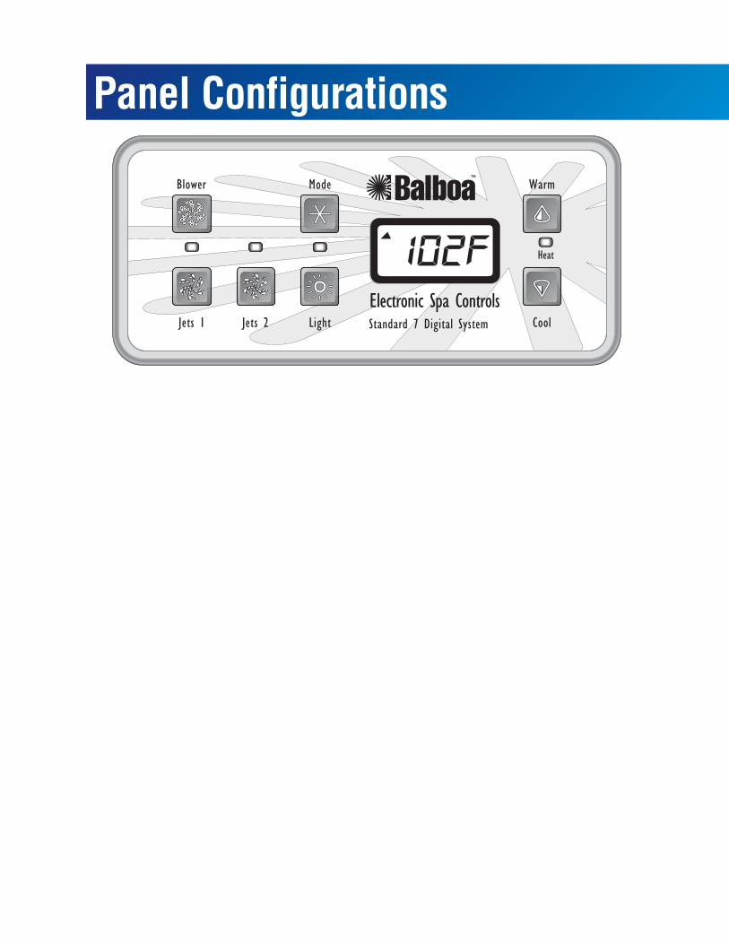
Panel Configurations
Related Documents