VS-626MC5 PG Orientation Card: User’s Manual (EZZ008138) [Preliminary] 1. Summary The VS-626MC5 PG orientation card will enable the user of the MC5 drive to stop the spindle axis at a desired position and electrically hold the spindle in position by using the position detection PG (pulse generator) on the spindle axis. Position of the spindle axis is determined by using an encoder (1024 ppr, A, B and Z phase) on the spindle axis. Stop position can be set internally to adjust the offset and can also be commanded externally by 12 bit binary signals. 2. Standard Specifications Item Description Orientation Card Code No. 73600-C0260 Positioning Method Absolute positioning using encoder on the spindle axis Position Detection Spindle angle detected by A, B and Z phase pulses of encoder Stop Position Position corresponding to the external command and/or internal setting (2) Angle Resolution 0.088° (= 360°/4096) Stop Position Accuracy Open loop vector mode: Depends on parameter setting (1) Flux vector mode: ±0.3° or less (3) Holding Torque Open loop vector mode: Provided by DC injection (1) Flux vector mode: Continuous rated torque (4) (5) / ±0.1° displacement (6) Required Spindle Axis Encoder A-, B- phase: 1024 pulses/rev. Z- phase : 1 pulse/rev. Power supply: +5VDC Required MC5 Software VSG105423 or later version (1) Not including the mechanical errors such as backlash and eccentricity (2) Spindle axis home position can be set in a parameter as the number of offset pulses. In addition, arbitrary stop position reference (12 bit binary) can be commanded externally. (3) Depends on the parameter P3-06 (orientation completion reset width). (4) Holding torque level depends on the parameter B2-02 (DC injection braking current). DC injection does not provide immediate off-position compensation. It is recommended to add mechanical locking or braking system to the machine when using orientation function in open loop vector mode. (5) Holding torque may be less than continuous rated torque due to gain setting. (6) Sudden load variation may cause larger displacement.

Welcome message from author
This document is posted to help you gain knowledge. Please leave a comment to let me know what you think about it! Share it to your friends and learn new things together.
Transcript
VS-626MC5 PG Orientation Card: User’s Manual (EZZ008138) [Preliminary]
1. Summary
The VS-626MC5 PG orientation card will enable the user of the MC5 drive to stop the spindle axis at a desired position and electrically hold the spindle in position by using the position detection PG (pulse generator) on the spindle axis. Position of the spindle axis is determined by using an encoder (1024 ppr, A, B and Z phase) on the spindle axis. Stop position can be set internally to adjust the offset and can also be commanded externally by 12 bit binary signals.
2. Standard Specifications
Item Description Orientation Card Code No. 73600-C0260 Positioning Method Absolute positioning using encoder on the spindle axis Position Detection Spindle angle detected by A, B and Z phase pulses of encoder Stop Position Position corresponding to the external command and/or internal setting(2) Angle Resolution 0.088° (= 360°/4096) Stop Position Accuracy Open loop vector mode: Depends on parameter setting (1)
Flux vector mode: ±0.3° or less (3)
Holding Torque Open loop vector mode: Provided by DC injection(1) Flux vector mode: Continuous rated torque
(4) (5) / ±0.1° displacement(6)
Required Spindle Axis Encoder
A-, B- phase: 1024 pulses/rev. Z- phase : 1 pulse/rev. Power supply: +5VDC
Required MC5 Software VSG105423 or later version
(1) Not including the mechanical errors such as backlash and eccentricity (2) Spindle axis home position can be set in a parameter as the number of offset pulses. In addition,
arbitrary stop position reference (12 bit binary) can be commanded externally. (3) Depends on the parameter P3-06 (orientation completion reset width). (4) Holding torque level depends on the parameter B2-02 (DC injection braking current). DC injection does
not provide immediate off-position compensation. It is recommended to add mechanical locking or braking system to the machine when using orientation function in open loop vector mode.
(5) Holding torque may be less than continuous rated torque due to gain setting. (6) Sudden load variation may cause larger displacement.
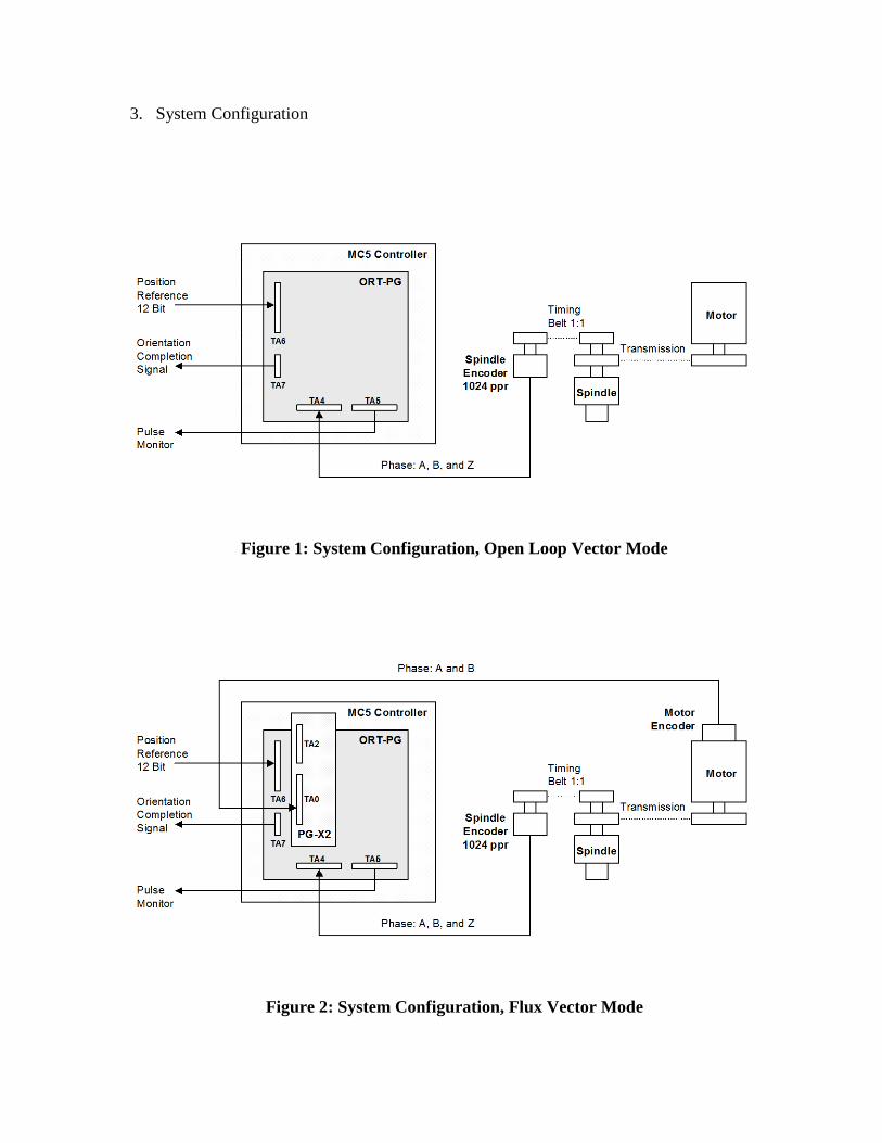
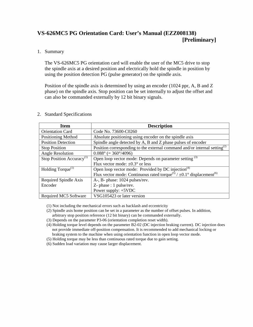
3. System Configuration
Figure 1: System Configuration, Open Loop Vector Mode
Figure 2: System Configuration, Flux Vector Mode
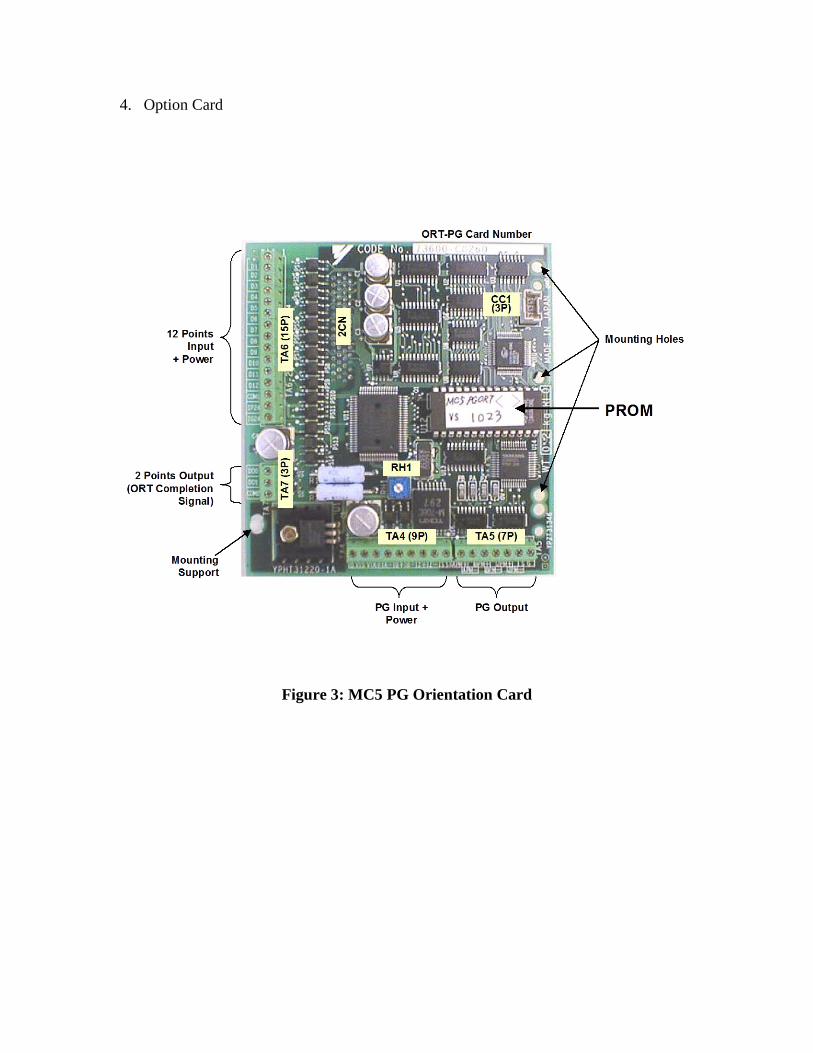
4. Option Card
Figure 3: MC5 PG Orientation Card
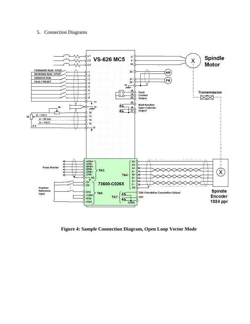
5. Connection Diagrams
Figure 4: Sample Connection Diagram, Open Loop Vector Mode
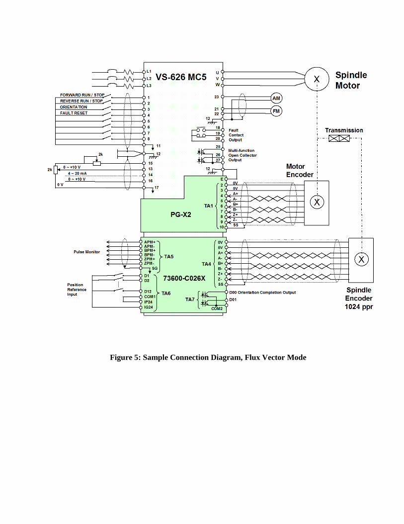
Figure 5: Sample Connection Diagram, Flux Vector Mode
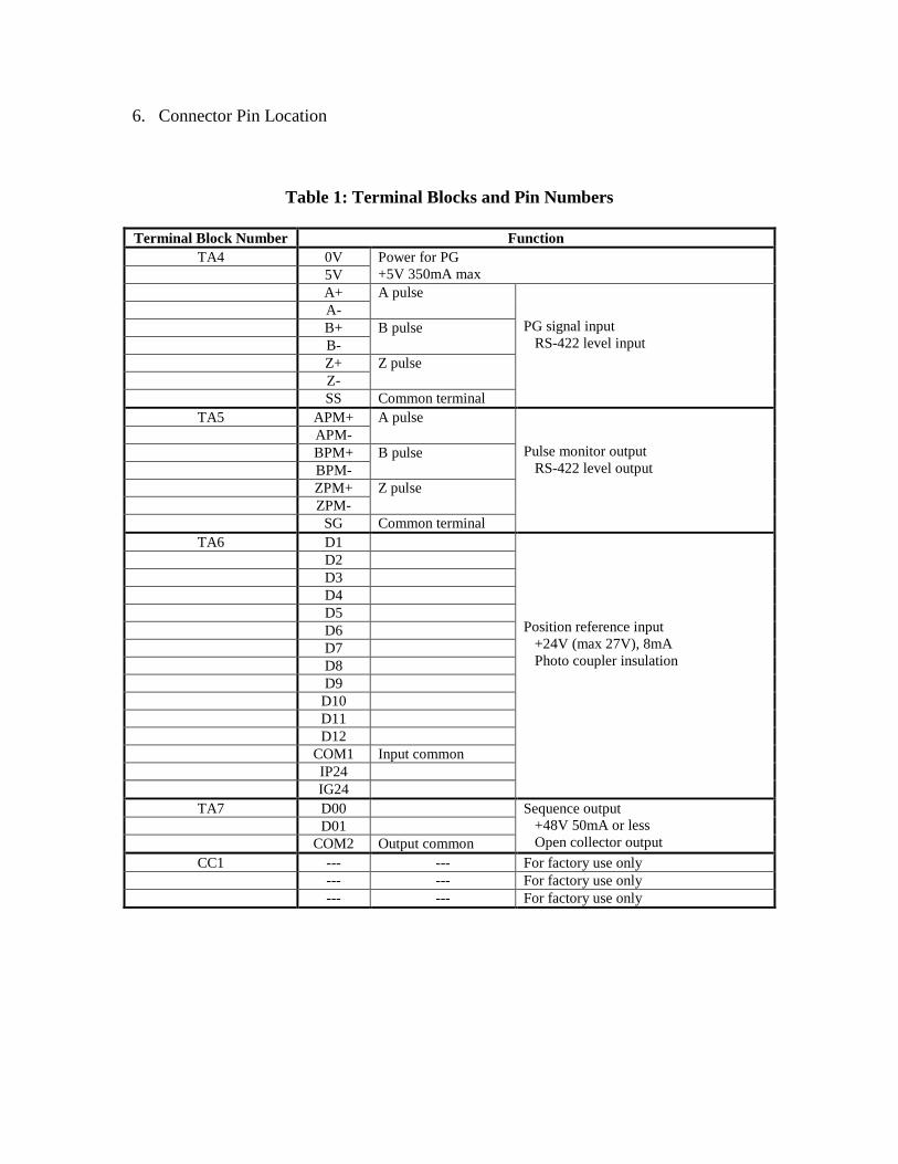
6. Connector Pin Location
Table 1: Terminal Blocks and Pin Numbers Terminal Block Number Function
TA4 0V Power for PG +5V 350mA max 5V
A+ A pulse PG signal input RS-422 level input
A- B+ B pulse B- Z+ Z pulse Z- SS Common terminal
TA5 APM+ A pulse Pulse monitor output RS-422 level output
APM- BPM+ B pulse BPM- ZPM+ Z pulse ZPM- SG Common terminal
TA6 D1 Position reference input +24V (max 27V), 8mA Photo coupler insulation
D2 D3 D4 D5 D6 D7 D8 D9 D10 D11 D12 COM1 Input common IP24 IG24
TA7 D00 Sequence output +48V 50mA or less Open collector output
D01 COM2 Output common
CC1 --- --- For factory use only --- --- For factory use only --- --- For factory use only
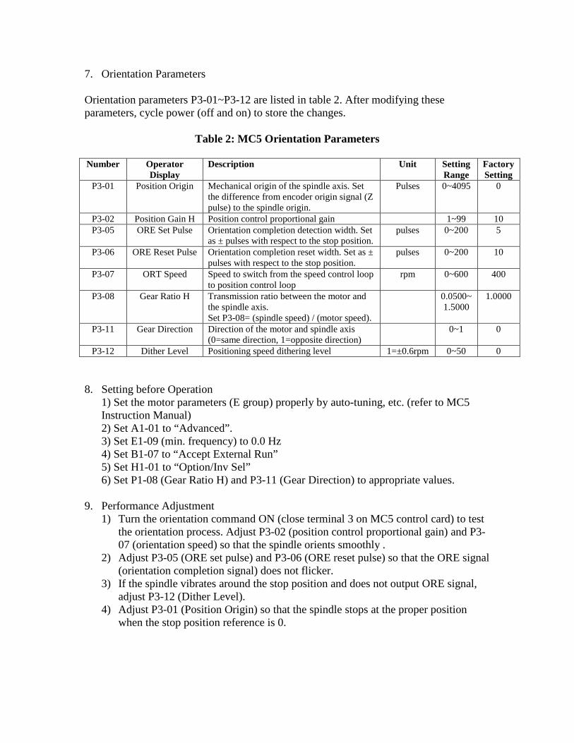
7. Orientation Parameters Orientation parameters P3-01~P3-12 are listed in table 2. After modifying these parameters, cycle power (off and on) to store the changes.
Table 2: MC5 Orientation Parameters Number Operator
Display Description Unit Setting
Range Factory Setting
P3-01 Position Origin Mechanical origin of the spindle axis. Set the difference from encoder origin signal (Z pulse) to the spindle origin.
Pulses
0~4095 0
P3-02 Position Gain H Position control proportional gain 1~99 10 P3-05 ORE Set Pulse Orientation completion detection width. Set
as ± pulses with respect to the stop position. pulses 0~200 5
P3-06 ORE Reset Pulse Orientation completion reset width. Set as ± pulses with respect to the stop position.
pulses 0~200 10
P3-07 ORT Speed Speed to switch from the speed control loop to position control loop
rpm 0~600 400
P3-08 Gear Ratio H Transmission ratio between the motor and the spindle axis. Set P3-08= (spindle speed) / (motor speed).
0.0500~1.5000
1.0000
P3-11 Gear Direction Direction of the motor and spindle axis (0=same direction, 1=opposite direction)
0~1 0
P3-12 Dither Level Positioning speed dithering level 1=±0.6rpm 0~50 0 8. Setting before Operation 1) Set the motor parameters (E group) properly by auto-tuning, etc. (refer to MC5
Instruction Manual) 2) Set A1-01 to “Advanced”.
3) Set E1-09 (min. frequency) to 0.0 Hz 4) Set B1-07 to “Accept External Run” 5) Set H1-01 to “Option/Inv Sel” 6) Set P1-08 (Gear Ratio H) and P3-11 (Gear Direction) to appropriate values.
9. Performance Adjustment
1) Turn the orientation command ON (close terminal 3 on MC5 control card) to test the orientation process. Adjust P3-02 (position control proportional gain) and P3-07 (orientation speed) so that the spindle orients smoothly .
2) Adjust P3-05 (ORE set pulse) and P3-06 (ORE reset pulse) so that the ORE signal (orientation completion signal) does not flicker.
3) If the spindle vibrates around the stop position and does not output ORE signal, adjust P3-12 (Dither Level).
4) Adjust P3-01 (Position Origin) so that the spindle stops at the proper position when the stop position reference is 0.
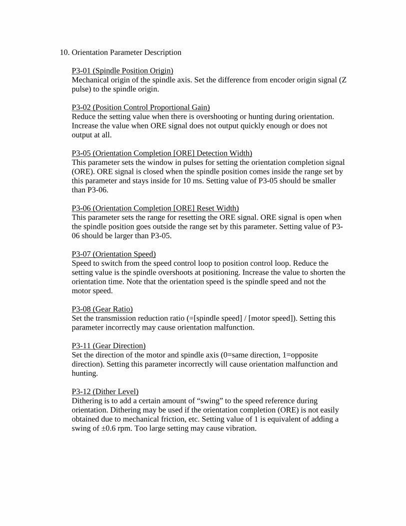
10. Orientation Parameter Description
Mechanical origin of the spindle axis. Set the difference from encoder origin signal (Z pulse) to the spindle origin.
P3-01 (Spindle Position Origin)
Reduce the setting value when there is overshooting or hunting during orientation. Increase the value when ORE signal does not output quickly enough or does not output at all.
P3-02 (Position Control Proportional Gain)
This parameter sets the window in pulses for setting the orientation completion signal (ORE). ORE signal is closed when the spindle position comes inside the range set by this parameter and stays inside for 10 ms. Setting value of P3-05 should be smaller than P3-06.
P3-05 (Orientation Completion [ORE] Detection Width)
This parameter sets the range for resetting the ORE signal. ORE signal is open when the spindle position goes outside the range set by this parameter. Setting value of P3-06 should be larger than P3-05.
P3-06 (Orientation Completion [ORE] Reset Width)
Speed to switch from the speed control loop to position control loop. Reduce the setting value is the spindle overshoots at positioning. Increase the value to shorten the orientation time. Note that the orientation speed is the spindle speed and not the motor speed.
P3-07 (Orientation Speed)
Set the transmission reduction ratio (=[spindle speed] / [motor speed]). Setting this parameter incorrectly may cause orientation malfunction.
P3-08 (Gear Ratio)
Set the direction of the motor and spindle axis (0=same direction, 1=opposite direction). Setting this parameter incorrectly will cause orientation malfunction and hunting.
P3-11 (Gear Direction)
Dithering is to add a certain amount of “swing” to the speed reference during orientation. Dithering may be used if the orientation completion (ORE) is not easily obtained due to mechanical friction, etc. Setting value of 1 is equivalent of adding a swing of ±0.6 rpm. Too large setting may cause vibration.
P3-12 (Dither Level)
11. Description of Orientation Process The method the MC5 uses to orient the spindle may change depending on the situation. Different methods are detailed below. (Open Loop Vector Mode) [from motor running]
1) When the orientation command is input, the spindle is decelerated to reach the orientation speed set by C3-07.
2) At the orientation speed, the drive looks for the Z pulse (marker) pulse. When the Z pulse is found, the drive switches to position control loop.
3) When the spindle comes within the orientation completion width (set by C3-05), the motor is stopped and held its position by DC injection. ORE signal is closed when the spindle stays inside the range for more than 10 ms.
4) If the spindle comes outside the orientation reset width (set by C3-06) due to external torque, ORE signal is open, DC injection is cancelled, and the drive engages in the position control loop again.
[from motor at stop: case 1] This case occurs if the spindle did not achieve more than 50 rpm since the
previous orientation: 1) When the orientation command is input, the drive immediately switches to the
position control loop. 2) When the spindle comes within the orientation completion width (set by C3-
05), the motor is stopped and held its position by DC injection. ORE signal is closed when the spindle stays inside the range for more than 10 ms.
3) If the spindle comes outside the orientation reset width (set by C3-06) due to external torque, ORE signal is open, DC injection is cancelled, and the drive switches to the position control loop again.
[from motor at stop: case 2] This case occurs if the spindle achieved more than 50 rpm since the previous
orientation: 1) When the orientation command is input, the spindle is accelerated to reach the
orientation speed set by C3-07. 2) At the orientation speed, the drive looks for the Z pulse (marker) pulse. When
the Z pulse is found, the drives switches to position control loop. 3) When the spindle comes within the orientation completion width (set by C3-
05), the motor is stopped and held its position by DC injection. ORE signal is closed when the spindle stays inside the range for more than 10 ms.
4) If the spindle comes outside the orientation reset width (set by C3-06) due to external torque, ORE signal is open, DC injection is cancelled, and the drive switches to the position control loop again.
Caution:
Do not keep the orientation signal ON indefinitely. Applying DC injection for a long period of time may cause the failure on drive or motor. Complete the tool change in a short period of time (a few seconds), and turn off the orientation signal when not needed.
(Flux Vector Mode) [from motor running]
1) When the orientation command (terminal 3 on MC5 control card) is input, the spindle is decelerated to reach the orientation speed (set by C3-07).
2) At the orientation speed, the drive looks for the Z pulse (marker) pulse. When the Z pulse is found, the drive switches to position control loop.
3) When the spindle comes within the orientation completion width (set by C3-05), the motor is stopped and held its position by servo loop. ORE signal is closed when the spindle stays inside the range for more than 10 ms.
4) If the spindle comes outside the orientation reset width (set by C3-06), ORE signal is open and the drive will correct its position.
[from motor at stop: case 1] This case occurs if the spindle did not achieve more than 50 rpm since the
previous orientation: 1) When the orientation command is input, the drive immediately switches to the
position control loop. 2) When the spindle comes within the orientation completion width (set by C3-
05), the motor is stopped and held its position by servo loop. ORE signal is closed when the spindle stays inside the range for more than 10 ms.
3) If the spindle comes outside the orientation reset width (set by C3-06), ORE signal is open and the drive will correct its position.
[from motor at stop: case 2] This case occurs if the spindle achieved more than 50 rpm from the previous
orientation: 1) When the orientation command is input, the spindle is accelerated to reach the
orientation speed set by C3-07. 2) At the orientation speed, the drive looks for the Z pulse (marker) pulse. When
the Z pulse is found, the drives switches to position control loop. 3) When the spindle comes within the orientation completion width (set by C3-
05), the motor is stopped and held its position by servo loop. ORE signal is closed when the spindle stays inside the range for more than 10 ms.
4) If the spindle comes outside the orientation reset width (set by C3-06), ORE signal is open and the drive will correct its position.

12. MC5 Parameter List
Refer to the MC5 Instruction Manual.
Related Documents


