VRS N-Series Installation Guide Version 1.3 February 2015

Welcome message from author
This document is posted to help you gain knowledge. Please leave a comment to let me know what you think about it! Share it to your friends and learn new things together.
Transcript

VRS N-Series
Installation Guide
Version 1.3
February 2015

VRS N-Series Installation Guide
HTS Proprietary Page 2
Hi-Tech Solutions, Ltd.
Telephone: +972-4-6774100
Fax: +972-4-6774101
E-Mail: [email protected]
The information contained in this document, or any addendum or revision thereof is proprietary of Hi-Tech Solutions Ltd. and is subject to all relevant copyright, patent and other laws and treaties protecting intellectual property, as well as any specific agreement protecting Hi-Tech Solutions Ltd. rights in the aforesaid information. Any use of this document or the information contained herein for any purposes
other than those for which it was disclosed is strictly forbidden. Hi-Tech Solutions Ltd. reserves the right, without prior notice or liability, to make changes in equipment design or specifications. Hi-Tech Solutions Ltd. assumes no responsibility for the use thereof nor for the rights of third parties, which may be affected in any way by
the use thereof. This document may contain flaws, omissions or typesetting errors; no warranty is granted nor liability assumed in relation thereto unless
specifically undertaken in Hi-Tech Solutions Ltd.’s sales contract or order confirmation. Information contained herein is periodically updated and changes will be incorporated into subsequent editions. If you have encountered an error, please notify Hi-Tech Solutions Ltd.
All specifications are subject to change without prior notice. © Copyright by Hi-Tech Solutions Ltd., 2009-2015. All rights reserved worldwide.
Document History
Version Number
Version Date
Author Comments Sections Affected
1.0 March 2014 Doron Almagor First release All
1.1 August 2014 Doron Almagor Adding DR-200, N60 Chapters 3,4,6,10
1.2 December 2014 Doron Almagor Added L-200
Deploying CAT6 cable.
Chapters 3, 5
Appendix C
1.3 February 2015 Doron Almagor Update DR-200 for P/S
Update Commission check list
Chapter 3, 12

VRS N-Series Installation Guide
HTS Proprietary Page 3
Table of Contents
CHAPTER 1 ABOUT THIS MANUAL ........................................................................................................... 14
1.1 Safety Symbols .................................................................................................................................... 14
1.2 LED Safety Compliance ........................................................................................................................ 14
1.3 List of Acronyms .................................................................................................................................. 15
1.4 Unit Conversion Table ......................................................................................................................... 16
1.5 Additional Support .............................................................................................................................. 16
CHAPTER 2 INTRODUCTION .................................................................................................................... 17
2.1 VRS Overview ...................................................................................................................................... 17
2.2 The VRS N-Series ................................................................................................................................. 18
2.3 VRS Configurations .............................................................................................................................. 18
Low-Speed Imaging Unit ................................................................................................................. 18 2.3.1
High-Speed Imaging Unit ................................................................................................................ 18 2.3.2
2.4 VRS Architecture ................................................................................................................................. 19
Imaging Units .................................................................................................................................. 20 2.4.1
Software .......................................................................................................................................... 21 2.4.2
Lane Controllers .............................................................................................................................. 21 2.4.3
2.5 VRS System Applications ..................................................................................................................... 21
2.6 Network connection ............................................................................................................................ 22
2.7 Video Compression ............................................................................................................................. 22
2.8 Powering ............................................................................................................................................. 22
Imaging Unit Powering ................................................................................................................... 22 2.8.1
CHAPTER 3 SYSTEM COMPONENT OVERVIEW ........................................................................................ 24
3.1 Structural Equipment .......................................................................................................................... 25
3.2 Lane Controller .................................................................................................................................... 26
Outdoor Lane Controller ................................................................................................................. 26 3.2.1
Indoor Lane Controller and Components ....................................................................................... 27 3.2.2
3.3 Software .............................................................................................................................................. 28
3.4 Imaging Unit & Illumination ................................................................................................................ 28
N-50 Imaging Unit ........................................................................................................................... 29 3.4.1
N-60 Imaging Unit ........................................................................................................................... 30 3.4.2
SCH-200 Imaging Unit ..................................................................................................................... 32 3.4.3
DR-200 Imaging Unit ....................................................................................................................... 34 3.4.4
L-100/L-200 Illumination Unit ......................................................................................................... 36 3.4.5
3.5 I/O Equipment ..................................................................................................................................... 39
ADAM-6060 Overview .................................................................................................................... 39 3.5.1
ADAM-6060 Specification ............................................................................................................... 39 3.5.2
3.6 Detectors ............................................................................................................................................. 41
Loop Detector ................................................................................................................................. 41 3.6.1
Infrared (IR) Beam (Optional) ......................................................................................................... 43 3.6.2
3.7 VRS Controller Cabinet ........................................................................................................................ 44

VRS N-Series Installation Guide
HTS Proprietary Page 4
VRS Small Controller Cabinet .......................................................................................................... 45 3.7.1
VRS Medium Controller Cabinet ..................................................................................................... 45 3.7.2
VRS Extended Temperature Controller Cabinet ............................................................................. 46 3.7.3
VRS Controller Cabinet Summary ................................................................................................... 48 3.7.4
VRS Controller Cabinet Ordering/Assembling ................................................................................ 49 3.7.5
3.8 Optional Components ......................................................................................................................... 50
CHAPTER 4 PLANNING THE INSTALLATION AND INFRASTRUCTURE......................................................... 51
4.1 General Considerations ....................................................................................................................... 51
Optical Considerations .................................................................................................................... 51 4.1.1
Optical Considerations for Non-Standard Installations .................................................................. 54 4.1.2
Optical Considerations for Overview Imaging Units ....................................................................... 54 4.1.3
4.2 Preparing Pole Design ......................................................................................................................... 54
Height of Imaging Unit .................................................................................................................... 54 4.2.1
Front Capture Installation ............................................................................................................... 55 4.2.2
Rear Capture Installation ................................................................................................................ 57 4.2.3
Front and Rear Capture (Stereo) Installation .................................................................................. 58 4.2.4
4.3 Preparing Gantry Design Drawings ..................................................................................................... 60
Two-Lane Gantry Design ................................................................................................................. 60 4.3.1
4.4 Detector Installation ........................................................................................................................... 61
Loop Design .................................................................................................................................... 61 4.4.1
Detector Selection .......................................................................................................................... 61 4.4.2
Speed Bumps .................................................................................................................................. 62 4.4.3
CHAPTER 5 LANE CONTROLLER INSTALLATION ........................................................................................ 63
5.1 Overview ............................................................................................................................................. 63
5.2 HASP License Plug Driver .................................................................................................................... 64
5.3 Operation ............................................................................................................................................ 64
CHAPTER 6 IMAGING & ILLUMINATION UNIT INSTALLATION .................................................................. 70
6.1 N-50 Imaging Unit Installation ............................................................................................................ 70
Preparing for the Installation .......................................................................................................... 70 6.1.1
Mechanical Installation ................................................................................................................... 71 6.1.2
Electrical Installation ....................................................................................................................... 76 6.1.3
I/O Connections .............................................................................................................................. 78 6.1.4
Network Installation ....................................................................................................................... 80 6.1.5
6.2 N-60 Imaging Unit Installation ............................................................................................................ 80
Preparing for the Installation .......................................................................................................... 80 6.2.1
Mechanical & Electrical Installation ................................................................................................ 82 6.2.2
Removing the IR Filter..................................................................................................................... 88 6.2.3
Network Installation ....................................................................................................................... 88 6.2.4
6.3 SCH-200 Imaging Unit Installation ...................................................................................................... 88
Preparing for the Installation .......................................................................................................... 89 6.3.1
Mechanical Installation ................................................................................................................... 90 6.3.2
Electrical Installation ....................................................................................................................... 98 6.3.3
Network Installation ....................................................................................................................... 99 6.3.4

VRS N-Series Installation Guide
HTS Proprietary Page 5
6.4 DR-200 Imaging Unit Installation ...................................................................................................... 100
Preparing for the Installation ........................................................................................................ 100 6.4.1
Mechanical Installation ................................................................................................................. 102 6.4.2
Electrical Installation ..................................................................................................................... 103 6.4.3
Network Installation ..................................................................................................................... 104 6.4.4
6.5 L-100/L-200 Illumination Unit Installation ........................................................................................ 104
Preparing for the Installation ........................................................................................................ 104 6.5.1
Mechanical Installation ................................................................................................................. 105 6.5.2
Electrical Installation ..................................................................................................................... 107 6.5.3
CHAPTER 7 I/O DEVICE INSTALLATION .................................................................................................. 111
7.1 N-50 as I/O Module ........................................................................................................................... 111
7.2 ADAM 6060 I/O Module .................................................................................................................... 111
7.3 Configuring the ADAM-6060 ............................................................................................................. 112
CHAPTER 8 SYSTEM INFRASTRUCTURE INSTALLATION .......................................................................... 115
8.1 Mounting the VRS Controller Cabinet ............................................................................................... 115
Pole Installation ............................................................................................................................ 115 8.1.1
8.2 Wiring the VRS Controller Cabinet .................................................................................................... 116
8.3 VRS Controller Cabinet Outlet Wiring ............................................................................................... 116
8.4 LAN Cable Connections ..................................................................................................................... 117
Assembling the RJ45 Connector ................................................................................................... 117 8.4.1
Flexible Protective Conduits for External Cables .......................................................................... 120 8.4.2
Testing Ethernet Cable .................................................................................................................. 120 8.4.3
8.5 External Illumination Connections .................................................................................................... 120
8.6 Loop Installation ................................................................................................................................ 122
8.7 IR Sensors .......................................................................................................................................... 125
8.8 Gate Control ...................................................................................................................................... 126
CHAPTER 9 SYSTEM CONFIGURATION ................................................................................................... 127
9.1 SeeWay ............................................................................................................................................. 127
SeeWay Installation ...................................................................................................................... 127 9.1.1
9.2 See Control ........................................................................................................................................ 127
CHAPTER 10 IMAGING UNIT ON-SITE CALIBRATION & FINE TUNING ...................................................... 128
10.1 General Information .......................................................................................................................... 128
10.2 N-50 Calibration Preparations ........................................................................................................... 128
10.3 SCH-200, DR-200 & N60 Calibration Preparations ............................................................................ 130
10.4 Setting the Overview Imaging Unit Parameters ................................................................................ 131
CHAPTER 11 CALIBRATION FORM ........................................................................................................... 132
CHAPTER 12 INSTALLATION READINESS (COMMISSIONING CHECKLIST) ................................................. 135
APPENDIX A GROUND LOOP SPECIFICATIONS AND USER’S GUIDE ......................................................... 142
APPENDIX B VRS CONTROLLER CABINET DRAWINGS .............................................................................. 149
APPENDIX C DEPLOYING CAT6 CABLE ..................................................................................................... 153

VRS N-Series Installation Guide
HTS Proprietary Page 6
APPENDIX D IMAGING UNIT NETWORK TOPOLOGIES ............................................................................. 158
APPENDIX E USING THE IP CONFIGURATOR UTILITY ............................................................................... 159

VRS N-Series Installation Guide
HTS Proprietary Page 7
List of Figures
Figure 1: Typical VRS Installation for Access Control ............................................................................ 17
Figure 2: VRS System Architecture with Triggering via an ADAM-6060 I/O Module ............................ 19
Figure 3: VRS System Architecture with Triggering via an N-50 Imaging Unit...................................... 19
Figure 4: VRS Imaging Unit Block Diagram............................................................................................ 21
Figure 5: LC-2000 VRS Outdoor Lane Controller ................................................................................... 26
Figure 6: N-50 Imaging Unit .................................................................................................................. 29
Figure 7: N-60 Imaging Unit .................................................................................................................. 30
Figure 8: SCH-200 Imaging Unit ............................................................................................................ 32
Figure 9: DR-200 Imaging Unit .............................................................................................................. 34
Figure 10: L-100/200 Illumination Unit ................................................................................................. 36
Figure 11: L-100/L-200 Daisy Chaining.................................................................................................. 37
Figure 12: L-100/L-200 Dimensions ...................................................................................................... 38
Figure 13: ADAM-6060 I/O Module ...................................................................................................... 39
Figure 14: Matrix Loop Detector ........................................................................................................... 41
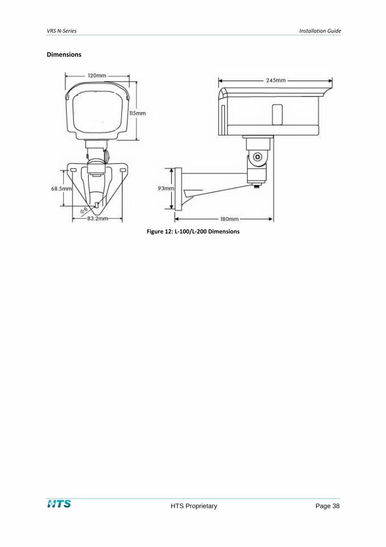
Figure 15: Loop Detector Specifications ............................................................................................... 42
Figure 16: Allen-Bradley Photoelectric Sensor Datasheet .................................................................... 43
Figure 17: VRS Controller Cabinet ......................................................................................................... 44
Figure 18: Sample of Extended VRS Controller Cabinet Architecture .................................................. 45
Figure 19: Sample Extended Controller Cabinet with Assembled Components................................... 46
Figure 20: HASP Security Key ................................................................................................................ 49
Figure 21: Advantech EKI-2741 Media Converter ................................................................................. 50
Figure 22: Typical Height for Pole Mount Installation .......................................................................... 54
Figure 23: Front Capture Installation Distances ................................................................................... 56
Figure 24: Rear Capture Installation Distances ..................................................................................... 57
Figure 25: Front and Rear Capture Installation Distances .................................................................... 59
Figure 26: Two-Lane Gantry Design ...................................................................................................... 60
Figure 27: Basic Loop Detector Scheme................................................................................................ 61
Figure 28: VRS Controller Configurator Icon ......................................................................................... 64
Figure 29: Welcome Window................................................................................................................ 65
Figure 30: IP Configuration Window ..................................................................................................... 66
Figure 31: User Configuration Window ................................................................................................ 67

VRS N-Series Installation Guide
HTS Proprietary Page 8
Figure 32: SeeControl Configuration Window ...................................................................................... 68
Figure 33: Configuration Summary Window ........................................................................................ 69
Figure 34: Mounting the Imaging Unit .................................................................................................. 71
Figure 35: Fastening the Safety Wire .................................................................................................... 72
Figure 36: Fastening the Adaptor to the Pole with a Metal Band ........................................................ 72
Figure 37: Attaching the Imaging Unit to the Pole Mount Adaptor ..................................................... 72
Figure 38: Pole-Mounted Imaging Unit ................................................................................................ 73
Figure 39: Sample Installation of N50 with Junction Box ..................................................................... 74
Figure 40: Photo of Junction Box .......................................................................................................... 75
Figure 41: Fitting (M20 thread, IP65 Compliant) .................................................................................. 75
Figure 42: Connecting the Wires........................................................................................................... 76
Figure 43: Adjusting the Imaging Unit’s Position .................................................................................. 77
Figure 44: Adjusting the Zoom and Focus (Varifocal Lens) ................................................................... 77
Figure 45: Adjusting the Sun Shield Hood ............................................................................................. 78
Figure 46: N-50 Imaging Unit I/O Connections ..................................................................................... 79
Figure 47: Sunshield .............................................................................................................................. 80
Figure 48: Wall Mounting Bracket ........................................................................................................ 81
Figure 49: Wall Mount Base .................................................................................................................. 81
Figure 50: Mounting Accessory Kit ....................................................................................................... 81
Figure 51: Waterproof Connectors ....................................................................................................... 81
Figure 52: Placement Sticker ................................................................................................................ 82
Figure 53: Dehumidifier Packet............................................................................................................. 82
Figure 54: Imaging Unit Connectors ..................................................................................................... 82
Figure 55: Covering Unused Wire Holes ............................................................................................... 83
Figure 56: Threading the Cable inside the Wall Mount Bracket ........................................................... 83
Figure 57: Using the Waterproof Connector ........................................................................................ 83
Figure 58: Securing the Imaging Unit to the Wall Mount Bracket ........................................................ 84
Figure 59: Wiring the RJ45 Connector .................................................................................................. 84
Figure 60: Wiring Power & DI/O to the Imaging Unit ........................................................................... 84
Figure 61: Closing the Imaging Unit ...................................................................................................... 85
Figure 62: Mounting the N60 on a Wall ................................................................................................ 85
Figure 63: Attaching the Dehumidifier Packet ...................................................................................... 85

VRS N-Series Installation Guide
HTS Proprietary Page 9
Figure 64: Attaching the Sunshield ....................................................................................................... 86
Figure 65: Attaching Imaging Unit to the Connecting Bracket ............................................................. 86
Figure 66: Attaching Imaging Unit to the Connecting Bracket - Other Side ......................................... 86
Figure 67: Attaching the Wall Mount Bracket to the Wall Mount Plate .............................................. 87
Figure 68: Screw Locations in the Pole Adaptor ................................................................................... 87
Figure 69: Pole Mount Adaptor ............................................................................................................ 87
Figure 70: Bracket Drawing and Dimensions ........................................................................................ 90
Figure 71: Pole Mount Adaptor ............................................................................................................ 90
Figure 72: BR-20 Pole Adaptor .............................................................................................................. 92
Figure 73: Screw locations in the Pole Adapter .................................................................................... 92
Figure 74: Mounting the Imaging Unit on a Pole .................................................................................. 93
Figure 75: Adjusting Imaging Unit Position and Direction .................................................................... 93
Figure 76: Cabling Pipes and Connectors (for SCH-200) ....................................................................... 94
Figure 77: Flexible protective conduits ................................................................................................. 94
Figure 78: Assembled Anodized Bracket............................................................................................... 95
Figure 79: Dimensions of Anodized Bracket ......................................................................................... 95
Figure 80: Pan/Tilt Bracket Screws ....................................................................................................... 96
Figure 81: Torque Wrench .................................................................................................................... 97
Figure 82: Upper Bracket ...................................................................................................................... 97
Figure 83: Upper Bracket attached to Bottom of Imaging Unit ............................................................ 97
Figure 84: Gantry Base Bracket ............................................................................................................. 98
Figure 85: Connecting the External Wires ............................................................................................ 99
Figure 86: Wall Mounting Bracket Model BR-13 ................................................................................ 100
Figure 87: Mounting Accessory Kit ..................................................................................................... 101
Figure 88: Pole Mount Adaptor .......................................................................................................... 101
Figure 89: Wall Mount Bracket ........................................................................................................... 102
Figure 90: Adjusting the Imaging Unit ................................................................................................ 102
Figure 91: Connecting the External Wires .......................................................................................... 103
Figure 92: Mounting Bracket (wall / pole design) ............................................................................... 105
Figure 93: Pole Mount Adaptor .......................................................................................................... 105
Figure 94: Bracket base Drawing and Dimensions .............................................................................. 106
Figure 95: Adjusting the Illumination Unit .......................................................................................... 106

VRS N-Series Installation Guide
HTS Proprietary Page 10
Figure 96: Screw Locations in the Pole Adapter ................................................................................. 107
Figure 97: Cable layout ....................................................................................................................... 108
Figure 98: Junction Box ....................................................................................................................... 108
Figure 99: Conduit Fitting for Flexible Conduit ................................................................................... 108
Figure 100: Connecting the ADAM-6060 to the VRS System .............................................................. 111
Figure 101: AdamApax .NET Utility Network Tabbed Window .......................................................... 112
Figure 102: Selecting an ADAM Device to Configure .......................................................................... 113
Figure 103: ADAM Password Entry ..................................................................................................... 113
Figure 104: ADAM-6060 Connectivity ................................................................................................. 114
Figure 105: Attaching a Metal Band to the VRS Controller Cabinet ................................................... 115
Figure 106: VRS Controller Cabinet Power and Communications Wiring .......................................... 116
Figure 107: Wiring Conduit ................................................................................................................. 117
Figure 108: Conduit Assembly ............................................................................................................ 117
Figure 109: RJ45 Connector Wiring per T568B standard .................................................................... 118
Figure 110: RJ45 CAT-6 Male Connector............................................................................................. 118
Figure 111: Cable jacket ...................................................................................................................... 119
Figure 112: Load Bars and Cable Jacket Conductors .......................................................................... 119
Figure 113: RJ45 and load bar cable ................................................................................................... 119
Figure 114: Crimping tool for RJ45 connectors ................................................................................... 120
Figure 115: Flexible protective conduits ............................................................................................. 120
Figure 116: Connecting the Junction Box ........................................................................................... 121
Figure 117: Junction Box for External Illuminator .............................................................................. 121
Figure 118: Ground Loop .................................................................................................................... 122
Figure 119: Setting the Ground Loop Controller for Multiple Loops .................................................. 123
Figure 120: IR Selecting Dark Mode .................................................................................................... 125
Figure 121: IR Receiver LED Behavior in Dark Mode .......................................................................... 125
Figure 122: IR Sensor Connections ..................................................................................................... 126
Figure 123: Connecting the N-50 Imaging Unit to a Technician’s Monitor ........................................ 129
Figure 124: Example of Bad Overview (left side) and Good Overview (right side) ............................ 131
Figure 125: VRS Controller Cabinet, Specifications and Wiring Spec. ................................................ 149
Figure 126: VRS Controller Cabinet, Principle and Interfaces ............................................................. 150
Figure 127: VRS Controller Cabinet Terminals .................................................................................... 150

VRS N-Series Installation Guide
HTS Proprietary Page 11
Figure 128: VRS Controller Cabinet, AC High Power Wiring ............................................................... 151
Figure 129: VRS Controller Cabinet Outlets Wiring Diagram .............................................................. 151
Figure 130: VRS Controller Cabinet Thermal Setup (For Extended Unit) ........................................... 152
Figure 131: RJ45 Wiring Guide ............................................................................................................ 153
Figure 132: Crimping a CAT6 Cable ..................................................................................................... 154
Figure 133: RJ45 Connection............................................................................................................... 155
Figure 134: RJ45 Crimping Tool........................................................................................................... 155
Figure 135: RJ45 Connector on Both Ends of CAT6 Cable .................................................................. 155
Figure 136: 1 Gbps Tester ................................................................................................................... 156
Figure 137: 1 Gbps Cable Test Report ................................................................................................. 157
Figure 138: Network Topology Type I ................................................................................................. 158
Figure 139: Network Topology Type II ........................................................................................... 158
Figure 140: IP Configurator Icon ......................................................................................................... 159
Figure 141: Login Window .................................................................................................................. 159
Figure 142: List of Imaging Units in the Network ............................................................................... 160
Figure 143: Add Imaging Unit Manually ............................................................................................. 160
Figure 144: Entering Imaging Unit Details Manually .......................................................................... 161
Figure 145: Imaging Unit Configuration Window ............................................................................... 161
Figure 146: Add a New IP Address Manually ...................................................................................... 162

VRS N-Series Installation Guide
HTS Proprietary Page 12
List of Tables
Table 1: Safety Symbols ........................................................................................................................ 14
Table 2: Acronyms ................................................................................................................................. 15
Table 3: Unit Conversion Table ............................................................................................................. 16
Table 4: VRS System Components ........................................................................................................ 24
Table 5: Structural Equipment .............................................................................................................. 25
Table 6: LC-2000/2100 Configuration Options ..................................................................................... 26
Table 7: Outdoor Lane Controller Components .................................................................................... 27
Table 8: Indoor Lane Controller Components....................................................................................... 27
Table 9: Low-Speed Imaging Units ........................................................................................................ 28
Table 10: High-Speed Imaging Unit....................................................................................................... 28
Table 11: N-60 Specifications ................................................................................................................ 31
Table 12: SCH-200 Specifications .......................................................................................................... 33
Table 13: DR-200 Specifications ............................................................................................................ 35
Table 14: Components in Extended Controller Cabinet ....................................................................... 47
Table 15: VRS Controller Cabinets ........................................................................................................ 48
Table 16: Optional Equipment .............................................................................................................. 50
Table 17: N-50 Imaging Unit FOV & Distance Table ............................................................................. 52
Table 18: N-60 Imaging Unit FOV & Distance Table ............................................................................. 52
Table 19: SCH-200 / DR-200 Imaging Unit and Lens Lookup Table ...................................................... 53
Table 20: N-50 Imaging Unit Connections ............................................................................................ 78
Table 21: Connecting the External Illumination Unit .......................................................................... 109
Table 22: Connecting the ADAM-6060 to the VRS System ................................................................. 112
Table 23: VRS Controller Cabinet Outlet Wiring ................................................................................. 116
Table 24: Connecting the External Illumination Unit to the Terminal Block ...................................... 122
Table 25: Setting the Ground Loop Controller for Multiple Loops ..................................................... 124
Table 26: LED Behavior of IR Receiver ................................................................................................ 125
Table 27: Calibration Form .................................................................................................................. 134
Table 28: Equipment ID List ................................................................................................................ 136
Table 29: Controller Cabinet Checklist ................................................................................................ 137
Table 30: Loop and Loop Controller Checklist .................................................................................... 137
Table 31: Imaging Unit Checklist ......................................................................................................... 138

VRS N-Series Installation Guide
HTS Proprietary Page 13
Table 32: Lane Controller Software Checklist ..................................................................................... 139
Table 33: SeeControl Checklist ........................................................................................................... 140
Table 34: DMS Checklist ...................................................................................................................... 141
Table 35: Operational Checklist .......................................................................................................... 141
Table 36: Performance Acceptance Test Checklist ............................................................................. 141
Table 37: RJ-45 Wiring ........................................................................................................................ 154
Table 38: System Requirements ......................................................................................................... 158

VRS N-Series Installation Guide
HTS Proprietary Page 14
Chapter 1 About This Manual
This manual will allow you to quickly install the VRS N-Series license plate recognition system with
minimal effort. The manual focuses on the two main methods for mounting VRS system
components:
Fastened to a pole (or a wall)
Mounted on a gantry
It is assumed that the lanes and gantries have already been built, so only basic information is
provided on those topics. Following installation, the system will be fully functional for its various
intended uses.
Prior to installing the system, please review the manual and pay special attention to the safety
instructions that appear within.
1.1 Safety Symbols
Observe all safety advisories to help prevent loss of service, equipment damage, personal injury, and
security breaches. This guide uses the following safety symbols:
IMPORTANT: An important statement calls attention to information that should be read carefully by the reader.
WARNING: A warning statement calls attention to a situation that could result in harm to system equipment.
HAZARD: A hazard statement calls attention to a situation that could cause personal injury if the user does not adhere to the instructions provided.
Table 1: Safety Symbols
1.2 LED Safety Compliance
The VRS internal illumination unit complies with International Standard IEC 60825–1 for products
containing Class 1 LEDs (light emitting diodes). This Class 1 LED product poses no hazard to the user
or to any other person present near the illumination unit. Use of the illumination unit is totally safe
and requires no specific safety precautions. In any case, one should not look directly into the LED for
a prolonged period of time.

VRS N-Series Installation Guide
HTS Proprietary Page 15
1.3 List of Acronyms
Acronym Meaning
AOI Area of Interest
AGE Automatic Gain and Exposure algorithm
B&W Black and White
CCR Container Code Recognition
CMOS Complementary Metal-Oxide Semiconductor image sensors
DLL Dynamic link library
FOV Field of View
GUI Graphical User Interface
HASP Hardware Against Software Piracy
HTS High Tech Solutions Ltd.
HW Hardware
IMO International Maritime Organization
ID Identification
IO Input/Output
JB Junction Box
LED Light Emitting Diode
LPR License Plate Recognition
MSMQ Microsoft Message Queuing
NIC Network Interface Controller
OCR Optical Character Recognition
OS Operating System
PC Personal Computer
PS Power Supply
SDK Software Development Kit
SI System Integrator
SW Software
TOS Terminal Operating System
VIR Vehicle Identity Recognition
VMD Vehicle Motion Detection
VRS Vehicle Recognition System
Table 2: Acronyms

VRS N-Series Installation Guide
HTS Proprietary Page 16
1.4 Unit Conversion Table
All dimensions in this manual are specified using metric measurements. To convert to non-metrics,
use the table below.
Conversion Type Conversion Formula
Centimeters To Feet Feet = Centimeters x 0.0328
Feet To Centimeters Centimeters = Feet x 30.488
Centimeters To Inches Inches = Centimeters x 0.3937
Inches To Centimeters Centimeters = Inches x 2.54
Feet – Inches 1 Foot = 12 Inches
Table 3: Unit Conversion Table
1.5 Additional Support
HTS offers additional support on its web site. You can access the support section using the link:
http://htsol.com/Support.asp Obtain a user name and password from your HTS representative.
The section includes contact information for technical support, a FAQ (frequently asked questions)
page, RMA (return merchandise authorization) procedures, and a download menu. The following
items can be downloaded from the site:
Software Releases
Drivers
Documentation
Tools and Utilities
You can contact us for more information and assistance at:
Telephone / Fax Email
Telephone: +972-4-6774100
Fax: +972-4-6774101
Marketing / Sales: [email protected]
Technical Support: [email protected]

VRS N-Series Installation Guide
HTS Proprietary Page 17
Chapter 2 Introduction
2.1 VRS Overview HTS’s Vehicle Recognition System (VRS) is a sophisticated, vision-based license plate recognition
(LPR) system that identifies and tracks plate numbers on vehicles traveling at a wide range of speeds.
VRS can be installed with an additional Imaging Unit to be used for Vehicle Identity Recognition
(VIR). The VIR Imaging Unit is accompanied by SeeWay software that enables the VRS system to
identify vehicle makes and models, license plate icons, and plate colors.
The VIR software improves identification levels and allows for more comprehensive vehicle profiling.
It is easily upgraded to enable the addition of new features.
Typical VIR applications include safe city monitoring, law enforcement, and border crossings.
Figure 1: Typical VRS Installation for Access Control

VRS N-Series Installation Guide
HTS Proprietary Page 18
2.2 The VRS N-Series
The N-Series refers to HTS’s VRS systems that employ imaging units that are housed separately from
the Lane Controller CPU. Imaging units that embed Lane Controller hardware and software are
referred to as the E-Series.
NOTE
The installation of E-Series imaging units is not within the scope of this document.
2.3 VRS Configurations The VRS family of Imaging Units includes two distinct product lines, each serving a different set of
applications:
Low-Speed Imaging Unit (N-50, N-60)
High-Speed Imaging Unit (SCH-200, DR-200)
Low-Speed Imaging Unit 2.3.1
The Low-Speed Imaging Unit is a 3 megapixel (full HD), rolling-shutter CMOS Imaging Unit designed
for use in low-speed applications, supporting recognition speeds of up to 40-50 kilometers per hour.
The system can be part of a traffic management system used for access control, critical-site
monitoring, or safe-city surveillance, and is intended for installation on roadside poles. Its imaging
system supports a 2.0-4.0 meter wide field-of-view, depending on license plate size and the required
vehicle data.
High-Speed Imaging Unit 2.3.2
The High-Speed Imaging Unit is a 2 megapixel, global-shutter CMOS Imaging Unit designed for use in
high-speed applications, supporting recognition speeds of up to 250 kilometers per hour. The
system can be part of a broad city-wide surveillance system, a free-flow toll road billing system, or a
border crossing, and is normally installed on overhead gantries. Its imaging system supports a 3.2-
4.0 meter wide field-of-view, depending on license plate size and the vehicle data required.

VRS N-Series Installation Guide
HTS Proprietary Page 19
2.4 VRS Architecture
The architecture of the VRS system is constructed from three major subsystems:
Imaging Units
Software
Lane Controller Hardware
The VRS subsystems are further described in this chapter. The two diagrams below represent two
distinct architectures for the forwarding of trigger signals.
The diagram in Figure 2 below depicts the forwarding of trigger signals to the Lane Controller via an
ADAM-6060 I/O Module:
Figure 2: VRS System Architecture with Triggering via an ADAM-6060 I/O Module
The diagram in Figure 3 below depicts the forwarding of trigger signals to the Lane Controller via an
N-50 Imaging Unit:
Figure 3: VRS System Architecture with Triggering via an N-50 Imaging Unit

VRS N-Series Installation Guide
HTS Proprietary Page 20
Imaging Units 2.4.1
Each lane is served by either one or two color digital Imaging Units according to one of the following
setup options:
A color Imaging Unit operating in black & white mode and IR-based setup that includes an
IR cut filter and IR LEDs used for LPR purposes.
A color Imaging Unit setup that includes an internal IR cut filter and white LEDs used for
either for LPR, VIR, or to provide a lane overview.
The lane overview Imaging Unit can be deployed in addition to one or two LPR imaging
units.
The Imaging Unit can be installed on the following types of mountings:
Pole (or wall)
Ceiling
Gantry
HTS’s imaging units are compliant with IP66, offer H.264 live streaming, and can be installed at any
location in the VRS network.
The N-Series Imaging Units available for use with the VRS system are as follows:
N-50 Low-Speed Imaging Unit
N-60 Low-Speed Imaging Unit
SCH-200 High-Speed Imaging Unit
DR-200 High-Speed Imaging Unit
For details on specific N-Series Imaging Units, please refer to section 3.4.
The Imaging Unit can be signaled to capture and identify a license plate image using the following
trigger types:
Software trigger – Vehicle Motion Detection (VMD)
Hardware trigger – loop detector, Laser trigger, or infrared detector
Combination software (VMD) and hardware trigger
The block diagram of a typical VRS Imaging Unit is depicted in Figure 4 below.

VRS N-Series Installation Guide
HTS Proprietary Page 21
Figure 4: VRS Imaging Unit Block Diagram
Software 2.4.2
The VRS system employs two software modules:
SeeWay. A vision-based application used to manage the VRS Imaging Units and obtain
vehicle identity data.
SeeControl. A centralized, web-based, client-server application used to aggregate and
manage information from the entire VRS installation. SeeControl can be used to transmit
the VRS information to the customer’s TOS-based application.
Both SeeWay and SeeControl run on the Microsoft Windows 7 operating system. SeeWay output
data is transmitted to SeeControl via a TCP/IP connection.
Lane Controllers 2.4.3
SeeWay can be housed in a variety of hardware-based server systems:
Embedded CPU. An Intel-based CPU embedded in the VRS Imaging Unit housing
NOTE
Installation of the Embedded CPU housing is not within the scope of this document.
LC-2000. An environmentally-hardened Lane Controller deployed close to the lane in an
outdoor controller cabinet.
LC-2100. Similar to the LC-2100, but with more RAM memory and a larger fixed disk,
making the Lane Controller suitable to house the SeeControl application as well.
LC-1000. An industry-standard Lane Controller deployed remotely from the lane in an
indoor environment, typically rack-mounted.
2.5 VRS System Applications
The following is a list of VRS System applications:
Toll Road. Automatic recognition of plates used for Vehicle Enforcement (VES) toll roads.

VRS N-Series Installation Guide
HTS Proprietary Page 22
Average Speeds. Speed data can be used for flow estimation and on-line traffic reports.
Monitoring. Recognition information can be used for a variety of security applications.
Access Control. For parking management and other access-oriented applications.
2.6 Network connection
The standard Fast Ethernet (10/100 megabit per second) connection over a CAT-6 cable provides
effective connectivity between system components within an 80 meter range:
Between the Imaging Unit and the VRS Lane Controller
Between the VRS Lane Controller and the VRS Server.
NOTE
For very short distances of up to 20 meters, a Wi-Fi connection can be used instead of the wired connection.
For longer distances, GPRS connectivity can be employed.
2.7 Video Compression
Compression methods supported:
H.264 (compressed)
JPG (uncompressed)
2.8 Powering
Imaging Unit Powering 2.8.1
The powering options supported for the N-50 Imaging Unit:
External power source, 24 VAC, 2.7 Amp. Supplied by HTS.
PoE Switch – 5 ports: 48 VDC, 3 Amp. For temperature range -10oC to +50oC only. Can be
purchased from HTS as an option.
PoE Switch – 8 ports: 24 VDC, 10 Amp. For temperature range -10oC to +50oC only. Can
be purchased from HTS as an option.
The powering options supported for the N60 Imaging Unit (Can be purchased from HTS as an
option):
External power source, 24 VAC.
External power source, 12 VDC.
PoE Switch – 5 ports: 48 VDC, 3 Amp. For temperature range -10oC to +50oC only.
PoE Switch – 8 ports: 24 VDC, 10 Amp. For temperature range -10oC to +50oC only.
The powering options supported for the SCH-200 Imaging Unit:

VRS N-Series Installation Guide
HTS Proprietary Page 23
External power source, 24 VDC, 3 Amp. Supplied by HTS.
The powering options supported for the DR-200 Imaging Unit:
External power source, 28 VDC, 5 Amp. Supplied by HTS. Lane Controller Powering
The powering options supported for the LC-2000/2100 Lane Controller:
Desktop power supply – 24 VDC, 5 Amp.
DIN rail power supply – 24 VDC, 6.3 Amp.

VRS N-Series Installation Guide
HTS Proprietary Page 24
Chapter 3 System Component Overview
This chapter provided details on the VRS system components, and is intended as a guide to ordering
the VRS system from HTS.
Please Note: The following products and services are not included in VRS system deliveries, and are
to be provided by third-party vendors:
Installation services
Integration services (can optionally be purchased from HTS)
Structural equipment
Stand-alone SeeControl Central Server
VRS system components are described in detail in the following sections as described in Table 4
below:
Section Component Type Major Components
3.1 Structural Equipment Gantry & pole construction, imaging unit brackets
3.2 Lane Controller Indoor / Outdoor Lane Controller and accessories
3.3 Software SeeWay Application, SeeControl Application
3.4 Imaging units and illumination N50, N60, SCH-200, DR-200
Stroboscopic External Illuminator SIL-200 (optional)
3.73.5 I/O Equipment I/O device
3.50 Hardware Detectors Loop detector, IR sensor
3.7 Controller cabinet Controller cabinets and accessories
3.8 Optional components Triggers, Power Supplies, and Network/Communications Devices
Table 4: VRS System Components

VRS N-Series Installation Guide
HTS Proprietary Page 25
3.1 Structural Equipment
After the design drawings are approved by the necessary authorities and reviewed by HTS, order the
following structural equipment for each lane:
Anchors for the pole/gantry foundation
The pole/gantry structure parts
The imaging unit is mounted to the pole or gantry using the following items.
Part ID Description
PMA-60 Pole Mount Adaptor for N60 imaging unit
BR-20 Pole Mount Adaptor for SCH-200 imaging unit
3AXIS-GRAY-M Mounting Bracket GRAY 3 Axis Metric for gantry design
2AXIS-GRAY-M Mounting Bracket GRAY 2 Axis Metric for gantry design
Table 5: Structural Equipment
NOTE
For the N-50, the pole mount is supplied together with the unit.
IMPORTANT: The design and construction of all pole and gantry installations are the sole
responsibility of VRS users. Your HTS representative is available for consultation in planning
the installation.
Details on the installation of Imaging Unit brackets on poles and gantries can be found in Chapter 6.

VRS N-Series Installation Guide
HTS Proprietary Page 26
3.2 Lane Controller
The Lane Controller houses the SeeWay application (and optionally the SeeControl application as
well).
Outdoor Lane Controller 3.2.1
The LC-2000 and LC-2100 Outdoor VRS Lane Controllers are environmentally hardened, fan-less
Controllers supplied by HTS for outdoor use. The Outdoor VRS Lane Controllers should be installed
in a protective cabinet.
Figure 5: LC-2000 VRS Outdoor Lane Controller
The main VRS controller features are:
Intel Core i7-2655LE, 2.2 GHz.
2 x RS-232 and 2 x RS-232/422/485 ports.
4 x 10/100/1000Base-T Ethernet ports.
Audio with Mic in, Line in, Line out.
6 x USB 2.0 ports.
Windows® 7 Pro.
Power supply
IP40 ingress protection.
Operating Temperature Range: -10° to +60°C.
The LC-2100 is designed to run both the SeeWay and the SeeControl applications, and therefore is
equipped with additional RAM memory and hard-disk space as detailed in the table below:
Part ID Description
LC-2000 DIN-rail mount, configured for SeeWay application
4 GB RAM memory, 120 GB SSD, Windows 7 Pro, 32-bit version
LC-2100 DIN-rail mount, configured for SeeWay and SeeControl applications
8 GB RAM memory, 256 GB SSD, Windows 7 Pro, 64-bit version
Table 6: LC-2000/2100 Configuration Options

VRS N-Series Installation Guide
HTS Proprietary Page 27
Quantity P/N Description Responsibility Comment
1 LC-2000 or LC-2100
Outdoor VRS Lane Controller Windows 7
Provided by HTS
1 580044 License Plug HASP – HL PRO USB
Provided by HTS Software security
1 940015/ 940020
iBoot – PC network reboot device / iBoot Bar
System Integrator (Available for purchase from HTS)
1 UPS System Integrator
1 KVM Switch (for Keyboard, Video, and Mouse)
System Integrator (Available for purchase from HTS)
Table 7: Outdoor Lane Controller Components
Indoor Lane Controller and Components 3.2.2
The following table contains a list of components for use in an optional indoor Lane Controller
installation:
Quantity P/N Description Responsibility Comment
1 LC-1000 Indoor VRS Lane Controller Windows 7
Provided by HTS
1 580044 License Plug HASP – HL PRO USB
Provided by HTS Software security
1 560011/ 560030/ 561030
Intel network interface card PRO1000 PT/PF dual/Femrice network card for single mode installations.
System Integrator (Available for purchase from HTS)
PT – regular PF – fiber
1 940015/ 940020
iBoot – PC network reboot device / iBoot Bar
System Integrator (Available for purchase from HTS)
1 Cable Set between the PC and the Controller Cabinet
System Integrator (Available for purchase from HTS)
1 PC Cabinet/Rack (including internal rack shelving, rails, etc.)
System Integrator (Available for purchase from HTS)
1 UPS System Integrator
1 KVM Switch (for Keyboard, Video, and Mouse)
System Integrator (Available for purchase from HTS)
Table 8: Indoor Lane Controller Components
VRS N-Series Installation Guide
HTS Proprietary Page 28
3.3 Software
The VRS system requires the use of the following software components.
Windows 7 Pro
SeeWay Application (LPR and VIR management software) and SeeCar Identification Library
(for identification of plates, jurisdiction, make, model). SeeWay is factory-installed on
HTS-supplied VRS Lane Controllers. Installation of SeeWay on a third-party lane controller
requires HTS certification. Please contact your HTS representative for further details.
SeeControl Application
3.4 Imaging Unit & Illumination
The VRS system employs state-of-the-art, megapixel Imaging Units that connect with the packet
network using an Ethernet interface. The Imaging Unit pumps compressed digital video images over
the network in a real-time stream. The same connection is used by the VRS management software
to control the imaging unit’s settings.
The following table contains a list of Imaging Units for the Low-Speed Image Processing System.
Part ID Description
VRS N-50 IR IR illumination, maximum speed 40 km/h
VRS N-50 White Visible White illumination maximum speed 40 km/h
VRS N-50 Yellow Visible Yellow illumination maximum speed 40 km/h
VRS N-60 IR IR illumination (850 nm or 730 nm), maximum speed 60 km/h
VRS N-60 White Visible White illumination maximum speed 60 km/h
Table 9: Low-Speed Imaging Units
The following table contains a list of Imaging Units for the High-Speed Image Processing System.
Part ID Description
VRS-SCH-200 IR IR, max 250 km/h
VRS SCH-200 White Visible illumination, max 250 km/h
VRS DR-200 IR IR illumination (850 nm), maximum speed 200 km/h
VRS DR-200 White Visible White illumination maximum speed 200 km/h
Table 10: High-Speed Imaging Unit

VRS N-Series Installation Guide
HTS Proprietary Page 29
N-50 Imaging Unit 3.4.1
The N-50 is a low-speed, 3 megapixel (full HD) imaging unit, offering the following features:
Illumination types: IR/White/Yellow
Resolution: 1920 x 1080 pixels
Vehicle speed: Up to 40 kph.
Distance to vehicle: 4-12 meters with internal illuminator. Distances greater than 12
meters require the use of an external illuminator.
Figure 6: N-50 Imaging Unit

VRS N-Series Installation Guide
HTS Proprietary Page 30
N-60 Imaging Unit 3.4.2
The N60 is a low-speed, 3 megapixel (full HD) imaging unit, offering the following features:
Illumination types: IR/White
Resolution: 1920 x 1080 pixels
Vehicle speed: Up to 60 kph.
Distance to vehicle: 5-10 meters with internal illuminator. Distances greater than 10
meters require the use of an external illuminator.
Figure 7: N-60 Imaging Unit
3.4.2.1 N-60 Specifications
Item Specification
Imaging Unit
Sensor type 1/3” 3MP True WDR progressive scan CMOS sensor
Active Pixels 1920x1080 @30 fps
Lens P Iris Motorized lens (3-10mm, F1.4)
Effective Range Standard: 5-10 meters, FOV: diagonal112.7°/ horizontal 89.8°/ vertical 67.1°
Video Compression H.264
Protocol TCP/IP
Housing – Mechanical / Electrical
Physical Dimensions 406.2mm (L) X 161mm (W) X 263.3mm (H)
Weight 1.5 Kg
Casing Die-Cast Aluminum Alloy
Protection Level Water/Dust proof IP66, Vandal IK08
Operating Temperature Range -40°C~60°C /-40°F~140°F
Adjustment Angles 2 (up/down, right/left)
Mounting bracket Full cable management
Line In 12VDC, 24VAC, PoE.
Heating Contains heater with thermostat control

VRS N-Series Installation Guide
HTS Proprietary Page 31
Illumination
Spectrum Infra-red (850 nm or 730 nm), or white illumination
Quantity 8 LEDs
Safety and Certifications
Emissions FCC Part 15 Class B, CE Class B
Product Safety CE: EN/IEC60950-1: 2005
Eye Safety EN60825-1, class-1 LED Product
Manufacturing quality certification ISO 9001-2008
Table 11: N-60 Specifications
3.4.2.2 N60 Imaging Unit Operation Modes
A second imaging unit can be software-configured to be a recognition unit or an overview unit.
Recognition. For LPR, make/model recognition, and recognition of other vehicle attributes
Overview. High-quality color images used in sync with a recognition unit.

VRS N-Series Installation Guide
HTS Proprietary Page 32
SCH-200 Imaging Unit 3.4.3
The SCH-200 is a high-speed, 2 megapixel imaging unit, offering the following features:
Illumination types: IR/White
Resolution: 1600x1200 pixels
Vehicle Speed: Up to 250 kph
Distance to vehicle: Up to 20 meters (non-reflective plates require external illumination)
Figure 8: SCH-200 Imaging Unit
3.4.3.1 SCH-200 Specifications
Item Specification
Imaging Unit – Basler BIP2-1600c-dn
Sensor type 1/1.8" color CCD
Shutter type Progressive Scan
Active Pixels 1600 (H) x 1200 (V)
Lens Standard: 35 mm, Optional: 16/25/50 mm
Effective Range Standard: 5-10 meters, Optional: 5-20 meters
Day/Night Removable IR-cut filter
Video Compression H.264
Protocol TCP/IP
Housing - Mechanical / Electrical
Physical Dimensions 245(L) x 120(W) x 115(H) mm
Weight 3280 grams (including mounting bracket)
Casing Die-Cast Aluminum Alloy
Protection Level IP66
Operating Temperature Range -20⁰ C to +50⁰ C
Adjustment Angles 3 (up/down, right/left, rotation)
Mounting bracket Full cable management
Electrical 24 VDC, 2 amperes
Heating Contains heater with thermostat control

VRS N-Series Installation Guide
HTS Proprietary Page 33
Illumination
Spectrum Infra-red (850 nm) or white illumination
Quantity 4 LEDs
Angle 30⁰, 45⁰
Intensity 4 levels (high, medium, low, off)
Frequency multiplier Internally via PLL card
Safety and Certifications
Emissions FCC Part 15 Class B, CE Class B
Product Safety CE: EN/IEC60950-1: 2005
Eye Safety EN60825-1, class-1 LED Product
Manufacturing quality certification ISO 9001-2008
Table 12: SCH-200 Specifications
3.4.3.2 SCH-200 Field of View
The SCH-200 supports the following lens types (for further information, refer to section 4.1.1):
50 mm
35 mm
16 mm
12 mm
8 mm
The SCH-200 supports the following types of illumination:
IR
White
3.4.3.3 SCH-200 Imaging Unit Operation Modes
A second imaging unit can be software-configured to be a recognition unit or an overview unit.
Recognition. For LPR, make/model recognition, and recognition of other vehicle attributes
Overview. High-quality color or black/white images used in sync with a recognition unit.

VRS N-Series Installation Guide
HTS Proprietary Page 34
DR-200 Imaging Unit 3.4.4
The DR-200 is a high-speed, 2 megapixel imaging unit, offering the following features:
Illumination types: IR/White
Resolution: 2048x1088 pixels
Vehicle Speed: Up to 200 kph
Distance to vehicle: 5-20 meters (non-reflective plates require external illumination)
Figure 9: DR-200 Imaging Unit
3.4.4.1 DR-200 Specifications
Item Specification
Imaging Unit
Sensor type 2/3” 2MP Global Shutter CMOS sensor
Active Pixels 2048x1088 @30 fps
Lens Varifocal lens: 12-36 mm lens, or
Fixed: 16 mm, 25 mm, 35 mm, 50 mm
Effective Range Standard: 5-20 meters
Video Compression H.264
Protocol TCP/IP
Housing – Mechanical / Electrical
Physical Dimensions 245(L) x 120(W) x 115(H) mm
Weight 3280gm (Including mounting bracket)
Casing Die-Cast Aluminum Alloy
Protection Level Water/Dust proof IP66, Vandal IK08
Operating Temperature Range -40°C~50°C
Adjustment Angles 3 (up/down, right/left, rotation)
Mounting bracket Full cable management
Electrical 28 VDC, 5 Amp.
Heating Contains heater with thermostat control

VRS N-Series Installation Guide
HTS Proprietary Page 35
Illumination
Spectrum Infra-red (850 nm) or white illumination
Quantity 24 LEDs
Table 13: DR-200 Specifications
3.4.4.2 DR-200 Field of View
The DR-200 supports the following lens types (for further information, refer to section 4.1.1):
Varifocal lens: 12-36 mm lens
Fixed lens: 16 mm, 25 mm, 35 mm, 50 mm
The DR-200 supports the following types of illumination:
IR
White
3.4.4.3 DR-200 Imaging Unit Operation Modes
A second imaging unit can be software-configured to be a recognition unit or an overview unit.
Recognition. For LPR, make/model recognition, and recognition of other vehicle attributes
Overview. High-quality color images.

VRS N-Series Installation Guide
HTS Proprietary Page 36
L-100/L-200 Illumination Unit 3.4.5The Illumination Unit (L-100/L-200) is an optional addition for VIR or non-reflective plate
applications, and can also be used for long distance capturing of plate images when the imaging
unit’s illumination system is not strong enough. It is added to increase the intensity of the light on
the rear side of the vehicle.
Figure 10: L-100/200 Illumination Unit
The Illumination unit is available in two models:
L-100: 24 built-in super power LEDs
L-200: 48 built-in super power LEDs
The following are specifications for the L-100/L-200 Illumination Unit:
Illumination
LEDS:
L-100: 24 built-in super power LEDs
L-200: 48 built-in super power LEDs
Color: White, Infra-Red 850 nm
Effective Range: 4-20 Meters
Operation modes:
Synchronized to Imaging Unit (via a synch cable)
Continuous lighting (requires use of an internal jumper)
Lenses: Two models are available:
Wide angle 48⁰ (for short distances <10 Meters),
Narrow angle 31⁰ (for extended distances >10 Meters)
Physical
Case: Die-Cast Aluminum Alloy
Protection degree: IP66
Adjustment angles: 2 levels (up/down, right/left)

VRS N-Series Installation Guide
HTS Proprietary Page 37
Mounting bracket: Full cable management
Operational temperature: -40⁰C to + 60⁰ C
Quality regulatory: ISO 9001-2008
Weight ~3.2Kg (including mounting bracket)
Electrical
Power source:
White LED illuminators: 24 VDC or 24VAC
IR Illuminators: 24VAC is recommended.
Power Cable: includes 2 wires:
Red 24 VDC(+)
Black GND (-)
Sync. Cable: includes 4 wires cable:
White Sync. In (+)
Green Sync. In (-)
Blue Sync. Out (+)
Brown Sync. Out (-)
Daisy-chaining
Illumination units can be chained, as shown in the following schematic diagram:
Figure 11: L-100/L-200 Daisy Chaining
Safety
LEDs IR eye-safety: EN60825-1, class-1
VRS N-Series Installation Guide
HTS Proprietary Page 38
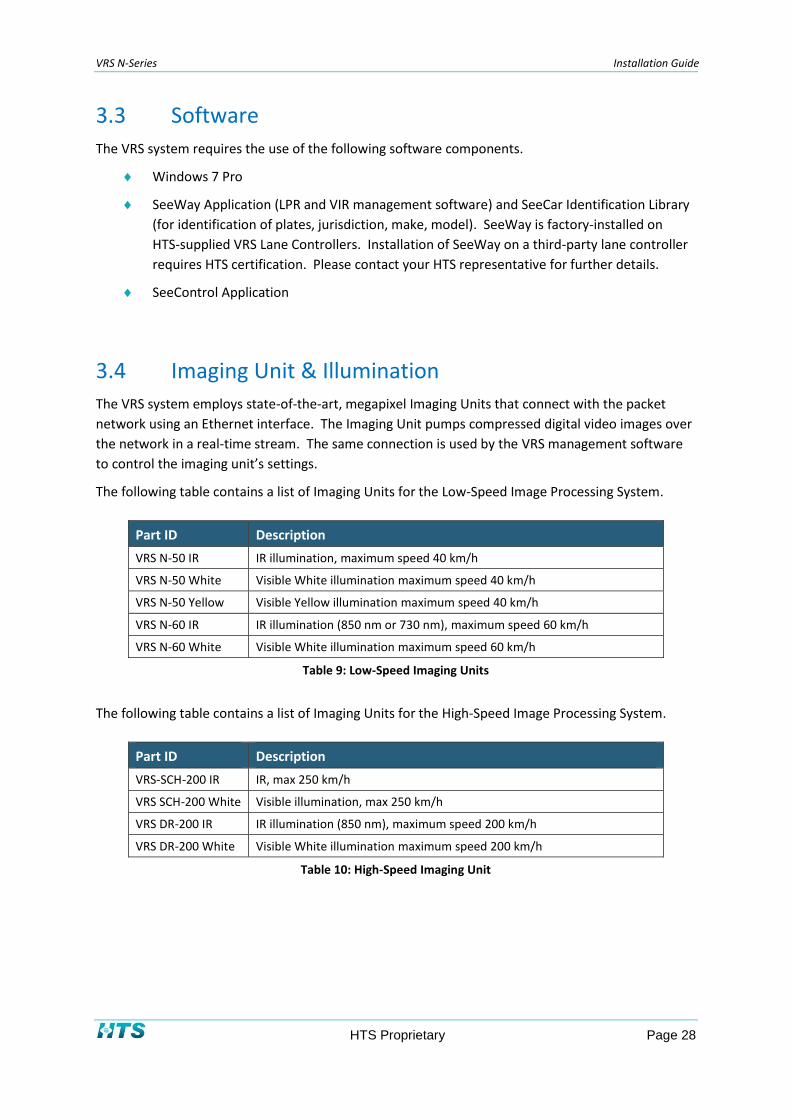
Dimensions
Figure 12: L-100/L-200 Dimensions

VRS N-Series Installation Guide
HTS Proprietary Page 39
3.5 I/O Equipment
ADAM-6060 Overview 3.5.1
HTS supplies an I/O module – the ADAM-6060 – for connecting lane equipment with the Lane
Controller.
Figure 13: ADAM-6060 I/O Module
The N-50 unit has a single input line and a single output line, allowing the installer to connect a
trigger device to the input line and an access control device to the output line. No additional I/O
equipment is required.
The SCH-200 Unit has no I/O lines, therefore the above-mentioned ADAM-6060 I/O module should
be deployed.
ADAM-6060 Specification 3.5.2
General
LAN 10/100Base-T(X)
Connectors 1 x RJ-45 (LAN), Plug-in screw terminal block (I/O and power)
Power Consumption 2 W @ 24 VDC (ADAM-6060), 2.5 W @ 24 VDC (ADAM-6066)
Power Input 10 – 30 VDC
Digital Input
Channels: 6
Dry Contact – Logic level 0: close to GND, Logic level 1: open
Wet Contact – Logic level 0: 3 VDC, Logic level 1: 10 – 30 VDC
Relay Output

VRS N-Series Installation Guide
HTS Proprietary Page 40
Channels: 6
Contact Rating (Resistive) ADAM-6060: 120 VAC @ 0.5 A, 30 VDC @ 1 A
Total Switching Time: 10 ms, Switching Capacity: 20 operations/minute
Protection
Isolation Voltage: 2,000 VDC
Power Reversal Protection
Environment
Operating Temperature: +10°C to +70°C (50°F to 158°F)
Storage Temperature: -20°C to 80°C (-4°F to 176°F)
Operating Humidity: 20% to 95% RH (non-condensing)
Storage Humidity: 0% to 95% RH (non-condensing)

VRS N-Series Installation Guide
HTS Proprietary Page 41
3.6 Detectors
Loop Detector 3.6.1
HTS can supply loop detectors (ground loop controllers) from Matrix and Feig.
A loop detector from Matrix appears in the photo below.
Figure 14: Matrix Loop Detector
Loop detectors selected by HTS customers should comply with the following specifications:
VRS N-Series Installation Guide
HTS Proprietary Page 42
Figure 15: Loop Detector Specifications
The loop detector has the following connections:
Power: 2 wires supplying 24VDC
Loop in: 2 wires (1 twisted pair) from the loop in the road
"Presence" out – 2 dry contact wires (open or closed) connected to the Imaging Unit

VRS N-Series Installation Guide
HTS Proprietary Page 43
Infrared (IR) Beam (Optional) 3.6.2
An infrared beam generator can optionally be used as a detector instead of the loop detector. HTS
supplies Allen-Bradley IR sensors from Rockwell Automation. A datasheet appears in the figure
below. For further details, see:
http://ab.rockwellautomation.com/sensors-switches/laser-sensors/42gr-lasersight-9000-laser-
sensors
Allen-Bradley Photoelectric Sensors
Figure 16: Allen-Bradley Photoelectric Sensor Datasheet

VRS N-Series Installation Guide
HTS Proprietary Page 44
3.7 VRS Controller Cabinet
The VRS Controller Cabinet serves as a connectivity access point for the entire VRS system. The
cabinet is a weather-proof enclosure that houses the following items:
Lane controller (The environmentally hardened LC-2000/2100 Outdoor LC)
Power supply for supporting the lane controller
The VRS Controller Cabinet also can house the following optional items:
Ground loop controllers.
Switch
I/O module (ADAM-6060) & Relay board
Gate control equipment
Media converter
Power supply for supporting the Imaging unit(s) lane controller(s), I/O modules, and
ground loop controllers
Figure 17: VRS Controller Cabinet
NOTE
The VRS Controller Cabinet and components can be purchased from HTS. Please contact your HTS representative for
details.
If the controller cabinet is to be used is not supplied by HTS, please ensure that the cabinet and installed components are
certified and approved by the CE.
VRS controllers can be housed in one of three VRS Controller Cabinets:
VRS Small Controller Cabinet. Operating temperature range: 0oC to 50oC
VRS Medium Controller Cabinet. Operating temperature range: -20oC to 50oC
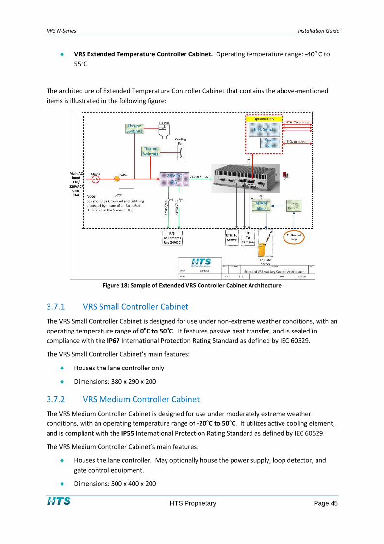
VRS N-Series Installation Guide
HTS Proprietary Page 45
VRS Extended Temperature Controller Cabinet. Operating temperature range: -40o C to
55oC
The architecture of Extended Temperature Controller Cabinet that contains the above-mentioned
items is illustrated in the following figure:
Figure 18: Sample of Extended VRS Controller Cabinet Architecture
VRS Small Controller Cabinet 3.7.1
The VRS Small Controller Cabinet is designed for use under non-extreme weather conditions, with an
operating temperature range of 0oC to 50oC. It features passive heat transfer, and is sealed in
compliance with the IP67 International Protection Rating Standard as defined by IEC 60529.
The VRS Small Controller Cabinet’s main features:
Houses the lane controller only
Dimensions: 380 x 290 x 200
VRS Medium Controller Cabinet 3.7.2
The VRS Medium Controller Cabinet is designed for use under moderately extreme weather
conditions, with an operating temperature range of -20oC to 50oC. It utilizes active cooling element,
and is compliant with the IP55 International Protection Rating Standard as defined by IEC 60529.
The VRS Medium Controller Cabinet’s main features:
Houses the lane controller. May optionally house the power supply, loop detector, and
gate control equipment.
Dimensions: 500 x 400 x 200

VRS N-Series Installation Guide
HTS Proprietary Page 46
VRS Extended Temperature Controller Cabinet 3.7.3
The VRS Extended Controller Cabinet is designed for use under extreme weather conditions, with an
operating temperature range of -40oC to 55oC. It utilizes active heating and cooling elements, and is
compliant with the IP55 International Protection Rating Standard as defined by IEC 60529.
The VRS Extended Temperature Controller Cabinet’s main features:
Dimensions: 500 x 400 x 200
Fan Module + Heater Module
A photo detailing the components of the Extended Temperature Controller Cabinet appears below in
Figure 19.
Figure 19: Sample Extended Controller Cabinet with Assembled Components

VRS N-Series Installation Guide
HTS Proprietary Page 47
The following table lists the components assembled in the sample Extended Controller Cabinet
shown in Figure 19:
Component
#
Description
1 PS
2 SA Surge Arrester
3 CB1 Main
4 CB2 Power Supply
5 SW21 PS TO CAM #1
6 SW22 PS TO CAM #2
7 SW23 PS TO CAM #3
8 SW24 PS TO CAM #4
9 TF HEATER FUSE
10 TF HEATER FUSE
11 Relay Board
12 I/O Module ADAM-6060
13 Ethernet Switch
14 T.B #1
15 T.B #4
16 LOOP DET #1
17 LOOP DET #2
18 EKI-2728
19 Fan
20 Heater
Table 14: Components in Extended Controller Cabinet

VRS N-Series Installation Guide
HTS Proprietary Page 48
VRS Controller Cabinet Summary 3.7.4
The following table provides summary information on VRS Controller Cabinet offerings from HTS:
Table 15: VRS Controller Cabinets
VRS Controller Cabinet Small Medium Extended
Environmental
Working Temp. 0°C to 55°C -20°C to 55°C -40°C to 55°C
Storage Temp. -40°C to 75°C
IP Rating IP67 IP55
Relative Humidity 95% @ 40°C (non-condensing)
Altitude 10,000 Feet
Electrical Interface
AC Input 220 VAC / 50 Hz or 120 VAC / 50-60 Hz
Power Out ----- 24VDC/6.4A 24VAC/5A
24VDC/10A
24VAC/5A
HW Interface
Loop Detector (Optional)
----- Yes Yes
Gate control (Optional) ----- Yes Yes
LAN (1G) 8 Channels
Lane Controller LC2000, LC2100 Yes Yes Yes
Mechanical
Dimensions L 380 W 290 H 200
L 500 W 400 H 200
L 500 W 400 H 200
Mount Type Wall or Pole or Gantry Mount
Color Gray (RAL7035)
Material Reinforced Polyester
General
Front door: Full door opens over 90° and locked with key.
Controller Cabinet is resistant to harsh weather conditions and ultraviolet radiation.

VRS N-Series Installation Guide
HTS Proprietary Page 49
VRS Controller Cabinet Ordering/Assembling 3.7.5
The VRS Controller Cabinet is not supplied as part of the VRS system. Nevertheless, it can be
purchased either from HTS, or from a third-party vendor. A detailed wiring diagram for the VRS
Controller Cabinet is presented in Appendix B.
NOTE
HTS recommends purchasing the fully-assembled VRS Controller Cabinet directly from HTS.
3.7.5.1 I/O Module
The ADAM-6060 I/O Module is used to connect the VRS Lane Controller with loop triggers and loop
control devices. See section 3.5 for further information on the ADAM-6060.
3.7.5.2 HASP
HASP is a hardware-key based software licensing solution that protects software vendors from
unauthorized use or distribution of their product. When attached to the USB port of a computer,
the HASP allows for seamless use of the software.
Figure 20: HASP Security Key
3.7.5.3 Controller Cabinet Power Supply
The VRS Controller Cabinet requires a 24 VDC power supply for supporting the lane controller(s), I/O
modules, relays, and loop controllers.
3.7.5.4 Media Converter (Optional)
HTS offers an Ethernet-to-Fiber Optic media converter for deployment scenarios in which the Server
PC is located over 80 meters from the VRS installation. The Advantech EKI-2741 (see the figure
below) supports Ethernet and Fiber Optic ports and serves as a range extender for VRS deployments.
Two types of media converter switches are available:
Single-mode (LX): When single-mode fiber optic cables are deployed
Multi-mode (SX): When multi-mode fiber optic cables are deployed

VRS N-Series Installation Guide
HTS Proprietary Page 50
Figure 21: Advantech EKI-2741 Media Converter
3.8 Optional Components
The system can be ordered with any of the following optional components:
Equipment Type Part ID Description
VRS Controller Cabinet CC-2000 Standard Cabinet
VRS Controller Cabinet CC-2100 Equipped Controller Cabinet
VRS Controller Cabinet CC-2200 Extended Temperature Equipped Controller Cabinet
VRS Controller LC-1000 19” Rack Mount, Configured for SeeWay (Instead of LC-2000)
Server Controller LC-2100 19” Rack Mount, Configured for SeeWay & SeeControl (Instead of LC-2100)
Communications WiFi Wireless (per unit)
Communications GPRS GPRS (per unit)
Triggers LDMS-545012 Loop Detection Matrix Set
Triggers 547007/8 IR Transmitter/Receiver
Illumination Unit SIL-200 White Illumination Unit SIL-200
Table 16: Optional Equipment

VRS N-Series Installation Guide
HTS Proprietary Page 51
Chapter 4 Planning the Installation and Infrastructure
This chapter describes the mechanical installation of the N-50 and SCH-200 Imaging Units and a
detector in a single-lane installation. For multiple-lane installations, repeat the instructions for each
lane.
4.1 General Considerations
IMPORTANT: The design and construction of all pole and gantry installations are the sole
responsibility of VRS users. Your HTS representative is available for consultation in planning
the installation.
Your pole and/or gantry installation should comply with the following basic requirements:
The gantry-based Imaging Unit should be installed at a height of approximately 7 meters.
The pole-based Imaging Unit should be installed at a height equivalent to ½ the distance to
the vehicle’s plate.
No object (such as a barrier) should obstruct the view of the Imaging Unit.
The Imaging Unit should be securely fastened to avoid movement in the event of strong
winds.
The base of the pole/gantry should be firmly anchored to a layer of concrete that has been
inspected and approved by certified construction engineers.
Poles should be between 3.5-4 inches (8-10 cm) in diameter in order to properly attach the
bracket.
Optical Considerations 4.1.1
For standard applications, a lens should be selected according to the following criteria:
Required field-of-view (FOV)
Distance to the plate (D)
Sensor size (S)
Focus (F)
Calculations have been performed by HTS. FOV and distance considerations for each imaging unit
are discussed in the following sections.

VRS N-Series Installation Guide
HTS Proprietary Page 52
4.1.1.1 Optical Considerations for the N-50 and N-60
The N-50 has a 9-22 mm varifocal lens. You can easily calculate the distance to the plate based on
the FOV.
In the following table, you will find the recommended FOV and distance from the Imaging Unit to the
plate for each lens ring position.
N-50 Min Distance Min FOV Max Distance Max FOV
Lens 9-22 mm 4 m 2.5 m 12 m (20 m with extra illumination) 4 m
Table 17: N-50 Imaging Unit FOV & Distance Table
N-60 Min Distance Min FOV Max Distance Max FOV
Lens 3-9 mm 1.5m 2.5m 9m 4m
Table 18: N-60 Imaging Unit FOV & Distance Table
4.1.1.2 Optical Considerations for the SCH-200 / DR-200
The following is a list of megapixel lenses for SCH-200 / DR-200 Imaging Unit recognition
applications. All lenses feature manual focusing and a manually adjustable iris.
8 mm – for short-range images
12 mm – for use with wide (~50 cm) plates
16 mm – for typical pole/wall applications
25 mm – for long-range images
35 mm – for typical gantry applications
In the following lookup table, you will find the recommended SCH-200/DR-200 Imaging Unit lens size
(in mm) for the required FOV and the distance from the Imaging Unit to the plate. Please note that
not all combinations are supported by HTS’s Imaging Unit offerings – these are marked with the
symbol N/A (not applicable).

VRS N-Series Installation Guide
HTS Proprietary Page 53
FOV for Fixed-Length Lenses (in meters)
Distance (in meters) 2 2.5 3 3.5 4
3 8mm N/A N/A N/A
3.5 8mm 8mm N/A N/A
4 8mm 8mm 8mm N/A
4.5 16mm 12mm 8mm 8mm 8mm
5 12mm 12mm N/A N/A
5.5 16mm 12mm N/A N/A
6 16mm 12mm 12mm N/A
6.5 16mm 12mm 12mm N/A
7 16mm 16mm N/A N/A
7.5 16mm 16mm N/A N/A
8 16mm 16mm 16mm N/A
8.5
16mm 16mm N/A
9 25mm 25mm 16mm 16mm 16mm
9.5 25mm 25mm N/A N/A N/A
10 35mm 25mm N/A N/A N/A
10.5 25mm 25mm N/A N/A
11 25mm 25mm N/A N/A
11.5 25mm 25mm N/A N/A
12 25mm 25mm N/A N/A
12.5 35mm 25mm 25mm N/A
13
25mm 25mm N/A
13.5 35mm 35mm 25mm 25mm N/A
14 35mm 35mm 25mm 25mm 25mm
14.5 35mm 35mm N/A N/A
15 35mm 35mm N/A N/A
15.5 35mm 35mm N/A N/A
16 35mm 35mm N/A N/A
16.5 35mm 35mm N/A N/A
17 35mm 35mm 35mm N/A
17.5 35mm 35mm 35mm N/A
18 35mm 35mm N/A
18.5 35mm 35mm N/A
19 35mm 35mm 35mm 35mm N/A
19.5 35mm 35mm 35mm 35mm 35mm
20 35mm 35mm 35mm 35mm 35mm
Table 19: SCH-200 / DR-200 Imaging Unit and Lens Lookup Table

VRS N-Series Installation Guide
HTS Proprietary Page 54
Optical Considerations for Non-Standard Installations 4.1.2
Non-standard installations may be required in the following cases:
Some countries use non-reflective plates – in this case, illumination is required. In
addition, installation ranges should be short as possible.
Special gate requirements (use of gates may require a smaller lens for close-in images or a
larger lens for greater distances).
Optical Considerations for Overview Imaging Units 4.1.3
For overview (color) Imaging Units, use of an auto-iris, manual-zoom lens is optional.
4.2 Preparing Pole Design
Height of Imaging Unit 4.2.1
4.2.1.1 Typical Heights
For most deployments, the recommended height for an SCH-200 pole installation is 1.3 meters. In
general, the installation should be within a range of 0.8 meters – 2.0 meters.
Figure 22: Typical Height for Pole Mount Installation
The recommended height optimizes performance by allowing the Imaging Unit to look downwards in
order to minimize the sun’s effect – since most plates are mounted at a height of 0.20 to
1.25 meters.

VRS N-Series Installation Guide
HTS Proprietary Page 55
4.2.1.2 Higher Installations
The maximum height for pole installations is approximately 3 meters. In general, the height should
be approximately half the distance between the loop and the pole or gantry. For such installations,
the Imaging Unit should be angled so that the center of the vertical field of view is aimed at the
trigger area.
For higher installations, consult the HTS support team at [email protected].
4.2.1.3 VIR Installations
A VIR (Vehicle Identity Recognition) deployment requires the same installation, but with additional
attention to the positioning of the extra illuminator.
The VIR illuminator is mounted close to the vehicle in order to achieve the high level of illumination
required for VIR. The formula for placement of the illuminator is one-tenth of the distance between
the Imaging Unit and the plate.
Front Capture Installation 4.2.2
This section provides information on installing an Imaging Unit to capture an image of the front of
the vehicle.
4.2.2.1 Adjacent to the Traffic Lane – Standard Lens and Plates
Install the pole/wall/controller cabinet 1.5-2.0 meters behind the barrier, in the direction of traffic,
at the side of the lane (as near as possible to the lane). See “B” in Figure 23. The distance from the
detection point to the vehicle plate is represented by “A” in Figure 23.
To select the proper Imaging Unit configuration:
1. Choose the Imaging Unit resolution based on the required field-of-view.
2. Determine the optimal distance from the Imaging Unit to the plate.
3. Use the field-of-view and the distance to select a lens from the lookup table (Table 19).
The following diagram shows the setup for an access control system. Note that the barrier (gate) is
optional and is used only in access-control (such as parking) installations.

VRS N-Series Installation Guide
HTS Proprietary Page 56
Figure 23: Front Capture Installation Distances
In the figure above, “A” represents the distance from the loop to the Imaging Unit. “B” represents
the distance from the barrier to the Imaging Unit.
The images will be captured at a point that is 0.5-1.0 meters beyond the line of detection, as the
vehicle comes to a halt. In the stop position, it is recommended that the plate will still be visible so
that the capture can be repeated in case the recognition failed.
IMPORTANT: Check if the barrier blocks the effective recognition view zone, which is the area from the start of detection, plus an additional 1.0-1.5 meters. In most gates, the barrier height is 0.80-1.20 meters, which should not cause blocking. The system should be tested with the barrier.
4.2.2.2 Adjacent to the Traffic Lane – Distance from Pole to Lane
The distance between the Imaging Unit and the side of the lane is labeled as “C” in Figure 23 above.
The distance should be in the range of 0.2-0.5 meter.

VRS N-Series Installation Guide
HTS Proprietary Page 57
Rear Capture Installation 4.2.3
This section provides information on installing a Imaging Unit to capture an image of the rear of the
vehicle.
The installation of the Imaging Unit/illumination unit behind the Vehicle is possible and may occur in
the following cases:
When a front installation is not possible due to traffic lane limitations (for example, if the
area in front of the Imaging Unit is located in a public area where no installation is
permitted).
When only rear plates are used.
When additional recognition resources are desired in order to increase the recognition
coverage (a dual-Imaging Unit per lane installation).
Figure 24: Rear Capture Installation Distances

VRS N-Series Installation Guide
HTS Proprietary Page 58
In a rear-capture installation, the detector should be defined in the SeeWay application as active
when the vehicle leaves the detection zone.
The distance between the loop and the Imaging Unit is labeled as “A” in Figure 24 above.
Select the optimal Imaging Unit and lens for the required field-of-view and distance, using the
lookup table (Table 19).
The distance between the Imaging Unit and the side of the lane is labeled as “C” in Figure 24. The
distance should be in the range of 0.2-0.5 meter.
4.2.3.1 Adjacent to the Traffic Lane – Distance from Pole to Lane
As with the front capture Imaging Unit, install the SCH-200 as close as possible to the traffic lane,
within a distance of 0.2-0.5 meters. See “C” in Figure 24.
Front and Rear Capture (Stereo) Installation 4.2.4
This section provides information on installing a Imaging Unit to capture an image of both the front
and the rear of the vehicle.
The VRS system can operate in dual-Imaging Unit per lane (“stereo”) mode. In this mode, two
Imaging Units are used to recognize a vehicle. The application uses special logic that takes both
results into consideration before registering the license plate number. For access control, the gate is
opened by recognition of either the front or the rear plate, so there is no additional delay in opening
the gate.
VRS can be set to take pictures from both Imaging Units at the same detection time on the same
loop event. In this configuration, a single sensor is shared by the front and rear Imaging Unit. In this
single-loop mode, the system is configured to activate the front and rear Imaging Unit either at the
rise of the sensor signal, or at the fall of the sensor signal. In this case, the rear imaging unit will be
configured to be the lead imaging unit and the front imaging unit will be the secondary imaging unit.
Installation of the single-loop Stereo mode is illustrated in Figure 25 below.

VRS N-Series Installation Guide
HTS Proprietary Page 59
Figure 25: Front and Rear Capture Installation Distances
The installation procedure is identical for installing front and rear systems, as described in the
previous sections. However, note that in case of the single-loop stereo, the loop must be installed
farther from the gate (as shown in Figure 25), so that the vehicle will clear the loop before stopping
at the barrier.
Choose an Imaging Unit resolution (High-Speed or Low-Speed) for the required field-of-view using
the lookup table (Table 19).
Based on site photography requirements, select the Imaging Unit-to-plate distances “A Front” and
“A Rear” (see Figure 25), and select the appropriate lens from the lookup table (Table 12).
When operating in stereo mode, the trigger should be set to "Sensor Rising" on both Imaging Units,
or to "Sensor Falling" on both Imaging Units.
Refer to Figure 25 in order to calculate distances for stereo mode operation.

VRS N-Series Installation Guide
HTS Proprietary Page 60
NOTE
For guidance, consult the HTS support team at [email protected].
4.3 Preparing Gantry Design Drawings
Two-Lane Gantry Design 4.3.1
VRS systems are typically installed on gantries over the middle of traffic lanes. The figure below
depicts a typical two-lane installation. In this installation, two DPUs and two SCH-200 imaging units
are used.
Units providing extra illumination should be placed adjacent to the Imaging Unit. The distance
between the illuminator and the Imaging Unit should be 1/10 of the distance between the vehicle
and the Imaging Unit. For example, if the distance to the vehicle is 15 meters, then the illuminator
should be placed 1.5 meters from the Imaging Unit.
Figure 26: Two-Lane Gantry Design

VRS N-Series Installation Guide
HTS Proprietary Page 61
In Figure 26 above, a detector is located 15 meters from the Imaging Unit, represented by “A”. The
system begins capturing plate images, whereas the last plate capture takes place at a distance of
approximately 19 meters (depending on vehicle speed).
4.4 Detector Installation
Loop Design 4.4.1
The loop is cut into the asphalt in the road. The loop should cover an area of 1 meter x 2 meters,
and should have four turns.
Figure 27: Basic Loop Detector Scheme
In case of two or more lanes, the loops will be laid out side by side. A minimum spacing of 1 meter
should separate adjacent loops.
Detector Selection 4.4.2
Different models of dry-contact sensors can be deployed in a VRS installation.
Sensors must consistently produce a single, continuous contact during the presence of the vehicle,
without producing multiple contacts (such as those caused by wheels when using pressure-type
detectors).
Magnetic loop detectors are most suitable for the VRS. They have the best detection rate, and a low
false-detection rate.
It is recommended to select a loop detector type with the following features:
Relay output (which connects a dry-contact to the terminal block).
Short response time. This will prevent adding a delay which might cause faster-moving cars
to be detected outside the field of view. HTS recommends a detector with a response time
of less than 50 msec, such as Matrix or other “traffic detector” models.
A single-ground loop is preferred to a dual detector, for faster response times.
VRS N-Series Installation Guide
HTS Proprietary Page 62
Speed Bumps 4.4.3
Speed bumps offer the following advantages:
Speed bumps slow down the traffic, so that the system can capture more images and thus
increase the recognition rate.
They separate the cars, so that two cars will not be seen as one. If a trailing vehicle is too
close to the leading car, the loop detector may not drop the signal.
Speed bumps force vehicles to slow down when approaching the gate.
The speed bumps should be installed close to the loop detector, approximately 1 meter before the
loop.
NOTE
Be careful not to install the speed bumps too close to the loop, as they might cause vehicles to rise up while their image is
being captured.

VRS N-Series Installation Guide
HTS Proprietary Page 63
Chapter 5 Lane Controller Installation
5.1 Overview
The VRS Controller Configurator is used to manage the basic settings of the VRS Controller:
Allocation of IP addresses to the Ethernet ports of the VRS Controller
VRS Controller name
Windows-based user ID and password
Connectivity to the SeeControl Server
A diagram depicting the Lane Controller and its connections appears in Figure 18.

VRS N-Series Installation Guide
HTS Proprietary Page 64
5.2 HASP License Plug Driver
The license plug (HASP) dongle is normally installed on the lane controller. However if you receive a
massage that the HASP is not installed, then you will need to install a driver. The installation
program is included in the SeeWay driver directory.
To install the HASP driver:
1. Connect the HASP dongle to a USB port on the lane controller.
2. Upload the HASP driver from the HTS site and run the hdd32.exe installation application.
5.3 Operation
The VRS Controller Configurator is executed automatically when the Lane Controller’s Windows
operating system is started for the first time. It can also be run at any time by double-clicking on the
icon shown below in Figure 28.
Figure 28: VRS Controller Configurator Icon
NOTE
In order to ensure proper data connectivity, the VRS Controller should be connected to the network BEFORE executing the
VRS Controller Configurator.

VRS N-Series Installation Guide
HTS Proprietary Page 65
To configure the VRS Lane Controller:
1. Make sure that the VRS Lane Controller is connected to the network.
2. Double-click on the icon shown in Figure 28 above. The configurator’s Welcome window
appears as depicted in Figure 29 below.
Figure 29: Welcome Window
3. Click Next to continue. The IP Configuration window appears as shown in Figure 30
below.

VRS N-Series Installation Guide
HTS Proprietary Page 66
Figure 30: IP Configuration Window
4. If required, you can enter a new controller name in the New controller name field.
5. Select the IP address of the Ethernet port you wish to modify from the IP address to
modify list box. (Note: In most cases, only one IP address will appear in the list box).
The address values appear in the New IP address text boxes. Modify the address (and
the Subnet Mask if necessary), and click on Set IP Settings to save the change. If
required, modify the Default Gateway, and click on Set Gateway to save the change.
Repeat this step with the other Ethernet ports as required.
6. Click Next. The User Configuration window appears as depicted in Figure 31 below.

VRS N-Series Installation Guide
HTS Proprietary Page 67
Figure 31: User Configuration Window
7. Enter your password in the Password field to continue.
8. If desired, you can change the Windows user and/or the password of the VRS Controller.
Enter the new user name in the Set user name field, and click on Set new password. Two
text fields appear, enabling you to enter and confirm the new password.
9. Click Next. The SeeControl Configuration window appears as shown in Figure 32 below.

VRS N-Series Installation Guide
HTS Proprietary Page 68
Figure 32: SeeControl Configuration Window
10. Enter the URL or IP address of the SeeControl Server to establish connectivity with
SeeControl. Enter the SeeControl administrator’s User name and Password.
11. Click Next. The Configuration Summary window appears as shown in Figure 33 below.

VRS N-Series Installation Guide
HTS Proprietary Page 69
Figure 33: Configuration Summary Window
12. To complete the activity, you can check one of the following check boxes in the window:
Start VRS Controller Configurator next time Windows is started. Check this box in
case further configuration is necessary.
Start SeeWay. Initializes the SeeWay application.
13. Click Finish.

VRS N-Series Installation Guide
HTS Proprietary Page 70
Chapter 6 Imaging & Illumination Unit Installation
This chapter contains easy step-by-step instructions for installing the imaging and illumination units.
6.1 N-50 Imaging Unit Installation
The N-50 Imaging Unit can be installed on a gantry, or on a pole or wall.
Preparing for the Installation 6.1.1
6.1.1.1 Unpacking the Unit
Check that everything in the packing box matches the order form and the packing slip. The items
below are found in the packing box:
One N-50 Imaging Unit
One 2-pin terminal block for power input
One printed quick installation guide
One BNC video monitor cable
One mounting template
Six screw anchors
Six M4 screws
One pole mount adapter
5" stainless steel band with screw clamps
Please contact HTS if any item is missing.
6.1.1.2 Checking for Damage
When first unpacking, please check if there is any visible damage to the unit and its accessories. The
protective materials used for the packaging should be able to protect the unit from most forms of
damage during transportation.
NOTE
Please contact HTS if the item or any of its accessories is damaged.

VRS N-Series Installation Guide
HTS Proprietary Page 71
6.1.1.3 Tools for Installation
The following tools will help you complete the installation:
Electric drill
Screwdrivers
Wire cutters
Mechanical Installation 6.1.2
6.1.2.1 Mounting the unit on a ceiling/wall
Use the mounting template supplied with each N50 imaging unit to mark and locate the center point
of the 6 holes of the base bracket in the desired location.
The size of the holes
Inner: Ø3.3-6x for TP4 type screws TP4 type
Outer: Ø6.0-6x for plastic anchor
Drill holes in the ceiling/wall, and insert the plastic anchors in the holes. Affix the mounting base,
and then fasten the Imaging Unit in place with the screws.
Figure 34: Mounting the Imaging Unit
Fasten the safety wire as illustrated in the following figure:

VRS N-Series Installation Guide
HTS Proprietary Page 72
Figure 35: Fastening the Safety Wire
6.1.2.2 Mounting the unit on a pole
To mount the N-50 Imaging Unit on a pole:
1. Fasten the pole mount adaptor with to the pole using a 5" metal band, as described in
the figure below:
Figure 36: Fastening the Adaptor to the Pole with a Metal Band
2. Fasten the imaging unit to the pole mount adaptor using six M4 screws as shown in the
figure below.
Figure 37: Attaching the Imaging Unit to the Pole Mount Adaptor

VRS N-Series Installation Guide
HTS Proprietary Page 73
Figure 38: Pole-Mounted Imaging Unit
HAZARD: Check the material used in the mounting surface. Different screws and anchors
than those supplied may be required. To prevent the unit from detaching from the
mounting surface, ensure that it is mounted in a highly secure location (ceiling slab or
channel).
HAZARD: To prevent damage and injury, use a safety wire, connecting one end to the
wall/ceiling and the other end to the unit’s safety-cord screw. Use a safety wire strong
enough to withstand the total weight of the unit. Pay special attention to the attachment of
the unit to the end of the wire.
6.1.2.3 Removing the IR filter
N-50 Imaging Units with IR LEDs are supplied with an 850 (25) nm IR filter.
The filter is factory-installed in the N-50 Imaging Unit. You may choose to remove it for one of the
following reasons:
Color images are required during the daytime.
The imaging unit must be able to read non-reflective plates.
NOTE
If you wish to remove the filter, contact HTS for information on how to remove it.
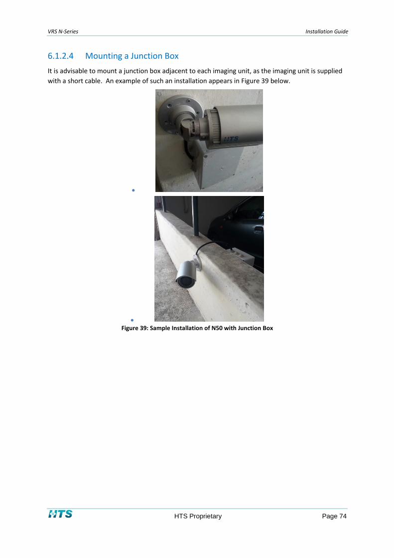
VRS N-Series Installation Guide
HTS Proprietary Page 74
6.1.2.4 Mounting a Junction Box
It is advisable to mount a junction box adjacent to each imaging unit, as the imaging unit is supplied
with a short cable. An example of such an installation appears in Figure 39 below.
●
● Figure 39: Sample Installation of N50 with Junction Box

VRS N-Series Installation Guide
HTS Proprietary Page 75
The junction boxes should be at least 15cm x 15cm. Outdoor installations should comply with IP67
regulations. Indoor installations should comply with IP-54 regulations.
Figure 40: Photo of Junction Box
To mount the junction box:
1. Mount the junction box (JB) on the pole or wall.
2. Drill holes in the ceiling/wall, and insert the plastic anchor.
3. Affix and fasten the junction box in place with screws. The imaging unit requires an M20
thread.
4. Insert and tighten the fitting in the junction box. A sample fitting is shown below in Figure
41.
Figure 41: Fitting (M20 thread, IP65 Compliant)
5. Insert a pipe – a black conduit (internal diameter 16 mm) from the junction box to the
controller cabinet.
NOTE
Parts can be purchased from PM Plastic Materials.
See http://www.pmplasticmaterials.it/webportal/inglese/index.asp

VRS N-Series Installation Guide
HTS Proprietary Page 76
Electrical Installation 6.1.3
6.1.3.1 Connecting the Wires
To connect the powering and communications cables:
1. Pass all the cables through the mounting bracket.
2. Connect the power cable to the power plugs with one of the following options.
24 VAC: Connect the 24V cables to the 24 VAC terminals ~AC 24V
PoE: Connect the RJ-45 jack to a PoE compatible network device that supplies power
via the Ethernet cable
3. Insert the audio and I/O cables to the unit, and connect the network cable’s RJ-45
connector to a switch port.
Figure 42: Connecting the Wires
6.1.3.2 Adjusting the Imaging Unit’s Position
Use a cross-head screwdriver to loosen the cross screw on one side of the mount bracket in a way
that you can adjust the tilt of the imaging unit.
Release the screw on the retaining ring to adjust the imaging unit’s camera angle.
After completing the adjustments, tighten the cross screw and fasten the retaining ring screw.

VRS N-Series Installation Guide
HTS Proprietary Page 77
Figure 43: Adjusting the Imaging Unit’s Position
6.1.3.3 Adjusting the zoom & focus (vari-focal) / default & reset button
Use a screwdriver to adjust the Near/Far and Tele/Wide controls, taking care to avoid damaging the
lens.
Use a flat-head screwdriver to open the cover, allowing you to press the factory settings default
button or the reset (system reboot) button.
Figure 44: Adjusting the Zoom and Focus (Varifocal Lens)
CAUTION: After adjustment, tighten the screws to prevent water from entering the unit.

VRS N-Series Installation Guide
HTS Proprietary Page 78
6.1.3.4 Adjusting the Sun Shield Hood
Move the sunshield hood forward and backward to adjust the shading.
CAUTION: Adjust the sun shield hood in coordination with the lens to properly shade the unit.
Don’t adjust the sun shield’s position excessively, as damage to the housing may occur.
Figure 45: Adjusting the Sun Shield Hood
I/O Connections 6.1.4
The N-50 Imaging Unit’s I/O connector can be connected to lane-based devices (loop controller,
barrier), or as an option, can be connected via an I/O device, such as the ADAM-6060.
For each lane, connect only one of the lane’s imaging units to the I/O device. The other imaging
units should be connected to the lane controller.
Connect the N-50 as specified in the table below.
N-50 Imaging Unit Connector Connection
Power Power Supply
RJ-45 Lane Controller
Alarm In Loop Controller
Alarm Out Barrier
Audio In --
Audio Out --
Table 20: N-50 Imaging Unit Connections

VRS N-Series Installation Guide
HTS Proprietary Page 79
A graphical depiction of N-50 imaging unit’s connectivity appears in Figure 46 below.
Figure 46: N-50 Imaging Unit I/O Connections

VRS N-Series Installation Guide
HTS Proprietary Page 80
Network Installation 6.1.5
6.1.5.1 Network Topology
The N-50 Imaging Unit delivers video images to a Lane Controller in real time, over the Internet and
your Intranet. See Appendix D for wiring instructions.
6.1.5.2 IP Configuration
6.1.5.2.1 Default IP Address
The N-50 Imaging Unit is a network-based unit. Its default IP address and subnet mask are assigned
by the manufacturer:
IP Address: 192.168.0.30
Subnet Mask: 255.255.255.0
6.1.5.2.2 IP Configurator Utility
The IP Configurator is a utility program that helps users to locate and configure the imaging unit in a
local area network. For instructions on operating the utility, see Appendix E.
6.2 N-60 Imaging Unit Installation
The N-60 Imaging Unit can be installed on a gantry, or on a pole or wall.
Preparing for the Installation 6.2.1
6.2.1.1 Unpacking the Unit
Check that everything in the packing box matches the order form and the packing slip. The items
below are found in the packing box:
One N60 Imaging Unit
One printed Quick Installation Guide (this document)
Sunshield
Figure 47: Sunshield
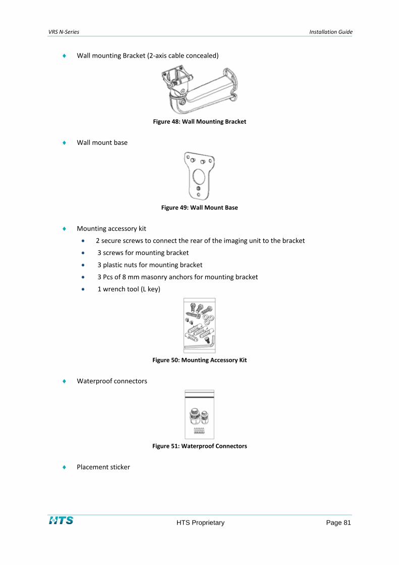
VRS N-Series Installation Guide
HTS Proprietary Page 81
Wall mounting Bracket (2-axis cable concealed)
Figure 48: Wall Mounting Bracket
Wall mount base
Figure 49: Wall Mount Base
Mounting accessory kit
2 secure screws to connect the rear of the imaging unit to the bracket
3 screws for mounting bracket
3 plastic nuts for mounting bracket
3 Pcs of 8 mm masonry anchors for mounting bracket
1 wrench tool (L key)
Figure 50: Mounting Accessory Kit
Waterproof connectors
Figure 51: Waterproof Connectors
Placement sticker

VRS N-Series Installation Guide
HTS Proprietary Page 82
Figure 52: Placement Sticker
Dehumidifier packets inside an aluminum foil bag. The installer has to remove the
aluminum foil bag before using the dehumidifier packets.
Figure 53: Dehumidifier Packet
6.2.1.2 Checking for Damage
When first unpacking, please check if there is any visible damage to the unit and its accessories. The
protective materials used for the packaging should be able to protect the unit from most forms of
damage during transportation.
NOTE
Please contact HTS if the item or any of its accessories is damaged.
6.2.1.3 Tools for Installation
The following tools will help you complete the installation:
Electric drill
Screwdrivers
Wire cutters
Set of hex keys (Allen wrenches)
Mechanical & Electrical Installation 6.2.2
6.2.2.1 Cable Wiring Description
HAZARD: All imaging unit installations should comply with your local electrical safety rules.
The imaging unit features two waterproof connectors; the left one in the diagram is for Ethernet
connection, while right one is for line in and DI/O connectivity.
Figure 54: Imaging Unit Connectors

VRS N-Series Installation Guide
HTS Proprietary Page 83
The right-side connector features four wire holes. Please cover unused holes with sealing plugs to
prevent water from entering.
Figure 55: Covering Unused Wire Holes
Applicable cable diameter:
Ø 2.5~1.8mm (Right)
Ø 6.9~4.7mm (Left)
To connect the imaging unit’s cables:
1. Run the cable inside the wall mount bracket and out through the cable opening at the
front.
Figure 56: Threading the Cable inside the Wall Mount Bracket
2. Press down the push-lock mechanism and secure the imaging unit onto the push-lock.
Wire the network cable to the waterproof connector on the right, and wire the line-in,
DI/O cable to the waterproof connector on the left. Tighten the waterproof connector
after all the cables are secured in place.
Figure 57: Using the Waterproof Connector
3. Secure the imaging unit onto the wall mount bracket using the two screws provided.

VRS N-Series Installation Guide
HTS Proprietary Page 84
Figure 58: Securing the Imaging Unit to the Wall Mount Bracket
4. Open the imaging unit's top cover to access the wired cables. Install the RJ45 connector
to the ends of the network cable and plug it into the corresponding port on the mounting
bracket module.
Figure 59: Wiring the RJ45 Connector
5. Insert the Line in to power pins: Be sure to connect the DC power correctly - insert minus
wire to pin #1 (-) & plus wire to pin #2 (+).
Figure 60: Wiring Power & DI/O to the Imaging Unit
NOTE
If a direct hardware trigger connection is required, connect the ALM IN pair to DI/O Pins #1 & #2.
NOTE
If an opening gate connection is required, connect the ALM OUT pair to DI/O Pins #3 & #4 (for NC) or pin#4 & pin #5 for
(NO).
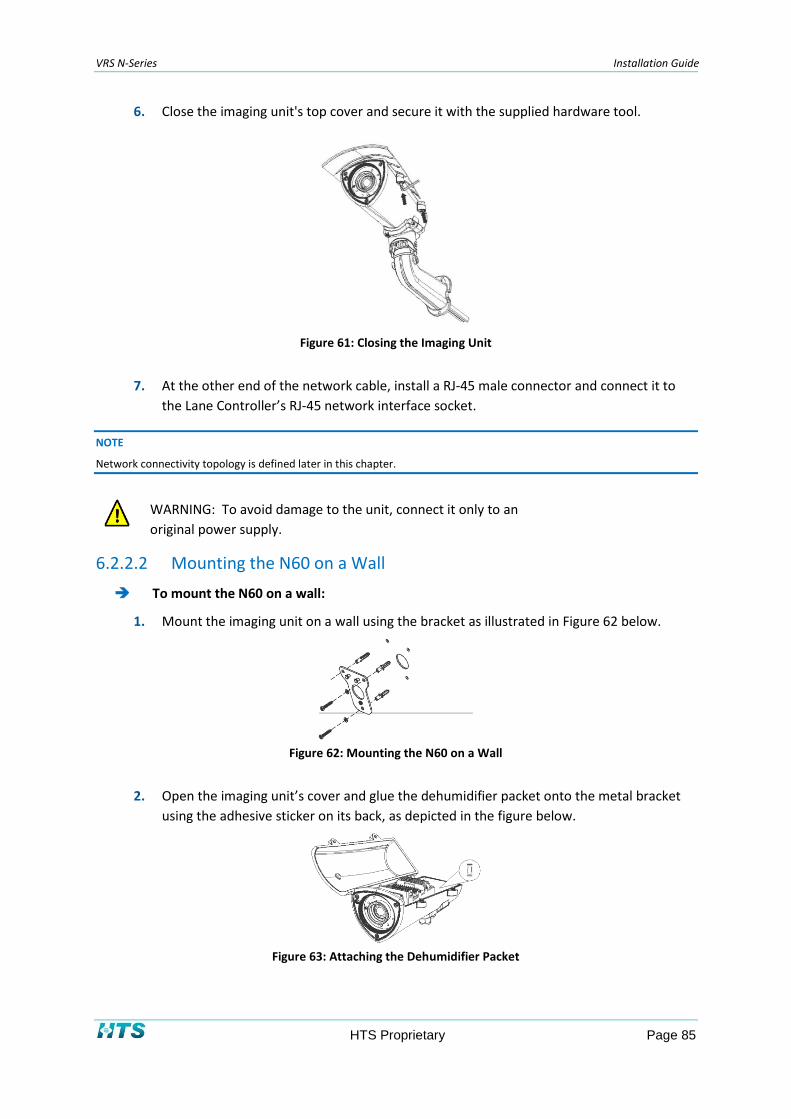
VRS N-Series Installation Guide
HTS Proprietary Page 85
6. Close the imaging unit's top cover and secure it with the supplied hardware tool.
Figure 61: Closing the Imaging Unit
7. At the other end of the network cable, install a RJ-45 male connector and connect it to
the Lane Controller’s RJ-45 network interface socket.
NOTE
Network connectivity topology is defined later in this chapter.
WARNING: To avoid damage to the unit, connect it only to an
original power supply.
6.2.2.2 Mounting the N60 on a Wall
To mount the N60 on a wall:
1. Mount the imaging unit on a wall using the bracket as illustrated in Figure 62 below.
Figure 62: Mounting the N60 on a Wall
2. Open the imaging unit’s cover and glue the dehumidifier packet onto the metal bracket
using the adhesive sticker on its back, as depicted in the figure below.
Figure 63: Attaching the Dehumidifier Packet

VRS N-Series Installation Guide
HTS Proprietary Page 86
3. Close the imaging unit’s cover and ensure the clip is locked in position. Install the
sunshield and tighten the screw on the side of cover.
Figure 64: Attaching the Sunshield
4. Secure the connecting bracket to the rear of the imaging unit. Press and hold down the
latch on the wall mount bracket and put it into the connecting bracket. Once in place,
secure the other side using the supplied hex wrench.
Figure 65: Attaching Imaging Unit to the Connecting Bracket
5. Once in place, secure the other side using the supplied hex wrench.
Figure 66: Attaching Imaging Unit to the Connecting Bracket - Other Side
6. Align the mounting holes on the wall mount bracket to the mounting holes on the wall
mount plate, and then secure it tightly with screws to finish the installation.

VRS N-Series Installation Guide
HTS Proprietary Page 87
Figure 67: Attaching the Wall Mount Bracket to the Wall Mount Plate
6.2.2.3 Mounting the N60 on a Pole
To mount the N60 on a pole:
1. Screw the wall mount base into the pole mount adaptor (PMA-60) using 3 x M8 screws.
(see “Step A” in Figure 68 below).
2. Screw the wall mount bracket on top of the base (see “Step B” in Figure 68 below).
NOTE
The N60 should be pre-screwed onto the wall mount bracket. Cables should be threaded through the bracket, base and
pole mount central hole. See Figure 68 for guidance in positioning the screws. The actual pole mount may be the one
shown or a different one.
Figure 68: Screw Locations in the Pole Adaptor
3. Secure the screws as shown previously in Figure 68.
Figure 69: Pole Mount Adaptor

VRS N-Series Installation Guide
HTS Proprietary Page 88
4. Insert two metal bands in the PMA-60 rectangular holes and stretch them around the
pole.
5. Adjust the N60 imaging unit.
Removing the IR Filter 6.2.3
N-60 Imaging Units with IR LEDs are supplied with one of the following IR filter types:
850 (25) nm
730 (25) nm
The filter is factory-installed in the N-60 Imaging Unit. You may choose to remove it for one of the
following reasons:
Color images are required during the daytime.
The imaging unit must be able to read non-reflective plates.
NOTE
If you wish to remove the filter, contact HTS for information on how to remove it.
Network Installation 6.2.4
6.2.4.1 Network Topology
The N-60 Imaging Unit delivers video images to a Lane Controller in real time, over the Internet and
your Intranet. See Appendix D for wiring instructions.
6.2.4.2 IP Configuration
6.2.4.2.1 Default IP Address
The N-60 Imaging Unit is a network-based unit. Its default IP address and subnet mask are assigned
by the manufacturer:
IP Address: 192.168.0.30
Subnet Mask: 255.255.255.0
6.2.4.2.2 IP Configurator Utility
The IP Configurator is a utility program that helps users to locate and configure the imaging unit in a
local area network. For instructions on operating the utility, see Appendix E.
6.3 SCH-200 Imaging Unit Installation
The SCH-200 Imaging Unit can be installed on a gantry, or on a pole or wall.

VRS N-Series Installation Guide
HTS Proprietary Page 89
Preparing for the Installation 6.3.1
6.3.1.1 Unpacking the Unit
Open the SCH-200 package and make sure that the contents match the order form and the packing
slip. In addition to this guide, items below are included in the package.
One SCH-200 Network Imaging Unit
One printed Quick Installation Guide
1 meter cable and outlet for power input and external illumination
One Ethernet cable outlet with female to female RJ45 connector
One mounting Bracket
3 screws, 3 plastic nuts, and three 8 mm masonry anchors
One hex key (Allen wrench)
One BR-20 pole mount adapter kit (Optional)
Please contact HTS if any of the items listed is missing.
6.3.1.2 Checking for Damage
When first unpacking, please check if there is any visible damage to the unit and its accessories. The
protective materials used for the packaging should be able to protect the unit from most forms of
damage during transportation.
NOTE
Please contact HTS if the item or any of its accessories is damaged.
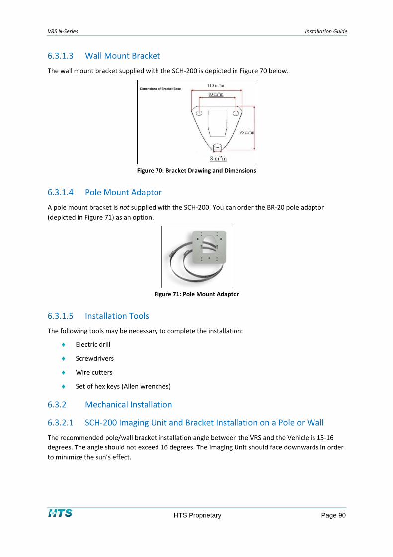
VRS N-Series Installation Guide
HTS Proprietary Page 90
6.3.1.3 Wall Mount Bracket
The wall mount bracket supplied with the SCH-200 is depicted in Figure 70 below.
Figure 70: Bracket Drawing and Dimensions
6.3.1.4 Pole Mount Adaptor
A pole mount bracket is not supplied with the SCH-200. You can order the BR-20 pole adaptor
(depicted in Figure 71) as an option.
Figure 71: Pole Mount Adaptor
6.3.1.5 Installation Tools
The following tools may be necessary to complete the installation:
Electric drill
Screwdrivers
Wire cutters
Set of hex keys (Allen wrenches)
Mechanical Installation 6.3.2
6.3.2.1 SCH-200 Imaging Unit and Bracket Installation on a Pole or Wall
The recommended pole/wall bracket installation angle between the VRS and the Vehicle is 15-16
degrees. The angle should not exceed 16 degrees. The Imaging Unit should face downwards in order
to minimize the sun’s effect.

VRS N-Series Installation Guide
HTS Proprietary Page 91
Since most plates are mounted at a height of 0.20 to 1.25 meters, the recommended height for the
VRS imaging unit is between 1 to 1.5 meters. The maximum height at which the VRS should be
installed is 3 meters. In this case, the Imaging Unit should be positioned in such a way that the
center of the vertical field of view is the trigger area. For higher installations, consult HTS.
The VIR illuminator is mounted close to vehicle in order to reach the high level of illumination
intensity required for VIR. The formula for placement of the illuminator is one tenth of the distance
from the Imaging Unit to the plate.
The following sections provide instructions for mounting the VRS system on a pole or a wall.

VRS N-Series Installation Guide
HTS Proprietary Page 92
6.3.2.1.1 Pole Mounting
To mount the SCH-200 on a pole, use the BR-20 pole adapter depicted in Figure 72 below. The pole
adaptor includes two straps of different sizes to accommodate various pole diameters.
NOTE
The BR-20 pole adaptor is not supplied with the Imaging Unit. It must be ordered separately.
To mount the imaging unit on a pole:
1. Attach the pole adapter to the pole using one of the straps. Tighten the strap.
Figure 72: BR-20 Pole Adaptor
2. Connect the bracket base of SCH-200 to the pole adapter board. Use the three screws
and nuts provided in the BR-20 pole adapter kit. See Figure 73 for guidance in positioning
the screws.
Figure 73: Screw locations in the Pole Adapter
3. Mount the SCH-200 on the pole as demonstrated in the following illustrations:

VRS N-Series Installation Guide
HTS Proprietary Page 93
Figure 74: Mounting the Imaging Unit on a Pole
4. Adjust the Imaging Unit head and secure the screws as shown below in Figure 75. Use
the two screws provided.
Figure 75: Adjusting Imaging Unit Position and Direction

VRS N-Series Installation Guide
HTS Proprietary Page 94
6.3.2.1.2 Wall Mounting
If you are wall mounting the SCH-200, secure the unit to the wall at the same height as in pole
mounting. You may consult HTS support team at [email protected].
To mount the VRS on a wall:
1. Mount the imaging unit on a wall using the bracket as illustrated in Figure 74 above
2. Adjust the position and angle of the imaging unit as shown in Figure 75 above.
NOTE
Depending on the mounting surface’s material, different screws and anchors than those supplied may be required.
6.3.2.1.3 Mounting a Junction Box
It is advisable to mount a junction box adjacent to each imaging unit, as the imaging unit is supplied
with a short cable. For a complete explanation, see the N-50 installation instructions in section 0.
6.3.2.1.4 Flexible Protective Conduits for External Cables
To apply flexible protective conduits for outdoor installations:
1. When installing the SCH-200 outdoors, add a fitting and a black conduit to the mounting
bracket as shown below in Figure 76.
● ● Figure 76: Cabling Pipes and Connectors (for SCH-200)
2. On the back of each SCH-200 imaging unit, flexible protective conduits should be
deployed, as shown in Figure 77 below. HTS recommends use of PG-9 type conduits with
an internal diameter of 12 mm.
Figure 77: Flexible protective conduits

VRS N-Series Installation Guide
HTS Proprietary Page 95
HAZARD: The imaging unit is heavy and could cause damage or personal injury if it falls. To
prevent the imaging unit from falling, ensure that it is mounted firmly on a wall or a pole.
Make sure that a safety wire connects the housing and the cover to prevent damage or
injury in the event that the unit detaches from the wall.
6.3.2.2 Bracket and Imaging Unit Installation on a Gantry
The recommended gantry bracket installation angle between the VRS and the Vehicle is 24-26
degrees. The angle should not exceed 26 degrees. The imaging unit should face downwards in order
to minimize the sun’s effect.
The bracket pictured in the figure below is supplied for Gantry installation. The bracket is factory-
assembled.
Figure 78: Assembled Anodized Bracket
The dimensions of the anodized bracket are depicted in the figure below.
Figure 79: Dimensions of Anodized Bracket
The following pan/tilt bracket screws are supplied together with accompanying spring and flat
washers:

VRS N-Series Installation Guide
HTS Proprietary Page 96
6 X 3/8” screws
3 X 1/4” screws
Figure 80: Pan/Tilt Bracket Screws
Prepare the following additional items for the installation:
Four M8 screws and washers that prevent movement of the base screws.
Soft cloth suitable for cleaning glass
Water repellent – such as Rain X or equivalent solvent
Torque wrench. An example of a suitable torque wrench can be ordered from
http://norbar.com, and is depicted in the figure below.

VRS N-Series Installation Guide
HTS Proprietary Page 97
Figure 81: Torque Wrench
Apply the following torque per screw (lbf-ft):
3/8” screws: 16 lbf-ft
1/4” screws: 4 lbf-ft
M8 screws: 14 lbf-ft
To install the bracket on the SCH-200 Imaging Unit assembly:
1. Unscrew and remove the upper bracket shown in Figure 82 below.
Figure 82: Upper Bracket
2. Attach the upper bracket to the bottom of the Imaging Unit and tighten the screws, as
shown in Figure 83 below.
Figure 83: Upper Bracket attached to Bottom of Imaging Unit

VRS N-Series Installation Guide
HTS Proprietary Page 98
3. Re-attach the upper and lower brackets, and tighten the screws.
4. Attach the base bracket to the gantry with the four M8 screws and washers.
NOTE
Before attaching the bracket, confirm that there is a horizontal base bracket on the gantry that is compatible
with HTS’s bracket. An example of such a base bracket is seen in Figure 84 below.
Figure 84: Gantry Base Bracket
5. Clean the front window of the Imaging Unit with a window spray cleaner.
Electrical Installation 6.3.3
6.3.3.1 Connecting the External Wiring
HAZARD: All imaging unit installations should comply with your local electrical safety rules.
The SCH-200 Imaging Unit is supplied with two 1-meter cables:
CAT-6 Ethernet cable with RJ-45 female to female connector
Cable containing 2 shielded pairs:
Red/black – 24 VDC, 2 amp power feeder
Green/white – sends synchronization pulses to an external illumination source

VRS N-Series Installation Guide
HTS Proprietary Page 99
Figure 85: Connecting the External Wires
To connect the external wiring, use the junction box and connect as follows:
1. Connect the powering pair (red/black) to the 24 VDC power supply.
2. If required, connect the synchronization pair (green/white) to the external illumination
source.
3. Connect RJ-45 male connector of the imaging unit to the Lane Controller using the
female-to-female RJ-45 network interface connector.
WARNING: To avoid damage to the unit, connect it only to a 24VDC/30W power supply.
Network Installation 6.3.4
6.3.4.1 Network Topology
The SCH-200 Imaging Unit delivers video images to a Lane Controller in real time, over the Internet
and your Intranet. See Appendix D for wiring instructions.
6.3.4.2 IP Configuration
6.3.4.2.1 Default IP Address
The SCH-200 Imaging Unit is a network-based unit. Its default IP address and subnet mask are
assigned by the manufacturer:
IP Address: 192.168.0.200
Subnet Mask: 255.255.255.0
6.3.4.2.2 IP Configurator Utility
The IP Configurator is a utility program that helps users to locate and configure the imaging unit in a
local area network. For instructions on operating the utility, see Appendix E.
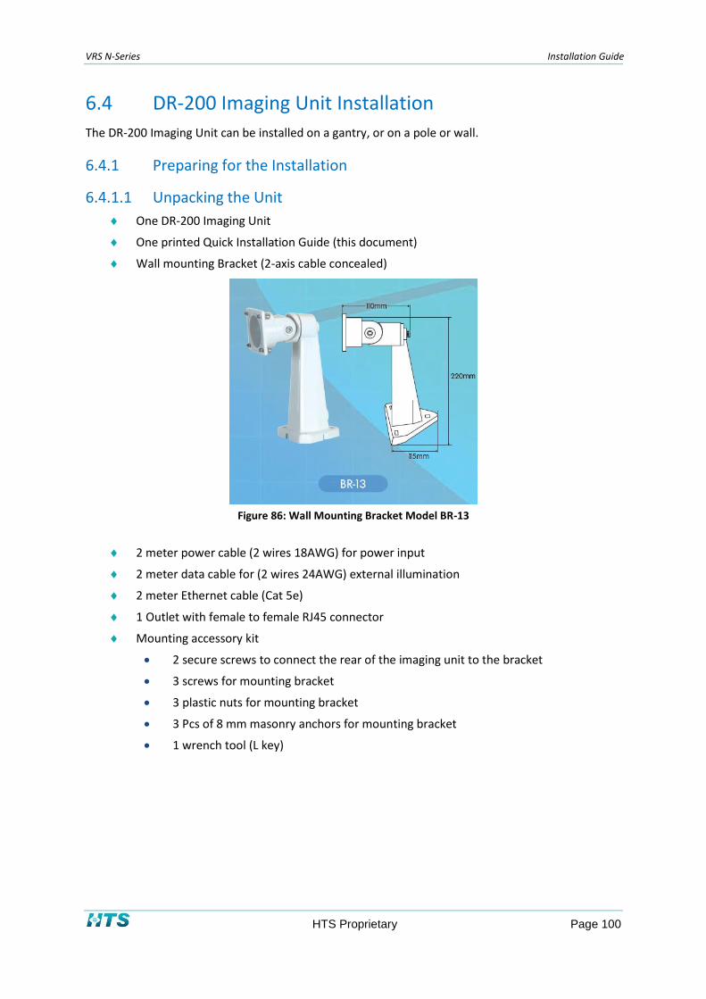
VRS N-Series Installation Guide
HTS Proprietary Page 100
6.4 DR-200 Imaging Unit Installation
The DR-200 Imaging Unit can be installed on a gantry, or on a pole or wall.
Preparing for the Installation 6.4.1
6.4.1.1 Unpacking the Unit
One DR-200 Imaging Unit
One printed Quick Installation Guide (this document)
Wall mounting Bracket (2-axis cable concealed)
Figure 86: Wall Mounting Bracket Model BR-13
2 meter power cable (2 wires 18AWG) for power input
2 meter data cable for (2 wires 24AWG) external illumination
2 meter Ethernet cable (Cat 5e)
1 Outlet with female to female RJ45 connector
Mounting accessory kit
2 secure screws to connect the rear of the imaging unit to the bracket
3 screws for mounting bracket
3 plastic nuts for mounting bracket
3 Pcs of 8 mm masonry anchors for mounting bracket
1 wrench tool (L key)

VRS N-Series Installation Guide
HTS Proprietary Page 101
Figure 87: Mounting Accessory Kit
NOTE
Please contact HTS if any of the items listed is missing.
6.4.1.2 Checking for Damage
When first unpacking, please check if there is any visible damage to the unit and its accessories. The
protective materials used for the packaging should be able to protect the unit from most forms of
damage during transportation.
NOTE
Please contact HTS if the item or any of its accessories is damaged.
6.4.1.3 Pole Mount Adaptor
The pole mount adaptor kit BR-20 (see the figure below) is not supplied with the DR-200. It is
optional to order the adaptor for pole mounting. The installation instructions for pole mounting are
the same as those described for the SCH-200 in section 6.3.
Figure 88: Pole Mount Adaptor
6.4.1.4 Installation Tools
The following tools may be necessary to complete the installation:
Electric drill
Screwdrivers

VRS N-Series Installation Guide
HTS Proprietary Page 102
Wire cutters
Set of hex keys (Allen wrenches)
Mechanical Installation 6.4.2
6.4.2.1 Mounting the DR-200 on a Wall
To mount the DR-200 on a wall:
1. Mount the imaging unit on a wall using the mounting bracket as illustrated in Figure 89
below.
Figure 89: Wall Mount Bracket
2. Adjust the position and angle of the imaging unit as shown in Figure 90 below.
Figure 90: Adjusting the Imaging Unit
NOTE
Depending on the mounting surface’s material, different screws and anchors than those supplied may be required.
HAZARD: The imaging unit is heavy and could cause damage or personal injury if it falls. To
prevent the imaging unit from falling, ensure that it is mounted firmly to a wall or a pole.
Make sure that a safety wire connects the housing and the cover to prevent damage or
injury if the event that the unit detaches from the wall.

VRS N-Series Installation Guide
HTS Proprietary Page 103
6.4.2.2 Mounting the DR-200 on a Pole
To mount the DR-200 on a pole:
1. Follow the pole mounting instructions for the SCH-200 found in section 6.3.2.1.1.
Electrical Installation 6.4.3
6.4.3.1 Connecting the External Wiring
HAZARD: All imaging unit installations should comply with your local electrical safety rules.
The DR-200 Imaging Unit is supplied with three cables (2-meter length for each cable):
CAT-5e Ethernet cable with RJ-45 female to female connector
Line In Cable, containing 2 shielded pairs – red/black – 24 VDC, power feeder
DI/O Cable containing 2 shielded pairs – green/white – sends synchronization pulses to an
external illumination source
Figure 91: Connecting the External Wires
To connect the external wiring:
2. Connect the powering pair (red/black) to 24 VDC power supply.
3. If required, connect the synchronization pair (green/white) to the external illumination
source.
4. Connect RJ-45 male connector of the imaging unit to the Lane Controller by using of
female to female RJ-45 network interface connector.
NOTE
Network connectivity topology is defined in the next paragraph.
WARNING: To avoid damage to the unit, connect it only to a 24VDC power supply.

VRS N-Series Installation Guide
HTS Proprietary Page 104
Network Installation 6.4.4
6.4.4.1 Network Topology
The DR-200 Imaging Unit delivers video images to a Lane Controller in real time, over the Internet
and your Intranet. See Appendix D for wiring instructions.
6.4.4.2 IP Configuration
6.4.4.2.1 Default IP Address
The DR-200 Imaging Unit is a network-based unit. Its default IP address and subnet mask are
assigned by the manufacturer:
IP Address: 192.168.0.30
Subnet Mask: 255.255.255.0
6.4.4.2.2 IP Configurator Utility
The IP Configurator is a utility program that helps users to locate and configure the imaging unit in a
local area network. For instructions on operating the utility, see Appendix E.
6.5 L-100/L-200 Illumination Unit Installation
Preparing for the Installation 6.5.1
6.5.1.1 Unpacking the Unit
Open the package and make sure that the contents match the order form and the packing slip. The
items listed below are included in the package.
L-100 or L-200 Illumination Unit
Printed Quick Installation Guide (this document)
Cables (x3 Pcs), Pig tail of ~2 meter length for each cable
Mounting bracket
Screws (x3 Pcs), plastic nuts (x3 Pcs), and 8 mm masonry anchors (x3 Pcs)
Hex key (Allen wrench)
BR-20 pole mount adapter kit (optional)
NOTE
Please contact HTS if any of the items listed is missing.
6.5.1.2 Checking for Damage
When first unpacking, please check if there is any visible damage to the unit and its accessories. The
protective materials used for the packaging should be able to protect the unit from damage during
transportation.

VRS N-Series Installation Guide
HTS Proprietary Page 105
NOTE
Please contact HTS if the item or any of its accessories are damaged.
6.5.1.3 Bracket
The bracket supplied with the L-200 or L-100 is depicted in the figure below. It is used for both pole
and wall installations.
Figure 92: Mounting Bracket (wall / pole design)
6.5.1.4 Pole Mount Adaptor
The pole mount bracket is not supplied with the illumination unit. You may optionally order the
adaptor for pole mounting. The BR-20 pole adaptor is depicted in the figure below.
Figure 93: Pole Mount Adaptor
6.5.1.5 Installation Tools
The following tools may be necessary to complete the installation:
Electric drill + 8mm drill bit
Screwdrivers
Wire cutters
Set of hex keys (Allen wrenches)
Mechanical Installation 6.5.2
6.5.2.1 Mounting the Illumination Unit on a Wall
Mount the illumination unit on a wall or ceiling using the bracket as illustrated in the figure below.
Use the three screws and nuts provided in the small nylon bag.

VRS N-Series Installation Guide
HTS Proprietary Page 106
Figure 94: Bracket base Drawing and Dimensions
Adjust the position and angle of the illumination unit as shown in the figure below.
Figure 95: Adjusting the Illumination Unit
NOTE
Depending on the mounting surface’s material, different screws and anchors than those supplied may be required.
HAZARD: The illumination unit is heavy and could cause damage or personal injury if it falls.
To prevent the illumination unit from falling, ensure that it is mounted firmly to a wall or a
pole.
Check that a safety wire is connected between the housing and the cover to prevent
damage or injury if the unit detaches from the wall.

VRS N-Series Installation Guide
HTS Proprietary Page 107
6.5.2.2 Mounting the Illumination Unit on a Pole
To mount the illumination unit on a pole:
1. Attach the pole adapter to the pole.
2. Mount the bracket base of the illumination unit at the correct height on the pole.
3. Mount the pole adapter board on the other side of the pole in line with the mounting
bracket.
4. Use one of the straps that provided in the BR-20 pole adapter kit to fasten the mounting
bracket to the pole strap.
Figure 96: Screw Locations in the Pole Adapter
5. Adjust the illumination unit and secure the screws.
Electrical Installation 6.5.3
6.5.3.1 Connecting the External Wiring
HAZARD: Installations should comply with your local electrical safety rules.
WARNING: To avoid damage to the unit, connect it only to an original power supply.
The Illumination unit supplied with two 2-meter cables:
Power cable: Red/black pair – connected to 24 VDC or 24 VAC, power feeder.
Red: 24 VDC(+)
Black: GND (-)
Sync. Cable: 2 twisted pairs. The green/white pair sends synchronization pulses from the
imaging unit to the illumination unit.
White: Sync. In (+)
Green: Sync. In (-)
Blue: Sync. Out (+)
Brown: Sync. Out (-)

VRS N-Series Installation Guide
HTS Proprietary Page 108
Figure 97: Cable layout
NOTE
There is no need to open the cover of the illumination unit. Cables are connected at the junction box terminal block.
6. HTS recommends use of a junction box; an external sealed IP-67 junction box is
presented in the figure below.
Figure 98: Junction Box
To prepare and connect the junction box:
1. Place a junction box close to the imaging unit and the illumination unit. The junction boxes
should be at least 15cm x 15cm. Outdoor installations should comply with IP-67.
NOTE
Before drilling, make sure that Imaging Unit cable and Illumination cables are long enough to enter the Junction Box.
2. Insert and tighten 3 flexible conduit fittings in the junction box.
One conduit fitting for the illuminator’s cables
One conduit fitting for the synch-in cable from the imaging unit
One conduit for feeding power source from the controller cabinet
Figure 99: Conduit Fitting for Flexible Conduit
3. Insert a terminal block in the junction box. An example of a junction box with a terminal
block is shown in the following image:

VRS N-Series Installation Guide
HTS Proprietary Page 109
Figure 9: Junction Box for External Illuminator
Mount the junction box and drill 4 holes, then insert 8 mm masonry anchors (x4 pcs)
Tighten the junction box using 4 screws
4. In order to protect the cables, attach a flexible conduit from the imaging unit in the cabinet
to the junction box outlet.
5. Insert the cables from Cabinet, Illumination Unit and Imaging Unit into the Junction Box
outlet.
Figure 10: Flexible Conduit
To assemble the wire ends in the junction box:
1. Open the junction box cover.
2. Connect the illuminator wires, imaging unit wires and the cabinet power wires into the
junction box terminal block as shown in the following table:
Terminal Block : Pin
Num.
Description Wire color
From
Illumination
Unit
From
Imaging Unit
From
Cabinet
From
Adjacent
Illumination
Unit
T.B. - 1 +24 VDC Red Red
T.B. - 2 +24/RTN Black Black
T.B. - 3 Sync in (-) White White
T.B. - 4 Sync in (+) Green Green
T.B. - 5 Sync out (-) Brown White
T.B. - 6 Sync out (+) Blue Green
Table 21: Connecting the External Illumination Unit

VRS N-Series Installation Guide
HTS Proprietary Page 110
Connect wires from illumination unit to one side of the terminal board as specified in
the above table.
Connect wires on the other side of the terminal board as follows:
From the imaging unit, connect the synchronization pair (green/white) as follows:
green to green, white to white.
From the cabinet, connect the power wires (red/black) as follows: black to black,
red to red.
From an adjacent illumination unit (using optional daisy-chaining): Connect the
sync out wires to the sync in of the adjacent illumination unit.
3. Close the junction box cover.
4. Close all flexible conduits end tightly. Check that the imaging unit, illumination unit, and
junction box are sealed, and that there is no water penetration.
NOTE
Add silicon rubber to seal conduit fittings if required.

VRS N-Series Installation Guide
HTS Proprietary Page 111
Chapter 7 I/O Device Installation
7.1 N-50 as I/O Module
The N-50 Imaging Unit can be used to relay triggering information to the Lane Controller. For further
information, please refer to section 6.1.4.
7.2 ADAM 6060 I/O Module
The diagram below illustrates the connection of the ADAM-6060 I/O module to the VRS system.
Figure 100: Connecting the ADAM-6060 to the VRS System

VRS N-Series Installation Guide
HTS Proprietary Page 112
The following table describes the connection of the ADAM-6060 to the VRS System.
ADAM-6060 Connector Port Connection
(R) +Vs 24 VDC
(B) GND 24 VDC return
Iso. GND Loop Detector, pin 8
One of the following: RL 1- to RL 5-
Ground
One of the following:
RL 1+ to RL5+
Barrier
One of the following: DI 0 to DI 5
Loop Detector, pin 7
RJ-45 Switch (or directly to lane controller)
Table 22: Connecting the ADAM-6060 to the VRS System
7.3 Configuring the ADAM-6060
To configure the ADAM-6060:
1. Double click on the ADAM-5000TCP-6000 AdamApax .NET Utility. The utility’s main
window appears. Click on the Network tab as shown in Figure 101 below.
Figure 101: AdamApax .NET Utility Network Tabbed Window
2. Use this window to establish IP connectivity between the lane controller and the ADAM
devices connected to it. Modify the ADAM device’s IP Address to configure it in the same
subnet as that of the Lane Controller. Confirm that the Subnet Address
is 255.255.255.0. Click on Apply change to save the settings.

VRS N-Series Installation Guide
HTS Proprietary Page 113
3. Right-click on the Ethernet entry in the navigation tree on the left-hand side of the
window, and select Search Devices. A search of connected ADAM devices is performed.
The list of ADAM devices discovered is displayed in the navigation tree as shown in Figure
102 below.
Figure 102: Selecting an ADAM Device to Configure
4. Find the record containing the IP address that you allocated to the device, and click on
the “6060” sub-record. A password entry screen is displayed.
Figure 103: ADAM Password Entry
5. Enter 00000000 (eight zeroes), and then click OK. A graphic depiction of the device and
its connections appears.

VRS N-Series Installation Guide
HTS Proprietary Page 114
Figure 104: ADAM-6060 Connectivity
6. Review the screen to determine that the device is connected properly. Check and modify
the connections if necessary, and view the screen again.
7. Check the connectivity between the lane controller and the I/O device. From the lane
controller, open a command window and ping the I/O device as follows:
> ping 192.168.2.100
The command window should display the I/O device’s response.

VRS N-Series Installation Guide
HTS Proprietary Page 115
Chapter 8 System Infrastructure Installation
This chapter describes the mechanical and electrical installation of VRS system infrastructure.
Information on the installation of system drivers and other software components is found in Chapter
9.
8.1 Mounting the VRS Controller Cabinet
In order to mount the cabinet, drill holes and install peripheral grommets. A grommet is required for
each Imaging Unit, power supply, I/O device, and LAN connection.
Pole Installation 8.1.1
The VRS Controller Cabinet should be installed on a 3-inch pole, at a height of at least 1 meter.
In order to fasten the cabinet to the pole, attach two 3-inch metal bands to the back side of the
cabinet, as shown in Figure 105 below. To attach the bands to the cabinet, you will need:
Four M8 screws
Four flat nuts
Four spring nuts
● ● Figure 105: Attaching a Metal Band to the VRS Controller Cabinet

VRS N-Series Installation Guide
HTS Proprietary Page 116
8.2 Wiring the VRS Controller Cabinet
Perform electric and communications wiring as specified in the drawing in Figure 106 below. Access
to networking cables is separate from access to power cables in order to avoid EMC interference.
Figure 106: VRS Controller Cabinet Power and Communications Wiring
8.3 VRS Controller Cabinet Outlet Wiring
Connect the devices with the appropriate wire types.
Device Wire Type
Power supply Power cable: 110 or 220 VAC, 1.5 mm2
or 14 AWG
LAN Ethernet CAT-6 Cabling
I/O Devices 22 AWG
Loop Detector 14 AWG
Table 23: VRS Controller Cabinet Outlet Wiring
Make a few holes at the bottom of cabinet for threading conduits. Make one hole for the power
supply (as far as possible from the others), one to four for the LAN cables, and one for the loop
cable.

VRS N-Series Installation Guide
HTS Proprietary Page 117
Insert the conduit fitting into each hole, locking the sealing nuts inside the cabinet. Outside the
cabinet, flexible conduits should be sealed with silicone rubber. Add some silicone at the end of the
flexible conduit, and push the flexible conduit onto the ferrule, tightening it with a few turns.
Figure 107: Wiring Conduit
Figure 108: Conduit Assembly
8.4 LAN Cable Connections
Assembling the RJ45 Connector 8.4.1
The imaging unit requires a CAT-6 external cable with RJ45-compliant connectors for connection to
the lane controller or switch.
CAT-6 cabling is used in network technologies such as 10Base-T, 100Base-T, and 1000Base-T
Ethernet, for applications requiring connections of 80 meters or less.
CAT-6 Cables are composed from four twisted pairs of 24 AWG stranded conductors with PVC
jackets. Conductors are wired to gold-plated RJ45 plugs in accordance with the TIA/EIA T568B
standard (Telephone Industry Association/Electronics Industry Association).
The following table describes the RJ45 connector wiring:
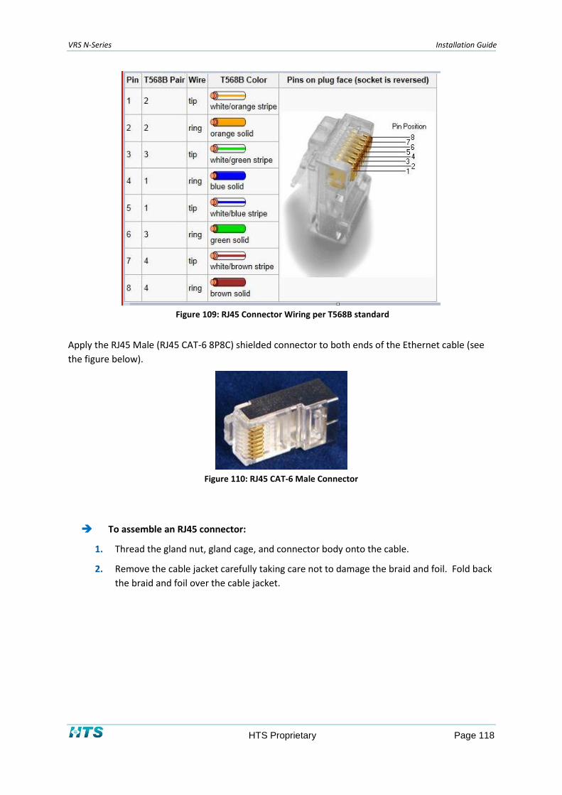
VRS N-Series Installation Guide
HTS Proprietary Page 118
Figure 109: RJ45 Connector Wiring per T568B standard
Apply the RJ45 Male (RJ45 CAT-6 8P8C) shielded connector to both ends of the Ethernet cable (see
the figure below).
Figure 110: RJ45 CAT-6 Male Connector
To assemble an RJ45 connector:
1. Thread the gland nut, gland cage, and connector body onto the cable.
2. Remove the cable jacket carefully taking care not to damage the braid and foil. Fold back
the braid and foil over the cable jacket.

VRS N-Series Installation Guide
HTS Proprietary Page 119
Figure 111: Cable jacket
3. Un-twist the conductors and feed them through the appropriate hole in the load bar,
according to the loading standard required. Push the loading bar to the cable. Trim
conductors to extend 8.64 mm (0.34”) out of the front of the load bar.
Figure 112: Load Bars and Cable Jacket Conductors
4. Push the load bar and cable fully home into the RJ45, ensuring the braid and foil are in
contact with the metal shell. Trim back the braid and foil flush with the rear of the RJ45
body.
Figure 113: RJ45 and load bar cable
5. Crimp the wires to the RJ45 pins using a crimping tool such as the one shown in Figure
114 below.

VRS N-Series Installation Guide
HTS Proprietary Page 120
Figure 114: Crimping tool for RJ45 connectors
NOTE
Before attaching the RJ-45 connectors, feed the cable through a flexible protect conduit, as described in section 8.4.2.
Flexible Protective Conduits for External Cables 8.4.2
On the back of each SCH-200 imaging unit, flexible protective conduits should be deployed, as shown
in Figure 115 below. HTS recommends use of PG-9 type conduits with an internal diameter of 12
mm.
Figure 115: Flexible protective conduits
Testing Ethernet Cable 8.4.3
An Ethernet traffic bandwidth tester should be used to check the bandwidth and CAT-6 certification
of the installed network cables. Use a certified tester for testing the Ethernet cable.
8.5 External Illumination Connections
For VIR applications, extra illumination is required. HTS recommends connecting the illuminator via
an external sealed IP67 junction Box.
The illumination from the SCH-200 is connected in parallel to the external illumination unit; also the
power supply is connected in parallel.
The following illustration presents the steps required to connect the power supply to one PG outlet
and the SCH-200 imaging unit and external illumination unit to the other PG outlet.

VRS N-Series Installation Guide
HTS Proprietary Page 121
Figure 116: Connecting the Junction Box
HTS supplies a junction box (see the figure below) for connecting an external illuminator.
Figure 117: Junction Box for External Illuminator

VRS N-Series Installation Guide
HTS Proprietary Page 122
The external illumination units’ wires are connected to the Terminal Block as follows:
Pin Number Description Color
1 Sync (+) Green
2 Sync (-) White
3 +24 VDC Red
4 +24/RTN Black
Table 24: Connecting the External Illumination Unit to the Terminal Block
8.6 Loop Installation
This section contains instructions for installing a Matrix magnetic loop detector. However, any
standard dry-contact vehicle sensor with a relay output may be suitable for use.
To connect the Matrix magnetic loop detector:
1. Read the loop detector’s installation guide before installation.
2. Install the loop detector as described in Appendix A.
3. The loop should be 2 meters wide and 1 meter long. It should have at least 4 turns, and
should be positioned in the middle of the lane. A photo of a loop installation appears in
Figure 118 below.
Figure 118: Ground Loop
4. Connect the loop to the Ground loop controller (GLC) using twisted pair cabling, as
specified by the manufacturer.
Connect the loop (pulse) wire to pin 7.
Connect the ground wire to pin 8.
5. Connect the detector’s plug to the ADAM-6060 I/O module.
Connect pin 5 to the ADAM-6060 GND

VRS N-Series Installation Guide
HTS Proprietary Page 123
Connect pin 6 to the ADAM-6060 DI-o
Refer to Figure 100 and Table 22 for details.
6. Run the detector setup program, using the following settings:
Use channel 1 of the sensor
Frequency: M-L
Sensitivity: D (normal)
Mode: 1 (presence)
7. Press the reset button following power up (with no vehicle on the loop).
8. Use normally open contacts for output (10, 11).
NOTE
A different loop configuration may be necessary in case of bumper-to-bumper vehicle traffic. Consult with HTS for advice.
NOTE
If several ground loop controllers are located in the same controller cabinet, the loops might interact and cause unstable
loop detection. To avoid this situation, set each ground loop to a different frequency by performing the steps detailed
below.
To set each loop to a different frequency:
1. Set each ground loop to a different frequency using DIP switches 1 and 2 (see Table 25
below).
Figure 119: Setting the Ground Loop Controller for Multiple Loops

VRS N-Series Installation Guide
HTS Proprietary Page 124
2. Set the DIP switches of the Ground Loop Controller, as specified in Table 25 below.
3. DIP Switch Number 4. Status
5. 3 6. Off (Active)
7. 4 8. On (ASB on)
9. 5 10. Off (Presence)
11. 6 12. Off
13. 7 14. Off
15. 8 16. Off
17. 9 18. Off
19. 10 20. Off
Table 25: Setting the Ground Loop Controller for Multiple Loops

VRS N-Series Installation Guide
HTS Proprietary Page 125
8.7 IR Sensors
To mount the sensors:
1. Mount the IR (infrared) receiver, 42GRR-9001 (HTS P/N 547008), on the right pole at a
height of approximately 1 meter.
2. Mount the corresponding IR transmitter, 42GRL-9040 (HTS P/N 547007), on the left pole
at a height of approximately 1 meter.
3. Make sure the IR receiver is configured to Dark Mode (see Figure 120).
Figure 120: IR Selecting Dark Mode
In Dark Mode, the LED behavior of the IR receiver is as follows:
LED Colors Indicates
Green LED Beam is blocked
Red LED Beam is not blocked
Yellow LED Power is always on
Table 26: LED Behavior of IR Receiver
Figure 121: IR Receiver LED Behavior in Dark Mode

VRS N-Series Installation Guide
HTS Proprietary Page 126
To connect the IR Sensors to a Power Source and to the ADAM-6060 I/O module:
1. Connect the IR transmitter to the 24 VDC power source.
2. Connect the IR receiver to the 24 VDC power source.
3. Connect the dry contact wires BLACK (normally open) and ORANGE (common / GND):
N-50: Directly to the imaging unit
SCH-200: Via the ADAM-6060 I/O module.
● Connect the black wire to DI0.
● Connect the orange wire to GND.
A diagram depicting the IR sensor connection appears below. Use of junction boxes (JBs) is optional.
Figure 122: IR Sensor Connections
8.8 Gate Control
In case of a gate (barrier) operation, high-current signals are used to control the gate.
To connect the gate to the N-50 Imaging Unit, see section 6.1.4.
To connect the gate to the SCH-200 via the ADAM-6060 I/O module, see section 7.1.
VRS N-Series Installation Guide
HTS Proprietary Page 127
Chapter 9 System Configuration
This chapter describes the installation of VRS support software and drivers. For purposes of the
installation, it is assumed that the hardware units are already inserted into the computer slots, and
the Lane Controller PC is still powered off.
9.1 SeeWay
SeeWay Installation 9.1.1
SeeWay comes factory-installed on the VRS Lane Controller.
NOTE
If a manual installation on a customer-provided lane controller is required, please contact your HTS representative for
details.
For detailed instructions on operation of the SeeWay system, please refer to the SeeWay User’s
Manual.
9.2 See Control
For detailed instructions on installing and operating the SeeControl system, please refer to the
SeeControl Installation Guide and the SeeControl User’s Manual.

VRS N-Series Installation Guide
HTS Proprietary Page 128
Chapter 10 Imaging Unit On-Site Calibration & Fine Tuning
10.1 General Information
This chapter describes the procedure for calibrating the VRS Imaging Unit on-site, including focus,
zoom, pan, and tilt. At this stage, it is assumed that imaging units are connected to the network and
configured.
NOTE
In order to ensure optimal performance, the calibrated system should be tested during the day, and also at night.
Before on-site calibration, please note:
The lane should be closed. Make all preparations for lane closing, such as road
blocks and flashing lights.
Equip workers with safety accessories, such as safety shoes and reflective vests.
10.2 N-50 Calibration Preparations
There are two options for calibrating the N-50 Imaging unit:
Option 1: Using the HTS SeeWay software with a remote access application, such as VNC.
Option 2: Using an analog monitor for technicians. This option requires opening the
service plug hole of the Imaging Unit.
Option 1 is recommended, as there is no need to open the imaging unit.
Preparing for N-50 Imaging Unit Calibration – Option 1
1. Connect a laptop using a LAN cable to the Imaging Unit network.
2. Configure the laptop for local area network connectivity, for example:
IP address: 192.168.0.201
Subnet mask: 255.255.255.0
3. Use the VNC application access to remotely access the Lane Controller PC.
4. Enter the IP address of the Lane Controller PC, and log in:
Password: HTS

VRS N-Series Installation Guide
HTS Proprietary Page 129
5. Open Live View window in the SeeWay application and adjust the Imaging Unit as
described in option 2.
Preparing for N-50 Imaging Unit Calibration – Option 2
1. Open the imaging unit. Connect a BNC analog cable (see Figure 123 below), attaching
one end to the imaging unit, and the other end to a technician’s monitor.
Figure 123: Connecting the N-50 Imaging Unit to a Technician’s Monitor
21. Adjust the focus and zoom of the imaging unit using the 2 screws underneath the unit.
22. Adjust the imaging unit’s pan and tilt using the unit’s arm.
NOTE
As a rule-of-thumb, for a plate with 50 cm width, the ratio between the monitor width and the plate width should be 8:1
for a maximal FOV, and 4:1 for a minimal FOV.

VRS N-Series Installation Guide
HTS Proprietary Page 130
10.3 SCH-200, DR-200 & N60 Calibration Preparations
There are two options for calibrating the SCH-200, DR-200, and N-60 Imaging Units. Both options
require the opening of the imaging units.
Option 1: Using the HTS SeeWay software with a remote access application, such as VNC.
Option 2: Using the Imaging Units Configuration Tool.
Preparing for Imaging Unit calibration – Option 1
1. Connect a laptop to the Imaging Unit network using a LAN cable.
2. Configure the laptop for local area network connectivity, for example:
IP address: 192.168.0.201
Subnet mask: 255.255.255.0
3. Use the VNC application access to remotely access the Lane Controller PC.
4. Enter the IP address of the Lane Controller PC, and log in.
Password: HTS
5. Open the Live View window in the SeeWay application and adjust the Imaging Unit as
described in Option 2 below.
Preparing for Imaging Unit calibration – Option 2
1. Open the imaging unit. Detach the LAN cable (from the Lane Controller) from the
imaging unit, and connect a LAN cable directly between the laptop and the LAN port of
the imaging unit.
2. Install and run the HTS Imaging Unit Configuration Tool, and enter a user name and
password.
User Name: admin
Password: 1234
3. Click on the Discovery button. The application displays a list of all the connected imaging
units.
4. Choose the relevant Imaging Unit. Note the Live Video window in upper-right corner of
the screen.
5. Press on the Play button to begin the live video presentation. Double-click on the
window to open the window in full-screen mode.
6. Focus the imaging unit as necessary and check the image quality in the Live Video
window. It is recommended to use the zoom-in feature of the Live Video window.
7. Zoom out and make sure that the whole plate is in sharp focus.

VRS N-Series Installation Guide
HTS Proprietary Page 131
10.4 Setting the Overview Imaging Unit Parameters
To configure the overview Imaging Unit:
1. In the Imaging Unit Level window, check the Overview Imaging Unit (not for recognition)
box.
2. In the Imaging Unit Image window, change the Exposure (shutter speed) to 12 (3840) or
13 (4160 microseconds) in order to optimize the contrast on the plate.
NOTE
When using a varifocal lens, the Imaging Unit may be over-zoomed with a field-of-view including more than a single lane.
The photos appearing below provide samples of bad and good overview images.
● ● Figure 124: Example of Bad Overview (left side) and Good Overview (right side)

VRS N-Series Installation Guide
HTS Proprietary Page 132
Chapter 11 Calibration Form
Follow the instructions below in order to confirm that the system has been properly calibrated.
Step Action Description
1 Locate a plate at the relevant distance from the imaging unit
Locate a vehicle at a relevant distance on the road – in the middle of the lane.
2 Adjust the tilt Open the Live View Window.
For Rear capture
Tilt the imaging unit’s head until the plate is at the bottom of the image. For front capture
Tilt the imaging unit’s head until the plate is at the top of the image.
3 Adjust the pan Pan the imaging unit’s head until the plate appears in the middle of the
imaging unit’s view.
4 Secure the pan and tilt Firmly tighten the screws of the pan and the tilt. Check that the pan and tilt are preserved.
Zoom Measure the plate size.
As a rule-of-thumb, for a plate with 50 cm width, the ratio between the display width and the plate width should be 8:1 for a maximal FOV, and 4:1 for a minimal FOV.
Zoom out using the right mouse button, and measure the plate width.

VRS N-Series Installation Guide
HTS Proprietary Page 133
Step Action Description
5 Focus the imaging unit Fully open the iris. Using the Live View window, zoom into the plate characters.
Change the focus to obtain the sharpest view where each letter’s outline appears either in black or white – with less gray pixels on the outline.
Ensure that the focus for the whole plate is now sharp.
6 In the SeeWay application, press F2 to simulate the sensor. The system will now capture images and recognize the plate number.
7 Check the trigger
Note: Perform this action for all hardware triggers
You must use a vehicle with front plate for front LPR and with rear plate for rear LPR.
For front LPR, the vehicle position for the test should be before the ground loop. To get the exact location, ask the driver to go slowly until you see the trigger LED in the ground loop controller. Make sure the vehicle is in the center of the loop width.
Move a vehicle slowly back and forward.
8 Verification of imaging unit adjustment
Repeat step 7 ten (10) times. Adjust the imaging unit to look at the plate where the plate is in the center of the image (front LPR – top of the image, rear LPR – bottom of the image, since the vehicle will move and we want to capture the plate in the second, third, or N images).
9 Image quality In the SeeWay application, open the settings and go to the Save Images tab and check the Save All Images box. The system will now save all the capture images.
Ask the driver to drive the vehicle on the left side of the lane, on the right side and in the middle. For each side, ask the driver to drive at different speeds.
After each drive, check the images in the images folder. The goal is to get as many quality images as possible. For instance: If the system is configured to capture 3 images, the expected results would be 3 images containing the plate.

VRS N-Series Installation Guide
HTS Proprietary Page 134
Step Action Description
15 Plates position If the imaging unit is installed on a gantry and we want to do rear LPR (the driver drives in the middle of the lane) we will get x images with plates appearing more and more distant:
If the imaging unit is installed on a pole and we want to do front LPR (the driver drives in the middle of the lane) we will get x images with plates appearing closer and closer, but also moving diagonally:
16 Tighten the screws and clean the window
Tighten all screws firmly and clean the front window of the VRS.
17 Open the lane for real traffic
Open the lane for real traffic. Make sure that all the vehicles are being triggered by the VRS, and verify that recognition is working properly by comparing the OCR result with the image.
18 Verification After the results are sufficient, it is time to perform a massive test. Get as many different vehicles as you can. Drive them 100-200 times with different speeds and different lane positions. Check the results.
19 Complete check list Form To confirm installation readiness, complete the Installation Readiness check list in Chapter 12.
20 Sign off Sign the Installation Readiness check list form in Chapter 12.
Table 27: Calibration Form
NOTE
If any item of equipment provided by HTS is not functioning correctly, replace it immediately while installing and send the
malfunctioning item to HTS under the RMA agreement.
3
2
1
4
1
2
4
3

VRS N-Series Installation Guide
HTS Proprietary Page 135
Chapter 12 Installation Readiness (Commissioning Checklist)
NOTE
Most of the tests are already performed during the installation. The goal of the checklist form target is to provide a
general picture of site installation readiness.
Site Name:
Gantry/Lane Id:
Installation Date:
Installer’s Name:
Installer’s Signature:
Customer Name:__________________________
Customer Title:___________________________
Customer signature: _______________________

VRS N-Series Installation Guide
HTS Proprietary Page 136
Table 28: Equipment ID List
# Device Lane Controller VRS Server Comments
Imaging Unit ____________
Type _____________
Configuration _______
SN___________ IP____________
FW version ____________
Controller number/ name
Controller type
(LC2100/LC2000/LC510/LC500)
SN____________________
IP___________
SeeControl
version(optional)_________
SeeWay Version
____________________
Imaging Units connected to this
Controller
___________________
Remote connection ID
LC2100 Controller
SN_________________
IP_______________
SeeControl version
_______________
Remote connection ID
Imaging Unit ____________
Type _____________
Configuration _______
SN___________ IP____________
FW version ____________
Imaging Unit ____________
Type _____________
Configuration _______
SN___________ IP____________
FW version ____________
Imaging Unit ____________
Type _____________
Configuration _______
SN___________ IP____________
FW version ____________
Imaging Unit ____________
Type _____________
Configuration _______
SN___________ IP____________
FW version ____________
Controller number/ name
Controller type
(LC2100/LC2000/LC510/LC500)
SN____________________
IP___________
SeeControl
version(optional)_________
SeeWay Version
____________________
Imaging Units connected to this
Controller
___________________
Remote connection ID
Imaging Unit ____________
Type _____________
Configuration _______
SN___________ IP____________
FW version ____________
Imaging Unit ____________
Type _____________
Configuration _______
SN___________ IP____________
FW version ____________
Imaging Unit ____________
Type _____________
Configuration _______
SN___________ IP____________
FW version ____________

VRS N-Series Installation Guide
HTS Proprietary Page 137
Table 29: Controller Cabinet Checklist
# Group Tested Unit Test Methods & Expected Results
Pass / No Pass
Comments
1 Controller Cabinet
Ensure that the Controller cabinet is properly mounted and sealed.
Visual observation.
Check that the door locks properly.
Spray the cabinet with water to check the seal.
The Lane Controller is installed, powered and running
Connect monitor (or remote laptop), power on the lane controller and verify that Windows is running.
Switch and ADAM I/O Make sure that the switch is on and that the ADAM indicator signal has a green light - signifying normal function.
Loop Controllers are wired to the VRS system
Check that the loop controller’s indicator signal is blinking - signifying normal function
UPS is installed, powered and connected to the lane controller.
Unplug the power cord and verify that lane controller is still operating.
(Optional)
Table 30: Loop and Loop Controller Checklist
# Group Tested Unit Test Methods & Expected Results
Pass / No Pass
Comments
2 External IO devices Loop & GLC
(Ground Loop Controllers)
Loop Controller
(Activate by driving on the ground loop)
Loop is installed according to the manufacturer datasheet specifications (number of turns, dimensions)
Loop controller shows activity (LED) when it is activated.
Drive a vehicle by the loop detector and ensure that the illuminator is triggered.

VRS N-Series Installation Guide
HTS Proprietary Page 138
Table 31: Imaging Unit Checklist
# Group Tested Unit Test Methods & Expected Results
Pass / No Pass
Comments
3 Imaging Unit
Mounting Imaging unit is properly mounted to the wall or pole with the correct fasteners.
Connectivity Use the IP configurator tool to check connectivity with the lane controller.
Ensure that the IP Addresses and Subnet Mask are correctly defined.
The imaging unit IP address indicated in the IP configurator should match the IP address written on the label on the imaging unit.
SeeWay Open the Live Video option in the SeeWay application.
Ensure that the imaging unit is functioning.
Imaging unit is pointed at the middle of the loop.

VRS N-Series Installation Guide
HTS Proprietary Page 139
Table 32: Lane Controller Software Checklist
# Group Tested Unit Test Methods & Expected Results
Pass / No Pass
Comments
4 Lane Controller Software
SeeWay software Verify HASP connected and SeeWay operating by double click
Provide IP address to the lane controller via the VRS controller configuration tool
IP address
_____________
Provide username password for lane controller via the VRS controller configuration tool
User _________
Pass _________
Provide URL or IP for SeeControl machine to establish connectivity with SeeControl.
Verify latest version SeeWay version
_____________
SeeWay IO configurator
Attached external IO device to the software
Configure the triggers
SeeWay Imaging Unit configuration
Imaging Unit added to settings
Correct trigger is assigned to relevant Imaging Unit
Plate Size ( scale factor )
Plate is in FOV for each capture (number of captures). Verify vehicle in different positions across the lane width
Image/plate quality is good for all hours of the day and night
If required configure day night capture sets
Configure the perspective correction (Optional)

VRS N-Series Installation Guide
HTS Proprietary Page 140
Table 33: SeeControl Checklist
# Group Tested Unit Test Methods & Expected Results
Pass / No Pass
Comments
5 SeeControl Settings Verify the SeeControl Service is up
Verify the SeeControl Version is the latest
SeeControl Version
______________
For domain network configure the service user name and password
(Optional)
User __________
Pass __________
Provide IP address for the SeeControl SeeControl IP
_______________
Interface to external application
Configure the required external interface (install the relevant plugin and configure it (if required )
(optional)
Site configuration Lane added to settings
Correct Imaging Unit is assigned to
lane
Correct Gate is assigned to Lane
Lane ( all elements ) is green in
Monitoring
Verify the system use the latest VRS package version and upload it from the Localization tab
(under Setup tab) to all the lane controllers
General Settings Set the retention time and folder directory
NTP – configure and configure the NTP to be sync with the SeeControl and other site devices
In Image view check the live view for
all the image units (Imaging Units)
In Image view open the gate
( if gate is set )
Server connectivity
From the server housing the SeeControl application, ping the lane controllers. The controllers should respond to the ping messages.
(optional)

VRS N-Series Installation Guide
HTS Proprietary Page 141
Table 34: DMS Checklist
# Group Tested Unit Test Methods & Expected Results
Pass / No Pass
Comments
6 DMS Configure the DMS (Optional)
Table 35: Operational Checklist
# Group Tested Unit Test Methods & Expected Results
Pass / No Pass
Comments
7 Operational Check
Pass the Vehicle through the lane
Event is created in SeeWay
Image with LP is shown in SeeWay
Correct result is provided in SeeWay
Event is sent to SeeControl
Event is shown in SeeControl
Correct recognition and image provided in Image/List views
Verify hot list hit ( if exists )
Gate is opened ( if above is true )
Verify all the relevant data sent to the external infract ( if exists )
(Optional)
Verify the DMS functionality (Optional)
Repeat the test for all the lanes
Table 36: Performance Acceptance Test Checklist
# Group Tested Unit Test Methods & Expected Results
Pass / No Pass
Comments
8 Performance Acceptance Test
50 Vehicles pass through the lane in the day time.
License plate recognition rate is above or equal to requirements
Date ________
Results _______
50 Vehicles pass through the lane at night.
License plate recognition rate is above or equal to requirements
Date ________
Results _______

VRS N-Series Installation Guide
HTS Proprietary Page 142
Appendix A Ground Loop Specifications and User’s Guide
This chapter contains datasheets for BEA Matrix loop sensors. For additional details, see:
http://www.beainc.com/beainc/products/Industrial/Activation/Matrix.php?prd=18.

VRS N-Series Installation Guide
HTS Proprietary Page 143

VRS N-Series Installation Guide
HTS Proprietary Page 144

VRS N-Series Installation Guide
HTS Proprietary Page 145

VRS N-Series Installation Guide
HTS Proprietary Page 146

VRS N-Series Installation Guide
HTS Proprietary Page 147

VRS N-Series Installation Guide
HTS Proprietary Page 148

VRS N-Series Installation Guide
HTS Proprietary Page 149
Appendix B VRS Controller Cabinet Drawings
The following pages contain a series of drawings intended to aid you in wiring the VRS Controller
Cabinet and in connecting it to the other components of the VRS system.
Figure 125: VRS Controller Cabinet, Specifications and Wiring Spec.

VRS N-Series Installation Guide
HTS Proprietary Page 150
Figure 126: VRS Controller Cabinet, Principle and Interfaces
Figure 127: VRS Controller Cabinet Terminals

VRS N-Series Installation Guide
HTS Proprietary Page 151
Figure 128: VRS Controller Cabinet, AC High Power Wiring
Figure 129: VRS Controller Cabinet Outlets Wiring Diagram

VRS N-Series Installation Guide
HTS Proprietary Page 152
Figure 130: VRS Controller Cabinet Thermal Setup (For Extended Unit)

VRS N-Series Installation Guide
HTS Proprietary Page 153
Appendix C Deploying CAT6 Cable
CAT6 cable is used in network applications such as 10Base-T, 100Base-T, and 1000Base-T Ethernet
technology, providing error-free transmission at distances up to 100 meters. CAT6 Cables are
composed of 4 twisted-pair 24 AWG stranded conductors with PVC jackets. Conductors are wired to
gold plated RJ45 plugs in accordance with the TIA/EIA 568B standard (Telephone Industry
Association/Electronics Industry Association).
The following table describes the wiring of the RJ45 connector:
Figure 131: RJ45 Wiring Guide
To crimp a CAT6 cable:
1. Strip 1 inch of the sheath from one end of the CAT6 cable using the wire stripping tool.
Separate 1/2-inch of each twisted pair within the cable, and then straighten the wires.

VRS N-Series Installation Guide
HTS Proprietary Page 154
Figure 132: Crimping a CAT6 Cable
3. Place the straightened wires in an RJ45 in the following order:
Table 37: RJ-45 Wiring
Pin Number Colors
1 White/Green
2 Green
3 White/Orange
4 Blue
5 White/Blue
6 Orange
7 White/Brown
8 Brown
4. The RJ45 connector must be oriented with the contacts pointed away and the connector
tab down while counting the wire slots from left to right. The wire ends should contact
the inside end of the RJ45 connector and the sheath should contact the inside of the
connector at the beginning of the wire slots.

VRS N-Series Installation Guide
HTS Proprietary Page 155
● ● Figure 133: RJ45 Connection
5. Insert the RJ45 connector into the RJ45 crimping tool and squeeze the crimping tool
handle firmly to press the RJ45 contacts into the wires.
Figure 134: RJ45 Crimping Tool
6. Repeat the steps above on the other end of the cable.
Figure 135: RJ45 Connector on Both Ends of CAT6 Cable

VRS N-Series Installation Guide
HTS Proprietary Page 156
To choose a certified tester:
A 1 Gbps bandwidth tester should be used to check the bandwidth and CAT6 certification of the
installed network cables.
Use a certified tester as shown in the following link:
http://www.flukenetworks.com/datacom-cabling/copper-testing/dtx-cableanalyzer-series
Figure 136: 1 Gbps Tester
Additional relevant documents:
DTX series – User Manual
http://www.l-com.com/multimedia/manuals/M_DTX-1800.PDF
DTX Series – Technical Reference Handbook
http://www2.warwick.ac.uk/services/its/servicessupport/cabling/activities/man_techref_r3_dtxseri
escableanalyzer_us.pdf
To test a 1 Gbps CAT6 cable:
1. Set the Cable ID (as marked in the above example) to the gantry/lane to which the cable
belongs.
2. Test the cable connecting the PC to the imagining unit to check the 1 Gbps bandwidth
and confirm CAT6 certification. Approve the cable for installation based on test results. In
case the cable fails the bandwidth and/or CAT6 certification test, replace the cable.
3. A CAT6 certification report should be issued for each cable that passed the test. The
following is an example of a test report issued by the testing device:
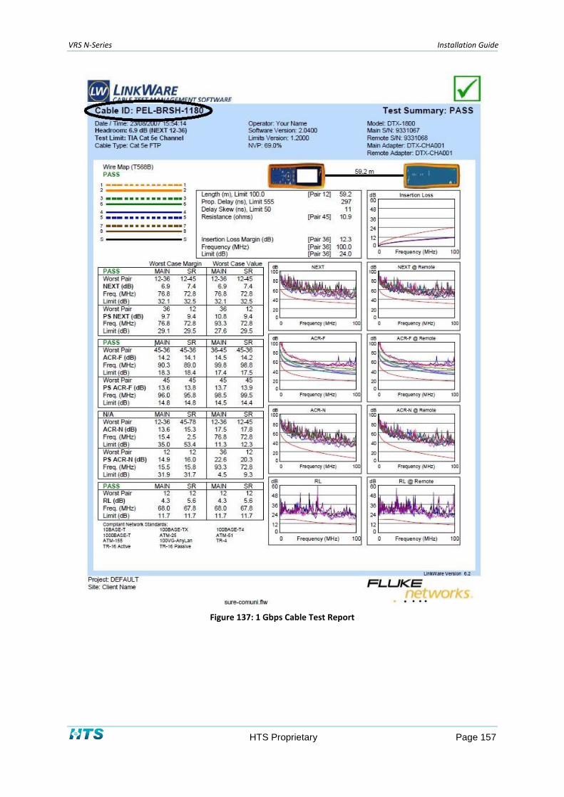
VRS N-Series Installation Guide
HTS Proprietary Page 157
Figure 137: 1 Gbps Cable Test Report

VRS N-Series Installation Guide
HTS Proprietary Page 158
Appendix D Imaging Unit Network Topologies
The VRS N-Series Imaging Units deliver video images and audio in real time over Internet and Intranet
connections. The imaging units are equipped with Ethernet RJ-45 network interfaces.
For up to 3 imaging units (2 imaging units for LC-500), use topology Type I.
For 4 or more imaging units, deploy a switch as shown in topology Type II.
To connect the network wiring:
1. Connect (up to 3 imaging units) to a single Lane Controller, either connecting directly (see
Figure 138), or using a switch (see Figure 139).
Figure 138: Network Topology Type I
Figure 139: Network Topology Type II
System Requirements
The table below lists the minimum requirement to implement and operate an Imaging Unit of N51.
Table 38: System Requirements
System Hardware Name Description
Lane controller LC-500 series (*) Mini Ruggedized controller
Lane controller LC-1000 19” Rack mount PC
Lane controller LC-2000 series (*) Ruggedized controller
(*)= Optional

VRS N-Series Installation Guide
HTS Proprietary Page 159
Appendix E Using the IP Configurator Utility
The IP Configurator is a utility program that helps users to locate the imaging unit in local area
network. It comes installed on HTS-supplied Lane Controllers.
The IP Configurator utility can be downloaded from the HTS web site, at: http://htsol.com/Support
To obtain it, log in to the support portal, and select Download >> Tools and Utilities >> IP
Configurator Utility.
To set a new IP address:
1. Make sure the imaging unit and your Lane Controller are in the same subnet.
2. Connect the imaging unit’s Ethernet connector directly to the Lane Controller, or via a
switch.
3. Double-click on the IP Configurator icon (see Figure 140) to run the utility.
Figure 140: IP Configurator Icon
The Login Window appears as shown in Figure 141 below.
Figure 141: Login Window
NOTE
Connect only one unit at a time to finalize the IP Configuration.

VRS N-Series Installation Guide
HTS Proprietary Page 160
4. Login to the configurator with the default username and password:
Username: admin
Password: 1234
5. Press the discover button. The window displays a list of units currently in operation on
the network, as depicted in Figure 142 below.
Figure 142: List of Imaging Units in the Network
6. In case the required Imaging Unit wasn't discovered after a few discovery retries, please
add it manually, taking the following steps:
Press the Add manually button.
Figure 143: Add Imaging Unit Manually
In the window that opens, type the IP of the relevant Imaging Unit (initially it will be
the factory-supplied default IP address). Enter the user name “admin”, and the
password “1234”.

VRS N-Series Installation Guide
HTS Proprietary Page 161
Figure 144: Entering Imaging Unit Details Manually
7. Select the unit with the appropriate Imaging Unit model number. The Imaging Unit
Configuration window appears as depicted in Figure 145 below.
Figure 145: Imaging Unit Configuration Window
8. Enter the new IP address in the field Add Manually labeled in Figure 146. Click Save to
activate the settings.

VRS N-Series Installation Guide
HTS Proprietary Page 162
Figure 146: Add a New IP Address Manually
9. Wait a few seconds while the imaging unit reboots with the new IP address, and exit the
utility.
NOTE
In order to recall the imaging unit’s IP address when necessary, stick a label with the IP address on the imaging unit.
END OF DOCUMENT
Related Documents