vrije Universiteit amsterdam CERN, November 27, 2000 VELO System J.F.J. van den Brand LHCb Vertex Detector System: Status Report J.F.J. van den Brand Subatomic Physics Group, VUA - NIKHEF • Milan design • Optimized design • mechanics • vacuum system • cooling system • Summary

Vrije Universiteit amsterdam CERN, November 27, 2000 VELO System J.F.J. van den Brand LHCb Vertex Detector System: Status Report J.F.J. van den Brand Subatomic.
Dec 14, 2015
Welcome message from author
This document is posted to help you gain knowledge. Please leave a comment to let me know what you think about it! Share it to your friends and learn new things together.
Transcript

vrije Universiteit amsterdam CERN, November 27, 2000 VELO System J.F.J. van den Brand
LHCb Vertex Detector System:Status Report
J.F.J. van den BrandSubatomic Physics Group, VUA - NIKHEF
• Milan design
• Optimized design • mechanics
• vacuum system
• cooling system
• Summary

vrije Universiteit amsterdam CERN, November 27, 2000 VELO System J.F.J. van den Brand
Mechanics: “TP” design
Side flange
Bending hinges
Detector support and cooling
Bellows (22000signal wires)
Support frame
Si detector
moves by 30 mmonly two positions:open or closed !!
See LHCb 99-042/VELO
top half = bottom half

vrije Universiteit amsterdam CERN, November 27, 2000 VELO System J.F.J. van den Brand
Milan design
VELO Design:
• Single flange • XY table• CO2 cooling• WF suppressors• Second. vacuum• Studied
• assembly• alignment
• To do• further design• FEA

vrije Universiteit amsterdam CERN, November 27, 2000 VELO System J.F.J. van den Brand
Detector and support frame
• both halves on same side• VD easier to mount and position in the tank• install complete VD at once• the two halves are no longer interchangeable
vrije Universiteit amsterdam CERN, November 27, 2000 VELO System J.F.J. van den Brand
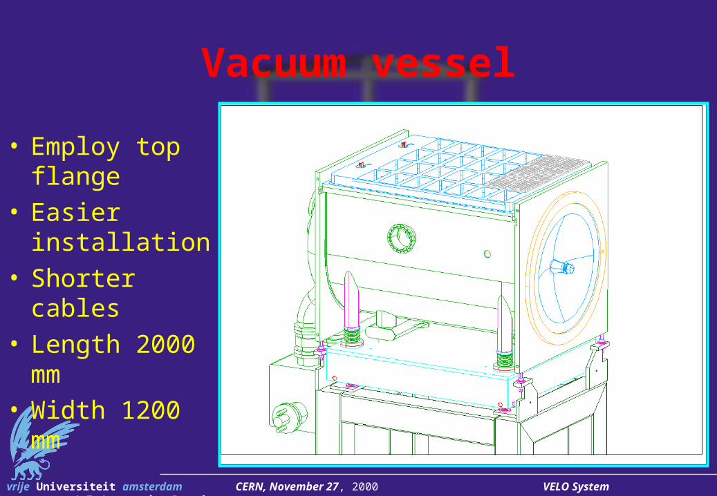
Vacuum vessel
• Employ top flange
• Easier installation• Shorter cables• Length 2000 mm• Width 1200 mm

vrije Universiteit amsterdam CERN, November 27, 2000 VELO System J.F.J. van den Brand
Top flange
770 19
00
Lif
t 60
0
• Length 1500 mm• Distance from
ceiling 1900 mm• Install using wires• Baking to 60o C?• Regenerate NEGs
after every access to Si detectors

vrije Universiteit amsterdam CERN, November 27, 2000 VELO System J.F.J. van den Brand
Optimized System
1250
1820
2150
1450
Total length: 1750
• Two detector boxes
• Baking up to 150o C
• Decouple access to Si detectors

vrije Universiteit amsterdam CERN, November 27, 2000 VELO System J.F.J. van den Brand
Support system
bellows
chain/beltcooling/bake out
gearbox 1:40
ball spindle 16x25 mm
linearbearing 2x
30 +5
motor
• Microswitches at out position
• LVDTs• Steel frame• Alignment:
– 2 planes
– 3 points each
– define IP

vrije Universiteit amsterdam CERN, November 27, 2000 VELO System J.F.J. van den Brand
Support system
• Alignment pins for reproducible coupling
• reproducible positioning

vrije Universiteit amsterdam CERN, November 27, 2000 VELO System J.F.J. van den Brand
Vessel Installation• Move bellows to
in-position• Install vessel
from top• Align vessel• Mount vessel to
frame• Mount bellows• Pump-outs visible
vrije Universiteit amsterdam CERN, November 27, 2000 VELO System J.F.J. van den Brand
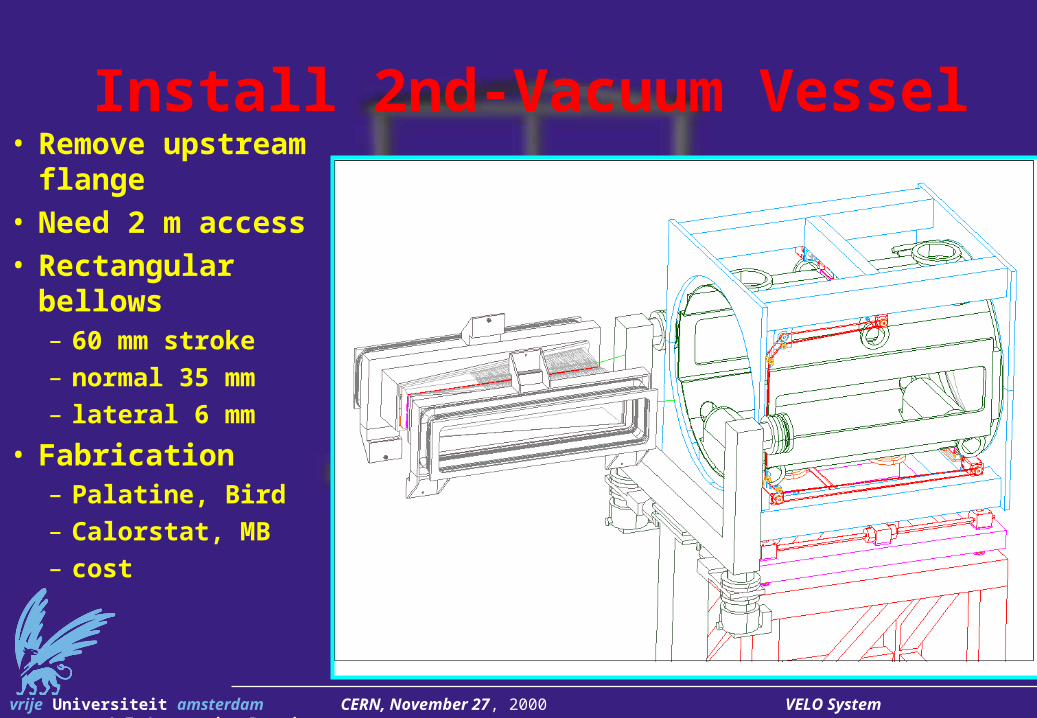
Install 2nd-Vacuum Vessel• Remove upstream
flange• Need 2 m access• Rectangular bellows
– 60 mm stroke– normal 35 mm– lateral 6 mm
• Fabrication– Palatine, Bird– Calorstat, MB– cost

vrije Universiteit amsterdam CERN, November 27, 2000 VELO System J.F.J. van den Brand
Vacuum vessel / Positioning system
• Moving parts not in vacuum
• Thin vacuum container
• Special bellows construction
Secundaryvacuum
Primaryvacuum

vrije Universiteit amsterdam CERN, November 27, 2000 VELO System J.F.J. van den Brand
After installation• Detector system
separated from vacuum system functionality
• Mount positioning system to detector housing
• Install– pump-out, valves
– turbos, damping

vrije Universiteit amsterdam CERN, November 27, 2000 VELO System J.F.J. van den Brand
Connect inner system to motion drives
• Mount M8 through side flanges

vrije Universiteit amsterdam CERN, November 27, 2000 VELO System J.F.J. van den Brand
Detector Installation
• Install detector halfs from sides
• Decouple detectors from box
• Tooling needed

vrije Universiteit amsterdam CERN, November 27, 2000 VELO System J.F.J. van den Brand
VELO Assembly
• Detectors mounted

vrije Universiteit amsterdam CERN, November 27, 2000 VELO System J.F.J. van den Brand
Wakefield suppressors• Mount screens
after mounting 2nd vacuum container
• Mount through top flanges– seal with view
ports?
• Upstream: mount with large flange off WF screens
420
910
IP

vrije Universiteit amsterdam CERN, November 27, 2000 VELO System J.F.J. van den Brand
Wakefield suppressor: downstream• Up/downstream
suppressors are identical
• Material: CuBe• Length: 179 mm• Thickness: 100
m• 16 segments• Mounting to box
non-trivial

vrije Universiteit amsterdam CERN, November 27, 2000 VELO System J.F.J. van den Brand
Wakefield suppressors• Segments deform
differently during movement
• Coating needed on suppressors
• Press-fit to beam pipe structure
• Anneal CuBe, deform, harden at 400o C

vrije Universiteit amsterdam CERN, November 27, 2000 VELO System J.F.J. van den Brand
Detector Mounting
Install Modules
3D alignment
Mount References

vrije Universiteit amsterdam CERN, November 27, 2000 VELO System J.F.J. van den Brand
Thin Vacuum foil
• Beryllium expensive: k$ 500 per container
• Aluminum– welding 250 m Al
is possible– press-shaping
being developed
• FEA ongoing
vrije Universiteit amsterdam CERN, November 27, 2000 VELO System J.F.J. van den Brand
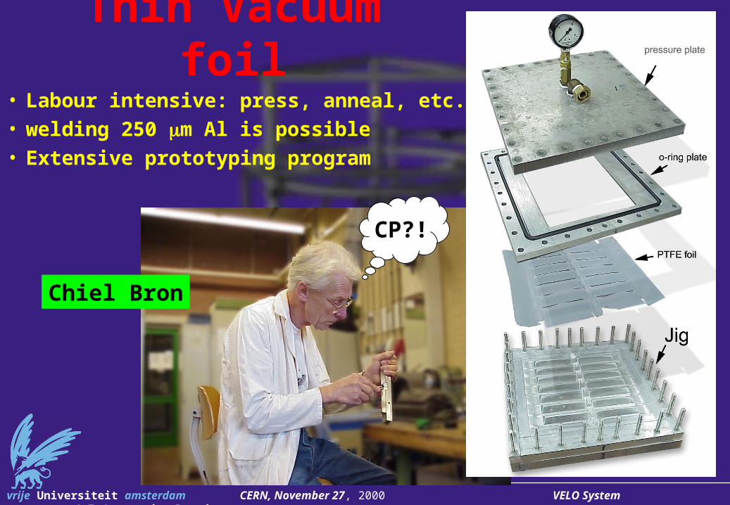
Thin Vacuum foil
• Labour intensive: press, anneal, etc.• welding 250 m Al is possible• Extensive prototyping program
Chiel Bron
CP?!

vrije Universiteit amsterdam CERN, November 27, 2000 VELO System J.F.J. van den Brand
Thin Vacuum foil• Increase radius: 10 20 mm to avoid
folding• Crystal structure is affected• Employ Al with magnesium alloy• Deform at higher temperature: 150 - 200o
C

vrije Universiteit amsterdam CERN, November 27, 2000 VELO System J.F.J. van den Brand
Foil design ongoing (continued)

vrije Universiteit amsterdam CERN, November 27, 2000 VELO System J.F.J. van den Brand
Foil design ongoing

vrije Universiteit amsterdam CERN, November 27, 2000 VELO System J.F.J. van den Brand
Control of Vacuum System
• Group active with experience at former NIKHEF accelerator
• Propose meeting in Q1 2001

vrije Universiteit amsterdam CERN, November 27, 2000 VELO System J.F.J. van den Brand
Vacuum Tests
• Self-regulating valve behaves as advertized
• Various gas flows have been characterized
vrije Universiteit amsterdam CERN, November 27, 2000 VELO System J.F.J. van den Brand
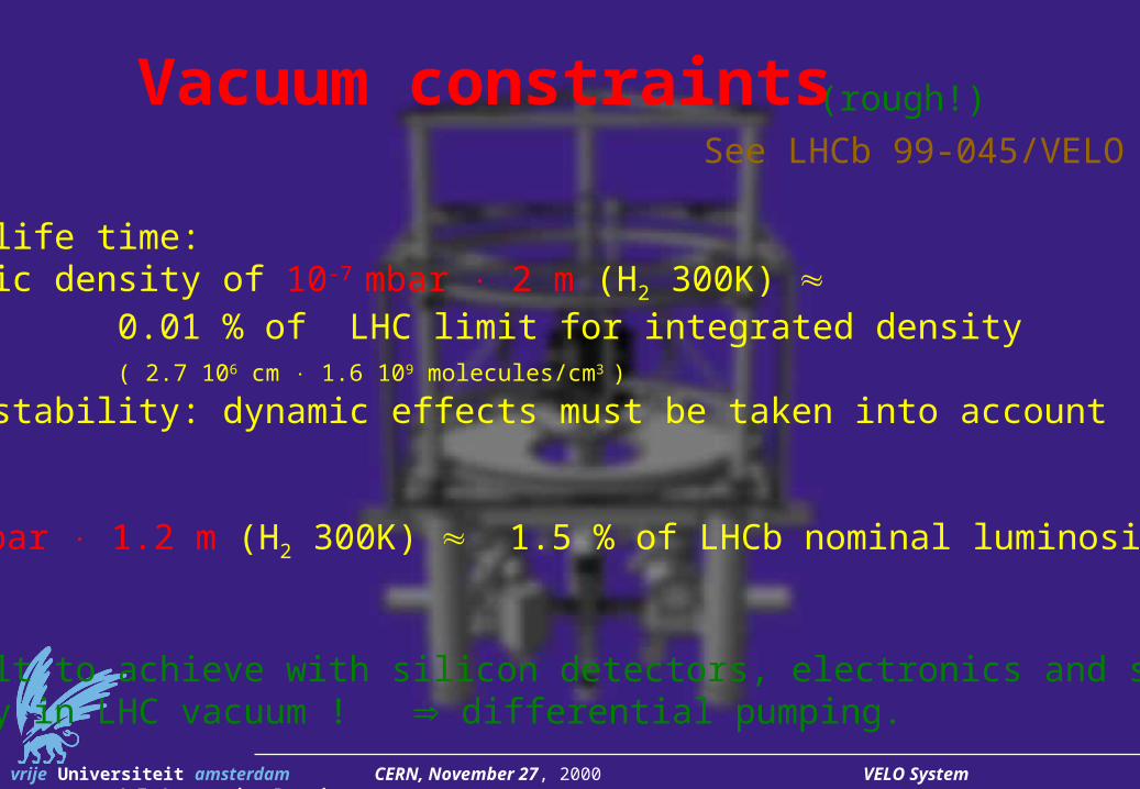
Vacuum constraints
LHC:• beam life time: static density of 10-7 mbar 2 m (H2 300K) 0.01 % of LHC limit for integrated density ( 2.7 106 cm 1.6 109 molecules/cm3 )
• beam stability: dynamic effects must be taken into account
LHCb:• 10-7 mbar 1.2 m (H2 300K) 1.5 % of LHCb nominal luminosity
Difficult to achieve with silicon detectors, electronics and signal wires directly in LHC vacuum ! differential pumping.
(rough!)
See LHCb 99-045/VELO

vrije Universiteit amsterdam CERN, November 27, 2000 VELO System J.F.J. van den Brand
Static pressure in VDConsider outgassing by: assuming outgassing rates of:
(mbar • l • s-1 • cm-2)
11 m2 Kapton (signal wires, pumped 40 hours) 10-7 H2O 2.3 m2 Al housing (per half) 10-10 H2
1.5 m2 bellows (per half) 10-9 H2
8 m2 SS vessel 10-10 H2
Pumps in detector volume: 140 l/s (per half) H2OPumps in tank: 4000 l/s H2
Bypass tube: 200 mm 4 mm pumped in the middle.
Calculate using a static flow model.Result: 1•10-4 mbar in detector volume
1•10-8 mbar in VD tank2•10-8 mbar • l • s-1 from det. vol. to VD tank

vrije Universiteit amsterdam CERN, November 27, 2000 VELO System J.F.J. van den Brand
Summary table:(Data are approximate. QLHCb_total = estimate for the full vertex detector, i.e. both halves.)
Item Outgassing rate of item QLHCb_total
[mbar l s -1] Kapton foil, after 40 hrs pumping 1 E-7 mbar l s -1 cm-2 n/a sample Kapton flat cable QPI 3 E-5 mbar l s -1 130 E-4 male/female pair of PEEK D-type 25-pin connectors 6 E-6 mbar l s -1 / pair 50 E-4 male/female pair of stand. D-type 25-pin connectors 1 E-5 mbar l s -1 / pair 100 E-4 Liverpool carbon-fiber Si support 1 E-8 mbar l s -1 cm-2 ~ 1 E-4
Outgassing measurements
Continue: measure all unknown outgassing rates of components in a detector station

vrije Universiteit amsterdam CERN, November 27, 2000 VELO System J.F.J. van den Brand
Dynamic Vacuum
Beam-induced particle bombardment desorption, emission
Ions, photons, electronsenergies up to keV
• Local pressure runaway (ion/electron-induced desorption)• Local static charge increase (electron multipacting)
LHC beam instability
See Adriana Rossi’s presentation

vrije Universiteit amsterdam CERN, November 27, 2000 VELO System J.F.J. van den Brand
Dynamic Vacuum (continued)
Perhaps a solution:
use coating of surfaces by Tiadvantages: low SEY , low , local pumping
Design issues: • better surfaces ? (NEG ?)• in-situ coating required or not ? • thickness of layer needed ?• what re-coating rate ?• affordable cathode temperature in-situ ? • wake field / RF properties ?• side effects ? (peeling, ...)
We need , for:• different materials • surface conditions (un)baked, saturated, activated, etc. • different impact energy spectra
Data available only in a few months ! (Mahner et al.)

vrije Universiteit amsterdam CERN, November 27, 2000 VELO System J.F.J. van den Brand
Cooling system with mixed-phase CO2
Phase diagram CO2
1
10
100
-80 -70 -60 -50 -40 -30 -20 -10 0 10 20 30 40 50
Temperature [°C]
Pre
ssur
e [b
ar]
vapor
liquidsolidgas
critical point
triple point
*

vrije Universiteit amsterdam CERN, November 27, 2000 VELO System J.F.J. van den Brand
CO2 Cooling Tests
Cooling system
-30o C
40 W/module

vrije Universiteit amsterdam CERN, November 27, 2000 VELO System J.F.J. van den Brand
CO2 gas-liquid storage tank57.3 bar at 20 C
CO2 supply line
compresssor
P [W]
P [W]
P [W]
flow restrictions
cooling lines
gas only
pressure (temperature)regulating valve
heat to 20 C
Mixed-phase CO2 Cooling systemSee LHCb 99-046/VELO
cool to 20 C
supply lineexpansion valve

vrije Universiteit amsterdam CERN, November 27, 2000 VELO System J.F.J. van den Brand
CO2 Cooling Tubes
Cooling tubes
1.1 (0.9) mm S.St.
Welding and brazing

vrije Universiteit amsterdam CERN, November 27, 2000 VELO System J.F.J. van den Brand
FEA ongoing

vrije Universiteit amsterdam CERN, November 27, 2000 VELO System J.F.J. van den Brand
Tests ongoing
vrije Universiteit amsterdam CERN, November 27, 2000 VELO System J.F.J. van den Brand
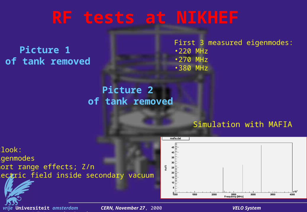
RF tests at NIKHEF
Simulation with MAFIA
First 3 measured eigenmodes:•220 MHz•270 MHz•380 MHz
Outlook:•Eigenmodes•Short range effects; Z/n•Electric field inside secondary vacuum
Picture 1 of tank removed
Picture 2 of tank removed

vrije Universiteit amsterdam CERN, November 27, 2000 VELO System J.F.J. van den Brand
Wake field Suppressor
Central cooling line
Temperature sensors (2 per station, 4 wires per measurement
vrije Universiteit amsterdam CERN, November 27, 2000 VELO System J.F.J. van den Brand
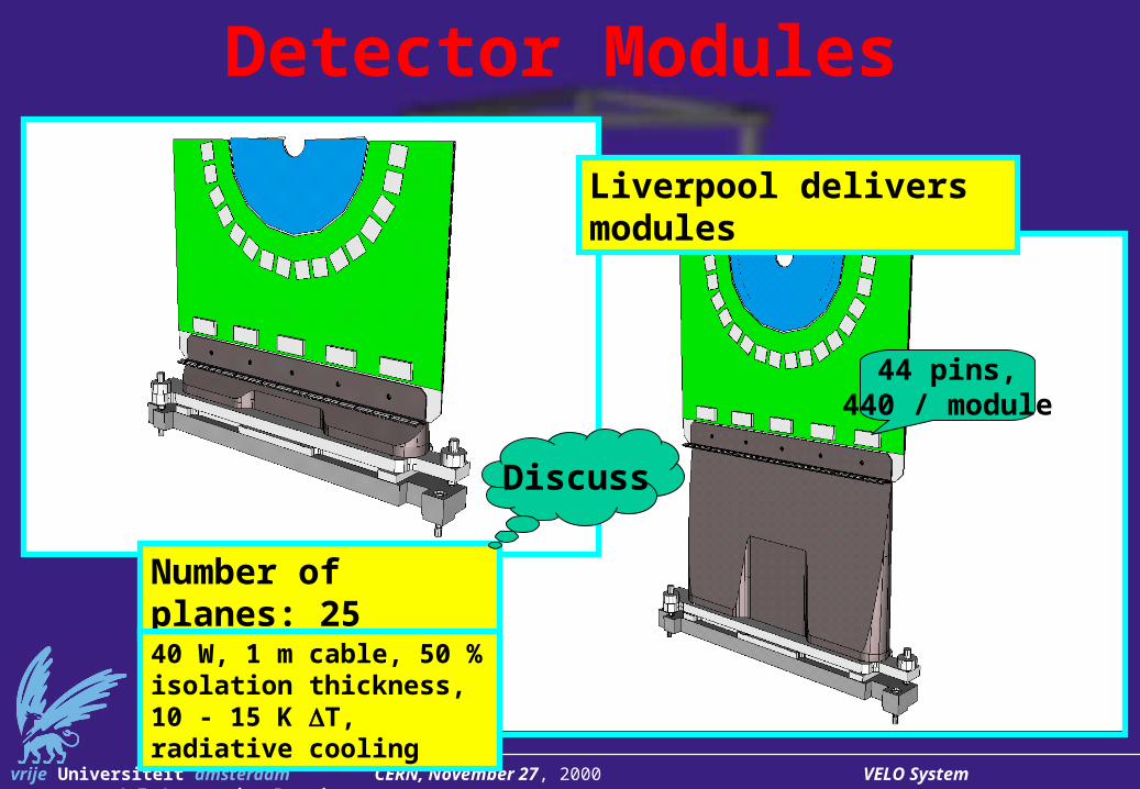
Detector Modules
Number of planes: 25
Discuss
Liverpool delivers modules
40 W, 1 m cable, 50 % isolation thickness, 10 - 15 K T, radiative cooling
44 pins,440 / module

vrije Universiteit amsterdam CERN, November 27, 2000 VELO System J.F.J. van den Brand
Summary• Design is based on secondary vacuum system
– Beryllium option: costly and uncertain
– needs approval for TDR
• Current design – allows baking up to 150o C
– decouples Si detectors from primary vacuum system
– employs venting with Argon
– cooling based on CO2 in gas-liquid phase
• Self-regulating valves behave as advertised
• Wakefield excitation under study
• Need information on dynamic vacuum effects
• Propose meeting on control issues (e.g. NIKHEF)
Related Documents