VOYAGE DATA RECORDER SIMPLIFIED VOYAGE DATA RECORDER VR-3000 VR-3000S

Welcome message from author
This document is posted to help you gain knowledge. Please leave a comment to let me know what you think about it! Share it to your friends and learn new things together.
Transcript

VOYAGE DATA RECORDER�SIMPLIFIED VOYAGE DATA RECORDER�
VR-3000�VR-3000S
The paper used in this manual
is elemental chlorine free.
FURUNO Authorized Distributor/DealerFURUNO Authorized Distributor/Dealer
9-52 Ashihara-cho,9-52 Ashihara-cho,Nishinomiya 662-8580, JAPANNishinomiya 662-8580, JAPAN
Telephone :Telephone : 0798-65-21110798-65-2111FaxFax 0798-65-42000798-65-4200::
FIRST EDITION :FIRST EDITION : APR.APR. 20062006Printed in JapanPrinted in JapanAll rights reserved.All rights reserved.C3C3 :: OCT.OCT. 24, 200624, 2006
Pub. No.Pub. No. OME-44370OME-44370*00015707812**00015707812**00015707812**00015707812*(( DAMIDAMI )) VR-3000/3000SVR-3000/3000S
* 0 0 0 1 5 7 0 7 8 1 2 ** 0 0 0 1 5 7 0 7 8 1 2 *
*OME44370C30**OME44370C30**OME44370C30**OME44370C30*
* O M E 4 4 3 7 0 C 3 0 ** O M E 4 4 3 7 0 C 3 0 *

i
IMPORTANT NOTICE • This manual is intended for use by native speakers of English. • No part of this manual may be copied or reproduced without written permission. • If this manual is lost or worn, contact your dealer about replacement. • The contents of this manual and equipment specifications are subject to change without
notice. • FURUNO will assume no responsibility for the damage caused by improper use or
modification of the equipment by an unauthorized agent or a third party. • Store this manual in a convenient place for future reference. • Dispose of the unit in accordance with local regulations.
ii
WARNINGELECTRICAL SHOCK HAZARDDo not open the equipment.
Only qualified personnelshould work inside theequipment.
Do not disassemble or modify theequipment.
Fire, electrical shock or serious injury canresult.
Immediately turn off the power (BATTERY, DC and AC switches inthat order) at the DCU and also turn off off the power at the ship's mains switchboard if water leaks into theequipment or the equipment is emittingsmoke or fire.
Continued use can cause fatal damage tothe equipment.
Only authorized personnel shalldisassemble the DRU.
Pressure may build up inside the unit whenit is subjected to fire or is retrieved from agreat depth.
Do not allow rain or water splash tocontact the equipment.
Fire or electrical shock can result.
SAFETY INSTRUCTIONS
WARNINGDo not disassemble the battery.
Battery fluid is harmful to the eyes and skin,particularly the eyes. If the fluid contactsskin or eyes, flush area with fresh water and contact a physician immediately.
Do not dispose of the battery or acousticbeacon in fire.
Those components may burst if disposed ofin fire. Further, dispose of the battery inaccordance with appropriate regulations.
Do not touch any electricaly conductiveparts.
Touching electrically conductive parts canresult in electrical shock. Use rubber gloves,etc. when conducting inspection ormaintenance work.
Do not short battery terminals.
Short can lead to bursting or fire.
Do not:- use batteries of different capacities- mix old batteries with new- mix batteries of different makes
Batteries themselves may becomedamaged or damage to electricalparts may result.
CAUTION
WARNINGTo avoid electrical shock, do not remove cover. No user-serviceable parts inside.
WARNING LABELSWarning labels are attached to the DCU. Do not remove the labels. If the label is missing or damaged, contact a FURUNO agent or dealerabout replacement.
Name: Warning Label 1Type: 86-003-1011-2Code No.: 100-236-232-10
WARNINGTo avoid electrical shock, do not remove cover. No user-serviceable parts inside.
Name: Warning Label 2Type: 03-129-1001-2Code No.: 100-236-742-10

iii
POWERING DATA COLLECTING UNIT
On the power control panel in the Data Collecting Unit (DCU), confirm that the status display shows “- - -“ and the NORMAL LED is lit after the power has been on for two minutes. If not, see Chapter 3. Procedure for turning on power 1. Turn the AC breaker switch on. 2. Turn the DC breaker switch on if DC power is connected. 3. Turn the BATTERY BACKUP breaker switch on.
NORMAL LED
Breaker switches (from left)Battery Backup, DC, AC
Status Display
Power control panel/status display inside the DCU
Error indication on Remote Alarm Panel (RAP) If the ERROR LED (red) lights on the RAP, check the error number on its status display and refer to the error code tables in Chapter 3.
ERROR LED
Remote Alarm Panel

iv
IF AN INCIDENT OCCURS Press the SAVE button on the Remote Alarm Panel. Bring the HDD with you after an incident occurs, if possible.
SAVE LED(yellow)
SAVE button
• The SAVE LED (yellow) starts flashing and shortly thereafter lights. Then, recording to the backup HDD in the Data Collecting Unit is stopped.
• Recording at the Data Recording Unit continues.

v
TABLE OF CONTENTS FOREWORD................................................................................................................... vi SYSTEM CONFIGURATION ......................................................................................... vii RECORD OF PUB REV., PROG. NO............................................................................ viii
1. OPERATION............................................................................................................... 1 1.1 Overview....................................................................................................................................1 1.2 Operating Procedure .................................................................................................................6
1.2.1 Powering, recording.........................................................................................................6 1.2.2 Stopping recording...........................................................................................................6
1.3 Operation on Remote Alarm Panel............................................................................................7 1.4 Removing HDD..........................................................................................................................8 1.5 How to Release DRU ................................................................................................................8
2. MAINTENANCE.......................................................................................................... 9 2.1 Annual Recertification................................................................................................................9 2.2 Cleaning.....................................................................................................................................9 2.3 Software Maintenance.............................................................................................................10
2.3.1 Software list ...................................................................................................................10 2.3.2 Checking software version of system program ..............................................................10 2.3.3 Checking software version of RAP................................................................................10
2.4 Replacing Batteries..................................................................................................................11 2.5 Replacing Acoustic Beacon .....................................................................................................12 2.6 Replacing Backup HDD...........................................................................................................13 2.7 Replacing Fuses......................................................................................................................14 2.8 Replacing Consumable Parts ..................................................................................................14
3. TROUBLESHOOTING.............................................................................................. 15 3.1 General Troubleshooting .........................................................................................................15 3.2 Error Codes .............................................................................................................................16 3.3 Testing Display of Remote Alarm Panel ..................................................................................20
4. LOCATION OF PARTS............................................................................................. 21 4.1 Parts Location..........................................................................................................................21
4.1.1 Data Collecting Unit (VR-3010) .....................................................................................21 4.1.2 Data Recording Unit (VR-5020-9G or VR-5020-6G).....................................................22 4.1.3 Junction Box (IF-8530) ..................................................................................................23 4.1.4 Remote Alarm Panel (VR-3016) ....................................................................................23
4.2 Parts List ..................................................................................................................................24
5. INTERFACE (IEC 61162-1, IEC 61162-2)................................................................. 25 5.1 Data Sentences .......................................................................................................................25 5.2 Interface Circuits......................................................................................................................38
5.2.1 IEC 61162-1 ...................................................................................................................38 5.2.2 IEC 61162-2 ...................................................................................................................39
APPENDIX: PLAYING BACK RECORDED DATA........................................................ 40
SPECIFICATIONS ..................................................................................................... SP-1

vi
FOREWORD A Word to the Owner of the VR-3000, VR-3000S Thank you for purchasing the FURUNO Voyage Data Recorder (VDR) VR-3000, Simplified Voyage Data Recorder (S-VDR) VR-3000S. We are confident you will discover why FURUNO has become synonymous with quality and reliability. What is a VDR, S-VDR? A VDR records various data and events encountered aboard ship. The purpose of the VDR is to help investigators locate the causes of marine incidents. There is no principle difference between a VDR and an S-VDR. The difference is the amount of information required to be recorded. The VDR is required to record more data than the S-VDR. Note that this manual refers to either the VDR or S-VDR as VDR. The revised SOLAS Chapter V requires the installation of VDRs on passenger ships of 150 GT and above on all voyages and other ships of 3000 GT and above on international voyages and for newly built ships on and after 1 July, 2002. The basic VR-3000/VR-3000S consists of a Data Collecting Unit (DCU), a Data Recording Unit (DRU), a Remote Alarm Panel (RAP) and microphones to record bridge audio. The VR-3000 is also equipped with a Junction Box (JB), which is optional on the VR-3000S. The DCU contains the Data Processor Unit, interface modules and backup batteries. It collects data from sensors as required by the IMO and IEC standards. The DCU processes the incoming data and information in the order of occurrence while old data is overwritten with new data for storage in the DRU for a 12 h period. The batteries supply power to the DCU to record bridge audio for 2 h in case of a main ship’s power failure. The flash memory in the DRU stores the data coming from the DCU. All essential navigation and status data including bridge conversation, VHF communications, and radar images are recorded. The data can be retrieved by using playback software for investigation after an incident. The DRU components are embodied in the protective capsule. The capsule ensures survival and recovery of the recorded data after an incident. An acoustical pinger helps locate the DRU underwater. Features • Reliable and fast data exchange between DCU and DRU via a single IEEE1394 cable. • Easy commissioning and maintenance by PC downloading/uploading. • 12-hour recording of normal sensor loading in standard memory. • UTC time tagged for system synchronization and easy data retrieval. • Choice of flash memory capacity in the Data Recording Unit. • Backup hard disk (HDD) for storage and retrieval of data. • Meets IMO A.861 (20), IEC 61996 and other relevant standards.
vii
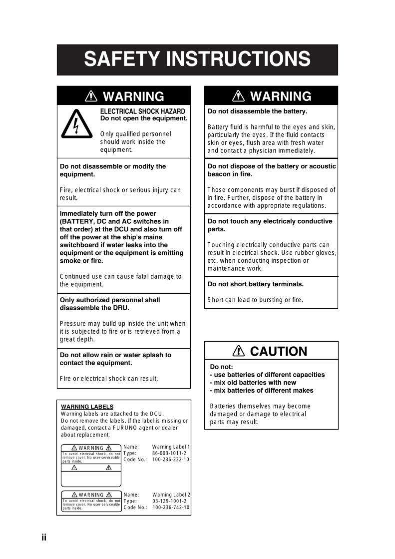
SYSTEM CONFIGURATION
Max. 4 ch
Analog(Max. 16 ch)
Digital (Max. 64 ch)
Max. 6 ch
Max. 2 ch
Serial (Max. 8)
Remote Alarm Panel (RAP) VR-3016
GPS Speed log Heading Echosounder Autopilot Engine telegraph Steering gear M/E remote system Main air compressor Bow thruster Shell door system Watertight doors Fire doors Anemometer Fire detection Main alarms Others
Data CollectingUnit (DCU)VR-3010
Radar I/FRI-3010*
100-230 VAC
24 VDC
: Standard supply equipment and cable: Optional supply equipment and cable: Local supply equipment and cable
VHF Audio
Radar
VHF I/F IF-5200
Bridge MICVR-5011
IEC 61162serial data
Alarm MonitoringSystem
Max.2 ch
Live Player ProVR-5034
Junction Box (JB) IF-8530*
Junction Box (JB) IF-8530 (max. 2) 24 VDC
Serial(1ch)
Serial (Max. 8 ch) Analog(Max. 16 ch)
Digital (Max. 64 ch)
Data Recording Unit (DRU)VR-5020-6G/VR-5020-9G
Waterproof MICVR-3012W
* Optional with VR-3000S
Serial (1 ch)
Environmental category DCU Protected from weather DRU Exposed to weather RAP Protected from weather Bridge MIC Protected from weather Waterproof MIC Exposed to weather VHF I/F unit Protected from weather JB Protected from weather For the S-VDR, where it is impossible to obtain radar data, the AIS target data should be recorded as a source of information from other ships. (Ref. IMO Res.MSC.163(78), section 5.4.7.)

viii
RECORD OF PUB REV., PROG. NO. Revision No., Date of Revision
Program No. (software)
Outline of Revision
A Apr. 19, 2006
VR-3000 SYSTEM 2450031-01
RAP 2450026-01
1st printing.
A1 June 2, 2006
Same as above Page vi, vii Revised system configuration drawings to include Waterproof MIC. Page viii Revised this page. Page 16 – 17 Changed error code no. as follows: 035→034 Storage failure 041→042 Grabber failure 048→046 DRU Index error SP-1 – SP-4 Revised specifications
B June 16, 2006
Same as above All pages revised.

1
1. OPERATION 1.1 Overview The VR-3000/VR-3000S consists of Data Collecting Unit (DCU), Data Recording Unit (DRU), Remote Alarm Panel (RAP), Junction Box (JB, optional supply with VR-3000S) and bridge microphone units. The VDR system continuously stores data from the past 12 hours onto the Flash Memory in the capsule, erasing the oldest data stored as new data is recorded. The data to be recorded includes the following:
Parameters to be recorded IEC 61162 formatter Notes Date and time ZDA Ship’s position and datum used GNS and DTM Speed (water and/or ground) VBW Heading (true) HDT Heading (magnetic) HDG AIS-VHF data-link message VDM AIS-VHF data-link own-vessel message VDO Depth (echo sounder) DPT Alarms ALR No requirement for S-VDR to
send alarm messages Rudder order/response manual RSA Rudder order/response automatic HTC, HTD Engine order/response RPM, XDR Hull openings, watertight doors XDR Accelerations and hull stress XDR, ALR Wind speed and direction MWV VDR alarm output $VRALR Radar data Bridge audio VHF communication audio Power supply precaution If ship’s mains power source (100-230 VAC) and emergency source fail, the VR-3000/VR-3000S continues to record bridge audio for 2 h from backup batteries.
2
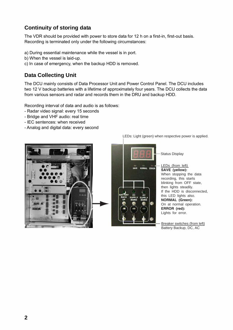
Continuity of storing data The VDR should be provided with power to store data for 12 h on a first-in, first-out basis. Recording is terminated only under the following circumstances: a) During essential maintenance while the vessel is in port. b) When the vessel is laid-up. c) In case of emergency, when the backup HDD is removed. Data Collecting Unit The DCU mainly consists of Data Processor Unit and Power Control Panel. The DCU includes two 12 V backup batteries with a lifetime of approximately four years. The DCU collects the data from various sensors and radar and records them in the DRU and backup HDD. Recording interval of data and audio is as follows: - Radar video signal: every 15 seconds - Bridge and VHF audio: real time - IEC sentences: when received - Analog and digital data: every second
Breaker switches (from left)Battery Backup, DC, AC
Status Display
LEDs (from left)SAVE (yellow):When stopping the datarecording, this starts blinking from OFF state,then lights steadily. If the HDD is disconnected,this LED lights also.NORMAL (Green):On at normal operation.ERROR (red):Lights for error.
LEDs: Light (green) when respective power is applied.
3
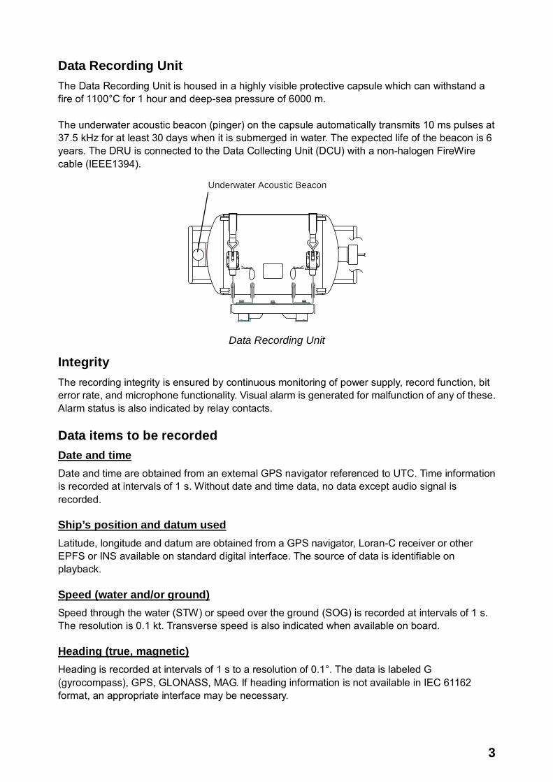
Data Recording Unit The Data Recording Unit is housed in a highly visible protective capsule which can withstand a fire of 1100°C for 1 hour and deep-sea pressure of 6000 m. The underwater acoustic beacon (pinger) on the capsule automatically transmits 10 ms pulses at 37.5 kHz for at least 30 days when it is submerged in water. The expected life of the beacon is 6 years. The DRU is connected to the Data Collecting Unit (DCU) with a non-halogen FireWire cable (IEEE1394).
Underwater Acoustic Beacon
Data Recording Unit
Integrity The recording integrity is ensured by continuous monitoring of power supply, record function, bit error rate, and microphone functionality. Visual alarm is generated for malfunction of any of these. Alarm status is also indicated by relay contacts. Data items to be recorded Date and time Date and time are obtained from an external GPS navigator referenced to UTC. Time information is recorded at intervals of 1 s. Without date and time data, no data except audio signal is recorded. Ship’s position and datum used Latitude, longitude and datum are obtained from a GPS navigator, Loran-C receiver or other EPFS or INS available on standard digital interface. The source of data is identifiable on playback. Speed (water and/or ground) Speed through the water (STW) or speed over the ground (SOG) is recorded at intervals of 1 s. The resolution is 0.1 kt. Transverse speed is also indicated when available on board. Heading (true, magnetic) Heading is recorded at intervals of 1 s to a resolution of 0.1°. The data is labeled G (gyrocompass), GPS, GLONASS, MAG. If heading information is not available in IEC 61162 format, an appropriate interface may be necessary.

4
AIS-VHF data-link message, AIS-VHF data-link own-vessel message Where there is no commercial off-the-shelf interface available to obtain radar data then AIS target data shall be recorded as a source of information regarding other ships, otherwise AIS information may be recorded additionally as a beneficial secondary source of information on both other and own ship. The VDM message (UAIS VHF Data-link) shall be recorded in such a way that all target data available from the onboard AIS are acquired. If the VDO message (UAIS VHF Data-link Own-vessel report) is recorded, this shall be additional to the recording of individual sensor data. Depth (echo sounder) Depth under keel up to a resolution of 0.1 m as available on the ship is recorded. Alarms The status of all IMO mandatory alarms is recorded individually with ID number and time stamp. Audible alarms from the alarm units are stored simultaneously by the bridge audio microphones. Rudder order/response Rudder order and response angles are recorded up to a resolution of 1° as available on the ship. The rudder information is recorded. If more than one rudder is provided, the circuitry can be duplicated. Engine order/response The DCU obtains the engine order and response from the engine telegraph or direct engine control. The signal level is normally 0-10 V. The engine parameters with shaft revolution and ahead/astern indicators are recorded to a resolution of 1 rpm. All order and response from bow, stern, thruster, tunnel thrusters and controllable pitch propellers shall be recorded. The S-VDR shall record this data if said serial data is available. Hull openings, watertight doors Inputs digital or RS-422 serial can be connected individually. The data is received at intervals of 1 s and stored with time stamps. Serial data sentence XDR is received at a data rate of 1,200-9,600 baud. Accelerations and hull stresses The DCU obtains signals from appropriate hull stress and response monitoring devices. The inputs are recorded individually and stored with time stamps. Serial data sentence XDR is received at a data rate of 1,200-9,600 baud. Wind speed and direction The DCU obtains the signal from appropriate wind speed and direction sensor. The inputs are recorded individually and stored with time stamps. Serial data sentence XDR is received at a data rate of 1,200-9,600 baud. VDR alarm output There is no requirement for the S-VDR to send alarm messages. If, as an option, such messages are sent then the appropriate sentence format is ALR.

5
Radar data Radar image including range rings, EBLs, VRMs, plotting symbols, radar maps, parts of SENC, voyage plan, and other essential navigational indications, is recorded in the DRU via the interface in the DCU which is connected to the buffered video output of the radar display unit. One complete picture frame is captured at intervals of 15 s. The radar display complying with IEC 60936-1 should have a buffered output (VESA DMTS compatible) with resolutions between 640 x 480 and 1280 x 1024, and can be directly connected with the VDR. Scanning may be interlaced or non-interlaced. Bridge audio Up to six microphones are supplied as standard to record conversation at conning station, radar display and chart table. If possible, the microphones should be positioned to capture the audio from the intercom, public address system, and audible alarms on the bridge. The microphones are labeled Mic1, Mic2, etc. Microphone captures conversation in the bridge, audio signals from equipment and sound from machinery. The microphone generates a test beep every 12 hours which is also recorded. The microphone picks up audio signals ranging from 150 to 6000 Hz. Communications audio A maximum of two VHF communications are recorded for both transmitted and received audio signals. The VHF radio connections are labeled VHF1 and VHF2.
6
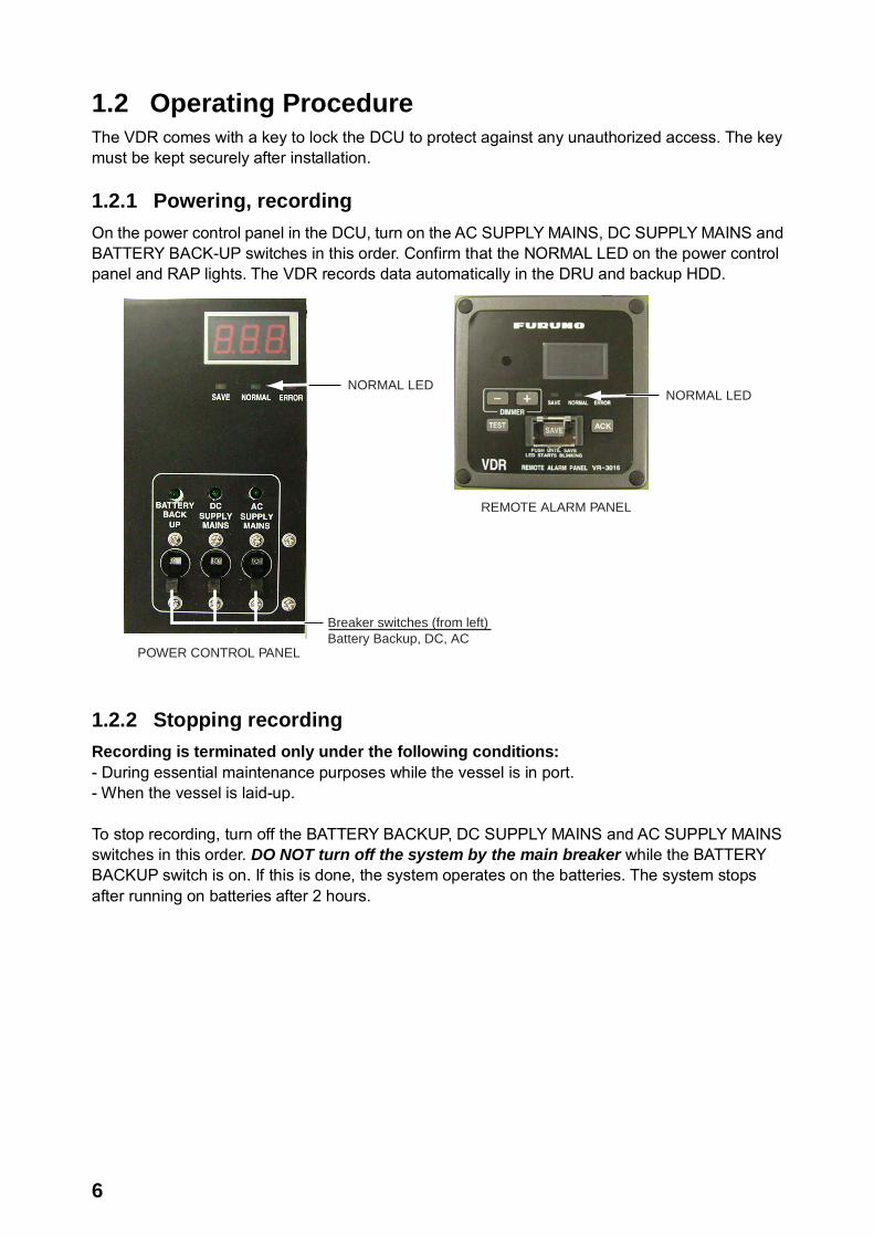
1.2 Operating Procedure The VDR comes with a key to lock the DCU to protect against any unauthorized access. The key must be kept securely after installation. 1.2.1 Powering, recording On the power control panel in the DCU, turn on the AC SUPPLY MAINS, DC SUPPLY MAINS and BATTERY BACK-UP switches in this order. Confirm that the NORMAL LED on the power control panel and RAP lights. The VDR records data automatically in the DRU and backup HDD.
Breaker switches (from left)Battery Backup, DC, AC
NORMAL LED
REMOTE ALARM PANEL
POWER CONTROL PANEL
NORMAL LED
1.2.2 Stopping recording Recording is terminated only under the following conditions: - During essential maintenance purposes while the vessel is in port. - When the vessel is laid-up. To stop recording, turn off the BATTERY BACKUP, DC SUPPLY MAINS and AC SUPPLY MAINS switches in this order. DO NOT turn off the system by the main breaker while the BATTERY BACKUP switch is on. If this is done, the system operates on the batteries. The system stops after running on batteries after 2 hours.

7
1.3 Operation on Remote Alarm Panel No power switch is provided on the Remote Alarm Panel; it is turned on and off by the power switch on the DCU. When the ERROR LED (red) on the Remote Alarm Panel is on, identify the error by checking code number in the error code tables in Chapter 3. The buttons on the Remote Alarm Panel work as described in the figure below.
LEDs (from left)SAVE (yellow):Starts blinking from OFF statewhen recording is stopped,then lights steadily. If the HDD is disconnected,this LED lights also.NORMAL (Green):On at normal operation.ERROR (red):Lights for error.
TEST: Tests LCD.
Status Display
DIMMER:Adjust panel backlighting;display software versionno. (pressed together).
Buzzer
ACK: Silences buzzer.
SAVE: Stops recording onto the backup HDD.See the NOTICE below.
Remote Alarm Panel
Note: The buzzer sounds every time the radar connected to the VDR is turned off. Press the ACK button to silence the alarm.
NOTICEAfter pressing the SAVE button, data willnot be recorded. Replace the HDD withan initialized one, or contact a FURUNOagent for necessary procedure.
SAVE button The SAVE button functions to stop recording to the backup HDD in the DCU. If an incident occurs, press this button to stop recording to the backup HDD, and then see paragraph 1.4 for how to remove the HDD,

8
1.4 Removing HDD VDR information is copied automatically into the backup hard disk drive (HDD) for more than 12 hours (max. 48 hours) and is then automatically written over with new data. Bring the HDD with you after an incident if possible. Press the SAVE button only when an incident occurs. To replace the HDD under other circumstances, see section 2.6. To remove the HDD, do the following: 1. Press the SAVE button (long press) on the RAP (Remote Alarm Panel). The yellow LED starts
blinking, showing that recording is being terminated. 2. Wait until the LED lights steadily. 3. Open the DCU with the key and turn off the power. 4. Pull the knob on the HDD door to open the door. 5. Disconnect the IEEE1394 cable. 6. Remove the HDD.
IEEE1394Cable
Knob
HDD
HD
DCU, showing location of HDD
1.5 How to Release DRU To remove the DRU from the bracket (cradle) do the following: 1. Loosen the hand-tightened cap. 2. Pull the DRU cable straight out.
(The cable may be cut after an incident.) 3. Remove two snap pins and then two hinge
pins. 4. Lift the release levers.
2. DRU cable
1. Cap
3. Hinge pin
3. Snap pin
4. Release levers.
9
MIC COVER
2. MAINTENANCE
Periodic checks and maintenance are important for proper operation of any electronic systems. This chapter contains maintenance instructions to be followed to obtain optimum performance and the longest possible life of the equipment. Any maintenance must be executed by a suitably qualified technician.
WARNINGELECTRICAL SHOCK HAZARDDo not open the equipment.
Only qualified personnelshould work inside theequipment.
Do not disassemble or modify theequipment.
Fire, electrical shock or serious injury canresult.
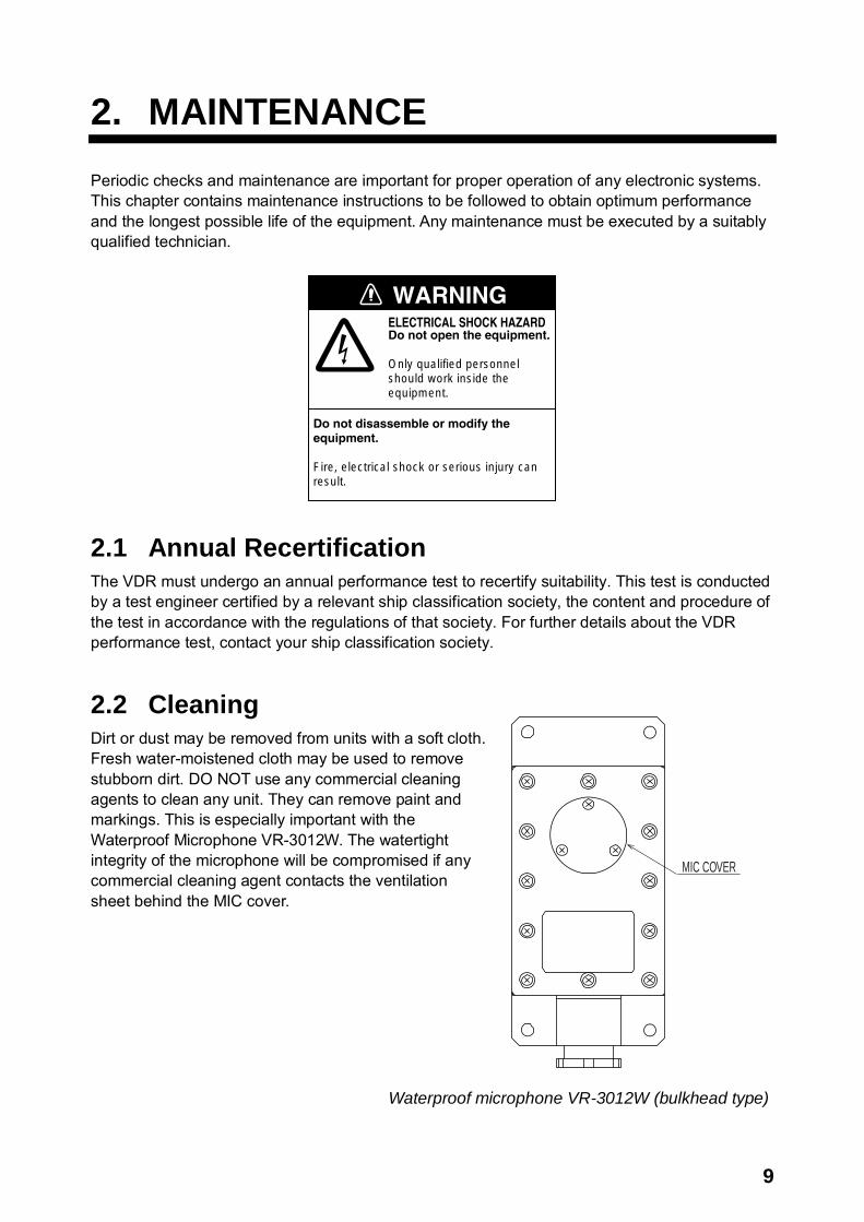
2.1 Annual Recertification The VDR must undergo an annual performance test to recertify suitability. This test is conducted by a test engineer certified by a relevant ship classification society, the content and procedure of the test in accordance with the regulations of that society. For further details about the VDR performance test, contact your ship classification society. 2.2 Cleaning Dirt or dust may be removed from units with a soft cloth. Fresh water-moistened cloth may be used to remove stubborn dirt. DO NOT use any commercial cleaning agents to clean any unit. They can remove paint and markings. This is especially important with the Waterproof Microphone VR-3012W. The watertight integrity of the microphone will be compromised if any commercial cleaning agent contacts the ventilation sheet behind the MIC cover.
Waterproof microphone VR-3012W (bulkhead type)
10
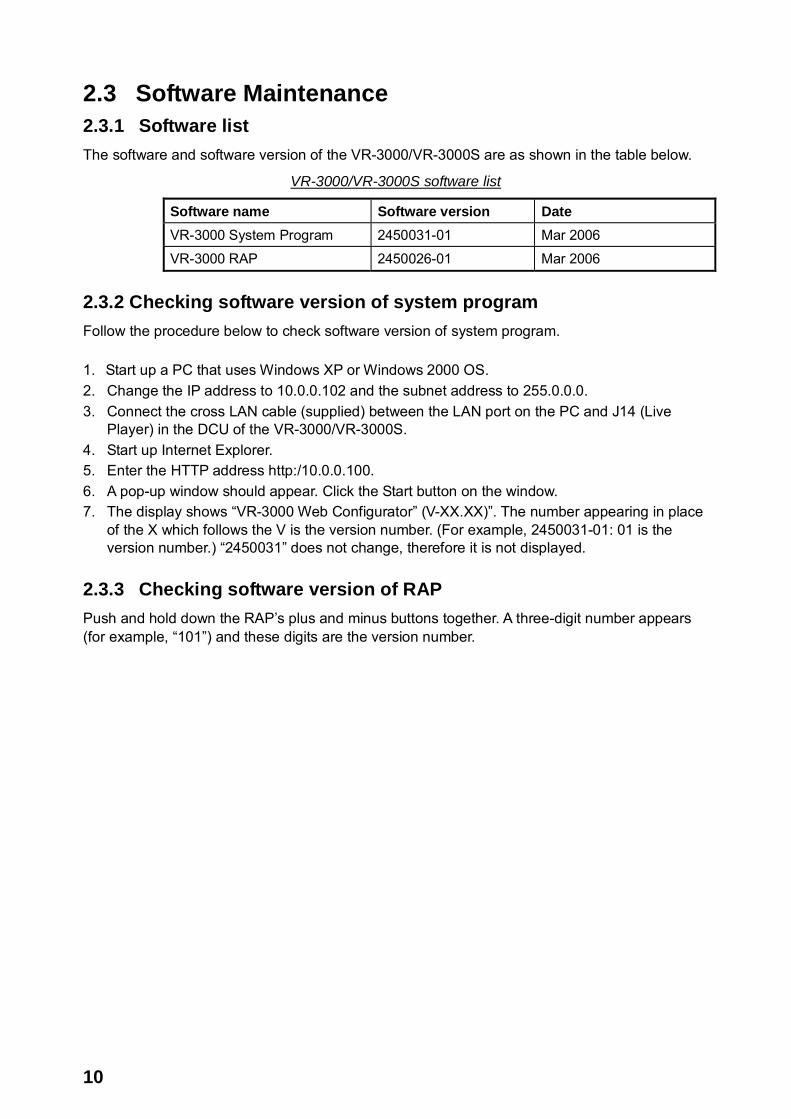
2.3 Software Maintenance 2.3.1 Software list The software and software version of the VR-3000/VR-3000S are as shown in the table below.
VR-3000/VR-3000S software list
Software name Software version Date VR-3000 System Program 2450031-01 Mar 2006 VR-3000 RAP 2450026-01 Mar 2006
2.3.2 Checking software version of system program Follow the procedure below to check software version of system program. 1. Start up a PC that uses Windows XP or Windows 2000 OS. 2. Change the IP address to 10.0.0.102 and the subnet address to 255.0.0.0. 3. Connect the cross LAN cable (supplied) between the LAN port on the PC and J14 (Live
Player) in the DCU of the VR-3000/VR-3000S. 4. Start up Internet Explorer. 5. Enter the HTTP address http:/10.0.0.100. 6. A pop-up window should appear. Click the Start button on the window. 7. The display shows “VR-3000 Web Configurator” (V-XX.XX)”. The number appearing in place
of the X which follows the V is the version number. (For example, 2450031-01: 01 is the version number.) “2450031” does not change, therefore it is not displayed.
2.3.3 Checking software version of RAP Push and hold down the RAP’s plus and minus buttons together. A three-digit number appears (for example, “101”) and these digits are the version number.
11
Screw
Battery leads(under vinyl boot)
Screw
Battery
Battery
J3
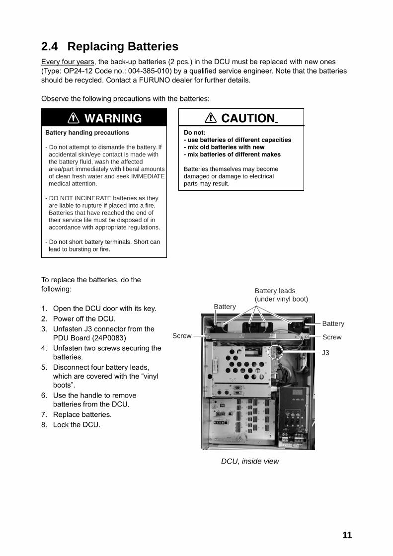
2.4 Replacing Batteries Every four years, the back-up batteries (2 pcs.) in the DCU must be replaced with new ones (Type: OP24-12 Code no.: 004-385-010) by a qualified service engineer. Note that the batteries should be recycled. Contact a FURUNO dealer for further details. Observe the following precautions with the batteries:
WARNINGBattery handing precautions
- Do not attempt to dismantle the battery. If accidental skin/eye contact is made with the battery fluid, wash the affected area/part immediately with liberal amounts of clean fresh water and seek IMMEDIATE medical attention.
- DO NOT INCINERATE batteries as they are liable to rupture if placed into a fire. Batteries that have reached the end of their service life must be disposed of in accordance with appropriate regulations. - Do not short battery terminals. Short can lead to bursting or fire.
Do not:- use batteries of different capacities- mix old batteries with new- mix batteries of different makes
Batteries themselves may becomedamaged or damage to electricalparts may result.
CAUTION
To replace the batteries, do the following: 1. Open the DCU door with its key. 2. Power off the DCU. 3. Unfasten J3 connector from the
PDU Board (24P0083) 4. Unfasten two screws securing the
batteries. 5. Disconnect four battery leads,
which are covered with the “vinyl boots”.
6. Use the handle to remove batteries from the DCU.
7. Replace batteries. 8. Lock the DCU.
DCU, inside view
12
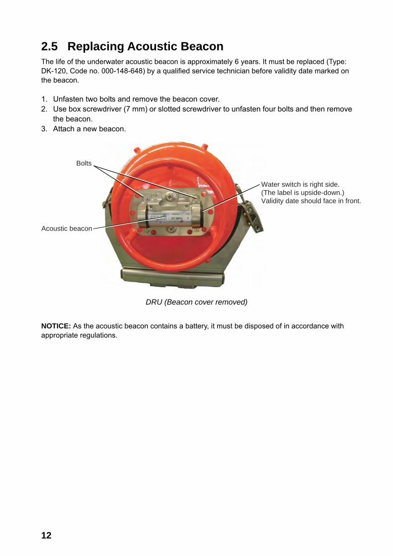
2.5 Replacing Acoustic Beacon The life of the underwater acoustic beacon is approximately 6 years. It must be replaced (Type: DK-120, Code no. 000-148-648) by a qualified service technician before validity date marked on the beacon. 1. Unfasten two bolts and remove the beacon cover. 2. Use box screwdriver (7 mm) or slotted screwdriver to unfasten four bolts and then remove
the beacon. 3. Attach a new beacon.
Bolts
Acoustic beacon
Water switch is right side.(The label is upside-down.)Validity date should face in front.
DRU (Beacon cover removed)
NOTICE: As the acoustic beacon contains a battery, it must be disposed of in accordance with appropriate regulations.
13
IEEE1394Cable
Knob
HDD
HD
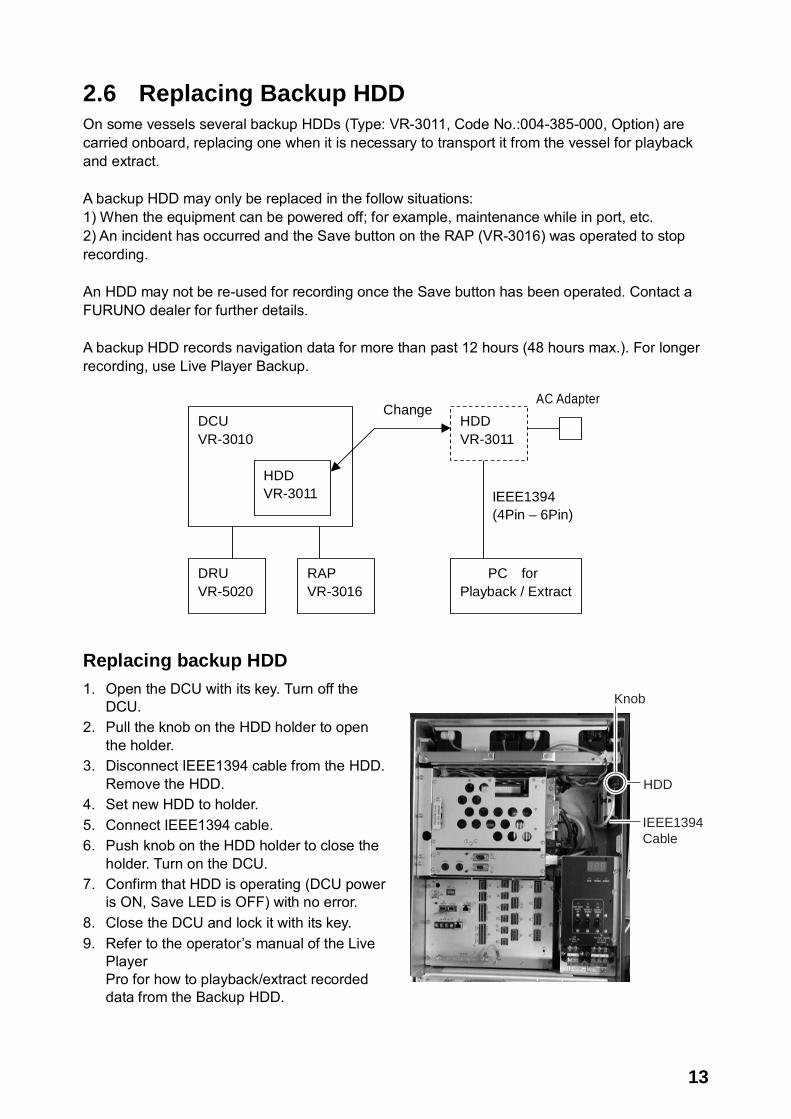
2.6 Replacing Backup HDD On some vessels several backup HDDs (Type: VR-3011, Code No.:004-385-000, Option) are carried onboard, replacing one when it is necessary to transport it from the vessel for playback and extract. A backup HDD may only be replaced in the follow situations: 1) When the equipment can be powered off; for example, maintenance while in port, etc. 2) An incident has occurred and the Save button on the RAP (VR-3016) was operated to stop recording. An HDD may not be re-used for recording once the Save button has been operated. Contact a FURUNO dealer for further details. A backup HDD records navigation data for more than past 12 hours (48 hours max.). For longer recording, use Live Player Backup.
DRU VR-5020
DCU VR-3010
PC for Playback / Extract
IEEE1394 (4Pin – 6Pin)
HDD VR-3011
Change AC Adapter
HDD VR-3011
RAP VR-3016
Replacing backup HDD 1. Open the DCU with its key. Turn off the
DCU. 2. Pull the knob on the HDD holder to open
the holder. 3. Disconnect IEEE1394 cable from the HDD.
Remove the HDD. 4. Set new HDD to holder. 5. Connect IEEE1394 cable. 6. Push knob on the HDD holder to close the
holder. Turn on the DCU. 7. Confirm that HDD is operating (DCU power
is ON, Save LED is OFF) with no error. 8. Close the DCU and lock it with its key. 9. Refer to the operator’s manual of the Live
Player Pro for how to playback/extract recorded data from the Backup HDD.
14
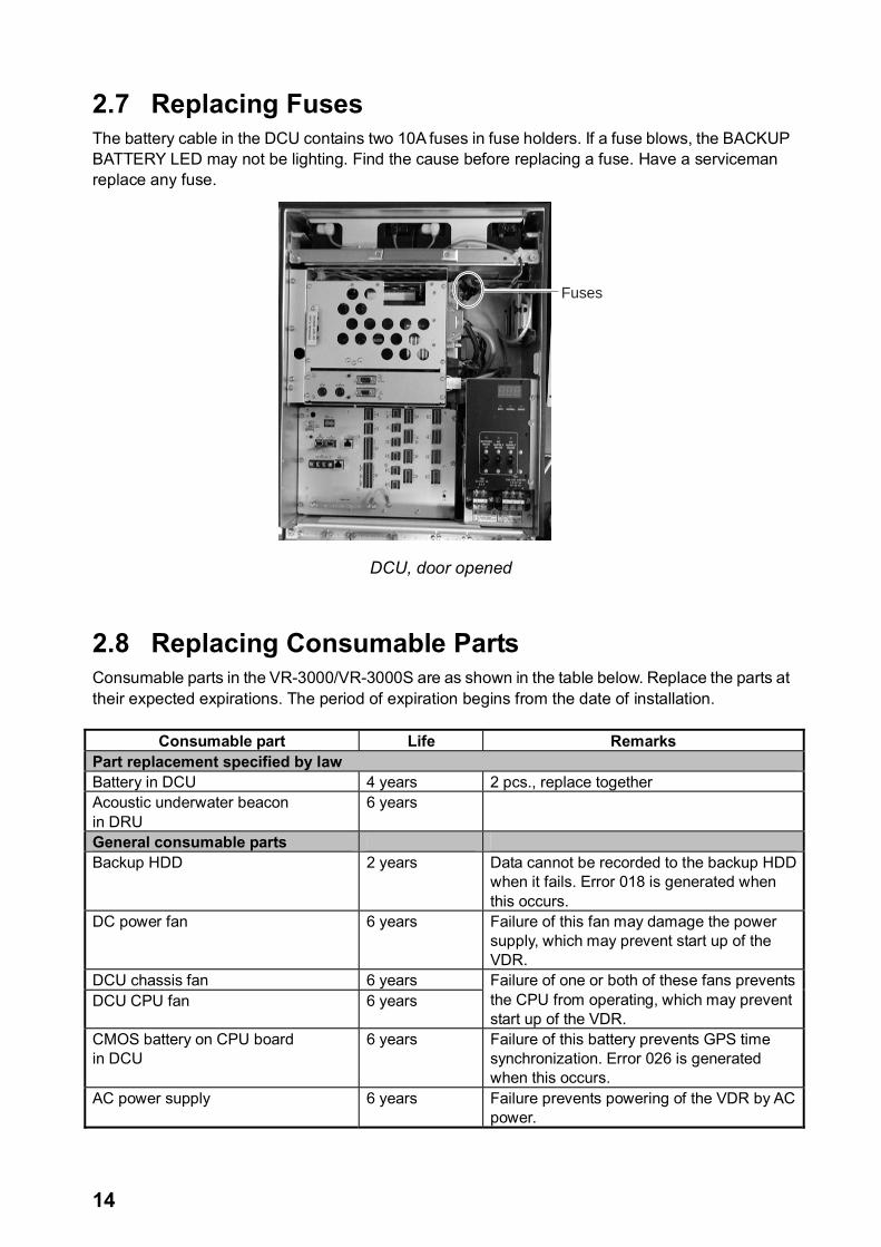
2.7 Replacing Fuses The battery cable in the DCU contains two 10A fuses in fuse holders. If a fuse blows, the BACKUP BATTERY LED may not be lighting. Find the cause before replacing a fuse. Have a serviceman replace any fuse.
Fuses
DCU, door opened
2.8 Replacing Consumable Parts Consumable parts in the VR-3000/VR-3000S are as shown in the table below. Replace the parts at their expected expirations. The period of expiration begins from the date of installation.
Consumable part Life Remarks Part replacement specified by law Battery in DCU 4 years 2 pcs., replace together Acoustic underwater beacon in DRU
6 years
General consumable parts Backup HDD 2 years Data cannot be recorded to the backup HDD
when it fails. Error 018 is generated when this occurs.
DC power fan 6 years Failure of this fan may damage the power supply, which may prevent start up of the VDR.
DCU chassis fan 6 years DCU CPU fan 6 years
Failure of one or both of these fans prevents the CPU from operating, which may prevent start up of the VDR.
CMOS battery on CPU board in DCU
6 years Failure of this battery prevents GPS time synchronization. Error 026 is generated when this occurs.
AC power supply 6 years Failure prevents powering of the VDR by AC power.

15
3. TROUBLESHOOTING This chapter provides information on possible causes of problems you may experience with your VDR. If you still have a problem after referring to the table, contact your local dealer or national distributor for further advice. Always provide the product serial number. 3.1 General Troubleshooting Use the table below to identify the trouble, cause and possible solution.
Troubleshooting table
Symptom Possible causes Possible solution AC and/or DC LED not lit No power supply Check the breaker switches on
ship’s mains switchboard. BATTERY BACKUP LED not lit No power from the battery Call for service. ERROR LED lighting in red Malfunction of the system Restart the system. If the problem
still remains, call for service. Check integrity of DRU connection.

16
3.2 Error Codes Error codes may appear on the status display on the Power Control Panel to alert to possible trouble. Below is a list of those codes.
Error codes
Error code Name Description Action
--- Normal operation after two minutes
None
Hdd BACKUP_HDD_MISSING Backup HDD not connected to VDR.
1) SAVE button pressed and backup HDD removed: Replace backup HDD. 2) Other situations: Reset VDR. If normal operation not restored, request service.
010 PRC_STATUS_DRU_FAILURE_ INDICATION
System is experiencing trouble communicating with DRU.
Trouble-shoot connection from DCU to DRU (cable, repeaters and possible IEEE1394/Firewire board in DCU).
014 PRC_STATUS_BACKUP_DEVICE_ FAILURE
Backup device is either faulty or not set up correctly.
Replace or reconfigure backup device
018 PRC_STATUS STORAGE BACKUP_CONNECTION_ TIMEOUT
This indicates that the BACKUP has been disconnected more than 120 seconds.
Connect BACKUP HDD or check LOG and repair/replace.
022 PRC_STATUS_STORAGE_DRU_ CONNECTION_TIMEOUT
DRU has been disconnected more than 120 seconds.
Connect DRU again or check LOG and repair/replace.
026 PRC_STATUS_TIMEDIFF_TOO_BIG This indicates that the time difference between system time and time supplied by UTC source is more than one hour.
Try to see if the CMOS clock is set correctly. If not, set it and restart VR-3000/S. If yes, find out why time source device defined in WEB_Configurator is delivered “out of bands” time info.
034 PRC_STATUS_STORAGE_FAILURE_INDICATION
Problem with data on storage devices.
Check LOG and repair/replace. Restart VR-3000/S
(Continued on next page)

17
Error codes (con’t from previous page)
Error code Name Description Action
042 PRC_STATUS_GRABBER_FAILURE_INDICATION
One of the active/enabled video channels can’t grab from the channel. This can be either because radar is turned OFF or wrong configuration.
If radar is turned OFF, press ACK on the RAP to silence alarm. Error will clear when radar is turned ON again. If radar is ON, check installation (cabling) and configuration.
046 PRC_STATUS_DRU_INDEX_ERROR This indicates problem with INDEX in DRU.
Check LOG and clear INDEX.
062 PRC_STATUS_STORAGE_LAST_ BUFFER_NOT_SAVED
Storage problem with DRU/BACKUP.
Check LOG or contact dealer for repair.
066 PRC_STATUS_CONFIGURATION INITIALIZATION FAILED
This indicates that CONFIG was unable to initialize CONFIGURATION.
Check LOG and/or contact supplier for repair.
082 PRC_STATUS_RAP_MISSING RAP is missing. Connection to RAP is lost.
Check cabling to RAP. Reconnect RAP.
084 PRC_STATUS_AP_MISSING No alarm panel connection
Check connection to alarm panel.
086 PRC_STATUS_CONFIG_ VDRDEFAULT_ERROR
Built-in configuration in VR-3000/S system software failed to load into DRU. Reason can be firmware itself or problem with DRU.
Clear CONFIG_area and restart VR-3000/S. This will install a “default minimum” configuration. If the error still occurs, try to see if DRU is set up correctly (partitions, partition size).
088 PRC_RJB_MISSING Indicates the Junction Box is missing.
Check cabling and IP-ADDR setting on DIP SW S5 in JB.
094 PRC_RECORDING_BACKUP_ INACTIVE
Indicates that Backup is inactive – not storing data.
Check communication to Backup HDD.
098 PRC_RECORDING_DRU_INACTIVE Indicates that DRU is inactive – not storing data.
Check communication to DRU.
102 PRC_STATUS_CONFIG_UNABLE_ TO_SAVE
VR-3000/S could not save configuration to DRU/BACKUP-DRIVE.
Check DRU connected; BACKUP DRIVE OK; For other call for service.
106 PRC_STATUS_SYSTEM_STOPPED SYSTEM_STOP request has been completed (system has stopped collecting data).
Turn off all power switches to power down, or recycle power to restart.
(Continued on next page)

18
Error codes (con’t from previous page)
Error code Name Description Action
130 PRC_STATUS_DATIO_FAILURE_ INDICATION
Problem with ANALOG/DIGITAL interface board. Self-test program run during boot should indicate which board.
Replace faulty board.
138 PRC_STATUS_CONFIG_FAILURE_ INDICATION
Unexpected error when trying to read CONFIG.
Check that installed firmware version is correct for DRU. IF this is a new DRU, CONFIG_area needs to be cleared.
150 PRC_STATUS_CONFIG_INVALID_ SIZE
Size of CONFIG_area in DRU is different from expected one. This should only happen during installation/service and upgrade of software.
Clear CONFIG_area and restart VR-3000/S. This will install a “default minimum” configuration.
154 PRC_STATUS_CONFIG_INVALID_ START_TAG
CONFIG_area in the DRU is clean. This should only happen during installation/service. This will also be displayed at first boot after CONFIG_area is cleared.
Restart VR-3000/S
170 PRC_STATUS_FATAL_FAILURE_ INDICATION
Fatal system error Call for service.
186 PRC_STATUS_GRABBER_IMAGE_ TOO_BIG
Video image capture from radar is larger than expected.
Check quality of captured image color mask (video channels) and re-adjust frame grabber.
(Continued on next page)

19
Error codes (con’t from previous page)
Error code Name Description Action
206 PRC_RECORDING_STOPPED_ INDICATION
The VR-3000 has stopped recording. The system has been running on BATTERY only, for more than two hours.
Reconnect AC or DC power. The system will start recording after 30 seconds.
214 PRC_STATUS RUNNING_ON_BATTERY
Both AC and DC power are down. Audible alarms will only be generated for max. two minutes.
Reconnect AC or DC power.
218 PRC_STATUS_MIC_TEST_FAILED This ALARM is issued when the microphone test fails to test the microphones defined in the WEB_configurator. This test can be run from CONFIGURATION menu in the WEB_configurator, and is run every 12-hours during normal operation (first time 2-minuttes after system-start).
Check if microphones mounted are disabled in the WEB_configurator. (AUDIO section>channels (3, 4, 5)). If this is OK, locate the faulty microphone and check/replace it.
226 PRC_NUM_FLASH_DRU_ERROR This indicates that no. of FLASH devices found in DRU and defined in CONFIGURATION is not same.
Check if CONFIGURATION is correct. If correct, check if DRU is correct.
234 PRC_UTC_TIMEOUT System has not received UTC info within two minutes after system start up
Check that a valid UTC source is connected to the serial port defined as UTC source.
238 PRC_SYSTEM_DRIVE_FAILURE System did not find valid system drive (DRU).
Check that valid DRU is connected. (Validated flashdrives installed.)
246 PRC_STATUS_PDU_NO_ CONNECTION
The cable between PDU and CPU block is not connected.
Reconnect cable between PDU and CPU block in DCU.
254 PRC_SELFTEST_FAILED System failed SELFTEST. Connect via web browser or VGA screen to see reason for failure.
300- 315
PRC_SERIAL_TIMEOUT (250) A serial channel has not delivered data within the specified timeout period.
Reconnect serial data. Check failed device.

20
3.3 Testing Display of Remote Alarm Panel Press the TEST button on the RAP to check that all LCD segments are displayed properly.
21
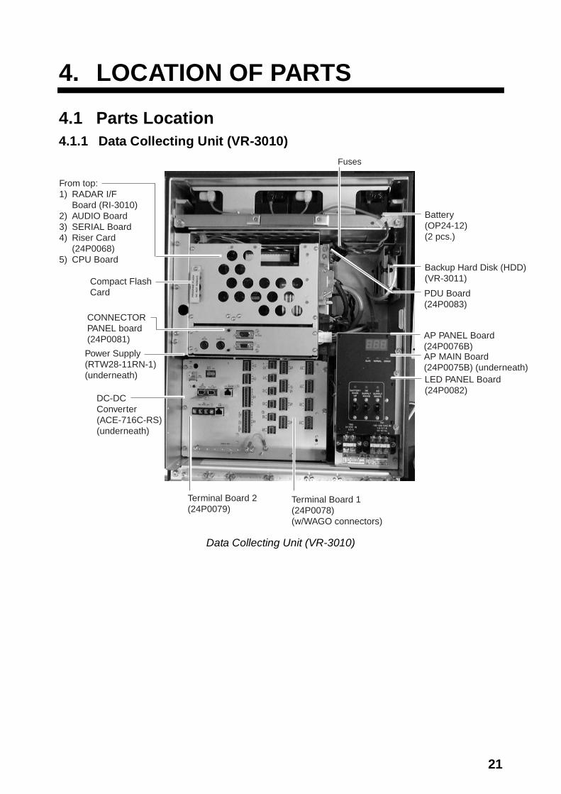
4. LOCATION OF PARTS 4.1 Parts Location 4.1.1 Data Collecting Unit (VR-3010)
Battery(OP24-12)(2 pcs.)
Backup Hard Disk (HDD)(VR-3011)
LED PANEL Board(24P0082)
CONNECTORPANEL board(24P0081)
From top:1) RADAR I/F Board (RI-3010)2) AUDIO Board3) SERIAL Board4) Riser Card
(24P0068)5) CPU Board
Terminal Board 2(24P0079)
Terminal Board 1(24P0078) (w/WAGO connectors)
AP PANEL Board(24P0076B)AP MAIN Board(24P0075B) (underneath)
Compact FlashCard
Power Supply(RTW28-11RN-1)(underneath)
DC-DCConverter(ACE-716C-RS)(underneath)
PDU Board(24P0083)
Fuses
Data Collecting Unit (VR-3010)
22
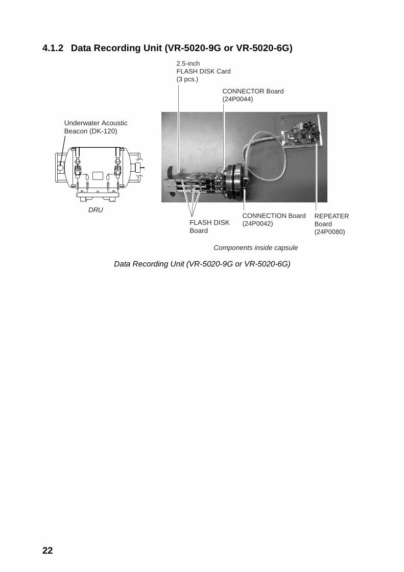
4.1.2 Data Recording Unit (VR-5020-9G or VR-5020-6G)
Underwater AcousticBeacon (DK-120)
FLASH DISKBoard
CONNECTOR Board(24P0044)
REPEATERBoard(24P0080)
CONNECTION Board(24P0042)
Components inside capsule
DRU
2.5-inchFLASH DISK Card(3 pcs.)
Data Recording Unit (VR-5020-9G or VR-5020-6G)
23
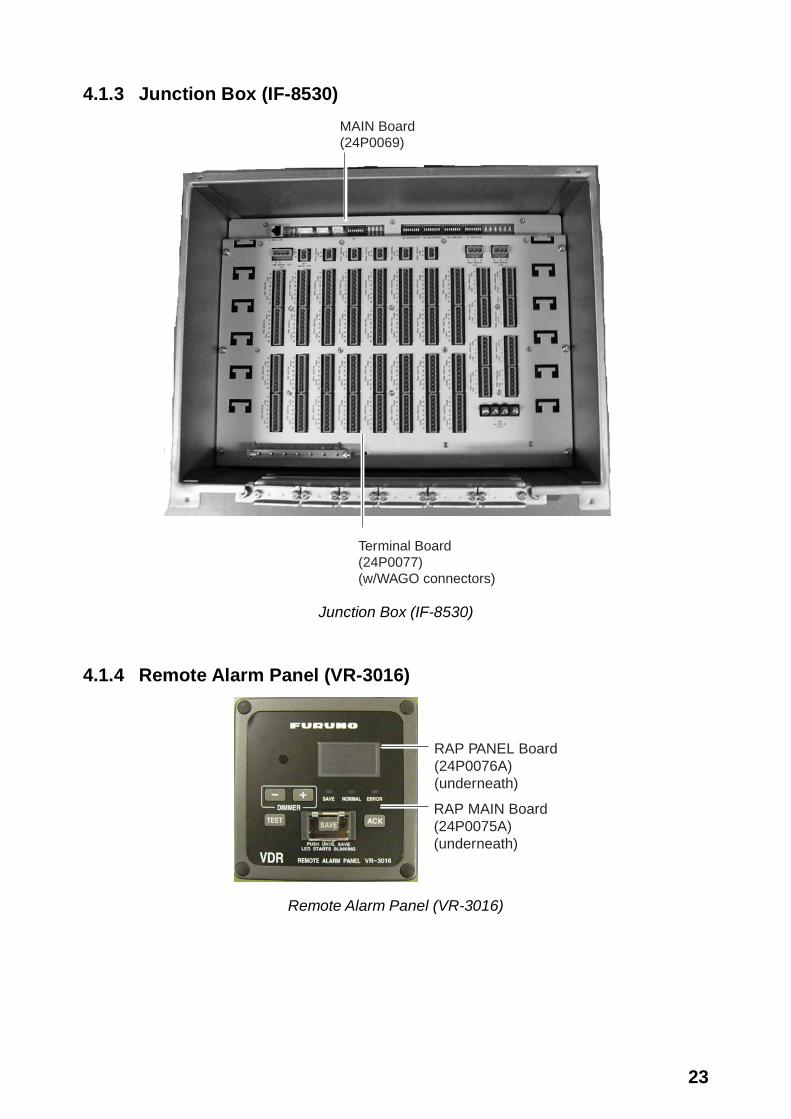
4.1.3 Junction Box (IF-8530)
Terminal Board (24P0077) (w/WAGO connectors)
MAIN Board (24P0069)
Junction Box (IF-8530)
4.1.4 Remote Alarm Panel (VR-3016)
RAP PANEL Board(24P0076A)(underneath)
RAP MAIN Board(24P0075A)(underneath)
Remote Alarm Panel (VR-3016)
24
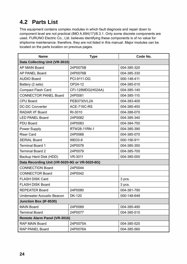
4.2 Parts List This equipment contains complex modules in which fault diagnosis and repair down to component level are not practical (IMO A.694(17)/8.3.1. Only some discrete components are used. FURUNO Electric Co., Ltd. believes identifying these components is of no value for shipborne maintenance; therefore, they are not listed in this manual. Major modules can be located on the parts location on previous pages.
Name Type Code No. Data Collecting Unit (VR-3010) AP MAIN Board 24P0075B 004-385-320 AP PANEL Board 24P0076B 004-385-330 AUDIO Board PCI-9111-DG 000-148-411 Battery (2 sets) OP24-12 004-385-010 Compact Flash Card CFI-128MDG(H02AA) 004-385-140 CONNECTOR PANEL Board 24P0081 004-385-110 CPU Board PEB3730VL2A 004-383-400 DC-DC Converter ACE-716C-RS 004-385-450 RADAR I/F Board RI-3010 004-388-070 LED PANEL Board 24P0082 004-385-340 PDU Board 24P0083 004-384-750 Power Supply RTW28-11RN-1 004-385-390 Riser Card 24P0068 004-385-070 SERIAL Board 99033-8 000-156-911 Terminal Board 1 24P0078 004-385-350 Terminal Board 2 24P0079 004-385-700 Backup Hard Disk (HDD) VR-3011 004-385-000 Data Recording Unit (VR-5020-9G or VR-5020-6G) CONNECTION Board 24P0044 CONNECTOR Board 24P0042 FLASH DISK Card 3 pcs. FLASH DISK Board 3 pcs. REPEATER Board 24P0080 004-381-790 Underwater Acoustic Beacon DK-120 000-148-648 Junction Box (IF-8530) MAIN Board 24P0069 004-385-490 Terminal Board 24P0077 004-385-510 Remote Alarm Panel (VR-3016) RAP MAIN Board 24P0075A 004-385-520 RAP PANEL Board 24P0076A 004-385-560

25
5. INTERFACE (IEC 61162-1, IEC 61162-2)
5.1 Data Sentences Some sentences described here are the ones proposed by the recent IEC TC80/WG6 (Digital Interface Working Group) at the time of this publication. They are marked with PAS 101 or PAS 102. ALA - Set detail alarm condition
0 1 2 3 4 5 6 7 8 9 $xxALA, hhmmss.ss, aa, aa, xx, xxx, A, A, c—c *hh<CR><LF>
0: Header 1: Event time (Optional) 2: System indicator of alarm source 3: Sub-system/equipment/item indicator of alarm source 4: Number of equipment / units / items 5: Number of alarm source 6: Alarm condition 7: Alarm’s acknowledge state 8: Alarm’s description text 9: Check-sum ALR - Set alarm status (PAS 101) Updated the text label of the alarm identification field to be the same as that field in the ACK sentence.
$--ALR,hhmmss.ss,xxx,A,A,c--c*hh<CR><LF>
Alarm’s description text Alarm’s acknowledge state, A = acknowledged, V= unacknowledged
Alarm condition (A = threshold exceeded, V = not exceeded) Unique alarm number (identifier) at alarm source
Time of alarm condition change, UTC

26
DOR - Door status indication This sentence indicates the status of watertight doors, fire doors and other hull openings / doors. Malfunction alarms of the watertight door, fire door and hull opening/door controller should be included in the “ALA” sentence.
$xxDOR, A, hhmmss.ss, aa, aa, xxx, xxx, A, c—c, *hh<cr><lf>
0 1 2 3 4 5 6 7 8 9
0) Header1) Message type S: Status for section: the number of faulty and/or open doors reported in the division specified in field 4. The section may be a whole section (one or both of the division indicators are empty) or a sub-section. (If S is used then it shall be transmitted at regular intervals.) E: Status for single door. (E may be used to indicate an event). F: Fault in system: If limited to one section, indicated by division indicator fields, if not, division indicators empty. (F may be used to indicate an event.)2) Time stamp Time when this status/message was valid.3) System indicator of door status Indicator characters as door system. The field is two fixed characters.4) Division indicator of door allocation (1) Indicator showing division where door is located. This field is two characters. It may be physical fire zone or entity identifier for control and monitoring system, e.g., central number.5) Division indicator of door allocation (2) Indicator showing in which division the door is located. This field is three numeric characters. It may bephysical deck number or identifier for control and monitoring system sub-system, e.g., loop number.6) Door number or door open count Number showing door number or number of doors that are open/faulty. This field is three fixed numeric characters.7) Door status This field includes a single character specified by the following: when S status indicated in 2nd field, this field is ignored O = Open C = Close F = Free status (for watertight door) X = Fault (impossible to know state)8) Message's description text Additional and optional descriptive text/door tag. Also if a door allocation identifier is string type, it is possible to use this field instead of above door allocation fields. Maximum number of characters will be limited by maximum sentence length and length of other fields. DPT - Depth IMO Resolution A.224 (VII). Water depth relative to the transducer and offset of the measuring transducer. Positive offset numbers provide the distance from the transducer to the waterline. Negative offset numbers provide the distance from the transducer to the part of the keel of interest.
$--DPT, x.x, x.x*hh<CR><LF>
Checksum Offset from transducer, in meters = distance from transducer to water-line Water depth relative to the transducer, in meters

27
DTM - Datum reference (to be further developed) Local geodetic datum to which a position location is referenced.
$--DTM, ccc, a*hh<CR><LF>
Country sub-division code W72 - WGS 72, W84 - WGS 84, IHO - datum code, 999 - user defined
ETL - Engine telegraph operation status The ETL sentence indicates engine telegraph position including operating location and sub-telegraph indicator.
$xxETL, hhmmss.ss, a, xx, xx, a, x, *hh<cr><lf>
0 1 2 3 4 5 6 7
0) Header1) Event Time2) Indicator of command O = Order A = Answerback3) Position indication of engine telepgraph 00 = Stop engine 01 = [AH] Dead Slow 02 = [AH] Slow 03 = [AH] Half 04 = Full 05 = [AH] Nav. Full 11 = [AS] Dead Slow 12 = [AS] Slow 13 = [AS] Half 14 = [AS] Fulll 15 = [AS] Crash Astern4) Position indication of sub telegraph 20 = S/B (Stand-by engine) 30 = F/A (Full away – Navigation full) 40 = F/E (Finish with engine)5) Operating location indicator B = Bridge P = Port wing 1 S = Starboard wing 1 C = Engine control room E = Engine side6) Number of engine or propeller shaft 0 = single or on centre-line Odd = starboard Even = port7) Checksum
28
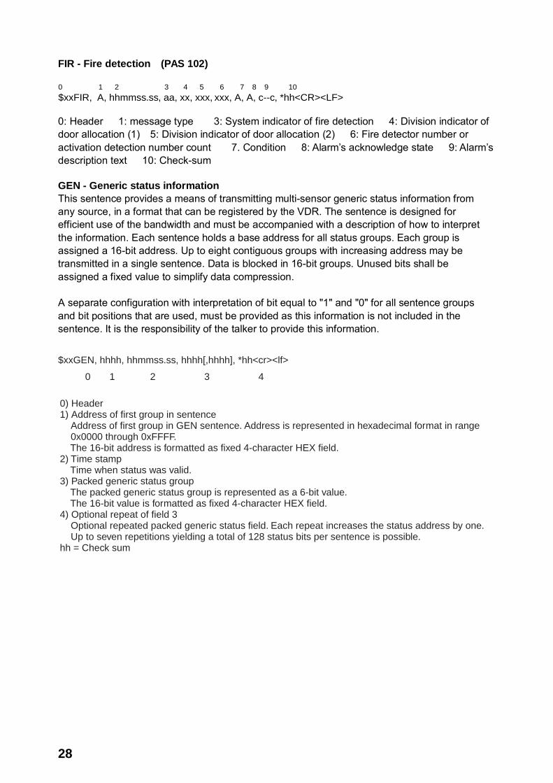
FIR - Fire detection (PAS 102)
0 1 2 3 4 5 6 7 8 9 10
$xxFIR, A, hhmmss.ss, aa, xx, xxx, xxx, A, A, c--c, *hh<CR><LF>
0: Header 1: message type 3: System indicator of fire detection 4: Division indicator of door allocation (1) 5: Division indicator of door allocation (2) 6: Fire detector number or activation detection number count 7. Condition 8: Alarm’s acknowledge state 9: Alarm’s description text 10: Check-sum GEN - Generic status information This sentence provides a means of transmitting multi-sensor generic status information from any source, in a format that can be registered by the VDR. The sentence is designed for efficient use of the bandwidth and must be accompanied with a description of how to interpret the information. Each sentence holds a base address for all status groups. Each group is assigned a 16-bit address. Up to eight contiguous groups with increasing address may be transmitted in a single sentence. Data is blocked in 16-bit groups. Unused bits shall be assigned a fixed value to simplify data compression. A separate configuration with interpretation of bit equal to "1" and "0" for all sentence groups and bit positions that are used, must be provided as this information is not included in the sentence. It is the responsibility of the talker to provide this information.
$xxGEN, hhhh, hhmmss.ss, hhhh[,hhhh], *hh<cr><lf>
0 1 2 3 4
0) Header1) Address of first group in sentence Address of first group in GEN sentence. Address is represented in hexadecimal format in range 0x0000 through 0xFFFF. The 16-bit address is formatted as fixed 4-character HEX field.2) Time stamp Time when status was valid.3) Packed generic status group The packed generic status group is represented as a 6-bit value. The 16-bit value is formatted as fixed 4-character HEX field.4) Optional repeat of field 3 Optional repeated packed generic status field. Each repeat increases the status address by one. Up to seven repetitions yielding a total of 128 status bits per sentence is possible.hh = Check sum
29
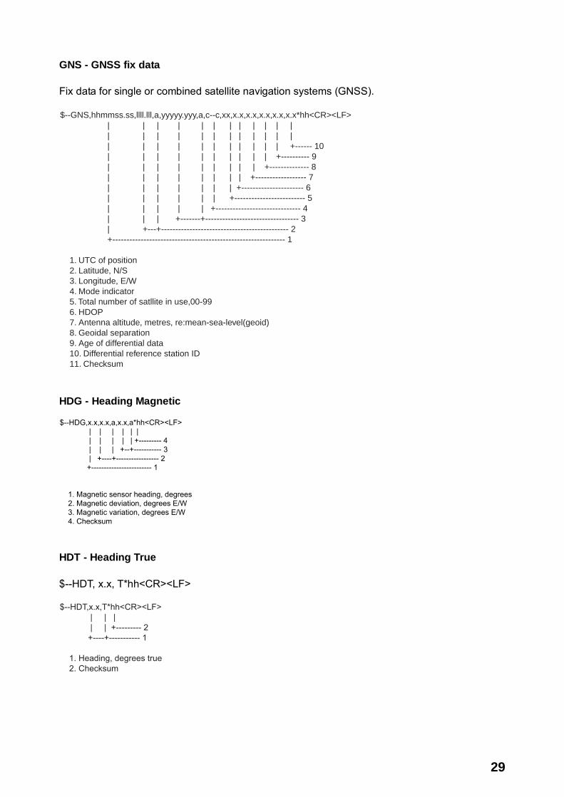
GNS - GNSS fix data Fix data for single or combined satellite navigation systems (GNSS).
$--GNS,hhmmss.ss,llll.lll,a,yyyyy.yyy,a,c--c,xx,x.x,x.x,x.x,x.x,x.x*hh<CR><LF> | | | | | | | | | | | | | | | | | | | | | | | | | | | | | | | | | | | +------ 10 | | | | | | | | | | +---------- 9 | | | | | | | | | +-------------- 8 | | | | | | | | +------------------ 7 | | | | | | | +---------------------- 6 | | | | | | +------------------------- 5 | | | | | +------------------------------ 4 | | | +-------+--------------------------------- 3 | +---+--------------------------------------------- 2 +------------------------------------------------------------- 1
1. UTC of position 2. Latitude, N/S 3. Longitude, E/W 4. Mode indicator 5. Total number of satllite in use,00-99 6. HDOP 7. Antenna altitude, metres, re:mean-sea-level(geoid) 8. Geoidal separation 9. Age of differential data 10. Differential reference station ID 11. Checksum
HDG - Heading Magnetic
$--HDG,x.x,x.x,a,x.x,a*hh<CR><LF> | | | | | | | | | | | +--------- 4 | | | +--+----------- 3 | +----+----------------- 2 +------------------------ 1
1. Magnetic sensor heading, degrees 2. Magnetic deviation, degrees E/W 3. Magnetic variation, degrees E/W 4. Checksum
HDT - Heading True $--HDT, x.x, T*hh<CR><LF>
$--HDT,x.x,T*hh<CR><LF> | | | | | +--------- 2 +----+----------- 1
1. Heading, degrees true 2. Checksum

30
HSS - Hull stress surveillance systems (PAS 102)
0 1 2 3 4
$xxHSS, c--c, x.x, A, *hh<cr><lf>
0: Header 1: Measurement point ID 2: Measurement value 3: Data status, A = data valid, V = data invalid 4: Check-sum Note: This must be verified by Ship Classification. VDR is required to log such data if HSS is fitted on ship. HTC - Heading/Track control command
$--HTC,A,x.x,a,a,a,x.x,x.x,x.x,x.x,x.x,x.x,x.x,a*hh<CR><LF> | | | | | | | | | | | | | | | | | | | | | | | | | | | +--- 14 | | | | | | | | | | | | +----- 13 | | | | | | | | | | | +-------- 12 | | | | | | | | | | +------------ 11 | | | | | | | | | +---------------- 10 | | | | | | | | +-------------------- 9 | | | | | | | +------------------------ 8 | | | | | | +---------------------------- 7 | | | | | +-------------------------------- 6 | | | | +----------------------------------- 5 | | | +------------------------------------- 4 | | +--------------------------------------- 3 | +------------------------------------------ 2 +--------------------------------------------- 1
1. Override, A = in use, V = not in use 2. Commanded rudder angle, degrees 3. Commanded rudder direction, L/R = port/starboard 4. Selected steering mode 5. Turn mode R = radius controlled T = turn rate controlled N = turn is not controlled 6. Commanded rudder limit, degrees(unsigned) 7. Commanded off-heading limit, degrees(unsigned) 8. Commanded radius of turn for heading changes, n.miles 9. Commanded rate of turn to heading changes, deg/min 10. Commanded heading-to-steer, degrees 11. Commanded off-track limit, n.miles(unsigned) 12. Commanded track, degrees 13. Heading reference in use, T/M 14. Checksum

31
HTD - Heading/Track control data
$--HTD,A,x.x,a,a,a,x.x,x.x,x.x,x.x,x.x,x.x,x.x,a,A,A,A,x.x*hh<CR><LF> | | | | | | | | | | | | | | | | | | | | | | | | | | | | | | | | | | | +--- 18 | | | | | | | | | | | | | | | | +------ 17 | | | | | | | | | | | | | | | +--------- 16 | | | | | | | | | | | | | | +----------- 15 | | | | | | | | | | | | | +------------- 14 | | | | | | | | | | | | +--------------- 13 | | | | | | | | | | | +------------------ 12 | | | | | | | | | | +---------------------- 11 | | | | | | | | | +-------------------------- 10 | | | | | | | | +------------------------------ 9 | | | | | | | +---------------------------------- 8 | | | | | | +-------------------------------------- 7 | | | | | +------------------------------------------ 6 | | | | +--------------------------------------------- 5 | | | +----------------------------------------------- 4 | | +------------------------------------------------- 3 | +---------------------------------------------------- 2 +------------------------------------------------------- 1
1. Override, A = in use, V = not in use 2. Commanded rudder angle, degrees 3. Commanded rudder direction, L/R = port/starboard 4. Selected steering mode 5. Turn mode R = radius controlled T = turn rate controlled N = turn is not controlled 6. Commanded rudder limit, degrees(unsigned) 7. Commanded off-heading limit, degrees(unsigned) 8. Commanded radius of turn for heading changes, n.miles 9. Commanded rate of turn to heading changes, deg/min 10. Commanded heading-to-steer, degrees 11. Commanded off-track limit, n.miles(unsigned) 12. Commanded track, degrees 13. Heading reference in use, T/M 14. Rudder status A = within limits, V = limit reached or exceeded 15. Off-heading status A = within limits, V = limit reached or exceeded 16. Off-track status A = within limits, V = limit reached or exceeded 17. Vessel heading, degrees 18. Checksum
32
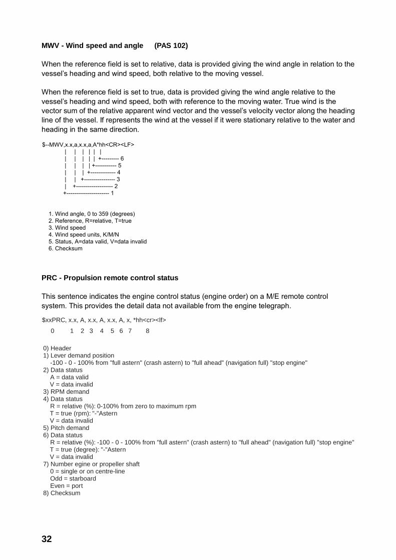
MWV - Wind speed and angle (PAS 102) When the reference field is set to relative, data is provided giving the wind angle in relation to the vessel’s heading and wind speed, both relative to the moving vessel. When the reference field is set to true, data is provided giving the wind angle relative to the vessel’s heading and wind speed, both with reference to the moving water. True wind is the vector sum of the relative apparent wind vector and the vessel’s velocity vector along the heading line of the vessel. If represents the wind at the vessel if it were stationary relative to the water and heading in the same direction.
$--MWV,x.x,a,x.x,a,A*hh<CR><LF> | | | | | | | | | | | +--------- 6 | | | | +----------- 5 | | | +------------- 4 | | +---------------- 3 | +------------------- 2 +---------------------- 1
1. Wind angle, 0 to 359 (degrees) 2. Reference, R=relative, T=true 3. Wind speed 4. Wind speed units, K/M/N 5. Status, A=data valid, V=data invalid 6. Checksum
PRC - Propulsion remote control status This sentence indicates the engine control status (engine order) on a M/E remote control system. This provides the detail data not available from the engine telegraph.
$xxPRC, x.x, A, x.x, A, x.x, A, x, *hh<cr><lf>
0 1 2 3 4 5 6 7 8
0) Header1) Lever demand position -100 - 0 - 100% from "full astern" (crash astern) to "full ahead" (navigation full) "stop engine"2) Data status A = data valid V = data invalid3) RPM demand4) Data status R = relative (%): 0-100% from zero to maximum rpm T = true (rpm): "-"Astern V = data invalid5) Pitch demand6) Data status R = relative (%): -100 - 0 - 100% from "full astern" (crash astern) to "full ahead" (navigation full) "stop engine" T = true (degree): "-"Astern V = data invalid7) Number egine or propeller shaft 0 = single or on centre-line Odd = starboard Even = port8) Checksum

33
RPM - Revolutions (PAS 102) Shaft or engine revolution rate and propeller pitch.
$--RPM, a, x, x.x, x.x, A*hh<CR><LF>
Status: A = data valid Propeller pitch, % of maximum, “-” = astern Speed, revolutions/min, “-” = counter-clockwise
Engine of shaft number, numbered from center-line
Odd = starboard, even = port, 0 = single or no center-line
Source, shaft/engine S/E
RSA - Rudder sensor angle
$--RSA, x.x, A, x.x, A*hh<CR><LF>
Port rudder sensor (see note), Status: A = data valid Starboard (or single) rudder sensor (see note), Status: A = data valid
NOTE - Relative measurement of rudder angle without units, “-” = turn to port. Sensor output is proportional to rudder angle but not necessarily 1 : 1. TRC - Thruster control data This sentence provides the control data for thruster devices
$xxTRC, x, x.x, A, x.x, A, x.x, *hh<cr><lf>
0 1 2 3 4 5 6 7
0) Header1) Number of thrusters Odd = Bow thruster Even = Stern thruster2) RPM demand3) Data status R = relative (%): 0-100% from zero to maximum rpm T = true (deg) V = data invalid4) Pitch demand value "-" port5) Data status R = relative (%) T = True (deg) V = Data invalid6) Azimuth demand Direction of thrust in degrees (0 deg - 360 deg) for thrusters capable of rotating direction of thrust7) Checksum

34
TRD - Thruster response data This sentence provides the response data for thruster devices.
$xxTRD, x, x.x, A, x.x, A, x.x, *hh<cr><lf>
0 1 2 3 4 5 6 7
0) Header1) Number of thrusters Odd = Bow thruster Even = Stern thruster2) RPM demand3) Data status R = relative (%): 0-100% from zero to maximum rpm T = true (deg) V = data invalid4) Pitch response value "-" port5) Data status R = relative (%) T = True (deg) V = Data invalid6) Azimuth demand Direction of thrust in degrees (0 deg - 360 deg) for thrusters capable of rotating direction of thrust7) Checksum
VBW - Dual ground/water speed: This sentence to be expanded as shown below: $--VBW,x.x,x.x,A,x.x,x.x,A,x.x,A,x.x,A*hh<CR><LF> | | | | | | | | | | | | | | | | | | | | | +--- 11 | | | | | | | | | +----- 10 | | | | | | | | +-------- 9 | | | | | | | +----------- 8 | | | | | | +-------------- 7 | | | | | +----------------- 6 | | | | +-------------------- 5 | | | +------------------------ 4 | | +--------------------------- 3 | +------------------------------ 2 +---------------------------------- 1
1. Longitudial water speed, knots 2. Transverse water speed, knots 3. Status: water speed, A=data valid V=data invalid 4. Longitudial ground speed, knots 5. Transverse ground speed, knots 6. Status: ground speed, A=data valid V=data invalid 7. Stern transverse water speed, knots 8. Status: stern water speed, A=data valid V=data invalid 9. Stern transverse ground speed, knots 10. Status: stern ground speed, A=data valid V=data invalid 11. Checksum

35
VDM - UAIS VHF Data-link Message (IEC 61162-2, for AIS)
!--VDM,x,x,x,x,s--s,x*hh<CR><LF> | | | | | | | | | | | | | +--- 7 | | | | | +----- 6 | | | | +-------- 5 | | | +------------ 4 | | +-------------- 3 | +---------------- 2 +------------------ 1
1. Total number of sentences needed to transfer the message, 1 to 9 2. Message sentence number, 1 to 9 3. Sequential message identifier, 0 to 9 4. AIS channel Number 5. Encapsulated ITU-R M.1371 radio message 6. Number of fill-bits, 0 to 5 7. Checksum
VDO - UAIS VHF Data-link Own-vessel report (IEC 61162-2, for AIS)
!--VDO,x,x,x,x,s--s,x*hh<CR><LF> | | | | | | | | | | | | | +--- 7 | | | | | +----- 6 | | | | +-------- 5 | | | +------------ 4 | | +-------------- 3 | +---------------- 2 +------------------ 1
1. Total number of sentences needed to transfer the message, 1 to 9 2. Message sentence number, 1 to 9 3. Sequential message identifier, 0 to 9 4. AIS channel Number 5. Encapsulated ITU-R M.1371 radio message 6. Number of fill-bits, 0 to 5 7. Checksum
36
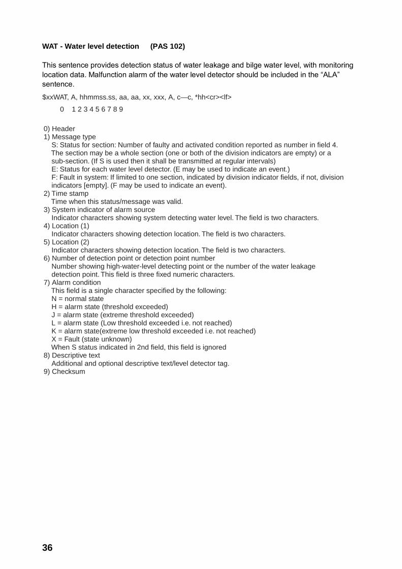
WAT - Water level detection (PAS 102) This sentence provides detection status of water leakage and bilge water level, with monitoring location data. Malfunction alarm of the water level detector should be included in the “ALA” sentence.
$xxWAT, A, hhmmss.ss, aa, aa, xx, xxx, A, c—c, *hh<cr><lf>
0 1 2 3 4 5 6 7 8 9
0) Header1) Message type S: Status for section: Number of faulty and activated condition reported as number in field 4. The section may be a whole section (one or both of the division indicators are empty) or a sub-section. (If S is used then it shall be transmitted at regular intervals) E: Status for each water level detector. (E may be used to indicate an event.) F: Fault in system: If limited to one section, indicated by division indicator fields, if not, division indicators [empty]. (F may be used to indicate an event). 2) Time stamp Time when this status/message was valid.3) System indicator of alarm source Indicator characters showing system detecting water level. The field is two characters.4) Location (1) Indicator characters showing detection location. The field is two characters.5) Location (2) Indicator characters showing detection location. The field is two characters. 6) Number of detection point or detection point number Number showing high-water-level detecting point or the number of the water leakage detection point. This field is three fixed numeric characters.7) Alarm condition This field is a single character specified by the following: N = normal state H = alarm state (threshold exceeded) J = alarm state (extreme threshold exceeded) L = alarm state (Low threshold exceeded i.e. not reached) K = alarm state(extreme low threshold exceeded i.e. not reached) X = Fault (state unknown) When S status indicated in 2nd field, this field is ignored8) Descriptive text Additional and optional descriptive text/level detector tag.9) Checksum

37
XDR - Transducer measurements Measurement data from transducers that measure physical quantities such as temperature, force, pressure, frequency, angular or linear displacement, etc. Data from a variable number of transducers measuring the same of different quantities can be mixed in the same sentence. This sentence is designed for use by integrated systems as well as transducers that may be connected in a “chain” where each transducer receives the sentence as an input and adds its own data fields on before retransmitting the sentence.
$--XDR, a, x.x, a, c--c, ........ a, x.x, a, c--c*hh<CR><LF>
Transducer “n” (see note 1) Data, variable number of transducers Transducer No. 1 ID Units of measure, transducer No. 1 (see note 2) Measurement data, transducer No. 1 Transducer type, transducer No. 1 (see note 2)
NOTES 1 Sets of the four fields “type-data-units-ID” are allowed for an undefined number of transducers. Up to “n” transducers may be included within the limits of allowed sentence length, null fields are not required except where portions of the “type-data-units-ID” combination are not available. ZDA - Time and date
$--ZDA,hhmmss.ss,xx,xx,xxxx,xx,xx*hh<CR><LF> | | | | | | | | | | | | | +--------- 7 | | | | | +----------- 6 | | | | +-------------- 5 | | | +------------------ 4 | | +---------------------- 3 | +------------------------- 2 +--------------------------------- 1
1. UTC 2. Day, 01 to 31(UTC) 3. Month, 01 to 12(UTC) 4. Year(UTC) 5. Local zone hours, 00h to +-13h 6. Local zone minutes, 00 to +59 as local hours 7. Checksum
NOTE - Zone description if the number of whole hours added to local time to obtain GMT. Zone description is negative for east longitudes.

38
5.2 Interface Circuits 5.2.1 IEC 61162-1 Data Collecting Unit
A
B
Junction Box
A
A
B

39
5.2.2 IEC 61162-2 Data Collecting Unit
G
B
A
Junction Box
B
A
G

40
APPENDIX: PLAYING BACK RECORDED DATA IMO Circulator SN Circ, 246 recommends that all VDR and S-VDR systems installed on or after 1 July 2006 be supplied with an accessible means for extracting the stored data from the VDR or S-VDR to a laptop computer. Manufacturers are required to provide software for extracting data, instructions for extracting data and cables for connection between recording device and computer. FURUNO provides the following: • LIVE PLAYER PRO (instructions) • LIVE PLAYER PRO CD (software) • Cables: Firewire and LAN Refer to the Operator’s Manual for the Live Player Pro for how to playback recorded data.
FURUNO VR-3000/VR-3000S
SP - 1 E4437S01C
SPECIFICATIONS OF VOYAGE DATA RECORDER VR-3000/
SIMPLIFIED VOYAGE DATA RECORDING VR-3000S
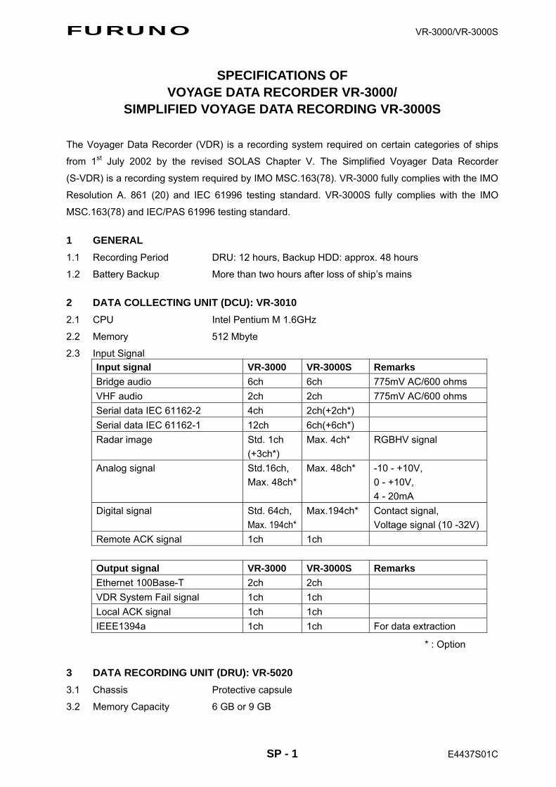
The Voyager Data Recorder (VDR) is a recording system required on certain categories of ships
from 1st July 2002 by the revised SOLAS Chapter V. The Simplified Voyager Data Recorder
(S-VDR) is a recording system required by IMO MSC.163(78). VR-3000 fully complies with the IMO
Resolution A. 861 (20) and IEC 61996 testing standard. VR-3000S fully complies with the IMO
MSC.163(78) and IEC/PAS 61996 testing standard.
1 GENERAL 1.1 Recording Period DRU: 12 hours, Backup HDD: approx. 48 hours
1.2 Battery Backup More than two hours after loss of ship’s mains
2 DATA COLLECTING UNIT (DCU): VR-3010 2.1 CPU Intel Pentium M 1.6GHz
2.2 Memory 512 Mbyte
2.3 Input Signal Input signal VR-3000 VR-3000S Remarks Bridge audio 6ch 6ch 775mV AC/600 ohms VHF audio 2ch 2ch 775mV AC/600 ohms Serial data IEC 61162-2 4ch 2ch(+2ch*) Serial data IEC 61162-1 12ch 6ch(+6ch*) Radar image Std. 1ch
(+3ch*) Max. 4ch* RGBHV signal
Analog signal Std.16ch, Max. 48ch*
Max. 48ch* -10 - +10V, 0 - +10V, 4 - 20mA
Digital signal Std. 64ch, Max. 194ch*
Max.194ch* Contact signal, Voltage signal (10 -32V)
Remote ACK signal 1ch 1ch
Output signal VR-3000 VR-3000S Remarks Ethernet 100Base-T 2ch 2ch VDR System Fail signal 1ch 1ch Local ACK signal 1ch 1ch IEEE1394a 1ch 1ch For data extraction
* : Option
3 DATA RECORDING UNIT (DRU): VR-5020 3.1 Chassis Protective capsule
3.2 Memory Capacity 6 GB or 9 GB
FURUNO VR-3000/VR-3000S
SP - 2 E4437S01C
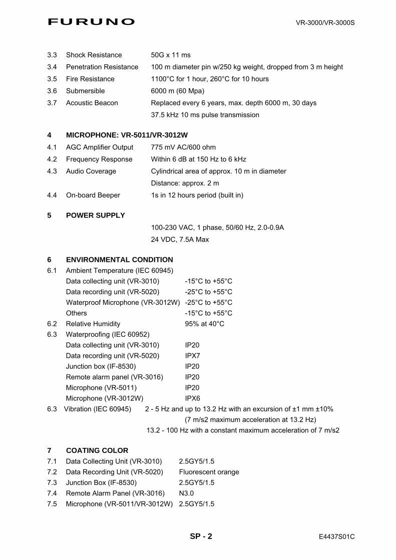
3.3 Shock Resistance 50G x 11 ms
3.4 Penetration Resistance 100 m diameter pin w/250 kg weight, dropped from 3 m height
3.5 Fire Resistance 1100°C for 1 hour, 260°C for 10 hours
3.6 Submersible 6000 m (60 Mpa)
3.7 Acoustic Beacon Replaced every 6 years, max. depth 6000 m, 30 days
37.5 kHz 10 ms pulse transmission
4 MICROPHONE: VR-5011/VR-3012W 4.1 AGC Amplifier Output 775 mV AC/600 ohm
4.2 Frequency Response Within 6 dB at 150 Hz to 6 kHz
4.3 Audio Coverage Cylindrical area of approx. 10 m in diameter
Distance: approx. 2 m
4.4 On-board Beeper 1s in 12 hours period (built in)
5 POWER SUPPLY 100-230 VAC, 1 phase, 50/60 Hz, 2.0-0.9A
24 VDC, 7.5A Max
6 ENVIRONMENTAL CONDITION 6.1 Ambient Temperature (IEC 60945)
Data collecting unit (VR-3010) -15°C to +55°C Data recording unit (VR-5020) -25°C to +55°C Waterproof Microphone (VR-3012W) -25°C to +55°C Others -15°C to +55°C
6.2 Relative Humidity 95% at 40°C 6.3 Waterproofing (IEC 60952)
Data collecting unit (VR-3010) IP20 Data recording unit (VR-5020) IPX7 Junction box (IF-8530) IP20 Remote alarm panel (VR-3016) IP20 Microphone (VR-5011) IP20 Microphone (VR-3012W) IPX6
6.3 Vibration (IEC 60945) 2 - 5 Hz and up to 13.2 Hz with an excursion of ±1 mm ±10% (7 m/s2 maximum acceleration at 13.2 Hz) 13.2 - 100 Hz with a constant maximum acceleration of 7 m/s2
7 COATING COLOR 7.1 Data Collecting Unit (VR-3010) 2.5GY5/1.5 7.2 Data Recording Unit (VR-5020) Fluorescent orange 7.3 Junction Box (IF-8530) 2.5GY5/1.5 7.4 Remote Alarm Panel (VR-3016) N3.0 7.5 Microphone (VR-5011/VR-3012W) 2.5GY5/1.5
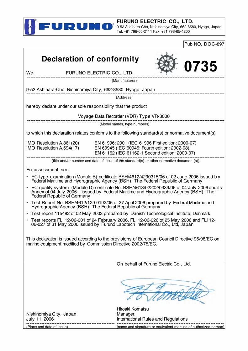
FURUNO ELECTRIC CO., LTD.9-52 Ashihara-Cho, Nishinomiya City, 662-8580, Hyogo, JapanTel: +81 798-65-2111 Fax: +81 798-65-4200
Pub NO. DOC-897
Declaration of conformity
We FURUNO ELECTRIC CO., LTD.----------------------------------------------------------------------------------------------------------------------
(Manufacturer)
9-52 Ashihara-Cho, Nishinomiya City, 662-8580, Hyogo, Japan----------------------------------------------------------------------------------------------------------------------
(Address)
hereby declare under our sole responsibility that the product
Voyage Data Recorder (VDR) Type VR-3000----------------------------------------------------------------------------------------------------------------------
(Model names, type numbers)
to which this declaration relates conforms to the following standard(s) or normative document(s)
IMO Resolution A.861(20) EN 61996: 2001 (IEC 61996 First edition: 2000-07)IMO Resolution A.694(17) EN 60945 (IEC 60945: Fourth edition: 2002-08)
EN 61162 (IEC 61162-1 Second edition: 2000-07)----------------------------------------------------------------------------------------------------------------------
(title and/or number and date of issue of the standard(s) or other normative document(s))
For assessment, see
• EC type examination (Module B) certificate BSH/4612/4290315/06 of 02 June 2006 issued b yFederal Maritime and Hydrographic Agency (BSH), The Federal Republic of Germany
• EC quality system�(Module D) certificate No. BSH/4613/02202/0339/06 of 04 July 2006 and itsAnnex of 04 July 2006 issued by Federal Maritime and Hydrographic Agency (BSH), TheFederal Republic of Germany
• Test Report No. BSH/4612/129 0192/05 of 27 April 2006 prepared by Federal Maritime andHydrographic Agency (BSH), The Federal Republic of Germany
• Test report 115482 of 02 May 2003 prepared by Danish Technological Institute, Denmark
• Test reports FLI 12-06-001 of 24 February 2006, FLI 12-06-026 of 25 May 2006 and FLI 12-06-027 of 31 May 2006 issued by Furuno Labotech International Co., Ltd, Japan
This declaration is issued according to the provisions of European Council Directive 96/98/EC onmarine equipment modified by Commission Directive 2002/75/EC.
Nishinomiya City, JapanJuly 11, 2006-----------------------------------------------------(Place and date of issue)
On behalf of Furuno Electric Co., Ltd.
Hiroaki KomatsuManager,International Rules and Regulations----------------------------------------------------------------(name and signature or equivalent marking of authorized person)
0735
Related Documents