Released April 2018 Page 1 INSTALLATION, OPERATION AND MAINTENANCE INSTRUCTIONS FOR SERIES VI WATER SOURCE HEAT PUMPS Models VP-A-020x–VP-A-120x, VP-B-020x – VP-B-120x, VP-C-020x – VP-C-120x Models VI-A-20x–VI-A-120x, VI-B-20x – VI-B-120x Note: This revision of the IOM supersedes all previous versions RECEIVING Whalen Series VP and VI heat pumps are shipped palletized (multiple unboxed units strapped to a shipping skid) as a standard. Units can be shipped individually packaged in corrugated shipping containers (with internal reinforcement for the tube extensions). Palletized shipments will require a fork lift to unload the units from the truck. For ease of handling and distribution, each unit is individually tagged with a label in three places containing information found on the approved unit schedule. This tagging is located on each end and front of the unit. UNITS READY FOR SHIPPING SAMPLE CABINET LABEL Typical label information includes job number, unit model, riser number, floor, LH, RH or REAR riser location, riser sizing, and other information specific to the project. This identification label aids in units being delivered to a particular location on the job site. The Whalen Series VP and VI units are made up of four separate parts. 1. Unit Cabinet: Unit cabinets are normally shipped first and are complete with integral supply, return, and condensate risers, return water hose (connected to supply and return ball valves), fan and motor, electric coils (on electric heat units) and with complete factory internal wiring, requiring only field connection of main power supply to unit junction box. Cabinets with “VP” in the model number are provided with external condensate risers, a separate internal drain pan and a rubber “P-Trap” drain line that connects to the condensate riser. The condensate drains from the pan through a hole in the center of the drain pan into the “P-trap” which is located below the pan and then drains to the condensate riser. Cabinets with “VI” in the model number are provided with internal condensate risers and Whalen drain pan (which is also the bottom of the cabinet). In this configuration the condensate drains from the pan through a hole located below the condensate riser. . 2. Unit Heat Pump Chassis: Heat Pump Chassis are normally shipped after grilles and thermostats have been installed and all plumbing and wiring has been completed. The chassis is complete and ready for installation. 3. Grilles: Supply grilles, return air acoustic panels and filters are normally shipped after unit cabinets, and are installed on cabinets after cabinets have been installed and all finishing and painting has been completed. 4. Thermostat: Thermostats are normally shipped separately and are to be installed only after all finishing and painting has been completed. Upon receipt, each shipment should be inspected for signs of damage. Visible damage should be noted on the freight bill at the time of delivery. All shipments are F.O.B. factory; the customer or consignee must report any claim for damages, visible or concealed, directly to the freight carrier.

Welcome message from author
This document is posted to help you gain knowledge. Please leave a comment to let me know what you think about it! Share it to your friends and learn new things together.
Transcript
Released April 2018 Page 1
INSTALLATION, OPERATION AND MAINTENANCE INSTRUCTIONS
FOR SERIES VI WATER SOURCE HEAT PUMPS
Models VP-A-020x–VP-A-120x, VP-B-020x – VP-B-120x, VP-C-020x – VP-C-120x Models VI-A-20x–VI-A-120x, VI-B-20x – VI-B-120x
Note: This revision of the IOM supersedes all previous versions
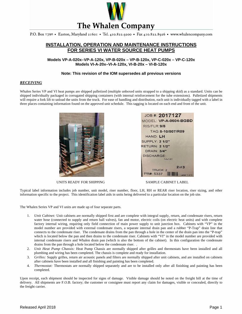
RECEIVING Whalen Series VP and VI heat pumps are shipped palletized (multiple unboxed units strapped to a shipping skid) as a standard. Units can be shipped individually packaged in corrugated shipping containers (with internal reinforcement for the tube extensions). Palletized shipments will require a fork lift to unload the units from the truck. For ease of handling and distribution, each unit is individually tagged with a label in three places containing information found on the approved unit schedule. This tagging is located on each end and front of the unit. UNITS READY FOR SHIPPING SAMPLE CABINET LABEL Typical label information includes job number, unit model, riser number, floor, LH, RH or REAR riser location, riser sizing, and other information specific to the project. This identification label aids in units being delivered to a particular location on the job site. The Whalen Series VP and VI units are made up of four separate parts.
1. Unit Cabinet: Unit cabinets are normally shipped first and are complete with integral supply, return, and condensate risers, return
water hose (connected to supply and return ball valves), fan and motor, electric coils (on electric heat units) and with complete factory internal wiring, requiring only field connection of main power supply to unit junction box. Cabinets with “VP” in the model number are provided with external condensate risers, a separate internal drain pan and a rubber “P-Trap” drain line that connects to the condensate riser. The condensate drains from the pan through a hole in the center of the drain pan into the “P-trap” which is located below the pan and then drains to the condensate riser. Cabinets with “VI” in the model number are provided with internal condensate risers and Whalen drain pan (which is also the bottom of the cabinet). In this configuration the condensate drains from the pan through a hole located below the condensate riser. .
2. Unit Heat Pump Chassis: Heat Pump Chassis are normally shipped after grilles and thermostats have been installed and all plumbing and wiring has been completed. The chassis is complete and ready for installation.
3. Grilles: Supply grilles, return air acoustic panels and filters are normally shipped after unit cabinets, and are installed on cabinets after cabinets have been installed and all finishing and painting has been completed.
4. Thermostat: Thermostats are normally shipped separately and are to be installed only after all finishing and painting has been completed.
Upon receipt, each shipment should be inspected for signs of damage. Visible damage should be noted on the freight bill at the time of delivery. All shipments are F.O.B. factory; the customer or consignee must report any claim for damages, visible or concealed, directly to the freight carrier.
Released April 2018 Page 2
IMPORTANT: THE RISERS ARE NOT HANDLES! DO NOT SUPPORT OR LIFT THE UNIT BY THE PIPE EXTENSIONS. Units may be stored in a horizontal position limiting stacking to no more than six (6) units high. Each unit undergoes a quality control inspection and is factory tested for proper operation. It is the customer’s responsibility to provide protection for the units upon arrival at the “ship to” destination. This protection includes but is not limited to vandalism and weather deterioration. The units must be protected from the elements and stored in above-freezing conditions. It is solely the customer’s responsibility to protect equipment from adverse weather conditions and to take security measures against theft and vandalism on the jobsite. INSTALLATION
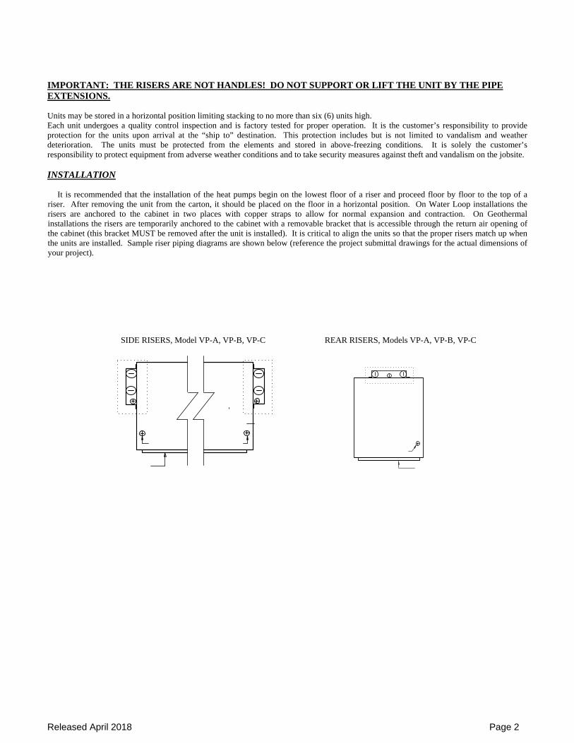
It is recommended that the installation of the heat pumps begin on the lowest floor of a riser and proceed floor by floor to the top of a riser. After removing the unit from the carton, it should be placed on the floor in a horizontal position. On Water Loop installations the risers are anchored to the cabinet in two places with copper straps to allow for normal expansion and contraction. On Geothermal installations the risers are temporarily anchored to the cabinet with a removable bracket that is accessible through the return air opening of the cabinet (this bracket MUST be removed after the unit is installed). It is critical to align the units so that the proper risers match up when the units are installed. Sample riser piping diagrams are shown below (reference the project submittal drawings for the actual dimensions of your project).
SIDE RISERS, Model VP-A, VP-B, VP-C REAR RISERS, Models VP-A, VP-B, VP-C
Released April 2018 Page 3
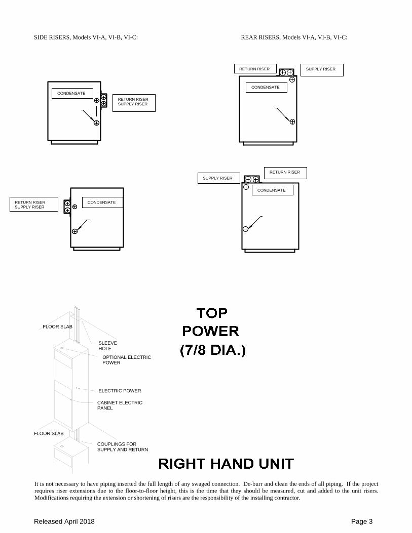
SIDE RISERS, Models VI-A, VI-B, VI-C: REAR RISERS, Models VI-A, VI-B, VI-C:
It is not necessary to have piping inserted the full length of any swaged connection. De-burr and clean the ends of all piping. If the project requires riser extensions due to the floor-to-floor height, this is the time that they should be measured, cut and added to the unit risers. Modifications requiring the extension or shortening of risers are the responsibility of the installing contractor.
SLEEVE HOLE
POWER OPTIONAL ELECTRIC
ELECTRIC POWER
CABINET ELECTRIC PANEL
COUPLINGS FOR SUPPLY AND RETURN
FLOOR SLAB
FLOOR SLAB
RETURN RISER SUPPLY RISER
RETURN RISER SUPPLY RISER
SUPPLY RISER
RETURN RISER
SUPPLY RISER RETURN RISER
CONDENSATE
CONDENSATE
CONDENSATE
CONDENSATE
Released April 2018 Page 4
Insulation on risers between units is usually not necessary for standard water-loop systems since water temperature in these risers is normally 70° to 105°F. Ground-water and Ground-loop systems require the risers to be insulated as the cold water in those system designs may cause condensation on the risers. Units with hydronic heat (“VP-C” and “VI-C”) require riser insulation. In coastal and humid areas, it is recommended that the condensate drain lines be insulated where pipes are in a non-air conditioned space. Units with P-Trap drains (“VP”) will be provided with an insulated condensate riser. VI cabinets that are installed in locations where the area below the unit is not conditioned or has high humidity conditions should be insulated to avoid condensation forming on the exterior of drain pan. If risers are to be insulated, measure the distance between units when in place (from bottom of upper unit to top of lower unit). Cut Armaflex or other approved closed cell vapor seal insulation to measured lengths plus one inch (1"). Slide over tubes. Apply recommended sealant (Armstrong 520) to upper end of Armaflex and around pipes at drain pan. Press Armaflex end to pan, insure seal, apply additional ring of sealant around connections. Move Armaflex up around pipes, as far as possible, and clamp temporarily until soldering is complete. Clean and apply flux to both male and female ends. Tip unit upright and guide pipes through sleeve hole in floor (requires two (2) men plus third man on floor below to guide upper male tubes into swaged female tubes of lower unit) - (an appliance hand truck has been found helpful
in maneuvering and positioning unit in place). Units must be level and vertically aligned in two planes to assure proper condensate drainage. Carefully position the unit so it is centered in the sleeve hole and insert the bottom of the risers into the swaged connections of the unit below. Riser piping and drain connections are soldered from floor below. Riser joints must be made with 95-5 solder. If high temperature solder is used, the top and bottom of the units should be shielded and protected from excessive heat. Soft solders or other low temperature alloys are not suitable for this application. After piping/riser systems has been hydrostatically tested for leaks, clean piping and top of unit, remove clamps on insulation. Apply sealant around pipe at unit top and Armaflex ends, press firmly to insure bond and vapor seal, apply additional ring of sealant around joint. (If insulation is installed after soldering extreme care must be used in application to insure proper sealing of all joints. Proper adhesives must be used and vapor barrier insured). Pipe chases may be further insulated with approved insulating material or foam sealed with a vapor barrier sealant. Riser stack must be securely anchored to the building structure with at least one contact point depending on stack height. To accommodate vertical expansion and contraction use expansion devices between anchors. DO NOT fasten risers rigidly to the unit. Whalen units include riser slots to accommodate up to 1-1/4 inch of vertical riser expansion/contraction in each direction. If the total calculated riser expansion/contraction exceeds these limits, the installing contractor must provide a means to compensate expansion and contraction of the riser. Whalen units may be set and piped as soon as floors are in place, thereby allowing installation prior to other interior work. It is recommended that the grille openings be covered during construction. IMPORTANT: All joints should be hydrostatically tested for leaks before furring-in the unit. If the riser floor sleeve hole extends beyond the bottom of the unit, a sub-plate can be provided to extend beyond the unit base and cover the hole to prevent air circulation. The riser sleeve hole must be sealed with proper materials to meet all applicable local fire ratings and building codes. MASTER/SLAVE UNITS Units configured in a Master/Slave arrangement are designed to share one set of risers between adjacent units (typically through a fire rated wall). The Master unit includes the risers and is installed as described above. The supply and return risers on the Master units are provided with female connections that accept 5/8” OD pipe (1/2” nominal pipe) on the opposite side of the riser from the Master unit for stub-out piping to the Slave unit. The condensate riser on all Master units is provided with female connections that accept 7/8” OD pipe (3/4” nominal pipe) on the opposite side of the riser from the Master unit for stub-out piping to the Slave unit. The Slave unit should be set in place and the length of the stub-out pipes measured from the swaged connection on the riser to a distance of no more than 3” insertion into the Slave cabinet. Install the stub-outs after the interceding wall has been constructed, drilling or cutting holes in the wall to allow the stub-outs to go through the wall. The stub-outs should be soldered to the swaged connections of the risers and the ball valves in the Slave cabinet with 95-5 solder. The holes cut into the wall for stub-outs must be sealed with proper materials to meet all applicable fire ratings and building codes.
Released April 2018 Page 5
RECOMMENDATIONS FOR CLEANING CLOSED LOOP WATER SYSTEMS BEFORE INSTALLING REFRIGERATION CHASSIS: The building condenser water system for the Whalen heat pumps should include the items below at a minimum and should be installed in accordance with good design practice:
Riser isolation valves Means to accommodate riser expansion and contraction Means to drain and vent risers Means to fill and drain system components Air separator Expansion tank System strainer with coarse and fine screens and suitable means for inspecting and flushing Filtered and treated water supply and suitable pressure regulator Water pumps Cooling tower or closed circuit cooler Boilers Condenser water temperature control systems
After the units are installed, the riser system should be thoroughly leak checked with Whalen riser water valves in each cabinet
closed. All risers (supply and return) should be supplied with blow down valves at the bottom and vent valves at the top. The individual system components (risers, run-outs, closed circuit cooler, etc) should be filled and dumped as required to clear
the system of dirt, solder, flux, weld slag, etc that may be present in the system PRIOR to running system pumps to avoid contamination of the whole system (it should be noted that repeated filling and draining of steel components in the system may cause corrosion of these of these items). The manufacturers of these components should be contacted for their specific cleaning recommendations.
After the water system has been cleaned, remove the hose from the return riser ball valve and put that end into the drain pan.
Open the supply riser ball valve and flush the supply connection. After flushed, close the supply ball valve, reconnect the hose to the return riser ball valve and remove the other end from the supply riser. Direct the open hose end into the drain pan, open the return riser ball valve and flush the return connection. After flushed, reconnect the hose to the supply riser and close the supply ball valve to prevent accidental water discharge.
DO NOT RUN THE SYSTEM WATER THROUGH THE WHALEN REFRIGERATION CHASSIS UNTIL A RUNNING FLUSH OF THE SYSTEM HAS BEEN COMPLETED.
Fill the system with treated and filtered water and run the system pumps. Water should be constantly bled off the system at or
near the pump discharge. The water bleed off should be replaced by the normal treated and filtered make-up water. Strainers should be checked and cleaned as necessary. Water samples should be taken from all system drains. The system is clean when the water samples are clear of particulate matter. It may take as long as three days of running the system to clear the water.
When the system water is clear, close the supply and return ball valves in each Whalen cabinet to prepare for chassis
installation. This is also a good time to check the condensate drain system when opening the supply and return cabinet hoses. A water treatment specialist should be called in to test the water condition and recommend proper water treatment. It is
important that the water is the proper pH to prevent corrosion, at the acceptable level of hardness to prevent scaling, free of organic matter that could be a health hazard and free of particulate matter that could foul the system.
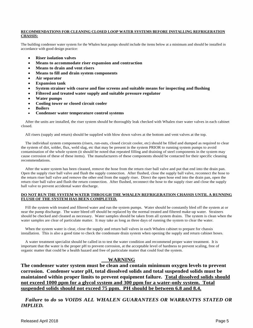
WARNING The condenser water system must be clean and contain minimum oxygen levels to prevent corrosion. Condenser water pH, total dissolved solids and total suspended solids must be maintained within proper limits to prevent equipment failure. Total dissolved solids should not exceed 1000 ppm for a glycol system and 300 ppm for a water-only system. Total suspended solids should not exceed 75 ppm. PH should be between 6.8 and 8.4.
Failure to do so VOIDS ALL WHALEN GUARANTEES OR WARRANTYS STATED OR
IMPLIED.
Released April 2018 Page 6
The Whalen Company cannot overemphasize the importance of insuring the condenser water system is clean and fully
operational before installation of the refrigeration chassis. Almost all installation problems with water source Heat Pump units are directly related to condenser water systems being dirty or not maintaining proper flow at each individual unit. It is recommended that all water system checks be completed before building drywalls and ceiling are installed.
The installing contractor is responsible for complying with all applicable building codes. ELECTRICAL A complete internal electrical wiring harness has been installed at the factory requiring only field connection of main power supply to the unit junction box, installation of the chassis and installation of the thermostat. All wires and thermostat wiring are color coded. All field electrical wiring should be performed in accordance with the National Electrical Code and any applicable local codes. Electrical data can be found within the approved submittal drawings or by referencing the wiring diagram and electrical label attached to the sheet metal inner panel that holds the refrigeration chassis in place, located behind the return air grille or acoustic panel. Standard unit power connection is made to a unit-mounted electrical junction box, through a 7/8” diameter opening located on either the left or right side of unit. Standard connections and clamps per local building codes should be used. Power supply need only be brought to the junction box inside the unit’s control cabinet. The power wiring configuration of the unit varies depending on the incoming voltage. The ground wire should be firmly secured to the junction box. For 115 and 265 Volt incoming power, the white line wire (Neutral) connects to the white wire in the box and the black line wire (L1) connects to the black wire in the box. For 208 / 230 Volt incoming power, the white line wire (L2) connects to the red wire(s) in the box and the black line wire (L1) connects to the black wire in the box. Connections should be secured and insulated as per local codes and ordinances. For 115 and 265 Volt units provided with a disconnect switch, connect the white line wire (Neutral) to the white wire in the control box and the black line wire (L1) connects to the open terminal on the disconnect switch. For 208 / 230 Volt units provided with a disconnect switch, connect the white line wire (L2) to the open red terminal on the disconnect switch and connect the black line wire (L1) to the open black terminal on the disconnect switch. A wiring diagram is affixed to the inner panel of each unit. Units are factory wired and require only field installation of the main power supply and remote thermostat wiring (if thermostat is mounted remotely from unit). DO NOT OPERATE THE UNIT WITHOUT THE THERMOSTAT OR RETURN AIR FILTER – DOING SO WILL VOID ALL WARRANTIES. DUCTWORK The Whalen Series VP and VI vertical stack heat pumps are designed to accommodate a minimum amount of supply air ductwork to distribute the treated air. Care should be taken to follow good design, fabrication and installation practices of the ductwork. The supply ductwork should be installed so that a minimum gap of 1/2” is maintained between the ductwork and the unit duct flange. The ductwork should be suspended from the building ceiling and isolated from the Whalen unit with a suitable flexible connector. No ductwork should be attached to the unit return air opening as all unit maintenance and service is done through the return air connection. The return air opening should be unblocked and uncluttered to provide maximum unit air flow and ease of service. Blocking off (or otherwise reducing the air flow of the unit) will result in nuisance safety trips and will eventually cause unit failure that is not covered by warranty. FINISHING The Whalen Unit is designed to be a free standing unit. FOR OPTIMAL SOUND CHARISTERISTICS, BRACING, DRYWALL, STUDS, WALL BOARD OR PLASTER MUST NOT TOUCH OR BE ATTACHED TO THE UNIT. Clean all drywall dust and debris from the unit after drywall installation and cutting of appropriate air and thermostat openings. All cabinet openings should be covered to keep out materials that may be harmful to unit components. Unit components showing signs of foreign material such as water, drywall dust, dirt or paint will not be covered under the equipment warranty. Return air panels or supply air grilles must not be attached to the unit casing in order to achieve minimum sound levels. Supply and return air openings must be sleeved to prevent the introduction of unconditioned air. The sleeves must not have hard connection at both ends. Use an appropriate flexible seal. Insulation should be placed between the drywall and the unit casing for sound attenuation.
Released April 2018 Page 7
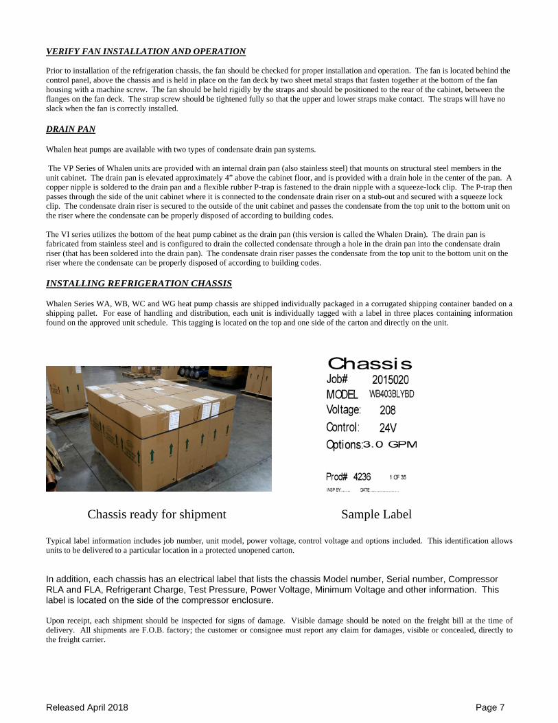
VERIFY FAN INSTALLATION AND OPERATION Prior to installation of the refrigeration chassis, the fan should be checked for proper installation and operation. The fan is located behind the control panel, above the chassis and is held in place on the fan deck by two sheet metal straps that fasten together at the bottom of the fan housing with a machine screw. The fan should be held rigidly by the straps and should be positioned to the rear of the cabinet, between the flanges on the fan deck. The strap screw should be tightened fully so that the upper and lower straps make contact. The straps will have no slack when the fan is correctly installed. DRAIN PAN Whalen heat pumps are available with two types of condensate drain pan systems. The VP Series of Whalen units are provided with an internal drain pan (also stainless steel) that mounts on structural steel members in the unit cabinet. The drain pan is elevated approximately 4” above the cabinet floor, and is provided with a drain hole in the center of the pan. A copper nipple is soldered to the drain pan and a flexible rubber P-trap is fastened to the drain nipple with a squeeze-lock clip. The P-trap then passes through the side of the unit cabinet where it is connected to the condensate drain riser on a stub-out and secured with a squeeze lock clip. The condensate drain riser is secured to the outside of the unit cabinet and passes the condensate from the top unit to the bottom unit on the riser where the condensate can be properly disposed of according to building codes. The VI series utilizes the bottom of the heat pump cabinet as the drain pan (this version is called the Whalen Drain). The drain pan is fabricated from stainless steel and is configured to drain the collected condensate through a hole in the drain pan into the condensate drain riser (that has been soldered into the drain pan). The condensate drain riser passes the condensate from the top unit to the bottom unit on the riser where the condensate can be properly disposed of according to building codes. INSTALLING REFRIGERATION CHASSIS Whalen Series WA, WB, WC and WG heat pump chassis are shipped individually packaged in a corrugated shipping container banded on a shipping pallet. For ease of handling and distribution, each unit is individually tagged with a label in three places containing information found on the approved unit schedule. This tagging is located on the top and one side of the carton and directly on the unit.
Chassis ready for shipment Sample Label Typical label information includes job number, unit model, power voltage, control voltage and options included. This identification allows units to be delivered to a particular location in a protected unopened carton. In addition, each chassis has an electrical label that lists the chassis Model number, Serial number, Compressor RLA and FLA, Refrigerant Charge, Test Pressure, Power Voltage, Minimum Voltage and other information. This label is located on the side of the compressor enclosure. Upon receipt, each shipment should be inspected for signs of damage. Visible damage should be noted on the freight bill at the time of delivery. All shipments are F.O.B. factory; the customer or consignee must report any claim for damages, visible or concealed, directly to the freight carrier.
Released April 2018 Page 8
IMPORTANT: THE CHASSIS MUST BE KEPT IN AN UPRIGHT POSITION AT ALL TIMES. Chassis may be stacked 2 high for storage. Each unit undergoes a quality control inspection and is factory tested for refrigeration leaks, water leaks, and proper operation. It is the customer’s responsibility to provide protection for the units upon arrival at the “ship to” destination. This protection includes but is not limited to vandalism and weather deterioration. It is solely the customer’s responsibility to protect equipment from adverse weather conditions and to take security measures against theft and vandalism on the jobsite.
Each chassis is designed and manufactured to fit into the corresponding cabinet size. Chassis are available from 200 CFM thru 1200 CFM
and match cabinets of the same designation (200, 300, 400, 500, 600, 800, 1000 and 1200 CFM). The chassis will fit in the cabinet and fit to the inlet air opening cut out of the sheet metal inner panel that fixes the chassis into position.
Installation of the chassis is performed in steps. 1) Remove the cabinet acoustic panel from the wall at the return air opening of the unit (chassis accessible panels need not be
removed, just open the front panel and secure it out of the way). 2) Remove the sheet metal inner panel from the cabinet. This is accomplished by removing the four flathead screws from the
cabinet and pulling the inner panel out of the cabinet. 3) If unit is provided with a P-trap drain configuration, lift up and tilt the drain pan to verify rubber P-trap is properly attached to
drain pan nipple and condensate riser. Set pan back on channels when proper installation is confirmed. 4) Inspect cabinet insulation before inserting chassis. Repair any tears with UL Listed foil tape. 5) Open the lid of the new chassis box and lift the chassis straight up out of the box (if you do not need to reuse the box, it can be
cut off of the new chassis without lifting the chassis). 6) Set the chassis on the galvanized steel rails in the bottom of the unit and slide it back a few inches, keeping the chassis centered
from left to right. 7) MAKE SURE RISER VALVES ARE CLOSED. 8) Disconnect the hose that is in the cabinet from the supply riser ball valve (The supply riser is the closest riser to the return air
opening on side riser units and is the riser adjacent to the condensate drain riser in rear riser units). 9) Connect the hose from the return riser to the chassis water pipe on the left side of the chassis (HAND TIGHTEN ONLY).
Connect the hose that is attached to the chassis right side water piping to the supply water riser chassis (HAND TIGHTEN ONLY). KEEP THE HOSES ORIENTED TO LEFT – RIGHT POSITION. DO NOT OPEN THE SHUT-OFF VALVES AT THIS TIME.
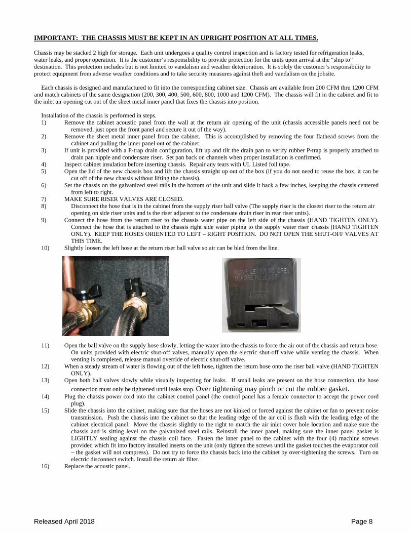
10) Slightly loosen the left hose at the return riser ball valve so air can be bled from the line.
11) Open the ball valve on the supply hose slowly, letting the water into the chassis to force the air out of the chassis and return hose. On units provided with electric shut-off valves, manually open the electric shut-off valve while venting the chassis. When venting is completed, release manual override of electric shut-off valve.
12) When a steady stream of water is flowing out of the left hose, tighten the return hose onto the riser ball valve (HAND TIGHTEN ONLY).
13) Open both ball valves slowly while visually inspecting for leaks. If small leaks are present on the hose connection, the hose
connection must only be tightened until leaks stop. Over tightening may pinch or cut the rubber gasket. 14) Plug the chassis power cord into the cabinet control panel (the control panel has a female connector to accept the power cord
plug). 15) Slide the chassis into the cabinet, making sure that the hoses are not kinked or forced against the cabinet or fan to prevent noise
transmission. Push the chassis into the cabinet so that the leading edge of the air coil is flush with the leading edge of the cabinet electrical panel. Move the chassis slightly to the right to match the air inlet cover hole location and make sure the chassis and is sitting level on the galvanized steel rails. Reinstall the inner panel, making sure the inner panel gasket is LIGHTLY sealing against the chassis coil face. Fasten the inner panel to the cabinet with the four (4) machine screws provided which fit into factory installed inserts on the unit (only tighten the screws until the gasket touches the evaporator coil – the gasket will not compress). Do not try to force the chassis back into the cabinet by over-tightening the screws. Turn on electric disconnect switch. Install the return air filter.
16) Replace the acoustic panel.
Released April 2018 Page 9
REFRIGERATIONCOAX CONDENSER
HOTWATER COIL
EV
AP
CO
IL
HOT WAT ER IN
ROOM AIR FLOW
N.C
.
N.O. COM M ON
HOT WATER IN
ROOM AIR FLOW
REFRIGERATIONCOAX CONDENSER
HOTWATER COIL
EV
AP
CO
IL
N.C.
N.C.
HOT WATER OUT
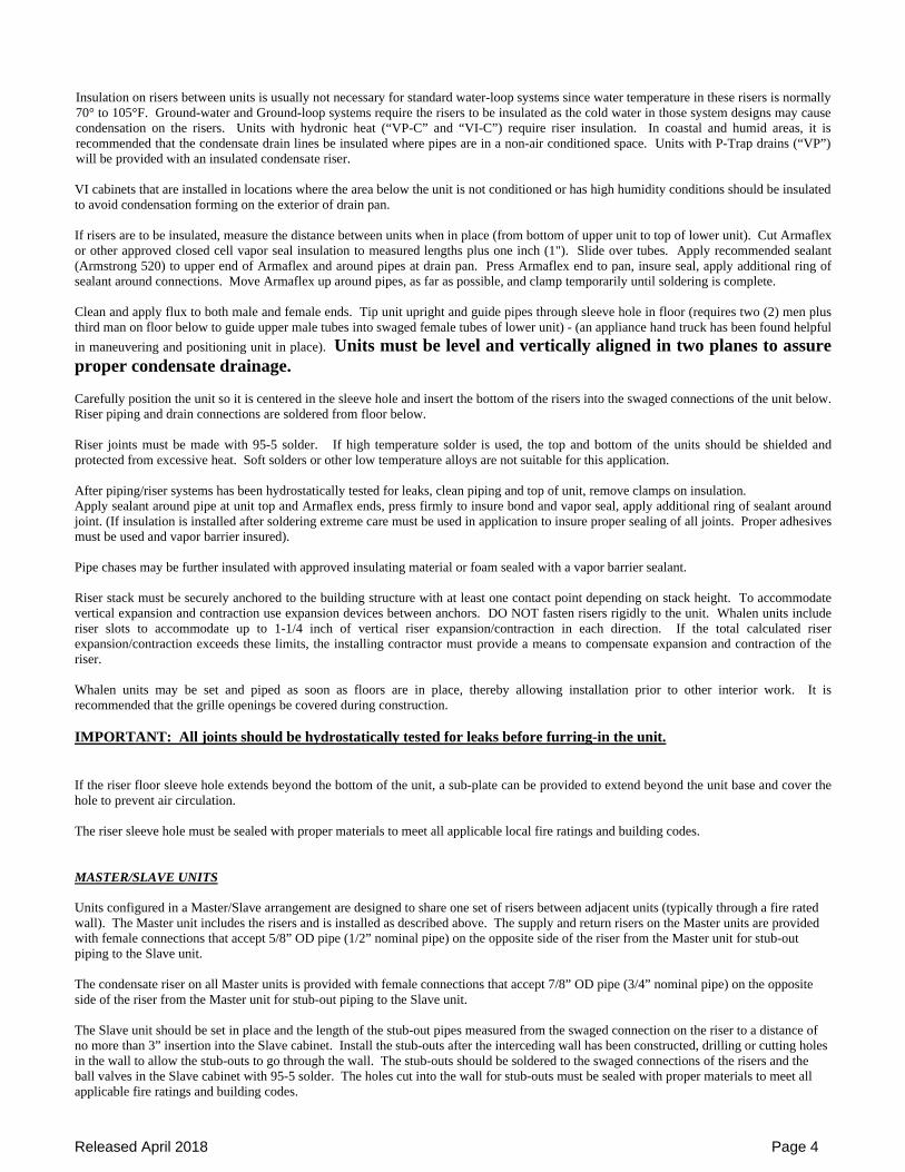
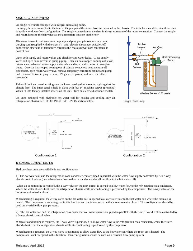
SINGLE RISER UNITS: On single riser units equipped with integral circulating pump, the supply hose is connected to the inlet of the pump and the return hose is connected to the chassis. The installer must determine if the riser is up-flow or down-flow configuration. The supply connection on the riser is always upstream of the return connection. Connect the supply and return hoses to the ball valves at the appropriate location on the riser. Disconnect two-pin quick-connect on pump and plug pump into temporary pump purging cord (supplied with the chassis). With electric disconnect switches off, connect the other end of temporary cord into the chassis power cord receptacle in control box. Open both supply and return valves and check for any water leaks. Close supply valve and open coin-air vent in pump piping. Once air has stopped coming out, close return water valve and open supply water valve and turn on disconnect to energize pump. Once air has stopped coming out of coin air vent, close vent and turn off disconnect, open return water valve, remove temporary cord from cabinet and pump and re-connect two-pin plug to pump. Plug chassis power cord into control box receptacle. Reinstall the inner panel, making sure the inner panel gasket is sealing tight against the chassis face. The inner panel is held in place with four (4) machine screws (provided) which fit into factory installed inserts on the unit. Turn on electric disconnect switch. On units equipped with Hydronic hot water coil for heating and cooling only air refrigeration chassis, see HYDRONIC HEAT UNITS section below.
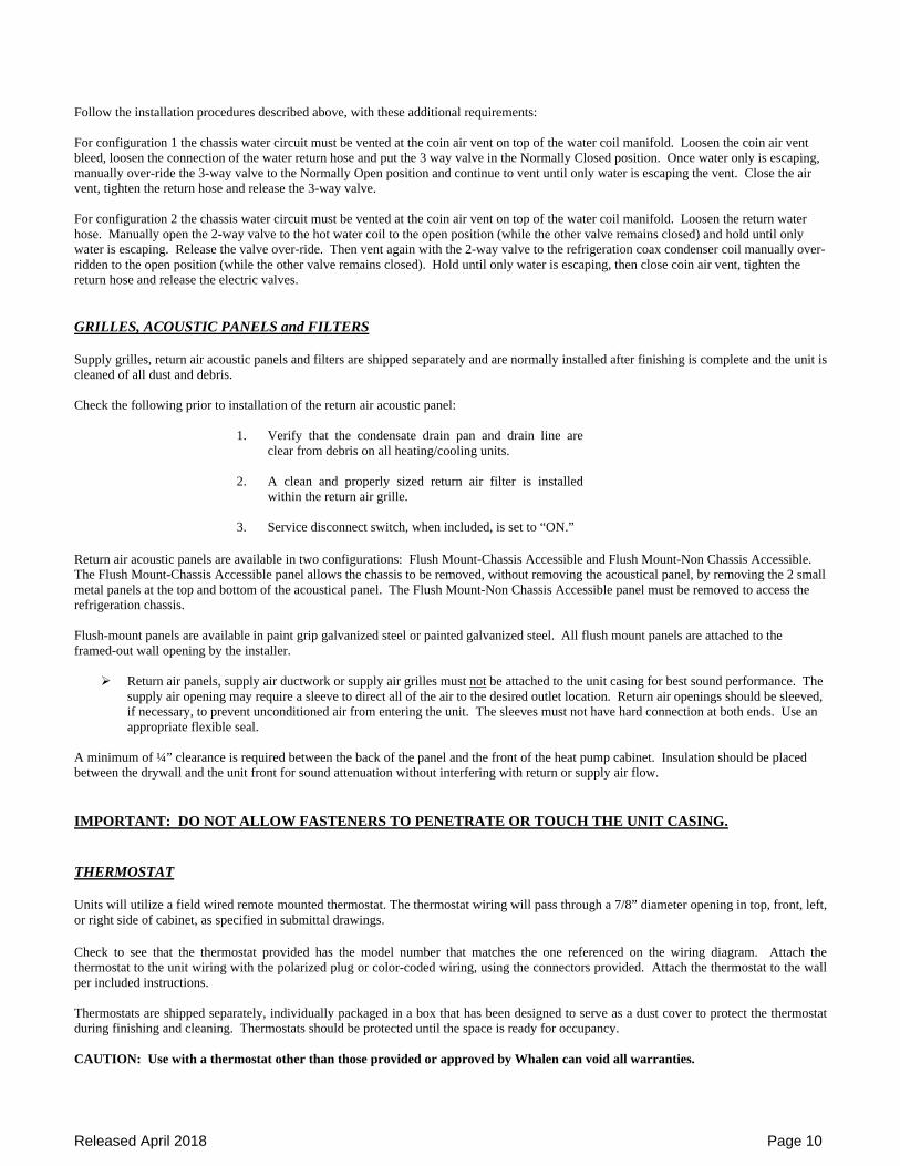
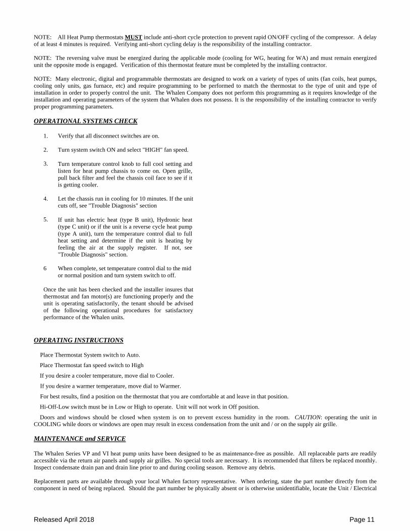
Configuration 1 Configuration 2 HYDRONIC HEAT UNITS: Hydronic heat units are available in two configurations: 1) The hot water coil and the refrigeration coax condenser coil are piped in parallel with the water flow supply controlled by two 2-way electric control valves (one valve allows flow to the coax and one valve allows flow to the hot water coil). When air conditioning is required, the 2-way valve on the coax circuit is opened to allow water flow to the refrigeration coax condenser, where the water absorbs heat from the refrigeration chassis while air conditioning is performed by the compressor. The 2-way valve on the hot water coil remains closed. When heating is required, the 2-way valve on the hot water coil is opened to allow water flow to the hot water coil where the room air is heated. The compressor is not energized in this function and the 2-way valve on that circuit remains closed. This configuration should be used on a variable flow pump system.
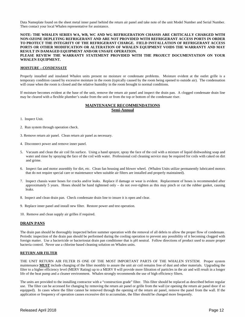
2) The hot water coil and the refrigeration coax condenser coil water circuits are piped in parallel with the water flow direction controlled by a 3-way electric control valve. When air conditioning is required, the 3-way valve is positioned to allow water flow to the refrigeration coax condenser, where the water absorbs heat from the refrigeration chassis while air conditioning is performed by the compressor. When heating is required, the 3-way valve is positioned to allow water flow to the hot water coil where the room air is heated. The compressor is not energized in this function. This configuration should be used on a constant flow pump system.
Released April 2018 Page 10
Follow the installation procedures described above, with these additional requirements: For configuration 1 the chassis water circuit must be vented at the coin air vent on top of the water coil manifold. Loosen the coin air vent bleed, loosen the connection of the water return hose and put the 3 way valve in the Normally Closed position. Once water only is escaping, manually over-ride the 3-way valve to the Normally Open position and continue to vent until only water is escaping the vent. Close the air vent, tighten the return hose and release the 3-way valve. For configuration 2 the chassis water circuit must be vented at the coin air vent on top of the water coil manifold. Loosen the return water hose. Manually open the 2-way valve to the hot water coil to the open position (while the other valve remains closed) and hold until only water is escaping. Release the valve over-ride. Then vent again with the 2-way valve to the refrigeration coax condenser coil manually over-ridden to the open position (while the other valve remains closed). Hold until only water is escaping, then close coin air vent, tighten the return hose and release the electric valves. GRILLES, ACOUSTIC PANELS and FILTERS Supply grilles, return air acoustic panels and filters are shipped separately and are normally installed after finishing is complete and the unit is cleaned of all dust and debris. Check the following prior to installation of the return air acoustic panel:
1. Verify that the condensate drain pan and drain line are clear from debris on all heating/cooling units.
2. A clean and properly sized return air filter is installed within the return air grille.
3. Service disconnect switch, when included, is set to “ON.” Return air acoustic panels are available in two configurations: Flush Mount-Chassis Accessible and Flush Mount-Non Chassis Accessible. The Flush Mount-Chassis Accessible panel allows the chassis to be removed, without removing the acoustical panel, by removing the 2 small metal panels at the top and bottom of the acoustical panel. The Flush Mount-Non Chassis Accessible panel must be removed to access the refrigeration chassis. Flush-mount panels are available in paint grip galvanized steel or painted galvanized steel. All flush mount panels are attached to the framed-out wall opening by the installer.
Return air panels, supply air ductwork or supply air grilles must not be attached to the unit casing for best sound performance. The supply air opening may require a sleeve to direct all of the air to the desired outlet location. Return air openings should be sleeved, if necessary, to prevent unconditioned air from entering the unit. The sleeves must not have hard connection at both ends. Use an appropriate flexible seal.
A minimum of ¼” clearance is required between the back of the panel and the front of the heat pump cabinet. Insulation should be placed between the drywall and the unit front for sound attenuation without interfering with return or supply air flow.
IMPORTANT: DO NOT ALLOW FASTENERS TO PENETRATE OR TOUCH THE UNIT CASING. THERMOSTAT Units will utilize a field wired remote mounted thermostat. The thermostat wiring will pass through a 7/8” diameter opening in top, front, left, or right side of cabinet, as specified in submittal drawings. Check to see that the thermostat provided has the model number that matches the one referenced on the wiring diagram. Attach the thermostat to the unit wiring with the polarized plug or color-coded wiring, using the connectors provided. Attach the thermostat to the wall per included instructions. Thermostats are shipped separately, individually packaged in a box that has been designed to serve as a dust cover to protect the thermostat during finishing and cleaning. Thermostats should be protected until the space is ready for occupancy. CAUTION: Use with a thermostat other than those provided or approved by Whalen can void all warranties.
Released April 2018 Page 11
NOTE: All Heat Pump thermostats MUST include anti-short cycle protection to prevent rapid ON/OFF cycling of the compressor. A delay of at least 4 minutes is required. Verifying anti-short cycling delay is the responsibility of the installing contractor. NOTE: The reversing valve must be energized during the applicable mode (cooling for WG, heating for WA) and must remain energized unit the opposite mode is engaged. Verification of this thermostat feature must be completed by the installing contractor. NOTE: Many electronic, digital and programmable thermostats are designed to work on a variety of types of units (fan coils, heat pumps, cooling only units, gas furnace, etc) and require programming to be performed to match the thermostat to the type of unit and type of installation in order to properly control the unit. The Whalen Company does not perform this programming as it requires knowledge of the installation and operating parameters of the system that Whalen does not possess. It is the responsibility of the installing contractor to verify proper programming parameters. OPERATIONAL SYSTEMS CHECK
1. Verify that all disconnect switches are on.
2. Turn system switch ON and select "HIGH" fan speed.
3. Turn temperature control knob to full cool setting and listen for heat pump chassis to come on. Open grille, pull back filter and feel the chassis coil face to see if it is getting cooler.
4. Let the chassis run in cooling for 10 minutes. If the unit cuts off, see "Trouble Diagnosis" section
5. If unit has electric heat (type B unit), Hydronic heat (type C unit) or if the unit is a reverse cycle heat pump (type A unit), turn the temperature control dial to full heat setting and determine if the unit is heating by feeling the air at the supply register. If not, see "Trouble Diagnosis" section.
6
When complete, set temperature control dial to the mid or normal position and turn system switch to off.
Once the unit has been checked and the installer insures that thermostat and fan motor(s) are functioning properly and the unit is operating satisfactorily, the tenant should be advised of the following operational procedures for satisfactory performance of the Whalen units.
OPERATING INSTRUCTIONS
Place Thermostat System switch to Auto. Place Thermostat fan speed switch to High If you desire a cooler temperature, move dial to Cooler. If you desire a warmer temperature, move dial to Warmer. For best results, find a position on the thermostat that you are comfortable at and leave in that position. Hi-Off-Low switch must be in Low or High to operate. Unit will not work in Off position. Doors and windows should be closed when system is on to prevent excess humidity in the room. CAUTION: operating the unit in
COOLING while doors or windows are open may result in excess condensation from the unit and / or on the supply air grille.
MAINTENANCE and SERVICE The Whalen Series VP and VI heat pump units have been designed to be as maintenance-free as possible. All replaceable parts are readily accessible via the return air panels and supply air grilles. No special tools are necessary. It is recommended that filters be replaced monthly. Inspect condensate drain pan and drain line prior to and during cooling season. Remove any debris. Replacement parts are available through your local Whalen factory representative. When ordering, state the part number directly from the component in need of being replaced. Should the part number be physically absent or is otherwise unidentifiable, locate the Unit / Electrical
Released April 2018 Page 12
Data Nameplate found on the sheet metal inner panel behind the return air panel and take note of the unit Model Number and Serial Number. Then contact your local Whalen representative for assistance. NOTE: THE WHALEN SERIES WA, WB, WC AND WG REFRIGERATION CHASSIS ARE CRITICALLY CHARGED WITH NON-OZONE DEPLETING REFRIGERANT AND ARE NOT PROVIDED WITH REFRIGERANT ACCESS PORTS IN ORDER TO PROTECT THE INTEGRITY OF THE REFRIGERANT CHARGE. FIELD INSTALLATION OF REFRIGERANT ACCESS PORTS OR OTHER MODIFICATION OR ALTERATION OF WHALEN EQUIPMENT VOIDS THE WARRANTY AND MAY RESULT IN DAMAGED EQUIPMENT AND/OR UNSAFE OPERATION. PLEASE REVIEW THE WARRANTY STATEMENT PROVIDED WITH THE PROJECT DOCUMENTATION ON YOUR WHALEN EQUIPMENT. MOISTURE – CONDENSATE Properly installed and insulated Whalen units present no moisture or condensate problems. Moisture evident at the outlet grille is a temporary condition caused by excessive moisture in the room (typically caused by the room being opened to outside air). The condensation will cease when the room is closed and the relative humidity in the room brought to normal conditions. If moisture becomes evident at the base of the unit, remove the return air panel and inspect the drain pan. A clogged condensate drain line may be cleared with a flexible plumber’s snake from the unit or from the top or bottom of the condensate riser.
MAINTENANCE RECOMMENDATIONS Semi-Annual
1. Inspect Unit. 2. Run system through operation check. 3. Remove return air panel. Clean return air panel as necessary. 4. Disconnect power and remove inner panel. 5. Vacuum and clean the air coil fin surface. Using a hand sprayer, spray the face of the coil with a mixture of liquid dishwashing soap and
water and rinse by spraying the face of the coil with water. Professional coil cleaning service may be required for coils with caked on dirt and grime.
6. Inspect fan and motor assembly for dirt, etc. Clean fan housing and blower wheel. (Whalen Units utilize permanently lubricated motors
that do not require special care or maintenance when suitable air filters are installed and properly maintained). 7. Inspect chassis water hoses for cracks and/or leaks. Replace if damage or wear is evident. Replacement of hoses is recommended after
approximately 5 years. Hoses should be hand tightened only – do not over-tighten as this may pinch or cut the rubber gasket, causing leaks.
8. Inspect and clean drain pan. Check condensate drain line to insure it is open and clear. 9. Replace inner panel and install new filter. Restore power and test operation. 10. Remove and clean supply air grilles if required. DRAIN PANS The drain pan should be thoroughly inspected before summer operation with the removal of all debris to allow the proper flow of condensate. Periodic inspection of the drain pan should be performed during the cooling operation to prevent any possibility of it becoming clogged with foreign matter. Use a bactericide or bacteriostat drain pan conditioner that is pH neutral. Follow directions of product used to assure proper bacteria control. Never use a chlorine based cleaning solution on Whalen units. RETURN AIR FILTER THE UNIT RETURN AIR FILTER IS ONE OF THE MOST IMPORTANT PARTS OF THE WHALEN SYSTEM. Proper system maintenance MUST include changing of the filter monthly to assure the unit air coil remains free of dust and other materials. Upgrading the filter to a higher efficiency level (MERV Rating) up to a MERV 8 will provide more filtration of particles in the air and will result in a longer life of the heat pump and a cleaner environment. Whalen strongly recommends the use of high efficiency filters. The units are provided to the installing contractor with a “construction grade” filter. This filter should be replaced as described before regular use. The filter can be accessed for changing by removing the return air panel or grille from the wall (or opening the return air panel door if so equipped). In cases where the filter cannot be removed through the opening of the return air panel, remove the panel from the wall. If the application or frequency of operation causes excessive dirt to accumulate, the filter should be changed more frequently.
Released April 2018 Page 13
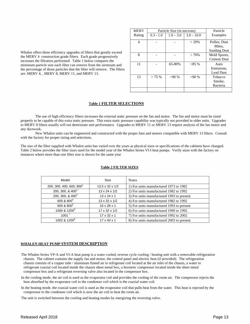
Whalen offers three efficiency upgrades of filters that greatly exceed the MERV 4 construction grade filters. Each grade progressively increases the filtration performed. Table 1 below compares the minimum particle size each filter can remove from the airstream and the percentage of those particles that the filter will remove. The filters are: MERV 4, , MERV 8, MERV 11, and MERV 13.
Table 1 FILTER SELECTIONS
The use of high efficiency filters increases the external static pressure on the fan and motor. The fan and motor must be sized
properly to be capable of this extra static pressure. This extra static pressure capability was typically not provided in older units. Upgrades to MERV 8 filters usually will not deteriorate unit performance. Upgrades to MERV 11 or MERV 13 require analysis of the fan motor and any ductwork.
New Whalen units can be engineered and constructed with the proper fans and motors compatible with MERV 13 filters. Consult with the factory for proper sizing and selections.
The size of the filter supplied with Whalen units has varied over the years as physical sizes or specifications of the cabinets have changed. Table 2 below provides the filter sizes used for the model year of the Whalen Series VI-I heat pumps. Verify sizes with the factory on instances where more than one filter size is shown for the same year Table 2 FILTER SIZES WHALEN HEAT PUMP SYSTEM DESCRIPTION
The Whalen Series VP-A and VI-A heat pump is a water cooled, reverse cycle cooling / heating unit with a removable refrigeration chassis. The cabinet contains the supply fan and motor, the control panel and electric heat (if provided). The refrigeration chassis consists of a copper tube / aluminum finned air to refrigerant coil located at the air inlet of the chassis, a water to refrigerant coaxial coil located inside the chassis sheet metal box, a hermetic compressor located inside the sheet metal compressor box and a refrigerant reversing valve also located in the compressor box.
In the cooling mode, the air coil is used as the evaporator coil and provides the cooling of the room air. The compressor rejects the heat absorbed by the evaporator coil to the condenser coil which is the coaxial water coil.
In the heating mode, the coaxial water coil is used as the evaporator coil that pulls heat from the water. This heat is rejected by the compressor to the condenser coil which is now the air coil to heat the room air.
The unit is switched between the cooling and heating modes by energizing the reversing valve.
Particle Size (in microns) MERV Rating 0.3 - 1.0 1.0 – 3.0 3.0 – 10.0
Particle Examples
4 - - > 20% Pollen, Dust Mites,
Sanding Dust 8 - - > 70% Mold Spores,
Cement Dust 11 - 65-80% >85 % Auto
Emissions, Lead Dust
13 > 75 % >90 % >90 % Tobacco Smoke, Bacteria
Model Size Notes
200, 300, 400, 600, 8001 13.5 x 32 x 1/2 1) For units manufactured 1973 to 1982 200, 300, & 4002 13 x 24 x 1/2 2) For units manufactured 1982 to 1992 200, 300, & 4003 13 x 24 x 1 3) For units manufactured 1993 to present
600 & 8004 13 x 32 x 1/2 4) For units manufactured 1982 to 1992 600 & 8005 15 x 28 x 1 5) For units manufactured 1993 to present
1000 & 12006 17 x 32 x 1/2 6) For units manufactured 1990 to 1992 1001 7 17 x 32 x 1 7) For units manufactured 1992 to 2002
1002 & 12008 17 x 40 x 1 8) For units manufactured 2003 to present
Released April 2018 Page 14
The Whalen Series VP-B and VI-B is a cooling only unit with electric heat and operates the same as the heat pump in the cooling mode. Cooling only units do not include a reversing valve.
The Whalen Series VP-C and VI-C is a cooling only unit with Hydronic hot water heat and operates the same as the heat pump in the cooling mode. In the heating mode the unit provides heat through the Hydronic hot water coil while the compressor is de-energized.
TYPICAL OPERATING PARAMETERS
The Whalen Company Series VP and VI heat pump chassis model number indicates the nominal cfm of the unit (example, in the model number WA303BLY, the first 3 signifies 300 cfm). Divide this cfm by 400 to determine the nominal cooling capacity of the unit in tons.
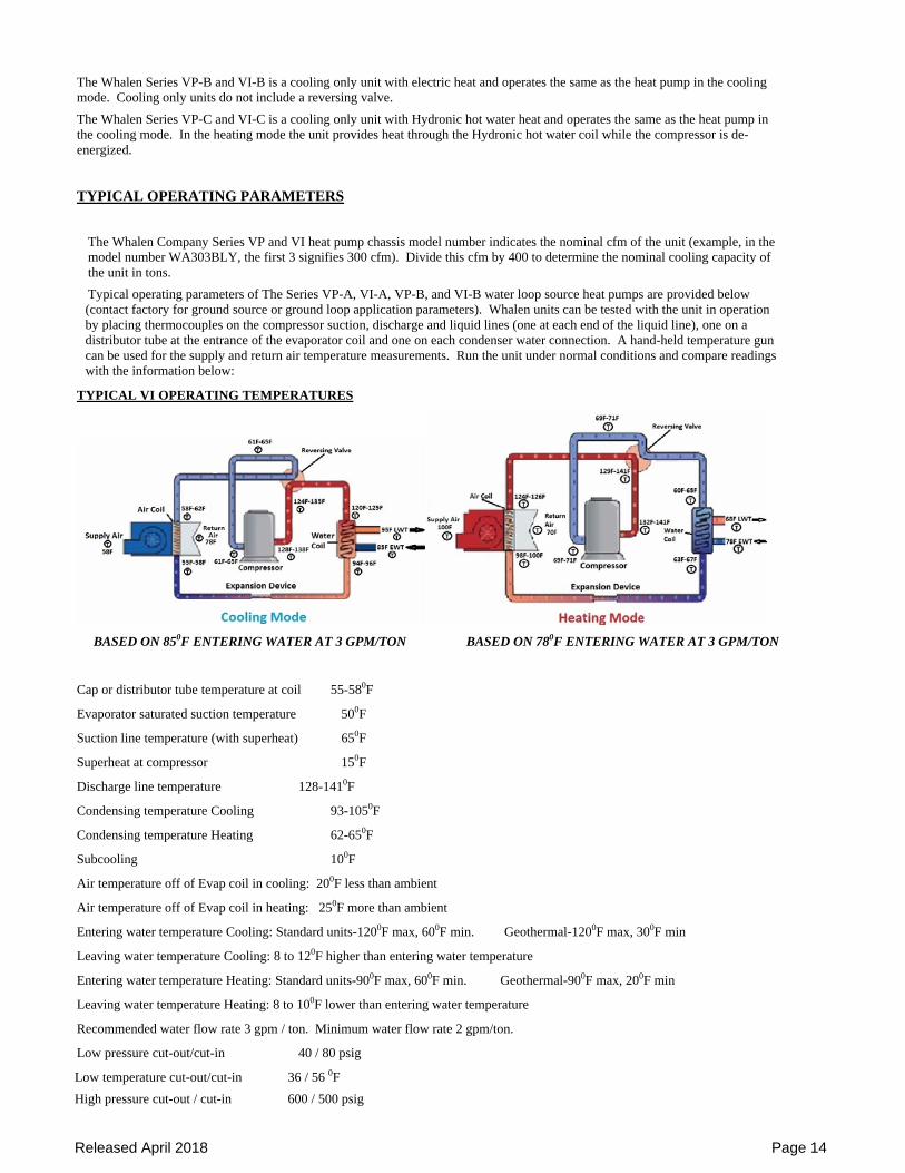
Typical operating parameters of The Series VP-A, VI-A, VP-B, and VI-B water loop source heat pumps are provided below (contact factory for ground source or ground loop application parameters). Whalen units can be tested with the unit in operation by placing thermocouples on the compressor suction, discharge and liquid lines (one at each end of the liquid line), one on a distributor tube at the entrance of the evaporator coil and one on each condenser water connection. A hand-held temperature gun can be used for the supply and return air temperature measurements. Run the unit under normal conditions and compare readings with the information below:
TYPICAL VI OPERATING TEMPERATURES
BASED ON 850F ENTERING WATER AT 3 GPM/TON BASED ON 780F ENTERING WATER AT 3 GPM/TON
Cap or distributor tube temperature at coil 55-580F
Evaporator saturated suction temperature 500F
Suction line temperature (with superheat) 650F
Superheat at compressor 150F
Discharge line temperature 128-1410F
Condensing temperature Cooling 93-1050F
Condensing temperature Heating 62-650F
Subcooling 100F
Air temperature off of Evap coil in cooling: 200F less than ambient
Air temperature off of Evap coil in heating: 250F more than ambient
Entering water temperature Cooling: Standard units-1200F max, 600F min. Geothermal-1200F max, 300F min
Leaving water temperature Cooling: 8 to 120F higher than entering water temperature
Entering water temperature Heating: Standard units-900F max, 600F min. Geothermal-900F max, 200F min
Leaving water temperature Heating: 8 to 100F lower than entering water temperature
Recommended water flow rate 3 gpm / ton. Minimum water flow rate 2 gpm/ton.
Low pressure cut-out/cut-in 40 / 80 psig
Low temperature cut-out/cut-in 36 / 56 0F
High pressure cut-out / cut-in 600 / 500 psig
Released April 2018 Page 15
TYPICAL VC OPERATING TEMPERATURES
Typical operating parameters of The Series VI-C water loop source cooling only / Hydronic heat units are provided below. Whalen VI-C units can be tested with the unit in operation by placing thermocouples on the compressor suction, discharge and liquid lines, one on a distributor tube at the entrance of the evaporator coil and one on each condenser water connection. A hand-held temperature gun can be used for the supply and return air temperature measurements. Run the unit under normal conditions and compare readings with the information below:
Capillary or distributor tube temperature at coil 600F
Evaporator saturated suction temperature 560F
Suction line temperature (with superheat) 660F
Superheat at compressor 100F
Discharge line temperature 128-1380F
Condensing temperature Cooling 1330F
Subcooling 210F
Air temperature to Evap coil: Ambient
Air temperature off Evap coil: 200F-250F lower than ambient
NOTE: the above data correspond to a 1200F EWT in cooling.
Entering water temperature Cooling: Standard units-1200F max, 600F min. Geothermal units- 1200F max, 300F min
Leaving water temperature Cooling: 90F-100F higher than entering water temperature
Entering water temperature Heating: Standard units 1400F max, 600F min. Geothermal units-1400F max, 600F min
Leaving water temperature Heating: 80F lower than entering water temperature
Air temperature off Hot Water coil: 1150F max, 950F min
Recommended water flow rate 3 gpm / ton. Minimum water flow rate 2 gpm/ton.
Low pressure cut-out/cut-in 40 / 80 psig
Low temperature cut-out/cut-in 36 / 56 0F
High pressure cut-out / cut-in 600 / 500 psig TROUBLE DIAGNOSIS
Trouble diagnosis should only be attempted by qualified maintenance personnel. Before any troubleshooting is performed, verify that the thermostat has been programmed as required for proper operation on the installation in question. The thermostat must include a minimum 4 minute compressor anti-cycle timer.
Fan Motor Fails to Start:
1. Verify that all main power and circuit breakers are on and not tripped. 2. Turn system switch on and select HI or LO fan speed. 3. Remove grille and front panel and carefully remove cover to electrical control panel in cabinet. 4. Refer to wiring diagram on front panel, identify incoming power black and red or black and white wires and determine if unit is
being supplied with correct voltage with Volt Ohm-meter (VOM). 5. If fan will not run on either LO or HI, verify 24 Volt transformer is operating correctly by checking voltage with VOM between
black and white with green stripe wires in the thermostat plug. If 24 volts is not present, check low voltage output from transformer by checking with VOM at blue and yellow wires on transformer. If 24 volts is not present, replace transformer. If 24 volts is present, check continuity of the black or red wire connecting transformer to thermostat.
6. If transformer is ok, disconnect power at either the building breaker panel or unit disconnect switch. Remove thermostat cover and inspect for visible indications of system ground or short. Also check for proper wiring connections between thermostat and unit, to assure colors match per wiring diagram and that insulation is intact. Check “pin” terminals for good contact on thermostats equipped with polarized quick-connect plugs VERIFY PINS ARE FULLY PRESSED INTO THE CONNECTOR PLUG..
7. Determine if fan motor is being supplied correct voltage. If not, check the 24 volt relays that connect power to the fan motor. If relay normally open contacts do not close when thermostat is calling for fan and relay is energized, replace relay.
8. If fan has power and hums, turn off power and make sure fan rotates freely. 9. Remove fan and motor and inspect fan motor and fan motor capacitor wiring; verify wiring is correct. If capacitor wiring or shield
Released April 2018 Page 16
is burned, replace wires. Check capacitor by removing wires from capacitor and measure capacitance with meter. Capacitance should measure within 6% of capacitor rating. If not, replace capacitor.
10. If fan motor is hot, it may be off on internal overload. Let cool and attempt to re-start. If fan runs, start and stop several times to determine if a starting problem. If fan continues to run, reinstall fan in cabinet and run for at least 10 minutes.
11. If fan will not run or cuts out on internal overload, replace motor. Heat Pump Chassis Fails to Start
1. Complete steps 1 -·3 of Fan Motor Fails to Start. 2. If Circuit Breakers are tripping when Heat Pump Chassis is turned on, unplug heat pump chassis. If circuit breakers continue to
trip, check control box wiring and field connections and verify unit is wired in accordance with wiring diagram. 3. If chassis caused circuit breakers to trip, identify red and black wires from heat pump chassis plug and determine if red or black
lead is shorted to ground with VOM. If wires are shorted, compressor replacement is Required by a qualified HVAC service technician.
4. Feel compressor in heat pump chassis. If hot, allow to cool and attempt to restart. If the compressor starts, see the appropriate section below. If heat pump fails to restart, open heat pump chassis control box and check for loose connections or burnt wiring. If none found, check the compressor thermal overload for continuity (if no continuity, overload is defective). If overload is ok, unplug chassis and check compressor resistance with VOM between the red and black wires at the chassis plug. Infinite ohms means that the internal overload is probably still open and compressor needs more time to cool. 2-5 ohms is the normal compressor winding resistance and indicates the compressor is O.K., but the capacitor may be bad or there may be a faulty connection at the control box plug or a starter problem in the control box.
5. If capacitor wiring or shield is burned, replace wires. Check capacitor by removing wires from capacitor and measure capacitance with meter. Capacitance should measure with 6% of capacitor rating. If not, replace capacitor.
Heat Pump Chassis Starts but Cuts Off Cooling Only Units:
1. After unit cuts off, determine if there is ice formation on the evaporator coil or if the condenser coil is extremely hot. 2. If there is ice formation on the coil, check for poor seal between inner panel and coil. Check for proper air flow. Check for
discharge grilles closed, blocked filters, etc. Is the room too cool (below 68°F)? If the supply water is 75°F or less, there may be premature freezing of the evaporator coil. If air flow and water temperatures are O.K., unit may be low on charge. If so, service is required by a qualified HVAC service technician.
3. If condenser water coil is hot, check for proper water supply with flow meter, if available. Check water temperatures. With proper water flow, there should be a temperature rise of about 10°F from supply to return, and the supply water should be 95°F or less. If no water flow, check electric water control valve for proper operation (if provided). The control valve is energized by the compressor contactor and is normally closed, power to open. If the control valve is operating properly, shut unit off and perform air venting procedure described in INSTALLING HEAT PUMP CHASSIS on page 4.
4. Inspect safety lock-out circuit. The chassis is provided with a high pressure switch that senses the refrigerant circuit condensing pressure and a low temperature switch that senses the refrigerant circuit suction temperature. These switches are normally open, fail to close and are automatic resetting devices. The switches are wired in series with a lock-out relay that energizes when either switch energizes on a failure condition. The lock-out relay interrupts the control voltage to the compressor contactor and prevents the compressor from running. The lock-out circuit will reset when the call for compressor (Y circuit from the thermostat) or power to the chassis is turned off and reset.
Heat Pump Chassis Starts but Cuts Off Heating and Cooling (Reverse Cycle Units)
1. If problem occurs in cooling, see checks under cooling only units. 2. If in heating and the unit cuts out, determine if there is ice formation on the evaporator coil or if the condenser air coil is extremely
hot. 3. If there is ice formation on the evaporator coil or it is extremely cold, check for proper water flow and entering water temperatures
between 65°F and 75°F. With proper water flow, there should be a temperature decrease of about 8°F from supply to return. If no water flow, check electric water control valve for proper operation (if provided). The control valve is energized by compressor contactor and is normally closed, power to open. If the control valve is operating properly, shut unit off and perform air venting procedure described in INSTALLING HEAT PUMP CHASSIS on page 4. If water flow and temperature is O.K., unit may be low on charge. If so, service is required by a qualified HVAC service technician.
4. If condenser air coil is extremely hot and compressor is hot, check for proper air flow. Select HI fan speed if fan is on LO speed and check for poor air seal between inner panel and coil, discharge grilles closed, blocked filters, etc. Is the room too hot (above 80°F)?
5. Check the safety lock-out circuit as described for Cooling Only units. Heat Pump Chassis Operating but not Cooling 1. Feel evaporator air coil and condenser water coil. If the air coil is not cool and condenser coil is not warm, system may not be properly
Released April 2018 Page 17
charged or compressor is defective. Service is required by a qualified HVAC service technician. Heat Pump Chassis Operating but not Heating (Reverse Cycle Only)
1. Feel condenser air coil and evaporator water coil. If the water coil is not cool and the condenser coil not warm, system may not be properly charged or compressor is defective. If so, service is required by a qualified HVAC service technician.
2. If chassis is cooling when heating is selected, verify that thermostat is set to correctly control the reversing valve. Refer to wiring diagram and locate blue (or orange) wire in control box and determine if it is supplying correct voltage to reversing valve solenoid coil. If correct voltage is supplied, shift unit rapidly from heating to cooling and listen for clicking sound in heat pump chassis. If no voltage, check wiring harness for proper connections (loose wires, etc). If valve is clicking but not reversing, the valve has malfunctioned and requires replacement by a qualified HVAC service technician.
Electric Heat Not Working
1. Complete steps 1-3 of Fan Motor Fails to Start. (Note electric heat is controlled by time delay relays and may take up to one minute before activated.)
2. Remove discharge grille and inner panel to access electric heat. 3. Inspect coil for foreign material, breaks in the coil or shorts to ground. 4. Disconnect power and remove heater cover. Check continuity across thermal high temperature cut-out and fusible link. Replace
cut-outs and fusible links as necessary. Hot water Heat Not Working
1. Complete steps 1-3 of Fan Motor Fails to Start. 2. Remove discharge grille and inner panel to access hot water heat coil. 3. Inspect coil for foreign material, breaks in the coil or shorted out control valve. 4. Check control valve for blockage
Released April 2018 Page 18
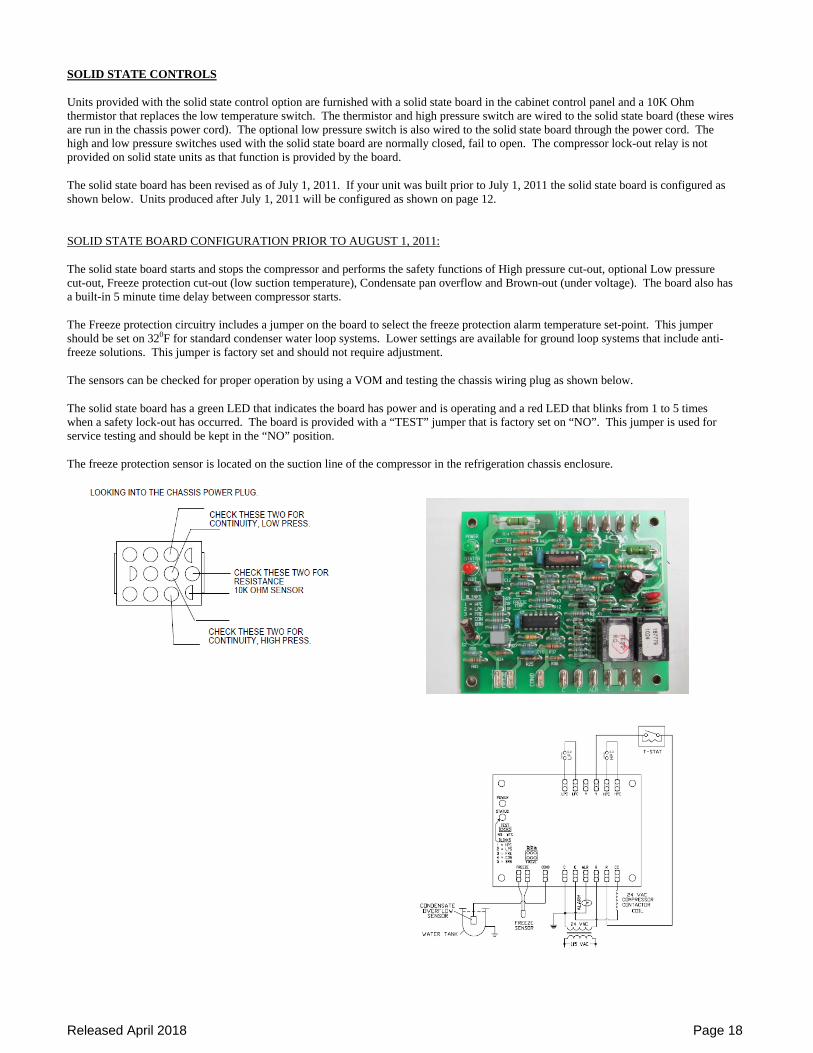
SOLID STATE CONTROLS Units provided with the solid state control option are furnished with a solid state board in the cabinet control panel and a 10K Ohm thermistor that replaces the low temperature switch. The thermistor and high pressure switch are wired to the solid state board (these wires are run in the chassis power cord). The optional low pressure switch is also wired to the solid state board through the power cord. The high and low pressure switches used with the solid state board are normally closed, fail to open. The compressor lock-out relay is not provided on solid state units as that function is provided by the board. The solid state board has been revised as of July 1, 2011. If your unit was built prior to July 1, 2011 the solid state board is configured as shown below. Units produced after July 1, 2011 will be configured as shown on page 12. SOLID STATE BOARD CONFIGURATION PRIOR TO AUGUST 1, 2011: The solid state board starts and stops the compressor and performs the safety functions of High pressure cut-out, optional Low pressure cut-out, Freeze protection cut-out (low suction temperature), Condensate pan overflow and Brown-out (under voltage). The board also has a built-in 5 minute time delay between compressor starts. The Freeze protection circuitry includes a jumper on the board to select the freeze protection alarm temperature set-point. This jumper should be set on 320F for standard condenser water loop systems. Lower settings are available for ground loop systems that include anti-freeze solutions. This jumper is factory set and should not require adjustment. The sensors can be checked for proper operation by using a VOM and testing the chassis wiring plug as shown below. The solid state board has a green LED that indicates the board has power and is operating and a red LED that blinks from 1 to 5 times when a safety lock-out has occurred. The board is provided with a “TEST” jumper that is factory set on “NO”. This jumper is used for service testing and should be kept in the “NO” position. The freeze protection sensor is located on the suction line of the compressor in the refrigeration chassis enclosure.
Released April 2018 Page 19
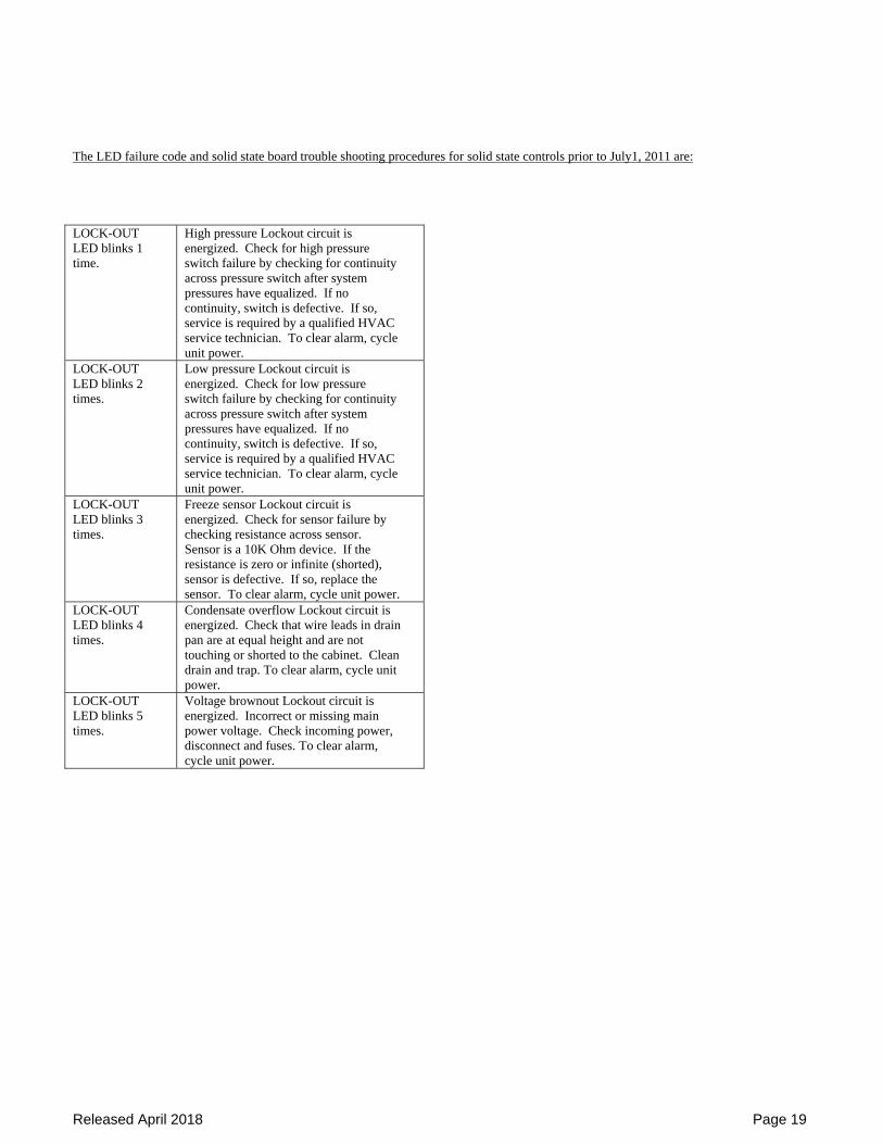
The LED failure code and solid state board trouble shooting procedures for solid state controls prior to July1, 2011 are: LOCK-OUT LED blinks 1 time.
High pressure Lockout circuit is energized. Check for high pressure switch failure by checking for continuity across pressure switch after system pressures have equalized. If no continuity, switch is defective. If so, service is required by a qualified HVAC service technician. To clear alarm, cycle unit power.
LOCK-OUT LED blinks 2 times.
Low pressure Lockout circuit is energized. Check for low pressure switch failure by checking for continuity across pressure switch after system pressures have equalized. If no continuity, switch is defective. If so, service is required by a qualified HVAC service technician. To clear alarm, cycle unit power.
LOCK-OUT LED blinks 3 times.
Freeze sensor Lockout circuit is energized. Check for sensor failure by checking resistance across sensor. Sensor is a 10K Ohm device. If the resistance is zero or infinite (shorted), sensor is defective. If so, replace the sensor. To clear alarm, cycle unit power.
LOCK-OUT LED blinks 4 times.
Condensate overflow Lockout circuit is energized. Check that wire leads in drain pan are at equal height and are not touching or shorted to the cabinet. Clean drain and trap. To clear alarm, cycle unit power.
LOCK-OUT LED blinks 5 times.
Voltage brownout Lockout circuit is energized. Incorrect or missing main power voltage. Check incoming power, disconnect and fuses. To clear alarm, cycle unit power.
Released April 2018 Page 20
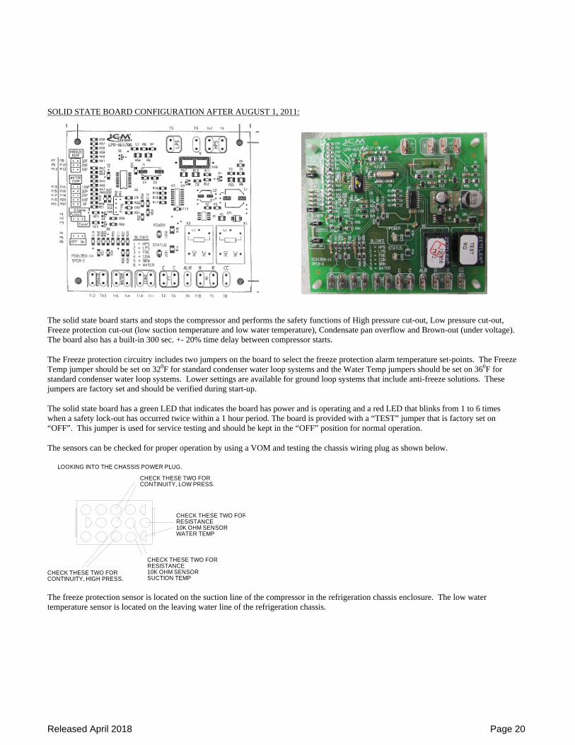
SOLID STATE BOARD CONFIGURATION AFTER AUGUST 1, 2011:
The solid state board starts and stops the compressor and performs the safety functions of High pressure cut-out, Low pressure cut-out, Freeze protection cut-out (low suction temperature and low water temperature), Condensate pan overflow and Brown-out (under voltage). The board also has a built-in 300 sec. +- 20% time delay between compressor starts. The Freeze protection circuitry includes two jumpers on the board to select the freeze protection alarm temperature set-points. The Freeze Temp jumper should be set on 320F for standard condenser water loop systems and the Water Temp jumpers should be set on 360F for standard condenser water loop systems. Lower settings are available for ground loop systems that include anti-freeze solutions. These jumpers are factory set and should be verified during start-up. The solid state board has a green LED that indicates the board has power and is operating and a red LED that blinks from 1 to 6 times when a safety lock-out has occurred twice within a 1 hour period. The board is provided with a “TEST” jumper that is factory set on “OFF”. This jumper is used for service testing and should be kept in the “OFF” position for normal operation. The sensors can be checked for proper operation by using a VOM and testing the chassis wiring plug as shown below.
LOOKING INTO THE CHASSIS POWER PLUG.
CHECK THESE TWO FORRESISTANCE10K OHM SENSORSUCTION TEMP
CHECK THESE TWO FORCONTINUITY, LOW PRESS.
CHECK THESE TWO FORCONTINUITY, HIGH PRESS.
CHECK THESE TWO FORRESISTANCE10K OHM SENSORWATER TEMP
The freeze protection sensor is located on the suction line of the compressor in the refrigeration chassis enclosure. The low water temperature sensor is located on the leaving water line of the refrigeration chassis.
Released April 2018 Page 21
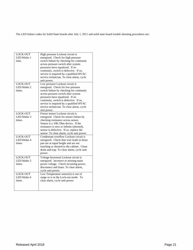
The LED failure codes for Solid State boards after July 1, 2011 and solid state board trouble shooting procedures are: LOCK-OUT LED blinks 1 time.
High pressure Lockout circuit is energized. Check for high pressure switch failure by checking for continuity across pressure switch after system pressures have equalized. If no continuity, switch is defective. If so, service is required by a qualified HVAC service technician. To clear alarm, cycle unit power.
LOCK-OUT LED blinks 2 times.
Low pressure Lockout circuit is energized. Check for low pressure switch failure by checking for continuity across pressure switch after system pressures have equalized. If no continuity, switch is defective. If so, service is required by a qualified HVAC service technician. To clear alarm, cycle unit power.
LOCK-OUT LED blinks 3 times.
Freeze sensor Lockout circuit is energized. Check for sensor failure by checking resistance across sensor. Sensor is a 10K Ohm device. If the resistance is zero or infinite (shorted), sensor is defective. If so, replace the sensor. To clear alarm, cycle unit power.
LOCK-OUT LED blinks 4 times.
Condensate overflow Lockout circuit is energized. Check that wire leads in drain pan are at equal height and are not touching or shorted to the cabinet. Clean drain and trap. To clear alarm, cycle unit power.
LOCK-OUT LED blinks 5 times.
Voltage brownout Lockout circuit is energized. Incorrect or missing main power voltage. Check incoming power, disconnect and fuses. To clear alarm, cycle unit power.
LOCK-OUT LED blinks 6 times
Low Temperature sensor(s) is out of range or is in the Lock-out mode. To clear alarm, cycle unit power.
Released April 2018 Page 22
USING SERIES VI HEAT PUMPS WITH GEOTHERMAL
GROUND LOOP PIPING SYSTEMS Ground-loop piping systems use the earth as the heat “source” or “sink” for the system rather than cooling towers and boilers. System energy consumption is reduced, however the heat pump operates over a wider range because the water temperature varies more than it does in the standard cooling tower and boiler loop. As a result, additives are usually required to prevent the water from freezing. When applied in ground-loop systems, the Whalen heat pumps include factory-set protective devices. These devices sense temperature and de-energize the heat pump should temperatures fall below the set point. The set points, along with the required antifreeze mixture specification, were based upon the submitted design condition and must not be altered.
ALTERING FREEZE PROTECTION SET POINTS OR ANTIFREEZE MIX WILL RESULT IN PERMANENT DAMAGE TO EQUIPMENT AND VOIDS THE WARRANTY
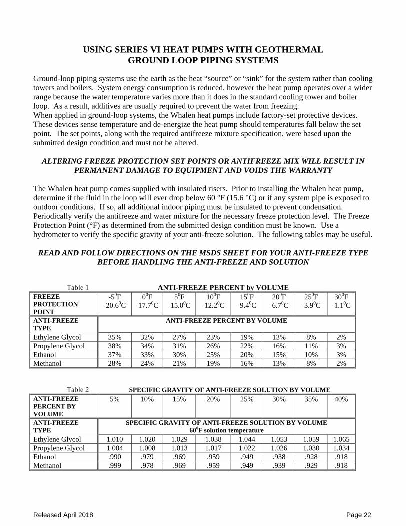
The Whalen heat pump comes supplied with insulated risers. Prior to installing the Whalen heat pump, determine if the fluid in the loop will ever drop below 60 °F (15.6 °C) or if any system pipe is exposed to outdoor conditions. If so, all additional indoor piping must be insulated to prevent condensation. Periodically verify the antifreeze and water mixture for the necessary freeze protection level. The Freeze Protection Point (°F) as determined from the submitted design condition must be known. Use a hydrometer to verify the specific gravity of your anti-freeze solution. The following tables may be useful.
READ AND FOLLOW DIRECTIONS ON THE MSDS SHEET FOR YOUR ANTI-FREEZE TYPE BEFORE HANDLING THE ANTI-FREEZE AND SOLUTION
Table 1 ANTI-FREEZE PERCENT by VOLUME FREEZE PROTECTION POINT
-50F -20.60C
00F -17.70C
50F -15.00C
100F -12.20C
150F -9.40C
200F -6.70C
250F -3.90C
300F -1.10C
ANTI-FREEZE TYPE
ANTI-FREEZE PERCENT BY VOLUME
Ethylene Glycol 35% 32% 27% 23% 19% 13% 8% 2% Propylene Glycol 38% 34% 31% 26% 22% 16% 11% 3% Ethanol 37% 33% 30% 25% 20% 15% 10% 3% Methanol 28% 24% 21% 19% 16% 13% 8% 2% Table 2 SPECIFIC GRAVITY OF ANTI-FREEZE SOLUTION BY VOLUME ANTI-FREEZE PERCENT BY VOLUME
5% 10% 15% 20% 25% 30% 35% 40%
ANTI-FREEZE TYPE
SPECIFIC GRAVITY OF ANTI-FREEZE SOLUTION BY VOLUME 600F solution temperature
Ethylene Glycol 1.010 1.020 1.029 1.038 1.044 1.053 1.059 1.065 Propylene Glycol 1.004 1.008 1.013 1.017 1.022 1.026 1.030 1.034 Ethanol .990 .979 .969 .959 .949 .938 .928 .918 Methanol .999 .978 .969 .959 .949 .939 .929 .918
ReleasedApril2018Page1
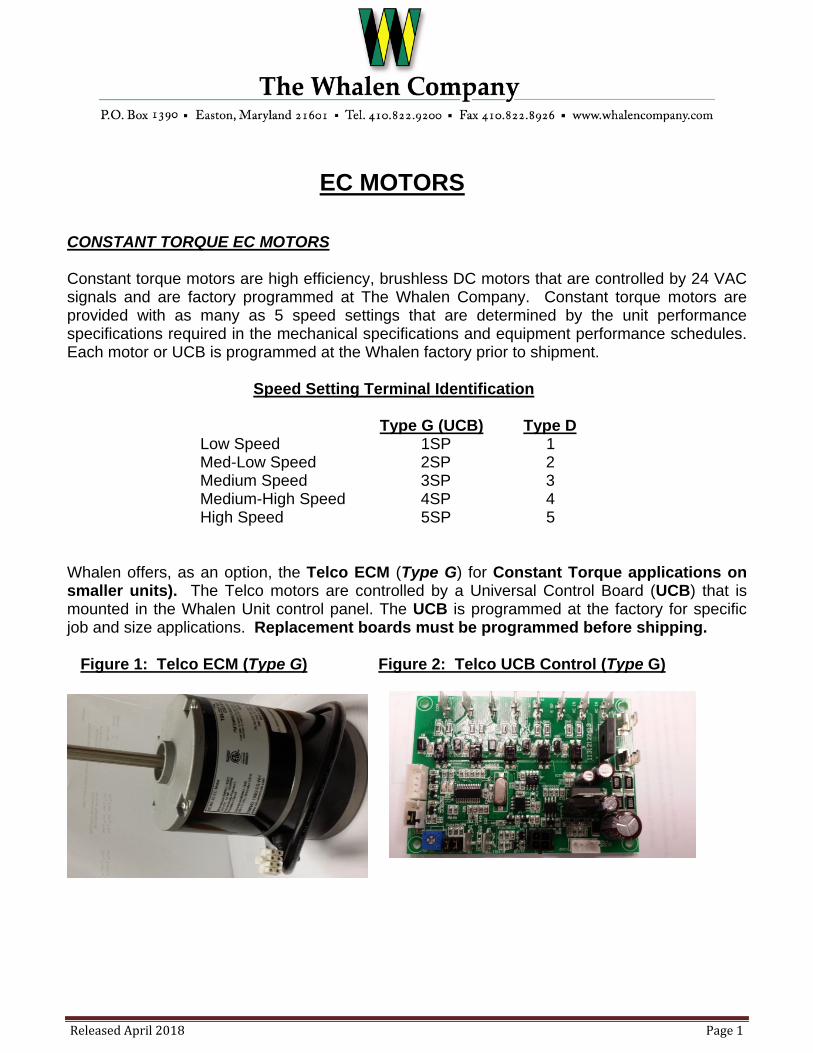
EC MOTORS CONSTANT TORQUE EC MOTORS Constant torque motors are high efficiency, brushless DC motors that are controlled by 24 VAC signals and are factory programmed at The Whalen Company. Constant torque motors are provided with as many as 5 speed settings that are determined by the unit performance specifications required in the mechanical specifications and equipment performance schedules. Each motor or UCB is programmed at the Whalen factory prior to shipment. Speed Setting Terminal Identification Type G (UCB) Type D Low Speed 1SP 1 Med-Low Speed 2SP 2 Medium Speed 3SP 3 Medium-High Speed 4SP 4 High Speed 5SP 5 Whalen offers, as an option, the Telco ECM (Type G) for Constant Torque applications on smaller units). The Telco motors are controlled by a Universal Control Board (UCB) that is mounted in the Whalen Unit control panel. The UCB is programmed at the factory for specific job and size applications. Replacement boards must be programmed before shipping. Figure 1: Telco ECM (Type G) Figure 2: Telco UCB Control (Type G)
ReleasedApril2018 Page2
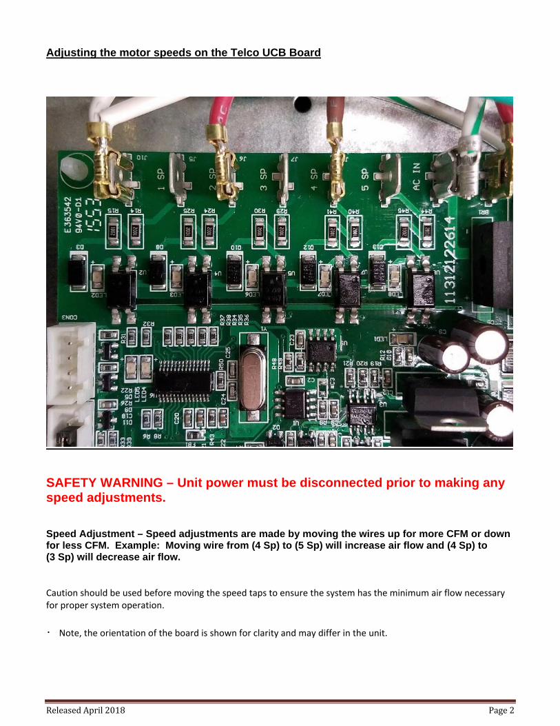
Adjusting the motor speeds on the Telco UCB Board
SAFETY WARNING – Unit power must be disconnected prior to making any speed adjustments. Speed Adjustment – Speed adjustments are made by moving the wires up for more CFM or down for less CFM. Example: Moving wire from (4 Sp) to (5 Sp) will increase air flow and (4 Sp) to (3 Sp) will decrease air flow. Caution should be used before moving the speed taps to ensure the system has the minimum air flow necessary for proper system operation.
・ Note, the orientation of the board is shown for clarity and may differ in the unit.
ReleasedApril2018 Page3
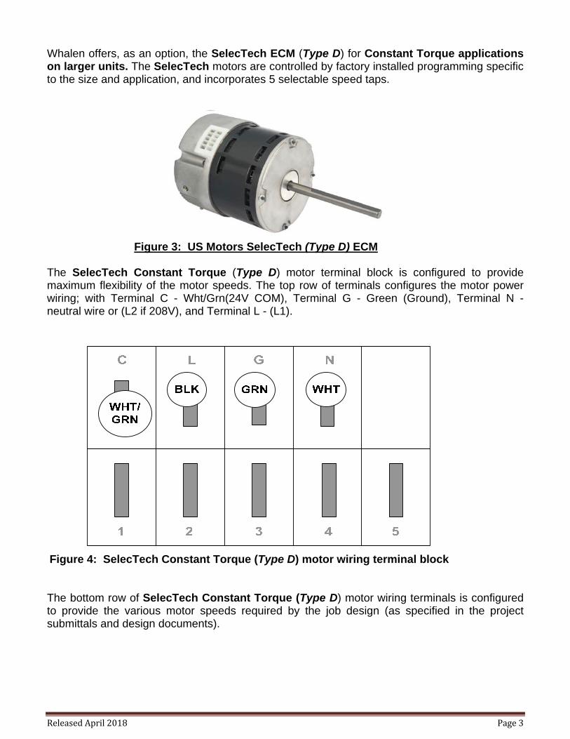
Whalen offers, as an option, the SelecTech ECM (Type D) for Constant Torque applications on larger units. The SelecTech motors are controlled by factory installed programming specific to the size and application, and incorporates 5 selectable speed taps. Figure 3: US Motors SelecTech (Type D) ECM The SelecTech Constant Torque (Type D) motor terminal block is configured to provide maximum flexibility of the motor speeds. The top row of terminals configures the motor power wiring; with Terminal C - Wht/Grn(24V COM), Terminal G - Green (Ground), Terminal N - neutral wire or (L2 if 208V), and Terminal L - (L1).
Figure 4: SelecTech Constant Torque (Type D) motor wiring terminal block The bottom row of SelecTech Constant Torque (Type D) motor wiring terminals is configured to provide the various motor speeds required by the job design (as specified in the project submittals and design documents).
ReleasedApril2018 Page4
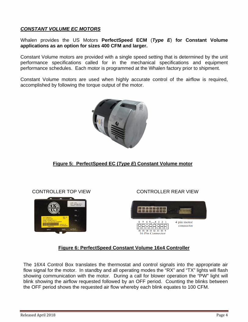
CONSTANT VOLUME EC MOTORS Whalen provides the US Motors PerfectSpeed ECM (Type E) for Constant Volume applications as an option for sizes 400 CFM and larger. Constant Volume motors are provided with a single speed setting that is determined by the unit performance specifications called for in the mechanical specifications and equipment performance schedules. Each motor is programmed at the Whalen factory prior to shipment. Constant Volume motors are used when highly accurate control of the airflow is required, accomplished by following the torque output of the motor. Figure 5: PerfectSpeed EC (Type E) Constant Volume motor CONTROLLER TOP VIEW CONTROLLER REAR VIEW Figure 6: PerfectSpeed Constant Volume 16x4 Controller
The 16X4 Control Box translates the thermostat and control signals into the appropriate air flow signal for the motor. In standby and all operating modes the “RX” and “TX” lights will flash showing communication with the motor. During a call for blower operation the “PW” light will blink showing the airflow requested followed by an OFF period. Counting the blinks between the OFF period shows the requested air flow whereby each blink equates to 100 CFM.
Related Documents


