Vostro 3401 Service Manual Regulatory Model: P132G Regulatory Type: P132G001 October 2021 Rev. A04

Welcome message from author
This document is posted to help you gain knowledge. Please leave a comment to let me know what you think about it! Share it to your friends and learn new things together.
Transcript
Vostro 3401Service Manual
Regulatory Model: P132GRegulatory Type: P132G001October 2021Rev. A04
Notes, cautions, and warnings
NOTE: A NOTE indicates important information that helps you make better use of your product.
CAUTION: A CAUTION indicates either potential damage to hardware or loss of data and tells you how to avoid
the problem.
WARNING: A WARNING indicates a potential for property damage, personal injury, or death.
© 2020-2021 Dell Inc. or its subsidiaries. All rights reserved. Dell, EMC, and other trademarks are trademarks of Dell Inc. or its subsidiaries.Other trademarks may be trademarks of their respective owners.
Chapter 1: Working on your computer........................................................................................... 6Safety instructions.............................................................................................................................................................. 6
Before working inside your computer.......................................................................................................................6Safety precautions.........................................................................................................................................................7Electrostatic discharge—ESD protection................................................................................................................7ESD field service kit ..................................................................................................................................................... 8After working inside your computer..........................................................................................................................9
Chapter 2: Technology and components.......................................................................................10USB features.......................................................................................................................................................................10HDMI 1.4............................................................................................................................................................................... 12Power button LED behavior............................................................................................................................................ 12
Chapter 3: Exploded View............................................................................................................ 15
Chapter 4: Disassembly and reassembly ...................................................................................... 18Secure Digital Card............................................................................................................................................................ 18
Removing the Secure Digital card............................................................................................................................18Installing the Secure Digital card.............................................................................................................................. 19
Base cover.......................................................................................................................................................................... 20Removing the base cover..........................................................................................................................................20Installing the base cover............................................................................................................................................ 22
Battery................................................................................................................................................................................. 24Lithium-ion battery precautions...............................................................................................................................24Disconnecting the battery.........................................................................................................................................24Reconnecting the battery......................................................................................................................................... 25Removing the battery.................................................................................................................................................26Installing the battery................................................................................................................................................... 27
Memory modules............................................................................................................................................................... 29Removing the memory module.................................................................................................................................29Installing the memory module...................................................................................................................................29
WLAN card..........................................................................................................................................................................30Removing the WLAN card.........................................................................................................................................30Installing the WLAN card............................................................................................................................................31
Solid-state drive................................................................................................................................................................ 32Removing the M.2 2230 Solid-state drive............................................................................................................ 32Installing the M.2 2230 Solid-state drive...............................................................................................................33Removing the M.2 2280 Solid-state drive............................................................................................................ 34Installing the M.2 2280 Solid-state drive.............................................................................................................. 35
Hard drive............................................................................................................................................................................36Removing the hard drive assembly......................................................................................................................... 36Installing the hard drive assembly............................................................................................................................37
Coin-cell battery................................................................................................................................................................39Removing the coin-cell...............................................................................................................................................39
Contents
Contents 3
Installing the coin-cell battery.................................................................................................................................. 40System fan..........................................................................................................................................................................40
Removing the system fan..........................................................................................................................................40Installing the system fan.............................................................................................................................................41
Heat sink..............................................................................................................................................................................42Removing the heatsink...............................................................................................................................................42Installing the heatsink.................................................................................................................................................43
Speakers.............................................................................................................................................................................. 44Removing the speakers..............................................................................................................................................44Installing the speakers................................................................................................................................................45
IO board............................................................................................................................................................................... 46Removing the IO board.............................................................................................................................................. 46Installing the IO board.................................................................................................................................................47
Touchpad.............................................................................................................................................................................48Removing the touch pad assembly......................................................................................................................... 48Installing the touch pad assembly........................................................................................................................... 49
Display assembly................................................................................................................................................................ 51Removing the display assembly................................................................................................................................ 51Installing the display assembly..................................................................................................................................53
Display bezel.......................................................................................................................................................................55Removing the display bezel...................................................................................................................................... 55Installing the display bezel ....................................................................................................................................... 56Camera...........................................................................................................................................................................56Display panel................................................................................................................................................................. 58Display back-cover and antenna assembly............................................................................................................62
Camera.................................................................................................................................................................................63Removing the camera.................................................................................................................................................63Installing the camera...................................................................................................................................................64
Display panel.......................................................................................................................................................................65Removing the display panel...................................................................................................................................... 65Installation display panel.............................................................................................................................................67
Display back-cover and antenna assembly................................................................................................................. 69Removing the display back-cover........................................................................................................................... 69Installing the display back-cover..............................................................................................................................70
Power button......................................................................................................................................................................70Removing the power button..................................................................................................................................... 70Installing the power button........................................................................................................................................ 71
System board......................................................................................................................................................................72Removing the system board - Realtek audio........................................................................................................ 72Installing the system board - Realtek audio.......................................................................................................... 75Removing the system board - Cirrus Logic audio................................................................................................ 77Installing the system board - Cirrus Logic audio..................................................................................................79
Power-adapter port.......................................................................................................................................................... 82Removing the power adapter port.......................................................................................................................... 82Installing the power adapter port............................................................................................................................ 83
Palm-rest and keyboard assembly.................................................................................................................................84Removing the palmrest and keyboard assembly..................................................................................................84
Chapter 5: Troubleshooting.........................................................................................................86Handling swollen Lithium-ion batteries........................................................................................................................ 86
4 Contents
Dell SupportAssist Pre-boot System Performance Check diagnostics................................................................87Running the SupportAssist Pre-Boot System Performance Check................................................................ 87
Enhanced Pre-Boot System Assessment (ePSA) diagnostics............................................................................... 87Running SupportAssist diagnostics.........................................................................................................................88
System diagnostic lights..................................................................................................................................................88Real-Time Clock (RTC Reset)........................................................................................................................................90Updating the BIOS in Windows..................................................................................................................................... 90Updating the BIOS using the USB drive in Windows............................................................................................... 90Backup media and recovery options.............................................................................................................................90WiFi power cycle............................................................................................................................................................... 90Drain residual flea power (perform hard reset).......................................................................................................... 91
Chapter 6: Getting help and contacting Dell................................................................................ 92
Contents 5
Working on your computer
Topics:
• Safety instructions
Safety instructions
Prerequisites
Use the following safety guidelines to protect your computer from potential damage and to ensure your personal safety. Unlessotherwise noted, each procedure included in this document assumes that the following conditions exist:● You have read the safety information that shipped with your computer.● A component can be replaced or, if purchased separately, installed by performing the removal procedure in reverse order.
About this task
WARNING: Before working inside your computer, read the safety information that shipped with your computer.
For additional safety best practices information, see the Regulatory Compliance Homepage
CAUTION: Many repairs may only be done by a certified service technician. You should only perform
troubleshooting and simple repairs as authorized in your product documentation, or as directed by the online or
telephone service and support team. Damage due to servicing that is not authorized by Dell is not covered by
your warranty. Read and follow the safety instructions that came with the product.
CAUTION: To avoid electrostatic discharge, ground yourself by using a wrist grounding strap or by periodically
touching an unpainted metal surface at the same time as touching a connector on the back of the computer.
CAUTION: Handle components and cards with care. Do not touch the components or contacts on a card. Hold a
card by its edges or by its metal mounting bracket. Hold a component such as a processor by its edges, not by
its pins.
CAUTION: When you disconnect a cable, pull on its connector or on its pull-tab, not on the cable itself. Some
cables have connectors with locking tabs; if you are disconnecting this type of cable, press in on the locking
tabs before you disconnect the cable. As you pull connectors apart, keep them evenly aligned to avoid bending
any connector pins. Also, before you connect a cable, ensure that both connectors are correctly oriented and
aligned.
NOTE: Disconnect all power sources before opening the computer cover or panels. After you finish working inside the
computer, replace all covers, panels, and screws before connecting to the power source.
CAUTION: Exercise caution when handling Lithium-ion batteries in laptops. Swollen batteries should not be used
and should be replaced and disposed properly.
NOTE: The color of your computer and certain components may appear differently than shown in this document.
Before working inside your computer
Steps
1. Save and close all open files and exit all open applications.
2. Shut down your computer. Click Start > Power > Shut down.
1
6 Working on your computer
NOTE: If you are using a different operating system, see the documentation of your operating system for shut-down
instructions.
3. Disconnect your computer and all attached devices from their electrical outlets.
4. Disconnect all attached network devices and peripherals, such as keyboard, mouse, and monitor from your computer.
5. Remove any media card and optical disc from your computer, if applicable.
6. After the computer is unplugged, press and hold the power button for 5 seconds to ground the system board.
CAUTION: Place the computer on a flat, soft, and clean surface to avoid scratches on the display.
7. Place the computer face down.
Safety precautions
The safety precautions chapter details the primary steps to be taken before performing any disassembly instructions.
Observe the following safety precautions before you perform any installation or break/fix procedures involving disassembly orreassembly:● Turn off the system and all attached peripherals.● Disconnect the system and all attached peripherals from AC power.● Disconnect all network cables, telephone, and telecommunications lines from the system.● Use an ESD field service kit when working inside any to avoid electrostatic discharge (ESD) damage.● After removing any system component, carefully place the removed component on an anti-static mat.● Wear shoes with non-conductive rubber soles to reduce the chance of getting electrocuted.
Standby power
Dell products with standby power must be unplugged before you open the case. Systems that incorporate standby power areessentially powered while turned off. The internal power enables the system to be remotely turned on (wake on LAN) andsuspended into a sleep mode and has other advanced power management features.
Unplugging, pressing and holding the power button for 20 seconds should discharge residual power in the system board.
Bonding
Bonding is a method for connecting two or more grounding conductors to the same electrical potential. This is done throughthe use of a field service electrostatic discharge (ESD) kit. When connecting a bonding wire, ensure that it is connected to baremetal and never to a painted or non-metal surface. The wrist strap should be secure and in full contact with your skin, andensure that you remove all jewelry such as watches, bracelets, or rings prior to bonding yourself and the equipment.
Electrostatic discharge—ESD protection
ESD is a major concern when you handle electronic components, especially sensitive components such as expansion cards,processors, memory DIMMs, and system boards. Very slight charges can damage circuits in ways that may not be obvious, suchas intermittent problems or a shortened product life span. As the industry pushes for lower power requirements and increaseddensity, ESD protection is an increasing concern.
Due to the increased density of semiconductors used in recent Dell products, the sensitivity to static damage is now higher thanin previous Dell products. For this reason, some previously approved methods of handling parts are no longer applicable.
Two recognized types of ESD damage are catastrophic and intermittent failures.● Catastrophic – Catastrophic failures represent approximately 20 percent of ESD-related failures. The damage causes
an immediate and complete loss of device functionality. An example of catastrophic failure is a memory DIMM that hasreceived a static shock and immediately generates a "No POST/No Video" symptom with a beep code emitted for missing ornonfunctional memory.
● Intermittent – Intermittent failures represent approximately 80 percent of ESD-related failures. The high rate ofintermittent failures means that most of the time when damage occurs, it is not immediately recognizable. The DIMMreceives a static shock, but the tracing is merely weakened and does not immediately produce outward symptoms related to
Working on your computer 7
the damage. The weakened trace may take weeks or months to melt, and in the meantime may cause degradation of memoryintegrity, intermittent memory errors, etc.
The more difficult type of damage to recognize and troubleshoot is the intermittent (also called latent or "walking wounded")failure.
Perform the following steps to prevent ESD damage:● Use a wired ESD wrist strap that is properly grounded. The use of wireless anti-static straps is no longer allowed; they do not
provide adequate protection. Touching the chassis before handling parts does not ensure adequate ESD protection on partswith increased sensitivity to ESD damage.
● Handle all static-sensitive components in a static-safe area. If possible, use anti-static floor pads and workbench pads.● When unpacking a static-sensitive component from its shipping carton, do not remove the component from the anti-static
packing material until you are ready to install the component. Before unwrapping the anti-static packaging, ensure that youdischarge static electricity from your body.
● Before transporting a static-sensitive component, place it in an anti-static container or packaging.
ESD field service kit
The unmonitored Field Service kit is the most commonly used service kit. Each Field Service kit includes three main components:anti-static mat, wrist strap, and bonding wire.
Components of an ESD field service kit
The components of an ESD field service kit are:● Anti-Static Mat – The anti-static mat is dissipative and parts can be placed on it during service procedures. When using an
anti-static mat, your wrist strap should be snug and the bonding wire should be connected to the mat and to any bare metalon the system being worked on. Once deployed properly, service parts can be removed from the ESD bag and placed directlyon the mat. ESD-sensitive items are safe in your hand, on the ESD mat, in the system, or inside a bag.
● Wrist Strap and Bonding Wire – The wrist strap and bonding wire can be either directly connected between your wristand bare metal on the hardware if the ESD mat is not required, or connected to the anti-static mat to protect hardware thatis temporarily placed on the mat. The physical connection of the wrist strap and bonding wire between your skin, the ESDmat, and the hardware is known as bonding. Use only Field Service kits with a wrist strap, mat, and bonding wire. Neveruse wireless wrist straps. Always be aware that the internal wires of a wrist strap are prone to damage from normal wearand tear, and must be checked regularly with a wrist strap tester in order to avoid accidental ESD hardware damage. It isrecommended to test the wrist strap and bonding wire at least once per week.
● ESD Wrist Strap Tester – The wires inside of an ESD strap are prone to damage over time. When using an unmonitoredkit, it is a best practice to regularly test the strap prior to each service call, and at a minimum, test once per week. Awrist strap tester is the best method for doing this test. If you do not have your own wrist strap tester, check with yourregional office to find out if they have one. To perform the test, plug the wrist-strap's bonding-wire into the tester while it isstrapped to your wrist and push the button to test. A green LED is lit if the test is successful; a red LED is lit and an alarmsounds if the test fails.
● Insulator Elements – It is critical to keep ESD sensitive devices, such as plastic heat sink casings, away from internal partsthat are insulators and often highly charged.
● Working Environment – Before deploying the ESD Field Service kit, assess the situation at the customer location. Forexample, deploying the kit for a server environment is different than for a desktop or portable environment. Servers aretypically installed in a rack within a data center; desktops or portables are typically placed on office desks or cubicles. Alwayslook for a large open flat work area that is free of clutter and large enough to deploy the ESD kit with additional space toaccommodate the type of system that is being repaired. The workspace should also be free of insulators that can cause anESD event. On the work area, insulators such as Styrofoam and other plastics should always be moved at least 12 inches or30 centimeters away from sensitive parts before physically handling any hardware components
● ESD Packaging – All ESD-sensitive devices must be shipped and received in static-safe packaging. Metal, static-shieldedbags are preferred. However, you should always return the damaged part using the same ESD bag and packaging that thenew part arrived in. The ESD bag should be folded over and taped shut and all the same foam packing material should beused in the original box that the new part arrived in. ESD-sensitive devices should be removed from packaging only at anESD-protected work surface, and parts should never be placed on top of the ESD bag because only the inside of the bag isshielded. Always place parts in your hand, on the ESD mat, in the system, or inside an anti-static bag.
● Transporting Sensitive Components – When transporting ESD sensitive components such as replacement parts or partsto be returned to Dell, it is critical to place these parts in anti-static bags for safe transport.
8 Working on your computer
ESD protection summary
It is recommended that all field service technicians use the traditional wired ESD grounding wrist strap and protective anti-staticmat at all times when servicing Dell products. In addition, it is critical that technicians keep sensitive parts separate from allinsulator parts while performing service and that they use anti-static bags for transporting sensitive components.
After working inside your computer
About this task
NOTE: Leaving stray or loose screws inside your computer may severely damage your computer.
Steps
1. Replace all screws and ensure that no stray screws remain inside your computer.
2. Connect any external devices, peripherals, or cables you removed before working on your computer.
3. Replace any media cards, discs, or any other parts that you removed before working on your computer.
4. Connect your computer and all attached devices to their electrical outlets.
5. Turn on your computer.
Working on your computer 9
Technology and componentsThis chapter details the technology and components available in the system.Topics:
• USB features• HDMI 1.4• Power button LED behavior
USB featuresUniversal Serial Bus, or USB, was introduced in 1996. It dramatically simplified the connection between host computers andperipheral devices like mouses, keyboards, external drivers, and printers.
Table 1. USB evolution
Type Data Transfer Rate Category Introduction Year
USB 2.0 480 Mbps High Speed 2000
USB 3.2 Gen 1 5 Gbps Super-Speed 2010
USB 3.2 Gen 2 10 Gbps Super-Speed 2013
USB 3.2 Gen 1 (Super-Speed USB)
For years, the USB 2.0 has been firmly entrenched as the de facto interface standard in the PC world with about 6 billiondevices sold, and yet the need for more speed grows by ever faster computing hardware and ever greater bandwidth demands.The USB 3.2 Gen 1 finally has the answer to the consumer's demands with a theoretically 10 times faster than its predecessor. Ina nutshell, USB 3.2 Gen 1 features are as follows:
● Higher transfer rates (up to 5 Gbps)● Increased maximum bus power and increased device current draw to better accommodate power-hungry devices● New power management features● Full-duplex data transfers and support for new transfer types● Backward USB 2.0 compatibility● New connectors and cable
The topics below cover some of the most commonly asked questions regarding USB 3.2 Gen 1.
Speed
Currently, there are 3 speed modes that are defined by the latest USB 3.2 Gen 1 specification. They are Super-Speed, Hi-Speed,and Full-Speed. The new Super-Speed mode has a transfer rate of 4.8 Gbps. While the specification retains Hi-Speed, andFull-Speed USB mode, commonly known as USB 2.0 and 1.1 respectively, the slower modes still operate at 480 Mbps and 12Mbps respectively and are kept to maintain backward compatibility.
USB 3.2 Gen 1 achieves the much higher performance by the technical changes below:
● An additional physical bus that is added in parallel with the existing USB 2.0 bus (see the figure below).
2
10 Technology and components
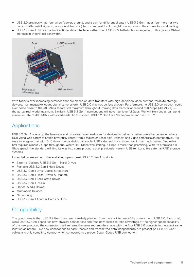
● USB 2.0 previously had four wires (power, ground, and a pair for differential data); USB 3.2 Gen 1 adds four more for twopairs of differential signals (receive and transmit) for a combined total of eight connections in the connectors and cabling.
● USB 3.2 Gen 1 utilizes the bi-directional data interface, rather than USB 2.0's half-duplex arrangement. This gives a 10-foldincrease in theoretical bandwidth.
With today's ever increasing demands that are placed on data transfers with high-definition video content, terabyte storagedevices, high megapixel count digital cameras etc., USB 2.0 may not be fast enough. Furthermore, no USB 2.0 connection couldever come close to the 480Mbps theoretical maximum throughput, making data transfer at around 320 Mbps (40 MB/s) —the actual real-world maximum. Similarly, USB 3.2 Gen 1 connections will never achieve 4.8Gbps. We will likely see a real-worldmaximum rate of 400 MB/s with overheads. At this speed, USB 3.2 Gen 1 is a 10x improvement over USB 2.0.
Applications
USB 3.2 Gen 1 opens up the laneways and provides more headroom for devices to deliver a better overall experience. WhereUSB video was barely tolerable previously (both from a maximum resolution, latency, and video compression perspective), it'seasy to imagine that with 5-10 times the bandwidth available, USB video solutions should work that much better. Single-linkDVI requires almost 2 Gbps throughput. Where 480 Mbps was limiting, 5 Gbps is more than promising. With its promised 4.8Gbps speed, the standard will find its way into some products that previously weren't USB territory, like external RAID storagesystems.
Listed below are some of the available Super-Speed USB 3.2 Gen 1 products:
● External Desktop USB 3.2 Gen 1 Hard Drives● Portable USB 3.2 Gen 1 Hard Drives● USB 3.2 Gen 1 Drive Docks & Adapters● USB 3.2 Gen 1 Flash Drives & Readers● USB 3.2 Gen 1 Solid-state Drives● USB 3.2 Gen 1 RAIDs● Optical Media Drives● Multimedia Devices● Networking● USB 3.2 Gen 1 Adapter Cards & Hubs
Compatibility
The good news is that USB 3.2 Gen 1 has been carefully planned from the start to peacefully co-exist with USB 2.0. First of all,while USB 3.2 Gen 1 specifies new physical connections and thus new cables to take advantage of the higher speed capabilityof the new protocol, the connector itself remains the same rectangular shape with the four USB 2.0 contacts in the exact samelocation as before. Five new connections to carry receive and transmitted data independently are present on USB 3.2 Gen 1cables and only come into contact when connected to a proper Super-Speed USB connection.
Technology and components 11
HDMI 1.4This topic explains the HDMI 1.4 and its features along with the advantages.
HDMI (High-Definition Multimedia Interface) is an industry-supported, uncompressed, all-digital audio/video interface. HDMIprovides an interface between any compatible digital audio/video source, such as a DVD player, or A/V receiver and acompatible digital audio and/or video monitor, such as a digital TV (DTV). The primary advantage is cable reduction and contentprotection provisions. HDMI supports standard, enhanced, or high-definition video, plus multichannel digital audio on a singlecable.
HDMI 1.4 Features
● HDMI Ethernet Channel - Adds high-speed networking to an HDMI link, allowing users to take full advantage of theirIP-enabled devices without a separate Ethernet cable.
● Audio Return Channel - Allows an HDMI-connected TV with a built-in tuner to send audio data "upstream" to a surroundaudio system, eliminating the need for a separate audio cable.
● 3D - Defines input/output protocols for major 3D video formats, paving the way for true 3D gaming and 3D home theaterapplications.
● Content Type - Real-time signaling of content types between display and source devices, enabling a TV to optimize picturesettings based on content type.
● Additional Color Spaces - Adds support for additional color models used in digital photography and computer graphics.● 4K Support - Enables video resolutions far beyond 1080p, supporting next-generation displays that will rival the Digital
Cinema systems used in many commercial movie theaters.● HDMI Micro Connector - A new, smaller connector for phones and other portable devices, supporting video resolutions up
to 1080p.● Automotive Connection System - New cables and connectors for automotive video systems, designed to meet the unique
demands of the motoring environment while delivering true HD quality.
Advantages of HDMI
● Quality HDMI transfers uncompressed digital audio and video for the highest, crispest image quality.● Low-cost HDMI provides the quality and functionality of a digital interface while also supporting uncompressed video formats
in a simple, cost-effective manner.● Audio HDMI supports multiple audio formats from standard stereo to multichannel surround sound.● HDMI combines video and multichannel audio into a single cable, eliminating the cost, complexity, and confusion of multiple
cables currently used in A/V systems.● HDMI supports communication between the video source (such as a DVD player) and the DTV, enabling new functionality.
Power button LED behaviorOn certain Dell Latitude systems, the power button LED is used to provide an indication of the system status, and as a result thepower button illuminates when pressed. The systems with the optional power button/fingerprint reader will have no LED underthe power button and hence will apply the available LED's in the system to provide an indication of the system status.
Power button LED behavior without Fingerprint reader
● System is ON (S0) = LED illuminates solid white.● System in Sleep/Standby (S3, SOix) = LED is off● System is Off/Hibernating (S4/S5) = LED is off
Power On and LED behavior with Fingerprint reader
● Pressing the power button for a duration between 50 msec to 2 sec turns on the device.● Power button does not register additional presses until the SOL (Sign-Of-Life) has been provided to the user.
12 Technology and components
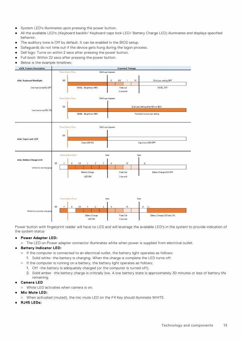
● System LED's illuminates upon pressing the power button.● All the available LED's (Keyboard backlit/ Keyboard caps lock LED/ Battery Charge LED) illuminates and displays specified
behavior.● The auditory tone is Off by default. It can be enabled in the BIOS setup.● Safeguards do not time out if the device gets hung during the logon process.● Dell logo: Turns on within 2 secs after pressing the power button.● Full boot: Within 22 secs after pressing the power button.● Below is the example timelines:
Power button with fingerprint reader will have no LED and will leverage the available LED's in the system to provide indication ofthe system status
● Power Adapter LED:○ The LED on Power adapter connector illuminates white when power is supplied from electrical outlet.
● Battery Indicator LED:○ If the computer is connected to an electrical outlet, the battery light operates as follows:
1. Solid white -the battery is charging. When the charge is complete the LED turns off.○ If the computer is running on a battery, the battery light operates as follows:
1. Off -the battery is adequately charged (or the computer is turned off).2. Solid amber -the battery charge is critically low. A low battery state is approximately 30 minutes or less of battery life
remaining.● Camera LED
○ White LED activates when camera is on.● Mic Mute LED:
○ When activated (muted), the mic mute LED on the F4 Key should illuminate WHITE.● RJ45 LEDs:
Technology and components 13
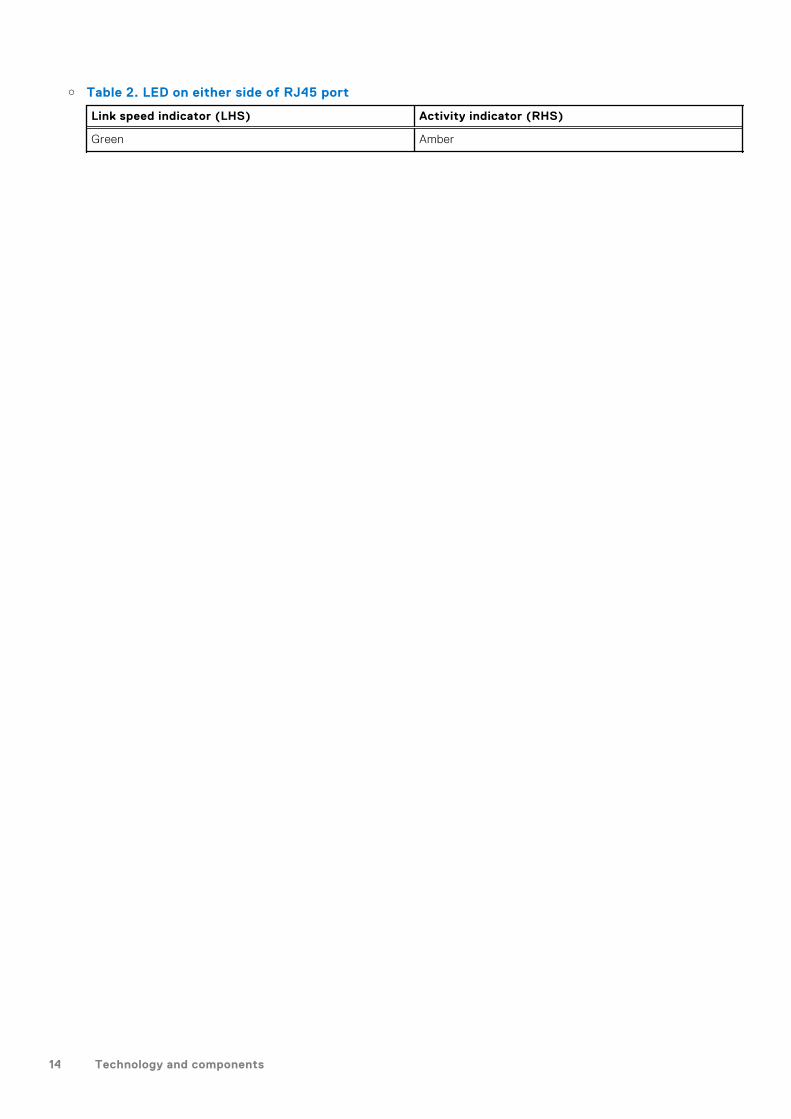
○ Table 2. LED on either side of RJ45 port
Link speed indicator (LHS) Activity indicator (RHS)
Green Amber
14 Technology and components

3
Exploded View 15
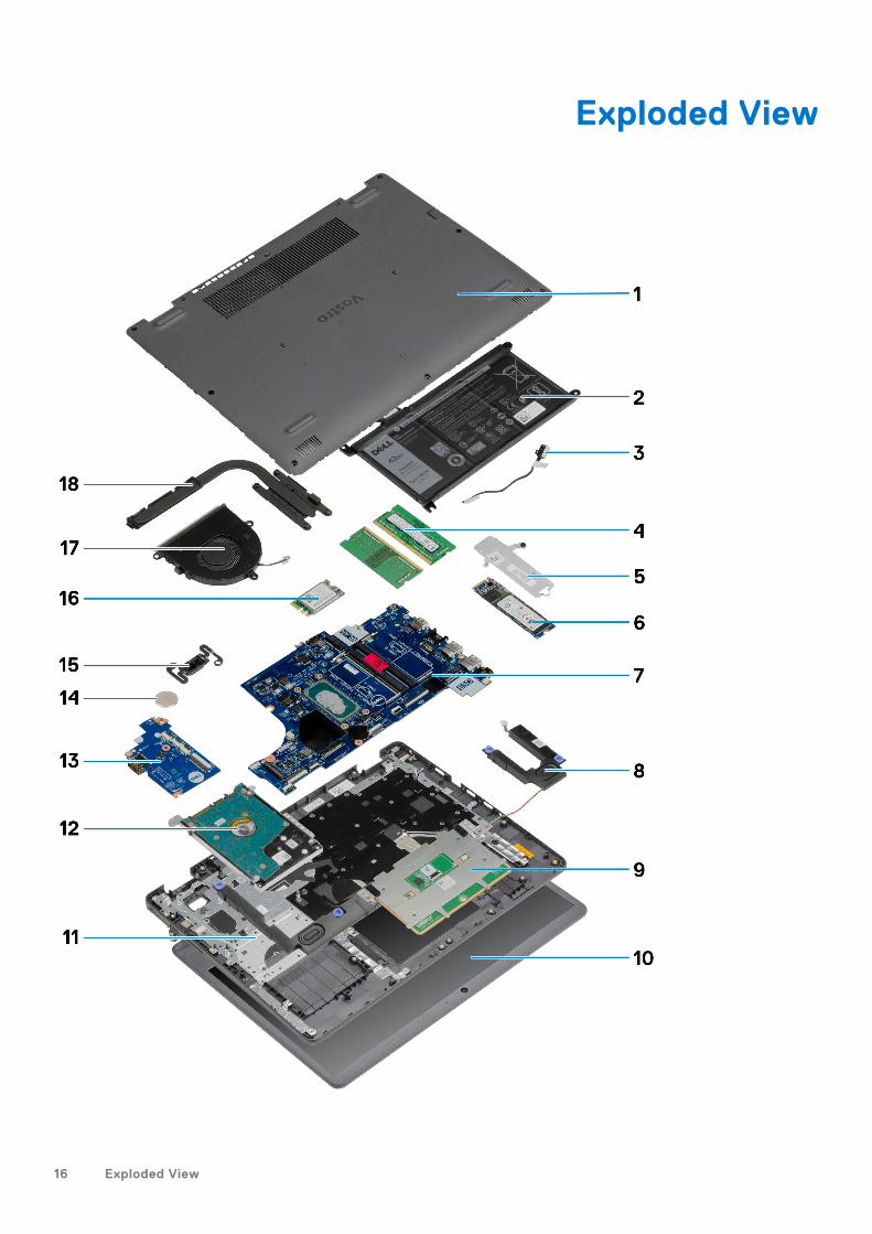
Exploded View
16 Exploded View
1. Base cover2. Battery3. DC-in Port4. Memory modules5. Solid-State Drive bracket6. Solid-State Drive7. System Board8. Speakers9. Touchpad10. Display Assembly11. Palmrest Assembly12. HDD Assembly13. IO Board14. Coin Cell Battery15. Power Button Module16. WLAN Card17. Fan Assembly18. Heatsink assembly
NOTE: Dell provides a list of components and their part numbers for the original system configuration purchased. These
parts are available according to warranty coverages purchased by the customer. Contact your Dell sales representative for
purchase options.
Exploded View 17
Disassembly and reassembly
NOTE: The images in this document may differ from your computer depending on the configuration you ordered.
Topics:
• Secure Digital Card• Base cover• Battery• Memory modules• WLAN card• Solid-state drive• Hard drive• Coin-cell battery• System fan• Heat sink• Speakers• IO board• Touchpad• Display assembly• Display bezel• Camera• Display panel• Display back-cover and antenna assembly• Power button• System board• Power-adapter port• Palm-rest and keyboard assembly
Secure Digital Card
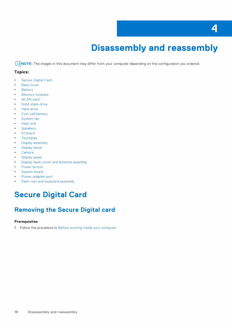
Removing the Secure Digital card
Prerequisites
1. Follow the procedure in Before working inside your computer
4
18 Disassembly and reassembly
About this task
Steps
1. Push the secure digital card to release it from the computer.
2. Slide the secure digital card out of the computer.
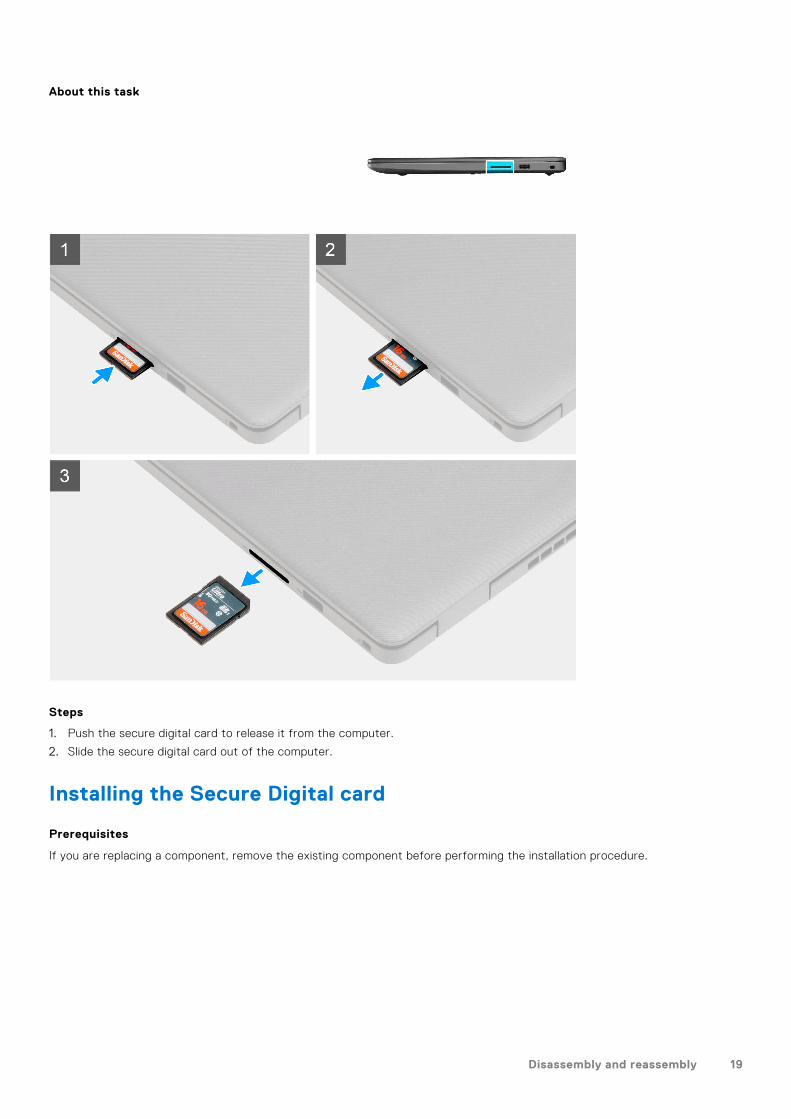
Installing the Secure Digital card
Prerequisites
If you are replacing a component, remove the existing component before performing the installation procedure.
Disassembly and reassembly 19
About this task
Steps
Slide the secure digital into the slot until it clicks into place.
Next steps
1. Follow the procedure in after working inside your computer
Base cover
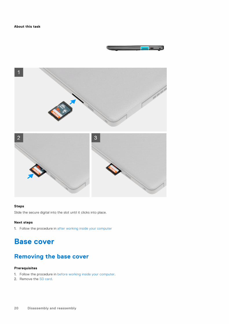
Removing the base cover
Prerequisites
1. Follow the procedure in before working inside your computer.2. Remove the SD card.
20 Disassembly and reassembly
About this task
Disassembly and reassembly 21
Steps
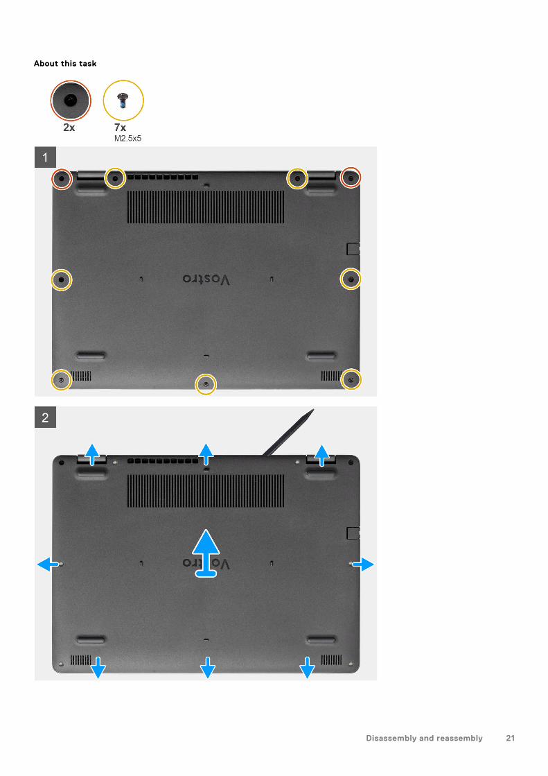
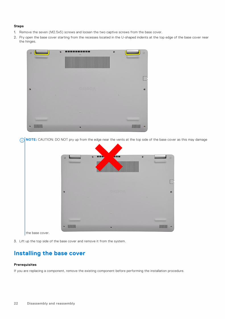
1. Remove the seven (M2.5x5) screws and loosen the two captive screws from the base cover.
2. Pry open the base cover starting from the recesses located in the U-shaped indents at the top edge of the base cover nearthe hinges.
NOTE: CAUTION: DO NOT pry up from the edge near the vents at the top side of the base cover as this may damage
the base cover.
3. Lift up the top side of the base cover and remove it from the system.
Installing the base cover
Prerequisites
If you are replacing a component, remove the existing component before performing the installation procedure.
22 Disassembly and reassembly
About this task
Disassembly and reassembly 23
Steps
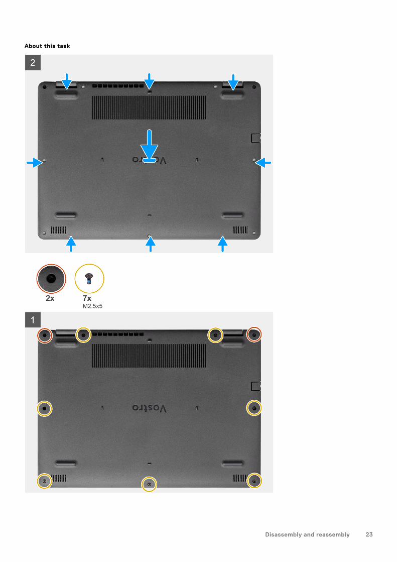
1. Align and place the base cover on the computer, press the edges and sides of the base cover until it snaps into place.
2. Tighten the seven (M2.5x5) screws and the two captive screws to secure the base cover to the computer.
Next steps
1. Replace the SD card2. Follow the procedure in after working inside your computer
Battery
Lithium-ion battery precautions
CAUTION:
● Exercise caution when handling Lithium-ion batteries.
● Discharge the battery completely before removing it. Disconnect the AC power adapter from the system and
operate the computer solely on battery power—the battery is fully discharged when the computer no longer
turns on when the power button is pressed.
● Do not crush, drop, mutilate, or penetrate the battery with foreign objects.
● Do not expose the battery to high temperatures, or disassemble battery packs and cells.
● Do not apply pressure to the surface of the battery.
● Do not bend the battery.
● Do not use tools of any kind to pry on or against the battery.
● Ensure any screws during the servicing of this product are not lost or misplaced, to prevent accidental
puncture or damage to the battery and other system components.
● If the battery gets stuck inside your computer as a result of swelling, do not try to release it as puncturing,
bending, or crushing a lithium-ion battery can be dangerous. In such an instance, contact Dell technical
support for assistance. See www.dell.com/contactdell.
● Always purchase genuine batteries from www.dell.com or authorized Dell partners and resellers.
● Swollen batteries should not be used and should be replaced and disposed properly. For guidelines on how to
handle and replace swollen Lithium-ion batteries, see Handling swollen Lithium-ion batteries.
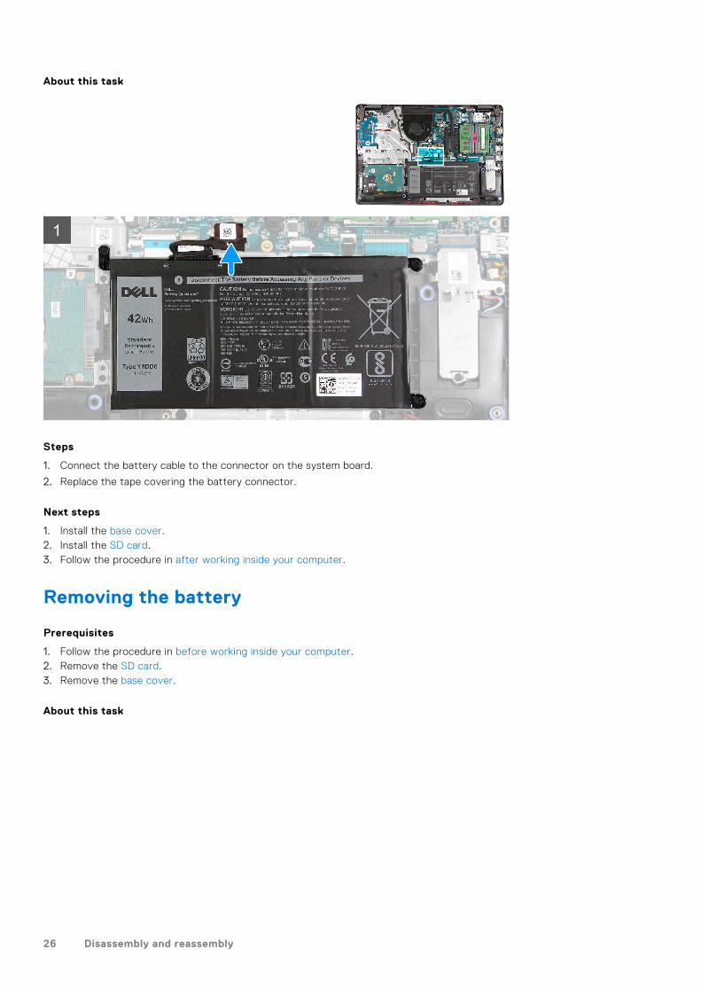
Disconnecting the battery
Prerequisites
1. Follow the procedure in before working inside your computer2. Remove the SD card.3. Remove the base cover.
24 Disassembly and reassembly
About this task
Steps
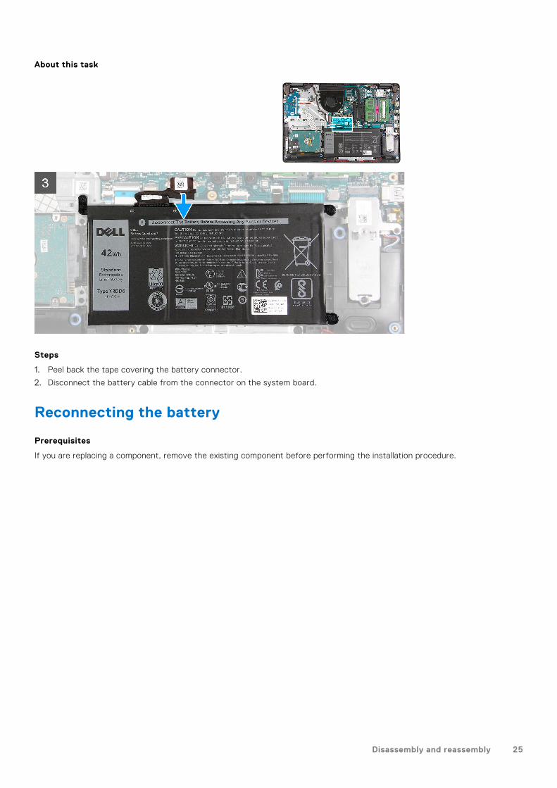
1. Peel back the tape covering the battery connector.
2. Disconnect the battery cable from the connector on the system board.
Reconnecting the battery
Prerequisites
If you are replacing a component, remove the existing component before performing the installation procedure.
Disassembly and reassembly 25
About this task
Steps
1. Connect the battery cable to the connector on the system board.
2. Replace the tape covering the battery connector.
Next steps
1. Install the base cover.2. Install the SD card.3. Follow the procedure in after working inside your computer.
Removing the battery
Prerequisites
1. Follow the procedure in before working inside your computer.2. Remove the SD card.3. Remove the base cover.
About this task
26 Disassembly and reassembly
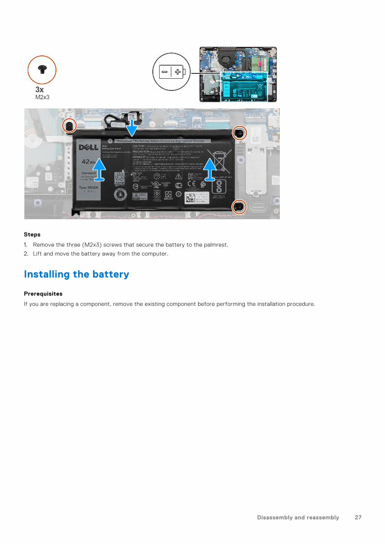
Steps
1. Remove the three (M2x3) screws that secure the battery to the palmrest.
2. Lift and move the battery away from the computer.
Installing the battery
Prerequisites
If you are replacing a component, remove the existing component before performing the installation procedure.
Disassembly and reassembly 27
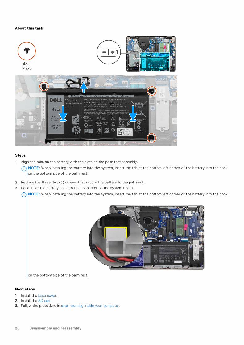
About this task
Steps
1. Align the tabs on the battery with the slots on the palm rest assembly.
NOTE: When installing the battery into the system, insert the tab at the bottom left corner of the battery into the hook
on the bottom side of the palm rest.
2. Replace the three (M2x3) screws that secure the battery to the palmrest.
3. Reconnect the battery cable to the connector on the system board.
NOTE: When installing the battery into the system, insert the tab at the bottom left corner of the battery into the hook
on the bottom side of the palm rest.
Next steps
1. Install the base cover.2. Install the SD card.3. Follow the procedure in after working inside your computer.
28 Disassembly and reassembly
Memory modules
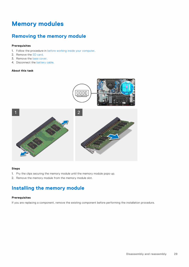
Removing the memory module
Prerequisites
1. Follow the procedure in before working inside your computer.2. Remove the SD card.3. Remove the base cover.4. Disconnect the battery cable.
About this task
Steps
1. Pry the clips securing the memory module until the memory module pops-up.
2. Remove the memory module from the memory module slot.
Installing the memory module
Prerequisites
If you are replacing a component, remove the existing component before performing the installation procedure.
Disassembly and reassembly 29
About this task
Steps
1. Align the notch on the memory module with the tab on the memory module slot and slide the memory module firmly into theslot at an angle.
2. Press the memory module down until the clips secure it.
NOTE: If you do not hear the click, remove the memory module and reinstall it.
Next steps
1. Connect the battery cable.2. Install the base cover.3. Install the SD card.4. Follow the procedure in after working inside your computer.
WLAN card
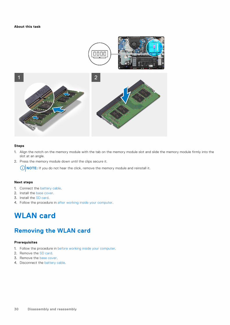
Removing the WLAN card
Prerequisites
1. Follow the procedure in before working inside your computer.2. Remove the SD card.3. Remove the base cover.4. Disconnect the battery cable.
30 Disassembly and reassembly
About this task
Steps
1. Remove the single (M2x3) screw that secures the WLAN card bracket to the system board.
2. Slide and remove the WLAN card bracket that secures the WLAN antenna cables.
3. Disconnect the WLAN antenna cables from the connectors on the WLAN card.
4. Pull out the WLAN card from the M.2 port on the system board.
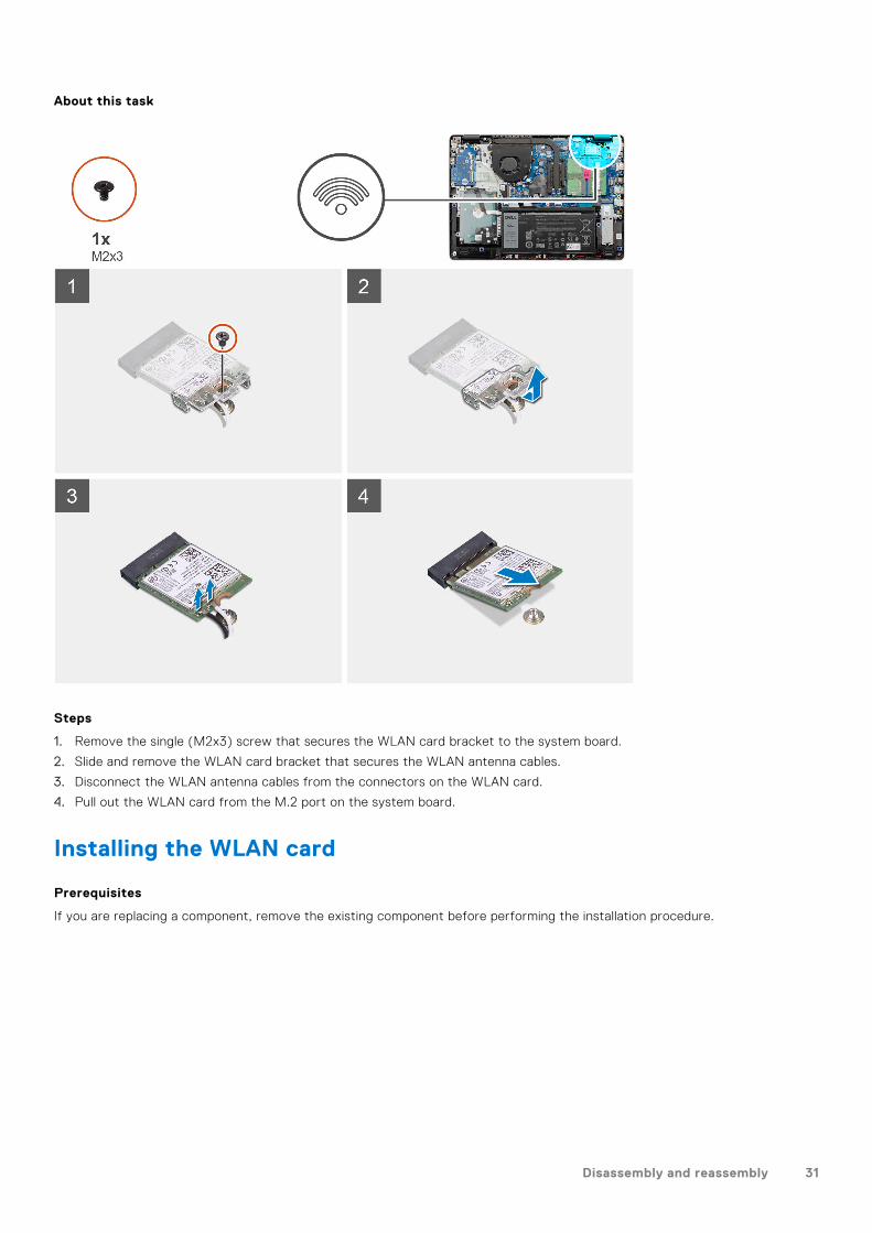
Installing the WLAN card
Prerequisites
If you are replacing a component, remove the existing component before performing the installation procedure.
Disassembly and reassembly 31
About this task
Steps
1. Replace the WLAN card into the M.2 Slot on the system board.
2. Connect the WLAN antenna cables to the connectors on the WLAN card.
3. Place the WLAN card bracket to secure the WLAN antenna cables to the WLAN card.
4. Replace the single (M2x3) screw to secure the WLAN bracket and the WLAN card to the palmrest.
Next steps
1. Connect the battery cable.2. Install the base cover.3. Install the SD card.4. Follow the procedure in after working inside your computer.
Solid-state drive
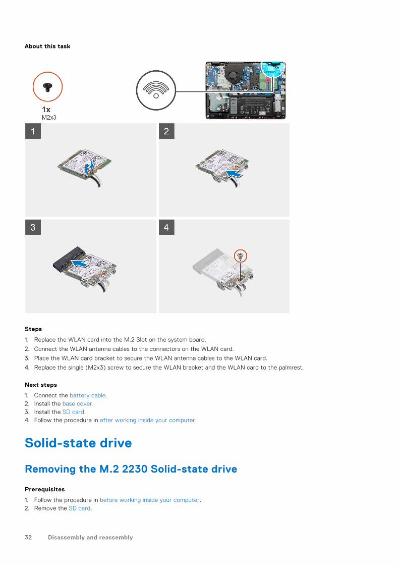
Removing the M.2 2230 Solid-state drive
Prerequisites
1. Follow the procedure in before working inside your computer.2. Remove the SD card.
32 Disassembly and reassembly
3. Remove the base cover.4. Disconnect the battery cable.
About this task
Steps
1. Remove the single (M2x2.2) screw and loosen the single captive screw, securing the SSD thermal plate to the palmrest, tolift it out of the system.
2. Turn the thermal plate over and remove the single (M2x2) screw securing the M.2 2230 SSD to the thermal plate.
3. Lift the solid-state drive off the thermal plate.
Installing the M.2 2230 Solid-state drive
Prerequisites
If you are replacing a component, remove the existing component before performing the installation procedure.
Disassembly and reassembly 33
About this task
Steps
1. Place the solid-state drive into the thermal plate and install the single (M2x2) screw.
2. Slide and insert the tab of the solid-state drive into the solid-state drive slot.
3. Replace the single (M2x2.2) screw and tighten the single captive screw to secures the thermal plate to the palmrest.
Next steps
1. Connect the battery cable.2. Install the base cover.3. Install the SD card.4. Follow the procedure in after working inside your computer.
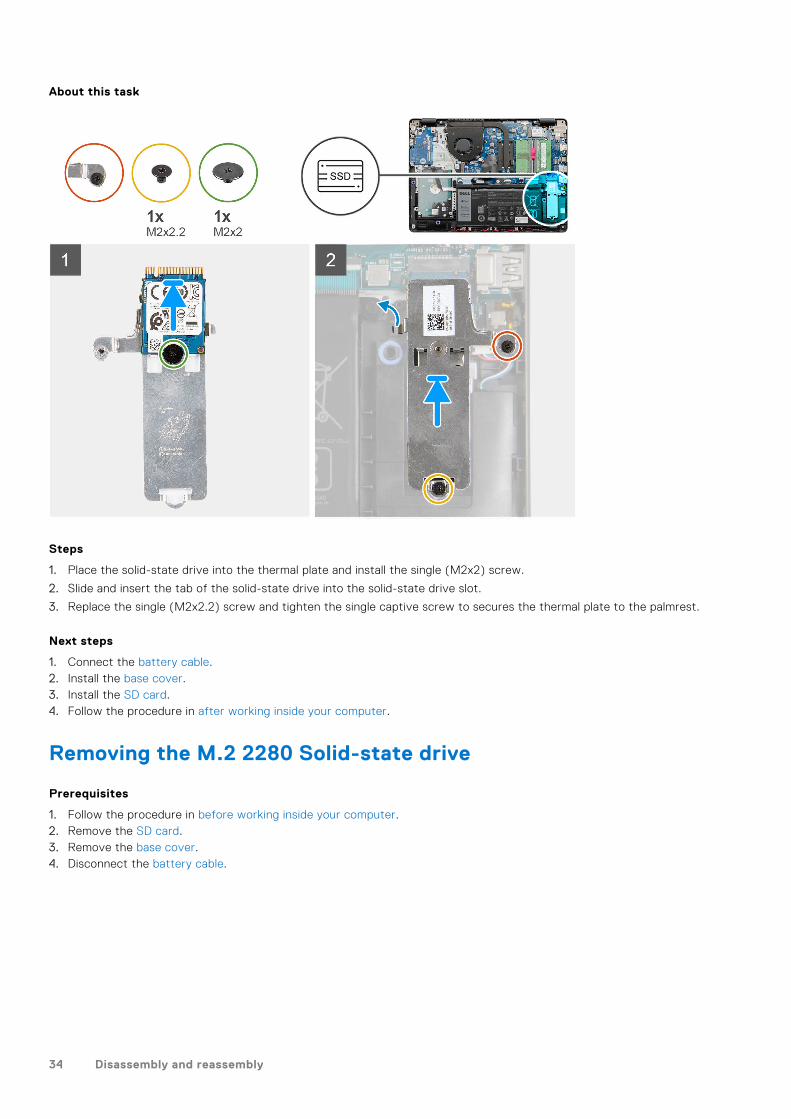
Removing the M.2 2280 Solid-state drive
Prerequisites
1. Follow the procedure in before working inside your computer.2. Remove the SD card.3. Remove the base cover.4. Disconnect the battery cable.
34 Disassembly and reassembly
About this task
Steps
1. Remove the two (M2x2.2) screw from the thermal bracket and lift the bracket out of the system.
2. Lift the solid-state drive from the M.2 slot on the system board and remove it from the system.
Installing the M.2 2280 Solid-state drive
Prerequisites
If you are replacing a component, remove the existing component before performing the installation procedure.
Disassembly and reassembly 35
About this task
Steps
1. Slide and insert the Solid-state drive into the M.2 port on the system board.
2. Place the thermal bracket on the solid-state drive, replace the two (M2x2.2) screws to secure the thermal plate to thepalmrest.
Next steps
1. Connect the battery cable.2. Install the base cover.3. Install the SD card.4. Follow the procedure in after working inside your computer.
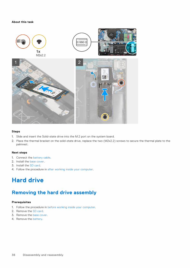
Hard drive
Removing the hard drive assembly
Prerequisites
1. Follow the procedure in before working inside your computer.2. Remove the SD card.3. Remove the base cover.4. Remove the battery.
36 Disassembly and reassembly
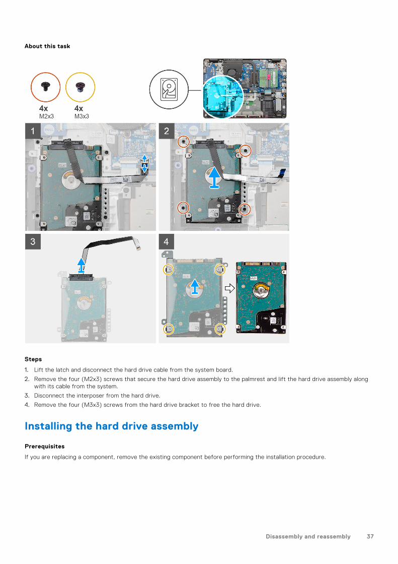
About this task
Steps
1. Lift the latch and disconnect the hard drive cable from the system board.
2. Remove the four (M2x3) screws that secure the hard drive assembly to the palmrest and lift the hard drive assembly alongwith its cable from the system.
3. Disconnect the interposer from the hard drive.
4. Remove the four (M3x3) screws from the hard drive bracket to free the hard drive.
Installing the hard drive assembly
Prerequisites
If you are replacing a component, remove the existing component before performing the installation procedure.
Disassembly and reassembly 37
About this task
Steps
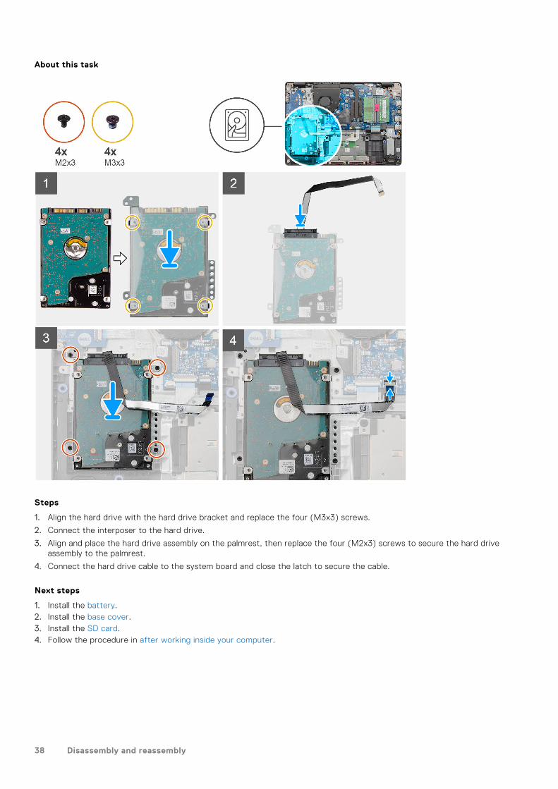
1. Align the hard drive with the hard drive bracket and replace the four (M3x3) screws.
2. Connect the interposer to the hard drive.
3. Align and place the hard drive assembly on the palmrest, then replace the four (M2x3) screws to secure the hard driveassembly to the palmrest.
4. Connect the hard drive cable to the system board and close the latch to secure the cable.
Next steps
1. Install the battery.2. Install the base cover.3. Install the SD card.4. Follow the procedure in after working inside your computer.
38 Disassembly and reassembly
Coin-cell battery
Removing the coin-cell
Prerequisites
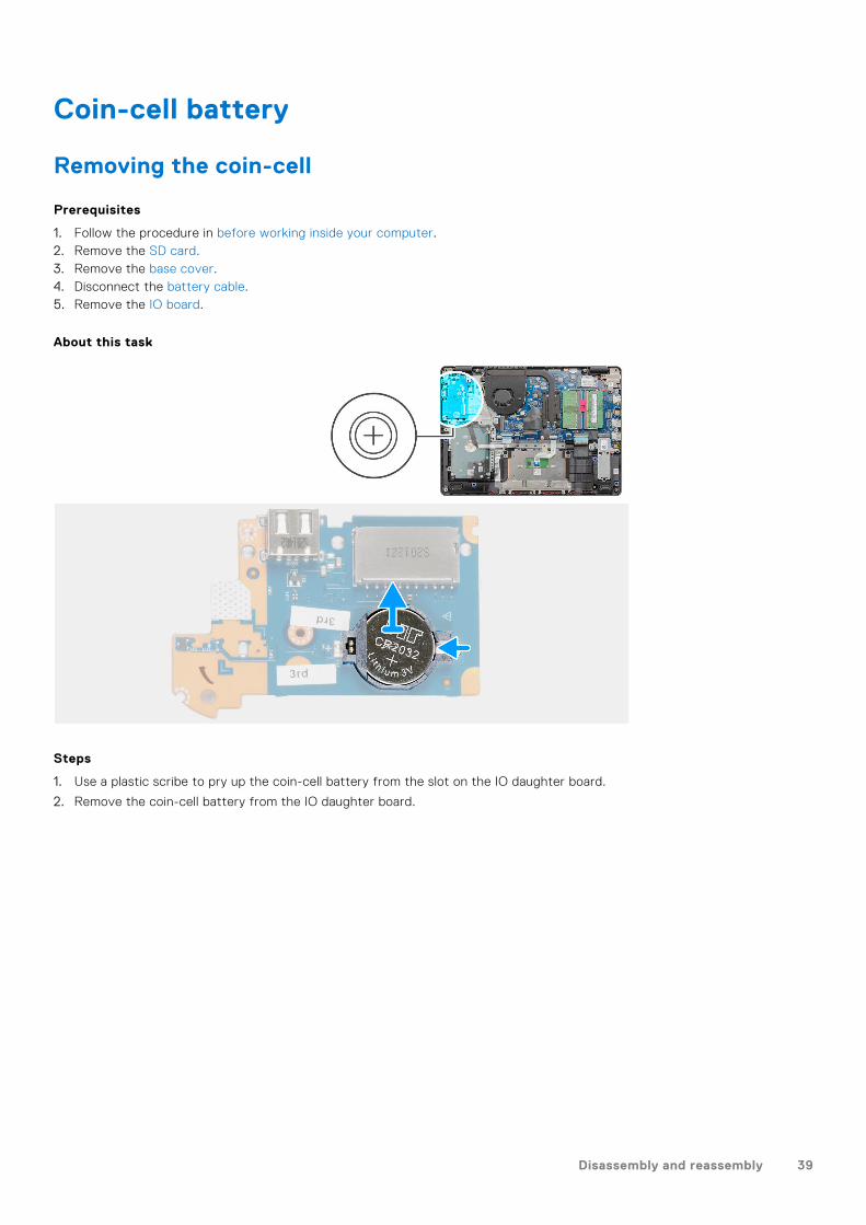
1. Follow the procedure in before working inside your computer.2. Remove the SD card.3. Remove the base cover.4. Disconnect the battery cable.5. Remove the IO board.
About this task
Steps
1. Use a plastic scribe to pry up the coin-cell battery from the slot on the IO daughter board.
2. Remove the coin-cell battery from the IO daughter board.
Disassembly and reassembly 39
Installing the coin-cell battery
About this task
Steps
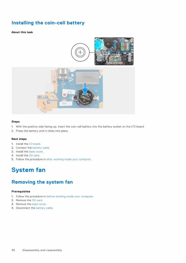
1. With the positive-side facing up, insert the coin-cell battery into the battery socket on the I/O board.
2. Press the battery until it clicks into place.
Next steps
1. Install the IO board.2. Connect the battery cable.3. Install the base cover.4. Install the SD card.5. Follow the procedure in after working inside your computer.
System fan
Removing the system fan
Prerequisites
1. Follow the procedure in before working inside your computer.2. Remove the SD card.3. Remove the base cover.4. Disconnect the battery cable.
40 Disassembly and reassembly
About this task
Steps
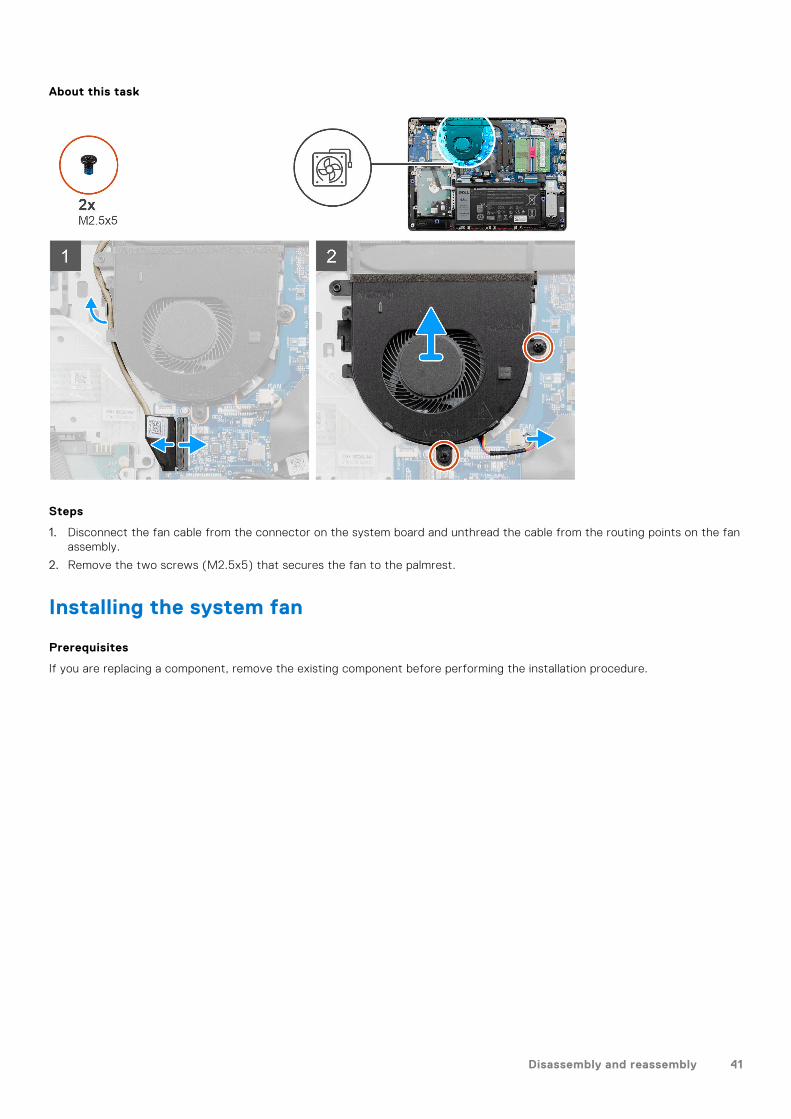
1. Disconnect the fan cable from the connector on the system board and unthread the cable from the routing points on the fanassembly.
2. Remove the two screws (M2.5x5) that secures the fan to the palmrest.
Installing the system fan
Prerequisites
If you are replacing a component, remove the existing component before performing the installation procedure.
Disassembly and reassembly 41
About this task
Steps
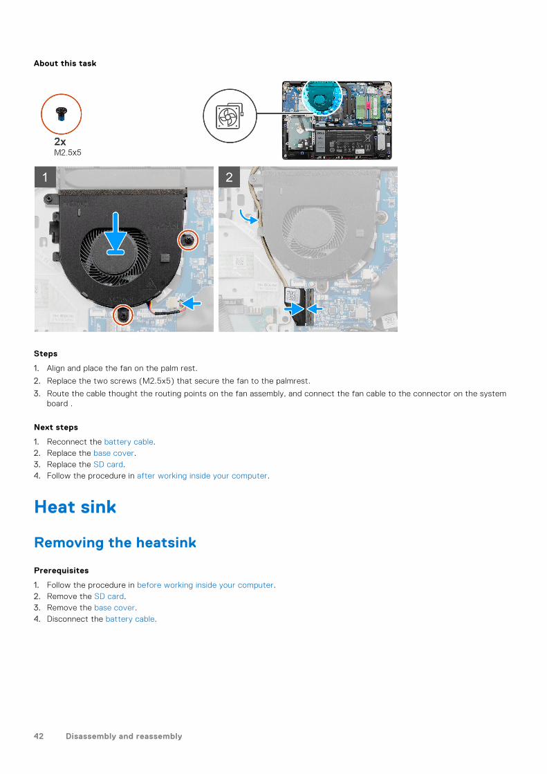
1. Align and place the fan on the palm rest.
2. Replace the two screws (M2.5x5) that secure the fan to the palmrest.
3. Route the cable thought the routing points on the fan assembly, and connect the fan cable to the connector on the systemboard .
Next steps
1. Reconnect the battery cable.2. Replace the base cover.3. Replace the SD card.4. Follow the procedure in after working inside your computer.
Heat sink
Removing the heatsink
Prerequisites
1. Follow the procedure in before working inside your computer.2. Remove the SD card.3. Remove the base cover.4. Disconnect the battery cable.
42 Disassembly and reassembly
About this task
Steps
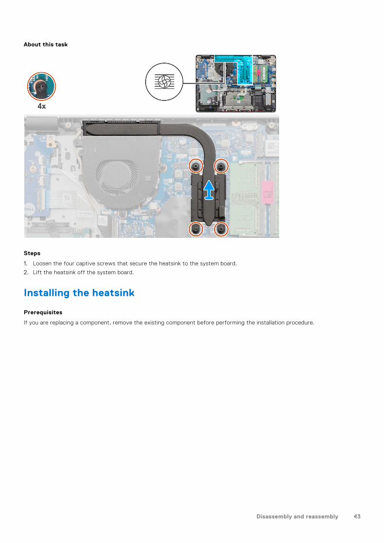
1. Loosen the four captive screws that secure the heatsink to the system board.
2. Lift the heatsink off the system board.
Installing the heatsink
Prerequisites
If you are replacing a component, remove the existing component before performing the installation procedure.
Disassembly and reassembly 43
About this task
Steps
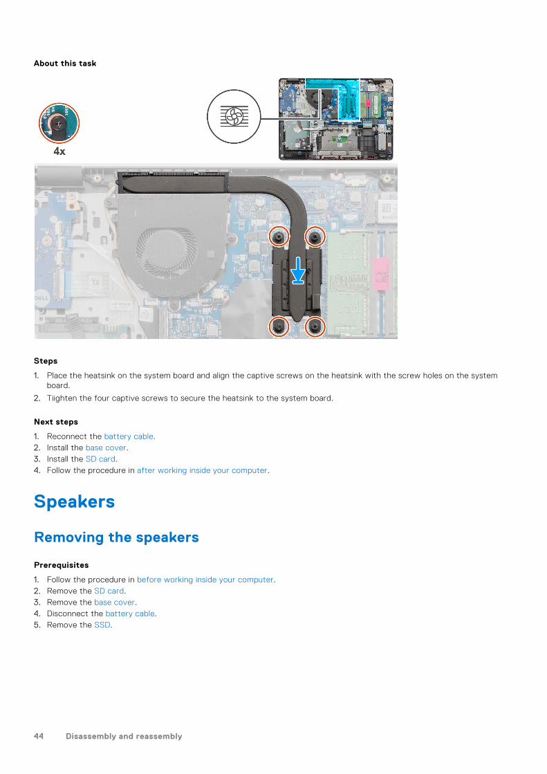
1. Place the heatsink on the system board and align the captive screws on the heatsink with the screw holes on the systemboard.
2. Tiighten the four captive screws to secure the heatsink to the system board.
Next steps
1. Reconnect the battery cable.2. Install the base cover.3. Install the SD card.4. Follow the procedure in after working inside your computer.
Speakers
Removing the speakers
Prerequisites
1. Follow the procedure in before working inside your computer.2. Remove the SD card.3. Remove the base cover.4. Disconnect the battery cable.5. Remove the SSD.
44 Disassembly and reassembly
About this task
Steps
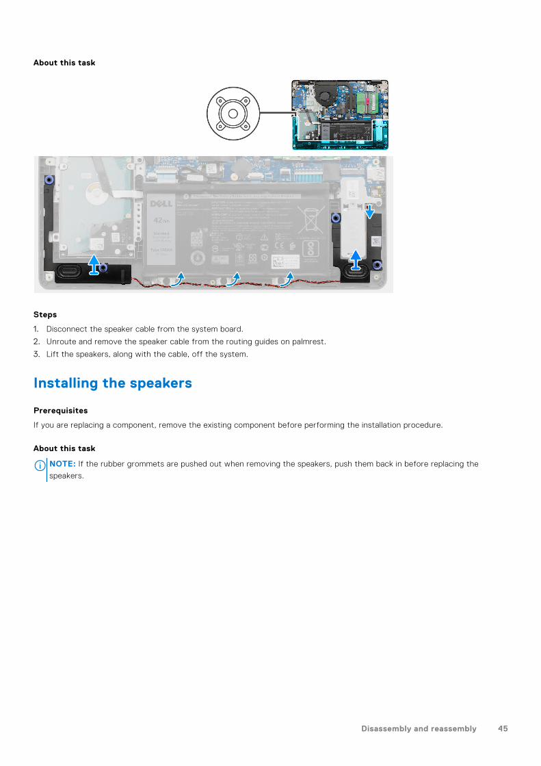
1. Disconnect the speaker cable from the system board.
2. Unroute and remove the speaker cable from the routing guides on palmrest.
3. Lift the speakers, along with the cable, off the system.
Installing the speakers
Prerequisites
If you are replacing a component, remove the existing component before performing the installation procedure.
About this task
NOTE: If the rubber grommets are pushed out when removing the speakers, push them back in before replacing the
speakers.
Disassembly and reassembly 45
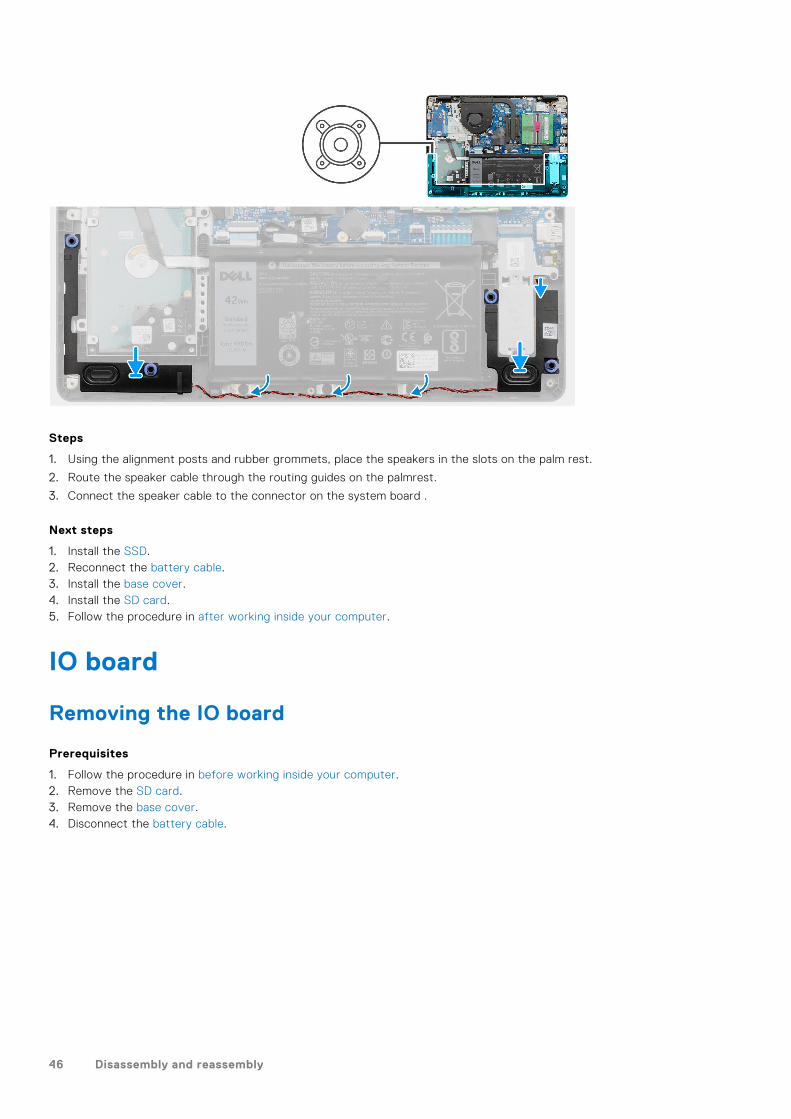
Steps
1. Using the alignment posts and rubber grommets, place the speakers in the slots on the palm rest.
2. Route the speaker cable through the routing guides on the palmrest.
3. Connect the speaker cable to the connector on the system board .
Next steps
1. Install the SSD.2. Reconnect the battery cable.3. Install the base cover.4. Install the SD card.5. Follow the procedure in after working inside your computer.
IO board
Removing the IO board
Prerequisites
1. Follow the procedure in before working inside your computer.2. Remove the SD card.3. Remove the base cover.4. Disconnect the battery cable.
46 Disassembly and reassembly
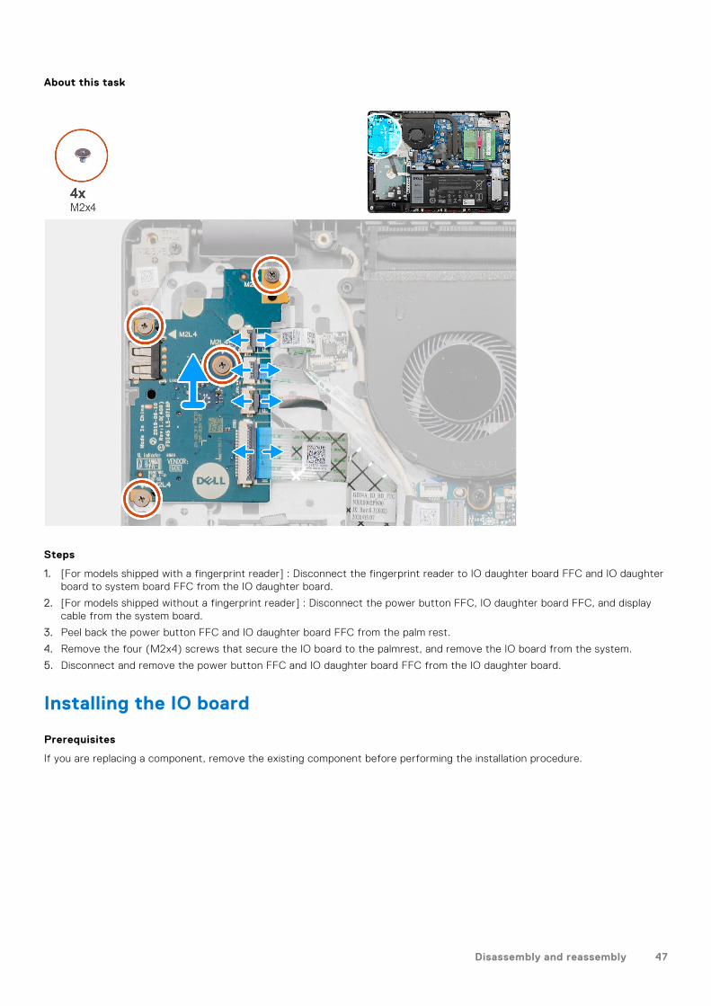
About this task
Steps
1. [For models shipped with a fingerprint reader] : Disconnect the fingerprint reader to IO daughter board FFC and IO daughterboard to system board FFC from the IO daughter board.
2. [For models shipped without a fingerprint reader] : Disconnect the power button FFC, IO daughter board FFC, and displaycable from the system board.
3. Peel back the power button FFC and IO daughter board FFC from the palm rest.
4. Remove the four (M2x4) screws that secure the IO board to the palmrest, and remove the IO board from the system.
5. Disconnect and remove the power button FFC and IO daughter board FFC from the IO daughter board.
Installing the IO board
Prerequisites
If you are replacing a component, remove the existing component before performing the installation procedure.
Disassembly and reassembly 47
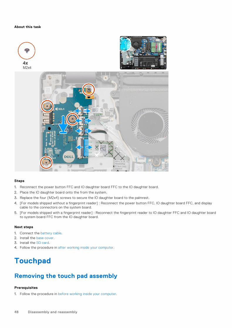
About this task
Steps
1. Reconnect the power button FFC and IO daughter board FFC to the IO daughter board.
2. Place the IO daughter board onto the from the system.
3. Replace the four (M2x4) screws to secure the IO daughter board to the palmrest.
4. [For models shipped without a fingerprint reader] : Reconnect the power button FFC, IO daughter board FFC, and displaycable to the connectors on the system board.
5. [For models shipped with a fingerprint reader] : Reconnect the fingerprint reader to IO daughter FFC and IO daughter boardto system board FFC from the IO daughter board.
Next steps
1. Connect the battery cable.2. Install the base cover.3. Install the SD card.4. Follow the procedure in after working inside your computer.
Touchpad
Removing the touch pad assembly
Prerequisites
1. Follow the procedure in before working inside your computer.
48 Disassembly and reassembly
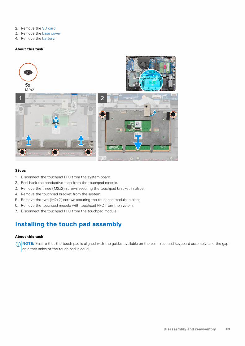
2. Remove the SD card.3. Remove the base cover.4. Remove the battery.
About this task
Steps
1. Disconnect the touchpad FFC from the system board.
2. Peel back the conductive tape from the touchpad module.
3. Remove the three (M2x2) screws securing the touchpad bracket in place.
4. Remove the touchpad bracket from the system.
5. Remove the two (M2x2) screws securing the touchpad module in place.
6. Remove the touchpad module with touchpad FFC from the system.
7. Disconnect the touchpad FFC from the touchpad module.
Installing the touch pad assembly
About this task
NOTE: Ensure that the touch pad is aligned with the guides available on the palm-rest and keyboard assembly, and the gap
on either sides of the touch pad is equal.
Disassembly and reassembly 49
Steps
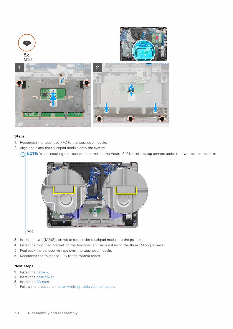
1. Reconnect the touchpad FFC to the touchpad module.
2. Align and place the touchpad module onto the system.
NOTE: When installing the touchpad bracket on the Vostro 3401, insert its top corners under the two tabs on the palm
rest.
3. Install the two (M2x2) screws to secure the touchpad module to the palmrest.
4. Install the touchpad bracket on the touchpad and secure it using the three (M2x2) screws.
5. Peel back the conductive tape over the touchpad module.
6. Reconnect the touchpad FFC to the system board.
Next steps
1. Install the battery.2. Install the base cover.3. Install the SD card.4. Follow the procedure in after working inside your computer.
50 Disassembly and reassembly
Display assembly
Removing the display assembly
Prerequisites
1. Follow the procedure in before working inside your computer.2. Remove the SD card.3. Remove the base cover.4. Disconnect the battery cable.5. Remove the WLAN.
About this task
Disassembly and reassembly 51
Steps
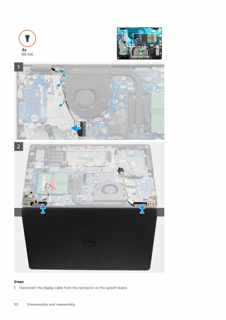
1. Disconnect the display cable from the connector on the system board.
52 Disassembly and reassembly
2. Unthread the display cable and WLAN antenna cables from the routing channels.
3. Open the system to at least 90-degrees and place the system on the edge of a table so that the palm rest is laying flat onthe table and the display assembly is over the edge.
4. Remove the four (M2.5x5) screws securing the display assembly in place.
5. Remove the display assembly from the system.
Installing the display assembly
Prerequisites
If you are replacing a component, remove the existing component before performing the installation procedure.
About this task
NOTE: Ensure that the hinges are opened to the maximum before replacing the display assembly on the palmrest and
keyboard assembly.
Disassembly and reassembly 53
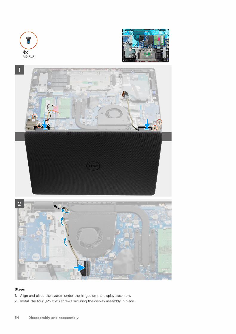
Steps
1. Align and place the system under the hinges on the display assembly.
2. Install the four (M2.5x5) screws securing the display assembly in place.
54 Disassembly and reassembly
3. Re-route the display cable and WLAN antenna cables through the routing channels on the palmrest.
4. Reconnect the display cable to the connector on the system board.
Next steps
1. Install the WLAN.2. Install the base cover.3. Install the SD card.4. Follow the procedure in after working inside your computer.
Display bezel
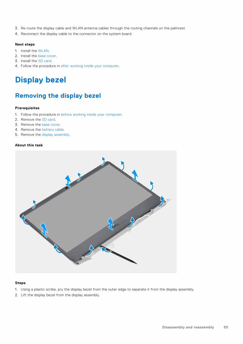
Removing the display bezel
Prerequisites
1. Follow the procedure in before working inside your computer.2. Remove the SD card.3. Remove the base cover.4. Remove the battery cable.5. Remove the display assembly.
About this task
Steps
1. Using a plastic scribe, pry the display bezel from the outer edge to separate it from the display assembly.
2. Lift the display bezel from the display assembly.
Disassembly and reassembly 55
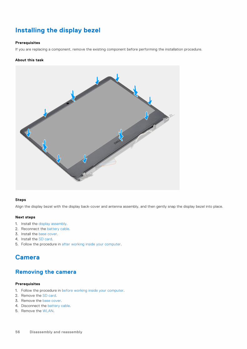
Installing the display bezel
Prerequisites
If you are replacing a component, remove the existing component before performing the installation procedure.
About this task
Steps
Align the display bezel with the display back-cover and antenna assembly, and then gently snap the display bezel into place.
Next steps
1. Install the display assembly.2. Reconnect the battery cable.3. Install the base cover.4. Install the SD card.5. Follow the procedure in after working inside your computer.
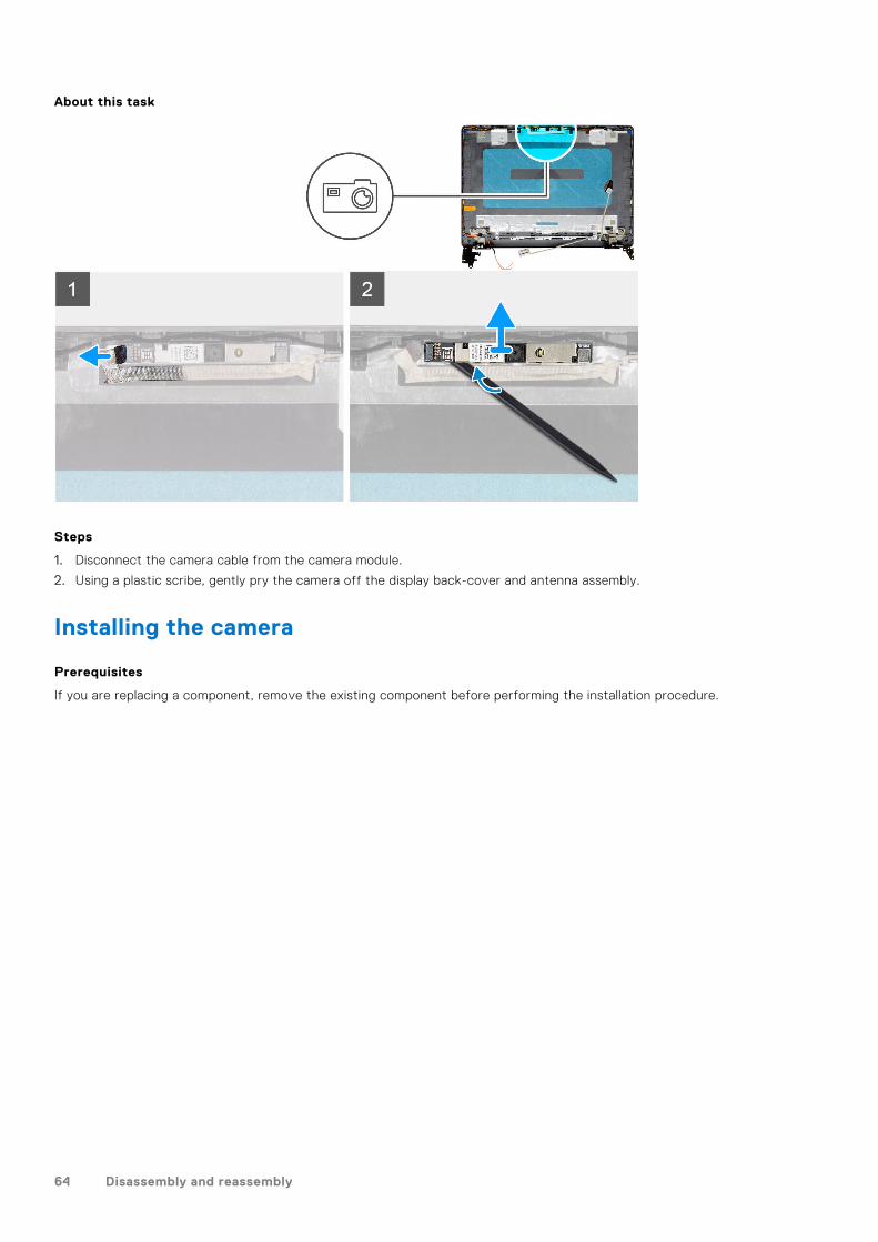
Camera
Removing the camera
Prerequisites
1. Follow the procedure in before working inside your computer.2. Remove the SD card.3. Remove the base cover.4. Disconnect the battery cable.5. Remove the WLAN.
56 Disassembly and reassembly
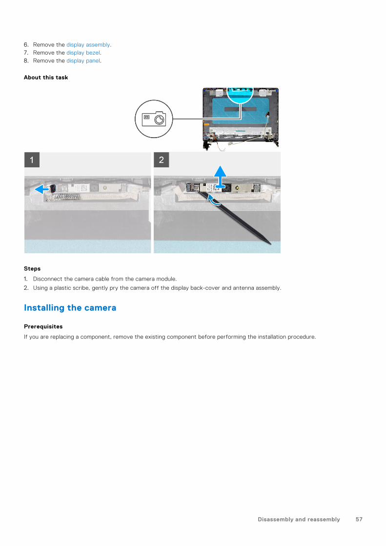
6. Remove the display assembly.7. Remove the display bezel.8. Remove the display panel.
About this task
Steps
1. Disconnect the camera cable from the camera module.
2. Using a plastic scribe, gently pry the camera off the display back-cover and antenna assembly.
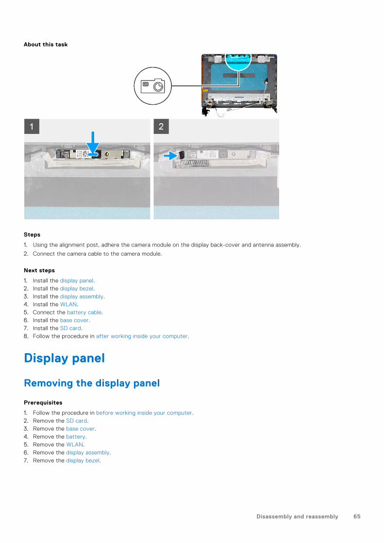
Installing the camera
Prerequisites
If you are replacing a component, remove the existing component before performing the installation procedure.
Disassembly and reassembly 57
About this task
Steps
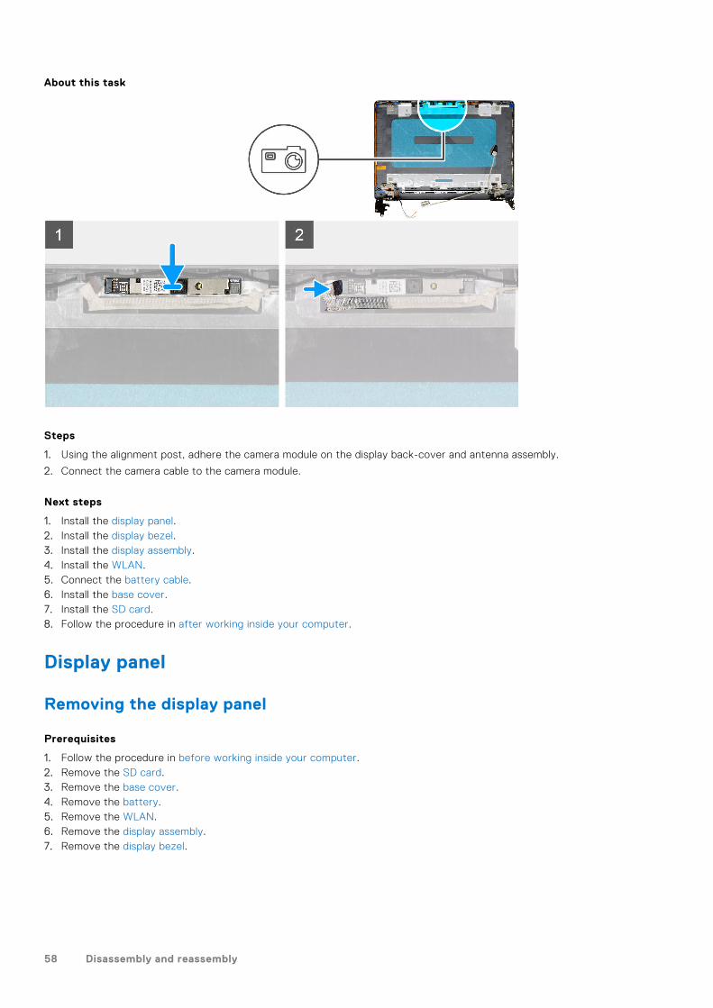
1. Using the alignment post, adhere the camera module on the display back-cover and antenna assembly.
2. Connect the camera cable to the camera module.
Next steps
1. Install the display panel.2. Install the display bezel.3. Install the display assembly.4. Install the WLAN.5. Connect the battery cable.6. Install the base cover.7. Install the SD card.8. Follow the procedure in after working inside your computer.
Display panel
Removing the display panel
Prerequisites
1. Follow the procedure in before working inside your computer.2. Remove the SD card.3. Remove the base cover.4. Remove the battery.5. Remove the WLAN.6. Remove the display assembly.7. Remove the display bezel.
58 Disassembly and reassembly
About this task
Disassembly and reassembly 59
Steps
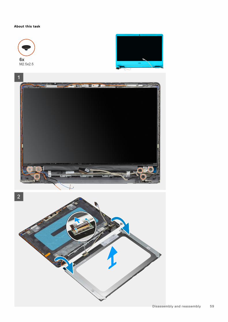
1. Remove the six (M2.5x2.5) screws securing the display panel to the hinges.
2. Gently flip the display panel assembly forward, peel back the mylar tape securing the display cable on the rear of the displaypanel.
NOTE: Ensure the panel has a clean and smooth surface to rest on to prevent damage.
3. Disconnect the display cable from the display panel assembly and lift the display panel away from the system.
NOTE: Do not remove the metal brackets from the panel.
Installation display panel
Prerequisites
If you are replacing a component, remove the existing component before performing the installation procedure.
60 Disassembly and reassembly

About this task
Disassembly and reassembly 61
Steps
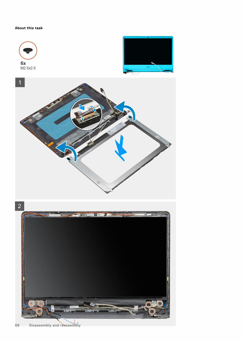
1. Place the display panel on a flat and clean surface .
2. Connect the display cable to the connector at the back of the display panel and close the latch to secure the cable .
3. Adhere the tape that secures the display cable to the back of the display panel .
4. Turn the display panel over and place it on the display back-cover .
5. Replace the six (M2.5x2.5) screws that secure the display panel to the display back-cover.
Next steps
1. Install the display panel.2. Install the display bezel.3. Install the display assembly.4. Install the WLAN.5. Install the battery.6. Install the base cover.7. Install the SD card.8. Follow the procedure in after working inside your computer.
Display back-cover and antenna assembly
Removing the display back-cover
Prerequisites
1. Follow the procedure in before working inside your computer.2. Remove the SD card.3. Remove the base cover.4. Disconnect the battery cable.5. Remove the WLAN.6. Remove the display assembly.7. Remove the display bezel.8. Remove the display panel.
About this task
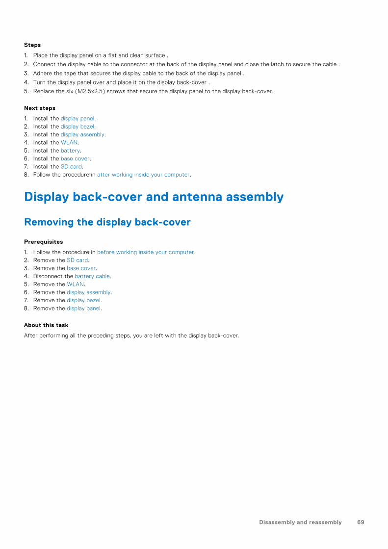
After performing all the preceding steps, you are left with the display back-cover.
62 Disassembly and reassembly
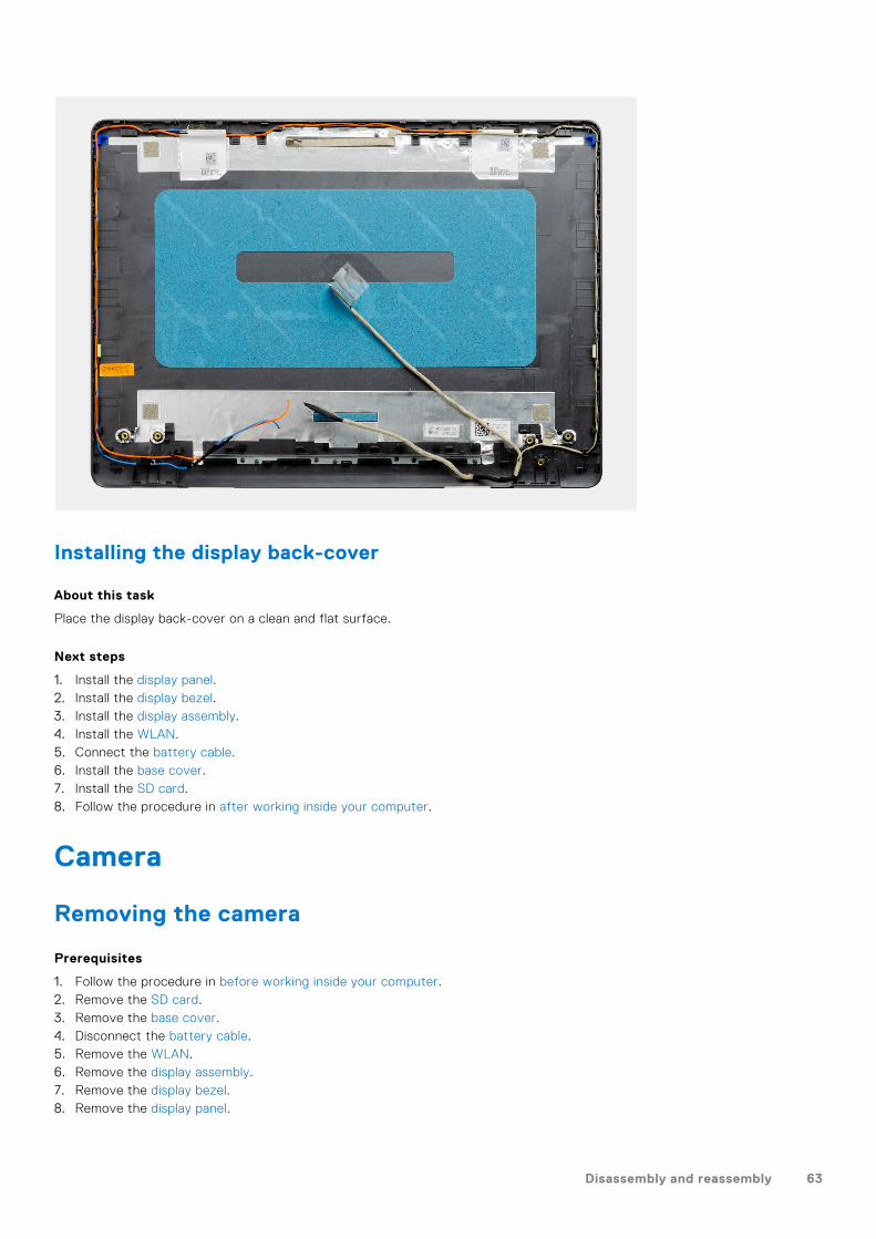
Installing the display back-cover
About this task
Place the display back-cover on a clean and flat surface.
Next steps
1. Install the display panel.2. Install the display bezel.3. Install the display assembly.4. Install the WLAN.5. Connect the battery cable.6. Install the base cover.7. Install the SD card.8. Follow the procedure in after working inside your computer.
Camera
Removing the camera
Prerequisites
1. Follow the procedure in before working inside your computer.2. Remove the SD card.3. Remove the base cover.4. Disconnect the battery cable.5. Remove the WLAN.6. Remove the display assembly.7. Remove the display bezel.8. Remove the display panel.
Disassembly and reassembly 63
About this task
Steps
1. Disconnect the camera cable from the camera module.
2. Using a plastic scribe, gently pry the camera off the display back-cover and antenna assembly.
Installing the camera
Prerequisites
If you are replacing a component, remove the existing component before performing the installation procedure.
64 Disassembly and reassembly
About this task
Steps
1. Using the alignment post, adhere the camera module on the display back-cover and antenna assembly.
2. Connect the camera cable to the camera module.
Next steps
1. Install the display panel.2. Install the display bezel.3. Install the display assembly.4. Install the WLAN.5. Connect the battery cable.6. Install the base cover.7. Install the SD card.8. Follow the procedure in after working inside your computer.
Display panel
Removing the display panel
Prerequisites
1. Follow the procedure in before working inside your computer.2. Remove the SD card.3. Remove the base cover.4. Remove the battery.5. Remove the WLAN.6. Remove the display assembly.7. Remove the display bezel.
Disassembly and reassembly 65

About this task
66 Disassembly and reassembly
Steps
1. Remove the six (M2.5x2.5) screws securing the display panel to the hinges.
2. Gently flip the display panel assembly forward, peel back the mylar tape securing the display cable on the rear of the displaypanel.
NOTE: Ensure the panel has a clean and smooth surface to rest on to prevent damage.
3. Disconnect the display cable from the display panel assembly and lift the display panel away from the system.
NOTE: Do not remove the metal brackets from the panel.
Installation display panel
Prerequisites
If you are replacing a component, remove the existing component before performing the installation procedure.
Disassembly and reassembly 67
About this task
68 Disassembly and reassembly
Steps
1. Place the display panel on a flat and clean surface .
2. Connect the display cable to the connector at the back of the display panel and close the latch to secure the cable .
3. Adhere the tape that secures the display cable to the back of the display panel .
4. Turn the display panel over and place it on the display back-cover .
5. Replace the six (M2.5x2.5) screws that secure the display panel to the display back-cover.
Next steps
1. Install the display panel.2. Install the display bezel.3. Install the display assembly.4. Install the WLAN.5. Install the battery.6. Install the base cover.7. Install the SD card.8. Follow the procedure in after working inside your computer.
Display back-cover and antenna assembly
Removing the display back-cover
Prerequisites
1. Follow the procedure in before working inside your computer.2. Remove the SD card.3. Remove the base cover.4. Disconnect the battery cable.5. Remove the WLAN.6. Remove the display assembly.7. Remove the display bezel.8. Remove the display panel.
About this task
After performing all the preceding steps, you are left with the display back-cover.
Disassembly and reassembly 69
Installing the display back-cover
About this task
Place the display back-cover on a clean and flat surface.
Next steps
1. Install the display panel.2. Install the display bezel.3. Install the display assembly.4. Install the WLAN.5. Connect the battery cable.6. Install the base cover.7. Install the SD card.8. Follow the procedure in after working inside your computer.
Power button
Removing the power button
Prerequisites
1. Follow the procedure in before working inside your computer.2. Remove the SD card.3. Remove the base cover.4. Disconnect the battery cable.5. Remove the IO board.
70 Disassembly and reassembly
About this task
Steps
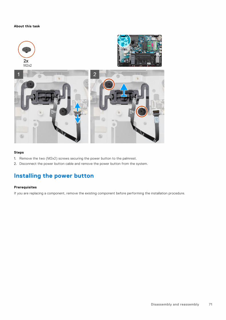
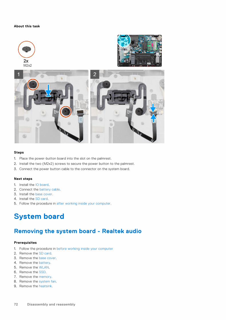
1. Remove the two (M2x2) screws securing the power button to the palmrest.
2. Disconnect the power button cable and remove the power button from the system.
Installing the power button
Prerequisites
If you are replacing a component, remove the existing component before performing the installation procedure.
Disassembly and reassembly 71
About this task
Steps
1. Place the power-button board into the slot on the palmrest.
2. Install the two (M2x2) screws to secure the power button to the palmrest.
3. Connect the power button cable to the connector on the system board.
Next steps
1. Install the IO board.2. Connect the battery cable.3. Install the base cover.4. Install the SD card.5. Follow the procedure in after working inside your computer.
System board
Removing the system board - Realtek audio
Prerequisites
1. Follow the procedure in before working inside your computer2. Remove the SD card.3. Remove the base cover.4. Remove the battery.5. Remove the WLAN.6. Remove the SSD.7. Remove the memory.8. Remove the system fan.9. Remove the heatsink.
72 Disassembly and reassembly

NOTE: The system board can be removed along with the heat sink.
10. Remove the display assembly.
About this task
Disassembly and reassembly 73
74 Disassembly and reassembly

Steps
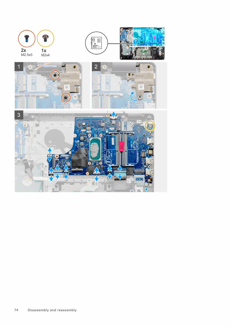
1. Remove the two (M2.5x5) screws from the right hinge, Fold the right hinge up.
2. Disconnect the following cables from the system board:
a. Speaker cableb. Keyboard FFCc. Power adapter port cabled. Keyboard backlight FFCe. Touchpad FFCf. Hard drive FFCg. IO board FFCh. Fingerprint reader FFCi. Power button FFC from the system board
3. Remove the single (M2x4) screw that secures the system board to the palmrest.
4. Carefully lift the system board away from the chassis.
Installing the system board - Realtek audio
Prerequisites
If you are replacing a component, remove the existing component before performing the installation procedure.
Disassembly and reassembly 75
About this task
76 Disassembly and reassembly
Steps
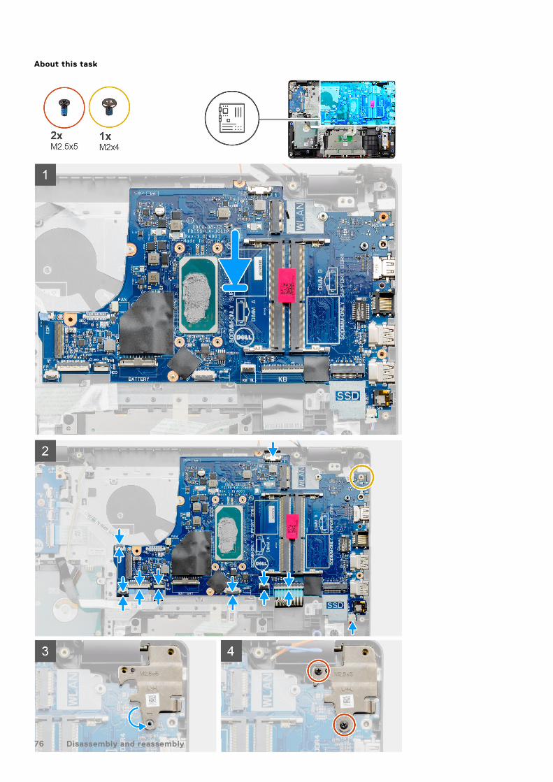
1. Align and place the system board on the palmrest.
2. Replace the single (M2x4) screw that secures the system board to the palmrest.
3. Connect the following cables to the system board:
a. Speaker cableb. Keyboard FFCc. Keyboard backlight FFCd. Touchpad FFCe. Hard drive FFCf. IO board FFCg. Power adapter port cableh. Fingerprint reader FFCi. Power button FFC from the system board
4. Fold back the right hinge and install the two (M2.5x5) screws to secure it to the palmrest.
Next steps
1. Install the display assembly.2. Install the heatsink.3. Install the system fan.4. Install the memory.5. Install the SSD.6. Install the WLAN.7. Install the battery.8. Install the base cover.9. Install the SD card.10. Follow the procedure in after working inside your computer.
Removing the system board - Cirrus Logic audio
Prerequisites
1. Follow the procedure in before working inside your computer2. Remove the SD card.3. Remove the base cover.4. Remove the battery.5. Remove the WLAN.6. Remove the SSD.7. Remove the memory.8. Remove the system fan.9. Remove the heatsink.
NOTE: The system board can be removed along with the heat sink.
10. Remove the display assembly.
Disassembly and reassembly 77
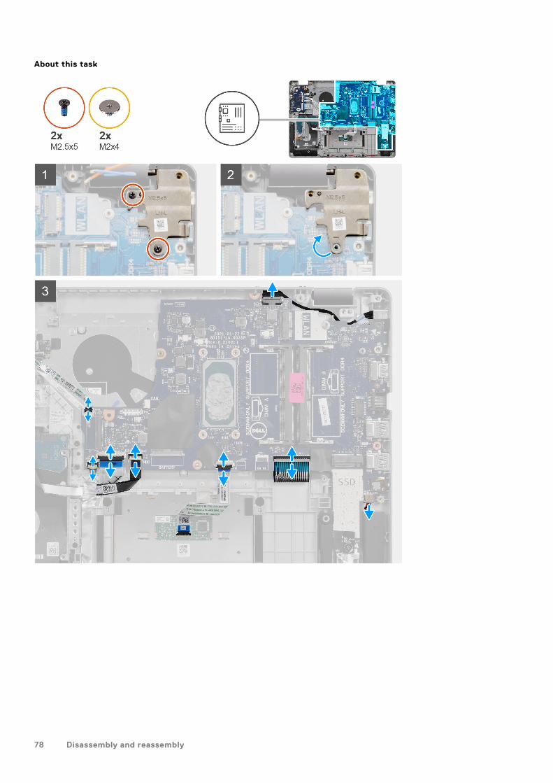
About this task
78 Disassembly and reassembly
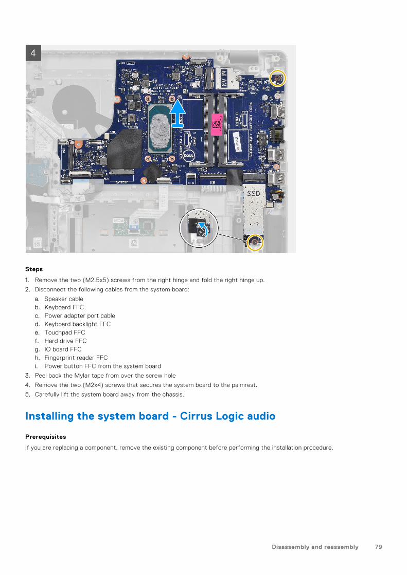
Steps
1. Remove the two (M2.5x5) screws from the right hinge and fold the right hinge up.
2. Disconnect the following cables from the system board:
a. Speaker cableb. Keyboard FFCc. Power adapter port cabled. Keyboard backlight FFCe. Touchpad FFCf. Hard drive FFCg. IO board FFCh. Fingerprint reader FFCi. Power button FFC from the system board
3. Peel back the Mylar tape from over the screw hole
4. Remove the two (M2x4) screws that secures the system board to the palmrest.
5. Carefully lift the system board away from the chassis.
Installing the system board - Cirrus Logic audio
Prerequisites
If you are replacing a component, remove the existing component before performing the installation procedure.
Disassembly and reassembly 79
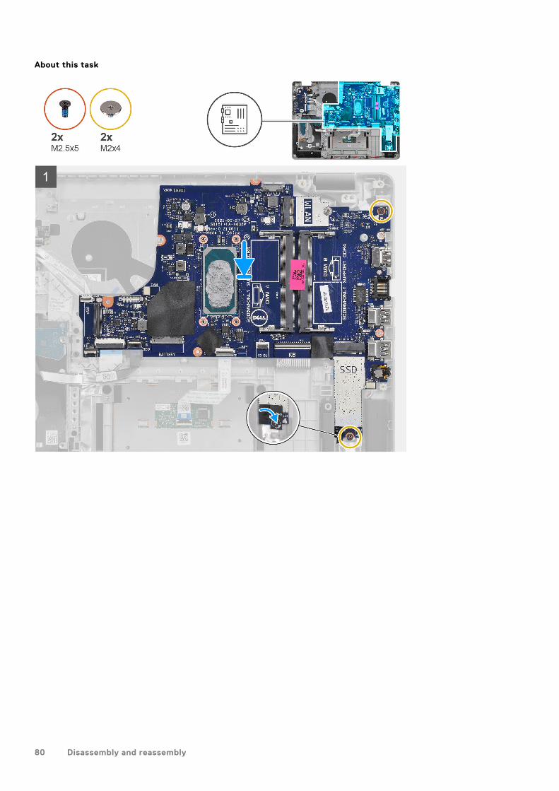
About this task
80 Disassembly and reassembly
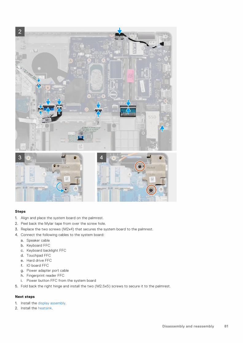
Steps
1. Align and place the system board on the palmrest.
2. Peel back the Mylar tape from over the screw hole.
3. Replace the two screws (M2x4) that secures the system board to the palmrest.
4. Connect the following cables to the system board:
a. Speaker cableb. Keyboard FFCc. Keyboard backlight FFCd. Touchpad FFCe. Hard drive FFCf. IO board FFCg. Power adapter port cableh. Fingerprint reader FFCi. Power button FFC from the system board
5. Fold back the right hinge and install the two (M2.5x5) screws to secure it to the palmrest.
Next steps
1. Install the display assembly.2. Install the heatsink.
Disassembly and reassembly 81
3. Install the system fan.4. Install the memory.5. Install the SSD.6. Install the WLAN.7. Install the battery.8. Install the base cover.9. Install the SD card.10. Follow the procedure in after working inside your computer.
Power-adapter port
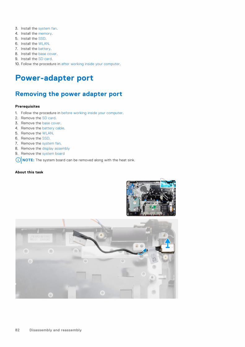
Removing the power adapter port
Prerequisites
1. Follow the procedure in before working inside your computer.2. Remove the SD card.3. Remove the base cover.4. Remove the battery cable.5. Remove the WLAN.6. Remove the SSD.7. Remove the system fan.8. Remove the display assembly9. Remove the system board
NOTE: The system board can be removed along with the heat sink.
About this task
82 Disassembly and reassembly
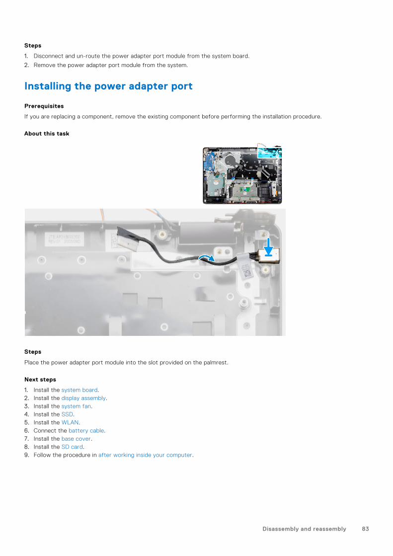
Steps
1. Disconnect and un-route the power adapter port module from the system board.
2. Remove the power adapter port module from the system.
Installing the power adapter port
Prerequisites
If you are replacing a component, remove the existing component before performing the installation procedure.
About this task
Steps
Place the power adapter port module into the slot provided on the palmrest.
Next steps
1. Install the system board.2. Install the display assembly.3. Install the system fan.4. Install the SSD.5. Install the WLAN.6. Connect the battery cable.7. Install the base cover.8. Install the SD card.9. Follow the procedure in after working inside your computer.
Disassembly and reassembly 83
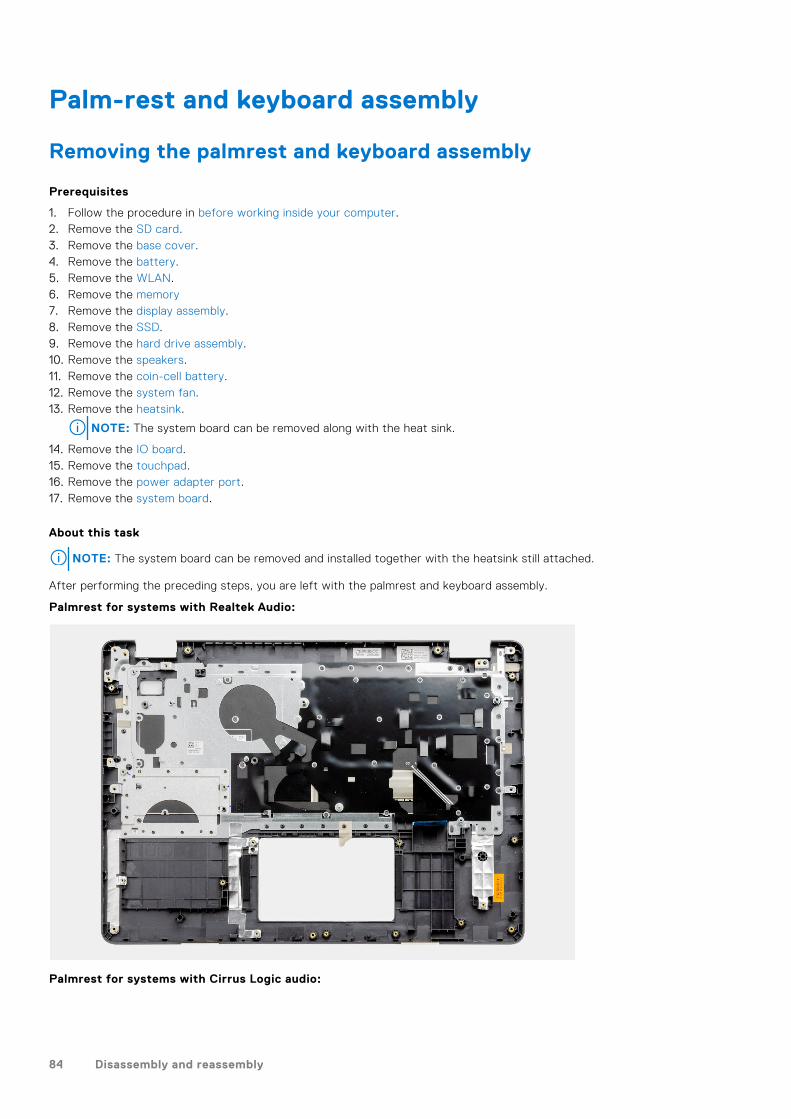
Palm-rest and keyboard assembly
Removing the palmrest and keyboard assembly
Prerequisites
1. Follow the procedure in before working inside your computer.2. Remove the SD card.3. Remove the base cover.4. Remove the battery.5. Remove the WLAN.6. Remove the memory7. Remove the display assembly.8. Remove the SSD.9. Remove the hard drive assembly.10. Remove the speakers.11. Remove the coin-cell battery.12. Remove the system fan.13. Remove the heatsink.
NOTE: The system board can be removed along with the heat sink.
14. Remove the IO board.15. Remove the touchpad.16. Remove the power adapter port.17. Remove the system board.
About this task
NOTE: The system board can be removed and installed together with the heatsink still attached.
After performing the preceding steps, you are left with the palmrest and keyboard assembly.
Palmrest for systems with Realtek Audio:
Palmrest for systems with Cirrus Logic audio:
84 Disassembly and reassembly
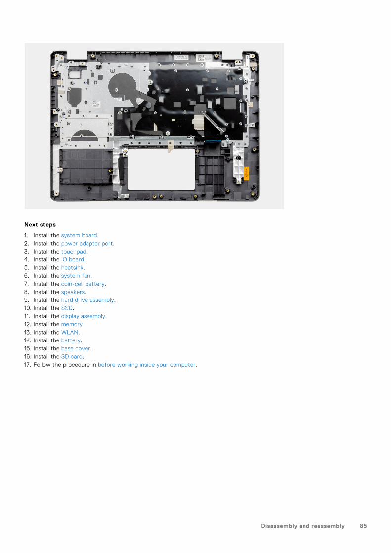
Next steps
1. Install the system board.2. Install the power adapter port.3. Install the touchpad.4. Install the IO board.5. Install the heatsink.6. Install the system fan.7. Install the coin-cell battery.8. Install the speakers.9. Install the hard drive assembly.10. Install the SSD.11. Install the display assembly.12. Install the memory13. Install the WLAN.14. Install the battery.15. Install the base cover.16. Install the SD card.17. Follow the procedure in before working inside your computer.
Disassembly and reassembly 85
Troubleshooting
Topics:
• Handling swollen Lithium-ion batteries• Dell SupportAssist Pre-boot System Performance Check diagnostics• Enhanced Pre-Boot System Assessment (ePSA) diagnostics• System diagnostic lights• Real-Time Clock (RTC Reset)• Updating the BIOS in Windows• Updating the BIOS using the USB drive in Windows• Backup media and recovery options• WiFi power cycle• Drain residual flea power (perform hard reset)
Handling swollen Lithium-ion batteriesLike most laptops, Dell laptops use lithium-ion batteries. One type of lithium-ion battery is the lithium-ion polymer battery.Lithium-ion polymer batteries have increased in popularity in recent years and have become standard in the electronics industrydue to customer preferences for a slim form factor (especially with newer ultra-thin laptops) and long battery life. Inherent tolithium-ion polymer battery technology is the potential for swelling of the battery cells.
Swollen battery may impact the performance of the laptop. To prevent possible further damage to the device enclosure orinternal components leading to malfunction, discontinue the use of the laptop and discharge it by disconnecting the AC adapterand letting the battery drain.
Swollen batteries should not be used and should be replaced and disposed of properly. We recommend contacting Dell productsupport for options to replace a swollen battery under the terms of the applicable warranty or service contract, including optionsfor replacement by a Dell authorized service technician.
The guidelines for handling and replacing Lithium-ion batteries are as follows:● Exercise caution when handling Lithium-ion batteries.● Discharge the battery before removing it from the system. To discharge the battery, unplug the AC adapter from the system
and operate the system only on battery power. When the system will no longer power on when the power button is pressed,the battery is fully discharged.
● Do not crush, drop, mutilate, or penetrate the battery with foreign objects.● Do not expose the battery to high temperatures, or disassemble battery packs and cells.● Do not apply pressure to the surface of the battery.● Do not bend the battery.● Do not use tools of any type to pry on or against the battery.● If a battery gets stuck in a device as a result of swelling, do not try to free it as puncturing, bending, or crushing a battery
can be dangerous.● Do not attempt to reassemble a damaged or swollen battery into a laptop.● Swollen batteries that are covered under warranty should be returned to Dell in an approved shipping container (provided
by Dell)—this is to comply with transportation regulations. Swollen batteries that are not covered under warranty should bedisposed of at an approved recycling center. Contact Dell product support at https://www.dell.com/support for assistanceand further instructions.
● Using a non-Dell or incompatible battery may increase the risk of fire or explosion. Replace the battery only with acompatible battery purchased from Dell that is designed to work with your Dell computer. Do not use a battery from othercomputers with your computer. Always purchase genuine batteries from https://www.dell.com or otherwise directly fromDell.
Lithium-ion batteries can swell for various reasons such as age, number of charge cycles, or exposure to high heat. For moreinformation on how to improve the performance and lifespan of the laptop battery and to minimize the possibility of occurrenceof the issue, see Dell Laptop Battery - Frequently Asked Questions.
5
86 Troubleshooting

Dell SupportAssist Pre-boot System PerformanceCheck diagnostics
About this task
SupportAssist diagnostics (also known as system diagnostics) performs a complete check of your hardware. The DellSupportAssist Pre-boot System Performance Check diagnostics is embedded with the BIOS and is launched by the BIOSinternally. The embedded system diagnostics provides a set of options for particular devices or device groups allowing you to:● Run tests automatically or in an interactive mode● Repeat tests● Display or save test results● Run thorough tests to introduce additional test options to provide extra information about the failed device(s)● View status messages that inform you if tests are completed successfully● View error messages that inform you of problems encountered during testing
NOTE: Some tests for specific devices require user interaction. Always ensure that you are present at the computer
terminal when the diagnostic tests are performed.
For more information, see https://www.dell.com/support/kbdoc/000180971.
Running the SupportAssist Pre-Boot System Performance Check
Steps
1. Turn on your computer.
2. As the computer boots, press the F12 key as the Dell logo appears.
3. On the boot menu screen, select the Diagnostics option.
4. Click the arrow at the bottom left corner.Diagnostics front page is displayed.
5. Click the arrow in the lower-right corner to go to the page listing.The items detected are listed.
6. To run a diagnostic test on a specific device, press Esc and click Yes to stop the diagnostic test.
7. Select the device from the left pane and click Run Tests.
8. If there are any issues, error codes are displayed.Note the error code and validation number and contact Dell.
Enhanced Pre-Boot System Assessment (ePSA)diagnostics
About this task
The SupportAssist diagnostics (also known as system diagnostics) performs a complete check of your hardware. TheSupportAssist diagnostics is embedded with the BIOS and is launched by the BIOS internally. The embedded system diagnosticsprovides a set of options for particular devices or device groups allowing you to:● Run tests automatically or in an interactive mode● Repeat tests● Display or save test results● Run thorough tests to introduce additional test options to provide extra information about the failed device(s)● View status messages that inform you if tests are completed successfully● View error messages that inform you of problems encountered during testing
NOTE: The SupportAssist window displays, listing all devices detected in the computer. The diagnostics starts running the
tests on all the detected devices.
Troubleshooting 87
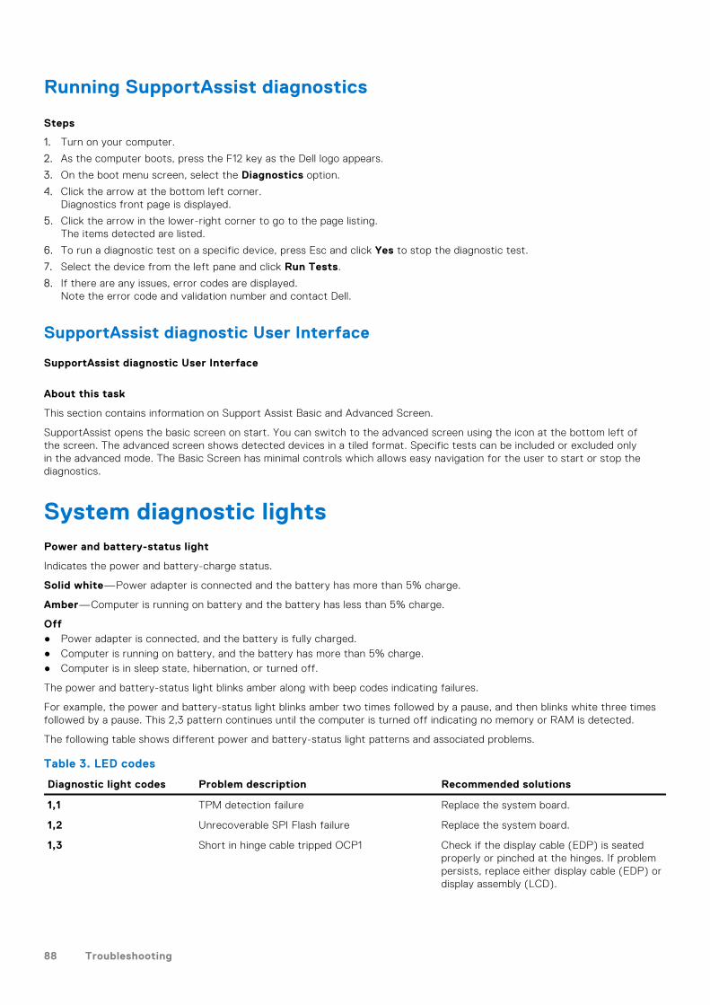
Running SupportAssist diagnostics
Steps
1. Turn on your computer.
2. As the computer boots, press the F12 key as the Dell logo appears.
3. On the boot menu screen, select the Diagnostics option.
4. Click the arrow at the bottom left corner.Diagnostics front page is displayed.
5. Click the arrow in the lower-right corner to go to the page listing.The items detected are listed.
6. To run a diagnostic test on a specific device, press Esc and click Yes to stop the diagnostic test.
7. Select the device from the left pane and click Run Tests.
8. If there are any issues, error codes are displayed.Note the error code and validation number and contact Dell.
SupportAssist diagnostic User Interface
SupportAssist diagnostic User Interface
About this task
This section contains information on Support Assist Basic and Advanced Screen.
SupportAssist opens the basic screen on start. You can switch to the advanced screen using the icon at the bottom left ofthe screen. The advanced screen shows detected devices in a tiled format. Specific tests can be included or excluded onlyin the advanced mode. The Basic Screen has minimal controls which allows easy navigation for the user to start or stop thediagnostics.
System diagnostic lightsPower and battery-status light
Indicates the power and battery-charge status.
Solid white—Power adapter is connected and the battery has more than 5% charge.
Amber—Computer is running on battery and the battery has less than 5% charge.
Off● Power adapter is connected, and the battery is fully charged.● Computer is running on battery, and the battery has more than 5% charge.● Computer is in sleep state, hibernation, or turned off.
The power and battery-status light blinks amber along with beep codes indicating failures.
For example, the power and battery-status light blinks amber two times followed by a pause, and then blinks white three timesfollowed by a pause. This 2,3 pattern continues until the computer is turned off indicating no memory or RAM is detected.
The following table shows different power and battery-status light patterns and associated problems.
Table 3. LED codes
Diagnostic light codes Problem description Recommended solutions
1,1 TPM detection failure Replace the system board.
1,2 Unrecoverable SPI Flash failure Replace the system board.
1,3 Short in hinge cable tripped OCP1 Check if the display cable (EDP) is seatedproperly or pinched at the hinges. If problempersists, replace either display cable (EDP) ordisplay assembly (LCD).
88 Troubleshooting
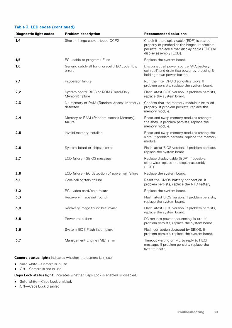
Table 3. LED codes (continued)
Diagnostic light codes Problem description Recommended solutions
1,4 Short in hinge cable tripped OCP2 Check if the display cable (EDP) is seatedproperly or pinched at the hinges. If problempersists, replace either display cable (EDP) ordisplay assembly (LCD).
1,5 EC unable to program i-Fuse Replace the system board.
1,6 Generic catch-all for ungraceful EC code flowerrors
Disconnect all power source (AC, battery,coin cell) and drain flea power by pressing &holding down power button.
2,1 Processor failure Run the Intel CPU diagnostics tools. Ifproblem persists, replace the system board.
2,2 System board: BIOS or ROM (Read-OnlyMemory) failure
Flash latest BIOS version. If problem persists,replace the system board.
2,3 No memory or RAM (Random-Access Memory)detected
Confirm that the memory module is installedproperly. If problem persists, replace thememory module.
2,4 Memory or RAM (Random-Access Memory)failure
Reset and swap memory modules amongstthe slots. If problem persists, replace thememory module.
2,5 Invalid memory installed Reset and swap memory modules among theslots. If problem persists, replace the memorymodule.
2,6 System-board or chipset error Flash latest BIOS version. If problem persists,replace the system board.
2,7 LCD failure - SBIOS message Replace display vable (EDP) if possible,otherwise replace the display assembly(LCD).
2,8 LCD failure - EC detection of power rail failure Replace the system board.
3,1 Coin-cell battery failure Reset the CMOS battery connection. Ifproblem persists, replace the RTC battery.
3,2 PCI, video card/chip failure Replace the system board.
3,3 Recovery image not found Flash latest BIOS version. If problem persists,replace the system board.
3,4 Recovery image found but invalid Flash latest BIOS version. If problem persists,replace the system board.
3,5 Power-rail failure EC ran into power sequencing failure. Ifproblem persists, replace the system board.
3,6 System BIOS Flash incomplete Flash corruption detected by SBIOS. Ifproblem persists, replace the system board.
3,7 Management Engine (ME) error Timeout waiting on ME to reply to HECImessage. If problem persists, replace thesystem board.
Camera status light: Indicates whether the camera is in use.
● Solid white—Camera is in use.● Off—Camera is not in use.
Caps Lock status light: Indicates whether Caps Lock is enabled or disabled.
● Solid white—Caps Lock enabled.● Off—Caps Lock disabled.
Troubleshooting 89
Real-Time Clock (RTC Reset)The Real Time Clock (RTC) reset function allows you or the service technician to recover Dell Latitude systems from NoPOST/No Power/No Boot situations. The legacy jumper enabled RTC reset has been retired on these models.
Start the RTC reset with the system powered off and connected to AC power. Press and hold the power button for thirty (30)seconds. The system RTC Reset occurs after you release the power button.
Updating the BIOS in Windows
Steps
1. Go to www.dell.com/support.
2. Click Product support. In the Search support box, enter the Service Tag of your computer, and then click Search.
NOTE: If you do not have the Service Tag, use the SupportAssist feature to automatically identify your computer. You
can also use the product ID or manually browse for your computer model.
3. Click Drivers & Downloads. Expand Find drivers.
4. Select the operating system installed on your computer.
5. In the Category drop-down list, select BIOS.
6. Select the latest version of BIOS, and click Download to download the BIOS file for your computer.
7. After the download is complete, browse the folder where you saved the BIOS update file.
8. Double-click the BIOS update file icon and follow the on-screen instructions.
For more information, see knowledge base article 000124211 at www.dell.com/support.
Updating the BIOS using the USB drive in Windows
Steps
1. Follow the procedure from step 1 to step 6 in Updating the BIOS in Windows to download the latest BIOS setup program file.
2. Create a bootable USB drive. For more information, see the knowledge base article 000145519 at www.dell.com/support.
3. Copy the BIOS setup program file to the bootable USB drive.
4. Connect the bootable USB drive to the computer that needs the BIOS update.
5. Restart the computer and press F12 .
6. Select the USB drive from the One Time Boot Menu.
7. Type the BIOS setup program filename and press Enter.The BIOS Update Utility appears.
8. Follow the on-screen instructions to complete the BIOS update.
Backup media and recovery optionsIt is recommended to create a recovery drive to troubleshoot and fix problems that may occur with Windows. Dell proposesmultiple options for recovering Windows operating system on your Dell PC. For more information. see Dell Windows BackupMedia and Recovery Options.
WiFi power cycle
About this task
If your computer is unable to access the internet due to WiFi connectivity issues a WiFi power cycle procedure may beperformed. The following procedure provides the instructions on how to conduct a WiFi power cycle:
NOTE: Some ISPs (Internet Service Providers) provide a modem/router combo device.
90 Troubleshooting
Steps
1. Turn off your computer.
2. Turn off the modem.
3. Turn off the wireless router.
4. Wait for 30 seconds.
5. Turn on the wireless router.
6. Turn on the modem.
7. Turn on your computer.
Drain residual flea power (perform hard reset)
About this task
Flea power is the residual static electricity that remains in the computer even after it has been powered off and the battery isremoved.
For your safety, and to protect the sensitive electronic components in your computer, you are requested to drain residual fleapower before removing or replacing any components in your computer.
Draining residual flea power, also known as a performing a "hard reset", is also a common troubleshooting step if your computerdoes not power on or boot into the operating system.
To drain residual flea power (perform a hard reset)
Steps
1. Turn off your computer.
2. Disconnect the power adapter from your computer.
3. Remove the base cover.
4. Remove the battery.
5. Press and hold the power button for 20 seconds to drain the flea power.
6. Install the battery.
7. Install the base cover.
8. Connect the power adapter to your computer.
9. Turn on your computer.
NOTE: For more information about performing a hard reset, see the knowledge base article 000130881 at
www.dell.com/support.
Troubleshooting 91
Getting help and contacting Dell
Self-help resourcesYou can get information and help on Dell products and services using these self-help resources:
Table 4. Self-help resources
Self-help resources Resource location
Information about Dell products and services www.dell.com
My Dell
Tips
Contact Support In Windows search, type Contact Support, and pressEnter.
Online help for operating system www.dell.com/support/windows
www.dell.com/support/linux
Troubleshooting information, user manuals, setup instructions,product specifications, technical help blogs, drivers, softwareupdates, and so on.
www.dell.com/support
Dell knowledge base articles for a variety of computerconcerns.
1. Go to https://www.dell.com/support/home/?app=knowledgebase.
2. Type the subject or keyword in the Search box.3. Click Search to retrieve the related articles.
Learn and know the following information about your product:● Product specifications● Operating system● Setting up and using your product● Data backup● Troubleshooting and diagnostics● Factory and system restore● BIOS information
See Me and My Dell at www.dell.com/support/manuals.
To locate the Me and My Dell relevant to your product,identify your product through one of the following:
● Select Detect Product.● Locate your product through the drop-down menu under
View Products.● Enter the Service Tag number or Product ID in the
search bar.
Contacting DellTo contact Dell for sales, technical support, or customer service issues, see www.dell.com/contactdell.
NOTE: Availability varies by country and product, and some services may not be available in your country.
NOTE: If you do not have an active internet connection, you can find contact information on your purchase invoice, packing
slip, bill, or Dell product catalog.
6
92 Getting help and contacting Dell
Related Documents