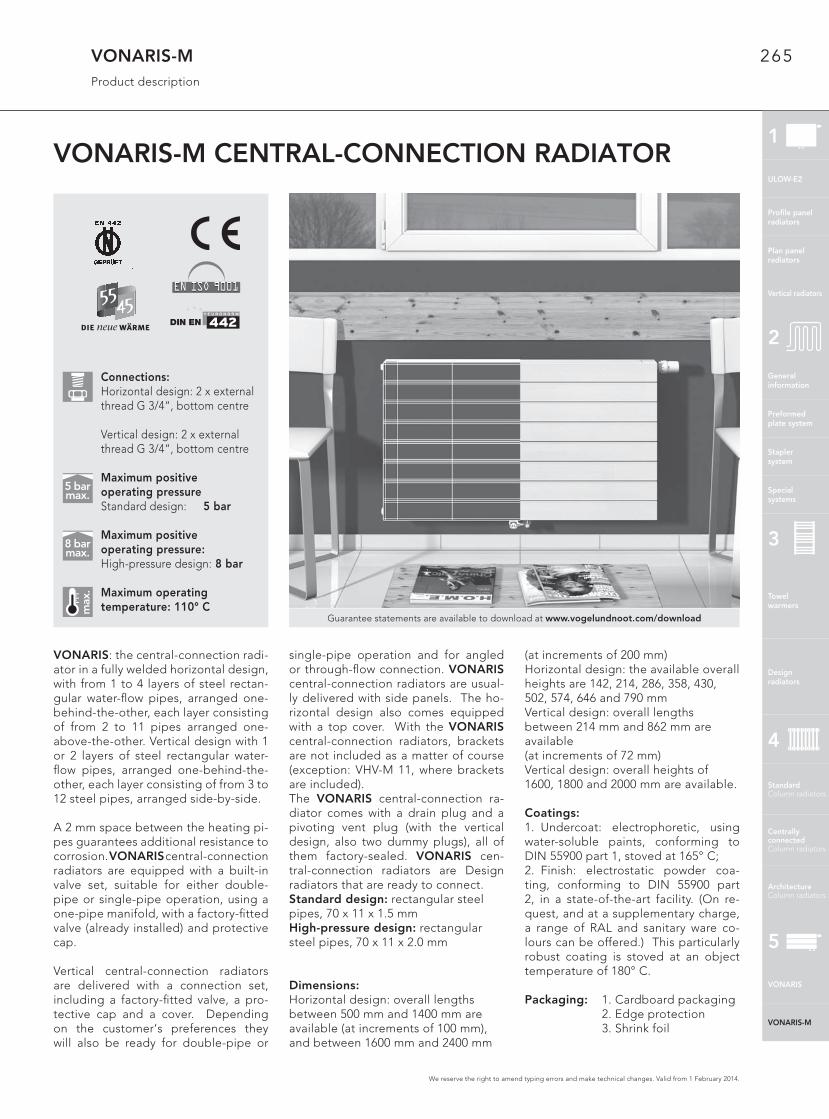
265 We reserve the right to amend typing errors and make technical changes. Valid from 1 February 2014. VONARIS-M Product description VONARIS-M CENTRAL-CONNECTION RADIATOR VONARIS: the central-connection radi- ator in a fully welded horizontal design, with from 1 to 4 layers of steel rectan- gular water-flow pipes, arranged one- behind-the-other, each layer consisting of from 2 to 11 pipes arranged one- above-the-other. Vertical design with 1 or 2 layers of steel rectangular water- flow pipes, arranged one-behind-the- other, each layer consisting of from 3 to 12 steel pipes, arranged side-by-side. A 2 mm space between the heating pi- pes guarantees additional resistance to corrosion. VONARIS central-connection radiators are equipped with a built-in valve set, suitable for either double- pipe or single-pipe operation, using a one-pipe manifold, with a factory-fitted valve (already installed) and protective cap. Vertical central-connection radiators are delivered with a connection set, including a factory-fitted valve, a pro- tective cap and a cover. Depending on the customer‘s preferences they will also be ready for double-pipe or single-pipe operation and for angled or through-flow connection. VONARIS central-connection radiators are usual- ly delivered with side panels. The ho- rizontal design also comes equipped with a top cover. With the VONARIS central-connection radiators, brackets are not included as a matter of course (exception: VHV-M 11, where brackets are included). The VONARIS central-connection ra- diator comes with a drain plug and a pivoting vent plug (with the vertical design, also two dummy plugs), all of them factory-sealed. VONARIS cen- tral-connection radiators are Design radiators that are ready to connect. Standard design: rectangular steel pipes, 70 x 11 x 1.5 mm High-pressure design: rectangular steel pipes, 70 x 11 x 2.0 mm Dimensions: Horizontal design: overall lengths between 500 mm and 1400 mm are available (at increments of 100 mm), and between 1600 mm and 2400 mm (at increments of 200 mm) Horizontal design: the available overall heights are 142, 214, 286, 358, 430, 502, 574, 646 and 790 mm Vertical design: overall lengths between 214 mm and 862 mm are available (at increments of 72 mm) Vertical design: overall heights of 1600, 1800 and 2000 mm are available. Coatings: 1. Undercoat: electrophoretic, using water-soluble paints, conforming to DIN 55900 part 1, stoved at 165° C; 2. Finish: electrostatic powder coa- ting, conforming to DIN 55900 part 2, in a state-of-the-art facility. (On re- quest, and at a supplementary charge, a range of RAL and sanitary ware co- lours can be offered.) This particularly robust coating is stoved at an object temperature of 180° C. Packaging: 1. Cardboard packaging 2. Edge protection 3. Shrink foil max. 5 bar max. 8 bar max. Guarantee statements are available to download at www.vogelundnoot.com/download Connections: Horizontal design: 2 x external thread G 3/4“, bottom centre Vertical design: 2 x external thread G 3/4“, bottom centre Maximum positive operating pressure Standard design: 5 bar Maximum positive operating pressure: High-pressure design: 8 bar Maximum operating temperature: 110° C 1 VONARIS VONARIS-M ULOW-E2 Profile panel radiators Plan panel radiators Vertical radiators General information Preformed plate system Stapler system Special systems 2 Towel warmers Design radiators 3 Standard Column radiators Centrally connected Column radiators Architecture Column radiators 4 5

Welcome message from author
This document is posted to help you gain knowledge. Please leave a comment to let me know what you think about it! Share it to your friends and learn new things together.
Transcript
265
We reserve the right to amend typing errors and make technical changes. Valid from 1 February 2014.
VONARIS-MProduct description
VONARIS-M CENTRAL-CONNECTION RADIATOR
VONARIS: the central-connection radi-ator in a fully welded horizontal design, with from 1 to 4 layers of steel rectan-gular water-fl ow pipes, arranged one-behind-the-other, each layer consisting of from 2 to 11 pipes arranged one-above-the-other. Vertical design with 1 or 2 layers of steel rectangular water-fl ow pipes, arranged one-behind-the-other, each layer consisting of from 3 to 12 steel pipes, arranged side-by-side.
A 2 mm space between the heating pi-pes guarantees additional resistance to corrosion. VONARIS central-connection radiators are equipped with a built-in valve set, suitable for either double-pipe or single-pipe operation, using a one-pipe manifold, with a factory-fi tted valve (already installed) and protective cap.
Vertical central-connection radiators are delivered with a connection set, including a factory-fi tted valve, a pro-tective cap and a cover. Depending on the customer‘s preferences they will also be ready for double-pipe or
single-pipe operation and for angled or through-fl ow connection. VONARIS central-connection radiators are usual-ly delivered with side panels. The ho-rizontal design also comes equipped with a top cover. With the VONARIS central-connection radiators, brackets are not included as a matter of course (exception: VHV-M 11, where brackets are included). The VONARIS central-connection ra-diator comes with a drain plug and a pivoting vent plug (with the vertical design, also two dummy plugs), all of them factory-sealed. VONARIS cen-tral-connection radiators are Design radiators that are ready to connect. Standard design: rectangular steel pipes, 70 x 11 x 1.5 mmHigh-pressure design: rectangular steel pipes, 70 x 11 x 2.0 mm
Dimensions:Horizontal design: overall lengths between 500 mm and 1400 mm are available (at increments of 100 mm), and between 1600 mm and 2400 mm
(at increments of 200 mm)Horizontal design: the available overall heights are 142, 214, 286, 358, 430, 502, 574, 646 and 790 mmVertical design: overall lengths between 214 mm and 862 mm are available (at increments of 72 mm)Vertical design: overall heights of 1600, 1800 and 2000 mm are available.
Coatings:1. Undercoat: electrophoretic, using water-soluble paints, conforming to DIN 55900 part 1, stoved at 165° C; 2. Finish: electrostatic powder coa-ting, conforming to DIN 55900 part 2, in a state-of-the-art facility. (On re-quest, and at a supplementary charge, a range of RAL and sanitary ware co-lours can be offered.) This particularly robust coating is stoved at an object temperature of 180° C.
Packaging: 1. Cardboard packaging 2. Edge protection 3. Shrink foil
max
.
5 barmax.
8 barmax.
Guarantee statements are available to download at www.vogelundnoot.com/download
Connections:Horizontal design: 2 x external thread G 3/4“, bottom centre
Vertical design: 2 x external thread G 3/4“, bottom centre
Maximum positive operating pressureStandard design: 5 bar
Maximum positive operating pressure: High-pressure design: 8 bar
Maximum operating temperature: 110° C
1
VONARIS
VONARIS-M
ULOW-E2
Profi le panelradiators
Plan panelradiators
Vertical radiators
Generalinformation
Preformed plate system
Stapler system
Special systems
2
Towel warmers
Design radiators
3
Standard Column radiators
Centrallyconnected Column radiators
Architecture Column radiators
4
5

266
We reserve the right to amend typing errors and make technical changes. Valid from 1 February 2014.
VONARIS-Mmodel overview / connection dimensions
Horizontal design, VHV-M models
* Note: if the VHV-M 34 model is turned around so that the valve is located to the left, the distance between the VONARIS rear panel and the connection point is 129 mm.
Model VHV-M 10 VHV-M 11 VHV-M 20 VHV-M 22 VHV-M S 22 VHV-M 34 VHV-M 46 VHV-M S 46Overall height
[mm]
358 430 502 358 430 502 358 430 502 214 286 358 214 286 142 214 142 214 142 214
574 646 718 574 646 718 574 646 718 430 502 574 286 286 286
790 790 790 646 718 790
Overall length
[mm]
500 - 2400 mm
Increments 100 mm (for an overal l length of 1400 mm and greater: 200 mm)
Horizontal design, VHV-M S models
Schematische Darstellung
257
12
9
VHV-M 46
68
26
VHV-M 11
93
47
VHV-M 20
93
47
VHV-M 22
175
47
*VHV-M 34
68
26
VHV-M 10
Bauhöhen
358
502
574
790 500 - 2400
500 - 2400
500 - 2400
500 - 2400
500 - 2400
500 - 2400
500 - 2400
500 - 2400
500 - 2400
500 - 2400
286
214
142
430
646
718
Baulänge/2
Baulängen
163
11
7
VHV-M S 22
327
VHV-M S 46
19
9
The WVO version with factory-welded, not water-bearing radiation shield through convection between radiator and radiation shield back the majority of the otherwise lost heat in the room.
Schematic diagram
Heights Lenghts
Lenght/2
268
We reserve the right to amend typing errors and make technical changes. Valid from 1 February 2014.
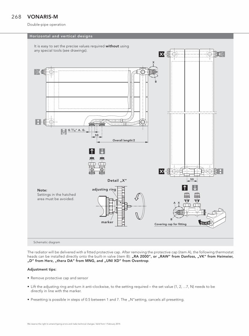
VONARIS-MDouble-pipe operation
The radiator will be delivered with a fi tted protective cap. After removing the protective cap (item A), the following thermostat heads can be installed directly onto the built-in valve (item B): „RA 2000“, or „RAW“ from Danfoss, „VK“ from Heimeier, „D“ from Herz, „thera DA“ from MNG, and „UNI XD“ from Oventrop.
Adjustment tips:
• Remove protective cap and sensor
• Lift the adjusting ring and turn it anti-clockwise, to the setting required – the set value (1, 2, ...7, N) needs to be directly in line with the marker.
• Presetting is possible in steps of 0.5 between 1 and 7. The „N“setting, cancels all presetting.
Horizontal and vertical designs
Schematic diagram
50
G 3/4" A. G.
X
B
N
Baulänge/2
It is easy to set the precise values required without using any special tools (see drawings).
CLICKArmaturen-Abdeckkappe
N
50
X
B
A
Note:Settings in the hatchedarea must be avoided.
N1
23
45
67
adjusting ring
marker
Detail „X“
Covering cap for fi tting
Overall length/2
269
We reserve the right to amend typing errors and make technical changes. Valid from 1 February 2014.
VONARIS-MDouble-pipe operation
54
32
9102
78
56
34210
Druckverlust [mbar]
He
izkö
rpe
rdu
rch
flu
ss [
l/h
]
103
9876
5
4
3
2
9876
5
4
3
2
10
102
Voreinstellu
ng N - k
v=0,75
7 - kv=
0,63
6 - kv=
0,52
5 - kv=
0,41
4 - kv=
0,31
3 - kv=
0,26
2 - kv=
0,21
1 - kv=
0,13
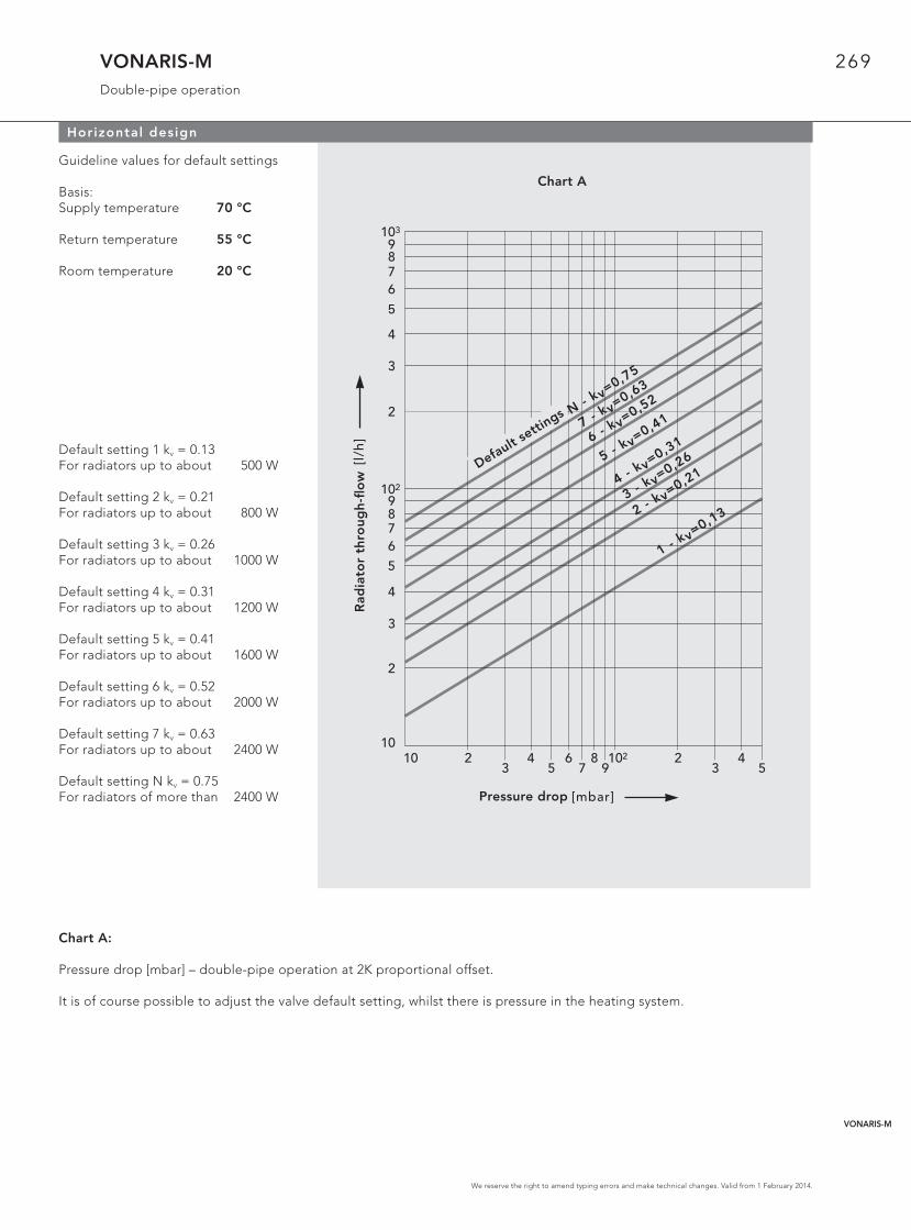
Horizontal design
Guideline values for default settings
Basis:Supply temperature 70 °C
Return temperature 55 °C
Room temperature 20 °C
Default setting 1 kv = 0.13For radiators up to about 500 W
Default setting 2 kv = 0.21For radiators up to about 800 W
Default setting 3 kv = 0.26For radiators up to about 1000 W
Default setting 4 kv = 0.31For radiators up to about 1200 W
Default setting 5 kv = 0.41For radiators up to about 1600 W
Default setting 6 kv = 0.52For radiators up to about 2000 W
Default setting 7 kv = 0.63For radiators up to about 2400 W
Default setting N kv = 0.75For radiators of more than 2400 W
Chart A:
Pressure drop [mbar] – double-pipe operation at 2K proportional offset.
It is of course possible to adjust the valve default setting, whilst there is pressure in the heating system.
Chart A
Rad
iato
r th
rou
gh
-fl o
w
Pressure drop
Default settin
gs
VONARIS-M
271
We reserve the right to amend typing errors and make technical changes. Valid from 1 February 2014.
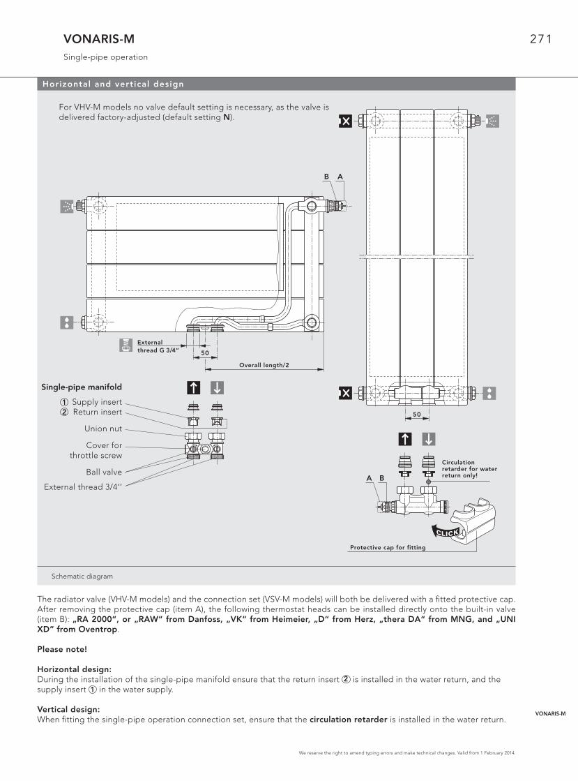
VONARIS-MSingle-pipe operation
Schematic diagram
50
N
CLICK
Armaturen-Abdeckkappe
Zirkulations-bremse nurim Rücklauf!A B
Horizontal and vertical design
For VHV-M models no valve default setting is necessary, as the valve is delivered factory-adjusted (default setting N).
The radiator valve (VHV-M models) and the connection set (VSV-M models) will both be delivered with a fi tted protective cap. After removing the protective cap (item A), the following thermostat heads can be installed directly onto the built-in valve (item B): „RA 2000“, or „RAW“ from Danfoss, „VK“ from Heimeier, „D“ from Herz, „thera DA“ from MNG, and „UNI XD“ from Oventrop.
Please note!
Horizontal design: During the installation of the single-pipe manifold ensure that the return insert 2 is installed in the water return, and the supply insert 1 in the water supply.
Vertical design: When fi tting the single-pipe operation connection set, ensure that the circulation retarder is installed in the water return.
50
G 3/4" A. G.N
Baulänge/2
B A
12
Single-pipe manifold
Supply insertReturn insert
Union nut
Cover forthrottle screw
Ball valve
External thread 3/4‘’
External thread G 3/4“
Overall length/2
Circulation retarder for water return only!
Protective cap for fitting
VONARIS-M
272
We reserve the right to amend typing errors and make technical changes. Valid from 1 February 2014.
VONARIS-MSingle-pipe operation
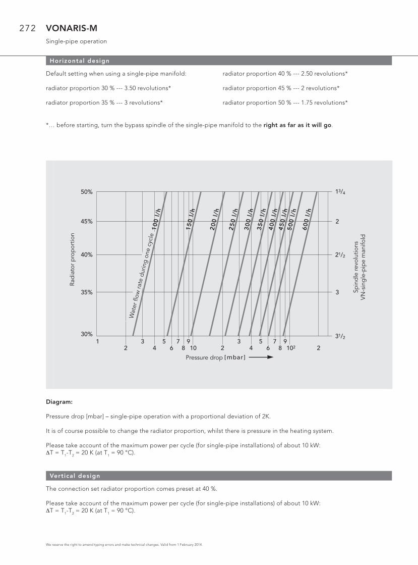
Horizontal design
2
Druckverlust [mbar]
1 34
56 8 10
7 92
3 5 7 94 6 8 102 2
31/2
3
21/2
2
13/4
Sp
ind
elv
erd
reh
un
ge
nV
N E
inro
hrv
ert
eil
er
He
izkö
rpe
ran
teil
30%
35%
40%
45%
50%
Kre
isw
asse
rdu
rch
flu
ss 1
00
l/h
15
0 l
/h
25
0 l
/h
20
0 l
/h
30
0 l
/h3
50
l/h
40
0 l
/h4
50
l/h
50
0 l
/h
60
0 l
/h
Default setting when using a single-pipe manifold:
radiator proportion 30 % --- 3.50 revolutions*
radiator proportion 35 % --- 3 revolutions*
radiator proportion 40 % --- 2.50 revolutions*
radiator proportion 45 % --- 2 revolutions*
radiator proportion 50 % --- 1.75 revolutions*
*… before starting, turn the bypass spindle of the single-pipe manifold to the right as far as it will go.
Diagram:
Pressure drop [mbar] – single-pipe operation with a proportional deviation of 2K.
It is of course possible to change the radiator proportion, whilst there is pressure in the heating system.
Please take account of the maximum power per cycle (for single-pipe installations) of about 10 kW:ΔT = T1-T2 = 20 K (at T1 = 90 °C).
Vertical design
The connection set radiator proportion comes preset at 40 %.
Please take account of the maximum power per cycle (for single-pipe installations) of about 10 kW:ΔT = T1-T2 = 20 K (at T1 = 90 °C).
Pressure drop
Rad
iato
r p
rop
ortio
n
Spin
dle
revo
lutio
nsV
N-s
ing
le-p
ipe
man
ifold
Wat
er fl
ow ra
te d
urin
g on
e cy
cle
273
We reserve the right to amend typing errors and make technical changes. Valid from 1 February 2014.
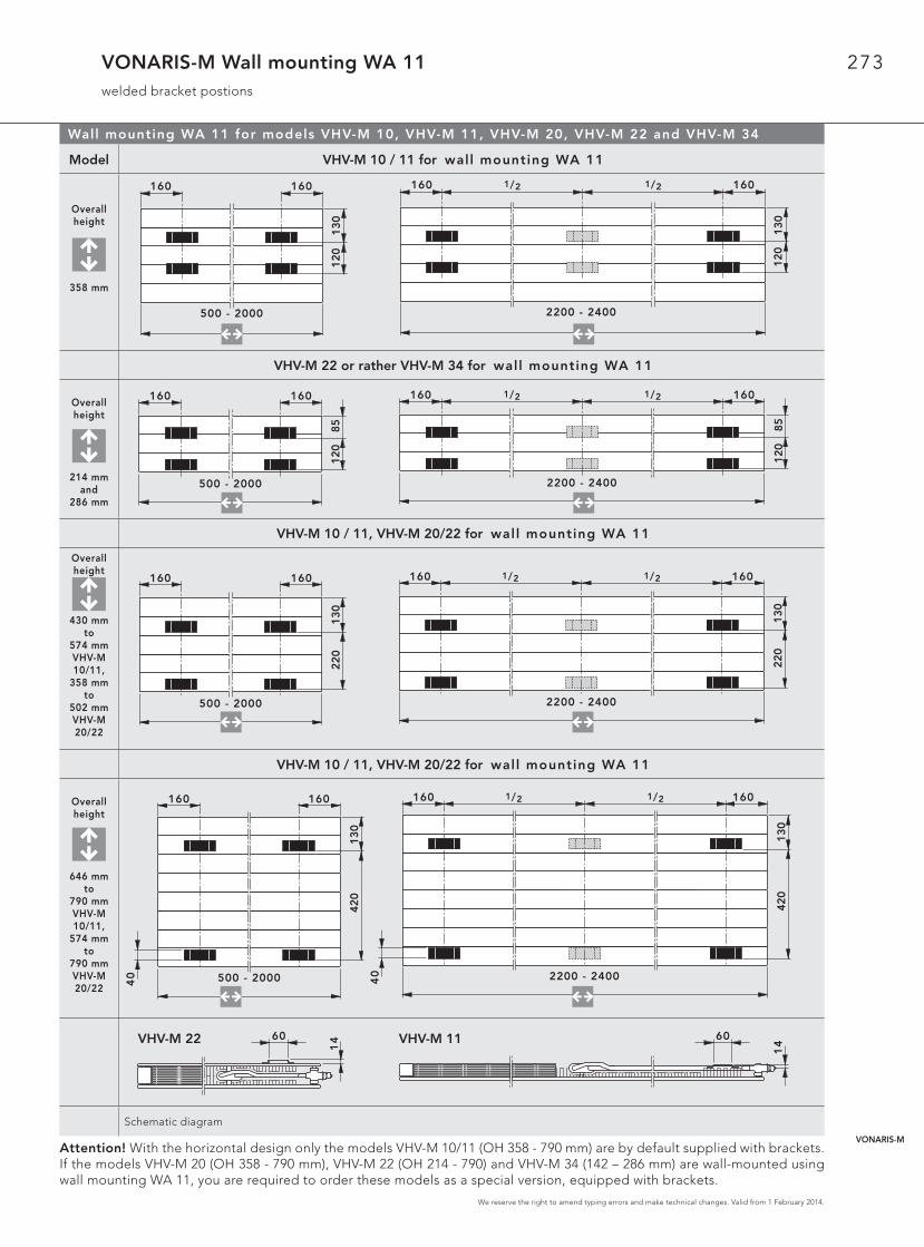
VONARIS-M Wall mounting WA 11welded bracket postions
Wall mounting WA 11 for models VHV-M 10, VHV-M 11, VHV-M 20, VHV-M 22 and VHV-M 34
Model VHV-M 10 / 11 for wal l mounting WA 11
Overallheight
358 mm
VHV-M 22 or rather VHV-M 34 for wal l mounting WA 11
Overallheight
214 mmand
286 mm
VHV-M 10 / 11, VHV-M 20/22 for wal l mounting WA 11
Overallheight
430 mmto
574 mmVHV-M 10/11,
358 mmto
502 mmVHV-M20/22
VHV-M 10 / 11, VHV-M 20/22 for wal l mounting WA 11
Overallheight
646 mmto
790 mmVHV-M 10/11,
574 mmto
790 mmVHV-M 20/22
Schematic diagram
Attention! With the horizontal design only the models VHV-M 10/11 (OH 358 - 790 mm) are by default supplied with brackets. If the models VHV-M 20 (OH 358 - 790 mm), VHV-M 22 (OH 214 - 790) and VHV-M 34 (142 – 286 mm) are wall-mounted using wall mounting WA 11, you are required to order these models as a special version, equipped with brackets.
130
120
500 - 2000
160 160
130
120
160 160
2200 - 2400
1/2 1/2
500 - 2000
160 160
85
12
0
160 1601/2 1/2
2200 - 2400
85
12
0
130
220
500 - 2000
160 160
130
220
160 160
2200 - 2400
1/2 1/2
60
14
60
14
13
04
20
500 - 2000
160 160
40
13
04
20
160 160
2200 - 240040
1/2 1/2
VHV-M 22 VHV-M 11
VONARIS-M
274
We reserve the right to amend typing errors and make technical changes. Valid from 1 February 2014.
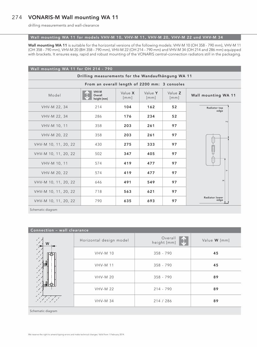
VONARIS-M Wall mounting WA 11drilling measurements and wall-clearance
Wall mounting WA 11 for models VHV-M 10, VHV-M 11, VHV-M 20, VHV-M 22 und VHV-M 34
Wall mounting WA 11 is suitable for the horizontal versions of the following models: VHV-M 10 (OH 358 - 790 mm), VHV-M 11(OH 358 - 790 mm), VHV-M 20 (BH 358 - 790 mm), VHV-M 22 (OH 214 - 790 mm) and VHV-M 34 (OH 214 and 286 mm) equipped with brackets. It ensures easy, rapid and robust mounting of the VONARIS central-connection radiators still in the packaging.
Wall mounting WA 11 for OH 214 - 790
Dri l l ing measurements for the Wandaufhängung WA 11
From an overal l length of 2200 mm: 3 consoles
ModelVHV-MOverall height [mm]
Value X [mm]
Value Y [mm]
Value Z [mm]
Wall mounting WA 11
VHV-M 22, 34 214 104 162 52
VHV-M 22, 34 286 176 234 52
VHV-M 10, 11 358 203 261 97
VHV-M 20, 22 358 203 261 97
VHV-M 10, 11, 20, 22 430 275 333 97
VHV-M 10, 11, 20, 22 502 347 405 97
VHV-M 10, 11 574 419 477 97
VHV-M 20, 22 574 419 477 97
VHV-M 10, 11, 20, 22 646 491 549 97
VHV-M 10, 11, 20, 22 718 563 621 97
VHV-M 10, 11, 20, 22 790 635 693 97
Schematic diagram
Connection – wall c learance
Horizontal design modelOveral l
height [mm]Value W [mm]
VHV-M 10 358 - 790 45
VHV-M 11 358 - 790 45
VHV-M 20 358 - 790 89
VHV-M 22 214 - 790 89
VHV-M 34 214 / 286 89
Schematic diagram
HeizkörperOberkante
HeizkörperUnterkante
XY
Z
W
Radiator topedge
Radiator lower edge
275
We reserve the right to amend typing errors and make technical changes. Valid from 1 February 2014.
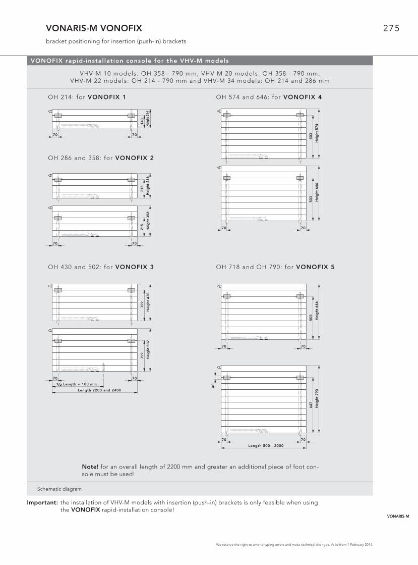
VONARIS-M VONOFIXbracket positioning for insertion (push-in) brackets
VONOFIX rapid-instal lation console for the VHV-M models
VHV-M 10 models: OH 358 - 790 mm, VHV-M 20 models: OH 358 - 790 mm,VHV-M 22 models: OH 214 - 790 mm and VHV-M 34 models: OH 214 and 286 mm
OH 214: for VONOFIX 1 OH 574 and 646: for VONOFIX 4
OH 286 and 358: for VONOFIX 2
OH 430 and 502: for VONOFIX 3 OH 718 and OH 790: for VONOFIX 5
Schematic diagram
215
Hei
ght
286
215
7070
Hei
ght
358
143
7070
Hei
ght
214
503
Hei
ght
574
503
7070
Hei
ght
646
359
Hei
ght
430
Length 2200 and 2400
1/2 Length + 100 mm
359
7070
Hei
ght
502
647
7070
Length 500 - 2000
40
Hei
ght
790
Important: the installation of VHV-M models with insertion (push-in) brackets is only feasible when using the VONOFIX rapid-installation console!
Note! for an overall length of 2200 mm and greater an additional piece of foot con-sole must be used!
503
7070
Hei
ght
646
VONARIS-M
276
We reserve the right to amend typing errors and make technical changes. Valid from 1 February 2014.
VONARIS-M VONOFIXdrilling measurements and wall clearance
VONOFIX rapid-instal lation console for the VHV-M models
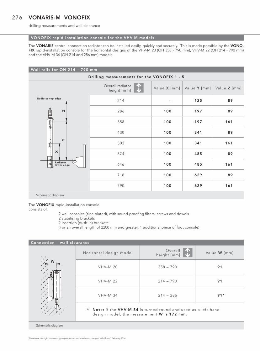
The VONARIS central connection radiator can be installed easily, quickly and securely. This is made possible by the VONO-FIX rapid-installation console for the horizontal designs of the VHV-M 20 (OH 358 - 790 mm), VHV-M 22 (OH 214 - 790 mm) and the VHV-M 34 (OH 214 and 286 mm) models.
Wall rai ls for OH 214 – 790 mm
Dri l l ing measurements for the VONOFIX 1 - 5
Overall radiatorheight [mm]
Value X [mm] Value Y [mm] Value Z [mm]
214 – 125 89
286 100 197 89
358 100 197 161
430 100 341 89
502 100 341 161
574 100 485 89
646 100 485 161
718 100 629 89
790 100 629 161
Schematic diagram
X
Heizkörper Oberkante
HeizkörperUnterkante
YZ
Connection – wall c learance
Horizontal design modelOveral l
height [mm]Value W [mm]
VHV-M 20 358 – 790 91
VHV-M 22 214 – 790 91
VHV-M 34 214 – 286 91*
* Note: i f the VHV-M 34 is turned round and used as a left-hand design model, the measurement W is 172 mm.
Schematic diagram
W
The VONOFIX rapid-installation console consists of: 2 wall consoles (zinc-plated), with sound-proofi ng fi lters, screws and dowels 2 stabilising brackets 2 insertion (push-in) brackets (For an overall length of 2200 mm and greater, 1 additional piece of foot console)
Radiator top edge
Radiator lower edge
278
We reserve the right to amend typing errors and make technical changes. Valid from 1 February 2014.
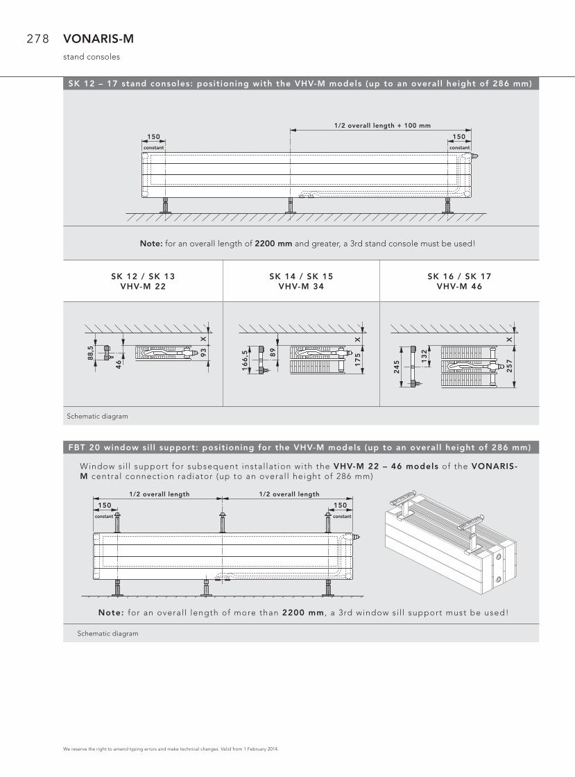
VONARIS-Mstand consoles
FBT 20 window si l l support: posit ioning for the VHV-M models (up to an overal l height of 286 mm)
Window si l l support for subsequent instal lat ion with the VHV-M 22 – 46 models of the VONARIS-M central connect ion radiator (up to an overal l height of 286 mm)
Note: for an overal l length of more than 2200 mm , a 3rd window si l l support must be used!
Schematic diagram
150 150
fix fix
Baulänge1/2 Baulänge1/2
SK 12 – 17 stand consoles: posit ioning with the VHV-M models (up to an overal l height of 286 mm)
Note: for an overall length of 2200 mm and greater, a 3rd stand console must be used!
SK 12 / SK 13VHV-M 22
SK 14 / SK 15VHV-M 34
SK 16 / SK 17VHV-M 46
Schematic diagram
150 150
fix fix
Baulänge + 100 mm1/2
X
88,5
93
46
16
6,5 8
9
X1
75
24
5 13
2
X2
57
1/2 overall length + 100 mm
constant constant
1/2 overall length 1/2 overall length
constant constant
Related Documents