MEFI MEFI Product Training Product Training Through 2005 Model year Through 2005 Model year STUDENT REFERENCE BOOK STUDENT REFERENCE BOOK

Volvo Penta MEFI Product Training 2005 STUDENT REFERENCE BOOK
Dec 20, 2015
Through 2005 Model year Through 2005 Model year STUDENT REFERENCE BOOK.
Course Content
•EFI Product Highlights
•MEFI Systems
•Inputs and Outputs
•Special Service Tools
•Service Information
•Safety Brief
•Ignition Systems
•Fuel Systems
•Power Distribution
•Introduction / Overview
Course Content
•EFI Product Highlights
•MEFI Systems
•Inputs and Outputs
•Special Service Tools
•Service Information
•Safety Brief
•Ignition Systems
•Fuel Systems
•Power Distribution
•Introduction / Overview
Welcome message from author
This document is posted to help you gain knowledge. Please leave a comment to let me know what you think about it! Share it to your friends and learn new things together.
Transcript

MEFIMEFI Product TrainingProduct TrainingThrough 2005 Model yearThrough 2005 Model yearSTUDENT REFERENCE BOOKSTUDENT REFERENCE BOOK

Table of Contents
Acronyms 1
Disabling Ignition System 4
Cylinder Balance Test 6
Compression/Leakdown Testing 8
Model Identification 15
Model Charts 18
New Product Highlights
Model Year 2003 31
Model Year 2004 32
Model Year 2005 35
MEFI System Identification 41
MEFI 4 RPM Limiter 48
MEFI 4 ECM Connector Pin Out 49
Speed Density Basic Operation 51
ECM Power and Ground 56
DLC & Master/Slave Connector 57
Wiring Problem Types 60
Input Types 61
CKP & CMP Inputs 65
MAP Input 70
TPS Input 75
Temperature Sensor Inputs 77
Battery Input 82
Riser Temperature Switches 83
Engine Protection Mode 84
KS Input & Octane Rating System 86
Shift Interrupt Input 90
Relays 91
Fuel Injectors 93
IAC 95
Delco Distributor Ignition System 97
8.1L Coil Near Plug Ignition System 105
High Voltage Switch Ignition System
4.3, 5.0, 5.7L MPFI 113
5.0, 5.7 Distributor Installation 120
MEFI 4 Ignition System Testing 125
TBI Fuel System 132
MPFI Fuel System 139
Special Service Tools 153
Oil System Info 170
Diagnostic Info 172
Fuse Box 177
Cooling Systems 179
Acronyms
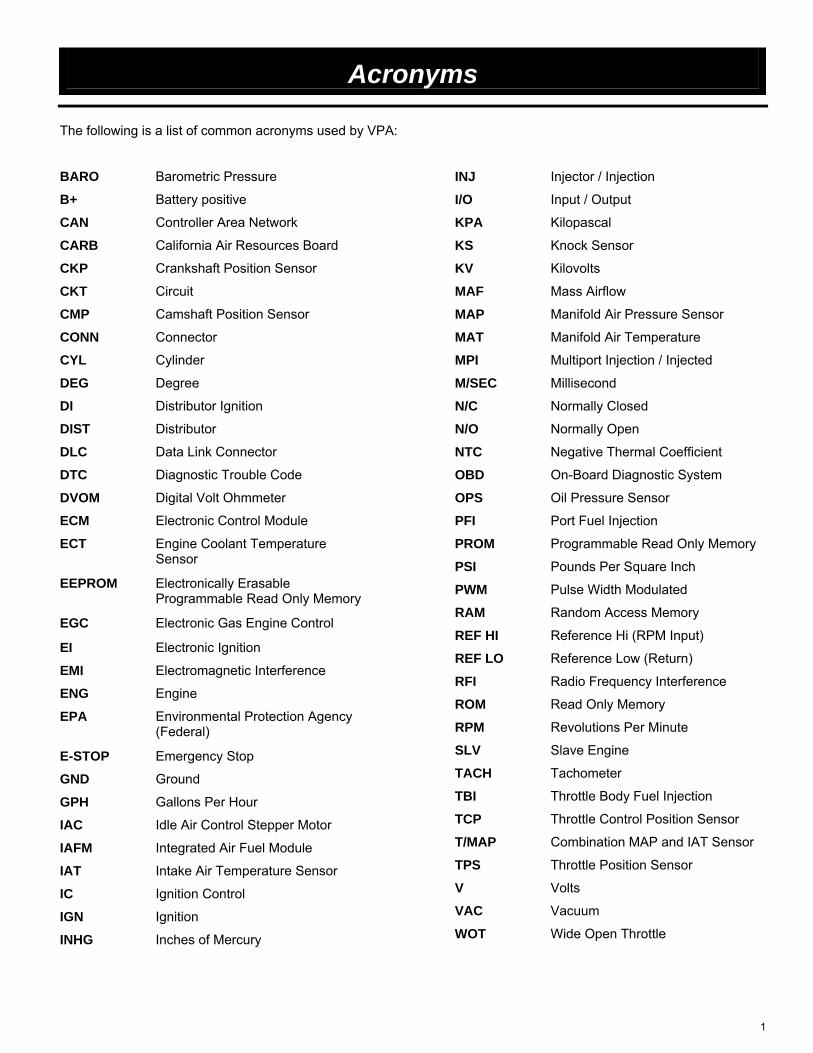
The following is a list of common acronyms used by VPA:
BARO Barometric Pressure
B+ Battery positive
CAN Controller Area Network
CARB California Air Resources Board
CKP Crankshaft Position Sensor
CKT Circuit
CMP Camshaft Position Sensor
CONN Connector
CYL Cylinder
DEG Degree
DI Distributor Ignition
DIST Distributor
DLC Data Link Connector
DTC Diagnostic Trouble Code
DVOM Digital Volt Ohmmeter
ECM Electronic Control Module
ECT Engine Coolant Temperature Sensor
EEPROM Electronically Erasable Programmable Read Only Memory
EGC Electronic Gas Engine Control
EI Electronic Ignition
EMI Electromagnetic Interference
ENG Engine
EPA Environmental Protection Agency (Federal)
E-STOP Emergency Stop
GND Ground
GPH Gallons Per Hour
IAC Idle Air Control Stepper Motor
IAFM Integrated Air Fuel Module
IAT Intake Air Temperature Sensor
IC Ignition Control
IGN Ignition
INHG Inches of Mercury
INJ Injector / Injection
I/O Input / Output
KPA Kilopascal
KS Knock Sensor
KV Kilovolts
MAF Mass Airflow
MAP Manifold Air Pressure Sensor
MAT Manifold Air Temperature
MPI Multiport Injection / Injected
M/SEC Millisecond
N/C Normally Closed
N/O Normally Open
NTC Negative Thermal Coefficient
OBD On-Board Diagnostic System
OPS Oil Pressure Sensor
PFI Port Fuel Injection
PROM Programmable Read Only Memory
PSI Pounds Per Square Inch
PWM Pulse Width Modulated
RAM Random Access Memory
REF HI Reference Hi (RPM Input)
REF LO Reference Low (Return)
RFI Radio Frequency Interference
ROM Read Only Memory
RPM Revolutions Per Minute
SLV Slave Engine
TACH Tachometer
TBI Throttle Body Fuel Injection
TCP Throttle Control Position Sensor
T/MAP Combination MAP and IAT Sensor
TPS Throttle Position Sensor
V Volts
VAC Vacuum
WOT Wide Open Throttle
1

MEFI Fuel Injection
Course Content
•EFI Product Highlights•MEFI Systems•Inputs and Outputs
•Special Service Tools•Service Information
•Safety Brief
•Ignition Systems•Fuel Systems•Power Distribution
•Introduction / Overview
Marine Fuel Injection is an adaptation of automotive EFI systems. The concept of EFI has been around for a long time. Electronic Fuel Injection is bringing a new level of performance and enjoyment to the boating world.
In Years past, Volvo Penta engines were equipped with 2 types of EFI systems, Throttle Body Injection (TBI) and Multiport Injection (MPI or PFI). Both systems used the same types of sensors and a similar ECM (Electronic Control Module). This course is designed to cover Speed Density Fuel Injection used on all Volvo Penta fuel injected engines through the 05 model year.
Minimum performance requirements for successful completion of this course are:1. Class quiz and test final average score of 80% or higher2. End of class reorganization of tools and equipment, as directed3. 100% class attendance
2

MEFI Fuel Injection
SAFETY AT WORK !
Whenever work is carried out on an engineor transmission during a Product Training session,all Safety Instructions as per our Workshop Manualsand Instruction Book must be obeyed.
Safety Brief
Please be advised that proper attire is required at all Volvo Penta training schools. Participants are asked to avoid wearing clothes that expose their legs and toes during classes. Additional common sense for any “horseplay”, language, and smoking is required by everybody.There is no smoking during class time. Smoking is allowed in designated areas before class, after class and during breaks and lunch.The instructor will manage and maintain a safe learning environment.
3

MEFI Fuel Injection
When you suspect an engine is hydro-locked, always assume the liquid is flammable. Disable the primary ignition system before removing the spark plugs.
When cranking an engine without spark plugs installed, always disable the ignition system. Besides damaging the ignition system via ‘open’ secondary circuits, EFI systems use ignition reference signals to initiate fuel delivery!
Flooded Cylinders
Ignition Modules are sensitive to the amount of secondary voltage required to complete the spark plug circuits. With the spark plug wires removed from any available ground, the module will be driven at maximum dwell saturation time for the coil(s) – read as HEAT. And when that maximum secondary spark is released, it may seek a ground right back through the ignition module –causing instant electronic failure.
When an engine is running with a spark plug wire “hanging”, you can bet the module and coil have had their service life compromised. How much depends on how long the wire was “hanging”.
To properly disable the ignition system on fuel Injected engines, with the key in the OFF position, unplug the crankshaft position sensor, remove the ignition relay or unplug the J-1 and J-2 connectors from the ECM before cranking the engine. On carbureted models, unplug or remove both connectors or wires from the ignition coil or unplug the distributor.This will prevent starting a fire by removing all spark and fuel (injected engines) capability from the engine.
4

MEFI Fuel Injection
Close all hatches and other openings before fueling.
Extinguish all smoking materials.
Turn off engines, electrical equipment, radios, stoves, and other appliances.
Remove all passengers.
Keep the fill nozzle in contact with the tank and wipe up any spilled fuel.
Open all ports, hatches, and doors to ventilate when finished.
Run the blower for at least four minutes.
Check the bilges for fuel vapors before starting the engine.
Coast Guard Recommended Refueling Procedures:
Class A fires are fires that burn consumables that leave an ash after burning. Class A fires are best fought with water, but can be fought with a number of fire extinguishing agents.
Class B fires are burning liquids. Class B fires are best fought with dry chemical or foam extinguishing agents. Water should be used only as a last resort because it spreads the fire. Never use a straight stream of water to fight a Class B fire.
Class C fires are electrical fires. Class C fires should only be fought using dry chemical extinguishing agents. Class C fires usually turn into Class A fires after the power has been secured.
Class D fires are burning metals fires. Most burning metals produce their own oxygen as they burn so they can’t be extinguished with water. Most burning metals react violently with water. They are characterized by a white hot flame and must be fought with smothering agents such as sodium chloride or sand.
The picture above lists common sense refueling practices. Keeping the fill nozzle in contact with the filler neck ensures no static electricity buildup between the two.
5

Cylinder Balance Testing
CYLINDER BALANCE TEST A cylinder balance test is used to determine if all cylinders are working equally. This test compares the rpm loss between each cylinder and based on the results, helps isolate the problem area. For example, if a 60 rpm drop occurs on the first seven cylinders, but there is no rpm drop on number eight, then there is a problem with the eighth cylinder tested. This test can also be used to isolate lower engine noise to a particular cylinder. If for example, a customer complains of a loss of power, or the engine runs “rough,” you may have to perform a cylinder balance test. RPM loss varies depending on engine size, configuration and extent of the miss. Cutting out one cylinder on a V8 has less rpm drop than removing one cylinder on a six-cylinder engine. It is easier to identify a weak cylinder with a load on the engine. The cylinder balance tests in the VP2000 and Diacom disable secondary ignition to individual cylinders while monitoring the change in rpm. These tests should only be performed under a load because weak cylinders show up better with a load on them. Do not perform this test on engines under NO load, the results will be invalid. 1. Hook up the VP2000 or Diacom and navigate to the cylinder balance test
(power balance test in the VP2000).
2. For Diacom, follow the on screen prompts.
3. Using a screwdriver or other mechanical device, hold the throttle open so that
the engine runs at approximately 1500 RPM and conduct a balance test for all
cylinders and record the RPM drop, by cylinder, below.
Cyl. # 1 _______ Cyl. # 5 _______
Cyl. # 2 _______ Cyl. # 6 _______
Cyl. # 3 _______ Cyl. # 7 _______
Cyl. # 4 _______ Cyl. # 8 _______
4. Are there any bad cylinders? If so, what are the cylinder number(s)?
_____________________________________________
6

Cylinder Balance Testing
5. What are the possible causes?
__________________________________________________________________
7

Compression Testing Activity
CYLINDER COMPRESSION TEST The most common method of measuring compression is with a specially designed pressure gauge. A fitting attached to the gauge is put in place of the spark plug of the cylinder being tested (all spark plugs removed).
Standard Compression Test For a dry compression test, remove all the spark plugs and insert the compression gauge adapter into the number 1 spark plug hole. Disable the ignition/fuel system by removing the Ignition relay. Be sure the throttle blade is fully open. If the throttle blade is not completely open, incoming air will be restricted and cause lower compression readings. Crank the engine at least five full cycles or until the cylinder has reached its peak compression pressure. Note: A cycle is two full revolutions of the crankshaft. Repeat the test steps for all additional cylinders. If one or more cylinders have abnormally low compression readings, perform a wet compression test to verify the results. If the same cylinder or cylinders confirm an abnormally low reading on the second compression test, a problem may exist in that cylinder. A leakdown test will determine where the pressure leak is. For a wet compression test with a standard compression gauge, add 28.4 ml (1 oz.) of 30-weight oil to the cylinder and perform the compression test again. Adding oil to the cylinder may temporarily seal worn rings to the cylinder walls. If compression readings increase, the piston rings are probably worn. If the compression readings did not change, the valves may not be sealing.
1. Remove all the spark plugs. Remove the Ignition relay. Conduct a dry compression test on 4 cylinders. Record the cylinder number and compression readings below. Cylinder # _____ Dry reading _______
Cylinder # _____ Dry reading _______
Cylinder # _____ Dry reading _______
Cylinder # _____ Dry reading _______
What is the condition of the four cylinders that were tested? _________________________________________________________________________________
8
Compression Testing Activity
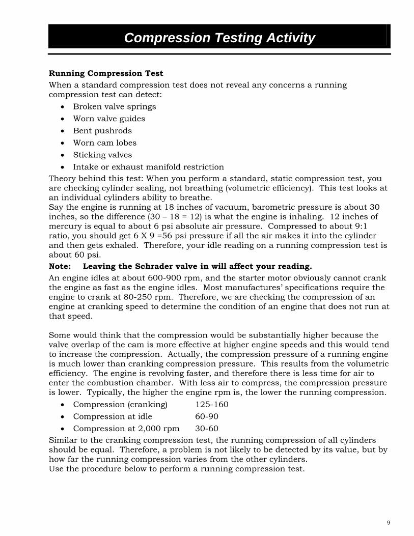
Running Compression Test When a standard compression test does not reveal any concerns a running compression test can detect:
• Broken valve springs • Worn valve guides • Bent pushrods • Worn cam lobes • Sticking valves • Intake or exhaust manifold restriction
Theory behind this test: When you perform a standard, static compression test, you are checking cylinder sealing, not breathing (volumetric efficiency). This test looks at an individual cylinders ability to breathe. Say the engine is running at 18 inches of vacuum, barometric pressure is about 30 inches, so the difference (30 – 18 = 12) is what the engine is inhaling. 12 inches of mercury is equal to about 6 psi absolute air pressure. Compressed to about 9:1 ratio, you should get 6 X 9 =56 psi pressure if all the air makes it into the cylinder and then gets exhaled. Therefore, your idle reading on a running compression test is about 60 psi. Note: Leaving the Schrader valve in will affect your reading. An engine idles at about 600-900 rpm, and the starter motor obviously cannot crank the engine as fast as the engine idles. Most manufactures’ specifications require the engine to crank at 80-250 rpm. Therefore, we are checking the compression of an engine at cranking speed to determine the condition of an engine that does not run at that speed. Some would think that the compression would be substantially higher because the valve overlap of the cam is more effective at higher engine speeds and this would tend to increase the compression. Actually, the compression pressure of a running engine is much lower than cranking compression pressure. This results from the volumetric efficiency. The engine is revolving faster, and therefore there is less time for air to enter the combustion chamber. With less air to compress, the compression pressure is lower. Typically, the higher the engine rpm is, the lower the running compression.
• Compression (cranking) 125-160 • Compression at idle 60-90 • Compression at 2,000 rpm 30-60
Similar to the cranking compression test, the running compression of all cylinders should be equal. Therefore, a problem is not likely to be detected by its value, but by how far the running compression varies from the other cylinders. Use the procedure below to perform a running compression test.
9

Compression Testing Activity
Note: This test is done with a conventional gauge.
RECORD ALL READINGS BELOW
1. Remove the spark plug from one of the 4 cylinders that were used for the static test.
2. Remove the Schrader valve from the compression gauge. 3. Screw the compression gauge into the spark plug hole. 4. Ground the spark plug wire, or unplug the coil for coil near plug engines, and
disconnect the fuel injector. 5. Start the engine. 6. Record the gauge reading at maximum sweep of the needle below. To see the
maximum sweep of the needle, use a piece of paper to cover the gauge face through the center of the gauge and rotate the paper until the needle disappears. Then back the paper up until the needle reappears. (pivot the paper around the center of the gauge)
7. Turn off the engine. 8. Remove the compression gauge, reinstall the spark plug and wire, and connect
the fuel injector. 9. Repeat steps 1-8 for the 3 more cylinders. Use the same 3 cylinders that were
used for the static compression test. Allow a 10 percent variance from the highest to the lowest cylinder.
Running Compression Readings
Cyl. # 1 _______ psi
Cyl. # 2 _______ psi
Cyl. # 3 _______ psi
Cyl. # 4 _______ psi
10

Cylinder Leakdown Testing
CYLINDER LEAKDOWN TEST The cylinder leakdown test is an accurate way of determining engine condition. The test detects if exhaust and intake valves are not seating properly, and checks for any leaks between adjacent cylinders or into the water jacket. The cylinder leakdown test also checks for any causes of combustion and compression pressure losses. WARNING: On a Closed Cooling System Engine Do Not Remove The Cooling
System Pressure Cap With The System Hot And Under Pressure Because Serious Burns From Coolant Can Occur.
1. On a closed cooling system engine, check the coolant level and fill as necessary. Do not install the cooling system pressure cap.
2. Start the engine and operate it until it reaches normal operating temperature.
3. Turn off the engine.
4. Remove the spark plugs. On a raw water cooled engine, disconnect the exhaust bypass hoses from the T-stat housing and install the clear-hose test set up. Tie the bypass hoses still connected to the T-stat housing to a vertical position and back fill the hoses to ensure that the engine is full of water.
5. Remove the oil filler cap.
6. Remove the air cleaner.
7. Calibrate the tester according to the manufacturer’s instructions. The shop air source for testing should maintain 483 kPa (70 psi) minimum or 1379 kPa (200 psi) maximum. The recommended pressure is 689 kPa (100 psi).
WARNING: Each Piston Must Be Exactly TDC When Checked, Otherwise The Engine Could Spin A Half Turn And Cause Injury.
8. Perform the test procedures on each cylinder according to the manufacturer’s instructions. While testing, listen for pressurized air escaping through the throttle body, tailpipe, and oil filler cap opening. Check for bubbles in the radiator coolant.
All gauge pressure indications should be equal, with no more than 25 percent leakage. For example: At 552 kPa (80 psi) input pressure, a minimum of 414 kPa (60 psi) should be maintained in the cylinder. Record your readings on the next page.
11

Cylinder Leakdown Testing
Leakdown Test Readings
Cyl. # 1 _______ psi
Cyl. # 2 _______ psi
Cyl. # 3 _______ psi
Cyl. # 4 _______ psi
Cyl. # 5 _______ psi
Cyl. # 6 _______ psi
Cyl. # 7 _______ psi
Cyl. # 8 _______ psi
What is the condition of the cylinders of this engine?
___________________________________________________________________________
___________________________________________________________________________
___________________________________________________________________________
12

MEFI Fuel Injection
8.1Gi/GXi
This is what we start with. The engines arrive from GM in different states of assembly according to which engine it is (carbureted or fuel injected). The engine is then marinized at our plant in Lexington, TN.
13

MEFI Fuel Injection
8.1Gi/GXi
This is what we build. Fully marinized and ready for shipment.
14

MEFI Fuel Injection
Model Identification for Joint Venture Product to Current Product
Displacement of engine in Liters:
Manufacturer of Base engine:
G – General Motors
F – Ford Motor Company
Engine Performance: Fuel Delivery Type:
3.04.35.05.75.87.48.18.2
L – Low Output(lowest possible output)
S – Superior Output
X – “Extreme” Output(highest possible output)
***The absence of a letter indicates the standard output of this type of engine.
Ex: 5.7Gi PEFS
i – Electronic Fuel Injection:
The absence of “i” indicates a carbureted engine
5.7GSi PEFSExample:
5.7 G S i
Engine model designation begins with the displacement of the engine in liters. The next digit denotes the engine manufacturer. All of our current engines are GM blocks. The next digit denotes a subjective power rating. This rating doesn’t indicate horsepower. It can only be used comparing engines. If there is a Gi and a GXi of the same displacement, side by side, then the GXi has more horse power than the Gi. The small “ i ” at the end indicates that the engine is fuel injected. The absence of the “ i ” in the model number indicates that the engine is carbureted.
15

MEFI Fuel InjectionExample: 5.7GSi PEFS
P EF S
Type of Steering
M- Mechanical
P - Power Assisted
X - Xact
Parts and Service Literature Reference Code
Between 1994 and 2001 Volvo Penta used a two character alphabetical code to designate which parts and service manuals to use while servicing these engines. These codes do not translate into specific meanings. Volvo Penta does not use “Model Year”designations and therefore a serial number or specific model number must be obtained in order to reference the correct service literature.
As of 2001, Volvo Penta started using a single letter designation that ascends as engine or model year changes occur. This is still a reference to which service literature to use.
MDHUNCLKBYWTEF
-A-B-C
Additional Engine Information
A series of unidentified letters that may designate changes or options with an engine that will be notated in a service or parts catalog when multiple procedures or parts may be a factor .
*** Special Note: ***
An Inboard application will include a capital “I” in the model designation. Ex. 7.4Gi IEFS.
Later models, a capital “F” indicates a freshwater cooling option. Ex: 8.1GXi-BF
The next digit (in the older numbering system) is the type of steering the boat is equipped with. The next 2 digits (in the old numbering system) indicate which service and parts literature is to be used. The new numbering system is shown on the next page and also parts bulletin P-00-0-3 which is located a couple of pages later in in this book.
16

MEFI Fuel InjectionExample: 8.1GXi -EF
GXi-EF
Type of Steering
M- Mechanical
P - Power Assisted
X - Xact
Parts and Service Literature Reference Code
Between 1994 and 2001 Volvo Penta used a two character alphabetical code to designate which parts and service manuals to use while servicing these engines. These codes do not translate into specific meanings. Volvo Penta does not use “Model Year”designations and therefore a serial number or specific model number must be obtained in order to reference the correct service literature.
As of 2001, Volvo Penta started using a single letter designation that ascends as engine or model year changes occur. This is still a reference to which service literature to use.
MDHUNCLKBYWTEF
-A-B-C
Additional Engine Information
A series of unidentified letters that may designate changes or options with an engine that will be notated in a service or parts catalog when multiple procedures or parts may be a factor .
*** Special Note: ***
An Inboard application will include a capital “I” in the model designation. Ex. 7.4Gi IEFS.
Later models, a capital “F” indicates a freshwater cooling option. Ex: 8.1GXi-BF
00-05 Model ChartPublication Selector for Engines
Engine Numbering Bulletin
This is an example of an 2005 8.1GXi-EF engine package. This is a high output 8.1L with a closed cooling system. This means that the engine cooling system contains a mixture of antifreeze and water. This mixture gets cooled by raw water (water the boat is operating in) in a heat exchanger located somewhere on the engine.To determine correct manual usage for the engine you are working on, first determine which model you are working on, then open the Publication Selector for Engines “pdf” file (using the Adobe Acrobat Reader program) and while holding the control key down type the letter F (the find function). In the find function type the engine model being worked on and press enter.
This document is available on www.vppn.com (Partner Network Website) in the Technical Information section. The file can then be saved to the dealer’s computer. This file is updated periodically.
Also available through Partner Network is a search feature to find all publications by serial number.
17

200
0 - 2
005
Gas
Eng
ine
Bui
ld C
hart
3.0
L, 4
.3L(
all)
and
5.0L
Car
b
EF 2
000
EF 2
001
MY
2002
, SO
FA 1
(6/0
1)
MY
2002
, SO
FA 2
(10/
01)
MY
2003
, SO
FA 1
30 G
LM-A
Des
igna
tion
386
9170
30 G
LP-A
Des
igna
tion
386
9171
3.0
GL
Sam
e 13
5 H
P R
atin
g as
3.0
GS
Das
h M
ount
ed W
arni
ng H
orn
New
Sty
le F
lush
Atta
chm
ent
RED
30G
SM
EFS
386
9051
30 G
SM
-A D
esig
natio
n 38
6910
530
GS
M-B
Des
igna
tion
386
9111
30 G
SM
-C D
esig
natio
n 3
8691
4730
GS
PE
FS
3869
052
30 G
SP
-A D
esig
natio
n 38
6910
630
GS
P-B
Des
igna
tion
386
9112
30 G
SP
-C D
esig
natio
n 3
8691
483.
0 G
S4
Poi
nt E
ngin
e M
ount
sC
oolin
g Fl
ow C
hang
edS
erpe
ntin
e B
elt
G
REY
G
REY
Cra
nksh
aft M
ount
Sea
wat
er P
ump
Aud
io W
arni
ng H
orn
43G
L-B
Des
igna
tion
386
9174
Shr
oude
d E
x. O
verh
eat S
enso
r4.
3 G
LD
ash
Mou
nted
War
ning
Hor
nN
ew S
tyle
Flu
sh A
ttach
men
tR
ED
43G
Xi-A
Des
igna
tion
386
9114
43G
Xi-B
Des
igna
tion
386
9132
43G
Xi-C
Des
igna
tion
386
9176
Exh
aust
Ove
rhea
t Sen
sors
43G
Xi-B
F D
esig
natio
n 3
8691
5543
GX
i-CF
Des
igna
tion
386
9178
Flus
h A
ttach
men
t22
5HP
Das
h M
ount
ed W
arni
ng H
orn
Rat
ing
205
hp->
225
hpIA
FM S
yste
mIA
FM S
yste
m T
BI
MEF
I 3
MEF
I 4
ECM
MEF
I 4
ECM
RED
RED
RED
50G
L-A
Des
igna
tion
386
9115
50G
L-B
Des
igna
tion
386
9162
50G
L-C
Des
igna
tion
386
9181
Exh
aust
Ove
rhea
t Sen
sors
Exh
aust
Ove
rhea
t Sen
sors
Shr
oude
d E
x.O
verh
eat S
enso
rsFl
ush
Atta
chm
ent
Flus
h A
ttach
men
tD
ash
Mou
nted
War
ning
Hor
nP
latin
um S
park
Plu
gsP
latin
um S
park
Plu
gsN
ew S
tyle
Flu
sh A
ttach
men
tR
EDG
M H
I Ign
ition
Sys
tem
GM
HI I
gniti
on S
yste
mR
EDR
ED
4.3
Car
b
4.3
EFI
NO
NE
BU
ILT
NO
NE
BU
ILT
NO
NE
BU
ILT
Pla
tinum
Spa
rk P
lugs
Exh
aust
Ove
rhea
t Sen
sor
Flus
h A
ttach
men
t
43G
i PE
FS 3
8690
55
43G
L P
EFS
386
9053
3.0
Car
b
5.0
Car
bG
REY
RED
GR
EY
GR
EYR
ED
43G
L-A
Des
igna
tion
386
9113
Exh
aust
Ove
rhea
t Sen
sors
Flus
h A
ttach
men
tA
udio
War
ning
Hor
nR
olle
r Roc
kers
Aud
io W
arni
ng H
orn
Fuel
Mod
ule
Ser
pent
ine
Bel
t
(Kee
ps V
-Bel
ts)
TBI
MEF
I 3
50G
LPE
FS 3
8690
56
NO
NE
BU
ILT
4.3G
i
4.3G
Xi
Aud
io W
arni
ng H
orn
(Kee
ps V
-Bel
ts)
18

200
0 - 2
005
Gas
Eng
ine
Bui
ld C
hart
3.0
L, 4
.3L(
all)
and
5.0L
Car
b
MY
2003
, SO
FA 2
(01/
01/0
3)M
Y 20
04M
Y 20
0530
GLM
-B D
esig
natio
n 3
8692
1130
GLM
-C D
esig
natio
n 3
8692
4930
GLM
-C D
esig
natio
n 3
8692
4930
GLP
-B D
esig
natio
n 3
8692
1230
GLP
-C D
esig
natio
n 3
8692
5030
GLP
-C D
esig
natio
n 3
8692
503.
0 G
L13
5 H
P
135
HP
13
5 H
P
Sam
e as
MY
03 S
OFA
1C
AR
B ce
rtifie
dC
AR
B ce
rtifie
dC
AR
B ce
rtifie
dR
EDR
EDR
ED
3.0
GS
43G
L-C
Des
igna
tion
386
9213
43G
L-D
Des
igna
tion
386
9251
43G
L-D
Des
igna
tion
386
9251
Sam
e as
MY
03 S
OFA
1C
AR
B ce
rtifie
dC
AR
B ce
rtifie
dC
AR
B ce
rtifie
d
RED
RED
RED
43G
Xi-D
Des
igna
tion
386
9214
43G
Xi-E
Des
igna
tion
386
9252
43G
Xi-E
Des
igna
tion
386
9252
43G
Xi-D
F D
esig
natio
n 3
8692
1543
GX
i-EF
Des
igna
tion
386
9253
43G
Xi-E
F D
esig
natio
n 3
8692
53S
ame
as M
Y03
SO
FA 1
43O
Si-E
Des
igna
tion
3869
268
43O
Si-E
Des
igna
tion
3869
268
CA
RB
certi
fied
43O
Si-E
F D
esig
natio
n 38
6926
943
OS
i-EF
Des
igna
tion
3869
269
IAFM
MEF
I 4
ECM
IAFM
MEF
I 4b
EC
MIA
FM M
EFI
4b E
CM
RED
RED
RED
50G
L-D
Des
igna
tion
386
9216
50G
L-E
Des
igna
tion
386
9254
50G
L-E
Des
igna
tion
386
9254
Sam
e as
MY
03 S
OFA
1C
AR
B ce
rtifie
dC
AR
B ce
rtifie
dC
AR
B ce
rtifie
d
GM
HI I
gniti
on S
yste
mG
M H
I Ign
ition
Sys
tem
GM
HI I
gniti
on S
yste
mR
EDR
EDR
ED
4.3G
i
4.3G
Xi
NO
NE
BU
ILT
NO
NE
BU
ILT
5.0
Car
b
4.3
Car
b
4.3
EFI
3.0
Car
b
19
200
0 - 2
005
Gas
Eng
ine
Bui
ld C
hart
5.0
L EF
I and
5.7
L C
arb
EF 2
000
EF 2
001
MY
2002
, SO
FA 1
(6/0
1)
MY
2002
, SO
FA 2
(10/
01)
50G
Xi-A
Des
igna
tion
386
9116
50G
Xi-B
Des
igna
tion
386
9134
Exh
aust
Ove
rhea
t Sen
sors
50G
Xi-B
F D
esig
natio
n 3
8691
56Fl
ush
Atta
chm
ent
270H
PR
atin
g 25
0 hp
-> 2
70hp
IAFM
Sys
tem
TB
I M
EFI 3
M
EFI
4 EC
MR
EDR
ED57
GL-
A D
esig
natio
n 3
8691
4657
GL-
B D
esig
natio
n 3
8691
63
MY
2003
MY
2003
SO
FA 2
(10/
01/0
3)M
Y 20
04M
Y200
5
50G
Xi-C
Des
igna
tion
386
9183
50G
Xi-D
Des
igna
tion
386
9217
50G
Xi-E
Des
igna
tion
386
9255
50G
Xi-E
Des
igna
tion
386
9255
50G
Xi-C
F D
esig
natio
n 3
8691
8550
GX
i-DF
Des
igna
tion
386
9218
50G
Xi-E
F D
esig
natio
n 3
8692
5650
GX
i-EF
Des
igna
tion
386
9256
Das
h M
ount
ed W
arni
ng H
orn
Sam
e as
MY
03 S
OFA
150
OS
i-E D
esig
natio
n 3
8692
7050
OS
i-E D
esig
natio
n 3
8692
70
IAFM
Sys
tem
CA
RB
certi
fied
50O
Si-E
F D
esig
natio
n 3
8692
7150
OS
i-EF
Des
igna
tion
386
9271
MEF
I 4
ECM
IAFM
MEF
I 4
ECM
IAFM
MEF
I 4b
EC
MIA
FM M
EFI
4b E
CM
RED
RED
RED
RED
57G
L-C
Des
igna
tion
386
9188
57G
L-D
Des
igna
tion
386
9219
57G
L-E
Des
igna
tion
386
9257
Shr
oude
d E
x. O
verh
eat S
enso
rsS
ame
as M
Y03
SO
FA 1
Das
h M
ount
ed W
arni
ng H
orn
CA
RB
certi
fied
CA
RB
certi
fied
New
Sty
le F
lush
Atta
chm
ent
GM
HI I
gniti
on S
yste
mG
M H
I Ign
ition
Sys
tem
GM
HI I
gniti
on S
yste
m
RED
RED
RED
GR
EY
Exh
aust
Ove
rhea
t Sen
sors
NO
NE
BU
ILT
Flus
h A
ttach
men
t
NO
NE
BU
ILT
5.0G
i
5.0
EFI
5.7G
L
50G
i PE
FS D
esig
natio
n 3
8690
57M
AT
Sen
sor A
dded
Ser
pent
ine
Bel
tA
udio
War
ning
Hor
nFu
el M
odul
e
NO
NE
BU
ILT
TBI
MEF
I 3
5.0G
Xi
5.7G
S
5.7
Car
b
5.0
EFI
5.0G
i
5.0G
Xi
5.7G
L
5.7
Car
b
NO
NE
BU
ILT
Pla
tinum
Spa
rk P
lugs
Rat
ing
250
hp ->
260
hp
GR
EY
RED
57G
S P
EFS
386
9058
Aud
io W
arni
ng H
orn
(Kee
ps V
-Bel
ts)
NO
NE
BU
ILT
NO
NE
BU
ILT
NO
NE
BU
ILT
5.7G
S
20
200
0 - 2
005
Gas
Eng
ine
Bui
ld C
hart
5.7
EFI
, 7.4
and
8.2
L
EF 2
000
EF 2
001
MY
2002
, SO
FA 1
(6/0
1)
MY
2002
, SO
FA 2
(10/
01)
57G
i-A D
esig
natio
n 3
8691
1757
Gi-B
Des
igna
tion
3869
136
Exh
aust
Ove
rhea
t Sen
sors
57G
i-BF
Des
igna
tion
3869
157
Flus
h A
ttach
men
t28
0 hp
ratin
g28
0 hp
IAFM
Sys
tem
TB
I M
EFI 3
M
EFI 4
EC
MR
EDR
ED
57G
Xi-A
Des
igna
tion
3869
096
57G
Xi-B
Des
igna
tion
3869
118
57G
Xi-C
Des
igna
tion
3869
137
Mod
ified
Inta
keM
odifi
ed In
take
57G
Xi-C
F D
esig
natio
n 38
6915
81.
61 ra
tio R
ocke
r Arm
s1.
61 ra
tio R
ocke
r Arm
s1.
61 ra
tio R
ocke
r Arm
s
320
hp
310
hpR
ated
315
hp ->
320
IAFM
Sys
tem
TBI
MEF
I 3TB
I M
EFI 3
MEF
I 4 E
CM
RED
RED
RED
74G
i PE
FS 3
8690
60S
erpe
ntin
e B
elt
Aud
io W
arni
ng H
orn
Fuel
Mod
ule
GR
EYM
EFI 3
74G
Si P
EFS
386
9061
Ser
pent
ine
Bel
tA
udio
War
ning
Hor
nFu
el M
odul
eG
REY
MEF
I 382
GS
i PE
FS 3
8690
62S
erpe
ntin
e B
elt
Aud
io W
arni
ng H
orn
Fuel
Mod
ule
GR
EYM
EFI 3
NO
NE
BU
ILT
NO
NE
BU
ILT
NO
NE
BU
ILT
NO
NE
BU
ILT
NO
NE
BU
ILT
7.4G
Si
5.7G
i
5.7G
Si
5.7G
Xi
5.7
EFI
7.4
EFI
8.2
EFI
57G
Si P
EFS
Des
igna
tion
386
9059
MA
T S
enso
r Add
ed
S
erpe
ntin
e B
elt
Aud
io W
arni
ng H
orn
Fuel
Mod
ule
TBI
MEF
I 3G
REY
7.4G
i
21

200
0 - 2
005
Gas
Eng
ine
Bui
ld C
hart
5.7
EFI
, 7.4
and
8.2
L
MY
2003
MY
2003
SO
FA 2
(01/
01/0
3)M
Y 20
04M
Y 20
05
57G
i-C D
esig
natio
n 3
8691
8957
Gi-D
Des
igna
tion
386
9220
57G
i-E D
esig
natio
n 3
8692
5857
Gi-E
Des
igna
tion
386
9258
57G
i-CF
Des
igna
tion
3869
190
57G
i-DF
Des
igna
tion
3869
221
57G
i-EF
Des
igna
tion
3869
259
57G
i-EF
Des
igna
tion
3869
259
Das
h M
ount
ed W
arni
ng H
orn
Sam
e as
MY
03 S
OFA
157
OS
i-D D
esig
natio
n 3
8692
7257
OS
i-D D
esig
natio
n 3
8692
72
IAFM
Sys
tem
CA
RB
cer
tifie
d57
OS
i-DF
Des
igna
tion
3869
259
57O
Si-D
F D
esig
natio
n 38
6925
9
MEF
I 4 E
CM
IAFM
MEF
I 4 E
CM
IAFM
MEF
I 4b
ECM
IAFM
MEF
I 4b
ECM
RED
RED
RED
RED
57G
Xi-D
Des
igna
tion
3869
193
57G
Xi-E
Des
igna
tion
3869
222
57G
Xi-F
Des
igna
tion
3869
260
57G
Xi-F
Des
igna
tion
3869
260
57G
Xi-D
F D
esig
natio
n 38
6919
457
GX
i-EF
Des
igna
tion
3869
223
57G
Xi-F
F D
esig
natio
n 38
6926
157
GX
i-FF
Des
igna
tion
3869
261
Das
h M
ount
ed W
arni
ng H
orn
Sam
e as
MY
03 S
OFA
157
OS
Xi-D
Des
igna
tion
3869
274
57O
SX
i-D D
esig
natio
n 38
6927
4
IAFM
Sys
tem
CA
RB
cer
tifie
d57
OS
Xi-D
F D
esig
natio
n 38
6927
557
OS
Xi-D
F D
esig
natio
n 38
6927
5
MEF
I 4 E
CM
IAFM
MEF
I 4 E
CM
IAFM
MEF
I 4b
ECM
IAFM
MEF
I 4b
ECM
RED
RED
RED
RED
NO
NE
BU
ILT
NO
NE
BU
ILT
NO
NE
BU
ILT
NO
NE
BU
ILT
5.7
EFI
5.7G
i
5.7G
Si
5.7G
Xi
7.4
EFI
7.4G
i
7.4G
Si
8.2
EFI
22
200
0 - 2
005
Gas
Eng
ine
Bui
ld C
hart
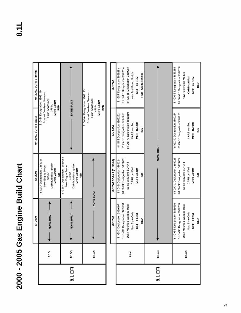
8.1
L
EF 2
000
EF 2
001
MY
2002
, SO
FA 1
(6/0
1)
MY
2002
, SO
FA 2
(10/
01)
81G
i-A D
esig
natio
n 3
8690
87N
ew E
ngin
e M
odel
375
hpD
istri
buto
rless
Igni
tion
MEF
I 4
ECM
RED
81G
Si-A
Des
igna
tion
386
9088
New
Eng
ine
Mod
el42
0 hp
Dis
tribu
torle
ss Ig
nitio
nM
EFI
4 EC
MR
ED
MY
2003
MY
2003
SO
FA 2
(01/
01/0
3)M
Y 20
04M
Y 20
05
81 G
i-C D
esig
natio
n 38
6919
781
Gi-D
Des
igna
tion
3869
224
81 G
i-E D
esig
natio
n 38
6926
281
Gi-F
Des
igna
tion
3869
283
81 G
i-CF
Des
igna
tion
3869
198
81 G
i-DF
Des
igna
tion
3869
225
81 G
i-EF
Des
igna
tion
3869
263
81 G
i-FF
Des
igna
tion
3869
284
Das
h M
ount
ed W
arni
ng H
orn
Sam
e as
MY
03 S
OFA
181
OS
i-A D
esig
natio
n 38
6928
081
OS
i-B D
esig
natio
n 38
6928
7
New
Sty
le C
oils
CA
RB
certi
fied
CA
RB
certi
fied
New
Fue
l Pum
p M
odul
e
MEF
I 4
ECM
MEF
I 4
ECM
MEF
I 4b
EC
MM
EFI
4b E
CM
RED
RED
RED
RED
C
AR
B c
ertif
ied
81 G
Xi-B
Des
igna
tion
3869
199
81 G
Xi-C
Des
igna
tion
3869
226
81 G
Xi-D
Des
igna
tion
3869
264
81 G
Xi-E
Des
igna
tion
3869
285
81 G
i-BF
Des
igna
tion
3869
200
81 G
i-CF
Des
igna
tion
3869
227
81 G
i-DF
Des
igna
tion
3869
265
81 G
Xi-E
F D
esig
natio
n 38
6928
6
Das
h M
ount
ed W
arni
ng H
orn
Sam
e as
MY
03 S
OFA
1N
ew F
uel P
ump
Mod
ule
New
Sty
le C
oils
CA
RB
cer
tifie
dC
AR
B c
ertif
ied
CA
RB
cer
tifie
d
MEF
I 4
ECM
MEF
I 4
ECM
MEF
I 4b
EC
MM
EFI
4b E
CM
RED
RED
RED
RED
NO
NE
BU
ILT
NO
NE
BU
ILT
MEF
I 4
ECM
RED
Flus
h A
ttach
men
t37
5 hp
8.1G
XiN
ON
E B
UIL
T
NO
NE
BU
ILT
MEF
I 4
ECM
RED
81G
Xi-A
Des
igna
tion
386
9123
Exh
aust
Ove
rhea
t Sen
sors
Flus
h A
ttach
men
t42
0 hp
8.1
EFI
8.1G
i
8.1G
Si
NO
NE
BU
ILT
8.1
EFI
8.1G
i
8.1G
Si
8.1G
Xi
81G
i-B D
esig
natio
n 3
8691
19E
xhau
st O
verh
eat S
enso
rs
23

Volvo Penta of the Americas1300 Volvo Penta DriveChesapeake, Virginia 23320-9810
How to identify a Volvo Penta gas engine
Models: later model gas engines
Distribution: Parts Date: Jan-2005 Binder: Parts Replaces: VPA 51-900
Parts BulletinGroup Number Version
P-00-0 3 01
24
To help you easily find parts and service information about our products, Volvo Penta has developed online search tools that are available only on our website, Partner Network. As an example, in July, 2004 we launched a serial number search for gas engines and drives. You can enter the product’s serial number and the system will provide you with all of the catalogs, manuals and bulletins that apply to that product. The system also provides links to online versions of these documents. New tools such as this are added perodically to make it easier for you to find information about the Volvo Penta products you are servicing. This is another way to insure that you have the latest, most current information about our products. Contact your dealer business specialist to sign up for the Partner Network.
The engine model name can also be used to search for parts or information. The text that follows explains the model names used by Volvo Penta for gas engines. Understanding these model names will help in finding the correct parts and information for the engines, whether you’re searching on-line or in paper publications.
Several methods have been used to provide the gas engines with unique model names. Some were based on horsepower ratings. More recent names are based on the displacement of the engine in liters. Each time the name was changed, it was due to some change in the parts content of the engine. Sometimes the changes were minor, sometimes they were major. The changes may or may not affect the
parts that you need for a repair. The safest method is to always search with the complete model name.
There are three distinct periods of gas engine production, each with a different naming method. Each is explained below;
Red Engines, early
Very early engines, built until the late 1980’s, were named based on the displacement (early) or horsepower (later) of the engines. The name started with AQ (sterndrive engine), BB (inboard) or MB (inboard). Next came the number for the displacement or horsepower. Most of these also included a one letter suffix, for version control. An AQ271A is older (and different) than a AQ271B.
EXAMPLES: AQ260A, AQ171C, AQ200F, BB260A
These engine names then changed to a system based on displacement. The names were a three digit number, followed by a letter. The first two digits of the number represented the displacement. The 43 in 434A meant the engine was a 4.3L. The third digit was used for version control. A 430 and a 431 are both 4.3L’s, however the last digit indicates there is difference between the engines. The numbers at the third digit were not always sequential. 430’s were built before 431’s, however 432’s and 434’s were built at the same time.
The letter at the end was also used for version control and was sequential. A 500A was built before a 500B.

Volvo Penta of the Americas Group Number Version Page
Parts Bulletin P-00-0 3 01 2(3)
These engines went out of production in 1993.
EXAMPLES: 432A, 500B, 251A, 740B
Nothing in the names in either of these sytems relates in any way to years of production. Some of these engines were in production for less than a year, others for many years.
Charcoal Engines
These engines were built during the joint venture with OMC and were painted a dark charcoal color. They were usually named by long character strings that contain two numbers followed by a series of letters.
· The character string starts with twonumbers, which are thedisplacement in liters.
· Next is a letter that indicates whomade the base engine.
G=GM, F=Ford
· After that, one or two letters that note the fuel system and/or output.
L=limited, S=superior,X=exceptional, i or I=fuel injected(no I means carburetted)
· Then one letter for the steeringsystem.P=power steering, M=manual,X=Exact steering, I=inboard
· The next two letters are the most important for finding parts. These are random letter pairs called model designators that indicate the years of production for the engine. All parts information for these engines is based on these letter codes.
· The next letter is also random and is used for version control. An “A” may not be the first version. A “C” may not have been built before an “S”. An “S” in one engine’s name may not mean the same thing as an “S” in another engine’s name, especially if the engines have different displacements or production years. When needed this code is noted in the parts publications.
· Some names have the letters “CE” at the end. This indicates the engine meets certain emmission requirements. The only service part affected is the ECU. These part numbers are noted when needed in the catalogs.
These engines went out of production in 2000.
EXAMPLES:
4.3GLPBYC = 4.3L, G=GM, L=limited output, carburetted (no i), P=power steering, BY=model designator, C=service code for version control
Model Designators
letter years of
code production
MD 1993-1994
HU 1994-1995
NC 1995-1996
LK 1996-1997
BY 1997-1998
WT 1998-1999
EF 1999-2000
25

Volvo Penta of the Americas Group Number Version Page
Parts Bulletin P-00-0 3 01 3(3)
5.8FSiPNCACE = 5.8L, Ford, Superior output, injected, power steering, NC=model designator, A service code, CE=certified emmissions
7.4GLPHUS = 7.4L, GM,limited output, carburetted, power steering, HU=model designator, S service code
3.0GLMMDA = 3.0L, GM,limited output, carburetted, manual steering, MD=model designator, A service code
Red Engines, current
Beginning in 2000 the gas engines are painted red again. The naming system was also changed. The first part of the name is the same as the charcoal engines, up to the letters for the fuel system.
· The two numbers are thedisplacement.
· Next is a letter that indicates who made the base engine. New engines have been added that use Volvo Penta’s new Ocean Series sterndrives, these engines have an OS for this letter.
· After that, one or two letters that note the fuel system and/or output.
· For 3.0L only, there is an M or P for the steering
· For Inboard engines only, there is an I after the lower case i.
· Then a dash (-) followed by a one or two letter suffix.This is the major change from the charcoal engines above.
The first letter is the version control, this is present on all models. –A is the first version, -B was the second version, etc… There is no link between the suffix and production years. All engines with –A were not built the same year. A 5.7GXi-B and a 5.0GXi-B
are not similar. A 4.3GL-D is newer than and different from a 4.3GL-C.
The second letter, if present is always an F, it notes that the engine is freshwater cooled.
EXAMPLES:
3.0GLM-C4.3GXi-DF5.0OSi-E8.1GXiI-B
26

MEFI Fuel Injection
ID TagsID Tag for Engine, drive and TSK
ID Tag for Engine
All engines have two engine ID tags, one is a sticker located somewhere near the front and top of the engine. In current production engines, the tag is located on the “rain hat” or plastic engine cover. The other tag is riveted to the engine block, left bank just forward of the flywheel housing. These tags contain the model number for the engine, the serial number of the engine and the specification number for the engine.The tag on the rain hat should also have the stickers for the transom shield and the drive (if applicable) attached to it.
27

Volvo Penta of the Americas1300 Volvo Penta DriveChesapeake, Virginia 23320-9810USA
Distribution: M Date: 07-2002 Binder: C Page: 1(2)
Service BulletinGroup Number Version
26-6 8 01
ComponentEngine Models
8.1Gi, 8.1GSi, 375DPX and 420DPX
During our routine auditing process of production, we have found certain inconsistencies within the thermostathousing of the 8.1 engines (P/N 3860872). Casting imperfections might be present that would prevent correctwater flow through this housing. Certain intake water temperatures and ambient air temperatures couldproduce water temperatures within the engine that could activate the alarm, thus causing the engine to enter“Power Reduction Mode”.
If you are investigating a high speed overheat condition, you should check this housing for anything (debris,casting slag) that can restrict the water flow to the exhaust manifolds. Inspect all hoses for kinked or collapsedhoses. The engine cooler is the first place the water is routed after the seawater pump, this tube type coolershould be checked for blockage.
If all the above items have been checked and eliminated, the passage for incoming water through the hosingmay be improperly sized. The following procedure explains how to be sure this possibility is eliminated.
NOTE ! To ensure the best accuracy while drilling and tapping, this procedure should be done with the housingremoved from the engine.
NOTE ! Drain and remove all hoses from the thermostat housing.
1. Remove the 90° pipe to hose fitting for the cooling hose to the fuel cell.
2. Clamp the housing securely.
Casting Imperfection22336
28
Group Number Version Page
26–6 8 01 2(2)
Volvo Penta of the AmericasService Bulletin
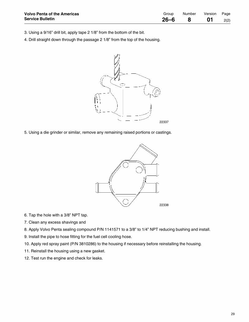
3. Using a 9/16” drill bit, apply tape 2 1/8” from the bottom of the bit.
4. Drill straight down through the passage 2 1/8” from the top of the housing.
5. Using a die grinder or similar, remove any remaining raised portions or castings.
6. Tap the hole with a 3/8” NPT tap.
7. Clean any excess shavings and
8. Apply Volvo Penta sealing compound P/N 1141571 to a 3/8” to 1/4” NPT reducing bushing and install.
9. Install the pipe to hose fitting for the fuel cell cooling hose.
10. Apply red spray paint (P/N 3810286) to the housing if necessary before reinstalling the housing.
11. Reinstall the housing using a new gasket.
12. Test run the engine and check for leaks.
22338
22337
29
MEFI Fuel Injection
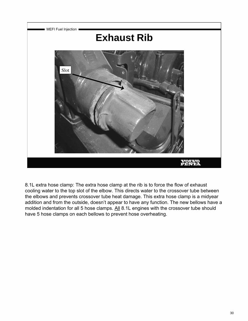
Exhaust Rib
Slot
8.1L extra hose clamp: The extra hose clamp at the rib is to force the flow of exhaust cooling water to the top slot of the elbow. This directs water to the crossover tube between the elbows and prevents crossover tube heat damage. This extra hose clamp is a midyear addition and from the outside, doesn’t appear to have any function. The new bellows have a molded indentation for all 5 hose clamps. All 8.1L engines with the crossover tube should have 5 hose clamps on each bellows to prevent hose overheating.
30

MEFI Fuel Injection
New for 2003 and Beyond 2003 IAFM MPFI Models
4.3 GXi 5.0 GXi 5.7 GXi
The acronym (first used in 2003) IAFM stands for a new multi port fuel injection system called Integrated Air Fuel Module. This is a combination of intake manifold, throttle body, and injectors. This setup changes these engines from TBI to MPI type engines.With this new system, Volvo Penta has increased the power output of our marine gasoline engines up to 20 more HP. With power ratings of up to 320 HP, the upgraded engines become faster and more reliable.
In Fall of 2001 Volvo Penta stopped producing throttle body injected gasoline engines. For 2005 we offer carbureted and Multi-port Fuel Injected (MFI) engines.
In carbureted engines, Volvo Penta offers the 3.0GL, 4.3GL, 5.0GL and the 5.7GL
In the IAFM multi port configuration, Volvo Penta offers the six cylinder 4.3L, the V8 small block 5.0L, and the 5.7L.
The big block 8.1L is again offered as MPFI, although it is not of IAFM configuration. For 05, the 8.1L uses a returnless fuel system. There is only one fuel line to the fuel rail and the pressure regulator has been moved from the fuel rail to the fuel pump module.
31

MEFI Fuel Injection
Changes for 2004EFI ENGINES
New exhaust bellows to reduce noise and vibration on the 5.0, 5.7 and 8.1L engines.
New 8.1L oil coolerNew emissions calibrationsA second knock sensor on the 4.3Gxi, 5.0Gxi, 5.7Gi and the 5.7GxiNew ECM anti-knock strategy for all EFI enginesEVC (Electronic Vessel Control) compatible harnesses for all EFI
enginesNew ECM for all engines: MEFI 4b Same functionality, just new
hardware
CARBURETED ENGINESNew Tyco electrical supply box with new engine harnessesNew emissions calibrations
There were very few changes for the 2005 model year. The changes are noted above.
32

MEFI Fuel Injection
On Carbed Engines, THIS ….
Individual fuses and relays got integrated into one box.
33

MEFI Fuel Injection
Becomes, THIS !
A single fuse box similar to the fuel injected engines.
34

MEFI Fuel Injection
Changes for 2005EFI ENGINES
New fuel pump module for 8.1L with fuel pressure regulator
Fuel rail now has a pulse damper and NO regulator
NEW FUEL SYSTEM FOR THE 8.1L ENGINES:The new 8.1L fuel pump module has the pressure regulator mounted on the high pressure pump. This change requires a new vacuum hose to the regulator and new fuel lines. There is now only one fuel line to the fuel rail.
The pulse damper on the rail dampens fuel pump pulses in the rail providing a smooth flow of fuel to the injectors.
Other EFI changes include new ECM calibrations, a new flush fitting (shown on next page) and improved Bussman box isolation with rubber isolators.
All V6’s and small block V8’s get a new thermostat housing for improved temperature regulation.
35

MEFI Fuel Injection
Changes for 2005NEW FLUSH FITTING FOR ALL ENGINES
O-Ring
New antifreeze for 05
This is the new flush fitting. It has a positive O-ring seal in addition to the conventional hose seal. The O-ring should periodically be lubricated with a drop or two of engine oil.
The older blue flush fitting can be upfitted with this new style, o-ring sealed, flush fitting; however both halves of the new fitting have to be used together. The half that connects to the engine hose has a relief cut in it for the o-ring. If just the cap is changed, the o-ring will be cut by the old lower fitting.
CAUTION: Care should be used with the old blue fitting. If it isn’t tight, it can cause an air leak to the inlet side of the raw water pump causing an overheat situation and damage to the pump impeller.
Starting with engine serial number 4012133180, all closed cooling system engines shipped from Lexington with have Ethylene Glycol antifreeze installed. This information is covered in Service Bulletin 26-1-10 dated 7/04
36

Volvo Penta of the AmericasVolvo Penta of the AmericasVolvo Penta of the AmericasVolvo Penta of the AmericasVolvo Penta of the Americas1300 Volvo Penta Drive1300 Volvo Penta Drive1300 Volvo Penta Drive1300 Volvo Penta Drive1300 Volvo Penta DriveChesapeake, Virginia 23320-9810Chesapeake, Virginia 23320-9810Chesapeake, Virginia 23320-9810Chesapeake, Virginia 23320-9810Chesapeake, Virginia 23320-9810USAUSAUSAUSAUSA
Distribution: M Date: 7-2004 Binder: C Page: 1(1)
Service BulletinGroup Number Version
26-1 10 01
Coolant ChangeModels
3869253, 3869256, 3869259, 3869261, 3869269, 3869271,3869273, 3869275, 3869284, 3869286, 3869288
Coolant Change for Fresh Water Cooled Gasoline EnginesVolvo Penta Fresh Water Cooled engines built after July 12, 2004 and commencing withserial number 4012133180 will be shipped from the factory with Ethylene Glycol coolant.This is the same specification coolant that is recommended in the owner’s manual and isoffered for service through Volvo Parts. Volvo Penta coolant is available as listed below:
Important Note:
·Ethylene Glycol must be used to “top-off” orrefill engines shipped with Ethylene Glycolstarting with the above serial number.
·Ethylene glycol can be used to “top-off” orrefill engines shipped with Propylene Glycolwith serial numbers lower than the aboveserial number.
·Propylene Glycol must never be used to “top-off” or refill engines that contain EthyleneGlycol.
23424
part no. 381081
Six pack of onegallon containers
part no. 3810287
Fifty five gallonmetal drum
23425 23426
37

MEFI Fuel Injection
• Crankshaft position sensor and reluctor ring (CKP)
• Camshaft position sensor (CMP)• Multiport injection• Single fuel pump assembly for all models (except 05 8.1L)
• No ignition timing adjustment• Cylinder balance “drop test” capability with scan tool (capability is in MEFI 4 ECM)
• Temperature controlled rev limiter
MEFI IV GM/Delphi Based Engine ModelsEFI Model Similarities
(Big Block vs. Small Block)
All the MEFI IV controlled engines have these items in common. The cylinder drop test is available using the diagnostic tools.
38

MEFI Fuel Injection
8.1L MPFI Differences from IAFM
• 40PSI (+/- 4 PSI) fuel rail pressure(note: error in ‘early’ manuals)
• 8 individual ignition coils and leads• No distributor to set• Different component locations
There are important differences between the engines that still must be noted other than those shown in the picture above.
The early 8.1L Workshop manual (7797351) incorrectly stated that fuel pressure should be 50-62 PSI.
IAFM stands for Integrated Air Fuel Module. IAFM is a special package consisting of an intake manifold, throttle body and injectors that is installed on Volvo Penta’s MPI V6 and small block V8 engines.
39

MEFI Fuel Injection
I A F M Model Differences
4.3, 5.0 and 5.7 GM Based IAFM Multi Port Engines
• 50-60 PSI fuel rail pressure• TBI fuel pump module not compatible• Single ignition coil• Spark distributed through a distributor housing• Critical distributor housing positioning, but no
timing specification• Different component locations
Do not move the distributor housing on the V6 and small block V8 engines unless the service manual states to do so. There is no timing adjustment for these engines. All timing advance is controlled by the ECM. Turning the distributor in the block only changes the air gap between the rotor and the distributor cap.
The higher fuel pressure rating for the multiport V6, 5 liter and 5.7 liter engines requires a new fuel cell (MOAS) compared to earlier throttle body models.
40

MEFI Fuel Injection
MEFI Systems
Marine
Electronic
Fuel
Injection
Volvo Penta has used 5 Electronic Control Modules (ECM’s). MEFI 1, MEFI 3, MEFI 4, MEFI 4b and for 1 ½ years, a Ford engine with Ford controls. MEFI 4b is the production module for all 2004’s and 2005’s. MEFI 2 was not used by Volvo Penta. The ECM is the control center of the electronic fuel injected engine. The ECM is nothing more than a computer. A computer consists of a Central Processing Unit (CPU), known as a micro-processor, memory and storage. The micro-processor is the thinking part of the ECM. It is capable of following a predetermined set of commands (programs) and can manipulate data.There are 3 types of memory, Random Access Memory (RAM), Read Only Memory (ROM) and Electronic Erasable Programmable Read Only Memory (EEPROM). RAM is the micro-processors “scratch pad”. The processor uses this to store ever changing sensor values as it makes calculations. Diagnostic Trouble Codes (DTC) are stored here until power is removed (battery disconnected or ECM unplugged). All data is erased from RAM whenever power is removed. ROM is permanent memory, it cannot be erased, this is where the main operating program is stored. ROM does not need power to retain its memory. EEPROM is where the engine calibration is stored, DTCs are stored here from RAM when the power is removed. EEPROM does not need power to retain its memory.
41

MEFI Fuel Injection
MEFI 1•Used on GM engines from 1994 to 1998
•“MD” thru “BY” models
•“J-1” and “J-2”connectors at either end
•Earliest versions were slightly longer but identical internally
All MEFI J-1 and J-2 connectors are not inter-changeable and are indexed differently so they can not readily be plugged in backwards.All MEFI 1,3,4 and 4b J1 connectors are indexed the same. All MEFI 1,3,4 and 4b J2 connectors are indexed the same. This makes it possible to plug in the wrong ECM on an engine.
42

43
44

MEFI Fuel Injection
MEFI 3•Used on GM engines from 1999 to 2001
•“WT” and “EF” models
•“J-1” and “J-2”connectors at right angles
•Integrated Knock Module
•Not inter -changeable with MEFI 1 module
Faster micro-processor.
Additional memory.
Additional inputs and outputs.
Smaller and lighter.
Functions with the Delco High Energy Ignition (HEI) system.
Uses inputs from a distributor mounted ignition module for RPM and cylinder position. The “Ref High” wire from the distributor module to the ECM is the ECM’s RPM input. All Speed Density Fuel Injection systems have to have an RPM input in order for the engine to run.
Previous external knock module is now incorporated inside the MEFI 3 controller.
45

MEFI Fuel Injection
MEFI 4 and 4b•First used on the 2001 8.1Gi-A, GSi-A (MEFI 4)
•Drives 8 coils, controlling spark advance at each individual cylinder
•Uses input from individual Crank and Cam position sensors for RPM & cylinder position
MEFI is more than just a fuel delivery system, it is an engine control system, it monitors:Inputs:
Crankshaft rotational position. (CKP) This sensor tells the ECM that a piston is coming to TDC and how fast it is comingCamshaft position. (CMP) This sensor tells the ECM which piston is coming to TDC.Manifold absolute pressure. (MAP) This sensor relays intake manifold pressure to the ECM. The ECM uses MAP and CKP together to determine airflow through the engine.Throttle position. (TPS) This sensor is used as an electronic replacement for a carburetor's accelerator pump. It is also used to determine closed throttle for idle mode of operation.Engine coolant temperature. (ECT) This sensor is used as an electronic replacement for a carburetor’s choke and fast idle cam. Cold engines need more fuel to run and a faster idle to keep them running. Intake air temperature. (MAT or IAT) This sensor provides air temperature information so that the ECM can advance timing for cooler air temperatures or retard timing for high intake air temperaturesPresence of engine knock. (KS) This input provides engine knock information so that the ECM can retard timing in case of spark knock or advance the timing when spark knock goes away.Battery voltage (B+) This input is used to help control injector pulsewidth. High voltage shortens pulsewidth and low voltage lengthens pulsewidth.
46

MEFI Fuel Injection
MEFI 4 and 4b•Externally the unit can only be distinguished from the MEFI 3 module by the “Delphi” sticker and the Volvo Penta calibration sticker
•Calibrations, recalibration software, and scantool software for MEFI 3 systems are not compatible with MEFI 4 systems
It then applies this incoming information to calibration tables, and controls:Outputs:
Injection pulse width. (Injectors)Engine idle speed. (Idle Air Control motor or IAC)Spark advance. (By triggering the firing of the ignition coil)Fuel pumps. (By turning on the fuel pump relay)
The ECM program is very specific to a particular engine’s configuration of camshaft, intake manifold, valve and injector size. Interchanging an ECM from another engine may cause performance problems. Always use the ECM as specified by the Volvo Penta part number in the applicable parts catalog.
2000 (EF) and newer: all 2000 and newer TBI’s are MEFI 3 and all 2000 and newer MPI’sare MEFI 4 or 4b except the 7.4L and 8.2L which are MPI and MEFI 3 (EF was last of these engines).All 2004 and 2005 EFI engines use the MEFI 4b controller.1994 – 1998 EFI engines were MEFI 1. MEFI 3 started in 99 and the last ones were built in 2001.All scan tools identify the MEFI module as to which version it is.
47

MEFI Fuel Injection
MEFI 4 and 4b Cold Engine Rev Limiter
Gi GXi68 deg F (20C) 4000rpm 4000rpm
104 deg F (40C) 4600rpm 4600rpm
140 deg F (60C) 4800rpm 5200rpm
We use a cold engine rev limit feature based on ECT, to prevent high RPMs on a cold engine. Limit will come into play as follows:
The cold engine rev limiter limits listed above are approximate and can change.The purpose of this feature is to reduce the chance of engine damage due to an engine being run at high rpm’s while still cold.When the rev limiter is engaged, the ECM kills ½ of the injectors until the rpm comes down below the rev limit. Then the ECM re-engages the disabled injectors until the rpm limit is reached again. This can be viewed using the scan tool as “RPM Reduction --- ON or OFF”.With this system, full rated rpm of the engine can NOT be reached until ECT climbs above 140-145 degrees (F). (60-63 degrees C)
48

224 VPA 7742218 03-2003
PFI Diagnosis
�� �� �� �� �� �� �� � � � � � � � �
�� �� �� �� �� � �� �� �� �� �� �� �� �� ���
J-1 ECM 32 Pin Connector
22657
J1-1 SB/GN Knock sensor number 2 signal
J1-2 W/SB Diagnostic test terminal
J1-3 Y/GR Master/Slave
J1-4
J1-5
J1-6 SB/Y Fuel pump relay control
J1-7 RPM Change state
J1-8 T/SB Alarm
J1-9
J1-10
J1-11 T/OR Fuel injector B driver
J1-12
J1-13 SB ECM ground
J1-14 GR Tachometer output
J1-15 GN/SB Idle air control (IAC) coil B low
J1-16 BL/Y Idle air control (IAC) coil A high
J1-17 SB/GN Knock sensor number 1 signal
J1-18
J1-19 Exhaust temperature sensor
J1-20 Shift interrupt
J1-21
J1-22
J1-23
J1-24
J1-25
J1-26 T/BL Fuel injector A driver
J1-27 GN/Y Check engine light
J1-28 SB ECM ground
J1-29 SB ECM ground
J1-30 P/BL Idle air control (IAC) coil B high
J1-31 BN/Y Idle air control (IAC) coil A low
J1-32
49
zus6823
Text Box
This is the "General Warning # 1 input" circuit. 11.5V from ECM looking for a ground. Grounded when riser switch is closed (hot)
zus6823
Text Box
2.5V from ECM on this circuit, when grounded with engine running = service mode
zus6823
Text Box
11.5V from ECM. Ungrounded indicates Master status, grounded indicates slave status
zus6823
Text Box
When grounded by ECM, the fuel pump relay is energized
zus6823
Text Box
When grounded by ECM the warning horn sounds
zus6823
Text Box
Low side driver for cylinders 1,4,6 and 7's fuel injectors
zus6823
Text Box
This circuit combined with J1-28 and J1-29 are the ECM's return path to the battery
zus6823
Text Box
12V square wave output from ECM for 8.1L RPM output
zus6823
Text Box
AC voltage input from Port or left bank knock sensor
zus6823
Text Box
AC voltage input from Port or left bank knock sensor
zus6823
Text Box
11.5V from ECM grounded during DPX shift, to reduce engine torque output at closed throttle
zus6823
Text Box
Low side driver for cylinders 2,3,5 and 8's fuel injectors
zus6823
Text Box
Low side driver, ECM grounds this circuit to illuminate the MIL
zus6823
Text Box
See J1-13
zus6823
Text Box
See J1-13

VPA 7742218 03-2003 225
PFI Diagnosis
�� �� �� �� �� �� �� � � � � � � � �
�� �� �� �� �� � �� �� �� �� �� �� �� �� ���
J-2 ECM 32 Pin Connector
22658
J2-1 R/PU Battery Feed
J2-2 GR/O 5 Volt reference
J2-3 SB/O Sensor ground
J2-4
J2-5
J2-6
J2-7 Y/BL ECT sensor signal
J2-8 Lt GN MAP sensor signal
J2-9
J2-10 O/SB Serial data
J2-11
J2-12 BL/W Ignition control H
J2-13 GN/W Ignition control F
J2-14 R Ignition control D
J2-15 PU Ignition control B / bypass (distributor applications)
J2-16 GR/BL Crank sensor
J2-17 SB/W DESPOWER
J2-18 GR/SB DEPSLO
J2-19 P/W Ignition feed
J2-20 T/SB Oil pressure input
J2-21 T/Y IAT sensor signal
J2-22
J2-23 O/BL TP sensor signal
J2-24
J2-25
J2-26
J2-27
J2-28 GN Ignition control G
J2-29 Lt BL Ignition control E
J2-30 R/W Ignition control C
J2-31 PU/W Ignition control A
J2-32 SB/T Cam sensor signal
50
zus6823
Text Box
Voltage feed to MAP and TPS
zus6823
Text Box
Isolated sensor return circuit to ECM from most sensors to eliminate electrical noise
zus6823
Text Box
Analog signal from sensor back to ECM
zus6823
Text Box
Analog signal from sensor back to ECM
zus6823
Text Box
Communications from ECM to scan tool
zus6823
Line
zus6823
Text Box
Trigger signal from ECM to cylinder # 3 ignition coil (8.1L only)
zus6823
Text Box
Trigger signal from ECM to cylinder # 1 ignition coil (8.1L only) , trigger signal to single ignition coil for all other engines
zus6823
Text Box
Trigger signal from ECM to cylinder # 7 ignition coil (8.1L only)
zus6823
Text Box
Trigger signal from ECM to cylinder # 6 ignition coil (8.1L only)
zus6823
Text Box
Trigger signal from ECM to cylinder # 4 ignition coil (8.1L only)
zus6823
Text Box
Trigger signal from ECM to cylinder # 8 ignition coil (8.1L only)
zus6823
Text Box
Trigger signal from ECM to cylinder # 2 ignition coil (8.1L only)
zus6823
Text Box
Trigger signal from ECM to cylinder # 5 ignition coil (8.1L only)
zus6823
Text Box
Analog signal from sensor back to ECM
zus6823
Text Box
Analog signal from sensor back to ECM
zus6823
Text Box
Analog signal from sensor back to ECM
zus6823
Text Box
Analog signal from sensor back to ECM
zus6823
Text Box
Dedicated 11.2-11.5V power feed for CKP and CMP sensors
zus6823
Text Box
Dedicated sensor return for CKP and CMP sensors
zus6823
Text Box
B+ from ignition relay to ECM. Used by ECM as it's wakeup signal
zus6823
Text Box
5V from ECM to oil pressure switch, with no oil pressure the switch is closed and circuit grounded
zus6823
Text Box
CAN Bus High Data bus used with EVC-mc only
zus6823
Text Box
CAN Bus Low Data bus used with EVC-mc only

MEFI Fuel Injection
ECMECM
INPUTS OUTPUTS
Basic System OperationElectronic Speed / Density
For diagnostic purposes there are only 5 parts to the entire system:1: The necessary INPUTS2: The wiring for those inputs (from the input to the ECM)3: The ECM (the control device or decision maker)4: The necessary outputs5: The wiring for those outputs (from the ECM to the output)Any electrical problem has to occur in one of those five areas !
Types of Inputs and Outputs:
Direct Inputs: Direct inputs are inputs hardwired to the module.Direct Outputs: Direct outputs are outputs hardwired to the module.Indirect Inputs: These are inputs hardwired to some other module but used as an input to this module. They are received over a bus communication system.Indirect Outputs: These are output messages or requests over a bus system to another controller
Examples of these are shown on the next page using and EVC-ec system.
51

MEFI Fuel Injection
EVC-ec Input / Output Examples
Voltage from lever Gear and Throttle CAN Frame(EVC CAN)
Throttle CAN Frame(Engine CAN)
Voltage to actuatorDirect Input to HIU
Indirect OutputFrom HIU
Indirect Inputto PCU
Actuator is DirectOutput
Indirect Output from PCUAND Indirect Input to ECU
Throttle lever voltage from the potentiometer is a direct input (hard wired) to the HIU. The HIU sends throttle lever voltage input over the CAN bus as an indirect output to the ECU.The ECU receives throttle lever voltage as an indirect input over the CAN BUS. The ECU translates the throttle lever voltage input into shift lever position and gear request and sends the shift request back to the PCU as an indirect output. The shift actuator is hardwired to the PCU, so it is a direct output of the PCU. The ECU uses the throttle status indirect input to anticipate load and increase/decrease fuel to the engine as requested.
52

MEFI Fuel Injection
SPEED DENSITY SYSTEM
RPM X MAP (X) ECT (X) IAT (X) TPS (X) B+ = Pulse Width MAX RPM BARO
Load + Modifiers = Pulse Width
Speed Density fuel injection is a term used to describe the calculated process by which the ECM determines the correct amount of fuel to inject for the operating conditions. The most important input is engine speed and the second most important is density of the air in the intake, thus Speed Density.
“MAX RPM” and “BARO” in the equation above are for reference points. Without these reference points, “MAP” and “RPM” would be meaningless.“MAX RPM” is where the rpm limiter is set and “BARO” is the barometric pressure for that “key on” weather and altitude and sets the starting point for fuel delivery.ECT: Cold engine gets more fuel and more timing; hot engine gets less fuel and less timing.IAT: Cold air gets more fuel and timing; hot air gets less fuel and less timingTPS: TPS only has an effect on fuel when it is moving. Rapid opening: add more fuel, rapid closing: subtract fuel. When TPS is constant it has no effect on fuel delivery. This is the EFI replacement for the carbureted accelerator pump.B+: Fuel injectors are rated to flow a given volume of fluid at a given supply voltage at a particular pulsewidth at a given pressure.KS: When engine knock is present, the ECM can add fuel and or retard timing to eliminate knock.
53

MEFI Fuel Injection
Speed Density Fuel Injection System5.0V
2.5V
0V 0 in vac 30 in vac
29.92 in hg 0 in hg14.7 PSI 0 PSI
Volvo Penta marine electronic fuel injection systems are “Speed Density” systems whether they are TBI or MPI systems.The ECM uses the RPM signal (CKP from MEFI 4 engines and “Ref High” from MEFI 1 and 3 engines) to compute speed and the MAP signal to measure air density in the intake manifold.
The Manifold Absolute Pressure (MAP) sensor input determines how much fuel the running engine receives. MAP is the sensor that has the greatest authority in controlling pulsewidth (after the engine is running).
After the PCM determines the base pulsewidth based on the CKP and MAP inputs, it will be further modified based on throttle position, coolant temperature, and intake air temperature.
Volvo Penta scan tools read in inches of mercury (in hg) or PSI not inches of vacuum. To convert from “in hg” to “in vac”, take the number 30 and subtract the number in “in hg” and the result is “in vac”.Example: 12 in hg in the chart above. 30 - 12 = 18 (in vac)To convert inches of mercury to PSI, divide by 2.Example: 14 in hg in the chart above. 14 divided by 2 = 7 (PSI).
54

MEFI Fuel Injection
3600 34.80 34.10 31.99 30.94 29.883200 34.10 33.05 31.99 29.88 28.122800 33.05 33.05 33.05 28.83 26.022400 29.88 29.88 29.88 26.02 23.912000 24.96 24.96 24.96 21.80 20.041600 20.04 20.04 20.04 17.93 16.881200 9.84 9.84 11.95 13.01 14.061000 7.03 7.03 8.09 9.84 11.95800 4.92 4.92 7.03 8.44 9.84600 4.92 4.92 7.03 8.44 9.84
12 inHG 18 inHG 24 inHG 27 inHG 30 inHG
Spark Advance (Degrees BTDC)
The ECM calculates total degrees of spark advance based upon the engine RPM and MAP sensor inputs. This combination of base timing and calculated advance forms the IC signal and controls spark timing.Fuel injected engines need fuel and spark at the right times. Carbureted engines have the same fuel and spark requirements. The table above shows the electronic replacements for the old mechanical and vacuum advance systems used on older carbureted engines.The table above is an actual spark table from one of Volvo Penta’s fuel injected engines. As RPM increases with no change in MAP, timing advances (mechanical advance). As pressure decreases (vacuum increases) with no change in RPM, timing increases (Vacuum advance).
55

MEFI Fuel Injection
ECM Power & Grounds
Power Grounds
B+
IgnitionFeed
The MEFI 4 ECM has 3 power grounds. They are located in the J1 connector at pins 13, 28, and 29. Prior to the 2003 model year, all 3 ground back at the engine flywheel housing on the grounding studs. Starting with the 2003 model year the 3 grounds are isolated from the other grounds. That means that the eyelet (with 3 wires) is located remotely and away from the 2 ground studs on the back of the engine. If all 3 grounds are open the engine will not start or run and the scan tool will be unable to communicate with the ECM. A ground point that is loose or corroded can cause a poor running engine that is hard to diagnose.The MEFI 4 ECM has 1 continuous battery feed circuit located in connector J2 at pin 1. This circuit is used by the ECM to internally provide all other circuits out of the ECM with power. The ECM also uses this as the B+ input for fuel injector pulsewidth. It can be seen on the scan tool as “Battery Voltage”.
The MEFI 4 ECM has 1 ignition feed circuit located in connector J2 at pin 19. This feed circuit comes from the ignition relay and should have B+ on it anytime the key is on. This circuit is the “wake up” signal to the ECM.
All of these circuits have to be functioning properly for the ECM to function properly. A loss of any of these circuits can cause anything from a poor running engine to a “will crank but not start” condition. Loss of either the B+ or the ignition feed will also cause a “no communication with the scan tool” condition in addition to the “no start” condition.
56

MEFI Fuel Injection
Data Link ConnectorMaster/Slave Connector
The data link connector (DLC) has 5 wires in a 10 cavity connector. Cavity A (black) is the ground for the scan tool (VP-2000, Techmate). If this ground is open, the scan tool will not communicate with the ECM. Cavity B ( white with a black tracer, or black with a white tracer) contains the diagnostic test terminal circuit. The ECM puts 2.5V on this wire. When this wire is grounded with no CKP (crank sensor) input, the ECM flashes codes at cavity E(green with a yellow tracer) by toggling the wire to ground through J1-27. Some vessels will have a check engine light bulb connected to this wire. If the wire at cavity B is grounded with the engine running, then service mode is entered and the engine will idle at 1000 rpm and timing is locked down to base timing.Cavity F (red with a purple tracer) is power for the scan tool (VP-2000, Techmate). This is the same circuit that powers up the ECM at connector J2 pin 1. Loss of this circuit to the DLC will cause loss of communication between the ECM and the scan tool due to no power at the scan tool.Cavity G (orange with a black tracer) is the serial communication wire. All communication between the scan tool and the ECM occurs over this wire.The Master/Slave connector has 2 wires, the orange with a black tracer and a yellow with a green tracer. The yellow with a green tracer wire is the master/slave wire. The ECM puts 11.5v on this wire. When this wire is grounded, it indicates to that ECM that it is the slave ECM in a twin engine setup. The orange with a black tracer is the communication wire. If the technician has a master/slave cable kit (3857221), the engines can be temporarily connected together so the scan tool (VP-2000 or Diacom) can gather information from both engines at the same time.
57
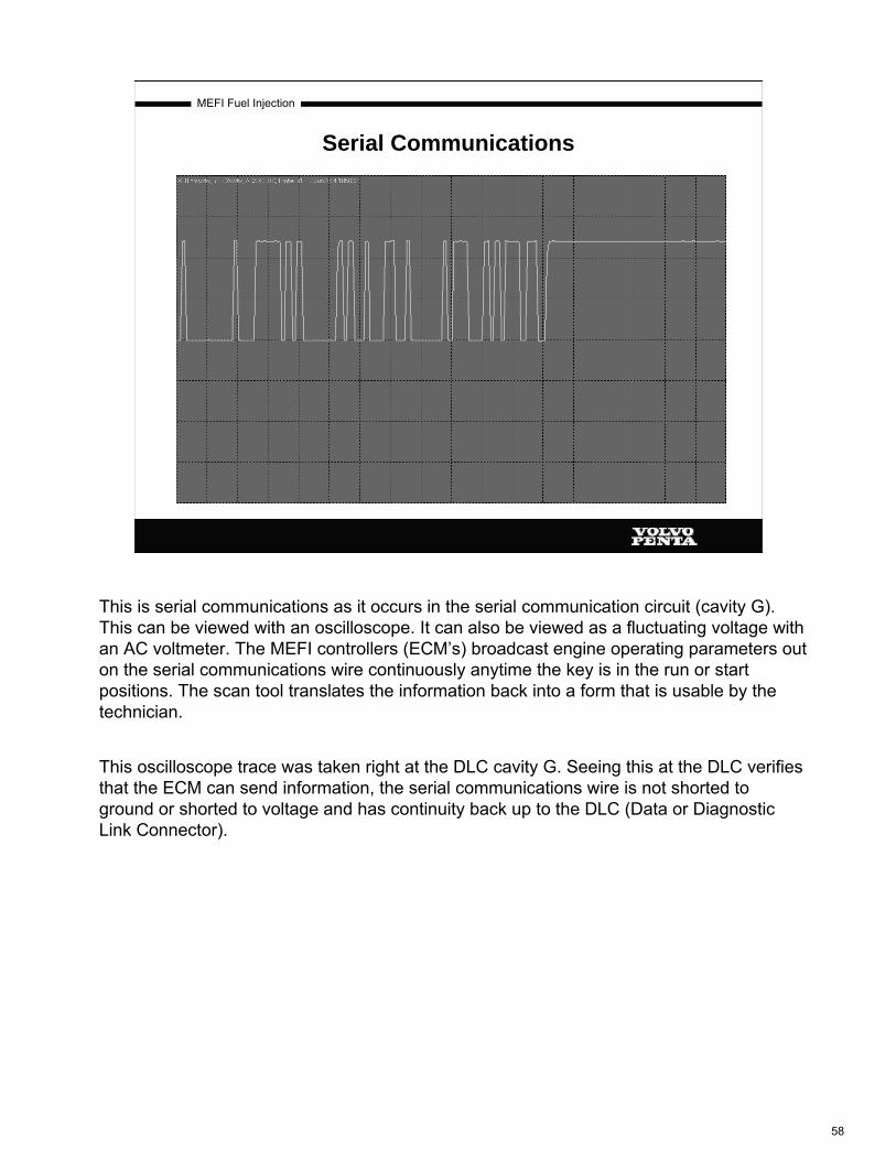
MEFI Fuel Injection
Serial Communications
This is serial communications as it occurs in the serial communication circuit (cavity G). This can be viewed with an oscilloscope. It can also be viewed as a fluctuating voltage with an AC voltmeter. The MEFI controllers (ECM’s) broadcast engine operating parameters out on the serial communications wire continuously anytime the key is in the run or start positions. The scan tool translates the information back into a form that is usable by the technician.
This oscilloscope trace was taken right at the DLC cavity G. Seeing this at the DLC verifies that the ECM can send information, the serial communications wire is not shorted to ground or shorted to voltage and has continuity back up to the DLC (Data or Diagnostic Link Connector).
58

MEFI Fuel Injection
ECMECM
INPUTS OUTPUTSCONTROLDEVICE
The ECM is a control device. It receives information from sensing devices as inputs, makes decisions and then controls load devices called outputs.
The available types of inputs to the ECM are sensors and switches.
The available types of outputs from the ECM are solenoids, relays, ignition coil(s) and a stepper motor.
Remember, the ECM’s decisions are only as good as the input information. If bad information is input to the ECM, then the ECM will make bad decisions. Bad decisions cause running problems.
59

MEFI Fuel Injection
Possible Wiring Problems
There are only 4 types of electrical problems that can occur in a wire. These 4 are: Open Circuit, Circuit Shorted to Ground, Circuit Shorted to Voltage and Unwanted (extra) Resistance due to corrosion. All 4 are pictured above. The effect that the problem has on the circuit depends on which problem is present and what wire is it in.All Diagnostic books are written to find opens, shorts to ground and shorts to voltage. These 3 types are easily found with a voltmeter, an Ohmmeter or a test light.Unwanted resistance due to corrosion is the hardest to find because the extra resistance usually doesn’t set any fault codes. The extra resistance does cause the circuit to flow less current which causes a voltage drop to or from a sensor, or it reduces current flow to an output (load device) which may cause the output to malfunction. Unwanted resistance due to corrosion usually will not set a DTC because the circuit still functions, just not properly.
60

MEFI Fuel Injection
INPUTS
All of the following are inputs to the ECM used for pulsewidth and timing calculations.
61

MEFI Fuel Injection
Analog Signals
Types of voltage input to an ECM:
Besides causing current flow in circuits, voltage can be used as a signal. Voltage signals can send information by changing levels, changing shape (waveform) or changing speed (frequency). Computers basically accept 2 types of voltage signal inputs.ANALOG SIGNALS:These signals are continuously variable. This means that the signal can be any voltage in a design range. Analog signals usually give information about a condition that is continuously changing. Coolant temperature, MAP and throttle position are all examples of signals that are constantly changing (analog).
62

MEFI Fuel Injection
Digital Signals
DIGITAL SIGNALS:In a computer, all data must be reduced to an electrical switch. A switch has only 2 possible states, “on” and “off”, so it has only 2 numerical symbols, 1 (on) and 0 (off). Because there are only 2 symbols it is known as “Binary”.Each 1 and each 0 is known as a “bit”, 8 bits together is known as a “Byte” or a word. Computers can store thousands of bytes of data, the only limit is the size of the memory. For example, the MEFI 4 can store up to 2 thousand bytes (2K) of calibration data, where as the MEFI 1 can only handle 512. This means the engine parameters can be monitored and adjusted in finer increments, such as 50 RPM instead of 200 RPM.Digital Binary is used by computers to communicate with one another and within itself. To a computer 10011101 might mean “turn on the fuel pump”.
Examples of digital inputs to the ECM are MEFI 4 CKP and CMP signals, Ref Hi input for MEFI 1 and MEFI 3 engines, the oil pressure switch and the exhaust riser temperature switches. The switches tell the ECM about a switch open or closed status. The CKP, CMP and Ref Hi inputs form a repeating high/low pattern that the ECM interprets as crankshaft speed and piston location.
63

MEFI Fuel Injection
Sensor Input
Over or under volts for a minimum length of time
A/D ConvertersAnd Circuits
The ECM receives voltage signals from the sensors via A/D (Analog to Digital) converters. These A/D converters are the ECM’s voltmeters. The normal voltage signal from a sensor may range from as low as 0.1 volt, to as high as 4.9 volts. This would be the sensor’s operating parameter or “window”. Each sensor has a different operating window.If a sensor is within acceptable parameters, the ECM does not detect a problem. When a sensor signal voltage input falls outside of this window, the ECM sees this as an invalid input voltage and after a programmed length of time will store a DTC. Once a DTC is set, the ECM defaults to a preprogrammed value for the lost sensor to restore limited engine performance.A sensor can report back incorrect information but the signal voltage still be within the operating window. This can cause engine performance problems without setting a DTC.Mechanical problems usually do not set a DTC, however, if severe enough, could possibly drive a sensor outside it’s operating window.Remember; to set a DTC, a sensor’s voltage must go out of range for a minimum length of time. If the sensor voltage goes out of range, but comes back before the timer has timed out, no DTC will be set. The ECM will believe the sensor input and react to it. This will cause some sort of owner complaint about runability with no fault codes.Some rationality checks are also performed.
64

MEFI Fuel Injection
ECMECM
DEPS Power
Sensor Signal
CKP or CMP
Sensor
Digital Engine Position Sensor
DEPS Lo
The DEPS generates a digital signal that is sent back to the ECM.
DEPS stands for "Digital Engine Position Sensor". Two ECM terminals provide a clean power supply (J2-17) and return or ground (J2-18) for digital sensors such as the crankshaft sensor (CKP) and the camshaft sensor (CMP) used on MEFI 4 MPI engines.
DEPS Power is a regulated and filtered +11.5 volt DC supply specifically for digital engine position sensors and is also used to power the cam sensor in a High Voltage Switch distributor on the small block V8’s and the 4.3 V6
Devices other than digital engine sensors should NOT be connected to J2-17 and J2-18 because of the potential to create electrical noise that may interfere with engine operation.
65

MEFI Fuel Injection
8.1L Crankshaft Position (CKP) Sensor
Tip reads reluctor wheel data
8.1L Crankshaft Position Sensor
The 8.1 crankshaft position sensor (CKP) is located on the left rear of the engine block. It is a magneto resistive type sensor. The CKP works in conjunction with a 24x (teeth) reluctor wheel.
As the crankshaft rotates, the reluctor wheel teeth interrupt a magnetic field produced by a magnet within the sensor. The CKP then outputs a 24x signal to the ECM.
The CKP is used to tell the ECM that a piston is coming to top dead center and how fast it is coming.
The IAFM CKP uses a 4x reluctor which will be discussed in the ignition systems section of this course.
66

MEFI Fuel Injection
Identifies which piston is at TDC
Camshaft PositionSensor
8.1L Camshaft Position (CMP) Sensor
The 8.1L camshaft position sensor (CMP) is mounted on the front of the engine. It is a magneto resistive type sensor. The cam position sensor detects the half moon “slot” on the camshaft timing gear.
The purpose of the CMP is to tell the ECM which piston is coming to top dead center.
The 8.1L CKP alone provides enough crankshaft information to run the engine in a waste spark mode if the CMP is lost before cranking. The IAFM engines don’t need CMP input to start or run.
There are 3 different groups of parts for the 8.1L CMP. The earliest was a one groove gear. The later was a 2 groove gear and a sensor with 2 magnets. The 2004 and newer setup uses the 2 groove gear, 2 magnet sensor with a new style connector and a new timing cover that moves the sensor in relation to the cam gear. None of the 3 different setups are interchangeable.
67

MEFI Fuel Injection
4.3, 5.0, 5.7L Crank Sensor (CKP) and Cam Sensor (CMP)
Above are the crank and cam sensors for the 4.3, 5.0, and 5.7L MEFI 4 engines. Just like the 8.1L, the sensors are feed power from the Depspower circuit and current is returned to the ECM via the DepsLo circuit. Depspower and DepsLo are shared circuits between the CMP and CKP sensors. Each sensor has it’s own signal wire back to the ECM. All of the CMP and CKP sensors used on the MEFI 4 engines produce an 11.5V square wave pattern on their signal wires in accordance with the number of teeth on each sensor’s reluctor. The IAFM engines use a 4X (4 teeth) CKP reluctor for the 5.0L and 5.7L and a 3x reluctor for the 4.3L. Both the 8.1L and the IAFM engines use a 1X (1 tooth) CMP reluctor. The 8.1L CMP reluctor is milled into the cam gear and the IAFM shutter is in the distributor (as pictured above).
68

MEFI Fuel Injection
CKP or CMP Sensor Circuit
Remember that a number of sensors share power feeds and sensor return wires, but each sensor on the engine has to have its own signal wire. That is the wire that the ECM looks at to receive a signal from the sensor.The CMP and CKP sensors share DepsPower and DepsLo. As the crankshaft turns, the reluctor passes the tip of the CKP sensor and the cam reluctor (or vane) passes the tip of the CMP sensor. As the reluctor passes by, voltage enters the signal wire. After the reluctor tooth passes by, the voltage level on the signal wire drops to 0V. So as the reluctor teeth pass by the sensor a square wave voltage signal is transmitted up the signal wire to the ECM. The ECM uses the A/D converter (voltmeter) on the signal wire to “see” and interpret the signal.CKP and CMP faults codes are usually generated when one signal is present and the other is missing. CKP signal input can be seen with a scan tool as “Engine RPM”. CMP input can be seen on a scan tool as “Cam Retard”. To use these as diagnostic tools, crank the engine and observe the “Engine RPM”. If RPM is greater than 0, then the ECM sees the CKP input. To check the CMP input, crank the engine and ensure that there is CKP input. As you crank the engine now look at “Cam Retard”, if cam retard is moving off of 0 degrees, then the ECM sees CMP input. No MEFI 4 ECM requires CMP input to start and run the engine. CKP input is required for any Speed Density fuel injection system to run.
69

MEFI Fuel Injection
Manifold Absolute Pressure Sensor (MAP)
MEFI 1 and 3 8.1L
The Manifold Absolute Pressure (MAP) sensor is a pressure transducer that measures changes in the intake manifold pressure. It takes this pressure and converts it into a voltage signal. The output is directly proportional to the intake manifold pressure. (inverse to manifold vacuum)A closed throttle will result in a low voltage. (low pressure)Wide open throttle will produce a high voltage. (high pressure)
The ECM uses the “key on” voltage to read barometric pressure which sets the fuel curve for the engine while it is running. This baro read voltage is critical to engine operation. If the “key on” baro reading is lower than the actual barometric pressure (due to a problem in the MAP or MAP circuit), then the engine will be starved for fuel. Conversely, if the key on baro reading is higher than the actual barometric pressure, the engine will receive too much fuel through out the entire range of engine operation.The only ways to validate the barometric pressure reading from the MAP is to compare the ECM’s baro reading to a barometer or compare it to a known good engine in the same area.
70
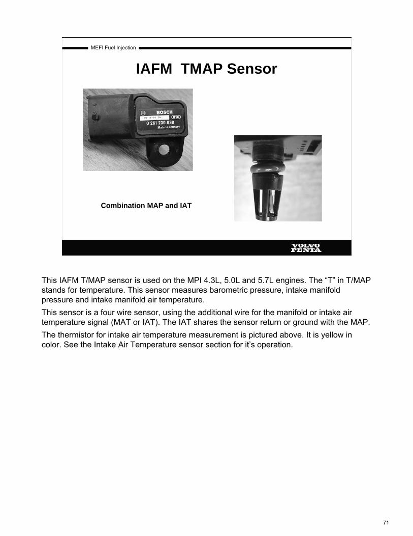
MEFI Fuel Injection
IAFM TMAP Sensor
Combination MAP and IAT
This IAFM T/MAP sensor is used on the MPI 4.3L, 5.0L and 5.7L engines. The “T” in T/MAP stands for temperature. This sensor measures barometric pressure, intake manifold pressure and intake manifold air temperature.This sensor is a four wire sensor, using the additional wire for the manifold or intake air temperature signal (MAT or IAT). The IAT shares the sensor return or ground with the MAP.The thermistor for intake air temperature measurement is pictured above. It is yellow in color. See the Intake Air Temperature sensor section for it’s operation.
71

MEFI Fuel Injection
Speed / Density Fuel System
5.0V
2.5V
At higher altitude (key on)
0V 0 in vac 30 in vac29.92 in hg 0 in hg14.7 PSI 0 PSI
The solid line in this chart represents the voltage output from a MAP sensor through the whole vacuum range at sea level.The dotted line represents the same sensor output at a higher altitude. Notice the entire voltage output from the MAP sensor is lower, which means the engine will get less fuel throughout the entire rpm range of the engine.At altitude, less oxygen in the air means less fuel needed.The same holds true on days when the atmospheric pressure outside is lower (i.e. a storm is present).Make a habit of checking MAP key on voltage and key on baro readings to establish what is normal for your area for a particular engine package.
Also compare the “Baro derived from MAP” with a barometer reading to check MAP sensor accuracy.A MAP sensor that reads baro incorrectly WILL cause a running problem that won’t set a fault code
72

MEFI Fuel Injection
8.1L MAP Circuit
The ECM sends a 5 volt reference voltage to the MAP sensor. This 5V feed is “watched” by the ECM’s A/D converter. If the voltage is too high or too low a “5V Reference out of range”fault code is set. The sensor responds to changes in the manifold pressure and returns a signal voltage (a portion of the supply voltage) on the signal wire. This signal will vary from about 1.0-1.5 volts at idle to about 4.0- 4.8 volts at WOT. The ECM sees this signal input through the A/D converter on the signal wire. Almost all inputs to the ECM that come in through an A/D converter can be seen by a scan tool. For the MAP sensor, this is “MAP Volts”. The 5V Reference voltage level is monitored by the ECM but can not be seen with a scan tool.There are 3 fault codes for the MAP sensor : “MAP Voltage High”, “MAP Voltage Low” and “5V Reference Out Of Range”. The “5V Reference Out Of Range” can be set by either the MAP or TPS as it is a shared circuit.
If the MAP sensor fails, the ECM will substitute a default MAP value that will vary with RPM and set the appropriate fault code.
73

MEFI Fuel Injection
IAFM T/MAP Circuit
The T/MAP on the IAFM engines (4.3L, 5.0L and 5.7L MPI) works the same way as an 8.1L MAP except the IAFM engines incorporate the IAT in the MAP sensor.The MAP and the IAT share the sensor return (ground). IAT functionality is discussed later in this book.
74

MEFI Fuel Injection
Throttle Position Sensor (TPS)
The Throttle Position Sensor (TPS) is a potentiometer connected to the throttle shaft on the throttle body. At closed throttle the voltage output is low. The voltage increases proportionately as the throttle is opened. The ECM uses the TPS signal to control the idle air controller and acceleration enrichment.
The following information is available with the scan tool: TPS voltage, TPS percent throttle, and Closed throttle (yes/no). TPS voltage is the actual input to the ECM. TPS Percent is a calculated value that is the difference between actual TPS voltage and learned TPS minimum. Closed throttle is a calculated value based off of TPS percent. If TPS percent is below 2%, then closed throttle is “yes”. Above 2% closed throttle is “no”.MEFI 3 and 4 TPS’s are non-adjustable.
75

MEFI Fuel Injection
TPS Circuit
The TPS and the MAP sensor share the 5 volt reference feed. The A/D converter on the 5 volt reference feed is used to detect whether the 5 volts is present or not. If the voltage is not there a “5v reference out of range” fault code. One possible cause of this fault is the 5 volt reference circuit being shorted to ground.The ECM watches the A/D converter on the signal wire. If the voltage goes too close to 0v, then a “TPS voltage low” fault is set. If the voltage goes too close to 5v, then the ECM sets a “TPS voltage high” fault.Remember, the fault codes are set by what voltage the ECM “sees” at the A/D converter. As an example, a TPS voltage low fault could be set by an open in the signal wire, a shorted signal wire, or an open in the 5 volt reference feed.A good quick check of the TPS circuitry is to disconnect the TPS and with a voltmeter check from cavity A to a known good ground. If the voltmeter measures 5 volts, then measure between cavities A and B. If the voltmeter still reads 5 volts, then the sensor return is good. Then short the 5 volt reference into the signal wire and read TPS Volts with a scan tool. If the scan tool reads 5 volts, then the signal wire is good and the ECM can read the voltage with the A/D converter.
76

MEFI Fuel Injection
Two Wire Temperature Sensor
This type of sensor is basically a variable resistor in series with a fixed resistor of a known value within the ECM. The variable resistor in the sensor determines how much current flows in the circuit. The amount of current flow determines how much of the 5 volts on the signal wire drops across the fixed resistor. The ECM reads the voltage level between the fixed resister and the variable resistor. This is known as a voltage divider circuit. The most commonly used variable resistors are called “Thermistors”. A thermistor changes resistance with temperature variations.All thermistors used on Volvo Penta engines are of the Negative Temperature Coefficient type (NTC), resistance goes down as temperature goes up.
Temp Resistance Signal Voltage UP DOWN DOWN
DOWN UP UPThe scan tool only displays the current temperature indicated by the sensor. If that value is out of limits for the ECM, the ECM sets a fault code and uses a default value preprogrammed into the ECM. That value is not displayed on the scan tool.The fault codes set are “High Temperature Indicated or ECT Voltage Low” and “Low Temperature Indicated or ECT Voltage High”.
77

MEFI Fuel Injection
Engine Coolant Temperature Sensor (ECT)
The ECM uses the ECT signal to calculate engine temperature to determine if the engine is cold, at normal operating temperature or overheating.
The MEFI 4 engines have a temperature controlled rev limiter. The purpose of this is to prevent engine damage from running a cold engine at high RPM. This feature will prevent the engine from achieving full RPM until it has reached operating temperature. The approximate limits are as follows:68 degrees F……4000 rpm.104 degrees F…..4600 rpm.140 degrees F+…Full throttle operating range.
Note: different engines have different rpm limits, however above approximately 140 degrees F all engines are allowed max rpm.
(Unplugging this sensor will default the Scan tool to -39 degrees F, the ECM will be using an non-displayed default value).
78

MEFI Fuel Injection
ECT CIRCUIT
The ECM sends out 5 volts to the sensor on the signal wire. As the temperature of the sensor changes, it’s resistance changes. As the sensor’s resistance decreases, the current flow in the circuit increases. As the current increases, the voltage drop across the fixed resistor in the ECM increases. This causes the voltage available at the A/D converter (between the fixed resistor and the sensor) to be lower as the sensor’s temperature rises.An open circuit in either the signal wire or the sensor return will set a “voltage high” fault. A “voltage high” fault is also a “low temperature indicated” fault.
The EFI manual has temperature/resistance charts for both the ECT and the IAT sensors. These charts are located at the DTC test for the fault.
79
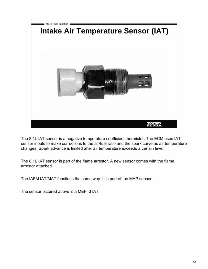
MEFI Fuel Injection
Intake Air Temperature Sensor (IAT)
The 8.1L IAT sensor is a negative temperature coefficient thermistor. The ECM uses IAT sensor inputs to make corrections to the air/fuel ratio and the spark curve as air temperature changes. Spark advance is limited after air temperature exceeds a certain level.
The 8.1L IAT sensor is part of the flame arrestor. A new sensor comes with the flame arrestor attached.
The IAFM IAT/MAT functions the same way. It is part of the MAP sensor.
The sensor pictured above is a MEFI 3 IAT.
80

MEFI Fuel Injection
IAT Circuit
IAFM Engines
8.1L Engines
The ECM sends out 5 volts to the sensor on the signal wire. As the temperature of the sensor changes, it’s resistance changes. As the sensor’s resistance decreases, the current flow in the circuit increases. As the current increases, the voltage drop across the fixed resistor in the ECM increases. This causes the voltage available at the A/D converter (between the fixed resistor and the sensor) to be lower as the sensor’s temperature rises.An open circuit in either the signal wire or the sensor return will set a “voltage high” fault. A “voltage high” fault is also a “low temperature indicated” fault.
The EFI manual has temperature/resistance charts for both the ECT and the IAT sensors. These charts are located at the DTC test for the fault.
81

MEFI Fuel Injection
B+
MEFI 3
B+ is a fuel delivery modifier. As battery voltage goes down, injector pulsewidth must go up for the volume of fuel delivery from the injector to remain constant. As the voltage goes up, the injector will open more easily and quickly, so injector pulsewidth must go down to maintain the correct volume of fuel in the cylinder. MEFI 3, 4 and 4b ECM’s have a limited range of pulsewidth adjustment for B+. Therefore, if the voltage supply to the ECM is low, the engine will run too lean and if the voltage supply to the ECM is too high the engine will run too rich. Either condition will cause a poor running condition.This B+ voltage input can be viewed with a scan tool. It is named “Battery Voltage”.The wiring diagram above is a typical MEFI 1 or 3 wiring diagram. These MEFI wiring diagrams were divided up by system. This picture is the B+ and fuel pump systems. MEFI 4 EFI system wiring diagrams show the entire engine system on one diagram.On MEFI 3 and MEFI 4 systems J2-1 provides B+ information to the ECM and also provides all power for the ECM.
82

MEFI Fuel Injection
Exhaust Temperature Switch
Switch isMounted here
(drilled and tapped first)
The switch is located in a protected housing in the manifold. The switch is not mounted in the exhaust stream or the cooling water flow. It only “sees” the temperature of the riser elbow metal. In the picture above, the hole for the switch has not been drilled and tapped. It is NOT drilled all the way through into the exhaust stream.
The switches can be knocked out of calibration by being hit or the stud being turned. If the stud for the harness connector is turned, even slightly, the switch is no longer any good and must be replaced.
These switches are either wired in parallel with the oil pressure switch or they are wired in parallel with themselves on their own separate circuit.There are 2 systems that use these switches. They are usually referred to as the Engine Mounted Horn system and the Remote Mounted Horn system.The Engine Mounted Horn system was used on the models built between 2001 and 2002. In 2003 we switched to the Remote Mounted Horn system. The operation of these 2 systems is discussed on the following pages.Monitored items for both systems are: oil pressure, engine water temperature and exhaust riser temperature.
83

MEFI Fuel Injection
Engine Protection Mode System
01-02 Model Years - Engine Mounted Horn System
Horn operation: The horn will sound 2 short beeps at each key on as a horn check. This is an audible check so that the operator will know that the horn is working. The horn will sound an “intermittent beep” when there is an “active” DTC stored in the ECM memory. This intermittent beep is one long beep followed by two short beeps. The horn also sounds if S.L.O.W. (Speed Limiting Operational Warning) mode or “engine protection mode” is activated. The horn sounds a steady beeping sound when S.L.O.W. Mode has been activated.System operation: The exhaust temperature switches and the oil pressure switch are all wired in parallel on the oil pressure switch input circuit to the ECM at connector J2-20. The ECM sends out 5 volts looking for a ground through any one of the 3 switches. The riser switches are normally open switches and the oil pressure switch is a normally closed switch. As soon as either one of the 3 switches closes (with the engine running longer than approximately 20 seconds), a “low oil pressure” fault is set in the ECM’s memory and the warning horn sounds. If the problem goes away, there is an approximately 20 second delay before S.L.O.W. mode is cleared and the warning horn is deactivated. Complete system operation and diagnosis is covered in the 7742218 diagnostic book between pages 252 and 255. Both systems use the ECT input for S.L.O.W. mode, and engine response to that input is the same for both systems and is explained on the next page.This system can be equipped with an optional remote mounted horn at the helm.
84

MEFI Fuel Injection
Engine Protection Mode System
03 through 05 model years - Remote Mounted Horn System:Horn operation: The only difference in horn operation between the two systems is that the remote horn system doesn’t activate the warning horn for active DTC’s. All other horn functions are unchangedSystem operation: The exhaust temperature switches input has been moved from the oil pressure switch input circuit to a new circuit at J1-19. This circuit is the “General Warning #1 Input” circuit. These switches are the only items on the general warning # 1 input circuit. Once the engine has been running approximately 20 seconds, if one of the exhaust temperature switches closes (due to high temp), S.L.O.W. mode is activated, the warning horn sounds a steady beeping sound and a “General Warning # 1” fault code is set in the ECM’s memory. The oil pressure switch input is still located on J2-20, but it is the only item on that circuit. While S.L.O.W. mode is activated, if the switch that activated S.L.O.W. mode returns to it’s normal state, the ECM waits approximately 20 seconds (to ensure that the change is valid) and then cancels S.L.O.W. mode.The ECT input is monitored for S.L.O.W. mode also. If the engine coolant temperature rises above a set value then S.L.O.W. mode is activated until the temperature drops below a set point. System operation and diagnosis is covered in the 7742218 diagnostic book on pages 255 through 259.While in S.L.O.W. mode, in addition to sounding the warning horn, the ECM kills ½ of the fuel injectors anytime the RPM exceeds 2500. The ECM turns them back on once RPM has dropped below 1200.
85

MEFI Fuel Injection
KS Circuit
MEFI 3 and 4
The ECM uses the knock sensor to detect detonation. The knock sensor is a piezoelectricdevice, or a crystal that creates a voltage when subjected to mechanical vibration. The knock sensor will produce a very low AC voltage signal anytime the engine is running. It will produce a larger AC voltage when detonation is present. When knock is detected the ECM can retard ignition timing to reduce knock.Little or no activity on the knock circuit at the ECM will set a DTC 44.If either knock sensor signal wire is routed too close to a spark plug wire, the ECM may translate the induced voltage as a knock signal, resulting in a false timing retard. This would cause an engine running problem that would look like the result of poor fuel quality.
86

MEFI Fuel Injection
Knock Sensor (KS) & Module
MEFI 1
The knock module is used in the MEFI 1 systems. During no knock conditions it sends an 8-10 volt signal to the ECM. When knock is detected it will remove the signal from the ECM. The ECM will then retard the timing as much as 10%. The knock system was fully incorporated into the ECM with the introduction of the “WT” models equipped with the MEFI 3 system. All MEFI 3 and 4 systems have a knock system built into the ECM.
87
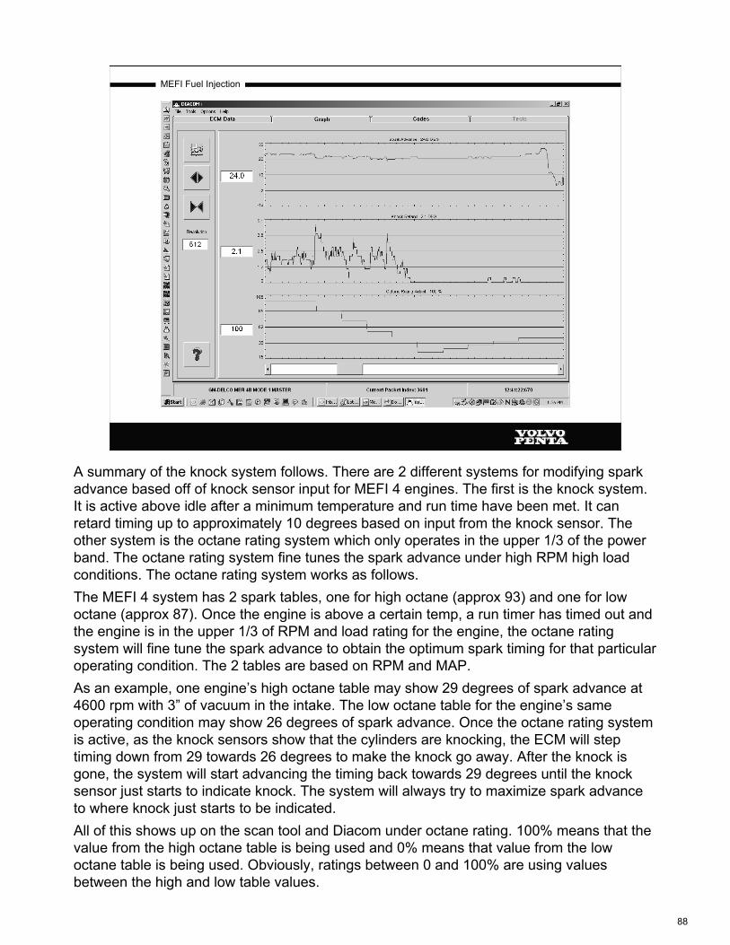
MEFI Fuel Injection
A summary of the knock system follows. There are 2 different systems for modifying spark advance based off of knock sensor input for MEFI 4 engines. The first is the knock system. It is active above idle after a minimum temperature and run time have been met. It can retard timing up to approximately 10 degrees based on input from the knock sensor. The other system is the octane rating system which only operates in the upper 1/3 of the power band. The octane rating system fine tunes the spark advance under high RPM high load conditions. The octane rating system works as follows.The MEFI 4 system has 2 spark tables, one for high octane (approx 93) and one for low octane (approx 87). Once the engine is above a certain temp, a run timer has timed out and the engine is in the upper 1/3 of RPM and load rating for the engine, the octane rating system will fine tune the spark advance to obtain the optimum spark timing for that particular operating condition. The 2 tables are based on RPM and MAP.As an example, one engine’s high octane table may show 29 degrees of spark advance at 4600 rpm with 3” of vacuum in the intake. The low octane table for the engine’s same operating condition may show 26 degrees of spark advance. Once the octane rating system is active, as the knock sensors show that the cylinders are knocking, the ECM will step timing down from 29 towards 26 degrees to make the knock go away. After the knock is gone, the system will start advancing the timing back towards 29 degrees until the knock sensor just starts to indicate knock. The system will always try to maximize spark advance to where knock just starts to be indicated.All of this shows up on the scan tool and Diacom under octane rating. 100% means that the value from the high octane table is being used and 0% means that value from the low octane table is being used. Obviously, ratings between 0 and 100% are using values between the high and low table values.
88

MEFI Fuel Injection
Knock Sensor Diagnostics
Normal Abnormal
The ECM checks the knock sensor and related wiring by comparing the actual knock signal to the assigned voltage range. A knock sensor signal (#3 in the above diagrams) should vary outside the assigned voltage range (#1 is the upper limit and #4 is the lower limit) as shown in the normal KS (knock sensor) figure. If the ECM detects a KS signal within the assigned voltage range as shown in the abnormal KS figure, then a code 44 is set for the affected knock sensor.Technician diagnostics for the sensor and circuit include checking continuity through the sensor and circuit, and hooking up an AC voltmeter or an oscilloscope to the sensor and gently tapping on the sensor with a metal object. Tapping on the sensor should produce an AC voltage on the voltmeter.
89

MEFI Fuel Injection
Shift Interrupt Input
Shift interrupt connector
The shift interrupt input is only used in high horsepower DPX applications (DPX 375, 420, 500 and 600). The white with a blue tracer wire from ECM connector J1 pin 20 has 11-11.5 volts on the wire supplied from the ECM. The ECM watches for this voltage to be pulled to ground. If the vessel is equipped with a shift interrupter switch, it is located in the shifter assembly. As the shifter is moved from neutral towards clutch ahead or astern, the switch closes and grounds the circuit. By the time the shifter has reached the clutch position the switch is again open. When the ECM sees this input it then looks at throttle position and engine RPM. If the engine is at idle, the ECM kills half of the injectors in order to reduce torque output of the engine during the shift.To summarize: any time the circuit is pulled to ground AND the engine is at idle (closed throttle), the ECM will kill half the injectors.This connector looks identical to the trim sender connector and sometimes gets plugged into the trim sender. This will cause a loss of half of the injectors at closed throttle when the drive is trimmed down.
90

MEFI Fuel Injection
Relays
Click to viewISO Relays
All ISO relays are wired in this manner. Pins 85 and 86 are the control circuit for activation of the relay. When the relay is de-energized, pin 30 is connected to pin 87a. Once 85 and 86 have power and ground, the relay is then energized and pin 30 is now connected to pin 87. See the ISO Relay sheet for relay pin configurations for the relay and the receptacle. In standard ISO relay wiring, pin 86 is power for the control circuit and pin 85 is the ground for the control circuit. Pin 30 is connected to B+ for the load path and pin 87 is the power supply circuit for the load that the rely operates.Relays are used so that high current circuits can be controlled by low current circuits. The ECM can handle the relatively low current of the relay control circuit, but not the high current flow that the load (such as the fuel pumps) carries.
91
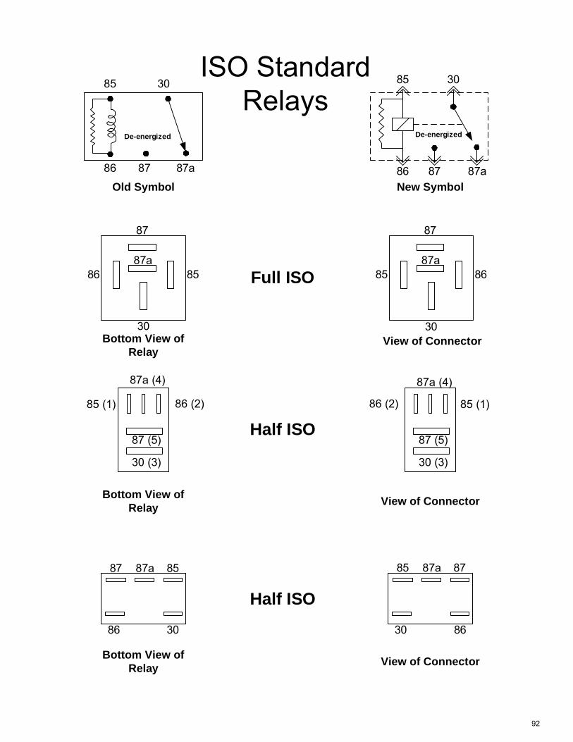
ISO StandardRelays
85 30
86 87 87a
85 30
86 87 87a
86
87
8587a
30
85
87
8687a
30
87a (4)
86 (2) 85 (1)
87 (5)
30 (3)
87 87a 85
86 30
85 87a 87
30 86
Old Symbol New Symbol
Bottom View ofRelay
Bottom View ofRelay
Bottom View ofRelay
View of Connector
View of Connector
View of Connector
Full ISO
Half ISO
Half ISO
87a (4)
86 (2)85 (1)
87 (5)
30 (3)
De-energized De-energized
92
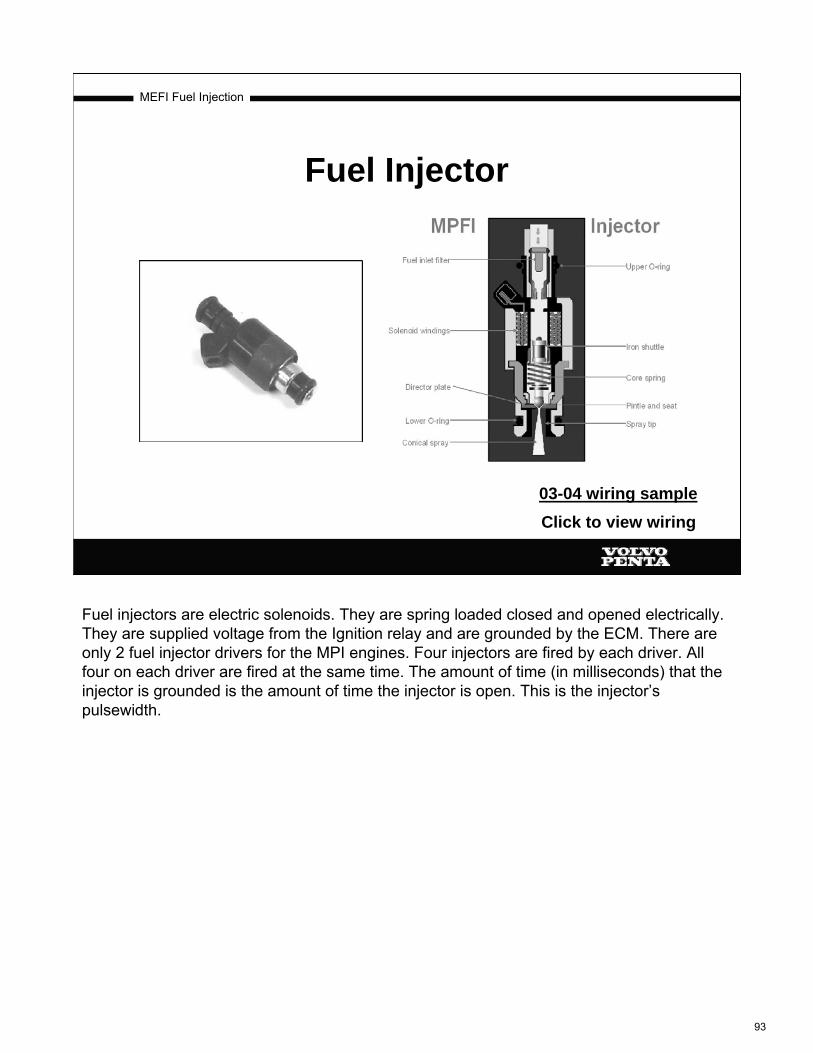
MEFI Fuel Injection
Fuel Injector
03-04 wiring sampleClick to view wiring
Fuel injectors are electric solenoids. They are spring loaded closed and opened electrically. They are supplied voltage from the Ignition relay and are grounded by the ECM. There are only 2 fuel injector drivers for the MPI engines. Four injectors are fired by each driver. All four on each driver are fired at the same time. The amount of time (in milliseconds) that the injector is grounded is the amount of time the injector is open. This is the injector’s pulsewidth.
93

MEFI Fuel Injection
InjectorDriver ACircuit
The diagram above shows the injector driver “A” circuit. The injector driver circuit is a “Low Side” driver meaning that the ECM controls the “Low” or ground side of the circuit. Each injector driver fires 4 injectors, 2 from each side of the engine. The injector driver B circuit drives the other 4 injectors.There is only 1 fault code for each of the injector driver circuits, injector driver circuit A or B “High, Low or Open”. This fault code is set by what the ECM “sees” on the driver circuit back at the ECM. There are 4 parallel circuits through the injectors in 1 driver circuit. For the fault code to set, the open has to be (in the diagram above) above the splice in the feed circuit or below the splice in the ground or driver circuit back to the ECM. If any injector has an open circuit in it, the code will NOT set. This is because there are still 3 more circuits (the other 3 injectors in that driver) carrying current. On the other hand, if the circuit is shorted to ground anywhere in the circuit, the fault will set. If the short is on the feed side, then the circuit protection device (fuse) will blow. If the short is in the ground or driver circuit, then the injectors will remain open with the key on until the injector coils melt and go open circuit (or short together and then blow the fuse).Remember basic electricity; opens in parallel circuits only affect the leg that has the open. Short circuits affect the entire circuit.
94

MEFI Fuel Injection
Idle Air Control Valve (IAC)
One of the major benefits of an EFI engine is its ability to maintain proper idle speed. The ECM will immediately compensate for increased load by providing additional fuel, air and spark timing, thereby maintaining proper idle rpm. Adding fuel is easy, the ECM simply holds the injectors open longer. Adding air, however, is a bit more complicated. On GM based EFI systems this is accomplished with a computer controlled motor in the throttle body. This motor is called an Idle Air Control motor (IAC). It is used along with a spark scatter strategy to control idle speed.An IAC is a stepper motor, the ECM controls the movement by sending voltage pulses to the IAC’s 2 coils, thereby causing the motor to take one or more steps in a particular direction. As the IAC opens, more air is allowed to bypass the throttle blade, increasing idle speed. As the IAC is closed, less air bypasses the throttle blade, reducing idle speed.The ECM “tracks” the intended IAC position by counting the step pulses it has sent the motor. Since the IAC does not provide “feedback” to the ECM indicating its actual position the ECM must “reset” the IAC periodically to ensure that it is where the ECM believes it to be. On most MEFI 4 ECM’s, once per key cycle the ECM will “reset” the IAC by driving it in the closed direction for a predetermined length of time followed by driving it in the open direction for another predetermined length of time and then returning it to the desired number of steps. Additionally, each time the the ignition key is turned off, the ECM remains electrically active for several seconds. One of the actions it performs during this period is it “parks” the IAC at a predetermined location in anticipation of the next start. At the next “key on” the ECM will move the IAC either open or closed from the park position based on ECT input.MEFI 4 and 4b engines perform an IAC reset (full closed to full open and back to preset position) the first time 2500 RPM is achieved each key cycle.
95

MEFI Fuel Injection
IAC Circuit
1. ECM 2. IAC
J1-15 J1-30 J1-16 J1-31
IAC motors are a different breed of DC motor and require a special electronic circuit to rotate. An IAC cannot be connected directly to a battery to operate.The IAC has 2 internal coils and 4 external connections. The 2 internal coils are commonly referred to as Coil A and Coil B. The 2 coils are identical. The IAC has an internal permanent magnet, but unlike most DC motors, no brushes or commutator to wear or replace.The ECM commands the IAC to turn CW or CCW by applying an alternating DC voltage in a specific sequence to the 2 coils through H drivers. The 2 H driver circuits act like 2 sets of 2 switches. By controlling the voltage polarity on each coil, the ECM causes the IAC to step in the desired direction. When voltage is set to both drivers (one at a time) in one direction (polarity), the IAC steps in one direction, one step at a time. When the 2 drivers are operated in the opposite polarity (one after the other), then the IAC is stepped in the opposite direction. On some engines the total number of allowed steps is 145, on others it is 245 steps.MEFI 4 engines also have an anti-stall program called “IAC follower”. This is an IAC count in addition to the actual IAC steps. When this program is active, the “IAC follower” must count down to 0 before the IAC is moved in the closed direction.On a diagnostic scan tool, the “IAC Position” value reflects the ECM’s assumed position of the IAC. The key word being ASSUMED.Failure of the IAC motor or circuitry will NOT set a code.
96

MEFI Fuel Injection
Ignition Systems:Delco Distributor Ignition
(Carbureted, TBI and 7.4/8.2L MPI)
97

MEFI Fuel Injection
Delco Distributor Ignition
All Delco distributor ignition (DI) systems include these essential components: battery,distributor, ignition coil, ignition switch, spark plugs,primary and secondary wiring. The DI system is connected to the ECM. The ECM monitors various engine sensors, computes the desired spark timing and signals the ignition control (IC) module in the distributor to change timing.The high energy ignition (HEI) distributor is made up of a housing, an IC module, a pick-up coil assembly, a rotor and a cap.The distributor used on marine engines is designed for the marine environment. The distributor base plate is equipped with 2 special vents to prevent fuel vapors from igniting.This ignition system is used on carbureted, TBI and 7.4/8.2L MPI engines.
98

MEFI Fuel Injection
Pick-up Assembly
The pick-up coil assembly consists of a stationary pole piece with internal teeth, a pick-up coil and a magnetic timer core that rotates with the distributor shaft. When the teeth of the timer core align with the teeth of the pole piece, an AC voltage signal is induced. This AC voltage signals the ECM or the IC module to turn off the primary ignition current, which causes the magnetic field in the ignition coil to collapse, inducing high voltage in the secondary windings, producing a spark at the plugs.
99
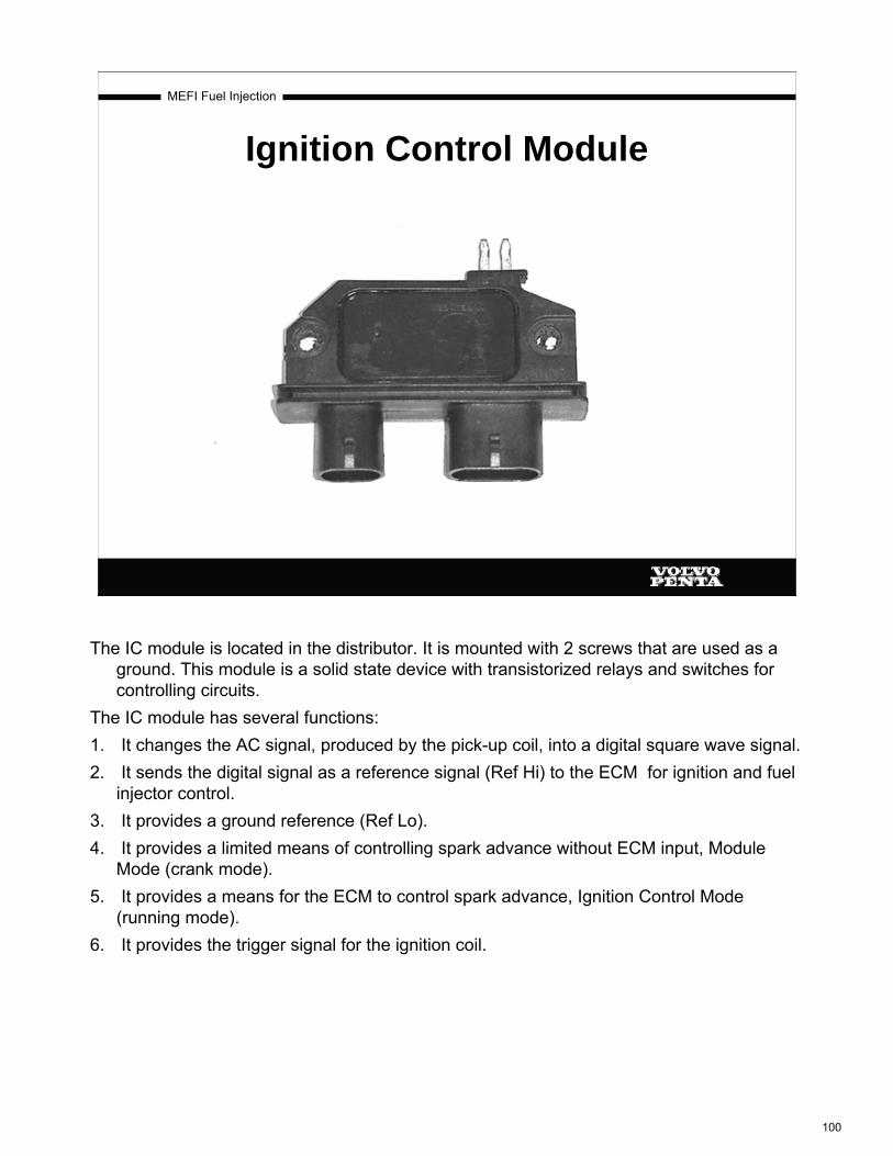
MEFI Fuel Injection
Ignition Control Module
The IC module is located in the distributor. It is mounted with 2 screws that are used as a ground. This module is a solid state device with transistorized relays and switches for controlling circuits.
The IC module has several functions:1. It changes the AC signal, produced by the pick-up coil, into a digital square wave signal.2. It sends the digital signal as a reference signal (Ref Hi) to the ECM for ignition and fuel
injector control.3. It provides a ground reference (Ref Lo).4. It provides a limited means of controlling spark advance without ECM input, Module
Mode (crank mode).5. It provides a means for the ECM to control spark advance, Ignition Control Mode
(running mode).6. It provides the trigger signal for the ignition coil.
100
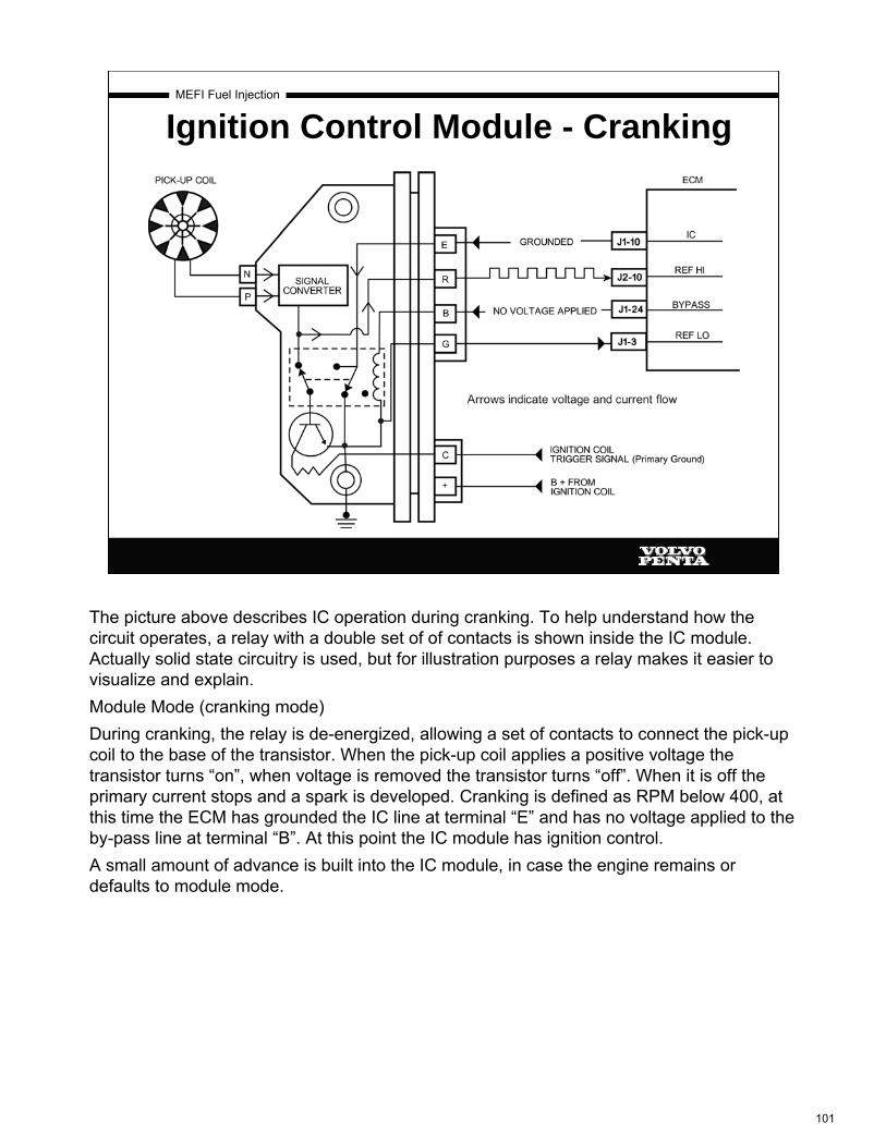
MEFI Fuel Injection
Ignition Control Module - Cranking
The picture above describes IC operation during cranking. To help understand how the circuit operates, a relay with a double set of of contacts is shown inside the IC module. Actually solid state circuitry is used, but for illustration purposes a relay makes it easier to visualize and explain.Module Mode (cranking mode)During cranking, the relay is de-energized, allowing a set of contacts to connect the pick-up coil to the base of the transistor. When the pick-up coil applies a positive voltage the transistor turns “on”, when voltage is removed the transistor turns “off”. When it is off the primary current stops and a spark is developed. Cranking is defined as RPM below 400, at this time the ECM has grounded the IC line at terminal “E” and has no voltage applied to the by-pass line at terminal “B”. At this point the IC module has ignition control.A small amount of advance is built into the IC module, in case the engine remains or defaults to module mode.
101

MEFI Fuel Injection
Ignition Control Module - Running
Ignition Control Mode (running mode)When the RPM exceeds 400, the ECM considers the engine running and applies 5 volts on the by-pass at terminal “B”. This energizes the “relay” and causes the contact to open, this un-grounds the IC line and connects it to the base of the transistor. This switches ignition control to the ECM. Now the ECM is sending the trigger signal to the base of the transistor over the IC circuit and controlling the firing of the ignition coil primary circuit. The Ref Lo signal at terminal “G” is a ground. This is the low current ground or return back to the ECM for the electronics in the IC module. The high current that comes from the ignition coil gets grounded through the module mounting bolts. It is important that there is a good ground through these bolts. A poor ground will result in a poor running engine.
See page 4-6 in the “EF” manual or pages 38 and 39 of 742218 manual for results of incorrect operation such as an open IC line or grounded IC line, etc.
102

MEFI Fuel Injection
MEFI 3 Ignition System
The ignition coil has 2 connectors, one black and one gray. The black connector has the power feed back to the ignition module and the ignition coil primary ground circuit. The power feed to the ignition module is pink and the primary ground is brown. The gray connector contains the power feed for the ignition coil and the tach lead. The power feed for the ignition coil is purple and the tach lead is gray. The purple wire is the output from the ignition relay.Current flows into the ignition coil through the purple wire, through the primary winding and on to the ignition module via the brown wire. Current is also supplied out of the coil on the pink wire to power up the IC module. The IC module high current ground is through the mounting bolts. Loose mounting bolts can cause a poor running engine due to weak spark.When the IC module grounds the brown wire the coil is saturated and builds up a large magnetic field. When the IC module or the ECM want to fire the ignition coil, the IC module shuts down the current flow in the primary and that induces a high voltage into the secondary winding that is supplied to the distributor.
103

MEFI Fuel Injection
Inductor Wiring Harness
The primary circuit pink wire, between the the ignition coil and the distributor 2 wire plug, contains an inductor to protect boat electronics against Electro-Magnetic Interference (EMI) generated by the ignition system itself.
If the inductor fails (open circuit), then power to the Ignition Module in the distributor will be lost. The engine will die and will not restart. Check the pink wire for continuity. Occasionally the wire breaks and intermittently opens the circuit, depending on the movement or location of the harness. If this happens, the engine may misfire or shutdown, but may restart.
104

MEFI Fuel Injection
Ignition Systems: 8.1L Distributorless Ignition
System
(Coil Near Plug, MEFI 4)
105

MEFI Fuel Injection
8.1 Gi/GXiIgnition Components
•One coil per cylinder
•Coil assemblies are interchangeable
DISDISIgnition coilsIgnition coils
The 8.1L engine is the only engine we have at this time that uses the distributorless ignition system.This systems consists of 8 individual ignition coils, 8 individual ignition control circuits, a camshaft position sensor(CMP) and a crankshaft position sensor (CKP).There is an IC circuit for each coil, each circuit is connected to the ECM. The ECM triggers each coil and makes all the timing decisions.The ignition timing is not adjustable, there are no timing marks on the balancer or the timing chain cover.Failure of an IC circuit will set DTC 41.
The 8 ignition coils are individually mounted above each cylinder on the rocker covers, the coils are fired sequentially.The coils secondary output voltage is very high, more than 40,000 volts.The assembly is completely interchangeable, coils are identical and wire colors are duplicated.
106
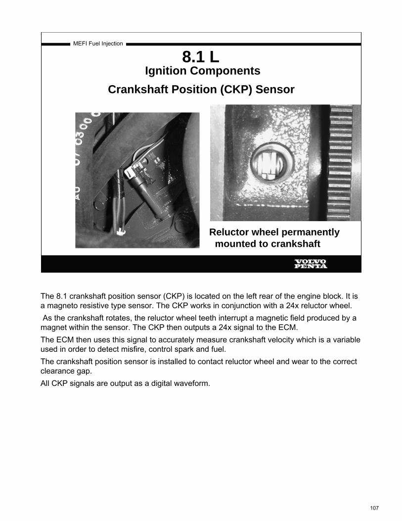
MEFI Fuel Injection
Reluctor wheel permanently mounted to crankshaft
8.1 LIgnition Components
Crankshaft Position (CKP) Sensor
The 8.1 crankshaft position sensor (CKP) is located on the left rear of the engine block. It is a magneto resistive type sensor. The CKP works in conjunction with a 24x reluctor wheel.As the crankshaft rotates, the reluctor wheel teeth interrupt a magnetic field produced by a
magnet within the sensor. The CKP then outputs a 24x signal to the ECM.The ECM then uses this signal to accurately measure crankshaft velocity which is a variable used in order to detect misfire, control spark and fuel.The crankshaft position sensor is installed to contact reluctor wheel and wear to the correct clearance gap.All CKP signals are output as a digital waveform.
107
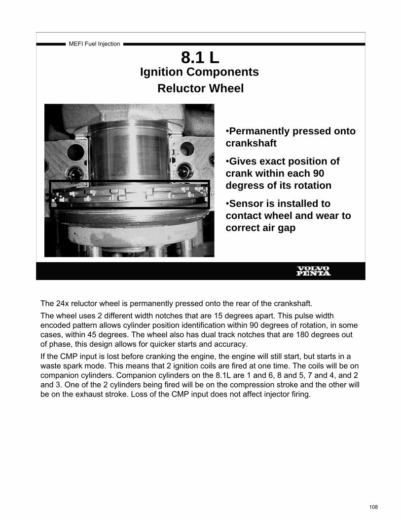
MEFI Fuel Injection
8.1 L Ignition Components
Reluctor Wheel
•Permanently pressed onto crankshaft
•Gives exact position of crank within each 90 degress of its rotation
•Sensor is installed to contact wheel and wear to correct air gap
The 24x reluctor wheel is permanently pressed onto the rear of the crankshaft.The wheel uses 2 different width notches that are 15 degrees apart. This pulse width encoded pattern allows cylinder position identification within 90 degrees of rotation, in some cases, within 45 degrees. The wheel also has dual track notches that are 180 degrees out of phase, this design allows for quicker starts and accuracy. If the CMP input is lost before cranking the engine, the engine will still start, but starts in a waste spark mode. This means that 2 ignition coils are fired at one time. The coils will be on companion cylinders. Companion cylinders on the 8.1L are 1 and 6, 8 and 5, 7 and 4, and 2 and 3. One of the 2 cylinders being fired will be on the compression stroke and the other will be on the exhaust stroke. Loss of the CMP input does not affect injector firing.
108

MEFI Fuel Injection
8.1Gi/GXi
Detects half - moon slots cut in timing gear This is second generation gear
•Reads Cam position each 180 degrees
CamGear
Camshaft Position (CMP) Sensor
The camshaft position sensor (CMP) is mounted on the front of the engine. The reluctor wheel has double (redundant) trigger machined into the front of the camshaft gear. The CMP senses the 1-tooth-per-revolution reluctor of the timing gear.The CMP determines whether #1 cylinder is on the compression stroke or the exhaust stroke. It reads cam position within 180 degrees.As the camshaft rotates, the reluctor interrupts a magnetic field produced by the sensor. The sensor’s internal circuitry detects this and sends a signal to the ECM.The ECM uses this 1x signal from the CMP sensor in combination with the 24x signal from the CKP sensor in order to determine crankshaft position and stroke.As long as the ECM receives the CKP 24x signal, the engine will start.
A failure of this sensor will set a DTC 81, Loss of CMP.
109

MEFI Fuel Injection
8.1L First Generation Gear
Only one slot
110

MEFI Fuel Injection
8.1L First Generation Ignition Coil
The first generation of ignition coils sat on black valve covers and the wire to the plug connected to the coil on the bottom of the coil (towards the plug).
111
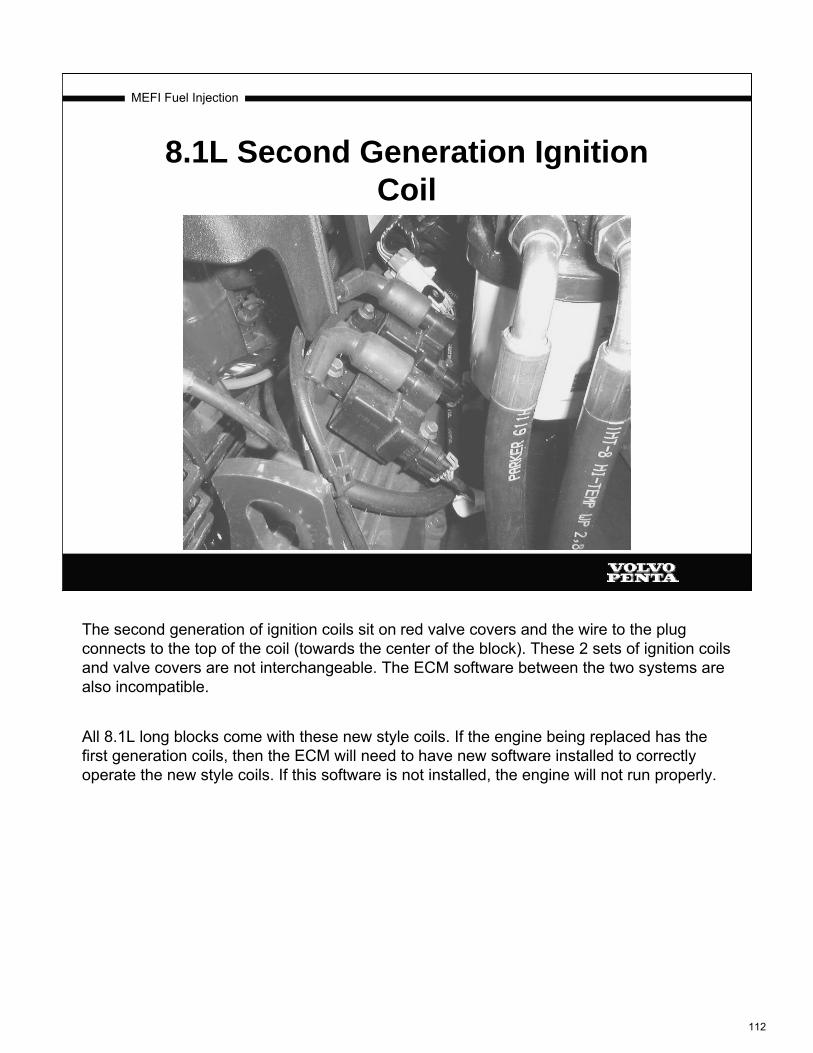
MEFI Fuel Injection
8.1L Second Generation Ignition Coil
The second generation of ignition coils sit on red valve covers and the wire to the plug connects to the top of the coil (towards the center of the block). These 2 sets of ignition coils and valve covers are not interchangeable. The ECM software between the two systems are also incompatible.
All 8.1L long blocks come with these new style coils. If the engine being replaced has the first generation coils, then the ECM will need to have new software installed to correctly operate the new style coils. If this software is not installed, the engine will not run properly.
112
MEFI Fuel Injection
Ignition systems: High Voltage Switch Ignition System
(MEFI 4 and 4b, IAFM)
113

MEFI Fuel Injection
Crankshaft Position Sensor
The crankshaft position sensor is mounted on the front of the engine, just behind the crankshaft balancer.It is a magneto-resistive type sensor that works in conjunction with a 4x reluctor wheel.The ECM uses the signal from the crankshaft position sensor, along with the camshaft position sensor signal for spark control, tachometer and fuel control.
114

MEFI Fuel Injection
Crankshaft Position Sensor Reluctor Ring
This 4x reluctor ring is positioned onto the front of the crankshaft, note the key for proper wheel alignment.
115

MEFI Fuel Injection
High Voltage Switch
The High Voltage Switch looks and more or less acts like a distributor. It distributes the high voltage from the coil to the spark plugs, it also contains the camshaft position sensor.The High Voltage Switch ignition system is used on our new MEFI 4 IAFM engines.This system features a camshaft driven distributor, an ignition control module, a crankshaft position sensor, a camshaft position sensor, and an ignition coil.The distributor has a composite base which incorporates the camshaft position vane switch and a rotary vane cup.The ECM takes the input signal from the cam and crank sensors, outputs an ignition control signal to the ignition control module, the IC module then triggers the coil.
116

MEFI Fuel Injection
Camshaft Position Sensor
The camshaft position sensor works by using a magnetic vane switch assembly (green oval) and a rotary vane cup (red circle).The rotary vane cup, made of ferrous metal, is used to trigger the signal on and off.
117
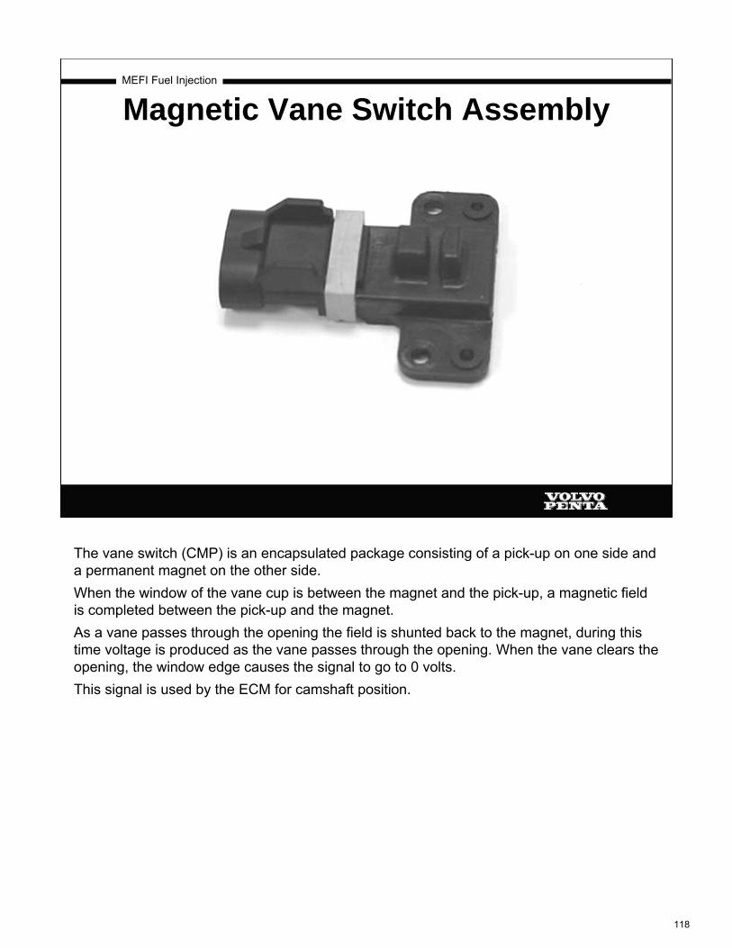
MEFI Fuel Injection
Magnetic Vane Switch Assembly
The vane switch (CMP) is an encapsulated package consisting of a pick-up on one side and a permanent magnet on the other side. When the window of the vane cup is between the magnet and the pick-up, a magnetic field is completed between the pick-up and the magnet.As a vane passes through the opening the field is shunted back to the magnet, during this time voltage is produced as the vane passes through the opening. When the vane clears the opening, the window edge causes the signal to go to 0 volts.This signal is used by the ECM for camshaft position.
118

MEFI Fuel Injection
Ignition Control Module
The external ignition control (IC) module is mounted on a bracket with the coil on the back of the engine. This is a one piece assembly.The IC module contains the coil driver. It receives an ignition timing signal from the ECM and triggers the coil.Pin A…..Ignition VoltagePin B…..Ignition Timing SignalPin C…..GroundPin D…..Coil Driver
119

Engine – 5.0 & 5.7 Liter
68 VPA 7743372 03-2003
NOTE! If the crankshaft was moved while distributor was out, complete ignition timing procedure must be followed. See below.
Gi and GXi models GL models: See Electric, Fuel and Ignition Workshop Manual 7743454.
1. Rotate the crankshaft balancer clockwise until the alignment marks on the crankshaft balancer (1) are aligned with the tabs on the engine front cover (2) and the number 1 piston is at top dead center of the compression stroke.
2. If not already removed, remove and discard the distributor cap screws.
3. Remove the distributor cap
4. Install NEW distributor gasket onto the distributor.
334551
1 2
500690
523516
120
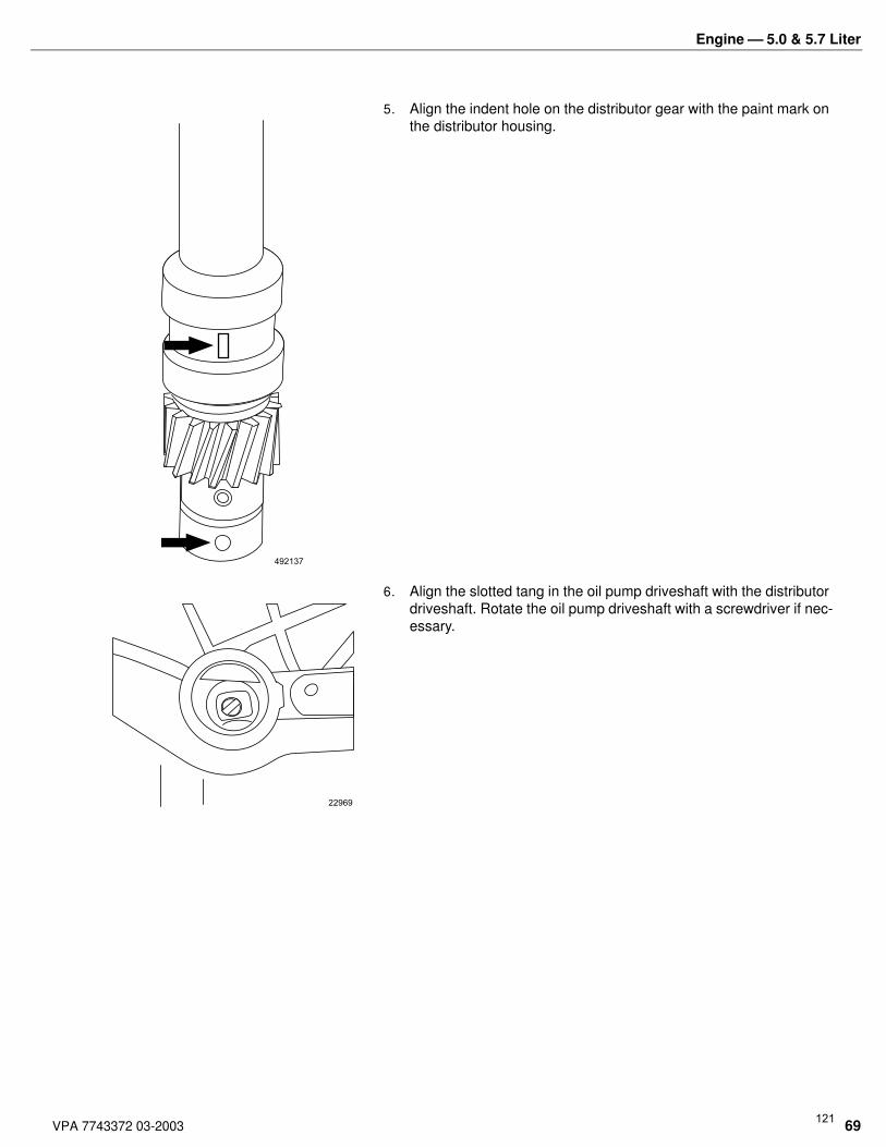
Engine – 5.0 & 5.7 Liter
VPA 7743372 03-2003 69
5. Align the indent hole on the distributor gear with the paint mark on the distributor housing.
6. Align the slotted tang in the oil pump driveshaft with the distributor driveshaft. Rotate the oil pump driveshaft with a screwdriver if nec-essary.
492137
22969
121

Engine – 5.0 & 5.7 Liter
70 VPA 7743372 03-2003
7. Align the flat (1) in the distributor housing toward the front of the engine.
8. Install the distributor and distributor clamp. The flat in the distribu-tor housing must be pointing toward the front of the engine.
9. Once the distributor is fully seated, align the distributor rotor seg-ment with the number 8 pointer (1) that is cast into the distributor base.
Note! If the distributor rotor segment does not come within a few degrees of the number 8 pointer, the gear mesh between the distributor and camshaft may be off a tooth or more. Repeat the procedure again in order to achieve proper alignment.
523746
1
310298
68505
122

Engine – 5.0 & 5.7 Liter
VPA 7743372 03-2003 71
10. Install the distributor clamp bolt. and Tighten the bolt to 25 N.m (18 lb. ft.).
11. Install the distributor cap and NEW distributor cap bolts.Tighten the screws to 2.4 N.m (21 lb. in).
12. Set timing, GL Models see Electrical Fuel and Ignition Workshop Manual 7743454. Gi and GXi Models see EFI Diagnostic Work-shop Manual 7742218 On Board Repair.
Alternator with mounting bracket. 13. Install distributor cap and high tension leads. See the General Information section in Electrical/Ignition/Fuel Service Manual for correct firing order and spark plug wire routing.
14. Install oil pressure sending unit.
Connect: 15. All electrical connections. Apply black neoprene dip, or equivalent, on all exposed connections.
16. Fuel lines to carburetor and fuel pump or throttle body and fuel pump/vapor separator.
17. Throttle cable.
18. All water hoses, and close all drain petcocks.
19. Both crankcase ventilation hoses.
20. Battery cables.
23321
23322
123

9. Once the distributor is fully seated, align thedistributor rotor segment with the number 6 pointer(1) that is cast into the distributor base.
If the distributor rotor segment does not come with afew degrees of the number 6 pointer (1), the gearmesh between the distributor and camshaft may beoff a tooth or more. Repeat the procedure again inorder to achieve proper alignment.
Notice: Refer to Fastener Notice in Cautions and Notices.
10. Install the distributor clamp bolt.
Tighten
Tighten the distributor clamp bolt to 25 N.m (18 lb ft).
11. Install the distributor cap and NEW distributor capbolts.
Tighten
Tighten the distributor cap bolts to 2.4 N.m (21 lb in).
334555
34403
301393
124
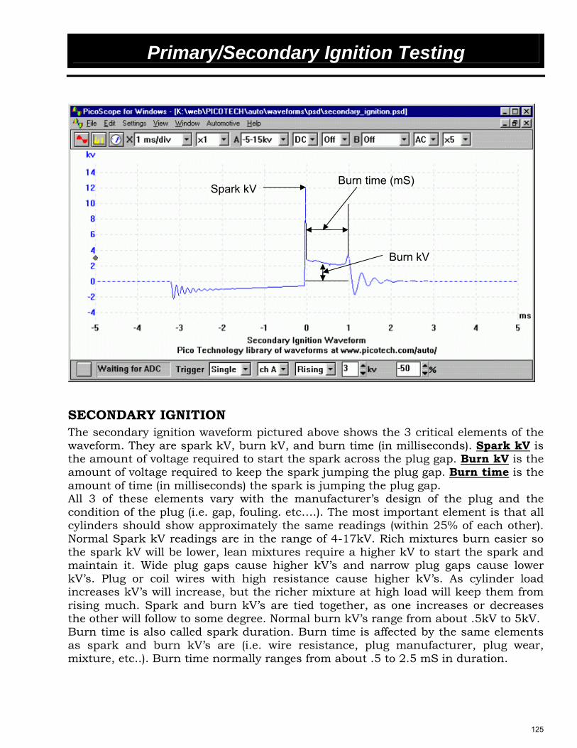
Primary/Secondary Ignition Testing
SECONDARY IGNITION The secondary ignition waveform pictured above shows the 3 critical elements of the waveform. They are spark kV, burn kV, and burn time (in milliseconds). Spark kV is the amount of voltage required to start the spark across the plug gap. Burn kV is the amount of voltage required to keep the spark jumping the plug gap. Burn time is the amount of time (in milliseconds) the spark is jumping the plug gap. All 3 of these elements vary with the manufacturer’s design of the plug and the condition of the plug (i.e. gap, fouling. etc….). The most important element is that all cylinders should show approximately the same readings (within 25% of each other). Normal Spark kV readings are in the range of 4-17kV. Rich mixtures burn easier so the spark kV will be lower, lean mixtures require a higher kV to start the spark and maintain it. Wide plug gaps cause higher kV’s and narrow plug gaps cause lower kV’s. Plug or coil wires with high resistance cause higher kV’s. As cylinder load increases kV’s will increase, but the richer mixture at high load will keep them from rising much. Spark and burn kV’s are tied together, as one increases or decreases the other will follow to some degree. Normal burn kV’s range from about .5kV to 5kV. Burn time is also called spark duration. Burn time is affected by the same elements as spark and burn kV’s are (i.e. wire resistance, plug manufacturer, plug wear, mixture, etc..). Burn time normally ranges from about .5 to 2.5 mS in duration.
Spark kV Burn time (mS)
Burn kV
125

Primary/Secondary Ignition Testing
Problems in the secondary ignition system are indicated by high or low spark kV or burn kV and long or short burn time.
SECONDARY IGNITION TESTING 1. Hook up the supplied secondary ignition tester to the coil wire of the 5.0L or any
plug wire on the 8.1L. Ensure there is a good ground for the alligator clip and that there is a minimum of ½ inch clearance between the inductive pickup of the tool and all other plug or coil wires.
2. Set the rotary switch on the kV tester to the Spark kV position. The left side of the screen reads the active reading in the wire. The right side of the screen shows the recorded minimum and maximum readings. To reset the readings turn the rotary knob to Off and then back to the desired function.
3. Test each plug wire and the coil wire and record your readings below. Max _______ Max _______ Cyl.# 1 _______ Cyl. # 5 _______ Min _______ Min _______ Max _______ Max _______ Cyl.# 2 _______ Cyl.# 6 _______ Min _______ Min _______ Max _______ Max _______ Cyl.# 3 _______ Cyl.# 7 _______ Min _______ Min _______ Max _______ Max _______ Cyl.# 4 _______ Cyl.# 8 _______ Min _______ Min _______ Max _______ Coil Wire _______ Min _______ 4. What is the condition of the secondary ignition system of your engine? ___________________________________________________________________________
126

Primary/Secondary Ignition Testing
PRIMARY IGNITION The secondary ignition system voltage is dependent on the operation of the primary ignition system. Think of the primary system as the input to the ignition coil and the secondary system as the output of the ignition coil. If there is poor input to the coil, there will be poor output. So if testing of the secondary reveals a problem, then the next logical thing to check is the primary ignition system. If the secondary system checks out ok, then there is no need to check the primary. Below is an oscilloscope picture of a typical primary ignition waveform. Look familiar?
What if you don’t have an oscilloscope? Is there any way to test the ignition primary? Not really. An oscilloscope is the only tool that can accurately show what is happening in the primary circuit with the engine running or cranking, but even with an oscilloscope the 8.1L primary circuit can’t be checked because most of it is internal to the ignition coil. With Volvo Penta’s ignition systems, the coil primary circuit is controlled by the Ignition Control (IC) signal input to either the coil (8.1L) or the ignition control module (ICM) from the ECM. So the coil primary only reacts to the IC input. No IC input to the coil or ICM, no coil primary operation. Since the IC circuit is an output from the ECM, there has to be some input that the ECM looks at to determine when to send the IC signal. That input is the crankshaft position sensor (CKP).
Dwell
Primary kick
127

Primary/Secondary Ignition Testing
So the whole picture here is that the ECM sees the CKP input and sends a signal out over the IC circuit to the ICM or the ignition coil (8.1L) to trigger the coil primary which induces voltage into the secondary ignition system. A breakdown anywhere in the system causes failure of the whole system. Taking what you have learned here, answer the following questions on the 5.0GXi-C engine. 1. In the picture below, which terminal (at the ignition coil) is the ignition coil
primary ground circuit? TERMINAL ____________
2. With the ignition switch on and engine not running, disconnect the ICM
connector and measure the voltage at pin D. What is the reading? __________ volts 3. What does this voltage reading tell you about the condition of the coil primary
circuit? _____________________________________________________________________
128

Primary/Secondary Ignition Testing
4. How many volts are there at the ICM connector pin A? __________ volts. What
would happen if this voltage wasn’t here?
_____________________________________________________________________
_____________________________________________________________________
5. What is the function of pin B at the ICM connector? _____________________________
6. What is the function of pin C at the ICM connector? _____________________________
7. With the ICM connector disconnected, hook up a voltmeter (using the AC voltage
function) to terminal B. Crank the engine and read the voltmeter while the engine
is cranking. What is your voltmeter reading? ________ VAC (normal reading is
1-4 VAC)
8. What does this voltage reading mean? ________________________________________
______________________________________________________________________
9. Turn the key off, reconnect disconnected connectors, remove voltmeter and
inform your instructor that you have finished.
Continue on next page
129

Primary/Secondary Ignition Testing
Using the engine and the diagram below, answer the following questions about
the 8.1Gi-A engine.
1. Disconnect the injector for cylinder #1. Disconnect the #1 ignition coil. With the
ignition switch on and the engine not running, measure the voltage at terminal D
of the ignition coil connector. What is the reading? _________ VDC
130

Primary/Secondary Ignition Testing
2. Where does this voltage come from? __________________________________________
3. The ignition coil connector terminals B and A are grounds and go to the ground
studs located at the rear of the engine. Hook up a voltmeter set to read Hz
(frequency) to terminal C (IC signal circuit) of the ignition coil connector. Start the
engine and read the frequency of the IC circuit. A properly working circuit should
read 3-20 Hz. What is the reading of the circuit being tested? __________ Hz
4. Shut engine down.
5. If the reading was 0 Hz, what could be wrong? __________________________________
______________________________________________________________________
6. Can the ignition coil primary circuit be tested for an open circuit with an
Ohmmeter?
_____________________________________________________________________
7. Reconnect the injector and ignition coil. Start engine and ensure proper engine
operation and clear any DTC’s with the scan tool.
131

MEFI Fuel Injection
Fuel Systems:Throttle Body Fuel Injection
132

MEFI Fuel Injection
Throttle Body Injection
Throttle body injected engines use a constant pressure high pressure fuel system. The high pressure pump provides high pressure (11 psi or 29 psi depending on model) to the injectors and the pressure regulator. Because the injector tips are always open to atmospheric pressure, fuel system pressure remains constant throughout the engine operating range (idle to wide open throttle).The throttle body assembly is mounted on a conventional carburetor type intake manifold. It is used to control air flow into the engine, thereby controlling engine power. The throttle plates within the throttle body are opened by the operator through the throttle control.
133

MEFI Fuel Injection
Throttle Body Assembly
The Throttle Body Injection (TBI) system uses the throttle body assembly as a location for mounting the:* Injectors.* Fuel metering assembly.* Pressure regulator.* IAC motor* TPS.
134

MEFI Fuel Injection
TBI Injector
Electronic fuel injectors are solenoid-operated valves controlled by the ECM. The injectors are supplied with 12 volts from the ignition relay. Drivers in the ECM supply a ground to the other terminal of the injector to actuate the solenoid.The ECM energizes the injector solenoid, which opens a ball valve allowing pressurized fuel to flow through a flow director plate that has 6 machined holes creating a conical pattern of finely atomized fuel.TBI systems fire one injector on one Ref Hi signal and the second injector on the next Ref Hi signal. The amount of fuel injected is determined by the length of time that the injector is energized, this is known as Pulse Width.The ECM calibration is based on the fact that an injector discharges a known amount of fuel per millisecond at a specified pressure at a specific voltage. Maintaining proper fuel pressure is ESSENTIAL to providing proper air/fuel ratio.NOTE:Do not apply a constant ground directly to the injector’s ground terminal. The internal solenoid will be damaged in a matter of a second or two. Review the following page for TBI service kits, injector colors and system pressures by model.
135
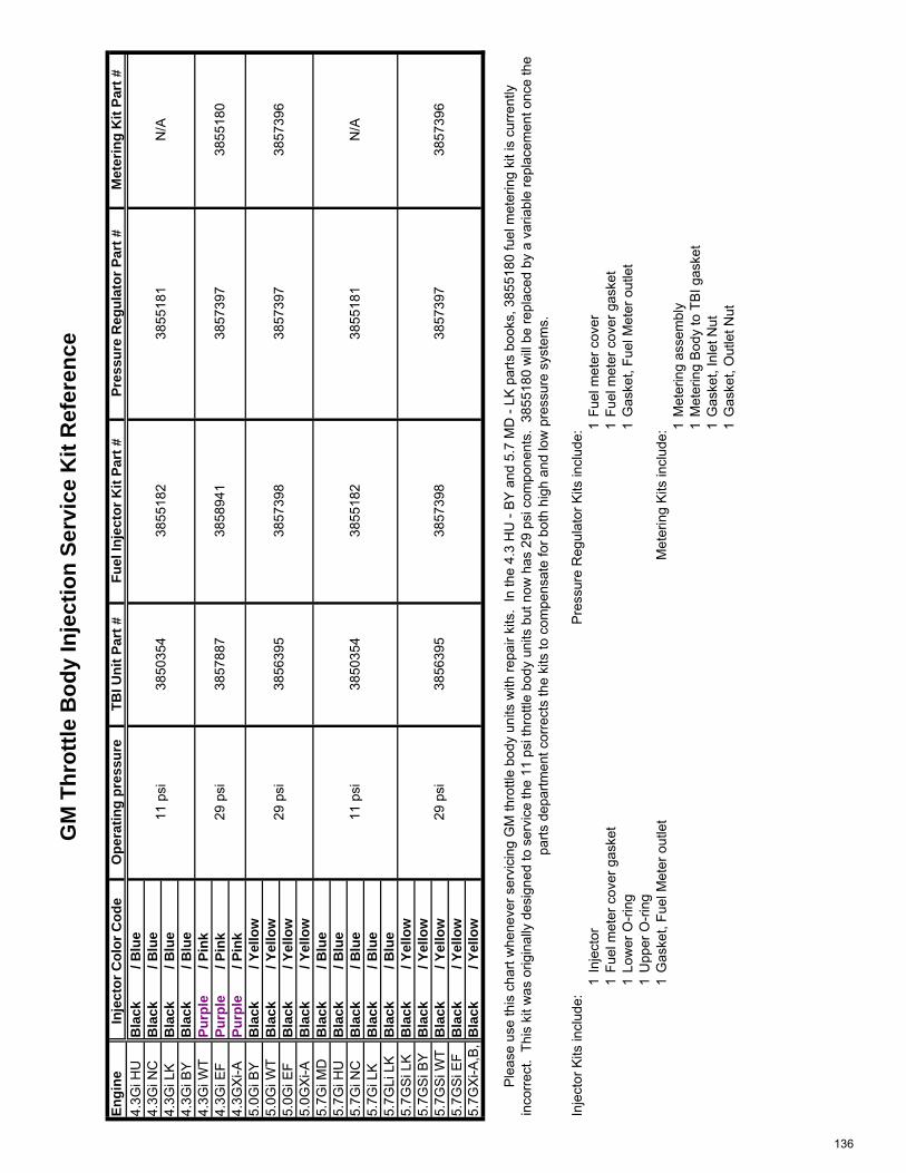
GM
Thr
ottle
Bod
y In
ject
ion
Serv
ice
Kit
Ref
eren
ce
Engi
neO
pera
ting
pres
sure
TBI U
nit P
art #
Fuel
Inje
ctor
Kit
Part
#Pr
essu
re R
egul
ator
Par
t #M
eter
ing
Kit
Part
#4.
3Gi H
UB
lack
/
Blu
e4.
3Gi N
CB
lack
/
Blu
e4.
3Gi L
KB
lack
/
Blu
e4.
3Gi B
YB
lack
/
Blu
e4.
3Gi W
TPu
rple
/ Pi
nk4.
3Gi E
FPu
rple
/
Pink
4.3G
Xi-A
Purp
le
/ Pi
nk5.
0Gi B
YB
lack
/
Yello
w5.
0Gi W
TB
lack
/
Yello
w5.
0Gi E
FB
lack
/
Yello
w5.
0GX
i-AB
lack
/
Yello
w5.
7Gi M
DB
lack
/
Blu
e5.
7Gi H
UB
lack
/
Blu
e5.
7Gi N
CB
lack
/ B
lue
5.7G
i LK
Bla
ck
/ B
lue
5.7G
Li L
KB
lack
/ B
lue
5.7G
Si L
KB
lack
/
Yello
w5.
7GS
i BY
Bla
ck
/ Ye
llow
5.7G
Si W
TB
lack
/
Yello
w5.
7GS
i EF
Bla
ck
/ Ye
llow
5.7G
Xi-A
,B,
Bla
ck
/ Ye
llow
Inje
ctor
Kits
incl
ude:
1In
ject
or1
Fuel
met
er c
over
1Fu
el m
eter
cov
er g
aske
t1
Fuel
met
er c
over
gas
ket
1Lo
wer
O-r
ing
1G
aske
t, Fu
el M
eter
out
let
1U
pper
O-r
ing
1G
aske
t, Fu
el M
eter
out
let
1M
eter
ing
asse
mbl
y1
Met
erin
g B
ody
to T
BI g
aske
t1
Gas
ket,
Inle
t Nut
1G
aske
t, O
utle
t Nut
3855
182
3855
182
3857
398
Inje
ctor
Col
or C
ode
11 p
si
11 p
si
29 p
si
3850
354
3850
354
29 p
si
N/A
N/A
3855
181
3855
181
3857
397
3855
180
3857
396
3857
397
3857
887
3856
395
3858
941
3857
398
29 p
si
Pre
ssur
e R
egul
ator
Kits
incl
ude:
Met
erin
g K
its in
clud
e:
Ple
ase
use
this
cha
rt w
hene
ver s
ervi
cing
GM
thro
ttle
body
uni
ts w
ith re
pair
kits
. In
the
4.3
HU
- B
Y a
nd 5
.7 M
D -
LK p
arts
boo
ks, 3
8551
80 fu
el m
eter
ing
kit i
s cu
rren
tly
inco
rrec
t. T
his
kit w
as o
rigin
ally
des
igne
d to
ser
vice
the
11 p
si th
rottl
e bo
dy u
nits
but
now
has
29
psi c
ompo
nent
s. 3
8551
80 w
ill b
e re
plac
ed b
y a
varia
ble
repl
acem
ent o
nce
the
parts
dep
artm
ent c
orre
cts
the
kits
to c
ompe
nsat
e fo
r bot
h hi
gh a
nd lo
w p
ress
ure
syst
ems.
3857
396
3856
395
3857
397
136

MEFI Fuel Injection
TBI Regulator
The regulator is a diaphragm operated relief valve with fuel pressure on one side of the diaphragm and opposing spring pressure on the other.The regulator’s function is to maintain a constant fuel pressure to the injectors at all times.It is housed inside the throttle body assembly and located in the fuel flow after the injectors.When fuel pressure exceeds spring pressure a valve will open allowing excess pressure to flow back to the reservoir. The balance between spring pressure, fuel pressure and fuel flow allows the regulator to maintain a constant pressure under all engine operating conditions.
137

MEFI Fuel Injection
TBI Fuel Flow
For TBI illustration purposes, this fuel flow diagram is shown using the older style vapor separating tank (VST) system.The low pressure pump brings fuel from the tank, through the filter and fills the reservoir.The reservoir fills from the bottom up and supplies fuel to the high pressure pump.The high pressure pump pulls fuel from near the bottom of the reservoir and supplies the fuel rail and injectors.If the fuel demand is less than the volume of fuel supplied by the pump, line pressure will increase until the regulator opens and allows fuel to exit the regulator and return to the reservoir.Fuel entering the reservoir is cooled by incoming water. A small volume of water moves through a passage at the base of the reservoir.Inside the reservoir is a float and needle mechanism that connects to a manifold vacuum line. The vapor rises to the top of the reservoir, vacuum pulls the vapor into the intake. A pulse limiter in the vacuum line prevents a backfire from igniting the fuel vapor.As the liquid fuel level rises, the float and needle mechanism closes and prevents fuel from entering the vacuum line.On high vacuum (18+inches Hg) small blocks, the VST needle would stick if not clipped correctly to the float tang.
138

MEFI Fuel Injection
Fuel Systems: Multi Port Fuel Injection
139

MEFI Fuel Injection
Multi-Port Fuel Injector
Multi-port fuel injectors are also solenoid operated valves controlled by the ECM.Multi-port systems have one fuel injector per cylinder, discharging fuel directly into the intake port behind the intake valve.Since there is no fuel in the intake manifold, the runners can be tuned for maximum air flow with out causing fuel separation.This precise fuel distribution and the increase in volumetric efficiency are the major reasons for the power increase associated with multi-port fuel injection.
140

MEFI Fuel Injection
Fuel inlet filter
Solenoid windings
Lower O-ring
Director plateCore spring
Spray tip
Upper O-ring
Pintle and seat
Iron shuttle
Conical spray
MPFI Injector
The injectors are supplied with 12 volts from the ignition/fuel relay. Drivers in the ECM supply a ground to the other terminal of the injector to actuate the solenoid.The ECM energizes the injector solenoid, which opens a ball valve allowing pressurized fuel to flow through a flow director plate that has a number (4-8) of machined holes creating a conical pattern of finely atomized fuel.The fuel is directed at the intake valve aiding in valve cooling and additional atomization.The multi-port system uses 2 injector drivers.The amount of fuel injected is determined by the length of time that the injector is energized, called Pulse Width.The unit of measure used for injector “on” time is milliseconds. Again, as with the TBI injectors, the pulse width is based on the fact that an injector discharges a known amount of fuel per millisecond at a specific fuel pressure and at a specific supply voltage, so maintaining proper pressure is ESSENTIAL to providing proper air/fuel ratio.When injectors stick or seize, no fault code will be set. Injector codes set for opens or shorts in the driver circuit back to the ECM.
141

MEFI Fuel Injection
MPFI Regulator
The regulator is a diaphragm operated relief valve with fuel pressure on one side of the diaphragm and opposing spring pressure and manifold vacuum on the other.The regulator’s function is to maintain a constant effective pressure at the injector tips at all times.The addition of manifold vacuum is necessary because injector tips are located inside the manifold, this would normally cause the pressure drop at the tip to change with manifold vacuum. With manifold vacuum acting on the regulator diaphragm the effective pressure at the tip remains constant.The regulator compensates for engine load by increasing fuel pressure as engine vacuum drops, this will cause the gauge to fluctuate with throttle opening while checking pressure.Fuel system pressure is checked with the engine off and the fuel pumps running or with the engine running and the vacuum hose to the regulator disconnected.
142

MEFI Fuel Injection
MPFI Fuel Flow
The low pressure pump brings fuel from the tank, through the filter and fills the reservoir.The reservoir fills from the bottom up and supplies fuel to the high pressure pump.The high pressure pump pulls fuel from near the bottom of the reservoir and supplies the fuel rail and injectors.If the fuel demand is less than the volume of fuel supplied by the pump, line pressure will increase until the regulator opens and allows fuel to exit the regulator and return to the reservoir.Fuel entering the reservoir is cooled by incoming water. A small volume of water moves through a passage around the reservoir.Inside the reservoir is a float and needle mechanism that connects to a plenum vacuum line. The vapor rises to the top of the reservoir, vacuum pulls the vapor into the plenum. A pulse limiter in the vacuum line prevents a backfire from igniting the fuel vapor.As the liquid fuel level rises the float and needle mechanism closes and prevents fuel from entering the vacuum line.
143

MEFI Fuel Injection
Fuel Pump Module
The fuel module replaces the VST system. This style of module is used in both late TBI and all MPI engines. The modules used between the TBI and MPI systems are NOT interchangeable. (see chart next page)It contains the low pressure pump, high pressure pump and the fuel cooler-vapor separator cylinder all mounted in one compact unit.The fuel cooling cylinder is made of anodized extruded aluminum and is sealed with double “O” rings at each end.The cylinder is mounted in a vertical position to keep the fuel level as high as possible and separate vapors through an improved needle and float valve.The low pressure pump fills the reservoir. The high pressure pump takes suction from the reservoir. The reservoir is raw water cooled. Raw water enters the unit at the bottom through the small hose and exits at the top of the module and is discharged to the inboard side of the exhaust riser.The second small rubber hose at the very top of the reservoir is the vapor line to the intake manifold.
144
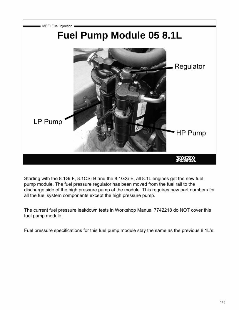
MEFI Fuel Injection
Fuel Pump Module 05 8.1L
Regulator
HP PumpLP Pump
Starting with the 8.1Gi-F, 8.1OSi-B and the 8.1GXi-E, all 8.1L engines get the new fuel pump module. The fuel pressure regulator has been moved from the fuel rail to the discharge side of the high pressure pump at the module. This requires new part numbers for all the fuel system components except the high pressure pump.
The current fuel pressure leakdown tests in Workshop Manual 7742218 do NOT cover this fuel pump module.
Fuel pressure specifications for this fuel pump module stay the same as the previous 8.1L’s.
145

MEFI Fuel Injection
Fuel Inlet Testing
For a temporary fuel flow test to check for fuel inlet air leaks or inlet restrictions, assemble a "T" with barbed fittings that will allow you to remove the hose easily. Put a clear plastic hose with nylon webbing on one side of the "T" and install on the fuel filter barb. On the other side, install the fuel hose. Install a vacuum gauge at the third fitting that reads from 0 to 30 inches Hg. The vacuum should NOT be above about 2 inches Hg when running. Also, look for air bubbles!
146
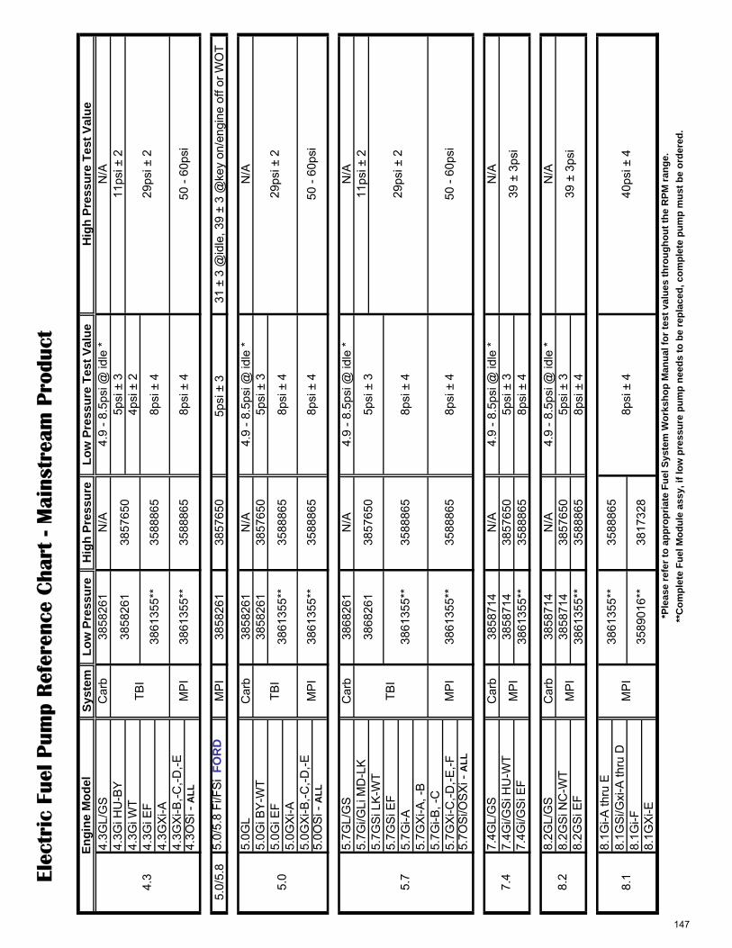
Elec
tric
Fue
l Pum
p R
efer
ence
Cha
rt -
Mai
nstr
eam
Pro
duct
Syst
emLo
w P
ress
ure
Hig
h Pr
essu
reLo
w P
ress
ure
Test
Val
ueH
igh
Pres
sure
Tes
t Val
ue4.
3GL/
GS
Car
b38
5826
1N
/A4.
9 - 8
.5ps
i @ id
le *
N/A
4.3G
i HU
-BY
5psi
± 3
11ps
i ± 2
4.3G
i WT
4psi
± 2
4.3G
i EF
4.3G
Xi-A
4.3G
Xi-B
,-C,-D
,-E4.
3OS
i - A
LL
5.0/
5.8
5.0/
5.8
Fi/F
Si
FOR
DM
PI
3858
261
3857
650
5psi
± 3
31
± 3
@id
le, 3
9 ±
3 @
key
on/e
ngin
e of
f or W
OT
5.0G
L C
arb
3858
261
N/A
4.9
- 8.5
psi @
idle
*N
/A5.
0Gi B
Y-W
T38
5826
138
5765
05p
si ±
35.
0Gi E
F5.
0GX
i-A5.
0GX
i-B,-C
,-D,-E
5.0O
Si -
ALL
5.7G
L/G
SC
arb
3868
261
N/A
4.9
- 8.5
psi @
idle
*N
/A5.
7Gi/G
Li M
D-L
K11
psi ±
25.
7GS
i LK
-WT
5.7G
Si E
F5.
7Gi-A
5.7G
Xi-A
, -B
5.7G
i-B, -
C5.
7GX
i-C,-D
,-E,-F
5.7O
Si/O
SX
i - A
LL
7.4G
L/G
SC
arb
3858
714
N/A
4.9
- 8.5
psi @
idle
*N
/A7.
4Gi/G
Si H
U-W
T38
5871
438
5765
05p
si ±
37.
4Gi/G
Si E
F38
6135
5**
3588
865
8psi
± 4
8.2G
L/G
SC
arb
3858
714
N/A
4.9
- 8.5
psi @
idle
*N
/A8.
2GS
i NC
-WT
3858
714
3857
650
5psi
± 3
8.2G
Si E
F38
6135
5**
3588
865
8psi
± 4
8.1G
i-A th
ru E
8.1G
Si/G
xi-A
thru
D8.
1Gi-F
8.1G
Xi-E
40ps
i ± 4
3817
328
3589
016*
*M
PI
3861
355*
*35
8886
58p
si ±
48.
1
*Ple
ase
refe
r to
appr
opria
te F
uel S
yste
m W
orks
hop
Man
ual f
or te
st v
alue
s th
roug
hout
the
RPM
rang
e.
**C
ompl
ete
Fuel
Mod
ule
assy
, if l
ow p
ress
ure
pum
p ne
eds
to b
e re
plac
ed, c
ompl
ete
pum
p m
ust b
e or
dere
d.
29ps
i ± 2
50 -
60ps
i
7.4
8.2
5.7
3857
650
29ps
i ± 2
50 -
60ps
i
29ps
i ± 2
50 -
60ps
i
8psi
± 4
8psi
± 4
8psi
± 4
3857
650
39 ±
3ps
i
39 ±
3ps
i
MP
I
MP
I
Engi
ne M
odel
4.3
3858
261
3861
355*
*35
8886
5
3861
355*
*35
8886
5TB
I
MP
I
MP
I
TBI
8psi
± 4
8psi
± 4
3861
355*
*35
8886
5
3861
355*
*35
8886
5
8psi
± 4
5.0
3868
261
5psi
± 3
TBI
MP
I38
6135
5**
3588
865
3861
355*
*35
8886
5
147

������������� ������������������������������� ������������������������� ��!"�
Distribution: M Date: 01-2004 Binder: C Page: 1(1)
23254
Service BulletinGroup Number Version
23-3 7 01
High pressure fuel pumpModels
All Fuel Cell equipped EFI Gasoline Engines
Volvo Penta has introduced a High Pressure FuelPump Replacement Kit PN 3588865. Use the instruc-tions included in the kit when servicing the fuel cell.
This kit is to be used if the high pressure fuel pumpneeds replacement on Fuel Cell PN 3861355 and PN3860210. In cases where only the high pressurepump needs to be replaced, this will allow for a fasterand more cost effective repair. In cases where aproblem exists in the low pressure fuel pump, or thereservoir portion of the fuel cell, the entire fuel cell willstill require replacement.
Testing at the low pressure test fitting at the base ofthe fuel cell, and the high pressure test fitting on thefuel rail, will easily isolate whether the low pressure orhigh pressure fuel pump has failed. Volvo Penta FuelPressure Test Kit P/N 3855533 includes both the lowpressure fitting adapter ( PN 3855354 ) and the highpressure fitting adapter ( PN 3862357 ) required toperform these tests. Also, unplugging the electricalconnector on each fuel pump one at a time and cyclingthe key to the "on" position, can assist in confirming asuspected seized fuel pump.
Note: This High Pressure Fuel Pump Kit is usedonly on Fuel Cell PN 3861355 and PN 3860210. Itdoes not apply to earlier models using the VaporSeparator style system.
Warning!
Follow all related safety procedures as noted inthe Workshop Manual during all fuel system test-ing procedures.
See the chart below for fuel pressure values:
Engines using Fuel Cell P/N 3861355 or P/N 3860210
Model Low pressure High Pressure
4.3 TBI 8 psi +/- 4psi 29 psi +/- 2psi
5.0 TBI 8 psi +/- 4psi 29 psi +/- 2psi
5.7 TBI 8 psi +/- 4psi 29 psi +/- 2psi
4.3 PFI 8 psi +/- 4psi 50-60 psi
5.0 PFI 8 psi +/- 4psi 50-60 psi
5.7 PFI 8 psi +/- 4psi 50-60 psi
7.4 PFI 8 psi +/- 4psi 36-44 psi
8.1 PFI 8 psi +/- 4psi 36-44 psi
High Pressure Fuel Pump
148

������������� ������������������������������� ������������������������� ��!"�
Distribution: M Date: 10-2003 Binder: C
Service BulletinGroup Number Version
23-0 2 02
ComponentAll Gasoline EnginesFuel Storage Mixture
This bulletin is to clarify our recommendations with regard to gasoline fuel treatment for storage or limiteduse. Today’s gasoline blends are not as stable as in the past and consideration must be given if the fuelwill not be used within a short time or if the engine is being placed in storage. Failure to properly stabilizethe fuel can damage fuel system components and is not considered as warrantable.Boat manufacturers should follow the gasoline storage mixture section for testing prior to shipment.
Note! Volvo Penta has discontinued the fuel stabilizer #3855832 noted in ourmanuals and a suitable replacement can be purchased locally at most automotivesupply stores.
Limited Use
If the vessels fuel within the tank(s) will not be consumed within a 30-day period from the time of filling, agasoline fuel stabilizer must be added as per the manufacturers instructions. This will help prevent the fuelfrom breaking down and causing reduced engine performance or damage from uncontrolled combustion.
Storage
If the boat is being placed into storage, a gasoline fuel stabilizer must be added to the tank(s) as per themanufacturers instructions. The amount of stabilizer required is determined by the quantity of fuel and thelength of time it will be placed in storage.
DANGER!
Any fuel leakage should be corrected immediately to prevent possible fire and/orexplosion.
Caution!
Do not run engine out of fuel or run the electric fuel pumps dry more than 20 se-conds. Running the electric fuel pumps dry will cause fuel pump damage.
Prepare a storage mixture
In addition to stabilization of the fuel, it is highly desirable to have the valves and cylinders coated with alight film of oil previously accomplished through “fogging”. Today’s multiport fuel injection manifolds are de-signed with a complex air channel design that will not allow the traditional fogging oils to be injected pastthe throttle plate while running. The oil will get stuck in the plenum and never reach the cylinders. Togetherwith the stabilizer, two-cycle motor oil can be added to a fuel mixture for stabilization purposes.
• Using an outboard motor six-gallon fuel tank, add two-cycle motor oil at a ratio of 50:1 (one pint to 6gallons) and stabilizer at one ounce per gallon (unless stated otherwise on the manufacturers label).Mix well.
• Disconnect boat fuel line at engine fuel pump. Attach the “storage mix” fuel tank.
• Connect a suitable engine flush device if the boat is not in the water.
149
Group Number Version Page
23-0 2 02 2(2)
Volvo Penta of the AmericasService Bulletin
• Run the engine on the “storage mixture” for approximately 5 minutes at 1500 RPM. This will ensure that all fuelsystem and internal engine components are thoroughly protected. Do not operate the engine above 1500 RPMas the water pump demand may exceed the supply, damaging the pump.
• Reduce the engine speed to idle and stop the engine.
• Reconnect the fuel fitting and check for fuel leaks.
Electric fuel pumps and fuel cellsRegardless of the ratio of fuel stabilizer to fuel we use, the maximum recommended storage time for gasoline, ac-cording to STA-BIL, is six months. During final assembly testing at our Lexington factory, each engine is run on afuel mix that is stabilized. Each engine is shut off without running the fuel pumps dry and the fuel system is sealedto prevent damage. With the delay in time between the product getting installed in a boat, shipped to you, sold andfinally delivered; the six-month time frame can easily be exceeded.
Since delivering a quality, dependable product is one of our highest goals; we work closely with our suppliers toidentify the root cause of failure on any parts returned for warranty credit. While there are certainly legitimate failuresof fuel pumps, the major portion of them are returned to us due to varnished fuel from long term storage. We wouldlike to offer some advice on dealing with these issues.
Stuck PumpsIf a fuel pump appears stuck and will not operate, you may try briefly reversing the polarity to the pump to turn it inthe opposite direction. You should disconnect the electrical plug of one pump at a time on the fuel cell to determinewhich pump might have a problem.
Noisy PumpsElectric pumps will often cavitate and become noisy if they are starving for fuel. On carbureted engines or low-pres-sure fuel cell pumps, check the fuel supply, quality of the fuel hose, anti-siphon valve, and filter before replacing thefuel pump.A noisy high-pressure pump on a fuel cell may indicate a low fuel level in the reservoir. Check the fuel supply andlow pressure pump operation to be sure the reservoir is receiving the correct volume of fuel. The same informationwould apply to engines with the earlier vapor separator tank design.
This information may help prevent the needless replacement of pumps in many cases and reduce the repair time forthe boat owner.
Note!Replacement fuel modules and fuel pumps are now shipped from the parts departmentwith testing fluid inside to extend their shelf life. The testing fluid is flammable and FAAregulations state that they cannot ship via air frieght.
150

Fuel Pressure/Leakdown Testing Activity
Fuel Pressure Testing and Leakdown Testing 1. With the ignition switch off, remove the fuel pump relay. Crank engine and run
engine out of fuel. Do this several times to ensure fuel pressure has been reduced to 0 psi. Turn key back to off position.
2. Connect fuel pressure gauge from gauge set VP part # 3855533 with adapter VP part # 3862357 to the fuel pressure rail.
3. Using the special tool for fuel line removal, disconnect both the pressure and return lines to the fuel rail.
4. Install the fuel line shutoff adapters, (Kent Moore J 37287) between the disconnected fuel lines and the fuel rail. Note: when installing there should be an audible click as hoses go together. After click is heard, try to pull the connection apart. It should NOT come apart. If it does come apart, then it wasn’t installed properly or the connection is damaged.
WARNING: IF THIS CONNECTION COMES APART WHILE ENGINE IS RUNNING, A LARGE FUEL LEAK WILL OCCUR WITH A POSSIBLE FIRE RESULTING.
5. Ensure the valves in the J 37287 fuel shut off adapters are in the open position (in line with the hose).
6. Reinstall fuel pump relay. Turn ignition switch on several times to run the fuel pumps and refill the lines. Check for any fuel leaks.
7. After fuel pressure has built up, turn key off and observe fuel pressure. Fuel pressure should hold at 40 psi + or – 4 psi for an 8.1L or 50-60 psi for the 5.0L.
8. Close both valves in the fuel shutoff adapters and record fuel pressure. ______ PSI
9. Record fuel pressure after 2 minutes. _______ PSI Fuel pressure should drop very little. If fuel pressure were to drop 10 PSI in those 2 minutes, where would the leak be and how would you fix it? ______________________________________________________________________________
10. Open both shutoff valves and cycle the ignition switch to rebuild fuel pressure. Close the fuel shutoff valve in the supply line to the fuel rail. Observe and record the fuel pressure drop after 2 minutes. _______ PSI drop.
11. If pressure did not drop in step 9 and pressure drops in step 10, what is (are) the possible component(s) causing the pressure drop? ________________________________________________________________________
12. Open both shutoff valves and cycle the ignition switch to rebuild fuel pressure. Close the fuel shutoff valve in the return line from the fuel rail. Observe and record the fuel pressure drop after 2 minutes. _______ PSI drop.
13. If the pressure did not drop in steps 9 or 10 but does drop now. Where is the leak? ________________________________________________________________________
151
Fuel Pressure/Leakdown Testing Activity
14. Remove fuel pump relay, start engine and run out of fuel. Disconnect fuel gauge
and fuel shutoff adapters. Reconnect fuel lines to fuel rail.(See the note in step 4) Recap fuel pressure test port on the fuel rail. Reinstall fuel pump relay and start engine. Check and ensure that there are no fuel leaks.
152

MEFI Fuel Injection
Special Service Tools
•Tools are supplied by Volvo Penta, Kent Moore, or other suppliers
•Kent Moore tools are listed in the Workshop Manuals
•Identified by “J- “ numbers
•Order direct from Kent Moore:1 800 345-2233
•DIACOM and other MEFI tools are supplied by Rinda Technologies:
www.rinda.com ph 773.736.6633
153

MEFI Fuel Injection
Special Service Tools•Late model fuel modules lack the Schrader valve for checking fuel pressure at the high pressure line at the fuel pump. A new service tool, VPA# 3861684 has been released so that high side fuel pressure can be checked at the pump.
•The 8.1L and IAFM fuel rails have an automotive Schrader valve configuration.
•Volvo Fuel Pressure Gauge Kit 3855533 with adapter VPA #3862357, required for 8.1L and all IAFM
•See EFI Diagnostic Workshop Manual for standard EFI tools.
•See Engine Mechanical Workshop Manual on new tools for engine assembly and disassembly.
154
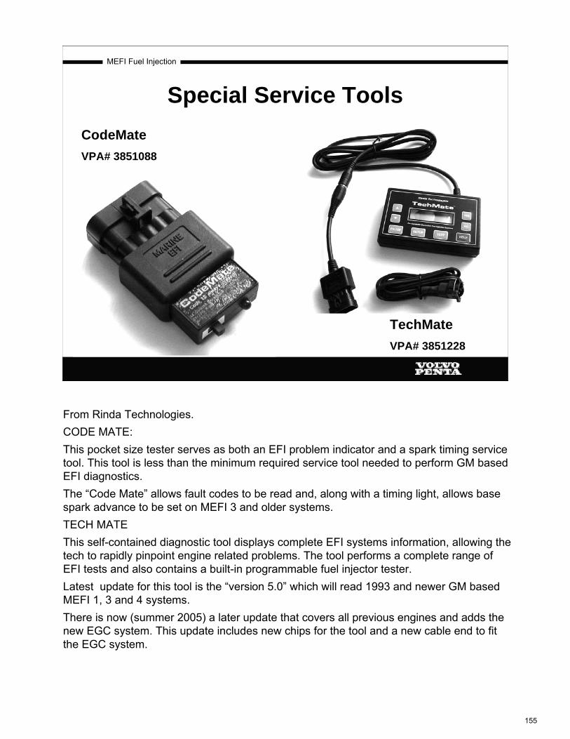
MEFI Fuel Injection
CodeMateVPA# 3851088
TechMateVPA# 3851228
Special Service Tools
From Rinda Technologies.CODE MATE:This pocket size tester serves as both an EFI problem indicator and a spark timing service tool. This tool is less than the minimum required service tool needed to perform GM based EFI diagnostics.The “Code Mate” allows fault codes to be read and, along with a timing light, allows base spark advance to be set on MEFI 3 and older systems.TECH MATEThis self-contained diagnostic tool displays complete EFI systems information, allowing the tech to rapidly pinpoint engine related problems. The tool performs a complete range of EFI tests and also contains a built-in programmable fuel injector tester.Latest update for this tool is the “version 5.0” which will read 1993 and newer GM based MEFI 1, 3 and 4 systems.There is now (summer 2005) a later update that covers all previous engines and adds the new EGC system. This update includes new chips for the tool and a new cable end to fit the EGC system.
155
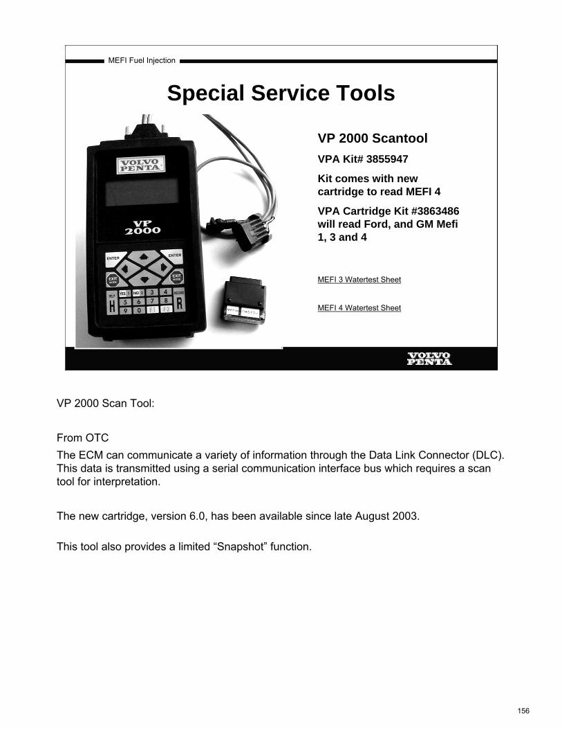
MEFI Fuel Injection
VP 2000 ScantoolVPA Kit# 3855947
Kit comes with new cartridge to read MEFI 4
VPA Cartridge Kit #3863486 will read Ford, and GM Mefi 1, 3 and 4
Special Service Tools
MEFI 3 Watertest Sheet
MEFI 4 Watertest Sheet
VP 2000 Scan Tool:
From OTCThe ECM can communicate a variety of information through the Data Link Connector (DLC). This data is transmitted using a serial communication interface bus which requires a scan tool for interpretation.
The new cartridge, version 6.0, has been available since late August 2003.
This tool also provides a limited “Snapshot” function.
156

Dea
ler N
umbe
r :C
onta
ct N
ame
:Ph
one
# :
Boat
Mod
el:
Ow
ner:
Engi
ne M
odel
:En
g S/
N :
Leng
th:
Driv
e R
atio
:D
rive
S/N
:Pr
op S
ize
:
Cal
CK
Sum
Logg
edKe
y on
Idle
1000
RPM
2000
RPM
3000
RPM
4000
RPM
WO
T >>
>>>
RPM
RPM
deg
Fde
g F
deg
Fde
g F
Hg
Hg
VV
Hg
Hg
VV
VV
%%
GPH
GPH
ms
ms
deg
deg
Y/N
Y/N
deg
deg
On/
Off
On/
Off
VV
Y/N
Y/N
hrs
hrs
Scan
Too
l Dat
a T
roub
le C
odes
Act
ive:
Map
sen
sor
Map
sen
sor
Engi
ne S
peed
EC
T se
nsor
IA
T se
nsor
T.P.
sen
sor
Baro
sen
sor
Baro
sen
sor
T.P.
sen
sor
Knoc
k Si
gnal
IAC
Pos
ition
Base
IAC
Pos
tion
Fuel
Rat
eIn
ject
ion
Puls
eSp
ark
Adva
nce
Engi
ne H
ours
Knoc
k R
etar
d
Shift
Inte
rrupt
IAC
Fol
low
erBa
ttery
Vol
tage
Pow
er R
educ
tion
ECT
sens
or
IAT
sens
or
Map
sen
sor
Map
sen
sor
*** A
ll R
eadi
ngs
Abo
ve Id
le M
ust B
e M
ade
Und
er L
oad,
On
Wat
er, W
ith E
ngin
e W
arm
***
VOLV
O P
ENTA
MEF
I III
EFI
WA
TER
TES
T SH
EET EC
M C
alib
ratio
n (M
arke
d on
EC
M):
IMPO
RTA
NT
WO
T =
Engi
ne S
peed
Baro
sen
sor
Baro
sen
sor
T.P.
sen
sor
T.P.
sen
sor
Fuel
Rat
eIn
ject
ion
Puls
eSp
ark
Adva
nce
Knoc
k Si
gnal
Knoc
k R
etar
dIA
C P
ositi
onBa
se IA
C P
ostio
nSh
ift In
terru
ptIA
C F
ollo
wer
Batte
ry V
olta
gePo
wer
Red
uctio
nEn
gine
Hou
rs
157

Dea
ler N
umbe
r :Ph
one
# :
Engi
ne M
odel
:B
oat M
odel
:Pr
op S
ize
:En
gine
S/N
:G
ear R
atio
:Le
ngth
:
Cal
CK
Sum
Logg
edK
ey o
nId
le10
00 R
PM20
00 R
PM30
00 R
PM40
00 R
PMW
OT
>>>>
>
RP
MR
PM
deg
Fde
g F
deg
Fde
g F
HG
HG
VV
HG
HG
VV
VV
%%
GP
HG
PH
ms
ms
ms
ms
deg
deg
Y/N
Y/N
deg
deg
##
deg
deg
%%
Y/N
Y/N
VV
Bat
tery
Vol
tage
Y/N
Y/N
Y/N
Y/N
Y/N
Y/N
Y/N
Y/N
Y/N
Y/N
hrs
hrs
h/m
/sh/
m/s
Eng
ine
Hou
rsR
un T
ime
T.P
. sen
sor
Inj A
Pul
seIn
j B P
ulse
Kno
ck S
igna
lK
nock
Ret
ard
IAC
pos
ition
Cam
Ret
ard
Oct
ane
Rat
ing
Ove
rhea
t Det
ectio
n
Ove
rhea
t Det
Pow
er R
educ
tion
Low
Oil
Sw
itch
Cau
se P
ower
Red
uctio
n
Bar
o se
nsor
Bar
o se
nsor
Fuel
Rat
e
Map
sen
sor
Map
sen
sor
T.P
. sen
sor
Inj A
Pul
seIn
j B P
ulse
T.P
. sen
sor
*** A
ll R
eadi
ngs
Abo
ve Id
le M
ust B
e M
ade
Und
er L
oad,
On
Wat
er, W
ith E
ngin
e W
arm
***
ECM
Cal
ibra
tion
:
Eng
ine
Hou
rsR
un T
ime
Ove
rhea
t Det
ectio
nLo
w O
il S
witc
hC
ause
Pow
er R
educ
tion
Ove
rhea
t Det
Clo
sed
Thro
ttle
Cau
se P
ower
Red
Pow
er R
educ
tion
Bar
o se
nsor
T.P
. sen
sor
Fuel
Rat
e
Spa
rk A
dv
VOLV
O PE
NTA
MEF
I 4 E
FI W
ATE
R T
EST
SHEE
T
IMPO
RTA
NT
WO
T =
Scan
Too
l Dat
a T
roub
le C
odes
Act
ive:
Con
tact
Nam
e :
Bar
o se
nsor
EC
T se
nsor
IAT
sens
orM
ap s
enso
rM
ap s
enso
r
Spa
rk A
dv
Clo
sed
Thro
ttle
Cau
se P
ower
Red
Kno
ck S
igna
lK
nock
Ret
ard
IAC
pos
ition
Bat
tery
Vol
tage
Cam
Ret
ard
Oct
ane
Rat
ing
Eng
ine
Spe
edE
CT
sens
orIA
T se
nsor
Eng
ine
Spe
ed
158

MEFI Fuel Injection
Diacom for WindowsNewly released in Windows format
Requires Windows 98, 2000 or XP
Graphing capability
Easily captures test runs
Displays additional engine history
Reads MEFI 1, 3 and 4
Special Service Tools
DiacomMarine Brochure
EFI diagnostic software from Rinda Technologies.This tool catches all serial data from the ECM and shows all values on one screen. It also will capture and record all serial data from the ECM for viewing back at the dock. The file created can then be viewed, graphed and sent via email or placed on storage media and mailed, to be viewed by anyone with the Diacom software.
159

The Diacom PC based diagnostic system gives you the power and
flexibility you need to troubleshoot today’s advanced marine EFI
systems. Diacom Marine breaks down the barriers between you and
your troubleshooting tasks with it’s intuitive features and complete set
of analysis tools. Diacom also supports today’s leading operating
systems including: Windows 98, Windows XP, Windows NT and 2000.
intuitive, more streamlined, and more
discoverable, so you can complete all of your
work in less time.
������������������
Chances are the Internet has already
changed the way you interact with your
customers and suppliers. Now it will change
the way you troubleshoot. Diacom was
designed to be Internet “aware” and provides
features that allow the easy exchange of data
with other parties. Diacom can also convert
engine data into formats easily read by other
popular PC programs such as Microsoft Excel
and Access.
DIACOM Marine
®
Marine Diagnostic Systemfor Windows 98, XP, NT, 2000
• Productivity equals profitability.
Leverage the computing strength of
industry standard notebook PCs to
diagnose EFI faults in less time.
• Stay compatible and competitive.
Easily access CD based service
information, exchange engine data
over the Internet, free yourself from
dedicated diagnostic tools and take
advantage of the latest notebook PC
technology.
���������� ����
Diacom Marine is a powerful Windows
based diagnostic tool that is revolutionizing
marine engine service. With advanced
engine control systems now standard on
nearly all gasoline inboard and stern drive
engines, you need a service tool that
pinpoints problems quickly and accurately.
Diacom unlocks the computing power of
your notebook PC and provides state-of-
the-art features that simply leave other
diagnostic tools in it’s wake.
���������������������
We started with a blank screen and
designed Diacom Marine from the ground
up with your feedback and suggestions in
mind. After all, who knows better than you
when it comes to getting your job done?
Over the past decade we’ve collected a
wealth of knowledge from the marine
service technicians and dealerships we
support. This gave our engineers quite a
wish list of features to consider. Thanks to
your input, Diacom has been made more
RindaTechnologies Inc.
Push the envelope. Move in a new direction.
Feel the future of technology.
160
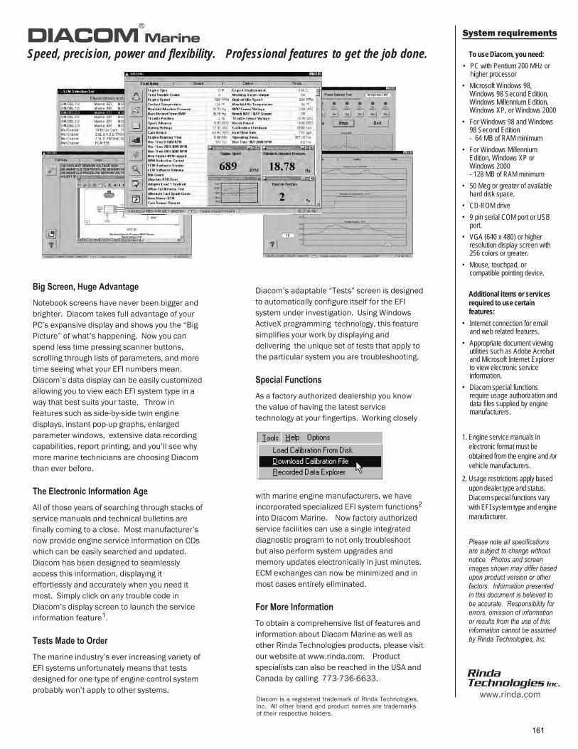
System requirements
To use Diacom, you need:
• PC with Pentium 200 MHz orhigher processor
• Microsoft Windows 98,Windows 98 Second Edition,Windows Millennium Edition,Windows XP, or Windows 2000
• For Windows 98 and Windows98 Second Edition- 64 MB of RAM minimum
• For Windows MillenniumEdition, Windows XP orWindows 2000- 128 MB of RAM minimum
• 50 Meg or greater of availablehard disk space.
• CD-ROM drive
• 9 pin serial COM port or USBport.
• VGA (640 x 480) or higherresolution display screen with256 colors or greater.
• Mouse, touchpad, orcompatible pointing device.
Additional items or servicesrequired to use certainfeatures:
• Internet connection for emailand web related features.
• Appropriate document viewingutilities such as Adobe Acrobatand Microsoft Internet Explorerto view electronic serviceinformation.
• Diacom special functionsrequire usage authorization anddata files supplied by enginemanufacturers.
1. Engine service manuals in
electronic format must be
obtained from the engine and /or
vehicle manufacturers.
2. Usage restrictions apply based
upon dealer type and status.
Diacom special functions vary
with EFI system type and engine
manufacturer.
Please note all specificationsare subject to change withoutnotice. Photos and screenimages shown may differ basedupon product version or otherfactors. Information presentedin this document is believed tobe accurate. Responsibility forerrors, omission of informationor results from the use of thisinformation cannot be assumedby Rinda Technologies, Inc.
DIACOM Marine
Speed, precision, power and flexibility. Professional features to get the job done.
������������������������
Notebook screens have never been bigger and
brighter. Diacom takes full advantage of your
PC’s expansive display and shows you the “Big
Picture” of what’s happening. Now you can
spend less time pressing scanner buttons,
scrolling through lists of parameters, and more
time seeing what your EFI numbers mean.
Diacom’s data display can be easily customized
allowing you to view each EFI system type in a
way that best suits your taste. Throw in
features such as side-by-side twin engine
displays, instant pop-up graphs, enlarged
parameter windows, extensive data recording
capabilities, report printing, and you’ll see why
more marine technicians are choosing Diacom
than ever before.
� ��!"��������#��$��������
All of those years of searching through stacks of
service manuals and technical bulletins are
finally coming to a close. Most manufacturer’s
now provide engine service information on CDs
which can be easily searched and updated.
Diacom has been designed to seamlessly
access this information, displaying it
effortlessly and accurately when you need it
most. Simply click on any trouble code in
Diacom’s display screen to launch the service
information feature1.
������%�������&����
The marine industry’s ever increasing variety of
EFI systems unfortunately means that tests
designed for one type of engine control system
probably won’t apply to other systems.
®
Diacom’s adaptable “Tests” screen is designed
to automatically configure itself for the EFI
system under investigation. Using Windows
ActiveX programming technology, this feature
simplifies your work by displaying and
delivering the unique set of tests that apply to
the particular system you are troubleshooting.
����"�'������
As a factory authorized dealership you know
the value of having the latest service
technology at your fingertips. Working closely
with marine engine manufacturers, we have
incorporated specialized EFI system functions2
into Diacom Marine. Now factory authorized
service facilities can use a single integrated
diagnostic program to not only troubleshoot
but also perform system upgrades and
memory updates electronically in just minutes.
ECM exchanges can now be minimized and in
most cases entirely eliminated.
'���%������#��$����
To obtain a comprehensive list of features and
information about Diacom Marine as well as
other Rinda Technologies products, please visit
our website at www.rinda.com. Product
specialists can also be reached in the USA and
Canada by calling 773-736-6633.RindaTechnologies Inc.
www.rinda.comDiacom is a registered trademark of Rinda Technologies,Inc. All other brand and product names are trademarksof their respective holders.
161

MEFI Fuel Injection
• Scan tool is a bare minimum
• Laptop offers the best protection against early obsolescence–Easy capture of data–More universal as to the brand of engine–Email captured files for help–Build your own “Database” of captured data–Upgrades more easily produced, often only software
Special Service Tools
The long list of codes that can be set on today's MEFI 4 and 4b systems will limit the usefulness of a “winkie blinky” tool. It is almost impossible to service the engine without a scan tool. The Tech-Mate, DDT and VP2000 are durable and well suited for the typical boat environment, but all pale compared to a laptop’s capability. The VP2000 will no longer be supported with the introduction of the Electronic Gas Control (EGC) engines during the summer of 2005.A used computer running Windows 98 or higher, can be found at a reasonable price at many computer shows around the country. With the future marine systems that will be introduced, this option allows the greatest potential for upgrade ability and flexibility.
162

MEFI Fuel Injection
Special Service Tools
The Diacom Marine program from Rinda Technologies can be used with many of the competitors engines as well as Volvo Penta’s engines. You can view and capture data that can be emailed later to the factory. The service manual is built right in and the codes display what they mean instead of just a code number (as with the winky-blinkie).The above graph shows a start cycle for an engine with a drivability complaint of hesitation on acceleration. During starting the voltage drop to 9.8 volts (or slightly lower) due to incorrect battery capacity, type or state of charge. This low voltage causes the ECM’s processor to shut down momentarily. Once the voltage rises again, the ECM “wakes up” and rereads baro while the engine is cranking over. This causes the barometric pressure (derived from the MAP reading) to be read while there is vacuum in the intake. In this example that causes the baro to change by 2 inches of mercury. This effectively tells the engine it is at altitude and reduces the amount of fuel to be delivered accordingly. So the engine will run lean until the baro gets updated and corrected (at WOT). You can see in the bottom graph that the engine RPM dips slightly during acceleration as a result. During a restart with a warm engine the barometric pressure remained at 29.2 inches and the hesitation was no longer present.
163

MEFI Fuel Injection
Special Service Tools
This is a normal reading from an 8.1Gi during a hard acceleration. The wave in the RPM graph was due to the prop ventilating slightly during the test. The center graph is the manifold air temperature declining as fresh air is pulled into the engine. The spark gets retarded slightly as the manifold pressure changes and RPM increases to prevent knock or detonation damage. The spark advance is related to RPM and MAP.
Ideally, make multiple recordings:COLD: One minute cold start up. Start recording first, then crank to start, let idle for
another 45 seconds.WARM: Warm engine, turn it off, key on and begin recording, start engine and do three
accelerations with 1)minimum throttle to maximum throttle as slow as reasonably done,2)repeat with a medium-fast rate of throttle opening to maximum, and 3)once more with rapid WOT, then back to idle and now stop recording. All three in one
file.Name the file as: engine model _ serial number _ altitude _ and either word cold or hot,
followed by .rec.Example: 50gxi_4012053616_7000ft_cold.rec
164
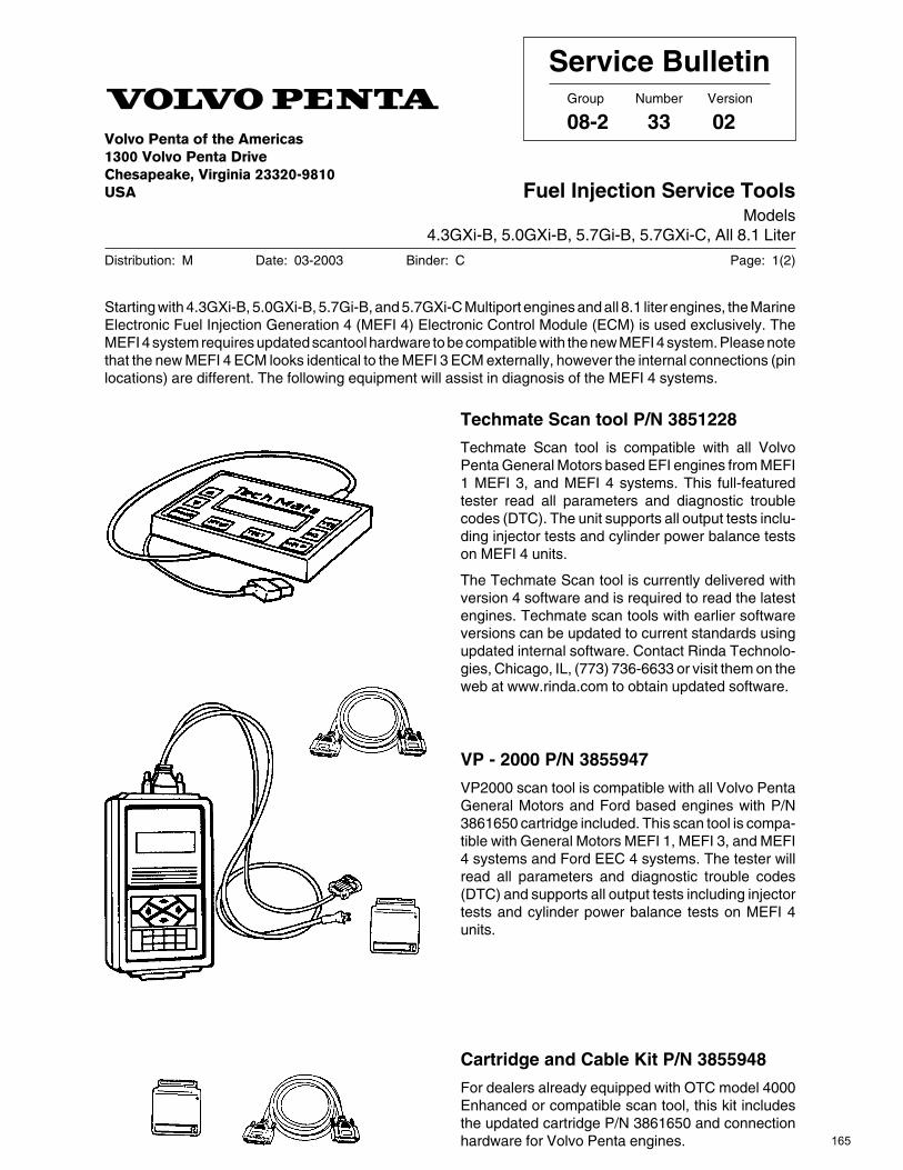
������������� ������������������������������� ������������������������� ��!"�
Distribution: M Date: 03-2003 Binder: C Page: 1(2)
Service BulletinGroup Number Version
08-2 33 02
Fuel Injection Service ToolsModels
4.3GXi-B, 5.0GXi-B, 5.7Gi-B, 5.7GXi-C, All 8.1 Liter
Starting with 4.3GXi-B, 5.0GXi-B, 5.7Gi-B, and 5.7GXi-C Multiport engines and all 8.1 liter engines, the MarineElectronic Fuel Injection Generation 4 (MEFI 4) Electronic Control Module (ECM) is used exclusively. TheMEFI 4 system requires updated scantool hardware to be compatible with the new MEFI 4 system. Please notethat the new MEFI 4 ECM looks identical to the MEFI 3 ECM externally, however the internal connections (pinlocations) are different. The following equipment will assist in diagnosis of the MEFI 4 systems.
Techmate Scan tool P/N 3851228
Techmate Scan tool is compatible with all VolvoPenta General Motors based EFI engines from MEFI1 MEFI 3, and MEFI 4 systems. This full-featuredtester read all parameters and diagnostic troublecodes (DTC). The unit supports all output tests inclu-ding injector tests and cylinder power balance testson MEFI 4 units.
The Techmate Scan tool is currently delivered withversion 4 software and is required to read the latestengines. Techmate scan tools with earlier softwareversions can be updated to current standards usingupdated internal software. Contact Rinda Technolo-gies, Chicago, IL, (773) 736-6633 or visit them on theweb at www.rinda.com to obtain updated software.
VP - 2000 P/N 3855947
VP2000 scan tool is compatible with all Volvo PentaGeneral Motors and Ford based engines with P/N3861650 cartridge included. This scan tool is compa-tible with General Motors MEFI 1, MEFI 3, and MEFI4 systems and Ford EEC 4 systems. The tester willread all parameters and diagnostic trouble codes(DTC) and supports all output tests including injectortests and cylinder power balance tests on MEFI 4units.
Cartridge and Cable Kit P/N 3855948
For dealers already equipped with OTC model 4000Enhanced or compatible scan tool, this kit includesthe updated cartridge P/N 3861650 and connectionhardware for Volvo Penta engines. 165
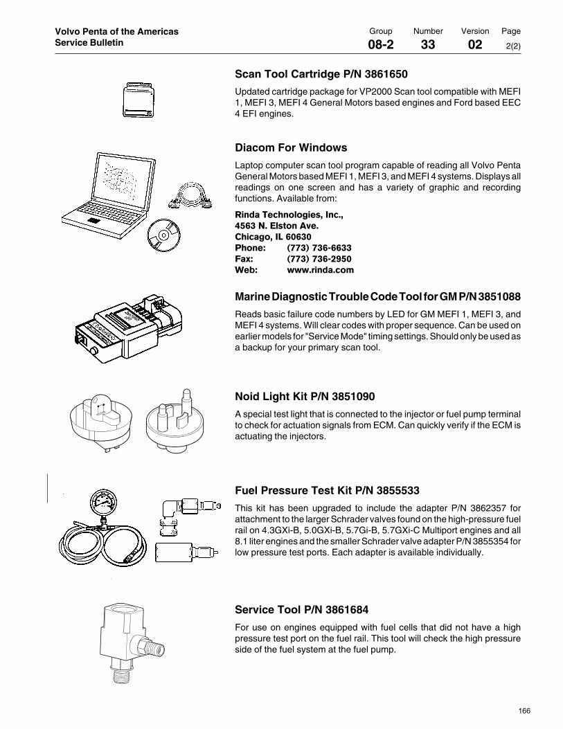
Group Number Version Page
08-2 33 02 2(2)
Volvo Penta of the AmericasService Bulletin
Service Tool P/N 3861684
For use on engines equipped with fuel cells that did not have a highpressure test port on the fuel rail. This tool will check the high pressureside of the fuel system at the fuel pump.
Fuel Pressure Test Kit P/N 3855533
This kit has been upgraded to include the adapter P/N 3862357 forattachment to the larger Schrader valves found on the high-pressure fuelrail on 4.3GXi-B, 5.0GXi-B, 5.7Gi-B, 5.7GXi-C Multiport engines and all8.1 liter engines and the smaller Schrader valve adapter P/N 3855354 forlow pressure test ports. Each adapter is available individually.
Noid Light Kit P/N 3851090
A special test light that is connected to the injector or fuel pump terminalto check for actuation signals from ECM. Can quickly verify if the ECM isactuating the injectors.
Marine Diagnostic Trouble Code Tool for GM P/N 3851088
Reads basic failure code numbers by LED for GM MEFI 1, MEFI 3, andMEFI 4 systems. Will clear codes with proper sequence. Can be used onearlier models for "Service Mode" timing settings. Should only be used asa backup for your primary scan tool.
Diacom For Windows
Laptop computer scan tool program capable of reading all Volvo PentaGeneral Motors based MEFI 1, MEFI 3, and MEFI 4 systems. Displays allreadings on one screen and has a variety of graphic and recordingfunctions. Available from:
#�$��%�� ���������&�'�()*��+'�,�������'� �������&-�*�*��� ��. /00�1�0�*�**��2�3. /00�1�0�*���)�4�5. 666'��$�'���
Scan Tool Cartridge P/N 3861650
Updated cartridge package for VP2000 Scan tool compatible with MEFI1, MEFI 3, MEFI 4 General Motors based engines and Ford based EEC4 EFI engines.
166

MEFI Fuel Injection
Special Service ToolsFuel Line Quick Disconnect Tool
# J 41769
OTC/Kent- MooreDemonstrate the use of theses tools
Fuel Line Quick Disconnect Tool # J 41769This set includes a 5/16” and a 3/8” disconnect tool.
167

MEFI Fuel Injection
Special Service ToolsFuel Injector Test Harness Fuel Injector Remover
Fuel Injector Test Harness
VPA# J 39021-380 for 8.1L engines (pictured above) and J 44602 (not pictured) for the 4.3, 5.0 and 5.7L multiport engines.
Adapts the scan tool injector test connector to the engine fuel injector.
Fuel Injector & Rail Removal Tool
VPA# J 43013
Used as a lever to pry off the o-ring seal at the fuel rail cups.
Flip it over to pry the injector from the manifold.
168

MEFI Fuel Injection
Oil Filter Bulletin Oil Fill Bulletin
THIS STICKER HAS THE ENGINE’S MAX RPM LISTED ON IT.On current product, this sticker is located on the plastic engine cover. Color coded service points. No engine is selected. The intent is to demonstrate the color coding of the service points on the engines.
169

Volvo Penta of the Americas1300 Volvo Penta DriveChesapeake, Virginia 23320-9810
Oil FiltersModels: all GM engines
Distribution: Parts Date: March 2005 Binder: Parts Replaces: N/A
Parts BulletinGroup Number Version
P-21-7 1 01
These are the oil filters for GM engines;
Oil filters mounted on block;
3.0L engines: 835440 and 3852412
V6 engines: 841750
V8 engines: 3850559, 835440 and 3852412
3852412 is shipped on some engines, it is replaced by 835440 in the Parts system.
For remote oil filter kits;
Use 3850559 or 835440.
Note! for later 8.1L engines only use 835440, 3850559 will not clear the ignition coils mounted below the filter.
Note! for 7.4/8.2L only use 3850559.
Caution! Gas engines require a precise oil fill level to operate correctly. Overfilling results in high operating temperatures, foaming (air in oil), loss of power and reduced engine life. Underfilling causes loss of lubrication.Always check for correct oil fill on the dipstick when changing engine oil.
M=maximum, N=minimum 170
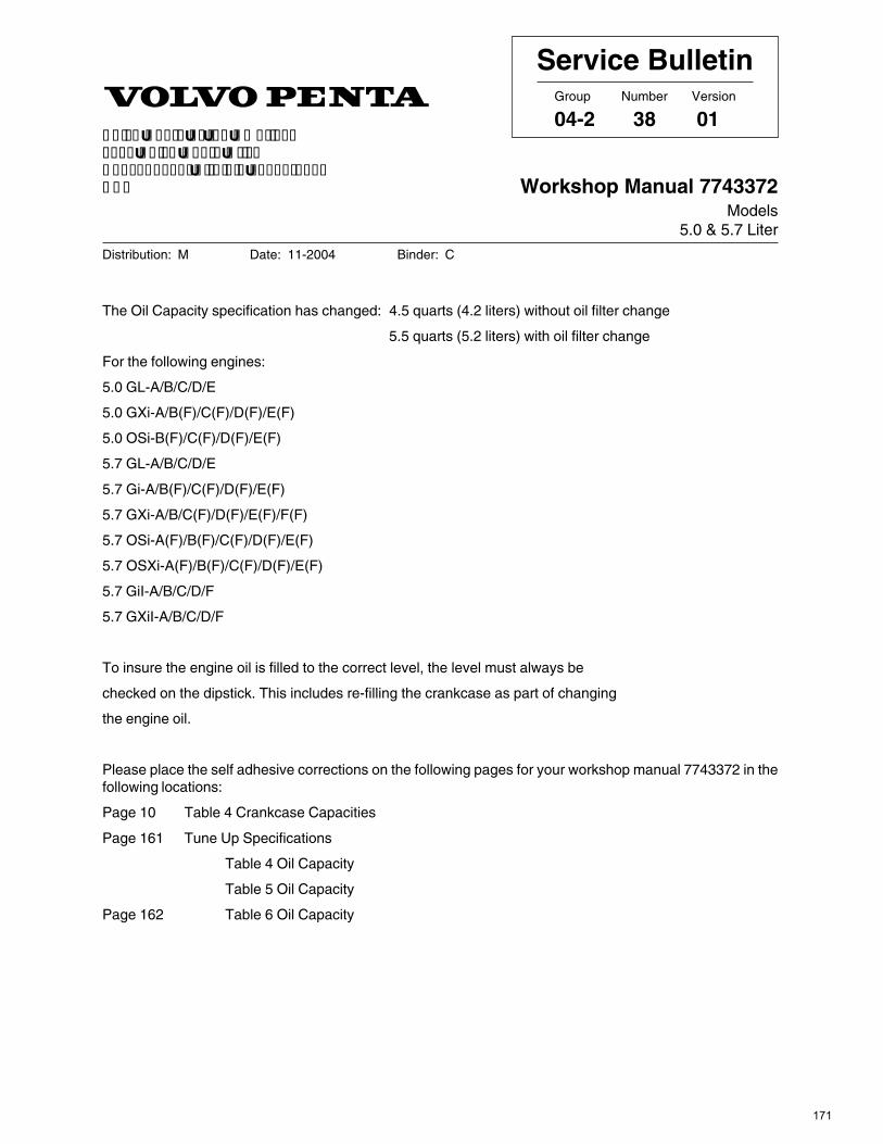
������������� ������������������������������� ������������������������� ��!"�
Distribution: M Date: 11-2004 Binder: C
Service BulletinGroup Number Version
04-2 38 01
Workshop Manual 7743372Models
5.0 & 5.7 Liter
The Oil Capacity specification has changed: 4.5 quarts (4.2 liters) without oil filter change
5.5 quarts (5.2 liters) with oil filter change
For the following engines:
5.0 GL-A/B/C/D/E
5.0 GXi-A/B(F)/C(F)/D(F)/E(F)
5.0 OSi-B(F)/C(F)/D(F)/E(F)
5.7 GL-A/B/C/D/E
5.7 Gi-A/B(F)/C(F)/D(F)/E(F)
5.7 GXi-A/B/C(F)/D(F)/E(F)/F(F)
5.7 OSi-A(F)/B(F)/C(F)/D(F)/E(F)
5.7 OSXi-A(F)/B(F)/C(F)/D(F)/E(F)
5.7 GiI-A/B/C/D/F
5.7 GXiI-A/B/C/D/F
To insure the engine oil is filled to the correct level, the level must always be
checked on the dipstick. This includes re-filling the crankcase as part of changing
the engine oil.
Please place the self adhesive corrections on the following pages for your workshop manual 7743372 in thefollowing locations:
Page 10 Table 4 Crankcase Capacities
Page 161 Tune Up Specifications
Table 4 Oil Capacity
Table 5 Oil Capacity
Page 162 Table 6 Oil Capacity
171

MEFI Fuel Injection
• Vacuum gauge can help identify potential mechanical problems
• Manifold vacuum determines load for the system• Read the spark plugs carefully• Compression test with a good battery• Leak-down test for more advanced look at cylinder and valve conditions
• Electrical connections! Low voltage or voltage drops can be extremely problematic to the system
Diagnostics - MechanicalAlways start with the base engine!
The fuel injection system is limited in that it can’t help an engine that has mechanical problems. Often times the system will create a new symptom that will lead you in the wrong direction. For example, black carbon fouled plugs could be due to a stuck open thermostat that causes the system to add fuel in what is called a “multiplier”. The same symptom can also be a tuliped valve that lowers manifold pressure. This in turn tells the system it is under more load than normal and it will add fuel. Any mechanical condition that causes less vacuum to be built up in the intake is assumed by the ECM to be an increase of load on the engine.Vacuum gauge diagnostics are located in the engine mechanical workshop manual.
172

MEFI Fuel Injection
Correct propeller and drive ratio?–Compare with other similar models–Check ratio versus the label if a problem since first
use–Check hub for slipping
Bottom paint added or fouling present–marine growth or barnacles?
Excessive load?–Is this a new problem?–Anchor chain in bow locker?–Dingy or personal watercraft added?–Any new weight added?
Reduce prop size by 1 (inch or size) for every 1000 additional pounds.
Diagnostics - Mechanical
One of the most common complaints we hear is poor top end performance. If the engine does not meet it’s rated RPM, it will not meet it’s rated horsepower. This leads to trying to troubleshoot a perfectly good engine. Left unresolved it can lead to high combustion temperatures due to engine overload that will cause valve or piston damage.If the problem has existed since the very first day, check the weight of the boat at some local scales. Compare the prop size, drive ratio and performance with similar sized boats. Be sure to allow for addition of bottom paint and other factors relating to load.Also be sure to check the exhaust for restrictions.
173
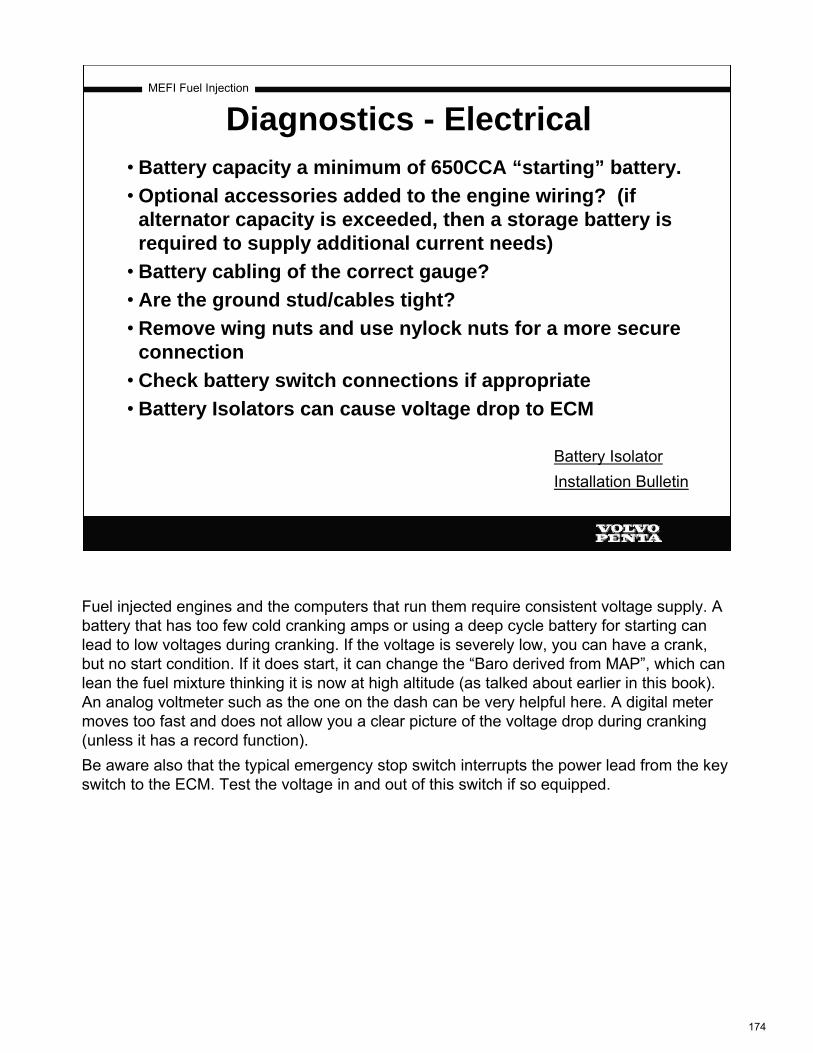
MEFI Fuel Injection
• Battery capacity a minimum of 650CCA “starting” battery. • Optional accessories added to the engine wiring? (if
alternator capacity is exceeded, then a storage battery is required to supply additional current needs)
• Battery cabling of the correct gauge?• Are the ground stud/cables tight?• Remove wing nuts and use nylock nuts for a more secure
connection• Check battery switch connections if appropriate• Battery Isolators can cause voltage drop to ECM
Diagnostics - Electrical
Battery Isolator Installation Bulletin
Fuel injected engines and the computers that run them require consistent voltage supply. A battery that has too few cold cranking amps or using a deep cycle battery for starting can lead to low voltages during cranking. If the voltage is severely low, you can have a crank, but no start condition. If it does start, it can change the “Baro derived from MAP”, which can lean the fuel mixture thinking it is now at high altitude (as talked about earlier in this book). An analog voltmeter such as the one on the dash can be very helpful here. A digital meter moves too fast and does not allow you a clear picture of the voltage drop during cranking (unless it has a record function).Be aware also that the typical emergency stop switch interrupts the power lead from the key switch to the ECM. Test the voltage in and out of this switch if so equipped.
174

Volvo Penta of the Americas1300 Volvo Penta DriveChesapeake, Virginia 23320-9810
Battery isolators, correct installationModels: EFI engines, see list
Distribution: M Date: Apr-2005 Binder: C
Service BulletinGroup Number Version
32-1 13 01
Engines affected;4.3GXi; -C,-CF,-D,-DF,-E,-EF 5.7OSi; -B,-BF,-C,-CF,-D,-DF4.3OSi; -C,-CF,-D,-DF,-E,-EF 5.7OSXi; -B,-BF,-C,-CF,-D,-DF5.0GXi; -C,-CF,-D,-DF,-E,-EF 8.1Gi; -C,-CF,-D,-DF,-E,-EF,-F,-FF5.0OSi; -C,-CF,-D,-DF,-E,-EF 8.1GiI; -C,-D,-E,-F,5.7Gi; -C,-CF,-D,-DF,-E,-EF 8.1GXi; -B,-BF,-C,-CF,-D,-DF,-E,-EF5.7GiI; -C,-D,-E, 8.1GXiI; -B,-C,-D,-E5.7GXi; -D,-DF,-E,-EF,-F,-FF 8.1OSi-; -A,-AF,-B,-BF5.7GXiI; -D,-E,-F
EFI engines have been found in the field with incorrectly installed battery isolators. This can lead to voltage drops in the electrical system and poor battery charging. If these symptoms are present, check the installation of the isolator. The installation should comply with the guidelines below.
Correct installation of battery isolators
Caution! Disconnect all power to the engine before proceeding
A. Disconnect alternator from engine harness;
At Bussman fuse/relay box,Remove gray connector with orange wire (C) from box.
Tape or tie strap the connector/wire to engine harness.
Install sealed connector 3817796 in box where gray connector/wire was removed.
175

Volvo Penta of the Americas Group Number Version Page
Service Bulletin 32-1 13 01 2(2)
B. Connect alternator to isolator;
Note! The alternator output wire assembly, which carries alternator output to the isolator, is critical to correct operation of the charging system. The wire must meet all current ABYC specifications regarding materials, attaching terminals and routing and protecting the wire.
At rear of alternator,Remove ring terminal/orange wire/boot (OR) from the B+ terminal.
Remove ring terminal (T) and boot (B) from wire, save boot.
Seal cut end of wire with electrical tape or liquid tape. Tape or tie strap the wire (OR) to engine harness.
Alternator and wire (OR) are now disconnected from the engine harness.
Note! Wire size of the output wire is critical to correct operation of the isolator and charging system.Wire size is determined by the total length of wire. The size of the output wire used in the installation must meet these ABYC standards;
0 - 3m (0-10 ft) 6 AWG3m to 6m (11-20 ft) 4 AWGover 6m (over 20 ft) 2 AWG
Using the correct wire size ensures that voltage drop occurs through the isolator diodes, and not in the wire.
Place boot (B) over output wire.Install a 5/16” or 8mm ring terminal (N) on output wire.Recommended terminal has mechanical crimping of the wire’s conductor and a heat shrink seal.
Install ring terminal/boot/wire on B+ stud on alternator.Nut torque = 10-17Nm or 7-13 ft/lbs Route the wire to avoid sharp edges or other chafe points. Sheathing the wire is recommended.
Complete the wiring of the battery isolator per manufacturer's recommended procedures.
176

SPARE
START
SPARE RELAY
20
20F5
F1151520
SPARE
FUEL PUMP
IGNITION
SPARE SPARE
F7F615 20
F3F2
SPARE SPARE
F4
VO
LVO
PE
NTA
CONNECTOR 6 (BLACK)
R1
F8
F1
6A
41F
F19
R2
F10 F12F11
R3
F13
3B
CONN
ECTO
R 3
(BLU
E)
3G
F5
F2 F4
F6 F7
6C
13E 9A (-12V)
5A
4D4A
4B4C
R2-
86R
1-86
F4R
3-87
5C
(13C)
CONNECTOR 5 (GREY)
CONN
ECTO
R 4
(GRE
EN)
4E4H
4G4F
R2-
87R
1-87
R3-
85R
1-85
NA
NA
R4
F3
F6 3F
F5 3E
6C
30
86
85
87
87a
C5
A5
C4
A4
F3
A3
B3
E7
C7 C8
F4
B6
A6
F5
E1
D1
15 20
D4 D5
F4
15
20
A1
B1
F1
20
A2
B2
F2
20F7
D3
E3
SB
30
86
85
87
87a 87a
87
85
86
30
F6
15
D2
E2Fuel PumpRelay
StarterRelay
4D 4A4B4C
R2-86 R1-86F4R3-87
4H
R2-87 R1-87R3-85R1-85
R/PU R/PU R/PU
3B
3G
NA
NA
F6
3F
F5
3E
IgnitionRelay
Pin 710 pin engineharness connector
“S” terminalStarter solenoid
Fuel Pumps
EngineGround
J1-6
J2-1
Alternator Excite terminalAlarm B+Pin 5 of 10 pin harness connector
Fuel Injectors B+Ignition Coils B+J2-19
SpareSpare
Alternator B+
50 AmpTrim/TiltCircuit Breaker
Pin 610 pin harnessconnector
Terminal “R”Starter Solenoid
4G4F4E
6A
R/PU
5A
5C
OR
R
R
Fuse Box Wiring Diagramand Layout
Internal wiring on Fuse Box isnot serviceable, For refrence only
WARNINGWARNING
177
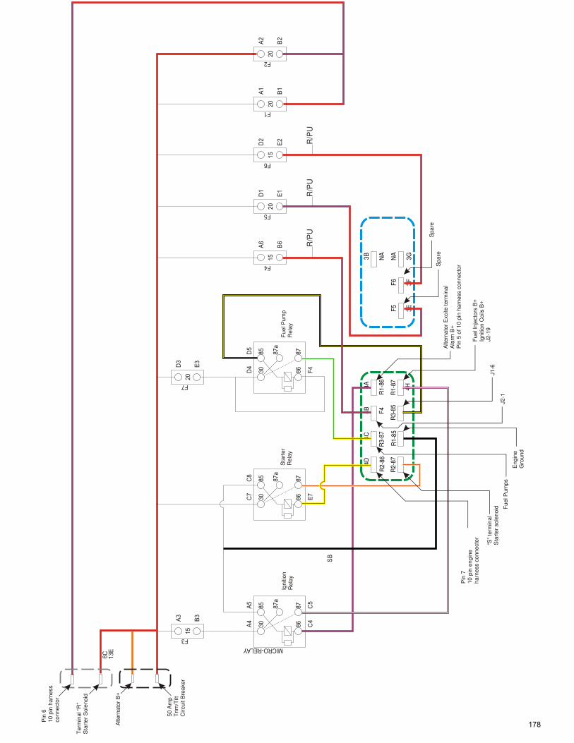
13
E
6C
30
86
MICRO-RELAY
85
87
87
a
C5
A5
C4
A4
F3
A3
B3
E7
C7
C8
F4
B6
A6
F5
E1
D1
15
20
D4
D5
F4
15
20
A1
B1
F1
20
A2
B2
F2
20
F7
D3
E3
SB
30
86
85
87
87
a8
7a
87
85
86
30
F6
15
D2
E2
Fue
l Pum
pR
elay
Sta
rter
Rel
ay
4D4A
4B4C
R2-
86R
1-86
F4R
3-87
4H
R2-
87R
1-87
R3-
85R
1-85
R/P
UR
/PU
R/P
U
3B 3GNA
NA
F6 3F
F5 3E
Igni
tion
Rel
ay Pin
710
pin
eng
ine
harn
ess
conn
ecto
r
“S”
term
inal
Sta
rter
sol
enoi
d Fue
l Pum
ps
Eng
ine
Gro
und
J1-6
J2-1
Alte
rnat
or E
xcite
term
inal
Ala
rm B
+P
in 5
of 1
0 pi
n ha
rnes
s co
nnec
tor
Fue
l Inj
ecto
rs B
+Ig
nitio
n C
oils
B+
J2-1
9
Spa
reS
pare
Alte
rnat
or B
+
50 A
mp
Trim
/Tilt
Circ
uit B
reak
er
Pin
610
pin
har
ness
conn
ecto
r
Ter
min
al “
R”
Sta
rter
Sol
enoi
d
178

MEFI Fuel Injection
Coolant Flow
Information about coolant flow in the raw water cooled or engines with a closed cooling system is located in the “cooling system” section of the current engine mechanical workshop manuals.The picture above shows a raw water cooled 8.1L. The other engines are similar.Raw water is pulled into the pump (11) through the drive and the power steering cooler (22). Raw water is then discharged from the pump to the thermostat housing (12). If the thermostat is closed (as in D above), water goes through a cast bypass (C) inside the thermostat housing and is sent to the exhaust risers (18) and then overboard in the exhaust.If the thermostat is open (as in B above), then the raw water is sent to the circulating pump (15), into the block (16), up through the heads (17) and back to the thermostat housing (12) under the thermostat. It then travels through the open thermostat, into the riser bypass hoses and then overboard.In both the raw water cooled systems and the closed cooling systems (antifreeze), the fuel cell (MOAS) is RAW water cooled. Water flow through the fuel cell is from the thermostat housing nipple (8) to the bottom of the fuel cell, through the cell, out the top of the fuel cell and over to one of the exhaust risers and then overboard. The fuel cell has a second hose on top of the cell that goes to the intake manifold. This is the high pressure pump reservoir vent line. Engine vacuum pulls the vapors off the top of the cell and into the engine intake system to be burned. The hose connects to a pulse limiter at the intake manifold. The pulse limiter prevents a backfire of the engine from igniting the fuel vapors in the hose.
179

MEFI Fuel Injection
Coolant Flow: CCS
System
The picture above shows both raw water flow and coolant flow in a closed cooling system (CCS). In a CCS, only an antifreeze mixture flows through the engine. Raw water and antifreeze never come in contact with each other. They do meet in the heat exchanger (16), but one liquid is inside the tubes and the other is outside the tubes. As stated on the previous page the fuel cell (17) is raw water cooled even in this system. As a general rule CCS engines run at a slightly higher operating temperature than raw water cooled engines.The raw water flow for this system is: water is pulled into the pump (12) and then discharged into the heat exchanger (16). The water leaves the heat exchanger and travels to the fuel cell and the exhaust risers (18), via separate hoses, and then is discharged overboard through the exhaust.Fresh water and antifreeze mixture is circulated by the circulating pump (15) into the block, through the heads and to the thermostat (13). If the thermostat is closed, the water goes through the thermostat bypass and straight back to the inlet side of the circulating pump. If the thermostat is open, the water passes through the heat exchanger, is cooled and then travels back to the inlet side of the circulating pump.Air in the system is vented from the top of the thermostat (13) housing to the coolant reservoir bottle (14).The heat exchanger has a zinc anode screwed into the side of it that requires periodic inspection and replacement.
180
Related Documents