Voluntary Movements for Robotic Control Chi-haur Wu, Kuu-Young Young, Kao-Shing Hwang, and Steven Lehman A neuromuscular-like nonlinear mathematical model for controlling robotic limbs has been developed. The model consists of two muscle-reflex models representing a pair of muscles acting as an agonist and an antagonist in moving a load. The responses of the model have been compared with experimental data from human wrist move- ments in order to identify command signals in the form of a series of rectangular pulses for effecting the measured movements with two different loads. These results can be used to obtain several empirical rules for muscle modulation control. The proposed control strategy can also compensate for unexpected disturbances, which is an essential capability for compliance control. Industrial Robot Compliance After two decades of designing active compliance controllers, the performance of industrial robots is still crude in providing compliance [I]. This deficiency remains one of the major problems limiting the scope of robotic applications. It is widely recognized that the primate limb has much superior per- formance for delicate, skillful maneuvers, especially in adaptability to different loads and capability to execute compliant tasks. The design of a good compliance control for robotic applications could emulate the com- pliant capability of the neuromuscular system. However, few developed schemes for robotic compliance control take advantage of findings in biological limb research. Hogan's im- pedance control [2] relates to the spring-like Presented at the I991 IEEE International Conference on Robotics and Automation, Sacramento, CA, April 7-12,1991.This work M'US supported by ONR Contract N00014-88- K-0339. Chi-haur Wu and Kao-Slzing Hwang are with the Department of Electrical En- gineering and Computer Science at Northwestern Universiry,Evanston, IL 60208. Kuu-Young Young is currently with the Department of Control Engineering, National Chiao Tung Uni\,ersio, Hsinchu, Taiwan. Steven Lehnian is currently with the Depart- ment of Physical Education and the Bioen- gineering Graduate Group, University of California,Berkeley, CA. interface between limb and environment. Modeling the spring-like behavior of the neuromuscular system, while the limb is in contact with the environment, allows success- ful impedance control to provide compliance for a robot. The concept of flexion and exten- sion in muscular system is also adopted by Jacobsen etal. [3] to control manipulator links with two tendon-driven actuators. Their con- trol algorithms in position and force control showed good results experimentally. The suc- cess of these efforts indicates that a better design of robotic compliance control may benefit from modeling the mechanisms of biological limbs. Results from neurophysiological studies [4],[5] strongly suggest that nonlinear dynam- ics in the neuromuscular system have a sub- stantial contribution to superior adaptability and facile performance in limb control. The nonlinear features of the neuromuscular sys- tem have been simulated and studied through 8 0272-1708/92/$03.000 1992IEEE /€€E Control Systems ~~

Welcome message from author
This document is posted to help you gain knowledge. Please leave a comment to let me know what you think about it! Share it to your friends and learn new things together.
Transcript
Voluntary Movements for Robotic Control Chi-haur Wu, Kuu-Young Young, Kao-Shing Hwang, and Steven Lehman
A neuromuscular - l ike nonl inear mathematical model for controlling robotic limbs has been developed. The model consists of two muscle-reflex models representing a pair of muscles acting as an agonist and an antagonist in moving a load. The responses of the model have been compared with experimental data from human wrist move- ments in order to identify command signals in the form of a series of rectangular pulses for effecting the measured movements with two different loads. These results can be used to obtain several empirical rules for muscle modulation control. The proposed control strategy can also compensate for unexpected disturbances, which is an essential capability for compliance control.
Industrial Robot Compliance
After two decades of designing active compliance controllers, the performance of industrial robots is still crude in providing compliance [I]. This deficiency remains one of the major problems limiting the scope of robotic applications. It is widely recognized that the primate limb has much superior per- formance for delicate, skillful maneuvers, especially in adaptability to different loads and capability to execute compliant tasks. The design of a good compliance control for robotic applications could emulate the com- pliant capability of the neuromuscular system. However, few developed schemes for robotic compliance control take advantage of findings in biological limb research. Hogan's im- pedance control [ 2 ] relates to the spring-like
Presented at the I991 IEEE International Conference on Robotics and Automation, Sacramento, CA, April 7-12,1991. This work M'US supported by ONR Contract N00014-88- K-0339. Chi-haur Wu and Kao-Slzing Hwang are with the Department of Electrical En- gineering and Computer Science at Northwestern Universiry, Evanston, IL 60208. Kuu-Young Young is currently with the Department of Control Engineering, National Chiao Tung Uni\,ersio, Hsinchu, Taiwan. Steven Lehnian is currently with the Depart- ment of Physical Education and the Bioen- gineering Graduate Group, University of California, Berkeley, CA.
interface between limb and environment. Modeling the spring-like behavior of the neuromuscular system, while the limb is in contact with the environment, allows success- ful impedance control to provide compliance for a robot. The concept of flexion and exten- sion in muscular system is also adopted by Jacobsen etal. [3] to control manipulator links with two tendon-driven actuators. Their con- trol algorithms in position and force control showed good results experimentally. The suc-
cess of these efforts indicates that a better design of robotic compliance control may benefit from modeling the mechanisms of biological limbs.
Results from neurophysiological studies [4],[5] strongly suggest that nonlinear dynam- ics in the neuromuscular system have a sub- stantial contribution to superior adaptability and facile performance in limb control. The nonlinear features of the neuromuscular sys- tem have been simulated and studied through
8 0272-1708/92/$03.000 1992IEEE
/€€E Control Systems
~~
Spindle-like w w I,,+&
I xw I rant
T Spindle-like I
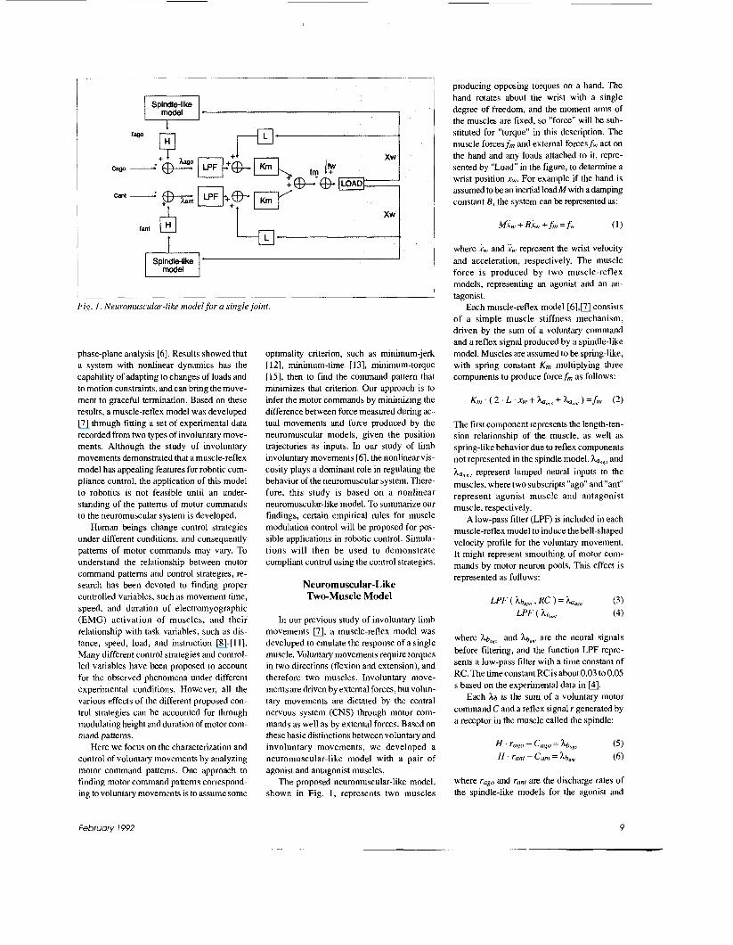
Fig. I . Neuromuscular-like model for a single joint.
phase-plane analysis [6]. Results showed that a system with nonlinear dynamics has the capability of adapting to changes of loads and to motion constraints, and can bring the move- ment to graceful termination. Based on these results, a muscle-reflex model was developed [7] through fitting a set of experimental data recorded from two types of involuntary move- ments. Although the study of involuntary movements demonstrated that a muscle-reflex model has appealing features for robotic com- pliance control, the application of this model to robotics is not feasible until an under- standing of the pattems of motor commands to the neuromuscular system is developed.
Human beings change control strategies under different conditions, and consequently pattems of motor commands may vary. To understand the relationship between motor command pattems and control strategies, re- search has been devoted to finding proper controlled variables, such as movement time, speed, and duration of electromyographic (EMG) activation of muscles, and their relationship with task variables, such as dis- tance, speed, load, and instruction [8]-[l l]. Many different control strategies and control- led variables have been proposed to account for the observed phenomena under different experimental conditions. However, all the various effects of the different proposed con- trol strategies can be accounted for through modulating height and duration of motor com- mand pattems.
Here we focus on the characterization and control of voluntary movements by analyzing motor command pattems. One approach to finding motor command pattems correspond- ing to voluntary movements is to assume some
optimality criterion, such as minimum-jerk [ 121, minimum-time [13], minimum-torque [15], then to find the command pattern that minimizes that criterion. Our approach is to infer the motor commands by minimizing the difference between force measured during ac- tual movements and force produced by the neuromuscular models, given the position trajectories as inputs. In our study of limb involuntary movements [6], the nonlinear vis- cosity plays a dominant role in regulating the behavior of the neuromuscular system. There- fore, this study is based on a nonlinear neuromuscular-like model. To summarize our findings, certain empirical rules for muscle modulation control will be proposed for pos- sible applications in robotic control. Simula- tions will then be used to demonstrate compliant control using the control strategies.
Neuromuscular-Like Two-Muscle Model
In our previous study of involuntary limb movements [7], a muscle-reflex model was developed to emulate the response of a single muscle. Voluntary movements require torques in two directions (flexion and extension), and therefore two muscles. Involuntary move- ments are driven by extemal forces, but volun- tary movements are dictated by the central nervous system (CNS) through motor com- mands as well as by external forces. Based on these basic distinctions between voluntary and involuntary movements, we developed a neuromuscular-like model with a pair of agonist and antagonist muscles.
The proposed neuromuscular-like model, shown in Fig. 1, represents two muscles
producing opposing torques on a hand. The hand rotates about the wrist with a single degree of freedom, and the moment arms of the muscles are fixed, so "force" will be sub- stituted for "torque" in this description. The muscle forces f m and extemal forces f w act on the hand and any loads attached to it, repre- sented by "Load" in the figure, to determine a wrist position xw. For example if the hand is assumed to be an inertial loadM with a damping constant B, the system can be represented as:
where nw and xw represent the wrist velocity and acceleration, respectively. The muscle force is produced by two muscle-reflex models, representing an agonist and an an- tagonist.
Each muscle-reflex model [6],[7] consists of a simple muscle stiffness mechanism, driven by the sum of a voluntary command and a reflex signal produced by a spindle-like model. Muscles are assumed to be spring-like, with spring constant K m multiplying three components to produce force f m as follows:
The first component represents the length-ten- sion relationship of the muscle, as well as spring-like behavior due to reflex components not represented in the spindle model. haaso and ha, ", represent lumped neural inputs to the muscles, where two subscripts "ago" and "ant" represent agonist muscle and antagonist muscle, respectively.
A low-pass filter (LPF) is included in each muscle-reflex model to induce the bell-shaped velocity profile for the voluntary movement. It might represent smoothing of motor com- mands by motor neuron pools. This effect is represented as follows:
where hb,,, and hb,,, are the neural signals before filtering, and the function LPF repre- sents a low-pass filter with a time constant of RC. The time constant RC is about 0.03 to 0.05 s based on the experimental data in [4].
Each k is the sum of a voluntary motor command C and a reflex signal r generated by a receptor in the muscle called the spindle:
where rago and rant are the discharge rates of the spindle-like models for the agonist and
February 1992 9
antagonist, respectively, scaled through a reflex gain coefficient H .
The spindle senses both muscle length and rate of change of muscle length, and produces a firing rate reflecting both measurements. The discharge rate for each spindle can be repre- sented by a nonlinear equation as follows [6]:
wherex,,;/,,,, .&,080, and xpooRc, are the internal position, velocity, and bias position of the spindle-like model for the agonist. (The an- tagonist counterparts are subscripted “ant.”) xR, represents the wrist position; and Kr is the reflex stiffness and B,, is a scaled damping coefficient for each spindle-like model.
The template data of involuntary move- ments used in our previous study [6] were used to identify all parameters of the model, except the command inputs. After fitting the transient responses of four step forces recorded from the experiments in [6], a set of parameters were obtained as follows: H = 0.00166, Km = 240 N/m, L = 0.5, Kr = 720 N/m, B, = 950 N/m.(s/m)’’’, xpougo = xpoa,,, = -0.01 m, and RC = 0.03 s. After fitting the transient responses of two ramped stretches, the parameters were obtained as follows: H = 0.00166, Km = 231 N/m, L = 0.5, K,. = 1150 N/m, Bp = 2200 N/m.(s/m)’”, x,,~,,, = xpo,,., = -0.008 m, and RC = 0.03 s.
The mean square error obtained from this neuromuscular-like model is similar to that from the muscle-reflex model [6]. The in- clusion of the low-pass filter does not have much effect on the response of the involuntary movement. However, it does smooth the input from the motor command.
Motor Command Pattern Identification
To identify pattems of motor commands, the experimental data recorded from fast voluntary movements at the wrist were studied. The movement distance of the hand in all cases was 3.0 cm. The instruction was to move as quickly as possible. Hand position, force, and electromyograms (EMG) of both wrist flexors and extensors were recorded during well-practiced wrist flexions against two different loads. In each case, the load was primarily an inertia, of 2.15 or 21.5 kg. Loads also included a small nonlinear viscous com- ponent.
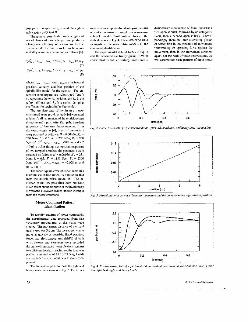
The force-time plots for both the light and heavy loads are shown as in Fig. 2. These data
were used as templates for identifying pattems of motor commands through our neuromus- cular-like model. Position-time plots are the dashed curves in Fig. 4. These data were used as inputs to the muscle-like models in the command identification.
The experimental data of forces in Fig. 2 and the recorded electromyograms (EMGs) show that rapid voluntary movements
demonstrate a sequence of burst pattems: a first agonist burst, followed by an antagonist burst, then a second agonist burst. Corres- pondingly, there are three altemating phases of force: fiist in the direction of movement, followed by an opposing force against the movement, then in the movement direction again. On the basis of these observations, we will assume that basic pattems of input motor
4
I-
‘ U \ \ \ \ /
-401 . I I I I I 0 0.2 0.4 0.6
time (sec)
Fig. 2. Force-time plots of experimental data: light load (solid line) and heavy load (dashed line).
0.16
0.12
0.08
0.04
0 0 2 4 6 8
position (cm)
Fig. 3. Functional plot between the motor command and the corresponding equilibrium position.
2.5
1.5
0.5
-0.5
-1.5 0 0.2 0.4 0.6
time (sec)
Fig. 4. Position-time plots of experimental data (dashed lines) and emulated limbpositions (solid lines) for both light and heavy loads.
10
0.3
0.1 U
2 8 5 E
-0.1 E
-0.3
-0.5
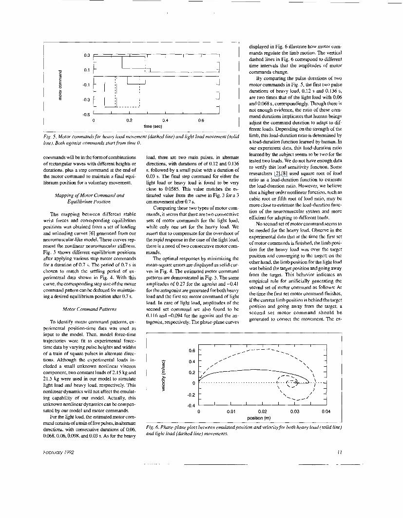
Fig. 5. Motor commands for heavy load movement (dashed line} and light load movement (solid line). Both agonist commands start from time 0.
I I I I I I - -
-- - 1-1- -
- I -
- - - - - - . - - - - - - -
I I I I I I
commands will be in the form of combinations of rectangular waves with different heights or durations, plus a step command at the end of the motor command to maintain a final equi- librium position for a voluntary movement.
Mapping of Motor Command and Equilibrium Position
The mapping between different stable wrist forces and corresponding equilibrium positions was obtained from a set of loading and unloading curves [6] generated from our neuromuscular-like model. These curves rep- resent the nonlinear neuromuscular stiffness. Fig. 3 shows different equilibrium positions after applying various step motor commands for a duration of 0.7 s. The period of 0.7 s is chosen to match the settling period of ex- perimental data shown in Fig. 4. With this curve, the corresponding step size of the motor command pattem can be deduced for maintain- ing a desired equilibrium position after 0.7 s.
Motor Command Patterns
To identify motor command pattems, ex- perimental position-time data was used as input to the model. Then, model force-time trajectories were fit to experimental force- time data by varying pulse heights and widths of a train of square pulses in altemate direc- tions. Although the experimental loads in- cluded a small unknown nonlinear viscous component, two constant loads of 2.15 kg and 2 1 .S kg were used in our model to simulate light load and heavy load, respectively. This nonlinear dynamics will not affect the emulat- ing capability of our model. Actually, this unknown nonlinear dynamics can be compen- sated by our model and motor commands.
For the light load, the estimated motor com- mand consists of atrain of five pulses, in altemate directions, with consecutive durations of 0.06, 0.068,0.06,0.098, and 0.03 s. As for the heavy
load, there are two main pulses, in altemate directions, with durations of of 0.12 and 0.136 s, followed by a small pulse with a duration of 0.03 s. The final step command for either the light load or heavy load is found to be very close to 0.0585 This value matches the es- timated value from the curve in Fig. 3 for a 3 cm movement after 0.7 s.
Comparing these two types of motor com- mands, it seems that there are two consecutive sets of motor commands for the light load, while only one set for the heavy load. We assert that to compensate for the overshoot of the rapid response in the case of the light load, there is a need of two consecutive motor com- mands.
The optimal responses by minimizing the mean-square errors are displayed as solid cur- ves in Fig. 4. The estimated motor command pattems are demonstrated in Fig. 5. The same amplitudes of 0.27 for the agonist and -0.41 for the antagonist are generated for both heavy load and the first set motor command of light load. In case of light load, amplitudes of the second set command are also found to be 0.116 and 4.094 for the agonist and the an- tagonist, respectively. The phase-plane curves
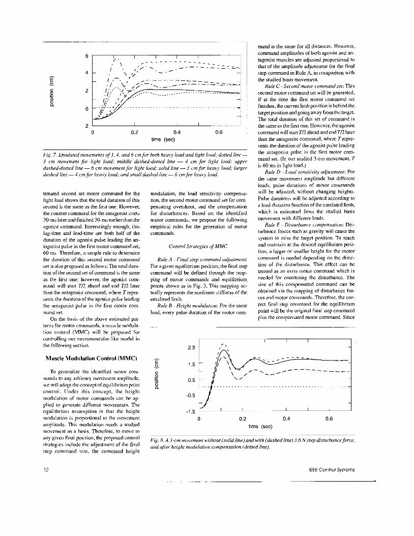
displayed in Fig. 6 illustrate how motor com- mands regulate the limb motion. The vertical dashed lines in Fig. 6 correspond to different time intervals that the amplitudes of motor commands change.
By comparing the pulse durations of two motor commands in Fig. 5, the first two pulse durations of heavy load, 0.12 s and 0.136 s, are two times that of the light load with 0.06 and 0.068 s, correspondingly. Though there is not enough evidence, the ratio of these com- mand durations implicates that human beings adjust the command duration to adapt to dif- ferent loads. Depending on the strength of the limb, this load-duration ratio is determined by a load-duration function learned by human. In our experiment data, this load-duration ratio learned by the subject seems to be two for the tested two loads. We do not have enough data to verify this load sensitivity function. Some researchers [2],[8] used square root of load ratio as a load-duration function to estimate the load-duration ratio. However, we believe that a higher order nonlinear function, such as cubic root or fifth root of load ratio, may be more close to estimate the load-duration func- tion of the neuromuscular system and more efficient for adapting to different loads.
No second set of motor command seems to be needed for the heavy load. Observe in the experimental data that at the time the first set of motor commands is finished, the limb posi- tion for the heavy load was over the target position and converging to the target; on the other hand, the limb position for the light load was behind the target position and going away from the target. This behavior indicates an empirical rule for artificially generating the second set of motor command as follows: At the time the first set motor command finishes, if the current limb position is behind the target position and going away from the target, a second set motor command should be generated to correct the movement. The es-
-
I I I I I I I I I I
/
L .' \ \
0.6
0.4
0
-0.2 t -0.4 I I I I I I I I
0 0.01 0.02 0.03 0.04 position (m)
Fig. 6 . Phase-plane plots between emulated position and velocity for both heavy load (solid line) and light load (dashed line) movements.
February 1992 J I
I I I I I
Fig. 7. Emulated movements of 3 , 4 , and 6 cm for both heavy load and light load: dotted line- 3 cm movement for light load; middle dashed-dotted line - 4 cm for light load; upper dashed-dotted line - 6 cm movement for light load; solid line - 3 cm for heavy load; larger dashed line - 4 cm for heavy load; and small dashed line - 6 cm for heavy load.
timated second set motor command for the light load shows that the total duration of this second is the same as the first one. However, the counter command for the antagonist starts 30-ms later and finished 30-ms earlier than the agonist command. Interestingly enough, this lag-time and lead-time are both half of the duration of the agonist pulse leading the an- tagonist pulse in the first motor command set, 60 ms. Therefore, a simple rule to determine the duration of this second motor command set is also proposed as follows: The total dura- tion of the second set of command is the same as the first one; however, the agonist com- mand will start T/2 ahead and end T/2 later than the antagonist command, where T repre- sents the duration of the agonist pulse leading the antagonist pulse in the first motor com- mand set.
On the basis of the above estimated pat- tems for motor commands, a muscle modula- tion control (MMC) will be proposed for controlling our neuromuscular-like model in the following section.
Muscle Modulation Control (MMC)
To generalize the identified motor com- mands to any arbitrary movement amplitude, we will adopt the concept of equilibrium point control. Under this concept, the height modulation of motor commands can be ap- plied to generate different movements. The equilibrium assumption is that the height modulation is proportional to the movement amplitude. This modulation needs a studied movement as a basis. Therefore, to move to any given final position, the proposed control strategies include the adjustment of the final step command size, the command height
modulation, the load sensitivity compensa- tion, the second motor command set for com- pensating overshoot, and the compensation for disturbances. Based on the identified motor commands, we propose the following empirical rules for the generation of motor commands.
Control Strategies of MMC
Rule A - Final step command adjustment: For a given equilibrium position, the final step command will be defined through the map- ping of motor commands and equilibrium points shown as in Fig. 3 . This mapping ac- tually represents the nonlinear stiffness of the emulated limb.
Rule B - Height modulation: For the same load, every pulse duration of the motor com-
mand is the same for all distances. However, command amplitudes of both agonist and an- tagonist muscles are adjusted proportional to that of the amplitude adjustment for the final step command in Rule A, in comparison with the studied basis movement.
Rule C - Second motor command set: This second motor command set will be generated, if at the time the first motor command set finishes, the current limb position is behind the target position and going away from the target. The total duration of this set of command is the same as the first one. However, the agonist command will start T/2 ahead and end T/2 later than the antagonist command, where T repre- sents the duration of the agonist pulse leading the antagonist pulse in the first motor com- mand set. (In our studied 3-cm movement, T is 60 ms in light load.)
Rule D - Load sensitivity adjustment: For the same movement amplitude but different loads, pulse durations of motor commands will be adjusted, without changing heights. Pulse durations will be adjusted according to a load-duration function of the emulated limb, which is estimated from the studied basis movement with different loads.
Rule E - Disturbance compensation: Dis- turbance forces such as gravity will cause the system to miss the target position. To reach and maintain at the desired equilibrium posi- tion, a larger or smaller height for the motor command is needed depending on the direc- tion of the disturbance. This effect can be treated as an extra motor command which is needed for countering the disturbance. The size of this compensated command can be obtained via the mapping of disturbance for- ces and motor commands. Therefore, the cor- rect final step command for the equilibrium point will be the original final step command plus the compensated motor command. Since
Fig. 8. A 3-cm movement without (solid line) and with (dashed line) 3.6 N step disturbance force, and after height modulation compensation (dotted line).
12 /€€E Control Systems
1.2 1 J h V
0 0.2 0.4 0.6 time (sec)
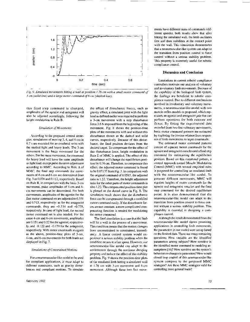
Fig. 9. Emulated movements hitting a wall at position 1.76 cm with a small motor command of 3 cm (solid line) and a large motor command of 6 cm (dashed line).
th i s f inal step command is changed , amplitudes of the agonist and antagonist will also be adjusted accordingly, following the height modulation in Rule B.
Simulation of Movements
According to the proposed control strate- gies, simulations of moving 3,4, and 6 cm in 0.7 s are executed for an emulated wrist with the studied light and heavy loads. The 3-cm movement is the basis movement for the others. For the same movement, the command for heavy load will have the same amplitude as light load, except pulse duration adjustment according to MMC. According to Rule A of MMC, the final step commands for move- ments of 4 cm and 6 cm are determined from Fig. 3 as 0.076 and 0.1 12, respectively. Based on Rule B, in comparison with the basis 3-cm movement, pulse amplitudes of 4-cm and 6- cm movements can be determined. For both movements, amplitudes of the agonist for the first motor command set are adjusted to 0.351 and 0.513, respectively; as for the antagonist commands, they are 4 . 5 3 4 and -0.779, respectively. In case of light load, the second motor command set is also needed. For the same 4-cm and 6-cm movements, amplitudes are 0.15 1 and 0.22 for the agonist, respective- ly, and -0.122 and -0.179 for the antagonist, respectively. With motor commands assigned as the above, position-time plots of 3-cm, 4-cm, and 6-cm movements for both loads are displayed in Fig. 7.
Simulations of Constrained Motions
For a neuromuscular-like model to be used for compliant applications, it must adapt to different constraints, such as gravity distur- bances and compliant motions. To simulate
the effect of disturbance forces, such as gravity effect, a simulated joint with the light load as defined earlier was required to perform a 3-cm movement with a step disturbance force 3.6 N imposed from the beginning of the movement. Fig. 8 shows the position-time plots of the movements with and without this disturbance shown as the dashed and solid curves, respectively. Because of this distur- bance, the final position deviates from the desired target. To compensate for the effect of this disturbance force, height modulation in Rule E of MMC is applied. The effect of this disturbance will change the equilibrium posi- tion by 0.76 cm. Therefore, to compensate this effect, the adjusted motor command is found to be 0.07 137 from Fig. 3. In comparison with the original command of 0.0585, the adjusted ratio is 1.22. Therefore, the height adjustment ratio for the other parts of motor commands is also 1.22. The compensated position-time plot is plotted as the dotted curve in Fig. 8. The simulation result shows that the disturbance force can be compensated through a modified motor command easily. If the disturbance for- ces are not constant, a more complicated com- pensating function is needed for modulating the motor command.
The final simulation is a case that the limb will hit a wall in the process of a movement. This condition means that the motion changes from unconstrained to constrained, immedi- ately. A linear control system would ex- perience a serious stability problem when the condition occurs at a fast speed. However, our neuromuscular-like model can adapt to the environment through the nonlinear damping property and reduce the effect of this stability problem. Fig. 9 shows the position-time plots of the emulated limb hitting a simulated wall at 1.76 cm with 3-cm movement and 6-cm movement. Although these two fast move-
ments have different sizes of commands (dif- ferent speeds), both results show that after hitting the simulated wall, the limb oscillates first and then stabilizes at the contact point with the wall. This simulation demonstrates that a neui-omuscular-like system can adapt to the transition from position control to force control without a serious stability problem. This property is extremely useful for robotic compliance control.
Discussion and Conclusion
Limitations in current robotic compliance controllers motivate our analysis of voluntary and involuntary limb movements. Because of the capability of the biological limb system, the findings are beneficial to robotic com- pliance control. Due to different mechanisms involved in involuntary and voluntary move- ments, a neuromuscular-like model with two muscle-reflex models is proposed, which rep- resents an agonist and antagonist pair that can perform operations for both extensor and flexor. By fitting the experimental data recorded from two fast voluntary movements, basic motor command patterns are estimated by exploring the inverse relation from respon- ses of limb movements to input commands.
The estimated motor command pattems consist of separate motor commands for the agonist and antagonist muscles and afmal step command for maintaining the equilibrium position. Based on this command pattern, a control approach named Muscle Modulation Control (MMC) with several empirical rules is proposed for controlling an emulated limb with the neuromuscular-like model. To generate different movements, MMC will regulate heights of motor commands for the agonist and antagonist muscles and the final step command for the desired equilibrium point. I t is also demonstrated that the neuromuscular-like model can adapt to the transition from position control to force con- trol without a serious stability problem. This capability is essential in designing a com- pliance control.
Although the result demonstrated from the neuromuscular-like model shows promising applications in controlling limb movements, the parameters in our model were set up based on the limited data. There are many remaining questions: How variable are the identified parameters among subjects? How sensitive is the identified motor command to modeling as- sumptions [ 16]? How sensitive are the system's behaviors to changes in parameters? How would closed-loop control of this neuromuscular-like system compare to the proposed MMC strategies? Are these MMC strategies valid for controlling more general loads?
Februaw 1992 13
Current industrial robots are very accurate, but poor in compliant control and adaptability. The neuromuscular system seems not so ac- curate but very good in tasks requiring com- pliance and adaptation. Based on the research presented in this paper, the expectation is that the design of robotic control may benefit from modeling the properties of the biological limb. Before a neuromuscular robot system can be realized, further research is needed to identify applications of a such neuromuscular-like model.
Acknowledgment
The authors would like to thank the reviewers for their invaluable comments.
References
[ I ] C.H. Wu, "Compliance," in International Encyclopedia ofRobotics: Application and Automa- tion, vol. 1. New York Wiley, Mar. 1988, pp. 192- 202.
[2] N. Hogan, "Impedance control: An approach to manipulation. Part I: Theory; Part 11: Implementa- tion; Part 111: Application," ASME J . Dyn. Syst., Meas., Control, vol. 107, pp. 1-24, 1985.
[3] S.C. Jacobsen, K. KO, E.K. Iversen, and C.C. Davis. "Control strategies for tendon-driven manipulator," IEEE Control Syst. Mag., vol. 10, pp. 23-28, Feb. 1990.
[4] C.C.A.M. Gielen and J.C. Houk, "Amodel of the motor servo: Incorporating nonlinear spindle recep- tor and muscle mechanical properties," Biol. Cybern., vol. 57, pp. 217-231, 1987.
[5] J.C. Houk and W.Z. Rymer, "Neural control of muscle length and tension," in Handbook of Physiology -The Nervous System I I , vol 11. Bethes- da, MD: Amer. Physiol. Soc., 1981, Sect. 1, Ch. 8, pp. 251-323.
(61 C.H. Wu, J.C. Houk, K.Y. Young, and L.E. Miller, "Nonlinear damping of limb motion," in Multiple Muscle Systems: Biomechanics and Movenienr Organization, J.M. Winters and S. L.-Y. Woo, Eds. New York: Springer-Verlag. 1990, pp. 214-235.
[7] C.H. Wu, K.Y. Young,andJ.C.Houk,"Aneumus- cular-like model for robotic compliance control," in Proc. 1990 IEEE Int. Con5 Robotics andAuromarion, Cincinnati, OH, May 1990, pp. 1885-1890.
[8] 0. Bock, "Load compensation in human goal- directed arm movements," Behavior Brain Res., vol. 41, pp. 167.177, 1990.
[9] D.M. Corcos, G.L. Gottlieb, and G.C. Aganval, "Organizing principles for single-joint movements
11. A speed-sensitive strategy," J . Neurophys., vol. 62, no. 2, pp. 358-368, 1989.
[IO] G.L. Gottlieb, D.M. Corcos, and G.C. Agarwal, "Organizing principles for single-joint movements I. A speed-insensitive strategy," J . Neurophys., vol. 62, no. 2, pp. 342-357. 1989.
[ 1 I] G.L. Gottlieb, D.M. Corcos, G.C. Agarwal, and M.L. Latash, "Organizing principles for single-joint movements 111. A speed-insensitive strategy as a default," J . Neurophys., vol. 63, no. 3. pp. 625-636, 1990.
1121 T. Flash, and N. Hogan, "The coordination of arm movements: An experimentally confirmed mathematical model," J . Neuroscience, vol. 5, pp. 1688-1703, 1985.
1131 S.L. Lehman and L.W. Stark, "Simulation of linear and nonlinear eye movement models: Sen- sitivity analyses and enumeration studies of time optimal control," J . Cybern. Info. Sei., vol. 4, pp. 21-43, 1979.
1141 T. Flash, "The control of hand equilibrium trajectories in multi-joint arm movements," Biol. Cybern., vol. 57. pp. 257-274, 1987.
1151 M. Kawato, Y. Uno, M. Isobe, and R. Suzuki, "Hierarchical neural network model for voluntary movement with application to robotics," IEEE Con- trolSyst. Mag., vol. 8, pp. 8-16, Apr. 1988.
1161 S.L. Lehman, "Input identification depends on model complexity," in Multiple Muscle Systems, J. M. Winters andS. L-Y. Woo, Eds. New York: Springer-Verlag, 1990, pp. 94-100.
Chi-huar Wu is an As- sociate Professor of Electr- cal Engineering and Com- puter Science at Northwestern University, Evanston, IL. He received the B.S. degree in electrical engineering from National Taiwan University, Taiwan, in 1973, the M.S. degree in
electrical engineering from Viginia Polytechnic In- stitute and State University in 1977, and the Ph.D. degree in electrical engineering from Purdue University in 1980. After graduating from Purdue, he joined Unimation Inc., Danbury, CT. During that period, his job involved designing robot motion control algorithms and digital servo systems for PUMA robots and hydraulic-servo Unimate robots. Since September 1983, he has been with Northwestem University. His areas of interest are robotics, robot accuracy and calibration, neural net- works and learning control, motor control of limb arm and roboticc, compliance and part assembly strategy, computer graphics and CAD/CAM in-
tegration, and integrated industrial automation. Cur- rently he is involved in designing a CAD-driven, surgical robot system. During 1985, he was honored with the Outstanding Young Manufacturing En- gineer Award from the Society of Manufacturing Engineers.
and Ph.D. degrees in electrical engineering from Northwestem Univer- sity in 1987 and 1990, respectively. Between 1983 and 1985, he served as an electronic officer in the ChineseNavy. Since 1990, he has been an Associate Professor in th Department of Control Engineering at National Chiao-Tung University, Hsinchu, Taiwan, R.O.C. His current research interests in- clude biological control systems, fuzzy control sys- tems, robot path planning, and accuracy analysis.
Kao S. Hwang received the B.S. degree from the Department of Industrial Design, National Cheng Kung University, Taiwan, in 1981, and the M.M.E. degree from Northwestem University in 1988. Presently, he is workring toward the Ph.D. degree in
the Department of Electrical Engineering and Com- ptuer Science at Northwestern University, Evanston, IL. His interests include robotics, neural networks, and CAD/CAM.
Steven L. Lehman was born in Portland, OR, in 1948. He receivedthe B.S. degree in mathematics from Stanford University and the Ph.D. degree in biophysics from the University of California, Berkeley.He joined the faculty of the Department
of Physical Education at Berkeley in 1983, and is also an active member of the U.C. San Francis- co/U.C. Berkeley Bioengineering Graduate Group. His research interests are in neuromotor control, biomechanics, and neuromuscular fatique.
14
--
/E€ Contra/ Systems
Related Documents