EPA Contract No. EP-S1-06-01 EPA Task Order No. 0060-RD-RD-01D5 EPA Project Officer: Heidi Horahan EPA Task Order Project Manager: Ed Hathaway VOLUME 1 OF 2 SPECIFICATIONS DURHAM MEADOWS WATERLINE REMEDIAL DESIGN 100% Design Submittal Durham Meadows Superfund Site Durham, Connecticut April 2018 Prepared by: AECOM, Inc. 500 Enterprise Drive Suite 1A Rocky Hill, CT 06067

Welcome message from author
This document is posted to help you gain knowledge. Please leave a comment to let me know what you think about it! Share it to your friends and learn new things together.
Transcript

EPA Contract No. EP-S1-06-01EPA Task Order No. 0060-RD-RD-01D5
EPA Project Officer: Heidi HorahanEPA Task Order Project Manager: Ed Hathaway
VOLUME 1 OF 2
SPECIFICATIONSDURHAM MEADOWS WATERLINE
REMEDIAL DESIGN
100% Design Submittal
Durham Meadows Superfund SiteDurham, Connecticut
April 2018
Prepared by:
AECOM, Inc.500 Enterprise Drive
Suite 1ARocky Hill, CT 06067

Durham Meadows Waterline RD Table of ContentsSection 00000-i
TABLE OF CONTENTS
VOLUME 1 OF 2:
DIVISION 0 - CONTRACT REQUIREMENTS00300 Bid FormDIVISION 1 - GENERAL REQUIREMENTS01010 Summary of Work01046 Control of Work01063 Miscellaneous Requirements01070 Regulatory Requirements01110 Environmental Protection Procedures01120 Safety and Health Program01150 Measurement and Payment01200 Project Meetings01300 Submittals01310 Construction Progress01390 Pre- and Post-Construction Surveys01400 Quality Assurance01410 Sampling Procedures and Laboratory Services01500 Temporary Facilities01568 Erosion Control, Sedimentation, and Containment of Construction
Materials01610 Delivery, Storage, and Handling01700 Contract Closeout01710 Cleaning Up01740 Warranties and BondsDIVISION 2 - SITE WORK02012 Protecting Existing Underground Utilities02013 Connections to Existing Buried Pipelines02018 Vibration Monitoring02053 Excavated Material Management Plan02100 Site Preparation02160 Excavation Support Systems02210 Earth Excavation, Backfill, Fill, and Grading02211 Rock Excavation and Disposal02223 Screened Gravel02224 Bank -Run or Crushed Gravel02225 Select Borrow02230 Site Clearing02240 Dewatering02241 Construction Water Management02273 Geotextile Fabric02371 Riprap02400 Temporary Cofferdam

Durham Meadows Waterline RD Table of ContentsSection 00000-ii
02435 Crushed Stone02510 Water Utilities02515 Disinfecting Water Utility Distribution System02521 Well Abandonment02630 Storm Drainage Utilities02740 Flexible Paving02820 Chain Link Fences and Gates02900 Planting02922 HydroseedingDIVISION 3 – CONCRETE03100 Concrete Formwork03200 Concrete Reinforcement03300 Cast-In-Place Concrete03410 Precast Structural Concrete Buildings03420 Precast Reinforced Concrete Vaults03800 Leakage Testing of Containment StructuresDIVISION 5 – METALS05515 Aluminum Stairs and LaddersDIVISION 7 – THERMAL AND MOISTURE PROTECTION07900 Joint Sealants
DIVISION 8 – OPENINGS08111 Flush Panel Aluminum Doors and Frames08710 Finish Hardware
DIVISION 9 – FINISHES09941 Field PaintingDIVISION 10 – SPECIALTIES10200 Louvers
DIVISION 11 – EQUIPMENT
11316 Sump Pumps and Appurtenances11353 Booster Chlorination System11355 THM Removal System11397 Gas Engine Generator Set and AppurtenancesDIVISION 13 – SPECIAL CONSTRUCTION13225 Prestressed Concrete Tanks13300 Utility Control Instrumentation System13300A Utility Control Instrumentation System -Attachment ADIVISION 15 – PLUMBING – MECHANICAL15101 Valves, Gates, Hydrants, and Appurtenances15105 Pipe Supports for Process Piping15112 Self-Contained Automatic Control Valves and Appurtenances
Durham Meadows Waterline RD Table of ContentsSection 00000-iii
15115 Flow Meter15400 Plumbing Systems15806 Heating, Ventilating, and Air Conditioning15809 Water Booster Pumps and Appurtenances
DIVISION 16 – ELECTRICAL16050 Electrical Work – General16110 Raceway and Boxes for Electrical Systems16120 Electric Wires and Cables16160 Panelboards16220 Electric Motors16260 Low Voltage Variable Frequency Drive Unit16400 Surge Protection Devices16402 Underground Ducts and Raceways for Electrical Systems16415 Automatic Transfer Switches16450 Grounding and Bonding for Electrical Systems16601 Lightning Protection16900 Electrical Controls and Miscellaneous Electrical Equipment16998 Field Inspection and Acceptance Tests
VOLUME 2 OF 2:
APPENDICESA – Geotechnical DataB – Water Service Work on Private Property – Details by AddressC – State Department of Labor Wage Rates (To be issued by Addendum)D – Historic Site Data (203R Main Street)

DIVISION 0
CONTRACT REQUIREMENTS
Bid FormDurham Meadows Waterline RD Section No. 00300-1
SECTION 00300
BID FORM
PROJECT IDENTIFICATION: Durham Meadows Waterline RD Project
PROJECT NUMBER: EPA Contract No. EP-S1-06-01
ARTICLE 1 – BID RECIPIENT
1.01 This Bid is submitted to:
US Army Corps of Engineers (USACE) as the Contracting Officer.
1.02 The undersigned Bidder proposes and agrees, if this Bid is accepted, to enter into anAgreement with the Contracting Officer in the form included in the Bidding Documents toperform all Work as specified or indicated in the Bidding Documents for the prices andwithin the times indicated in this Bid and in accordance with the other terms and conditionsof the Bidding Documents.
ARTICLE 2 – BIDDER’S ACKNOWLEDGEMENTS
2.01 Bidder accepts all of the terms and conditions of the Official Notice to Bidders andInstructions to Bidders, including without limitation those dealing with the disposition ofBid security. This Bid will remain subject to acceptance for the Bid withdrawal time periodspecified in the Official Notice to Bidders after the Bid opening, or for such longer period oftime that Bidder may agree to in writing upon request of the Contracting Officer.
ARTICLE 3 – BIDDER’S REPRESENTATIONS
3.01 In submitting this Bid, Bidder represents that:
A. Bidder has examined and carefully studied the Bidding Documents, other related dataidentified in the Bidding Documents, and the following Addenda, receipt of which ishereby acknowledged:
Addendum No. Addendum Date
B. Bidder has visited the Site and become familiar with and is satisfied as to the general,local, and Site conditions that may affect cost, progress, and performance of the Work.

Bid FormDurham Meadows Waterline RD Section No. 00300-2
C. Bidder is familiar with and is satisfied as to all Laws and Regulations that may affectcost, progress, and performance of the Work.
D. Bidder has carefully studied all: (1) reports of explorations and tests of subsurfaceconditions at or contiguous to the Site and all drawings of physical conditions relating toexisting surface or subsurface structures at the Site (except Underground Facilities) thathave been identified in SC-4.02 as containing reliable "technical data," and (2) reportsand drawings of Hazardous Environmental Conditions, if any, at the Site that have beenidentified in SC-4.06 as containing reliable "technical data."
E. Bidder has considered the information known to Bidder; information commonly knownto contractors doing business in the locality of the Site; information and observationsobtained from visits to the Site; the Bidding Documents; and the Site-related reports anddrawings identified in the Bidding Documents, with respect to the effect of suchinformation, observations, and documents on (1) the cost, progress, and performance ofthe Work; (2) the means, methods, techniques, sequences, and procedures ofconstruction to be employed by Bidder, including applying the specific means, methods,techniques, sequences, and procedures of construction expressly required by the BiddingDocuments; and (3) Bidder’s safety precautions and programs.
F. Based on the information and observations referred to in Paragraph 3.01.E above,Bidder does not consider that further examinations, investigations, explorations, tests,studies, or data are necessary for the determination of this Bid for performance of theWork at the price(s) bid and within the times required, and in accordance with the otherterms and conditions of the Bidding Documents.
G. Bidder is aware of the general nature of work to be performed by the ContractingOfficer and the Engineer and others at the Site that relates to the Work as indicated inthe Bidding Documents.
H. Bidder has given Engineer written notice of all conflicts, errors, ambiguities, ordiscrepancies that Bidder has discovered in the Bidding Documents, and the writtenresolution thereof by Engineer is acceptable to Bidder.
I. The Bidding Documents are generally sufficient to indicate and convey understandingof all terms and conditions for the performance of the Work for which this Bid issubmitted.
ARTICLE 4 – BIDDER’S CERTIFICATION
4.01 Bidder certifies that:
A. This Bid is genuine and not made in the interest of or on behalf of any undisclosedindividual or entity and is not submitted in conformity with any collusive agreement orrules of any group, association, organization, or corporation;
B. Bidder has not directly or indirectly induced or solicited any other Bidder to submit afalse or sham Bid;
Bid FormDurham Meadows Waterline RD Section No. 00300-3
C. Bidder has not solicited or induced any individual or entity to refrain from bidding; and
D. Bidder has not engaged in corrupt, fraudulent, collusive, or coercive practices incompeting for the Contract. For the purposes of this Paragraph 4.01.D:
1. “corrupt practice” means the offering, giving, receiving, or soliciting of any thing ofvalue likely to influence the action of a public official in the bidding process;
2. “fraudulent practice” means an intentional misrepresentation of facts made (a) toinfluence the bidding process to the detriment of the Contracting Officer, (b) toestablish bid prices at artificial non-competitive levels, or (c) to deprive theContracting Officer of the benefits of free and open competition;
3. “collusive practice” means a scheme or arrangement between two or more Bidders,with or without the knowledge of the Contracting Officer, a purpose of which is toestablish bid prices at artificial, non-competitive levels; and
4. “coercive practice” means harming or threatening to harm, directly or indirectly,persons or their property to influence their participation in the bidding process oraffect the execution of the Contract.
ARTICLE 5 – BASIS OF BID
5.01 Bidder will complete the Work in accordance with the Contract Documents for thefollowing prices listed below:
5.02 All prices, except item totals, shall be stated in both words and figures. In the event of adiscrepancy between the price in words and the price in figures, the words shall govern. Inthe event of a discrepancy between the total of the items and the total stated, the total of theitems shall govern.
5.03 Interlineations, alteration, or erasure may void the Bid. All prices shall be typewritten orwritten by hand in ink.

Bid FormDurham Meadows Waterline RD Section No. 00300-4
BID ITEMS
Item Description QuantityExtended
Total
1 For Mobilization/Demobilization as specified, the sum of(not to exceed five (5) percent of the sum of all Bid Itemsexclusive of Item 1)
_____________________________________________Dollars ($ ) lump sum
1 ___________
2 For construction of the Water Storage Tank and AccessRoadway as specified including allowances
_____________________________________________Dollars ($ ) lump sum
1 ___________
3A For 20-inch DI pipe, furnished and installed as specified, thesum of
INCLUDED IN ITEM 2Dollars ($ Included under Item 2) per l.f.
0 ___________
3B For 16-inch DI pipe, furnished and installed asspecified, the sum of
_____________________________________________Dollars ($ ) per l.f.
5,070 ___________
3C For 12-inch DI pipe, furnished and installed as specified, thesum of
_____________________________________________Dollars ($ ) per l.f.
3,700 ___________
3D For 8-inch DI pipe, furnished and installed as specified,the sum of
_____________________________________________Dollars ($ ) per l.f.
1,900 ___________
3E For 20-inch Restrained Joint DI pipe, furnished andinstalled as specified, the sum of
_____________________________________________Dollars ($ ) per l.f.
202 ___________
Bid FormDurham Meadows Waterline RD Section No. 00300-5
BID ITEMS
Item Description QuantityExtended
Total
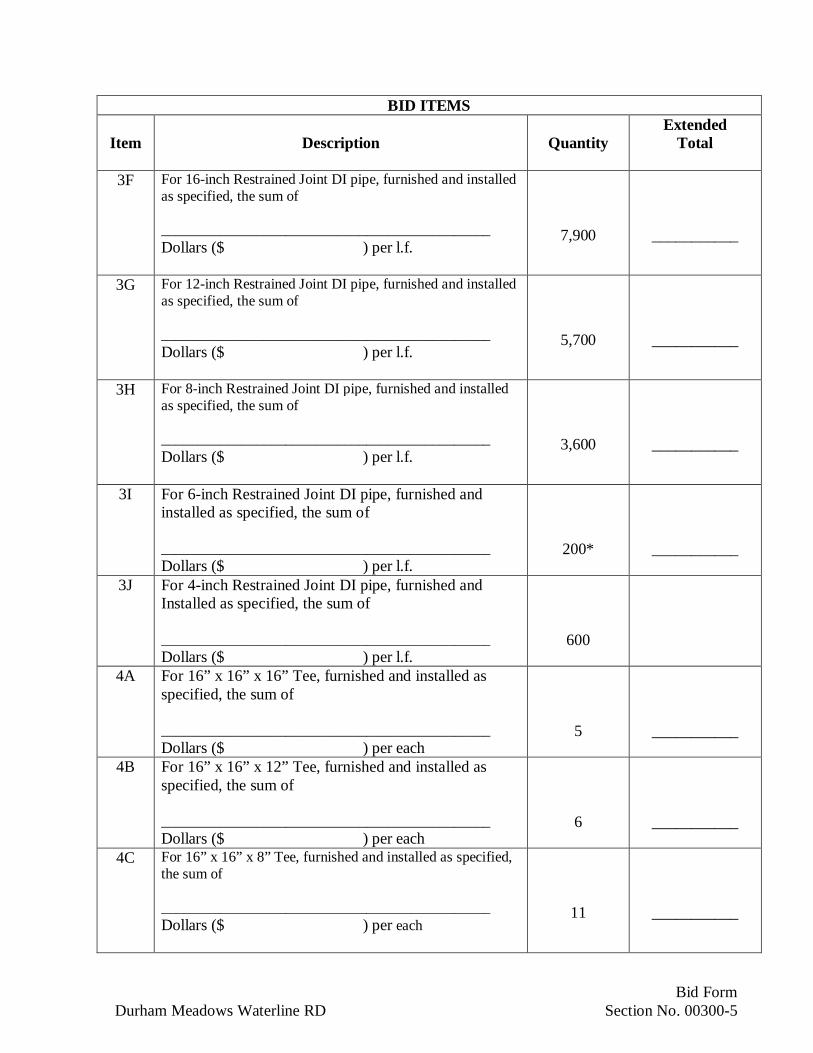
3F For 16-inch Restrained Joint DI pipe, furnished and installedas specified, the sum of
_____________________________________________Dollars ($ ) per l.f.
7,900 ___________
3G For 12-inch Restrained Joint DI pipe, furnished and installedas specified, the sum of
_____________________________________________Dollars ($ ) per l.f.
5,700 ___________
3H For 8-inch Restrained Joint DI pipe, furnished and installedas specified, the sum of
_____________________________________________Dollars ($ ) per l.f.
3,600 ___________
3I For 6-inch Restrained Joint DI pipe, furnished andinstalled as specified, the sum of
_____________________________________________Dollars ($ ) per l.f.
200* ___________
3J For 4-inch Restrained Joint DI pipe, furnished andInstalled as specified, the sum of
_____________________________________________Dollars ($ ) per l.f.
600
4A For 16” x 16” x 16” Tee, furnished and installed asspecified, the sum of
_____________________________________________Dollars ($ ) per each
5 ___________
4B For 16” x 16” x 12” Tee, furnished and installed asspecified, the sum of
_____________________________________________Dollars ($ ) per each
6 ___________
4C For 16” x 16” x 8” Tee, furnished and installed as specified,the sum of
_____________________________________________Dollars ($ ) per each
11 ___________
Bid FormDurham Meadows Waterline RD Section No. 00300-6
BID ITEMS
Item Description QuantityExtended
Total
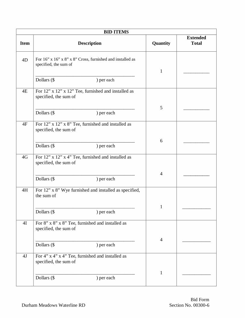
4D For 16” x 16” x 8” x 8” Cross, furnished and installed asspecified, the sum of
_____________________________________________Dollars ($ ) per each
1 ___________
4E For 12” x 12” x 12” Tee, furnished and installed asspecified, the sum of
_____________________________________________Dollars ($ ) per each
5 ___________
4F For 12” x 12” x 8” Tee, furnished and installed asspecified, the sum of
_____________________________________________Dollars ($ ) per each
6 ___________
4G For 12” x 12” x 4” Tee, furnished and installed asspecified, the sum of
_____________________________________________Dollars ($ ) per each
4 ___________
4H For 12” x 8” Wye furnished and installed as specified,the sum of
_____________________________________________Dollars ($ ) per each
1 ____________
4I For 8” x 8” x 8” Tee, furnished and installed asspecified, the sum of
_____________________________________________Dollars ($ ) per each
4 ____________
4J For 4” x 4” x 4” Tee, furnished and installed asspecified, the sum of
_____________________________________________Dollars ($ ) per each
1 ____________

Bid FormDurham Meadows Waterline RD Section No. 00300-7
BID ITEMS
Item Description QuantityExtended
Total
5A For 20” Butterfly Valve, furnished and installed asspecified, the sum of
_____________________________________________Dollars ($ ) per each
1 ____________
5B For 16” Butterfly Valve, furnished and installed asspecified, the sum of
_____________________________________________Dollars ($ ) per each
43 ____________
5C For 12” Gate Valve, furnished and installed asspecified, the sum of
_____________________________________________Dollars ($ ) per each
37 ____________
5D For 8” Gate Valve, furnished and installed as specified,the sum of
_____________________________________________Dollars ($ ) per each
30 ___________
5E For 6” Gate Valve, furnished and installed as specified,the sum of
_____________________________________________Dollars ($ ) per each
1 ___________
5F For 4” Gate Valve, furnished and installed as specified,the sum of
_____________________________________________Dollars ($ ) per each
8 ___________
6A Fire Hydrant Assembly, furnished and placed asspecified, the sum of
_____________________________________________Dollars ($ ) per each
57 ___________
Bid FormDurham Meadows Waterline RD Section No. 00300-8
BID ITEMS
Item Description QuantityExtended
Total
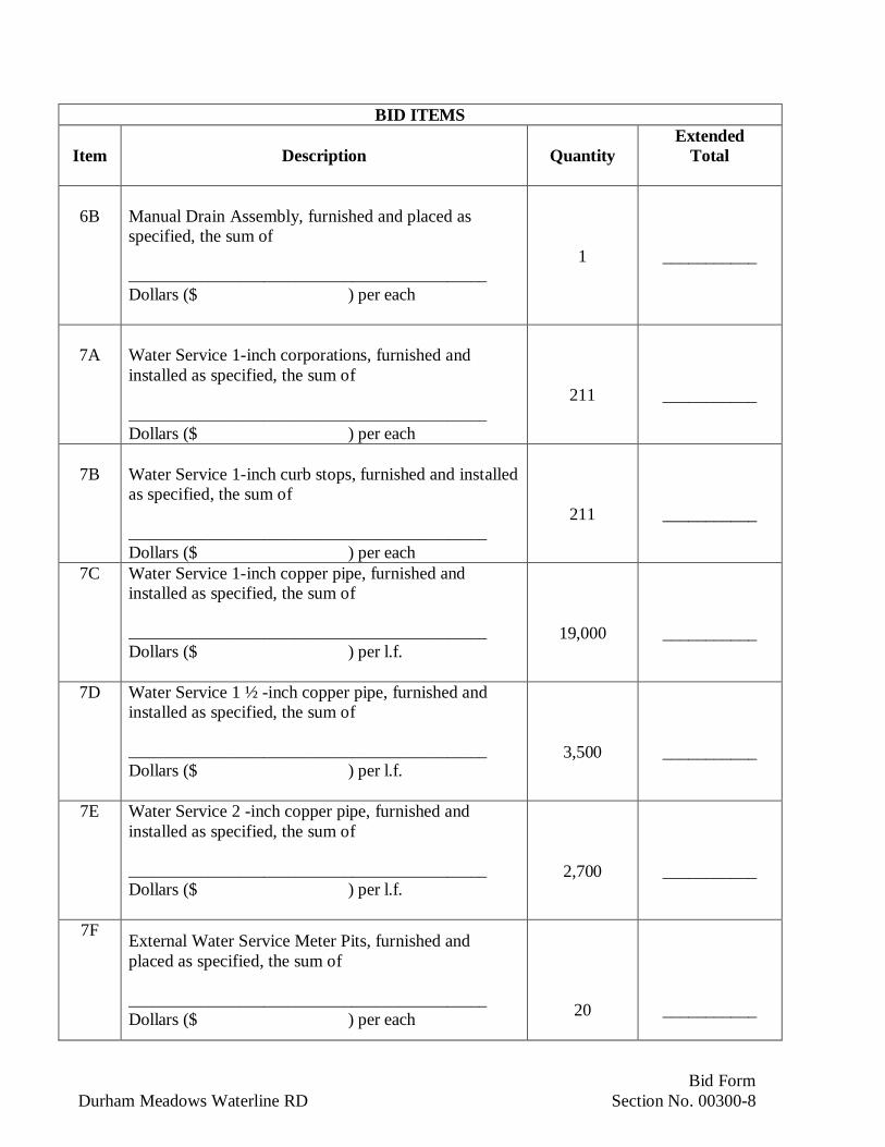
6B Manual Drain Assembly, furnished and placed asspecified, the sum of
_____________________________________________Dollars ($ ) per each
1 ___________
7A Water Service 1-inch corporations, furnished andinstalled as specified, the sum of
_____________________________________________Dollars ($ ) per each
211 ___________
7B Water Service 1-inch curb stops, furnished and installedas specified, the sum of
_____________________________________________Dollars ($ ) per each
211 ___________
7C Water Service 1-inch copper pipe, furnished andinstalled as specified, the sum of
_____________________________________________Dollars ($ ) per l.f.
19,000 ___________
7D Water Service 1 ½ -inch copper pipe, furnished andinstalled as specified, the sum of
_____________________________________________Dollars ($ ) per l.f.
3,500 ___________
7E Water Service 2 -inch copper pipe, furnished andinstalled as specified, the sum of
_____________________________________________Dollars ($ ) per l.f.
2,700 ___________
7F External Water Service Meter Pits, furnished andplaced as specified, the sum of
_____________________________________________Dollars ($ ) per each 20 ___________

Bid FormDurham Meadows Waterline RD Section No. 00300-9
BID ITEMS
Item Description QuantityExtended
Total
7G Special 4-inch Water Service Meter Pits, furnished andplaced as specified, the sum of
_____________________________________________Dollars ($ ) per each
2 ___________
7H External Backflow Preventer, furnished and placed asspecified, the sum of
_____________________________________________Dollars ($ ) per each
1 ___________
7I Water Service installation by soil piercing methodunder sidewalks, furnished and placed as specified, thesum of
_____________________________________________Dollars ($ ) l.f.
1,120 ___________
7J Plumbing work required to complete new water serviceinstallation to building cold water feed plumbing asspecified and indicated, the sum of
_____________________________________________Dollars ($ ) per each
115 ___________
8A Decommissioning of Water Supply Wells as specified,the sum of
_____________________________________________Dollars ($ ) per each
125 ___________
8B Conversion of Water Supply Wells to Monitoring Wellas specified,
_____________________________________________Dollars ($ ) per each
4 ___________
8C Decommissioning and conversion of Durham FairgroundWells to Monitoring Wells as specified, the sum of
_____________________________________________Dollars ($ ) per lump sum
2 ___________

Bid FormDurham Meadows Waterline RD Section No. 00300-10
BID ITEMS
Item Description QuantityExtended
Total
8D Removal and Disposal of Treatment Units, complete asspecified and indicated, the sum of
_____________________________________________Dollars ($ ) per each
52 ___________
9A Stream Crossing, STA 904 + 50 to STA 905 + 50Complete as specified and indicated, the sum of
_____________________________________________Dollars ($ ) per lump sum
1 ___________
9B Stream Crossing, STA 509 + 20 to STA 512 + 00Complete as specified and indicated, the sum of
_____________________________________________Dollars ($ ) per lump sum
1 ___________
9C Stream Crossing, STA 410 + 50 to STA 412 + 00Complete as specified and indicated, the sum of
_____________________________________________Dollars ($ ) per lump sum
1 ___________
10 Long Hill Pump Station ModificationsComplete as specified and indicated includingallowances, the lump sum of
_____________________________________________Dollars ($ ) per lump sum
1 ___________
11 Booster Station at Main Street, STA 750+59+/-Complete as specified and indicated including allowance, thesum of
_____________________________________________Dollars ($ ) per lump sum
1 ___________
12 Meter Station at Main Street, STA 125+20+/-Complete as specified and indicated including allowance, thesum of
_____________________________________________Dollars ($ ) per lump sum
1 ___________
Bid FormDurham Meadows Waterline RD Section No. 00300-11
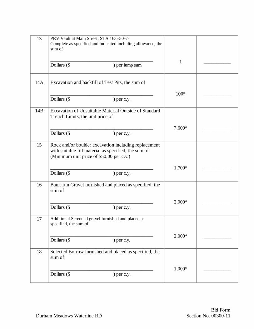
13 PRV Vault at Main Street, STA 163+50+/-Complete as specified and indicated including allowance, thesum of
_____________________________________________Dollars ($ ) per lump sum
1 ___________
14A Excavation and backfill of Test Pits, the sum of
_____________________________________________Dollars ($ ) per c.y.
100* ___________
14B Excavation of Unsuitable Material Outside of StandardTrench Limits, the unit price of
_____________________________________________Dollars ($ ) per c.y.
7,600* ___________
15 Rock and/or boulder excavation including replacementwith suitable fill material as specified, the sum of(Minimum unit price of $50.00 per c.y.)
_____________________________________________Dollars ($ ) per c.y.
1,700* ___________
16 Bank-run Gravel furnished and placed as specified, thesum of
_____________________________________________Dollars ($ ) per c.y.
2,000* ___________
17 Additional Screened gravel furnished and placed asspecified, the sum of
_____________________________________________Dollars ($ ) per c.y.
2,000* ___________
18 Selected Borrow furnished and placed as specified, thesum of
_____________________________________________Dollars ($ ) per c.y.
1,000* ___________
Bid FormDurham Meadows Waterline RD Section No. 00300-12
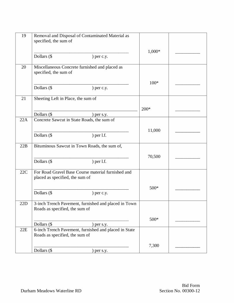
19 Removal and Disposal of Contaminated Material asspecified, the sum of
_____________________________________________Dollars ($ ) per c.y.
1,000* ___________
20 Miscellaneous Concrete furnished and placed asspecified, the sum of
_____________________________________________Dollars ($ ) per c.y.
100* ___________
21 Sheeting Left in Place, the sum of
_____________________________________________Dollars ($ ) per s.y.
200* ___________
22A Concrete Sawcut in State Roads, the sum of
_____________________________________________Dollars ($ ) per l.f.
11,000 ___________
22B Bituminous Sawcut in Town Roads, the sum of,
_____________________________________________Dollars ($ ) per l.f.
70,500 ___________
22C For Road Gravel Base Course material furnished andplaced as specified, the sum of
_____________________________________________Dollars ($ ) per c.y.
500* ___________
22D 3-inch Trench Pavement, furnished and placed in TownRoads as specified, the sum of
_____________________________________________Dollars ($ ) per s.y.
500* ___________
22E 6-inch Trench Pavement, furnished and placed in StateRoads as specified, the sum of
_____________________________________________Dollars ($ ) per s.y.
7,300 ___________

Bid FormDurham Meadows Waterline RD Section No. 00300-13
22F Class 4 Bituminous Concrete to match existingthickness in State Roads, furnished and placed asspecified, the sum of
_____________________________________________Dollars ($ ) per ton
1,300 ___________
22G 2-inch Overlay Pavement, furnished and placed inTown Roads as specified, the sum of
_____________________________________________Dollars ($ ) per s.y.
43,600 ___________
22H Milling and 2-inch Overlay Pavement, furnished andplaced in State Roads as specified, the sum of
_____________________________________________Dollars ($ ) per s.y.
10,100 ___________
22I Driveway apron overlay at State roadways, furnishedand placed as specified, the sum of
_____________________________________________Dollars ($ ) per s.y.
600 ___________
22J 6-inch Bituminous concrete curbing, furnished andplaced as specified, the sum of
_____________________________________________Dollars ($ ) per l.f.
360 ___________
23A Main Street Traffic Loop Detector at Middlefield Road,as specified, the sum of
_____________________________________________Dollars ($ ) per lump sum
1 ___________
23B Main Street Traffic Loop Detector at Wallingford Road,as specified, the sum of
_____________________________________________Dollars ($ ) per lump sum
1 ___________
Bid FormDurham Meadows Waterline RD Section No. 00300-14
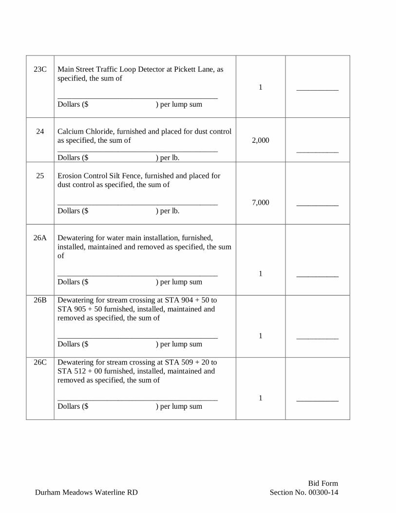
23C Main Street Traffic Loop Detector at Pickett Lane, asspecified, the sum of
_____________________________________________Dollars ($ ) per lump sum
1 ___________
24 Calcium Chloride, furnished and placed for dust controlas specified, the sum of_____________________________________________Dollars ($ ) per lb.
2,000___________
25 Erosion Control Silt Fence, furnished and placed fordust control as specified, the sum of
_____________________________________________Dollars ($ ) per lb.
7,000 ___________
26A Dewatering for water main installation, furnished,installed, maintained and removed as specified, the sumof
_____________________________________________Dollars ($ ) per lump sum
1 ___________
26B Dewatering for stream crossing at STA 904 + 50 toSTA 905 + 50 furnished, installed, maintained andremoved as specified, the sum of
_____________________________________________Dollars ($ ) per lump sum
1 ___________
26C Dewatering for stream crossing at STA 509 + 20 toSTA 512 + 00 furnished, installed, maintained andremoved as specified, the sum of
_____________________________________________Dollars ($ ) per lump sum
1 ___________

Bid FormDurham Meadows Waterline RD Section No. 00300-15
26D Dewatering for stream crossing at STA 410 + 50 toSTA 412 + 00 furnished, installed, maintained andremoved as specified, the sum of
_____________________________________________Dollars ($ ) per lump sum
1 ___________
27 Coordination, Permitting, Traffic Control, Sitepreparation, Environmental Controls, and TurfEstablishment or Other Incidental Work, the sum of
_____________________________________________Dollars ($ ) per lump sum
1 ___________
28 Uniformed Police Officers – Refer to SECTION 01150MEASUREMENT AND PAYMENT
Seven Hundred Ninety-eight ThousandDollars ($ 798,000 ) Allowance
1 ___________
29A Engineer’s field office, furnished, installed, andremoved as specified, the sum of
_____________________________________________Dollars ($ ) per lump sum
1 ___________
29B Engineer’s field office, maintained as specified, thesum of
_____________________________________________Dollars ($ ) per month
24 ___________
30A Construction Water Treatment System, Furnished,Installed and Removed as Specified, the sum of
_____________________________________________Dollars ($ ) per lump sum
1 ___________
30B Construction Water Treatment System, Operated andMaintained as specified, the sum of
_____________________________________________Dollars ($ ) per week
20* ___________

Bid FormDurham Meadows Waterline RD Section No. 00300-16
30C Construction Water Analytical Testing as specified, thesum of Five Thousand_____________________________________________Dollars ($ 5,000 ) Allowance
1___________
* Note: The quantities identified with an asterisk are indeterminate items and are provided forestablishing a unit price cost for the respective Bid Item.
BID PRICE (Summation of Bid Items) Dollars(dollars written)
($ )(figures)
A. Bidder acknowledges that estimated quantities are not guaranteed, and are solely for thepurpose of comparison of Bids, and final payment for all unit price Bid items will bebased on actual quantities, determined as provided in the Contract Documents.
END OF SECTION

DIVISION 1
GENERAL REQUIREMENTS

Summary of WorkDurham Meadows Waterline RD Section No. 01010-1
SECTION 01010
SUMMARY OF WORK
PART 1 - GENERAL
1.01 LOCATION OF WORK:
A. The work of this Contract is located in the Town of Durham, and City of Middletown
1.02 SCOPE OF WORK:
A. Furnish all supervision, labor, materials, equipment and incidentals necessary to completethe work and render it ready for operation as shown on the Drawings and specifiedherein.
B. Work to include, but not limited to the following major items:
1. Construction of a new 0.80 million gallon prestressed concrete water storage tank,access roadway, site improvements, and appurtenances off Talcott Ridge Drive in theCity of Middletown.
2. Modifications at the Long Hill Pump Station in the City of Middletown.
3. Construction of a booster pump station on South Main Street, including siteimprovements and appurtenances, in Middletown on the northern portion of the CTDOT property across from the intersection of Talcott Ridge Road.
4. Construction of a water meter station, including site improvements andappurtenances, in the City of Middletown on City-owned property on South MainStreet at the corner of Acorn Drive.
5. Installation of approximately 31,2000 linear feet water main (20-inch to 6-inchdiameter) and appurtenances in Town of Durham and CTDOT roadways, includingbut not limited to:
(1) Talcott Ridge Drive in Middletown,
(2) South Main Street (Route 17) in Middletown from Talcott Ridge Drive to thetown line with Durham,
(3) Main Street (Route 17) in Durham from the town line to Mill Pond Lane,
(4) Talcott Lane in Durham,

Summary of WorkDurham Meadows Waterline RD Section No. 01010-2
(5) Maple Avenue in Durham from Talcott Lane south to the Allyn Brook crossingand from the south point of the crossing near John’s Way to connect to theexisting water main,
(6) Wallingford Road from Main Street west past Maple Avenue to near No. 47Wallingford Road,
(7) Maiden Lane from Main Street to the intersection with Pickett Lane,
(8) Pickett Lane; and
(9) Main Street service extensions (limited lengths) at; Royal Oak Drive, LittletonLane, Parson Lane, Winsome Road, Middlefield Road, Haddam Quarter Road,Maiden Lane and Pickett Lane.
6. Installation of approximately 500 linear feet of 12-inch water main andappurtenances on Town of Durham property west of Maple Avenue and crossingAllyn Brook.
7. Installation of approximately 206 water service connections (from corporation tocurb stops) of which approximately 115 will be installed into the building structure toestablish a new water supply. Components of approximately 125 existing privatewater supply systems to be abandoned include existing wells and appurtenances, andapproximately 115 pressure tanks and water treatment devices to be removed, asspecified, including property restoration. Six supply wells shall be converted tomonitoring wells.
1.03 TYPE OF CONTRACT
A. Project will be constructed under a single prime contract.
1.04 ACCESS TO SITE
A. Use of Site: Do not disturb portions of Project site beyond areas in which the Work isindicated. Work in roadways is limited to public right of ways unless otherwise indicate.
B. Work on private property is limited to building exterior unless private plumbing work isrequired inside basement. All work on private property is limited to the written accessagreement provided and as coordinated with the Private Property Owner and Occupant.
1.05 WORK RESTRICTIONS
A. Work Restrictions, General: Comply with restrictions on construction operations.1. Comply with limitations on use of public streets and with other requirements of
authorities having jurisdiction.
Deleted: Five private•--

Summary of WorkDurham Meadows Waterline RD Section No. 01010-3
2. All work on private property to be pre-scheduled with the Private Property Ownerand Engineer.
B. Work Hours: Limit work to normal business working hours of 7:00 a.m. to 4:00 p.m.,Monday through Friday, except as indicated below or unless otherwise indicated.
1. Work hours on State Highways shall adhere to the following requirements:
(a) Work hours shall be limited to 8 a.m. to 3 p.m. providing two-way trafficis maintained or town-approved detours are established.
(b) Work hours shall be limited to 9 a.m. to 2 p.m. if two-way traffic cannotbe maintained.
(c) Night hours shall be allowed between the hours of 7 p.m. and 5 a.m. withthe approval of the towns, as required to comply with local noiseordinances.
1.02 Weekend Hours: Not allowed unless required (and coordinated with) by PrivateProperty Owners for water service connections and/or well abandonment work.
C. Existing Utility Interruptions: Do not interrupt utilities serving facilities occupied by themunicipalities (Town of Durham/Middletown) or others unless permitted under thefollowing conditions and then only after providing temporary utility services according torequirements indicated:
1. Notify the Contracting Officer not less than five working days in advance ofproposed utility interruptions.
2. Obtain Contracting Officer's written permission before proceeding with utilityinterruptions.
D. Employee Identification: The Contractor shall confirm with the Contracting Officerthat access has been obtained before entering private property. When working onprivate property, the Contractor’s personnel shall wear corporate identification tags.
1.06 MISCELLANEOUS PROVISIONS:
A. GREEN REMEDIATIONContractor shall incorporate EPA Green Remediation practices whenever practical, inaccordance with: http://www2.epa.gov/superfund/superfund-green-remediationContractor shall identify Green Remediation practices to be used during completion of thework in his bid and project plans.
B. PROTECTION OF CULTURAL RESOURCESThe EPA has no evidence to suggest that the Durham Meadows Waterline ExpansionProject Area, including the Cherry Hill Tank Site, may contain archeological sites, humanremains, funerary objects, graves, or any other Native American cultural resources of anykind (collectively, “Cultural Resource(s)”). If previously unidentified items that may be
Deleted: Owner
Deleted: Engineer and Owner
Deleted: Engineer's and Owner
Deleted: Provide corporate identification tags(i.e., company name and logo) for Contractorpersonnel working on Private Property. TheContractor’s personnel shall provide AccessConsent Form and wear corporate identificationtags at all times
T_ __________ .- ---------~-~
_ _,•'
1: ------------------------------------------------------------------------------------------------------------------------------------------------- ----
L //1 ~-~

Summary of WorkDurham Meadows Waterline RD Section No. 01010-4
Cultural Resources are discovered during the Work, the Contractor shall immediatelynotify the Engineer, and the Engineer shall immediately notify the EPA. The EPA, inconsultation with the Engineer and CTDEEP, shall determine whether the Work mayreasonably be expected to adversely affect the discovered Cultural Resources. If EPAdetermines that the Work is reasonably expected to have an adverse effect on thediscovered Cultural Resources, (a) Work on that portion of the Site will stop immediately,except as may be required for emergency response, or as deemed necessary by theEngineer and the EPA, in consultation with CTDEEP, to protect public health, safety, orthe environment, and (b) no further Work may proceed in the area in question until theEPA determines that the Work is not reasonably expected to adversely affect thediscovered Cultural Resources. In the event that EPA determines that the Work will notlikely have an adverse effect on discovered Cultural Resources, the Work may continue.
END OF SECTION

Control of WorkDurham Meadows Waterline RD Section No. 01046-1
SECTION 01046
CONTROL OF WORK
PART 1 - GENERAL
1.01 PLAN AND HOURS OF CONSTRUCTION:
A. Furnish plan and equipment which will be efficient, appropriate to secure a satisfactoryquality of work and a rate of progress which will insure the completion of the workwithin the Contract Time. If at any time such plan appears to the Contracting Officerto be insufficient for securing the quality of work required or for producing the rate ofprogress expected, he may order the Contractor to make changes to meet the projectrequirements. Failure of the Contracting Officer to give such order shall in no wayrelieve he Contractor of his obligations to secure the quality of the work and rate ofprogress required.
B. Normal construction activity shall take place only between the hours of 7 a.m. to 4 p.m.,excluding Saturdays, Sundays, and legal holidays, except as indicated below. Workoutside the above time periods will be permitted only on an emergency basis and onlywith the written approval of the Contracting Officer. Additional restrictions will applyfor work to be performed in conjunction with road and/or lane closures. Specialrestrictions will apply for work on private property.
1. Work hours on State Highways shall adhere to the following requirements:
(a) Work hours shall be limited to 8 a.m. to 3 p.m. providing two-way traffic ismaintained or town-approved detours are established. The Contractor shallattempt to establish two-way traffic or detours whenever possible.
(b) Work hours shall be limited to 9 a.m. to 2 p.m. if two-way traffic cannot bemaintained.
(c) Night hours shall be allowed between the hours of 7 p.m. and 5 a.m. with theapproval of the towns, as required to comply with local noise ordinances.
C. The Contractor shall be aware that special restrictions will apply during the week priorto and during the annual Durham Fair typically held in September.
D. All work shall be performed as required by local noise ordinances.
1.02 OCCUPYING PRIVATE LAND:
A. The Contractor shall confirm with the Contracting Officer that access has beenobtained before entering private property. When working on private property, theContractor’s personnel shall wear corporate identification tags..
Deleted: Engineer
Deleted: Engineer
Deleted: Owner
Deleted: The Contractor shall not (except afterwritten consent from the proper parties) enter oroccupy with personnel, tools, materials, orequipment any land outside the rights of way orproperty of the Owner. A copy of the writtenconsent shall be given to the Engineer
, _________________________________________ -1-------~-
~----------------------------------------------------------------------------------------------------------------1 -------~-
'-------------------------------------------------------------------------------------------------------------1 -------~-
. . .. •·1
~-

Control of WorkDurham Meadows Waterline RD Section No. 01046-2
1.03 PIPE LOCATIONS:
A. Exterior pipelines will be located substantially as indicated on the Drawings, but theright is reserved to the Contracting Officer, to make such modifications in location asmay be found desirable to avoid interference with existing structures or for otherreasons. Where fittings, etc., are noted on the Drawings, such notation is for theContractor's convenience and does not relieve him from laying and jointing different oradditional items where required.
B. Small interior piping is indicated diagrammatically on the Drawings, and the exactlocation is to be determined in the field. Piping shall be arranged in a neat, compact, andworkmanlike manner, with a minimum of crossing and interlacing, so as not to interferewith equipment or access ways, and, in general, without diagonal runs.
1.04 DIMENSION OF EXISTING STRUCTURES:
A. The Contractor shall verify the dimensions and locations of existing structures in thefield before the fabrication of any material or equipment which is dependent on thecorrectness of such information.
1.05 OPEN EXCAVATIONS:
A. All open excavations shall be adequately safeguarded by providing temporarybarricades, fencing, caution signs, lights, and other means to prevent accidents topersons and damage to property, and in accordance with applicable occupational healthand safety regulations. The Contractor shall, at his own expense, provide suitable andsafe bridges and other crossings for accommodating travel by pedestrians and workmen.Bridges provided for access during construction shall be removed when no longerrequired. The length or size of excavation will be controlled by the particularsurrounding conditions, but shall always be confined to the limits prescribed by theContracting Officer. If the excavation becomes a hazard, or if it excessively restrictstraffic at any point, the Contracting Officer may require special constructionprocedures such as limiting the length of the open trench, prohibiting stacking excavatedmaterial in the street, and requiring that the trench shall not remain open overnight.
B. The Contractor shall take precautions to prevent injury to the public due to opentrenches. All trenches, excavated material, equipment, or other obstacles which could bedangerous to the public shall be well lighted at night.
1.06 TEST PITS:
A. Test pits for the purpose of locating underground pipeline or structures in advance of theconstruction shall be excavated and backfilled by the Contractor at the direction of theContracting Officer. Test pits shall be backfilled immediately after their purpose hasbeen satisfied and the surface restored and maintained in a manner satisfactory to theContracting Officer.
Deleted: Owner, acting through the Engineer
Deleted: Engineer
Deleted: Engineer
Deleted: Engineer
Deleted: Engineer
•-----------
~--------

Control of WorkDurham Meadows Waterline RD Section No. 01046-3
1.07 INTERFERENCE WITH AND PROTECTION OF STREETS:
A. The Contractor shall not close or obstruct any portion of a street, road, or private waywithout obtaining permits therefor from the proper authorities. If any street, road, orprivate way shall be rendered unsafe by the Contractor's operations, he shall make suchrepairs or provide such temporary ways or guards as shall be acceptable to the properauthorities.
B. Streets, roads, private ways, and walks not closed shall be maintained passable and safeby the Contractor, who shall assume and have full responsibility for the adequacy andsafety of provisions made therefor.
C. The Contractor shall, at least 24 hours in advance, notify the Police and FireDepartments in writing, with a copy to the Contracting Officer, if the closure of a streetor road is necessary. The Contractor shall cooperate with the Local Officials and/orState Police as require in the establishment of alternate routes and shall provide adequatedetour signs, plainly marked, and well lighted, in order to minimize confusion.
1.08 DUST CONTROL:
A. Perform dust control operations whenever necessary or when directed even though otherwork on the project may be suspended. Dust control on exposed soil in trenches orrights of way shall be generally accomplished by the use of water. Calcium chloridemay be used when necessary to control dust nuisance on paved surfaces or sidewalks.
B. Calcium Chloride:
1. Calcium chloride shall conform to the requirements of AASHTO M144, Type I orType II and ASTM “ Specification for Calcium Chloride,” ASTM D98, latestrevision. The calcium chloride shall be packaged in moisture-proof bags orairtight drums marked with the manufacturer’s name, name of product, date ofmanufacture, net weight and percentage of calcium chloride guaranteed by themanufacturer, all legibly marked on each container.
2. Calcium chloride failing to meet the requirements of the aforementionedspecifications, or that which has become caked or sticky in shipment, etc., may besubject to rejection at the discretion of the Contracting Officer.
C. Water:
1. Water shall be reasonably clean, shall not be salty or brackish, and shall be freefrom petroleum products, acids, injurious alkalis and vegetable matter or otherdeleterious material. The water shall be tested in accordance with AASHTOMethod T26 (except if water originates from the municipalities’ water mains).
2. Where a water supply system is available, the Contractor may utilize water fromsaid supply system for controlling dust; however, prior to the use of such water,
Deleted: Engineer
Deleted: Engineer
Deleted: is
Deleted: Owner
Deleted: an Owner
_____________________________________________________________________________________ _]_ _.-----'--------'
~ ___ ___ ______ ___ ___ ______ ___ ___ ______ ___ ___ ______ ___ ___ ______ ___ ___ ______ __ _]_ __ .----'--------'

Control of WorkDurham Meadows Waterline RD Section No. 01046-4
the Contractor shall make the necessary arrangements with the respective waterdepartment.
1.09 TRAFFIC CONTROL:
A. Whenever and wherever, in the opinion of the Contracting Officer or Local SafetyOfficial, traffic is sufficiently congested or public safety is endangered, the Contractor,as required, shall schedule uniformed special officers to direct traffic and to keep trafficoff the road area affected by his construction operations. Such officers shall be inaddition to the watchmen required under other provisions of the contract.
B. The Contractor will be billed for the cost of such special officers and will be reimbursedunder the appropriate item in the Bid Form. Should the Contractor schedule, but notutilize special uniformed officers, the Contractor will be responsible for the chargesaccording to the minimum charge policy of the Local or State Police Department asapplicable.
C. The employment or presence of traffic flagmen, special officers, or police shall in noway relieve the Contractor of any responsibility or liability which is his under the termsof the contract.
1.10 MAINTENANCE AND PROTECTION OF TRAFFIC:
A. The Contractor shall provide, install, maintain, adjust, remove, store and transport all thenecessary or required construction signs, barricades, traffic cones, traffic drums, signsupports, concrete barrier curbs, impact attenuation systems, steel plates, pavementmarkings, black out tape, permanent traffic signs, traffic signals, vehicle loop detectorsand all other traffic control items as is necessary for the maintenance and protection ofvehicular and pedestrian traffic. The Contractor shall take all the necessary measuresand precautions for the maintenance and protection of vehicular and pedestrian traffic,both in the immediate work zones, and throughout the overall project area as deemednecessary by the Municipality (with which the Work is located in), CTDOT (if work isoccurring on a state road) and/or the Contracting Officer. The Contractor shall furnishall the labor, equipment, tools, materials and services required to perform all the Work.The duration of this Work shall be from the date any work is started on the Contractorsite, including mobilization and until the date of final Contract acceptance. Temporarymaterial and components that are furnished by the Contractor shall remain the propertyof the Contractor.
B. Unless other provisions are made on the contract Drawings or in these Contractdocuments, the Contractor shall keep the roadway under construction open to traffic forthe full length of the project and shall provide a sufficient number of travel lanes andpedestrian pass ways to move traffic and pedestrians. The travel lanes and pedestrianpass ways shall be depth reasonable smooth and in suitable condition at all times. TheContractor shall conduct its operation to ensure the safety and convenience of travelersand abutting property owners.
Deleted: Engineer
Deleted: by the Owner
Deleted: Owner\'.. __________________________________________________________________________________________________ __________________ _
Control of WorkDurham Meadows Waterline RD Section No. 01046-5
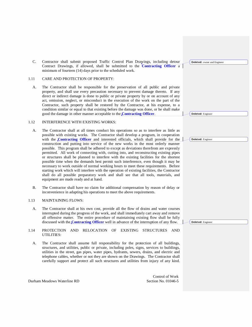
C. Contractor shall submit proposed Traffic Control Plan Drawings, including detourContract Drawings, if allowed, shall be submitted to the Contracting Officer aminimum of fourteen (14) days prior to the scheduled work.
1.11 CARE AND PROTECTION OF PROPERTY:
A. The Contractor shall be responsible for the preservation of all public and privateproperty, and shall use every precaution necessary to prevent damage thereto. If anydirect or indirect damage is done to public or private property by or on account of anyact, omission, neglect, or misconduct in the execution of the work on the part of theContractor, such property shall be restored by the Contractor, at his expense, to acondition similar or equal to that existing before the damage was done, or he shall makegood the damage in other manner acceptable to the Contracting Officer.
1.12 INTERFERENCE WITH EXISTING WORKS:
A. The Contractor shall at all times conduct his operations so as to interfere as little aspossible with existing works. The Contractor shall develop a program, in cooperationwith the Contracting Officer and interested officials, which shall provide for theconstruction and putting into service of the new works in the most orderly mannerpossible. This program shall be adhered to except as deviations therefrom are expresslypermitted. All work of connecting with, cutting into, and reconstructing existing pipesor structures shall be planned to interfere with the existing facilities for the shortestpossible time when the demands best permit such interference, even though it may benecessary to work outside of normal working hours to meet these requirements. Beforestarting work which will interfere with the operation of existing facilities, the Contractorshall do all possible preparatory work and shall see that all tools, materials, andequipment are made ready and at hand.
B. The Contractor shall have no claim for additional compensation by reason of delay orinconvenience in adapting his operations to meet the above requirements.
1.13 MAINTAINING FLOWS:
A. The Contractor shall at his own cost, provide all the flow of drains and water coursesinterrupted during the progress of the work, and shall immediately cart away and removeall offensive matter. The entire procedure of maintaining existing flow shall be fullydiscussed with the Contracting Officer well in advance of the interruption of any flow.
1.14 PROTECTION AND RELOCATION OF EXISTING STRUCTURES ANDUTILITIES:
A. The Contractor shall assume full responsibility for the protection of all buildings,structures, and utilities, public or private, including poles, signs, services to buildings,utilities in the street, gas pipes, water pipes, hydrants, sewers, drains, and electric andtelephone cables, whether or not they are shown on the Drawings. The Contractor shallcarefully support and protect all such structures and utilities from injury of any kind.
Deleted: owner and Engineer
Deleted: Engineer
Deleted: Engineer
Deleted: Engineer
• ·············································r ······
....................................................................... -1
L ................................................................................................................................................... J ... •··· \_ _______ _)
______________________ J

Control of WorkDurham Meadows Waterline RD Section No. 01046-6
Any damage resulting from the Contractor's operations shall be repaired by him at hisexpense.
B. The Contractor shall bear full responsibility for obtaining all locations of undergroundstructures and utilities (including existing water services, drain lines, and sewers).Services to buildings shall be maintained, and all costs or charges resulting from damagethereto shall be paid by the Contractor.
C. Protection and temporary removal and replacement of existing utilities and structures asdescribed in this Section shall be a part of the work under the Contract and all costs inconnection therewith shall be included in the Total Price Bid in the Bid Form.
D. If, in the opinion of the Contracting Officer, permanent relocation of a utility isrequired, he may direct the Contractor, in writing, to perform the work. Work so orderedwill be paid at the Contract unit prices, if applicable, or as extra work under Article 11 ofthe Supplementary Conditions. If relocation of a privately owned utility is required, theContracting Officer will notify the Utility to perform the work as expeditiously aspossible. The Contractor shall fully cooperate with the Contracting Officer and Utility,and shall have no claim for delay due to such relocation. The Contractor shall notify allutility companies in writing at least 72 hours (excluding Saturdays, Sundays, and Legalholidays) before excavating in any public way. Contractor shall also notify Dig Safe,800-922-4455 at least 72 hours prior to start of work.
E. The Contractor shall coordinate the removal and replacement of traffic loops and signals,if required for the performance of the work, at no additional cost.
1.15 INSPECTION OF WORK AWAY FROM THE SITE:
A. If work to be done away from the construction site is to be inspected on behalf of theContracting Officer during its fabrication, manufacture, or testing, or before shipment,the Contractor shall give notice to the Contracting Officer of the place and time wheresuch fabrication, manufacture, testing, or shipping is to be done. Such notice shall be inwriting and delivered to the Contracting Officer in ample time so that the necessaryarrangements for the inspection can be made.
1.16 COOPERATION WITHIN THIS CONTRACT:
A. All firms or persons authorized to perform any work under this Contract shall cooperatewith General Contractor and his Subcontractors or trades, and shall assist inincorporating the work of other trades where necessary or required.
B. Cutting and patching, drilling and fitting shall be carried out where required by the tradeor subcontractor having jurisdiction, unless otherwise indicated herein or recommendedby the Contracting Officer.
Deleted: Engineer
Deleted: Engineer
Deleted: Engineer
Deleted: to the Owner
Deleted: Owner
Deleted: Engineer
Deleted: Engineer
Deleted: Engineer
•-----------------
'f_ _ _ __ _
•-------------------
•-------------------
"- -------------------
~- - ---
' -------------------
' -----------
Control of WorkDurham Meadows Waterline RD Section No. 01046-7
1.17 CLEANUP AND DISPOSAL OF EXCESS MATERIAL:
A. During the course of the work, the Contractor shall keep the site of his operations in asclean and as neat a condition as is possible. He shall dispose of all residue resultingfrom the construction work and, at the conclusion of the work, he shall remove and haulaway any surplus excavation, broken pavement, lumber, equipment, temporarystructures, and any other refuse remaining from the construction operations, and shallleave the entire site of the work in a neat and orderly condition.
B. In order to prevent environmental pollution arising from the construction activitiesrelated to the performance of this Contract, the Contractor and his subcontractors shallcomply with all applicable Federal, State, and local laws, and regulations concerningwaste material disposal, as well as the specific requirements stated in this Section andelsewhere in the Specifications.
C. The Contractor is advised that the disposal of excess excavated material in wetlands,stream corridors, and plains is strictly prohibited even if the permission of the propertyowner is obtained. Any violation of this restriction by the Contractor or any personemployed by him will be brought to the immediate attention of the responsibleregulatory agencies, with a request that appropriate action be taken against the offendingparties. Therefore, the Contractor will be required to remove the fill at his own expenseand restore the area impacted.
PART 2 - PRODUCTS - (Not Used)
PART 3 - EXECUTION - (Not Used)
END OF SECTION
Miscellaneous RequirementsDurham Meadows Waterline RD Section No. 01063-1
SECTION 01063
MISCELLANEOUS REQUIREMENTS
PART 1 - GENERAL
1.01 PROJECT IDENTIFICATION:
A. This project Durham Waterline Remedial Design is part of an agreement reachedbetween the Town of Durham and the U.S. Environmental Protection Agency (EPA) andthe Connecticut Department of Energy and Environmental Protection (CTDEEP) relatedto mitigation of the Durham Meadows Superfund Site.
1.02 SCOPE OF WORK:
B. The Contractor shall conform to all miscellaneous requirements as herein specified.
1.03 SUBMITTALS:
A. Contractor shall submit a Maintenance and Plan of Operation (MAPO) for requirements ofthis section and as specified herein.
B. MAPO shall consist of a proposed sequence of construction and proposed temporaryequipment to be utilized to maintain operation of the force main during construction.
1. Contractor shall develop a detailed narrative to address the following.
a. Sequence of construction, testing, and start-up. Particular attentionshall be paid to ensuring that there is no loss of fire protection forstructures existing fire protection; that loss of water service shall notexceed 2 hours at any time.
b. The plan shall address the Contractor’s approach to minimizingresidence time of the water in the system, with particular attentionpaid to the residence time in the Cherry Hill Storage Tank.
c. The plan shall address work during anticipated periods of hightraffic, including daily as well as annual events, including the DurhamFair.
d. The plan shall include work schedules and proposed detours requiredduring high traffic periods.
2. The MAPO shall include a schedule addressing the above.
C. No site work will be allowed until acceptance of the MAPO by the Contracting Officer.
Deleted: under EPA Task Order No. 0060-RD-RD-01D5
Deleted: narrative describing
Deleted: Engineer" ----------------------------------------------- -- -- ---- ~-----------------~

Miscellaneous RequirementsDurham Meadows Waterline RD Section No. 01063-2
1.04 PROTECTION OF CULTURAL RESOURCES:
A. The EPA has no evidence to suggest that the Durham Meadows Waterline RD projectarea, including the Cherry Hill Tank Site, may contain archaeological sites, humanremains, funerary objects, graves, or any other Native American cultural resources of anykind (collectively, “Cultural Resource(s)”). If previously identified items that may beCultural Resources are discovered during the Work, the Contractor shall immediatelynotify the Contracting Officer, who will in turn immediately notify the EPA. The EPA,in consultation with the Contracting Officer and CTDEEP shall determine whether theWork may reasonably be expected to adversely affect the discovered Cultural Resources.
1. If EPA determines that the Work is reasonably expected to have an adverse effecton the discovered Cultural Resources,a. Work on that portion of the Site will stop immediately, except as may be
required for emergency response, or as deemed necessary by theContracting Officer and the EPA, in consultation with CTDEEP, toprotect public health, safety, or the environment, and
b. No further Work may proceed in the area in question until the EPAdetermines that the Work is not reasonably expected to adversely affectthe discovered Cultural Resources.
2. If and/or when the EPA determines that the Work will not likely have an adverseeffect on Discovered Cultural Resources, the Work may continue.
1.05 GREEN REMEDIATION
A. Contractor shall incorporate EPA Green Remediation practices whenever practical, inaccordance with: http://www2.epa.gov/superfund/superfund-green-remediation
Contractor shall identify Green Remediation practices to be used during completion of thework in his bid and project plans.
1.06 BURIED UTILITY WARNING AND IDENTIFICATION TAPE:
A. Provide warning tape manufactured specifically for warning and identification of buriedpiping. Provide tape in rolls, 6 inches minimum width, color coded for the utilityinvolved with warning and identification imprinted in bold black letters continuously andrepeatedly over entire tape length. Warning and identification shall be CAUTIONBURIED UTILITY PIPING BELOW or similar language. Use permanent code andletter coloring unaffected by moisture and other substances contained in trench backfillmaterial. Bury tape with the printed side up at a depth as indicated in the Drawings.
Deleted: Engineer
Deleted: Engineer
Deleted: Engineer
"'------------------------------------------------------------------------------------------------------------------------------ ------
"'------------------------------------------------------------------------------------------------------------------------------------------------ ------

Miscellaneous RequirementsDurham Meadows Waterline RD Section No. 01063-3
1.07 PROTECTION AGAINST ELECTROLYSIS:
A. Where dissimilar metals are used in conjunction with each other, suitable insulation shallbe provided between adjoining surfaces so as to eliminate direct contact and any resultantelectrolysis. The insulation shall be bituminous impregnated felt, heavy bituminouscoatings, nonmetallic separators or washers, or other acceptable materials.
END OF SECTION
State Regulation RequirementsDurham Meadows Waterline RD Section No. 01070-A2
SECTION 01070
REGULATORY REQUIREMENTS
PART 1 - GENERAL
1.01 CULTURAL RESOURCES:
A. Compliance with the requirements of the National Historic Preservation Act (NHPA)and the Connecticut State Historic Preservation Office (SHPO).
1. During the life of this contract, the Contractor is herewith required to immediatelynotify the Engineer in the event that any articles such as “charcoal”, “bone”,“shell”, “cultural objects – fire cracked stones or stone flaking material” or anyother such related items of historical significance are discovered.
2. No further Work may proceed in the area in question until the EPA determinesthat the Work is not reasonably expected to adversely affect the discoveredCultural Resources.
1.02 DAVIS BACON ACT:
A. The Contract is subject to the Davis Bacon Act (FAR 52.222-6).
B. The Contractor shall certify that he/she will comply with the Act, and the List of WageDeterminations which have been provided in the Contract and future revisions to theWage Determination thereof. (OR will be incorporated in these specifications byaddendum prior to the receipt of bids).
C. During the progress of the work, the Contractor shall, on a weekly basis, submit to theEngineer certified payroll and the U.S. Department of Labor Payroll Form, WH-347, acopy of which is attached to the wage rates schedule.
1.03 NONDISCRIMINATION
A. The Contractor agrees and warrants that in the performance of this contract he will notdiscriminate or permit discrimination against any person or group of persons on thegrounds of race, color, religious creed, age, marital status, national origin, sex, mentalretardation or physical disability, including, but not limited to, blindness, unless it isshown by such contractor that such disability prevents performatnce of the work involvedin any manner prohibited by the laws of the United States or of the State of Connecticut,and further agrees to provide the commission on human rights and opportunities whensuch information requested by the commission concerning the empolyment practices andprocedures of the contractor as related to the provisions of Public Act 78-148.

State Regulation RequirementsDurham Meadows Waterline RD Section No. 01070-A2
B. This contract is subject to the provisions of Executive Order No. Three of GovernorThomas J. Meskill promulgated June 16, 1971 and, as such, this contract may becancelled, terminated or suspended by the State Labor Commissioner for violation of ournoncompliance with said Executive Order No. Three, or any state or federal lawconcerning nondiscrimation, notwithstanding that the Labor Commissioner is not a partyto this contract. The parties to this contract as part of the consideration hereof, agree thatExecutive Order No. Three is incorporated herein by reference and made a part hereof.The parties agree to abide by said Executive Order and agree that the State LaborCommissioner shall have continuing jurisdiction in respect to contract performance inregard to nondiscrimination, until the contract is completed or terminated prior tocompletion. The Governor’s Executive Order No. Three is attached hereto and is herebymade a part of this agreement.
1.04 LISTING ALL EMPLOYMENT OPENINGS:
A. This contract is executed subject to the Governor’s Executive Order No. 17, a copy ofwhich is attached hereto and is hereby made a part of this Agreement. Governor’sExecutive Order No. 17 requires that all contractors and subcontractors shall list allemployment openings with the office of the Connecticut State Employment Service inthe area where the work is to be performed or where the services are to be rendered.Failure of the contractor to conform with the requirements of the Governor’s ExecutiveOrder No. 17 and any orders, rules or regulations issued pursuant thereto, shall be abasis for termination of this Agreement by the State.
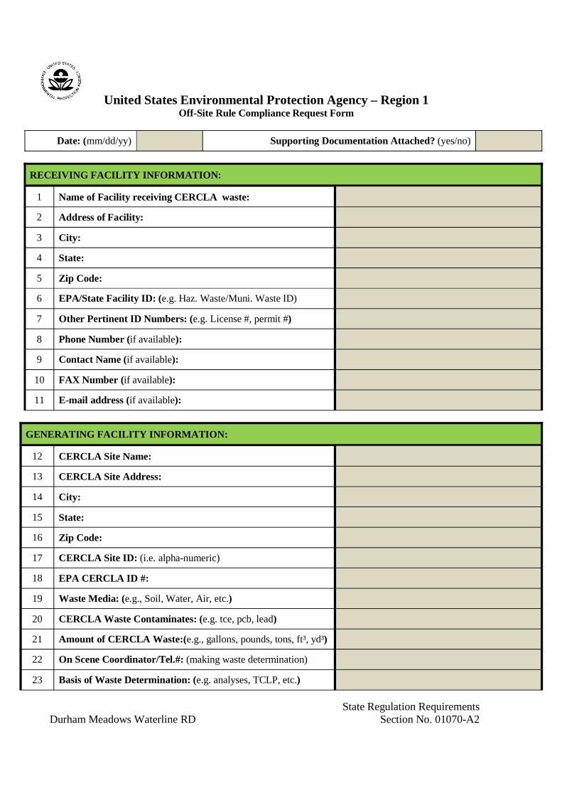
1.05 EPA OFF-SITE RULE
A. Section 121(d)(3) of the Comprehensive Environmental Response, Compensation, andLiability Act (CERCLA) applies to any CERCLA response action involving the off-sitetransfer of any hazardous substance, pollutant or contaminant (CERCLA wastes). Thatsection requires that CERCLA wastes may only be placed in a facility operating incompliance with the Resource Conservation and Recovery Act (RCRA) or otherapplicable Federal or State requirements. That section further prohibits the transfer ofCERCLA wastes to a land disposal facility that is releasing contaminants into theenvironment, and requires that any releases from other waste management units must becontrolled. These principles are interpreted in the Off-Site Rule (OSR), set forth in theNational Contingency Plan (NCP), at 40 CFR 300.440. The purpose of the OSR is toavoid having CERCLA wastes from response actions authorized or funded underCERCLA contribute to present or future environmental problems by directing thesewastes to management units determined to be environmentally sound (preamble to finalOSR, 58 FR 49200, 49201, Sept. 22, 1993).
B. The OSR establishes the criteria and procedures for determining whether facilities areacceptable for the receipt of CERCLA wastes from response actions authorized orfunded under CERCLA. The OSR establishes compliance criteria and release criteria,and establishes a process for determining whether facilities are acceptable based onthose criteria. The OSR also establishes procedures for notification of unacceptability,
State Regulation RequirementsDurham Meadows Waterline RD Section No. 01070-A2
reconsideration of unacceptability determinations, and re-evaluation of unacceptabilitydeterminations.
C. Contractor may ship hazardous substances, pollutants, and contaminants from the Siteto an off-Site facility only if they comply with Section 121(d)(3) of CERCLA,42 U.S.C. § 9621(d)(3), and 40 C.F.R. § 300.440. Contractor will be deemed to be incompliance with CERCLA § 121(d)(3) and 40 C.F.R. § 300.440 regarding a shipment ifcontractor obtain a prior determination from EPA that the proposed receiving facilityfor such shipment is acceptable under the criteria of 40 C.F.R. § 300.440(b). Allrequests shall be made using the EPA Off-Site Compliance Request Form, included asAttachment 3.
D. Contractor may ship Waste Material from the Site to an out-of-state waste managementfacility only if, prior to any shipment, they provide notice to the appropriate stateenvironmental official in the receiving facility’s state and to the EPA. This noticerequirement will not apply to any off-Site shipments when the total quantity of all suchshipments does not exceed 10 cubic yards. The notice must include the followinginformation, if available: (1) the name and location of the receiving facility; (2) the typeand quantity of Waste Material to be shipped; (3) the schedule for the shipment; and(4) the method of transportation. Contractor also shall notify the state environmentalofficial referenced above and the EPA of any major changes in the shipment plan, suchas a decision to ship the Waste Material to a different out-of-state facility. Contractorshall provide the notice to EPA at least 60 days prior to the date when Waste Material isscheduled to be shipped.
E. Contractor may ship contaminated soil or Investigation Derived Waste (IDW) from theSite to an off-Site facility only if they comply with Section 121(d)(3) of CERCLA, 42U.S.C. § 9621(d)(3), 40 C.F.R. § 300.440, EPA’s Guide to Management ofInvestigation Derived Waste, OSWER 9345.3-03FS (Jan. 1992), and any IDW-specificrequirements contained in the Durham Meadows Record of Decision. Wastes shippedoff-Site to a laboratory for characterization, and RCRA hazardous wastes that meet therequirements for an exemption from RCRA under 40 CFR § 261.4(e) shipped off-sitefor treatability studies, are not subject to 40 C.F.R. § 300.440.
F. The property at 201/203 Main Street in Durham, Connecticut, as designated on thedrawings, shall be considered the Site, for the purpose of this Contract.
1.06 PERMITS:
A. Under the NCP Section 300.400(e)(1), CERCLA Section 121 (e) (1), and per the Officeof Solid Waste Emergency Response (OSWER) Directive 9355.7-03, no federal, stateor local permits are required for a Superfund remediation for the work done entirely on-site; however, the work still has to meet the substantive requirements of any applicableor relevant and appropriate permits. Section 300.400(e)(1) of the NCP clarifies that thisrule applies to all of the work conducted inside the area defined as the Superfund Site,defined for the purpose of this Contract as the area within the Town of Durham,Connecticut to receive water service connections. This exemption does not apply to the
State Regulation RequirementsDurham Meadows Waterline RD Section No. 01070-A2
project site outside of this area. This requirement does not relieve the Contractor frommeeting the substantive requirements of all applicable permits.
B. All relevant permits outside of the Superfund Site area shall be secured by theContractor. The Contractor shall coordinate with all applicable entities to meetpermitting requirements, including but not limited to Federal and State agencies, theTown of Durham, and the City of Middletown.
C. Relevant permits that have been obtained by others with their expiration dates areincluded in Table 01070-1 in Attachment 4. The Contractor shall be responsiblefor renewing required permits that expire prior to completion of the work.
END OF SECTION(Attachments – additional pages to follow)

Regulatory RequirementsDurham Meadows Waterline RD Section No. 01070-A1
ATTACHMENT 1 TO SECTION 01070
PREVAILING WAGE RATE SCHEDULE(To be included at time of bidding)

State Regulation RequirementsDurham Meadows Waterline RD Section No. 01070-A2
ATTACHMENT 2 TO SECTION 01070
EXECUTIVE ORDERS #3 AND #17

STATE OF CONNECTICUT
BY HIS EXCELLENCY
DANNEL P. MALLOY
EXECUTIVE ORDER NO. 3
WHEREAS, the temporary worker retiree program ( TWR ), codified in Sec. 5-164a of theConnecticut General Statutes, as amended by the Pension Award, and administered by theDepartment of Administrative Services, provides for temporary employment of state retirees forperiods not to exceed 120 days per calendar year in cases where such employment is costeffective and facilitates the maintenance of important programs or services;
WHEREAS, the legislature has recognized the value of employing retired state employees for alimited number of days to provide institutional expertise;
WHEREAS, the State will begin a period of transition beginning on January 5, 2011 due to achange of administration;
WHEREAS, the maintenance and effective functioning of state services during a time oftransition is in the public interest;
WHEREAS, the TWR program aids state agencies in maintaining a proficient and efficientworkforce during a period of transition;
WHEREAS, certain efficiencies and budgetary savings can be realized from the practice ofemploying retired state employees when managed appropriately; and
WHEREAS, Executive Order 27-A, dated October 22, 2009, limited the parameters for approvalof an individual under the TWR program;
NOW, THEREFORE, I, DANNEL P. MALLOY, Governor of the State of Connecticut, byvirtue of the authority vested in me by the Constitution and by the Statutes of the State ofConnecticut, ORDER AND DIRECT:
1. Nothing in Executive Order 27-A, dated October 22, 2009 shall prevent a member of thestate retirement system who has twice prior been approved for and took part in the TWRprogram and who is otherwise eligible to take part in such program from being approvedfor participation during the first year of a new administration ifreemployment does not exceed sixty days.
2. The provisions of this order shall apply to any new or renewed employment that iseffective on or after the effective date of this order.
3. Executive Order 27-A, dated October 22, 2009, is hereby amended with the text hereof.
This order shall take effect immediately.
Dated at Hartford, Connecticut this 5th day of January 2011.
_____________________________________
DANNEL P. MALLOYGovernor
such member's

By Her
_____________________________________
Denise MerrillSecretary of the State
Excellency's Order

STATE OF CONNECTICUT
BY HIS EXCELLENCY
DANNEL P. MALLOY
EXECUTIVE ORDER NO. 17
:,c:CKtlA!l.'I OF.HiE SlA> 1
CAPITOL OFFICE
)OllJAN 12 AH II: 52 1ft(l, W
WHEREAS, this administration is connnitted to promoting the overall economic development of the state, creating more job opportunities, enhancing the state's economic development tools, and encouraging innovation and entrepreneurship;
WHEREAS, the success of the 2011 Governor's Economic Summit and the October special
session on job creation marked a new beginning in making Connecticut more competitive, including passage of the watershed An Act Promoting Economic Growth and Job Creation in the State;
WHEREAS, it is critical to build on this success and continue to focus on the inter-relationship between economic, fiscal, and tax policy;
WHEREAS, while Connecticut's total effective business tax burden is the lowest in the nation, we must continue to evaluate and improve the state's business tax policy, which is vital to assuring a positive environment for business development and job growth;
WHEREAS, in this current economic climate it is particularly appropriate to evaluate all of the state's economic development tax credit programs to ensure that such programs are effective,
utilized properly and are a worthwhile use of the Connecticut tax payer's money;
NOW, THEREFORE, I, DANNEL P. MALLOY, Governor of the State of Connecticut, by virtue of the power and authority vested in me by the Constitution and by the Statutes of the State of Connecticut do hereby ORDER AND DIRECT:
1. There is hereby established a Governor's Business Tax Policy Review Taskforce. The
Taskforce shall consist of 9 members appointed as follows:
a. The Commissioners of the Departments of Revenue Services and Economic and Community Development, who shall serve as co-chairs;
b. Three members appointed by the Governor who shall have expertise in issues related to business growth, tax policy and/or municipal economic development;
c. The Commissioner of the Department of Labor, or the Commissioner's designee;
and
d. The Secretary of the Office of Policy and Management, or the Secretary's
designee; and
e. The Treasurer and the Comptroller, or their designees.
2. The Taskforce shall, with staff support from the Departments of Revenue Services and Economic and Community Development and the Office of Policy and Management:
a. establish a work plan identifying specific business tax areas and other issues, including business tax credits or other targeted business tax relief, that should be the focus of
future legislation and/or state economic policy;
b. evaluate the cost, benefit, efficiency, effectiveness and measurable performance of the current business tax credit structure with respect to economic development, business retention and growth, and employment retention and growth; and
c. report its findings and recommendations to the Governor no later than October I,
2012.

3. All members of the Taskforce shall serve coterminously with and at the pleasure of the appointing authority.
4. A majority of the members of the Taskforce shall constitute a quorum.
5. Meetings of the Taskforce shall be scheduled and convened jointly by the co-chairs of the Taskforce or upon majority vote of the membership.
This Order shall take effect immediately.
Dated at Hartford, Connecticut, this \"1.,, day of January 2012.
By His Excellency's Order
Denise Merrill Secretary of the State
Governor

State Regulation RequirementsDurham Meadows Waterline RD Section No. 01070-A2
ATTACHMENT 3 TO SECTION 01070
OFF-SITE RULE COMPLIANCE REQUEST FORM
State Regulation RequirementsDurham Meadows Waterline RD Section No. 01070-A2
United States Environmental Protection Agency – Region 1Off-Site Rule Compliance Request Form
Date: (mm/dd/yy) Supporting Documentation Attached? (yes/no)
RECEIVING FACILITY INFORMATION:
1 Name of Facility receiving CERCLA waste:
2 Address of Facility:
3 City:
4 State:
5 Zip Code:
6 EPA/State Facility ID: (e.g. Haz. Waste/Muni. Waste ID)
7 Other Pertinent ID Numbers: (e.g. License #, permit #)
8 Phone Number (if available):
9 Contact Name (if available):
10 FAX Number (if available):
11 E-mail address (if available):
GENERATING FACILITY INFORMATION:
12 CERCLA Site Name:
13 CERCLA Site Address:
14 City:
15 State:
16 Zip Code:
17 CERCLA Site ID: (i.e. alpha-numeric)
18 EPA CERCLA ID #:
19 Waste Media: (e.g., Soil, Water, Air, etc.)
20 CERCLA Waste Contaminates: (e.g. tce, pcb, lead)
21 Amount of CERCLA Waste:(e.g., gallons, pounds, tons, ft³, yd³)
22 On Scene Coordinator/Tel.#: (making waste determination)
23 Basis of Waste Determination: (e.g. analyses, TCLP, etc.)

Table 01710-1 PermitsPermit Agency Permit or Regulatory
AgreementPermit Number (if applicable)
Expiration Date(if applicable)
Connecticut Department ofEnergy and EnvironmentalProtection (CT DEEP)
General Permit for Diversionof Water for ConsumptiveUse
DIVC-201702168GP
January 17, 2027
Connecticut Department ofPublic Health (CT DPH)
Approval for Construction orInstallation of Water andTreatment Works
PWS ID:CT0830011DPH Project #:2016-0084
Issued 2/15/2018. Void12 months after issuanceif construction has notstarted (2/15/19).
Connecticut Department ofPublic Health (CT DPH)
Authorization of Sale ofExcess Water Permit
SEW2016-03R July 11, 2026
City of MiddletownInland Wetlands andWatercourses Agency
Inland Wetland andWatercourses Permit:Talcott Ridge Drive
16-23 January 4, 2022
City of MiddletownInland Wetlands andWatercourses Agency
Inland Wetland andWatercourses Permit:32/0048 and 32/0008
17-20 November 1, 2022
City of MiddletownPlanning and ZoningCommission
Site Plan Review forconstruction of a storage tank32/0069
SPR2017-265 N/A
City of MiddletownPlanning and ZoningCommission
Special Exception PublicUtilities for Tank Parcel onTalcott Ridge Road
SE2017-9 N/A
City of MiddletownPlanning and ZoningCommission
Special Exception PublicUtilities for construction of aBooster/Pump Station
SE2017-10 N/A
City of MiddletownPlanning and ZoningCommission
Special Exception toconstruct a Meter Vault
SE2017-11 N/A
City of MiddletownPlanning and ZoningCommission
Affirmative G.S 8-24 Reviewfor Durham Water Lineproject
G.S. 8-24 2017-18 N/A

Environmental Protection ProceduresDurham Meadows Waterline RD Section No. 01110-1
SECTION 01110
ENVIRONMENTAL PROTECTION PROCEDURES
PART 1 - GENERAL
1.01 SCOPE OF WORK:
A. The work covered by this Section consists of furnishing all labor materials and equipmentand performing all work required for the prevention of environmental pollution inconformance with applicable laws and regulations, and employ Green Remediation BestManagement Practices (BMPs) (EPA 542-F-13-003, 2013) whenever possible during andas the result of construction operations under this Contract. For the purpose of thisSpecification, environmental pollution is defined as the presence of chemical, physical, orbiological elements or agents which adversely affect human health or welfare;unfavorably alter ecological balances of importance to human life; affect other species ofimportance to man; or degrade the utility of the environment for aesthetic and/orrecreational purposes.
B. The control of environmental pollution requires consideration of air, water, and land, andinvolves management of noise and solid waste, as well as other pollutants.
C. The Contractor shall immediately address any event that occurs during the performance ofthe Work that causes or threatens to cause a spill or release of Waste Material on, at, orfrom the Site.
D. Schedule and conduct all work in a manner that will minimize the erosion of soils in thearea of the work. Provide erosion control measures such as diversion channels,sedimentation or filtration systems, berms, staked hay bales, seeding, mulching, or otherspecial surface treatments as are required to prevent silting and muddying of streams,rivers, impoundments, lakes, etc. All erosion control measures shall be in place in an areaprior to any construction activity in that area. Specific requirements for erosion andsedimentation controls are specified in Section 01568.
E. These Specifications are intended to ensure that construction is achieved with a minimumof disturbance to the existing ecological balance between a water resource and itssurroundings. These are general guidelines. It is the Contractor's responsibility todetermine the specific construction techniques to meet these guidelines.
F. All phases of sedimentation and erosion control shall comply with and be subject to theapproval of the Connecticut Department of Energy and Environmental Protection andlocal Conservation Commission.

Environmental Protection ProceduresDurham Meadows Waterline RD Section No. 01110-2
G. Schedule and conduct all work in a manner that will minimize the level of noise escapingthe site, especially at night and on weekends.
1.02 DEFINITIONS
A. Dewatering Water is defined as shallow groundwater or runoff removing duringtrenching activities. Contamination other than sediment is not anticipated.
B. Construction Water shall be defined as water that may be impacted withcontaminants from the Durham Superfund Site, and is defined as the following:
1. Water that is collected from water supply wells that are being abandoned.
2. Water removing during trenching activities in designated areas on the DurhamManufacturing Company property.
3. Liquids generated during decontamination activities associated with the aboveactivities.
1.03 APPLICABLE REGULATIONS:
A. Comply with all applicable Federal, State, and local laws and regulations concerningenvironmental pollution control and abatement.
1.04 NOTIFICATIONS:
A. The Engineer will notify the Contractor in writing of any non-compliance with theforegoing provisions or of any environmentally objectionable acts and corrective action tobe taken. State or local agencies responsible for verification of certain aspects of theenvironmental protection requirements shall notify the Contractor in writing, through theEngineer, of any non-compliance with State or local requirements. The Contractor shall,after receipt of such notice from the Engineer or from the regulatory agency through theEngineer, immediately take corrective action. Such notice, when delivered to theContractor or his authorized representative at the site of the work, shall be deemedsufficient for the purpose. If the Contractor fails or refuses to comply promptly, theContracting Officer may issue an order stopping all or part of the work until satisfactorycorrective action has been taken. No part of the time lost due to any such stop orders shallbe made the subject of a claim for extension of time or for excess costs or damages by theContractor unless it is later determined that the Contractor was in compliance.
1.05 IMPLEMENTATION:
Deleted: Owner,: ___________________________________________________________________________________________________________________________________________________________________________ ..... •····~----~

Environmental Protection ProceduresDurham Meadows Waterline RD Section No. 01110-3
A. Prior to commencement of the work, meet with the Engineer to develop mutualunderstandings relative to compliance with this provision and administration of theenvironmental pollution control program.
B. Remove temporary environmental control features, when approved by the Engineer, andincorporate permanent control features into the project at the earliest practicable time.
PART 2 - PRODUCTS (NOT USED)
PART 3 - EXECUTION
3.01 EROSION CONTROL:
A. Provide positive means of erosion control such as shallow ditches around construction tocarry off surface water. Erosion control measures such as siltation basins, hay checkdams, mulching, jute netting, and other equivalent techniques shall be used as appropriate.Offsite surface water shall be diverted around the site to a downstream channel ahead ofsiltation barriers. Flow of surface water into excavated areas shall be prevented. Ditchesaround construction area shall also be used to carry away water resulting from dewateringof excavated areas. At the completion of the work, ditches shall be backfilled and theground surface restored to original condition.
3.02 PROTECTION OF STREAMS, WETLANDS, AND SURFACE WATER:
A. Care shall be taken to prevent or reduce to a minimum any damage to any stream,drainage ditch, storm drain of sewer from pollution by debris, sediment, or other material,or from the manipulation of equipment and/or materials in or near such streams. Waterthat has been used for washing or processing, or that contains oils or sediments that willreduce the quality of the water in the stream, shall not be directly returned to the stream.Such water will be diverted through a settling basin or filter before being directed into thestreams.
B. The Contractor shall not discharge water from dewatering operations directly into any liveor intermittent stream, channel, wetlands, surface water, or any storm sewer. Water fromdewatering operations shall be treated by filtration, settling basins, or other approvedmethod to reduce the amount of sediment contained in the water to allowable levels.
C. All preventative measures shall be taken to avoid spillage of petroleum products and otherpollutants. In the event of any spillage, prompt remedial action shall be taken inaccordance with a contingency action drawing or plan approved by the ConnecticutDepartment of Energy and Environmental Protection. Contractor shall submit to copies ofapproved contingency drawings or plans to the Engineer.
3.03 PROTECTION OF LAND RESOURCES:
Environmental Protection ProceduresDurham Meadows Waterline RD Section No. 01110-4
A. Land resources within the project boundaries and outside the limits of permanent workshall be restored to a condition, after completion of construction that will appear to benatural and not detract from the appearance of the project. Confine all constructionactivities to areas shown on the Drawings.
B. Outside of areas requiring earthwork for the construction of the new facilities, theContractor shall not deface, injure, or destroy trees or shrubs, nor remove or cut themwithout prior approval. No ropes, cables, or guys shall be fastened to or attached to anyexisting nearby trees for anchorage unless specifically authorized by the Engineer. Wheresuch special emergency use is permitted, first wrap the trunk with a sufficient thickness ofburlap or rags over which softwood cleats shall be tied before any rope, cable, or wire isplaced. The Contractor shall in any event be responsible for any damage resulting fromsuch use.
C. Where trees may possibly be defaced, bruised, injured, or otherwise damaged by theContractor's equipment, dumping or other operations, protect such trees by placing boards,planks, or poles around them. Monuments and markers shall be protected similarly beforebeginning operations near them.
D. Any trees or other landscape feature scarred or damaged by the Contractor's equipment oroperations shall be restored as nearly as possible to its original condition. The Engineerwill decide what method of restoration shall be used and whether damaged trees shall betreated and healed or removed and disposed of.
All scars made on trees by equipment, construction operations, or by the removal of limbslarger than 1-in. in diameter shall be coated as soon as possible with an approved treewound dressing. All trimming or pruning shall be performed in an approved manner byexperienced workmen with saws or pruning shears. Tree trimming with axes will not bepermitted.
Climbing ropes shall be used where necessary for safety. Trees that are to remain, eitherwithin or outside established clearing limits, that are subsequently damaged by theContractor and are beyond saving in the opinion of the Engineer, shall be immediatelyremoved or replaced.
E. The locations of the Contractor's storage, and other construction building, requiredtemporarily in the performance of the work, shall be cleared portions of the job site orareas to be cleared as shown on the Drawings and shall require written approval of theEngineer and shall not be within wetlands or floodplains. The preservation of thelandscape shall be an imperative consideration in the selection of all sites and in theconstruction of buildings. Drawings showing storage facilities shall be submitted forapproval of the Engineer.

Environmental Protection ProceduresDurham Meadows Waterline RD Section No. 01110-5
F. Remove all signs of temporary construction facilities such as haul roads, work areas,structures, foundations of temporary structures, stockpiles of excess of waste materials, orany other vestiges of construction as directed by the Engineer. It is anticipated thatexcavation, filling, and plowing of roadways will be required to restore the area to nearnatural conditions which will permit the growth of vegetation thereon. The disturbedareas shall be prepared and seeded as described in Section 01568, or as approved by theEngineer.
G. All debris and excess material will be disposed of outside wetland or floodplain areas inan environmentally sound manner.
3.04 PROTECTION OF AIR QUALITY:
A. Burning. The use of burning at the project site for the disposal of refuse and debris willnot be permitted.
B. Dust Control. The Contractor will be required to maintain all excavations, embankments,stockpiles, access roads, plant sites, waste areas, borrow areas, and all other work areaswithin or without the project boundaries free from dust which could cause the standardsfor air pollution to be exceeded, and which would cause a hazard or nuisance to others.
C. An approved method of stabilization consisting of sprinkling or other similar methods willbe permitted to control dust. The use of chlorides may be permitted with approval fromthe Engineer.
D. Sprinkling, to be approved, must be repeated at such intervals as to keep all parts of thedisturbed area at least damp at all times, and the Contractor must have sufficientcompetent equipment on the job to accomplish this if sprinkling is used. Dust controlshall be performed as the work proceeds and whenever a dust nuisance or hazard occurs,as determined by the Engineer.
E. The Contractor shall employ BMPs to minimize, and when possible eliminate, theproduction of Green House Gas (GHGs) emissions. Requirements include use of solar-power generators; selection of lower GHG emitting fuel sources (e.g., biodiesel) for smallequipment and trucks.
F. Restrict idling whenever possible.
G. Employ energy conservation and efficiency approaches, including use of Energy Starequipment and renewable forms of energy to the maximum extent possible.
H. Obtain materials, including backfill, and from local sources to the maximum extentpossible. Choose suppliers with production and distribution centers near the work area tominimize fuel consumption associated with delivery.

Environmental Protection ProceduresDurham Meadows Waterline RD Section No. 01110-6
3.05 MAINTENANCE OF POLLUTION CONTROL FACILITIES DURINGCONSTRUCTION:
A. During the life of this Contract, maintain all facilities constructed for pollution control aslong as the operations creating the particular pollutant are being carried out or until thematerial concerned has become stabilized to the extent that pollution is no longer beingcreated.
3.06 SPILL PREVENTION
A. The Contractor shall adhere to the requirements of the Spill Prevention Plan, prepared inaccordance with Section 01120.
3.07 EMERGENCY RESPONSE AND REPORTING
A. If any event occurs during performance of the Work that causes or threatens to cause arelease of Waste Material on, at, or from the Site and that either constitutes an emergencysituation or that may present an immediate threat to public health or welfare or theenvironment, the Contractor shall: (1) immediately take all appropriate action to prevent,abate, or minimize such release or threat of release; (2) immediately notify theContracting Officer orally; and (3) take such actions in consultation with theContracting Officer and the Engineer in accordance with all applicable provisions of theHealth and Safety Plan, the Emergency Response Plan, and any other deliverableapproved under the contract.
B. Upon the occurrence of any event during performance of the Work that contractor isrequired to report pursuant to Section 103 of CERCLA, 42 U.S.C. § 9603, or Section 304of the Emergency Planning and Community Right-to-know Act (EPCRA), 42 U.S.C. §11004, contractor shall immediately notify the authorized Contracting Officer orally.The contractor shall: (1) within [14] days after the onset of such event, submit a report toContracting Officer describing the actions or events that occurred and the measurestaken, and to be taken, in response thereto; and (2) within 30 days after the conclusion ofsuch event, submit a report to Contracting Officer describing all actions taken inresponse to such event. These reporting requirements are in addition to the reportingrequired by CERCLA § 103 or EPCRA § 304.
3.08 WASTE MINIMIZATION
A. Recycle or reuse uncontaminated materials removed from the work area to the greatestextent possible. When disposal is required, select a landfill that collects methane.
Deleted: Owner
Deleted: and the Engineer
Deleted: Owner
Deleted: Owner
Deleted: and the Engineer
Deleted: Owner
Deleted: Owner
'!: ----------------------------------------------------------------------------------------------------------------------------------------------------------------------------
_______ ____________ ____________ _______ y_
"----------------------------------------------------------------------------------------------------------------------------------------------------------------------------------

Environmental Protection ProceduresDurham Meadows Waterline RD Section No. 01110-7
3.09 NOISE CONTROL:
A. The Contractor shall make every effort to minimize noises caused by his operations.Equipment shall be equipped with silencers or mufflers designed to operate with the leastpossible noise in compliance with State and Federal (OSHA) regulations.
B. Contractor shall also be bound by local regulations governing noise limitations.Contractor shall pay particular attention to these regulations and obtain pertinentapprovals (as necessary) during excavation operations.
END OF SECTION

Environmental Protection ProceduresDurham Meadows Waterline RD Section No. 01110-8

Durham Meadows Waterline RD Safety and Health ProgramSection No. 01120-1
SECTION 01120SAFETY AND HEALTH PROGRAM
PART 1 GENERAL
1.01 SECTION INCLUDES
Contractor’s minimum requirements for preparing, submitting and implementing a safety andhealth program at the work site. Contractor’s program shall address the requirements of OSHAregulation 29 CFR 1926 “Safety and Health Regulations for Construction and the requirements ofOSHA 29 CFR 1910.120 “Hazardous Waste Operations and Emergency Response” for workinvolving contact or potential contact with contaminated soil or groundwater.
1.02 GENERAL SPECIFICATIONS
A. At a minimum the Contractor must at all times comply with applicable laws andregulation of any public body having jurisdiction for the safety of persons or property.Requirements in this document are in addition to or an amplification of procedures andrequirements of the referenced regulations and documents.
B. The Contractor must fully adhere to any additional requirements of the ContractingOfficer’s Safety, Health and Environmental Policies and Plans including those instanceswhere they are more stringent than related governing regulations such as but not limitedto, OSHA, EPA or DOT.
C. The Contractor shall initiate, maintain and constantly supervise safety precautions andprograms in connection with the work. Take necessary precautions for safety ofContractor employees, Subcontractors, and other persons and organizations that may beaffected by the implementation of the work, continuously enforce health and safetyrequirements, and take all necessary safety precautions.
D. Contractor shall implement procedures for the protection of personnel working on theSite from in areas where exposure to on-site contaminants could occur, includingpreparing, submitting, and implementing a site-specific health and safety plan (SSHP) toprotect personnel working on the Site from exposure to on-site contaminants generated orreleased as a result of the Contractor's work on-site.
E. The Contractor is responsible for providing the Contracting Officer with a copy of theirproject-specific Safety, Health and Environment documentation.
F. The Contractor shall provide proof of safety training and current certification as requiredfor the hazards identified, inclusive of any required medical surveillance documentation.
G. If at any time the Contractor obtains the services of a lower-tier subcontractor orconsultant for any portion of the work performed a copy of the Subcontractor’sscope of work and approved project-specific SH&E documentation shall beprovided to the Contracting Officer. Subcontractors and consultants shall fullycomply with the Contractor’s contractual obligations to the Contracting Officer.
Deleted: Engineer
Deleted: AECOM
Deleted: AECOM
Deleted: AECOM
" ------------
._ __
"-----------------
'f __ _

Durham Meadows Waterline RD Safety and Health ProgramSection No. 01120-2
1.03 DEFINITIONS
A. Safety staff shall mean the Safety Professional and his/her Safety Representative(s).
B. Competent Person, as defined by OSHA means one who is capable of identifying existingand predictable hazards in the surroundings or working conditions which are unsanitary,hazardous, or dangerous to employees, and who has authorization to take promptcorrective measures to eliminate them.
C. Qualified Person, as defined by OSHA means one who, by possession of a recognizeddegree, certificate, or professional standing, or who by extensive knowledge, training andexperience, has successfully demonstrated his/her ability to solve or resolve problemsrelating to the subject matter, the work, or the project.
1.04 GENERAL REQUIREMENTS
A. Contractors are responsible for safely performing their SOW in accordance with all applicablefederal and state/provincial/territorial regulations, acts, and codes, industry standards andcontractual requirements.
B. The Contractor shall be responsible for the safety of the Contractor's employees, the public andall other persons at or about the site of the work. The Contractor shall be solely responsible forthe adequacy and safety of all construction methods, materials, equipment and the safeprosecution of the work.
C. The Contractor shall immediately notify the Contracting Officer whenever they are contactedby a local, state, or federal regulatory agency concerning any aspect of the job or are present toconduct an inspection or visit.
D. The Contractor shall employ a Certified Safety Professional (CSP) familiar with all workunder this contract whose duties shall be to initiate, review and cause implementation of measuresfor the protection of health and prevention of accidents. The Contractor shall also employ full-time Safety Representative(s) whose duties shall be to work under the direct supervision of theSafety Professional, to implement the safety program for work under this Contract.
E. The Certified Safety Professional and his/her Safety Representatives shall be experienced withand knowledgeable of all applicable health and safety requirements of all governing laws, rulesand regulations as well as of best safety practice and shall ensure compliance with them.
F. The Contractor shall immediately stop work whenever a work procedure or a condition at awork site is deemed unsafe by the Contractor or the Contractor’s Safety Staff. If theContracting Officer stops the Contractor’s work for a health and safety related issue, theContracting Officer shall not be responsible for Contractor’s damages due to any resultingdelays.
G. The Contractor shall effectively implement a Disciplinary policy with a clear graduated systemof enforcement and follow-up inspections for non-compliance issues.
H. The Contractor shall be responsible for communicating and flowing-down all requirements inthis document to any subcontractor or subconsultant the Contractor hires.
Deleted: Engineer
Deleted: Engineer
Deleted: EngineerT ____ _

Durham Meadows Waterline RD Safety and Health ProgramSection No. 01120-3
I. The Safety Staff shall be provided with an appropriate office space on the job siteto maintain and keep available safety records, up-to-date copies of all pertinent safety rules,regulations and governing legislation, material safety data sheets, the Contractor’s Health andSafety Policies, and the site Construction Health and Safety Plan including informationconcerning foreseeable emergency conditions, location of emergency and telephone contacts forsupportive actions and federal, state and local postings.
J. The Safety Representative shall maintain files for of all safety related records associated withthe project for the duration of the project. Files shall be stored on-site, in an orderly fashion sothey are readily available to the Contracting Officer upon request. No safety related files maybe discarded without notification and written acceptance of the Contracting Officer.
K. It is anticipated that workers likely to be exposed to Oil and\or Hazardous materials associatedwith the Site during the execution of work will be the workers conducting trench and installingpipe at the Durham Manufacturing Company, located at 201 Main Street, and the Driller, whowill be responsible for potable well abandonment. Contamination is not known to be present inother areas of the work site; however, it is the responsibility of the Contractor to assess workingconditions throughout the project site. All workers involved in activities where contaminants areknown to be present will be expected to follow all the requirements of the C-HASP, in addition tomeeting the following requirements:
All project activities shall be conducted in accordance with OSHA standards (29 CFR1910), which specify training, medical monitoring, and use of personal protectiveequipment.
The Contractor and its subcontractors, as applicable, shall prepare a Site-Specific Healthand Safety Plan (SSHP) that will meet all OSHA and other applicable requirements. TheSSHP shall be for all of the work to be performed by the Subcontractor and shall befurnished to the Contracting Officer along with the C-HASP.
All Contractor personnel and their subcontractors shall meet the requirements of 29 CFR1910.120, Hazardous Waste Operations and Emergency Response and all otherapplicable regulations when working in areas of known contamination.
The Contractor shall provide all necessary personnel protective equipment (PPE) for itsworkers.
The Contractor shall provide certification of 40-hour OSHA Health and Safety Training,Emergency Response Training and Medical Surveillance for all their workers andsubcontractors who will be performing work in areas of known contamination, inaccordance with the provisions of 29 CFR 1910.120.
The Contractor and its subcontractors shall provide personal protection equipment asrequired for all workers on the Site, as appropriate for the work task.
The Contractor and its subcontractors and its subcontractors shall perform the Work inaccordance with all applicable federal, state, and local regulations, laws, codes, andordinances including:
Deleted: Engineer
Deleted: Engineer
Deleted: Engineer
• ------------------------------------------------------------------------------------------------------------------------------ :o=======<
'f ____ _
Durham Meadows Waterline RD Safety and Health ProgramSection No. 01120-4
1. Occupational Safety and Health Administration (OSHA) regulations:
29 CFR, Part 1094, Recording and Reporting Occupational Injuries andIllnesses,29 CFR, Part 1910,29 CFR, Part 1926.
2. Title 40, Code of Federal Regulations (CFR).
3. Federal Resource Conservation and Recovery Act, as amended.
4. Other federal, state, and/or local regulations and statutes as applicable.
The Contractor and its subcontractors shall abide by the provisions of the SSHP andcomply with all applicable federal, state, and local regulations pertaining to health andsafety.
1.06 SITE INFORMATION
A. Soil and Groundwater Contamination
While most of the work will occur within the public roadways or other areas outside of theDurham Meadows Superfund Site source areas, installation of a water service connection to theDurham Manufacturing Company at 201 and 203 Main Street will involved trenching in an areaof known contamination. Known site soil and groundwater contaminants in the work area, asshown on Contracto Drawing C-21, include volatile organic compounds (VOCs), particularlyTCE, PCE, methylene chloride. Additionally, well abandonment throughout the project area willinvolve potential contact with groundwater contaminated with VOCs. A summary of Sitecontamination is included in Appendix D of this specification.
1.05 SAFETY STAFF MINIMUM QUALIFICATIONS
A. Certified Safety Professional
Recognition as a safety professional shall be based on a minimum of certification as a CertifiedSafety Professional (CSP) granted by the Board of Certified Safety Professionals and 5 years ofdocumented professional safety and health management experience or certification as a CertifiedIndustrial Hygienist granted by American Board of Industrial Hygiene and 5 years of documentedprofessional safety and health management experience and a Master of Science degree in safety,industrial hygiene, occupational safety and health, environmental health and science and 5 yearsof documented professional safety and health management experience. All documentedprofessional safety and health management experience must be in the types of construction andconditions expected to be encountered on the site.
B. Safety Representative
The Contractor must identify and assign a Safety Representative for the project. That individualmust be responsible to the Contractor and have the authority and knowledge necessary toimplement the SSHP and verify compliance with applicable safety and health requirements.

Durham Meadows Waterline RD Safety and Health ProgramSection No. 01120-5
1.06 SAFETY STAFF GENERAL DUTIES
A. The Contractor shall have a Safety Professional or his trained Safety Representative active onthe job at all times while work is in progress, shall have a documented safety and health program.
C. The Safety Representative must be at the job site full time whenever work is in progress.When multiple shift work is in progress a Safety Representative will be required for each shift.
D. The Contractor shall ensure any OSHA Competent Persons and any OSHA Qualified Person isphysically present at the work site whenever work activities require their presence.
E. The Safety Representative and the Certified Safety Professional shall make themselvesavailable to the Contracting Officer as necessary.
F. Job Site Safety and Health Inspections:
1. The Safety Representative shall at a minimum conduct daily job site safety and healthinspections during periods of work activity. All non-compliance issues shall beimmediately corrected. A written daily inspection report shall include date and time ofthe inspection, locations inspected, those hazards and violations discovered during thesite visit, the corrective actions taken, name of the individual assigned to correct the non-compliance and date and time of correction. The report shall be submitted to theContractor, the Safety Professional and with a copy to the Contracting Officer by theclose of the business day.
2. The Certified Safety Professional shall also visit and inspect all work areas at a minimumof four (4) hours each week, as frequently as necessary and shall be available forconsultation whenever necessary. All non-compliance issues shall be immediatelycorrected. After each visit, the Safety Professional shall verbally communicate findingsto the Safety Representative, Contractor and the Contracting Officer. The SafetyProfessional shall then prepare a written report, acceptable to the t Contracting Officer,detailing the findings. The report shall include date and time of the inspection, locationsinspected, those hazards and violations discovered during the site visit, the correctiveactions taken, name of the individual assigned to correct the non-compliance and date andtime of correction those hazards and violations discovered during the site visit, thecorrective actions taken, name of the individual assigned to correct the non-complianceand the date and time of correction. The report shall be submitted to the SafetyRepresentative, the Contractor with copies to the Contracting Officer within one (1)business day of the site visit.
1.07 SAFETY DOCUMENTS
A. Health and Safety Policy Manual
The Contractor shall have a written Health and Safety Policy Manual. The Health and SafetyPolicy Manual shall be approved by the most senior safety professional within the Contractor’sOrganization and approved by a corporate officer of the Contractor’s company authorized toobligate the company. The Contractor shall have a written Health and Safety Policy for each task
Deleted: Engineer
Deleted: Engineer
Deleted: Engineer
Deleted: Engineer
Deleted: Engineer
" ---------------------------------------------------------------------------------------------------------------------------------------------------- -- ----- ~-----~
•------
" --------------------------------------------------------------------------------------=-----=
" --------------------------------------------- -- ---- -- --
•------

Durham Meadows Waterline RD Safety and Health ProgramSection No. 01120-6
that the Contractor will perform at the site. The Contractor shall also have a Disciplinary policywith a clear graduated system of enforcement and follow-up.
B. Construction Health and Safety Plan
The Contractor shall have a written Construction Health and Safety Plan (C-HASP). The C-HASP shall interface with the Contractor’s Health and Safety policy Manual. The C-HASP shallestablish, in detail, the protocols necessary for the anticipation, recognition, evaluation andcontrol of hazards associated with all tasks performed by the Contractor. The Safety Professionalmust visit the site prior to generating the Contractor’s C-HASP. The C-HASP shall be prepared,dated and signed by a Safety Professional and approved by a corporate officer of the Contractor’scompany authorized to obligate the company. The C-HASP shall be submitted to theContracting Officer at least sixty (60) days prior to the start of construction related activities.No on-site work shall commence until the plan has been accepted by the Contracting Officer.Submittal of the Contractor’s C-HASP shall neither impose on the Contracting Officerresponsibility for adequacy of the C-HASP nor relieve the Contractor from full responsibilitythereof. An accepted copy of the C-HASP shall be maintained by the Safety Representative andavailable to personnel on site at all times.
The level of detail provided in the C-HASP shall be tailored to the type of work, complexity ofoperations to be performed and hazards anticipated. At a minimum the C-HASP shall contain thefollowing elements:
1) Safety and Health Policy Statementa. A Safety and Health Policy statement detailing the Contractor’s commitment to
providing a safe and healthful workplace signed by a Corporate Officer of theContractor’s company authorized to obligate the company.
2) Emergency Action Plan and/or Emergency Response Plana. Posting of emergency contacts and numbersb. Emergency evacuation proceduresc. Fire prevention plan
i. Selection and placement of fire extinguishing equipment on-siteii. Procedures for handling and responding to small and large fires.
iii. Procedures to provide fire traffic lanes and access.iv. Management, storage and use of flammable and combustible materials
and gasesv. Hot Work Program
d. First Aid and Medical Treatmenti. Identify on-site personnel who are currently First Aid and CPR certified
(American Red Cross or Equivalent). Contractor shall determine andprovide an appropriate number of First Aid and CPR trained personnelon site, and at a minimum two (2) Contractor employees shall becertified and physically present on site to administer first aid and CPRwhenever Contractor personal are on site related. All Contractoremployees who are First Aid and/or CPR trained shall also be trained inBloodborne Pathogens.
e. Location and procedure for initiating a site alarm, communications, emergencyevacuation, assembly areas and places of refuge, procedures for contactingemergency response personnel, performance of headcount, and location of thenearest medical facility.
f. Emergency Equipment
Deleted: Engineer
Deleted: Engineer
Deleted: Engineer
,: ________ _
"'---------

Durham Meadows Waterline RD Safety and Health ProgramSection No. 01120-7
i. Location of emergency equipment including but not limited to:1. Suitable facilities for quick drenching or flushing of the eyes
and body at the worksite.2. First aid kit and supplies3. Stretcher, man basket, or other extraction equipment4. Exposure monitoring equipment, gas detectors, oxygen
deficiency indicators, combustible gas detectors, etc.3) Responsibilities and Lines of Authorities
a. Include a statement of the Contractor’s ultimate responsibility for theimplementation of the C-HASP , identification and accountability of personnelresponsible for safety at all levels of the operation including but not limited toConstruction Managers, Forepersons, Safety Professional, Safety Representative,Competent Persons, Qualified Persons, etc. Names, titles, office and cellnumbers for each of these persons shall be included in the C-HASP.Responsibilities and Lines of Authorities shall also be communicated in anorganizational chart.
4) Summary Description of the Construction Project5) Site Security
a. Describe measures to control and monitor entry/exit from the work site and tosecure the site during non scheduled work hours.
b. Describe measures to maintain a daily visitor log. Maintenance of log for theduration of the project and method to provide log to the Contracting Officerupon request.
c. Describe process to provide the Contracting Officer with a list of all Contractorpersonnel who are authorized to enter the site prior to the start of operations,update as necessary.
d. Describe process for informing the Contracting Officer of any scheduled toursor visits.
e. Methods to control unauthorized persons from entering the site.6) Activity Hazard Analysis
a. Generation of an Activity Hazard Analysis (AHA) for each task to be performedby the Contractor in accordance with the format established by the United StatesArmy Corp of Engineers (USACE) 385 1-1 9/2008.
7) Traininga. Describe all safety related training provided to Contractor employees and
methods to document training. At a minimum, description shall include trainingfor the Emergency Action Plan, safety orientation, daily tool box safety meetings,weekly jobsite safety meetings and any periodic retraining/recertificationrequirements.
b. Describe method to provide training documentation to the Contracting Officerupon request.
8) Medical Monitoring and Surveillancea. Define all medical surveillance requirements for Contractor employees.b. Describe requirements for Contractor employees to participate in a medical
monitoring program.9) Personal Protective Equipment (PPE)
a. Describe requirements for suitable work clothing at the job site. At a minimumrequirements shall include short-sleeve shirt, long pants (excessively long orbaggy are prohibited). Describe clothing requirements to address weatherconditions shall also be included.
Deleted: Engineer
Deleted: Engineer
Deleted: Engineer
Deleted: Engineer
"' ---------------------------------------------- ----------·~-----~
'f __ __ _
• ------------------------------------------------·····~-----~
Durham Meadows Waterline RD Safety and Health ProgramSection No. 01120-8
b. Describe and list all PPE required for each site task. PPE for each site task shallbe determined by the Activity Hazard Analysis (AHA), however the followingminimum requirements shall be established to be worn by all Contractorpersonnel at the job site:
i. Eyewear in accordance with ANSI Z87.1ii. Hearing protection shall be worn whenever 85 dBA TWA is exceeded.
iii. Hard hats in compliance with ANSI Z89.1iv. Leather safety-toed work boot with puncture resistant sole in accordance
with ANSI Z41.1v. Traffic vest
c. Describe protocols the Contractor will use to ensure personnel are wearingrequired PPE.
10) Hazard Communicationa. Describe the Hazard Communication program for the site including but not
limited to Chemical Inventory, location of Material Safety Data Sheets (MSDSs),Hazard Warning Symbols and information and training requirements.
b. Describe all chemical hazards associated with site construction related activities(e.g. volatile organic compounds, mercury, silica dust, lead paint, PCBs. PCBsin paint, asbestos, welding gases, metals and fumes) and measures to controlexposures and releases.
c. Include MSDSs for all site chemicals and site contaminants11) Airborne Hazards and Exposure Monitoring
a. Describe administrative or the Contracting Officering measures to be taken tocontrol the generation of dust, vapors, gases, mists and odors during theperformance of the work.
b. Describe measures, frequency and task which will require implementation of anexposure monitoring program and Action Levels which would require additionalcontrols.
12) Fall Protection Programa. Note: All Contractor employees exposed to a fall hazard of 6 feet or more shall
be either protected by a guardrail system or personal fall arrest system regardlessof any exemption provided under OSHA.
13) Confined Space Entrya. Note: Contractor shall be required to implement all requirements of OSHA 29
CFR 1910.146 Permit-Required Confined Spaces, regardless of the nature of thework that is being performed.
14) Safe Work Practices15) General Housekeeping
a. Material Storage and Handlingb. Flammable Liquid and Gas Storagec. Fuel Storage and Dispensingd. Illumination Requirementse. Posting Requirements
16) Contingency Plan for Severe Weathera. Lightingb. Rainc. Hurricanes/Tornadosd. Temperature Extremes
i. Heat and Cold Stress Management17) Substance Abuse Protocols18) Site Sanitation Plan
Deleted: engineer'f ____ _
Durham Meadows Waterline RD Safety and Health ProgramSection No. 01120-9
a. Define protocols for change rooms, hot and cold water, towels, soap in sufficientquantities for all anticipated personnel. Clarify restroom, lunch and break roomfacilities.
19) C-HASP Amendmenta. The Contractor shall establish an amendment process whenever as a result of
change conditions there is a need to modify the C-HASP.b. A completed C-HASP Amendment form shall be provided to the Contracting
Officer at least two (2) business days in advance of the anticipated change.c. The C-HASP Amendment form shall at a minimum contain the following:
i. Sequential Amendment Numberii. Date of Request
iii. Current Processiv. Recommended Amendmentv. Reason for Amendment
vi. New Activity Hazard Analysisvii. Signatures of Contractor’s Foreperson, Safety Professional and Safety
Representative and date of signaturesd. Note: Should an unforeseen safety hazard become evident during the
performance of the work, the Contractor shall address immediately to re-establishand maintain a safe work environment and address the issue and immediatelyverbally inform the Contracting Officer.
i. Signature line for the Contracting Officer acceptance of theamendment.
1.08 TRAINING
A. Site Safety Orientation
The Contractor shall provide their employees with a Safety and Health Orientation. At aminimum the orientation shall contain the following:
a. Site Safety Orientationi. Names of personnel responsible for safety
ii. Training in Emergency Action Planiii. Hazard Communicationiv. Training in the C-HASPv. Training in Contractor specific requirements
vi. Review of applicable safety requirements in OSHA’s Construction IndustryDigest (latest version of OSHA form #2002)
vii. Specialized Training required by the Contractor
The Contractor will provide each employee with their own personal copy of the “pocket” versionof OSHA’s Construction Industry Digest (latest version of OSHA form #2002). The orientationshall be provided by the Safety Representative. The orientation signature sheet shall includelanguage:
“By my signature, I certify that I have read and understand the requirements of theEmergency Action Plan, the Construction Health and Safety Plan (C-HASP), Contractorspecific requirements and have reviewed the applicable OSHA requirements in the
Deleted: Engineer
Deleted: Engineer
Deleted: Engineer
' ------------------------------·-·········~-------~
'f ___ _
T ---------------------------------------------------------------------------------------------- - - - - -- - --
Durham Meadows Waterline RD Safety and Health ProgramSection No. 01120-10
Construction Industry Digest. I have been given the opportunity to ask any safety relatedquestions.”
The Safety and Health orientation shall be documented with the Contractor’s employee’s printedname, employee signature, and date of the orientation. The Contractor shall also provide the SiteSafety Orientation to all site visitors.
B. Daily Tool Box Meetings and Weekly Safety Meetings
The Contractor shall provide daily “tool box” meetings at the start of each work day and allContractor employees shall attend. At a minimum, the daily tool box meetings will cover safetyissues from the previous day and review all applicable safety requirements for the work day. Thedate, time, duration, information covered, presenter, and signature of all attendees shall berecorded. A copy of the daily tool box meeting shall be submitted to the Contracting Officer bythe close of the business day.
C. OSHA 10 Hour Occupational Safety and Health Training Course in Construction Safety
All Contractor employees entering the site shall have successfully completed an OSHA 10 HourOccupational Safety and Health Training Course in Construction Safety and Health. Copies of allOSHA cards shall be provided to the Contracting Officer seven (7) days before the Contractoremployee is allowed onto the work site.
D. Personnel working in areas of known contamination shall receive training in accordancewith the Contractor’s written safety and health program and 29 CFR Section 120.
1.09 PROTECTIVE EQUIPMENT
All personnel employed by the Contractor or his subcontractors or any visitors whenever enteringthe job site shall be required to wear appropriate personal protection equipment required for thatarea. The Contractor shall continuously provide all necessary personal protective equipment asdetermined by the Contractor’s C-HASP. The Contractor shall remove from the site any personwho fails to comply with this or any other safety requirement.
1.10 SPILL PREVENTION
The contractor shall establish a Spill Prevention Program (SPP) for the prevention of spills ofpetroleum products, hazardous substances and chemicals utilized by the Contractor. The writtenSPP shall be included in the Contractor’s C-HASP. The plan will at a minimum address thefollowing:
a) Procedures for containing dry and liquid spillsb) Absorbent materials available on sitec) Procedures for the storage and disposal of released materials.d) Decontamination procedures
The contractor shall bear sole responsibility for all costs and delays resulting from, any spills orreleases on the project which occur as a result of the work activities. The Contracting Officerreserves the right to prohibit any piece of equipment which the Contracting Officer determinesto be leaking, poorly maintained, defective or otherwise deficient.
Deleted: Engineer
Deleted: Engineer
Deleted: Engineer
Deleted: Engineer
•------
"'------------------------------------------------------------------------------------------------------------------------·~-----~
,: ____________________________________________ ________ ... >=======a-----=======;

Durham Meadows Waterline RD Safety and Health ProgramSection No. 01120-11
1.11 MEDICAL SURVEILLANCE
All personnel who are entering into areas with known contamination or who will be potentiallyexposed to contaminated media shall participate in a medical surveillance program as required byOSHA 29 CFR 1910.120(f). The medical evaluation shall categorize personnel as fit-for-duty andassess the ability of the worker to wear respiratory protection in accordance with OSHA 29 CFR1910.134.
A. Medical Surveillance Program. The Contractor shall maintain evidence of a medicalsurveillance program (MSP), for employees engaged in on-site operations, consistentwith 29 CFR 1910.120(f) regulations.
B. Personnel Certification. The Contractor shall maintain written approval by a certifiedphysician of the medical fitness for work of all employees designated to engage in on-siteoperations.
C. Employee Heat and Cold Stress Prevention
1. As dictated by seasonal conditions, the Contractor shall implement an employeeheat and cold stress prevention program during Site operations and shallincorporate the program into the SSHP.
2. The program shall include employee awareness of the signs and symptoms of heat andcold stress, preventive measures, and environmental and employee parameters to be monitored.
1.12 DECONTAMINATION
A. The Contractor shall develop and implement personnel and equipment decontaminationprocedures appropriate for site specific locations and activities and include thoseprocedures in the SSHP. The procedures shall include, but not necessarily be limited to,the necessary equipment and personnel and the steps to achieve Contractor's specifiedlevel of decontamination, provisions for any personnel protection, and a diagramoutlining the steps or stations in the procedures. The procedures must includecontainment and removal of any decontamination solutions and spent disposableprotective apparel.
1.13 REPORTS
A. Incident Reports
The Contractor shall promptly report to the Contracting Officer all incidents involving nearmisses, work related injuries/illnesses to personnel or damage to equipment and structures as soonas possible. The following situations require immediate notification to the Contracting Officer
a) A fatalityb) The hospitalization of an employeec) Property damaged) Regulatory agency making a site contact or visit
Deleted: Engineer
Deleted: Engineer't: __ __ _

Durham Meadows Waterline RD Safety and Health ProgramSection No. 01120-12
The Contractor shall thoroughly investigate incidents and submit findings of the investigationsalong with appropriate corrective actions. Each corrective action shall identify an individualresponsible and a date of completion of the action. Each Contractor must submit a preliminaryincident report to the Contracting Officer within four (4) hours of the incident, and the finalreport no later that five (5) business days. At a minimum incident reports shall contain thefollowing:
Name of affected individual, telephone number and location of theemployeeName and title of the person generating the reportDate and time of the incidentDate, time and who was notifiedName and title of witnessesDetailed description of the incidentPPE worn at the time of the incidentPotential Cause(s) of the IncidentPreventative and Corrective actions taken, names and titles of individualsassigned to correct and date of correction completion.
1.14 SUBMITTALS
A. The Contractor shall submit two (2) copies of the Health and Safety Policy Manual and two(2) copies of the site-specific Construction HASP (C-HASP) sixty (60) days before the start ofany field site activities.
B. Submittal of the Contractor’s C-HASP to the Contracting Officer shall neither impose uponthe Contracting Officer the responsibility for its adequacy nor relieve the Contractor’s from anyof its safety responsibilities.
C. Within sixty (60) days of receiving a Notice to Proceed, each Contractor shall submit the nameof a Safety Professional, employed by the Contractor, responsible for project safety management,the name of the Safety Representative(s) who will work under his direction an the names of allCompetent Persons and Qualified Persons as defined by OSHA.
D. A resume, along with other qualifications of the Safety Professional and the safetyrepresentative(s), must be submitted to the Contracting Officer for review and acceptance. Theresume shall include such items as: experience, education, special safety courses completed,safety conferences attended and certification and registrations. Documentation and/or personalreferences confirming the qualifications may also be required.
E. For each Competent and/or Qualified Person(s), the Contractor shall provide a letter signed bythe safety professional and a corporate officer of the Contractor’s company authorized to obligatethe company indicating that the competent person is knowledgeable about the requirements of theapplicable standard in which they are competent in and has the training or knowledge to identifyand correct hazards. Proof of competency/qualification must also be attached. Signature pageshall also note title of individual and date of signature.
F. The Contracting Officer may reject persons proposed as Safety Professional, SafetyRepresentative(s) or Competent and/or Qualified Person for failure to have adequatequalifications or for other cause.
Deleted: Engineer
Deleted: Engineer
Deleted: Engineer
Deleted: Engineer
Deleted: Engineer
.,. ___ _ _
' ----------------------------------------------------------------------------------------------------->=====-------==<
y --------------------------------------------------------------------------------------------------------------------------------------------------------------------------- - - --- - ---
T -------------------------------------------------------------------------------------------------- -- - ---

Durham Meadows Waterline RD Safety and Health ProgramSection No. 01120-13
Summary of key documentation required to be made available to the Contracting Officer:
A. Health and Safety Policy ManualB. Construction Health and Safety PlanC. Resumes and Qualifications of Safety Professional, Safety RepresentativeD. Contractor’s certification of Competent and Qualified PersonE. First Aid/CPR Trained PersonnelF. Visitor LogsG. Safety Training
b. Site Safety Orientation signature sheetsc. OSHA 10 Hour Construction Safety Cardsd. Daily “Tool Box” meetings signature sheetse. Weekly Safety meeting signature sheetsf. Requirements for mandatory safety training and certifications that are applicable to
this project (e.g. fall protection, hazard communication, etc)g. Result of any exposure monitoring data
H. Safety InspectionsI. Disciplinary ReportsJ. Incident Reports
Deleted: Engineer•------

Measurement and PaymentDurham Meadows Waterline RD Section No. 01150-1
SECTION 01150
MEASUREMENT AND PAYMENT
PART 1 - GENERAL
1.01 MEASUREMENT AND PAYMENT:
A. The following subsections describe the measurement of and payment for the work to be doneunder the items listed in the BID.
B. Each unit or lump sum price stated in the BID shall constitute full compensation as hereinspecified for each item of work completed in accordance with the drawings and specifications.
C. The prices for those items which involve excavation shall include compensation for disposal ofsurplus excavated material, handling water, and installation of all necessary sheeting andbracing.
D. In all items involving excavation, the price shall be based on doing the entire excavation inearth. Where rock is excavated, the price therefor, shall be in addition to the cost of excavatingearth, and no deduction will be made in the amount for earth excavation.
E. The prices for all water mains and pipe items shall constitute full compensation for furnishing,laying, jointing, and testing pipe; earth excavation, bedding and backfill; temporary pavement,and cleaning up.
1.02 LIMITS OF NORMAL EXCAVATION:
A. In determining the quantities of excavation to which unit prices shall apply, the limits of normalwidth and depth of excavation shall be as described below, unless other limits are indicated onthe Drawings or specified.
B. For pipes in trench, the normal width and depth of the trench shall be measured as noted on theDrawings.
PART 2 - BID ITEMS
2.01 MOBILIZATION AND DEMOBILIZATION:
A. Method of Measurement: This item being paid for on a lump sum basis will not be measuredfor payment.
B. Basis of Payment: The lump sum price for this item shall constitute full compensation for allmobilization and demobilization tasks associated with this contract, for cleaning andrestoration of the sites to pre-contract conditions and other miscellaneous tasks required tocomplete the intent of the work under this contract as detailed in the drawings and set forth in

Measurement and PaymentDurham Meadows Waterline RD Section No. 01150-2
the specifications herein complete, including all work incidental thereto and not specificallyincluded for payment under other items.
C. Payment under this item shall be no more than 75 percent of the bid value, payable formobilization defined as when the Contractor has established all machinery, tools andequipment necessary to provide substantial commencement of the work. A minimum of 10percent of the bid value shall be retained for demobilization, cleaning and restoration.
2.02 WATER STORAGE TANK AND ACCESS ROADWAY:
A. The lump-sum price for Bid Item 2 shall constitute full compensation for all labor, equipment,tools, and materials necessary to complete the Work, as specified, located within the Limit ofWork shown for the construction of the Water Storage Tank and Access roadway on theDrawings including the watermain installation and connection at STA 23+00+/- matchline inTalcott Ridge Drive. This shall include all Work performed by the Contractor,Subcontractor(s) or Contractor’s Consultant(s) for construction complete including allincidental Work relative thereto. No other payment Item will be used for compensation forWork performed under this item except rock excavation and disposal and replacement ofunsuitable materials which are included under Item Nos. 14 and 13B respectively.
1. The electrical allowance of $5,000 specified under Division 16 is to pay for utilitycompany charges to provide permanent service to the Storage Tank site and incidentalwork, and shall be included in the lump sum bid under this Item.
2. The telephone allowance of $5,000 specified under Division 16 is to pay for utilitycompany charges to provide permanent service to the Storage Tank site incidental work,and shall be included in the lump sum bid for this Item.
B. Payment
1. Payment for water storage tank and access road construction shall be made based on apercent of progress against the established schedule of values, as approved by theEngineer.
2. Payment for electric company charges shall be made at 100 percent based on the actualcharges paid by the Contractor based on invoice receipts.
3. Payment for telephone company charges shall be made at 100 percent based on the actualcharges paid by the Contractor based on invoice receipts.
2.03 WATER MAIN PIPE (RESTRAINED AND UNRESTRAINED):
A. Method of Measurement: The length of pipe under this item shall be measured by the linearfoot along the centerline of the completed pipe, including all fittings, bends and appurtenancesinstalled, tested and accepted, and not specifically included for payment under other items. Nodeductions will be made for bends, fittings, couplings, sleeves, or valves. Cut and uncutlengths of pipe not installed will not be measured or included for payment.

Measurement and PaymentDurham Meadows Waterline RD Section No. 01150-3
1. Measurement of water main used for lateral connections shall be from the centerline oftees or tapping sleeves to the centerline of tees or tapping sleeves.
2. Water main used for hydrant branches shall be paid for under the hydrant assembly.
B. Basis of Payment: The unit price for this item shall constitute full compensation for furnishingand installing the piping including but not limited to pipe, all associated fittings, jointrestraints, saw cutting, excavation, removal and legal disposal of existing bituminous and/orcement concrete and/or reinforced concrete pavement, dewatering, bedding, geotextile, backfill,temporary pavement or surface restoration, connections to existing piping, appurtenances,testing, all work required for a complete and functional installation, as indicated on thedrawings and as specified including all work incidental thereto and not specifically included forpayment under other items.
C. Ten percent of the value of this item shall be retained until pipe has been pressure tested andaccepted (exclusive of normal Contract retainage).
2.04 SPECIAL WATER MAIN FITTINGS:
A. The prices bid under each division of this Bid Item shall constitute full compensation forfurnishing, installation and testing, and other work incidental to the specified fitting assemblycomplete, to be paid for under the appropriate subdivisions of this item, and shall be equal tothe actual number installed.
B. The unit prices for this item shall not include payment for items related to excavation which arepaid under other items.
2.05 VALVES:
A. The prices bid under each division of this Bid Item shall constitute full compensation forfurnishing and installation of the valve, included but not limited to, valve interconnections,restrained joints, glands, gaskets, thrust blocks, valve boxes, appurtenances, and testing,complete as indicated on the drawings and as specified including all work incidental theretoand not specifically included for payment under other items.
B. The unit prices for this item shall not include payment for items related to excavation which arepaid under other items.
2.06 FIRE HYDRANT AND MANUAL DRAIN ASSEMBLY
A. The unit prices bid under each division of this Bid Item shall constitute full compensation forfurnishing and installation of the following items.
1. The price bid for the Fire Hydrant shall be furnished and installed as specified, includingbut not limited to excavation and backfill, thrust restraint, valve interconnections,restrained joints and piping, tee and valves, glands, gaskets, thrust blocks, valve boxes,appurtenances, and testing, painting and all other work incidental thereto, and notspecifically included for payment under other items.
Measurement and PaymentDurham Meadows Waterline RD Section No. 01150-4
2. The price bid for the Manual Drain Assembly shall be furnished and installed asspecified, including but not limited to excavation and backfill, thrust restraint, valveinterconnections, restrained joints and piping, tee and valves, glands, gaskets, thrustblocks, valve boxes, precast concrete manhole, appurtenances, and testing, painting andall other work incidental thereto, and not specifically included for payment under otheritems.
B. The unit price for this item shall not include payment for items related to excavation which arepaid under other items.
2.07 WATER SERVICE CONNECTIONS
A. An allowance has been established to pay for services provided by Connecticut WaterCompany (CWC) related to service connections in Durham including setting the meter andperforming start-up. The allowance has been estimated based on a CWC price list.
1. Measurement shall be made per the established CWC price list and approved by theContracting Officer.
2. Payment for CWC charges shall be made at 100 percent of the actual charges paidby the Contractor based on invoice receipts.
3. If the total cost for such charges is greater or less than the allowance amount statedunder this item in the BID, a debit or credit of the difference in cost shall be assessedto the Contract value.
B. For all other work under this category, the prices bid under each other division of this BidItem shall constitute full compensation for all labor, equipment, tools and materials necessaryto complete the Work as specified, which shall include excavation, assembling piping, saddles,service and/or valve boxes and covers, corporation stops, curb stops, couplings, adapters,fittings, service pipe, valves within the meter pits, connections for inline water usage meters aswell as mountings for the associated radio transmitters (meter to be set and mounted by CWC,connecting to existing cold water plumbing, as specified and all other incidental Work relativethereto, and not specifically included for payment under other items.
1. Some of the Work is located on private property. The Contractor must gain an accessagreement with the property owner before working on private property as approved bythe Engineer.
C. Measurement shall be made per applicable type of installation as defined and approved by theEngineer.
1. Water service piping and materials to be paid for shall be the measured length, in linearfeet of pipe in place, of service pipe from the centerline of the water main to theconnection point of the existing water service or building plumbing connection wherenew water service replaces former well use and shall include all work incidentalincluding site restoration, system testing and disinfection for full service as approved bythe engineer thereto and not specifically included for payment under other items.
Formatted: Font color: Red
Formatted: P1_Level3
Deleted: Payment shall be made directly to CWCbased on actual costs invoiced by CWC based on theCWC price list with no mark-up by the Contractor,as approved by the Contracting Officer.
Formatted: Font color: Red
Deleted: T
Deleted: the
Deleted: Connecticut Water Company)
._ _________________________________________________________________________________________________________________________________________________________________________ ,

Measurement and PaymentDurham Meadows Waterline RD Section No. 01150-5
2. Corporation connections, curb stops, and meter pits shall be measured per each completeassembly installation as specified and approved.
3. External water meter pits shall be measured per each as specified and indicated on thedrawings including pit enclosure, piping, and post for remote read register including allwork incidental thereto.
4. Water usage meters and remote read registers and cables shall be supplied and installedby Connecticut Water Company.
5. External backflow preventer shall be measured per each complete, including hotbox,piping and fittings, and concrete pad, as specified and indicated on the drawingsincluding all work incidental thereto and not specifically included for payment underother items.
6. Water services installed under sidewalks, in the town Center District, by earth piercingmethod shall be measured by the linear foot, as approved by the Engineer.
7. All other plumbing work completed generally inside the building basement includingcoring and sealing foundation penetration, interior pipe, fittings, and appurtenancesincidental thereto and not specifically included for payment under unit price items shallbe measured per each as a lump sum as specified.
D. Payment for furnishing and installing blow-offs, and water service materials shall be made atthe unit prices bid per linear foot or per each under this Bid Item.
1. No payment will be made for the setting of water usage meter.
2. No payment will be made for temporary blow offs, air vents or water services materialsused for hydrostatic testing or disinfection procedures.
3. Payment for curb stops shall include all required adaptors, couplings, and other accessoryitems necessary for connection to water service piping.
4. Payment for interior plumbing work shall be as a lump sum based on completion of allsystem testing and approvals to put new connection in service and disconnect existingwell system as approved by the Engineer.
5. Twenty five (25) percent of the value of this item shall be retained until all restoration onprivate property has been completed and accepted by the Engineer.
2.08 CONNECTICUT WATER COMPANY ALLOWANCEWATER SERVICE CONNECTIONS
2.09 DECOMMISSIONING OF WATER SUPPLY WELLS
A. The work of this section includes the furnishing of all labor, tools, materials, equipment andperforming all operations in connection with the abandoning and decommissioning of privatesupply wells, in accordance with the specifications as well as State and Local regulations;
Measurement and PaymentDurham Meadows Waterline RD Section No. 01150-6
including disinfecting and plugging the well, treatment of the displaced well water, removal ofthe hydropneumatic tank and related piping, and site restoration complete as specifiedincluding all work incidental thereto and not specifically included for payment under otheritems. As noted in Specification 02521 four (4) of the wells to be abandoned will be convertedto monitoring wells and will be paid under its respective bid item.
1. The Contractor or Subcontractor who performs the Work shall be certified to completethe work in the State of Connecticut.
2. The Contractor must gain an access agreement with the property owner before workingon private property as approved by the Engineer.
3. The Decommissioning Work cannot be performed until the water service to the newwatermain has been completed, tested, and approved by the Engineer.
B. Measurement
1. Decommissioning of private water supply wells for full abandonment or continued accessas a monitoring well shall be measured based on the actual number completed, asspecified herein, regardless of depth, as approved by the Engineer.
2. Converting of three (3) private water supply wells to monitoring wells, as specified, shallbe measured based on the actual number completed, as approved by the Engineer.
3. Decommissioning of Durham Fairground wells includes one to be fully abandoned andone to be converted to a monitoring well, and shall be measured based on a percent ofprogress completed.
4. Well water displaced to be treated as specified will not be measured and shall be includedin the decommissioning unit price for each well unless otherwise paid under another BidItem.
C. Payment
1. Payment for each completed private well abandonment shall be made at the unit price bidper each under this Bid Item.
2. Payment for each private well converted for use as a monitoring well shall be made at theunit price bid per each under this Bid Item.
3. Payment for decommissioning of the Durham Fairground wells is at the lump sum pricefor this item complete as specified, and approved by the Engineer.
2.10 STREAM CROSSINGS:
A. The lump sum prices bid for these items shall constitute full compensation for constructing the12-in DI water main piping from STA 904+50± to STA 905+50± and specified 36-in steelcasing pipe across Allyn Brook at Maple Avenue and from STA 509+20± to STA 512+00±

Measurement and PaymentDurham Meadows Waterline RD Section No. 01150-7
across Allyn Brook (Hersig Branch) at Pickett Lane and from STA 410+50± to STA 412+00±under the Allyn Brook culvert in Maiden Lane, as specified and indicated on the drawingsincluding but not limited to; all labor, equipment, tools and materials necessary to complete thework performed by the Contractor and its Subcontractor(s) for the installation of the casingpipe and watermain including all fittings and isolating gave valves, excavation, backfill andcompaction, legal disposal of excess materials, casing spacers, sand fill, bulkheads, temporarystructures, site restoration and all other incidental work relative thereto and not specificallyincluded for payment under other items.
B. Payment shall be at the lump sum prices for these items complete as specified, and approved bythe Engineer.
2.11 LONG HILL PUMP STATION MODIFICATIONS
A. The lump-sum price bid for this Item shall constitute full compensation for the improvementsto Long Hill Pump Station, complete the Work, as specified, and as indicated on the drawingsincluding but not limited to; all labor, equipment, tools and materials necessary to complete thework performed by the Contractor and its Subcontractor(s) for select demolition, the deliveryand installation of new equipment including VFDs, chlorination feed system, legal disposal ofmaterials, site restoration, and all other incidental work relative thereto and not specificallyincluded for payment under other items.
1. The Temporary Pressure Storage Tank allowance is provided in the event it is required tomaintain operations during construction and testing of the water main. A total allowanceof $110,000 is assumed for comparison of bids for a 15,000 gallon pressure storage tankinstalled and connected to a fire hydrant on Long Hill, including; delivery, set-up andremoval and a twelve (12) month rental period. The prices bid under each division of thisitem shall constitute full compensation to furnish, install, maintain, and remove thepotable water storage tank meeting AWWA requirements, and approved by the Engineer,including all other incidental Work relative thereto and not specifically included forpayment under other items.
B. Payment
1. Payment for Long Hill Pump Station Modifications shall be made based on a percent ofprogress against the established schedule of values, as approved by the Engineer.
2. Payment for furnishing, installation, water testing and first month rental and removal ofthe Temporary Pressure Storage Tank shall be made at 100 percent of the actual chargespaid by the Contractor based on invoice receipts as approved by the Middletown WaterDepartment and the Engineer.
3. Payment for the storage tank rental maintenance and operation shall be on a monthlybasis based on actual receipts and Engineer’s approval as requested by the MiddletownWater Department.
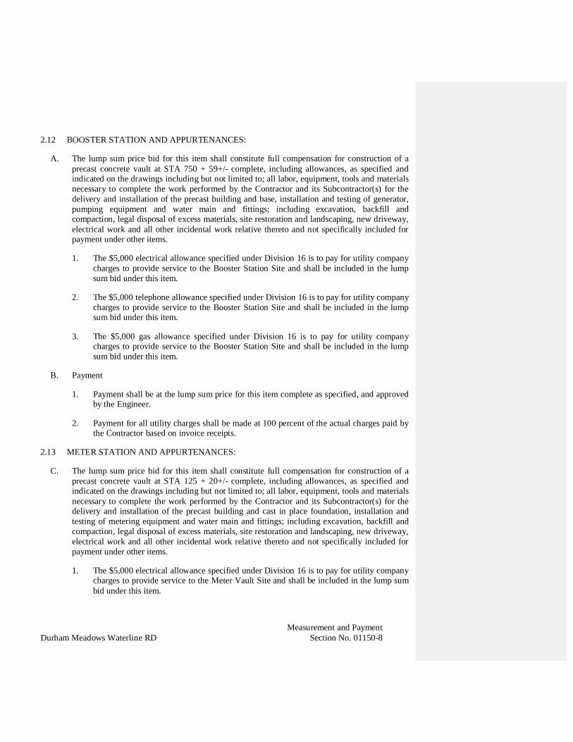
Measurement and PaymentDurham Meadows Waterline RD Section No. 01150-8
2.12 BOOSTER STATION AND APPURTENANCES:
A. The lump sum price bid for this item shall constitute full compensation for construction of aprecast concrete vault at STA 750 + 59+/- complete, including allowances, as specified andindicated on the drawings including but not limited to; all labor, equipment, tools and materialsnecessary to complete the work performed by the Contractor and its Subcontractor(s) for thedelivery and installation of the precast building and base, installation and testing of generator,pumping equipment and water main and fittings; including excavation, backfill andcompaction, legal disposal of excess materials, site restoration and landscaping, new driveway,electrical work and all other incidental work relative thereto and not specifically included forpayment under other items.
1. The $5,000 electrical allowance specified under Division 16 is to pay for utility companycharges to provide service to the Booster Station Site and shall be included in the lumpsum bid under this item.
2. The $5,000 telephone allowance specified under Division 16 is to pay for utility companycharges to provide service to the Booster Station Site and shall be included in the lumpsum bid under this item.
3. The $5,000 gas allowance specified under Division 16 is to pay for utility companycharges to provide service to the Booster Station Site and shall be included in the lumpsum bid under this item.
B. Payment
1. Payment shall be at the lump sum price for this item complete as specified, and approvedby the Engineer.
2. Payment for all utility charges shall be made at 100 percent of the actual charges paid bythe Contractor based on invoice receipts.
2.13 METER STATION AND APPURTENANCES:
C. The lump sum price bid for this item shall constitute full compensation for construction of aprecast concrete vault at STA 125 + 20+/- complete, including allowances, as specified andindicated on the drawings including but not limited to; all labor, equipment, tools and materialsnecessary to complete the work performed by the Contractor and its Subcontractor(s) for thedelivery and installation of the precast building and cast in place foundation, installation andtesting of metering equipment and water main and fittings; including excavation, backfill andcompaction, legal disposal of excess materials, site restoration and landscaping, new driveway,electrical work and all other incidental work relative thereto and not specifically included forpayment under other items.
1. The $5,000 electrical allowance specified under Division 16 is to pay for utility companycharges to provide service to the Meter Vault Site and shall be included in the lump sumbid under this item.

Measurement and PaymentDurham Meadows Waterline RD Section No. 01150-9
2. The $5,000 telephone allowance specified under Division 16 is to pay for utility companycharges to provide service to the Meter Station Site and shall be included in the lump sumbid under this item.
D. Payment
1. Payment shall be at the lump sum price for this item complete as specified, and approvedby the Engineer.
2. Payment for all utility charges shall be made at 100 percent of the actual charges paid bythe Contractor based on invoice receipts.
3. Payment for telephone utility charges shall be made at 100 percent of the actual chargespaid by the Contractor based on invoice receipts.
2.14 PRV VAULT AND APPURTENANCES:
A. The lump sum price bid for this item shall constitute full compensation for construction of aprecast concrete PRV Vault at STA 163+50+/- complete, including allowances, as specifiedand indicated on the drawings including but not limited to; all labor, equipment, tools andmaterials necessary to complete the work performed by the Contractor and its Subcontractor(s)for the delivery and installation of the precast structure, installation and testing of pressurerelief valve, watermain and all fittings; including excavation, backfill and compaction, legaldisposal of excess materials, site restoration, electrical work and all other incidental workrelative thereto and not specifically included for payment under other items.
1. The $5,000 electrical allowance specified under Division 16 is to pay for utility companycharges to provide service to the PRV Vault Site and shall be included in the lump sumbid under this item.
B. Payment
1. Payment shall be at the lump sum price for this item complete as specified, and approvedby the Engineer.
2. Payment for electric utility charges shall be made at 100 percent of the actual chargespaid by the Contractor based on invoice receipts.
2.15 MISCELLANEOUS EARTH EXCAVATION:
A. The quantity of earth excavation and backfill above normal depth to be paid for under this itemshall be the number of cubic yards excavated and backfilled, measured to the extent of the workdone as ordered by the Engineer for test pits.
B. The unit price for the appropriate subdivision of this item shall constitute full compensation forexcavation and backfill for test pits.

Measurement and PaymentDurham Meadows Waterline RD Section No. 01150-10
C. The quantity of earth excavation below normal depth (limit of normal excavation) to beincluded for payment under this item shall be the number of cubic yards of unsuitable materialexcavated, measured to the depths and lengths ordered, and to the width between paymentlimits for normal excavation as indicated on the drawings.
D. The unit price for the appropriate subdivision of this item shall constitute full compensation forexcavation below normal depth and disposal of unsuitable material.
E. No payment will be made for replacement of unsuitable material above trench grade whensuitable excess excavated material is available from other excavations made under this Project.
2.16 ROCK EXCAVATION AND DISPOSAL:
A. Where rock is encountered, it shall be uncovered but not excavated until measurements havebeen made by the Engineer, unless in the opinion of the Engineer, satisfactory measurementscan be made in some other manner.
B. The quantity of rock to be paid for under this item shall be the number of cubic yards of rock,measured in place before excavation, within the payment limits indicated on the drawings andas defined in this Section, unless rock excavation beyond such limits has been authorized inwriting by the Engineer, in which case measurements shall be made to the authorized limits.
C. Excavated rock which has not been disposed of shall not be included for payment.
D. The bidder shall include in his bid for items involving excavation, the cost of doing the entireexcavation as earth, the price for this item being intended to cover the difference between thecost of rock excavation and the cost of earth excavation. The price for this item shall be paid inaddition to any payment made for earth excavation.
E. The unit price for this item shall constitute full compensation for rock excavation and disposal,for all necessary backfilling, and for furnishing all additional material needed for backfilling.
F. Payment for rock and/or boulder removal shall be made at the unit price bid per cubic yardunder this item which shall not be less than $50.00 per cubic yard.
2.17 BANK-RUN GRAVEL:
A. Bank-run gravel backfill below normal depth shall be paid for under this item. The quantity ofbank-run gravel backfill below normal depth to be paid for shall be the same as that number ofcubic yards of earth excavation below normal depth measured for payment under theappropriate subdivision of "Miscellaneous Earth Excavation", which said gravel replaces.
B. Bank-run gravel ordered for backfill of trenches above normal depth shall be paid for under thisitem. The quantity of bank-run gravel used as backfill for trenches above normal depth shall bemeasured by the cubic yard to the depth and length ordered and to the width between paymentlimits for normal excavation as indicated on the drawings. Bank-run gravel outside the limitsof normal excavation shall be furnished, placed, and compacted at the Contractor's expense,and no measurement will be made for such gravel.

Measurement and PaymentDurham Meadows Waterline RD Section No. 01150-11
C. Bank-run gravel ordered to be used at other locations shall be measured after compaction andpaid for under this item as the number of cubic yards of gravel actually placed and compactedas specified.
D. Bank-run gravel used to backfill rock excavations will not be measured for payment under thisitem.
E. The unit price for this item shall constitute full compensation for furnishing, placing, andcompacting bank-run gravel, as specified.
2.18 ADDITIONAL SCREENED GRAVEL:
A. Screened gravel backfill below normal depth shall be paid for under this item. The quantity ofscreened gravel backfill below normal depth to be paid for shall be the same as that number ofcubic yards of earth excavation below normal depth measured for payment under theappropriate subdivision of "Miscellaneous Earth Excavation", which said gravel replaces.
B. Additional screened gravel used for support of existing utilities or ordered to be used at otherlocations shall be paid for under this item. The quantity to be paid for shall be the number ofcubic yards, measured in place after compaction, of additional screened gravel within the limitsdirected by the Engineer.
C. Screened gravel used for bedding pipe, to backfill unauthorized excavations, for any drainagepurpose, or as indicated on the drawings for work for which appropriate payment items havebeen provided, shall not be measured for payment under this item.
D. The unit price for this item shall constitute full compensation for furnishing, placing, andcompacting screened gravel, as specified.
2.19 SELECTED BORROW:
A. Selected borrow backfill below normal depth shall be paid for under this item. The quantity ofselected borrow backfill below normal depth to be paid for shall be the same as that number ofcubic yards of earth excavation below normal depth measured for payment under theappropriate subdivision of "Miscellaneous Earth Excavation," which said borrow replaces.
B. Selected borrow ordered for backfill of trenches above normal depth shall be paid for under thisitem. The quantity of selected borrow used as backfill for trenches above normal depth shall bemeasured by the cubic yard to the depth and length ordered and to the width between paymentlimits for normal excavation as indicated on the drawings. Selected borrow outside the limitsof normal excavation shall be furnished, placed, and compacted at the Contractor's expense,and no measurement will be made for such borrow.
C. Selected borrow ordered to be used at other locations shall be measured after compaction andpaid for under this item as the number of cubic yards of borrow actually placed and compactedas specified.

Measurement and PaymentDurham Meadows Waterline RD Section No. 01150-12
D. Selected borrow used to backfill rock excavations will not be measured for payment under thisitem.
E. The unit price for this item shall constitute full compensation for furnishing from an acceptableborrow pit, placing, and compacting selected borrow, as specified.
2.20 REMOVAL AND DISPOSAL OF CONTAMINATED MATERIAL:
A. An allowance has been included in the bid form for costs associated with handling and disposalof contaminated soil and/or groundwater. This item would be used only if contaminatedmaterials are encountered during construction. No payment will be made for materials cross-contaminated by the placement of clean excavated material with contaminated excavatedmaterial. This item shall include, but not limited to, the excavation, stockpiping, covering,control of water, the pumping, temporary storage, treatment prior to discharge, analyticaltesting to determine disposal requirements, discharge, transport and any Licensed SiteProfessional (LSP) services associated with the work. The allowance shall be adjustedaccordingly and payment to the Contractor made to cover the actual expense incurred for theseservices.
B. This work does not include treatment of the water displaced by the decommissioning of watersupply wells included under a separate bid item.
C. Payment shall be review of the invoices submitted by the Contractor for work bysubcontractors, consultants, vendors, haulers, or disposal facilities, and detailed, itemizedsummaries for work completed directly by the Contractor, as reviewed and approved by theEngineer.
2.21 MISCELLANEOUS CONCRETE:
A. The quantity of concrete to be measured for payment under this item shall be the number ofcubic yards placed as recommended by the Engineer.
B. No measurement shall be made under this item for concrete used as indicated on the drawingsfor work for which appropriate payment items have been provided or for concrete used tobackfill unauthorized excavations.
C. The unit price for this item shall constitute full compensation for furnishing and placingconcrete as specified.
2.22 SHEETING LEFT IN PLACE:
A. The quantity of sheeting left in place to be paid for under this item shall be that sheetingindicated on the drawings to be left in place, and not included for payment under other items, orotherwise ordered by the Engineer to be left in place, and shall be measured by the square footalong vertical planes parallel to the centerline of the pipe.
B. The number of square feet of sheeting to be measured shall be ONLY that left in place, asspecified above. No measurement shall be made for sheeting, bracing, and cofferdamming
Measurement and PaymentDurham Meadows Waterline RD Section No. 01150-13
which is left in place at the option of the Contractor or which is removed from the excavation,it being understood and agreed that the compensation for all such sheeting and for cost offurnishing, placing, cutting, and removal thereof is included in the price to be paid for the itemsinvolving earth excavation for which sheeting is used.
C. The unit price or prices for this item shall constitute full compensation for all sheetingincluding bracing and other accessories left in place as specified.
2.23 PAVEMENT:
A. The quantities of gravel-base course, temporary pavement, and permanent pavement, to bemeasured for payment under the appropriate subdivisions of this item shall be measured by thelinear foot along the centerline of the pipeline without deductions for manholes. Where twopipelines are constructed in the same trench, measurement shall be at 1-1/2 times the linear footquantity.
B. The unit price for gravel-base course shall constitute full compensation for furnishing materialfor gravel-base course as specified and as indicated, when so ordered by the Engineer. Placingand compacting the gravel-base course is incidental to the appropriate items involving backfill.
C. Suitable material, as determined by the Engineer, taken from excavations made as part of thecontract work and used for gravel-base course shall not be included for payment under thisitem.
D. The unit price or prices for temporary pavement shall constitute full compensation forconstructing and maintaining the temporary pavement, as specified and as indicated.
E. The unit price for trench pavement in State roadways shall constiture full compensation forfurnishing and installing up to 6-inches of supplemental bituminous pavement as required toreplace concrete base removed, and shall be measured by square yard as specified andindicated.
F. The unit price for Class 4 bituminous concrete to match existing thickness shall constitute fullcompensation for furnishing and installing supplemtal bituminous pavement as measured andapproved by the Engineer.
G. The unit price for 2-inch overlay pavement in Town roads shall include installation ofpavement overlay, adjusting existing structures, valve boxes, frames and covers to grade,pavement striping and crosswalk replacement, and incidental work in accordance with theDrawings and Specifications.
H. The unit price for milling and 2-inch overlay pavement in State roads shall include saw cuttingexisting pavement, milling and removal and disposal of existing pavement, installation ofpavement overlay, adjusting existing structures, valve boxes, frames and covers to grade,pavement striping and crosswalk replacement, and incidental work in accordance with theDrawings and Specifications.

Measurement and PaymentDurham Meadows Waterline RD Section No. 01150-14
I. All pavement work shall also include cooordination with the Town of Durham and the State ofConnecticut Department of Transporation to ensure complete conformance with Town andState requirements.
2.24 REPLACEMENT OF TRAFFIC LOOP DETECTORS AT STATE INTERSECTIONS
A. The price bid under this item shall be constitute full compensation for furnishing, installation,and maintenance during construction of the traffic loop detectors at each state road intersectionbut not limited to sawcutting roadway, installation of wiring, coordination with traffic signalsin accordance with CT DOT requirements as indicated on the drawings and as specifiedincluding all work incidental thereto.
B. Measurement will be based on the lump sum price for each intersection.
C. Payment shall be based on completion of each traffic loop installation, complete and tested asapproved by the Engineer.
2.25 CALCIUM CHLORIDE:
A. The quantity of calcium chloride to be paid for under this item shall be equal to the number ofpounds furnished and spread to the extent ordered by the Engineer
B. The unit price for this item shall constitute full compensation for furnishing and spreadingcalcium chloride.
2.26 EROSION CONTROL SILT FENCE:
A. The quantity of erosion control silt fence to be paid for under this item shall be equal to thenumber of linear feet furnished and installed as approved by the Engineer.
B. The unit price for this item shall constitute full compensation for furnishing and installing siltfence in accordance with the drawings and approved by the Engineer.
2.27 DEWATERING:
A. Work under these items include but is not limited to design, permits, installation, operation,maintenance and removal of the dewatering systems employed (such as but not limited topumps, well points, and header pipes), legal disposal of all water obtained during the operationof the dewatering system and all other incidental work related thereto, not specifically includedfor payment under other items.
B. Measurement will be based on the lump sum price for each item as approved by the Engineer.
C. No additional payment will be made for any excavation and/or materials which are required forthe installation and removal of the dewatering system.

Measurement and PaymentDurham Meadows Waterline RD Section No. 01150-15
2.28 CONTROL OF WORK, PERMITTING, TRAFFIC CONTROL, SITE PREPARATION,ENVIRONMENTAL CONTROLS, AND TURF ESTABLISHMENT OR OTHERINCIDENTAL WORK:
A. The unit price for this item shall constitute full compensation for all other incidental workincluding but not limited to all cleaning, installation, protection and maintenance oferosion/pollution/sedimentation control measures, coordination with Call-Before-You-Dig, anyrequired permitting, specialized bonds and insurance associated with work within state, or townroadway rights of way, private property, signage, maintenance and protection of traffic,reestablishment of turf in areas disturbed during construction, coordination with Town, State,utilities, authorities, cleaning storm drainage pipes and structures at project closeout and othertasks associated with preparation for the work under this contract which is not otherwise notedon the bid form including all work incidental thereto and not specifically included for paymentunder other items.
B. Measurement will be based on the lump sum price for each item as approved by the Engineer.
2.29 SERVICES OF UNIFORMED SPECIAL OFFICERS:
A. Under this item, the Contractor shall be reimbursed for certain charges for the services ofuniformed special officers rendered in connection with traffic control as specified under"Traffic Control" in MISCELLANEOUS REQUIREMENTS.
B. The lump-sum price for this item established in the BID is an estimated figure to facilitatecomparison of bids.
C. The actual amount to be paid under this item shall constitute full compensation for wages paid,premiums on Workmen's Compensation Insurance, payment on account of Social Security andother direct assessments on payroll, and all other costs incidental to the employment of suchuniformed special officers.
D. Payment for Uniformed Special Officers shall be made at 100 percent of the actualcharges paid by the Contractor and approved by the Contracting Officer.
E. If the total cost for such charges is greater or less than the allowance amount stated under thisitem in the BID, a debit or credit of the difference in cost shall be assessed to the Contractvalue.
2.30 ENGINEER’S FIELD OFFICE
A. The prices bid under each division of this item shall constitute full compensation to furnish,install, maintain, and remove the Engineer’s Field Office as specified, and approved by theEngineer, including all other incidental Work relative thereto and not specifically included forpayment under other items.
B. Payment for furnishing, installation and removal shall be in an amount of 75 percent of thelump sum bid amount for the Engineer’s Field Office based on Engineer’s approval for full
Deleted:
Deleted: made to the Owner'-----------------------------------------------1--------~-~

Measurement and PaymentDurham Meadows Waterline RD Section No. 01150-16
installation. The remaining 25 percent (exclusive of normal contract retainage) will be madefollowing the removal of the engineer’s Field Office from the Project.
C. Payment for maintaining Engineer’s field office shall be on a monthly basis based onEngineer’s approval.
2.31 CONSTRUCTION WATER TREATMENT SYSTEM
A. The prices bid under each division of this item shall constitute full compensation to furnish,install, maintain, and remove the construction water treatment system as specified, andapproved by the Engineer, including all other incidental Work relative thereto and notspecifically included for payment under other items.
B. Payment for furnishing, installation and removal shall be in an amount of 75 percent of thelump sum bid amount for the Treatment System based on Engineer’s approval for fullinstallation. The remaining 25 percent (exclusive of normal contract retainage) will be madefollowing the removal of the Treatment System from the Project.
C. Payment for maintaining construction water treatment system shall be on a weekly basis asapproved by the Engineer.
D. Payment for operating construction water treatment system shall be on a weekly basis asapproved by the Engineer.
E. The lump-sum allowance for analytical testing established in the BID is an estimated figure tofacilitate comparison of bids.
F. Payment for construction water analytical testing shall be based on lab receipts presented foreach test as approved by the Engineer.
END OF SECTION
Project MeetingsDurham Meadows Waterline RD Section No. 01200-1
SECTION 01200
PROJECT MEETINGS
PART 1 - GENERAL
1.01 COORDINATION:
A. General Contractor shall establish on-site lines of authority and communications.
1. Schedule and conduct progress meetings.
2. Establish procedures for intra-Project communications.
a. Submittals.
b. Reports and records.
c. Recommendations.
d. Coordination drawings.
e. Schedules.
f. Resolution of conflicts.
3. Interpret Contract Documents.
a. Consult with Contracting Officer to obtain interpretation, as required.
b. Assist in resolution of questions or conflicts which may arise.
c. Forward written interpretations to other Contractors, and to other concernedparties.
4. Assist in obtaining permits and approvals.
a. Building permits and special permits required for Work or temporaryfacilities.
b. Verify Contractors and Subcontractors have obtained inspections for Workand temporary facilities.
5. Control use of site.
a. Supervise field engineering and site layout.
Deleted: Engineer, _________________________________________________________________________________________________________________________ J_,/ '---_____,)

Project MeetingsDurham Meadows Waterline RD Section No. 01200-2
b. Allocate space for each prime Contractor’s use for field offices, sheds, andWork and storage areas.
c. Allocate field office and storage space, and Work and storage areas, for useof each prime Contractor.
d. Establish access, traffic, and parking allocations and regulations.
e. Monitor use of site during construction.
1.02 SUMMARY:
A. Contractor shall schedule and administer progress meetings with their own staff and/orother contractors, construction foremen’s meetings, and specially called meetings withthese parties throughout progress of Work. Contractor shall:
1. Prepare agenda for meetings.
2. Distribute written notice of specially called meetings minimum of one workingday(s) in advance of meeting date.
3. Make physical arrangements for meetings.
4. Preside at meetings.
5. Record minutes; include significant proceedings and decisions.
6. Prepare formal minutes and distribute within 2 working days after each meeting tothe following:
a. Meeting participants.
b. Parties affected by decisions made at meeting.
c. Contracting Officer.
B. Representatives of Contractor, Subcontractors, and Suppliers attending meetings shall bequalified and authorized to act on behalf of entity each represents.
C. Contracting Officer may attend meetings.
1.03 PRECONSTRUCTION CONFERENCE:
A. Engineer will schedule and conduct preconstruction conference in accordance with theContract and this section.
B. Location: At location to be selected by Engineer.
C. Attendance.
Deleted: Engineer and Owner
Deleted: Owner and Engineer
"-------------------------------------------------------------------------------------------------------------------------------------------------- ' '
"---------------------------------------------------------------------------------------------------------------------------------'
Project MeetingsDurham Meadows Waterline RD Section No. 01200-3
1. Contractor’s Project Manager.
2. Contractor’s Resident Superintendent.
3. Contractor’s “hands-on” person designated by Contractor to submit ShopDrawings to Engineer.
4. Subcontractors’ or suppliers’ representatives Contractor may desire to invite orEngineer may request.
5. Engineer’s representatives.
6. Contracting Officer’s representatives.
7. Local utility representatives.
D. Suggested format includes, but not be limited to following:
1. Project Safety.
2. Presentation of preliminary progress schedule in accordance with Section 01310“Construction Progress Schedule” and preliminary schedule of Shop Drawing andsample submissions in accordance with Section 01300 “Submittals” of ContractDocuments.
3. Check of required bonds and insurance policies prior to Notice to Proceed.
5. Liquidated damages.
6. Procedures for handling submittals such as substitutions and Shop Drawings.
7. O&M submittal procedures.
8. Training requirements.
9. Requirements for startup, and performance testing.
10. On-site witness testing by independent subconsultants and approval/regulatoryagencies.
11. Direction of correspondence and coordinating responsibility.
12. Weekly and monthly progress meetings.
13. Equal opportunity requirements.
14. Laboratory and field testing requirements.
Deleted: Owner
------------------------------------------------------------------------------------------------------------------------------------------------------- - J ----,,,-~-~

Project MeetingsDurham Meadows Waterline RD Section No. 01200-4
15. Provisions for inventory of material stored on-site or off-site if off-site storage isauthorized.
16. Schedule of values, application for progress payment, and progress paymentprocedures.
17. Change Order procedures.
18. Posting of Contracting Officer/Funding Agency’s sign.
19. Contractor’s proposed Environmental Management and Erosion Control Plan.
20. Contractor’s proposed Health and Safety Plan.
21. Contractor’s proposed Quality Control Plan.
22. Coordination requirements with plant staff and ongoing operations.
23. Construction sequencing and stipulated construction and plant operationalconstraints.
1.04 PROGRESS MEETINGS WITH ENGINEER:
A. In addition to other regular project meetings for other purposes (as indicated elsewherein the Contract Documents), hold general progress meetings with times coordinated withpreparation of payment requests. Meeting dates and schedule will be established by theEngineer. All personnel then involved in the planning, coordination or performance ofwork to be represented at each meeting.
B. Suggested format includes, but not limited to following:
1. Review each entity's present and future needs including interface requirements
2. Construction sequence, coordination and shutdown requirements
3. Construction schedule and progress reporting
4. On-site witness testing by independent subconsultants and approval/regulatoryagencies
5. Deliveries
6. Access
7. Site utilization
8. Temporary facilities and services
9. Hours of work
Deleted: Owner
Project MeetingsDurham Meadows Waterline RD Section No. 01200-5
10. Safety, hazards and risks
11. Housekeeping
12. Submittals
13. Change managements (request for quotation, change directives, change orders)
14. Contract administration logs (request for information, etc.)
15. Documentation of information for payment requests
16. O&M submittal
17. Training
18. Startup, commissioning, and performance testing
C. Discuss whether each element of current work is ahead of schedule. Determine howbehind-time work will be expedited and secure commitments from the entities involvedin doing so. Discuss whether schedule revisions are required to ensure that current workand subsequent work will be completed within the Contract Time. Review everything ofsignificance which could affect the progress of the work.
D. Within two days after each progress meeting date, the Engineer will forward copies ofthe minutes-of-the-meeting, to the Contractor.
E. Immediately following each progress meeting where revisions to the ProgressSchedule/Critical Path Schedule have been made or recognized (regardless of whetheragreed to by each entity represented), revise the Schedule. Reissue revised Schedulewithin 10 working days after meeting.
F. At intervals matching the preparation of payment requests, revise and reissue theSchedule to show actual progress of the work in relation to the latest revision of theSchedule.
1.05 CONSTRUCTION FOREMEN’S MEETINGS:
A. Schedule weekly.
B. Location: Contractor’s field office.
C. Attendance.
1. Resident superintendent.
2. Subcontractor’s foremen.
D. Suggested Agenda.
Project MeetingsDurham Meadows Waterline RD Section No. 01200-6
1. Health and safety.
2. Review agenda of Work progress since previous meeting.
3. Proposed progress and schedule for succeeding Work period.
4. Field observations, problems, and conflicts.
5. Problems which affect construction schedule.
6. Coordination and shutdown requirements.
1.06 HEALTH AND SAFETY MEETINGS:
A. Schedule Biweekly.
B. Location: Contractor’s field office.
C. Attendance.
1. Resident superintendent.
2. Subcontractor’s foremen.
3. Contractor’s Health and Safety Manager
4. Contracting Officer’s Health and Safety Representative
5. Engineer’s Health and Safety Representative
D. Suggested Agenda.
1. Health and safety statistics.
2. Review Work progress since previous meeting.
3. New staff and training requirements.
1.07 TESTING, STARTUP AND COMMISSIONING MEETINGS:
A. Schedule in advance as provided in the project schedule and in agreement with theContracting Officer’s representatives, and local utility representatives.
END OF SECTION
Deleted: Owner
Deleted: Engineer and Owner
~------
T -------------------------------------------------------------------------------------------------------------------------------- -- -

SubmittalsSection No. 01300-1
Durham Meadows Waterline RD
SECTION 01300
SUBMITTALS
PART 1 - GENERAL
1.01 DESCRIPTION:
A. This Section specifies the general methods and requirements of submissions applicableto the following work-related submittals.
1. Shop Drawings, Product Data and Samples.
2. Construction Photographs/Surveys.
3. Contractor’s Responsibilities.
4. Submission Requirements.
5. Review of Shop Drawings, Product Data, Working Drawings and Samples.
6. Distribution.
7. General Procedures for Submittals.
8. Certificate of Design.
9. Certificates of Compliance.
10. Schedules.
B. Additional general submission requirements are contained in Paragraph 6.17 of theGeneral Conditions.
C. Detailed submittal requirements will be specified in the technical specifications section.
1.02 DEFINITIONS:
A. Written and graphic information and physical samples that require Engineer’sresponsive action. Action submittals are those submittals indicated in individualSpecification Sections as "action submittals."
B. Portable Document Format (PDF): An open standard file format licensed by AdobeSystems used for representing documents in a device-independent and displayresolution-independent fixed-layout document format.
C. Shop drawings, as defined in the General Conditions, and as specified in individual workSections include, but are not necessarily limited to: custom-prepared data such as

SubmittalsSection No. 01300-2
Durham Meadows Waterline RD
fabrication and erection/installation (working) drawings of concrete reinforcement,structural details and piping layout, scheduled information, setting diagrams, actualshopwork manufacturing instructions, custom templates, special wiring diagrams,coordination drawings, individual system or equipment inspection and test reportsincluding performance curves and certifications as applicable to the work.
1.03 SUBMITTALS:
A. Submittal Schedule: Submit a schedule of submittals, arranged in chronological orderby dates required by construction schedule. Include time required for review, ordering,manufacturing, fabrication, and delivery when establishing dates. Include additionaltime required for making corrections or revisions to submittals noted by Engineer andadditional time for handling and reviewing submittals required by those corrections.
1. Coordinate submittal schedule with list of subcontracts, the schedule of values, andContractor’s construction schedule.
2. Final Submittal: Submit concurrently with the first complete submittal ofContractor's construction schedule.
a. Submit revised submittal schedule to reflect changes in current status andtiming for submittals.
3. Format: Arrange the following information in a tabular format:
a. Scheduled date for first submittal.
b. Specification Section number and title.
c. Submittal category: Action; informational.
d. Name of subcontractor.
e. Description of the Work covered.
f. Scheduled date for Engineer’s final release or acceptance.
g. Scheduled date of fabrication.
h. Scheduled dates for purchasing.
i. Scheduled dates for installation.
j. Activity or event number.
1.04 SUBMITTAL ADMINISTRATIVE REQUIREMENTS:
A. Engineer's Digital Data Files: Electronic digital data files of the Contract Drawings willbe provided by Engineer for Contractor's use in preparing submittals.
SubmittalsSection No. 01300-3
Durham Meadows Waterline RD
1. Engineer will furnish Contractor one set of digital data drawing files of theContract Drawings for use in preparing Shop Drawings.
a. Engineer makes no representations as to the accuracy or completeness ofdigital data drawing files as they relate to the Contract Drawings.
b. Digital Drawing Software Program: The Contract Drawings are available inAutoCad 2014 or version required by Contractor.
c. Contractor shall execute a data licensing agreement in the form ofAgreement form acceptable to Owner and Engineer.
B. Coordination: Coordinate preparation and processing of submittals with performance ofconstruction activities.
1. Coordinate each submittal with fabrication, purchasing, testing, delivery, othersubmittals, and related activities that require sequential activity.
2. Submit all submittal items required for each Specification Section concurrentlyunless partial submittals for portions of the Work are indicated on acceptedsubmittal schedule.
3. Submit action submittals and informational submittals required by the sameSpecification Section as separate packages under separate transmittals.
a. Engineer reserves the right to withhold action on a submittal requiringcoordination with other submittals until related submittals are received.
4. The Contractor shall revise and resubmit rejected submittals and those requiringcorrections or verification of information in a timely manner such that the overallprogress of the Work is not impeded.
5. Coordination of Submittal Times: The Contractor shall prepare and transmit eachsubmittal sufficiently in advance of performing the related Work or otherapplicable activities, or within the time specified in the individual Sections of theSpecifications, so that the installation will not be delayed by processing times,including rejection and resubmittal (if required), coordination with othersubmittals, testing, purchasing, fabrication, delivery, and similar sequencedactivities. No extension of Contract Time will be authorized because of theContractor’s failure to transmit submittals sufficiently in advance of the Work.
C. All shop drawings shall be submitted using the transmittal form furnished by theEngineer.
D. All shop drawings submitted by subcontractors for approval shall be sent directly to theContractor for checking. The Contractor shall be responsible for their submission at theproper time so as to prevent delays in delivery of materials.
SubmittalsSection No. 01300-4
Durham Meadows Waterline RD
E. Processing Time: Allow time for submittal review, including time for resubmittals, asfollows. Time for review shall commence on Engineer’s receipt of submittal. Noextension of the Contract Time will be authorized because of failure to transmitsubmittals enough in advance of the Work to permit processing, including resubmittals.
1. Initial Review: Allow 15working days for initial review of each submittal. Allowadditional time if coordination with subsequent submittals is required. Engineerwill advise Contractor when a submittal being processed must be delayed forcoordination.
2. Intermediate Review: If intermediate submittal is necessary, process it in samemanner as initial submittal.
3. Resubmittal Review: Allow 15working days for review of each resubmittal.
F. Paper Submittals: Place a permanent label or title block on each submittal item foridentification.
1. Indicate name of firm or entity that prepared each submittal on label or title block.
2. Provide a space approximately 6 by 8 inches on label or beside title block to recordContractor's review and approval markings and action taken by Engineer.
3. Number of submittals required:
a. Shop Drawings: Unless otherwise stated in the respective SpecificationsSections, submit six (6) copies.
b. Product Data: Unless otherwise stated in the respective SpecificationsSections, submit six (6) copies.
c. Samples: Submit the number stated in the respective Specification Sections.
4. Include the following information for processing and recording action taken:
a. Project name.
b. Date.
c. Name of Engineer.
d. Name of Contractor.
e. Name of subcontractor.
f. Name of supplier.
g. Name of manufacturer.
SubmittalsSection No. 01300-5
Durham Meadows Waterline RD
h. Submittal number or other unique identifier, including revision identifier.
(1) Submittal number shall use Specification Section number followed bya decimal point and then a sequential number (e.g., 02600.01).Resubmittals shall include an alphabetic suffix after another decimalpoint (e.g., 02600.01.A).
i. Number and title of appropriate Specification Section.
j. Drawing number and detail references, as appropriate.
k. Location(s) where product is to be installed, as appropriate.
l. Other necessary identification.
5. Additional Paper Copies: Unless additional copies are required for final submittal,and unless Engineer observes noncompliance with provisions in the ContractDocuments, initial submittal may serve as final submittal.
a. Submit one copy of submittal to concurrent reviewer in addition to specifiednumber of copies to Engineer.
6. Transmittal for Paper Submittals: Assemble each submittal individually andappropriately for transmittal and handling. Transmit each submittal using atransmittal form. Engineer will return without review or discard submittalsreceived from sources other than Contractor.
a. Transmittal Form for Paper Submittals: Use CSI Form 12.1A or asapproved by the Engineer including the following information:
(1) Project name.
(2) Date.
(3) Destination (To:).
(4) Source (From:).
(5) Name and address of Engineer.
(6) Name of Construction Manager.
(7) Name of Contractor.
(8) Name of firm or entity that prepared submittal.
(9) Names of subcontractor, manufacturer, and supplier.
(10) Category and type of submittal.

SubmittalsSection No. 01300-6
Durham Meadows Waterline RD
(11) Submittal purpose and description.
(12) Specification Section number and title.
(13) Specification paragraph number or drawing designation and genericname for each of multiple items.
(14) Drawing number and detail references, as appropriate.
(15) Indication of full or partial submittal.
(16) Transmittal number, numbered consecutively.
(17) Submittal and transmittal distribution record.
(18) Remarks.
(19) Signature of transmitter.
G. Electronic Submittals: Identify and incorporate information in each electronic submittalfile as follows:
1. Assemble complete submittal package into a single indexed file incorporatingsubmittal requirements of a single Specification Section and transmittal form withlinks enabling navigation to each item.
2. Name file with submittal number or other unique identifier, including revisionidentifier.
a. File name shall use project identifier and Specification Section numberfollowed by a decimal point and then a sequential number (e.g., 02600.01).Resubmittals shall include an alphabetic suffix after another decimal point(e.g., -02600.01.A).
3. Provide means for insertion to permanently record Contractor's review andapproval markings and action taken by Engineer.
4. Transmittal Form for Electronic Submittals: Use electronic form acceptable toEngineer, containing the following information:
a. Project name.
b. Date.
c. Name and address of Engineer.
d. Name of Construction Manager.
e. Name of Contractor.

SubmittalsSection No. 01300-7
Durham Meadows Waterline RD
f. Name of firm or entity that prepared submittal.
g. Names of subcontractor, manufacturer, and supplier.
h. Category and type of submittal.
i. Submittal purpose and description.
j. Specification Section number and title.
k. Specification paragraph number or drawing designation and generic namefor each of multiple items.
l. Drawing number and detail references, as appropriate.
m. Location(s) where product is to be installed, as appropriate.
n. Related physical samples submitted directly.
o. Indication of full or partial submittal.
p. Transmittal number, numbered consecutively.
q. Submittal and transmittal distribution record.
r. Other necessary identification.
s. Remarks.
5. Metadata: Include the following information as keywords in the electronicsubmittal file metadata:
a. Project name.
b. Number and title of appropriate Specification Section.
c. Manufacturer name.
d. Product name.
Options: Identify options requiring selection by Engineer.
H. Deviations and Additional Information: On an attached separate sheet, prepared onContractor's letterhead, record relevant information, requests for data, revisions otherthan those requested by Engineer on previous submittals, and deviations fromrequirements in the Contract Documents, including minor variations and limitations.Include same identification information as related submittal.
SubmittalsSection No. 01300-8
Durham Meadows Waterline RD
I. Resubmittals: Make resubmittals in same form and number of copies as initialsubmittal.
1. Note date and content of previous submittal.
2. Note date and content of revision in label or title block and clearly indicate extentof revision.
3. Resubmit submittals until they are marked with acceptance notation fromEngineer’s action stamp.
J. Distribution: Furnish copies of final submittals to manufacturers, subcontractors,suppliers, fabricators, installers, authorities having jurisdiction, and others as necessaryfor performance of construction activities. Show distribution on transmittal forms.
K. Use for Construction: Retain complete copies of submittals on Project site. Use onlyfinal action submittals that are marked with acceptance notation from Engineer’s actionstamp.
1.05 CONSTRUCTION PHOTOGRAPHS:
A. The Contractor shall provide construction photographs in accordance with requirementsspecified in Section 01390.
PART 2 - PRODUCTS
2.01 SUBMITTAL PROCEDURES:
A. General Submittal Procedure Requirements: Prepare and submit submittals required byindividual Specification Sections. Types of submittals are indicated in individualSpecification Sections.
1. Submit electronic submittals via email as PDF electronic files unless otherwisearranged with the Engineer.
a. Engineer will return annotated file. Annotate and retain one copy of file asan electronic Project record document file.
b. Provide a digital signature with digital certificate on electronically submittedcertificates and certifications where indicated.
c. Provide a notarized statement on original paper copy certificates andcertifications where indicated.
B. Product Data: Collect information into a single submittal for each element ofconstruction and type of product or equipment.

SubmittalsSection No. 01300-9
Durham Meadows Waterline RD
1. If information must be specially prepared for submittal because standard publisheddata are not suitable for use, submit as Shop Drawings, not as Product Data.
2. Mark each copy of each submittal to show which products and options areapplicable.
3. Include the following information, as applicable:
a. Manufacturer's catalog cuts.
b. Manufacturer's product specifications.
c. Standard color charts.
d. Statement of compliance with specified referenced standards.
e. Testing by recognized testing agency.
f. Application of testing agency labels and seals.
g. Notation of coordination requirements.
h. Availability and delivery time information.
4. For equipment, include the following in addition to the above, as applicable:
a. Wiring diagrams showing factory-installed wiring.
b. Printed performance curves.
c. Operational range diagrams.
d. Clearances required to other construction, if not indicated on accompanyingShop Drawings.
5. Submit Product Data before or concurrent with Samples.
C. Shop Drawings: Prepare Project-specific information, drawn accurately to scale. Do notbase Shop Drawings on reproductions of the Contract Documents or standard printeddata.
1. Certified shop and erection drawings. Contractor shall submit electronic files ofthe proposed equipment in the capacity, size, and arrangement as indicated andspecified. Electronic files shall conform to the following minimum requirements:
a. Electronic Files: AutoCAD latest version, 3D, drawn to scale.
b. Submit electronic files as part of the Shop Drawing submittal.

SubmittalsSection No. 01300-10
Durham Meadows Waterline RD
c. Submit electronic files on CD or DVD.
d. Drawings shall include plan views, sectional views, title block, TagNumbers, serial numbers, Parts List (identifying each component),dimensions, connection sizes and types and all details of all related items. Incases where certain information is proprietary and is omitted, provided astatement indicating that the information is proprietary and is being omitted.
e. Drawings shall be in conformance with all other requirements as specified inthis specification.
2. Preparation: Fully illustrate requirements in the Contract Documents. Include thefollowing information, as applicable:
a. Identification of products.
b. Schedules.
c. Compliance with specified standards.
d. Notation of coordination requirements.
e. Notation of dimensions established by field measurement.
f. Relationship and attachment to adjoining construction clearly indicated.
g. Seal and signature of professional engineer if specified.
3. Sheet Size: Except for templates, patterns, and similar full-size drawings, submitShop Drawings on sheets at least 8-1/2 by 11 inches, but no larger than 24 by 36inches
4. Submit Shop Drawings in the following format:
a. PDF electronic file.
b. Two opaque (bond) copies of each submittal. Engineer will return one (1)copy.
D. Samples: Submit Samples for review of kind, color, pattern, and texture for a check ofthese characteristics with other elements and for a comparison of these characteristicsbetween submittal and actual component as delivered and installed.
1. Transmit Samples that contain multiple, related components such as accessoriestogether in one submittal package.
2. Identification: Attach label on unexposed side of Samples that includes thefollowing:

SubmittalsSection No. 01300-11
Durham Meadows Waterline RD
a. Generic description of Sample.
b. Product name and name of manufacturer.
c. Sample source.
d. Number and title of applicable Specification Section.
e. Specification paragraph number and generic name of each item.
3. For projects where electronic submittals are required, provide correspondingelectronic submittal of Sample transmittal, digital image file illustrating Samplecharacteristics, and identification information for record.
4. Disposition: Maintain sets of accepted Samples at Project site, available forquality-control comparisons throughout the course of construction activity.Sample sets may be used to determine final acceptance of construction associatedwith each set.
a. Samples not incorporated into the Work, or otherwise designated as Owner'sproperty, are the property of Contractor.
5. Samples for Initial Selection: Submit manufacturer's color charts consisting ofunits or sections of units showing the full range of colors, textures, and patternsavailable.
6. Samples for Verification: Submit full-size units or Samples of size indicated,prepared from same material to be used for the Work, cured and finished inmanner specified, and physically identical with material or product proposed foruse, and that show full range of color and texture variations expected. Samplesinclude, but are not limited to, the following: partial sections of manufactured orfabricated components; small cuts or containers of materials; complete units ofrepetitively used materials; swatches showing color, texture, and pattern; colorrange sets; and components used for independent testing and inspection.
a. Number of Samples: Submit three (3) sets of Samples. Engineer will retainone (1) Sample sets; remainder will be returned. Mark up and retain onereturned Sample set as a project record sample.
(1) Submit a single Sample where assembly details, workmanship,fabrication techniques, connections, operation, and other similarcharacteristics are to be demonstrated.
(2) If variation in color, pattern, texture, or other characteristic is inherentin material or product represented by a Sample, submit at least three(3) sets of paired units that show approximate limits of variations.
SubmittalsSection No. 01300-12
Durham Meadows Waterline RD
E. Coordination Drawing Submittals: Comply with requirements specified in Division 01Section "Project Management and Coordination."
F. Contractor's Construction Schedule: Comply with requirements specified in Division 01Section "Construction Progress Documentation."
G. Application for Payment and Schedule of Values: Comply with requirements specifiedin Division 01 Section "Payment Procedures."
H. Test and Inspection Reports and Schedule of Tests and Inspections Submittals: Complywith requirements specified in Division 01 Section "Quality Requirements."
I. Closeout Submittals and Maintenance Material Submittals: Comply with requirementsspecified in Division 01 Section "Closeout Procedures."
J. Maintenance Data: Comply with requirements specified in Division 01 Section"Operation and Maintenance Data."
K. LEED Submittals: Comply with requirements specified in Division 01 sustainabledesign requirements Section.
L. Qualification Data: Prepare written information that demonstrates capabilities andexperience of firm or person. Include lists of completed projects with project names andaddresses, contact information of Engineers and owners, and other information specified.
M. Welding Certificates: Prepare written certification that welding procedures andpersonnel comply with requirements in the Contract Documents. Submit record ofWelding Procedure Specification and Procedure Qualification Record on AWS forms.Include names of firms and personnel certified.
N. Installer Certificates: Submit written statements on manufacturer's letterhead certifyingthat Installer complies with requirements in the Contract Documents and, whererequired, is authorized by manufacturer for this specific Project.
O. Manufacturer Certificates: Submit written statements on manufacturer's letterheadcertifying that manufacturer complies with requirements in the Contract Documents.Include evidence of manufacturing experience where required.
P. Product Certificates: Submit written statements on manufacturer's letterhead certifyingthat product complies with requirements in the Contract Documents.
Q. Material Certificates: Submit written statements on manufacturer's letterhead certifyingthat material complies with requirements in the Contract Documents.
R. Material Test Reports: Submit reports written by a qualified testing agency, on testingagency's standard form, indicating and interpreting test results of material forcompliance with requirements in the Contract Documents.
SubmittalsSection No. 01300-13
Durham Meadows Waterline RD
S. Product Test Reports: Submit written reports indicating that current product producedby manufacturer complies with requirements in the Contract Documents. Base reportson evaluation of tests performed by manufacturer and witnessed by a qualified testingagency, or on comprehensive tests performed by a qualified testing agency.
T. Research Reports: Submit written evidence, from a model code organization acceptableto authorities having jurisdiction, that product complies with building code in effect forProject. Include the following information:
1. Name of evaluation organization.
2. Date of evaluation.
3. Time period when report is in effect.
4. Product and manufacturers' names.
5. Description of product.
6. Test procedures and results.
7. Limitations of use.
U. Preconstruction Test Reports: Submit reports written by a qualified testing agency, ontesting agency's standard form, indicating and interpreting results of tests performedbefore installation of product, for compliance with performance requirements in theContract Documents.
V. Compatibility Test Reports: Submit reports written by a qualified testing agency, ontesting agency's standard form, indicating and interpreting results of compatibility testsperformed before installation of product. Include written recommendations for primersand substrate preparation needed for adhesion.
W. Field Test Reports: Submit written reports indicating and interpreting results of fieldtests performed either during installation of product or after product is installed in itsfinal location, for compliance with requirements in the Contract Documents.
X. Design Data: Prepare and submit written and graphic information, including, but notlimited to, performance and design criteria, list of applicable codes and regulations, andcalculations. Include list of assumptions and other performance and design criteria and asummary of loads. Include load diagrams if applicable. Provide name and version ofsoftware, if any, used for calculations. Include page numbers.
2.02 DELEGATED-DESIGN SERVICES:
A. Performance and Design Criteria: Where professional design services or certificationsby a design professional are specifically required of Contractor by the Contract
SubmittalsSection No. 01300-14
Durham Meadows Waterline RD
Documents, provide products and systems complying with specific performance anddesign criteria indicated.
1. If criteria indicated are not sufficient to perform services or certification required,submit a written request for additional information to Engineer.
B. Delegated-Design Services Certification: In addition to Shop Drawings, Product Data,and other required submittals, submit digitally signed PDF electronic file and three (3)paper copies of certificate (Form 01300-1), signed and sealed by the responsible designprofessional, for each product and system specifically assigned to Contractor to bedesigned or certified by a design professional.
1. Indicate that products and systems comply with performance and design criteria inthe Contract Documents. Include list of codes, loads, and other factors used inperforming these services.
PART 3 - EXECUTION
3.01 CONTRACTOR'S REVIEW:
A. Submittals: Review each submittal and check for coordination with other Work of theContract and for compliance with the Contract Documents prior to submission to theEngineer. Mark with approval stamp before submitting to Engineer.
B. Contractor review shall verify the following:
1. Field measurements
2. Field construction criteria
3. Catalog numbers and similar data
4. Conformance with the Specifications
C. If a shop drawing shows any deviation from the requirements of the ContractDocuments, the Contractor shall make specific mention of the deviations in theTransmittal Form furnished by the Engineer and provide a description of the deviationsin a letter attached to the submittal.
D. The review and approval of shop drawings, samples or product data by the Engineershall not relieve the Contractor from his responsibility with regard to the fulfillment ofthe terms of the Contract. All risks of error and omission are assumed by the Contractorand the Engineer will not have responsibility for any such errors and omissions.
E. No portion of the work requiring a shop drawing, sample, or product data shall be startednor shall any materials be fabricated or installed prior to the approval or qualifiedapproval of such item by the Engineer. Any fabrication performed, materials purchased

SubmittalsSection No. 01300-15
Durham Meadows Waterline RD
or on-site construction accomplished which does not conform to accepted shop drawingsand data shall be at the Contractor's own risk. The Owner will not be liable for anyexpense or delay due to corrections or remedies required to accomplish conformity withthe requirements of the Contract.
F. Project Closeout and Maintenance Material Submittals: See requirements in Division 01Section "Closeout Procedures."
G. Approval Stamp: Stamp each submittal with a uniform, approval stamp. Include Projectname and location, submittal number, Specification Section title and number, name ofreviewer, date of Contractor's approval, and statement certifying that submittal has beenreviewed, checked, and approved for compliance with the Contract Documents.
3.02 ENGINEER’S ACTION:
A. The Engineer 's review is for general conformance with the design concept and contractdocuments. Markings or comments shall not be construed as relieving the Contractorfrom compliance with the contract plans and specifications or from departurestherefrom. The Contractor remains responsible for details and accuracy, forcoordinating the work with all other associated work and trades, for selecting fabricationprocesses, for techniques of assembly, and for performing work in a safe manner.
B. Submittals will be reviewed for the Contractor’s approval stamp. Submittals notstamped by the Contractor will be returned without any action.
C. The review of shop drawings, data, and samples will be general. They shall not beconstrued:
1. as permitting any departure from the Contract requirements;
2. as relieving the Contractor of responsibility for any errors or omissions, includingdetails, dimensions, and materials;
3. as approving departures from details furnished by the Engineer, except asotherwise provided herein.
D. If the shop drawings, data or samples as submitted describe variations and show adeparture from the Contract requirements which the Engineer finds to be in the interestof the Owner and to be so minor as not to involve a change in Contract Price or time forperformance, the Engineer may return the reviewed drawings without noting anexception.
E. Two (maximum) copies of shop drawings or product data will be returned to theContractor. Samples will not be returned.
F. Submittals will be returned to the Contractor under one of the action codes indicatedbelow and defined on the transmittal form furnished by the Engineer.

SubmittalsSection No. 01300-16
Durham Meadows Waterline RD
1. Marking: No Exception Taken.
a. When submittals are marked as “No Exception Taken,” Work covered bysubmittal may proceed provided it complies with Contract Documents.Acceptance of Work depends on that compliance.
2. Marking: Make Corrections Noted.
a. When submittals are marked as “Make Corrections Noted,” Work coveredby submittal may proceed provided it complies with Engineer’s notations orcorrections on submittal and with Contract Documents. Acceptance of Workdepends on that compliance. Resubmittal not required.
3. Marking: Amend and Resubmit.
a. When submittals are marked as “Amend and Resubmit,” do not proceed withWork covered by submittal. Do not permit Work covered by submittals tobe used at Project site or elsewhere where Work is in progress.
b. Revise submittal or prepare new submittal in accordance with Enginee’srnotations in accordance with resubmittal requirements of this section.Resubmit without delay. Repeat if required to obtain different actionmarking.
4. Marking: Rejected; See Remarks.
a. When submittals are marked as “Rejected; See Remarks,” do not proceedwith Work covered by submittal. Work covered by submittal does notcomply with Contract Documents.
b. Prepare new submittal for different material or equipment supplier ordifferent product line or material of same supplier complying with ContractDocuments.
5. Marking: For Information Only.
a. When submittals are marked as “For Information Only,” the Engineer willreview the submittal but take no action.
b. It will be recorded as “For Information Only”. Work covered by thissubmittal may proceed provided it complies with the Contract Documents.
6. Marking: Not Required for Review.
a. When submittals are marked as “Not Required for Review,” the Engineerhas not reviewed the submittal and it is being returned.

SubmittalsSection No. 01300-17
Durham Meadows Waterline RD
b. Work covered by this submittal may proceed provided it complies with theContract Documents.
G. Resubmittals will be handled in the same manner as first submittals. On resubmittals theContractor shall direct specific attention, in writing, on the letter of transmittal and onresubmitted shop drawings by use of revision triangles or other similar methods, torevisions other than the corrections requested by the Engineer, on previous submissions.Any such revisions which are not clearly identified shall be made at the risk of theContractor. The Contractor shall make corrections to any Work done in relation torevisions which are not specifically pointed out to the Engineer which are deemed, bythe Engineer, not to be in accordance with the Contract Documents .
H. Partial submittals may not be reviewed. The Engineer will be the only judge as to thecompleteness of a submittal. Submittals not complete will be returned to the Contractor,and will be considered "Rejected" until resubmitted. The Engineer may at his optionprovide a list or mark the submittal directing the Contractor to the areas that areincomplete.
I. If the Contractor considers any correction indicated on the shop drawings to constitute achange to the Contract Documents, the Contractor shall give written notice thereof to theEngineer at least seven working days prior to release for manufacture. The shopdrawing and the Product data sheet reviews do not authorize changes in Contract Priceor Contract Time. Changes involving Contract Price or Contract Time are authorizedonly by a signed Change Order, in accordance with the General Conditions.
J. When the shop drawings have been completed to the satisfaction of the Engineer, theContractor shall carry out the construction in accordance therewith and shall make nofurther changes therein except upon written instructions from the Engineer.
K. Material and equipment delivered to the Site will not be paid for until the pertinent shopdrawings have been reviewed and accepted by the Engineer.
3.03 DISTRIBUTION:
A. Distribute reproductions of accepted shop drawings and copies of accepted product dataand samples, where required, to the job site file and elsewhere as directed by theEngineer. Number of copies shall be as directed by the Engineer but shall not exceed 6.
3.04 CERTIFICATE OF DESIGN:
A. If specifically specified in other Sections of these Specifications, the Contractor shallsubmit the applicable Certificate of Design for each item required, Form 01300-1,completely filled in and signed and sealed by a registered professional engineer.

SubmittalsSection No. 01300-18
Durham Meadows Waterline RD
3.05 CERTIFICATES OF COMPLIANCE:
A. Certificates of Compliance as specified in the specifications shall include and meancertificates, manufacturer’s certificates, certifications, certified copies, letters ofcertification and certificate of materials.
B. The Contractor shall be responsible for providing Certificates of Compliance asspecified in the technical specifications. Certificates are required for demonstratingproof of compliance with specification requirements and shall be executed in six (6)copies unless otherwise specified. Each certificate shall be signed by an officialauthorized to certify on behalf of the manufacturing company and shall contain the nameand address of the Supplier, the project name and location, and the quantity and date ordates of shipment or delivery to which the certificates apply. Copies of laboratory testreports submitted with certificates shall contain the name and address of the testinglaboratory and the date or dates of the tests to which the report applies. Certificationshall not be construed as relieving the Supplier from furnishing satisfactory material, ifafter tests are performed on selected samples, the material is found not to meet thespecific requirements.
3.06 SCHEDULES:
A. Provide all schedules specified in Articles 2.05 B, 2.07, 14.01 and elsewhere in theGeneral Conditions.
B. Article 14.02 of the General Conditions, Progress Payments, shall be subject to meetingthe Schedule Requirements of Section 01300 Table 01300-1. No progress paymentidentified in Section 01300 Table 01300-1 over the limits identified will be made untilthe milestones set in this table are satisfied.
Table 01300-1
Section Number SubmittalSchedule Requirement/
Payment Milestone01151 Schedule of values is submitted
and reaches no exceptions takenstatus.
Prior to 5% payment
01311 Project schedule is submittedand reaches no exceptions takenstatus.
Prior to 5% payment
01300 Shop drawings are submittedand reach no exceptions takenstatus.
Prior to 25% payment.
01700 Record documentation issubmitted and reaches noexceptions taken status.
Prior to 95% payment.
01700 Punch list is completed andcorrected.
Prior to 95% payment.
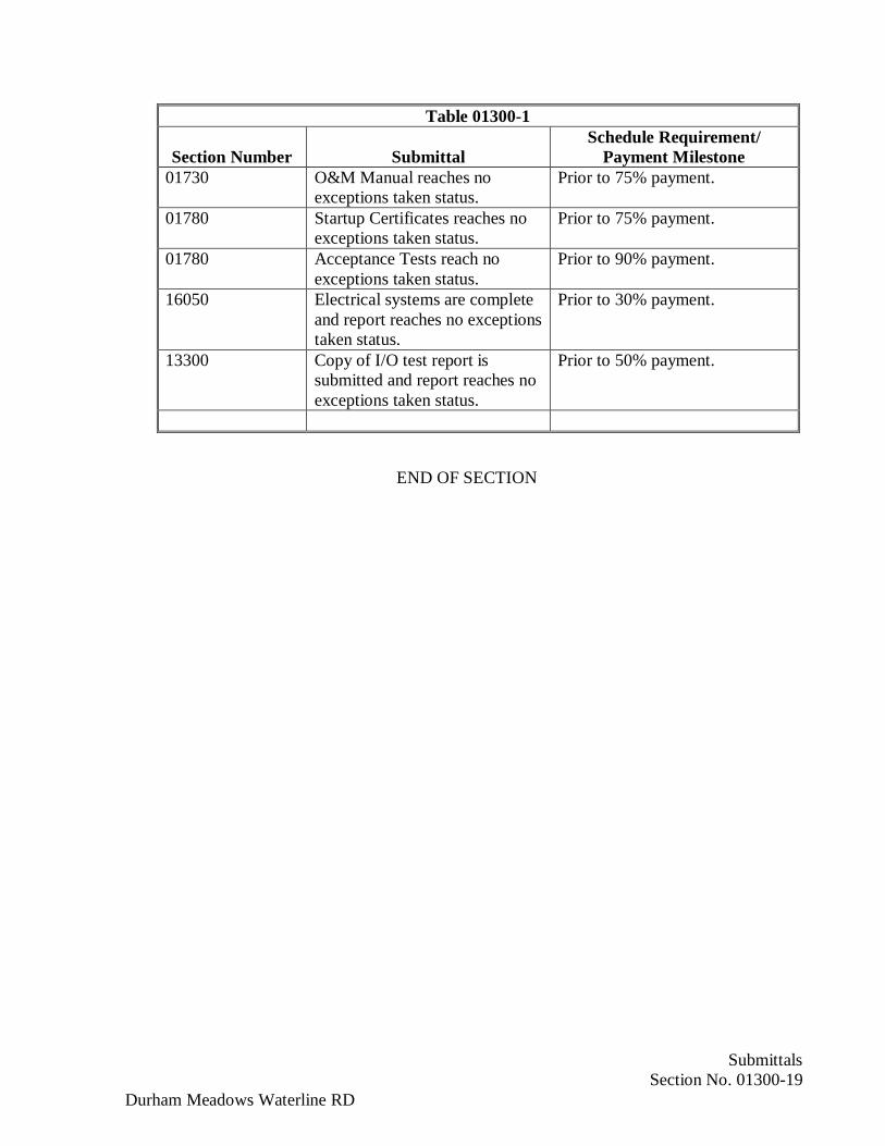
SubmittalsSection No. 01300-19
Durham Meadows Waterline RD
Table 01300-1
Section Number SubmittalSchedule Requirement/
Payment Milestone01730 O&M Manual reaches no
exceptions taken status.Prior to 75% payment.
01780 Startup Certificates reaches noexceptions taken status.
Prior to 75% payment.
01780 Acceptance Tests reach noexceptions taken status.
Prior to 90% payment.
16050 Electrical systems are completeand report reaches no exceptionstaken status.
Prior to 30% payment.
13300 Copy of I/O test report issubmitted and report reaches noexceptions taken status.
Prior to 50% payment.
END OF SECTION

SubmittalsSection No. 01300-20
Durham Meadows Waterline RD
Form 01300-1CERTIFICATE OF DELEGATED DESIGN SERVICES
The undersigned hereby certifies that he/she is a Professional Engineer registered in the state of_______________________ and that he/she has been employed by (Name of Contractor)________________________ to design _____________________________ in accordance with SpecificationsSection _____ for the (Name of Project) ________________ The undersigned further certifies that he/she hasperformed similar designs previously and has performed the design of the __________________________; thatsaid design is in conformance with all applicable local, state, and federal codes, rules, and regulations andprofessional practice standards; that his/her signature and Professional Engineer (P.E) Stamp have been affixedto all calculations and drawings used in, and resulting from, the design; and that the use of that stamp signifies theresponsibility of the undersigned for that design.
The undersigned hereby certifies that he/she has Professional Liability Insurance with limits of $1,000,000.00 anda Certificate of Insurance is attached.
The undersigned hereby agrees to make all original design drawings and calculations available to the Town/Cityof __________________ or Owner’s representative within seven (7) days following written request therefore bythe Owner.
__________________________ ____________________________P.E. Name Contractor’s Name
__________________________ ____________________________Signature Signature
__________________________ ____________________________Title Title
__________________________ ____________________________Address Address

Construction Progress SchedulesSection No. 01310-1
Durham Meadows Waterline RD
SECTION 01310
CONSTRUCTION PROGRESS
PART 1 - GENERAL
1.01 DESCRIPTION:
A. Section includes administrative and procedural requirements for planning, monitoringand documenting the progress of construction during performance of the Work.
B. Contractor shall prepare and submit to Contracting Officer for review within 60 daysafter Notice to Proceed, a construction progress schedule.
C. No work shall be done between 6 p.m. and 7 a.m. nor on Sundays or legal holidayswithout written permission of Contracting Officer. However, emergency work may bedone without prior permission.
A. Work hours on State Highways shall adhere to the following requirements:
(a) Work hours shall be limited to 8 a.m. to 3 p.m. providing two-way trafficis maintained or town-approved detours are established. The Contractorshall attempt to establish two-way traffic or detours whenever possible.
(b) Work hours shall be limited to 9 a.m. to 2 p.m. if two-way traffic cannotbe maintained.
D. Night hours shall be allowed between the hours of 7 p.m. and 5 a.m. with theapproval of the towns, as required to comply with local noise ordinances.
E. Night work may be established by Contractor as regular procedure with writtenpermission of Contracting Officer. Such permission, however, may be revoked at anytime by Contracting Officer if Contractor fails to maintain adequate equipment andsupervision for proper prosecution and control of work at night.
F. The Contractor has the obligation and responsibility at all times to plan and monitor allof its activities, anticipating and scheduling its staff, materials, plant and Work methodsin a manner that is likely to ensure completion of the Work in accordance with the termsand conditions of the Contract and at a rate that will allow it to be completed within theContract Time.
1.02 FORM OF SCHEDULES:
A. Prepare schedules in form of a horizontal bar chart.
1. Provide separate horizontal bar for each trade or operation.
2. Horizontal Time Scale: Identify first work day of each week.
Deleted: Engineer
Deleted: Owner
Deleted: Owner
Deleted: Owner
. .......................................................................................... J .... /~-~
' ------------------------------------------------------------------------------------------------------------------------ '-------------'
• . ..... • ............................................................................................................................................ J::::::: >==============-~
Construction Progress SchedulesSection No. 01310-2
Durham Meadows Waterline RD
3. Scale and spacing to allow space for notations and future revisions.
B. Format of Listings: Chronological order of start of each item of work.
C. Identification of Listings: By major specification section numbers.
1.03 CONTENT OF SCHEDULES:
A. Construction Progress Schedule:
1. Show complete sequence of construction by activity.
2. Show dates for beginning and completion of each major element of constructionand installation dates for major items of equipment. Elements shall include, butnot be limited to, the following:
a. Shop drawing log of major project items.
b. Material and equipment order, manufacturer, delivery, installation, andcheckout.
c. Performance tests and supervisory services activity.
d. Construction of various facilities.
e. Backfilling, grading, seeding, sodding, landscaping, fence construction, andpaving.
f. Water main installation.
g. Start-up and Testing
h. Training.
i. Final cleanup.
j. Allowance for inclement weather.
3. Show projected percentage of completion for each item as of first day of eachmonth.
1.04 SCHEDULE REVISIONS:
A. Every 30 days Contractor shall revise construction schedule to reflect changes inprogress of work.
B. Indicate progress of each activity at date of submittal.
Construction Progress SchedulesSection No. 01310-3
Durham Meadows Waterline RD
C. Show changes occurring since previous submittal of schedule.
1. Major changes in scope.
2. Activities modified since previous submittal.
3. Revised projections of progress and completion.
D. Provide a narrative report as needed to define:
1. Problem areas, anticipated delays, and impact on schedule.
2. Corrective action recommended and its effect.
E. Recovery Schedule:
1. When periodic update indicates the Work is 14 or more calendar days behind thecurrent accepted schedule, submit a separate recovery schedule indicating meansby which Contractor intends to regain compliance with the schedule. Indicatechanges to working hours, working days, crew sizes, and equipment required toachieve compliance, and date by which recovery will be accomplished.
2. If, at any time, the Work is behind schedule with respect to the progress schedulecurrently in force, and if the Contracting Officer believes there is a risk of theWork not being completed within the Contract Time as a result of such delay, theContractor shall take all necessary measures to make up for such delay either byincreasing staff, plant or facilities, or by amending its Work methods, whichever isapplicable, with no change to the Contract Price.
1.05 CONTRACTOR’S LOOK-AHEAD SCHEDULES
A. The Contractor shall provide short interval “look ahead” schedules bi-weekly,identifying Work that has been performed during the past two weeks and activities thatare planned for the next four weeks. The short interval schedule shall be consistent withthe progress schedule currently in force.
B. The Look-Ahead Schedules shall generally reflect the Work associated with the DetailedProgress Schedule. The activities in the Look-Ahead Schedules shall be identified bythe same number coding as the Detailed Progress Schedule and revised as necessary.
C. The final format of the look-ahead schedules will be determined by the ContractingOfficer.
1.06 DAILY CONSTRUCTION REPORT:
A. Contractor shall prepare a written Daily Construction Report in a format acceptable tothe Contracting Officer. The Daily Construction Report shall be prepared for each day
Deleted: Engineer
Deleted: Engineer and Owner
Deleted: Engineer
, ____________________________________________________________________________________________________ _]_ _______ \_ _____ __)
...................... 1
• -- - ----------- - ----------- - ----------- - ----------- - ----------- - ----------- - ----------- - ----------- - ----------- - ----------- - ----------- - ----------- - ----------- J ------- \_ _____ __J

Construction Progress SchedulesSection No. 01310-4
Durham Meadows Waterline RD
Contractor is on the Project Site and submitted to the Contracting Officer,electronically and in hard copy, no later than 10:00 A.M. the next Working day.
B. Daily Construction Reports shall include:
1. Number of Workers for each trade and the names of the Workers.
2. Names of Sub-Contractors and their on-site employees.
3. Hours of Work for each trade or type of equipment.
4. Equipment on the Project Site and materials furnished.
5. Major Work activities performed, location of work performed, and progressthereof, including estimated quantities and amounts of specialty Work.
6. Weather conditions and temperature.
7. Unforeseen subsurface conditions.
8. A list of Submittals transmitted to or received from the Contracting Officer.
9. Meetings attended.
10. Accidents, safety, and security issues.
11. Tests and inspections performed and the results of tests and inspections.
12. Reasons for construction delays.
13. Units of T&M Work, subject to approval daily by the Contracting Officer.
14. Daily Trucking Logs of all materials transported to the Work Site and removedfrom the Work Site.
15. Problems encountered and plan for resolution.
C. If multiple daily Work shifts are used, Contractor shall submit a Daily ConstructionReport for each shift.
D. The Daily Construction Reports may be used to substantiate any claim for delay, impact,or change, and shall contain sufficient information to document each potential impact.The Daily Construction Report may be used as the basis for documentation of T&MWork.
E. The units of T&M Work reported by the Contractor’s Project Superintendent shall bereviewed daily by the Contracting Officer and are subject to approval by theContracting Officer. Contractor’s Project Superintendent shall promptly make any
Deleted: Engineer
Deleted: Engineer
Deleted: Engineer
Deleted: Engineer
Deleted: Engineer

Construction Progress SchedulesSection No. 01310-5
Durham Meadows Waterline RD
changes, as required by the Contracting Officer, to the units of T&M Work recorded onthe Daily Construction Report.
1.07 BIWEEKLY PROGRESS REPORTS
A. Contractor shall prepare a written Biweekly Construction Report in a format acceptableto the Contracting Officer. The Biweekly Construction Report shall be submitted to theContracting Officer, electronically and in hard copy, no later than the Wednesdayfollowing the close of each two-week period.
B. Biweekly Construction Reports shall include:
1. A summary of work completed during the prior two-week period.
2. A projection of work to be completed during the next two-week period.
3. A copy of the Construction Schedule and the Look-Ahead Schedule.
4. A map which shows the project area with color designation of the areas wherework has been completed, where work is ongoing, and where work has not yetbeen started.
5. Green remediation concepts that have been or are being used shall be identified.
6. Photographs representative of the work conducted during the two week period.Identify name of Project, contract number, phase, location, orientation of view,date and time of view on each photograph or in an accompanying photo log.
7. The report shall be prepared for a general audience.
1.08 SUBMITTAL REQUIREMENTS:
A. For initial submittal of construction schedule and subsequent revisions thereof, furnishsix copies of schedule to Contracting Officer.
B. Format for Submittals: Submit required submittals in the following format:
1. Working electronic copy of schedule file, where indicated.
2. PDF electronic file of schedule and reports.
1.09 CONTRACTOR’S LOOK-AHEAD SCHEDULES
A. The Contractor shall provide short interval “look ahead” schedules bi-weekly,identifying Work that has been performed during the past two weeks and activities thatare planned for the next four weeks. The short interval schedule shall be consistent withthe progress schedule currently in force.
Deleted: Engineer
Deleted: Engineer
Deleted: Engineer
Deleted: Engineer
. ______ ____________ ____________ ____________ ____________ ____________ ____________ ____________ ____________ ___________ _]_ ______________ _,,
~--------------------------------------------------------------------------------------------------------------------------1 -------_______ _,,
Construction Progress SchedulesSection No. 01310-6
Durham Meadows Waterline RD
B. The Look-Ahead Schedules shall generally reflect the Work associated with the DetailedProgress Schedule. The activities in the Look-Ahead Schedules shall be identified bythe same number coding as the Detailed Progress Schedule and revised as necessary.
C. The final format of the look-ahead schedules will be determined by the ContractingOfficer.
PART 2 - PRODUCTS
(Not Used)
PART 3 - EXECUTION
(Not Used)
END OF SECTION
Deleted: Engineer and Owner

Pre- and Post-Construction SurveysDurham Meadows Waterline RD Section No. 01 01390-1
SECTION 01390
PRE- AND POST-CONSTRUCTION SURVEYS
PART 1 - GENERAL
1.01 DESCRIPTION:
A. Provide pre- and post-construction surveys and construction photographs as indicatedand specified.
B. Section includes administrative and procedural requirements for the following:
1. Pre-construction photographs.
2. Final completion construction photographs.
3. Pre-construction video recordings.
4. Certified topographic field surveys performed by a registered land surveyor todetermine first floor elevations, etc. as specified herein.
1.02 SUBMITTALS:
A. Submit the following shop drawings in accordance with Section 01300.
B. Qualification Data:
1. Samples of work by proposed photographer on construction photography ofsimilar nature to the Work under this Contract.
2. Proposed photographer’s qualifications as specified in Paragraph 1.03.B.
C. Field Reports:
1. 4 copies of each draft and final Pre-Construction Survey reports.
2. 4 copies of each draft and final Post-Construction Survey reports.
D. Key Plan: Submit key plan of Project site and building with notation of vantage pointsmarked for location and direction of each photograph. Indicate elevation or story ofconstruction. Include same information as corresponding photographic documentation.
E. Digital Photographs: Submit image files within (3) days of taking photographs.
1. Digital Camera: Minimum sensor resolution of (8) megapixels.

Pre- and Post-Construction SurveysDurham Meadows Waterline RD Section No. 01 01390-2
2. Format: Minimum (3200 by 2400) pixels, in unaltered original files, with sameaspect ratio as the sensor, uncropped, date and time stamped, in folder named bydate of photograph, accompanied by key plan file.
3. Identification: Provide the following information with each image description infile metadata tag:
a. Name of Project.
b. Name and contact information for photographer.
c. Name of Engineer.
d. Name of Contractor.
e. Date photograph was taken.
f. Description of vantage point, indicating location, direction (by compasspoint), and elevation or story of construction.
g. Unique sequential identifier keyed to accompanying key plan.
F. Video Recordings: Submit video recordings within seven (7) days of recording.
1. Submit video recordings in digital video disc format acceptable to Engineer.
2. Identification: With each submittal, provide the following information:
a. Name of Project.
b. Name and address of photographer.
c. Name of Engineer.
d. Name of Contractor.
e. Date video recording was recorded.
f. Description of vantage point, indicating location, direction (by compasspoint), and elevation or story of construction.
g. Weather conditions at time of recording.
3. Transcript: Prepared on 8-1/2-by-11-inch paper, punched and bound in heavy-duty, three-ring, vinyl-covered binders. Mark appropriate identification on frontand spine of each binder. Include a cover sheet with same label information ascorresponding video recording. Include name of Project and date of videorecording on each page.

Pre- and Post-Construction SurveysDurham Meadows Waterline RD Section No. 01 01390-3
1.03 QUALITY ASSURANCE:
A. Comply with the requirements specified in Section 01400.
B. Photographer to use techniques, material and equipment capable of producingphotographs with a minimum of six megapixels.
C. Dates for photography at site to be coordinated with the Property Owner. The Ownermust be present during photographic periods at site.
D. Photographer to make and retain all photographs and digital files.
A. The topographic survey shall be performed by or under the supervision of and certifiedby a Connecticut Registered Land Surveyor.
1.04 USAGE RIGHTS:
A. Obtain and transfer copyright usage rights from photographer to Owner for unlimitedreproduction of photographic documentation.
1.05 SEQUENCING AND SCHEDULING:
A. Dates for Pre- and Post-Construction Survey at the site shall be coordinated with theEngineer.
PART 2 - PRODUCTS
2.02 PHOTOGRAPHIC MEDIA:
A. Digital Images: Provide images in JPG format, produced by a digital camera withminimum sensor size of (8) megapixels, and at an image resolution of not less than(3200 by 2400) pixels.
B. Digital Video Recordings: Provide high-resolution, digital video disc in formatacceptable to Engineer.
2.03 PRINTS:
A. Type: Color prints.
B. Finish: Smooth glossy surface.
C. Size: 4-inch x 6-inch.
D. Paper weight: Single weight.
E. Number of prints: Two of each photograph.

Pre- and Post-Construction SurveysDurham Meadows Waterline RD Section No. 01 01390-4
2.04 PRINT IDENTIFICATION:
A. Each print to carry identification and information without interfering with exposureprinted.
B. Each photograph shall have permanently written on it an identification number forreference and a legible description indicating name of Project, title of contract, numberof contract, building, structure or road, owner, date taken, location identification,description data, and Contractor’s name.
C. Back of Print:
1. Project name, photographer’s numbered identification of exposure, time and dateof exposure, name of photographer making exposure, detailed description of viewincluding point from which exposure made, compass direction of view, verticaldeclination of view (horizontal, looking up, looking down, etc.) identification ofmain features in view and information pertinent to the purpose and identificationof the exposure.
2. Weather conditions under which exposure made.
2.05 PRINT MOUNTING:
A. Each print to be inserted in a clear plastic envelope intended for the purpose:
1. Envelope material or fabrication shall be acid free.
2. Envelope shall be sealed to prevent print from accidentally slipping out of theenvelope.
3. Front and back of print shall be visible through the plastic envelope.
4. Envelope shall be resealable for removal and insertion of print.
5. Envelope shall have a reinforced binding edge for binder specified herein.
2.06 PRINT FILING BINDER:
A. Furnish binders for filing specified under Paragraph 2.05.
1. Furnish 2 binders for filing prints. Prints shall be inserted into binders.
2. All binders to be identical.
B. Binders:
1. Intended for long term filing of prints.
2. Provisions for labeling front cover and binding face.

Pre- and Post-Construction SurveysDurham Meadows Waterline RD Section No. 01 01390-5
3. Have back and front cover hinges.
4. Of size appropriate for filing mounted prints.
5. Permit removal and insertion of mounted prints.
2.07 PHOTO-CD:
A. Provide photographic compact disc (photo-CD) for digital image at the time ofdevelopment of each print.
2.08 TOPOGRAPHIC SURVEYS:
A. Provide first floor elevations, the corners of buildings and structures foundations bothfront and rear.
B. Provide elevations of sidewalks, driveways, edge of roadway, retaining walls, fence,garages, sheds, etc.
C. The location of each elevation shall be described in detail in words and located on theplan. The cotour interval shall be 1-foot.
PART 3 - EXECUTION
3.01 PRE- AND POST-CONSTRUCTION SURVEYS:
A. Provide construction surveys for existing (pre-construction) and final (post-construction)conditions in accordance with the following:
1. Notify the Owner a minimum of 48 hours prior to each survey.
2. The Contractor shall obtain permission, by registered mail, from the PropertyOwner a minimum of 7 days prior to conducting each interview and survey.
3. If the Contractor is unable, after two repeated attempts, to obtain permission fromthe Property Owners, then the Contractor shall immediately notify the Engineer sothat appropriate measure may be taken.
4. Obtain the age of each facility, known permit modification and foundationinformation from local building departments.
5. Detailed examination shall include a visual internal and external survey of thebuilding or structure; digital video and color photographs showing visually evidentinternal and external structural cracks and damage.
6. For the Pre-Construction Survey, interview Property Owner regarding existingconditions and structural faults, and determine dates and extent of recent repairs.

Pre- and Post-Construction SurveysDurham Meadows Waterline RD Section No. 01 01390-6
7. Color photographs shall be taken to indicate conditions. The Contractor shallfurnish (two) prints of each photograph and photographic compact disk(s).
8. The report shall include location and description of site; results of visualinspection; color photographs; digital video recordings; sketches; results ofproperty owner or tenant interviews. Description of existing facility foundation.Points where deterioration has occurred shall be noted and color photographs anddigital video recording taken on all sides of the buildings and structures to showexisting condition and any deterioration or other deficiencies. The absence ofdeficiencies shall also be recorded. The Engineer shall examine said draft reportsand may indicate additional information that is required. The final report copiesshall be given to Engineer and the Property Owner.
3.02 CLOSEOUT ACTIVITIES:
A. Provide in accordance with Section 01700.
END OF SECTION
Quality AssuranceSection No. 01400-1
Durham Meadows Waterline RD
SECTION 01400
QUALITY ASSURANCE
PART 1 - GENERAL
1.01 DESCRIPTION:
A. This section covers Quality Assurance and Quality Control requirements for thiscontract.
B. The Contractor is responsible for controlling the quality of work, including work of itssubcontractors, and suppliers and for assuring the quality specified in the TechnicalSpecifications is achieved.
C. All Connecticut Department of Public Health requirements must be met. Refer to 1.03B, C, and D for regulatory references.
D. Refer to the General Conditions Article 6 - Contractor’s Responsibilities, paragraphs6.01, 6.02, and 6.03.
1.02 SUMMARY:
A. Section includes administrative and procedural requirements for quality assurance andquality control.
B. Testing and inspecting services are required to verify compliance with requirementsspecified or indicated. These services do not relieve Contractor of responsibility forcompliance with the Contract Document requirements.
1. Specific quality-assurance and quality-control requirements for individualconstruction activities are specified in the Sections that specify those activities.Requirements in those Sections may also cover production of standard products.
2. Specified tests, inspections, and related actions do not limit Contractor's otherquality-assurance and quality-control procedures that facilitate compliance withthe Contract Document requirements.
3. Requirements for Contractor to provide quality-assurance and quality-controlservices required by Engineer, Owner, or authorities having jurisdiction are notlimited by provisions of this Section.
C. Related Requirements:
1. Division 01 Section "Allowances" for testing and inspecting allowances.

Quality AssuranceSection No. 01400-2
Durham Meadows Waterline RD
2. Divisions 02 through 16 Sections for specific test and inspection requirements.
1.03 REFERENCES:
A. American Society for Testing and Materials (ASTM):
1. E329: Standard Specification for Agencies Engaged in Construction Inspectionand/or Testing
B. State of Connecticut Department of Public Health Drinking Water Section Water MainDesign and Construction Guidelines. Effective October 1, 2006
C. Connecticut Department of Public Health Regulations of Connecticut State Agencies(RCSA) 19-13-B102. Standards for quality of public drinking water.
D. General Statutes of Connecticut, CGS 25-39, Revised January 2015.
1.04 DEFINITIONS:
A. Quality-Assurance Services: Activities, actions, and procedures performed before andduring execution of the Work to guard against defects and deficiencies and substantiatethat proposed construction will comply with requirements.
B. Quality-Control Services: Tests, inspections, procedures, and related actions during andafter execution of the Work to evaluate that actual products incorporated into the Workand completed construction comply with requirements. Services do not include contractenforcement activities performed by Engineer.
C. Mockups: Full-size physical assemblies that are constructed on-site. Mockups areconstructed to verify selections made under Sample submittals; to demonstrate aestheticeffects and, where indicated, qualities of materials and execution; to reviewcoordination, testing, or operation; to show interface between dissimilar materials; andto demonstrate compliance with specified installation tolerances. Mockups are notSamples. Unless otherwise indicated, accepted mockups establish the standard bywhich the Work will be judged.
D. Preconstruction Testing: Tests and inspections performed specifically for Projectbefore products and materials are incorporated into the Work, to verify performance orcompliance with specified criteria.
E. Product Testing: Tests and inspections that are performed by a Nationally RecognizedTesting Laboratory (NRTL), an (National Voluntary Laboratory Accreditation Program(NVLAP), or a testing agency qualified to conduct product testing and acceptable toauthorities having jurisdiction, to establish product performance and compliance withspecified requirements.
1. NRTL: A nationally recognized testing laboratory according to 29 CFR 1910.7.
Quality AssuranceSection No. 01400-3
Durham Meadows Waterline RD
2. NVLAP: A testing agency accredited according to NIST's National VoluntaryLaboratory Accreditation Program.
F. Source Quality-Control Testing: Tests and inspections that are performed at the source,e.g., plant, mill, factory, or shop.
G. Field Quality-Control Testing: Tests and inspections that are performed on-site forinstallation of the Work and for completed Work.
H. Testing Agency: An entity engaged to perform specific tests, inspections, or both.Testing laboratory shall mean the same as testing agency.
I. Installer/Applicator/Erector: Contractor or another entity engaged by Contractor as anemployee, Subcontractor, or Sub-subcontractor, to perform a particular constructionoperation, including installation, erection, application, and similar operations.
1. Use of trade-specific terminology in referring to a trade or entity does not requirethat certain construction activities be performed by accredited or unionizedindividuals, or that requirements specified apply exclusively to specific trade(s).
J. Experienced: When used with an entity or individual, "experienced" means havingsuccessfully completed a minimum of five previous projects similar in nature, size, andextent to this Project; being familiar with special requirements indicated; and havingcomplied with requirements of authorities having jurisdiction.
1.05 CONFLICTING REQUIREMENTS:
A. Referenced Standards: If compliance with two or more standards is specified and thestandards establish different or conflicting requirements for minimum quantities orquality levels, comply with the most stringent requirement. Refer conflictingrequirements that are different, but apparently equal, to Engineer for a decision beforeproceeding.
B. Minimum Quantity or Quality Levels: The quantity or quality level shown or specifiedshall be the minimum provided or performed. The actual installation may complyexactly with the minimum quantity or quality specified, or it may exceed the minimumwithin reasonable limits. To comply with these requirements, indicated numeric valuesare minimum or maximum, as appropriate, for the context of requirements. Referuncertainties to Engineer for a decision before proceeding.
1.06 SUBMITTALS:
A. Shop Drawings: For mockups, provide plans, sections, and elevations, indicatingmaterials and size of mockup construction.
1. Indicate manufacturer and model number of individual components.
Quality AssuranceSection No. 01400-4
Durham Meadows Waterline RD
2. Provide axonometric drawings for conditions difficult to illustrate in twodimensions.
B. Contractor's Quality-Control Plan: For quality-assurance and quality-control activitiesand responsibilities.
C. Qualification Data: For Contractor's quality-control personnel.
D. Contractor's Statement of Responsibility: When required by authorities havingjurisdiction, submit copy of written statement of responsibility sent to authorities havingjurisdiction before starting work on the following systems:
1. Seismic-force-resisting system, designated seismic system, or component listed inthe designated seismic system quality-assurance plan prepared by Engineer.
2. Main wind-force-resisting system or a wind-resisting component listed in thewind-force-resisting system quality-assurance plan prepared by Engineer.
E. Testing Agency Qualifications: For testing agencies specified in "Quality Assurance"Article to demonstrate their capabilities and experience. Include proof of qualificationsin the form of a recent report on the inspection of the testing agency by a recognizedauthority.
F. Schedule of Tests and Inspections: Prepare in tabular form and include the following:
1. Specification Section number and title.
2. Entity responsible for performing tests and inspections.
3. Description of test and inspection.
4. Identification of applicable standards.
5. Identification of test and inspection methods.
6. Number of tests and inspections required.
7. Time schedule or time span for tests and inspections.
8. Requirements for obtaining samples.
9. Unique characteristics of each quality-control service.
1.07 CONTRACTOR'S QUALITY-CONTROL PLAN:
A. Quality-Control Plan, General: Submit quality-control plan within 10 days of Notice toProceed, and not less than 5 days prior to preconstruction conference. Submit in formatacceptable to Engineer. Identify personnel, procedures, controls, instructions, tests,

Quality AssuranceSection No. 01400-5
Durham Meadows Waterline RD
records, and forms to be used to carry out Contractor's quality-assurance and quality-control responsibilities. Coordinate with Contractor's construction schedule.
B. Quality-Control Personnel Qualifications: Engage qualified full-time personnel trainedand experienced in managing and executing quality-assurance and quality-controlprocedures similar in nature and extent to those required for Project.
C. Submittal Procedure: Describe procedures for ensuring compliance with requirementsthrough review and management of submittal process. Indicate qualifications ofpersonnel responsible for submittal review.
D. Testing and Inspection: In quality-control plan, include a comprehensive schedule ofWork requiring testing or inspection, including the following:
1. Contractor-performed tests and inspections including subcontractor-performedtests and inspections. Include required tests and inspections and Contractor-elected tests and inspections.
2. Special inspections required by authorities having jurisdiction and indicated onthe "Statement of Special Inspections."
3. Owner-performed tests and inspections indicated in the Contract Documents.
E. Continuous Inspection of Workmanship: Describe process for continuous inspectionduring construction to identify and correct deficiencies in workmanship in addition totesting and inspection specified. Indicate types of corrective actions to be required tobring work into compliance with standards of workmanship established by Contractrequirements and accepted mockups.
F. Monitoring and Documentation: Maintain testing and inspection reports including logof accepted and rejected results. Include work Engineer has indicated asnonconforming or defective. Indicate corrective actions taken to bring nonconformingwork into compliance with requirements. Comply with requirements of authoritieshaving jurisdiction.
1.08 REPORTS AND DOCUMENTS:
A. Test and Inspection Reports: Prepare and submit certified written reports specified inother Sections. Include the following:
1. Date of issue.
2. Project title and number.
3. Name, address, and telephone number of testing agency.
4. Dates and locations of samples and tests or inspections.
Quality AssuranceSection No. 01400-6
Durham Meadows Waterline RD
5. Names of individuals making tests and inspections.
6. Description of the Work and test and inspection method.
7. Identification of product and Specification Section.
8. Complete test or inspection data.
9. Test and inspection results and an interpretation of test results.
10. Record of temperature and weather conditions at time of sample taking andtesting and inspecting.
11. Comments or professional opinion on whether tested or inspected Work complieswith the Contract Document requirements.
12. Name and signature of laboratory inspector.
13. Recommendations on retesting and reinspecting.
B. Manufacturer’s Technical Representative’s Field Reports: Prepare written informationdocumenting manufacturer’s technical representative's tests and inspections specified inother Sections. Include the following:
1. Name, address, and telephone number of technical representative making report.
2. Statement on condition of substrates and their acceptability for installation ofproduct.
3. Statement that products at Project site comply with requirements.
4. Summary of installation procedures being followed, whether they comply withrequirements and, if not, what corrective action was taken.
5. Results of operational and other tests and a statement of whether observedperformance complies with requirements.
6. Statement whether conditions, products, and installation will affect warranty.
7. Other required items indicated in individual Specification Sections.
C. Factory-Authorized Service Representative’s Reports: Prepare written informationdocumenting manufacturer's factory-authorized service representative's tests andinspections specified in other Sections. Include the following:
1. Name, address, and telephone number of factory-authorized service representativemaking report.
2. Statement that equipment complies with requirements.
Quality AssuranceSection No. 01400-7
Durham Meadows Waterline RD
3. Results of operational and other tests and a statement of whether observedperformance complies with requirements.
4. Statement whether conditions, products, and installation will affect warranty.
5. Other required items indicated in individual Specification Sections.
D. Permits, Licenses, and Certificates: For Owner's records, submit copies of permits,licenses, certifications, inspection reports, releases, jurisdictional settlements, notices,receipts for fee payments, judgments, correspondence, records, and similar documents,established for compliance with standards and regulations bearing on performance ofthe Work.
1.09 QUALITY ASSURANCE:
A. General: Qualifications paragraphs in this article establish the minimum qualificationlevels required; individual Specification Sections specify additional requirements.
B. Manufacturer Qualifications: A firm experienced in manufacturing products or systemssimilar to those indicated for this Project and with a record of successful in-serviceperformance, as well as sufficient production capacity to produce required units.
C. Fabricator Qualifications: A firm experienced in producing products similar to thoseindicated for this Project and with a record of successful in-service performance, as wellas sufficient production capacity to produce required units.
D. Installer Qualifications: A firm or individual experienced in installing, erecting, orassembling work similar in material, design, and extent to that indicated for this Project,whose work has resulted in construction with a record of successful in-serviceperformance.
E. Professional Engineer Qualifications: A professional engineer who is legally qualifiedto practice in jurisdiction where Project is located and who is experienced in providingengineering services of the kind indicated.
F. Specialists: Certain Specification Sections require that specific construction activitiesshall be performed by entities who are recognized experts in those operations.Specialists shall satisfy qualification requirements indicated and shall be engaged forthe activities indicated.
1. Requirements of authorities having jurisdiction shall supersede requirements forspecialists.
G. Testing Agency Qualifications: An NRTL, an NVLAP, or an independent agency withthe experience and capability to conduct testing and inspecting indicated, asdocumented according to ASTM E329; and with additional qualifications specified inindividual Sections; and, where required by authorities having jurisdiction, that isacceptable to authorities.
Quality AssuranceSection No. 01400-8
Durham Meadows Waterline RD
H. Manufacturer's Technical Representative Qualifications: An authorized representativeof manufacturer who is trained and approved by manufacturer to observe and inspectinstallation of manufacturer's products that are similar in material, design, and extent tothose indicated for this Project.
I. Factory-Authorized Service Representative Qualifications: An authorizedrepresentative of manufacturer who is trained and approved by manufacturer to inspectinstallation of manufacturer's products that are similar in material, design, and extent tothose indicated for this Project.
J. Preconstruction Testing: Where testing agency is indicated to perform preconstructiontesting for compliance with specified requirements for performance and test methods,comply with the following:
1. Contractor responsibilities include the following:
a. Provide test specimens representative of proposed products andconstruction.
b. Submit specimens in a timely manner with sufficient time for testing andanalyzing results to prevent delaying the Work.
2. Testing Agency Responsibilities: Submit a certified written report of each test,inspection, and similar quality-assurance service to Engineer, with copy toContractor. Interpret tests and inspections and state in each report whether testedand inspected work complies with or deviates from the Contract Documents.
K. Mockups: Before installing portions of the Work requiring mockups, build mockupsfor each form of construction and finish required to comply with the followingrequirements, using materials indicated for the completed Work:
L. Codes and Standards: Refer to General Conditions Article 3 - Contract Documents:Intent, Amending, Reuse, paragraph 3.03 of the General Conditions.
M. Copies of applicable referenced standards are not included in the Contract Documents.Where copies of standards are needed by the Contractor for superintendence and qualitycontrol of the work, the Contractor shall obtain a copy or copies directly from thepublication source and maintain at the jobsite, available to the Contractor's personnel,subcontractors, and Engineer.
N. Quality of Materials: Unless otherwise specified, all materials and equipment furnishedfor permanent installation in the Work shall conform to applicable standards andspecifications and shall be new, unused, and free from defects and imperfections, wheninstalled or otherwise incorporated in the Work. The Contractor shall not use materialand equipment for any purpose other than that intended or specified unless the Engineerauthorizes such use.

Quality AssuranceSection No. 01400-9
Durham Meadows Waterline RD
O. Where so specified, products or workmanship shall also conform to the additionalperformance requirements included within the Contract Documents to establish a higheror more stringent standard or quality than that required by the referenced standard.
1.10 OFFSITE INSPECTION:
A. When the specifications require inspection of materials or equipment during theproduction, manufacturing, or fabricating process, or before shipment, such servicesshall be performed by the Owner’s independent testing laboratory, or inspectionorganization acceptable to Engineer in conjunction with or by the Engineer.
B. The Contractor shall give appropriate written notice to the Engineer not less than30 days before offsite inspection services are required, and shall provide for theproducer, manufacturer, or fabricator to furnish safe access and proper facilities and tocooperate with inspecting personnel in the performance of their duties.
1.11 MATERIALS AND EQUIPMENT:
A. The Contractor shall maintain control over procurement sources to ensure that materialsand equipment conform to specified requirements in the Contract Documents.
B. The Contractor shall comply with manufacturer’s printed instructions regarding allfacets of materials and/or equipment movement, storage, installation, testing, startup,and operation. Should circumstances occur where the contract documents are morestringent than the manufacturer’s printed instructions, the Contractor shall comply withthe specifications. In cases where the manufacturer’s printed instructions are morestringent than the contract documents, the Contractor shall advise the Engineer of thedisparity and conform to the manufacturer’s printed instructions. In either case, theContractor is to apply the more stringent specification or recommendation, unlessaccepted otherwise by the Engineer.
1.12 QUALITY CONTROL:
A. Owner Responsibilities: Where quality-control services are indicated as Owner'sresponsibility, Owner will engage a qualified testing agency to perform these services.
1. Owner will furnish Contractor with names, addresses, and telephone numbers oftesting agencies engaged and a description of types of testing and inspecting theyare engaged to perform.
2. The Contractor shall furnish a construction schedule and a minimum of 48 hournotice of readiness for testing and inspection of the work. The Engineer shalldetermine the exact time and location of field sampling and testing, and mayrequire such additional sampling and testing to determine that materials andequipment conform with data previously furnished by Contractor and with theContract Documents.
Quality AssuranceSection No. 01400-10
Durham Meadows Waterline RD
3. The Contractor shall schedule the work to permit adequate time for testing and re-testing should test results not conform to the contract documents. Lack of testingor inspection which is attributable to insufficient notice by the Contractor orfailure of the Contractor to cooperate, will be cause for rejection of the work.
4. The Contractor shall deliver materials in sufficient quantities to the Owner’stesting agency as may be required. Laboratory testing shall be performed within areasonable time, consistent with the specified standards.
5. The Contractor shall furnish material samples and cooperate in the field samplingand testing activities, interrupting the work when necessary. The Contractor shallfurnish personnel, facilities and access to assist in the sampling and testingactivities.
6. Payment for these services will be made from testing and inspecting allowances,as authorized by Change Orders.
7. Costs for retesting and reinspecting construction that replaces or is necessitated bywork that failed to comply with the Contract Documents will be charged toContractor.
B. Contractor Responsibilities: Tests and inspections not explicitly assigned to Owner areContractor's responsibility. Perform additional quality-control activities required toverify that the Work complies with requirements, whether specified or not.
1. Unless otherwise indicated, provide quality-control services specified and thoserequired by authorities having jurisdiction. Perform quality-control servicesrequired of Contractor by authorities having jurisdiction, whether specified or not.
2. Monitor quality control over suppliers, manufacturers, products, services, siteconditions, and workmanship, to produce Work of specified quality.
3. Comply with manufacturers' instructions, including each step in sequence.
4. When manufacturers' instructions conflict with Contract Documents, requestclarification from Engineer before proceeding.
5. Comply with specified standards as minimum quality for the Work except wheremore stringent tolerances, codes, or specified requirements indicate higherstandards or more precise workmanship.
6. Perform Work by persons qualified to produce required and specified quality.
7. Verify field measurements are as indicated on Shop Drawings or as instructed bymanufacturer.
8. Secure products in place with positive anchorage devices designed and sized towithstand stresses, vibration, physical distortion, or disfigurement.

Quality AssuranceSection No. 01400-11
Durham Meadows Waterline RD
9. Where services are indicated as Contractor's responsibility, engage a qualifiedtesting agency to perform these quality-control services.
a. Contractor shall not employ same entity engaged by Owner, unless agreedto in writing by Owner.
10. Notify testing agencies at least 24 hours in advance of time when Work thatrequires testing or inspecting will be performed.
11. Where quality-control services are indicated as Contractor's responsibility, submita certified written report, in duplicate, of each quality-control service.
12. Testing and inspecting requested by Contractor and not required by the ContractDocuments are Contractor's responsibility.
13. Submit additional copies of each written report directly to authorities havingjurisdiction, when they so direct.
C. Tolerances:
1. Monitor fabrication and installation tolerance control of products to produceacceptable Work. Do not permit tolerances to accumulate.
2. Comply with manufacturers' tolerances. When manufacturers' tolerances conflictwith Contract Documents, request clarification from Engineer before proceeding.
3. Adjust products to appropriate dimensions; position before securing products inplace.
D. Manufacturer's Field Services: Where indicated, engage a factory-authorized servicerepresentative to inspect field-assembled components and equipment installation,including service connections. Report results in writing as specified in Division 01Section "Submittals."
E. Manufacturer's Technical Services: Where indicated, engage a manufacturer's technicalrepresentative to observe and inspect the Work. Manufacturer's technicalrepresentative's services include participation in preinstallation conferences,examination of substrates and conditions, verification of materials, observation ofInstaller activities, inspection of completed portions of the Work, and submittal ofwritten reports.
F. Retesting/Reinspecting: Regardless of whether original tests or inspections wereContractor's responsibility, provide quality-control services, including retesting andreinspecting, for construction that replaced Work that failed to comply with theContract Documents.

Quality AssuranceSection No. 01400-12
Durham Meadows Waterline RD
G. Testing Agency Responsibilities: Cooperate with Engineer and Contractor inperformance of duties. Provide qualified personnel to perform required tests andinspections.
1. Notify Engineer and Contractor promptly of irregularities or deficienciesobserved in the Work during performance of its services.
2. Determine the location from which test samples will be taken and in which in-situtests are conducted.
3. Conduct and interpret tests and inspections and state in each report whether testedand inspected work complies with or deviates from requirements.
4. Submit a certified written report, in duplicate, of each test, inspection, and similarquality-control service through Contractor.
5. Do not release, revoke, alter, or increase the Contract Document requirements orapprove or accept any portion of the Work.
6. Do not perform any duties of Contractor.
H. Associated Services: Cooperate with agencies performing required tests, inspections,and similar quality-control services, and provide reasonable auxiliary services asrequested. Notify agency sufficiently in advance of operations to permit assignment ofpersonnel. Provide the following:
1. Access to the Work.
2. Incidental labor and facilities necessary to facilitate tests and inspections.
3. Adequate quantities of representative samples of materials that require testing andinspecting. Assist agency in obtaining samples.
4. Facilities for storage and field curing of test samples.
5. Delivery of samples to testing agencies.
6. Preliminary design mix proposed for use for material mixes that require controlby testing agency.
7. Security and protection for samples and for testing and inspecting equipment atProject site.
I. Coordination: Coordinate sequence of activities to accommodate required quality-assurance and -control services with a minimum of delay and to avoid necessity ofremoving and replacing construction to accommodate testing and inspecting.
1. Schedule times for tests, inspections, obtaining samples, and similar activities.
Quality AssuranceSection No. 01400-13
Durham Meadows Waterline RD
J. Schedule of Tests and Inspections: Prepare a schedule of tests, inspections, and similarquality-control services required by the Contract Documents as a component ofContractor's quality-control plan. Coordinate and submit concurrently with Contractor'sconstruction schedule. Update as the Work progresses.
1. Distribution: Distribute schedule to Owner, Engineer, testing agencies, and eachparty involved in performance of portions of the Work where tests and inspectionsare required.
1.13 SPECIAL TESTS AND INSPECTIONS:
A. Special Tests and
B. detailed Inspections: Contractor will engage a qualified a special inspector to conductspecial tests and inspections required by authorities having jurisdiction as theresponsibility of Owner, as required by the Contract Document, and as follows:
C. Special Tests and Inspections: Conducted by a qualified a special inspector as requiredby authorities having jurisdiction, as indicated in individual Specification Sections, andas follows:
1. Verifying that manufacturer maintains fabrication and quality-control proceduresand reviews the completeness and adequacy of those procedures to perform theWork.
2. Notifying Engineer and Contractor promptly of irregularities and deficienciesobserved in the Work during performance of its services.
3. Submitting a certified written report of each test, inspection, and similar quality-control service to Engineer with copy to Contractor and to authorities havingjurisdiction.
4. Submitting a final report of special tests and inspections at SubstantialCompletion, which includes a list of unresolved deficiencies.
5. Interpreting tests and inspections and stating in each report whether tested andinspected work complies with or deviates from the Contract Documents.
6. Retesting and reinspecting corrected work.
PART 2 - PRODUCTS
(Not Used)

Quality AssuranceSection No. 01400-14
Durham Meadows Waterline RD
PART 3 - EXECUTION
3.01 EXAMINATION:
A. Verify existing site conditions and substrate surfaces are acceptable for subsequentWork. Beginning new Work means acceptance of existing conditions.
B. Verify existing substrate is capable of structural support or attachment of new Workbeing applied or attached.
C. Examine and verify specific conditions described in individual specification sections.
D. Verify utility services are available, of correct characteristics, and in correct locations.
3.02 PREPARATION:
A. Clean substrate surfaces prior to applying next material or substance.
B. Seal cracks or openings of substrate prior to applying next material or substance.
C. Apply manufacturer required or recommended substrate primer, sealer, or conditionerprior to applying new material or substance in contact or bond.
3.03 QUALITY CONTROL:
A. Quality control is the responsibility of the Contractor, and the Contractor shall maintaincontrol over construction and installation processes to assure compliance with specifiedrequirements.
B. Certifications for personnel, procedures, and equipment associated with specialprocesses (e.g., welding, cable splicing, instrument calibration, surveying) shall bemaintained in the Contractor’s field office, available for inspection by the Engineer.Copies shall be made available to the Engineer upon request.
C. Means and methods of construction and installation processes are the responsibility ofthe Contractor, and at no time is it the intent of the Engineer to supersede or void thatresponsibility.
3.04 TEST AND INSPECTION LOG:
A. Test and Inspection Log: Prepare a record of tests and inspections. Include thefollowing:
1. Date test or inspection was conducted.
2. Description of the Work tested or inspected.
3. Date test or inspection results were transmitted to Engineer.

Quality AssuranceSection No. 01400-15
Durham Meadows Waterline RD
4. Identification of testing agency or special inspector conducting test or inspection.
B. Maintain log at Project site. Post changes and revisions as they occur. Provide accessto test and inspection log for Engineer’s reference during normal working hours.
3.05 REPAIR AND PROTECTION:
A. General: On completion of testing, inspecting, sample taking, and similar services,repair damaged construction and restore substrates and finishes.
1. Provide materials and comply with installation requirements specified in otherSpecification Sections or matching existing substrates and finishes. Restorepatched areas and extend restoration into adjoining areas with durable seams thatare as invisible as possible. Comply with the Contract Document requirementsfor cutting and patching in Division 01 Section "Execution."
B. Protect construction exposed by or for quality-control service activities.
3.06 CERTIFICATION:
A. Upon completion of all work, including construction and testing, the Contractor shallprepare the CT DPH Certificate of Completed Water or Treatment WorksConstruction/Installation letter for signature of the Administrative Official of the PublicWater System, along with all required documentation. The form letter for certificationmay be found on the CT DPH website at:
http://www.ct.gov/dph/cwp/view.asp?a=3139&q=387316#CertificationLetter.
END OF SECTION

Sampling Procedures and Laboratory ServicesDurham Meadows Waterline RD Section No. 01410-1
SECTION 01410
SAMPLING PROCEDURES AND LABORATORY SERVICES
PART 1 - GENERAL
1.01 SCOPE OF WORK
A. Sampling and analysis requirements related to the following:
1. Testing of soil from areas of known contamination (see drawings) or contaminatedsoil encountered during the course of the work to meet the requirements for disposalof materials.
2. Testing of Construction Water treatment system effluent prior to discharge.
1.02 RELATED SECTIONS
A. Section 01300 - Submittals
B. Section 02053 - Excavated Material Management Plan
C. Section 02241 - Construction Water Management
D. Section 02210 – Earth Excavation, Backfill, Fill, and Grading
1.03 REFERENCES
The publications listed below form a part of this specification to the extent referenced.The publications are referred to in the text by the regulatory agency name only.
A. U.S. Environmental Protection Agency (EPA)
1. SW-846, Test Methods for Evaluating Solid Waste Physical/Chemical Methods, 3rdedition, November 1986, including revisions through February 2007, and anysubsequent revisions.
2. EPA 816-F-09-0004, Maximum Contaminant Levels (MCLs) for Drinking Water,Summer 2009, and any subsequent revisions.
5. EPA EPA/240/R-02/900, Guidance for Quality Assurance Project Plans, December2002, and any subsequent revisions.
B. Connecticut Department of Energy and Environmental Protection (CTDEEP)
1. Laboratory Quality Assurance and Quality Control Guidance; Reasonable
Sampling Procedures and Laboratory ServicesDurham Meadows Waterline RD Section No. 01410-2
Confidence Protocols Guidance Document, December 2010, and any subsequentrevisions.
2. Laboratory Quality Assurance and Quality Control; Data Quality Assessment andData Usability Evaluation, Guidance Document, May 2009, and any subsequentrevisions.
3. Connecticut Remediation Standard Regulations (Sections 22a-133k-1 through 22a-133k-3), January 1997, and any additional approved criteria.
4. Connecticut Permit Requirements for Waste Facilities, Section 22a-6h and 22a-454.
1.04 DEFINITIONS
AA Atomic AbsorptionCD Personal computer compatible compact discCLP USEPA Contract Laboratory ProgramCTDEEP Connecticut Department of Energy and Environmental ProtectionCy Cubic yardDEC Connecticut Residential Direct Exposure CriteriaDOT United States Department of TransportationEPA United States Environmental Protection AgencyEPA-NE EPA New England (Region I)CT-ETPH Connecticut Extractable Total Petroleum HydrocarbonsGC/ECD gas chromatograph/electron capture detectorGC/FID gas chromatograph/flame ionization detectorGC/MS gas chromatograph/mass spectrometerGWPC Connecticut Groundwater Protection CriteriaICP Inductively coupled plasmaICP-AES Inductively coupled plasma/atomic emission spectrometerICP/MS Inductively coupled plasma/mass spectrometerLQMM Laboratory Quality Management ManualMCL Drinking Water Maximum Contaminant LevelMS/MSD Matrix Spike/Matrix Spike DuplicateNELAC National Environmental Accreditation ConferencePAH Polyaromatic HydrocarbonPCB Polychlorinated BiphenylPDF Adobe Portable Document FormatPMC Connecticut Pollutant Mobility CriteriaQA Quality AssuranceQC Quality ControlRCRA Resource Conservation and Recovery ActRCRA8+Cu arsenic, cadmium, chromium, lead, mercury, barium, selenium, silver, and copperRSR Connecticut Remediation Standard RegulationsSAP Sampling and Analysis PlanSOP Standard Operating Procedure

Sampling Procedures and Laboratory ServicesDurham Meadows Waterline RD Section No. 01410-3
SPLP Synthetic Precipitation Leaching Procedure, EPA Method SW846-1312TCLP Toxicity Characteristic Leaching Procedure, EPA Method SW846-1311VOC Volatile Organic Compound
1.05 SUBMITTALS
A. See Section 01300 - Administrative Requirements, for submittal procedures.
B. Sampling and Analysis Plan
1. Submit for approval a Sampling and Analysis Plan (SAP) developed in accordancewith EPA Guidance for Quality Assurance Project Plans. The SAP must besubmitted for approval at least 30 calendar days prior to any sampling activities.Table 01410-1 summarizes the requirements for the analyses to be included in theSAP.
Table 01410-1 Sampling and Analysis SummaryMatrix Testing Frequency Analyses Data Use
Soil Disposal As required bydisposal facility
As requiredby disposalfacility
Classify excavatedmaterial for disposalfacility acceptance
TreatedConstructionWaterDischarge
1 per batch treated VOCs, or asrequired bythe CT DEEPGeneralPermit fordischarge orotherapplicabledischargecriteria.
Document water meetsdischarge criteria
Table 01410-1 Notes; See Section 1.04 for Definition of Terms
2. Prior to the start of Work, the Contractor shall provide a Laboratory QualityManagement Manual (LQMM) for each laboratory to be used. The LQMM shallprovide the chemical quality control procedures necessary for those chemicalanalyses to be performed by each contracted laboratory. This submittal may be inthe form of a laboratory off-the-shelf Quality Management Manual, provided that allrelevant quality assurance (QA)/quality control (QC) procedures are present. Theplan(s) shall be submitted by the Contractor upon selection of laboratories, at least30 calendar days prior to any sampling activities. The LQMM(s) shall be includedas an appendix to the SAP. Each laboratory identified is subject to an audit (eitheron-site or via document review) by the Engineer.
3. Prior to start of Work, the Contractor shall provide documentation of project
Deleted: to a POTW
Sampling Procedures and Laboratory ServicesDurham Meadows Waterline RD Section No. 01410-4
organization and quality management responsibilities. This information must beprovided in the SAP.
C. Test Reports
For analyses without an EPA Contract Laboratory Program (CLP) equivalent, CLP-likedeliverables includes summary forms and data as specified by the method’s ConnecticutReasonable Confidence Protocol (CT RCP) criteria.
1. Waste Characterizationa. Analytical results shall be submitted to the Engineer at least two business days
prior to material being taken off-site and include comparison to the Contractor’sdesignated soil disposal facility limits. Data submittals shall include the resultsof all analyses, including duplicate sample analyses. Results should alsoinclude any unusual observations such as the presence of interferences, etc.Details on the report contents and laboratory turnaround times must be providedin the SAP. It is the responsibility of the Contractor to collect and submit anysamples and analytical results required by their disposal facilities directly tothose facilities.
b. The analytical results shall be submitted to the Engineer in the form of aMicrosoft Excel spreadsheet and in PDF format on a CD or via electronic mail,and also in hard copy form. Field QC sample results (trip blanks, fieldduplicates, equipment blanks, MS/MSDs) shall be included and clearlyidentified.
c. Submission of raw data and calculations by the laboratories is required in theformat of a digital deliverable, such as a CD for archiving purposes. The CDshall contain full CLP-like deliverables including all raw data.
4. Construction Water Dischargea. Preliminary analytical results shall be submitted to the Engineer at least 8
business hours prior to discharge of treated water and include comparison to thedischarge criteria specified in Section 02240. Final analytical results shall besubmitted to the Engineer within 21 calendar days of sample collection. Datasubmittals shall include the results of all analyses, including duplicate sampleanalyses. Results should also include any unusual observations such as thepresence of interferences, etc. Details on the report contents and laboratoryturnaround times must be provided in the SAP.
b. The analytical results shall be submitted to the Engineer in the form of aMicrosoft Excel spreadsheet and in PDF format on a CD or via electronic mail,and also in hard copy form. Field QC sample results (trip blanks, fieldduplicates, equipment blanks, MS/MSDs) shall be included and clearlyidentified. After the data evaluation has been performed by the Contractor, theresults shall be submitted to the Engineer with the appropriate qualifiers in thesame formats and include comparison to the discharge criteria specified inSection 02240.
c. Submission of raw data and calculations by the laboratories is required in the

Sampling Procedures and Laboratory ServicesDurham Meadows Waterline RD Section No. 01410-5
format of a digital deliverable, such as a CD for archiving purposes. The CDshall contain full CLP-like deliverables including all raw data.
D. Field Notes
1. Copies of field logbook entries, all sample collection forms, and detailed samplelocation information for all sample collection shall be submitted with the test reportsrequired above. Results of all field measurements performed must be included inthese notes and/or summarized in spreadsheet format, as described above.
1.06 CONTRACTOR REQUIREMENTS
A. Laboratory Services
1. The Contractor shall provide and coordinate the services of an environmentalchemical laboratory to perform analyses. Laboratory capabilities must be providedfor the duration of the work. Laboratories are subject to audit by the Engineer, bothon-site or via document review, at any time.
a. Data Quality Requirements1) The Contractor must adhere to the requirements detailed in their SAP for
the project (as required in part 1.05.B of this specification.) The purpose ofthe SAP is to ensure that the Contractor adequately addresses all chemicalquality management requirements associated with this project. TheContractor shall ensure that all technical data generated are accurate,precise, and representative. The types and quality of the samplingprocedures and analytical testing shall be based on the requirements setforth in these specifications and the SAP. Each contracted laboratory shallsubmit a LQMM for review and approval by the Engineer.
2) Quality data shall be generated by the Contractor from the followingsampling and analysis programs:(a) Characterization of excavated material for disposal purposes.(b) Testing of treated construction water, consisting of groundwater from
well abandonment activities and equipment decontamination water.b. Quality Control/Assurance Policy
1) The Contractor shall adhere to the requirements detailed in their approvedSAP. The SAP will include consideration of the technical specificationrequirements and contains provisions to assure identification andcompliance with requirements of EPA and Connecticut Department ofEnvironmental Protection (CTDEEP) regulations.
c. Responsibilities1) The Contractor’s Quality Management Program shall provide assurance
that activities affecting chemical quality are documented and accomplishedin accordance with written instructions, drawings, and procedures.Provisions shall be established for communicating to all responsibleindividuals in the Contractor’s organization that Quality Assurance
Sampling Procedures and Laboratory ServicesDurham Meadows Waterline RD Section No. 01410-6
policies, plans, and procedures are mandatory requirements which shall beimplemented.
2) Activities affecting quality shall be accomplished under controlledconditions. Controlled conditions include the use of appropriateprocedures and equipment; suitable environmental conditions foraccomplishing the activity, such as adequate cleanliness; documentationthat specified decontamination procedures were followed; adequate off-sitelaboratory facilities; and assurance that all prerequisites for the givenactivity have been satisfied.
d. Quality Management Organization1) The Contractor shall execute the SAP which will clearly define the
organizational structure within which the SAP is to be implemented andexecuted. The Contractor shall detail the names, qualifications, authorities,and responsibilities of all QA/QC personnel as well as the relationshipand/or interrelationship with the overall project organization. Theauthority and responsibility of persons performing quality managementactivities shall be stated in writing. The Quality Management organizationshall document the functional lines of authority within the Qualityorganization.
PART 2 - PRODUCTS (Not Applicable)
PART 3 – EXECUTION
3.01 PROJECT ORGANIZATION
A. The Contractor shall provide details relative to the project organization and qualitymanagement responsibilities for the Contractor and any Subcontractors to be involved inthe completion of the proposed work. This information must be included in the SAP andshall clearly define the project management assignments by name and theirresponsibilities to ensure compliance with QA/QC protocols.
B. Overall Project Organization
1. Overall project organization shall include schematic diagrams indicating keyQA/QC individuals by name for the prime Contractor and any Subcontractor andshowing all Contractor-Subcontractor interactions and responsibilities.
C. List of Key Individuals
1. A listing of key individuals and descriptions of qualifications and experiencerelative to toxic or hazardous materials/wastes sampling and analyses shall beprovided.
D. Sampling Program Organization
Sampling Procedures and Laboratory ServicesDurham Meadows Waterline RD Section No. 01410-7
1. The Contractor shall clearly specify the sampling program organization to beutilized during all field sampling efforts. The Contractor shall clearly identifywhether individual Subcontractors will be responsible for specific samplingprograms. The Contractor shall identify all Subcontractors responsible for chain-of-custody transfer between sample collection and receipt by the laboratories.
E. Contractor Quality Control Supervisor
1. The Contractor’s Quality Control Supervisor shall be responsible for overallmanagement of the Chemical QA/QC System and have the authority to act in allQA/QC matters for the Contractor. The QC Supervisor for this contract shall havethe ultimate responsibility to ensure compliance with the approved SAP as well asbe in charge of the Contractor’s Quality Control Program for the overall projectspecifications. The name of this person and/or authorized assistants shall beprovided by the Contractor along with a summary of their prior experience whichshall demonstrate their ability to perform correctly the duties required to thesatisfaction of the Engineer. All of the Contractor’s submittals for approval shall bereviewed and modified or corrected as needed by him or his authorized assistantsand approved prior to forwarding of such submittals to the Engineer.
2. The Contractor’s Quality Control Supervisor may designate some of hisresponsibilities to another qualified person who shall be approved in advance by theEngineer in the following situations:a. When the Contractor’s Quality Control Supervisor does not personally have the
requisite skills.b. When the Contractor’s Quality Control Supervisor is unable to be physically
present when tasks involving chemical sampling and analysis activities arebeing conducted on Site.
c. When deemed necessary by the Engineer.
F. Laboratory Certification
1. The Contractor shall show evidence of the prequalification auditing of the certifiedlaboratories. The prequalification shall include a description of the facilities,analytical instrumentation, and personnel responsible for the performance of alllaboratory analyses, including supervisors, chemists and technicians. These personsshall be identified together with a corresponding description of experience andqualifications. An on-site audit of the laboratory is not required by the Contractor.
3.02 LABORATORY APPROVAL REQUIREMENTS
A. General
1. The Contractor shall provide and coordinate the services of an analytical laboratory
Sampling Procedures and Laboratory ServicesDurham Meadows Waterline RD Section No. 01410-8
to perform analyses certified by the EPA’s National Environmental LaboratoryAccreditation Conference (NELAC) within the required turnaround time. Thelaboratory shall be certified by NELAC for the EPA analytical methodologiesrequired under this program. The SAP must detail the matrices and methods whichneed to be documented as NELAC accredited. The laboratory is subject toinspection (auditing) and prior approval by the Engineer. In addition, individuallaboratories will be required to submit the necessary documentation demonstratingthe NELAC certification for the EPA analytical methodologies required under thisprogram.
2. Laboratories shall possess NELAC certification for each environmental matrix andeach specific analytical method to be employed. The Contractor must showdocumentation of prequalification and auditing of all selected laboratories havingNELAC certification for all of the analytes and matrices specific to the project. Thedocumentation must show that the laboratories were chosen not only for the lowprice but for their qualifications. The laboratories’ QA plan, resumes, StandardOperating Procedures (SOPs) and Statement of Qualifications which includes listsof laboratory instrumentation, facility description, and experience/references shouldbe available for review by the Engineer. If the laboratory was audited by theContractor, a record of the results of that audit must be available to the Engineer.All of the above information must show relevance to the project.
B. Inspection and Approval
1. The Contractor’s laboratory and organization must be approved by the Engineerprior to receiving Site samples for analysis. Satisfactory completion of the entirelaboratory certification process and approval of the individual Laboratory LQMM inaccordance with this section must be made before sampling and analysis of anysamples may be performed.
C. Laboratory Personnel
1. Generala. The Contractor’s laboratory or subcontracted laboratory shall be experienced in
the type of testing to be performed. A representative of the laboratory shallcoordinate sampling and testing to control the quality of the work. Thelaboratory personnel will be evaluated and approved with reference to theireducation and related professional experience in the performance of specifiedanalytical and QA/QC activities. At a minimum, the laboratory personnel shallconsist of the following:
2. Organic Laboratory Supervisor
a. An Organic Laboratory Supervisor shall have a minimum of a bachelor’sdegree in chemistry or any physical science and at least three years oflaboratory experience, including at least one year of supervisory experience.

Sampling Procedures and Laboratory ServicesDurham Meadows Waterline RD Section No. 01410-9
3. GC/MS Operatora. A gas chromatograph/mass spectrometer (GC/MS) Operator shall have a
minimum of a bachelor’s degree in chemistry or any physical science and oneyear of experience in operating and maintaining GC/MS systems. This appliesto operators of low resolution and high resolution GC/MS systems.
4. GC/ECD Operatora. A gas chromatograph/electron capture detector (GC/ECD) Operator shall have
a minimum of a bachelor’s degree in chemistry or any physical science and oneyear of experience in operating and maintaining GC/ECD systems.
5. GC/FID Operatora. A gas chromatograph/flame ionization detector (GC/FID) Operator shall have a
minimum of a bachelor’s degree in chemistry or any physical science and oneyear of experience in operating and maintaining GC/FID systems.
6. Mass Spectral Interpretations Specialista. A Mass Spectral Interpretations Specialist shall have a minimum of a
bachelor’s degree in chemistry or any physical science, a training course(s) inmass spectral interpretation and a minimum of two years’ experience.
7. Organic Sample Preparation Specialista. An organic sample preparation specialist shall have a minimum of a high school
diploma and a college level course in general chemistry or equivalent, and aminimum of six months experience in an analytical laboratory.
8. Back-Up Techniciana. The laboratory shall have a minimum of one (1) chemist available at any one
time of operation as a back-up technical person with a minimum of a bachelor’sdegree in chemistry or any physical science and a minimum of one yearexperience in each of the following areas: GC/MS operation and maintenancefor volatile and semivolatile analyses; mass spectral interpretation; sampleextraction and preparation; and GC/ECD operation and maintenance forpesticide/PCB analyses.
9. Inorganics Laboratory Supervisora. An Inorganics Laboratory Supervisor shall have a minimum of a bachelor’s
degree in chemistry or any scientific/engineering discipline and a minimum ofthree years of laboratory experience, including at least one year in a supervisoryposition.
10. ICP/AES and/or ICP/MS Spectroscopista. An Inductively coupled plasma/atomic emission spectrometer (ICP/AES)
and/or ICP/mass spectrometer (MS) Spectroscopist shall have a minimum of abachelor’s degree in chemistry or any scientific/engineering discipline, a
Sampling Procedures and Laboratory ServicesDurham Meadows Waterline RD Section No. 01410-10
specialized training in ICP/AES and/or ICP/MS Spectroscopy and a minimumof two years of applied experience with ICP/AES and/or ICP/MS analysis ofenvironmental samples.
11. ICP/AES Operatora. An ICP/AES Operator shall have a minimum of a bachelor’s degree in
chemistry or any scientific/engineering discipline, a minimum of one year ofexperience in operating and maintaining ICP/AES instrumentation, inconjunction with the educational requirements; or, in lieu of educationalrequirements, three additional years of operating and maintaining ICP/AESinstrumentation.
12. Atomic Absorption Operatora. An Atomic Absorption (AA) Operator shall have a minimum of a bachelor’s
degree in chemistry or any scientific/engineering discipline, a minimum of oneyear of experience in operating and maintaining AA instrumentation forwhichever of the following AA techniques will be utilized during this program:(a) flame, (b) graphite furnace, and (c) cold vapor, in conjunction with theeducational requirements; or, in lieu of educational requirements, threeadditional years of operating and maintaining AA instrumentation, includingflame, graphite furnace, and cold vapor techniques.
13. Inorganic Sample Preparation Specialista. An Inorganic Sample Preparation Specialist shall have a minimum of a high
school diploma and a college level course in general chemistry or equivalent,and a minimum of six months of experience in an analytical laboratory.
14. Spectrophotometric and/or Titration Specialista. A Spectrophotometric and/or Titration Specialist (based on which procedure is
used for cyanide analysis) shall have a minimum of a high school diploma and acollege level course in general chemistry or equivalent, and a minimum of sixmonths of experience in an analytical laboratory.
15. Traininga. The laboratory must provide documentation of all training. This will include
the time of training, curriculum of material taught, the qualification of thetrainers, and a testing procedure or method of documenting the learningprocess.
D. Laboratory Facilities
1. Certain basic facilities are necessary for the safe, accurate, and timely analysis of therequired samples. At a minimum, the laboratory facilities shall include thefollowing:
a. Sample Receipt Area: A sample receipt area providing adequate, contamination-

Sampling Procedures and Laboratory ServicesDurham Meadows Waterline RD Section No. 01410-11
free, well-ventilated work space with chemical resistant bench tops for receiptand safe handling of samples.
b. Storage Area: A Storage Area with sufficient refrigerator space to maintainunused sample volume for 60 days after data submission and sample extracts for365 days after data submission. NOTE: Volatile samples, extractable organicsamples, sample extracts, and standards must each be stored separately.
c. Sample Preparation Area: A Sample Preparation Area shall have adequate,contamination-free, well-ventilated work space provided with: benches withchemical resistant tops, fume hoods, laboratory ovens, desiccators, a vacuumsource (Note: Standards must be prepared in a separated hood or isolated area),source of distilled or demineralized organic-free water and analytical balance(s)located away from drafts and rapid changes in temperature.
E. Laboratory Instrumentation
1. At a minimum, the laboratory shall have the following instruments in operation atthe time of the post-award laboratory evaluation. The instruments must becommitted for the full duration of the contract. The instruments must be capable ofachieving the required reporting limits specified in the SAP.
2. Volatile Analysisa. For volatile analysis, a GC/MS system with a purge and trap device shall be
provided.
3. Semivolatile Analysisa. For semivolatile analysis, a GC/MS system with an autosampler/injector shall
be provided.
4. Backup for Organic Instrumentationa. As a backup for organic instrumentation, the laboratory shall provide, at a
minimum, one (1) GC/MS system and one (1) purge and trap device. Inaddition, the laboratory shall have an in-house stock of instrument parts andcircuit boards or maintain manufacturer instrument service contracts for eachinstrument to ensure continuous operation to meet contract-specified holdingtimes and turnaround times.
5. Metals Analysis (excluding mercury)a. For the analysis of metals, an ICP/AES and/or an ICP/MS shall be provided.
The choice of instruments used will be dependent upon the laboratory and therequired reporting limits for metals. The instrument chosen must meet therequired reporting limits for metals presented in the SAP. If required reportinglimits cannot be met by ICP/AES and an ICP/MS is unavailable to thelaboratory, an atomic absorption spectrophotometer may be used, as specifiedin this section.
Sampling Procedures and Laboratory ServicesDurham Meadows Waterline RD Section No. 01410-12
b. If an ICP/MS is unavailable to the laboratory, an AA Metals Analysisspectrophotometer with a graphite furnace shall be provided.
6. Mercury Analysisa. For mercury analysis, a mercury cold vapor AA analyzer or AA instrument
modified for cold vapor analysis shall be provided.
7. Cyanide Analysisa. For cyanide analysis, a spectrophotometer suitable for measurements between
570 and 580 nanometers shall be provided.
8. Backup for Inorganic Instrumentationa. As a backup for inorganic instrumentation, the Contractor laboratory shall
provide the following: one graphite furnace equipped atomic absorptionspectrometer and one mercury cold vapor atomic absorption system. Inaddition, the Contractor laboratory shall have an in-house stock of circuitboards and instrument parts or maintain manufacturer instrument servicecontracts for each piece of equipment to ensure continuous operation to meetcontract specified turnaround times.
F. Laboratory Management Capability
1. The Contractor laboratory must have an organization with well-definedresponsibilities for each individual in the management system to ensure sufficientresources for this contract and to maintain a successful operation. To establish thiscapability, the Contractor laboratory shall designate personnel to carry out thefollowing responsibilities for the contract. Functions include, but are not limited to,the following:
2. Project Managera. Project Manager shall be responsible for overall aspects of the contract (from
sample receipt through data delivery) and shall be the primary contact.
3. Sample Custodiana. Sample Custodian shall be responsible for receiving the samples (logging,
handling and storage).
4. Quality Assurance Officera. Quality Assurance Officer shall be responsible for overseeing the quality
assurance aspects of the data, ensuring corrective action procedures areimplemented when necessary and shall report directly to upper management.
5. Data Reporting and Delivery Officera. Data Reporting and Delivery Officer shall be responsible for all aspects of data
Sampling Procedures and Laboratory ServicesDurham Meadows Waterline RD Section No. 01410-13
deliverables organization, packaging, copying, and delivery.
3.03 SAMPLING PROCEDURES
A. Sampling Plan Overview
1. The SAP must include a sampling plan for each matrix to be sampled. Each planclearly addresses procedures to obtain representative data. The SAP must containdescriptions of sampling equipment and sample sizes. The SAP must containdescriptions of sample containers, sample preservation, sample shipment andhandling and sampling program organization. SOPs for sampling, if available, shallbe provided by the Contractor and included as an Appendix of the SAP.
2. Sampling and sample custody procedures shall be consistent with EPA guidelinesunless otherwise specified.
3. Specific sampling and analytical procedures must be identified in the SAP includingrelated extraction procedures and analytical methodologies for appropriate chemicalanalyses. Detailed procedures must be provided in the SAP for analyticalmethodologies requiring special modifications.
4. The Engineer shall have the right to direct modifications to the samplingmethodology or SOPs to ensure representative sampling.
5. The SAP shall identify the proposed disposal facilities and describe the analyticaland sample frequency requirements of each proposed disposal facility.
6. The SAP shall describe, for all soil disposal characterization samples (includingthose for delineating TCLP lead exceedances) and excavation control samples:a. Sample depth intervalb. Rationale and method for creation of composite samples (if used) from grab
samples
B. Sampling and Analysis Requirements
1. Sampling and analysis requirements for each matrix must be summarized in theSAP. Requirements are further described in Section 02053 - Excavated MaterialManagement Plan, Section 02241 - Construction Water Management and Section02210 – Earth Excavation, Backfill, Fill, and Grading. Sampling rationale,frequency requirements associated with each matrix, associated target compounds,required reporting limits, chemical analyses and required QC analyses must bedetailed in the SAP.
Sampling Procedures and Laboratory ServicesDurham Meadows Waterline RD Section No. 01410-14
C. Decontamination Procedures
1. The Contractor shall follow the decontamination procedure that must be provided inthe SAP for the decontamination of sampling equipment. Sampling methods andequipment shall be chosen to minimize decontamination requirements and thepossibility of cross contamination. Any sampling equipment used must bedecontaminated before use and between sampling locations.
D. Sample Handling
1. Sample Containers and Preservationa. Containers for all samples and coolers shall be supplied by the laboratory. All
sample containers utilized by the Contractor shall be provided from an EPA-approved supplier utilizing pre-cleaned containers.
b. The Contractor shall employ the sample preservation methods that must bedetailed in the SAP following sample collection. The SAP must include allchemical preservatives to be used, required physical conditions of storage andshipment, and required holding times.
2. Chain of Custodya. Each sample container shall be clearly identified with the name of the project,
the field sample number, date and time of sampling and the name of thesampling personnel. Field information shall be written in indelible ink and thelabel shall be affixed in such a manner to ensure that is does not becomeseparated from its respective container.
b. The Contractor shall follow the sample custody procedures detailed in the SAPwhich will assure that any sample which is analyzed will yield resultsrepresentative of the sample’s condition at the time of sampling. Theprocedures provided are in conformance with the appropriate EPA guidelines.
c. The Contractor shall follow the chain-of-custody procedures detailed in theSAP and shall adequately record, for evidence, at a minimum, the followinginformation:1) Sample type, sample number, date and time of collection and signatures of
the collector.2) Signatures of persons involved in sample chain of custody.3) Inclusive dates of possession of all individuals involved in sample
possession.4) Additional remarks the sample handler may have to transcribe onto the
chain of custody form.5) Analytical parameters required (name and method number).6) Name of the project.7) Name and telephone number of the point of contact to call for any
questions on the sample shipment.d. The Contractor shall refer to the SAP for the methods by which written chain-
of-custody information shall be stored for future use.
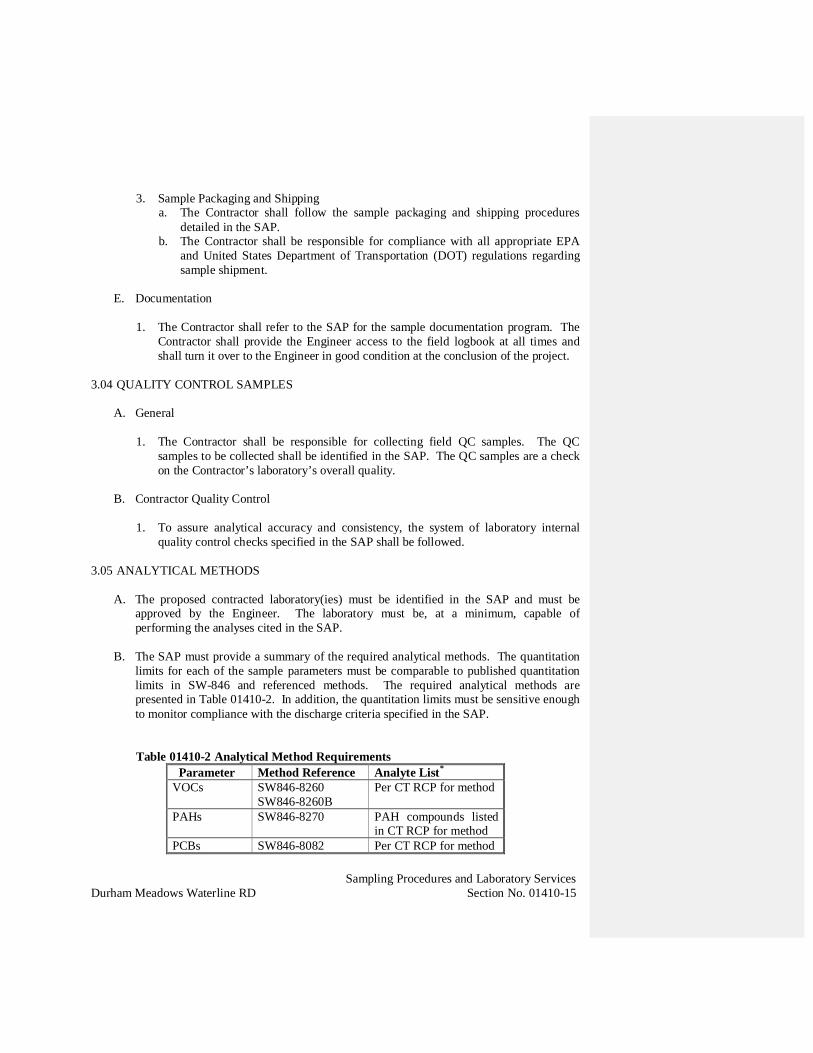
Sampling Procedures and Laboratory ServicesDurham Meadows Waterline RD Section No. 01410-15
3. Sample Packaging and Shippinga. The Contractor shall follow the sample packaging and shipping procedures
detailed in the SAP.b. The Contractor shall be responsible for compliance with all appropriate EPA
and United States Department of Transportation (DOT) regulations regardingsample shipment.
E. Documentation
1. The Contractor shall refer to the SAP for the sample documentation program. TheContractor shall provide the Engineer access to the field logbook at all times andshall turn it over to the Engineer in good condition at the conclusion of the project.
3.04 QUALITY CONTROL SAMPLES
A. General
1. The Contractor shall be responsible for collecting field QC samples. The QCsamples to be collected shall be identified in the SAP. The QC samples are a checkon the Contractor’s laboratory’s overall quality.
B. Contractor Quality Control
1. To assure analytical accuracy and consistency, the system of laboratory internalquality control checks specified in the SAP shall be followed.
3.05 ANALYTICAL METHODS
A. The proposed contracted laboratory(ies) must be identified in the SAP and must beapproved by the Engineer. The laboratory must be, at a minimum, capable ofperforming the analyses cited in the SAP.
B. The SAP must provide a summary of the required analytical methods. The quantitationlimits for each of the sample parameters must be comparable to published quantitationlimits in SW-846 and referenced methods. The required analytical methods arepresented in Table 01410-2. In addition, the quantitation limits must be sensitive enoughto monitor compliance with the discharge criteria specified in the SAP.
Table 01410-2 Analytical Method RequirementsParameter Method Reference Analyte List*
VOCs SW846-8260SW846-8260B
Per CT RCP for method
PAHs SW846-8270 PAH compounds listedin CT RCP for method
PCBs SW846-8082 Per CT RCP for method

Sampling Procedures and Laboratory ServicesDurham Meadows Waterline RD Section No. 01410-16
CT ETPH CT RCP MethodETPH
Per CT RCP for method
Metals SW846-6010 orSW846-6020 orSW846-7000
Per CT RCP for method
Mercury SW846-7470 orSW846-7471
Per CT RCP for method
TCLPextraction
SW846-1311 Per CT RCP
SPLPextraction
SW846-1312 Per CT RCP
WasteCharacteristics
SW846-9000 series As required by disposalfacility
Chlorine SM4500Table 0410-2 Notes; See Section 1.04 for Definition of Terms* Or as required by disposal facility for waste characterization
C. Analytical Instrumentation
1. The apparatus and instrumentation to be used for all analyses shall be identified aspart of the Laboratory(ies) LQMM:a. Specific field and laboratory instrumentation including manufacturer and model
number.b. Operating parameters.c. Laboratory chemicals necessary to perform the analyses.d. Standards including those for calibration.
D. Corrective Action
1. The Contractor shall refer to the SAP for the protocol describing the correctiveactions to be taken by the Contractor should any analytical data fall outside ofacceptable control limits during review.
E. Data Analysis and Reporting
1. The Contractor shall refer to the SAP for the specific system to be used in handlingthe raw data from the time of analysis to the time of reporting to the time of archivalstorage.
2. At a minimum, the Contractor shall conform to EPA SW-846 and shall haveprocedures in place to address the following items for each analytical method andmajor measurement parameter.a. The laboratory data management system including:
1) The date collected from the Chain of Custody and field manuals2) Field manual notes3) The raw data collection system

Sampling Procedures and Laboratory ServicesDurham Meadows Waterline RD Section No. 01410-17
4) The final calculated results5) The data storage system in its entirety including provisions for security and
prevention of data loss6) Data quality assurance documentation including copies of the method-
specified forms presented in SW-8467) Identification system for all data collected8) Identification of individuals involved in data management and reporting9) Identification of schedule for reporting QC analytical data to the Engineer
and EPAb. The data analysis system including units and equations required to convert
instrument response into chemical concentrations.c. Plans for testing questionable or incorrect data or inaccurate programming
sequences.
3. The Contractor shall determine the required laboratory turnaround times for eachmatrix, noting the following:a. Effluent water from the construction water treatment system cannot be
discharged until sample results are received and demonstrate the achievementof the discharge criteria.
4. Electronic data deliverable requirements are outlined in Section 1.05 (c) and in theSAP.
END OF SECTION

Temporary FacilitiesDurham Meadows Waterline RD Section No. 01500-1
SECTION 01500
TEMPORARY FACILITIES
PART 1 GENERAL
1.01 SCOPE
A. The Work of this section includes the furnishing of all labor, tools, equipment, andmaterials, performing all operations necessary to provide temporary facilities as specifiedherein and as directed by the Engineer.
1.02 MEASUREMENT AND PAYMENT
A. Measurement and payment for work described in this section will be made in accordancewith the provisions of SECTION 01150, MEASUREMENT AND PAYMENT and asfollows:
1. Arrange for and pay for all temporary telephone and internet service to the Engineer'sfield office. The Contractor shall pay all monthly internet service and user charges forthe Engineer’s, printer and computer connection.
2. Arrange for and pay for all temporary water services to the Engineer's field office andto all extensions required by the Contractor for construction purposes. TheContractor shall pay all monthly water and sanitary services and user charges.
3. Arrange for and pay for all temporary electrical service to the Engineer's field officeand to all extensions required by the Contractor for construction purposes. TheContractor shall pay all monthly electrical service and user charges.
PART 2 PRODUCTS
2.01 TEMPORARY BUILDINGS
A. Furnish, such temporary offices, storage and fabrication facilities as may be required for theContractor’s own uses and obtain all necessary applicable permits and/or approvalsrequired for their use. Such buildings shall be located as required by the Contractor and asto not interfere with the Work of the Project and shall be completely removed at thecompletion of the Work. The Contractor shall select energy efficient facilities wheneverpossible. The contractor is responsible for finding a suitable location with room forEPA/USACE support trailers. The Engineer and the Owner prior to the start of the Projectshall approve the locations of the field offices.
B. Engineer's Field Offices
1. The Contractor shall provide at the start of the work and for the duration of theproject, unless otherwise specified, two temporary field offices for the use of theEngineer. The offices shall be 12 feet by 24 feet, constructed in a manner and ofmaterials satisfactory to the Engineer, watertight, with at least 2 windows, sanitaryconveniences, lighted, heated and air conditioned, and maintained by the Contractor.They shall each contain the following; a conference table and 6 chairs, a desk, a 2 feet6 inch by 6 feet plan table, a 4-drawer steel file cabinet, 2 chairs, a refrigerator, bottledwater service, a digital camera with a 1.0 gigabyte memory card, a color printer, colorprinter paper, a scanner, an electrostatic copy machine, a plain paper facsimilemachine, plain paper, a telephone with speakerphone, a telephone answering machine,adequate office supplies (pens, pencils, scales, etc.) and a suitable plan rack. Trailers

Temporary FacilitiesDurham Meadows Waterline RD Section No. 01500-2
having approximately the same floor area and all of the equipment mentioned abovemay be considered an acceptable alternate upon approval of the Engineer.
2. The offices shall be located at the work sites in an area to be determined by theContractor, where they will not interfere with the construction work. Space shall beprovided with crushed stone base for at least three vehicles adjacent to each of theoffices for the exclusive use of the Engineer and visitors. The Contractor shall beresponsible for snow removal, mud, and dust control of the parking areas adjacent tothe offices.
3. Provide a submittal showing the proposed locations of the field offices prior to thepre-construction meeting.
PART 3 EXECUTION
3.01 TELEPHONE SERVICES
A. Provide separate wifi internet services in the field offices for use by the Contractor,subcontractors and the Engineer up to the time of final acceptance of the project.
B. The Engineer’s Field Office shall be provided with at least three (3) internet connections orwifi service for a printer/copier/facsimile lines and two (2) computer connections.
3.02 WATER
A. Make connections to the nearest municipal water supply, where available, and or providean alternate source of water, and use this supply for construction purposes. Any portions,which are to become a part of the permanent system, shall conform to the applicablesections of these specifications.
B. Furnish and maintain and subsequently provide the water meters and backflow preventersat each location. Furnish all extensions required. Provide drinking water, satisfactorilycooled.
3.03 ELECTRICITY
A. Arrange for, furnish and maintain all expenses for all electricity required for proper lighting,the use of power tools, for temporary heat for construction operations and for field officesup to the time of final acceptance of the project.
B. Furnish all wiring, fixtures, lamps and other accessories required for his or hissubcontractors’ work, and for proper lighting, the use of power tools and for temporaryheat for construction operations up to the time of final acceptance. Power shall be obtaineddirectly from power company lines or from portable, gasoline driven generator sets.
C. Use of solar-powered generators, or similar, shall be employed. Alternately, the Contractorshall participate in Northeast Clean Power when purchasing power from the local utilitycompany.
3.04 SANITARY CONVENIENCES
A. Sanitary conveniences for the use of all persons employed on the project, properly screenedfrom public observation, shall be provided in sufficient numbers in such manner and at suchpoints as shall be approved. The contents shall be removed and legally disposed of at afrequency acceptable to the public health agency having jurisdiction or as required.

Temporary FacilitiesDurham Meadows Waterline RD Section No. 01500-3
B. The sanitary conveniences shall be the obligation and responsibility of the Contractor forthe duration of the project. The facilities shall be made available to all subcontractors,inspectors, and project visitors.
3.05 PROJECT SIGNS –
A. Project Sign(s) shall be provided as required by funding and regulatory agencies and at aminimum shall include the following information.
1. Project title, as indicated on Contract Documents
2. Names and titles of authorities
3. Names and titles of Engineer
4. Name of prime Contractor
B. Project sign(s) shall be located as approved by the Engineer and be constructed to meet thefollowing requirements:
1. Construction materials and erection supports to resist wind loads and all weather-related impacts for the duration of the project.
2. Comply with CT DOT standards as approved by the Engineer
3.06 BARRICADES AND GUARD LIGHTS
A. Barricades, signs, fences and similar safety and warning devices shall be provided asrequired, in order to insure the protection of employees and others concerned with theirduties and presence on the premises at the project site.
B. Provide and maintain guard lights at all barricades, obstructions in plant ways, and at alltrenches and pits adjacent to traveled ways.
3.07 BRACING, SHORING AND SHEETING
A. Provide all bracing, shoring and sheeting as required for safety and for the properexecution of work. Unless otherwise ordered by the Engineer, all bracing, shoring, andsheeting shall be removed when work is completed.
END OF SECTION

Erosion Control, Sedimentation & Containment of Construction MaterialsDurham Meadows Waterline RD Section No. 01568-1
SECTION 01568
EROSION CONTROL, SEDIMENTATION, ANDCONTAINMENT OF CONSTRUCTION MATERIALS
PART 1 - GENERAL
1.01 DESCRIPTION:
A. Provide all work and take all measures necessary to control soil erosion resulting fromconstruction operations, prevent flow of sediment from construction site(s), and containconstruction materials (including excavation and backfill) within protected working areaas to prevent damage to any stream or wetlands.
1.02 REFERENCES:
A. "Connecticut Guidelines for Soil Erosion and Sediment Control" published (2002) byThe Connecticut Council on Soil and Water Conservation in cooperation with theConnecticut Department of Environmental Protection.
B. United Stated Environmental Protection Agency (USEPA):
1. Guidelines for Erosion and Sediment Control, Planning and Implementation.
2. Processes, Procedures and Methods to Control Pollution Resulting from allConstruction Activity.
1.03 SUBMITTALS:
A. Submit the following shop drawings in accordance with Section 01300.
B. Two weeks prior to the start of the work, submit to Engineer, for review, a plan withdetailed sketches showing the proposed methods to be used for controlling erosionduring construction.
C. The anticipated schedule for work near wetland areas in Middletown shall be provided tothe Middletown Inland Wetlands and Watercourses Agency in advance of the work.
1.04 QUALITY ASSURANCE:
A. Comply with the requirements specified in Section 01400.
B. Use acceptable procedures, including use of water diversion structures, diversionditches, settling basins, and sediment traps.
C. Operations restricted to areas of work indicated on drawings and area which must beentered for construction of temporary or permanent facilities.

Erosion Control, Sedimentation & Containment of Construction MaterialsDurham Meadows Waterline RD Section No. 01568-2
D. If construction materials are washed away during construction, remove materials fromfouled areas.
E. Erosion and sedimentation controls shall be placed before construction begins and mustremain in place until the soil on site is fully stabilized.
F. Stabilize diversion outlets by means acceptable to Engineer.
G. Engineer has authority to limit surface area of erodible earth material exposed byclearing and grubbing, excavation, borrow and fill operations and to direct immediatepermanent or temporary pollution control measures to prevent contamination of anystream or wetlands, including construction of temporary berms, dikes, dams, sedimentbasins, sediment traps, slope drains, and use of temporary mulches, mats, or othercontrol devices or methods to control erosion.
H. There are protected species habitats in many areas throughout the project extent. It isnoted that a species of special concern, Wood Turtle (Glyptemys insculpta, is indicatedin several areas within the project: the access driveway to the Cherry Hill Tank offTalcott Ridge Drive, the Meter Vault at the intersection with SR-17 and Acorn Drive,and areas near the Allyn Brook and Hersig Brook crossings. In addition, several wetlandand aquatic species were noted in the vicinity of the proposed Allyn Brook crossings,including Slimy Sculpin (Cottus cognatus). The Contractor shall consult a wetland orwildlife biologist and follow best management practices to perform the work to protectthese species to the extent possible. A detailed schedule and approach will be submittedto the Engineer for review and approval before start of work in these areas.
PART 2 - PRODUCTS
2.01 BALES:
A. Hay or straw or other suitable material acceptable to Engineer.
2.02 WOOD STAKES:
A. 2 inches by 2 inches by 3 feet (50 mm by 50 mm by 0.9 mm).
2.03 SILT FENCE:
A. Refer to Section 02273 Geotextile Fabric.
PART 3 - EXECUTION
3.01 GENERAL:
A. Do not discharge chemicals, fuels, lubricants, bitumen, raw sewage, and other harmfulwaste into or alongside any watercourse.

Erosion Control, Sedimentation & Containment of Construction MaterialsDurham Meadows Waterline RD Section No. 01568-3
B. Design erosion and sediment controls to handle peak runoff resulting from storm events.
C. The Contractor shall be responsible for inspecting and maintaining these controlmeasures to ensure their proper function and adequate sediment storage at all times. TheContractor shall remove sediment once it reaches 50 percent of the capacity of thestructure. Sediment collected shall be disposed of offsite at the Contractor’s cost.
D. The Contractor shall comply with special protection measures for protection of speciesof special concern, including the Wood Turtle, as much as possible as noted include thefollowing:
1. If possible stream crossings will not be constructed during the months of lateAugust through September or from Mid-March through May, as these are thetimes that amphibians and reptiles are most active near wetlands.
2. If possible, stream crossings will be constructed in November when stream flowsare low and amphibian activity has slowed.
3. Silt fencing should be installed around work areas prior to construction whereapplicable to exclude Wood Turtles from the work area. The use of erosion controlproducts that are embedded with netting should not be used, since these can snareturtles.
4. To protect wood turtles, silt fencing should be used around stockpiles of dirt toexclude them from nesting. Nesting season is in early spring and late summer.
5. Vehicles and machinery should not be parked in turtle habitat. Turtle habitatincludes wetlands and undisturbed forest floor.
6. Construction contractor should be apprised of the possible presence of turtles andtheir description. Any turtles discovered should be moved to an appropriate areaas outlined in the CT DEEP, Wildlife Division information in Attachment.
7. A subsequent NDDB request should be submitted if construction has not begun onthis project by July 28th, 2019.
8. Work conducted during early morning and evening hours will occur with specialcare not to harm basking or foraging individuals.
3.02 INSTALLATION:
A. Install baled hay or straw erosion checks in all locations as directed, surrounding base ofall deposits of stored excavated material outside of disturbed area, and where directed bythe Engineer.
Erosion Control, Sedimentation & Containment of Construction MaterialsDurham Meadows Waterline RD Section No. 01568-4
B. Install checks immediately after site is cleared and before trench excavation. Locatechecks, surrounding stored material, approximately 6 feet (1.8 m) from material.
C. Hold bales in place with two 2 inches by 2 inches by 3 feet (50 mm by 50 mm by 0.9 m)stakes so that each bale is butted tightly against adjoining bale thereby precludingshortcircuiting of erosion check.
D. Construct earth berms or diversions to intercept and divert runoff water from criticalareas.
E. Discharge silt-laden water from excavations onto filter fabric mat and/or baled hay orstraw sediment traps to ensure that only sediment-free water is returned to watercourses.
F. Do not place excavated soil material adjacent to water-course in manner that will causeit to wash away by high water or runoff.
G. Prevent damage to vegetation by excessive watering or silt accumulation in thedischarge area.
H. Do not dump spoiled material into any streams, wetlands, surface waters, or unspecifiedlocations.
I. Prevent indiscriminate, arbitrary, or capricious operation of equipment in streams,wetlands or surface waters.
J. Do not pump silt-laden water from trenches or excavations into surface waters, streams,wetlands, or natural or man-made channels leading thereto.
K. Prevent damage to vegetation adjacent to or outside of construction area limits.
L. Do not dispose of trees, brush, debris, paints, chemicals, asphalt products, concretecuring compounds, fuels, lubricants, insecticides, washwater from concrete trucks orhydroseeders, or any other pollutant in streams, wet-lands, surface waters, or natural orman-made channels leading thereto, or unspecified locations.
M. Do not alter flow line of any stream unless indicated or specified.
N. Construction equipment will not be allowed to enter wetland areas except for theproposed brook crossings at Durham Fairgrounds and Pickett Lane where the alignmentmust be installed off-road. Any construction activities that require limited work withinthe wetlands will be performed under the supervision of a wetland scientist. Appropriateconstruction mats will be employed for construction equipment to operate from.
O. All refueling operations will be undertaken in upland areas to prevent accidental spills offuel into the wetlands.
P. Any disturbance of the wetlands will be repaired as soon as practicable with appropriatewetland plants and the area seeded and mulch applied to promote proper growth.
Erosion Control, Sedimentation & Containment of Construction MaterialsDurham Meadows Waterline RD Section No. 01568-5
END OF SECTION
(REFER TO ATTACHMENT FROM CT DEEP, WILDLIFE DIVISION)
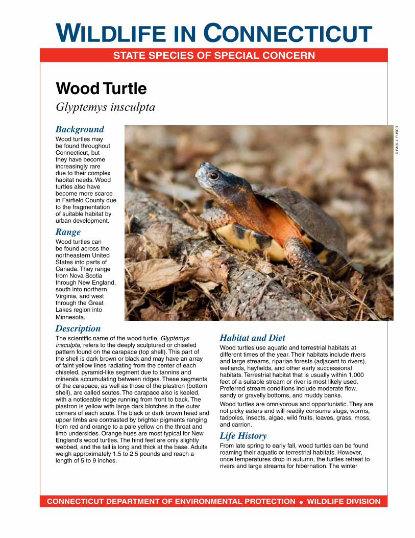
WILDLIFE IN CONNECTICUTSTATE SPECIES OF SPECIAL CONCERN
CONNECTICUT DEPARTMENT OF ENVIRONMENTAL PROTECTION WILDLIFE DIVISION
Wood TurtleGlyptemys insculpta
BackgroundWood turtles may be found throughout Connecticut, but they have become increasingly rare due to their complex habitat needs. Wood turtles also have become more scarce in Fairfield County due to the fragmentation of suitable habitat by urban development.
RangeWood turtles can be found across the northeastern United States into parts of Canada. They range from Nova Scotia through New England, south into northern Virginia, and west through the Great Lakes region into Minnesota.
DescriptionThe scientific name of the wood turtle, Glyptemys insculpta, refers to the deeply sculptured or chiseled pattern found on the carapace (top shell). This part of the shell is dark brown or black and may have an array of faint yellow lines radiating from the center of each chiseled, pyramid-like segment due to tannins and minerals accumulating between ridges. These segments of the carapace, as well as those of the plastron (bottom shell), are called scutes. The carapace also is keeled, with a noticeable ridge running from front to back. The plastron is yellow with large dark blotches in the outer corners of each scute. The black or dark brown head and upper limbs are contrasted by brighter pigments ranging from red and orange to a pale yellow on the throat and limb undersides. Orange hues are most typical for New England’s wood turtles. The hind feet are only slightly webbed, and the tail is long and thick at the base. Adults weigh approximately 1.5 to 2.5 pounds and reach a length of 5 to 9 inches.
Habitat and DietWood turtles use aquatic and terrestrial habitats at different times of the year. Their habitats include rivers and large streams, riparian forests (adjacent to rivers), wetlands, hayfields, and other early successional habitats. Terrestrial habitat that is usually within 1,000 feet of a suitable stream or river is most likely used. Preferred stream conditions include moderate flow, sandy or gravelly bottoms, and muddy banks.
Wood turtles are omnivorous and opportunistic. They are not picky eaters and will readily consume slugs, worms, tadpoles, insects, algae, wild fruits, leaves, grass, moss, and carrion.
Life HistoryFrom late spring to early fall, wood turtles can be found roaming their aquatic or terrestrial habitats. However, once temperatures drop in autumn, the turtles retreat to rivers and large streams for hibernation. The winter
© P
AU
L J.
FU
SC
O
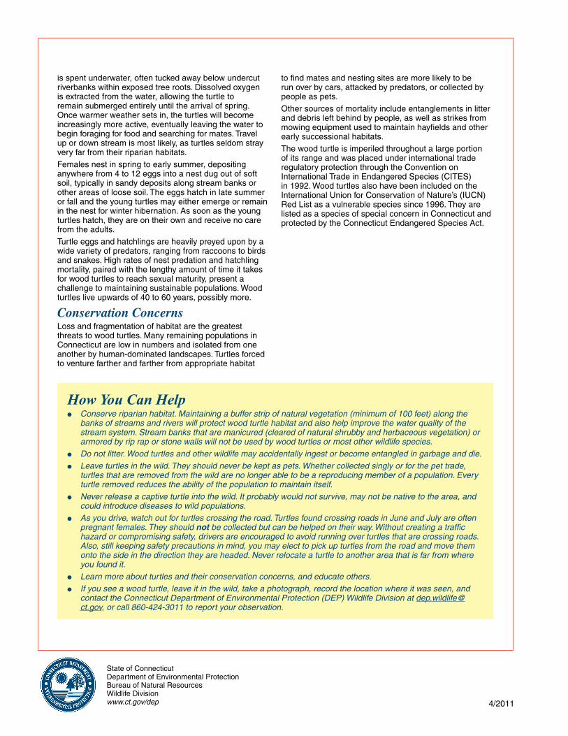
State of ConnecticutDepartment of Environmental ProtectionBureau of Natural ResourcesWildlife Divisionwww.ct.gov/dep 4/2011
is spent underwater, often tucked away below undercut riverbanks within exposed tree roots. Dissolved oxygen is extracted from the water, allowing the turtle to remain submerged entirely until the arrival of spring. Once warmer weather sets in, the turtles will become increasingly more active, eventually leaving the water to begin foraging for food and searching for mates. Travel up or down stream is most likely, as turtles seldom stray very far from their riparian habitats.
Females nest in spring to early summer, depositing anywhere from 4 to 12 eggs into a nest dug out of soft soil, typically in sandy deposits along stream banks or other areas of loose soil. The eggs hatch in late summer or fall and the young turtles may either emerge or remain in the nest for winter hibernation. As soon as the young turtles hatch, they are on their own and receive no care from the adults.
Turtle eggs and hatchlings are heavily preyed upon by a wide variety of predators, ranging from raccoons to birds and snakes. High rates of nest predation and hatchling mortality, paired with the lengthy amount of time it takes for wood turtles to reach sexual maturity, present a challenge to maintaining sustainable populations. Wood turtles live upwards of 40 to 60 years, possibly more.
Conservation ConcernsLoss and fragmentation of habitat are the greatest threats to wood turtles. Many remaining populations in Connecticut are low in numbers and isolated from one another by human-dominated landscapes. Turtles forced to venture farther and farther from appropriate habitat
How You Can Help Conserve riparian habitat. Maintaining a buffer strip of natural vegetation (minimum of 100 feet) along the
banks of streams and rivers will protect wood turtle habitat and also help improve the water quality of the stream system. Stream banks that are manicured (cleared of natural shrubby and herbaceous vegetation) or armored by rip rap or stone walls will not be used by wood turtles or most other wildlife species.
Do not litter. Wood turtles and other wildlife may accidentally ingest or become entangled in garbage and die.
Leave turtles in the wild. They should never be kept as pets. Whether collected singly or for the pet trade, turtles that are removed from the wild are no longer able to be a reproducing member of a population. Every turtle removed reduces the ability of the population to maintain itself.
Never release a captive turtle into the wild. It probably would not survive, may not be native to the area, and could introduce diseases to wild populations.
As you drive, watch out for turtles crossing the road. Turtles found crossing roads in June and July are often pregnant females. They should not be collected but can be helped on their way. Without creating a traffic hazard or compromising safety, drivers are encouraged to avoid running over turtles that are crossing roads. Also, still keeping safety precautions in mind, you may elect to pick up turtles from the road and move them onto the side in the direction they are headed. Never relocate a turtle to another area that is far from where you found it.
Learn more about turtles and their conservation concerns, and educate others.
If you see a wood turtle, leave it in the wild, take a photograph, record the location where it was seen, and contact the Connecticut Department of Environmental Protection (DEP) Wildlife Division at [email protected], or call 860-424-3011 to report your observation.
to find mates and nesting sites are more likely to be run over by cars, attacked by predators, or collected by people as pets.
Other sources of mortality include entanglements in litter and debris left behind by people, as well as strikes from mowing equipment used to maintain hayfields and other early successional habitats.
The wood turtle is imperiled throughout a large portion of its range and was placed under international trade regulatory protection through the Convention on International Trade in Endangered Species (CITES) in 1992. Wood turtles also have been included on the International Union for Conservation of Nature’s (IUCN) Red List as a vulnerable species since 1996. They are listed as a species of special concern in Connecticut and protected by the Connecticut Endangered Species Act.
Delivery, Storage and HandlingDurham Meadows Waterline RD Section No. 01610-1
SECTION 01610
DELIVERY, STORAGE AND HANDLING
PART 1 - GENERAL
1.01 GENERAL:
A. This Section specifies the general requirements for the delivery handling, storage andprotection for all items required in the construction of the work. Specific requirements,if any, are specified with the related item.
1.02 TRANSPORTATION AND DELIVERY:
A. Transport and handle items in accordance with manufacturer's printed instructions.
B. Before shipping to the Site, contact the Engineer, in writing, giving at least fourteen (14)Days prior notice to enable the Engineer or its authorized inspector to inspect theequipment if necessary. Assemble the complete unit in the factory for inspection by theEngineer or its authorized inspector. Do not ship the equipment until the Engineer hascompleted its inspection.
C. Schedule delivery to reduce long term on-site storage prior to installation and/oroperation. Under no circumstances shall equipment be delivered to the site more thanone month prior to installation without written authorization from the Engineer.
D. Ship equipment, material and spare parts complete except where partial disassembly isrequired by transportation regulations or for protection of components.
E. Pack spare parts in containers bearing labels clearly designating contents and pieces ofequipment for which intended. All spare parts shall be cross-referenced to theirapplicable the Specification Section.
F. Carefully pack and crate equipment for shipment. Protect polished and machined metalsurfaces from corrosion and damage during shipment and installation. Specially packelectrical equipment to prevent damage by moisture. Cover equipment having exposedbearings and glands to exclude foreign matter. Carefully pack machines for shipmentand protect electrical equipment from moisture damage. Protect bearings, seals andglands from grit and dirt.
G. Identify each component with durable identifying labels or tags securely attached to eachpiece of equipment, crate or container.
H. Finished surfaces of all exposed flanges shall be protected by fiberboard blank flangesstrongly built and securely bolted thereto.

Delivery, Storage and HandlingDurham Meadows Waterline RD Section No. 01610-2
I. Deliver spare parts at same time as pertaining equipment. Deliver spare parts to ownerafter completion of work.
J. Coordinate delivery with installation to ensure minimum holding time for items that arehazardous, flammable, easily damaged or sensitive to deterioration.
K. Deliver products to the site in manufacturer's original sealed containers or other packingsystems, complete with instructions for handling, storing, unpacking, protecting andinstalling.
L. Assume responsibility for equipment material and spare parts just before unloading fromcarrier at site.
M. All items delivered to the site shall be unloaded and placed in a manner which will nothamper the Contractor's normal construction operation or those of subcontractors andother contractors and will not interfere with the flow of necessary traffic.
N. Provide equipment and personnel to unload all items delivered to the site..
O. Promptly inspect shipment to assure that products comply with requirements, quantitiesare correct, and items are undamaged. For items furnished by others (i.e. Owner, otherContractors), perform inspection in the presence of the Engineer. Notify Engineerverbally, and in writing, of any problems.
P. Pay all demurrage charges if failed to promptly unload items.
1.03 STORAGE AND PROTECTION:
A. Store and protect products and equipment in accordance with the manufacturer'sinstructions, with seals and labels intact and legible. Storage instruction shall be studiedby the Contractor and reviewed with the Engineer by him. Instructions shall be carefullyfollowed and a written record of this kept by the Contractor for each product and piecesof equipment.
B. Arrange storage of products and equipment to permit access for inspection. Periodicallyinspect to make sure products and equipment are undamaged and are maintained underspecified conditions.
C. Provide protective maintenance during storage consisting of manually exercisingequipment, inspecting mechanical surfaces for signs or corrosion or other damage,lubricating, applying any coatings as recommended by the equipment manufacturernecessary for its protection and all other precautions to assure proper protection of allequipment stored and for compliance with manufacturers’ requirements related towarranties. Log all protective maintenance for each piece of equipment in the writtenrecord noted above.
D. Store loose granular materials on solid flat surface in a well-drained area. Preventmixing with foreign matter.

Delivery, Storage and HandlingDurham Meadows Waterline RD Section No. 01610-3
E. Cement and lime shall be stored under a roof and off the ground and shall be keptcompletely dry at all times. All structural, miscellaneous and reinforcing steel shall bestored off the ground or otherwise to prevent accumulation of dirt or grease, and in aposition to prevent accumulations of standing water and to minimize rusting. Beamsshall be stored with the webs vertical. Precast concrete shall be handled and stored in amanner to prevent accumulations of dirt, standing water, staining, chipping or cracking.Brick, block and similar masonry products shall be handled and stored in manner toreduce breakage, cracking and spalling to a minimum.
F. All mechanical and electrical equipment and instruments shall be covered with canvasand stored in a weathertight building to prevent injury. The building may be atemporary structure on the site or elsewhere, but it shall be satisfactory to the Engineer.Building shall be provided with adequate ventilation to prevent condensation. Maintaintemperature and humidity within range required by manufacturer and to preventcondensation on the equipment being stored.
1. All equipment shall be stored fully lubricated with oil, grease and other lubricantsunless otherwise instructed by the manufacturer.
2. Moving parts shall be rotated a minimum of once weekly to insure properlubrication and to avoid metal-to-metal "welding". Log all rotation maintenancefor each piece of equipment in the written record noted above.
3. Upon installation of the equipment, the Contractor shall start the equipment, atleast half load, once weekly for an adequate period of time to ensure that theequipment does not deteriorate from lack of use. Log all startup for each piece ofequipment in the written record noted above.
4. Lubricants shall be changed upon completion of installation and as frequently asrequired thereafter during the period between installation and acceptance. Newlubricants shall be put into the equipment at the time of acceptance.
5. Prior to acceptance of the equipment, the Contractor shall have the manufacturerinspect the equipment and certify that its condition has not been detrimentallyaffected by the long storage period. Such certifications by the manufacturer shallbe deemed to mean that the equipment is judged by the manufacturer to be in acondition equal to that of equipment that has been shipped, installed, tested andaccepted in a minimum time period. As such, the manufacturer will guaranty theequipment equally in both instances. If such a certification is not given, theequipment shall be judged to be defective. It shall be removed and replaced at theContractor's expense.
PART 2 - PRODUCTS
(Not Used)

Delivery, Storage and HandlingDurham Meadows Waterline RD Section No. 01610-4
PART 3 - EXECUTION
(Not Used)
END OF SECTION

Contract CloseoutDurham Meadows Waterline RD Section No. 01700-1
SECTION 01700
CONTRACT CLOSEOUT
PART 1 - GENERAL
1.01 RELATED DOCUMENTS:
A. Drawings and general provisions of the Contract, including General and SupplementaryConditions and other Division 01 Specification Sections, apply to this Section.
B. Section 01046 Control of Work.
C. Section 01710 Cleaning Up.
1.02 SUMMARY:
A. Section includes administrative and procedural requirements for contract closeout,including, but not limited to, the following:
1. Substantial Completion procedures.
2. Final completion procedures.
3. Construction Closeout and Remedial Action Reports
4. Warranties.
5. Final cleaning.
6. Repair of the Work.
7. Specific closeout and special cleaning requirements for the Work in thoseSections.
1.03 SUBMITTALS:
A. Submit the following shop drawings in accordance with Section 01300.
1. Contractor's List of Incomplete Items: Initial submittal at Substantial Completion.
2. Certified List of Incomplete Items: Final submittal at Final Completion.
3. Certificates of Release: From authorities having jurisdiction.
4. Certificate of Insurance: For continuing coverage.
Contract CloseoutDurham Meadows Waterline RD Section No. 01700-2
5. Schedule of Maintenance Material Items: For maintenance material submittalitems specified in other Sections.
B. Contractor shall prepare a Construction Completion Report.
1. The Construction Completion Report shall contain: 1) all project documentationidentified in the specs, including but not limited to as-built plans, test results,weight slips, material disposal documentation, and photo/video documentation; 2)a summary of all work performed with sufficient detail to provide an unfamiliarperson a good understanding of the completed work.
2. The Construction Completion Report shall be submitted in draft form to theEngineer for review.
3. Upon receipt of comments, the Construction Completion Report shall be submittedin final form.
C. Upon approval of the Construction Completion Report, the Contractor shall prepare aRemedial Action Report (RAR), in accordance with EPA’s Close Out Procedures forNPL Sites guidance (May 2011):
http://www.epa.gov/superfund/programs/npl_hrs/closeout/pdf/2011guidance.pdf
The RAR shall: (1) include statements by a registered professional engineer and by thecontractor that construction of the system is complete and that the system is functioningproperly and as designed; (2) include a demonstration, and supporting documentation,that construction of the system is complete and that the system is functioning properlyand as designed; (3) include as-built drawings signed and stamped by a registeredprofessional engineer licensed in the State of Connecticut; and (4) be prepared inaccordance with Chapter 2 (Remedial Action Completion) of EPA’s Close OutProcedures for NPL Sites guidance (May 2011).
1.04 SUBSTANTIAL COMPLETION PROCEDURES:
A. Contractor's List of Incomplete Items: Prepare and submit a list of items to becompleted and corrected (Contractor's punch list), indicating the value of each item onthe list and reasons why the Work is incomplete.
B. Submittals Prior to Substantial Completion: Complete the following a minimum of 10days prior to requesting inspection for determining date of Substantial Completion. Listitems below that are incomplete at time of request.
1. Certificates of Release: Obtain and submit releases from authorities havingjurisdiction permitting Owner unrestricted use of the Work and access to servicesand utilities. Include occupancy permits, operating certificates, and similarreleases.

Contract CloseoutDurham Meadows Waterline RD Section No. 01700-3
2. Submit closeout submittals specified in other Division 01 Sections, includingproject record documents, operation and maintenance manuals, final completionconstruction photographic documentation, damage or settlement surveys, propertysurveys, and similar final record information.
3. Submit closeout submittals specified in individual Divisions 02 through 16Sections, including specific warranties, workmanship bonds, maintenance serviceagreements, final certifications, and similar documents.
4. Submit maintenance material submittals specified in individualDivisions 02 through 16 Sections, including tools, spare parts, extra materials, andsimilar items, and deliver to location designated by Engineer. Label withmanufacturer's name and model number where applicable.
a. Schedule of Maintenance Material Items: Prepare and submit schedule ofmaintenance material submittal items, including name and quantity of eachitem and name and number of related Specification Section. ObtainEngineer’s signature for receipt of submittals.
5. Submit test records.
6. Submit changeover information related to Owner's occupancy, use, operation, andmaintenance.
C. Procedures Prior to Substantial Completion: Complete the following a minimum of 10days prior to requesting inspection for determining date of Substantial Completion. Listitems below that are incomplete at time of request.
1. Advise Owner of pending insurance changeover requirements.
2. Make final changeover of permanent locks and deliver keys to Owner. AdviseOwner’s personnel of changeover in security provisions.
3. Complete startup and testing of systems and equipment.
4. Perform preventive maintenance on equipment used prior to SubstantialCompletion.
5. Instruct Owner's personnel in operation, adjustment, and maintenance of products,equipment, and systems.
6. Advise Owner of changeover in heat and other utilities.
7. Participate with Owner in conducting inspection and walkthrough with localemergency responders.
8. Terminate and remove temporary facilities from Project site, construction tools,and similar elements.
Contract CloseoutDurham Meadows Waterline RD Section No. 01700-4
9. Remove labels that are not permanent labels.
10. Complete final cleaning requirements, including touchup painting.
11. Touch up and otherwise repair and restore marred exposed finishes to eliminatevisual defects.
D. Inspection: Submit a written request for inspection to determine Substantial Completiona minimum of 10 days prior to date the work will be completed and ready for finalinspection and tests. On receipt of request, Engineer will either proceed with inspectionor notify Contractor of unfulfilled requirements. Engineer will prepare the Certificate ofSubstantial Completion after inspection or will notify Contractor of items, either onContractor's list or additional items identified by Engineer, that must be completed orcorrected before certificate will be issued.
1. Reinspection: Request reinspection when the Work identified in previousinspections as incomplete is completed or corrected.
2. Results of completed inspection will form the basis of requirements for finalcompletion.
E. Coordinate schedule for start-up of various equipment and systems.
F. Notify Engineer one week prior to start-up of each item.
G. Verify each piece of equipment or system has been checked for proper lubrication, driverotation, belt tension, control sequence, and for conditions which may cause damage.
H. Verify tests, meter readings, and specified electrical characteristics agree with thoserequired by equipment or system manufacturer.
I. Verify wiring and support components for equipment are complete and tested.
J. Execute start-up under supervision of applicable personnel in accordance withmanufacturers’ instructions.
K. When specified in individual specification Sections, require manufacturer to provideauthorized representative to be present at site to inspect, check, approve equipment orsystem installation prior to start-up, to supervise placing equipment or system inoperation, and to train the Owner’s staff.
L. Submit a written report in accordance with Section 01300 that equipment or system hasbeen properly installed and is functioning correctly.

Contract CloseoutDurham Meadows Waterline RD Section No. 01700-5
1.05 DEMONSTRATION AND INSTRUCTIONS:
A. Utilize operation and maintenance manuals as basis for instruction. Review contents ofmanual with Owner's personnel in detail to explain all aspects of operation andmaintenance.
B. Demonstrate start-up, operation, control, adjustment, trouble-shooting, servicing,maintenance, and shutdown of system(s).
C. Prepare and insert additional data in operations and maintenance manuals when need foradditional data becomes apparent during instruction.
D. Required instruction time for each item of equipment and system is specified inindividual sections.
1.06 TESTING, ADJUSTING AND BALANCING:
A. Owner will appoint and employ services of independent firm to perform additionaltesting if required. Contractor shall pay for services from cash allowance specified inSection 01150.
B. Reports will be submitted by independent firm to Engineer indicating observations andresults of tests and indicating compliance or non-compliance with requirements ofContract Documents.
1.07 PROJECT RECORDS DOCUMENTS
A. The Contractor shall record any actual revisions to the Work and maintain one set of thefollowing Project Record Documents on Site:
1. Contract Drawings, Specifications, and Addenda.
2. Change Orders, Field Orders, and other written notices.
3. Shop drawings, Product data, and samples.
4. Records of surveying and layout Work.
5. Project Record Drawings.
B. The Contractor shall record information on the Project Record Documents concurrentwith construction progress and store these documents separately from the documentsused for construction.
1. The Owner will supply a set of Contract Drawings. The Contractor shall markthereon all revisions as the Work progresses in order to produce a set of as-bulitdrawings.

Contract CloseoutDurham Meadows Waterline RD Section No. 01700-6
2. The Contractor shall note any changes made during construction by any of theContractor's forces or those of any Subcontractors.
3. The Contractor shall dimension the locations of buried or concealed Work,especially piping and conduit, with reference to exposed structures.
4. The Contractor shall dimension the installed locations of concealed service lineson the Site or within the structure by reference from the centre line of the serviceto the structure column lines, or other main finished faces, or other structuralpoints which are easily identified and located in the finished Work.
5. Certificates of Substantial Performance and Total Performance shall not be issueduntil as-built drawings are complete and submitted, and the Contractor hassatisfied all requirements for Substantial Performance and Total Performance ofthe Work.
C. For Project Record Documents and Record Shop Drawings, the Contractor shall legiblymark each item to record actual construction including:
1. Field changes of dimensions and details.
2. Measured horizontal and vertical locations of underground utilities andappurtenances, referenced to permanent surface improvements.
3. Measured locations of internal utilities and appurtenances which are concealed inconstruction, referenced to visible and accessible features of the Work.
4. Changes in the Work caused by Site conditions, or originated by the Owner, theEngineer, the Contractor, or Subcontractors, and by addenda, supplementaldrawings, change orders, correspondence, and directions of any regulatoryauthorities.
5. Record the location of concealed mechanical services and electrical main feeders,junction boxes and pullboxes.
D. Upon completion of the Work, the Contractor shall prepare two CD-ROM sets of theRecord Shop Drawings and an index.
E. The Record Shop Drawings CD-ROM index shall identify the Owner’s project number,project name, and Contract number and the contents of each CD in the following format:
1. The index shall include the following columns of information for each RecordShop Drawing:
a. CD number.
b. Specification Section number.
Contract CloseoutDurham Meadows Waterline RD Section No. 01700-7
c. Specification title.
d. Shop drawing transmittal number.
e. Shop drawing equipment description Vendor/Supplier.
2. The index shall be printed by the following two sorts:
a. Primary sort: Specification Section number. Secondary sort: shop drawingtransmittal number.
b. Primary sort: CD number. Secondary sort: Specification Section number.
3. The index shall be generated using Microsoft Excel software. A copy of theelectronic file shall be furnished to the Owner.
4. The Contractor shall remove the /Engineer seal from all documents.
5. The Contractor shall provide a set of Project Record Documents on CD-ROM inan electronic format compatible with the plant CD-ROM record standards. Alldrawings are to be provided electronically on CD-ROM in both AutoCAD (latestversion) and Adobe Acrobat PDF (latest version).
1.08 EQUIPMENT INVENTORY SPREADSHEET
A. As part of the Owner’s asset management program, the Contractor shall complete allfields for the equipment inventory file for each piece of equipment and device providedunder this Contract, as a requirement for Substantial Performance. An electronic formatof the equipment inventory spreadsheet will be provided on a CD to the successfulGeneral Contractor.
1.09 EQUIPMENT PREVENTATIVE MAINTENANCE SPREADSHEET
A. As part of the Owner’s asset management program, the Contractor shall complete allfields for each piece of equipment and device provided under this Contract, as arequirement for Substantial Completion. The Contractor shall transfer all of themanufacturer’s recommended preventative maintenance tasks and frequencies into thespreadsheet. An electronic format of the equipment inventory spreadsheet will beprovided on a CD to the successful General Contractor
1.10 PROTECTING INSTALLED CONSTRUCTION:
A. Protect installed Work and provide special protection where specified in individualspecification sections.
B. Provide temporary and removable protection for installed products. Control activity inimmediate work area to prevent damage.
C. Protect finished surfaces from traffic, dirt, wear, damage, or movement of heavy objects.

Contract CloseoutDurham Meadows Waterline RD Section No. 01700-8
D. Protect all landscaped areas from damage and maintain as specified.
1.11 SPARE PARTS AND MAINTENANCE PRODUCTS:
A. Furnish spare parts, maintenance, and extra products in quantities specified in individualspecification sections.
B. Deliver to Project site in approved containers with labels and place in location asdirected by Engineer or Owner; obtain receipt prior to final payment.
1.12 FINAL COMPLETION PROCEDURES:
A. Submittals Prior to Final Completion: Before requesting final inspection for determiningfinal completion, complete the following:
1. Submit a final Application for Payment according to Division 01 Section"Payment Procedures."
2. Certified List of Incomplete Items: Submit certified copy of Engineer'sSubstantial Completion inspection list of items to be completed or corrected(punch list), endorsed and dated by Engineer. Certified copy of the list shall statethat each item has been completed or otherwise resolved for acceptance.
3. Certificate of Insurance: Submit evidence of final, continuing insurance coveragecomplying with insurance requirements.
4. Submit pest-control final inspection report.
B. Inspection: Submit a written request for final inspection to determine acceptance aminimum of 10 days prior to date the work will be completed and ready for finalinspection and tests. On receipt of request, Engineer will either proceed with inspectionor notify Contractor of unfulfilled requirements. Engineer will prepare a final Certificatefor Payment after inspection or will notify Contractor of construction that must becompleted or corrected before certificate will be issued.
1. Reinspection: Request reinspection when the Work identified in previousinspections as incomplete is completed or corrected.
1.13 LIST OF INCOMPLETE ITEMS (PUNCH LIST):
A. Organization of List: Include name and identification of each major element (withsubcategories as appropriate), and area affected by construction operations forincomplete items and items needing correction including, if necessary, areas disturbedby Contractor that are outside the limits of construction.
B. Submit list of incomplete items in MS Excel electronic format. Engineer will returnannotated file.

Contract CloseoutDurham Meadows Waterline RD Section No. 01700-9
1.14 SUBMITTAL OF PROJECT WARRANTIES:
A. Time of Submittal: Submit written warranties on request of Engineer for designatedportions of the Work where commencement of warranties other than date of SubstantialCompletion is indicated, or when delay in submittal of warranties might limit Owner’srights under warranty.
B. Organize warranty documents into an orderly sequence based on the table of contents ofContract Documents.
1. Bind warranties and bonds in heavy-duty, three-ring, vinyl-covered, loose-leafbinders, thickness as necessary to accommodate contents, and sized to receive8-1/2-by-11-inch paper.
2. Provide heavy paper dividers with plastic-covered tabs for each separate warranty.Mark tab to identify the product or installation. Provide a typed description of theproduct or installation, including the name of the product and the name, address,and telephone number of Installer.
3. Identify each binder on the front and spine with the typed or printed title"WARRANTIES," Project name, and name of Contractor.
4. Warranty Electronic File: Scan warranties and bonds and assemble completewarranty and bond submittal package into a single indexed electronic PDF filewith links enabling navigation to each item. Provide bookmarked table of contentsat beginning of document.
C. Provide sufficient copies of warranties to distribute to the Engineer, the EPA, the CTDEEP, the City of Middletown, and the Town of Durham. Provide additional copies ofeach warranty to include in operation and maintenance manuals.
PART 2 - PRODUCTS – NOT USED
PART 3 - EXECUTION
3.01 REPAIR OF THE WORK:
A. Complete repair and restoration operations before requesting inspection fordetermination of Substantial Completion.
B. Repair or remove and replace defective construction. Repairing includes replacingdefective parts, refinishing damaged surfaces, touching up with matching materials, andproperly adjusting operating equipment. Where damaged or worn items cannot berepaired or restored, provide replacements. Remove and replace operating componentsthat cannot be repaired. Restore damaged construction and permanent facilities usedduring construction to specified condition.

Contract CloseoutDurham Meadows Waterline RD Section No. 01700-10
END OF SECTION

Cleaning UpDurham Meadows Waterline RD Section No. 01710-1
SECTION 01710
CLEANING UP
PART 1 - GENERAL
1.01 DESCRIPTION OF WORK:
A. Provide final cleanup in addition to requirements during construction noted in Section01046.
B. During its progress, the work and the adjacent areas affected thereby shall be cleaned upand all rubbish, surplus materials, and unneeded construction equipment shall beremoved and all damage repaired so that the public and property owners will beinconvenienced as little as possible.
C. Where material or debris has washed or flowed into or been placed in existingwatercourses, ditches, gutters, drains, pipes, catch basins, structures, work done underthis contract, or elsewhere during the course of the Contractor's operations, such materialor debris shall be entirely removed and satisfactorily disposed of during the progress ofthe work, and the ditches, channels, drains, pipes, catch basins, structures, and work, etc.,shall, upon completion of the work, be left in a clean and neat condition.
D. On or before the completion of the work, the Contractor shall, unless otherwise especiallydirected or permitted in writing, tear down and remove all temporary buildings andstructures built by him; shall remove all temporary works, tools, and machinery or otherconstruction equipment furnished by him; shall remove, acceptably disinfect, and coverall organic matter and material containing organic matter in, under, and around privies,houses, and other buildings used by him; shall remove all rubbish from any groundswhich he has occupied; and shall leave the roads and all parts of the premises andadjacent property affected by his operations in a neat and satisfactory condition.
E. The Contractor shall thoroughly clean all materials and equipment installed by him andhis sub-contractors, and on completion of the work shall deliver it undamaged and infresh and new-appearing condition. All mechanical equipment shall be left fully chargedwith lubricant and ready for operation.
F. The Contractor shall restore or replace, when and as directed, any public or privateproperty damaged by his work, equipment, or employees, to a condition at least equal tothat existing immediately prior to the beginning of operations. To this end the Contractorshall do as required all necessary highway or driveway, walk, and landscaping work.Suitable materials, equipment, and methods shall be used for such restoration. Therestoration of existing property or structures shall be done as promptly as practicable aswork progresses and shall not be left until the end of the contract period.
END OF SECTION

Warranties and BondsDurham Meadows Waterline RD Section No. 01740-1
SECTION 01740
WARRANTIES AND BONDS
PART 1 - GENERAL
1.01 SCOPE OF WORK:
A. This Section specifies general administrative and procedural requirements for warrantiesand bonds required by the Contract Documents, including manufacturer’s standardwarranties on products and special warranties.
1.02 DEFINITIONS:
A. Standard Product Warranties are pre-printed written warranties published by individualmanufacturers for particular products and are specifically endorsed by the manufacturerto the Owner.
B. Special Warranties are written warranties required by or incorporated in the ContractDocuments, either to extend time limits provided by standard warranties or to providegreater rights for the Owner.
C. Standard Product Warranties and Special Warranties shall start on the date established asthe date of Substantial Completion.
D. For all warranties, “Owner” shall be the City or Town in which the equipment ormaterial covered by the bond and/or warranty is installed (Middletown or Durham, CT),and shall be identified appropriately.
1.03 RELATED WORK:
A. Refer to Conditions of Contract for the general requirements relating to warranties andbonds.
B. General closeout requirements are included in Section 01700.
C. Specific requirements for warranties for the Work and products and installations that arespecified to be warranted, are included in the individual Sections of Division 2 through16.
D. Certifications and other commitments and agreements for continuing services to Ownerare specified elsewhere in the Contract Documents.
1.04 SUBMITTALS:
A. Submit written warranties to the Owner prior to the date fixed by the Engineer forSubstantial Completion. If the Certificate of Substantial Completion designates a

Warranties and BondsDurham Meadows Waterline RD Section No. 01740-2
commencement date for warranties other than the date of Substantial Completion for theWork, or a designated portion of the Work, submit written warranties upon request ofthe Owner.
B. When a designated portion of the Work is completed and occupied or used by theOwner, by separate agreement with the Contractor during the construction period,submit properly executed warranties to the Owner within fifteen days of completion ofthat designated portion of the Work.
C. When a special warranty is required to be executed by the Contractor, or the Contractorand a subcontractor, supplier or manufacturer, prepare a written document that containsappropriate terms and identification, ready for execution by the required parties. Submita draft to the Engineer for acceptance prior to final execution.
D. Refer to individual Sections of Divisions 2 through 48 for specific content requirements,and particular requirements for submittal of special warranties.
E. At Final Completion, compile two copies of each required warranty and bond properlyexecuted by the Contractor, or by the Contractor, subcontractor, supplier, ormanufacturer. Organize the warranty documents into an orderly sequence based on thetable of contents of the Contract Documents.
F. Bind warranties and bonds in heavy-duty, commercial quality, durable 3-ring vinylcovered loose-leaf binders, thickness as necessary to accommodate contents, and sized toreceive 8-1/2-inch by 11-inch paper.
G. Table of Contents: Neatly typed, in the sequence of the Table of Contents of theContract Documents, with each item identified with the number and title of thespecification Section in which specified, and the name of the product or work item.
H. Provide heavy paper dividers with celluloid covered tabs for each separate warranty.Mark the tab to identify the product or installation. Provide a typed description of theproduct or installation, including the name of the product, and the name, address andtelephone number of the installer, supplier, and manufacturer.
I. Identify each binder on the front and the spine with the typed or printed title"WARRANTIES AND BONDS," the Project title or name, and the name, address, andtelephone numbers of the Contractor and equipment supplier.
J. When operating and maintenance manuals are required for warranted construction,provide additional copies of each required warranty, as necessary, for inclusion in eachrequired manual.
1.05 WARRANTY REQUIREMENT:
A. Related Damages and Losses: When correcting warranted Work that has failed, removeand replace other Work that has been damaged as a result of such failure or that must beremoved and replaced to provide access for correction of warranted Work.
Warranties and BondsDurham Meadows Waterline RD Section No. 01740-3
B. Reinstatement of Warranty: When Work covered by a warranty has failed and beencorrected by replacement or rebuilding, reinstate the warranty by written endorsement.The reinstated warranty shall be equal to the original warranty with an equitableadjustment for depreciation.
C. Replacement Cost: Upon determination that Work covered by a warranty has failed,replace or rebuild the Work to an acceptable condition complying with requirements ofContract Documents. The Contractor is responsible for the cost of replacing orrebuilding defective Work regardless of whether the Owner has benefited from use ofthe Work through a portion of its anticipated useful service life.
D. Owner's Recourse: Written warranties made to the Owner are in addition to impliedwarranties, and shall not limit the duties, obligations, rights and remedies otherwiseavailable under the law, nor shall warranty periods be interpreted as limitations on timein which the Owner can enforce such other duties, obligations, rights, or remedies.
E. Rejection of Warranties: The Owner reserves the right to reject warranties and to limitselections to products with warranties not in conflict with requirements of the ContractDocuments.
F. The Owner reserves the right to refuse to accept Work for the Project where a specialwarranty, certification, or similar commitment is required on such Work or part of theWork, until evidence is presented that entities required to countersign such commitmentsare willing to do so.
G. Disclaimers and Limitations: Manufacturer's disclaimers and limitations on productwarranties do not relieve the Contractor of the warranty on the Work that incorporatesthe products, nor does it relieve suppliers, manufacturers, and subcontractors required tocountersign special warranties with the Contractor.
PART 2 - PRODUCTS
(Not Used)
PART 3 - EXECUTION
(Not Used)
END OF SECTION
DIVISION 2
SITE WORK
Protecting Existing Underground UtilitiesDurham Meadows Waterline RD Section No. 02012-1
SECTION 02012
PROTECTING EXISTING UNDERGROUND UTILITIES
PART 1 - GENERAL
1.01 DESCRIPTION:
A. Protecting existing underground utilities.
1. Removing and plugging abandoned lines.
2. Compaction.
3. Protecting thrust blocks.
1.02 REFERENCES:
A. American Society for Testing and Materials International (ASTM):
1.03 DEFINITIONS:
A. Controlled Low Strength Fill: Refer to Section 02210.
B. Class C Concrete: Refer to Section 03300.
1.04 SUBMITTALS:
A. Submit the following shop drawings in accordance with Section 01300.
1. Record drawings to include record survey coordinates and elevations.
2. Proposed locations for test pits.
1.05 QUALITY ASSURANCE:
A. Comply with the requirements specified in Section 01400.
1.06 PROJECT/SITE CONDITIONS:
A. Pipelines will be indicated on the drawings, but the right is reserved to the ContractingOfficer to make such modifications in location as may be found desirable to avoidinterference with existing utilities.

Protecting Existing Underground UtilitiesDurham Meadows Waterline RD Section No. 02012-2
PART 2 - PRODUCTS
2.01 MATERIALS:
A. Except as indicated, or as specifically authorized by the Contracting Officer, whereexisting utilities to remain must be removed, reconstruct utilities with new material ofthe same size, type, and quality as that removed.
PART 3 - EXECUTION
3.01 EXAMINATION:
A. Comply with the requirements in Section 01046.
B. Notify Dig-Safe at least 72 hours before digging operations are scheduled to begin.
C. Test Pits: Excavate test pits to field verify the locations, depth of bury, diameter, andpipe material of existing underground utilities at crossings and at tie-in points beforeordering materials or commencing excavation. Immediately notify the ContractingOfficer if conflicts are encountered.
3.02 PREPARATION:
A. Where utilities are parallel to or cross work, but do not conflict with work, notify theutility owner at least 48 hours in advance of construction at the crossing. Coordinate theconstruction schedule with the utility owner.
3.03 PROCEDURES:
A. Protect in Place: Protect utilities in place, unless abandoned, and maintain the utility inservice, unless otherwise indicated or specified.
B. Damage to Utilities to Remain: If existing utilities to remain are damaged, immediatelynotify utility owner, and repair to owner’s satisfaction.
3.04 COMPACTION:
A. Protecting Existing Utilities:
1. Backfill and compact under and around utilities. Compaction shall conform toSection 02210.
2. Where compaction cannot adequately be performed around utility due to thepresence of encroaching existing utilities, protect using Controlled Low StrengthFill.
Protecting Existing Underground UtilitiesDurham Meadows Waterline RD Section No. 02012-3
3.05 PROTECTION OF THRUST BLOCKS:
A. Protect thrust blocks on existing waterlines or sewer force mains in place or shore toresist the thrust by a means accepted by the Contracting Officer, and reconstruct. If thethrust blocks are exposed or rendered to be ineffective in the opinion of the ContractingOfficer, reconstruct them to bear against firm unexcavated or backfill material.
1. Provide firm support by backfilling affected portion of the trench for a distance of2 feet on each side of the thrust block to be reconstructed from the pipe bedding tothe pavement subgrade with either:
a. Controlled low strength fill, or
b. Native material compacted to a relative compaction of 95 percent. SeeSection 02210 for compaction requirements.
2. Excavate the backfill material for construction of the thrust block.
3. Test compaction of the backfill material before pouring any concrete thrust block.Concrete shall conform to Section 03300.
3.06 CLOSEOUT ACTIVITIES:
A. Provide in accordance with Section 01700.
END OF SECTION

Durham Meadows Waterline RD Connections to Existing Buried PipelinesSection No. 02013-1
SECTION 02013
CONNECTIONS TO EXISTING BURIED PIPELINES
PART 1 - GENERAL
1.01 DESCRIPTION:
A. Connecting to Existing Buried Pipelines
1. Tapping existing buried ductile iron pipelines.
1.02 REFERENCES:
A. American Society of Mechanical Engineers (ASME):
1. B16.1: AN Standard for Cast Iron Pipe Flanges and Flanged Fittings, Class 25,125, 250 and 800
B. American Society for Testing and Materials International (ASTM):
1. A36: Standard Specification for Carbon Structural Steel
2. A325: Standard Specification for Structural Bolts, Steel, Heat-Treated 120/105 ksiMinimum Tensile Strength
3. A325M: Standard Specification for Structural Bolts, Steel, Heat-Treated 830 MPaMinimum Tensile Strength (Metric)
4. A536: Standard Specification for Ductile Iron Castings
C. American Water Works Association (AWWA):
1. C110: Ductile Iron and Gray Iron Fittings
2. C153: Ductile-Iron Compact Fittings for Water Service
3. C213: Fusion Bonded Epoxy Coating for the Interior and Exterior of Steel WaterPipelines
4. C223: Fabricated Steel and Stainless Steel Tapping Sleeves
5. C509: Resilient Seated Gate Valves for Water Service
6. C550: Protective Interior Coatings for Valves and Hydrants
7. C800: Underground Service Line Valves and Fittings

Durham Meadows Waterline RD Connections to Existing Buried PipelinesSection No. 02013-2
D. Manufacturer's Standardization Society (MSS):
1. SP-60: Connecting Flange Joint Between Tapping Sleeves and Tapping Valves
2. SP-111: Gray Iron and Ductile Iron Tapping Sleeves
3. SP-113: Connection Joint Between Tapping Machine and Tapping Valve
E. NSF International (NSF):
1. 61: Drinking Water System Components Health Effects
1.03 SUBMITTALS:
A. Submit the following shop drawings in accordance with Section 01300.
1. Manufacturer’s catalog data for products to be used.
1.04 QUALITY ASSURANCE:
A. Comply with the requirements specified in Section 01400.
1.05 DELIVERY STORAGE AND HANDLING:
A. Comply with the requirements specified in Section 01610.
PART 2 - PRODUCTS
2.01 MATERIALS:
A. Tapping Sleeves (for tapping outlets 4-inch to 12-inch diameter) for Ductile Iron pipe.
1. Manufacturers:
a. Smith-Blair
b. Mueller
2. Products:
a. Complies with AWWA C223.
b. Ductile Iron.
c. Bolts, Nuts, and Washers: Type 304 Stainless Steel, coated to protect fromgalvanic corrosion.

Durham Meadows Waterline RD Connections to Existing Buried PipelinesSection No. 02013-3
d. Outlet: Recessed for tapping valve per MSS-SP 60.
e. Pressure Rating: To match or exceed rating of existing piping.
B. Tapping Valves (4-inch to 12-inch diameter):
1. Manufacturers:
a. Mueller
b. US Pipe
c. American Pipe
2. Products:
a. Conforms to AWWA C509.
b. Ends: Conform to ANSI B16.1, Class 125, and MSS SP-60 and MSS SP-113.
c. Wedge: Iron, fully encapsulated in rubber.
d. Stem: Non-rising.
e. Bonnet and Stuffing Box: 304 stainless steel.
f. Nuts and Bolts: 304 stainless steel.
3. Coating:
a. Fusion bonded epoxy, conforming to AWWA C550.
b. Certified to meet NSF 61 standard.
4. Rubber Stopper:
a. Fully expandable rubber, minimum 100 psi pressure rating, or
b. Carbon steel pivoting head with Buna-N sealing element, minimum 100 psipressure rating.

Durham Meadows Waterline RD Connections to Existing Buried PipelinesSection No. 02013-4
PART 3 - EXECUTION
3.01 EXAMINATION:
A. Tapping: Expose the existing pipeline to be tapped. Verify material of construction andoutside diameter prior to ordering tapping materials.
3.02 PREPARATION:
A. Coordinate work to be performed with Contracting Officer.
3.03 INSTALLATION:
A. Line Stopping:
1. Install concrete and support thrust blocking before installing the temporarypressure tapping machinery and valve.
2. After tapping and line stopping operations have been completed, seal the tee fittingwith an ASTM A36 steel pin-locked completion plug with Buna-N O-ring seal.
3. Close the fitting with a blind flange meeting the requirements of AWWA C110.
4. Repair any damage that occurs to line stop fitting, accessories, or existing pipeline.
5. Dispose of water and existing pipeline at no additional cost to Contracting Officer.
3.04 CLOSEOUT ACTIVITIES:
A. Provide in accordance with Section 01700.
END OF SECTION

Vibration MonitoringDurham Meadows Waterline RD Section No. 02018-1
SECTION 02018
VIBRATION MONITORING
PART 1 - GENERAL
1.01 DESCRIPTION:
A. Provide vibration monitoring as indicated and in compliance with Contract Documents.
1. Furnish, install, maintain, monitor, and remove vibration monitoring equipment asspecified and as indicated.
2. Monitor vibrations, air blast overpressures and noise levels originating fromconstruction operations as indicated or specified.
3. Modify construction operation procedures if existing operation creates vibration,air blast overpressure, or noise exceeding specified amounts.
4. Vibration monitoring for blasting shall conform to the requirements of thisspecification section and the requirements of all applicable Local and StateAuthorities.
1.02 QUALITY ASSURANCE:
A. Provide in accordance with Section 01400.
B. Retain the services of an independent vibration consulting firm with the following in-house personnel to conduct the following vibration monitoring requirements:
1. Preparation, signing and stamping of monitoring plans and daily reports, andoverseeing monitoring and interpretation of monitoring equipment shall beperformed by personnel with the following qualifications:
a. Be a Connecticut Licensed Professional Engineer.
b. Have a minimum of five (5) years experience in the vibration consultingfield.
c. Have successfully completed at least five (5) projects with vibration-inducing operations, air blast overpressures, and noise levels equal to ormore severe than those to be encountered.
2. Installation, monitoring and interpretation of monitoring equipment shall beperformed by personnel with the following qualifications:

Vibration MonitoringDurham Meadows Waterline RD Section No. 02018-2
a. Have at least three (3) years of experience in the operation of monitoringequipment proposed for use and interpretation of records produced by suchequipment.
b. Have installed, operated, monitored and interpreted equipment and recordson at least three (3) projects with vibration-inducing operations, air blastoverpressures, and noise levels from similar construction activities.
3. Performed and maintained calibration records on all instruments used to monitorthe blasting program.
1.03 SUBMITTALS:
A. Submit the following shop drawings in accordance with Section 01300.
1. Qualifications of the independent vibration consulting firm's Professional Engineeras specified in subparagraph 1.02B.1 including the names of the five (5)successfulprojects with names, current addresses, and telephone numbers of persons incharge of representing the owners or the owners at the time of monitoredvibration-inducing operation, air blast overpressures, and noise levels.
2. Qualifications of the vibration consulting firm's personnel to install, operate andinterpret the monitoring equipment as specified in subparagraph 1.02B.2 includingthe name of the personnel and the names of the three (3) projects per person whichthey installed, operated, monitored, and interpreted monitoring equipment withnames, current addresses and telephone numbers of persons in charge ofrepresenting the owners or the owners at the time of monitored vibration-inducingoperations, air blast overpressures, and noise levels.
3. Two weeks prior to commencement of blasting or other vibration inducingoperations, submit in writing the plan for monitoring operations and equipment tobe used to assure compliance with the vibration, air blast overpressure, and noiselimitation. As a minimum, this plan shall provide for the following:
a. Recommended vibration limiting methods to meet the specified peak particlevelocity limitations and locations for taking measurements.
b. Manufacturer's brochures and written operation instructions for seismographrecording equipment intended to be used for each vibration occurrence.
4. Daily reports, while blasting or performing other vibration-inducing operations,detailing each source of vibration, location of monitoring, and the vibrationrecords highlighting peak particle velocities. For blasting, include the air blastoverpressure records as well as a plot of particle velocity versus scaled distance.All daily reports shall be stamped and signed by the Vibration Consulting Firm'sProfessional Engineer.

Vibration MonitoringDurham Meadows Waterline RD Section No. 02018-3
PART 2 - PRODUCTS
2.01 EQUIPMENT:
A. Provide a low frequency sensitive three-component seismic recording instrument withwave paper trace, variable trigger level setting, peak particle velocity memory operation(in inches/second) and air blast overpressure and sound level readout capability thatmeets the following criteria:
1. Seismic Frequency Range: 2 to 200 Hz (+/- 3 dB)
2. Acoustic Frequency Range: 2 to 200 Hz (+/- 1 dB)
3. Velocity Range: 0.02 to 4.0 inches per second.
4. Sound Range: 90 to 140 dB linear.
5. Transducer: Three mutually perpendicular axes: radial, transverse, and vertical.
6. Recording: Time-history of waveform capability.
B. Manufacturers:
1. Instantel, Inc., Kanata (Ottawa) Ontario, Canada.
2. Slope Indicator Co., Seattle, WA.
3. Thomas Instruments, Inc., Spoffard, NH.
PART 3 - EXECUTION
3.01 EXAMINATION:
A. Furnish specified instrumentation to be installed, operated and interpreted by thevibration consulting firm's personnel, as specified below and indicated.
B. Monitor vibrations and record the entire particle velocity wave train, not just peakvelocities. Obtain accurate, legible seismometer records of monitored vibrations.
C. Perform all blasting and other vibration-inducing operations so that vibrations reachingadjacent structures and facilities are within specified limits.
D. Monitor vibrations by measuring the peak particle velocity in the vicinity of work. Peakparticle velocity is defined as a maximum vector sum of three velocity components,measured concurrently in mutually perpendicular directions at any point by aninstrument. The peak particle velocity as measured by the vibration consulting firm'spersonnel on or at the location as specified in the submitted vibration monitoring plan,shall not exceed the limits specified below:

Vibration MonitoringDurham Meadows Waterline RD Section No. 02018-4
Peak Particle VelocityType of Concrete Age of concrete (hrs) in./sec _
Mass Concrete(footings, mats, slab-on-grade, 0-10 1.0fill concrete, etc.) 11 and over 2.0
Concrete Structures 0-11 0.5(walls, columns, elevated 11-24 1.0slabs, etc.) 24 and over 2.0
Existing Structures, residences - 0.5or utilities
E. Air blast over pressures resulting from the blasting shall be recorded. Operate theinstruments to make a permanent record for each blast.
F. In the event any recordings indicate that vibration or air over pressure limits are beingexceeded, immediately suspend all blasting and other vibration-inducing operations andsubmit a report to the Contracting Officer. Revise operations to reduce vibrations andsubmit a copy of the revised procedure to the Contracting Officer at no additional cost tothe Contracting Officer.
G. If evidence of displacement or damage to utilities, equipment, or structures is observedor reported, immediately notify the Contracting Officer and discontinue operationscreating the vibrations. Revise operation to reduce vibrations and submit a copy of therevised procedure to the Contracting Officer.
H. Restore or replace utilities, equipment, or structures damaged by vibrations or air blastoverpressures at no additional cost to the Contracting Officer.
3.02 CONTRACT CLOSEOUT:
A. Provide in accordance with Section 01700.
END OF SECTION

Excavated Material Management PlanDurham Meadows Waterline RD Section No. 02053-1
SECTION 02053
EXCAVATED MATERIAL MANAGEMENT PLAN
PART 1 - GENERAL
1.01 SCOPE OF WORK
A. The Contractor shall comply with the requirements of this section for transport, access,institutional and regulatory requirements for disposal of excavated materials from theDurham Manufacturing Company located at 201/203R Main Street, Durham CT in thearea shown on the Drawings. The Contractor shall be responsible for managing excavatedmaterials so as to conduct the Work as described herein, within the boundaries of thisproperty.
B. The Contractor is responsible, subject to review by the Contracting Officer, forcharacterizing excavated materials, as needed for disposal and to transport and dispose ofthe materials in a safe and legal manner. The Contractor may characterize soil on-sitefollowing excavation, or may precharacterize soil in place prior to excavation, asappropriate to meet disposal facility requirements. Excavated materials shall not be storedoff-site prior to transport for disposal. The Contractor shall determine the destinationfacilities subject to approval by EPA, and means of transport using a licensed hauler, andshall prepare appropriate shipping documentation. Available soil data from this locationare included in Appendix D of the Contract Documents.
C. Requirements of this section apply to soil from trenching or other excavation activities at201/203R Main Street as shown on the Drawings.
D. For contaminated soils/waste that are encountered during pipeline trenching and otherexcavation activities outside of the limits of the Durham Manufacturing Company propertyor on property not owned by the utility, and contamination was not created by the utility,the Contractor shall comply with the requirements of the CT DEEP Guidance for UtilityCompany Excavation (included as Attachment A).
1.02 RELATED SECTIONS
A. Section 01070 – Regulatory Requirements
B. Section 01300 – Submittals
C. Section 01120 – Health & Safety
D. Section 01400 – Quality Assurance
E. Section 01410 – Sampling Procedures and Laboratory Services
Excavated Material Management PlanDurham Meadows Waterline RD Section No. 02053-2
F. Section 02241 – Construction Water Management
G. Section 02210 – Earth Excavation, Backfill, Fill, and Grading
1.03 REFERENCES
Compliance with all applicable regulations, including but not limited to the following, isrequired. All Work shall be conducted in compliance with applicable regulations andpolicies, as well as any changes or addenda to the same as set forth prior to the completionof the Work. Nothing in this section will limit the Contractor’s responsibility to adhere tothese regulations and recognized standards and regulatory practices. The EPA will not beresponsible at any time for Contractor’s violations of any applicable local, state, or federalregulations or endangerment of his employees or of his Subcontractors.
A. Code of Federal Regulations (CFR)
1. Code of Federal Regulations (CFR) Title 40: Protection of Environment, including butnot limited to the following:a. 40 CFR Part 261 - Identification and Listing of Hazardous Wasteb. 40 CFR Part 262 - Standards Applicable to Generators of Hazardous Wastec. 40 CFR Part 263 - Standards Applicable to Transporters of Hazardous Wasted. 40 CFR Part 264 - Standards for Owners and Operators of Hazardous Waste
Treatment, Storage, and Disposal Facilitiese. 40 CFR Part 265 - Interim Status Standards for Owners and Operators of
Hazardous Waste Treatment, Storage, and Disposal Facilitiesf. 40 CFR Part 266 - Standards for the Management of Specific Hazardous Waste
and Specific Types of Hazardous Waste Management Facilitiesg. 40 CFR 300.440 - Procedures for planning and implementing off-site response
actions
2. CFR Title 49: Transportation, including but not limited to the following:a. 49 CFR Part 172 - Hazardous Materials Table, Special Provisions, Hazardous
Materials Communications, Emergency Response Information, TrainingRequirements, and Security Plans
b. 49 CFR Part 173 - Shippers -- General Requirements for Shipments and Packaging.c. 49 CFR Part 178 - Specifications for Packagingd. 49 CFR Part 179 - Specifications for Tank Carse. Resource Conservation and Recovery Act (40 CFR 260 through 267)
B. State Regulations
1. Connecticut Regulation of Department of Environmental Protection concerningRemediation Standard (Sections 22a-133k-1 thru 22a-133k-3 of Regulations ofConnecticut State Agencies).

Excavated Material Management PlanDurham Meadows Waterline RD Section No. 02053-3
2. Connecticut Hazardous Waste Management Regulations (Sections 22a-454-1 and 22a-209-17 of the Regulations of Connecticut State Agencies).
3. Connecticut Hazardous Waste Transporter Permit Regulations (Section 22a-449(c)-11of the regulations of Connecticut State Agencies).
4. Connecticut Solid Waste Management Regulations (Chapter 446d).
5. Connecticut General Permit for Contaminated Soil and/or Sediment Management(Staging and Transfer) (Section 22a-208a(i).
6. Connecticut Permit Requirements for Waste Facilities (Section 22a-6h and 22a-454)
7. Connecticut RCRA “Contained-In” Policy.
C. Local Fire Department regulations.
1.04 DEFINITIONS
A. CT RSR: Connecticut Regulation of Department of Environmental Protection concerningRemediation Standard
B. EPA: U.S. Environmental Protection Agency
C. Embedded Debris: Man-made debris greater than 6” length in any dimension, encounteredwithin or in contact with soil which is excavated. Embedded Debris may include pavementand foundations.
D. Excavated Material: Excavated soil and embedded debris
E. OSHA: Occupational Safety and Health Administration
F. PID: Photoionization Detector
G. Shipping documents: refers to Uniform Hazardous Waste manifests or other manifests,Bills-of-Lading, Material Shipping Records, or any other document required by State orFederal regulation, or by the destination facility, to be carried by the excavated materialtransporter. The Transport document must also provide for certification of receipt by thedestination facility. The Transport document shall describe the contents of the load inaccordance with State or Federal regulations or destination facility requirements.
H. Classifications for Excavated Material:
1. Characteristic Hazardous Waste: Excavated soil defined as RCRA characteristichazardous waste as determined by the Toxic Characteristic Leaching Procedure in

Excavated Material Management PlanDurham Meadows Waterline RD Section No. 02053-4
accordance with 40 CFR 261, but not otherwise listed waste. Note: based on availabledata, as provided in Appendix D, soil that meets the definition of RCRA CharacteristicHazardous Waste is not known to be present in the water service line work area;however, RCRA Characteristic Hazardous Waste is present in soil at the DurhamManufacturing Facility.
2. Connecticut-Regulated Soils containing VOCs: Soil with one or more volatile organiccompounds at concentrations exceeding applicable CT Remediation StandardRegulations and/or Cleanup Levels, but not hazardous waste.
3. Connecticut-Regulated Soils not containing VOCs: Soil with one or more compoundsnot including VOCs at concentrations exceeding applicable CT Remediation StandardRegulations and/or Cleanup Levels, but not hazardous waste.
1.05 SUBMITTALS
A. Submit in accordance with Section 01300 – Submittals.
B. Submittals shall include all required information specified in this section.
C. Soil Management Plan: The Contractor shall provide the plan to the Engineer for review60 calendar days after NTP.
D. Destination Facilities: No less than three weeks prior to transport of any contaminatedmaterial off-site, the Contractor shall submit a written list of proposed destination facilities,including facility name, address, contact name and phone number, title of contact person,and EPA permit numbers for the facility, the facility criteria for acceptance (test type andfrequency) of soil, and any other relevant information related to the facility, including butnot limited to: working hours; days of operation; name, address, and telephone number ofthe chief municipal officer and health officer of the town/city in which the landfill orrecycling/disposal facility is located; and information on landfill closure schedule, ifapplicable. A complete copy of the EPA Off-Site Compliance Request Form shall beprovided.
E. Transporters: No less than one week prior to transportation, provide name and address ofall hazardous material transporters to be used to complete project including statetransporter identification number and expiration date and proof of permit, license, orauthorization to transport hazardous material in all affected states.
F. Shipping documents for excavated materials: The Contractor shall submit the signature-ready shipping documents to Contracting Officer for signature 14 days prior to soilremoval. Submittals shall be prepared in accordance with applicable regulations.
G. Excavated Material Disposal Report: The Contractor shall provide the completion reportto the Contracting Officer within 30 days of completion of soil removal.

Excavated Material Management PlanDurham Meadows Waterline RD Section No. 02053-5
H. Completed Shipping documents: Within twenty-one (21) days after final transport off-siteof contaminated soil or water, the Contractor shall submit completed copies of thedocumentation related to the disposal, including but not limited to certified disposal facilityweight slips. The Contractor shall submit final shipping documents to state agencies asrequired by state regulations of Connecticut and the destination states, with copiesprovided to the Contracting Officer.
1.06 PERFORMANCE REQUIREMENTS
A. General Requirements:
1. The Contractor shall provide all facilities, labor, materials, tools, equipment,transportation, supervision, and related Work necessary to complete the Workspecified in this section.
2. The Contractor shall be responsible for excavation and removal of material for legaldisposal. The Contractor shall excavate, manage, handle, segregate, store, load, treat,recycle, reuse, transport, discharge, and/or dispose of soils in compliance with theprovisions of CT RSRs and all other applicable federal, state, and local regulations andbylaws, and the criteria of this section.
3. The Contractor shall be responsible for all material characterization, sampling andanalysis.
4. The Contractor may choose to characterize excavated soil from on-site stockpiles ormay choose to precharacterize soils in place prior to excavation to allow direct loadingof excavated materials. Characterization methods must comply with the requirementsof the disposal facility.
5. Excavated material storage, transportation, disposal and treatment, dust and vaporcontrol measures, field monitoring, and contingencies for materials suspected orconfirmed to be contaminated are also included in the Work to be performed by theContractor.
6. Construction workers, surrounding human populations and environmental receptorsshall be protected from exposure to oil or hazardous materials during excavationactivities.
B. Excavation Requirements
Excavation activities shall be limited to only those actions that are necessary for completionof the project. Excavation shall be performed in a local and controlled manner, such that itdoes not result in exacerbation of existing contamination.
Excavated Material Management PlanDurham Meadows Waterline RD Section No. 02053-6
1. Excavate materials by methods that will permit observation to identify, test, andsegregate excavated materials, and that will reduce the potential for mixing materialswith different classifications.
2. The Contractor shall allow sufficient time for the Contracting Officer to observe theexcavation and excavated materials, and shall collect representative samples for use bythe Contracting Officer as directed by the Contracting Officer
3. Excavated material removed from the project area shall be managed in compliance withthe provisions of all applicable Federal, State and local laws.
4. The Contractor shall notify the Contracting Officer immediately of excavated materialthat is observed to be contaminated with a separate phase product, or a waste nototherwise specified that cannot be identified by field inspectors. Further excavationshall be halted until the Contractor and the Contracting Officer evaluate the situationand determine the appropriate course of action to safeguard workers, the public, andthe environment.
C. Excavated Material Handling and Storage
1. The Contractor shall implement a soil tracking system in compliance with the SoilManagement Plan.
2. The Contractor shall manage materials encountered during excavation in a manner thatis protective of health, safety, public welfare, and the environment.
3. The handling and storage of excavated soil material shall be within the Site boundarydesignated on the Drawings, according to the procedures presented herein and asdirected by the Contracting Officer.
4. Excavated material stockpiles, if used, shall be covered and secured as required in thissection, to minimize airborne transport of material, runoff, and saturation and seepagefrom precipitation. The Contractor has the option of drumming excavated material foroff-site disposal.
5. The Contractor shall be responsible for scheduling and coordinating the removal ofmaterial from the Site based on the available space. It shall be the Contractor’sresponsibility to obtain the required chemical testing data in a timely manner consistentwith the Contractor’s schedule for removing excavated materials.
6. The Contractor shall perform an analytical characterization program of the material asrequired by the destination facility. The Contractor shall obtain a laboratory andprovide all labor and materials to collect soil samples and to transport the samples tothe laboratory for chemical analysis in accordance with the requirements of the contractdocuments. The Contractor shall provide the characterization data to the ContractingOfficer.

Excavated Material Management PlanDurham Meadows Waterline RD Section No. 02053-7
7. Based on the characterization results and comparison to material classificationsidentified herein, the Contractor may elect to perform supplemental characterizationtesting to provide information necessary to obtain facility approval at no additional costto the Contracting Officer.
D. Excavated Material Transport and Disposal
1. The Contractor shall be responsible for the legal disposal of all excavated materialgenerated during the Work.
2. All excavated material shall be transported to and disposed of at a permitted disposalfacility approved by EPA for such materials.
3. The Contractor shall evaluate the material based on the testing data and propose thedestination facility and contract directly with the facility for the disposal of the material.The Contractor shall provide documentation to the Contracting Officer, withsupporting analytical data and rationale, that the facility may accept the material underits governing permit(s).
4. The Contractor shall prepare signature-ready drafts of shipping documents forshipment of the material, and submit them and all supporting data to the ContractingOfficer for review.
5. The Contracting Officer reserves the right to direct the Contractor to re-evaluate thedestination facility determination, based on the Contracting Officer’s interpretation ofthe excavated material characterization data, any analytical results from split samplesthe Contracting Officer may collect, or regulatory status of the facility. Upon approvalof the destination facility and shipping papers by the Contracting Officer, theContractor shall coordinate and make all necessary arrangements for transportation ofthe material to the appropriate reuse/disposal/treatment facility.
6. The Contractor shall not remove any excavated material from the Site without ashipping document signed by the Contracting Officer,
1.07 QUALITY ASSURANCE
A. Provide in accordance with Section 01400 – Quality Assurance.
B. General: The Contractor shall conform to all applicable requirements, ordinances,regulations, and laws.
C. Inspection

Excavated Material Management PlanDurham Meadows Waterline RD Section No. 02053-8
1. The Contracting Officer will observe the Contractor’s activities associated with theWork under this section on behalf of the EPA and will provide on-site observation ofexcavation operations to assess:a. requirements for excavated material segregation, storage, and handling;b. requirements for excavated material transportation and final destination based on
observations, screening and results of chemical characterization by the Contractor;c. Environmental controls at all excavated material storage areas.
2. All services shall be subject to inspection by the Contracting Officer. The ContractingOfficer shall have the right, but not the duty, to inspect and obtain copies of all writtenlicenses, training records, permits, and approvals issued by any government entity oragency to the Contractor, which are applicable to the performance of services underthis section; to inspect and test, at its own expense, transportation vehicles or vessels,containers, and treatment facilities provided by the Contractor; and to inspect thehandling, loading, storage, transportation, treatment, and disposal operationsconducted by the Contractor in the performance of the Work.
3. The Contracting Officer will have the right to inspect and obtain duplicates of allsamples collected by the Contractor. If requested, the Contractor shall collect andsupply these samples to the Contracting Officer for analyses by the ContractingOfficer’s laboratory. Contractor shall resolve any discrepancies between Contractorand Contracting Officer analytical results to the satisfaction of the Contracting Officerat no additional cost to the Contracting Officer. Actions to resolve discrepancies mayinclude review of data or resampling and analysis at no additional cost to theContracting Officer.
4. The Contracting Officer will be afforded free access to any facility used by theContractor and any Subcontractors in performing the services described in this section,including offices and facilities where contract-related records are retained.
5. The Contractor is solely and exclusively responsible for the quality of all servicesperformed under this contract. The Contracting Officer’s right to conduct inspectionsat Contractor or Subcontractor facilities does not relieve the Contractor of thisresponsibility. Neither the Contracting Officer’s failure to make such inspection, norfailure to discover nonconforming services, impose any liability on the ContractingOfficer, shall prejudice the rights of the Contracting Officer thereafter to reject services,nor relieve the Contractor of its obligation to perform Work strictly in accordance withthe contract and applicable local, State and Federal regulations.
6. The Contractor shall be responsible for all corrective actions required to address non-compliance issues discovered during inspections at no additional cost to theContracting Officer.
Excavated Material Management PlanDurham Meadows Waterline RD Section No. 02053-9
1.08 PROJECT/SITE CONDITIONS
A. Environmental sampling and analysis has been conducted throughout the project area.Subsurface soils and groundwater were sampled and analyzed as summarized in thereferenced reports. Refer to Soil Analytical Results Table, provided in Appendix D of theContract Documents.
B. The Contractor is responsible for determining if such information is valuable for completingthe Work. No basis for claim shall result from the Contractor’s failure to completelycharacterize any waste material.
C. Historic data in Appendix D are made available to the Contractor for information only andshall not be interpreted as a warranty of subsurface conditions.
PART 2 - PRODUCTS
2.01 PRODUCTS
A. Soil Management Plan: The Soil Management Plan shall identify: (a) specific plans andproposed implementation schedule for Work, including excavated material storage, erosioncontrol, and soil transportation and disposal, (b) contingency procedure for notification ofthe Contracting Officer of unexpected contamination and of modifications to the plan, and(c) proposed environmental monitoring. The Soil Management Plan shall include:
1. Proposed destination facilities.
2. Characterization data to be collected by the Contractor as needed by their disposalfacilities.
3. Plan for building and removing stockpiles relative to the disposal categories identifiedin this section, including a location map.
4. Transport document procedures for transport from the Site to final destination.Documentation required by the destination state must be provided.
5. Soil tracking system to track all excavated soils between excavation and finaldisposition. The tracking system shall consist of, for each category of soil transported:a. Location, depth, and date of excavationb. Stockpile or drum identification and location, if applicablec. Stockpile sampling locations, if applicabled. Daily log sheets and field records documenting field screening and chemical
characterization sampling
6. Procedures for routine field screening and observation during excavation, including:a. Frequency of screening and observations

Excavated Material Management PlanDurham Meadows Waterline RD Section No. 02053-10
b. Checklist for visual and olfactory observationsc. Instructions for headspace screeningd. Equipment and instrument requirements
B. Shipping documents for excavated materials: The Contractor shall submit the signature-ready shipping documents to Contracting Officer for signature 14 days prior to soil orwaste removal. Submittals shall be prepared in accordance with applicable regulations.
C. Excavated Material Disposal Report. The report shall include details of waste quantities,means and location of disposal and following information, as applicable:
1. Description of Work performed, including deviations from the Soil Management Plan
2. Soil characterization data
3. Summary of soil quantities removed and transported to each destination facility anddates of transport
4. Certificates of final treatment/disposal signed by the responsible facility official
D. Completed Shipping documents.
1. Each transport document shall note the truck registration number, state of registration,driver, and date of removal.
2. Within twenty-one (21) days after final transport off-site of any material, theContractor shall submit completed copies of the documentation related to the disposal,including but not limited to: certified disposal facility weight slips.
3. The Contractor shall submit final shipping documents to state agencies as required bystate regulations of Connecticut and the destination states, with copies provided to theContracting Officer.
2.02 MATERIALS
A. Polyethylene plastic: Provide polyethylene plastic sheeting with a minimum thickness of 20mil (liner) and polyethylene sheeting with a thickness of 6 mil (cover).
B. Jersey barriers and/or hay bales to segregate the Work areas and excavated materialstorage perimeters.
C. Granular absorbent: Provide granular absorbent such as Speedy-Dry or approved equal.
D. Furnish all drums, storage containers, packing materials, and related products, andmaterials required for collecting, storing and transporting hazardous materials incompliance with State, EPA, and U.S. DOT requirements.

Excavated Material Management PlanDurham Meadows Waterline RD Section No. 02053-11
2.03 EQUIPMENT
A. Photoionization detector capable of calibrating to 100 parts per million by volume (ppmv)for use in field screening. Photoionization detector shall have a minimum detection limit of1 ppmv. Calibration standard shall be suitable for known site-related contaminants.
PART 3 - EXECUTION
3.01 APPLICATION
A. Characterization of Site Soil
1. The Contractor shall be responsible for characterizing soil for appropriate disposal.The Contractor may choose to perform precharacterization of soil prior to excavationto allow load and go operations.
2. The Contractor shall be responsible for collection, transporting, and analyzing all soilsamples.
3. The Contractor shall inform the Contracting Officer prior to collecting samples so thatthe Contracting Officer can observe the sampling locations and procedures.
4. All sampling shall be performed in accordance with Sampling and Analysis Planprepared by the Contractor and approved by the Contracting Officer (Section 01410).
5. The Contractor shall evaluate the soil based on the testing data and proposeddestination facility based on the resultant classification of the material.
B. Field Screening and Observation During Excavation
1. The Contractor shall conduct field screening of excavated materials, as it is generated,to identify gross contamination (if present) that could affect construction safety andsubsequent handling of excavated materials.
2. Excavated soils will be field-screened for the presence of oil and hazardous materials,using appropriate visual, ambient air, and jar headspace evaluations. For ambient airand jar headspace screening, a photoionization detector or suitable equivalent andcalibrated daily shall be used.
3. Headspace Screening Criteria: Headspace screening will be performed whenever thereare obvious visual or olfactory changes in the material or at least once every hourduring the excavation or for every 50 cubic yards of material or as required to fullyevaluate the soil. Excavated material will be segregated based on headspace readings

Excavated Material Management PlanDurham Meadows Waterline RD Section No. 02053-12
for separate chemical characterization by laboratory analysis in order to isolated soilswith different levels of contamination that may be suitable for different destinationfacilities. Excavated materials shall be segregated by headspace reading as follows:less than 10 ppmv, 10 ppmv to 100 ppmv, and greater than 100 ppmv.
4. Visual and Olfactory Criteria: Excavated soils shall be monitored for visual andolfactory evidence of contamination, including, but not limited to, discoloration,texture, and odor. If material has staining or odor; or exhibits unnatural color, product,unidentified waste or other indications of contamination, the excavated material will besegregated from other excavated materials for separate chemical characterization bylaboratory analysis.
C. Embedded Debris
1. Embedded debris which exceeds size requirements of the destination facility shall beseparated from soil.
2. Embedded debris shall be cleaned of loose materials and inspected for staining, odor, orevidence of contamination.
3. The Contractor shall notify the Contracting Officer of embedded debris which hasevidence of contamination prior to off-site transport.
4. Embedded debris which has evidence of contamination shall be set aside for evaluationby the Contracting Officer.
5. Embedded debris shall be broken to a size to facilitate hauling and disposal.
6. All embedded debris shall be disposed of at an EPA-approved facility
7. Embedded debris that is free of evidence of contamination shall be classified as aConnecticut-Regulated Soil not containing VOCs.
D. Management of Excavated Material Storage Areas
1. The Contractor shall coordinate with the Contracting Officer and with to identify asuitable location within the property boundary for the temporary storage of excavatedmaterial prior to transport off-site.
2. The Contractor shall store material in a manner that is protective of health, safety,public welfare, and the environment.
3. Excavated material that has been characterized and is awaiting disposal shall besegregated from uncharacterized soils and from grossly contaminated soils.
4. Stockpiling, if used, shall be done according to the following procedures:

Excavated Material Management PlanDurham Meadows Waterline RD Section No. 02053-13
a. All excavated material storage shall be performed within the security of continuousconstruction fencing.
b. The Contractor shall be responsible for protecting each stockpile fromprecipitation, stormwater runoff, and other forms of moisture.
c. The Contractor shall place polyethylene sheeting (20 mil) on ground in excavatedmaterial stockpile area or drum storage area, with a minimum overlap of 18 inchesfor adjacent sheets, and overhanging the berm or containment.
d. All stockpiles shall be shaped and graded to facilitate surface drainage. TheContractor shall take appropriate measures to prevent dust and leachate fromleaving any stockpile.
e. Place stockpiled soil on prepared surface.f. Cover the stockpiles at all times with polyethylene or other suitable tarp, secure the
cover in place to prevent dust blow off and withstand wind and rain.g. Hold downs which will not tear the sheeting (i.e., tires or sand bags) shall be used
approximately every 15 feet.h. Collect drainage water for transport and treatment in accordance with Section
02241 – Construction Water Management. Alternately, the Contractor may elect todispose of water at an off-site facility in lieu of on-site treatment and discharge, atno additional cost to the Contracting Officer, the EPA, or the State.
i. Minimize the contact of workers and passers-by with stockpiled material.j. Clearly label, mark, and classify stockpiles or drums by type, for recycling, reuse or
disposal.k. Alternatively, excavated material shall be stored as directed in the Soil Management
Plan in a manner that provides similar level of control of emissions, runoff, andleachate.
5. Based on analytical results and as approved by the Contracting Officer, the Contractormay merge or further segregate stored materials.
6. Storage shall comply with the substantive requirements of the Connecticut GeneralPermit for Contaminated Soil and/or Sediment Management (Staging and Transfer)(Section 22a-208a(i)).
7. Under no circumstances will stored excavated material be allowed to remain in storagefor longer than 45 days.
E. Transportation and Disposal of Excavated Material
1. No excavated material shall be transported from the Site until all shipping documentsare completed.
2. The Contractor shall be responsible for proper handling, loading, transportation anddisposal of materials in accordance with applicable federal, state and local laws.

Excavated Material Management PlanDurham Meadows Waterline RD Section No. 02053-14
3. Prior to transport the Contractor shall drain all materials of free liquid. Liquids shall becollected and transported to a location designated by the Contracting Officer fortreatment and disposal, in accordance with Section 02241 – Construction WaterManagement. Alternately, the Contractor may elect to dispose of water at an off-sitefacility in lieu of on-site treatment and discharge, at no additional cost to theContracting Officer, the EPA, or the State.
4. The Contractor shall not remove excavated material from the Site without approval ofthe Contracting Officer.
5. The Contractor shall load and transport material to the receiving facilities in accordancewith U.S. DOT, EPA, OSHA, and State regulations.
6. The Contractor shall utilize hauler(s) that are licensed in all states affected by transport.
7. The Contractor shall coordinate the schedule for truck arrivals and departures at thestorage areas to meet the approved project schedule.
8. Materials shall not be delivered to any facility other than that listed on the transportdocument.
9. The Contractor shall be responsible for inspecting the access routes for roadconditions, overhead clearance, and weight restrictions, and shall provide traffic controlwhen needed.
10. Materials removed for disposal shall be loaded within the limits of the storage area. Atarpaulin shall cover all trucks leaving the project areas. Soil material shall be removedfrom truck tires within a designated decontamination area prior to leaving the storagearea. The Contractor shall take all steps necessary to prevent debris and fluid frombeing spilled from trucks or tracked from the storage area onto local streets. Eachworkday or more often as conditions warrant or as directed by the Contracting Officer,the Contractor shall clean local streets of any spillage, soil, and debris.
F. Handling of Characteristic Hazardous Wastes: Separate, store, and dispose of hazardouswastes according to applicable regulations (if applicable).
1. All materials shall be disposed of in accordance with the EPA Off-Site Rule.
2. The Contractor shall prepare hazardous waste manifest(s) identifying the EPA Region1 as the generator. Contracting Officer shall sign the manifests as an agent for the EPAprior to transport and disposal of hazardous wastes. The Contractor shall track anddistribute all copies of the manifest to the appropriate agencies and the ContractingOfficer. The Contractor shall provide a copy of the manifest for review by theContracting Officer prior to scheduling waste pick-up.

Excavated Material Management PlanDurham Meadows Waterline RD Section No. 02053-15
3. The Contractor shall provide for the safe transportation of all hazardous wastematerials for proper final disposal at a licensed facility.
4. Disposal Facility Requirements:a. The Contractor shall furnish to the Contracting Officer, no less than three weeks
prior to disposal, the names, locations, EPA/RCRA ID numbers, facility contacts,and documentation that the facilities will accept the waste, for at least two eligibledisposal facilities. The Contractor shall designate one disposal facility as theprimary facility and the other as the alternate facility should project conditionsrequire the use of a back-up facility. Any additional costs if an alternate facility isused shall not be incurred by the Contracting Officer.
b. The final disposal facilities shall be approved by EPA prior to removal of anyhazardous wastes. A completed copy of the EPA Off-Site Rule ComplianceRequest Form shall be provided to the Contracting Officer. Coordination of thisapproval shall be conducted by Contracting Officer.
c. Contractor-selected disposal facilities shall be established, fully operational, and infull compliance with all applicable federal, state and local regulations. TheContractor shall document that the disposal locations proposed have allcertifications and permits as required by local, State, and Federal regulatoryagencies to receive and dispose of hazardous materials or wastes, including tank,drums and tank and drum contents.
d. The Contractor shall obtain approvals or letters of intent and facility information forthe disposal facilities and/or recycle facilities selected to receive wastes. TheContractor shall furnish such documents to the Contracting Officer no less than oneweek prior to disposal. The facilities information shall include the following:
1) The disposal facilities shall provide written confirmation that they arepermitted to accept and will accept the hazardous waste of the generalquality and quantity described by these specifications.
2) The disposal facilities shall provide a listing of all permits, licenses, letters ofapproval, and other authorizations to operate that they hold, pertaining tothe receipt and management of the waste specified in these specifications.
5. Transportation Requirementsa. Before offering hazardous waste for transportation off-site, the Contractor shall
package that waste in compliance with applicable regulations of the Department ofTransportation (DOT), 49 CFR Parts 173, 178, and 179.
b. Before offering hazardous waste for transportation off-site, the Contractor shalllabel each package in compliance with the applicable regulations of the DOT,49 CFR Part 172, as may be amended from time to time.
c. Before transporting hazardous waste off-site, the Contractor shall placard, or offerthe initial transporter the appropriate placards, in compliance with regulations ofthe DOT, 49 CFR Part 172, as may be amended from time to time.
d. The Contractor shall transport material off-site for final disposal to the disposalfacility approved by the EPA and Contracting Officer.
e. The Contractor shall transport material from the Site to the disposal facilities inaccordance with all DOT, EPA, state, local, and other applicable regulations.

Excavated Material Management PlanDurham Meadows Waterline RD Section No. 02053-16
f. The Contractor and/or transporter(s) shall be licensed in all states affected bytransport.
g. The Contractor shall be responsible for ensuring that all containers are labeled andsealed properly and that spillage does not occur during transport.
h. The Contractor shall maintain complete control of the transport of waste and incase of a spill, shall be responsible for all clean-up.
i. The vehicle which is used for the transport of hazardous waste shall bear allmarkings, including placards, required by any federal or state statute or regulation.
j. The Contractor shall have in place:1) Current registration with DOT via the Hazardous Materials Certificate of
Registration;2) Insurance coverage based on type of waste/vehicle;3) DOT safety rating;4) Results of state inspections of terminals which usually address level of
maintenance and the general condition of the company's equipment;5) Verification that Contractor keeps transportation manifests on file for three
years from the date of transport, including emergency telephone numbers;6) Name and address of all hazardous waste transporters; and7) EPA identification number and expiration date.
6. Vehicle for off-site transport of hazardous waste must be DOT approved and mustdisplay the proper DOT placard. Such vehicles must also conform with appropriateState(s), local, Federal hazardous materials requirements and/or other relevanttransportation requirements.
I. Spill Responsibility
1. The Contractor is solely responsible for any and all spills or leaks of hazardousmaterials during the performance of the Work which occur as a result of or arecontributed to by the actions of its agents, employees, or Subcontractors. TheContractor agrees to clean up such spills or leaks to the satisfaction of the ContractingOfficer and in a manner that complies with applicable Federal, State and local laws andregulations.
END OF SECTION

CT DEEP Guidance for Utility CompanyExcavation
The Department of Energy & Environmental Protection (DEEP) currently recommends thefollowing procedure to be followed by utilities that encounter contaminated soil during repairor construction activities. This applies to cases where:
1. Contaminated soils/waste are encountered on property not owned by the utility, and2. Contamination was not created by the utility.
The utility may reuse the contaminated soil in the same excavation within the same area ofconcern without prior approval by DEEP provided:
1. Any condition that would be a significant environmental hazard as defined inCGS Section 22a-6(u) is reported by the utility and that the location isidentified on a map submitted to the DEEP Remediation Division.
2. Any excess contaminated material is disposed in accordance with solid andhazardous waste regulations as appropriate.
3. The upper 1 foot of the excavation is filled with clean fill material or paved.
Any sampling required to make a determination as to whether a significant environmentalhazard exists or how excess soils will be disposed will be the responsibility of the public orprivate entity performing the excavation.

Site PreparationDurham Meads Waterline RD Section No. 02100-1
SECTION 02100
SITE PREPARATION
PART 1 - GENERAL
1.01 DESCRIPTION:
A. Provide labor, material, tools, and equipment to prepare site as indicated and specified.
1.02 RELATED WORK:
A. Section 02210: Earth Excavation, Backfill, Fill and Grading
PART 2 - PRODUCTS (NOT USED)
PART 3 - EXECUTION
3.01 EXISTING TREES AND VEGETATION:
A. Avoid cutting or injuring trees and vegetation outside easement line and outside areas tobe cleared as indicated, without Contracting Officer's permission.
B. Accept responsibility for damages outside these lines.
C. Remove trees and stumps within permanent and temporary easement as designated byContracting Officer or as indicated.
3.02 EXISTING STRUCTURES AND PROPERTY:
A. Remove existing signs, posts, catchbasin frames and grates, manhole frames and covers,and granite curbing within construction path unless directed otherwise.
B. Store at a site designated by Contracting Officer, items in reusable condition asdetermined by Contracting Officer.
C. For work in loamed areas, strip loam to one side to avoid mixing with excavationmaterials. Do not take loam from site.
3.03 CLEARING:
A. Cut or remove trees, brush, and other vegetable matter such as snags, bark and refuse,from areas to be cleared. Clear ground to width of permanent easement unless otherwisedirected.
Site PreparationDurham Meads Waterline RD Section No. 02100-2
B. Cut trees, stumps, and stubs to be cleared, except where clearing done by machinery, asclose to ground surface as practicable, but no more than 6 in. above ground surface forsmall trees and 12 in. for larger trees.
C. Bury elm bark, at least 1 ft. deep, or burn in incinerators off site with antipollutioncontrols and fire prevention controls, to prevent spread of Dutch Elm disease as requiredby applicable laws.
3.04 CLEARING IN WOODED AREAS:
A. Chip and stockpile wood cleared at location directed by Contracting Officer. Do NOTPERMIT use of elm wood and elm bark as wood chips.
3.05 GRUBBING, STRIPPING, DISPOSAL:
A. Remove stumps and roots larger than 1/2 in. in diameter to the depth of 12 in belowproposed water main.
B. Strip stumps, roots, foreign matter, topsoil, loam and unsuitable earth from groundsurface. Utilize topsoil and loam insofar as possible for finished surfacing. Do not takeloam from site.
C. Promptly dispose off site material from clearing and grubbing not reused or stockpiled.In doing so, observe all applicable laws, ordinances, rules and regulations. Do notconsider work completed until final cleaning, unless otherwise directed.
3.06 CONTRACT CLOSEOUT:
A. Provide in accordance with Section 01700.
END OF SECTION

Durham Meadows Waterline RD Excavation Support SystemsSection No. 02160-1
SECTION 02160
EXCAVATION SUPPORT SYSTEMS
PART 1 - GENERAL
1.01 DESCRIPTION:
A. Provide excavation support systems as indicated and in compliance with ContractDocuments.
B. Design, furnish, and install excavation support systems to maintain lateral support,prevent loss of ground, limit soil movements to acceptable limits and protect fromdamage existing and proposed improvements including pipelines, utilities, structures,roadways, railroads and other facilities.
C. The requirement of specified excavation support systems in areas indicated on thedrawings does not relieve the Contractor from the responsibility of furnishing andinstalling proper temporary excavation support systems in other areas.
D. Common types of excavation support system include, but are not limited to; singular ormultiple stages comprised of cantilevered or internally braced soldier piles and lagging,steel sheetpile wall, timber sheetpile wall, trench box, or combinations thereof. Trenchbox temporary excavation support system is only acceptable for pipe or utility trenchexcavations approved by the Contracting Officer. Temporary unsupported open cutexcavation with stable sloping sides is allowed where applicable.
E. Extraction of steel sheetpile wall, timber sheetpile wall, or solider piles are not permittedunless otherwise indicated, specified or approved by the Contracting Officer.
F. Wherever the word "sheeting" is used in this section or on the contract drawings, it shallbe in reference to any type of excavation support system specified except trench box.
G. Construction of the excavation support systems shall not disturb the existing structuresor the completed proposed structures. Damage to such structures shall be repaired atContractor’s expense.
H. Adjacent structures are those that are bear upon soils above the proposed excavationdepth and within a distance equal to twice the total depth of the excavation away fromthe closest edge of the excavation. Monitor and protect adjacent structures as specifiedand indicated.
I. Vibration monitoring for excavation support systems shall be performed as specified inSection 02180.
Durham Meadows Waterline RD Excavation Support SystemsSection No. 02160-2
J. Bear the entire cost and responsibility of correcting any failure, damages, subsidence,upheaval, or cave-ins as a result of improper installation, maintenance or design of theexcavation support systems. Pay for all claims, costs and damages that arise as a resultof the Work performed at Contractor’s expense.
1.02 REFERENCES:
A. American Concrete Institute (ACI):
1. 304: Recommended Practice for Measuring, Mixing, Transporting and PlacingConcrete.
B. American Society for Testing and Materials International (ASTM):
1. A36: Standard Specification for Structural Steel.
2. A416: Standard Specification for Strand Steel, Uncoated Seven Wire forPrestressed Concrete.
3. A572: Standard Specification for High-Strength Low Alloy Columbium-Vanadium Structural Steel.
4. A615: Standard Specifications for Deformed and Plain Billet Steel Bars forConcrete Reinforcement
5. A722: Specification for Uncoated High Strength Steel Bar for PrestressingConcrete
C. American Wood-Preserves Association (AWPA) Standards.
1. P23-10: Standard for Chromated Copper Arsenate Type C (CCA-C).
2. P50-10: Standard for Fire Retardant FR-2 (FR-2).
D. American Welding Society (AWS)
1. D1.1: Structural Welding Code.
E. Occupational Safety and Health Administration (OSHA) Standards and Regulationscontained in Title 29: Subpart P - Excavations, Trenching, and Shoring.
1.03 SUBMITTALS
A. Submit the following in accordance with Section 01300.
1. Submit the following qualifications four (4) weeks prior to the construction:

Durham Meadows Waterline RD Excavation Support SystemsSection No. 02160-3
a. Qualifications of Contractor’s excavation support system designer asspecified in Paragraph 1.04.G.
b. Qualifications of Contractor’s excavation support system installer asspecified in Paragraph 1.04.H.
c. Qualifications of Contractor’s independent tieback testing laboratory asspecified in Paragraph 1.04.I, if a tieback system is utilized.
d. Qualifications of Contractor’s excavation support system installationsupervisor as specified in Paragraph 1.04.J.
e. Qualifications of vacuum excavation subcontractor as specified in Paragraph1.04.F, if DMPs for utilities are utilized.
2. Submit an excavation support plan stamped and signed by a RegisteredProfessional Engineer at least two weeks prior to start of the construction. Do notsubmit design calculations. The review will be only for the information of theContracting Officer and third parties for an overall understanding of the projectrelating to access, maintenance of existing facilities and proper utilization of thesite. The Contractor remains responsible for the adequacy and safety of the means,methods, and sequencing of construction. The plan shall include the followingitems as a minimum:
a. Proposed excavation support system(s), details, location, layout, depths,extent of different types of support relative to existing features and thepermanent structures to be constructed, and methods and sequence ofinstallation and removal.
b. Certificate of Design: Refer to Section 01300.
c. A list of all design assumptions, including safety factors used for theexcavation support system(s) and all lateral pressures used for each system.
d. If utilizing a tieback system, include tieback installation procedures andcriteria for acceptance of tiebacks for performance and proof tests. Submitthe tieback testing results to the Contracting Officer for information only.
e. Requirements of dewatering during the construction.
f. Minimum lateral distance from the edge of the excavation support systemfor use for vehicles, construction equipment, and stockpiled construction andexcavated materials.
g. List of equipment used for installing the excavation support systems.
h. Monitoring schedule, installation procedures and location plans forvibration/noise monitoring, geotechnical instrumentation (deformation

Durham Meadows Waterline RD Excavation Support SystemsSection No. 02160-4
monitoring points and inclinometers) and observation wells/piezometers tomonitor ground, excavation support system, adjacent structures andgroundwater fluctuation during the entire construction period.
3. Submit a Construction Contingency Plan specifying the methods and procedures tomaintain excavation support system stability if the allowable movement of theadjacent ground and adjacent structures is exceeded.
4. Monitoring data within one (1) day of data collection from vibration and noiserecording equipment, observation wells, deformation monitoring points and offsetlines. Data shall include:
a. Horizontal and vertical movements of geotechnical instruments andgroundwater readings.
b. New movements since the initial readings of the geotechnical instruments.
c. Weekly summary in tabular and graphic form at the end of each week.
d. A schematic plan of excavation and/or relevant construction activities at thetime of monitoring.
5. For excavation support systems left in place, submit the following as-builtinformation prior to backfilling and covering the excavation support systems:
a. Survey locations of the excavation support systems, including coordinates ofthe ends and points of change in direction.
b. Type of the excavation support system.
c. Elevations of top and bottom of the excavation support systems left in place.
1.04 QUALITY ASSURANCE:
A. Provide in accordance with Section 01400.
B. Conform to the requirements of the OSHA Standards and Interpretations: "Part 1926Subpart P - Excavation, Trenching, and Shoring
C. Construction operations to conform to noise regulations provided in the Noise ControlPlan and this Section.
D. Retain the services of an independent vibration consulting firm meeting the requirementsas specified in Section 02018.
E. The peak particle velocity for pile driving, or other vibration-inducing operations, shallmeet the requirements as specified in Section 02018.

Durham Meadows Waterline RD Excavation Support SystemsSection No. 02160-5
F. If utilizing deformation monitoring points (DMPs) for utilities, vacuum excavation shallbe performed by subcontractor having five (5) years of experience in non-destructivevacuum excavation methods for utilities.
G. Prepare design, including calculations and drawings, under the direction of aProfessional Engineer registered in the state where the project is located and having thefollowing qualifications:
1. Not less than ten (10) years experience in the design of specific excavation supportsystems to be used.
2. Completed not less than five (5) successful excavation support system projects ofequal type, size, and complexity within the last five (5) years.
H. Excavation Support System Installer's Qualifications:
1. Not less than three (3) year experience in the installation of similar types and equalcomplexity as the proposed system.
2. Completed not less than three (3) successful excavation support systems of similartype and equal complexity as the proposed system.
I. If utilizing a tieback system, employ an independent testing laboratory to test the tiebacksystem with the following qualifications:
1. Be accredited by the American Association of State Highway and TransportationOfficials (AASHTO) Accreditation Program.
2. Employ personnel conducting testing who are trained in the methods andprocedures to test and monitor tieback systems of similar type and equalcomplexity, as the proposed system.
3. Have not less than five (5) years experience in testing of tieback systems of similartype and equal complexity as the proposed system.
4. Have successfully tested at least three (3) tieback systems of similar type and equalcomplexity as the proposed system.
J. Install all excavation support systems under the supervision of a supervisor having thefollowing qualifications:
1. Not less than five (5) years experience in installation of systems of similar typeand equal complexity as the proposed system.
2. Completed at least five (5) successful excavation support systems of similar typeand equal complexity as the proposed system.
K. All welding shall be performed in accordance with AWS D1.1.

Durham Meadows Waterline RD Excavation Support SystemsSection No. 02160-6
1.05 DESIGN CRITERIA:
A. Design of excavation support systems shall meet the following minimum requirements:
1. Support systems shall be designed for earth pressures, hydrostatic pressure,equipment, temporary stockpiles, construction loads, roadways, railroads, andother surcharge loads.
2. Design a bracing system to provide sufficient reaction to maintain stability.
3. Limit movement of ground adjacent to the excavation support system to be withinthe allowable ground deformation as specified.
4. Design the embedment depth below bottom of excavation to minimize lateral andvertical earth movements and provide bottom stability. Toe of braced temporaryexcavation support systems shall not be less than 5 feet below the bottom of theexcavation.
5. Design excavation support systems to withstand an additional 2 feet of excavationbelow proposed bottom of excavation without redesign except for the addition oflagging and/or bracing.
6. Maximum width of pipe trench excavation shall be as indicated on the drawings.
7. Do not cast permanent structure walls directly against excavation support walls.
8. The design location of the excavation support wall shall be determined such thatthe installed wall and bracing system components are all located outside the limitsof the permanent structure. Construction tolerances (e.g. wall verticality) shall beconsidered in determining the plan location.
1.06 DELIVERY, STORAGE AND HANDLING:
A. Provide in accordance with Sections 01610 and as specified.
B. Store sheeting and bracing materials to prevent sagging which would produce permanentdeformation. Keep concentrated loads which occur during stacking or lifting below thelevel which would produce permanent deformation of the material.
1.07 PROJECT CONDITIONS:
A. Subsurface Soil Conditions: Refer to Section 02100 and Appendix A.
Durham Meadows Waterline RD Excavation Support SystemsSection No. 02160-7
PART 2 - PRODUCTS
2.01 MATERIALS:
A. Structural Steel: All soldier piles, wales, rakers, struts, wedges, plates, waterstop andaccessory steel shapes shall conform to ASTM A36.
B. Steel Sheet Piling: ASTM A572, continuous interlocking type.
C. Timber Lagging Left in Place: Pressured treated per AWPA standards.
D. Tieback Tendons: Tieback tendons shall be high strength steel wire strand cablesconforming to ASTM A416, or bars conforming to ASTM A722. Splicing of individualcables shall not be permitted.
E. Raker Ties: ASTM A615 Grade 60.
F. Cement Grout Materials And Admixtures For Tieback Anchorages: Grout cube strengthshall be a minimum 3500 psi at 7 days and 5000 psi at 28 days.
G. Concrete: Section 03300.
H. Tamping tools adapted for backfilling voids after removal of the excavation supportsystem.
I. Provide specific trench box sizes for each pipe and utility excavation with structuralcapacity of retaining soil types as described in OSHA's 29 CFR Part 1926 Subpart P.
2.02 EQUIPMENT:
A. A vibratory hammer shall be utilized for driving the sheet piling providing that suchoperations do not exceed vibration/noise requirements of the specifications. Impacthammer shall be utilized when vibratory hammer is unable to drive sheet piling torequired depth and/or unable to meet vibration requirements. Impact hammer shall alsomeet noise requirement.
PART 3 - EXECUTION
3.01 INSTALLATION:
A. Installation of the excavation support systems shall not commence until the related earthexcavation and dewatering submittals have been reviewed by the Contracting Officerwith all Contracting Officer’s comments satisfactorily addressed.
B. Install excavation support systems in accordance with the excavation support plan.

Durham Meadows Waterline RD Excavation Support SystemsSection No. 02160-8
C. If utilizing a tieback system, all performance and proof tests shall be conducted in thepresence of the Contracting Officer. Testing performed without the Contracting Officerpresent is considered invalid. Repeat testing in the Contracting Officer's presence atContractor’s expense.
D. Do not drive sheeting within 100 feet of concrete less than seven (7) days old.
E. Carry out program of excavation support in such a manner as to prevent undermining ordisturbing foundations of existing structures of Work ongoing or previously completed.
F. Bottom of the trench box excavation support system shall be above the pipe invert priorto installing the pipe.
G. Install and read geotechnical instrumentation in accordance with the excavation supportplan. Notify the Contracting Officer immediately if any geotechnical instrumentation isdamaged. Repair or replace damaged geotechnical instrumentation at the sole option ofthe Contracting Officer and at Contractor’s expense.
H. Continuously monitor movements of the ground adjacent to excavation support systemsand adjacent structures. In events of the measured movements approaching or exceedingthe allowable movements, take immediate steps to arrest further movement by revisingprocedures such as providing supplementary bracing, filling voids behind the trench box,supporting utilities or other measures (Construction Contingency Plan).
I. Notify utility owners if existing utilities interfere with the excavation support system.Modify the existing utility with the utility owner’s permission or have the utility ownermake the modifications at Contractor’s expense.
3.02 GROUND DEFORMATION ADJACENT TO EXCAVATION SUPPORT SYSTEMS:
A. Allowable Vertical (heave/settlement) and Lateral Movements: 2 inches maximum forthe trench box excavation support system, and 1 inch maximum for other types ofexcavation support systems at any location behind the excavation support system.
B. Monitoring personnel shall use a procedure for reading and recording geotechnicalinstrumentation data which compares the current reading to the last reading during datacollection to eliminate spurious readings.
C. Plot the observed ground deformation readings versus time. Annotate the plots withconstruction loading and excavation events having an impact on the readings. Evaluateplots by means of secondary rate-of-change plots to provide early warning ofaccelerating ground movements.
D. Notify the Contracting Officer when the allowable ground deformation is exceeded.
E. Implement Construction Contingency Plan under direction of the temporary excavationsupport system designer and the Contracting Officer.

Durham Meadows Waterline RD Excavation Support SystemsSection No. 02160-9
3.03 REMOVAL OF EXCAVATION SUPPORT SYSTEMS:
A. Sheeting shall be left in place unless otherwise indicated.
B. When indicated, remove the excavation support system without endangering theconstructed or adjacent structures, utilities, or property. Immediately backfill all voidsleft or caused by withdrawal of excavation support systems with bank-run gravel,screened gravel or select borrow by tamping with tools specifically adapted for thatpurpose.
C. When tiebacks are used, release tension in tiebacks as the excavation is backfilled. Donot leave tensioned tieback in place at the completion of the Work.
D. The excavation support system left-in-place shall be cut-off a minimum of 2 feet belowthe bottom of the next higher foundation level or a minimum of 5 feet below finishedgrade.
E. Conduct survey of the locations and final cut-off elevations of the excavation supportsystems left in place.
3.04 CONTRACT CLOSEOUT:
A. Provide in accordance with Section 01700.
END OF SECTION
Earth Excavation, Backfill, Fill, and GradingDurham Meadows Waterline RD Section No. 02210-1
SECTION 02210
EARTH EXCAVATION, BACKFILL, FILL, AND GRADING
PART 1 - GENERAL
1.01 DESCRIPTION:
1. Perform the following earth excavation, backfill, fill and grading as indicated orspecified:
2. Make excavations to accommodate piping, conduits, foundations and otherstructures.
3. Provide materials for backfilling excavations and constructing embankments andfills as indicated and specified.
4. Construct embankments of compacted materials.
5. Grade surfaces to meet finished grades indicated.
6. Immediately notify the Contracting Officer if suspected hazardous materials areencountered and cease operations in that part of work.
7. Remove boulders within the excavation limits.
1.02 REFERENCES:
A. American Society for Testing and Materials (ASTM) Publications:
1. C33: Specification for Concrete Aggregates.
2. C136: Sieve Analysis of Fine and Coarse Aggregates.
3. D421: Practice for Dry Preparation of Soil Samples for Particle Size Analysis andDetermination of Soil Constants.
4. D422: Test Method for Particle-Size Analysis of Soils.
5. D1140: Test Method for Amount of Material in Soils Finer than the No. 200 (75Fm) Sieve.
6. D1556: Test Method for Density and Unit Weight of Soil in Place by the Sand-Cone Method.

Earth Excavation, Backfill, Fill, and GradingDurham Meadows Waterline RD Section No. 02210-2
7. D1557: Test Method for Laboratory Compaction Characteristics of Soil UsingModified Effort (56,000 ft-lb/ft3).
8. D2167: Test Method for Density and Unit Weight of Soil in Place by the RubberBalloon Method.
9. D2922: Test Method for Density of Soil and Soil-Aggregate in Place by NuclearMethods. (Shallow Depth).
10. D3017: Test Method for Water Content of Soil and Rock in Place by NuclearMethods (Shallow Depth).
11. D4318: Test Method for Liquid Limit, Plastic Limit and Plasticity Index of Soils.
12. D4718: Practice for Correction of Unit Weight and Water Content for SoilsContaining Oversized Particles.
13. D4944: Test Method for Field Determination of Water (Moisture) Content of Soilby the Calcium Carbide Pressure Tester Method.
14. D4959: Test Method for Field Determination of Water (Moisture) Content of Soilby Direct Heating Method.
15. D5080: Test Method for Rapid Determination of Percent Compaction.
16. Occupational Safety and Health Administration (OSHA) Standards andRegulations contained in Title 29: Subpart P - Excavations, Trenching, andShoring.
1.03 DEFINITIONS:
A. Percentage of compaction is defined as the ratio of the field dry density, as determined byASTM D1556 to the maximum dry density determined by ASTM D1557 Procedure C,multiplied by 100.
B. Proof Roll: Compaction with a minimum of 4 passes of a vibratory steel drum or rubbertire roller. Vibratory plate compactors shall be used in small areas where vibratory steeldrum or rubber tire roller can not be used.
C. Acceptable Material: Material which does not contain marine silt or marine clay, organicsilt or organic clay, peat, vegetation, wood or roots, stones or rock fragments over 6-inchin diameter, porous biodegradable matter, loose or soft fill, excavated pavement,construction debris, or refuse. Stones or rock fragments shall not exceed 40 percent byweight of the backfill material.
Earth Excavation, Backfill, Fill, and GradingDurham Meadows Waterline RD Section No. 02210-3
D. Unacceptable Materials: Materials that do not comply with the requirements for theacceptable material or which cannot be compacted to the specified or indicated densitydue to excessive moisture content or other reasons.
1.04 SUBMITTALS:
A. Submit the following in accordance with Section 01300:
1. Qualifications of the Contractor’s Independent Testing Laboratory as specified inParagraph 1.06 H, four (4) weeks prior to the execution of any earth excavation,backfilling, filling, or compaction process.
2. Submit an excavation, backfilling, and filling plan at least two weeks prior to startof any earth moving activities. The review will be only for the information of theContracting Officer and third parties for an overall understanding of the projectrelating to access, maintenance of existing facilities and proper utilization of thesite. The Contractor shall remain responsible for the adequacy and safety of themeans, methods, and sequencing of construction. The plan shall include, but notbe limited to the following items:
a. Detailed sequence of work.
b. General description of construction methods.
c. Numbers, types, and sizes of equipment proposed to perform excavationand compaction.
d. Details of dust control measures.
e. Proposed locations of stockpiled excavation and/or backfill materials.
f. Proposed surplus excavated material off-site disposal areas and requiredpermits.
g. Details of erosion and sedimentation control measures which will preventerosion and sedimentation during the earth moving activities.
3. The following material submittals shall be submitted to the Contracting Officerprior to backfilling and filling:
a. Screened Gravel: As specified in Section 02223.
b. Bank Gravel: As specified in Section 02224.
c. Select Borrow: As specified in Section 02225.

Earth Excavation, Backfill, Fill, and GradingDurham Meadows Waterline RD Section No. 02210-4
d. Crushed Stone: As specified in Section 02435.
e. Other Acceptable Materials: Laboratory testing results of gradation andmoisture-density relationship. Submittal shall include specific location ofthe source and the date when sample was taken.
4. During Construction, submit written confirmation of fill lift thickness, in-place soilmoisture content, and percentage of compaction to the Contracting Officer beforeplacing the next lift or constructing foundations.
1.05 QUALITY ASSURANCE AND CONTROL:
A. Provide in accordance with Section 01400 and as specified.
B. Dewatering and Groundwater Control: Provide and maintain as specified in Section02240.
C. Excavations shall be performed in the dry, and kept free from water, snow, and ice duringconstruction. Bedding and backfill material shall not be placed in water. Water shall notbe allowed to rise upon or flow over the bedding and backfill material.
D. Excavation Support Systems: Provide and maintain as specified in Section 02160.
1. The Contractor shall be solely responsible for making all excavations in a safemanner. All excavation, trenching, and related sheeting, bracing, etc. shall complywith the requirements of OSHA excavation safety standards (29 CFR Part 1926Subpart P) and State requirements. Where conflict between OSHA and Stateregulations exists, the more stringent requirements shall apply.
2. Do not excavate, construct embankments, or fill until all the required submittalshave been reviewed by the Contracting Officer.
3. Formulate excavation, backfilling, and filling schedule and procedures to eliminatepossibility of undermining or disturbing foundations of partially and completedstructures, pipelines and embankments or existing structures and pipelines.
4. Employ an independent testing laboratory to perform particle size and gradationanalyses in accordance with ASTM D422, and to determine compactibility inaccordance with ASTM D1557 for all the proposed backfill and fill materials, andmonitoring field compaction operations. The Contractor’s independent testinglaboratory shall have the following qualifications:
5. Be accredited by the American Associates of State Highway and TransportationOfficials (AASHTO) Accreditation Program or the National Institute of Standards
Earth Excavation, Backfill, Fill, and GradingDurham Meadows Waterline RD Section No. 02210-5
and Technology (NIST) National Voluntary Laboratory Accreditation Program forat least the past 3 years.
6. Have three (3) years of experience in sampling, testing, and analysis of soil andaggregates, and monitoring field compaction operations.
7. Able to provide three (3) references from previous work.
8. Field Testing and Inspections:
9. By Contractor’s independent testing laboratory, acceptable to the ContractingOfficer, at Contractor's expense as specified in Paragraph 1.06 J.
10. Location of tests mutually acceptable to testing laboratory and the ContractingOfficer or as directed by the Contracting Officer.
11. In the event compacted material does not meet specified in-place density, re-compact material and retest this area until specified results are obtained at noadditional cost to the Contracting Officer.
12. Contractor’s testing laboratory to perform inspection at least once daily to confirmlift thickness and compaction effort for entire fill area.
13. Contracting Officer may retain the services of an independent testing laboratory toconduct confirmatory testing and inspection.
14. Methods of Field Testing:
15. In-Place Density: ASTM D1556, ASTM D2167, or ASTM D2922.
16. In-Place Moisture Content: ASTM D3017, ASTM D4944, or ASTM D4959.
17. Material Testing Frequency: The following testing frequencies are minimumrequired for all structural and non-structural fill, grading, and embankment.
18. Field In-Place Density and Moisture Content - Screened gravel and crushed stoneshall be compacted as specified and indicated. For other backfill and fill materials,minimum test frequency shall be as follows, and no less than one test per:
19. Trenches under structures, foundation preparation, or roadways sub-base: Every500 linear feet per lift.
20. Trenches in areas without structures or roadways: Every 500 linear feet peralternate lift.
Earth Excavation, Backfill, Fill, and GradingDurham Meadows Waterline RD Section No. 02210-6
21. Paved Roadways or Parking Areas: Every 200 linear feet per lift.
22. Under Structure: 1,000 square feet per lift.
23. Around Structures: 1,500 square feet per lift.
24. Moisture Density - One per source, except for screened gravel and crushed stone.Repeat the moisture density test for every 500 cubic yard of material use, andwhenever visual inspection indicates a change in material gradation as determinedby the Contracting Officer.
25. Gradation Analysis - A minimum of one per source and for each moisture densitytest and whenever visual inspection indicates a change in material gradation.
26. Liquid Limit, Plastic Limit and Plasticity Index - Minimum of one test per 500cubic yard of soil for use as fill material and whenever classification of material isin doubt as determined by the Contracting Officer.
27. Contracting Officer’s testing laboratory may conduct confirmatory testing at aminimum frequency of 25% of the specified frequencies in paragraph 1.05 K, 1-4,or as directed by the Contracting Officer.
28. Construction Tolerances:
29. Construct finished surfaces to plus or minus ½ inch of the elevations indicated.
30. Grade cut and fill areas to plus or minus 0.20 foot of the grades indicated.
31. Complete embankment edges to plus or minus 6 inches of the slope linesindicated.
32. Provide the Contracting Officer with adequate survey information to verifycompliance with above tolerances.
33. Cut pavement with a saw to prevent damage to remaining pavement without extracompensation. Where pavement is removed in large pieces, dispose of piecesbefore proceeding with excavation.
34. Pipes, drains, and other utilities may exist in certain locations not indicated ondrawings. No attempt has been made to show all services. Completeness oraccuracy of information given is not guaranteed.
35. Dig test pits considered as incidental to the normal excavation as indicated andspecified in this Section, at no additional compensation.

Earth Excavation, Backfill, Fill, and GradingDurham Meadows Waterline RD Section No. 02210-7
36. Carefully support and protect from damage, existing pipes, poles, wires, fences,curbing, property line markers, and other structures, which the Contracting Officerdetermines must be preserved in place without being temporarily or permanentlyrelocated. Should such items be damaged, restore without compensation therefore,to at least as good condition as that in which they were found immediately beforethe work was begun.
37. Whenever certain existing structures, as described below, are encountered, and theContracting Officer so directs, change the location, remove and later restore, orreplace such structures, or assist the Contracting Officer in doing so. Such work tobe paid for under applicable items of work, otherwise as Extra Work.
38. In removing existing pipes or other structures, include for payment only those newmaterials which are necessary to replace those unavoidably damaged asdetermined by the Contracting Officer.
39. The preceding two paragraphs apply to pipes, wires, and other structures whichmeet the following: (a) are not indicated on the drawings or otherwise providedfor, (b) encroach upon or are encountered near and substantially parallel to theedge of the excavation, and (c) in the opinion of the Contracting Officer, willimpede progress to such an extent that satisfactory construction cannot proceeduntil they have been changed in location, removed (to be later restored), orreplaced.
40. Restore existing property or structures as promptly as practicable.
41. If material unacceptable for foundation (in the opinion of the Contracting Officer)is found at or below the grade to which excavation would normally be carried inaccordance with the drawings and/or specifications, remove such material to therequired width and depth as directed by the Contracting Officer and replace it withscreened gravel, select borrow, or concrete.
42. Do not remove excavation materials from the site of the work or dispose of exceptas directed or permitted by the Contracting Officer.
43. Haul away and dispose of surplus excavated materials at locations directed by theContracting Officer at no additional cost to the Contracting Officer.
44. During progress of work, conduct earth moving operations and maintain work siteso as to minimize the creation and dispersion of dust. Furnish and spread calciumchloride if the Contracting Officer decides that it is necessary for more effectivedust control.

Earth Excavation, Backfill, Fill, and GradingDurham Meadows Waterline RD Section No. 02210-8
45. Provide suitable and safe bridges and other crossings where required foraccommodation of travel, and to provide access to private property duringconstruction, and remove said structures thereafter.
1.06 SITE CONDITIONS:
A. Subsurface Conditions: Refer to Appendix A.
PART 2 - PRODUCTS
2.01 GENERAL:
A. Use only acceptable materials from excavations or borrows as specified herein.
B. Provide 1,500 psi concrete, screened gravel, bank-run gravel, fine aggregate, selectborrow, and crushed stone.
C. Provide Fine Aggregate conforming to ASTM C33.
D. Provide erosion/sedimentation control devices as indicated, including geotextile fabric inaccordance with Section 02273.
E. Provide geotextile fabric as indicated, meeting the requirements and conforming toSection 02273.
2.02 EQUIPMENT:
A. The compaction equipment shall be selected by the Contractor, and shall be capable ofconsistently achieving the specified compaction requirements. The selected compactionequipment shall meet the following minimum requirements:
1. Manually operated vibratory plate compactors weighing no less than 200 poundswith vibration frequency no less than 1600 cycles per minute.
2. Vibratory steel drum or rubber tire roller weighing at least 12,000 pounds.
PART 3 - EXECUTION
3.01 SITE MAINTENANCE:
A. Roadway and Site Leveling: Grade roadway and site as to maintain them in a levelunrutted condition and to eliminate puddling of surface and subsurface water.
Earth Excavation, Backfill, Fill, and GradingDurham Meadows Waterline RD Section No. 02210-9
3.02 EXCAVATION:
A. Execution of any earth excavation shall not commence until the related dewatering,excavation support systems, and backfill and fill materials submittals are reviewed by theContracting Officer and all Contracting Officer’s comments satisfactorily addressed.
B. Carry out program of excavation, dewatering, and excavation support systems to eliminatepossibility of undermining or disturbing foundations of existing structures or of workpreviously completed under this contract.
C. Excavate to widths that give suitable room for building structures or laying and jointingpiping.
D. Do not plow, scrape, or dig by machinery near to finished subgrade in a manner thatwould result in disturbance of subgrade.
E. Excavate to lines and grades indicated in an orderly and continuous program.
F. Establish limits of excavation to allow adequate working space for installing forms and forsafety of personnel.
G. Excavate to elevations indicated, or deeper, as directed by the Contracting Officer, toremove unacceptable bottom material.
H. Exercise care to preserve material below and beyond the lines of excavations.
I. Place excavated material at the approved stockpile locations and in no case closer than 3feet from edge of excavations to prevent cave-ins of bank slides.
J. Regard small, less than one cubic yard, boulders, rock fragments, and concreteencountered during excavation as a normal part of in-place soils and not included forpayment as rock.
K. Excavate for depressed foundations, where mat foundations are indicated as depressed.Sheet and shore existing ground so that adjacent sections of foundation mat will rest onundisturbed ground as indicated. Installation of sheeting shall be in accordance withSection 02160.
3.03 SEPARATION OF EXCAVATED MATERIALS FOR REUSE:
A. Remove only existing pavement that is necessary for prosecution of work.
B. Carefully remove loam and topsoil from excavated areas. Store separately for further useor furnish equivalent loam and topsoil as directed.
Earth Excavation, Backfill, Fill, and GradingDurham Meadows Waterline RD Section No. 02210-10
C. Carefully remove acceptable material from excavated areas and store separately.Materials from excavated areas shall not be assumed to be acceptable for reuse and shallbe legally disposed of.
3.04 TRENCH EXCAVATION:
A. When pipe is to be laid in gravel bedding or concrete cradle, excavate trench bymachinery to, or just below designated subgrade. If material remaining at bottom oftrench is disturbed, recompaction shall be required.
B. When pipe is to be laid directly on bottom of trench, do not excavate lower part oftrenches by machinery to subgrade. Remove remainder of material to be excavated justbefore placing of pipe by use of hand tools. Form a flat or shaped bottom, true to grade,so pipe will have a uniform and continuous bearing. Support on firm and undisturbedmaterial between joints, except for limited areas where use of pipe slings have disturbedbottom.
3.05 DEPTH OF TRENCH:
A. Excavate trenches to depths so as to permit pipe to be laid at elevations, slopes, or depthsof cover indicated on drawings, and at uniform slopes between indicated elevations.
3.06 WIDTH OF TRENCH:
A. Make pipe trenches as narrow as practicable and do not widen by scraping or looseningmaterials from the sides. Make every effort to maintain sides of trenches firm andundisturbed until backfilling has been placed and compacted.
B. Excavate trenches with approximately vertical sides between the invert of the pipe andelevation 1 foot above the top of pipe.
3.07 TRENCH EXCAVATION IN FILL:
A. Place and compact material to top of fill or to a minimum height of 1 ft. above top of pipe,whichever is less, when pipe is to be laid in embankment or other recently filled material.Take particular care to ensure maximum consolidation of material under pipe location.Excavate pipe trench as though in undisturbed material.
3.08 EXCAVATION NEAR EXISTING STRUCTURES:
A. Discontinue digging by machinery when excavation approaches pipes, conduits, or otherunderground structures. Continue excavation by use of hand tools. Include such manualexcavation in work to be done when incidental to normal excavation and under itemsinvolving normal excavation.
Earth Excavation, Backfill, Fill, and GradingDurham Meadows Waterline RD Section No. 02210-11
B. Excavate test pits when determination of exact location of pipe or other undergroundstructure is necessary for doing work properly.
3.09 REMOVAL OF SUBSURFACE OBSTRUCTIONS:
A. Remove indicated subsurface structures and related obstructions to extent shown.
B. Promptly notify the Contracting Officer when any unexpected subsurface facilities areencountered during excavation such as utility lines and appurtenances, walls andfoundations.
3.10 UNAUTHORIZED EXCAVATION:
A. When the bottom of any excavation for structures is taken out beyond limits indicated orspecified, backfill, with screened gravel and crushed stone wrapped with non-wovengeotextile fabric or with 1,500 psi concrete.
3.11 REUSE AND DISPOSAL OF SURPLUS EXCAVATED MATERIALS:
A. Reuse surplus acceptable excavated materials for backfill only for non-paved, ornonstructural locations. Deposit neatly and grade so as to make or widen fills, flatten sideslopes, or fill depressions; or legally dispose off-site; all as directed or permitted andwithout additional compensation.
B. Any fly ash materials encountered in trench excavations are to be placed back into theexcavated trench and are not to be removed from the project site.
3.12 SUBGRADE PREPARATION AND PROTECTION:
A. Remove loam and topsoil, loose vegetable matter, stumps and large roots from areas uponwhich embankments will be built or material will be placed for grading. Shape subgradeas indicated on drawings, and prepare by forking, furrowing, or plowing so that the firstlayer of new material placed thereon will be well bonded to it.
B. As directed by the Contracting Officer, over excavate unacceptable materials below thefoundation subgrade. Backfill the over excavation with compacted screened gravel orcrushed stone wrapped with nonwoven geotextile fabric. In no case shall the screenedgravel be placed directly on the exposed subgrade prior to placing the geotextile fabric.
C. Proof roll the foundation subgrade prior to backfilling and filling operation, or placingfoundation concrete.
1. Proof roll the pipe trench foundation subgrade prior to backfilling and fillingoperation, or placing soil-supported pipeline.
Earth Excavation, Backfill, Fill, and GradingDurham Meadows Waterline RD Section No. 02210-12
3.13 CARE AND RESTORATION OF PROPERTY:
A. Enclose uncut tree trunks adjacent to work in wooden boxes of such height as may benecessary for protection from injury from piled material, equipment, operations, orotherwise due to work. Operate excavating machinery and cranes of suitable type withcare to prevent injury to trees not to be cut and particularly to overhanging branches andlimbs.
B. Cut all branches, limbs, and roots smoothly and neatly without splitting or crushing.Neatly trim, cut the injured portions and cover with an application of grafting wax or treehealing paint as directed.
C. Protect cultivated hedges, shrubs, and plants which might be injured by the Contractor'soperations by suitable means or dig up and temporarily replant and maintain. Afterconstruction operations have been substantially completed, replant in original positionsand care for until growth is reestablished. If cultivated hedges, shrubs, and plants areinjured to such a degree as to affect their growth or diminish in their beauty or usefulness,replace by items of equal kind and quality existing at the start of the work.
D. Do not use or operate tractors, bulldozers, or other power-operated equipment on pavedsurfaces when their treads or wheels of which are so shaped as to cut or otherwise damagesuch surfaces.
E. Restore surfaces damaged by the Contractor's operations to a condition at least equal tothat in which they were found immediately before work commenced. Use suitablematerials and methods for such restoration.
3.14 BACKFILLING - GENERAL:
A. Do not place frozen materials in backfill or place backfill upon frozen material. Removepreviously frozen material or treat before new backfill is placed.
B. Do not place, spread, roll or compact fill material during unfavorable weather conditions.If interrupted by heavy rain or other unfavorable conditions, do not resume untilascertaining that the moisture content and density of the previously placed soil are asspecified.
C. Do not use puddling, ponding or flooding as a means of compaction.
3.15 MATERIAL PLACEMENT AND COMPACTION REQUIREMENTS:

Earth Excavation, Backfill, Fill, and GradingDurham Meadows Waterline RD Section No. 02210-13
A. Select Borrow, Bank Gravel and Fine Aggregate:
1. Dump and spread in layers not to exceed 8-inches uncompacted thickness.
2. Compact, fill and backfill under structure, paved areas, and bedding for pipes(from below pipe to spring line) as indicated but to not less than 95 percent.Compact to not less than 90 percent in other areas unless otherwise indicated.
3. Screened Gravel and Crushed Stone:
4. Dump and spread in layers not to exceed 8-inches uncompacted thickness.
5. Compact using self-propelled vibratory steel drum or rubber tire rollers with aminimum of 4 passes in directions perpendicular to one another in open areas. Insmall areas, use manually operated vibratory plate compactors with a minimum of4 passes.
6. Bank Gravel and Acceptable materials for use as non-structural fill:
7. Dump and spread in layers not to exceed 12-inches uncompacted thickness.
8. Compact to not less than 90 percent unless otherwise indicated.
9. Backfilling and filling operation shall be suspended in areas where tests are beingmade until tests are completed and the testing laboratory has advised theContracting Officer that adequate densities are obtained.
3.16 STRUCTURAL FILL AND BACKFILL UNDER STRUCTURES:
A. Compact fill and backfill under structures and pavements with screened gravel, crushedstone, select borrow, or fine aggregate as specified and indicated.
3.17 NON-STRUCTURAL BACKFILL AROUND STRUCTURES:
A. Use acceptable materials for non-structural backfill around structures and compacted asspecified and indicated.
1. Conduct hydraulic testing as soon as practicable after structures are constructedand other necessary work has been done. Start backfilling promptly aftercompletion of tests.
2. Deposit material evenly around structure to avoid unequal soil pressure.

Earth Excavation, Backfill, Fill, and GradingDurham Meadows Waterline RD Section No. 02210-14
3. Do not place backfill against or on structures until they have attained sufficientstrength to support the loads (including construction loads) to which they will besubjected, without distortion, cracking, or other damage.
3.18 BACKFILLING PIPE TRENCHES:
A. General:
1. Begin backfilling and proceed until completed after: the pipes and conduits havebeen laid, joints have acquired maximum degree of hardness, pipelines andconduits have successfully passed tests and inspections as required in theSpecifications, and concrete or masonry structures within the trench have reachedtheir design strength to support all loads.
2. Backfill and compact indicated material under, around, and above pipes, conduits,and other structures to the indicated or specified compaction density requirement.Utilize compaction devices which will not damage the pipe, conduit, or structurewithin the trench.
3. Do not drop backfill material into trench from a height of more than 5 ft, or in amanner which will damage the pipe, conduit, or other structure within trench.
4. Pipe Trenches:
5. Materials:
6. From below pipe to 1 foot above top of pipe: Use screened gravel, sand, orcrushed stone as indicated in the trench detail, unless otherwise indicated.
7. One foot above top of pipe to finished grade or to pavement subbase: Use screenedacceptable material from onsite excavations, unless otherwise indicated.
8. Compacting Around Pipes: Compact material around circumference of pipe andthe area between the trench wall and the pipe by hand tamping in 6 inches layers.
9. Compacting Above Pipe: Compact material by hand tamping. If trench width iswide enough to accommodate power tools and the compacted material over thepipe will support the load of the power tools without damage to the pipe, userollers or other powered compaction equipment able to more readily achievecompaction requirements.
3.19 MATERIAL FOR FILLING AND EMBANKMENTS:
A. Use acceptable materials for filling and building embankments unless otherwise indicated.

Earth Excavation, Backfill, Fill, and GradingDurham Meadows Waterline RD Section No. 02210-15
3.20 PLACING AND COMPACTING EMBANKMENT MATERIAL:
A. Compact fill material as specified and indicated.
B. Perform fill operation in an orderly and systematic manner using equipment in propersequence to meet the specified compaction requirements.
C. Place fill on surfaces which are free of unacceptable materials.
D. Begin filling in lowest section of work area. Grade surface of fill approximately horizontalbut provide with sufficient longitudinal and transverse slope to allow for runoff of surfacewater from every point.
E. Conduct filling so that no obstruction to drainage from other sections of fill area is createdat any time.
F. Install temporary dewatering sumps in low areas during filling operation where excessiveamounts of rain runoff collect.
G. Reduce moisture content of fill material, if necessary, in source area by working it overunder warm and dry atmospheric conditions. A large disc harrow with two to three footdiameter disks may be required for working soil in a drying operation.
H. Compact uniformly throughout. Keep surfaces of fill reasonably smooth and free fromhumps and hollows which would prevent proper and uniform compaction. Do not permithauling equipment to follow a single track on the same layer but direct equipment tospread out to prevent over compaction in localized areas. Take care in obtaining thoroughcompaction at edges of fill.
I. Slightly slope surface of fill to ensure drainage during periods of wet weather. Do notplace fill while rain is falling or after a rain-storm until the Contracting Officer considersconditions satisfactory. During such periods and upon suspension of filling operations forany period in excess of 12 hours, roll smooth the surface of fill using a smooth wheelstatic roller to prevent excessive absorption of rainfall and surface moisture. Prior toresuming compaction operations, remove muddy material off surface to expose firm,compacted material, as determined by the Contracting Officer.
J. When fill is placed against an earlier fill or against in-situ material under and aroundstructures, including around piping beneath structures or embankments, slope junctionbetween two sections of fill, 1 vertical to 1.5 horizontal. Bench edge of existing fill 24-in.to form a serrated edge of compact stable material against which to place the new fill.Ensure that rolling extends over junction between fills.
Earth Excavation, Backfill, Fill, and GradingDurham Meadows Waterline RD Section No. 02210-16
K. When fill is placed directly upon another older fill, clean surface thoroughly of debris andremove any loose material. Then proof roll the entire old surface.
L. After spreading each loose lift to the required thickness and adjusting its moisture contentas necessary, roll with sufficient number of passes to obtain the required compaction. Onepass is defined as the required number of successive trips which by means of sufficientoverlap will insure complete coverage and uniform compaction of an entire lift. Do notmake additional passes until previous pass has been completed.
M. In case material of any fill sinks and weaves under roller or under hauling units and otherequipment, required degree of compaction is not being obtained. Reduce the moisturecontent. If such sinking and weaving produces surface cracks, suspend operations on thatpart of the embankment until it becomes sufficiently stabilized. Ideal condition in fill isthat attained when the entire fill below the surface being rolled is so firm and hard as toshow only the slightest weaving and deflection as roller passes. Spread out rollingoperations over the maximum practicable area to minimize condition of sinking andweaving.
N. If because of defective workmanship, compaction obtained over any area is less than thatrequired, remedy condition at no cost to Contracting Officer. If additional rolling or othermeans fail to produce satisfactory results, remove material in that area down to a level ofsatisfactory density. Perform removal, replacement, and rerolling without additionalcompensation.
3.21 COMPACTION CONTROL OF BACKFILL, FILL, AND EMBANKMENT:
A. Compact to density specified and indicated for various types of material. Controlmoisture content of material being placed as specified or if not specified, at a level slightlylower than optimum.
B. The soil testing laboratory shall provide inspection during filling or backfilling operationsto ensure compaction of screened gravel or crushed stone and record compactionequipment in use.
C. Moisture control may be required either at the stockpile area, pits, or on embankment orbackfill. Increase moisture content when material is too dry by sprinkling or other meansof wetting uniformly. Reduce moisture content when material is too wet by using ditches,pumps, drainage wells, or other devices and by exposing the greatest possible area to sunand air in conjunction with harrowing, plowing, spreading of material or any othereffective methods.
3.22 ALLOWANCE FOR SHRINKAGE:
A. Build embankments or backfill to a height above finished grade which will, in the opinionof the Contracting Officer, allow for the shrinkage or consolidation of material. Initially,

Earth Excavation, Backfill, Fill, and GradingDurham Meadows Waterline RD Section No. 02210-17
provide at all points, an excess of at least one percent of total height of backfill measuredfrom stripped surface to top of finished surface.
B. Supply specified materials and build up low places as directed, without additional cost ifembankment or backfilling settles so as to be below the indicated level for proposedfinished surface at any time before final acceptance of the work.
3.23 CONTRACT CLOSEOUT
A. Provide in accordance with Section 01700.
END OF SECTION

Earth Excavation, Backfill, Fill, and GradingDurham Meadows Waterline RD Section No. 02210-18

Durham Meadows Waterline RD Rock Excavation and DisposalSection No. 02211-1
SECTION 02211
ROCK EXCAVATION AND DISPOSAL
PART 1 - GENERAL
1.01 DESCRIPTION:
A. Provide rock excavation and disposal as indicated and in compliance with ContractDocuments.
B. Remove and dispose of rock, as defined in Section 01150, Measurement and Payment,and furnish acceptable material for backfill in place of excavated rock as indicated.
C. Rock excavation shall be performed by any of the following methods typically used inthe construction industry:
1. Expansive agents or tools.
2. Mechanical means.
3. Blasting.
4. Combinations of the above.
1.02 REFERENCES:
A. National Fire Protection Association (NFPA):
B. Local rules and regulations regarding blasting.
1.03 SUBMITTALS:
A. Submit the following shop drawings in accordance with Section 01300.
1. For each kind of blasting agents and explosives to be used, submit the perchloratecontent provided by the suppliers and/or manufacturers. The Contractor has toobtain written permission from the Contracting Officer and the Local Authority touse perchlorate-containing explosive products.
2. Submit the blasting program and distance-quantity tables to the ContractingOfficer 21 days prior to commencement of production blasting.
3. Keep and submit to Contracting Officer and at time specified by ContractingOfficer, a record of each blast showing general location of blast, depth and numberof drillholes, kind and quantity of explosive used, kind and number and interval ofdelay periods used, and all monitoring data required for a complete record.

Durham Meadows Waterline RD Rock Excavation and DisposalSection No. 02211-2
1.04 QUALITY ASSURANCE:
A. Comply with the requirements specified in Section 01400.
B. If rock is excavated beyond the limits of payment indicated on the drawings, specified,or authorized in writing by the Contracting Officer, backfill excess excavation, whetherresulting from overbreakage or other causes, at no additional compensation and asspecified in Part 3 - EXECUTION.
C. Employ an approved, independent, vibration/blasting consultant to conduct test blastingprior to production blasting, to devise suitable blasting procedures for productionblasting, and to monitor production blasting. Require the vibration/blasting consultant tobe a Registered Professional Engineer in the State of Connecticut and to have aminimum of 10 years experience as a vibration/blasting consultant. Prior to starting thework, submit the name of the vibration/blasting consultant to the Contracting Officer.
D. Conduct pre and post construction surveys of structures and utilities within 50 feet ofproposed blasting operations in accordance with Section 01390.
E. Test blast to develop control procedures for production blasting so that no disturbance ordamage shall be done to utilities, equipment, buildings, or structures.
F. Based on the results of test blasting, have the vibration blasting consultant develop asuitable blasting program and distance-quantity of explosive tables for the productionblasting. Conduct production blasting operations in accordance with the blastingprogram and NFPA 495.
G. Require the vibration/blasting consultant to perform continuous monitoring of blastingoperations. Perform vibration monitoring as specified in Section 02018.
H. If evidence of disturbance or damage to utilities, equipment, buildings, or structures isobserved or reported, immediately notify the Contracting Officer and discontinueblasting operations and require vibration/blasting consultant to recommend revisedblasting procedures.
I. Initiate the revised procedures before blasting is continued.
J. Restore or replace utilities, equipment, buildings, or structures damaged by blastingoperations at no cost to the Contracting Officer.
1.05 SAFETY REQUIREMENTS:
A. Keep explosives on the site only in such quantity as needed for work under way and onlyduring time as being used. Notify Contracting Officer at least 24 hours in advance ofintention to store and use explosives. Store explosives in a secure manner and separatefrom all tools. Store caps or detonators safely at a point over 100 feet distant fromexplosives. Promptly remove from premises remaining material when need forexplosives has ended.

Durham Meadows Waterline RD Rock Excavation and DisposalSection No. 02211-3
B. Conform to State, Federal, and municipal laws, ordinances, and regulations relating totransportation, storage, handling, and use of explosives. If any of above-mentionedlaws, ordinances, or regulations require a licensed blaster to perform or supervise thework of blasting, employ a licensed blaster. Require him to have his license on site andpermit examination by Contracting Officer or other officials having jurisdiction.
C. Conduct operations involving explosives with all possible care to avoid injury to personsand property. Do blasting only with such quantities and strengths of explosives and insuch manner as will break rock approximately to intended lines and grades, leaving rocknot to be excavated in an unshattered condition. Avoid excessive cracking of rock uponor against which any structure will be built. Prevent injury to existing pipes, structuresand property above or below ground. Cover rock with logs or mats, or both. Givesufficient warning to persons in vicinity of work before a charge is exploded.
D. Complete blasting within a distance of 50 feet before any portion of a masonry structureis placed or any pipe is laid.
E. Determine presence of two-way-radios, stray electrical currents and other conditionsadversely affecting blasting operations and implement necessary precautions to preventaccidents and premature blasts.
1.06 JOBSITE CONDITIONS:
A. Protect structures, underground utilities, and other construction from damaged causedby pile driving.
B. A geotechnical report was prepared for this Project and is provided as an attachment tothe Contract Documents.
PART 2 - PRODUCTS
2.01 EXPLOSIVE PRODUCTS:
A. To the extent practical, avoid the use of perchlorate-containing explosive products whensurface or groundwater can be affected.
2.02 CONCRETE AND GRAVEL:
A. Class A Concrete, Class B Concrete and Screened Gravel.
PART 3 - EXECUTION
3.01 ROCK REMOVAL – MECHANICAL METHODS:
A. Excavate and remove rock by the mechanical methods.

Durham Meadows Waterline RD Rock Excavation and DisposalSection No. 02211-4
1. Drill holes and utilize expansive agents, tools or wedges, mechanicaldisintegration compound to fracture rock.
B. Cut away rock at bottom of excavation to form level bearing.
C. Remove shaled layers to provide sound and unshattered base for footings andfoundations.
D. In utility trenches, excavate to 6 inch below invert elevation of pipe and 24 inch widerthan pipe diameter.
E. Remove excavated materials from site and reuse for site landscaping.
F. Correct unauthorized rock removal in accordance with backfilling and compactingrequirements of Section 02210 as specified.
3.02 PROCEDURE:
A. Excavate rock in pipe trenches to no less than 6 inches below the proposed invert of thepipe. Backfill trench, before pipe is laid, to correct subgrade elevation. Use compacted,specified material indicated on drawings, or the material specified for bedding pipe tobackfill excess excavation. Furnish and place at no additional compensation.
B. Fill excess excavation below elevation of the top of bedding, cradle, or envelope when inpipe trenches with material of same type and placed and compacted in same manner asspecified for bedding, cradle, or envelope.
C. At option of Contractor, fill excess excavation in rock beneath foundations with Class Cconcrete in accordance with Section 03300.
D. Drill and blast a single line of holes in vertical face of rock at end of trench, whenshattering rock at ends of pipe or elsewhere as indicated. Provide minimum depthdrillholes of 4 feet and maximum spacing of 18 inch centers. Use sufficient explosive toshatter rock for future excavation. Complete shattering before any pipe or fitting isplaced within 50 feet of rock to be shattered.
E. If allowed by local rules and regulations, the use of perchlorate-containing products shallbe reviewed by the Contracting Officer:
1. Institute rigorous “housekeeping” practices: The explosive products shall beproperly detonated so that perchlorates are destructed to the maximum degreepossible. Also, minimize the loss of product via spills or debris that could causeenvironmental pollution. In the event of spills or debris, reasonable effort shouldbe made to collect and properly manage or dispose of perchlorate-containingmaterials.
2. Take reasonable steps to prevent and address misfires: In cases where explosivesor blasting agents are washed or removed for a borehole following a misfire,
Durham Meadows Waterline RD Rock Excavation and DisposalSection No. 02211-5
reasonable efforts should be made to collect and properly manage or dispose ofperchlorate-containing materials.
F. Remove shattered rock. If rock below normal depth is shattered due to drilling orblasting operations of Contractor and Contracting Officer considers such shattered rockto be unfit for foundations, remove it and backfill excavation with concrete as specified,except that in pipe trenches, use screened gravel for backfill. Do such removal andbackfilling at no additional compensation.
G. Remove dirt and loose rock, as directed, from designated areas and clean surface of rockusing steam to melt snow and ice, if necessary. Remove water in depressions, so thatwhole surface of designated area can be inspected to determine whether seams or otherdefects exist.
H. Roughen surfaces of rock foundations sufficiently, cut into benches or steps to bond wellwith masonry and embankments to be built thereon.
I. Remove from the rock surface to remain all vegetation, dirt, sand, clay, boulders, scale,excessively cracked rock, loose fragments, ice, snow, and other objectionablesubstances. Use picking, barring, wedging, streams of water under sufficient pressure,stiff brushes, hammers, steam jets, and other effective means to accomplish thiscleaning, and remove free water left on the surface of rock. Perform all of above beforeany masonry or embankment is built on or against rock.
J. Remove piles of boulders or loose rock encountered within limits of earth embankmentsfor disposal.
K. Use excavated rock in backfilling trenches subject to following limitations:
1. Do not use pieces of rock larger than permitted under Section 02210.
2. Do not allow rock quantities used in backfill in any location to result in formationof voids.
3. Do not place rock backfill within 16 inches of surface of finish grade.
L. Backfill with material obtained from outside sources at no additional compensation,when material specified for backfilling is not available in sufficient quantity from otherexcavations.
3.03 CONTRACT CLOSEOUT:
A. Provide in accordance with Section 01700.
END OF SECTION
Screened GravelDurham Meadows Waterline RD Section No. 02223-1
SECTION 02223
SCREENED GRAVEL
PART 1 – GENERAL
1.01 DESCRIPTION:
A. Provide and compact screened gravel as indicated and specified.
B. Also referred to as “crushed stone.”
1.02 RELATED WORK:
A. Section 02210: Earth Excavation, Backfill, Fill and Grading
1.03 REFERENCES:
A. American Society for Testing and Materials (ASTM) Publications:
1. C33: Specification for Concrete Aggregates
2. D422: Test Method for Particle-Size Analysis of Soils.
1.04 SUBMITTALS:
A. Submit the following in accordance with Section 01300:
1. Gradation test result from the soil testing laboratory, at least two (2) weeks prior tohauling material, for the Contracting Officer’s acceptance.
2. Submit a 20-lb. sample of the material when requested by the Contracting Officer.
1.05 QUALITY ASSURANCE:
A. Provide in accordance with Section 01400 and as specified.
B. Qualifications of the independent soil testing laboratory as specified in Section 02210.
C. Maximum particle size and gradation analyses shall be performed in accordance with ASTMD422.
Material testing frequency and requirements as specified in Section 02210.
PART 2 – PRODUCTS
Screened GravelDurham Meadows Waterline RD Section No. 02223-2
2.01 MATERIAL:
A. Screened gravel: Gradation and physical property requirements of screened gravel shallconform to ASTM C33, gradation as indicated on the Drawings.
B. Screened gravel shall be free from roots, leaves, and other organic materials, and free of ice,snow, frost and frozen soil particles.
C. Crushed rock of equivalent size and grading may be used instead of screened gravel.
D. Recycled materials shall not be used.
PART 3 – EXECUTION
3.01 PLACEMENT AND COMPACTION:
A. Specified in Section 02210 and as indicated on the drawings.
3.02 CONTRACT CLOSEOUT:
A. Provide in accordance with Section 01700.
END OF SECTION
Bank-Run or Crushed GravelDurham Meadows Waterline RD Section No. 02224-1
SECTION 02224
BANK-RUN OR CRUSHED GRAVEL
PART 1 – GENERAL
1.01 DESCRIPTION:
A. Provide and compact bank or crushed gravel as indicated and specified.
1.02 RELATED WORK:
A. Section 02210: Earth Excavation, Backfill, Fill and Grading
1.03 REFERENCES:
A. American Society for Testing and Materials (ASTM) Publications:
1. D422: Test Method for Particle-Size Analysis of Soils.
2. D1140: Test Method for Amount of Material in Soils Finer than the No. 200 (75µm) Sieve.
3. 3. D1557: Test Method for Laboratory Compaction Characteristics of Soil UsingModified Effort (56,000 ft-lbf/ft3).
1.04 SUBMITTALS:
A. Submit the following in accordance with Section 01300:
1. Gradation and compaction test results from the soil testing laboratory, at least two(2) weeks prior to hauling material, for the ’s acceptance.
2. Submit a 20-lb. sample of the material when requested by the .
1.05 QUALITY ASSURANCE:
A. Provide in accordance with Section 01400 and as specified.
B. Qualifications of the independent soil testing laboratory as specified in Section 02210.
C. Maximum particle size and gradation analyses shall be performed in accordance withASTM D422. Soil compaction test shall be performed in accordance with ASTM D1557Procedure C.
Bank-Run or Crushed GravelDurham Meadows Waterline RD Section No. 02224-2
D. Material testing frequency and requirements as specified in Section 02210.
PART 2 – PRODUCTS
2.01 MATERIAL:
A. Bank or crushed gravel shall consist of sound, tough, durable particles of crushed oruncrushed gravel free from soft, thin, elongated or laminated pieces and vegetable or otherdeleterious materials.
B. Bank or crushed gravel shall be unfrozen and substantially free from vegetation, roots,loam, and other organic matter, clay, snow, frozen particles and other fine or harmfulsubstances.
C. Bank or crushed gravel shall meet the following gradation criteria, Grading B, asmeasured at the source of supply or at the project site:
Sieve Percentage by Weight PassingDesignation Square Mesh Sieves5 in. 1003-1/2 in. 90 - 1001-1/2 in. 55 – 951/4 in. 25 – 60No. 10 15 - 45No. 40 5 - 25No. 100 0 - 10No. 200 0 – 5
D. Reclaimed miscellaneous aggregate materials shall not be utilized under this Contract.
PART 3 – EXECUTION
3.01 PLACEMENT AND COMPACTION:
A. Specified in Section 02210 and where indicated on the drawings.
3.02 CONTRACT CLOSEOUT:
A. Provide in accordance with Section 01700.
END OF SECTION

Select BorrowDurham Meadows Waterline RD Section No. 02225-1
SECTION 02225
SELECT BORROW
PART 1 – GENERAL
1.01 DESCRIPTION:
A. Provide and compact select borrow as indicated and specified.
1.02 RELATED WORK:
A. Section 02210: Earth Excavation, Backfill, Fill and Grading
1.03 REFERENCES:
A. American Society for Testing and Materials (ASTM) Publications:
B. C33: Specification for Concrete Aggregates
C. D422: Test Method for Particle-Size Analysis of Soils.
D. D1140: Test Method for Amount of Material in Soils Finer than the No. 200 (75 µm)Sieve.
E. D1557: Test Method for Laboratory Compaction Characteristics of Soil Using ModifiedEffort (56,000 ft-lbf/ft3.
F. D2487: Standard Classification of Soils for Engineering Purposes (Unified SoilClassification System).
1.04 SUBMITTALS:
A. Submit the following in accordance with Section 01300:
B. Gradation and compaction test results from the soil testing laboratory, at least two (2)weeks prior to hauling material, for the Contracting Officer’s acceptance.
C. Submit a 20-lb. sample of the material when requested by the Contracting Officer.
1.05 QUALITY ASSURANCE:
A. Provide in accordance with Section 01400 and as specified.
Select BorrowDurham Meadows Waterline RD Section No. 02225-2
B. Qualifications of the independent soil testing laboratory as specified in Section 02210.
C. Maximum particle size and gradation analyses shall be performed in accordance withASTM D422. Soil compaction test shall be performed in accordance with ASTM D1557Procedure C.
D. Material testing frequency and requirements as specified in Section 02210.
PART 2 - PRODUCT
2.01 MATERIAL:
A. Use only material free from roots, leaves, and organic matter, and free of ice, snow, frostand frozen soil particles.
B. Select borrow shall be well-graded coarse-grained soil in accordance with ASTM D2487and shall meet the following gradation:
Sieve Percentage by Weight PassingDesignation Square Mesh Sieves3 in. 1001-1/2 in. 70 - 1003/4 in. 50 - 85No. 4 30 - 60No. 50 10 - 25No. 200 0 - 5
C. Soil particles shall conform to the physical property requirements of ASTM C33.
PART 3 – EXECUTION
3.01 PLACEMENT AND COMPACTION:
A. Specified in Section 02210 and as indicated on the drawings.
3.02 CONTRACT CLOSEOUT:
A. Provide in accordance with Section 01700.
END OF SECTION

Durham Meadows Waterline RD Site ClearingSection No. 02230-1
SECTION 02230
SITE CLEARING
PART 1 - GENERAL
1.01 DESCRIPTION:
A. Provide site clearing as indicated and in compliance with Contract Documents.
B. Section Includes:
1. Clearing and grubbing.
2. Tree and shrub protection and removal.
3. Removal of debris related to clearing and grubbing operations.
1.02 DEFINITIONS:
A. Caliper: Instrument used to measure tree diameter.
B. Clearing: Removal and disposal of above-ground items defined herein.
C. Grubbing: Removal and disposal of below-ground items defined herein.
1.03 SUBMITTALS:
A. Submit the following in accordance with Section 01300.
1. Permits
a. Erosion & Sediment Control Compliance Agreement for work conducted inthe City of Middletown, CT
2. Certificates
a. Copy of herbicide label bearing EPA registration number.
b. Copy of Arborist Certification
1.04 QUALITY ASSURANCE:
A. Comply with the requirements specified in Section 01400.
B. Certified Arborist: All tree pruning, tree repair, and tree removal shall be performed bycompetent workers, under the supervision of an arborist holding certification from theInternational Society of Arboriculture (ISA).

Durham Meadows Waterline RD Site ClearingSection No. 02230-2
1.05 DELIVERY STORAGE AND HANDLING:
A. Comply with the requirements specified in Section 01610.
B. Herbicide: Comply with Federal Insecticide, Fungicide, and Rodenticide Act (FIFRA) –Title 7 U.S.C. Section 136. Submit copy of herbicide label, bearing EPA registrationnumber.
1.06 SITE CONDITIONS:
A. Existing facilities, structures, and utilities are shown in accordance with availablesurveys and records. The indicated locations of underground utilities and structures areapproximate. Other utilities may exist which are not indicated.
PART 2 - PRODUCTS - Not Used
PART 3 - EXECUTION
3.01 EXAMINATION:
A. Verify survey benchmarks and intended elevations for the Work are as indicated.
B. Verify temporary erosion and sediment control measures are installed beforecommencing with any other work at the site.
C. Verify location and existence of all underground utilities and structures by contactingutility owners, as required by law. Go to “Call Before You Dig” to receive state-specificinformation. Access this information by dialing 811 or going to http://www.cbyd.com.
D. Provide 72-hour notice to existing utility owners, prior to beginning construction.
E. Contact utility companies and authorities to make arrangements for handling anddisposal of utilities encountered during construction.
3.02 PREPARATION:
A. Protect bench marks, survey control points, and existing structures to remain fromdamage or displacement.
B. Protect trees and vegetation to remain. Do not cut or injure trees and vegetation outsideeasement lines and outside designated clearing areas.
C. Protect all underground utilities and structures that are to remain. If damage occurs,immediately notify the utility owner within the hour.
D. Protect site features to remain from damage by construction equipment and vehiculartraffic.

Durham Meadows Waterline RD Site ClearingSection No. 02230-3
E. Identify waste and salvage areas for stockpiling of removed materials.
3.03 RESTORATION:
A. Existing surfaces, features, utilities, or structures that are to remain but are damagedduring construction shall be restored to at least the condition in which they were foundimmediately before work began, unless noted otherwise.
B. Restore damaged utilities to the satisfaction of the utility owner.
C. Restore damaged private property to the satisfaction of the property owner.
3.04 CLEARING:
A. Remove and dispose of off site:
1. Trees, snags, brush, shrubs, downed timber, decayed wood, and other vegetativegrowth.
2. Rocks, tiles, lumps of concrete, trash piles, debris, refuse, rubbish, and fencing.Remove all evidence of their presence from the surface.
B. Clear ground within limits of work, unless otherwise noted.
C. Manual cutting of trees, stumps, and stubs during clearing shall be as close to groundsurface as practicable but no higher than 6 inches above ground for small trees (8 inchesor less), and not higher than 12 inches above ground for larger trees (greater than 8inches).
D. Obey all federal, state and local regulations and guidance regarding the cutting, burning,and disposal of diseased trees and vegetation.
3.05 CLEARING IN WOODED AREAS:
A. Chip and stockpile cleared wood at location directed by the Contracting Officer.
3.06 GRUBBING:
A. Remove and dispose of all stumps, buried logs, matted roots, roots larger than 2 inches,and organic materials off site.
B. Roots larger than 2 inches in diameter shall be removed to a depth of 12 inches, androots larger than 1/2-inches in diameter to a depth of 6 inches.
C. Areas designated to receive pavement or structures shall be grubbed a depth of 18inches. Measure depths of cut from existing ground surface or proposed finished grade,whichever is lower.
D. Apply herbicide to remaining roots and vegetation to inhibit growth.

Durham Meadows Waterline RD Site ClearingSection No. 02230-4
E. Depressions made by grubbing shall be filled with suitable material and compacted toconform to original adjacent grade.
F. Do not grub areas within drip line of trees to remain to avoid damage to roots.
3.07 TREE AND SHRUB REMOVAL:
A. Remove trees and shrubs within permanent and temporary easement by felling or cuttingindividual vegetation and grubbing.
3.08 TREE AND SHRUB PROTECTION:
A. Protect indicated trees and shrubs within the clearing limits.
3.09 PRUNING:
A. Trim dead branches 1-1/2-inches or more in diameter and branches to heights and in amanner as indicated. Neatly cut limbs and branches close to the bole of the tree or mainbranches. Paint cuts more than 1-1/4-inches in diameter tree wound paint.
3.10 BURNING:
A. Burning is not permitted on site.
3.11 CLEANING:
A. Promptly dispose of excess and unsuitable material off site.
B. Remove debris, junk, and trash from site.
C. Leave site in clean condition, ready for subsequent work.
D. Clean up spillage and wind-blown debris before entering public or private property,adjacent to site.
3.12 CLOSEOUT ACTIVITIES:
A. Provide in accordance with Section 01700.
END OF SECTION

Durham Meadows Waterline RD DewateringSection No. 02240-1
SECTION 02240
DEWATERING
PART 1 - GENERAL
1.01 DESCRIPTION:
A. Provide dewatering as indicated and in compliance with Contract Documents.
B. Design, furnish, operate, maintain, and remove temporary dewatering systems to controlgroundwater and surface water to maintain stable, undisturbed subgrades, and permitwork to be performed under dry and stable conditions. Work to be done as part ofdewatering includes, but is not limited to:
1. Lower the groundwater level.
2. Lower hydrostatic pressure.
3. Prevent surface water from entering the excavation during construction.
4. Implement erosion control measures for disposing of discharge water.
C. Groundwater within the excavation area shall be lowered to at least 2 feet (60 cm) belowthe lowest excavation levels as specified and as indicated.
D. Common dewatering methods include, but are not limited to, sump pumping, deep wells,well points, vacuum well points, or combinations thereof.
E. Common groundwater recharge methods include, but are not limited to, deep wells, largesumps or combination thereof.
F. The Contractor shall obtain the required permits for discharge from the Contractor’sdewatering systems in accordance with 40 CFR Part 122 for all discharges outside of theTown of Durham, CT. The discharge location shall be in accordance with permitrequirements. The Connecticut Department of Energy and Environmental Protection (CTDEEP) General Permit will apply. Work conducted in Durham is exempt but substantivecompliance is required.
1.02 REFERENCES:
A. Code of Federal Regulations, Title 40 – Protection of Environment (CFR):
1. 40 CFR Part 122: EPA Administered Permit Programs: The National PollutantDischarge Elimination System.
Durham Meadows Waterline RD DewateringSection No. 02240-2
1.03 SUBMITTALS:
A. Submit the following in accordance with Section 01300.
1. Qualification of the Contractor’s dewatering specialist's or firm's qualifications aminimum of 4 weeks prior to dewatering work. The submittal shall include, butnot be limited to:
a. Qualifications of specialist's or firm's Registered Professional Engineer.
b. Qualifications of specialist's or firm's field representative who will overseethe installation, operation, and maintenance of the dewatering system.
2. Submit a dewatering plan, and, if applicable, a groundwater recharge plan at least2 weeks prior to start of dewatering work. Do not submit design calculations. Thereview will be only for the information of the Contracting Officer and third partiesfor an overall understanding of the project relating to access, maintenance ofexisting facilities and proper utilization of the site. The Contractor shall remainresponsible for the adequacy and safety of the means, methods and sequencing ofconstruction. The plan shall include the following items as a minimum:
a. Dewatering plan and details stamped and signed by a RegisteredProfessional Engineer registered in the state where the project resides.
b. Certificate of Design: Refer to Section 01300.
c. A list of equipment including, but not limited to, pumps, prime movers, andstandby equipment.
d. Detailed description of dewatering, maintenance, and system removalprocedures.
e. Monitoring plan and details, including, but not limited to, number andlocations of observation wells, and geotechnical instruments such assettlement and, and frequency of reading the monitoring devices.
f. Erosion and sedimentation control measures, and methods for disposal ofpumped water.
g. List of all applicable laws, regulations, rules, and codes to which dewateringdesign conforms.
h. List of assumptions mode for design of dewatering, including but not limitedto groundwater levels, soil profile, permeabilities, and duration of pumping.
3. Measurement records consisting of observation well groundwater records and thegeotechnical instrumentation readings within one day of monitoring.

Durham Meadows Waterline RD DewateringSection No. 02240-3
4. A modified dewatering plan within 24 hours, if open pumping from sumps andditches results in boils, loss of fines or softening of the ground.
1.04 QUALITY ASSURANCE:
A. Comply with the requirements specified in Section 01400.
B. Employ the services of a dewatering specialist or firm having the followingqualifications:
1. Have completed at least 5 successful dewatering projects of equal size andcomplexity and with equal systems within the last 5 years.
2. Retain the services of a Professional Engineer Registered in Connecticut having aminimum of 5 years experience in the design of well points, deep wells, rechargesystems, or equal systems.
3. Retain the services of a field representative having a minimum of 5 yearsexperience in installation of well points, deep wells, recharge systems, or equalsystems.
C. If subgrade soils are disturbed or become unstable due to dewatering operation or aninadequate dewatering system, notify the Contracting Officer, stabilize the subgrade, andmodify system to perform as specified.
D. Notify the Contracting Officer immediately if settlement or movement is detected onstructures. If the settlement or movement is deemed by the Contracting Officer to berelated to the dewatering, take actions to protect the adjacent structures and submit amodified dewatering plan to the Contracting Officer within 24 hours. Implement themodified plan and repair damage incurred to adjacent structures.
E. Immediately notify the Contracting Officer if oil or other hazardous materials areencountered after dewatering begins.
1.05 PRECAUTIONS AGAINST HYDROSTATIC UPLIFT DURING CONSTRUCTION:
A. The Contractor shall maintain a low groundwater elevation in the vicinity of thestructures until they are complete. In case of extremely high water during constructionof the structures, it may be necessary to flood the structures to maintain stableconditions.
1.06 DELIVERY STORAGE AND HANDLING:
A. Comply with the requirements specified in Section 01610.
1.07 SITE CONDITIONS:
A. Subsurface Conditions: Refer to Appendix A.

Durham Meadows Waterline RD DewateringSection No. 02240-4
PART 2 - PRODUCTS
2.01 MATERIALS:
A. Provide settlement markers, piezometers and other geotechnical instruments inaccordance with the submitted dewatering plan or as specified.
B. Provide casings, well screens, piping, fittings, pumps, power and other items required fordewatering system.
C. Provide sand and gravel filter around the well screen. Wrapping geotextile fabricdirectly around the well screen shall not be allowed.
D. When deep wells, well points, or vacuum well points are used, provide pumping unitscapable of maintaining high vacuum and handling large volumes of air and water at thesame time.
E. Provide auxiliary dewatering equipment in the event of breakdown. Equipment shallconsist of pumps and hoses and be stored on site. Provide at least 1 pump for every 5pumps used.
F. Provide and maintain erosion and sedimentation control devices as indicated or specifiedand in accordance with the dewatering plan.
G. Provide temporary pipes, hoses, flumes, or channels for the transport of discharge waterto the discharge location.
H. Provide cement grout having a water cement ratio of 1 to 1 by volume.
3.01 INSTALLATION:
A. Execution of earth excavation, installing earth retention systems, and dewatering shallnot commence until the related submittals have been reviewed by the ContractingOfficer and comments have been satisfactorily addressed and the geotechnicalinstrumentation has been installed.
B. Provide and maintain dewatering system in accordance with the dewatering plan.
C. Carry out dewatering program in such a manner as to prevent undermining or disturbingfoundations of existing structures or of work ongoing or previously completed.
D. Do not excavate until the dewatering system is operational.
E. Unless otherwise specified, continue dewatering uninterrupted until all structures, pipes,and appurtenances below groundwater level have been completed such that they will notbe floated or otherwise damaged by an increase in groundwater elevation.

Durham Meadows Waterline RD DewateringSection No. 02240-5
F. Discontinue open pumping from sumps and ditches when such pumping results in boils,loss of fines, softening of the ground, or instability of the slopes. Modify dewateringplan and submit revised plan to the Contracting Officer for acceptance.
G. Where subgrade materials are disturbed or become unstable due to dewateringoperations, remove and replace the materials in accordance with Section 02210.
H. Dewatering Discharge:
1. Install sand and gravel filters in conjunction with well points and deep wells toprevent the migration of fines from the existing soil during the dewateringoperation.
2. Transport pumped or drained water to discharge location without interference toother work, damage to pavement, other surfaces, or property.
3. Provide separately controllable pumping lines.
4. The Contracting Officer reserves the right to sample discharge water at any time.
5. Immediately notify the Contracting Officer if suspected contaminated groundwateris encountered. Do not pump water found to be contaminated with oil or otherhazardous material to the discharge locations.
I. Monitoring Devices and Records:
1. Install, maintain, monitor, and take readings from the observation wells andgeotechnical instruments in accordance with the dewatering plan.
2. Install settlement markers on structures within the zone of influence for dewateringa distance equal to twice the depth of the excavation, from the closest edge of theexcavation. Conduct and report settlement surveys to 1/8-inch.
J. Install and maintain erosion/sedimentation control devices at the point of discharge asindicated or specified and in accordance with the dewatering plan.
K. Removal:
1. Do not remove dewatering system without written acceptance from theContracting Officer.
2. Backfill and compact sumps or ditches with screened gravel or crushed stonewrapped with geotextile fabric in accordance with Section 02273.
3. All dewatering wells shall be abandoned upon completion of the work, andcompletely backfilled with cement grout.
Durham Meadows Waterline RD DewateringSection No. 02240-6
3.02 CLOSEOUT ACTIVITIES:
A. Provide in accordance with Section 01700.
END OF SECTION

Construction Water ManagementDurham Meadows Waterline RD Section No. 02241- 1
SECTION 02241
CONSTRUCTION WATER MANAGEMENTPART 1 – GENERAL
1.01 SCOPE OF WORK
A. The Contractor shall manage liquids generated during equipment decontaminationactivities, and water from wells being abandoned (“Construction Water”) in a mannerthat is protective of health, safety, public welfare, and the environment.
B. The Contractor shall provide all labor, equipment, and materials to handle, store, treat,and discharge or dispose of Construction Water. On-site treatment shall consist of unitoperations necessary to remove Site contaminants to achieve discharge criteria compliantwith the Contractor’s method of discharge. Site contaminants that may be detected inConstruction Water include volatile organic compounds (VOCs), as well as chlorine andparticulate matter.
C. Alternately, the Contractor may elect to dispose of groundwater generated during wellabandonment at a Publically Owned Treatment Works (POTW), in accordance with theCT DEEP General Permit for the Discharge of Groundwater Remediation Wastewater toa Sanitary Sewer (DEP-WD-GP-007).
D. The Contractor shall develop a Construction Water Management Plan describing thehandling, storage, treatment, and discharge of Construction Water and disposal ofassociated sludge generated during the Work.
E. The Contractor shall be responsible for all measures needed to comply with the intent ofapplicable State and Federal discharge permits.
F. The Contractor may, at no additional cost to the Contracting Officer, elect to transportand dispose of water at an off-site facility in lieu of on-site treatment and discharge.
1.02 RELATED SECTIONS
A. Section 01300 - Submittals
B. Section 01410 - Sampling Procedures and Laboratory Requirements
C. Section 01568 - Erosion Control, Sedimentation, and Containment of ConstructionMaterials
D. Section 02053 - Excavated Material Management Plan
E. Section 02210 – Earth Excavation, Backfill, Fill, and Grading
Construction Water ManagementDurham Meadows Waterline RD Section No. 02241- 2
1.03 REFERENCES
A. Connecticut Department of Energy and Environmental Protection (CTDEEP), Bureau ofWater Management requirements.
B. CTDEEP General Permit for the Discharge of Groundwater Remediation Wastewater,February 21, 2018.
C. CTDEEP Comprehensive General Permit for Discharges to Surface Water andGroundwater, December 14, 2017.
D. Maximum Contaminant Levels (MCLs) for Drinking Water, EPA 816-F-09-0004, U.S.Environmental Protection Agency, Summer 2009.
1.04 DEFINITIONS
A. Construction Water shall be defined as the following:
1. Water that is collected from water supply wells that are being abandoned.
2. Water removing during trenching activities in designated areas on the DurhamManufacturing Company property.
3. Liquids generated during decontamination activities.
1.05 SUBMITTALS
A. See Section 01300 - Administrative Requirements, for submittal procedures.
B. Construction Water Management Plan. Submit no later than 30 days prior to initiatingon-site activities that may result in the generation of Construction Water.
C. The Contractor shall submit to the Contracting Officer for review all analytical test resultsfor effluent water samples and shall not discharge any treated water until approved by theContracting Officer.
D. Prior to project closeout, the Contractor shall submit to the Contracting Officer a report oftreatment system operation including dates of operation, results of testing, averagepumping rate, in gallons per minute (gpm), and total volume discharged.
1.06 PERFORMANCE REQUIREMENTS
A. The Work of this Section shall be performed in accordance with all substantiverequirements of the applicable Federal, State, and local regulations, laws, codes, andordinances for all activities carried out on-site. Nothing in this section will limit the
Construction Water ManagementDurham Meadows Waterline RD Section No. 02241- 3
Contractor’s responsibility to adhere to these regulations and recognized standards andregulatory practices. The EPA, the State, and the Contracting Officer will not beresponsible at any time for Contractor’s violations of any applicable local, state, orfederal regulations or endangerment of his employees or of his Subcontractors.
B. The Contractor shall obtain all necessary permits and state licenses for activities notcarried out on-site, including but not limited to the transport and disposal of hazardousmaterials to off-site facilities. The Contractor shall meet the intent of any dischargepermits for activities conducted on-site.
C. Construction Water discharged at the location designated by the Contracting Officer shallbe treated to remove Site Contaminants to less than or equal to the MaximumContaminant Levels (MCLs) for Drinking Water, EPA 816-F-09-0004, U.S.Environmental Protection Agency, Summer 2009 and to achieve any federal or staterequirements for discharge to surface water or a POTW.
D. The space requirements for the storage and treatment equipment and transport vehiclesshall not exceed 2,000 square feet.
E. If the Contractor elects to dispose of the well abandonment water at a POTW, theContractor shall complete the General Permit for the Discharge of GroundwaterRemediation Wastewater to a Sanitary Sewer for approval by the CT DEEP.
F. Groundwater to be disposed of at a POTW shall be tested in accordance with Section 6.0and Appendix A of the General Permit for the Discharge of Groundwater RemediationWastewater to a Sanitary Sewer. Requirements for testing are available on the CT DEEPwebsite at www.ct.gov/deep/waterdischargepermitapps
PART 2 – PRODUCTS
2.01 CONSTRUCTION WATER MANAGEMENT PLAN
A. The Contractor shall submit a plan for managing Construction Water. The plan shallinclude, but is not limited to:
1. Methods, means, and facilities required to manage Construction Water and residualsgenerated during the Work.
2. The Contractor's proposed method of handling, sampling, analysis, storage,treatment, disposal, and discharge of Construction Water generated during the Work.
3. Equipment and personnel required to manage Construction Water.
4. A detailed description of the water treatment system including system componentsprovided to store Construction Water prior to treatment; to treat the Construction

Construction Water ManagementDurham Meadows Waterline RD Section No. 02241- 4
Water to remove Site contaminants that may be present; and to store the treatedConstruction Water while it is sampled and tested prior to discharge.
5. A detailed description of the method of discharge, designed to meet the performancerequirements of Section 01568 - Erosion Control, Sedimentation, and Containmentof Construction Materials.
6. Procedure for decontamination of equipment prior to demobilization from Site.
B. The acceptable method of handling Construction Water is limited to collection anddischarge to the ground surface within the limits of a location to be designated by theContracting Officer, after appropriate treatment; or containerization and off-site disposal.No water shall be discharged to any other property.
C. The acceptable method of handling any sludge and sediments generated by theContractor's management of Construction Water is containerization and removal from theSite, in accordance with waste management procedures identified in Section 02053 –Excavated Material Management Plan.
D. If the Contractor elects to dispose of Construction Water off-site, he shall do so inaccordance with the off-site transport and disposal requirements of Section 02053 Part3.01F.
PART 3 – EXECUTION
3.01 GENERAL
A. The Contractor shall provide all labor, materials, and equipment required for sampling,handling, storage, treatment, and disposal of Construction Water in accordance with theapproved Construction Water Management Plan.
B. It shall be the responsibility of the Contractor to investigate and comply with allapplicable Federal, State, and Local laws and regulations governing the handling, storage,and disposal of Construction Water. All Construction Water shall be disposed of in amanner which meets the intent of applicable permit requirements, laws, and regulations.
C. Any sampling and analysis necessary to protect the health and welfare of the Contractor'semployees and/or agents and/or to characterize collected water, treated water, or residualsshall remain the sole responsibility of the Contractor.
D. Construction Water shall be handled using equipment compatible with anticipatedcontaminants which may be present.
3.02 TREATMENT SYSTEM MOBILIZATION
Construction Water ManagementDurham Meadows Waterline RD Section No. 02241- 5
A. The Contractor shall be responsible for the placement of the water storage, treatment, anddisposal systems at the location designated by the Contracting Officer.
B. The Contractor is responsible for providing utilities required for operation of thetreatment system.
3.03 DISCHARGE
A. General
1. No Construction Water shall be discharged until the Contractor has demonstratedthat it meets regulatory requirements.
2. All testing required for compliance with discharge criteria shall be the responsibilityof the Contractor and shall be in accordance with Section 01410 - SamplingProcedures and Laboratory Services.
B. Effluent Testing Frequency
1. One sample shall be collected per batch (10,000 gallons or less) of ConstructionWater and analyzed in accordance with Section 01410, prior to discharge. Watershall not be discharged until analytical results which demonstrate that treated watermeets the discharge criteria have been received and approved by the ContractingOfficer.
2. At no time shall the discharged volume sample frequency be less than specifiedrequirements.
3. In the event that stored water does not meet discharge criteria, it shall be re-treated tomeet discharge criteria and re-tested prior to discharge.
C. The Contractor shall discharge treated water to the ground surface in a controlled mannerto prevent erosion, runoff from the designated location, and flooding or pooling.
3.04 MINIMIZATION OF CONSTRUCTION WATER
A. The Contractor shall make every effort to minimize the generation of Construction Waterand associated sediments and sludge in accordance with procedures outlined in Section02521 Well Abandonment.
END OF SECTION

Geotextile FabricDurham Meadows Waterline RD Section No. 02273-1
SECTION 02273
GEOTEXTILE FABRIC
PART 1 - GENERAL
1.01 DESCRIPTION:
A. Provide nonwoven geotextile fabric in foundation preparation for separation of existingsoil from screened gravel or crushed stone.
B. Provide woven geotextile fabric for silt fence as indicated or specified.
1.02 REFERENCES:
A. American Society for Testing and Materials (ASTM) Publications:
1. D4355: Test Method for Deterioration of Geotextiles by Exposure to Light,Moisture and Heat in a Xenon ARC Type Apparatus.
2. D4491: Test Methods for Water Permeability of Geotextile by Permittivity.
3. D4533: Test Method for Trapezoid Tearing Strength of Geotextiles.
4. D4632: Test Method for Grab Breaking Load and Elongation of Geotextiles.
5. D4751: Test Method for Determining Apparent Opening Size of a Geotextile.
6. D4833: Test Method for Index Puncture Resistance of Geotextiles, Geomembranesand Related Products.
1.03 SUBMITTALS:
A. Submit the following in accordance with Section 01300:
1. At least two weeks prior to shipment, submit manufacturer's certificate ofcompliance and physical property data sheet indicating that requirements formaterials and manufacture are in conformance as specified.
2. For informational purposes only, submit manufacturer’s printed installationinstructions.
1.04 QUALITY ASSURANCE:
A. Provide in accordance with Section 01400 and as specified.
Geotextile FabricDurham Meadows Waterline RD Section No. 02273-2
B. General:
1. Producer of geotextile fabric to maintain competent laboratory at point ofmanufacture to insure quality control in accordance with ASTM testing procedures.Laboratory to maintain records of quality control results.
2. Do not expose geotextile fabric, except the geotextile fabric for silt fence, toultraviolet radiation (sunlight) for more than 14 days total in period of timefollowing manufacture until geotextile fabric is installed and covered with fill orbackfill material.
3. Take all precautions to protect geotextile fabric from damage resulting from anycause. Either repair or replace geotextile fabric to Contracting Officer's satisfactionat no additional cost to the Contracting Officer.
1.05 DELIVERY, STORAGE AND HANDLING:
A. Provide in accordance with Section 01610 and as specified.
B. Provide geotextile fabric in rolls wrapped with protective covering to protect geotextilefabric from mud, dirt, dust, and debris. Label each roll of geotextile fabric with numberor symbol to identify production run.
C. Protect geotextile fabric from sunlight during transportation and storage. Do not leavegeotextile fabric exposed to sunlight for more than two weeks during installationoperations.
PART 2 - PRODUCTS
2.01 MANUFACTURERS:
A. Provide the following nonwoven geotextile fabric:
1. Geotex 501 as manufactured by Propex.
2. Mirafi 160N as manufactured by TenCate Geosynthetics.
3. 150 EX as manufactured by Thrace - LINQ.
4. Or acceptable equivalent product.
B. Provide the following woven geotextile fabric except for silt fence:
1. 200 ST as manufactured by Propex.

Geotextile FabricDurham Meadows Waterline RD Section No. 02273-3
2. Mirafi 500X as manufactured by TenCate Geosynthetics.
3. GTF 200 as manufactured by Thrace-LINQ.
4. Or acceptable equivalent product.
C. Provide the following woven geotextile fabric for silt fence:
1. Geotex 2130 as manufactured by Propex.
2. W100 as manufactured by SKAPS Industries.
3. Beltech 940 by Belton Industries Inc.
4. Or acceptable equivalent product.
2.02 MATERIAL:
A. Geotextile fabric shall conforms to test requirements for minimum average roll value(weakest principle direction) for strength properties of any individual roll tested frommanufacturing lot or lots of particular shipment in excess of minimum average roll value(weakest principle direction) as specified hereafter:
B. Physical Properties of Minimum Average Roll of the nonwoven geotextile fabric shall be:
ASTMProperty Test Method Units Value
1. Grab Strength D4632 lbs 150 (min.)
2. Grab Elongation D4632 % 50 (min.)
3. Trapezoidal Tear Strength D4533 lbs 60 (min.)
4. Puncture Strength D4833 lbs 75 (min.)
5. Permittivity D4491 sec -1 1.3 (min.)
6. Apparent Opening D4751 Sieve Size Number 70-100
7. Ultraviolet D4355 Percent 70 (min.) Stability

Geotextile FabricDurham Meadows Waterline RD Section No. 02273-4
C. Woven geotextile fabric, except for silt fence, shall be:
ASTM Property Test Method Units Value
1. Grab Strength D4632 lbs 200 (min.)
2. Grab Elongation D4632 % 15 (min.)
3. Trapezoidal Tear Strength D4533 lbs 75 (min.)
4. Puncture Strength D4833 lbs 80 (min.)
5. Permittivity D4491 sec -1 0.02 (min.)
6. Apparent Opening D4751 Sieve Size Number 30-70
7. Ultraviolet D4355 Percent 70 (min.) Stability
D. Physical Properties of Minimum Average Roll of the woven geotextile fabric for silt fenceshall be:
ASTM Property Test Method Units Value
1. Grab Strength D4632 lbs 100 (min.)
2. Permittivity D4491 sec -1 0.10 (min.)
3. Apparent Opening D4751 Sieve Size Number 20-30
4. Ultraviolet D4355 Percent 70 (min.) Stability
Geotextile FabricDurham Meadows Waterline RD Section No. 02273-5
PART 3 - EXECUTION:
3.01 INSTALLATION:
A. Install geotextile fabric in accordance with manufacturer’s printed instructions.
B. Place geotextile fabric on the foundation subgrade prior to placing the screened gravel orcrushed stone.
C. Overlap geotextile fabric 18 inches minimum for unsewn lap joint. Overlap fabric 6inches at seam for sewn joint.
D. Do not permit traffic or construction equipment to travel directly on geotextile fabric.
E. Place geotextile fabric in relatively smooth condition to prevent tearing or puncturing.Lay geotextile fabric loosely but without wrinkles or creases so that placement of thebackfill materials will not stretch or tear geotextile fabric. Leave sufficient slack ingeotextile fabric around irregularities to allow for readjustments.
F. Patch all tears in geotextile fabric by placing additional section of geotextile fabric overtear with a minimum of 3 feet overlay.
G. Extend the geotextile fabric and wrap around the screened gravel or crushed stone alongthe perimeter of the foundation.
H. Install silt fence in accordance with the manufacturer’s printed instructions and asindicated.
3.02 CONTRACT CLOSEOUT:
A. Provide in accordance with Section 01700.
END OF SECTION

Geotextile FabricDurham Meadows Waterline RD Section No. 02273-6

RiprapDurham Meadows Waterline RD Section No. 02371-1
SECTION 02371
RIPRAP
PART 1 - GENERAL
1.01 DESCRIPTION:
A. Provide riprap as indicated and in compliance with Contract Documents.
B. Section includes:
1. Riprap stone for plunge pool at Storage Tank site.
2. Riprap stone for stream crossing at Allyn Brook.
3. Riprap stone identified on the drawings and as directed by the Contracting Officer.
1.02 REFERENCES:
A. American Association of State Highway and Transportation Officials (AASHTO):
1. M288: Standard Specification for Geotextile Specification for HighwayApplications.
B. American Society for Testing and Materials International (ASTM):
1. C33/C33M: Standard Specification for Concrete Aggregates.
2. C88: Standard Test Method for Soundness of Aggregates by Use of SodiumSulfate or Magnesium Sulfate.
3. C127: Standard Test Method for Density, Relative Density (Specific Gravity), andAbsorption of Coarse Aggregate.
4. C535: Standard Test Method for Resistance to Degradation of Large-Size CoarseAggregate by Abrasion and Impact in the Los Angeles Machine.
5. D5519: Standard Test Methods for Particle Size Analysis of Natural and Man-Made Riprap Materials.
6. D6092: Standard Practicefor Specifying Standard Sizes of Stone for ErosionControl.
7. D6473: Standard Test Method for Specific Gravity and Absorption of Rock forErosion Control.

RiprapDurham Meadows Waterline RD Section No. 02371-2
1.03 SUBMITTALS:
A. Submit the following in accordance with Section 01300.
1. Material certificates for commercial sources.
2. Material testing results for non-commercial sources.
3. Stone gradation analysis.
1.04 QUALITY ASSURANCE:
A. Comply with the requirements specified in Section 01400.
1.05 DELIVERY STORAGE AND HANDLING:
A. Comply with the requirements specified in Section 01610.
PART 2 - PRODUCTS
2.01 MATERIAL SOURCE:
A. Source: Imported from commercial source.
B. Non-commercial Sources: Provide 3 samples to an independent laboratory for testing.The samples shall represent the quality range as found at the source – poor, average, andbest; determined by visual inspection. Samples from weathered surfaces or outcropsshall not be used. Obtain fresh material from trenching or core drilling having apreferred size of 6 inches for individual pieces. Submit test results to ContractingOfficer for acceptance.
C. Commercial Sources: Submit material certificate for each source. Certificate shall statesoundness, durability, and absorption properties that are representative of the source.
2.02 GRANULAR BEDDING:
A. Bedding: ASTM D6092, 6 inches minimum.
2.03 GEOTEXTILE BEDDING:
A. Geotextile Fabric:
1. Slope Stabilization: AASHTO M288, Table 6 for permanent erosion control.
a. Non-Woven Geotextile: Table 1, Class 1 for strength properties.
RiprapDurham Meadows Waterline RD Section No. 02371-3
2.04 RIPRAP:
A. Physical Properties:
1. Crushed or fractured bedrock fragments, sound, durable, and free from seams,cracks, structural weaknesses, porous structure, and deleterious material.
2. Shape: Angular with 100 percent fractured faces; excluding flat or needle-likeshapes where width or thickness is less than 1/3 of length.
3. Soundness: ASTM C88, 5 percent maximum loss, after 5 magnesium sulfatecycles.
4. Durability: ASTM C535, 12 percent maximum loss, at 100 revolutions.
5. Absorption: less than 2 percent.
B. Gradation: Grading of stone shall be according to ASTM D5519. Submit gradation toContracting Officer for acceptance.
PART 3 - EXECUTION
3.01 PREPARATION:
A. Clear subgrade of all obstacles and objects that could puncture geotextile fabric.
B. Clear subgrade of all obstacles.
C. Trim and dress areas to conform to lines and grades.
D. Provide level subgrade such that depressions or humps do not exceed 6 inches in depthor height, respectively.
E. Compact subgrade, as specified in Section 02740 for pavement, when subgrade isachieved by filling. Compaction is not required when subgrade is achieved byexcavating.
F. Place geotextile bedding.
3.02 RIPRAP PLACEMENT:
A. Placing rocks:
1. Machine place rocks with longitudinal axis normal to embankment face.
2. Leave minimum voids so that rock above foundation course has 3-point bearing onunderlying rocks.

RiprapDurham Meadows Waterline RD Section No. 02371-4
B. Placing rocks:
1. Provide minimum voids
2. Place larger rocks in foundation course and on outside of slope protection.
3. Spreading by equipment is acceptable.
C. Do not dump stone or bear on gravel used for filling voids.
D. Dress up outer facing to render a smooth surface, without irregularities measuring morethan 1/4 of the maximum stone size when measured normal to the slope.
E. Chink voids in outer facing with smaller stones. Remove loose stones.
F. Choke riprap voids with gravel and sand by water jetting.
3.03 CLOSEOUT ACTIVITIES:
A. Provide in accordance with Section 01700.
END OF SECTION
Durham Meadows Waterline RD Temporary CofferdamSection No. 02400-1
SECTION 02400
TEMPORARY COFFERDAM
PART 1 - GENERAL
1.01 DESCRIPTION:
A. The work of this section consists of furnishing, installing, maintaining and removing atemporary cofferdam.
B. The cofferdam shall consist of one or combination of systems, such as the following:portable dam, interlocking steel sheet pile, or soldier pile with steel plate lagging.
1.02 RELATED REQUIREMENTS
A. Sediment control devices are specified in Section 01568.B. Dewatering requirements are specified in Section 02240.
1.03 PROJECT CONDITIONS
A. The temporary cofferdam shall be installed in two phases. In the first phase, thetemporary cofferdam shall be installed from one riverbank to approximately the midpointof the river, allowing flow in the river to be maintained. Following installation of thework in the cofferdam, the cofferdam shall be removed, and installed from opposite riverbank to approximately the midpoint of the river, allowing flow in the river to bemaintained during the work. After the work is complete and has been tested and accepted,the temporary cofferdam shall be removed and the impacted area shall be restored.
B. The cofferdam shall not extend outside the limits of temporary or permanent easements.
1.04 SUBMITTALS:
A. Shop Drawing: Submit the following in accordance with Section 01300 - SUBMITTALS:
1. Submit the following qualifications two (2) weeks prior to the construction:
a. Qualifications of Contractor’s temporary cofferdam system designer.
b. Qualifications of Contractor’s temporary cofferdam system installer.
2. Manufacturer’s material and installation information.

Durham Meadows Waterline RD Temporary CofferdamSection No. 02400-2
3. Dewatering Plan to include drawings with written descriptions of the proposedprocedures for dewatering and disposal of the fluidized materials. The DewateringPlan shall provide detailed information of the proposed temporary cofferdamsystem’s materials, dimension, layout and pumping plan.
4. Submit a temporary cofferdam plan stamped and signed by a RegisteredProfessional Engineer at least two (2) weeks prior to start of the construction. Donot submit design calculations. The review will be only for the information of theContracting Officer and third parties for an overall understanding of the projectrelating to access, maintenance of existing facilities and proper utilization of thesite. The Contractor shall remain responsible for the adequacy and safety of themeans, methods and sequencing of construction. The plan shall include thefollowing items as a minimum:
a. Proposed temporary cofferdam system(s), details, location, layout, depths,extent of different types of support relative to existing features andmethods and sequence of installation and removal.
b. Certificate of Design: Refer to Section 01300.
c. Requirements of dewatering during the construction.
d. List of equipment used for installing the temporary cofferdam systems.
1.05 QUALITY ASSURANCE:
A. Provide in accordance with Section 01400 and as specified.
B. Conform to the requirements of the OSHA Standards and Interpretations and all otherapplicable laws, regulations, rules, and codes.
C. Prepare design, including calculations and drawings, under the direction of a ConnecticutRegistered Professional Engineer and having the following qualifications:
1. Not less than ten (10) years experience in the design of specific temporarycofferdam systems to be used.
2. Completed not less than five (5) successful temporary cofferdam system projectsof equal type, size, and complexity within the last five (5) years.
D. Temporary Cofferdam System or Installer's Qualifications:
1. Not less than three (3) year experience in the installation of similar types and equalcomplexity as the proposed system.
--

Durham Meadows Waterline RD Temporary CofferdamSection No. 02400-3
2. Completed not less than three (3) successful cofferdam systems of similar type andequal complexity as the proposed system.
E. Install temporary cofferdam systems under the supervision of a supervisor having thefollowing qualifications:
1. Not less than five (5) years experience in installation of systems of similar typeand equal complexity as the proposed system.
2. Completed at least five (5) successful temporary cofferdam systems of similar typeand equal complexity as the proposed system.
1.06 DESIGN CRITERIA:
A. Design of temporary cofferdam systems shall meet the following minimum requirements:
1. Support systems shall be designed for hydrostatic pressure, water current, waveforces, ice forces, and other surcharge loads.
PART 2 - PRODUCTS
2.01 TEMPORARY COFFERDAM
A. A temporary dam to enable the dewatering of the construction area within the river forexcavation, formwork erection, concrete placement and gabion installation in the dry.
B. The temporary cofferdam may be a portable dam system, interlocking steel sheeting,soldier piles with steel plate lagging. Selection of the cofferdam type is the Contractor’sresponsibility.
C. The portable cofferdam shall be as manufactured by Portadam, Inc., or approved equal.The Contractor shall have full responsibility for the structural and protective adequacy ofthe portable cofferdam system installed. The portable dam shall be capable of beingerected on land as well as under water. The cofferdam system shall consist of freestanding steel frame supports placed on the existing ground surface. The steel framesupport members shall be of welded construction and designed to transfer fluid loading toa near vertical (downward) load. A high strength flexible fabric waterproof membraneshall be supported by the steel frame. The membrane shall be capable of providing thewaterstop when positioned along the diagonal face of the steel frame supports andextended around the perimeter of the framework assembly. The fabric membrane shallconsist of nylon reinforced vinyl at the upper portion and a lighter, flexible fabricextending out across the riverbed to provide a sealing effect produced by the hydrostaticpressure.

Durham Meadows Waterline RD Temporary CofferdamSection No. 02400-4
D. Interlocking steel sheeting or soldier piles with steel plate lagging cofferdams shallcomply with all the requirements of Section 02160 Excavation Support Systems.
E. Quarry stone cofferdams may be substituted with approval from the Contracting Officer,and providing the preconstruction riverbed topography is maintained upon completion.
PART 3 - EXECUTION
3.01 GENERAL
A. The Dewatering Plan shall be approved by the Contracting Officer. All sediment anderosion control measures shall be in place prior to the commencement of the constructionfor the portable cofferdam. The Contractor shall notify the Contracting Officer 48 hoursin advance of the delivery and onsite erection o the portable cofferdam system.
B. The Contractor shall be responsible for maintaining a safe, clean and accessibleconstruction site. The Contractor shall have full responsibility for the complete andproper diversion of water during all stages of the project and shall repair, at no additionalexpense to the Contracting Officer, any damage to any equipment, materials or workcaused by floods, high water or failure of the diversion of protective works.
C. The temporary cofferdam shall be constructed to provide adequate clearances in alldirections are required for the execution of work to be performed in the dewatered area.This shall include room for the dewatering pumps and installation and removal operations.
D. A temporary protective and/or diversionary works shall be installed upstream of thedewatered work area where necessary, to reduce the impact of the stream flow on thecofferdam.
3.02 SUBGRADE PREPARATION
A. The portable dam shall be placed directly on the existing ground of the riverbed. If largeobstructions are encountered, such as boulders, their removal is necessary. Softer groundareas may be traversed by using distribution pads under the steel framework or by drivingsteel poles down to suitable subsurface material. Either of these methods shall beperformed in accordance with the manufacturer’s recommendations.
3.03 FRAME INSTALLATION
A. Assembly of the steel framework for the portable dam requires in-water labor to positionframe toes properly and can be accomplished using floating, light-lift equipment orlandside crane. Assemble the steel framework using bolted clamps and pinnedconnections. Place appropriate portable dam frames as per the manufacturer’srecommendations.

Durham Meadows Waterline RD Temporary CofferdamSection No. 02400-5
3.04 MEMBRANE INSTALLATION
A. Membrane for the portable dam shall be installed and sealed after the frames are installedin accordance with the manufacturer’s recommendations. The fabric sections areconnected on shore, rolled, and floated into position on the assembled framework. Afterconnection of the top of the fabric at the desired elevation, it is unrolled down the diagonalface of the framework and extended over the riverbed to the required distance out from thetoes. Sandbags may be used to anchor the ends of the membrane approximately onesandbag per linear foot.
3.05 STEEL SHEETING OR SOLDIER PILE AND LAGGING
A. Steel sheeting or soldier pile and lagging shall be installed in conformance with Section02160 Excavation Support Systems.
3.06 DEWATERING
A. After the cofferdam has been installed and adequately sealed, the Contractor shall pumpout the water behind the membrane into the river. Minor leaks shall be located and sealed.All water pumped after construction has started shall be pumped to a temporarydewatering sediment basin which shall filter the water prior to reentering the river.
B. Temporary sump holes may be installed within the area to be dewatered to create a moresuitable pumping area. Pumps shall be capable of dewatering at a faster rate than riverwater enters the area. Pumps shall be kept in a workable condition and a spare pump shallbe available for breakdowns or emergency conditions.
C. A temporary dewatering sediment basin shall be sized, constructed, and located by theContractor. The sides of the dewatering basin shall be constructed of substantial materialsdesigned for the prevention of siltation. The siltation prevention screening shall extendtwo feet above normal high water.
3.07 REMOVAL
A. The Contractor shall notify the Contracting Officer 48 hours in advance prior to removingany portion of the temporary cofferdam system. Upon completion, cleanup, inspection,and acceptance of the internal dry work, the enclosed area shall be flooded to equalize thewater pressure on both side of the cofferdam. For the portable dam option, the fabric isfirst removed and then the frames. Sandbags shall be removed and disposed of. TheContractor shall check the ground surface for any stray objects, and dispose all surplusand unsuitable material from the site in accordance with all local, state, and federal rules.
END OF SECTION

Crushed StoneDurham Meadow Waterline RD Section No. 02435-1
SECTION 02435
CRUSHED STONE
PART 1 - GENERAL
1.01 DESCRIPTION:
A. Provide and compact crushed stone as indicated and specified.
1.02 RELATED WORK:
A. Section 02210: Earth Excavation, Backfill, Fill and Grading
1.03 REFERENCES:
A. American Society for Testing and Materials (ASTM) Publications:
1. C33: Specification for Concrete Aggregates
2. D422: Test Method for Particle-Size Analysis of Soils.
1.04 SUBMITTALS:
A. Submit the following in accordance with Section 01300:
1. Gradation test result from the soil testing laboratory, at least two (2) weeks prior tohauling material, for the Contracting Officer’s acceptance.
2. Submit a 20-lb. sample of the material when requested by the Contracting Officer.
1.05 QUALITY ASSURANCE:
A. Provide in accordance with Section 01400 and as specified.
B. Qualifications of the independent soil testing laboratory as specified in Section 02210.
C. Maximum particle size and gradation analyses shall be performed in accordance withASTM D422.
D. Material testing frequency and requirements as specified in Section 02210.
PART 2 - PRODUCTS
2.01 MATERIAL:
Crushed StoneDurham Meadow Waterline RD Section No. 02435-2
A. Crushed Stone: Gradation and physical property requirements of crushed stone shallconform to ASTM C33, Coarse Aggregate number 67.
B. Crushed stone shall be free from roots, leaves, and other organic materials, and free of ice,snow or frost and frozen soil particles.
PART 3 - EXECUTION
3.01 PLACEMENT AND COMPACTION:
A. Specified in Section 02210 and as indicated on the drawings.
3.02 CONTRACT CLOSEOUT:
A. Provide in accordance with Section 01700.
END OF SECTION

Durham Meadows Waterline RD Water UtilitiesSection No. 02510-1
SECTION 02510
WATER UTILITIES
PART 1 - GENERAL
1.01 DESCRIPTION:
A. Provide water utilities beyond 5 feet from buildings as indicated and in compliance withContract Documents.
B. Coordinate with Work and Products specified under Sections 15101 and 15400.
C. Section includes:
1. Water mains and fittings
2. Water line, valves, fire hydrants, service connections, accessories, andappurtenances.
D. For water utilities work in the Town of Durham, conform to requirements of“Connecticut Water Company, Purchasing Standards for Waterworks Materials, RevisedOctober 2016.”
E. For water utilities work in the City of Middletown, conform to requirements of “City ofMiddletown, Water and Sewer Department, General Requirements for Water Main andService Installation, January 2017.”
1.02 REFERENCES:
A. American Society of Mechanical Engineers (ASME):
1. B16.1: Cast Iron Pipe Flanges and Flanged Fittings, Class 25, 125, 250, and 800.
2. B16.18: Cast Copper Alloy Solder Joint Pressure Fittings.
3. B16.22: Wrought Copper and Copper Alloy Solder-Joint Pressure Fittings.
B. American Society of Testing and Materials International (ASTM):
1. A126: Standard Specification for Gray Iron Castings for Valves, Flanges, andPipe Fittings.
2. B88: Standard Specification for Seamless Copper Water Tube.
3. D1785: Standard Specification for Poly (Vinyl Chloride) (PVC) Plastic Pipe,Schedules 40, 80, and 120.

Durham Meadows Waterline RD Water UtilitiesSection No. 02510-2
4. D2441: Standard Specification for Poly (Vinyl Chloride) (PVC) Pressure-RatedPipe (SDR Series).
5. D2466: Standard Specification for Poly (Vinyl Chloride) (PVC) Plastic PipeFittings, Schedule 40.
6. D2467: Standard Specification for Poly (Vinyl Chloride) (PVC) Plastic PipeFittings, Schedule 80.
C. American Water Works Association (AWWA):
1. C104/A21.4: Cement-Mortar Lining for Ductile-Iron Pipe and Fittings for Water.
2. C105/A21.5: Polyethylene Encasement for Ductile-Iron Pipe Systems.
3. C110/A21.10: Ductile Iron and gray Iron Fittings, 3 Inch Through 48 Inch forWater and Other Liquids.
4. C111/A21.11: Rubber-Gasket Joints for Ductile-Iron Pressure Pipe and Fittings.
5. C115/A21.15: Flanged Ductile Iron Pipe with Threaded Flanges.
6. C150/A21.50: Thickness Design of Ductile Iron Pipe.
7. C151/A21.51: Ductile-Iron Pipe, Centrifugally Cast, for Water.
8. C153/A21.53: Ductile Iron Compact Fittings, 3 inch through 24 Inch and 54 InchThrough 64 Inch for Water Service.
9. C500: Metal-Seated Gate Valves for Water Supply Service.
10. C504: Rubber Seated Butterfly Valves.
11. C508: Swing-Check Valves for Waterworks Service, 2 Inch Through 24 Inch.
12. C509: Resilient-Seated Gate Valves for Water Supply Service.
13. C510: Double Check Valve Backflow Prevention Assembly.
14. C511: Reduced - Pressure Principle Backflow Prevention Assembly.
15. C512: Air-Release, Air/Vacuum, and Combination Air Valves for WaterworksService.
16. C515: Reduced-Wall, Resilient-Seated Gate Valves for Water Supply Services.
17. C550: Protective Interior Coatings for Valves and Hydrants.
Durham Meadows Waterline RD Water UtilitiesSection No. 02510-3
18. C600: Installation of Ductile-Iron Water Mains and Their Appurtenances.
19. C700: Cold Water Meters - Displacement Type, Bronze Main Case.
20. C701: Cold Water Meters - Turbine Type, for Customer Service.
1.03 DEFINITIONS:
A. Appurtenances: Additional piping items as required to provide a complete pipingsystem suitable to convey water as specified and intended. These items may or may notbe specified, but are necessary to complete the piping system.
1.04 SUBMITTALS:
A. Submit the following in accordance with Section 01300.
1. Pipe materials.
2. Pipe fittings.
3. Pipe couplings.
4. Pipe thrust restraint.
5. Valves.
6. Fire Hydrants.
7. Accessories.
8. Appurtenances.
B. Manufacturer's Certificate: Certify that products meet or exceed specified requirements.
C. Instructions: Provide manufacturer's installation instructions for pipe, hydrants, valves,and appurtenances.
D. Field Test Reports: Provide results for hydrostatic and bacteriological tests.
E. Project Record Documents: Provide actual locations of piping mains, valvesconnections, thrust restraints, and invert elevations. Identify and describe unexpectedvariations to subsoil conditions or discovery of uncharted utilities.
1.05 SPARE PARTS:
A. Comply with the requirements specified in Section 01610.
Durham Meadows Waterline RD Water UtilitiesSection No. 02510-4
1.06 QUALITY ASSURANCE:
A. Comply with the requirements specified in Section 01400.
B. Perform Work in accordance with Town of Durham and City of Middletown WaterWorks standards.
C. Valves: Manufacturer’s name and pressure rating marked on valve body.
1.07 DELIVERY STORAGE AND HANDLING:
A. Comply with the requirements specified in Section 01610.
B. Deliver and store valves in shipping containers with labeling in place.
1.08 WARRANTY:
A. Provide standard product warranties for piping materials and as required by the Town ofDurham and City of Middletown Water Works Standards.
PART 2 - PRODUCTS
2.01 MANUFACTURERS:
A. Ductile Iron Water Pipe and Fittings:
1. United States Pipe and Foundry Company or acceptable equivalent product.
2. Restrained joint pipe to be TR FLEXÒ as manufactured by the United States Pipeand Foundry Company or acceptable equivalent product..
B. Valves – Provide valves manufactured by the following:
1. Gate Valves: Resilient Seat; Mueller, U.S. Pipe, American Cast Iron Pipe, oracceptable equivalent product.
2. Air Release Valves: APCO Willamette Valve and PRIMER Corp or approvedequal.
C. Fire Hydrants: Mueller; Super Centurion 250 Model No. A421 (Middletown), ModelNo. A-423 (Durham).
D. Accessories – Provide accessories manufactured by the following:
1. Backflow Preventer: RPZ lead-free, Watts LF 909QT-s or acceptable equivalentproduct.

Durham Meadows Waterline RD Water UtilitiesSection No. 02510-5
2. Water Meters: As provided by the Municipality.
2.02 PIPE:
A. Ductile Iron:
1. Design conforming to AWWA A21.50.
2. Manufacture conforming to AWWA A21.15 or AWWA A21.51.
3. Thickness class, unless otherwise indicated or specified:
a. Minimum Thickness Class 52.
b. Minimum thickness Class 53 for use with threaded flanges.
c. Minimum thickness Class 53 for use with flanged pipe.
d. Minimum thickness Class 54 for use with grooved couplings conforming toAWWA C606.
4. Pressure Class, Not used.
2.03 PIPE FOR USE WITH COUPLINGS:
A. As specified above except ends shall be plain.
B. With bolted split sleeve couplings, ends cast or machined at right angles to axis.
C. With grooved type coupling:
1. Ductile-Iron of thickness class specified above.
2. Grooved End dimensions conforming to AWWA C606 for flexible or rigid jointsto suit joint requirements.
2.04 FLEXIBLE JOINT PIPE:
A. Provide joints with maximum deflection 15 degrees in any direction from pipe axis.Joint design to prevent pulling apart, and to remain watertight at any deflection anglewithin specified range.
B. Provide boltless type with rubber gaskets.
C. Pipe barrel thickness: According to manufacturer's standard but not less than ANStandard for pipe of corresponding class.
D. Machine joint contact surfaces spherical, without depressions or chatter marks, or roughtool cuts.
Durham Meadows Waterline RD Water UtilitiesSection No. 02510-6
1. Smooth by grinding, and buffing.
2. Machining accuracy: Finished pipes interchangeable without loss ofwatertightness or flexibility.
3. Protect spherical spigot and plain ends of cut lengths by fastened wood lagging.
2.05 FITTINGS:
A. Provide cement lined ductile iron fittings conforming to AWWA A21.10 or AWWAA21.53, at least Class 150 and match piping class.
B. Provide all bell mechanical-joint fittings unless otherwise indicated or specified.
C. Face and drill flanged fittings conforming to AWWA A21.10 except special drilling ortapping for correct alignment and bolting.
D. If flanged fittings are not available under AWWA A21.10 provide fittings conforming toASME B16.1 in 125 lb. pressure class.
E. Provide standard base fittings where indicated.
F. Provide grooved-end fittings ductile-iron conforming to AWWA A21.10 for center-to-face dimensions.
1. End preparation for grooved-ends conforming to AWWA C606 for flexible orrigid joints as required by type of joint.
2.06 NONSTANDARD FITTINGS:
A. Acceptable design.
B. Same diameter and thickness as standard fittings.
C. Manufactured to meet requirements of same specifications as standard fittings except forlaying length and types of ends.
2.07 WALL CASTINGS:
A. Provide size and type indicated and specified.
1. Piping 24-inches (600 mm) and Smaller: Mechanical Joint with specified restraintor Restrained Push-On.
2. Piping 30-inches (750 mm) and Larger: Restrained Push-On.
B. Wall Castings: Conform to requirements of AWWA A21.10 or fabricate of Class 53ductile iron pipe with screwed on flanges and welded on waterstop. Screwed onmechanical or push-on joints are not acceptable.
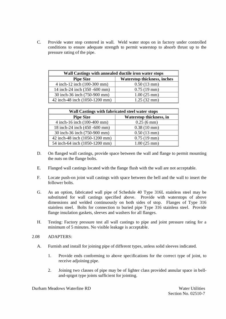
Durham Meadows Waterline RD Water UtilitiesSection No. 02510-7
C. Provide water stop centered in wall. Weld water stops on in factory under controlledconditions to ensure adequate strength to permit waterstop to absorb thrust up to thepressure rating of the pipe.
Wall Castings with annealed ductile iron water stopsPipe Size Waterstop thickness, inches
4 inch-12 inch (100-300 mm) 0.50 (13 mm)14 inch-24 inch (350 -600 mm) 0.75 (19 mm)30 inch-36 inch (750-900 mm) 1.00 (25 mm)
42 inch-48 inch (1050-1200 mm) 1.25 (32 mm)
Wall Castings with fabricated steel water stopsPipe Size Waterstop thickness, in
4 inch-16 inch (100-400 mm) 0.25 (6 mm)18 inch-24 inch (450 -600 mm) 0.38 (10 mm)30 inch-36 inch (750-900 mm) 0.50 (13 mm)
42 inch-48 inch (1050-1200 mm) 0.75 (19 mm)54 inch-64 inch (1050-1200 mm) 1.00 (25 mm)
D. On flanged wall castings, provide space between the wall and flange to permit mountingthe nuts on the flange bolts.
E. Flanged wall castings located with the flange flush with the wall are not acceptable.
F. Locate push-on joint wall castings with space between the bell and the wall to insert thefollower bolts.
G. As an option, fabricated wall pipe of Schedule 40 Type 316L stainless steel may besubstituted for wall castings specified above. Provide with waterstops of abovedimensions and welded continuously on both sides of stop. Flanges of Type 316stainless steel. Bolts for connection to buried pipe Type 316 stainless steel. Provideflange insulation gaskets, sleeves and washers for all flanges.
H. Testing: Factory pressure test all wall castings to pipe and joint pressure rating for aminimum of 5 minutes. No visible leakage is acceptable.
2.08 ADAPTERS:
A. Furnish and install for joining pipe of different types, unless solid sleeves indicated.
1. Provide ends conforming to above specifications for the correct type of joint, toreceive adjoining pipe.
2. Joining two classes of pipe may be of lighter class provided annular space in bell-and-spigot type joints sufficient for jointing.

Durham Meadows Waterline RD Water UtilitiesSection No. 02510-8
2.09 JOINTS:
A. Provide push-on joint and mechanical joint pipe with necessary accessories, conformingto AWWA A21.11.
1. Provide SBR gasket composition.
B. Provide pipe flanges and accessories conforming to AWWA A21.15.
1. Provide flat faced flanges.
2. Provide 1/8-inch (3 mm) thick, full faced SBR gaskets designed for exposure toliquid within pipe.
C. Provide restrained joint on pipe and fittings where indicated. Provide restrained jointwhich is:
1. Boltless
2. Capable of being deflected after assembly
3. Designs using set screws or requiring field welding are not acceptable.
4. Manufacturers:
a. American Cast Iron Pipe Co. Flex-Ring.
b. U.S. Pipe TR FLEX.
c. McWane TR-FLEX.
2.10 MECHANICAL JOINT FITTINGS – RESTRAINT SYSTEM:
A. Provide restraint devices for pipe consisting of multiple gripping wedges incorporatedinto a follower gland meeting requirements of AWWA A21.10.
1. Mechanical joint restraint shall require conventional tools and installationprocedures per AWWA C600, retaining full mechanical joint deflection duringassembly and allowing joint deflection after assembly.
2. Provide actuation of the gripping wedges ensured with torque limiting twist offnuts.
3. Provide restraint devices Listed by Underwriters Laboratories (3 inch (75 mm)through 24 inch (600 mm) size) and Designed by Factory Mutual (3 inch (75 mm)through 12 inch (300 mm) size).
4. Gland body, wedges and wedge actuating components must be domesticmanufactured in the USA.

Durham Meadows Waterline RD Water UtilitiesSection No. 02510-9
B. Working Pressure Rating:
1. 16-inch (400 mm) and Smaller: 350 psi (2450 kPa).
2. 18-inch (450 mm) and Larger: 250 psi (1750 kPa).
3. Minimum safety factor of 2 to 1.
C. Materials:
1. Gland body, wedges and wedge actuating components: Grade 65-45-12 ductileiron in accordance with ASTM A536.
2. Ductile iron gripping wedges: Heat treated, 370 to 470 BHN.
3. Provide three (3) test bars incrementally poured per production shift as perUnderwriter’s Laboratory (U.L.) specifications and ASTM A536. Testing fortensile, yield and elongation in accordance with ASTM E8.
4. Provide chemical and nodularity tests performed as recommended by the DuctileIron Society, on a per ladle basis.
5. Provide an identification number consisting of year, day, plant and shift(YYDDD)(plant designation)(Shift number) cast into each gland body.
6. Record all physical and chemical test results such that they can be accessed via theidentification number on the casting. Provide the Material Traceability Records(MTRs) available, in hard copy.
7. Provide coating for restraint devices consisting of the following:
a. Process all wedge assemblies and related parts through a phosphate wash,rinse and drying operation prior to coating application.
b. Coating: A minimum of two coats of liquid thermoset epoxy coating withheat cure to follow each coat.
c. Surface pretreat all casting bodies with a phosphate wash, rinse and sealerbefore drying. The coating shall be electrostatically applied and heat cured.Coating: Polyester based powder to provide corrosion, impact and UVresistance.
d. Coating system: MEGA-BOND by EBAA Iron, Inc.
D. Manufacturer:
1. EBAA Iron MegaLug Series 1100

Durham Meadows Waterline RD Water UtilitiesSection No. 02510-10
2.11 FLANGE ADAPTORS:
A. Provide restrained flange adaptors for pipe consisting of multiple individual grippingwedges incorporated into a follower gland meeting requirements of AWWA A21.10.
1. Provide actuation of the gripping wedges ensured with torque limiting twist offnuts.
2. Provide restraint devices Listed by Underwriters Laboratories (3-inch (75 mm)through 12 inch (300 mm) size) and Designed by Factory Mutual (4-inch(100 mm) through 12-inch (300 mm) size).
3. Gland body, wedges and wedge actuating components must be domesticmanufactured in the USA.
B. Joint Deflection capability:
1. 3-inch through 8-inch (30 mm through 200 mm): 5 degrees
2. 10-inch and 12-inch (250 mm and 300 mm): 3 degrees
3. 14-inch and 16-inch (350 mm and 400 mm): 2 degrees
4. 18-inch and 20-inch (450 mm and 500 mm): 1.5 degrees
5. 20-inch, 42-inch and 48-inch (500 mm, 1050 mm and 1200 mm): 1 degrees
6. 30-inch and 36-inch (750 mm and 900 mm): 3 degrees
C. Provide flange adaptor to maintain seal with and 0.6 inch (15 mm) gap between end ofpipe and mating flange
D. Working Pressure Rating:
1. 16-inch (400 mm) and Smaller: 350 psi (2450 kPa)
2. 18-inch (450 mm): 300 psi (2100 kPa)
3. 20-inch (500 mm): 250 psi (1750 kPa)
4. 24-inch (600 mm): 200 psi (1400 kPa)
5. 30-inch through 48-inch (750 mm through 1200 mm): 150 psi (1050 kPa)
6. Minimum safety factor of 2 to 1.

Durham Meadows Waterline RD Water UtilitiesSection No. 02510-11
E. Materials:
1. Gland body, wedges and wedge actuating components: Grade 65-45-12 ductileiron in accordance with ASTM A536.
2. Ductile iron gripping wedges: Heat treated, 370 to 470 BHN.
3. Provide three (3) test bars incrementally poured per production shift as perUnderwriter’s Laboratory (U.L.) specifications and ASTM A536. Testing fortensile, yield and elongation in accordance with ASTM E8.
4. Provide chemical and nodularity tests performed as recommended by the DuctileIron Society, on a per ladle basis.
5. Provide an identification number consisting of year, day, plant and shift(YYDDD)(plant designation)(Shift number) cast into each gland body.
6. Record all physical and chemical test results such that they can be accessed via theidentification number on the casting. Provide the Material Traceability Records(MTRs) available, in hard copy.
7. Provide coating for restraint devices consisting of the following:
a. Process all wedge assemblies and related parts through a phosphate wash,rinse and drying operation prior to coating application.
b. Coating: A minimum of two coats of liquid thermoset epoxy coating withheat cure to follow each coat.
c. Surface pretreat all casting bodies with a phosphate wash, rinse and sealerbefore drying. The coating shall be electrostatically applied and heat cured.Coating: Polyester based powder to provide corrosion, impact and UVresistance.
d. Coating system: MEGA-BOND by EBAA Iron, Inc.
F. Manufacturer:
1. EBAA Iron MegaFlange Series 2100
2.12 FLEXIBLE CONNECTIONS:
A. Use as specified or indicated:
1. Bolted split sleeve couplings
2. Grooved couplings
3. Expansion joints
Durham Meadows Waterline RD Water UtilitiesSection No. 02510-12
2.13 BOLTED SPLIT SLEEVE COUPLINGS:
A. Provide in accordance with Section 15101.
B. Pressure rating at least equal to that of related pipeline.
C. Provide with gaskets of composition designed for exposure to liquid within pipe.
D. Provide gaskets with copper tips for electrical continuity through joints.
2.14 GROOVED COUPLINGS:
A. Conform to AWWA C606.
B. Minimum pipe wall thickness specified under "Pipe For Use With Couplings."
C. Where grooved couplings are indicated to provide for expansion or flexibility, cut pipegrooves to provide necessary expansion or flexibility.
D. Where grooved couplings are used instead of flanged joints, joint to be of rigid type withpipe grooves cut to bring pipe ends together. Beam strength of joint shall be equal to orgreater than that of flanged joint.
2.15 EXPANSION JOINTS:
A. Provide in accordance with Section 15105.
B. Pressure rating at least equal to that of related pipeline.
2.16 FILLING RINGS:
A. Provide where necessary.
B. Materials, workmanship, facing, and drilling, conforming to 125-lb. ANSI (Class 125).
C. Suitable length with nonparallel faces and corresponding drilling, if necessary, forcorrect assembly of adjoining piping or equipment.
2.17 WATER SERVICE MATERIALS
A. All water service materials, which shall include but is not limited to corporation cocks,curb stops, couplings, adapters, and fittings shall have compression type connections.Castings shall be sufficiently heavy to meet all service conditions without springing orleaking and be clean and free from roughness both inside and out. Waterways shall besmooth, full size and free from obstruction. All threads shall be cut sharp, clean andtrue.
1. Service Pipe 1-in ASTM B 88, Type K, annealed.
Durham Meadows Waterline RD Water UtilitiesSection No. 02510-13
2. Fittings: ASME B16.18, cast copper, or ASME B16.22, wrought copper.
3. Joints: Compression connection or AWS A5.8, BCuP silver braze.
4. Only lead-free solder shall be used.
5. Working Pressure: Minimum of 55 psi .
6. Bronze curb stop with compression CTS connections and
7. Cast Iron Curb Box with SS operating rod.
8. Full Port Corporation Stop; MuellerH-15008 or Ford F-100G AWWA
2.18 PVC PIPE:
1. PVC Material: ASTM D1784, Type 1, Grade 1.
a. PVC: ASTM D1784, Cell classification 12454-B.
2. PVC Pipe 2-4 inches in diameter:
a. Pipe: ASTM D1785, Schedule 40/80 or ASTM D2441, SDR 17 (unlessnoted otherwise
b. Fittings: ASTM D2467 for solvent welded joints; ASTMD 2464 for threadedjoints. Match schedule and pressure rating of adjacent pipe.
c. Joints: Solvent welded or Push-on in accordance with ASTM D3139.Drilled in accordance with ANSI/ASME B16.1, Class 125 with full-faceteflon or natural rubber gaskets.
d. Trace Wire: Wire: Magnetic detectable conductor, clear plastic covering,imprinted with "Drain" in large letters.
3. Solvent Cements: Use fast-drying solvent for 1-1/2 inch sizes and smaller. Useheavy slow-drying type for sizes 2 inches and larger. Solvent as furnished bymanufacturer of pipe used. Cement shall be compatible with piped fluid.
a. PVC: ASTM D2564.
4. Thread Lubricant:
a. Liquid: Teflon base liquid in plastic squeeze bottles. Use liquid lubricant onpermanent joints.
b. Tape: Teflon base tape. Use tape on joints for valves or joints that may bedisconnected often.

Durham Meadows Waterline RD Water UtilitiesSection No. 02510-14
2.19 HIGH DENSITY POLYETHYLENE (HDPE) PIPE
A. For Tank underdrain, 6 inches diameter perforated to face down.
B. SDR 11
C. Trace Wire: Magnetic detectable conductor, clear plastic covering, imprinted with"Water Service" in large letters.
2.20 VALVES
A. Resilient Seated Gate Valves (buried service) as specified in Section 15101:
1. 3 Inches and Over: AWWA C500, iron body, bronze trim, non-rising stem withsquare nut, single wedge, [flanged] [mechanical joint] ends, control rod, [postindicator,] extension box [and valve key 3 feet longer than depth of valve nut.AWWA C509 or C515, Iron body, bronze trim, non-rising stem with square nut,single wedge, resilient seat, flanged or mechanical joint ends, control rod, postindicator, extension box and valve key 3 feet longer than depth of valve nut.Protective interior coating per AWWA C550. Gate valves 16 inches and larger tobe equipped with spur or beveled gears enclosed in a seal grease case, in thehorizontal position to be equipped with rollers, tracks, and scrappers.
2. Provide one operating wrench of length to operate deepest valve.
B. Manual Air Release Valve Assembly
1. 1-inch Wedge Air Release Valve
2. 1-inch Mueller H-15015 Corporation Stop (AWWA Taper Thread x FIP Thread)
3. Valve Box as specified.
C. Butterfly Valves (buried service)
1. Manufacturers: Mueller, Pratt, Valmatic
2. Conform to AWWA C504, Class 150B and NSF 61
3. Class 150B for cast iron body, Class 250B for ductile iron body, mechanical jointconnections, fusion bonded epoxy coating inside and out, 250 psi rated workingpressure, gear operator with 2-inch operating nut.
4. Type 316 stainless steel mating surfaces, seat placement, shaft, fasteners/screws,retaining ring.
5. Valve body: ASTM A126 Class B cast iron or ASTM A536 GR65/45/12 ductileiron

Durham Meadows Waterline RD Water UtilitiesSection No. 02510-15
6. Valve bearings: Self-lubricating, non-metallic material to isolate disc shaftassembly from valve body.
7. Valve seats: Molded new natural or synthetic rubber suitable for potable waterservice
2.21 VALVE BOXES:
A. General: Provide cast-iron valve boxes for all buried valves, rated for vehicular traffic.
B. Cast-Iron Boxes: Extension type with slide-type adjustment, flared base and 3/16-inchminimum thickness of metal.
C. Cast the word “WATER” in cover. Adapt box length, without full extension, to depth ofcover required over pipe at valve location.
D. Bell end of lower section shall in all cases be sufficiently large to fit over the stuffingboxes of the valves. Minimum inside dimension shall be 5 ¼ inches.
E. Valve box extensions, if required, shall be supplied at no additional cost.
2.22 FIRE HYDRANTS:
A. AWWA C502, UL 246, dry barrel type compression hydrant with double O-ring seals;rotation to open as required by local Water Utility and as indicated. Protective interiorcoating per AWWA C550.
B. In City of Middletown:
1. Mueller Super Centurion 250 Model No. A-421.
2. 4 ½-in Main valve opening
3. Opening Direction: Left (counterclockwise)
4. Provide One (1) 4 ½-in pumper nozzle and Two (2) 2 ½-in hose nozzles
5. Bonnet and cap factory coated John Deer Green and remainder of hydrant paintedJohn Deer Yellow.
C. In Town of Durham:
1. Mueller Super Centurion 250 Model No. A-423.
2. 5 ½-in Main valve opening
3. Opening Direction: Right (clockwise)
4. Provide One (1) 4 ½-in pumper nozzle and Two (2) 2 ½-in hose nozzles

Durham Meadows Waterline RD Water UtilitiesSection No. 02510-16
5. Hydrant to be factory coated with a White Reflective Bonnet and Yellow Barrel.
6. Provide a stenciled identification label in accordance with Connecticut WaterCompany requirements (Operator).
D. Provide threads on nozzles in conformance with Local fire-hose coupling screw-threaddimensions. Nozzles shall be replaceable.
E. Fabricate extensions in multiples of 6 inches with rod and coupling to increase barrellength.
F. Working Pressure: 150 psi (1050 kPa) minimum.
G. Provide 1 safety flange repair kit.
H. UL Listed/FM Approved.
2.23 BEDDING AND COVER MATERIALS:
A. As specified in Section 02210.
2.24 THRUST RESTRAINT:
A. Mechanical Joint Restraint: Wedge action restrained joint retainer gland devices.Mechanical joint restraint incorporated into the design of the follower gland.
B. Thrust Blocks: Only where restrained joint pipe cannot be used as directed by theContracting Officer. Restrained Joint Pipe is specified for all pipe and fittings. Concretetype for thrust restraints is specified under Section 03300.
C. Pipe Clamps and Tie Rods: ANSI/NFPA 24.
D. Push-On Restrained Joint Pipe: Provide joint restraint and conforming joint to AWWAC111/21.11, fabricated to be easily disassembled. Provide assembly and disassemblykits.
E. Wall Pipes: Cast or ductile iron with an intermediate wall collar, unless noted otherwise.End connections as indicated.
2.25 COUPLINGS:
A. Mechanical Couplings: Dresser Style 38, long sleeve unless shown otherwise;equivalent by Smith-Blair or Baker. Harness when required for thrust restraint.
B. Flanged Coupling Adapters: Dresser Style 127 (2-12 inches), Dresser Style 128 (14-96inches), equivalent by Smith Blair or equal.
Durham Meadows Waterline RD Water UtilitiesSection No. 02510-17
2.26 ACCESSORIES:
A. Backflow Preventer: 1-in RPZ Lead Free backflow preventer with strainer and air gapfitting (Watts LF type with isolation valves and testing connections).
B. Exterior Backflow Preventer: Installation arrangement per drawing detail 6 on Sheet C-503; including precast concrete base slab, Hot Rok insulated fiberglass enclosure andappurtenances, complete as specified and indicated on the drawings.
C. Meter: To be obtained by the Contractor from the Municipality.
D. Water Meter Pit (For 1-in meters): 18-inch DIA x 54-inch SDR 35 PVC (0.485 in.minimum wall thickness) for 5/8-in or 3/4- in meters. Cast Iron Frame and 15-inch DIAlocking Lid labeled “WATER” with hole and plug for touch pad reader.
E. Water Meter Pit (For 4-in meters): Per drawing detail 7 on Sheet C-503; including vault,piping and all appurtenances, complete as specified and indicated on the drawings.
F. Tapping Sleeves: Ductile- or cast-iron, split-sleeve type with flanged or grooved outlet,and with bolts, follower rings and gaskets on each end of sleeve suitable for maximumworking pressure of 150 psi. Bolts shall have square heads and hexagonal nuts.Longitudinal gaskets and mechanical joints with gaskets shall be as recommended bymanufacturer of sleeve.
G. Tapping Valves: Provide tapping valves that conform to gate valves, specified herein.Provide tapping valves suitable for installation with tapping sleeves and pipe used,designed for minimum water working pressure of 150 psi, and have clear waterwayequal to full nominal diameter of valve.
H. Service Clamp: Pressure rating not less than connecting pipe; either single or doubleflattened strap type. Clamps shall have rubber gasket cemented to galvanized malleable-iron body. Straps and nuts shall be cadmium-plated.
I. Service Boxes: Cast iron or concrete and shall be extension service boxes of lengthrequired for depth of line, with either screw or slide-type adjustment. Boxes shall havehousings of sufficient size to completely cover service stop or valve and shall becomplete with identifying covers.
2.27 DISINFECTION CHEMICALS:
A. Refer to Section 02515.
2.28 APPURTENANCES:
A. Provide appurtenances for a complete piping system suitable for operation, and inconformance with Project Documents.

Durham Meadows Waterline RD Water UtilitiesSection No. 02510-18
2.29 SHOP PAINTING/COATINGS:
A. Unless noted otherwise, provide standard manufacturer paint and coatings for piping,valves, hydrants, and accessories to prevent corrosion for the life of the component inaccordance with 09941.
2.30 SHOP TESTING:
A. Test pipes, valves, hydrants, and applicable accessories per manufacturer requirements,and as required by referenced Standards.
PART 3 - EXECUTION
3.01 EXAMINATION:
A. Verify existing conditions.
B. Coordinate all private property work with Contracting Officer.
3.02 PREPARATION:
A. Ream pipe and tube ends and remove burrs.
B. Remove scale and dirt, on inside and outside, before assembly.
C. Prepare pipe connections to equipment with flanges or unions.
D. Excavate pipe trench in accordance with Section 02210 for work of this Section. Handtrim excavation for accurate placement of pipe to elevations indicated.
3.03 WATER PIPE INSTALLATION:
A. Maintain separation of water main from sewer as follows:
1. Parallel Installation
a. Under normal conditions water mains shall be laid at least 10 feethorizontally from a sewer or sewer manhole. The distance shall bemeasured edge-to-edge.
b. Under unusual conditions when local conditions prevent a horizontalseparation of 10 feet the water main may be laid closer to a sewer or sewermanhole provided that:
c. The bottom (invert) of the water main shall be at least 18 inches above thetop (crown) of the sewer;

Durham Meadows Waterline RD Water UtilitiesSection No. 02510-19
d. Where this vertical separation cannot be obtained, the sewer shall beconstructed of AWWA approved water pipe, pressure tested in place withoutleakage prior to backfilling; and
e. The sewer manhole shall be of watertight construction and tested in place.
2. Crossing
a. Where necessary water lines crossing sewers shall be laid to provide aseparation of at least 18 inches between the bottom of the water line and thetop of the sewer whenever possible.
B. Install pipes and structures to within tolerance of 1/2-inch of indicated elevations.
C. Install ductile iron piping and fittings to AWWA C600.
F. Install joint restraint per manufacturer’s instructions. Submit instruction to theContracting Officer for review.
G. Form and place concrete for thrust blocks at each elbow or change of direction of pipemain [and as indicated.
H. Establish elevations of buried piping to ensure not less than 4 feet of cover and asindicated.
I. Install trace wire continuous over top of pipe buried 12 inches above pipe line or asdirected by the Contracting Officer. Extend wire into valve boxes and adjacent tohydrants for connection to location equipment.
J. Backfill trench in accordance with Section 02210.
3.04 VALVES AND HYDRANTS INSTALLATION:
A. Set valves on solid bearing.
B. Center and plumb valve box over valve. Set box cover flush with finished grade.
C. Set hydrants plumb and locate pumper nozzle perpendicular to roadway.
D. Provide drainage pit as indicated and as approved by the Contracting Officer. Wrapdrainage pit and gravel with filter fabric. Do not connect drain opening to sewer.
E. Paint fire hydrants in accordance with local water utility requirements.
F. Install tapping sleeves and tapping valves in accordance with manufacturer’srecommendations.

Durham Meadows Waterline RD Water UtilitiesSection No. 02510-20
G. Install valves and hydrants according to applicable AWWA Standards.
3.05 DISINFECTION OF DOMESTIC WATER PIPING SYSTEM:
A. Refer to Section 02515 and Section 15400.
3.06 SERVICE CONNECTIONS:
A. Provide water service including corporation stop, copper pipe, curb stop, meter setter,and water meter pit as indicated and specified.
3.07 REPAIR/RESTORATION:
A. Repair any existing utilities/structures, or features damaged during installation of waterutilities to s’s satisfaction, and at no cost to Contracting Officer.
3.08 FIELD TESTING:
A. Perform field-testing under provisions of AWWA C600 and Section 02515.
3.09 FIELD PAINTING/COATINGS:
A. Repair any shop painting/coatings damaged during storage or installation to ContractingOfficer’s satisfaction.
3.10 ADJUSTING:
A. Coordinate with Contracting Officer for any field adjustments. The Contracting Officerreserves the right to reject any field adjustments.
3.11 PROTECTION:
A. Protect installed water utilities from damage throughout storage, installation, testing, andfinal approval.
3.12 CLOSEOUT ACTIVITIES:
A. Provide in accordance with Section 01700.
END OF SECTION

Durham Meadows Waterline RD Disinfecting Water Distribution SystemSection No. 02515-1
SECTION 02515
DISINFECTING WATER DISTRIBUTION SYSTEM
PART 1 - GENERAL
1.01 DESCRIPTION:
A. Provide disinfection of water utility distribution system as indicated and in compliancewith Contract Documents.
1. Coordinate with City of Middletown regarding testing and disinfection of Storagetank and pipelines in Middletown.
2. Coordinate with Town of Durham and its water system operator ConnecticutWater Company (CWC) regarding testing and disinfection of water main facilitiesin Durham including specific procedures, schedule, and use of water.
B. Section Includes:
1. Disinfection of water mains in accordance with AWWA C651 and water storagefacility in accordance with AWWA C652, except as modified below.
2. Refer to Section 13225 for additional tank disinfection requirements.
1.02 REFERENCES:
A. American Water Works Association (AWWA):
1. C651: Disinfecting Water Mains.
2. C652: Disinfection of Water-Storage Facilities.
1.03 SEQUENCING:
A. Basic procedure for disinfecting water mains:
1. Testing and disinfection of water mains shall be limited to 1,000 ft sections or asapproved by the Contracting Officer.
2. Inspecting materials to be used to ensure their integrity.
3. Preventing contaminating materials from entering the water main during storage,construction, or repair and noting potential contamination at the construction site.
4. Removing, by flushing or other means, those materials that may have entered thewater main.
Durham Meadows Waterline RD Disinfecting Water Distribution SystemSection No. 02515-2
5. Chlorinating any residual contamination that may remain, and flushing thechlorinated water from the main.
6. Protecting the existing distribution system from backflow caused by hydrostaticpressure test and disinfection procedures.
7. Documenting that an adequate level of chlorine contacted each pipe to providedisinfection.
8. Determining the bacteriological quality by laboratory test after disinfection.
9. Final connection of the accepted new water main to the active distribution system.
1.04 SUBMITTALS:
A. Submit the following in accordance with Section 01300.
1. Supervisor qualifications.
2. Equipment list.
1.05 QUALITY ASSURANCE:
A. Comply with the requirements specified in Section 01400.
B. Regulatory Requirements:
1. Disinfection work shall be acceptable to the water system operators of Durhamand Middletown. If requirements of this section are in conflict with requirementsof regulatory agencies, the latter shall govern.
C. Source Quality Assurance:
1. Perform Work in connection with disinfection under direction of experiencedsupervisor.
2. Use equipment in proper working condition and adequate for specified Work.
D. Prior to starting disinfection work, furnish detailed outline of proposed sequence ofoperation, manner of filling and flushing units, source and quality of water to be used,and disposal of wasted water.
E. Perform work in connection with disinfection under direction of experienced supervisor.
F. Use equipment in proper working condition and adequate for specified work.
1.06 DELIVERY STORAGE AND HANDLING:
A. Comply with the requirements specified in Section 01610.

Durham Meadows Waterline RD Disinfecting Water Distribution SystemSection No. 02515-3
1.07 PROJECT CONDITIONS:
A. Discharge of chlorinated water into watercourses or surface waters is regulated by theNational Pollutant Discharge Elimination System (NPDES). Disposal of the chlorinateddisinfection water and the flushing water is the Contractor's responsibility.
B. Schedule the rate of flow and locations of discharges in advance to permit review andcoordination with Contracting Officer and regulatory authorities
PART 2 - PRODUCTS
2.01 CONTRACTING OFFICER-SUPPLIED PRODUCTS:
A. In coordination with the Contracting Officer, the City of Middletown will providepotable water for the first disinfection effort. Submit request for use of water fromwaterlines of Middletown and Durham 48 hours in advance. If bacteriological testingshows that the first disinfection effort was not successful, the Contractor will be charged,at Middletown's current rates, the cost of additional water for subsequent disinfectionefforts.
2.02 MATERIALS:
A. Water: Use potable water for cleaning and disinfection.
B. Chlorine: Provide in accordance with AWWA C652.
1. Liquid Chlorine: Inject with a solution feed chlorinator and a water booster pump.Follow the instructions of the chlorinator manufacturer.
2. Calcium Hypochlorite (Dry): Dissolve in water to a known concentration in adrum and pump into the pipeline at a metered rate. Tablet form calciumhypochlorite may be used only for water mains up to 12 inches in diameter andless than 2,500 feet in length.
3. Sodium Hypochlorite (Solution): Further dilute in water to desired concentrationand pump into the pipeline at a metered rate.
2.03 EQUIPMENT:
A. Submit list of equipment used for disinfecting work.
2.04 ACCESSORIES:
A. Chlorine Residual Test Kit: For measuring chlorine concentration, supply and use amedium range, drop count, DPD drop dilution method kit per AWWA C651, AppendixA.1. Maintain kits in good working order available for immediate test of residuals atpoint of sampling.

Durham Meadows Waterline RD Disinfecting Water Distribution SystemSection No. 02515-4
PART 3 - EXECUTION
3.01 PREPARATION:
A. Isolate new work being disinfected from system to avoid possibility of contaminatingmaterials entering distribution system.
B. Water Storage Facilities:
1. Remove debris and material not part of structural or operating facilities of tank.
2. Clean using high pressure water jet or other equally effective means to remove dirtand foreign material.
3. Cleaning shall:
a. Remove deposits of foreign nature.
b. Remove growths.
c. Broom walls, floor, and ceiling.
d. Avoid damage to structure.
e. Avoid contamination by workers and equipment.
4. Remove water, dirt, and foreign material and dispose.
5. Water used in cleaning reservoir shall be wasted before adding chlorinating agentto reservoir.
C. Method of disinfection for water containment devices and piping systems shall conformto AWWA C651 and AWWA C652.
3.02 CHLORINE PREPARATION:
A. Liquid Chlorine:
1. Apply chlorine gas-water solution by means of solution feed chlorinating deviceor, if accepted by the Contracting Officer dry gas may be fed directly throughproper devices for regulating rate of flow and providing effective diffusion of gasinto water within unit being treated.
2. Provide chlorinating devices for feeding solutions of chlorine gas that preventbackflow of water into chlorine cylinder.

Durham Meadows Waterline RD Disinfecting Water Distribution SystemSection No. 02515-5
B. Calcium Hypochlorite:
1. Prepare granular calcium hypochlorite as water mixture before introduction intounit. Make dry powder into paste and thin to approximately 1 percent chlorinesolution.
3.03 PIPELINE PREPARATION:
A. After pressure and leakage tests complete, flush units thoroughly to remove foreignmaterial.
B. Release entrapped air at high points and fill units with disinfecting agent and water toallow disinfecting agent to come in contact with interior surfaces.
C. If complete venting cannot be accomplished through available outlets, provide necessarycorporation cocks and vent piping.
3.04 APPLICATION OF DISINFECTANT:
A. Point of Application:
1. Apply chlorinating agent at supply end of unit being disinfected.
2. For pipes, apply disinfectant through corporation cock installed in top of pipe.
3. Place tablets in accordance with AWWA C651.
B. Rate of Application:
1. Introduce water at controlled rate in order to regulate chlorine dosage.
2. Proportion rate of chlorine mixture flow to rate of water entering unit so chlorinedose applied produces at least 25 mg/L chlorine residual after period of 24 hours.
3. Method of determining rate of flow of water into unit being disinfected shall beaccepted by the Contracting Officer.
C. Isolating Systems:
1. Keep chlorine gas-water disinfecting solution and contaminated water fromflowing into units previously chlorinated and flushed.
D. Quality:
1. Retain chlorinated water in unit long enough to destroy non-spore formingbacteria.
2. Minimum retention period shall be 24 hours with chlorine residual at end of thisperiod of not less than 25 mg/L (ppm).
Durham Meadows Waterline RD Disinfecting Water Distribution SystemSection No. 02515-6
E. Disinfecting Valves:
1. Operate valves and appurtenances while line or unit is being disinfected to ensuresurfaces of valves are disinfected.
F. Swabbing:
1. Flush and swab pipe, fittings or valves that must be placed in service immediatelywith 5 percent solution of calcium hypochlorite immediately prior to assembly.
2. Secure acceptance from the Contracting Officer before using this method ofdisinfection.
G. Valve Operation: Performed by Operator.
3.05 DISINFECTING METHODS:
A. Continuous Feed Method:
1. Introduce potable water into the pipeline at a constant measured rate. Feed thechlorine solution into the same water at a measured rate. Proportion the two ratesso that the chlorine concentration in the pipeline is maintained at a minimumconcentration of 25 mg/L. Check the concentration at points downstream duringthe filling to ascertain that sufficient chlorine is being added.
B. Slug Method:
1. Introduce the water in the pipeline at a constant measured rate. At the start of thetest section, feed the chlorine solution into the pipeline at a measured rate so thatthe chlorine concentration created in the pipeline is 100 mg/L. Feed the chlorinefor a sufficient period to develop a solid column or "slug" of chlorinated water thatwill, as it passes along the line, expose all interior surfaces to a concentration of atleast 100 mg/L for at least three hours.
C. Disinfection of Valves, Blind Flanges, and Appurtenances:
1. During the period that the chlorine solution or slug is in the section of pipeline,open and close valves to obtain a chlorine residual at hydrants and other pipelineappurtenances. Swab exposed faces of valves and blind flanges prior to boltingflanges in place with a 1 percent sodium hypochlorite solution.
D. Disinfection of Connections to Existing Pipelines
1. Disinfect isolation valves, pipe, and appurtenances in accordance with AWWAC651, Section 4.7. Flush with potable water until discolored water, mud, anddebris are eliminated. Swab interior of pipe and fittings with a 1 percent sodiumhypochlorite solution. After disinfection, flush with potable water again until wateris free of chlorine odor.
Durham Meadows Waterline RD Disinfecting Water Distribution SystemSection No. 02515-7
E. Confirmation of Residual:
1. After the chlorine solution applied by the continuous feed method has beenretained in the pipeline for 24 hours, confirm that a chlorine residual of 10 mg/Lminimum exists along the pipeline by sampling at air valves and other points ofaccess.
2. With the slug method, confirm by sampling as the slug passes each access pointand as it leaves the pipeline that the chlorine concentration in the slug is at least50 mg/L.
3.06 FINAL FLUSHING AND TEST:
A. Following chlorination, flush unit or system until replacement water in system is provento be comparable in quality to water which will enter unit or system.
B. Above acceptable condition of water delivered by each unit or system shall continue forat least 2 days, as demonstrated by laboratory examination of samples. Laboratory testsshall show chlorine residual, after final flushing, of less than 1 mg/L (ppm).
C. Repetition of Flushing and Testing:
1. If initial treatment results in unsatisfactory bacterial test, repeat disinfection untilsatisfactory results obtained.
D. Prevent entry of contaminated water into previously disinfected units or systems.
3.07 DISINFECTING TANK:
A. Disinfect in accordance with AWWA C652 and as specified in 13225.
B. Place water containing 50 ppm chlorine in reservoir to depth that, when reservoir isfilled, resultant chlorine concentration shall be no less than 2 ppm, 24 hours beforefilling reservoir.
C. Fill reservoir.
D. Full reservoir shall stand for 24 hours, after which reservoir may be put into servicewithout draining water used to disinfect it, providing safe samples obtained byContracting Officer.
E. If safe samples are not obtained using above procedure, add additional chlorine to fullreservoir in amounts necessary to obtain safe sample. After obtaining safe sample, drainprior to placing in service.
F. Cost of water and chlorine for re-chlorination of reservoir if first attempt does not testsafely shall be Contractor’s responsibility.
Durham Meadows Waterline RD Disinfecting Water Distribution SystemSection No. 02515-8
3.08 BACTERIOLOGIC TESTS:
A. Collect two sets of samples per AWWA C651, Section 5.1, deliver to a certifiedlaboratory within six hours of obtaining the samples, and obtain a bacteriologic qualitytest to demonstrate the absence of coliform organisms in each separate section of thepipeline after chlorination and refilling. Collect at least one set of samples from every1,200 feet of the new water main, plus one set from the end of the line and at least oneset from each branch.
B. Repetition of Procedure: If the initial chlorination fails to produce required residualsand bacteriologic tests, repeat the chlorination and retesting until satisfactory results areobtained.
C. Test Facility Removal: After satisfactory disinfection, disinfect and replace air valves,restore the pipe coating, and complete the pipeline where temporary disinfection or testfacilities were installed.
3.09 FIELD QUALITY CONTROL:
A. Contracting Officer will obtain samples for and submit to laboratory for analysis beforereservoir placed in service.
B. If safe samples not obtained using above procedure, Contractor shall add additionalchlorine in amounts necessary to obtain safe samples.
3.10 CLOSEOUT ACTIVITIES:
A. Provide in accordance with Section 01700.
END OF SECTION

Well AbandonmentDurham Meadows Waterline RD Section No. 02521-1
SECTION 02521
WELL ABANDONMENTPART 1 – GENERAL
1.01 DESCRIPTION
A. Furnish labor, materials, tools and equipment for fully abandoning up to125 water supplywells in accordance with the specifications and drawings. The full abandonmentprocedure, which is described in detail in this specification, generally includes removingall existing equipment from the well, filling the wells with appropriate backfill forabandonment, restoring any areas that were affected by the well abandonment to thepre-work condition, and submitting records of abandonment.
B. Furnish labor, materials, tools and equipment for partially abandoning six water supplywells, which are proposed to be used as long-term monitoring wells. The six wells arethe two Fairgrounds public water supply wells; the Regional school supply well; one ofthe Hill Hollow Condo supply wells (the others will be fully abandoned); DurhamManufacturing (DMC) Well #1, and DMC Well #2. The partial abandonment procedure,which is described in detail in this specification, generally includes removing all existingequipment from the well, removing and replacing the upper portion of the well casing,restoring any areas that were affected by the well abandonment to the pre-work condition,and submitting records.
1.02 RELATED SECTIONS
A. Section 01120 - Health & Safety
B. Section 01063 – Miscellaneous Requirements
C. Section 01300 – Submittals
D. Section 01400 – Quality Assurance
E. Section 01710 – Cleaning Up
F. Section 02241 – Construction Water Management
G. Section 02900 – Planting
H. Section 2922 – Hydroseeding
1.03 REFERENCES
A. Connecticut Well Drilling Code
Well AbandonmentDurham Meadows Waterline RD Section No. 02521-2
B. Letter from Connecticut DCP to Connecticut DEEP, dated July 23, 2014, explainingpermitted deviation from well abandonment procedures in Connecticut Well DrillingCode (attached at end of section).
1.04 SUBMITTALS
A. Well Abandonment, Verification of Work Completed forms, attached and available fordownload at http://www.ct.gov/dcp/cwp/view.asp?a=1622&q=446490 completed for allwells abandoned, with additional information as specified below.
1.05 PERFORMANCE REQUIREMENTS
A. Work shall be performed in accordance with the Connecticut Well Drilling Coderequirements for well abandonment, except that 1) deviations as described in the letterfrom Connecticut DCP to Connecticut DEEP, dated July 23, 2014 (attached), may beused in lieu of the Code requirements, and 2) permits will not be required in accordancewith Superfund NCP Section 300.400 (e)(1).
PART 2 - PRODUCTS
2.01 MATERIALS
A. Bentonite Chips - raw mined sodium montmorillonite in chip form, with chips sizedbetween ¼ and ½-inch.
B. Fine Sand – A poorly graded (SP) sand in which 100% passes the #40 sieve and no morethan 10% passes the #200 sieve.
PART 3 – EXECUTION
3.01 ABANDONMENT OF WELLS
A. Prior to well abandonment work being done, all residences and businesses must have beenpermanently connected to the new municipal water supply such that the wells are nolonger needed to supply potable water. Also, in accordance with other specificationsections, the water service pipe from the well to the pressure tank and the well pumppower duct shall have been cut off and capped or plugged watertight at the interiorbasement wall.
B. Locate the well and gain access to its interior by removing any materials, equipment, orappurtenances (e.g., well caps, concrete well covers, soil, decorative well covers) thatcover or seal the well. If a decorative well cover is removed, place it on the ground at adistance from the well where it will not be damaged or impede the abandonment process.
C. Remove all materials and equipment that are within the well including, but not limited to,the well pump; all wire, pipe, and conduit; and any other downhole appurtenances. The

Well AbandonmentDurham Meadows Waterline RD Section No. 02521-3
well pump, wire, and/or piping shall be placed at a location on the property as directed bythe owner if he/she wants to retain it. Any materials and equipment removed from thewell that are not wanted by the property owner shall become the property of theContractor, to be recycled (to the maximum extent possible) or disposed. Water that ispresent in the piping and pump as they are raised in the well shall not be released onto theground and must be either collected in a container or poured back down the well.
D. Record all requested information on the Well Abandonment, Verification of WorkCompleted form, and make actual measurements of the well diameter, the depth of thewell below ground surface (bgs), and the depth to water in the well (include this on theform even though it is not listed as a requested measurement). Also include a sketch ofthe well location so that the property owner will have a record of it with the wellabandonment form.
E. Calculate the volume of standing water in the well and add enough chlorine to create asolution with 50 ppm available chlorine throughout the well. Chlorine shall be addedthroughout the length of well, or shall be circulated in the well, to ensure distributionthroughout the water column.
F. In the case of a drilled well in bedrock:
1. Add fine sand to the well, at a rate not exceeding 50 lbs every 30 seconds. Sound thewell continuously, or at least every time enough sand has been added to fill 10 ft ofthe borehole, to assure that bridging is not occurring. If bridging occurs, useappropriate means to collapse bridge(s) so that voids in sand are eliminated.
2. The addition of the sand will cause the water level in the well to rise. The rate of risewill depend on the permeability and depth of water-bearing fracture zones and rate atwhich sand is added. No water shall be released onto the ground. If the water levelrises close to the top of the well, the rate of sand placement shall be slowed, or watershall be pumped from the well to a storage container, so that no water overflows ontothe ground. Any water that is collected during well abandonment shall betransported to a location designated by the Contracting Officer for treatment anddisposal in accordance with Section 02241 Construction Water Management.
3. When the level of the sand is 40 feet below ground surface, stop adding sand. Theportion of the well above a depth of 40 feet bgs shall be filled with bentonite chips(1/4-inch to 1/2-inch size) so that the final level of bentonite after swelling is 4 feetbgs. The chips shall be poured into the well at a rate of 20 pounds per minute or less.If the chlorine in the water interferes with expansion of the bentonite, the water shallbe removed and replaced with non-chlorinated water, and the removed water shall becaptured and handled as described above. Sound the well continuously, or at leastevery time enough bentonite has been added to fill 6 ft of the borehole, to assure thatbridging is not occurring. If bridging occurs, use appropriate means to collapsebridge(s) so that voids are eliminated. Since smaller pieces of bentonite or bentonitedust can contribute to bridging, the chips will be screened as they are placed in the

Well AbandonmentDurham Meadows Waterline RD Section No. 02521-4
well such that any particles of bentonite smaller than ¼-inch are removed. The smallpieces and dust that are screened out shall be collected on a ground cover and may beadded to the well in the final stages of filling (when level is less than 8 ft bgs).
4. The addition of the bentonite chips will cause the water level in the well to rise. Therate of rise will depend on the permeability and depth of water-bearing fracture zonesand rate at which chips are added. No water shall be released onto the ground. Ifthe water level rises close to the top of the well, the rate of chip placement shall beslowed, or water shall be pumped from the well to a storage container, so that nowater overflows onto the ground. Any water that is collected during wellabandonment shall be transported to a location designated by the Contracting Officerfor treatment and disposal in accordance with Section 02241 Construction WaterManagement. If necessary to keep the chips submerged and achieve full swelling,add water to the well.
5. When the chips have fully swelled, cut the well casing off below the pitless adapter orat a depth of at least 4 feet bgs (whichever is deeper) and recycle or dispose of it. Cutoff the water service pipe and the well power conduit (if present) at or below the 4 ftdepth and cap or plug each watertight. Backfill the hole with any excess soil fromexcavations only on that property, supplemented with fine sand if necessary, from 4feet bgs to the depth at which landscaping materials will be placed.
6. Landscape in accordance with Sections 02900 and 02922. With the exception of anydecorative well cover that may have been present over the well and any materials thatare being retained by the property owner, all well materials, equipment, andappurtenances that were removed for the abandonment, plus all excess materials(sand, chips, water), should be removed from the property and, after recycling to theextent possible, disposed of by the Contractor.
G. In the case of dug wells, or wells whose dimensions preclude abandonment in accordancewith the above procedures:
1. Fill the portion of the well that is more than 4 feet bgs with a sealant per theConnecticut Well Drilling Code or with bentonite chips. If bridging occurs, useappropriate means to collapse bridge(s) so that voids in the sealant are eliminated.
2. The addition of the sealant will cause the water level in the well to rise. The rate ofrise will depend on the permeability of the soil and rate at which sealant is added. Nowater shall be released onto the ground. If the water level rises close to the top of thewell, the rate of sealant placement shall be slowed, or water shall be pumped from thewell to a storage container, so that no water overflows onto the ground. Any waterthat is collected during well abandonment shall be transported to a locationdesignated by the Contracting Officer for treatment and disposal in accordance withSection 02241 Construction Water Management. When the level of the sealant is 4feet bgs, stop adding sealant.
Well AbandonmentDurham Meadows Waterline RD Section No. 02521-5
3. Remove well casing to a depth of 4 feet bgs. Recycle or dispose of the removedcasing. Backfill the hole with any excess soil from excavations only on thatproperty, supplemented with fine sand as necessary, from 4 feet bgs to the depth atwhich landscaping materials will be placed.
4. Landscape in accordance with Sections 02900 and 02922. With the exception of anydecorative well cover that may have been present over the well and any materials thatare being retained by the property owner, all well materials, equipment, andappurtenances that were removed for the abandonment, plus all excess materials(sand, chips, water), should be removed from the property and, after recycling to theextent possible, disposed of by the Contractor.
H. Submit well abandonment records.
1. All blank spaces on the Well Abandonment, Verification of Work Completed formshall be completed with the possible exception of the casing length, if unknown andundeterminable. In addition to filling in all the blank spaces on the form, the depth tostatic water level (bgs) shall be noted, and a sketch map of the well location on theproperty shall be provided.
3.02 PARTIAL ABANDONMENT OF WELLS TO BE USED AS LONG-TERMMONITORING WELLS
A. Prior to well conversion work being done, the residence or business must have beenpermanently connected to the new municipal water supply such that the well is no longerneeded to supply potable water. The water service pipe from the well to the pressure tankand the well pump power duct shall have been cut off and capped or plugged watertight atthe interior basement wall, in accordance with other specification sections (note that thetwo Fairgrounds public water supply wells may require additional or alternate treatment,to be coordinated with the Contracting Officer and the well owner).
B. Locate the well and gain access to its interior by removing any materials, equipment, orappurtenances (e.g., well caps, concrete well covers, soil, decorative well covers) thatcover or seal the well (note that the two Fairgrounds public water supply wells mayrequire additional or alternate treatment, to be coordinated with the Contracting Officerand the well owner). If a decorative well cover is removed, place it on the ground at adistance from the well where it will not be damaged or impede the abandonment process.
C. Remove the well pump, piping, and all wire. The well pump, piping, and wire shall beplaced at a location on the property directed by the owner if he/she wants to retain it. Anymaterials and equipment removed from the well that is not wanted by the owner shallbecome the property of the Contractor, to be recycled (to the maximum extent possible) ordisposed. For the Durham Manufacturing Well #1 (DMC#1) and Well #2 (DMC #2),which are highly contaminated, and for the Regional school supply well and the HillHollow Supply well, which are contaminated to a lesser degree, water that is present in thepump or piping as it is raised in the well shall not be released onto the ground and must be

Well AbandonmentDurham Meadows Waterline RD Section No. 02521-6
either be collected in a container or poured back down the well. Any water that iscollected shall be transported to a location designated by the Contracting Officer fortreatment and disposal in accordance with Section 02241 Construction WaterManagement.
D. After removing the contents of the well (excluding the water), remove the well casing to adepth below any casing perforation (e.g., pitless adapter) or to a depth of at least 4 feet bgs,whichever is deeper. Recycle or dispose of the removed casing. The section of wellcasing removed shall be replaced by a section of pipe matching the dimensions of theexisting well casing. The new pipe shall be joined to the existing casing by a weldedwatertight connection. The top of casing shall be 2 feet above finish grade (post soilremoval and backfill). A locking well cap shall be placed on the top of the new casing,such that the well can be easily accessed for monitoring.
END OF SECTION

STATE OF CONNECTICUT DEPARTMENT OF PUBLIC HEALTH
Jewel Mullen, M,D., M.P.H., M.P.A. Commissioner
April 1, 2014
Anni Loughlin US Environmental Protection Agency 5 Post Office Square, Suite 100 Mail Code: OSRR07-1 Boston, MA 02109-3912
Dannel P. Malloy Governor
Nancy Wyman Lt. Governor
SUBJECT: Durham Water Line Project- Comments to CT DEEP letter dated January 22, 2014
Dear Ms. Loughlin:
This correspondence is provided in response to your verbal request on March 13, 2014 for the Connecticut Department of Public Health (CT DPH) to submit written comments on the Connecticut Department of Energy and Environment's request for an exception to the Connecticut Well Drilling Board Rules and Regulations (copy attached). The CT DPH has reviewed the exemption request letter and offers the following:
1. Public Well Abandonment Procedures
• The alternate abandonment method is acceptable as long as it is equivalent to the method currently in the Well Drilling Code in preventing surface water intrusion.
• For public water supply wells in the impacted area of Durham, CT, there should be some level of chlorination. DPH suggests a dose of 50 ppm which is consistent with the disinfection guidance document which can be found at this link: http://www.ct.gov/dph/lib/dph/drinking water/pdf/Well Disinfection.pdf
• Source Abandonment Application - source abandonment permits are required pursuant to Connecticut General Statute 25-33k for each public water system well abandonment. The DPH plans to reach out to system owners to review the requirements and streamline the process. Are there any requirements that we are waiving? Or do we need to clarify what type of public systems need to supply this?
2. Private Well Abandonment Procedures
• The permitting of private wells is under the jurisdiction of the Local Health Department.
,_,.'I, to"'•«•k~1 It•• .i, ~1,.
All private well abandonment procedures should be reviewed and approved by the Durham Director of Health.
DPH Phone: (860) 509-8171 • Fax: (860) 509-7541 • VP: (860) 899-1611
410 Capitol Avenue, MS#12RSV, P.O. Box 340308 Hmtford, Connecticut 06134-0308
www.ct.gov/dph j!!\11 Connectkut Department
of Pl.lb!k Health Affirmative Action/Equal Opportunity Employer

Anni Loughlin Page 2 April 1, 2014
CT DPH broadly supports the disinfection of abandoned wells because nearby drinking water wells that may not connect immediately need to be protected from potential contamination. DPH fu1iher believes that any exemption that the Plumbing and Piping Board choses to grant should be applicable only to the area covered by the Durham water line.
If you have any questions, please contact me at (860) 509-8171.
s01~4' Ellen Blaschinski Public Health Branch Chief Regulatory Services Branch
EB/sm attachment
c: Laura L. Francis, First Selectman, Town of Durham Aimee Eberly, Director of Health, Durham Health Department William Milardo, Assistant Director of Health, Durham Health Department Chuck Appleby Sr, Chairman, Plumbing and Piping Board, 165 Capitol Ave, Haiiford, CT
06106 Patrick Bowe, Director, CT DEEP

;;, f--ii Connecticut Department of
ENERGY &
ENVIRONMENTAL PROTECTION
79 Elm Street• Hartford, CT 06106-5127
Mr. Charles E. Appleby, Sr., Chainnan Plumbing and Piping Work Examining Board Department of Consumer Protection l 65 Capitol Avenue Hartford, Connecticut 06106-1630
Dear Mr. Appleby:
January 22, 2014
www.ct.gov/deep Affirmative Action/Equal Opportunity Employer
RE: Request for Exemption Pursuant to Sec. 25-133 of Title 25 of the State Well Drilling Board Rules and Regulations
This Jetter is being sent to the Department of Consumer Protection's Plumbing and Piping Work Examining Board for its consideration of granting the Connecticut Depa1iment of Energy & Environmental Protection (CT DEEP) and the U.S. Environmental Protection Agency (EPA) an exemption pursuant to Section 25-133 of Title 25 of the Regulations of Connecticut State Agencies to disinfect drinking water wells by chlorination ai1d to use an altemative grout method and material as part of a proposed widespread well abandonment project in Durham center.
The CT DEEP and EPA are currently working to design and subsequently contract the extension of an alternate water supply from the City of Middletown into the Town of Durham to address an expansive area of groundwater contamination at the Durham Meadows Superfund Site in Durham, Connecticut. This waler line will service over 100 properties, including mostly residential homes and some businesses, in the Town of Durham.
The grnundwater in this area is contaminated with volatile organic compounds (VOCs), and many of the potable wells have been on carbon filters since 1982. Some properties are also provided with bottled water for drinking. The agencies determined that it is technically impracticable to clean up the contamination in bedrock groundwater in the area. As part of the water line remedy, it is the agencies' expectation that when properties are connected to the water line, virtually all potable wells will be permanently abandoned, and a Town Ordinance will be passed to prohibit the use of groundwater for drinking water within the Superfund site area except maybe for agricultural pmposes.
In light of the preceding discussion, CT DEEP, in conjunction with EPA and its contractor AECOM, hereby requests pursuant to Section 25-133 of Title 25 of the Regulations of Connecticut State Agencies, an exemption to the Department of Consumer Protection's regulations requiring chlorination of wells prior to abandonment. Based on tile number of wells that will require abandonment (100+) in the area and the average depth of each well, it is estimated that approximately 500 gallons of chlorine laden water per well ( or more than 50,000 gallons total) will be generated and have to be properly disposed of in accordance with applicable regulations.
Locally recharging groundwater with the chlorinated water in an area that is already contaminated would be unwise as it may cause the existing pollution to expand into areas that are not presently impacted and possibly pollute drinking water wells that are currently unaffected. Jn addition, overloading tile bedrock aquifer in such a concentrated area via the abandonment of more than one hundred drinking water wells will not allow sufficient dilution of the chlorine and thus possibly creates a pollution problem of its own. Furthennore, there is nlso a possibility that extracted water may adve1·sely impact the.properties and neighboring surface water bodies (nearby Ball Brook, Allyn·Brook, and the Durham Meadows conservation area including the Coginchaug Riwr).

Request for Exemption Durham Meadows Superfund Site Page 2 of2
Cost is also a concern to the agencies. The cost to disinfect each well and properly dispose of the wastewater for these 100+ properties will be exorbitant. The added cost of properly handling and disposing of such a large volume of chlorinated water could potentially be so costly that it would significantly delay the project until additional funds become available to cover the costs of the work or prevent the project from being done at all.
Based on these issues and the long-standing historic pollution in the groundwater, the agencies believe that the chlorination will not provide any added benefit to this project especially if the ordinance prohibiting the use of ground water in the federal Superfund site area is passed by the Town.
At this time, the agencies are also requesting approval for an alternative g1·outing method based on the proposed well abandonments. In accordance with Sec. 25-128-57 of Title 25 of the Regulations of Connecticut State Agencies, the agencies propose to fill drilled wells that are constrncted in bedrock with fine sand to a depth of about 40 feet. The sand will be placed slowly enough tliat the standing water in the well will seep back into the rock as it is displaced by the sand, rather than rising to the top of the well. This altemative method will limit the potential for contaminated water to spill onto the surface of the ground.
Above the sand, the agencies' preference is to fill the wells with bentonite chips, with a specification in place to detect and eliminate any potential bridging problems. The bentonite will also be placed slowly enough that the standing water either seeps back into the rock or is absorbed by the bentonite as it swells. Using bcntonite chips rather than traditional grouting will negate the significant work and cost associated with collection and disposal of displaced water in each of the 100+ wells and the possibility of accidental releases of contaminated water to the surface of the ground.
The agencies will only begin widespread well abandomnent in the Superfund site area after the water line is constructed and prope1ties are hooked up to public water. Because of funding considerations, it is unclear when the construction will occm, but the agencies cmrnntly anticipate this work will commence in 2015. Regardless, DEEP will provide the Board a list of wells coincided with street addresses that are su~ject to abandonment once the well abandonment work is complete.
Thank you for the Board's consideration of the proposed exemption from chlorination and of the alternative grouting methods for the abandonment of drinking wells in the Superfund site area of Durham based on the prospective extension of public water. The agencies look forward to your decision, so that the Snperfund project may seek appropriate state and federal funds to move forward.
If you have any questions regarding this letter, please do not hesitate to contact Jing Chen or Bill Warzecha of my staff at (860) 424-3391 and (860) 424-3776, respectively.
cc: Laura L. Francis, First Selectman Aimee Eberly, Director of Health Bill Milardo, Sanitarian
Patdck F. Bowe Director Remediation Division
Richard Hurlbmi, Department of Consumer Protection Anni Loughlin, US BP A

Storm Drainage UtilitiesDurham Meadows Waterline RD Section No. 02630-1
SECTION 02630
STORM DRAINAGE UTILITIES
PART 1 - GENERAL
1.01 SUMMARY:
A. This section specifies storm drainage systems and excludes interceptors, stormseparators, or subdrainage.
1.02 DESCRIPTION:
A. Provide storm drainage utilities as indicated and in compliance with ContractDocuments.
B. Section includes:
1. Furnishing and installing (or resetting existing) storm drainage piping, fittings, andaccessories.
2. Furnishing and installing storm drainage catch basins, inlets, manholes or otherstructures.
1.03 REFERENCES:
A. American Association of State Highway and Transportation Officials (AASHTO):
1. M198: Standard Specification for Joints for Concrete Pipe, Manholes, and PrecastBox Sections Using Preformed Flexible Joint Sealants.
B. Connecticut Department of Transportation (ConnDOT):
1. ConnDOT Specifications: State of Connecticut Department of Transportation,Form 817, Standard Specifications for Roads, Bridges, and IncidentalConstruction, 2016 Edition, as amended and supplemented.
C. American Society of Testing and Materials International (ASTM):
1. A123/A123M: Standard Specification for Zinc (Hot-Dip Galvanized) Coatings onIron and Steel Products.
2. A536: Standard Specification for Ductile Iron Castings.
3. A716: Standard Specification for Ductile Iron Culvert Pipe.
Storm Drainage UtilitiesDurham Meadows Waterline RD Section No. 02630-2
4. C76: Standard Specification for Reinforced Concrete Culvert, Storm Drain, andSewer Pipe.
5. C139: Standard Specification for Concrete Masonry Units for Construction ofCatch Basins and Manholes.
6. C150: Standard Specification for Portland Cement.
7. C207: Standard Specification for Hydrated Lime for Masonry Purposes.
8. C361: Standard Specification for Reinforced Concrete Low-Head Pressure Pipe.
9. C443: Standard Specification for Joints for Concrete Pipe and Manholes, UsingRubber Gaskets.
10. C478: Standard Specification for Precast Reinforced Concrete Manhole Sections.
11. C890: Standard Practice for Minimum Structural Design Loading for Monolithicor Sectional Precast Concrete Water and Wastewater Structures.
13. C923: Standard Specification for Resilient Connectors Between ReinforcedConcrete Manhole Structures, Pipes, and Laterals.
14. C990: Standard Specification for Joints for Concrete Pipe, Manholes, and PrecastBox Sections Using Preformed Flexible Joint Sealants.
15. D1785: Standard Specification for Poly(Vinyl Chloride) (PVC) Plastic Pipe,Schedules 40, 80, and 120.
16. D2729: Standard Specification for Poly(Vinyl Chloride) (PVC) Sewer Pipe andFittings.
17. D3034: Standard Specification for Type PSM Poly(Vinyl Chloride) (PVC) SewerPipe and Fittings.
18. D3212: Standard Specification for Joints for Drain and Sewer Plastic Pipes UsingFlexible Elastomeric Seals.
1.04 DEFINITIONS:
A. Catch Basin or Catchbasin: A special type of inlet structure designed to retain sedimentand debris transported by stormwater into the storm drainage system.
1.05 SUBMITTALS:
A. Submit the following in accordance with Section 01300.
1. Shop Drawings:

Storm Drainage UtilitiesDurham Meadows Waterline RD Section No. 02630-3
a. Precast Concrete Structures: Indicate locations, dimensions, configuration,thicknesses, elevations, sizes, and penetration elevations.
2. Product Data:
a. Pipe: Material, pipe accessories, and manufacturer’s installationinstructions.
3. Certificates: Manufacturer’s certificate stating that product meets or exceedsspecified requirements.
4. Project Record Documents: Provide record drawings of actual pipe run locations,connections, structures, and invert elevations.
5. Testing Results.
1.06 QUALITY ASSURANCE:
A. Comply with the requirements specified in Section 01400.
B. Conform to referenced ConnDOT Form 817 for materials and installation of workspecified in this section.
1.07 DELIVERY STORAGE AND HANDLING:
A. Comply with the requirements specified in Section 01610.
PART 2 - PRODUCTS
2.01 PIPE MATERIALS:
A. Ductile Iron Culvert Pipe: ASTM A716; nominal inside diameter as indicated.
C. Reinforced Concrete Pipe (RCP):
1. Culvert (drain) pipe and joint sealant; per ConnDOT Form 817, Article M.08.01
2. End Joints: Bell and spigot for drain pipes in under roadway.
D. Plastic Pipe (PVC):
1. Pipe: ASTM D2729, Polyvinyl Chloride (PVC) material; nominal inside diameteras indicated.
2. End Joints: Bell and spigot.
3. Joint Device: Solvent sealed joint.

Storm Drainage UtilitiesDurham Meadows Waterline RD Section No. 02630-4
E. Plastic Pipe (PVC):
1. Pipe: ASTM D1785, Schedule 40, PVC material; nominal inside diameter asindicated.
2. End Joints: Bell and spigot.
3. Joint Device: Solvent sealed joint.
F. Plastic Pipe (HDPE): AASHTO M294, Type S; high density polyethylene (HDPE)material; smooth interior and annular-corrugated exterior; bell shall be an integral part ofthe pipe and shall be watertight in accordance with ASTM D3212. Pipe gaskets shall bemanufacturer installed. Joints shall remain watertight when subjected to a 1.5 degreemisalignment.
2.02 CATCHBASINS:
A. Type C, or CL as specified on the drawings.
C. Minimum sump depth is 12 inches, unless noted otherwise.
D. Materials for construction to Conform to ConnDOT Form 817, Article M.08.02.
E. Protective compound shal conform to ConnDOT Form 817, Article M.03.09.
F. Galvanizing shall conform to ConnDOT Form 817, Article M.02.05.
G. Geotextile shall conform to ConnDOT Form 817, Subarticle rticle M.08.01-19.
2.03 PRECAST STRUCTURES:
A. Manhole Sections: Reinforced precast concrete in accordance with ASTMC478/C478M), with resilient connectors complying with ASTM C923/C923M.
B. Pipe Connections: Grout pipe at manhole to form a watertight connection. Storm drains42 inches and smaller, ASTM C923. Storm drains larger than 42 inches, grout 4 feetspool piece into place on manhole. Connect pipe to spool piece using flexibleconnection.
C. Joints: ASTM C443/C443M, watertight.
2.04 CAST-IN-PLACE STRUCTURES:
A. Materials:
1. Concrete: Section 03300, minimum compressive strength of 4,000 psi.
2. Portland Cement: ASTM C150, Type II.

Storm Drainage UtilitiesDurham Meadows Waterline RD Section No. 02630-5
3. Hydrated Lime: ASTM C207, Type S.
4. Sand: ASTM C33, Fine Aggregate, except all passes No. 8 sieve.
5. Water: Potable, not detrimental to concrete.
6. Brick: ASTM C32, Grade MS, maximum 8 percent absorption computed fromaverage of 5 cycles.
7. Precast Concrete Masonry Units: ASTM C139, precast machine-made solidsegments with the following:
a. Use Type II cement except as otherwise permitted.
b. Width of units as indicated.
c. Inside and outside surfaces of units curved to necessary radius; interiorsurfaces of structures cylindrical, except top batter courses to reduce insidesection of structure uniformly to required size and shape at top.
d. Only full-length units required to lay any one course.
e. Accept units on basis of material tests and inspection of completed product.
B. Components:
1. Bases: Cast-in-place concrete, one piece, precast concrete sumps or precastsegmental plates, as indicated.
2. Walls: Precast Concrete Masonry Units.
3. Top of Cone: Brickwork for adjusting frame to meet finished surface shall notexceed 6 inches.
4. Frames and Grates: As indicated and specified.
C. Precast Concrete Sumps: ASTM C478/C478M base section, Type 2; minimum wallthickness of 6 inches and meeting the following requirements:
1. ASTM C150, Type II cement, unless noted otherwise.
2. Cure by saturated steam between temperatures of 100 and 130 degrees F forminimum of 12 hours. Continue curing process until the minimum compressivestrength is achieved.
3. Maximum of 2 lift holes in each sump, cast or drilled.
4. Acceptance of sump is on basis of material tests and inspection of completedwork.

Storm Drainage UtilitiesDurham Meadows Waterline RD Section No. 02630-6
D. Mixes:
1. Concrete: Section 03300.
2. Mortar for Brickwork: Mix Portland cement, hydrated lime and sand. Volume ofsand not to exceed three times sum of volumes of cement and lime. Proportioncement and lime as directed. Cement to lime proportions may vary between 1 partcement to 1/4 part lime for dense hard burned brick, and 1 part cement to 3/4 partlime for softer brick. Generally mix mortar in proportion of 1 part cement to1/2 part lime to 4-1/2 parts sand. Use sufficient water to form a workable mixture.
3. Mortar for Masonry Units: Mix 1 part Portland cement and 2 parts of sand byvolume with sufficient water to form a workable mixture.
2.05 MIXES:
A. Mortar for Plugging Lift Holes: Mix Portland cement and sand, 1 part cement to 1/2 partsand with sufficient water to make mortar damp without "balling".
2.06 COMPONENTS:
A. Frame and Cover: ASTM A48/A48M, Class 30B cast iron construction or ASTMA536, Grade 60-40-18 ductile iron construction. Machined flat bearing surface,removable lid; rated for AASHTO HS20-44 loading, unless noted otherwise. Castingsshall be as follows:
1. Free from scale, lumps, blisters, and sandholes.
2. Machine contact surfaces to prevent rocking.
3. Thoroughly clean and hammer inspect.
B. Manhole Steps: ASTM C478.
PART 3 - EXECUTION
3.01 TRENCHING:
A. Per Conn DOT Form 817, Article M.08.03 for bedding and Article M.02.01 for GranularFill.
1. Pipes less than 48-in diameter shall be installed in a Type I installation.
2. Pipes 48-in diameter or greater shall be installed in a Type II installation.
B. Refer to Section 02210 for additional requirements.
C. Hand trim excavation for accurate placement of pipe to indicated elevations.

Storm Drainage UtilitiesDurham Meadows Waterline RD Section No. 02630-7
3.03 CATCHBASINS AND CLEANOUTS:
A. Form bottom of excavation, clean and smooth and to correct elevation.
B. Provide bedding in accordance with Section 02210 and ConnDOT Form 817.
C. Place structure plumb and level on prepared bedding.
D. Orient structure for pipe connections.
E. Form and place cast-in-place concrete base pad.
F. Level the top surface of base pad and sleeve concrete shaft sections to receive stormdrainage pipe sections.
G. Establish elevations and pipe inverts as indicated.
H. Establish top elevation and mount frame and cover.
I. Mount frame level in grout, secured to top cone section.
3.04 PRECAST STRUCTURES:
A. Provide bedding according to Section 02210 as indicated.
B. Place manhole sections plumb and level on prepared bedding. Orient manhole to allowfor connection with pipe. Trim to correct elevation.
3.05 CAST-IN-PLACE STRUCTURES:
A. Brickwork and Masonry Units:
1. Use clean units.
2. Bricks:
a. Moisten bricks to prevent absorption of water from mortar. Limit moistureto prevent bricks from becoming slippery during placement.
b. Lay each brick in full bed and joint of mortar without requiring subsequentgrouting, flushing or filling; bond thoroughly.
3. Concrete Masonry Units:
a. Do not moisten concrete masonry units.
b. Lay each masonry unit in full bed of mortar; bond thoroughly. Fill verticalkeyways, completely, with mortar.

Storm Drainage UtilitiesDurham Meadows Waterline RD Section No. 02630-8
B. Plastering and Curing Brick Masonry:
1. Plaster outside faces with mortar 1/4- to 3/8-inch thick.
2. Moisten brick masonry before application of mortar, if required.
3. Spread and trowel plaster carefully.
4. Check for bond and soundness after hardening, by tapping.
5. Remove and replace unbonded and unsound plaster.
6. Protect from too rapid drying by use of moist burlap or other accepted means.
7. Protect from weather and frost.
C. Setting Frames, Grates, and Curb Inlets:
1. Set inlets and frames with tops conforming accurately to finished ground orpavement surface as indicated and directed.
2. Set circular frames concentric with top of masonry.
3. Set frames in full bed of mortar to fill and make watertight completely the spacebetween top of masonry and bottom flange of the frame.
4. Place a thick ring of mortar extending to the outer edge of masonry, around bottomflange. Finish mortar smoothly and give a slight slope to shed water away fromthe frame.
5. Place grates in the frames after completing all other work at the structure.
3.06 FIELD QUALITY CONTROL:
A. Remove work that does pass tests; replace and retest until successful installation isachieved.
B. Displacement Test:
1. Contracting Officer will test pipe for displacement after trench has been backfilledand compacted, and after pipe has been cleaned of silt and debris.
2. Contracting Officer will visually inspect pipe. Pipes that do not present a uniformbore due to displacement and misalignment shall be replaced.

Storm Drainage UtilitiesDurham Meadows Waterline RD Section No. 02630-9
C. Deflection Test:
1. Test pipes for vertical ring deflection within 15 days after completion of backfill atleast 4 months after installation but not later than 30 days before estimatedsubstantial completion.
2. Maximum allowable ring deflection is 5 percent of vertical internal pipe diameter.
3. Replace pipe exceeding this allowable deflection.
4. Make deflection tests with deflectometer which produces a continuous record ofpipe deflection by pulling mandrel, sphere, or pin-type go/no-go device throughpipe. Make the diameter of go/no-go device to be 95 percent of the undeflectedinside pipe diameter.
3.07 PROTECTION:
A. Protect pipe and bedding from damage or displacement until backfilling operation iscompleted.
3.08 CLOSEOUT ACTIVITIES:
A. Provide in accordance with Section 01700.
END OF SECTION

Flexible PavingDurham Meadows Waterline RD Section No. 02740-1
SECTION 02740
FLEXIBLE PAVING
PART 1 - GENERAL
1.01 DESCRIPTION:
A. Provide flexible paving as indicated and in compliance with Contract Documents.
1. Scope includes:
a. Aggregate base course.
b. Asphalt concrete pavement.
1.02 REFERENCES:
A. Connecticut Department of Transportation (ConnDOT):
1. ConnDOT Specifications: State of Connecticut Department of Transportation,Form 817, Standard Specifications for Roads, Bridges, and IncidentalConstruction, 2016 Edition, as amended and supplemented.
B. American Association of State Highway and Transportation Officials (AASHTO):
1. M147: Standard Specification for Materials for Aggregate and Soil-AggregateSubbase, Base, and Surface Courses.
2. M226: Standard Specification for Viscosity-Graded Asphalt Cement.
3. M320: Standard Specification for Performance-Graded Asphalt Binder.
4. T89: Standard Method of Test for Determining the Liquid Limit of Soils.
5. T90: Standard Method of Test for Determining the Plastic Limit and PlasticityIndex of Soils.
6. T99: Standard Method of Test for Moisture-Density Relations of Soils Using a5.5-lb Rammer and a 12-in. Drop.
7. T104: Soundness of Aggregate by Use of Sodium Sulfate or Magnesium Sulfate.
C. American Society for Testing and Materials International (ASTM):
1. C125: Standard Terminology Relating to Concrete and Concrete Aggregates.

Flexible PavingDurham Meadows Waterline RD Section No. 02740-2
2. D242: Standard Specification for Mineral Filler For Bituminous Paving Mixtures.
3. D946: Standard Specification for Penetration-Graded Asphalt Cement for Use inPavement Construction
4. D977: Standard Specification for Emulsified Asphalt.
5. D2027: Standard Specification for Cutback Asphalt (Medium-Curing Type).
6. D3381/D3381M: Standard Specification for Viscosity-Graded Asphalt Cementfor Use in Pavement Construction.
7. D6373: Standard Specification for Performance Graded Asphalt Binder.
1.03 DEFINITIONS:
A. Gravel: Coarse aggregate resulting from natural disintegration and abrasion of rock orprocessing of weakly bound conglomerate.
B. Crushed Gravel: The product resulting from the artificial crushing of gravel withsubstantially all fragments having at least one face resulting from fracture.
C. Crushed Stone: The product resulting from the artificial crushing of rocks, boulders, orlarge cobblestones, substantially all faces of which have resulted from the crushingoperation.
1.04 SUBMITTALS:
A. Submit the following shop drawings in accordance with Section 01300.
1. Base course testing results.
2. Submit haul route, procedures, and schedule of operation times.
1.05 QUALITY ASSURANCE:
A. Comply with the requirements specified in Section 01400.
B. Codes and Standards: Comply with CTDOT Specifications, Form 817, 2016 Edition asamended.
1.06 DELIVERY STORAGE AND HANDLING:
A. Comply with the requirements specified in Section 01610.
B. Transport bituminous mixtures in covered trucks whenever:
1. Rainy weather, or

Flexible PavingDurham Meadows Waterline RD Section No. 02740-3
2. Air temperature is less than 60 degrees F.
C. Adjust weight, type, capacity, haul routes, and method of operation of hauling vehiclesso that:
1. No damage results to existing streets, subgrade or base course, and
2. Noise and air pollution levels are not noticeably increased along selected haulroute.
D. Haul routes through residential areas shall be avoided.
E. Submit haul route, procedures for transport, and schedule of operation times to theContracting Officer for acceptance.
1.07 PROJECT CONDITIONS:
A. Weather Limitations: Apply prime and tack coats when ambient temperature is above50 degrees F, and when temperature has not been below 35 degrees F for 12 hoursimmediately prior to application. Do not apply when base is wet or contains an excessof moisture.
B. Place asphalt concrete surface course when atmospheric temperature is above40 degrees F, and when base is dry. Place binder course when air temperature is above30 degrees F, and rising.
PART 2 - PRODUCTS
2.01 GENERAL:
A. All materials shall conform to the requirements of “State of Connecticut Department ofTransportation Standard Specification for Roads, Bridges and Incidental ConstructionForm 817”, including supplemental specifications (hereinafter referred to as the “StateSpecifications”) and as specified herein.
2.02 CALCIUM CHLORIDE
A. Calcium Chloride shall conform to the requirements of Section 9.42 of the StateSpecifications.
2.03 BASE COURSE:
A. Gravel base course shall conform to the requirements of Section M.02.06, Grading “B”of the State Specifications. The maximum size of stone in the gravel shall be 3 inches.
B. Processed aggregate base course shall conform to the requirements of Section M.05.01of the State Specifications except that recycled or reclaimed materials shall not beutilized.
Flexible PavingDurham Meadows Waterline RD Section No. 02740-4
2.04 BITUMINOUS CONCRETE PAVEMENT
A. The base, binder, and top courses for bituminous concrete pavement shall conform to therequirements of Section M.04 of the State Specifications as shown in the drawings.
B. No bituminous concrete pavement shall be placed until the Contracting Officer approvesthe job mix formula.
2.05 TACK COAT
A. Tack Coat shall conform to the requirements of Section M.05.02 of the StateSpecifications.
2.06 CONCRETE SIDEWALKS
A. Cement concrete for walks shall be of 4,000 psi compressive strength at 28 days, andshall conform to Section M.03.01 (class "C" concrete) of the State Specifications and tothe Concrete sections of the specifications contained herein.
B. Welded steel wire fabric shall meet AASHTO-M55 and shall have a minimum end-lapof six inches except where expansion joints occur. Mesh shall be 6 inches by 6 inches,W2.9 by W2.9 welded wire fabric.
C. Pre-molded expansion joint filler shall meet AASHTO-M153 thickness and widthsrequired for the expansion joint widths.
2.07 PARKING AND ROADWAY MARKINGS
A. Paint for parking and roadway markings shall be a white and/or yellow reflectorized, fastdrying paint, conforming to Section M.07.22 of the State Specifications.
PART 3 - EXECUTION
3.01 EXAMINATION:
A. Check subgrade as to soundness, outline, and contour.
3.02 DUST CONTROL
A. Calcium chloride shall be applied to control dust. No calcium chloride will be allowedwhere runoff will enter water bodies or wetlands.
B. Calcium chloride shall be uniformly applied at the rate of 1-1/2 pounds per square yard.
3.03 SUBGRADE PREPARATION:
A. Scrape down subgrade bumps and irregularities to obtain smooth, even surface.

Flexible PavingDurham Meadows Waterline RD Section No. 02740-5
B. Proof roll as specified in Section 02210.
C. Remove and replace soft or spongy areas as specified in Section 02210.
D. The Contractor shall raise all drain and sewer manhole frames and covers, catch basinframes and grates and gate boxes to the established grades before paving is applied.
E. Prior to submitting his bid, the Contractor shall contact the other utilities so as to gaintheir requirements concerning any possible adjustment of gate boxes and other suchstructures. If the utility wishes the Contractor to raise these boxes it shall be inaccordance with the utilities requirements. If the utility wishes to adjust their own gateboxes the Contractor shall give the utility adequate notice of his paving schedule.
F. If the gravel base course is disturbed by the adjustment of utilities, the disturbed basematerial shall be carefully removed and replaced with Portland cement concrete. (Foradditional requirements see DIVISION 3 – CONCRETE).
3.04 PAVEMENT PREPARATION:
A. Remove loose material from compacted base course immediately before applyingherbicide treatment or prime coat.
B. If base course becomes rutted, loose or uneven due delays in placing subsequent coursesthen proof roll prepared surface to check for unstable areas. Provide additionalcompaction or remove unstable areas, backfill and compact. Do not begin paving workuntil deficient areas have been re-graded and corrected and are ready to receive paving.
3.05 DRIVEWAYS
A. Where trenches are dug through existing bituminous concrete paved driveways, thetrench shall be resurfaced with a 2-1/2 inch binder course of bituminous concretefollowed by a 1-1/2 inch top course over the full width of the existing paved driveway.The limits of the overlay course shall be as defined by the Contracting Officer.
3.06 LEVELING COURSE
A. Where specified or directed by the Contracting Officer, the Contractor shall install aleveling course of bituminous concrete to the depths as required and as approved by theContracting Officer. The leveling course shall be installed utilizing bituminous materialas specified above for a top course.
3.07 TEMPOARY SURFACNG
A. Temporary surfacing shall be placed over trenches in hard surfaced streets and roads,and other areas where directed and shall be of bituminous concrete base course asspecified herein before, laid in one course, 2 inches thick. Backfill at top of trench shallbe removed to allow for placing temporary surfacing.

Flexible PavingDurham Meadows Waterline RD Section No. 02740-6
B. Contractor shall maintain temporary surfacing in good condition. Trenches shall beinspected at least once a week and also immediately after each storm. Holes andsettlements shall be promptly refilled with bituminous mixture.
3.08 PERMANENT SURFACING
A. Permanent resurfacing shall not be started before May 15th for trenching completed byJanuary 15th. If the trenching is completed after January 15th, permanent resurfacingcannot be completed until May 15th of the next calendar year.
B. Overlay Pavement Method
1. After the trenches have been completely consolidated and when directed by theContracting Officer, the Contractor shall carefully remove the temporary surfacingand foundation gravel base to such a depth as required to receive the permanentbituminous concrete and overlay. The existing pavement shall be saw cut back aminimum of 12” on each side of the trench. The pavement surrounding andincluding the excavation shall be milled to a depth of 2-in. and shall extend aminimum of 10 ft. beyond the edges of the original trench line, from the centerlineto the curb as specified. The edges of abutting bituminous concrete surfacingshall be painted with an emulsion to ensure a satisfactory, watertight bond betweenthe two materials.
2. After placement of a tack coat, permanent bituminous concrete pavement shallthen be laid in a top or finished course as indicated on the Contract Drawings.Each course shall be completely rolled and compacted to form a smooth densesurface. The finished surface elevation of the top course shall allow for theoverlay pavement. Construction requirements for placement of bituminousconcrete surfacing shall conform to the applicable requirements of Section 4.06 ofthe State Specifications and as herein specified.
3. Permanent bituminous concrete pavement overlay surfacing shall be applied inlocations indicated on the Contract Drawings. Milling shall be provided aroundexisting catch basins to provide smooth transition of new bituminous overlay toexisting catch basin frame grades. Milling shall be performed as required tomaintain a 6” curb reveal. The placement of bituminous concrete surfacing shallconform to the applicable requirements of Section 4.06 of the State Specificationsand as herein specified. Permanent bituminous overlay pavement shall be laid inone course with a depth as shown on the Contract Drawings. The bituminousconcrete shall be thoroughly rolled and compacted to form a smooth dense surface.The limits of the wearing (top) course shall be as defined by the ContractingOfficer.
C. Permanent Bituminous Concrete Pavement
1. After the trenches have been completely consolidated and when directed by theContracting Officer, the Contractor shall carefully remove the temporary surfacingand foundation gravel base to such a depth as required to receive the permanent

Flexible PavingDurham Meadows Waterline RD Section No. 02740-7
bituminous concrete. The existing pavement shall be saw cut back a minimum of12” on each side of the trench. The edges of abutting bituminous concretesurfacing shall be painted with an emulsion to ensure a satisfactory, watertightbond between the two materials.
2. Permanent bituminous concrete surfacing shall then be laid in 2 courses consistingof a base or binder course and a top or finished course. The depth of each courseshall be as indicated on the Contract Drawings. Each course shall be completelyrolled and compacted to form a smooth dense surface. The finished surfaceelevation of the top course shall match those adjoining undisturbed existing pavedsurfaces. Construction requirements for placement of bituminous concretesurfacing shall conform to the applicable requirements of Section 4.06 of the StateSpecifications and as herein specified.
D. The Contractor shall furnish and install the materials of the type necessary to reshape theroad shoulders so that the new pavement meets the elevation of the existing groundsurface.
3.09 GRAVEL BASE COURSE
A. Construction requirements for gravel base course shall conform to the requirements forgravel fill in SECTION 02230, SITE CLEARING.
B. Material as previously specified shall be placed and compacted to the required thicknessfor the particular application. The moisture content of material may have to be adjustedto obtain the specified compaction. Refer to the SECTION 02230, SITE CLEARINGfor specific compaction requirements. After compaction, all base course placement forpavements shall be as indicated on the drawings.
3.10 BITUMINOUS CONCRETE PAVEMENT
A. Construction requirements for bituminous concrete pavement shall conform to Section4.06.03 of the State Specifications.
B. Material for proposed bituminous concrete roadway shall be spread on the preparedgravel base course to the compacted thickness indicated on the drawings. If there hasbeen an appreciable lag in time between installing bituminous concrete courses, or if thebinder course has been used extensively during construction, the Contracting Officershall determine whether tack coat and/or cleaning will be required.
C. In areas indicated for proposed bituminous concrete resurfacing, the Contractor shallthoroughly clean and repair the existing pavement to the satisfaction of the ContractingOfficer. Upon securing approval, the Contractor shall apply a tack coat as specified andshall place a bituminous concrete mix to a minimum depth as shown on the ContractDrawings in an approved manner.

Flexible PavingDurham Meadows Waterline RD Section No. 02740-8
3.11 CEMENT CONCRETE SIDEWALKS
A. Construction requirements for cement concrete walks shall conform to the requirementof Section 9.21.03 of the State Specifications, and meet special color requirements in theDurham Center Historic District. Where possible, new utilities shall be installed by soilpiercing method to avoid disturbance of concrete walks in the Durham Center HistoricDistrict.
B. Walks shall be sloped as indicated on drawings and slightly adjust grades atintersections.
C. Concrete walk sections shall be one-course construction and of thickness, widths, andlengths shown on drawings.
D. The concrete shall be tamped and screened true to grade and section.
E. Expansion joints shall be 1/2 inch expansion joints, with pre-molded fillers here shownon the drawings and at walk junctions and intersections, at top and bottom of steps, andwhere walks abut building, platforms, or other fixed structures. Expansion joints shallextend full depth of concrete. Pre-molded filler shall extend to within 3/8 inch of thewalk surfaces.
F. Control joints shall be located as shown on the drawings; depth and width as required.
G. Finish cement concrete walks shall be finished according to Section 9.21 of the StateSpecifications. A final medium broom finish shall be applied as indicated on thedrawings.
3.12 BITUMINOUS CONCRETE CURBING
A. Construction requirements for bituminous concrete curing shall conform to therequirement of Section 8.15.03 of the State Specifications.
3.13 PARKING STALL LINES AND ROADWAY MARKINGS
A. Parking stall lines and roadway markings shall be painted on non-windy days usingwhatever methods are necessary to prevent overspray from discoloring pavement. Linesshall be white, 4 inches in width. Painting, in general, shall conform to Section 12.10.03of the State Specifications.
3.14 REPLACEMENT OF REMOVED CURBS, WALKS, FENCES, STONE WALLS ANDOTHER SIMILAR ITEMS
A. All existing curbs, walks, fences, stone walls and other similar items removed for theconstruction of the sanitary sewer, services, connections, water and/or storm drain linesshall be replaced in a manner equal or better than their original condition.

Flexible PavingDurham Meadows Waterline RD Section No. 02740-9
3.15 ROLLING:
A. General: Begin rolling when mixture will bear roller weight without excessivedisplacement. Compact mixture with hot hand tampers or vibrating plate compactors inareas inaccessible to rollers.
B. Breakdown Rolling: Accomplish breakdown or initial rolling immediately followingrolling of joints and outside edge. Check surface after breakdown rolling, and repairdisplaced areas by loosening and filling, if required, with hot material.
C. Second Rolling: Follow breakdown rolling as soon as possible, while mixture is hot.Continue second rolling until mixture has been thoroughly compacted.
D. Finish Rolling: Perform finish rolling while mixture is still warm enough for removal ofroller marks. Continue rolling until roller marks are eliminated and course has attainedmaximum density.
E. Patching: Remove and replace paving areas mixed with foreign materials and defectiveareas. Cut-out such areas and fill with fresh, hot asphalt concrete. Compact by rolling tomaximum surface density and smoothness.
3.16 FIELD QUALITY CONTROL:
A. Base Course Testing:
1. Optimum Moisture Content and Maximum Density: Comply with AASHTO T99,Method C, with replacement of fraction of aggregate retained on 3/4 inch sieve.Replace with No. 4 to 3/4 inch material.
B. Pavement Testing:
1. General: Test in-place asphalt concrete courses for compliance with requirementsfor thickness and surface smoothness. Repair or remove and replace unacceptablepaving.
2. Thickness Tolerances: In-place compacted thickness will not be acceptable ifexceeding following allowable variation from required thickness:
a. Base Course Thickness: Less than 1/4-inches, plus or minus.
b. Surface Course Thickness: Less than 1/4-inches, plus or minus.
3. Surface Smoothness Tolerances: Test finished surface of each asphalt concretecourse for smoothness, using 10-foot straightedge applied parallel with, and atright angles to centerline of paved area. Surfaces will not be acceptable ifexceeding following tolerances for smoothness.
a. Binder Course: 1/4-inches.

Flexible PavingDurham Meadows Waterline RD Section No. 02740-10
b. Surface Course: 1/8-inches.
c. Crowned Surfaces: Test with crowned template centered and at right angleto crown. Maximum allowable variance from template, 1/4 inches.
d. Profile and Section: Variation from true shall not exceed +/- 3/8-inches.
3.17 PROTECTION:
A. After final rolling:
1. Do not permit vehicular traffic on pavement until it has cooled and hardened.
2. Protect paving from traffic until mixture has cooled enough not to become marked.
3.18 CLOSEOUT ACTIVITIES:
A. Provide in accordance with Section 01700.
END OF SECTION

Chain Link Fences and GatesDurham Meadows Waterline RD Section No. 02820-1
SECTION 02820
CHAIN LINK FENCES AND GATES
PART 1 - GENERAL
1.01 DESCRIPTION:
A. Section includes:
1. Chain link fence framework, fabric, and accessories.
2. Excavation for post bases.
3. Manual gates and related hardware.
1.02 REFERENCES:
A. American Association of State Highway and Transportation Officials (AASHTO):
1. M181: Standard Specification for Chain-Link Fence.
B. American Society for Testing and Materials (ASTM):
1. A53/A53M: Standard Specification for Pipe, Steel, Black, and Hot-Dipped, Zinc-Coated, Welded and Seamless.
2. A121: Standard Specification for Metallic-Coated Carbon Steel Barbed Wire.
3. A392: Standard Specification for Zinc-Coated Steel Chain-Link Fence Fabric.
4. F567: Standard Practice for Installation of Chain-Link Fence.
5. F654: Standard Specification for Residential Chain Link Fence Gates.
6. F900: Standard Specification for Industrial and Commercial Swing Gates.
7. F1184: Standard Specification for Industrial and Commercial Horizontal SlideGates.
C. Chain Link Fence Manufacturers Institute (CLFMI):
1. PM 2445: Chain Link Fence Manufacturers Institute Product Manual.
1.03 SUBMITTALS:
A. Submit the following in accordance with Section 01300.
Chain Link Fences and GatesDurham Meadows Waterline RD Section No. 02820-2
1. Submit Manufacturer's specifications, drawings, details and fence layout withappurtenances.
2. Submit two samples of fencing materials. Mark or tag each sample and submit 30days prior to erection of fence.
3. Submit certified test reports with results of tests for fence finish.
4. Submit shop drawings, samples, and certificates simultaneously as one completepackage.
1.04 SPARE PARTS:
A. Comply with the requirements specified in Section 01600.
1.05 QUALITY ASSURANCE:
A. Comply with the requirements specified in Section 01400.
B. Sustainability Standards Certifications.
1.06 DELIVERY STORAGE AND HANDLING:
A. Comply with the requirements specified in Section 01610.
PART 2 - PRODUCTS
2.01 SYSTEM DESCRIPTION:
A. Provide framework, fabric, accessories, and gates in accordance with ASTM F567.
D. Fence heights as indicated with top rail, bottom tension wire, and three strands of barbedwire projecting outward at top.
E. Gates:
1. Residential: Provide gates in accordance with ASTM F654.
2. Industrial and Commercial:
a. Provide swing gates in accordance with ASTM F900.
b. Provide horizontal slide gates in accordance with ASTM F1184.

Chain Link Fences and GatesDurham Meadows Waterline RD Section No. 02820-3
2.02 FENCE FABRIC:
A. Colored PVC-coated steel fabric with galvanized and factory-painted steel posts,hardware, and fittings. Color of vinyl coating shall be selected by the ContractingOfficer.
B. Fabric woven in 2-inch mesh from PVC coated wire in an 8 feet height with barbedselvages top and bottom. PVC coating thermally fused and bonded over galvanizedplastic primed commercial quality steel wire with minimum coating thickness of 7 mils.Coated wire 9-gage with minimum breaking strength of 1,200 lbs. Color to be selectedto match total fence system (0.40 oz. of zinc per sq. ft. of surface).
2.03 BARBED WIRE AND SUPPORT ARMS:
A. Galvanized-steel barbed wire consisting of two strands of twisted No. 12-1/2 gage wireswith 4-point barbs spaced 3 inches apart and conforming to ASTM A121, with Class 3zinc coating (minimum of 0.8 oz of zinc coating over each square foot of uncoated wiresurface for No. 12-1/2 gage wire).
B. Support arms projecting outward, from top of posts, at 45 degrees and capable ofwithstanding 200 lb. downward pull on outermost end of arm, without failure. Armswith provision for attachment of three strands of evenly spaced barbed wire and integralwith post top weather caps with holes for passage of top rail at intermediate posts.
2.04 TENSION WIRE:
A. No. 7-gage coil spring steel wire with galvanized finish having minimum of 0.8 oz ofzinc coating over each square foot of uncoated wire surface.
2.05 TIE WIRES:
A. Tie wires, for fastening fence fabric to line posts and rails, not less than 9 gage (outsidediameter) color matched PVC coated galvanized steel wire.
2.06 LINE POSTS:
A. 2-3/8 inches outside diameter steel pipe weighing not less than 3.65 lb/ft, or 1-7/8 inchhigh carbon steel H-beams weighing not less than 2.70 lb/ft.
2.07 END, CORNER, AND PULL POSTS:
A. 2-7/8 inch outside diameter steel pipe weighing not less than 5.79 lb/ft, or 2-1/2 inchsquare steel tube weighing not less than 5.14 lb/ft, or 3-1/2 inch by 3-1/2 inch roll-formed, steel corner section weighing not less than 5.14 lb/ft.
Chain Link Fences and GatesDurham Meadows Waterline RD Section No. 02820-4
2.08 GATE POSTS:
A. 2-7/8 inches outside diameter steel pipe and gate posts, for gate leaves up to andincluding 6 feet wide, weighing not less than 5.79 lb. per ft., or 2-1/2 inch square steeltube weighing not less than 5.14 lb. per ft., or 3-1/2 inch by 3-1/2 inch roll-formed, steelcorner section weighing not less than 5.14 lb/ft.
B. 4 inch outside diameter steel pipe, gate posts for gate leaves over 6 feet wide and up toand including 13 feet wide and weighing not less than 9.10 lb/ft.
C. 6-5/8 inch outside diameter steel pipe, gate posts for gate leaves over 13 feet wide andup to and including 18 feet weighing not less than 18.97 lb/ft.
2.09 RAILINGS:
A. 1-5/8 inch outside diameter steel pipe with minimum weight of 2.27 lb/ft or 1-5/8 inchby 1-1/4 inch, 14-gage roll-form section, for top railing and railings for top middle andbottom braces between terminal posts and adjacent line posts.
2.10 TRUSS:
A. 3/8 inch diameter steel rod diagonal truss braces between terminal and adjacent lineposts and for gate framework.
2.11 FITTINGS:
A. Heavy-duty malleable iron or pressed steel fittings of suitable size to produce strongconstruction.
2.12 STRETCHER BARS:
A. Flat bars with minimum cross section dimensions of 1/4-inch by 3/4 inch, full height offabric, secured with bar bands of minimum 11-gage sheet steel, spaced approximately 15inches on centers and bolted with 3/8-inch diameter bolts, for attaching fabric to terminalposts.
2.13 GATE LEAF FRAMEWORK:
A. 1-7/8 inch outside diameter steel pipe weighing 2.72 lb/ft, minimum.
2.14 GATE HINGES:
A. Heavy pattern of adequate strength for gate size, with large bearing surfaces forclamping or bolting in position.
2.15 LATCH:
A. Gates with suitable latch, accessible from both sides and with provision for padlocking.
Chain Link Fences and GatesDurham Meadows Waterline RD Section No. 02820-5
2.16 GATE PADLOCKS:
A. Manufacturers:
1. Eaton Corp. Lock & Hardware Div., Yale Marketing Dept., Charlotte, NC.
2. P&F Corbin, Div. of Emhart Corp., Berlin, CT.
3. Best Universal Lock Co., Inc., Indianapolis, IN.Solid brass cases hardened steelshackles, removable core cylinders, and galvanized steel chains attached to shackleby a clevis.
2.17 CONCRETE FOOTINGS:
A. Section 03300 Cast-In-Place Concrete, Class A concrete.
2.18 GROUT:
A. One part Portland cement and three parts of clean, sharp, well-graded sand withminimum water for proper workability for posts set in solid rock.
2.19 ACCESSORIES:
A. Steel pipe dimensions and weights: ASTM A53/A53M, Schedule 40. Dimensionsspecified are nominal pipe sizes.
B. Dimensions and weight tolerances: Plus or minus 5 percent.
C. Zinc Coating: Minimum 2.0 ounces per square foot.
D. Provide posts with tops of same material, and designed to fit securely over post andcarry top rail. Carry apron around outside of post at base of top fitting.
E. Ferrous metal fittings, posts, fence, gate framework, and accessories galvanized withheavy coating of 2.0 oz/ft2 pure zinc spelter per square foot or surface area to be coated.Use hot-dip process. Thinner zinc coatings, electro-galvanizing, zinc paint or coldgalvanizing compounds not used as substitute for hot-dipped galvanized finish notacceptable.
F. Fabricate and weld before hot-dip galvanizing. Weld conforming to American WeldingSociety standards.
G. Hot-dip galvanized gate frame, after welding, if bolted or riveted corner fittings notused.
H. Galvanize fittings, posts, fence and gate framework, and accessories, then epoxyphenolic primed and top coated with matching PVC, using thermal bond process.
Chain Link Fences and GatesDurham Meadows Waterline RD Section No. 02820-6
I. Single and double leaf swing gates with center bolt, center stop, and automaticbackstops.
J. Cantilever sliding (rolling type) gate complete with latch, stop, keeper, rollers, heavyduty roller track, and 3 strands of barbed wire installed vertically above fabric.
PART 3 - EXECUTION
3.01 EXAMINATION:
A. Examine conditions under which fence and gates are to be installed. Notify theContracting Officer, in writing, of improper conditions of work.
B. Do not proceed with work until unsatisfactory conditions have been corrected.
C. Verify measurements at site.
D. Check location of underground work to make sure fence footings clear utilities anddrainage work.
E. Do not install fence until final grading is complete and finish elevations are established.
F. Do not drive equipment on areas to be landscaped, except as accepted by the ContractingOfficer. Areas not accessible from roads shall be protected with heavy wood planking.Remove barricades and protection at completion of project. Repair damaged landscapesurfaces.
3.02 INSTALLATION:
A. Footings:
1. Vertical sides to minimize up-lift. Dispose of excavated material in accordancewith Section 01710.
2. Rod and compact concrete around posts. Slope top of footings above level ofadjacent grade, and trowel finish.
3. Size:
a. 6 inches minimum diameter, plus outside dimension of post.
b. Set corner, end, pull, and gate posts 42 inches into concrete.
c. Set line posts set 36 inches into concrete.
d. Total depth of concrete 6 inches greater than required for post embedment.

Chain Link Fences and GatesDurham Meadows Waterline RD Section No. 02820-7
4. Time of Set: 48 hours before rails are erected or before fabric is applied orstretched.
B. Framing:
1. Install line posts not more than 10 feet apart.
2. Install pull posts not more than 600 feet apart where a straight run of fence exceeds600 feet and where fence line changes direction by more than 15 degrees but lessthan 30 degrees.
3. Install corner posts where the fence line changes direction by more than 30degrees.
4. Set posts in concrete footings, plumb and true to line.
5. Brace and truss end, pull, corner, and gate posts to adjacent line posts. Providebrace to match top rail spaced midway between top rail and tension wire andextending to adjacent line posts. Provide brace to match top rail spaced midwaybetween top rail and tension wire and extending to adjacent line post. Trussdiagonally with 5/16-inch diameter tension rod with turnbuckle.
6. Fasten top rail to end, pull, gate and corner posts. Pass top rail through fittings ofline posts.
7. Provide expansion and contraction joints in top rail for each 100 linear feet offence.
8. Fasten bottom tension wire to end, pull, gate, corner, and line posts.
9. Maximum area of unbraced fence shall not exceed 1,500 square feet.
10. When rock is encountered, set posts into rock a minimum depth of 12 inches forline posts and 18 inches for terminal posts. If solid ledge is encountered withoutoverburden of soil. Provide post holes at least 1 inch greater in diameter than post,fill post holes with concrete work post into hole taking care not to cause voids,remove excess concrete and crown remainder at top to shed water. Where solidrock is covered by overburden, do not exceed total setting depth required forsetting in earth, grout posts into rock as described.
C. Fabric:
1. Place fabric on outside of posts and stretch to avoid bulging or buckling.

Chain Link Fences and GatesDurham Meadows Waterline RD Section No. 02820-8
2. Fasten at line posts, top rail, and bottom tension wire with aluminum or zinc PVCcoated ties. Space ties not more than 15 inches apart on line posts and not morethan 24 inches apart on rail and tension wire.
3. Fasten at terminal posts at intervals not exceeding 15 inches using flat or beveledgalvanized steel bands with 5/16-inch x 1-1/4 inch galvanized carriage bolts andnuts.
4. Make tie connections on interior side of fence.
5. Provide steel angle metal closures where finished ground surface is more than twoinches below bottom tension wire. Bolt steel angle to fence posts, and installreinforcing rods and bracing members as accepted. Install rods of accepted lengthvertically. Where drainage ditches cross fence line, provide concrete ditch liningand steel reinforcing bar grill.
6. Install three strands of barbed wire on each extension arm of line fence and at topof each gate. Pull wires taut and fasten at each support.
7. Install barbed wire on extension arms as indicated. Pull each wire taut, and makeentire assembly secure Attach wire to end, corner, pull, and gate posts with wirestretching bands.
8. Install gates plumb, level, and secure for full width of opening and hardwareadjusted for smooth operation.
3.03 REPAIR:
A. Remove and replace fencing which is improperly located or is not true to line, grade andplumb within tolerances as indicated.
B. Repair damaged vinyl-coated components as recommended by manufacturer.
3.04 CLOSEOUT ACTIVITIES:
A. Provide in accordance with Section 01700.
END OF SECTION

PlantingSection No. 2900-1
Durham Meadows Waterline RD
SECTION 02900
PLANTING
PART 1 - GENERAL
1.01 DESCRIPTION:
A. Provide for establishment of permanent vegetation to restore unpaved areas disturbed bythe Contractor’s operations and work to pre-existing conditions.
B. Provide topsoiling, fertilizing, seeding, planting and related work as indicated and asrequired for restoration and as indicated and specified.
C. Trees, shrubs, ground cover, and perennials.
D. Repairing existing areas damaged by Work.
1.02 REFERENCES:
A. Standard Specification for Roads, Bridges and Incidental Construction, State ofConnecticut Department of Transportation, Form 817, 2004 as amended andsupplemented.
B. Comply with American National Standards Institute (ANSI) Z60.1-2004 AmericanStandard for Nursery Stock.
C. American Society for Testing and Materials International (ASTM):
1. D5268: Standard Specification for Topsoil Used for Landscaping Purposes.
2. D5435: Standard Test Method for Plant Growth and Food Chain Protection.
1.03 SUBMITTALS:
A. Product Data:List indicating source of plant material to be provided, at least 4 weeksprior to digging. Include see list naming seeds, pounds per acre, and supplier’sname, address and phone number.
2. Product Data, rates of application, and anticipated uses of pesticides, herbicides,and fumigants.
3. Certificates concerning seed mixture, purity, germinating value, and crop yearidentification.
B. Samples:

PlantingSection No. 2900-2
Durham Meadows Waterline RD
1. When specified, submit samples and certified analyses by recognized laboratoryapproved by Contracting Officer for topsoil, humus, fertilizer, fungicide,insecticide, tree paint, and anti-desiccant before delivery. Manufacturer’s analysisfor standard products will be acceptable.
2. When specified submit samples of soil separation matting, erosion control matting,natural fiber material, and/or geosynthetic liners.
3. Approval shall not be construed as final acceptance. Contracting Officer may takesamples of materials delivered to site and analyze them for compliance withSpecifications.
C. Miscellaneous:
1. Prior to end of maintenance period, furnish 2 copies of typed maintenanceinstructions recommending procedures to be established for maintenance oflandscape Work for one year.
2. Inspection certificates required by federal, state or other governing agency shallaccompany each shipment.
3. Shop drawings showing locations and depths of agronomic soil samples collected.
D. Submit in accordance with Section 01300.
1.04 QUALITY ASSURANCE:
A. Qualifications:
1. Subcontractor shall have specialized equipment and experience for hydroseeding.Hydroseeding will be warranted by the Contractor for a period of 1 year.Maintenance will occur every 6 months at a minimum.
B. Planting Plan
1. Follow planting plan in accordance with Contracting Officer’s drawings and asrequired for restoration as specified.
C. Inspection:
1. The Contracting Officer may inspect plant material at nursery. Such inspectionshall be in addition to inspection at Site.
2. Upon delivery and before planting, the Contracting Officer will inspect plants.Plants must not be dried out and must be free of mold, fungus, and other pests.
3. Inspection and approval is for quality, size, and variety only, and in no wayimpairs right of rejection for failure to meet other requirements during progress ofWork.

PlantingSection No. 2900-3
Durham Meadows Waterline RD
4. Contractor shall be present during required inspections or as may be required bythe Contracting Officer.
D. Source Quality Control:
1. Certification: Landscape materials shall be from stock inspected and certified byauthorized governmental agencies. Material shall comply with governmentalregulations prevailing at supply source and project. Investigate sources of supplyand make assurances that plants will be supplied as indicated in the Planting Planin sizes, variety and quality noted and specified before submitting bid.Substitution of species must be approved in writing prior to bidding. Ensure thatmaterials can be procured depending on the time of year. Failure to take thisprecaution will not relieve responsibility for furnishing and installing plantmaterial in accordance with Contract requirements and without additional expenseto Contracting Officer.
2. Plant material shall comply with State of Connecticut and federal laws withrespect to inspection for plant diseases and insect infestation.
3. When specified, provide analyses and tests of topsoil, fertilizer and humus inaccordance with requirements of Association of Official Agricultural Chemists.USDA Service Center Locator. Analyze appropriate soil samples for nutrients(nitrogen, phosphorous, potassium), pH, and appropriate parameters asrecommended by the local USDA NRCS extension office. Apply soilamendments in accordance with agronomic soil results, experience, and localconditions. Report shall include a fertility and plant suitability analysis withwritten recommendations for organic soil amendments, fertilizers, soilconditioners, and their respective application rates for soil treatment and plantmaintenance. The soils report recommendations shall take precedence over theminimum amendment, fertilizer, and conditioner application rates specified hereinonly when they exceed specified minimums. Agronomic test results shall includenitrogen, phosphorous, potassium, pH, or other soil mineral content as applicable.
4. Plant names used in plant list are in accordance with “Standardized Plant Names,”published by American Joint Committee on Horticulture Nomenclature (currentedition). Plants will be referred to by common name and genus and species.
5. Size and grading standards of plant materials shall be in accordance withAmerican Association of Nurserymen, Inc. (AAN) Standard: American Standardfor Nursery Stock (ANSI Z60.1).
6. Contractor will furnish two copies of written maintenance, instructions formaintenance and care of installed plants and lawn areas.
7. Provide only nursery grown plants having been transplanted at least once andgrowing in a nursery for at least two years.

PlantingSection No. 2900-4
Durham Meadows Waterline RD
8. Provide container grown stock in containers long enough for root system todevelop sufficiently to hold soil together firm and whole when removed fromcontainer. Use no plants loose in the container.
9. Notify the Contracting Officer at least 48 hours in advance of all planned plantingoperations and identify specific material and its location. Plant material must notbe dried out and must free of mold, fungus, or other pests.
10. Furnish suitable quantities of water, hose and appurtenances.
11. Provide topsoil that complies with ASTM 5268 – Standard Specification forTopsoil Used for Landscaping Purposes.
12. Begin maintenance immediately after planting. Continue maintenance for 2 years.
13. Repair or replace seeded areas, plants, shrubs, and trees, which in judgment of theContracting Officer, have not survived and grown in a satisfactory manner, for aperiod of 1 year after date of acceptance.
14. Provide as specified seedings or plantings replacements of the same type and sizeas approved by the Contracting Officer.
1.05 DELIVERY STORAGE AND HANDLING:
A. Preparation for Delivery:
1. Balled and Burlapped (B&B) Plants:
2. Dig and prepare for shipment in manner that will not damage roots, branches,shape, and future development of plant.
3. Originate from soil which will hold good ball and be wrapped with burlap orsimilar material, bound with twine or cord to hold balls firm and intact.
4. Ball Sizes: Not less than standard established by AAN for B&B stock.
B. Potted or Container Plants:
1. Provide container to hold ball shape protecting root mass during delivery andhandling.
C. Delivery:
1. Schedule shipping to minimize on-site storage of materials.
2. Plant Material: Take precautions in accordance with best trade practices to ensurearrival of plant material at Site in good condition and without injury. Cover plantsto prevent freezing, drying, transit injury, or other exposure that may be harmful.
PlantingSection No. 2900-5
Durham Meadows Waterline RD
During shipment, plants shall not be bent, stacked, or bound in manner thatdamages bark, breaks branches, deforms root balls, or destroys natural shape.
3. Fertilizer: Deliver fertilizer to site in original, unopened containers bearingweight, manufacturer’s guaranteed chemical analysis, name, trade name,trademark, and conformance to state law.
4. Notify the Contracting Officer 48 hrs before delivery of plant material.
5. Each shipment shall be accompanied by invoice showing sizes and varietiesincluded.
a. Provide copy of invoice to the Contracting Officer upon delivery of plantmaterial.
6. Deliver topsoil in an unfrozen and non-muddy condition
D. Temporary Storage:
1. Storage of Plant Material:
a. Set plants which are not to be planted within 4 hrs, on ground and heal inwith peat, soil, mulch or other approved media.
b. Protect roots of plant material from drying or other possible injury.
c. Water plants until planted.
d. Plants shall not remain unplanted for longer than 3 days.
1.06 PROJECT/SITE CONDITIONS:
A. Inspection:
1. Prior to beginning Work, Contractor shall examine and verify acceptability of Sitefor conditions under which Work will be performed. Do not proceed with Workuntil unsatisfactory conditions have been corrected.
2. Starting Work constitutes acceptance of conditions under which Work is to beperformed. After such acceptances, Contractor shall be responsible for correctingunsatisfactory and defective Work resulting from such unsatisfactory conditions.
3. It is the intent of this specification that existing trees within grading and seedinglimits, not be disturbed by Contractor’s operations and be saved and protected,except where specified to be removed. Clear trees required to be removed onlyafter approval by the Contracting Officer. Contracting Officer directs variationsrequired in grading on the job. Trees to be saved shall be clearly marked withcaution tape. Jurisdictional wetland and/or stream banks will be flagged andprotected in accordance with local, state, and federal Clean Water Act (CWA)
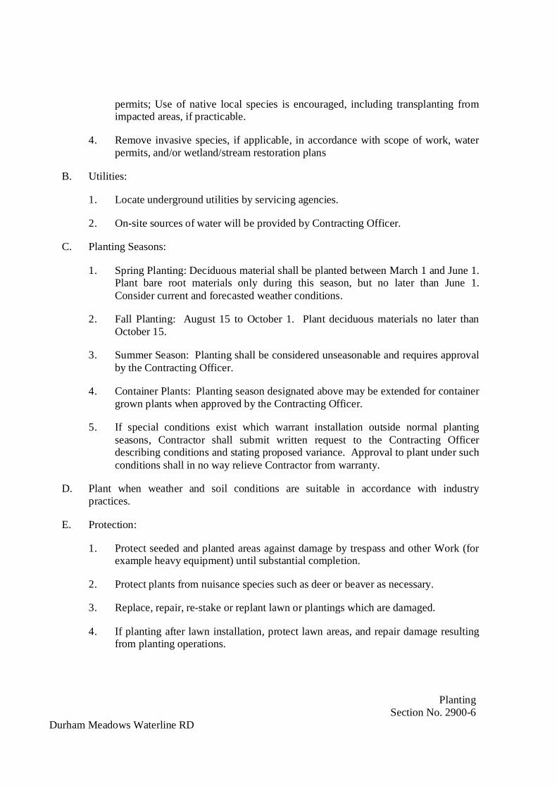
PlantingSection No. 2900-6
Durham Meadows Waterline RD
permits; Use of native local species is encouraged, including transplanting fromimpacted areas, if practicable.
4. Remove invasive species, if applicable, in accordance with scope of work, waterpermits, and/or wetland/stream restoration plans
B. Utilities:
1. Locate underground utilities by servicing agencies.
2. On-site sources of water will be provided by Contracting Officer.
C. Planting Seasons:
1. Spring Planting: Deciduous material shall be planted between March 1 and June 1.Plant bare root materials only during this season, but no later than June 1.Consider current and forecasted weather conditions.
2. Fall Planting: August 15 to October 1. Plant deciduous materials no later thanOctober 15.
3. Summer Season: Planting shall be considered unseasonable and requires approvalby the Contracting Officer.
4. Container Plants: Planting season designated above may be extended for containergrown plants when approved by the Contracting Officer.
5. If special conditions exist which warrant installation outside normal plantingseasons, Contractor shall submit written request to the Contracting Officerdescribing conditions and stating proposed variance. Approval to plant under suchconditions shall in no way relieve Contractor from warranty.
D. Plant when weather and soil conditions are suitable in accordance with industrypractices.
E. Protection:
1. Protect seeded and planted areas against damage by trespass and other Work (forexample heavy equipment) until substantial completion.
2. Protect plants from nuisance species such as deer or beaver as necessary.
3. Replace, repair, re-stake or replant lawn or plantings which are damaged.
4. If planting after lawn installation, protect lawn areas, and repair damage resultingfrom planting operations.

PlantingSection No. 2900-7
Durham Meadows Waterline RD
5. Where planting occurs in close proximity to other site improvements, protectfeatures prior to commencing Work. Any items damaged due to plantingoperations shall be repaired to their original condition.
1.07 WARRANTY:
A. During 1 year correction period replace plants which have died, or are in dyingcondition, or which has failed to flourish so its usefulness or appearance has beenimpaired. Replace trees with dead main leader or crown which is 25 percent or moredead.
1. Replacement and Damages:
a. Decisions of the Contracting Officer for required replacements are final andbinding upon Contractor.
b. Contractor is responsible for repairing damage to property caused bydefective workmanship and materials.
2. Exclusions:
a. Contractor is not liable for replacement cost of plants damaged by deicingcompounds, fertilizers, pesticides or other materials not specified in ContractDocuments or not applied by Contractor, by relocating or removal by others,by acts of God, or by vandalism, and losses due to curtailment of water bylocal authorities.
3. Inspection of Maintenance:
a. During correction period, Contractor shall, periodically (once a week),inspect watering, cultivation, and other maintenance operations byContracting Officer, and notify Contracting Officer of methods, practices oroperations considered unsatisfactory and not in accordance with goodhorticultural practices.
b. Failure of Contractor to inspect or report shall be construed as acceptance ofContracting Officer’s maintenance operations, and Contractor shall notclaim or assert defects which may later develop are result of such methods orpractices or operations.
c. Contracting Officer will notify Contractor when maintenance is to beperformed so Contractor may observe maintenance procedures.

PlantingSection No. 2900-8
Durham Meadows Waterline RD
PART 2 - PRODUCTS
2.01 PLANTS:
A. General:
1. Provide plants in accordance with ANSI Standard for Nursery Stock, DesignationZ60.1-2004.
2. Plant material shall be nursery grown unless otherwise specified or approved inwriting by the Contracting Officer. Plants shall have been grown within samehardiness zone as Project site or acclimated to conditions of same hardiness zonefor minimum of 2 growing seasons. Hardiness zones shall conform to “Zones ofPlant Hardiness” as provided by U.S. Department of Agriculture.
3. Unless specifically noted otherwise, plants shall be of selected specimen quality;have normal habit of growth; and be sound, healthy, vigorous plants with welldeveloped root systems. Plants shall be free of disease, insect pests, their eggs orlarvae, and injuries.
4. Do not prune before delivery. Prune at time of planting. Trees with damaged,crooked leader or multiple leaders, unless specifically specified, will be rejected.Trees with abrasion of bark, sun scalds, disfiguring knots or fresh cuts of limbsover 1-1/4 inch which have not completely calloused, will be rejected. Prune inaccordance with American Association of Nurserymen standards to preservenatural form and character of the plant. Plants shall be freshly dug or containergrown. Heeled-in plants or plants for cold storage are not acceptable unlessContractor makes such request in writing and plants are inspected and approved.
5. Plant Name and Size:
a. Measure plants when branches are in normal position. Height and spreadrefer to plant’s main body and not from tip to branch tip.
b. Take caliper measurement at specified distance above root collar asdescribed in ANSI Z60.1.
c. If range of size is given, no plant shall be less than minimum size and notless than 50 percent of plants shall be as large as upper half of rangespecified.
d. Measurements specified are minimum size acceptable and are measurementsafter pruning, where pruning is required. Plants meeting measurementsspecified, but not producing normal balance between height and spread, willbe rejected.
PlantingSection No. 2900-9
Durham Meadows Waterline RD
e. Shrubs shall be matched specimens from single block source.
f. Plants shall be true to species and variety and conform to measurementspecified in Plant Schedule, except plants larger than specified may be usedif approved by the Contracting Officer. Use of such plants will not result inincrease in Contract Price. If larger plants are approved, increase ball ofearth in proportion to size of plant.
g. Where plants larger than specified have been submitted in writing forapproval and approved in writing by the Contracting Officer, Contractorshall assume responsibility of guarantee for plant in size as planted.
B. Balled and Burlapped Plants (B&B):
1. Dig plants with firm natural balls of earth of sufficient diameter and depth toencompass fibrous and feeding root system necessary for full recovery of plant.
2. Plants having balls broken or cracked during delivery or at time of planting will berejected.
3. Ball sizes shall meet or exceed requirements of ANSI Z60.1.
4. The Contracting Officer may reject plants specified as B&B which, in theContracting Officer’s opinion, fails to conform to balling requirements.
C. Bare Roots Plants (BR):
1. Dig shrubs marked BR at nursery without injury to fibrous root system necessaryfor full recovery of plant.
2. Cover root with thick coating of mud by puddling or wrap in wet straw, moss orother suitable packing material immediately after they are dug for protection untildelivery and installation.
3. Root Spread:
Height of Plant Minimum Spread of Root (in.)18 - 24 inches 10
2 - 3 feet 113 - 4 feet 144 - 5 feet 165 - 6 feet 186 - 8 feet 20
4. Maintain bare root plants in cold storage at approximately 30 degrees F prior tobeing delivered to Site.

PlantingSection No. 2900-10
Durham Meadows Waterline RD
D. Container or Pot Grown Plants (Cont. or Pot):
1. Container grown plants shall have heavy fibrous root system, or well developedtap root, developed by proper horticultural practice including transplanting androot pruning, and shall have grown in container for at least 1 growing season.
2. Root system shall have developed sufficiently long for new fibrous roots todevelop so root mass will retain its shape and hold together when removed fromcontainer.
3. Container shall not strangle or girdle natural growth of plant. Plants, other thangroundcovers, over-established in container as evidenced by pot-bound root ends,will be rejected.
E. Bulbs, Corms, or Tubers:
1. Healthy and viable, free from fungus and disease; and not dried out, desiccated ordamaged by digging or handling. Provide proper period of rest.
2. Bulbs and corms shall meet diameter or circumference as set forth in ANSI Z60.1.
3. Tubers shall have minimum of 2 “eyes” or buds.
F. Perennials, Biennials, Prairie Forbes, and Grasses:
1. Perennials, biennials, prairie forbes, and grasses specified as “container” or “pot”shall be provided as container-grown plants, or provided with firm natural balls ofearth with diameter and depth in accordance with ANSI Z60.1 for size specified onPlant List.
2. Ship balled plants in open air boxes or crates to minimize handling of each plantprior to installation. Do not plant balled plants if ball is cracked or broken beforeor during process of planting.
G. Collected Plants:
1. Plant material collected from native stands or established plantings shall bedesignated as such. Spread of roots, bare root or root balled trees shall be aminimum of 1/3 greater in size than recommended for nursery grown stock inaccordance with ANSI Z60.1.
2. Plant material collected from wild or native stands may be considered nurserygrown when successfully re-established in nursery row and grown under regularnursery cultural practices for minimum of 2 growing seasons and attained adequateroot and top growth to indicate full recovery from transplanting into nursery row.
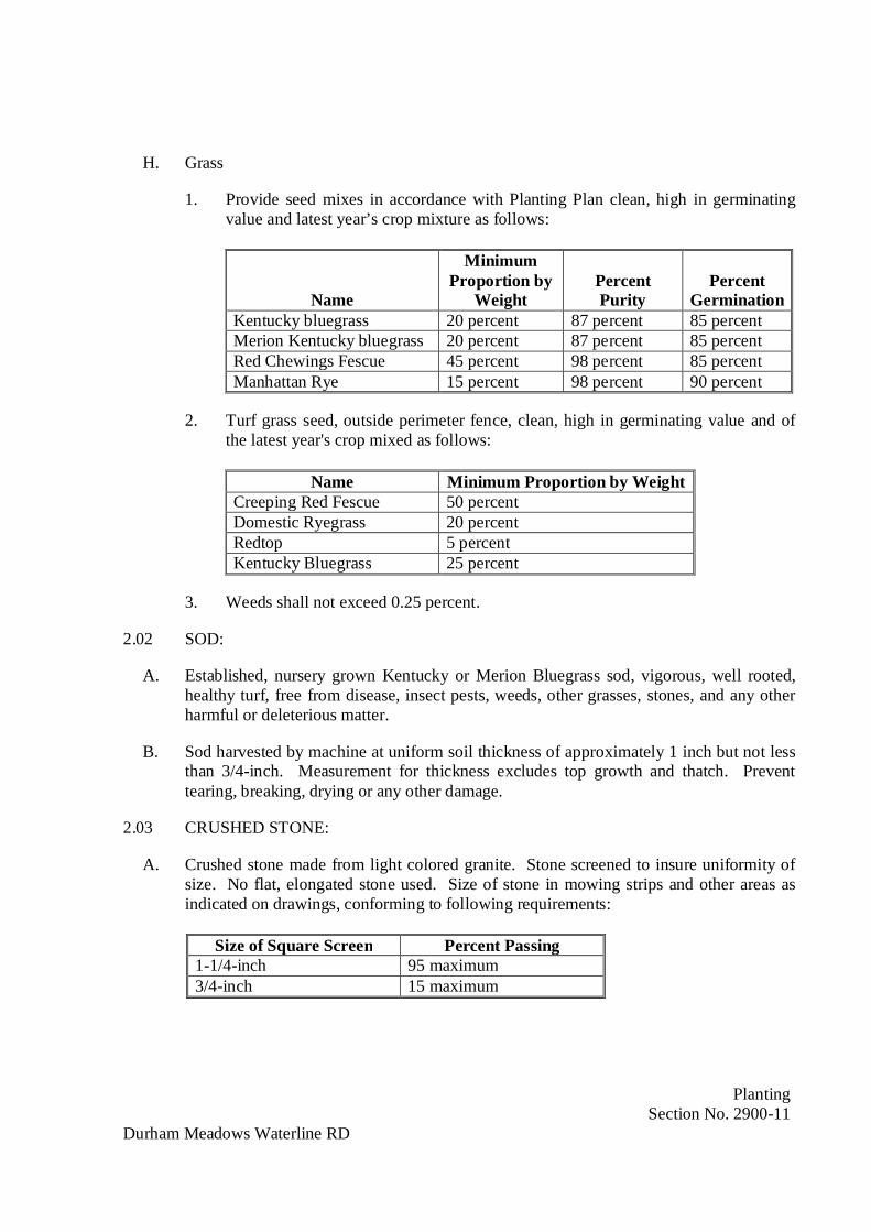
PlantingSection No. 2900-11
Durham Meadows Waterline RD
H. Grass
1. Provide seed mixes in accordance with Planting Plan clean, high in germinatingvalue and latest year’s crop mixture as follows:
Name
MinimumProportion by
WeightPercentPurity
PercentGermination
Kentucky bluegrass 20 percent 87 percent 85 percentMerion Kentucky bluegrass 20 percent 87 percent 85 percentRed Chewings Fescue 45 percent 98 percent 85 percentManhattan Rye 15 percent 98 percent 90 percent
2. Turf grass seed, outside perimeter fence, clean, high in germinating value and ofthe latest year's crop mixed as follows:
Name Minimum Proportion by WeightCreeping Red Fescue 50 percentDomestic Ryegrass 20 percentRedtop 5 percentKentucky Bluegrass 25 percent
3. Weeds shall not exceed 0.25 percent.
2.02 SOD:
A. Established, nursery grown Kentucky or Merion Bluegrass sod, vigorous, well rooted,healthy turf, free from disease, insect pests, weeds, other grasses, stones, and any otherharmful or deleterious matter.
B. Sod harvested by machine at uniform soil thickness of approximately 1 inch but not lessthan 3/4-inch. Measurement for thickness excludes top growth and thatch. Preventtearing, breaking, drying or any other damage.
2.03 CRUSHED STONE:
A. Crushed stone made from light colored granite. Stone screened to insure uniformity ofsize. No flat, elongated stone used. Size of stone in mowing strips and other areas asindicated on drawings, conforming to following requirements:
Size of Square Screen Percent Passing1-1/4-inch 95 maximum3/4-inch 15 maximum
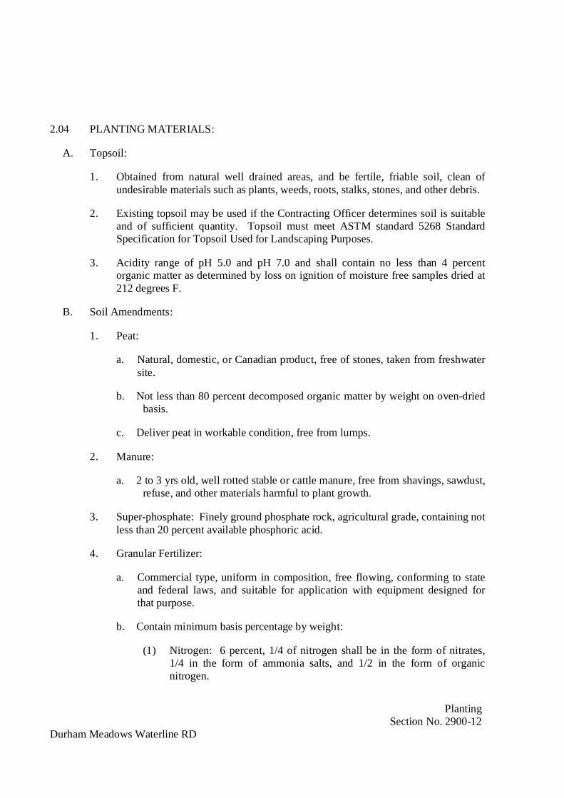
PlantingSection No. 2900-12
Durham Meadows Waterline RD
2.04 PLANTING MATERIALS:
A. Topsoil:
1. Obtained from natural well drained areas, and be fertile, friable soil, clean ofundesirable materials such as plants, weeds, roots, stalks, stones, and other debris.
2. Existing topsoil may be used if the Contracting Officer determines soil is suitableand of sufficient quantity. Topsoil must meet ASTM standard 5268 StandardSpecification for Topsoil Used for Landscaping Purposes.
3. Acidity range of pH 5.0 and pH 7.0 and shall contain no less than 4 percentorganic matter as determined by loss on ignition of moisture free samples dried at212 degrees F.
B. Soil Amendments:
1. Peat:
a. Natural, domestic, or Canadian product, free of stones, taken from freshwatersite.
b. Not less than 80 percent decomposed organic matter by weight on oven-driedbasis.
c. Deliver peat in workable condition, free from lumps.
2. Manure:
a. 2 to 3 yrs old, well rotted stable or cattle manure, free from shavings, sawdust,refuse, and other materials harmful to plant growth.
3. Super-phosphate: Finely ground phosphate rock, agricultural grade, containing notless than 20 percent available phosphoric acid.
4. Granular Fertilizer:
a. Commercial type, uniform in composition, free flowing, conforming to stateand federal laws, and suitable for application with equipment designed forthat purpose.
b. Contain minimum basis percentage by weight:
(1) Nitrogen: 6 percent, 1/4 of nitrogen shall be in the form of nitrates,1/4 in the form of ammonia salts, and 1/2 in the form of organicnitrogen.
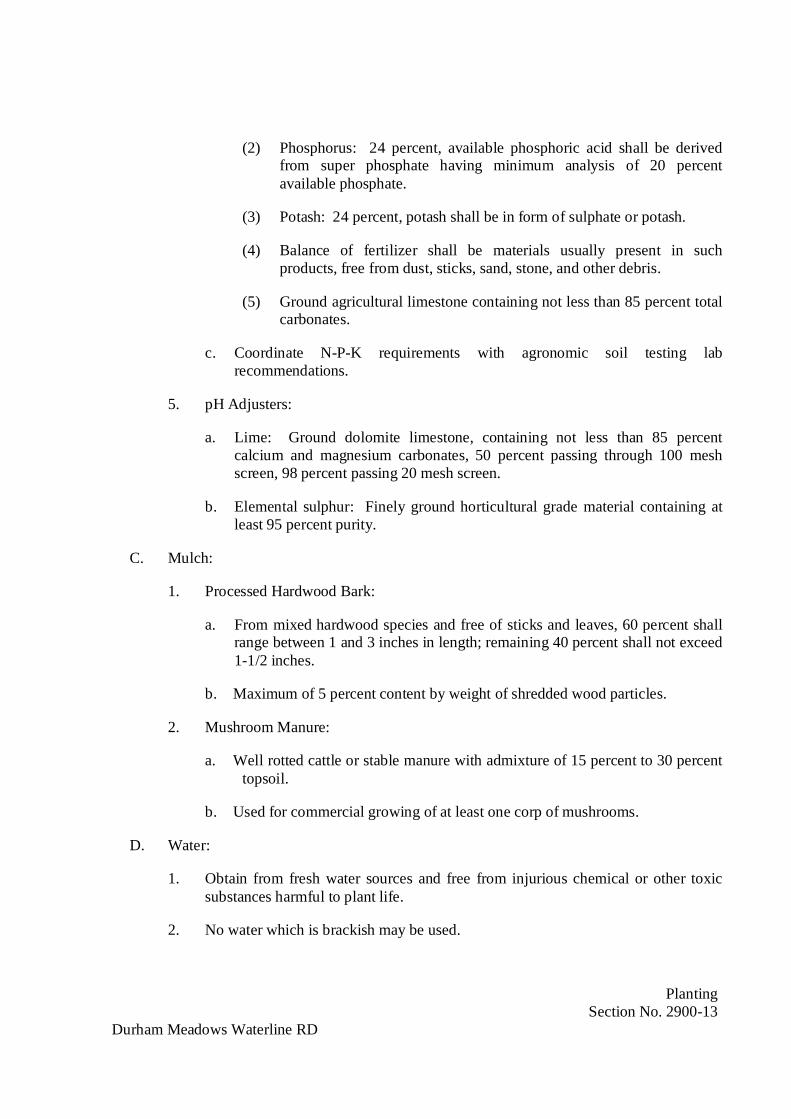
PlantingSection No. 2900-13
Durham Meadows Waterline RD
(2) Phosphorus: 24 percent, available phosphoric acid shall be derivedfrom super phosphate having minimum analysis of 20 percentavailable phosphate.
(3) Potash: 24 percent, potash shall be in form of sulphate or potash.
(4) Balance of fertilizer shall be materials usually present in suchproducts, free from dust, sticks, sand, stone, and other debris.
(5) Ground agricultural limestone containing not less than 85 percent totalcarbonates.
c. Coordinate N-P-K requirements with agronomic soil testing labrecommendations.
5. pH Adjusters:
a. Lime: Ground dolomite limestone, containing not less than 85 percentcalcium and magnesium carbonates, 50 percent passing through 100 meshscreen, 98 percent passing 20 mesh screen.
b. Elemental sulphur: Finely ground horticultural grade material containing atleast 95 percent purity.
C. Mulch:
1. Processed Hardwood Bark:
a. From mixed hardwood species and free of sticks and leaves, 60 percent shallrange between 1 and 3 inches in length; remaining 40 percent shall not exceed1-1/2 inches.
b. Maximum of 5 percent content by weight of shredded wood particles.
2. Mushroom Manure:
a. Well rotted cattle or stable manure with admixture of 15 percent to 30 percenttopsoil.
b. Used for commercial growing of at least one corp of mushrooms.
D. Water:
1. Obtain from fresh water sources and free from injurious chemical or other toxicsubstances harmful to plant life.
2. No water which is brackish may be used.
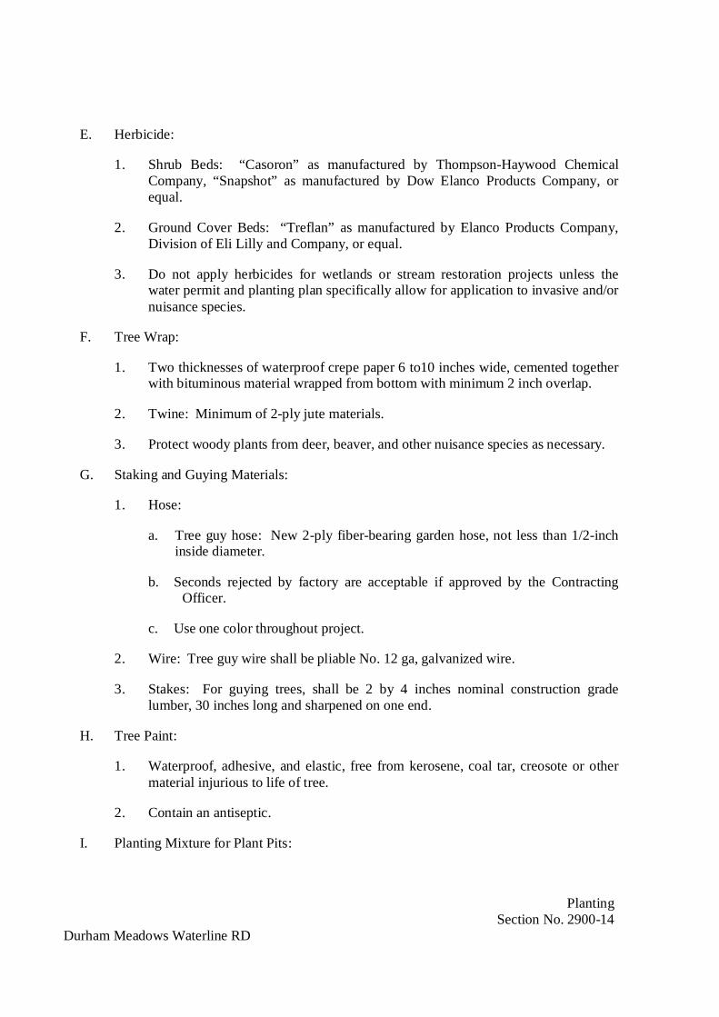
PlantingSection No. 2900-14
Durham Meadows Waterline RD
E. Herbicide:
1. Shrub Beds: “Casoron” as manufactured by Thompson-Haywood ChemicalCompany, “Snapshot” as manufactured by Dow Elanco Products Company, orequal.
2. Ground Cover Beds: “Treflan” as manufactured by Elanco Products Company,Division of Eli Lilly and Company, or equal.
3. Do not apply herbicides for wetlands or stream restoration projects unless thewater permit and planting plan specifically allow for application to invasive and/ornuisance species.
F. Tree Wrap:
1. Two thicknesses of waterproof crepe paper 6 to10 inches wide, cemented togetherwith bituminous material wrapped from bottom with minimum 2 inch overlap.
2. Twine: Minimum of 2-ply jute materials.
3. Protect woody plants from deer, beaver, and other nuisance species as necessary.
G. Staking and Guying Materials:
1. Hose:
a. Tree guy hose: New 2-ply fiber-bearing garden hose, not less than 1/2-inchinside diameter.
b. Seconds rejected by factory are acceptable if approved by the ContractingOfficer.
c. Use one color throughout project.
2. Wire: Tree guy wire shall be pliable No. 12 ga, galvanized wire.
3. Stakes: For guying trees, shall be 2 by 4 inches nominal construction gradelumber, 30 inches long and sharpened on one end.
H. Tree Paint:
1. Waterproof, adhesive, and elastic, free from kerosene, coal tar, creosote or othermaterial injurious to life of tree.
2. Contain an antiseptic.
I. Planting Mixture for Plant Pits:
PlantingSection No. 2900-15
Durham Meadows Waterline RD
1. 6 parts topsoil or suitable existing soil thoroughly mixed with 2 parts peat and1 part manure, plus 1 pound 6-24-24 fertilizer/cu yd of mixture.
PART 3 - EXECUTION
3.01 PREPARATION:
A. Do not install plantings where depth of soil over underground construction, obstructionsor rock is insufficient to accommodate roots or where pockets in rock or impervious soilrequire drainage.
1. Where such conditions are encountered in excavation planting areas and wherestone, boulders or other obstruction cannot be broken or removed by hand methodsand where trees to be planted are under overhead wires, alternate locations forplanting may be designated by the Contracting Officer.
2. Where locations cannot be changed as determined by the Contracting Officer,submit cost required to remove obstructions to depth of not less than 6 inchesbelow required pit depth. Proceed with Work after approval of the ContractingOfficer.
3. Dispose of excavated material not suitable for backfilling off-site.
4. If drainage problems are encountered detrimental to growth of specified plantmaterial, notify the Contracting Officer of conditions before proceeding withWork.
B. Remove rock or other underground construction and drain planting areas only whenapproved by the Contracting Officer. Payment for extra work shall be based on in-placevolume required to provide normal requirements for plantings.
3.02 INSTALLATION:
A. Topsoil/Finish Grading:
1. Do not place or work topsoil in frozen or muddy condition.
2. Finish grade is established final grade. Grades not otherwise indicated are uniformlevels or slopes between points where elevations given or between such points andexisting finished grades.
3. Where Drawings show existing grades of landscaped areas are not to be changedor if new grade is less than 4 inches above existing grades, remove enoughmaterial to allow placement of 4 inches new topsoil, unless existing topsoil torequired depth is undisturbed and of equal or better quality than topsoil specified.In latter case, existing topsoil may be left in-place, using enough new topsoil tobring these areas up to grade.
PlantingSection No. 2900-16
Durham Meadows Waterline RD
B. Preparation:
1. Planting Season: Conform to planting seasons.
2. Preparation of Planting Areas: Cover surrounding turf (if existing) to protectturfed areas that are to be trucked or hauled over and upon which soil is to betemporarily stocked.
3. Stake or paint locations of plants and outlines of bed. The Contracting Officer willapprove locations before excavation starts. Make adjustments in locations andoutlines as required. If pits or areas for planting are prepared and backfilled withtopsoil to grade prior to commencement of lawn operations, mark so they can bereadily located when planting proceeds.
C. Excavation for Planting:
1. Planting Pits:
a. Circular pits with vertical sides and flat bottoms.
b. Depth of pits for trees shall be suitable to accommodate ball, container orbare roots when plant is set to finished grade allowing for 6 inches. ofcompacted, prepared soil in bottom of pit.
c. If rotating augers or other mechanical diggers are used to excavate holes,scarify vertical sides of pits to eliminate impervious surfaces.
d. Continuous trench may be utilized instead of separate round pits for hedgeplantings.
2. Shrub bed preparation:
a. Excavated existing soil in shrub beds and replace with planting bed soilmixture.
b. Planting beds shall be brought to smooth and even surface conforming toestablished grades.
D. Preparation for Planting:
1. Preparation of Planting Pits:
a. Loosen soil at bottom of pit to minimum depth of 4 inches by spading orother effective methods.
b. Backfill pit with 6 inches layer of compacted, prepared soil.
2. Preparation of Groundcover, Annual, and Perennial Beds:
PlantingSection No. 2900-17
Durham Meadows Waterline RD
a. Cover areas specified for ground cover, annuals, and perennials with 2-inchlayer of mushroom manure.
b. Work into soil to minimum depth of 9 inches by use of rototiller or othercultivating mechanism.
c. After completion, mulch bed throughout with additional 3-inch layer ofmushroom manure prior to planting of plants.
d. Mix herbicide directly into prepared planting soils in conformance withmanufacturer’s recommendations.
E. Planting:
1. B&B Plants:
a. Cut away burlap, rope, wire or other wrapping materials from top of ball andremove from pit. Do not remove burlap or ties from sides and bottom ofroot ball. If plastic wrap or other non-degradable materials are used in lieuof burlap, remove them before placing of backfill.
b. Backfill planting pits approximately 2/3 full with prepared soil, add waterand allow settling. After water has been absorbed, fill planting pit withplanting mixture and tamp to match finish grade. Form shallow sauceraround each isolated plant pit with prepared soil.
2. Container-Grown Plants:
a. Open and remove potted plants from containers.
b. If growing medium is comprised of 75 percent or more of peat, perlite, sandor like material other than soil, pull visible roots away from containermedium so as to leave roots partially exposed.
c. Place plants in plant pit or trench and backfill with prepared soil amongexposed roots. Continue backfilling and tamping in 6-inch layers untilplanting mixture is at final grade.
3. Bare Root Plants:
a. Place plants which have been puddled in mud or peat and water solution incenter of pit or trench.
b. Cut off broken or frayed roots.
c. Spread roots in natural position and backfill moist prepared soil among rootsin 6-inch layers until planting mixture is at final grade.
d. Form shallow saucer around each isolated plant pit with prepared soil.
PlantingSection No. 2900-18
Durham Meadows Waterline RD
e. Water plants immediately after planting.
4. Bulbs, Corms, Tubers and Grass sprigs:
a. Plant at time and depth in accordance with best horticultural practice.
F. Pruning:
1. Prune new trees and shrubs at time of or after planting. Prune and repair existingtrees designated to remain. Prune in accordance with American Association ofNurserymen standards.
2. Prune in accordance with standard horticultural practices to retain natural formand character of plant.
3. Prune and remove dead wood, suckers, injured twigs and branches, badly formedor interfering limbs, and sufficient other growth to insure health and symmetricalgrowth of new wood. Up to one third (1/3) of branches may be removed.
4. Use clean, sharp tools.
5. Make cuts flush and clean, leaving no stubs.
6. For cuts greater than 3/4-inch in diameter and bruises or scars on bark, traceinjured cambium back to living tissue and remove. Smooth and shape wounds soas not to retain water.
7. Paint pruning cuts greater than 3/4-inch with tree paint.
8. Prune flowering trees only to remove dead or damaged branches. Do not removemain leader. In case of multiple leaders, preserve one that will best promotesymmetry of tree, and remove or cut back rest.
9. Prune shrubs by removing broken branches, thinning out canes, and cutting backor removing unsymmetrical branches. Pruning shall result in loose outlineconforming to general shape of shrub type. Do not use hedge shears.
G. Wrapping:
1. Wrap deciduous trees with tree wrap immediately after planting.
2. Wrap spirally from base of trunk to first lateral branches, overlapping precedingwrap by one-half width of paper.
3. Trunks may be inspected by the Contracting Officer prior to wrapping for injury tobark, improper pruning, and evidence of insect or disease infestation.
4. Tie wrap securely in place at top, bottom, and 18 inches maximum intervals withtwine.
PlantingSection No. 2900-19
Durham Meadows Waterline RD
H. Fertilizer:
1. First Application (Ratio 1-4-4): Prior to installation of mulch to plant beds andsaucers, apply commercial fertilizer to plant bed or saucer area at rate of 1/2 poundactive ingredient per 100 square feet.
2. Second Application (Ratio 5-3-2): Applied in 60 days after planting at rate of 1/2pound active ingredient per 100 square feet..
I. Herbicide Application:
1. Comply with manufacturer’s recommendations before mulching.
2. Place herbicide in direct contact with soil.
3. Plant leaf surfaces shall be dry during herbicide application.
J. Mulching:
1. Mulch shade trees, ornamental trees, singularly planted shrubs, hedge plantings,and massed shrub plantings. Cover entire planting pit or bed with uniform 4 inchdepth of shredded hardwood bark.
2. Mulch within 5 days after installation.
3. Keep mulch out of crowns of shrubs and off buildings, walks, and pavements, lightstandards, and other structures.
K. Staking and Guying:
1. Stake and guy trees.
2. Stake and guy immediately after wrapping. Plants shall stand plumb after staking.
L. Watering:
1. Water immediately after installation.
2. Water during period of temporary maintenance.
3. Provide hose and other equipment for watering.
3.03 CLEAN UP AND PROTECTION
A. Remove excess and waste material daily.
B. Remove soil or similar material brought onto paved areas, keeping areas broom clean.

PlantingSection No. 2900-20
Durham Meadows Waterline RD
C. Upon completion of planting, remove excess soil, stones, and debris and dispose of off-site.
D. Damage to existing landscape, pavements, or other site features as result of Work shallbe repaired to its original condition.
E. Protect landscape Work and materials from damage due to landscape operations,operations by other contractors and trades, and trespassers. Maintain protection duringinstallation and maintenance periods.
3.04 MAINTENANCE
A. Temporary Maintenance:
1. Maintain plant material until substantial completion as defined in section 3.06.Acceptance of this specification.
2. Temporary maintenance begins immediately after each plant is installed and shallinclude watering, necessary cultivation, weeding, pruning, disease and insect pestcontrol, protective spraying, resetting of plants to proper grades or uprightposition, restoration of damaged planting saucers, and other procedures consistentwith good horticultural practice necessary to ensure normal, vigorous, and healthygrowth of plantings.
3. Remove and replace dead and unacceptable plants as their condition becomesapparent.
4. Upon substantial completion, Contractor assumes responsibility for plantmaintenance, except as below.
a. For duration of one year correction period, Contractor is responsible forresetting of settled plants, straightening of plants which are not plumb, andtightening of tree guys.
b. Contractor shall remove and dispose of tree wrap, stakes, tublings, and guysat end of 1 yr period.
3.05 REPLACEMENTS:
A. Replace plants which have died prior to substantial completion.
B. Plants which die or require replacement for other reasons during one-year correctionperiod shall be replaced as soon as possible during acceptable planting seasons.
1. Spring Replacement Season: All plants-when ground becomes workable to June1.
2. Fall Replacement Season:
PlantingSection No. 2900-21
Durham Meadows Waterline RD
a. Deciduous plants: October 15 until the ground freezes.
b. Evergreen plants: August 15 to October 1.
C. Procedure:
1. Dispose of removed plants off-site.
2. Replacements shall be of same size and species as original plant unless otherwiseapproved by the Contracting Officer.
3. Replacements shall be supplied and installed in accordance with Specifications.
4. Restore areas damaged by replacement operations to original condition.
5. Notify the Contracting Officer at conclusion of replacement program.
6. The Contracting Officer will conduct inspection of replacements for determiningfinal acceptance.
3.06 ACCEPTANCE:
A. Preliminary Planting Acceptance:
1. Notify the Contracting Officer at conclusion of planting operations so theContracting Officer can determine substantial completion by field inspection.
2. Substantial completion requires:
a. Plant material conforms to Contract Documents with respect to quantity,quality, size, species, and location, except those items accepted or revised infield by the Contracting Officer.
b. Plant material shall be in healthy condition as defined under warranty.
c. Vegetation density (for herb species) and/or woody species stems/acre shallbe in accordance with water permit and/or wetlands/stream restorationcriteria.
B. Final Planting Acceptance:
1. Final planting acceptance shall be granted after completion of replacementoperations required to fulfill guarantee.
2. Final inspection of planting will be made by Contractor and Contracting Officer.
3. On or about expiration of 1 yr correction period, follow-up inspection will bemade to determine replacements required to be made by Contractor in accordancewith provisions of these Specifications. The Contracting Officer will document
PlantingSection No. 2900-22
Durham Meadows Waterline RD
findings in field report, and forward copies to Contractor. Items identified forreplacement will be tagged during inspection with plastic flagging.
4. Upon completion of replacement program, the Contracting Officer will inspect todetermine acceptability of required replacements. If acceptable, the ContractingOfficer shall notify Contractor in writing, of final acceptance of Work.
5. Complete vegetative monitoring and reporting in accordance with water permit,scope of work, and/or EEP criteria.
3.07 CLOSEOUT ACTIVITIES:
A. Provide in accordance with Section 01700.
END OF SECTION
HydroseedingSection No. 02922-1
Durham Meadows Waterline RD
SECTION 02922
HYDROSEEDING
PART 1 - GENERAL
1.01 DESCRIPTION:
A. This section describes hydroseeding, hydromulching, and seed mix establishment andmaintenance for erosion control and revegetation.
1.02 REFERENCES:
A. Standard Specification for Roads, Bridges and Incidental Construction, State ofConnecticut Department of Transportation, Form 817, 2004 as amended andsupplemented.
B. American National Standards Institute (ANSI):
1. Z60.1-2004: American Standard for Nursery Stock.
C. American Society for Testing and Materials International (ASTM):
1. ASTM D5268, Standard Specification for Topsoil Used for Landscaping Purposes.
2. ASTM D5435, Standard Test Method for Plant Growth and Food ChainProtection.
1.03 SUBMITTALS:
A. Submit the following shop drawings in accordance with Section 01300.
1. After completion of grading and prior to soil preparation, obtain soil samples for arepresentative sampling of planting areas. Submit a location map showingproposed soil sample locations for review prior to collecting samples. Collect twosoil samples at each sample location. Collect samples at depths of 0-6 inches and6-12 inches. Submit soil samples for agronomic soils test report. Tests shall beperformed by an agronomic soils testing laboratory. USDA Service Center LocatorReport shall include a fertility and plant suitability analysis with writtenrecommendations for organic soil amendments, fertilizers, soil conditioners, andtheir respective application rates for soil treatment and plant maintenance. Thesoils report recommendations shall take precedence over the minimumamendment, fertilizer, and conditioner application rates specified herein only whenthey exceed specified minimums.

HydroseedingSection No. 02922-2
Durham Meadows Waterline RD
2. Submit materials list noting product (generic) name and manufacturer or supplier.List shall include fertilizers, organic amendments, soil conditioners, soil binder,herbicides, fiber mulch, etc.
3. Submit seed list naming seeds, application rate in pounds per acre, andsupplier's name, address, and phone number.
4. Submit laboratory analysis of fertilizers, organic amendments, soilconditioners, soil binder, herbicides, etc.
5. Submit the above submittals to the Contracting Officer no later than 30 daysprior to performing the work, giving evidence that Contractor has a sourcefor specified hydrospray materials and seed mix and that they conform tothese specifications.
1.04 QUALITY ASSURANCE:
A. Qualifications:
1. Subcontractor shall have specialized equipment and experience for hydroseeding.
B. Planting Plan:
1. Follow planting plan in accordance with Contracting Officerdrawings and applyhydroseeding as required for site restoration.
C. Inspection:
1. The Contracting Officer may inspect hydroseeded area. Such inspection shall bein addition to inspection at Site.
2. Contractor shall be present during required inspections or as may be required bythe Contracting Officer.
1.05 WARRANTY:
1. During 1 year correction period replace bare spots, or areas that have failed toflourish so its usefulness or appearance has been impaired.
2. Replacement and Damages:
a. Decisions of the Contracting Officer for required replacements is final andbinding upon Contractor.
b. Contractor is responsible for repairing damage to property caused bydefective workmanship and materials.
3. Exclusions:
HydroseedingSection No. 02922-3
Durham Meadows Waterline RD
a. Contractor is not liable for replacement cost of grass damaged by deicingcompounds, fertilizers, pesticides or other materials not specified in ContractDocuments or not applied by Contractor, by relocating or removal by others,by acts of God, or by vandalism, and losses due to curtailment of water bylocal authorities.
1.06 OBSERVATIONS:
A. Request observation by the Contracting Officer at least 48 hours in advance of requiredobservation time.
B. Observation will be required for the following parts of the work:
1. Review landscape final grading and weed control prior to hydroseeding.
2. When hydroseeding work is ready to begin, a review of slurry materials and seedmixes shall be performed prior to slurry preparation.
3. During and upon completion of maintenance and seed mix establishment.
PART 2 - PRODUCTS
2.01 SEED MIX:
A. Deliver seeds to the site in sealed bags with certification tags, including weight, seedtype, seed purity, germination percent, and date seed tested. Give seed certification tagsto Contracting Officer.
B. Seed shall be fresh, clean, new crop seed. Seed shall be delivered to the work site witheach container bearing the dealer's guaranteed analysis. Seed mixes shall be composedsubstantially as follows with less than 1.5 percent inert matter, not more than one percentcrop seed content, and no noxious weed seeds. Seed shall be spread at rates indicatedafter each mixture.
C. Mowable Grass Seed Mixture (4 pounds/1,000 square feet)
1. Mowable grass seed mixture shall conform to seed mixture of State of ConnecticutDepartment of Transportation Standard Specifications Section M13.04.
2.02 FIBER MULCH:
Fiber mulch shall be derived from wood chips or recycled paper products. The mulchshall be free of chemicals and growth inhibitors. Mulch shall contain a green dye toassist in metering the application.
A. Cellulose fiber mulch shall be Conwed 2000 (wood fiber), Conwed Corp. 612/631-5700; Cellin-K (cellulose fiber), Cellin Manuf. Inc. 703/690-1195; or equal.
HydroseedingSection No. 02922-4
Durham Meadows Waterline RD
2.03 HYDRO MULCH:
A. Material for hydromulching shall consist of the fiber mulch material.
2.04 STRAW:
A. Materials for straw tack shall consist of the straw from oats, barley, wheat, or rye andshall be seed free or fumigated to prevent introduction of weeds. At least 50 percent ofthe mulch by weight shall be 10 inches or more in length. Do not use old, dry straw thatbreaks and does not bend.
2.05 WOVEN JUTE MESH NETTING
A. Woven jute mesh netting shall be "Ludlow Soil Saver", as manufactured by the LudlowCorp., Needham Heights, Massachusetts, or an equal manufactured by Advance NettingCompany, Lodi, New Jersey, or "Jute - Net" by Bemis, Inc., St. Louis, Missouri, andshall be placed on all slopes greater than 3 to 1, and all slopes 3 to 1 which are higherthan 10 feet. Woven Jute Mesh Netting will only be required for the protection ofmowable grassed areas or in any other areas where erosion is a problem.
2.06 TOPSOIL:
A. Fertile, friable, natural topsoil typical of locality, without admixture of subsoil, refuse orother foreign materials, and obtained from well-drained arable site. Mixture of sand, siltand clay particles in equal proportions. Free of stumps, roots, heavy or stiff clay, stoneslarger than 1 inch in diameter, lumps, coarse sand, noxious weeds, sticks, brush or otherdeleterious matter. Topsoil shall be in accordance with ASTM 5268 StandardSpecification for Topsoil Used for Landscaping Purposes.
2.07 FERTILIZERS, SOIL CONDITIONERS, SOIL BINDER, AND HERBICIDES:
A. Provide slow-release fertilizer with an analysis of 20-10-5.
B. Provide superphosphate fertilizer with an analysis of 0-18-0.
C. Agricultural gypsum shall be an agricultural calcium sulfate and shall contain 19 percentcombined sulfur.
D. Soil sulfur shall contain 99 percent combined sulfur.
E. Soil Binder:
1. Soil binder shall be a physllium based, organic compound derived from naturalplant sources. Binder shall consist of an active hydrophilic colloid, which willhydrate with water and, upon drying after application, will tack hydrospray mix tosoil surface.
2. Binder shall be nontoxic and contain no growth or germination inhibitors.

HydroseedingSection No. 02922-5
Durham Meadows Waterline RD
3. Binder shall be R-2400 by Reclamare Co. 206/824-2385, Sentinel from AlbrightSeed Co. 805/484-0551, Ecology M-Binder, or equal.
F. Herbicide shall be Roundup® by Monsanto Company or equal.
G. Fertilizer application rates shall be based on results of agronomic soil testing section104.A.1.
PART 3 - EXECUTION
3.01 DELIVERY OF AMENDMENTS AND FERTILIZERS:
A. Deliver amendments and fertilizers in sacks with manufacturer's label showing weightand analysis attached to each sack. The Contracting Officer will review amendmentsand fertilizers prior to hydroseeding.
3.02 LANDSCAPE GRADING:
A. Bring planting areas to grade by filling or removing surplus dirt. Final grades shall beuniform and smooth in nonturf areas. Topsoil shall be a minimum of 4 inches belowadjacent hardscape. Areas shall slope to drain.
B. Remove rock debris over 1 inch in diameter.
C. Topsoil shall be scarified to a depth of 4 inches inches prior to seeding.
3.03 IRRIGATION:
A. Irrigation system shall be installed per Section 02813,
3.04 WEED AND INVASIVE SPECIES ABATEMENT:
A. After establishment of grades and installation of irrigation system and prior tohydroseeding, cut weeds and grasses to ground. Remove from site. Do not drag cutmaterials.
B. Apply 150 pounds per acre of urea fertilizer and irrigate several times per day for aminimum of two weeks to germinate weed seeds.
C. Following germination, a licensed pest control applicator shall spray a postemergentweed killer, Roundup® or equal, per manufacturer's directions in hydroseed areas.
D. Wait a minimum of one week for dissipation. Remove residual foliage.

HydroseedingSection No. 02922-6
Durham Meadows Waterline RD
3.05 HYDROSEEDING:
A. Hydroseed the locations indicated in the drawings and where the native vegetation hasbeen destroyed by construction or grading operations. Hydroseed excavation and fillareas.
B. Prior to hydroseeding, all other work in areas to be hydroseeded shall be complete (i.e.,grading, irrigation, other plant installations, etc.).
C. Application:
1. Measure the site and stake to identify the areas to be sprayed by each truckload ofmix.
2. Water the area to be hydroseeded for three consecutive days prior to or until theupper 2 inches of soil are wet. Let the top 1/4-inch of soil dry out, leaving someresidual moisture in the soil below.
3. Apply the hydroseed in the form of a slurry consisting of fiber mulch, seed, soilbinder, soil conditioners, fertilizer, and water. When hydraulically sprayed on thesoil surface, the mix shall form a blotter-like ground cover impregnated uniformlywith seed and fertilizer and shall allow moisture to percolate to the underlying soil.
4. Hydroseed in the time period between March 15 to June 15 and August 15 toOctober 15. Repeat in accordance with warranty, water permit, local and/or stateregulations, State of Connecticut Department of Transportation criteria, and/orwarranty as required.
D. Hydroseed Slurry Mixture:
Seed Mix:Fiber mulch 2,000 lbs per acreSlow-release fertilizer:20-10-5 200 lbs per acre
0-18-0 single super-phosphate 150 lbs per acre
Agricultural gypsum 500 lbs per acre
Soil sulfur 100 lbs per acre
Soil binder 100 lbs per acre
E. Mix the soil binder at the rate of 60 pounds of concentrate mixed with 1,500 gallons ofwater.
F. Equipment:
HydroseedingSection No. 02922-7
Durham Meadows Waterline RD
1. Use an agitator mixer for the application of the slurry. This equipment shall have abuilt-in agitation system and operating capacity sufficient to agitate, suspend, andhomogeneously mix a slurry containing not less than 82 pounds pounds ofcellulose fiber mulch, plus a combined total of 15 pounds pounds of fertilizersolids for each 100 gallons of water.
2. The slurry distribution hose lines shall be large enough to prevent stoppage andshall be equipped with a set of hydraulic spray nozzles that will provide acontinuous nonfluctuating discharge. Mount slurry tank on a traveling unit.
3.06 GEOTEXTILE AND STABILIZATION FABRIC
A. Install as specified in accordance with water permit, design plans, and/or wetland/streamrestoration plan.
3.07 STRAW TACK:
A. After the hydroseed application, spread straw uniformly over the hydroseed area at therate of 3 tons per acre.
B. Apply hydromulch over straw.
3.08 HYDROMULCHING:
A. Hydromulching application shall be similar to hydroseeding as far as equipment andprocedures.
B. Apply hydromulch over hydroseed or straw.
C. Hydromulch slurry mix shall be as follows:
1. Fiber Mulch: 200 lbs per acre.
2. Soil Binder: 50 lbs per acre.
D. Mix soil binder at the rate of 30 pounds of concentrate mixed with 1,500 gallons ofwater.
3.09 MAINTENANCE:
A. Maintenance work shall include the following plant establishment work:
1. Maintain the entire project for a minimum period of 90 calendar days,commencing from the time all contract work items have been completed to thesatisfaction of the Contracting Officer and evidence of such satisfaction has beenreceived in writing.
2. Rehydroseed planting areas that do not show a prompt establishment of plantmaterial at 10-day intervals.
HydroseedingSection No. 02922-8
Durham Meadows Waterline RD
B. Repair damage to hydroseeded areas immediately and throughout the maintenanceperiod. Rehydroseed immediately after repairs are finished.
1. Fill and level depressions caused by vehicles or foot traffic.
2. Exterminate gophers and moles and repair damage as above.
3. Fill rills and gullies caused by erosion.
C. Remove obvious undesirable and/or invasive plants (such as noxious weeds, thistle, etc.)that have grown in with the hydroseed mix.
D. Keep watering basins of container stock planted in hydroseed area free of hydroseededplants that overgrow container stock.
E. Maintain site in a neat and clean condition. Remove debris and trash from the siteweekly.
END OF SECTION
DIVISION 3
CONCRETE
Durham Meadows Waterline RD Concrete FormworkSection No. 03100-1
SECTION 03100
CONCRETE FORMWORK
PART 1 - GENERAL
1.01 DESCRIPTION:
A. Provide design and furnish materials for fabricating, erecting and removing formwork,false work and shoring for cast-in-place concrete as shown on the contract drawings andspecified herein for a complete installation.
B. Use formwork to cast all cast-in-place concrete structures.
C. Provide and remove all formwork for electrical work as shown on the drawings orspecified under electrical work.
1.02 REFERENCES:
A. American Concrete Institute (ACI):
1. 117/117R: Standard Tolerances for Concrete Construction and Materials.
2. 309.2R: Identification and Control of Visible Effects of Consolidation on FormedConcrete Surfaces.
3. 318/318R: Building Code Requirements for Structural Concrete and Commentary.
4. 347: Guide to Formwork for Concrete.
5. 350/350R: Code Requirements for Environmental Concrete Structures andCommentary.
B. National Sanitation Foundation (NSF):
1. 61: Drinking Water System Components – Health Effects
C. Engineered Wood Association (APA)
D. National Institute of. Product Standards and Technology
1. Voluntary Product Standard PS 1 Structural Plywood
1.03 DESIGN REQUIREMENTS:
A. Design formwork in conformance with methodology of ACI 347R for anticipated loads,lateral pressures, depth of concrete placement and rate of concrete placement. Designshall consider any special requirements due to the use of self-consolidating, plasticized
Durham Meadows Waterline RD Concrete FormworkSection No. 03100-2
and/or retarded set concrete. All forms and shoring shall be designed at the contractor’sexpense.
1.04 QUALIFICATIONS:
A. Formwork Designer: Formwork, false work, and shoring design shall be by an engineerlicensed in the state where the Project is located.
1.05 SUBMITTALS:
A. Submit product data for form ties, spreaders, chamfer strips, rustication strips, formliners, form coatings, and bond breakers.
B. Submit following shop drawings in accordance with 01300.
1. Layout of panel joints and tie hole pattern for architectural formwork.
2. Form Ties: Submit data sheets for form ties proposed for use.
3. Form Ties-Tapered Through-Bolts: Proposed method of sealing and patching formtie holes.
4. ANSI/NSF 61 Certification that form release agents proposed for use in structuresto contain potable water are non-toxic and have no adverse effect on the quality orappearance of potable water.
1.06 QUALITY ASSURANCE:
A. Comply with requirements in section 01400 and as specified.
B. Design of Formwork:
1. The Contractor shall assume responsibility for the design, engineering andconstruction of formwork. Forms shall be designed to produce concrete membersidentical in shape, lines and dimensions to members shown on the ContractDocuments.
2. When high range water reducer (superplasticizer) is used in concrete mix or whenself-consolidated concrete is specified, forms shall be designed for full hydrostaticpressure per ACI 347.
3. The formwork shall be designed for the loads and lateral pressures in accordancewith ACI 347 and wind loads as specified by the local building code.
4. Construction and contraction joints, openings, offsets, keyways, recesses,moldings, chamfers, blocking, screeds, bulkheads, waterstops, anchorages, inserts,and other features shall be provided.

Durham Meadows Waterline RD Concrete FormworkSection No. 03100-3
5. Formwork shall be designed to be readily removable without impact, shock, ordamage to 'green' concrete surfaces and adjacent materials.
6. The maximum panel deflection shall be 1/360 of the span between structuralmembers.
C. Unless otherwise specified herein, formwork shall be constructed so that the concretesurfaces will conform to the tolerance limits as given in ACI 117.
D. Materials, fabrications and workmanship found defective shall be promptly removed andreplaced and new acceptable work shall be provided in accordance with Contractrequirements at no additional cost to the Contracting Officer.
1.07 DELIVERY, STORAGE AND HANDLING:
A. Comply with the requirements in section 01610.
B. Materials shall be delivered to the site in an undamaged condition and at such intervalsas will avoid delay in the work.
C. Material shall be stored and protected in a clean, properly drained location. Materialshall be kept off the ground under a weather-tight covering permitting good aircirculation. Formwork materials shall be stored on dry wood sleepers, pallets, platformsor other appropriate supports which have slope for positive drainage. Materials shall beprotected from distortion, excessive stresses, corrosion and other damage. Materialsshall not be stored on the structure in a manner that might cause distortion or damage tothe supporting structure.
PART 2 - PRODUCTS
2.01 LUMBER:
A. Lumber used in form construction shall be Douglas fir, No. 2 grade, S4S, StandardGrading and Dressing Rules No. 16, West Coast Lumber Inspection Bureau; or SouthernYellow Pine, No. 2, S4S, Standard Grade Rules Southern Pine Inspection Bureau.Boards shall be 6 inches or more in width.
2.02 PLYWOOD:
A. Only grade-marked plywood conforming to APA shall be provided.
B. Plywood used in form construction shall be Grade B-B, Class 1 plyform, mill-oiled, andsanded on both sides in conformance with U.S. Product Standard PS 1 StructuralPlywood.
C. Thickness shall be sized to maintain alignment and surface smoothness, but not less than5/8-inch (16 mm) thick.
Durham Meadows Waterline RD Concrete FormworkSection No. 03100-4
2.03 STEEL FORMS:
A. Commercial grade sheets not less than 16 gage shall be provided.
B. Stock material that is free from warps, bends, kinks, cracks, and rust or other matter thatcould stain the concrete shall be provided.
2.04 FORM MATERIAL LOCATIONS:
A. Wall Forms and Underside of Slabs and Beams:
1. Materials: Plywood, hard plastic finished plywood or steel in new and undamagedcondition, of sufficient strength and surface smoothness to produce specifiedfinish.
B. Column Forms:
1. Rectangular Columns: As specified for walls.
2. Circular Columns: Fabricated steel or fiber reinforced plastic with bolted togethersections or spirally wound laminated fiber form internally treated with releaseagent for height of column.
C. All Other Forms: Materials as specified for wall forms.
D. Rustication Grooves and Chamfer Strips: Nonabsorbent material, compatible with formsurface, fully sealed on all sides prohibiting loss of paste or water between the twosurfaces.
2.05 FORM TIES:
A. Locate form ties on exposed surfaces in a uniform pattern. Place form ties so theyremain embedded in the concrete except for a removable portion at each end. Form tiesshall have conical or spherical type inserts with a maximum diameter of 1 inch(25.4 mm). Construct form ties so that no metal is within 1-1/2 inch (38.1 mm) of theconcrete surface when the forms, inserts, and tie ends are removed. Do not use wire ties.Ties shall withstand all pressures and maintain forms within acceptable deflection limits.
B. Flat bar ties shall not be used.
C. Tapered form ties shall be tapered through-bolts or through-bolts that utilize a removabletapered sleeve.
D. Water Stop Ties: For water-holding structures, basements, pipe galleries, and accessiblespaces below finish grade, furnish one of the following:
1. Integral steel water stop 0.103 inch (2.6 mm) thick and 0.625 inch (16 mm) indiameter tightly and continuously welded to tie.

Durham Meadows Waterline RD Concrete FormworkSection No. 03100-5
2. Neoprene water stop 3/16-inch (4.8 mm) thick and 15/16 inch (23.8 mm) diameterwhose center hole is one-half diameter of tie, or molded plastic water stop ofcomparable size.
E. Elastic Vinyl Plug:
1. Design and size of plug shall allow insertion with tool to enable plug to elongateand return to original length and diameter upon removal forming watertight seal.
2. Manufacturer:
a. Dayton Superior; A58 Sure Plug.
b. Or acceptable equivalent product.
E. Mechanical EPDM Rubber Plug:
3. Mechanical plug for taper tie
4. Manufacturers:
a. Sika Greenstreak, St. Louis, MO; X-Plug
b. Or acceptable equivalent product.
5. Friction fit plugs will not be allowed.
2.06 BOND BREAKER:
A. Bond breaker shall be a V.O.C.-compliant nonstaining type that will provide positivebond prevention.
B. Manufacturers:
1. Edoco Burke; Clean Lift 90 W.B..
2. Nox-Crete, Inc.; Silcoseal 97EC.
3. Or acceptable equivalent product.
2.07 CHAMFER STRIPS:
A. Provide 3/4 inch by 3/4-inch (19.1 mm by 19.1 mm) chamfer strips milled from clear,straight-grain pine, surfaced each side or extruded vinyl type with or without nailingflange unless otherwise shown on the Contract Documents.

Durham Meadows Waterline RD Concrete FormworkSection No. 03100-6
2.08 INSERTS:
A. Provide galvanized cast steel or galvanized welded steel inserts, complete with anchorsto concrete and fittings such as bolts, wedges and straps.
2.09 FORM RELEASE AGENT:
A. Form release agent shall not bond with, stain, or adversely affect concrete surfaces andshall not impair subsequent treatments of concrete surfaces. Form release agent shall bea ready-to-use water-based material formulated to reduce or eliminate surfaceimperfections and containing no mineral oil or organic solvents.
B. Certified as meeting the requirement of ANSI/NSF 61 for contact with potable water.
C. Manufacturers and Products:
1. BASF; MBT, Rheofinish 211.
2. Cresset Chemical Company; Crete-Lease 20-VOC.
3. Unitex Chemicals; Farm Fresh.
4. Symons Corporation: Magic Kote
5. Or acceptable equivalent product.
PART 3 - EXECUTION
3.01 FORM TOLERANCES:
A. Comply with the requirements of ACI 117 for tolerances for formed surfaces except asspecified in Table 03100-1.
Table 03100-1Vertical alignment (plumbness) 1/4-inch (6 mm) in any 10 feet (3 meters)
and 1-inch (25 mm) maximum for entirelength
Variation in the lines and surfaces offoundation mats, base slabs and walls
1/4-inch (6 mm) in any 10 feet (3 meters)and 1-inch (25 mm) max. for entire length
Variation from the level or from the gradesindicated on the drawings
1/4-inch (6 mm) in any 10 feet (3 meters)
Variation of the linear building lines fromestablished position in plan
1/2-inch (13 mm) in any 20 feet (6 meters)and 1-inch (25 mm) maximum for entirelength
Variation of distance between walls 1/4-inch (6 mm) in any 10 feet (3 meters)and 1-inch (25 mm) maximum for entire

Durham Meadows Waterline RD Concrete FormworkSection No. 03100-7
length and height
Variation in the sizes and locations ofsleeves, floor openings and wall openings
Minus 1/4-inch (6 mm) .Plus 1/2-inch (13 mm) .
Variation in cross-sectional dimensions ofcolumns and beams and in the thickness ofslabs and walls
Minus 1/4-inch (6 mm) .Plus 1/2-inch (13 mm) .
Offset between adjacent panels offormwork facing material
1/2-inch (13 mm) (ACI 117 Class Cfinish).
Offset between adjacent panels offormwork facing material for exposedsurfaces where appearance is of importance
1/8-inch (3 mm) (ACI 117 Class A finish).
B. Tolerances are not cumulative
C. Where equipment is to be installed, comply with manufacturer's tolerances if morerestrictive than above.
D. Failure of the forms to produce the specified concrete surface and surface tolerance shallbe grounds for rejection of the concrete work. Rejected work shall be repaired orreplaced at no additional cost to the Contracting Officer.
3.02 PREPARATION:
A. Clean form surfaces to be in contact with concrete of foreign material prior toinstallation. Tape, gasket, plug, and/or caulk joints, gaps, and apertures in forms so thatthe joint will remain watertight and withstand placing pressures without bulging outwardor creating surface irregularities.
B. Coat form surfaces in contact with concrete with a form release agent prior to forminstallation.
C. Keep form coatings off steel reinforcement, items to be embedded, and previouslyplaced concrete.
D. Steel Forms: Apply form release agent to steel forms as soon as they are cleaned toprevent discoloration of concrete from rust.
E. Form liners for architectural concrete finish shall be installed in accordance with themanufacturer’s recommendations.
3.03 ERECTION AND INSTALLATION:
A. Forms shall be constructed in accordance with ACI 347 to required dimensions, plumb,straight and mortar tight. Forms shall be substantial, properly braced, and tied together tomaintain position and shape and to resist all pressures to which they may be subject.Unless otherwise indicated on the Contract Documents, formwork shall be constructed

Durham Meadows Waterline RD Concrete FormworkSection No. 03100-8
so that the concrete surfaces will conform to the tolerance limits in ACI 117 and hereinspecified.
B. Provide means for holding adjacent edges and ends of form panels tight and in accuratealignment to prevent the formation of ridges, fins, offsets, or similar surface defects inthe finished concrete.
C. Provide one cleanout and inspection opening 12 inches wide by 18 inches high (305 mmwide by 450 mm high) every 7 feet (2130 mm) at the bottom of each lift of forms.
D. Provide exterior corners of concrete members with chamfers as specified.
E. Provide means for removing forms without injury to the surface of finished concrete.
F. Do not embed any form-tying device or part thereof other than metal in the concrete.
G. Locate large end of taper tie on the "wet" side of the wall.
H. Use only form or form-tying methods that do not cause spalling of the concrete uponform stripping or tie removal.
I. Form surfaces of concrete members except where placement of the concrete against theground is shown in the drawings or as indicated below. The dimensions of concretemembers shown in the drawings apply to formed surfaces, except where otherwiseindicated. Add 2 inches (50.8 mm) of concrete where concrete is placed against trimmedundisturbed ground in lieu of forms. Placement of concrete against the ground shall belimited to footings and other nonexposed concrete and only where the character of theground is such that it can be trimmed to the required lines and will stand securelywithout caving or sloughing.
J. Provide openings with continuous keyways and water stops. Provide a slight flare tofacilitate grouting and the escape of entrained air during grouting. Provide formedopenings with additional reinforcement as shown in the typical structural details.Reinforcing shall be at least 2 inches (50.8 mm) clear from the opening surfaces andencased items.
K. Set anchor bolts and other embedded items accurately before placing concrete and holdsecurely in position until the concrete is placed and set. Check special castings, channels,or other metal parts that are to be embedded in the concrete prior to and again afterplacing concrete. Check nailing blocks, plugs, and strips necessary for the attachment oftrim, finish, and similar work prior to placing concrete.
3.04 PROTECTION:
A. During installation, the forms shall not be used as a storage platform nor as a workingplatform until the forms have been permanently fastened in position.

Durham Meadows Waterline RD Concrete FormworkSection No. 03100-9
3.05 PIPES AND WALL CASTINGS CAST IN CONCRETE:
A. Install wall castings, wall flanges, and wall anchors before placing concrete. Do notweld, tie, or otherwise connect the wall castings or anchors to the reinforcing steel.
B. Pipes or wall castings located below operating water level shall have water stop ringcollars and shall be cast in place. Do not block out such piping and grout after theconcrete section is cast unless permitted, authorized or directed by the ContractingOfficer. Pipes fitted with thrust rings shall be cast in place.
3.06 REMOVAL OF FORMS:
A. Forms shall be removed in accordance with ACI 347 recommendations without damageto concrete and in a manner to ensure complete safety to the structure. Forms, form tiesand bracing shall not be removed without specific permission of the Contractor'sRegistered Professional Contracting Officer.
B. The following table indicates the minimum allowable time after the last cast concrete isplaced before forms, shoring, or wall bracing may be removed; during which the airsurrounding the concrete is above 50 degrees F (10 degrees C).
Table 03100-2Sides of footings and encasements, walls,vertical sides of slabs, beams, girders,columns, and similar members notsupporting loads
24 hours
Bottom forms of slabs, beams, and girdersand shoring for slabs, beams, and girderswith immediate reshoring
10 days or until concrete strengthreaches 70 percent specified 28-daystrength
C. Removal times will be increased if the concrete temperature following placement ispermitted to drop below 50 degrees F (10 degrees C).
D. Do not remove supports and reshore.
3.07 PATCHING OF TAPERED TIE HOLES:
A. Clear tie hole of all loose debris with a taper tie void brush and flush debris from tie holewith air or water.
B. Install plug from larger tie hole end in accordance with manufacturer’s instructions usingan insertion tool as recommended by the manufacturer.
C. Fill each side of hole with mortar. Apply mortar to the "wet" side of the wall first.Consolidate mortar solidly into the hole.
Durham Meadows Waterline RD Concrete FormworkSection No. 03100-10
3.08 CLOSEOUT:ACTIVITIES:
A. Provide in accordance with Section 01700.
END OF SECTION

Reinforcement BarsDurham Meadows Waterline RD Section No. 03200-1
SECTION 03200
REINFORCEMENT BARS
PART 1 - GENERAL
1.01 DESCRIPTION:
A. Provide concrete reinforcement as indicated and in compliance with ContractDocuments:
1. Section Includes:
a. Reinforcement bars.
b. Welded wire reinforcement.
c. Reinforcement accessories.
1.02 REFERENCES:
A. ASTM International (ASTM):
1. A82: Standard Specification for Steel Wire, Plain, for Concrete Reinforcement.
2. A184: Standard Specification for Fabricated Deformed Steel Bar Mats forConcrete Reinforcement.
3. A185/A185M: Standard Specification for Steel Welded Wire Reinforcement,Plain, for Concrete.
4. A370: Standard Test Methods and Definitions for Mechanical Testing of SteelProducts
5. A496: Standard Specification for Steel Wire, Deformed, for ConcreteReinforcement.
6. A497: Standard Specification for Steel Welded Wire Reinforcement, Deformed,for Concrete Reinforcement.
7. A555: Standard Specification for General Requirements for Stainless Steel Wireand Wire Rods.
8. A615: Standard Specification for Deformed and Plain Billet-Steel Bars forConcrete Reinforcement.
9. A616: Standard Specification for Rail-Steel Deformed and Plain Bars forConcrete Reinforcement.

Reinforcement BarsDurham Meadows Waterline RD Section No. 03200-2
10. A617: Standard Specification for Axle-Steel Deformed and Plain Bars forConcrete Reinforcement.
11. A704/A704M: Standard Specification for Welded Steel Plain Bar or Rod Mats forConcrete Reinforcement
12. A706: Standard Specification for Low-Alloy Steel Deformed and Plain Bars forConcrete Reinforcement.
13. A767: Standard Specification for Zinc-Coated (Galvanized) Steel Bars forConcrete Reinforcement.
14. A775: Standard Specification for Epoxy-Coated Reinforcement Steel Bars.
15. A884: Standard Specification for Epoxy-Coated Steel Wire and Welded WireReinforcement.
16. A955/A955M: Standard Specification for Deformed and Plain Stainless SteelBars for Concrete Reinforcement.
B. American Concrete Institute (ACI):
1. 301: Standard Specification for Structural Concrete.
2. 315: Details and Detailing of Concrete Reinforcement.
3. 318: Building Code Requirements for Structural Concrete.
4. 350: Building Code Requirements for Environmental Engineering ConcreteStructures
5. SP-66: ACI Detailing Manual.
C. Concrete Reinforcing Steel Institute (CRSI):
1. Manual of Standard Practice.
2. Placing Reinforcing Bars.
D. American Welding Society (AWS):
1. D1.4: Structural Welding Code, Reinforcement Steel.
E. Where reference is made to one of the above standards, the version in effect at the timeof bid opening shall apply.
Reinforcement BarsDurham Meadows Waterline RD Section No. 03200-3
1.03 SUBMITTALS:
A. Unless otherwise acceptable to the Contracting Officer, each submittal shall includereinforcement only for the individual structure to which it pertains.
B. Shop Drawings:
1. Submit bar lists and placing drawings for all reinforced concrete and masonrystructures in accordance with Section 01300.
2. Detail reinforcement in conformance with ACI SP-66.
3. Clearly indicate bar sizes, spacings, locations and quantities of reinforcement steeland wire reinforcement, bending schedules, and supporting and spacing devices.Show joints, with applicable joint reinforcement.
4. Coordinate bar splicing and placement with Contractor’s concrete placing scheduleand joint locations. Do not add or delete joints without permission from theContracting Officer.
5. Show wall reinforcement in elevation.
6. Show slab reinforcement in plan view.
7. Show location and size of all penetrations greater than 12-inches (300 mm) indiameter or least dimension of the opening with the corresponding addedreinforcement around the penetrations.
8. Clearly show marking for each reinforcement item.
9. Indicate locations of reinforcement bar cut-offs, splices and development lengths.
C. Where mechanical couplers are required or permitted to be used to splice reinforcementsteel, submit Manufacturer's literature that contains instructions and recommendationsfor installation for each type of coupler used; certified test reports that verify the loadcapacity of each type and size of coupler used; and Shop Drawings that show thelocation of each coupler with details of how they are to be installed in the formwork.
1.04 QUALITY ASSURANCE:
A. Comply with requirements in Section 01600 and as specified.
B. Do not fabricate reinforcement until shop and placement drawings have been reviewedand accepted by the Contracting Officer.
C. Perform concrete reinforcement work in accordance with ACI 301, and ACI 350/350M.
Reinforcement BarsDurham Meadows Waterline RD Section No. 03200-4
D. An independent testing agency shall be retained by Contractor and accepted byContracting Officer to visually inspect and test reinforcing steel welds in accordancewith AWS D1.4/D1.4M.
1.05 QUALIFICATIONS:
A. Welders: AWS qualified within previous 12 months.
1.06 INSPECTION AND TESTING:
A. In no case shall any reinforcement steel be covered with concrete until the installation ofthe reinforcement has been observed by the Contracting Officer and local buildinginspector and the Contracting Officer’s and local building inspector’s authorization toproceed with the concreting has been obtained. The Contracting Officer and localbuilding inspector shall be given 48 hours minimum prior notice of the readiness ofplaced reinforcement for observation. The forms shall be kept open until the ContractingOfficer and local building inspector has finished observations of the reinforcement steel.
1.07 DELIVERY STORAGE AND HANDLING:
A. Comply with the requirements in Section 01610.
B. Keep reinforcement steel free from mill scale, rust, dirt, grease or other foreign matter.
C. Ship and store reinforcement steel with bars of the same size and shape fastened inbundles with durable tags, marked in a legible manner with waterproof markingsshowing the same "mark" designations as those shown on the submitted placingdrawings.
D. Store reinforcement steel off the ground, protected from moisture and kept free fromdirt, oil or other injurious contaminants.
E. Provide equipment for handling epoxy coated reinforcement steel with protected contactareas. Lift bundles of coated reinforcement at multiple pick-up points to minimize bar tobar abrasion from sags in bundles. Do not drop or drag coated reinforcement steel orbundles.
F. Store coated reinforcement steel on protective cribbing.
G. Coating damage due to handling, shipment and placing need not be repaired in caseswhere damaged area is 0.1 sq. inch (65 sq. mm) or smaller. Repair damaged areas largerthan 0.1 sq. inch (65 sq. mm). Maximum amount of damage, including repaired andunrepaired areas, shall not exceed 2 percent of surface area of each bar.
1.08 EPOXY COATING REBARS:
A. Provide equipment for handling epoxy coated reinforcement steel with protected contactareas. Lift bundles of coated reinforcement at multiple pick-up points to minimize bar to
Reinforcement BarsDurham Meadows Waterline RD Section No. 03200-5
bar abrasion from sags in bundles. Do not drop or drag coated reinforcement steel orbundles.
B. Store coated reinforcement steel on protective cribbing.
C. Coating damage due to handling, shipment and placing need not be repaired in caseswhere damaged area is 0.1 sq. inch (65 sq. mm) or smaller. Repair damaged areas largerthan 0.1 sq. inch (65 sq. mm). Maximum amount of damage, including repaired andunrepaired areas, shall not exceed 2 percent of surface area of each bar.
PART 2 - PRODUCTS
2.01 REINFORCEMENT STEEL:
A. Reinforcement Steel: ASTM A615/A615M, 60 ksi (420 MPa) yield grade; deformedbillet steel bars, unfinished finish.
B. Welded Steel Wire Fabric: ASTM A185/A185M. Provide in flat sheets only. Rolls arenot acceptable.
C. Epoxy Coated Reinforcement Steel: Deformed bars conforming to ASTM A615,Grade 60 (420 MPa), with epoxy coating in accordance with ASTM A775.
D. Reinforcement Steel Plain Bar and Rod Mats: ASTM A704/A704M, ASTMA615/A615M, Grade 60 (420MPa); steel bars or rods, unfinished.
E. Spiral reinforcement shall be cold-drawn steel wire conforming to the requirements ofASTM A82.
F. Welded Wire Reinforcement:
1. Provide welded wire reinforcement conforming to ASTM A185 in flat sheets.
2. Provide deformed welded wire reinforcement to ASTM A497 in flat sheets.
3. Provide support bars and reinforcement bar supports as specified herein to obtainthe concrete cover indicated.
4. Provide welded wire reinforcement heavier than W2.9 in flat sheets.
2.02 ACCESSORY MATERIALS:
A. Tie Wire: Minimum 16 gage annealed type.
B. Chairs, Bolsters, Bar Supports, and Spacers: sized and shaped for strength and support ofreinforcement during concrete placement including load bearing pad on bottom of baseslabs and slabs on grade to prevent puncturing the vapor retarder.
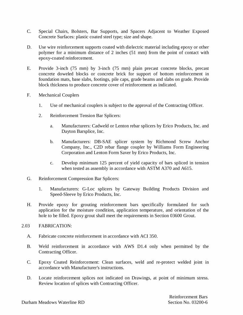
Reinforcement BarsDurham Meadows Waterline RD Section No. 03200-6
C. Special Chairs, Bolsters, Bar Supports, and Spacers Adjacent to Weather ExposedConcrete Surfaces: plastic coated steel type; size and shape.
D. Use wire reinforcement supports coated with dielectric material including epoxy or otherpolymer for a minimum distance of 2 inches (51 mm) from the point of contact withepoxy-coated reinforcement.
E. Provide 3-inch (75 mm) by 3-inch (75 mm) plain precast concrete blocks, precastconcrete doweled blocks or concrete brick for support of bottom reinforcement infoundation mats, base slabs, footings, pile caps, grade beams and slabs on grade. Provideblock thickness to produce concrete cover of reinforcement as indicated.
F. Mechanical Couplers
1. Use of mechanical couplers is subject to the approval of the Contracting Officer.
2. Reinforcement Tension Bar Splicers:
a. Manufacturers: Cadweld or Lenton rebar splicers by Erico Products, Inc. andDayton Barsplice, Inc.
b. Manufacturers: DB-SAE splicer system by Richmond Screw AnchorCompany, Inc., C2D rebar flange coupler by Williams Form EngineeringCorporation and Lenton Form Saver by Erico Products, Inc.
c. Develop minimum 125 percent of yield capacity of bars spliced in tensionwhen tested as assembly in accordance with ASTM A370 and A615.
G. Reinforcement Compression Bar Splicers:
1. Manufacturers: G-Loc splicers by Gateway Building Products Division andSpeed-Sleeve by Erico Products, Inc.
H. Provide epoxy for grouting reinforcement bars specifically formulated for suchapplication for the moisture condition, application temperature, and orientation of thehole to be filled. Epoxy grout shall meet the requirements in Section 03600 Grout.
2.03 FABRICATION:
A. Fabricate concrete reinforcement in accordance with ACI 350.
B. Weld reinforcement in accordance with AWS D1.4 only when permitted by theContracting Officer.
C. Epoxy Coated Reinforcement: Clean surfaces, weld and re-protect welded joint inaccordance with Manufacturer's instructions.
D. Locate reinforcement splices not indicated on Drawings, at point of minimum stress.Review location of splices with Contracting Officer.

Reinforcement BarsDurham Meadows Waterline RD Section No. 03200-7
E. Cold bend bars. Do not straighten or rebend bars.
F. When bending, apply slow, steady pressure. Replace bars that develop cracks or splits.
G. Do not heat reinforcement steel to bend or straighten.
H. Bend bars around a revolving collar having a diameter of not less than thatrecommended by ACI 350.
I. Cut bar ends that are to be butt spliced, or threaded by saw cutting. Terminate such endsin flat surfaces within 1-1/2 degrees of a right angle to the axis of the bar.
J. Apply epoxy coating to the deformed reinforcement bars under the following guidelines:
1. Shop bend reinforcement before coating.
2. Maintain thickness of the coating at 7 mil +/- 2 mil (0.175 mm +/- 0.050 mm).
3. Blast clean bars to near white metal before coating.
4. Clean and coat cut ends.
5. Patch damaged areas immediately before visible rust has formed. Patch at thefabrication plant.
6. Provide coatings free from holes, voids, contamination, cracks and damaged areas.Check coatings visually after curing.
7. Not more than two "holidays" (pinholes not visible to the naked eye) per 12 inch(300 mm) of bar are allowed in the coatings. Test coatings with a 67.5 volt holidaydetector in accordance with the Manufacturer's instructions.
8. Check each production lot and certify that all the coated bars are supplied in thefully cured condition.
9. Evaluate the flexibility of the coating by selecting bars from production lots bent120 degrees (after rebound) around a 6 inch (150 mm) diameter mandrel. Make thebend at a uniform rate in not more than one minute. The longitudinal deformationsmay be placed in a plane perpendicular to the mandrel radius, and the testspecimens shall be at a constant temperature between 70 degrees F (20 degrees C)and 85 degrees F (30 degrees C) throughout the bend test.
10. If no cracks in the coating of the bent specimen are visible to the naked eye thecoating is satisfactory.

Reinforcement BarsDurham Meadows Waterline RD Section No. 03200-8
PART 3 - EXECUTION
3.01 INSTALLATION:
A. Place, support and secure reinforcement against displacement. Do not deviate fromrequired position. Place reinforcement a minimum of 2 inches (51 mm) clear of anymetal pipe or fittings.
B. Do not displace or damage vapor retarder.
C. Position dowels accurately. Rigidly support, align and securely tie dowels normal to theconcrete surface before concrete placement. Setting dowels into wet concrete isprohibited.
D. Position wall dowels projecting from base slabs on grade with templates or guides heldin place above the concrete placement line. Position the templates to obtain the requiredclearance between the dowels and the face of the walls.
E. Bars additional to those indicated that may be found necessary or desirable by theContractor for the purpose of securing reinforcement in position shall be provided by theContractor at no additional cost to the Contracting Officer.
F. Do not extend continuous reinforcement or other fixed metal items through expansionjoints. Provide 2 inches (51 mm) clearance from each face of expansion joint.
G. Provide additional reinforcement bars to support top reinforcement in slabs. Do not shiftreinforcement bars from positions in upper layers to positions in lower layers as asubstitute for additional support bars.
H. Support and tie reinforcement steel in accordance with CRSI “Placing ReinforcementBars” with maximum spacing of 4 feet-0 inches (1200 mm).
I. Tie reinforcement steel at intersections in accordance with CRSI “PlacingReinforcement Bars”:
1. Maximum tie spacing for footings, walls and columns: every third intersection or 3feet-0 inches (1,000 mm).
2. Maximum spacing for slabs and other work: every fourth intersection or 3 feet-0 inches (1,000 mm).
3. Tie a minimum of 25 percent of all intersecting bars in foundation mats, baseslabs, footings, pile caps, slabs on grade and elevated slabs.
4. Secure all dowels in place before placing concrete.
5. Tie wires shall be bent away from the forms and from finished concrete surfaces inorder to provide the required concrete coverage.

Reinforcement BarsDurham Meadows Waterline RD Section No. 03200-9
J. Locate reinforcement to avoid interference with items drilled in later, such as concreteanchors.
3.02 WELDED WIRE REINFORCEMENT:Extend welded wire reinforcement to within 2inches (50 mm) of edges of slab or section. Lap sheets at least 12 inches (300 mm) ortwo wire spaces, whichever is greater, at ends and edges and wire tightly together.Stagger end laps.
B. Unless shown otherwise on Drawings, place welded wire reinforcement in slabs ongrade between the upper third point and mid-point of slab. Placing welded wirereinforcement on the subgrade and pulling it up during concrete placement is notpermitted.
C. Support welded wire reinforcement placed over the ground on wired concrete blocks(dobies) spaced not more than 3 feet (900 mm) on centers in any direction.
D. Support welded wire reinforcement placed over horizontal forms on slab bolsters spacednot more than 30 inches (750 mm) on center.
E. Mechanical coupler systems may be substituted for dowels at Contractor’s option whenpermitted by Contracting Officer.
F. Provide additional reinforcement bars to support ties and stirrups in beams where topreinforcement is not continuous.
G. Securely support and tie reinforcement steel to prevent movement during concreteplacement.
H. Ship, handle and place stainless steel reinforcement bars such that they do not come intodirect contact with carbon steel. Use stainless steel or non-metallic tie wires and barchairs. Use nylon, PVC, or polyethylene spacers where stainless steel bar must beattached to carbon steel, to maintain a minimum 1 inch clearance.
I. Unless otherwise shown on the Drawings or permitted by the Contracting Officer, do notbend reinforcement bars that project from in-place concrete.
J. Do not weld reinforcement steel bars (including tack welded) either during fabrication orerection unless specifically shown on the Drawings or specified herein, or unless priorwritten permission has been obtained from the Contracting Officer. Immediately removebars that have been welded, including tack welds, without such permission from thework. Comply with AWS D1.4 when welding of reinforcement is or called for.
K. Reinforcement steel interfering with the location of other reinforcement steel, conduitsor embedded items may be moved within the specified tolerances or one bar diameter,whichever is greater. Make greater displacement of bars to avoid interference only withthe permission of the Contracting Officer. Do not cut reinforcement to install inserts,conduits, mechanical openings or other items without the prior permission from theContracting Officer.

Reinforcement BarsDurham Meadows Waterline RD Section No. 03200-10
L. Reinforcement shall be clean and free from loose mill scale, dirt, grease, oil, formrelease agent, dried concrete or any material reducing bond with concrete.
M. Setting bars and welded wire reinforcement on layers of fresh concrete as the workprogresses or adjusting reinforcement during the placement of concrete is prohibited.
N. Provide and place safety caps on all exposed ends of vertical reinforcement that pose adanger to injury or life safety.
3.03 CONCRETE COVER OVER REINFORCEMENT BARS:
A. Conform to ACI 350 and drawings for concrete cover over reinforcement.
3.04 REINFORCEMENT AROUND OPENINGS AND PENETRATIONS:
A. Accommodate placement of formed openings and penetrations.
B. Unless specific additional reinforcement around openings and penetrations is shown onthe Drawings, provide additional reinforcement steel on each side of opening orpenetration equivalent to one half of the cross-sectional area of the reinforcement steelinterrupted by an opening or penetration. The bars shall have sufficient length to be fullydeveloped at each end beyond the opening or penetration.
C. Refer to details on Drawings for additional diagonal bars around openings orpenetrations and bar extension length on each side of openings or penetrations.
D. Where welded wire fabric is used provide extra reinforcement using fabric or deformedbars around opening or penetration.
3.05 SPLICING OF REINFORCEMENT:
A. Splices may be used to provide continuity due to bar length limitations. Minimum lengthof bars spliced for this reason is 40 feet (12 m). Do not splice reinforcement that isdetailed to be continuous in the Drawings.
B. Stagger bar splices.
C. Provide tension lap splices at all laps in compliance with ACI 350. Class A splices maybe used when 50 percent or less of the bars are spliced within the required lap length.Use Class B splices at all other locations.
D. Except as otherwise indicated on the Drawings, stagger splices in circumferentialreinforcement in circular walls using Class B tension splices. Do not splice adjacent barswithin the required lap length.
E. Make splices for reinforcement in tension tie members, with a full mechanical or fullwelded splice and staggered at least 30 inches (762 mm).
F. Make splices in column spiral reinforcement, when necessary, by a lap of 1-1/2 turns.
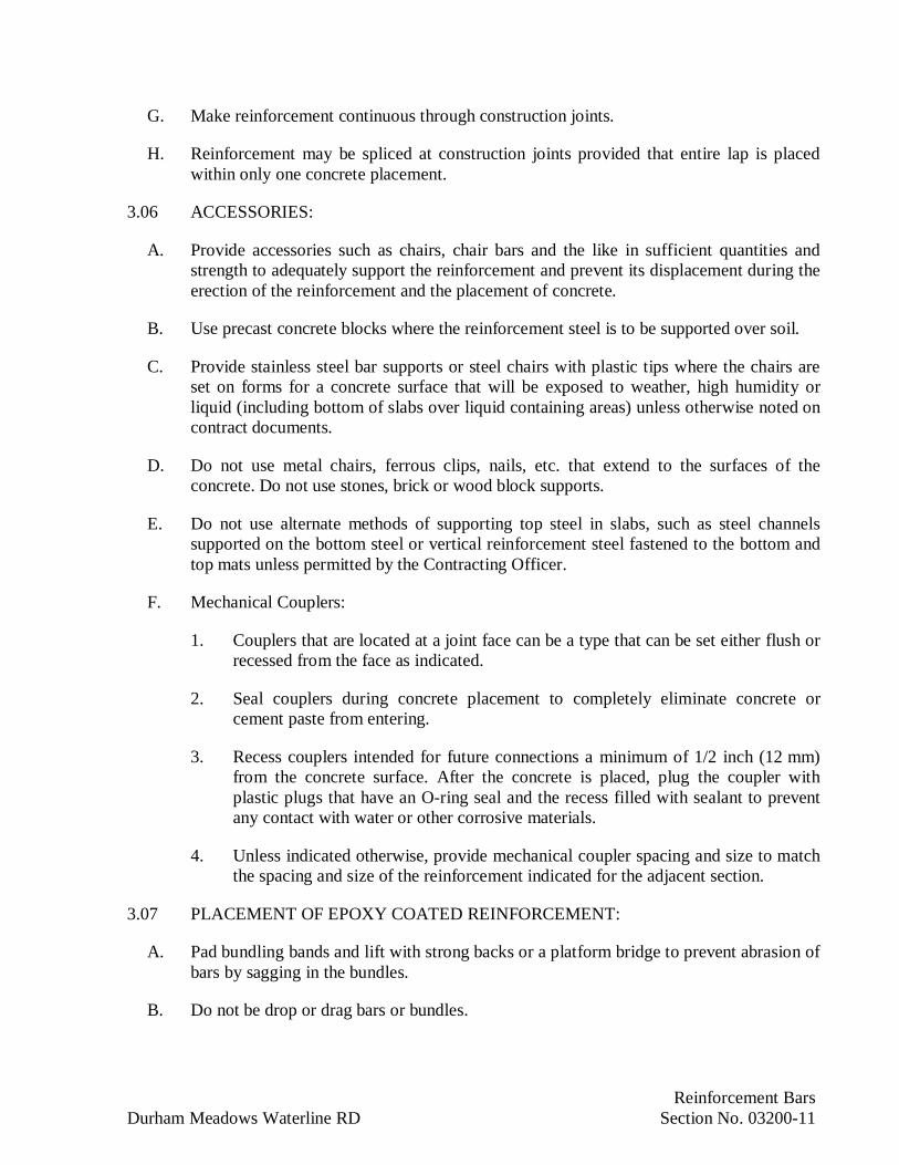
Reinforcement BarsDurham Meadows Waterline RD Section No. 03200-11
G. Make reinforcement continuous through construction joints.
H. Reinforcement may be spliced at construction joints provided that entire lap is placedwithin only one concrete placement.
3.06 ACCESSORIES:
A. Provide accessories such as chairs, chair bars and the like in sufficient quantities andstrength to adequately support the reinforcement and prevent its displacement during theerection of the reinforcement and the placement of concrete.
B. Use precast concrete blocks where the reinforcement steel is to be supported over soil.
C. Provide stainless steel bar supports or steel chairs with plastic tips where the chairs areset on forms for a concrete surface that will be exposed to weather, high humidity orliquid (including bottom of slabs over liquid containing areas) unless otherwise noted oncontract documents.
D. Do not use metal chairs, ferrous clips, nails, etc. that extend to the surfaces of theconcrete. Do not use stones, brick or wood block supports.
E. Do not use alternate methods of supporting top steel in slabs, such as steel channelssupported on the bottom steel or vertical reinforcement steel fastened to the bottom andtop mats unless permitted by the Contracting Officer.
F. Mechanical Couplers:
1. Couplers that are located at a joint face can be a type that can be set either flush orrecessed from the face as indicated.
2. Seal couplers during concrete placement to completely eliminate concrete orcement paste from entering.
3. Recess couplers intended for future connections a minimum of 1/2 inch (12 mm)from the concrete surface. After the concrete is placed, plug the coupler withplastic plugs that have an O-ring seal and the recess filled with sealant to preventany contact with water or other corrosive materials.
4. Unless indicated otherwise, provide mechanical coupler spacing and size to matchthe spacing and size of the reinforcement indicated for the adjacent section.
3.07 PLACEMENT OF EPOXY COATED REINFORCEMENT:
A. Pad bundling bands and lift with strong backs or a platform bridge to prevent abrasion ofbars by sagging in the bundles.
B. Do not be drop or drag bars or bundles.

Reinforcement BarsDurham Meadows Waterline RD Section No. 03200-12
C. Patch and touch up coated bars after placing. Do not place concrete until patching isreviewed by the Contracting Officer.
D. In systems for lifting, transporting and storing coated bars, pad areas in contact with thebars.
3.08 FIELD QUALITY CONTROL:
A. Remove reinforcement with kinks or bends not shown on shop or placement drawings.Remove such reinforcement from job site and replace with new fabricated steel. Do notfield bend of reinforcement unless reinforcement is indicated or specified to be fieldbent.
B. Protect reinforcement from rusting, deforming, bending, kinking and other injury. Cleanin-place reinforcement that has rusted, or been splattered with concrete using sand orwater blasting prior to incorporation into the Work.
3.09 CONTRACT CLOSEOUT:
A. Provide in accordance with Section 01700.
END OF SECTION

Cast in Place ConcreteDurham Meadows Waterline RD Section No. 03300-1
SECTION 03300
CAST-IN-PLACE CONCRETE
PART 1 - GENERAL
1.01 DESCRIPTION:
A. Provide cast-in-place concrete as indicated and in compliance with Contract Documents.
1.02 REFERENCES:
A. American Concrete Institute (ACI):
1. 211.1: Standard Practice for Selecting Proportions for Normal, Heavyweight, andMass Concrete
2. 214R: Recommended Practice for Evaluation of Strength Test Results of Concrete
3. 301: Standard Specifications for Structural Concrete
4. 304R: Guide for Measuring, Mixing, Transporting and Placing Concrete
5. 304.2R: Placing Concrete by Pumping Methods
6. 305R: Hot Weather Concreting
7. 306R: Cold Weather Concreting
8. 308: Standard Practice for Curing Concrete
9. 309R: Guide for Consolidation of Concrete
10. 311.4R: Guide for Concrete Inspection
11. 318: Building Code Requirements for Structural Concrete
12. 350: Code Requirements For Environmental Engineering Concrete Structures
B. ASTM International (ASTM):
1. A123: Standard Specification for Zinc (Hot-Dip Galvanized) Coatings on Iron andSteel Products
2. A153: Standard Specification for Zinc Coating (Hot-Dip) on Iron and SteelHardware

Cast in Place ConcreteDurham Meadows Waterline RD Section No. 03300-2
3. C31: Standard Practice for Making and Curing Concrete Test Specimens in theField
4. C33: Standard Specification for Concrete Aggregates
5. C39: Standard Test Method for Compressive Strength of Cylindrical ConcreteSpecimens
6. C40: Standard Test Method for Organic Impurities in Fine Aggregates forConcrete
7. C42: Standard Test Method for Obtaining and Testing Drilled Cores and SawedBeams of Concrete
8. C87: Standard Test Method for Effect of Organic Impurities in Fine Aggregate onStrength of Mortar
9. C88: Standard Test Method for Soundness of Aggregates by Use of SodiumSulfate or Magnesium Sulfate
10. C94: Standard Specification for Ready-Mixed Concrete
11. C109: Standard Test Method for Compressive Strength of Hydraulic CementMortars (Using 2-in or [50-mm] Cube Specimens)
12. C123: Standard Test Method for Lightweight Particles in Aggregate
13. C136: Standard Test Method for Sieve Analysis of Fine and Coarse Aggregates
14. C138: Standard Test Method for Unit Weight, Yield, and Air Content(Gravimetric) of Concrete
15. C143: Standard Test Method for Slump of Hydraulic Cement Concrete
16. C150: Standard Specification for Portland Cement
17. C157: Standard Test Method for Length Change of Hardened Hydraulic Cement,Mortar and Concrete
18. C171: Standard Specification for Sheet Materials for Curing Concrete
19. C172: Standard Practice for Sampling Freshly Mixed Concrete
20. C192: Standard Practice for Making and Curing Concrete Test Specimens in theLaboratory
21. C231: Standard Test Method for Air Content of Freshly Mixed Concrete by thePressure Method

Cast in Place ConcreteDurham Meadows Waterline RD Section No. 03300-3
22. C260: Standard Specification for Air-Entraining Admixtures for Concrete
23. C289: Standard Test Method for Potential Alkali-Silica Reactivity of Aggregates(Chemical Method)
24. C295: Standard Guide for Petrographic Examination of Aggregates for Concrete
25. C309: Standard Specification for Liquid Membrane-Forming Compounds forCuring Concrete
26. C311: Standard Test Methods for Sampling and Testing Fly Ash or NaturalPozzolans for Use as a Mineral Admixture in Portland Cement Concrete
27. C494: Standard Specification for Chemical Admixtures for Concrete
28. C595: Standard Specification for Blended Hydraulic Cements
29. C618: Standard Specification for Coal Fly Ash and Raw or Calcined NaturalPozzolan for Use as a Mineral Admixture in Portland Cement Concrete
30. C881: Standard Test Method for Epoxy Resin Base Bonding Systems forConcrete
31. C882: Standard Test Method for Bond Strength of Epoxy Resin Systems Usedwith Concrete by Slant Shear
32. C989: Standard Specification for Ground Granulated Blast-Furnace Slag for Usein Concrete and Mortars
33. C1017: Standard Specification for Chemical Admixtures for Use in ProducingFlowing Concrete
34. C1064: Standard Test Method for Temperature of Freshly Mixed Portland CementConcrete
35. C1107: Standard Specification for Packaged Dry, Hydraulic-Cement Grout(Nonshrink)
36. C1116: Standard Specification for Fiber Reinforced Concrete
37. C1240: Standard Specification for Silica Fume for Use as a Mineral Admixture inHydraulic-Cement Concrete, Mortar, and Grout
38. D75: Standard Practice for Sampling Aggregates
39. E154: Test Methods for Water Vapor Retarders Used in Contact with Earth UnderConcrete Slabs, on Walls, or as Ground Cover
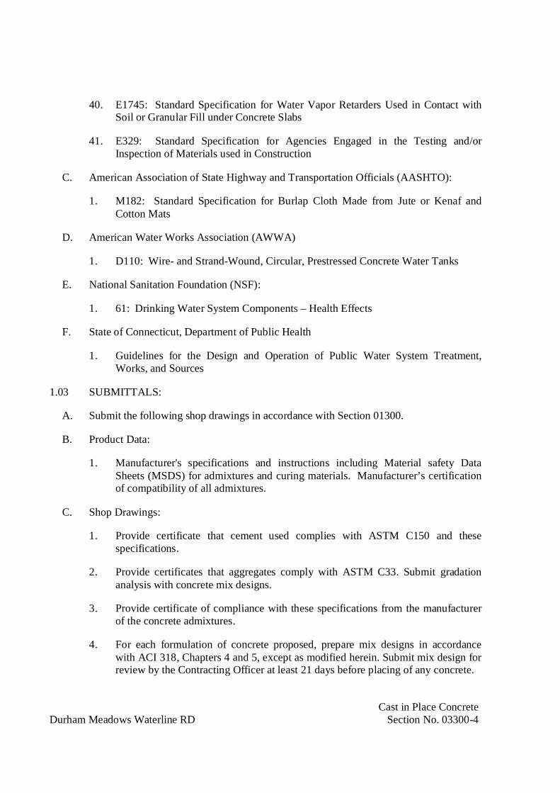
Cast in Place ConcreteDurham Meadows Waterline RD Section No. 03300-4
40. E1745: Standard Specification for Water Vapor Retarders Used in Contact withSoil or Granular Fill under Concrete Slabs
41. E329: Standard Specification for Agencies Engaged in the Testing and/orInspection of Materials used in Construction
C. American Association of State Highway and Transportation Officials (AASHTO):
1. M182: Standard Specification for Burlap Cloth Made from Jute or Kenaf andCotton Mats
D. American Water Works Association (AWWA)
1. D110: Wire- and Strand-Wound, Circular, Prestressed Concrete Water Tanks
E. National Sanitation Foundation (NSF):
1. 61: Drinking Water System Components – Health Effects
F. State of Connecticut, Department of Public Health
1. Guidelines for the Design and Operation of Public Water System Treatment,Works, and Sources
1.03 SUBMITTALS:
A. Submit the following shop drawings in accordance with Section 01300.
B. Product Data:
1. Manufacturer's specifications and instructions including Material safety DataSheets (MSDS) for admixtures and curing materials. Manufacturer’s certificationof compatibility of all admixtures.
C. Shop Drawings:
1. Provide certificate that cement used complies with ASTM C150 and thesespecifications.
2. Provide certificates that aggregates comply with ASTM C33. Submit gradationanalysis with concrete mix designs.
3. Provide certificate of compliance with these specifications from the manufacturerof the concrete admixtures.
4. For each formulation of concrete proposed, prepare mix designs in accordancewith ACI 318, Chapters 4 and 5, except as modified herein. Submit mix design forreview by the Contracting Officer at least 21 days before placing of any concrete.

Cast in Place ConcreteDurham Meadows Waterline RD Section No. 03300-5
5. Provide certificate that materials used in concrete mix design including admixturesand additives for concrete in potable water service complies in all respects with therequirements of the Stae of Connecticut, Department of Public Health, Guidelinesfor the Design and Operation of Public Water System Treatment, Works, andSources, Chapter VI, Potable Water Storage Facilities for conformance with NSFStandards.
6. Provide proposed special procedures for protection of concrete under wet weatherplacement conditions.
7. Provide proposed special procedures for protection and curing of concrete underhot and cold weather conditions.
D. Test and Evaluation Reports
1. Provide results of drying shrinkage tests from trial concrete mixes by theContractor's testing laboratory firm.
E. Manufacturers' Instructions
1. Provide epoxy bonding compound manufacturer's specific instructions for use.Provide manufacturer's data sheets as to suitability of product to meet jobrequirements with regard to surface, pot life, set time, vertical or horizontalapplication, and forming restrictions.
F. Field Quality Control Submittals
1. Provide delivery tickets for ready-mix concrete or weighmasters certificate perASTM C94, including weights of cement and each size aggregate and amount ofwater added at the plant and record of pours. Record the amount of water added onthe job on the delivery ticket. Water added at the plant shall account for moisturein both coarse and fine aggregate.
1.04 QUALITY ASSURANCE:
A. Provide in accordance with Section 01400.
B. Concrete will be tested as identified in the mix performance part of this specificationwhich includes Paragraph 1.03.E, Paragraph 1.06.C “Trial Mixes”, Paragraph 1.06.D“Testing of Ready Mix Concrete” and Section 3.13 “Concrete Quality Assurance”.
C. Unless otherwise indicated, materials, workmanship, and practices shall conform to thefollowing standards:
1. State of Connecticut Building Code, including supplements and ammendments.
2. ACI 301, "Structural Concrete for Buildings.”
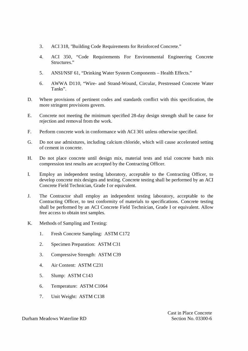
Cast in Place ConcreteDurham Meadows Waterline RD Section No. 03300-6
3. ACI 318, "Building Code Requirements for Reinforced Concrete.”
4. ACI 350, “Code Requirements For Environmental Engineering ConcreteStructures.”
5. ANSI/NSF 61, “Drinking Water System Components – Health Effects.”
6. AWWA D110, “Wire- and Strand-Wound, Circular, Prestressed Concrete WaterTanks”.
D. Where provisions of pertinent codes and standards conflict with this specification, themore stringent provisions govern.
E. Concrete not meeting the minimum specified 28-day design strength shall be cause forrejection and removal from the work.
F. Perform concrete work in conformance with ACI 301 unless otherwise specified.
G. Do not use admixtures, including calcium chloride, which will cause accelerated settingof cement in concrete.
H. Do not place concrete until design mix, material tests and trial concrete batch mixcompression test results are accepted by the Contracting Officer.
I. Employ an independent testing laboratory, acceptable to the Contracting Officer, todevelop concrete mix designs and testing. Concrete testing shall be performed by an ACIConcrete Field Technician, Grade I or equivalent.
J. The Contractor shall employ an independent testing laboratory, acceptable to theContracting Officer, to test conformity of materials to specifications. Concrete testingshall be performed by an ACI Concrete Field Technician, Grade I or equivalent. Allowfree access to obtain test samples.
K. Methods of Sampling and Testing:
1. Fresh Concrete Sampling: ASTM C172
2. Specimen Preparation: ASTM C31
3. Compressive Strength: ASTM C39
4. Air Content: ASTM C231
5. Slump: ASTM C143
6. Temperature: ASTM C1064
7. Unit Weight: ASTM C138

Cast in Place ConcreteDurham Meadows Waterline RD Section No. 03300-7
8. Obtaining Drilled Cores: ASTM C42
9. Drying Shrinkage: ASTM C157
L. Acceptance of Structure: Acceptance of completed concrete work requires conformancewith dimensional tolerances, appearance and strength as indicated or specified.
M. Hot weather concrete to conform to ACI 305R and as specified herein.
N. Cold weather concrete to conform to ACI 306R and as specified herein.
O. Reject concrete delivered to job site that exceeds the time limit or temperaturelimitations specified.
P. Do not place concrete in water or on frozen or uncompacted ground.
Q. Workability
1. Concrete shall be of such consistency and composition that it can be workedreadily into the forms and around the reinforcement without excessive vibratingand without permitting the materials to segregate or free water to collect on thesurface.
2. Concrete mix shall be designed to reflect the method of transportation to theproject site.
3. Adjust the proportions to secure a plastic, cohesive mixture, and one that is withinthe specified slump range.
4. To avoid unnecessary changes in consistency, obtain the aggregate from a sourcewith uniform quality, moisture content, and grading. Handle materials to minimizevariations in moisture content that would interfere with production of concrete ofthe established degree of uniformity and slump.
1.05 DELIVERY, STORAGE, AND HANDLING:
A. Provide in conformance with Section 01610 and as specified herein.
B. Deliver concrete to discharge locations in watertight agitator or mixer trucks withoutaltering the specified properties of water-cement ratio, slump, air entrainment,temperature and homogeneity.
C. Reject concrete not conforming to specification, unsuitable for placement, exceeding thetime or temperature limitations or not having a complete delivery batch ticket.

Cast in Place ConcreteDurham Meadows Waterline RD Section No. 03300-8
1.06 SITE CONDITIONS:
A. Do not place concrete until conditions and facilities for making and curing control testspecimens are in compliance with ASTM C31 and as specified herein.
PART 2 - PRODUCTS
2.01 MATERIALS:
A. Cement:
1. Portland Cement, ASTM C150, Type II.
2. Use only one brand of cement in any individual structure. Use no cement that hasbecome damaged, partially set, lumpy, or caked. Reject the entire contents of thesack or container that contains such cement. Use no salvaged or reclaimed cement.
3. Maximum tricalcium aluminate shall not exceed 8 percent. The maximum percentalkalies shall not exceed 0.6 percent.
B. Fine Aggregates:
1. Clean, sharp, natural sand conforming to requirements of ASTM C33 with afineness modulus between 2.50 and 3.0.
C. Coarse Aggregate:
1. Well graded crushed stone, natural rock conforming to requirements of ASTMC33.
2. Limit deleterious substances in accordance with ASTM C33, Table 3, SevereWeathering Regions, limit clay lumps not to exceed 1.0 percent by weight, andlimit loss when tested for soundness using magnesium sulfate to 12 percent.
D. Water and Ice:
1. Use water and ice free from injurious amounts of oil, acid, alkali, salt, organicmatter or other deleterious substances and conforms to requirements of ASTMC94.
2. Water shall not contain more than 500 mg/L of chlorides nor more than 500 mg/Lof sulfate.
3. Heat or cool water to obtain concrete temperatures specified, and in conformancewith ACI 305R and ACI 306R.
E. Color Additive for Exterior Electrical Duct Encasement:
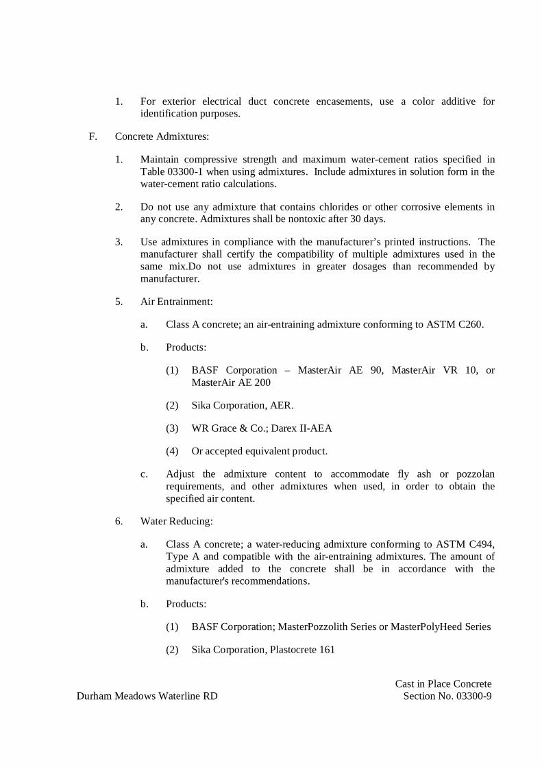
Cast in Place ConcreteDurham Meadows Waterline RD Section No. 03300-9
1. For exterior electrical duct concrete encasements, use a color additive foridentification purposes.
F. Concrete Admixtures:
1. Maintain compressive strength and maximum water-cement ratios specified inTable 03300-1 when using admixtures. Include admixtures in solution form in thewater-cement ratio calculations.
2. Do not use any admixture that contains chlorides or other corrosive elements inany concrete. Admixtures shall be nontoxic after 30 days.
3. Use admixtures in compliance with the manufacturer’s printed instructions. Themanufacturer shall certify the compatibility of multiple admixtures used in thesame mix.Do not use admixtures in greater dosages than recommended bymanufacturer.
5. Air Entrainment:
a. Class A concrete; an air-entraining admixture conforming to ASTM C260.
b. Products:
(1) BASF Corporation – MasterAir AE 90, MasterAir VR 10, orMasterAir AE 200
(2) Sika Corporation, AER.
(3) WR Grace & Co.; Darex II-AEA
(4) Or accepted equivalent product.
c. Adjust the admixture content to accommodate fly ash or pozzolanrequirements, and other admixtures when used, in order to obtain thespecified air content.
6. Water Reducing:
a. Class A concrete; a water-reducing admixture conforming to ASTM C494,Type A and compatible with the air-entraining admixtures. The amount ofadmixture added to the concrete shall be in accordance with themanufacturer's recommendations.
b. Products:
(1) BASF Corporation; MasterPozzolith Series or MasterPolyHeed Series
(2) Sika Corporation, Plastocrete 161

Cast in Place ConcreteDurham Meadows Waterline RD Section No. 03300-10
(3) WR Grace & Co.; Daracem 65
(4) Euclid Chemical Company; Eucon NW
(5) Or accepted equivalent product.
7. Water Reducing and Retarding:
a. Class A concrete; a water-reducing and retarding admixture conforming toASTM C494, Type D and compatible with the air-entraining admixtures.The amount of admixture added to the concrete shall be in accordance withthe manufacturer's recommendations.
b. Products:
(1) BASF Corporation; MasterPozzolith Series
(2) Sika Corporation; Plastiment
(3) WR Grace & Co.; WRDA 64
(4) Or accepted equivalent product.
8. High-Range Water-Reducing Admixture (Superplasticizer):
a. Class A concrete; a High-Range water-reducing admixture conforming toASTM C494, Type F or ASTM C1017, Type I.
b. Products:
(1) BASF Corporation; MasterRheobuild 1000 or MasterGlenium Series
(2) WR Grace & Co.; Daracem 100
(3) Euclid Chemical company; Eucon SPC
(4) Or accepted equivalent product.
G. Fiber Reinforcement:
1. Fiber reinforcing shall conform to ASTM C 1116, Type III.
2. Fibers shall be macro fibers. Micro fibers are prohibited.
3. Fibers shall be 100 percent virgin polypropylene fibrillated fibers containing noreprocessed olefin materials and specifically manufactured to an optimumgradation for use as concrete secondary reinforcement
4. Physical Characteristics:

Cast in Place ConcreteDurham Meadows Waterline RD Section No. 03300-11
a. Specific gravity: 0.91
b. Tensile strength: 40,000 to 110,000 psi (275 to 758 MPa)
c. Fiber length: 1/2-inch (13 mm) to 3/4-inch (19 mm)
5. Fibrous concrete reinforcement materials provided in this section shall produceconcrete conforming to the requirements for strength of concrete specified.
H. Epoxy Bonding Agent:
1. Epoxy bonding agent shall conform to ASTM C881 Type I, II, IV or V; Grade 2for epoxy resin adhesives. The class of epoxy bonding agent shall be suitable forambient and substrate temperatures.
2. Products:
a. Sika Corp.; Sikadur 32
b. Euclid Chemical Company; Duralcrete
c. BASF Corporation, Concresive Liquid LPL
3. Vapor Retarder: 10 mil (0.25 mm) polyethylene sheet conforming to ASTME1745.
I. Curing Compound:
1. Liquid form, which will form impervious membrane over, exposed surface ofconcrete when applied to fresh concrete by means of spray gun. Compound shallnot inhibit future bond of floor covering or concrete floor treatment. Use Type I-Dcompound with red fugitive dye, Class B, having 18 percent minimum solidsconforming to ASTM C309.
2. Provide a copy of manufacturer’s certification that the curing compound meets therequirements of ANSI/NSF 61 for concrete surfaces that will be in contact withpotable water.
3. Products:
a. BASF Building Systems; Kure 1315.
b. Euclid Chemical Company; Super Diamond Clear VOX.
c. W. R. Meadows, Inc.; VOCOMP-30.
d. Dayton Superior Corp; Safe Cure and Seal 30 percent.
J. Burlap Mats:
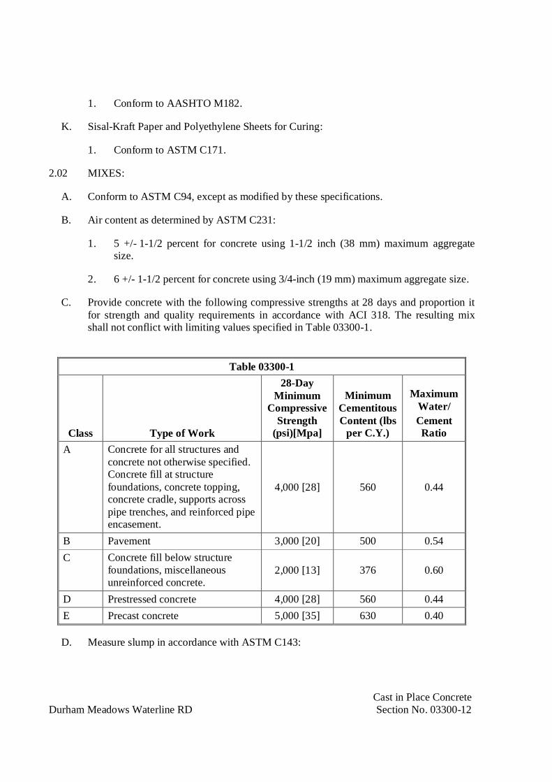
Cast in Place ConcreteDurham Meadows Waterline RD Section No. 03300-12
1. Conform to AASHTO M182.
K. Sisal-Kraft Paper and Polyethylene Sheets for Curing:
1. Conform to ASTM C171.
2.02 MIXES:
A. Conform to ASTM C94, except as modified by these specifications.
B. Air content as determined by ASTM C231:
1. 5 +/- 1-1/2 percent for concrete using 1-1/2 inch (38 mm) maximum aggregatesize.
2. 6 +/- 1-1/2 percent for concrete using 3/4-inch (19 mm) maximum aggregate size.
C. Provide concrete with the following compressive strengths at 28 days and proportion itfor strength and quality requirements in accordance with ACI 318. The resulting mixshall not conflict with limiting values specified in Table 03300-1.
Table 03300-1
Class Type of Work
28-DayMinimum
CompressiveStrength
(psi)[Mpa]
MinimumCementitousContent (lbs
per C.Y.)
MaximumWater/CementRatio
A Concrete for all structures andconcrete not otherwise specified.Concrete fill at structurefoundations, concrete topping,concrete cradle, supports acrosspipe trenches, and reinforced pipeencasement.
4,000 [28] 560 0.44
B Pavement 3,000 [20] 500 0.54C Concrete fill below structure
foundations, miscellaneousunreinforced concrete.
2,000 [13] 376 0.60
D Prestressed concrete 4,000 [28] 560 0.44E Precast concrete 5,000 [35] 630 0.40
D. Measure slump in accordance with ASTM C143:
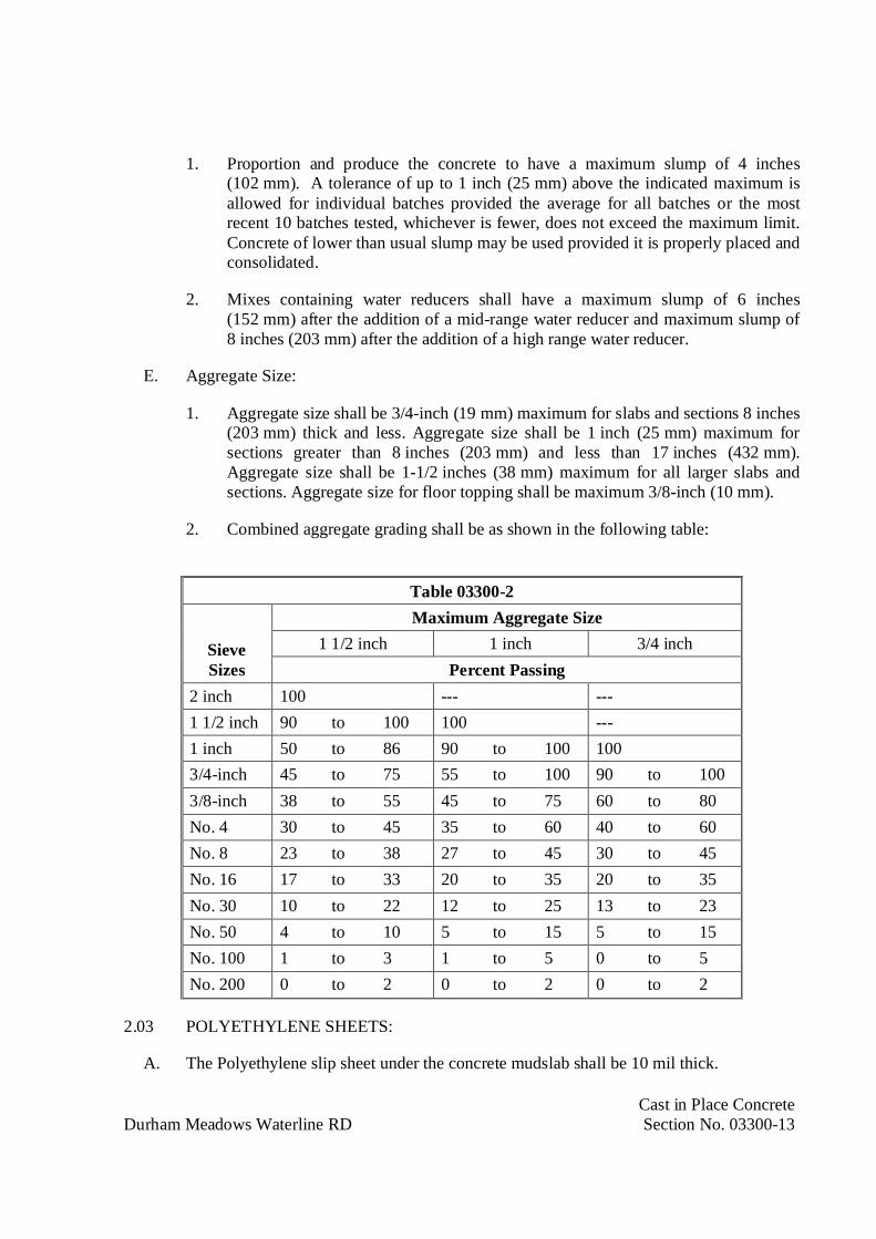
Cast in Place ConcreteDurham Meadows Waterline RD Section No. 03300-13
1. Proportion and produce the concrete to have a maximum slump of 4 inches(102 mm). A tolerance of up to 1 inch (25 mm) above the indicated maximum isallowed for individual batches provided the average for all batches or the mostrecent 10 batches tested, whichever is fewer, does not exceed the maximum limit.Concrete of lower than usual slump may be used provided it is properly placed andconsolidated.
2. Mixes containing water reducers shall have a maximum slump of 6 inches(152 mm) after the addition of a mid-range water reducer and maximum slump of8 inches (203 mm) after the addition of a high range water reducer.
E. Aggregate Size:
1. Aggregate size shall be 3/4-inch (19 mm) maximum for slabs and sections 8 inches(203 mm) thick and less. Aggregate size shall be 1 inch (25 mm) maximum forsections greater than 8 inches (203 mm) and less than 17 inches (432 mm).Aggregate size shall be 1-1/2 inches (38 mm) maximum for all larger slabs andsections. Aggregate size for floor topping shall be maximum 3/8-inch (10 mm).
2. Combined aggregate grading shall be as shown in the following table:
Table 03300-2
SieveSizes
Maximum Aggregate Size1 1/2 inch 1 inch 3/4 inch
Percent Passing2 inch 100 --- ---1 1/2 inch 90 to 100 100 ---1 inch 50 to 86 90 to 100 1003/4-inch 45 to 75 55 to 100 90 to 1003/8-inch 38 to 55 45 to 75 60 to 80No. 4 30 to 45 35 to 60 40 to 60No. 8 23 to 38 27 to 45 30 to 45No. 16 17 to 33 20 to 35 20 to 35No. 30 10 to 22 12 to 25 13 to 23No. 50 4 to 10 5 to 15 5 to 15No. 100 1 to 3 1 to 5 0 to 5No. 200 0 to 2 0 to 2 0 to 2
2.03 POLYETHYLENE SHEETS:
A. The Polyethylene slip sheet under the concrete mudslab shall be 10 mil thick.
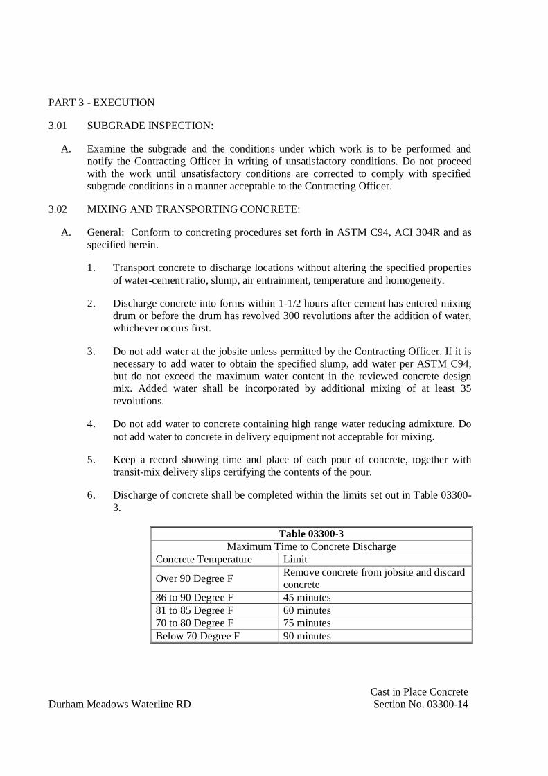
Cast in Place ConcreteDurham Meadows Waterline RD Section No. 03300-14
PART 3 - EXECUTION
3.01 SUBGRADE INSPECTION:
A. Examine the subgrade and the conditions under which work is to be performed andnotify the Contracting Officer in writing of unsatisfactory conditions. Do not proceedwith the work until unsatisfactory conditions are corrected to comply with specifiedsubgrade conditions in a manner acceptable to the Contracting Officer.
3.02 MIXING AND TRANSPORTING CONCRETE:
A. General: Conform to concreting procedures set forth in ASTM C94, ACI 304R and asspecified herein.
1. Transport concrete to discharge locations without altering the specified propertiesof water-cement ratio, slump, air entrainment, temperature and homogeneity.
2. Discharge concrete into forms within 1-1/2 hours after cement has entered mixingdrum or before the drum has revolved 300 revolutions after the addition of water,whichever occurs first.
3. Do not add water at the jobsite unless permitted by the Contracting Officer. If it isnecessary to add water to obtain the specified slump, add water per ASTM C94,but do not exceed the maximum water content in the reviewed concrete designmix. Added water shall be incorporated by additional mixing of at least 35revolutions.
4. Do not add water to concrete containing high range water reducing admixture. Donot add water to concrete in delivery equipment not acceptable for mixing.
5. Keep a record showing time and place of each pour of concrete, together withtransit-mix delivery slips certifying the contents of the pour.
6. Discharge of concrete shall be completed within the limits set out in Table 03300-3.
Table 03300-3Maximum Time to Concrete Discharge
Concrete Temperature Limit
Over 90 Degree F Remove concrete from jobsite and discardconcrete
86 to 90 Degree F 45 minutes81 to 85 Degree F 60 minutes70 to 80 Degree F 75 minutesBelow 70 Degree F 90 minutes
Cast in Place ConcreteDurham Meadows Waterline RD Section No. 03300-15
B. Conveying: Convey concrete from agitator or mixer truck to place of final deposit informs by one of the following methods:
1. Buckets or hoppers with discharge gates having a clear opening equal to not lessthan one-third the maximum interior horizontal area or five times the maximumaggregate size being used, whichever is greater, and side slopes of not less than60 degrees to horizontal.
2. Buggies or wheelbarrows equipped with pneumatic tires.
3. Round bottom, metal or metal-lined chutes with inclined slope of between 2 to3 feet (600 to 900 mm) horizontally to 1 foot (300 mm) vertically and of sufficientcapacity to avoid overflow.
4. Circular drop pipes with a top diameter of at least eight times the maximumaggregate size, but not less than 6 inch (150 mm), or tapered to not less than sixtimes maximum aggregate size.
3.03 CONCRETE ACCEPTANCE:
A. Accept or reject each batch of concrete delivered to the point of agitator or mixer truckdischarge. Sign delivery batch tickets to indicate concrete acceptance.
B. Reject concrete delivered without a complete concrete delivery batch ticket as specifiedherein. The concrete supplier will furnish copies of the signed batch ticket to theContractor and Contracting Officer.
C. The testing agency shall perform field tests at the point of agitator or mixer truckdischarge. Accept or reject concrete on the basis of conformity with slump, air contentand temperature specified.
D. The testing agency shall inspect concrete transit truck's barrel revolution counter andgauge for measuring water added to the concrete. Reject concrete that exceeds themaximum barrel revolution of 300, the limits in Table 03300-3 or concrete that haswater content exceeding the specified water-cement ratio.
E. Reject concrete not conforming to specification before discharging into the forms.
3.04 PREPARATION AND COORDINATION:
A. Laitance must be mechanically removed from the face of concrete from previouscastings at construction joints and the surface must be thoroughly cleaned beforeadjacent concrete is placed.
B. Hardened concrete paste and rust shall be clean of the surface of the reinforcementprojecting from the face of the concrete before adjacent concrete is placed.
C. Sleeves and Inserts:

Cast in Place ConcreteDurham Meadows Waterline RD Section No. 03300-16
1. No sleeves, ducts, pipes, or other openings shall pass through joists, beams,column capitals or columns, except where indicated or approved by theContracting Officer.
2. Where approved by the Contracting Officer, set sleeves, ties, pipe hangers, andother inserts and openings as indicated or specified elsewhere. Sleeves andopenings, greater than 100 mm x 100 mm, that are not indicated must be approvedby the Contracting Officer.
3. Do not eliminate or displace reinforcement to accommodate hardware. If insertscannot be located as specified, obtain approval of modifications from theContracting Officer before placing of concrete.
4. Check locations and sizes of sleeves and openings shown on drawings.
D. Anchor Bolts:
1. Set anchor bolts to templates under supervision of appropriate trade prior toplacing concrete.
2. Under special circumstances, with approval of the Contracting Officer, groutedanchor bolts may be installed into preformed holes or holes drilled after concretehas set. Formed holes or sleeves shall be a minimum 100 mm diameter and bedeformed or dovetailed.
3. Protect anchor bolt holes from water accumulations and snow, and ice build up.
4. When using proprietary anchor systems set bolts and fill holes with epoxy grout, inaccordance with the manufacturer’s requirements. All proprietary anchors must beapproved by the Contracting Officer.
5. Locate anchor bolts used in connection with expansion shoes, rollers, and rockerswith due regard to ambient temperature at time of erection.
E. Drainage Holes and Weep Holes:
1. Form the weep holes and drainage holes in accordance with Section 03100 –“Concrete Forms and Accessories”. If wood forms are used, remove them afterconcrete has set.
2. Install the weep hole tubes and drains as indicated.
F. Coordination:
1. Adjust the work to suit final shop drawings of the equipment being supplied.Verify all sizes with the trade supplying and installing the equipment. Obtain,utilize and submit data on relevant sizes to suit any change in equipment. Confirmthe adjustments with the Contracting Officer.
Cast in Place ConcreteDurham Meadows Waterline RD Section No. 03300-17
G. Grouting:
1. Grout under base plates and/or machinery using procedures in accordance withmanufacturer’s recommendations that result in 100 percent contact over groutedarea. Install bleed holes in base plates to ensure full coverage of grout.
H. Contractor shall notify the Contracting Officer and local building official of readiness toplace concrete in any portion of the work a minimum of 2 working days prior to concreteplacement. Failure to provide this notification will be cause for delay in placing untilobservations can be completed.
I. Reinforcement, installation of waterstop, positioning of embedded items, and conditionof formwork will be observed by the Contracting Officer and local building official priorto concrete placement.
J. Coordinate the sequence of placement such that construction joints will occur only asdesigned.
K. Schedule sufficient equipment for continuous concrete placing. Provide for backupequipment and procedures to be taken in case of an interruption in placing. Providebackup concrete vibrators at the project site. Test concrete vibrators the day beforeplacing concrete.
L. Compact the subgrade and/or bedding. Saturate the subgrade approximately eight hoursbefore placement and sprinkle ahead of the placement of concrete in areas where vaporbarrier is not used. Remove standing water, mud, and foreign matter before concrete isdeposited.
M. Where shown on contract drawings, intentionally roughen surfaces of set concrete in amanner to expose bonded aggregate uniformly at joints.
N. Provide mud slabs to obtain a dry and stable working platform for placement of slabs.
O. When shown on contract drawings, install a granular base beneath slabs on ground.Place granular material on a compacted subgrade and compact granular base.
P. Place vapor barrier under structural slabs and buildings and where shown on contractdrawings. Install material with 6 inch (150 mm) lap at joints and seal joints with tape asrecommended by the vapor barrier manufacturer. Tape material cut for slab penetrationsto the pipe, conduit or other items passing through the slab. Use tape recommended bythe vapor barrier manufacturer.
Q. Install vapor barrier without punctures or tears and protect against punctures and breaks.
R. Where concrete is required to be placed and bonded to existing concrete, coat the contactsurfaces with epoxy bonding agent. The method of preparation and application of thebonding agent shall conform to the manufacturer's recommendations.

Cast in Place ConcreteDurham Meadows Waterline RD Section No. 03300-18
3.05 CONCRETE PLACEMENT:
A. Placement shall conform to ACI 304R as modified by these specifications.
B. Alternate sections of concrete walls and slabs may be cast simultaneously. Do not placeadjacent sections of walls and slabs until seven days after placement of first placedconcrete.
C. Do not place concrete until free water has been removed or has been diverted by pipes orother means and carried out of the forms, clear of the work. Do not deposit concreteunderwater, and do not allow free water to rise on any concrete until the concrete hasattained its initial set. Do not permit free or storm water to flow over surfaces ofconcrete so as to injure the quality or surface finish.
D. Do not place concrete during inclement weather. Protect concrete placed from inclementweather. Keep sufficient protective covering ready at all times for this purpose.
E. Deposit concrete at or near its final position to avoid segregation caused by rehandlingor flowing. Do not deposit concrete in large quantities in one place to be worked alongthe forms with a vibrator.
F. Deposit concrete continuously and in level layers 1 to 2 feet (305 to 610 mm) thick.Avoid inclined layers and cold joints. Place concrete at lower portion of slope first onsloping surfaces.
G. Do not deposit partially hardened concrete in forms. Retempering of partially hardenedconcrete is not permitted. Remove partially hardened concrete from site at no additionalcompensation.
H. Do not allow concrete to fall freely in forms to cause segregation (separation of coarseaggregate from mortar). Limit maximum free fall of concrete to 4 feet (1,220 mm). Donot move concrete horizontally more than four feet from point of discharge. Spacepoints of deposit not more than eight feet apart.
I. At least two hours shall elapse after depositing concrete in the columns or walls beforedepositing in beams, girders, or slabs supported thereon. Place beams, girders, brackets,column capitals, and haunches monolithically as part of the floor or roof system, unlessotherwise shown on contract drawings.
J. Consolidate concrete using mechanical vibrators operated within the mass of concreteand/or on the forms conforming to procedures set forth in ACI 309R and as specifiedherein.
K. Conduct vibration to produce concrete of uniform texture and appearance, free ofhoneycombing, streaking, cold joints or visible lift lines.
L. Conduct vibration in a systematic manner with regularly maintained vibrators. Furnishsufficient backup units at job site. Use vibrators having minimum frequency of 8,000
Cast in Place ConcreteDurham Meadows Waterline RD Section No. 03300-19
vibrations per minute and of sufficient amplitude to consolidate concrete. Use not lessthan one vibrator with crew for each 35 to 40 cubic yards (25 to 30 cubic meters) ofconcrete placed per hour.
M. Insert and withdraw vibrator vertically at a uniform spacing over the entire area ofplacement. Space distances between insertions such that spheres of influence of eachinsertion overlap.
N. Use additional vibration with pencil vibrators on vertical surfaces and on exposedconcrete to bring full surface of mortar against the forms so as to eliminate air voids, bugholes and other surface defects. Employ the following additional procedures forvibrating concrete as necessary to maintain proper consolidation of concrete:
1. Reduce distance between internal vibration insertions and increase time for eachinsertion.
2. Insert vibrator as close to face of form as possible without contacting form orreinforcement.
3. Thoroughly vibrate area immediately adjacent to waterstops without damaging thewaterstop.
4. Use spading as a supplement to vibration where particularly difficult conditionsexist.
O. Pumping Concrete:
1. Conform to the recommendations of ACI 304.2R except as modified herein.
2. Base pump size on rate of concrete placement, length of delivery pipe or hose,aggregate size, mix proportions, vertical lift, and slump of concrete.
3. Use pipe with inside diameter of at least three times the maximum coarseaggregate size, but not less than 2 inches (50 mm).
4. Do not use aluminum pipes for delivery of concrete to the forms.
P. Waterstops:
1. Prevent displacement of waterstops during concrete placement,
3.06 CURING AND PROTECTION:
A. General:
1. Protect concrete from premature drying, hot or cold temperatures, and mechanicalinjury, beginning immediately after placement and maintain concrete with minimalmoisture loss at relatively constant temperature.
Cast in Place ConcreteDurham Meadows Waterline RD Section No. 03300-20
2. Comply with curing procedures set forth in ACI 301, ACI 308 and as specifiedherein.
3. Perform hot weather concreting in conformance with ACI 305R and as specifiedherein when the ambient atmospheric temperature is 80 degrees F (27 degrees C)or above.
4. Perform cold weather concreting in conformance with ACI 306R.
5. Concrete required to be moist cured shall remain moist for the entire duration ofthe cure. Repeated wetting and drying cycles of the curing process will not beallowed.
B. Curing Duration:
1. Start initial curing after placing and finishing concrete as soon as free moisture hasdisappeared from unformed concrete surfaces. Initial curing starts as soon asconcrete achieves final set. Forms left tightly in place are considered as part of thecuring system, provided that wooden forms are kept continuously moist. Keepcontinuously moist for not less than 72 hours.
2. Begin final curing procedures immediately following initial curing and before theconcrete has dried. Continue final curing for at least 7 days and in accordance withACI 301 procedures for a total curing period, initial plus final, of at least 10 days.
3. Avoid rapid drying at the end of the final curing period
C. Curing Requirements:
1. Unformed Surfaces: Cover and cure entire surface of newly placed concreteimmediately after completing finishing operations and water film has evaporatedfrom surface or as soon as marring of concrete will not occur. Protect finishedslabs from direct rays of the sun to prevent checking, crazing and plasticshrinkage.
2. Formed Surfaces: Minimize moisture loss for formed surfaces exposed to heatingby the sun by keeping forms wet until safely removed. Keep surface continuouslywet by warm water spray or warm water saturated fabric immediately followingform removal.
3. Water containment and below Grade Structures: Moist cure by the application ofwater to maintain the surface in a continually wet condition. Use water that is freeof impurities that could etch or discolor exposed concrete surfaces.
4. Other concrete: Moist cure by moisture-retaining cover curing, or by the use ofcuring compound.
D. Curing Methods:
Cast in Place ConcreteDurham Meadows Waterline RD Section No. 03300-21
1. Water Curing: Use water curing for unformed surfaces. Continuously water cureall exposed concrete for the entire curing period. Provide moisture curing by anyof the following methods:
a. Keeping the surface of the concrete continuously wet by ponding orimmersion.
b. Continuous water-fog spray or sprinkling.
c. Covering the concrete surface with curing mats, thoroughly saturating themats with water, and keeping the mats continuously wet with sprinklers orporous hoses. Place curing mats so as to provide coverage of the concretesurfaces and edges, with a 4 inch (100 mm) lap over adjacent mats. Weightdown the curing cover to maintain contact with the concrete surface.
2. Sealing Materials:
a. Use common sealing materials such as plastic film or waterproofing (kraft)paper.
b. Lap adjacent sheets a minimum of [12 inch (300 mm)]. Seal edges withwaterproof tape or adhesive. Use sheets of sufficient length to cover sides ofconcrete member.
c. Place sheet materials only on moist concrete surfaces. Wet concrete surfacewith fine water spray if the surface appears dry before placing sheetmaterial.
d. The presence of moisture on concrete surfaces at all times during theprescribed curing period is proof of acceptable curing using sheet material.
3. Membrane Curing Compound:
a. If approved in writing by the Contracting Officer, a membrane curingcompound can be used under limited circumstances, to assist in the curing ofthe concrete. Apply membrane-curing compound uniformly over concretesurface by means of roller or spray at a rate recommended by the curingcompound manufacturer, but not less than 1 gallon per 150 sq. ft. (1 liter per4 sq. meters) of surface area. Agitate curing material in supply containerimmediately before transfer to distributor and thoroughly agitate it duringapplication for uniform consistency and dispersion of pigment.
b. Do not use curing compounds on construction and expansion joints or onsurfaces to receive liquid hardener, dustproofer/sealer, concrete paint, tile,concrete fills and toppings or other applications requiring positive bond.

Cast in Place ConcreteDurham Meadows Waterline RD Section No. 03300-22
c. Reapply membrane-curing compound to concrete surfaces that have beensubjected to wetting within 3 hours after curing compound has been appliedby method for initial application.
E. Protection from environmental conditions: Maintain the concrete temperature above50 degrees F (10 degrees C) continuously throughout the curing period. Makearrangements before concrete placing for heating, covering, insulation or housing tomaintain the specified temperature and moisture conditions continuously for the curingperiod.
1. When the atmospheric temperature is 80 degrees F (25 degrees C) and above, orduring other climatic conditions which will cause too rapid drying of the concrete,make arrangements before the start of concrete placing for the installation of windbreaks or shading, and for fog spraying, wet sprinkling, or moisture-retainingcovering.
2. Protect the concrete continuously for the entire curing period.
3. Maintain concrete temperature as uniformly as possible, and protect from rapidatmospheric temperature changes.
4. Avoid temperature changes in concrete that exceed 5 degrees F (3 degrees C) inany one hour and 50 degrees F (10 degrees C) in any 24-hour period.
F. Protection from physical injury: Protect concrete from physical disturbances such asshock and vibration during curing period. Protect finished concrete surfaces fromdamage by construction equipment, materials, curing procedures and rain or runningwater. Do not load concrete in such a manner as to overstress concrete.
G. Protection from Deicing Agents: Do not apply deicing chemicals to concrete.
3.07 FIELD QUALITY CONTROL:
A. Hot Weather Requirements
1. During hot weather, give proper attention to ingredients, production methods,handling, placing, protection, and curing to prevent excessive concretetemperatures or water evaporation in accordance with ACI 305R and thefollowing.
2. When the weather is such that the temperature of the concrete as placed wouldexceed 90 degrees F (32.2 degrees C), use ice or other means of cooling theconcrete during mixing and transportation so that the temperature of the concreteas placed will not exceed 90 degrees F (32.2 degrees C).
3. Take precautions when placing concrete during hot, dry weather to eliminate earlysetting of concrete. This includes protection of reinforcing from direct sunlight to
Cast in Place ConcreteDurham Meadows Waterline RD Section No. 03300-23
prevent heating of reinforcing, placing concrete during cooler hours of the day,and the proper and timely application of specified curing methods.
4. There will be no additional reimbursement to the Contractor for costs incurred forplacing concrete in hot weather.
B. Cold Weather Requirements
1. Provide adequate equipment for heating concrete materials and protecting concreteduring freezing or near-freezing weather in accordance with ACI 306R and thefollowing.
2. When the temperature of the surrounding atmosphere is 40 degrees F(4.4 degrees C) or is likely to fall below this temperature, use heated mixing waternot to exceed 140 degrees F (60 degrees C). Do not allow the heated water to comein contact with the cement before the cement is added to the batch.
3. When placed in the forms during cold weather, maintain concrete temperature atnot less than 55 degrees F (12.8 degrees C). Materials shall be free from ice, snow,and frozen lumps before entering the mixer.
4. Maintain the air and the forms in contact with the concrete at temperatures above40 degrees F (4.4 degrees C) for the first five days after placing, and above35 degrees F (1.7 degrees C) for the remainder of the curing period. Providethermometers to indicate the ambient temperature and the temperature 2 inches(50 mm) inside the concrete surface.
5. There will be no additional reimbursement made to the Contractor for costsincurred for placing concrete during cold weather.
C. Backfill Against Walls
1. Do not place backfill against walls until the concrete has obtained a compressivestrength equal to the specified 28-day compressive strength. Where backfill is tobe placed on both sides of the wall, place the backfill uniformly on both sides.
2. Do not backfill the walls of structures that will be laterally restrained or supportedby suspended slabs or slabs on grade until the slab is poured and the concrete hasreached the specified compressive strength.
D. Concrete Testing
1. The Contracting Officer or the Contracting Officer’s authorized agent, other thanthe contractor shall employ an independent testing agency retained by theContractor.
2. The testing agency will use concrete samples provided by the Contractor at thepoint of agitator or mixer truck discharge to perform slump (per ASTM C143) , air

Cast in Place ConcreteDurham Meadows Waterline RD Section No. 03300-24
content (per ASTM C231), and temperature tests (per ASTM C1064) and for fieldcontrol test specimens.
3. The testing agency will submit test reports of concrete field measurementsspecified above to the Contractor and to the Contracting Officer.
4. Provide and maintain facilities for safe storage and proper curing of concrete testspecimens on the project site, as required by ASTM C31.
5. Concrete Quality Test Specimen:
a. Perform sampling and curing of test specimen in accordance with ASTMC31.
b. Testing agency personnel will record truck and load number from thedelivery batch ticket, the concrete placement location of each specimen, thedate, concrete strength, slump, air content and temperature.
c. The testing agency will cast a minimum of one set of 6 test specimens, each6 inch (150 mm)] diameter by 12 inch (300 mm)] long cylinders, for each 50cubic yard (38 cubic meters) of each mix design of concrete but not less thanonce a day nor less than once for each 5,000 sq. ft. (450 sq. meters) ofsurface area of foundation mats, base slabs, footings, pile caps, slabs ongrade, grade beams, walls, or elevated slabs.
d. Test cylinders in accordance with ASTM C39. Test one cylinder at 7 daysfor information; test three [2 cylinders at 28 days for acceptance; and holdtwo reserve cylinders for verification. Strength acceptance will be based onthe average of the strengths of the three cylinders tested at 28 days. If onecylinder of a 28-day test manifests evidence of improper sampling, molding,or testing, other than low strength, discard it and use a reserve cylinder forthe test result
6. The Contractor may take field control test specimens for small quantities ofconcrete.
7. Concrete acceptance shall be based on the requirements of ACI 318.
8. Field cured cylinders conforming to ASTM C31 will be required to determine fieldcompressive strength of concrete. Laboratory cured cylinders for concrete qualitytesting shall not be used for determining field compressive strength.
9. Concrete Coring:
a. When the concrete quality test specimen compression tests fail to be incompliance with the Contract Documents or when the Contracting Officerdetects deficiencies in the concrete, the Contractor will take concrete cores at

Cast in Place ConcreteDurham Meadows Waterline RD Section No. 03300-25
least 2 inches (50 mm) in diameter from the structure in conformance withASTM C 42 at locations determined by the Contracting Officer.
b. Obtain at least three representative cores from each member or area ofconcrete that is considered potentially deficient.
c. Obtain additional cores to replace cores that show evidence of having beendamaged subsequent to or during removal from the structure.
d. The testing agency shall compression test the cores taken from the structurein conformance with ASTM C39 and submit test strength test results ofcores specified above to the Contractor and to the Contracting Officer.
e. All costs associated with coring and testing of cores will be borne by theContractor at no additional cost to the Contracting Officer.
3.08 EXAMINATION OF COMPLETED STRUCTURES:
A. Undertake, with the Contracting Officer, review of concrete surfaces for defects andfinishes.
B. Undertake, with the Contracting Officer, assessments and measurements of the concretestructures for cracking.
C. Provide a written summary of defects noted complete with a plan showing locations ofeach defect.
D. Submit a plan for repair of each defect in accordance with these specifications.
3.09 CLOSEOUT ACTIVITIES:
A. Provide in accordance with Section 01700.
END OF SECTION

Precast Structural Concrete BuildingDurham Meadows Waterline RD Section No. 03410-1
SECTION 03410
PRECAST STRUCTURAL CONCRETE BUILDINGS
PART 1 - GENERAL
1.01 SUMMARY:
A. Section Includes:
1. Precast Concrete Structures.
1.02 REFERENCES:
A. Aluminum Association (AA):
1. Aluminum Design Manual–Specifications and Guidelines for AluminumStructures.
2. B26: Specification for Aluminum-Alloy Sand Castings.
3. B209: Specification for Aluminum and Aluminum-Alloy Sheet and Plate.
4. B211: Specification for Aluminum-Alloy Bars, Rods, Profiles and Tubes.
5. B221: Specification for Aluminum-Alloy Extruded Bars, Rods, Wire, Shapes,and Tubes.
6. B247: Specification for Aluminum and Aluminum-Alloy Die Forgings, HandForgings and Rolled Ring Forgings.
7. B429: Specification for Aluminum-Alloy Extruded Structural Pipe and Tube.
B. American Concrete Institute (ACI):
1. 301: Specifications Structural Concrete for Buildings.
2. 318/318M: Building Code Requirements for Structural Concrete.
C. ASTM International (ASTM):
1. A185: Standard Specification for Steel Welded Wire Fabric, Plain, for ConcreteReinforcement.
2. A497: Standard Specification for Steel Welded Wire Fabric, Deformed, forConcrete Reinforcement.

Precast Structural Concrete BuildingDurham Meadows Waterline RD Section No. 03410-2
3. A1064/1064M: Standard Specification for Steel Wire and Welded WireReinforcement, Plain and Deformed, for Concrete.
4. A706 - Standard Specification for Low-Alloy Steel Deformed and Plain Bars forConcrete Reinforcement.
5. C150: Standard Specification for Portland Cement.
D. American Welding Society, (AWS):
1. D1.1: Structural Welding Code - Steel.
2. D1.4: Structural Welding Code -Reinforcing Steel.
E. Precast/Prestressed Concrete Institute, (PCI):
1. MNL-116S: Manual for Quality Control for Plants and Production of Precast andPrestressed Concrete Products.
2. MNL-120: PCI Design Handbook - Precast and Prestressed Concrete.
1.03 DESIGN REQUIREMENTS:
A. Design components and connections for the following:
1. Live loads, wind, snow and seismic are specified on Drawing 00 S-001.
2. Seismic Design: Design and detail elements and connections to resist seismicforce prescribed on Drawing 00 S-001.
3. Design buildings for thermal movements.
4. Design system to accommodate construction tolerances and clearances andprovide openings shown on the Contract Documents.
5. The building shall be professionally designed and engineered to meet all zoningand building code requirements for the state and county in which the building is tobe located. Furnish a letter of certification signed and sealed by a ProfessionalStructural Engineer registered in the State of Connecticut stating the buildingsystem meets the prescribed design load requirements.
B. Design Description;
1. Provide one precast concrete Pump Station and one precast concrete meter vaultdimensions as indicated. Concrete Pump Station shall be installed on precastconcrete foundation as indicated on the Drawings. The pump station buildingshall be cast as sections and combined on site to form a water proof structure.The meter vault shall be cast as one piece.

Precast Structural Concrete BuildingDurham Meadows Waterline RD Section No. 03410-3
1.04 SUBMITTALS:
A. Submit the following shop drawings in accordance with the Section 01300, Submittals.
B. Detailed shop drawings for all precast concrete structures. Indicate dimensions, layouts,architectural details, reinforcing steel, inserts, connections, openings, edge conditions,bearing requirements, support conditions, connection details, lifting devices andopenings intended to be field cut.
C. Submit mix designs and test results for concrete used in the precast structural concretein accordance with Section 03300, Cast-In-Place Concrete.
D. Shop Drawings shall be signed and sealed by a Structural Engineer registered in theState where the building will be installed.
E. Mark each member for identification. Show mark on erection plan and place it legiblyon unit at time of manufacture.
F. Product Data: Indicate standard component configurations, design loads, deflections,cambers, and bearing requirements.
G. Samples: Submit two (2) samples 24” x 36” in size illustrating surface finish treatment.
H. Certification, signed and sealed by a Professional Structural Engineer Registered in theState of Connecticut and employed by the building manufacturer stating:
1. Elements and connections are designed to withstand required loads and forces.
2. Codes and specifications to which structural design conforms.
3. Do not submit calculations.
1.05 QUALITY ASSURANCE:
A. Comply with requirements as specified in Section 01400, Quality Requirements.
B. Perform Work in accordance with requirements of PCI MNL-116S, PCI MNL-123, andPCI MNL-120.
C. Perform Work in accordance with applicable state building code.
1.06 QUALIFICATIONS:
A. Fabricator qualifications: Company specializing in manufacturing the Work of thissection with minimum 5 years documented experience.
B. Erector qualifications: Company specializing in erecting the Work of this section with5 years documented experience approved by manufacturer.

Precast Structural Concrete BuildingDurham Meadows Waterline RD Section No. 03410-4
C. Design precast concrete members under direct supervision of Structural Engineerexperienced in design of this Work and licensed in the state where the Project is located.
D. Welding Qualification and Certification:
1. Furnish written welding procedure for welds in conformance with the AWS D1.1.
2. Each welder and welding operator shall be certified by test to perform type ofwork required in conformance with AWS D 1.1.
3. If a welder or welding operator has not been engaged in a specific weldingprocess for a period of six months or more, that individual shall be deemedunqualified and shall not perform work on the project until the individual hasbeen qualified again by testing in conformance with AWS D 1.1.
1.07 PRE-INSTALLATION MEETING:
A. Administrative Requirements: Pre-installation meeting required.
B. Convene minimum 1 week prior to commencing Work of this section.
C. Coordinate all Work associated with the Work of this section.
1.08 DELIVERY, STORAGE, AND HANDLING:
A. Handle precast members in position consistent with their shape and design. Lift andsupport only from support points.
B. Lifting or Handling Devices: Capable of supporting member in positions anticipatedduring manufacture, storage, transportation, and erection.
C. Load structural members in such a manner that they may be transported and unloadedwithout being over-stressed, deformed or otherwise damaged.
D. Protect members to prevent staining, chipping, and spalling of concrete.
E. Mark each member with date of production and final positions in structure.
1.09 TRAFFIC MANAGEMENT:
A. Refer to Section 01046 and the Contract Drawings for a description of the trafficmanagement requirements.
Precast Structural Concrete BuildingDurham Meadows Waterline RD Section No. 03410-5
PART 2 – PRODUCTS
2.01 FABRICATORS:
A. Fabricators:
1. United Concrete Products, Inc.
2. Shea Concrete Products Inc.
3. Old Castle Precast, Inc.
4. Or Contracting Officer approved equal.
2.02 CONCRETE:
A. Concrete used in the manufacture of the various structural components of the precastconcrete building shall be factory batched and shall meet the following requirements:
1. Portland cement shall be Type I, II or III conforming to ASTM C-150.
2. Fine aggregate shall consist of natural sand conforming to ASTM specification C-33.
3. Coarse aggregate shall consist of ½” maximum well graded crushed stoneconforming to ASTM specification C-33.
4. Air entrainment admixture shall conform to ASTM C260. The air-entrainedcontent shall be not less than 4% or greater than 7%.
5. A superplasticizer shall be used and shall conform to ASTM C494 Type F or G.Concrete shall be placed at a slump of between 5 and 8 inches.
6. Concrete used for structural components shall attain a minimum 28-daycompressive strength of 5,000 psi.
2.03 STEEL REINFORCING:
A. Welded wire fabric shall conform to ASTM A1064. Reinforcing steel shall be newbillet steel meeting the requirements of ASTM A615.
B. All reinforcement shall be free from loose rust, oil, and contaminants which reducebond. Any foreign material shall be removed by suitable means prior to installation.
C. Provide supports for reinforcement including chairs, bolster bars, and other devices forspacing and securing reinforcing in accordance with CRSI requirements. Legs of allsupports in contact with exposed-to-view surfaces shall be plastic coated in accordancewith CRSI, class I.

Precast Structural Concrete BuildingDurham Meadows Waterline RD Section No. 03410-6
2.04 ACCESSORIES:
A. Connecting and Supporting Devices: ASTM A36/A36M carbon steel plates, angles,items cast into concrete or items connected to steel framing members, inserts,conforming to PCI MNL-123; prime painted. Do not paint surfaces in contact withconcrete or surfaces requiring field welding.
B. Bearing Pads: Provide in accordance with the calculations made by the precastmanufacturer’s engineer.
C. Bolts, Nuts and Washers: Stainless steel.
2.05 FABRICATION:
A. Fabrication procedure to conform to PCI MNL-116S.
B. Maintain plant records and quality control program during production of precastmembers. Make records available upon request.
C. Ensure reinforcing steel, anchors, inserts, plates, angles, and other cast-in items areembedded and located as indicated on shop drawings.
D. Tension reinforcement tendons as required to achieve design load.
E. Fabricate required openings with a dimension larger than 10 inch and embedaccessories provided by other sections, at indicated locations.
F. Exposed Ends at Stressing Tendons: Fill recess with non-shrink grout, trowel flush.
G. Weld steel fabrications in accordance with ANSI/AWS D1.1. Do not weld reinforcing.
2.06 FINISHES:
A. Finish exposed-to-view finish surfaces of precast concrete members uniform in colorand appearance.
B. Cure members under identical conditions to develop required concrete quality, andminimize appearance blemishes including non-uniformity, staining, or surface cracking.
C. Finish members to PCI MNL-116S Commercial grade.
D. Architectural Finish: Exterior finish shall be an architectural chamfer finish.
2.07 FABRICATION TOLERANCES:
A. Conform to PCI MNL-116S.
B. Maximum Variation from Nominal Dimension: 1 inch.
Precast Structural Concrete BuildingDurham Meadows Waterline RD Section No. 03410-7
C. Maximum Variation from Intended Camber: 5/8-inch.
D. Maximum Out-of-Square: 1/8-inch in 10 feet, non-cumulative.
E. Maximum Out-of-Round: 1/8-inch in 10 feet diameter, non-cumulative.
F. Maximum Misalignment of Anchors, Inserts, Openings: 1/8-inch.
G. Maximum Bowing of Members: Length of Bow/ 360.
2.08 COMPONENTS:
A. Provide the precast concrete structures, fasteners, anchors, sealants, flashing, louvers,dampers, exhaust fan, and all other parts necessary for complete building systems asspecified and indicated on the Drawings.
2.09 WALLS-INTERIOR INSULATED:
A. Insulate the walls and ceilings of the structures per related precast structures details.
2.10 BUILDING FINISHES:
A. Exterior finish shall be natural stone veneer formliner. Color to be selected by City ofMiddletown.
B. Interior walls and ceilings shall be FRP with insulation specified and ¾-in fire/moldtreated plywood (drycon).
C. Building floors shall be non-skid epoxy slate gray. (Sikagard 62 high-gloss sealer withnon skid additive).
PART 3 – EXECUTION
3.01 PREPARATION:
A. Prepare support equipment for the erection procedure, temporary bracing, and inducedloads during erection.
B. Prepare a means of protection of embeds from damage during construction,transportation and erection.
3.02 ERECTION:
A. Erect members without damage to structural capacity, shape or finish. Replace or repairdamaged components.
B. Align and maintain uniform horizontal and vertical joints, as erection progresses.
Precast Structural Concrete BuildingDurham Meadows Waterline RD Section No. 03410-8
C. Maintain temporary bracing in place until final support is provided. Protect membersfrom staining.
D. Provide temporary lateral support to prevent bowing, twisting, or warping of members.
E. Adjust differential camber between precast members to tolerance before finalattachment.
F. Install bearing pads.
G. Level differential elevation of adjoining horizontal members with grout to maximumslope of 1:12.
H. Set vertical units dry, without grout, attaining joint dimension with lead or plasticspacers.
I. Secure units in place. Perform welding in accordance with AWS D1.1.
3.03 ERECTION TOLERANCES:
A. Erect members level and plumb within allowable tolerances.
B. Conform to PCI MNL-116S.
C. Design and erect to the following tolerances:
1. Maximum variation from plane or location as indicated and/or specified: 1/4-inchin 10 feet and 3/8-inch in 100 feet, non-cumulative.
2. Maximum offset from indicated alignment between members: 1/4-inch.
3. Maximum variation from dimensions: Plus or minus 1/8-inch.
D. Exposed joint dimension: 3/8-inch plus or minus 1/4-inch.
3.04 PROTECTION OF INSTALLED CONSTRUCTION:
A. Protect members from damage caused by field welding or erection operations.
B. Use non-combustible shields during welding operations to protect adjacent Work.
3.05 FOUNDATION:
A. Structure shall be placed on and secured to a reinforced cast in place foundation asindicated and/or specified. A compressible butyl gasket shall be installed between thestructure and the foundation to prevent leakage.

Precast Structural Concrete BuildingDurham Meadows Waterline RD Section No. 03410-9
3.06 WARRANTY:
A. Manufacturer shall warrant the building and its components for one (1) year from thedate of installation.
B. Precast concrete structure shall endure and not deteriorate for a period of 25 years.
3.07 CONTRACT CLOSEOUT:
A. Provide in accordance with Section 01700, Contract Closeout.
B. Clean weld marks, dirt, or blemishes from surface of exposed members.
END OF SECTION

Precast Reinforced Concrete VaultsDurham Meadows Waterline RD Waterline RD Section No. 03420-1
SECTION 03420
PRECAST REINFORCED CONCRETE VAULTS
PART 1 - GENERAL
1.01 DESCRIPTION:
A. This section includes materials, design, and installation of factory-built precastreinforced concrete underground vaults and related access hatches.
1.02 REFERENCES:
A. American Association of State Highway and Transportation Officials (AASHTO):
1. HB: Standard Specifications for Highway Bridges.
2. M198: Standard Specification for Joints for Concrete Pipe, Manholes, andPrecast Box Sections Using Preformed Flexible Joint Sealants
B. American Concrete Institute (ACI):
1. ACI 211.1: Standard Practice for Selecting Proportions for Normal,Heavyweight, and Mass Concrete
2. ACI 301: Standard Specifications for Structural Concrete
3. ACI 304R: Guide for Measuring, Mixing, Transporting and PlacingConcrete
4. ACI 305R: Hot Weather Concreting
5. ACI 306R: Cold Weather Concreting
6. ACI 308: Standard Practice for Curing Concrete
7. ACI 309R: Guide for Consolidation of Concrete
1. 318: Building Code Requirements for Structural Concrete and Commentary
C. ASTM International (ASTM):
1. A48: Standard Specification for Gray Iron Castings.
2. C31: Practice for Making and Curing Concrete Test Specimens in the Field
3. C33: Specification for Concrete Aggregates
Precast Reinforced Concrete VaultsDurham Meadows Waterline RD Waterline RD Section No. 03420-2
4. C39: Test Method for Compressive Strength of Cylindrical ConcreteSpecimens
5. C143: Test method for Slump of Hydraulic Cement Concrete
6. C150: Specification for Portland Cement
7. C172: Practice for Sampling Freshly Mixed Concrete
8. C192: Practice for Making and Curing Concrete Test Specimens in theLaboratory
9. C231: Test Method for Air Content of Freshly Mixed Concrete by thePressure Method
10. C260: Specification for Air-Entraining Admixtures for Concrete
11. C494: Specification for Chemical Admixtures for Concrete
12. C857: Practice for Minimum Structural Design Loading for UndergroundPrecast Concrete Utility Structures.
13. C858: Specification for Underground Precast Utility Chambers
14. C1064: Test Method for Temperature of Freshly Mixed Portland CementConcrete
15. D75: Practice for Sampling Aggregates
16. D4101: Standard Specification for Polypropylene Injection and ExtrusionMaterials
1.03 SUBMITTALS:
A. Shop Drawings: Submit the following in accordance with Section 01300.
1. Completely detailed shop drawings for precast concrete vaults. Indicate alldimensions, details, reinforcing steel, inserts, connections, openings, andlifting devices. Mark each component for identification. Show mark onerection plan and place legibly on unit at time of manufacture.
2. Submit manufacturer’s specification and product data for all itemsspecified.
B. Drawings of modifications or changes in features or details, which arenecessitated by design requirements. Make such modifications without additionalcompensation.
Precast Reinforced Concrete VaultsDurham Meadows Waterline RD Waterline RD Section No. 03420-3
C. Do not fabricate precast concrete vaults before shop drawings are accepted by theContracting Officer.
D. Certification, signed and sealed by a Professional Structural Engineer registeredin the jurisdiction where the vaults will be installed and employed by the vaultmanufacturer and stating:
1. Elements and connections are designed to withstand required loads andforces
2. Structure is not affected by buoyant forces.
3. Codes and specifications to which structural design conforms.
4. Do not submit calculations.
1.04 QUALITY ASSURANCE:
A. Comply with the requirements specified in Section 01400.
B. Vault design and construction comply with the specified design load conditions,ASTM C858 and as specified herein.
1.05 DELIVERY, STORAGE AND HANDLING:
A. Comply with the requirements specified in Section 01610.
B. Store vaults on clean blocking, off the ground and protected from rain and groundsplatter.
C. Coordinate the delivery, storage, handling and installation of precast concretevaults.
PART 2 - PRODUCTS
2.01 PRECAST REINFORCED CONCRETE VAULTS:
A. Manufacturers:
1. United Concrete, Inc.
2. Oldcastle Precast, Inc.
3. Or acceptable equivalent product.

Precast Reinforced Concrete VaultsDurham Meadows Waterline RD Waterline RD Section No. 03420-4
B. Materials:
1. Minimum concrete compressive strength of 5,000 psi at 28 days conformingto Section 03300.
2. Portland cement: ASTM C150, Type II.
3. Coarse Aggregate and sand conforming to Section 03300
4. Steel reinforcement conforming to ASTM A615, Grade 60.
5. Water: Potable.
6. Provide air entraining and water reducing concrete admixtures as specifiedin Section 03300
7. Butyl rubber-based sealants conforming to AASHTO M198, Type B butwith no bitumen content.
8. Non-Shrink Grout:
a. BASF Chemical Company; Masterflow 713 Plus
b. The Euclid Chemical Co.; Euco NS Grout
c. Sika Corporation; SikaGrout 212
d. Or acceptable equivalent product.
C. Design Criteria. Use design loads according to ASTM C857 or as indicatedbelow, whichever produces the more severe conditions:
1. Design precast reinforced concrete vault to withstand earth and groundwaterloads. Provide design based on an equivalent fluid pressure equal to aminimum of 65 pounds per cubic foot.
2. Design precast reinforced concrete vault to withstand an H20 vehicleloading with an impact factor as prescribed in ASTM C857 with aminimum surcharge of 250 psf. Account for vehicle positions both aboveand alongside vault including directly on each manhole cover.
3. Design precast reinforced concrete vault ceiling to withstand additionalconcentrated loads from lifting hooks located directly above each valve,meter or other equipment. Provide lifting hook capable of supporting theload, but not less than 2,500 pounds each hook.
4. Design and install vaults to withstand hydrostatic uplift caused by agroundwater elevation at grade level or equal to the top of the vault,

Precast Reinforced Concrete VaultsDurham Meadows Waterline RD Waterline RD Section No. 03420-5
whichever produces the most severe condition. Use only the weight of thevault and hold-down slab to resist hydrostatic uplift with a minimum safetyfactor of 1.3. Do not include side friction of soil on walls.
5. Walls and floor slab: minimum of 6 inches in thickness. Cast lower wallsection and floor slab together in one placement.
6. Precast reinforced concrete vault roof: minimum of 8 inches in thickness.
7. Design vault to withstand the load condition where the vault roof isremoved while the structure is backfilled to grade and subject to live anddead loads.
8. Provide precast reinforced concrete vault as indicated on the drawings.Provide a watertight vault enclosure including sump as indicated.
9. Fabricate precast reinforced concrete vault in sections for as required forhandling and installation.
10. Provide pipe sleeves with water stops, rubber pipe boots, or other devices atpipe penetrations as indicated.
2.02 BITUMINOUS WATERPROOFING MATERIAL:
A. Manufacturers:
1. Tnemec Company, Inc.; Series 46-465 H.B. Tnemecol
2. PPG Industries; Amercoat 78HB.
3. Carboline; Bitumastic 300M
4. Or acceptable equivalent product.
2.03 ACCESS HATCH:
A. Type 304L Stainless steel roof hatches, type and size as indicated in theDrawings, pre-assembled from the manufacturer.
B. Performance Characteristics:
1. Cover shall be reinforced to support a minimum live load of 40 psf with amaximum deflection of 1/150th of the span and 20 psf wind uplift.
2. Operation of the cover shall be smooth and easy with controlled operationthroughout the entire arc of opening and closing.
3. Operation of the cover shall not be affected by temperature.

Precast Reinforced Concrete VaultsDurham Meadows Waterline RD Waterline RD Section No. 03420-6
4. Entire hatch shall be insulated, gasketed, and weathertight with fully weldedcorner joints on cover and curb.
C. Cover shall be minimum 14 gauge Type 304L stainless steel with a 3-inchminimum beaded flange with formed reinforcing members. Cover shall have aheavy extruded EPDM rubber gasket that is bonded to the cover interior to assurea continuous seal when compressed to the top surface of the curb. Cover shallinclude a minimum 1-inch thick rigid insulation protected by a 22 gauge Type304L stainless steel liner.
D. Curb shall be minimum 14 gauge Type 304L stainless steel, height as indicated onDrawings. Curb shall be formed to encapsulate a minimum of 1-inch rigidinsulation and include a rigid flange with mounting holes spaced for attachmentand creating a watertight seal to the vault roof.
E. Lifting mechanism: Provide compression spring operators enclosed in telescopictubes to provide, smooth, easy, and controlled cover operation throughout theentire arc of opening and closing. The upper tube shall be the outer tube toprevent accumulation of moisture, grit, and debris inside the lower tube assembly.The lower tube shall interlock with a flanged support shoe through bolted to thecurb assembly.
F. Hardware shall be Type 316 stainless steel with the following features:
1. Provide heavy pintle hinges.
2. Provide an enclosed two point spring latch with interior and exterior turnhandles.
3. Provide interior and exterior padlock hasps.
4. The latch strike shall be a stamped component bolted to the curb assembly.
5. Cover shall automatically lock in the open position with a rigid hold openarm equipped with a red vinyl grip handle to permit easy release for closing.
6. Compression spring tubes shall be Type 316L stainless steel.
7. Cover hardware shall be bolted into heavy gauge channel reinforcingwelded to the underside of the cover and concealed within the insulationspace.
8. Factory finish shall be mill finish stainless steel.
2.04 MAINTENANCE HATCH
A. All hatch covers shall be of aluminum as manufactured by Bilco or approvedequal.
Precast Reinforced Concrete VaultsDurham Meadows Waterline RD Waterline RD Section No. 03420-7
B. The hatch opening sizes and locations shall be as shown on the Drawings to allowinstallation and/or removal of the equipment below.
C. Hatch covers shall be double leaf, watertight, self-draining type. Door leaf shallbe of 1/4 inch thick aluminum diamond pattern plates reinforced with aluminumstiffeners as required and capable of withstanding a live load of 300 pounds persquare foot. Channel frame shall be 1/4 inch thick aluminum with anchor flangearound the perimeter. Each door leaf shall be equipped with a minimum of 2hinges, with stainless steel pins, compression spring operators enclosed intelescopic tubes to afford easy operation, and an automatic hold-open arm withrelease handle. Snap locks with removable handle and safety chains
D. Provide a hinged safety grate with the entrance hatch. Grate shall have openings5-inch by 5-inch, shall have a permanent hinging system which will lock the gatein the 90 degree position once opened, shall have an opening arm with a vinylgrip handle which will allow opening of the grate while providing the grate as abarrier between the operator and the opening, and shall be painted with a safetyorange paint. Safety grate shall be constructed of 6061-T6 aluminum with aminimum ultimate strength of 38,000 psi and minimum yield strength of 35,000psi as per A.S.T.M. B221. Grate shall withstand live loads of 300 pounds persquare foot with a deflection not to exceed 1/150th of the opening. Welding shallbe in accordance with ANSI/AWS D1.2-90 Structural Welding Code forAluminum. Hinged safety gate shall be as manufactured by Syracuse CastingSales Corp., Cicero, New York, or equal. Size shall be coordinated between grateand hatch.
E. Hatches that are not shown connected to a drainage system shall be provided withextensions to the drainage coupling to allow drainage to the area below.
F. Hatch covers shall be installed in accordance with the recommendations of themanufacturer and as approved by the Contracting Officer.
2.05 LIFTING HOOKS:
A. Provide lifting hooks in the ceiling above pumps, valves, and meters.
1. Lifting hooks shall have adequate capacity to lift the equipment, but not lessthan 2,500 pounds.
PART 3 - EXECUTION
3.01 PROTECTION:
A. Protect aluminum from contact with dissimilar metals, concrete, masonry ormortar.

Precast Reinforced Concrete VaultsDurham Meadows Waterline RD Waterline RD Section No. 03420-8
B. Before coating application, clean contact surfaces, remove dirt, grease, oil,foreign substances.
3.02 FINISHES:
A. Finishes: Ships ladders and entrance hatches shall receive and AluminumAssociation clear anodic finish, designation C22A31.
3.03 INSTALLATION:
A. Install precast reinforced concrete vault, and related appurtenances in accordancewith manufacturer's instructions.
B. Place precast reinforced concrete vault onto level prepared bedding as indicated.Provide uniform bearing over entire base of vault.
C. Seal all joints inside and out with specified sealant to ensure joints are waterproof.
D. Repair or replace damaged waterproofing.
E. Backfill vault excavation uniformly and in such a manner so as not to damage thewaterproofing.
3.04 PROTECTIVE COATING:
A. Apply two coats of protective coating material (minimum 10 mils dry filmthickness per coat) to exterior of walls, floor and ceiling by brush or sprayaccording to manufacturer’s printed instructions.
B. Repair or replace damaged protective coating as determined by the ContractingOfficer at no additional cost to the Contracting Officer.
C. Backfill vault excavation uniformly and in such a manner so as not to damage thewaterproofing.
3.05 CLOSEOUT ACTIVITIES:
A. Provide in accordance with Section 01700.
END OF SECTION
Durham Meadows Waterline RD Leakage Test of Containment StructuresSection No. 03800-1
SECTION 03800
LEAKAGE TESTING OF CONTAINMENT STRUCTURES
PART 1 - GENERAL
1.01 DESCRIPTION:
A. This section describes the method of testing concrete containment structures for leakage.All containment structures shall be leak tested unless specifically exempted by theContracting Officer.
1.02 REFERENCES:
A. American Concrete Institute (ACI):
1. 350.1: Tightness Testing of Environmental Engineering Concrete Structures andCommentary.
PART 2 - PRODUCTS
2.01 MATERIALS:
A. Provide piping and equipment to test concrete structures for leakage as described herein.
PART 3 - EXECUTION
3.01 GENERAL:
A. Hydrostatically test reinforced concrete structures which will contain fluids to determinethat they conform to leakage criteria specified herein and are free of detectable leaks. Donot hydrostatically test walls that are to be restrained or laterally supported by slabs untilslab concrete has obtained the specified compressive strength.
B. Prior to testing, clean exposed surfaces by thoroughly hosing and removing surfacelaitance and loose matter from walls and slabs. Remove wash water and debris from thestructures by means other than washing through plant piping. All potential leakagepoints shall be identified and repaired prior to filling the tank with water for the tightnesstest.
C. No backfilling, floor finish, concrete or mortar fill, wall insulation, gas proofing orprotective coatings shall be applied to or installed in any new containment structuresuntil they have been subjected to loading for settlement and tested for leakage. Testingshall not be done until the concrete has reached its specified design strength.

Durham Meadows Waterline RD Leakage Test of Containment StructuresSection No. 03800-2
3.02 PRELOADING TEST:
A. For the Preloading Test the Contractor shall maintain the liquid level in the structures atthe design maximum water level for 72-hours. If the characteristics of settlement of thestructure so require, the loading shall continue for a longer period to permit thenecessary consolidation of the foundation material, in which case the Contractor shall beentitled to no extra compensation, but a commensurate extension of time for completionof the whole work under this contract shall be allowed.
3.03 LEAK TEST PROCEDURE:
A. Leakage testing shall meet the provisions of ACI 350.1 – Tightness Testing ofEnvironmental Engineering Concrete Structures. The test criterion shall be HST-NML(no measurable loss) as defined by ACI 350.1.
B. During the test period, the excavation around the structure shall be kept dewatered by theContractor. Dewatering shall maintain the groundwater level to below the top of thebase slab. The Contractor shall temporarily seal all bottom openings and wall openingsbelow maximum water level in the structures, furnish and fill the structures to the designmaximum water level with clean water. The Contractor shall make his ownarrangements for handling the water for testing and its transfer from one structure toanother and its final disposal.
C. Filling rate shall not exceed a rate as permitted by the Contracting Officer. Filling shallbe at a uniform rate with continuous monitoring.
D. During the leakage test period, the Contracting Officer will inspect the structure forleakage or change in volume. If moist spots become visible, indicating the existence ofminor leaks, or if the water level indicates hidden leakage, the Contractor shall furnishall materials and do all work necessary to locate the leaks and make the structurewatertight to the complete satisfaction of the Contracting Officer. No additionalcompensation will be allowed for such work.
E. If, in the opinion of the Contracting Officer, during the course of the test weatherconditions are such that it becomes difficult to accurately monitor the water level in thetank, the test shall be stopped, and started over again when weather permits, at noadditional cost to the Contracting Officer.
F. On conclusion of the test, the Contractor shall pump or drain the water from the structureand dispose of it without damage to structures or surrounding facilities.
G. The structure will be considered as passing the water tightness test when no wet spotsare observed on the exterior surfaces of the containment structure during the watertightness test period and when the measured loss is less than the maximum specified.
Durham Meadows Waterline RD Leakage Test of Containment StructuresSection No. 03800-3
3.04 REPAIR METHODS
A. Methods for repairing concrete not passing the leakage test (if allowed) shall be only asapproved by the Contracting Officer.
3.05 CLOSEOUT ACTIVITIES
A. Provide in accordance with Section 01700.
END OF SECTION

DIVISION 5
METALS
Aluminum Stairs and LaddersDurham Meadows Waterline RD Section No. 05515-1
SECTION 05515
ALUMINUM STAIRS AND LADDERS
PART 1 - GENERAL
1.01 DESCRIPTION:
A. This section describes materials, fabrication, and installation of aluminum stairs forvaults and ladders as indicated and in compliance with Contract Documents.
1.02 REFERENCES:
A. Aluminum Association (AA):
1. Aluminum Design Manual–Specifications and Guidelines for AluminumStructures.
B. American Society for Testing and Materials International (ASTM):
1. A276: Standard Specification for Stainless Steel Bars and Shapes.
2. B26: Specification for Aluminum-Alloy Sand Castings.
3. B209: Specification for Aluminum and Aluminum-Alloy Sheet and Plate.
4. B211: Specification for Aluminum-Alloy Bars, Rods, Profiles and Tubes.
5. B221: Specification for Aluminum-Alloy Extruded Bars, Rods, Wire, Shapes, andTubes.
6. B247: Specification for Aluminum and Aluminum-Alloy Die Forgings, HandForgings and Rolled Ring Forgings.
7. B429: Specification for Aluminum-Alloy Extruded Structural Pipe and Tube.
C. American Welding Society (AWS):
1. A2.4: Standard Symbols for Welding, Brazing, and Nondestructive Examination.
2. D1.1: Structural Welding Code - Steel.
D. State of Connecticut Building Code including ammendments and supplements.
E. Occupational Safety and Health Administration (OSHA):
1. 29 CFR, Part 1910, Occupational Safety and Health Standards.
Aluminum Stairs and LaddersDurham Meadows Waterline RD Section No. 05515-2
1.03 DESIGN CRITERIA:
A. Stairs and ladders shall conform to OSHA Safety Standards, and State of ConnecticutBuilding Code requirements.
B. Stairs and inclined (ships) ladders shall be designed to withstand a minimum uniformlive load of 100 psf (4.8 kPa) or a concentrated live load of 300 pounds (1.3 kN) appliedon an area of 4 square inches (2,500 square millimeters) at any point along the element.
C. Vertical ladders shall be designed to withstand a minimum of two loads of 250 pounds(1.1 kN) each, concentrated between any two consecutive attachments. The number andspacing of additional loads shall be in accordance with the anticipated usage of theladder. Individual steps or rungs shall be designed to support a load of 250 pounds(1.1 kN) applied at any point.
1.04 SUBMITTALS:
A. Submit the following shop drawings in accordance with Section 01300.
1. Shop drawings showing clearly the location, size and details of all members
2. Indicate materials, dimensions, connection attachments, anchorage, size and typeof fasteners, holes, finishes, and accessories for aluminum stairs and ladders.
3. Reference materials of construction by ASTM designation and grade.
4. Indicate welds including length and size of all shop and field welds by symbolsconforming to AWS standards.
5. Letter certifying that stairs and ladders are designed and detailed to meet therequirements of standards, building codes, specifications and design criteria hereindescribed.
B. Product Data:
1. Manufacturer’s catalog sheets on pre-manufactured items.
2. Manufacturer’s specifications, load tables, anchor details, and installation details.
C. Certificates:
1. Welders' Certificates: Certifying welders employed on the Work, verifying AWSqualification within the previous 12 months.
2. Manufacturer's Certificate: Certify that Products meet or exceed specifiedrequirements.
Aluminum Stairs and LaddersDurham Meadows Waterline RD Section No. 05515-3
1.05 QUALITY ASSURANCE:
A. Comply with the requirements specified in Section 01400.
B. Obtain field measurements and elevations prior to preparation of shop drawings andfabrication.
C. Welding Qualification and Certification:
1. Furnish written welding procedure for all welds in conformance with AWSStructural Welding Code.
2. Use welders, tackers and welding operators certified by test to perform type ofwork required in conformance with AWS Structural Welding Code. Maintaincurrent test records certified by an independent testing laboratory.
3. Maintain duplicate qualification and certification records at the job site readilyavailable for examination.
1.06 DELIVERY, STORAGE AND HANDLING:
A. Comply with the requirements specified in Section 01610
B. Identify and match-mark materials, items and fabrications, for installation and fieldassembly.
C. Deliver items to jobsite as complete units, wherever practicable, ready for installation orerection, with anchors, hangers, fasteners and miscellaneous metal items required forinstallation.
D. Carefully handle and store materials, protected from weather, corrosion and otherdamage.
E. Store off the ground on suitable supports.
F. Accept material on site. Inspect for damage.
G. Do not incorporate damaged material in the work.
PART 2 - PRODUCTS
2.01 MATERIALS:
A. Aluminum plates, shapes, pipe and castings shall conform to the following ASTMspecifications, alloy and temper designations.
1. Extruded structural shapes, bars and tubes: ASTM B221 Alloy 6061-T6.

Aluminum Stairs and LaddersDurham Meadows Waterline RD Section No. 05515-4
2. Extruded structural tube or pipe: ASTM B429 Alloy 6061-T6.
3. Sheet and plate: ASTM B209 Alloy 6061-T6.
4. Die and hand forgings: ASTM B247 Alloy 6061-T6.
5. Castings: ASTM B26.
6. Bolts, washers and nuts: Type 304 stainless steel.
7. Gratings (bearing bars): ASTM B211 Alloy 6061-T6 (connecting bars): ASTMB211 Alloy 6061-T5.
B. Welding:
1. Provide filler materials appropriate for the alloys and tempers in accordance withthe AWS Structural Welding Code.
2. Provide Class 4043 electrodes.
C. Handrails and Railings per Section 05520.
2.02 FABRICATION:
A. General:
1. Fabricate true to shape, size and tolerances as indicated and specified.
2. Straighten work bent by shearing or punching.
3. Dress exposed edges and ends of metal smooth, with no sharp edges and withcorners slightly rounded.
4. Provide sufficient quantity and size of anchors for the proper fastening of thework.
5. Fabricate details and connection assemblies in accordance with drawings, withprojecting corners clipped and filler pieces welded flush.
6. Provide clips, lugs, brackets, straps, plates, bolts, nuts, washers, and similar items,as required for fabrication and erection.
7. Use connections of type and design required by forces to be resisted, and toprovide secure fastening.
8. Fit work together in fabrication shop and deliver complete, or in parts, ready to beset in place.
B. Welding:

Aluminum Stairs and LaddersDurham Meadows Waterline RD Section No. 05515-5
1. Grind exposed edges of welds to a 1/8 inch (3 mm) minimum radius. Grind burrs,jagged edges and surface defects smooth.
2. Prepare welds and adjacent areas such that there is no undercutting or reverseridges on the weld bead and no sharp peaks or ridges along the weld bead.
3. Grind embedded pieces of electrode or wire flush with adjacent surface of weldbead.
C. Bolting:
1. Provide stainless steel stud bolts and nuts with heavy aluminum washers forfastening aluminum material.
2. Provide holes required for the connection of adjacent or adjoining work wherevernoted on drawings. Locate holes for bolting to supports to a tolerance of 1/16-inch(2 mm) of exact dimensions indicated.
2.03 ALUMINUM STAIRS:
A. Provide aluminum stairs fabricated from structural aluminum channel stringers,aluminum pipe rails and aluminum treads.
B. Rectangular Bar Grating Treads:
1. Provide stair treads of the same type and bar spacing as grating specified.
2. Provide non-skid top surface of bearing bars.
3. Provide minimum 3 inch by 3/16 inch (75 mm by 5 mm) carrier end plates weldedto stair treads and punched for bolting to stringers.
4. Provide 1-1/4 inch (30 mm) abrasive nosings.
5. Manufacturers:
a. Borden Metal Products Co.; Type S/BX.
b. Harsco Industrial IKG, Safe-T-Grid
c. Ohio Gratings, Inc.; Type SGI Series.
2.04 VERTICAL LADDERS:
A. Fabricate ladders as shown in the contract drawings.
B. Minimum diameter of rungs shall be 3/4-inch (20 mm). The distance between rungs,cleats, and steps shall not exceed 12 inches (305 mm) and shall be uniform throughoutthe length of the ladder.

Aluminum Stairs and LaddersDurham Meadows Waterline RD Section No. 05515-6
C. The minimum clear length of rungs or cleats shall be 16 inches (405 mm).
D. Coat rungs with coarse grain nonskid epoxy coating. Color of coating shall be yellow.Apply nonskid coating per manufacturer's recommendations.
PART 3 - EXECUTION
3.01 GENERAL:
A. Set and secure in place as indicated. Where bolted connections are used, draw togetherand draw nuts tightly. Use bolts of lengths required so that they do not project morethan 1/4-inch (6 mm) beyond face of nut. Do not use washers unless specified. Providehexagonal head bolts with hexagonal nuts.
B. Locate anchors and anchor bolts and build into connecting work.
C. Install stairs and ladders in accordance with accepted shop drawings.
3.02 STAIRS:
A. Provide structural aluminum angles, struts, rod hangers, closure plates, and bracketsindicated.
3.03 LADDERS:
A. Anchor uprights to wall with angles or bent plates welded to uprights and anchored towall. Grind welds smooth where required. Provide assemblies with no sharp or roughsurface.
B. Secure interior ladders to floor slabs with floor flanges.
C. Provide safety cages or fall prevention system as indicated.
D. Provide structural aluminum angles, struts, rod hangers, closure plates, and bracketsindicated.
3.04 CORROSION PROTECTION FOR ALUMINUM SURFACES:
A. Coat aluminum surfaces to be embedded or which will be in contact with concrete ormasonry per Section 09940.
B. Where aluminum surfaces come in contact with dissimilar metals, keep the dissimilarmetallic surfaces from direct contact by use of neoprene gaskets or washers.
3.05 CLOSEOUT ACTIVITIES:
A. Provide in accordance with Section 01700
END OF SECTION
DIVISION 7
THERMAL AND MOISTURE PROTECTION
Joint SealantsDurham Meadows Waterline RD Section No. 07900-1
SECTION 07900
JOINT SEALANTS
PART 1 - GENERAL
1.01 DESCRIPTION:
A. Provide joint sealants as indicated and specified including the following:
1. Exterior Joints in Vertical Surfaces and Non-traffic Horizontal Surfaces asIndicated Below:
a. Joints between architectural precast concrete units.
b. Control and expansion joints in unit masonry.
c. Perimeter joints between materials listed above and frames of doors,louvers, and windows.
d. Other joints as indicated.
e. Joints at precast concrete coping.
2. Interior Joints in Vertical Surfaces and Horizontal Non-traffic Surfaces asIndicated Below:
a. Control and expansion joints on exposed interior surfaces of exteriorwalls.
b. Perimeter joints of exterior openings where indicated.
c. Tile control and expansion joints.
d. Vertical control joints on exposed surfaces of interior unit masonry wallsand partitions.
e. Perimeter joints between interior wall surfaces and frames of interiordoors, louvers, and windows.
f. Perimeter joints of toilet fixtures.
g. Other joints as indicated.

Joint SealantsDurham Meadows Waterline RD Section No. 07900-2
3. Interior Joints in Horizontal Traffic Surfaces as Indicated Below:
a. Joints as indicated.
1.02 RELATED WORK:
A. Section 03410: Precast Structural Concrete Building.
B. Section 03420: Precast Reinforced Concrete Vaults.
C. Section 10200: Louvers.
1.03 REFERENCES:
A. American Society for Testing and Materials (ASTM) Publications:
1. ASTM C 834: Standard Specification for Latex Sealing Compounds.
2. ASTM C 919: Standard Practice for Use of Sealants in Acoustical Applications.
3. ASTM C 920: Standard Specification for Elastomeric Joint Sealants.
4. ASTM C 1193: Standard Guide for Use of Joint Sealants.
1.04 SUBMITTALS:
A. Submit the following in accordance with Section 01300:
1. Product Data: For each joint sealant product specified.
2. Samples: For selection purposes submit three (3) of manufacturer's standard colorchart including bead samples, consisting of strips of actual products showing fullrange of colors available, for each product exposed to view.
3. VOC Content Submittal:
a. Product Data for sealants and sealant primers used inside theweatherproofing system, including printed statement of VOC content.
1.05 QUALITY ASSURANCE:
A. Provide in accordance with Section 01400 and as specified.
B. Installer Qualifications: Engage an experienced Installer who has completed joint sealantapplications similar in material, design, and extent to that indicated for Project that have

Joint SealantsDurham Meadows Waterline RD Section No. 07900-3
resulted in construction with a record of successful in service performance.
C. Single Source Responsibility for Joint Sealant Materials: Obtain joint sealant materialsfrom a single manufacturer for each different product required.
1.06 DELIVERY, STORAGE, AND HANDLING:
A. Provide in accordance with Section 01610 and as specified.
B. Deliver materials to Project site in original unopened containers or bundles with labelsindicating manufacturer, product name and designation, color, expiration period for use,pot life, curing time, and mixing instructions for multi-component materials.
C. Store and handle materials in compliance with manufacturer's recommendations toprevent their deterioration or damage due to moisture, high or low temperatures,contaminants, or other causes.
1.07 SYSTEM PERFORMANCE REQUIREMENTS:
A. Provide joint sealants that have been produced and installed to establish and to maintainwatertight and airtight continuous seals without causing staining or deterioration of jointsubstrates.
B. Provide joint sealants for interior applications that have been produced and installed toestablish and maintain airtight continuous seals that are water resistant and cause nostaining or deterioration of joint substrates.
1.08 PROJECT CONDITIONS:
A. Environmental Conditions: Do not proceed with installation of joint sealants under thefollowing conditions:
1. When ambient and substrate temperature conditions are outside the limitspermitted by joint sealant manufacturer.
2. When ambient and substrate temperature conditions are outside the limitspermitted by joint sealant manufacturer or below 40 degrees F (4.4 degrees C).
3. When joint substrates are wet.
B. Joint Width Conditions: Do not proceed with installation of joint sealants where jointwidths are less than allowed by joint sealant manufacturer for application indicated.
C. Joint Substrate Conditions: Do not proceed with installation of joint sealants untilcontaminants capable of interfering with their adhesion are removed from jointsubstrates.
Joint SealantsDurham Meadows Waterline RD Section No. 07900-4
1.09 SEQUENCING AND SCHEDULING:
A. Sequence installation of joint sealants to occur not less than 21 nor more than 30 daysafter completion of waterproofing, unless otherwise indicated.
PART 2 - PRODUCTS
2.01 MATERIALS:
A. Compatibility: Provide joint sealants, joint fillers, and other related materials that arecompatible with one another and with joint substrates under conditions of service andapplication, as demonstrated by sealant manufacturer based on testing and fieldexperience.
1. Provide paintable sealants at locations that are exposed to view.
B. VOC Content of Interior Sealants: Provide sealants and sealant primers for use inside theweatherproofing system that comply with the following limits for VOC content whencalculated according to 40 CFR 59, Part 59, Subpart D (EPA Method 24):
1. Architectural Sealants: 250 g/L.2. Sealant Primers for Nonporous Substrates: 250 g/L.3. Sealant Primers for Porous Substrates: 775 g/L.
2.02 TYPES/MANUFACTURERS:
A. Type 1 - General Purpose Exterior Sealant: Polyurethane; ASTM C920, Type M, GradeNS, Class 25; two component.
1. Sonolastic NP-2; Sonneborne
2. Dymeric; Tremco
3. Sikaflex-2c, NS; Sika
4. Dynatrol 2; Pecora
5. Vulkem 922; Vulkem
6. Chem-Calk 500; Bostik
7. Or acceptable equivalent product.
Joint SealantsDurham Meadows Waterline RD Section No. 07900-5
B. Type 2 - General Purpose Interior Sealant: Acrylic emulsion latex; ASTM C834, singlecomponent, paintable.
1. Tremco Acrylic Latex; Tremco
2. AC-20; Pecora
3. Chem-Calk 600; Bostik
4. Or acceptable equivalent product.
C. Type 3 - Bathtub/Tile Sealant: White silicone; ASTM C920, Uses M and A; singlecomponent, mildew resistant.
1. Sanitary 1700; GE Silicones
2. 898 Silicone; Pecora
3. 786 MR Silicone; Dow Corning
4. Or acceptable equivalent product.
D. Type 4 - Acoustical Sealant: Butyl or acrylic sealant; ASTM C920, Grade NS, Class 12-1/2, Uses M and A; single component, solvent release curing, non-skinning.
1. Tremco Acoustical Sealant; Tremco
2. AC-20 FTR Acoustical Sealant; Pecora Corp.
3. Sheetrock Acoustical Sealant; United States Gypsum Co.
4. Or acceptable equivalent product.
Joint SealantsDurham Meadows Waterline RD Section No. 07900-6
2.03 JOINT SEALANT BACKING:
A. General: Provide sealant backings of material and type that are nonstaining; arecompatible with joint substrates, sealants, primers and other joint fillers; and areapproved for applications indicated by sealant manufacturer based on field experienceand laboratory testing.
B. Plastic Foam Joint Fillers: Preformed, compressible, resilient, nonstaining, nonwaxing,nonextruding strips of flexible plastic foam of material indicated below and of size,shape, and density to control sealant depth and otherwise contribute to producingoptimum sealant performance:
1. Closed cell polyethylene foam, nonabsorbent to liquid water and gas,nonoutgassing in unruptured state.
C. Bond Breaker Tape: Polyethylene tape or other plastic tape as recommended by sealantmanufacturer for preventing sealant from adhering to rigid, inflexible joint filler materialsor joint surfaces at back of joint where such adhesion would result in sealant failure.Provide self adhesive tape where applicable.
2.04 MISCELLANEOUS MATERIALS
A. Primer: Material recommended by joint sealant manufacturer where required for adhesionof sealant to joint substrates indicated, as determined from preconstruction joint sealantsubstrate tests and field tests.
B. Cleaners for Nonporous Surfaces: Chemical cleaners acceptable to manufacturers ofsealants and sealant backing materials, free of oily residues or other substances capable ofstaining or harming in any way joint substrates and adjacent nonporous surfaces, andformulated to promote optimum adhesion of sealants with joint substrates.
C. Masking Tape: Nonstaining, nonabsorbent material compatible with joint sealants andsurfaces adjacent to joints.
PART 3 - EXECUTION
3.01 EXAMINATION:
A. Examine joints indicated to receive joint sealants, with Installer present, for compliancewith requirements for joint configuration, installation tolerances, and other conditionsaffecting joint sealant performance. Do not proceed with installation of joint sealantsuntil unsatisfactory conditions have been corrected.

Joint SealantsDurham Meadows Waterline RD Section No. 07900-7
3.02 PREPARATION:
A. Surface Cleaning of Joints: Clean out joints immediately before installing joint sealants tocomply with recommendations of joint sealant manufacturer and the followingrequirements:
1. Remove all foreign material from joint substrates that could interfere withadhesion of joint sealant, including dust, paints (except for permanent, protectivecoatings tested and approved for sealant adhesion and compatibility by sealantmanufacturer), old joint sealants, oil, grease, waterproofing, water repellents,water, surface dirt, and frost.
2. Clean concrete, masonry, unglazed surfaces of ceramic tile, and similar porousjoint substrate surfaces by brushing, grinding, blast cleaning, mechanicalabrading, or a combination of these methods to produce a clean, sound substratecapable of developing optimum bond with joint sealants. Remove loose particlesremaining from above cleaning operations by vacuuming or blowing out jointswith oil free compressed air.
3. Remove laitance and form release agents from concrete.
4. Clean metal, glass, porcelain enamel, glazed surfaces of ceramic tile, and othernonporous surfaces with chemical cleaners or other means that do not stain, harmsubstrates, or leave residues capable of interfering with adhesion of joint sealants.
B. Joint Priming: Prime joint substrates where indicated or where recommended by jointsealant manufacturer based on preconstruction joint sealant substrate tests or priorexperience. Apply primer to comply with joint sealant manufacturer's recommendations.Confine primers to areas of joint sealant bond; do not allow spillage or migration ontoadjoining surfaces.
C. Masking Tape: Use masking tape to prevent contact of sealant with adjoining surfacesthat otherwise would be permanently stained or damaged by such contact or by cleaningmethods required to remove sealant smears. Remove tape immediately after toolingwithout disturbing joint seal.
3.03 INSTALLATION OF JOINT SEALANTS:
A. General: Comply with joint sealant manufacturer's printed installation instructionsapplicable to products and applications indicated, except where more stringentrequirements apply.
B. Sealant Installation Standard: Comply with recommendations of ASTM C 1193 for use ofjoint sealants as applicable to materials, applications, and conditions indicated.
Joint SealantsDurham Meadows Waterline RD Section No. 07900-8
C. Acoustical Sealant Application Standard: Comply with recommendations of ASTM C919 for use of joint sealants in acoustical applications as applicable to materials,applications, and conditions indicated.
D. Installation of Sealant Backings: Install sealant backings to comply with the followingrequirements:
1. Install joint fillers of type indicated to provide support of sealants duringapplication and at position required to produce the cross sectional shapes anddepths of installed sealants relative to joint widths that allow optimum sealantmovement capability.
a. Do not leave gaps between ends of joint fillers.
b. Do not stretch, twist, puncture, or tear joint fillers.
2. Install bond breaker tape between sealants where backer rods are not usedbetween sealants and joint fillers or back of joints.
E. Installation of Sealants: Install sealants by proven techniques that result in sealantsdirectly contacting and fully wetting joint substrates, completely filling recesses providedfor each joint configuration, and providing uniform, cross sectional shapes and depthsrelative to joint widths that allow optimum sealant movement capability. Install sealantsat the same time sealant backings are installed.
F. Tooling of Nonsag Sealants: Immediately after sealant application and prior to timeskinning or curing begins, tool sealants to form smooth, uniform beads of configurationindicated, to eliminate air pockets, and to ensure contact and adhesion of sealant withsides of joint. Remove excess sealants from surfaces adjacent to joint. Do not usetooling agents that discolor sealants or adjacent surfaces or are not approved by sealantmanufacturer.
1. Provide concave joint configuration unless otherwise indicated.
G. Installation of Preformed Foam Sealants: Install each length of sealant immediately afterremoving protective wrapping, taking care not to pull or stretch material, and to complywith sealant manufacturer's directions for installation methods, materials, and tools thatproduce seal continuity at ends, turns, and intersections of joints. For applications at lowambient temperatures where expansion of sealant requires acceleration to produce seal,apply heat to sealant in conformance with sealant manufacturer's recommendations.
3.04 CLEANING:
A. Clean off excess sealants or sealant smears adjacent to joints as work progresses bymethods and with cleaning materials approved by manufacturers of joint sealants and ofproducts in which joints occur.
Joint SealantsDurham Meadows Waterline RD Section No. 07900-9
3.05 PROTECTION:
A. Protect joint sealants during and after curing period from contact with contaminatingsubstances or from damage resulting from construction operations or other causes so thatthey are without deterioration or damage at time of Substantial Completion. If, despitesuch protection, damage or deterioration occurs, cut out and remove damaged ordeteriorated joint sealants immediately so that and installations with repaired areas areindistinguishable from original work.
3.06 SCHEDULE:
A. Exterior Joints for Which No Other Sealant Type is Indicated: Type 1; colors as selected.
B. Joints Between Exterior Metal Frames and Adjacent Work (except masonry): Type 2.
C. Interior Joints for Which No Other Sealant is Indicated: Type 2; colors as selected.
D. Joints Between Plumbing Fixtures and Walls and Floors, and Between Countertops andWalls: Type 3.
E. Exposed and Concealed Joints where Acoustical Sealant is indicated and required: Type4, colors as selected.
3.07 CONTRACT CLOSEOUT:
A. Provide in accordance with Section 01700.
END OF SECTION

DIVISION 8
OPENINGS

Flush Panel Aluminum Doors and FramesDurham Meadows Waterline RD Section No. 08111-1
SECTION 08111
FLUSH PANEL ALUMINUM DOORS AND FRAMES
PART 1 - GENERAL
1.01 DESCRIPTION:
A. Provide aluminum doors and frames with sidelight and accessories as indicated and incompliance with Contract Documents.
1. Section Includes:
a. Exterior and interior manual-swing entrance doors and door-frame units.
1.02 REFERENCES:
A. Aluminum Association (AA):
1. M12C22A31: Mechanical Finish
2. M12C22A31/A34: Mechanical Finish
3. M12C22A32/A34: Mechanical Finish
4. M12C22A41: Anodized Plus Finish
5. M12C22A42/A44: Mechanical Finish
B. American Architectural Manufacturers Association (AAMA):
1. AAMA 603.8: Performance Requirements and Test Procedures for PigmentedOrganic Coatings on Extruded Aluminum.
2. AAMA 607.1: Guide Specification and inspection methods for clear AnodizeFinishes for Architectural Aluminum.
3. AAMA 608.1: Guide Specification and inspections methods for ElectrolyticallyDeposited Color Anodic Finished for Architectural Aluminum.
4. AAMA 609 & 610-2: Cleaning and Maintenance Guide for ArchitecturallyFinished Aluminum.
C. American National Standards Institute (ANSI):
1. ANSI/NFPA 80: Standard for Fire Doors and fire Windows: National Fireprotection Association.
Flush Panel Aluminum Doors and FramesDurham Meadows Waterline RD Section No. 08111-2
2. ANSI A 117.1: Accessible and Usable Buildings and Facilities.
D. American Society for Testing and Materials International (ASTM):
1. B209/B209M: Standard Specification for Aluminum and Aluminum-Alloy Sheetand Plate
2. B221/B221M: Standard Specification for Aluminum and Aluminum-AlloyExtruded Bars, Rods, Wire, Profiles, and Tubes.
3. B308/B308M: Standard Specification for Aluminum-Alloy 6061-T6 StandardStructural Profiles
4. B429: Standard Specification for Aluminum-Alloy Extruded Structural Pipe andTube
5. D2287: Standard Specification for Nonrigid Vinyl Chloride Polymer andCopolymer Molding and Extrusion Compounds.
6. E90: Standard Test Method for Laboratory Measurement of Airborne SoundTransmission Loss of Building Partitions and Elements
7. E413: Classification for Rating Sound Insulation
8. E699: Standard Practice for Evaluation of Agencies Involved in Testing, QualityAssurance, and Evaluating of Building Components
E. American Welding Society (AWS):
1. A5.10/A5.10M: Specification for Bare Aluminum and Aluminum-Alloy WeldingElectrodes and Rods
2. D1.2: Structural Welding Code - Aluminum
F. Builders Hardware Manufacturer’s Association Inc. (BHMA):
1. A156.1: Butts and Hinges.
2. A156.3: Exit Devices.
3. A156.4: Door Controls - Closers.
4. A156.5: Auxiliary Locks & Associated Products.
5. A156.6: Architectural Door Trim.
6. A156.8: Door Controls - Overhead Stops and Holders.
7. A156.16: Auxiliary Hardware
Flush Panel Aluminum Doors and FramesDurham Meadows Waterline RD Section No. 08111-3
8. A156.21: Thresholds.
G. GANA:
1. Glazing Manual
H. International Building Code (IBC):
1. ICC/IBC: International Building Code
I. National Association of Architectural metal Manufacturers (NAAMM):
1. NAAMM: Metal Finished Manual for Architectural and Metal Products.
J. National Fire Protection Association (NFPA):
1. 101: Life Safety Code
2. 252: Standard Method of Fire Tests of door Assemblies.
K. The Society for Protective Coatings (SSPC):
1. Guide 12: Guide for Illumination of Industrial Painting Projects
2. Paint 12: Cold-Applied Asphalt Mastic (Extra Thick Film)
3. SP COM: Surface Preparation Commentary for Steel and Concrete Substrates
L. Underwriters' Laboratories, Inc. (UL).
1. 305: Safety Panic Hardware
1.03 DEFINITIONS:
A. ADA/ABA Accessibility Guidelines: U.S. Architectural & Transportation BarriersCompliance Board's "Americans with Disability Act (ADA) and Architectural BarriersAct (ABA) Accessibility Guidelines for Buildings and Facilities."
1.04 PERFORMANCE REQUIREMENTS:
A. General Performance: Aluminum-framed systems shall withstand the effects of thefollowing performance requirements without exceeding performance criteria or failuredue to defective manufacture, fabrication, installation, or other defects in construction:
1. Movements of supporting structure indicated on Drawings including, but notlimited to, story drift and deflection from uniformly distributed and concentratedlive loads.
2. Dimensional tolerances of building frame and other adjacent construction.
Flush Panel Aluminum Doors and FramesDurham Meadows Waterline RD Section No. 08111-4
3. Failure includes the following:
a. Deflection exceeding specified limits.
b. Glazing-to-glazing contact.
c. Loosening or weakening of fasteners, attachments, and other components.
d. Failure of operating units.
B. Sound Transmission: Provide aluminum-framed systems with fixed glazing and framingareas having the following sound-transmission characteristics:
1. Sound Transmission Class (STC): Minimum 35 STC when tested for laboratorysound transmission loss according to ASTM E90 and determined by ASTM E413.
C. Structural Sealant: Capable of withstanding tensile and shear stresses imposed byaluminum-framed systems without failing adhesively or cohesively. When tested forpreconstruction adhesion and compatibility, cohesive failure of sealant shall occur beforeadhesive failure.
1. Adhesive failure occurs when sealant pulls away from substrate cleanly, leavingno sealant material behind.
2. Cohesive failure occurs when sealant breaks or tears within itself but does notseparate from each substrate because sealant-to-substrate bond strength exceedssealant's internal strength.
1.05 SUBMITTALS:
A. Submit the following shop drawings in accordance with Section 01300.
B. Product Data: For each type of product indicated. Include construction details, materialdescriptions, dimensions of individual components and profiles, and finishes foraluminum-framed systems.
C. Shop Drawings: For aluminum-framed systems. Include plans, elevations, sections,details, and attachments to other work.
1. Include details of provisions for system expansion and contraction and fordrainage of moisture in the system to the exterior.
D. Samples for Initial Selection: For units with factory-applied color finishes.
E. Samples for Verification: For each type of exposed finish required, in manufacturer'sstandard sizes.
Flush Panel Aluminum Doors and FramesDurham Meadows Waterline RD Section No. 08111-5
F. Fabrication Sample: Of each vertical-to-horizontal intersection of aluminum-framedsystems, made from 12-inch (300-mm) lengths of full-size components and showingdetails of the following:
1. Joinery, including concealed welds.
2. Anchorage.
3. Expansion provisions.
4. Glazing.
G. Welding certificates.
H. Preconstruction Test Reports: For sealant.
I. Product Test Reports: Based on evaluation of comprehensive tests performed by aqualified testing agency, for aluminum-framed systems, indicating compliance withperformance requirements.
J. Source quality-control reports.
K. Quality-Control Program for Structural-Sealant-Glazed System: Include reports.
L. Field quality-control reports.
M. Warranties: Sample of special warranties.
N. Maintenance Data: For aluminum-framed systems to include in maintenance manuals.
1.06 SPARE PARTS:
A. Comply with the requirements specified in Section 01610.
1.07 QUALITY ASSURANCE:
A. Comply with the requirements specified in Section 01400.
B. Installer Qualifications: Manufacturer's authorized representative who is trained andapproved for installation of units required for this Project.
C. Testing Agency Qualifications: Qualified according to ASTM E699 for testingindicated.
D. Engineering Responsibility: Prepare data for aluminum-framed systems, including ShopDrawings, based on testing and engineering analysis of manufacturer's standard units insystems similar to those indicated for this Project.

Flush Panel Aluminum Doors and FramesDurham Meadows Waterline RD Section No. 08111-6
E. Product Options: Information on Drawings and in Specifications establishesrequirements for systems' aesthetic effects and performance characteristics. Aestheticeffects are indicated by dimensions, arrangements, alignment, and profiles ofcomponents and assemblies as they relate to sightlines, to one another, and to adjoiningconstruction. Performance characteristics are indicated by criteria subject to verificationby one or more methods including preconstruction testing, field testing, and in-serviceperformance.
1. Do not revise intended aesthetic effects, as judged solely by Engineer, except withEngineer's acceptance. If revisions are proposed, submit comprehensiveexplanatory data to Engineer for review.
F. Accessible Doors and Frames: Comply with applicable provisions in the U.S.Architectural & Transportation Barriers Compliance Board's ADA-ABA AccessibilityGuidelines and ICC/ANSI A117.1.
G. Source Limitations for Aluminum Doors and Frames: Obtain from single source fromsingle manufacturer.
H. Welding Qualifications: Qualify procedures and personnel according to AWS D1.2,"Structural Welding Code - Aluminum."
I. Preinstallation Conference: Conduct conference at Project site.
1. Convene minimum one week prior to commencing Work of this section.
1.08 DELIVERY STORAGE AND HANDLING:
A. Deliver aluminum frames and doors individually protective wrapped within cartons andmarked for the corresponding scheduled opening. Do not bulk pack frames.
B. Inspect frames upon delivery for damage.
1. Repair minor damage to pre-finished products as recommended by manufacturer.
2. Replace frames that cannot be satisfactorily repaired.
C. Store aluminum frames and doors at Project site under cover and as near as possible tofinal installation location. Do not use covering material that will cause discoloration ofaluminum finish.
D. Protect finished aluminum surfaces with wrapping. Do not use adhesive papers orsprayed coatings that bond when exposed to sunlight or weather.
Flush Panel Aluminum Doors and FramesDurham Meadows Waterline RD Section No. 08111-7
1.09 PROJECT/SITE CONDITIONS:
A. Field Measurements: Verify actual locations of structural supports for aluminum-framedsystems by field measurements before fabrication and indicate measurements on ShopDrawings.
B. Environmental Conditions: Do not install sealants nor glazing materials when ambienttemperature is less than 40 degrees F during and 48 hours after installation.
C. Do not install aluminum frames and door until area of work has been completelyenclosed and interior is protected from the elements.
D. Maintain temperature and humidity in areas of installation within reasonable limits, asclose as possible to final occupancy standards. If necessary, provide artificial heating,cooling and ventilation to maintain required environmental conditions.
1.10 COORDINATION:
A. Coordinate the Work with installation of firestopping, components or materials.
1.11 WARRANTY:
A. Special Warranty: Manufacturer's standard form in which manufacturer agrees to repairor replace components of aluminum-framed systems that do not comply withrequirements or that fail in materials or workmanship within specified warranty period.
1. Failures include, but are not limited to, the following:
a. Structural failures including, but not limited to, excessive deflection.
b. Deterioration of metals, metal finishes, and other materials beyond normalweathering.
c. Adhesive or cohesive sealant failures.
d. Failure of operating components.
2. Warranty Period: 10 years from date of Substantial Completion.
B. Special Finish Warranty: Manufacturer's standard form in which manufacturer agrees torepair or replace components on which finishes do not comply with requirements or thatfail in materials or workmanship within specified warranty period. Warranty does notinclude normal weathering.
1. Warranty Period: 10 years from date of Substantial Completion.

Flush Panel Aluminum Doors and FramesDurham Meadows Waterline RD Section No. 08111-8
PART 2 - PRODUCTS
2.01 SYSTEM DESCRIPTION:
A. Aluminum doors and frames include tubular aluminum sections, aluminum, shopfabricated, factory finished, infill, related anchorage and attachment devices.
B. System Assembly: Shop unitized assembly.
2.02 MANUFACTURERS:
A. Special-Lite, Inc.
B. Commercial Door Systems
C. Cline Doors
D. Alutech Corporation.
2.03 ALUMINUM FLUSH DOORS:
A. As Basis of Design provide Model: SL-16 aluminum flush doors with aluminumframes, as manufactured by Special-Lite or comparable product which meets or exceedsthe performance, material and appearance characteristics of the Basis of Design asjudged by the Contracting Officer’s representative.
B. Construction:
1. Door Thickness: 1-3/4 inches.
2. Stiles and Rails: Aluminum extrusions made from prime-equivalent billet that isproduced from 100% reprocessed 6063-T6 alloy recovered from industrialprocesses, minimum of 2-5/16-inch depth.
3. Corners: Mitered.
4. Provide joinery of 3/8-inch diameter full-width tie rods through extruded splinestop and bottom integral to standard tubular shaped stiles and rails reinforced toaccept hardware as specified.
5. Securing Internal Door Extrusions: 3/16-inch angle blocks and locking hex nutsfor joinery. Welds, glue, or other methods are not acceptable.
6. Furnish extruded stiles and rails with integral reglets to accept face sheets. Lockface sheets into place to permit flush appearance.
7. Rail caps or other face sheet capture methods are not acceptable.
8. Extrude top and bottom rail legs for interlocking continuous weather bar.

Flush Panel Aluminum Doors and FramesDurham Meadows Waterline RD Section No. 08111-9
9. Meeting Stiles: Pile brush weatherseals. Extrude meeting stile to include integralpocket to accept pile brush weatherseals.
10. Bottom of Door: Install bottom weather bar with nylon brush weatherstrippinginto extruded interlocking edge of bottom rail.
11. Glue: Use of glue to bond sheet to core or extrusions is not acceptable
C. Face Sheet:
1. Material: 0.062-inch thick aluminum.
2. Texture: Embossed pattern.
D. Core:
1. Material: Poured-in-place polyurethane foam.
2. Density: Minimum of 5 pounds per cubic foot.
3. R-Value: Minimum of 9.
4. ASTM E84: Class A.
E. Cutouts:
1. Manufacture doors with cutouts for required vision lites, louvers, and panels.
2. Factory install vision lites, louvers, and panels.
F. Hardware:
1. Premachine doors in accordance with templates from specified hardwaremanufacturers and hardware schedule.
2. Factory install hardware.
2.04 MATERIALS:
A. Aluminum Members:
1. Aluminum extrusions made from prime-equivalent billet that is produced from100% reprocessed 6063-T6 alloy recovered from industrial processes: ASTM B221.
2. Sheet and Plate: ASTM B 209.
3. Alloy and Temper: As required by manufacturer for strength, corrosion resistance,application of required finish, and control of color.
Flush Panel Aluminum Doors and FramesDurham Meadows Waterline RD Section No. 08111-10
B. Components: Door and frame components from same manufacturer.
C. Fasteners:
1. Material: Aluminum, 18-8 stainless steel, or other non-corrosive metal.
2. Compatibility: Compatible with items to be fastened.
3. Exposed Fasteners: Screws with finish matching items to be fastened.
2.05 FABRICATION:
A. Sizes and Profiles: Required sizes for door and frame units, and profile requirementsshall be as indicated on the Drawings.
B. Coordination of Fabrication: Field measure before fabrication and show recordedmeasurements on shop drawings.
C. Assembly:
1. Complete cutting, fitting, forming, drilling, and grinding of metal before assembly.
2. Remove burrs from cut edges.
D. Welding: Welding of doors or frames is not acceptable.
E. Fit:
1. Maintain continuity of line and accurate relation of planes and angles.
2. Secure attachments and support at mechanical joints with hairline fit at contactingmembers.
2.06 ALUMINUM DOOR FRAMING SYSTEMS:
A. Tubular Framing:
1. Size and Type: As indicated on the Drawings.
2. Materials: Aluminum extrusions made from prime-equivalent billet that isproduced from 100% reprocessed 6063-T6 alloy recovered from industrialprocesses, 1/8-inch minimum wall thickness.
3. Applied Door Stops: 0.625-inch high, with screws and weatherstripping.Doorstop shall incorporate pressure gasketing for weathering seal. Counterpunchfastener holes in door stop to preserve full metal thickness under fastener head.
4. Frame Members: Box type with 4 enclosed sides. Open-back framing is notacceptable.

Flush Panel Aluminum Doors and FramesDurham Meadows Waterline RD Section No. 08111-11
5. Caulking: Caulk joints before assembling frame members.
6. Joints:
a. Secure joints with fasteners.
b. Provide hairline butt joint appearance.
7. Field Fabrication: Field fabrication of framing using stick material is notacceptable.
8. Applied Stops: For side, transom, and borrowed lites and panels. Applied stopsshall incorporate pressure gasketing for weathering seal. Reinforce with solid barstock fill for frame hardware attachments.
9. Hardware:
a. Premachine and reinforce frame members for hardware in accordance withmanufacturer's standards and hardware schedule.
b. Factory install hardware.
10. Anchors:
a. Anchors appropriate for wall conditions to anchor framing to wall materials.
b. Doorjamb and header mounting holes shall be spaced no more than 24inches apart.
c. Secure head and sill members of transom, side lites, and similar conditions.
11. Side Lites:
a. Factory preassemble side lites to greatest extent possible.
b. Mark frame assemblies according to location.
B. Framing System:
1. As Basis of Design provide Model: SL-1030 Series, or comparable product by anapproved manufacturer which meets or exceeds performance, material andappearance characteristics of Basis of Design as judged by Contracting Officer’srepresentative.
2. Insert frame as indicated on the Drawings, using integral stop fitted withweatherstripping.
3. Corner joints of miter design, secure with furnished aluminum clips, and screwinto place.

Flush Panel Aluminum Doors and FramesDurham Meadows Waterline RD Section No. 08111-12
4. Hardware:
a. Premachine and reinforce insert frame members for hardware in accordancewith manufacturer's standards and hardware schedule.
b. Factory install hardware.
5. Anchors:
a. Anchors of suitable type to fasten insert framing to existing frame materials.
b. Minimum of 5 anchors on jambs up to 7'-4" height, 3 anchors on headers,and 1 additional anchor for each additional foot of frame.
C. Frame Capping:
1. Model: SL-70.
2. Capping: With insert frame as indicated on the Drawings.
3. Finish: Match framing.
2.07 HARDWARE:
A. Premachine doors in accordance with templates from specified hardware manufacturersand hardware schedule.
B. Factory install hardware.
C. Hardware Schedule: As specified in Section 08710.
2.08 ALUMINUM FINISHES:
A. High High-Performance Organic Coating Finish: AA-C12C42R1x. Prepare, pretreat,and apply coating to exposed metal surfaces to comply with coating and resinmanufacturers’ written instructions.
PART 3 - EXECUTION
3.01 EXAMINATION:
A. Examine areas to receive doors. Notify Contracting Officer of conditions that wouldadversely affect installation or subsequent use. Do not proceed with installation untilunsatisfactory conditions are corrected.
B. Verify dimensions and method of attachment with other work.

Flush Panel Aluminum Doors and FramesDurham Meadows Waterline RD Section No. 08111-13
3.02 PREPARATION:
A. Ensure openings to receive frames are plumb, level, square, and in tolerance.
3.03 INSTALLATION:
A. Install doors in accordance with manufacturer's instructions. Do not install damagedcomponents.
B. Install doors plumb, level, square, true to line, and without warp or rack.
C. Anchor frames securely in place.
D. Separate aluminum from other metal surfaces with bituminous coatings or other meansapproved by Contracting Officer.
E. Set thresholds in bed of mastic and backseal.
F. Install exterior doors to be weathertight in closed position.
G. Repair minor damages to finish in accordance with manufacturer's instructions and asapproved by Contracting Officer.
H. Remove and replace damaged components that cannot be successfully repaired asdetermined by Contracting Officer.
3.04 FIELD QUALITY CONTROL:
A. Manufacturer's Field Services: Manufacturer's representative shall provide technicalassistance and guidance for installation of doors.
3.05 ADJUSTING:
A. Adjust doors, hinges, and locksets for smooth operation without binding.
3.06 CLEANING:
A. Clean doors promptly after installation in accordance with manufacturer's instructions.
B. Do not use harsh cleaning materials or methods that would damage finish.
3.07 PROTECTION:
A. Protect installed doors to ensure that, except for normal weathering, doors will bewithout damage or deterioration at time of substantial completion.

Flush Panel Aluminum Doors and FramesDurham Meadows Waterline RD Section No. 08111-14
3.08 CONTRACT CLOSEOUT:
A. Provide in accordance with Section 01700.
END OF SECTION
Finish HardwareDurham Meadows Waterline RD Section No. 08710-1
SECTION 08710
FINISH HARDWARE
PART 1 - GENERAL
1.01 DESCRIPTION:
A. Section Includes:
1. Finish hardware for doors as specified and as listed in "Hardware Groups" andrequired by actual conditions.
2. Include screws, special screws, bolts, special bolts, expansion shields, and otherdevices for proper application of hardware.
B. General Requirements:
1. Provide items, articles, materials, operations and methods listed, mentioned orscheduled herein or on drawings, in quantities as required to complete project.Provide hardware that functions properly. Prior to furnishing hardware, adviseContracting Officer of items that will not operate properly, are improper forconditions, or will not remain permanently anchored.
1.02 REFERENCES:
A. ANSI 156: American National Standards Institute
B. DHI: Door and Hardware Institute
C. BHMA: Builders Hardware Manufacturers Association
1.03 SUBMITTALS:
A. Submit the following in accordance with Section 01300:
1. Hardware Schedule: Submit hardware schedule in vertical format as illustrated bythe Sequence of Format for the Hardware Schedule as published by the Door andHardware Institute. Schedules, which do not comply, will be returned forcorrection before checking. Hardware schedule shall clearly indicate ContractingOfficer’s hardware group and manufacturer of each item proposed. The scheduleshall be reviewed prior to submission by a certified Architectural HardwareConsultant (AHC).

Finish HardwareDurham Meadows Waterline RD Section No. 08710-2
a. Provide illustrations from manufacturers catalogs and data in brochure form forall products, including model, function, design, finishes, and options.
b. Check specified hardware for suitability and adaptability to details andsurrounding conditions. Indicate unsuitable or incompatible items andproposed substitutions in hardware schedule.
c. Provide listing of manufacturer's template numbers for each item of hardware inhardware schedule.
d. Furnish other Contractors, and Subcontractors concerned, with copies of finalapproved hardware schedule. Submit necessary templates and schedules assoon as possible to door fabricators in accordance with schedule that is requiredfor fabrication.
e. Samples: Lever design or finish sample: Provide samples if requested byContracting Officer.
2. Installation Instructions: Provide manufacturer's written installation and adjustmentinstructions for finish hardware. Send installation instructions to site withhardware after approval of finish hardware.
3. Templates: Submit templates and final approved hardware schedule to door andframe supplier and others as applicable to enable proper and accurate sizing andlocations of cutouts and reinforcing.
4. Closeout Submittals: Comply with Section 01700 including specific requirementsindicated.
a. Operating and maintenance manuals: Submit sets containing the following:
(1) Complete information in care, maintenance, and adjustment, and data onrepair and replacement parts, and information on preservation offinishes.
(2) Catalog pages for each product.
(3) Name, address, and phone number of local representative for eachmanufacturer.
(4) Parts list for each product.
b. Copy of final approved hardware schedule, edited to reflect "As installed.”
c. Copy of final keying schedule.

Finish HardwareDurham Meadows Waterline RD Section No. 08710-3
d. One complete set of special tools required for maintenance and adjustment ofhardware, including changing of cylinders.
e. Copy of all warrantees; including all appropriate reference numbers formanufacturers to identify the project.
1.04 QUALITY ASSURANCE:
A. Provide in accordance with Section 01400 and as specified.
B. Manufacturer: Obtain each type of hardware (ie. latch and locksets, hinges, closers) fromsingle manufacturer, although several may be indicated as offering products complyingwith requirements.
C. Supplier: Recognized architectural finish hardware supplier, with warehousing facilities,who has been providing hardware for period of not less than 3 years. The supplier shallbe, or employ, a certified Architectural Hardware Consultant (AHC), who is registered inthe continuing education program as administered by the Door and Hardware Institute.The hardware schedule shall be prepared and signed by a certified AHC.
D. Installer: Firm with 3 years experience in installation of similar hardware to that requiredfor this project, including specific requirements indicated.
E. Regulatory Label Requirements: Provide nationally recognized testing agency label orstamp on hardware for labeled openings. Where UL requirements conflict with drawingsor specifications, hardware conforming to UL requirements shall be provided. Conflictsand proposed substitutions shall be clearly indicated in hardware schedule.
F. Handicapped Requirements: Doors to stairs (other than exit stairs), loading platforms,boiler rooms, stages and doors serving other hazardous locations shall have knurled orother similar approved marking of door lever handles or cross bars in accordance withlocal building codes.
G. Pre-Installation Conference: Prior to the installation of hardware, manufacturer'srepresentatives for locksets, closers, and exit devices shall arrange and hold a jobsitemeeting to instruct the installing contractor's personnel on the proper installation of theirrespective products. A letter of compliance, indicating when this meeting is held andwho is in attendance, shall be sent to the Contracting Officer.
1.05 DELIVERY, STORAGE AND HANDLING:
A. Provide in accordance with Section 01610 and as specified.

Finish HardwareDurham Meadows Waterline RD Section No. 08710-4
B. Deliver hardware to jobsite in manufacturer's original packaging, marked to correspondwith approved hardware schedule. Do not deliver hardware until suitable locked storagespace is available. Check hardware against reviewed hardware schedule. Store hardwareto protect against loss, theft or damage.
C. Deliver hardware required to be installed during fabrication of hollow metal, aluminum,wood, or stainless steel doors prepaid to manufacturer.
1.06 GUARANTEE/WARRANTY:
A. General: Guarantee workmanship and material provided against defective manufacture.Repair or replace defective workmanship and material appearing within period of oneyear after Substantial Completion.
B. Provide five year factory warranty on exit devices against defects in material andworkmanship from date of occupancy of Project.
C. Provide ten year factory warranty on door closer body against defects in material andworkmanship from date of occupancy of Project.
D. Replace shortages and incorrect items with correct material at no additional cost toContracting Officer.
E. At completion of project, a qualified factory representative shall inspect closerinstallations. After this inspection, letter shall be sent to Contracting Officer reporting onconditions, verifying that closers have been properly installed and adjusted.
1.07 SEQUENCING AND SCHEDULING:
A. Deliver finish hardware to the jobsite in a timely manner so as not to delay progress ofother trades.
PART 2 - PRODUCTS
2.01 MANUFACTURERS:
A. Manufacturers listed have been chosen to establish a standard of quality, design, andfunction.
B. Manufacturer information:
1. The following is a list of approved manufacturers, address, and website (ifavailable). This information is being supplied for reference only and in no wayimplies product acceptance. Only the products listed in the respective category areconsidered to be acceptable for this project.

Finish HardwareDurham Meadows Waterline RD Section No. 08710-5
a. ABH Elk Grove, ILb. Corbin-Russwin Monroe, NCc. Detex New Braunfels, TXd. Don-jo Sterling, MAe. Folger Adam Lemont, ILf. Glynn-Johnson Indianapolis, INg. Hager St. Louis, MIh. HES Phoenix, AZi. Key Control Katy, TXj. LCN Princeton,ILk. Locknetics Forestville, CTl. Lund Bath, OHm. Markar Lancaster, NYn. McKinney Scranton, PAo. National Guard Memphis, TNp. Norton Monroe, NCq. Pemko Memphis, TNr. Precision Romulus, MIs. Reese Rosemont, MNt. Rixson Monroe, NCu. Rockwood Altoona, PAv. Sargent New Haven, CTw. Schlage Colorado Springs, COx. Securitron Sparks, NVy. Sentrol Tualatin, ORz. Stanley New Britain, CTaa. Telkee Dover, DEbb. Von Duprin Indianapolis, INcc. Westguard Twinsburg, OH
2.02 BUTTS AND HINGES:
A. Acceptable Manufacturers and Products:
Type McKinney Hager Stanley1. Type 1 T4A3795 BB1262 FBB2682. Type 2 TA2714 BB1279 FBB1793. Type 3 TA2314 BB1191 FBB1914. Type 4 T4A3786 BB1168 FBB1685. Type 5 T4A3386 BB1199 FBB199
B. Application:
Finish HardwareDurham Meadows Waterline RD Section No. 08710-6
1. Exterior over 36 inches wide: Type 5
2. Exterior 36 inches wide or less: Type 3
3. Interior doors over 36 inches wide: Type 5
4. Interior doors 36 inches wide or less: Type 3
5. Interior corridor pairs of doors swinging in same direction: Type 1(unless reveal or clearance does not allow)
6. Provide NRP (non-removable pins) at out-swinging lockable doors(interior or exterior).
C. Size:
1. 2-1/4 inch Doors: 5 inch by 5 inch
2. 1-3/4 inch Doors: 4-1/2 inch by 4-1/2 inch
3. 1-3/8 inch Doors: 3-1/3 inch by 3-1/2 inch
D. Quantity:
1. 2 - hinges per leaf for openings through 60 inches high.
2. 1 - additional hinge per leaf for each additional 30 inches in height or fractionthereof.
3. 4 - Dutch doors up to 90 inches in height.
E. Drill 5/32 inch hole and use No. 12, 1-1/4 inch steel threaded to the head wood screws forhinges on wood doors.
2.03 FLUSH BOLTS AND DUSTPROOF STRIKES:
A. Acceptable Manufacturers and Products:
Type Rockwood Hager Donjo1. Manual, Hollow Metal Doors 555 282D 15552. Manual, Wood Doors 555 282D 15553. Automatic, Hollow Metal Doors 1842 292D FLM-14. Automatic, Wood Doors 1942 291D FLW-225. Dust Proof Strike 570 280X 1570

Finish HardwareDurham Meadows Waterline RD Section No. 08710-7
B. Non-labeled Openings: Provide 2 flush bolts 555 for inactive leaf of pairs of locked andlatched doors. Locate centerline of top bolt not more than 78 inches from finished floor.Provide dust proof strike 570 for bottom bolt.
C. Labeled Openings: Provide automatic flush bolt set 1842 or 1942, as applicable, forinactive leaf of pairs of doors. Provide dust proof strike 570 for bottom bolt.
2.04 LOCKSETS – MORTISE:
A. Acceptable Manufacturers and Products:
Manufacturer Series1. Sargent 8200 x LNL2. Schlage L9000 x 06A3. Corbin-Russwin ML2000 x NSA
B. Provide lock series and functions as specified in Hardware Groups, with the provisionsbelow. Sargent product numbers are referenced in the Hardware Groups.
1. Cylinders: Refer to keying requirements
2. Backsets: 2-3/4 inches.
3. Strikes: Provide wrought boxes and strikes with proper lip length to protect trim butnot to project more than 1/8 inch beyond trim, frame or inactive leaf. Whererequired, provide open back strike and protected to allow practical and secureoperation.
4. Doors to stairs (other than exit stairs), loading platforms, boiler rooms, stages anddoors serving other hazardous locations shall have knurled or other similarapproved marking of door lever handles or cross bars in accordance with localbuilding codes.
2.05 DEADLOCKS:
A. Acceptable Manufacturers and Products:
Manufacturer Series1. Sargent 48702. Schlage L4603. Corbin-Russwin DL4000
B. Provide deadlock series and functions as specified in Hardware Groups, with theprovisions below. Sargent product numbers are referenced in the Hardware Groups.
I I
I I
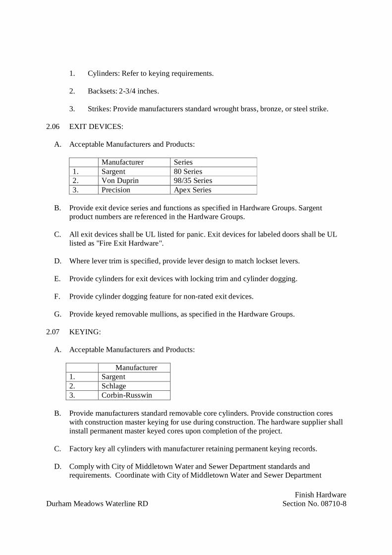
Finish HardwareDurham Meadows Waterline RD Section No. 08710-8
1. Cylinders: Refer to keying requirements.
2. Backsets: 2-3/4 inches.
3. Strikes: Provide manufacturers standard wrought brass, bronze, or steel strike.
2.06 EXIT DEVICES:
A. Acceptable Manufacturers and Products:
Manufacturer Series1. Sargent 80 Series2. Von Duprin 98/35 Series3. Precision Apex Series
B. Provide exit device series and functions as specified in Hardware Groups. Sargentproduct numbers are referenced in the Hardware Groups.
C. All exit devices shall be UL listed for panic. Exit devices for labeled doors shall be ULlisted as "Fire Exit Hardware".
D. Where lever trim is specified, provide lever design to match lockset levers.
E. Provide cylinders for exit devices with locking trim and cylinder dogging.
F. Provide cylinder dogging feature for non-rated exit devices.
G. Provide keyed removable mullions, as specified in the Hardware Groups.
2.07 KEYING:
A. Acceptable Manufacturers and Products:
Manufacturer1. Sargent2. Schlage3. Corbin-Russwin
B. Provide manufacturers standard removable core cylinders. Provide construction coreswith construction master keying for use during construction. The hardware supplier shallinstall permanent master keyed cores upon completion of the project.
C. Factory key all cylinders with manufacturer retaining permanent keying records.
D. Comply with City of Middletown Water and Sewer Department standards andrequirements. Coordinate with City of Middletown Water and Sewer Department
I I
I I
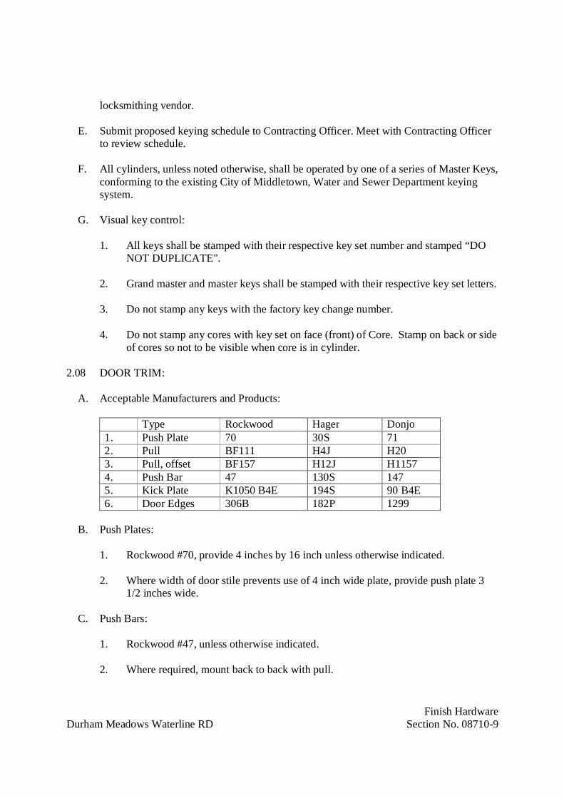
Finish HardwareDurham Meadows Waterline RD Section No. 08710-9
locksmithing vendor.
E. Submit proposed keying schedule to Contracting Officer. Meet with Contracting Officerto review schedule.
F. All cylinders, unless noted otherwise, shall be operated by one of a series of Master Keys,conforming to the existing City of Middletown, Water and Sewer Department keyingsystem.
G. Visual key control:
1. All keys shall be stamped with their respective key set number and stamped “DONOT DUPLICATE".
2. Grand master and master keys shall be stamped with their respective key set letters.
3. Do not stamp any keys with the factory key change number.
4. Do not stamp any cores with key set on face (front) of Core. Stamp on back or sideof cores so not to be visible when core is in cylinder.
2.08 DOOR TRIM:
A. Acceptable Manufacturers and Products:
Type Rockwood Hager Donjo1. Push Plate 70 30S 712. Pull BF111 H4J H203. Pull, offset BF157 H12J H11574. Push Bar 47 130S 1475. Kick Plate K1050 B4E 194S 90 B4E6. Door Edges 306B 182P 1299
B. Push Plates:
1. Rockwood #70, provide 4 inches by 16 inch unless otherwise indicated.
2. Where width of door stile prevents use of 4 inch wide plate, provide push plate 31/2 inches wide.
C. Push Bars:
1. Rockwood #47, unless otherwise indicated.
2. Where required, mount back to back with pull.

Finish HardwareDurham Meadows Waterline RD Section No. 08710-10
D. Pull, offset:
1. Rockwood #BF157, unless otherwise indicated.
2. Where required, mount back to back with push bar.
E. Pulls:
1. Rockwood #BF111, unless otherwise indicated.
2. Where required, mount back to back with push bar.
F. Pull Plate:
1. Rockwood #BF111 pull x #70 plate, provide plate 4 inches by 16 inch unlessotherwise indicated.
2. Where width of door stile prevents use of 4 inch wide plate, provide push plate 31/2 inches wide.
G. Kick Plates and Armor Plates:
1. Minimum of 0.050 inch thick, beveled 4 edges.
2. At single doors provide width 1-1/2 inch less than door width on stop side and oneinch less than door width on face side.
3. At pairs of doors provide width one inch less than door width on either sides.
4. Provide Height:
a. Mop Plates: 4 inches, unless otherwise indicated.
b. Kick Plates: 8 inches, unless otherwise indicated.
c. Armor Plates: 34 inches, unless otherwise indicated.
H. Edge Guards:
1. Minimum .050" thick, stainless steel.
2. Rockwood #306B x 42 inches high as noted in Hardware Groups.

Finish HardwareDurham Meadows Waterline RD Section No. 08710-11
2.09 COORDINATORS:
A. Acceptable Manufacturers and Products:
Manufacturer Series1. Rockwood 1600 Series2. Hager 297D3. Donjo 2010/2020 Series
B. Provide 1600 Series coordinator for labeled pairs of doors equipped with automatic flushbolts and those with vertical rod/mortise lock fire exit device combinations withastragals.
C. Provide filler bars for total opening width, closer mounting brackets, carry bars, andspecial preparation for top latches where applicable.
2.10 DOOR CLOSERS:
A. Acceptable Manufacturers and Products:
Type Sargent LCN Norton1. Stop Arm 351-CPS 4040S-CUSH UNI-7500-BF2. Stop/Holder Arm 351-CPSH 404S-H-CUSH UNI-7500BF-H3. Regular Arm 351-O 4040 7500BF4. HD Parallel Arm 351-P10 4040EDA PR7500BF
B. Provide all closers on exterior openings with a stop arm, unless noted otherwise.
C. Provide all closers on interior openings with a regular arm or heavy duty parallel arm,unless noted otherwise.
D. Provide non-sized closers, adjustable to meet maximum opening force requirements ofADA.
E. Provide drop plates, brackets, or adapters for arms as required to suit details.
F. Mount closers on room side of corridor doors, inside of exterior doors, and stair side ofstairway doors. Closers shall not be visible in corridors, lobbies and other public spacesunless necessary.
G. Provide back-check for closers.
H. Provide holder arms where indicated.
I. Provide stop arms where indicated.
I I

Finish HardwareDurham Meadows Waterline RD Section No. 08710-12
J. Provide delayed action where indicated.
K. Provide closers for doors as noted in Hardware Groups and, in addition, provide closersfor labeled doors whether or not specifically noted in group.
L. Provide closers meeting the requirements of UBC 7-2 and UL 10C positive pressure tests.
M. Provide bolt attachments or blocking for mineral core door application as directed byContracting Officer and/or door specifications.
2.11 OVERHEAD STOPS/HOLDERS:
A. Acceptable Manufacturers and Products:
Type Sargent ABH Glynn Johnson1. Surface, med. Duty 1540 3300 4502. Surface, heavy duty 590 9000 900
B. Provide 1540 Series overhead stop for interior doors equipped with regular arm surfacetype closer that swing more than 140 degrees before striking wall, and for doors that openagainst equipment, casework, sidelights, other objects that would make wall stopsinappropriate. Provide 590 Series overhead stop for exterior doors where specified.
C. Provide bolt attachments or blocking for mineral core door application as directed byContracting Officer and/or door specifications.
2.12 STOPS AND HOLDERS:
A. Acceptable Manufacturers and Products:
Type Rockwood Hager Donjo1. Wall, convex 406 232W 14062. Floor 440/442 241F/243F 1440/14423. Floor, heavy duty 470/471 267F267S 14714. Stop/Holder, heavy duty 472/472 268F/268S 1473
B. Provide Rockwood #406 wall stop for each door leaf except where floor stops arescheduled in Hardware Groups. Where conditions do not allow a wall stop or a floor stoppresents a tripping hazard than provide an overhead stop.
C. Provide 1540 Series overhead stop for interior doors and 590 Series overhead stop forexterior doors that swing more than 140 degrees before striking a wall.
D. Floor or base stops shall be used only where definitely specified or absolutelyunavoidable.

Finish HardwareDurham Meadows Waterline RD Section No. 08710-13
2.13 THRESHOLDS:
A. Acceptable Manufacturers and Products:
Interior DoorSaddle Type
Exterior DoorStop Type
Manufacturer Series Series1. Pemko 171 2000B2. Reese S205 54833. National Guard 425 896
B. Provide thresholds as indicated on drawings and as specified.
1. Refer to drawings for special details. Provide accessories, shims and fasteners.
2. Where thresholds occur at openings with one or more mullions, they shall be cutfor the mullions and extended continuously for the entire opening.
2.14 WEATHERSTRIPPING:
A. Acceptable Manufacturers and Products:
Type Pemko Reese National Guard1. Sweeps 315CN 323 200N2. Jambs 316AV DS75 1523. Astragals 18061CP 964C C6074. Rain Drip 346C R201 16D
B. Where weatherstripping is specified in hardware groups, provide 316AV at jambs, unlessdetailed or scheduled otherwise.
1. Provide self-tapping fasteners for weatherstripping being applied to hollow metalframes.
C. Where astragals are specified in hardware groups, provide 2 pieces of 18061CP unlessdetailed or scheduled otherwise.
D. Where sweeps are specified in hardware groups, provide 315CN unless detailed orscheduled otherwise.
E. Where rain drips are specified in hardware groups, provide 346C x full frame width,unless detailed otherwise.
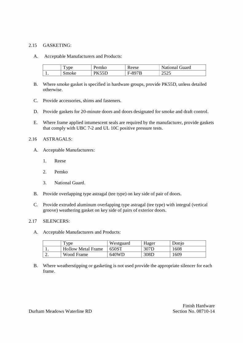
Finish HardwareDurham Meadows Waterline RD Section No. 08710-14
2.15 GASKETING:
A. Acceptable Manufacturers and Products:
Type Pemko Reese National Guard1. Smoke PK55D F-897B 2525
B. Where smoke gasket is specified in hardware groups, provide PK55D, unless detailedotherwise.
C. Provide accessories, shims and fasteners.
D. Provide gaskets for 20-minute doors and doors designated for smoke and draft control.
E. Where frame applied intumescent seals are required by the manufacturer, provide gasketsthat comply with UBC 7-2 and UL 10C positive pressure tests.
2.16 ASTRAGALS:
A. Acceptable Manufacturers:
1. Reese
2. Pemko
3. National Guard.
B. Provide overlapping type astragal (tee type) on key side of pair of doors.
C. Provide extruded aluminum overlapping type astragal (tee type) with integral (verticalgroove) weathering gasket on key side of pairs of exterior doors.
2.17 SILENCERS:
A. Acceptable Manufacturers and Products:
Type Westguard Hager Donjo1. Hollow Metal Frame 650ST 307D 16082. Wood Frame 640WD 308D 1609
B. Where weatherstipping or gasketing is not used provide the appropriate silencer for eachframe.
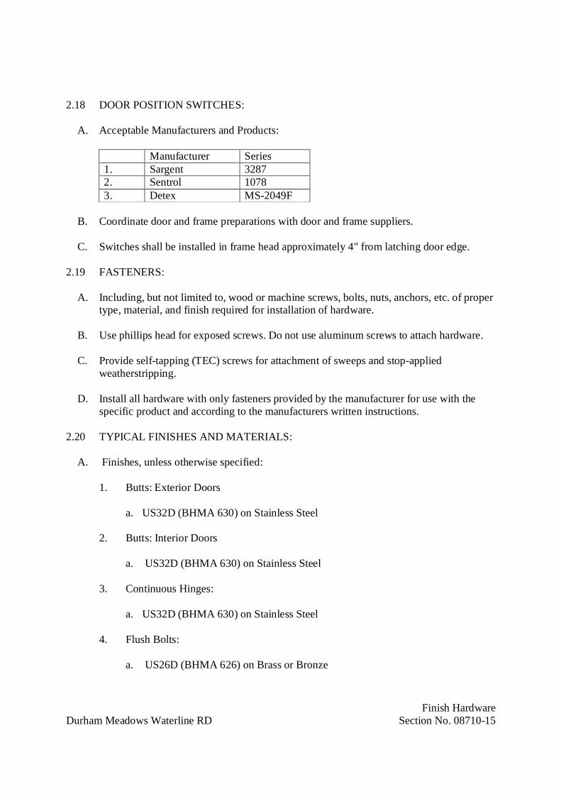
Finish HardwareDurham Meadows Waterline RD Section No. 08710-15
2.18 DOOR POSITION SWITCHES:
A. Acceptable Manufacturers and Products:
Manufacturer Series1. Sargent 32872. Sentrol 10783. Detex MS-2049F
B. Coordinate door and frame preparations with door and frame suppliers.
C. Switches shall be installed in frame head approximately 4" from latching door edge.
2.19 FASTENERS:
A. Including, but not limited to, wood or machine screws, bolts, nuts, anchors, etc. of propertype, material, and finish required for installation of hardware.
B. Use phillips head for exposed screws. Do not use aluminum screws to attach hardware.
C. Provide self-tapping (TEC) screws for attachment of sweeps and stop-appliedweatherstripping.
D. Install all hardware with only fasteners provided by the manufacturer for use with thespecific product and according to the manufacturers written instructions.
2.20 TYPICAL FINISHES AND MATERIALS:
A. Finishes, unless otherwise specified:
1. Butts: Exterior Doors
a. US32D (BHMA 630) on Stainless Steel
2. Butts: Interior Doors
a. US32D (BHMA 630) on Stainless Steel
3. Continuous Hinges:
a. US32D (BHMA 630) on Stainless Steel
4. Flush Bolts:
a. US26D (BHMA 626) on Brass or Bronze
I I

Finish HardwareDurham Meadows Waterline RD Section No. 08710-16
5. Exit Devices:
a. US32D (BHMA 630) on Stainless Steel
6. Locks and Latches:
a. US32D (BHMA 630) on Stainless Steel
7. Push Plates, Pulls and Push Bars:
a. US32D (BHMA 630) on Stainless Steel
8. Coordinators:
a. US26D (BHMA 626) on Brass or Bronze
9. Kick Plates, Armor Plates, and Edge Guards:
a. US32D (BHMA 630) on Stainless Steel
10. Overhead Stops and Holders:
a. US26D (BHMA 626) on Brass or Bronze
11. Closers: Surface mounted:
a. Sprayed Aluminum Lacquer
12. Miscellaneous Hardware:
a. US32D (BHMA 630) on Stainless Steel or US26D (BHMA 626) on Brass orBronze
PART 3 – EXECUTION
3.01 EXAMINATION:
A. Examine doors, frames, and related items for conditions that would prevent the properapplication of finish hardware. Do not proceed until defects are corrected.
B. Field verify existing doors, frames, hardware, and conditions prior to schedulinghardware.
Finish HardwareDurham Meadows Waterline RD Section No. 08710-17
3.02 INSTALLATION:
A. Install finish hardware in accordance with reviewed hardware schedule andmanufacturer's printed instructions. Prefit hardware before finish is applied. Remove andreinstall after finish is completed. Install hardware so that parts operate smoothly, closetightly and do not rattle.
B. Installation of hardware shall comply with NFPA 80 and NFPA 101 requirements.
C. Set units level, plumb and true to line and location. Adjust and reinforce attachment tosubstrate as necessary for proper installation and operation.
D. Drill and countersink units that are not factory-prepared for anchorage fasteners. Spacefasteners and anchors in accordance with industry standards.
E. Set thresholds for exterior doors in full bed of butyl-rubber or polyisobutylene masticsealant, forming tight seal between threshold and surface to which set. Securely andpermanently anchor thresholds, using countersunk non-ferrous screws to match color ofthresholds (stainless steel screws at aluminum thresholds).
F. Lead Protection: Lead wrap hardware penetrating lead-lined doors. Levers and roses tobe lead lined. Apply kick and armor plates with 3M adhesive #1357, as recommended by3M Co., on lead-lined doors.
3.03 FIELD QUALITY CONTROL:
A. After installation has been completed, a qualified person from the hardware supplier is tocheck the Project to determine proper application of finish hardware according toschedule. Also check operation and adjustment of all hardware items.
B. Installer shall deliver to Contracting Officer, upon completion, one set of installation andmaintenance instructions and specialty tools for all hardware items.
3.04 ADJUSTING AND CLEANING:
A. At completion, hardware shall be left clean and free from disfigurement. Makeadjustment to door closers and other items of hardware. Where hardware is founddefective repair or replace or otherwise correct as directed.
B. Adjust door closers to meet opening force requirements of Uniform Federal AccessibilityStandards.
C. Adjust door control devices to compensate for final operation of heating and ventilatingequipment.
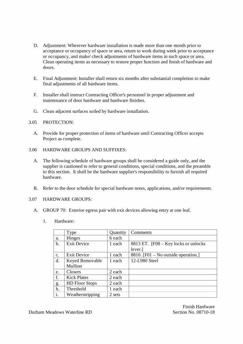
Finish HardwareDurham Meadows Waterline RD Section No. 08710-18
D. Adjustment: Wherever hardware installation is made more than one month prior toacceptance or occupancy of space or area, return to work during week prior to acceptanceor occupancy, and make/ check adjustments of hardware items in such space or area.Clean operating items as necessary to restore proper function and finish of hardware anddoors.
E. Final Adjustment: Installer shall return six months after substantial completion to makefinal adjustments of all hardware items.
F. Installer shall instruct Contracting Officer's personnel in proper adjustment andmaintenance of door hardware and hardware finishes.
G. Clean adjacent surfaces soiled by hardware installation.
3.05 PROTECTION:
A. Provide for proper protection of items of hardware until Contracting Officer acceptsProject as complete.
3.06 HARDWARE GROUPS AND SUFFIXES:
A. The following schedule of hardware groups shall be considered a guide only, and thesupplier is cautioned to refer to general conditions, special conditions, and the preambleto this section. It shall be the hardware supplier's responsibility to furnish all requiredhardware.
B. Refer to the door schedule for special hardware notes, applications, and/or requirements.
3.07 HARDWARE GROUPS:
A. GROUP 70: Exterior egress pair with exit devices allowing entry at one leaf.
1. Hardware:
Type Quantity Commentsa. Hinges 6 eachb. Exit Device 1 each 8813 ET. [F08 – Key locks or unlocks
lever.]c. Exit Device 1 each 8810. [F01 – No outside operation.]d. Keyed Removable
Mullion1 each 12-L980 Steel
e. Closers 2 eachf. Kick Plates 2 eachg. HD Floor Stops 2 eachh. Threshold 1 eachi. Weatherstripping 2 sets
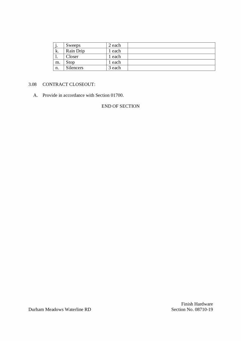
Finish HardwareDurham Meadows Waterline RD Section No. 08710-19
j. Sweeps 2 eachk. Rain Drip 1 eachl. Closer 1 eachm. Stop 1 eachn. Silencers 3 each
3.08 CONTRACT CLOSEOUT:
A. Provide in accordance with Section 01700.
END OF SECTION

DIVISION 9
FINISHES
Field PaintingDurham Meadows Waterline RD 09941-1
SECTION 09941
FIELD PAINTING
PART 1 – GENERAL
1.01 DESCRIPTION:
A. Provide and apply paints and coatings specified and indicated. Prepare, clean, and finishall surfaces to be field painted as specified and indicated.
1. The terms “paint” and “coating” used herein include emulsions, enamels, paints,stains, varnishes, seal waters, and other coatings, organic or inorganic, whether usedas intermediate, or finish coats.
2. Stainless steel piping, fittings and supports will not be field painted.
B. Complete painting in accordance with specifications, paint manufacturer's current surfacepreparation and application instructions and safety requirements. In the event of conflict,the more stringent specifications will apply.
1.02 RELATED WORK:
C. Section 13225: Prestressed Concrete Tanks
D. Section 15101: Process Piping, Valves and Appurtenances
1.03 REFERENCES:
A. Society for Protective Coatings (SSPC) Specifications:
B. SSPC-PA 1: Shop, Field, and Maintenance Painting of Steel.
C. SSPC-PA-2: Measurement of Dry Coating Thickness with Magnetic Gages.
D. SSPC-SP 1: Solvent Cleaning.
E. SSPC-SP 3: Power Tool Cleaning.
F. SSPC-SP 6: Commercial Blast Cleaning.
G. SSPC-SP10: Near-White Blast Cleaning.
H. American National Standards Institute (ANSI):

Field PaintingDurham Meadows Waterline RD 09941-2
1.04 QUALITY ASSURANCE:
A. Provide in accordance with Section 01400 and as specified.
B. Use products of one manufacturer in any one paint coating system with compatiblecoating materials. Provide same coating product for touch-up as for original coating.
C. Do not use or retain contaminated, outdated, or diluted materials for painting. Do not usematerials from previously opened containers.
D. Provide paint products having a minimum of five (5) years of service, with no peeling,flaking, chipping, blistering, or fading, under similar service conditions.
1.05 SUBMITTALS:
A. Submit the following in accordance with Section 01300:
1. List of coating products (Paint Schedule) with brand, type and manufacturerincluding dry film thickness and volatile organic compound (V.O.C.) regulationsconforming to these specifications. Refer to Paragraph 2.04.
2. Manufacturer's current printed recommendations and data sheets for each productincluding performance criteria, surface preparation, application instructions.
3. Product data and pertinent information including results of test patch data indicatingcompatibility of field applied coatings with shop applied primers including aschedule listing each primer with field applied coatings to be applied over theprimer.
4. Color chip samples of materials proposed and matching color of coatings indicatedin Finish Schedule.
5. Color chip samples matching colors indicated in Piping Identification Schedule,included in this specification. Submit list of piping to be included under each color.
6. Submit manufacturer's published data showing service record specified in paragraph1.04 D.
7. Submit letter(s) signed by paint manufacturer certifying that submitted products aresuitable for application on the surfaces to be coated and for the service conditions.
8. Submit a Certificate of Compliance for coatings submerged in potable water withNational Sanitation Foundation approval.
9. Product data for mil thickness testing equipment including operating instructions.
Field PaintingDurham Meadows Waterline RD 09941-3
B. Field Submittals:
1. Submit letter(s) signed by Painting Subcontractor, certifying that surfaces to becoated have been prepared in accordance with paint manufacturer's printedinstructions and are ready for field paint application.
2. Approved mil thickness test results, including location, and surface or item foridentification.
1.06 PAINT STORAGE AND MIXING AREAS, AND WASTE DISPOSAL:
A. Store paints and painter's materials in area or areas designated by the Contracting Officersolely for this purpose. Confine mixing, thinning, clean-up and associated operations, andstorage of painting debris, to these areas before authorized disposal.
B. Do not use plumbing fixtures, piping or mechanical equipment for mixing or disposal ofpaint materials.
1. Transport water to paint area by temporary hose or piping.
2. Store waste temporarily in closed, nonflammable containers until final disposal.Keep no rubbish in painter's area longer than 24 hours. Dispose any hazardousmaterials in accordance with Connecticut requirements and OSHA regulations, andplace all non-hazardous waste in the central trash trailer area.
1.07 DELIVERY, STORAGE, AND HANDLING:
A. General Contractor will provide storage and protection in accordance with Section 01610and as specified.
B. Deliver materials to painter's area in original, unbroken, containers with name andanalysis of product, manufacturer's name, and shelf life date. Do not use or retaincontaminated, outdated, prematurely opened, or diluted materials.
C. Store coated items and protect coating from damage and foreign matter, by not allowingcontact with soil or pavement, exposure to wind-blown particles, or other harmful contactswhich necessitate special cleaning. Use blocking during storage.
D. Protect coated items, whether prime or finish, from damage due to shipping and handling.
1.08 JOB CONDITIONS:
A. Environmental Requirements:
1. Comply with manufacturer's printed recommendations as to environmentalconditions under which coatings and coating systems can be applied.

Field PaintingDurham Meadows Waterline RD 09941-4
2. Do not apply coatings when dust is being generated.
B. Protection:
1. Cover or otherwise protect finish work of other trades and surfaces not beingpainted concurrently or not to be painted.
2. Do not paint over nameplates, tagging or other identification devices.
PART 2 – PRODUCTS
2.01 MANUFACTURERS:
A. Tnemec Co., Inc.
B. Carboline.
C. PPG Protective & Marine Coatings, Inc.
D. TAMOSEAL (Tank exterior)
E. Or acceptable equivalent product.
2.02 MATERIALS – GENERAL:
A. Products:
1. Recommended by their manufacturer for intended service.
2. Potable Water:
a. Ferrous metals submerged or which are subject to splash action in contact withpotable water, provide one coat with a dry mil thickness of 3.0 to 3.5 mils of acertified NSF Standard 61 product by one of the following or equal:
(1) 91 H20 Urethane Zinc Rich Primer made by Tnemec Co.
(2) Carboguard 561 made by Carboline Co.
(3) Aquapon High Build Potable Water Epoxy 95-132 Series made by PPGProtective & Marine Coatings (4.0 – 6.0 DFT).
(4) Or acceptable equivalent product.
Field PaintingDurham Meadows Waterline RD 09941-5
3. Non-buried (Vault) Piping:
a. All ferrous metals not subject to potable water provide one coat with a dry filmthickness of 2.5 to 3.0 mils. By one of the following or equal:
(1) Series 1 Prime made by Tnemec Co.
(2) Carbozinc 859 by Carboline Co.
(3) Multiprime EFD Epoxy Fast Day Inhibitive Primer 94-109 made by PPGProtective & Marine Coatings (4.0 – 6.0 DFT).
B. Material Compatibility:
1. Provide block fillers, undercoats and finish-coat materials that are compatible withone another and the substrates indicated under conditions of service and application,as demonstrated by manufacturer based on testing and field experience.
2. Provide field applied coatings that are compatible with shop applied primers.
2.03 COLORS AND FINISHES:
A. Interior finish colors: As indicated in Finish Schedule and Pipe Identification Schedule.
B. To provide contrast between successive coats, lightly tint each coat to distinguish it frompreceding coats.
C. Unless otherwise indicated for finish paint, use gloss or semi-gloss on metal and satinfinish on masonry and concrete.
2.04 COATING TYPES:
A. Coatings are described in the COATING IDENTIFICATION SCHEDULE byabbreviations, generic type, minimum solids by volume and minimum dry film thickness.Provide coatings that comply with the volatile organic compounds (VOC) regulationsapplicable to the project site and in no case to exceed 3.5 lbs/gal.
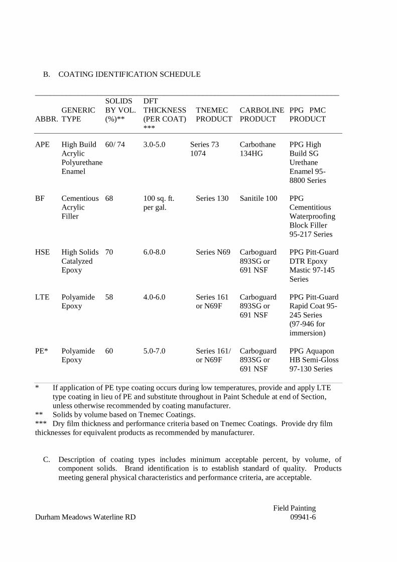
Field PaintingDurham Meadows Waterline RD 09941-6
B. COATING IDENTIFICATION SCHEDULE
______________________________________________________________________________SOLIDS DFT
GENERIC BY VOL. THICKNESS TNEMEC CARBOLINE PPG PMCABBR. TYPE (%)** (PER COAT) PRODUCT PRODUCT PRODUCT
***
APE High Build 60/ 74 3.0-5.0 Series 73 Carbothane PPG HighAcrylic 1074 134HG Build SGPolyurethane UrethaneEnamel Enamel 95-
8800 Series
BF Cementious 68 100 sq. ft. Series 130 Sanitile 100 PPGAcrylic per gal. CementitiousFiller Waterproofing
Block Filler95-217 Series
HSE High Solids 70 6.0-8.0 Series N69 Carboguard PPG Pitt-GuardCatalyzed 893SG or DTR EpoxyEpoxy 691 NSF Mastic 97-145
Series
LTE Polyamide 58 4.0-6.0 Series 161 Carboguard PPG Pitt-Guard Epoxy or N69F 893SG or Rapid Coat 95-
691 NSF 245 Series(97-946 forimmersion)
PE* Polyamide 60 5.0-7.0 Series 161/ Carboguard PPG AquaponEpoxy or N69F 893SG or HB Semi-Gloss
691 NSF 97-130 Series
* If application of PE type coating occurs during low temperatures, provide and apply LTEtype coating in lieu of PE and substitute throughout in Paint Schedule at end of Section,unless otherwise recommended by coating manufacturer.
** Solids by volume based on Tnemec Coatings.*** Dry film thickness and performance criteria based on Tnemec Coatings. Provide dry filmthicknesses for equivalent products as recommended by manufacturer.
C. Description of coating types includes minimum acceptable percent, by volume, ofcomponent solids. Brand identification is to establish standard of quality. Productsmeeting general physical characteristics and performance criteria, are acceptable.

Field PaintingDurham Meadows Waterline RD 09941-7
D. Provide coatings submerged in potable water with National Sanitation Foundationapproval.
2.05 PIPE, VALVE/EQUIPMENT IDENTIFICATION AND COLOR CODING:
A. Provide identification of pipes, valves, pumps, tanks and similar vessels by color asspecified in the Pipe Identification Schedule and with name of contents, directional flowarrows and other required legend.
1. Use stenciled letters and arrows or self-adhesive labels or tapes located at intervalsno greater than 20 ft. apart on straight runs except that stainless steel piping atintervals shall be no greater than 15 ft. apart on straight runs. Mark each valve,branch, wye change in direction and each side of floor and wall penetrations.
a. Labels or tapes shall be moisture and U.V. resistant.
B. Provide legend of size, character and location conforming to ANSI A13.1 for stenciledletters or labels.
C. Refer to notes at end of Pipe Identification Schedule for further clarifications.
PART 3 - EXECUTION
3.00 HOISTING, SCAFFOLDING, STAGING, AND PLANKING:
A. Provide, set-up, and maintain all required derricks, hoisting machinery, scaffolds, andstaging and planking, and perform all hoisting required to complete the Work of thissection as indicated and specified.
3.01 INSPECTION:
A. Examine surfaces scheduled to receive paint and finishes for conditions that will adverselyaffect execution, permanence or quality of work.
B. Do not proceed with surface preparation or coating application until after submitting to theEngineer a letter signed by Contractor, stating that surfaces to be painted are in acceptablecondition for preparation and painting according to the Painting Subcontractor and inaccordance with paint manufacturer’s printed instructions.
C. Do not proceed with coating application until after submitting to the Contracting Officer aletter signed by paint manufacturer certifying that submitted products are suitable forapplication in accordance with paint manufacturer’s printed instructions.
Field PaintingDurham Meadows Waterline RD 09941-8
3.02 PREPARATION:
A. Basic Steps:
1. Prepare and paint surfaces in heated enclosure unless the ambient weatherconditions ensure still, dry air above 50 degree F temperature, and humidity abovemanufacturer's printed recommended level. Do not apply paints to surfaces in directsunlight. Conform to manufacturer's printed instructions for safety requirements.
2. Coordinate cleaning and painting operations to eliminate contamination of one bythe other.
3. Maintain coating materials at manufacturer's recommended mixing and applicationtemperatures for not less than 24 hours before use. Have clean containers, sprayequipment, applicators, and accessory items ready for use before decanting ormixing paint materials.
4. Coordinate materials to be applied with previous coatings on affected surfaces.Obtain, in all cases, manufacturer's written directions, and follow them strictly,except where otherwise specified.
5. Coordinate preparation and material compatibility requirements with the workspecified.
B. Before any paint application, clean surfaces to be coated of dust, dirt, grease, white rust,paint unsuitable for top coating, efflorescence, oil, moisture, foreign matter, or similarconditions detrimental to coating bond and durability.
1. Following cleaning, apply preparatory treatment in strict accordance withmanufacturer's written instructions.
2. Fill imperfections and holes in surfaces to be painted with material recommended bypaint manufacturer.
C. Metals to Receive Paint Finishes:
1. Prepare ferrous metals, including field welds and unprimed shop welds, withoutshop prime coats as follows:
a. Near White blast cleaned (SSPC-SP-10), for submerged components.
b. Commercial blast cleaned (SSPC-SP-6), for non-submerged components.
c. Use needle gun for field welds and shop welds which occur in narrow, unprimedareas in an otherwise shop primed surface, followed by SSPC-SP1-solvent wipe.

Field PaintingDurham Meadows Waterline RD 09941-9
2. Clean previously shop primed ferrous metals in accordance with manufacturersprinted recommendations prior to field painting.
3. Non-ferrous and galvanized metal surfaces scheduled for paint finish:
a. Clean in accordance with manufacturers recommendations prior to field painting(SSPC-SP-1 including power washing).
b. For interior galvanized and non-ferrous metals not exposed to wet environmentsapply in accordance with manufacturers written instructions.
D. Concrete to Receive Paint Finishes:
1. Clean thoroughly of form oil, release agents, dirt, dust, grease, paint, loose materialand foreign matter. Remove laitance, roughen smooth surfaces by brush sandblasting, remove fins and projections, and fill voids and honeycombs with materialrecommended by paint manufacturer.
2. Prime after concrete has dried in strict accordance with manufacturer's printedinstructions.
E. Concrete unit masonry for paint finishes:
1. Clean thoroughly by brushing, scraping and sanding or grinding slick areas.Remove loose or projecting mortar, solvent wash oil, grease, paint spots beforeapplying block filler.
F. Provide higher degree of cleaning for acceptable equivalent paint products when paintmanufacturer recommends in his printed surface preparation recommendations.
G. Delay painting of areas which will be damaged by heat from welding, until welding iscomplete. Reclean and recoat substrate as specified for original coats, when coated areashave been damaged by welding or have not been painted to allow welding.
H. PVC Pipe:
1. Sand all surfaces with 60-80 grit paper to provide profile to adhere coatings.
3.03 TOUCH-UP:
A. Before applying field coat, touch-up abraided areas of shop coats with paint of the sametype. Apply an entire coat to abraided area. Touch-up coats are in addition to, and not asubstitute for first field coat. Clean deteriorated surfaces as specified herein and inaccordance with manufacturer’s recommendations before applying touch-up coat.
Field PaintingDurham Meadows Waterline RD 09941-10
B. Equipment, motors, pumps, instrumentation panels, electrical switchgear, and similaritems with shop coats, paint filler, enamel or other treatment customary withmanufacturer; after installation, touch-up scratches and blemishes before applying fieldcoats.
3.04 APPLICATION:
A. Refer to Paint Schedule at end of this specification for coating requirements. Provideadditional prime, undercoat, and finish coats as specified, indicated, and recommended bycoating manufacturer's printed instructions.
B. Conditions:
1. Do not apply paints or other finish to wet or damp surfaces, except in accordancewith instructions of manufacturer. Do not apply exterior paint during cold, rainy, orfrosty weather, or when temperature is likely to drop to freezing. Do not applypaints to surfaces in direct sunlight.
2. Paint surfaces which have been cleaned, pretreated, or otherwise prepared forpainting with first field coat as soon as practicable after such preparation has beencompleted, but in any event prior to deterioration of prepared surface.
3. Coat blast cleaned metal surfaces in accordance with SSPC guidelines, before anyrusting or other deterioration or contamination of the surface occurs. Do not coatblast cleaned surfaces later than 8 hours after cleaning.
C. Methods:
1. Spraying with apparatus may be substituted for brush application of paints inlocations approved for spraying.
2. Prepare surfaces, mix and apply paint materials in strict accordance withmanufacturer's printed instructions and recommendations. Control temperature ofmaterials upon mixing and application, surface temperature and condition, thinningand modifying.
3. Protect surfaces to be coated, before, during and after application.
D. Workmanship:
1. Apply coating materials to meet manufacturer's spreading rate and dry filmthickness recommendations. Dry film thicknesses specified are constant for brush,spray, roller or other form of application.

Field PaintingDurham Meadows Waterline RD 09941-11
a. Control thinning in accordance with V.O.C. regulations for spray use and tomanufacturer's printed instructions, and produce specified dry film thickness onlevel surfaces, interior and exterior angles.
2. Apply paints and coatings using painters continuously employed in the paintingprofession for no less than five (5) years, brushed or rolled out carefully to asmooth, even coating without runs or sags. Curing time in accordance withmanufacturers printed instructions.
3. Finish surfaces: Uniform in finish and color, and free from flash spots and brushmarks.
3.05 PROTECTION AND CLEAN-UP:
A. Protect surfaces to be painted or coated under this Section as follows:
1. Arrange for preparation and coating activities to be performed in areas and duringtimes when no continuous traffic and no dust generating activity will be present.
2. During time between preparation and coating, protect work from dust and dirt withdropcloth. Do not allow contact with surfaces in this time period.
3. During painting activity, clearly mark the area being used by painters to preventinterference with painting being applied as specified.
4. After painting, clearly barricade painted surfaces with cones, plastic barrier tape, orother visible barrier. Locate "WET PAINT" signs near painted surfaces. Do notremove barriers and signs until paint surface dries throughout entire film thickness.
B. Remove or completely mask accessory items, finish hardware, lighting fixtures,escutcheon plates, trim and similar finish items not to be painted before painting adjacentsurfaces. Carefully replace and reposition upon completion of adjacent painting andcleaning work.
C. Upon completion of the work, clean up paint spots, oil, and stains from floors, glass,hardware, and similar finished items and remove tape.
3.06 SCHEDULE OF PAINTING:
A. Coordinate and schedule the various cleaning, touch-up and finishing operations.Transmit and coordinate the transmission of materials data, color selections, and coatingsystem methods between the coating applicators. Do not exceed exposure and recoat timelimits.
B. Colors to be as follows unless otherwise specified or directed by the Contracting Officer.

Field PaintingDurham Meadows Waterline RD 09941-12
1. All valves shall be Safety Red.2. Exposed water pipe in vaults shall be blue (as approved by Town of Durham and
City of Middletown in respective locations.)
3. Tank Exterior to be Tamoseal Oyster, or as directed by the City of Middletown
PAINT SCHEDULEItem No. Surface or Item Field Coats
____ 1st_____2nd_____Final__
1 Interior concrete indicated to be painted PE - PE
2 New miscellaneous ferrous metal-work, ferrous piping,ferrous parts of operating devices, valve handles andsupports PE - PE
3 Exterior shop painted structural steel, exterior galvanizedstructural steel, lintel angles, ferrous piping, ferrous partsof operating devices and supports, guard posts,bollards and exterior surfaces of roll-updoor frames PE PE APE
4 Emulsified asphalt-coated ferrous piping PE - PE
5 Items with factory finish Touch-up withmaterials supplied bymanufacturer
6 Shop painted ferrous metals, galvanized PE HSE HSEmetals and equipment submerged and non-submerged
7 Interior shop painted ferrous metals, galvanized PE HSE HSEmetals and equipment non-submerged and subjectto splashing
8 Exterior shop painted ferrous metals, galvanized PE HSE APEmetals and equipment non-submerged and subject
______________________________________________________________________________Note:
4. If prime coat has been exposed for more than 6 months, Painting Subcontractor willprovide test patches to insure adhesion of field-applied coatings. Test patches inaccordance with paint manufacturer’s instructions.
Field PaintingDurham Meadows Waterline RD 09941-13
3.07 FINAL TOUCH-UP:
A. Prior to final completion and acceptance, examine painted and finished surfaces andretouch or refinish areas to leave touched-up areas with same appearance as and even withthe surrounding finish specified.
3.08 TESTING:
A. Conduct field testing in the presence of the Contracting Officer for specified mil thicknessin accordance with SSPC-PA-2.
B. Test results shall meet requirements of SSPC-PA-2. Failure of test results shall requirethat surfaces be repainted until approved results of testing have been obtained for thespecified mil thickness.
3.09 CONTRACT CLOSEOUT:
A. Provide in accordance with Section 01700.
END OF SECTION

DIVISION 10
SPECIALTIES
LouversDurham Meadows Waterline RD Section No. 10200-1
SECTION 10200
LOUVERS
PART 1 - GENERAL
1.01 DESCRIPTION:
A. Provide aluminum louvers as indicated and specified.
B. The extent of louver work includes the following:
1. Fixed, extruded all welded aluminum louvers.
1.02 RELATED WORK:
A. Section 07900: Joint Sealants for joint sealant materials and installation.
B. Section 15806: Heating, Ventilation and Air Conditioning.
1.03 REFERENCES:
A. American Architectural Manufacturers Association (AAMA) Specification.
1. AAMA 2605-02: Voluntary Specification for High Performance Organic Coatings on ArchitecturalExtrusions and Panels.
2. AAMA 611-98: Voluntary Guide Specification for Anodized Architectural Aluminum.
B. AMCA: Air Movement and Control Association Publications.
1. Test Standard: AMCA 500-L-99, Laboratory Methods of Testing Louvers for Rating, Section 8.3.1-WaterPenetration Test.
2. Test Standard: AMCA 500-L-99, Laboratory Methods of Testing Louvers for Rating, Section 8.3.2 – WindDriven Rain Water Penetration Test.
C. American Society for Testing Materials (ASTM) Publications:
1. ASTM B209-95: Specification for Aluminum and Aluminum-Alloy Sheet and Plate.
2. ASTM B221-95a: Specification for Aluminum-Alloy Extruded Bars, Rods, Wire, Shapes and Tubes.

LouversDurham Meadows Waterline RD Section No. 10200-2
3. ASTM E90-97: Laboratory Measurement of Airborne Sound Transmission Loss of Building Partitions.
4. ASTM E 413-87 (Reapproved 1994): Classification for Rating Sound Insulation.
D. American Welding Society
1. AWD D1.2-90: Structural Welding Code – Aluminum
E. National Association of Architectural Metal Manufacturers
1. Metal Finishes Manual for Architectural and Metal Products. 1988.
F. Sheet Metal and Air Conditioning Contractors Association (SMACNA).
G. Society for Protective Coatings – SSPC – Paint 12: Cold Applied Asphalt Mastic (Extra Thick Film).
1.04 QUALITY ASSURANCE:
A. Provide in accordance with Section 01400 and as specified.
B. Structural Performance: Provide exterior metal louvers and aluminum architectural screen capable ofwithstanding the effects of loads and stresses from wind and normal thermal movement without evidencingpermanent deformation of louver components including blades, frames and supports; noise or metal fatiguecaused by louver blade rattle or flutter; or permanent damage to fasteners and anchors.
1. Wind Load: Uniform pressure (velocity pressure) of 30 lbf/sq. ft. (1440 Pa), acting inward or outward.
2. Thermal Movements: Provide louvers that allow for the thermal movements resulting from change inambient and surface temperatures by preventing buckling, opening of joints, overstressing ofcomponents, and other detrimental effects.
C. Air Performance and Water-Penetration Ratings: Provide louvers complying with performance requirementsindicated, as demonstrated by testing manufacturer’s stock units 48-in. wide by 48-in. high. Test units accordingto AMCA 500.
1.05 SUBMITTALS:
A. Submit the following in accordance with Section 01300:

LouversDurham Meadows Waterline RD Section No. 10200-3
1. Shop drawings of louver units and architectural screen accessories shall include plans, elevations,sections and details showing profiles, angles, spacing of louver blades, unit dimensions related to wallopenings and construction; free areas for each size indicated; profiles of frames at jambs, head and sills;and anchorage details and locations.
2. Submit three (3) color charts for aluminum finish.
3. Product test reports indicating compliance for louvers with performance requirements specified forstandard free area, wind driven rain, airborne sound transmission loss and structural performance.
4. Product certificates signed by louver manufacturer certifying that their products which comply withproject requirements are licensed to bear the AMCA seal based on tests made in accordance with AMCAStandard 500 and complying with AMCA Certified Ratings Program.
1.06 DELIVERY, STORAGE AND HANDLING:
A. Provide in accordance with Section 01610 and as specified.
B. Brace and support units to prevent deformation during delivery.
C. Factory wrap units with approved materials to protect finish during delivery and storage.
D. Handle units with care to prevent bending or scratching.
PART 2 – PRODUCTS
2.01 MANUFACTURERS:
A. The Airolite Co.
B. Construction Specialties, Inc.
C. Industrial Louvers, Inc.
D. Or acceptable equivalent product.
2.02 MATERIALS:
A. Aluminum Extrusions: ASTM B221, alloy 6063-T5 or 6063-T52.
LouversDurham Meadows Waterline RD Section No. 10200-4
B. Aluminum Sheet: ASTM B209, alloy 3003 or 5005 with temper as required for forming, or as otherwiserecommended by metal producer for required finish.
C. Fasteners: Type 304A series stainless steel.
D. Provide continuous aluminum perimeter angles (alloy 6063) and anchors of type, size, and material required forloading and installation indicated. Provide stainless steel anchors.
E. Bituminous Paint: Cold-applied asphalt mastic complying with SSPC-Paint 12 but containing no asbestos fibers.
2.03 GENERAL:
A. Assemble louvers in factory to minimize field splicing and assembly. Disassemble units as necessary for shippingand handling limitations.
B. Maintain equal louver blade spacing to produce uniform appearance.
C. All Welded Assembly: Join stationary blade and frames and frame members with fillet welds concealed fromview. Louver blades shall be joined to each jamb frame with a minimum of two fillet welds produced with thePulsed Gas Metal Arc Welded (GMAW/Mig) process. Each weld shall be a minimum of 1-inch (25.4 mm) in lengthwith a minimum 3/16-inch (4.76 mm) leg. Frames shall be joined at each corner with a full-length GMAW filletweld with a minimum 3/16-inch (4.76 mm) throat.
D. Fabricate frames, channel type to fit in openings of sizes indicated, with allowances made for fabrication andinstallation tolerances, adjoining materials; tolerances, and perimeter sealant joints.
E. Include supports, anchorages, and accessories required for complete assembly.
F. Provide vertical mullions of type and at spacings indicated, but not more than recommended by manufacturer, or72-in. (1830 mm) o.c., whichever is less.
G. Provide sill extensions fabricated of continuous 0.125-in. thick aluminum where indicated and required fordrainage to exterior and to prevent water penetrating to interior.
H. Provide 0.125-in thick interior aluminum stools where indicated on drawings. Color and finish of sills to matchlouver.

LouversDurham Meadows Waterline RD Section No. 10200-5
2.04 FIXED ALUMINUM DRAINABLE LOUVERS:
A. Louver Construction: Provide fixed-blade, sight-proof, drainable type louvers with extruded-aluminum frames andblades complying with the following:
1. Louver Depth: 5 in. unless otherwise indicated.
2. Frame and Blade Thickness: 0.081-in. (2.06 mm).
3. Standard Free Area: Not less than 56% based on 48-in. x 48-in. tested unit to AMCA Standard.
4. Free Area Velocity at Beginning Point of Water Penetration – 0.01 oz H20/sq.ft. Free Area: 1,134 fpm (5.76 m/s).
5. Air Volume Flow Rate at Beginning Point of Water Penetration – 4 ft. x 4 ft.Unit: 10,331 cfm (4,896 m3/s).
6. Pressure Drop at Beginning Point of Water Penetration: 0.40 in. H20 (0.100pKa)
2.05 LOUVER SCREENS:
A. General: Provide each exterior louver with louver screens complying with the following requirements:
1. Screen Location for Fixed Louvers: Interior face.
2. Screening Type: 1/2-in. mesh, 0.063-in. diameter aluminum bird screening, unless otherwise indicated.
3. Screening Type: 18x14 mesh, .0123-in. 5056 alloy aluminum insect screening where indicated.
B. Secure screens to louver frames with stainless-steel machine screws, spaced a maximum of 6-in. (150 mm) fromeach corner and at 12-in. (300 mm) o.c.
C. Louver Screen Frames: Fabricate rewirable screen frames with mitered corners to louver sizes indicated and withthe same kind and form of metal as indicated for louver to which screens are attached.
1. Finish: Same finish as louver frames to which louver screens are attached.

LouversDurham Meadows Waterline RD Section No. 10200-6
D. Provide louver guards fabricated to dimensions indicated, of 12 gage steel wire woven in a 3/4-in. mesh, crimpedwoven in a 3/4-in. mesh, crimped into 1/2-in. x 1/8-in. steel channel frames hot dipped galvanized louver guardsdipped galvanized louver guards after fabrication and shop apply two coats epoxy paint finish to match color ofpaint finish to match color of louver.
2.06 BLANK-OFF PANELS:
A. Provide laminated metal-faced panels where required to seal off louver area not connected to ductwork,consisting of insulating core surfaced on back and front with metal sheets.
1. Thickness: 2-in. (50 mm).
2. Metal Facing Sheets: Aluminum sheet, 0.032-in. (0.8 mm) thick.
3. Insulating Core: Extruded-polystyrene insulation board complying with ASTM C578, Type VII.
4. Edge Treatment: Trim perimeter edges of blank-off panels with louver manufacturer’s standardextruded-aluminum-channel frames 0.081-in. (2.06 mm) thick, with corners mitered and with same finishas panels.
5. Finish: Same as finish applied to louvers.
6. Attach blank-off panels to back of louver frames with stainless steel sheet-metal screws.
2.07 FINISHES:
A. Comply with NAAMM’s “Metal Finishes Manual for Architectural and Metal Products” for recommendations forapplying and designating finishes.
B. Finish louvers and aluminum screen after assembly.
C. Finish designations prefixed by AA comply with system established by the Aluminum Association for designatingaluminum finish.
D. High-Performance Organic Coating Finish: AA-C12C42R1x. Prepare, pretreat, and apply coating to exposedmetal surfaces to comply with coating and resin manufacturers’ written instructions.
1. Fluoropolymer Two-Coat Coating System: Manufacturer’s standard two-coat, thermocured systemconsisting of specially formulated inhibitive primer and fluorpolymer color topcoat containing not less than70 percent polyvinylidene fluoride resin by weight; complying with AAMA 2605-02.
LouversDurham Meadows Waterline RD Section No. 10200-7
a. Custom color to be selected by Contracting Officer.
a. Provide custom color as indicated.
PART 3 – EXECUTION
3.01 PREPARATION:
A. Coordinate Setting Drawings, diagrams, templates, instructions, and directions for installation of anchorages thatare to be embedded in concrete or masonry construction.
3.02 INSTALLATION:
A. Locate and place louver and architectural screen units level, plumb, and as indicated alignment with adjacentwork.
B. Provide continuous angle supports mitered at corners with finish to match louver.
C. Form closely fitted joints with exposed connections accurately located and secured.
D. Provide perimeter reveals and openings of uniform width for sealants and joint fillers, as indicated.
E. Repair finishes damages by cutting, welding, soldering, and grinding. Restore finishes so no evidence remains ofcorrective work. Return items that cannot be refinished in the field to the factory, make required alterations, andrefinish entire unit or provide new units.
F. Isolate aluminum from contact with masonry or dissimilar metals with heavy coat of bituminous paint orneoprene gaskets.
G. Mount bird screens of all louvers unless indicated otherwise on inside face with clips, machine screw into frames.
H. Verify size, location and placement of continuous louvers and individual louver units prior to fabrication.Coordinate field measurement and shop assembly to minimize field adjustment.
3.03 CLEANING:
A. Upon completion remove any and all protective coatings, and clean off all parts of the work.

LouversDurham Meadows Waterline RD Section No. 10200-8
3.04 CONTRACT CLOSEOUT:
A. Provide in accordance with Section 01700.
END OF SECTION

DIVISION 11
EQUIPMENT
Sump Pumps and AppurtenancesDurham Meadows Waterline RD Section No. 11316 -1
SECTION 11316
SUMP PUMPS AND APPURTENANCES
PART 1 - GENERAL
1.01 DESCRIPTION:
A. Provide and test pumps, motors, and appurtenances as indicated and specified.
1.02 REFERENCES:
A. American Society for Testing and Materials International (ASTM):
1. A36: Standard Specification for Carbon Structural Steel.
2. A48: Standard Specification for Gray Iron Castings.
3. A108: Standard Specification for Steel Bar, Carbon and Alloy, Cold-Finished
4. B584: Standard Specification for Copper Alloy Sand Castings for GeneralApplications
B. Hydraulic Institute (HI):
1. Current Standards.
C. National Electrical Manufacturers Association (NEMA):
1. MG1: Motors and Generators.
1.03 SUBMITTALS:
A. Submit the following shop drawings in accordance with Section 01300:
1. Data regarding pump and motor characteristics and performance:
a. Provide catalog performance curves at maximum pump speed indicated andspecified for each service showing acceptable operating range (AOR) andpreferred operating range (POR).
b. Submit curves for guaranteed performance, and shop performance tests on8-1/2-inch by 11-inch (A4) sheets, one curve per sheet.
2. Shop drawing data for accessory items.
3. Certified setting plans, with tolerances, for anchor bolts.
Sump Pumps and AppurtenancesDurham Meadows Waterline RD Section No. 11316 -2
4. Manufacturer's literature as needed to supplement certified data.
5. Operating and maintenance instructions and parts lists.
6. List of recommended spare parts other than those specified.
7. Shop and field inspection reports.
8. Special tools.
1.04 QUALITY ASSURANCE:
A. Comply with the requirements specified in Section 01400.
B. Pumps shall be manufacturer’s standard cataloged product and modified to providecompliance with the drawings, specifications and the service conditions specified andindicated.
1.05 DELIVERY, STORAGE AND HANDLING:
A. Comply with the requirements specified in Section 01610.
PART 2 - PRODUCTS
2.01 SUMP PUMPS (SUBMERSIBLE TYPE):
A. UL listed, factory assembled and tested submersible type pumps for operation underwater up to maximum 120 degrees F and capable of passing minimum 1/2-inch sphericalsolids. Pump shall be complete with cast-iron casing with corrosion resistant finish, castiron or bronze impeller, stainless steel shaft, carbon/ceramic mechanical seals, sealedbearings, water-cooled hermetically-sealed motor, built-in automatic reset thermalprotection, stainless steel lift handle, and waterproof three-conductor cables andgrounded plugs. Pumps shall have single seal design. Pumps shall have integral floatswitch.
B. Minimum 6 foot power cord.
C. Pump shall be Zoeller Model M57 or equal by Gould or Hydromatic.
PART 3 - EXECUTION
3.01 INSTALLATION:
A. Install items in accordance with accepted shop drawings, manufacturer's printedinstructions and as indicated.

Sump Pumps and AppurtenancesDurham Meadows Waterline RD Section No. 11316 -3
3.02 FIELD TESTING:
A. Make all adjustments necessary to place equipment in specified working order.
B. Remove all replace equipment at no additional cost to the Contracting Officer withequipment that will meet all requirements specified and indicated if unable todemonstrate to the satisfaction of the Contracting Officer that equipment will performthe service specified, indicated and as submitted and accepted.
3.03 FIELD TOUCH-UP PAINTING:
A. After installation and accepted testing by the Contracting Officer, apply touch-up paintto all scratched, abraided and damaged shop painted surfaces. Coating type and colorshall match shop painting.
3.04 CONTRACT CLOSEOUT:
A. Provide in accordance with Section 01700.
END OF SECTION

Booster Chlorination SystemSection No. 11353-1Durham Meadows Waterline Remedial Design
SECTION 11353
BOOSTER CHLORINATION SYSTEM
PART 1 – GENERAL
1.1 SCOPE
A. The system shall be designed to feed low concentrations of chlorine in solutionintermittently or continuously as required at the Long Hill Pump Station. The systemshall be a single pre-assembled, factory prewired, package unit in a welded powdercoated stainless steel frame consisting of chlorinator, chlorine system control panel,booster pumps as required, and solution tank for ease of installation and operation. Fieldassembled systems shall not be acceptable.
B. Chlorination system manufacturer shall also supply all accessories and appurtenancesas specified herein and as indicated on the Drawings, including a supply waterpressure reducing valve, particulate filter, inline heater as required, booster pump,chlorine solution eductor with automatic dose control valve, chlorine injection quill, aircirculation system, and chlorine analyzer as specified in this section.
C. CONTRACTOR shall furnish and install chemical containment pallet with dimensions asshown on Drawings. Minimum containment capacity shall be 25 gallons. Materials shallbe resistant to chlorine solutions up to 2% solutions.
D. CONTRACTOR shall furnish pre-assembled three step 24” x 36” mobile work platformladder with handrails for tablet tank access (as needed, depending on manufacturerselected). Tubular steel, all-welded construction. Corrosion resistant powder coat finish.800 lb capacity. Two casters for transport with brakes. 30” high handrails. Meets OSHAand ANSI requirements.
1.2 REFERENCES
A. Underwriters Laboratories Inc., UL 508
B. NSF / ANSI Standard 60 & 61
C. National Fire Protection Association (NFPA):
1. 70: National Electrical Code (NEC).
2. Connecticut Electrical Code (CEC).
D. National Electrical Manufacturers Association (NEMA):
1. 250: Enclosures for Electrical Equipment (1000 Volts Maximum).
2. ICS 1: Industrial Control and Systems General Requirements.3. MG1: Motors and Generators.
1.3 RELATED WORK
A. The system manufacturer shall coordinate with the following items:
1. Division 11 – Piping and valves between items of equipment.
Booster Chlorination SystemSection No. 11353-2Durham Meadows Waterline Remedial Design
2. Division 13 – Utility Controls and Instrumentation.
3. Division 15 – Drain piping.
4. Division 16 – Electrical.
1.4 CONTRACTOR SUBMITTALS
A. NSF Certification
1. Copies of the NSF-60 and NSF-61 certified listing for all materials.
B. Installation, Operations, and Maintenance Manuals shall be obtained and submitted. Thefollowing sections shall be included:
1. General equipment specifications and data sheets.
2. Installation, start-up, operation, and maintenance instructions.
3. Factory-recommended maintenance schedule and list of recommended spare parts.
4. List of equipment or tooling necessary for diagnostics, trouble-shooting, repair orgeneral maintenance.
5. Shop drawings for the equipment.
6. A copy of the warranty statement.
7. Control philosophy provided in both written and schematic form.
8. Wiring diagrams of field connections with identification of terminations betweenlocal panel, junction boxes, equipment items, instrument devices and the like.
9. Electrical schematics and interconnection wiring diagrams.
10. Control Panels:
a. Bill of materials.
b. Front elevations, with and without door.
c. Elementary wiring connection diagrams.
11. Manufacturer’s standardized elementary wiring diagrams will not be acceptableunless application portions of the diagram have been clearly annotated to show whatis being provided.
1.5 QUALITY ASSURANCE
A. The systems shall be tested prior to deployment. Certification of this completed testingshall accompany the equipment documentation.
B. The manufacturer of the equipment shall have extensive experience in the production ofsuch equipment, and the equipment shall be manufactured in the continental United

Booster Chlorination SystemSection No. 11353-3Durham Meadows Waterline Remedial Design
States. The major components of the chlorination system shall be furnished by a singlesupplier.
C. For factory delivery and installation, services shall be performed by full time factoryemployees experienced in the operation of this equipment.
1.6 WARRANTY
A. The manufacturer shall guarantee in writing that this unit, if operated in accordance withwritten instructions given and accepted by the Contracting Officer, will perform incomplete accord with the specifications. All components will be warranted againstmanufacturers’ defects for twelve (12) months from its original installation date oreighteen (18) months from its shipment date, whichever first occurs.
PART 2 – PRODUCTS
2.1 PERFORMANCE REQUIREMENTS
A. Design Parameters
Minimum Flow Rate to be treated, GPM 50Maximum Flow Rate to be treated, GPM 590Minimum Chlorine Dosing Rate, PPM 2Maximum Chlorine Dosing Rate, PPM 3Available Chlorine Maximum Feed Rate, PPHMaximum Injection Line Pressure, PSI 110Injection Point Line Size, IN 6Supply Water Inlet Size, IN ½ or 1*Supply Water Outlet Size, IN ½ or 1*
*As required by the manufacturer
2.2 SYSTEM FEATURES
A. The chlorine solution concentration shall be maintained at a level that preventscalcification in system components to minimize required maintenance.
B. Delivery shall be by erosion feed technology to control accurate and consistentconcentration limits in the chlorine treatment solution. Spray and/or vortex technologysystems shall not be acceptable.
C. The chlorinator shall automatically and continuously feed chlorine in solution as needed,to treat the flow rate as required by the Design Parameters in the table above. Chlorineloss shall be prevented by sizing and controlling the solution feed to minimize excessquantities of solution to be produced and held for an extended period of time. Batchsystems preparing excess quantities of solution for delivery over an extended period shallnot be acceptable.
D. A booster pump wired to the chlorine system control panel shall feed freshly mixedchlorine treatment solution only as required for maximum efficiency.
E. All piping in the chlorinator unit shall be Schedule 80 PVC or chlorine solution
Booster Chlorination SystemSection No. 11353-4Durham Meadows Waterline Remedial Design
compatible materials of equivalent durability. Chlorinator unit shall be hard-piped toinjection point.
F. The Chlorine System Control Panel shall be skid mounted and factory prewired. Factorypre-wiring shall include all wire and conduit from the Chlorine System Control Panel toall skid mounted components, including valves, pumps, switches, and instrumentation.
2.3 SYSTEM COMPONENTS
A. Tablet Chlorinator. Tablet capacity of 200 lbs.
B. Inlet Water Supply Connection with Filter. See Design Parameters table above for Inletsize. Inlet Supply Water Particulate Filter, 20 microns.
C. Inline Supply Water Heater, 480 VAC, 27 kW, to maintain water temperature between65ºF and 85 ºF. (Optional equipment based on actual incoming water temperature.)
D. Inlet Solenoid Valve. Opens and closes on command when the system receives a signal.Size to match inlet supply piping, 115 VAC, 60 Hz, NEMA 4X.
E. Inlet Flow Meter. A flow-through flow meter shows the flow of the fresh water-dissolving stream. Meter shall be capable of measuring zero flow. Range shall be sized todeliver accurate metering appropriate to the magnitude of the incoming flow.
F. Solution Tank. Made of medium-density polyethylene. Capacity: 22 gallons.
G. Primary Solution Tank Level Control. Made from PVC, float valve shall meter thetablet by-pass flow. The by-pass stream balances the variation in the water-dissolvingstream. In VFD controlled systems, ALL water is metered via this valve to maintainconstant solution tank level. Alternately, tank level may be controlled by feedback loop toautomatically feed a set quantity of incoming water through solenoid into tablet tank,creating a set quantity of chlorine solution in proportion to flow from the flowmeter’s 4-20mA analog signal.
H. Secondary High/Low Level Solution Tank Control. Prevents the solution tank fromoverflowing. High level: when activated, a switch opens the circuit to the solenoid valve,causing the valve to close. Low level: shuts pump down preventing cavitation. A restarttimer prevents the pump from “chattering”.
I. Solution Delivery Booster Pump. Delivers chlorinated solution into a pressurized stream. A3 HP, 460V vertical multi-stage centrifugal pump shall be provided. Inverter duty rated,NEMA premium efficient motor in accordance with Section 16220 and NEMA MG1.
J. Field Installed Spare Pump. Secondary pump that is field installed on a separate stand andfactory prewired to the chlorine system control panel. Can be switched from main systempump via a Pump Selection Switch.
K. Solution Injection Pump Air Bleed. Used to prime the pump at start-up, or at any time, ifnecessary. Also functions as a recycle line for tank cleaning. IPM Systems TC90 tabletchlorinator using ACL90 trichlor tablets does not require tank cleaning, thereby reducingcost of additional pump.
L. Primary Backflow Prevention. A PVC Ball check valve prevents reverse flow of water intothe system.
M. Chlorine Solution Eductor, with PVC Check Valve, sized to match Outlet pipe.

Booster Chlorination SystemSection No. 11353-5Durham Meadows Waterline Remedial Design
N. Chlorine Injection Quill, ball valve, PVC, sized to match Supply Water Outlet size.
O. Dose Control Valve, an electrically actuated ½” PVC ball valve, for proportioning chlorinedosing rate to the 4-20 mA input signal from chlorine residual analyzer. Rated NEMA 4X.
P. Outlet Connection. See Design Parameters table above for Outlet size.
Q. Air Ventilation System to dry tablets on shut down and remove fumes from the system tooutside atmosphere, 120 VAC, 27W.
R. All electrical and controls equipment shall be NEMA 4X rated, UL listed enclosures.
S. Support Frame. Powder Coated 304 Stainless Steel.
T. Inlet Pressure Regulator. Schedule 80 PVC pressure regulator installed for water inletpressure above 70 PSIG.
U. Inlet Pressure Gauge. Gauge reading 0 to 150 PSIG installed for inlet pressure above 70PSIG.
V. Variable frequency drives (VFDs) and inverter duty rated motors for the solution deliverypumps. VFDs shall be controlled by the chlorine system control panel. An electricallyactuated ball valve may be substituted for the VFD if required. Capability to control inFlow-Pacing, Residual, or Compound Loop modes shall be provided.
U. Weight Scale. Load cell factory-installed under the chlorinator to measure tablet weight.
V. Chlorine Residual Analyzer
1. Chlorine Analyzer shall be provided to continuously measure free chlorine residual ata sample point enough downstream from chemical injection points that the chemistry isstabilized. Sample piping shall be supplied by the CONTRACTOR.a. The method of measuring free or total chlorine will be with a three-electrode
amperometric sensor immersed into an electrolytic medium with a membrane,selective to chlorine, separating it from the sample.
b. Model CLF10sc Reagentless Free Chlorine Analyzer, HACH Company,Loveland, CO or equal.
W. All power for the chlorine system equipment except the in-line heater and ventilation fanshall be obtained from the Chlorine System Control Panel (CL-CP) and be provided asfactory pre-wired.
2.4 CONTROL SYSTEM:
A. Chlorine System Control Panel
1. Enclosure: NEMA 4X, 316 Stainless Steel
2. Power
a. Control Panel shall operate on 480VAC, 3 phase.
b. Provide 480-120VAC fused control power transformer.

Booster Chlorination SystemSection No. 11353-6Durham Meadows Waterline Remedial Design
c. Provide through-the-door main disconnecting circuit breaker with lockablehandle. Circuit breaker short circuit rating shall be a minimum of 42,000 amps.
3. Control panel shall be UL508A-Listed.
4. Provide a skid mounted, factory prewired control panel.
5. Provide enclosure with main circuit breakers, motor starters, VFDs, reset buttons,fused control circuit transformer, relays, switches, indication and alarm lights and allnecessary appurtenances, completely factor prewired to provide a coordinate andoperating set of controls.
6. Provide red running lights, green off/ready lights, and amber lights for alarms.
7. RUN-OFF-AUTO selector switches.
8. Provide dry alarm contacts for remote indication of the following:
a. In Auto
b. CL Booster Pump No.1 Fault
c. CL Booster Pump No.2 Fault
d. CL Booster Pump No.1 Running
e. CL Booster Pump No.2 Running
f. Tank Low Level Alarm
g. Tank High Level Alarm
9. Provide terminal board for all external circuits.
10. Provide all necessary controls for ancillary devices including solenoid valves, flowcontrol valves, exhaust fans, heaters, analyzers, level instruments and switches.
11. Provide identification labels for all internal components.
2.5 ACCEPTABLE MANUFACTURERS
A. Specified Equipment. The chlorination system package shall be manufactured by:
1. IPM Systems, Lee’s Summit, MO.
2. Axiall Corporation, Pittsburgh, PA.
3. Or approved equal.
Booster Chlorination SystemSection No. 11353-7Durham Meadows Waterline Remedial Design
PART 3 – EXECUTION
3.1 INSTALLATION
A. The CONTRACTOR shall furnish services of a factory-trained installer or crew havingexperience with installation procedures as well as operation and maintenancerequirements for the type of equipment installed under these specifications. Two person-days shall be included for installation oversight, start up and certification of equipmentand system.
3.2 TRAINING
A. The Chlorination System manufacturer staff or their representatives will provideinstruction on the safe and proper operation of the mixer to CONTRACTING OFFICER.This training will reference the operations manual provided with equipment, and showhow to check the equipment to ensure it is operating properly. A minimum of 8 hoursof training will be provided, not including travel to and from the site. As part of thistraining, the manufacturer shall instruct the CONTRACTING OFFICER to the optimaldosing for the system.
END OF SECTION


THM Removal System60445033 Durham Meadows Waterline Remedial Design Section No. 11355-1
SECTION 11355
THM REMOVAL SYSTEM
PART 1 – GENERAL
1.01 SCOPE
A. These specifications provide the requirements to furnish, install and place into operationa trihalomethanes removal system (THMRS) consisting of floating spray equipment,submersible mixing equipment, and a forced-air injection blower for the Cherry HillTank in Durham, CT for the Middletown, CT Water Department. The system shall bedesigned to achieve a minimum of 40% reduction in total THM removal based on amaximum 750 GPM feed to the tank and a future design maximum flow through the tankof 440,000 gallons per day with 80 µg/L THM concentration.
B. The proposed Cherry Hill above ground concrete tank shall be 45’ diameter x 78’overallheight with a capacity of 880,400 gallons. The tank will have two 48-inch by 48-inchhatches located on opposite ends of the domed roof. A 16" inlet and 16" outlet will belocated on the tank floor. Initially the average flow rate will be 92,000 gallons per daywith a maximum flow rate of 234,000 gallons per day and a maximum fill rate estimatedat 750 gallons per minute from the Long Hill pump station in Middletown. A boosterchlorination system to be provided under this Contract will be installed at the Long Hillpump station, approximately 8,800 feet upstream.
C. The Contractor shall provide all equipment and materials as specified and indicated onthe drawings.
D. CONTRACTOR shall furnish and install concrete blower pad as shown on the Drawings.
E. CONTRACTOR shall furnish and install acoustical enclosure as specified in this Section.
F. CONTRACTOR shall furnish and install Sch 10 stainless steel 12-inch diameterductwork and use flexible couplings at blower discharge and outlet at top of tank asshown on the Drawings.
1.02 REFERENCES
A. Occupational Safety and Health Administration, OSHA
B. Department of Transportation, DOT
C. Underwriters Laboratories Inc., UL 508
D. NSF / ANSI Standard 61
E. National Electrical Code, NEC
F. National Electrical Manufacturers Association (NEMA):
1. 250: Enclosures for Electrical Equipment (1000 Volts Maximum).

THM Removal System60445033 Durham Meadows Waterline Remedial Design Section No. 11355-2
2. ICS 1: Industrial Control and Systems General Requirements.
3. MG1: Motors and Generators.
1.03 CONTRACTOR SUBMITTALS
A. NSF Certification
1. Copies of the NSF-61 certified listing for all material being placed inside the tanksand headspace, including the motor power cable and penetration fittings.
A. Installation, Operations, and Maintenance Manuals shall be obtained and submitted. Thefollowing sections shall be included:
1. General equipment specifications and data sheets
2. Installation, start-up, operation, and maintenance instructions
3. Factory-recommended maintenance schedule and list of recommended spare parts
4. Wiring diagrams of field connections with identification of terminations betweenlocal panel, junction boxes, equipment items, instrument devices and the like.
5. Electrical schematics and interconnection wiring diagrams.
6. Control Panels:
a. Bill of materials.
b. Front elevations, with and without door.
c. Elementary wiring connection diagrams.
7. List of equipment or tooling necessary for diagnostics, trouble-shooting, repair orgeneral maintenance
8. Shop drawings for the circulation equipment.
9. A copy of the warranty statement.
1.04 QUALITY ASSURANCE
A. The systems shall be tested prior to deployment. Certification of this completed testingshall accompany the equipment documentation.
B. The THMRS equipment shall be designed to operate continuously, all day and all night.
C. THMRS shall have no visual defects, and shall have high quality welds, assembly, andcorrosion resistant finish.

THM Removal System60445033 Durham Meadows Waterline Remedial Design Section No. 11355-3
D. The manufacturer of the equipment shall have extensive experience in the production ofsuch equipment, and the equipment shall be manufactured in the continental UnitedStates.
E. For factory delivery and installation, services shall be performed by full time factoryemployees experienced in the operation of this equipment and who have completedOSHA safety trainings applicable to this type of installation.
1.05 ACCEPTABLE MANUFACTURERS
A. Medora Corporation, Dickinson, ND.
B. Or equal.
1.06 WARRANTY
A. From the period of substantial completion and ending on the time periods listed below,the THM Removal System and appurtenances are warranted to be free from defects inmaterial and workmanship.
1. Minimum two (2) years on all supplied parts and labor.
1.07 FIELD SERVICES
A. Factory Personnel. The installation and startup shall be performed by full time factoryemployees trained in the operation of the THMR floating spray equipment.
B. Safety. Installation personnel shall have received job-specific safety training on (a)Working over Water, (b) Boating Safety, (c) Disinfecting Procedures, (d) Confined SpaceEntry, (e) Fall Protection, (f) Self Rescue, and (g) DOT Compliance.
C. Safety Equipment. Installation personnel shall be equipped with job-specific safetyequipment to complete the installation of THMR floating spray equipment following allOSHA safety regulations. Safety equipment shall include confined space, fall protection,rescue, decontamination, and communication tools such as (air monitor, ventilation fan,tri-pod, winches, FBH’s, retractables, ropes, lanyards, descenders, radios, hard hats, steppools, disinfectant sprayer, etc.)
PART 2 – PRODUCTS
2.01 SYSTEM PERFORMANCE AND FEATURES
A. Units Required. To meet the project objectives, the following equipment shall beinstalled:
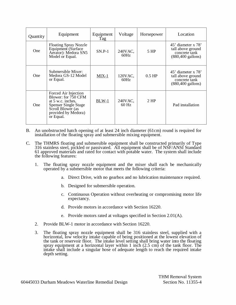
THM Removal System60445033 Durham Meadows Waterline Remedial Design Section No. 11355-4
Quantity Equipment EquipmentTag
Voltage Horsepower Location
OneFloating Spray NozzleEquipment (SurfaceAerator): Medora SN5Model or Equal.
SN.P-1 240VAC,60Hz
5 HP45’ diameter x 78’tall above ground
concrete tank(880,400 gallons)
OneSubmersible Mixer:Medora GS-12 Modelor Equal.
MIX-1 120VAC,60Hz
0.5 HP45’ diameter x 78’tall above ground
concrete tank(880,400 gallons)
One
Forced Air InjectionBlower: for 750 CFMat 5 w.c. inches,Spenser Single StageScroll Blower (asprovided by Medora)or Equal.
BLW-1 240VAC,60 Hz
2 HPPad installation
B. An unobstructed hatch opening of at least 24 inch diameter (61cm) round is required forinstallation of the floating spray and submersible mixing equipment.
C. The THMRS floating and submersible equipment shall be constructed primarily of Type316 stainless steel, pickled or passivated. All equipment shall be of NSF/ANSI Standard61 approved materials and rated for contact with potable water. The system shall includethe following features:
1. The floating spray nozzle equipment and the mixer shall each be mechanicallyoperated by a submersible motor that meets the following criteria:
a. Direct Drive, with no gearbox and no lubrication maintenance required.
b. Designed for submersible operation.
c. Continuous Operation without overheating or compromising motor lifeexpectancy.
d. Provide motors in accordance with Section 16220.
e. Provide motors rated at voltages specified in Section 2.01(A).
2. Provide BLW-1 motor in accordance with Section 16220.
3. The floating spray nozzle equipment shall be 316 stainless steel, supplied with ahorizontal, low velocity intake capable of being positioned at the lowest elevation ofthe tank or reservoir floor. The intake level setting shall bring water into the floatingspray equipment at a horizontal layer within 1 inch (2.5 cm) of the tank floor. Theintake shall include a singular hose of adequate length to reach the required intakedepth setting.
THM Removal System60445033 Durham Meadows Waterline Remedial Design Section No. 11355-5
4. The floating spray equipment shall be equipped with a nozzle assembly sizedspecifically for the pump capacity output. Constructed of 316 stainless steel foroptimal corrosion resistance and long wear life.
5. Forced Air Injection: The THMRS shall be provided with one turbine blower withTEFC motor capable of 750 CFM flow, CE, UL listed and CSA certified motor withNEMA Class F insulation. Blower to be mounted on type 316 stainless steel baseand skid frame, adaptable to mounting on concrete pad next to the tank, as shown onthe drawings, sized according to the blower manufacturer’s recommendations.Appropriate ducting to connect the blower to the top of the tank shall be supplied bythe general contractor as directed by the THMRS supplier.
D. Maintenance Requirements. The THMRS equipment shall operate normally with thefollowing maintenance features.
1. No scheduled lubrication is required of any system components including motor.
2. No spare parts shall be required to be kept on hand.
2.02 CONTROL SYSTEM:
A. Provide BLW-1, MIX-1, and SN.P-1 each with a local control panel as specified andindicated.
1. Enclosure: NEMA 1.
2. Provide UL 508A listed control panels and components.
3. Provide enclosure with main circuit breakers, motor starters, reset buttons, fusedcontrol circuit transformer, relays, switches, contacts, indicating and alarm lights andall necessary appurtenances, completely factory wired to provide a coordinated andoperating set of controls.
4. Provide magnetic motor starters with overload protection and manual reset.
5. Red running lights, green off/ready lights, and amber lights for alarms.
6. RUN-OFF-AUTO selector switches.
7. Run time meters.
8. Provide dry alarm contacts for remote indication of the following:
a. Not In Auto
b. Fault
c. Running
9. Provide terminal board for all external circuits.
10. Operation:
a. In AUTO the equipment shall operate continuously.

THM Removal System60445033 Durham Meadows Waterline Remedial Design Section No. 11355-6
b. Provide shutdown of equipment on fault detection.
2.03 ACOUSTICAL BLOWER ENCLOSURE
A. Provide sound attenuated and weather-proof outdoor enclosure.
1. Rigidity wind test equal to 150 mph.
2. Roof load equal to 50 psf.
3. Rain test equal to 5 in. per hr.
4. Certified to meet Uniform Building Code.
B. Building to consist of roof, two (2) side walls, and two (2) end walls of prepainted steelstressed-skin construction, door and door frame, lifting rings, mounting frame, insulation,electrical package, louvers, exhaust fan, intake filter mounting bracket, and otherappurtenances to make complete installation. Enclosure to be coordinated with blowermanufacturer/supplier to include:
1. Roof:
a. One piece roof sheet, min. 0.040 in. thick steel alloy, with extrudedrecessed side and end rails.
b. Roof bows, extruded "I" beams, spaced as required to carry loads.
2. Walls:
a. Posts to be extruded steel sections, sized and spaced as required to carryloads.
b. Panels to be min. 0.045 in. thick steel sheet, mill-prepainted, inside andoutside, and riveted to posts.
3. Panel Frame:
a. Provide welded frame of extruded alloy, riveted to side panels.
b. Provide removable maintenance panels to form weathertight seal, withstainless steel locks.
c. All panels, doors and other openings shall be tight fitting to prevent entryof mice or other rodents.
4. Mounting Frame:
a. Provide steel perimeter mounting frame for mounting onto concrete pad.
5. Insulation:
a. Provide semi-rigid fiberglass (thermoacoustic) insulation.

THM Removal System60445033 Durham Meadows Waterline Remedial Design Section No. 11355-7
b. Provide sound attenuation for a 25 dBA noise reduction from the interior tothe exterior of the enclosure.
6. Louvers:
a. Provide louvers and dampers for ventilation air. Provide insect screens.
b. Fixed louvers, all aluminum construction, riveted into aluminized steelframe to form rigid, water resistant assembly. Motorized dampers asspecified hereinafter.
c. Properly size louvers and dampers to allow sufficient ventilation air withmaximum 0.5 in. water restriction. Coordinate with fan manufacturer.
7. Intake Air Filter Mounting Bracket:
a. Provide suitable bracket to secure fan inlet air filter on the exterior of theenclosure.
b. Coordinate with fan manufacturer as required.
C. Access:
1. Large cable entry area for installation ease.
2. Panels located convenient to controls and service areas.
3. Double panels on both sides.
4. Vertically hinged doors allow 180º opening rotation.
5. Drains piped to exterior of enclosure and terminated with drain valves.
6. “Lift-off” hinges allow doors to be removed if required.
D. Security and Safety:
1. Lockable access doors with keys.
2. Roof outlet for fan intake filter.
3. Stub-up cover sheets for rodent proofing.
E. Transportability:
1. Lifting points on base frame.
2. Optional tested and certified single point lifting facility.

THM Removal System60445033 Durham Meadows Waterline Remedial Design Section No. 11355-8
PART 3 – EXECUTION
3.01 INSTALLATION
A. The CONTRACTOR shall furnish services of a factory-trained installer or crew havingexperience with installation procedures as well as operation and maintenancerequirements for the type of equipment installed under these specifications. Equipmentmust be able to be installed through a 48x48 inch hatch.
1. The THMR floating spray equipment manufacturer shall have capability to provideInstallation, Startup, and On-Site Water Testing Services to insure (a) properequipment spatial placement in the reservoir, and (b) proper pump placement andfloating spray discharge setting.
2. The field services shall be performed by full time factory employees experienced inthe operation of this equipment, and who have completed safety trainings requiredfor this type of installation in compliance with OSHA regulations including (a)Working over Water, (b) Boating Safety, (c) Disinfecting Procedures, (d) ConfinedSpace Entry, (e) Fall Protection, (f) Self Rescue, and (g) DOT Compliance.
3. Within 30 days following installation, the manufacturer shall provide an installationreport detailing as described in submittal section.
4. The THMR floating spray equipment manufacturer shall provide the followingsupport services to the Contracting Officer under this Contract:
a. A minimum of eight two-member factory crew service hours.
b. Customer service staff shall include engineers and science personnel that aretrained for assistance in this application.
B. The Tank Supplier shall perform tank penetrations and securing any materials to the tank.
1. Cables will be run through a conduit which will be secured to the outside of the tank.
C. Tank penetrations shall conform to the following:
1. Fittings shall be water tight.
2. Fittings shall be sufficient in diameter to allow cable to pass through.
3. Strain relief for power cables shall be part of the CONTRACTOR-supplied fittings.
4. Coating around tank penetrations shall be recoated to match existing coating in bothmaterial and color on both the dry side and wet side of each tank.
5. Tank penetration will be performed adjacent to the hatch on the dome of the tank.
D. Installation of wet-side components shall be performed by experienced installationpersonnel with confined space training while the tank is full, but isolated from thesystem.
E. Before being placed back into service tank shall be chlorinated and tested in accordancewith the provisions of SECTION 13225, PRESTRESSED CONCRETE TANKS. The

THM Removal System60445033 Durham Meadows Waterline Remedial Design Section No. 11355-9
CONTRACTOR shall clean the floor of the tank and interior area of the tank wall wherethe penetration occurs as need for proper installation.
3.02 TRAINING
A. The THM Removal System manufacturer staff or their representatives will provideinstruction on the safe and proper operation of the mixer to CONTRACTING OFFICER.This training will reference the operations manual provided with equipment, and showhow to check the equipment to ensure it is operating properly. Training shall take placeat the time of installation. As part of this training, the manufacturer shall instruct theCONTRACTING OFFICER to the optimal speed of mixer operation for mixing.
END OF SECTION
Gas Engine (Less than 100kW) – Generator Set and AppurtenancesDurham Meadows Waterline RD Section No. 11397-1
SECTION 11397
GAS ENGINE (LESS THAN 100KW) - GENERATOR SETAND APPURTENANCES
PART 1 - GENERAL
1.01 SCOPE OF WORK:
A. Furnish, place in operation, and field test standby natural gas engine driven generator set,EPA Compliant, complete with enclosure, instrumentation and controls, and requiredsupporting systems as specified herein. The unit shall be provided in an outdoor, weatherproof, non walk-in, sound attenuated with sub base enclosure.
B. The unit shall have a minimum standby power rating as indicated on the contractdrawings at 80 percent lagging power factor with three-phase, 60-Hertz, 480 volt, four-wire, alternating current generator.
C. The unit shall be arranged for automatic starting and stopping, and load transfer uponfailure of the normal source of power through an automatic transfer system. The enginegenerator set shall exhibit less than 20% voltage dip and less than 5% frequency dipduring starting of the loads identified in Attachment A to this Section.
D. The engine-generator package shall be complete in all respects and shall include allequipment and controls necessary for a fully operational standby power supply system.
1.02 RELATED WORK:
A. Division 1: General Requirements
B. Section 01784: Field Inspection and Acceptance Tests
C. Division 13: Utility Control and Instrumentation\
D. Division 15: Mechanical
E. Division 16: Electrical Work
1.03 REFERENCES
A. American Gear Manufacturers Association (AGMA)
B. American Institute of Steel Construction (AISC)C. American Iron and Steel Institute (AISI)
D. American Society of Mechanical Engineers (ASME)
E. American National Standards Institute (ANSI)
F. American Society for Testing Materials (ASTM)
G. American Welding Society (AWS)
H. American Bearing Manufacturers Association (ABMA)
I. Institute of Electrical and Electronic Engineers (IEEE)
J. National Electrical Code (NEC)

Gas Engine (Less than 100kW) – Generator Set and AppurtenancesDurham Meadows Waterline RD Section No. 11397-2
K. National Electrical Manufacturers Association (NEMA)
L. Occupational Safety and Health Administration (OSHA)
M. Steel Structures Painting Council (SSPC)
N. Underwriters Laboratories, Inc. (UL)
O. National Fire Protection Association (NFPA)
1.04 SEISMIC REQUIREMENTS:
A. Contractor shall conform to the seismic requirements as indicated and as specified inStructural Drawing S-001.
1.05 DESIGN REQUIREMENTS:
A. Design Considerations:
1. Provide an EPA emissions standby certified generator and in compliance withConnecticut emissions regulations and standards.
2. Furnish to the Contracting Officer, within 15 working days of the date of anyrequest, all documents and other information required to verify compliance withpermit and applicable air pollution control laws and regulations, including EPAemission requirements in effect at the bid date of the project.
1.06 SUBMITTALS:
A. Shop Drawings:
1. A copy of this specification section with addenda and all referenced specificationsections with addenda, with each paragraph check-marked to indicatespecification compliance.a. Failure to include a copy of the marked-up specification sections will
result in rejection of the entire submittal without further review andconsideration until the marked-up specification are resubmitted with theentire package.
2. Outline equipment drawings, equipment catalog cuts, internal wiring and ladderdiagram schematics and other documents required to completely describe thesystems and equipment being furnished. Elevation drawings with shipping splitsand estimated weights identified.
3. Identification, description and dimensions.
4. Dimensional engine-generator skid base drawings, indicating size and location ofanchor bolts, and conduit locations.
5. Performance specifications of all items of equipment.
6. Control panel layout drawings, dimensions, and component bill of materials.Outline drawings showing conduit entry areas and anchoring information.Description of control including operation of interface equipment.
Gas Engine (Less than 100kW) – Generator Set and AppurtenancesDurham Meadows Waterline RD Section No. 11397-3
7. Complete electrical, instrumentation, control and wiring diagrams in sufficientdetail to allow installation of instrumentation and controls and electricalcomponents.
8. Provide certificate of conformance to UL Standard 2200, Stationary EngineGenerator Assemblies.
9. Attenuation curve for the silencing equipment as offered to accomplish therequired silencing for this installation.
10. Information on the proposed jacket water treatment and procedures for flushing ofthe cooling systems.
11. Submit generator load calculation confirming compliance with specified enginecapacity and operating parameters when operating loads provided in AttachmentA of this Section based on rated kW specified.
12. Operations and Maintenance Manuals, covering all equipment furnished,annotated to reference only the specific model numbers supplied. Include partslists and parts prices current to the date of submittal; include information relevantto part supply and ordering. Submit prior to the startup and testing of theengine/generator units.
13. Time-current characteristic curves for the generator circuit breaker.
14. Manufacturer's certified shop test record of complete engine driven generator unit.15. As-built drawings and material summary shall be shipped with the equipment.
16. Data to be provided by engine generator system supplier:
a. Submit the following manufacturer information:
(1) Engine Data
(a) Manufacturer
(b) Model
(c) Number and arrangement of cylinders
1) RPM
2) Bore X stroke
3) Maximum power at rated RPM4) BMEP at rated kW (including any parasitic loads
and generator efficiency)
5) Piston speed, feet per minute
6) Make and model of governor
7) Make and model of overspeed shutdown device
(d) Incoming Natural Gas Minimum Water Column (Pressure)Requirements.
Gas Engine (Less than 100kW) – Generator Set and AppurtenancesDurham Meadows Waterline RD Section No. 11397-4
(2) Generator Data
(a) Manufacturer
(b) Model
(c) Rated kVA
(d) Rated kW
(e) Voltage
(f) Temperature rise above 40 degrees C ambient. Stator bythermometer and field by resistance in degrees C.
(g) Class of insulation
(h) Generator efficiency including excitation losses at 80percent PF
1) Full load
2) Three quarters load
3) Half load
(i) Generator subtransient reactance in ohms
(3) Generator unit and accessories
(a) Weight of unit
(4) Exhaust gas emissions data, maximum values at full load, 3/4 load,1/2 load, and 1/4 load:
(5) Combustion air volume in CFM
(6) Cold cranking amperes rating of engine starting batteries (CCA).
17. Provide manufacturer's printed installation instructions including anchoringdetails to meet earthquake requirements as specified and indicated.
18. Performance Test Reports: Upon completion of installed system, submit inbooklet form all field tests performed to prove compliance with specifiedperformance criteria including final settings of devices.
19. Certificate of Delegated Design Services in accordance with Section 01300.1.07 QUALITY ASSURANCE:
A. Contractor to ensure that conduit size and wire quatity, size, and type are suitable for theequipment supplied. Contractor to review the proper installation of the equipment and ofeach type of device with the equipment supplier prior to installation.
B. The engine-generator set shall be factory designed, certified prototype tested, and asspecified. The manufacturer shall be regularly engaged in the production of this type ofequipment and shall maintain a permanent service organization and supply of spare parts,of the types utilized for the equipment specified herein.

Gas Engine (Less than 100kW) – Generator Set and AppurtenancesDurham Meadows Waterline RD Section No. 11397-5
C. The manufacturer shall have testing facilities for performing the shop tests andinspections specified herein.
D. The enclosure shall be professionally designed and engineered to meet the seismicrequirements specified and all the building code requirements for the state in which thebuilding is to be located.
E. Provide services of Service Technician, specifically trained on type of equipmentspecified. Person-day requirements are listed exclusive of travel time:
1. Assist in location of devices, methods of mounting, field erection, inspection priorto energizing the equipment, etc.a. 1 person-day
2. Start-up and testing.
a. 2 person-days
3. Person-day is defined as one 8-hour day, excluding travel time.
4. The manufacturer shall certify that equipment has been inspected and is ready tobe placed into service.
1.08 UNIT PERFORMANCE:
A. The units shall be utilized to provide standby power service in the event the normalsource is not available.
B. The voltage regulation shall be within plus or minus one percent from zero load to full-rated load. Upon application or removal of full-rated load in one step, the transientvoltage dip and recovery to steady state operation shall be within five seconds.
C. Stable or steady state operation is defined as operation with the frequency variation notexceeding plus or minus 0.25 percent (0.15 Hertz) and voltage variation plus or minusone percent of their mean value for constant load from zero load to full rated load. Arheostat shall provide plus or minus five percent voltage adjustment from rated voltage.
1.09 REGULATORY REQUIREMENTS:
A. All applicable Federal Laws and Regulations.
B. State of Connecticut applicable Local Codes and Standards.C. Furnish all documents and other information which the CT Department of the
Environment requests to determine compliance with applicable Air Quality Control Lawsand Regulations.
D. Stack Heights: Exhaust stacks shall be configured to discharge the combustion gasesvertically and shall not be equipped with any part or device that restricts the verticalexhaust flow of the emitted combustion gases, including but not limited to rain protectiondevices such as “shanty caps” and “egg beaters”.
1.10 WARANTY AND SERVICE:
A. Provide in accordance with Section 01740.

Gas Engine (Less than 100kW) – Generator Set and AppurtenancesDurham Meadows Waterline RD Section No. 11397-6
B. Guarantee all components, parts, and assemblies supplied by manufacturer againstdefects in materials and workmanship for a minimum period of 24 months.
C. Ensure that equipment manufacturer has local branch office staff with trained, full-timeemployees who are capable of performing testing, inspecting, repair, and maintenanceservices.
1.11 ACCEPTABLE MANUFACTURERS:
A. KohlerB. Cummins
C. Or equal.
1.12 DELIVERY, STORAGE AND HANDLING:
A. Provide in accordance with Specification Section 01610.
PART 2 - PRODUCTS
2.01 GENERAL:
A. Engine-generator set shall be a factory-assembled unit. The engine and generator shall bedirectly connected with a flexible coupling, shall be free from injurious torsional or othervibration and shall be mounted on a heavy steel sub-base.
B. The engine and generator shall be directly connected and shall operate at the samerotative speed. The use of gearing or other speed adjustment between the engine and thegenerator, such that the engine and generator operate at different rotative speeds will notbe allowed.
C. The engine-generator set shall allow easy access to the various parts for maintenancepurposes.
D. The engine-generator set shall be pre-piped and pre-wired.
E. The complete engine-generator unit shall be free from harmful torsional or othervibration throughout the entire operating range of speed and load. The enginemanufacturer shall provide, an analysis of the complete engine-generator unit, whichshall show where any critical speed will be encountered, together with the order, thefrequency and magnitude of any critical speed.
2.02 GASEOUS ENGINE:
A. Heavy-duty spark ignition type, arranged for direct connection to an alternating currentgenerator. It shall be a current model of a type in regular production by a manufacturerregularly engaged in building this type of gas engine. Engine shall have at least apublished intermittent brake horsepower rating at specified generator speed required bythe generator at rated full load output and shall operate without undue heating, vibration,or wear.
B. Engine shall be four cycle and naturally aspirated.
Gas Engine (Less than 100kW) – Generator Set and AppurtenancesDurham Meadows Waterline RD Section No. 11397-7
2.03 GASEOUS FUEL SYSTEM:
A. The gaseous fuel system shall consist of gas pressure regulators and carburetors. Thecarburetor shall be a diaphragm type which includes a load screw for air fuel rationadjustment, and throttle body to control the air-fuel mixture to the engine.
B. Fuel system shall include an electrically operated shutoff valve, in the supply lineenergized form battery circuit, that closes when engine shuts down.
2.04 GOVERNOR:A. Provide isochronous solid state governor, capable of maintaining isochronous regulation
from no load to full rated load within 0.25 percent of rated frequency.
B. The governor controller shall be mounted within the generator control panel. Thegovernor shall have the capability for manual adjustment of speed setting and speeddroop. Speed droop shall be adjustable from 0 to 5 percent from no load to full load.The controller shall eliminate all electromagnetic interference.
C. Provide a separate overspeed shutdown device which shall, in case of predeterminedoverspeed of the operation of various protective devices as later specified, instantly stopthe engine without the fuel injection system losing its prime.
2.05 GENERATOR AND EXCITATION SYSTEM:A. The generator shall be drip-proof, guarded, and be able to connect to the specified engine
output and shall be 3-phase, 60-Hertz, 4-wire, 480 volt operation, "WYE" connected.The generator shall be mechanically and torsionally matched to the engine driver andshall be provided to withstand inherent pulsating torques of the engine. Full loadefficiency of the combined generator, exciter and regulator shall be not less than 95percent.
B. The generator shall conform to the applicable parts of the following standards, unlessotherwise specified:
1. NEMA MG1, Motors and Generators
2. IEEE 43, Recommended Practice for Insulation Testing of Large AC RotatingMachinery
3. CSA C22.2-100 Designation ABL3
4. Testing shall be in accordance with IEEE-115 and NEMA MG-1 standards
C. The generator windings, insulation and excitation system shall be braced to withstand anypossible short-circuit stresses.
D. The temperature rise of the generator windings, when operated at rated prime power loadand under continuous duty conditions with cooling air inlet temperature of 40 degrees C,shall not exceed 130 degrees C when measured by the resistance method.
E. The stator frame shall be fabricated bar and plate steel construction.
1. All insulation materials used in the stator shall have a temperature rating of ClassH per IEEE Standard 1. The coils shall be of a formed coil construction using amagnet wire meeting NEMA MW36-C specifications.
Gas Engine (Less than 100kW) – Generator Set and AppurtenancesDurham Meadows Waterline RD Section No. 11397-8
2. The complete stator shall be wound with a 2/3 stator winding pitch and processedin a vacuum pressure impregnation chamber. Encapsulation of the stator shall beaccomplished with a two-part epoxy system.
F. The rotor shall be of the fully laminated, salient pole type. Cooling fans shall be anintegral part of the rotor assembly. The rotor shall be dynamically balanced for all speedsup to 125 percent of rated speed per NEMA specification.
1. Insulation materials used on the rotor shall have a temperature rating of Class H.The poles shall be of a layer wound construction using a magnet wire meetingNEMA MW35-C or MW36-C specifications.
2. The complete winding and rotor pole assembly shall be in a vacuum pressureimpregnation chamber. Encapsulation of the assembly shall be accomplishedwith a thixotropic, single component epoxy resin.
G. The exciter shall be a high frequency, direct connected, rotating brushless type, threephase, full wave rectified, and shall be matched with the generator rotor and controlsystem. Both the armature and field windings shall be a vacuum pressure impregnatedwith epoxy resin.
H. The pilot exciter shall be permanent magnet generator type. The stator winding shall bevacuum pressure impregnated with epoxy resin. The permanent magnet generator shallhave the ability to provide a nominal 300 percent of the 130 degrees C rise rated three-phase short circuit for ten seconds at the alternator terminals.
I. The digital voltage regulator shall be hermetically sealed, silicon controlled rectifier typeand shall employ a zener reference and three phase sensing. The voltage regulator shallprovide automatic protection of the entire unit on 3 phase short-circuits. The voltageregulator shall include automatic over-excitation and under-frequency protection. Inputisolation transformers and filters shall be provided. Exciter shall be fast response typewith a rotating rectifier and surge suppresser, 3-phase, full-wave bridge.
J. The voltage regulator and associated equipment shall be mounted in the generatorterminal box. Manual voltage adjustment potentiometer shall be mounted in theGenerator Control Panel.
K. Generator stator leads shall be connected to tinned copper bus bars in an oversizeterminal box. The box shall allow bottom entry of cables and conduits shown on thecontract drawings.
2.06 ENGINE GENERATOR SET ENCLOSURE:
A. Provide weatherproof, sound attenuated, factory installed enclosure with internallymounted silencer.
B. Features:
1. Corrosion Resistant Constructiona. Black zinc die cast hinges to withstand extreme conditions of corrosion.
b. Stainless steel fasteners.
Gas Engine (Less than 100kW) – Generator Set and AppurtenancesDurham Meadows Waterline RD Section No. 11397-9
c. Body made from aluminum components treated with polyester powdercoating.
C. Access:
1. Large cable entry area for installation ease.
2. Doors located convenient to controls and service areas.
3. Double doors on both sides.
4. Vertically hinged doors allow 180 degree opening rotation.
5. Lube oil and coolant drains piped to exterior of enclosure and terminated withdrain valves.
6. Radiator fill on outside of enclosure.
7. “Lift-off” hinges allow doors to be removed if required.
D. Security and Safety:
1. Lockable access doors with keys.
2. Cooling fan and battery charging alternator fully guarded.
3. Exhaust silencing system totally enclosed for operator safety.
4. Roof outlet exhaust with sealed roof aperture and rain-cap.
5. Stub-up cover sheets for rodent proofing.
E. Transportability:
1. Lifting points on baseframe.2. Optional tested and certified single point lifting facility.
F. Sound Attenuation:
1. Provide Level 2 sound attenuation for a 25 dBA noise reduction up to 23 feet (7m) from the enclosure.
G. Options:
1. Panel Viewing Window.
2. CSB2 External Emergency stop push button (red) mounted flush on exteriorenclosure wall.
3. Junction box for all 120 volt and 208 volt circuits to power:
a. Battery pad heater.
b. Jacket water heater.
c. Battery charger.d. Generator stator heater.
2.07 SYSTEMS:
A. General:

Gas Engine (Less than 100kW) – Generator Set and AppurtenancesDurham Meadows Waterline RD Section No. 11397-10
1. The Contractor shall comply with the generator manufacturer’s requirement forinstallation of systems and components.
B. Electric (Battery) Starting System:
1. Starting shall be accomplished by a 24-volt, engine mounted, solenoid shiftelectric starter, capable of withstanding four consecutive continuous crankingperiods of 15 seconds duration each separated by 15 seconds rest periods beforeshutting down completely and sounding the overcrank alarm.
2. The starting batteries shall be low maintenance, premium industrial grade, high-output, long-life, lead acid type especially designed for diesel engine crankingservice, and of a capacity as recommended by the battery manufacturer forcranking the engine being furnished. The engine starting batteries shall be sizedto also supply power to the generator control panel.
3. Furnish an engine starting battery charger for charging the starting batteries forthe engine. The battery charger shall be U.L. listed, fully automatic, filtered,equalize and float-type, appropriate for wall or rack mounting. Supply voltageshall be 120 volts, AC, single phase, 60 Hz obtained from the generator electricalpackage. The DC output shall be not less than 20 amperes, regulated to withinone percent with plus or minus ten percent fluctuations of the input voltage, andshall be current limited at 120 percent of rated output. Accessories shall includeDC ammeter and voltmeter (panel type; 2 percent accuracy), adjustable float andequalize controls toggle switch, AC and DC circuit breakers, AC power failurealarm relay, low DC voltage alarm relay and DC ground fault relay. Fault relaysshall operate individual alarm indicators on the face of the charger panel and shallalso operate a common alarm relay for remote transmission of alarm. Chargershall have a continuous power rating sufficient to power all generator controldevices in both the standby mode and the running mode.
C. Lubrication System:1. The engine shall be provided with a full pressure lubricating oil system arranged
to lubricate and cool the pistons and distribute oil to all moving parts of theengine including the turbocharger bearings. The system shall include a full flowoil filter of the replaceable element type, an appropriately sized shell and tubetype oil cooler, and an automatic temperature regulator.
2. Furnish a low oil level float switch to alarm to the generator control panel.
D. Engine Cooling System Radiator:
1. General: Provide a unit mounted radiator complete with integral jacket watercirculating pump, thermostatic central of cooling system, fan and drive motorsized to maintain full load operation continuously as specified herein for engine-generator set.
2. Provide radiator to operate engine at full rated generator load at 104 F ambienttemperature.
Gas Engine (Less than 100kW) – Generator Set and AppurtenancesDurham Meadows Waterline RD Section No. 11397-11
3. Provide jacket water treatment for the prevention of both scale formation andcorrosion in the engine water jackets and cooling system components which are incontact with the engine jacket water. This treatment shall be added to the coolingsystem prior to running the field acceptance test
E. Miscellaneous Equipment and Requirements:
1. Heaters:
a. Automatic thermostatically controlled heater(s), shall be provided tomaintain not less than 90º F temperature for the engine jacket watersystem.
b. Heater shall be automatically deactivated when the engine-generator unitis in operation.
2. Emergency Stop Pushbuttons:
a. Furnish an emergency stop pushbutton external to the engine controlpanel. Provide a second emergency stop button, “push to stop”, forremote operation from the Talcott Ridge Booster Station. The emergencystop button shall be maintained type, red colored, push to stop, mushroomtype with a hinged plastic Lexan cover, labeled as "Emergency Stop,""Push." Each pushbutton shall be wired to the engine-generatorinstrument/control panel and shall immediately stop the engine.
3. Control Power Fuses:
a. Fuses shall be mounted in locations where they are accessible. Pullouttype fuses shall be provided.
4. Main Circuit Breaker
a. Provide generator with a service entrance rated, 65 KAIC rated, moldedcase circuit breaker to protect generator against overload and short circuitconditions. Circuit breaker position shall be located such that it can beviewed through generator enclosure viewing window. Circuit breaker shallconform to the provisions of NEMA Standard AB1 and UL Standard 489.
b. Provide circuit breaker with microprocessor-based rms sensing adjustabletrip unit, rating plug, long-time, short-time and instantaneous protectiverelaying and ground fault protection. Provide arc reduction switch (ARS)where indicated.
5. Terminal Blocks:
a. Terminal blocks shall be one-piece, 20 AMP rated, with barriersappropriate for ring tongue terminals and provided with binding headscrews. The terminal block rating shall be 600 V.
Gas Engine (Less than 100kW) – Generator Set and AppurtenancesDurham Meadows Waterline RD Section No. 11397-12
6. Solid State Circuitry:
a. Heavy-duty solid state controls, relays, timers or monitors shall meet thefollowing specifications:
Accuracy: + 2% of set pointTemp Range: - 40 C to +65 C
(-40 F to 150 F)Protection: Transient overvoltage withstand of 1500
volts peak, 1 m sec. time constantRatings: Current ratings to exceed application of
devices. Devices shall be UL listed.
2.08 SYSTEM OPERATING SEQUENCE:
A. The engine generator unit shall be operated in the following manner:
1. The engine generator unit shall be arranged for automatic or manual starting andstopping.
2. The engine generator shall be brought up to rated voltage and frequency andclosed onto the facility main panelboard DP-1.
B. Normal – system utility powered:
1. During normal system operation, the utility source shall power the electricaldistribution system with loads as indicated.
C. Loss of utility power - standby operation:
1. Upon loss of utility power, automatic transfer switch ATS -1 shall sense loss ofpower and after an adjustable time delay the automatic transfer system shallinitiate generator start.
2. When the generator is up to speed and capable of accepting load, loads indicatedin Attachment A will be transferred to generator power.
3. Upon return of utility power, automatic transfer switch ATS-1 shall initiatetransfer back to the utility after an adjustable time delay
4. After an adjustable cool-down period, the engine-generator shall shutdown.
2.09 ENGINE CONTROL PANEL:
A. The engine starting control logic shall be microprocessor based and shall automaticallystart, protect and monitor the engine-generator set. Electro-mechanical controls areunacceptable.
B. The following gauges shall be mounted within an engine mounted control panel. Gaugesshall be digital:
1. Jacket water temperature cooler temperature into heat exchanger
2. Lube oil temperature
3. Lube oil pressure

Gas Engine (Less than 100kW) – Generator Set and AppurtenancesDurham Meadows Waterline RD Section No. 11397-13
4. Lube oil filter differential pressure.
C. An engine coolant level switch shall be furnished. Level switch shall shut downgenerator on low level.
D. The engine starting control logic shall be capable of controlling the following enginedevices.
1. Starting motor magnetic switch.
2. Electrically operated fuel control.
3. Normally open protective switches that close for abnormal conditions of pressure,temperature, speed and liquid level.
E. The panel shall have the following controls:
1. Emergency stop
2. Lamp test
3. Cycle crank
4. Voltage control
5. Cool-down timer
6. Phase selector switch
7. Programmable relays 4 (std)8. Stop/Auto/Test.
F. The panel shall be provided with the following indicating lights:
1. Low oil pressure
2. High coolant temperature
3. Over speed
4. Over crank
5. Emergency stop
6. Fault shutdown
7. 3 spare lights, programmable input.
8. Not in Auto9. Low Gas Pressure
G. Protection shall include:
1. Over and under voltage
2. Over and under frequency
3. Low coolant level
4. Oil temperature.

Gas Engine (Less than 100kW) – Generator Set and AppurtenancesDurham Meadows Waterline RD Section No. 11397-14
H. Provide contacts to alarm the following functions:
1. Low oil pressure
2. Low Gas Pressure
3. Battery malfunction
4. Low battery voltage
5. Common fault alarm
6. Not in automatic7. In exerciser mode
8. E-stop activated
9. Generator run status
10. Low coolant level
I. Provide control system with programmable generator unit exerciser.
J. Engine Start/Stop Operation: The automatic engine control logic shall initiate operationof the engine upon receipt of a signal from a 120VAC dry-contact at ATS-1 automatictransfer switch. The contact(s) shall close for engine run and open for engine stop.
K. If the engine fails to start after 4 adjustable cranking attempts (factory set at 10 secondson, 10 seconds off, adjustable from 5 to 30 seconds) or if any protective device shouldoperate while the engine is running, the engine shall be disconnected from service andimmediately stopped. The engine control logic shall lock the failed set out of service andrequires a manual reset. The engine control logic shall include a provision for conversionto single cycle cranking, adjustable from 35 to 210 seconds.
L. Three-position engine control switch:
1. Stop/Reset: In this position, the engine shall not be capable of starting and/orrunning. If the engine was shutdown due to the operation of a protective device,the shutdown malfunction shall be reset when the switch is moved to this position.If the engine is running when the switch is moved to this position, it shall beimmediately shutdown.
2. Automatic: In this position, the engine control shall be in readiness for fullyautomatic operation upon receipt of a start signal.
3. Test: When placed in this position, the engine shall start and run as if a startsignal were received except it shall not be connected to the bus unless a startsignal is received. When returned to the automatic position, the engine will shutdown.
2.10 SHOP PAINTING:
A. The engine-generator set shall be shop primed and factory finished coated in accordancewith the manufacturer's standard practice prior to shipment. A 24 oz. supply of touch-uppaint shall be supplied by the manufacturer.

Gas Engine (Less than 100kW) – Generator Set and AppurtenancesDurham Meadows Waterline RD Section No. 11397-15
2.11 SHOP TESTING:
A. The complete engine-generator set shall be shop tested to simulate a complete andintegrated system prior to shipment. Shop test shall utilize a reactive load bank tosimulate facility loads.
B. Provide all details of the proposed testing, including arrangements, test instruments andcalibration, and procedures to be used to verify controls and alarms. Four copies of thecomplete certified test record shall be submitted within 30 days after the completed test.
C. Tests shall assure that unit will operate successfully and meet all specified operationalrequirements.
D. The shop test shall include four continuous hours of operation at full load and varyingpower factor. Voltage and frequency regulation and transient response shall be tested andrecorded to show full compliance with this specification. During the shop test, readingsshall be taken and recorded every thirty minutes for each of the following:
1. Time
2. Ambient temperature
3. Volts for each phase
4. Load:
a. Amps for each phase
b. KW
c. Power factor
d. Frequency5. Engine jacket water temperature
6. Lubricating oil pressure
7. Exhaust gas temperature
8. Fuel consumption.
E. The procedure for the shop test of the gas engine shall cover the engine manufacturer’sstandard practice.
2.12 SPARE PARTS:
A. Provide a recommended spare parts list.B. Provide one year supply of all filter types installed.
PART 3 EXECUTION
3.01 COORDINATION:
A. Equipment personnel and services required for load and performance testing of theengines shall be provided by the engine-generator set supplier.

Gas Engine (Less than 100kW) – Generator Set and AppurtenancesDurham Meadows Waterline RD Section No. 11397-16
3.02 INSTALLATION:
A. The generator unit shall be installed as indicated and in accordance with the manufacturerinstructions.
B. Provide services of a qualified factory representative to inspect in detail the installation ofthe engine-generator units, and related auxiliary systems, prior to energizing anyequipment to confirm manufacturer’s recommended installation.
C. The generator unit shall be mounted on a concrete pad provided by the Contractor underthis contract.
D. The enclosure bottom shall be flashed or other means provided to prevent water entranceinto the unit.
3.03 EQUIPMENT START-UP:A. Operate the unit to demonstrate ability to operate continuously without vibration,
jamming, leaking or overheating and to perform specified functions, after installation andafter manufacturer's representative check of installed equipment.
B. Comply with manufacturer's operating and maintenance instructions during start-up andoperation.
C. Make all final adjustments necessary to place the equipment in working order. Prior toany testing or operation of the units, the manufacturer's service representative shallinspect the installation, and shall certify, in writing, that the assemblies are, in all ways,ready for operation. Start-up shall not commence without the presence of themanufacturer's representative.
3.04 FIELD TEST:
A. Provide testing as specified herein and in accordance with specification section 16998 –Field Inspection and Acceptance Tests.
B. Upon completion of the installation and as soon as conditions permit, the diesel enginedriven generator, including the engine, generator, electrical circuit controls, transfercontrols other devices shall be tested in the presence of the Contracting Officer by theContractor and the service representative for the manufacturer of the engine drivengenerator unit to assure that the system functions as specified.
1. Perform load bank tests with portable resistive load banks for a four-hour durationto verify loading and ratings. Take system data readings each 30 minutes.
2. Perform actual load test with the facility operating loads connected to the engine.Run the test for a duration of four hours.
3. During the test, system parameter readings, shall be taken and recorded at 30-minute intervals.
C. As part of the field test, each of the automatic shutdown devices shall be tested and therespective values recorded at which the devices will stop engine. Any adjustmentsrequired shall be made in the devices to make the operating values correspond to thoserecommended by the engine manufacturer and as recorded during the stop test.

Gas Engine (Less than 100kW) – Generator Set and AppurtenancesDurham Meadows Waterline RD Section No. 11397-17
D. Take and record octave band sound pressure level readings while the engine drivengenerator is operating using the station load. These readings shall be within the limitsidentified in the engine generator data submittals for acceptable sound revel.
3.05 CONTRACT CLOSEOUT:
A. Provide in accordance with Section 01700.
END OF SECTION

Gas Engine (Less than 100kW) – Generator Set and AppurtenancesDurham Meadows Waterline RD Section No. 11397-18
ATTACHMENT A
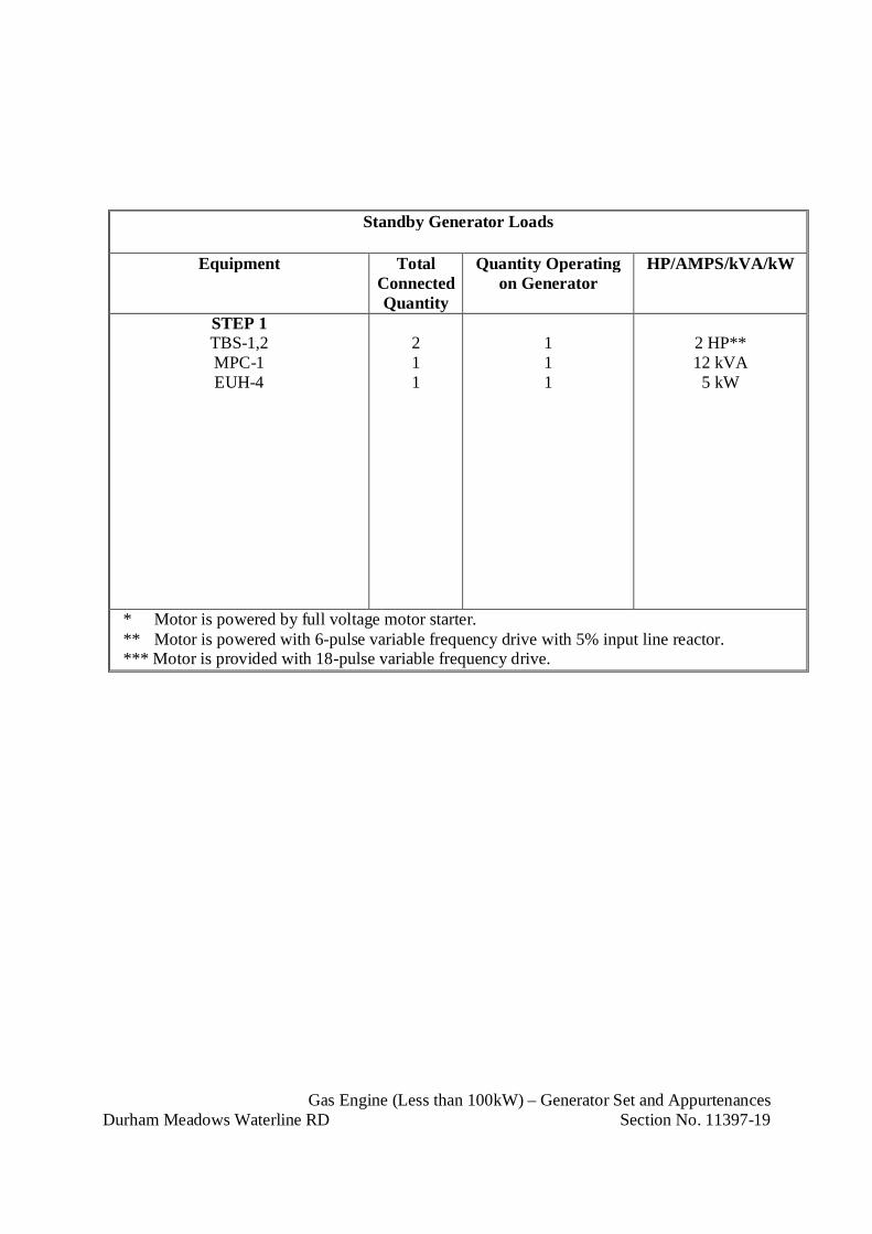
Gas Engine (Less than 100kW) – Generator Set and AppurtenancesDurham Meadows Waterline RD Section No. 11397-19
Standby Generator Loads
Equipment TotalConnectedQuantity
Quantity Operatingon Generator
HP/AMPS/kVA/kW
STEP 1TBS-1,2MPC-1EUH-4
211
111
2 HP**12 kVA5 kW
* Motor is powered by full voltage motor starter.** Motor is powered with 6-pulse variable frequency drive with 5% input line reactor.*** Motor is provided with 18-pulse variable frequency drive.
Prestressed Concrete TanksDurham Meadows Waterline RD Section No. 13225-1
SECTION 13225
PRESTRESSED CONCRETE TANKS
PART 1 - GENERAL
1.01 DESCRIPTION:
A. Design, construct, test, disinfect, and warrantee, Type III wire-wound, prestressedconcrete circular tank with steel diaphragm; cast-in-place reinforced concrete membranefloor; and precast or cast-in-place concrete roof in accordance with AWWA D-110 andas specified.
B. Excavate, grade, prepare subgrade for tank foundation, and backfill around completedtank structure and appurtenances.
C. Design, construct, test, and disinfect a hydrodynamic tank mixing system, supplementalrecirculation pump, accessories, and appurtenances. The complete hydrodynamicmixing system including the recirculation pump system shall be supplied by the variableorifice nozzle manufacturer to maintain a single source of responsibility for the system.
1.02 REFERENCES:
A. American Concrete Institute (ACI):
1. ACI 301: Specifications for Structural Concrete
2. ACI 350.1: Specification for Tightness Testing of Environmental EngineeringConcrete Containment Structures and Commentary
3. ACI 350.3: Seismic Design of Liquid-Containing Concrete Structures andCommentary
4. ACI 506R: Guide to Shotcrete
B. American Society of Civil Engineers (ASCE)
1. ASCE 7-16: Minimum Design Loads and Associated Criteria for Buildings andOther Structures
C. ASTM International (ASTM):
1. ASTM A185/A185M: Standard Specification for Steel Welded WireReinforcement, Plain, for Concrete
2. ASTM A312/A312M: Standard Specification for Seamless, Welded, and HeavilyCold Worked Austenitic Stainless Steel Pipes

Prestressed Concrete TanksDurham Meadows Waterline RD Section No. 13225-2
3. ASTM A351/A351M: Standard Specification for Castings, Austenitic, forPressure-Containing Parts
4. ASTM A416/A416M: Standard Specification for Low-Relaxation, Seven-WireSteel Strand for Prestressed Concrete
5. ASTM A475: Standard Specification for Zinc-Coated Steel Wire Strand
6. ASTM A536: Standard Specification for Ductile Iron Castings
7. ASTM A615/A615M: Standard Specification for Deformed and Plain Carbon-Steel Bars for Concrete Reinforcement
8. ASTM A821/A821M: Standard Specification for Steel Wire, Hard-Drawn forPrestressed Concrete Tanks
9. ASTM C33/C33M: Standard Specification for Concrete Aggregates
10. ASTM C94/C94M: Standard Specification for Ready-Mixed Concrete
11. ASTM C618: Standard Specification for Coal Fly Ash and Raw or CalcinedNatural Pozzolan for Use in Concrete
12. ASTM C920: Standard Specification for Elastomeric Joint Sealants
13. ASTM C1116/C1116M: Standard Specification for Fiber-Reinforced Concrete
14. ASTM D471: Standard Test Method for Rubber Property – Effect of Liquids
15. ASTM D698: Standard Test Methods for Laboratory Compaction Characteristicsof Soil Using Standard Effort (12,400 ft-lbf/ft3 (600 kN-m/m3))
16. ASTM D1056: Standard Specification for Flexible Cellular Materials – Sponge orExpanded Rubber
17. ASTM D1556/D1556M: Standard Test Method for Density and Unit Weight ofSoil in Place by Sand-Cone Method
18. ASTM D1557: Standard Test Methods for Laboratory Compaction Characteristicsof Soil Using Modified Effort (56,000 ft-lbf/ft3(2,700 kN-m/m3))
19. ASTM D6938: Standard Test Method for In-Place Density and Water Content ofSoil and Soil-Aggregate by Nuclear Methods (Shallow Depth)
20. ASTM F593: Standard Specification for Stainless Steel Bolts
21. ASTM F594: Standard Specification for Stainless Steel Nuts

Prestressed Concrete TanksDurham Meadows Waterline RD Section No. 13225-3
D. American Water Works Association (AWWA):
1. ANSI/AWWA C104/A21.4: Cement-Mortar Lining for Ductile-Iron Pipe andFittings
2. ANSI/AWWA C110/A21.10: Ductile-Iron and Gray-Iron Fittings for Water.
3. ANSI/AWWA C111/A21.11: Rubber-Gasket Joints for Ductile-Iron PressurePipe and Fittings
4. ANSI/AWWA C151/A21.51: Standard for Ductile-Iron Pipe, Centrifugally Cast,for Water
5. AWWA C651: Disinfecting Water Mains
6. AWWA C652: AWWA Standard for Disinfection of Water-Storage Facilities
7. AWWA D110: Wire- and Strand-Wound, Circular, Prestressed Concrete WaterTanks
E. NSF International (NSF)
1. NSF/ANSI 60, Drinking Water Treatment Chemicals – Health Effects
For sealants, coatings, and repair materials only.
2. NSF/ANSI 61, Drinking Water System Components – Health Effect
For sealants, coatings, and repair materials only.
F. Occupational Safety and Health Administration (OSHA)
1. OSHA 1910 Subpart D – Walking-Working Surfaces
G. State of Connecticut
1. 2016 Connecticut State Building Code
H. SSPC: The Society for Protective Coatings (SSPC)
1. SSPC-10: Near-White Metal Blast Cleaning
I. U.S. Army Corps of Engineers (COE):
1. CRD C572: Handbook for Concrete and Cement Corps of EngineersSpecifications for Polyvinylchloride Waterstop
Prestressed Concrete TanksDurham Meadows Waterline RD Section No. 13225-4
1.03 TANK DESIGN REQUIREMENTS:
A. Conform to latest applicable recommendations, codes, and standards cited inParagraph 1.02 and their latest amendments unless otherwise specified herein or shownon the drawings.
B. Minimum Loads: Use the following loads for tank design:
1. Dead load: Weight of all permanent construction, appurtenances, and fittings.
2. Internal fluid load: Weight of all water when tank is filled to overflowing.
3. Snow load: Minimum design load for snow shall conform to ASCE-7. The snowload need not be considered as acting concurrent with the live loads.
4. Live load: 40 pounds per square foot over entire roof of tank.
5. Backfill pressure: Earth loads determined by rational methods of soil mechanics.Backfill pressure shall not be used to reduce the amount of required prestressing.
6. Wind loads: Minimum design loads for wind shall conform to ASCE-7 and the2016 Connecticut State Building Code.
7. Seismic loads: Minimum design loads for earthquake shall conform to ASCE-7and to ACI 350.3.
8. Thermal differential loads: Provide for a minimum thermal differential of50 degrees Fahrenheit in design of tank elements.
9. Loads on platforms and walkways: 60 pounds per square foot.
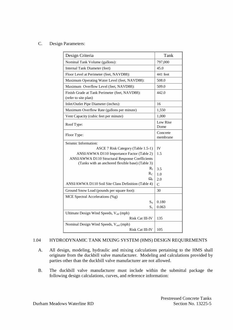
Prestressed Concrete TanksDurham Meadows Waterline RD Section No. 13225-5
C. Design Parameters:
Design Criteria TankNominal Tank Volume (gallons): 797,000Internal Tank Diameter (feet) 45.0Floor Level at Perimeter (feet, NAVD88): 441 feetMaximum Operating Water Level (feet, NAVD88): 508.0Maximum Overflow Level (feet, NAVD88): 509.0Finish Grade at Tank Perimeter (feet, NAVD88):(refer to site plan)
442.0
Inlet/Outlet Pipe Diameter (inches): 16Maximum Overflow Rate (gallons per minute) 1,550Vent Capacity (cubic feet per minute) 1,000
Roof Type: Low RiseDome
Floor Type: Concretemembrane
Seismic Information:ASCE 7 Risk Category (Table 1.5-1)
ANSI/AWWA D110 Importance Factor (Table 2)ANSI/AWWA D110 Structural Response Coefficients
(Tanks with an anchored flexible base) (Table 3)RI
RC
Ω0
ANSI/AWWA D110 Soil Site Class Definition (Table 4)
IV1.5
3.51.02.0C
Ground Snow Load (pounds per square foot): 30MCE Spectral Accelerations (%g)
SS
S1
0.1800.063
Ultimate Design Wind Speeds, Vult (mph)Risk Cat III-IV 135
Nominal Design Wind Speeds, Vasd (mph)Risk Cat III-IV 105
1.04 HYDRODYNAMIC TANK MIXING SYSTEM (HMS) DESIGN REQUIREMENTS
A. All design, modeling, hydraulic and mixing calculations pertaining to the HMS shalloriginate from the duckbill valve manufacturer. Modeling and calculations provided byparties other than the duckbill valve manufacturer are not allowed.
B. The duckbill valve manufacturer must include within the submittal package thefollowing design calculations, curves, and reference information:

Prestressed Concrete TanksDurham Meadows Waterline RD Section No. 13225-6
1. Calculations showing the fill time required, under isothermal conditions, for theHMS system to achieve complete mix of the reservoir volume at minimum,average and peak fill rates. Complete mixing defined as 95% homogenoussolution. The theory and equations used in calculating the mixing times must befrom a published AWWA reference manual or paper. The reference document(s)must be submitted with the equations and calculations.
2. Calculations showing the water level drawdown required to achieve completemixing on the fill cycles at minimum, average, and peak flow rates.
3. Calculations of average storage tank water age for both fill-then-draw, andsimultaneous fill and draw scenarios. Theory used in calculating water age mustbe submitted with the calculations.
4. A Computational Fluid Dynamics (CFD) model evaluation of the proposed HMSsystem configuration applied within the tank provided under this contract. Modeloutput documentation shall include all design variables applied for the simulation,plot of the 3-D geometry showing the mesh definition, velocity magnitude vectorand contour plots at different cross-sections throughout the water volume,simulated tracer animations showing the spatial and temporal distribution of inletwater in real time during the fill cycle.
5. Hydraulic calculations showing the resulting jet velocities of each inlet nozzle atminimum, average, and peak fill rates.
6. Hydraulic calculations showing the flow distribution among all inlet ports atminimum, average, and peak fill rates.
7. Manifold hydraulic calculations showing the total headloss of the HMS atminimum, average, and peak fill and draw rates. Headloss shall include all minorlosses and headloss of nozzles and outlet check valves.
8. Hydraulic curves showing thrust vs. flow for the inlet nozzles.
9. Hydraulic curves for each outlet check valves showing headloss vs. flow.
10. Calculations showing the terminal rise height of the jets that discharge at an angleabove horizontal. The terminal rise height shall be calculated assuming 10ºF and20ºF colder inlet water and calculated at minimum, average and peak fill rates.The theory and equations used to calculate the terminal rise height shall beincluded.
11. Hydraulic curves for each inlet nozzle of Densimetric Froude number vs. flow
12. If the calculations and supporting data provided do not show compliance with thehydrodynamic requirements of the system as interpreted by the ContractingOfficer then the submittal shall be rejected.
Prestressed Concrete TanksDurham Meadows Waterline RD Section No. 13225-7
13. Design and calculations shall be signed and sealed by a Professional Engineerholding current registration in the jurisdiction where the HMS is to be located
1.05 TANK SUBMITTALS:
A. Submit the following shop drawings and product data in accordance with Section 01300.
B. Shop Drawings: Signed and sealed by professional engineer licensed in the State ofConnecticut.
1. Submit certification signed and sealed by a Professional Structural Engineerholding current registration in the jurisdiction where the tank is to be locatedstating that the design conforms to the conditions specified and all applicablecodes and standards.
2. Include details of reinforcing steel, wire-wound prestressing, joint design, andconcrete mix design.
3. Include details of openings in wall diaphragm.
4. Include reinforcing steel identification marks for each bar.
5. Include precast concrete unit identification marks for each unit.
6. Submit horizontal and vertical loadings, overflow pipe connection details, anchorbolt sizes and locations, erection and settlement tolerances, maximum loadsimparted to the foundation and estimated weight of tank.
7. Show details for foundation, base and roof joint, wall construction andprestressing, overflow, piping connections, ladders, roof hatch, walkways andrailings, and other information as required by this and related specifications and asrequested by the engineer, including certified reports on the manufacture andtesting of prestressing wire and steel diaphragm.
C. Product Data: Submit manufacturer's product literature including catalog information,dimensions, materials, instructions for installation and use, and application rates for:
1. Waterstops.
2. Joint Filler.
3. Bond Breaker.
4. Curing Compound.
5. Coatings.
6. Vibration Equipment.

Prestressed Concrete TanksDurham Meadows Waterline RD Section No. 13225-8
7. Bearing Pads.
8. Joint Sealant.
9. Roof Hatch.
10. Roof Ventilator.
11. Ladders, Platforms, and Railings.
12. Fall Protection Equipment.
13. Tank Mixing Systems
14. Wall Manhole.
15. Pipe, pipe fittings, joints, joint gaskets, hardware, and coatings.
16. Couplings.
D. Design Data:
1. Submit structural calculations for tank and tank foundation, signed and sealed by aRegistered Professional Engineer holding current registration in the jurisdictionwhere the tank is to be located.
2. Submit design calculations and CFD modeling results for the tank mixing system,signed and sealed by a Professional Engineer currently licensed in the State ofConnecticut.
E. Test Reports:
1. Submit reports of concrete slump tests, air content tests, and strength tests.
F. Manufacturer's Certificates: Certify products meet or exceed specified requirements forthe following:
1. Non-prestressed reinforcing steel.
2. Non-prestressed welded steel wire fabric.
3. Concrete mix design.
4. Provide statement that all materials used in concrete mix design are consistant withthe requirements of the Connecticut Department of Health, Guidelines for theDesign and Operation of Public Water System Treatment, Works, and Sources,Chapter VI, Potable Water Storage Facilities.
5. Concrete mix ingredients, including admixtures.

Prestressed Concrete TanksDurham Meadows Waterline RD Section No. 13225-9
6. Hydrodynamic mixing system
G. Concrete batch tickets in accordance with ASTM C94 with the following additionalinformation:
1. Type, name, and quantity of admixtures.
2. Type, brand, and quantity of cement.
3. Total water content by producer.
4. Maximum size of aggregate.
5. Weights of fine and coarse aggregate.
6. Indicate ingredients are as previously certified.
H. Start of fabrication or construction prior to the Engineer's review and acceptance ofdrawings is prohibited.
I. Shop drawing review by the Engineer will not in any way relieve the Tank Contractor offull responsibility for the accuracy and completeness of his design and his drawings.
J. Exterior Finish: Furnish color charts of finish coat of exterior acrylic coating forContracting Officer's selection.
K. Reports of wire stress readings and final report on total stresses applied to the tank wallsand dome ring wall shall conform to AWWA D110.
1.06 HYDRODYNAMIC MIXING SYSTEM (HMS) SUBMITTALS
A. Submit the following shop drawings in accordance with Section 01300.
B. Provide engineering installation drawings of the complete manifold piping system.These drawings shall include plan view piping arrangement, sections and elevations asrequired, support bracket installation details, duckbill nozzle orientation details, and alldimensions required for locating the system within the tank.
C. Provide CFD modeling report for this project verifying that the proposed system designwill achieve complete tank mixing.
D. Provide HMS component catalog data detailing materials, dimensions, parts lists, andassemblies.
E. Provide head loss characteristics for duckbills and check valves.
F. Provide system head calculations for the recirculation pump that include all pipe friction,velocity head, and fitting losses. Recirculation system shall turn tank volume over atleast four times per day.

Prestressed Concrete TanksDurham Meadows Waterline RD Section No. 13225-10
G. Provide a copy of the NSF61 Certified listing for the valves used in the HydraulicMixing System (HMS). The valves themselves must be NSF61 certified, not just theelastomer used in construction of the valves. NSF61 approved/certified materials willnot be accepted in lieu of valve certification. The NSF61 Certification for the valvesmust be for a minimum volume of 2,000 gallons. Valves with NSF61 Certification forminimum volume of less than 2,000 gallons are not acceptable.
H. Provide a copy of test report from an accredited independent laboratory that confirmedthere is no degradation in the HMS elastomers when exposed to chlorine and chloramineper ASTM D471 “Standard Test Method for Rubber Property – Effect of Liquids”.
1.07 QUALITY ASSURANCE:
A. Provide in accordance with Section 01400 and the applicable provisions of AWWAD110 and as specified.
B. General requirements for materials, design, construction and testing shall conform toAWWA D110, Standard for Wire- and Strand-Wound, Circular, Prestressed ConcreteWater Tanks, except as otherwise noted or indicated herein.
C. Subgrade preparation shall conform to Specification Sections 02315 and 02317.
D. Design Responsibility:
1. It is the intent of this specification to require single party responsibility for thedesign and the construction of the tank. The tank design and construction shall beperformed by an established Tank Contractor of recognized ability, having at leastten years of experience in the design and construction of tanks with an AWWAD110, Type III wire or strand wound prestressed concrete core wall as specifiedherein. The design and construction of all aspects of the foundation, floor slab,wall, prestressing, shotcrete and dome roof of the wire or strand wound circularprestressed tank shall be performed by the Tank Contractor. The tank contractormay subcontract labor for reinforcing steel installation and for concrete slabplacement under the tank contractor’s direct supervision.
2. Support Data: Submit the following:
a. Codes, standards, and specifications that the tank was designed inconformance with.
b. Type and strength of materials to be used.
c. Loading conditions considered in the design of the tank.
d. Allowable stresses used in design.
e. Foundation plan.
Prestressed Concrete TanksDurham Meadows Waterline RD Section No. 13225-11
3. Calculations: Calculations will be returned without review or checking. A copywill be retained in the project file.
4. Qualifications and Experience:
a. Acceptable Tank Contractors:
(1) DN Tank, Wakefield, MA;
(2) Preload LLC, Louisville, KY
(3) Approved equal.
b. Work shall be performed by a company that specializes in the design andconstruction of precast, wire-wound prestressed concrete tanks using themethod of circumferential prestress wire reinforcing and with provencapability of meeting all the requirements of these specifications.
c. No company is considered qualified unless it has designed and constructedin its own name at least 24 precast, wire-wound prestressed concrete tanksconforming to AWWA D110 of the type specified in the last 15 years ofequal or greater size which have been in successful service for a minimum offive years. Five of the 24 constructed tanks shall have a sidewater depth of50 feet or greater above the floor elevation.
d. The tank contractor shall have in its employ a design engineer with a minimum of10 years of experience in the design of AWWA D110 Type III tanks and who hasbeen the engineer of record for a minimum of 10 AWWA D110 Type III tanks.
e. The tank contractor shall have in its employ for this project a team consisting of atank project manager/superintendent, shotcrete foreman, wire-winding foreman,and precast erection foreman, each of whom shall have constructed a minimum offive (5) AWWA D110 Type III tanks.
f. Experience in the design and construction of AWWA D110 Type I, Type II orType IV tanks is not acceptable and will not be considered.
5. Submittals: The general contractor shall state the name of the tank contractor proposedfor the work in their bid. Tank contractors seeking approval as an “equal” shall providethe submittals listed below with their bids. Bids that do not state the name of the tankcontractor or include the required qualifications as shown below will be rejected.
a. Tank contractors seeking approval as an “equal” shall submit preliminary designdrawings and calculations showing the dimensions of the tank, details of the typeof construction, wire-wound prestressing methods, and sizes of principal members.The drawings and calculations shall be of sufficient detail to show compliancewith the specification and all required standards and shall be signed and sealed byan Engineer registered in the state where the tank is to be constructed. The
Prestressed Concrete TanksDurham Meadows Waterline RD Section No. 13225-12
registered Engineer shall certify the design is in conformance with AWWA D110,Type III.
b. Tank contractors seeking approval as an “equal” shall submit a completeexperience record for the tanks they have designed and built in their own companyname, meeting the requirements of paragraph 1.05 D.4.c. The record shall includethe contractor’s experience in the design and construction of precast, wire-wound,prestressed concrete tanks conforming to AWWA D110, Type III. The recordshall also indicate the capacity of each tank, the sidewater depth, the name andaddress of the Owner, the year of construction, and the name of the Engineer foreach project.
c. Tank contractors seeking approval as an “equal” shall submit statements ofqualifications to demonstrate compliance with the design and constructionqualifications listed in paragraph 4, above. Tank contractors shall submit the nameof the tank designer currently in its employ, and his/her experience as the designerof record for AWWA D110, Type III tanks.
d. Tank contractors seeking approval as an “equal” shall submit the resumes andexperience records for each member of the project team including the tanksuperintendent, project manager, shotcrete foreman, wire-winding foreman, andprecast erection foreman that will be used for this project, meeting therequirements of paragraph 1.05 D.4.e.
e. Tank contractors seeking approval as an “equal” must submit items identified inparagraph 1.05 D.5.a-d. at least ten (10) days prior to bid for Contracting Officerreview. Five days prior to bid, the Contracting Officer will issue an addendum toconfirm additional approved tank builders, if any.
f. The Contracting Officer reserves the right to reject the use of any and all tankcontractors who, in the Contracting Officer’s judgment, are unqualified.
1.08 OPERATION AND MAINTENANCE MANUALS
A. Provide 6 hardcopies in three ring archive quality binders and two electronic copies inpdf format of operation and maintenance manual for hydrodynamic mixing system(HMS).
B. Operation and maintenance manuals shall include:
1. Table of contents
2. Copy of design calculations for the manifold system as defined in the previoussection.
3. Copy of complete set of the installation plans.
4. Copy of NSF61 Certified Listing for the valves.

Prestressed Concrete TanksDurham Meadows Waterline RD Section No. 13225-13
5. Parts and equipment list with specification numbers for ordering of replacementparts.
6. Product specification sheets for nozzles, outlet valves, expansion joints, concreteanchors, and any other specialized items supplied with the system.
7. Installation guidelines for the HMS manifold system.
8. Operational procedures for the HMS manifold system.
9. Guidelines for repair of system components.
10. Schedule for suggested periodic maintenance of the manifold system.
1.09 SPARE PARTS
A. Provide one spare hydrodynamic mixing system recirculation pump, complete withmotor packaged for long tem storage.
1.10 PRE-INSTALLATION MEETINGS:
A. Convene minimum one week prior to commencing work of this section.
1.11 DELIVERY STORAGE AND HANDLING:
A. Comply with the requirements specified in Section 01610.
B. Precast Units:
1. Transport and handle units with equipment designed to protect units from damage.
2. Do not place units in positions capable of causing overstress, warp or twist.
3. Separate stacked units with battens across full width of each bearing point.
4. Stack units with lifting devices accessible and undamaged, and identificationmarks discernible.
C. Reinforcing Steel:
1. For reinforcing steel fabricated on-site, ship from mill in bundles, limited to onesize and length, tagged with waterproof tag showing name of mill, heat number,grade and size of bars, and identifying number.
2. For reinforcing steel fabricated off-site, deliver in bundles identified as to structureand shop drawing number; identify each individual bar with waterproof tagshowing grade, size and bar mark from shop drawings.
Prestressed Concrete TanksDurham Meadows Waterline RD Section No. 13225-14
3. Protect reinforcing steel and wire fabric from damage and from dirt, oil, grease,other foreign matter, and rust-causing conditions.
4. Do not store reinforcement in direct contact with ground.
D. Concrete Ingredients:
1. Handle, control and store concrete materials in accordance with ACI 301,paragraph 4.1.4.
E. Ductile Iron Pipe and Fittings:
1. During loading, transporting, unloading, and storage on-site, exercise care toprevent damage to piping materials.
2. Do not drop pipe or fittings.
3. Store materials on site in enclosures or under protective coverings.
4. Secure openings in pipe and fittings to prevent the entry of wildlife and pests.
5. Keep materials clean and dry.
6. Do not store materials directly on ground.
1.12 FIELD MEASUREMENTS:
A. Verify field measurements prior to fabrication.
1.13 WARRANTY:
A. Warrantee the structure and appurtenances against any defective materials orworkmanship and to be and to remain watertight and not show wet spots on the exteriordue to penetration of water from within under all conditions. Warrantee shall be for aperiod of three years after the date of substantial completion.
B. If a defect needing repair under the warrantee is identified, the tank Contractor mustmake all repairs promptly and at his own expense. The tank warrantee shall be extendedfrom the time of the repair completion for a period of three years.
C. The complete HMS including all piping, inlet nozzles, outlet valves, recirculationpumps, pipe support brackets, joint connections, expansion joints, and anchors shall bewarranted by the HMS manufacturer against failure under design conditions for a periodof three years from the date of substantial completion. Elastomer components damagedbecause of maintenance activities, foreign debris, or excessive exposure to directultraviolet and thermal radiation shall be excluded warranted coverage.

Prestressed Concrete TanksDurham Meadows Waterline RD Section No. 13225-15
PART 2 - PRODUCTS
2.01 TANK MATERIALS:
A. Concrete:
1. Concrete for walls and roof and mortar fill shall have a minimum compressivestrength of 4,000 psi at 28 days and shall be air entrained.
2. Concrete for tank floor, footings and pipe encasement shall have a minimumcompressive strength for 4,000 psi at 28 days and shall not be air entrained.
3. Proportioning of concrete and mortar shall be in accordance with ACI 301.Concrete for roof and walls shall be air entrained.
4. Concrete shall conform to Specification Section 03300 unless otherwise specifiedherein.
B. Shotcrete shall conform to ACI 506 applied by either the dry-mix or wet-mix processexcept as modified by the drawings and specifications. Shotcrete shall have a minimumcompressive strength at end 28 days of 4,500 psi.
1. Shotcrete used for covering prestressed wire or strand shall consist of not morethan three parts sand to one part Portland cement by weight.
2. Shotcrete in contact with prestressing steel shall have a maximum water solublechloride ion concentration of 0.06 percent by weight of cement.
3. Additional coats of shotcrete shall consist of not more than four parts sand to onepart Portland cement by weight.
4. Polypropylene fibers shall be included in the shotcrete used for the finish covercoat.
a. Fibers shall be Fibercast 500 by Propex, Fibermesh or equal.
b. Fibers shall be virgin polypropylene and comply with ASTM C-1116performance level I.
c. Fiber length shall be ¼ inch.
d. The amount of the fibers added to the shotcrete used for the finish cover coatshall conform to the Manufacturer’s recommendations.
5. Fly ash may be incorporated into the tank exterior finish cover coat. Fly ash shallconform to ASTM C618, Type F. Shotcrete shall have a minimum strength of4,500 psi at twenty-eight days and have a maximum water to cementitious ratio of0.42.

Prestressed Concrete TanksDurham Meadows Waterline RD Section No. 13225-16
C. Coarse and fine aggregate shall conform to ASTM C33.
D. Admixtures:
1. Concrete for walls and roof shall be air entrained in accordance with therequirements of Section 03300. Concrete for floor construction shall not be airentrained.
2. A water reducing admixture, a super plasticizer and reinforcing fibers shall beincorporated in the concrete mix used for the tank floor.
3. Admixtures containing calcium chloride or causing accelerated setting of concreteare NOT PERMITTED.
4. Use admixtures from the same manufacturer or compatible admixtures in any onebatch of concrete. Provide a statement of compatibility form all manufacturers ifadmixtures are provided by more than one manufacturer.
E. Fiber Reinforcement:
1. Fiber reinforcing shall conform to ASTM C1116, Type III.
2. Fibers shall be macro fibers. Micro fibers are prohibited.
3. Fibers shall be 100 percent virgin polypropylene fibrillated fibers containing noreprocessed olefin materials and specifically manufactured to an optimumgradation for use as concrete secondary reinforcement
4. Dosage Rate: Volume of fibers shall be a minimum of 3 pounds per cubic yard(1,780 grams per cubic meter).
5. Physical Characteristics:
a. Specific gravity: 0.91
b. Tensile strength: 40,000 to 110,000 psi (275 to 758 MPa)
c. Fiber length: 1/2 inch (13 mm) to 3/4 inch (19 mm)
6. Fibrous concrete reinforcement materials provided in this section shall produceconcrete conforming to the requirements for strength of concrete specified.
F. Reinforcement Steel:
1. Bar and welded wire fabric reinforcement shall conform to Specification Section03200 unless otherwise specified herein.
2. Reinforcement shall conform to ASTM A615, Grade 60.

Prestressed Concrete TanksDurham Meadows Waterline RD Section No. 13225-17
3. Welded wire fabric shall conform to ASTM A185.
G. Prestressing steel shall be uncoated, cold-drawn, Class II wire conforming to ASTMA821 with a minimum ultimate tensile strength 210,000 psi. Stranded prestressing wire,prestressing cable and horizontal tendons are NOT PERMITTED. .
H. Seismic base restraint cables shall be hot-dipped galvanized seven-wire strand and shallbe manufactured in accordance with ASTM A416 prior to galvanizing, and ASTM A475after galvanizing.
I. Neoprene sleeves for base restraint cables shall be closed-cell conforming to ASTMD1056, Type 2, Class A, and Grade 3. The sleeves shall have a compression deflectionlimited to 25% at 9 to 13 psi, hardness of 60 to 80 durometer, a minimum tensilestrength of 175 psi, a minimum elongation of 180%, and a maximum compressive set of35%.
J. Elastomeric Materials:
1. Waterstops shall be polyvinylchloride conforming to CRD-C572. Waterstopsplices shall be in accordance with manufacturer's recommendations.
2. Bearing pads shall be neoprene or natural rubber in accordance with AWWAD110.
3. Sponge filler shall be in accordance with AWWA D110.
K. Steel Diaphragm: Provide an uncoated continuous steel diaphragm as the outside formof the core wall panels in conformance with the requirements of AWWA D110, exceptno horizontal joints will be permitted. Vertical seams shall be rolled seams containingPVC tape. Vertical seams between precast panels shall be sealed with a polysulfide orpolyurethane sealant per AWWA D110. Air curing of sealants is NOT PERMITTED.
L. Polysulfide or polyurethane sealant will be a two or three component elastomericcompound meeting the requirements of ASTM C920.
M. Inserts:
1. Recess the lifting inserts embedded in the precast concrete from the panel surface aminimum of 1 inch.
2. Plug all insert holes solid when no longer needed with a non-shrink non-metallicgrout. Grout shall be:
3. F-100 Grout made by Sauereisen Cements Co., Pittsburgh, PA;
4. Five Star Grout made by U.S. Grout Corp., Old Greenwich, CT;
5. Upcon made by Upcon Co., Cleveland, OH;

Prestressed Concrete TanksDurham Meadows Waterline RD Section No. 13225-18
6. Or acceptable equivalent product.
7. Moisten the hole to be plugged immediately prior to grouting to prevent flashsetting. Cure grout with plastic patches sealed on all sides. Remove the entiresealed patch after the curing period, which is the same as specified for concrete inSection 03300.
N. Exterior acrylic coating for above grade areas of tank exterior walls and roof shall be atwo coat acrylic system conforming to the following:
1. Two coats of Tammscoat, DFT as recommended by manufacturer’s writteninstructions, by Euclid Chemical Company, Cleveland, OH.
2. Color and texture to be selected by Contracting Officer from manufacturer’sstandard colors and textures.
3. If the coating application work is to be performed in hot or windy conditions,provide an additional primer coat in accordance with the coating manufacturer’swritten recommendations.
4. Cure concrete surfaces in accordance with AWWA D110.
O. Cover coat protection for below grade areas of tank exterior walls shall be a two-component, self-priming high build epoxy similar to:
1. Two coats of Series 46H-413 Hi-Build Tneme-Tar, DFT 14.0 to 20.0 mils percoat, by Tnemec Co., North Kansas City, MO or
2. Two coats of B69 Hi-Mil Sher-Tar Epoxy, DFT 16.0 to 24.0 mils per coat, bySherwin Williams Co., Cleveland, OH or
3. Two coats of Amercoat 78 HB, DFT 12.0 to 16.0 mils per coat, by PPG Industries,Pittsburg, PA.
4. Cure concrete surfaces prior to application in accordance with coatingmanufacturer recommendations.
2.02 PIPING AND FITTINGS
A. Influent, Overflow, Mixing System, and Drain Pipe
1. Ductile-iron conforming to ANSI/AWWA C151/A21.51.
2. Laying length: 18 feet
3. Thickness: Thickness Class 54
4. Joint Type: Push-on or flanged type as indicated, conforming to ANSI/AWWAC111/A21.11.

Prestressed Concrete TanksDurham Meadows Waterline RD Section No. 13225-19
5. Joint Gasket: SBR (Styrene Butadiene) conforming to ANSI/AWWAC111/A21.11. Flanged gaskets shall be Full Face Flange-Tyte gaskets asmanufactured by U.S. Pipe and Foundry Co..
6. Interior Lining: Double-thickness cement mortar conforming to ANSI/AWWAC104/A21.4. Provide seal coat qualified in accordance with the requirements ofNSF/ANSI 61.
7. Exterior Coating: Prepare surface to SSPC-SP-10 and coat with two coats ofNSF61 compliant Tnemec Series N140 Pota-Pox Plus to a total dry film thicknessof 10 to 16 mils.
8. Manufactured in the United States of America or Canada.
B. Influent, Overflow, Mixing System, and Drain Fittings
1. Ductile-iron conforming to ANSI/AWWA C110/A21.10.
2. Pressure Rating: 350 psi rated working pressure.
3. Joint Type: Mechanical Joint or Flanged as indicated.
a. Mechanical joints conforming to with ductile iron restrained glands. Grey-iron glands will not be acceptable.
b. Flanged joints conforming to ANSI/AWWA C111/A21.11, with ductile ironflanges.
4. Joint Gasket: SBR (Styrene Butadiene) conforming to ANSI/AWWAC111/A21.11. Flanged gaskets shall be Full Face Flange-Tyte gaskets asmanufactured by U.S. Pipe and Foundry Co..
5. Interior Lining: Double-thickness cement mortar conforming to ANSI/AWWAC104/A21.4. Provide seal coat qualified in accordance with the requirements ofNSF/ANSI 61.
6. Exterior Coating: Prepare surface to SSPC-SP-10 and coat with two coats of NSF61 compliant Tnemec Series N140 Pota-Pox Plus to a total dry film thickness of10 to 16 mils.
7. Manufactured in the United States of America or Canada.
C. Tank Level sensor piping shall be Ductile Iron conforming to ANSI/ AWWAC110/A21.10.
D. Restrained Glands: Ductile-iron gland with multiple gripping wedges providingmechanical joint restraint. Restrained glands shall conform to the followingrequirements:
Prestressed Concrete TanksDurham Meadows Waterline RD Section No. 13225-20
1. Acceptable Products:
a. Series 1100 Megalug with Mega-Bond coating, as manufactured by EBAAIron Sales, Inc.
b. Contracting Officer approved equivalent.
2. Restrained glands shall be Listed by Underwriters Laboratories (3” through 24”inch size) and Approved by Factory Mutual (3” through 12” inch size).
3. Restrained glands shall have a working pressure rating of 350 psi for 3-16 inchdiameter, and 250 psi for 18-48 inch diameter. Ratings are for water pressure andmust include a minimum safety factor of 2 to 1 in all sizes.
4. Restrained gland body, wedges and wedge actuating components shall be castfrom grade 65-45-12 ductile iron material in accordance with ASTM A536.
5. Ductile iron gripping wedges shall be heat treated within a range of 370 to 470BHN.
6. Restrained glands shall be processed through a phosphate wash, rinse, and dryingoperation and then coated with an epoxy or polyester based heat cured coating.
7. Proper actuation of the gripping wedges shall be ensured with torque limiting twistoff nuts.
E. Mechanical Joint Bolts and Nuts: Cor-Ten T-bolts and nuts conforming to therequirements of ANSI/AWWA C111/A21.11 with minimum 1.2 mil thick blue, resin-bonded, thermally cured, fluoropolymer coating.
F. Flanged Joint Bolts and Nuts: Type 316L stainless steel, hex head conforming to ASTMF593 or ASTM F594 as applicable.
2.03 TANK HYDRODYNAMIC MIXING SYSTEM (HMS)
A. Mixing system to be as designed and manufactured by Tideflex Technologies, Carnegie,PA. The design, sizing, and spacing of the inlet/outlet riser manifold and mixing systemvalves shall be performed by the HMS manufacturer. Manufacturer’s and/or contractorssubmitting an alternative to the named Tideflex Technologies mixing system shall beresponsible for obtaining any and all proprietary rights, license fees, royalties,technology licenses, and/or permissions required to provide such a system. TheManufacturer shall indemnify and hold harmless the Contracting Officer against allclaims, damages, losses, and expenses arising out of any infringement of patent rights orcopyright incident relating to this system
B. Mixing system pipe and fittings to conform to the requirements of specificationparagraph 2.02.

Prestressed Concrete TanksDurham Meadows Waterline RD Section No. 13225-21
C. Variable Orifice Duckbill Inlet Nozzles
1. Inlet ports/nozzles shall be duckbill-style check valves that allow fluid to enter thetank during fill cycles and prevent flow in the reverse direction through the nozzleduring draw periods. Inlet ports/nozzles may not be fixed-diameter ports or pipes.
2. The duckbill valves shall be NSF61 Certified. NSF61 approved/Certifiedmaterials will not be accepted in lieu of valve certification.
3. Inlet ports/nozzles shall have a variable diameter vs. flow hydraulic profile thatprovides a non-linear jet velocity vs. flow characteristic and a linear headloss vs.flow characteristic. The hydraulic characteristics of the duckbill valves shall bedefined by “Hydraulic Code”.
4. The inlet ports/nozzles shall discharge an elliptically shaped jet. The nozzle musthave been modeled by an independent laboratory using Laser InducedFluorescence (LIF).
5. Manufacturer shall have conducted independent hydraulic testing to determinehead loss and jet velocity characteristics on a minimum of eight (8) sizes ofduckbill valves ranging from 2” through 48”. The testing must include multipleconstructions (stiffness) within each size and must have been conducted for freedischarge (discharge to atmosphere) and submerged conditions.
6. Manufacturer shall have conducted an independent hydraulic test where multiplevalves (at least four) of the same size and construction (stiffness) were tested tovalidate the submitted headloss characteristics and to prove the repeatability of themanufacturing process to produce the same hydraulic characteristics.
7. Manufacturer shall have conducted independent hydraulic testing to study the flowdistribution characteristics of duckbill valves installed on multiport manifolds.
8. Manufacturer to have conducted Finite Element Analysis (FEA) on variousduckbill valves to determine deflection, stress, and strain characteristics undervarious load conditions. Modeling must have been done for flowing conditions(positive differential pressure) and reverse differential pressure.
9. Manufacturer must have conducted in-house backpressure testing on duckbillvalves ranging from ¾” to 48”.
10. Manufacturer shall have at least fifteen years experience in the manufacturing of“duckbill” style elastomeric valves.
11. The duckbill style nozzles shall be one-piece elastomer matrix with internal fabricreinforcing designed to produce the required discharge velocity and minimumheadloss requirements as stipulated in the Submittals section. The flange portionshall be an integral portion of the nozzle with fabric reinforcing spanning acrossthe joint between the flange and nozzle body.
Prestressed Concrete TanksDurham Meadows Waterline RD Section No. 13225-22
12. The elastomer used in construction of the duckbill valves must have been tested byan accredited independent laboratory that confirmed there is no degradation in theelastomer when exposed to chlorine and chloramine per the ASTM D471-98“Standard Test Method for Rubber Property – Effect of Liquids.”
13. The manufacturer’s name, plant location, serial number and product part numberwhich designates nozzle size, material and construction specifications shall bebonded onto the surface of the nozzle.
D. Outlet Check Valves
1. The outlet flow valves shall be perforated disc type with elastomeric membrane.
2. The valves shall be NSF61 Certified. NSF61 approved/Certified materials will notbe accepted in lieu of valve certification.
3. The perforated disc shall be fabricated of stainless steel plate with welded supportgussets. The disc shall be flanged and drilled to mate with ANSI B16.1, Class125/ANSI B16.5 Class 150 flanges. The disc shall have three (3) tapped holesused for fastening the membrane and support rod to the disc with stainless steelbolts, nuts, and lock washers. The top of the disc shall be tapped and suppliedwith lifting eyebolt for installation.
4. The membrane shall be circular, one piece rubber construction with fabricreinforcement. The diameter of the membrane shall allow adequate clearancebetween the membrane O.D. and the pipe I.D. The membrane shall be vulcanizedwith a specified convex radius to produce a compression set to allow themembrane to seal against the perforated disc at low reverse differential pressure.
5. The support rod shall be stainless steel and drilled with three (3) longitudinal holesto allow fastening of rod to membrane and perforated disc.
6. When line pressure inside the valve exceeds the backpressure outside the valve,the line pressure forces the membrane to open, allowing flow to pass through theperforations in the disc. When backpressure exceeds the line pressure, themembrane seats on the perforated disc preventing backflow.
7. The valve shall allow flow out of the reservoir during draw cycles and preventflow into the reservoir during fill cycles.
8. The elastomer used in construction of the membrane must have been tested by anaccredited independent laboratory that confirmed there is no degradation in theelastomer when exposed to chlorine and chloramine per the ASTM D471“Standard Test Method for Rubber Property – Effect of Liquids.”
9. The manufacturer’s name, plant location, serial number and product part numberwhich designates membrane size, material and construction specifications shall bebonded onto the surface of the membrane.

Prestressed Concrete TanksDurham Meadows Waterline RD Section No. 13225-23
E. Hydrodynamic Mixing System Recirculation Pump
1. System to include recirculation pump as shown on drawings located insideAltitude Valve Vault and include all required piping, valves, controls andappurtenances to operate fully.
2. Pump Characteristics: Inline, vertical, flanged end connections, cast iron casing,bronze impeller, silicon carbide mechanical seal, stainless steel bolting hardware.Refer to drawings for pump performance characteristics.
3. Motor Characteristics: TEFC, 1775 maximum RPM, 1.15 S.F., 1 phase, 60 Hz,115/230 volts with thermal winding protection.
F. Mixing system pipe and fitting supports shall be adjustable and fabricated from Type316L stainless steel pipe or structural shapes with Type 316L hardware. Supports shallbe attached to the tank structure with Type 316L stainless steel epoxy anchor bolts.
2.04 ACCESSORIES:
A. Inserts:
1. Recess the lifting inserts embedded in the precast concrete from the panel surface aminimum of 1 inch.
2. Plug all insert holes solid when no longer needed with a non-shrink non-metallicgrout. Grout shall be:
a. F-100 Grout made by Sauereisen Cements Co., Pittsburgh, PA;
b. Five Star Grout made by U.S. Grout Corp., Old Greenwich, CT;
c. Upcon made by Upcon Co., Cleveland, OH;
d. Or acceptable equivalent product.
3. Moisten the hole to be plugged immediately prior to grouting to prevent flashsetting. Cure grout with plastic patches sealed on all sides. Remove the entiresealed patch after the curing period, which is the same as specified for concrete inSection 03300.
B. Roof Hatch:
1. Manufacturers:
a. Bilco Co., New Haven, CT;
b. Babcock-Davis Hatchways, Inc., Arlington, MA;
c. Halliday, Orlando, FL;

Prestressed Concrete TanksDurham Meadows Waterline RD Section No. 13225-24
d. Inland-Ryerson Construction Products Co., Milwaukee, WI;
e. Or Contracting Officer approved equivalent product.
2. Provide roof hatch with location and minimum dimensions as indicated on thedrawings. Secure to raised concrete curb with Type 316L stainless steel epoxyanchor bolts. Cover shall be 0.097 inch thick sheet aluminum with a 3 inch beadedflange neatly welded and ground smooth. Provide 1 inch thick fiberglassinsulation protected by 0.040 inch thick sheet aluminum liner.
3. Provide completely assembled roof hatch with heavy pintle forged brass hinges,stainless steel pins, compression spring operators enclosed in telescopic tubes,positive snap latch with turn handles, suitable hasp for padlocking and neoprenedraft seal. Provide automatic hand-open arm complete with vinyl grip handle. Allhardware shall be Type 316L stainless steel.
4. Installed hatch shall be completely sealed against water and air intrusion.
5. Prepare exterior surface of roof hatches to SSPC-SP-10 and coat with two coats ofNSF61 compliant Tnemec Series N140 Pota-Pox Plus to a total dry film thicknessof 10 to 16 mils. Coating color to match concrete tank finish coating.
C. Vent:
1. Provide complete heavy grade aluminum vent assembly including vent cap, 24mesh Type 316 stainless steel insect screen and security angles. Secure the vent toa 6 inch wide concrete curb projecting not less than 6” above the roof line withType 316L stainless steel epoxy anchors set into the concrete curb. Provide aminimum roof opening of 2 feet in diameter.
2. Provide sufficient vent capacity to allow net inflow or withdrawal rates of thespecified rate without creating positive or negative pressures inside the tank and inaccordance with AWWA D110.
3. Roof vents shall be located as indicated on drawings.
4. Prepare exterior surface of roof vents to SSPC-SP-10 and coat with two coats ofNSF61 compliant Tnemec Series N140 Pota-Pox Plus to a total dry film thicknessof 10 to 16 mils. Coating color to match concrete tank finish coating.
D. Overflow:
1. Provide an overflow weir length and overflow pipe diameter sized for themaximum overflow rate with not more than 4-inches rise in water surface abovethe overflow weir elevation.

Prestressed Concrete TanksDurham Meadows Waterline RD Section No. 13225-25
2. Use minimum of thickness class 54 cement-lined ductile iron pipe for overflowpipe. Use mechanical joints or flanged joints unless otherwise indicated ondrawings.
3. Prepare exterior of pipes not encased in concrete to SSPC-10 and coat with twocoats of NSF61 compliant Tnemec Series N140 Pota-Pox Plus to a total dry filmthickness of 10 to 16 mils instead of the standard exterior bituminous coating.
4. Use cast iron sleeve couplings on overflow pipes inside reservoirs as indicated onthe drawings. Coat sleeve couplings with a fusion bonded epoxy coatingcompliant with NSF61 and suitable for use in potable water. Use Type 316Lstainless steel bolts and hardware for assembly of sleeve couplings and drainconnections.
5. Design the concrete overflow pipe support to be a rigid structure suitable towithstand forces imposed by the overflow and to be undamaged by ice formationinside the reservoir.
6. Overflow exit to include ductile-iron elbow with 24 mesh stainless steel screen,and Tideflex duckbill outlet valve as manufactured by Red Valve Company, Inc.,Carnegie, PA and as shown on drawings. Valve shall be fabricated of UV resistantEPDM elastomer with Type 316 stainless steel retaining ring and boltinghardware.
E. Tank Silt Stop:
1. Silt stop shall be a piece of thickness class 54 cement lined ductile iron pipeprojecting 6” above the finished floor.
F. Exterior Ladder:
1. Exterior ladders shall be fabricated from 6061-T6 aluminum with a mill finish.Fasten with Type 316 stainless steel attachment hardware providing fortemperature expansion and galvanic isolation of dissimilar metals.
2. Outside ladders shall begin 8 feet above the level of the finished ground surface atthe ladder location and terminate at the roof platform.
3. Outside ladders shall be provided with an OSHA approved safety and accesssecurity cage. Access security cage shall utilize perforated aluminum sheet withperforation size and spacing as selected by Contracting Officer. Provide cage witha padlock hasp lockable access door plate. Roof ladders and stairs shall beprovided with OSHA approved handrails.
4. Tank ladder shall be equipped with a fall prevention system consisting of a laddermounted notched rail, rung clamps, shuttle, 54” removable aluminum dismountextension, and safety harness system as manufactured by Miller – HoneywellIndustrial Safety, Smithfield, RI . Provide a complete system with aluminum rail,

Prestressed Concrete TanksDurham Meadows Waterline RD Section No. 13225-26
aluminum rung clamps, aluminum dismount extension, two shuttles, one harnesswith large belt, one harness with extra-large belt, two lanyards with sofStop, andone storage box.
5. Prepare exterior ladder and appurtenances to SSPC-SP-10 and coat with two coatsof NSF61 compliant Tnemec Series N140 Pota-Pox Plus to a total dry filmthickness of 10 to 16 mils. Coating color to match concrete tank finish coating.
G. Interior Ladders
1. Interior ladders shall be designed and fabricated so that they may be assembled,installed, or removed via the tank wall manways without the need for cutting orwelding. Ladders shall conform to all OSHA and Connecticut Building Coderequirements.
2. Interior ladders shall be fabricated from Type 316L stainless steel structuralshapes, gratings, railings, and treads.
3. Ladder hardware, fasteners, and bolting shall be Type 316L stainless steel.Fasteners for anchoring the ladder to the tank structure shall be Type 316L epoxyanchors.
H. Walkways and Railings:
1. Roof Safety Railing System: A 6061-T6 Schedule 40 anodized aluminum roofsafety railing system shall be provided as shown on drawings to enclose the roofaccess hatches, the vent, and access between them.
2. Roof Safety Cable System: Stainless Steel safety cable system includinganchorages, supports and additional D-Ring tie-off points shall be provided asshown on drawings.
3. Prepare railings and appurtenances to SSPC-SP-10 and coat with two coats ofNSF61 compliant Tnemec Series N140 Pota-Pox Plus to a total dry film thicknessof 10 to 16 mils. Coating color to match concrete tank finish coating.
I. Wall Manways:
1. Provide a circular wall manway with a hinged cover. Manway and cover shall beType 316 stainless steel. A Type 316 stainless steel grab bar and Type 316stainless steel platform and ships ladder shall be installed at the manway locations.Locate access manways as shown on drawings.
2. Manway covers shall open into tank and be provided with wall mounted davitdesigned to support full weight of the cover.
3. Manway frames, covers and appurtenances shall be of Type 316 stainless steelconstruction. Field welding is NOT PERMITTED.
Prestressed Concrete TanksDurham Meadows Waterline RD Section No. 13225-27
4. Manway frames, covers and appurtenances shall be designed for reservoir loadingat manway elevation with 1.5 safety factor.
5. An interior landing platform with ships ladder or ladder to the floor as shown onthe drawings shall be installed at each manway location. Locate access manway asshown on drawings.
J. Padlocks: Permanent padlocks shall be provided by Contracting Officer. Contractorshall supply required temporary padlocks until final completion of construction.
K. Sleeve Couplings: Sleeve-type couplings shall be as made by Dresser Mfg. Div.,Bradford, PA; Rockwell International, Municipal & Utility Div., Pittsburgh, PA; or R.H. Baker & Co., Inc., Los Angeles, CA; or equal.
L. Floor Sump and Drain
1. An 8” diameter drain within a 2’- 0” square x 6” deep sump shall be provided inthe tank floor. The drain pipe shall include a removable silt stop. Location of thedrain pipe and sump as shown on the drawings.
M. Shotcrete Antenna Pads:
1. Two shotcrete antenna pads per tank shall be provided at the top of the tank wall,under the dome ring, location to be as directed by the Contracting Officer.
N. Air Duct and Conduit Sleeves:
1. Provide Type 316L stainless steel air duct sleeve with watertight welded water-stop at the top of the tank and a cast in place concrete curb.
2. Provide air duct support pads and Type 316L stainless steel air duct supportbrackets to support the air duct on the side of the tank.
3. Air duct pipe shall be schedule 10S, Type 316L stainless steel conforming toASTM A-312. Air duct fittings shall be Type 316L stainless steel conforming toASTM A-403. Plate flanges shall be Type 316L stainless steel.
4. Expansion joint to be Style 9394 flanged, reinforced nitrile, with a minimumpressure rating of 3 psi, as manufactured by Garlock Sealing Technologies orContracting Officer approved equivalent.
5. Conduit sleeves to be Type 316L stainless steel with water stops and conduit-cablesealing bushings. Provide conduit support pads and Type 316L conduit supporthangars and hardware for tank supported conduits.
6. Conduit Sealing Bushings shall be type CSBG as manufactured by OZ Gedney orContracting Officer approved equivalent.
Prestressed Concrete TanksDurham Meadows Waterline RD Section No. 13225-28
PART 3 - EXECUTION
3.01 GENERAL:
A. Clear the area to be excavated for the tank construction. Remove and dispose of debris,vegetation and topsoil. Excavate to such depths and widths as will provide adequateroom for construction of the tank and preparation of the subgrade. Dispose of or storeexcavated materials as directed by the Contracting Officer.
B. Prepare subgrade in accordance with the contract drawings and construct and compactthe required structural backfill to the specified percent of maximum density inaccordance with ASTM D1557.
C. Prepare surface of foundation for construction of tank floor and footings. Subgradecompaction shall achieve a density of at least 95 percent of the maximum laboratorydensity determined by ASTM D1557 or at least 98 percent of the maximum laboratorydensity determined by ASTM D698. Field tests for measurement of in-place densityshall be performed in accordance with ASTM D1556 or ASTM D6938.
D. Construct tank in accordance with applicable provisions of AWWA D110.
E. Construct concrete membrane floor in one continuous placement with no constructionjoints. Reinforcement shall have a concrete cover of not less than 1-inch between thebars or wires and the top surface of the concrete. The cover between the bottom of theslab and the reinforcement shall not be less than 2-inches. Thicken concrete membranefloor as required to accommodate tank wall and construction loads and to accommodateepoxy anchor minimum depths of embedment.
F. Horizontal construction joints shall not be allowed in walls.
G. Sandblast all concrete surfaces to receive shotcrete to remove material which mayprevent bonding. Steel to be covered with shotcrete shall have a bondable surface andmay require light sandblasting as directed by Contracting Officer.
H. Water jet cleaning may be used if demonstrated to Contracting Officer's satisfaction thatthe result is the same as sandblasting and water runoff will not undermine tankfoundation.
I. No curing compounds shall be applied to surfaces to be covered with shotcrete.
J. Temporary wall openings may be provided for access to and removal of constructionmaterials from the tank interior subject to the approval of the Contracting Officer.Prestressing wires shall not be "bunched" at the opening, but shall be banded bydisplacing the number of wires required at the opening into circumferential bandsimmediately above or below the opening.
K. Prestressing wire shall be placed in accordance with AWWA D110.

Prestressed Concrete TanksDurham Meadows Waterline RD Section No. 13225-29
L. Provide continuous waterproof steel diaphragm within the tank wall between the waterand the prestressing wire.
1. No form tie holes will be allowed.
2. Provide a minimum concrete cover on the inside face of the diaphragm of fourinches.
3. Provide a minimum shotcrete cover on the outside face of the diaphragm of oneand one-half inches.
M. Tank finishes:
1. Floor slab: Bull float or Fresno finish.
2. Precast wall panels: Broom finish. Finished interior walls shall have a smoothfinish.
3. Roof: Light broom finish.
4. Finish exterior shotcrete to receive waterproofing as required by manufacturer ofwaterproofing material.
N. Tank Accessories:
1. Install in accordance with approved shop drawings.
3.02 QUALITY CONTROL:
A. Contracting Officer shall engage and pay for the services of an independent NationalVoluntary Laboratory Accreditation Program (NVLAP) accredited constructionmaterials testing laboratory to perform field quality assurance testing. Contractor shallengage and pay for NVLAP testing laboratory for all services required to demonstratecompliance of materials submitted for shop drawing review.
B. Testing of materials for compliance with the technical requirements of the specificationsshall be in accordance with those standards listed herein.
C. A set of four test cylinders shall be made for each 50 cubic yards of concrete, or fractionthereof, placed in one day. One cylinder shall be tested at seven days, two at twenty-eight days, and one held as a spare.
D. Testing of shotcrete shall be in accordance with ACI-506. Test panels shall be madefrom shotcrete as it is being placed, and shall be representative of the material beingapplied. The method of making a test sample shall be as follows: A frame of 4-meshwire fabric, 1 foot square, 3 inches in depth, shall be secured to a plywood panel andhung or placed in the location where shotcrete is being placed. This form shall be filledin layers simultaneously with the nearby application. After twenty-four hours, the fabric
Prestressed Concrete TanksDurham Meadows Waterline RD Section No. 13225-30
and plywood backup shall be removed and sample slab placed in a safe location at thesite. The sample slab shall be moist cured in a manner identical to the regular surfaceapplication. The sample slab shall be sent to an approved testing laboratory and tested atthe age of seven days and twenty-eight days. Nine 3-inch cubes shall be cut from thesample slab and subjected to compression tests in accordance with current ASTMStandards. Three cubes shall be tested at the age of seven days, three shall be tested atthe age of twenty-eight days, and three shall be retained as spares.
E. The tank contractor shall furnish a calibrated stress recording device, which can beeasily recalibrated. This device shall be used in determining wire stress levels on thewall during and after the wrapping process. At least one stress reading per foot of wallheight or one stress reading per coil of wire, whichever is greater, shall be takenimmediately after the wire has been applied on the wall. Readings shall be recorded andshall reference the applicable height and layer of wire for which the stress is being taken.A written record of stress readings shall be kept. All stress readings shall be made onstraight lengths of wire. If applied stresses fall below the design prestress in the steel,additional wire shall be provided to bring the prestressing up to the design prestressingforce. If the prestress in the steel is more than 7 percent over the design prestress, thewrapping operation shall be discontinued.
F. Leakage testing shall be carried out in accordance with AWWA D110 and ACI 350.1prior to tank backfilling. Tank shall not be backfilled until it has successfully passedleakage testing.
3.03 INSTALLATION
A. Install hydrodynamic mixing system in accordance with manufacturer’s writteninstallation instructions.
B. Install THM removal system in accordance with manufacturer’s written installationinstructions.
3.04 PROTECTION:
A. Protect surfaces of completed installations to prevent damage during constructionactivities.
B. Aluminum surface shall be isolated from contact with concrete. Protect with a minimum4-mil dry thickness coat of zinc chromate primer on the aluminum surfaces and aminimum 2 mil dry thickness coat of all-metal primer followed by one coat of minimum3 mil dry thickness aluminum paint to the dissimilar metal.
3.05 REPAIR OF DEFECTIVE WORK:
A. Remove stained or otherwise defective work and replace with no additional cost toContracting Officer.
Prestressed Concrete TanksDurham Meadows Waterline RD Section No. 13225-31
3.06 WATERPROOFING:
A. Preparation of the exterior wall and roof surfaces to be coated shall be in accordancewith the coating manufacturer's written recommendations.
3.07 BELOW GRADE PROTECTIVE COATING:
A. Apply cover coat protective coating to all areas of walls below finish grade andextending out over the top of the cast-in-place floor or base.
B. Apply in strict accordance with coating manufacturers installation specifications.
3.08 MANUFACTURER’S FIELD SERVICES:
A. Furnish field representative experienced in installation of tank to supervise installation.
1. Furnish Installation Certificate attesting foundation, and tank are properly installedand conform to all specification requirements and all warrantees are in full forceand effect.
B. Hydrodynamic mixing system (HMS) manufacturer shall provide a minimum of twodays start up services of a factory-trained service representative for system startup andoperator training.
1. Following installation of the complete HMS manifold piping system, thecontractor shall open the upstream isolation valve to allow flow into the tankthrough the manifold system. The isolation valve must be opened slowly toprevent surge or over-pressurization of the manifold system. The isolation valvemust be fully opened to inspect the flow characteristics of the manifold system.
2. The contractor and factory-trained representative shall visually inspect the entirepiping system for leakage.
3. The contractor and factory-trained representative shall visually inspect all of theinlet nozzles to ensure flow is being discharged into the tank through all nozzles.
4. The contractor and factory-trained representative shall visually inspect and verifyproper operation of the recirculation pump system.
5. Provide one two hour operator training session for the HMS. Training shall bevideo recorded and provided to the Contracting Officer in DVD format.
3.09 TANK DISINFECTION:
A. Disinfect tank and connecting piping with chlorine not sooner than seven days aftercompletion all work but before tank is placed in operation. City of Middletown Waterand Sewer Department will furnish water for disinfection and testing. Contractor shallfurnish all labor, chlorinating agent, hoses and water-injecting apparatus for delivering
Prestressed Concrete TanksDurham Meadows Waterline RD Section No. 13225-32
chlorine-bearing water into the tank and for the satisfactory completion of tankdisinfection.
B. Method of tank disinfection shall conform to AWWA C652, Chlorination method 3, andto the requirements of the City of Middletown Water and Sewer Department, except asotherwise specified herein. Chemicals used in the disinfection process shall comply withNSF/ANSI 60.
C. Close the valve nearest to the tank. Thoroughly hose down the interior of the tank withwater containing 50 ppm chlorine content. Solution shall be pumped into the tank to adepth that when the remainder of the tank is filled with water the resulting chlorinecontent will be 2 ppm. The 50 ppm solution shall be held in the tank for 6 hours prior tothe addition of water to fill tank. The 2 ppm solution shall be held in the tank for24 hours at which point the tank shall be placed directly into service without draining thetank provided that the piping downstream of nearest valve has been properly disinfected.
D. City of Middletown Water and Sewer Department will collect all water quality sampleswith Contractor assistance and will perform all required water quality testing.Contractor shall provide at least 72 hours advance notice for scheduling testing.
E. Contractor shall not place any portion of the tank in service unless authorized by the Cityof Middletown Water and Sewer Department.
3.10 PIPING DISINFECTION
A. Method of piping disinfection shall conform to AWWA C651, continuous feed method,and as required by the City of Middletown Water and Sewer Department. Chemicalsused in the disinfection process shall comply with NSF/ANSI 60.
B. City of Middletown Water and Sewer Department will collect all water quality sampleswith Contractor assistance and will perform all required water quality testing. Contractorshall provide at least 72 hours advance notice for scheduling testing.
C. Contractor shall not place any portion of the piping in service unless authorized by theCity of Middletown Water and Sewer Department.
3.11 CLOSEOUT ACTIVITIES:
A. Provide in accordance with Section 01700.
END OF SECTION

DIVISION 13
SPECIAL CONSTRUCTION
Utility Control Instrumentation SystemDurham Meadows Waterline RD Section No. 13300-1
SECTION 13300
UTILITY CONTROL INSTRUMENTATION SYSTEM
PART 1 – GENERAL
1.01 DESCRIPTION:
A. Provide, calibrate and test the instrumentation and control systems specified. Provideequipment, installation services and appurtenances required to achieve a complete,integrated and fully operational system.
B. Provide instruments as specified herein and as indicated on the Contract Drawings.
C. Provide control panels and components as specified herein and as indicated on theContract Drawings.
D. Provide programming and system operation in accordance with loop descriptionsindicated on the Contract P&ID’s.
E. All equipment shall comply with the electrical Area Classification schedule indicated onthe electrical drawings.
F. Provide materials and equipment which are listed, labeled or certified by UnderwritersLaboratories (UL) Inc. or equivalent, where such standards have been established.
G. In order to standardize SCADA controls for the Cherry Hill Tank, Water Meter Vault,Talcott Ridge Booster Station, and Waterline RD project, obtain the services of KnappEngineering, Prospect, CT.
H. The SCADA system provided shall include the following components:
1. Changes to Existing Components
a. Long Hill Pump Station
1. Modify the existing Station Monitoring Control Panel to accept newfrom new devices as shown on the Contract P&IDs.
2. Modify the existing Station Monitoring Control Panel to providemonitoring and control of new equipment at the Cherry Hill StorageTank and Altitude Valve Vault as shown on the Contract P&IDs.
3. Modify the existing remote communication system to include newmonitoring signals as shown on the Contract P&IDs.

Utility Control Instrumentation SystemDurham Meadows Waterline RD Section No. 13300-2
b. Expand the system network to include new devices as shown on theContract P&IDs.
c. Higby and Roth Filter Plants
1. Modify existing SCADA systems as shown on the Contract P&IDs.
2. SCADA Control Panels
a. Cherry Hill Storage Tank:
1. Provide the Cherry Hill Control Panel (CH-CP) and Cherry Hill PLC(CH-PLC) at the Cherry Hill Storage Tank as shown on the ContractP&IDs and as specified herein.
2. Expand the system network to include new devices as shown on theContract P&IDs.
b. Water Meter Vault:
1. Provide the Water Meter Vault PLC/Control Panel (WMV.PLC/CP)at the water meter vault as shown on the Contract P&IDs and asspecified herein.
c. Talcott Ridge Booster Station:
1. Provide the Talcott Ridge Booster Station PLC/Control Panel(TBS.PLC/CP) at the Talcott Ridge Booster Station as shown on theContract P&IDs and as specified herein.
1.02 RELATED WORK:
A. Division 1: General Requirements
B. Division 11: Equipment
C. Division 16: Electrical
1.03 REFERENCES:
A. National Fire Protection Association (NFPA)
B. Connecticut Electrical Code (CEC)
C. Underwriters Laboratories (UL)
Utility Control Instrumentation SystemDurham Meadows Waterline RD Section No. 13300-3
D. National Electrical Manufacturers’ Association (NEMA)
E. International Society of Automation (ISA)
F. The Institute of Electrical and Electronics Engineers (IEEE)
G. The American Society for Testing and Materials (ASTM)
H. National Institute of Standards and Technology (NIST)
1.04 SUBMITTALS:
A. Submit the following in accordance with Section 01300:
1. A copy of this specification section with addenda and all referenced specificationsections with addenda, with each paragraph check-marked to indicatespecification compliance.
a. Failure to include a copy of the marked-up specification sections willresult in return of the entire submittal without further review until marked-up specification are resubmitted with the entire package.
2. Wiring diagrams, control panel elevations, catalog cut sheets and descriptiveliterature. Annotate information to clearly identify the proposed items andoptions.
3. Submit documentation that all control panels are constructed in conformance withUL 508A and bear the UL seal confirming the construction.
4. Control Panel Submittal:
a. Submit control panel loop diagrams on 11 inch by 17 inch sheets. Show allloops in their entirety including control wiring within and between all fielddevices including those devices furnished under other Divisions. Clearlyidentify the selector switch contact states in each selector switch position.Identify normally open or normally closed status for all relay and switchcontacts. Assign each wire a unique wire number. Show all powersources, grounding, isolation and lightning protection. Show both analogand discrete signals on a single loop diagram.
b. Submit equipment outline drawings showing exterior and interiorelevations, front panel arrangement, internal panel wiring and internalpanel layout.
c. Provide complete Bill of Materials indicating manufacturer’s part
Utility Control Instrumentation SystemDurham Meadows Waterline RD Section No. 13300-4
numbers.
d. Certified shop test, field test and inspection reports.
e. Identify where exceptions are being taken or an “or equal” piece ofhardware is being proposed.
f. Submit electrical load data used for UPS sizing calculations.
5. Instrument Submittal:
a. Instrument manufacturing data sheets indicating pertinent data. Identifyeach instrument submitted with applicable loop numbers andnomenclature as indicated on the Contract Drawings and specifications.
b. Instrument drawings indicating dimensions, mounting and externalconnection details.
1.05 QUALITY ASSURANCE:
A. Calibrate all instrumentation. Provide calibration tag to all calibrated instruments. Thecalibration tag shall have the name and phone number of the SI who performed thecalibration with the date of calibration. Provide calibration records to the ContractingOfficer prior to substantial completion.
B. The SI shall coordinate with the mechanical and electrical system suppliers to identifyany signal isolation or auxiliary relays that may be required to complete the system.
C. Protect materials and equipment against damage during shipping, storage andconstruction.
PART 2 – PRODUCTS
2.01 GENERAL:
A. Equipment, cabinets, instruments and other devices furnished under this section shall besuitable for continuous use in the intended application.
B. The system shall consist of current production products.
C. I/O points required are identified by type on the Contract Drawings.
2.02 INSTRUMENTS:
A. Provide instruments in accordance with the data sheets attached to this specification as13300-A.

Utility Control Instrumentation SystemDurham Meadows Waterline RD Section No. 13300-5
B. Data sheets specify minimum requirements.
C. Provide all brackets, hangers, and miscellaneous metals for mounting of equipment.Mounting hardware shall be installed in accordance with the manufacturers printedrecommendations and not interfere with any other equipment.
D. All equipment shall be tested at the factory prior to shipment.
2.03 CONTROL PANELS:
A. Control Panel Enclosure
1. Panels furnished under this section shall be of the design, arrangement and size asshown on the Contract Drawings and specified herein.
2. Provide control panels with NEMA rating in accordance with the electrical areaclassification indicated on the electrical drawings.
3. Provide panels doors extending the full width for full access to panel-rearmounted components. Doors shall open 180° and be provided with drawingpocked to hold as-built and service documentation.
B. Surge Protection
1. Provide Surge Protection Devices (SPDs) for panel as follows:a. For each power feed into the control panel.b. Rated a minimum of 10 kilo amps (kA)c. With light indicating faultd. Mount SPD inside control panele. Minimize lead length of SPDf. SPD manufactured by Joslyn, Dehn, MTL, Harger or equal
2. Provide surge protection for analog signals as follows:a. For signals originating in a structure outside the one housing the control
panel or greater than 200 feet from the control panel.b. Surge protection shall be: two-stage common-mode protection by means
of arrestor reactor and varistor in combination and differential modeprotection by means of gas arrestor, reactor and zener diode incombination.
c. Rated a minimum of 10 kilo amps (kA)d. Manufactured by Dehn, Harger, MTL or equal.

Utility Control Instrumentation SystemDurham Meadows Waterline RD Section No. 13300-6
C. Power Supplies
1. Provide provisions for two separate external 120VAC circuits. One circuit shallbe utilized for the UPS, PLC, I/O cards, etc. The second circuit shall be utilizedfor 120VAC power to remote instruments and courtesy equipment indicatedbelow. Provide a local disconnecting circuit breaker for each circuit.
D. Courtesy Equipment
1. Provide a 120VAC duplex service receptacle and switchable light fixture withineach control panel.
E. Power to Remote Instruments
1. Provide provisions for power to field instruments from the same panel thatreceives the signal. Feed each instrument from an individual fused disconnect orcircuit breaker.
F. Mounting
1. Mount all panel components to allow easy access for servicing, calibration,adjustments, testing and removal, without the removal of other equipment.
2. Provide internal panel components mounted directly on removable plates made ofthe same material and finish as the panel, of a thickness to provide rigid supportfor mounted components.
3. Mount all equipment on wall of panel enclosure. Loose equipment on the floor ofenclosure is not acceptable.
G. Labeling
1. Attach identification labels to all internal components.
2. All control panel wiring shall be numbered at both ends with type written heatshrinkable wire markers. Number wiring in accordance with the numberingsystem used on the instrument submittal drawings.
3. Terminal strip labeling shall be identical to the wire numbers.
H. Switching
1. Pushbuttons shall be of oil-tight, heavy-duty momentary contact pushbuttons,rated for 10A at 120VAC unless specified otherwise.
Utility Control Instrumentation SystemDurham Meadows Waterline RD Section No. 13300-7
2. Rotary selector switches shall be oil-tight, heavy-duty, maintained contact typerated for 10A at 120VAC.
I. Indicating Lights
1. Provide oil-tight, heavy-duty, LED cluster type pilot lights, with average life of40,000 hours, minimum, unless otherwise specified.
J. Control Relays
1. Provide sealed relays DIN rail mounted with indicating light to indicate its'operation. Contacts shall be rated for 10A at 120VAC.
2. Provide electronic timer delay of the plug-in, digital type with output contactsrated for 10A at 120VAC.
3. Provide all relays from a single manufacturer.
K. Termination Points
1. Terminate all wiring at a central terminal array consisting of rigid terminal stripswith numbering identical to the wire numbers.
2. Arrange the terminal blocks into functional groups indicated below:
a. 120VAC power wiringb. DC power wiringc. Discrete signalsd. Analog signals
3. Provide 25% spare terminal blocks for each functional group.
4. Use only one side of each terminal block row for internal wiring. Use the otherside for field wiring. Do not locate terminal blocks within 6 inches of any rightangle panel surface.
5. Provide terminal blocks of corrosion proof material such as nickel plated copper.Provide AC and DC control terminals suitable for 12 AWG or larger wire.Provide terminals for DC analog signals suitable for 16 AWG wire.
L. Wires
1. Power and control wire shall be 600 Volt class, Type THHN/THWN insulatedstranded copper and shall be of the sizes required for the current to be carried, butnot smaller than 14 AWG.
Utility Control Instrumentation SystemDurham Meadows Waterline RD Section No. 13300-8
2. Provide 16 AWG shielded cable pairs for all analog signals internal to the panels.
M. Wiring Methods
1. Grounding
a. Provide a grounding terminal strip bonded to the panel enclosure with 20percent spare terminals.
b. Individually connect ground wires between control panel components togrounding terminal strip.
2. Wire Troughs
a. Provide internal wiring troughs of the plastic, open-side type with snap-oncovers.
b. Wiring troughs shall not be filled to greater than 60% capacity. Providesnap-on covers marked to identify their locations.
3. Wire Path
a. Group wiring within the panel according to function. Harness groupstogether or place within ducts which are secured to the panel structure.
b. Remote instrument power shall not be commingled with panel power forother panel devices.
c. Crossings of the two system's wires shall be at right angles. Parallel runsof the two system's wires shall be separated by a minimum of 12 inches.
d. Partition intrinsically safe wiring separately from all other wiring. Providea protective cover with labeling to cover the intrinsically safe wires.
4. Wire colors shall be assigned as follows:
AC Power BlackAC Neutral or Common WhiteAC Control RedDC Control BlueEquipment or Panel Ground GreenExternally Powered Circuits Yellow
5. Wire connectors shall be the hook-fork type, with non-insulated barrel to alloweasy inspection of crimp integrity.

Utility Control Instrumentation SystemDurham Meadows Waterline RD Section No. 13300-9
N. Signal Management
1. Design all instrumentation equipment to operate on 120VAC, +/-10%, at 60Hz,except as specifically noted. Provide power supplies, regulators and constant-voltage transformers to allow compliance with the above.
2. Provide electronic type solid-state instrumentation utilizing linear transmissionsignals of 4-20mADC, (milliampere direct current), except as specifically noted.
3. Provide 4-20mADC outputs capable of driving a 750 ohm load from alltransmitters, controllers, and signal processing devices. Inputs to controllers,recorders, indicators, signal processing devices shall be 4-20mADC.
4. Convert nonstandard signals into compatible standard signals at their source.Zero based signals are not acceptable.
5. Direct interlock of equipment without auxiliary relaying shall not be allowed.
6. For all signals to be transferred to/from another panel, provide current isolators(analog) or dry relay contacts (discrete) wired out to terminal blocks.
O. Human Machine Interface (HMI)
1. Provide HMI as specified in the data sheet in Attachment A (13300-A).
P. Uninterruptable Power Supply (UPS)
1. Provide UPS as specified in the data sheet in Attachment A (13300-A).
Q. Programmable Logic Controller (PLC)
1. Provide PLC as specified in the data sheet in Attachment A (13300-A).
2.04 SHOP TESTING
A. Provide a shop, factory and field test plan outlining the SI’s procedures for testing allfield primary devices, final control elements, local control panels, the control system andtermination cabinets at the factory prior to shipment. This plan shall demonstrate thesystem performs as specified and as indicated. Submit the shop test plan with the shopdrawings as specified. Submit results of test to Contracting Officer.

Utility Control Instrumentation SystemDurham Meadows Waterline RD Section No. 13300-10
PART 3 – EXECUTION
3.01 GENERAL INSTALLATION
A. Instrumentation and accessory equipment shall be installed in accordance with themanufacturer's printed instructions and approved shop drawings.
B. The locations of equipment, transmitters, alarms and similar devices are diagrammaticonly. Exact locations shall be determined by the SI during development and fabricationof systems.
C. The shield on each process instrumentation cable shall be continuous from source todestination and be grounded as directed by the instrument manufacturer , but in no caseshall more than one ground point be employed for each shield.
D. All work shall be executed in full accordance with codes and these contract documents.Should any work be performed contrary to said rulings, ordinances and regulations, theSI shall bear full responsibility for such violations and at no additional cost to theContracting Officer.
E. All equipment used in areas designated as hazardous shall be designed for the Class,Group and Division as indicated in the area classification schedule on the electricaldrawings.
F. Unless specifically indicated, direct reading or electrical transmitting instrumentationshall not be mounted on process piping. Instrumentation shall be mounted on instrumentracks or stands as detailed on the installation detail drawings. All instrumentationconnections shall be provided with shutoff and drain valves. For differential pressuretransmitters, valve manifolds for calibration, testing and blowdown service shall also beprovided. For slurries, chemical or corrosive fluids, diaphragm seals with flushingconnections shall be provided.
G. All piping and tubing to and from field instrumentation shall be provided with unions,calibrations and test tees, couplings, adaptors, and shut off valves. Process tubing shallbe installed to slope from the instrument toward process for gas measurement service andfrom the process toward the instrument for liquid measurement service. Providedrain/vent valves or fittings at any process tubing points where the required slopes cannotbe maintained.
3.02 FACTORY TESTS:
A. The SI shall test all equipment provided by the SI at the factory prior to shipment unlessotherwise specified.

Utility Control Instrumentation SystemDurham Meadows Waterline RD Section No. 13300-11
B. Each test shall be in the cause and effect format. The person conducting the test shallinitiate an input (cause) and upon the system's or subsystem's producing the correct result(effect), the specific test requirement will have been satisfied. The SI shall provide adetailed step by step test procedure for review and approval by the Contracting Officer.
C. All tests shall be conducted in accordance with prior Contracting Officer approvedprocedures, forms and checklist. Each specific test to be performed shall be describedand a space provided after it for sign off by the appropriate party after its satisfactorycompletion.
D. No equipment shall be shipped until the Contracting Officer has received all test resultsand approved the system is ready for shipment.
3.03 INSTRUMENT INSPECTION AND CALIBRATION:
A. Calibrate instrument with calibration tools that conform to NIST traceability chain.Calibration instruments shall be twice as accurate as the instrument being calibrated butas a minimum the calibration instrument shall have a measurement uncertainty of 0.02percent.
B. Provide calibration of instruments at 10%, 50%, 80% and 100% of measured span.Provide calibration tag for all calibrated instruments. Provide calibration tag with name,phone number, date and signature of the person and company performing the calibration.Provide calibration documentation and records to the Contracting Officer prior tosubstantial completion.
3.04 FIELD TESTS:
A. Perform field testing in accordance with equipment manufacturer recommendinstructions.
B. The test shall be in the cause and effect format. The person conducting the test shallinitiate an input (cause) and upon the system's or subsystem's producing the correct result(effect), the specific test requirement will have been satisfied. The SI shall provide adetailed step by step test procedure for review and approval by the Contracting Officerprior to testing. Each specific test to be performed shall be signed off by the appropriateparty after its satisfactory completion.
C. Wherever possible, perform tests using actual process variables, equipment, and data.Where it is not practical to test with real process variables, equipment and data, providesuitable means of simulation. Define these simulation techniques in the test procedures.
D. Signed copies of the test procedures prepared by the SI, forms and checklists willconstitute the required test documentation.

Utility Control Instrumentation SystemDurham Meadows Waterline RD Section No. 13300-12
E. The SI shall furnish the services of field service engineers, all special calibration and testequipment and labor to perform the field tests.
F. A witnessed Functional Acceptance Test shall be performed on the complete system todemonstrate that it is operating and in compliance with these specifications. Eachspecified function shall be demonstrated on a paragraph by paragraph, loop by loop, andsite by site basis.
3.05 START-UP TESTING:
A. After completion of the Field Tests indicated above, the acceptance testing period shallbegin. All furnished hardware and software shall operate for a period of 30 consecutivedays, under conditions of full plant process operation, without a single non fieldrepairable malfunction.
B. During this test, operations personnel and SI personnel shall be present as required. TheSI shall have staff available, within 4 hours of notification, who have an intimateknowledge of the hardware and SI furnished systems.
C. While the start-up testing is proceeding, the Contracting Officer shall have full use of thesystem.
D. Any malfunction to the SI’ system during the tests shall be analyzed and corrected by theSystem Integrator. The Contracting Officer shall determine whether any suchmalfunctions are sufficiently serious to warrant a repeat of this test.
E. Any malfunction attributed to the SI during the Start-up Testing which cannot becorrected within 24 hours of occurrence by the SI's personnel, or more than two similarfailures of any duration, will be considered as a non-field repairable malfunction.
F. Upon completion of repairs by the SI, the associated test shall be repeated as specifiedherein.
G. In the event of rejection of any part or function, the SI shall perform repairs at noadditional cost to the Contracting Officer.
H. Upon successful completion of the 30 day startup operation test and subsequent reviewand approval of complete system final documentation, the system shall be consideredSubstantially Complete, after approval by the Contracting Officer.
3.06 CONTRACT CLOSEOUT:
A. Provide in accordance with Section 01700.
END OF SECTION

Utility Control Instrumentation SystemAttachment A
Durham Meadows Waterline RD Section No. 13300-A-1
SECTION 13300 – ATTACHMENT A
PROCESS INSTRUMENT DATA SHEETS
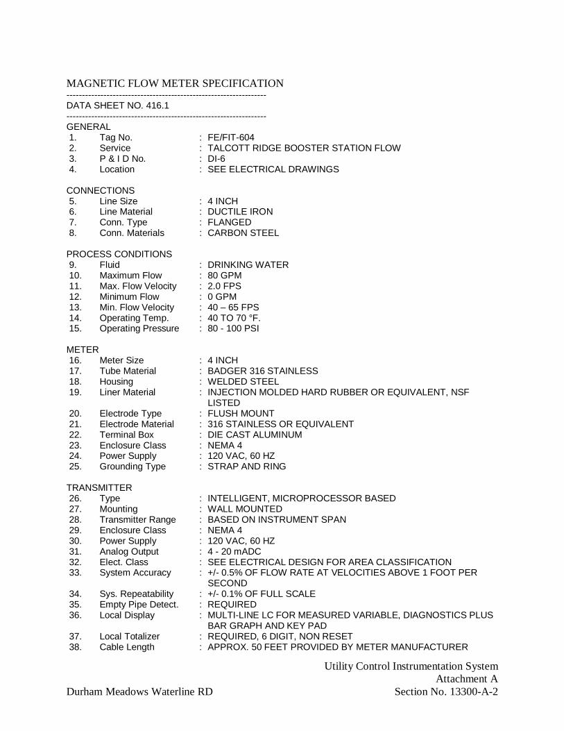
Utility Control Instrumentation SystemAttachment A
Durham Meadows Waterline RD Section No. 13300-A-2
MAGNETIC FLOW METER SPECIFICATION-----------------------------------------------------------------DATA SHEET NO. 416.1-----------------------------------------------------------------GENERAL 1. Tag No. : FE/FIT-604 2. Service : TALCOTT RIDGE BOOSTER STATION FLOW 3. P & I D No. : DI-6 4. Location : SEE ELECTRICAL DRAWINGS
CONNECTIONS 5. Line Size : 4 INCH 6. Line Material : DUCTILE IRON 7. Conn. Type : FLANGED 8. Conn. Materials : CARBON STEEL
PROCESS CONDITIONS 9. Fluid : DRINKING WATER 10. Maximum Flow : 80 GPM 11. Max. Flow Velocity : 2.0 FPS 12. Minimum Flow : 0 GPM 13. Min. Flow Velocity : 40 – 65 FPS 14. Operating Temp. : 40 TO 70 °F. 15. Operating Pressure : 80 - 100 PSI
METER 16. Meter Size : 4 INCH 17. Tube Material : BADGER 316 STAINLESS 18. Housing : WELDED STEEL 19. Liner Material : INJECTION MOLDED HARD RUBBER OR EQUIVALENT, NSF
LISTED 20. Electrode Type : FLUSH MOUNT 21. Electrode Material : 316 STAINLESS OR EQUIVALENT 22. Terminal Box : DIE CAST ALUMINUM 23. Enclosure Class : NEMA 4 24. Power Supply : 120 VAC, 60 HZ 25. Grounding Type : STRAP AND RING
TRANSMITTER 26. Type : INTELLIGENT, MICROPROCESSOR BASED 27. Mounting : WALL MOUNTED 28. Transmitter Range : BASED ON INSTRUMENT SPAN 29. Enclosure Class : NEMA 4 30. Power Supply : 120 VAC, 60 HZ 31. Analog Output : 4 - 20 mADC 32. Elect. Class : SEE ELECTRICAL DESIGN FOR AREA CLASSIFICATION 33. System Accuracy : +/- 0.5% OF FLOW RATE AT VELOCITIES ABOVE 1 FOOT PER
SECOND 34. Sys. Repeatability : +/- 0.1% OF FULL SCALE 35. Empty Pipe Detect. : REQUIRED 36. Local Display : MULTI-LINE LC FOR MEASURED VARIABLE, DIAGNOSTICS PLUS
BAR GRAPH AND KEY PAD 37. Local Totalizer : REQUIRED, 6 DIGIT, NON RESET 38. Cable Length : APPROX. 50 FEET PROVIDED BY METER MANUFACTURER
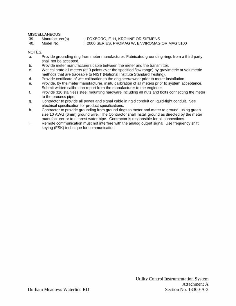
Utility Control Instrumentation SystemAttachment A
Durham Meadows Waterline RD Section No. 13300-A-3
MISCELLANEOUS 39. Manufacturer(s) : FOXBORO, E+H, KROHNE OR SIEMENS 40. Model No. : 2000 SERIES, PROMAG W, ENVIROMAG OR MAG 5100
NOTES. a. Provide grounding ring from meter manufacturer. Fabricated grounding rings from a third party
shall not be accepted. b. Provide meter manufacturers cable between the meter and the transmitter. c. Wet calibrate all meters (at 3 points over the specified flow range) by gravimetric or volumetric
methods that are traceable to NIST (National Institute Standard Testing). d. Provide certificate of wet calibration to the engineer/owner prior to meter installation. e. Provide, by the meter manufacturer, insitu calibration of all meters prior to system acceptance.
Submit written calibration report from the manufacturer to the engineer. f. Provide 316 stainless steel mounting hardware including all nuts and bolts connecting the meter
to the process pipe. g. Contractor to provide all power and signal cable in rigid conduit or liquid-tight conduit. See
electrical specification for product specifications. h. Contractor to provide grounding from ground rings to meter and meter to ground, using green
size 10 AWG (6mm) ground wire. The Contractor shall install ground as directed by the metermanufacturer or to nearest water pipe. Contractor is responsible for all connections.
i. Remote communication must not interfere with the analog output signal. Use frequency shiftkeying (FSK) technique for communication.

Utility Control Instrumentation SystemAttachment A
Durham Meadows Waterline RD Section No. 13300-A-4
PROGRAMMABLE LOGIC CONTROLLER SPECIFICATION---------------------------------------------------------------DATA SHEET NO. 567.1---------------------------------------------------------------GENERAL1. Tag Number : CHERRY HILL-PLC, WMV.PLC, TBS.PLC2. P & I D No. : DI-1, DI-2, DI-3, DI-4, DI-6, DI-73. Location : EE-1 AND OTHER LOCATIONS, SEE ELECTRICAL DRAWINGS
CONTROLLER4. Discrete Inputs : 120 VAC 7mA WETTING CURRENT5. Analog Inputs : INTO 250 OHMS MAXIMUM LOAD6. Discrete Outputs : 120 VAC ON CURRENT 2 A CONTINUOUS7. Contact Rating : 120 VAC @ 10 AMPS -- PROVIDE INTERPOSING RELAYS8. Analog Outputs : INTO 500 OHMS MINIMUM9. Memory : AS NECESSARY TO OPERATE10. Functions : AND, OR, NOR, COMPLEMENTS, TIMERS, COUNTERS,
SEQUENCERS, ARITHMETIC OPERATIONS, COMPARATORS, AND LATCHING RELAYS
11. Hot Backup : NOT REQUIRED12. Program Scan Time : LESS THAN 0.9 MILLISECONDS/K WORD13. Memory Protection : MULTIPLE LEVELS OF PASSWORD PROTECTION14. Communications : PROVIDE OPEN NETWORK TO SUIT THE PROJECT
APPLICATION. PROVIDE FOR FUTURE MIGRATION TO OTHER AUTOMATION EQUIPMENT. PROVIDE UPWARD MIGRATION TO PERSONAL COMPUTERS AND MAINFRAMES.
15. Network Features : OPEN SYSTEM, CONFORMING TO OSI ISO SEVEN LAYERMODEL. PROVIDE FOR REMOTE I/O COMMUNICATION,PLC PEER TO PEER COMMUNICATION ANDCOMMUNICATION TO FIELD DEVICES OVER FIELD BUS.PROVIDE COMMUNICATION TO HIGHER LEVELCOMPUTING OR PROCESS CONTROL SYSTEM.
16. Ports : PROVIDE PORTS REQUIRED TO CONNECT TO REMOTEI/O, DATA HIGHWAY, LAPTOP PC, AND MODEM. EACHMODEM CONNECTION SHALL HAVE AN INDIVIDUALPORT FROM THE PLC MASTER. MULTIPLEXING FROM ASINGLE PLC PORT SHALL NOT BE ALLOWED.
17. Mounting : CHASSIS SYSTEM IN BACK OF PANEL18. Connections : PROVIDE INDIVIDUALLY FUSSED TERMINAL BLOCKS.
PROVIDE GAS TIGHT WAGO TYPE CAGE CLAMPTERMINAL BLOCKS FOR FIELD INPUT WIRING.PROVIDE AMP TYPE HOODED CONNECTOR FROM THETERMINAL BLOCK TO THE I/O MODULE. THE I/OMODULE SHALL BE REPLACEABLE W/OUT REMOVINGFIELD WIRING. FIELD WIRE CONTINUITY ANDCURRENT LOOP TESTING MAY BE PERFORMED FROMTHE TERMINAL BLOCK W/OUT DISRUPTION OF OTHERI/O W/ THE REMOVAL OF THE INDIVIDUAL I/O FUSS.
19. Diagnostic Ind : DC POWER OK, PC RUN, CPU FAULT, BATTERY LOW,FORCED I/O, I/O STATUS
POWER SUPPLY20. Nominal Volts : 120 VAC 60 HZ21. Min Supply Volts : 85 VAC

Utility Control Instrumentation SystemAttachment A
Durham Meadows Waterline RD Section No. 13300-A-5
22. Max Supply Volts : 132 VAC23. Power Loss Duration : WITHSTAND POWER LOSS FOR A MINIMUM OF 20 mSEC24. Battery Back-up : SEE DATA SHEET 702.1.
SERVICE CONDITIONS25. Environmental : OPERATE AT 0-140°F (0-60°C) AND 5-95% HUMIDITY,
NON-CONDENSING
HUMAN MACHINE INTERFACE (HMI)26. HMI : SEE DATA SHEET 575.1.
MISCELLANEOUS27. Connection :PROVIDE HIGHEST DATA-THROUGHPUT LEVEL
POSSIBLE TO PROVIDE UPDATES FOR ALL SYSTEMPOINTS AT A FREQUENCY TO SUPPORT A REAL-TIMECONNECTION.
28. Documentation :PROVIDE ALL DISTRIBUTION MEDIA ANDDOCUMENTATION
29. Model (s) :CONTROLWAVE30. Manufacturer(s) :EMERSON31. Operating Sequence :SEE DI-2 AND SPECIFICATIONS32. Documentation :PROVIDE HARD COPY AND CD WITH LADDER
DIAGRAMS.
NOTES.a. Provide preliminary ladder diagram with PLC submittal.b. Provide 15% active spare I/O. Provide as a minimum one spare card of each I/O type.c. Provide PLC spares to include; one each power supply, processor, network card and I/O of each type.d. Provide true PID algorithm for continuous control like temperature, and pressure.e. The Contractors Control System Integrator shall provide all PLC and HMI hardware and software.f. The Contractors Control System Integrator shall provide all foreign device gateways and interfaces to PLCs
provided with process equipment and I/O interfaces to receive pulse interfaces from electric utilityprovided pulse type meters.
g. Provide all wire and cable as shown on the system block diagram except for discrete instrument wiringprovided by electrical. The contractor shall provide installation of all cable through the electricalcontractor.

Utility Control Instrumentation SystemAttachment A
Durham Meadows Waterline RD Section No. 13300-A-6
HMI FOR PLC SYSTEMS SPECIFICATION---------------------------------------------------------------DATA SHEET NO. 575.1---------------------------------------------------------------GENERAL1.Service : CHERRY HILL STORAGE TANK, WATER METER VAULT, TALCOTT
RIDGE BOOSTER STATION2. Location : EE-1 AND OTHER LOCATIONS, SEE ELECTRICAL DRAWINGS3. Certified : UL
DISPLAY4. Size : 10-INCH,5. Type : LCD6. Min Resolution : 640x4807. Color : YES8. Touch Screen : YES
ENCLOSURE9. Rating :IN ACCORDANCE WITH AREA CLASSIFICATION SCHEDULE ON
ELECTRICAL DRAWINGS10. Material : N/A
ENVIRONMENTAL11. Operating Temp : 0°-55°C (32°-131°F)12. Humidity :5-95% NONCONDENSING @55°C13. Rating : IN ACCORDANCE WITH AREA CLASSIFICATION SCHEDULE ON
ELECTRICAL DRAWINGS
ELECTRICAL14. Power Supply : 120VAC, PROVIDE POWER ISOLATION TRANSFORMER15. Power Consumption : 100 WATTS MAX
COMMUNICATIONS16. Connection Type : ETHERNET, 2 EACH RS-232 & 2 EACH USB
MISCELLANEOUS17. Manufacturer(s) : C-MORE
NOTES a. Provide software and configuration so an operator can monitor and control a unit process from any HMI. b. Provide all hardware, software and ancillary network devices so HMI shall be seamlessly integrated withtotal plant control system.

Utility Control Instrumentation SystemAttachment A
Durham Meadows Waterline RD Section No. 13300-A-7
UNINTERRUPTIBLE POWER SUPPLY SPECIFICATION---------------------------------------------------------------DATA SHEET NO. 702.1---------------------------------------------------------------GENERAL1. Tag No. : UPS-1, UPS-2, UPS-32. Service : BACKUP POWER FOR PLC SYSTEMS3. Location : IN CHERRY HILL PLC, WMV.PLC, TBS.PLC4. Input Voltage : 120 VAC @ 60 HZ +/- 20%5. Output Voltage : 120 VAC @ 60 HZ +/- 3% SINE WAVE LESS THAN 5% THD6. Operating Temp. : 32 TO 105 DEG. F.7. Surge Protection : 6000 VOLT AND MEET IEEE C62.41 CATEGORIES A AND B8. Backup Time : 15 MINUTES MINIMUM AT 125% OF FULL LOAD9. Low Battery Ind. : REQUIRED10. Brownout Protection : REQUIRED AT 95 VAC11. UPS Type : LINE INTERACTIVE12. Efficiency : 92% MINIMUM ON-LINE13. Transfer Time : LESS THAN 1 MILLISECOND14. Digital Disp. Param. : VOLTAGE IN, VOLTAGE OUT, BATTERY VOLTAGE,
PERCENT LOADING, ALARMS15. Alarms : LOW BACKUP TIME, OVERLOAD, REPLACE BATTERY,
LOW BATTERY16. Audible Noise : LESS THAN 50 dB @ 3 FT
BATTERY 1. Type : SEALED GEL-CELL OR SEALED LEAD ACID 2. Battery Protection : THERMAL, OVERVOLTAGE AND OVERCURRENT 3. Battery Enclosure : PROVIDE BATTERIES MOUNTED IN SEPARATE ENCLOSURE FROM
UPSMISCELLANEOUS 4. Manufacturer(s) : BEST, SOLA, APC OR EQUAL
NOTES. a. Provide UPS system such that upon failure of the UPS feeder, batteries provided with UPS immediately
take over as the power source. b. Provide external bypass switch with Make-Before-Break. Provide bypass to isolate the UPS equipment for
maintenance. Provide bypass with switch test so the switch may be tested without the risk of dropping theload caused by static switch failure.
c. Provide static transfer switch to transfer load upon loss of power at the output of the UPS. Transfer switchshall complete transfer within 1/4 cycle.
d. Provide UPS sizing calculations in the shop drawing submittal. UPS shall supply power to PLC, datalogging and communications equipment in control panel. Provide sizing calculations which are based onrequired load plus 25%.

Utility Control Instrumentation SystemAttachment A
Durham Meadows Waterline RD Section No. 13300-A-8
LEVEL SWITCH (FLOAT TYPE) SPECIFICATION-----------------------------------------------------------------DATA SHEET NO. 853.1-----------------------------------------------------------------GENERAL1. Tag Number : LSH-103, LSH-600, LSH-7002. Service : HIGH SUMP LEVEL3. P & I D No. : DI-4, DI-6, DI-74. Location : SEE ELECTRICAL DRAWINGS
FLOAT5. Dimensions : APPROX. 6 INCH DIAMETER6. Material : POLYPROPYLENE
SWITCH7. Type : MICRO SWITCH STEEL BALL ACTIVATED, NO MERCURY8. Contact : SPDT9. Rating : 5 AMPS AT 120 VAC10. Enclosure : ENCAPSULATED11. Open/Close : CLOSE12. On Level Incr/Decr : INCREASING13. Mounting : ADJUSTABLE CLAMP ON 1 INCH STAINLESS PIPE14. Elec. Classification : NEMA 4X, NEMA 6, SEE AREA CLASSIFICATION SCHEDULE ON
ELECTRICAL DRAWINGS
PROCESS CONDITIONS15. Operating Temp. : 40 TO 75 DEG. F.16. Operating Pressure : ATMOSPHERE TO 10 FT SUBMERGED
MISCELLANEOUS17. Interconn. Cable : AS REQUIRED APPROX. 200 FEET18. Manufacturer(s) : COX OR KARI NO OR EQUAL19. Model No.(s) : OPTI-FLOAT OR KA SERIES NO OR EQUAL
NOTES a. Provide 1-inch diameter SCH 40 316L SS pipe to mount the float switch(s). b. Provide COX or KARI level switches as specified. Other manufacturers shall not be accepted based on
performance. c. Provide detailed instructions for proper installation of switches, enclosures and mounting hardware. d. Provide 316 SS brackets and hardware to attach pipe to side of well or tank. e. Provide a minimum of 3 brackets spaced a maximum of 10'-0" OC. f. Provide all 316 SS mounting hardware to mount float switch(s) to 1-inch pipe. Mounting hardware shall
allow for float level adjustment with hand tools. g. Provide single sealed well/tank penetration for float switch(s) cables. h. Provide 316 SS NEMA 4X or cast aluminum termination enclosure (based on area electrical classification).
The enclosure shall provide termination for the float(s) and include isolation relays and intrinsic safetybarriers.
i. Provide termination enclosure mounted on 316 SS UNISTRUT® supports for wall or floor mounting.
ACCESS HATCH INTRUSION SWITCH SPECIFICATION-----------------------------------------------------------------

Utility Control Instrumentation SystemAttachment A
Durham Meadows Waterline RD Section No. 13300-A-9
DATA SHEET NO. 1110.1 1-----------------------------------------------------------------GENERAL 1. Tag Number : ZS-101 2. Service : ALTITUDE VALVE VAULT HATCH ALARM OPEN 3. P & I D No. : DI-4 4. Location : SEE ELECTRICAL DRAWINGS
SWITCH5. Type(Single/Dual) : SINGLE6. Head Type : BEST SUITED FOR HATCH. SEE NOTE b.7. Mounting : ON HATCH FRAME. SEE NOTE c8. Matrl of Const : 316 SS CAST BODY, 316 SS ACTUATOR & OPERATING HEAD,
FLUOROCARBON SEALS9. Enclosure : NEMA 4X, SEE AREA CLASSIFICATION SCHEDULE ON
ELECTRICAL DRAWINGS10. Form : DPDT11. Contact Rating : 10 AMPS @ 120 V12. Output Signal For : HATCH OPEN ALARM
MISCELLANEOUS13. Manufacturer(s) : HONEYWELL MICRO SWITCH OR EQUAL14. Model No.(s) : HDLS SERIES OR EQUAL
NOTES a. Provide w/ sealed cable pre-wired connection b. Provide written recommendation from hatch manufacturer on switch head type. c. Provide details of mounting w/ hatch assemble w/ written approval of the hatch manufacturer.

Utility Control Instrumentation SystemAttachment A
Durham Meadows Waterline RD Section No. 13300-A-10
DOOR ALARM SWITCH ASSEMBLY SPECIFICATION-----------------------------------------------------------------DATA SHEET NO. 1111 . 1-----------------------------------------------------------------GENERAL 1. Tag Number : ZS-600, ZS-700 2. Service : DOUBLE DOOR INTRUSTION ALARM 3. P & I D No. :DI-6, DI-7 4. Location : WATER METER VAULT, BOOSTER STATIONSWITCH 5. Type :MAGNETIC CONTACT 6. Housing :ABS PLASTIC 7. Mounting :SURFACE W/ SS SCREWS W/ TAMPER-PROOF HEAD 8. Terminals :RECESSED 9. Test Pts :EXTERNAL 10. Form :SPDT 11. Voltage :30 V AC/DC 12. Output Signal For :DOOR ALARM SEE NOTE aMISCELLANEOUS 13. Manufacturer(s) :SENTROL OR EQUAL 14. Rating :SEE AREA CLASSIFICATION SCHEDULE ON ELECTRICAL
DRAWINGS
NOTES.
a. Provide switch wired for both doors, on the double door, to the PLC so the PLC can determine anopened door.

Utility Control Instrumentation SystemAttachment A
Durham Meadows Waterline RD Section No. 13300-A-11
GAUGE PRESSURE TRANSMITTER SPECIFICATION-----------------------------------------------------------------DATA SHEET NO. 1451.1 1-----------------------------------------------------------------GENERAL 1. Tag Number : PT/PIT-201A & PT/PIT-201B, PIT-600A & PIT-600B 2. Service : TANK LEVEL, PRESSURE 3. P & I D No. : DI-4, DI-6, DI-7 4. Location : SEE ELECTRICAL DRAWINGS
TRANSMITTER 5. Type : INTELLIGENT, MICROPROCESSOR BASED 6. Element : CAPACITANCE CELL, RESONANT WIRE OR PIEZORESISTIVE
SENSOR 7. Remote Calibration : ZERO AND SPAN VIA HANDHELD TERMINAL, WITHOUT
ADDITIONAL HARDWARE, AT ANY TERMINATION POINT INLOOP
8. Transmittal/Terminal : TWO WAY COMMUNICATION VIA LOOP WIRING SEE NOTEa
9. Self-Diagnostics : CONTINUOUS 10. Ambient Temp. Comp. : AUTOMATIC 11. Power Supply : 24 VDC 12. Output Signal : 4 - 20 mADC OR DIGITAL 13. Dir/Rev Acting : DIRECT 14. Turn Down : 6:1 15. Span : 0 - 100 FT WATER 16. Accuracy : +/- 0.1% OF CALIBRATED SPAN 17. Repeatability : +/- 0.05% 18. Local Indicator : REQUIRED 19. Indicator Display : DIGITAL; ENGINEERING UNITS, SIGNAL OUTPUT AND
DIAGNOSTICS 20. Bypass Manifold : REQUIRED, 2 VALVE TYPE, 316 SS SEE NOTE b 21. Span (Elev/Suppr) : UP TO 500% OF CALIBRATED SPAN 22. Enclosure : NEMA 4X, 4 23. Elec. Class : SEE AREA CLASSIFICATION SCHEDULE ON ELECTRICAL
DRAWINGS 24. Mounting : WALL OR PEDESTAL 25. Process Connections : ½ INCH NPT
MATERIALS OF CONSTRUCTION 26. Body : LOW COPPER ALUMINUM 27. Wetted Parts : 316 SS. FOR CORROSIVE CHEMICALS PROVIDE TANTALUM
DIAPHRAGM AND TEFLON GASKETS AND HASTELLOYBODY, PROCESS FLANGE AND SENSOR WITH TEFLONGASKETS.
28. Fill : SILICON OIL. FOR OXYGEN SERVICE USE FLUORINERT.
SERVICE CONDITIONS 29. Fluid : DRINKING WATER 30. Specific Gravity : APPROX. 1.0 31. Max. Static Pressure : SEE TABLE 32. Operating Temp. : -20 TO 180 DEG. F. SEE NOTE d 33. Ambient Temp. : 0 TO 100 DEG. F.
MISCELLANEOUS
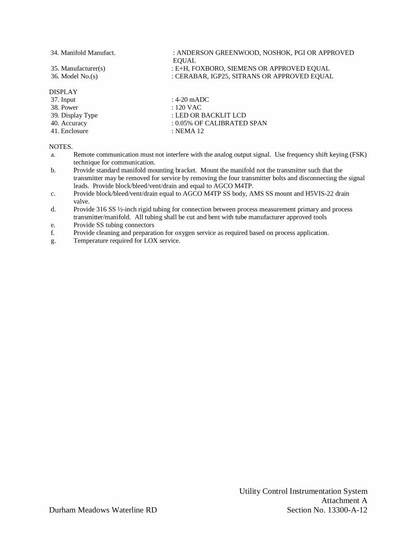
Utility Control Instrumentation SystemAttachment A
Durham Meadows Waterline RD Section No. 13300-A-12
34. Manifold Manufact. : ANDERSON GREENWOOD, NOSHOK, PGI OR APPROVEDEQUAL
35. Manufacturer(s) : E+H, FOXBORO, SIEMENS OR APPROVED EQUAL 36. Model No.(s) : CERABAR, IGP25, SITRANS OR APPROVED EQUAL
DISPLAY 37. Input : 4-20 mADC 38. Power : 120 VAC 39. Display Type : LED OR BACKLIT LCD 40. Accuracy : 0.05% OF CALIBRATED SPAN 41. Enclosure : NEMA 12
NOTES. a. Remote communication must not interfere with the analog output signal. Use frequency shift keying (FSK)
technique for communication. b. Provide standard manifold mounting bracket. Mount the manifold not the transmitter such that the
transmitter may be removed for service by removing the four transmitter bolts and disconnecting the signalleads. Provide block/bleed/vent/drain and equal to AGCO M4TP.
c. Provide block/bleed/vent/drain equal to AGCO M4TP SS body, AMS SS mount and H5VIS-22 drainvalve.
d. Provide 316 SS ½-inch rigid tubing for connection between process measurement primary and processtransmitter/manifold. All tubing shall be cut and bent with tube manufacturer approved tools
e. Provide SS tubing connectors f. Provide cleaning and preparation for oxygen service as required based on process application. g. Temperature required for LOX service.

Utility Control Instrumentation SystemAttachment A
Durham Meadows Waterline RD Section No. 13300-A-13
AIR TEMPERATURE SENSOR AND TRANSMITTER SPECIFICATION-----------------------------------------------------------------DATA SHEET NO. 1662.1 1-----------------------------------------------------------------GENERAL 1. Tag Number : TE/TT-102, TE/TT-600, TE/TT-700 2. Service : WATER METER VAULT, ALTITUDE VAULT, AND TALCOTT
RIDGE BOOSTER STATION TEMPERATURE 3. P & I D No. : DI-4, DI-6, DI-7 4. Location : SEE ELECTRICAL DRAWINGS
SENSOR 5. Type : PLATINUM RTD W/ ALUMINUM SENSING TIP 6. Leads : 3 LEADS FOR RTD 7. Lead Wires : 100mm (4") LONG 22 AWG, PTFE INSULATED 8. RTD Length : 75mm (3") MINIMUM 9. Housing : NEMA 4X, NEMA 610. Material : CAST ALUMINUM
TRANSMITTER 13. Type : ELECTRONIC 14. Power : 120 VAC 15. Output Signal : 4 - 20 mADC INTO 550 OHMS 16. Range : -40 TO 80 C 176 F) 17. Linearity : +/- 0.1% WITH SPAN 18. Calibration : MATCH RTD 19. Enclosure : NEMA 4X OR AS REQUIRED BY AREA CLASSIFICATION
SCHEUDLE ON ELECTRICAL DRAWINGS 20. Mounting : INTEGRAL WITH WELL
PROCESS CONDITIONS 22. Fluid : AIR
MISCELLANEOUS 23. Manufacturer(s) : MICON, WEED, PYROMATION OR EQUAL
NOTES a. Provide complete temperature monitor assembly w/ all hardware for
wall mounting.
DIVISION 15
PLUMBING - MECHANICAL

Process Piping, Valves, and AppurtenancesDurham Meadows Waterline RD Section No. 15101-1
SECTION 15101
PROCESS PIPING, VALVES, AND APPURTENANCES
PART 1 - GENERAL
1.01 DESCRIPTION:
A. Provide and install all process piping, valves, and appurtenances as indicated and incompliance with Contract Documents.
1. Provide sizes and capacities as indicated or specified.
2. For water main piping and appurtenances not specified herein, refer to Section02510.
1.02 RELATED WORK
A. Division 1: General Requirements
B. Section 02510 Water Utilities.
C. Section 13225 Prestressed Concrete Tanks
D. Section 15105 Pipe Supports for Process Piping
1.03 REFERENCES:
A. American Society of Mechanical Engineers (ASME):
1. B1.20.7: Hose Coupling Screw Threads.
2. B16.1: Standard for Cast Iron Pipe Flanges and Flanged Fittings, 125 lb.
3. B16.4: Cast-Iron Threaded Fittings, Class 125 and 250.
4. B16.10: Face-to-Face and End-to-End Dimensions of Ferrous Valves.
B. American Society for Testing and Materials International (ASTM):
1. A48: Standard Specification for Gray Iron Castings.
2. A126: Standard Specification for Gray Iron Castings for Valves, Flanges and PipeFittings.
3. A536: Standard Specification for Ductile Iron Castings.
C. American Water Works Association (AWWA):

Process Piping, Valves, and AppurtenancesDurham Meadows Waterline RD Section No. 15101-2
1. C500: Metal-Seated Gate Valves for Water Supply Service.
2. C504: Rubber-Seated Butterfly Valves.
3. C509: Standard Specifications for Resilient-Seated Gate Valves for Water andSewage Systems.
4. D102: Coating Steel Water-Storage Tanks.
D. NSF International (NSF):
1. 61: Drinking water system components Health effects.
1.04 SUBMITTALS:
A. Submit the following in accordance with Section 01300:
1. Data, regarding valve characteristics and performance including Cv.
2. Shop drawing data for accessory items.
3. Manufacturer's literature as needed to supplement certified data.
4. Operating and maintenance instructions and parts lists.
5. Valve shop test results.
6. Shop and Field inspections reports.
7. List of manufacturer’s recommended spare parts.
8. Recommendations for short and long term storage.
9. Shop and field testing procedures and equipment to be used.
10. Number of service technician days provided and per diem field service rate.
11. Manufacturer’s product data and specifications for shop painting.
12. Provide a layout drawing, plan and section showing orientation of gate, check, ballvalves and actuators and nearest obstructions for each valve.
13. Provide a listing of the materials recommended for each service specified andindicated. Provide documentation showing compatibility with process fluid andservice specified and indicated.
14. The most recent ISO 9000 series certification or quality system plan.
15. Material Certification:

Process Piping, Valves, and AppurtenancesDurham Meadows Waterline RD Section No. 15101-3
a. Provide certification from the equipment manufacturer that the materials ofconstruction specified are recommended and suitable for the serviceconditions specified and indicated. If materials other than those specifiedare proposed based on incompatibility with the service conditions, providetechnical data and certification that the proposed materials are recommendedand suitable for the service conditions specified and indicated including aninstallation list of a minimum of five (5) installations in operation for aminimum of five (5) years. Provide proposed materials at no additional costto the Contracting Officer.
b. Where materials are not specified, provide technical data and certificationthat the proposed materials are recommended and suitable for the serviceconditions specified and indicated.
1.05 SPARE PARTS:
A. Comply with requirements specified in Section 01610.
1.06 QUALITY ASSURANCE:
A. Comply with the requirements specified in Section 01400.
B. Provide enclosures for the area classifications specified and indicated.
C. Contractor responsible for verifying outside diameter of pipe to be tapped.
D. Services of Manufacturer’s Representative as stated in Section 01400 and specifiedherein.
E. Manufacturer of valve shall have a minimum of five (5) similar installations and in thesame service as specified operating for not less than five (5) years.
F. If equipment proposed is heavier, taller, different laying length or requires moreoperating space than specified and indicated; provide all structural, architectural,mechanical, electrical and plumbing revisions at no additional cost to the ContractingOfficer.
1. If equipment is heavier than specified, the Contractor shall provide all hoistingequipment sized to maintain the minimum safety factor between the specifiedmaximum equipment weight and the lifting capacity of the hoisting equipmentindicated and specified.
1.07 DELIVERY, STORAGE AND HANDLING:
A. Comply with the requirements specified in Section 01610 and as specified.
B. Requirements of Regulatory Agencies:
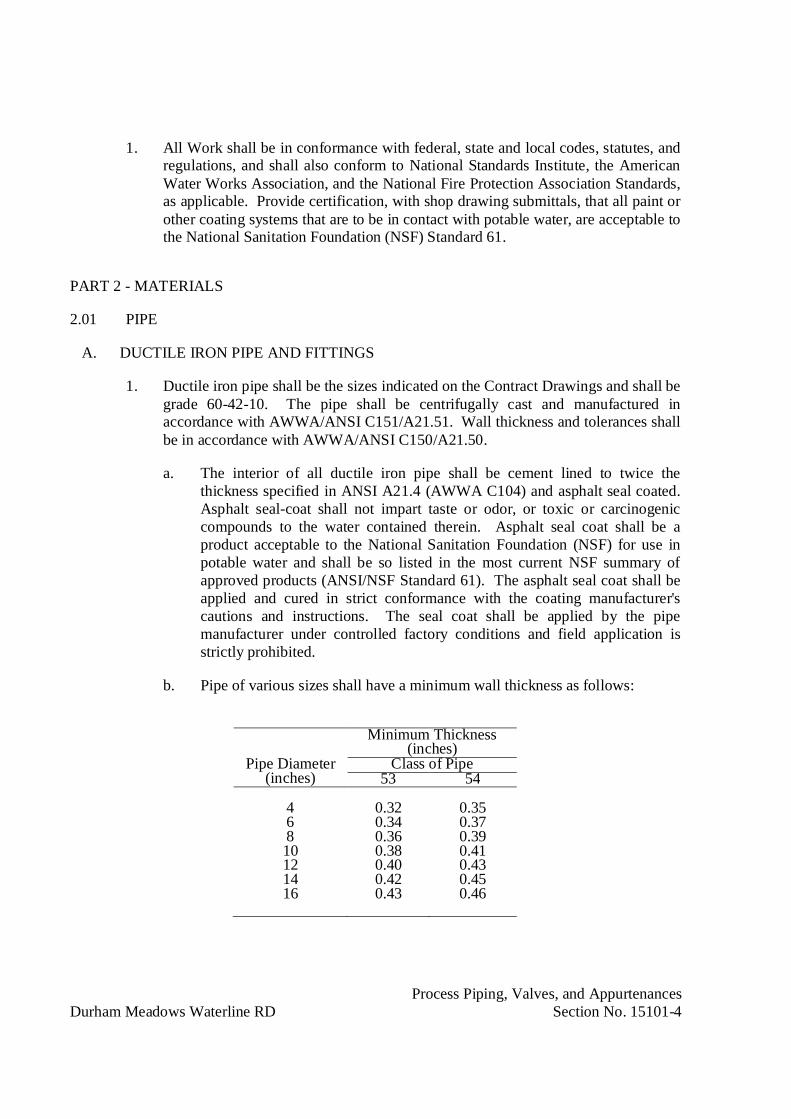
Process Piping, Valves, and AppurtenancesDurham Meadows Waterline RD Section No. 15101-4
1. All Work shall be in conformance with federal, state and local codes, statutes, andregulations, and shall also conform to National Standards Institute, the AmericanWater Works Association, and the National Fire Protection Association Standards,as applicable. Provide certification, with shop drawing submittals, that all paint orother coating systems that are to be in contact with potable water, are acceptable tothe National Sanitation Foundation (NSF) Standard 61.
PART 2 - MATERIALS
2.01 PIPE
A. DUCTILE IRON PIPE AND FITTINGS
1. Ductile iron pipe shall be the sizes indicated on the Contract Drawings and shall begrade 60-42-10. The pipe shall be centrifugally cast and manufactured inaccordance with AWWA/ANSI C151/A21.51. Wall thickness and tolerances shallbe in accordance with AWWA/ANSI C150/A21.50.
a. The interior of all ductile iron pipe shall be cement lined to twice thethickness specified in ANSI A21.4 (AWWA C104) and asphalt seal coated.Asphalt seal-coat shall not impart taste or odor, or toxic or carcinogeniccompounds to the water contained therein. Asphalt seal coat shall be aproduct acceptable to the National Sanitation Foundation (NSF) for use inpotable water and shall be so listed in the most current NSF summary ofapproved products (ANSI/NSF Standard 61). The asphalt seal coat shall beapplied and cured in strict conformance with the coating manufacturer'scautions and instructions. The seal coat shall be applied by the pipemanufacturer under controlled factory conditions and field application isstrictly prohibited.
b. Pipe of various sizes shall have a minimum wall thickness as follows:
Pipe Diameter(inches)
Minimum Thickness(inches)
Class of Pipe53 54
4 0.32 0.356 0.34 0.378 0.36 0.3910 0.38 0.4112 0.40 0.4314 0.42 0.4516 0.43 0.46

Process Piping, Valves, and AppurtenancesDurham Meadows Waterline RD Section No. 15101-5
(1) Cement mortar lining minimum thickness shall be as follows:
Pipe Size(inches)
Minimum LiningThickness (inches)
3-12 1/814-24 3/16
2. All interior ductile iron pipe shall be a minimum Class 53, working pressure 250psi, and shall be designed and manufactured in accordance with AWWA/ANSIC115/A21.15.
3. Interior ductile iron pipe joints shall be flanged with gaskets, bolts and nutsconforming to AWWA/ANSI C115/A21.15. Flanges shall be flat faced andgaskets shall be full face.
4. All fittings associated with interior ductile iron pipe shall be ductile ironconforming to AWWA/ANSI C110/A21.10. Refer to the Contract Drawings forspecial bolt hole drill patterns for certain fittings. Fittings shall have flat-facedflanges, full face gaskets, and be complete with nuts and bolts.
5. All nuts, bolts, and washers for flanged pipe located in subterranean concretevaults and/or manholes, wet process basins, or other subterranean and/orsubmerged locations shall be 300 series stainless steel.
6. The outside surface of all interior, flanged ductile iron pipe with the exception offlange faces shall be factory prime coated with a rust inhibitive primer compatiblewith the appropriate finish coating systems specified in Section 09941. Finishpaint shall be field applied in strict accordance with Section 09941 and/or the paintmanufacturer’s written instructions.
7. Connections – Tapped: Provide service saddles for all taps for lines 24-inch andsmaller.
a. Body: Ductile iron ASTM A395 or Bronze.
b. Straps and Hardware: Type 316 stainless steel.
B. PVC PIPE AND FITTINGS:
1. Schedule 80
2. Material: Type I, Grade I Polyvinyl Chloride (PVC) compound with a CellClassification of 12454 per ASTM D1784.
Process Piping, Valves, and AppurtenancesDurham Meadows Waterline RD Section No. 15101-6
3. Provide pipe and fittings manufactured in compliance to ASTM D1785 meetingand/or exceeding the Quality Assurance test requirements of this standard withregard to material, workmanship, burst pressure, flattening, and extrusion quality.
4. Provide pipe and fittings manufactured in the USA, using domestic materials, byan ISO 9002 certified manufacturer. Store all pipe shall be stored indoors afterproduction at the manufacturing site until shipped from factory.
5. Provide standard lengths of pipe sizes 10-inch (250 mm) and larger beveled eachend by the pipe manufacturer.
6. Provide pipe and fittings with the National Sanitation Foundation (NSF) seal ofapproval for potable water applications.
7. Joining:
a. Solvent cementing process.
b. Provide flanges at valves, pumps and equipment only or as indicated andspecified.
c. Provide Type 316 stainless steel flange bolting and hardware for all pipingsystem except sodium hypochorite use titanium.
2.02 STAINLESS STEEL PIPE AND FITTINGS ½-INCH [15 MM] TO 2-INCH [50 MM]:
A. Provide either Pressfit or a socket welded system.
1. Provide a sufficient number of unions to allow removal of all valves and inlinedevices.
2. Provide threaded connections only where required.
B. Pressfit System:
1. Pressfit system, ½-inch [15 mm] through 2-inch [50 mm] Sch 5S comprised ofstainless steel Pressfit fittings, couplings and pipe.
2. Type 316 stainless steel Pressfit couplings and fittings and Type 316 stainless steelPressfit pipe UL classified to ANSI/NSF 61 for cold +86 degrees F (+30 degreesC) and hot +180 degrees F (+82 degrees C) potable water service.
a. Maximum working pressure of 300 psi [20.6 bar] for water, oil, gas,chemical, air and vacuum services.
3. Couplings, Fittings: Pressfit products formed of Type 316/316L stainless steeltubing including a self-contained o-ring seals molded of synthetic EPDM rubber.

Process Piping, Valves, and AppurtenancesDurham Meadows Waterline RD Section No. 15101-7
4. Valves ½-in [15 mm] through 2-in [50 mm]: ball valves with Type 316 stainlesssteel plain ends for Pressfit assembly.
a. Pressure Rating: 300 PSI [20.6 bar]
b. CF8M stainless steel body and ball
c. Type 316 stainless steel stem
d. PTFE seats.
5. Pipe: Type 316/316L ASTM A-312 stainless steel
a. 0.065 wall [1.65 mm]
b. Provide pipe fully finished annealed with polished O.D.
C. Socket Welded System:
1. Schedule 40 Type 316L stainless steel pipe and fittings with socket weldedconnections.
2.03 EXPANSION JOINTS-ELASTOMERIC FLEXIBLE CONNECTION:
A. General: Provide flexible connectors as indicated, specified and as required for ductileiron and steel piping
1. At equipment connection: To eliminate vibration and stress on equipment.
B. Manufacturers:
1. Mercer Rubber Co.
2. General Rubber Co.
3. Garlock, Inc.
4. Or acceptable equivalent product.
C. Products:
1. Straight-through or tapered design as required.
2. Furnish control rods for test pressures as indicated or required.
3. Materials: Suitable for service specified and indicated.
4. Flanges: 125 lb. drilling.
Process Piping, Valves, and AppurtenancesDurham Meadows Waterline RD Section No. 15101-8
5. Provide enamel coated ductile iron or galvanized carbon steel retaining rings.
D. Install joints in their neutral position.
2.04 RESILIENT SEAT GATE VALVES 3-INCH AND LARGER:
A. Resilient Seat Gate Valves:
1. Manufacturers-OS&Y Type Valves:
a. Kennedy Valve/ American RD.
b. Mueller.
c. Seguro Valve.
2. Manufacturers-NRS Type Valves:
a. US Pipe.
b. American Cast Iron Pipe.
c. Kennedy Valve.
d. Mueller.
e. Seguro Valve.
B. General:
1. Provide valves that conform to NSF Standard 61.
2. Non-potable water service: Provide resilient seat gate valves for all sizesindicated. If resilient seat valves are not available provide solid wedge gatevalves.
3. Potable water service: Provide resilient seat gate valves for all sizes indicated. Ifresilient seat valves are not available provide double revolving disc gate valves.
4. Provide metallic seated valves conforming to AWWA C500 except as hereinmodified. (Valves larger than 48-inch, size shall comply with the intent ofAWWA C500.)
5. Provide resilient seated valves conforming to AWWA C509 except as modifiedherein.
C. Materials:
1. Body and Bonnet: ASTM A536 ductile iron.
Process Piping, Valves, and AppurtenancesDurham Meadows Waterline RD Section No. 15101-9
2. Wedge: ASTM A536 ductile iron encapsulated with EPDM.
3. Provide all other materials as specified in AWWA C500 and C509. Workingwater pressure:
Size Pressure3 to 16-inch 250 psi
18-inch and larger 150 psi
4. Exposed Valves: Flanged OS&Y valves. Face-to-face dimensions to comply withANSI B16.10, flanges to comply with ANSI B16.1.
5. Buried Valves: Mechanical joint or push-on joint ends, non-rising stem valveswith operating nut in lieu of hand wheel. Provide gate boxes, steel extensionstems or universal-joint operating rods with 2-in square operating nuts at upperend with coupling connected to valve stem to bring to operating nut to within 6inches of ground surface.
6. Provide counterclockwise rotation to open valves.
7. Provide handwheels with arrow and word "open" to indicate open direction.
8. Provide geared operators for all valves 16-inch and larger. Gearing shall be steelwith enclosed cases.
a. Provide spur gears for buried valves with stems vertical
b. Provide bevel gears where required by position of valve.
c. Provide buried valves with totally enclosed gear cases to enclose both thegears and valve stuffing box and provide gasketed Type 316 stainless steelremovable cover plates with Type 316 stainless steel fasteners to allowaccess to the stuffing box.
9. Chainwheels: Provide where required as specified herein. Provide beveled gearoperator to mount chainwheel in vertical position. Provide valve mounted so thatthe arrow indicator will be visible from the floor level.
10. Provide conventional packing in OS&Y valves.
11. Provide conventional packing or double O rings in non-rising stem valves.
12. Valves capable of being repacked or O ring replaceable while under pressure.
13. Provide Type 316 stainless steel bolts and bronze nuts for stuffing box follower.
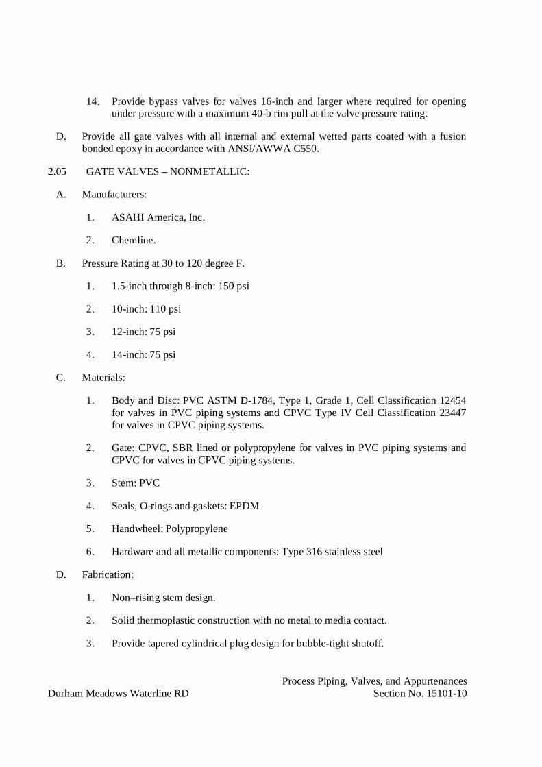
Process Piping, Valves, and AppurtenancesDurham Meadows Waterline RD Section No. 15101-10
14. Provide bypass valves for valves 16-inch and larger where required for openingunder pressure with a maximum 40-b rim pull at the valve pressure rating.
D. Provide all gate valves with all internal and external wetted parts coated with a fusionbonded epoxy in accordance with ANSI/AWWA C550.
2.05 GATE VALVES – NONMETALLIC:
A. Manufacturers:
1. ASAHI America, Inc.
2. Chemline.
B. Pressure Rating at 30 to 120 degree F.
1. 1.5-inch through 8-inch: 150 psi
2. 10-inch: 110 psi
3. 12-inch: 75 psi
4. 14-inch: 75 psi
C. Materials:
1. Body and Disc: PVC ASTM D-1784, Type 1, Grade 1, Cell Classification 12454for valves in PVC piping systems and CPVC Type IV Cell Classification 23447for valves in CPVC piping systems.
2. Gate: CPVC, SBR lined or polypropylene for valves in PVC piping systems andCPVC for valves in CPVC piping systems.
3. Stem: PVC
4. Seals, O-rings and gaskets: EPDM
5. Handwheel: Polypropylene
6. Hardware and all metallic components: Type 316 stainless steel
D. Fabrication:
1. Non–rising stem design.
2. Solid thermoplastic construction with no metal to media contact.
3. Provide tapered cylindrical plug design for bubble-tight shutoff.

Process Piping, Valves, and AppurtenancesDurham Meadows Waterline RD Section No. 15101-11
4. Provide a sealed position indicator.
E. Ends:
1. Flanged, 150 lb Rating.
2. Hardware: Type 316 stainless steel.
F. Operator:
1. Handwheel: Provide chainwheels where required as specified herein.
2. Manual operator for buried valve: provide 2-inch square operating nut andType 316 stainless shaft extension.
2.06 BUTTERFLY VALVES – LIQUID SERVICE (AWWA):
A. Manufacturers:
1. DeZurik.
2. Val-Matic.
3. Rodney Hunt.
B. Provide valves that conform to NSF Standard 61.
C. Provide valves conforming to AWWA Standard C504 for Rubber Seated Butterfly Valvesexcept as modified herein.
D. Provide valves larger than 72-inch in accordance with the requirements of AWWAC504.
E. Valves utilizing: Continuous rubber lining on the internal body surfaces and extendingover the flanges, or a disk which sits at an angle to the axis of the pipe are acceptable.
F. Valve Bearings: Self-lubricating, nonmetallic material to effectively isolate the disc-shaftassembly from the valve body. Cast or ductile iron thrust or journal bearing surfaces areNOT acceptable.
G. Class 150B valves except as specified or indicated.
H. Valve Body: ASTM A126 Class B cast iron or ductile iron.
1. Exposed or submerged service: Flanged short body valve.
2. Buried service: Mechanical joint body.

Process Piping, Valves, and AppurtenancesDurham Meadows Waterline RD Section No. 15101-12
3. Wafer, lug wafer or tapped wafer valves may be used only as specified orindicated.
I. Valve Seats:
1. Potable Water Service: Molded new natural rubber or synthetic rubber.
2. Wastewater or Sludge Service: Molded neoprene, Buna-N or other syntheticelastomer resistant to oil and grease.
3. Provide seat mounted on disc or in body.
4. Provide seats offset from shaft and field replaceable for all valves 24-inch andlarger.
5. Provide seats mounted on disc, mechanically fastened to disc with Type 316stainless steel hex head screws. Provide rubber seat reinforced with stainless steelretaining ring. Seats vulcanized or bonded to the disc are not acceptable.
J. Mating surfaces for valves with seat on disc: Type 316 stainless steel.
1. Provide mating surface mechanically retained in body and sealed with O-ring.
K. For valves with seats mounted on body provide the seats clamped or mechanicallysecured with Type 316 stainless steel fasteners.
L. Mating surfaces for valve with seat in body: Type 316 stainless steel or plasma appliednickel-chromium material containing 80 percent nickel, 20 percent chrome.
M. Plated or sprayed on mating surface material not acceptable.
N. Seat Placement:
1. If seat on disc provide disc of ASTM A126 Class B cast iron or ductile iron.
2. If seat in body, provide disc of ASTM A126 Class B cast iron, ductile iron orType 316 stainless steel. Type 316 Stainless steel edge on cast or ductile-irondiscs secured with Type 316 stainless steel threaded fasteners, heat shrunk on disc,a welded-on overlay, or a plasma applied nickel-chrome material.
O. Shaft: Type 316 stainless steel. Either one piece extending completely through disc orstub shafts inserted into valve disc stubs.
P. Shaft seal of the split-V type or O-ring type. Seal replaceable without disassembly ofvalve.

Process Piping, Valves, and AppurtenancesDurham Meadows Waterline RD Section No. 15101-13
Q. Manual Operators:
1. Operator capable of valve operation at rated pressure with a maximum 80 lb(36 kg) pull on actuator. Operator to be self-locking.
2. Valves 8-inch (200 mm) and smaller, provide lever operator, 18-inch maximumlength.
3. Valves 10-inch and larger, or where chain wheels are required, provide travelingnut operator. Provide position indicator.
4. Chainwheels: Provide where required as specified herein.
R. Buried or submerged valves: Provide gear operator with operating nut and valve box orhandwheel operated floorstand as shown. Gear operator to be totally enclosed withgasketed Type 316 stainless steel covers with Type 316 stainless steel fasteners for accessto valve packing.
2.07 BALL VALVES – GENERAL SERVICE:
A. Manufacturers:
1. Jamesbury
2. KF
3. Inline
4. Kitz
B. Valves 1/2-inch (15 mm) thru 4-inch (100 mm)
1. Materials:
a. Body and End Cap: Three piece, ASTM A351 Grade CF8M.
b. Body Seal: PTFE.
c. Seat: RTFE.
d. Ball: Type 316 stainless steel.
e. Stem: Type 316 stainless steel.
2. Pressure Rating:
a. 1/2-inch thru 2-inch: 1000 psi at 100 degree F
b. 2-1/2-inch thru 4-inch: 800 psi at 100 degree F

Process Piping, Valves, and AppurtenancesDurham Meadows Waterline RD Section No. 15101-14
3. Ends:
a. 2-inch and Smaller: Screwed or flanged.
b. 3-inch and larger: Flanged.
C. Valves 4-inch thru 12-inch.
1. Materials:
a. Body and Adaptor: Two piece, ASTM A351 Grade CF8M.
b. Seat: TFE.
c. Ball: Type 316 stainless steel.
d. Stem: Type 316 stainless steel.
2. Pressure Rating: ANSI Class 150.
3. Ends: Flanged.
D. Actuators:
1. Manual:
a. 4-inch and Smaller: Lever.
b. 6-inch and Larger: Gear operator.
c. Provide chainwheels where required as specified herein.
2. Electric Motor Actuators: Provide in accordance with Section 15109.
2.08 BALL VALVES - NON-METALLIC:
A. Manufacturers:
1. Spears
2. ASAHI
3. NIBCO/Chemtrol
4. Hayward
B. Materials:
1. Body: Material as specified or indicated.
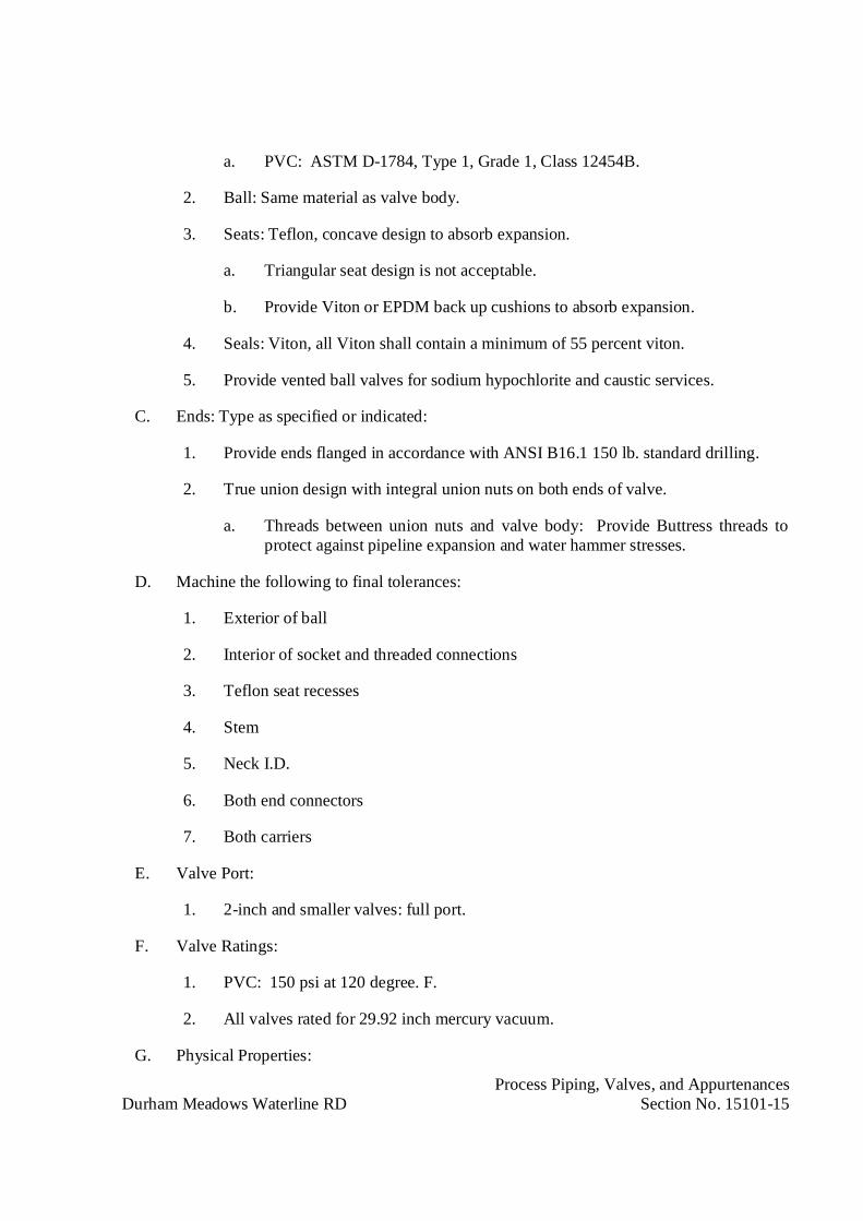
Process Piping, Valves, and AppurtenancesDurham Meadows Waterline RD Section No. 15101-15
a. PVC: ASTM D-1784, Type 1, Grade 1, Class 12454B.
2. Ball: Same material as valve body.
3. Seats: Teflon, concave design to absorb expansion.
a. Triangular seat design is not acceptable.
b. Provide Viton or EPDM back up cushions to absorb expansion.
4. Seals: Viton, all Viton shall contain a minimum of 55 percent viton.
5. Provide vented ball valves for sodium hypochlorite and caustic services.
C. Ends: Type as specified or indicated:
1. Provide ends flanged in accordance with ANSI B16.1 150 lb. standard drilling.
2. True union design with integral union nuts on both ends of valve.
a. Threads between union nuts and valve body: Provide Buttress threads toprotect against pipeline expansion and water hammer stresses.
D. Machine the following to final tolerances:
1. Exterior of ball
2. Interior of socket and threaded connections
3. Teflon seat recesses
4. Stem
5. Neck I.D.
6. Both end connectors
7. Both carriers
E. Valve Port:
1. 2-inch and smaller valves: full port.
F. Valve Ratings:
1. PVC: 150 psi at 120 degree. F.
2. All valves rated for 29.92 inch mercury vacuum.
G. Physical Properties:
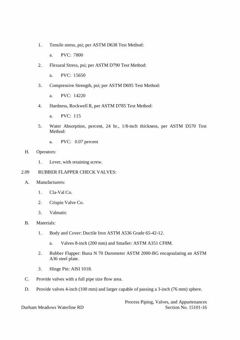
Process Piping, Valves, and AppurtenancesDurham Meadows Waterline RD Section No. 15101-16
1. Tensile stress, psi; per ASTM D638 Test Method:
a. PVC: 7800
2. Flexural Stress, psi; per ASTM D790 Test Method:
a. PVC: 15650
3. Compressive Strength, psi; per ASTM D695 Test Method:
a. PVC: 14220
4. Hardness, Rockwell R, per ASTM D785 Test Method:
a. PVC: 115
5. Water Absorption, percent, 24 hr., 1/8-inch thickness, per ASTM D570 TestMethod:
a. PVC: 0.07 percent
H. Operators:
1. Lever, with retaining screw.
2.09 RUBBER FLAPPER CHECK VALVES:
A. Manufacturers:
1. Cla-Val Co.
2. Crispin Valve Co.
3. Valmatic
B. Materials:
1. Body and Cover: Ductile Iron ASTM A536 Grade 65-42-12.
a. Valves 8-inch (200 mm) and Smaller: ASTM A351 CF8M.
2. Rubber Flapper: Buna N 70 Durometer ASTM 2000-BG encapsulating an ASTMA36 steel plate.
3. Hinge Pin: AISI 1018.
C. Provide valves with a full pipe size flow area.
D. Provide valves 4-inch (100 mm) and larger capable of passing a 3-inch (76 mm) sphere.

Process Piping, Valves, and AppurtenancesDurham Meadows Waterline RD Section No. 15101-17
E. Provide a threaded connection with bronze plug on cover and on the bottom of the valve.
F. Working Pressure:
1. 2-inch (50 mm) through 24-inch (600 mm): 250 psi (1750 kPa).
2. 30-inch (750 mm) and 36-inch (900 mm): 150 psi (1050 kPa).
G. Ends: Flanged ANSI B16.1, Class 150.
H. Provide seating surface at a 45 degree angle such that the flapper travels a maximum of35 degrees from full closed to full open position.
I. Provide valve with cover designed for removal of the valve internals without removingthe valve from the pipeline.
J. Position Indicator:
1. Provide a mechanical indicator to provide disc position for valves 4-inch(100 mm) and larger.
2. Provide the indication with continuous contact with the disc.
K. Provide all check valves with all internal and external wetted parts coated with a fusionbonded epoxy in accordance with ANSI/AWWA C550.
2.10 SWING CHECK VALVES – 3-INCH (75 MM) AND SMALLER:
A. Valves 1/2-inch (13 mm) to 2-inch (50 mm):
1. Working Pressure: 200 psi (1400 kPa)
2. Type: Y-Pattern
3. Ends: Threaded ASME 1.20.1
4. Materials:
a. Body, Cap Disc and Hinge Arm: ASTM A351 CF8M
b. Hinge Pin, Disc Nut Disc Washer and Plug: ASTM A276 Type 316stainless steel
c. Seal and Gaskets: PTFE
B. Valves 1/2-inch (13 mm) to 3-inch (75 mm):

Process Piping, Valves, and AppurtenancesDurham Meadows Waterline RD Section No. 15101-18
1. Working Pressure: ANSI Class 150
2. Type: Swing check with bolted cover
3. Ends:
a. 1/2-inch (13 mm) through 2-inch (50 mm): Threaded ASME 1.20.1
b. 1/2-inch (13 mm) thru 3-inch (75 mm): Flanged
4. Materials:
a. Body, Cap Disc and Hinge Arm: ASTM A351 CF8M
b. Hinge Pin and Plug: ASTM A276 Type 316 stainless steel
c. Plug Seals and Gaskets: PTFE
2.11 SWING CHECK VALVES – NON METALLIC:
A. Manufacturers:
1. Spears.
2. ASAHI/America, Inc.
3. NIBCO/Chemtrol Inc.
4. Hayward Industrial Plastics.
B. Materials:
1. Body and Disc: PVC, ASTM D-1784, Type 1, Grade 1.
2. Seats and Seals: EPDM.
C. Fabrication:
1. Solid thermoplastic construction with no metal to media contact.
2. Single disc design.
3. Provide integral top entry to valve body.
4. Machine finish all seat surfaces.
5. Provide outside level and weight.
D. Pressure Rating at 30 to 120 degree F:
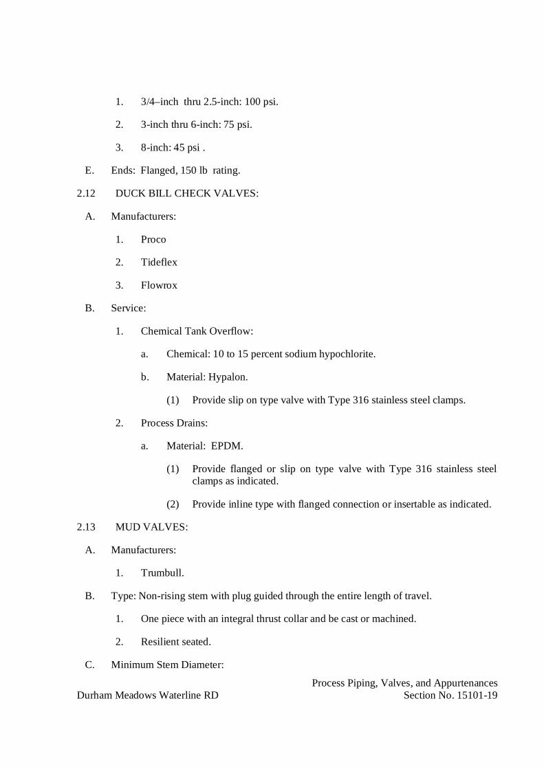
Process Piping, Valves, and AppurtenancesDurham Meadows Waterline RD Section No. 15101-19
1. 3/4–inch thru 2.5-inch: 100 psi.
2. 3-inch thru 6-inch: 75 psi.
3. 8-inch: 45 psi .
E. Ends: Flanged, 150 lb rating.
2.12 DUCK BILL CHECK VALVES:
A. Manufacturers:
1. Proco
2. Tideflex
3. Flowrox
B. Service:
1. Chemical Tank Overflow:
a. Chemical: 10 to 15 percent sodium hypochlorite.
b. Material: Hypalon.
(1) Provide slip on type valve with Type 316 stainless steel clamps.
2. Process Drains:
a. Material: EPDM.
(1) Provide flanged or slip on type valve with Type 316 stainless steelclamps as indicated.
(2) Provide inline type with flanged connection or insertable as indicated.
2.13 MUD VALVES:
A. Manufacturers:
1. Trumbull.
B. Type: Non-rising stem with plug guided through the entire length of travel.
1. One piece with an integral thrust collar and be cast or machined.
2. Resilient seated.
C. Minimum Stem Diameter:

Process Piping, Valves, and AppurtenancesDurham Meadows Waterline RD Section No. 15101-20
Valve Sizeinch
Minimum Stem Diameterinch
4 1-3/166 1-3/168 1-7/16
10 1-7/1612 1-7/1616 1-1/2
D. Pressure Capability: 100 psi unseating.
E. Provide valves capable of withstanding a minimum input torque of 490 foot pounds(664 N-m) without damage to the valve.
F. Provide the valve to leak a maximum of one quart per hour, when the valve is closed to astem torque of 35 foot pounds.
1. Provide leakage and torque testing with a report from an independent testlaboratory.
G. Provide valves with stem coupled to the extension stem with a Type 316 stainless steelmachined coupling or a cast Type 316 stainless steel 2-in square operating nut andretained with a 1/4-in Type 316 stainless steel spring pin.
1. Stainless steel welded components are not acceptable for this connection or to thevalve stem.
2. Provide stems retained with fasteners assembled through holes drilled in the valveguide and yoke and retained with hex nuts. Valve designs which retain the valvestem by threading stainless screws into tapped holes are not acceptable.
3. Provide stems with a permanently bonded coating to prevent galling with otherstainless components.
a. Provide the coating safe for potable water use and capable of enduring aminimum of 15,000 open-close cycles without galling.
b. Provide cycle testing report from an independent test laboratory.
4. Provide adjustable stem guides with support spacing not to exceed 7 feet(2.1 meters).
H. Provide the base flange drilled in accordance with ANSI 125 pound standard with aminimum thickness of 3/4-inch.
1. Machine the base flange seating surface.
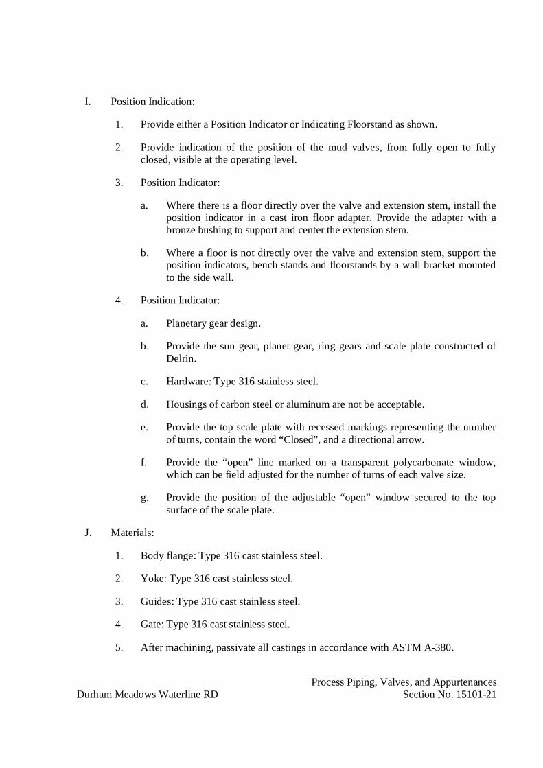
Process Piping, Valves, and AppurtenancesDurham Meadows Waterline RD Section No. 15101-21
I. Position Indication:
1. Provide either a Position Indicator or Indicating Floorstand as shown.
2. Provide indication of the position of the mud valves, from fully open to fullyclosed, visible at the operating level.
3. Position Indicator:
a. Where there is a floor directly over the valve and extension stem, install theposition indicator in a cast iron floor adapter. Provide the adapter with abronze bushing to support and center the extension stem.
b. Where a floor is not directly over the valve and extension stem, support theposition indicators, bench stands and floorstands by a wall bracket mountedto the side wall.
4. Position Indicator:
a. Planetary gear design.
b. Provide the sun gear, planet gear, ring gears and scale plate constructed ofDelrin.
c. Hardware: Type 316 stainless steel.
d. Housings of carbon steel or aluminum are not be acceptable.
e. Provide the top scale plate with recessed markings representing the numberof turns, contain the word “Closed”, and a directional arrow.
f. Provide the “open” line marked on a transparent polycarbonate window,which can be field adjusted for the number of turns of each valve size.
g. Provide the position of the adjustable “open” window secured to the topsurface of the scale plate.
J. Materials:
1. Body flange: Type 316 cast stainless steel.
2. Yoke: Type 316 cast stainless steel.
3. Guides: Type 316 cast stainless steel.
4. Gate: Type 316 cast stainless steel.
5. After machining, passivate all castings in accordance with ASTM A-380.

Process Piping, Valves, and AppurtenancesDurham Meadows Waterline RD Section No. 15101-22
6. Valves including components welded from stainless steel are not acceptable.
7. Resilient Seat: Viton and mechanically retained.
8. Hardware: Type 316 stainless steel.
9. Stem: Type 316 stainless steel.
10. Extension Stem: Type 316 stainless steel, either schedule 40 pipe or solid roundbar.
11. Top Nut and Bottom Couplings: Cast or machined from Type 316 stainless steel.
12. Stem guides and supports: Type 316 cast stainless steel.
13. Stem Guide Bushings: Bronze, NSF 61.
14. Seat: Viton O-rings.
15. Hardware: Type 316 stainless steel.
K. Operator:
1. Provide a Type 316 stainless steel handwheel operated floor stand or benchstandas shown and as specified herein.
2. Provide a 2-inch (50 mm) square operating nut with floor box and cover.
3. Provide an electric actuator as specified in Section 15109.
2.14 SOLENOID VALVES:
A. Manufacturers:
1. JD Gould.
2. ASCO.
3. Berkert.
B. Type:
1. Size: 1/8-inch (3 mm) to 2-inch (50 mm).
2. Globe type.
3. 2-way, internal piston pilot operated.
4. Energize to open.
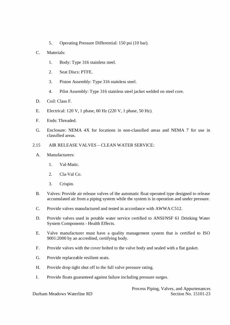
Process Piping, Valves, and AppurtenancesDurham Meadows Waterline RD Section No. 15101-23
5. Operating Pressure Differential: 150 psi (10 bar).
C. Materials:
1. Body: Type 316 stainless steel.
2. Seat Discs: PTFE.
3. Piston Assembly: Type 316 stainless steel.
4. Pilot Assembly: Type 316 stainless steel jacket welded on steel core.
D. Coil: Class F.
E. Electrical: 120 V, 1 phase, 60 Hz (220 V, 1 phase, 50 Hz).
F. Ends: Threaded.
G. Enclosure: NEMA 4X for locations in non-classified areas and NEMA 7 for use inclassified areas.
2.15 AIR RELEASE VALVES – CLEAN WATER SERVICE:
A. Manufacturers:
1. Val-Matic.
2. Cla-Val Co.
3. Crispin.
B. Valves: Provide air release valves of the automatic float operated type designed to releaseaccumulated air from a piping system while the system is in operation and under pressure.
C. Provide valves manufactured and tested in accordance with AWWA C512.
D. Provide valves used in potable water service certified to ANSI/NSF 61 Drinking WaterSystem Components - Health Effects.
E. Valve manufacturer must have a quality management system that is certified to ISO9001:2000 by an accredited, certifying body.
F. Provide valves with the cover bolted to the valve body and sealed with a flat gasket.
G. Provide replaceable resilient seats.
H. Provide drop tight shut off to the full valve pressure rating.
I. Provide floats guaranteed against failure including pressure surges.

Process Piping, Valves, and AppurtenancesDurham Meadows Waterline RD Section No. 15101-24
J. Mechanical linkage to provide sufficient mechanical advantage so that the valve willopen under full operating pressure.
1. Simple lever designs: Provide valves consisting of a single pivot arm and aresilient orifice button.
2. Compound lever designs: Provide valves consisting of two levers and anadjustable threaded resilient orifice button.
K. Provide valve body with threaded NPT inlets and outlets.
1. Inlet Connection: Provide hexagonal for a wrench connection.
2. Working Pressure: 175 psi.
3. Provide valves with two (2) additional NPT connections with ball valves asspecified herein, one connection with a plug and one with a hose coupling for thegauges, testing, and draining.
4. Provide a vacuum check on the outlet to prevent air from re-entering the systemduring negative pressure conditions.
L. Provide valves with an inflow preventer to prevent the introduction of contaminatedwater through the air valve outlet.
1. Provide the inflow preventer to allow the admittance and exhausting of air whilepreventing contaminated water from entering during normal operating conditions.
a. Provide the inflow preventer flow tested by an independent testing labapproved by the American Society of Sanitary Engineers.
M. Materials:
1. Valve Body, Cover and Baffle:
a. ASTM A536 Grade 65-45-12 Cast Ductile Iron. For working pressures300 psig (2100 kPa) and greater.
2. Floats, Orifice and linkage: Type 316 stainless steel, non-metallic components arenot acceptable.
3. Orifice Button: Viton for simple lever valves and Buna-N for compound leverdesigns.
4. Hardware: Type 316 stainless steel.
5. Screened Hood: Type 316 stainless steel.
N. Testing:

Process Piping, Valves, and AppurtenancesDurham Meadows Waterline RD Section No. 15101-25
1. Test valves at 1.5 times the rated working pressure.
2.16 MECHANICAL SEALS AT WALL PENETRATIONS:
A. Provide modular, mechanical type seals, consisting of inter-locking synthetic rubber linksshaped to continuously fill the annular space between the pipe and the wall opening.
B. Provide the elastomeric elements sized and selected per manufacturer's recommendationsand have the following properties as designated by ASTM. Coloration shall be throughoutelastomer for positive field inspection. Each link shall have a permanent identification ofthe size and manufacturer's name molded into it.
1. Temperature Range: -40 to +250ºF
2. Material: EPDM, ATSM D2000 M3 BA510
3. Color: Black
C. Modular seal pressure plates: Molded of glass reinforced Nylon Polymer with thefollowing properties:
1. Izod Impact - Notched: 2.05ft-lb/in. per ASTM D-256
2. Flexural Strength @ Yield: 30,750 psi per ASTM D-790
3. Flexural Modulus: 1,124,000 psi per ASTM D-790
4. Elongation Break: 11.07% per ASTM D-638
5. Specific Gravity:1.38 per ASTM D-792
D. Hardware: Type 316 stainless steel.
2.17 SHOP PAINTING:
A. Coat internal and external ferrous surfaces of valves with NSF Certified Epoxy inaccordance with ANSI/NSF Std. 61, and in conformance to AWWA D102 Inside SystemNo. 1 for all valves not specified to have a fusion bonded epoxy coating. The coatingsshall be applied by the valve manufacturer under controlled factory conditions and fieldapplication is strictly prohibited.
B. Process Valve Color: Red.

Process Piping, Valves, and AppurtenancesDurham Meadows Waterline RD Section No. 15101-26
PART 3 - EXECUTION
3.01 INSTALLATION:
A. Prior to installation, protect stored pipe, valves and appurtenances from damage due toexposure to sunlight, heat, dirt, debris, freezing and thawing, vandalism, etc.
B. Clean all debris, dirt, gravel, etc, from inside of piping before placing valves in place.
C. Erect and support valves in respective positions free from distortion and strain onappurtenances during handling and installation. Inspect material for defects inworkmanship and material. Clean out debris and foreign material from valve openingsand seats, test operating mechanisms to check functioning, and check nuts and bolts fortightness. Repair, valves and other equipment which do not operate easily or areotherwise defective at no additional cost to the Contracting Officer.
D. Set plumb and support valves in conformance with instructions of manufacturer. Shimvalves mounted on face of concrete vertically and grout in place. Install valves incontrol piping for access.
E. Provide bolted split sleeve coupling or flexible type grooved coupling on downstreamside of buried valves to assist in valve removal.
F. Where indicated provide Type 316 stainless steel stem extension to operating floorelevation as shown and provide the bevel gear operator with a fabricated steel floorstandand handwheel.
3.02 GATE VALVES:
A. Install gate valve stem as shown or with stems between vertical and 45 degrees abovethe horizontal. Valves installed with stems below horizontal are not acceptable.
3.03 CHECK VALVES:
A. Install swing check valves horizontally in pipelines unless otherwise indicated.
3.04 FIELD TESTING:
A. Pressure test valves with pipeline pressure testing.
B. Test functions of each valve.
C. Make all adjustments necessary to place valves in specified working order at time ofabove tests.
D. Remove all replace valves and appurtenances at no additional cost to the ContractingOfficer with equipment that will meet all requirements specified and indicated if unableto demonstrate to the satisfaction of the Contracting Officer that valves will perform theservice specified, indicated and as submitted and accepted.

Process Piping, Valves, and AppurtenancesDurham Meadows Waterline RD Section No. 15101-27
3.05 FIELD TOUCH-UP PAINTING:
A. After installation and accepted testing by the Contracting Officer, apply touch-up paintto all scratched, abraided and damaged shop painted surfaces. Coating type and colorshall match shop painting.
3.06 CONTRACT CLOSEOUT:
A. Provide in accordance with Section 01700.
END OF SECTION

Pipe Supports for Process PipingDurham Meadows Waterline RD Section No. 15105 - 1
SECTION 15105
PIPE SUPPORTS FOR PROCESS PIPING
PART 1 - GENERAL
1.01 DESCRIPTION
A. All Products to be provided and Work to be completed in accordance with NSF 61 andAWWA requirements specified for potable water supply installations.
B. Design, and provide a complete system of pipe supports with inserts, bolts, nuts, restrainingand hanger rods, washers, miscellaneous steel, sliding Teflon plates, and accessories asindicated and specified. The term pipe support includes hangers, guides, restraints, anchorsand saddles.
C. Provide all support systems and the design of all support systems for all piping as specifiedherein. The Contractor shall provide pipe support locations, configurations and detailsthrough accepted shop drawing submittals stamped by a Registered Professional Engineer asspecified herein.
D. The Contractor shall be responsible for the proper design, fabrication, location, shop drawingsand installation of all pipe supports in accordance with the specified requirements.
E. Pipe support locations and types for piping 1/2-inch and larger shall be determined by theContractor using the guidelines for support spacing specified herein and other criteriacontained in this pipe support specification. Guidelines for pipe supports may need to beadjusted based upon field coordination, field routing, or other considerations outlined hereinsuch as structural load limits. The Contractor may revise the pipe support locations anddetails through accepted shop drawing submittals stamped by a Registered ProfessionalEngineer as specified herein. The Contractor is responsible for the proper design, installationand fabrication of all pipe supports in accordance with the specified requirements. For pipesupports 1/2-inch and larger pipe support shop drawings together with a marked up pipingdrawing showing support number, location and typical type shall be submitted by theContractor for acceptance.
1. The Contractor shall be responsible for coordinating all pipe support designs for alltrades to ensure compliance with all of the requirements of this specification, includingbut not limited to the total limitations specified herein.
F. Design and provide all temporary pipe supports required during installation and testing.
1.02 REFERENCES
A. The American Society of Mechanical Engineers (AMSE):
1. B31.1: Power Piping.
B. American Society for Testing and Materials (ASTM):

Pipe Supports for Process PipingDurham Meadows Waterline RD Section No. 15105 - 2
1. A36: Standard Specification for Carbon Structural Steel
2. A307: Standard Specification for Carbon Steel Externally Threaded Standard Fasteners
3. A312: Seamless and Welded Austenic Stainless Steel Pipe
4. A500: Cold Formed Welded and Seamless Carbon Steel Structural Tubing.
5. A572: Specification for Steel Plate.
6. E165: Practice for Liquid Penetrant Inspection Method.
7. E709: Practice for Magnetic Particle Examination.
8. American Welding Society (AWS):
9. D1.1: Structural Welding
10. Fluid Sealing Association: Technical Handbook.
C. Manufacturers’ Standardization Society (MSS):
1. SP-58: Pipe Hangers and Supports - Materials and Design.
2. SP-69: Pipe Hangers and Supports - Selection and Application.
3. SP-89: Pipe Hangers and Supports - Fabrication and Installation Practices.
4. SP-90: Guidelines on Terminology for Pipe Hangers and Supports.
D. National Association of Expansion Joint Manufacturers: Standards of the Expansion JointManufacturers Association, Inc.
1.03 SUBMITTALS
A. Submit the following in accordance with Section 01300.
1. Pipe support drawings specified herein and including data for accessory items foracceptance prior to fabrication. Including:a. A table of applied forces and moments.
b. A complete bill of materials.
c. A unique identification and revision level.
d. Stamp of a Registered Professional Engineer, registered in the state where thisproject is being constructed, experienced in pipe support design and pipe stressanalysis as specified herein.
e. Detailed connections to existing structure.
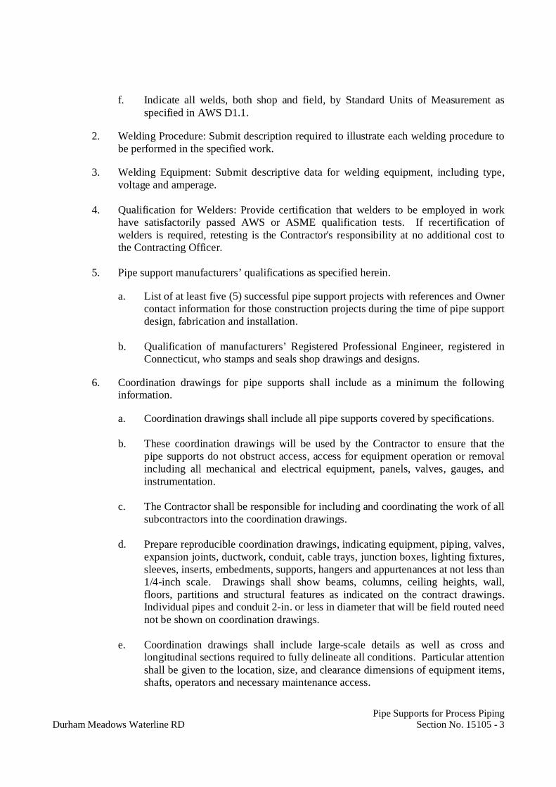
Pipe Supports for Process PipingDurham Meadows Waterline RD Section No. 15105 - 3
f. Indicate all welds, both shop and field, by Standard Units of Measurement asspecified in AWS D1.1.
2. Welding Procedure: Submit description required to illustrate each welding procedure tobe performed in the specified work.
3. Welding Equipment: Submit descriptive data for welding equipment, including type,voltage and amperage.
4. Qualification for Welders: Provide certification that welders to be employed in workhave satisfactorily passed AWS or ASME qualification tests. If recertification ofwelders is required, retesting is the Contractor's responsibility at no additional cost tothe Contracting Officer.
5. Pipe support manufacturers’ qualifications as specified herein.
a. List of at least five (5) successful pipe support projects with references and Ownercontact information for those construction projects during the time of pipe supportdesign, fabrication and installation.
b. Qualification of manufacturers’ Registered Professional Engineer, registered inConnecticut, who stamps and seals shop drawings and designs.
6. Coordination drawings for pipe supports shall include as a minimum the followinginformation.
a. Coordination drawings shall include all pipe supports covered by specifications.
b. These coordination drawings will be used by the Contractor to ensure that thepipe supports do not obstruct access, access for equipment operation or removalincluding all mechanical and electrical equipment, panels, valves, gauges, andinstrumentation.
c. The Contractor shall be responsible for including and coordinating the work of allsubcontractors into the coordination drawings.
d. Prepare reproducible coordination drawings, indicating equipment, piping, valves,expansion joints, ductwork, conduit, cable trays, junction boxes, lighting fixtures,sleeves, inserts, embedments, supports, hangers and appurtenances at not less than1/4-inch scale. Drawings shall show beams, columns, ceiling heights, wall,floors, partitions and structural features as indicated on the contract drawings.Individual pipes and conduit 2-in. or less in diameter that will be field routed neednot be shown on coordination drawings.
e. Coordination drawings shall include large-scale details as well as cross andlongitudinal sections required to fully delineate all conditions. Particular attentionshall be given to the location, size, and clearance dimensions of equipment items,shafts, operators and necessary maintenance access.

Pipe Supports for Process PipingDurham Meadows Waterline RD Section No. 15105 - 4
f. Make all minor changes in duct, pipe or conduit routings that do not affect theintended function, but items may not be resized or exposed items relocatedwithout the approval of the Contracting Officer. No changes shall be made in anywall locations, ceiling heights, door swings or locations, window or otheropenings or other features affecting the function or aesthetic effect of thebuilding. If conflicts or interferences cannot be resolved, the Contracting Officershall be notified. Any problems of coordination that require architectural orstructural changes of design shall be submitted to the Contracting Officer forresolution.
g. After the reproducible drawings have been coordinated and all changes have beenmade, the drawings shall be signed by the Contractor and all subcontractorsindicating that all work on that drawing has been coordinated with all associatedvendors and subcontractors and all conflicts have been resolved.
h. Relocation of any duct, pipe, conduit or other material that has been installedwithout proper coordination among all trades shall be performed at no additionalcost to the Contracting Officer.
7. Written notification of any deviations from the requirements of this specification.
8. Support documentation and justification as specified.
9. Certificates of Design signed by a Registered Professional Engineer for all pipesupports.
10. Manufacturer’s product data and specifications for shop painting.
11. Material Certification:
a. Provide certification from the manufacturer that the materials of constructionspecified are recommended and suitable for the service conditions specified andindicated. If materials other than those specified are proposed based onincompatibility with the service conditions, provide technical data andcertification that the proposed materials are recommended and suitable for theservice conditions specified and indicated including an installation list of aminimum of five (5) installations in operation for a minimum of five (5) years.Provide proposed materials at no additional cost to the Contracting Officer.
12. Where materials are not specified, provide technical data and certification that theproposed materials are recommended and suitable for the service conditions specifiedand indicated.
13. A copy of the contract mechanical process, and structural drawings, with addenda thatare applicable to the equipment specified in this section, marked to show all changesnecessary for the equipment proposed for this specification section. If no changes arerequired, mark all drawings with “No changes required” or provide a statement that nochanges are required.
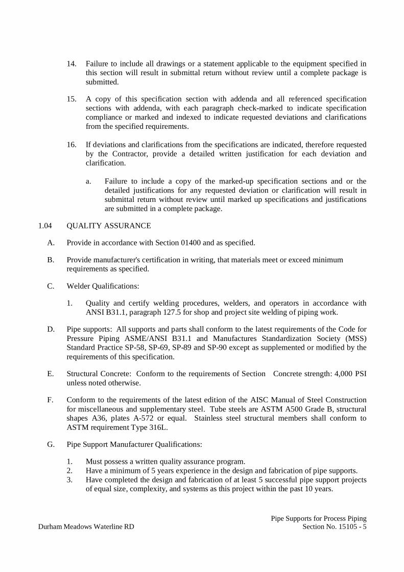
Pipe Supports for Process PipingDurham Meadows Waterline RD Section No. 15105 - 5
14. Failure to include all drawings or a statement applicable to the equipment specified inthis section will result in submittal return without review until a complete package issubmitted.
15. A copy of this specification section with addenda and all referenced specificationsections with addenda, with each paragraph check-marked to indicate specificationcompliance or marked and indexed to indicate requested deviations and clarificationsfrom the specified requirements.
16. If deviations and clarifications from the specifications are indicated, therefore requestedby the Contractor, provide a detailed written justification for each deviation andclarification.
a. Failure to include a copy of the marked-up specification sections and or thedetailed justifications for any requested deviation or clarification will result insubmittal return without review until marked up specifications and justificationsare submitted in a complete package.
1.04 QUALITY ASSURANCE
A. Provide in accordance with Section 01400 and as specified.
B. Provide manufacturer's certification in writing, that materials meet or exceed minimumrequirements as specified.
C. Welder Qualifications:
1. Quality and certify welding procedures, welders, and operators in accordance withANSI B31.1, paragraph 127.5 for shop and project site welding of piping work.
D. Pipe supports: All supports and parts shall conform to the latest requirements of the Code forPressure Piping ASME/ANSI B31.1 and Manufactures Standardization Society (MSS)Standard Practice SP-58, SP-69, SP-89 and SP-90 except as supplemented or modified by therequirements of this specification.
E. Structural Concrete: Conform to the requirements of Section Concrete strength: 4,000 PSIunless noted otherwise.
F. Conform to the requirements of the latest edition of the AISC Manual of Steel Constructionfor miscellaneous and supplementary steel. Tube steels are ASTM A500 Grade B, structuralshapes A36, plates A-572 or equal. Stainless steel structural members shall conform toASTM requirement Type 316L.
G. Pipe Support Manufacturer Qualifications:
1. Must possess a written quality assurance program.2. Have a minimum of 5 years experience in the design and fabrication of pipe supports.3. Have completed the design and fabrication of at least 5 successful pipe support projects
of equal size, complexity, and systems as this project within the past 10 years.

Pipe Supports for Process PipingDurham Meadows Waterline RD Section No. 15105 - 6
4. Retains the services of a Registered Professional Engineer, registered in the state wherethis project is being constructed, with a minimum of ten years experience in the designof piping systems and pipe supports.
5. Manufacturers’ Standardization Society (MSS) Member.6. Have a field service technician on staff with at least 5 years experience in resolving
field installation, interference and interface problems associated with the design,installation and manufacture of pipe supporting components.
H. Hanger inspections shall be performed in accordance with MSS-SP-89 and ASME B31.1.
1.05 DELIVERY, STORAGE AND HANDLING
A. Comply with the requirements specified in Section 01600 – MATERIALS ANDEQUIPMENT.
PART 2 - PRODUCTS
2.01 MATERIALS
A. Provide Type 316L stainless steel for pipe supports, hangers, guides, restraints, and anchors.
B. Provide only new material. Previously used and/or scrap material is not acceptable.
C. Provide tube steels that are ASTM A500 Grade B, Structural shapes A-36, plates A-572 orequal.
D. Provide sliding Teflon plates. The sliding surfaces shall be a nominal 3/8-inches glass filledTeflon bonded to stainless steel backup plate with a 10 gauge minimum thickness. Thebearing pad upper and lower units shall be as follows: Conslide Type CSA elements asmanufactured by Con-Serv. Inc., Balco TFE Slide Bearing Plates 10N-cs as manufactured byBalco Inc., or Dynalon Slide Bearings as manufactured by JVI, Inc. or acceptable equivalentproduct.
E. Concrete anchor bolts - Hilti Kwik-Bolt II Stud Anchors, Rawl Bolt, Phillips Wedge Anchors,or equal.
2.02 DESIGN, LOCATION, AND TYPE OF PIPE SUPPORTS
A. Design and provide pipe supports for piping 1/2-inch and larger to include the followingloads:
1. Gravity Force: This force includes the weight of pipe, pipe contents (hydro load),valves, in-line equipment, insulation and any other weight imposed on the piping and/orpipe support.
2. Thermal Expansion Force: This force is developed by the restraint of free enddisplacement of the piping due to thermal growth.
3. Hydrostatic/Dynamic Forces: These forces are developed due to the internal pressure(positive and negative) during operation of the piping system. These forces include the
Pipe Supports for Process PipingDurham Meadows Waterline RD Section No. 15105 - 7
forces due to water hammer, pressure pulses due to rapid valve closure, fluid dischargeresulting from pump startup, operation of positive displacement pumps, etc.
B. Provide supports, guides, anchors, flexible couplings and expansion joints in accordance withthe coupling and joint manufacturers’ specifications and requirements.
C. Where possible, provide pipe supports, which are the manufacturers’ standard products.
1. Provide pipe supports with individual means of adjustment for alignment.
2. Provide pipe supports complete with appurtenances including locking and adjustingnuts.
3. Hanger rods shall be subjected to tension only.
4. Where lateral or axial pipe movement occurs, provide hangers for the necessary swingwithout exceeding 4 degrees. Provide base supports designed using pipe slides. Thebearing surfaces: 0.06 coefficient of friction or less.
5. Provide concrete inserts capable of supporting the design loads.
6. Metal framing systems will be acceptable to support piping 2 inch (50 mm) and smaller.
7. Provide insulated piping supported using rigid load bearing insulation (baton boardtype) with 16 gauge (1.5 mm) shields to fit between the insulation and the support.Shields to encompass a minimum 1/3 of the pipe circumference and be 12 inch (300mm) in length.
8. Provide load-bearing insulation capable of supporting the load, as a minimum on thebottom 60 degrees of the pipe support. Cope insulation and adjust to avoid interferenceof steel structures.
9. Provide supplementary steel as needed.
10. Do not support pipes from other pipe, conduits or metal stairs.
11. Chain, strap, T-bar, perforated bar and/or wire hangers are not acceptable.
12. Contact between piping and dissimilar metals such as hangers, building structural workor equipment subject to galvanic action is not acceptable.
13. All pipe supports located in fluid flow shall be supplied with double nutting.
D. Provide thrust anchors to resist thrust where required. Wall pipes may be used as thrustanchors if so designed. Welded attachments shall be of material comparable to that of thepiping, and designed in accordance with governing codes.
E. Provide expansion joints where indicated and where required based on Contractor's design ofthe pipe support system. Indicate expansion joints on submittal drawings.
F. For piping 2-inch and smaller provide manufacturer’s standard supports and standard spacingguidelines
Pipe Supports for Process PipingDurham Meadows Waterline RD Section No. 15105 - 8
G. Pipe supports connected to structural framing and slabs are subject to the followinglimitations:
H. All outside above ground supports shall be Type 316L stainless steel as specified herein.
I. Provide pipe supports that do not overload or over stress the piping, equipment, or structurethat they are supporting or to which they are attached. Allowable pipe stress to be withinANSI B31.1 code allowable.
J. The Contractor shall provide the services of a field service technician (preferably from thepipe support manufacturer) to field coordinate the locations of supports and resolveinterferences and conflicts encountered during installation.
2.03 FABRICATION
A. Provide pipe supports formed in accordance with paragraph 5.1 of MSS-SP-58.
B. Providing welding in accordance with Structural Welding Code.
C. Provide dimensional tolerances as specified in MSS-SP-89.
D. Provide threading and tapping in accordance with MSS-SP-89.
2.04 SHOP PAINTING
A. Primer and Finish Paint: Shop apply to all exterior ferrous surfaces, high solids epoxy inaccordance with Section 09900 - PAINTING.
B. Ferrous surfaces which are not to be painted shall be given a shop applied coat of grease orrust resistant coating.
C. Provide additional shop paint coating for touch-up to all surfaces after installation and testingis completed and equipment accepted.
PART 3 - EXECUTION
3.01 INSTALLATION
A. Install items in accordance with manufacturers’ printed instructions and as indicated andspecified herein.
B. Perform welding in accordance with Structural Welding Code:
1. Visually inspect welding while the operators are making the welds and again after thework is completed in accordance with AWS D1.1 Section 6.0. After the welding iscompleted, hand or power wire brush welds, and clean them before the QualifiedInspector makes the check inspection. The Qualified Inspector shall inspect welds withmagnifiers under light for surface cracking, porosity, and slag inclusions; excessiveroughness; unfilled craters; gas pockets; undercuts; overlaps; size and insufficient throat
Pipe Supports for Process PipingDurham Meadows Waterline RD Section No. 15105 - 9
and concavity. The Qualified Inspector shall inspect the preparation of grove welds forthroat opening and for snug positioning for back-up bars.
2. Nondestructive evaluation of welds connecting structural steel members subjected tocritical stresses: Perform in accordance with the weld quality and standards ofacceptance in AWS D1.1.
3. Magnetic Particle Inspection: Perform in accordance with ASTM E709.
4. Liquid Penetrant Inspection: Perform in accordance with ASTM E165.
5. For weld areas containing defects exceeding the standards of acceptance in accordancewith AWS D1.1, Section 3.7. Provide additional testing of the repaired area at noadditional cost to the Contracting Officer.
6. Test Locations: As selected by the Contracting Officer.
7. Correct any deficiencies detected as directed by the Contracting Officer’sRepresentative at no additional cost.
C. Proceed with the installation of the pipe supports only after required building structural workhas been completed and concrete support structure has reached its 28-day compressivestrength as specified in Division 3 .
D. Install pipe supports to comply with MSS-SP-89. Group parallel runs of horizontal piping tobe supported together on trapeze type hangers.
E. Install pipe supports to provide indicated pipe slopes. Do not exceed maximum pipedeflection allowed by ANSI B31.1.
F. For exposed continuous pipe runs, install pipe supports of same type and style as installed foradjacent similar piping.
G. Install pipe supports to allow controlled movement of piping systems. Permit freedom ofmovement between pipe anchors, and facilitate action of expansion joints, expansion loops,expansion bends, and similar units.
H. Piping to be free to move when it expands or contracts except where fixed anchors areindicated or required by the Contractor's pipe support systems. Where hanger rod swinglength cannot be provided or where pipe movement based on expansion of 1 inch/100 feet, foreach 100 degrees F change in temperature exceed 1/2-inch, provide sliding supports.
I. Prevent contact between dissimilar metals. Where concrete or metal support is used, place1/8-inch thick Teflon, neoprene rubber, or plastic strip under piping at point of bearing. Cutto fit entire area of contact between pipe and pipe support.
J. Prevent electrolysis in support of copper tubing by use of pipe supports which are plasticcoated. Electrician's tape is not an acceptable isolation method.
K. Apply an anti-seize compound to nuts and bolts on all pipe supports.

Pipe Supports for Process PipingDurham Meadows Waterline RD Section No. 15105 - 10
L. Locate reinforcing steel in concrete structure with x-ray prior to drilling for embedment platesand anchor bolts. Avoid contact or interference with reinforcing steel.
3.02 SUPPORT PIPING FROM STRUCTURAL FRAMING, UNLESS OTHERWISEINDICATED.
A. Concrete Inserts:
1. Use existing embedded concrete items whenever possible.
2. Use expansion anchors only when existing embedded attachment points are notavailable or unsuitable. Attach to hardened concrete or completed masonry.
3.03 THRUST ANCHORS AND GUIDES
A. Thrust Anchors:
1. Center thrust anchors between expansion joints and between elbows and expansionjoints for suspended piping. Anchors must hold pipe rigid to force expansion andcontraction movement to take place at expansion joints and/or elbows and to precludeseparation of joints.
2. Restraining rod size and number shall be as indicated and adhere to manufacturersrecommendations as a minimum.
B. Pipe guides: Provide adjacent to sliding expansion joints in accordance with recommendationsof the National Association of Expansion Joint Manufacturers and the specific jointmanufacturer.
3.04 PIPE SUPPORTS
A. Where piping of various sizes is to be supported together, space supports for the largest pipesize and install intermediate supports for smaller diameter pipes.
B. Provide minimum of two pipe supports for each pipe piece.
C. Where pipe connects to equipment, support pipe independently from the equipment. Do notuse equipment to support piping.
D. Provide pipe supports so that there is no interference with maintenance or removal ofequipment.
E. Unless otherwise indicated or authorized by the Contracting Officer’s Representative placepiping running parallel to walls approximately 1-1/2 inch out from face of wall and at least 3in. below ceiling.
F. Pedestal pipe supports: adjustable with stanchion, saddle, and anchoring flange. Providegrout between baseplate and floor.
G. Piping supports for vertical piping passing through floor sleeves: use hot dipped galvanizedsteel riser clamps.

Pipe Supports for Process PipingDurham Meadows Waterline RD Section No. 15105 - 11
H. Support piping to prevent strain on valves, fittings, and equipment. Provide pipe supports atchanges in direction or elevation, adjacent to flexible couplings, adjacent to non-rigid joints,and where otherwise indicated. Do not install pipe supports in equipment access areas orbridge crane runs.
I. Stacked horizontal runs of piping along walls may be supported by metal framing systemattached to concrete insert channels.
J. Do not support piping from other piping.
K. Designs generally accepted as exemplifying good engineering practice, using stock orproduction parts, shall be utilized whenever possible.
L. Whenever possible, pipe attachments for horizontal piping shall be pipe clamps.
M. All rigid rod hangers shall provide a means of vertical adjustment after erection.
N. Where the piping system is subjected to shock loads, such as disturbances due to pumpdischarge or thrust due to actuation of safety valves, hanger design shall include provisionsfor rigid restraints or shock absorbing devices.
O. Hanger rods shall be subject to tensile loading only. At hanger locations where lateral or axialmovement is anticipated suitable linkage shall be provided to permit rod swing.
P. Hanger spacing shall not exceed the spacing listed below:
1. In the case of concentrated loads the supports shall be placed as close as possible to theload to reduce the bending stress.
2. Where changes in direction of the piping system occur between supports, the totallength between supports shall be kept to less than three-fourths of the full span. Whenpractical, a support shall be placed immediately adjacent to any change in direction ofthe piping system.
Q. Where practical, riser piping shall be supported independently of the connected horizontalpiping. Pipe support attachments to the riser piping shall be riser clamp shear lugs. Weldedattachments shall be of material comparable to that of the piping, and designed in accordancewith governing codes. If friction is relied upon to support riser piping proper justification anddocumentation shall be submitted to ensure that enough friction force is provided to resist theapplied loading.
R. Hanger components shall not be used for purposes other than for which they were designed.They shall not be used for rigging and erection purposes.
S. All threads shall be UNC unless otherwise specified.
T. TFE slide bearing plates with steel backup plates shall be stitch weld attachments to thestructure. A 1/8-inch fillet weld, 1/2-inch long every 3 inches on center each side of anelement shall be used unless otherwise indicated or specified by the manufacturers’ writtenrecommendations. Bearing elements with slots or holes shall be stitch welded in place for
Pipe Supports for Process PipingDurham Meadows Waterline RD Section No. 15105 - 12
location. The TFE surfaces of the bearings shall be maintained clean and free from grit, dirtor grease.
3.05 INSULATED PIPING
A. Attach clamps, including spacers (if any), to piping with clamps projecting through insulation;do not exceed allowable pipe stresses.
B. Where vapor barriers are indicated on water piping, install coated protective shields.
3.06 CONTRACT CLOSEOUT
A. Provide in accordance with Section 01700.
END OF SECTION

Self-Contained Automatic Control Valves and AppurtenancesDurham Meadows Waterline RD Waterline RD Section No. 15112-1
SECTION 15112
SELF-CONTAINED AUTOMATIC CONTROL VALVES AND APPURTENANCES
PART 1 - GENERAL
1.01 DESCRIPTION:
A. Provide and test self-contained automatic control valves and appurtenances as indicatedand specified.
1. Provide sizes and capacities as indicated or specified.
1.02 REFERENCES:
A. American Society of Mechanical Engineers (ASME):
1. B16.1: Standard for Cast Iron Pipe Flanges and Flanged Fittings, 125 lb.
2. B16.4: Cast-Iron Threaded Fittings, Class 125 and 250.
B. American Society for Testing and Materials International (ASTM):
1. A48: Standard Specification for Gray Iron Castings.
2. A126: Standard Specification for Gray Iron Castings for Valves, Flanges and PipeFittings.
3. A536: Standard Specification for Ductile Iron Castings.
C. American Water Works Association (AWWA):
1. C500: Metal-Seated Gate Valves for Water Supply Service.
D. NSF International (NSF):
1. 61: Drinking water system components Health effects.
1.03 SUBMITTALS:
A. Submit the following in accordance with Section 01300:
1. Data, regarding valve characteristics and performance including Cv.
2. Shop drawing data for accessory items.
3. Manufacturer's literature as needed to supplement certified data.
Self-Contained Automatic Control Valves and AppurtenancesDurham Meadows Waterline RD Waterline RD Section No. 15112-2
4. Operating and maintenance instructions and parts lists.
5. Listing of reference installations as specified with contact names and telephonenumbers.
6. Valve shop test results.
7. Qualifications of field service technician.
8. Shop and Field inspections reports.
9. List of recommended spare parts other than those specified.
10. Recommendations for short and long term storage.
11. Special tools.
12. Shop and field testing procedures and equipment to be used.
13. Number of service technician days provided and per diem field service rate.
14. Manufacturer’s product data and specifications for shop painting.
15. Provide a layout drawing, plan and section showing orientation of valves andnearest obstructions for each valve.
16. Manufacturer's product data and specifications for shop coating and painting.
17. Provide a listing of the materials recommended for each service specified andindicated. Provide documentation showing compatibility with process fluid andservice specified and indicated.
18. The most recent ISO 9000 series certification or quality system plan.
19. Material Certification:
a. Provide certification from the equipment manufacturer that the materials ofconstruction specified are recommended and suitable for the serviceconditions specified and indicated. If materials other than those specifiedare proposed based on incompatibility with the service conditions, providetechnical data and certification that the proposed materials are recommendedand suitable for the service conditions specified and indicated including aninstallation list of a minimum of five (5) installations in operation for aminimum of five (5) years. Provide proposed materials at no additional costto the Contracting Officer.
b. Where materials are not specified, provide technical data and certificationthat the proposed materials are recommended and suitable for the serviceconditions specified and indicated.

Self-Contained Automatic Control Valves and AppurtenancesDurham Meadows Waterline RD Waterline RD Section No. 15112-3
B. A copy of this specification section with addenda and all referenced specificationsections with addenda, with each paragraph check-marked to indicate specificationcompliance or marked to indicate requested deviations and clarifications from thespecified requirements.
1. If deviations and clarifications from the specifications are indicated, thereforerequested by the Contractor, provide a detailed written justification for eachdeviation and clarification.
2. Failure to include a copy of the marked-up specification sections and or thedetailed justifications for any requested deviation or clarification will result insubmittal return without review until marked up specification and justification areresubmitted with the entire package.
1.04 SPARE PARTS:
A. Comply with manufacturer’s recommendations and requirements specified in Section01610.
1.05 QUALITY ASSURANCE:
A. Comply with the requirements specified in Section 01400.
B. Provide enclosures for the area classifications specified and indicated.
C. Contractor responsible for verifying outside diameter of pipe to be tapped.
D. Services of Manufacturer’s Representative as stated in Section 01400 and specifiedherein.
E. Manufacturer of valve shall have a minimum of five (5) operating installations withpumps of the size specified and in the same service as specified operating for not lessthan five (5) years.
1.06 DELIVERY, STORAGE AND HANDLING:
A. Comply with the requirements specified in Section 01610 and as specified.
PART 2 - MATERIALS
2.01 SELF-CONTAINED AUTOMATIC CONTROL VALVES:
A. Manufacturers:
1. Cla-Val
2. Ross
Self-Contained Automatic Control Valves and AppurtenancesDurham Meadows Waterline RD Waterline RD Section No. 15112-4
3. Golden Anderson
B. Type: Pilot operated piston or diaphragm design, automatic valve.
1. Body Type: Globe or angle body, provide body style as indicated.
2. Provide valve that utilize line pressure as its operating source.
3. Provide valves with all necessary accessories to provide a complete operating unit.
C. Provide size and configuration as specified and indicated.
D. End Connections:
1. Valves 3-inches and Smaller: NPT
2. Valves 1-1/2-inches and Larger: Flanged end connections ANSI standard B16.1 ofa class to mate with pipe flanges.
E. Diameter of Seat Opening: Equal to diameter of pipe size.
F. Provide valves designed to remove and replace all internal parts without removing thevalve body from the pipeline.
G. Diaphragm style valves: Provide NSF 61 approved replaceable seals designed to preventmetal to metal contact.
1. Material: Type 316 stainless.
H. Piston style valves: Provide treated leather replaceable seals designed to prevent metal tometal contact.
1. Material: Treated leather or polyurethane seats.
I. Minimum pressure rating: 150 psi
J. Hydrostatic test: 300 psi
K. Provide a visual position indicator.
L. Materials:
1. Valve Body and Covers: A536 (65-45-12) ductile iron or ASTM A126 cast iron.
a. Diaphragm style valve cover: Provide a separate stem cap giving access tothe stem for alignment check, spring installation and ease of assembly.
(1) Provide main bonnet cover and locating pins to accurately locate themain valve body.

Self-Contained Automatic Control Valves and AppurtenancesDurham Meadows Waterline RD Waterline RD Section No. 15112-5
b. Internal and External Coating: NSF 61 fusion bonded epoxy.
c. Provide two NPT connections on each side of the valve body for externalcontrol piping and provide Type 316 stainless steel plugs for all unused ports
2. Piston: ASTM B62 Bronze, for piston style valves.
3. Diaphragm: EPDM or Buna N of the rolling type design.
4. Stem: Type 316 stainless steel, for diaphragm style valves.
5. Seat Disc:
a. Valves 12-inches and Smaller: ASTM B62 Bronze, Cast Iron, Ductile Ironor Type 316 stainless steel.
b. Valves 14-inches through 36-inches :
(1) ASTM A126 cast iron center with ASTM B62 bronze outer ring orcast iron.
(2) One piece design in Ductile Iron or Type 316 stainless steel.
c. Valves 42-inches through 48-inches: Cast steel, Cast Iron, Ductile Iron orType 316 stainless steel.
6. Plates:
a. Valves 4-inches through 36-inches: ASTM B62 bronze or Ductile iron A536(65-45-12).
b. Valves 42-inches through 48-inches: Cast steel or Ductile Iron A536 (65-45-12).
7. Bushings:
a. Valves 4-inches through 36-inches: ASTM B62 bronze.
b. Valves 42-inches through 48-inches: Type 316 stainless steel.
8. Seat Ring, Stem Nuts, Indicator, and Seat Packing Support: Type 316 stainlesssteel.
9. External Control Piping, Strainers, and Valves: Type 316 stainless steel.
a. Provide tubing or hose.

Self-Contained Automatic Control Valves and AppurtenancesDurham Meadows Waterline RD Waterline RD Section No. 15112-6
M. Valve Types:
1. Pressure Reducing Valves:
a. Provide reduced-port pressure reducing valves designed to maintain a pre-adjusted downstream pressure regardless of changes in flow rate.
b. Provide an external pilot control including an external strainer, needle valve,position indicator, gauges, and isolation ball valves.
c. Provide valves with ductile iron body and cover meeting ASTM A536,ANSI B16.42, 150 F pressure class. Disc guide, seat and cover bearing shallbe stainless steel, with Buna-N disc and nylon reinforced Buna-N rubberdiaphragm. Disc retainer and diaphragm washer to be cast iron.
d. Provide reduced internal port type with anti-cavitation valve wherespecified.
e. Provide settings as specified and indicated. Adjustment range is 15-75 psi.
2. Anti-cavitation Valves:
a. Provide hydraulically operated, single diaphragm actuated globe patternvalve with diaphragm assembly forming a sealed chamber to separateoperating pressure from line pressure.
b. Provide valves with an anti-cavitation trim design to regulate internalpressure in high differential applications for relief valves having atmosphericdischarge up to 150 psid.
c. Provide high service type with 316 SS disc guide and seat with drip-tightpositive sealing. Valve shall be serviced without removal from piping.
d. Provide settings as specified and indicated.
3. Altitude Valves – 1 way:
a. Provide valves designed as a two position control valve, either fully open orfully closed.
(1) Provide valves to allow normal forward flow to fill the reservoir ortank to the maximum level and then closes drip-tight at the set-point.
(2) Provide valves to opens to refill the reservoir or tank once the leveldrops a fixed distance below the high water level.
(3) Valves do not operate as a check valve to prevent reverse flow.

Self-Contained Automatic Control Valves and AppurtenancesDurham Meadows Waterline RD Waterline RD Section No. 15112-7
b. Provide an external pilot control including an external strainer, needle valve,position indicator, gauges and isolation ball valves.
c. Provide positive action valve switch assembly actuated by opening orclosing of the altitude valve to provide remote indication of valve position.The switch shall be a UL listed single pole, double throw with a normallyclosed contact when the valve is actuated in the close position. Switch shallbe rated for 15A at 120VAC and shall be weather proof.
d. Provide settings as specified and indicated.
N. Provide all valves in compliance with NSF 61 for all services.
PART 3 - EXECUTION
3.01 INSTALLATION:
A. Prior to installation, protect stored valves and appurtenances from damage due toexposure to sunlight, heat, dirt, debris, freezing and thawing, vandalism, etc.
B. Clean all debris, dirt, gravel, etc, from inside of piping before placing valves in place.
C. Erect and support valves in respective positions free from distortion and strain onappurtenances during handling and installation. Inspect material for defects inworkmanship and material. Clean out debris and foreign material from valve openingsand seats, test operating mechanisms to check functioning, and check nuts and bolts fortightness. Repair valves and other equipment which does not operate easily or areotherwise defective at no additional cost to the Contracting Officer.
D. Set plumb and support valves in conformance with instructions of manufacturer. Shimvalves mounted on face of concrete vertically and grout in place. Install valves incontrol piping for access.
3.02 FIELD TESTING:
A. Pressure test valves with pipeline pressure testing.
B. Test functions of each valve.
C. Make all adjustments necessary to place valves in specified working order at time ofabove tests.
D. Remove all replaced valves and appurtenances at no additional cost to the ContractingOfficer with equipment that will meet all requirements specified and indicated if unableto demonstrate to the satisfaction of the Contracting Officer that valves will perform theservice specified, indicated and as submitted and accepted.
Self-Contained Automatic Control Valves and AppurtenancesDurham Meadows Waterline RD Waterline RD Section No. 15112-8
3.03 FIELD TOUCH-UP PAINTING:
A. After installation and accepted testing by the Contracting Officer apply touch-up paint toall scratched, abraided and damaged shop painted surfaces. Coating type and color shallmatch shop painting.
3.04 CONTRACT CLOSEOUT:
A. Provide in accordance with Section 01700.
END OF SECTION
FlowmeterDurham Meadows Waterline RD Waterline RD Section No. 15115-1
SECTION 15115
FLOWMETER
PART 1 - GENERAL
1.01 DESCRIPTION:
A. Provide and test flowmeter and appurtenances as indicated and specified.
1. Provide sizes and capacities as indicated or specified.
1.02 REFERENCES:
A. American Society of Mechanical Engineers (ASME):
1. B16.1: Standard for Cast Iron Pipe Flanges and Flanged Fittings, 125 lb.
2. B16.4: Cast-Iron Threaded Fittings, Class 125 and 250.
B. American Society for Testing and Materials International (ASTM):
1. A48: Standard Specification for Gray Iron Castings.
2. A536: Standard Specification for Ductile Iron Castings.
C. NSF International (NSF):
1. 61: Drinking water system components Health effects.
1.03 SUBMITTALS:
A. Submit the following in accordance with Section 01300:
1. Data, regarding flowmeter characteristics and performance including Cv.
2. Shop drawing data for accessory items.
3. Manufacturer's literature as needed to supplement certified data.
4. Operating and maintenance instructions and parts lists.
5. Listing of reference installations as specified with contact names and telephonenumbers.
6. Flowmeter shop test results.
7. Qualifications of field service technician.

FlowmeterDurham Meadows Waterline RD Waterline RD Section No. 15115-2
8. Shop and Field inspections reports.
9. List of recommended spare parts other than those specified.
10. Recommendations for short and long term storage.
11. Special tools.
12. Shop and field testing procedures and equipment to be used.
13. Number of service technician days provided and per diem field service rate.
14. Manufacturer’s product data and specifications for shop painting.
15. Provide a layout drawing, plan and section showing orientation offlowmeter.
16. Manufacturer's product data and specifications for shop coating andpainting.
17. Provide a listing of the materials recommended for each service specifiedand indicated. Provide documentation showing compatibility with processfluid and service specified and indicated.
18. The most recent ISO 9000 series certification or quality system plan.
19. Material Certification:
a. Provide certification from the equipment manufacturer that thematerials of construction specified are recommended and suitablefor the service conditions specified and indicated. If materials otherthan those specified are proposed based on incompatibility with theservice conditions, provide technical data and certification that theproposed materials are recommended and suitable for the serviceconditions specified and indicated including an installation list of aminimum of five (5) installations in operation for a minimum offive (5) years. Provide proposed materials at no additional cost tothe Contracting Officer.
b. Where materials are not specified, provide technical data andcertification that the proposed materials are recommended andsuitable for the service conditions specified and indicated.
B. A copy of this specification section with addenda and all referenced specificationsections with addenda, with each paragraph check-marked to indicatespecification compliance or marked to indicate requested deviations andclarifications from the specified requirements.

FlowmeterDurham Meadows Waterline RD Waterline RD Section No. 15115-3
1. If deviations and clarifications from the specifications are indicated, thereforerequested by the Contractor, provide a detailed written justification for eachdeviation and clarification.
2. Failure to include a copy of the marked-up specification sections and or thedetailed justifications for any requested deviation or clarification will result insubmittal return without review until marked up specification and justification areresubmitted with the entire package.
1.04 SPARE PARTS:
A. Comply with manufacturer’s recommendations and requirements specified in Section01610.
1.05 QUALITY ASSURANCE:
A. Comply with the requirements specified in Section 01400.
B. Provide enclosures for the area classifications specified and indicated.
C. Contractor responsible for verifying outside diameter of pipe to be tapped.
D. Services of Manufacturer’s Representative as stated in Section 01400 and specifiedherein.
E. Manufacturer of flowmeter shall have a minimum of five (5) operating installations withflows as specified and in the same service as specified operating for not less than five (5)years.
1.06 DELIVERY, STORAGE AND HANDLING:
A. Comply with the requirements specified in Section 01610 and as specified.
PART 2 - MATERIALS
2.01 FLOWMETER:
A. Manufacturers:
1. Neptune
2. Or equal
B. Type
1. Meters shall consist of a combination of an AWWA Class II in-line horizontal axisturbine for measuring high rates of flow and a positive displacement bypass meterconforming to AWWA C700 for measuring low rates of flow.

FlowmeterDurham Meadows Waterline RD Waterline RD Section No. 15115-4
2. An automatic valve shall direct the flow from the bypass meter to themainline meter as flow rates increase and back to the bypass meter as flowrates decrease.
3. All components of the meter assembly shall be both UL (Underwriter’sLaboratory) Listed and FM (Factory Mutual) approved for fire service use.
4. Meters shall be certified to NSF/ANSI 61, Annex G and Annex Frequirements.
5. Provide size and configuration as specified and indicated.
C. Capacity
1. The capacity of the meters in terms of normal operating range, maximumrate for continuous use, maximum loss of head, and extended low flowcapability is as follows:
Size NormalOperatingRange (gpm)
Maximum Ratefor ContinuousUse (gpm)
Maximum Loss ofHead @ Max Rate(psi)
ExtendedLow Flow(gpm)
4” 3/4 - 1200 1200 9 3/86” 1 1/2 - 2500 2500 10.5 3/48” 2 - 4000 4000 10.5 110” 2 - 6500 6500 9 1
D. Size
1. The size of meters shall be determined by the nominal size (in inches) of theopening in the inlet and outlet flanges. Overall lengths of the meters shall beas follows:
Meter Size Laying Length4” 33”6” 45”8” 53”10” 68”
E. Case and Cover
1. The meter body, strainer body, and valve body shall be 300 series stainlesssteel.
2. The meter body shall be welded to the valve body effecting a uni-bodyconstruction with the valve.
3. The strainer outlet and meter inlet shall be connected by a Style 77 Victaulicor other UL Listed/FM Approved grooved coupling.
4. The meter assembly shall have a rated working pressure of 175 psi.

FlowmeterDurham Meadows Waterline RD Waterline RD Section No. 15115-5
5. The meter cover shall be cast of a NSF/ANSI 61, Annex G and Annex F lead freealloy containing a minimum of 85% copper.
6. An arrow indicating direction of flow shall be cast in raised characters on thecover. The cover shall have a rated working pressure of 175 psi. The cover shallcontain a calibration vane for the purpose of calibrating the turbine measuringelement while in-line and under pressure. The calibration vane shall be mountedunder the register that is attached in a tamper-resistant manner.
F. Strainer
1. Designed and approved for fire service use by UL and FM and shall have a ratedworking pressure of 175 psi. The size, model, and NSF certification shall bemarked on the strainer cover.
2. The strainer shall be constructed of 300 series stainless.
3. The strainer basket shall be constructed of AISI Type 18-8 stainless steel.
4. The strainer shall contain a flushing port located near its bottom to facilitate easycleaning.
G. External Bolts
1. Meter strainer and valve cover bolts shall be made of AISI Type 316 stainlesssteel. All other bolts shall be 300 series stainless steel.
H. Connections
1. Inlet and outlet flanges shall be 300 series stainless steel and round flanged perAWWA C207, Class D.
I. Registers, Boxes, Sealing
1. Registers shall be permanently roll-sealed in a copper can and glass lens, straightreading in gallons, cubic feet, or cubic meters. Registers shall include a center-sweep test hand and low flow indicator. Registers shall be removable forreplacement without interruption of the service line.
2. Register boxes and covers shall be of bronze composition. The name of themanufacturer and the meter serial number shall be clearly identifiable and locatedon the register box covers.
3. The register box shall be affixed to the top cover by means of a plastictamperproof seal pin that must be destroyed in order to remove the register.
J. Unitized Measuring Element
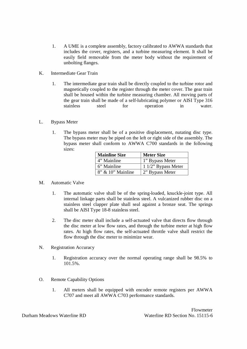
FlowmeterDurham Meadows Waterline RD Waterline RD Section No. 15115-6
1. A UME is a complete assembly, factory calibrated to AWWA standards thatincludes the cover, registers, and a turbine measuring element. It shall beeasily field removable from the meter body without the requirement ofunbolting flanges.
K. Intermediate Gear Train
1. The intermediate gear train shall be directly coupled to the turbine rotor andmagnetically coupled to the register through the meter cover. The gear trainshall be housed within the turbine measuring chamber. All moving parts ofthe gear train shall be made of a self-lubricating polymer or AISI Type 316stainless steel for operation in water.
L. Bypass Meter
1. The bypass meter shall be of a positive displacement, nutating disc type.The bypass meter may be piped on the left or right side of the assembly. Thebypass meter shall conform to AWWA C700 standards in the followingsizes:
Mainline Size Meter Size4” Mainline 1” Bypass Meter6” Mainline 1 1/2” Bypass Meter8” & 10” Mainline 2” Bypass Meter
M. Automatic Valve
1. The automatic valve shall be of the spring-loaded, knuckle-joint type. Allinternal linkage parts shall be stainless steel. A vulcanized rubber disc on astainless steel clapper plate shall seal against a bronze seat. The springsshall be AISI Type 18-8 stainless steel.
2. The disc meter shall include a self-actuated valve that directs flow throughthe disc meter at low flow rates, and through the turbine meter at high flowrates. At high flow rates, the self-actuated throttle valve shall restrict theflow through the disc meter to minimize wear.
N. Registration Accuracy
1. Registration accuracy over the normal operating range shall be 98.5% to101.5%.
O. Remote Capability Options
1. All meters shall be equipped with encoder remote registers per AWWAC707 and meet all AWWA C703 performance standards.

FlowmeterDurham Meadows Waterline RD Waterline RD Section No. 15115-7
PART 3 - EXECUTION
3.01 INSTALLATION:
A. Prior to installation, protect stored flowmeter and appurtenances from damage due toexposure to sunlight, heat, dirt, debris, freezing and thawing, vandalism, etc.
B. Clean all debris, dirt, gravel, etc, from inside of piping before placing flowmeter inplace.
C. Erect and support flowmeter in respective positions free from distortion and strain onappurtenances during handling and installation. Inspect material for defects inworkmanship and material. Clean out debris and foreign material from flowmeteropenings and seats, test operating mechanisms to check functioning, and check nuts andbolts for tightness. Repair flowmeter and other equipment which does not operate easilyor are otherwise defective at no additional cost to the Contracting Officer.
D. Set plumb and support flowmeter in conformance with instructions of manufacturer.
3.02 FIELD TESTING:
A. Pressure test flowmeter with pipeline pressure testing.
B. Test functions of flowmeter.
C. Make all adjustments necessary to place flowmeter in specified working order at time ofabove tests.
D. Remove and replace flowmeter and appurtenances at no additional cost to theContracting Officer with equipment that will meet all requirements specified andindicated if unable to demonstrate to the satisfaction of the Contracting Officer thatflowmeter will perform the service specified, indicated and as submitted and accepted.
3.03 FIELD TOUCH-UP PAINTING:
A. After installation and accepted testing by the Contracting Officer apply touch-up paint toall scratched, abraided and damaged shop painted surfaces. Coating type and color shallmatch shop painting.
3.04 CONTRACT CLOSEOUT:
A. Provide in accordance with Section 01700.
END OF SECTION

Plumbing SystemsDurham Meadows Waterline RD Section No. 15400-1
SECTION 15400
PLUMBING SYSTEMS
PART 1 - GENERAL
1.01 DESCRIPTION:
A. Provide new and modify existing plumbing systems as indicated and in compliance withContract Documents.
B. Remove and dispose of in-home treatment systems, as designated on the Details inAppendix B.
C. The Work of this Section shall include all labor, materials, tools, equipment andappurtenances, and performing all operations necessary to furnish and install completeand operable systems in accordance with this Section of these Specifications, theDrawings, and the codes and standards listed herein.
D. Coordinate with the Local Water Department as to any Local restrictions orrequirements relative to backflow prevention devices and metering.
1.02 REFERENCES:
A. Except as specified herein, the latest edition of the standards listed below form a part ofthis Specification to the extent referenced in this Section. Where earlier editions ofstandards are adopted as referenced in applicable codes, those shall govern. Thepublications are referred to within the text by the basic designation only.
B. In each of the standards referred to herein, consider the advisory provisions to bemandatory, as though the word, "shall" had been substituted for "should" wherever itappears.
C. American Society of Mechanical Engineers (ASME):
1. B16.18: Cast Copper Alloy Solder Joint Pressure Fittings
2. B16.22: Wrought Copper and Copper Alloy Solder Joint Pressure Fittings
3. B16.24: Cast Copper Alloy Pipe Flanges and Flanged Fittings Class 150, 300,400, 600, 900, 1500, and 2500
4. B16.50: Wrought Copper and Copper Alloy Braze-Joint Pressure Fittings
5. B40.1: Pressure Gauges and Gauge Attachments
D. American Society of Sanitary Engineering (ASSE):

Plumbing SystemsDurham Meadows Waterline RD Section No. 15400-2
1. 1013: Reduced Pressure Principle Backflow Preventers and Reduced Pressure FireProtection Principle Backflow Preventers
E. American Society for Testing Materials (ASTM):
1. B32: Solder Metal
2. B42: Seamless Copper Pipe, Standard Sizes
3. B88: Seamless Copper Water Tube
4. B584: Copper Alloy Sand Castings for General Applications
F. American Welding Society (AWS):
1. A5.8: Filler Metals for Brazing and Braze Welding
2. BRH: Brazing Handbook
G. Foundation For Cross-Connection Control And Hydraulic Research (FCCCHR):
1. FCCCHR List: List of Approved Backflow Prevention Assemblies
H. Manufacturers Standardization Society of the Valve and Fittings Industry (MSS):
1. SP-58: Pipe Hangers and Supports - Materials, Design, Manufacture, Selection,Application and Installation
2. SP-80: Bronze Gate, Globe, Angle and Check Valves
3. SP-110: Ball Valves Threaded, Socket Welding, Solder Joints, Grooved and FlaredEnds
I. National Sanitation Foundation (NSF):
1. 61: Drinking Water System Components
2. 372: Drinking Water System Components - Lead Content
1.03 SUBMITTALS:
A. Submit the following shop drawings in accordance with Section 01300:
1. Product Data - Annotate descriptive data to show the specific manufacturer,model, type, size, capacity, curves, wiring diagrams, options, etc. of each item.Where products are available with Energy Star labeling, they shall be provided.
a. Pipe and fittings
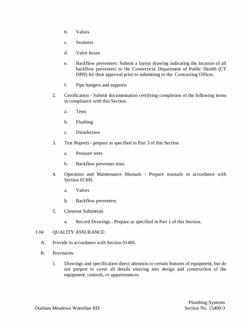
Plumbing SystemsDurham Meadows Waterline RD Section No. 15400-3
b. Valves
c. Strainers
d. Valve boxes
e. Backflow preventers: Submit a layout drawing indicating the location of allbackflow preventers to the Connecticut Department of Public Health (CTDPH) for their approval prior to submitting to the Contracting Officer.
f. Pipe hangers and supports
2. Certification - Submit documentation certifying completion of the following itemsin compliance with this Section.
a. Tests
b. Flushing
c. Disinfection
3. Test Reports - prepare as specified in Part 3 of this Section
a. Pressure tests
b. Backflow preventer tests
4. Operation and Maintenance Manuals - Prepare manuals in accordance withSection 01300.
a. Valves
b. Backflow preventers
5. Closeout Submittals
a. Record Drawings - Prepare as specified in Part 1 of this Section.
1.04 QUALITY ASSURANCE:
A. Provide in accordance with Section 01400.
B. Provisions:
1. Drawings and specification direct attention to certain features of equipment, but donot purport to cover all details entering into design and construction of theequipment, controls, or appurtenances.

Plumbing SystemsDurham Meadows Waterline RD Section No. 15400-4
2. Consideration shall be given only to products of manufacturers who demonstratesuccessful experience in manufacture, operation, and servicing equipment of type,size, performance, and reliability equal to that specified. Equipment andcomponents shall be the product of a single manufacturer insofar as possible.
3. Equipment furnished to fit within the space allocated with adequate clearance forproper operation and maintenance.
C. Workmanship and Design:
1. Provide equipment such that all parts are designed for continuous anduninterrupted service, and such that lubrication, adjustment, or replacement ofparts is possible without manufacturer's assistance. Corresponding parts ofmultiple units shall be interchangeable.
2. Install equipment that complies with state, local and federal codes and regulations.
D. Alternate Equipment and Arrangement:
1. If any equipment submitted for acceptance requires arrangement differing fromthat indicated or specified, prepare and submit for review, detailed structural,mechanical and electrical drawings, and equipment lists showing all necessarychanges and all special features of equipment proposed. Changes are at noadditional cost.
1.05 DELIVERY, STORAGE AND HANDLING:
A. Provide in accordance with Section and as specified.
B. Shipping:
1. Equipment, material and spare parts are to be shipped completely assembledexcept where partial disassembly is required by transportation regulations or forprotection of components.
C. Receiving:
1. Inspect and inventory items upon delivery to site.
2. Store and safeguard equipment, material and spare parts in accordance withmanufacturer's recommendations.
1.06 COOPERATION AND COORDINATION WITH OTHER TRADES:
A. Work shall be performed in cooperation with other trades on the project and soscheduled as to allow efficient completion of the project. Materials and equipment shallbe installed as fast as conditions will permit, and installed properly.

Plumbing SystemsDurham Meadows Waterline RD Section No. 15400-5
B. Furnish to all other trades advance information on location and size of all concrete pads,chases, frames, boxes, pits, sleeves, and openings needed for the Work, and also furnishlayout information and shop drawings necessary to permit other trades affected by theWork to install their work properly coordinated and without delay.
C. Where there is evidence that Work installed interferes with the work of other Sections,assist in working out space conditions to make satisfactory adjustments.
D. With the acceptance of and without extra cost to the Contracting Officer, makereasonable modifications in Work specified under this Section required to coordinatewith normal structural interference's, or for proper execution of specified work.
E. If work is installed before coordinating with other trades so as to cause interference withthe work of such trades, make all necessary changes in Work under this Section of the atno additional cost to the Contracting Officer.
F. Protect all materials and work of other trades from damage that may be caused by theWork required under this Section and be responsible for repairing any damages causedby such work without any additional cost to the Contracting Officer.
G. Follow Drawings in layout work. Check drawings of, and coordinate with, other tradesto verify special provisions, installation requirements and spaces in which Workprovided under this Section will be installed. Maintain maximum headroom or spaceconditions at all points. Where headroom or space conditions appear inadequate, notifythe Contracting Officer before proceeding.
H. Attend regular coordination and job progress meetings required.
1.07 REMOVAL WORK:
A. Particular care shall be taken to avoid creating hazards on the site or causing disruptionof service of unaffected spaces and/or systems.
B. All existing equipment indicated to be removed shall be done in a neat and workmanlikemanner. All equipment shall be removed from the premises and legally disposed of.
C. Remove all abandoned material and equipment not built into building construction. Alllive services left by removal work shall have ends capped and marked live.
D. Should any asbestos and/or asbestos related products or materials be encountered duringthe performance of the Work, stop work immediately and inform the ContractingOfficer of the presence of asbestos.
1.08 CODES, PERMITS AND FEES:
A. Except for additional requirements as specified or indicated under the Work of thisSection, materials, workmanship and equipment shall conform with the governingedition of the following regulations, and agency requirements.

Plumbing SystemsDurham Meadows Waterline RD Section No. 15400-6
1. State and Local Building Codes, including but not limited to, the ConnecticutPlumbing Code, and Connecticut Building Code.
2. Connecticut Department of Energy and Environmental Protection (CT DEEP)
3. Local Fire Department
4. Local Water Department
5. Occupational Safety and Health Administration (OSHA)
6. Any other local codes or requirements of Authorities Having Jurisdiction.
B. Pay for all fees and give all notices, file all plans, obtain all permits and licenses, andobtain all necessary approvals from Authorities Having Jurisdiction. Deliver allcertificates of inspection to the Authorities Having Jurisdiction. No work shall becovered before examination and approval by Authorities Having Jurisdiction. Replaceimperfect or condemned work to conform to inspectional requirements, satisfactory tothe Contracting Officer and Authorities Having Jurisdiction without extra cost to theContracting Officer. If Work is covered before inspection and acceptance, pay costs ofuncovering and reinstalling the covering, whether it meets contract requirements or not.
PART 2 - PRODUCTS
2.01 GENERAL:
A. Where applicable, all products requiring approval by the Connecticut Division ofConstruction Services shall be so approved. Where product types are available withEnergy Star labeling, they shall be provided.
B. All potable water piping components shall comply with NSF 61 test standards via third-party testing and certification. Potable water piping components under the jurisdictionof the Federal Reduction of Lead in Drinking Water Act shall comply with NSF 372 teststandards via third-party testing and certification.
2.02 DOMESTIC WATER PIPING:
A. Buried Piping:
1. Copper Tubing for Piping 2 inch and Smaller:
a. ASTM B88, Type K, soft annealed copper tubing with ASME B16.50brazed joint fittings. Provide minimum number of joints in buried coppertubing.
(1) Joints shall be brazed. Brazing filler metal shall conform to AWSA5.8, Type BAg-5 with AWS Type 3 flux, except Type BCuP-5 orBCuP-6 may be used for brazing copper-to-copper joints.

Plumbing SystemsDurham Meadows Waterline RD Section No. 15400-7
B. Aboveground Piping:
1. Copper Tubing:
a. ASTM B88, Type L, hard drawn copper tubing with ANSI B16.18 orASME16.22 solder joint fittings. Provide ASTM B42 copper pipe nippleswith threaded end connections. Provide copper unions. Provide ASTMB32, 95-5 tin-antimony solder, or provide Plumbing Code approved lead-free solder.
C. Flanges:
1. ASME B16.22 or ANSI B16.24 for use in copper tubing.
2. Flange Accessories:
a. Gaskets: Provide one piece, factory cut, 1/16 inch thick, synthetic rubbergaskets suitable for use with potable water. Gaskets shall be rated for 32 to180 degrees F service temperature. Provide full-face gaskets for flat-faceflanged joints, and ring gaskets for raised-face flanged joints. Dimensionsfor gaskets shall be in accordance with ASME B16.21.
b. Bolting: Material for bolts and studs ASTM A307, Grade-B and for nutsASTM A194/A194M, Grade-2. Dimensions of bolts, studs and nuts ANSIB18.2.1 and ASME B18.2.2 with threads conforming to ASME B1.1 coarsetype, with Class 2A fit for bolts and studs, and Class 2B for nuts.
D. Valves:
1. Provide valves suitable for minimum of 125 psig and minimum of 180 degrees Fhot water. Valves shall have threaded end connections with a union on all but oneside of the valve, or solder end connections for connections between bronze valvesand copper tubing. For gate, globe and angle valves, provide blue finish, and redfinish on handwheels for valves in domestic cold water piping, and domestic hotwater piping respectively. Ball valves may be provided in lieu of gate valves.
2. Gate Valves (3 inch and Smaller):
a. MSS SP-80, Class 125 bronze valves.
3. Globe and Angle Valves:
a. MSS SP-80, Class 125.
4. Check Valves:
a. MSS SP-80, Class 125, swing check.
5. Ball Valves:

Plumbing SystemsDurham Meadows Waterline RD Section No. 15400-8
a. MSS SP-110, full port design, copper alloy. Valves shall have lever handles,stainless steel ball and PTFE seats and seals.
6. Hose bibbs:
a. Provide angle type copper alloy hose bibb with lockshield andremovable handwheel. Inlet shall have internal threads. Outlet shallhave vacuum breaker with 3/4 inch external hose threads
E. Strainers:
1. Wye type, Class 125, copper alloy body, threaded ends. Provide 20 mesh stainlesssteel strainer element. Strainers shall have blow off outlet with pipe nipple andgate valve or ball valve with discharge pipe nipple.
F. Valve Boxes:
1. For each buried valve provide cast-iron box of a suitable size. Provide cast-ironcover for the box with the word "WATER" cast on the cover. Coat cast-iron boxeswith bituminous paint. Provide stainless steel valve operating rod.
G. Backflow Preventers:
1. Provide reduced pressure principle backflow preventer with gate or ball valve onboth ends and inlet strainer. Backflow preventers shall have replaceable seats anddiscs, bronze body, rated for minimum 35 to 150 degrees F and 175 psig.Backflow prevention assemblies shall have current "Certificate of Approval fromthe Foundation for Cross-Connection Control and Hydraulic Research, FCCCHRList." Listing of the specific make, model, design, and size in the FCCCHR Listshall be acceptable as the required documentation. Reduced pressure principlebackflow preventers shall be tested and certified under ASSE 1013 and beprovided with test cocks and drainage air gap fitting.
H. Dielectric Unions:
1. Provide dielectric unions in all copper to ferrous transitions. Couplings shall befactory certified to withstand a minimum of 600 volts on a dry line with noflashover. Couplings shall be rated for minimum 300 degrees F at 250 psig .
2.03 PIPE HANGERS AND SUPPORTS:
A. Provide MSS SP-58, Type 3, 4 and 7 hangers with adjustable type steel support rods,except as specified or indicated otherwise.
B. Attach to Steel W or S beams with Type 21, 28, 29, or 30 clamps. Attach to steel anglesand vertical web steel channels with Type 20 clamp with beam clamp channel adapter.Attach to horizontal web steel channel with drilled hole on centerline and double nut andflat washer. Attach to wood framed structures using wood screws designed for use with

Plumbing SystemsDurham Meadows Waterline RD Section No. 15400-9
threaded rod adapters, or through-bolted with double nut and flat washer. Attach toconcrete with drilled expansion anchor.
C. Hangers, supports, rods and fasteners shall be hot dipped galvanized steel, excepthangers and supports in contact with bare copper tubing shall be copper, copper-platedor PVC coated.
2.04 SUPPLEMENTARY STEEL AND CHANNELS:
A. Provide all supplementary steel and factory fabricated channels required for properinstallation, mounting and support of all equipment and systems provided under thisSection.
B. Channels and supplementary steel shall be of sufficient strength and size to allow only aminimum deflection in conformance with the manufacturer's requirements for thespecific loading on the system installed herein.
C. All supplementary steel shall be ASTM A36 factory-formed standard mill finishedstructural shapes. Supplementary steel assemblies shall be hot dipped galvanized afterfabrication. Channels shall be hot dipped galvanized steel.
2.05 PIPE SLEEVES:
A. Sleeves in Masonry and Concrete Walls and Floors: Standard weight ductile-iron orcast-iron pipe sleeves.
PART 3 - EXECUTION
3.01 INSTALLATION:
A. Installation, workmanship, inspection, and testing shall be in accordance with thespecified Plumbing Code and Building Code with the additions specified herein. Installpiping straight and true to bear evenly on hangers and supports. Keep the interior andends of new piping and existing piping affected by the Work thoroughly cleaned ofwater and foreign matter. Keep piping systems clean during installation by means ofplugs or other acceptable methods. When work is not in progress, securely close openends of piping to prevent entry of water and foreign matter. Inspect piping beforeplacing into position. When fixtures require both hot water and cold water supplies,provide the hot water supply to the left of the cold water supply. Copper tube extractedjoints shall not be permitted.
B. Piping shall not be permitted within 6 feet of electrical panelboards and other electricalequipment unless otherwise permitted by the Connecticut Electrical Code .
C. Piping and other apparatus shall not be installed in such a manner so as to interfere withthe full swing of doors, movement of personnel and equipment, and access to otherequipment.
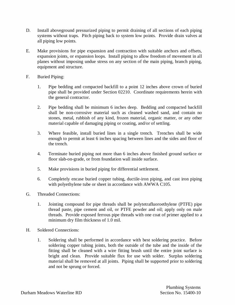
Plumbing SystemsDurham Meadows Waterline RD Section No. 15400-10
D. Install aboveground pressurized piping to permit draining of all sections of each pipingsystems without traps. Pitch piping back to system low points. Provide drain valves atall piping low points.
E. Make provisions for pipe expansion and contraction with suitable anchors and offsets,expansion joints, or expansion loops. Install piping to allow freedom of movement in allplanes without imposing undue stress on any section of the main piping, branch piping,equipment and structure.
F. Buried Piping:
1. Pipe bedding and compacted backfill to a point 12 inches above crown of buriedpipe shall be provided under Section 02210. Coordinate requirements herein withthe general contractor.
2. Pipe bedding shall be minimum 6 inches deep. Bedding and compacted backfillshall be non-corrosive material such as cleaned washed sand, and contain nostones, metal, rubbish of any kind, frozen material, organic matter, or any othermaterial capable of damaging piping or coating, and/or of settling.
3. Where feasible, install buried lines in a single trench. Trenches shall be wideenough to permit at least 6 inches spacing between lines and the sides and floor ofthe trench.
4. Terminate buried piping not more than 6 inches above finished ground surface orfloor slab-on-grade, or from foundation wall inside surface.
5. Make provisions in buried piping for differential settlement.
6. Completely encase buried copper tubing, ductile-iron piping, and cast iron pipingwith polyethylene tube or sheet in accordance with AWWA C105.
G. Threaded Connections:
1. Jointing compound for pipe threads shall be polytetrafluoroethylene (PTFE) pipethread paste, pipe cement and oil, or PTFE powder and oil; apply only on malethreads. Provide exposed ferrous pipe threads with one coat of primer applied to aminimum dry film thickness of 1.0 mil.
H. Soldered Connections:
1. Soldering shall be performed in accordance with best soldering practice. Beforesoldering copper tubing joints, both the outside of the tube and the inside of thefitting shall be cleaned with a wire fitting brush until the entire joint surface isbright and clean. Provide suitable flux for use with solder. Surplus solderingmaterial shall be removed at all joints. Piping shall be supported prior to solderingand not be sprung or forced.

Plumbing SystemsDurham Meadows Waterline RD Section No. 15400-11
2. For solder end valves, remove stems and washers and other items subject todamage by heat during installation. Reassemble valve after soldering is complete.Valves without heat sensitive parts do not require disassembly but shall be fullyopened during soldering.
I. Brazed Connections:
1. Brazing of copper tubing joints shall be performed in accordance with AWS BRH,except as modified herein. During brazing, the pipe and fittings shall becontinuously purged with a pressure regulated inert gas, such as nitrogen, toprevent the formation of scale. Before brazing, both the outside of the tube and theinside of the fitting shall be cleaned with a wire fitting brush until the entire jointsurface is bright and clean. Brazing flux shall not be used. Surplus brazingmaterial shall be removed at all joints. Piping shall be supported prior to brazingand not be sprung or forced.
J. Flanged Connections:
1. Flanges shall be faced true, and made square and tight.
K. Pipe Hangers and Supports:
1. Selection, application and installation of piping hangers and supports shallconform with MSS SP-58, unless otherwise indicated.
2. Furnish and install safe and substantial means of support for all parts of the pipingsystem. Attach all pipes securely to the structure in correct alignment and pitch, toprevent vibration and to effectively care for expansion and construction.
3. All piping shall be hung to true alignment, using appropriate hanger arrangements.Wire and strap hangers shall not be permitted. Hangers shall be located so thatpiping and hangers will be 6 inches clear from other piping, hangers, conduits,lighting fixtures, equipment, ceiling suspension systems, ductwork and otherobstructions. Where insulation or other covering is provided, minimum clearanceshall take into account such covering.
4. Supplementary steel and channels shall be firmly connected to the buildingconstruction in a manner accepted by the Contracting Officer or as otherwiseshown on the Drawings. Equipment and piping shall not be supported from metaldecking or plaster ceilings.
5. Rod Sizes, MSS SP-58.
6. Maximum Spacing Between Supports
a. Vertical Piping: Support piping at each floor, but at not more than 10 footintervals, with pipe riser clamps or offset pipe clamps. Pipe shall besupported not more than 2 feet from end of risers.
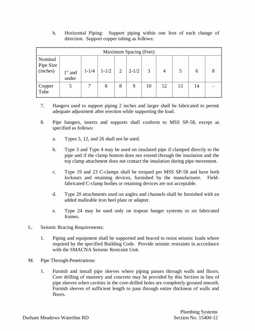
Plumbing SystemsDurham Meadows Waterline RD Section No. 15400-12
b. Horizontal Piping: Support piping within one foot of each change ofdirection. Support copper tubing as follows:
Maximum Spacing (Feet)NominalPipe Size(inches) 1" and
under1-1/4 1-1/2 2 2-1/2 3 4 5 6 8
CopperTube
5 7 8 8 9 10 12 13 14 -
7. Hangers used to support piping 2 inches and larger shall be fabricated to permitadequate adjustment after erection while supporting the load.
8. Pipe hangers, inserts and supports shall conform to MSS SP-58, except asspecified as follows:
a. Types 5, 12, and 26 shall not be used.
b. Type 3 and Type 4 may be used on insulated pipe if clamped directly to thepipe and if the clamp bottom does not extend through the insulation and thetop clamp attachment does not contact the insulation during pipe movement.
c. Type 19 and 23 C-clamps shall be torqued per MSS SP-58 and have bothlocknuts and retaining devices, furnished by the manufacturer. Field-fabricated C-clamp bodies or retaining devices are not acceptable.
d. Type 20 attachments used on angles and channels shall be furnished with anadded malleable iron heel plate or adapter.
e. Type 24 may be used only on trapeze hanger systems or on fabricatedframes.
L. Seismic Bracing Requirements:
1. Piping and equipment shall be supported and braced to resist seismic loads whererequired by the specified Building Code. Provide seismic restraints in accordancewith the SMACNA Seismic Restraint Unit.
M. Pipe Through-Penetrations:
1. Furnish and install pipe sleeves where piping passes through walls and floors.Core drilling of masonry and concrete may be provided by this Section in lieu ofpipe sleeves when cavities in the core-drilled holes are completely grouted smooth.Furnish sleeves of sufficient length to pass through entire thickness of walls andfloors.
Plumbing SystemsDurham Meadows Waterline RD Section No. 15400-13
2. Pipe Penetrations Through Interior Building Construction: Provide not less than1-inch space between exterior of piping or pipe insulation and interior of sleeve orcore-drilled hole. Firmly pack space with mineral wool insulation. For non-firerated assemblies, seal at both ends of the sleeve or core-drilled hole with silicone.Seal both ends of penetrations through fire rated assemblies to maintain fireresistive integrity with UL listed fill, void, or cavity material.
3. Pipe Penetrations Through Exterior Building Construction: Provide not less than1/2-inch space between exterior of piping and interior of sleeve or core-drilledhole. Firmly pack space with non shrink grout.
4. Extend sleeves in floor slabs 2 inches above the finished floor. Sleeves throughwalls shall terminate flush with the finished surface on either side of the wall.
N. Cross Connection and Interconnections:
1. No equipment, devices or piping shall be installed which will provide a cross orinterconnection between a domestic water supply and a drainage, soil or wastepipe which will permit or make possible the backflow of sewage, polluted water orwaste into the domestic water supply system.
3.02 TREATMENT SYSTEM REMOVAL
A. General: Point-of-use treatment systems shall be removed from existing plumbing priorto connecting to the new service line. Any materials and equipment removed that are notwanted by the property owner shall be recycled, to the maximum extent possible, ordisposed. Spent carbon or other treatment residuals shall be sent to an appropriatefacility for regeneration or disposal. POU devices, including residuals, are consideredhousehold waste and are exempt from being regulated as hazardous waste under RCRA.However, applicable state regulations shall apply.
3.03 FIELD QUALITY CONTROL:
A. General: After system installation has been completed and prior to initial operation,inspect piping for compliance with Drawings, Specifications, and accepted submittals.Perform flushing and tests in compliance with the specified Plumbing Code with theadditions specified herein. Have piping accepted by the Contracting Officer beforeinsulating or otherwise concealing.
B. Test Procedures and Reports:
1. Prepare and submit procedures for all specified tests to the Contracting Officer foracceptance prior to the planned preliminary tests. Test reports shall includeaccepted test procedures, test results, deficiencies identified, and recommendedcorrective actions. Provide a complete explanation including supportingdocumentation detailing the design deficiencies. State that no deficiencies areevident if that is the case.

Plumbing SystemsDurham Meadows Waterline RD Section No. 15400-14
2. Material and equipment used in testing shall be subject to inspection by theContracting Officer. Provide instruments, appliances, equipment, connectingdevices, and personnel for the tests. The Contracting Officer will furnish waterand electricity for the tests.
3. When tests have been completed and corrections made, submit signed and datedtest reports.
4. Test all new equipment and piping to demonstrate compliance with the contractrequirements. Correct defects in the Work and repeat tests until Work is incompliance with contract requirements.
5. Gages used in pressure tests shall have been calibrated within the 6-month periodpreceding the tests. Leaks found during tests shall be repaired by replacing pipeand/or fittings and the system retested. Caulking of joints shall not be permitted.
C. Tests:
1. Domestic Water Piping Pressure Tests: Before applying insulation, and before theinstallation of fixtures, cap ends of each system and hydrostatically test eachpiping system at not less than 100 psig for a period of time sufficient for inspectionof every joint in the system but in no case less than 1 hour. During the pressuretest, there shall be no leakage or reduction in pressure.
2. Backflow Preventer Tests: Backflow preventers shall be tested by a locallyapproved and certified backflow assembly tester. A copy of the test report shall beprovided to the Contracting Officer prior to placing the domestic water systeminto operation, or no later than 5 days after the test.
D. Flushing:
1. After completion of testing and before placing in operation, flush all new andexisting piping of all foreign matter. Use the permanent water service at itsmaximum available pressure as the source of flushing water. Remove integralstrainer screens, aerators, shower heads, hose end vacuum breakers, and otherdevices susceptible to clogging prior to flushing and re-install upon completion.Flush piping through each fixture outlet, strainer blowdown and equipment drainvalve. Discharge used water to sanitary sewer. Remove and provide new screensin strainers after flushing is completed. System shall be drained prior to finalfilling.
3.04 MANUFACTURERS INSTRUCTIONS:
A. Obtain instructions from the manufacturer for the proper method of installation andconnection of the equipment that is to be installed. Obtain all information that isnecessary to facilitate the Work and to complete the project.

Plumbing SystemsDurham Meadows Waterline RD Section No. 15400-15
3.05 DISINFECTION:
A. Disinfect the new water piping and existing water piping affected by the Work inaccordance with the specified Plumbing Code with the additions specified herein. Fillpiping systems with chlorine solution and allow solution to stand. Following therequired standing time, flush solution from the systems with domestic water untilmaximum residual chlorine content is within the range of 0.2 to 0.5 ppm, or the residualchlorine content of domestic water supply. Obtain at least two consecutive satisfactorybacteriological samples from new and existing water piping, analyzed by a certifiedlaboratory, and submit results prior to the new and existing water piping being placedinto service.
B. Where it is not possible to disinfect a potable water storage tank as specified above, theentire interior of the tank shall be swabbed with a solution which contains 200 parts permillion of available chlorine; and the solution shall than be allowed to stand 3 hoursbefore the tank is flushed and returned to service.
C. For a potable water filter or similar device, the dosage shall be determined by theConnecticut Department of Environmental Protection.
3.06 CONTRACT CLOSEOUT:
A. Provide in accordance with Section 01700 .
END OF SECTION

Heating, Ventilating and Air ConditioningDurham Meadows Waterline RD Section No. 15806-1
SECTION 15806
HEATING, VENTILATING AND AIR CONDITIONING
PART 1 - GENERAL
1.01 DESCRIPTION:
A. Provide heating, ventilating and dehumidification equipment, controls, accessories andappurtenances as indicated and specified.
B. Furnish all local, state and federal permits as necessary.
1.02 RELATED WORK:
A. Division 1: General Requirements
B. Section 16220: Electric Motors
C. Section 09941: Field Painting
D. Section 10200: Louvers
E. Section 13300: Utility Control Instrumentation System
F. Section 15105: Pipe Supports
G. Section 15400: Plumbing
H. Section 16050: Electrical Work - General
I. Section 16900: Electrical Controls and Miscellaneous Electrical Equipment
1.03 REFERENCES:
A. Underwriters' Laboratories (UL)
B. National Electric Code (NEC)
C. Air Moving and Conditioning Association (AMCA)
D. American Society of Heating, Refrigeration and Air-Conditioning Engineers (ASHRAE)
E. American Society of Mechanical Engineers (ASME)
Heating, Ventilating and Air ConditioningDurham Meadows Waterline RD Section No. 15806-2
F. Building Officials and Code Administrators (BOCA)
G. Low and High Pressure Duct Construction Standards by Sheet Metal and AirConditioning Contractors National Association, Inc. (SMACNA)
H. National Fire Protection Association (NFPA)
I. American National Standards Institute (ANSI)
J. Associated Air Balance Council (AABC)
K. American Society for Testing and Materials (ASTM) Publications:
1. D1785: Specification for Poly (Vinyl Chloride) (PVC) Plastic Pipe, Schedules 40,80, and 120.
2. D2464: Specification for Threaded Poly (Vinyl Chloride) (PVC) Plastic PipeFittings, Schedule 80.
3. D2467: Specification for Socket-Type Poly (Vinyl Chloride) (PVC) Plastic PipeFittings, Schedule 80.
4. D2564: Specification for Solvent Cements for Poly (Vinyl-Chloride) (PVC) PlasticPipe and Fittings.
L. Factory Mutual (FM).
1.04 SYSTEM DESCRIPTION:
A. Heating is provided by electric unit heaters as specified herein and indicated on theequipment schedule and contract drawings.
B. The ventilating systems have fans, dampers, and associated ductwork as specified hereinand indicated on the equipment schedule and contact drawings.
C. Dehumidifiers are specified herein and indicated on the equipment schedule and contractdrawings.
1.05 SUBMITTALS:
A. Submit the following in accordance with Section 01300:
1. Shop drawings including manufacturer's specifications and catalog data, brochures,descriptive matter, illustrations, diagrams, including complete motor data, andfinishes with color charts of equipment to be selected, and complete performance
Heating, Ventilating and Air ConditioningDurham Meadows Waterline RD Section No. 15806-3
data. Where product types are available with Energy Star labeling, they shall beprovided.
a. Equipment performance curves.
b. Schematic wiring diagrams with control system submittals.
2. For informational purposes only, submit manufacturer’s printed installationinstructions for all items specified.
3. Record drawings of heating, ventilation and air conditioning installation.
4. Operation and maintenance manuals in accordance with Section 01730.
5. List of manufacturer's recommended spare parts.
6. Provide nomenclature labels on submittals.
1.06 QUALITY ASSURANCE:
A. Provide in accordance with Section 01400 and as specified.
B. Provisions:
1. Drawings and specification direct attention to certain features of equipment, but donot purport to cover all details entering into design and construction of theequipment, controls, or appurtenances.
2. Considerations given only to products of manufacturers who demonstratesuccessful experience in manufacture, operation, and servicing equipment of type,size, performance, and reliability equal to that specified. Equipment andcomponents shall be the product of a single manufacturer insofar as possible.
3. Equipment furnished to fit with in the space allocated with adequate clearance forproper operation and maintenance.
C. Workmanship and Design:
1. Provide equipment such that all parts are proportioned for continuous anduninterrupted service, and such that lubrication, adjustment, or replacement of partsis possible without manufacturer's assistance. Corresponding parts of multipleunits and shall be interchangeable.
2. Equipment is subject to corrosion. Provide coatings to all metallic elements asspecified in subpart – PAINTING.

Heating, Ventilating and Air ConditioningDurham Meadows Waterline RD Section No. 15806-4
3. Install equipment that complies with state, local and federal codes and regulations.
D. Alternate Equipment and Arrangement:
1. If any equipment submitted for acceptance requires arrangement differing from thatindicated or specified, Contractor to prepare and submit for review, drawings, andequipment lists showing all necessary changes and all special features of equipmentproposed. Changes are at no additional compensation to the Contractor.
1.07 DELIVERY, STORAGE AND HANDLING:
A. Provide in accordance with Section 01610 and as specified.
B. Shipping:
1. Equipment, material and spare parts are to be shipped completely assembled exceptwhere partial disassembly is required by transportation regulations or for protectionof components.
C. Receiving:
1. Inspect and inventory items upon delivery to site.
2. Store and safeguard equipment, material and spare parts in accordance withmanufacturer's recommendations.
1.08 INTERFACE WITH OTHER TRADES:
A. Power wiring, circuit breakers, starters, conduit, wire and connections for equipment andappurtenances are as indicated and specified under Division 16, unless otherwiseindicated or specified. All control conduit and wire required between HVAC equipmentand control points are provided under this Section.
B. Wiring and conduit for power and building alarm signaling are provided in Sections16050 and 16900.
C. Louvers are provided under Section 10200.
PART 2 - PRODUCTS
2.01 GENERAL:
A. Where product types are available with Energy Star labeling, they shall be provided.

Heating, Ventilating and Air ConditioningDurham Meadows Waterline RD Section No. 15806-5
2.02 DEHUMIDIFIER:
A. General: The dehumidifier shall be a heavy-duty industrial self-contained indoor unit,completely assembled, piped, wired and factory tested. The unit includes the followingminimum parts and components: Compressor, evaporator coil (dehumidifier), condensercoil (reheat), blower, blower motor, refrigeration valves and electrical controls. The unitshall be fixed mounted with a broad operating temperature range that includes lowtemperature operation.
B. Quality Assurance: All parts and components shall be shall be UL listed. Themanufacturer of the dehumidification system shall have a minimum of five (5) years ofexperience in the production of these systems.
C. Enclosure: The frame, panels, and removable access panels shall be constructed of 16- or18-gauge Galvanneal steel. The base panel shall be 11-gauge Galvanneal steel. Panelsshall be removable to allow easy access to internal parts.
D. Paint and Finish: All metal parts shall be painted with 1-1/2 to 3 mils powder coat paint.Powder coat shall be oven cured per paint manufacturer’s specifications.
E. Evaporator (Dehumidifier coil):
1. Fins: Fins shall be die formed, plate type tempered aluminum for easy cleaningand shall be damage resistant. Fins shall have extruded fin collars.
2. Tubes: Coil tubes shall be fabricated from seamless drawn copper. The tubes shallbe mechanically expanded into the tubes to form a permanent metal to metal bond.
3. Headers: All manifolds, headers, and connecting tubing shall be made with heavywall seamless copper tubing.
4. Testing: Coils shall be leak tested with 625-psig nitrogen and sealed to preventcontamination.
F. Condenser (Reheat Coil):
1. Fins: Fins shall be die formed, plate type tempered aluminum for easy cleaningand shall be damage resistant. Fins shall have extruded fin collars.
2. Tubes: Coil tubes shall be fabricated from seamless drawn copper. The tubes shallbe mechanically expanded into the tubes to form a permanent metal to metal bond.
3. Testing: Coils shall be leak tested with 625-psig nitrogen and sealed to preventcontamination.
Heating, Ventilating and Air ConditioningDurham Meadows Waterline RD Section No. 15806-6
G. Refrigerant Feature: Low Temperature Feature: Unit will be equipped with a demanddefrost system. Evaporating temperatures must be capable of dropping below 32F tomaximize moisture removal during low load. The demand defrost system will monitorconditions at the evaporator, activating and de-activating the evaporator defrost cycle onan as-needed basis.
H. Compressor: The compressor shall be a heavy-duty, hermetic, rotary type. Thecompressor is equipped with a high-pressure safety switch, and internally protected fromoverheating. The compressor shall be vibration isolated internally and externally. Thecompressor shall be covered by a two-year warranty.
I. Electrical Control Panel: The electrical control panel shall be easily accessible so that allservice can be performed from one side of the unit. It shall be of adequate size to houseall electrical controls and devices. The electrical controls shall include a Class 2 low-voltage control transformer, clearly labeled high- and low-voltage terminal strips,potential starting relay, start and run capacitors, and high-pressure protection with manualreset.
J. Controls: Unit shall have an on / off switch, a factory wired and installed humidistat anda factory installed run timer.
K. Condensate Drain Pan: Drain pan shall be made of ABS plastic or stainless steel and bemounted directly under the coil assembly. Pan must have round edges and be slopedtoward the drain to assure no standing water in the pan.
L. Blower: The blower shall be a single inlet, direct drive, centrifugal fan type.
M. Filter Rack: Unit must be equipped with filter rack utilizing 18 ” x 18” x 1” extendedsurface filter. Filter shall be disposable and must meet or exceed average (ASHRAE52.1-1992) atmospheric efficiency of 20 to 35% and arrestance of 92%.
N. Warranty: All components shall be warranted for a period of two (2) years from date ofshipment.
O. Approvals/Listings: The complete unit shall be ETL listed.
P. Unit Manufacturer: The unit shall be manufactured by Desert Aire Corp., Milwaukee,Wisconsin, or equal.
2.03 METAL DUCTWORK:
A. Ducts shall be fabricated of sheet aluminum, designation 1100 or 3003, H-14 alloy andtemper.

Heating, Ventilating and Air ConditioningDurham Meadows Waterline RD Section No. 15806-7
B. Design for 2 in. w.g. positive or negative, with weight of duct and stiffener materials,fabrication methods and crossbreaking conforming to latest low pressure constructionstandard published by SMACNA; do not use beaded duct construction.
C. Provide joints recommended by SMACNA for duct pressure rating, except that buttonpunch snaplock joints shall not be used.
D. Provide access doors for maintenance of dampers and equipment and access panels at firedampers.
E. Provide neoprene-coated, flexible, airtight, fabric sleeves weighing approximately 30-oz.per square yard for ductwork connections to equipment.
F. Ductwork Insulation: Provide 1-1/2-inches of 1-1/2-lb. minimum density flexible blanketfibrous glass with factory applied vapor barrier jacket. Provide insulation asmanufactured by Owens-Corning Fiberglass Corp., Toledo, OH; PPG Industries, Inc.,Pittsburgh, PA; Certain-Teed Products Corp., Valley Forge, PA; or acceptable equivalentproduct.
2.04 DAMPERS GENERAL:
A. Motor-operated dampers are specified and furnished under CONTROLS unless otherwiseindicated or specified. Motor operators furnished and installed under CONTROLS.
B. For dampers in outdoor intakes, provide an 18 by 14 aluminum mesh, 0.0123-in.diameter wire insect screen, secured in a removable aluminum frame with provisions forscreen replacement.
2.05 ELECTRIC UNIT HEATERS:
A. Corrosion Resistant Electric Unit Heaters:
1. Provide corrosion resistant forced-convection type, electric unit heater, rated asindicted on the equipment schedules.
2. Provide each heater unit complete with heating element, fan, contactor, and integralthermostat.
3. Provide fan motors totally enclosed, oil sealed, and quiet in operation.
4. Provide each unit housed in a sheet-metal enclosure equipped with swivel hangersuitable for ceiling or wall mounting as indicated.
5. Provide adjustable louver and thermal cutout. Cutout to protect heater fromoverheating by opening the electric circuit and automatically reenergizing theheater when a safe temperature is reached.

Heating, Ventilating and Air ConditioningDurham Meadows Waterline RD Section No. 15806-8
6. Provide integral corrosion resistant thermostat.
2.06 VENTILATING FANS:
A. General:
1. AMCA rated and constructed for capacity and sound level. UL labeled.
2. Impeller wheels statically and dynamically balanced, free from vibration and noise.
3. Provide electric motor, drive equipment, controls, vibration isolators, supports andappurtenances including safety disconnect switches at each unit.
4. Provide fan with non-overloading characteristics for maximum CFM and staticpressure achievable with drive provided.
5. Provide direct drive, motor sized to deliver maximum CFM.
6. For electric motors, provide adjustable heavy steel plate mounts; provide singlephase motors with built-in thermal overload protection.
7. Provide motor-operated damper for fan openings as indicated. Motor-operateddampers and motor operators are specified under subpart – CONTROLS.
8. Provide vibration isolation fan mountings.
B. Inline- Fans- Square:
1. Manufacturers:
a. Greenheck Fan Corp.
b. Loren Cook Co.
c. Penn Ventilator
2. Fan shall be duct mounted, direct driven centrifugal square inline.
3. The fan shall be of bolted construction utilizing corrosion resistant fasteners.Housing shall be minimum 18 gauge galvanized steel with integral duct collars.Bolted access doors shall be provided on three sides, sealed with closed cellneoprene gasketing.

Heating, Ventilating and Air ConditioningDurham Meadows Waterline RD Section No. 15806-9
4. Wheel shall be centrifugal backward inclined, constructed of 100% aluminum,including a precision machined cast aluminum hub. Wheel inlet shall overlap anaerodynamic aluminum inlet cone.
5. Motor shall be heavy duty type with permanently lubricated sealed ball bearings.
2.07 CONTROLS - GENERAL:
A. Provide all control operators for control items furnished by equipment suppliers hereinspecified.
B. Provide control item enclosures of the appropriate NEMA classification as indicated onthe Electrical Drawings for the area the enclosure is to be located.
C. Provide factory-fabricated multiblade control insulated dampers with factory-mountedlinkages, minimum 0.080-inch (No. 12 AWG gage) thick extruded aluminum blades andframes. Reinforced channel-type frames; maximum 6-inch wide blades with interlockingor overlapping edges; minimum 1/2-inch diameter rods with self-lubricating bearings; allhardware of noncorrosive material or cadmium plated.
1. Provide low-leakage dampers. Damper construction to have compressible seals atall points of contact to minimize leakage when damper is closed; manufacturer tosubmit guarantee that damper leakage will not exceed 20 cfm per square foot whenclosed against a static pressure of 4-inches w.c.
2. Provide parallel blade dampers for two-position operation, which shall open wideto give minimum air stream resistance.
D. Provide damper motor-operators of rugged commercial/industrial construction and quietin operation. When operated at rated voltage, each motor capable of delivering not lessthan twice the torque required by the damper, and to withstand, without damage,continuous stalling. Motors designed to function properly with a 10 percent plus or minuschange in line voltage feeding the equipment, maximum 120/1/60 HZ control systemvoltage. Manufacturers: Belimo, Andover, Allerton or acceptable equivalent product.
1. Damper actuators shall be electronic direct coupled, unless the control shaft is notaccessible. Actuator-drive pinions and high-speed gears may be made of a suitablenonmetallic composition to ensure quiet operation. All other gears of steel orbronze. All gears accurately machine cut, with face widths of not less than 1/8-in.Shafts of hardened steel, running in bronze, hardened steel, nylon or other suitablesleeves or ball bearings. Lever arms attached to motor shafts with set screws orother secure and adjustable means. Actuators shall contain a “V” bolt mountingmechanism for mounting to the control shaft. Set screws will not be acceptable.
2. Motors and gear trains totally enclosed in dustproof housing of pressed steel oracceptable cast metal with rigid conduit connections. Motors shall be protected by

Heating, Ventilating and Air ConditioningDurham Meadows Waterline RD Section No. 15806-10
electronic current overload circuitry. End switches for motor protection will not beaccepted.
3. Proportioning motors of the reversing, shaded pole or capacitor induction type,capable of stopping at any point in the cycle and starting either direction from anypoint. Reversing and proportioning motors with limit switches to limit the levertravel in either direction, unless operator is "stall" type.
4. Motors provided with spring return so they will "fail safe" in closed position, asindicated or required to suit job conditions, in the event of power failure. Batterybackup and capacitor discharge types of fail safe actuators will not be accepted.
5. Damper motor-operating speeds to be selected or adjusted so that the motors willremain in step with the controller without hunting, regardless of load variations.Provide motors which operate in sequence with other motors with adjustableoperating ranges and starting points to permit adjustment of the control sequence asrequired by the operating characteristics of the system.
6. When direct coupling is not feasible, dampers to be provided with adjustablelinkages and crank arms as required, suitable for the motors hereinbefore specified.Linkages and crank arms to be zinc or cadmium plated.
7. Damper linkages and operators to be arranged for mounting out of the air streamand to be rated for at least twice the maximum operating force of the damper motor.Do not locate operator outside of building, unless allowed by Contracting Officer.
2.08 HVAC SEQUENCE OF OPERATION:
A. HVAC Sequences of Operation
1. Ventilation Fan VF-2 & VF-4:
a. The ventilation fans shall be controlled by a manual switch. When the buildingis occupied, the fan shall be turned on and the interlocked motor operateddampers MD-1 and MD-2 shall open.
b. When the switch is closed the fan shall stop and the dampers close.
2. Motor Operated Dampers
a. The inlet and exhaust dampers shall be closed when the Ventilation Fan is off.The dampers shall open when the ventilation fan is turned on.
b. The dampers shall fail closed on loss of power.

Heating, Ventilating and Air ConditioningDurham Meadows Waterline RD Section No. 15806-11
3. Dehumidifier
a. Dehumidifiers shall be controlled by manufacturer provided controls.
4. Electric Unit Heaters
a. The unit heater shall be controlled by an integral thermostat. On a drop in roomtemperature below the thermostat set point of 55 degrees F (adjustable), the unitheater shall start. When the space temperature is above the set point, the unitshall stop.
2.09 CONTROLS - IDENTIFICATION PLATES:
A. Provide identification plates for the identification of room thermostats, adjustablecontrols, manual switches and remote operators, control panels and boxes, indicatinglights, and alarm devices. Plates to identify the system or unit controlled and its functionor position. Also provide, where appropriate, indicators and labels for switch positions.
B. Plates to have 1/4-in. high white letters on a black background.
C. Provide identification plate above ventilation fan switch that states: “SHUT OFFVENTILATION FAN WHEN BUILDING UNOCCUPIED”.
2.10 PAINTING:
A. Field painting is specified under Section 09941.
B. Give ferrous surfaces obviously not to be painted a shop coat of grease or other suitablerust-resistant coatings.
C. Protect aluminum work, unless otherwise specified, against contact with other metals bycoating nonaluminum surfaces with an aluminum pigmented asphalt paint. Coataluminum in contact with concrete with asphalt or bituminous mastic.
D. Other shop painting to be as specified under SHOP PAINTING.
E. Motors, fan casings, and similar equipment customarily finished at the shop given coatsof paint filler and enamel or other treatment customary with the manufacturer.
F. Provide other ferrous surfaces not previously specified with one shop coat of Kop-Coat622-LCF Primer made by Koppers Co., Inc., Pittsburgh, PA.; 37-77 Chem-Prime madeby Tnemec Co., North Kansas City, MO; U-Prime 280 made by Porter International,Louisville, KY; or an acceptable equivalent product applied in accordance with theinstructions of the manufacturer.

Heating, Ventilating and Air ConditioningDurham Meadows Waterline RD Section No. 15806-12
2.11 SPARE PARTS:
A. Provide in accordance with Section 01730.
B. Furnish the following spare parts for the equipment:
1. One set of replacement filters for each dehumidifier.
C. Delivered from supplier at the same time as the equipment to which they pertain.
D. Properly store and safeguard until completion of the work, then deliver to ContractingOfficer.
PART 3 - EXECUTION
3.01 INSTALLATION - GENERAL
A. General:
1. Obtain and pay for all permits.
2. Comply with Sections 15105, 16050 and 16900.
3. Field painting per Section 09941.
4. Install equipment and appurtenances in accordance with manufacturers'recommendations.
3.02 INSTALLATION OF PIPING:
A. Install to grades and elevations indicated.
B. Install hangers and supports per Section 15105.
3.03 DUCTWORK:
A. Aluminum ductwork shall be used.
B. Assemble per SMACNA.
C. Do not exceed 6-ft. spacing of hangers on horizontal ducts; 4-ft. on vertical ducts.
D. Support ductwork from structure per SMACNA; use steel rods and angles for ducts withlargest dimension more than 42-in. Use hanger material similar to ducts; use anglebrackets to support vertical ducts. Friction clamps are not allowed.
Heating, Ventilating and Air ConditioningDurham Meadows Waterline RD Section No. 15806-13
E. Use anchors, inserts or forged beam clamps with restraints to secure hangers tostructures; use stainless steel anchors if drilled-in type are installed.
F. Install duct connections to masonry openings airtight.
G. Wherever aluminum is in contact with concrete, thoroughly clean aluminum to removeall dirt, heavy deposits of grease or oil, and other foreign substances, and immerse in orswab with a suitable solvent; rinse the surface with clear water and thoroughly dry; coatcleaned surfaces with Bitumastic Super Service Black manufactured by Koppers Co.,Inc.; Tarmastic 103 manufactured by Porter Coatings Div.; or an acceptable equivalentproduct.
H. Insulate aluminum from dissimilar metals by strips or roofing felt or other approvedmeans.
I. Apply dull black paint to ductwork at visible locations behind registers.
J. Pack the space between the sleeve and framed prepared opening and the duct and the ductinstallation with mineral wool or other approved fire resistant material.
3.04 DUCTWORK INSULATION:
A. Apply with adhesive or fasten with pins or clips.
B. Install flexible blanket type externally.
C. Seal seams and joint strips for butt joints with vapor-barrier adhesive.
3.05 IDENTIFICATION PLATES:
A. Affix identification plates to switch boxes, controls and appurtenances as specified.
3.06 CONTROLS:
A. Provide competent mechanics, experienced in control system installations, for the work.
B. After all installations are complete, operate equipment in presence of the ContractingOfficer to demonstrate satisfactory performance.
C. Leave all systems complete and in first-class condition ready to operate.
3.07 TEST AND ADJUSTMENTS:
A. Provide all materials and equipment required.
Heating, Ventilating and Air ConditioningDurham Meadows Waterline RD Section No. 15806-14
3.08 CONTRACT CLOSEOUT:
A. Provide in accordance with Section 01700.
END OF SECTION

WATER BOOSTER PUMPS AND APPURTENANCESDurham Meadows Waterline RD 15809 - 1
SECTION 15809
WATER BOOSTER PUMPS AND APPURTENANCES
PART 1 - GENERAL
1.01 DESCRIPTION:
A. Provide and test water pumps, motors, and bladder tank, as specified and indicated.
B. Service Description: The pump station purpose is to increase water distribution systempressure in the 12-inch and 8-inch water mains serving Talcott Ridge Drive and WatchHill Drive.
C. Two service pumps will be provided. The service pumps shall be controlled with apressure transmitter on the discharge header and will be operated on alternate cycles.Each shall be capable of 45 gpm at 101-feet TDH and will be automatically activated asneeded, when boosted distribution system pressure falls at or below 80 psi.
D. Pumps shall be stainless steel inline vertical multi-stage centrifugal pumps.
1.02 RELATED WORK:
A. Division 1: General Requirements
B. Section 09941: Field Painting
C. Section 13300: Utility Control Instrumentation System
D. Section 15101: Process Piping, Valves and Appurtenances
E. Section 16220: Electric Motors
F. Section 16260: Low Voltage Variable Frequency Drive Unit
1.03 REFERENCES:
A. American Society of Mechanical Engineers (ASME):
1. ASME Boiler and Pressure Code, Section VIII, Division 1
B. ASTM International (ASTM):
1. A351: Standard Specification for Castings, Austenitic, for Pressure-ContainingParts
2. D2240: Standard Test Method for Rubber Property – Durometer Hardness.
C. American National Standards Institute (ANSI).

WATER BOOSTER PUMPS AND APPURTENANCESDurham Meadows Waterline RD 15809 - 2
D. Hydraulic Institute (HI):
1. Current Standards.2. 14.6: Rotodynamic Pumps for Hydraulic Performance Acceptance Tests
E. American Iron and Steel Institute (AISI).
F. National Electrical Manufacturers Association (NEMA):
1. MG1: Motors and Generators.
G. NSF International:
1. NSF/ANSI Standard 61: Drinking Water System Components.
1.04 SUBMITTALS:
A. Submit the following shop drawings in accordance with Section 01300 – SubmittalProcedures:
1. Pumps:
a. Data regarding pump and motor characteristics and performance:
(1) Prior to fabrication and testing, provide guaranteed performancecurves based on actual shop tests of mechanically duplicate pumps,showing they meet indicated and specified requirements for head,capacity, horsepower, efficiency and NPSH3.
(a) For units of same size and type, provide curves for a single unitonly.
(2) Provide catalog performance curves at maximum pump speedindicated and specified for each service showing maximum andminimum impeller diameters available, acceptable operating range(AOR) and preferred operating range (POR).
(3) Results of shop performance tests as specified.
(4) Submit curves for guaranteed performance, and shop performancetests on 8-1/2-inch by 11-inch sheets, one curve per sheet.
b. Characteristic curves for variable speed pumps for maximum pump speedand for speeds required to obtain minimum pump flow and head conditionsspecified and indicated. Identify curves by speed and provide all curves onone sheet. Provide NPSH3 curve for each speed.
c. 11x17, to-scale, dimensioned drawings in US customary units with thesupplier’s title block showing plans and sections. Identify location, type,

WATER BOOSTER PUMPS AND APPURTENANCESDurham Meadows Waterline RD 15809 - 3
and size of all external connections. Identify all instruments. Show allclearances required for maintenance and replacement. Show empty andflooded weights.
d. Motor data sheets.
e. Product sheets for valves and instruments, annotated so it is clear whichmodels, options, materials, and accessories are being provided.
f. Operating and maintenance instructions and parts lists.
g. List of reference installations as specified with contact names and telephonenumbers.
h. Certified results of hydrostatic testing.
i. Certified results of dynamic balancing.
j. Bearing Life: Certified by the pump manufacturer. Include design data.
k. Bearing temperature operating range for the service conditions specified.
l. List of recommended spare parts other than those specified.
m. Shop and field inspection reports.
n. Pump shop test results.
o. Motor shop test results.
p. Qualifications of field service engineer.
q. Recommendations for short and long-term storage.
r. Shop and field testing procedures, pump and piping set up, equipment to beused and ANSI/HI testing tolerances to be followed.
s. Special tools.
t. Number of service person-days provided and per diem field service rate.
u. Results of field vibration test data including a vibration signature for eachpump and drive assembly. Provide vibration testing procedure for review.
v. Manufacturer’s product data, specifications and color charts for shoppainting.

WATER BOOSTER PUMPS AND APPURTENANCESDurham Meadows Waterline RD 15809 - 4
w. Provide a listing of the materials recommended for each service specifiedand indicated. Provide documentation showing compatibility with processfluid and service specified and indicated.
x. The latest ISO 9001 series certification or quality control plan.
B. Bladder Tank:
1. Manufacturer’s product sheets annotated to indicate which model, options,materials, and accessories are being provided.
2. Dimensioned shop drawings.
C. A copy of the contract mechanical process, electrical and instrumentation drawings,with addenda that are applicable to the equipment specified in this section, marked toshow all changes necessary for the equipment proposed for this specification section. Ifno changes are required, mark all drawings with “No changes required” or provide astatement that no changes are required.
1. Failure to include all drawings or a statement applicable to the equipmentspecified in this section will result in submittal return without review until acomplete package is submitted.
D. A copy of this specification section with addenda and all referenced specificationsections with addenda, with each paragraph check-marked to indicate specificationcompliance or marked and indexed to indicate requested deviations and clarificationsfrom the specified requirements.
1. If deviations and clarifications from the specifications are indicated, thereforerequested by the Contractor, provide a detailed written justification for eachdeviation and clarification.
2. Failure to include a copy of the marked-up specification sections and or thedetailed justifications for any requested deviation or clarification will result insubmittal return without review until marked up specifications and justificationsare submitted in a complete package.
1.05 SPARE PARTS:
A. Comply with the requirements specified in Section 01610 – Delivery, Storage andHandling.
B. Provide spare parts that are identical to and interchangeable with similar parts installed.
1. For each pump:
a. (1) complete set of gaskets and O-rings
b. (1) mechanical seal

WATER BOOSTER PUMPS AND APPURTENANCESDurham Meadows Waterline RD 15809 - 5
c. (1) set of all special tools required.
1.06 QUALITY ASSURANCE:
A. Comply with the requirements in Section 01400 – Quality Assurance.
B. Pumps to be the product of one manufacturer.
C. Pumps to be manufacturer’s standard cataloged product and modified to providecompliance with the drawings, specifications and the service conditions specified andindicated.
D. Welding: In accordance with latest applicable American Welding Society Code orequivalent.
E. Shop tests as specified.
F. The Contractor to obtain the pumps and motors from the pump manufacturer, as acomplete and integrated package.
G. Services of Manufacturer's Representative as stated in Section 01400 – QualityAssurance and as specified herein.
H. Provide services of pump manufacturer’s service technician, specifically trained on thespecified equipment:
1. Service technician must be present on site for all items listed below. Person-dayrequirements listed are exclusive of travel time, and do not relieve Contractor ofthe obligation to place equipment in operation as specified.
2. Installation, Functional Testing, Field Performance Testing: Inspect grouting,location of anchor bolts, setting, leveling, alignment, and electrical. Calibrate,check alignment and perform a functional test with water. Tests to include allitems specified. Field performance test equipment specified.
a. (1) person-day.
3. Vendor Training: Provide classroom and field operation and maintenanceinstruction including all materials, slides, videos, handouts and preparation to leadand teach classroom sessions.
a. (1) person-day.
4. Credit to the Contracting Officer, all unused service person-days specified above,at the manufacturer’s published field service rate.
5. Any additional time required of the factory trained service technician to assist inplacing the equipment in operation, or testing or to correct deficiencies in

WATER BOOSTER PUMPS AND APPURTENANCESDurham Meadows Waterline RD 15809 - 6
installation, equipment or material shall be provided at no additional cost to theContracting Officer.
I. Manufacturer of pumps to have a minimum of (20) operating installations with pumpsof the size specified and in the same service as specified operating for not less than (5)years.
J. If equipment proposed is heavier or taller, different rotation, or discharge arrangementthan specified and indicated; provide all structural, architectural, mechanical, electricaland plumbing revisions at no additional cost to the Contracting Officer.
1.07 DELIVERY, STORAGE AND HANDLING:
A. Comply with the requirements specified in Section 01610 – Delivery, Storage andHandling.
PART 2 - PRODUCTS
2.01 PUMP:
A. Manufacturers:
1. Xylem, Goulds Water Technology
2. Grundfos
3. Or an acceptable equivalent product
B. Design Conditions:
1. Refer to the Process Pump Schedule on the mechanical process drawings forgeneral layout and specific design criteria.
2. Installed in a temperature controlled building.
3. Flooded suction, 57-67 psig available.
4. Service: Potable water.
C. Pumps:
1. Type: Stainless steel inline vertical multi-stage centrifugal.
2. Materials:
a. Pump body and casing: CF8M, ASTM A351
b. Pump base: Aluminum

WATER BOOSTER PUMPS AND APPURTENANCESDurham Meadows Waterline RD 15809 - 7
c. Motor Stool: Cast Iron ASTM Class 35/40B
d. Flanges: CF8M, ASTM A351
e. Shaft: 316 stainless steel
f. Impellers, diffuser, seal chamber, outer sleeve: 316 stainless steel
g. Impeller wear rings: PPS
h. Shaft sleeve and bushing: Tungsten carbide
i. Pump bearing: Tungsten Carbide
j. O-Rings and/or gaskets: Viton
k. Coupling: Aluminum
3. Shaft Seal:
a. Single flush-less mechanical cartridge type with the following materials:
(1) Collar, drivers, spring: Type 316 stainless steel
(2) Shaft sleeve, gland plate: Type 316 stainless steel
(3) Stationary ring: Silicon carbide imbedded with graphite
(4) Rotating ring: Carbon
(5) O-rings: Viton
b. Replaceable without removing pump from piping, other than couplingguard, shaft coupling, and motor.
4. Provide a vent valve or screw at top of pump.
D. Instruments:
1. Mount a pressure gauge on the suction and discharge header:
a. Discharge range: 0-150 psig
b. Suction range: Vacuum to 150 psig
2. Pressure Gauges:
a. Manufacturers: 3D, Perma-Cal, Wika
b. 4.5-in process gauge, gearless direct drive, non-liquid filled
WATER BOOSTER PUMPS AND APPURTENANCESDurham Meadows Waterline RD 15809 - 8
c. Case: ABS
d. Lens: Acrylic
e. Helical wound bourdon tube: Inconel X-750
f. Shaft bearing: synthetic sapphire both ends
g. Fittings and socket: 316 stainless
h. Connection: 1/2-in
i. Diaphragm Seal: 316 stainless
j. External zero adjustment
k. Accuracy: +/- 0.5% at mid scale
l. Repeatability: +/- 0.025% at full scale
3. All instruments to be factory calibrated.
E. Motors:
1. Horsepower rating of motors: Not less than maximum brake horsepowerrequirements to start pumps under any condition of operation specified andindicated without operating in the motor service factor.
2. Motor HP, speed, and enclosure: In accordance with the Process Pump Scheduleon the mechanical process contract drawings.
3. Provide ball or roller bearings with at least one bearing designed for thrust.Bearings to have a minimum B-10 life of 100,000 hours.
4. Overall sound-pressure level of each motor shall not exceed 88 decibels whenmeasured on flat network using an octave-band frequency analyzer conforming toANSI S1.11. Determine overall sound-pressure level as average of four or morereadings at evenly spaced points, 3 feet from motor.
5. Operate without overheating at the speeds specified and indicated.
6. Power: 460V, 3-phase, 60 Hertz.
7. Inverter duty rated with 1.0 service factor when operating with VFD.
8. Premium efficient with nominal and minimum efficiencies per NEMA MG1.
9. Insulation: Class F with Class B temperature rise, 40 degrees C ambient.
WATER BOOSTER PUMPS AND APPURTENANCESDurham Meadows Waterline RD 15809 - 9
10. Site altitude: Less than 3,300 feet above sea level.
11. Provide thermal overload and anti-condensation heater.
12. Provide nameplates per NEMA MG1.
13. For motors heavier than 50 lbs, provide lifting lugs.
F. Booster Pump Station Description of Control:
1. The booster pump station has two pumps with space available for a future thirdpump. One pump shall be the service pump and the other is a standby unit.
2. In automatic operation, the control system shall activate the service pump whenthe pressure sensor on the discharge header measures 80 psi or lower.
3. In automatic mode, the system will maintain system pressure at the setpoint, 100psi.
4. The service pump shall shutdown when the pressure sensor on the dischargeheader exceeds 100 psi for a set amount of time or the flow rate is less than 25gpm.
5. The pumps will switch starting positions after each activation.
G. Shop Testing:
1. Provide motor shop testing in accordance with Section 16220 – Electric Motors.
2. Pump Tests:
a. Perform hydrostatic static test of all pressure components at 1.3 times thenominal pressure of each part.
b. Provide certified performance tests as specified herein for all pumps.
c. Certified performance testing.
(1) Run pump at full speed rating point for (60) minutes prior to start ofany testing.
(2) Full speed tests:
(a) Test pumps at the conditions specified and indicated and takenot less than (7) operating points between shut-off and run out.Test points must be at the conditions specified and indicated.
(b) Take readings to determine flow, differential pressure, rpm,horsepower, and efficiency.
WATER BOOSTER PUMPS AND APPURTENANCESDurham Meadows Waterline RD 15809 - 10
(c) Operate each pump for not less than one hour and take readingsto determine the pump will operate as specified and indicatedwithout cavitation at the specified minimum head conditionwith not more than the specified NPSH available.
(d) Use tested job motors that are shipped to the pump testingfacility for use in the pump tests.
(e) Use factory calibrated test drives.
d. Run all tests in accordance with the latest standards of the HydraulicInstitute and as specified.
e. Testing Acceptance Grade and Tolerances:
(1) ANSI/HI 14.6 Acceptance Grade: 1U.
(2) Efficiency Tolerance: -0 percent.
(3) If pumps do not meet the tolerances specified, trim the impeller andretest until the specified results are obtained.
f. In the event specified tests reveal that pump or motor, will not meet thespecifications, Contracting Officer has the right to require additionalcomplete tests for all pumps and motors, at no additional cost to theContracting Officer.
g. Repeat tests until specified results are obtained.
h. Correct or replace promptly all defects or defective equipment revealed byor noted during tests at no additional cost to the Contracting Officer.
2.02 BLADDER TANK:
A. Manufacturers:
1. Amtrol, Well-X-Trol Series, WX
2. Or an acceptable equivalent product
B. Service: Potable Water Service.
C. Shape: 48-in diameter vertical steel tank with integrated stand.
D. Steel shell designed, fabricated, tested, and stamped per ASME section VIII, Division 1.
1. Working Pressure: 150 psig
2. Maximum Operating Temperature: 240 Deg F
WATER BOOSTER PUMPS AND APPURTENANCESDurham Meadows Waterline RD 15809 - 11
E. Minimum tank volume: 422 gallons
F. Full acceptance butyl bladder, replaceable through a bolted flange on top of the tank.
1. Minimum thickness: 0.100-in
G. Connections:
1. Water: 3-in NPTF
2. Air valve: Schrader valve with EPDM seats and threaded cap.
3. Provide a 3/4-in NPT drain plug on the tank bottom.
H. Provide seismic restraints.
I. Pipe and Valves:
1. Connect tank to the water system as indicated on the mechanical processdrawings.
2. Provide Class 53 ductile iron pipe in accordance with Section 15101 – ProcessPiping, Valves, and Appurtenances.
3. Provide resilient seat gate valves in accordance with Section 15101 – ProcessPiping, Valves and Appurtenances.
J. Painting:
1. Shop painting: Tank manufacturer to provide red oxide primer.
2. Field painting: Contractor to provide (2) coats of two-part high solids polyamideepoxy in accordance with Section 09941 – Field Painting.
K. Installation:
1. Mount tank on concrete pad as indicated.
2. Follow manufacturer’s procedures for charging the tank with air.
PART 3 - EXECUTION
3.01 INSTALLATION:
A. Install all items in accordance with accepted shop drawings, manufacturer's printedinstructions and as indicated.
B. Mount bladder tank on concrete pad as indicated.
WATER BOOSTER PUMPS AND APPURTENANCESDurham Meadows Waterline RD 15809 - 12
1. Prior to filling the tank with water, use an air compressor to charge the tank to thespecified pressure.
C. After alignment is correct, grout using high grade non-shrink grout.
1. Do not imbed leveling nuts in grout.
3.02 FIELD TESTING:
A. Test piping connections to prove the pump nozzles are installed with the pipe in a freesupported state and without need to apply vertical or horizontal pressure to align pipingwith pump nozzles. This must be performed and the piping acceptable prior to any fieldperformance testing.
B. Field testing will not be conducted without an accepted procedure, calibrationcertificates for all testing equipment, gauges and flow meters and a completed andsigned pretesting check list.
C. After installation of pumping equipment, and after inspection, operation, testing andadjustment have been completed by the manufacturer’s field service technician, conductrunning test for each pump in presence of the Contracting Officer to determine itsability to operate within the vibration and temperature limits specified, and to deliver itsrated capacity under specified conditions.
1. During tests, observe and record head, capacity, pump bearing housings andmotor bearing temperature, noise and vibration and motor inputs.
a. Provide vibration signature test data for each pump and drive assembly.
(1) Limit: ANSI/HI allowable limits.
b. Bearing Temperature: Bearing temperature not to exceed 180 degrees F.
c. Test Duration: Determined by the Contracting Officer, but not less than (3)hours of continuous operation.
2. Run each pump for minimum (2) hours prior to taking temperature readings.
3. Immediately correct or replace all defects or defective equipment revealed by ornoted during tests at no additional cost to the Contracting Officer.
4. Repeat tests until specified results are obtained.
5. Contractor to provide all water, labor, piping, testing equipment, equipment, flowmeters and test gauges for conducting tests.
a. Contractor to provide calibrated test gauges for all permanently installedgauges and portable calibrated flow meters for all pumping systems even inthose cases where permanent flow meters are installed.

WATER BOOSTER PUMPS AND APPURTENANCESDurham Meadows Waterline RD 15809 - 13
b. All calibrations must be within 30 days of the field testing.
c. The testing will not be started and will not be accepted until the calibratedtesting equipment stated above is operational and all certifications havebeen submitted.
D. Make all adjustments necessary to place equipment in specified working order at timeof above tests.
E. Remove and replace equipment at no additional cost to the Contracting Officer withequipment that will meet all requirements specified and indicated if unable todemonstrate to the satisfaction of the Contracting Officer that equipment will performthe service specified, indicated and as submitted and accepted.
3.03 FIELD TOUCH-UP PAINTING:
A. After installation and accepted testing by the Contracting Officer, apply touch-up paintto all scratched, abraided and damaged shop painted surfaces. Coating type and colorshall match shop painting.
3.04 CONTRACT CLOSEOUT:
A. Provide in accordance with Section 01700 – Contract Closeout.
END OF SECTION

DIVISION 16
ELECTRICAL

Electrical Work - GeneralSection No. 16050-1
Durham Meadows Waterline RD
SECTION 16050
ELECTRICAL WORK – GENERAL
PART 1 - GENERAL
1.01 DESCRIPTION:
A. Provide complete and operational systems for normal electric power systems, lightingsystems, controls system, grounding systems and other specificed systems, inlcluding theinstallation and wiring of miscellaneous equipment and devices. Perform all work andtesting as indicated and specified.
1. Provide conduit, wiring and connections for power, control, lighting,instrumentation and alarms for equipment furnished under this contract.
2. Provide temporary circuits, overcurrent devices, conduit and wiring, and otherequipment required during construction and change-over from existing to proposedelectric system. Perform work at the convenience of the Contracting Officer.
3. Raceways supports and equipment anchoring shall be provided as specified in theDivision 16 sections which form a part of the Contract Documents.
4. Provide electrical relocation work associated with the relocation of equipment forthe existing and new facilities, including disconnecting all existing wiring andconduits and providing new wiring and conduit to the relocated equipment. Makeequipment scheduled for relocation free of electrical shock hazard.
5. The equipment enclosure classification of the project areas are indicated on theArea Classification Schedule. Provide all equipment, devices and materialmeeting the requirements for these area classifications unless otherwise noted orspecified.
1.02 REFERENCES:
A. National Fire Protection Association (NFPA):
1. 70: National Electrical Code (NEC).
2. Connecticut Electrical Code (CEC).
B. Applicable local codes and standards.
1.03 SEQUENCING AND SCHEDULING:
A. Coordinate electrical equipment installation with other building components.
--
Electrical Work - GeneralSection No. 16050-2
Durham Meadows Waterline RD
B. Arrange for chases, slots and openings in the building structures during the progress ofconstruction to allow for the electrical installation.
C. Coordinate installing required supporting devices and set sleeves in poured-in-placeconcrete and other structural components as they are constructed.
D. Review the electrical underground system and the civil yard piping. Install the electricalunderground system in a manner that avoids conflicts with manholes, catch basins,piping etc. provided under other Divisions of the specifications.
E. Sequence, coordinate and integrate the installation of electrical materials and equipmentfor efficient flow of the work.
F. Sequencing and scheduling work at existing facilities:
1. Remove and demolish equipment and materials in such a sequence that theexisting and proposed plant will function properly with no disruption of power.Continuous service is required on all circuits and outlets affected by the workdetailed in the contract, except where the Contracting Officer will permit an outagefor a specific time. Obtain Contracting Officer’s consent before removing anycircuit from continuous service.
2. Coordinate electrical power outages to the electrical systems and equipment withthe Contracting Officer. Where duration of proposed outage cannot be allowed bythe Contracting Officer, phase the work to allow the system or equipment to be re-connected to the electrical power system within the time frame allowed by theContracting Officer or provide temporary power connections as required tomaintain service to the systems or equipment. The temporary power can be from agenerator or another part of the facility not affected by the outage provided there issufficient spare capacity.
1.04 QUALITY ASSURANCE:
A. Install electrical work in conformance with latest rules and requirements of National FireProtection Association Standard No. 70 (National Electrical Code) and in accordancewith requirements of State and Local Codes.
1.05 SUBMITTALS:
A. Submit the following:
1. The following defines a minimum for all Division 16 shop drawing and datasubmittals:
a. Submit shop drawings delineated by specification number with allinformation for one piece of equipment provided as one package.
b. Partial submittals will be returned without action.

Electrical Work - GeneralSection No. 16050-3
Durham Meadows Waterline RD
c. Submit bills of material: Include a numbered list of all components, withmanufacturer's name, catalog number, rating, and other identification. Placeitem number or similar identification on all other drawings where itemappears.
d. Submittal shall include:
(1) Manufacturer’s drawings
(2) Panel layout
(3) Equipment layout
(4) Schematic diagram
(5) One line diagram
(6) Control sequence diagrams
(7) Interconnection diagrams
(8) Wiring diagrams
(9) Catalog data
e. Submit only completed drawings showing all local and remote devicesassociated with each item.
f. Mark shop drawings and data submitted showing only items applicable tospecific contract.
g. Where additions and modifications are made to existing equipment, providedrawings which include both retained existing equipment and new work.
h. Submit time-current characteristic curves for all submitted protectiondevices such as circuit breakers and fuses.
i. Submit other documentary or descriptive information as required for eachassembly to demonstrate compliance with the applicable contractdocuments.
1.06 INTERFERENCE AND ERRONEOUS LOCATIONS:
A. Locations of electrical equipment, devices, outlets, and similar items, as indicated, areapproximate only. Exact locations shall be determined during construction.
B. Verify in field, all data and final locations of work installed under other sections ofspecifications, required for placing of electrical work.
Electrical Work - GeneralSection No. 16050-4
Durham Meadows Waterline RD
C. In case of interference with other work or erroneous locations with respect to equipmentor structures, furnish all labor and materials to complete the work.
1.07 SEISMIC DESIGN REQUIREMENTS:
A. All raceways and equipment installed under Division 16 shall use earthquake resistantsupporting systems as specifically required in each applicable section.
1.08 APPROVAL AND MARKING EQUIPMENT:
A. Insure that devices and materials are listed and/or labeled by UL, wherever standardshave been established by that organization. Where a UL listing is not available forequipment, submit certified test reports of a Nationally Recognized Testing Laboratory(NRTL), approved by the local inspecting authority, indicating that equipment is inconformance with local code requirements or any other applicable requirements. Testsand inspections for approval of equipment shall be performed at no additional cost toContracting Officer.
B. Clearly mark equipment, devices and material with name or trademark of manufacturerand rating in volts and amperes and other pertinent information on a nameplate.
1.09 ELECTRIC SERVICE:
A. Electrical power system for the following facilities operates at 120/240 volt, 1-phase, 3wire, 60 Hertz:
1. Cherry Hill Storage Tank/Altitude Valve Vault (Dwg. E-2, E-3, E-4)
2. Water Meter Vault (Dwg. E-5)
3. Pressure Reducing Valve Vault (Dwg. E-6)
B. Electrical power system for the following facilities operate at 480 volt, 3-phase, 3 wire,60 Hertz:
1. Long Hill Pump Station (Dwg. E-8 through E-12)
C. Electrical power system for the following facilities operate at 480/277 volt, 3-phase,4-wire, 60 Hertz:
1. Talcott Ridge Booster Station (Dwg. E-13 through E-14)
1.10 EQUIPMENT SPECIFIED ELSEWHERE:
A. Certain items of control equipment and other equipment are indicated on electricaldrawings for connection, but are specified in other sections pertaining to plumbing,heating, ventilating and air conditioning, mechanical process, instrumentation, etc. Suchitems are not furnished as part of electrical work.

Electrical Work - GeneralSection No. 16050-5
Durham Meadows Waterline RD
1.11 INCOMING SERVICE:
A. Contact the following organization for coordinating the incoming power requirementsfor the project:
EversourceCalvin HartField Engineering Design Specialist(860) 267-387722 East High StreetEast Hampton, CT 06424
B. The Electrical Utility to provide and install the following:
1. Pole and pole-mounted transformer.
2. Meter.
3. Primary service cable and final terminations
C. The Electrical Contractor shall provide and install the following in accordance with thecontract documents:
a. Primary and Secondary Service duct banks.
b. Secondary cables of sufficient length for termination at the transformer.
c. Grounding at pad and service pole.
d. Conduit at service pole.
e. Meter socket.
2. Provide all conduit and wire to service pole, extend conduit up pole for distance of10 feet, and leave sufficient length of conductors to reach the electrical distributionsystem overhead conductors. Connections at pole shall be made by the powercompany. Perform work at service pole in accordance with the power company'srequirements.
D. Include an allowance of $5,000 per location to cover cost of power company's chargesand fees for providing service. If the total cost of such charges is greater or less than theallowance, a debit or credit of difference in cost will be made to Contracting Officer.
E. Perform all work in accordance with power company's requirements and in mannerapproved by power company.
F. Notify power company, in writing, within two weeks after the contract award dateconcerning incoming service requirements.
Electrical Work - GeneralSection No. 16050-6
Durham Meadows Waterline RD
G. The final, complete installation shall comply with all state and local statutoryrequirements having jurisdiction. The Contractor shall arrange for all necessary permits,pay all fees and arrange for all required inspections by local authorities. In general, allwork shall comply with the requirements of the National Electrical Code, all state codesand the codes and ordinances of the city or town in which the work is to be done.
1.12 TELEPHONE SERVICE
A. For telephone service, coordinate new telephone service requirements with the followingcontact:
Eldon BaileyTechnology Services Department(860) 638-4991City of Middletown245 deKoven DriveMiddletown, CT 06457
B. Include an allowance of $5,000 per location to cover the cost of the telephonecompany’s charges and fee’s for providing service. If the total cost of such chargers isgreater or less than allowance, a debit or credit of difference in cost will be made to theowner.
1.13 CALCULATE THE ARC FLASH HAZARD LEVEL:
A. Perform a calculation to determine the short circuit and the arc flash hazard levels.
B. Aquire the utility fault current availability from the utility.
C. Perform work and provide warning labels in accordance with Connecticut ElectricalCode, IEEE-1584 and NFPA-70E.
1.14 FAULT CURRENT AND ARC FLASH HAZARD LEVEL LABELING:
A. Provide electrical warning labels describing fault current availability at the metersocket,the main service disconnect, the electrical system enclosure and panels. Affix label toequipment.
B. For existing facilities obtain and field verify existing equipment information to supportrequired study for new equipment to be provided under this contract.
C. Provide label describing the arc flash hazard at the required equipment. Label shalldeisplay the following information:
1. Available incident energy and the corresponding working distance.

Electrical Work - GeneralSection No. 16050-7
Durham Meadows Waterline RD
2. Required level of personal protective equipment (PPE).
3. Highest hazard/risk category for the equipment.
4. Nominal system voltage.
5. Arc flash boundary.
6. Shock hazard.
PART 3 - EXECUTION
3.01 METERING EQUIPMENT:
A. Install metering equipment as follows:
1. Obtain from power company drilling templates, dimensions, and mountingarrangements for metering transformers. Transmit this information to electricalequipment manufacturer for cutting and drilling.
2. Ensure that metering equipment installation shall be in accordance withrequirements of power company by submitting drawings, sketches, cataloginformation and other appropriate material for power company approval.
3.02 REMOVAL AND RELOCATION OF MATERIAL AND EQUIPMENT:
A. Carefully dismantle and salvage electrical equipment, switches, fixtures, conduits,cables, wiring, boxes, as necessary to carry out proposed changes. Rehabilitate andrelocate items of equipment as required and as indicated or specified.
1. Deliver material and equipment not indicated for reuse to Contracting Officer forhis disposal.
B. Remove from site and dispose of material and equipment not indicated for reuse.
3.03 WORK IN EXISTING STRUCTURES:
A. In general, any or all existing electrical equipment and services are to remain inoperation and shall not be disturbed unless otherwise noted in these Specificationsand/or on the drawings or as required for the proper execution of the work.
B. In each area of the work, disconnect and carefully remove the existing electricalequipment and devices so noted. With the exception of items indicated as having to bere-used, all such existing equipment and devices shall be disposed of as specified herein.If not required by the Contracting Officer, remove them from the premises and site. Allexisting electrical equipment and devices indicated as not removed or abandoned are tobe maintained in operation and any circuits disturbed by the construction shall berestored.

Electrical Work - GeneralSection No. 16050-8
Durham Meadows Waterline RD
C. Maintain existing electrical services and systems to and in the buildings throughout theproject and all “down-time” shall be scheduled at least two weeks in advance with thepermission of the Contracting Officer and such scheduling shall be rigidly adhered to.
3.04 DEMOLITION:
A. Survey the existing electrical systems and equipment identified for removal withrepresentatives from the other trades prior to performing any demolition work. Identifyall conduit and equipment to be removed with tags or paint.
B. Where a piece of equipment is to be removed all associated ancillary components (e.g.solenoid valves, pressure switches, etc) and associated wiring and conduit shall also beremoved.
C. Equipment, building or structures scheduled for complete demolition shall be made safefrom electrical shock hazard prior to demolition. Disconnect all electrical power,communications, alarm and signal system.
D. Equipment scheduled to be turned over to the Contracting Officer shall be carefullydisconnected, removed and delivered to the Contracting Officer where indicated.Provide labor, hoisting and transportation of the equipment. All other miscellaneouselectrical materials, devices, etc., associated with the equipment being turned over shallbe demolished and removed from the site.
E. Remove electrical work associated with equipment scheduled for demolition exceptthose portions to remain or be reused.
F. Unless otherwise specifically noted, remove unused exposed conduit and supportsystems back to point of concealment including abandoned circuit above accessibleceiling finishes. Removed unused wiring back to source (or nearest point of usage).
G. Disconnect abandoned outlets and removed devices. Removed abandoned outlets ifconduit services them is abandoned or being removed. Provide blank covers forabandoned outlets which are not removed.
H. Disconnect and remove abandoned electrical equipment unless otherwise indicated orspecified.
I. Disconnect and remove abandoned luminaries. Remove brackets, stems, hangers andother accessories.
J. Repair adjacent construction and finishes damaged during demolition and extensionwork.
K. Where electrical systems pass through the demolition areas to serve other portions of thepremises, they shall remain or be suitably relocated and the system restored to normaloperation.

Electrical Work - GeneralSection No. 16050-9
Durham Meadows Waterline RD
L. The electrical and process equipment to be removed or relocated under this contract hasbeen identified on the Drawings.
M. Trace out existing wiring that is to be relocated, or removed and perform the relocationor removed work as required for a complete operating and safe system.
N. Remove exposed conduits, wireways, outlet boxes, pull boxes and hangers madeobsolete by the alterations, unless specifically designated to remain. Patch surfaces andprovide blank covers for abandoned outlets which are removed.
O. All equipment, materials, controls, motor starters, branch and feeder breakers,panelboards, transformers, wiring, raceways, etc. furnished and installed to thetemporarily keep circuits energized shall be removed when the permanent installation isfully operational.
3.05 PROTECTION OF ELECTRICAL EQUIPMENT:
A. Store equipment in compliance with manufacturer’s recommendations and as specifiedherein.
B. Protect electrical equipment from the weather, especially from water dripping orsplashing upon it, at all times during shipment, storage, and construction.
C. Do not store equipment outdoors.
D. Where equipment is installed or stored in moist areas, or unheated buildings, provideacceptable means to prevent moisture damage. Provide uniformly distributed source ofheat in electrical equipment to prevent condensation and damage to electrical insulationsystems.
3.06 DEFECTIVE OR DAMAGED EQUIPMENT:
A. Damaged equipment shall not be used. Equipment damaged in shipment, storage,installation or through other means shall be replaced without additional cost to theContracting Officer.
B. All equipment showing signs of water damage shall be rejected regardless of dielectrictest results.
C. All electrical equipment is considered “in storage” regardless of location until firstenergized. Manufacturer’s recommendations for storage precautions, conditions and careshall be followed.
3.07 DRAWINGS AND SPECIFICATIONS:
A. Drawings and specifications are typical of work to be done and of the arrangementdesired. Provide accessories and appurtenances which the Contracting Officer deems

Electrical Work - GeneralSection No. 16050-10
Durham Meadows Waterline RD
functionally necessary for a complete installation, whether or not explicitly indicated ordescribed.
3.08 AS-BUILT DRAWINGS:
A. The Contractor shall maintain a master set of as-built drawings showing the changes anddeviations from the contract drawings.
B. A minimum of 30 days prior to application for Final Payment, submit two sets ofdrawings for approval that are marked to show the as-installed equipment, devices,raceway locations and wiring. The markings on the drawings are to be neat, clean andlegible.
3.09 CONTRACT CLOSEOUT:
A. Provide in accordance with Section 01700.
END OF SECTION
Raceway and Boxes for Electrical SystemsSection No. 16110-1
Durham Meadows Waterline RD
SECTION 16110
RACEWAY AND BOXES FOR ELECTRICAL SYSTEMS
PART 1 - GENERAL
1.01 DESCRIPTION:
A. Provide complete raceway systems, with matching accessories, fittings, boxes, and otherhardware, as indicated and specified. When non-metallic raceway systems are specified,provide green insulated grounding conductor sized per National Electrical Code (NEC)requirements.
B. All raceway runs are indicated diagrammatically to outline general routing of raceway.Unless specifically identified for installation in concrete walls or slabs, raceways shall berun exposed with raceway supporting systems. Avoid interfering with pipes, ducts,structural members, or other equipment. Any installation deviations from the contractrequirements shall be corrected at no cost to Contracting Officer.
C. Provide raceway systems in accordance with the following:
1. In NEMA 1, NEMA 12, NEMA 3R, NEMA 4, and NEMA 4X areas, useGalvanized Rigid Steel (GRS) raceway systems.
2. Inside concrete slabs or walls, use PVC Schedule 40 raceway systems exceptwhere GRS has been indicated on the duct bank schedule.
D. All raceway systems shall be installed in accordance with the criteria described in thissection. Any proposed deviations from these requirements shall be submitted to theContracting Officer in writing for review and disposition.
1. Use Type 316 stainless steel support systems for exterior applications and inNEMA 4 and NEMA 4X areas.
2. All NEMA 1 areas shall use hot dipped galvanized steel support systems.
E. Aluminum conduit and boxes are not acceptable products.
F. All raceways shall be supported to NEC requirements and to meet all applicable seismiccriteria. Raceways 2 inch (50 mm) outside diameter or greater shall be independentlysupported in a manner to meet the criteria to resist failure during earthquake events.
1.02 REFERENCES:
A. National Electrical Manufacturers Association (NEMA):
Raceway and Boxes for Electrical SystemsSection No. 16110-2
Durham Meadows Waterline RD
1. RN-1: Polyvinylchloride (PVC) Externally Coated Galvanized Rigid SteelConduit and Intermediate Metal Conduit
2. TC-3: Polyvinyl Chloride (PVC) Fittings for Use with Rigid PVC Conduit andTubing
B. National Fire Protection Association (NFPA):
1. 70: National Electrical Code (NEC).
C. Occupational Safety & Health Act (OSHA).
1. Regulation 1910.7
D. Underwriter's Laboratories, Inc. (UL):
1. 1: Electrical Flexible Metal Conduit
2. 6: Rigid Metal Electrical Conduit
3. 94: UL Standard for Safety Tests for Flammability of Plastic Materials for Parts inDevices and Appliances
4. 360: Electrical Liquid-Tight Flexible Steel
5. 651: Schedule 40 and 80 PVC Conduit
6. 1684: UL Standard for Safety Reinforced Thermosetting Resin Conduit (RTRC)and Fittings
1.03 SUBMITTALS:
A. Submit the following shop drawings in accordance with Section 01300:
1. Submit shop drawings and manufacturers' product data in accordance with therequirements of Section 16050.
1.04 QUALITY ASSURANCE:
A. Provide in accordance with Section 01400 and as specified.
B. Items provided under this section shall be listed and labeledby UL or other NationallyRecognized Testing laboratory (NRTL).
1. Term “NRTL” shall be as defined in OSHA Regulation 1910.7.
2. Terms “listed” and “labeled” shall be as defined in NFPA 70, National ElectricalCode, Article 100.

Raceway and Boxes for Electrical SystemsSection No. 16110-3
Durham Meadows Waterline RD
C. Regulatory requirements:
1. National Electrical Code (NEC): Components and installation shall comply withNational Fire Protection Association (NFPA) 70.
1.05 SEISMIC DESIGN REQUIREMENTS:
A. It shall be the responsibility of manufacturer and supplier along with the ElectricalContractor to conform to the seismic design requirements for this project and for thework of this specification section.
B. Install supports for raceway systems greater than 2 inches (50 mm) in diameter to meetthe seismic requirements indicated and specified.
PART 2 - PRODUCTS
2.01 MANUFACTURERS:
A. Galvanized Rigid Steel Conduit:
1. Triangle/PWC, Inc.
2. Perma-Cote Industries.
3. Republic Steel Corporation.
4. Robroy Industries.
5. Allied Tube and Conduit.
B. Polyvinylchloride (PVC) Conduit:
1. Triangle/PWC, Inc.
2. Robroy Industries.
3. Carlon Electrical Sciences, Inc.
C. Flexible Conduit:
1. American Flexible Conduit Company.
2. Anamet, Inc.
3. Electri-Flex Company.
4. International Metal Hose Company.

Raceway and Boxes for Electrical SystemsSection No. 16110-4
Durham Meadows Waterline RD
5.
D. Boxes and Fittings:
1. O.Z./Gedney Company.
2. Crouse-Hinds Electrical Construction Materials.
3. Appleton Electric Company.
E. Fiberglass-Reinforced Polyester Boxes:
1. Crouse-Hinds Electrical Construction Materials.
2. Fibox.
3. Hoffman Engineering Company.
4. Vynckier Enclosure Systems.
F. Support Systems:
1. Michigan Hanger Co., (O-Strut).
2. Thomas & Betts (Superstrut).
3. Unistrut Corp.
2.02 MATERIALS AND COMPONENTS:
A. Rigid Metal Conduit:
1. Provide galvanized rigid metal conduit, each with a coupling on one end andthread protector on other end.
2. Hot-dip galvanize rigid steel conduit over entire length, along interior and exteriorsurfaces, including threads. Conduit shall conform to UL 6.
B. Flexible-Metal Conduit:
1. Provide flexible-metal conduit for use in dry areas and match fittings, size, andmaterial to rigid conduit to which it is connected. Flexible-metal conduit shallconform to UL 1.
2. Provide liquid-tight flexible-metal conduit for use in damp areas consisting offlexible-metal conduit, with liquid-tight, sunlight-resistant jacket extruded over theconduit. Provide stainless steel, braided flexible conduit in NEMA 4 andNEMA 4X, corrosive areas. On larger than 1-1/4 inch (30 mm), furnish separate

Raceway and Boxes for Electrical SystemsSection No. 16110-5
Durham Meadows Waterline RD
external ground wire. Liquid-Tight flexible-metal conduit shall conform toUL 360.
C. Polyvinylchloride (PVC) Conduit:
1. Provide PVC conduit, Schedule 40 and Schedule 80 conforming to NEMAStandard TC-2 and UL-651.
2. Fittings and Conduit Bodies: NEMA TC 3 as recommended by the conduitmanufacturer.
D. Boxes:
1. In NEMA 1, NEMA 12, and NEMA 3R areas, provide standard, sheet-metal,outlet and junction boxes constructed of code-gauge, galvanized sheet steel. Sizeeach box as required by the Connecticut Electrical Code.
2. Provide boxes containing fixture studs for hanging fixtures. Use concrete-tightboxes for installation in concrete. Do not use shallow boxes unless buildingconstruction is such that it is impossible to use standard-depth boxes.
3. Provide cast boxes with covers or device plates suitable for the area classification.Use cover screws of stainless steel or high brass for iron boxes.
4. Provide polyvinylchloride boxes for use as junction boxes and provide high impactstrength fiberglass-reinforced polyester boxes for use as device boxes, pull boxes,and terminal boxes for use with polyvinylchloride conduit. Size each box asrequired by the NEC.
5. In NEMA 4 and NEMA 4X areas, provide 316L stainless stel outlet and junctionboxes. Size each box as required by the Connecticut Electrical Code.
E. Fittings:
1. Provide cast-iron fittings of malleable iron or a mixture of gray iron and cast steel.
2. Provide suitable expansion fittings where conduits cross expansion joints. Equipthese fittings with grounding straps, clamps, and copper bonding jumpers.
PART 3 - EXECUTION
3.01 INSTALLATION:
A. Perform all work in accordance with the NEC.
B. Use no conduit less than 3/4-inch (20 mm) in diameter, unless otherwise indicated.

Raceway and Boxes for Electrical SystemsSection No. 16110-6
Durham Meadows Waterline RD
C. Install raceways, boxes, enclosures, and cabinets as indicated, according tomanufacturer’s printed instructions.
3.02 SEISMIC RESTRAINTS:
A. For conduits and other raceways installed in open areas, not adjacent to and secured tostructural elements, and 2 inch (50 mm) outside diameter or greater, support suchraceways using seismic restraints rated for the applicable project earthquake criteria.
B. Methods of Restraining Raceways:
1. Utilize threaded rod with rod stiffeners and transverse channel braces atapproximately 45 degrees angle, at 15 feet (4.5 m) on center, maximum, and onone side of rod support.
2. Utilize longitudinal bracing with channel braces at 30 feet (9.1 m) on center,maximum.
3. Strap raceways directly to transverse channel braces, using pipe strap with bothends of strap bolted into the channel brace.
4. Do not rigidly brace raceways to different parts of a building that may responddifferently during an earthquake. Seismic restraints shall not limit expansion andcontraction of the raceway support system.
5. Provide flexible connections for conduits 2 inch (50 mm) outside diameter orgreater than when terminating to fixed equipment to prevent loss of racewayintegrity in the event of an earthquake.
3.03 INSTALLATION OF FITTINGS:
A. Install expansion fittings wherever conduits cross structural expansion joints. Keep thefittings in line with conduit, and install with regard to temperature so that full workingrange of expansion is available.
B. Do not install fittings to replace elbows and pull boxes, unless space or other problemsmake use of fittings necessary. Use oversize fittings whenever large cable is installed, inorder to maintain proper bending radius.
C. Terminate ends of all floor conduits installed for future use with couplings and readilyremovable plugs set flush with finished floor surface. Cap spare wall conduits at wallwhere they enter building.
D. Equip ends of all conduits with conduit fittings. Fit conduits terminating at powerdistribution equipment, or in box above or below, with grounding type bushings, orsolidly ground by locknuts or other acceptable fittings. Connect each grounding bushingto ground bus by a bare or green-covered copper wire. Do not use ground wire smallerthan 12 AWG. Install ground wire larger than 12 AWG when required by NEC. Where
Raceway and Boxes for Electrical SystemsSection No. 16110-7
Durham Meadows Waterline RD
conduits terminate in unprotected areas or where bonding is required over expansionjoint, flexible conduit or equivalent; use ground wires 6 AWG. copper or larger.
E. Terminate conduits entering gasketed sheet-metal boxes or gasketed sheet-metalequipment enclosures with gasketed hubs.
F. Terminate conduits entering non-gasketed sheet-metal boxes or enclosures with doublelocknuts and insulated bushings, or with acceptable equivalent.
G. Join raceways with fittings listed for the purpose. Make joints tight. Use racewayfittings compatible with raceway and suitable for use and location. For intermediatesteel conduit, use threaded rigid steel conduit fittings, except as otherwise indicated.
1. Make raceway terminations tight. Use bonding bushings or wedges at connectionssubject to vibration. Use bonding jumpers where joints cannot be made tight.
2. Use insulating bushings to protect conductors.
3. Tighten set screws of threadless fittings with suitable tool.
3.04 INSTALLATION OF RACEWAYS:
A. Install exposed raceways parallel or at right angles to walls and ceiling beams. Make allchanges in directions with listed bends, elbows, and pull boxes. Space parallel runsuniformly throughout. Secure in place by hangers and fasteners. Ground raceways byconnection to properly grounded enclosures, bonding, or other means, to obtainpermanent low resistance path to ground throughout installation. Ensure that racewaysections in single run and in parallel runs are of same type and finish.
1. Run parallel or banked raceways together, on common supports where practical.
2. Install raceways level and square and at proper elevations.
B. Support raceways concealed above suspended ceilings from slab above ceiling in samemanner as exposed raceways. Do not support raceways from ceiling supports.
C. Provide cast-in-place inserts in concrete to support all runs, unless otherwise permitted.Use stainless steel sleeve type concrete anchors for installing boxes, and conduitsupports. Provide Type 316 stainless steel nut, bolts, and washers, for use with concreteanchors.
D. Support conduits by hangers or pipe straps spaced according to NEC, but in no casemore than 10 feet (3 m) on centers.
E. Provide hot-dipped galvanized supports for galvanized conduit.
F. When specified on the Contract Drawings, install conduits in slabs as close to middle ofconcrete slabs as practicable without disturbing reinforcement. Do not use conduit with

Raceway and Boxes for Electrical SystemsSection No. 16110-8
Durham Meadows Waterline RD
outside diameter exceeding one-third of slab thickness. Do not place conduits closerthan three diameters on centers, except at cabinet locations where slab thickness isincreased as permitted by the Contracting Officer.
G. Where conduits are concealed in bottom floor slab, place in concrete slab and not in fillbelow slab. Install in middle third of the slab thickness where practical, and leave atleast 4 inches (100 mm) of concrete cover.
1. Secure raceways to reinforcing rods and to prevent sagging or shifting duringconcrete placement.
2. Space raceways laterally to prevent voids in the concrete.
3. Run conduit larger than 1-inch (25 mm) trade size parallel to or at right angles tomain reinforcement. When at right angles to reinforcement, place conduit close toslab support.
H. Stub-Up Connections: Extend conduits through concrete floor for connection tofreestanding equipment with an adjustable top or coupling threaded inside for plugs, andset flush with the finished floor. Extend conductors to equipment with rigid steelconduit. Flexible metal conduit may be used 6 inches (150 mm) above the floor. Whereequipment connections are not made under this Contract, terminate ends of floorconduits installed for future use with couplings and readily removable plugs 8 inch(250 mm) above finished floor surface. Cap spare wall conduits at wall entrance tobuilding.
I. Provide sleeves passing through exterior walls and slabs which are wall entrance seals ofwatertight construction. For new construction, furnish watertight seal between slab andsleeve, and between sleeve and conduit or cable similar to O.Z./Gedney Type "FSK".For existing construction, furnish watertight seal for use in core bit drilled holes thatprovides seal between concrete and conduit or cable similar to O.Z./Gedney Type"CSM1". Use wall-entrance seals of malleable iron with watertight sealing gland whichmay be tightened any time after installation.
J. Do not use dissimilar metals in conjunction with each other. Use an insulation betweenadjoining surfaces so as to eliminate direct contact and any resultant electrolysis.Maintain electrical continuity of system. Use bituminous impregnated felt, heavybituminous coatings, nonmetallic separators or washers, or other acceptable materials asinsulation.
K. Install fittings to match raceway being used.
L. Install expansion fittings wherever conduits cross structural expansion joints atconnections between buildings. Keep fittings in line with conduit, and install withregard to temperature so that full working range of expansion is available.
M. Where conduits pass through firewalls, grout hole around the conduit to the full depth ofthe material penetrated.

Raceway and Boxes for Electrical SystemsSection No. 16110-9
Durham Meadows Waterline RD
N. Provide separate raceways for all low voltage instrumentation raceways (50 volts andbelow) from control and power raceways.
O. Terminations: Where raceways are terminated with locknuts and bushings, align theraceway to enter squarely, and install the locknuts with dished part against the box; usetwo locknuts, one inside and one outside the box.
P. Where terminating in threaded hubs, screw the raceway or fitting tight into the hub sothe end bears against the wire protection shoulder. Where chase nipples are used, alignthe raceway so the coupling is square to the box, and tighten the chase nipple so nothreads are exposed.
Q. Install pull wires in all empty raceways. Use 14 AWG zinc-coated steel ormonofilament plastic line having not less than 200 lb (890 N) tensile strength. Leave notless than 12 inches (300 mm) of slack at each end of the pull wire.
R. Keep raceways at least 6 inches (150 mm) away from parallel runs of flues and steam orhot water pipes. Install horizontal raceway runs above water and steam piping.
S. Complete raceway installation before beginning conductor installation.
T. Use temporary closures to prevent foreign matter from entering raceway.
U. Protect stub-ups from damage where conduits rise through floor slabs. Arrange socurved portion of bends is not visible above the finished slab.
V. Where metal conduits rise through floor slabs in wet areas, provide PVC Coated Rigidconduits for a distance of 6 inches (150 mm) above and below slab grade.
3.05 BENDS:
A. Make all bends carefully to prevent distortion of circular cross section. Field bendconduit shall have an inside radius of not less than nine diameters.
B. Where bends of less than nine diameters are necessary, use standard factory elbows.Size conduit to permit cable-bending radius within the factory elbow of at least eighttimes cable diameter.
C. Allow no conduit greater than 50 feet (15.2 meters) to have more than two 90 degreebends or equivalent thereof between pulling points. For conduits less than 50 feet(15.2 meters) in length, allow only three 90 degree bends between pulling points.
3.06 CUTTING, THREADING AND CONNECTING:
A. Make all field cuts in conduits squarely, file cut ends, ream to remove rough edges andthread in accordance with NEC. No running thread permitted. Make all connectionsmechanically strong and tight, and with acceptable connectors. Where conduit surface

Raceway and Boxes for Electrical SystemsSection No. 16110-10
Durham Meadows Waterline RD
coating is damaged or removed in the cutting, threading or reaming process, restore thesurface to its original condition.
3.07 CONDUIT CLEANING:
A. Clean all conduit carefully before and after installation, ream ends free of burrs, and freeinside surfaces from all imperfections likely to injure cable.
B. After installation of each complete new conduit run, snake the run with band to which isattached a tube cleaner with cylindrical mandrel of a diameter not less than 85 percent ofnominal diameter of conduit. Remove and replace all conduit through which mandrelwill not pass.
C. Use a sponge with steel brush to clean steel conduit and use a sponge with nylon brushto clean PVC conduits.
D. After cleaning, protect ends of all conduit with standard caps to prevent entrance ofwater, concrete, debris, or other foreign substance.
3.08 CONDUIT DRAINAGE:
A. Where practicable, pitch conduit to drain to outlet boxes, or install so as to avoidtrapping moisture. Where dips are unavoidable in exposed conduits, install fitting withdrain hole at low point.
3.09 INSTALLATION OF BOXES:
A. Unless otherwise indicated, install sheet metal boxes only in dry, accessible locations.Install cast-metal boxes in exterior concrete or masonry walls, in floor slabs, inbasements, all other below grade locations and elsewhere as indicated. Cast metal boxesshall be used (unless otherwise indicated) where vapor-tight fixtures are required, for allsurface mounting of wall switches and receptacles and for all outdoor use. Install pullboxes for motor control centers and large ceiling hung boxes where indicated.
B. Install boxes in conformance with all the requirements of NEC. Install boxes designedfor type of construction involved. Support boxes in same manner as required forconduit. Size boxes to provide bending radius for wire or cable of at least eight timesdiameter or in accordance with NEC, whichever is larger.
C. Center all outlets in panels, or spaces and adjust to structural finish. Where specificlocations are not indicated, locate outlets with respect to equipment served.
D. Place all outlet boxes, junction boxes and pull boxes, in accessible locations when theyare installed above or behind plastered ceilings, furred spaces, or suspended ceilings.Install access panels of suitable size. Mark all access panels for all boxes so panels canbe readily located in future. Mark, using metal tabs or plastic buttons which cannotmark ceilings or walls, appropriate for type of construction being used.
Raceway and Boxes for Electrical SystemsSection No. 16110-11
Durham Meadows Waterline RD
E. Assemble cast-metal boxes with threaded conduit hubs in such manner that conduitconnections and gasketed covers are watertight. Close all unused threaded openingswith pipe plugs and compound.
F. Provide cast boxes with covers and device plates suitable for the area classification.Install screws of stainless steel or high brass for iron boxes.
3.10 FLEXIBLE CONNECTIONS TO MOTORS AND EQUIPMENT:
A. At all motors and electrically operated equipment to which conduit connections aremade, install with a complete connection between end of conduit and terminal box ofmotor or other equipment.
B. Install the conduits in locations permitting direct connection to motors.
C. Make connections between rigid raceway and motor or equipment subject to vibrationand adjustment using flexible conduit. Make each connection with at least one quarterbend so that no vibration can be transmitted beyond flexible connection.
D. Install flexible metal conduit, fittings, and accessories in dry areas in accordance withrequirements of NEC.
E. Install liquid-tight flexible metal conduit in damp and corrosive areas. Locate conduit toreduce the possibility of damage to the exterior coating. Use fittings that screw intoflexible conduit and provide gaskets.
F. Use maximum of 6 feet (2 m) of flexible conduit for recessed and semirecessed lightingfixtures and; for equipment subject to vibration, noise transmission, or movement; andfor all motors. Use liquid tight flexible conduit in wet or damp locations. Install liquid-tight flexible metal conduit in areas subject to wetting due to fire protection sprinklers orbroken or ruptured water line. Locate conduit to reduce the possibility of damage to theexterior flexible conduit jacket. Use fittings that screw into flexible conduit and providegaskets. Install separate ground conductor across flexible connections.
3.11 TELEPHONE RACEWAY INSTALLATION:
A. Install conduit system between all telephone outlets, terminal boxes, and cabinets.Provide pull cable and leave in conduit for telephone system cable.
B. Telephone and Signal System Raceways: Install in maximum lengths of 150 feet (60 m)and with a maximum of two 90 degree bends or equivalent. Install pull or junctionboxes to comply with these requirements. Route signal system raceways a minimum of12 inch (300 mm) separation from power raceways.

Raceway and Boxes for Electrical SystemsSection No. 16110-12
Durham Meadows Waterline RD
3.12 PROTECTION:
A. Provide protection and install in accordance with manufacturer printed instructions. Theconduit and raceway equipment manufacturers, to ensure that coatings, finishes, andenclosures are without damage or deterioration at completion of project.
1. Repair damage to galvanized finishes with zinc-rich paint recommended bymanufacturer.
2. Repair damage to PVC or paint finishes with matching touch-up coatingrecommended by the manufacturer.
3.13 FINAL SYSTEM ACCEPTANCE:
A. Upon completion of installation of system, including outlet fittings and devices, inspectexposed finish. Remove burrs, dirt, and construction debris and repair damaged finish,including chips, scratches, and abrasions and at no additional cost to the ContractingOfficer.
B. Label all raceways and boxes in accordance with the requirements of Section 16050.
3.14 CONTRACT CLOSEOUT:
A. Provide in accordance with Section 01700.
END OF SECTION

Electric Wires and CablesDurham Meadows Waterline RD Section No.16120-1
SECTION 16120
ELECTRIC WIRES AND CABLES
PART 1 - GENERAL
1.01 DESCRIPTION:
A. Provide wires and cables for complete electrical systems as indicated and specified.
1.02 REFERENCES:
A. American Society for Testing and Materials International (ASTM):
1. B3: Soft or Annealed Copper Wire.
2. B8: Concentric-Lay-Stranded Copper Conductors, Hard, Medium-Hard, or Soft.
3. B33: Tinned Soft or Annealed Copper Wire for Electrical Purposes.
B. Insulated Cables Engineers Association, Inc. (ICEA)/National Electrical Mfg'sAssociation (NEMA):
1. S-61-4021/WC 5: Thermoplastic Insulated Wire & Cable.
2. S-66-524/NEMA WC 7; Cross-Linked-Thermosetting-Polyethylene InsulatedWire and Cable.
3. S-68-516/WC 8: Ethylene-Propylene-Rubber-Insulated Wire & Cable.
C. National Fire Protection Association (NFPA):
1. 70: National Electrical Code (NEC).
D. American National Standards Institute (ANSI)/Telecommunications IndustryAssociation (TIA)/Electronic Industries Association (EIA):
1. ANSI/TIA/EIA-568-B; Commercial Building Telecommunications CablingStandards.
E. Underwriters Laboratories, Inc. (UL):
1. 44: Thermoset-Insulated Wires and Cables.
2. 83: Thermoplastic-Insulated Wires and Cables.
3. 854: Service Entrance Cables.

Electric Wires and CablesDurham Meadows Waterline RD Section No.16120-2
1.03 SUBMITTALS:
A. Submit the following shop drawings in accordance with Section 01300:
1. Submit shop drawings and manufacturer's product data for all cables, terminations,terminal blocks, lugs, connectors, fire proofing tape, identification tags, etc. inaccordance with the requirements of Division 16, Section 16050.
2. Submit the following data for fire stop material:
a. Manufacturer’s Listed Systems Designs.
b. Manufacturer’s Product Data Sheets.
c. Manufacturer’s Materials Safety Data Sheets.
d. Manufacturer’s printed instructions for installation on each proposedproduct. Identify where each material will be used at the project site.
e. Manufacturer’s prefabricated devices providing descriptions foridentification at the project site.
3. A copy of this specification section with addenda and all referenced specificationsections with addenda, with each paragraph check-marked to indicate specificationcompliance.
a. Failure to include a copy of the marked-up specification sections will resultin rejection of the entire submittal without further review and considerationuntil the marked-up specifications are re-submitted with the entire package.
1.04 DELIVERY STORAGE AND HANDLING:
A. Comply with the requirements specified in Section 01610.
B. Deliver wire and cables in full reels protected against injury. Deliver reels with factoryattached UL approved tags showing the manufacturers name and the type of insulation,size, and length of wire in each coil or reel.
C. Accept wire and cable on site in manufacturer's packaging. Inspect for damage.
D. Store and protect in accordance with manufacturer's instructions.
E. Protect from weather. Provide adequate ventilation to prevent condensation.
Electric Wires and CablesDurham Meadows Waterline RD Section No.16120-3
PART 2 - PRODUCTS
2.01 MANUFACTURERS:
A. 600V Cable:
1. Okonite.
2. Southwire.
3. American Insulated Wire.
B. Control and Metering Wire:
1. Belden Wire and Cable.
2. Alpha Wire.
3. Coleman Cable.
2.02 MATERIALS AND COMPONENTS:
A. Furnish copper conductors. Material and stranding of conductors to conform toASTM B3, ASTM B33, and to ASTM B8, for the appropriate class.
B. Uncoated, soft or annealed copper wire conforming to ASTM B3.
C. Wires and Cables for Maximum 600-Volt Power Circuits: For No. 8 AWG gauge andsmaller provide type THWN/THHN. Where used in lighting or receptacle branchcircuits provide No. 12 AWG gauge and No. 10 AWG gauge as solid conductor.Provide other wire with Class C stranding. Provide No. 6 AWG gauge and larger asXHHW-2 with Class B stranding. Provide wires and cable conforming to UL 83.
D. Wires and Cables for Control, Indicating, Metering, or Alarm Circuits: Single andmulti-conductor control cable, copper conductors, Class B or C stranding. Insulation;600-volt polyethylene, polyvinylchloride, or EPR. Continuous rating of 90C dry and75C wet. Color coding conforming to Table K-2, ICEA/NEMA S-61-4021/WC 5.
E. Shielded Cable for Instrumentation Wiring: 7-strand copper conductors, size No. 16AWG. Insulate conductors individually with color coded polyethylene orpolyvinylchloride. Twist pairs with varying lay (if more than one pair) and cover withcable tape and copper or aluminum coated Mylar shielding tape and tinned copper drainwire. Jacket: polyvinylchloride. Cables: rated 600 volts and 90 degrees C.
F. Category 5e Cable: Category 5e cable shall consist of 4 twisted pairs of different layand ground wires, enclosed by an overall conductive mylar backed aluminum foil shield.This shall be enclosed by an overall thermoplastic jacket. The cable shall meet theapplicable requirements of ANSI/TIA/IEA-568-B.

Electric Wires and CablesDurham Meadows Waterline RD Section No.16120-4
PART 3 - EXECUTION
3.01 GENERAL:
A. Perform work in accordance with the National Electrical Code.
B. Provide power cable identification as follows:
SystemVoltage Neutral Phase A Phase B Phase C
208/120V White Black Red Blue240/120V White-
Gray StripeBlack-Blue Stripe
Red-Blue Stripe
None
480/277V Gray Brown Orange Yellow
C. Use green to identify insulated ground conductors.
NOTE: Colored insulation, tapes or sleeves may be used to provide color coding.Insulated ground conductors must have green covering.
D. Permanently post means of identification of grounded and ungrounded conductors foreach nominal voltage system at each panelboard and motor control center.
E. In power and multiconductor cables manufactured without a grounding conductoridentify one of the multiconductors as the equipment grounding conductor at each cableend and at every point where the conductors are accessible.
3.02 INSTALLATION OF WIRING:
A. Unless otherwise indicated, use no conductor smaller than No. 12 AWG for power,No. 14 AWG for control, and No. 16 AWG for shielded applications.
B. Install conductors continuous from outlet to outlet and make no splices except withinoutlet or junction boxes.
C. Install cable in underground raceway system without splices. There shall be no splicesbetween connection points unless otherwise indicated.
D. Draw all conductors contained within a single conduit at the same time.
E. Apply wire pulling compound to conductors being drawn through conduits. Use pullingcompound, Minerallac No. 100, Y-er-Eas, Yellow 77, High Performance PolywaterCable Lubricant or acceptable equivalent.
F. Use no cable bend with radius of less than eight times its diameter.
G. Wires and cables installed without prior submittal review are subject to removal at noadditional expense.

Electric Wires and CablesDurham Meadows Waterline RD Section No.16120-5
3.03 CONDUCTOR IDENTIFICATION:
A. Label each wire at both termination points. Carry individual conductor or circuitidentification throughout, with circuit numbers or other identification clearly stamped onterminal boards and printed on directory cards in distribution cabinets and panelboards.
B. Identify each wire in junction boxes, cabinets, and terminal boxes where total number ofcontrol, indicating, and metering wires is three or more and no terminal board isprovided, including all power wire. Where no termination is made use a plastic-coated,self-adhesive, wire marker and where termination is made use a, plastic, pre-printedsleeve wire marker.
C. In cases similar to above where terminal boards are provided for the control, indicating,and metering wires, identify all wires including motor leads and other power wires toolarge for connection to terminal boards, by sleeve wire markers as specified above.
D. In manholes and handholes, identify each power wire by laminated plastic tag located soit is easily seen. Control wires to be bundled and marked as listed in conduit and wireschedule.
3.04 CONNECTORS, TERMINAL LUGS AND BOARDS:
A. For wiring of circuits consisting of No. 10 or No. 12 AWG solid wires, such as forlighting branch circuits, use self-insulated pressure type connectors for all splices orjoints.
B. Terminate all wires connected to terminal boards, terminal blocks, or to other similarterminals by means of ring and tongue, nylon self-insulated, tin-plated copper pressureterminals.
C. Terminal boards shall be 600 volts and rated for 125 percent of the ampacity of theconnected circuit. They shall have screw terminals, with white marking strips for wireidentification, of the 4-, 6-, 8-, or 12-pole type, as necessary.
D. Wire connections for which terminals are not supplied, for example, at solenoids ormotor terminal junction boxes:
1. 10 AWG and smaller: Use self insulated pressure-type connectors.
2. 8 AWG and larger: Use insulated, mechanical type with set screw or followerbearing directly on the wire. Split bolt connectors are not acceptable.
E. Clearly and permanently mark terminal strips with ink or indelible pencil. Mark eachwire consistently throughout entire system, using notation of wires given onmanufacturer's wiring diagrams wherever possible.

Electric Wires and CablesDurham Meadows Waterline RD Section No.16120-6
3.05 FIELD TESTING:
A. Field test wires as specified herein in accordance with Section 16998.
B. Submit results of all cable tests on forms indicating cable size, voltage, and date withname of tester and witness.
3.06 CONTRACT CLOSEOUT:
A. Provide in accordance with Section .
END OF SECTION

PanelboardsDurham Meadows Waterline RD Section No. 16160-1
SECTION 16160
PANELBOARDS
PART 1 - GENERAL
1.01 DESCRIPTION:
A. Provide panelboards rated 600 volts or less and 1200 amperes or less.
B. Provide with circuit breakers and cabinets complete, as indicated and specified.
C. Surge Protection Devices (SPD) shall be integral to the panelboard cabinet. SPDs shallbe as specified in Section 16400.
1.02 REFERENCES:
A. Federal Specifications (FS):
1. QQ-S-365B: General Requirements for Silver Plating, Electro Deposited
2. W-C-375B: Automatic Circuit Breakers.
3. W-P-115A: Panel, Power Distribution.
B. National Electrical Manufacturers Association (NEMA):
1. 250: Enclosures for Electrical Equipment (1000 volts maximum)
2. AB 1: Molded Case Circuit Breakers
3. PB 1: Panelboards
C. National Fire Protection Association (NFPA):
1. 70: National Electrical Code (NEC)
D. Underwriter's Laboratories, Inc. (UL):
1. 50: Cabinets and Boxes
2. 67: Panelboards
3. 86A: Wire Connectors and Soldering Lugs for Use with Copper Conductors
4. 489: Circuit Breakers, Molded Case and Circuit Breaker Enclosures
PanelboardsDurham Meadows Waterline RD Section No. 16160-2
1.03 SUBMITTALS:
A. Submit shop drawings and manufacturer's product data in accordance with requirementsof Section 16050.
B. Submit time current characteristic curves, short circuit rating, and data for each circuitbreaker type and rating.
C. Submit the following for Mini Power Centers:
1. Dimension drawing and Weights
2. Transformer ratings including:
a. kVA
b. Primary and secondary voltage
c. Taps
d. Primary and secondary continuous current
e. Insulation class and temperature rise
f. Sound level
3. Component ratings including:
a. Voltage
b. Continuous current
c. Interrupting ratings
4. Cable terminal sizes
5. Product data sheets
6. Connection diagrams
7. Installation information
D. A copy of this specification section with addenda and all referenced specificationsections with addenda, with each paragraph check marked to indicate specificationcompliance.
1. Failure to include copy of the marked-up specification section will result in returnof the entire submittal without further review and consideration until the mark-upspecification are re-submitted with the entire package.
PanelboardsDurham Meadows Waterline RD Section No. 16160-3
1.04 QUALITY ASSURANCE:
A. Provide in accordance with Section 01400 and as specified.
B. All panelboards shall be designed, manufactured and assembled in accordance with thereferenced standards.
C. Listing and Labeling: All panelboards shall be listed and labeled by Underwriter’sLaboratories, Inc. (UL), or other nationally-recognized testing laboratory (NRTL).
D. Service Entrance panelboards shall be UL/NRTL-labeled as suitable for that purpose.
E. Single-source Responsibility: Provide panelboards products that are new, and from thesame manufacturer for each building or job. Panelboard components shall be from thesame manufacturer, or listed as an assembly thereof.
PART 2 - PRODUCTS
2.01 PANELBOARD MANUFACTURERS:
A. Manufacturers acceptable contingent upon products' compliance with the specifications:
1. Eaton Cutler-Hammer Products.
2. General Electric Company.
3. Schneider Square D.
4. Or Equal.
2.02 PANELBOARDS:
A. Factory assembled deadfront type panelboards.
B. Furnish panelboards complete with main and branch circuit breakers.Only provide mainlugs only if indicated.
C. Furnish panelboards with full capacity separate ground bus, separate insulated neutralbus and furnish panelboards connected to a 3 phase, 4 wire service or single phase,3-wire service as indicated.
D. Provide panelboards with the voltage, frequency and current ratings as indicatedconforming to NEMA Standard PB1, Federal Specification W-P-115A. U.L. 67, and theNEC.
E. Furnish the panelboard main and neutral buses, with minimum 98 percent conductivitytinned copper bus provided with bolted type lugs as necessary.

PanelboardsDurham Meadows Waterline RD Section No. 16160-4
F. Drill buses to fit either "A", "B" or "C" Phase connectors, and ensure that connectors areinter-changeable and installed in a distributed phase sequence.
G. Prevent terminal lugs from turning per NEMA standard PB 1 and ensure they aresuitable for the conductor material and size.
H. Provide main bus-bracing for each panel board adequate for 10,000 amperessymmetrical short circuit at 240 or 208 volts and 65,000 amperes symmetrical shortcircuit at 480 volts.
I. Where the word “space” occurs on panel schedules, provide all necessary hardware inthe space, including connection straps, mounting brackets, and filler plates so that onlythe addition of a future circuit breaker is required. Panelboard connection straps shall berated a minimum of 100A.
J. Provide integral Surge Protection Devices (SPD) in accordance with Section 16400where indicated on the drawings.
K. Provide dry contacts for remote indication as indicated on the contract drawings.
2.03 CIRCUIT BREAKERS:
A. Each circuit breaker shall be bolted into position in the panelboard, whether by directbolted connection to the bus or by being bolted to the panelboard frame. Each circuitbreaker shall be replaceable without disturbing adjacent units. Plug-on circuit breakersheld in place only by spring force of the bus lug and the pressure of the deadfront are notacceptable.
B. Furnish frame sizes, trip settings and number of poles as indicated. Clearly and visiblymark circuit breakers with ampere trip rating. Furnish breakers meeting therequirements of F.S. W-C-375B and NEMA AB1.
C. Furnish all breakers with quick-make, quick-break, toggle mechanisms and thermal-magnetic, inverse time-limit overload and instantaneous short circuit protection on allpoles, unless otherwise indicated. Automatic tripping indicated by the breaker handleassuming a clearly distinctive position from the manual ON and OFF position. Furnishbreaker handle that is trip-free on overloads.
D. Do not use single pole breakers with handle ties or bails in lieu of multi-pole breakers.
E. For each panelboard, furnish quantity four handle lock devices for individual breakers toprevent the manual opening of the selected breakers. Turn devices over to ContractingOfficer at completion of the project work.
F. Ensure that voltage and interrupting rating of all breakers in a panelboard is not less thanvoltage and short circuit rating of the panelboard main buses, as indicated. Furnishbreakers suitable to operate satisfactorily at the frequency indicated.

PanelboardsDurham Meadows Waterline RD Section No. 16160-5
G. Furnish ground fault interrupter (GFI) circuit breakers for certain circuits as indicated onthe drawings.
H. Furnish single pole breakers with full module size. Do not install two pole breakers in asingle module.
I. Furnish time-current characteristic curves and catalog information and data for each sizeof breaker furnished.
2.04 CABINETS:
A. Provide cabinets with NEMA enclosure type in accordance with the area classificationschedule and without knockouts. Drill cabinets only for the exact conduit entrances andmounting bolts.
B. Finish cabinet fronts, trims and surface-mounted boxes in ANSI No. 61 or 49, light-grayenamel over a rust-inhibitive primer. Attach the fronts (exterior trims) to the boxes orinterior trims, by quarter-turn, indicating trim clamps. Design cabinets for surface orflush mounting as indicated.
C. Unless otherwise specified, construct panelboard cabinets of code-gauge galvanized,sheet steel and equip with gutters of ample size for the risers and outgoing circuits.Ensure that the cabinets do not exceed 78 inch in height.
D. Trims for branch circuit panelboards shall be supplied with a hinged door over all circuitbreaker handles. Doors in panelboard trims shall not uncover any live parts. Doors shallhave a semi flush cylinder lock and catch assembly. Door-in-door trim shall be provided.Both hinged trim and trim door shall utilize three point latching. No tools shall berequired to install or remove trim. Trim shall be equipped with a door-actuated trimlocking tab. Equip locking tab with provision for a screw such that removal of trimrequires a tool, at the Contracting Officer’s option. Installation shall be tamper resistantwith no exposed hardware on the panelboard trim.
2.05 MINI POWER CENTER:
A. The Contractor shall furnish and install three-phase general purpose individuallymounted mini-power center of the two-winding type, self-cooled, as specified herein andas shown on the contract drawings.
B. The mini-power center and all components shall be designed, manufactured and tested inaccordance with the latest applicable standards of UL, ANSI and NEMA.
C. Operation and Maintenance Manuals
1. Equipment operation and maintenance manuals shall be provided with eachassembly shipped, and shall include instruction leaflets and instruction bulletinsfor the complete assembly and each major component.
PanelboardsDurham Meadows Waterline RD Section No. 16160-6
D. Ratings
1. kVA and voltage ratings shall be as shown on the drawings.
2. Units shall be designed for continuous operation at rated kVA, for 24 hours a day,365 days a year operation, with normal life expectancy as defined in ANSIC57.96.
3. Transformer sound levels shall not exceed the following ANSI and NEMA levelsfor self-cooled ratings:Up to 9 kVA 40 db10 to 30 kVA 45 db
E. Construction
1. Each mini-power center shall include a primary main breaker, an encapsulateddry-type transformer, and a panelboard with secondary main breaker.
2. Primary main, secondary main, and feeder breakers shall be enclosed with apadlockable hinged door.
3. Mini-power centers shall be suitable for service entrance application and labeled assuch.
4. Insulation Systems
a. Transformers shall be insulated with a 180 degrees C insulation system andrated at 115 degrees C temperature rise.
b. Required performance shall be obtained without exceeding the above-indicated temperature rise in a 40 degrees C maximum ambient, with a 30degrees C average over 24 hours
c. All insulation materials shall be flame-retardant and shall not supportcombustion as defined in ASTM Standard Test Method D635
5. Core and Coil Assemblies
a. Transformer core shall be constructed with high-grade, non-aging, siliconsteel with high magnetic permeability, and low hysteresis and eddy currentlosses. Maximum magnetic flux densities shall be substantially below thesaturation point. The transformer core volume shall allow efficienttransformer operation at 10% above the nominal tap voltage. The corelaminations shall be tightly clamped and compressed. Coils shall be woundof electrical grade copper with continuous wound construction.
b. The core and coil assembly shall be completely encapsulated in aproportioned mixture of resin and aggregate to provide a moisture proof,
PanelboardsDurham Meadows Waterline RD Section No. 16160-7
shock-resistant seal. The core and coil encapsulation system shall minimizethe sound level.
c. The core of the transformer shall be grounded to the enclosure
d. Provide two (2) 5% FCBN taps.
F. Bus
1. Secondary bus shall be copper.
G. Wiring/Terminations
1. All interconnecting wiring between the primary breaker and transformer,secondary main breaker and transformer and distribution section shall be factoryinstalled.
2. All transformers shall be equipped with a wiring compartment suitable for conduitentry and large enough to allow convenient wiring.
H. Main devices
1. Each mini-power center shall include a primary main breaker with an interruptingrating of 65kA at 277/480 volts; and a secondary main breaker with an interruptingrating of 10kA at 120/208 volts, and a panelboard.
I. Feeder Devices
1. The secondary distribution section shall accommodate one-inch bolt-on breakerswith 10 kA interrupting capacity.
J. Enclosure
1. The enclosure shall be made of heavy-gauge steel and the maximum temperatureof the enclosure shall not exceed 90 degrees C.
2. The enclosure shall be totally enclosed, nonventilated, NEMA 3R, with liftingprovisions.
2.06 FACTORY TESTING:
A. Standard factory tests shall be performed on the equipment provided under this section.All tests shall be in accordance with the latest version of NEMA and UL standards.
B. Mini Power Center:
1. Ratio tests at the rated voltage connection and at all tap connections
2. Polarity and phase-relation tests on the rated voltage connection

PanelboardsDurham Meadows Waterline RD Section No. 16160-8
3. Applied potential tests
4. Induced potential tests
5. No-load and excitation current at rated voltage on the rated voltage connection
PART 3 - EXECUTION
3.01 INSTALLATION:
A. Mount panelboards, plumb and rigid without distortion of the box. Mount such that theheight of the top operating handle does not exceed 6 feet 7 inches from the floor.
B. Hang each door of the cabinet on semi- or fully-concealed hinges with a combinationcatch and lock.
C. On cabinets 48 inches high and over, install a 3 point catch assembly latching at top,bottom and approximate middle.
D. Verify all panelboard locks are keyed alike.
E. Provide typed directory card filled-out to clearly indicate the load served.
F. Door hinge to be on the side opposite escape route if applicable.
G. Install Mini Power Center in accordance with the manufacturer’s recommendedrequirements and the Contract Drawings.
3.02 CONTRACT CLOSEOUT:
A. Provide in accordance with Section 01700.
END OF SECTION

Electric MotorsSection No. 16220-1
Durham Meadows Waterline RD
SECTION 16220
ELECTRIC MOTORS
PART 1 - GENERAL1.01 DESCRIPTION:
A. Low voltage electric motors and accessories, furnished under other Sections, and whichare a part of equipment assemblies shall be in conformance with the requirementsspecified in this Section, unless otherwise noted. This section includes performance, anddescriptive type specifications.
B. Unless otherwise specified or approved, all electric motors furnished and installed shallconform to the requirements specified herein.
1. Motors connected to Variable Frequency Drives shall be inverter duty rated inaccordance with the requirements of NEMA MG-1.
2. Motors shall be premium efficient type per NEMA MG-1.1.02 RELATED WORK:
A. Division 11: EquipmentB. Division 15: Mechanical
C. Section 16050: Electrical Work – GeneralD. Section 16260: Low Voltage Variable Frequency Drives
E. Section 16450: GroundingF. Section 16998: Field Inspection and Acceptance Tests
1.03 REFERENCES:A. Institute of Electrical and Electronics Engineers (IEEE).
1. 85: Test Procedures for Airborne Sound Measurements on Rotating ElectricMachinery.
2. 112: Test Procedures for Polyphase Induction Motors and Generators.3. 841: Service Duty Totally Enclosed Fan Cooled (TEFC) Squirrel Cage Induction
Motors.B. National Electric Manufacturer's Association (NEMA):
1. MG-1: Motors and Generators.2. WP-1: Enclosed Electric Motor.
C. National Fire Protection Association (NFPA):1. 70: National Electrical Code (NEC).
D. Connecticut Electrical Code
Electric MotorsSection No. 16220-2
Durham Meadows Waterline RD
E. Underwriters Laboratories, Inc. (UL)F. American Bearing Manufacturers Association (ABMA)
G. American National Standard Institute (ANSI)1.04 SUBMITTALS
A. Shop drawings: Submit the following in accordance with Section 01300.B. Submit shop drawings and manufacturers' product data in accordance with the
requirements of Section 16050.C. A copy of this specification section with addenda and all referenced specification
sections with addenda, with each paragraph check-marked to indicate specificationcompliance.
1. Failure to include a copy of the marked-up specification sections will result inreturn of the entire submittal without further review until marked-up specificationare resubmitted with the entire package.
D. Submit motor data with the associated driven equipment submittals.
1. Descriptive literature and motor characteristics.2. Shop drawings and descriptive data to include:
a. Complete list of all motors to be furnished.b. Outlines, dimensions, weights, and wiring diagrams.
c. Location of main and accessories boxes with size of conduit entrance.d. Efficiency and power factor at 1/2, 3/4 and full load.
e. Bearing design data and grease requirements.f. Nameplate data.
g. Shop test report.h. Field acceptance test report.
i. Full load current.j. Strip heaters KW and voltage ratings.
k. Built in overload protection device.l. Starting restrictions, acceleration time-current curve of motor starting load.
m. Horsepower versus current curves.n. Motor thermal limit or damage curves.
o. Service factor.p. All motor data use in Section 16359 submittals of electrical system studies.
3. Submit Pump, Motor and VFD Coordination Certificate.4. Submit certified copies of all factory shop test results.

Electric MotorsSection No. 16220-3
Durham Meadows Waterline RD
5. Submit list of recommended spare parts and mainteneance tools for each type ofmotor.
1.05 QUALITY ASSURANCEA. Provide in accordance with Section 01400 and as specified.
B. Motors to comply with the latest reference standards specified.C. Routine tests shall be performed on representative motors, and shall include the
information described on NEMA MG1-12.54 Report of Test Form for Routine Tests onInduction Motors. Efficiency shall be determined in accordance with IEEE PublicationNo. 112, Method B. Power factor shall be measured on representative motors.
1.06 STORAGE AND HANDLING
A. Provide in accordance with Section 01610 and as specified.B. Storage:
1. Inspect and inventory items upon delivery to site.2. Store and safeguard equipment and material as recommended by equipment
manufacturer.3. Protect motors from moisture at all times.
PART 2 - PRODUCTS2.01 MOTOR MANUFACTURERS:
A. General Electric Company.B. Reliance Electric.
C. U.S. Motors.2.02 ELECTRIC MOTOR RATINGS:
A. Voltage Ratings:1. Unless otherwise specified, motors with ratings of 1/2 to 350 hp
(0.37 to 261kW) shall be rated 460-volt (nameplate rating), three-phase, 60-Hertz;motors of 1/3 hp (0.25 kW) or less to be rated 115-volt, single-phase, 60 Hertz.
B. The following specific motor requirements shall be in the equipment specifications:1. RPM.
2. Motor enclosure type.2.03 MOTOR REQUIREMENTS:
A. Every motor shall be of sufficient capacity to operate the driven equipment under allload and operating conditions without exceeding its rated nameplate current or power orits specified temperature limit at rated voltage. Each motor shall develop ample torquefor its required service throughout its acceleration range at a voltage 10 percent belownameplate rating. Where indicated on the electrical drawings to be operated on a
Electric MotorsSection No. 16220-4
Durham Meadows Waterline RD
reduced voltage starter, the motor shall develop ample torque under the conditionsimposed by the reduced voltage starting method.
B. The motor shall have sufficient capacity to operate the driven equipment as given in theequipment detail specifications. The motor shall not be required to deliver more than itsrated nameplate horsepower, at unity (1.0) service factor, under any condition ofmechanical or hydraulic loading.
C. Type of Motors:1. All motors shall be NEMA Design B or of a type having starting characteristics
and ruggedness as may be necessary under the actual conditions of operation and,unless otherwise specified, shall be suitable for full-voltage starting.
D. Insulation:1. All motors shall have Class B (fractional horse power only) and Class F insulation
for all other size motors.2. Insulation systems shall be manufacturer’s premium grade, resistant to attack by
moisture, acids, alkalies and mechanical or thermal shock for 480 volt motors.Provide 80 degrees C, Class B rise or better by resistance at 100 percent load andprovide a Class F insulation system, suitable for an ambient temperature motoroperation of 0 to 40 degrees C at no more than 3,300 feet (1,000 m) above sealevel for inverter duty motors. This temperature rise shall be met when motors areoperated and controlled with the VFD(s). The motor insulation system shall havefull capability to handle the common mode voltage conditions imposed by theVFD.
3. Insulation for inverter duty motor windings shall meet or exceed the PulseEndurance Index for magnetic wire and shall not be injured when exposed torepeated pulse type waveforms, repetitive high voltage transients, switchingfrequency and rate of rise of the pulse. Class H varnish shall be used.
E. Enclosures:1. Motors shall have a steel or cast iron frame and a cast iron or stamped steel
conduit box, as specified below. Conduit box shall be split from top to bottom andshall be capable of being rotated to four positions. Synthetic rubber-like gasketsshall be provided between the frame and the conduit box and between the conduitbox and its cover. Motor leads shall be sealed with a non-wicking, non-hygroscopic insulating material. A frame mounted pad with drilled and tappedhole, not less than 1/4-inch (6 mm) diameter, shall be provided inside the conduitbox for motor frame grounding.
2. Totally Enclosed, Fan-Cooled: TEFC Motors shall have a TEFC enclosure with asteel or cast iron frame, cast iron end brackets, cast iron conduit box, 1.15 servicefactor at 40 degrees C, tapped drain holes (corrosion resistant plugs for frames286T and smaller and automatic breather/drain devices for frames 324T andlarger) and upgraded insulation by additional dips and bakes to increase moistureresistance.

Electric MotorsSection No. 16220-5
Durham Meadows Waterline RD
3. Totally enclosed non-ventilated: TENV motors shall include the same rating andaccessories as specified for TEFC motors.
F. Special Purpose Motors:1. Chemical duty motors shall be provided with severe duty rating. Motors shall be
of the corrosion resistant type conforming to motors designated by themanufacturer as Corro-Duty, Mill and Chemical, Custom Severe Duty, or similarquality designation. Severe duty motors shall have a cast iron frame, cast iron endbrackets, cast iron conduit box and 1.15 service factor at 40 degrees C and tappeddrain holes (corrosion resistant plug for frames 286T and smaller and automaticbreather/drain devices for frames 324T and larger).
2. Hermetically sealed air conditioning units, elevators, hoists, cranes and otherdevices complying with special safety codes shall be furnished with motors,control equipment, accessories and safety devices for approved, safe, and efficientoperation, in accordance with the manufacturer's standards and to be rated for theduty cycle as specified for the driven equipment. Minimum service factor 1.15above 3 hp.
3. Inverter duty rated: Motors for operation on variable frequency drives shall meetcurrent power quality levels published in NEMA MG1, Part 31. Enclosures shallbe equal to those furnished for severe duty or explosion proof motors. Motor shaftand bearings shall be insulated. Internal service factor shall be 1.15 that of thenameplate. Ventilation system shall be designed for maximum heat transfer.Stator laminations shall be stagger-stacked and stamped from high grade electricalsteel to minimize eddy-current losses and heat build-up caused by inverter inducedharmonics. Rotors shall be configured to minimize skin-effect heating.
G. General:1. Motors shall comply with the latest NEMA Standards Publication No. MG1 for
Motors and Generators, unless otherwise specified.2. Bearings shall be of the self-lubricating type, designed to ensure proper alignment
of rotor and shaft and to prevent leakage of lubricant.a. Bearings for open motors shall be of the sleeve or ball type, as specified
under the respective items of mechanical equipment.b. Bearings for totally enclosed and explosionproof motors shall be of the ball
type.c. Bearing minimum L-10 fatigue life in hours at 100 percent load shall be
50,000.d. Bearing grease shall be of the 120 degrees C thermal capability type.
3. Vertical motors shall be provided with thrust bearings adequate for all thrusts towhich they can be subjected in operation.
4. All three phase two speed motors shall be of the two-winding design.5. All three phase motors shall be provided with a 1.15 service factor.

Electric MotorsSection No. 16220-6
Durham Meadows Waterline RD
6. All VFD driven motors shall be provided with isolated bearings and motor shaftgrounding rings.
7. Three phase motors shall be of cast iron construction including frame and endbrackets.
8. Totally enclosed motors shall be provided with automatic breather and drain9. Motor nameplates shall be stainless steel.
10. Motor Terminal Boxes and Leads:a. Motors shall be furnished with oversize conduit terminal boxes to provide
for making and housing the connections, and with flexible leads of sufficientlength to extend for a distance of not less than 4 inches beyond the face ofthe box. The size of cable terminals, and terminal box conduit hoses shall beas permitted by the Contracting Officer. An acceptable type of solderlesslug to be furnished. Totally enclosed and explosionproof motors to havecast-iron terminal boxes.
b. A grounding terminal shall be provided in the main terminal box and abronze grounding bolt to be furnished at the conduit side of the motor frame.
H. Motor Efficiencies:1. Three phase motors rated 1 hp (0.75 kW) and larger shall be of the premium
efficiency, “Design E”, type per Table 12.1 of NEMA MG1 Part 12. Motors shallhave a NEMA Nominal Efficiency not less than the values referenced in NEMAMG1. Efficiency values shall be based on tests performed in accordance withIEEE Publication No. 112, Method B. Motors with horsepower or rpm’s not listedshall conform to comparable standards of construction and materials as those forlisted motors.
I. Shop Painting:1. Unless otherwise specified, motors shall be given a shop application of paint filler
or enamel sealer, a flat coat of undercoater for enamel, and two coats of enamel or,in lieu of this treatment, other corrosion-resistant treatment customary with themanufacturer.
J. Motor Data:
1. Provide five certified copies of characteristic curves of each motor furnished,except 115-volt motors. Curves shall be supplied as a part of the driven equipmentsubmittal.
K. Motor Shop Tests:
1. Motor shop tests shall be made in accordance with the IEEE Test Codes asspecified in the NEMA MG1 Standards for Motors and Generators. NEMAreport-of-test forms to be used in submitting test data.
2. Motor efficiency shall be determined by use of IEEE Standard 112 Test Method B,and by use of MGI-12.53 a and b.
Electric MotorsSection No. 16220-7
Durham Meadows Waterline RD
3. For induction motors larger than 5 HP, up to and including 50 HP copies of routinetests reports of electrically duplicate motors shall be furnished.
L. Spare Parts:1. Furnish one spare bearing of each type for each motor size and type.
2. Provide recommended spare parts list.PART 3 - EXECUTION
3.01 INSTALLATION:A. After motor installation but before connection to power wiring, test motor winding
insulation in accordance with the applicable Division 16 requirements.B. After connection to power wiring, check for operating temperature, correct rotation,
vibration, alignment and operating current drawn under load.3.02 TESTING
A. Inspect physical and mechanical condition.B. Inspection for correct anchorage, mounting, grounding, connection and lubrication.
C. Verify tightness of accessible bolted electrical connectioned by calibrated torque-wrenchmethod in accordance with manufacturers published data.
D. Verify the asbsense of unusual mechanical or electrical noise or signs of overheatingduring initial test run.
E. Submit all motor test results for review and record.F. Provide testing in accordance with Section 16998.
3.03 CONTRACT CLOSEOUT:A. Provide in accordance with Section 01700.
END OF SECTION

Low Voltage Variable Frequency Drive UnitSection No. 16260-1
Durham Meadows Waterline RD
SECTION 16260
LOW VOLTAGE VARIABLE FREQUENCY DRIVE UNIT
PART 1 - GENERAL
1.01 DESCRIPTION:
A. Provide complete active front end, solid state AC to AC inverter type variable frequencydrive (VFD) units with IGBT (Insulated Gate Bipolar Transistors) and appurtenancesincluding drive reactors, DC chokes, harmonic filters, enclosures, and certain auxiliaryitems in one integral line-up, as indicated and as specified, to provide a completeoperating system.
B. Coordinate the VFD units with the driven equipment manufacturers.
C. VFD units shall be manufacturer's standard technology and in production for no less than5 years.
D. Provide control system operation, input and control signals, status signals and devices inaccordance with Section 13300, as specified herein and as indicated by the Contractdrawings.
E. Coordinate VFD input harmonic filter with results of final harmonics study outlined inParagraph 2.02.
F. Provide each VFD unit as one complete line-up, complete with main circuit breaker,inverter section, power converter, harmonic filter, output filter, and control circuit asindicated. Floor mounted VFD units provided shall be secured to a concrete pad. VFDunits shall not have dimensions larger than what is indicated on the Contract drawings.
1.02 RELATED WORK:
A. Division 1: General Requirements
B. Division 11: Equipment
C. Section 13300: Utility Control Instrumentation System
D. Division 15: Mechanical
E. Division 16: Electrical
1.03 REFERENCES:
A. Underwriter's Laboratories Inc. (UL):
Low Voltage Variable Frequency Drive UnitSection No. 16260-2
Durham Meadows Waterline RD
1. UL-508 Electrical Industrial Control Equipment.
B. National Electrical Manufacturers Association (NEMA): MG 1.
C. National Fire Protection Association (NFPA):
1. NFPA-70 National Electric Code.
D. Connecticut Electric Code.
1.04 SUBMITTALS:
A. A copy of this specification section with addenda and all referenced specification sectionswith addenda, with each paragraph check-marked to indicate specification compliance.
1. Failure to include a copy of the marked-up specification sections will result inreturn of the entire submittal without further review and consideration until themarked-up specification are resubmitted with the entire package.
B. Shop Drawings: Provide a complete list of equipment components, and materials,including manufacturer's descriptive and technical literature, and catalog cuts. Providecomplete wiring, system interconnection and schematic diagrams for the equipment andcontrols furnished including external interlocked and controlled components, equipmentlayout, time versus current curves for protective devices and any other details required todemonstrate that the system and the required external controls have been coordinated andwill function as specified and indicated.
1. Provide data to verify that drives can be used for motor lead lengths up to 100 feetwithout output filters. Include information from the VFD manufacturer or outputfilter manufacturer stating that the motor terminal voltage limitations as definedby NEMA Standard MG-1 are met.
2. Provide enclosure drawings and details showing all dimensions and constructiondetails.
3. Submit a statement from each driven equipment manufacturer indicating that theVFD drive submitted is compatible with driven equipment and is rated for thespecified application.
4. Harmonic Analyses Report: Provide harmonic analysis report as outlined inParagraph 2.02.
5. Provide installation and anchoring details to meet earthquake requirements asspecified and indicated on the structural drawings.
Low Voltage Variable Frequency Drive UnitSection No. 16260-3
Durham Meadows Waterline RD
6. Submit manufacturer’s printed installation instructions.
7. Spare Parts Data: Submit a list of spare parts.
8. Operating and Maintenance Instruction Manuals:
a. Furnish:
(1) Operating instruction manuals outlining step-by-step proceduresrequired for system startup and operation.
(2) Manufacturer's name, model number, service manual parts list.
(3) Brief description of equipment and basic operating features.
(4) Maintenance instruction manuals outlining maintenanceprocedures.
(5) Troubleshooting guide listing possible reasons for breakdown(s)and repair(s).
(6) Point-to-point connection wiring diagram for the system.
9. Performance Test Reports: Upon completion of installed system, submit inbooklet form all shop and field tests performed to prove compliance withspecified performance criteria.
1.05 QUALITY ASSURANCE:
A. Provide services of Service Technician, specifically trained on type of equipmentspecified.
PART 2 - PRODUCTS
2.01 MANUFACTURERS:
B. ABB
2.02 HARMONIC ANALYSIS:
A. The VFD manufacturer shall provide a detailed harmonic analysis as described under thissection.
B. The VFD system shall be provided such that there is less than 5% voltage total harmonicdistortion at the point of common coupling (PCC). Current distortion at the terminalswill be in accordance with Table 2.02A.

Low Voltage Variable Frequency Drive UnitSection No. 16260-4
Durham Meadows Waterline RD
TABLE 2.02AMAXIMUM HARMONIC CURRENTDISTORTION IN PERCENT ISC/IL
ODD HARMONICRatio 5 to 9 11 to 15 17 to 21 23 to 33 35 + TDD
Less than20 4.0 2.0 1.5 0.6 0.3 5.0
20 to 50 7.0 3.5 2.5 1.0 0.5 8.050 to 100 10.0 4.5 4.0 1.5 0.7 12.0
100 to 1000 12.0 5.5 5.0 2.0 1.0 15.01000 + 15.0 7.0 6.0 2.5 1.4 20.0
Notes:
1. Even harmonics are limited to 25% of odd harmonics.2. DC offset distortions not allowed.3. Ratio = Isc/IL where
Isc = Maximum short circuit current at PCC.
IL = Maximum demand load current at PCC (fundamental frequency component)
C. The harmonic analysis performed shall be based on the following:
1. Point of common coupling shall be at the 480 VAC bus immediately upstream ofthe main distribution panel MDP and distribution panel DP-1 at the Long HillPump Station and Talcott Booster Station, respectively. Provide separate studiesfor each site.
2. Obtain the available fault current information and upstream transformer data fromthe electrical utility and provide to the VFD manufacturer to perform the analysisfor each location.
3. Harmonic analysis shall be performed for two cases.
a. When the system is fed by the electrical utility.
b. When the system is fed by the onsite generator.
D. The studies shall include an explanation of all assumptions, sources of data,methodologies and formulas used in the study and a summary of the study results.

Low Voltage Variable Frequency Drive UnitSection No. 16260-5
Durham Meadows Waterline RD
E. Based on the harmonic study results, supply the VFD units with any additional filteringequipment required to meet the harmonic requirements specified herein.
F. The Long Hill Pump Station study shall include the following VFDs:
1. High Capacity Pump P1-VFD (50 HP)
2. High Capacity Pump P2-VFD (50 HP)
3. The study shall assume 50 kVA of linear loads.
G. The Talcott Ridge Booster Station Study shall contain
1. Talcott Booster Pump TBS-1 (2 HP)
2. Talcott Booster Pump TBS-2 (2 HP)
3. The study shall assume 20kVA of linear loads.
2.03 PROVISIONS:
A. Service conditions shall be as follows:
1. Ambient Temperature Range: 0 deg. C to 40 deg. C.
2. Operational Humidity: Up to 90 percent non-condensing.
3. Environment: As indicated on enclosure schedule.
4. Altitude: Below 3,300 ft. above sea level.
5. Input Power:
a. Nominal voltage - 460 volts (plus 10 percent or minus 10 percent), 3-phase, 3 wire
b. Nominal Frequency - 60 Hertz (plus or minus 2 Hz.)
B. Drive Systems:
1. General:
a. Furnish solid state variable frequency, microprocessor type with PulseWidth Modulated (PWM) output wave form converter. The VFD shallemploy an AC to AC converter, a DC bus choke, DC bus capacitors and
Low Voltage Variable Frequency Drive UnitSection No. 16260-6
Durham Meadows Waterline RD
Insulated Gate Bipolar Transistors (IGBT) as the output switching deviceto convert nominal 480 volts, 3 phase, 60 Hertz, 3 wire input power intoadjustable-frequency 3 wire system at 0 to 480 volts, 3 phase, 0 to 60Hertz output power.
b. Motor control circuits shall be wired in accordance with the requirementsspecified herein and as indicated.
c. Ensure the compatibility of the drive and control system serving the motorand driven equipment. This includes the responsibility for verifying allloads, torque, speed, and performance requirements provided by the pumpand motor manufacturers.
d. Provide constant torque drives or variable torque drives based on the typeof the driven equipment load.
e. Provide VFD control so that there is accurate zero to full load torquecontrol at low frequencies, including zero speed, with torque repeatabilityaccuracy of 2% or better and torque response time less than 20 ms.
f. Provide on drive thermal magnetic type, 480 volts circuit breaker rated for65 kA symmetrical to be used as main disconnecting device and fixeddiode input rectifier for a constant power factor.
g. RMS harmonic output of the drive not to provide more than 5 percentincrease in motor heating over similar operation of the motor with zeroharmonics in the current.
h. The unit shall withstand drive output terminal line-to-line and line-to-ground short circuits without component failure during start-up and duringoperation. Drive to safely shutdown until short is cleared.
i. Provide drives with NEMA rating in accordance with the AreaClassification schedule.
j. Provide drive output such that the motors have a base rating voltage lessthan or equal to 600 volts and that the peak instantaneous voltage shall belimited to 1600 volts or less, with a voltage rise time greater than or equalto 0.1 micro-seconds per NEMA Standard MG-1, Part 31.40.4.2.
k. The drive unit shall be of modular design to provide for ease and speed ofmaintenance.
l. Control circuits shall be isolated from power circuits. Unit to accept a4-20 mA DC speed control signal from an isolated, ungroundedtransmitter with unit in remote mode and from local door-mounted manual
Low Voltage Variable Frequency Drive UnitSection No. 16260-7
Durham Meadows Waterline RD
speed potentiometer or micro-processor type keypad with unit in localmode. The input 4-20 mA signal to be optically isolated from the driverun control circuit. Furnish door-mounted switch on the enclosure forlocal/remote mode. Manual speed potentiometer or keypad controls tohave adjustable minimum speed setting of 10 to 80% of full speed andmaximum speed setting of 50 to 100% of full speed. The total speedsetting to follow a linear time ramp, adjustable from 1-300 seconds foracceleration and deceleration control. Provide output 4-20mA signal forVFD speed statues.
m. Harmonic filters shall be provided with contactors and controlled by theVFD to remove them from the line when the drive is not operating.Contactors shall be provided with spare contacts for remote alarm and toenergize status lamp at VFD enclosure.
n. VFD shall be capable of full rated output when powered by incomingvoltage with Total Harmonic Distortion (THD) in excess of 10%.
o. Furnish series choke and capacitors on DC bus to reduce ripple in rectifieroutput and to reduce harmonic distortion reflected into incoming powerfeeders.
p. Size enclosure to dissipate heat generated by VFD within limits ofspecified service conditions. Provide integral fans or cooling systems.VFD enclosures to have keypad controls located on exterior of enclosure.Provide visual alarm indicator on cabinet door.
q. Provide oversized cable lugs for incoming and outgoing cables. Cablelugs size shall be per cables as indicated.
2. Performance characteristics:
a. Continuous current rating (amps): Minimum of 110 percent of motorrated full load amps, continuous.
b. Acceleration time to top speed, 1-60 seconds, adjustable.
c. Deceleration time from top speed, 1-60 seconds, adjustable.
d. Frequency stability: +/- 0.5% (at 25 degrees C, +/- 10 degrees C) afterreaching operating temperature.
e. Output voltage: Proportional to frequency with low speed boost.

Low Voltage Variable Frequency Drive UnitSection No. 16260-8
Durham Meadows Waterline RD
f. Combined drive/and filtering efficiency, defined as VFD output KWdivided by VFD input KW, shall meet the following requirements at thespecified operating points:
(1) 96 percent minimum at 60 Hz VFD output and 100 percent load.
(2) 92 percent minimum at 50 Hz VFD output and 60 percent load.
g. VFD fundamental power factor shall be 0.95 or higher at all speeds andloads.
h. The VFD shall be capable of sustaining continued operation with a 30%dip in nominal line voltage.
i. Losses to be utilized in drive system efficiency calculation shall includethe input isolation transformer, harmonic filter and power factor correctionif applicable. Auxiliary controls such as internal VFD control boards andcooling fans shall be included in all loss calculations.
3. Drive Protection:
a. General :
(1) Fault detection and trip circuits shall protect VFD and connectedmotor against line voltage transients, single-phase, power lineover-voltage and under-voltage, output over-voltage and over-current, and VFD over-temperature. The VFD shall employ three(3) current limit circuits to provide trip free operation. The slowcurrent regulation limit circuit shall be adjustable to 125% of theVFD’s variable torque current rating. The rapid current regulationlimit shall be adjustable to 170% of the VFD’s variable torquecurrent rating. The current switch off limit shall be fixed at 225%of the VFD’s full load current rating.
b. Internal Protection: Provide circuitry as follows:
(1) Current limiting, fast acting, semiconductor input fuses forprotection of internal power semiconductors.
(2) Instantaneous output over-current trip max. - 200 percent.
(3) DC bus and control circuit transformer fusing.
(4) Grounded control chassis.
(5) Under and over voltage trip, 3 phases.
Low Voltage Variable Frequency Drive UnitSection No. 16260-9
Durham Meadows Waterline RD
(6) Motor overload protection, with solid state relays.
(7) Main circuit breaker, with door interlocked handle. Provide meansto allow entry into panel by authorized personnel. Circuit breakerto be rated 65,000 AIC.
(8) Fault reset push button.
(9) Line to ground faults.
(10) Input metal oxide varistor and input line reactor for transientprotection.
(11) VFD over-temperature.
c. Troubleshooting: Provide diagnostic aids to indicate cause of fault; usedto assist in troubleshooting circuit problems. Isolated Form C contacts forremote indication of alarms to include the following:(1) Over/under voltage indication.
(2) Over-current trip indication.
(3) DC bus charged indication.
(4) Fault detection indication.
(5) Recycle start indication (to indicate that the unit tried to pick upload for three previous tries and failed).
d. Provide power loss ride through capability which will allow the logic tomaintain control due to load inertia without faulting.
C. Auxiliary Systems:
1. Provide variable frequency drive unit with appropriate power circuitry andauxiliary contacts, etc. for energizing and controlling the variable frequency driveas indicated.
D. Control Features:
1. Provide VFD control circuit as indicated on Contract Electrical Drawings.
2. Accept a grounded, isolated, 4-20 mA input remote speed control signal from anexternal device.
Low Voltage Variable Frequency Drive UnitSection No. 16260-10
Durham Meadows Waterline RD
3. Provide a 4-20 mA output signal proportioned to VFD output frequency forremote speed indication.
4. Jog permissive input. When activated along with remote run contact, VFD willrun at a pre-set speed.
E. Devices:
1. Provide operating, monitoring or alarm indicating devices, door mounted, asindicated on Contract Electrical Drawings and as follows:
a. System speed control selector switch (LOCAL/AUTO) (When in LOCALposition, speed controlled by manual speed potentiometer).
b. Manual speed potentiometer or keypad controls to set speed in manualmode.
c. Speed indicating meter in percent speed to indicate speed of the poweredmotor.
d. Control relays as indicated.
e. Alarm and status lights. Provide LED cluster type.
F. Tie all instrument transformer outputs to motor protection relay.
2.04 SHOP TESTING:
A. Provide a factory performance test for each variable frequency drive unit. The test toconsist of simulating the expected load to be driven.
B. Provide a factory control and alarm test on each drive unit by simulating each controlsignal and each alarm function to verify proper and correct drive unit action.
C. Provide certified documentation of all tests performed.
D. Provide above stated tests in addition to routine factory tests.
PART 3 – EXECUTION
3.01 INSPECTION:
A. Examine VFD location for preparation in accordance with manufacturers writteninstructions. Check conduits and raceway location for connection to units.
Low Voltage Variable Frequency Drive UnitSection No. 16260-11
Durham Meadows Waterline RD
B. Visually inspect delivered unit(s) and accessories for conformance with specification anddrawings.
C. Verify availability of appropriate pacing signal and program motor protection relaysettings.
3.02 INSTALLATION:
A. The VFDs shall be installed as indicated and in accordance with the manufacturer’sinstallation instructions.
B. Factory-trained service technician, other than sales representatives, shall supervise fieldinstallation, inspect, make final adjustments and operational checks, make functionalchecks of spare parts, and prepare a final report for record purposes. Adjust control andinstrument equipment until this equipment has been field tested.
3.03 FIELD TESTING:
A. Perform testing checkout, and start-up for variable frequency drive equipment undertechnical direction of manufacturer's service technician.
B. Coordinate all testing with electrical testing performed under Section 16998.
C. Field Tests:
1. Test each drive over the total speed range that it will be required to operatethrough for the load being driven for two hours. Determine for each drive, motor,and load combination the following at minimum speed, maximum speed, and at1/3 and 2/3 points between the minimum and maximum speeds:
a. Input power (kW), voltage, current and RMS power factor on the line sideof the drive isolation device.
b. Output to the driven load in kilowatts.
c. For each drive, measure the harmonic voltage distortion and harmoniccurrent distortion for each harmonic at the main distribution bus formaximum and minimum load conditions.
d. Measure the total harmonic voltage distortion and total harmonic currentdistortion at each PCC, while all drive loads are running. The test resultsshall confirm the harmonic study results and have to shall prove thatharmonic distortion limits specified in Paragraph 2.02 have been met. Iftesting results are not within the specified limits, provide additionalfiltering equipment to meet the harmonic distortion limits specified.
Low Voltage Variable Frequency Drive UnitSection No. 16260-12
Durham Meadows Waterline RD
2. Test each drive by using the actual control signal for remote and local operation.
3. Test each driver alarm functions.
4. Perform all tests in the presence of the Contracting Officer’s representative.
5. Perform the above test in addition to the manufacturer's normal field tests anddriven equipment testing as specified in Division 11.
6. Submit final test report with summary comparing field test data with harmonicanalysis design calculated values for each drive.
END OF SECTION
Surge Protection DevicesDurham Meadows Waterline RD Section No. 16400-1
SECTION 16400
SURGE PROTECTION DEVICES
PART 1 - GENERAL
1.01 DESCRIPTION:
A. Provide Surge Protection Devices (SPDs) components integral to the electricaldistribution system equipment as indicated on the drawings. The distribution systemincludes 240/120V, 480/277V, and 208/120 panelboards.
B. The components shall provide protection for electrical and electronic devices against thedamaging effects of surges, transients and electrical line noise.
1.02 REFERENCES:
A. American National Standard Institute (ANSI)/Institute of Electrical and ElectronicsEngineers (IEEE):
1. C62.41.1: IEEE Guide on the Surges Environment in Low-Voltage (1000V andLess) AC Power Circuits
2. C62.45: Recommended Practice on Surge Testing for Equipment Connected toLow-Voltage (1000 V and Less) AC Power Circuits
B. Military Standard (MIL):
1. 220A: Radio Frequency Interference and Electromagnetic Interference
C. National Electrical Manufacturers Association (NEMA):
1. 250: Enclosures for Electrical Equipment (1000 volts maximum)
2. LS 1: Low Voltage Surge Protection Devices
D. National Fire Protection Association (NFPA):
1. 70: National Electrical Code (NEC).
E. Underwriters Laboratory (UL):
1. 1449: Standard for Safety, Surge Protective Devices - Third Edition.
2. 1283: Standard for Safety, Electromagnetic Interference Filters

Surge Protection DevicesDurham Meadows Waterline RD Section No. 16400-2
1.03 SUBMITTALS:
A. Submit the following in accordance with Section 01300:
1. Shop drawings, manufacturer's product data, and component ratings in accordancewith this section and the requirements of Section 16050.
2. SPD type, model number, system voltage, phases, modes of protection, MaximumContinuous Operating Voltage (MCOV) Voltage Protection Rating (VPR), ShortCircuit Current Rating (SCCR), and Nominal Discharge Current (In).
3. Provide outline drawings and internal wiring diagrams.
4. List all required installation criteria including circuit breaker trip rating to meetUL 1449, Third Edition.
5. Identify all cable sizes, distance limits and accessory devices when SPD units areto be provided in separate enclosures, where applicable.
6. For informational/purposes only, submit installation instructions and separate fromall other submittals.
7. UL 1449 listing and summary of factory test data.
1.04 QUALITY ASSURANCE:
A. SPD units and all components shall be designed manufactured and tested in accordancewith the latest applicable UL Standard ANSI/UL 1449 Third Edition.
1.05 DELIVERY, STORAGE AND HANDLING:
A. Provide in accordance with Section 16050 and as specified.
B. Shipping:
1. Ship equipment and materials, except where partial disassembly is required bytransportation regulations or for protection, complete with identification andquantity of items.
2. Pack spare parts in containers bearing labels clearly designating contents andpieces of equipment for which intended.
3. Deliver spare parts after installation but before start-up of system as specified.Deliver to Contracting Officer after completion of work.
C. Storage:
1. Inspect and inventory items upon delivery to site.
Surge Protection DevicesDurham Meadows Waterline RD Section No. 16400-3
2. Store and safeguard equipment, material and spare parts.
1.06 WARRANTY AND SERVICE:
A. Provide in accordance with Section 01740 and as specified.
B. The Surge Protection Device (SPD) manufacturer is to warranty the components againstdefective materials and workmanship for a period of five years following delivery fromthe manufacturer.
PART 2 - PRODUCTS
2.01 MANUFACTURERS:
A. Surge Protection Device components.
1. Eaton/Cutler-Hammer.
2. Phoenix Contact.
3. Siemens.
4. General Electric Company.
2.02 PROVISIONS:
A. Environmental Requirements:
1. Operating Temperature: minus 40 degrees C to 60 degrees C.
2. Relative Humidity: 5 to 95 percent.
3. Operating Altitude: 0 to 12,000 Feet.
4. Audible Noise: Less than 35 dBA at 3 feet.
B. Electrical Requirements:
1. The maximum continuous operating voltage of all suppression componentsutilized is not to be less than 115 percent of the nominal operating voltage at theinstalled location.
2. ANSI/UL 1449 3rd Edition Voltage Protection Rating (VPR) – The maximumANSI/UL 1449 3rd Edition VPR for the device shall not exceed the following:
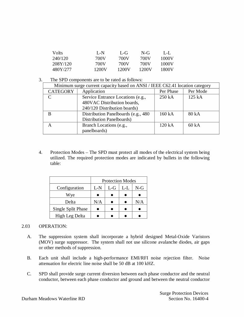
Surge Protection DevicesDurham Meadows Waterline RD Section No. 16400-4
Volts L-N L-G N-G L-L240/120 700V 700V 700V 1000V208Y/120 700V 700V 700V 1000V480Y/277 1200V 1200V 1200V 1800V
3. The SPD components are to be rated as follows:Minimum surge current capacity based on ANSI / IEEE C62.41 location category
CATEGORY Application Per Phase Per ModeC Service Entrance Locations (e.g.,
480VAC Distribution boards,240/120 Distribution boards)
250 kA 125 kA
B Distribution Panelboards (e.g., 480Distribution Panelboards)
160 kA 80 kA
A Branch Locations (e.g.,panelboards)
120 kA 60 kA
4. Protection Modes – The SPD must protect all modes of the electrical system beingutilized. The required protection modes are indicated by bullets in the followingtable:
Protection ModesConfiguration L-N L-G L-L N-G
WyeDelta N/A N/A
Single Split PhaseHigh Leg Delta
2.03 OPERATION:
A. The suppression system shall incorporate a hybrid designed Metal-Oxide Varistors(MOV) surge suppressor. The system shall not use silicone avalanche diodes, air gapsor other methods of suppression.
B. Each unit shall include a high-performance EMI/RFI noise rejection filter. Noiseattenuation for electric line noise shall be 50 dB at 100 kHZ.
C. SPD shall provide surge current diversion between each phase conductor and the neutralconductor, between each phase conductor and ground and between the neutral conductor

Surge Protection DevicesDurham Meadows Waterline RD Section No. 16400-5
and ground. For delta systems, the SPD shall have components directly connectedbetween each phase conductor and between each phase conductor and ground.
D. The SPD shall provide a low impedance path for surge current using oversizedconductors with equal impedance paths to each suppression element. Plug-in styleconnections or printed circuit boards for use in the path of surge current shall not beused.
E. Operating Parameters:
1. The maximum response time shall not exceed 1 nanosecond.
2. Provide with a noise filtering system capable of managing noise levels producedby electro-magnetic interference and radio frequency interference. The noisefiltering system shall reject a minimum of 50db at 100 kHz as measured by the50 Ohm Insertion Loss Method (Military Standard 220A).
3. The parallel system components shall operate over a minimum frequency range of47 Hertz to 63 Hertz.
4. The SPD components shall limit total harmonic distortion produced to less thanone percent.
5. SPD component ratings to be per UL 1449.
6. Each unit shall be factory tested at the maximum continuous operating voltage andshort circuit tested, prior to delivery.
F. Product Components:
1. Protection and Filtering Elements:
a. The SPD components shall consist of replaceable protection modulesdesigned to suppress and divert transient voltages and surge currents. Eachprotection module shall contain one or more individually fused metal oxidevaristers capable of withstanding over 1000 surges of Category C(IEEE/ANSI C62.41.1) current rated at 10,000 amperes.
b. Each protection module shall contain filtering elements capable of providingnoise attenuation.
c. The SPD components shall substantially limit transient waveform rise-timecharacteristics. The components are to be configured as parallel connected,current carrying elements designed to enhance the surge suppression anddiversion performance of the protection modules.
2. Provide individual fusing to allow the SPD to be isolated during fault conditions.

Surge Protection DevicesDurham Meadows Waterline RD Section No. 16400-6
3. Provide red and green solid-state status lights which indicate operational status ofeach unit and visual diagnostic monitoring of each component and module.Provide audible alarm to activate on fault condition, with a silence switch andpush-to-test alarm switch.
4. Provide surge counter with battery backup to retain memory upon loss of ACpower.
5. Provide remote status monitoring with form C dry contacts monitoring all phases.
2.04 SHOP TESTING:
A. Perform factory performance testing on each unit. The test to consist of the following:
1. High voltage impedance test.
2. Current test.
B. Tests shall be in accordance with the following standards:
1. ANSI/IEEE C62.41.1 Cat. A, B, & C.
2. ANSI/IEEE C62.45.
3. Military Standard 220A.
4. Underwriters Laboratory UL 1449.
C. Submit certified documentation of all factory tests performed.
D. Perform above tests in addition to standard factory tests.
2.05 SPARE PARTS:
A. Provide in accordance with Section and as specified.
B. Provide one spare protection module of each type for on-site spare parts purposes.
PART 3 - EXECUTION
3.01 INSPECTION:
A. Visually inspect delivered unit(s) and accessories for conformance with drawings andspecifications. Replace all components found to exhibit defects.
Surge Protection DevicesDurham Meadows Waterline RD Section No. 16400-7
3.02 INSTALLATION:
A. Install unit in compliance with the manufacturers printed instructions. All electricalinstallation work shall be in accordance with UL Listing Requirements and applicableNational or Local Electrical Codes.
B. For units mounted adjacent to electrical distribution equipment, verify conduit and wirefor the SPD components are as specified by the SPD manufacturer and installed in strictaccordance with the National Electrical Code.
C. Verify UL 1449, third edition or fourth edition, label is provided on each unit.
3.03 CONTRACT CLOSEOUT:
A. Provide in accordance with Section 01700.
END OF SECTION

Underground Ducts and Raceways for Electrical SystemsDurham Meadows Waterline RD Section No. 16402-1
SECTION 16402
UNDERGROUND DUCTS AND RACEWAYS FOR ELECTRICAL SYSTEMS
PART 1 - GENERAL
1.01 DESCRIPTION:
A. Provide complete underground distribution system as indicated and specified.
B. Conform to lines, grades, elevations, and dimensions. Resolve interferences with otherunderground conduit, piping or equipment, either new or existing with the ContractingOfficer. Match components suitable for proper installation.
C. Provide concrete encasement of duct system where indicated. Include forms andreinforcing in installation. Perform work in accordance with Section 16050.
D. Provide Schedule 40 polyvinylchloride (PVC) conduit for power and control circuits andfurnish and install rigid galvanized steel conduits for instrumentation, andcommunication.
1.02 REFERENCES:
A. National Fire Protection Association (NFPA):
1. 70: National Electrical Code (NEC).
1.03 SUBMITTALS:
A. Submit the following shop drawings in accordance with Section 01300:
B. Submit shop drawings and manufacturers' product data in accordance with requirementsof Section 16050.
C. Provide "Record" drawings.
PART 2 - PRODUCTS
2.01 MANUFACTURER'S COMPLIANCE:
A. Manufacturer's acceptance contingent upon products' compliance with specifications.
2.02 MANUFACTURERS:
A. Polyvinylchloride (PVC) Conduit:
1. Specified in Section 16110.
Underground Ducts and Raceways for Electrical SystemsDurham Meadows Waterline RD Section No. 16402-2
B. Rigid Steel Conduit, Galvanized:
1. Specified in Section 16110.
2.03 MATERIALS AND COMPONENTS:
A. Conduit Spacers: Provide conduit spacers made of plastic to maintain spacing betweenconduits.
B. Concrete: Minimum compressive strength, 3,000 psi (20 MPa).
C. Hot-dipped galvanized steel conduit used underground to be painted with bituminouspaint.
PART 3 - EXECUTION
3.01 INSTALLATION OF CONDUITS:
A. Lay conduits, indicated to be direct buried in the ground, in trench on 3 inch bed of sandand cover with an equivalent 3 inch bed of sand. Ensure that no rocks come in contactwith conduit during backfilling. Dig trenches to depth and location indicated.
B. Provide minimum separation of power and control conduits of 3 inches both verticallyand horizontally. Build ductbank layer by layer, backfill and compact each layer toprovide support for next layer.
C. Separate power and control ducts from instrument ducts by a minimum of 12 inches.
D. Backfill ductbank in layers and tamp or "puddle" as directed by the Contracting Officer.Provide yellow ductbank marker tapes, reading "Caution - Electrical Lines Below", overentire length of ductline. Locate tapes 12 inches below grade. Provide a tape for every12 inches of ductline width.
E. Install conduit, indicated to be encased in concrete with spacers and reinforcing, asspecified and as indicated. Rigid galvanized steel conduits to be painted withbituminous paint.
F. Install conduit runs following routing on drawing and running in straight lines. Wheredeviation from a straight line becomes necessary, install bends of radius which allow forrodding and installation of cable.
G. Accomplish changes in direction of runs exceeding total of 10 degrees, either vertical orhorizontal, by long sweep bends having minimum radius of curvature of 25 feet.Manufactured bends can be used at ends of short runs of 100 feet or less, and then onlyat or close to the end of run. Provide long sweep bends made up of one or more curvedor straight sections and/or combinations thereof. Install manufactured bends withminimum radius of 36 inch where larger radius cannot be used.

Underground Ducts and Raceways for Electrical SystemsDurham Meadows Waterline RD Section No. 16402-3
H. Lay ductlines to minimum slope of 4 inches per 100 feet and slope to manholes andhandholes, as indicated. Ductlines are to slope away from buildings.
I. Install spacers at intervals of approximately 4 feet and stagger between tiers of ducts toprovide not less than 12 inches of longitudinal separation. Install base spacers to provideat least 3 inches between bottom of trench and underside of bottom conduits.Completely fill space with concrete. Firmly wire conduits and spacers together beforeconcrete is placed.
J. Ductbanks are to be formed, unless trench conditions allow for neat placement ofconcrete with specified clearances.
K. Prior to placing of concrete, remove all dirt, sand, and any other debris from betweenconduits and from trench bottoms. Hold conduits in place to prevent floating oraccidental movement.
L. Stagger joints in conduits at least 6 inches. Do not allow couplings to rest on bottom oftrench. Install couplings for plastic conduit in accordance with manufacturer'srecommendations.
M. Install concrete encasements so minimum clearance of 12 inches from concrete toparallel pipes, lines, structures, etc., is maintained. Where ducts cross, minimumclearance of 6 inches is required. Do not allow the top of concrete to be less than 30inches below finished grade or paving. Submit special conditions which may requirelesser clearances or special conditions which may require greater than 30 inches depthto Contracting Officer for acceptance.
N. Where a connection is made to existing ductline, bond or dowel concrete encasement toexisting encasement. Use waterstop between ductpours and between manholes orbuildings and ductwork as indicated.
O. Do not use power-driven vibrators for spading of concrete around ducts.
P. Roll and grade backfill, and restore surface to condition equal to the site finish grade, oras otherwise indicated.
Q. Locate ductbank markers at ends of all ductbanks except at manholes or handholes, atapproximately every 200 feet along duct run, and at each change in direction of duct run.Place markers approximately on ductbank. Install markers 6 inches square or roundsection by 3 feet long made of Class B concrete. Imprint the letter "D" or cast it on topof the marker. Install top of duct markers flush in paved areas, protruding no more 2-inches above finished grade in unpaved areas. In finished lawns, allow marker toprotrude 1/2-inch.
R. Keep conduits clean of concrete, dirt, and other substances during the course ofconstruction. After the ductlines have been completed, pull a standard flexible mandrelnot less than 12 inches long, having a diameter approximately 1/4-inch less than theinside diameter of the conduit, through each conduit, after which pull a brush with stiff
Underground Ducts and Raceways for Electrical SystemsDurham Meadows Waterline RD Section No. 16402-4
bristles through each conduit to make certain that no particles of earth, sand, or gravelhave been left in the line. Replace conduit runs that do not allow the passage of themandrel at no additional cost to the Contracting Officer. Pneumatic rodding may beused to draw in the lead wire. Install in spare conduits a pull wire or rope, and plug andseal spare conduits after cleaning.
3.02 RECORD DRAWINGS OF UNDERGROUND WORK:
A. Provide one set of marked copies of contract drawings, showing exact routing anddepths of all underground conduit, duct handholes and manholes. Provide scaled plotplans, showing principal outline of buildings and structures. Reference conduits, ducts,and manholes, and all bends deviating from straight line, dimensionally from fixedobjects or structures.
3.03 CONTRACT CLOSEOUT:
A. Provide in accordance with Section 01700.
END OF SECTION

Automatic Transfer SwitchesDurham Meadows Waterline RD Section No. 16415-1
SECTION 16415
AUTOMATIC TRANSFER SWITCHES
PART 1 - GENERAL
1.01 DESCRIPTION:
A. This section includes materials and installation of the automatic transfer switch ATS-1.
B. Provide a 480VAC, 3-phase, 3-wire automatic transfer switch. Provide with minimumshort circuit rating of 65KAIC.
1.02 REFERENCES:
A. National Fire Protection Association (NFPA):
1. 70: National Electrical Code (NEC).
2. Connecticut Electrical Code
B. National Electrical Manufacturers Association (NEMA):
1. ICS 2: Industrial Controls and Systems Controllers, Contactors, and OverloadRelays Rated 600 Volts.
C. Underwriters Laboratories (UL):
1. 1008: Automatic Transfer Switches.
1.03 SUBMITTALS:
A. Submit shop drawings and manufacturers' product data in accordance with therequirements of Section 16050.
B. Shop Drawings: Submit the following as specified herein:
1. A copy of this specification section with addenda and all referenced specificationsections with addenda, with each paragraph check-marked to indicate specificationcompliance.
a. Failure to include a copy of the marked-up specification sections will resultin return of the entire submittal without further review and considerationuntil the marked-up specification are resubmitted with the entire package.
----

Automatic Transfer SwitchesDurham Meadows Waterline RD Section No. 16415-2
C. Submit complete list of equipment and materials., including manufacturer's descriptivedata including ratings, circuit diagrams, dimensional data, conduit entry restrictions, anda list of accessories.
D. Spare Parts Data: Provide a recommended spare parts list.
1.04 OPERATION AND MAINTENANCE MANUALS:
A. Submit operation and maintenance manuals in accordance with Section16050.
1.05 MANUFACTURER'S SERVICES:
A. Provide manufacturer's services at the jobsite for the minimum labor days listed below,travel time excluded:
1. One labor day to check the installation and advise during start-up, testing, andadjustment of the transfer switch.
PART 2 - PRODUCTS
2.01 TRANSFER SWITCH:
A. Transfer switch shall be in a free standing enclosure with a NEMA rating in accordancewith the Area Classification Schedule. Transfer switch shall have number of poles,amperage, and voltage ratings as shown in the drawings. Withstand current rating shallnot be less as indicated on the contract drawings.
B. Switch shall be listed per UL 1008.
C. Transfer switch shall be electrically operated and mechanically held in each direction bya single operating mechanism momentarily energized from the source to which the loadshall be transferred. Accomplish mechanical locking in each direction without the aid oflatching solenoids, toggle mechanisms, or gear arrangements. Total operating transfertime shall not exceed one-sixth of a second.
D. An overload or short circuit shall not cause the switch to go to a neutral position. Do notuse main contact structures not originally manufactured for transfer switch service(molded case circuit breakers or contactors). Inspection and replacement of all contacts(stationary and arcing) shall be possible from the front of the switch without anydisassembly of operating linkages or power conductors. Provide a handle to permit no-load manual operation.
E. Provide transfer switch with current limiting fuses to provide the specified short circuitrating.

Automatic Transfer SwitchesDurham Meadows Waterline RD Section No. 16415-3
2.02 ACCESSORIES:
A. Provide a solid-state sensing and control logic panel. Include the following operationalcharacteristics:
1. Adjustable (0.5 to 6.0 seconds) time delay on engine starting to overridemomentary dips in normal source, set at 1 second.
2. Full phase voltage relay supervision of the normal source with at least one closedifferential relay to detect "brownout" condition, set at 70 percent dropout and90 percent pickup.
3. Voltage/frequency lockout relay to prevent premature transfer, set at 90 percentvoltage and 90 percent frequency.
4. Engine starting control contacts (one normally open and one normally closed).
5. Adjustable (2 to 25 minutes) time delay on retransfer to normal, set at 20 minutes.
6. Unloaded running time delay for generator cool down (adjustable 0.1 to10 minutes), set at 5 minutes.
7. Transfer to emergency time delay (adjustable 1 to 300 seconds), set at 1 second.
8. Programmable generator automatic exercise.
B. Provide a system test switch (momentary type) on the front of the enclosure.
C. Manual push button to bypass the time delay on retransfer.
D. Indicating lights to indicate source to which the load is connected.
E. Indicating light to indicate presence of normal power source.
F. Auxiliary contacts for remote indication of switch position, one normally open and onenormally closed contact for normal power and emergency position.
2.03 MANUFACTURERS:
A. The transfer switch shall be as manufactured by:
1. Kohler
2. Cummins
3. Or Equal
Automatic Transfer SwitchesDurham Meadows Waterline RD Section No. 16415-4
PART 3 - EXECUTION
3.01 INSTALLATION:
A. Secure transfer switch rigidly to wall and floor or mounting pad with anchor bolts orPhillips Drill Company concrete anchors. Anchor bolts or concrete anchors shall be 316stainless steel.
3.02 FIELD TESTING:
A. Field test per manufacturer’s recommended standard test procedure.
B. Field test and calibrate timing and monitoring logic. All adjustments shall be within 5percent of the previously specified set points.
C. Field test and calibrate the in-phase monitor. Demonstrate that the switch transfers whensource phase differences are within 20 degrees under varying generator speeds.
3.03 CONTRACT CLOSEOUT:
A. Provide in accordance with Division 1 Specification requirements.
END OF SECTION

GroundingDurham Meadows Waterline RD Section No. 16450-1
SECTION 16450
GROUNDING
PART 1 - GENERAL
1.01 DESCRIPTION:
A. Provide a single, complete, integrated grounding system, including conductors,raceways, and connections, indicated and specified, and in accordance with the NationalElectrical Code Article 250 and the National Electrical Safety Code.
B. Include electric equipment enclosures, ground grid systems with ground rod and waterpipe connections; structural steel, and lightning protection system.
C. Include grounding conductors completely inter-connecting water supply pipe, groundrods, ground grid, ground buses, other distribution equipment, and other groundableequipment.
1.02 REFERENCES:
A. American National Standards Institute (ANSI)/Institute of Electrical and ElectronicsEngineers (IEEE):
1. ANSI/IEEE C2: National Electrical Safety Code.
B. American Society for Testing and Materials International (ASTM):
1. B3: Standard Specification for Soft or Annealed Copper Wire.
2. B8: Standard Specification for Concentric-Lay-Stranded Copper Conductors,Hard, Medium-Hard, or Soft.
3. B33: Standard Specification for Tinned Soft or Annealed Copper Wire forElectrical Purposes.
C. Institute of Electrical and Electronics Engineers (IEEE):
1. Standard 81: Guide for Measuring Earth Resistivity, Ground Impedance, andEarth Surface Potential of a Ground System.
D. National Fire Protection Association (NFPA):
1. 70: National Electrical Code.
2. 780: Lightning Protection Code.
GroundingDurham Meadows Waterline RD Section No. 16450-2
E. Underwriters Laboratories (UL):
1. 467: Standard for Grounding and Bonding Equipment.
1.03 SUBMITTALS:
A. Submit the following shop drawings in accordance with Section 01300:
B. Submit shop drawings and manufacturers' product data in accordance with requirementsof Section 16050.
C. Submit catalog and dimensional data for the following:
1. Ground rods
2. Exothermic welding
3. Connecting hardware
D. Submit grounding system test results.
PART 2 - PRODUCTS
2.01 MANUFACTURER'S COMPLIANCE:
A. Manufacturer's acceptance contingent upon products' compliance with the specifications.
2.02 MANUFACTURERS:
A. Ground Rods:
1. ERICO Products Inc.
2. Galvan Electrical Products.
3. Nehring Electrical Works.
B. Exothermic Welding:
1. ERICO Products, Inc.
2. American Brass Mfg. Co.
3. Orgo-Thermit, Inc.
C. Connecting Hardware:
1. American Brass Mfg. Co.

GroundingDurham Meadows Waterline RD Section No. 16450-3
2. Thomas and Betts
3. Anderson Electric Corp.
2.03 MATERIALS AND COMPONENTS:
A. Conductors:
1. Provide copper grounding conductors bare or insulated, sized as indicated. Whennot indicated on the drawing provide in accordance with the NEC. Provideprotection of conductors in locations where physical damage would result fromdirect exposure.
2. Ground and bond wires for substations, main panels and distribution points, andground rod connections shall be annealed bare copper conforming to ASTM B3,stranded, with 98 percent conductivity.
3. Equipment ground conductors run with circuit conductors and grounding electrodeconductor shall be 600 volt with green insulation, unless noted otherwise on theContract documents.
4. Unless noted otherwise, all conductors No. 8 AWG and larger shall be stranded,Class B in accordance with ASTM B8.
a. Uninsulated conductors shall be bare copper in accordance with ASTM B3,tinned in accordance with ASTM B33.
b. Use tinned-coated in corrosive environments including when buried in earthor embedded in concrete.
B. Connectors and Fasteners:
1. Provide ground clamps which are UL listed for use on copper or brass pipes.
2. Provide ground clamps, for use on iron pipes, of galvanized or malleable iron, orof standard noncorrosive material for use on iron pipes.
3. Provide ground clamps, for use on pipes, with rigid metal base providing goodcontact by proper seating on the pipe. Do not use strap type clamps.
C. Ground Rods:
1. Ground rods shall conform to the requirements of NFPA 70 and UL Standard 467.
2. Ground rods shall be copper-clad steel rods not less than 3/4 inch in diameter andnot less than 10 feet long per section.
3. Ground rods shall be clean and smooth with the following characteristics:

GroundingDurham Meadows Waterline RD Section No. 16450-4
a. Cone-shaped point on the first section.
b. Die-stamped near the top with the name or trademark of the manufacturerand the length of the rod in millimeters or feet.
PART 3 - EXECUTION
3.01 EXOTHERMIC WELDING:
A. Welding shall be by the exothermic process.
B. Within the welding procedure, include the proper mold and powder charge and conformto the manufacturer’s recommendations.
C. Welding processes shall be the exothermic fusion type that will make a connectionwithout corroding or loosening.
D. The welding process shall join all strands and not cause the parts to be damaged orweakened.
E. Completed connection or joint shall be equal or larger in size than the conductors joinedand have the same current-carrying capacity as the largest conductor.
F. Paint buried ground connection with a bitumastic paint.
3.02 INSTALLATION OF GROUNDING CONDUCTORS:
A. Install grounding conductors so that they will not be exposed to physical damage. Installconnections firm and tight. Arrange conductors and connectors so no strain onconnections.
B. Run grounding conductors associated with direct burial cables in common trenchesabove cables except as indicated otherwise.
C. Bury equipment grounding conductors 30 inches deep. Bring loops or taps up forconnection to equipment or other items to be grounded.
D. Where raceways are used to contain and protect grounding conductors, install inaccordance with Sections 16110 and 16402.
E. Where bare grounding conductors are contained within metallic raceways, bond ends ofraceways to conductors.
F. Install loop type, low impedance, grounding system interconnecting all components so atleast two grounding connections are provided for each major item of electricalequipment. Ensure that severing of any single grounding conductor in this system doesnot remove grounding protection on any major item.

GroundingDurham Meadows Waterline RD Section No. 16450-5
G. Connect structural steel to the external perimeter loop of grounding conductors installedaround all sides of building foundation, buried at least 30 inches below grade. Connectto each vertical column by loop or tap. Connect two opposite points on external loop totwo different points on grounding system.
H. Buried and concealed ground connections shall use exothermic welding.
I. Make accessible connections to structural members by exothermic welding process or bybolted connector. Connections to equipment or ground bus by bolted connectors.
3.03 INSTALLATION OF GROUND RODS:
A. Install ground rods in manholes in accordance with requirements specified under thesection Underground Distribution Systems. Connect each grounding conductor enteringa manhole to ground rod by exothermic weld.
B. Install ground rods where indicated. Install the top of the rod 12 inch below the groundsurface.
C. Make connection to overall grounding system as indicated.
D. Ensure that final resistance of interconnected ground system is 5 ohms, or less. Measureground resistance in normally dry conditions, and not less than 48 hours after rainfall.
3.04 EQUIPMENT GROUNDING:
A. Ground each piece of electrical equipment by means of a grounding conductor installedin raceway feeding that piece of equipment. Grounding conductors installed in conduitwith insulated conductors to be furnished with green, 600 volt insulation. Groundconductors are in addition to and not to be considered as the neutral wire of the system.
B. Connect power transformer cases and neutrals to grounding system. Connect neutralground connection at transformer terminal. Provide two separate, independent,diagonally opposite, connections for power transformers so removal of one connectionwill not impair continuity of other.
C. Connect two separate ground connections from ground grid to ground bus of switchgearassemblies, motor control centers, switchboards and all outdoor substation andtransformer equipment. Ensure that each connection for item of equipment is fromdifferent section of ground grid.
D. Connect a grounding conductor between panelboard and grounding system. Where agrounding bar is furnished with panelboard, connect grounding conductor to bar.
E. Conduits entering metal enclosures shall utilize bonding type locknuts and groundingbushings. Locknuts that gouge into the metal enclosures are not acceptable.
GroundingDurham Meadows Waterline RD Section No. 16450-6
F. Where conduits are not effectively grounded by firm contact with a grounded enclosure,apply grounding bushings on at least one end of conduit run. Conduit connections shallbe wrench tight.
G. Connect grounding conductors from equipment in area where ground bus is required toground bus. Connect ground bus to grounding system. Mount ground bus on 600 voltpedestal insulators.
H. Connect lightning arresters to ground system by suitable conductors. Where lightningarresters are furnished with electrical equipment and grounding connections are notinherently provided, ensure that suitable separate grounding conductor connectslightning arresters with system ground.
I. Connect generator neutral to grounding system by a grounding conductor. Connectgrounding conductor to generator disconnect enclosure and generator neutral ongenerator side of disconnect. Ground generator frame with two separate independentconnections, so removal of one connection will not impair continuity of other.
J. Ground each street lighting standard by ground rod driven near base of standard, inaccordance with requirements of the National Electric Safety Code. Connect groundrods to grounding conductor brought with street lighting feeder cable.
K. Ground transformers, lightning arresters, insulators and other appurtenances, installed onpoles, poles and timber structures, or metal structure. Run grounding conductorsbetween poles or structure and ground rods. Protect grounding conductor by moldingapplied for at least 8 feet above ground, with both molding and conductor stapled.Install ground rod where indicated and driven until top of rod is 1 foot below ground.
L. Ground wire fences when used to enclose electrical equipment or when overheadelectrical lines cross fence. Unless otherwise indicated, provide grounding by buriedoutside peripheral ground loop; connections to each corner fence post and nearby groundrod; flexible connections to each gate; and at least two connections to grounding systemfrom approximately opposite positions on fence.
M. Connect individual ground rods to the grounding loop using the direct burial groundingcable.
3.05 SIGNAL GROUNDING:
A. Ground signal surge protection and shields of twisted, shielded cable using a signalbonding conductor. The signal bonding conductor shall be a continuous path from theinstrument surge protection or shield to the grounding electrode conductor. The signalbonding conductor shall be isolated from the equipment grounding conductor for itsentire path.
B. Where convenient several signal bonding conductors may be conbined, providing that allthe following conditions are met:

GroundingDurham Meadows Waterline RD Section No. 16450-7
1. The combined signal bonding conductor shall have the equivalent cross section ofthe conductors that it was combined from or three times the cross section of thelargest conductor that it was combined from, whichever is less.
2. The combined signal bonding conductor shall be isolated from the equipmentgrounding conductor.
3. Where two signal bonding conductors are combined use a three port insulatedsplice.
4. Where three or more signal bonding conductors are combined, use a copper busmounted on 600 volt insulators. Attach each conductor to the bus using aninsulated ring tongue lug and screw terminal.
3.06 FIELD TESTING:
A. Refer to Section 16998 for testing requirements.
B. Test grounding systems for ground resistance. Total resistance from any point on theground network to the building counterpoise must not exceed 3 ohms.
C. Ground resistance and counterpoise tests must be made during dry weather and nosooner than 48 hours after rainfall. Conditions of soil and weather shall be documentedon test forms.
D. Conduct tests using the ratio method that measures the ratio of the resistance to earth ofan auxiliary test electrode to the series resistance of the electrode under test and a secondauxiliary electrode. Perform measurements in accordance with IEEE Standard 81.
E. Indicating instrument must be self-contained and include a direct-current generator,synchronized current and potential reversers, crossed-current and potential coils, direct-reading ohmmeter, series resistors, and range-selector switch. Calibrate direct-readingohmmeter for ranges of 0 to 20 ohms and 0 to 200 ohms.
F. Place auxiliary grounding electrodes in accordance with instrument manufacturer’srecommendations but not less than 50 feet (15 m) apart, in accordance with IEEEStandard 81.
G. Perform continuity test on all power receptacles to ensure that the ground terminals areproperly grounded to the facility ground system.
H. Furnish copies of test reports on ground system.
3.07 CONTRACT CLOSEOUT:
A. Provide in accordance with Section 01700.
END OF SECTION
Lightning ProtectionDurham Meadows Waterline RD Section No.16601-1
SECTION 16601
LIGHTNING PROTECTION
PART 1 - GENERAL
1.01 DESCRIPTION:
A. Provide lightning protection system on the Cherry Hill Storage Tank. The system shallconsist of air terminals, conductors, ground terminals, interconnection conductors,arresters, and other connectors or fittings for a complete system.
B. All systems are to be provided and installed by trained Service Technicians having five(5) years active experience. Provide proof of previous MASTER LABEL installationsreceiving the U.L. “C” plate of acceptance.
1.02 RELATED WORK
A. Division 1: General Requirements
B. Section 16050: Electrical Work – General
C. Section 16450: Grounding
D. Section 16998: Field Inspection and Acceptance Tests
1.03 REFERENCES:
A. Underwriters’ Labratories, Inc. (UL):
1. UL-96: Lighting Protection Componenets
2. UL-96A: Installtion Requirements for Lighting Protection Systems
B. National Fire Protection Association (NFPA):
1. NFPA-70: National Electrical Code.
2. NFPA-780: Lightning Protection Code.
3. Conneticut Electrical Code.

Lightning ProtectionDurham Meadows Waterline RD Section No.16601-2
1.04 SUBMITTALS:
A. Shop Drawings: Submit the following in accordance with Section 01300 and as specifiedherein:
1. A copy of this specification section with addenda and all referenced specificationsections with addenda, with each paragraph check-marked to indicate specificationcompliance.
a. Failure to include a copy of the marked-up specification sections will resultin return of the entire submittal without further review and considerationuntil the marked-up specification are resubmitted with the entire package.
2. List of equipment and materials, including manufacturer's descriptive andtechnical literature, catalog cuts, installation instructions.
3. Detailed shop drawings, drawn to scale, indicating type, placement, and location ofprotection devices, including cable attachments, grounding, mounting and anyother details integral with the system.
4. Spare Parts Data: Provide a list of recommended spare parts for the material andequipment to be provided, including current unit prices and source of supply.
5. Inspection and Maintenance: Provide a written recommended inspection andmaintenance procedure, including periodicity of inspections.
A. As-Built Drawings: Provide a complete set of "as-built" drawings showing the locationof all grounds as well as a detailed layout of type, size, location and method ofinstallation of all downleads, roof cables, bonding leads and connections, air terminals,and in the case where structural steel is used for downleads, the method and location ofall roof and ground connections to the steel must be clearly detailed.
1.05 QUALITY ASSURANCE
A. Provide in accordance with Section 01400 and as specified herein.
B. Conduit size and wire quantity, type and size shall be useable for the equipmentsupplied.
C. Provide systems furnished and installed by trained Service Technicians.
D. Provide UL listed components.
1.06 DELIVERY STORAGE AND HANDLING:
A. Provide in accordance with Section 01610 and as specified herein.
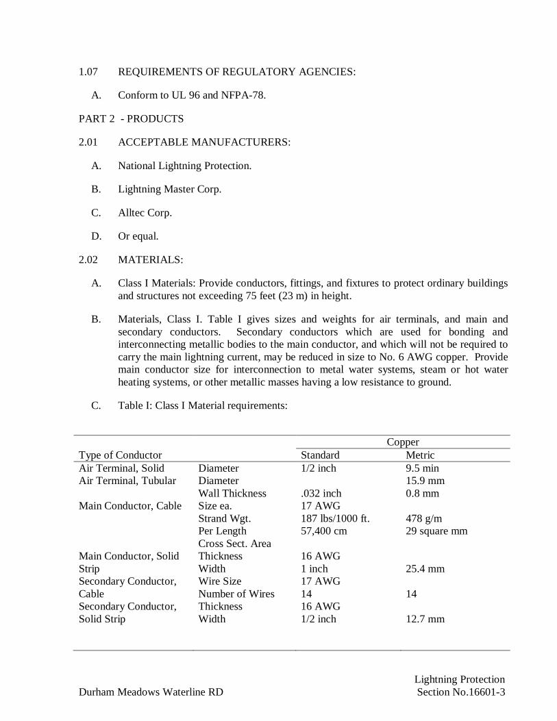
Lightning ProtectionDurham Meadows Waterline RD Section No.16601-3
1.07 REQUIREMENTS OF REGULATORY AGENCIES:
A. Conform to UL 96 and NFPA-78.
PART 2 - PRODUCTS
2.01 ACCEPTABLE MANUFACTURERS:
A. National Lightning Protection.
B. Lightning Master Corp.
C. Alltec Corp.
D. Or equal.
2.02 MATERIALS:
A. Class I Materials: Provide conductors, fittings, and fixtures to protect ordinary buildingsand structures not exceeding 75 feet (23 m) in height.
B. Materials, Class I. Table I gives sizes and weights for air terminals, and main andsecondary conductors. Secondary conductors which are used for bonding andinterconnecting metallic bodies to the main conductor, and which will not be required tocarry the main lightning current, may be reduced in size to No. 6 AWG copper. Providemain conductor size for interconnection to metal water systems, steam or hot waterheating systems, or other metallic masses having a low resistance to ground.
C. Table I: Class I Material requirements:
Type of ConductorCopper
Standard MetricAir Terminal, Solid Diameter 1/2 inch 9.5 minAir Terminal, Tubular Diameter
Wall Thickness .032 inch15.9 mm0.8 mm
Main Conductor, Cable Size ea.Strand Wgt.Per LengthCross Sect. Area
17 AWG187 lbs/1000 ft.57,400 cm
478 g/m29 square mm
Main Conductor, SolidStrip
ThicknessWidth
16 AWG1 inch 25.4 mm
Secondary Conductor,Cable
Wire SizeNumber of Wires
17 AWG14 14
Secondary Conductor,Solid Strip
ThicknessWidth
16 AWG1/2 inch 12.7 mm
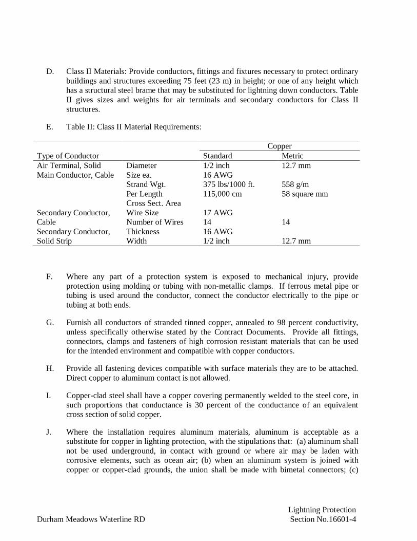
Lightning ProtectionDurham Meadows Waterline RD Section No.16601-4
D. Class II Materials: Provide conductors, fittings and fixtures necessary to protect ordinarybuildings and structures exceeding 75 feet (23 m) in height; or one of any height whichhas a structural steel brame that may be substituted for lightning down conductors. TableII gives sizes and weights for air terminals and secondary conductors for Class IIstructures.
E. Table II: Class II Material Requirements:
Type of ConductorCopper
Standard MetricAir Terminal, Solid Diameter 1/2 inch 12.7 mmMain Conductor, Cable Size ea.
Strand Wgt.Per LengthCross Sect. Area
16 AWG375 lbs/1000 ft.115,000 cm
558 g/m58 square mm
Secondary Conductor,Cable
Wire SizeNumber of Wires
17 AWG14 14
Secondary Conductor,Solid Strip
ThicknessWidth
16 AWG1/2 inch 12.7 mm
F. Where any part of a protection system is exposed to mechanical injury, provideprotection using molding or tubing with non-metallic clamps. If ferrous metal pipe ortubing is used around the conductor, connect the conductor electrically to the pipe ortubing at both ends.
G. Furnish all conductors of stranded tinned copper, annealed to 98 percent conductivity,unless specifically otherwise stated by the Contract Documents. Provide all fittings,connectors, clamps and fasteners of high corrosion resistant materials that can be usedfor the intended environment and compatible with copper conductors.
H. Provide all fastening devices compatible with surface materials they are to be attached.Direct copper to aluminum contact is not allowed.
I. Copper-clad steel shall have a copper covering permanently welded to the steel core, insuch proportions that conductance is 30 percent of the conductance of an equivalentcross section of solid copper.
J. Where the installation requires aluminum materials, aluminum is acceptable as asubstitute for copper in lighting protection, with the stipulations that: (a) aluminum shallnot be used underground, in contact with ground or where air may be laden withcorrosive elements, such as ocean air; (b) when an aluminum system is joined withcopper or copper-clad grounds, the union shall be made with bimetal connectors; (c)

Lightning ProtectionDurham Meadows Waterline RD Section No.16601-5
precautions be taken at connections with dissimilar metals; and (d) cable conductors beof electrical conductor grade aluminum.
K. Materials such as galvanized steel is not acceptable.
2.03 AIR TERMINALS
A. Air terminals shall be provided and located to intercept a direct lightning strike.
B. Aire terminals shall be ½ inch as indicated. Air terminals shall extend above theprojected object between 10 inches and 36 inches. If over 24 inches high, air terminalsshall be braced.
C. Air terminals up to 24 inches high shall be spaced at intervals of 20 feet or less; those 24inches or higher shall be spaced 25 feet or less. Terminals shall be placed on the ridgesof gable, gambrel, and hip roofs of ordinary or high slope, and at the perimeters of flat orlow-slope roofs. A shed roof with a high or normal slope shall be considered as half of agable roof. There shall be an air terminal within two feet of the end of each ridge oreach corner of a flat or low-slope roof.
D. Air terminals shall be placed within two feet of the edge along the perimeter of a flat orlow-slope roof. A low-slope roof is one which is 40 feet wide or less and has a pitch of1/8 or less; or is over 40 feet wide and has a pitch of 1/4 or less. The center of such aroof shall have intermediate air terminals at intervals not exceeding 50 feet.
PART 3 - EXECUTION
3.01 INSTALLATION
A. Provide all material, equipment, and labor to install the lightning protection system asindicated and as specified. Equipment shall be installed by Service Technicianspecifically trained on installing lightning protection.
B. Main conductors shall: (a) interconnect air terminals in a direct or closed-loop roofsystem; (b) serve as downleads from the roof system to the ground system; (c) connectmetal bodies of inductance or conductance to the main conducting system; and (d) serveas ground electrodes in some cases, or to connect ground rods in certain other cases.
C. Bend of conductor shall form an included angle of 90 degrees and have a radius of bendof 8 inches (203 mm).
D. Interconnect all conductors, air terminals to form a two-way pasth from each air terminalhorizontally or downward to connections with ground terminals.
E. Conductors may be coursed through air without support for a distance of 3 feet or less.With a 5/8 inch rod or its equivalent as a support, fastened at each end, a conductor maybe coursed through air for a distance not to exceed 6 feet.
Lightning ProtectionDurham Meadows Waterline RD Section No.16601-6
F. Install roof conductors to interconnect all air terminals and provide a two-way path toground horizontally or downward from the base of each terminal.
G. Metal roofing and siding, eave troughs, downspouts, and other metal parts are notacceptable as substitutes for lightning conductors.
H. Install two down conductors on any kind of structure. Location depends on placement ofair terminals, size of structure, most direct coursing, security against displacement andlocation of metallic bodies, water pipes, and ground conditions. Separate downconductors. For structures over 200 feet in perimeter, install one additional downconductor for each additional 100 feet of perimeter or fraction thereof.
I. The structural steel columns on the outside perimeter of the structure shall not be utilizedas the main down conductor from roof to ground for the lightning protection system. Noparts of the structural steel structure shall substitute for lightning down conductors. Thesteel columns around the outside perimeter of the structure shall be grounded at everyother column and in no case shall average over 60-ft. apart. A through the roofconnector shall be installed where a conductor penetrates the roof, by the LightningProtection Subcontractor. The through the roof connector shall be 1/2-in stainless steelthreaded rod equipped with neoprene washers and stainless nuts for a watertight seal.
J. Terminate each down conductor at a ground rod.
K. Use connector fittings on all lightning conductors at “end-to-end” “tee” or “Y” spalices.Attach them so as to withstand a pull test of 200 pounds. Make fittings for connection tometal tracts, gutters, downspouts, ventilators, chimney extensions, or other metal partsabout the structure tight to the object by compression under bolt heads. Both crimp typeand exothermic weld splicers of stamped or cast metal are acceptable under Class Irequirements. Do not use crimp type clamps and splicers in Class II installations. Useexothermic welds for all below grade system connections.
L. Attach conductors to the building or other object upon which they are placed. Usefasteners not subject to breakage. Furnish nails, screws and bolts, with which fastenersare attached, of the same material as the conductor or of such nature that there will be noelectrolytic corrosion in the presence of moisture because of contact between thedifferent parts. Space conductor fasteners not more than 3 feet apart on all conductors.
M. All requirements covering exposed systems apply to concealed installations. Conductorsare coursed the same except that they may be coursed behind the exterior wall facing, inconcealed or embedded conduit, or embedded directly in concrete.
N. Materials, installation methods and procedures are to be in accordance with UL-96 and96A, NFPA 780, NEC and local electrical codes. Provide for and obtain a “U.L.Certificate of Compliance” for the Work performed.
Lightning ProtectionDurham Meadows Waterline RD Section No.16601-7
3.02 SYSTEM TESTING:
A. Perform system testing as part of the grounding system tests identified in Sections 16450and 16998.
END OF SECTION
Electrical Controls and Miscellaneous Electrical EquipmentDurham Meadows Waterline RD Section No. 16900-1
SECTION 16900
ELECTRICAL CONTROLS AND MISCELLANEOUS ELECTRICAL EQUIPMENT
PART 1 - GENERAL
1.01 DESCRIPTION:
A. Provide and connect the electrical control equipment and miscellaneous electricalequipment, including such instruments and devices indicated and specified. Deviceenclosures for electrical equipment as indicated and specified.
B. Control panel enclosures and devices specified herein are provided under thosespecification sections which invoke this section for control panel requirements or asindicated on electrical drawings.
C. Provide equipment in accordance with the area classification schedule on the electricalcontract drawings.
1.02 REFERENCES:
A. American Society for Testing and Materials International (ASTM):
1. D178: Standard Specification for Rubber Insulating Matting
B. National Electrical Manufacturers Association (NEMA):
1. 250: Enclosures for Electrical Equipment (1000 volts maximum).
2. ICS 1: Industrial Control and Systems General Requirements
3. ICS 2: Industrial Controls and Systems Controllers, Contactors, and OverloadRelays Rated 600 Volts.
4. ICS 4: Terminal Blocks for Industrial Use.
C. National Fire Protection Association (NFPA):
1. 70: National Electrical Code (NEC).
D. Underwriter's Laboratories, Inc. (UL):
1. 467: Standard for Grounding and Bonding Equipment.
2. 486A: UL Standard for Safety Wire Connectors and Soldering Lugs for Use withCopper Conductors.

Electrical Controls and Miscellaneous Electrical EquipmentDurham Meadows Waterline RD Section No. 16900-2
3. 489: Standard for Molded-Case Circuit Breakers, Molded-Case Switches andCircuit-Breaker Enclosures.
1.03 SUBMITTALS:
A. Submit the following shop drawings in accordance with Section 01300.
B. Submit shop drawings and manufacturers' product data in accordance with therequirements of Section 16050.
C. Wiring diagrams to show control interface points provided with other equipment.
D. Shop drawings to include:
1. Outline drawings with elevations.
2. Equipment arrangement drawings.
3. Anchor bolt location drawings.
4. Electrical schematics and wiring diagrams.
5. Electrical fuse/circuit breaker characteristic.
6. Equipment performance curves and data.
7. Bill of installation/assembly materials.
8. Equipment weights.
9. Completed manufacturer’s data sheets.
10. Sustainable design submittals.
1.04 SPARE PARTS:
A. Comply with the requirements specified in Section 01610.
1.05 QUALITY ASSURANCE:
A. Comply with the requirements specified in Section 01400.
B. Sustainability Standards Certifications.
1.06 DELIVERY STORAGE AND HANDLING:
A. Comply with the requirements specified in Section 01610.
Electrical Controls and Miscellaneous Electrical EquipmentDurham Meadows Waterline RD Section No. 16900-3
PART 2 - PRODUCTS
2.01 MANUFACTURERS FOR ELECTRICAL DISTRIBUTION EQUIPMENT:
A. Siemens.
B. General Electric Company.
C. Eaton/Cutler-Hammer.
D. Square D Company.
E. Appleton Electric Company.
F. Crouse-Hinds Company.
G. O-Z/Gedney.
2.02 SAFETY DISCONNECT SWITCHES:
A. Provide heavy duty type, safety switches, with external operating handles, 3 PST, rated600 volt, 60 Hertz with ampere rating as indicated, and having provisions forpadlocking.
B. Provide fuses for safety switches as indicated.
C. Heavy duty safety switches to be UL listed, File E 2875 and 154828, and meet or exceedNEMA Standard KS1.
2.03 PUSHBUTTON AND SELECTOR SWITCH STATIONS:
A. Provide HAND-OFF-AUTO switches, push buttons, tumbler switches and otheraccessory devices as necessary for the control of motors and other electrical equipmentor devices.
B. Provide pushbutton and selector switch stations designed for heavy-duty service andwith momentary or maintaining contacts as indicated or as necessary for starting andstopping of equipment with 10 amp contact ratings.
C. Provide heavy duty switches and pushbuttons, Square D Company, Class 9001 orapproved equal. Indicating lights to be led cluster type.
2.04 MANUAL MOTOR STARTERS:
A. Provide manual motor starters where indicated and for 120 volt, 60 Hertz fractionalhorsepower motors.
B. Provide each manual motor starter with overload heater or heaters of suitable capacityfor motor running overcurrent protection for motor it controls. Provide manual starters

Electrical Controls and Miscellaneous Electrical EquipmentDurham Meadows Waterline RD Section No. 16900-4
as single or 2 pole, as necessary, and with toggle mechanisms indicating OFF and ONpositions.
2.05 CONTROL PANELS AND ELECTRICAL ENCLOSURES:
A. Provide control panels and other equipment, as indicated. Ensure that dimensions,NEMA rating, construction and mounting of equipment are as indicated.
B. Provide enclosures with back panels constructed of at least 14 gage (1.90 mm) steel andprovided with terminal blocks for connection of external wiring. Provide door and bodystiffeners in panels over 36 inches (915 mm) in length. NEMA 4X panels are to beprovided with hand operated quick disconnects of stainless steel material.
C. Provide UL listed and NEMA rated pushbuttons, indicator lights and switches of heavyduty, oil tight types. Provide relays of industrial types, with 120 volt, 60 Hertz operatingcoils, and contacts rated for intended service. Power from fused control powertransformers.
D. Provide nameplates for each panel and each device on panel. Nameplates of laminatedplastic material, at least 3/32-inch (2.4 mm) thick, and with white letters on a blackbackground.
E. Secure nameplates with self-tapping, Type 316 stainless steel metal screws.
F. Terminal Blocks:
1. Provide terminal blocks rated for 600 volts with screw type terminals.
2. Terminal blocks to be one piece with full barriers.
3. Provide General Electric EB-25 terminal blocks or equal.
G. Provide print pocket on inside of enclosure and include as-built drawings for theMunicipality’s use.
H. Where visual strobe or warning lamps are required, provide heavy duty beacon, EdwardsSignal Catalogue No. 93 or approved equal.
I. Where audible horn alarms are required, provide Edwards Signal 870P or approvedequal.
J. Where equipment and devices are to be installed in hazardous locations, provideequipment and components suitable for the environment.
K. Where intrinsically safe wiring is required within the panels, the following requirementsshall be met:

Electrical Controls and Miscellaneous Electrical EquipmentDurham Meadows Waterline RD Section No. 16900-5
1. Within enclosures, conductors or intrinsically safe (IS) circuits shall be separatedat least two inches (50 mm) from conductors of any non-intrinsically safe circuit.Within the enclosure the conductors shall be secured.
2. Intrinsically safe wiring shall not be routed in the same conduit as non-IS wiring.
3. Terminals in panels with IS wiring shall be identified in a manner that will preventunintentional interference with the control circuits during testing and servicing.
L. All indicating lamps to be LED cluster type.
2.06 CONTACTORS AND RELAYS:
A. Provide mechanically held, heavy duty type contactors (relays) for lighting control, rated30 amps, 600 volts, with number of poles as indicated.
B. Provide contactor in the required NEMA enclosure suitable for wall mounting. Providecircuit breaker or fuse protection on each ungrounded pole. Provide contactor similar toSquare D Company, Class 8903, Type LX or approved equal.
C. Provide control power transformer with primary and secondary fuse protection. Controlpower to be 120 volts, single phase.
D. Provide timing relays by Allen Bradley, Series 700 or equal.
E. Provide industrial grade relays, NEMA rated, Square D Company, Class 8501 or equal.
2.07 NAMEPLATES:
A. Provide nameplates for equipment (including pushbutton and selector switch stations)listed in this section and other controls furnished under this contract, to designate theequipment controlled and their function.
B. Nameplates shall be laminated black bakelite with 1/4-inch (6 mm) high, white, recessedletters. Securely attach to the equipment with Type 316 stainless steel screws, or rivets.Adhesives, glue or cements will not be permitted.
C. Provide all junction boxes, pull boxes, disconnect switches and control panels with anameplate to designate the system wiring contained within.
D. Install nameplates in a location near or on the equipment or devices.
2.08 MANUAL TRANSFER SWITCH
A. Transfer switch shall be installed in the electrical enclosure.
B. Transfer switch shall be double-pole and double throw manual switch.
C. Switch shall be heavy-duty 600V rated, 3-pole with NEMA 12 enclosure.

Electrical Controls and Miscellaneous Electrical EquipmentDurham Meadows Waterline RD Section No. 16900-6
D. Transfer switch shall have a withstand current rating not less than 10,000 ampre rmssymmetrical.
E. Switch shall be listed per UL 1008 as a recognized component for emergency systemsand be rated for all classes of loads.
PART 3 - EXECUTION
3.01 WIRING OF MISCELLANEOUS DEVICES:
A. Make electrical connections required for recording and indicating instruments, andmiscellaneous devices. Provide electrical supplies to metering, instrumentation, control,and alarm systems.
B. Connect HAND-OFF-AUTO switches, safety switches, tumbler switches, and otheraccessory devices as indicated or necessary for control of motors and other electricalequipment or devices.
C. Install conduit and wiring and make electrical connections between all instrumentpanels, consoles, cabinets, and external equipment and devices. Panels, cabinets, etc., areindicated.
3.02 WIRING OF EQUIPMENT FURNISHED UNDER OTHER SECTIONS:
A. As specified in Section 16050, install conduit, wiring, and connections for equipmentand devices furnished under other Sections of specifications, and as indicated.
B. Refer to section 16998 for Field Testing and Acceptance.
C. Refer to mechanical specifications and drawings for locations of pressure-operatedcontrol switches, float switches, butterfly valves, solenoid operated valves, sump pumps,metering instruments, control panels, alarm actuating contacts, indicating lamps, limitswitches, and other devices requiring wiring or interconnections with equipmentsupplied under Electrical Sections of these specifications.
3.03 CLOSEOUT ACTIVITIES:
A. Provide in accordance with Section 01700.
END OF SECTION

Field Inspection and Acceptance TestsDurham Meadows Waterline RD Section No. 16998-1
SECTION 16998
FIELD INSPECTION AND ACCEPTANCE TESTS
PART 1 - GENERAL
1.01 DESCRIPTION:
A. Perform electrical system tests to demonstrate that each component of each system is inproper working order and in accordance with applicable codes, manufacturer'sinstructions, drawings, and specifications. Tests are in addition to, and no substitutionfor, factory tests of individual equipment.
1. Perform insulation and ground resistance tests before operating tests.
2. Determine proper rotation of motors before permanent connections are made.
B. Testing shall be performed to:
1. Provide initial acceptance tests and recorded data that can be used as a bench markfor future routine maintenance and trouble shooting by facility operating staff.
2. Ensure a successful start-up with a minimum of last minute interruptions andproblems.
3. Determine the suitability of the equipment and systems for energization andplacing into operating service.
4. Provide assurance that each system component is not only installed satisfactorilybut performs, and will continue to perform, its function in the system withreasonable reliability throughout the life of the facility.
C. Provide all supervision and labor, materials, tools, test instruments or other equipment orservices and expenses required to test, adjust, set, calibrate, functionally andoperationally check all work and components of the various electrical systems andcircuitry throughout the installation. Provide sufficient personnel to assist in anyadditional checks they may require for acceptance, start-up, run-in and placing theequipment and systems into continuous service.
D. The tests and inspections performed shall in no way relieve the Contractor of theresponsibility for the performance of the tests, check outs, and inspections specifiedunder other sections of the specification during construction.
E. The listings and descriptions of the tests, and checks described herein shall not beconsidered as complete and all inclusive. Additional normal standard construction (andsometimes repetitive) checks and tests may be necessary throughout the job, prior tofinal acceptance by the Contracting Officer.
Field Inspection and Acceptance TestsDurham Meadows Waterline RD Section No. 16998-2
F. Pay all costs for tests including expenses incident to retests occasioned by defects andfailures of equipment to meet specifications.
1. Replace wiring and equipment found defective, or failing to meet specifiedrequirements, without charge, unless written acceptance for repair is given by theContracting Officer.
2. Unless otherwise specified, the Contracting Officer will supply electric powernecessary for tests.
1.02 REFERENCES:
A. All inspections and tests shall be in accordance with the following applicable codes andstandards latest revisions except as provided otherwise herein.
1. All Standard, Special and Supplemental Conditions of the Contract.
2. Association of Edison Illuminating Companies (AEIC).
3. American National Standards Institute (ANSI):
a. Z244-1: American National Standard for Personnel Protection
4. American Society for Testing and Materials International (ASTM).
5. Insulated Cable Engineers Association (ICEA).
6. Institute of Electrical and Electronic Engineers (IEEE).
a. C2: National Electrical Safety Code
7. National Electrical Manufacturer's Association (NEMA).
8. International Electrical Testing Association (NETA):
a. ATS: Acceptance Testing Specifications for Electrical Power DistributionEquipment and Systems.
9. National Fire Protection Association (NFPA):
a. 70: National Electrical Code
b. 70B: Electrical Equipment Maintenance
c. 70E: Electrical Safety Requirements for Employer Workplaces
d. 101: Life Safety Code
e. 780: Lightning Protection Code
Field Inspection and Acceptance TestsDurham Meadows Waterline RD Section No. 16998-3
10. Occupational Safety and Health Administration (OSHA):
a. Part 1926; Subpart V, 1926.950 through 1926.960
11. State and Local Codes and Ordinances.
B. All inspections and tests shall utilize the following references:
1. Project Design Specifications
2. Project Design Drawings
3. Project Electrical System Studies
4. Manufacturer's instruction manuals applicable to each particular apparatus
1.03 SUBMITTALS:
A. Submit the following shop drawings in accordance with Section 01300.
1. Submit test plans and test data in accordance with the requirements of Section16050.
2. Submit evidence of NETA membership, experience and staff qualifications.
3. Submit in 3-ring notebook, test plans for each system and piece of equipment to beinspected and tested. Provide sample test data sheets with blanks identified wheretest data will be recorded, test instrument identification, calibration date, andblanks provided to identify the person performing the test and the personwitnessing the test.
4. Submit test results.
1.04 SCHEDULING:
A. The Contractor shall be responsible for the preparation of proposed procedures andschedules for all inspections, tests, settings and calibrations specified or otherwiserequired prior to or during the check out for start-up and acceptance of all the electricalcomponents, equipment and systems. This work shall be coordinated and to becompatible with both the work of other crafts and the project schedule. The above mustbe organized and submitted with all proposed testing and check out forms. Theprocedures shall provide specific instructions for the checking and testing of eachcomponent in addition to the system functional checks. Tests and inspections shall bescheduled as the job progresses and may require repetition in greater detail at a laterstage of construction. All procedures submitted shall include job safety rules proposed.
B. Equipment shall be inspected and tested to determine its condition. See other applicablesections of the specifications and contract documents for required checks andresponsibilities.
Field Inspection and Acceptance TestsDurham Meadows Waterline RD Section No. 16998-4
C. At any stage of construction and when observed, any electrical equipment or systemdetermined to be damaged, faulty, or requiring repairs shall be reported to theContracting Officer. Corrective action may require prior approval.
D. Prior to check out and testing for start-up, ensure that all equipment and wiring isproperly and permanently identified with nameplates and other identification asspecified elsewhere. Check and tighten all terminals and connection points, remove allshipping blocks and hardware, thoroughly clean all equipment, repair all damaged orscratched finishes, inspect for broken and missing parts and review and collectmanufacturer's drawings and instructions for submittal to the Contracting Officer. Makeroutine checks and tests as the job progresses and as necessary to insure that all wiringand equipment is properly installed and wired.
E. All testing and checkout work shall be performed with fully qualified personnel skilledin the particular tests being conducted. This is essential for obtaining and properlyevaluating data while the tests are in progress and for insuring that important facts andquestionable data are reported.
F. All inspections, tests, and calibrations shall be reported in writing on forms submitted forreview under Submittals. The recorded data form shall have the signatures of thepersons conducting the tests and authorized witnesses. The forms shall be designed toserve as the test and inspection checklist for inspection requirements. "As-found" and"as-left" test data shall be recorded and reported in writing.
G. The sequence of all tests and checks shall be such that the equipment can be energizedimmediately after the completion of the applicable tests.
H. When applicable electrical tests and inspections specified herein, or otherwise requiredare completed and results reported and reviewed then the Contractor may consider thatportion of the electrical equipment system or installation electrically complete. TheContractor shall then affix appropriate dated completion or calibration labels to thetested equipment. The Contractor shall notify the Contracting Officer of electricalcompletion. If the Contracting Officer finds completed work unacceptable, theContractor will be notified in writing of the unfinished or deficient work which shall becorrected by the Contractor. The Contractor shall notify the Contracting Officer inwriting when all exceptions have been corrected. If later in-service operation or furthertesting determines problems attributable to the Contractor, these shall be corrected by theContractor or suitable arrangements shall be made to suit operating circumstances.
PART 2 - PRODUCTS
2.01 TESTING EQUIPMENT:
A. Calibration:
1. Furnish all material, test equipment, and power sources required for testing,calibrating and check out. All calibration and setting checks by the independent
Field Inspection and Acceptance TestsDurham Meadows Waterline RD Section No. 16998-5
testing laboratory shall be performed with laboratory calibrated test instruments ofappropriate accuracy. This test equipment shall have calibrations traceable to theNational Bureau of Standards. Testing laboratory dated calibration labels shall bevisible on all test equipment. Calibrations over 6 months old will not beacceptable on field test instruments. The accuracy of all test instruments shall beat least twice that of the accuracy of the equipment, device, relay or meter undertest. All testing instruments shall be checked to insure satisfactory operation priorto proceeding with the tests. Serial and model numbers of the instruments usedshall be recorded on the test forms.
2. Make necessary openings in circuits for testing instruments and place and connectall instruments, equipment, and devices, necessary for the tests. Upon completionof tests, remove instruments and instrument connections and restore all circuits topermanent condition.
2.02 TESTING:
A. Coordination:
1. Coordinate activities, and cooperate with others on project, to ensure that systemsare energized when required, loads applied, and other requirements of Section arecarried out on timely, coordinated basis.
2. Conduct tests in presence of the Contracting Officer. Notify the ContractingOfficer seven calendar days or more in advance when any test to be performed,and do not start tests without the Contracting Officer's permission.
3. Other Sections of specifications require services of one or more manufacturer'srepresentatives, to ensure that equipment supplied has been installed properly andadjusted to proper working order. Advise representative of all applicable tests inthis Section, so that work will be coordinated, and tests combined where feasible.
4. It is important that equipment warranties or guarantees not be voided by testingand checkout work. The checks and tests to normally be supplemental to andcompatible with the manufacturer's installation instruction leaflets and literature.Where deviations are apparent, the manufacturer's review shall be obtained prior totesting. Reasonable cooperation shall be extended to permit witnessing by themanufacturer's representative if so requested. Where any questionable repairs,modifications, significant adjustments, tests or checks are to be made, theContractor shall contact the Contracting Officer to determine if the work should beperformed by or with the manufacturer's representative.
B. Preparation:
1. Make up no high and/or medium-voltage connections at service entrance,transformers, substations, motors, medium voltage motor control centers,switchgear and generator permanently until correct phase rotation of all equipmentis determined. Install and insulate these connections temporarily, if necessary,

Field Inspection and Acceptance TestsDurham Meadows Waterline RD Section No. 16998-6
while determining proper rotation. Make permanent connections after properrotation has been established and subsequent to completion of insulation resistanceand dielectric tests.
PART 3 - EXECUTION
3.01 INSULATION TESTS OF EQUIPMENT, CABLE, AND CIRCUITS:
A. General:
1. Perform DC insulation tests of the type specified on electrical equipment,apparatus and cables under any one or more of the conditions described as follows:At the time equipment such as motors, transformers, power circuit breakers andswitches, bus duct, and similar electrical equipment is :
a. Delivered to the site for care, storage, and/or installation,
b. Prior to energization and/or placing into service and acceptance by theContracting Officer,
c. When damage to the insulation is suspected or known to exist,
d. After repairs or modifications to the equipment affecting the insulation,
e. Routinely as necessary to determine or evaluate the condition of theinsulation, especially moisture conditions, to determine the need for drying,cleaning or other maintenance work or protection,
f. Where lightning or other surge conditions are known to have existed on thecircuit.
2. Insulation tests are required to be performed by the testing firm at various stages ofconstruction. The equipment, cable and systems that require testing, the maximumtest voltages, and the type tests required shall be in accordance with the applicableparagraphs of NETA.
3. List each circuit and measured resistance as test data.
4. Maintain record of all insulation resistance values. Identify conductor, orequipment, date that value was taken and resistance value. Arrange information insuitable neat tabular form and submit to the Contracting Officer.
3.02 SPECIFIC TESTS AND INSPECTIONS:
A. General:
1. The following specific items of work shall be performed by the Contractor. Thelist is not all inclusive, nor does it define how the tests and checks are to be made.

Field Inspection and Acceptance TestsDurham Meadows Waterline RD Section No. 16998-7
Refer to applicable sections of NETA and equipment specifications for additionaldetails. The equipment and cable shall be deenergized and isolated as necessary toperform the tests.
2. The Contractor shall perform all tests and inspections as defined in the othersections of this specification. Tests and inspections required by these sections arenot necessarily repeated under specific equipment in Paragraph 3.02
3. All equipment received for the job and for which the Contractor is responsible tobe stored and cared for per the manufacturer's instructions. It is the Contractor'sresponsibility to obtain such information even where the instructions are notshipped with the equipment.
B. Equipment Test and Inspection During Construction and Prior to Acceptance Testing:
1. Complete inspection and electrical tests requirements per NETA ATS:
(1) Switches
(2) Circuit Breakers
(3) Surge Arresters
(4) Instrument Transformers
(5) Metering Devices
(6) Panelboards and Distribution Panels
(7) Variable Frequency Drives
(8) Mini-Power Centers
2. Grounding Systems:
a. All grounding loops and major equipment grounds shall be tested to remoteearth or directly referenced to an extremely low resistance (approximately1 ohm) reference ground bench mark. Visual inspection of all systems,raceway and equipment grounds shall be made to determine the adequacyand integrity of the grounding. All ground testing results shall be properlyrecorded, witnessed, and submitted.
b. Ground tests shall be performed in accordance with NETA ATS,Section 8.13 using a J. G. Biddle Company low resistance, Null balancetype, ground testing with ‘ohmmeter with test lead compensation in place.The test instrument shall be the type which compensates for potential andcurrent rod resistances.
Field Inspection and Acceptance TestsDurham Meadows Waterline RD Section No. 16998-8
c. Test each ground rod and submit tabulation of results to the ContractingOfficer. Include identification of electrode, date of reading and groundresistance value in results.
d. Test each entire grounding system for continuity of connections and forresistance. Ensure that ground resistance of conduits, equipment cases, andsupporting frames does not vary appreciably from that of system as wholeand does not exceed 5 Ohms.
e. Where ground test results indicate the need for additional groundingconductors or rods that are not indicated on drawings or specified, additionalgrounding provisions shall be initiated to obtain the acceptable values. TheContractor shall be responsible for the proper installation of the groundingshown on drawings or specified and for the correction of improperinstallations as determined by inspections and tests.
3. Protective Relays and Metering:
a. Prior to final check out as described in Paragraph 3.03, visually inspect andcorrect, where appropriate, all relays, meters, wiring and related circuitry fortightness of connections, physical damage, compliance with specificationsand Vendor data, mechanical condition, freedom of movement, and presenceof or possibility of moisture, dust, or other contaminants.
b. Clean, check, and pre-set all protective relays.
c. Complete inspection and electrical tests per NETA ATS. Section 7.9.
C. Wire and Cable:
1. Before energizing, the continuity and insulation resistance of every circuit externalto equipment shall be measured with a megger from each wire to all others andground and test results recorded on forms. Tests shall normally be conducted atvoltages 500 volts or lower. High potential testing will normally be performed bythe independent testing laboratory as described in Paragraph 3.03.
2. Insulation resistance measurements shall be taken of the following: (Refer toParagraph 3.01 for additional information.)
a. Motor Feeders: With motors disconnected, measure and record insulationresistance from load side of contactors or circuit breakers. Repeat this testafter motors are connected and just before energizing at lower voltage aslimited by the maximum test voltage for the motor.
b. Power Panel Feeders: Measure and record insulation resistance with circuitbreakers, lighting transformers and panelboards connected, but with lightingbranch circuit breakers or switches open.

Field Inspection and Acceptance TestsDurham Meadows Waterline RD Section No. 16998-9
c. Power Panel Branch Circuits: Measure and record insulation resistance afterall lampholders, receptacles, fixtures, etc., are connected but before lamping.
d. Feeder Circuits: Measure and record insulation resistance with connectionsto circuit breakers made up but with breakers open and loads not connected.
3. All cables and wires shall be checked for proper identification numbering and/orcolor coding.
D. Overhead Conduit Systems:
1. The overhead conduit system shall be checked for proper installation by using thefollowing check list: (This list not to be considered all inclusive but as a guide forinspection).
a. Conduits are supported on appropriate independent supports (i.e., not onprocess piping, pipe ways, or piping hangers).
b. Exposed conduits are run in a neat workmanlike manner, parallel orperpendicular to structural members.
c. Conduits are routed as far away from possible fire hazards and heat sourcesas practical.
d. Conduits are supported at the required intervals.
e. Pull boxes and fittings are installed so that covers are easily removable.Verify that all covers are installed and tightly bolted with gaskets providedwhere needed.
f. Number of bends in the conduit does not exceed 270 degrees without a pullbox installed.
g. Circular cross sectional area is uniform at conduit bends. Single bends donot exceed 90 degrees.
h. Conduits are terminated in threaded hubs or bushings to prevent damage towire.
i. Conduits joints have joint compound of the type specified and are tight andconduit ends are properly reamed and threaded not to engage less than5 threads.
j. Pull fittings are of adequate size such that cable can be installed and replacedat a later date without the bending radius of the cable being less than code ormanufacturer's requirements.

Field Inspection and Acceptance TestsDurham Meadows Waterline RD Section No. 16998-10
k. Seal fittings and/or sealing compound is installed at moisture barriers toprevent entry of moisture into equipment and/or where shown on plans.
l. Drains and conduit seals are installed on vertical conduit runs enteringdevices, equipment, and enclosures to prevent entrance of moisture.
m. Flexible conduit is installed at motors and other equipment as specified orrequired. Verify that all cabling and conduit runs are properly identified ateach end.
E. Underground Conduit Systems:
1. Underground conduit systems shall be inspected and checked for compliance withstandard practices, plans and specifications as the job progresses.
2. Upon construction completion of the underground conduit banks or runs and priorto backfill, the routing and the elevation and depth below grade shall be checkedand any deviations from plans and/or specification to be recorded and in additionnoted on record drawings.
F. Relay Panels, Operator and Instrument Control Panels, Communications Systems, StaticEquipment, Programmable Controllers, Micro-Processors, Battery Systems and OtherMiscellaneous Equipment:
1. Upon receipt of equipment, each item shall be inspected for damage, loose ormissing parts.
2. Upon completion of equipment installation, all equipment and their control devicesshall be visually and functionally tested for tightness of connections and for properoperation. In the case of battery systems, static inverters and the like,manufacturer's recommended test and installation manuals shall be reviewed andcomplied with. In the case of operator, instrument, and relay panels and cabinetsor devices used solely for control, each circuit, where possible, shall befunctionally tested for proper operation and conformance with drawings. Wherefunctional testing is deemed undesirable by the Contracting Officer from a safetyor plant operational standpoint, then continuity and terminal connectionverification checks will be adequate. The Contractor shall insure that instrumentsand associated components cannot be energized until instructed by the ContractingOfficer. For functional, operational, and calibration checks of instrument loops,refer to the instrument installation specifications.
3. Panelboard electrical checks shall be as included in the Wire and Cable section ofthis specification, Paragraph 3.02.D. Panelboards to be checked for proper circuitidentification on the door schedule.
G. Sealing of Openings: The Contractor shall inspect the entire job with the ContractingOfficer to insure that all openings are properly sealed as specified elsewhere.

Field Inspection and Acceptance TestsDurham Meadows Waterline RD Section No. 16998-11
H. Record Drawings: The Contractor shall maintain a master set of record drawings thatshows changes and any other deviations from the base drawing. The markups shall bemade as the changes are done. At the conclusions of the job, these master recorddrawings shall be complete and delivered to the Contracting Officer for forwarding tothe design group.
I. Electrical system apparatus to be surveyed to include:
1. Small service transformers, and power transformers.
2. Power distribution panels and centers.
3. Static power supply equipment.
4. Lightning arresters.
5. Rotating equipment.
6. Bus ducts.
3.03 CONTRACT CLOSEOUT:
A. Provide in accordance with Section 01700.
END OF SECTION
Related Documents