Rensselaer Polytechnic Institute Electrical, Computer, and Systems Engineering 1 Voltage-Sourced Converter Based FACTS Controller Seminar NSF US-Africa Research and Education Collaboration Workshop December 15, 2004 Joe H. Chow Electrical, Computer, & Systems Engineering Rensselaer Polytechnic Institute Troy, New York, USA www.ecse.rpi.edu/homepages/chowj © 2004 by Joe H. Chow

Welcome message from author
This document is posted to help you gain knowledge. Please leave a comment to let me know what you think about it! Share it to your friends and learn new things together.
Transcript
Rensselaer Polytechnic InstituteElectrical, Computer, and Systems Engineering
1
Voltage-Sourced Converter Based FACTS Controller Seminar
NSF US-Africa Research and Education Collaboration WorkshopDecember 15, 2004
Joe H. ChowElectrical, Computer, & Systems Engineering
Rensselaer Polytechnic InstituteTroy, New York, USA
www.ecse.rpi.edu/homepages/chowj
© 2004 by Joe H. Chow

Rensselaer Polytechnic InstituteElectrical, Computer, and Systems Engineering
2
Outline• Research experience in Flexible AC
Transmission System (FACTS) controllers• Modeling of voltage-sourced converter
based FACTS controllers• Operating modes • Loadflow algorithm and sensitivity analysis• Dispatch strategies• Operator training simulator
Rensselaer Polytechnic InstituteElectrical, Computer, and Systems Engineering
3
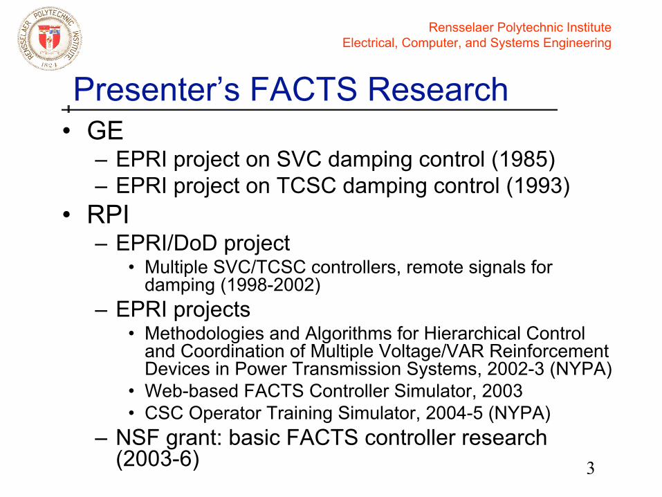
Presenter’s FACTS Research• GE
– EPRI project on SVC damping control (1985)– EPRI project on TCSC damping control (1993)
• RPI– EPRI/DoD project
• Multiple SVC/TCSC controllers, remote signals for damping (1998-2002)
– EPRI projects• Methodologies and Algorithms for Hierarchical Control
and Coordination of Multiple Voltage/VAR Reinforcement Devices in Power Transmission Systems, 2002-3 (NYPA)
• Web-based FACTS Controller Simulator, 2003• CSC Operator Training Simulator, 2004-5 (NYPA)
– NSF grant: basic FACTS controller research (2003-6)

Rensselaer Polytechnic InstituteElectrical, Computer, and Systems Engineering
4
Presenter’s Selected Publications in FACTS • VSC-based FACTS Controller
– X. Wei, J. H. Chow, B. Fardanesh, and A.-A. Edris, “A Common Modeling Framework of Voltage-Sourced Converters for Loadflow, Sensitivity, and Dispatch Analysis,” IEEE T-PS, 19, 2004.
– X. Wei, J. H. Chow, B. Fardanesh, and A.-A. Edris, “Dispatchability of Voltage-Sourced Converter Based FACTS Controllers,” IX SEPOPE, Rio de Janeiro, May 2004.
– X. Wei, J. H. Chow, B. Fardanesh, and A.-A. Edris, “A Dispatch Strategy for a Unified Power Flow Controller to Maximize Voltage-Stability Limited Power Transfer,” to appear in IEEE T-PS.
– X. Wei, J. H. Chow, B. Fardanesh, and A.-A. Edris, “A Dispatch Startegy for Interline Power Flow Controller Operating at Rated Capacity,” presented at IEEE Power System Conf and Expos, 2004.
Rensselaer Polytechnic InstituteElectrical, Computer, and Systems Engineering
5
Presenter’s Selected Publications in FACTS
• SVC, TCSC, and control– E. V. Larsen and J. H. Chow, “SVC Control Design Concepts for
System Dynamic Performance,” in IEEE Power Engineering Society Publication 87TH0187-5-PWR “Application of Static Var Systems for System Dynamic Performance.”
– E. V. Larsen, J. J. Sanchez-Gasca, and J. H. Chow, “Concepts for Design of FACTS Controllers to Damp Power Swings," IEEE T-PS, 10:948-956, 1995.
– G. N. Taranto and J. H. Chow, "A Robust Frequency Domain Optimization Technique for Tuning Series Compensation Damping Controller," IEEE T-PS, 10:1219-25, 1995.
– Jaewon Chang and J. H. Chow, “Time-Optimal Control of Power Systems Requiring Multiple Switchings of Series Capacitors,” IEEE T-PS, 13:367-73, 1998.
– J. H. Chow, J. J. Sanchez-Gasca, H. Ren, and S. Wang, “Power System Damping Controller Design using Multiple Input Signals,” IEEE Control Systems Magazine, 20:4:82-90, 2000.
– X. Wei, J. H. Chow, and J. J. Sanchez-Gasca, “On the Sensitivities of Network Variables for FACTS Device Damping Control,” Proc 2002 IEEE PES Winter Meeting, 2:1188-1193, 2002.

Rensselaer Polytechnic InstituteElectrical, Computer, and Systems Engineering
6
Flexible AC Transmission System (FACTS) Controllers
• FACTS Controllers can be used to control flows and voltages in an AC transmission system
• Thyristor-controlled devices applied to capacitors and reactors: – SVC (Static Var Control)– TCSC (Thyristor-controlled series compensation)
These devices control voltages and flows by changing system impedances.

Rensselaer Polytechnic InstituteElectrical, Computer, and Systems Engineering
7
Flexible AC Transmission System (FACTS) Controllers
• Voltage-sourced converters (VSC) using gate-turnoff (GTO) thyristors, require only a capacitor to hold DC voltage– Can operate in a stand-alone configuration– The DC capacitors of VSCs can be coupled to
circulate active powerThese devices control voltages and flows by inserting AC voltage sources that can lead or lag the AC current.

Rensselaer Polytechnic InstituteElectrical, Computer, and Systems Engineering
8
VSC-based FACTS Controllers
SSSC
UPFCIPFC
STATCOM

Rensselaer Polytechnic InstituteElectrical, Computer, and Systems Engineering
9
VSC-based FACTS Controllers
Back-to-Back (B2B) STATCOM
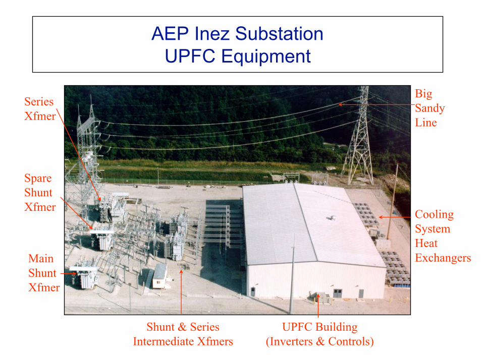
AEP Inez SubstationUPFC Equipment
Big Sandy Line
SeriesXfmer
SpareShuntXfmer
MainShuntXfmer
Shunt & SeriesIntermediate Xfmers
CoolingSystemHeatExchangers
UPFC Building(Inverters & Controls)
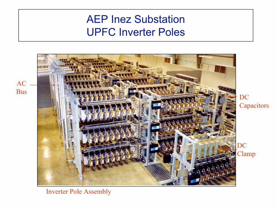
AEP Inez SubstationUPFC Inverter Poles
ACBus
Inverter Pole Assembly
DCCapacitors
DCClamp

Rensselaer Polytechnic InstituteElectrical, Computer, and Systems Engineering
12
VSC Operation • In a voltage-sourced converter, the DC
voltage source does not change sign. • An AC current is injected into the VSC.• An AC voltage is obtained by switching on
and off gate-turnoff (GTO) thyristors; the switching is controlled to provide either a leading or lagging AC voltage.
• A capacitor is used to supply the DC voltage.

Rensselaer Polytechnic InstituteElectrical, Computer, and Systems Engineering
13
VSC Operation
Single valve operation
vd
va
idDC Side AC Side
Active DCpower Active &
ReactiveAC Power
N. G. Hingorani and L. Gyugyi, Understanding FACTS: Concepts and Technology of Flexible AC Transmission Systems, IEEE Press, 2000.

Rensselaer Polytechnic InstituteElectrical, Computer, and Systems Engineering
14
VSC Operation
Svd
P
P&Qa
b
vabiab
id
1 1'
4
3 3'
4' 2 2' Single-phase, full-wave circuit
Rensselaer Polytechnic InstituteElectrical, Computer, and Systems Engineering
15
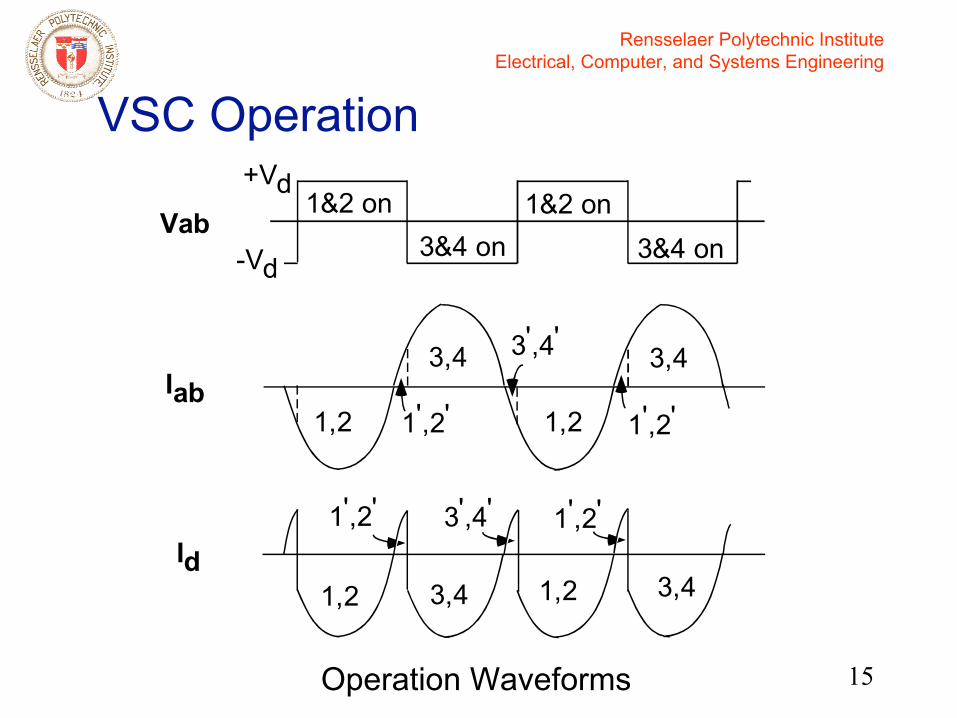
VSC Operation
Operation Waveforms
+Vd
-Vd
1&2 on3&4 on
1&2 onVab
3&4 on
1,2
3,4
1,2
3,4
1',2'
3',4'
1',2'Iab
1,2 3,4 1,2 3,4
1',2' 3',4' 1',2'Id
Rensselaer Polytechnic InstituteElectrical, Computer, and Systems Engineering
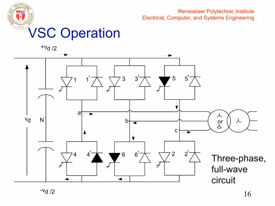
16
VSC Operation
Three-phase, full-wave circuit
vda
+vd /2
1
4
3 3'
4' 6 6'
N
1' 5 5'
2 2'
bc
or
-vd /2

Rensselaer Polytechnic InstituteElectrical, Computer, and Systems Engineering
17
VSC Operation
Operation Waveforms
Va
Vb
Vc
14
1
63
6
25
+Vd/2
-Vd/2
-Vd/2
+Vd/2
+Vd/2
-Vd/2
Vn+Vd/6-Vd/6
Vab
+Vd
-Vd
1,6
3,4
1,61,3 4,6
+2Vd/3+Vd/3
-Vd/3-2Vd/3
Van
Rensselaer Polytechnic InstituteElectrical, Computer, and Systems Engineering
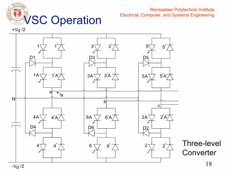
18
VSC Operation
ia
4'
1 1'
4'A
1A 1'A
N
4
4A
D4
D1
+Vd /2
-Vd /2
a
6'
3 3'
6'A
3A 3'A
6
6A
D6
D3
b
2'
5'
2'A
5A 5'A
2
2A
D2
D5
c
5
Three-level Converter
Rensselaer Polytechnic InstituteElectrical, Computer, and Systems Engineering
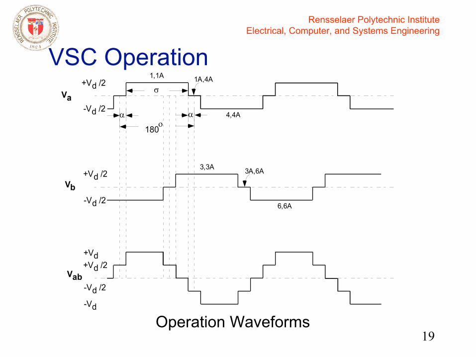
19
VSC Operation
+Vd /2
-Vd /2
Va+Vd /2
-Vd /2
1,1A
4,4A
1A,4A
Vb
3,3A
6,6A
3A,6A
Vab+Vd /2+Vd
-Vd /2
-Vd
σ
αο
180
α
Operation Waveforms

Rensselaer Polytechnic InstituteElectrical, Computer, and Systems Engineering
20
Voltage/Current EquationsShunt VSC Series VSC
θ is bus angle relative to swing bus
α is Vm angle relative to swing bus
Rensselaer Polytechnic InstituteElectrical, Computer, and Systems Engineering
21
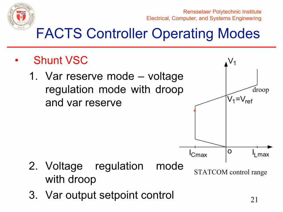
FACTS Controller Operating Modes
• Shunt VSC1. Var reserve mode – voltage
regulation mode with droop and var reserve
2. Voltage regulation mode with droop
3. Var output setpoint control
ICmax ILmax
V1
V1=Vref
o
STATCOM control range
droop

Rensselaer Polytechnic InstituteElectrical, Computer, and Systems Engineering
22
FACTS Controller Operating Modes
• Series VSC– Standalone1. Fixed line P flow setpoint2. Fixed series voltage injection magnitude (leading
or lagging)– Coupled1. Fixed line P,Q flow setpoints2. Fixed series voltage injection vd,vq, measured
with respect to the from (shunt) bus (Marcy) voltage
3. Fixed series voltage injection vd,vq, measured with respect to series line current (future implementation)
Rensselaer Polytechnic InstituteElectrical, Computer, and Systems Engineering
23
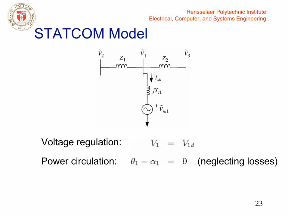
STATCOM Model
Power circulation:
Voltage regulation:
(neglecting losses)
Rensselaer Polytechnic InstituteElectrical, Computer, and Systems Engineering
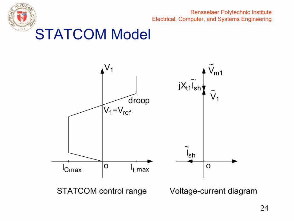
24
STATCOM Model
Voltage-current diagram
ICmax ILmax
V1
V1=Vref
Ish
V1
Vm1
jXt1Ish
oo
~
~~
~
droop
STATCOM control range
Rensselaer Polytechnic InstituteElectrical, Computer, and Systems Engineering
25
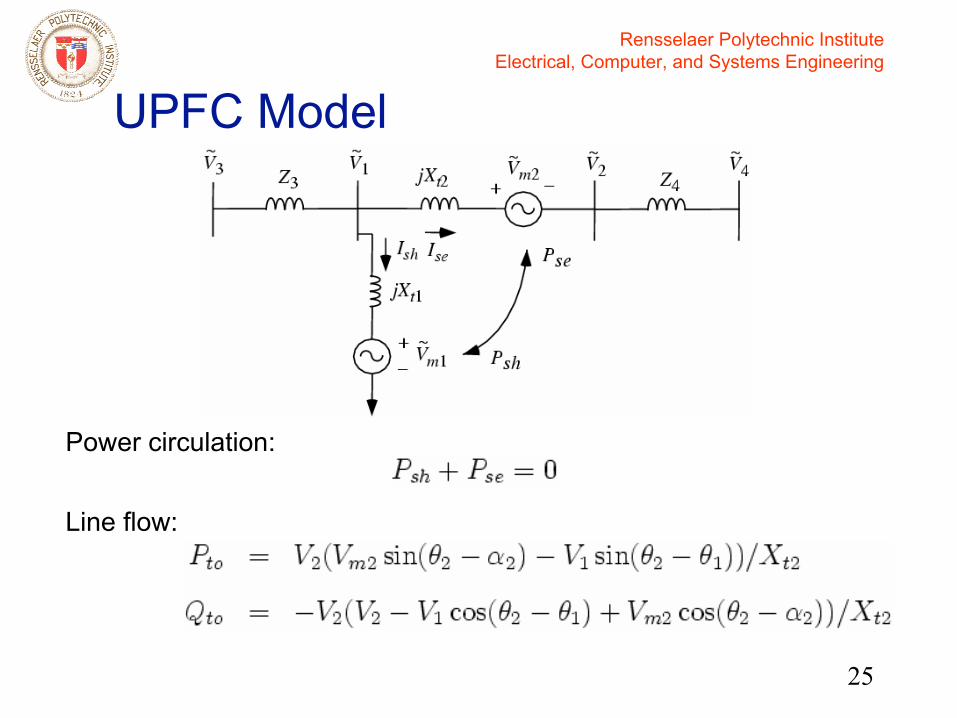
UPFC Model
UPFC
Power circulation:
Line flow:

Rensselaer Polytechnic InstituteElectrical, Computer, and Systems Engineering
26
UPFC Model
Voltage-current diagram
0δδ >
2
~~
mse VI ⊥
No UPFC With UPFC, no power circulation
~Ise
V4~V1
~IseZ4~ V2
V4
Ise
V1
o
~
~ ~
~
Vm2~
IseZ4~
δ
δ0
o

Rensselaer Polytechnic InstituteElectrical, Computer, and Systems Engineering
27
UPFC Model
Voltage-current diagram
oIsh
Vm1jXt1Ish V2
V4
Ise
V1
o
~
~
~ ~
~
~~
V1~
Shunt Series
Power circulation from shunt to series
Rensselaer Polytechnic InstituteElectrical, Computer, and Systems Engineering
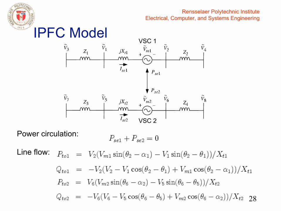
28
IPFC Model
Power circulation:
Line flow:
VSC 1
VSC 2
Rensselaer Polytechnic InstituteElectrical, Computer, and Systems Engineering
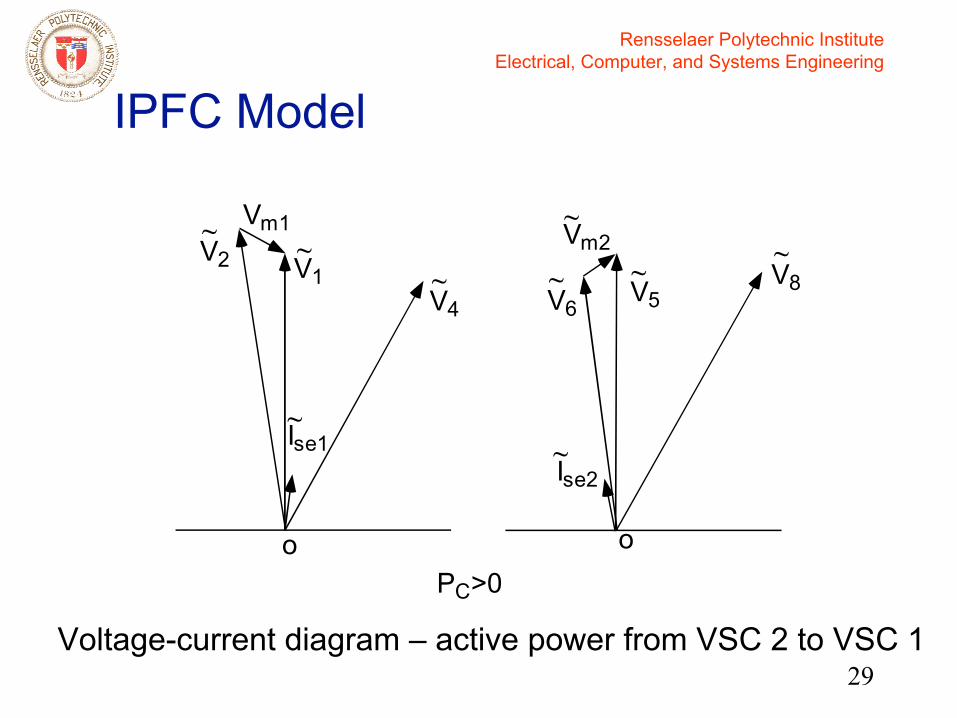
29
IPFC Model
Voltage-current diagram – active power from VSC 2 to VSC 1
~Ise1
V4~V1
~
V6V8
Ise2
V5
o
~ ~~
~
Vm2~
o
Vm1V2~
PC>0
Rensselaer Polytechnic InstituteElectrical, Computer, and Systems Engineering
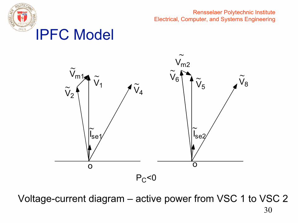
30
IPFC Model
~Ise1
V4~V1
~ V6 V8
Ise2
V5
o
~~ ~
~
Vm2~
o
Vm1~
V2~
PC<0
Voltage-current diagram – active power from VSC 1 to VSC 2
Rensselaer Polytechnic InstituteElectrical, Computer, and Systems Engineering
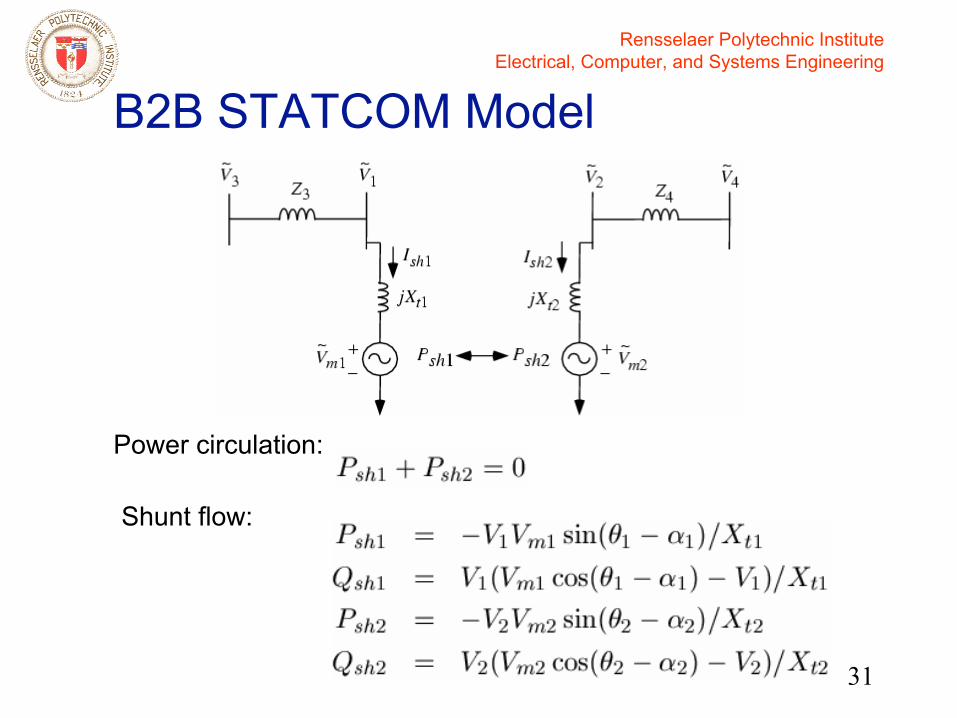
31
B2B STATCOM Model
Power circulation:
Shunt flow:

Rensselaer Polytechnic InstituteElectrical, Computer, and Systems Engineering
32
B2B STATCOM Model
Voltage-current diagram
oIsh1
V1
Vm1
jXt1Ish1
oIsh2
V2
Vm2
jXt2Ish2
~
~
~
~
~
~
~~
Rensselaer Polytechnic InstituteElectrical, Computer, and Systems Engineering
33
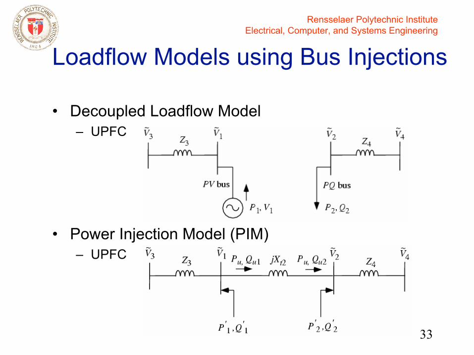
• Decoupled Loadflow Model– UPFC
• Power Injection Model (PIM)– UPFC
Loadflow Models using Bus Injections

Rensselaer Polytechnic InstituteElectrical, Computer, and Systems Engineering
34
• PIM equations
Loadflow Models using Bus Injections
Rensselaer Polytechnic InstituteElectrical, Computer, and Systems Engineering
35
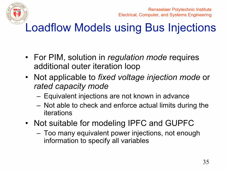
• For PIM, solution in regulation mode requires additional outer iteration loop
• Not applicable to fixed voltage injection mode or rated capacity mode– Equivalent injections are not known in advance– Not able to check and enforce actual limits during the
iterations• Not suitable for modeling IPFC and GUPFC
– Too many equivalent power injections, not enough information to specify all variables
Loadflow Models using Bus Injections
Rensselaer Polytechnic InstituteElectrical, Computer, and Systems Engineering
36
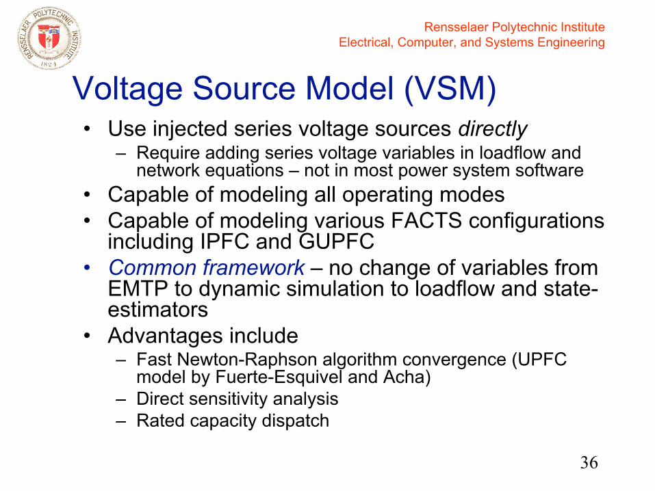
Voltage Source Model (VSM)• Use injected series voltage sources directly
– Require adding series voltage variables in loadflow and network equations – not in most power system software
• Capable of modeling all operating modes• Capable of modeling various FACTS configurations
including IPFC and GUPFC• Common framework – no change of variables from
EMTP to dynamic simulation to loadflow and state-estimators
• Advantages include – Fast Newton-Raphson algorithm convergence (UPFC
model by Fuerte-Esquivel and Acha)– Direct sensitivity analysis– Rated capacity dispatch
Rensselaer Polytechnic InstituteElectrical, Computer, and Systems Engineering
37
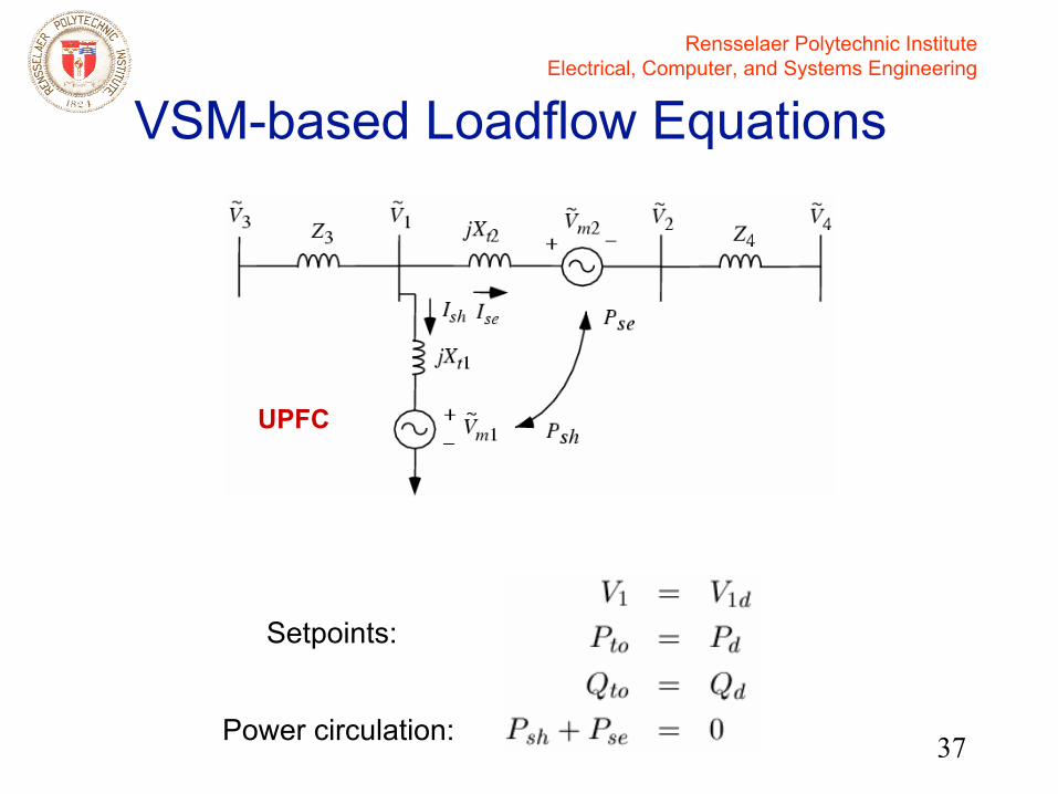
VSM-based Loadflow Equations
Setpoints:
Power circulation:
UPFC
Rensselaer Polytechnic InstituteElectrical, Computer, and Systems Engineering
38
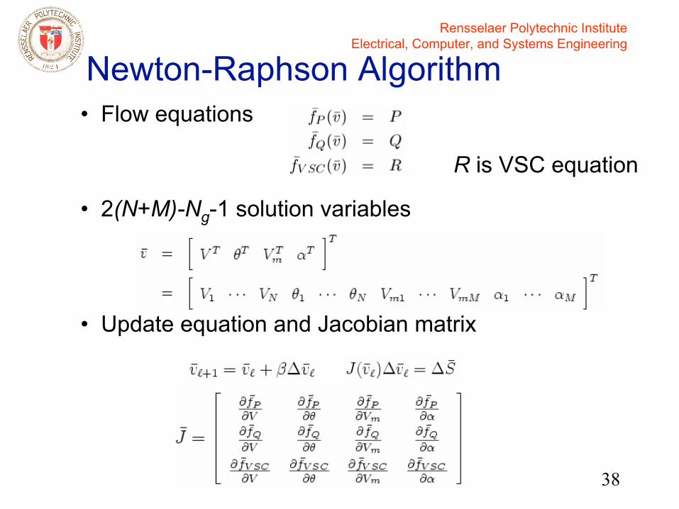
Newton-Raphson Algorithm• Flow equations
• 2(N+M)-Ng-1 solution variables
• Update equation and Jacobian matrix
R is VSC equation

Rensselaer Polytechnic InstituteElectrical, Computer, and Systems Engineering
39
Newton-Raphson Algorithm
• Given M VSCs:
Always keep the same 2M variablesfor VSCs
Flow equations: add 2M equations athe end
Jacobian: only need to change the last 2M rows
• Efficient coding

Rensselaer Polytechnic InstituteElectrical, Computer, and Systems Engineering
40
Loadflow Convergence Example • 13-bus
test system– UPFC on
Line 4-6(A closed,B open,C closed)
• Large 1564-bus New York system

Rensselaer Polytechnic InstituteElectrical, Computer, and Systems Engineering
41
NR Loadflow Convergence
• Convergence results for the large 1564-bus New York system are similar to those for the small test system
Rensselaer Polytechnic InstituteElectrical, Computer, and Systems Engineering
42
Control Issues with FACTS Controllers
• What kind of control flexibility does a FACTS controller have?
• FACTS controller shift factors?• Setpoint control or other strategies?
– Steady state – Transient stability
Rensselaer Polytechnic InstituteElectrical, Computer, and Systems Engineering
43
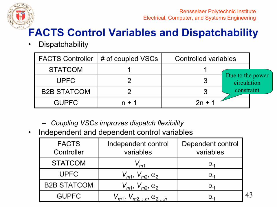
FACTS Control Variables and Dispatchability• Dispatchability
– Coupling VSCs improves dispatch flexibility• Independent and dependent control variables
2n + 1n + 1GUPFC32B2B STATCOM32UPFC11STATCOM
Controlled variables# of coupled VSCsFACTS Controller
Due to the power circulation constraint
α1Vm1, Vm2,…n, α2,…nGUPFCα1Vm1, Vm2, α2B2B STATCOMα1Vm1, Vm2, α2UPFCα1Vm1STATCOM
Dependent control variables
Independent control variables
FACTS Controller
Rensselaer Polytechnic InstituteElectrical, Computer, and Systems Engineering
44
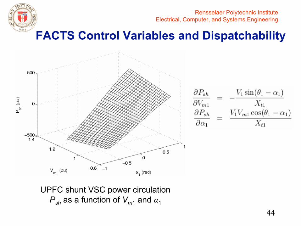
FACTS Control Variables and Dispatchability
UPFC shunt VSC power circulation Psh as a function of Vm1 and α1
Rensselaer Polytechnic InstituteElectrical, Computer, and Systems Engineering
45
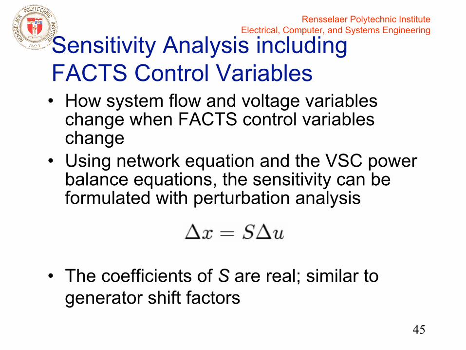
Sensitivity Analysis including FACTS Control Variables• How system flow and voltage variables
change when FACTS control variables change
• Using network equation and the VSC power balance equations, the sensitivity can be formulated with perturbation analysis
• The coefficients of S are real; similar to generator shift factors
Rensselaer Polytechnic InstituteElectrical, Computer, and Systems Engineering
46
Generator Shift Factors• The shift factors show how one additional MW
from a generator serves one MW of load, at specific locations in a system, will be distributed between a number of transmission paths
• Generator shift factors are (mostly) determined from a DC loadflow
• These shift factors are used to determine how the generations should be adjusted in order to observe power transfer constraints
Rensselaer Polytechnic InstituteElectrical, Computer, and Systems Engineering
47
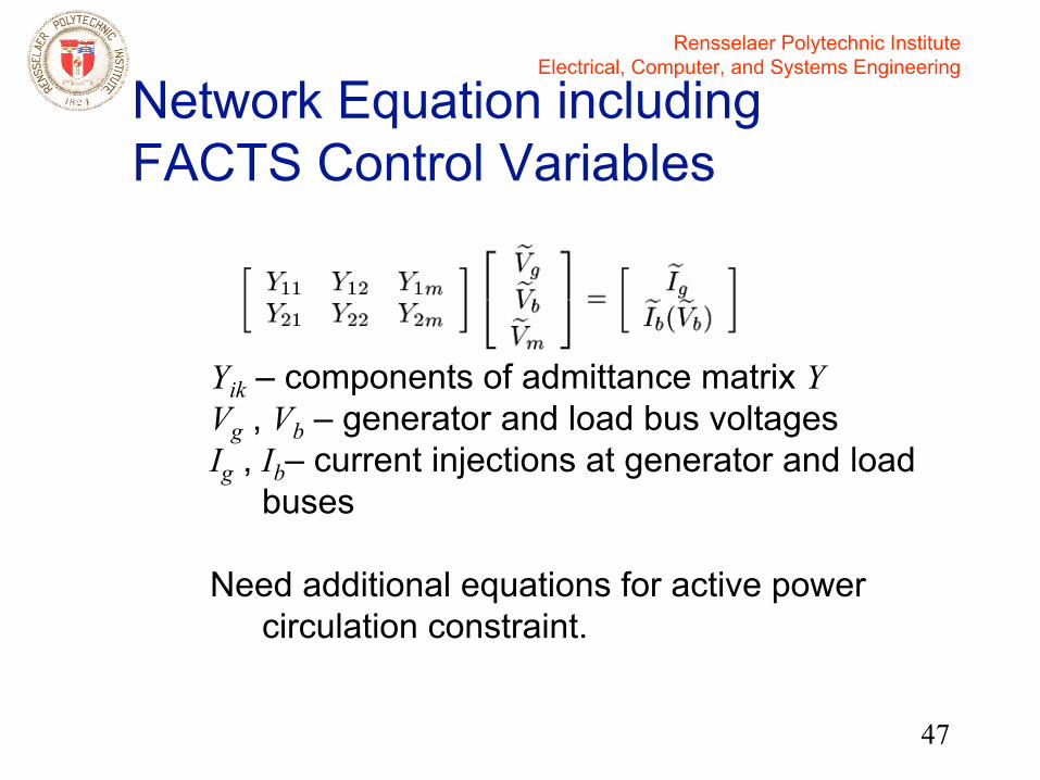
Network Equation including FACTS Control Variables
Yik – components of admittance matrix YVg , Vb – generator and load bus voltages Ig , Ib– current injections at generator and load
buses
Need additional equations for active power circulation constraint.

Rensselaer Polytechnic InstituteElectrical, Computer, and Systems Engineering
48
Perturbation Analysis
• Computation steps:1.Perturb each independent control variable
and solve for Vb from the network equations.
2.Solve dependent control variable from power balance equation based on Vb .
3.Update control voltages, repeat Steps 1 and 2 until convergence.
4.Repeat Steps 1 to 3 for each independent control variable separately.

Rensselaer Polytechnic InstituteElectrical, Computer, and Systems Engineering
49
13-Bus Test System

Rensselaer Polytechnic InstituteElectrical, Computer, and Systems Engineering
50
FACTS Controller Shift Factors• 13-bus system, UPFC on Line 4-6, System
base 100 MVA• (V4, Pd, Qd) = (1.027 pu, 940 MW, 140 Mvar)
0.0145-1.59826.6030P4-13 (pu)-0.485614.266610.2842P4-12 (pu)-0.0125-0.00170.5203V6 (pu)-0.04050.00430.7673V12 (pu)0.00070.01310.7842V4 (pu)
α2 (rad)Vm2 (pu)Vm1 (pu)

Rensselaer Polytechnic InstituteElectrical, Computer, and Systems Engineering
51
Use of FACTS Shift Factors
• Voltage and power dispatch– From a base case, specify desired voltage or
power profile
– Increment setpoints

Rensselaer Polytechnic InstituteElectrical, Computer, and Systems Engineering
52
UPFC Voltage Dispatch ExampleSeries VSCexceeds rating
Shunt VSCexceeds rating
Rensselaer Polytechnic InstituteElectrical, Computer, and Systems Engineering
53
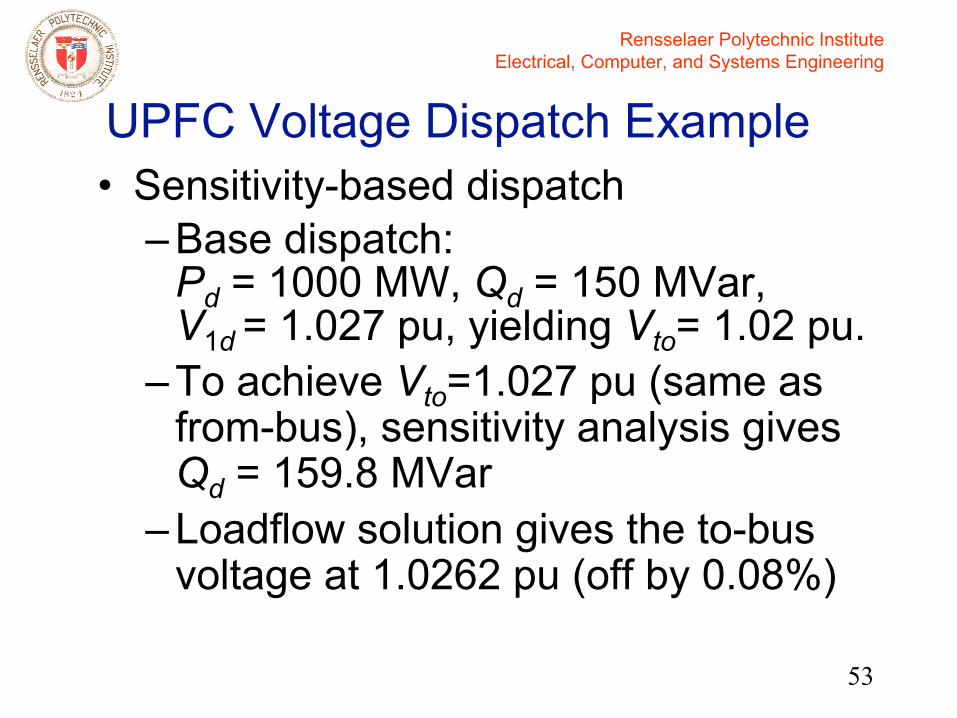
UPFC Voltage Dispatch Example• Sensitivity-based dispatch
– Base dispatch: Pd = 1000 MW, Qd = 150 MVar, V1d = 1.027 pu, yielding Vto= 1.02 pu.
– To achieve Vto=1.027 pu (same as from-bus), sensitivity analysis gives Qd = 159.8 MVar
– Loadflow solution gives the to-bus voltage at 1.0262 pu (off by 0.08%)

Rensselaer Polytechnic InstituteElectrical, Computer, and Systems Engineering
54
Power Dispatch Example• 13-bus system – UPFC setpoints P = 960
MW, Q = 140 MVar. To increase other line power flow by 40 MW.
• Large system – similar properties as the small system
Rensselaer Polytechnic InstituteElectrical, Computer, and Systems Engineering
55
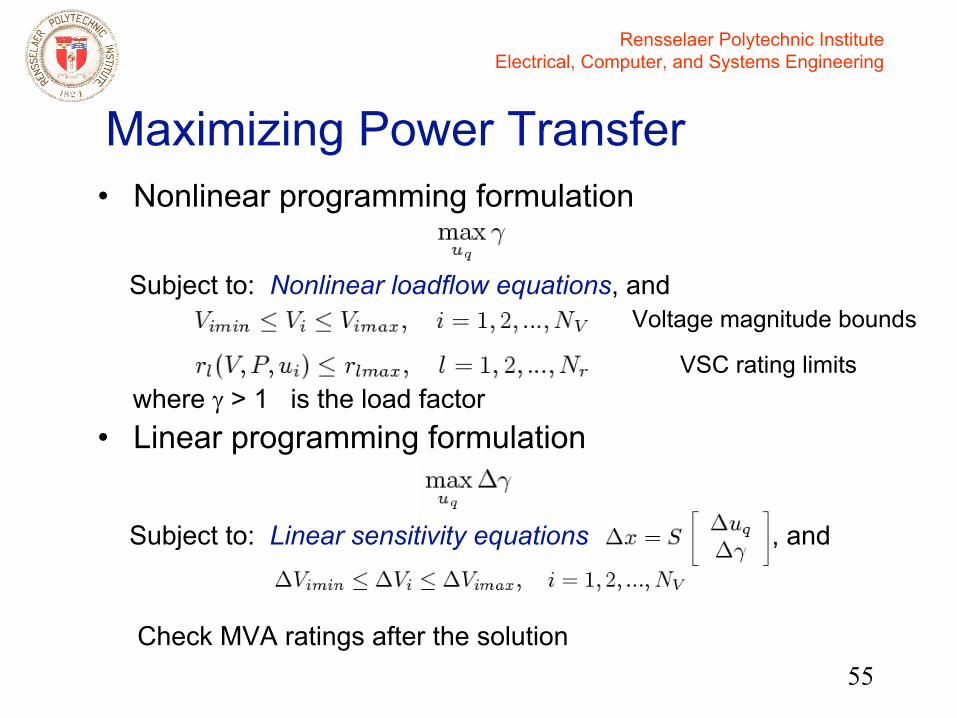
Maximizing Power Transfer• Nonlinear programming formulation
where γ > 1 is the load factor• Linear programming formulation
Subject to: Nonlinear loadflow equations, and
Subject to: Linear sensitivity equations , and
Check MVA ratings after the solution
Voltage magnitude bounds
VSC rating limits
Rensselaer Polytechnic InstituteElectrical, Computer, and Systems Engineering
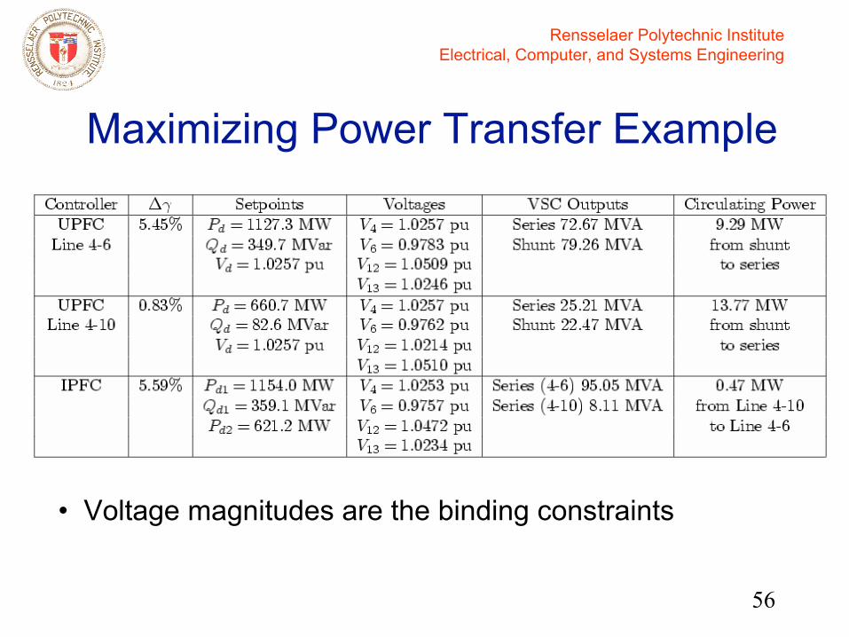
56
Maximizing Power Transfer Example
• Voltage magnitudes are the binding constraints

Rensselaer Polytechnic InstituteElectrical, Computer, and Systems Engineering
57
FACTS Controller Operating Constraints
• Max VSC voltage limit• Max VSC current limit• Max VSC MVA limit • Maximum power circulation between
coupled VSC• Maximum and minimum line side voltage
J. Bian, et al., “A Study of Equipment Sizes and Constraints for a Unified Power Flow Controller,” IEEE T-PD, 12:1385-91, 1997.
Rensselaer Polytechnic InstituteElectrical, Computer, and Systems Engineering
58
FACTS Controllers Operating at Rated Capacity
• Maximum dispatch benefit often occurs when FACTS Controllers operate at rated capacity, as in post contingencies – not possible to maintain either voltage setpoint, or flow
setpoints, or both
• For STATCOM and SSSC, enforce the limit and maintain zero power generation
• For UPFC and IPFC, power circulation optimizes the coupled VSCs, and may become the deciding factor in optimal dispatch for maximum power transfer
Rensselaer Polytechnic InstituteElectrical, Computer, and Systems Engineering
59
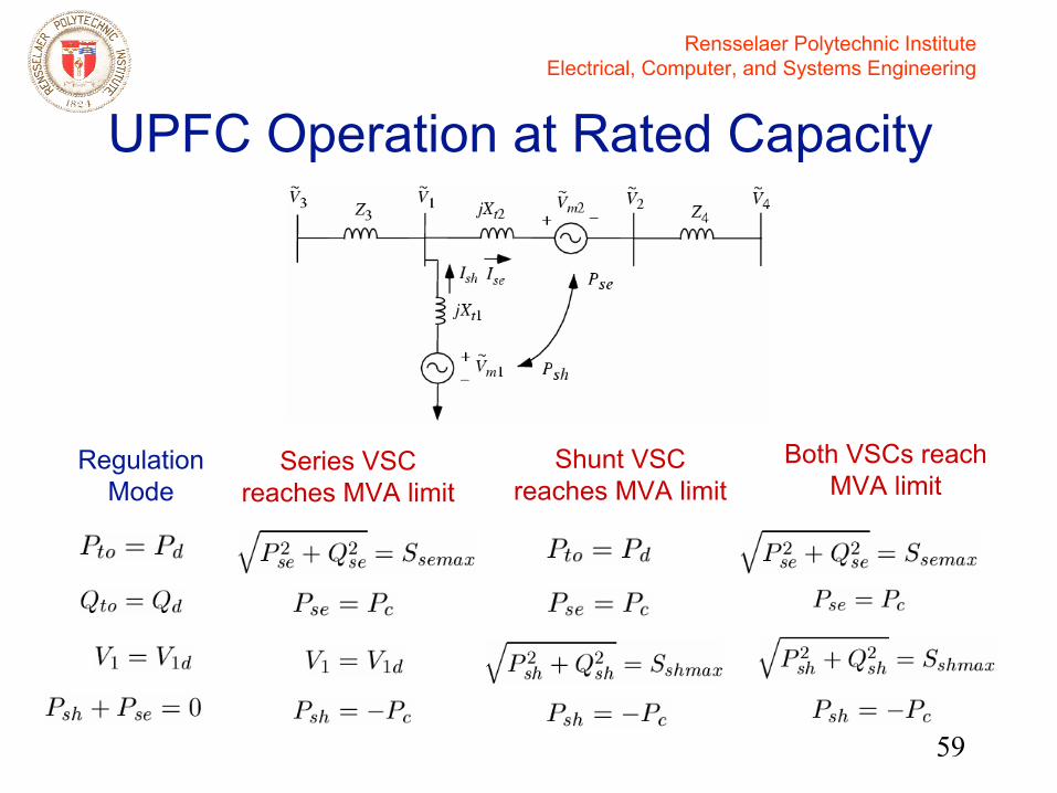
UPFC Operation at Rated Capacity
Regulation Mode
Series VSC reaches MVA limit
Shunt VSC reaches MVA limit
Both VSCs reach MVA limit

Rensselaer Polytechnic InstituteElectrical, Computer, and Systems Engineering
60
4-bus System Example
• Voltage stability analysis – maximum power transfer with various levels of circulating active power between the shunt VSC and the series VSC

Rensselaer Polytechnic InstituteElectrical, Computer, and Systems Engineering
61
4-bus System Example
V1d=1.03 pu, Pd=0.8Pload, both shunt and series VSCs MVA limit=50MVA

Rensselaer Polytechnic InstituteElectrical, Computer, and Systems Engineering
62
4-bus System Example• In this system, by increasing Pc from shunt to
series, maximum power transfer is improved – At V3=0.95 pu, a 10 MW increase in Pc results in
20 MW increase in power transfer– If V3 is desired to be 1 pu, we can increase Pc as
Pload increases until it is no longer possible by the controller
• Coupling VSCs improves dispatch flexibility, and power circulation optimizes the coupled VSCs together
• Similar possibility with an IPFC: more complex – 2 active power paths
Rensselaer Polytechnic InstituteElectrical, Computer, and Systems Engineering
63
Rated Capacity Solution Algorithm
• To generate PV curve, additional logic to switch from non-saturated to saturated operation
• MVA rated capacity operation code functional
• In development:– Fixed Vp,Vq with respect to from-bus
voltage phasor – Fixed Vm, variable power circulation

Rensselaer Polytechnic InstituteElectrical, Computer, and Systems Engineering
64
• Regulation mode– Regulate voltage and line flow setpoints
• Fixed voltage injection mode for series element– Fix the magnitude and/or angle of the injected
voltage source
• Rated capacity operation mode
FACTS Controller Operating Modes
V1d, V2d, PdB2B STATCOMPd1, Qd1, Pd2IPFCV1d, Pd, QdUPFCV1dSTATCOM
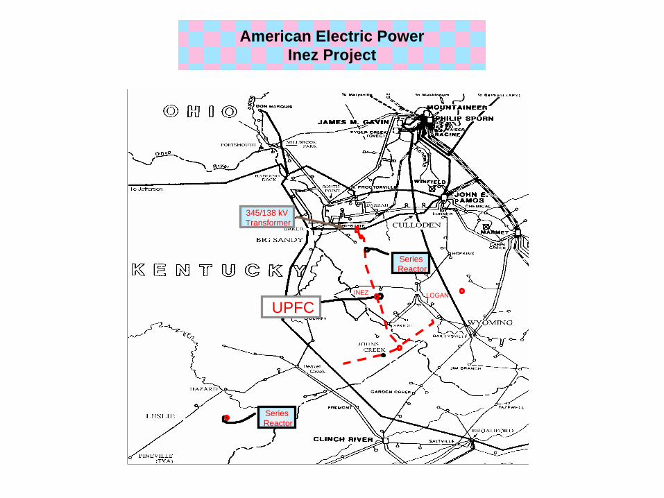
345/138 kVTransformer
UPFC
SeriesReactor
SeriesReactor
LOGANINEZ
American Electric PowerInez Project
Rensselaer Polytechnic InstituteElectrical, Computer, and Systems Engineering
66
• AEP Inez UPFC– Power control to limit steady-state and
post-disturbance flow on 138 kV system, thus eliminating thermal overload on the line and preventing low voltages on 138 kV transmission system.
– The overall project also includes mechanically-switched line reactors and shunt capacitors.
Series VSC Control
C. Schauder, et al., “AEP UPFC Project: Installation, Commissioning and Operation of the ±160 MVA STATCOM (Phase I),” IEEE T-PD, 13:1530-1535, 1998
Rensselaer Polytechnic InstituteElectrical, Computer, and Systems Engineering
67
• NYPA Marcy CSC (Convertible Static Compensation)– NY Central East transfer is voltage limited at
Albany (before the Athans units came online)– In UPFC configuration, fixed (P,Q) setpoint control
to limit post-disturbance flow would not be optimal; prefer UPFC to carry more flow in post-disturbance than in pre-disturbance
– Fixed P setpoint control also reduces system synchronizing torque
– Use fixed inserted voltage control (vd,vq); in post-disturbance, this control will naturally accommodate additional flow; use studies to validate
Series VSC Control
Rensselaer Polytechnic InstituteElectrical, Computer, and Systems Engineering
68
• NYPA Marcy CSC in UPFC mode– Use fixed inserted voltage control (vd,vq); in
post-disturbance, this control will naturally accommodate additional flow; use studies to validate
– Disturbance initiated control possibilities1. Ramp up P setpoint to some pre-determined
max value in post-disturbance 2. Use rated-capacity strategies as described
earlier to adjust inserted voltage magnitude and circulating power
Series VSC Control
Rensselaer Polytechnic InstituteElectrical, Computer, and Systems Engineering
69
• Fixed Vm to allow unrestricted active power flow in post-disturbance condition, to be limited by rated current.
• In post disturbance – if Vm is not at limit, increase Vm to
maximum allowable, without violating current and MVA constraints.
– Adjust power circulation Pc (if available) to improve voltage profile.
A Series VSC Control Strategy
Rensselaer Polytechnic InstituteElectrical, Computer, and Systems Engineering
70
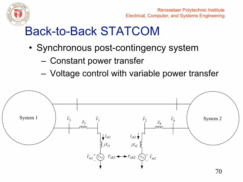
• Synchronous post-contingency system– Constant power transfer– Voltage control with variable power transfer
Back-to-Back STATCOM
Z4V2Z3
V1V3 V4
jXt1
Ish1
+_Vm1
~
~ ~ ~ ~
Psh1
Ish2
jXt2
Vm2~+
_Psh2
System 1 System 2

Rensselaer Polytechnic InstituteElectrical, Computer, and Systems Engineering
71
• Asynchronous post-contingency system– Constant power transfer– Variable power transfer for frequency
regulation, for loss of load or generation
Back-to-Back STATCOM
Z4V2Z3
V1V3 V4
jXt1
Ish1
+_Vm1
~
~ ~ ~ ~
Psh1
Ish2
jXt2
Vm2~+
_Psh2
System 1 System 2
Rensselaer Polytechnic InstituteElectrical, Computer, and Systems Engineering
72
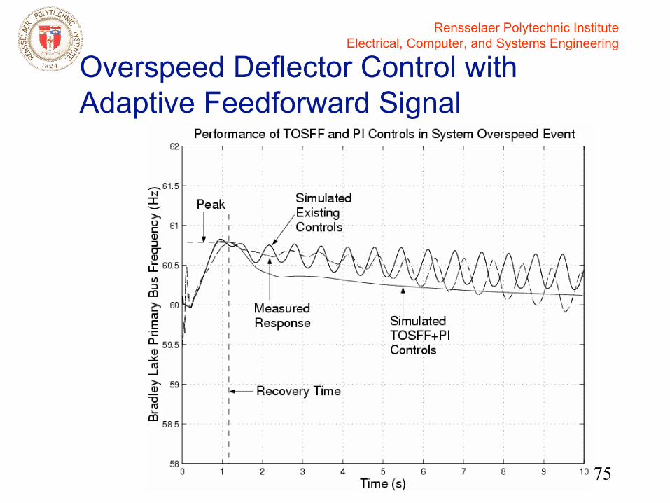
• Frequency regulation in asynchronous post-contingency system– On-demand feedforward/adaptive +
feedback frequency control– Example: Bradley Lake Hydro control in
Alaska Kenai Peninsula
Back-to-Back STATCOM
R. M Johnson, J. H. Chow, and M. V. Dillon, “Pelton Turbine Deflector OverspeedControl for a Small Power System,” IEEE T-PS, 19, 2004

Rensselaer Polytechnic InstituteElectrical, Computer, and Systems Engineering
73
Bradley Lake Hydro Units• Two 65 MVA Pelton turbines with
deflectors for overspeed protection• Loss of Southern Tie isolates the Kenai
area and causes system oscillations
South North
Rensselaer Polytechnic InstituteElectrical, Computer, and Systems Engineering
74
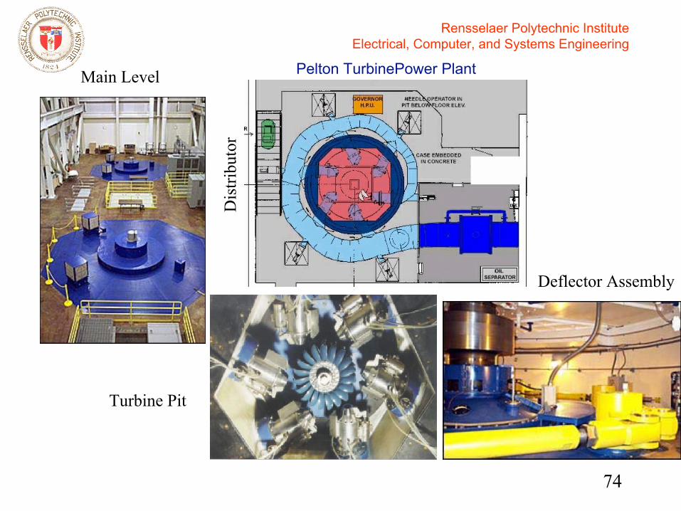
Pelton TurbinePower PlantMain Level
Dis
tribu
tor
Deflector Assembly
Turbine Pit
Rensselaer Polytechnic InstituteElectrical, Computer, and Systems Engineering
75
Overspeed Deflector Control with Adaptive Feedforward Signal
Rensselaer Polytechnic InstituteElectrical, Computer, and Systems Engineering
76
EPRI/NYPA FACTS Operator Training Simulator (2004-5)
• New York Power has installed a Convertible Static Compensator (CSC) as Marcy substation in Central New York State:– Two VSC modules of 100 MVA each– Two series transformers– One shunt transformer with two primary
windings

Rensselaer Polytechnic InstituteElectrical, Computer, and Systems Engineering
77
Rensselaer Polytechnic InstituteElectrical, Computer, and Systems Engineering
78
Objectives• Development of an off-line general
purpose FACTS Operator Training Simulator, with customization to NYPA’sCSC (Convertible Static Compensation)
• Learning tool for operators to study the impact of CSC in the NY power system
• All 11 configurations of the CSC operation included in the simulator
S. Arabi, H. Hamadanizadeh, and B. Fardanesh, “Convertible Static Compensator Per-formance Studies on the NY State Transmission System,” IEEE T-PS, 17:701-6, 2002.

Rensselaer Polytechnic InstituteElectrical, Computer, and Systems Engineering
79
CSC Configurations
Configuration Converter 1 Controlled Quantity
Converter 2 Controlled Quantity
One STATCOM VT – One STATCOM – VT
Two STATCOMs VT VT SSSC on line #1 P1 – SSSC on line #2 – P2
Two SSSCs P1 P2 IPFC P1 (or P1 & Q1) P2 & Q2 (or P2)
One STATCOM & SSSC on line #1
VT P1
One STATCOM & SSSC on line #2
VT P2
UPFC line #1 VT P1 & Q1 UPFC line #2 VT P2 & Q2
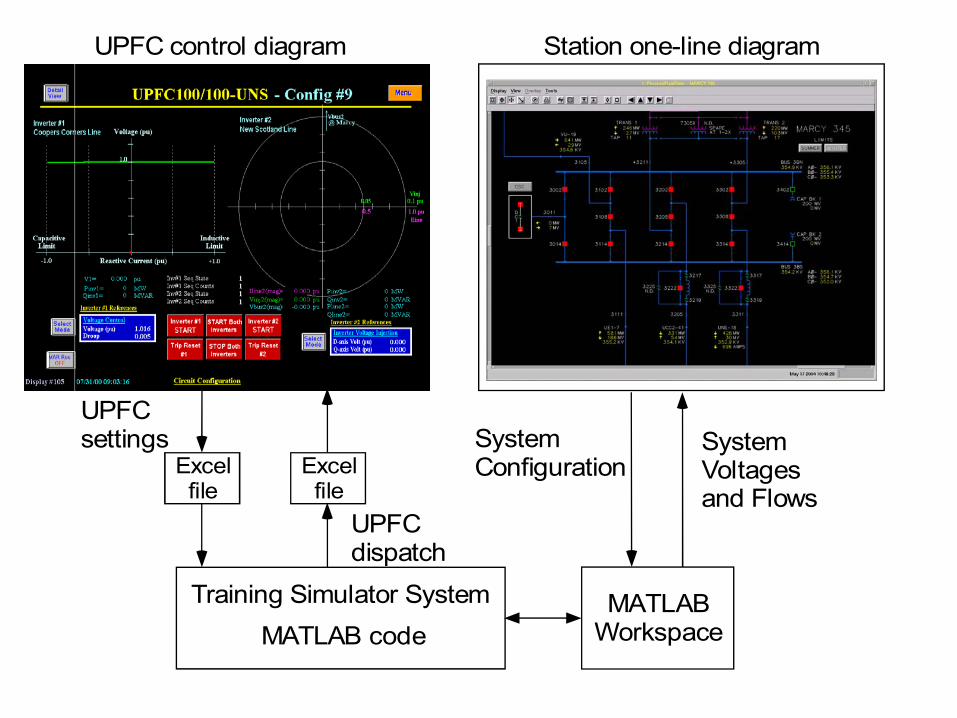
Training Simulator SystemMATLAB code
UPFCdispatch
SystemConfiguration
UPFCsettings System
Voltagesand Flows
UPFC control diagram Station one-line diagram
Excelfile
Excelfile
MATLABWorkspace

Rensselaer Polytechnic InstituteElectrical, Computer, and Systems Engineering
81Dual display monitors

Rensselaer Polytechnic InstituteElectrical, Computer, and Systems Engineering
82
GENESIS
• FACTS control screens are identical to those supplied by Siemens for NYPA’s CSC using GENESIS 32 from Iconics(converted from version 3.54 to version 7).
• Simulation data are stored in GENESIS registers (Tags).
• Interface dialog boxes and data population (Input/output) are programmed using Visual Basic.

Rensselaer Polytechnic InstituteElectrical, Computer, and Systems Engineering
83
Power system toolbox (MATLAB)
• Receive setpoints from an Excel file which contains the data from the GENESIS FACTS control screens.
• Loadflow computation with multiple FACTS dispatch modes.
• Plot one-line diagrams of different substations.
• Send result to an Excel file for use by GENESIS FACTS control screen.

Rensselaer Polytechnic InstituteElectrical, Computer, and Systems Engineering
84
NYPA CSC Configuration Selection
Rensselaer Polytechnic InstituteElectrical, Computer, and Systems Engineering
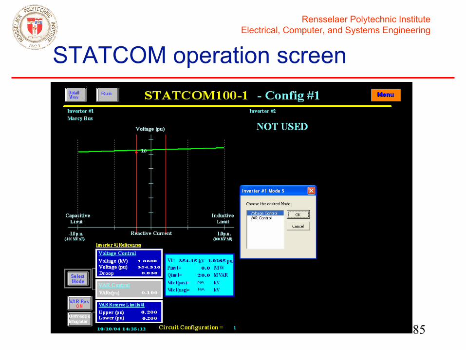
85
STATCOM operation screen

Rensselaer Polytechnic InstituteElectrical, Computer, and Systems Engineering
86
Marcy CSC one-line diagram
Rensselaer Polytechnic InstituteElectrical, Computer, and Systems Engineering
87
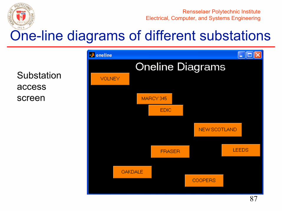
One-line diagrams of different substations
Substation access screen
Rensselaer Polytechnic InstituteElectrical, Computer, and Systems Engineering
88
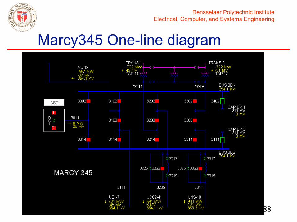
Marcy345 One-line diagram
Rensselaer Polytechnic InstituteElectrical, Computer, and Systems Engineering
89
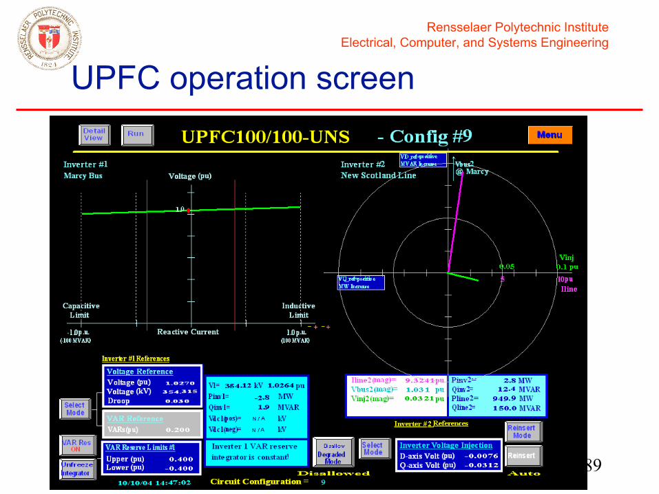
UPFC operation screen
Rensselaer Polytechnic InstituteElectrical, Computer, and Systems Engineering
90
Acknowledgements• Research supported by
– NSF– EPRI: Dr. Aty Edris– NYPA: Drs. Bruce Fardanesh and Edvina
Uzunovic, and others• Students
– Xuan Wei, Xia Jiang• Computer code: Power System Toolbox
– Graham Rogers, Cherry Tree Scientific Software• Thank you for your attention
Related Documents