Relion ® 615 series Voltage Protection and Control REU615 Application Manual

Welcome message from author
This document is posted to help you gain knowledge. Please leave a comment to let me know what you think about it! Share it to your friends and learn new things together.
Transcript

Relion® 615 series
Voltage Protection and ControlREU615Application Manual


Document ID: 1MRS758128Issued: 2014-05-14
Revision: AProduct version: 4.1
© Copyright 2014 ABB. All rights reserved

CopyrightThis document and parts thereof must not be reproduced or copied without writtenpermission from ABB, and the contents thereof must not be imparted to a thirdparty, nor used for any unauthorized purpose.
The software or hardware described in this document is furnished under a licenseand may be used, copied, or disclosed only in accordance with the terms of suchlicense.
TrademarksABB and Relion are registered trademarks of the ABB Group. All other brand orproduct names mentioned in this document may be trademarks or registeredtrademarks of their respective holders.
WarrantyPlease inquire about the terms of warranty from your nearest ABB representative.
ABB
Nanjing SAC Power Grid Automation Co., Ltd.
No. 11 Phoenix Road, Jiangning Development Zone
211100 Nanjing
China
Telephone: +86 25 51183000
Facsimile: +86 25 51183883
Customer hotline: 4008876268
http://www.abb.com/substationautomation

DisclaimerThe data, examples and diagrams in this manual are included solely for the conceptor product description and are not to be deemed as a statement of guaranteedproperties. All persons responsible for applying the equipment addressed in thismanual must satisfy themselves that each intended application is suitable andacceptable, including that any applicable safety or other operational requirementsare complied with. In particular, any risks in applications where a system failure and/or product failure would create a risk for harm to property or persons (including butnot limited to personal injuries or death) shall be the sole responsibility of theperson or entity applying the equipment, and those so responsible are herebyrequested to ensure that all measures are taken to exclude or mitigate such risks.
This product has been designed to be connected and communicate data andinformation via a network interface which should be connected to a securenetwork. It is the sole responsibility of the person or entity responsible for networkadministration to ensure a secure connection to the network and to take thenecessary measures (such as, but not limited to, installation of firewalls, applicationof authentication measures, encryption of data, installation of anti virus programs,etc.) to protect the product and the network, its system and interface included,against any kind of security breaches, unauthorized access, interference, intrusion,leakage and/or theft of data or information. ABB is not liable for any such damagesand/or losses.
This document has been carefully checked by ABB but deviations cannot becompletely ruled out. In case any errors are detected, the reader is kindly requestedto notify the manufacturer. Other than under explicit contractual commitments, inno event shall ABB be responsible or liable for any loss or damage resulting fromthe use of this manual or the application of the equipment.

ConformityThis product complies with the directive of the Council of the EuropeanCommunities on the approximation of the laws of the Member States relating toelectromagnetic compatibility (EMC Directive 2004/108/EC) and concerningelectrical equipment for use within specified voltage limits (Low-voltage directive2006/95/EC). This conformity is the result of tests conducted by ABB inaccordance with the product standards EN 50263 and EN 60255-26 for the EMCdirective, and with the product standards EN 60255-1 and EN 60255-27 for the lowvoltage directive. The product is designed in accordance with the internationalstandards of the IEC 60255 series.

Table of contents
Section 1 Introduction.......................................................................3This manual........................................................................................3Intended audience..............................................................................3Product documentation.......................................................................4
Product documentation set............................................................4Document revision history.............................................................4Related documentation..................................................................5
Symbols and conventions...................................................................5Symbols.........................................................................................5Document conventions..................................................................6Functions, codes and symbols......................................................6
Section 2 REU615 overview.............................................................9Overview.............................................................................................9
Product version history..................................................................9PCM600 and IED connectivity package version............................9
Operation functionality......................................................................10Optional functions........................................................................10
Physical hardware............................................................................10Local HMI.........................................................................................11
Display.........................................................................................12LEDs............................................................................................13Keypad........................................................................................13
Web HMI...........................................................................................14Authorization.....................................................................................15
Audit trail......................................................................................16Communication.................................................................................18
Ethernet redundancy...................................................................19
Section 3 REU615 standard configurations...................................23Standard configurations....................................................................23
Addition of control functions for primary devices and theuse of binary inputs and outputs..................................................25LED functionality..........................................................................26
Connection diagrams........................................................................27Presentation of standard configurations...........................................30Standard configuration A..................................................................31
Applications.................................................................................31Functions.....................................................................................32
Default I/O connections..........................................................33
Table of contents
REU615 1Application Manual

Default disturbance recorder settings.....................................34Functional diagrams....................................................................35
Functional diagrams for protection.........................................35Functional diagram for disturbance recorder..........................42Functional diagrams for control and interlocking....................43
Standard configuration B..................................................................46Applications.................................................................................46Functions.....................................................................................47
Default I/O connections..........................................................48Default disturbance recorder settings.....................................50
Functional diagrams....................................................................51Functional diagrams for protection.........................................51Functional diagrams for disturbance recorder andsupervision functions..............................................................55Functional diagrams for control and interlocking ...................57
Section 4 Requirements for measurement transformers................61Current transformers........................................................................61
Current transformer requirements for non-directionalovercurrent protection..................................................................61
Current transformer accuracy class and accuracy limitfactor......................................................................................61Non-directional overcurrent protection...................................62Example for non-directional overcurrent protection................63
Section 5 IED physical connections...............................................65Inputs................................................................................................65
Energizing inputs.........................................................................65Phase currents.......................................................................65Residual current.....................................................................65Phase voltages.......................................................................65Residual voltage.....................................................................66
RTD/mA inputs............................................................................66Auxiliary supply voltage input......................................................67Binary inputs................................................................................67
Outputs.............................................................................................68Outputs for tripping and controlling..............................................68Outputs for signalling...................................................................69IRF...............................................................................................70
Section 6 Glossary.........................................................................71
Table of contents
2 REU615Application Manual

Section 1 Introduction
1.1 This manual
The application manual contains application descriptions and setting guidelinessorted per function. The manual can be used to find out when and for what purposea typical protection function can be used. The manual can also be used whencalculating settings.
1.2 Intended audience
This manual addresses the protection and control engineer responsible forplanning, pre-engineering and engineering.
The protection and control engineer must be experienced in electrical powerengineering and have knowledge of related technology, such as protection schemesand principles.
1MRS758128 A Section 1Introduction
REU615 3Application Manual

1.3 Product documentation
1.3.1 Product documentation set
Pla
nn
ing
&
pu
rch
ase
En
gin
ee
rin
g
Insta
llatio
n
Co
mm
issio
nin
g
Op
era
tio
n
Ma
inte
na
nce
De
co
mm
issio
nin
g,
de
insta
llatio
n &
dis
po
sa
l
Quick start guide
Quick installation guide
Brochure
Product guide
Operation manual
Installation manual
Connection diagram
Engineering manual
Technical manual
Application manual
Communication protocol manual
IEC 61850 Engineering guide
Point list manual
c
c
GUID-12DC16B2-2DC1-48DF-8734-0C8B7116124C V1 EN
Figure 1: The intended use of documents during the product life cycle
Product series- and product-specific manuals can be downloadedfrom the ABB Website http://www.abb.com/relion.
1.3.2 Document revision historyDocument revision/date Product version HistoryA/2014-05-14 4.1 First release
Download the latest documents from the ABB Websitehttp://www.abb.com/substationautomation.
Section 1 1MRS758128 AIntroduction
4 REU615Application Manual

1.3.3 Related documentationName of the document Document IDModbus Communication Protocol Manual 1MRS756468
IEC 60870-5-103 Communication Protocol Manual 1MRS756710
IEC 61850 Engineering Guide 1MRS756475
Engineering Manual 1MRS757121
Installation Manual 1MRS756375
Operation Manual 1MRS756708
Technical Manual 1YHT530004D05
1.4 Symbols and conventions
1.4.1 Symbols
The electrical warning icon indicates the presence of a hazardwhich could result in electrical shock.
The warning icon indicates the presence of a hazard which couldresult in personal injury.
The caution icon indicates important information or warning relatedto the concept discussed in the text. It might indicate the presenceof a hazard which could result in corruption of software or damageto equipment or property.
The information icon alerts the reader of important facts andconditions.
The tip icon indicates advice on, for example, how to design yourproject or how to use a certain function.
Although warning hazards are related to personal injury, it is necessary tounderstand that under certain operational conditions, operation of damagedequipment may result in degraded process performance leading to personal injuryor death. Therefore, comply fully with all warning and caution notices.
1MRS758128 A Section 1Introduction
REU615 5Application Manual

1.4.2 Document conventionsA particular convention may not be used in this manual.
• Abbreviations and acronyms in this manual are spelled out in the glossary. Theglossary also contains definitions of important terms.
• Push-button navigation in the LHMI menu structure is presented by using thepush-button icons.To navigate between the options, use and .
• HMI menu paths are presented in bold.Select Main menu/Settings.
• LHMI messages are shown in Courier font.To save the changes in non-volatile memory, select Yes and press .
• Parameter names are shown in italics.The function can be enabled and disabled with the Operation setting.
• Parameter values are indicated with quotation marks.The corresponding parameter values are "On" and "Off".
• IED input/output messages and monitored data names are shown in Courier font.When the function starts, the START output is set to TRUE.
1.4.3 Functions, codes and symbolsTable 1: REU615 functions, codes and symbols
Function IEC 61850 IEC 60617 IEC-ANSIProtection
Three-phase non-directional overcurrentprotection, low stage PHLPTOC1 3I> (1) 51P-1 (1)
Three-phase non-directional overcurrentprotection, high stage PHHPTOC1 3I>> (1) 51P-2 (1)
Three-phase non-directional overcurrentprotection, instantaneous stage PHIPTOC1 3I>>> (1) 50P/51P (1)
Residual overvoltage protection ROVPTOV1 Uo> (1) 59G (1)
ROVPTOV2 Uo> (2) 59G (2)
ROVPTOV3 Uo> (3) 59G (3)
Three-phase undervoltage protection PHPTUV1 3U< (1) 27 (1)
PHPTUV2 3U< (2) 27 (2)
PHPTUV3 3U< (3) 27 (3)
Three-phase overvoltage protection PHPTOV1 3U> (1) 59 (1)
PHPTOV2 3U> (2) 59 (2)
PHPTOV3 3U> (3) 59 (3)
Positive-sequence undervoltage protection PSPTUV1 U1< (1) 47U+ (1)
PSPTUV2 U1< (2) 47U+ (2)
Negative-sequence overvoltage protection NSPTOV1 U2> (1) 47O- (1)
NSPTOV2 U2> (2) 47O- (2)
Table continues on next page
Section 1 1MRS758128 AIntroduction
6 REU615Application Manual

Function IEC 61850 IEC 60617 IEC-ANSIFrequency protection FRPFRQ1 f>/f<,df/dt (1) 81 (1)
FRPFRQ2 f>/f<,df/dt (2) 81 (2)
FRPFRQ3 f>/f<,df/dt (3) 81 (3)
FRPFRQ4 f>/f<,df/dt (4) 81 (4)
FRPFRQ5 f>/f<,df/dt (5) 81 (5)
FRPFRQ6 f>/f<,df/dt (6) 81 (6)
Three-phase thermal overload protection forpower transformers, two time constants T2PTTR1 3Ith>T 49T
Master trip TRPPTRC1 Master Trip (1) 94/86 (1)
TRPPTRC2 Master Trip (2) 94/86 (2)
Arc protection ARCSARC1 ARC (1) 50L/50NL (1)
ARCSARC2 ARC (2) 50L/50NL (2)
ARCSARC3 ARC (3) 50L/50NL (3)
Multi-purpose protection MAPGAPC1 MAP (1) MAP (1)
MAPGAPC2 MAP (2) MAP (2)
MAPGAPC3 MAP (3) MAP (3)
MAPGAPC4 MAP (4) MAP (4)
MAPGAPC5 MAP (5) MAP (5)
MAPGAPC6 MAP (6) MAP (6)
Load shedding and restoration LSHDPFRQ1 UFLS/R (1) 81LSH (1)
LSHDPFRQ2 UFLS/R (2) 81LSH (2)
LSHDPFRQ3 UFLS/R (3) 81LSH (3)
LSHDPFRQ4 UFLS/R (4) 81LSH (4)
LSHDPFRQ5 UFLS/R (5) 81LSH (5)
Control
Circuit-breaker control CBXCBR1 I <-> O CB I <-> O CB
Disconnector control DCXSWI1 I <-> O DCC (1) I <-> O DCC (1)
DCXSWI2 I <-> O DCC (2) I <-> O DCC (2)
Earthing switch control ESXSWI1 I <-> O ESC I <-> O ESC
Disconnector position indication DCSXSWI1 I <-> O DC (1) I <-> O DC (1)
DCSXSWI2 I <-> O DC (2) I <-> O DC (2)
DCSXSWI3 I <-> O DC (3) I <-> O DC (3)
Earthing switch indication ESSXSWI1 I <-> O ES (1) I <-> O ES (1)
ESSXSWI2 I <-> O ES (2) I <-> O ES (2)
Tap changer position indication TPOSSLTC1 TPOSM 84M
Tap changer control with voltage regulator OLATCC1 COLTC 90V
Synchronism and energizing check SECRSYN1 SYNC 25
Condition monitoring
Trip circuit supervision TCSSCBR1 TCS (1) TCM (1)
TCSSCBR2 TCS (2) TCM (2)
Table continues on next page
1MRS758128 A Section 1Introduction
REU615 7Application Manual

Function IEC 61850 IEC 60617 IEC-ANSICurrent circuit supervision CCRDIF1 MCS 3I MCS 3I
Fuse failure supervision SEQRFUF1 FUSEF 60
Measurement
Disturbance recorder RDRE1 - -
Three-phase current measurement CMMXU1 3I 3I
Sequence current measurement CSMSQI1 I1, I2, I0 I1, I2, I0
Three-phase voltage measurement VMMXU1 3U 3U
Residual voltage measurement RESVMMXU1 Uo Vn
Sequence voltage measurement VSMSQI1 U1, U2, U0 U1, U2, U0
Three-phase power and energy measurement PEMMXU1 P, E P, E
RTD/mA measurement XRGGIO130 X130 (RTD) X130 (RTD)
Frequency measurement FMMXU1 f f
Section 1 1MRS758128 AIntroduction
8 REU615Application Manual

Section 2 REU615 overview
2.1 Overview
The voltage protection and control IED, REU615 is available in two standardconfigurations, denoted A and B. Configuration A is preadapted for voltage andfrequency-based protection schemes in utility and industrial power systems anddistribution systems including networks with distributed power generation. The Bconfiguration is designed for automatic voltage regulation of power transformersequipped with an on-load tap-changer. Both configurations also feature additionalCB control, measuring and supervising functions. REU615 is a member of ABB’sRelion® product family and part of its 615 protection and control product series.The 615 series IEDs are characterized by their compactness and withdrawable–unitdesign.
Re-engineered from the ground up, the 615 series has been designed to unleash thefull potential of the IEC 61850 standard for communication and interoperabilitybetween substation automation devices. Once the standard configuration IED hasbeen given the application-specific settings, it can directly be put into service.
The 615 series IEDs support a range of communication protocols including IEC61850 with GOOSE messaging, IEC 60870-5-103 and Modbus®.
2.1.1 Product version historyProduct version Product history4.1 Product released
2.1.2 PCM600 and IED connectivity package version• Protection and Control IED Manager PCM600 Ver. 2.6 or later• REU615 Connectivity Package Ver. 4.1 or later
• Parameter Setting• Firmware Update• Disturbance Handling• Signal Monitoring• Lifecycle Traceability• Signal Matrix• Communication Management• Configuration Wizard• Label Printing• IED User Management
1MRS758128 A Section 2REU615 overview
REU615 9Application Manual

• Application Configuration• Graphical Display Editor• Event Viewer
Download connectivity packages from the ABB Websitehttp://www.abb.com/substationautomation.
2.2 Operation functionality
2.2.1 Optional functions• Arc protection (configuration A only)• Modbus TCP/IP or RTU/ASCII• IEC 60870-5-103• RTD/mA measurements and multi-purpose protection (configuration B only)
2.3 Physical hardware
The IED consists of two main parts: plug-in unit and case. The content depends onthe ordered functionality.
Table 2: Plug-in unit and case
Main Slot ID Content optionsPlug-inunit
- HMI Small (4 lines, 16 characters)Large (8 lines, 16 characters)
X100 Auxiliary power/BOmodule
48-250V DC/100-240 V AC; or 24-60 V DC2 normally-open PO contacts1 change-over SO contacts1 normally open SO contact2 double-pole PO contacts with TCS1 dedicated internal fault output contact
X110 BIO module 8 binary inputs4 signal output contacts
X120 AI/BI module Only with configuration B:3 phase current inputs (1/5 A)1 residual current input (1/5 A)3 phase voltage inputs (60-210 V)
Table continues on next page
Section 2 1MRS758128 AREU615 overview
10 REU615Application Manual

Main Slot ID Content optionsCase X130 AI/BI module Only with configuration A:
3 phase voltage inputs (60-210 V)1 residual voltage input (60-210 V)1 reference voltage input for SECRSYN1 (60-210 V)4 binary inputs
Optional RTD/mA module Optional for configuration B:2 generic mA inputs6 RTD sensor inputs
Optional BIO module Optional for configuration B:6 binary inputs3 signal output contacts
X000 Optional communicationmodule
See technical manual for details about differenttype of communication modules.
Rated values of the current and voltage inputs are basic setting parameters of theIED. The binary input thresholds are selectable within the range 18…176 V DC byadjusting the binary input setting parameters.
The rated input levels are selected in the IED software for phase current andground current. The binary input thresholds 18...176 V DC are selected byadjusting the IED's parameter settings.
The optional BIO module can be added in the IED to all standardconfigurations.
The connection diagrams of different hardware modules are presented in this manual.
See the installation manual for more information about the case andthe plug-in unit.
Table 3: Number of physical connections in standard configurations
Conf. Analog channels Binary channels CT VT RTD/mA BI BO
A - 5 - 12 10
B 4 3- 8 (14)1) 10 (13)1)
6/22) 8 10
1) With optional BIO module2) With optional RTD/mA module
2.4 Local HMI
The LHMI is used for setting, monitoring and controlling the IED. The LHMIcomprises the display, buttons, LED indicators and communication port.
1MRS758128 A Section 2REU615 overview
REU615 11Application Manual

REF615
Overcurrent
Dir. earth-fault
Voltage protection
Phase unbalance
Thermal overload
Breaker failure
Disturb. rec. Triggered
CB condition monitoring
Supervision
Arc detected
Autoreclose shot in progr.
A070704 V3 EN
Figure 2: Example of the LHMI
2.4.1 DisplayThe LHMI includes a graphical display that supports two character sizes. Thecharacter size depends on the selected language. The amount of characters androws fitting the view depends on the character size.
Table 4: Small display
Character size1) Rows in the view Characters per rowSmall, mono-spaced (6x12 pixels) 5 20
Large, variable width (13x14 pixels) 4 8 or more
1) Depending on the selected language
Table 5: Large display
Character size1) Rows in the view Characters per rowSmall, mono-spaced (6x12 pixels) 10 20
Large, variable width (13x14 pixels) 8 8 or more
1) Depending on the selected language
Section 2 1MRS758128 AREU615 overview
12 REU615Application Manual

The display view is divided into four basic areas.
1 2
3 4A070705 V3 EN
Figure 3: Display layout
1 Header
2 Icon
3 Content
4 Scroll bar (displayed when needed)
2.4.2 LEDsThe LHMI includes three protection indicators above the display: Ready, Start andTrip.
There are also 11 matrix programmable LEDs on front of the LHMI. The LEDscan be configured with PCM600 and the operation mode can be selected with theLHMI, WHMI or PCM600.
2.4.3 KeypadThe LHMI keypad contains push-buttons which are used to navigate in differentviews or menus. With the push-buttons you can give open or close commands toobjects in the primary circuit, for example, a circuit breaker, a contactor or adisconnector. The push-buttons are also used to acknowledge alarms, resetindications, provide help and switch between local and remote control mode.
1MRS758128 A Section 2REU615 overview
REU615 13Application Manual

A071176 V1 EN
Figure 4: LHMI keypad with object control, navigation and command push-buttons and RJ-45 communication port
2.5 Web HMI
The WHMI allows accessing the IED via a Web browser. The supported Webbrowser versions are Internet Explorer 7.0, 8.0 and 9.0.
WHMI is disabled by default.
WHMI offers several functions.
• Programmable LEDs and event lists• System supervision• Parameter settings• Measurement display• Disturbance records• Phasor diagram• Single-line diagram
The menu tree structure on the WHMI is almost identical to the one on the LHMI.
Section 2 1MRS758128 AREU615 overview
14 REU615Application Manual

A070754 V4 EN
Figure 5: Example view of the WHMI
The WHMI can be accessed locally and remotely.
• Locally by connecting the laptop to the IED via the front communication port.• Remotely over LAN/WAN.
2.6 Authorization
The user categories have been predefined for the LHMI and the WHMI, each withdifferent rights and default passwords.
The default passwords can be changed with Administrator user rights.
User authorization is disabled by default for LHMI but WHMIalways uses authorization.
1MRS758128 A Section 2REU615 overview
REU615 15Application Manual

Table 6: Predefined user categories
Username User rightsVIEWER Read only access
OPERATOR • Selecting remote or local state with (only locally)• Changing setting groups• Controlling• Clearing indications
ENGINEER • Changing settings• Clearing event list• Clearing disturbance records• Changing system settings such as IP address, serial baud rate
or disturbance recorder settings• Setting the IED to test mode• Selecting language
ADMINISTRATOR • All listed above• Changing password• Factory default activation
For user authorization for PCM600, see PCM600 documentation.
2.6.1 Audit trailThe IED offers a large set of event-logging functions. Normal process-relatedevents can be viewed by the normal user with Event Viewer in PCM600. Criticalsystem and IED security-related events are logged to a separate nonvolatile audittrail for the administrator.
Audit trail is a chronological record of system activities that allows thereconstruction and examination of the sequence of events and changes in an event.Past user and process events can be examined and analyzed in a consistent methodwith the help of Event List and Event Viewer in PCM600. The IED stores 2048system events to the nonvolatile audit trail. Additionally, 1024 process events arestored in a nonvolatile event list. Both the audit trail and event list work accordingto the FIFO principle.
User audit trail is defined according to the selected set of requirements from IEEE1686. The logging is based on predefined usernames or user categories. The useraudit trail events are supported in IEC 61850-8-1, PCM600, LHMI and WHMI.
Table 7: Audit trail events
Audit trail event DescriptionConfiguration change Configuration files changed
Firmware change
Setting group remote User changed setting group remotely
Table continues on next page
Section 2 1MRS758128 AREU615 overview
16 REU615Application Manual

Audit trail event DescriptionSetting group local User changed setting group locally
Control remote DPC object control remote
Control local DPC object control local
Test on Test mode on
Test off Test mode off
Setting commit Settings have been changed
Time change
View audit log Administrator accessed audit trail
Login
Logout
Firmware reset Reset issued by user or tool
Audit overflow Too many audit events in the time period
PCM600 Event Viewer can be used to view the audit trail events together withnormal events. Since only the administrator has the right to read audit trail,authorization must be properly configured in PCM600. The audit trail cannot bereset but PCM600 Event Viewer can filter data. Some of the audit trail events areinteresting also as normal process events.
To expose the audit trail events also as normal process events,define the level parameter via Configuration/Authorization/Authority logging.
Table 8: Comparison of authority logging levels
Audit trail event Authority logging level
NoneConfiguration change
Settinggroup
Settinggroup,control
Settingsedit
All
Configuration change ● ● ● ● ●
Firmware change ● ● ● ● ●
Setting group remote ● ● ● ●
Setting group local ● ● ● ●
Control remote ● ● ●
Control local ● ● ●
Test on ● ● ●
Test off ● ● ●
Setting commit ● ●
Time change ●
View audit log ●
Login ●
Table continues on next page
1MRS758128 A Section 2REU615 overview
REU615 17Application Manual

Audit trail event Authority logging levelLogout ●
Firmware reset ●
Audit overflow ●
2.7 Communication
The IED supports a range of communication protocols including IEC 61850, IEC60870-5-103 and Modbus®. Operational information and controls are availablethrough these protocols. However, some communication functionality, forexample, horizontal communication between the IEDs, is only enabled by the IEC61850 communication protocol.
The IEC 61850 communication implementation supports all monitoring andcontrol functions. Additionally, parameter settings, disturbance recordings andfault records can be accessed using the IEC 61850 protocol. Disturbance recordingsare available to any Ethernet-based application in the standard COMTRADE fileformat. The IED can send and receive binary signals from other IEDs (so-calledhorizontal communication) using the IEC61850-8-1 GOOSE profile, where thehighest performance class with a total transmission time of 3 ms is supported.Furthermore, the IED supports sending and receiving of analog values usingGOOSE messaging. The IED meets the GOOSE performance requirements fortripping applications in distribution substations, as defined by the IEC 61850standard. The IED can simultaneously report events to five different clients on thestation bus.
The IED can support five simultaneous clients. If PCM600 reserves one clientconnection, only four client connections are left, for example, for IEC 61850 andModbus.
All communication connectors, except for the front port connector, are placed onintegrated optional communication modules. The IED can be connected to Ethernet-based communication systems via the RJ-45 connector (100Base-TX) or the fibre-optic LC connector (100Base-FX).
For the correct operation of redundant loop topology, it is essential that the externalswitches in the network support the RSTP protocol and that it is enabled in theswitches. Otherwise, connecting the loop topology can cause problems to thenetwork. The IED itself does not support link-down detection or RSTP. The ringrecovery process is based on the aging of the MAC addresses, and the link-up/link-down events can cause temporary breaks in communication. For a betterperformance of the self-healing loop, it is recommended that the external switchfurthest from the IED loop is assigned as the root switch (bridge priority = 0) andthe bridge priority increases towards the IED loop. The end links of the IED loopcan be attached to the same external switch or to two adjacent external switches. Aself-healing Ethernet ring requires a communication module with at least twoEthernet interfaces for all IEDs.
Section 2 1MRS758128 AREU615 overview
18 REU615Application Manual

Managed Ethernet switchwith RSTP support
Managed Ethernet switchwith RSTP support
Client BClient A
Network ANetwork B
GUID-283597AF-9F38-4FC7-B87A-73BFDA272D0F V3 EN
Figure 6: Self-healing Ethernet ring solution
The Ethernet ring solution supports the connection of up to 30IEDs. If more than 30 IEDs are to be connected, it is recommendedthat the network is split into several rings with no more than 30IEDs per ring. Each IED has a 50-μs store-and-forward delay, andto fullfill the performance requirements for fast horizontalcommunication, the ring size is limited to 30 IEDs.
2.7.1 Ethernet redundancyIEC 61850 specifies a network redundancy scheme that improves the systemavailability for substation communication. It is based on two complementaryprotocols defined in the IEC 62439-3 standard: parallel redundancy protocol PRPand high-availability seamless redundancy HSR protocol. Both the protocols relyon the duplication of all transmitted information via two Ethernet ports for onelogical network connection. Therefore, both are able to overcome the failure of alink or switch with a zero-switchover time, thus fulfilling the stringent real-timerequirements for the substation automation horizontal communication and timesynchronization.
PRP specifies that each device is connected in parallel to two local area networks.HSR applies the PRP principle to rings and to the rings of rings to achieve cost-effective redundancy. Thus, each device incorporates a switch element thatforwards frames from port to port. The HSR/PRP option is available for REF615,REM615, RET615 and REU615.
1MRS758128 A Section 2REU615 overview
REU615 19Application Manual

PRPEach PRP node, called a doubly attached node with PRP (DANP), is attached totwo independent LANs operated in parallel. These parallel networks in PRP arecalled LAN A and LAN B. The networks are completely separated to ensure failureindependence, and they can have different topologies. Both networks operate inparallel, thus providing zero-time recovery and continuous checking of redundancyto avoid communication failures. Non-PRP nodes, called singly attached nodes(SANs), are either attached to one network only (and can therefore communicateonly with DANPs and SANs attached to the same network), or are attached througha redundancy box, a device that behaves like a DANP.
Ethernet switchIEC 61850 PRPEthernet switch
REF615 REF620 RET620 REM620 REF615
SCADACOM600
GUID-334D26B1-C3BD-47B6-BD9D-2301190A5E9D V1 EN
Figure 7: PRP solution
In case a laptop or a PC workstation is connected as a non-PRP node to one of thePRP networks, LAN A or LAN B, it is recommended to use a redundancy boxdevice or an Ethernet switch with similar functionality between the PRP networkand SAN to remove additional PRP information from the Ethernet frames. In somecases, default PC workstation adapters are not able to handle the maximum-lengthEthernet frames with the PRP trailer.
There are different alternative ways to connect a laptop or a workstation as SAN toa PRP network.
• Via an external redundancy box (RedBox) or a switch capable of connecting toPRP and normal networks
• By connecting the node directly to LAN A or LAN B as SAN• By connecting the node to the IED interlink port
Section 2 1MRS758128 AREU615 overview
20 REU615Application Manual

HSRHSR applies the PRP principle of parallel operation to a single ring, treating thetwo directions as two virtual LANs. For each frame sent, a node, DANH, sends twoframes, one over each port. Both frames circulate in opposite directions over thering and each node forwards the frames it receives, from one port to the other.When the originating node receives a frame sent to itself, it discards that to avoidloops; therefore, no ring protocol is needed. Individually attached nodes, SANs,such as laptops and printers, must be attached through a “redundancy box” that actsas a ring element. For example, a 615 series IED with HSR support can be used asa redundancy box.
GUID-207430A7-3AEC-42B2-BC4D-3083B3225990 V1 EN
Figure 8: HSR solution
1MRS758128 A Section 2REU615 overview
REU615 21Application Manual

22
Section 3 REU615 standard configurations
3.1 Standard configurations
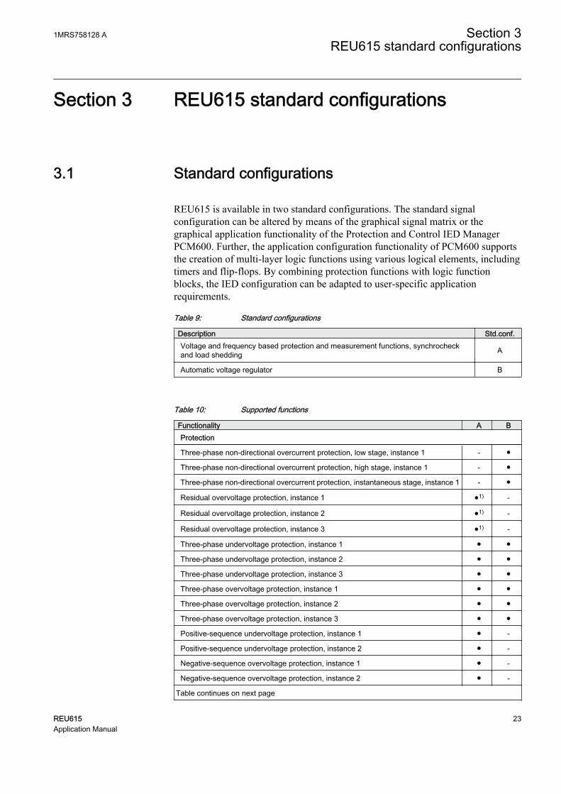
REU615 is available in two standard configurations. The standard signalconfiguration can be altered by means of the graphical signal matrix or thegraphical application functionality of the Protection and Control IED ManagerPCM600. Further, the application configuration functionality of PCM600 supportsthe creation of multi-layer logic functions using various logical elements, includingtimers and flip-flops. By combining protection functions with logic functionblocks, the IED configuration can be adapted to user-specific applicationrequirements.
Table 9: Standard configurations
Description Std.conf.Voltage and frequency based protection and measurement functions, synchrocheckand load shedding A
Automatic voltage regulator B
Table 10: Supported functions
Functionality A BProtection
Three-phase non-directional overcurrent protection, low stage, instance 1 - ●
Three-phase non-directional overcurrent protection, high stage, instance 1 - ●
Three-phase non-directional overcurrent protection, instantaneous stage, instance 1 - ●
Residual overvoltage protection, instance 1 ●1) -
Residual overvoltage protection, instance 2 ●1) -
Residual overvoltage protection, instance 3 ●1) -
Three-phase undervoltage protection, instance 1 ● ●
Three-phase undervoltage protection, instance 2 ● ●
Three-phase undervoltage protection, instance 3 ● ●
Three-phase overvoltage protection, instance 1 ● ●
Three-phase overvoltage protection, instance 2 ● ●
Three-phase overvoltage protection, instance 3 ● ●
Positive-sequence undervoltage protection, instance 1 ● -
Positive-sequence undervoltage protection, instance 2 ● -
Negative-sequence overvoltage protection, instance 1 ● -
Negative-sequence overvoltage protection, instance 2 ● -
Table continues on next page
1MRS758128 A Section 3REU615 standard configurations
REU615 23Application Manual

Functionality A BFrequency protection, instance 1 ● -
Frequency protection, instance 2 ● -
Frequency protection, instance 3 ● -
Frequency protection, instance 4 ● -
Frequency protection, instance 5 ● -
Frequency protection, instance 6 ● -
Three-phase thermal overload protection for power transformers, two time constants - ●
Master trip, instance 1 ● ●
Master trip, instance 2 ● ●
Arc protection, instance 1 o2) -
Arc protection, instance 2 o2) -
Arc protection, instance 3 o2) -
Multi-purpose protection, instance 13) - o4)
Multi-purpose protection, instance 23) - o4)
Multi-purpose protection, instance 33) - o4)
Multi-purpose protection, instance 43) - o4)
Multi-purpose protection, instance 53) - o4)
Multi-purpose protection, instance 63) - o4)
Load shedding and restoration, instance 1 ● -
Load shedding and restoration, instance 2 ● -
Load shedding and restoration, instance 3 ● -
Load shedding and restoration, instance 4 ● -
Load shedding and restoration, instance 5 ● -
Control
Circuit-breaker control ● ●
Disconnector control, instance 1 ●4) ●4)
Disconnector control, instance 2 ●4) ●4)
Earthing switch control ●4) ●4)
Disconnector position indication, instance 1 ● ●4)
Disconnector position indication, instance 2 ●4) ●4)
Disconnector position indication, instance 3 ●4) ●4)
Earthing switch indication, instance 1 ●4) ●4)
Earthing switch indication, instance 2 ●4) ●4)
Tap changer position indication - ●
Tap changer control with voltage regulator - ●
Synchronism and energizing check ● -
Condition Monitoring
Trip circuit supervision, instance 1 ● ●
Table continues on next page
Section 3 1MRS758128 AREU615 standard configurations
24 REU615Application Manual

Functionality A BTrip circuit supervision, instance 2 ● ●
Current circuit supervision - ●
Fuse failure supervision - ●
Measurement
Disturbance recorder ● ●
Three-phase current measurement, instance 1 - ●
Sequence current measurement - ●
Three-phase voltage measurement ● ●
Residual voltage measurement ● -
Sequence voltage measurement ● ●
Three-phase power and energy measurement, including power factor - ●
RTD/mA measurement - o
Frequency measurement ● -
● = included, o = optional at the time of order
1) U0 selectable by parameter, U0 measured as default.2) Light only.3) Multi-purpose protection is used for, for example, RTD/mA based protection.4) Available in IED and SMT but not connected to anything in logic.
3.1.1 Addition of control functions for primary devices and theuse of binary inputs and outputsIf extra control functions intended for controllable primary devices are added to theconfiguration, additional binary inputs and/or outputs are needed to complementthe standard configuration.
If the number of inputs and/or outputs in a standard configuration is not sufficient,it is possible either to modify the chosen IED standard configuration in order torelease some binary inputs or binary outputs which have originally been configuredfor other purposes, or to integrate an external input/output module, for exampleRIO600, to the IED.
The external I/O module’s binary inputs and outputs of can be used for the less time-critical binary signals of the application. The integration enables releasing someinitially reserved binary inputs and outputs of the IED’s standard configuration.
The suitability of the IED’s binary outputs which have been selected for primarydevice control should be carefully verified, for example make and carry andbreaking capacity. If the requirements for the primary device control circuit are notmet, using external auxiliary relays should be considered.
1MRS758128 A Section 3REU615 standard configurations
REU615 25Application Manual

3.1.2 LED functionalityThe IED has dynamic programmable LEDs. The presentation of the LEDs in thismanual differs from the actual function blocks in the configurations.
GUID-4576631D-C686-454F-8CF0-DC654779B178 V1 EN
Figure 9: Drawing symbol used in the manual and the default connection ofthe LED function blocks in the configurations
Section 3 1MRS758128 AREU615 standard configurations
26 REU615Application Manual

3.2 Connection diagrams
GUID-E8E4A6F1-57F5-4E53-AACF-FA95E7D92D83 V1 EN
Figure 10: Connection diagram for the A configuration
1MRS758128 A Section 3REU615 standard configurations
REU615 27Application Manual

GUID-46B7ECD1-0F3F-4DCA-8144-8A485D02061A V1 EN
Figure 11: Connection diagram for the A configuration (voltage protection withphase-to-earth voltage measurement)
Section 3 1MRS758128 AREU615 standard configurations
28 REU615Application Manual

GUID-64ADD3D1-99D0-458B-8E28-5023277CFD6C V1 EN
Figure 12: Connection diagram for the B configuration
1MRS758128 A Section 3REU615 standard configurations
REU615 29Application Manual

GUID-AE8916E5-D21C-4C90-B38A-C93EDE80FF2E V1 EN
Figure 13: Connection diagram for the B configuration (on load tap changercontrol with phase-to-earth voltage measurement)
3.3 Presentation of standard configurations
Functional diagramsThe functional diagrams describe the IED's functionality from the protection,measuring, condition monitoring, disturbance recording, control and interlockingperspective. Diagrams show the default functionality with simple symbol logics
Section 3 1MRS758128 AREU615 standard configurations
30 REU615Application Manual

forming principle diagrams. The external connections to primary devices are alsoshown, stating the default connections to measuring transformers. The positivemeasuring direction of directional protection functions is towards the outgoing feeder.
The functional diagrams are divided into sections with each section constitutingone functional entity. The external connections are also divided into sections. Onlythe relevant connections for a particular functional entity are presented in eachsection.
Protection function blocks are part of the functional diagram. They are identifiedbased on their IEC 61850 name but the IEC based symbol and the ANSI functionnumber are also included. Some function blocks, such as PHHPTOC, are usedseveral times in the configuration. To separate the blocks from each other, the IEC61850 name, IEC symbol and ANSI function number are appended with a runningnumber, that is an instance number, from one upwards. If the block has no suffixafter the IEC or ANSI symbol, the function block has been used, that is,instantiated, only once. The IED’s internal functionality and the externalconnections are separated with a dashed line presenting the IED’s physical casing.
Signal Matrix and Application ConfigurationWith Signal Matrix and Application Configuration in PCM600, it is possible tomodify the standard configuration according to the actual needs. The IED isdelivered from the factory with default connections described in the functionaldiagrams for binary inputs, binary outputs, function-to-function connections andalarm LEDs. The Signal Matrix is used for GOOSE signal input engineering andfor making cross-references between the physical I/O signals and the functionblocks. The Signal Matrix tool cannot be used for adding or removing functionblocks, for example, GOOSE receive function blocks. The ApplicationConfiguration tool is used for these kind of operations. If a function block isremoved with Application Configuration, the function related data disappears fromthe menus as well as from the 61850 data model, with the exception of some basicfunction blocks, which are mandatory and thus cannot be removed from the IEDconfiguration by removing them from the Application Configuration.
3.4 Standard configuration A
3.4.1 Applications
The standard configuration is intended for voltage protection and synchronismcheck in medium voltage networks. The standard configuration handles faultconditions originating from abnormal voltages in the power system. Also thesynchronism and energizing check can be handled for two galvanicallyinterconnected networks.
The IED with a standard configuration is delivered from the factory with defaultsettings and parameters. The end-user flexibility for incoming, outgoing and
1MRS758128 A Section 3REU615 standard configurations
REU615 31Application Manual

internal signal designation within the IED enables this configuration to be furtheradapted to different primary circuit layouts and the related functionality needs bymodifying the internal functionality using PCM600.
3.4.2 FunctionsTable 11: Functions included in the standard configuration A
Functionality IEC 61850 IEC 60617 IEC-ANSIProtection
Residual overvoltage protection, instance 1 ROVPTOV1 Uo> (1) 59G (1)
Residual overvoltage protection, instance 2 ROVPTOV2 Uo> (2) 59G (2)
Residual overvoltage protection, instance 3 ROVPTOV3 Uo> (3) 59G (3)
Three-phase undervoltage protection, instance1 PHPTUV1 3U< (1) 27 (1)
Three-phase undervoltage protection, instance2 PHPTUV2 3U< (2) 27 (2)
Three-phase undervoltage protection, instance3 PHPTUV3 3U< (3) 27 (3)
Three-phase overvoltage protection, instance 1 PHPTOV1 3U> (1) 59 (1)
Three-phase overvoltage protection, instance 2 PHPTOV2 3U> (2) 59 (2)
Three-phase overvoltage protection, instance 3 PHPTOV3 3U> (3) 59 (3)
Positive-sequence undervoltage protection,instance 1 PSPTUV1 U1< (1) 47U+ (1)
Positive-sequence undervoltage protection,instance 2 PSPTUV2 U1< (2) 47U+ (2)
Negative-sequence overvoltage protection,instance 1 NSPTOV1 U2> (1) 47O- (1)
Negative-sequence overvoltage protection,instance 2 NSPTOV2 U2> (2) 47O- (2)
Frequency protection, instance 1 FRPFRQ1 f>/f<,df/dt (1) 81 (1)
Frequency protection, instance 2 FRPFRQ2 f>/f<,df/dt (2) 81 (2)
Frequency protection, instance 3 FRPFRQ3 f>/f<,df/dt (3) 81 (3)
Frequency protection, instance 4 FRPFRQ4 f>/f<,df/dt (4) 81 (4)
Frequency protection, instance 5 FRPFRQ5 f>/f<,df/dt (5) 81 (5)
Frequency protection, instance 6 FRPFRQ6 f>/f<,df/dt (6) 81 (6)
Master trip, instance 1 TRPPTRC1 Master Trip (1) 94/86 (1)
Master trip, instance 2 TRPPTRC2 Master Trip (2) 94/86 (2)
Arc protection, instance 1 ARCSARC1 ARC (1) 50L/50NL (1)
Arc protection, instance 2 ARCSARC2 ARC (2) 50L/50NL (2)
Arc protection, instance 3 ARCSARC3 ARC (3) 50L/50NL (3)
Load shedding and restoration, instance 1 LSHDPFRQ1 UFLS/R (1) 81LSH (1)
Load shedding and restoration, instance 2 LSHDPFRQ2 UFLS/R (2) 81LSH (2)
Load shedding and restoration, instance 3 LSHDPFRQ3 UFLS/R (3) 81LSH (3)
Load shedding and restoration, instance 4 LSHDPFRQ4 UFLS/R (4) 81LSH (4)
Table continues on next page
Section 3 1MRS758128 AREU615 standard configurations
32 REU615Application Manual

Functionality IEC 61850 IEC 60617 IEC-ANSILoad shedding and restoration, instance 5 LSHDPFRQ5 UFLS/R (5) 81LSH (5)
Control
Circuit-breaker control CBXCBR1 I <-> O CB I <-> O CB
Disconnector control, instance 1 DCXSWI1 I <-> O DCC(1)
I <-> O DCC(1)
Disconnector control, instance 2 DCXSWI2 I <-> O DCC(2)
I <-> O DCC(2)
Earthing switch control ESXSWI1 I <-> O ESC I <-> O ESC
Disconnector position indication, instance 1 DCSXSWI1 I <-> O DC (1) I <-> O DC (1)
Disconnector position indication, instance 2 DCSXSWI2 I <-> O DC (2) I <-> O DC (2)
Disconnector position indication, instance 3 DCSXSWI3 I <-> O DC (3) I <-> O DC (3)
Earthing switch indication, instance 1 ESSXSWI1 I <-> O ES (1) I <-> O ES (1)
Earthing switch indication, instance 2 ESSXSWI2 I <-> O ES (2) I <-> O ES (2)
Synchronism and energizing check SECRSYN1 SYNC 25
Condition monitoring
Trip circuit supervision, instance 1 TCSSCBR1 TCS (1) TCM (1)
Trip circuit supervision, instance 2 TCSSCBR2 TCS (2) TCM (2)
Measurement
Disturbance recorder RDRE1 - -
Three-phase voltage measurement VMMXU1 3U 3U
Residual voltage measurement RESVMMXU1 Uo Vn
Sequence voltage measurement VSMSQI1 U1, U2, U0 U1, U2, U0
Frequency measurement FMMXU1 f f
3.4.2.1 Default I/O connections
Table 12: Default connections for binary inputs
Binary input Default usage Connector pinsX110-BI1 Setting group change X110-1,2
X110-BI2 Manual restore group 1 X110-3,4
X110-BI3 Manual restore group 2 X110-5,6
X110-BI4 X110-7,6
X110-BI5 Voltage transformer truck in indication X110-8,9
X110-BI6 Voltage transformer truck out indication X110-10,9
X110-BI7 Earth switch closed indication X110-11,12
X110-BI8 Earth switch open indication X110-13,12
X130-BI1 Blown primary fuse indication X130-1,2
X130-BI2 Line voltage transformer MCB open X130-3,4
X130-BI3 Bus voltage transformer MCB open X130-5,6
X130-BI4 Lockout reset X130-7,8
1MRS758128 A Section 3REU615 standard configurations
REU615 33Application Manual

Table 13: Default connections for binary outputs
Binary output Default usage Connector pinsX100-PO1 X100-6,7
X100-PO2 In synchronism for close X100-8,9
X100-SO1 General start indication X100-10,11,(12)
X100-SO2 General operate indication X100-13,14
X100-PO3 Open circuit breaker/trip coil 1 X100-15-19
X100-PO4 Open circuit breaker/trip coil 2 X100-20-24
X110-SO1 Load shedding group 1 X110-14,15,16
X110-SO2 Load shedding group 2 X110-17,18,19
X110-SO3 Load restore group 1 X110-20,21,22
X110-SO4 Load restore group 2 X110-23,24
Table 14: Default connections for LEDs
LED Default usage1 Overvoltage protection operated
2 Undervoltage protection operated
3 Residual voltage protection operated
4 Sequence voltage protection operated
5 Frequency protection operated
6 Load shedding operated
7 Disturbance recorder triggered
8 Systems synchronized
9 Voltage transformer secondary MCB open
10 Arc fault detected
11 Primary voltage transformer fuse blown
3.4.2.2 Default disturbance recorder settings
Table 15: Default analog channel selection and text settings
Channel Selection and text1 Uo
2 U1
3 U2
4 U3
5 U1B
6 -
7 -
8 -
Table continues on next page
Section 3 1MRS758128 AREU615 standard configurations
34 REU615Application Manual

Channel Selection and text9 -
10 -
11 -
12 -
Additionally, all the digital inputs that are connected by default are also enabledwith the setting. Default triggering settings are selected depending on theconnected input signal type. Typically all protection START signals are selected totrigger the disturbance recorded by default.
3.4.3 Functional diagrams
The functional diagrams describe the default input, output, alarm LED and function-to-function connections. The default connections can be viewed and changed withPCM600 according to the application requirements, if necessary.
The analog channels, measurements from voltage transformers, have fixedconnections towards the different function blocks inside the IED’s standardconfiguration. Exceptions from this rule are the 12 analog channels available forthe disturbance recorder function. These channels are freely selectable and a part ofthe disturbance recorder’s parameter settings.
The analog channels are assigned to different functions. The common signalmarked with 3U represents the three phase voltages. The signal marked with Uorepresents the measured residual voltage via open-delta connected voltagetransformers.
3.4.3.1 Functional diagrams for protection
The functional diagrams describe the IED’s protection functionality in detail andpicture the factory set default connections.
1MRS758128 A Section 3REU615 standard configurations
REU615 35Application Manual

GUID-4071AE4F-377A-4D4A-A506-B5A55C840C74 V1 EN
Figure 14: Overvoltage protection
Three overvoltage protection stages (PHxPTOV) protect against abnormal phasevoltage conditions in the power system. The operation of voltage functions isconnected to alarm LED 1.
Depending on the selected operation mode, the active setting group can be changedeither with a parameter or via binary input.
All operate signals are connected to the Master Trip and also to the alarm LEDs.LED 1 indicates operation of overvoltage and LED 2 operation of undervoltageprotection functions. LED 3 indicates operation of residual overvoltage and LED 4voltage unbalance protection. LED 5 indicates operation of frequency protection.
Section 3 1MRS758128 AREU615 standard configurations
36 REU615Application Manual

GUID-BBD0D81F-5F94-4E97-8CF5-560F9EA9562F V1 EN
Figure 15: Undervoltage protection
Three undervoltage protection stages (PHxPTUV) protect against abnormal phasevoltage conditions in the power system. The operation of voltage functions isconnected to alarm LED 2. An external supervision device detects failures inprimary high voltage fuses and the activation is connected to binary inputX130:BI1. Activating the binary input to avoid faulty undervoltage tripping blocksthe undervoltage protection functions.
GUID-6A4FADFD-F55D-433D-894F-370CF538F902 V1 EN
Figure 16: Residual overvoltage protection
1MRS758128 A Section 3REU615 standard configurations
REU615 37Application Manual

The residual overvoltage protection (ROVPTOV) provides earth-fault protectionby detecting abnormal level of residual voltage. It can be used, for example, as anonselective backup protection for the selective directional earth-faultfunctionality. The operation signal is connected to alarm LED 3.
GUID-98C7A5F0-B1A7-4008-92D2-FBACE327C843 V1 EN
Figure 17: Positive and negative sequence voltage protection
Four unbalance voltage protection functions are offered: two stages of negative-sequence overvoltage protection (NSPTOV1) and two stages positive-sequenceundervoltage protection (PSPTUV1) functions. NSPTOV1 and PSPTUV1 areblocked in case a blown primary fuse is detected.
Section 3 1MRS758128 AREU615 standard configurations
38 REU615Application Manual

GUID-0F39CC9C-7388-47F5-89F3-666E4D0D42CB V1 EN
Figure 18: Frequency protection
The selectable underfrequency or overfrequency protection (FRPFRQ) preventsdamage to network components under unwanted frequency conditions.
1MRS758128 A Section 3REU615 standard configurations
REU615 39Application Manual

The function contains a selectable rate of change of the frequency (gradient)protection to detect an increase or decrease in the fast power system frequency atan early stage. This can be used as an early indication of a disturbance in thesystem. The operation signal is connected to alarm LED 5.
GUID-3B69C572-5221-4320-850C-DD1DB0933037 V2 EN
Figure 19: Load shedding and restoration
Five load shedding and restoration stages are offered in the standard configuration.The load shedding and restoration function (LSHDPFRQ) is capable of sheddingload based on underfrequency and the rate of change of the frequency. The loadthat is shed during the frequency disturbance can be restored once the frequency isstabilized to the normal level. Also manual restore commands can be given viabinary inputs.
Section 3 1MRS758128 AREU615 standard configurations
40 REU615Application Manual

In this standard configuration two restore stages are implemented. Depending oninput and output usage, it is possible to take other stages into use as well. Theoperation signal is connected to the alarm LED 6.
GUID-ACA8588C-03FB-4389-B559-92CB612C6F8A V1 EN
Figure 20: Arc protection
Arc protection (ARCSARC1...3) is included as an optional function.
The arc protection offers individual function blocks for three arc sensors that canbe connected to the IED. The arc protection in this standard configuration detectsan arc flash and supplies the information for the operating arc protection unit,which de-energizes the faulty area by opening the circuit breaker. It is possible touse, for example, fast GOOSE communication to route the detected information tothe circuit breaker.
The alarm LED 10 is used as a common arc detected indication.
1MRS758128 A Section 3REU615 standard configurations
REU615 41Application Manual

3.4.3.2 Functional diagram for disturbance recorder
LED7 (DR TRIGGERING)
NSPTOV1_STARTNSPTOV2_START
PHPTOV1_STARTPHPTOV2_STARTPHPTOV3_START
OR
NSPTOV1_OPERATENSPTOV2_OPERATE
OR
PHPTOV1_OPERATE
ARCSARC1_ARC_FLT_DETARCSARC2_ARC_FLT_DETARCSARC3_ARC_FLT_DET
BI 2_LINE_VT_MCB_OPEN
ROVPTOV2_STARTROVPTOV1_START
PHPTUV1_STARTPHPTUV2_STARTPHPTUV3_START
PHPTOV2_OPERATEPHPTOV3_OPERATE
ROVPTOV1_OPERATEROVPTOV2_OPERATEROVPTOV3_OPERATE
OR
PHPTUV1_OPERATEPHPTUV2_OPERATEPHPTUV3_OPERATE
RDRE1
BI#1
BI#2
BI#3
BI#4
BI#5
BI#6
BI#7
BI#8
BI#9
BI#10
BI#11
BI#12
BI#13
BI#14
BI#15
BI#16
BI#17
BI#18
BI#19
BI#20
BI#21
BI#22
BI#23
BI#24
BI#25
BI#26
BI#27
BI#28
BI#29
BI#30
BI#31
BI#32
BI#33
BI#34
BI#35
BI#36
BI#37
BI#38
TRIGGERED
OR
FRPFRQ1_OPERATEFRPFRQ2_OPERATEFRPFRQ3_OPERATE
OR
SECRSYN_SYNC_OKSECRSYN_SYNC_INPRO
FRPFRQ1_STARTFRPFRQ2_STARTFRPFRQ3_START
DISTURBANCE RECORDER
FRPFRQ4_STARTFRPFRQ5_STARTFRPFRQ6_STARTLSHDPFRQ1_START
ROVPTOV3_START
PSPTUV1_STARTPSPTUV2_START
LSHDPFRQ2_STARTLSHDPFRQ3_STARTLSHDPFRQ4_STARTLSHDPFRQ5_START
FRPFRQ4_OPERATEFRPFRQ5_OPERATEFRPFRQ6_OPERATE
LSHDPFRQ1_OPERATE
LSHDPFRQ5_OPERATELSHDPFRQ4_OPERATELSHDPFRQ3_OPERATELSHDPFRQ2_OPERATE
OR
PSPTUV1_OPERATEPSPTUV2_OPERATE
LSHDPFRQ1_RESTORE
LSHDPFRQ5_RESTORELSHDPFRQ4_RESTORELSHDPFRQ3_RESTORELSHDPFRQ2_RESTORE
OR
BI 3_BUS_VT_MCB_OPEN
GUID-95F1202A-A4AD-46C5-B059-B36F02FB2951 V2 EN
Figure 21: Disturbance recorder
All start and operate signals from the protection stages are routed to trigger thedisturbance recorder or alternatively only to be recorded by the disturbancerecorder depending on the parameter settings. Additionally, the ARC protection,synchrocheck and voltage measuring circuit related signals are also connected.
Section 3 1MRS758128 AREU615 standard configurations
42 REU615Application Manual

3.4.3.3 Functional diagrams for control and interlocking
GUID-4F3709BF-87AC-4EB7-86AE-0FD490AA925A V2 EN
Figure 22: Synchronism and energizing check
The synchronism and energizing check (SECRSYN) function is offered in thestandard configuration. It is used for interconnecting two separate power systemnetwork parts. The standard configuration is implemented to be used as continuousmode by default. The permission signal for circuit breaker closing is connected toX100:PO2 and it can be used in series in circuit breaker closing circuit. Theinformation that systems are synchronous to be interconnected is connected to LED8.
SECRSYN is blocked if primary voltage transformer fuse is blown (X130:BI1) orif the miniature circuit breaker failure is detected from the line or bus-sidesecondary voltage measuring circuit (X130:BI2 or X130:BI3).
1MRS758128 A Section 3REU615 standard configurations
REU615 43Application Manual

GUID-134FABAF-FD7D-4CDF-A47A-B6E9D988065E V1 EN
Figure 23: Master Trip
The operate signals from the protections are connected to the two trip outputcontacts PO3 (X100:15-19) and PO4 (X100:20-24) via the corresponding MasterTrips TRPPTRC1 and TRPPTRC2.
TRPPTRC1 and 2 provide the lockout/latching function, event generation and thetrip signal duration setting. If the lockout operation mode is selected, one binaryinput can be reassigned to the RST_LKOUT input of the Master Trip to enableexternal reset with a push button.
Section 3 1MRS758128 AREU615 standard configurations
44 REU615Application Manual

GUID-1CF419D7-518A-431F-BCAB-02413BE39E22 V1 EN
Figure 24: Disconnector position indication
There are two types of disconnector and earthing switch blocks available.DCSXSWI1...3 and ESSXSWI1...2 are status only type, and DCXSWI1...2 andESXSWI1 are controllable type. By default, the status only blocks are connected instandard configuration logic. If controllable operation is preferred, the controllabletype of disconnector and earthing switch blocks can be used instead of the statusonly type. The connection and configuration of the control blocks can be doneusing PCM600.
OLD_The voltage transformer truck position indication is done with DCSXSWI1function block. There are three disconnector status blocks (DCSXSWI1…3)available in the IED. The remaining two not described in the functional diagramare available in PCM600 for connection where applicable.
The binary inputs X110:5 and X110:6 are used for connection of voltagetransformer truck position. The inputs are connected to DCSXSWI1.
Table 16: Device positions indicated by binary inputs 5 and 6
Primary device position Input to be energized Input 5 (X110:8-9) Input 6 (X110:10-9)
Busbar disconnector closed x
Busbar disconnector open x
Voltage transformer truck in serviceposition
x
Voltage transformer truck in test position x
The binary inputs X110:7 and X110:8 are used for the position indication of thebusbar-side earth switch.
1MRS758128 A Section 3REU615 standard configurations
REU615 45Application Manual

GUID-02E97DB4-8623-4B39-A38A-589778A9186A V1 EN
Figure 25: Common alarm/indication 1 and 2
The signal outputs from the IED are connected to give dedicated information on:
• Start of any protection function SO1 (X100:10-12)• Operation (trip) of any protection function SO2 (X100: 13-15)
TPGAPC are timers and used for setting the minimum pulse length for the outputs.There are four generic timers (TPGAPC1..4) available in the IED. The remainingones not described in the functional diagram are available in PCM600 forconnection where applicable.
3.5 Standard configuration B
3.5.1 Applications
The standard configuration is intended for automatic voltage regulation of powertransformers equipped with an on-load tap changer. It also features three-stage three-
Section 3 1MRS758128 AREU615 standard configurations
46 REU615Application Manual

phase non-directional overcurrent protection, three-phase under and overvoltageprotection. The IED also incorporates a thermal overload protection function,which supervises the thermal stress of the transformer windings to preventpremature aging of the winding's insulation.
The RTD/mA input module is optional in the standard configuration. When usingthe RTD/mA input module it is possible to have the tap changer position indicationas an mA signal, ambient temperature of the power transformer can be used inthermal protection and the multi-purpose protection functions are available. Themulti-purpose protection function enables protection based on analog values fromthe IEDs RTD/mA input module, or from other IEDs using analog horizontalGOOSE messaging.
The IED with a standard configuration is delivered from the factory with defaultsettings and parameters. The end-user flexibility for incoming, outgoing andinternal signal designation within the IED enables this configuration to be furtheradapted to different primary circuit layouts and the related functionality needs bymodifying the internal functionality using PCM600.
3.5.2 FunctionsTable 17: Functions included in the standard configuration B
Functionality IEC 61850 IEC 60617 IEC-ANSIProtection
Three-phase non-directional overcurrentprotection, low stage, instance 1 PHLPTOC1 3I> (1) 51P-1 (1)
Three-phase non-directional overcurrentprotection, high stage, instance 1 PHHPTOC1 3I>> (1) 51P-2 (1)
Three-phase non-directional overcurrentprotection, instantaneous stage, instance 1 PHIPTOC1 3I>>> (1) 50P/51P (1)
Three-phase undervoltage protection, instance1 PHPTUV1 3U< (1) 27 (1)
Three-phase undervoltage protection, instance2 PHPTUV2 3U< (2) 27 (2)
Three-phase undervoltage protection, instance3 PHPTUV3 3U< (3) 27 (3)
Three-phase overvoltage protection, instance 1 PHPTOV1 3U> (1) 59 (1)
Three-phase overvoltage protection, instance 2 PHPTOV2 3U> (2) 59 (2)
Three-phase overvoltage protection, instance 3 PHPTOV3 3U> (3) 59 (3)
Three-phase thermal overload protection forpower transformers, two time constants T2PTTR1 3Ith>T 49T
Master trip, instance 1 TRPPTRC1 Master Trip (1) 94/86 (1)
Master trip, instance 2 TRPPTRC2 Master Trip (2) 94/86 (2)
Multi-purpose protection, instance 1 MAPGAPC1 MAP (1) MAP (1)
Multi-purpose protection, instance 2 MAPGAPC2 MAP (2) MAP (2)
Multi-purpose protection, instance 3 MAPGAPC3 MAP (3) MAP (3)
Table continues on next page
1MRS758128 A Section 3REU615 standard configurations
REU615 47Application Manual

Functionality IEC 61850 IEC 60617 IEC-ANSIMulti-purpose protection, instance 4 MAPGAPC4 MAP (4) MAP (4)
Multi-purpose protection, instance 5 MAPGAPC5 MAP (5) MAP (5)
Multi-purpose protection, instance 6 MAPGAPC6 MAP (6) MAP (6)
Control
Circuit-breaker control CBXCBR1 I <-> O CB I <-> O CB
Disconnector control, instance 1 DCXSWI1 I <-> O DCC(1)
I <-> O DCC(1)
Disconnector control, instance 2 DCXSWI2 I <-> O DCC(2)
I <-> O DCC(2)
Earthing switch control ESXSWI1 I <-> O ESC I <-> O ESC
Disconnector position indication, instance 1 DCSXSWI1 I <-> O DC (1) I <-> O DC (1)
Disconnector position indication, instance 2 DCSXSWI2 I <-> O DC (2) I <-> O DC (2)
Disconnector position indication, instance 3 DCSXSWI3 I <-> O DC (3) I <-> O DC (3)
Earthing switch indication, instance 1 ESSXSWI1 I <-> O ES (1) I <-> O ES (1)
Earthing switch indication, instance 2 ESSXSWI2 I <-> O ES (2) I <-> O ES (2)
Tap changer position indication TPOSSLTC1 TPOSM 84M
Tap changer control with voltage regulator OLATCC1 COLTC 90V
Condition monitoring
Trip circuit supervision, instance 1 TCSSCBR1 TCS (1) TCM (1)
Trip circuit supervision, instance 2 TCSSCBR2 TCS (2) TCM (2)
Current circuit supervision CCRDIF1 MCS 3I MCS 3I
Fuse failure supervision SEQRFUF1 FUSEF 60
Measurement
Disturbance recorder RDRE1 - -
Three-phase current measurement, instance 1 CMMXU1 3I 3I
Sequence current measurement CSMSQI1 I1, I2, I0 I1, I2, I0
Three-phase voltage measurement VMMXU1 3U 3U
Sequence voltage measurement VSMSQI1 U1, U2, U0 U1, U2, U0
Three-phase power and energy measurement,including power factor PEMMXU1 P, E P, E
RTD/mA measurement XRGGIO130 X130 (RTD) X130 (RTD)
3.5.2.1 Default I/O connections
Table 18: Default connections for binary inputs
Binary input Default usage Connector pinsX110-BI1 Tap changer operates X110-1,2
X110-BI2 Voltage transformer secondary MCB open X110-3,4
X110-BI3 Lower local request X110-5,6
X110-BI4 Raise local request X110-7,6
Table continues on next page
Section 3 1MRS758128 AREU615 standard configurations
48 REU615Application Manual

Binary input Default usage Connector pinsX110-BI5 Activate parallel operation X110-8,9
X110-BI6 Activate automatic mode X110-10,9
X110-BI7 Circuit breaker closed indication X110-11,12
X110-BI8 Circuit breaker open indication X110-13,12
Table 19: Default connections for binary inputs (alternative to the RTD card)
Binary input Default usage Connector pinsX130-BI1 BCD sign bit (tap changer position) X130-1,2
X130-BI2 BCD bit 1 MSB X130-2,3
X130-BI3 BCD bit 2 X130-4,5
X130-BI4 BCD bit 3 X130-5,6
X130-BI5 BCD bit 4 X130-7,8
X130-BI6 BCD bit 5 LSB X130-8,9
Table 20: Default connections for RDT/mA inputs
RTD/mA input Default usage Connector pinsX130-AI1 Tap changer position X130-1,2
X130-AI2 X130-3,4
X130-AI3 Transformer ambient temperature X130-5,6,11c
X130-AI4 X130-7,8,11c
X130-AI5 X130-9,10,11c
X130-AI6 X130-13,14,12c
X130-AI7 X130-15,16,12c
X130-AI8 X130-17,18,12c
Table 21: Default connections for binary outputs
Binary output Default usage Connector pinsX100-PO1 Lower own command X100-6,7
X100-PO2 Raise own command X100-8,9
X100-SO1 General start indication X100-10,11,(12)
X100-SO2 General operate indication X100-13,14
X100-PO3 Master trip X100-15-19
X100-PO4 Close circuit breaker X100-20-24
X110-SO1 Tap changer control alarm X110-14,15,16
X110-SO2 Overcurrent operate alarm X110-17,18,19
X110-SO3 Voltage protection operate alarm X110-20,21,22
X110-SO4 Overload protection operate alarm X110-23,24
1MRS758128 A Section 3REU615 standard configurations
REU615 49Application Manual

Table 22: Default connections for LEDs
LED Default usage1 Overcurrent protection operated
2 Overvoltage protection operated
3 Undervoltage protection operated
4 Thermal overload protection operated
5 Raise own
6 Lower own
7 Disturbance recorder triggered
8 Tap changer control alarm
9 Supervision
10 Tap changer operates
11
3.5.2.2 Default disturbance recorder settings
Table 23: Default analog channel selection and text settings
Channel Selection and text1 IL1
2 IL2
3 IL3
4 Io
5 U1
6 U2
7 U3
8 -
9 -
10 -
11 -
12 -
Additionally, all the digital inputs that are connected by default are also enabledwith the setting. Default triggering settings are selected depending on theconnected input signal type. Typically all protection START signals are selected totrigger the disturbance recorded by default.
Section 3 1MRS758128 AREU615 standard configurations
50 REU615Application Manual

3.5.3 Functional diagramsThe functional diagrams describe the default input, output, alarm LED and function-to-function connections. The default connections can be viewed and changed withPCM600 according to the application requirements, if necessary.
The analog channels, measurements from current transformers and voltagetransformers, have fixed connections towards the different function blocks insidethe IED’s standard configuration. Exceptions from this rule are the 12 analogchannels available for the disturbance recorder function. These channels are freelyselectable and a part of the disturbance recorder’s parameter settings.
The analog channels are assigned to different functions. The common signalmarked with 3I represents the three phase currents and 3U represents the threephase voltages. The signal marked with Uo represents the measured residualvoltage via open-delta connected voltage transformers. The signal marked with Iorepresents the measured residual current, via a sum connection of second currenttransformer cores of the phase current transformers.
3.5.3.1 Functional diagrams for protection
The functional diagrams describe the IED’s protection functionality in detail andpicture the factory set default connections.
1MRS758128 A Section 3REU615 standard configurations
REU615 51Application Manual

GUID-2125AE49-AD79-460A-AF83-3965D2F06F2F V2 EN
Figure 26: Overcurrent protection
Three overcurrent stages (PHLPTOC1, PHHPTOC1 and PHIPTOC1) are offeredfor overcurrent and short-circuit protection. LED 1 is used for indicating theoperation of overcurrent and short circuit functions. Also the same alarminformation is connected to the binary output SO2 (X110:17-19).
All operate signals are connected to the Master Trip and also to the alarm LEDs.LED 1 indicates operation of overcurrent and LED 2 operation of overvoltageprotection functions. LED 3 indicates operation of undervoltage and LED 4thermal overload protection.
Section 3 1MRS758128 AREU615 standard configurations
52 REU615Application Manual

GUID-C07A4101-8768-4365-BB4F-17CF3CF3D075 V1 EN
Figure 27: Thermal overload protection
Three-phase thermal overload protection (T2PTTR1) provides indication onoverload situations. The operate signal of the thermal overload protection isconnected to the Master Trip and also to an alarm LED 4.
If the RTD/mA input module is included in the IED, the ambient temperature ofthe power transformer is connected from the RTD channel to the thermal overloadfunction.
GUID-3EC07F90-DCAB-436A-B36F-965BD8AAB645 V1 EN
Figure 28: Overvoltage protection
Three overvoltage protection stages (PHPTOV1, PHPTOV2 and PHPTOV3) offerprotection against abnormal overvoltage conditions in the power system. LED 2
1MRS758128 A Section 3REU615 standard configurations
REU615 53Application Manual

indicates the operation of PHPTOV. The same alarm information is connected tothe binary output SO3 (X110:20-22).
GUID-CA6719A8-E586-4B52-80F2-9504EA0CCA26 V1 EN
Figure 29: Undervoltage protection
Three undervoltage protection stages (PHPTUV1, PHPTUV2 and PHPTUV3)offer protection against abnormal undervoltage conditions in the power system.LED 3 indicates the operation of PHPTUV. The same alarm information isconnected to the binary output SO3 (X110:20-22).
Section 3 1MRS758128 AREU615 standard configurations
54 REU615Application Manual

3.5.3.2 Functional diagrams for disturbance recorder and supervisionfunctions
GUID-F538B88A-B5BB-4DB8-8364-06E7CF14239C V2 EN
Figure 30: Disturbance recorder
All start and operate signals from the protection stages are routed to trigger thedisturbance recorder or alternatively only to be recorded by the disturbancerecorder depending on the parameter settings. Additionally, the supervision relatedsignals, tap changer control signals and circuit breaker position indications are alsoconnected.
1MRS758128 A Section 3REU615 standard configurations
REU615 55Application Manual

GUID-E7EAE99F-92BC-4192-B485-EB1677BA407D V1 EN
Figure 31: Trip circuit supervision
Two separate trip circuit supervision functions are included, TCSSCBR1 for PO3(X100:15-19) for Master trip and TCSSCBR2 for PO4 (X100:20-24) for circuitbreaker closing. The trip circuit supervision 1 is blocked by the Master Trip(TRPPTRC1) and the circuit-breaker open position signal. The trip circuitsupervision 2 is blocked by the circuit breaker closed position signal. The tripcircuit supervision alarm indication is connected to LED 9.
The fuse failure supervision SEQRFUF1 detects failures in voltage measurementcircuits. Failures, such as open miniature circuit breaker, are detected and the alarmis connected to supervision alarm LED 9.
Failures in current measuring circuits are detected by CCRDIF. The alarm signal isconnected to the supervision alarm LED 9.
Section 3 1MRS758128 AREU615 standard configurations
56 REU615Application Manual

3.5.3.3 Functional diagrams for control and interlocking
GUID-73D10A91-CE58-4368-9C88-39D2268580E6 V1 EN
Figure 32: Master Trip
The operate signals from the protections are connected to the trip output contactPO3 (X100:15-19) via the corresponding Master Trip TRPPTRC1.
TRPPTRC provides the lockout/latching function, event generation and the tripsignal duration setting. If the lockout operation mode is selected, one binary inputcan be reassigned to the RST_LKOUT input of the Master Trip to enable externalreset with a push button.
LED6 (LOWER_OWN)
LED8 (OLATCC_ALARM)
BI7 (CB closed)
SEQRFUF_3PH
SEQRFUF_U
CCRDIF_FAIL
BI1 (Tap changer operates)
X110
5
6
7
SPCGGIO1
SPC (1)
SPC (1)BLOCK
IN1
IN2
IN3
IN4
IN5
IN6
IN7
IN8
IN9
IN10
IN11
IN12
IN13
IN14
IN15
IN16
O1
O2
O3
O4
O5
O6
O7
O8
O9
O10
O11
O12
O13
O14
O15
O16
OLATCC1
COLTC
90V3U
3I
TR1_TAP_POS
TR2_TAP_POS
TR3_TAP_POS
RAISE_LOCAL
LOWER_LOCAL
TAPCHG_FLLW
PARALLEL
AUTO
CON_STATUS
LTC_BLOCK
TCO
RSV
TR1_I_AMPL
TR1_I_ANGL
TR2_I_AMPL
TR2_I_ANGL
TR3_I_AMPL
TR3_I_ANGL
RAISE_OWN
LOWER_OWN
FLLW1_CTL
FLLW2_CTL
FLLW3_CTL
BLKD_I_LOD
BLKD_U_UN
RNBK_U_OV
BLKD_I_CIR
BLKD_LTCBLK
ALARM
PAR_FAIL
PARALLEL
AUTO
TIMER_ONOR
+
PO1
+
PO2
+
SO1
X100
6
7
8
9
X110
14
16
15
LOWER_OWN
LED5 (RAISE_OWN)
RAISE_OWN
LED10 (TAP CHANGER OPERATES)
ON LOAD TAP CHANGER CONTROL
BI 3
BI 4
Lower local
request
Raise local
request
Lower own
Raise own
Tap changer
control alarm
GUID-E4270342-93C0-4C06-B8F2-297E24A434FE V2 EN
Figure 33: On load tap changer control
The on load tap changer control functionality is provided with the OLATCC1function. Both manual and automatic controlling of the on load tap changer is donevia OLATCC. The external push button controlling of the local tap changer can be
1MRS758128 A Section 3REU615 standard configurations
REU615 57Application Manual

wired to binary inputs, BI3 (X110:5-6) for lower request and BI4 (X110:7-6) forraise request. These inputs are connected to the OLATCC1 function viaSPCGGIO1. By default, the raise or lower local request can also be send viaSPCGGIO1 by using the programmable buttons in the Single Line Diagram. Alsothe operation mode (AUTO and PARALLEL inputs) of the OLATCC1 functioncan be controlled via SPCGGIO1 by using the programmable buttons in the SingleLine Diagram.
The binary inputs BI5 (X110:8-9) and BI6 (X110:10-9) are not connected to thePARALLEL and AUTO inputs of OLACC1 by default. If the operation mode ofOLATCC1 is preferred to be controlled externally via BI5 and BI6, the applicationconfiguration must be changed accordingly using PCM600. As the SPCGGIOinputs are triggered by rising edge, it is recommended to connect BI5 and BI6directly to the PARALLEL and AUTO inputs of OLATCC1 in case the operationmode of OLATCC1 is preferred to be controlled externally.
The tap changer operating information can be connected to the binary input BI1(X110:1-2).
OLATCC is blocked in automatic mode as a default setting if the LTC_BLOCKinput is active. The activation of the input fuse failure or current circuit failure isdetected.
The output commands are routed to the binary outputs and programmable LEDs.The raise command is connected to PO2 (X100:8-9) and to the alarm LED 5. Thelower command is connected to PO1 (X100:6-7) and to the alarm LED 6.
The common alarm signal of OLATCC1 is connected to SO1 (X110:14-16) and tothe alarm LED 8.
T2PTTR1_BLK_CLOSE
GUID-A2EC9415-7947-4CBB-B1AF-32F53E87EA78 V1 EN
Figure 34: Circuit breaker control and interlocking
The ENA_CLOSE input, which enables the closing of the circuit breaker, is astatus of the Master Trip in the breaker control function block CBXCBR. The openoperation is always enabled.
Section 3 1MRS758128 AREU615 standard configurations
58 REU615Application Manual

If the ENA_CLOSE signal is completely removed from the breakercontrol function block CBXCBR with PCM600, the functionassumes that the breaker close commands are allowed continuously.
GUID-A6A3A186-BAC4-4609-B163-E13A00C528D6 V1 EN
Figure 35: Tap changer position indication
The tap changer position indication (TPOSSLTC1) can be made by using binarycoded information or an mA signal. It depends on the selected IED hardware. Byusing the mA/RTD input module in the X130 slot, the tap changer position can beconnected as an mA signal. If the binary input output card is selected in the X130slot, the position indication can be made with binary coded information.
When the mA/RTD card is used, the ambient temperature of the power transformeris connected from first RTD channel to the thermal overload protection function.
1MRS758128 A Section 3REU615 standard configurations
REU615 59Application Manual

GUID-160A639B-35DA-446D-B176-D606EBE3FDB9 V2 EN
Figure 36: Common alarm/indication 1-5
The signal outputs from the IED are connected to give dedicated information on:
• Start of any protection function SO1 (X100:10-12)• Operation (trip) of any protection function SO2 (X100:13-14)• Operation of overcurrent protection function SO2 (X110:17-19)• Operation of voltage protection function SO3 (X110:20-22)• Operation of thermal overload protection SO4 (X110:23-24)
TPGAPC are timers and used for setting the minimum pulse length for the outputs.There are four generic timers (TPGAPC1..4) available in the IED. The remainingones not described in the functional diagram are available in PCM600 forconnection where applicable.
Section 3 1MRS758128 AREU615 standard configurations
60 REU615Application Manual

Section 4 Requirements for measurementtransformers
4.1 Current transformers
4.1.1 Current transformer requirements for non-directionalovercurrent protectionFor reliable and correct operation of the overcurrent protection, the CT has to bechosen carefully. The distortion of the secondary current of a saturated CT mayendanger the operation, selectivity, and co-ordination of protection. However,when the CT is correctly selected, a fast and reliable short circuit protection can beenabled.
The selection of a CT depends not only on the CT specifications but also on thenetwork fault current magnitude, desired protection objectives, and the actual CTburden. The protection settings of the IED should be defined in accordance withthe CT performance as well as other factors.
4.1.1.1 Current transformer accuracy class and accuracy limit factor
The rated accuracy limit factor (Fn) is the ratio of the rated accuracy limit primarycurrent to the rated primary current. For example, a protective current transformerof type 5P10 has the accuracy class 5P and the accuracy limit factor 10. Forprotective current transformers, the accuracy class is designed by the highestpermissible percentage composite error at the rated accuracy limit primary currentprescribed for the accuracy class concerned, followed by the letter "P" (meaningprotection).
Table 24: Limits of errors according to IEC 60044-1 for protective current transformers
Accuracy class Current error atrated primarycurrent (%)
Phase displacement at rated primarycurrent
Composite error atrated accuracy limitprimary current (%)minutes centiradians
5P ±1 ±60 ±1.8 5
10P ±3 - - 10
The accuracy classes 5P and 10P are both suitable for non-directional overcurrentprotection. The 5P class provides a better accuracy. This should be noted also ifthere are accuracy requirements for the metering functions (current metering,power metering, and so on) of the IED.
1MRS758128 A Section 4Requirements for measurement transformers
REU615 61Application Manual

The CT accuracy primary limit current describes the highest fault currentmagnitude at which the CT fulfils the specified accuracy. Beyond this level, thesecondary current of the CT is distorted and it might have severe effects on theperformance of the protection IED.
In practise, the actual accuracy limit factor (Fa) differs from the rated accuracylimit factor (Fn) and is proportional to the ratio of the rated CT burden and theactual CT burden.
The actual accuracy limit factor is calculated using the formula:
F FS S
S Sa n
in n
in
≈ ×
+
+
A071141 V1 EN
Fn the accuracy limit factor with the nominal external burden Sn
Sin the internal secondary burden of the CT
S the actual external burden
4.1.1.2 Non-directional overcurrent protection
The current transformer selectionNon-directional overcurrent protection does not set high requirements on theaccuracy class or on the actual accuracy limit factor (Fa) of the CTs. It is, however,recommended to select a CT with Fa of at least 20.
The nominal primary current I1n should be chosen in such a way that the thermaland dynamic strength of the current measuring input of the IED is not exceeded.This is always fulfilled when
I1n > Ikmax / 100,
Ikmax is the highest fault current.
The saturation of the CT protects the measuring circuit and the current input of theIED. For that reason, in practice, even a few times smaller nominal primary currentcan be used than given by the formula.
Recommended start current settingsIf Ikmin is the lowest primary current at which the highest set overcurrent stage is tooperate, the start current should be set using the formula:
Current start value < 0.7 x (Ikmin / I1n)
I1n is the nominal primary current of the CT.
Section 4 1MRS758128 ARequirements for measurement transformers
62 REU615Application Manual

The factor 0.7 takes into account the protection IED inaccuracy, currenttransformer errors, and imperfections of the short circuit calculations.
The adequate performance of the CT should be checked when the setting of thehigh set stage overcurrent protection is defined. The operate time delay caused bythe CT saturation is typically small enough when the overcurrent setting isnoticeably lower than Fa.
When defining the setting values for the low set stages, the saturation of the CTdoes not need to be taken into account and the start current setting is simplyaccording to the formula.
Delay in operation caused by saturation of current transformersThe saturation of CT may cause a delayed IED operation. To ensure the timeselectivity, the delay must be taken into account when setting the operate times ofsuccessive IEDs.
With definite time mode of operation, the saturation of CT may cause a delay thatis as long as the time the constant of the DC component of the fault current, whenthe current is only slightly higher than the starting current. This depends on theaccuracy limit factor of the CT, on the remanence flux of the core of the CT, andon the operate time setting.
With inverse time mode of operation, the delay should always be considered asbeing as long as the time constant of the DC component.
With inverse time mode of operation and when the high-set stages are not used, theAC component of the fault current should not saturate the CT less than 20 times thestarting current. Otherwise, the inverse operation time can be further prolonged.Therefore, the accuracy limit factor Fa should be chosen using the formula:
Fa > 20*Current start value / I1n
The Current start value is the primary pickup current setting of the IED.
4.1.1.3 Example for non-directional overcurrent protection
The following figure describes a typical medium voltage feeder. The protection isimplemented as three-stage definite time non-directional overcurrent protection.
1MRS758128 A Section 4Requirements for measurement transformers
REU615 63Application Manual

A071142 V1 EN
Figure 37: Example of three-stage overcurrent protection
The maximum three-phase fault current is 41.7 kA and the minimum three-phaseshort circuit current is 22.8 kA. The actual accuracy limit factor of the CT iscalculated to be 59.
The start current setting for low-set stage (3I>) is selected to be about twice thenominal current of the cable. The operate time is selected so that it is selective withthe next IED (not visible in the figure above). The settings for the high-set stageand instantaneous stage are defined also so that grading is ensured with thedownstream protection. In addition, the start current settings have to be defined sothat the IED operates with the minimum fault current and it does not operate withthe maximum load current. The settings for all three stages are as in the figure above.
For the application point of view, the suitable setting for instantaneous stage (I>>>)in this example is 3 500 A (5.83 x I2n). For the CT characteristics point of view, thecriteria given by the current transformer selection formula is fulfilled and also theIED setting is considerably below the Fa. In this application, the CT rated burdencould have been selected much lower than 10 VA for economical reasons.
Section 4 1MRS758128 ARequirements for measurement transformers
64 REU615Application Manual

Section 5 IED physical connections
5.1 Inputs
5.1.1 Energizing inputs
5.1.1.1 Phase currents
The IED can also be used in single or two-phase applications byleaving one or two energizing inputs unoccupied. However, at leastterminals X120/7-8 must be connected.
Table 25: Phase current inputs
Terminal DescriptionX120-7, 8 IL1
X120-9, 10 IL2
X120-11, 12 IL3
5.1.1.2 Residual current
Table 26: Residual current input included in configuration B
Terminal DescriptionX120–13, 14 Io
5.1.1.3 Phase voltages
Table 27: Phase voltage inputs included in configuration B
Terminal DescriptionX120-1, 2 U1
X120-3, 4 U2
X120-5, 6 U3
1MRS758128 A Section 5IED physical connections
REU615 65Application Manual

Table 28: Phase voltage inputs included in configuration A
Terminal DescriptionX130-11, 12 U1
X130-13, 14 U2
X130-15, 16 U3
Table 29: Reference voltage input for SECRSYN1 included in configuration A
Terminal DescriptionX130-9, 10 U12B
5.1.1.4 Residual voltage
Table 30: Residual voltage input included in configuration A
Terminal DescriptionX130-17, 18 Uo
5.1.2 RTD/mA inputsRTD/mA inputs are optional for configuration B.
Table 31: RTD/mA inputs
Terminal DescriptionX130-1 mA1 (AI1), +
X130-2 mA1 (AI1), -
X130-3 mA2 (AI2), +
X130-4 mA2 (AI2), -
X130-5 RTD1 (AI3), +
X130-6 RTD1 (AI3), -
X130-7 RTD2 (AI4), +
X130-8 RTD2 (AI4), -
X130-9 RTD3 (AI5), +
X130-10 RTD3 (AI5), -
X130-11 Common1)
X130-12 Common2)
X130-13 RTD4 (AI6), +
X130-14 RTD4 (AI6), -
X130-15 RTD5 (AI7), +
Table continues on next page
Section 5 1MRS758128 AIED physical connections
66 REU615Application Manual

Terminal DescriptionX130-16 RTD5 (AI7), -
X130-17 RTD6 (AI8), +
X130-18 RTD6 (AI8), -
1) Common ground for RTD channels 1-3.2) Common ground for RTD channels 4-6.
5.1.3 Auxiliary supply voltage inputThe auxiliary voltage of the IED is connected to terminals X100/1-2. At DCsupply, the positive lead is connected to terminal X100-1. The permitted auxiliaryvoltage range (AC/DC or DC) is marked on the top of the LHMI of the IED.
Table 32: Auxiliary voltage supply
Terminal DescriptionX100-1 + Input
X100-2 - Input
5.1.4 Binary inputsThe binary inputs can be used, for example, to generate a blocking signal, tounlatch output contacts, to trigger the disturbance recorder or for remote control ofIED settings.
Table 33: Binary input terminals X110-1...13
Terminal DescriptionX110-1 BI1, +
X110-2 BI1, -
X110-3 BI2, +
X110-4 BI2, -
X110-5 BI3, +
X110-6 BI3, -
X110-6 BI4, -
X110-7 BI4, +
X110-8 BI5, +
X110-9 BI5, -
X110-9 BI6, -
X110-10 BI6, +
X110-11 BI7, +
X110-12 BI7, -
X110-12 BI8, -
X110-13 BI8, +
1MRS758128 A Section 5IED physical connections
REU615 67Application Manual

Binary inputs of slot X130 are optional for configuration B.
Table 34: Binary input terminals X130-1...9
Terminal DescriptionX130-1 BI1, +
X130-2 BI1, -
X130-2 BI2, -
X130-3 BI2, +
X130-4 BI3, +
X130-5 BI3, -
X130-5 BI4, -
X130-6 BI4, +
X130-7 BI5, +
X130-8 BI5, -
X130-8 BI6, -
X130-9 BI6, +
Binary inputs of slot X130 are available with configuration A.
Table 35: Binary input terminals X130-1...8
Terminal DescriptionX130-1 BI1, +
X130-2 BI1, -
X130-3 BI2, +
X130-4 BI2, -
X130-5 BI3, +
X130-6 BI3, -
X130-7 BI4, +
X130-8 BI4, -
5.2 Outputs
5.2.1 Outputs for tripping and controllingOutput contacts PO1, PO2, PO3 and PO4 are heavy-duty trip contacts capable ofcontrolling most circuit breakers. On delivery from the factory, the trip signalsfrom all the protection stages are routed to PO3 and PO4.
Section 5 1MRS758128 AIED physical connections
68 REU615Application Manual

Table 36: Output contacts
Terminal DescriptionX100-6 PO1, NO
X100-7 PO1, NO
X100-8 PO2, NO
X100-9 PO2, NO
X100-15 PO3, NO (TCS resistor)
X100-16 PO3, NO
X100-17 PO3, NO
X100-18 PO3 (TCS1 input), NO
X100-19 PO3 (TCS1 input), NO
X100-20 PO4, NO (TCS resistor)
X100-21 PO4, NO
X100-22 PO4, NO
X100-23 PO4 (TCS2 input), NO
X100-24 PO4 (TCS2 input), NO
5.2.2 Outputs for signallingOutput contacts SO1 and SO2 in slot X100 or SO1, SO2, SO3 and SO4 in slotX110 or SO1, SO2 and SO3 in slot X130 (optional) can be used for signalling onstart and tripping of the IED. On delivery from the factory, the start and alarmsignals from all the protection stages are routed to signalling outputs.
Table 37: Output contacts X100-10...14
Terminal DescriptionX100-10 SO1, common
X100-11 SO1, NC
X100-12 SO1, NO
X100-13 SO2, NO
X100-14 SO2, NO
Table 38: Output contacts X110-14...24
Terminal DescriptionX110-14 SO1, common
X110-15 SO1, NO
X110-16 SO1, NC
X110-17 SO2, common
X110-18 SO2, NO
X110-19 SO2, NC
X110-20 SO3, common
Table continues on next page
1MRS758128 A Section 5IED physical connections
REU615 69Application Manual

Terminal DescriptionX110-21 SO3, NO
X110-22 SO3, NC
X110-23 SO4, common
X110-24 SO4, NO
Output contacts of slot X130 are optional for configuration B.
Table 39: Output contacts X130-10...18
Terminal DescriptionX130-10 SO1, common
X130-11 SO1, NO
X130-12 SO1, NC
X130-13 SO2, common
X130-14 SO2, NO
X130-15 SO2, NC
X130-16 SO3, common
X130-17 SO3, NO
X130-18 SO3, NC
5.2.3 IRFThe IRF contact functions as an output contact for the self-supervision system ofthe protection IED. Under normal operating conditions, the IED is energized andthe contact is closed (X100/3-5). When a fault is detected by the self-supervisionsystem or the auxiliary voltage is disconnected, the output contact drops off and thecontact closes (X100/3-4).
Table 40: IRF contact
Terminal DescriptionX100-3 IRF, common
X100-4 Closed; IRF, or Uaux disconnected
X100-5 Closed; no IRF, and Uaux connected
Section 5 1MRS758128 AIED physical connections
70 REU615Application Manual

Section 6 Glossary
ANSI American National Standards InstituteASCII American Standard Code for Information InterchangeCT Current transformerDANP Doubly attached node with PRPDPC Double-point controlEMC Electromagnetic compatibilityFIFO First in, first outGOOSE Generic Object-Oriented Substation EventHMI Human-machine interfaceHSR High-availability seamless redundancyI/O Input/outputIEC International Electrotechnical CommissionIEC 60870-5-103 1. Communication standard for protective equipment
2. A serial master/slave protocol for point-to-pointcommunication
IEC 61850 International standard for substation communicationand modeling
IEC 61850-8-1 A communication protocol based on the IEC 61850standard series
IED Intelligent electronic deviceIP address A set of four numbers between 0 and 255, separated
by periods. Each server connected to the Internet isassigned a unique IP address that specifies thelocation for the TCP/IP protocol.
LAN Local area networkLC Connector type for glass fibre cableLCD Liquid crystal displayLED Light-emitting diodeLHMI Local human-machine interfaceModbus A serial communication protocol developed by the
Modicon company in 1979. Originally used forcommunication in PLCs and RTU devices.
1MRS758128 A Section 6Glossary
REU615 71Application Manual

Modbus TCP/IP Modbus RTU protocol which uses TCP/IP andEthernet to carry data between devices
PCM600 Protection and Control IED ManagerPRP Parallel redundancy protocolRIO600 Remote I/O unitRJ-45 Galvanic connector typeRSTP Rapid spanning tree protocolRTU Remote terminal unitSAN Singly attached nodeSingle-linediagram
Simplified notation for representing a three-phasepower system. Instead of representing each of threephases with a separate line or terminal, only oneconductor is represented.
WAN Wide area networkWHMI Web human-machine interface
Section 6 1MRS758128 AGlossary
72 REU615Application Manual

73

Contact us
ABBNanjing SAC Power Grid AutomationCo., Ltd.No. 11 Phoenix Road, JiangningDevelopment Zone211100 Nanjing, ChinaPhone +86 25 51183000Fax +86 25 51183883
www.abb.com/substationautomation
1MR
S75
8128
A©
Cop
yrig
ht 2
014
AB
B. A
ll rig
hts
rese
rved
.
Related Documents