Volkswagen MKVI Jetta w/Keyless Start Traction Control Button Retrofit Kit Installation Instructions Proper service and repair procedures are vital to the safe, reliable operation of all motor vehicles as well as the personal safety of those performing the repairs. Standard safety procedures and precautions (including use of safety goggles and proper tools and equipment) should be followed at all times to eliminate the possibility of personal injury or improper service which could damage the vehicle or compromise its safety.

Welcome message from author
This document is posted to help you gain knowledge. Please leave a comment to let me know what you think about it! Share it to your friends and learn new things together.
Transcript

Volkswagen MKVI Jetta w/Keyless StartTraction Control Button Retrofit KitInstallation Instructions
Proper service and repair procedures are vital to the safe, reliable operation of all motor vehicles as well as the personal safety of those performing the repairs. Standard safety procedures and precautions (including use of safety goggles and proper tools and equipment) should be followed at all times to eliminate the possibility of personal injury or improper service which could damage the vehicle or compromise its safety.

R
VOLKSWAGEN MKVI JETTA TRACTION CONTROL RETROFIT KIT INSTALLATION
ECS TUNING 1000 SEVILLE RD. WADSWORTH, OH 44281 1.800.924.5172 WWW.ECSTUNING.COM 2
ES#2660879
BASIC SKILLS REQUIRED
ADVANCED SKILLS &EXPERIENCE REQUIRED
PROFESSIONAL SKILLS & SPECIALTY TOOLS REQUIRED
ADVANCED SKILLS &EXPERIENCE REQUIRED
Are you tired of giving up control of your vehicle to a computer? Take some of it back with a Traction Control Retrofit Kit from ECS Tuning. An easy project that can be completed in a couple of hours, you will be able to disable the traction control on your MKVI Jetta with the push of a button. A clean factory look is retained and you will be able to put all the spin you want into your front wheels. Thank you for purchasing our Volkswagen MKVI Jetta Traction Control Retrofit Kit. We appreciate your business!
INTRODUCTION
The Volkswagen MKVI Jetta Traction Control Retrofit kit offers the following features:• Provides a traction control deactivation button• Comes complete with all wiring and connectors• Easy Installation• Factory appearance
Volkswagen MKVI Jetta Trac tion Control Retrofit Kit ES#2660879
SOME EXPERIENCE RECOMMENDED
BASIC SKILLS REQUIRED
SOME EXPERIENCE RECOMMENDED
PROFESSIONAL SKILLS & SPECIALTY TOOLS REQUIRED
R
VOLKSWAGEN MKVI JETTA TRACTION CONTROL RETROFIT KIT INSTALLATION
ECS TUNING 1000 SEVILLE RD. WADSWORTH, OH 44281 1.800.924.5172 WWW.ECSTUNING.COM 3
ES#2660879R
TABLE OF CONTENTSKit Contents .....................................................................................................................pg.4
Required Tools and Equipment ................................................................................pg.5
Shop Supplies and Materials .....................................................................................pg.5
Installation Notes ..........................................................................................................pg.6
Preparation and Safety ................................................................................................pg.6
Traction Control Retrofit Installation ......................................................................pg.7
VAG-COM Programming .............................................................................................pg.27
R
VOLKSWAGEN MKVI JETTA TRACTION CONTROL RETROFIT KIT INSTALLATION
ECS TUNING 1000 SEVILLE RD. WADSWORTH, OH 44281 1.800.924.5172 WWW.ECSTUNING.COM 4
ES#2660879
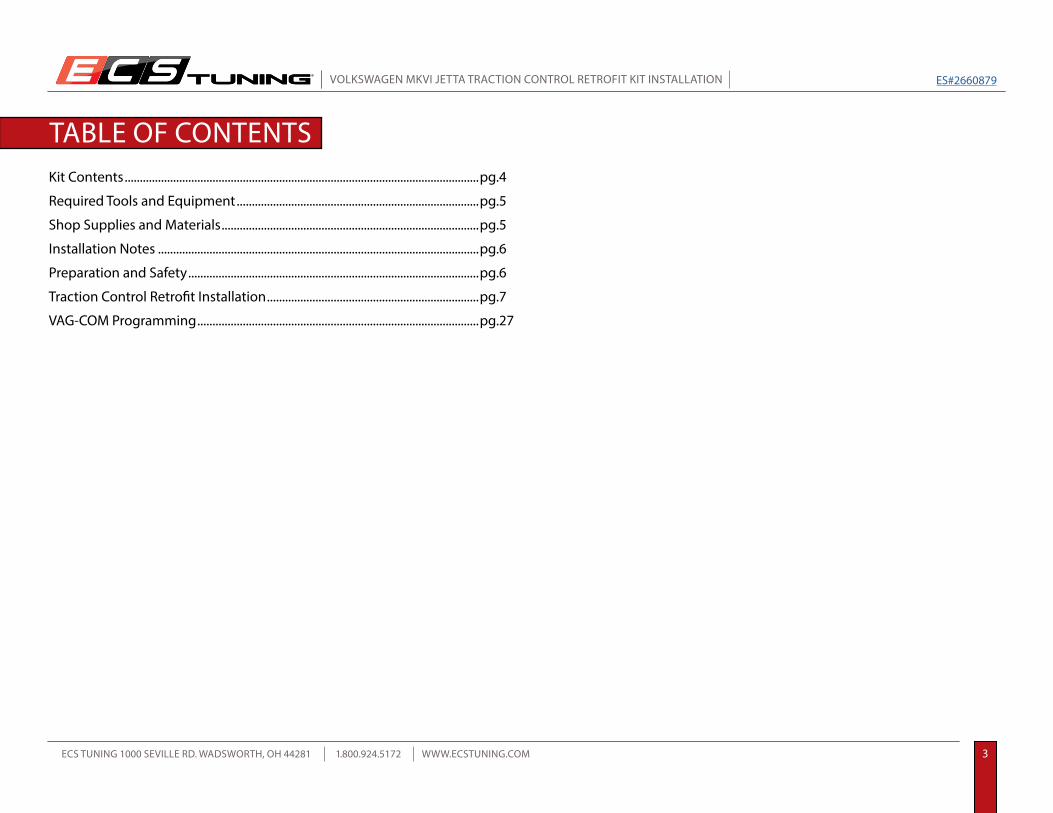
TRACTION CONTROL RETROFIT KIT CONTENTS
Traction Control Harness Traction Control Switch T-taps (3)

R
VOLKSWAGEN MKVI JETTA TRACTION CONTROL RETROFIT KIT INSTALLATION
ECS TUNING 1000 SEVILLE RD. WADSWORTH, OH 44281 1.800.924.5172 WWW.ECSTUNING.COM 5
ES#2660879
REQUIRED TOOLSBelow is a list of the tools we used to install the Traction Control Refrofit kit. Be sure to have all tools on hand before beginning.
SHOP SUPPLIES AND MATERIALS• Hand Cleaner/Degreaser ..................................................................................... Available at ecstuning.com .................................................................ES#2167336• Shop Rags ............................................................................................................... Available at your local auto parts store• Electrical Tape ........................................................................................................ Available at your local auto parts store• Silicone Lubricant ................................................................................................. Available at your local auto parts store• Welding Rod or Coat Hanger about 3 Feet in length• Paper Clip
• Non-Marring Trim Tool ................................................................................................... Available at ecstuning.com ..........................................................................ES#2500877• Flat Blade Screwdriver(s) ............................................................................................... Available at ecstuning.com ..........................................................................ES#2225921• Spring Clamp Pliers (2.5 Liter Engine Cover Removal) ....................................... Available at ecstuning.com ..........................................................................ES#2702616• Torx Drivers: T20 ............................................................................................................... Available at ecstuning.com ..........................................................................ES#11417• Small Angled Pick• Bench Grinder• Slip Joint Pliers
Note: The tools required for each step will be listed by the step number throughout these instructions.

R
VOLKSWAGEN MKVI JETTA TRACTION CONTROL RETROFIT KIT INSTALLATION
ECS TUNING 1000 SEVILLE RD. WADSWORTH, OH 44281 1.800.924.5172 WWW.ECSTUNING.COM 6
ES#2660879
INSTALLATION NOTES• RH refers to the passenger side of the vehicle.• LH refers to the driver side of the vehicle.• Always use the proper torque specifications.• If applicable to this installation, torque specifications will be listed throughout the document and at the end as well.• Please read all of these instructions and familiarize yourself with the complete process before you begin.
GENERAL PREPARATION AND SAFETY INFORMATION
• Park your car in a safe, well lit, level area.• Shut the engine off and remove the key from the ignition switch.• Make sure any remote start devices are properly disabled.• Always wear safety glasses.• Make sure the parking brake is applied until the vehicle is safely lifted and supported.• If using an automotive lift, be sure and utilize the factory specified lift points. Lifting a vehicle in an incorrect location can cause damage to the suspension/running gear.• When lifting a vehicle using a jack, always utilize the factory specified lift points. Lifting a vehicle in an incorrect location can cause damage to the suspension/running gear. Always support the vehicle with jack stands.• Always read and follow all safety information and warnings for the equipment you are using.
Never get underneath a vehicle that is supported only by a jack. Always make sure that the vehicle is securely supported on jack stands.!
ECS Tuning cares about your health and safety. Please read the following safety information. This information pertains to automotive service in general, and while it may not pertain to every job you do, please remember and share these important safety tips.

R
VOLKSWAGEN MKVI JETTA TRACTION CONTROL RETROFIT KIT INSTALLATION
ECS TUNING 1000 SEVILLE RD. WADSWORTH, OH 44281 1.800.924.5172 WWW.ECSTUNING.COM 7
ES#2660879
In order to install the retrofit kit, you will need to access the ABS control unit. It is located on the RH (Passenger) side of the car, behind the engine, against the firewall. On some cars, such as this TDI model, you will have enough access without removing the engine cover.
TRACTION CONTROL RETROFIT KIT INSTALLATION
On some cars, such as this 2.5 Liter model, the engine cover is closer to the firewall and you may need to remove it to gain access to the ABS control unit.
The 2.5 Liter engine cover can be removed by disconnecting the intake tube at the Mass Air flow sensor, removing the intake duct from the air scoop on the front, then pulling it upwards off of it’s mounting grommets.
Step 1: ABS Unit Location
ABS Unit Location

R
VOLKSWAGEN MKVI JETTA TRACTION CONTROL RETROFIT KIT INSTALLATION
ECS TUNING 1000 SEVILLE RD. WADSWORTH, OH 44281 1.800.924.5172 WWW.ECSTUNING.COM 8
ES#2660879
Locate the ABS control unit slide lock connector (arrow).
Pull up on the slide lock. As you pull up on the slide lock, the connector will separate from the ABS Unit.
Step 2:
Step 3:
TRACTION CONTROL RETROFIT KIT INSTALLATION
Slide lock engaged (down) Slide lock disengaged (up)
R
VOLKSWAGEN MKVI JETTA TRACTION CONTROL RETROFIT KIT INSTALLATION
ECS TUNING 1000 SEVILLE RD. WADSWORTH, OH 44281 1.800.924.5172 WWW.ECSTUNING.COM 9
ES#2660879
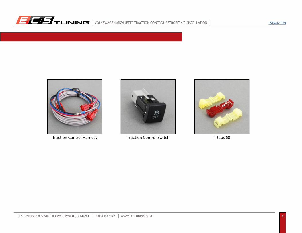
Step 4:
Step 5:
Pull the ABS connector up away from the ABS Unit so you can access it in order to install the signal wire from the kit.
The ABS connector cover is held in place by four small side hooks on the connector body (two on each side) and one large hook on the end of the cover itself. Remove it using the following procedure:
Small Angled Pick
TRACTION CONTROL RETROFIT KIT INSTALLATION
Some vehicles will have a plastic shield surrounding the ABS unit. You do not need to remove it. You can easily pull the connector out from underneath it.
NOTE
ABS connector
End Hook
End Hook
1. 2.
1. Spread the open end of the cover to release the cover tabs (1) from the first two side hooks.
2. Begin to pivot the cover upwards, then using a small pick pull the remaining cover tabs (2) outward to release them from the last two side hooks, then pivot it all the way up and unhook it at the end.
Side HookSide Hook

R
VOLKSWAGEN MKVI JETTA TRACTION CONTROL RETROFIT KIT INSTALLATION
ECS TUNING 1000 SEVILLE RD. WADSWORTH, OH 44281 1.800.924.5172 WWW.ECSTUNING.COM 10
ES#2660879
Step 6:
Step 7:
Moving inside the car to the RH (passenger) footwell, remove the two plastic retainers (arrows) and remove the foam insulation panel.
Note the location of the dashed arrow and proceed with the next step.
Look up under the dash and locate the wiring harness that exits the firewall near the ABS unit under the hood (the approximate location is indicated by the dashed arrow in step six).
TRACTION CONTROL RETROFIT KIT INSTALLATION Flat Blade Screwdriver
This is difficult to see, but once you have located it follow the harness all the way to the firewall with your fingers so you can feel the rubber boot that seals the harness where it exits the cabin. You will be running the signal wire through this boot. Now that you are familiar with it’s location, proceed with the next step.

R
VOLKSWAGEN MKVI JETTA TRACTION CONTROL RETROFIT KIT INSTALLATION
ECS TUNING 1000 SEVILLE RD. WADSWORTH, OH 44281 1.800.924.5172 WWW.ECSTUNING.COM 11
ES#2660879
Step 8:
Step 9:
Sharpen the end of a welding rod or coat hanger so it has a pointed tip. This will be used to pierce the rubber boot and also to pull the wire through from the cabin to the engine compartment.
Guide the pointed tip of your new piercing tool up to the rubber boot that you located in step seven, then push it through. Once it is through the boot, push about three to four inches into the engine compartment.
TRACTION CONTROL RETROFIT KIT INSTALLATION Welding Rod or Coat Hanger
This picture shows you the angle at which the piercing tool will be positioned. You will find that this will work very easily by feel - no need to strain your neck or back by trying to work under the dash.

R
VOLKSWAGEN MKVI JETTA TRACTION CONTROL RETROFIT KIT INSTALLATION
ECS TUNING 1000 SEVILLE RD. WADSWORTH, OH 44281 1.800.924.5172 WWW.ECSTUNING.COM 12
ES#2660879
Step 10:
Step 11:
Look under the hood near the ABS unit and you will see the end of the piercing tool right where you want it.
Grab the end of the piercing tool and pull it through about another 12 inches.
TRACTION CONTROL RETROFIT KIT INSTALLATION

R
VOLKSWAGEN MKVI JETTA TRACTION CONTROL RETROFIT KIT INSTALLATION
ECS TUNING 1000 SEVILLE RD. WADSWORTH, OH 44281 1.800.924.5172 WWW.ECSTUNING.COM 13
ES#2660879
Step 12:
Step 13:
Now get the Traction Control Harness from your kit and move back inside the car. Unbundle the harness and locate the long gray wire with the bare terminal on the end. Fold the wire as shown, then tape it securely to the piercing tool. Make sure the terminal on the end is covered with tape so it does not snag the rubber boot as it passes through.
Make sure that the gray wire is uncoiled and not tangled in any way, then slowly pull the wire through the firewall until you have pulled enough through to reach the ABS unit connector.
Electrical Tape
Lubricate the electrical tape with a small amount of silicone spray.
Lube
TRACTION CONTROL RETROFIT KIT INSTALLATION

R
VOLKSWAGEN MKVI JETTA TRACTION CONTROL RETROFIT KIT INSTALLATION
ECS TUNING 1000 SEVILLE RD. WADSWORTH, OH 44281 1.800.924.5172 WWW.ECSTUNING.COM 14
ES#2660879
Step 14:
Step 15:
Untape the wire from the piercing tool.
The gray signal wire will be installed in the ABS connector in the cavity shown in the picture. Use the large brown wire as a reference point, then begin at the small brown wire just to it’s left (1). Count over to the eighth connector cavity. This is where the wire will be installed.
Note the white rubber plug that is installed in the empty cavity.
1.8.
TRACTION CONTROL RETROFIT KIT INSTALLATION

R
VOLKSWAGEN MKVI JETTA TRACTION CONTROL RETROFIT KIT INSTALLATION
ECS TUNING 1000 SEVILLE RD. WADSWORTH, OH 44281 1.800.924.5172 WWW.ECSTUNING.COM 15
ES#2660879
Step 16:
Step 17:
Flip the connector over and locate the same cavity on the terminal side.
Straighten a paper clip and push the white rubber plug out of cavity eight.
Paper Clip
1.8.
The numbers used here for wire location are used for ease of identification and are not related to any factory numbering or markings on the connector housing.
NOTE
TRACTION CONTROL RETROFIT KIT INSTALLATION
R
VOLKSWAGEN MKVI JETTA TRACTION CONTROL RETROFIT KIT INSTALLATION
ECS TUNING 1000 SEVILLE RD. WADSWORTH, OH 44281 1.800.924.5172 WWW.ECSTUNING.COM 16
ES#2660879
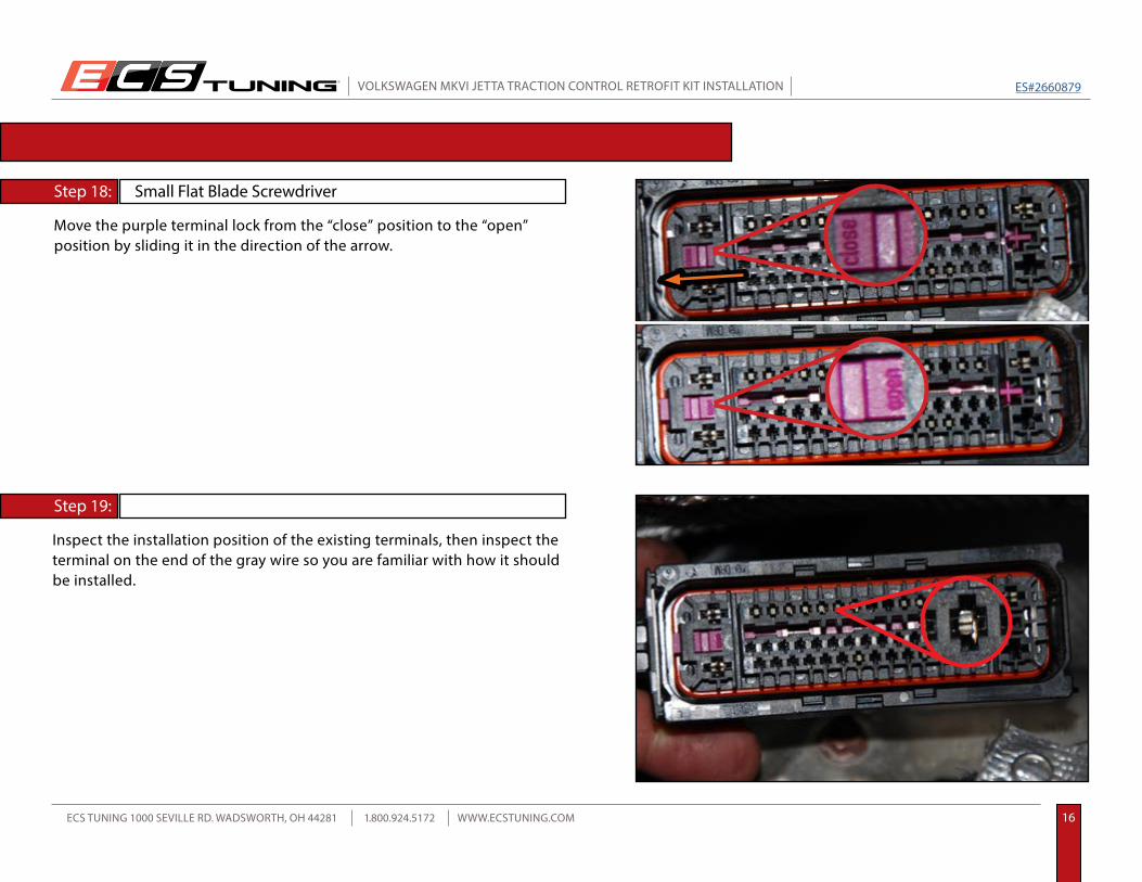
Step 18:
Step 19:
Move the purple terminal lock from the “close” position to the “open” position by sliding it in the direction of the arrow.
Inspect the installation position of the existing terminals, then inspect the terminal on the end of the gray wire so you are familiar with how it should be installed.
Small Flat Blade Screwdriver
TRACTION CONTROL RETROFIT KIT INSTALLATION
R
VOLKSWAGEN MKVI JETTA TRACTION CONTROL RETROFIT KIT INSTALLATION
ECS TUNING 1000 SEVILLE RD. WADSWORTH, OH 44281 1.800.924.5172 WWW.ECSTUNING.COM 17
ES#2660879
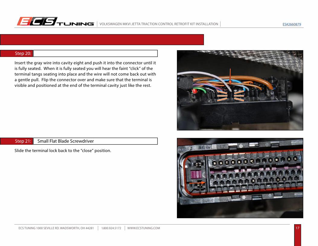
Step 20:
Step 21:
Slide the terminal lock back to the “close” position.
Small Flat Blade Screwdriver
TRACTION CONTROL RETROFIT KIT INSTALLATION
Insert the gray wire into cavity eight and push it into the connector until it is fully seated. When it is fully seated you will hear the faint “click” of the terminal tangs seating into place and the wire will not come back out with a gentle pull. Flip the connector over and make sure that the terminal is visible and positioned at the end of the terminal cavity just like the rest.

R
VOLKSWAGEN MKVI JETTA TRACTION CONTROL RETROFIT KIT INSTALLATION
ECS TUNING 1000 SEVILLE RD. WADSWORTH, OH 44281 1.800.924.5172 WWW.ECSTUNING.COM 18
ES#2660879
Step 22:
Step 23:
Hook the connector cover back onto the end of the connector, then push it back onto the four hooks until it is locked in place. Make sure the gray wire does not get pinched and runs out the open end of the connector.
Reconnect the ABS connector to the ABS control unit, then secure the gray wire in place along side the ABS harness using a wire tie.
TRACTION CONTROL RETROFIT KIT INSTALLATION

R
VOLKSWAGEN MKVI JETTA TRACTION CONTROL RETROFIT KIT INSTALLATION
ECS TUNING 1000 SEVILLE RD. WADSWORTH, OH 44281 1.800.924.5172 WWW.ECSTUNING.COM 19
ES#2660879
Step 24:
Step 25:
Gently pull the gray wire into the car to remove any extra slack. Your work is complete under the hood and you are ready for the installation inside the car. Reinstall the engine covers if they have been removed.
Pull up on the shifter trim/shift boot to release it from the console.
TRACTION CONTROL RETROFIT KIT INSTALLATION

R
VOLKSWAGEN MKVI JETTA TRACTION CONTROL RETROFIT KIT INSTALLATION
ECS TUNING 1000 SEVILLE RD. WADSWORTH, OH 44281 1.800.924.5172 WWW.ECSTUNING.COM 20
ES#2660879
Step 26:
Step 27:
Lift the shifter trim/shift boot above the shifter knob and move the shift lever into a rearward position so you can access the front storage tray, then remove the two hold down screws (arrows).
Lift the front storage tray upwards to access the start button and power outlet connectors underneath. Disconnect both connectors (they both have simple press-in release tabs), then remove the storage tray from the console.
T20 Torx
TRACTION CONTROL RETROFIT KIT INSTALLATION
Some vehicles may have an additional auxilliary port that you will have to disconnect.
NOTE

R
VOLKSWAGEN MKVI JETTA TRACTION CONTROL RETROFIT KIT INSTALLATION
ECS TUNING 1000 SEVILLE RD. WADSWORTH, OH 44281 1.800.924.5172 WWW.ECSTUNING.COM 21
ES#2660879
Step 28:
Step 29:
Route the Traction Control Harness through the back side of the console and into the space underneath the storage tray.
Carefully trim about one inch of electrical tape away from the wires on the power outet connector.
Razor Blade
TRACTION CONTROL RETROFIT KIT INSTALLATION

R
VOLKSWAGEN MKVI JETTA TRACTION CONTROL RETROFIT KIT INSTALLATION
ECS TUNING 1000 SEVILLE RD. WADSWORTH, OH 44281 1.800.924.5172 WWW.ECSTUNING.COM 22
ES#2660879
Step 30:
Step 31:
Locate the two yellow T-taps from the installation kit. The T-taps work in the following manner:
Install one yellow T-tap onto the Red/Black wire for the power outlet and one yellow T-tap onto the Brown wire for the power outlet.
Slip Joint Pliers
TRACTION CONTROL RETROFIT KIT INSTALLATION
Blade
Insulator
1. The T-tap comes fully open as shown in the picture on the left. The insulator is the full length of the T-tap and the blade is located on only one side.
2. Begin to fold the T-Tap shut, then locate the wire you are connecting to so it is centered between the blade and the wire cups.
3. Close the T-tap so it is gripping the wire, then crimp it with a pair of slip joint pliers until it locks shut. The final crimp will cut the insulation and contact the wire core at the same time as it engages the lock.
Wire
R
VOLKSWAGEN MKVI JETTA TRACTION CONTROL RETROFIT KIT INSTALLATION
ECS TUNING 1000 SEVILLE RD. WADSWORTH, OH 44281 1.800.924.5172 WWW.ECSTUNING.COM 23
ES#2660879
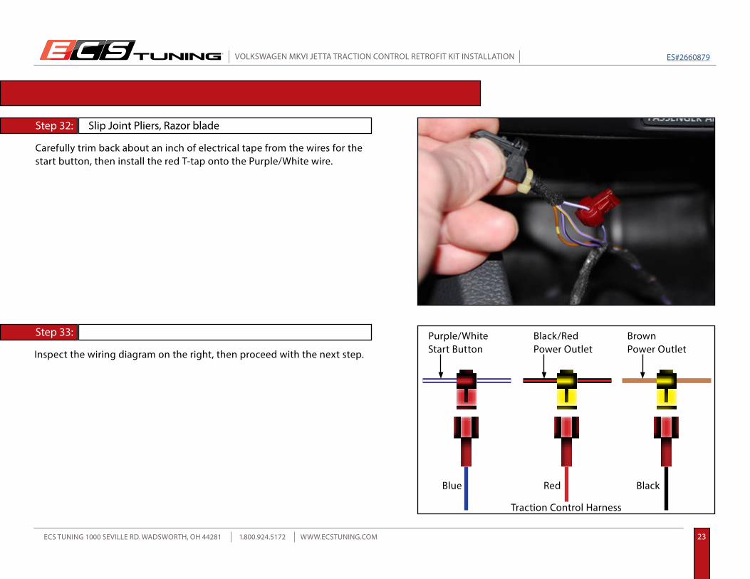
Step 32:
Step 33:
Carefully trim back about an inch of electrical tape from the wires for the start button, then install the red T-tap onto the Purple/White wire.
Inspect the wiring diagram on the right, then proceed with the next step.
Slip Joint Pliers, Razor blade
TRACTION CONTROL RETROFIT KIT INSTALLATION
Purple/WhiteStart Button
Black/RedPower Outlet
BrownPower Outlet
Traction Control Harness
Blue Red Black
R
VOLKSWAGEN MKVI JETTA TRACTION CONTROL RETROFIT KIT INSTALLATION
ECS TUNING 1000 SEVILLE RD. WADSWORTH, OH 44281 1.800.924.5172 WWW.ECSTUNING.COM 24
ES#2660879
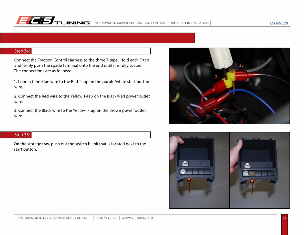
Step 34:
Step 35:
Connect the Traction Control Harness to the three T-taps. Hold each T-tap and firmly push the spade terminal onto the end until it is fully seated. The connections are as follows:
On the storage tray, push out the switch blank that is located next to the start button.
TRACTION CONTROL RETROFIT KIT INSTALLATION
1. Connect the Blue wire to the Red T-tap on the purple/white start button wire.
2. Connect the Red wire to the Yellow T-Tap on the Black/Red power outlet wire.
3. Connect the Black wire to the Yellow T-Tap on the Brown power outlet wire.
1.
2.
3.
R
VOLKSWAGEN MKVI JETTA TRACTION CONTROL RETROFIT KIT INSTALLATION
ECS TUNING 1000 SEVILLE RD. WADSWORTH, OH 44281 1.800.924.5172 WWW.ECSTUNING.COM 25
ES#2660879
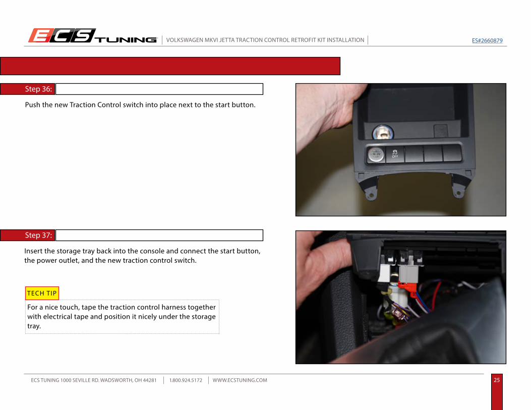
Step 36:
Step 37:
Push the new Traction Control switch into place next to the start button.
Insert the storage tray back into the console and connect the start button, the power outlet, and the new traction control switch.
TRACTION CONTROL RETROFIT KIT INSTALLATION
For a nice touch, tape the traction control harness together with electrical tape and position it nicely under the storage tray.
TECH TIP

R
VOLKSWAGEN MKVI JETTA TRACTION CONTROL RETROFIT KIT INSTALLATION
ECS TUNING 1000 SEVILLE RD. WADSWORTH, OH 44281 1.800.924.5172 WWW.ECSTUNING.COM 26
ES#2660879
Final Installation:
2. The intensity of the light should change with the dash lights when adjusted.
TRACTION CONTROL RETROFIT KIT INSTALLATION
Secure the gray sensor wire along the underside of the dash.
Reinstall the foam insulation panel.
Install the shifter boot.
Install the storage tray and screws.
Test the operation of your new Traction Control switch.
1. The switch should illuminate with the ignition on.
3. With the engine running, press and hold the Traction Control switch for about one or two seconds and the
“Traction Control Off” warning light will come on in the lower left hand side of the tachometer.
4. Each time the ignition is shut off, the traction control will automatically be active when the engine is started.
Some 2014 models may require VAG-COM programming in order for the traction control off feature to operate. If your traction control will not deactiviate, refer to page 27 for VAG-COM information.
NOTE

R
VOLKSWAGEN MKVI JETTA TRACTION CONTROL RETROFIT KIT INSTALLATION
ECS TUNING 1000 SEVILLE RD. WADSWORTH, OH 44281 1.800.924.5172 WWW.ECSTUNING.COM 27
ES#2660879
VAG-COM PROGRAMMING
The following information will change the long coding for the ABS system on your car. If you are not completely familiar with VAG-COM operation, we recommend you consult with a professional before proceeding.
CAUTION
VAG-COM Coding to allow for disabling of the traction control system:
Select “Long Coding Helper”.
Record your original long coding in case you need to return it to the original setting.
Select “Long Coding 07”.
Select “03-ABS Brakes”.
Your original long coding will be similar to this: A14B400C49240003851302E5921A0042A1100012
Byte 17 and Byte 19 of your new long coding will change: A14B400C49240003851302E5921A0042A1180022
Save the new long coding and exit VAG-COM.
Select Byte 19. The value will be 12. Uncheck Bit 4 and check Bit 5 and the value will change to 22.
Select Byte 17. The value will be 10. Check Bit 3 and the value will change to 18.
Test the operation of your new Traction Control switch.
Byte 19Byte 17
Byte 19Byte 17
When performing any type of coding, always connect a battery charger to prevent battery voltage from dropping too low, risking damage to your ECU.

These instructions are provided as a courtesy by ECS Tuning.
Your MKVI Jetta Traction Control Retrofit installation is complete!
Proper service and repair procedures are vital to the safe, reliable operation of all motor vehicles as well as the personal safety of those performing the repairs. Standard safety procedures and precautions (including use of safety goggles and proper tools and equipment) should be followed at all times to eliminate the possibility of personal injury or improper service which could damage the vehicle or compromise its safety.
Although this material has been prepared with the intent to provide reliable information, no warranty (express or implied) is made as to its accuracy or completeness. Neither is any liability assumed for loss or damage resulting from reliance on this material. SPECIFICALLY, NO WARRANTY OF MERCHANTABILITY, FITNESS FOR A PARTICULAR PURPOSE OR ANY OTHER WARRANTY IS MADE OR TO BE IMPLIED WITH RESPECT TO THIS MATERIAL. In no event will ECS Tuning, Incorporated or its affiliates be liable for any damages, direct or indirect, consequential or compensatory, arising out of the use of this material.
Related Documents