SPECIFICATION FOR PIPELINE PRE-COMMISSIONING AND COMMISSIONING OF PIPELINE PROJECT SPECIFICATION NO. MEC/S/05/62/61, R-1 (PROCESS & PIPELINE DESIGN SECTION) MECON LIMITED DELHI - 110 092

Welcome message from author
This document is posted to help you gain knowledge. Please leave a comment to let me know what you think about it! Share it to your friends and learn new things together.
Transcript
SPECIFICATION FOR
PIPELINE PRE-COMMISSIONING AND COMMISSIONING
OF PIPELINE PROJECT
SPECIFICATION NO. MEC/S/05/62/61, R-1
(PROCESS & PIPELINE DESIGN SECTION) MECON LIMITED DELHI - 110 092

MECON LIMITED REGD. OFF : RANCHI (BIHAR)
PROCESS & PIPING DESIGN SECTION
NEW DELHI
STANDARD SPECIFICATION
SPECIFICATION NO. PAGE 1 OF 8 TITLE PIPELINE PRE-COMMISSIONING
AND COMMISSIONING OF PIPELINE PROJECT MEC/S/05/62/61 REVISION 1
CONTENTS Sl.No. Description Page No. 1.0 INTRODUCTION 2 2.0 GENERAL 2 3.0 THE WORK 3 4.0 PRE-COMMISSIONING CHECKS 3 – 7 5.0 DOCUMENTATION 7 – 8
PREPARED BY CHECKED BY APPROVED BY

MECON LIMITED REGD. OFF : RANCHI (BIHAR)
PROCESS & PIPING DESIGN SECTION
NEW DELHI
STANDARD SPECIFICATION
SPECIFICATION NO. PAGE 2 OF 8 TITLE PIPELINE PRE-COMMISSIONING AND COMMISSIONING OF PIPELINE PROJECT MEC/S/05/62/61 REVISION - 1
1.0 INTRODUCTION This specification covers the minimum technical requirements for pre-
commissioning and commissioning of gas pipeline, including pre-commissioning activities such as pre-commissioning checks, flushing of terminal piping, dewatering, swabbing and nitrogen purging.
2.0 GENERAL The scope of work for testing and commissioning including pre-commissioning
activities shall include, but not limited to the manpower, machinery & equipment, detailed procedures, materials and consumables, communications etc. to perform the work satisfactorily.
Contractor shall prepare detailed procedures for flushing of terminal piping,
dewatering, swabbing, inertisation and commissioning of the pipeline, covering all aspects of work for company’s approval. This shall include, but not limited to, the sequence and description of all operations, data on materials, equipment, instruments, consumables, communications systems, necessary calculations, detailed time schedule and organisation chart.
The Contractor shall be responsible for demonstrating the successful
completion of all the activities i.e. flushing of terminal piping, dewatering, swabbing, inertisation and commissioning of the pipeline. All necessary work to perform the job successfully including necessary modifications required shall be the responsibility of the Contractor.
Contractor shall design and supply all temporary line connections, valves,
instruments, etc. as required during the various operations. In the event of any detail which is not fully addressed, it is warranted by
Contractor that work shall be performed in accordance with company’s specification and the best recognised practices in the on-shore pipeline industry.
MECON LIMITED REGD. OFF : RANCHI (BIHAR)
PROCESS & PIPING DESIGN SECTION
NEW DELHI
STANDARD SPECIFICATION
SPECIFICATION NO. PAGE 3 OF 8 TITLE PIPELINE PRE-COMMISSIONING AND COMMISSIONING OF PIPELINE PROJECT MEC/S/05/62/61 REVISION – 1
3.0 THE WORK The work to be performed by the Contractor shall consist of the following
activities : Pre-commissioning : Entire pipeline project shall be checked with respect
to latest P&ID’s and other design specification. Dewatering : Removal of hydrotest water from the entire pipeline
network system. Swabbing : Reducing the amount of remaining water in the
main pipeline system which is left behind after completion of the dewatering operations to make the pipeline free of water.
Inertisation : Inertising the entire pipeline with nitrogen. Commissioning : Charging the entire pipeline network with the
product and achieving normal operating conditions of the pipeline.
4.0 PRE-COMMISSIONING CHECKS 4.1 The pre-commissioning checks shall be carried out for the pipeline to ascertain
that the pipeline system has been mechanically completed in all respects. These checks shall cover the main pipeline including distribution network system and sectionalising valve stations. The pre-commissioning checks shall include the following:
i) System Checks The entire facilities shall be checked against the latest P&ID’s and other
design specification codes.
MECON LIMITED REGD. OFF : RANCHI (BIHAR)
PROCESS & PIPING DESIGN SECTION
NEW DELHI
STANDARD SPECIFICATION
SPECIFICATION NO. PAGE 4 OF 8 TITLE PIPELINE PRE-COMMISSIONING AND COMMISSIONING OF PIPELINE PROJECT MEC/S/05/62/61 REVISION - 1
ii) Checking of Field Instruments All the field instruments like control valves, sectionalising valves,
transmitters, solenoid valves, shut down switches, alarms etc. shall be checked physically and also for their intended application by simulating the operating conditions. It will also include checking of different meters, gauges action of shutdown valves etc. as applicable.
iii) Survey of the Pipelines This shall be performed to confirm that proper fittings/ supports, route
markets, fencing around SV Stations etc. have been intalled along the pipeline.
iv) Checking of Communications System This is to check that there is proper communications with adequate
back-up power to ensure uninterrupted communication. v) Checking of Electrical Distribution System This is to ensure safety and also to ensure an uninterrupted power
supply during startup and normal pipeline operation. vi) Checking of Instruments, Controls & Interlocks This is to check that instrument controls and interlocks are functional as
per the normal operating conditions. vii) Checking of Utilities This is to check that utilities like power, nitrogen, UPS system
instrument air, etc. are available prior to startup. viii) Any other checks as may be considered necessary.

MECON LIMITED REGD. OFF : RANCHI (BIHAR)
PROCESS & PIPING DESIGN SECTION
NEW DELHI
STANDARD SPECIFICATION
SPECIFICATION NO. PAGE 5 OF 8 TITLE PIPELINE PRE-COMMISSIONING AND COMMISSIONING OF PIPELINE PROJECT MEC/S/05/62/61 REVISION - 1
4.2 DEWATERING 4.2.1 General During the dewatering operation the major quantity of hydrotest water shall be
removed from the main pipeline and distribution network. It is the responsibility of the Contractor to develop suitable dewatering procedure and submit for Company’s approval.
The disposal of the water shall be performed such that no harm is done to the
environment. 4.2.2 Operational Requirements The dewatering operation shall consist of number of dewatering pig runs when
air is used as propellant for pig trains. Bi-directional cup pigs shall be used and will be suitable for traversing the
entire length of the pipeline/ pipe segment being dewatered. Contractor shall ensure that all the pigs are designed to prevent damage to the pipeline internal coating, if any.
The Contractor shall propose the minimum speed and the back pressure of the
pigs in order that continuous operation will be performed without the pig getting stuck. Contractor shall submit all the calculations regarding this procedure and a contingency plan for implementation in case the pigs get stuck.
Contractor shall provide a suitable compressor for oil-free air with sufficient
capacity and pressure. Upon arrival of the pigs at the receiving end the Contractor in the presence of
Company’s representative shall remove the pigs without delay.
MECON LIMITED REGD. OFF : RANCHI (BIHAR)
PROCESS & PIPING DESIGN SECTION
NEW DELHI
STANDARD SPECIFICATION
SPECIFICATION NO. PAGE 6 OF 8 TITLE PIPELINE PRE-COMMISSIONING AND COMMISSIONING OF PIPELINE PROJECT MEC/S/05/62/61 REVISION – 1
4.2.3 Acceptance Criteria Before proceeding to the next stage of the inertisation operation Contractor
shall ensure that bulk of the water has been removed from the pipeline. Contractor shall specify when the dewatering phase if finished and shall obtain approval of the company before proceeding to the next inertisation phase.
4.3 Swabbing 4.3.1 General The swabbing operation is meant to reduce the remaining water in the pipeline
to bring the pipeline into touch dry condition. Swabbing operation shall be carried out to ensure that there is no free water
left inside the pipeline. This is done by driving number of swabbing pigs so that the weight increase in pig before and after the swabbing operation is not more then 25%. The Contractor shall submit the detailed procedure along with the duration of the swabbing operation and obtain approval of the company before starting the operation.
4.3.2 Acceptance Criteria The Contractor shall ensure that the swabbing operation is considered to be
completed when it is established that there is no free water left in the pipeline and the pipeline has achieved a touch dry condition. This shall be subject to company’s approval.
4.4 Inertisation During the inertisation operation, the air left in the pipeline shall be replaced by
nitrogen before admitting the product natural gas that the pipeline will ultimately carry.

MECON LIMITED REGD. OFF : RANCHI (BIHAR)
PROCESS & PIPING DESIGN SECTION
NEW DELHI
STANDARD SPECIFICATION
SPECIFICATION NO. PAGE 7 OF 8 TITLE PIPELINE PRE-COMMISSIONING AND COMMISSIONING OF PIPELINE PROJECT MEC/S/05/62/61 REVISION - 1
The inertisation operation shall start as soon as possible after the swabbing
operation has been completed and approved by the company. Contractor shall submit the detailed purging procedure for approval for the company prior to its implementation.
Nitrogen needed for inertisation of the pipeline, shall be provided by the
Contractor. The maximum allowable oxygen content inside the pipeline shall be less than 1% by volume.
Multiple separation pigs with nitrogen slugs in between shall be used for
pipeline commissioning. At least three batches of nitrogen separated by four separation pigs shall be used for inertisation of the pipeline during charging of gas in it. The combined nitrogen column length to be used for inertisation should be at least 5% of the total pipeline length.
4.4.1 Safety Review before start of commissioning A pre-startup safety review shall be carried out of the pipeline system before
permitting entry of natural gas into the new facility. Owner/ Owner’s representative shall also participate in the pre-startup safety review.
4.5 COMMISSIONING 4.5.1 General Commissioning of pipeline shall be considered completed when the line is
charged with product natural gas at operating pressure and the total system operated at normal operating parameters for a minimum period of 72 hours with all the instruments, controls and interlocks working satisfactorily at normal operating conditions. Contractor shall submit a detailed commissioning procedure for company’s approval.
5.0 DOCUMENTATION Contractor shall submit for approval of the company the complete description,
detailed procedure and time schedule of all the dewatering, swabbing, purging and commissioning operations, as applicable.
MECON LIMITED REGD. OFF : RANCHI (BIHAR)
PROCESS & PIPING DESIGN SECTION
NEW DELHI
STANDARD SPECIFICATION
SPECIFICATION NO. PAGE 8 OF 8 TITLE PIPELINE PRE-COMMISSIONING AND COMMISSIONING OF PIPELINE PROJECT MEC/S/05/62/61 REVISION - 1
Documents shall also contain all procedures and safety plans to be followed
while carrying out the activities. Upon successful completion of the work, Contractor shall prepare a final report
of the work which shall include necessary charts, diagrams, graphs, calculations, recordings, daily logs, measurements, details of the operation, etc. Report shall also include all certificates of calibration of instruments required together with records of calibration performed at site prior to the start of any operation.
5.1 Spares and Consumables Supply of spares, tools and consumables for start-up & commissioning. 5.2 Safety Follow the safety practice during execution of pre-commissioning/
commissioning works as detailed in the scope of work. Maintain and follow all safety practices equivalent or better than those being practiced for the pipeline during pre-commissioning and commissioning.

D:\old data\Vijyant\GSPL\Tender\Const\Vol II of V\spec\pdf\PDF Final\63 Specification - CPT of U-G Steel PL.doc
SPECIFICATIONFOR
CORROSION PROTECTION COALTARBASED TAPECOATING OF
UNDERGROUND STEEL PIPELINESFOR WATER SERVICE
SPECIFICATION NO. MEC/S/05/62/63
(PROCESS & PIPELINE DESIGN SECTION)
MECON LIMITEDDELHI - 110 092

D:\old data\Vijyant\GSPL\Tender\Const\Vol II of V\spec\pdf\PDF Final\63 Specification - CPT of U-G Steel PL.doc
MECON LIMITEDREGD. OFF : RANCHI (BIHAR)
PROCESS & PIPINGDESIGN SECTION
NEW DELHI
STANDARD SPECIFICATION
SPECIFICATION NO. PAGE 1 OF 15TITLE CORROSION PROTECTIONCOALTAR BASED TAPECOATINGOF UNDERGROUND STEELPIPELINES FOR WATER SERVICE
MEC/S/05/62/63 REVISION 0
CONTENTS
Sl.No. Description Page No.
1.0 SCOPE 2
2.0 REFERENCE DOCUMENTS 2
3.0 GENERAL REQUIREMENTS 2
4.0 DOCUMENTATION 3
5.0 MATERIALS 4
6.0 SURFACE PREPARATION 8
7.0 APPLICATION OF PRIMER 8
8.0 TAPE COATING SYSTEM AND APPLICATION 8
9.0 INSPECTION AND TESTING FOR QUALITY ASSURANCE 9
ANNEXURE-I 12
PREPARED BY CHECKED BY APPROVED BY
D:\old data\Vijyant\GSPL\Tender\Const\Vol II of V\spec\pdf\PDF Final\63 Specification - CPT of U-G Steel PL.doc
MECON LIMITEDREGD. OFF : RANCHI (BIHAR)
PROCESS & PIPINGDESIGN SECTION
NEW DELHI
STANDARD SPECIFICATION
SPECIFICATION NO. PAGE 2 OF 15TITLE CORROSION PROTECTIONCOALTAR BASED TAPECOATINGOF UNDERGROUND STEELPIPELINES FOR WATER SERVICE
MEC/S/05/62/63 REVISION - 0
TECHNICAL SPECIFICATION FOR CORROSION PROTECTIONTAPECOATING OF UNDER GROUND STEEL PIPELINES
1.0 SCOPE
This specification covers the requirements for materials, surface preparation,application, inspection, repair and handling for external corrosion protectiontapecoating, in situ of underground steel pipelines with service temperatureupto 60°, using coaltar based tapecoating materials conforming to AWWA C-203 (1991).
2.0 REFERENCE DOCUMENTS
The latest edition of the following standards and documents shall apply:
2.1 AWWA C-203 (1991): Coal tar protective coatings and linings for steel waterpipelines.
2.2 Doc: MTD 24 (3624) BIS: Draft Indian Standard specification for coaltar basedAnticorrosion tape for protection of underground mild steel pipelines.
2.3 SIS-05-5900 “Pictorial surface preparation standard for painting steel surface”.Or ISO-8501-1988
2.4 SSPC-SP steel structure painting council surface preparation specifications.
SSPC-SP1 Solvent CleaningSSPC-SP3 Power Tool CleaningSSPC-SP10 Near White Metal Blast Cleaning
3.0 GENERAL REQUIREMENTS
3.1 Equipments and accessories required for tape coating shall be in goodoperating conditions at least for completion of the the coating job. Adequacyof equipments and accessories shall be approved by the Engineer-in-charge.
3.2 Necessary arrangements for power supply and other utilities shall be for madethe completion of the job.

D:\old data\Vijyant\GSPL\Tender\Const\Vol II of V\spec\pdf\PDF Final\63 Specification - CPT of U-G Steel PL.doc
MECON LIMITEDREGD. OFF : RANCHI (BIHAR)
PROCESS & PIPINGDESIGN SECTION
NEW DELHI
STANDARD SPECIFICATION
SPECIFICATION NO. PAGE 3 OF 15TITLE CORROSION PROTECTIONCOALTAR BASED TAPECOATINGOF UNDERGROUND STEELPIPELINES FOR WATER SERVICE
MEC/S/05/62/63 REVISION - 0
3.3 Necessary testing and inspection facilities as required by this standard shall bedeveloped at site and shall be approved by the Engineer-in-charge.
3.4 Protective tapes and other materials brought to site shall be as per thespecifications of this standard and should be approved by the Engineer-in-Charge.
Field and laboratory tests as given in this standard shall be carried out for eachbatch of primer and tape.
3.5 All work shall be carried out in accordance with this specification and shall bephase wise approved by the Engineer-in-Charge. Any working procedurecomputed from this specification shall be approved in advance by theEngineer-in-Charge.
3.6 Manufacturers recommended supervisor and skilled applicator shall beengaged by the Contractor for application, inspection and quality assurance.
3.7 Manufacture shall possess copy of reference documents and test procedureappearing in this standard.
4.0 DOCUMENTATION
The following documentation is required :
4.1 A written quality plan with procedures for qualification trails and for the actualwork.
The quality plan shall include a time table for the various activities, with adescription of coating materials to be used, their application, qualification ofpersonal involved in the work, responsibilities and lines of communications,details of equipment and their calibration, proposed hold points for company’sinspection and endorsement and the detailed procedures for the testing andinspection.
4.2 Daily progress reports with details on weather conditions, particulars ofapplication, e.g. blast cleaning, number of wraps and type of materials applied,anomalies and progress of work versus programme.

D:\old data\Vijyant\GSPL\Tender\Const\Vol II of V\spec\pdf\PDF Final\63 Specification - CPT of U-G Steel PL.doc
MECON LIMITEDREGD. OFF : RANCHI (BIHAR)
PROCESS & PIPINGDESIGN SECTION
NEW DELHI
STANDARD SPECIFICATION
SPECIFICATION NO. PAGE 4 OF 15TITLE CORROSION PROTECTIONCOALTAR BASED TAPECOATINGOF UNDERGROUND STEELPIPELINES FOR WATER SERVICE
MEC/S/05/62/63 REVISION - 0
4.3 Documented evidence that the requirements of this specification have beenmet during production trials as well as during the work.
The documentation shall include:-
• Results of comparison of surface cleanliness, surface profile on blastcleaned surface, tape coating thickness, holiday detection and adhesiontests.
• Particulars of surface preparation, priming and tape application.
• Details of non-compliance rejects and repairs.
• Types of testing equipments and calibration.
• Code and batch numbers of coating materials used
• Field tests on primers and tape coat.
5.0 MATERIALS
5.1 General Requirements
5.1.1 Manufacturer’s test certificates shall be produced and examined by theEngineer-in-Charge for all materials, proposed to be used for tapecoating asper this standard .
5.1.2 All materials brought to site for tapecoating shall be suitably marked andidentifiable with the following information:
• Manufacturer’s name• Type of material and code• Batch Number• Date of manufacturing/ expiry• Technical datasheet for each type of material• Shelf life

D:\old data\Vijyant\GSPL\Tender\Const\Vol II of V\spec\pdf\PDF Final\63 Specification - CPT of U-G Steel PL.doc
MECON LIMITEDREGD. OFF : RANCHI (BIHAR)
PROCESS & PIPINGDESIGN SECTION
NEW DELHI
STANDARD SPECIFICATION
SPECIFICATION NO. PAGE 5 OF 15TITLE CORROSION PROTECTIONCOALTAR BASED TAPECOATINGOF UNDERGROUND STEELPIPELINES FOR WATER SERVICE
MEC/S/05/62/63 REVISION - 0
• Manufacturer’s Quality control test certificates with actual results ofeach batch.
5.1.3 Materials without manufacturer’s test certificates and identification marks shallnot be accepted and used.
5.1.4 Test certificate from competent Govt. laboratory on the properties of materialsquoted by the manufacturer in the technical data sheet shall also be submittedalongwith the Technical data sheet of the products.
5.1.5 Each batch of primer and tape shall be tested in the field by the procedure asmentioned in this standard. Engineer-in-charge will review the field test databefore use of the materials.
5.2 Characteristics and FunctionalRequirements of coating materials.
5.2.1 Coal tar tapes
Materials for coal tar tapecoating shall conform to AWWA C-203 (1991).Following are the salient features of coal tar tapecoating materials.
5.2.1.1 Primer
The primer shall be type B as specified in AWWA C-203 (1991) Section 8.0.Following are the main characteristics:
• Type : Fast drying, synthetic, chlorinatedrubber-synthetic plasticizer-solventbased.
• Drying time : 5-15 mts. Test MethodASTM D1640-83/89
• Flash point : >23°C : ASTM D93-90/ D3941-90
• Volatile matter (105-110°C): 75 : ASTM D2369-90per cent by mass

D:\old data\Vijyant\GSPL\Tender\Const\Vol II of V\spec\pdf\PDF Final\63 Specification - CPT of U-G Steel PL.doc
MECON LIMITEDREGD. OFF : RANCHI (BIHAR)
PROCESS & PIPINGDESIGN SECTION
NEW DELHI
STANDARD SPECIFICATION
SPECIFICATION NO. PAGE 6 OF 15TITLE CORROSION PROTECTIONCOALTAR BASED TAPECOATINGOF UNDERGROUND STEELPIPELINES FOR WATER SERVICE
MEC/S/05/62/63 REVISION - 0
• Viscosity, on FORD : 35-60secs. ASTM D1200-88CUP No. 4: 4mmNozzle 23° C
• Coverage (theoretical) : 8-10M2/lit/coat
• Coverage (Practical) @ 25 : 8-10 M2/Lit/Coat ASTM D344-89Microns DFT coat
• Application properties : by brush/ Spray should producean effective bond between metal andsubsequent coaltar tape.
• Adhesion test : The primer shall be tested afterapplying Tapecoating as perAWWAC-203 (1991).
5.2.1.2 Coal Tar Tape
a) The tape shall be coal-tat component supported on fabric oforganic or Inorganic fibres.
The coal tar (hard pitch) component shall be produced from coal thathas a minimum heating value of 13000 BtU/lb (7.223 x 10⁶ Cal/Kg) on amoisture and mineral matter free basis (ASTM D 388) and that hasbeen carbonised in a slot-type coke even at a temperature of not lessthan 900°C. The coal tar (hard pitch) shall have the following salientproperties:
Softening Point °C 65 121 ASTM D 36-86
Specific gravity 1.124±0.03% ASTM D 71-94
Ash content 1.08% Max. ASTM D2415-66 (1991)
Trichloroethylene insoubleContent% by wt: 35-40% (IS-1216-1978)
Petrol insoluble content % by wt: 90-95% (by IS:1216-1978 procedure)

D:\old data\Vijyant\GSPL\Tender\Const\Vol II of V\spec\pdf\PDF Final\63 Specification - CPT of U-G Steel PL.doc
MECON LIMITEDREGD. OFF : RANCHI (BIHAR)
PROCESS & PIPINGDESIGN SECTION
NEW DELHI
STANDARD SPECIFICATION
SPECIFICATION NO. PAGE 7 OF 15TITLE CORROSION PROTECTIONCOALTAR BASED TAPECOATINGOF UNDERGROUND STEELPIPELINES FOR WATER SERVICE
MEC/S/05/62/63 REVISION - 0
b) Physical properties of coaltar tape
Property Requirement Test MethodMin - Max
Service temperature °C - 60
Tape thickness mm 2.0 2.5 Section 8.11.3 ofAWWA C-203
Weight average 1.25kg/sq.m/mm ASTM D146
Breaking strength in long 0.7 (min.) AWWA C-203longitudinal direction kN/m 10.3.1.2.5
Adhesion To pass test as per BIS.DOC.SMDC.29(3624) or8.11.2 of AWWA C-203
c) Physical properties of coal tar component in the tape:
Softening point °C 65 121 ASTM D36-86
Penetration at 25C/100g/ 3 20 AWWA C-20310-1 mm/5 Sec See 8.11.5 (or) ASTM D-5
Filler % 20 30 ASTM D 2415 or AWWAC-203 See 8.11.6
d) Type: The fabric shall be a thin, flexible, uniform mat or tissuecomposed of glass fibers in an open structure bonded with a suitableresinous inert material compatible with coaltar.
Weight (min) g/m2 : 40Thickenss (min) mm : 0.3
Note: (1) manufacture’s test data in the laboratory are required for theabove properties on the materials supplied
D:\old data\Vijyant\GSPL\Tender\Const\Vol II of V\spec\pdf\PDF Final\63 Specification - CPT of U-G Steel PL.doc
MECON LIMITEDREGD. OFF : RANCHI (BIHAR)
PROCESS & PIPINGDESIGN SECTION
NEW DELHI
STANDARD SPECIFICATION
SPECIFICATION NO. PAGE 8 OF 15TITLE CORROSION PROTECTIONCOALTAR BASED TAPECOATINGOF UNDERGROUND STEELPIPELINES FOR WATER SERVICE
MEC/S/05/62/63 REVISION - 0
6.0 SURFACE PREPARATION
6.1 All oil, grease on the pipe metal surface shall be thoroughly removed byflushing with a suitable solvent (such as xylene or 1,1,1 trichloroethylene) andwiping with clean rags. The solvent cleaning shall be as per SSPC-SP-1. Ifrequired detergent cleaning shall be done before or after solvent cleaning.
6.2 The degreased pipe metal-surface shall be blast cleaned to Sa 2½ of SIS055900 or SSPC-SP-10. Blasted surface that rusts before priming shall becleaned by wire brushing or shall be reblasted. Priming shall be done within 4hours of completion of blast cleaning. Otherwise total reblasting may benecessary.
7.0 APPLICATION OF PRIMER
One coat of primer shall be applied on blast cleaned surface by brush or sprayto achieve wet film thickness as recommended by the manufacturer. In casethe surface is wet during application of primer the surface should be made dry.The primer shall be allowed to become touch dry prior to tape application.Primer and tape shall be furnished by the same manufacturer.
8.0 TAPE COATING SYSTEM AND APPLICATION
8.1 Type coating system:
a) One coat to fast drying synthetic primer @ 25 microns DFT/ coat bybrush or spray after surface preparation.
b) One layer of coal tar Tape coating with 2mm thickness on the surface ofprimed pipe after touch dry.
c) Second coat of fast drying synthetic primer @ 25 microns DFT / Coat bybrush or spray on 1st layer of tape coating.
d) Second layer of coaltar tape coating with 2mm thickness on the surfaceof primed pipe after touch dry.
D:\old data\Vijyant\GSPL\Tender\Const\Vol II of V\spec\pdf\PDF Final\63 Specification - CPT of U-G Steel PL.doc
MECON LIMITEDREGD. OFF : RANCHI (BIHAR)
PROCESS & PIPINGDESIGN SECTION
NEW DELHI
STANDARD SPECIFICATION
SPECIFICATION NO. PAGE 9 OF 15TITLE CORROSION PROTECTIONCOALTAR BASED TAPECOATINGOF UNDERGROUND STEELPIPELINES FOR WATER SERVICE
MEC/S/05/62/63 REVISION - 0
8.2 Application Method:
Tape application should follow primer application as soon as the primed pipesurface is touch dry. The primer and tape application should not be done incase of dusty/ windy weather or during rains. Primed surface should not bekept exposed to atmosphere for very long duration.
The tape shall be wrapped in accordance with the manufacturer’srecommendations in a manner that shall meet the adhesion and holidaydetection requirement of this standard. In any event there shall be a minimumof 12.5mm overlap per single wrap.
The applied coating system shall be as follows:
a) In application care shall be taken that there are no air pockets orbubbles beneath tape and the tape shall be in intimate contact with theprimed steel.
b) Manufacturer recommended supervisor and skilled applicator shall beengaged for tape application.
9.0 INSPECTION AND TESTING FOR QUALITY ASSURANCE
The following stage wise inspection and testing shall be carried out atmanufacturer’s end/ at site by the owner or by owner’s representative thirdparty inspection agency.
9.1 Fast drying synthetic primer Materials:
As per the physical properties of 5.2.1.1 and procedure given in Annexure-I.
9.2 Tape Coating
As per 5.2.1.2 (b), (c) & (d) and procedure given in Annexure-I.
9.3 Measurement of pipe thickness.
D:\old data\Vijyant\GSPL\Tender\Const\Vol II of V\spec\pdf\PDF Final\63 Specification - CPT of U-G Steel PL.doc
MECON LIMITEDREGD. OFF : RANCHI (BIHAR)
PROCESS & PIPINGDESIGN SECTION
NEW DELHI
STANDARD SPECIFICATION
SPECIFICATION NO. PAGE 10 OF 15TITLE CORROSION PROTECTIONCOALTAR BASED TAPECOATINGOF UNDERGROUND STEELPIPELINES FOR WATER SERVICE
MEC/S/05/62/63 REVISION - 0
9.4 Surface preparation
• Blast cleaning equipment for nozzle type, size, Safety gauges, workingcondition, pressure at the tip of the gun.
• Abrassive type, hardness to provide required profile size andcleanliness.
• Measurement of surface profile and comparing cleanliness with Visualstandard of ISO:8501-1988.
9.5 Measurement of pitting depth area of pitted portion, inspection of weld fillingand grinding and patch plate welding, welding of replaced pipe if any.
9.6 Checking of condition of concrete saddles, Rubber padding and end sealswherever required.
9.7 Inspection of primer after application.
• Checking for drying time to be touch dry, tack free drying and harddrying of primer.
• Checking for hiding power of primer @ at 25 microns DFT.
9.8 Inspection of Tapecoating after application:
• Visual inspection for uniformity without any wrinkles and irregularitiesand overlapping width as per specification
• Adhesion test as per AWWA-C-203. (1991)
• H.V. Holiday detection test for pinholes as per AWWA-C-203. (1991)
9.9 Visual
The coated pipes including field joint coating shall be visually inspected forcracks, trapped air, uniformity, damage etc. Any repair arising out of visualinspection will be decided by Engineer-in-charge.
D:\old data\Vijyant\GSPL\Tender\Const\Vol II of V\spec\pdf\PDF Final\63 Specification - CPT of U-G Steel PL.doc
MECON LIMITEDREGD. OFF : RANCHI (BIHAR)
PROCESS & PIPINGDESIGN SECTION
NEW DELHI
STANDARD SPECIFICATION
SPECIFICATION NO. PAGE 11 OF 15TITLE CORROSION PROTECTIONCOALTAR BASED TAPECOATINGOF UNDERGROUND STEELPIPELINES FOR WATER SERVICE
MEC/S/05/62/63 REVISION - 0
9.10 Thickness
Thickness has to be measured with a caliper with caliper surfaces of at least20 mm diameter, on 5 tape pieces with an edge length of at least 50mm takenfrom 5 different coils. The measuring pressure should be 0.5N/m2. Themeasuring accuracy should be within 0.1mm.
9.11 Adhesion test
9.11.1 Adhesion tests shall be made to determine the proper bond between the tapeand the primed pipe. One test per section (of upto 10 meter length) shall becarried out initially afterwards adhesion test is to be done as per the advise ofthe ENGINEER IN CHARGE. Repair required due to adhesion testing shall bedecided by the Engineer-in-charge.
9.11.2 Temperature of the tape and pipe to be tested shall be between 10°C and27°C. if required cold water shall be poured over the test areas to bring downthe temperature to within the above range.
• A test area shall be selected where the tape is smooth for 152mm in thelongitudinal direction of the pipe.
• Two knife cuts of 152mm long and 51mm apart shall be made throughthe tape.
• A flat blade shall be used to pry up 51mm of the fabric.
• The 51mm flap of fabric shall be grasped firmly in one hand and shall bepulled with a quick motion in the direction of the remaining 102mm ofthe 152mm knife cut.
• The adhesion is satisfactory if (i) the tape tears at the point of strippingor (ii) the fabric strips so the underlying tape component, leaving nomore than 10% or less of the primer or bare metal exposed.
9.11.3 Adhesion between tape to tape can tested following similar procedure as in9.11.2. However, this should preferably be done on a test panel.

D:\old data\Vijyant\GSPL\Tender\Const\Vol II of V\spec\pdf\PDF Final\63 Specification - CPT of U-G Steel PL.doc
MECON LIMITEDREGD. OFF : RANCHI (BIHAR)
PROCESS & PIPINGDESIGN SECTION
NEW DELHI
STANDARD SPECIFICATION
SPECIFICATION NO. PAGE 12 OF 15TITLE CORROSION PROTECTIONCOALTAR BASED TAPECOATINGOF UNDERGROUND STEELPIPELINES FOR WATER SERVICE
MEC/S/05/62/63 REVISION - 0
ANNEXURE-I
1.0 PRIMER : (FAST DRYING CHLORINATED RUBBER BASED SYNTHETICPRIMER)
1.1 Test Method for volatile content (ASTM D2369-90)
Procedure : A specimen sample of primer 0.50 ± 0.10 gms is weighed into atared aluminum foil dish into which add 3 ml of solvent toluene technical gradeand disperse completely. Heat the above sample in the forced draft over for60 mins at 110°C ± 5°C. Remove the dishes from the oven place immediatelyin desicator, cool to R/T and weigh. Calculate the % volatile matter-V.
(W2 – W1) x 100V = -------------
S
Where W2 - Weight of Dish + SpecimenW1 - Weight of dish + Specimen after heating andS - Specimen Wt.
1.2 Test Method for Viscosity by Fordcup No. 4 (ASTM D1200-88)
The efflux time of primer is determined by fordcup no. 4 the cup is cleanedthoroughly by solvent toluene and a soft brush. Fill the cup with the primer tofull level by holding the orifice with a rubber stopper or finger. Pull thestopper away and simultaneously start the timer. Measure the time until thefirst break in the orifice. Measure the temperature of the fluid in the effluxstream. Report the efflux time in seconds at a measured temperature.
1.3 Test Method for Drying Time; (ASTM D1640-83/ 89) at AmbientTemperature
Apply the primer by brush on clean glass/ clean MS panels of suitable sizesand measure the drying time at normal R/T and 50% relative humidity withthe coated panels on horizontal position :
D:\old data\Vijyant\GSPL\Tender\Const\Vol II of V\spec\pdf\PDF Final\63 Specification - CPT of U-G Steel PL.doc
MECON LIMITEDREGD. OFF : RANCHI (BIHAR)
PROCESS & PIPINGDESIGN SECTION
NEW DELHI
STANDARD SPECIFICATION
SPECIFICATION NO. PAGE 13 OF 15TITLE CORROSION PROTECTIONCOALTAR BASED TAPECOATINGOF UNDERGROUND STEELPIPELINES FOR WATER SERVICE
MEC/S/05/62/63 REVISION - 0
i) Set-to-touch Time : Lightly touch the test film with the tip of cleanfinger and immediately place the finger tip against a piece of clean clearglass. Observe if any coating is transferred to the glass. The film is set-to-touch where it still shows a tacky condition, but none of it adheres tothe finger.
ii) Dust Free Time : The coating film is considered to have dried dust freewhen the cotton fibres can be removed by blowing lightly over thesurface of film.
iii) Tack Free Time : The film is considered free from after tack when thetest paper drops of the test film within 10 seconds.
2.0 Coal Tar Tape
2.1 Test Method for relative density of tape : (ASTM D71 954)
The test sample is suspended from a thin wire and weighed first in air, then inwater at 25°C in a glass beaker. The relative density is calculated from theseweights.
aRelative density of Tape Sample at 25°C = ------------
(a – b)Where
a - Weight of specimen in air in mg.b - Weight of specimen in water at 25°C in mg.
2.2 Test method for adhesion in laboratory : (AWWA-C-203) : Clean a section of 2inch dia. steel pipe of 2 ft. length or a flat steel panel of 2 inch x 6 inch. Primethe cleaned metal and apply a 2 inch width of tape as per manufacturer’srecommendations. The coating shall be allowed to set at room temperaturefor 18 hrs. After the test sample has completely set, grasp one end of the tapeand pull it off by hand. The coating is considered to have satisfactoryadhesion if (1) the fabric, tears at the point of stripping or (2) the fabric stripsfrom the under lying coating material having no more than approximately 10%or less of the primer or bare metal exposed.

D:\old data\Vijyant\GSPL\Tender\Const\Vol II of V\spec\pdf\PDF Final\63 Specification - CPT of U-G Steel PL.doc
MECON LIMITEDREGD. OFF : RANCHI (BIHAR)
PROCESS & PIPINGDESIGN SECTION
NEW DELHI
STANDARD SPECIFICATION
SPECIFICATION NO. PAGE 14 OF 15TITLE CORROSION PROTECTIONCOALTAR BASED TAPECOATINGOF UNDERGROUND STEELPIPELINES FOR WATER SERVICE
MEC/S/05/62/63 REVISION - 0
2.3 Test Method for % wt. loss in 24 hrs immersion of tape in TCE(Trichloro Ethylene) or Petrol
Weigh accurately about 100 gms (Wt. A) of a tape sample and put this samplein a clean and dry one litre capacity glass beaker. Pour enough TCE/ petrolinto the glass beaker so that the tape sample gets totally immersed in petrol.The level of petrol shall be about 5 cm above the tape sample.
Cover the month of the beaker with two layers of thick polyethylene sheetsand tie these polyethylene sheets with a rubber band around the mouth of theglass beaker. Allow the beaker to stand at room temperature for 24 hrswithout any disturbance. No stirring is to be done. Take the tape sample outof the the beaker after 24 hrs and spread it on blotting papers on a table,allow it to dry in the air for 4 hrs weigh the tape accurately again (Wt. B).
(A-B) x 100Loss in Wt. (%) = -----------
A%insoluble = 100-% Wt. loss.
Carryout the above test simultaneously with 3 more tape samples selected atrandom and take the average result.
The indicative loss for coal tar tape shall be 7% maximum.
2.4 Standard test method for relative density of solid hard pitch of coal :(ASTM D71-954). This test is applicable for testing at manufacturer’send
2.4.1 Summary of Test Method
The sample is suspended from a thin wire and weighed first in air, thensubmerged in water at 25°C. The relative density is calculated from theseweights.
ARelative density of sample at 25°C = ----------
(A – B)

D:\old data\Vijyant\GSPL\Tender\Const\Vol II of V\spec\pdf\PDF Final\63 Specification - CPT of U-G Steel PL.doc
MECON LIMITEDREGD. OFF : RANCHI (BIHAR)
PROCESS & PIPINGDESIGN SECTION
NEW DELHI
STANDARD SPECIFICATION
SPECIFICATION NO. PAGE 15 OF 15TITLE CORROSION PROTECTIONCOALTAR BASED TAPECOATINGOF UNDERGROUND STEELPIPELINES FOR WATER SERVICE
MEC/S/05/62/63 REVISION - 0
WhereA – Weight of specimens in air in mg.B – Weight of the specimen in water at 25°C in mg.
2.4.2 Procedure
Take the balance with a piece of 0.127 mg (5 ml) nichrome wire ormonofilament nylon line sufficiently long to reach from the hook on the pan.Support to the saddle when the latter is in position across the pan. Attach thetest specimen to the wire or line, so that it is suspended 20 to 30 mm abovethe saddle when the other end of the wire is attached to the hook.
Weigh the suspended specimen to the nearest 1 mg. and record this weight as“A”. Fill a 400 or 600 ml beaker two thirds full with freshly boiled distilledwater containing a small amount of detergent. About 100 mgs of alconoxdetergent to 200 ml of water has been found satisfactory. Adjust thetemperature of water to (25±2)°C and maintain this temperature during theremainder of the test. Place the beaker with water on the saddle with thespecimen, till suspended and fully submerged. Weigh the immersed specimento the nearest 1 mg, record this weight as “B”.
Repeat the determination with the second test specimen.
2.4.3 Report
Report the average of two determination to the third place, unless theindividual values differ by more than 0.005. In this case, repeat thedeterminations.

D:\Technical Specifications & Standards\Specification for HS & E(HSE)M - 65-3.doc
SPECIFICATIONFOR
HEALTH, SAFETYAND
ENVIRONMENT (HSE)MANAGEMENT
SPECIFICATION NO. : MEC/S/05/62/65
(PROCESS & PIPELINE DESIGN SECTION)
MECON LIMITEDDELHI - 110 092
D:\Technical Specifications & Standards\Specification for HS & E(HSE)M - 65-3.doc
C O N T E N T S
Clause No. Title Page No.
1.0 SCOPE 1
2.0 REFERENCE DOCUMENTS 1
3.0 HEALTH, SAFETY AND ENVIRONMENT (HSE) REQUIREMENTS 1 - 6
4.0 DETAILS OF HSE MANAGEMENT SYSTEM BY CONTRACTOR 6 - 7
ANNEXURES
1. ANNEX-A-RELEVANT I.S. CODES 8
2. ANNEX-B-REPORTING FORMATS – 5 NOS. 9 – 18
3. ANNEX-C-DO’s & DON’T’S ABOUT SAFETY ASPECTS AS PER FACTORIES ACT
D:\Technical Specifications & Standards\Specification for HS & E(HSE)M - 65-3.doc
1.0 SCOPE
This specification establishes the Healthy, Safety and Environment (HSE)management requirement to be compiled with by the Contractors duringconstruction.
Requirement stipulated in this specification shall supplement therequirement of HSE management given in relevant Act (S)/ legislations.General Condition of Contract (GCC) Special Condition of Contract (SCC)and Job Specifications. Where different documents stipulate differentrequirements, the most stringent shall be adopted.
2.0 REFERENCES
This document should be read in conjunction with following:
- General Conditions of Contract (GCC)- Special Conditions of Contract (SCC)- Job Specifications- Relevant IS Codes (refer Annexure-A)- Reporting Formats (refer Annexure-B)
3.0 REQUIREMENT OF HEALTH, SAFETY & ENVIRONMENT (HSE)MANAGEMENT SYSTEM TO BE COMPLETED BY BIDDERS.
3.1 Management Responsibility
3.1.1 The Contract should have a document HSE policy to cover commitment ofthe organization to ensure health, safety and environment aspects in theirline of operations
3.1.2 The HSE management system of the Contractor shall cover HSErequirement including but not limited to what specified under clause 1.0 &2.0 mentioned above
3.1.3 Contractor shall be fully responsible for planning and implementing HSErequirement to the satisfaction of the company. Contractor as a minimumrequirement shall designate/deploy the following to co-ordinate theabove:
No. Of workers deployedUp to 250 - Designate one safety supervisor who
will guide the workers from time to
D:\Technical Specifications & Standards\Specification for HS & E(HSE)M - 65-3.doc
time, as well as impart training basicguidelines at least weakly once.
Above 250 & upto 500 - Deploy one qualified and experiencedsafety Engineer/ Officer who will guidethe workers from time to time as well asimpart basic guideline & training at leastweakly once.
Above 500 - One additional safety engineer/Officer(for every 500 or less) whose function will be as mentioned
above
Contractor shall indemnify and hold harmless GAIL/ MECON & theirrepresentative’s from any and all liabilities arising out of non fulfillment ofHSE requirements.
3.1.4 The Contractor shall ensure that the Health, Safety and Environment(HSE) requirements are clearly understood & faithfully implemented at alllevels, at each and every site/ work place.
3.1.5 The Contractor shall promote and develop consciousness for Healthy,Safety and Environment among all personnel working for the Contractor.Regular awareness programs and fabrication shop/work site meeting shallbe arranged on HSE activities to cover hazards involved in variousoperations during construction.
3.1.6 Arrange suitable first aid measures such as First Aid Box, trainedpersonnel to give First Aid, Stand by Ambulance or Vehicle and install fireprotection measures such as: adequate number of steel buckets with sandand water and adequate fire extinguishers to the satisfaction of GAIL/MECON.
3.1.7 The Contractor shall evolve a comprehensive planned and documentedsystem for implementation and monitoring of the HSE requirements. Thisshall submitted to GAIL & MECON for approval well in advance, prior tostart of work. The monitoring for implementation shall be done by regularinspection and compliance to the observations thereof. The Contractorshall get similar HSE requirements implemented at his sub-contractor (s)work site/ Office. However, compliance of HSE requirement shall be thesole responsibility of the Contractor. Any review/ approval by GAIL/MECON shall not absolve the Contractor of his responsibility/ liability inrelation to all HSE requirements.

D:\Technical Specifications & Standards\Specification for HS & E(HSE)M - 65-3.doc
3.1.8 Non-Conformance on HSE by the Contractor (including his Sub-contractors) as brought out during review/ audit by MECON/ OWNERrepresentative shall be resolved forthwith by Contractor. Compliancereport shall be possibility submitted to MECON/ GAIL at the earliest.
3.1.9 The Contractor shall ensure participation of his Resident Engineer/Site-in-Charge in the Safety Committee/HSE Committee meetings arranged byGAIL/ MECON. The compliance of any observation shall be arrangedurgently. Contractor shall assist GAIL/MECON to achieve the targets set bythem on HSE during the project implementation.
3.1.10 The Contractor shall adhere consistently to all provisions of HSErequirements. In case of non-compliance or continuous failure inimplementation of any of HSE provisions; GAIL/ MECON may imposestoppage of work without any Cost & Time implication to Owner and/orimpose a suitable penalty for non-compliance with a notice of suitableperiod, upto a cumulative limit of 1.0% (one percent) of Contract valuewith a ceiling of Rs. 10 lakhs. This penalty shall be in addition to all otherpenalties specified else where in the contract. The decision of imposingstoppage of work, its extent & monitory penalty shall rest withMECON/GAIL & binding on the Contractor.
3.1.11 All fatal accidents and other personnel accidents shall be investigated by ateam of Contractor’s senior personnel for root cause and recommendcorrective and preventive actions. Findings shall documented and suitableactions taken to avoid recurrences shall be communicated toGAIL/MECON. GAIL/MECON shall have the liberty to independentlyinvestigate such occurrences and Contractor shall extend all necessaryhelp and co-operation in this regard.
3.2 House Keeping
3.2.1 Contractor shall ensure that a high degree of house keeping is maintainedand shall ensure the followings:
a. All surplus earth and debris are removed/disposed off from theworking site to identified location (s).
b. Unused/Surplus Cables Steel items and steel scrap lying scatteredat different places within the working areas are removed toidentified location (s).

D:\Technical Specifications & Standards\Specification for HS & E(HSE)M - 65-3.doc
c. All wooden scrap, empty wooden cable drums and othercombustible packing materials shall be removed from work place toidentified location(s).
d. Roads shall be kept clear and materials like pipes, steel, sand,boulders, concrete chips and bricks, etc. shall not be allowed in theroads to obstructs free movement of men & machineries.
e. Fabricated steel structurals, pipes & piping materials shall bestacked properly for erection.
f. Water logging on rods shall not be allowed.
g. No parking of trucks/ trolleys, cranes and trailors etc. shall beallowed on of roads, which may obstruct the traffic movements.
h. Utmost care shall be taken to ensure over all cleanliness and properup keep of the working areas.
i. Trucks carrying sand, earth and pulverized materials etc. shall becovered while moving within the plant areas.
3.3 Healthy, Safety and Environment
a) The Contractor shall provide safe means of access to any workingplace including provision of suitable and sufficient scaffolding atvarious stages during all operations of the work for the safety of hisworkmen, and GAIL/ MECON. Contractor shall ensure deploymentof appropriate equipment and appliances for adequate safety andhealthy of the workmen and protection of surrounding areas.
b) The Contractor shall ensure that all their staff workers includingtheir sub-Contractor (s) shall wear Safety Helmet and Safety shoes.Contractor shall also ensure use of safety belt, protective goggles,gloves etc. by the personnel as per jobs requirements. All thesegadgets shall conform to relevant IS specification equivalent.
c) Contractor shall ensure that a proper Safety Net System shall beused at appropriate locations. The safety net shall be located notmore than 30 feet (9.0 metrs) below the working surface at site toarrest or to reduce the consequences of possible fall of personsworking at different heights.
D:\Technical Specifications & Standards\Specification for HS & E(HSE)M - 65-3.doc
d) Contractor shall ensure that flash back arrester shall used whileusing gas Cylinders at site. Cylinders shall be mounted on trollys.
e) The Contractor shall assign to his workmen, tasks commensuratewith their qualification, experience and state of health for driving ofvehicles, handling and erections of materials and equipment’s. Alllifting equipments shall be tested certified for its capacity beforeuse. Adequate and suitable lighting at every work place andapproach there to shall be provided by the contractor beforestarting the actual work/ operation at night..
f) Hazardous and/or toxic material such as solvent coating or thinnersshall be stored in appropriate containers.
g) All hazardous materials shall be labeled with the name of thematerials, the hazards associated with its use and necessaryprecautions to be taken.
h) Contractor shall ensure that during the performance of the work allhazards to the health of personnel have been identified assessedand eliminated.
i) Chemical spills shall be contained & cleaned up immediately toprevent further contamination.
j) All personnel exposed to physical agents such as ionizing or non-ionizing radiation ultraviolet rays or similar other physical agentsshall be provided with adequate shielding or protectioncommensurate with type of exposure involved.
k) Where contract or exposure of hazardous materials could exceedlimits or could otherwise have harmful affects, appropriate personalprotective equipment’s such as gloves, goggles, aprons, chemicalresistant clothing and respirator shall be used
l) Contractor shall ensure the following facilities at work sites:
I) A Crèche where 10 or more female workers are havingchildren below the age of 6 years.
II) Reasonable Canteen facilities are made available atappropriate location depending upon site conditions.
D:\Technical Specifications & Standards\Specification for HS & E(HSE)M - 65-3.doc
m) Suitable facilities for toilet, drinking water, proper lighting shall beprovided at site and labor camps, commensurate with applicableLaws/Legislation.
n) Contractor shall ensure storage and utilization methodology ofmaterial that are not detrimental to the environment. Whereverrequired Contractor shall ensure that only the environment friendlymaterial are selected.
o) All person deployed at site shall be knowledgeable of and complywith the environmental laws, rules & regulation relating to thehazardous materials substance and wastes. Contractor shall notdump, release or otherwise discharge or dispose off any suchmaterials without the authorization of GAIL/ MECON.
4.0 DETAILS OF HSE MANAGEMENT SYSTEM BY CONTRACTOR
4.1 On Awards of Contract
The Contractor shall prior to start of work submit his Health. Safety andEnvironment Manual of procedure and HSE Plans for approval byGAIL/MECON. The Contractor shall participate in the pre-start meetingwith GAIL/MECON to finalize HSE plans including the following.
- Job procedure to be followed by Contractor for activities coveringHandling of equipment’s, Scaffolding, Electric Installation,describing the risks involved, actions to be taken and methodologyfor monitoring each.
- Organizations structure alongwith responsibility and authorityrecords/ reports etc. on HSE activities.
4.2 During job execution
4.2.1 Implement approved Health, Safety and Environment managementprocedure including but not limited to as brought our under para 3.0.Contractor shall also ensure to:
- Arrange workmen compensation insurance, registration under ESIAct, third party liability insurance etc. as applicable.
- Arrange all HSE permits before start of activities (as applicable) likeher work, confined space, work at heights, storage of
D:\Technical Specifications & Standards\Specification for HS & E(HSE)M - 65-3.doc
Chemicals/explosives materials and its use and implement allprecautions mentioned therein
- Submit timely the completed check list on HSE activities, MonthlyHSE report, accident report, investigation report, etc. as perGAIL/MECON requirements. Compliance of instructions on HSE shallbe done by Contractor and informed urgently to GAIL/MECON.
- Ensure that resident Engineers/Site-In-Charge of the Contractorshall amend all the Safety Committee/HSE meeting arranged byGAIL/ MECON only in case of his absence from site, a secondssenior most person shall be nominated by him in advance andcommunicated to GAIL/MECON.
- Display at site office and work locations caution boards, list ofhospitals for emergency services available.
- Provided posters, banners, for safe working to promote safetyconsciousness
- Carryout audits/inspection at sub Contractor work as per approvedHSE documents & submit the reports for GAIL/MECON review.
- Assistk in HSE audits by GAIL/ MECON and submit compliancereport.
- Generate & submit HSE records/ reports as per HSE Plan.
- Appraise GAIL/MECON on HSE activities at site.

D:\Technical Specifications & Standards\Specification for HS & E(HSE)M - 65-3.doc
ANNEXURE-A
RELEVANT IS-CODES FOR PERSONNEL PROTECTION
IS:2925-1984 : Industrial Safety Helmets.
IS:4770-1968 : Rubber gloves for electrical purposes
IS:6994-1973 (Part-I) : Industrial Safety Gloves (Leather & Cotton)
IS:1989-1986 (Part-I & III): Leather safety boots and shoes.
IS:3738-1975 : Rubber knee boots
IS:5557-1969 : Industrial and Safety rubber knee boots.
IS:6519-1971 : Code of practice for selection, care and repair ofSafety footwear
IS:11226-1985 : Leather Safety footwear having direct moulding sole.
IS:5983-1978 : Eye protectors.
IS:9167-1979 : Ear protectors.
IS:3521-1983 : Industrial Safety belts and harness.

D:\Technical Specifications & Standards\Specification for HS & E(HSE)M - 65-3.doc
ANNEXURE-BFormat – 1.0
1.0 HEALTHY, SAFETY & ENVIRONMENT(HSE) PLAN
Project:________________________________ Contractor:_______________________________
date:___________________________________ Owner:______________________________________
(To be prepared & submitted by each Construction Agency)
Performing Function Audit FunctionActivityDescription
Procedure/W.I./
Guidelines
Code ofConformance Performance Checker Approver Customer Review/
Audit Requirements
PREPARED BY REVIEWED APPROVED BY

D:\Technical Specifications & Standards\Specification for HS & E(HSE)M - 65-3.doc
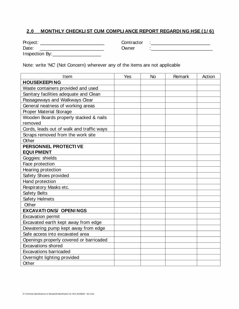
2.0 MONTHLY CHECKLIST CUM COMPLIANCE REPORT REGARDING HSE (1/6)
Project: _________________________ Contractor :_______________________Date: _________________________ Owner :________________________Inspection By:___________________
Note: write ‘NC’ (Not Concern) wherever any of the items are not applicable
Item Yes No Remark ActionHOUSEKEEPINGWaste containers provided and usedSanitary facilities adequate and CleanPassageways and Walkways ClearGeneral neatness of working areasProper Material StorageWooden Boards properly stacked & nailsremovedCords, leads out of walk and traffic waysScraps removed from the work siteOtherPERSONNEL PROTECTIVEEQUIPMENTGoggies: shieldsFace protectionHearing protectionSafety Shoes providedHand protectionRespiratory Masks etc.Safety BeltsSafety Helmets OtherEXCAVATIONS/ OPENINGSExcavation permitExcavated earth kept away from edgeDewatering pump kept away from edgeSafe access into excavated areaOpenings properly covered or barricadedExcavations shoredExcavations barricadedOvernight lighting providedOther

D:\Technical Specifications & Standards\Specification for HS & E(HSE)M - 65-3.doc
MONTHLY CHECKLIST CUM COMPLIANCE REPORT REGARDING HSE (2/6)
Item Yes No Remark ActionWELDING CUTTINGValid not work permitFlashback arrester provided forcylindersPower cable not crossing the weldingcableAdequate earthing providedNo combustible materials kept nearwelding & cutting worksGas cylinder chained upright & kept introlleysCables and hoses not obstructingScreens or shields usedFlammable materials protectedFire extinguisher (s) accessibleOtherSCAFFOLDINGFully decked platformGuard and intermediate rails in placeToe boards in place & tied properlyAdequate shoringAdequate accessOtherLADDERSExtension side rails I m aboveTop of landingProperly secured at top & bottomAngle ± 70° from horizontalOther

D:\Technical Specifications & Standards\Specification for HS & E(HSE)M - 65-3.doc
MONTHLY CHECKLIST CUM COMPLIANCE REPORT REGARDING HSE (3/6)
ITEM YES NO REMARK ACTIONHOISTS, CRANES AND DERRICKSCondition of cables and sheaves OKCondition of slings, chains, hooks andeyes OKInspection and maintenance logsmaintainedOutinggers usedSingh/barricades providedSignals observed and understoodQulified opretorsOtherMACHINERY, TOOLS ANDEQUIPMENTProper instructionSaftey devicesProper cordsInspections and maintenanceOtherVEHICLE AND TRAFFICRules and regulations observedInspection and mantinanceLicensed driversOthers
D:\Technical Specifications & Standards\Specification for HS & E(HSE)M - 65-3.doc
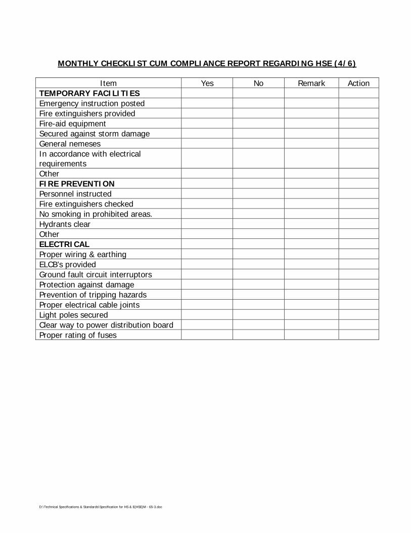
MONTHLY CHECKLIST CUM COMPLIANCE REPORT REGARDING HSE (4/6)
Item Yes No Remark ActionTEMPORARY FACILITIESEmergency instruction postedFire extinguishers providedFire-aid equipmentSecured against storm damageGeneral nemesesIn accordance with electricalrequirementsOtherFIRE PREVENTIONPersonnel instructedFire extinguishers checkedNo smoking in prohibited areas.Hydrants clearOtherELECTRICALProper wiring & earthingELCB’s providedGround fault circuit interruptorsProtection against damagePrevention of tripping hazardsProper electrical cable jointsLight poles securedClear way to power distribution boardProper rating of fuses

D:\Technical Specifications & Standards\Specification for HS & E(HSE)M - 65-3.doc
MONTHLY CHECKLIST CUM COMPLIANCE REPORT REGARDING HSE (5/6)
Item Yes No Remark ActionHANDLING AND STORAGE OFMATERIALSProperly stored or stackedPassageways clearOtherFLAMMABLE GASES AND LIQUIDSContainers clearly identifiedProper storageFire extingui HSErs nearbyOtherWORKING AT HEIGHTErection planSafety netsSafety belts tied properlyIlluminationNo loose material at heightNO body under working areaAll openings coveredOtherENVIRONMENTChemical and other Effluents properlydisposedCleaning liquid of pipes disposed offproperlySeawater used for hydrotestingdisposed off as per agreed proceedingLubricant Waste/Engine oils properlydisposedWaste from Canteen office, sanitationetc. disposed properlyDisposal of surplus earth, strippingmaterials, Oily rags and combustiblematerials done properlyGreen belt protection

D:\Technical Specifications & Standards\Specification for HS & E(HSE)M - 65-3.doc
MONTHLY CHECKLIST CUM COMPLIANCE REPORTREGARDING HSE (Contd…. 6/6)
Item Yes No Remark ActionHEALTH CHECKSHygienic conditions at labour campsOLAvailability of First Aid facilitiesProper sanitation at site, officer andlabour campsArrangements of medical facilityMeasures for dealing with illnessAvailability of potable drinking watersfor workmen & staff.Provision of cretches for children.ERECTIONSlings/ D’shakle checkedSignal ManTag line for guiding the loadProtecting the slings from sharp edgesNo loose materials at heightLadder & platform welding inspectedNo one under the suspended loadStay ropeSWL
___________________Signature of Resident
Engineer with Seal

D:\Technical Specifications & Standards\Specification for HS & E(HSE)M - 65-3.doc
ANNEXURE-BFormat-3
3.0 ACCIDENT REPORT(To be submitted by Contractor after every accident within 2 hours of accident)
Report No:___________________Date: _______________________
Name of Site:-_______________________CONTRACTOR______________________
NAME OF THE INJURED………………………………………………………………………………..FATHER’S NAME………………………………………………………………………………………..SUB-CONTRACTOR M/S………………………………………………………………………………..DATE & TIME OF ACCIDENT………………………………………………………………………….LOCATION ………………………………………………………………………………………………BRIEF DESCRIPTION OF ACCIDENT
CAUSE OF ACCIDENT
NATURE OF INJURY/DAMAGE
MEDICAL AID PROVIDED/ACTIONS TAKEN
INTIMATION TO LOCAL AUTHORITIES
DATE: SIGNATURE OF CONTRACTORWITH SEAL
To : OWNER………………………….. 1 COPY: RCM/SITE-IN-CHARGE, MECON 1 COPY
D:\Technical Specifications & Standards\Specification for HS & E(HSE)M - 65-3.doc
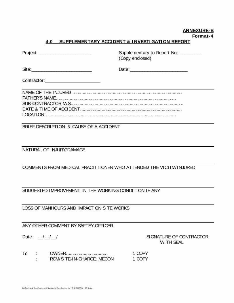
ANNEXURE-BFormat-4
4.0 SUPPLEMENTARY ACCIDENT & INVESTIGATION REPORT
Project:_____________________ Supplementary to Report No: _________(Copy enclosed)
Site:________________________ Date:_______________________
Contractor:______________________
NAME OF THE INJURED …………………………………………………………………………….FATHER’S NAME…………………………………………………………………………………...SUB-CONTRACTOR M/S……………………………………………………………………………...DATE & TIME OF ACCIDENT………………………………………………………………………LOCATION……………………………………………………………………………………………
BRIEF DESCRIPTION & CAUSE OF A ACCIDENT
NATURAL OF INJURY/DAMAGE
COMMENTS FROM MEDICAL PRACTITIONER WHO ATTENDED THE VICTIM/INJURED
SUGGESTED IMPROVEMENT IN THE WORKING CONDITION IF ANY
LOSS OF MANHOURS AND IMPACT ON SITE WORKS
ANY OTHER COMMENT BY SAFTEY OFFICER.
Date : __/__/__/ SIGNATURE OF CONTRACTORWITH SEAL
To : OWNER…………………………… 1 COPY: RCM/SITE-IN-CHARGE, MECON 1 COPY
D:\Technical Specifications & Standards\Specification for HS & E(HSE)M - 65-3.doc
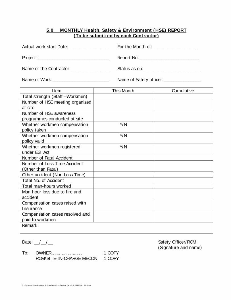
5.0 MONTHLY Health, Safety & Environment (HSE) REPORT(To be submitted by each Contractor)
Actual work start Date:________________ For the Month of:__________________
Project:_____________________________ Report No:________________________
Name of the Contractor:________________ Status as on:_______________________
Name of Work:_______________________ Name of Safety officer:_______________
Item This Month CumulativeTotal strength (Staff –Workmen)Number of HSE meeting organizedat siteNumber of HSE awarenessprogrammes conducted at siteWhether workmen compensationpolicy taken
Y/N
Whether workmen compensationpolicy valid
Y/N
Whether workmen registeredunder ESI Act
Y/N
Number of Fatal AccidentNumber of Loss Time Accident(Other than Fatal)Other accident (Non Loss Time)Total No. of AccidentTotal man-hours workedMan-hour loss due to fire andaccidentCompensation cases raised withInsuranceCompensation cases resolved andpaid to workmenRemark
Date: __/__/__ Safety Officer/RCM(Signature and name)
To: OWNER…………………….. 1 COPY RCM/SITE-IN-CHARGE MECON 1 COPY

D:\Technical Specifications & Standards\Latest\66 quality assurance system\Specification - Quality Assurance Plan - Reqd. - 66.doc
SPECIFICATIONFOR
QUALITY ASSURANCE SYSTEMSREQUIREMENTS
SPECIFICATION NO. MEC/S/05/62/66
(PROCESS & PIPELINE DESIGN SECTION)
MECON LIMITEDDELHI - 110 092

D:\Technical Specifications & Standards\Latest\66 quality assurance system\Specification - Quality Assurance Plan - Reqd. - 66.doc
MECON LIMITEDREGD. OFF : RANCHI (BIHAR)
PROCESS & PIPINGDESIGN SECTION
NEW DELHI
STANDARD SPECIFICATION
SPECIFICATION NO. PAGE 1 OF 7TITLE QUALITY ASSURANCE SYSTEMS
REQUIREMENTS MEC/S/05/62/66 REVISION 0
CONTENTS
Sl.No. Description Page No.
1.0 INTRODUCTION 1
2.0 DEFINITIONS 1 - 2
3.0 CONTRACTORS SCOPE OF WORK 2 - 4
4.0 QUALITY ASSURANCE REQUIREMENTS 4 - 7
ATTACHMENTS
TITLE NUMBER
FORMAT FOR QUALITY PLAN FORMAT 00001
FORMAT FOR OBSERVATION ON FORMAT 00002
PREPARED BY CHECKED BY APPROVED BY

D:\Technical Specifications & Standards\Latest\66 quality assurance system\Specification - Quality Assurance Plan - Reqd. - 66.doc
MECON LIMITEDREGD. OFF : RANCHI (BIHAR)
PROCESS & PIPINGDESIGN SECTION
NEW DELHI
STANDARD SPECIFICATION
SPECIFICATION NO. PAGE 2 OF 7TITLE QUALITY ASSURANCE SYSTEMS
REQUIREMENTS MEC/S/05/62/66 REVISION 0
1.0 INTRODUCTION
This specification establishes the Quality Assurance Requirements to be met bythe sub-contractors (including turnkey Contractors) and their sub-vendors.
In case of any conflict between this specification and other provisions of thecontract/ purchase order, the same shall be brought to the notice of MECON,at the stage of bidding and shall be resolved with MECON, prior to theplacement of order.
2.0 DEFINITION
Bidder
For the purpose of this specification, the word “Bidder” means the person(s),firm, company or organisation who is under the process of being contracted byMECON/ Owner for delivery of some products (including service). The word isconsidered synonymous to supplier, contractor or vendor.
Correction
Action taken to eliminate the detected non-conformity.
Refers to repair, rework or adjustment and relates to the disposition of anexisting non-conformity.
Corrective Action
Action taken to eliminate the causes of an existing non-conformity, defect orother undesirable situation in order to prevent recurrence.
Preventive Action
Action taken to eliminate the causes of a potential non-conformity, defect orother undesirable situation in order to prevent its recurrence.
Process
Set of inter-related resources and activities which transform inputs intooutputs.
D:\Technical Specifications & Standards\Latest\66 quality assurance system\Specification - Quality Assurance Plan - Reqd. - 66.doc
MECON LIMITEDREGD. OFF : RANCHI (BIHAR)
PROCESS & PIPINGDESIGN SECTION
NEW DELHI
STANDARD SPECIFICATION
SPECIFICATION NO. PAGE 3 OF 7TITLE QUALITY ASSURANCE SYSTEMS
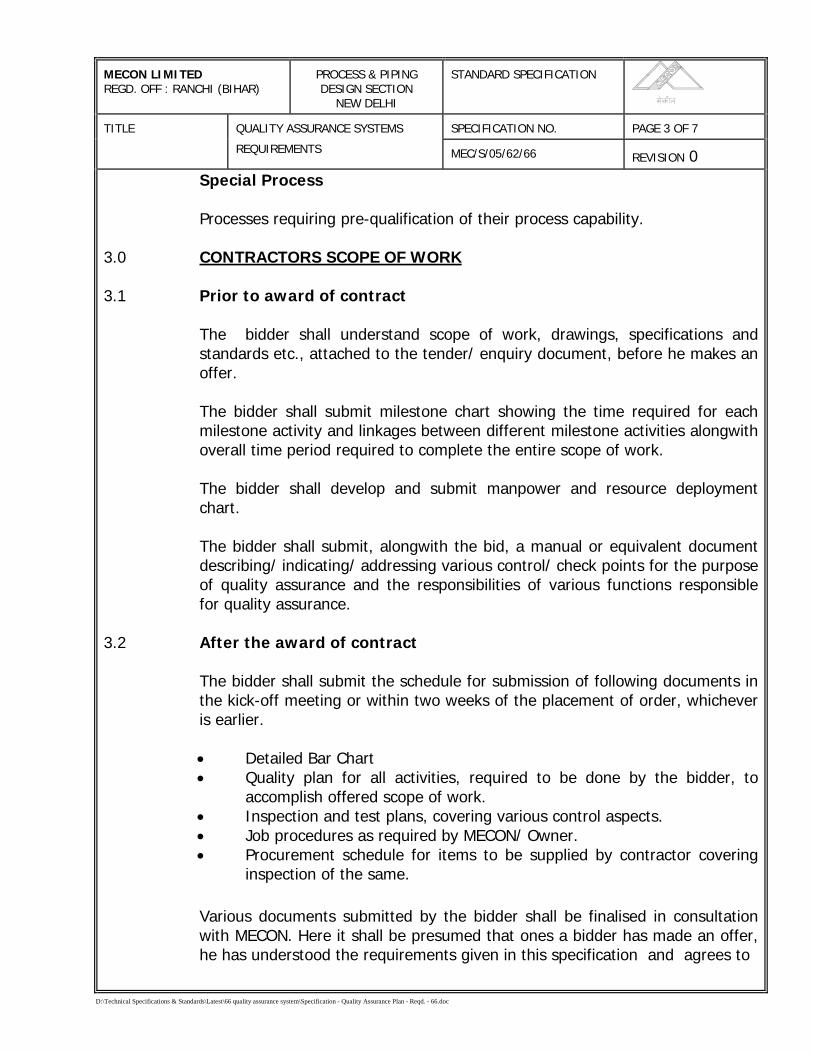
REQUIREMENTS MEC/S/05/62/66 REVISION 0Special Process
Processes requiring pre-qualification of their process capability.
3.0 CONTRACTORS SCOPE OF WORK
3.1 Prior to award of contract
The bidder shall understand scope of work, drawings, specifications andstandards etc., attached to the tender/ enquiry document, before he makes anoffer.
The bidder shall submit milestone chart showing the time required for eachmilestone activity and linkages between different milestone activities alongwithoverall time period required to complete the entire scope of work.
The bidder shall develop and submit manpower and resource deploymentchart.
The bidder shall submit, alongwith the bid, a manual or equivalent documentdescribing/ indicating/ addressing various control/ check points for the purposeof quality assurance and the responsibilities of various functions responsiblefor quality assurance.
3.2 After the award of contract
The bidder shall submit the schedule for submission of following documents inthe kick-off meeting or within two weeks of the placement of order, whicheveris earlier.
• Detailed Bar Chart• Quality plan for all activities, required to be done by the bidder, to
accomplish offered scope of work.• Inspection and test plans, covering various control aspects.• Job procedures as required by MECON/ Owner.• Procurement schedule for items to be supplied by contractor covering
inspection of the same.
Various documents submitted by the bidder shall be finalised in consultationwith MECON. Here it shall be presumed that ones a bidder has made an offer,he has understood the requirements given in this specification and agrees to
D:\Technical Specifications & Standards\Latest\66 quality assurance system\Specification - Quality Assurance Plan - Reqd. - 66.doc
MECON LIMITEDREGD. OFF : RANCHI (BIHAR)
PROCESS & PIPINGDESIGN SECTION
NEW DELHI
STANDARD SPECIFICATION
SPECIFICATION NO. PAGE 4 OF 7TITLE QUALITY ASSURANCE SYSTEMS
REQUIREMENTS MEC/S/05/62/66 REVISION 0
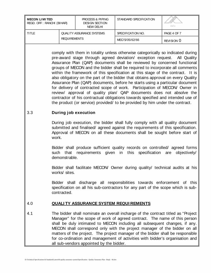
comply with them in totality unless otherwise categorically so indicated duringpre-award stage through agreed deviation/ exception request. All QualityAssurance Plan (QAP) documents shall be reviewed by concerned functionalgroups of MECON and the bidder shall be required to incorporate all commentswithin the framework of this specification at this stage of the contract. It isalso obligatory on the part of the bidder that obtains approval on every QualityAssurance Plan (QAP) documents, before he starts using a particular documentfor delivery of contracted scope of work. Participation of MECON/ Owner inreview/ approval of quality plan/ QAP documents does not absolve thecontractor of his contractual obligations towards specified and intended use ofthe product (or service) provided/ to be provided by him under the contract.
3.3 During job execution
During job execution, the bidder shall fully comply with all quality documentsubmitted and finalised/ agreed against the requirements of this specification.Approval of MECON on all these documents shall be sought before start ofwork.
Bidder shall produce sufficient quality records on controlled/ agreed formssuch that requirements given in this specification are objectively/demonstrable.
Bidder shall facilitate MECON/ Owner during quality/ technical audits at hisworks/ sites.
Bidder shall discharge all responsibilities towards enforcement of thisspecification on all his sub-contractors for any part of the scope which is sub-contracted.
4.0 QUALITY ASSURANCE SYSTEM REQUIREMENTS
4.1 The bidder shall nominate an overall incharge of the contract titled as “ProjectManager” for the scope of work of agreed contract. The name of this personshall be duly intimated to MECON including all subsequent changes, if any.MECON shall correspond only with the project manager of the bidder on allmatters of the project. The project manager of the bidder shall be responsiblefor co-ordination and management of activities with bidder’s organisation andall sub-vendors appointed by the bidder.
D:\Technical Specifications & Standards\Latest\66 quality assurance system\Specification - Quality Assurance Plan - Reqd. - 66.doc
MECON LIMITEDREGD. OFF : RANCHI (BIHAR)
PROCESS & PIPINGDESIGN SECTION
NEW DELHI
STANDARD SPECIFICATION
SPECIFICATION NO. PAGE 5 OF 7TITLE QUALITY ASSURANCE SYSTEMS
REQUIREMENTS MEC/S/05/62/66 REVISION 0
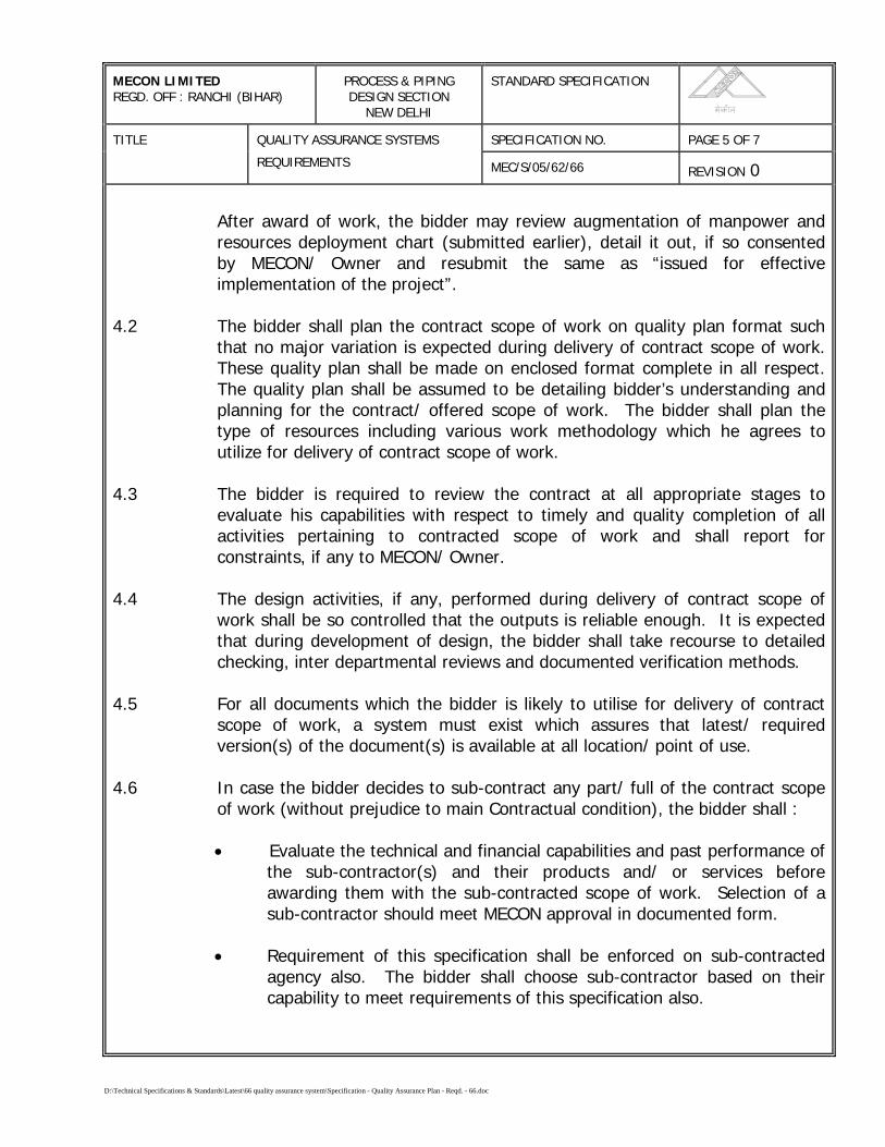
After award of work, the bidder may review augmentation of manpower andresources deployment chart (submitted earlier), detail it out, if so consentedby MECON/ Owner and resubmit the same as “issued for effectiveimplementation of the project”.
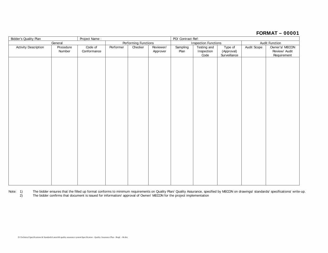
4.2 The bidder shall plan the contract scope of work on quality plan format suchthat no major variation is expected during delivery of contract scope of work.These quality plan shall be made on enclosed format complete in all respect.The quality plan shall be assumed to be detailing bidder’s understanding andplanning for the contract/ offered scope of work. The bidder shall plan thetype of resources including various work methodology which he agrees toutilize for delivery of contract scope of work.
4.3 The bidder is required to review the contract at all appropriate stages toevaluate his capabilities with respect to timely and quality completion of allactivities pertaining to contracted scope of work and shall report forconstraints, if any to MECON/ Owner.
4.4 The design activities, if any, performed during delivery of contract scope ofwork shall be so controlled that the outputs is reliable enough. It is expectedthat during development of design, the bidder shall take recourse to detailedchecking, inter departmental reviews and documented verification methods.
4.5 For all documents which the bidder is likely to utilise for delivery of contractscope of work, a system must exist which assures that latest/ requiredversion(s) of the document(s) is available at all location/ point of use.
4.6 In case the bidder decides to sub-contract any part/ full of the contract scopeof work (without prejudice to main Contractual condition), the bidder shall :
• Evaluate the technical and financial capabilities and past performance ofthe sub-contractor(s) and their products and/ or services beforeawarding them with the sub-contracted scope of work. Selection of asub-contractor should meet MECON approval in documented form.
• Requirement of this specification shall be enforced on sub-contractedagency also. The bidder shall choose sub-contractor based on theircapability to meet requirements of this specification also.

D:\Technical Specifications & Standards\Latest\66 quality assurance system\Specification - Quality Assurance Plan - Reqd. - 66.doc
MECON LIMITEDREGD. OFF : RANCHI (BIHAR)
PROCESS & PIPINGDESIGN SECTION
NEW DELHI
STANDARD SPECIFICATION
SPECIFICATION NO. PAGE 6 OF 7TITLE QUALITY ASSURANCE SYSTEMS
REQUIREMENTS MEC/S/05/62/66 REVISION 0
Note: It may so happen that, in a given situation, a sub-contractor may nothave a system meeting the requirements of this specification. In allsuch eventualities, bidder may lend his system to sub-contractor for thecontract such that sub-contractor effectively meets the requirements ofthis specification. In all such cases MECON shall be duly informed.
4.7 Bidder shall establish adequate methodology such that the materials suppliedby the Owner/ MECON shall be adequately preserved, handled and made useof for the purpose for which they are provided.
4.8 All output delivered against contract scope of work shall be suitably identifiedin such a manner that either through identification or some other means,sufficient traceability is maintained which permits effective resolution of anyproblem reported in the outputs.
4.9 Critical activities shall be identified and the bidder is required to havedocumented methodologies which he is going to utilize for carrying out suchactivities under the contract scope of work. Wherever it is difficult to fullyinspect or verify the output (special process), bidder shall pre-qualify, theperformers and methodologies.
4.10 All inspections carried out by the bidder’s surveillance/ inspection staff shall beconformity to quality plans and/ or inspection and test plans. All inspectionresults shall be duly documented on controlled/ agreed forms such that resultscan be co-related to specific product, that was inspected/ tested.
4.11 All inspection, measuring & test equipments (IMTEs) shall be duly calibrated asper National/ International standards/ codes and only calibrated and certifiedIMTEs shall be utilized for delivery of contract scope of work.
4.12 All outputs/ products delivered against contract scope of work shall be dulymarked such that their inspection status is clearly evident during all stages/period of the contract.
4.13 All non-conformities (NCs) found by the contractor’s inspection/ surveillancestaff shall be duly recorded, including their disposal action. The deficienciesobserved during stage of the product, shall be recorded and resolved suitably.Effective corrective and preventive action shall be implemented by the bidderfor all repetitive NCs, including deficiencies.

D:\Technical Specifications & Standards\Latest\66 quality assurance system\Specification - Quality Assurance Plan - Reqd. - 66.doc
MECON LIMITEDREGD. OFF : RANCHI (BIHAR)
PROCESS & PIPINGDESIGN SECTION
NEW DELHI
STANDARD SPECIFICATION
SPECIFICATION NO. PAGE 7 OF 7TITLE QUALITY ASSURANCE SYSTEMS
REQUIREMENTS MEC/S/05/62/66 REVISION 0
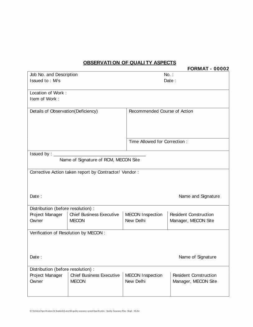
4.14 All deficiencies noticed by MECON/ Owner representative(s) shall be recordedon a controlled form (Format No. 00002). Such deficiencies shall be analysedby the bidder and effective and appropriate correction, corrective andpreventive actions shall be implemented. Bidder shall intimate MECON/ Ownerof all such corrective and preventive action implemented by him.
4.15 Bidder shall establish appropriate methodologies for safe and effectivehandling, storage, preservation of various materials/ inputs encounteredduring delivery of contract scope of work.
4.16 Bidder shall prepare sufficient records for various processes carried out by himfor delivery of contract scope of work such that requirements of thisspecification are objectively demonstrable. In case MECON/ Owner finds thatenough objective evidence/ recording is not available for any particularprocess, bidder shall be obliged to make additional records so as to providesufficient objective evidence. The decision of MECON/ Owner shall be finaland binding on such issues.
4.17 The bidder shall arrange internal quality audits at quarterly intervals, toindependently assess the conformance by various performers to therequirements of this specification. The findings of such assessment shall beduly recorded and a copy shall be sent to MECON/ Owner for review.
4.18 For all special processes, bidder shall deploy only qualified performers.Wherever MECON/ Owner observes any deficiency, the bidder shall arrangethe adequate training to the performer(s) before any further delivery of work.
D:\Technical Specifications & Standards\Latest\66 quality assurance system\Specification - Quality Assurance Plan - Reqd. - 66.doc
OBSERVATION OF QUALITY ASPECTSFORMAT - 00002
Job No. and Description No. :Issued to : M/s Date :
Location of Work :Item of Work :
Recommended Course of ActionDetails of Observation(Deficiency)
Time Allowed for Correction :
Issued by : _____________________________________Name of Signature of RCM, MECON Site
Corrective Action taken report by Contractor/ Vendor :
Date : Name and Signature
Distribution (before resolution) :Project ManagerOwner
Chief Business ExecutiveMECON
MECON InspectionNew Delhi
Resident ConstructionManager, MECON Site
Verification of Resolution by MECON :
Date : Name of Signature
Distribution (before resolution) :Project ManagerOwner
Chief Business ExecutiveMECON
MECON InspectionNew Delhi
Resident ConstructionManager, MECON Site
D:\Technical Specifications & Standards\Latest\66 quality assurance system\Specification - Quality Assurance Plan - Reqd. - 66.doc
FORMAT – 00001Bidder’s Quality Plan Project Name : PO/ Contract Ref:
General Performing Functions Inspection Functions Audit FunctionActivity Description Procedure
NumberCode of
ConformancePerformer Checker Reviewer/
ApproverSampling
PlanTesting andInspection
Code
Type of(Approval)
Surveillance
Audit Scope Owner’s/ MECONReview/ AuditRequirement
Note: 1) The bidder ensures that the filled up format conforms to minimum requirements on Quality Plan/ Quality Assurance, specified by MECON on drawings/ standards/ specifications/ write-up.2) The bidder confirms that document is issued for information/ approval of Owner/ MECON for the project implementation

D:\SPECIFICATIONS\TECHNICAL SPECIFICATIONS\LAYING OR INSTALLATION\MAINLINE\WORD,ACAD\69 Specification for Documentation for PL Const.doc
SPECIFICATION FOR
DOCUMENTATION FOR PIPELINE CONSTRUCTION
SPECIFICATION NO. MEC/S/05/62/69
(PROCESS & PIPELINE DESIGN SECTION) MECON LIMITED DELHI - 110 092
D:\SPECIFICATIONS\TECHNICAL SPECIFICATIONS\LAYING OR INSTALLATION\MAINLINE\WORD,ACAD\69 Specification for Documentation for PL Const.doc
C O N T E N T S 1.0 SCOPE 2.0 RECORDS 3.0 AS-BUILT DRAWINGS AND PIPE BOOK
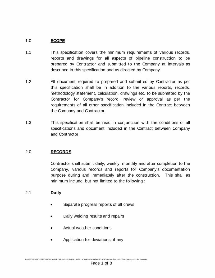
D:\SPECIFICATIONS\TECHNICAL SPECIFICATIONS\LAYING OR INSTALLATION\MAINLINE\WORD,ACAD\69 Specification for Documentation for PL Const.doc Page 1 of 8
1.0 SCOPE 1.1 This specification covers the minimum requirements of various records,
reports and drawings for all aspects of pipeline construction to be prepared by Contractor and submitted to the Company at intervals as described in this specification and as directed by Company.
1.2 All document required to prepared and submitted by Contractor as per
this specification shall be in addition to the various reports, records, methodology statement, calculation, drawings etc. to be submitted by the Contractor for Company’s record, review or approval as per the requirements of all other specification included in the Contract between the Company and Contractor.
1.3 This specification shall be read in conjunction with the conditions of all
specifications and document included in the Contract between Company and Contractor.
2.0 RECORDS
Contractor shall submit daily, weekly, monthly and after completion to the Company, various records and reports for Company’s documentation purpose during and immediately after the construction. This shall as minimum include, but not limited to the following :
2.1 Daily
• Separate progress reports of all crews • Daily welding results and repairs
• Actual weather conditions
• Application for deviations, if any
D:\SPECIFICATIONS\TECHNICAL SPECIFICATIONS\LAYING OR INSTALLATION\MAINLINE\WORD,ACAD\69 Specification for Documentation for PL Const.doc Page 2 of 8
• Accidents
• Damages
• Activities required from Company
• Materials Receipts
• Urgently required materials 2.2 Weekly
• Up-to-date list of confirmed site instruction issued by Company
• Materials `taken over’
• Material defects and repairs
• Outstanding activities of Company
• List of installed markers, chainage
• Required approval from Company
• Progress planned
• Reports of manning of all crews, equipment and plant
• Report of equipment and plant
• Report of accidents
• Report of damages
• Report of acquired release, permits

D:\SPECIFICATIONS\TECHNICAL SPECIFICATIONS\LAYING OR INSTALLATION\MAINLINE\WORD,ACAD\69 Specification for Documentation for PL Const.doc Page 3 of 8
• Priced variations
• Required materials for next month 2.3 Monthly
• Progress report for payment, safety report, report of accidents, security report, health and environment report, material balance, approved deviations.
2.4 Further, Contractor shall supply (for approval if required to the Company
with document such as but not limited :
• Organogram for construction work. • Bio-data of key personnel (including foremen).
• (Revised) list of address of personnel in particular of medical staff,
safety and security offers.
• (Revised) list of approved coaters.
• (Revised) list of approved sub-contractors.
• Time schedule.
• Acquired permits and/ or approvals from Authorities, if any.
• Minutes of meeting with Company with comments, if any.
• Material certificates, material receipt.
• Guarantee from vendors and sub-contractor.
• Calculations, temporary works, bouyance, blasting.

D:\SPECIFICATIONS\TECHNICAL SPECIFICATIONS\LAYING OR INSTALLATION\MAINLINE\WORD,ACAD\69 Specification for Documentation for PL Const.doc Page 4 of 8
• Drawings issued by Contractor.
• Vendors drawings.
• As-built of route maps, alignment sheets, details drawings and isometric drawings.
• Procedures such as surveying, stacking, fencing.
• Welding procedure qualification records, radiographic procedure
qualification, welder qualification.
• Coating procedure.
• Installation of crossings.
• Hydrostatic testing.
• Blasting.
• Radiographic report alongwith original radiographs
• Pipe and welding book.
• Reports
- Material tests (coating, welding, painting) - Computerised Potential Logging Test - Water Samples - Cleaning, Pigging Report before Hydrostatic Test - Hydrostatic Test - Calibration Test - Blasting Trials - Equipment certificate (dead weight tester, instruments,
vessels, equipment) - Manuals

D:\SPECIFICATIONS\TECHNICAL SPECIFICATIONS\LAYING OR INSTALLATION\MAINLINE\WORD,ACAD\69 Specification for Documentation for PL Const.doc Page 5 of 8
- Major water crossings - Waste disposal - Disposal of water after hydrostatic test.
2.5 Contractor shall submit to company colour photographs of various
construction activities/ operations at regular intervals. Size, number and frequency of the photographs shall be mutually agreed upon at a later stage. Also Contractor shall make video recordings of all operations right from the start of construction till the completion of the work, covering to the extent as instructed by Company and submit to Company. Upon completion of the work, Contractor and submit edited master tape plus six copies of video recording in VHS formats or any format ordered by the Company. The duration of video recording shall be of ½ hour and shall cover all aspects of the job.
3.0 AS-BUILT DRAWINGS AND PIPE BOOK 3.1 General Contractor shall prepare “as-built” drawings of all by or on behalf of
Company issued drawings and of all Contractor work drawings including vendor drawing, such as but not limited to :
For Pipeline Section :
- Route Maps - Alignment Sheets - Detail Drawings (road, railway, minor water crossings, major water
crossings, valley crossings) - Isometric drawings of installations - Special installation
Further Contractor shall prepare a pipe Weld Book.

D:\SPECIFICATIONS\TECHNICAL SPECIFICATIONS\LAYING OR INSTALLATION\MAINLINE\WORD,ACAD\69 Specification for Documentation for PL Const.doc Page 6 of 8
If required by the Company, Contractor shall update the diskettes for drawings issued for construction of the job.
3.2 “As-Built” Drawings Contractor shall prepare a complete set of “as-built” drawings. From the
start of construction, Contractor shall on daily basis process any changes in two sets of drawings. Deleted parts shall be indicated in red, new parts in blue, remarks in green and unchanged parts in yellow. Said drawings shall be kept at site and be available to Company at all times. Contractor shall prepare “as-built” drawings based on these data. On completion of the work, one revised film transparency of all drawing made “as-built” by Contractor containing the “as-built” information shall be handed over to Company as well as one complete set of CD ROM/ floppy diskettes as specified by Company.
Contractor shall prepare and submit a specimen of the layout of the
drawings for Company’s approval. The required measurement for “as-built” drawing shall be executed by
Contractor by experienced, qualified surveyors. The surveyors shall daily take care of all measurement required such as
but not limited to:
- Horizontal location of pipeline with regard to deviations and Permanent Grid Pillars.
- Vertical Level with regard to Mean Sea Level of pipeline and grade. - Location and type of bends, fittings etc. and grades, points of
intersection. - Change of wall thickness, materials. - Location and details of valves, insulating flanges, fencing. - Location and details of crossing pipes, vents. - Location and type of coating. - Location and type of weighting, anchoring. - Location and type of markers.
D:\SPECIFICATIONS\TECHNICAL SPECIFICATIONS\LAYING OR INSTALLATION\MAINLINE\WORD,ACAD\69 Specification for Documentation for PL Const.doc Page 7 of 8
- Location of further appurtenance (Pig-Signallers) - Location of ROU and of pipeline with respect to ROU. - Type of soil. - Type of rock - Type of blasting and ripping. - Sand padding. - Type of road pavement. - Details of bank protection, number of insulators, seals.
Contractor shall also prepare isometric drawings of all installation (facilitates) etc. for which the data as mentioned in or required for the Pipe and Welding Book can be identified and these drawings can also be used for material accounting.
3.3 Nameplates of Equipment All permanent equipment supplied and installed by Contractor shall be
provided with plates by Contractor. All texts shall be submitted to Company for approval before plates may be manufactured.
3.4 Pipe Book Every page of the pipe and Welding Book shall mention:
- Data relevant to the project and section there of. - Sequential number. - Length brought forward (for pipes and other materials). - Length to bring forward (for pipes and other materials).
Alignment sheet number and atleast the location thereon of two welds on every page of the pipe Book.
Further, - Diameter of pipeline - Length of each pipe

D:\SPECIFICATIONS\TECHNICAL SPECIFICATIONS\LAYING OR INSTALLATION\MAINLINE\WORD,ACAD\69 Specification for Documentation for PL Const.doc Page 8 of 8
- Wall thickness - Pipe number - Heat number, certificate number - Cut and re-numbered pipe ends - Coating type - Date of stringing - Date of welding - Direction of working - Heat treatment - Equipment used for radiography - Limits of water crossings - Test pressure and date of test.
In order to achieve this, Contractor shall identify all pipe elements. Sample format of Pipe Book shall be submitted for Company approval.
3.5 As-Built Documents Contractor shall prepare all documents in the prescribed format as
indicated below. In addition to the three hard copies, three copies of final documents shall also be submitted in electronic media i.e. CD ROM/ floppy diskettes.
Software used for the preparation of these documents shall be as follows: Type document Software a) Reports/ Documents MS Office b) Drawings Auto CAD For the purpose of preparation of as-built drawings, Contractor shall
update the “Issued for construction” drawings issued by the Company. It shall be the Contractor’s responsibility to covert the drawings furnished by the Company in hard copy into CAD drawings including scanning, digitising and converting the drawings into a suitable format compatible with the AutoCAD and above. As-built drawings shall be prepared only on AutoCAD drawings.

\\Akjha\work contrac\standard TS for Pipe Line WC (Vol-II) MASTER FOLDER\70 caliper pigging spec\Specification for Caliper Pigging - 70.doc
SPECIFICATION
FOR
CALIPER PIGGING
SPECIFICATION NO. MEC/S/05/62/70
(PROCESS & PIPELINE DESIGN SECTION)
MECON LIMITEDDELHI - 110 092
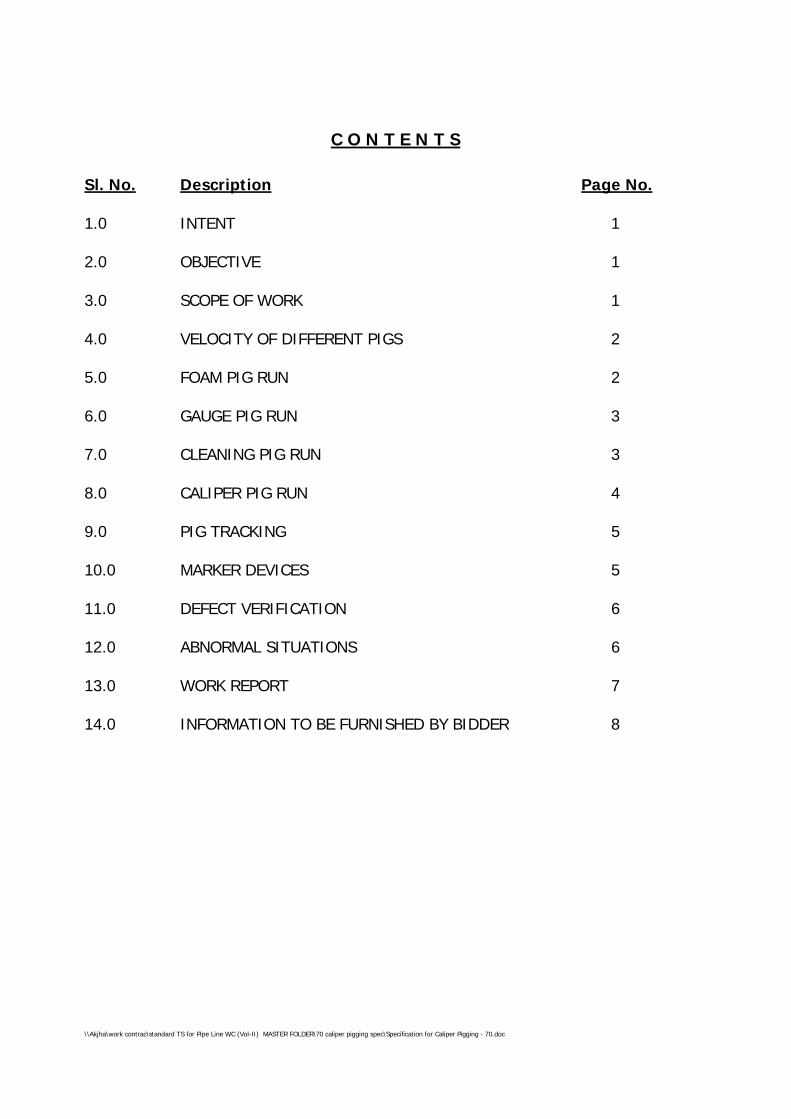
\\Akjha\work contrac\standard TS for Pipe Line WC (Vol-II) MASTER FOLDER\70 caliper pigging spec\Specification for Caliper Pigging - 70.doc
C O N T E N T S
Sl. No. Description Page No.
1.0 INTENT 1
2.0 OBJECTIVE 1
3.0 SCOPE OF WORK 1
4.0 VELOCITY OF DIFFERENT PIGS 2
5.0 FOAM PIG RUN 2
6.0 GAUGE PIG RUN 3
7.0 CLEANING PIG RUN 3
8.0 CALIPER PIG RUN 4
9.0 PIG TRACKING 5
10.0 MARKER DEVICES 5
11.0 DEFECT VERIFICATION 6
12.0 ABNORMAL SITUATIONS 6
13.0 WORK REPORT 7
14.0 INFORMATION TO BE FURNISHED BY BIDDER 8
\\Akjha\work contrac\standard TS for Pipe Line WC (Vol-II) MASTER FOLDER\70 caliper pigging spec\Specification for Caliper Pigging - 70.doc Page 1 of 9
SPECIFICATION FOR CALIPER PIGGING
1.0 INTENT
The intent of this specification is to setforth the requirements of the
caliper pigging. The specification is not intended to be all-inclusive and the
use of this specification will not absolve the contractor of his responsibility
of generating valid, interpretable and physically verifiable data.
2.0 OBJECTIVE
The objective of the present pigging programme to access the internal
geometry of the following pipelines and detect significant geometry
defects if any, which may affect safe operation of the pipeline.
The relevant technical specifications of the pipeline including launcher and
receiver details in the Annexure.
3.0 SCOPE OF WORK
To achieve the above objective, contractors SCOPE OF WORK includes
running of adequate numbers of foam pigs, cleaning pigs (magnet, brush,
commination of brush and magnet, scraper, pin wheel etc.), gauge pig
and caliper pig.
Further the scope of work comprises supply of skilled personnel, all
equipment e.g. foam pigs cleaning pigs, gauging pig, caliper pigs, pig
locating and pig tracking devices, spares consumables, communication
and transportation including their mobilisation and demobilisation. It is
expressly understood that this do not limit the scope of work of the
CONTRACTOR in any way. The quantities to be mobilized for different
equipment (different types of pigs pig tracking device, marker device)
accessories, spare and consumables need to be carefully evaluate by the
CONTRACTOR taking in to the consideration that caliper pigging of various

\\Akjha\work contrac\standard TS for Pipe Line WC (Vol-II) MASTER FOLDER\70 caliper pigging spec\Specification for Caliper Pigging - 70.doc Page 2 of 9
pipelines in the scope of work should be carried out without any constraint
and turn around time.
The contractor shall submit the details of each type of pig including foam,
gauge cleaning and caliper for approval of MECON/ GAIL, which he
proposes to use. Pigs shall be launched in the pipeline only after their
design and size has been approved by MECON/ GAIL. Due care shall be
taken not to damage internal coating by the contractor, while proposing
the pigs for internally coated pipeline.
The detailed scope of work shall be, but not limited to under
- Supply of all equipment, personnel and consumables.
- Running of foam, Gauge, Cleaning and Caliper pigs and Tracking to
generate valid data.
- Placement of marker devices along the Row over the pipeline.
- Identification of defects in the field as found
- Preparation of work reports.
4.0 VELOCITY OF DIFFERENT PIGS
Contractor shall be required to maintain velocities of propelling medium in
such a way that the objective of each pig run shall be achieved.
5.0 FOAM PIG RUN
Contractor to carry out adequate number of foam pigs runs in each
pipeline covered under Scope of Work prior to running of cleaning pigs to
make a final assessment of the line piggability to the satisfaction of the
Contractor and provide detailed daily site report for each run in the
approved format before commencing the subsequent run. Contractor to
select size of the foam pigs in such a way that the objective shall be
achieved.
\\Akjha\work contrac\standard TS for Pipe Line WC (Vol-II) MASTER FOLDER\70 caliper pigging spec\Specification for Caliper Pigging - 70.doc Page 3 of 9
6.0 GAUGE PIG RUN
Contractor to carry out adequate number of gauging pig runs in each
pipeline covered under Scope of work including pig tracking for pipeline to
assess any internal restriction in the pipeline that may restrict the passage
of cleaning and caliper pig. Contractor to provide detailed daily site report
for each run in the approved format before commencing the subsequent
run Gauge pig shall be equipped with a gauge plate made of Aluminium
having its diameters 95% of minimum pipeline Internal Diameter (I.D.).
The gauge pig should be able to pass over or negotiate lateral tees or
bends on the pipeline.
7.0 CLEANING PIG RUN
7.1 Pipelines with Internal Coating
Contractor to carry out adequate number of cleaning pig runs by running
suitable cleaning pigs in the pipelines including pig tracking till such time
contractor is satisified with himself about the degree of cleanliness of
pipeline and provide detailed daily site report for each run in the approved
format before commencing the subsequent run. Choice of the type of
cleaning pig has been left to the contractor. The contractor shall assure
that the pigs, which are proposed to be used, are adequately soft and
they do not damage internal coating under any circumstances. The
brushes and scrappers used shall be of nonmetallic/ plastic material.
However, the details of these pigs including their construction details of
brushes, scrappers etc. (if applicable) shall be submitted to MECON/ GAIL
for approval before their usage.
7.2 Pipelines Without Internal Coating
CONTRACTOR to carry out adequate numbers of cleaning pig runs by
running suitable cleaning pigs in pipeline covered under SCOPE OF WORK
including pig tracking till such time CONTRACTOR is satisfied with himself
\\Akjha\work contrac\standard TS for Pipe Line WC (Vol-II) MASTER FOLDER\70 caliper pigging spec\Specification for Caliper Pigging - 70.doc Page 4 of 9
about the degree of cleanliness of pipeline and provide detailed daily site
report for each run in the approved format before commencing the
subsequent run. Choice of the type of cleaning pig has been left to the
contractor. Contractor may deploy brush cleaning pig, magnetic cleaning
pig, combination of brush and magnet, scrapper pig etc. the cleaning pigs
should be able to pass over negotiate lateral tees or bends on the pipeline
8.0 CALIPER PIG RUN
CONTRACTOR to carry out adequate number of electronic geometry
(caliper) pig runs each pipeline covered under SCOPE OF WORK including
pig tracking for each pipeline decided after findings of gauging pig run to
generate valid and interpretable geometry data of the pipeline and
analysis of data of the caliper survey to detect the nature, extent and
location of geometry defect. Contractor to provide detailed daily site
report for each run in the approved format before commencing the
subsequent run. The caliper should be capable of inspecting entire length
of the pipeline i.e. from launcher to receiver in single run. Battery life
should be adequate to commensurate with the run time required to travel
the pipeline length. The electronic recorder system should have requisite
data storage capacity. The drive cups should have requisite resistance to
wear and tear to maintain effective seal throughout the entire run time.
The measurement shall cover the entire 360° of internal pipe wall
circumference using properly oriented and suffcient quantity of sensors.
For internally coated pipelines adequate care shall be taken by using soft
cups so that no damage takes place to the internal coating of pipe. The
tool shall be capable to identify and locate the following features as
minimum.
- Individual Girth weld
- Dent, ovality, buckles, or any other out of roundness, change in
pipeline I.D. and difference of thickness.
- Bend with bend radius and degree of bend.

\\Akjha\work contrac\standard TS for Pipe Line WC (Vol-II) MASTER FOLDER\70 caliper pigging spec\Specification for Caliper Pigging - 70.doc Page 5 of 9
- Valves or any partially closed valves.
- Tees/ off-takes.
The caliper pig should have minimum capability to identify and detect the
defects of following threshold.
Dent : 3% of outer diameter (O. D.)
Ovality : 5% of outer Diameter (O. D.)
Location accuracy : Axial ± 3.0m
Circumferential : ± 12°
(For dents, ovalities and pipeline feature as detailed above).
9.0 PIG TRACKING
The movement of any type of pig (Except, foam pig) put into the line
during caliper pigging shall be required to be monitored along the pipeline
length from launcher to receiver trap. The BIDDER shall detail out the
complete methodology of pig tracking proposed to be deployed by him
including complete technical details of the equipment and device proposed
to be used for this purpose.
It is proposed that pig tracking would be done in a discrete manner at
least 5 to and 10 km - interval on each pipeline at preselected locations.
The exact KM chainage of these locations shall be decided at site in
consultation with the Contractor and CONSULTANT/ COMPANY.
10.0 MARKER DEVICES
The contractor shall submit the details of marker devices, which he
proposes to place for relocating the defect accurately in the field, when
the same has been identified as a result of Caliper survey.
\\Akjha\work contrac\standard TS for Pipe Line WC (Vol-II) MASTER FOLDER\70 caliper pigging spec\Specification for Caliper Pigging - 70.doc Page 6 of 9
The contractor shall be responsible for placing these devices (Marker
Magnets or Locator coils or any other device) at suitable interval so that
the defect can be easily located in the field with minimum above ground
measurement. It may be noted that placement of marker devices, their
retrieval and locating the identified defect in the field shall be the
responsibility of the contractor. The liquidation of defects, if any, is
however, not included in the scope of work of the contract.
11.0 DEFECT VERIFICATION
At the discretion of the COMPANY/ CONSULTANT identify at least two
verification dig sites for each pipeline jointly with MECON and GAIL from
the recorded data and provide MECON/ GAIL with their distance from the
nearest pipeline feature or reference marker to facilitate location of defect
in the field.
The contractor shall depute his representative to observe the verification
at verification sites for proving that filed log detected anomalies conform
to sizing including linear and circumferential positions.
12.0 ABNORMAL SITUATIONS
The objective of this section is to write down foreseeable abnormal
circumstances for taking appropriate measures, should such a condition
arise during implementation of project.
The following abnormal condition have been foreseen by the Comapny.
However, if the BIDDER foresees any other abnormal condition, he is free
to make a mention of the same in his technical BID offer:
12.1 Tool Failure
CONTRACTOR is required to get valid interpretable and verifiable data for
pipeline. In case CONTRACTOR’S equipment fails to perform electronic

\\Akjha\work contrac\standard TS for Pipe Line WC (Vol-II) MASTER FOLDER\70 caliper pigging spec\Specification for Caliper Pigging - 70.doc Page 7 of 9
geometry inspection to generate valid data for any of the pipeline,
CONTRACTOR will make extra runs of pigs to get valid and physically
verifiable data.
12.2 Stuck-Up Tool
The BIDDER shall details out a contingency plan in his BID as proposed by
him in case any of the pigs get stuck up. The plan shall identify procedure
for exactly locating the stuck up pig, detail procedure for retrieval of pig,
equipment, including support facilities required to retrieve the pig.
If pig do not move from stuck up location, by any measure, then the
pipeline section shall have to be cut for retrieval of Pig. Necessary
erection, fabrication and modification of pipe with new pipe piece after
retrieval of pig shall be done by Contractor. The cost for this works shall
be borne by Contractor on actuals. After fabrication & erection, pigging
contractor shall run Gauge pig to check internal restriction, if any.
Locating the stuck up pig and its retrieval shall be the responsibility of the
CONTRACTOR.
13.0 WORK REPORT
The work report shall be prepared and submitted in hard copy (4 sets)
and Electronics media (2 sets)
The work report shall consist of following as a minimum.
- All field activities.
- Equipment description
- List of installations
- List of significance with feature information and installation
reference
- Survey log and enlargement areas of special interest to suitable
scale.

\\Akjha\work contrac\standard TS for Pipe Line WC (Vol-II) MASTER FOLDER\70 caliper pigging spec\Specification for Caliper Pigging - 70.doc Page 8 of 9
14.0 INFORMATION TO BE FURNISHED BY BIDDER IN HIS OFFER FOREVALUATION.
- List of similar projects executed in the past.
- Specification of foam pigs, cleaning pigs, gauge pig and caliper pig
for pipelines with and without internal coating respectively.
- Details of caliper pig in following respect.
Max.% of Nominal pipeline ID tool can pass (% of ID)
Minimum deformation level reported (as % of ID)
Accuracy of measurement (% of ID)
Bend radius tool able to negotiate
- details of pig tracking equipment and pig tracking procedure.
- Pig contingency plan.
- Proposed methodology for execution of pipeline pigging.
- Sample reporting format.
- Minimum velocity of various pigs acceptable to bidder for generation of
valid data.

\\Akjha\work contrac\standard TS for Pipe Line WC (Vol-II) MASTER FOLDER\70 caliper pigging spec\Specification for Caliper Pigging - 70.doc Page 9 of 9
ANNEXURE
PIPELINE DETAILS
NOMINAL DIAMETER mm (inch.) : 300 (12)
DESIGN PRESSURE Kg/ cm2 : 92DESIGN TEMPERATURE, °C : 65
WALL THICKNESS, mm : 6.4 & 11.1
PIG LAUNCHER DETAILS:
BODY SIZE NB, mm (inch) : 400 (16)
PIG RECEIVER DETAILS:
BODY SIZE NB, mm (inch) : 450 (18)
NUMBER OF SECTIONALIZINGVALVE STATIONS

Page 1 of 13
SPECIFICATIONFOR
INTELLIGENT PIGGING
Specification No. : MEC/S/05/21/70A, R-0

Page 2 of 13
CONTENTS
1.0 INTENT
2.0 TECHNIQUES FOR INTELLIGENT PIGGING
3.0 VELOCITY OF DIFFERENT PIGS
4.0 PRE-INSPECTION ACTIVITIES
4.1 Magnet marker installation
4.2 Procedure document and Operation Manual
4.3 Pull Through Test
4.4 Pre-Inspection Pig runs
5.0 INSPECTION PIG RUNS
5.1 Electronic Geometry (CALIPER) Pig run
5.2 Intelligent Pig run
6.0 DEFECT SIGNIFICANCE
7.0 PIG TRACKING
8.0 PRELIMINARY REPORT AND DEFECT VERIFICATION
9.0 DATA ANALYSIS
10.0 FINAL WORK REPORT
11.0 CONTINGENCY WORKS
12.0 ABNORMAL SITUATIONS
12.1 Tool failure
12.2 Stuck –Up tool
12.3 Mismatch of inspection results with actual defects during site verification
ANNEXURE – I : PROFORMA FOR GUAGING PIG, BRUSH CLEANING PIG,MAGNET CLEANING PIG DETAILS
ANNEXURE – II : PROFORMA FOR ELECTRONIC GEOMETRY PIG DETAILS
ANNEXURE – III : PROFORMA FOR HIGH RESOLUTION MFL INSPECTION PIGDETAILS

Page 3 of 13
SPECIFICATIONS FOR INTELLIGENT PIGGING
1.0 INTENT
The intent of the specification is to set forth the requirements of the on-lineinspection of the pipelines.
This requirement is not intended to be all inclusive and use of guidelines set-forthdoes not relieve the CONTRACTOR to his responsibility to carry out all activitiessuccessfully as defined in Scope of WORK and to obtain valid, interpretable andphysically verifiable data from the intelligent pig runs about the condition of thepipeline.
2.0 TECHNIQUE FOR INTELLIGENT PIGGING
The Corrosion Detection tool used for On line Inspection should be High resolutioninspection tool based on Magnetic Flux leakage (MFL) Technology.
3.0 VELOCITY OF DIFFERENT PIGS
CONTRACTOR shall be required to maintain the velocities of different pigs in such amanner that normal flow through the pipeline while a particular pig is traveling is notrequired to be altered.
The normal flow rate and pressure for pipeline are given in Design Basis enclosed inTender Document.
4.0 PRE-INSPECTION ACTIVITIES
Following activities are envisaged prior to running of high resolution intelligent pig .The sequence shown here is indicative which may vary during execution as peragreed schedule between OWNER and Contractor.
4.1 Magnet marker installation
Contractor to supply adequate numbers of permanent magnet markers forinstallation of the same on the pipeline at 1.0(one) Km interval irrespective ofpermanent pipeline installations. These permanent magnet markers shall not beretrieved back after completion of inspection work and shall not be taken back byContractor. Contractor to supply these permanent magnet markers in advance sothat same can be installed by him before commencement of inspection works. Themaximum coating thickness on the pipeline is 4-6 mm. Contractor to deploy magnetmarkers of adequate strength so that same shall be detected by high resolutioninspection pig during inspection at above coating thickness and gas velocities.Contractor to take all adequate precautions so that pipeline and coating is notdamaged during installation of magnet markers. Contractor to submit to the OWNERthe sketch containing reference of magnet marker location with respect topermanent features/installation available in the vicinity.

Page 4 of 13
4.2 Procedure document and Operation Manual
Contractor shall submit operation manual for pigs and procedure document forexecution of the field activities for the various pipelines covered under scope of workbefore commencing the job for OWNER/CONSULTANT approval. The document shallinclude as a minimum data sheets of pigs deployed at site, list of items to bemobilized, launching & receiving procedure, pig tracking procedure, reportingformats for each type of pig run, format for preliminary report , specificconsiderations to be observed during pigging etc.
4.3 Pull Through Test
CONTRACTOR is required to pre-calibrate the inspection tools( Intelligent pig)perform the pilot/loop test at his inspection Centre before mobilisation of theseinspection tools to SITE. COMPANY/CONSULTANT at its discretion reserves the rightto witness and / or to appoint its authorised agency to witness the above pre-calibration/pilot/loop tests to ascertain the diagnostic capability, mechanicalperformance requirements, reliability etc. of the inspection tools to be deployed atSITE. During pull through test , the OWNER/Consultant representatives shall beallowed to share the technical information related to the Corrosion Detection Pigincluding test pipe data, tool velocity, magnetisation level achieved and metal lossinspection performance achieved during testing. However, it is clearly and expresslyunderstood by the CONTRACTOR that such association of theCOMPANY/CONSULTANT for witnessing the pre-calibration/pilot/loop tests shall in noway absolve the responsibility of the CONTRACTOR either for the performance of theinspection tools or his obligations under the CONTRACT. COMPANY/CONSULTANTshall bear the expenses of his representative /authorised agency related to travel, (toand fro) boarding, lodging and other incidentals during the period of their stay forwitnessing above tests of inspection the above tests of inspection tools at theinspection Centre of the CONTRACTOR. Pull through test report for each size ofCorrosion Detection pig shall be submitted within seven days of performing the test.
4.4 Pre-Inspection Pig runs
Prior to launching of corrosion detection pigs, CONTRACTOR shall complete allactivities required to establish piggability and adequate cleanliness of pipeline to thesatisfaction of the CONTRACTOR and to verify the internal geometry of the pipelinewith relation to ovality, dent etc. and to ensure that internal bore restriction at anylocation does not exceed the limitation of proposed tools to be used subsequently.
4.4.1 Gauge Pig run
CONTRACTOR shall run a gauging pig with the gauging plate made of Aluminum andits diameter should be 95% of minimum pipeline internal diameter. CONTRACTOR' scleaning and gauging pig assemblies should be able to pass over or negotiate lateraltees or bends of sizes or radii given in the tender document. The cups/disc shouldhave requisite resistance to wear and tear to maintain effective seal throughout theentire run time.

Page 5 of 13
4.4.2 Cleaning Pig runs
CONTRACTOR shall carry out at least one run of brush cleaning pig and magnetcleaning pig to decide the number of cleaning runs required and the choice of thecleaning pig for subsequent cleaning runs as suitable for the purpose to obtaininternal condition adequately clean so as to obtain valid and interpretable inspectiondata from the intelligent pig and to safeguard caliper and intelligent pig againstdamage due to debris.
A single cleaning run is not expected to produce any conclusive information.Performance of each cleaning pig run shall be assessed from the debris quantity,debris quality and physical condition of pig.
The cleaning pigs for successive cleaning pig runs including configuration of each pigshall be selected by the CONTRACTOR in such a manner that effective cleaning isachieved with minimum number of runs and then the same should not get lodgedinto the pipeline.
5.0 INSPECTION PIG RUNS
5.1 Electronic Geometry (CALIPER) Pig run
The electronic geometry (caliper) pig should be capable of recording the entirelength of each segment i. e. from launcher to receiver in one single run andtherefore its electronic recorder system should have requisite data storage capacity.Battery life therefore should be adequate to commensurate with the run timerequired to travel the pipe length of each segment and the drive cups should haverequisite resistance to wear and tear to maintain effective seal throughout the entirerun time.
The measurement shall cover the entire 360o
of internal pipe wall circumferenceusing properly oriented and sufficient quantity of sensors. The tool should becapable to identify and locate the following features as a minimum.
• Individual Girth weld• Dent, ovality, buckles, or any other out of roundness, change in pipeline I.D.
and difference of thickness.• Bend with bend radius and degree of bend.• Valves or any partially closed valves.
5.2 Intelligent Pig run
Upon completion of all preceding activities (foam, cleaning, gauging, caliper runs)and based on their results CONTRACTOR shall intimate about his readiness forrunning the high resolution corrosion detection pig. COMPANY/CONSULTANT shallindicate the exact time of launching the corrosion detection pig in consultation withCONTRACTOR.
Marker devices should be placed at approximately 1 KM interval as mentioned atclause 4.1 prior to running of Intelligent Pig.

Page 6 of 13
The intelligent pig proposed by the BIDDER should be capable of identifying thefollowing anomalies keeping in view the defect significance detailed out at para 6.0below:
• • General corrosion• Pitting corrosion• Circumferential gouging• Axial gouging• Location of girth welds, valves, lateral joints• Circumferential cracks• Proximity of any ferrous object to pipeline.• Manufacturing defects• Metal loss in dents• 6.0 DEFECT SIGNIFICANCE
6.1 The following information/performance is expected out from the Geometry survey.
The electronic geometry pig/Caliper pig deployed by Contractor should be able toperform inspection of pipelines as per following detection and sizing specifications.
6.2 The following information/performance is expected out of the intelligent piginspection:
6.2.1 The external or internal metal loss/mechanical defects should be identified,discriminated , sized (L x B x D) and suitably reported in a mutually agreed manner.
6.2.2 Inspection of entire length of each segment to be completed in one single run.
6.2.3 To check the effect of inter-active corrosion if a cluster of pits are identified close toeach other, values of L1, L2, ........W1, W2 .....should be reported (refer sketchbelow) and the location of each pit cluster is to be identified with reference topermanent pipeline feature.
Two individual metal loss features interact when axial spacing between the metalloss feature edges is less than the smallest metal loss feature length andcircumferential spacing is less than smallest metal loss feature width.

Page 7 of 13
6.2.4 Any metal loss in the heat affected zone of the weld should be specificallyhighlighted in the report but may not be sized.
6.2.5 ACCURACY OF DEFECTS
The best accuracy offered and guaranteed by the BIDDER for each category ofdefect should be clearly spelt out. The BIDDER must define the "pitting corrosion",general corrosion and the accuracy offered by him in each case for a) depth ofcorrosion b) axial and circumferential location of corrosion and c) length of corrosion.
CONFIDENCE LEVEL AND PROBABILITY OF DETECTION
A confidence level of 80% is acceptable in defect sizing accuracy (i. e. guaranteedaccuracy is acceptable for equal to or more than 80% metal loss features reported)with 90% Probability ofDetection(POD).
The intelligent pig should have as a minimum, the following capabilities with 80%confidence level and 90% probability of detection (POD).
DETECTION CAPABILITY AND SIZING ACCURACY

Page 8 of 13
7.0 PIG TRACKING
The movement of any type of pig put into the line during pre-inspection or intelligentpigging shall be required to be monitor along the pipeline length from launcher toreceiver trap. The pig tracking system should be capable of working under Over headhigh voltage transmission lines. Bidder to propose a tracking system which shall beable to detect pig passage in the existing pipe cover. The transmitter should haveadequate battery life so that stuck up pig can be located within reasonable timeframe. The pig tracking system should be capable of locating the stuck up pig in therange of ±15 Meter. The BIDDER shall detail out the complete methodology of pigtracking proposed to be deployed by him including complete technical details of theequipment and device proposed to be used for this purpose.
It is proposed that pig tracking would be done in a discrete manner generally at 2 to3 KM interval at pre-selected locations. The exact KM chainage of these locationsshall be decided at site in consultation with the CONTRACTOR andCONSULTANT/COMPANY.
Page 9 of 13
8.0 PRELIMINARY REPORT AND DEFECT VERIFICATION
Contractor on completion of the CDP run, to furnish a preliminary inspection reportindicating all detected defects including sizing of defects, chainage of defects,circumferential location, distance from magnet marker/pipeline feature, pipe jointlength etc to enable the OWNER to locate the defect in the field. The preliminaryinspection report shall also include information about the data quality, generalpipeline conditions and major observations during inspection.
The preliminary report shall be submitted within three weeks from the date ofcompletion of High resolution MFL pig run.
OWNER/CONSULTANT shall identify a maximum of Five verification defects from thepreliminary report/recorded data and contractor to provide CONSULTANT/OWNERwith their distance from the nearest pipeline feature or reference marker to facilitatelocation of defect in the field. Verification shall be done by OWNER within four weeksfrom the date of receiving the information on dig site verification.
All defects recorded by the High Resolution tool shall be reported in the Contractorsreport.
However, while selecting the defects for verification purpose , following guidelinesshall be observed:
- A maximum of 5 numbers of most injurious verifiable metal loss defects to beidentified in the segment having any one or combination of following.
- General Corrosion defects with length and width greater than 3t x 3t andmetal loss depth 20% of wall thickness or more.
- Pitting corrosion defects with length and width greater than 2t x 2t and metalloss depth 40% of pipe wall thickness or more.
- Mill defects and other manufacturing defects which threaten the pipelineintegrity .
- Geometry defects with metal loss.
- Any other critical defect at the discretion of OWNER.
In case there is a mismatch in the reported defects and those measured at siteduring verification then the contractor shall depute his representative to observeverification by non destructive testing at dig sites for proving that field log detectedanomalies conform to wall thickness loss and sizing within the limits of tolerance asper provision of technical specification in Bid Document. The data can be reviewedby the Contractor based on the witnessed NDT results and a revised report can begiven. Again OWNER/CONSULTANT shall select five defects from the revised reportfor verification in the field. In case of non compliance of these defects to the tenderrequirements, the run shall be considered as unsuccessful. In case physicallyverifiable defects are not found , the Contractor shall explicitly indicate this situationin his preliminary report.

Page 10 of 13
9.0 DATA ANALYSIS
CONSULTANT/COMPANY shall participate in the analysis of the recorded datatogether with the engineering and other personnel of CONTRACTOR. This analysisshall be carried out at BIDDER's Analysis Centre to achieve the following objectives:
a) To identify the locations of internal or external defects likely to jeopardize thenormal safety and operation of the pipeline.
b) To arrive at general methodology of repair to be followed.
c) Short-term measures to be taken in view of potentially hazardous defects, iffound in any of the pipelines.
BIDDER shall provide all raw and processed data and his software package alongwith his compatible hardware. The software package shall be user friendly.
10.0 FINAL WORK REPORT
The BIDDER shall include in his offer the most appropriate reporting procedureenvisaged for the subject pipeline. This will have to be mutually agreed between thesuccessful BIDDER and CONSULTANT/COMPANY.
However, any reporting system shall include but not limited to the following:
- Preliminary site report for each pipe segment for each running of foam,cleaning, caliper, intelligent pig runs stating comments/observations of eachrun, pig condition, operating parameters and total time required.
- A detailed report in respect of each pipe segment of running each of the pre-inspection tool such as cleaning pig, caliper pig.
- A detailed report on the geometry survey of each pipeline segmentincorporating the following supplemented with raw/processed data logs.
List of installations
List of Significances with
• Feature information• Feature type• Feature description• Feature log Distance• Feature Clock orientation• Feature length• Feature depth ( Change in ID)
Installation references
• Distance form next Installation• Installation Distance• Installation type
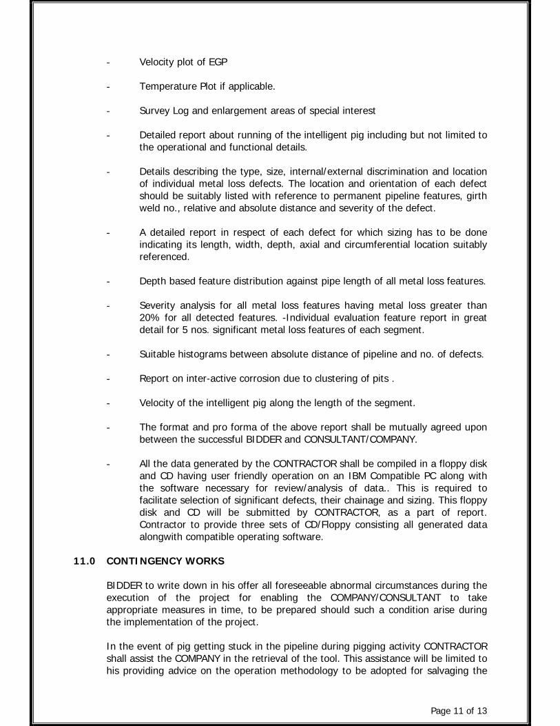
Page 11 of 13
- Velocity plot of EGP
- Temperature Plot if applicable.
- Survey Log and enlargement areas of special interest
- Detailed report about running of the intelligent pig including but not limited tothe operational and functional details.
- Details describing the type, size, internal/external discrimination and locationof individual metal loss defects. The location and orientation of each defectshould be suitably listed with reference to permanent pipeline features, girthweld no., relative and absolute distance and severity of the defect.
- A detailed report in respect of each defect for which sizing has to be doneindicating its length, width, depth, axial and circumferential location suitablyreferenced.
- Depth based feature distribution against pipe length of all metal loss features.
- Severity analysis for all metal loss features having metal loss greater than20% for all detected features. -Individual evaluation feature report in greatdetail for 5 nos. significant metal loss features of each segment.
- Suitable histograms between absolute distance of pipeline and no. of defects.
- Report on inter-active corrosion due to clustering of pits .
- Velocity of the intelligent pig along the length of the segment.
- The format and pro forma of the above report shall be mutually agreed uponbetween the successful BIDDER and CONSULTANT/COMPANY.
- All the data generated by the CONTRACTOR shall be compiled in a floppy diskand CD having user friendly operation on an IBM Compatible PC along withthe software necessary for review/analysis of data.. This is required tofacilitate selection of significant defects, their chainage and sizing. This floppydisk and CD will be submitted by CONTRACTOR, as a part of report.Contractor to provide three sets of CD/Floppy consisting all generated dataalongwith compatible operating software.
11.0 CONTINGENCY WORKS
BIDDER to write down in his offer all foreseeable abnormal circumstances during theexecution of the project for enabling the COMPANY/CONSULTANT to takeappropriate measures in time, to be prepared should such a condition arise duringthe implementation of the project.
In the event of pig getting stuck in the pipeline during pigging activity CONTRACTORshall assist the COMPANY in the retrieval of the tool. This assistance will be limited tohis providing advice on the operation methodology to be adopted for salvaging the
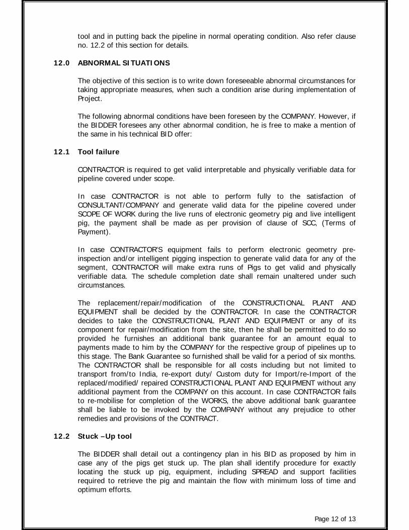
Page 12 of 13
tool and in putting back the pipeline in normal operating condition. Also refer clauseno. 12.2 of this section for details.
12.0 ABNORMAL SITUATIONS
The objective of this section is to write down foreseeable abnormal circumstances fortaking appropriate measures, when such a condition arise during implementation ofProject.
The following abnormal conditions have been foreseen by the COMPANY. However, ifthe BIDDER foresees any other abnormal condition, he is free to make a mention ofthe same in his technical BID offer:
12.1 Tool failure
CONTRACTOR is required to get valid interpretable and physically verifiable data forpipeline covered under scope.
In case CONTRACTOR is not able to perform fully to the satisfaction ofCONSULTANT/COMPANY and generate valid data for the pipeline covered underSCOPE OF WORK during the live runs of electronic geometry pig and live intelligentpig, the payment shall be made as per provision of clause of SCC, (Terms ofPayment).
In case CONTRACTOR'S equipment fails to perform electronic geometry pre-inspection and/or intelligent pigging inspection to generate valid data for any of thesegment, CONTRACTOR will make extra runs of Pigs to get valid and physicallyverifiable data. The schedule completion date shall remain unaltered under suchcircumstances.
The replacement/repair/modification of the CONSTRUCTIONAL PLANT ANDEQUIPMENT shall be decided by the CONTRACTOR. In case the CONTRACTORdecides to take the CONSTRUCTIONAL PLANT AND EQUIPMENT or any of itscomponent for repair/modification from the site, then he shall be permitted to do soprovided he furnishes an additional bank guarantee for an amount equal topayments made to him by the COMPANY for the respective group of pipelines up tothis stage. The Bank Guarantee so furnished shall be valid for a period of six months.The CONTRACTOR shall be responsible for all costs including but not limited totransport from/to India, re-export duty/ Custom duty for Import/re-Import of thereplaced/modified/ repaired CONSTRUCTIONAL PLANT AND EQUIPMENT without anyadditional payment from the COMPANY on this account. In case CONTRACTOR failsto re-mobilise for completion of the WORKS, the above additional bank guaranteeshall be liable to be invoked by the COMPANY without any prejudice to otherremedies and provisions of the CONTRACT.
12.2 Stuck –Up tool
The BIDDER shall detail out a contingency plan in his BID as proposed by him incase any of the pigs get stuck up. The plan shall identify procedure for exactlylocating the stuck up pig, equipment, including SPREAD and support facilitiesrequired to retrieve the pig and maintain the flow with minimum loss of time andoptimum efforts.

Page 13 of 13
In the event of the pig getting stuck in the any segment of the pipeline during anyPigging activity CONTRACTOR shall assist the COMPANY and his CONSULTANT andCONTINGENCY CONTRACTOR or other authorised agencies of the COMPANY inretrieval of the tool. The assistance in the field will be limited to his providing advice.After retrieval of the pig, decision to continue with the next phase of activities shallbe taken by COMPANY/CONSULTANT. Locating the Stuck up pig shall be theresponsibility of the CONTRACTOR.
Reverse flow is not possible. Pressure surges may be possible which need to becritically planned in consultation with COMPANY, CONSULTANT and CONTINGENCYCONTRACTOR. If Pig do not move from stuck up location, by any measure, then thepipeline section shall have to be cut for retrieval of Pig. Hot tapping, bypass loopinstallation, Pipe cutting etc. before pig retrieval and Necessary erection, fabricationand modification of pipe with new pipe piece after retrieval of pig shall be done byowner. If Gauge pig get stuck due to some anomaly/reduction in diameter of pipelinethen cost of replacement will be borne by Owner. However, locating the stuck pig isresponsibility of Pigging Contractor with an accuracy of +/-15 M. If Gauge Pig getstuck due to Contractor’s fault then replacement cost shall be borne by PiggingContractor. After Gauge pigging, any subsequent pig get stuck then replacement costshall be borne by Pigging Contractor. However consequential damages shall not becharged from pigging contractor. After fabrication & erection and resumption of flow,pigging Contractor shall run Gauge pig to check internal restriction, if any.
12.3 Mismatch of inspection results with actual defects during site verification
In case of variance between the results of physical defect verification and the resultsreported by the contractor on the basis of intelligent pigging (after considering thetolerance as provided in the contract) even after allowing extra runs, COMPANY shallreview the entire case in consultation with the contractor.

Page 1 of 5
ANNEXURESFOR
INTELLIGENT PIGGING

Page 2 of 5
ANNEXURE – I
PROFORMA FOR GUAGING PIG, BRUSH CLEANING PIG, MAGNET CLEANINGPIG DETAILS
DIAMETER OF TOOLS : 12”
Sr.No.
Description Bidders Details
1.0 GAUGE PIG1.1 Minimum % of ID that the GAUGE pig pass without
damaging pig and pipe1.2 Number of modules and length of tool1.3 Weight of gauge pig1.4 Bend radius able to negotiate1.5 % diameter of Aluminium Gauge plate1.6 Schematic sketch of foam pig enclosed indicating
configuration.2.0 BRUSH CLEANING PIG2.1 Minimum % of ID that the BRUSH CLEANING pig pass
without damaging pig and pipe2.2 Number of modules and length of tool2.3 Weight of Brush cleaning pig2.4 Bend radius able to negotiate2.5 Number of brushes mounted on pig2.6 Schematic sketch of BRUSH pig indicating configuration.3.0 MAGNET CLEANING PIG3.1 Minimum % of ID that the MAGNET CLEANING pig pass
without damaging pig and pipe3.2 Number of magnets mounted on pig3.3 Number of modules and length of tool3.4 Weight of pig3.5 Bend radius able to negotiate3.6 Schematic sketch of magnet pig enclosed indicating
configuration.
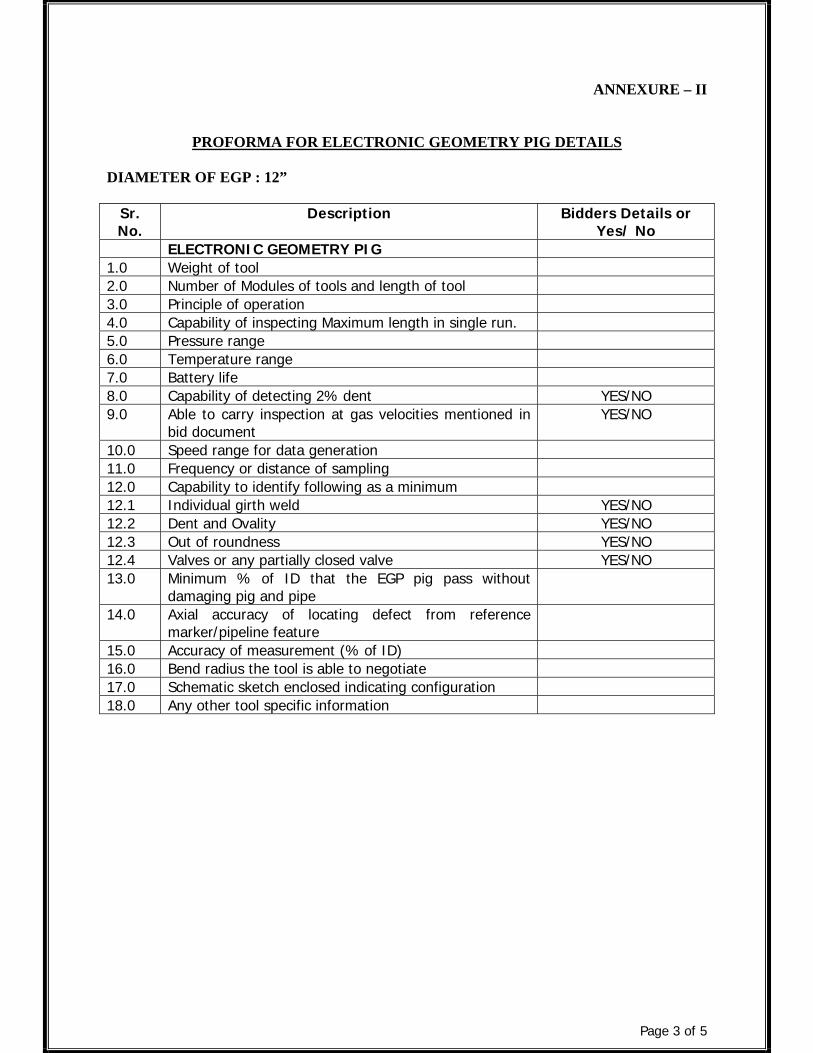
Page 3 of 5
ANNEXURE – II
PROFORMA FOR ELECTRONIC GEOMETRY PIG DETAILS
DIAMETER OF EGP : 12”
Sr.No.
Description Bidders Details orYes/ No
ELECTRONIC GEOMETRY PIG1.0 Weight of tool2.0 Number of Modules of tools and length of tool3.0 Principle of operation4.0 Capability of inspecting Maximum length in single run.5.0 Pressure range6.0 Temperature range7.0 Battery life8.0 Capability of detecting 2% dent YES/NO9.0 Able to carry inspection at gas velocities mentioned in
bid documentYES/NO
10.0 Speed range for data generation11.0 Frequency or distance of sampling12.0 Capability to identify following as a minimum12.1 Individual girth weld YES/NO12.2 Dent and Ovality YES/NO12.3 Out of roundness YES/NO12.4 Valves or any partially closed valve YES/NO13.0 Minimum % of ID that the EGP pig pass without
damaging pig and pipe14.0 Axial accuracy of locating defect from reference
marker/pipeline feature15.0 Accuracy of measurement (% of ID)16.0 Bend radius the tool is able to negotiate17.0 Schematic sketch enclosed indicating configuration18.0 Any other tool specific information

Page 4 of 5
ANNEXURE – III
PROFORMA FOR HIGH RESOLUTION MFL INSPECTION PIG DETAILS
DIAMETER OF HIGH RESOLUTION MFL TOOL: 12”
Sr.No.
Description Bidders Details orYes/ No
1.0 Bidder to confirm that the MFL inspection tool is ofHighResolution tool
YES/NO
2.0 Bidder to confirm that the HR MFL inspection tool isowned by him
YES/NO
3.0 Wall thickness range in MM4.0 Magnetization level to be achieved in the different pipe
thickness. OR Enclose graph indicating relationshipbetween magnetic field strength and wall thickness
5.0 a Speed range in m/s for data generation as per bidspecification.
5.0 b Maximum speed m/s at which the tool can beoperated.
6.0 Device if proposed for pig speed control to achievevalid,interpretable and quality data as per detection andsizing specifications of tender document.
7.0 Temperature range8.0 Maximum pressure9.0 Minimum pressure for gas pipelines10.0 Weight of tool11.0 Number of Modules of tools and total tool length12.0 Bend radius able to negotiate13.0 Capability of inspecting Maximum length in single run14.0 Axial sampling rate (frequency or distance)15.0 Circumferential sampling rate16.0 Total number of primary sensors17.0 Total number of secondary sensors18.0 Data storage capacity19.0 Battery life20.0 Maximum limit on adjacent sensors damage during the
run in order to generate data as per bid specification.21.0 Maximum % of primary and secondary sensors damage
permissible during the run in order to generate the dataas per bid specification.
22.0 Minimum % of ID that the MFL inspection pig passwithout damaging pig and pipe
23.0 Capability to identify following as a minimum23.1 General corrosion YES/NO23.2 Pitting corrosion YES/NO23.3 Circumferential gouging YES/NO23.4 Axial gouging YES/NO23.5 Location of girth weld, valves and lateral joints YES/NO23.6 Circumferential crack YES/NO
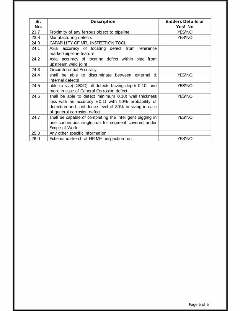
Page 5 of 5
Sr.No.
Description Bidders Details orYes/ No
23.7 Proximity of any ferrous object to pipeline YES/NO23.8 Manufacturing defects YES/NO24.0 CAPABILITY OF MFL INSPECTION TOOL24.1 Axial accuracy of locating defect from reference
marker/pipeline feature24.2 Axial accuracy of locating defect within pipe from
upstream weld joint.24.3 Circumferential Accuracy24.4 shall be able to discriminate between external &
internal defectsYES/NO
24.5 able to size(LXBXD) all defects having depth 0.10t andmore in case of General Corrosion defect.
YES/NO
24.6 shall be able to detect minimum 0.10t wall thicknessloss with an accuracy ±0.1t with 90% probability ofdetection and confidence level of 80% in sizing in caseof general corrosion defect.
YES/NO
24.7 shall be capable of completing the intelligent pigging inone continuous single run for segment covered underScope of Work
YES/NO
25.0 Any other specific information26.0 Schematic sketch of HR MFL inspection tool. YES/NO
Related Documents