Internetworking With TCP/IP Douglas Comer Computer Science Department Purdue University 250 N. University Street West Lafayette, IN 47907-2066 http://www.cs.purdue.edu/people/comer © Copyr igh t 2005 . All righ ts reserv ed. This document may not be re pr od uc ed by an y me ans with out written consent of th e aut hor.

Welcome message from author
This document is posted to help you gain knowledge. Please leave a comment to let me know what you think about it! Share it to your friends and learn new things together.
Transcript

8/6/2019 Vol1 Presentation
http://slidepdf.com/reader/full/vol1-presentation 1/856
InternetworkingWith TCP/IP
Douglas Comer
Computer Science DepartmentPurdue University
250 N. University StreetWest Lafayette, IN 47907-2066
http://www.cs.purdue.edu/people/comer
© Copyright 2005. All rights reserved. This document may notbe reproduced by any means without written consent of the author.

8/6/2019 Vol1 Presentation
http://slidepdf.com/reader/full/vol1-presentation 2/856
PART I
COURSE OVERVIEWAND
INTRODUCTION
Internetworking With TCP/IP vol 1 -- Part 1 1 2005

8/6/2019 Vol1 Presentation
http://slidepdf.com/reader/full/vol1-presentation 3/856
Topic And Scope
Internetworking: an overview of concepts, terminology, and
technology underlying the TCP/IP Internet protocol suite and
the architecture of an internet.
Internetworking With TCP/IP vol 1 -- Part 1 2 2005

8/6/2019 Vol1 Presentation
http://slidepdf.com/reader/full/vol1-presentation 4/856
You Will Learn
Terminology (including acronyms)
Concepts and principles
– The underlying model
– Encapsulation
– End-to-end paradigm
Naming and addressing
Functions of protocols including ARP, IP, TCP, UDP,
SMTP, FTP, DHCP, and more
Layering model
Internetworking With TCP/IP vol 1 -- Part 1 3 2005

8/6/2019 Vol1 Presentation
http://slidepdf.com/reader/full/vol1-presentation 5/856
You Will Learn
(continued)
Internet architecture and routing
Applications
Internetworking With TCP/IP vol 1 -- Part 1 4 2005

8/6/2019 Vol1 Presentation
http://slidepdf.com/reader/full/vol1-presentation 6/856
What You Will NOT Learn
A list of vendors, hardware products, software products,
services, comparisons, or prices
Alternative internetworking technologies (they have all
disappeared!)
Internetworking With TCP/IP vol 1 -- Part 1 5 2005
8/6/2019 Vol1 Presentation
http://slidepdf.com/reader/full/vol1-presentation 7/856
Schedule Of Topics
Introduction
Review of
– Network hardware
– Physical addressing
Internet model and concept
Internet (IP) addresses
Higher-level protocols and the layering principle
Examples of internet architecture
Internetworking With TCP/IP vol 1 -- Part 1 6 2005

8/6/2019 Vol1 Presentation
http://slidepdf.com/reader/full/vol1-presentation 8/856
Schedule Of Topics
(continued)
Routing update protocols
Application-layer protocols
Internetworking With TCP/IP vol 1 -- Part 1 7 2005

8/6/2019 Vol1 Presentation
http://slidepdf.com/reader/full/vol1-presentation 9/856
Why Study TCP/IP?
The Internet is everywhere
Most applications are distributed
Internetworking With TCP/IP vol 1 -- Part 1 8 2005

8/6/2019 Vol1 Presentation
http://slidepdf.com/reader/full/vol1-presentation 10/856
Remainder Of This Section
History of Internet protocols (TCP/IP)
Organizations
Documents
Internetworking With TCP/IP vol 1 -- Part 1 9 2005

8/6/2019 Vol1 Presentation
http://slidepdf.com/reader/full/vol1-presentation 11/856
Vendor Independence
Before TCP/IP and the Internet
– Only two sources of network protocols
* Specific vendors such as IBM or Digital Equipment
* Standards bodies such as the ITU (formerly known
as CCITT)
TCP/IP
– Vendor independent
Internetworking With TCP/IP vol 1 -- Part 1 10 2005

8/6/2019 Vol1 Presentation
http://slidepdf.com/reader/full/vol1-presentation 12/856
Who Built TCP/IP?
Internet Architecture Board (IAB)
Originally known as Internet Activities Board
Evolved from Internet Research Group
Forum for exchange among researchers
About a dozen members
Reorganized in 1989 and 1993
Merged into the Internet Society in 1992
Internetworking With TCP/IP vol 1 -- Part 1 11 2005

8/6/2019 Vol1 Presentation
http://slidepdf.com/reader/full/vol1-presentation 13/856
Components Of The
IAB Organization
IAB (Internet Architecture Board)
– Board that oversees and arbitrates
– URL is
http://www.iab.org/iab
IRTF (Internet Research Task Force)
– Coordinates research on TCP/IP and internetworking
– Virtually defunct, but may re-emerge
Internetworking With TCP/IP vol 1 -- Part 1 12 2005

8/6/2019 Vol1 Presentation
http://slidepdf.com/reader/full/vol1-presentation 14/856
Components Of The
IAB Organization
(continued)
IETF (Internet Engineering Task Force)
– Coordinates protocol and Internet engineering
– Headed by Internet Engineering Steering Group (IESG)
– Divided into N areas ( N is 10 plus or minus a few)
– Each area has a manager
– Composed of working groups (volunteers)
– URL is
http://www.ietf.org
Internetworking With TCP/IP vol 1 -- Part 1 13 2005

8/6/2019 Vol1 Presentation
http://slidepdf.com/reader/full/vol1-presentation 15/856
ICANN
Internet Corporation for Assigned Names and Numbers
http://www.icann.org
Formed in 1998 to subsume IANA contract
Not-for-profit managed by international board
Now sets policies for addresses and domain names
Support organizations
– Address allocation (ASO)
– Domain Names (DNSO)
– Protocol parameter assignments (PSO)
Internetworking With TCP/IP vol 1 -- Part 1 14 2005

8/6/2019 Vol1 Presentation
http://slidepdf.com/reader/full/vol1-presentation 16/856
ICANN
Internet Corporation for Assigned Names and Numbers
http://www.icann.org
Formed in 1998 to subsume IANA contract
Not-for-profit managed by international board
Now sets policies for addresses and domain names
Support organizations
– Address allocation (ASO)
– Domain Names (DNSO)
– Protocol parameter assignments (PSO)
For fun see http://www.icannwatch.org
Internetworking With TCP/IP vol 1 -- Part 1 14 2005

8/6/2019 Vol1 Presentation
http://slidepdf.com/reader/full/vol1-presentation 17/856
World Wide Web Consortium
Organization to develop common protocols for World Wide
Web
Open membership
Funded by commercial members
URL is
http://w3c.org
Internetworking With TCP/IP vol 1 -- Part 1 15 2005

8/6/2019 Vol1 Presentation
http://slidepdf.com/reader/full/vol1-presentation 18/856
Internet Society
Organization that promotes the use of the Internet
Formed in 1992
Not-for-profit
Governed by a board of trustees
Members worldwide
URL is
http://www.isoc.org
Internetworking With TCP/IP vol 1 -- Part 1 16 2005

8/6/2019 Vol1 Presentation
http://slidepdf.com/reader/full/vol1-presentation 19/856
Protocol Specifications
And Documents
Protocols documented in series of reports
Documents known as Request For Comments ( RFCs)
Internetworking With TCP/IP vol 1 -- Part 1 17 2005

8/6/2019 Vol1 Presentation
http://slidepdf.com/reader/full/vol1-presentation 20/856
RFCs
Series of reports that include
– TCP/IP protocols
– The Internet
– Related technologies
Edited, but not peer-reviewed like scientific journals
Contain:
– Proposals
– Surveys and measurements– Protocol standards
Internetworking With TCP/IP vol 1 -- Part 1 18 2005

8/6/2019 Vol1 Presentation
http://slidepdf.com/reader/full/vol1-presentation 21/856
RFCs
Series of reports that include
– TCP/IP protocols
– The Internet
– Related technologies
Checked and edited by IESG
Contain:
– Proposals
– Surveys and measurements– Protocol Standards
– Jokes!
Internetworking With TCP/IP vol 1 -- Part 1 19 2005

8/6/2019 Vol1 Presentation
http://slidepdf.com/reader/full/vol1-presentation 22/856
RFCs
(continued)
Numbered in chronological order
Revised document reissued under new number
Numbers ending in 99 reserved for summary of previous
100 RFCs
Index and all RFCs available on-line
Internetworking With TCP/IP vol 1 -- Part 1 20 2005

8/6/2019 Vol1 Presentation
http://slidepdf.com/reader/full/vol1-presentation 23/856
Requirements RFCs
Host Requirements Documents
– Major revision/clarification of most TCP/IP protocols
– RFC 1122 (Communication Layers)
– RFC 1123 (Application & Support)
– RFC 1127 (Perspective on 1122-3)
Router Requirements
– Major specification of protocols used in IP gateways
(routers)
– RFC 1812 (updated by RFC 2644)
Internetworking With TCP/IP vol 1 -- Part 1 21 2005

8/6/2019 Vol1 Presentation
http://slidepdf.com/reader/full/vol1-presentation 24/856
Special Subsets Of RFCs
For Your Information (FYI)
– Provide general information
– Intended for beginners
Best Current Practices (BCP)
– Engineering hints
– Reviewed and approved by IESG
Internetworking With TCP/IP vol 1 -- Part 1 22 2005

8/6/2019 Vol1 Presentation
http://slidepdf.com/reader/full/vol1-presentation 25/856
A Note About RFCs
RFCs span two extremes
– Protocol standards
– Jokes
Question: how does one know which are standards?
Internetworking With TCP/IP vol 1 -- Part 1 23 2005

8/6/2019 Vol1 Presentation
http://slidepdf.com/reader/full/vol1-presentation 26/856
TCP/IP Standards (STD)
Set by vote of IETF
Documented in subset of RFCs
Found in Internet Official Protocol Standards RFC and on
IETF web site
– Issued periodically
– Current version is RFC 3600
Internetworking With TCP/IP vol 1 -- Part 1 24 2005

8/6/2019 Vol1 Presentation
http://slidepdf.com/reader/full/vol1-presentation 27/856
Internet Drafts
Preliminary RFC documents
Often used by IETF working groups
Available on-line from several repositories
Either become RFCs within six months or disappear
Internetworking With TCP/IP vol 1 -- Part 1 25 2005

8/6/2019 Vol1 Presentation
http://slidepdf.com/reader/full/vol1-presentation 28/856
Obtaining RFCs And
Internet Drafts
Available via
– FTP
– World Wide Web
http://www.ietf.org/
IETF report contains summary of weekly activity
http://www.isoc.org/ietfreport/
Internetworking With TCP/IP vol 1 -- Part 1 26 2005

8/6/2019 Vol1 Presentation
http://slidepdf.com/reader/full/vol1-presentation 29/856
Summary
TCP/IP is vendor-independent
Standards set by IETF
Protocol standards found in document series known as
Request For Comments ( RFCs)
Standards found in subset of RFCs labeled STD
Internetworking With TCP/IP vol 1 -- Part 1 27 2005

8/6/2019 Vol1 Presentation
http://slidepdf.com/reader/full/vol1-presentation 30/856
Questions?

8/6/2019 Vol1 Presentation
http://slidepdf.com/reader/full/vol1-presentation 31/856
PART II
REVIEW OF
NETWORK HARDWARE AND
PHYSICAL ADDRESSING
Internetworking With TCP/IP vol 1 -- Part 2 1 2005

8/6/2019 Vol1 Presentation
http://slidepdf.com/reader/full/vol1-presentation 32/856
The TCP/IP Concept
Use existing network hardware
Interconnect networks
Add abstractions to hide heterogeneity
Internetworking With TCP/IP vol 1 -- Part 2 2 2005

8/6/2019 Vol1 Presentation
http://slidepdf.com/reader/full/vol1-presentation 33/856
The Challenge
Accommodate all possible network hardware
Question: what kinds of hardware exist?
Internetworking With TCP/IP vol 1 -- Part 2 3 2005

8/6/2019 Vol1 Presentation
http://slidepdf.com/reader/full/vol1-presentation 34/856
Network Hardware Review
We will
– Review basic network concepts
– Examine example physical network technologies
– Introduce physical (hardware) addressing
Internetworking With TCP/IP vol 1 -- Part 2 4 2005

8/6/2019 Vol1 Presentation
http://slidepdf.com/reader/full/vol1-presentation 35/856
Two Basic Categories
Of Network Hardware
Connection oriented
Connectionless
Internetworking With TCP/IP vol 1 -- Part 2 5 2005
8/6/2019 Vol1 Presentation
http://slidepdf.com/reader/full/vol1-presentation 36/856
Connection Oriented
(Circuit Switched Technology)
Paradigm
– Form a ‘‘connection’’ through the network
– Send / receive data over the connection
– Terminate the connection
Can guarantee bandwidth
Proponents argue that it works well with real-time
applications
Example: ATM network
Internetworking With TCP/IP vol 1 -- Part 2 6 2005

8/6/2019 Vol1 Presentation
http://slidepdf.com/reader/full/vol1-presentation 37/856
Connectionless
(Packet Switched Technology)
Paradigm
– Form ‘‘packet’’ of data
– Pass to network
Each packet travels independently
Packet includes identification of the destination
Each packet can be a different size
The maximum packet size is fixed (some technologies limitpacket sizes to 1,500 octets or less)
Internetworking With TCP/IP vol 1 -- Part 2 7 2005

8/6/2019 Vol1 Presentation
http://slidepdf.com/reader/full/vol1-presentation 38/856
Broad Characterizations Of
Packet Switching Networks
Local Area Network (LAN)
Wide Area Network (WAN)
Categories are informal and qualitative
Internetworking With TCP/IP vol 1 -- Part 2 8 2005

8/6/2019 Vol1 Presentation
http://slidepdf.com/reader/full/vol1-presentation 39/856
Local Area Networks
Engineered for
– Low cost
– High capacity
Direct connection among computers
Limited distance
Internetworking With TCP/IP vol 1 -- Part 2 9 2005

8/6/2019 Vol1 Presentation
http://slidepdf.com/reader/full/vol1-presentation 40/856
Wide Area Networks
(Long Haul Networks)
Engineered for
– Long distances
– Indirect interconnection via special-purpose hardware
Higher cost
Lower capacity (usually)
Internetworking With TCP/IP vol 1 -- Part 2 10 2005
8/6/2019 Vol1 Presentation
http://slidepdf.com/reader/full/vol1-presentation 41/856
Examples Of Packet
Switched Networks
Wide Area Nets
– ARPANET, NSFNET, ANSNET
– Common carrier services
Leased line services
– Point-to-point connections
Local Area Nets
– Ethernet
– Wi-Fi
Internetworking With TCP/IP vol 1 -- Part 2 11 2005

8/6/2019 Vol1 Presentation
http://slidepdf.com/reader/full/vol1-presentation 42/856
ARPANET (1969-1989)
Original backbone of Internet
Wide area network around which TCP/IP was developed
Funding from Advanced Research Project Agency
Initial speed 50 Kbps
Internetworking With TCP/IP vol 1 -- Part 2 12 2005
8/6/2019 Vol1 Presentation
http://slidepdf.com/reader/full/vol1-presentation 43/856
NSFNET (1987-1992)
Funded by National Science Foundation
Motivation: Internet backbone to connect all scientists and
engineers
Introduced Internet hierarchy
– Wide area backbone spanning geographic U.S.
– Many mid-level (regional) networks that attach to
backbone
– Campus networks at lowest level
Initial speed 1.544 Mbps
Internetworking With TCP/IP vol 1 -- Part 2 13 2005

8/6/2019 Vol1 Presentation
http://slidepdf.com/reader/full/vol1-presentation 44/856
ANSNET (1992-1995)
End-User Site
MCI Point of Presence
Backbone of Internet before commercial ISPs
Typical topology
Internetworking With TCP/IP vol 1 -- Part 2 14 2005

8/6/2019 Vol1 Presentation
http://slidepdf.com/reader/full/vol1-presentation 45/856
Wide Area Networks Available
From Common Carriers
Point-to-point digital circuits
– T-series (e.g., T1 = 1.5 Mbps, T3 = 45 Mbps)
– OC-series (e.g., OC-3 = 155 Mbps, OC-48 = 2.4 Gbps)
Packet switching services also available
– Examples: ISDN, SMDS, Frame Relay, ATM
Internetworking With TCP/IP vol 1 -- Part 2 15 2005

8/6/2019 Vol1 Presentation
http://slidepdf.com/reader/full/vol1-presentation 46/856
Example Local Area
Network: Ethernet
Extremely popular
Can run over
– Copper (twisted pair)
– Optical fiber
Three generations
– 10Base-T operates at 10 Mbps
– 100Base-T (fast Ethernet) operates at 100 Mbps
– 1000Base-T (gigabit Ethernet) operates at 1 Gbps
IEEE standard is 802.3
Internetworking With TCP/IP vol 1 -- Part 2 16 2005

8/6/2019 Vol1 Presentation
http://slidepdf.com/reader/full/vol1-presentation 47/856
Ethernet Frame Format
8 octets 6 octets 6 octets 2 octets 46–1500 octets 4 octets
PreambleDestination
AddressSource
AddressFrameType Frame Data CRC
Header format fixed (Destination, Source, Type fields)
Frame data size can vary from packet to packet
– Maximum 1500 octets
– Minimum 46 octets
Preamble and CRC removed by framer hardware before
frame stored in computer’s memory
Internetworking With TCP/IP vol 1 -- Part 2 17 2005

8/6/2019 Vol1 Presentation
http://slidepdf.com/reader/full/vol1-presentation 48/856
Example Ethernet Frame In Memory
02 07 01 00 27 ba 08 00 2b 0d 44 a7 08 00 45 00
00 54 82 68 00 00 f f 01 35 21 80 0a 02 03 80 0a
02 08 08 00 73 0b d4 6d 00 00 04 3b 8c 28 28 20
0d 00 08 09 0a 0b 0c 0d 0e 0 f 10 11 12 13 14 15
16 17 18 19 1a 1b 1c 1d 1e 1f 20 21 22 23 24 25
26 27 28 29 2a 2b 2c 2d 2e 2f 30 31 32 33 34 35
36 37
Octets shown in hexadecimal
Destination is 02.07.01.00.27.ba
Source is 08.00.2b.0d.44.a7
Frame type is 08.00 (IP)
Internetworking With TCP/IP vol 1 -- Part 2 18 2005

8/6/2019 Vol1 Presentation
http://slidepdf.com/reader/full/vol1-presentation 49/856
Point-to-Point Network
Any direct connection between two computers
– Leased line
– Connection between two routers
– Dialup connection
Link-level protocol required for framing
TCP/IP views as an independent network
Note: some pundits argue the terminology is incorrect because aconnection limited to two endpoints is not technically a
‘‘network’’
Internetworking With TCP/IP vol 1 -- Part 2 19 2005

8/6/2019 Vol1 Presentation
http://slidepdf.com/reader/full/vol1-presentation 50/856
Hardware Address
Unique number assigned to each machine on a network
Used to identify destination for a packet
Internetworking With TCP/IP vol 1 -- Part 2 20 2005

8/6/2019 Vol1 Presentation
http://slidepdf.com/reader/full/vol1-presentation 51/856
Hardware Address Terminology
Known as
– MAC (Media Access Control) address
– Physical address
– Hardware unicast address
Hardware engineers assign fine distinctions to the above
terms
We will treat all terms equally
Internetworking With TCP/IP vol 1 -- Part 2 21 2005
8/6/2019 Vol1 Presentation
http://slidepdf.com/reader/full/vol1-presentation 52/856
Use Of Hardware Address
Sender supplies
– Destination’s address
– Source address (in most technologies)
Network hardware
– Uses destination address to forward packet
– Delivers packet to proper machine.
Important note: each technology defines its own addressing
scheme
Internetworking With TCP/IP vol 1 -- Part 2 22 2005

8/6/2019 Vol1 Presentation
http://slidepdf.com/reader/full/vol1-presentation 53/856
Three Types Of Hardware
Addressing Schemes
Static
– Address assigned by hardware vendor
Configurable
– Address assigned by customer
Dynamic
– Address assigned by software at startup
Internetworking With TCP/IP vol 1 -- Part 2 23 2005

8/6/2019 Vol1 Presentation
http://slidepdf.com/reader/full/vol1-presentation 54/856
Examples Of Hardware Address Types
Configurable: proNET-10 (Proteon)
– 8-bit address per interface card
– All 1s address reserved for broadcast
– Address assigned by customer when device installed
Dynamic MAC addressing: LocalTalk (Apple)
– Randomized bidding
– Handled by protocols in software
Internetworking With TCP/IP vol 1 -- Part 2 24 2005

8/6/2019 Vol1 Presentation
http://slidepdf.com/reader/full/vol1-presentation 55/856
Examples Of Hardware Address Types
(continued)
Static MAC addressing: Ethernet
– 48-bit address
– Unicast address assigned when device manufactured
– All 1s address reserved for broadcast
– One-half address space reserved for multicast (restricted
form of broadcast)
Ethernet’s static addressing is now most common form
Internetworking With TCP/IP vol 1 -- Part 2 25 2005

8/6/2019 Vol1 Presentation
http://slidepdf.com/reader/full/vol1-presentation 56/856
Bridge
Hardware device that connects multiple LANs and makes
them appear to be a single LAN
Repeats all packets from one LAN to the other and vice
versa
Introduces delay of 1 packet-time
Does not forward collisions or noise
Called Layer 2 Interconnect or Layer 2 forwarder
Makes multiple LANs appear to be a single, large LAN
Often embedded in other equipment (e.g., DSL modem)
Internetworking With TCP/IP vol 1 -- Part 2 26 2005

8/6/2019 Vol1 Presentation
http://slidepdf.com/reader/full/vol1-presentation 57/856
Bridge
(continued)
Watches packets to learn which computers are on which
side of the bridge
Uses hardware addresses to filter
Internetworking With TCP/IP vol 1 -- Part 2 27 2005

8/6/2019 Vol1 Presentation
http://slidepdf.com/reader/full/vol1-presentation 58/856
Layer 2 Switch
Electronic device
Computers connect directly
Applies bridging algorithm
Can separate computers onto virtual networks (VLAN
switch)
Internetworking With TCP/IP vol 1 -- Part 2 28 2005

8/6/2019 Vol1 Presentation
http://slidepdf.com/reader/full/vol1-presentation 59/856
Physical Networks As
Viewed By TCP/IP
TCP/IP protocols accommodate
– Local Area Network
– Wide Area Network
– Point-to-point link
– Set of bridged LANs
Internetworking With TCP/IP vol 1 -- Part 2 29 2005

8/6/2019 Vol1 Presentation
http://slidepdf.com/reader/full/vol1-presentation 60/856
The Motivation For Heterogeneity
Each network technology has advantages for some
applications
Consequence: an internet may contain combinations of
technologies
Internetworking With TCP/IP vol 1 -- Part 2 30 2005
8/6/2019 Vol1 Presentation
http://slidepdf.com/reader/full/vol1-presentation 61/856
Heterogeneity And Addressing
Recall: each technology can define its own addressing
scheme
Heterogeneous networks imply potential for heterogeneous
addressing
Conclusion: cannot rely on hardware addressing
Internetworking With TCP/IP vol 1 -- Part 2 31 2005

8/6/2019 Vol1 Presentation
http://slidepdf.com/reader/full/vol1-presentation 62/856
Summary
TCP/IP is designed to use all types of networks
– Connection-oriented
– Connectionless
– Local Area Network (LAN)
– Wide Area Network (WAN)
– Point-to-point link
– Set of bridged networks
Internetworking With TCP/IP vol 1 -- Part 2 32 2005

8/6/2019 Vol1 Presentation
http://slidepdf.com/reader/full/vol1-presentation 63/856
Summary
(continued)
Each technology defines an addressing scheme
TCP/IP must accommodate heterogeneous addressing
schemes
Internetworking With TCP/IP vol 1 -- Part 2 33 2005

8/6/2019 Vol1 Presentation
http://slidepdf.com/reader/full/vol1-presentation 64/856
Questions?

8/6/2019 Vol1 Presentation
http://slidepdf.com/reader/full/vol1-presentation 65/856
PART III
INTERNETWORKING CONCEPT
AND ARCHITECTURAL MODEL
Internetworking With TCP/IP vol 1 -- Part 3 1 2005

8/6/2019 Vol1 Presentation
http://slidepdf.com/reader/full/vol1-presentation 66/856
Accommodating Heterogeneity
Approach 1
– Application gateways
– Gateway forwards data from one network to another
– Example: file transfer gateway
Approach 2
– Network-level gateways
– Gateway forwards individual packets
Discussion question: which is better?
Internetworking With TCP/IP vol 1 -- Part 3 2 2005
i i
8/6/2019 Vol1 Presentation
http://slidepdf.com/reader/full/vol1-presentation 67/856
Desired Properties
Universal service
End-to-end connectivity
Transparency
Internetworking With TCP/IP vol 1 -- Part 3 3 2005
A N d d T

8/6/2019 Vol1 Presentation
http://slidepdf.com/reader/full/vol1-presentation 68/856
Agreement Needed To
Achieve Desired Properties
Data formats
Procedures for exchanging information
Identification
– Services
– Computers
– Applications
Broad concepts: naming and addressing
Internetworking With TCP/IP vol 1 -- Part 3 4 2005
Th TCP/IP I C

8/6/2019 Vol1 Presentation
http://slidepdf.com/reader/full/vol1-presentation 69/856
The TCP/IP Internet Concept
Use available networks
Interconnect physical networks
– Network of networks
– Revolutionary when proposed
Devise abstractions that hide
– Underlying architecture
– Hardware addresses
– Routes
Internetworking With TCP/IP vol 1 -- Part 3 5 2005
N t k I t ti
8/6/2019 Vol1 Presentation
http://slidepdf.com/reader/full/vol1-presentation 70/856
Network Interconnection
Uses active system
Each network sees an additional computer attached
Device is IP router (originally called IP gateway)
Internetworking With TCP/IP vol 1 -- Part 3 6 2005
Ill t ti Of

8/6/2019 Vol1 Presentation
http://slidepdf.com/reader/full/vol1-presentation 71/856
Illustration Of
Network Interconnection
Net 1 R Net 2
Network technologies can differ
– LAN and WAN
– Connection-oriented and connectionless
Internetworking With TCP/IP vol 1 -- Part 3 7 2005
B ildi A I t t

8/6/2019 Vol1 Presentation
http://slidepdf.com/reader/full/vol1-presentation 72/856
Building An Internet
Use multiple IP routers
Ensure that each network is reachable
Do not need router between each pair of networks
Internetworking With TCP/IP vol 1 -- Part 3 8 2005
E l Of M lti l N t k

8/6/2019 Vol1 Presentation
http://slidepdf.com/reader/full/vol1-presentation 73/856
Example Of Multiple Networks
R2 R2Net 1 Net 2 Net 3
Networks can be heterogeneous
No direct connection from network 1 to network 3
Internetworking With TCP/IP vol 1 -- Part 3 9 2005
Ph i l C ti it

8/6/2019 Vol1 Presentation
http://slidepdf.com/reader/full/vol1-presentation 74/856
Physical Connectivity
In a TCP/IP internet, special computers called IP routers or IP
gateways provide interconnections among physical networks.
Internetworking With TCP/IP vol 1 -- Part 3 10 2005
P k t T i i P di

8/6/2019 Vol1 Presentation
http://slidepdf.com/reader/full/vol1-presentation 75/856
Packet Transmission Paradigm
Source computer
– Generates a packet
– Sends across one network to a router
Intermediate router
– Forwards packet to ‘‘next’’ router
Final router
– Delivers packet to destination
Internetworking With TCP/IP vol 1 -- Part 3 11 2005
An Important Point

8/6/2019 Vol1 Presentation
http://slidepdf.com/reader/full/vol1-presentation 76/856
An Important Point
About Forwarding
Routers use the destination network, not the destination
computer, when forwarding packets.
Internetworking With TCP/IP vol 1 -- Part 3 12 2005
Equal Treatment

8/6/2019 Vol1 Presentation
http://slidepdf.com/reader/full/vol1-presentation 77/856
Equal Treatment
The TCP/IP internet protocols treat all networks equally. A
Local Area Network such as an Ethernet, a Wide Area Network
used as a backbone, or a point-to-point link between two
computers each count as one network.
Internetworking With TCP/IP vol 1 -- Part 3 13 2005
User’s View Of Internet

8/6/2019 Vol1 Presentation
http://slidepdf.com/reader/full/vol1-presentation 78/856
User’s View Of Internet
Single large (global) network
User’s computers all attach directly
No other structure visible
Internetworking With TCP/IP vol 1 -- Part 3 14 2005
Illustration Of User’s View Of

8/6/2019 Vol1 Presentation
http://slidepdf.com/reader/full/vol1-presentation 79/856
Illustration Of User’s View Of
A TCP/IP Internet
user’s view
Internetworking With TCP/IP vol 1 -- Part 3 15 2005
Actual Internet Architecture

8/6/2019 Vol1 Presentation
http://slidepdf.com/reader/full/vol1-presentation 80/856
Actual Internet Architecture
Multiple physical networks interconnected
Each host attaches to one network
Single virtual network achieved through software that
implements abstractions
Internetworking With TCP/IP vol 1 -- Part 3 16 2005
The Two Views Of

8/6/2019 Vol1 Presentation
http://slidepdf.com/reader/full/vol1-presentation 81/856
The Two Views Of
A TCP/IP Internet
user’s view actual connections
Internetworking With TCP/IP vol 1 -- Part 3 17 2005
Architectural Terminology

8/6/2019 Vol1 Presentation
http://slidepdf.com/reader/full/vol1-presentation 82/856
Architectural Terminology
End-user system is called host computer
– Connects to physical network
– Possibly many hosts per network
– Possibly more than one network connection per host
Dedicated systems called IP gateways or IP routers
interconnect networks
– Router connects two or more networks
Internetworking With TCP/IP vol 1 -- Part 3 18 2005
Many Unanswered Questions

8/6/2019 Vol1 Presentation
http://slidepdf.com/reader/full/vol1-presentation 83/856
Many Unanswered Questions
Addressing model and relationship to hardware addresses
Format of packet as it travels through Internet
How a host handles concurrent communication with several
other hosts
Internetworking With TCP/IP vol 1 -- Part 3 19 2005
Summary

8/6/2019 Vol1 Presentation
http://slidepdf.com/reader/full/vol1-presentation 84/856
Summary
Internet is set of interconnected (possibly heterogeneous)
networks
Routers provide interconnection
End-user systems are called host computers
Internetworking introduces abstractions that hide details of underlying networks
Internetworking With TCP/IP vol 1 -- Part 3 20 2005

8/6/2019 Vol1 Presentation
http://slidepdf.com/reader/full/vol1-presentation 85/856
Questions?

8/6/2019 Vol1 Presentation
http://slidepdf.com/reader/full/vol1-presentation 86/856
PART IV
CLASSFUL INTERNET ADDRESSES
Internetworking With TCP/IP vol 1 -- Part 4 1 2005
Definitions

8/6/2019 Vol1 Presentation
http://slidepdf.com/reader/full/vol1-presentation 87/856
Definitions
Name
– Identifies what an entity is
– Often textual (e.g., ASCII)
Address
– Identifies where an entity is located
– Often binary and usually compact
– Sometimes called locator
Route
– Identifies how to get to the object
– May be distributed
Internetworking With TCP/IP vol 1 -- Part 4 2 2005
Internet Protocol Address

8/6/2019 Vol1 Presentation
http://slidepdf.com/reader/full/vol1-presentation 88/856
Internet Protocol Address
(IP Address)
Analogous to hardware address
Unique value assigned as unicast address to each host on
Internet
Used by Internet applications
Internetworking With TCP/IP vol 1 -- Part 4 3 2005
IP Address Details

8/6/2019 Vol1 Presentation
http://slidepdf.com/reader/full/vol1-presentation 89/856
IP Address Details
32-bit binary value
Unique value assigned to each host in Internet
Values chosen to make routing efficient
Internetworking With TCP/IP vol 1 -- Part 4 4 2005
IP Address Division

8/6/2019 Vol1 Presentation
http://slidepdf.com/reader/full/vol1-presentation 90/856
IP Address Division
Address divided into two parts
– Prefix (network ID) identifies network to which host
attaches
– Suffix (host ID) identifies host on that network
Internetworking With TCP/IP vol 1 -- Part 4 5 2005
Classful Addressing

8/6/2019 Vol1 Presentation
http://slidepdf.com/reader/full/vol1-presentation 91/856
Classful Addressing
Original IP scheme
Explains many design decisions
New schemes are backward compatible
Internetworking With TCP/IP vol 1 -- Part 4 6 2005
Desirable Properties Of An

8/6/2019 Vol1 Presentation
http://slidepdf.com/reader/full/vol1-presentation 92/856
Desirable Properties Of An
Internet Addressing Scheme
Compact (as small as possible)
Universal (big enough)
Works with all network hardware
Supports efficient decision making
– Test whether a destination can be reached directly
– Decide which router to use for indirect delivery
– Choose next router along a path to the destination
Internetworking With TCP/IP vol 1 -- Part 4 7 2005
Division Of Internet Address

8/6/2019 Vol1 Presentation
http://slidepdf.com/reader/full/vol1-presentation 93/856
Division Of Internet Address
Into Prefix And Suffix
How should division be made?
– Large prefix, small suffix means many possible
networks, but each is limited in size
– Large suffix, small prefix means each network can be
large, but there can only be a few networks
Original Internet address scheme designed to accommodate
both possibilities
– Known as classful addressing
Internetworking With TCP/IP vol 1 -- Part 4 8 2005
Original IPv4 Address Classes

8/6/2019 Vol1 Presentation
http://slidepdf.com/reader/full/vol1-presentation 94/856
O g C
0 netid hostid
1 0 netid hostid
1 1 0 netid hostid
1 1 1 0 IP multicast
1 1 1 1 0 reserved
Class A
Class B
Class C
Class D
Class E
Three Principle Classes
Other (seldom used) Classes
0 1 8 16 24 31
0 1 2 3 31
Internetworking With TCP/IP vol 1 -- Part 4 9 2005
Important Property

8/6/2019 Vol1 Presentation
http://slidepdf.com/reader/full/vol1-presentation 95/856
p p y
Classful addresses are self-identifying
Consequences
– Can determine boundary between prefix and suffix from
the address itself
– No additional state needed to store boundary information
– Both hosts and routers benefit
Internetworking With TCP/IP vol 1 -- Part 4 10 2005
Endpoint Identification

8/6/2019 Vol1 Presentation
http://slidepdf.com/reader/full/vol1-presentation 96/856
p
Because IP addresses encode both a network and a host on that
network, they do not specify an individual computer, but a
connection to a network.
Internetworking With TCP/IP vol 1 -- Part 4 11 2005
IP Address Conventions

8/6/2019 Vol1 Presentation
http://slidepdf.com/reader/full/vol1-presentation 97/856
When used to refer to a network
– Host field contains all 0 bits
Broadcast on the local wire
– Network and host fields both contain all 1 bits
Directed broadcast: broadcast on specific (possibly remote)
network
– Host field contains all 1 bits
– Nonstandard form: host field contains all 0 bits
Internetworking With TCP/IP vol 1 -- Part 4 12 2005
Assignment Of IP Addresses

8/6/2019 Vol1 Presentation
http://slidepdf.com/reader/full/vol1-presentation 98/856
g
All hosts on same network assigned same address prefix
– Prefixes assigned by central authority
– Obtained from ISP
Each host on a network has a unique suffix
– Assigned locally
– Local administrator must ensure uniqueness
Internetworking With TCP/IP vol 1 -- Part 4 13 2005
Advantages Of Classful Addressing

8/6/2019 Vol1 Presentation
http://slidepdf.com/reader/full/vol1-presentation 99/856
g g
Computationally efficient
– First bits specify size of prefix / suffix
Allows mixtures of large and small networks
Internetworking With TCP/IP vol 1 -- Part 4 14 2005
Directed Broadcast

8/6/2019 Vol1 Presentation
http://slidepdf.com/reader/full/vol1-presentation 100/856
IP addresses can be used to specify a directed broadcast in
which a packet is sent to all computers on a network; such
addresses map to hardware broadcast, if available. By
convention, a directed broadcast address has a valid netid and
has a hostid with all bits set to 1.
Internetworking With TCP/IP vol 1 -- Part 4 15 2005
Limited Broadcast

8/6/2019 Vol1 Presentation
http://slidepdf.com/reader/full/vol1-presentation 101/856
All 1’s
Broadcast limited to local network only (no forwarding)
Useful for bootstrapping
Internetworking With TCP/IP vol 1 -- Part 4 16 2005
All Zeros IP Address

8/6/2019 Vol1 Presentation
http://slidepdf.com/reader/full/vol1-presentation 102/856
Can only appear as source address
Used during bootstrap before computer knows its address
Means ‘‘this’’ computer
Internetworking With TCP/IP vol 1 -- Part 4 17 2005
Internet Multicast

8/6/2019 Vol1 Presentation
http://slidepdf.com/reader/full/vol1-presentation 103/856
IP allows Internet multicast, but no Internet-wide multicast
delivery system currently in place
Class D addresses reserved for multicast
Each address corresponds to group of participating
computers
IP multicast uses hardware multicast when available
More later in the course
Internetworking With TCP/IP vol 1 -- Part 4 18 2005
Consequences Of IP Addressing
8/6/2019 Vol1 Presentation
http://slidepdf.com/reader/full/vol1-presentation 104/856
If a host computer moves from one network to another, its
IP address must change
For a multi-homed host (with two or more addresses), the
path taken by packets depends on the address used
Internetworking With TCP/IP vol 1 -- Part 4 19 2005
Multi-Homed Hosts And Reliability
8/6/2019 Vol1 Presentation
http://slidepdf.com/reader/full/vol1-presentation 105/856
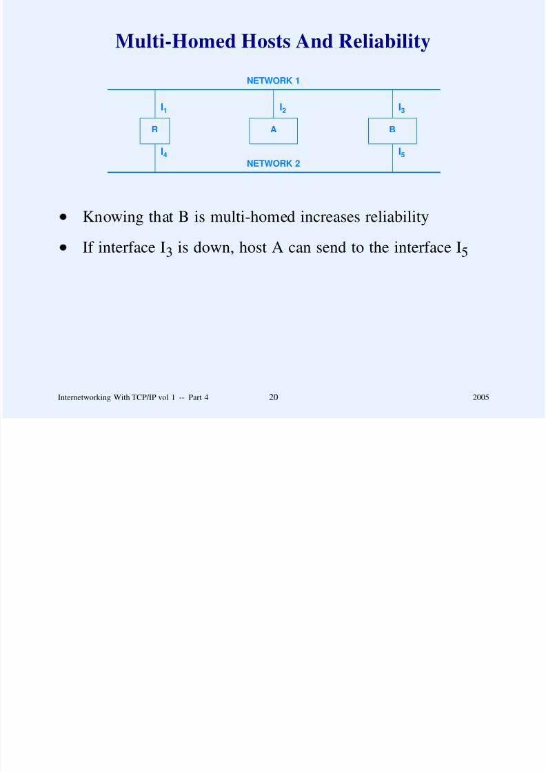
NETWORK 1
NETWORK 2
R A B
I1 I2 I3
I4 I5
Knowing that B is multi-homed increases reliability
If interface I3 is down, host A can send to the interface I5
Internetworking With TCP/IP vol 1 -- Part 4 20 2005
Dotted Decimal Notation

8/6/2019 Vol1 Presentation
http://slidepdf.com/reader/full/vol1-presentation 106/856
Syntactic form for expressing 32-bit address
Used throughout the Internet and associated literature
Represents each octet in decimal separated by periods (dots)
Internetworking With TCP/IP vol 1 -- Part 4 21 2005
Example Of Dotted Decimal

8/6/2019 Vol1 Presentation
http://slidepdf.com/reader/full/vol1-presentation 107/856
Notation
A 32-bit number in binary
10000000 00001010 00000010 00000011
The same 32-bit number expressed in dotted decimalnotation
128 . 10 . 2 . 3
Internetworking With TCP/IP vol 1 -- Part 4 22 2005
Loopback Address

8/6/2019 Vol1 Presentation
http://slidepdf.com/reader/full/vol1-presentation 108/856
Used for testing
Refers to local computer (never sent to Internet)
Address is 127.0.0.1
Internetworking With TCP/IP vol 1 -- Part 4 23 2005
Classful Address Ranges

8/6/2019 Vol1 Presentation
http://slidepdf.com/reader/full/vol1-presentation 109/856
Class Lowest Address Highest Address
A 1.0.0.0 126.0.0.0
B 128.1.0.0 191.255.0.0C 192.0.1.0 223.255.255.0
D 224.0.0.0 239.255.255.255
E 240.0.0.0 255.255.255.254
Internetworking With TCP/IP vol 1 -- Part 4 24 2005
Summary Of Address Conventions

8/6/2019 Vol1 Presentation
http://slidepdf.com/reader/full/vol1-presentation 110/856
all 0s
all 0s host
all 1s
net all 1s
127 anything (often 1)
This host 1
Host on this net 1
Limited broadcast (local net) 2
Directed broadcast for net 2
Loopback 3
1 Allowed only at system startup and is
never a valid destination address.2 Never a valid source address.3 Should never appear on a network.
Notes:
Internetworking With TCP/IP vol 1 -- Part 4 25 2005
An Example Of IP Addresses

8/6/2019 Vol1 Presentation
http://slidepdf.com/reader/full/vol1-presentation 111/856
ISP9.0.0.0
ETHERNET128.10.0.0
WI-FINETWORK128.210.0.0
routers
Internetworking With TCP/IP vol 1 -- Part 4 26 2005
Example Host Addresses

8/6/2019 Vol1 Presentation
http://slidepdf.com/reader/full/vol1-presentation 112/856
ETHERNET 128.10.0.0
MERLIN(multi-homed
host)
GUENEVERE(Ethernet
host)
LANCELOT(Ethernet
host)
WI-FINETWORK128.210.0.0
ARTHUR
(Wi-Fihost)
128.10.2.3 128.10.2.8 128.10.2.26
128.210.0.1
128.210.0.3
128.10.0.6
128.210.50
128.10.2.70
TALIESYN(router)
GLATISANT(router)
To ISP
Internetworking With TCP/IP vol 1 -- Part 4 27 2005
Another Addressing Example

8/6/2019 Vol1 Presentation
http://slidepdf.com/reader/full/vol1-presentation 113/856
Assume an organization has three networks
Organization obtains three prefixes, one per network
Host address must begin with network prefix
Internetworking With TCP/IP vol 1 -- Part 4 28 2005
Illustration Of IP Addressing

8/6/2019 Vol1 Presentation
http://slidepdf.com/reader/full/vol1-presentation 114/856
R1Router to Internet
Rest of the Internet
R2 R3
H1
128.10.0.0
192.5.48.0 128.211.0.0
128.211.0.9
Example host
Hosts and routersusing other addresses
Site with three
networks
Internetworking With TCP/IP vol 1 -- Part 4 29 2005
Summary

8/6/2019 Vol1 Presentation
http://slidepdf.com/reader/full/vol1-presentation 115/856
IP address
– 32 bits long
– Prefix identifies network
– Suffix identifies host
Classful addressing uses first few bits of address todetermine boundary between prefix and suffix
Internetworking With TCP/IP vol 1 -- Part 4 30 2005
Summary
( ti d)

8/6/2019 Vol1 Presentation
http://slidepdf.com/reader/full/vol1-presentation 116/856
(continued)
Special forms of addresses handle
– Limited broadcast
– Directed broadcast
– Network identification
– This host
– Loopback
Internetworking With TCP/IP vol 1 -- Part 4 31 2005

8/6/2019 Vol1 Presentation
http://slidepdf.com/reader/full/vol1-presentation 117/856
Questions?

8/6/2019 Vol1 Presentation
http://slidepdf.com/reader/full/vol1-presentation 118/856
PART V
MAPPING INTERNET ADDRESSESTO PHYSICAL ADDRESSES
(ARP)
Internetworking With TCP/IP vol 1 -- Part 5 1 2005
Motivation

8/6/2019 Vol1 Presentation
http://slidepdf.com/reader/full/vol1-presentation 119/856
Must use hardware (physical) addresses to communicate
over network
Applications only use Internet addresses
Internetworking With TCP/IP vol 1 -- Part 5 2 2005
Example
8/6/2019 Vol1 Presentation
http://slidepdf.com/reader/full/vol1-presentation 120/856
Computers A and B on same network
Application on A generates packet for application on B
Protocol software on A must use B’s hardware address
when sending a packet
Internetworking With TCP/IP vol 1 -- Part 5 3 2005
Consequence

8/6/2019 Vol1 Presentation
http://slidepdf.com/reader/full/vol1-presentation 121/856
Protocol software needs a mechanism that maps an IP
address to equivalent hardware address
Known as address resolution problem
Internetworking With TCP/IP vol 1 -- Part 5 4 2005
Address Resolution

8/6/2019 Vol1 Presentation
http://slidepdf.com/reader/full/vol1-presentation 122/856
Performed at each step along path through Internet
Two basic algorithms
– Direct mapping
– Dynamic binding
Choice depends on type of hardware
Internetworking With TCP/IP vol 1 -- Part 5 5 2005
Direct Mapping

8/6/2019 Vol1 Presentation
http://slidepdf.com/reader/full/vol1-presentation 123/856
Easy to understand
Efficient
Only works when hardware address is small
Technique: assign computer an IP address that encodes the
hardware address
Internetworking With TCP/IP vol 1 -- Part 5 6 2005
Example Of Direct Mapping

8/6/2019 Vol1 Presentation
http://slidepdf.com/reader/full/vol1-presentation 124/856
Hardware: proNet ring network
Hardware address: 8 bits
Assume IP address 192.5.48.0 (24-bit prefix)
Assign computer with hardware address K an IP address
192.5.48.K
Resolving an IP address means extracting the hardware
address from low-order 8 bits
Internetworking With TCP/IP vol 1 -- Part 5 7 2005
Dynamic Binding

8/6/2019 Vol1 Presentation
http://slidepdf.com/reader/full/vol1-presentation 125/856
Needed when hardware addresses are large (e.g., Ethernet)
Allows computer A to find computer B’s hardware address
– A starts with B’s IP address
– A knows B is on the local network
Technique: broadcast query and obtain response
Note: dynamic binding only used across one network at a
time
Internetworking With TCP/IP vol 1 -- Part 5 8 2005
Internet Address Resolution Protocol (ARP)

8/6/2019 Vol1 Presentation
http://slidepdf.com/reader/full/vol1-presentation 126/856
Standard for dynamic address resolution in the Internet
Requires hardware broadcast
Intended for LAN
Important idea: ARP only used to map addresses within a
single physical network, never across multiple networks
Internetworking With TCP/IP vol 1 -- Part 5 9 2005
ARP

8/6/2019 Vol1 Presentation
http://slidepdf.com/reader/full/vol1-presentation 127/856
Machine A broadcasts ARP request with B’s IP address
All machines on local net receive broadcast
Machine B replies with its physical address
Machine A adds B’s address information to its table
Machine A delivers packet directly to B
Internetworking With TCP/IP vol 1 -- Part 5 10 2005
Illustration Of ARP
Request And Reply Messages

8/6/2019 Vol1 Presentation
http://slidepdf.com/reader/full/vol1-presentation 128/856
Request And Reply Messages
X B YA
A broadcasts request for B
(across local net only)
A X YB
B replies to request
Internetworking With TCP/IP vol 1 -- Part 5 11 2005
ARP Packet Format When
Used With Ethernet

8/6/2019 Vol1 Presentation
http://slidepdf.com/reader/full/vol1-presentation 129/856
Used With Ethernet
0 8 16 31
ETHERNET ADDRESS TYPE (1) IP ADDRESS TYPE (0800)
ETH ADDR LEN (6) IP ADDR LEN (4) OPERATION
SENDER’S ETH ADDR (first 4 octets)
SENDER’S ETH ADDR (last 2 octets) SENDER’S IP ADDR (first 2 octets)
SENDER’S IP ADDR (last 2 octets) TARGET’S ETH ADDR (first 2 octets)
TARGET’S ETH ADDR (last 4 octets)
TARGET’S IP ADDR (all 4 octets)
Internetworking With TCP/IP vol 1 -- Part 5 12 2005
Observations About Packet Format

8/6/2019 Vol1 Presentation
http://slidepdf.com/reader/full/vol1-presentation 130/856
General: can be used with
– Arbitrary hardware address
– Arbitrary protocol address (not just IP)
Variable length fields (depends on type of addresses)
Length fields allow parsing of packet by computer that doesnot understand the two address types
Internetworking With TCP/IP vol 1 -- Part 5 13 2005
Retention Of Bindings

8/6/2019 Vol1 Presentation
http://slidepdf.com/reader/full/vol1-presentation 131/856
Cannot afford to send ARP request for each packet
Solution
– Maintain a table of bindings
Effect
– Use ARP one time, place results in table, and then sendmany packets
Internetworking With TCP/IP vol 1 -- Part 5 14 2005
ARP Caching

8/6/2019 Vol1 Presentation
http://slidepdf.com/reader/full/vol1-presentation 132/856
ARP table is a cache
Entries time out and are removed
Avoids stale bindings
Typical timeout: 20 minutes
Internetworking With TCP/IP vol 1 -- Part 5 15 2005
Algorithm For Processing
ARP Requests
8/6/2019 Vol1 Presentation
http://slidepdf.com/reader/full/vol1-presentation 133/856
ARP Requests
Extract sender’s pair, (IA, EA) and update local ARP table if it exists
If this is a request and the target is ‘‘me’’
– Add sender’s pair to ARP table if not present
– Fill in target hardware address
– Exchange sender and target entries
– Set operation to reply
– Send reply back to requester
Internetworking With TCP/IP vol 1 -- Part 5 16 2005
Algorithm Features

8/6/2019 Vol1 Presentation
http://slidepdf.com/reader/full/vol1-presentation 134/856
If A ARPs B, B keeps A’s information
– B will probably send a packet to A soon
If A ARPs B, other machines do not keep A’s information
– Avoids clogging ARP caches needlessly
Internetworking With TCP/IP vol 1 -- Part 5 17 2005
Conceptual Purpose Of ARP
8/6/2019 Vol1 Presentation
http://slidepdf.com/reader/full/vol1-presentation 135/856
Isolates hardware address at low level
Allows application programs to use IP addresses
Internetworking With TCP/IP vol 1 -- Part 5 18 2005
ARP Encapsulation

8/6/2019 Vol1 Presentation
http://slidepdf.com/reader/full/vol1-presentation 136/856
ARP message travels in data portion of network frame
We say ARP message is encapsulated
Internetworking With TCP/IP vol 1 -- Part 5 19 2005
Illustration Of ARP Encapsulation

8/6/2019 Vol1 Presentation
http://slidepdf.com/reader/full/vol1-presentation 137/856
FRAMEHEADER
FRAME DATA AREA
ARP MESSAGE
Internetworking With TCP/IP vol 1 -- Part 5 20 2005
Ethernet Encapsulation

8/6/2019 Vol1 Presentation
http://slidepdf.com/reader/full/vol1-presentation 138/856
ARP message placed in frame data area
Data area padded with zeroes if ARP message is shorter
than minimum Ethernet frame
Ethernet type 0x0806 used for ARP
Internetworking With TCP/IP vol 1 -- Part 5 21 2005
Reverse Address Resolution Protocol

8/6/2019 Vol1 Presentation
http://slidepdf.com/reader/full/vol1-presentation 139/856
Maps Ethernet address to IP address
Same packet format as ARP
Intended for bootstrap
– Computer sends its Ethernet address
– RARP server responds by sending computer’s IP address
Seldom used (replaced by DHCP)
Internetworking With TCP/IP vol 1 -- Part 5 22 2005
Summary

8/6/2019 Vol1 Presentation
http://slidepdf.com/reader/full/vol1-presentation 140/856
Computer’s IP address independent of computer’s hardware
address
Applications use IP addresses
Hardware only understands hardware addresses
Must map from IP address to hardware address for
transmission
Two types
– Direct mapping
– Dynamic mapping
Internetworking With TCP/IP vol 1 -- Part 5 23 2005
Summary
(continued)

8/6/2019 Vol1 Presentation
http://slidepdf.com/reader/full/vol1-presentation 141/856
( )
Address Resolution Protocol (ARP) used for dynamicaddress mapping
Important for Ethernet
Sender broadcasts ARP request, and target sends ARP reply
ARP bindings are cached
Reverse ARP was originally used for bootstrap
Internetworking With TCP/IP vol 1 -- Part 5 24 2005

8/6/2019 Vol1 Presentation
http://slidepdf.com/reader/full/vol1-presentation 142/856
Questions?

8/6/2019 Vol1 Presentation
http://slidepdf.com/reader/full/vol1-presentation 143/856
PART VI
INTERNET PROTOCOL:
CONNECTIONLESS DATAGRAMDELIVERY
Internetworking With TCP/IP vol 1 -- Part 6 1 2005
Internet Protocol

8/6/2019 Vol1 Presentation
http://slidepdf.com/reader/full/vol1-presentation 144/856
One of two major protocols in TCP/IP suite
Major goals
– Hide heterogeneity
– Provide the illusion of a single large network
– Virtualize access
Internetworking With TCP/IP vol 1 -- Part 6 2 2005
The Concept

8/6/2019 Vol1 Presentation
http://slidepdf.com/reader/full/vol1-presentation 145/856
IP allows a user to think of an internet as a single virtual
network that interconnects all hosts, and through which
communication is possible; its underlying architecture is both
hidden and irrelevant.
Internetworking With TCP/IP vol 1 -- Part 6 3 2005
Internet Services
And Architecture

8/6/2019 Vol1 Presentation
http://slidepdf.com/reader/full/vol1-presentation 146/856
Of Protocol Software
APPLICATION SERVICES
RELIABLE TRANSPORT SERVICE
CONNECTIONLESS PACKET DELIVERY SERVICE
Design has proved especially robust
Internetworking With TCP/IP vol 1 -- Part 6 4 2005
IP Characteristics

8/6/2019 Vol1 Presentation
http://slidepdf.com/reader/full/vol1-presentation 147/856
Provides connectionless packet delivery service
Defines three important items
– Internet addressing scheme
– Format of packets for the (virtual) Internet
– Packet forwarding
Internetworking With TCP/IP vol 1 -- Part 6 5 2005
Internet Packet
8/6/2019 Vol1 Presentation
http://slidepdf.com/reader/full/vol1-presentation 148/856
Analogous to physical network packet
Known as IP datagram
Internetworking With TCP/IP vol 1 -- Part 6 6 2005
IP Datagram Layout

8/6/2019 Vol1 Presentation
http://slidepdf.com/reader/full/vol1-presentation 149/856
DATAGRAM HEADER DATAGRAM DATA AREA
Header contains
– Source Internet address
– Destination Internet address
– Datagram type field
Payload contains data being carried
Internetworking With TCP/IP vol 1 -- Part 6 7 2005
Datagram Header Format

8/6/2019 Vol1 Presentation
http://slidepdf.com/reader/full/vol1-presentation 150/856
0 4 8 16 19 24 31
VERS HLEN TYPE OF SERVICE TOTAL LENGTH
IDENT FLAGS FRAGMENT OFFSET
TTL TYPE HEADER CHECKSUM
SOURCE IP ADDRESS
DESTINATION IP ADDRESS
IP OPTIONS (MAY BE OMITTED) PADDING
BEGINNING OF PAYLOAD (DATA)...
Internetworking With TCP/IP vol 1 -- Part 6 8 2005
Addresses In The Header

8/6/2019 Vol1 Presentation
http://slidepdf.com/reader/full/vol1-presentation 151/856
SOURCE is the address of original source
DESTINATION is the address of ultimate destination
Internetworking With TCP/IP vol 1 -- Part 6 9 2005
IP Versions

8/6/2019 Vol1 Presentation
http://slidepdf.com/reader/full/vol1-presentation 152/856
Version field in header defines version of datagram
Internet currently uses version 4 of IP, IPv4
Preceding figure is the IPv4 datagram format
IPv6 discussed later in the course
Internetworking With TCP/IP vol 1 -- Part 6 10 2005
Datagram Encapsulation

8/6/2019 Vol1 Presentation
http://slidepdf.com/reader/full/vol1-presentation 153/856
Datagram encapsulated in network frame
Network hardware treats datagram as data
Frame type field identifies contents as datagram
– Set by sending computer
– Tested by receiving computer
Internetworking With TCP/IP vol 1 -- Part 6 11 2005
Datagram Encapsulation For Ethernet

8/6/2019 Vol1 Presentation
http://slidepdf.com/reader/full/vol1-presentation 154/856
IP DATAIP HEADER
FRAME DATAFRAME HEADER
Ethernet header contains Ethernet hardware addresses
Ethernet type field set to 0x0800
Internetworking With TCP/IP vol 1 -- Part 6 12 2005
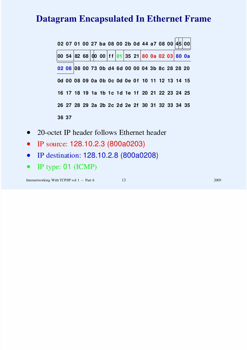
Datagram Encapsulated In Ethernet Frame
8/6/2019 Vol1 Presentation
http://slidepdf.com/reader/full/vol1-presentation 155/856
02 07 01 00 27 ba 08 00 2b 0d 44 a7 08 00 45 00
00 54 82 68 00 00 f f 35 2101 80 0a 02 03 80 0a
02 08 08 00 73 0b d4 6d 00 00 04 3b 8c 28 28 20
0d 00 08 09 0a 0b 0c 0d 0e 0 f 10 11 12 13 14 15
16 17 18 19 1a 1b 1c 1d 1e 1f 20 21 22 23 24 25
26 27 28 29 2a 2b 2c 2d 2e 2f 30 31 32 33 34 35
36 37
20-octet IP header follows Ethernet header
IP source: 128.10.2.3 (800a0203)
IP destination: 128.10.2.8 (800a0208)
IP type: 01 (ICMP)
Internetworking With TCP/IP vol 1 -- Part 6 13 2005
Standards For Encapsulation
TCP/IP l d fi l i f h ibl

8/6/2019 Vol1 Presentation
http://slidepdf.com/reader/full/vol1-presentation 156/856
TCP/IP protocols define encapsulation for each possible type
of network hardware– Ethernet
– Frame Relay
– Others
Internetworking With TCP/IP vol 1 -- Part 6 14 2005
Encapsulation Over Serial Networks
S i l h d f f

8/6/2019 Vol1 Presentation
http://slidepdf.com/reader/full/vol1-presentation 157/856
Serial hardware transfers stream of octets
– Leased serial data line
– Dialup telephone connection
Encapsulation of IP on serial network
– Implemented by software
– Both ends must agree
Most common standards: Point to Point Protocol (PPP)
Internetworking With TCP/IP vol 1 -- Part 6 15 2005
Encapsulation For Avian Carriers (RFC 1149)
Ch t i ti f i i

8/6/2019 Vol1 Presentation
http://slidepdf.com/reader/full/vol1-presentation 158/856
Characteristics of avian carrier
– Low throughput
– High delay
– Low altitude
– Point-to-point communication
– Intrinsic collision avoidance
Encapsulation
– Write in hexadecimal on scroll of paper
– Attach to bird’s leg with duct tape
For an implementation see
http://www.blug.linux.no/rfc1149
A Potential Problem
A d t t i t 65535 t t l t t (i l di

8/6/2019 Vol1 Presentation
http://slidepdf.com/reader/full/vol1-presentation 159/856
A datagram can contain up to 65535 total octets (including
header)
Network hardware limits maximum size of frame (e.g.,
Ethernet limited to 1500 octets)
– Known as the network Maximum Transmission Unit
( MTU )
Question: how is encapsulation handled if datagram exceeds
network MTU?
Internetworking With TCP/IP vol 1 -- Part 6 16 2005
Possible Ways To Accommodate
Networks With Differing MTUs

8/6/2019 Vol1 Presentation
http://slidepdf.com/reader/full/vol1-presentation 160/856
Force datagram to be less than smallest possible MTU
– Inefficient
– Cannot know minimum MTU
Hide the network MTU and accommodate arbitrarydatagram size
Internetworking With TCP/IP vol 1 -- Part 6 17 2005
Accommodating Large Datagrams
C t d l d t i i l f

8/6/2019 Vol1 Presentation
http://slidepdf.com/reader/full/vol1-presentation 161/856
Cannot send large datagram in single frame
Solution
– Divide datagram into pieces
– Send each piece in a frame
– Called datagram fragmentation
Internetworking With TCP/IP vol 1 -- Part 6 18 2005
Illustration Of When Fragmentation Needed

8/6/2019 Vol1 Presentation
http://slidepdf.com/reader/full/vol1-presentation 162/856
Net 2
MTU=620R1
Host
A
Net 1
MTU=1500
R2
Host
B
Net 3
MTU=1500
Hosts A and B send datagrams of up to 1500 octets
Router R1 fragments large datagrams from Host A before
sending over Net 2
Router R2 fragments large datagrams from Host B beforesending over Net 2
Internetworking With TCP/IP vol 1 -- Part 6 19 2005
Datagram Fragmentation
Performed by routers

8/6/2019 Vol1 Presentation
http://slidepdf.com/reader/full/vol1-presentation 163/856
Performed by routers
Divides datagram into several, smaller datagrams calledfragments
Fragment uses same header format as datagram
Each fragment forwarded independently
Internetworking With TCP/IP vol 1 -- Part 6 20 2005
Illustration Of Fragmentation
Original datagram

8/6/2019 Vol1 Presentation
http://slidepdf.com/reader/full/vol1-presentation 164/856
Header
g g
data1
600 bytes
..........
.
data2
600 bytes
..........
.
data3
200 bytes
Header1 data1 fragment #1 (offset of 0)
Header2 data2 fragment #2 (offset of 600)
Header3 data3 fragment #3 (offset of 1200)
Offset specifies where data belongs in original datagram
Offset actually stored as multiples of 8 octets
MORE FRAGMENTS bit turned off in header of fragment
#3
Internetworking With TCP/IP vol 1 -- Part 6 21 2005
Fragmenting A Fragment
Fragment can be further fragmented

8/6/2019 Vol1 Presentation
http://slidepdf.com/reader/full/vol1-presentation 165/856
Fragment can be further fragmented
Occurs when fragment reaches an even-smaller MTU
Discussion: which fields of the datagram header are used,
and what is the algorithm?
Internetworking With TCP/IP vol 1 -- Part 6 22 2005
Reassembly
Ultimate destination puts fragments back together

8/6/2019 Vol1 Presentation
http://slidepdf.com/reader/full/vol1-presentation 166/856
Ultimate destination puts fragments back together
– Key concept!
– Needed in a connectionless Internet
Known as reassembly
No need to reassemble subfragments first
Timer used to ensure all fragments arrive
– Timer started when first fragment arrives
– If timer expires, entire datagram discarded
Internetworking With TCP/IP vol 1 -- Part 6 23 2005
Time To Live
TTL field of datagram header decremented at each hop (i e

8/6/2019 Vol1 Presentation
http://slidepdf.com/reader/full/vol1-presentation 167/856
TTL field of datagram header decremented at each hop (i.e.,
each router)
If TTL reaches zero, datagram discarded
Prevents datagrams from looping indefinitely (in case
forwarding error introduces loop)
IETF recommends initial value of 255 (max)
Internetworking With TCP/IP vol 1 -- Part 6 24 2005
Checksum Field In Datagram Header
16-bit 1’s complement checksum

8/6/2019 Vol1 Presentation
http://slidepdf.com/reader/full/vol1-presentation 168/856
16-bit 1 s complement checksum
Over IP header only!
Recomputed at each hop
Internetworking With TCP/IP vol 1 -- Part 6 25 2005
IP Options
Seldom used

8/6/2019 Vol1 Presentation
http://slidepdf.com/reader/full/vol1-presentation 169/856
Seldom used
Primarily for debugging
Only some options copied into fragments
Are variable length
Note: padding needed because header length measured in32-bit multiples
Option starts with option code octet
Internetworking With TCP/IP vol 1 -- Part 6 26 2005
Option Code Octet
0 1 2 3 4 5 6 7

8/6/2019 Vol1 Presentation
http://slidepdf.com/reader/full/vol1-presentation 170/856
COPY OPTION CLASS OPTION NUMBER
Option Class Meaning
0 Datagram or network control
1 Reserved for future use
2 Debugging and measurement
3 Reserved for future use
Internetworking With TCP/IP vol 1 -- Part 6 27 2005
IP Semantics
IP uses best-effort delivery

8/6/2019 Vol1 Presentation
http://slidepdf.com/reader/full/vol1-presentation 171/856
IP uses best effort delivery
– Makes an attempt to deliver
– Does not guarantee delivery
In the Internet, routers become overrun or change routes,
meaning that:
– Datagrams can be lost
– Datagrams can be duplicated
– Datagrams can arrive out of order or scrambled
Motivation: allow IP to operate over the widest possible
variety of physical networks
Internetworking With TCP/IP vol 1 -- Part 6 28 2005
Output From
PING Program

8/6/2019 Vol1 Presentation
http://slidepdf.com/reader/full/vol1-presentation 172/856
PING venera.isi.edu (128.9.0.32): 64 data bytes
at 1.0000 second intervals
72 bytes from 128.9.0.32: icmp_seq=0. time=170. ms
72 bytes from 128.9.0.32: icmp_seq=1. time=150. ms
72 bytes from 128.9.0.32: icmp_seq=1. time=160. ms
72 bytes from 128.9.0.32: icmp_seq=2. time=160. ms
72 bytes from 128.9.0.32: icmp_seq=3. time=160. ms
----venera.isi.edu PING Statistics----
4 packets transmitted, 5 packets received,
-25% packet loss
round-trip (ms) min/avg/max = 150/160/170
Shows actual case of duplication
Internetworking With TCP/IP vol 1 -- Part 6 29 2005
Summary
Internet Protocol provides basic connectionless delivery

8/6/2019 Vol1 Presentation
http://slidepdf.com/reader/full/vol1-presentation 173/856
Internet Protocol provides basic connectionless delivery
service for the Internet
IP defines IP datagram to be the format of packets on the
Internet
Datagram header
– Has fixed fields
– Specifies source, destination, and type
– Allows options
Datagram encapsulated in network frame for transmission
Internetworking With TCP/IP vol 1 -- Part 6 30 2005
Summary
(continued)

8/6/2019 Vol1 Presentation
http://slidepdf.com/reader/full/vol1-presentation 174/856
Fragmentation
– Needed when datagram larger than MTU
– Usually performed by routers
– Divides datagram into fragments
Reassembly
– Performed by ultimate destination
– If some fragment(s) do not arrive, datagram discarded
To accommodate all possible network hardware, IP does not
require reliability (best-effort semantics)
Internetworking With TCP/IP vol 1 -- Part 6 31 2005

8/6/2019 Vol1 Presentation
http://slidepdf.com/reader/full/vol1-presentation 175/856
Questions?

8/6/2019 Vol1 Presentation
http://slidepdf.com/reader/full/vol1-presentation 176/856
PART VII
INTERNET PROTOCOL:
FORWARDING IP DATAGRAMS
Internetworking With TCP/IP vol 1 -- Part 7 1 2005
Datagram Transmission
Host delivers datagrams to directly connected machines

8/6/2019 Vol1 Presentation
http://slidepdf.com/reader/full/vol1-presentation 177/856
g y
Host sends datagrams that cannot be delivered directly torouter
Routers forward datagrams to other routers
Final router delivers datagram directly
Internetworking With TCP/IP vol 1 -- Part 7 2 2005
Question

8/6/2019 Vol1 Presentation
http://slidepdf.com/reader/full/vol1-presentation 178/856
Does a host need to make forwarding choices?
Internetworking With TCP/IP vol 1 -- Part 7 3 2005
Question

8/6/2019 Vol1 Presentation
http://slidepdf.com/reader/full/vol1-presentation 179/856
Does a host need to make forwarding choices?
Answer: YES!
Internetworking With TCP/IP vol 1 -- Part 7 3 2005
Example Host That Must Choose
How To Forward Datagrams

8/6/2019 Vol1 Presentation
http://slidepdf.com/reader/full/vol1-presentation 180/856
HOST
R1 R2
path to some
destinations
path to other
destinations
Note: host is singly homed!
Internetworking With TCP/IP vol 1 -- Part 7 4 2005
Two Broad Cases
Direct delivery

8/6/2019 Vol1 Presentation
http://slidepdf.com/reader/full/vol1-presentation 181/856
y
– Ultimate destination can be reached over one network
– The ‘‘last hop’’ along a path
– Also occurs when two communicating hosts both attach
to the same physical network
Indirect delivery
– Requires intermediary (router)
Internetworking With TCP/IP vol 1 -- Part 75
2005
Important Design Decision

8/6/2019 Vol1 Presentation
http://slidepdf.com/reader/full/vol1-presentation 182/856
Transmission of an IP datagram between two machines on a
single physical network does not involve routers. The sender
encapsulates the datagram in a physical frame, binds the
destination IP address to a physical hardware address, and
sends the resulting frame directly to the destination.
Internetworking With TCP/IP vol 1 -- Part 76
2005
Testing Whether A Destination
Lies On The Same Physical Network
As The Sender

8/6/2019 Vol1 Presentation
http://slidepdf.com/reader/full/vol1-presentation 183/856
Because the Internet addresses of all machines on a single
network include a common network prefix and extracting that
prefix requires only a few machine instructions, testing whether
a machine can be reached directly is extremely efficient.
Internetworking With TCP/IP vol 1 -- Part 7 7 2005
Datagram Forwarding
General paradigm

8/6/2019 Vol1 Presentation
http://slidepdf.com/reader/full/vol1-presentation 184/856
– Source host sends to first router
– Each router passes datagram to next router
– Last router along path delivers datagram to destination
host
Only works if routers cooperate
Internetworking With TCP/IP vol 1 -- Part 7 8 2005
General Concept

8/6/2019 Vol1 Presentation
http://slidepdf.com/reader/full/vol1-presentation 185/856
Routers in a TCP/IP Internet form a cooperative,
interconnected structure. Datagrams pass from router to router
until they reach a router that can deliver the datagram directly.
Internetworking With TCP/IP vol 1 -- Part 7 9 2005
Efficient Forwarding
Decisions based on table lookup

8/6/2019 Vol1 Presentation
http://slidepdf.com/reader/full/vol1-presentation 186/856
Routing tables keep only network portion of addresses (sizeproportional to number of networks, not number of hosts)
Extremely efficient
– Lookup
– Route update
Internetworking With TCP/IP vol 1 -- Part 7 10 2005
Important Idea
Table used to decide how to send datagram known as

8/6/2019 Vol1 Presentation
http://slidepdf.com/reader/full/vol1-presentation 187/856
routing table (also called a forwarding table)
Routing table only stores address of next router along the
path
Scheme is known as next-hop forwarding or next-hop
routing
Internetworking With TCP/IP vol 1 -- Part 7 11 2005
Terminology
Originally
8/6/2019 Vol1 Presentation
http://slidepdf.com/reader/full/vol1-presentation 188/856
– Routing used to refer to passing datagram from router torouter
More recently
– Purists decided to use forwarding to refer to the process
of looking up a route and sending a datagram
But...
– Table is usually called a routing table
Internetworking With TCP/IP vol 1 -- Part 7 12 2005
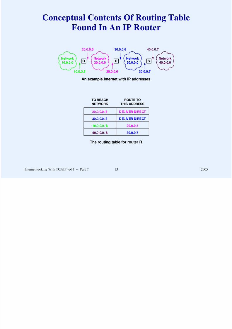
Conceptual Contents Of Routing Table
Found In An IP Router
8/6/2019 Vol1 Presentation
http://slidepdf.com/reader/full/vol1-presentation 189/856
Network
10.0.0.0
Network
20.0.0.0
Network
30.0.0.0
Network
40.0.0.0Q R S
10.0.0.5 20.0.0.6
20.0.0.5
30.0.0.7
30.0.0.6 40.0.0.7
20.0.0.0 /8 DELIVER DIRECT
30.0.0.0 /8 DELIVER DIRECT
10.0.0.0 / 8 20.0.0.5
40.0.0.0 / 8 30.0.0.7
TO REACH
NETWORK
ROUTE TO
THIS ADDRESS
An example Internet with IP addresses
The routing table for router R
Internetworking With TCP/IP vol 1 -- Part 7 13 2005
Special Cases
Default route

8/6/2019 Vol1 Presentation
http://slidepdf.com/reader/full/vol1-presentation 190/856
Host-specific route
Internetworking With TCP/IP vol 1 -- Part 7 14 2005
Default Route
Special entry in IP routing table

8/6/2019 Vol1 Presentation
http://slidepdf.com/reader/full/vol1-presentation 191/856
Matches ‘‘any’’ destination address
Only one default permitted
Only selected if no other match in table
Internetworking With TCP/IP vol 1 -- Part 7 15 2005
Host-Specific Route
Entry in routing table
8/6/2019 Vol1 Presentation
http://slidepdf.com/reader/full/vol1-presentation 192/856
Matches entire 32-bit value
Can be used to send traffic for a specific host along a
specific path (i.e., can differ from the network route)
More later in the course
Internetworking With TCP/IP vol 1 -- Part 7 16 2005
Level Of Forwarding Algorithm
DATAGRAM
TO BE FORWARDED
EXAMINATION OR
UPDATES OF ROUTES

8/6/2019 Vol1 Presentation
http://slidepdf.com/reader/full/vol1-presentation 193/856
FORWARDING
ALGORITHM
ROUTING
TABLE
DATAGRAM TO BE SENT
PLUS ADDRESS OF NEXT HOP
IP addresses used
Physical addresses used
Routing table uses IP addresses, not physical addresses
Internetworking With TCP/IP vol 1 -- Part 7 17 2005
Summary
IP uses routing table to forward datagrams

8/6/2019 Vol1 Presentation
http://slidepdf.com/reader/full/vol1-presentation 194/856
Routing table
– Stores pairs of network prefix and next hop
– Can contain host-specific routes and a default route
Internetworking With TCP/IP vol 1 -- Part 7 18 2005

8/6/2019 Vol1 Presentation
http://slidepdf.com/reader/full/vol1-presentation 195/856
Questions?

8/6/2019 Vol1 Presentation
http://slidepdf.com/reader/full/vol1-presentation 196/856
PART VIII
ERROR AND CONTROL
MESSAGES(ICMP)
Internetworking With TCP/IP vol 1 -- Part 8 1 2005
Errors In Packet Switching Networks
Causes include

8/6/2019 Vol1 Presentation
http://slidepdf.com/reader/full/vol1-presentation 197/856
– Temporary or permanent disconnection
– Hardware failures
– Router overrun
– Routing loops
Need mechanisms to detect and correct
Internetworking With TCP/IP vol 1 -- Part 8 2 2005
Error Detection And
Reporting Mechanisms

8/6/2019 Vol1 Presentation
http://slidepdf.com/reader/full/vol1-presentation 198/856
IP header checksum to detect transmission errors
Error reporting mechanism to distinguish between events
such as lost datagrams and incorrect addresses
Higher level protocols (i.e., TCP) must handle all other
problems
Internetworking With TCP/IP vol 1 -- Part 8 3 2005
Error Reporting Mechanism
Named Internet Control Message Protocol ( ICMP)

8/6/2019 Vol1 Presentation
http://slidepdf.com/reader/full/vol1-presentation 199/856
Required and integral part of IP
Used primarily by routers to report delivery or routing
problems to original source
Also includes informational (nonerror) functionality
Uses IP to carry control messages
No error messages sent about error messages
Internetworking With TCP/IP vol 1 -- Part 8 4 2005
ICMP Purpose

8/6/2019 Vol1 Presentation
http://slidepdf.com/reader/full/vol1-presentation 200/856
The Internet Control Message Protocol allows a router to send error or control messages to the source of a datagram, typically
a host. ICMP provides communication between the Internet
Protocol software on one machine and the Internet Protocol
software on another.
Internetworking With TCP/IP vol 1 -- Part 8 5 2005
Error Reporting Vs. Error Correction
ICMP does not

8/6/2019 Vol1 Presentation
http://slidepdf.com/reader/full/vol1-presentation 201/856
– Provide interaction between a router and the source of trouble
– Maintain state information (each packet is handled
independently)
Consequence
When a datagram causes an error, ICMP can only report the
error condition back to the original source of the datagram; the
source must relate the error to an individual application
program or take other action to correct the problem.
Internetworking With TCP/IP vol 1 -- Part 8 6 2005
Important Restriction
ICMP only reports problems to original source

8/6/2019 Vol1 Presentation
http://slidepdf.com/reader/full/vol1-presentation 202/856
Discussion question: what major problem in the Internetcannot be handled with ICMP?
Internetworking With TCP/IP vol 1 -- Part 8 7 2005
ICMP Encapsulation
ICMP message travels in IP datagram

8/6/2019 Vol1 Presentation
http://slidepdf.com/reader/full/vol1-presentation 203/856
Entire ICMP message treated as data in the datagram
Two levels of encapsulation result
Internetworking With TCP/IP vol 1 -- Part 8 8 2005
ICMP Message Encapsulation
ICMP MESSAGE

8/6/2019 Vol1 Presentation
http://slidepdf.com/reader/full/vol1-presentation 204/856
IP DATAIP HEADER
FRAME DATAFRAME HEADER
ICMP message has header and data area
Complete ICMP message is treated as data in IP datagram
Complete IP datagram is treated as data in physical network
frame
Internetworking With TCP/IP vol 1 -- Part 8 9 2005
Example Encapsulation In Ethernet
02 07 01 00 27 ba 08 00 2b 0d 44 a7 08 00 45 00

8/6/2019 Vol1 Presentation
http://slidepdf.com/reader/full/vol1-presentation 205/856
00 54 82 68 00 00 f f 01 35 21 80 0a 02 03 80 0a
02 08 04 3b 8c 28 28 2000 73 0b d4 6d08 00 00
0d 00 08 09 0a 0b 0c 0d 0e 0 f 10 11 12 13 14 15
16 17 18 19 1a 1b 1c 1d 1e 1f 20 21 22 23 24 25
26 27 28 29 2a 2b 2c 2d 2e 2f 30 31 32 33 34 35
36 37
ICMP header follows IP header, and contains eight bytes
ICMP type field specifies echo request message (08)
ICMP sequence number is zero
Internetworking With TCP/IP vol 1 -- Part 8 10 2005
ICMP Message Format
Multiple message types
8/6/2019 Vol1 Presentation
http://slidepdf.com/reader/full/vol1-presentation 206/856
Each message has its own format
Messages
– Begin with 1-octet TYPE field that identifies which of
the basic ICMP message types follows
– Some messages have a 1-octet CODE field that further
classifies the message
Example
– TYPE specifies destination unreachable
– CODE specifies whether host or network was
unreachable
Internetworking With TCP/IP vol 1 -- Part 8 11 2005
ICMP Message Types
Type Field ICMP Message Type
0 Echo Reply
3 D ti ti U h bl

8/6/2019 Vol1 Presentation
http://slidepdf.com/reader/full/vol1-presentation 207/856
3 Destination Unreachable
4 Source Quench
5 Redirect (change a route)
6 Alternate Host Address
8 Echo Request
9 Router Advertisement
10 Router Solicitation
11 Time Exceeded for a Datagram
12 Parameter Problem on a Datagram13 Timestamp Request
14 Timestamp Reply
15 Information Request
16 Information Reply
17 Address Mask Request
18 Address Mask Reply
Internetworking With TCP/IP vol 1 -- Part 8 12 2005
ICMP Message Types
(continued)
Type Field ICMP Message Type
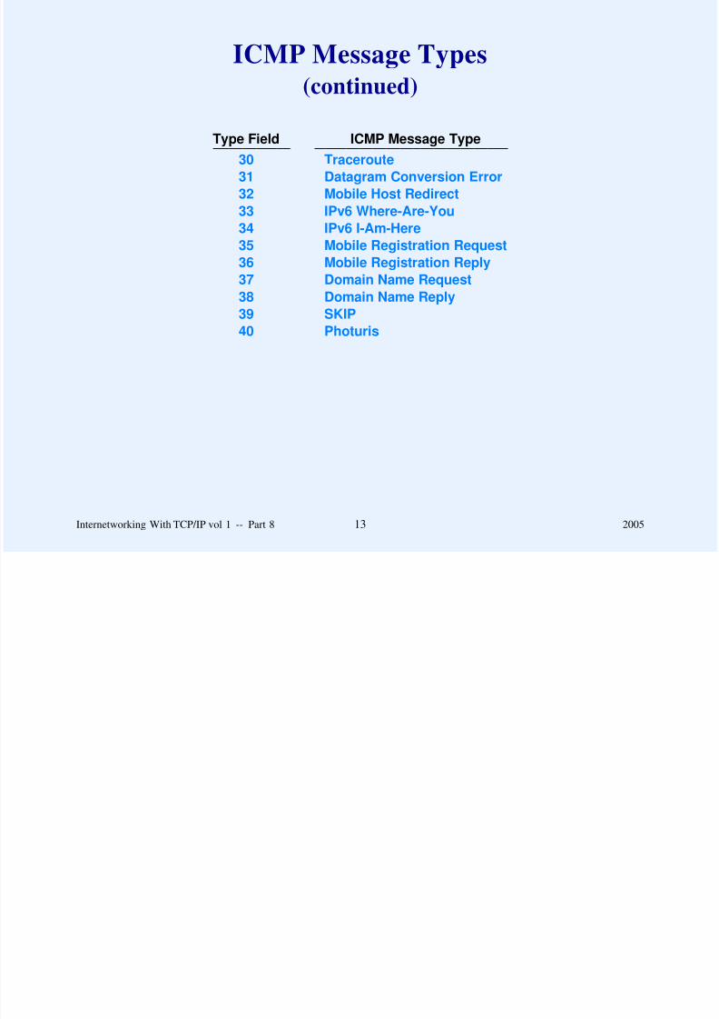
8/6/2019 Vol1 Presentation
http://slidepdf.com/reader/full/vol1-presentation 208/856
Type Field ICMP Message Type
30 Traceroute31 Datagram Conversion Error
32 Mobile Host Redirect
33 IPv6 Where-Are-You
34 IPv6 I-Am-Here
35 Mobile Registration Request
36 Mobile Registration Reply
37 Domain Name Request38 Domain Name Reply
39 SKIP
40 Photuris
Internetworking With TCP/IP vol 1 -- Part 8 13 2005
Example ICMP Message
(ICMP Echo Request)
0 8 16 31

8/6/2019 Vol1 Presentation
http://slidepdf.com/reader/full/vol1-presentation 209/856
TYPE (8 or 0) CODE (0) CHECKSUM
IDENTIFIER SEQUENCE NUMBER
OPTIONAL DATA
. . .
Sent by ping program
Used to test reachability
Internetworking With TCP/IP vol 1 -- Part 8 14 2005
Example ICMP Message
(Destination Unreachable)
0 8 16 31

8/6/2019 Vol1 Presentation
http://slidepdf.com/reader/full/vol1-presentation 210/856
TYPE (3) CODE (0-12) CHECKSUM
UNUSED (MUST BE ZERO)
INTERNET HEADER + FIRST 64 BITS OF DATAGRAM
. . .
Used to report that datagram could not be delivered
Code specifies details
Internetworking With TCP/IP vol 1 -- Part 8 15 2005
Example ICMP Message
(Redirect)
0 8 16 31

8/6/2019 Vol1 Presentation
http://slidepdf.com/reader/full/vol1-presentation 211/856
TYPE (5) CODE (0 to 3) CHECKSUM
ROUTER INTERNET ADDRESS
INTERNET HEADER + FIRST 64 BITS OF DATAGRAM
. . .
Used to report incorrect route
Internetworking With TCP/IP vol 1 -- Part 8 16 2005
Situation Where An ICMP Redirect
Cannot Be Used

8/6/2019 Vol1 Presentation
http://slidepdf.com/reader/full/vol1-presentation 212/856
S
R1
R2
R3
R4
R5
D
R5 cannot redirect R1 to use shorter path
Internetworking With TCP/IP vol 1 -- Part 8 17 2005
Example ICMP Message
(Time Exceeded)
0 8 16 31

8/6/2019 Vol1 Presentation
http://slidepdf.com/reader/full/vol1-presentation 213/856
TYPE (11) CODE (0 or 1) CHECKSUM
UNUSED (MUST BE ZERO)
INTERNET HEADER + FIRST 64 BITS OF DATAGRAM
. . .
At least one fragment failed to arrive, or
TTL field in IP header reached zero
Internetworking With TCP/IP vol 1 -- Part 8 18 2005
ICMP Trick
Include datagram that caused problem in the error message

8/6/2019 Vol1 Presentation
http://slidepdf.com/reader/full/vol1-presentation 214/856
– Efficient (sender must determine how to correctproblem)
– Eliminates need to construct detailed message
Problem: entire datagram may be too large
Solution: send IP header plus 64 bits of data area (sufficient
in most cases)
Internetworking With TCP/IP vol 1 -- Part 8 19 2005
Summary
ICMP

8/6/2019 Vol1 Presentation
http://slidepdf.com/reader/full/vol1-presentation 215/856
– Required part of IP
– Used to report errors to original source
– Reporting only: no interaction or error correction
Several ICMP message types, each with its own format
ICMP message begins with 1-octet TYPE field
ICMP encapsulated in IP for delivery
Internetworking With TCP/IP vol 1 -- Part 8 20 2005

8/6/2019 Vol1 Presentation
http://slidepdf.com/reader/full/vol1-presentation 216/856
Questions?

8/6/2019 Vol1 Presentation
http://slidepdf.com/reader/full/vol1-presentation 217/856
PART IX
INTERNET PROTOCOL:
CLASSLESS AND SUBNET
ADDRESS EXTENSIONS
(CIDR)
Internetworking With TCP/IP vol 1 -- Part 9 1 2005
Recall
8/6/2019 Vol1 Presentation
http://slidepdf.com/reader/full/vol1-presentation 218/856
In the original IP addressing scheme, each physical network is
assigned a unique network address; each host on a network has
the network address as a prefix of the host’s individual address.
Routers only examine prefix (small routing tables)
Internetworking With TCP/IP vol 1 -- Part 9 2 2005
An Observation
Division into prefix and suffix means: site can assign and
use IP addresses in unusual ways provided

8/6/2019 Vol1 Presentation
http://slidepdf.com/reader/full/vol1-presentation 219/856
– All hosts and routers at the site honor the site’s scheme
– Other sites on the Internet can treat addresses as a
network prefix and a host suffix
Internetworking With TCP/IP vol 1 -- Part 9 3 2005
Classful Addressing
Three possible classes for networks
8/6/2019 Vol1 Presentation
http://slidepdf.com/reader/full/vol1-presentation 220/856
Class C network limited to 254 hosts (cannot use all-1s orall-0s)
Personal computers result in networks with many hosts
Class B network allows many hosts, but insufficient class B
prefixes
Internetworking With TCP/IP vol 1 -- Part 9 4 2005
Question
How can we minimize the number of assigned network
prefixes (especially class B) without abandoning the 32-bit

8/6/2019 Vol1 Presentation
http://slidepdf.com/reader/full/vol1-presentation 221/856
addressing scheme?
Internetworking With TCP/IP vol 1 -- Part 9 5 2005
Two Answers To The Minimization Question
Proxy ARP

8/6/2019 Vol1 Presentation
http://slidepdf.com/reader/full/vol1-presentation 222/856
Subnet addressing
Internetworking With TCP/IP vol 1 -- Part 9 6 2005
Proxy ARP
Layer 2 solution

8/6/2019 Vol1 Presentation
http://slidepdf.com/reader/full/vol1-presentation 223/856
Allow two physical networks to share a single IP prefix
Arrange special system to answer ARP requests and forward
datagrams between networks
Internetworking With TCP/IP vol 1 -- Part 9 7 2005
Illustration Of Proxy ARP
H1 H2 H3
R
Main Network
Router running proxy ARP
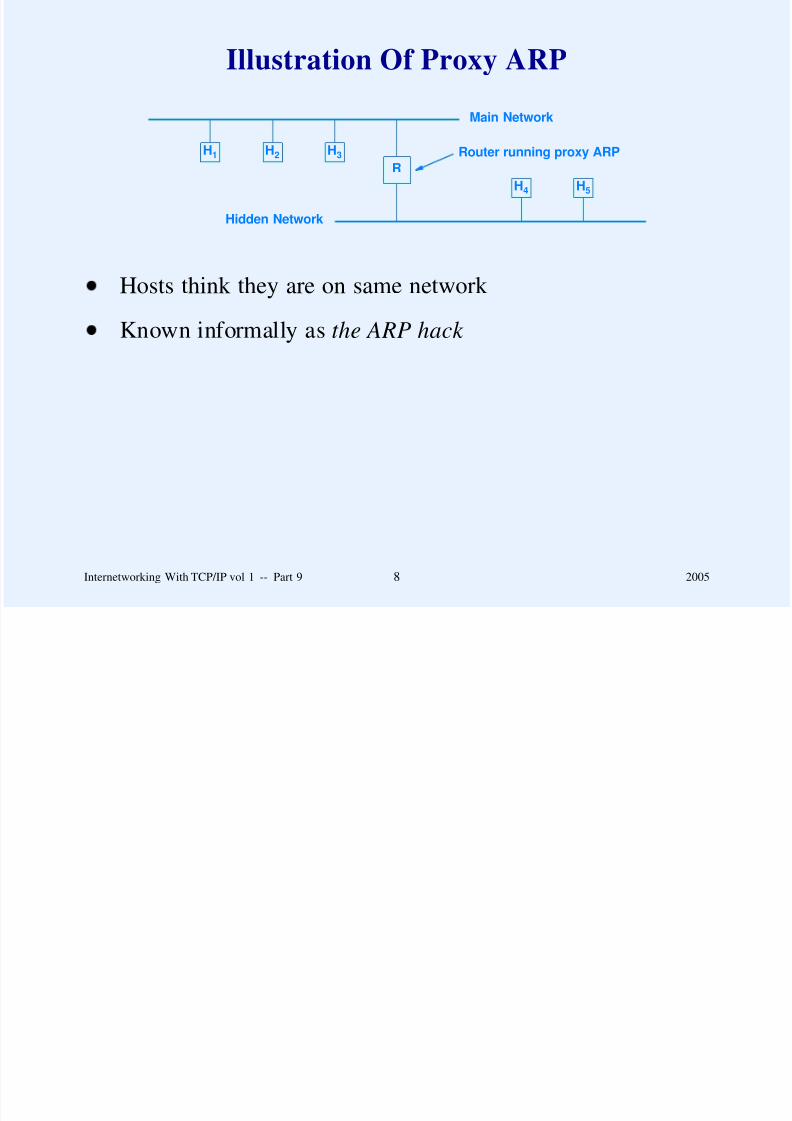
8/6/2019 Vol1 Presentation
http://slidepdf.com/reader/full/vol1-presentation 224/856
R
H4 H5
Hidden Network
Hosts think they are on same network
Known informally as the ARP hack
Internetworking With TCP/IP vol 1 -- Part 9 8 2005
Assessment Of Proxy ARP
Chief advantages

8/6/2019 Vol1 Presentation
http://slidepdf.com/reader/full/vol1-presentation 225/856
– Transparent to hosts
– No change in IP routing tables
Chief disadvantages
– Does not generalize to complex topology– Only works on networks that use ARP
– Most proxy ARP systems require manual configuration
Internetworking With TCP/IP vol 1 -- Part 9 9 2005
Subnet Addressing
Not part of original TCP/IP address scheme

8/6/2019 Vol1 Presentation
http://slidepdf.com/reader/full/vol1-presentation 226/856
Allows an organization to use a single network prefix formultiple physical networks
Subdivides the host suffix into a pair of fields for physical
network and host
Interpreted only by routers and hosts at the site; treated likenormal address elsewhere
Internetworking With TCP/IP vol 1 -- Part 9 10 2005
Example Of Subnet Addressing
H1 H2
Network 128.10.1.0
128.10.1.1 128.10.1.2

8/6/2019 Vol1 Presentation
http://slidepdf.com/reader/full/vol1-presentation 227/856
REST OF THEINTERNET
R
H3 H4
Network 128.10.2.0
128.10.2.1 128.10.2.2
all traffic to
128.10.0.0
Both physical networks share prefix 128.10
Router R uses third octet of address to choose physical net
Internetworking With TCP/IP vol 1 -- Part 9 11 2005

8/6/2019 Vol1 Presentation
http://slidepdf.com/reader/full/vol1-presentation 228/856
Example Of Address Interpretation
(Subnetted Class B Address)

8/6/2019 Vol1 Presentation
http://slidepdf.com/reader/full/vol1-presentation 229/856
Internetpart localpart
Internetpart
physicalnetwork
host
...................
...................
...................
Note: in this case, 16-bit host portion is divided into two 8-bit
fields
Internetworking With TCP/IP vol 1 -- Part 9 13 2005
Choice Of Subnet Size
How should host portion of address be divided?

8/6/2019 Vol1 Presentation
http://slidepdf.com/reader/full/vol1-presentation 230/856
Answer depends on topology at site and number of hosts pernetwork
Internetworking With TCP/IP vol 1 -- Part 9 14 2005

8/6/2019 Vol1 Presentation
http://slidepdf.com/reader/full/vol1-presentation 231/856
Illustration Of Subnet Addressing
Rest of the Internet
Subnet address treated as

8/6/2019 Vol1 Presentation
http://slidepdf.com/reader/full/vol1-presentation 232/856
R1Router at site
R2 R3
128.10.1.0
128.10.2.0 128.10.3.0
Site using third octet tosubnet address 128.10.0.0
normal IP address
Subnet identified by using part of host
portion to identify physical net
Internetworking With TCP/IP vol 1 -- Part 9 16 2005

8/6/2019 Vol1 Presentation
http://slidepdf.com/reader/full/vol1-presentation 233/856

8/6/2019 Vol1 Presentation
http://slidepdf.com/reader/full/vol1-presentation 234/856
Fixed-length Subnet Masks
Organization uses same mask on all networks

8/6/2019 Vol1 Presentation
http://slidepdf.com/reader/full/vol1-presentation 235/856
Advantages
– Uniformity
– Ease of debugging / maintenance
Disadvantages
– Number of nets fixed for entire organization
– Size of physical nets fixed for entire organization
Internetworking With TCP/IP vol 1 -- Part 9 19 2005
Possible Fixed-Length Subnets
For Sixteen Bit Host Address
Bits in mask # subnets # hosts/subnet
6 6 3

8/6/2019 Vol1 Presentation
http://slidepdf.com/reader/full/vol1-presentation 236/856
16 1 6553418 2 16382
19 6 8190
20 14 4094
21 30 2046
22 62 1022
23 126 510
24 254 25425 510 126
26 1022 62
27 2046 30
28 4094 14
29 8190 6
30 16382 2
All-0s and all-1s values must be omitted
Organization chooses one line in table
Internetworking With TCP/IP vol 1 -- Part 9 20 2005
Variable-Length Subnet Masks (VLSM)
Administrator chooses size for each physical network
M k i d k b i

8/6/2019 Vol1 Presentation
http://slidepdf.com/reader/full/vol1-presentation 237/856
Mask assigned on per-network basis
Advantages
– Flexibility to mix large and small nets
– More complete use of address space
Disadvantages
– Difficult to assign / administer
– Potential address ambiguity
– More routes
Internetworking With TCP/IP vol 1 -- Part 9 21 2005

8/6/2019 Vol1 Presentation
http://slidepdf.com/reader/full/vol1-presentation 238/856

8/6/2019 Vol1 Presentation
http://slidepdf.com/reader/full/vol1-presentation 239/856
VLSM Example
Use low-order sixteen bits of 128.10.0.0
C t b t

8/6/2019 Vol1 Presentation
http://slidepdf.com/reader/full/vol1-presentation 240/856
Create seven subnets
Subnet 1
– Up to 254 hosts
– Subnet mask is 24 bits
Subnets 2 through 7
– Up to 62 hosts each
– Subnet mask is 26 bits
Internetworking With TCP/IP vol 1 -- Part 9 24 2005

8/6/2019 Vol1 Presentation
http://slidepdf.com/reader/full/vol1-presentation 241/856
Example VLSM Prefixes
(continued)
Subnet 4 (up to 62 hosts)

8/6/2019 Vol1 Presentation
http://slidepdf.com/reader/full/vol1-presentation 242/856
mask: 11111111 11111111 11111111 11000000
prefix: 10000000 00001010 00000001 00000000
Subnet 5 (up to 62 hosts)
mask: 11111111 11111111 11111111 11000000
prefix: 10000000 00001010 00000001 01000000
Subnet 6 (up to 62 hosts)
mask: 11111111 11111111 11111111 11000000
prefix: 10000000 00001010 00000001 10000000
Internetworking With TCP/IP vol 1 -- Part 9 26 2005
Example VLSM Prefixes
(continued)
Subnet 7 (up to 62 hosts)

8/6/2019 Vol1 Presentation
http://slidepdf.com/reader/full/vol1-presentation 243/856
mask: 11111111 11111111 11111111 11000000
prefix: 10000000 00001010 00000001 11000000
Internetworking With TCP/IP vol 1 -- Part 9 27 2005
Address Ambiguity
Address of host 63 on subnet 1 is
k 11111111 11111111 11111111 00000000

8/6/2019 Vol1 Presentation
http://slidepdf.com/reader/full/vol1-presentation 244/856
mask: 11111111 11111111 11111111 00000000
prefix: 10000000 00001010 00000001 00000000
host: 10000000 00001010 00000001 00111111
Directed broadcast address on subnet 4 is
mask: 11111111 11111111 11111111 11000000
prefix: 10000000 00001010 00000001 00000000
bcast: 10000000 00001010 00000001 00111111
Internetworking With TCP/IP vol 1 -- Part 9 28 2005

8/6/2019 Vol1 Presentation
http://slidepdf.com/reader/full/vol1-presentation 245/856
More Address Ambiguity
Directed broadcast address on subnet 1 is
mask: 11111111 11111111 11111111 00000000

8/6/2019 Vol1 Presentation
http://slidepdf.com/reader/full/vol1-presentation 246/856
mask: 11111111 11111111 11111111 00000000
prefix: 10000000 00001010 00000001 00000000
broadcast: 10000000 00001010 00000001 11111111
Directed broadcast address on subnet 7 is
mask: 11111111 11111111 11111111 11000000
prefix: 10000000 00001010 00000001 11000000
broadcast:10000000 00001010 00000001 11111111
Internetworking With TCP/IP vol 1 -- Part 9 29 2005

8/6/2019 Vol1 Presentation
http://slidepdf.com/reader/full/vol1-presentation 247/856
Example Of Illegal Subnet Assignment
Net 1 (not a subnet address)

8/6/2019 Vol1 Presentation
http://slidepdf.com/reader/full/vol1-presentation 248/856
HR1 R2
Net 2 (subnet of address N) Net 3 (subnet of address N)
Host cannot route among subnets
Rule: subnets must be contiguous!
Internetworking With TCP/IP vol 1 -- Part 9 30 2005
Variety Of Routes
Forwarding must accommodate
Network specific routes

8/6/2019 Vol1 Presentation
http://slidepdf.com/reader/full/vol1-presentation 249/856
– Network-specific routes– Subnet-specific routes
– Host-specific routes
– Default route
– Limited broadcast
– Directed broadcast to network
– Directed broadcast to specific subnet
Single algorithm with address masks can accommodate all
the above
Internetworking With TCP/IP vol 1 -- Part 9 31 2005
Use Of Address Masks
Each entry in routing table also has address mask
All 1s mask used for host specific routes

8/6/2019 Vol1 Presentation
http://slidepdf.com/reader/full/vol1-presentation 250/856
All-1s mask used for host-specific routes
Network mask used for network-specific routes
Subnet mask used for subnet-specific routes
All-0s mask used for default route
Internetworking With TCP/IP vol 1 -- Part 9 32 2005
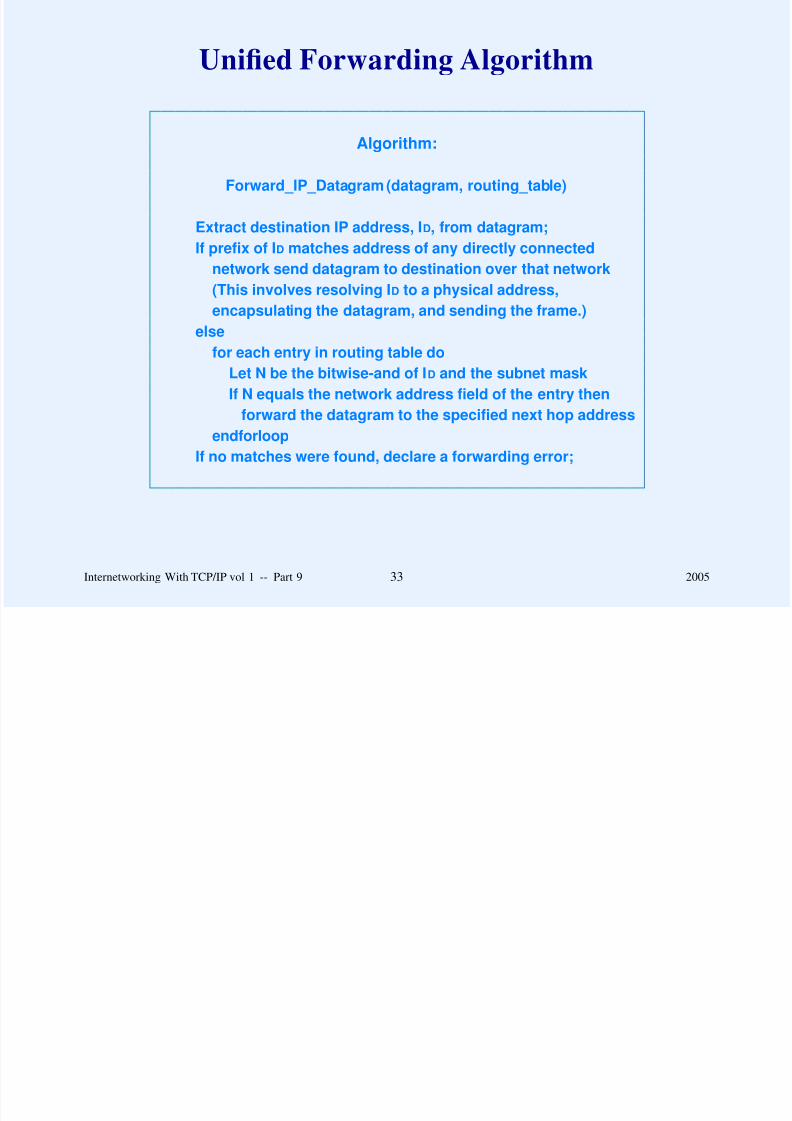
8/6/2019 Vol1 Presentation
http://slidepdf.com/reader/full/vol1-presentation 251/856
Special Case: Unnumbered Serial Network
Only two endpoints
Not necessary to assign (waste) network prefix

8/6/2019 Vol1 Presentation
http://slidepdf.com/reader/full/vol1-presentation 252/856
Not necessary to assign (waste) network prefix
Trick: use remote IP address as next hop
Internetworking With TCP/IP vol 1 -- Part 9 34 2005

8/6/2019 Vol1 Presentation
http://slidepdf.com/reader/full/vol1-presentation 253/856

8/6/2019 Vol1 Presentation
http://slidepdf.com/reader/full/vol1-presentation 254/856
CIDR Addressing
Solution to problem
– Temporary fix until next generation of IP

8/6/2019 Vol1 Presentation
http://slidepdf.com/reader/full/vol1-presentation 255/856
Temporary fix until next generation of IP– Backward compatible with classful addressing
– Extend variable-length subnet technology to prefixes
CIDR was predicted to work ‘‘for a few years’’
– Extremely successful!
– Will work for at least 25 years!
Internetworking With TCP/IP vol 1 -- Part 9 37 2005

8/6/2019 Vol1 Presentation
http://slidepdf.com/reader/full/vol1-presentation 256/856
CIDR Notation
Addresses written NUMBER / m
– NUMBER is IP prefix

8/6/2019 Vol1 Presentation
http://slidepdf.com/reader/full/vol1-presentation 257/856
NUMBER is IP prefix– m is ‘‘address mask’’ length
Example
214.5.48.0/20
– Prefix occupies 20 bits
– Suffix occupies 12 bits
Mask values must be converted to dotted decimal when
configuring a router (and binary internally)
Internetworking With TCP/IP vol 1 -- Part 9 39 2005
Route Proliferation
If classful forwarding used, CIDR addresses result in more
routes
Example:

8/6/2019 Vol1 Presentation
http://slidepdf.com/reader/full/vol1-presentation 258/856
Example:
– Single CIDR prefix spans 256 Class C network numbers
(supernetting)
– Classful routing table requires 256 separate entries
Internetworking With TCP/IP vol 1 -- Part 9 40 2005
Route Condensation
Solution: change forwarding as well as addressing
Store address mask with each route

8/6/2019 Vol1 Presentation
http://slidepdf.com/reader/full/vol1-presentation 259/856
Send pair of (address, mask) whenever exchanging routing
information
Known as a CIDR block
Internetworking With TCP/IP vol 1 -- Part 9 41 2005
Example Of A CIDR Block
Dotted Decimal 32-bit Binary Equivalentlowest 128 211 168 0 10000000 11010011 10101000 00000000

8/6/2019 Vol1 Presentation
http://slidepdf.com/reader/full/vol1-presentation 260/856
lowest 128.211.168.0 10000000 11010011 10101000 00000000
highest 128.211.175.255 10000000 11010011 10101111 11111111
Internetworking With TCP/IP vol 1 -- Part 9 42 2005
Dotted Decimal Equivalents
CIDR Notation Dotted Decimal CIDR Notation Dotted Decimal
/1 128.0.0.0 /17 255.255.128.0
/2 192.0.0.0 /18 255.255.192.0
/3 224.0.0.0 /19 255.255.224.0/4 240 0 0 0 /20 255 255 240 0

8/6/2019 Vol1 Presentation
http://slidepdf.com/reader/full/vol1-presentation 261/856
/4 240.0.0.0 /20 255.255.240.0
/5 248.0.0.0 /21 255.255.248.0
/6 252.0.0.0 /22 255.255.252.0
/7 254.0.0.0 /23 255.255.254.0
/8 255.0.0.0 /24 255.255.255.0
/9 255.128.0.0 /25 255.255.255.128
/10 255.192.0.0 /26 255.255.255.192
/11 255.224.0.0 /27 255.255.255.224
/12 255.240.0.0 /28 255.255.255.240
/13 255.248.0.0 /29 255.255.255.248
/14 255.252.0.0 /30 255.255.255.252
/15 255.254.0.0 /31 255.255.255.254
/16 255.255.0.0 /32 255.255.255.255
Internetworking With TCP/IP vol 1 -- Part 9 43 2005
Example Of /30 CIDR Block
Dotted Decimal 32-bit Binary Equivalent
lowest 128.211.176.212 10000000 11010011 10110000 11010100
highest 128.211.176.215 10000000 11010011 10110000 11010111

8/6/2019 Vol1 Presentation
http://slidepdf.com/reader/full/vol1-presentation 262/856
Useful when customer of ISP has very small network
Internetworking With TCP/IP vol 1 -- Part 9 44 2005
Implementation Of CIDR Route Lookup
Each entry in routing table has address plus mask
Search is organized from most-specific to least-specific (i.e.,
entry with longest mask is tested first)

8/6/2019 Vol1 Presentation
http://slidepdf.com/reader/full/vol1-presentation 263/856
entry with longest mask is tested first)
Known as longest-prefix lookup or longest-prefix search
Internetworking With TCP/IP vol 1 -- Part 9 45 2005
Implementing Longest-Prefix Matching
Cannot easily use hashing
Data structure of choice is binary trie

8/6/2019 Vol1 Presentation
http://slidepdf.com/reader/full/vol1-presentation 264/856
Identifies unique prefix needed to match route
Internetworking With TCP/IP vol 1 -- Part 9 46 2005
Example Of Unique Prefixes
32-Bit Address Unique Prefix
00110101 00000000 00000000 00000000 0001000110 00000000 00000000 00000000 0100

8/6/2019 Vol1 Presentation
http://slidepdf.com/reader/full/vol1-presentation 265/856
01000110 00000000 00000000 00000000 0100
01010110 00000000 00000000 00000000 0101
01100001 00000000 00000000 00000000 011
10101010 11110000 00000000 00000000 1010
10110000 00000010 00000000 00000000 10110
10111011 00001010 00000000 00000000 10111
Internetworking With TCP/IP vol 1 -- Part 9 47 2005
Example Binary Trie For The Seven Prefixes
0 1

8/6/2019 Vol1 Presentation
http://slidepdf.com/reader/full/vol1-presentation 266/856
0 1
0
0 1
1
0
1
0 1
0 1
Path for 0101 is shown in red
Internetworking With TCP/IP vol 1 -- Part 9 48 2005
Modifications And Extensions
Several variations of trie data structures exist
– PATRICIA trees

8/6/2019 Vol1 Presentation
http://slidepdf.com/reader/full/vol1-presentation 267/856
– Level-Compressed tries (LC-tries)
Motivation
– Handle longest-prefix match
– Skip levels that do not distinguish among routes
Internetworking With TCP/IP vol 1 -- Part 9 49 2005
Nonroutable Addresses
CIDR blocks reserved for use within a site
Must never appear on the Internet

8/6/2019 Vol1 Presentation
http://slidepdf.com/reader/full/vol1-presentation 268/856
ISPs do not maintain routes
Also called private addresses
Prefix Lowest Address Highest Address10 / 8 10.0.0.0 10.255.255.255
172.16 / 1 2 172.16.0.0 172.31.255.255
192.168 / 16 192.168.0.0 192.168.255.255
169.254 / 16 169.254.0.0 169.254.255.255
Internetworking With TCP/IP vol 1 -- Part 9 50 2005
Summary
Original IP addressing scheme was classful
Two extensions added

8/6/2019 Vol1 Presentation
http://slidepdf.com/reader/full/vol1-presentation 269/856
– Subnet addressing
– CIDR addressing
Subnetting used only within a site
CIDR used throughout the Internet
Both use 32-bit address mask
– CIDR mask identifies division between network prefix
and host suffix
– Subnet mask identifies boundary between subnet and
individual host
Internetworking With TCP/IP vol 1 -- Part 9 51 2005
Summary
(continued)
Single unified forwarding algorithm handles routes that are
– Network-specific

8/6/2019 Vol1 Presentation
http://slidepdf.com/reader/full/vol1-presentation 270/856
Network specific
– Subnet-specific
– Host-specific
– Limited broadcast
– Directed broadcast to network
– Directed broadcast to subnet
– Default
Longest-prefix match required
– Typical implementation: binary trie
Internetworking With TCP/IP vol 1 -- Part 9 52 2005

8/6/2019 Vol1 Presentation
http://slidepdf.com/reader/full/vol1-presentation 271/856
Questions?
PART X

8/6/2019 Vol1 Presentation
http://slidepdf.com/reader/full/vol1-presentation 272/856
PROTOCOL LAYERING
Internetworking With TCP/IP vol 1 -- Part 10 1 2005
Motivation For Layering
Communication is difficult to understand
Many subproblems
H d f il

8/6/2019 Vol1 Presentation
http://slidepdf.com/reader/full/vol1-presentation 273/856
– Hardware failure
– Network congestion
– Packet delay or loss
– Data corruption
– Data duplication or inverted arrivals
Internetworking With TCP/IP vol 1 -- Part 10 2 2005
Solving The Problem
Divide the problem into pieces
Solve subproblems separately
C bi i t i t t d h l

8/6/2019 Vol1 Presentation
http://slidepdf.com/reader/full/vol1-presentation 274/856
Combine into integrated whole
Result is layered protocols
Internetworking With TCP/IP vol 1 -- Part 10 3 2005
Protocol Layering
Separates protocol functionality
Each layer solves one part of the communication problem
I t d d i il f t l d i

8/6/2019 Vol1 Presentation
http://slidepdf.com/reader/full/vol1-presentation 275/856
Intended primarily for protocol designers
Set of layers is called a protocol stack
Internetworking With TCP/IP vol 1 -- Part 10 4 2005
Concept Of Layering
L
Sender
L
Receiver

8/6/2019 Vol1 Presentation
http://slidepdf.com/reader/full/vol1-presentation 276/856
Layer 1
Layer 2
. . .
Layer n
Layer 1
Layer 2
. . .
Layer n
Network
Internetworking With TCP/IP vol 1 -- Part 10 5 2005
More Realistic Layering
High-LevelProtocol Layer
Protocol 2Protocol 1 Protocol 3
Conceptual Layers Software Organization
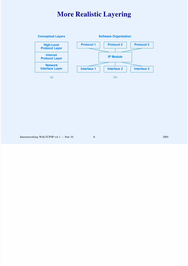
8/6/2019 Vol1 Presentation
http://slidepdf.com/reader/full/vol1-presentation 277/856
NetworkInterface Layer
InternetProtocol Layer
IP Module
Interface 2Interface 1 Interface 3
(a) (b)
Internetworking With TCP/IP vol 1 -- Part 10 6 2005
Layering In An Internet
Sender Receiver

8/6/2019 Vol1 Presentation
http://slidepdf.com/reader/full/vol1-presentation 278/856
Interface
IP Layer
Interface
IP Layer
Interface
IP Layer
Interface
IP Layer
other... other...
Net 1 Net 2 Net 3
Internetworking With TCP/IP vol 1 -- Part 10 7 2005
Examples Of Layering
Two models exist
ISO 7-layer reference model for Open System
Interconnection (OSI )

8/6/2019 Vol1 Presentation
http://slidepdf.com/reader/full/vol1-presentation 279/856
– Predates TCP/IP
– Does not include an Internet layer
– Prescriptive (designed before protocols)
Internet 5-layer reference model
– Designed for TCP/IP
– Descriptive (designed along with actual protocols)
Internetworking With TCP/IP vol 1 -- Part 10 8 2005
ISO 7-Layer Reference Model
Application7
FunctionalityLayer

8/6/2019 Vol1 Presentation
http://slidepdf.com/reader/full/vol1-presentation 280/856
Physical HardwareConnection
1
Data Link(Hardware Interface)
2
Network3
Transport4
Session5
Presentation6
Internetworking With TCP/IP vol 1 -- Part 10 9 2005
TCP/IP 5-Layer Reference Model
Application
Conceptual Layer Objects PassedBetween Layers
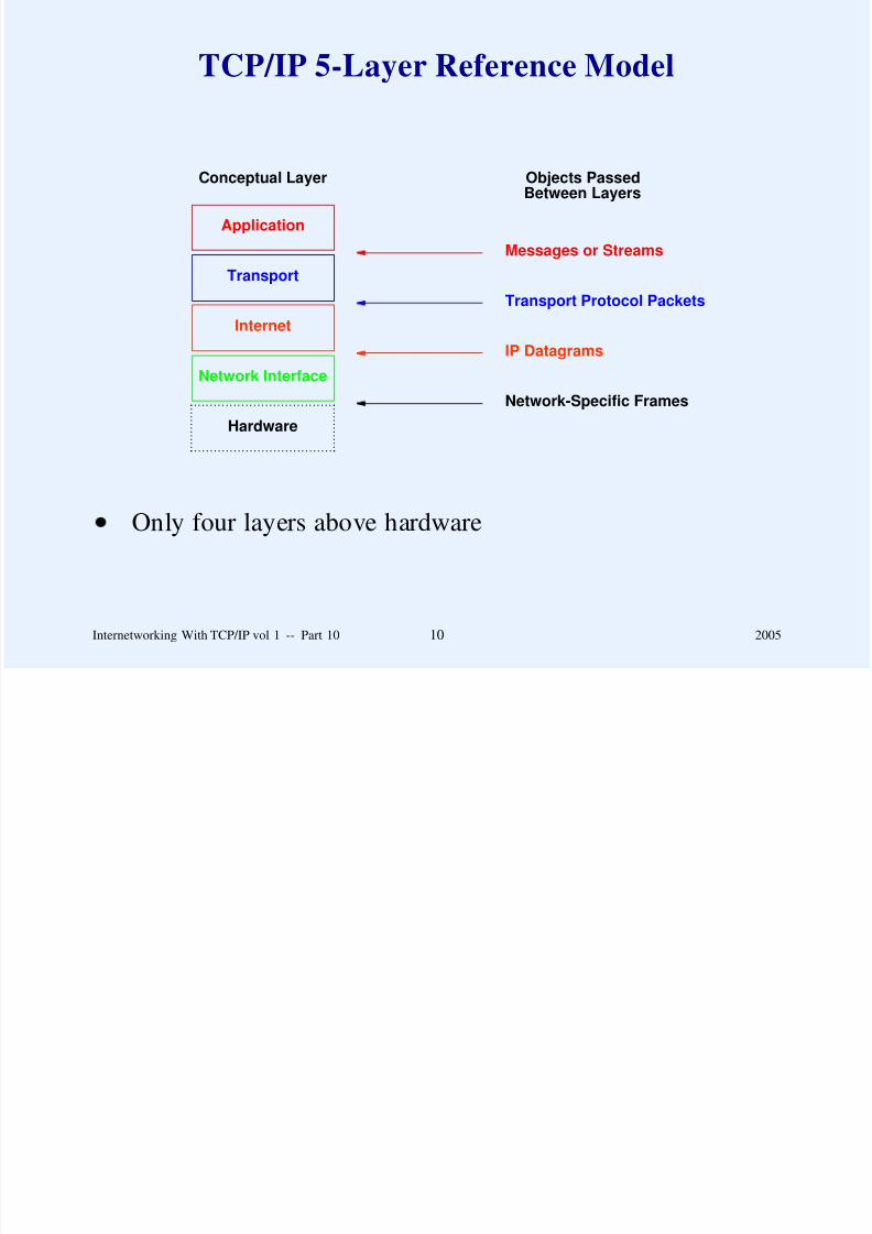
8/6/2019 Vol1 Presentation
http://slidepdf.com/reader/full/vol1-presentation 281/856
Hardware
. . . . . . . . . . . . . . . . . . . . . . . . . . . . . . . . . . . . ................................................................
Network Interface
Internet
Transport
Network-Specific Frames
IP Datagrams
Transport Protocol Packets
Messages or Streams
Only four layers above hardware
Internetworking With TCP/IP vol 1 -- Part 10 10 2005
TCP/IP Layer 1: Physical Hardware
Defines electrical signals used in communication (e.g.,
voltages on wires between two computers)
Uninteresting except to electrical engineers

8/6/2019 Vol1 Presentation
http://slidepdf.com/reader/full/vol1-presentation 282/856
Internetworking With TCP/IP vol 1 -- Part 10 11 2005
TCP/IP Layer 2: Network Interface
Defines communication between computer and network
hardware
Isolates details of hardware (MAC) addressing

8/6/2019 Vol1 Presentation
http://slidepdf.com/reader/full/vol1-presentation 283/856
Example protocol: ARP
Code is usually in the operating system
Internetworking With TCP/IP vol 1 -- Part 10 12 2005
TCP/IP Layer 3: Internet
Protocol is IP
Provides machine to machine communication
Defines best-effort connectionless datagram delivery service

8/6/2019 Vol1 Presentation
http://slidepdf.com/reader/full/vol1-presentation 284/856
Defines best-effort, connectionless datagram delivery service
for the Internet
Code is usually in the operating system
Internetworking With TCP/IP vol 1 -- Part 10 13 2005
TCP/IP Layer 4: Transport
Provides end-to-end connection from application program to
application program
Often handles reliability, flow control

8/6/2019 Vol1 Presentation
http://slidepdf.com/reader/full/vol1-presentation 285/856
Protocols are TCP and UDP
Code is usually in the operating system
Internetworking With TCP/IP vol 1 -- Part 10 14 2005
TCP/IP Layer 5: Application
Implemented by application programs
Many application-specific protocols in the Internet
Built on top of transport layer

8/6/2019 Vol1 Presentation
http://slidepdf.com/reader/full/vol1-presentation 286/856
Built on top of transport layer
Internetworking With TCP/IP vol 1 -- Part 10 15 2005
Two Differences Between TCP/IPAnd Other Layered Protocols
TCP/IP uses end-to-end reliability instead of link-level
reliability

8/6/2019 Vol1 Presentation
http://slidepdf.com/reader/full/vol1-presentation 287/856
TCP/IP places the locus of intelligence and decision making
at the edge of the network instead of the core
Internetworking With TCP/IP vol 1 -- Part 10 16 2005
The Layering Principle
Software implementing layer n at the destination receivesexactly the message sent by software implementing layer n at

8/6/2019 Vol1 Presentation
http://slidepdf.com/reader/full/vol1-presentation 288/856
y g y f p g y
the source.
Internetworking With TCP/IP vol 1 -- Part 10 17 2005
Illustration Of Layering Principle
Application Application
Host A Host B
identical

8/6/2019 Vol1 Presentation
http://slidepdf.com/reader/full/vol1-presentation 289/856
Transport
Internet
NetworkInterface
NetworkInterface
Internet
Transport
Physical Net
message
identical
packet
identical
datagram
identical
frame
Internetworking With TCP/IP vol 1 -- Part 10 18 2005
When A Datagram Traverses The Internet
All layers involved at
– Original source
– Ultimate destination

8/6/2019 Vol1 Presentation
http://slidepdf.com/reader/full/vol1-presentation 290/856
Ultimate destination
Only up through IP layer involved at
– Intermediate routers
Internetworking With TCP/IP vol 1 -- Part 10 19 2005
Illustration Of Layering In An Internet
Application Application
Host A Host B
identical
message

8/6/2019 Vol1 Presentation
http://slidepdf.com/reader/full/vol1-presentation 291/856
Transport
Internet
NetworkInterface
NetworkInterface
Internet
NetworkInterface
Internet
Transport
Physical Net 1 Physical Net 2
Router R
identical
packet
identical
frame
identical
frame
identical
datagram
identical
datagram
Internetworking With TCP/IP vol 1 -- Part 10 20 2005
A Key Definition
A protocol is classified as end-to-end if the layering
principle applies from one end of the Internet to the other
Examples

8/6/2019 Vol1 Presentation
http://slidepdf.com/reader/full/vol1-presentation 292/856
– IP is machine-to-machine because layering principle
only applies across one hop
– TCP is end-to-end because layering principle fromoriginal source to ultimate destination
Internetworking With TCP/IP vol 1 -- Part 10 21 2005
Practical Aspect Of Layering
Multiple protocols at each layer
One protocol used at each layer for given datagram

8/6/2019 Vol1 Presentation
http://slidepdf.com/reader/full/vol1-presentation 293/856
Internetworking With TCP/IP vol 1 -- Part 10 22 2005
Example Of Two ProtocolsAt Network Interface Layer:
SLIP And PPP
Both used to send IP acrossSerial data circuit

8/6/2019 Vol1 Presentation
http://slidepdf.com/reader/full/vol1-presentation 294/856
– Serial data circuit
– Dialup connection
Each defines standards for
– Framing (encapsulation)
– Addressing
Incompatible
Internetworking With TCP/IP vol 1 -- Part 10 23 2005
Notion Of Multiple Interfaces And Layering
Transport Protocol 2Protocol 1 Protocol 3
Conceptual Layer Software Organization

8/6/2019 Vol1 Presentation
http://slidepdf.com/reader/full/vol1-presentation 295/856
NetworkInterface
Internet
Intranet
IP Module
Interface 2
Point-To-Point
(Intranet)
Interface 1 Interface 3
(a) (b)
Internetworking With TCP/IP vol 1 -- Part 10 24 2005
Boundaries In The TCP/IP Layering Model
High-level protocol address boundary
– Division between software that uses hardware addresses
and software that uses IP addresses

8/6/2019 Vol1 Presentation
http://slidepdf.com/reader/full/vol1-presentation 296/856
Operating system boundary
– Division between application program running outside
the operating system and protocol software running
inside the operating system
Internetworking With TCP/IP vol 1 -- Part 10 25 2005
The Consequence Of An Address Boundary
Application programs as well as all protocol software from the Internet layer upward use only IP addresses; the network
f l h dl h l dd

8/6/2019 Vol1 Presentation
http://slidepdf.com/reader/full/vol1-presentation 297/856
interface layer handles physical addresses.
Internetworking With TCP/IP vol 1 -- Part 10 26 2005
Illustration Of The Two Boundaries
T t
Application
Conceptual Layer Boundary
Software outside the operating system
Software inside the operating system

8/6/2019 Vol1 Presentation
http://slidepdf.com/reader/full/vol1-presentation 298/856
NetworkInterface
Internet
Transport
Hardware
. . . . . . . . . . . . . . . . . . . . . . . . . . . . . . . . . . . . . . . . ................................................................
Only IP addresses used
Physical addresses used
Software inside the operating system
Internetworking With TCP/IP vol 1 -- Part 10 27 2005
Handling Multiple Protocols Per Layer
Sender places field in header to say which protocol used at
each layer
Receiver uses field to determine which protocol at next layer
receives the packet
8/6/2019 Vol1 Presentation
http://slidepdf.com/reader/full/vol1-presentation 299/856
receives the packet
Known as multiplexing and demultiplexing
Internetworking With TCP/IP vol 1 -- Part 10 28 2005
Example Of Demultiplexing An Incoming Frame
ARP ModuleIP Module RARP Module

8/6/2019 Vol1 Presentation
http://slidepdf.com/reader/full/vol1-presentation 300/856
Demultiplexing BasedOn Frame Type
Frame Arrives
Internetworking With TCP/IP vol 1 -- Part 10 29 2005
Example Of Demultiplexing Performed By IP
ICMP Module UDP Module TCP Module

8/6/2019 Vol1 Presentation
http://slidepdf.com/reader/full/vol1-presentation 301/856
IP Module
Datagram Arrives
Internetworking With TCP/IP vol 1 -- Part 10 30 2005
Example Of Demultiplexing Performed By TCP
Application 1 Application 2 . . . Application n
TCP Module

8/6/2019 Vol1 Presentation
http://slidepdf.com/reader/full/vol1-presentation 302/856
Segment Arrives
TCP is part of operating system
Transfer to application program must cross operating system
boundary
Internetworking With TCP/IP vol 1 -- Part 10 31 2005
Discussion
What are the key advantages and disadvantages of
multiplexing / demultiplexing?
Can you think of an alternative?

8/6/2019 Vol1 Presentation
http://slidepdf.com/reader/full/vol1-presentation 303/856
Internetworking With TCP/IP vol 1 -- Part 10 32 2005
Summary
Layering
– Intended for designers
– Helps control complexity in protocol design

8/6/2019 Vol1 Presentation
http://slidepdf.com/reader/full/vol1-presentation 304/856
TCP/IP uses 5-layer reference model
Conceptually, a router only needs layers 2 and 3, and a host
needs all layers
IP is machine-to-machine protocol
TCP is end-to-end protocol
Demultiplexing used to handle multiple protocols at eachlayer
Internetworking With TCP/IP vol 1 -- Part 10 33 2005

8/6/2019 Vol1 Presentation
http://slidepdf.com/reader/full/vol1-presentation 305/856
Questions?
PART XI

8/6/2019 Vol1 Presentation
http://slidepdf.com/reader/full/vol1-presentation 306/856
USER DATAGRAM PROTOCOL
(UDP)
Internetworking With TCP/IP vol 1 -- Part 11 1 2005
Identifying The Ultimate Destination
IP address only specifies a computer
Need a way to specify an application program (process) on a
computer
f l

8/6/2019 Vol1 Presentation
http://slidepdf.com/reader/full/vol1-presentation 307/856
Unfortunately
– Application programs can be created and destroyed
rapidly
– Each operating system uses its own identification
Internetworking With TCP/IP vol 1 -- Part 11 2 2005
Specifying An Application Program
TCP/IP introduces its own specification
Abstract destination point known as protocol port number
(positive integer)
E h OS d i h bi d l b

8/6/2019 Vol1 Presentation
http://slidepdf.com/reader/full/vol1-presentation 308/856
Each OS determines how to bind protocol port number to
specific application program
Internetworking With TCP/IP vol 1 -- Part 11 3 2005
User Datagram Protocol
Transport-layer protocol (Layer 4)
Connectionless service: provides application programs with
ability to send and receive messages
All l i l li i i l hi

8/6/2019 Vol1 Presentation
http://slidepdf.com/reader/full/vol1-presentation 309/856
Allows multiple, application programs on a single machine
to communicate concurrently
Same best-effort semantics as IP
– Message can be delayed, lost, or duplicated
– Messages can arrive out of order
Application accepts full responsibility for errors
Internetworking With TCP/IP vol 1 -- Part 11 4 2005
The Added Benefit Of UDP
The User Datagram Protocol (UDP) provides an unreliableconnectionless delivery service using IP to transport messages
between machines It uses IP to carry messages but adds the

8/6/2019 Vol1 Presentation
http://slidepdf.com/reader/full/vol1-presentation 310/856
between machines. It uses IP to carry messages, but adds the
ability to distinguish among multiple destinations within a given
host computer.
Internetworking With TCP/IP vol 1 -- Part 11 5 2005
UDP Message Format
0 16 31
UDP SOURCE PORT UDP DESTINATION PORT
UDP MESSAGE LENGTH UDP CHECKSUM

8/6/2019 Vol1 Presentation
http://slidepdf.com/reader/full/vol1-presentation 311/856
DATA
. . .
If UDP CHECKSUM field contains zeroes, receiver does not
verify the checksum
Internetworking With TCP/IP vol 1 -- Part 11 6 2005
Port Numbers In A UDP Message
SOURCE PORT identifies application on original source
computer
DESTINATION PORT identifies application on ultimatedestination computer

8/6/2019 Vol1 Presentation
http://slidepdf.com/reader/full/vol1-presentation 312/856
p
Note: IP addresses of source and destination do not appear
explicitly in header
Internetworking With TCP/IP vol 1 -- Part 11 7 2005
UDP Pseudo-Header
Used when computing or verifying a checksum
Temporarily prepended to UDP message
Contains items from IP header

8/6/2019 Vol1 Presentation
http://slidepdf.com/reader/full/vol1-presentation 313/856
Guarantees that message arrived at correct destination
Note: pseudo header is not sent across Internet
Internetworking With TCP/IP vol 1 -- Part 11 8 2005
Contents Of UDP Pseudo-Header
0 8 16 31
SOURCE IP ADDRESS
DESTINATION IP ADDRESS

8/6/2019 Vol1 Presentation
http://slidepdf.com/reader/full/vol1-presentation 314/856
ZERO PROTO UDP LENGTH
SOURCE ADDRESS and DESTINATION ADDRESS
specify IP address of sending and receiving computers
PROTO contains the Type from the IP datagram header
Internetworking With TCP/IP vol 1 -- Part 11 9 2005
Position Of UDP In Protocol Stack
Application
Conceptual Layering

8/6/2019 Vol1 Presentation
http://slidepdf.com/reader/full/vol1-presentation 315/856
Network Interface
Internet (IP)
User Datagram (UDP)
UDP lies between applications and IP
Internetworking With TCP/IP vol 1 -- Part 11 10 2005
Encapsulation
IPHEADER IP DATA AREA
UDPHEADER UDP DATA AREA

8/6/2019 Vol1 Presentation
http://slidepdf.com/reader/full/vol1-presentation 316/856
FRAMEHEADER FRAME DATA AREA
Internetworking With TCP/IP vol 1 -- Part 11 11 2005
Division Of Duties BetweenIP and UDP
The IP layer is responsible for transferring data between a pair
of hosts on an internet while the UDP layer is responsible for

8/6/2019 Vol1 Presentation
http://slidepdf.com/reader/full/vol1-presentation 317/856
of hosts on an internet, while the UDP layer is responsible for
differentiating among multiple sources or destinations within
one host.
IP header only identifies computer
UDP header only identifies application programs
Internetworking With TCP/IP vol 1 -- Part 11 12 2005
Demultiplexing Based OnUDP Protocol Port Number
Port 2Port 1 Port 3

8/6/2019 Vol1 Presentation
http://slidepdf.com/reader/full/vol1-presentation 318/856
UDP: DemultiplexingBased On Port
Port 2Port 1 Port 3
IP Module
UDP Datagram arrives
Internetworking With TCP/IP vol 1 -- Part 11 13 2005
Assignment Of UDP Port Numbers
Small numbers reserved for specific services
– Called well-known ports
– Same interpretation throughout the Internet

8/6/2019 Vol1 Presentation
http://slidepdf.com/reader/full/vol1-presentation 319/856
– Used by server software
Large numbers not reserved
– Available to arbitrary application program
– Used by client software
More later in the course
Internetworking With TCP/IP vol 1 -- Part 11 14 2005
Examples Of Assigned UDP Port Numbers
Decimal Keyword UNIX Keyword Description
0 - - Reserved7 ECHO echo Echo9 DISCARD discard Discard
11 USERS systat Active Users13 DAYTIME daytime Daytime15 - netstat Network Status Program17 QUOTE qotd Quote of the Day

8/6/2019 Vol1 Presentation
http://slidepdf.com/reader/full/vol1-presentation 320/856
17 QUOTE qotd Quote of the Day19 CHARGEN chargen Character Generator37 TIME time Time42 NAMESERVER name Host Name Server43 NICNAME whois Who Is
53 DOMAIN nameserver Domain Name Server67 BOOTPS bootps BOOTP or DHCP Server68 BOOTPC bootpc BOOTP or DHCP Client69 TFTP tftp Trivial File Transfer88 KERBEROS kerberos Kerberos Security Service
111 SUNRPC sunrpc Sun Remote Procedure Call123 NTP ntp Network Time Protocol161 - snmp Simple Network Management Protocol
162 - snmp-trap SNMP traps512 - biff UNIX comsat513 - who UNIX rwho Daemon514 - syslog System Log525 - timed Time Daemon
Internetworking With TCP/IP vol 1 -- Part 11 15 2005
Summary
User Datagram Protocol (UDP) provides connectionless,
best-effort message service
UDP message encapsulated in IP datagram for delivery
IP identifies destination computer; UDP identifies

8/6/2019 Vol1 Presentation
http://slidepdf.com/reader/full/vol1-presentation 321/856
IP identifies destination computer; UDP identifies
application on the destination computer
UDP uses abstraction known as protocol port numbers
Internetworking With TCP/IP vol 1 -- Part 11 16 2005

8/6/2019 Vol1 Presentation
http://slidepdf.com/reader/full/vol1-presentation 322/856
Questions?
PART XII
8/6/2019 Vol1 Presentation
http://slidepdf.com/reader/full/vol1-presentation 323/856
RELIABLE STREAM TRANSPORT SERVICE
(TCP)
Internetworking With TCP/IP vol 1 -- Part 12 1 2005
Transmission Control Protocol(TCP)
Major transport service in the TCP/IP suite
Used for most Internet applications (esp. World Wide Web)

8/6/2019 Vol1 Presentation
http://slidepdf.com/reader/full/vol1-presentation 324/856
Internetworking With TCP/IP vol 1 -- Part 12 2 2005
TCP Characteristics
Stream orientation
Virtual circuit connection
Buffered transfer

8/6/2019 Vol1 Presentation
http://slidepdf.com/reader/full/vol1-presentation 325/856
Unstructured stream
Full duplex connection
Reliability
Internetworking With TCP/IP vol 1 -- Part 12 3 2005
Providing Reliability
Traditional technique: Positive Acknowledgement with
Retransmission (PAR)
– Receiver sends acknowledgement when data arrives
– Sender starts timer whenever transmitting

8/6/2019 Vol1 Presentation
http://slidepdf.com/reader/full/vol1-presentation 326/856
Sender starts timer whenever transmitting
– Sender retransmits if timer expires before
acknowledgement arrives
Internetworking With TCP/IP vol 1 -- Part 12 4 2005
Illustration Of Acknowledgements
Send Packet 1
Receive Packet 1Send ACK 1
Events At Sender Site Network Messages Events At Receiver Site

8/6/2019 Vol1 Presentation
http://slidepdf.com/reader/full/vol1-presentation 327/856
Receive ACK 1Send Packet 2
Receive Packet 2Send ACK 2
Receive ACK 2
Time moves from top to bottom in the diagram
Internetworking With TCP/IP vol 1 -- Part 12 5 2005
Illustration Of Recovery After Packet Loss
Send Packet 1Start Timer
Packet should arriveACK should be sent
Events At Sender Site Network Messages Events At Receiver Site
Packet lost

8/6/2019 Vol1 Presentation
http://slidepdf.com/reader/full/vol1-presentation 328/856
ACK would normallyarrive at this time
Timer Expires
Retransmit Packet 1Start Timer
Receive Packet 1Send ACK 1
Receive ACK 1Cancel Timer
Internetworking With TCP/IP vol 1 -- Part 12 6 2005
The Problem With Simplistic PAR
A simple positive acknowledgement protocol wastes asubstantial amount of network bandwidth because it must delay
sending a new packet until it receives an acknowledgement for

8/6/2019 Vol1 Presentation
http://slidepdf.com/reader/full/vol1-presentation 329/856
sending a new packet until it receives an acknowledgement for
the previous packet.
Problem is especially severe if network has long latency
Internetworking With TCP/IP vol 1 -- Part 12 7 2005
Solving The Problem
Allow multiple packets to be outstanding at any time
Still require acknowledgements and retransmission
Known as sliding window

8/6/2019 Vol1 Presentation
http://slidepdf.com/reader/full/vol1-presentation 330/856
Internetworking With TCP/IP vol 1 -- Part 12 8 2005
Illustration Of Sliding Window
1 2 3 4 5 6 7 8 9 10 . . .
initial window
(a)

8/6/2019 Vol1 Presentation
http://slidepdf.com/reader/full/vol1-presentation 331/856
1 2 3 4 5 6 7 8 9 10 . . .
window slides
(b)
Window size is fixed
As acknowledgement arrives, window moves forward
Internetworking With TCP/IP vol 1 -- Part 12 9 2005
Why Sliding Window Works
Because a well-tuned sliding window protocol keeps thenetwork completely saturated with packets, it obtains
substantially higher throughput than a simple positive

8/6/2019 Vol1 Presentation
http://slidepdf.com/reader/full/vol1-presentation 332/856
substantially higher throughput than a simple positive
acknowledgement protocol.
Internetworking With TCP/IP vol 1 -- Part 12 10 2005
Illustration Of Sliding Window
Send Packet 1
Send Packet 2Receive Packet 1Send ACK 1
R i P k 2
Events At Sender Site Network Messages Events At Receiver Site

8/6/2019 Vol1 Presentation
http://slidepdf.com/reader/full/vol1-presentation 333/856
Send Packet 3Receive Packet 2Send ACK 2
Receive Packet 3Send ACK 3
Receive ACK 1
Receive ACK 2
Receive ACK 3
Internetworking With TCP/IP vol 1 -- Part 12 11 2005
Sliding Window Used By TCP
Measured in byte positions
Illustration
current window......

8/6/2019 Vol1 Presentation
http://slidepdf.com/reader/full/vol1-presentation 334/856
1 2 3 4 5 6 7 8 9 10 11 . . ...........
Bytes through 2 are acknowledged
Bytes 3 through 6 not yet acknowledged
Bytes 7 though 9 waiting to be sent
Bytes above 9 lie outside the window and cannot be sent
Internetworking With TCP/IP vol 1 -- Part 12 12 2005
Layering Of The Three Major Protocols
User Datagram (UDP)Reliable Stream (TCP)
Application
Conceptual Layering

8/6/2019 Vol1 Presentation
http://slidepdf.com/reader/full/vol1-presentation 335/856
Network Interface
Internet (IP)
User Datagram (UDP)Reliable Stream (TCP)
Internetworking With TCP/IP vol 1 -- Part 12 13 2005
TCP Ports, Connections, And Endpoints
Endpoint of communication is application program
TCP uses protocol port number to identify application
TCP connection between two endpoints identified by four
items

8/6/2019 Vol1 Presentation
http://slidepdf.com/reader/full/vol1-presentation 336/856
– Sender’s IP address
– Sender’s protocol port number
– Receiver’s IP address
– Receiver’s protocol port number
Internetworking With TCP/IP vol 1 -- Part 12 14 2005
An Important Idea About Port Numbers
Because TCP identifies a connection by a pair of endpoints, agiven TCP port number can be shared by multiple connections
on the same machine

8/6/2019 Vol1 Presentation
http://slidepdf.com/reader/full/vol1-presentation 337/856
on the same machine.
Internetworking With TCP/IP vol 1 -- Part 12 15 2005
Passive And Active Opens
Two sides of a connection
One side waits for contact
– A server program
Uses TCP’s passive open

8/6/2019 Vol1 Presentation
http://slidepdf.com/reader/full/vol1-presentation 338/856
– Uses TCP s passive open
One side initiates contact
– A client program
– Uses TCP’s active open
Internetworking With TCP/IP vol 1 -- Part 12 16 2005
TCP Segment Format
0 4 10 16 24 31
SOURCE PORT DESTINATION PORT
SEQUENCE NUMBER
ACKNOWLEDGEMENT NUMBER
HLEN RESERVED CODE BITS WINDOW

8/6/2019 Vol1 Presentation
http://slidepdf.com/reader/full/vol1-presentation 339/856
CHECKSUM URGENT PTR
OPTIONS (MAY BE OMITTED) PADDING
BEGINNING OF PAYLOAD (DATA)
. . .
Offset specifies header size (offset of data) in 32-bit words
Internetworking With TCP/IP vol 1 -- Part 12 17 2005
Code Bits In The TCP Segment Header
Bit (left to right) Meaning if bit set to 1URG Urgent pointer field is valid
ACK Acknowledgement field is valid
PSH This segment requests a push

8/6/2019 Vol1 Presentation
http://slidepdf.com/reader/full/vol1-presentation 340/856
g q p
RST Reset the connection
SYN Synchronize sequence numbers
FIN Sender has reached end of its byte stream
Internetworking With TCP/IP vol 1 -- Part 12 18 2005
Flow Control And TCP Window
Receiver controls flow by telling sender size of currently
available buffer measured in bytes
Called window advertisement
Each segment, including data segments, specifies size of

8/6/2019 Vol1 Presentation
http://slidepdf.com/reader/full/vol1-presentation 341/856
window beyond acknowledged byte
Window size may be zero (receiver cannot accept additional
data at present)
Receiver can send additional acknowledgement later when
buffer space becomes available
Internetworking With TCP/IP vol 1 -- Part 12 19 2005
TCP Checksum Computation
Covers entire segment (header plus data)
Required (unlike UDP)
Pseudo header included in computation as with UDP

8/6/2019 Vol1 Presentation
http://slidepdf.com/reader/full/vol1-presentation 342/856
Internetworking With TCP/IP vol 1 -- Part 12 20 2005
TCP Pseudo Header
0 8 16 31
SOURCE IP ADDRESS
DESTINATION IP ADDRESS
ZERO PROTOCOL TCP LENGTH
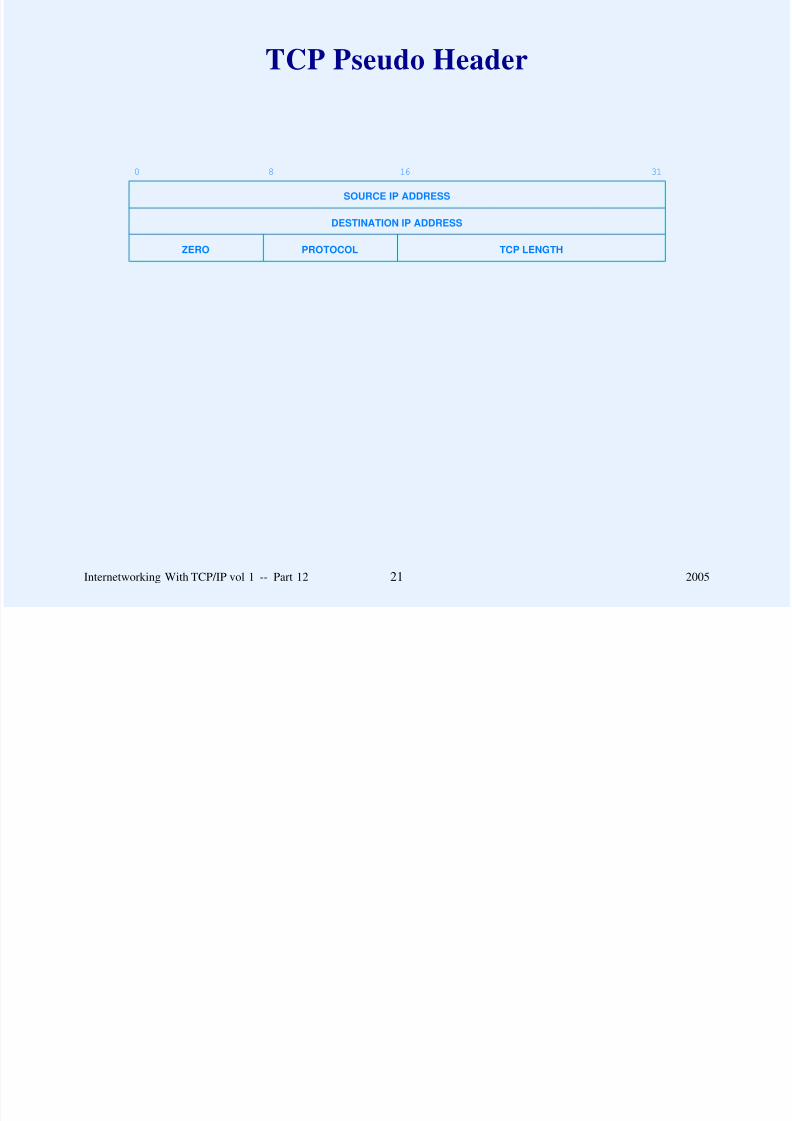
8/6/2019 Vol1 Presentation
http://slidepdf.com/reader/full/vol1-presentation 343/856
Internetworking With TCP/IP vol 1 -- Part 12 21 2005
TCP Retransmission
Designed for Internet environment
– Delays on one connection vary over time
– Delays vary widely between connections
Fixed value for timeout will fail

8/6/2019 Vol1 Presentation
http://slidepdf.com/reader/full/vol1-presentation 344/856
Fixed value for timeout will fail
– Waiting too long introduces unnecessary delay
– Not waiting long enough wastes network bandwidth
with unnecessary retransmission
Retransmission strategy must be adaptive
Internetworking With TCP/IP vol 1 -- Part 12 22 2005
Adaptive Retransmission
TCP keeps estimate of round-trip time (RTT) on each
connection
Round-trip estimate derived from observed delay betweensending segment and receiving acknowledgement
Ti f i i b d d i

8/6/2019 Vol1 Presentation
http://slidepdf.com/reader/full/vol1-presentation 345/856
Timeout for retransmission based on current round-trip
estimate
Internetworking With TCP/IP vol 1 -- Part 12 23 2005
Difficulties With AdaptiveRetransmission
The problem is knowing when to retransmit
Segments or ACKs can be lost or delayed, making round-trip estimation difficult or inaccurate

8/6/2019 Vol1 Presentation
http://slidepdf.com/reader/full/vol1-presentation 346/856
Round-trip times vary over several orders of magnitude
between different connections
Traffic is bursty, so round-trip times fluctuate wildly on a
single connection
Internetworking With TCP/IP vol 1 -- Part 12 24 2005
Difficulties With AdaptiveRetransmission
(continued)
Load imposed by a single connection can congest routers or
networks
Retransmission can cause congestion

8/6/2019 Vol1 Presentation
http://slidepdf.com/reader/full/vol1-presentation 347/856
Because an internet contains diverse network hardware
technologies, there may be little or no control for intra-
network congestion
Internetworking With TCP/IP vol 1 -- Part 12 25 2005
Solution: Smoothing
Adaptive retransmission schemes keep a statistically
smoothed round-trip estimate
Smoothing keeps running average from fluctuating wildly,and keeps TCP from overreacting to change
Diffi lt h i f thi h

8/6/2019 Vol1 Presentation
http://slidepdf.com/reader/full/vol1-presentation 348/856
Difficulty: choice of smoothing scheme
Internetworking With TCP/IP vol 1 -- Part 12 26 2005
Original Smoothing Scheme
Let RTT be current (old) average round-trip time
Let NRT be a new sample
Compute
RTT = α * RTT + β * NRT

8/6/2019 Vol1 Presentation
http://slidepdf.com/reader/full/vol1-presentation 349/856
β
where
α + β = 1
Example: α= .8, β= .2
Large α makes estimate less susceptible to a single long
delay (more stable)
Large β makes estimate track changes in round-trip time
quickly
Internetworking With TCP/IP vol 1 -- Part 12 27 2005
Problems With OriginalScheme
Associating ACKs with transmissions
– TCP acknowledges receipt of data, not receipt of transmission

8/6/2019 Vol1 Presentation
http://slidepdf.com/reader/full/vol1-presentation 350/856
– Assuming ACK corresponds to most recent transmission
can cause instability in round-trip estimate (Cypress
syndrome)
– Assuming ACK corresponds to first transmission can
cause unnecessarily long timeout
– Both assumptions lead to lower throughput
Internetworking With TCP/IP vol 1 -- Part 12 28 2005
Partridge / Karn Scheme†
Solves the problem of associating ACKs with correct
transmission
Specifies ignoring round-trip time samples that correspondto retransmissions
Separates timeout from round trip estimate for retransmitted

8/6/2019 Vol1 Presentation
http://slidepdf.com/reader/full/vol1-presentation 351/856
Separates timeout from round-trip estimate for retransmitted
packets
†Also called Karn’s Algorithm
Internetworking With TCP/IP vol 1 -- Part 12 29 2005
Partridge / Karn Scheme(continued)
Starts (as usual) with retransmission timer as a function of
round-trip estimate
Doubles retransmission timer value for each retransmission
without changing round-trip estimate

8/6/2019 Vol1 Presentation
http://slidepdf.com/reader/full/vol1-presentation 352/856
g g p
Resets retransmission timer to be function of round-trip
estimate when ACK arrives for nonretransmitted segment
Internetworking With TCP/IP vol 1 -- Part 12 30 2005
Flow Control And Congestion
Receiver advertises window that specifies how many
additional bytes it can accept
Window size of zero means sender must not send normaldata (ACKs and urgent data allowed)
Receiver can never decrease window beyond previously

8/6/2019 Vol1 Presentation
http://slidepdf.com/reader/full/vol1-presentation 353/856
Receiver can never decrease window beyond previously
advertised point in sequence space
Sender chooses effective window smaller than receiver’sadvertised window if congestion detected
Internetworking With TCP/IP vol 1 -- Part 12 31 2005
Jacobson / KarelsCongestion Control
Assumes long delays (packet loss) due to congestion
Uses successive retransmissions as measure of congestion
Reduces effective window as retransmissions increase

8/6/2019 Vol1 Presentation
http://slidepdf.com/reader/full/vol1-presentation 354/856
Effective window is minimum of receiver’s advertisement
and computed quantity known as the congestion window
Internetworking With TCP/IP vol 1 -- Part 12 32 2005
Multiplicative Decrease
In steady state (no congestion), the congestion window is
equal to the receiver’s window
When segment lost (retransmission timer expires), reducecongestion window by half
Never reduce congestion window to less than one maximum

8/6/2019 Vol1 Presentation
http://slidepdf.com/reader/full/vol1-presentation 355/856
Never reduce congestion window to less than one maximum
sized segment
Internetworking With TCP/IP vol 1 -- Part 12 33 2005
Jacobson / Karels Slow Start
Used when starting traffic or when recovering from
congestion
Self-clocking startup to increase transmission rate rapidly aslong as no packets are lost
When starting traffic initialize the congestion window to the

8/6/2019 Vol1 Presentation
http://slidepdf.com/reader/full/vol1-presentation 356/856
When starting traffic, initialize the congestion window to the
size of a single maximum sized segment
Increase congestion window by size of one segment eachtime an ACK arrives without retransmission
Internetworking With TCP/IP vol 1 -- Part 12 34 2005
Jacobson / Karels Congestion Avoidance
When congestion first occurs, record one-half of last
successful congestion window (flightsize) in a threshold
variable
During recovery, use slow start until congestion window
reaches threshold

8/6/2019 Vol1 Presentation
http://slidepdf.com/reader/full/vol1-presentation 357/856
Above threshold, slow down and increase congestion
window by one segment per window (even if more than onesegment was successfully transmitted in that interval)
Internetworking With TCP/IP vol 1 -- Part 12 35 2005
Jacobson / Karels Congestion Avoidance(continued)
Increment window size on each ACK instead of waiting forcomplete window
increase = segment / window
Let N be segments per window, or

8/6/2019 Vol1 Presentation
http://slidepdf.com/reader/full/vol1-presentation 358/856
N = congestion_window / max segment size
soincrease = segment / N
= (MSS bytes / N)
= MSS / (congestion_window/MSS)
orincrease = (MSS*MSS)/congestion_window
Internetworking With TCP/IP vol 1 -- Part 12 36 2005
Changes In Delay
Original smoothing scheme tracks the mean but not changes
To track changes, compute
DIFF = SAMPLE - RTT
RTT = RTT + δ * DIFF
DEV = DEV + δ (| DIFF | - DEV)

8/6/2019 Vol1 Presentation
http://slidepdf.com/reader/full/vol1-presentation 359/856
DEV = DEV + δ (| DIFF | DEV)
DEV estimates mean deviation
δ is fraction between 0 and 1 that weights new sample
Retransmission timer is weighted average of RTT and DEV:
RTO = µ * RTT + φ *DEV
Typically, µ= 1 and φ= 4
Internetworking With TCP/IP vol 1 -- Part 12 37 2005
Computing Estimated Deviation
Extremely efficient (optimized) implementation possible
– Scale computation by 2n
– Use integer arithmetic
– Choose δ to be 1/2n

8/6/2019 Vol1 Presentation
http://slidepdf.com/reader/full/vol1-presentation 360/856
– Implement multiplication or division by powers of 2
with shifts
– Research shows n = 3 works well
Internetworking With TCP/IP vol 1 -- Part 12 38 2005
TCP Round-Trip Estimation
100
80
.. .
.......
.................
.......
.....
........
............
....
......
..
..........
..
......
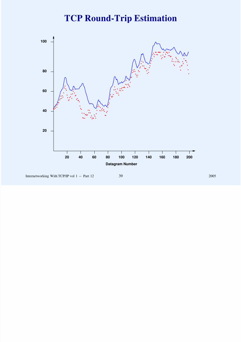
8/6/2019 Vol1 Presentation
http://slidepdf.com/reader/full/vol1-presentation 361/856
60
40
20
200180160140120100
Datagram Number
80604020
.........
...........
...................
............
.........
................
.......
.....
.............
...........
Internetworking With TCP/IP vol 1 -- Part 12 39 2005
Measurement Of Internet Delays For 100Successive Packets At 1 Second Intervals
12 s
10 s
8 s xx..x.....x...... .
....x. .x

8/6/2019 Vol1 Presentation
http://slidepdf.com/reader/full/vol1-presentation 362/856
8 s
6 s
Time
4 s
2 s
1009080706050
Datagram Number
403020101
x......................x. .x. .x. .x..
........x....x..
....x. .x..
.
......x. .x.
......x. .x.
....x....x...x. .x..
.
.
.
.
.
.
.
.
.
.
.
.x...x....................x...x.....x...x. .x. .x. .x..
.x.............x....x..
.x.
.
.
.
.
.
.
.
.....x...x.
.x. .x. .x...........x. .x..
.x...........x...x.......x. .x. .x.
.x. .x...x.......x...x..
.......x. .x. .x.
.
.
.
.
.
.
.
.
.
.
.
.
.x...x...x........x.....................................x. .x. .
.
.
.
.
.
.
.
.
.
.x...x.....x......x.................................x..
.x.....x.......x.....x. .x. .x..
.....x...x...x.
..x.....x....x......x. .x..
....x.....x. .x..
.
.....x.....x. .x..
.....x...x.......x...x.....................x. .x. .x..
....x. .x...x..
.......x.........................x......................x...x....................
.
.
.
.
.
.
.
.
.
.
.
.
.
.
.
.x..
Internetworking With TCP/IP vol 1 -- Part 12 40 2005
TCP Round-Trip Estimation ForSampled Internet Delays
12 s
10 s
8 s xx..x.....x...... .
....x. .x

8/6/2019 Vol1 Presentation
http://slidepdf.com/reader/full/vol1-presentation 363/856
8 s
6 s
Time
4 s
2 s
1009080706050
Datagram Number
403020101
x......................x. .x. .x. .x..
........x....x..
....x. .x..
.
......x. .x.
......x. .x.
....x....x...x. .x..
.
.
.
.
.
.
.
.
.
.
.
.x...x....................x...x.....x...x. .x. .x. .x..
.x.............x....x..
.x.
.
.
.
.
.
.
.
.....x...x.
.x. .x. .x...........x. .x..
.x...........x...x.......x. .x. .x.
.x. .x...x.......x...x..
.......x. .x. .x.
.
.
.
.
.
.
.
.
.
.
.
.
.x...x...x........x.....................................x. .x. .
.
.
.
.
.
.
.
.
.
.x...x.....x......x.................................x..
.x.....x.......x.....x. .x. .x..
.....x...x...x.
..x.....x....x......x. .x..
....x.....x. .x..
.
.....x.....x. .x..
.....x...x.......x...x.....................x. .x. .x..
....x. .x...x..
.......x.........................x......................x...x....................
.
.
.
.
.
.
.
.
.
.
.
.
.
.
.
.x..
Internetworking With TCP/IP vol 1 -- Part 12 41 2005
TCP Details
Data flow may be shut down in one direction
Connections started reliably, and terminated gracefully
Connection established (and terminated) with a 3-way
handshake

8/6/2019 Vol1 Presentation
http://slidepdf.com/reader/full/vol1-presentation 364/856
Internetworking With TCP/IP vol 1 -- Part 12 42 2005
3-Way HandshakeFor Connection Startup
Send SYN seq=x
Receive SYN segment
Events At Site 1 Network Messages Events At Site 2

8/6/2019 Vol1 Presentation
http://slidepdf.com/reader/full/vol1-presentation 365/856
Receive SYN segmentSend SYN seq=y, ACK x+1
Receive SYN + ACK segmentSend ACK y+1
Receive ACK segment
Internetworking With TCP/IP vol 1 -- Part 12 43 2005
3-Way HandshakeFor Connection Shutdown
(application closes connection)Send FIN seq=x
Receive FIN segmentSend ACK x 1
Events At Site 1 Network Messages Events At Site 2
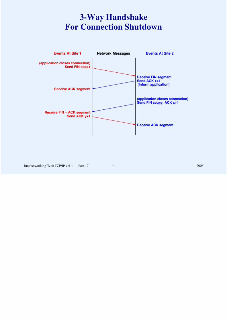
8/6/2019 Vol1 Presentation
http://slidepdf.com/reader/full/vol1-presentation 366/856
Send ACK x+1(inform application)
Receive ACK segment
(application closes connection)Send FIN seq=y, ACK x+1
Receive FIN + ACK segmentSend ACK y+1
Receive ACK segment
Internetworking With TCP/IP vol 1 -- Part 12 44 2005
TCP Finite State Machine
CLOSED
LISTEN
anything / reset
begin
active open / syn
close passive open
send /syn
syn / syn + ack
reset

8/6/2019 Vol1 Presentation
http://slidepdf.com/reader/full/vol1-presentation 367/856
SYN
RECVD
SYN
SENT
ESTAB-
LISHED
FIN
WAIT-1
CLOSE
WAIT
CLOSING
FIN
WAIT-2
TIME
WAIT
LAST
ACK
reset
ack
close /fin
syn/ syn + ack
syn + ack/ ack
close /fin
fin/ack
fin/ack
ack/ fin-ack / ack
fin/ack
ack/
close /fin
ack/
close /
timeout / reset
timeout after 2 segment lifetimes......
Internetworking With TCP/IP vol 1 -- Part 12 45 2005
TCP Urgent Data
Segment with urgent bit set contains pointer to last octet of
urgent data
Urgent data occupies part of normal sequence space
Urgent data can be retransmitted
R i i TCP h ld d li t d t t li ti

8/6/2019 Vol1 Presentation
http://slidepdf.com/reader/full/vol1-presentation 368/856
Receiving TCP should deliver urgent data to application
‘‘immediately’’ upon receipt
Internetworking With TCP/IP vol 1 -- Part 12 46 2005
TCP Urgent Data(continued)
Two interpretations of standard
– Out-of-band data interpretation
– Data mark interpretation

8/6/2019 Vol1 Presentation
http://slidepdf.com/reader/full/vol1-presentation 369/856
Internetworking With TCP/IP vol 1 -- Part 12 47 2005
Data-Mark InterpretationOf Urgent Data
Has become widely accepted
Single data stream
Urgent pointer marks end of urgent data

8/6/2019 Vol1 Presentation
http://slidepdf.com/reader/full/vol1-presentation 370/856
Urgent pointer marks end of urgent data
TCP informs application that urgent data arrived
Application receives all data in sequence
TCP informs application when end of urgent data reached
Internetworking With TCP/IP vol 1 -- Part 12 48 2005
Data-Mark InterpretationOf Urgent Data
(continued)
Application
– Reads all data from one stream
– Must recognize start of urgent data

8/6/2019 Vol1 Presentation
http://slidepdf.com/reader/full/vol1-presentation 371/856
– Must buffer normal data if needed later
Urgent data marks read boundary
Internetworking With TCP/IP vol 1 -- Part 12 49 2005
Urgent DataDelivery
Receiving application placed in urgent mode
Receiving application leaves urgent mode after readingurgent data
Receiving application acquires all available urgent data

8/6/2019 Vol1 Presentation
http://slidepdf.com/reader/full/vol1-presentation 372/856
v g app a a q all ava a g a a
when in urgent mode
Internetworking With TCP/IP vol 1 -- Part 12 50 2005
Fast Retransmit
Coarse-grained clock used to implement RTO
– Typically 300 to 500ms per tick
Timer expires up to 1s after segment dropped
Fast retransmission

8/6/2019 Vol1 Presentation
http://slidepdf.com/reader/full/vol1-presentation 373/856
– Sender uses three duplicate ACKs as trigger
– Sender retransmits ‘‘early’’
– Sender reduces congestion window to half
Internetworking With TCP/IP vol 1 -- Part 12 51 2005
Other TCP Details
Silly Window Syndrome (SWS) avoidance
Nagle algorithm
Delayed ACKs
For details, read the text

8/6/2019 Vol1 Presentation
http://slidepdf.com/reader/full/vol1-presentation 374/856
Internetworking With TCP/IP vol 1 -- Part 12 52 2005
Comparison Of UDP And TCP
Network Interface
Internet (IP)
Reliable Stream (TCP) User Datagram (UDP)

8/6/2019 Vol1 Presentation
http://slidepdf.com/reader/full/vol1-presentation 375/856
TCP and UDP lie between applications and IP
Otherwise, completely different
Internetworking With TCP/IP vol 1 -- Part 12 53 2005
Comparison Of UDP and TCP
UDP TCP
between apps. and IP between apps. and IP
packets called datagrams packets called segments
unreliable reliable
checksum optional checksum required

8/6/2019 Vol1 Presentation
http://slidepdf.com/reader/full/vol1-presentation 376/856
checksum optional checksum required
connectionless connection-oriented
record boundaries stream interfaceintended for LAN useful over WAN or LAN
no flow control flow control
1-to-1, 1-many, many-1 1-to-1
allows unicast, multicast unicast only
or broadcast
Internetworking With TCP/IP vol 1 -- Part 12 54 2005
TCP Vs. UDP Traffic
Around 95% of all bytes and around 85-95% of all packets on
the Internet are transmitted using TCP.
– Eggert, et. al. CCR

8/6/2019 Vol1 Presentation
http://slidepdf.com/reader/full/vol1-presentation 377/856
Summary Of TCP
Major transport service in the Internet
Connection oriented
Provides end-to-end reliability
Uses adaptive retransmission

8/6/2019 Vol1 Presentation
http://slidepdf.com/reader/full/vol1-presentation 378/856
Includes facilities for flow control and congestion avoidance
Uses 3-way handshake for connection startup and shutdown
Internetworking With TCP/IP vol 1 -- Part 12 55 2005
Questions?

8/6/2019 Vol1 Presentation
http://slidepdf.com/reader/full/vol1-presentation 379/856
Questions?
PART XIII
ROUTING: CORES, PEERS,
AND ALGORITHMS

8/6/2019 Vol1 Presentation
http://slidepdf.com/reader/full/vol1-presentation 380/856
AND ALGORITHMS
Internetworking With TCP/IP vol 1 -- Part 13 1 2005
Internet Routing(review)
IP implements datagram forwarding
Both hosts and routers
– Have an IP module
Forward datagrams

8/6/2019 Vol1 Presentation
http://slidepdf.com/reader/full/vol1-presentation 381/856
– Forward datagrams
IP forwarding is table-driven
Table known as routing table
Internetworking With TCP/IP vol 1 -- Part 13 2 2005
How / When Are IP RoutingTables Built?
Depends on size / complexity of internet
Static routing
– Fixes routes at boot time
Useful only for simplest cases

8/6/2019 Vol1 Presentation
http://slidepdf.com/reader/full/vol1-presentation 382/856
– Useful only for simplest cases
Dynamic routing
– Table initialized at boot time
– Values inserted / updated by protocols that propagate
route information
– Necessary in large internets
Internetworking With TCP/IP vol 1 -- Part 13 3 2005
Routing Tables
Two sources of information
– Initialization (e.g., from disk)
– Update (e.g., from protocols)
Hosts tend to freeze the routing table after initialization

8/6/2019 Vol1 Presentation
http://slidepdf.com/reader/full/vol1-presentation 383/856
Routers use protocols to learn new information and update
their routing table dynamically
Internetworking With TCP/IP vol 1 -- Part 13 4 2005
Routing With Partial Information
A host can forward datagrams successfully even if it only has partial routing information because it can rely on a router.
8/6/2019 Vol1 Presentation
http://slidepdf.com/reader/full/vol1-presentation 384/856
Internetworking With TCP/IP vol 1 -- Part 13 5 2005
Routing With Partial Information(continued)
The routing table in a given router contains partial information
about possible destinations. Routing that uses partial
information allows sites autonomy in making local routing
changes but introduces the possibility of inconsistencies that

8/6/2019 Vol1 Presentation
http://slidepdf.com/reader/full/vol1-presentation 385/856
changes, but introduces the possibility of inconsistencies that
may make some destinations unreachable from some sources.
Internetworking With TCP/IP vol 1 -- Part 13 6 2005
Original Internet
ARPANET BACKBONE
R2R1 Rn
Local Net 1 Local Net 2 Local Net n
CoreRouters
. . .
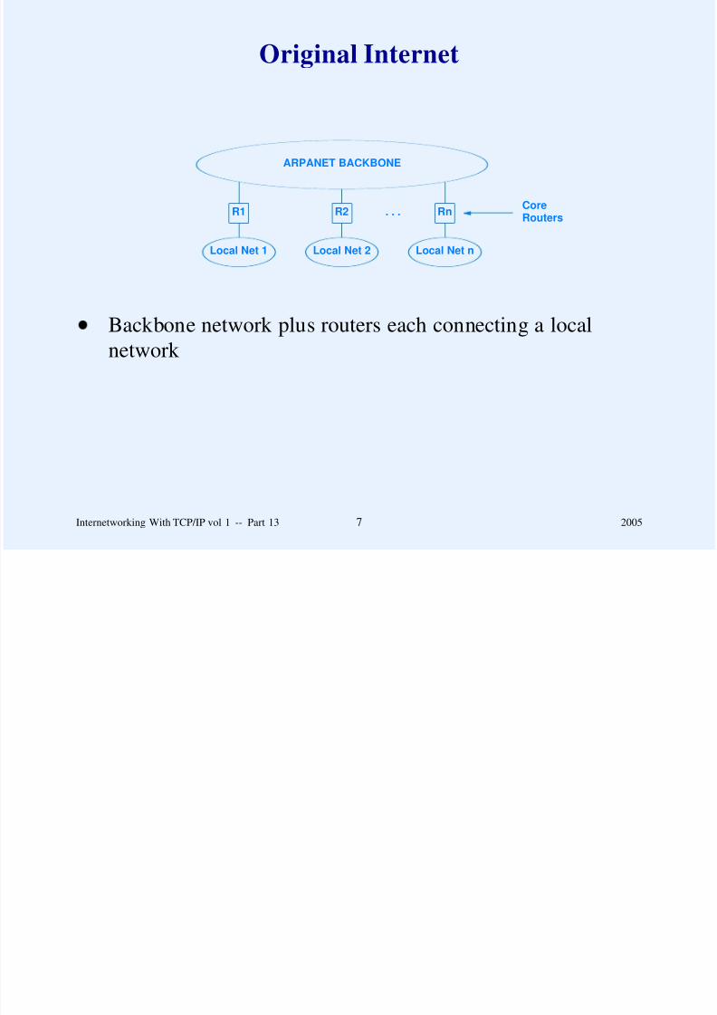
8/6/2019 Vol1 Presentation
http://slidepdf.com/reader/full/vol1-presentation 386/856
Backbone network plus routers each connecting a local
network
Internetworking With TCP/IP vol 1 -- Part 13 7 2005
Worst Case If All RoutersContain A Default Route
BACKBONE
R2R1 Rn. . .
...

8/6/2019 Vol1 Presentation
http://slidepdf.com/reader/full/vol1-presentation 387/856
Local Net 1 Local Net 2 Local Net n
Datagram sent to nonexistent destination loops until TTL
expires
Internetworking With TCP/IP vol 1 -- Part 13 8 2005
Original Routing Architecture
Small set of ‘‘core’’ routers with complete information
about all destinations
Other routers know local destinations and use the core ascentral router

8/6/2019 Vol1 Presentation
http://slidepdf.com/reader/full/vol1-presentation 388/856
Internetworking With TCP/IP vol 1 -- Part 13 9 2005
Illustration Of Default RoutesIn The Original Internet Core
L1
L2Ln
..

8/6/2019 Vol1 Presentation
http://slidepdf.com/reader/full/vol1-presentation 389/856
CORE
SYSTEM L3
L4
L5
L6
L7
..
Internetworking With TCP/IP vol 1 -- Part 13 10 2005
Disadvantage Of Original Core
Central bottleneck for all traffic
No shortcut routes possible
Does not scale
8/6/2019 Vol1 Presentation
http://slidepdf.com/reader/full/vol1-presentation 390/856
Internetworking With TCP/IP vol 1 -- Part 13 11 2005
Beyond A Core Architecture
Single core insufficient in world where multiple ISPs each
have a wide-area backbone
Two backbones first appeared when NSF and ARPA fundedseparate backbone networks
Known as peer backbones

8/6/2019 Vol1 Presentation
http://slidepdf.com/reader/full/vol1-presentation 391/856
Internetworking With TCP/IP vol 1 -- Part 13 12 2005
Illustration Of Peer Backbones
ARPANET BACKBONE
NSFNET BACKBONE
R2R1 R3
HOST 1 HOST 2
HOST 3 HOST 4

8/6/2019 Vol1 Presentation
http://slidepdf.com/reader/full/vol1-presentation 392/856
Internetworking With TCP/IP vol 1 -- Part 13 13 2005
Partial Core
Cannot have ‘‘partial core’’ scheme
Proof:
PARTIALCORE #1
PARTIALCORE #2
default route to sitesbeyond core 1default routes
from sitesbehind core 1
default routesfrom sites
behind core 2

8/6/2019 Vol1 Presentation
http://slidepdf.com/reader/full/vol1-presentation 393/856
default route to sitesbeyond core 2
Datagram destined for nonexistent destination loops until
TTL expires
Internetworking With TCP/IP vol 1 -- Part 13 14 2005
When A Core Routing Architecture Works
A core routing architecture assumes a centralized set of routers
serves as the repository of information about all possible
destinations in an internet. Core systems work best for
internets that have a single, centrally managed backbone.
Expanding the topology to multiple backbones makes routing
complex; attempting to partition the core architecture so that
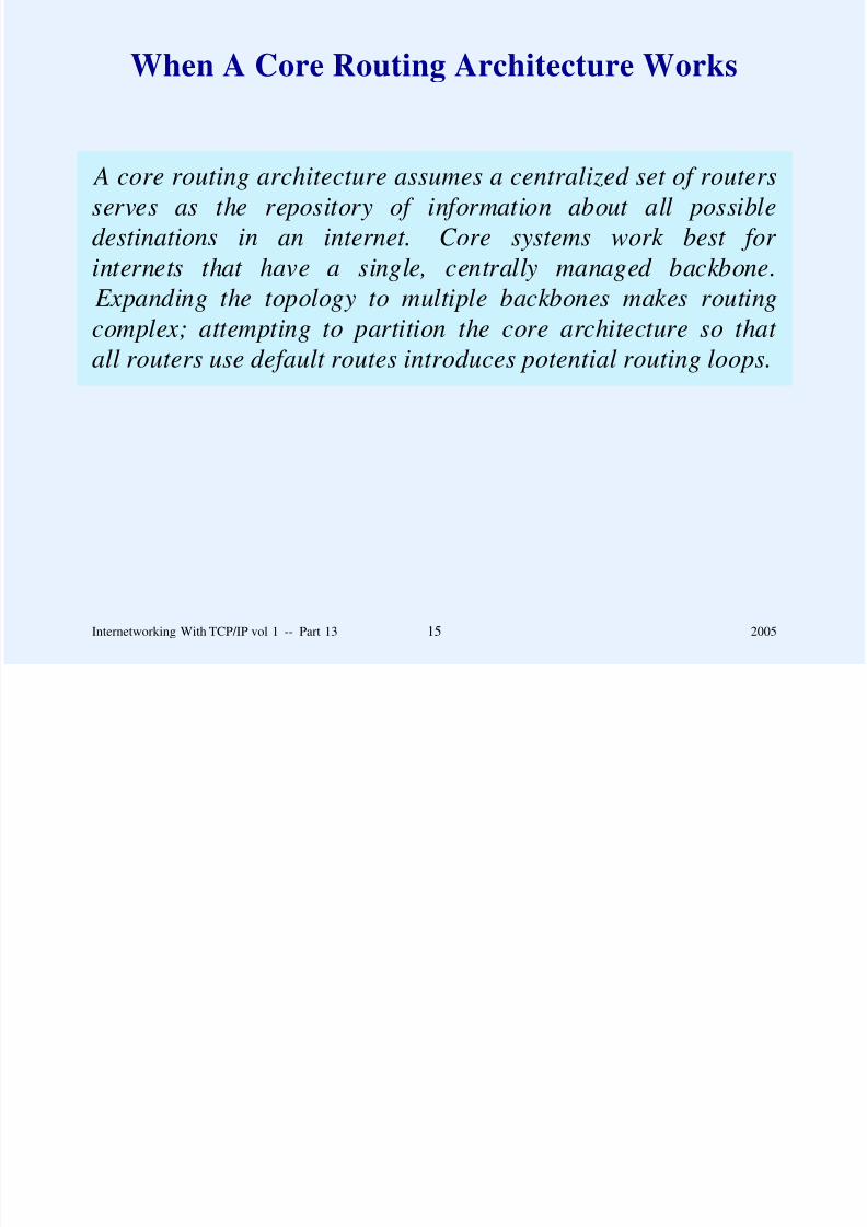
8/6/2019 Vol1 Presentation
http://slidepdf.com/reader/full/vol1-presentation 394/856
complex; attempting to partition the core architecture so that
all routers use default routes introduces potential routing loops.
Internetworking With TCP/IP vol 1 -- Part 13 15 2005
General Idea
Have a set of core routers know routes to all locations
Devise a mechanism that allows other routers to contact the
core to learn routes (spread necessary routing informationautomatically)
Continually update routing information

8/6/2019 Vol1 Presentation
http://slidepdf.com/reader/full/vol1-presentation 395/856
Internetworking With TCP/IP vol 1 -- Part 13 16 2005
Automatic Route Propagation
Two basic algorithms used by routing update protocols
– Distance-vector
– Link-state
Many variations in implementation details

8/6/2019 Vol1 Presentation
http://slidepdf.com/reader/full/vol1-presentation 396/856
Internetworking With TCP/IP vol 1 -- Part 13 17 2005
Distance-Vector Algorithm
Initialize routing table with one entry for each directly-
connected network
Periodically run a distance-vector update to exchangeinformation with routers that are reachable over directly-
connected networks

8/6/2019 Vol1 Presentation
http://slidepdf.com/reader/full/vol1-presentation 397/856
Internetworking With TCP/IP vol 1 -- Part 13 18 2005
Dynamic Update With Distance-Vector
One router sends list of its routes to another
List contains pairs of destination network and distance
Receiver replaces entries in its table by routes to the senderif routing through the sender is less expensive than the
current route

8/6/2019 Vol1 Presentation
http://slidepdf.com/reader/full/vol1-presentation 398/856
Receiver propagates new routes next time it sends out an
update
Algorithm has well-known shortcomings (we will see an
example later)
Internetworking With TCP/IP vol 1 -- Part 13 19 2005
Example Of Distance-Vector Update
Destination Distance Route
Net 1
Net 2Net 4
Net 17
Net 24
Net 30
Net 42
0
08
5
6
2
2
direct
directRouter L
Router M
Router J
Router Q
Router J
Destination Distance
Net 1
Net 4Net 17
Net 21
Net 24
Net 30
Net 42
2
36
4
5
10
3

8/6/2019 Vol1 Presentation
http://slidepdf.com/reader/full/vol1-presentation 399/856
Net 42 2 Router J Net 42 3
(a) (b)
(a) is existing routing table
(b) incoming update (marked items cause change)
Internetworking With TCP/IP vol 1 -- Part 13 20 2005
Link-State Algorithm
Alternative to distance-vector
Distributed computation
– Broadcast information
– Allow each router to compute shortest paths
Avoids problem where one router can damage the entire

8/6/2019 Vol1 Presentation
http://slidepdf.com/reader/full/vol1-presentation 400/856
Avoids problem where one router can damage the entire
internet by passing incorrect information
Also called Shortest Path First (SPF)
Internetworking With TCP/IP vol 1 -- Part 13 21 2005
Link-State Update
Participating routers learn internet topology
Think of routers as nodes in a graph, and networks
connecting them as edges or links
Pairs of directly-connected routers periodically
– Test link between them

8/6/2019 Vol1 Presentation
http://slidepdf.com/reader/full/vol1-presentation 401/856
– Propagate (broadcast) status of link
All routers
– Receive link status messages
– Recompute routes from their local copy of information
Internetworking With TCP/IP vol 1 -- Part 13 22 2005
Summary
Routing tables can be
– Initialized at startup (host or router)
– Updated dynamically (router)
Original Internet used core routing architecture
Current Internet accommodates peer backbones

8/6/2019 Vol1 Presentation
http://slidepdf.com/reader/full/vol1-presentation 402/856
Current Internet accommodates peer backbones
Two important routing algorithms
– Distance-vector
– Link state
Internetworking With TCP/IP vol 1 -- Part 13 23 2005
Questions?

8/6/2019 Vol1 Presentation
http://slidepdf.com/reader/full/vol1-presentation 403/856
Questions?
PART XIV
ROUTING: EXTERIOR GATEWAY
PROTOCOLS AND AUTONOMOUS

8/6/2019 Vol1 Presentation
http://slidepdf.com/reader/full/vol1-presentation 404/856
SYSTEMS (BGP)
Internetworking With TCP/IP vol 1 -- Part 14 1 2005
General Principle
Although it is desirable for routers to exchange routing
information, it is impractical for all routers in an arbitrarilylarge internet to participate in a single routing update protocol.

8/6/2019 Vol1 Presentation
http://slidepdf.com/reader/full/vol1-presentation 405/856
Consequence: routers must be divided into groups
Internetworking With TCP/IP vol 1 -- Part 14 2 2005
A Practical Limit On Group Size
It is safe to allow up to a dozen routers to participate in a
single routing information protocol across a wide areanetwork; approximately five times as many can safely
participate across a set of local area networks.

8/6/2019 Vol1 Presentation
http://slidepdf.com/reader/full/vol1-presentation 406/856
Internetworking With TCP/IP vol 1 -- Part 14 3 2005
Router Outside A Group
Does not participate directly in group’s routing information
propagation algorithm
Will not choose optimal routes if it uses a member of thegroup for general delivery

8/6/2019 Vol1 Presentation
http://slidepdf.com/reader/full/vol1-presentation 407/856
Internetworking With TCP/IP vol 1 -- Part 14 4 2005
The Extra HopProblem
BACKBONER1 R2
R3
Local Net 1 Local Net 2
non-participatingrouter
participatingrouter
participatingrouter
N i i i i k i i i

8/6/2019 Vol1 Presentation
http://slidepdf.com/reader/full/vol1-presentation 408/856
Non-participating router picks one participating router to use
(e.g., R2)
Non-participating router routes all packets to R2 across
backbone
Router R2 routes some packets back across backbone to R1
Internetworking With TCP/IP vol 1 -- Part 14 5 2005
Statement Of The Problem
Treating a group of routers that participate in a routing update
protocol as a default delivery system can introduce an extrahop for datagram traffic; a mechanism is needed that allows
nonparticipating routers to learn routes from participating
routers so they can choose optimal routes.

8/6/2019 Vol1 Presentation
http://slidepdf.com/reader/full/vol1-presentation 409/856
Internetworking With TCP/IP vol 1 -- Part 14 6 2005
Solving The ExtraHop Problem
Not all routers can participate in a single routing exchange
protocol (does not scale)
Even nonparticipating routers should make routing decisions
Need mechanism that allows nonparticipating routers to
obtain correct routing information automatically (without the

8/6/2019 Vol1 Presentation
http://slidepdf.com/reader/full/vol1-presentation 410/856
g y (
overhead of participating fully in a routing exchange
protocol)
Internetworking With TCP/IP vol 1 -- Part 14 7 2005
Hidden Networks
Each site has complex topology
Nonparticipating router (from another site) cannot attach to
all networks

8/6/2019 Vol1 Presentation
http://slidepdf.com/reader/full/vol1-presentation 411/856
Internetworking With TCP/IP vol 1 -- Part 14 8 2005
Illustration Of Hidden Networks
INTERNET BACKBONE
R1
Local Net 1
R2 R3
Local Net 2 Local Net 3 R4 Local Net 4
Participating
Router

8/6/2019 Vol1 Presentation
http://slidepdf.com/reader/full/vol1-presentation 412/856
4
Propagation of route information is independent of datagram
routing
Group must learn routes from nonparticipating routers
Example: owner of networks 1 and 3 must tell group that
there is a route to network 4
Internetworking With TCP/IP vol 1 -- Part 14 9 2005
A Requirement For Reverse Information Flow
Because an individual organization can have an arbitrarily
complex set of networks interconnected by routers, no router from another organization can attach directly to all networks.
A mechanism is needed that allows nonparticipating routers to
inform the other group about hidden networks.

8/6/2019 Vol1 Presentation
http://slidepdf.com/reader/full/vol1-presentation 413/856
Internetworking With TCP/IP vol 1 -- Part 14 10 2005
Autonomous System Concept(AS)
Group of networks under one administrative authority
Free to choose internal routing update mechanism
Connects to one or more other autonomous systems

8/6/2019 Vol1 Presentation
http://slidepdf.com/reader/full/vol1-presentation 414/856
Internetworking With TCP/IP vol 1 -- Part 14 11 2005
Modern Internet Architecture
A large TCP/IP internet has additional structure to
accommodate administrative boundaries: each collection of networks and routers managed by one administrative authority
is considered to be a single autonomous system that is free to
choose an internal routing architecture and protocols.

8/6/2019 Vol1 Presentation
http://slidepdf.com/reader/full/vol1-presentation 415/856
Internetworking With TCP/IP vol 1 -- Part 14 12 2005
EGPs: Exterior GatewayProtocols
Originally a single protocol for communicating routes
between two autonomous systems
Now refers to any exterior routing protocol
Solves two problems
Allows router outside a group to advertise networks

8/6/2019 Vol1 Presentation
http://slidepdf.com/reader/full/vol1-presentation 416/856
– Allows router outside a group to advertise networks
hidden in another autonomous system
– Allows router outside a group to learn destinations in the
group
Internetworking With TCP/IP vol 1 -- Part 14 13 2005
Border Gateway Protocol
The most popular (virtually the only) EGP in use in the
Internet
Current version is BGP-4
Allows two autonomous systems to communicate routing
information
Supports CIDR (mask accompanies each route)
8/6/2019 Vol1 Presentation
http://slidepdf.com/reader/full/vol1-presentation 417/856
Supports CIDR (mask accompanies each route)
Each AS designates a border router to speak on its behalf
Two border routers become BGP peers
Internetworking With TCP/IP vol 1 -- Part 14 14 2005
Illustration Of An EGP(Typically BGP)
Network
Common
an EGP used
R1 R2

8/6/2019 Vol1 Presentation
http://slidepdf.com/reader/full/vol1-presentation 418/856
Internetworking With TCP/IP vol 1 -- Part 14 15 2005
Key Characteristics Of BGP
Provides inter-autonomous system communication
Propagates reachability information
Follows next-hop paradigm
Provides support for policies
Sends path information

8/6/2019 Vol1 Presentation
http://slidepdf.com/reader/full/vol1-presentation 419/856
Permits incremental updates
Allows route aggregation
Allows authentication
Internetworking With TCP/IP vol 1 -- Part 14 16 2005
Additional BGP Facts
Uses reliable transport (i.e., TCP)
– Unusual: most routing update protocols use
connectionless transport (e.g., UDP)
Sends keepalive messages so other end knows connection is
valid (even if no new routing information is needed)

8/6/2019 Vol1 Presentation
http://slidepdf.com/reader/full/vol1-presentation 420/856
Internetworking With TCP/IP vol 1 -- Part 14 17 2005
Four BGP Message Types
Type Code Message Type Description
1 OPEN Initialize communication
2 UPDATE Advertise or withdraw routes3 NOTIFICATION Response to an incorrect message
4 KEEPALIVE Actively test peer connectivity

8/6/2019 Vol1 Presentation
http://slidepdf.com/reader/full/vol1-presentation 421/856
Internetworking With TCP/IP vol 1 -- Part 14 18 2005
BGP Message Header
0 16 24 31
MARKER
LENGTH TYPE

8/6/2019 Vol1 Presentation
http://slidepdf.com/reader/full/vol1-presentation 422/856
Each BGP message starts with this header
Internetworking With TCP/IP vol 1 -- Part 14 19 2005
BGP Open Message
0 8 16 31
VERSION
AUTONOMOUS SYSTEMS NUM
HOLD TIME
BGP IDENTIFIER
PARM. LEN

8/6/2019 Vol1 Presentation
http://slidepdf.com/reader/full/vol1-presentation 423/856
Optional Parameters (variable)
Used to start a connection
HOLD TIME specifies max time that can elapse between
BGP messages
Internetworking With TCP/IP vol 1 -- Part 14 20 2005
BGP Update Message
0 16 31
WITHDRAWN LEN
Withdrawn Destinations (variable)
PATH LEN
Path Attributes (variable)
Destination Networks (variable)

8/6/2019 Vol1 Presentation
http://slidepdf.com/reader/full/vol1-presentation 424/856
( )
Sender can advertise new routes or withdraw old routes
Internetworking With TCP/IP vol 1 -- Part 14 21 2005
Compressed Address Entries
Each route entry consists of address and mask
Entry can be compressed to eliminate zero bytes

8/6/2019 Vol1 Presentation
http://slidepdf.com/reader/full/vol1-presentation 425/856
Internetworking With TCP/IP vol 1 -- Part 14 22 2005
Format Of BGP Address EntryThat Permits Compression
0 8 31
LEN
IP Address (1-4 octets)
LEN field specifies size of address that follows

8/6/2019 Vol1 Presentation
http://slidepdf.com/reader/full/vol1-presentation 426/856
p
Internetworking With TCP/IP vol 1 -- Part 14 23 2005
Third-Party Routing Information
Many routing protocols extract information from the local
routing table
BGP must send information ‘‘from the receiver’s
perspective’’

8/6/2019 Vol1 Presentation
http://slidepdf.com/reader/full/vol1-presentation 427/856
Internetworking With TCP/IP vol 1 -- Part 14 24 2005
Example Of Architecture In WhichBGP Must Consider Receiver’s Perspective
R1 R2
To peer in other Autonomous System
Runs BGP
Net 5

8/6/2019 Vol1 Presentation
http://slidepdf.com/reader/full/vol1-presentation 428/856
R1 R2
R3
R4
Runs BGP
Net 1 Net 2
Net 3
Net 4
Internetworking With TCP/IP vol 1 -- Part 14 25 2005
Metric Interpretation
Each AS can use its own routing protocol
Metrics differ
– Hop count
– Delay
– Policy-based values

8/6/2019 Vol1 Presentation
http://slidepdf.com/reader/full/vol1-presentation 429/856
EGP communicates between two separate autonomoussystems
Internetworking With TCP/IP vol 1 -- Part 14 26 2005
Key Restriction On An EGP
An exterior gateway protocol does not communicate or interpret
distance metrics, even if metrics are available.
Interpretation: ‘‘my autonomous system provides a path to

8/6/2019 Vol1 Presentation
http://slidepdf.com/reader/full/vol1-presentation 430/856
p y y p p
this network’’
Internetworking With TCP/IP vol 1 -- Part 14 27 2005
The Point About EGPs
Because an Exterior Gateway Protocol like BGP only
propagates reachability information, a receiver can implement policy constraints, but cannot choose a least cost route. A
sender must only advertise paths that traffic should follow.

8/6/2019 Vol1 Presentation
http://slidepdf.com/reader/full/vol1-presentation 431/856
Internetworking With TCP/IP vol 1 -- Part 14 28 2005
Summary
Internet is too large for all routers to participate in one
routing update protocol
Group of networks and routers under one administrative
authority is called Autonomous System ( AS)
Each AS chooses its own interior routing update protocol
Exterior Gateway Protocol (EGP) is used to communicate

8/6/2019 Vol1 Presentation
http://slidepdf.com/reader/full/vol1-presentation 432/856
routing information between two autonomous systems
Current exterior protocol is Border Gateway Protocol
version 4, BGP-4
An EGP provides reachability information, but does not
associate metrics with each route
Internetworking With TCP/IP vol 1 -- Part 14 29 2005
Questions?

8/6/2019 Vol1 Presentation
http://slidepdf.com/reader/full/vol1-presentation 433/856
PART XV
ROUTING: INSIDE AN
AUTONOMOUS SYSTEM
(RIP OSPF HELLO)

8/6/2019 Vol1 Presentation
http://slidepdf.com/reader/full/vol1-presentation 434/856
(RIP, OSPF, HELLO)
Internetworking With TCP/IP vol 1 -- Part 15 1 2005
Static Vs. Dynamic Interior Routes
Static routes
– Initialized at startup
– Never change
– Typical for host
– Sometimes used for router

8/6/2019 Vol1 Presentation
http://slidepdf.com/reader/full/vol1-presentation 435/856
Dynamic router
– Initialized at startup
– Updated by route propagation protocols
– Typical for router
– Sometimes used in host
Internetworking With TCP/IP vol 1 -- Part 15 2 2005
Illustration Of Topology In WhichStatic Routing Is Optimal
R2
R1
Net 2
Net 3
Net 1

8/6/2019 Vol1 Presentation
http://slidepdf.com/reader/full/vol1-presentation 436/856
R4R3
Net 4 Net 5
Only one route exists for each destination
Internetworking With TCP/IP vol 1 -- Part 15 3 2005
Illustration Of Topology In Which
Dynamic Routing Is Needed
R2
R1
R5
Net 2
Net 3
Net 1
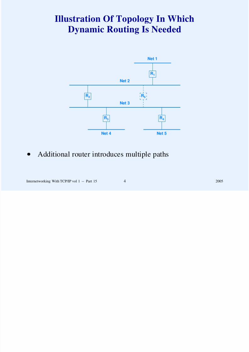
8/6/2019 Vol1 Presentation
http://slidepdf.com/reader/full/vol1-presentation 437/856
R4R3
Net 4 Net 5
Additional router introduces multiple paths
Internetworking With TCP/IP vol 1 -- Part 15 4 2005
Exchanging Routing Information
Within An Autonomous System
Mechanisms called interior gateway protocols, IGPs
Choice of IGP is made by autonomous system
Note: if AS connects to rest of the world, a router in the AS
must use an EGP to advertise network reachability to other
autonomous systems.

8/6/2019 Vol1 Presentation
http://slidepdf.com/reader/full/vol1-presentation 438/856
Internetworking With TCP/IP vol 1 -- Part 15 5 2005
Example Of Two Autonomous Systems
And the Routing Protocols Used
BGP used
R1 R2
IGP1
IGP1
IGP2
IGP2

8/6/2019 Vol1 Presentation
http://slidepdf.com/reader/full/vol1-presentation 439/856
1 2
Internetworking With TCP/IP vol 1 -- Part 15 6 2005
Example IGPs
RIP
HELLO
OSPF

8/6/2019 Vol1 Presentation
http://slidepdf.com/reader/full/vol1-presentation 440/856
Internetworking With TCP/IP vol 1 -- Part 15 7 2005
Routing Information
Protocol (RIP)
Implemented by UNIX program routed
Uses hop count metric
Distance-vector protocol
Relies on broadcast
Assumes low delay local area network

8/6/2019 Vol1 Presentation
http://slidepdf.com/reader/full/vol1-presentation 441/856
Assumes low-delay local area network
Uses split horizon and poison reverse techniques to solve
inconsistencies
Current standard is RIP2
Internetworking With TCP/IP vol 1 -- Part 15 8 2005
Two Forms Of RIP
Active
– Form used by routers
– Broadcasts routing updates periodically
– Uses incoming messages to update routes
Passive

8/6/2019 Vol1 Presentation
http://slidepdf.com/reader/full/vol1-presentation 442/856
– Form used by hosts
– Uses incoming messages to update routes
– Does not send updates
Internetworking With TCP/IP vol 1 -- Part 15 9 2005
Illustration Of Hosts
Using Passive RIP
. . .
128.10.0.0
R1
To Some PartsOf Internet
128.10.0.200
R2
To Some PartsOf Internet
128.10.0.209
Host routing table initialized to:

8/6/2019 Vol1 Presentation
http://slidepdf.com/reader/full/vol1-presentation 443/856
Destination Route
128.10.0.0 direct
default 128.10.0.200
Host listens for RIP broadcast and uses data to update table
Eliminates ICMP redirects
Internetworking With TCP/IP vol 1 -- Part 15 10 2005
RIP Operation
Each router sends update every 30 seconds
Update contains pairs of
(destination address, distance)
Distance of 16 is infinity (i.e., no route)

8/6/2019 Vol1 Presentation
http://slidepdf.com/reader/full/vol1-presentation 444/856
Internetworking With TCP/IP vol 1 -- Part 15 11 2005
Slow Convergence Problem
(Count To Infinity)
NetworkN
R1 R2 R3
Routers with routes to network N

8/6/2019 Vol1 Presentation
http://slidepdf.com/reader/full/vol1-presentation 445/856
Internetworking With TCP/IP vol 1 -- Part 15 12 2005
Slow Convergence Problem
(Count To Infinity)
NetworkN
R1 R2 R3
Routers with routes to network N

8/6/2019 Vol1 Presentation
http://slidepdf.com/reader/full/vol1-presentation 446/856
NetworkN
R1 R2 R3
R1 erroneously routes to R2 after failure
Internetworking With TCP/IP vol 1 -- Part 15 12 2005
RIP1 Update Format
0 8 16 31
COMMAND VERSION (1) RESERVED
FAMILY OF NET 1 NET 1 ADDR., OCTETS 1 - 2
NET 1 ADDRESS, OCTETS 3 - 6
NET 1 ADDRESS, OCTETS 7 - 10
NET 1 ADDRESS, OCTETS 11 - 14
DISTANCE TO NETWORK 1
FAMILY OF NET 2 NET 2 ADDR., OCTETS 1 - 2
NET 2 ADDRESS, OCTETS 3 - 6
NET 2 ADDRESS, OCTETS 7 - 10

8/6/2019 Vol1 Presentation
http://slidepdf.com/reader/full/vol1-presentation 447/856
NET 2 ADDRESS, OCTETS 11 - 14
DISTANCE TO NETWORK 2
. . .
Uses FAMILY field to support multiple protocols
IP address sent in octets 3 - 6 of address field
Message travels in UDP datagram
Internetworking With TCP/IP vol 1 -- Part 15 13 2005
Changes To RIP
In Version 2
Update includes subnet mask
Authentication supported
Explicit next-hop information
Messages can be multicast (optional)
– IP multicast address is 224 0 0 9

8/6/2019 Vol1 Presentation
http://slidepdf.com/reader/full/vol1-presentation 448/856
IP multicast address is 224.0.0.9
Internetworking With TCP/IP vol 1 -- Part 15 14 2005
RIP2 Update Format
0 8 16 31
COMMAND VERSION (1) UNUSED
FAMILY OF NET 1 ROUTE TAG FOR NET 1
NET 1 IP ADDRESS
NET 1 SUBNET MASK
NET 1 NEXT HOP ADDRESS
DISTANCE TO NETWORK 1
FAMILY OF NET 2 ROUTE TAG FOR NET 2
NET 2 IP ADDRESS
NET 2 SUBNET MASK

8/6/2019 Vol1 Presentation
http://slidepdf.com/reader/full/vol1-presentation 449/856
NET 2 NEXT HOP ADDRESS
DISTANCE TO NETWORK 2
. . .
Packet format is backward compatible
Infinity still limited to 16
RIP2 can be broadcast
Internetworking With TCP/IP vol 1 -- Part 15 15 2005
Measures Of Distance
That Have Been Used
Hops
– Zero-origin– One-origin (e.g., RIP)
Delay
Throughput

8/6/2019 Vol1 Presentation
http://slidepdf.com/reader/full/vol1-presentation 450/856
Throughput
Jitter
Internetworking With TCP/IP vol 1 -- Part 15 16 2005
HELLO: A Protocol That
Used Delay
Developed by Dave Mills
Measured delay in milliseconds
Used by NSFNET fuzzballs
Now historic

8/6/2019 Vol1 Presentation
http://slidepdf.com/reader/full/vol1-presentation 451/856
Internetworking With TCP/IP vol 1 -- Part 15 17 2005
How HELLO Worked
Participants kept track of delay between pairs of routers
HELLO propagated delay information across net
Route chosen to minimize total delay

8/6/2019 Vol1 Presentation
http://slidepdf.com/reader/full/vol1-presentation 452/856
Internetworking With TCP/IP vol 1 -- Part 15 18 2005
Route Oscillation
Effective delay depends on traffic (delay increases as traffic
increases)
Using delay as metric means routing traffic where delay is
low
Increased traffic raises delay, which means route changes
Routes tend to oscillate

8/6/2019 Vol1 Presentation
http://slidepdf.com/reader/full/vol1-presentation 453/856
Internetworking With TCP/IP vol 1 -- Part 15 19 2005
Why HELLO Worked
HELLO used only on NSFNET backbone
All paths had equal throughput
Route changes damped to avoid oscillation

8/6/2019 Vol1 Presentation
http://slidepdf.com/reader/full/vol1-presentation 454/856
Internetworking With TCP/IP vol 1 -- Part 15 20 2005
Open Shortest Path First (OSPF)
Developed by IETF in response to vendors’ proprietary
protocols
Uses SPF (link-state) algorithm
More powerful than most predecessors
Permits hierarchical topology
More complex to install and manage

8/6/2019 Vol1 Presentation
http://slidepdf.com/reader/full/vol1-presentation 455/856
Internetworking With TCP/IP vol 1 -- Part 15 21 2005
OSPF Features
Type of service routing
Load balancing across multiple paths
Networks partitioned into subsets called areas
Message authentication
Network-specific, subnet-specific, host-specific, and CIDR
routes

8/6/2019 Vol1 Presentation
http://slidepdf.com/reader/full/vol1-presentation 456/856
Designated router optimization for shared networks
Virtual network topology abstracts away details
Can import external routing information
Internetworking With TCP/IP vol 1 -- Part 15 22 2005
OSPF Message Header
0 8 16 24 31
VERSION (1) TYPE MESSAGE LENGTH
SOURCE ROUTER IP ADDRESS
AREA ID
CHECKSUM AUTHENTICATION TYPE
AUTHENTICATION (octets 0-3)
AUTHENTICATION (octets 4-7)
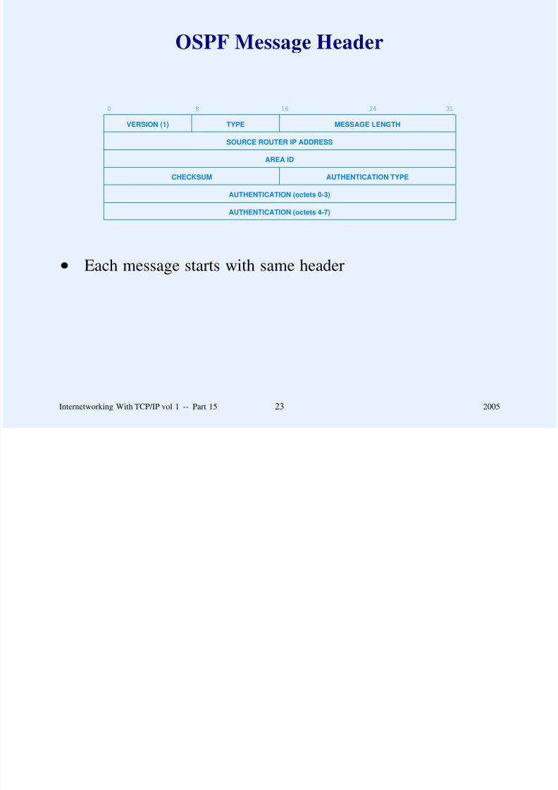
8/6/2019 Vol1 Presentation
http://slidepdf.com/reader/full/vol1-presentation 457/856
Each message starts with same header
Internetworking With TCP/IP vol 1 -- Part 15 23 2005
OSPF Message Types
Type Meaning
1 Hello (used to test reachability)
2 Database description (topology)
3 Link status request4 Link status update
5 Link status acknowledgement

8/6/2019 Vol1 Presentation
http://slidepdf.com/reader/full/vol1-presentation 458/856
Internetworking With TCP/IP vol 1 -- Part 15 24 2005
OSPF HELLO Message Format
0 8 16 24 31
OSPF HEADER WITH TYPE= 1
NETWORK MASK
DEAD TIMER HELLO INTER GWAY PRIO
DESIGNATED ROUTER
BACKUP DESIGNATED ROUTER

8/6/2019 Vol1 Presentation
http://slidepdf.com/reader/full/vol1-presentation 459/856
NEIGHBOR1 IP ADDRESS
NEIGHBOR2 IP ADDRESS
. . .
NEIGHBORn IP ADDRESS
Used to test reachability
Internetworking With TCP/IP vol 1 -- Part 15 25 2005
OSPF Database Description Message Format
0 8 16 24 29 31
OSPF HEADER WITH TYPE= 2
MUST BE ZERO I M S
DATABASE SEQUENCE NUMBER
LINK TYPE
LINK ID
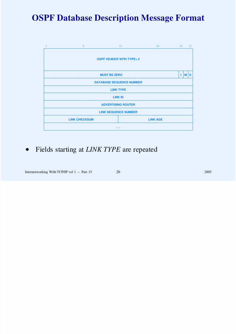
8/6/2019 Vol1 Presentation
http://slidepdf.com/reader/full/vol1-presentation 460/856
ADVERTISING ROUTER
LINK SEQUENCE NUMBER
LINK CHECKSUM LINK AGE
. . .
Fields starting at LINK TYPE are repeated
Internetworking With TCP/IP vol 1 -- Part 15 26 2005
Values In The LINK Field
Link Type Meaning
1 Router link
2 Network link
3 Summary link (IP network)4 Summary link (link to border router)
5 External link (link to another site)

8/6/2019 Vol1 Presentation
http://slidepdf.com/reader/full/vol1-presentation 461/856
Internetworking With TCP/IP vol 1 -- Part 15 27 2005
OSPF Link Status Request Message Format
0 16 31
OSPF HEADER WITH TYPE= 3
LINK TYPE
LINK ID
ADVERTISING ROUTER
. . .

8/6/2019 Vol1 Presentation
http://slidepdf.com/reader/full/vol1-presentation 462/856
Internetworking With TCP/IP vol 1 -- Part 15 28 2005
OSPF Link Status Update Message Format
0 16 31
OSPF HEADER WITH TYPE= 4
NUMBER OF LINK STATUS ADVERTISEMENTS
LINK STATUS ADVERTISEMENT1
. . .

8/6/2019 Vol1 Presentation
http://slidepdf.com/reader/full/vol1-presentation 463/856
LINK STATUS ADVERTISEMENTn
Internetworking With TCP/IP vol 1 -- Part 15 29 2005
Header Used In OSPF Link Status Advertisements
0 16 31
LINK AGE LINK TYPE
LINK ID
ADVERTISING ROUTER
LINK SEQUENCE NUMBER
LINK CHECKSUM LENGTH
Four possible formats follow

8/6/2019 Vol1 Presentation
http://slidepdf.com/reader/full/vol1-presentation 464/856
– Links from a router to given area
– Links from a router to physical net
– Links from a router to physical nets of a subnetted IPnetwork
– Links from a router to nets at other sites
Internetworking With TCP/IP vol 1 -- Part 15 30 2005
Discussion Question
What are the tradeoffs connected with the issue of routing in
the presence of partial information?

8/6/2019 Vol1 Presentation
http://slidepdf.com/reader/full/vol1-presentation 465/856
Internetworking With TCP/IP vol 1 -- Part 15 31 2005
Summary
Interior Gateway Protocols (IGPs) used within an AS
Popular IGPs include
– RIP (distance vector algorithm)
– OSPF (link-state algorithm)

8/6/2019 Vol1 Presentation
http://slidepdf.com/reader/full/vol1-presentation 466/856
Internetworking With TCP/IP vol 1 -- Part 15 32 2005
Questions?

8/6/2019 Vol1 Presentation
http://slidepdf.com/reader/full/vol1-presentation 467/856
PART XVI
INTERNET MULTICASTING

8/6/2019 Vol1 Presentation
http://slidepdf.com/reader/full/vol1-presentation 468/856
Internetworking With TCP/IP vol 1 -- Part 16 1 2005
Hardware Multicast
Form of broadcast
Only one copy of a packet traverses the net
NIC initially configured to accept packets destined to
– Computer’s unicast address
– Hardware broadcast address
U d i ll dd ( d l )

8/6/2019 Vol1 Presentation
http://slidepdf.com/reader/full/vol1-presentation 469/856
User can dynamically add (and later remove)– One or more multicast addresses
Internetworking With TCP/IP vol 1 -- Part 16 2 2005
A Note About Hardware Multicast
Although it may help to think of multicast addressing as a
generalization that subsumes unicast and broadcast addresses,
the underlying forwarding and delivery mechanisms can make
multicast less efficient.
8/6/2019 Vol1 Presentation
http://slidepdf.com/reader/full/vol1-presentation 470/856
Internetworking With TCP/IP vol 1 -- Part 16 3 2005
Ethernet Multicast
Determined by low-order bit of high-order byte
Example in dotted decimal:
01.00.00.00.00.0016
Remaining bits specify a multicast group

8/6/2019 Vol1 Presentation
http://slidepdf.com/reader/full/vol1-presentation 471/856
Internetworking With TCP/IP vol 1 -- Part 16 4 2005
IP Multicast
Group address: each multicast group assigned a unique class
D address
Up to 228 simultaneous multicast groups
Dynamic group membership: host can join or leave at any
time
Uses hardware multicast where available
B t ff t d li ti ( IP)

8/6/2019 Vol1 Presentation
http://slidepdf.com/reader/full/vol1-presentation 472/856
Best-effort delivery semantics (same as IP)
Arbitrary sender (does not need to be a group member)
Internetworking With TCP/IP vol 1 -- Part 16 5 2005
Facilities Needed For Internet Multicast
Multicast addressing scheme
Effective notification and delivery mechanism
Efficient Internet forwarding facility

8/6/2019 Vol1 Presentation
http://slidepdf.com/reader/full/vol1-presentation 473/856
Internetworking With TCP/IP vol 1 -- Part 16 6 2005
IP Multicast Addressing
Class D addresses reserved for multicast
General form:
0 1 2 3 4 31
1 1 1 0 Group Identification
Two types
W ll k ( dd d f ifi t l)

8/6/2019 Vol1 Presentation
http://slidepdf.com/reader/full/vol1-presentation 474/856
– Well-known (address reserved for specific protocol)
– Transient (allocated as needed)
Internetworking With TCP/IP vol 1 -- Part 16 7 2005
Multicast Addresses
Address range
224.0.0.0 through 239.255.255.255
Notes
– 224.0.0.0 is reserved (never used)
224 0 0 1 i ‘‘ ll t ’’

8/6/2019 Vol1 Presentation
http://slidepdf.com/reader/full/vol1-presentation 475/856
– 224.0.0.1 is ‘‘all systems’’
– 224.0.0.3 is ‘‘all routers’’
– Address up through 224.0.0.255 used for multicast
routing protocols
Internetworking With TCP/IP vol 1 -- Part 16 8 2005
Example Multicast Address Assignments
Address Meaning
224.0.0.0 Base Address (Reserved)
224.0.0.1 All Systems on this Subnet
224.0.0.2 All Routers on this Subnet
224.0.0.3 Unassigned
224.0.0.4 DVMRP Routers
224.0.0.5 OSPFIGP All Routers
224.0.0.6 OSPFIGP Designated Routers
224.0.0.7 ST Routers
224.0.0.8 ST Hosts
224.0.0.9 RIP2 Routers
224 0 0 10 IGRP Routers
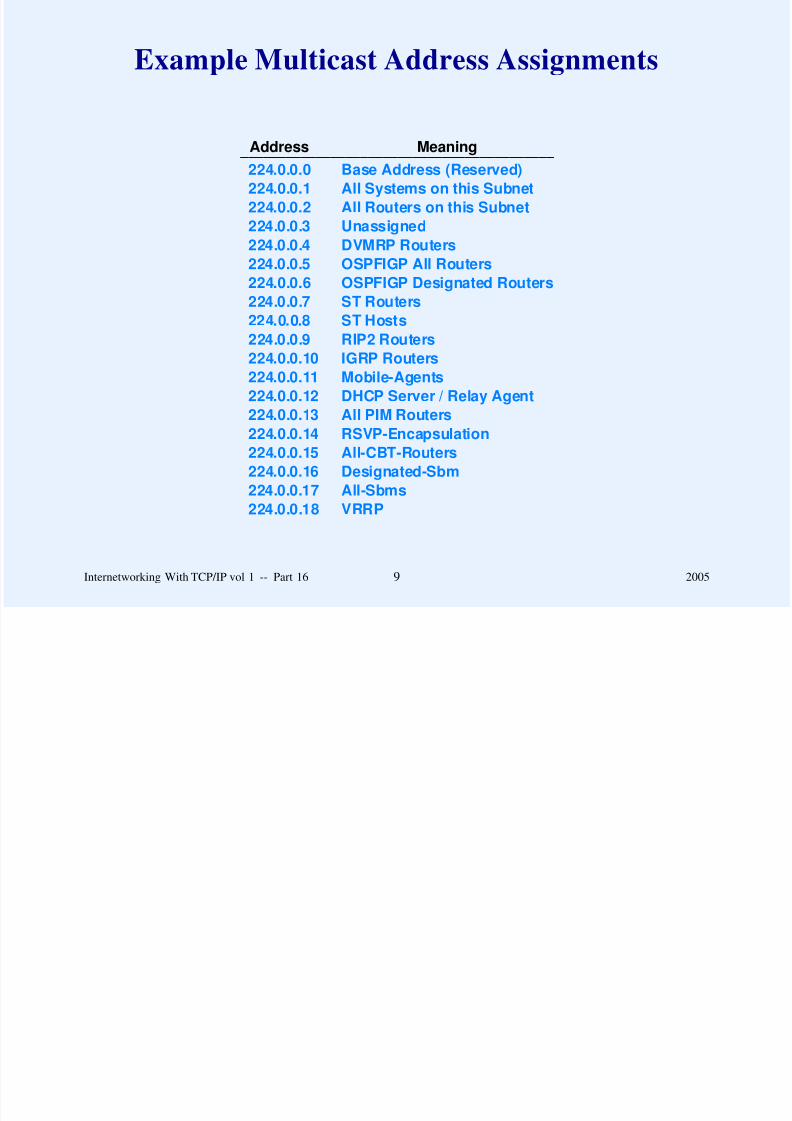
8/6/2019 Vol1 Presentation
http://slidepdf.com/reader/full/vol1-presentation 476/856
224.0.0.10 IGRP Routers224.0.0.11 Mobile-Agents
224.0.0.12 DHCP Server / Relay Agent
224.0.0.13 All PIM Routers
224.0.0.14 RSVP-Encapsulation
224.0.0.15 All-CBT-Routers
224.0.0.16 Designated-Sbm
224.0.0.17 All-Sbms224.0.0.18 VRRP
Internetworking With TCP/IP vol 1 -- Part 16 9 2005
Example Multicast Address Assignments
(continued)
Address Meaning
224.0.0.19
through224.0.0.255
Other Link Local Addresses
224.0.1.0
through Globally Scoped Addresses
238.255.255.255
239.0.0.0
through
239 255 255 255
Scope restricted to one organization

8/6/2019 Vol1 Presentation
http://slidepdf.com/reader/full/vol1-presentation 477/856
239.255.255.255
Internetworking With TCP/IP vol 1 -- Part 16 10 2005
Mapping An IP Multicast Address
To An Ethernet Multicast Address
Place low-order 23 bits of IP multicast address in low-order
23 bits of the special Ethernet address:
01.00.5E.00.00.0016
Example IP multicast address 224.0.0.2 becomes Ethernet
multicast address
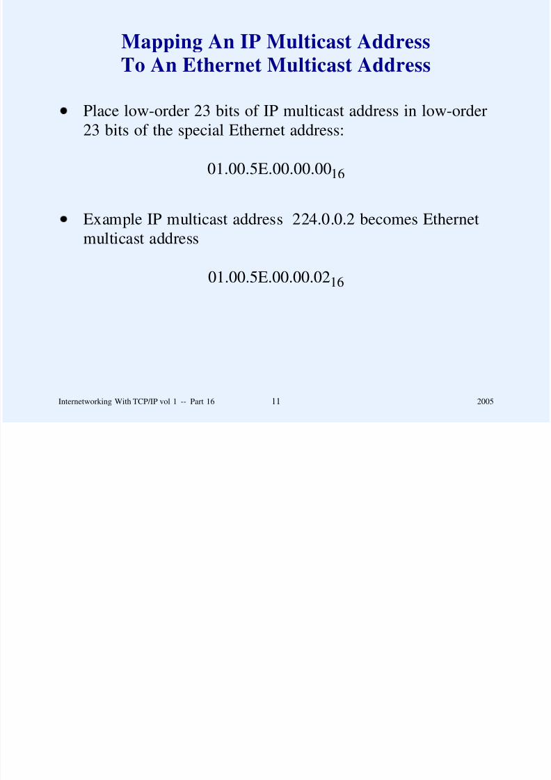
8/6/2019 Vol1 Presentation
http://slidepdf.com/reader/full/vol1-presentation 478/856
01.00.5E.00.00.0216
Internetworking With TCP/IP vol 1 -- Part 16 11 2005
Transmission Of Multicast Datagrams
Host does not install route to multicast router
Host uses hardware multicast to transmit multicast
datagrams
If multicast router is present on net
– Multicast router receives datagram
– Multicast router uses destination address to determine
routing

8/6/2019 Vol1 Presentation
http://slidepdf.com/reader/full/vol1-presentation 479/856
routing
Internetworking With TCP/IP vol 1 -- Part 16 12 2005
Multicast Scope
Refers to range of members in a group
Defined by set of networks over which multicast datagrams
travel to reach group
Two techniques control scope
– IP’s TTL field (TTL of 1 means local net only)
– Administrative scoping
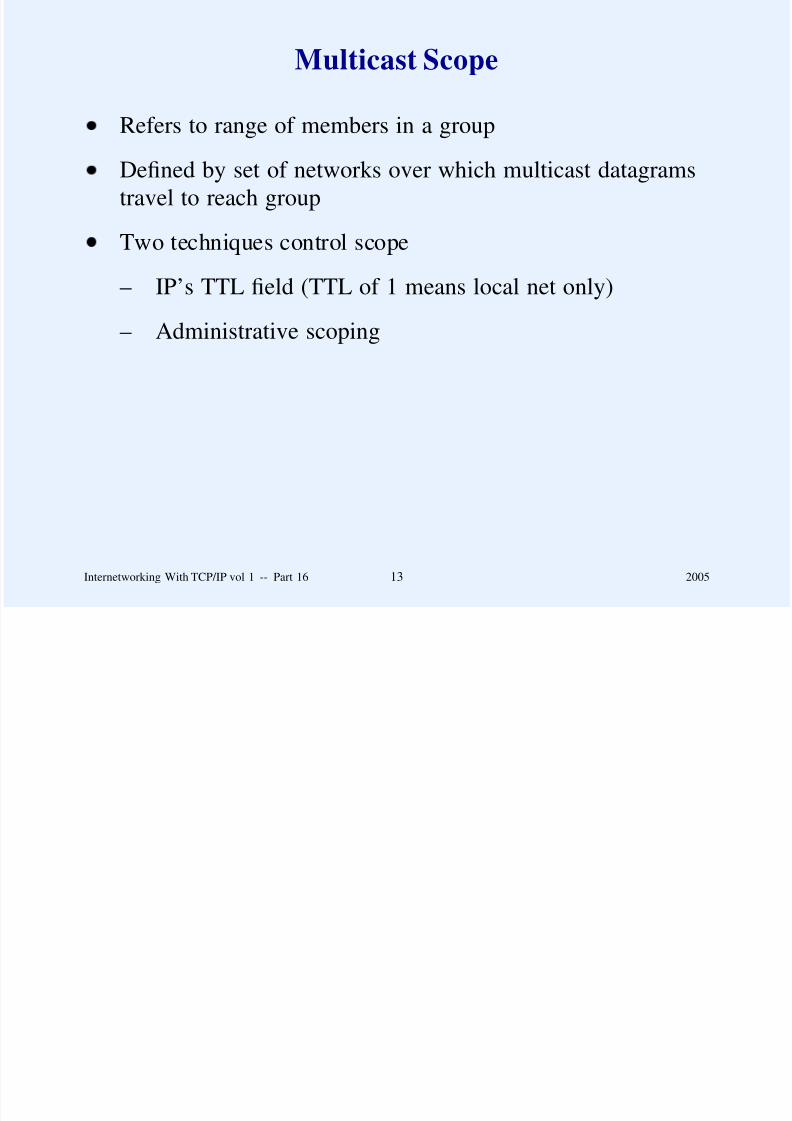
8/6/2019 Vol1 Presentation
http://slidepdf.com/reader/full/vol1-presentation 480/856
Internetworking With TCP/IP vol 1 -- Part 16 13 2005
Host Participation In IP Multicast
Host can participate in one of three ways:
Level Meaning
0 Host can neither send nor receive IP multicast
1 Host can send but not receive IP multicast
2 Host can both send and receive IP multicast
Note: even level 2 requires additions to host software

8/6/2019 Vol1 Presentation
http://slidepdf.com/reader/full/vol1-presentation 481/856
Internetworking With TCP/IP vol 1 -- Part 16 14 2005
Host Details For Level 2 Participation
Host uses Internet Group Management Protocol ( IGMP) to
announce participation in multicast
If multiple applications on a host join the same multicast
group, each receives a copy of messages sent to the group
Group membership is associated with a specific network:
A host joins a specific IP multicast group on a specific network.

8/6/2019 Vol1 Presentation
http://slidepdf.com/reader/full/vol1-presentation 482/856
Internetworking With TCP/IP vol 1 -- Part 16 15 2005
IGMP
Allows host to register participation in a group
Two conceptual phases
– When it joins a group, host sends message declaringmembership
– Multicast router periodically polls a host to determine if
any host on the network is still a member of a group

8/6/2019 Vol1 Presentation
http://slidepdf.com/reader/full/vol1-presentation 483/856
Internetworking With TCP/IP vol 1 -- Part 16 16 2005
IGMP Implementation
All communication between host and multicast router uses
hardware multicast
Single query message probes for membership in all active
groups
Default polling rate is every 125 seconds
If multiple multicast routers attach to a shared network, one
is elected to poll

8/6/2019 Vol1 Presentation
http://slidepdf.com/reader/full/vol1-presentation 484/856
Host waits random time before responding to poll (to avoid
simultaneous responses)
Host listens to other responses, and suppresses unnecessary
duplicate responses
Internetworking With TCP/IP vol 1 -- Part 16 17 2005
IGMP State Transitions
Host uses FSM to determine actions:
NON-MEMBER
MEMBERDELAYINGMEMBER
join group / start timer
leave group / cancel timer
reference count becomes zero / leave group
timer expires / send response
query arrives / start timer
another host responds / cancel timer

8/6/2019 Vol1 Presentation
http://slidepdf.com/reader/full/vol1-presentation 485/856
Separate state kept for each multicast group
Internetworking With TCP/IP vol 1 -- Part 16 18 2005
IGMP Message Format
0 8 16 31
TYPE RESP TIME CHECKSUM
GROUP ADDRESS (ZERO IN QUERY)
Message TYPE field is one of:
Type Group Address Meaning0 11 d ( ) G l b hi

8/6/2019 Vol1 Presentation
http://slidepdf.com/reader/full/vol1-presentation 486/856
Type Group Address Meaning0x11 unused (zero) General membership query
0x11 used Specific group membership query
0x16 used Membership report
0x17 used Leave group
0x12 used Membership report (version 1)
Internetworking With TCP/IP vol 1 -- Part 16 19 2005
Multicast Forwarding Example
network 1
network 2
network 3
R
A
EDCB
F G

8/6/2019 Vol1 Presentation
http://slidepdf.com/reader/full/vol1-presentation 487/856
Hosts marked with dot participate in one group
Hosts marked with X participate in another group
Forwarding depends on group membership
Internetworking With TCP/IP vol 1 -- Part 16 20 2005
The Complexity Of Multicast Routing
Unlike unicast routing in which routes change only when the
topology changes or equipment fails, multicast routes can
change simply because an application program joins or leaves
a multicast group.

8/6/2019 Vol1 Presentation
http://slidepdf.com/reader/full/vol1-presentation 488/856
Internetworking With TCP/IP vol 1 -- Part 16 21 2005
Multicast Forwarding Complication
Multicast forwarding requires a router to examine more than
the destination address.
In most cases, forwarding depends on the source address as
well as the destination address

8/6/2019 Vol1 Presentation
http://slidepdf.com/reader/full/vol1-presentation 489/856
Internetworking With TCP/IP vol 1 -- Part 16 22 2005
Final Item That Complicates IP Multicast
A multicast datagram may originate on a computer that is not
part of the multicast group, and may be forwarded across
networks that do not have any group members attached.

8/6/2019 Vol1 Presentation
http://slidepdf.com/reader/full/vol1-presentation 490/856
Internetworking With TCP/IP vol 1 -- Part 16 23 2005
Multicast Routing Paradigms
Two basic approaches
Flood-and-prune
– Send a copy to all networks– Only stop forwarding when it is known that no
participant lies beyond a given point
Multicast trees
Routers interact to form a ‘‘tree’’ that reaches all

8/6/2019 Vol1 Presentation
http://slidepdf.com/reader/full/vol1-presentation 491/856
– Routers interact to form a tree that reaches all
networks of a given group
– Copy traverses branches of the tree
Internetworking With TCP/IP vol 1 -- Part 16 24 2005
Reverse Path Forwarding
Early flood-and-prune approach
Actual algorithm is Truncated Reverse Path Forwarding
(TRPF )

8/6/2019 Vol1 Presentation
http://slidepdf.com/reader/full/vol1-presentation 492/856
Internetworking With TCP/IP vol 1 -- Part 16 25 2005
Example Topology In Which
TRPF Delivers Multiple Copies
network 1
network 2 network 3
network 4
R1 R2
R3 R4
A

8/6/2019 Vol1 Presentation
http://slidepdf.com/reader/full/vol1-presentation 493/856
B
Internetworking With TCP/IP vol 1 -- Part 16 26 2005
Multicast Trees
A multicast forwarding tree is defined as a set of paths through
multicast routers from a source to all members of a multicast
group. For a given multicast group, each possible source of
datagrams can determine a different forwarding tree.

8/6/2019 Vol1 Presentation
http://slidepdf.com/reader/full/vol1-presentation 494/856
Internetworking With TCP/IP vol 1 -- Part 16 27 2005
Examples Of Multicast Routing Protocols
Reverse Path Multicasting (RPM)
Distance-Vector Multicast Routing Protocol (DVMRP)
Core-Based Trees (CBT)
Protocol Independent Multicast - Dense Mode (PIM-DM)
Protocol Independent Multicast - Sparse Mode (PIM-SM)

8/6/2019 Vol1 Presentation
http://slidepdf.com/reader/full/vol1-presentation 495/856
Internetworking With TCP/IP vol 1 -- Part 16 28 2005
Reverse Path Multicasting (RPM)
Early form
Routers flood datagrams initially
Flooding pruned as group membership information learned

8/6/2019 Vol1 Presentation
http://slidepdf.com/reader/full/vol1-presentation 496/856
Internetworking With TCP/IP vol 1 -- Part 16 29 2005
Distance-Vector Multicast Routing Protocol
(DVMRP)
Early protocol
Defines extension of IGMP that routers use to exchange
multicast routing information
Implemented by Unix mrouted program
– Configures tables in kernel
– Supports tunneling
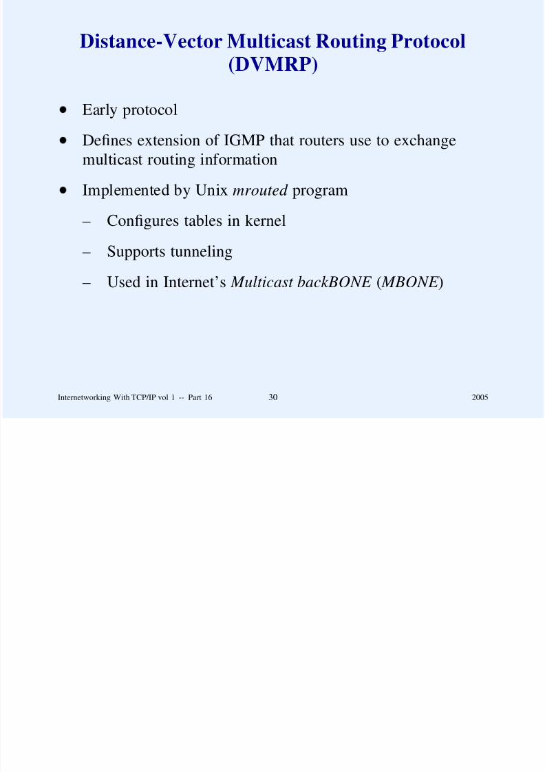
8/6/2019 Vol1 Presentation
http://slidepdf.com/reader/full/vol1-presentation 497/856
pp g
– Used in Internet’s Multicast backBONE ( MBONE )
Internetworking With TCP/IP vol 1 -- Part 16 30 2005
Topology In Which Tunneling Needed
INTERNET(with no support
for multicast)R1 R2
net 1 net 2

8/6/2019 Vol1 Presentation
http://slidepdf.com/reader/full/vol1-presentation 498/856
Internetworking With TCP/IP vol 1 -- Part 16 31 2005
Encapsulation Used With Tunneling
DATAGRAMHEADER
UNICAST DATAGRAM DATA AREA
DATAGRAMHEADER
MULTICAST DATAGRAM DATA AREA
IP travels in IP

8/6/2019 Vol1 Presentation
http://slidepdf.com/reader/full/vol1-presentation 499/856
Internetworking With TCP/IP vol 1 -- Part 16 32 2005
Core-Based Trees (CBT)
Proposed protocol
Better for sparse network
Does not forward to a net until host on the net joins a group
Request to join a group sent to ‘‘core’’ of network
Multiple cores used for large Internet

8/6/2019 Vol1 Presentation
http://slidepdf.com/reader/full/vol1-presentation 500/856
Internetworking With TCP/IP vol 1 -- Part 16 33 2005
Division Of Internet
Because CBT uses a demand-driven paradigm, it divides the
internet into regions and designates a core router for each
region; other routers in the region dynamically build a
forwarding tree by sending join requests to the core.

8/6/2019 Vol1 Presentation
http://slidepdf.com/reader/full/vol1-presentation 501/856
Internetworking With TCP/IP vol 1 -- Part 16 34 2005
Protocol Independent Multicast - Dense Mode
(PIM-DM)
Allows router to build multicast forwarding table from
information in conventional routing table
Term ‘‘dense’’ refers to density of group members
Best for high density areas
Uses flood-and-prune approach

8/6/2019 Vol1 Presentation
http://slidepdf.com/reader/full/vol1-presentation 502/856
Internetworking With TCP/IP vol 1 -- Part 16 35 2005
Protocol Independent Multicast - Sparse Mode
(PIM-SM)
Allows router to build multicast forwarding table from
information in conventional routing table
Term ‘‘sparse’’ refers to relative density of group members
Best for situations with ‘‘islands’’ of participating hosts
separated by networks with no participants
Uses tree-based approach

8/6/2019 Vol1 Presentation
http://slidepdf.com/reader/full/vol1-presentation 503/856
Internetworking With TCP/IP vol 1 -- Part 16 36 2005
Question For Discussion
How can we provide reliable multicast?

8/6/2019 Vol1 Presentation
http://slidepdf.com/reader/full/vol1-presentation 504/856
Internetworking With TCP/IP vol 1 -- Part 16 37 2005
Summary
IP multicasting uses hardware multicast for delivery
Host uses Internet Group Management Protocol (IGMP) to
communicate group membership to local multicast router
Two forms of multicast routing used
– Flood-and-prune
– Tree-based
8/6/2019 Vol1 Presentation
http://slidepdf.com/reader/full/vol1-presentation 505/856
Internetworking With TCP/IP vol 1 -- Part 16 38 2005
Summary
(continued)
Many multicast routing protocols have been proposed
– TRPF
– DVMRP
– CBT
– PIM-DM
– PIM-SM

8/6/2019 Vol1 Presentation
http://slidepdf.com/reader/full/vol1-presentation 506/856
PIM SM
Internetworking With TCP/IP vol 1 -- Part 16 39 2005
Questions?

8/6/2019 Vol1 Presentation
http://slidepdf.com/reader/full/vol1-presentation 507/856
PART XVII
IP Switching And MPLS

8/6/2019 Vol1 Presentation
http://slidepdf.com/reader/full/vol1-presentation 508/856
Internetworking With TCP/IP vol 1 -- Part 17 1 2005
Switching Technology
Designed as a higher-speed alternative to packet forwarding
Uses array lookup instead of destination address lookup
Often associated with Asynchronous Transfer Mode (ATM)

8/6/2019 Vol1 Presentation
http://slidepdf.com/reader/full/vol1-presentation 509/856
Internetworking With TCP/IP vol 1 -- Part 17 2 2005
Switching Concept
S1
S2
S3
0
1
0
0
actionlabel
(a)
0
1
2
3
send out interface 1
send out interface 1
send out interface 0
send out interface 1...

8/6/2019 Vol1 Presentation
http://slidepdf.com/reader/full/vol1-presentation 510/856
(b)
Part (b) shows table for switch S1
Identifier in packet known as label
All labels except 2 go out interface 1
Internetworking With TCP/IP vol 1 -- Part 17 3 2005
Extending Switching To A Large Network
S0 S1
S2
S3
0
10
0
0
actionlabel0
1
2
3
label→ 1; send out 0
label→ 0; send out 0
label→ 3; send out 0
label→ 2; send out 0
actionlabel0
1
2
3
label → 2; send out 1
label → 4; send out 1
label → 1; send out 0
label → 3; send out 1
Label replacement known as label swapping

8/6/2019 Vol1 Presentation
http://slidepdf.com/reader/full/vol1-presentation 511/856
A path through the network corresponds to a sequence of
labels
Internetworking With TCP/IP vol 1 -- Part 17 4 2005
An Important Note
Switching uses a connection-oriented approach. To avoid the
need for global agreement on the use of labels, the technology
allows a manager to define a path of switches without requiring
that the same label be used across the entire path.

8/6/2019 Vol1 Presentation
http://slidepdf.com/reader/full/vol1-presentation 512/856
Internetworking With TCP/IP vol 1 -- Part 17 5 2005
Potential Advantages Of Switching
For IP Forwarding
Faster forwarding
Aggregated route information
Ability to manage aggregate flows

8/6/2019 Vol1 Presentation
http://slidepdf.com/reader/full/vol1-presentation 513/856
Internetworking With TCP/IP vol 1 -- Part 17 6 2005
IP Switching
Pioneered by Ipsilon Corporation
Originally used ATM hardware
Variants by others known as
– Layer 3 switching
– Tag switching
– Label switching
Ideas eventually consolidated into Multi Protocol Label

8/6/2019 Vol1 Presentation
http://slidepdf.com/reader/full/vol1-presentation 514/856
Ideas eventually consolidated into Multi-Protocol Label
Switching (MPLS)
Internetworking With TCP/IP vol 1 -- Part 17 7 2005
MPLS Operation
Internet divided into
– Standard routers
– MPLS core
Datagram encapsulated when entering the MPLS core and
de-encapsulated when leaving
Within the core, MPLS labels are used to forward packets
8/6/2019 Vol1 Presentation
http://slidepdf.com/reader/full/vol1-presentation 515/856
Internetworking With TCP/IP vol 1 -- Part 17 8 2005
Processing An Incoming Datagram
Datagram classified
– Multiple headers examined
– Example: classification can depend on TCP port
numbers as well as IP addresses
Classification used to assign a label
Note: each label corresponds to ‘‘flow’’ that may include
may TCP sessions

8/6/2019 Vol1 Presentation
http://slidepdf.com/reader/full/vol1-presentation 516/856
Internetworking With TCP/IP vol 1 -- Part 17 9 2005
Hierarchical MPLS
Multi-level hierarchy is possible
Example: corporation with three campuses and multiple
buildings on each campus
– Conventional forwarding within a building
– One level of MPLS for buildings within a campus
– Additional level of MPLS between campuses
To accommodate hierarchy, MPLS uses stack of labels

8/6/2019 Vol1 Presentation
http://slidepdf.com/reader/full/vol1-presentation 517/856
Internetworking With TCP/IP vol 1 -- Part 17 10 2005
MPLS Label Processing
Only top label is used to forward
When entering new level of hierarchy, push addtional label
on stack
When leaving a level of the hierarchy, pop the top label
from the stack

8/6/2019 Vol1 Presentation
http://slidepdf.com/reader/full/vol1-presentation 518/856
Internetworking With TCP/IP vol 1 -- Part 17 11 2005
MPLS Encapsulation
FRAMEHEADER
FRAME DATA AREA
DATAGRAMHEADER
DATAGRAM DATA AREA
MPLS header
MPLS can run over conventional networks
Shim header contains labels

8/6/2019 Vol1 Presentation
http://slidepdf.com/reader/full/vol1-presentation 519/856
Internetworking With TCP/IP vol 1 -- Part 17 12 2005
Fields In An MPLS Shim Header
0 20 22 24 31
LABEL EXP S TTL
Shim header– Prepended to IP datagram
– Only used while datagram in MPLS core
MPLS switches use LABEL in shim when forwarding
packet

8/6/2019 Vol1 Presentation
http://slidepdf.com/reader/full/vol1-presentation 520/856
Internetworking With TCP/IP vol 1 -- Part 17 13 2005
Label Switching Router (LSR)
Device that connects between conventional Internet and
MPLS core
Handles classification
Uses data structure known as Next Hop Label Forwarding
Table (NHLFT) to choose an action

8/6/2019 Vol1 Presentation
http://slidepdf.com/reader/full/vol1-presentation 521/856
Internetworking With TCP/IP vol 1 -- Part 17 14 2005
Next Hop Label Forwarding Entry
Found in NHLFT
Specifies
– Next hop information (e.g., the outgoing interface)
– Operation to be performed
– Encapsulation to use (optional)
– How to encode the label (optional)
– Other information needed to handle the packet (optional)

8/6/2019 Vol1 Presentation
http://slidepdf.com/reader/full/vol1-presentation 522/856
Other information needed to handle the packet (optional)
Internetworking With TCP/IP vol 1 -- Part 17 15 2005
Possible Operations
Replace label at top of stack
Pop label at top of stack
Replace label at top of stack, and then push one or more
new labels onto stack

8/6/2019 Vol1 Presentation
http://slidepdf.com/reader/full/vol1-presentation 523/856
Internetworking With TCP/IP vol 1 -- Part 17 16 2005
Control Processing And Label Distribution
Needed to establish Label Switched Path (LSP)
– Coordinate labels along the path
– Configure next-hop forwarding in switches
Performed by Label Distribution mechanism
Series of labels selected automatically

8/6/2019 Vol1 Presentation
http://slidepdf.com/reader/full/vol1-presentation 524/856
Internetworking With TCP/IP vol 1 -- Part 17 17 2005
Protocols For MPLS Control
Two primary protocols proposed
– Label Distribution Protocol (MPLS-LDP)
– Constraint-Based Routing LDP (CR-LDP)
Other proposals to extend routing protocols
– OSPF
– BGP

8/6/2019 Vol1 Presentation
http://slidepdf.com/reader/full/vol1-presentation 525/856
Internetworking With TCP/IP vol 1 -- Part 17 18 2005
Notes About Fragmentation
Outgoing
– MPLS prepends shim header to each datagram
– If datagram fills network MTU, fragmentation will be
required
Incoming
– Classification requires knowledge of headers (e.g., TCP
port numbers)
Only first fragment contains needed information

8/6/2019 Vol1 Presentation
http://slidepdf.com/reader/full/vol1-presentation 526/856
– Only first fragment contains needed information
– LSR must collect fragments and reassemble before
classification
Internetworking With TCP/IP vol 1 -- Part 17 19 2005
Mesh Topology
Used in many MPLS cores
LSP established between each pair of LSRs
Parallel LSPs can be used for levels of service
Example
– One LSP reserved for VOIP traffic
– Another LSP used for all other traffic

8/6/2019 Vol1 Presentation
http://slidepdf.com/reader/full/vol1-presentation 527/856
Internetworking With TCP/IP vol 1 -- Part 17 20 2005
Service Differentiation
Because MPLS classification can use arbitrary fields in a
datagram, including the IP source address, the service adatagram receives can depend on the customer sending the
datagram as well as the type of data being carried.

8/6/2019 Vol1 Presentation
http://slidepdf.com/reader/full/vol1-presentation 528/856
Internetworking With TCP/IP vol 1 -- Part 17 21 2005
Questions?

8/6/2019 Vol1 Presentation
http://slidepdf.com/reader/full/vol1-presentation 529/856
PART XVIII
MOBILE IP

8/6/2019 Vol1 Presentation
http://slidepdf.com/reader/full/vol1-presentation 530/856
Internetworking With TCP/IP vol 1 -- Part 18 1 2005
Mobility And IP Addressing
Recall: prefix of IP address identifies network to which host
is attached
Consequence: when moving to a new network either
– Host must change its IP address
– All routers install host-specific routes

8/6/2019 Vol1 Presentation
http://slidepdf.com/reader/full/vol1-presentation 531/856
Internetworking With TCP/IP vol 1 -- Part 18 2 2005
Mobile IP
Technology to support mobility
– Allows host to retain original IP address
– Does not require routers to install host-specific routes
8/6/2019 Vol1 Presentation
http://slidepdf.com/reader/full/vol1-presentation 532/856
Internetworking With TCP/IP vol 1 -- Part 18 3 2005
Characteristics Of Mobile IP
Transparent to applications and transport protocols
Interoperates with standard IPv4
Scales to large Internet
Secure
Macro mobility (intended for working away from home
rather than moving at high speed)

8/6/2019 Vol1 Presentation
http://slidepdf.com/reader/full/vol1-presentation 533/856
Internetworking With TCP/IP vol 1 -- Part 18 4 2005
General Approach
Host visiting a foreign network obtains second IP address
that is local to the site
Host informs router on home network
Router at home uses second address to forward datagrams
for the host to the foreign network
– Datagrams sent in a tunnel
– Uses IP-in-IP encapsulation

8/6/2019 Vol1 Presentation
http://slidepdf.com/reader/full/vol1-presentation 534/856
Internetworking With TCP/IP vol 1 -- Part 18 5 2005
Two Broad Approaches
Foreign network runs system known as foreign agent
– Visiting host registers with foreign agent
– Foreign agent assigns host a temporary address
– Foreign agent registers host with home agent
Foreign network does not run a foreign agent
– Host uses DHCP to obtain temporary address
– Host registers directly with home agent

8/6/2019 Vol1 Presentation
http://slidepdf.com/reader/full/vol1-presentation 535/856
Internetworking With TCP/IP vol 1 -- Part 18 6 2005
Foreign Agent Advertisement Extension
Sent by router that runs foreign agent
Added to ICMP router advertisement
Format:
0 8 16 24 31
TYPE (16) LENGTH SEQUENCE NUM
LIFETIME CODE RESERVED
CARE-OF ADDRESSES

8/6/2019 Vol1 Presentation
http://slidepdf.com/reader/full/vol1-presentation 536/856
Internetworking With TCP/IP vol 1 -- Part 18 7 2005
CODE Field In Advertisement Message
Bit Meaning
0 Registration with an agent is required; co-located
care-of addressing is not permitted
1 The agent is busy and is not accepting registrations2 Agent functions as a home agent
3 Agent functions as a foreign agent
4 Agent uses minimal encapsulation
5 Agent uses GRE-style encapsulation
6 Agent supports header compression when communicating
with mobile
7 Unused (must be zero)

8/6/2019 Vol1 Presentation
http://slidepdf.com/reader/full/vol1-presentation 537/856
Internetworking With TCP/IP vol 1 -- Part 18 8 2005
Host Registration Request
0 8 16 31
TYPE (1 or 3) FLAGS LIFETIME
HOME ADDRESS
HOME AGENT
CARE-OF ADDRESS
IDENTIFICATION
EXTENSIONS . . .

8/6/2019 Vol1 Presentation
http://slidepdf.com/reader/full/vol1-presentation 538/856
Internetworking With TCP/IP vol 1 -- Part 18 9 2005
FLAGS Field In Host Registration Request
Bit Meaning
0 This is a simultaneous (additional) address
rather than a replacement.
1 Mobile requests home agent to tunnel a copy ofeach broadcast datagram
2 Mobile is using a co-located care-of address and
will decapsulate datagrams itself
3 Mobile requests agent to use minimal encapsulation
4 Mobile requests agent to use GRE encapsulation
5 Mobile requests header compression
6-7 Reserved (must be zero)

8/6/2019 Vol1 Presentation
http://slidepdf.com/reader/full/vol1-presentation 539/856
Internetworking With TCP/IP vol 1 -- Part 18 10 2005
Consequence Of Mobile IP
Because a mobile uses its home address as a source address
when communicating with an arbitrary destination, each reply
is forwarded to the mobile’s home network, where an agent intercepts the datagram, encapsulates it in another datagram,
and forwards it either directly to the mobile or to the foreign
agent the mobile is using.
8/6/2019 Vol1 Presentation
http://slidepdf.com/reader/full/vol1-presentation 540/856
Internetworking With TCP/IP vol 1 -- Part 18 11 2005
Illustration Of The Two-Crossing Problem
R1 R4
INTERNETR2 R3
M
D
Home Site Foreign Site
mobile
destination
mobile’s original home
foreign agent home agent

8/6/2019 Vol1 Presentation
http://slidepdf.com/reader/full/vol1-presentation 541/856
Internetworking With TCP/IP vol 1 -- Part 18 12 2005
A Severe Problem
Mobile IP introduces a routing inefficiency known as the two-
crossing problem that occurs when a mobile visits a foreign
network far from its home and then communicates with a
computer near the foreign site. Each datagram sent to the
mobile travels across the Internet to the mobile’s home agent
which then forwards the datagram back to the foreign site.
Eliminating the problem requires propagating host-specific
routes; the problem remains for any destination that does not
receive the host-specific route.

8/6/2019 Vol1 Presentation
http://slidepdf.com/reader/full/vol1-presentation 542/856
Internetworking With TCP/IP vol 1 -- Part 18 13 2005
Summary
Mobile IP allows a host to visit a foreign site without
changing its IP address
A visiting host obtains a second, temporary address which is
used for communication while at the site
The chief advantage of mobile IP arises from transparency
to applications
The chief disadvantage of mobile IP arises from inefficient
routing known as a two-crossing problem

8/6/2019 Vol1 Presentation
http://slidepdf.com/reader/full/vol1-presentation 543/856
Internetworking With TCP/IP vol 1 -- Part 18 14 2005
Questions?

8/6/2019 Vol1 Presentation
http://slidepdf.com/reader/full/vol1-presentation 544/856
PART XIX
PRIVATE NETWORK INTERCONNECTION
(NAT AND VPN)

8/6/2019 Vol1 Presentation
http://slidepdf.com/reader/full/vol1-presentation 545/856
Internetworking With TCP/IP vol 1 -- Part 19 1 2005
Definitions
An internet is private to one group (sometimes called
isolated ) if none of the facilities or traffic is accessible to
other groups
– Typical implementation involves using leased lines tointerconnect routers at various sites of the group
The global Internet is public because facilities are shared
among all subscribers

8/6/2019 Vol1 Presentation
http://slidepdf.com/reader/full/vol1-presentation 546/856
Internetworking With TCP/IP vol 1 -- Part 19 2 2005
Hybrid Architecture
Permits some traffic to go over private connections
Allows contact with global Internet

8/6/2019 Vol1 Presentation
http://slidepdf.com/reader/full/vol1-presentation 547/856
Internetworking With TCP/IP vol 1 -- Part 19 3 2005
Example Of Hybrid Architecture
INTERNET
R1
R2
R3
R4
leased circuit
128.10.1.0
128.10.2.0
192.5.48.0
128.210.0.0
Site 1 Site 2

8/6/2019 Vol1 Presentation
http://slidepdf.com/reader/full/vol1-presentation 548/856
Internetworking With TCP/IP vol 1 -- Part 19 4 2005
The Cost Of Private And Public Networks
Private network extremely expensive
Public Internet access inexpensive
Goal: combine safety of private network with low cost of
global Internet

8/6/2019 Vol1 Presentation
http://slidepdf.com/reader/full/vol1-presentation 549/856
Internetworking With TCP/IP vol 1 -- Part 19 5 2005
Question
How can an organization that uses the global Internet to
connect its sites keep its data private?
Answer: Virtual Private Network (VPN )

8/6/2019 Vol1 Presentation
http://slidepdf.com/reader/full/vol1-presentation 550/856
Internetworking With TCP/IP vol 1 -- Part 19 6 2005
Virtual Private Network
Connect all sites to global Internet
Protect data as it passes from one site to another
– Encryption
– IP-in-IP tunneling

8/6/2019 Vol1 Presentation
http://slidepdf.com/reader/full/vol1-presentation 551/856
Internetworking With TCP/IP vol 1 -- Part 19 7 2005
Illustration Of Encapsulation
Used With VPN
DATAGRAMHEADER
OUTER DATAGRAM DATA AREA
ENCRYPTED INNER DATAGRAM

8/6/2019 Vol1 Presentation
http://slidepdf.com/reader/full/vol1-presentation 552/856
Internetworking With TCP/IP vol 1 -- Part 19 8 2005
The Point
A Virtual Private Network sends data across the Internet, but
encrypts intersite transmissions to guarantee privacy.

8/6/2019 Vol1 Presentation
http://slidepdf.com/reader/full/vol1-presentation 553/856
Internetworking With TCP/IP vol 1 -- Part 19 9 2005
Example Of VPN Addressing And Routing
INTERNET
R1
R2
R3
R4
128.10.1.0
128.10.2.0
192.5.48.0
128.210.0.0
Site 1 Site 2
Routing table in R1
destination next hop
128.10.1.0 direct
128.10.2.0 R2
192.5.48.0 tunnel to R3
128.210.0.0 tunnel to R3
default ISP’s router

8/6/2019 Vol1 Presentation
http://slidepdf.com/reader/full/vol1-presentation 554/856
Routing table in R1
Internetworking With TCP/IP vol 1 -- Part 19 10 2005
Example VPN With Private Addresses
INTERNETSite 1
using subnet
10.1.0.0
Site 2using subnet
10.2.0.0R
1
R2
valid IP address
10.1 address
valid IP address
10.2 address
Advantage: only one globally valid IP address needed per
site

8/6/2019 Vol1 Presentation
http://slidepdf.com/reader/full/vol1-presentation 555/856
Internetworking With TCP/IP vol 1 -- Part 19 11 2005
General Access With Private Addresses
Question: how can a site provide multiple computers at the
site access to Internet services without assigning each
computer a globally-valid IP address?
Two answers– Application gateway (one needed for each service)
– Network Address Translation ( NAT )

8/6/2019 Vol1 Presentation
http://slidepdf.com/reader/full/vol1-presentation 556/856
Internetworking With TCP/IP vol 1 -- Part 19 12 2005
Network Address Translation (NAT)
Extension to IP addressing
IP-level access to the Internet through a single IP address
Transparent to both ends
Implementation
– Typically software
– Usually installed in IP router
– Special-purpose hardware for highest speed
8/6/2019 Vol1 Presentation
http://slidepdf.com/reader/full/vol1-presentation 557/856
Internetworking With TCP/IP vol 1 -- Part 19 13 2005
Network Address Translation (NAT)
(continued)
Pioneered in Unix program slirp
Also known as
– Masquerade (Linux)
– Internet Connection Sharing (Microsoft)
Inexpensive implementations available for home use

8/6/2019 Vol1 Presentation
http://slidepdf.com/reader/full/vol1-presentation 558/856
Internetworking With TCP/IP vol 1 -- Part 19 14 2005
NAT Details
Organization
– Obtains one globally valid address per Internet
connection
– Assigns nonroutable addresses internally (net 10)
– Runs NAT software in router connecting to Internet
NAT
– Replaces source address in outgoing datagram
– Replaces destination address in incoming datagram
8/6/2019 Vol1 Presentation
http://slidepdf.com/reader/full/vol1-presentation 559/856
Replaces destination address in incoming datagram
– Also handles higher layer protocols (e.g., pseudo header
for TCP or UDP)
Internetworking With TCP/IP vol 1 -- Part 19 15 2005
NAT Translation Table
NAT uses translation table
Entry in table specifies local (private) endpoint and global
destination.
Typical paradigm
– Entry in table created as side-effect of datagram leaving
site
– Entry in table used to reverse address mapping for
incoming datagram

8/6/2019 Vol1 Presentation
http://slidepdf.com/reader/full/vol1-presentation 560/856
Internetworking With TCP/IP vol 1 -- Part 19 16 2005
Example NAT Translation Table
Private Private External External NAT Protocol
Address Port Address Port Port Used
10.0.0.5 21023 128.10.19.20 80 14003 tcp
10.0.0.1 386 128.10.19.20 80 14010 tcp10.0.2.6 26600 207.200.75.200 21 14012 tcp
10.0.0.3 1274 128.210.1.5 80 14007 tcp
Variant of NAT that uses protocol port numbers is known as
Network Address and Port Translation ( NAPT )

8/6/2019 Vol1 Presentation
http://slidepdf.com/reader/full/vol1-presentation 561/856
Internetworking With TCP/IP vol 1 -- Part 19 17 2005
Use Of NAT By An ISP
INTERNET
ISP using NAT
hosts using
dialup access

8/6/2019 Vol1 Presentation
http://slidepdf.com/reader/full/vol1-presentation 562/856
Internetworking With TCP/IP vol 1 -- Part 19 18 2005
Higher Layer Protocols And NAT
NAT must
– Change IP headers
– Possibly change TCP or UDP source ports
– Recompute TCP or UDP checksums
– Translate ICMP messages
– Translate port numbers in an FTP session

8/6/2019 Vol1 Presentation
http://slidepdf.com/reader/full/vol1-presentation 563/856
Internetworking With TCP/IP vol 1 -- Part 19 19 2005
Applications And NAT
NAT affects ICMP, TCP, UDP, and other higher-layer
protocols; except for a few standard applications like FTP, an
application protocol that passes IP addresses or protocol port numbers as data will not operate correctly across NAT.

8/6/2019 Vol1 Presentation
http://slidepdf.com/reader/full/vol1-presentation 564/856
Internetworking With TCP/IP vol 1 -- Part 19 20 2005
Summary
Virtual Private Networks (VPNs) combine the advantages of
low cost Internet connections with the safety of private
networks
VPNs use encryption and tunneling
Network Address Translation allows a site to multiplex
communication with multiple computers through a single,
globally valid IP address.
NAT uses a table to translate addresses in outgoing andincoming datagrams

8/6/2019 Vol1 Presentation
http://slidepdf.com/reader/full/vol1-presentation 565/856
Internetworking With TCP/IP vol 1 -- Part 19 21 2005
Questions?

8/6/2019 Vol1 Presentation
http://slidepdf.com/reader/full/vol1-presentation 566/856
PART XX
CLIENT-SERVER MODEL
OF INTERACTION

8/6/2019 Vol1 Presentation
http://slidepdf.com/reader/full/vol1-presentation 567/856
Internetworking With TCP/IP vol 1 -- Part 20 1 2005
Client-Server Paradigm
Conceptual basis for virtually all distributed applications
One program initiates interaction to which another program
responds
Note: ‘‘peer-to-peer’’ applications use client-serverparadigm internally

8/6/2019 Vol1 Presentation
http://slidepdf.com/reader/full/vol1-presentation 568/856
Internetworking With TCP/IP vol 1 -- Part 20 2 2005
Definitions
Client
– Any application program
– Contacts a server
– Forms and sends a request
– Awaits a response
Server
– Usually a specialized program that offers a service– Awaits a request
C
8/6/2019 Vol1 Presentation
http://slidepdf.com/reader/full/vol1-presentation 569/856
– Computes an answer
– Issues a response
Internetworking With TCP/IP vol 1 -- Part 20 3 2005
Server Persistence
A server starts execution before interaction begins and (usually)
continues to accept requests and send responses without ever
terminating. A client is any program that makes a request and awaits a response; it (usually) terminates after using a server a
finite number of times.

8/6/2019 Vol1 Presentation
http://slidepdf.com/reader/full/vol1-presentation 570/856
Internetworking With TCP/IP vol 1 -- Part 20 4 2005
Illustration Of The
Client-Server Paradigm
client
..
..
..
server
..
..
..request sent towell-known port
Client sends request

8/6/2019 Vol1 Presentation
http://slidepdf.com/reader/full/vol1-presentation 571/856
Internetworking With TCP/IP vol 1 -- Part 20 5 2005
Illustration Of The
Client-Server Paradigm
client
..
..
..
server
..
..
..request sent towell-known port
Client sends request

8/6/2019 Vol1 Presentation
http://slidepdf.com/reader/full/vol1-presentation 572/856
client
..
..
..
server
..
..
..response sent toclient’s port
Server sends response
Internetworking With TCP/IP vol 1 -- Part 20 5 2005
Use Of Protocol Ports
A server waits for requests at a well-known port that has been
reserved for the service it offers. A client allocates an
arbitrary, unused, nonreserved port for its communication.

8/6/2019 Vol1 Presentation
http://slidepdf.com/reader/full/vol1-presentation 573/856
Internetworking With TCP/IP vol 1 -- Part 20 6 2005
Client Side
Any application program can become a client
Must know how to reach the server
– Server’s Internet address
– Server’s protocol port number
Usually easy to build

8/6/2019 Vol1 Presentation
http://slidepdf.com/reader/full/vol1-presentation 574/856
Internetworking With TCP/IP vol 1 -- Part 20 7 2005
Server Side
Finds client’s location from incoming request
Can be implemented with application program or in
operating system
Starts execution before requests arrive
Must ensure client is authorized
Must uphold protection rules
Must handle multiple, concurrent requests
Usually complex to design and build

8/6/2019 Vol1 Presentation
http://slidepdf.com/reader/full/vol1-presentation 575/856
Internetworking With TCP/IP vol 1 -- Part 20 8 2005
Concurrent Server Algorithm
Open well-known port
Wait for next client request
Create a new socket for the client
Create thread / process to handle request
Continue with wait step

8/6/2019 Vol1 Presentation
http://slidepdf.com/reader/full/vol1-presentation 576/856
Internetworking With TCP/IP vol 1 -- Part 20 9 2005
Complexity Of Servers
Servers are usually more difficult to build than clients because,
although they can be implemented with application programs,
servers must enforce all the access and protection policies of the computer system on which they run and must protect
themselves against all possible errors.

8/6/2019 Vol1 Presentation
http://slidepdf.com/reader/full/vol1-presentation 577/856
Internetworking With TCP/IP vol 1 -- Part 20 10 2005
Summary
Client-server model is basis for distributed applications
Server is specialized, complex program (process) that offers
a service
Arbitrary application can become a client by contacting aserver and sending a request
Most servers are concurrent

8/6/2019 Vol1 Presentation
http://slidepdf.com/reader/full/vol1-presentation 578/856
Internetworking With TCP/IP vol 1 -- Part 20 11 2005
Questions?

8/6/2019 Vol1 Presentation
http://slidepdf.com/reader/full/vol1-presentation 579/856
PART XXI
THE SOCKET INTERFACE

8/6/2019 Vol1 Presentation
http://slidepdf.com/reader/full/vol1-presentation 580/856
Internetworking With TCP/IP vol 1 -- Part 21 1 2005
Using Protocols
Protocol software usually embedded in OS
Applications run outside OS
Need an Application Program Interface ( API ) to allow
application to access protocols

8/6/2019 Vol1 Presentation
http://slidepdf.com/reader/full/vol1-presentation 581/856
Internetworking With TCP/IP vol 1 -- Part 21 2 2005
API
TCP/IP standards
– Describe general functionality needed
– Do not give details such as function names and
arguments
Each OS free to define its own API
In practice: socket interface has become de facto standard
API

8/6/2019 Vol1 Presentation
http://slidepdf.com/reader/full/vol1-presentation 582/856
Internetworking With TCP/IP vol 1 -- Part 21 3 2005
Socket API
Defined by U.C. Berkeley as part of BSD Unix
Adopted (with minor changes) by Microsoft as Windows
Sockets

8/6/2019 Vol1 Presentation
http://slidepdf.com/reader/full/vol1-presentation 583/856
Internetworking With TCP/IP vol 1 -- Part 21 4 2005
Characteristics Of Socket API
Follows Unix’s open-read-write-close paradigm
Uses Unix’s descriptor abstraction
– First, create a socket and receive an integer descriptor
– Second, call a set of functions that specify all the details
for the socket (descriptor is argument to each function)
Once socket has been established, use read and write or
equivalent functions to transfer data
When finished, close the socket

8/6/2019 Vol1 Presentation
http://slidepdf.com/reader/full/vol1-presentation 584/856
Internetworking With TCP/IP vol 1 -- Part 21 5 2005
Creating A Socket
result = socket(pf, type, protocol)
Argument specifies protocol family as TCP/IP

8/6/2019 Vol1 Presentation
http://slidepdf.com/reader/full/vol1-presentation 585/856
Internetworking With TCP/IP vol 1 -- Part 21 6 2005
Terminating A Socket
close(socket)
Closing a socket permanently terminates the interaction

8/6/2019 Vol1 Presentation
http://slidepdf.com/reader/full/vol1-presentation 586/856
Internetworking With TCP/IP vol 1 -- Part 21 7 2005
Specifying A Local Address For The Socket
bind(socket, localaddr, addrlen)

8/6/2019 Vol1 Presentation
http://slidepdf.com/reader/full/vol1-presentation 587/856
Internetworking With TCP/IP vol 1 -- Part 21 8 2005
Format Of A Sockaddr Structure
(Generic)
0 16 31
ADDRESS FAMILY ADDRESS OCTETS 0-1
ADDRESS OCTETS 2-5
ADDRESS OCTETS 6-9
ADDRESS OCTETS 10-13

8/6/2019 Vol1 Presentation
http://slidepdf.com/reader/full/vol1-presentation 588/856
Internetworking With TCP/IP vol 1 -- Part 21 9 2005
Format Of A Sockaddr Structure
When Used With TCP/IP
0 16 31
ADDRESS FAMILY (2) PROTOCOL PORT
IP ADDRESS
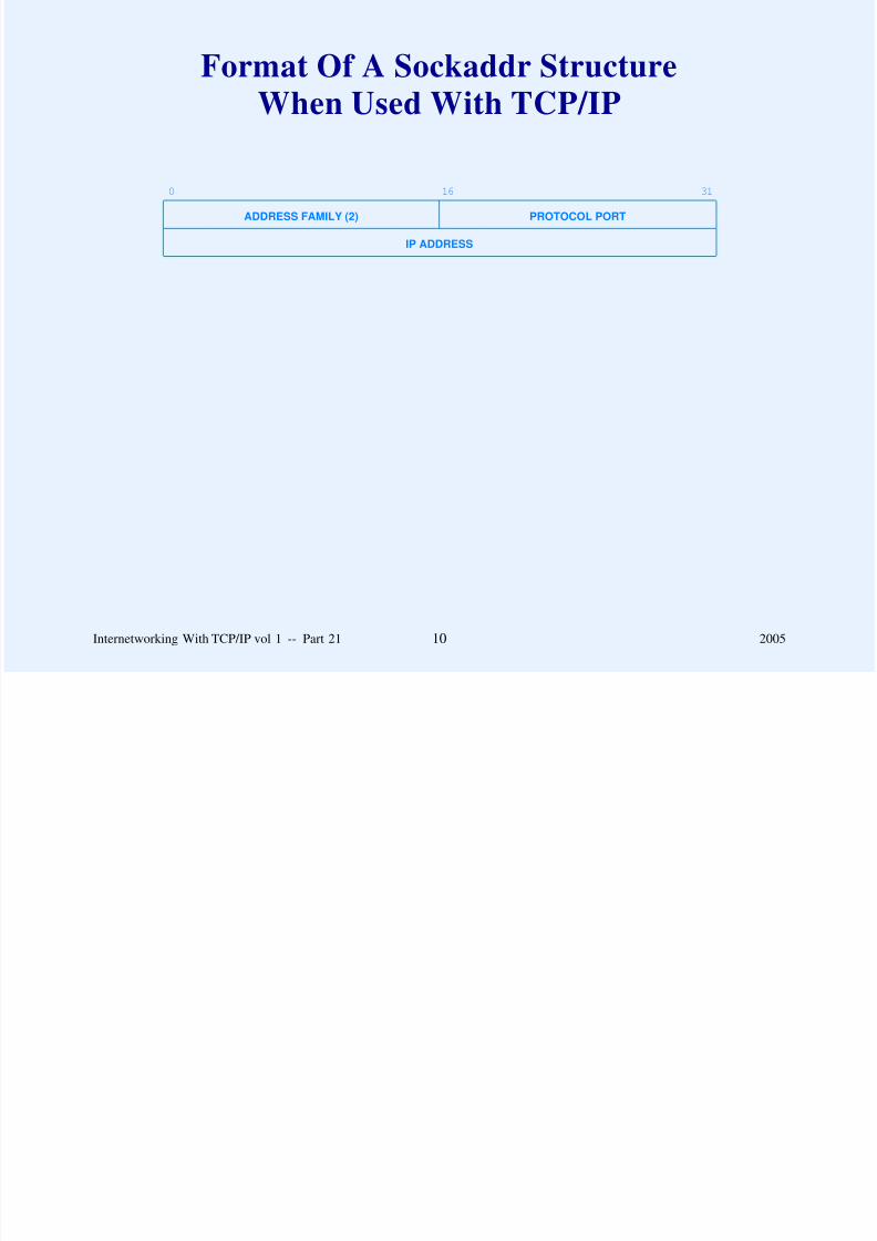
8/6/2019 Vol1 Presentation
http://slidepdf.com/reader/full/vol1-presentation 589/856
Internetworking With TCP/IP vol 1 -- Part 21 10 2005
Connecting A Socket To
A Destination Address
connect(socket, destaddr, addrlen)
Can be used with UDP socket to specify remote endpoint
address

8/6/2019 Vol1 Presentation
http://slidepdf.com/reader/full/vol1-presentation 590/856
Internetworking With TCP/IP vol 1 -- Part 21 11 2005
Sending Data Through A Socket
send(socket, message, length, flags)
Note
– Function write can also be used
– Alternatives exist for connectionless transport (UDP)

8/6/2019 Vol1 Presentation
http://slidepdf.com/reader/full/vol1-presentation 591/856
Internetworking With TCP/IP vol 1 -- Part 21 12 2005
Receiving Data Through A Socket
recv(socket, buffer, length, flags)
Note
– Function read can also be used
– Alternatives exist for connectionless transport (UDP)

8/6/2019 Vol1 Presentation
http://slidepdf.com/reader/full/vol1-presentation 592/856
Internetworking With TCP/IP vol 1 -- Part 21 13 2005
Obtaining Remote And Local
Socket Addresses
getpeername(socket, destaddr, addrlen)
andgetsockname(socket, localaddr, addrlen)

8/6/2019 Vol1 Presentation
http://slidepdf.com/reader/full/vol1-presentation 593/856
Internetworking With TCP/IP vol 1 -- Part 21 14 2005
Set Maximum Queue Length (Server)
listen(socket, qlength)
Maximum queue length can be quite small

8/6/2019 Vol1 Presentation
http://slidepdf.com/reader/full/vol1-presentation 594/856
Internetworking With TCP/IP vol 1 -- Part 21 15 2005
Accepting New Connections (Server)
newsock = accept(socket, addr, addrlen)
Note:
– Original socket remains available for accepting
connections
– New socket corresponds to one connection
– Permits server to handle requests concurrently

8/6/2019 Vol1 Presentation
http://slidepdf.com/reader/full/vol1-presentation 595/856
Internetworking With TCP/IP vol 1 -- Part 21 16 2005
Handling Multiple Services With One Server
Server
– Creates socket for each service
– Calls select function to wait for any request
– Select specifies which service was contacted
Form of select
nready = select(ndesc, indesc, outdesc, excdesc, timeout)

8/6/2019 Vol1 Presentation
http://slidepdf.com/reader/full/vol1-presentation 596/856
Internetworking With TCP/IP vol 1 -- Part 21 17 2005
Socket Functions Used For DNS
Mapping a host name to an IP address
gethostname(name, length)
Obtaining the local domain
getdomainname(name, length)

8/6/2019 Vol1 Presentation
http://slidepdf.com/reader/full/vol1-presentation 597/856
Internetworking With TCP/IP vol 1 -- Part 21 18 2005
Illustration Of A Socket Library
System Calls InComputer’s Operating System
Application Program Code
Library Routines Used
application program bound with library routines it calls
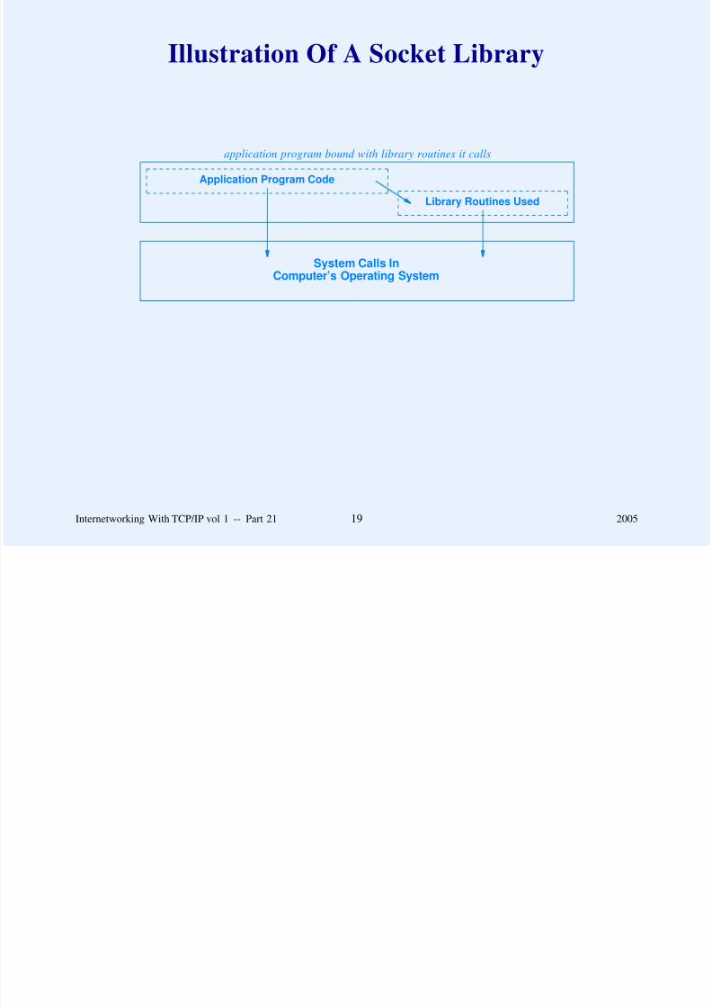
8/6/2019 Vol1 Presentation
http://slidepdf.com/reader/full/vol1-presentation 598/856
Internetworking With TCP/IP vol 1 -- Part 21 19 2005
Byte Order Conversion Routines
Convert between network byte order and local host byte
order
If local host uses big-endian, routines have no effect
localshort = ntohs(netshort)
locallong = ntohl(netlong)
netshort = htons(localshort)
netlong = htonl(locallong)

8/6/2019 Vol1 Presentation
http://slidepdf.com/reader/full/vol1-presentation 599/856
Internetworking With TCP/IP vol 1 -- Part 21 20 2005
IP Address Manipulation
Routines
Convert from dotted decimal (ASCII string) to 32-bit binary
value
Example:
address = inet_addr(string)

8/6/2019 Vol1 Presentation
http://slidepdf.com/reader/full/vol1-presentation 600/856
Internetworking With TCP/IP vol 1 -- Part 21 21 2005
Other Socket Routines
Many other functions exist
Examples: obtain information about
– Protocols
– Hosts
– Domain name

8/6/2019 Vol1 Presentation
http://slidepdf.com/reader/full/vol1-presentation 601/856
Internetworking With TCP/IP vol 1 -- Part 21 22 2005
Example Client Program
/* whoisclient.c - main */
#include <stdio.h>
#include <sys/types.h>
#include <sys/socket.h>
#include <netinet/in.h>
#include <netdb.h>
/*----------------------------------------------------------------------
* Program: whoisclient
*
* Purpose: UNIX application program that becomes a client for the
* Internet "whois" service.
** Use: whois hostname username
*
* Author: Barry Shein, Boston University
*

8/6/2019 Vol1 Presentation
http://slidepdf.com/reader/full/vol1-presentation 602/856
* Date: Long ago in a universe far, far away
*
*----------------------------------------------------------------------*/
Internetworking With TCP/IP vol 1 -- Part 21 23 2005
Example Client Program (Part 2)
main(argc, argv)
int argc; /* standard UNIX argument declarations */
char *argv[];
{
int s; /* socket descriptor */
int len; /* length of received data */
struct sockaddr_in sa; /* Internet socket addr. structure */struct hostent *hp; /* result of host name lookup */
struct servent *sp; /* result of service lookup */
char buf[BUFSIZ+1]; /* buffer to read whois information */
char *myname; /* pointer to name of this program */
char *host; /* pointer to remote host name */
char *user; /* pointer to remote user name */
myname = argv[0];
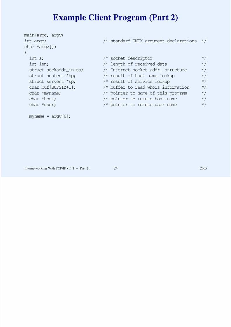
8/6/2019 Vol1 Presentation
http://slidepdf.com/reader/full/vol1-presentation 603/856
Internetworking With TCP/IP vol 1 -- Part 21 24 2005
Example Client (Part 3)
/*
* Check that there are two command line arguments
*/
if(argc != 3) {
fprintf(stderr, "Usage: %s host username\n", myname);
exit(1);
}host = argv[1];
user = argv[2];
/*
* Look up the specified hostname
*/
if((hp = gethostbyname(host)) == NULL) {
fprintf(stderr,"%s: %s: no such host?\n", myname, host);exit(1);
}
/*
* Put host’s address and address type into socket structure

8/6/2019 Vol1 Presentation
http://slidepdf.com/reader/full/vol1-presentation 604/856
Put host s address and address type into socket structure
*/
bcopy((char *)hp->h_addr, (char *)&sa.sin_addr, hp->h_length);
sa.sin_family = hp->h_addrtype;
Internetworking With TCP/IP vol 1 -- Part 21 25 2005

8/6/2019 Vol1 Presentation
http://slidepdf.com/reader/full/vol1-presentation 605/856
Example Client (Part 5)
/*
* Connect to the remote server
*/
if(connect(s, &sa, sizeof sa) < 0) {
perror("connect");
exit(1);
}/*
* Send the request
*/
if(write(s, user, strlen(user)) != strlen(user)) {
fprintf(stderr, "%s: write error\n", myname);
exit(1);
}/*
* Read the reply and put to user’s output
*/
while( (len = read(s, buf, BUFSIZ)) > 0)
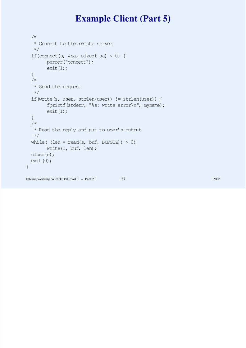
8/6/2019 Vol1 Presentation
http://slidepdf.com/reader/full/vol1-presentation 606/856
( ( ( , , )) )
write(1, buf, len);
close(s);
exit(0);}
Internetworking With TCP/IP vol 1 -- Part 21 27 2005
Example Server Program
/* whoisserver.c - main */
#include <stdio.h>
#include <sys/types.h>
#include <sys/socket.h>
#include <netinet/in.h>
#include <netdb.h>#include <pwd.h>
/*----------------------------------------------------------------------
* Program: whoisserver
*
* Purpose: UNIX application program that acts as a server for
* the "whois" service on the local machine. It listens* on well-known WHOIS port (43) and answers queries from
* clients. This program requires super-user privilege to
* run.
*

8/6/2019 Vol1 Presentation
http://slidepdf.com/reader/full/vol1-presentation 607/856
* Use: whois hostname username
*
Internetworking With TCP/IP vol 1 -- Part 21 28 2005
Example Server (Part 2)
* Author: Barry Shein, Boston University
*
* Date: Long ago in a universe far, far away
*
*----------------------------------------------------------------------
*/
#define BACKLOG 5 /* # of requests we’re willing to queue */
#define MAXHOSTNAME 32 /* maximum host name length we tolerate */
main(argc, argv)
int argc; /* standard UNIX argument declarations */
char *argv[];
{int s, t; /* socket descriptors */
int i; /* general purpose integer */
struct sockaddr_in sa, isa; /* Internet socket address structure */
struct hostent *hp; /* result of host name lookup */

8/6/2019 Vol1 Presentation
http://slidepdf.com/reader/full/vol1-presentation 608/856
p p
char *myname; /* pointer to name of this program */
struct servent *sp; /* result of service lookup */
char localhost[MAXHOSTNAME+1];/* local host name as character string */
Internetworking With TCP/IP vol 1 -- Part 21 29 2005
Example Server (Part 3)
myname = argv[0];
/*
* Look up the WHOIS service entry
*/
if((sp = getservbyname("whois","tcp")) == NULL) {
fprintf(stderr, "%s: No whois service on this host\n", myname);
exit(1);}
/*
* Get our own host information
*/
gethostname(localhost, MAXHOSTNAME);
if((hp = gethostbyname(localhost)) == NULL) {
fprintf(stderr, "%s: cannot get local host info?\n", myname);exit(1);
}

8/6/2019 Vol1 Presentation
http://slidepdf.com/reader/full/vol1-presentation 609/856
Internetworking With TCP/IP vol 1 -- Part 21 30 2005
Example Server (Part 4)
/*
* Put the WHOIS socket number and our address info
* into the socket structure
*/
sa.sin_port = sp->s_port;
bcopy((char *)hp->h_addr, (char *)&sa.sin_addr, hp->h_length);
sa.sin_family = hp->h_addrtype;/*
* Allocate an open socket for incoming connections
*/
if((s = socket(hp->h_addrtype, SOCK_STREAM, 0)) < 0) {
perror("socket");
exit(1);
}/*
* Bind the socket to the service port
* so we hear incoming connections
*/

8/6/2019 Vol1 Presentation
http://slidepdf.com/reader/full/vol1-presentation 610/856
if(bind(s, &sa, sizeof sa) < 0) {
perror("bind");
exit(1);}
Internetworking With TCP/IP vol 1 -- Part 21 31 2005
Example Server (Part 5)
/*
* Set maximum connections we will fall behind
*/
listen(s, BACKLOG);
/*
* Go into an infinite loop waiting for new connections
*/while(1) {
i = sizeof isa;
/*
* We hang in accept() while waiting for new customers
*/
if((t = accept(s, &isa, &i)) < 0) {
perror("accept");exit(1);
}
whois(t); /* perform the actual WHOIS service */
close(t);

8/6/2019 Vol1 Presentation
http://slidepdf.com/reader/full/vol1-presentation 611/856
}
}
Internetworking With TCP/IP vol 1 -- Part 21 32 2005
Example Server (Part 6)
/*
* Get the WHOIS request from remote host and format a reply.
*/
whois(sock)
int sock;
{
struct passwd *p;char buf[BUFSIZ+1];
int i;
/*
* Get one line request
*/
if( (i = read(sock, buf, BUFSIZ)) <= 0)return;
buf[i] = ’\0’; /* Null terminate */

8/6/2019 Vol1 Presentation
http://slidepdf.com/reader/full/vol1-presentation 612/856
Internetworking With TCP/IP vol 1 -- Part 21 33 2005
Example Server (Part 7)
/*
* Look up the requested user and format reply
*/
if((p = getpwnam(buf)) == NULL)
strcpy(buf,"User not found\n");
else
sprintf(buf, "%s: %s\n", p->pw_name, p->pw_gecos);/*
* Return reply
*/
write(sock, buf, strlen(buf));
return;
}

8/6/2019 Vol1 Presentation
http://slidepdf.com/reader/full/vol1-presentation 613/856
Internetworking With TCP/IP vol 1 -- Part 21 34 2005
Summary
Socket API
– Invented for BSD Unix
– Not official part of TCP/IP
– De facto standard in the industry
– Used with TCP or UDP
– Large set of functions
General paradigm: create socket and then use a set of
functions to specify details

8/6/2019 Vol1 Presentation
http://slidepdf.com/reader/full/vol1-presentation 614/856
Internetworking With TCP/IP vol 1 -- Part 21 35 2005
Questions?

8/6/2019 Vol1 Presentation
http://slidepdf.com/reader/full/vol1-presentation 615/856
PART XXII
BOOTSTRAP AND AUTOCONFIGURATION
(DHCP)

8/6/2019 Vol1 Presentation
http://slidepdf.com/reader/full/vol1-presentation 616/856
Internetworking With TCP/IP vol 1 -- Part 22 1 2005
System Startup
To keep protocol software general
– IP stack designed with many parameters
– Values filled in when system starts
Two possible sources of information
– Local storage device (e.g., disk)
– Server on the network

8/6/2019 Vol1 Presentation
http://slidepdf.com/reader/full/vol1-presentation 617/856
Internetworking With TCP/IP vol 1 -- Part 22 2 2005
Bootstrapping
BOOTstrap Protocol (BOOTP)
– Early alternative to RARP
– Provided more than just an IP address
– Obtained configuration parameters from a server
– Used UDP
Dynamic Host Configuration Protocol (DHCP)
– Replaces and extends BOOTP
– Provides dynamic address assignment

8/6/2019 Vol1 Presentation
http://slidepdf.com/reader/full/vol1-presentation 618/856
Internetworking With TCP/IP vol 1 -- Part 22 3 2005
Apparent Contradiction
DHCP used to obtain parameters for an IP stack
DHCP uses IP and UDP to obtain the parameters
Stack must be initialized before being initialized

8/6/2019 Vol1 Presentation
http://slidepdf.com/reader/full/vol1-presentation 619/856
Internetworking With TCP/IP vol 1 -- Part 22 4 2005
Solving The Apparent Contradiction
DHCP runs as application
Only needs basic facilities
In particular:
An application program can use the limited broadcast IP
address to force IP to broadcast a datagram on the local
network before IP has discovered the IP address of the local
network or the machine’s IP address.
Note: server cannot use ARP when replying to client
because client does not know its own IP address

8/6/2019 Vol1 Presentation
http://slidepdf.com/reader/full/vol1-presentation 620/856
Internetworking With TCP/IP vol 1 -- Part 22 5 2005
DHCP Retransmission
Client handles retransmission
Initial timeout selected at random
Timeout for successive retransmissions doubled

8/6/2019 Vol1 Presentation
http://slidepdf.com/reader/full/vol1-presentation 621/856
Internetworking With TCP/IP vol 1 -- Part 22 6 2005
Two-Step Bootstrap
DHCP provides information, not data
Client receives
– Name of file that contains boot image
– Address of server
Client must use another means to obtain the image to run
(typically TFTP)

8/6/2019 Vol1 Presentation
http://slidepdf.com/reader/full/vol1-presentation 622/856
Internetworking With TCP/IP vol 1 -- Part 22 7 2005
Dynamic Address Assignment
Needed by ISPs
– Client obtains an IP address and uses temporarily
– When client finishes, address is available for another
client
Also used on many corporate networks

8/6/2019 Vol1 Presentation
http://slidepdf.com/reader/full/vol1-presentation 623/856
Internetworking With TCP/IP vol 1 -- Part 22 8 2005
DHCP Address Assignment
Backward compatible with BOOTP
Can assign addresses in three ways
– Manual (manager specifies binding as in BOOTP)
– Automatic (address assigned by server, and machine
retains same address)
– Dynamic (address assigned by server, but machine may
obtain new address for successive request)
Manager chooses type of assignment for each address

8/6/2019 Vol1 Presentation
http://slidepdf.com/reader/full/vol1-presentation 624/856
Internetworking With TCP/IP vol 1 -- Part 22 9 2005
DHCP Support For Autoconfiguration
Because it allows a host to obtain all the parameters needed for
communication without manual intervention, DHCP permits
autoconfiguration. Autoconfiguration is, of course, subject toadministrative constraints.

8/6/2019 Vol1 Presentation
http://slidepdf.com/reader/full/vol1-presentation 625/856
Internetworking With TCP/IP vol 1 -- Part 22 10 2005
Dynamic Address Assignment
Client is granted a lease on an address
Server specifies length of lease
At end of lease, client must renew lease or stop using
address
Actions controlled by finite state machine

8/6/2019 Vol1 Presentation
http://slidepdf.com/reader/full/vol1-presentation 626/856
Internetworking With TCP/IP vol 1 -- Part 22 11 2005
Server Contact
To use DHCP, a host becomes a client by broadcasting a
message to all servers on the local network. The host then
collects offers from servers, selects one of the offers, and verifies acceptance with the server.

8/6/2019 Vol1 Presentation
http://slidepdf.com/reader/full/vol1-presentation 627/856
Internetworking With TCP/IP vol 1 -- Part 22 12 2005
DHCP Finite State Machine
REBIND
INITIALIZE
RENEW
SELECT
REQUEST
/ DHCPDISCOVER
Select Offer / DHCPREQUEST
DHCPOFFER
DHCPACK
DHCPACK
DHCPACK
DHCPNACKDHCPNACK
or Lease Expires
Lease Reaches50% Expiration / DHCPREQUEST
Lease Reaches87.5% Expiration / DHCPREQUEST
Host Boots

8/6/2019 Vol1 Presentation
http://slidepdf.com/reader/full/vol1-presentation 628/856
BOUND
DHCPACK DHCPREQUEST
Cancel Lease / DHCPRELEASE
Internetworking With TCP/IP vol 1 -- Part 22 13 2005
DHCP Message Format
0 8 16 24 31
OP HTYPE HLEN HOPS
TRANSACTION ID
SECONDS FLAGS
CLIENT IP ADDRESS
YOUR IP ADDRESS
SERVER IP ADDRESS
ROUTER IP ADDRESS
CLIENT HARDWARE ADDRESS (16 OCTETS)...
SERVER HOST NAME (64 OCTETS)..
.
BOOT FILE NAME (128 OCTETS)...
OPTIONS (VARIABLE)...

8/6/2019 Vol1 Presentation
http://slidepdf.com/reader/full/vol1-presentation 629/856
Internetworking With TCP/IP vol 1 -- Part 22 14 2005
Message Type Field
0 8 16 23
CODE (53) LENGTH (1) TYPE (1 - 7)
TYPE FIELD Corresponding DHCP Message Type
1 DHCPDISCOVER
2 DHCPOFFER
3 DHCPREQUEST
4 DHCPDECLINE
5 DHCPACK
6 DHCPNACK
7 DHCPRELEASE
8 DHCPINFORM
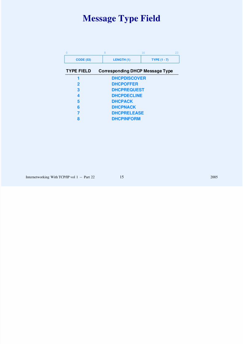
8/6/2019 Vol1 Presentation
http://slidepdf.com/reader/full/vol1-presentation 630/856
Internetworking With TCP/IP vol 1 -- Part 22 15 2005
Questions For Discussion
Explain the relationship between DHCP and DNS
What basic facility is needed? Why?

8/6/2019 Vol1 Presentation
http://slidepdf.com/reader/full/vol1-presentation 631/856
Internetworking With TCP/IP vol 1 -- Part 22 16 2005
Summary
Two protocols available for bootstrapping
– BOOTP (static binding of IP address to computer)
– DHCP (extension of BOOTP that adds dynamic binding
of IP addresses)
DHCP
– Server grants lease for an address
– Lease specifies length of time– Host must renew lease or stop using address when lease
expires
i ll d b fi i hi

8/6/2019 Vol1 Presentation
http://slidepdf.com/reader/full/vol1-presentation 632/856
– Actions controlled by finite state machine
Internetworking With TCP/IP vol 1 -- Part 22 17 2005
Questions?

8/6/2019 Vol1 Presentation
http://slidepdf.com/reader/full/vol1-presentation 633/856
PART XXIII
DOMAIN NAME SYSTEM
(DNS)

8/6/2019 Vol1 Presentation
http://slidepdf.com/reader/full/vol1-presentation 634/856
Internetworking With TCP/IP vol 1 -- Part 23 1 2005
Names For Computers
Humans prefer pronounceable names rather than numeric
addresses
Two possibilities
– Flat namespace
– Hierarchical namespace

8/6/2019 Vol1 Presentation
http://slidepdf.com/reader/full/vol1-presentation 635/856
Internetworking With TCP/IP vol 1 -- Part 23 2 2005
Naming Hierarchy
Two possibilities
– According to network topology
– By organizational structure (independent of physical
networks)
Internet uses the latter

8/6/2019 Vol1 Presentation
http://slidepdf.com/reader/full/vol1-presentation 636/856
Internetworking With TCP/IP vol 1 -- Part 23 3 2005
Internet Hierarchy
In a TCP/IP internet, hierarchical machine names are assigned
according to the structure of organizations that obtain authority
for parts of the namespace, not necessarily according to the
structure of the physical network interconnections.

8/6/2019 Vol1 Presentation
http://slidepdf.com/reader/full/vol1-presentation 637/856
Internetworking With TCP/IP vol 1 -- Part 23 4 2005
Internet Domain Names
Flexible hierarchy
– Universal naming scheme (same everywhere)
– Each organization determines internal naming structure
Mechanism known as Domain Name System ( DNS)
Name assigned to a computer known as domain name

8/6/2019 Vol1 Presentation
http://slidepdf.com/reader/full/vol1-presentation 638/856
Internetworking With TCP/IP vol 1 -- Part 23 5 2005
Domain Name Syntax
Set of labels separated by delimiter character (period)
Example
cs . purdue . edu
Three labels: cs, purdue, and edu
String purdue . edu is also a domain
Top-level domain is edu

8/6/2019 Vol1 Presentation
http://slidepdf.com/reader/full/vol1-presentation 639/856
Internetworking With TCP/IP vol 1 -- Part 23 6 2005
Original Top-Level Domains
Domain Name Assigned To
com Commercial organizations
edu Educational institutions (4-year)
gov Government institutions
mil Military groups
net Major network support centers
org Organizations other than those above
arpa Temporary ARPANET domain (obsolete)
int International organizations
country code Each country (geographic scheme)
Meaning assigned to each
Three domains considered generic
.com
.net
org

8/6/2019 Vol1 Presentation
http://slidepdf.com/reader/full/vol1-presentation 640/856
.org
Internetworking With TCP/IP vol 1 -- Part 23 7 2005
New Top-Level Domains
Domain Name Assigned To
aero Air-Transport Industry
biz Businesses
coop Non-Profit Cooperatives
info Unrestricted
museum Museumsname Individuals
pro Professionals (accountants, lawyers, physicians)
Proponents argued (incorrectly) that DNS would collapse
without additional TLDs
New TLDs created legal nightmare

8/6/2019 Vol1 Presentation
http://slidepdf.com/reader/full/vol1-presentation 641/856
Internetworking With TCP/IP vol 1 -- Part 23 8 2005
Illustration Of Part Of The DNS Tree
com edu gov us
dec purdue nsf va
cc cs ecn reston
cnri
. . .
unnamed root

8/6/2019 Vol1 Presentation
http://slidepdf.com/reader/full/vol1-presentation 642/856
Internetworking With TCP/IP vol 1 -- Part 23 9 2005
Authority For Names
Authority delegated down the tree
Example
– Purdue University registers under top level domain .edu
and receives authority for domain purdue . edu
– Computer Science Department at Purdue registers with
the Purdue authority, and becomes the authority for
cs . purdue . edu
– Owner of a lab in the CS Department registers with thedepartmental authority, and becomes the authority for
xinu.cs.purdue.edu

8/6/2019 Vol1 Presentation
http://slidepdf.com/reader/full/vol1-presentation 643/856
Internetworking With TCP/IP vol 1 -- Part 23 10 2005
DNS Database
Record has (name, class)
Class specifies type of object (e.g., computer, email
exchanger)
Consequence:
A given name may map to more than one item in the domain
system. The client specifies the type of object desired when
resolving a name, and the server returns objects of that type.

8/6/2019 Vol1 Presentation
http://slidepdf.com/reader/full/vol1-presentation 644/856
Internetworking With TCP/IP vol 1 -- Part 23 11 2005
Mapping Domain Names To Addresses
DNS uses a set of on-line servers
Servers arranged in tree
Given server can handle entire subtree
– Example: ISP manages domain names for its clients
(including corporations)
8/6/2019 Vol1 Presentation
http://slidepdf.com/reader/full/vol1-presentation 645/856
Internetworking With TCP/IP vol 1 -- Part 23 12 2005
Terminology
DNS server known as name server
DNS client software known as resolver

8/6/2019 Vol1 Presentation
http://slidepdf.com/reader/full/vol1-presentation 646/856
Internetworking With TCP/IP vol 1 -- Part 23 13 2005
Illustration Of Topology Among
DNS Servers
server for.com
server for.edu
server for.gov
server for.us
RootServer
server fordec.com
server forpurdue.edu
server fornsf.gov
server forva.us
. . .

8/6/2019 Vol1 Presentation
http://slidepdf.com/reader/full/vol1-presentation 647/856
Internetworking With TCP/IP vol 1 -- Part 23 14 2005
In Practice
Single server can handle multiple levels of the naming tree
Example: root server handles all top-level domains
8/6/2019 Vol1 Presentation
http://slidepdf.com/reader/full/vol1-presentation 648/856
Internetworking With TCP/IP vol 1 -- Part 23 15 2005
Domain Name Resolution
Conceptually, must search from root of tree downward
In practice
– Every name server knows location of a root server
– Only contacts root if no subdomain known
– Lookup always starts with local server first (host can
learn address of DNS server from DHCP)

8/6/2019 Vol1 Presentation
http://slidepdf.com/reader/full/vol1-presentation 649/856
Internetworking With TCP/IP vol 1 -- Part 23 16 2005
Efficient Translation
Facts
– Most lookups refer to local names
– Name-to-address bindings change infrequently
– User is likely to repeat same lookup
To increase efficiency
– Initial contact begins with local name server
– Every server caches answers (owner specifies cachetimeout)

8/6/2019 Vol1 Presentation
http://slidepdf.com/reader/full/vol1-presentation 650/856
Internetworking With TCP/IP vol 1 -- Part 23 17 2005
Domain Server Message Format
0 16 31
IDENTIFICATION PARAMETER
NUMBER OF QUESTIONS NUMBER OF ANSWERS
NUMBER OF AUTHORITY NUMBER OF ADDITIONAL
QUESTION SECTION
. . .
ANSWER SECTION
. . .
AUTHORITY SECTION
. . .
ADDITIONAL INFORMATION SECTION
. . .

8/6/2019 Vol1 Presentation
http://slidepdf.com/reader/full/vol1-presentation 651/856
Internetworking With TCP/IP vol 1 -- Part 23 18 2005
Parameter Bits
Bit of PARAMETER field Meaning0 Operation:0 Query1 Response
1-4 Query Type:0 Standard1 Inverse2 Server status request3 Completion (now obsolete)4 Notify5 Update
5 Set if answer authoritative6 Set if message truncated7 Set if recursion desired8 Set if recursion available9 Set if data is authenticated
10 Set if checking is disabled11 Reserved
12-15 Response Type:
0 No error1 Format error in query2 Server failure3 Name does not exist5 Refused6 Name exists when it should not7 RR set exists8 RR set that should exist does not

8/6/2019 Vol1 Presentation
http://slidepdf.com/reader/full/vol1-presentation 652/856
8 RR set that should exist does not9 Server not authoritative for the zone
10 Name not contained in zone
Internetworking With TCP/IP vol 1 -- Part 23 19 2005
Format Of Question Section
0 16 31
QUERY DOMAIN NAME
. . .
QUERY TYPE QUERY CLASS

8/6/2019 Vol1 Presentation
http://slidepdf.com/reader/full/vol1-presentation 653/856
Internetworking With TCP/IP vol 1 -- Part 23 20 2005
Format Of Resource Records
0 16 31
RESOURCE DOMAIN NAME
. . .
TYPE CLASS
TIME TO LIVE
RESOURCE DATA LENGTH
RESOURCE DATA
. . .

8/6/2019 Vol1 Presentation
http://slidepdf.com/reader/full/vol1-presentation 654/856
Internetworking With TCP/IP vol 1 -- Part 23 21 2005
Abbreviation Of Domain Names
DNS only recognizes full domain names
Client software allows abbreviation

8/6/2019 Vol1 Presentation
http://slidepdf.com/reader/full/vol1-presentation 655/856
Internetworking With TCP/IP vol 1 -- Part 23 22 2005
Example Of Domain Name Abbreviation
Client configured with suffix list
– . cs . purdue . edu
– . cc . purdue . edu
– . purdue . edu– null
User enters abbreviation xinu
Client tries the following in order
– xinu. cs . purdue . edu
– xinu. cc . purdue . edu
– xinu. purdue . edu
i

8/6/2019 Vol1 Presentation
http://slidepdf.com/reader/full/vol1-presentation 656/856
– xinu
Internetworking With TCP/IP vol 1 -- Part 23 23 2005
The Point About Abbreviation
The Domain Name System only maps full domain names into
addresses; abbreviations are not part of the Domain Name
System itself, but are introduced by client software to make
local names convenient for users.

8/6/2019 Vol1 Presentation
http://slidepdf.com/reader/full/vol1-presentation 657/856
Internetworking With TCP/IP vol 1 -- Part 23 24 2005
Inverse Query
Map in reverse direction
Excessive overhead
May not have unique answer
Not used in practice

8/6/2019 Vol1 Presentation
http://slidepdf.com/reader/full/vol1-presentation 658/856
Internetworking With TCP/IP vol 1 -- Part 23 25 2005
Pointer Query
Special case of inverse mapping
Convert IP address to domain name
Trick: write IP address as a string and look up as a name

8/6/2019 Vol1 Presentation
http://slidepdf.com/reader/full/vol1-presentation 659/856
Internetworking With TCP/IP vol 1 -- Part 23 26 2005
Example Of Pointer Query
Start with dotted decimal address such as
aaa . bbb . ccc . ddd
Rearrange dotted decimal representation as a string:
ddd . ccc . bbb . aaa . in-addr . arpa
Look up using a pointer query type
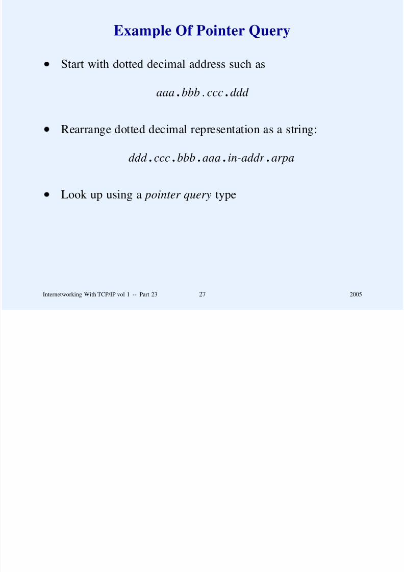
8/6/2019 Vol1 Presentation
http://slidepdf.com/reader/full/vol1-presentation 660/856
Internetworking With TCP/IP vol 1 -- Part 23 27 2005
Object Types That DNS Supports
Type Meaning Contents
A Host Address 32-bit IP address
CNAME Canonical Name Canonical domain name for an alias
HINFO CPU & OS Name of CPU and operating system
MINFO Mailbox info Information about a mailbox or mail listMX Mail Exchanger 16-bit preference and name of host that
acts as mail exchanger for the domain
NS Name Server Name of authoritative server for domain
PTR Pointer Domain name (like a symbolic link)
SOA Start of Authority Multiple fields that specify which
parts of the naming hierarchy
a server implementsTXT Arbitrary text Uninterpreted string of ASCII text
AAAA Host Address 128-bit IPv6 address

8/6/2019 Vol1 Presentation
http://slidepdf.com/reader/full/vol1-presentation 661/856
Internetworking With TCP/IP vol 1 -- Part 23 28 2005
Summary
Domain Name System provides mapping from
pronounceable names to IP addresses
Domain names are hierarchical; top-level domains are
dictated by a central authority
Organizations can choose how to structure their domain
names
DNS uses on-line servers to answer queries
Lookup begins with local server, which caches entries

8/6/2019 Vol1 Presentation
http://slidepdf.com/reader/full/vol1-presentation 662/856
Internetworking With TCP/IP vol 1 -- Part 23 29 2005
Questions?

8/6/2019 Vol1 Presentation
http://slidepdf.com/reader/full/vol1-presentation 663/856
PART XXIV
APPLICATIONS:REMOTE LOGIN
(TELNET AND RLOGIN)

8/6/2019 Vol1 Presentation
http://slidepdf.com/reader/full/vol1-presentation 664/856
Internetworking With TCP/IP vol 1 -- Part 24 1 2005
Remote Interaction
Devised when computers used (ASCII) terminals
Terminal abstraction extended to remote access over a
network

8/6/2019 Vol1 Presentation
http://slidepdf.com/reader/full/vol1-presentation 665/856
Internetworking With TCP/IP vol 1 -- Part 24 2 2005
Client-Server Interaction
Client
– Invoked by user
– Forms connection to remote server
– Passes keystrokes from user’s keyboard to server anddisplays output from server on user’s screen
Server
– Accepts connection over the network
– Passes incoming characters to OS as if they were typed
on a local keyboard
– Sends output over connection to client

8/6/2019 Vol1 Presentation
http://slidepdf.com/reader/full/vol1-presentation 666/856
Internetworking With TCP/IP vol 1 -- Part 24 3 2005

8/6/2019 Vol1 Presentation
http://slidepdf.com/reader/full/vol1-presentation 667/856
Illustration Of TELNET
Internet
operatingsystem
telnetclient
operatingsystem
telnetserver
appl.
user’sscreen &keyboard
client reads from keyboard
client sendsto server
server receives from client
server sends to pseudo terminal
the input reaches anapplicationthrough the
pseudo terminal

8/6/2019 Vol1 Presentation
http://slidepdf.com/reader/full/vol1-presentation 668/856
Internetworking With TCP/IP vol 1 -- Part 24 5 2005
Accommodating Heterogeneity
Network Virtual Terminal ( NVT ) describes system-
independent encoding
TELNET client and server map NVT into local computer’s
representation

8/6/2019 Vol1 Presentation
http://slidepdf.com/reader/full/vol1-presentation 669/856
Internetworking With TCP/IP vol 1 -- Part 24 6 2005
Illustration Of How NVT
Accommodates Heterogeneity
Client
user’skeyboard& display Server
Server’sSystem
TCP connection across internet
Client System format used NVT format used Server System format used

8/6/2019 Vol1 Presentation
http://slidepdf.com/reader/full/vol1-presentation 670/856
Internetworking With TCP/IP vol 1 -- Part 24 7 2005
Definition Of TELNET NVT
ASCII Decimal
Control Code Value Assigned Meaning
NUL 0 No operation (has no effect on output)
BEL 7 Sound audible/visible signal (no motion)
BS 8 Move left one character positionHT 9 Move right to the next horizontal tab stop
LF 10 Move down (vertically) to the next line
VT 11 Move down to the next vertical tab stop
FF 12 Move to the top of the next page
CR 13 Move to the left margin on the current line
other control – No operation (has no effect on output)

8/6/2019 Vol1 Presentation
http://slidepdf.com/reader/full/vol1-presentation 671/856
Internetworking With TCP/IP vol 1 -- Part 24 8 2005
TELNET NVT Control Functions
Signal Meaning
IP Interrupt Process (terminate running program)
AO Abort Output (discard any buffered output)
AYT Are You There (test if server is responding)
EC Erase Character (delete the previous character)EL Erase Line (delete the entire current line)
SYNCH Synchronize (clear data path until TCP urgent
data point, but do interpret commands)
BRK Break (break key or attention signal)

8/6/2019 Vol1 Presentation
http://slidepdf.com/reader/full/vol1-presentation 672/856
Internetworking With TCP/IP vol 1 -- Part 24 9 2005
TELNET Commands
Decimal
Command Encoding Meaning
IAC 255 Interpret next octet as command (when the IAC
octet appears as data, the sender doubles it
and sends the 2-octet sequence IAC-IAC)
DON’T 254 Denial of request to perform specified option
DO 253 Approval to allow specified optionWON’T 252 Refusal to perform specified option
WILL 251 Agreement to perform specified option
SB 250 Start of option subnegotiation
GA 249 The ‘‘go ahead’’ signal
EL 248 The ‘‘erase line’’ signal
EC 247 The ‘‘erase character’’ signal
AYT 246 The ‘‘are you there’’ signalAO 245 The ‘‘abort output’’ signal
IP 244 The ‘‘interrupt process’’ signal
BRK 243 The ‘‘break’’ signal
DMARK 242 The data stream portion of a SYNCH (always
accompanied by TCP Urgent notification)
NOP 241 No operation
SE 240 End of option subnegotiation

8/6/2019 Vol1 Presentation
http://slidepdf.com/reader/full/vol1-presentation 673/856
SE 240 End of option subnegotiation
EOR 239 End of record
Internetworking With TCP/IP vol 1 -- Part 24 10 2005
TELNET Control Sequences And TCP
TELNET cannot rely on the conventional data stream alone to
carry control sequences between client and server because a
misbehaving application that needs to be controlled might
inadvertently block the data stream.
Solution: use TCP’s urgent data to send control sequences

8/6/2019 Vol1 Presentation
http://slidepdf.com/reader/full/vol1-presentation 674/856
Internetworking With TCP/IP vol 1 -- Part 24 11 2005
TELNET Option Negotiation
TELNET uses a symmetric option negotiation mechanism to
allow clients and servers to reconfigure the parameters
controlling their interaction. Because all TELNET software
understands a basic NVT protocol, clients and servers caninteroperate even if one understands options another does not.

8/6/2019 Vol1 Presentation
http://slidepdf.com/reader/full/vol1-presentation 675/856
Internetworking With TCP/IP vol 1 -- Part 24 12 2005
Remote Login (rlogin)
Invented for BSD Unix
Includes facilities specifically for Unix
Allows manager to configure a set of computers so that if
two or more computers have same login id, X, the logins are
owned by the same individual
Permits other forms of authentication

8/6/2019 Vol1 Presentation
http://slidepdf.com/reader/full/vol1-presentation 676/856
Internetworking With TCP/IP vol 1 -- Part 24 13 2005
Remote Shell (rsh)
Similar to rlogin
Also part of BSD Unix
Allows remote execution of a single command

8/6/2019 Vol1 Presentation
http://slidepdf.com/reader/full/vol1-presentation 677/856
Internetworking With TCP/IP vol 1 -- Part 24 14 2005
Secure Remote Login (ssh)
Alternative to TELNET/rlogin
Transport layer protocol with service authentication
User authentication protocol
Connection protocol
– Multiplexes multiple transfers
– Uses encryption for privacy

8/6/2019 Vol1 Presentation
http://slidepdf.com/reader/full/vol1-presentation 678/856
Internetworking With TCP/IP vol 1 -- Part 24 15 2005
Port Forwarding
Novel aspect of ssh
Similar to NAT
Permits incoming TCP connection to be forwarded across
secure tunnel

8/6/2019 Vol1 Presentation
http://slidepdf.com/reader/full/vol1-presentation 679/856
Internetworking With TCP/IP vol 1 -- Part 24 16 2005
Remote Desktop
Intended for systems that have a GUI interface
Allows a remote user to see screen of remote system and
use mouse as well as keyboard
Examples include
– Virtual Network Computing (VNC)
– Remote Desktop Protocol (RDP)

8/6/2019 Vol1 Presentation
http://slidepdf.com/reader/full/vol1-presentation 680/856
Internetworking With TCP/IP vol 1 -- Part 24 17 2005
Summary
Remote interaction allows client software to connect localkeyboard and screen to remote system
Standard protocol is TELNET
Alternatives include rlogin, rsh, and ssh
Remote desktop extends remote access to handle GUI
inteface

8/6/2019 Vol1 Presentation
http://slidepdf.com/reader/full/vol1-presentation 681/856
Internetworking With TCP/IP vol 1 -- Part 24 18 2005
Questions?

8/6/2019 Vol1 Presentation
http://slidepdf.com/reader/full/vol1-presentation 682/856
PART XXV
APPLICATIONS:FILE TRANSFER AND ACCESS
(FTP, TFTP, NFS)

8/6/2019 Vol1 Presentation
http://slidepdf.com/reader/full/vol1-presentation 683/856
Internetworking With TCP/IP vol 1 -- Part 25 1 2005
On-Line File Sharing
Always a popular application
Two basic paradigms
– Whole-file copying
– Piecewise file access
Piecewise access mechanism
– Opaque: application uses special facilities to access
remote file
– Transparent: application uses same facilities to access
local and remote files

8/6/2019 Vol1 Presentation
http://slidepdf.com/reader/full/vol1-presentation 684/856
Internetworking With TCP/IP vol 1 -- Part 25 2 2005
File Transfer
Whole file copying
Client
– Contacts server
– Specifies file
– Specifies transfer direction
– Server
– Maintains set of files on local disk
– Waits for contact
– Honors request from client
8/6/2019 Vol1 Presentation
http://slidepdf.com/reader/full/vol1-presentation 685/856
Internetworking With TCP/IP vol 1 -- Part 25 3 2005
File Transfer Protocol (FTP)
Major TCP/IP protocol for whole-file copying
Uses TCP for transport
Features
– Interactive access
– Format specification (ASCII or EBCDIC)
– Authentication control (login and password)

8/6/2019 Vol1 Presentation
http://slidepdf.com/reader/full/vol1-presentation 686/856
Internetworking With TCP/IP vol 1 -- Part 25 4 2005
FTP Process Model
TCP/IPinternet
operating
system
datatransfer
controlprocess
operating
system
controlprocess
datatransfer
server systemclient system
client dataconnection
client controlconnection
server control
connection
server dataconnection
Separate processes handle
– Interaction with user
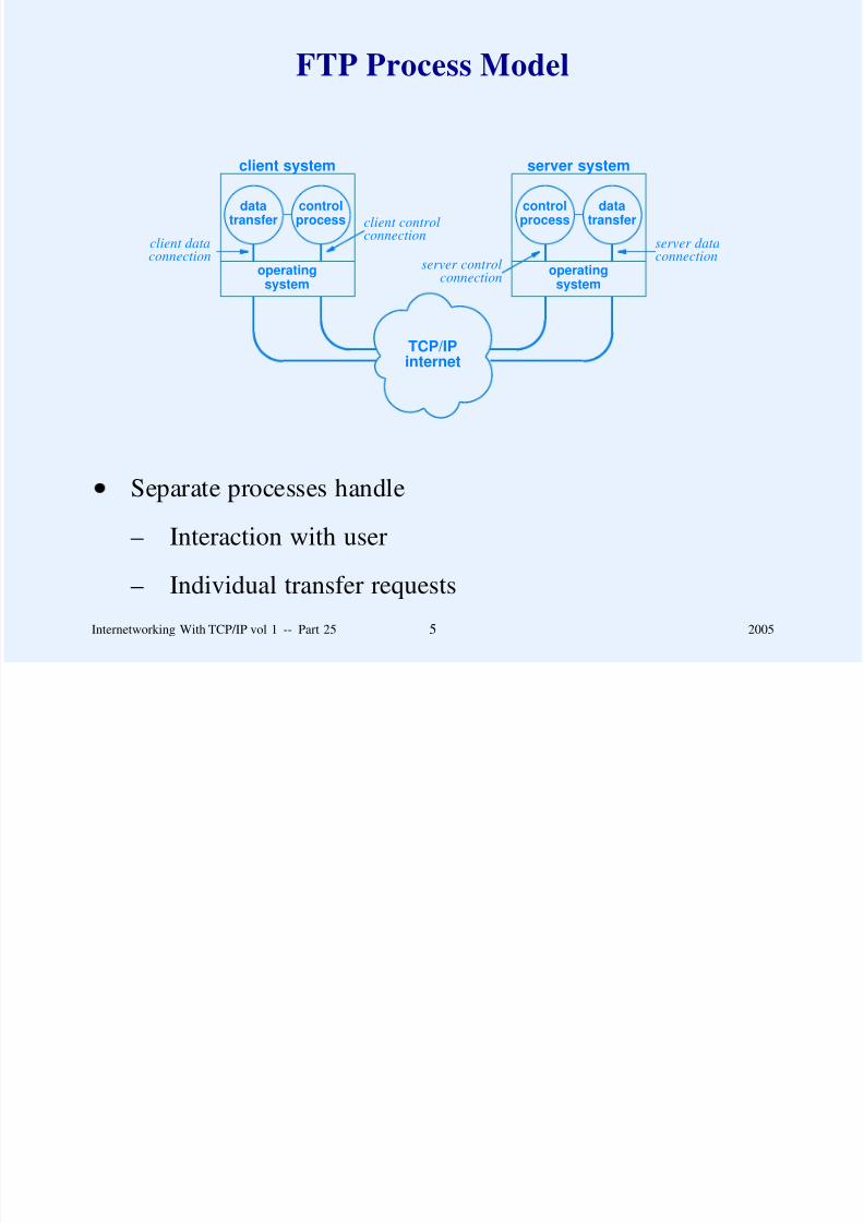
8/6/2019 Vol1 Presentation
http://slidepdf.com/reader/full/vol1-presentation 687/856
– Individual transfer requests
Internetworking With TCP/IP vol 1 -- Part 25 5 2005
FTP’s Use of TCP Connections
Data transfer connections and the data transfer processes that
use them can be created dynamically when needed, but the
control connection persists throughout a session. Once the
control connection disappears, the session is terminated and thesoftware at both ends terminates all data transfer processes.

8/6/2019 Vol1 Presentation
http://slidepdf.com/reader/full/vol1-presentation 688/856
Internetworking With TCP/IP vol 1 -- Part 25 6 2005
Control Connection Vs. Data Connection
For data transfer, client side becomes server and server sidebecomes client
Client
– Creates process to handle data transfer
– Allocates port and sends number to server over control
connection
– Process waits for contact
Server
– Receives request
– Creates process to handle data transfer

8/6/2019 Vol1 Presentation
http://slidepdf.com/reader/full/vol1-presentation 689/856
– Process contacts client-side
Internetworking With TCP/IP vol 1 -- Part 25 7 2005
Question For Discussion
What special relationship is required between FTP andNAT?

8/6/2019 Vol1 Presentation
http://slidepdf.com/reader/full/vol1-presentation 690/856
Internetworking With TCP/IP vol 1 -- Part 25 8 2005
Interactive Use Of FTP
Initially a command-line interface
– User invokes client and specifies remote server
– User logs in and enters password
– User issues series of requests– User closes connection
Currently
– Most FTP initiated through browser
– User enters URL or clicks on link
– Browser uses FTP to contact remote server and obtainlist of files
– User selects file for download

8/6/2019 Vol1 Presentation
http://slidepdf.com/reader/full/vol1-presentation 691/856
Internetworking With TCP/IP vol 1 -- Part 25 9 2005
Anonymous FTP
Login anonymous
Password guest
Used for ‘‘open’’ FTP site (where all files are publicly
available
Typically used by browsers

8/6/2019 Vol1 Presentation
http://slidepdf.com/reader/full/vol1-presentation 692/856
Internetworking With TCP/IP vol 1 -- Part 25 10 2005
Secure File Transfer Protocols
Secure Sockets Layer FTP (SSL-FTP)
– Uses secure sockets layer technology
– All transfers are confidential
Secure File Transfer Program (sftp)
– Almost nothing in common with FTP
– Uses ssh tunnel
Secure Copy (scp)
– Derivative of Unix remote copy (rcp)
– Uses ssh tunnel

8/6/2019 Vol1 Presentation
http://slidepdf.com/reader/full/vol1-presentation 693/856
Internetworking With TCP/IP vol 1 -- Part 25 11 2005
Trivial File Transfer Protocol (TFTP)
Alternative to FTP
Whole-file copying
Not as much functionality as FTP
Code is much smaller
Intended for use on Local Area Network
Runs over UDP
Diskless machine can use to obtain image at bootstrap
8/6/2019 Vol1 Presentation
http://slidepdf.com/reader/full/vol1-presentation 694/856
Internetworking With TCP/IP vol 1 -- Part 25 12 2005
TFTP Packet Types
READ REQ. (1) FILENAME 0 MODE 0
2-octet opcode n octets 1 octet n octets 1 octet
WRITE REQ. (2) FILENAME 0 MODE 0
2-octet opcode n octets 1 octet n octets 1 octet
DATA (3) BLOCK # DATA OCTETS...
2-octet opcode 2 octets up to 512 octets
ACK (4) BLOCK #
2-octet opcode 2 octets
ERROR (5) ERROR CODE ERROR MESSAGE 02-octet opcode 2 octets n octets 1 octet

8/6/2019 Vol1 Presentation
http://slidepdf.com/reader/full/vol1-presentation 695/856
Internetworking With TCP/IP vol 1 -- Part 25 13 2005
TFTP Retransmission
Symmetric (both sides implement timeout andretransmission)
Data block is request for ACK
ACK is request for next data block

8/6/2019 Vol1 Presentation
http://slidepdf.com/reader/full/vol1-presentation 696/856
Internetworking With TCP/IP vol 1 -- Part 25 14 2005
Sorcerer’s Apprentice Bug
Consequence of symmetric retransmission
Duplicate packet is perceived as second request, which
generates another transmission
Duplicate response triggers duplicate packets from the other
end
Cycle continues

8/6/2019 Vol1 Presentation
http://slidepdf.com/reader/full/vol1-presentation 697/856
Internetworking With TCP/IP vol 1 -- Part 25 15 2005
Network File System (NFS)
Protocol for file access, not copying
Developed by Sun Microsystems, now part of TCP/IP
standards
Transparent (application cannot tell that file is remote)

8/6/2019 Vol1 Presentation
http://slidepdf.com/reader/full/vol1-presentation 698/856
Internetworking With TCP/IP vol 1 -- Part 25 16 2005
NFS Implementation
application
localfile
system
localdisk
NFSclient
network connectionto NFS server
local / remote decision

8/6/2019 Vol1 Presentation
http://slidepdf.com/reader/full/vol1-presentation 699/856
Internetworking With TCP/IP vol 1 -- Part 25 17 2005
Remote Procedure Call (RPC)
Also developed by Sun Microsystems, now part of TCP/IPstandards
Used in implementation of NFS
Relies on eXternal Data Representation ( XDR) standard for
conversion of data items between heterogeneous computers

8/6/2019 Vol1 Presentation
http://slidepdf.com/reader/full/vol1-presentation 700/856
Internetworking With TCP/IP vol 1 -- Part 25 18 2005
Summary
Two paradigms for remote file sharing
– Whole file copying
– Piecewise file access
File Transfer Protocol (FTP)
– Standard protocol for file copying
– Separate TCP connection for each data transfer
– Client and server roles reversed for data connection
Examples of secure alternatives to FTP
– SSL-FTP, sftp, and scp

8/6/2019 Vol1 Presentation
http://slidepdf.com/reader/full/vol1-presentation 701/856
Internetworking With TCP/IP vol 1 -- Part 25 19 2005
Summary
(continued)
Trivial File Transfer Protocol (TFTP)
– Alternative to FTP that uses UDP
– Symmetric retransmission scheme– Packet duplication can result in Sorcerer’s Apprentice
problem
Network File System (NFS)
– Standard protocol for piecewise file access
– Uses RPC and XDR

8/6/2019 Vol1 Presentation
http://slidepdf.com/reader/full/vol1-presentation 702/856
Internetworking With TCP/IP vol 1 -- Part 25 20 2005
Questions?

8/6/2019 Vol1 Presentation
http://slidepdf.com/reader/full/vol1-presentation 703/856
PART XXVI
APPLICATIONS:ELECTRONIC MAIL
(SMTP, POP, IMAP, MIME)

8/6/2019 Vol1 Presentation
http://slidepdf.com/reader/full/vol1-presentation 704/856
Internetworking With TCP/IP vol 1 -- Part 26 1 2005
Electronic Mail
Among most widely used Internet services
Two major components
– User interface
– Mail transfer software
Paradigm: transfer is separate background activity

8/6/2019 Vol1 Presentation
http://slidepdf.com/reader/full/vol1-presentation 705/856
Internetworking With TCP/IP vol 1 -- Part 26 2 2005
Illustration Of Email System Components
userinter-face
. . . . . . . . . . . .
............
outgoingmail spool
area
mailboxesfor
incomingmail
client(background
transfer)
server(to accept
mail)
TCP connection
for outgoing mail
TCP connection
for incoming mail
user sends mail
user reads mail

8/6/2019 Vol1 Presentation
http://slidepdf.com/reader/full/vol1-presentation 706/856
Internetworking With TCP/IP vol 1 -- Part 26 3 2005
Mailbox Names And Aliases
Email destination identified by pair
( mailbox, computer )
Aliases permitted (user enters alias that is expanded)

8/6/2019 Vol1 Presentation
http://slidepdf.com/reader/full/vol1-presentation 707/856
Internetworking With TCP/IP vol 1 -- Part 26 4 2005
Forwarding
Powerful idea
Email arriving on a computer can be forwarded to an
ultimate destination

8/6/2019 Vol1 Presentation
http://slidepdf.com/reader/full/vol1-presentation 708/856
Internetworking With TCP/IP vol 1 -- Part 26 5 2005
Illustration Of Aliases And Forwarding
userinter-face
. . . . . . . . . . . .
............
aliasexpansion
andforwarding
aliasdatabase
outgoingmail spool
area
mailboxesforincoming
server(to accept
mail)
client(background
transfer)
user sends mail
user reads mail

8/6/2019 Vol1 Presentation
http://slidepdf.com/reader/full/vol1-presentation 709/856
Internetworking With TCP/IP vol 1 -- Part 26 6 2005
TCP/IP Standards For Email
Syntax for email addresses
Format of email message
Protocols for email transfer and mailbox access

8/6/2019 Vol1 Presentation
http://slidepdf.com/reader/full/vol1-presentation 710/856
Internetworking With TCP/IP vol 1 -- Part 26 7 2005
Email Address Syntax
Mailbox identified by string
mailbox@computer
String computer is domain name of computer on which amailbox resides
String mailbox is unique mailbox name on the destination
computer

8/6/2019 Vol1 Presentation
http://slidepdf.com/reader/full/vol1-presentation 711/856
Internetworking With TCP/IP vol 1 -- Part 26 8 2005
Format Of Email Message
Message consists of
– Header
– Blank line
– Body of message
Headers have form
keyword : information
Standard given in RFC 2822

8/6/2019 Vol1 Presentation
http://slidepdf.com/reader/full/vol1-presentation 712/856
Internetworking With TCP/IP vol 1 -- Part 26 9 2005
Protocol For Email Transfer
Specifies interaction between transfer components
– Transfer client
– Transfer server
Standard protocol is Simple Mail Transfer Protocol (SMTP)

8/6/2019 Vol1 Presentation
http://slidepdf.com/reader/full/vol1-presentation 713/856
Internetworking With TCP/IP vol 1 -- Part 26 10 2005
SMTP
Application-level protocol
Uses TCP
Commands and responses encoded in ASCII
8/6/2019 Vol1 Presentation
http://slidepdf.com/reader/full/vol1-presentation 714/856
Internetworking With TCP/IP vol 1 -- Part 26 11 2005
Example Of SMTP
S: 220 Beta.GOV Simple Mail Transfer Service ReadyC: HELO Alpha.EDU
S: 250 Beta.GOV
C: MAIL FROM:<[email protected]>
S: 250 OK
C: RCPT TO:<[email protected]>
S: 250 OK
C: RCPT TO:<[email protected]>
S: 550 No such user here
C: RCPT TO:<[email protected]>
S: 250 OK
C: DATA
S: 354 Start mail input; end with <CR><LF>.<CR><LF>
C: ...sends body of mail message...
C: ...continues for as many lines as message contains
C: <CR><LF>.<CR><LF>
S: 250 OK
C: QUIT
S: 221 Beta.GOV Service closing transmission channel

8/6/2019 Vol1 Presentation
http://slidepdf.com/reader/full/vol1-presentation 715/856
S: 221 Beta.GOV Service closing transmission channel
Internetworking With TCP/IP vol 1 -- Part 26 12 2005
Protocol For Mailbox Access
Used when user’s mailbox resides on remote computer
Especially helpful when user’s local computer is not always
on-line
Two protocols exist
– Post Office Protocol version 3 (POP3)
– Internet Message Access Protocol ( IMAP)
Each provides same basic functionality
– User authentication
– Mailbox access commands

8/6/2019 Vol1 Presentation
http://slidepdf.com/reader/full/vol1-presentation 716/856
Internetworking With TCP/IP vol 1 -- Part 26 13 2005
Multipurpose Internet Mail Extensions
(MIME)
Permits nontextual data to be sent in email
– Graphics image
– Voice or video clip
Sender
– Encodes binary item into printable characters
– Places in email message for transfer
Receiver
– Receives email message containing encoded item
– Decodes message to extract original binary value

8/6/2019 Vol1 Presentation
http://slidepdf.com/reader/full/vol1-presentation 717/856
Internetworking With TCP/IP vol 1 -- Part 26 14 2005
MIME Header
Header in email message describes encoding used
Example
From: [email protected]
To: [email protected]: 1.0
Content-Type: image/jpeg
Content-Transfer-Encoding: base64
...data for the image...

8/6/2019 Vol1 Presentation
http://slidepdf.com/reader/full/vol1-presentation 718/856
Internetworking With TCP/IP vol 1 -- Part 26 15 2005
Seven Basic MIME Types
Content Type Used When Data In the Message Is
text Textual (e.g. a document).
image A still photograph or computer-generated image
audio A sound recording
video A video recording that includes motion
application Raw data for a program
multipart Multiple messages that each have a separate content
type and encoding
message An entire e-mail message (e.g., a memo that has been
forwarded) or an external reference to a
message (e.g., an FTP server and file name)

8/6/2019 Vol1 Presentation
http://slidepdf.com/reader/full/vol1-presentation 719/856
Internetworking With TCP/IP vol 1 -- Part 26 16 2005
Example Of Mixed / Multipart Message
From: [email protected]: [email protected]
MIME-Version: 1.0
Content-Type: Multipart/Mixed; Boundary=StartOfNextPart
--StartOfNextPart
Content-Type: text/plain
Content-Transfer-Encoding: 7bitJohn,
Here is the photo of our research lab I promised
to send you. You can see the equipment you donated.
Thanks again, Bill
--StartOfNextPartContent-Type: image/jpeg
Content-Transfer-Encoding: base64
...data for the image...

8/6/2019 Vol1 Presentation
http://slidepdf.com/reader/full/vol1-presentation 720/856
Internetworking With TCP/IP vol 1 -- Part 26 17 2005
Summary
Email operates at application layer
Conceptual separation between
– User interface
– Mail transfer components
Simple Mail Transfer Protocol (SMTP)
– Standard for transfer
– Uses ASCII encoding
Post Office Protocol (POP) And Internet Mail AccessProtocol (IMAP) allow access of remote mailbox.
Multipurpose Internet Mail Extensions (MIME) permitstransfer of nontextual information (e.g., images)

8/6/2019 Vol1 Presentation
http://slidepdf.com/reader/full/vol1-presentation 721/856
Internetworking With TCP/IP vol 1 -- Part 26 18 2005
Questions?

8/6/2019 Vol1 Presentation
http://slidepdf.com/reader/full/vol1-presentation 722/856
PART XXVII
APPLICATIONS:WORLD WIDE WEB
(HTTP)

8/6/2019 Vol1 Presentation
http://slidepdf.com/reader/full/vol1-presentation 723/856
Internetworking With TCP/IP vol 1 -- Part 27 1 2005
World Wide Web
Distributed hypermedia paradigm
Major service on the Internet
Use surpassed file transfer in 1995

8/6/2019 Vol1 Presentation
http://slidepdf.com/reader/full/vol1-presentation 724/856
Internetworking With TCP/IP vol 1 -- Part 27 2 2005
Web Page Identifier
Known as Uniform Resource Locator (URL)
Encodes
– Access protocol to use
– Domain name of server
– Protocol port number (optional)
– Path through server’s file system (optional)
– Parameters (optional)– Query (optional)
Format
http: // hostname [: port] / path [; parameters] [? query]

8/6/2019 Vol1 Presentation
http://slidepdf.com/reader/full/vol1-presentation 725/856
Internetworking With TCP/IP vol 1 -- Part 27 3 2005
Web Standards
Separate standards for
– Representation
– Transfer

8/6/2019 Vol1 Presentation
http://slidepdf.com/reader/full/vol1-presentation 726/856
Internetworking With TCP/IP vol 1 -- Part 27 4 2005
Representation
HyperText Markup Language ( HTML)
Document contains text plus embedded links
HTML gives guidelines for display, not details
Consequence: two browsers may choose to display samedocument differently

8/6/2019 Vol1 Presentation
http://slidepdf.com/reader/full/vol1-presentation 727/856
Internetworking With TCP/IP vol 1 -- Part 27 5 2005
Transfer
Used between browser and web server
Protocol is HyperText Transfer Protocol ( HTTP)
Runs over TCP

8/6/2019 Vol1 Presentation
http://slidepdf.com/reader/full/vol1-presentation 728/856
Internetworking With TCP/IP vol 1 -- Part 27 6 2005
HTTP Characteristics
Application level
Request / response paradigm
Stateless
Permits bi-directional transfer
Offers capability negotiation
Support for caching
Support for intermediaries

8/6/2019 Vol1 Presentation
http://slidepdf.com/reader/full/vol1-presentation 729/856
Internetworking With TCP/IP vol 1 -- Part 27 7 2005
HTTP Operation
Browser sends requests to which server replies
Typical request: GET used to fetch document
Example
GET http://www.cs.purdue.edu/people/comer/ HTTP/1.1
Relative URL also permitted
GET /people/comer/ HTTP/1.1

8/6/2019 Vol1 Presentation
http://slidepdf.com/reader/full/vol1-presentation 730/856
Internetworking With TCP/IP vol 1 -- Part 27 8 2005
Error Messages
HTTP includes set of error responses
Server can format error as HTML message for user or use
internal form and allow browser to format message

8/6/2019 Vol1 Presentation
http://slidepdf.com/reader/full/vol1-presentation 731/856
Internetworking With TCP/IP vol 1 -- Part 27 9 2005
Persistent Connections
HTTP version 1.0 uses one TCP connection per transfer
– Browser forms TCP connection to server
– Browser sends GET request
– Server returns header describing item
– Server returns item
– Server closes connection
HTTP version 1.1 permits connection to persist acrossmultiple requests

8/6/2019 Vol1 Presentation
http://slidepdf.com/reader/full/vol1-presentation 732/856
Internetworking With TCP/IP vol 1 -- Part 27 10 2005
HTTP Headers
HTTP uses MIME-like headers to carry meta information. Both
browsers and servers send headers that allow them to negotiate
agreement on the document representation and encoding to be
used.

8/6/2019 Vol1 Presentation
http://slidepdf.com/reader/full/vol1-presentation 733/856
Internetworking With TCP/IP vol 1 -- Part 27 11 2005
Handing Persistence
To allow a TCP connection to persist through multiple requests
and responses, HTTP sends a length before each response. If it
does not know the length, a server informs the client, sends the
response, and then closes the connection.

8/6/2019 Vol1 Presentation
http://slidepdf.com/reader/full/vol1-presentation 734/856
Internetworking With TCP/IP vol 1 -- Part 27 12 2005
Headers And Length Encoding
HTTP headers use same syntax as email headers
– Lines of text followed by blank line
– Lines of text have form keyword:information
For persistent connection header specifies length (in octets)of data item that follows

8/6/2019 Vol1 Presentation
http://slidepdf.com/reader/full/vol1-presentation 735/856
Internetworking With TCP/IP vol 1 -- Part 27 13 2005
Items That Can Appear In An HTTP Header
Header Meaning
Content-Length Size of item in octets
Content-Type Type of item
Content-Encoding Encoding used for itemContent-Language Language(s) used in item

8/6/2019 Vol1 Presentation
http://slidepdf.com/reader/full/vol1-presentation 736/856
Internetworking With TCP/IP vol 1 -- Part 27 14 2005
Example Of Header
Content-Length: 34
Content-Language: english
Content-Encoding: ascii
<HTML> A trivial example. </HTML>
Note: if length is not known in advance, server can inform
browser that connection will close following transfer
Connection: close

8/6/2019 Vol1 Presentation
http://slidepdf.com/reader/full/vol1-presentation 737/856
Internetworking With TCP/IP vol 1 -- Part 27 15 2005
Negotiation
Either server or browser can initiate
Items sent in headers
Can specify representations that are acceptable with
preference value assigned to each
Example
Accept: text/html, text/plain; q=0.5, text/x-dvi; q=0.8

8/6/2019 Vol1 Presentation
http://slidepdf.com/reader/full/vol1-presentation 738/856
Internetworking With TCP/IP vol 1 -- Part 27 16 2005
Items For Negotiation
Accept-Encoding:
Accept-Charset:
Accept-Language:

8/6/2019 Vol1 Presentation
http://slidepdf.com/reader/full/vol1-presentation 739/856
Internetworking With TCP/IP vol 1 -- Part 27 17 2005
Conditional Request
Allows browser to check cached copy for freshness
Eliminates useless latency
Sends If-Modified-Since in header of GET request
Example
If-Modified-Since: Wed, 31 Dec 2003 05:00:01 GMT

8/6/2019 Vol1 Presentation
http://slidepdf.com/reader/full/vol1-presentation 740/856
Internetworking With TCP/IP vol 1 -- Part 27 18 2005
Proxy Servers
Browser can be configured to contact proxy
Permits caching for entire organization
Server can specify maximum number of proxies along path
(including none)

8/6/2019 Vol1 Presentation
http://slidepdf.com/reader/full/vol1-presentation 741/856
Internetworking With TCP/IP vol 1 -- Part 27 19 2005
Caching Of Web Pages
Caching essential to efficiency
Server specifies
– Whether page can be cached
– Maximum time page can be kept
Intermediate caches and browser cache web pages
Browser can specify maximum age of page (forces
intermediate caches to revalidate)

8/6/2019 Vol1 Presentation
http://slidepdf.com/reader/full/vol1-presentation 742/856
Internetworking With TCP/IP vol 1 -- Part 27 20 2005
Summary
Web is major application in the Internet
Standard for representation is HTML
Standard for transfer is HTTP
– Request-response protocol
– Header precedes item
– Version 1.1 permits persistent connections
– Server specifies length of time item can be cached
– Browser can issue conditional request to validate cached
item

8/6/2019 Vol1 Presentation
http://slidepdf.com/reader/full/vol1-presentation 743/856
Internetworking With TCP/IP vol 1 -- Part 27 21 2005
Questions?

8/6/2019 Vol1 Presentation
http://slidepdf.com/reader/full/vol1-presentation 744/856
PART XXVIII
APPLICATIONS:VOICE AND VIDEO OVER IP
(VOIP, RTP, RSVP)

8/6/2019 Vol1 Presentation
http://slidepdf.com/reader/full/vol1-presentation 745/856
Internetworking With TCP/IP vol 1 -- Part 28 1 2005
TCP/IP Protocols
Designed for data
Can also handle voice and video
Industry excited about Voice Over IP (VOIP)

8/6/2019 Vol1 Presentation
http://slidepdf.com/reader/full/vol1-presentation 746/856
Internetworking With TCP/IP vol 1 -- Part 28 2 2005
Representation
Voice and video must be converted between analog anddigital forms
Typical device is codec (coder / decoder )
Example encoding used by phone system is Pulse Code
Modulation (PCM )
– Note: 128 second audio clip encoded in PCM requires
one megabyte of memory
Codec for voice, known as vocodec, attempts to recognize
speech rather than just waveforms
3

8/6/2019 Vol1 Presentation
http://slidepdf.com/reader/full/vol1-presentation 747/856
Internetworking With TCP/IP vol 1 -- Part 28 3 2005
Playback
Internet introduces burstiness
Jitter buffer used to smooth bursts
Protocol support needed
I ki Wi h TCP/IP l 1 P 28 4 2005

8/6/2019 Vol1 Presentation
http://slidepdf.com/reader/full/vol1-presentation 748/856
Internetworking With TCP/IP vol 1 -- Part 28 4 2005
Requirements For Real-Time
Because an IP Internet is not isochronous, additional protocol
support is required when sending digitized real-time data. In
addition to basic sequence information that allows detection of
duplicate or reordered packets, each packet must carry a
separate timestamp that tells the receiver the exact time at which the data in the packet should be played.
I ki Wi h TCP/IP l 1 P 28 5 2005

8/6/2019 Vol1 Presentation
http://slidepdf.com/reader/full/vol1-presentation 749/856
Internetworking With TCP/IP vol 1 -- Part 28 5 2005
Illustration Of Jitter Buffer
K
items extractedat a fixed rate
items inserted ata variable rate
Data arrives in bursts
Data leaves at steady rate
I t t ki With TCP/IP l 1 P t 28 6 2005

8/6/2019 Vol1 Presentation
http://slidepdf.com/reader/full/vol1-presentation 750/856
Internetworking With TCP/IP vol 1 -- Part 28 6 2005
Real-Time Transport Protocol (RTP)
Internet standard
Provides playback timestamp along with data
Allows receiver to playback items in sequence
Internet orking With TCP/IP ol 1 Part 28 7 2005

8/6/2019 Vol1 Presentation
http://slidepdf.com/reader/full/vol1-presentation 751/856
Internetworking With TCP/IP vol 1 -- Part 28 7 2005
RTP Message Format
Each message begins with same header
0 1 3 8 16 31
VER P X CC M PTYPE SEQUENCE NUM
TIMESTAMP
SYNCHRONIZATION SOURCE IDENTIFIER
CONTRIBUTING SOURCE ID
. . .
Internetworking With TCP/IP vol 1 Part 28 8 2005

8/6/2019 Vol1 Presentation
http://slidepdf.com/reader/full/vol1-presentation 752/856
Internetworking With TCP/IP vol 1 -- Part 28 8 2005
Terminology And Layering
Name implies that RTP is a transport-layer protocol
In fact
– RTP is an application protocol
– RTP runs over UDP
Internetworking With TCP/IP vol 1 Part 28 9 2005

8/6/2019 Vol1 Presentation
http://slidepdf.com/reader/full/vol1-presentation 753/856
Internetworking With TCP/IP vol 1 -- Part 28 9 2005
Mixing
RTP can coordinate multiple data streams
Intended for combined audio and video
Up to 15 sources
Header specifies mixing
Internetworking With TCP/IP vol 1 Part 28 10 2005

8/6/2019 Vol1 Presentation
http://slidepdf.com/reader/full/vol1-presentation 754/856
Internetworking With TCP/IP vol 1 -- Part 28 10 2005
RTP Control Protocol (RTCP)
Required part of RTP
Allows sender and receiver to exchange information about
sessions that are in progress
Separate data stream
Uses protocol port number one greater than port number of
data stream
Internetworking With TCP/IP vol 1 -- Part 28 11 2005

8/6/2019 Vol1 Presentation
http://slidepdf.com/reader/full/vol1-presentation 755/856
Internetworking With TCP/IP vol 1 -- Part 28 11 2005
RTCP Message Types
Type Meaning
200 Sender report
201 Receiver report
202 Source description message
203 Bye message
204 Application specific message
Internetworking With TCP/IP vol 1 -- Part 28 12 2005

8/6/2019 Vol1 Presentation
http://slidepdf.com/reader/full/vol1-presentation 756/856
Internetworking With TCP/IP vol 1 Part 28 12 2005
RTCP Interaction
Receivers generate receiver report messages
Inform sender about reception and loss
Senders generate sender report
Provide absolute timestamp and relate real time to relativeplayback timestamp
Internetworking With TCP/IP vol 1 -- Part 28 13 2005

8/6/2019 Vol1 Presentation
http://slidepdf.com/reader/full/vol1-presentation 757/856
Internetworking With TCP/IP vol 1 Part 28 13 2005
VOIP
RTP used for encoding and transfer
Also need signaling protocol for
– Dialing
– Answering a call– Call forwarding
Gateway used to connect IP telephone network to Public
Switched Telephone Network (PSTN )
PSTN uses SS7 for signaling
Internetworking With TCP/IP vol 1 -- Part 28 14 2005

8/6/2019 Vol1 Presentation
http://slidepdf.com/reader/full/vol1-presentation 758/856
Internetworking With TCP/IP vol 1 Part 28 14 2005
Standards For IP Telephony
H.323
SIP
Internetworking With TCP/IP vol 1 -- Part 28 15 2005

8/6/2019 Vol1 Presentation
http://slidepdf.com/reader/full/vol1-presentation 759/856
g
H.323
ITU standard
Set of many protocols
Major protocols specified by H.323 include
Protocol PurposeH.225.0 Signaling used to establish a call
H.245 Control and feedback during the call
RTP Real-time data transfer (sequence and timing)
T.120 Exchange of data associated with a call
Internetworking With TCP/IP vol 1 -- Part 28 16 2005

8/6/2019 Vol1 Presentation
http://slidepdf.com/reader/full/vol1-presentation 760/856
g
How H.323 Protocols Fit Together
IP
UDP TCP
RTP
RTCPH.225
Registr.H.225
SignalingH.245
ControlT.120Data
audio/ video applications signaling and control
audiocodec
videocodec
dataapplications
Internetworking With TCP/IP vol 1 -- Part 28 17 2005

8/6/2019 Vol1 Presentation
http://slidepdf.com/reader/full/vol1-presentation 761/856
g
Session Initiation Protocol (SIP)
IETF standard
Alternative to H.323
– Less functionality
– Much smaller
Permits SIP telephone to make call
Does not require RTP for encoding
Internetworking With TCP/IP vol 1 -- Part 28 18 2005

8/6/2019 Vol1 Presentation
http://slidepdf.com/reader/full/vol1-presentation 762/856
Session Description Protocol (SDP)
Companion to SIP
Specifies details such as
– Media encoding
– Protocol port numbers– Multicast addresses
Internetworking With TCP/IP vol 1 -- Part 28 19 2005

8/6/2019 Vol1 Presentation
http://slidepdf.com/reader/full/vol1-presentation 763/856
Quality Of Service (QoS)
Statistical guarantee of performance
Requires changes to underlying Internet infrastructure
Proponents claim it is needed for telephony
Others claim only larger bandwidth will solve the problem
Internetworking With TCP/IP vol 1 -- Part 28 20 2005

8/6/2019 Vol1 Presentation
http://slidepdf.com/reader/full/vol1-presentation 764/856
Resource ReSerVation Protocol (RSVP)
IETF response to ATM
End-to-end QoS guarantees
Abstraction is unidirectional flow
Initiated by endpoint
Internetworking With TCP/IP vol 1 -- Part 28 21 2005

8/6/2019 Vol1 Presentation
http://slidepdf.com/reader/full/vol1-presentation 765/856
RSVP Requests
An endpoint uses RSVP to request a simplex flow through an IP
internet with specified QoS bounds. If routers along the path
agree to honor the request, they approve it; otherwise, theydeny it. If an application needs QoS in two directions, each
endpoint must use RSVP to request a separate flow.
Internetworking With TCP/IP vol 1 -- Part 28 22 2005

8/6/2019 Vol1 Presentation
http://slidepdf.com/reader/full/vol1-presentation 766/856
Note About RSVP
RSVP defines
– Messages endpoint sends to router to request QoS
– Messages routers send to other routers
– Replies
RSVP does not specify how enforcement done
Separate protocol needed
Internetworking With TCP/IP vol 1 -- Part 28 23 2005
8/6/2019 Vol1 Presentation
http://slidepdf.com/reader/full/vol1-presentation 767/856
Common Open Policy Services (COPS)
Proposed enforcement protocol for RSVP
Known as traffic policing
Uses policy server
Checks data sent on flow to ensure the flow does not exceedpreestablished bounds
Internetworking With TCP/IP vol 1 -- Part 28 24 2005

8/6/2019 Vol1 Presentation
http://slidepdf.com/reader/full/vol1-presentation 768/856
Summary
Codec translates between analog and digital forms
RTP used to transfer real-time data
RTP adds timestamp that sender uses to determine playback
time
RTCP is companion protocol for RTP that senders and
receivers use to control and coordinate data transfer
Voice Over IP uses
– RTP for digitized voice transfer
– SIP or H.323 for signaling
RSVP and COPS provide quality of service guarantees
Internetworking With TCP/IP vol 1 -- Part 28 25 2005

8/6/2019 Vol1 Presentation
http://slidepdf.com/reader/full/vol1-presentation 769/856
Questions?

8/6/2019 Vol1 Presentation
http://slidepdf.com/reader/full/vol1-presentation 770/856
PART XXIX
APPLICATIONS:INTERNET MANAGEMENT
(SNMP)
Internetworking With TCP/IP vol 1 -- Part 29 1 2005

8/6/2019 Vol1 Presentation
http://slidepdf.com/reader/full/vol1-presentation 771/856
Management Protocols
Early network systems used two approaches
– Separate, parallel management network
– Link-level management commands
TCP/IP pioneered running management protocols at the
application layer
– Motivation: provide internet-wide capability instead of
single network capability
Internetworking With TCP/IP vol 1 -- Part 29 2 2005

8/6/2019 Vol1 Presentation
http://slidepdf.com/reader/full/vol1-presentation 772/856
The Point About Internet Management
In a TCP/IP internet, a manager needs to examine and control
routers and other network devices. Because such devices attach
to arbitrary networks, protocols for internet management
operate at the application level and communicate using TCP/IPtransport-level protocols.
Internetworking With TCP/IP vol 1 -- Part 29 3 2005

8/6/2019 Vol1 Presentation
http://slidepdf.com/reader/full/vol1-presentation 773/856
Architectural Model
MA
MA
MA
MAMA
MC
MA
MA
Devices being managed
Manager’s Host
Router being managed
Other devices
Internetworking With TCP/IP vol 1 -- Part 29 4 2005

8/6/2019 Vol1 Presentation
http://slidepdf.com/reader/full/vol1-presentation 774/856
Terminology
Agent– Runs on arbitrary system (e.g., a router)
– Responds to manager’s requests
Management software
– Runs on manager’s workstation
– Sends requests to agents as directed by the manager
Internetworking With TCP/IP vol 1 -- Part 29 5 2005
8/6/2019 Vol1 Presentation
http://slidepdf.com/reader/full/vol1-presentation 775/856
TCP/IP Network Management Protocols
Management Information Base ( MIB)
Structure Of Management Information (SMI )
Simple Network Management Protocol (SNMP)
Internetworking With TCP/IP vol 1 -- Part 29 6 2005

8/6/2019 Vol1 Presentation
http://slidepdf.com/reader/full/vol1-presentation 776/856
Management Information Base (MIB)
All management commands are encoded as fetch or storeoperations on ‘‘variables’’
Example: to reboot, store a zero in a variable that
corresponds to the time until reboot.
A MIB is a set of variables and the semantics of fetch andstore on each
Internetworking With TCP/IP vol 1 -- Part 29 7 2005

8/6/2019 Vol1 Presentation
http://slidepdf.com/reader/full/vol1-presentation 777/856
MIB Categories
MIB category Includes Information About
system The host or router operating system
interfaces Individual network interfaces
at Address translation (e.g., ARP mappings)
ip Internet Protocol software
icmp Internet Control Message Protocol softwaretcp Transmission Control Protocol software
udp User Datagram Protocol software
ospf Open Shortest Path First software
bgp Border Gateway Protocol software
rmon Remote network monitoring
rip-2 Routing Information Protocol software
dns Domain Name System software
Internetworking With TCP/IP vol 1 -- Part 29 8 2005

8/6/2019 Vol1 Presentation
http://slidepdf.com/reader/full/vol1-presentation 778/856
Examples of MIB Variables
MIB Variable Category Meaning
sysUpTime system Time since last reboot
ifNumber interfaces Number of network interfaces
ifMtu interfaces MTU for a particular interface
ipDefaultTTL ip Value IP uses in time-to-live field
ipInReceives ip Number of datagrams receivedipForwDatagrams ip Number of datagrams forwarded
ipOutNoRoutes ip Number of routing failures
ipReasmOKs ip Number of datagrams reassembled
ipFragOKs ip Number of datagrams fragmented
ipRoutingTable ip IP Routing table
icmpInEchos icmp Number of ICMP Echo Requests received
tcpRtoMin tcp Minimum retransmission time TCP allows
tcpMaxConn tcp Maximum TCP connections allowed
tcpInSegs tcp Number of segments TCP has received
udpInDatagrams udp Number of UDP datagrams received
Internetworking With TCP/IP vol 1 -- Part 29 9 2005

8/6/2019 Vol1 Presentation
http://slidepdf.com/reader/full/vol1-presentation 779/856
Structure of Management Information (SMI)
Set of rules for defining MIB variable names
Includes basic definitions such as
– Address (4-octet value)
– Counter (integer from 0 to 232 - 1)
Specifies using Abstract Syntax Notation 1 ( ASN.1)
Internetworking With TCP/IP vol 1 -- Part 29 10 2005

8/6/2019 Vol1 Presentation
http://slidepdf.com/reader/full/vol1-presentation 780/856
ASN.1
ISO standard
Specifies
– Syntax for names (user-readable format)
– Binary encoding (format used in a message)
Absolute, global, hierarchical namespace
Internetworking With TCP/IP vol 1 -- Part 29 11 2005

8/6/2019 Vol1 Presentation
http://slidepdf.com/reader/full/vol1-presentation 781/856
Position of MIB In The ASN.1 Hierarchy
unnamed
itu2
iso1
joint-iso-itu
3
org
3
dod6
internet1
mgmt2
directory1
experi-mental
3
private4
mib1
Internetworking With TCP/IP vol 1 -- Part 29 12 2005
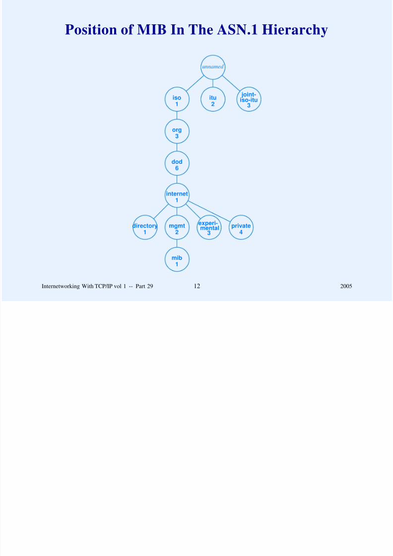
8/6/2019 Vol1 Presentation
http://slidepdf.com/reader/full/vol1-presentation 782/856
Syntactic Form
Variable name written as sequence of labels with dot (periodas delimiter)
Numeric encoding used in messages
Example: prefix for mgmt node is
1 . 3 . 6 . 1 . 2 . 1
Internetworking With TCP/IP vol 1 -- Part 29 13 2005

8/6/2019 Vol1 Presentation
http://slidepdf.com/reader/full/vol1-presentation 783/856
ASN.1 Hierarchy For TCP/IP
internet1
.
.
.
mgmt
2
mib1
directory
1
experi-mental
3
private
4
system1
inter-faces
2
addr.trans.
3ip4
icmp5
tcp6
udp7
label from the root tothis point is 1 . 3 . 6
Internetworking With TCP/IP vol 1 -- Part 29 14 2005

8/6/2019 Vol1 Presentation
http://slidepdf.com/reader/full/vol1-presentation 784/856
Example MIB Variables
Prefix for variable ipInReceives is
iso . org . dod . internet . mgmt . mib . ip . ipInReceives
Numeric value is
1 . 3 . 6 . 1 . 2 . 1 . 4 . 3
Internetworking With TCP/IP vol 1 -- Part 29 15 2005

8/6/2019 Vol1 Presentation
http://slidepdf.com/reader/full/vol1-presentation 785/856
MIB Tables
Correspond to data structures programmers think of asarrays or structs
ASN.1 definition uses keyword SEQUENCE
Array index is appended to MIB variable name
Internetworking With TCP/IP vol 1 -- Part 29 16 2005

8/6/2019 Vol1 Presentation
http://slidepdf.com/reader/full/vol1-presentation 786/856
Example Of SEQUENCE Definition
IpAddrEntry ::= SEQUENCE {
ipAdEntAddr
IpAddress,
ipAdEntIfIndex
INTEGER,ipAdEntNetMask
IpAddress,
ipAdEntBcastAddr
IpAddress,
ipAdEntReasmMaxSizeINTEGER (0..65535)
}
Internetworking With TCP/IP vol 1 -- Part 29 17 2005

8/6/2019 Vol1 Presentation
http://slidepdf.com/reader/full/vol1-presentation 787/856
Simple Network Management Protocol (SNMP)
Specifies communication between manager’s workstationand managed entity
Uses fetch-store paradigm
Internetworking With TCP/IP vol 1 -- Part 29 18 2005

8/6/2019 Vol1 Presentation
http://slidepdf.com/reader/full/vol1-presentation 788/856
Operations That SNMP Supports
Command Meaning
get-request Fetch a value from a specific variable
get-next-request Fetch a value without knowing its exact name
get-bulk-request Fetch a large volume of data (e.g., a table)
response A response to any of the above requests
set-request Store a value in a specific variableinform-request Reference to third-part data (e.g., for a proxy)
snmpv2-trap Reply triggered by an event
report Undefined at present
Internetworking With TCP/IP vol 1 -- Part 29 19 2005

8/6/2019 Vol1 Presentation
http://slidepdf.com/reader/full/vol1-presentation 789/856
SNMP Message Format
Defined using ASN.1 notation
Similar to BNF grammar
Internetworking With TCP/IP vol 1 -- Part 29 20 2005

8/6/2019 Vol1 Presentation
http://slidepdf.com/reader/full/vol1-presentation 790/856
Example ASN.1 Definition
SNMPv3Message ::=
SEQUENCE {
msgVersion INTEGER (0..2147483647),
-- note: version number 3 is used for SNMPv3
msgGlobalData HeaderData,
msgSecurityParameters OCTET STRING,
msgData ScopedPduData
}
Internetworking With TCP/IP vol 1 -- Part 29 21 2005

8/6/2019 Vol1 Presentation
http://slidepdf.com/reader/full/vol1-presentation 791/856
Definition Of HeaderData Area In SNMP Message
HeaderData ::= SEQUENCE {
msgID INTEGER (0..2147483647),
-- used to match responses with requests
msgMaxSize INTEGER (484..2147483647),
-- maximum size reply the sender can acceptmsgFlags OCTET STRING (SIZE(1)),
-- Individual flag bits specify message characteristics
-- bit 7 authorization used
-- bit 6 privacy used
-- bit 5 reportability (i.e., a response needed)msgSecurityModel INTEGER (1..2147483647)
-- determines exact format of security parameters that follow
}
Internetworking With TCP/IP vol 1 -- Part 29 22 2005

8/6/2019 Vol1 Presentation
http://slidepdf.com/reader/full/vol1-presentation 792/856
Discriminated Union
ASN.1 uses CHOICE keyword for a discriminated union
Example
ScopedPduData ::= CHOICE {
plaintext ScopedPDU,
encryptedPDU OCTET STRING -- encrypted ScopedPDU value
}
Internetworking With TCP/IP vol 1 -- Part 29 23 2005

8/6/2019 Vol1 Presentation
http://slidepdf.com/reader/full/vol1-presentation 793/856
Summary
TCP/IP management protocols reside at application layer
Management Information Base (MIB) specifies set of
variables that can be accessed
Structure Of Management Information (SMI) specifies rules
for naming MIB variables
Simple Network Management Protocol (SNMP) specifies
format of messages that pass between a manager’s
workstation and managed entity
Variables named using ASN.1 (absolute, global,hierarchical)
Message format defined with ASN.1 (similar to BNF
grammar)
Internetworking With TCP/IP vol 1 -- Part 29 24 2005

8/6/2019 Vol1 Presentation
http://slidepdf.com/reader/full/vol1-presentation 794/856
Questions?

8/6/2019 Vol1 Presentation
http://slidepdf.com/reader/full/vol1-presentation 795/856
PART XXX
INTERNET SECURITYAND FIREWALL DESIGN
(IPsec, SSL)
Internetworking With TCP/IP vol 1 -- Part 30 1 2005

8/6/2019 Vol1 Presentation
http://slidepdf.com/reader/full/vol1-presentation 796/856
Network Security
Refers in broad sense to confidence that information and
services available on a network cannot be accessed by
unauthorized users
Implies
– Safety– Freedom from unauthorized access or use
– Freedom from snooping or wiretapping
– Freedom from disruption of service
– Assurance that outsiders cannot change data
Also called information security
Internetworking With TCP/IP vol 1 -- Part 30 2 2005

8/6/2019 Vol1 Presentation
http://slidepdf.com/reader/full/vol1-presentation 797/856
A Crucial Point
Just as no physical property is absolutely secure against crime,
no network is completely secure.
Internetworking With TCP/IP vol 1 -- Part 30 3 2005

8/6/2019 Vol1 Presentation
http://slidepdf.com/reader/full/vol1-presentation 798/856
Aspects Of Protection
Data integrity
Data availability
Privacy or confidentiality
Authorization
Authentication
Replay avoidance
Internetworking With TCP/IP vol 1 -- Part 30 4 2005

8/6/2019 Vol1 Presentation
http://slidepdf.com/reader/full/vol1-presentation 799/856
Information Policy
Defines what is allowed
Special note:
Humans are usually the most susceptible point in any security
scheme. A worker who is malicious, careless, or unaware of anorganization’s information policy can compromise the best
security.
Internetworking With TCP/IP vol 1 -- Part 30 5 2005

8/6/2019 Vol1 Presentation
http://slidepdf.com/reader/full/vol1-presentation 800/856
Internet Security
Especially difficult
Data travels across many networks owned by many groups
from source to destination
Computers in the middle can change data
Internetworking With TCP/IP vol 1 -- Part 30 6 2005

8/6/2019 Vol1 Presentation
http://slidepdf.com/reader/full/vol1-presentation 801/856
A Point About Authentication
An authorization scheme that uses a remote machine’s IP
address to authenticate its identity does not suffice in an
unsecure internet. An imposter who gains control of an
intermediate router can obtain access by impersonating an
authorized client.
Internetworking With TCP/IP vol 1 -- Part 30 7 2005

8/6/2019 Vol1 Presentation
http://slidepdf.com/reader/full/vol1-presentation 802/856
Two Basic Techniques For Internet Security
Encryption
Perimeter Security
Internetworking With TCP/IP vol 1 -- Part 30 8 2005

8/6/2019 Vol1 Presentation
http://slidepdf.com/reader/full/vol1-presentation 803/856
IP Security Protocol (IPsec)
Devised by IETF
Actually a set of protocols
Name IPsec applies collectively
Works with IPv4 or IPv6
Gives framework, but does not specify exactly which
encryption or authentication algorithms to use
Choice between authentication and encryption
Internetworking With TCP/IP vol 1 -- Part 30 9 2005

8/6/2019 Vol1 Presentation
http://slidepdf.com/reader/full/vol1-presentation 804/856
IPsec Authentication Header (AH)
Not an IP option
Added after IP header
Follows IPv6 format (more on IPv6 later in the course)
Internetworking With TCP/IP vol 1 -- Part 30 10 2005

8/6/2019 Vol1 Presentation
http://slidepdf.com/reader/full/vol1-presentation 805/856
Illustration of Authentication Header Insertion
IPv4HEADER
TCPHEADER
TCPDATA
IPv4HEADER
AUTHENTICATIONHEADER
TCPHEADER
TCPDATA
(a)
(b)
(a) shows datagram and (b) shows same datagram after
header has been inserted
Internetworking With TCP/IP vol 1 -- Part 30 11 2005

8/6/2019 Vol1 Presentation
http://slidepdf.com/reader/full/vol1-presentation 806/856
Type Information
IPv4 PROTOCOL field is modified so the type is IPsec
Authentication header contains NEXT HEADER field that
specifies original type
Internetworking With TCP/IP vol 1 -- Part 30 12 2005

8/6/2019 Vol1 Presentation
http://slidepdf.com/reader/full/vol1-presentation 807/856
Illustration Of Type Information
With Authentication
0 8 16 31
NEXT HEADER PAYLOAD LEN RESERVED
SECURITY PARAMETERS INDEX
SEQUENCE NUMBER
AUTHENTICATION DATA (VARIABLE)
. . .
Internetworking With TCP/IP vol 1 -- Part 30 13 2005

8/6/2019 Vol1 Presentation
http://slidepdf.com/reader/full/vol1-presentation 808/856
Security Association
Not all information related to security can fit in header
Sender and receiver communicate, agree on security
parameters, assign small index to each parameter, and then
use index values in headers
Internetworking With TCP/IP vol 1 -- Part 30 14 2005

8/6/2019 Vol1 Presentation
http://slidepdf.com/reader/full/vol1-presentation 809/856
IPsec Encapsulating Security Payload (ESP)
Used to encrypt packet contents
More complex than authentication header
Internetworking With TCP/IP vol 1 -- Part 30 15 2005

8/6/2019 Vol1 Presentation
http://slidepdf.com/reader/full/vol1-presentation 810/856
Illustration Of ESP
IPv4HEADER
TCPHEADER
TCPDATA
IPv4HEADER
ESPHEADER
TCPHEADER
TCPDATA
ESPTRAILER
ESPAUTH
(a)
(b)
encrypted
authenticated
Internetworking With TCP/IP vol 1 -- Part 30 16 2005
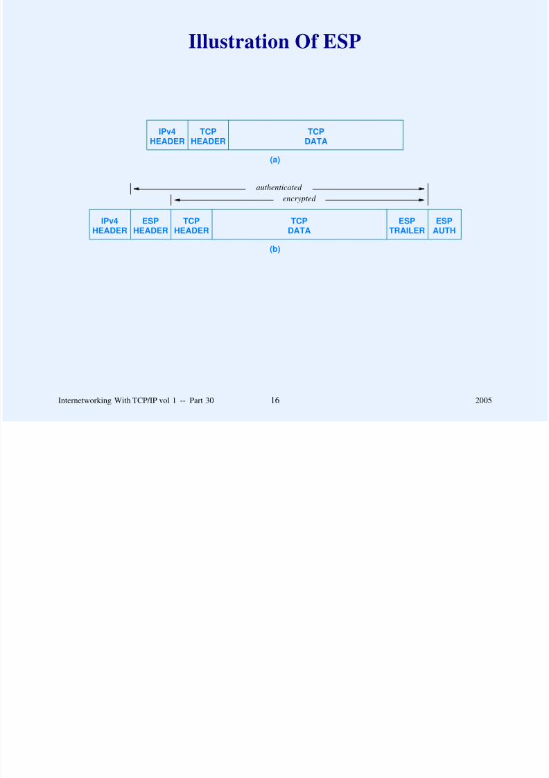
8/6/2019 Vol1 Presentation
http://slidepdf.com/reader/full/vol1-presentation 811/856
ESP Header
0 16 31
SECURITY PARAMETERS INDEX
SEQUENCE NUMBER
Eight octets
Precedes payload
Internetworking With TCP/IP vol 1 -- Part 30 17 2005

8/6/2019 Vol1 Presentation
http://slidepdf.com/reader/full/vol1-presentation 812/856
ESP Trailer
0 16 24 31
0 - 255 OCTETS OF PADDING PAD LENGTH NEXT HEADER
ESP AUTHENTICATION DATA (VARIABLE)
. . .
Authentication data variable size
Padding optional
Internetworking With TCP/IP vol 1 -- Part 30 18 2005

8/6/2019 Vol1 Presentation
http://slidepdf.com/reader/full/vol1-presentation 813/856
Mutable Header Fields
Some IP header fields change (e.g., TTL)
IPsec designed to ensure end-to-end integrity
One possibility: IPsec tunneling
– Place IPsec datagram inside normal datagram
– Often used in VPNs
Internetworking With TCP/IP vol 1 -- Part 30 19 2005

8/6/2019 Vol1 Presentation
http://slidepdf.com/reader/full/vol1-presentation 814/856
Illustration Of IPsec Tunneling
OUTER IPHEADER
AUTHENTICATIONHEADER
INNER IP DATAGRAM(INCLUDING IP HEADER)
OUTER IPHEADER
ESPHEADER
INNER IP DATAGRAM(INCLUDING IP HEADER)
ESPTRAILER
ESPAUTH
encrypted
authenticated
(a)
(b)
(a) when used with authentication
(b) when used with encapsulated security payload
Internetworking With TCP/IP vol 1 -- Part 30 20 2005
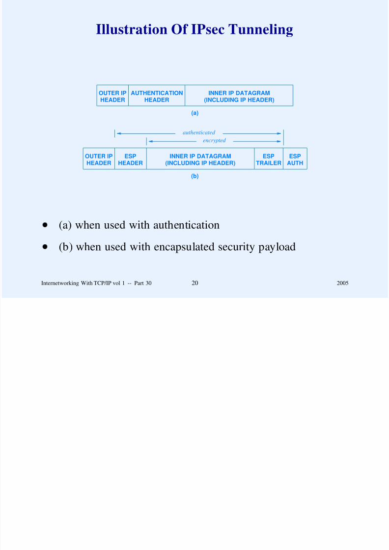
8/6/2019 Vol1 Presentation
http://slidepdf.com/reader/full/vol1-presentation 815/856
Mandatory Security Algorithms For IPsec
Authentication
HMAC with MD5 RFC 2403
HMAC with SHA-1 RFC 2404
Encapsulating Security Payload
DES in CBC mode RFC 2405
HMAC with MD5 RFC 2403
HMAC with SHA-1 RFC 2404
Null Authentication
Null Encryption
Internetworking With TCP/IP vol 1 -- Part 30 21 2005

8/6/2019 Vol1 Presentation
http://slidepdf.com/reader/full/vol1-presentation 816/856
Secure Sockets Layer (SS)
Created by Netscape, Inc.
Widely used
Not formally adopted by IETF
Same API as sockets
Provides authentication and encryption
De facto standard for web browsers
Internetworking With TCP/IP vol 1 -- Part 30 22 2005

8/6/2019 Vol1 Presentation
http://slidepdf.com/reader/full/vol1-presentation 817/856
Transport Layer Security (TLS)
Created by IETF
So closely related to SSL that the same protocol port is used
Most implementations of SSL also support TLS
Internetworking With TCP/IP vol 1 -- Part 30 23 2005

8/6/2019 Vol1 Presentation
http://slidepdf.com/reader/full/vol1-presentation 818/856
Perimeter Security
Form of access control
Mechanism is Internet firewall
Firewall placed at each connection between site and rest of
Internet
All firewalls use coordinated policy
Blocks unwanted packets
Internetworking With TCP/IP vol 1 -- Part 30 24 2005

8/6/2019 Vol1 Presentation
http://slidepdf.com/reader/full/vol1-presentation 819/856
Firewall Implementation
Basic technique is packet filter
Typically runs in a router
Manager specifies restrictions on incoming packets
Filter drops packets that are not allowed
Internetworking With TCP/IP vol 1 -- Part 30 25 2005

8/6/2019 Vol1 Presentation
http://slidepdf.com/reader/full/vol1-presentation 820/856
Illustration Of Packet Filter
R 12 INSIDEOUTSIDE
ARRIVES ON IP IP SOURCE DEST.
INTERFACE SOURCE DEST. PROTOCOL PORT PORT
2 * * TCP * 21
2 * * TCP * 23
1 128.5.0.0 / 16 * TCP * 25
2 * * UDP * 43
2 * * UDP * 69
2 * * TCP * 79
Internetworking With TCP/IP vol 1 -- Part 30 26 2005

8/6/2019 Vol1 Presentation
http://slidepdf.com/reader/full/vol1-presentation 821/856
Effective Filtering
To be effective, a firewall that uses datagram filtering should
restrict access to all IP sources, IP destinations, protocols, and
protocol ports except those computers, networks, and services
the organization explicitly decides to make available externally.
A packet filter that allows a manager to specify which
datagrams to admit instead of which datagrams to block can
make such restrictions easy to specify.
Internetworking With TCP/IP vol 1 -- Part 30 27 2005

8/6/2019 Vol1 Presentation
http://slidepdf.com/reader/full/vol1-presentation 822/856
Consequences Of A Restrictive Filter
If an organization’s firewall restricts incoming datagrams
except for ports that correspond to services the organization
makes available externally, an arbitrary application inside the
organization cannot become a client of a server outside the
organization.
Internetworking With TCP/IP vol 1 -- Part 30 28 2005

8/6/2019 Vol1 Presentation
http://slidepdf.com/reader/full/vol1-presentation 823/856
Proxy Access
Allows specific clients to access specific services
Handles problems like virus detection on incoming files
Uses bastion host
Internetworking With TCP/IP vol 1 -- Part 30 29 2005

8/6/2019 Vol1 Presentation
http://slidepdf.com/reader/full/vol1-presentation 824/856
Illustration Of Proxy Access
GLOBALINTERNET(OUTSIDE)
INTRANET(INSIDE)
bastion host
manually enabled bypass
Two firewall filters restrict
– Incoming packets from Internet to proxy
– Outgoing packets from site to proxy
Internetworking With TCP/IP vol 1 -- Part 30 30 2005

8/6/2019 Vol1 Presentation
http://slidepdf.com/reader/full/vol1-presentation 825/856
Stateful Firewalls
Allow clients inside an organization to contact servers in the
Internet
Firewall
– Watches outgoing packets
– Records source and destination information
– Uses recorded information when admitting packets
Communication still subject to policies
Internetworking With TCP/IP vol 1 -- Part 30 31 2005

8/6/2019 Vol1 Presentation
http://slidepdf.com/reader/full/vol1-presentation 826/856
Managing Firewall State
Connection tracking
– Uses FIN to remove state for TCP connection
– Does not work well with UDP
Soft state
– Timer set when entry created
– Idle entry removed after timeout
Internetworking With TCP/IP vol 1 -- Part 30 32 2005

8/6/2019 Vol1 Presentation
http://slidepdf.com/reader/full/vol1-presentation 827/856
Content Protection With Proxies
Firewall only operates at packet level
Mechanism known as application proxy protects against
incoming
– Viruses
– Other illicit content
Proxy can examine entire content (e.g., mail message)
Internetworking With TCP/IP vol 1 -- Part 30 33 2005

8/6/2019 Vol1 Presentation
http://slidepdf.com/reader/full/vol1-presentation 828/856
Summary
Two basic techniques used for Internet security
– Encryption
– Perimeter security
IETF has defined IPsec as a framework for security
IPsec offers choice of
– Authentication header (AH)
– Encapsulated Security Payload (ESP)
Internetworking With TCP/IP vol 1 -- Part 30 34 2005

8/6/2019 Vol1 Presentation
http://slidepdf.com/reader/full/vol1-presentation 829/856
Summary
(continued)
Firewall is mechanism used for perimeter security
Packet filter specified by manager
Firewall rejects packets except those explicitly allowed
Stateful firewall allows clients in organization to initiate
communication
Application proxy can be used to check content
Internetworking With TCP/IP vol 1 -- Part 30 35 2005

8/6/2019 Vol1 Presentation
http://slidepdf.com/reader/full/vol1-presentation 830/856
Questions?

8/6/2019 Vol1 Presentation
http://slidepdf.com/reader/full/vol1-presentation 831/856
PART XXXI
THE FUTURE OF TCP/IP
(IPv6)
Internetworking With TCP/IP vol 1 -- Part 31 1 2005

8/6/2019 Vol1 Presentation
http://slidepdf.com/reader/full/vol1-presentation 832/856
Current Version
TCP/IP has worked well for over 25 years
Design is flexible and powerful
Has adapted to
– New computer and communication technologies
– New applications
– Increases in size and load
Internetworking With TCP/IP vol 1 -- Part 31 2 2005

8/6/2019 Vol1 Presentation
http://slidepdf.com/reader/full/vol1-presentation 833/856
Most Significant Technical Problem
Address space limitation
IPv4 address space may be exhausted by the year 2020
Internetworking With TCP/IP vol 1 -- Part 31 3 2005

8/6/2019 Vol1 Presentation
http://slidepdf.com/reader/full/vol1-presentation 834/856
History Of The New Version
Developed by IETF
Started in early 1990s
Input from many groups, including: computer
manufacturers, hardware and software vendors, users,
managers, programmers, telephone companies, and the cable
television industry
Internetworking With TCP/IP vol 1 -- Part 31 4 2005

8/6/2019 Vol1 Presentation
http://slidepdf.com/reader/full/vol1-presentation 835/856
History Of The New Version
(continued)
Three main proposals
Eventually new version emerged
Assigned version number 6, and known as IPv6
RFC in 1994
Defined over 10 years ago!
Internetworking With TCP/IP vol 1 -- Part 31 5 2005

8/6/2019 Vol1 Presentation
http://slidepdf.com/reader/full/vol1-presentation 836/856
Major Changes From IPv4
Larger addresses
Extended address hierarchy
Variable header format
Facilities for many options
Provision for protocol extension
Support for autoconfiguration and renumbering
Support for resource allocation
Internetworking With TCP/IP vol 1 -- Part 31 6 2005

8/6/2019 Vol1 Presentation
http://slidepdf.com/reader/full/vol1-presentation 837/856
IPv6 Address Size
128 bits per address
Absurd increase in capacity
IPv6 has 1024 addresses per square meter of the Earth’s
surface!
Internetworking With TCP/IP vol 1 -- Part 31 7 2005

8/6/2019 Vol1 Presentation
http://slidepdf.com/reader/full/vol1-presentation 838/856
General Form Of IPv6 Datagram
DATA . . .Base
Header
Extension
Header 1. . .
Extension
Header N
optional
Base header required
Extension headers optional
Internetworking With TCP/IP vol 1 -- Part 31 8 2005

8/6/2019 Vol1 Presentation
http://slidepdf.com/reader/full/vol1-presentation 839/856
IPv6 Base Header Format
0 4 12 16 24 31
VERS TRAFFIC CLASS FLOW LABEL
PAYLOAD LENGTH NEXT HEADER HOP LIMIT
SOURCE ADDRESS
DESTINATION ADDRESS
Alignment is on 64-bit multiples
Fragmentation in extension header
Flow label intended for resource reservation
Internetworking With TCP/IP vol 1 -- Part 31 9 2005

8/6/2019 Vol1 Presentation
http://slidepdf.com/reader/full/vol1-presentation 840/856
Size Of Base Header
Each IPv6 datagram begins with a 40-octet base header that
includes fields for the source and destination addresses, the
maximum hop limit, the traffic class, the flow label, and the
type of the next header. Thus, an IPv6 datagram must contain
at least 40 octets in addition to the data.
Internetworking With TCP/IP vol 1 -- Part 31 10 2005
8/6/2019 Vol1 Presentation
http://slidepdf.com/reader/full/vol1-presentation 841/856
IPv6 Extension Headers
Sender chooses zero or more extension headers
Only those facilities that are needed should be included
Internetworking With TCP/IP vol 1 -- Part 31 11 2005

8/6/2019 Vol1 Presentation
http://slidepdf.com/reader/full/vol1-presentation 842/856
Parsing An IPv6 Datagram
Base Header
NEXT=TCPTCP Segment
Base Header
NEXT=ROUTE
Route Header
NEXT=TCPTCP Segment
Base Header
NEXT=ROUTE
Route Header
NEXT=AUTH
Auth Header
NEXT=TCPTCP Segment
(a)
(b)
(c)
Each header includes NEXT HEADER field
NEXT HEADER operates like type field
Internetworking With TCP/IP vol 1 -- Part 31 12 2005

8/6/2019 Vol1 Presentation
http://slidepdf.com/reader/full/vol1-presentation 843/856
IPv6 Fragmentation And Reassembly
Like IPv4
– Ultimate destination reassembles
Unlike IPv4
– Routers avoid fragmentation
– Original source must fragment
Internetworking With TCP/IP vol 1 -- Part 31 13 2005

8/6/2019 Vol1 Presentation
http://slidepdf.com/reader/full/vol1-presentation 844/856
How Can Original Source Fragment?
Option 1: choose minimum guaranteed MTU of 1280
Option 2: use path MTU discovery
Internetworking With TCP/IP vol 1 -- Part 31 14 2005

8/6/2019 Vol1 Presentation
http://slidepdf.com/reader/full/vol1-presentation 845/856
Path MTU Discovery
Guessing game
Source sends datagram without fragmenting
If router cannot forward, router sends back ICMP error
message
Source tries smaller MTU
Internetworking With TCP/IP vol 1 -- Part 31 15 2005

8/6/2019 Vol1 Presentation
http://slidepdf.com/reader/full/vol1-presentation 846/856
Fragmentation Details
0 8 16 29 31
NEXT HEADER RESERVED FRAG. OFFSET RS M
DATAGRAM IDENTIFICATION
Fragmentation information carried in extension header
Internetworking With TCP/IP vol 1 -- Part 31 16 2005

8/6/2019 Vol1 Presentation
http://slidepdf.com/reader/full/vol1-presentation 847/856
Discussion Questions
Is fragmentation desirable?
What are the consequences of the IPv6 design?
Internetworking With TCP/IP vol 1 -- Part 31 17 2005

8/6/2019 Vol1 Presentation
http://slidepdf.com/reader/full/vol1-presentation 848/856
IPv6 Colon Hexadecimal Notation
Replaces dotted decimal
Example: dotted decimal value
104.230.140.100.255.255.255.255.0.0.17.128.150.10.255.255
Becomes
68E6:8C64:FFFF:FFFF:0:1180:96A:FFFF
Internetworking With TCP/IP vol 1 -- Part 31 18 2005

8/6/2019 Vol1 Presentation
http://slidepdf.com/reader/full/vol1-presentation 849/856
Zero Compression
Successive zeroes are indicated by a pair of colons
Example
FF05:0:0:0:0:0:0:B3
Becomes
FF05::B3
Internetworking With TCP/IP vol 1 -- Part 31 19 2005
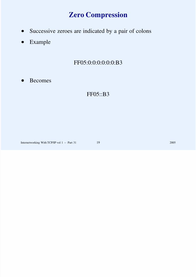
8/6/2019 Vol1 Presentation
http://slidepdf.com/reader/full/vol1-presentation 850/856
IPv6 Destination Addresses
Three types
– Unicast (single host receives copy)
– Multicast (set of hosts each receive a copy)
– Anycast (set of hosts, one of which receives a copy)
Note: no broadcast (but special multicast addresses (e.g.,
‘‘all hosts on local wire’’)
Internetworking With TCP/IP vol 1 -- Part 31 20 2005

8/6/2019 Vol1 Presentation
http://slidepdf.com/reader/full/vol1-presentation 851/856
Proposed IPv6 Address Space
Binary Prefix Type Of Address Part Of Address Space
0000 0000 Reserved (IPv4 compatibility) 1/2560000 0001 Unassigned 1/256
0000 001 NSAP Addresses 1/128
0000 01 Unassigned 1/64
0000 1 Unassigned 1/32
0001 Unassigned 1/16
001 Global Unicast 1/8
010 Unassigned 1/8011 Unassigned 1/8
100 Unassigned 1/8
101 Unassigned 1/8
110 Unassigned 1/8
1110 Unassigned 1/16
1111 0 Unassigned 1/32
1111 10 Unassigned 1/641111 110 Unassigned 1/128
1111 1110 0 Unassigned 1/512
1111 1110 10 Link-Local Unicast Addresses 1/1024
1111 1110 11 IANA - Reserved 1/1024
1111 1111 Multicast Addresses 1/256
Internetworking With TCP/IP vol 1 -- Part 31 21 2005

8/6/2019 Vol1 Presentation
http://slidepdf.com/reader/full/vol1-presentation 852/856
Backward Compatibility
Subset of IPv6 addresses encode IPv4 addresses
Dotted hex notation can end with 4 octets in dotted decimal
80 zero bits 16 bits 32 bits
0000 . . . . . . . . . . . . . . . . . . 0000 0000 IPv4 Address
0000 . . . . . . . . . . . . . . . . . . 0000 FFFF IPv4 Address
Internetworking With TCP/IP vol 1 -- Part 31 22 2005

8/6/2019 Vol1 Presentation
http://slidepdf.com/reader/full/vol1-presentation 853/856
Myths About IPv6
According To Geoff Huston
IPv6 is
– More secure
– Required for mobility
– Better for wireless networks
IPv6 offers better QoS
Only IPv6 supports auto-configuration
IPv6 solves route scaling
Internetworking With TCP/IP vol 1 -- Part 31 23 2005

8/6/2019 Vol1 Presentation
http://slidepdf.com/reader/full/vol1-presentation 854/856
Myths About IPv6
According To Geoff Huston
(continued)
IPv6 provides better support for
– Rapid prefix renumbering
– Multihomed sites
IPv4 has run out of addresses
Source: G. Huston, ‘‘The Mythology Of IP Version 6,’’ The Internet
Protocol Journal vol. 6:2 (June, 2003)
Internetworking With TCP/IP vol 1 -- Part 31 23 2005

8/6/2019 Vol1 Presentation
http://slidepdf.com/reader/full/vol1-presentation 855/856
Summary
IETF has defined next version of IP to be IPv6
Addresses are 128 bits long
Datagram starts with base header followed by zero or more
extension headers
Sender performs fragmentation
Many myths abound about the advantages of IPv6
No strong technical motivation for change
Internetworking With TCP/IP vol 1 -- Part 31 23 2005

8/6/2019 Vol1 Presentation
http://slidepdf.com/reader/full/vol1-presentation 856/856
Questions?
Related Documents