Class II Division 1 Malocclusion with 5mm of Crowding Treated Non-Extraction with IZC Miniscrews Anchorage Drs. Irene Yi-Hung Shih, John Jin-Jong Lin & W. Eugene Roberts Class II, Excessive Overjet and Deep Bite with a Congenitally Missing Lower Incisor Drs. Yi-Yang Su, Chris Chang & W. Eugene Roberts Forty Consecutive Ramus Bone Screws Used to Correct Horizontally Impacted Mandibular Molars Drs. Chris Chang, Shih-Yung Lin & W. Eugene Roberts 3D Cortical Bone Anatomy of the Mandibular Buccal Shelf: a CBCT study to define sites for extra-alveolar bone screws to treat Class III malocclusion Drs. Chris Chang, Chi Huang & W. Eugene Roberts I J OI International Journal of Orthodontics & Implantology Vol. 41 Jan 1, 2016 Bust and portrait of the father of orthodontic biomechanics, Charles J. Burstone (1928-2015). Permanent collection in Beethoven Orthodontic Center, Taiwan. International Journal of Orthodontics & Implantology is an experience sharing magazine for worldwide orthodontists and Implantologists. Download it at http://iaoi.pro. 《僅供牙科專業人士參閱》

Welcome message from author
This document is posted to help you gain knowledge. Please leave a comment to let me know what you think about it! Share it to your friends and learn new things together.
Transcript
Class II Division 1 Malocclusion with 5mm of Crowding Treated Non-Extraction with IZC Miniscrews AnchorageDrs. Irene Yi-Hung Shih, John Jin-Jong Lin & W. Eugene Roberts
Class II, Excessive Overjet and Deep Bite with a Congenitally Missing Lower IncisorDrs. Yi-Yang Su, Chris Chang & W. Eugene Roberts
Forty Consecutive Ramus Bone Screws Used to Correct Horizontally Impacted Mandibular MolarsDrs. Chris Chang, Shih-Yung Lin & W. Eugene Roberts
3D Cortical Bone Anatomy of the Mandibular Buccal Shelf: a CBCT study to define sites for extra-alveolar bone screws to treat Class III malocclusionDrs. Chris Chang, Chi Huang & W. Eugene Roberts
IJOIInternational Journal of
Orthodontics & Implantology
Vol. 41 Jan 1, 2016
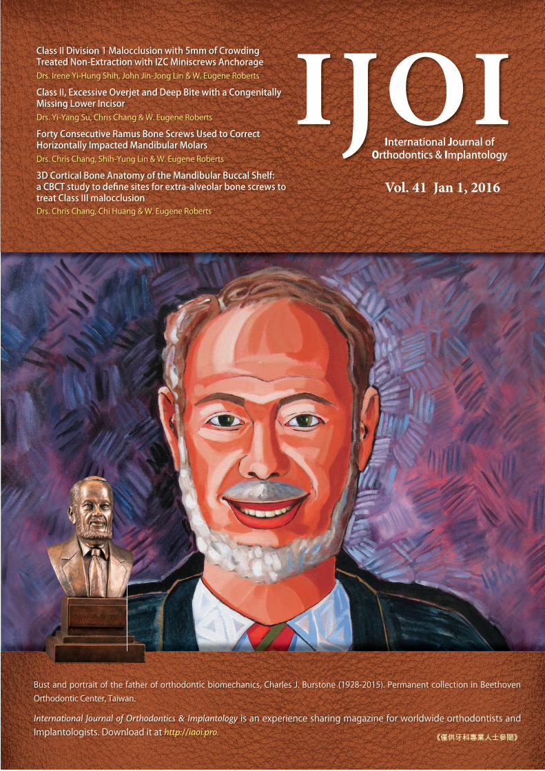
Bust and portrait of the father of orthodontic biomechanics, Charles J. Burstone (1928-2015). Permanent collection in Beethoven Orthodontic Center, Taiwan.
International Journal of Orthodontics & Implantology is an experience sharing magazine for worldwide orthodontists and Implantologists. Download it at http://iaoi.pro.
《僅供牙科專業人士參閱》
2016.07.14简报圣经
Dr. Kokich
Steve Jobs
Advanced Keynote
2016.08.0410大演讲秘诀
令人目眩神迷的演讲技巧2016.09.15
2016.10.22 - 24
高效简报学习法2016 Keynote Workshop
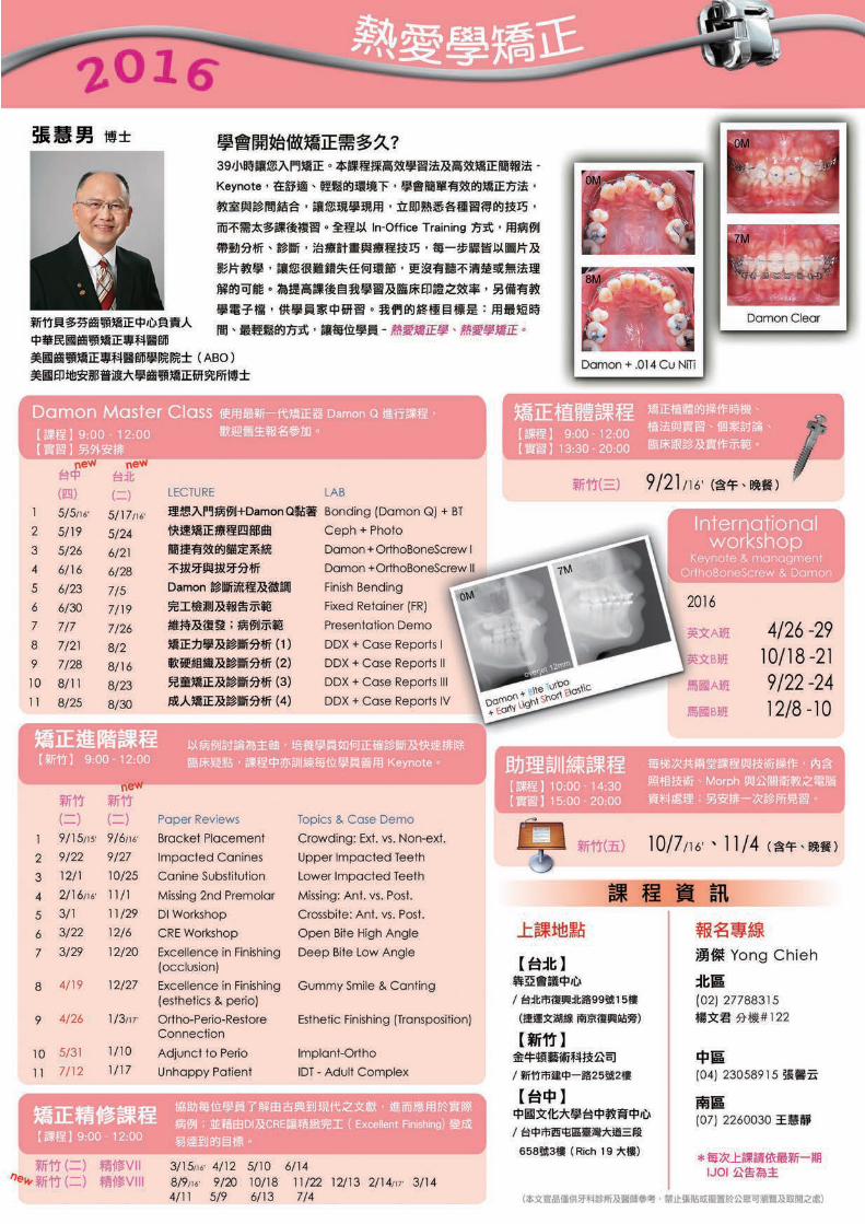
数位化潮流下的牙科简报,不仅需要清晰的临床照片,也需要精确的图表和流畅的动画来吸引观众,而优秀的视觉化工具更使您的演讲独树一格且令人难忘。Keynote 456课程中,Dr. Rungsi 将分享他利用Keynote软体绘制精美牙科插图的经验,并一步步教会您如何从构想和草图创建出令人惊艳的成果。跟随简报美学大师的脚步,您也可以秀出创意、站上世界舞台!
名额有限,以缴费顺序为依据。旧生享特惠优惠价,限额6名。若取消报名,7/22前退款将扣除10%行政手续费,7/23后扣除30%行政手续费。
。。。
金牛顿艺术科技 新竹市建中一路25號2楼 报名专线:03-5735676
报名2016课程即赠送2015及2016课程视讯。
看过太多充满复杂文字和图表的幻灯片,听过就忘了的演讲吗?Keynote系列课程教你如何利用Mac内建软体Keynote,制作出令人目眩神迷、印象深刻的电脑简报。透过小班教学,贴身指导,务必让你在课程中轻松掌握Keynote的简报技巧。
Keynote 101
Speaker: Dr. Rungsi
Newton’s A
K123
K456
讲师:Dr. Rungsi Thavarungkul

IAOI welcomes general submissions and inquiries to be sent to [email protected]
Encountering Charlie Burstone ‒ a journey that changed the course of my life.
There are not so many people who can say that a certain person has changed their life. I can and I’d like to share how much that person changed my life.
27 years ago as a junior dentist, I was invited by my teacher to join a seminar to be held by Charlie Burstone in Taipei. At the time, this was a huge financial investment for me and was the first time that I would attend a presentation by a foreign speaker. The subject was to be Biomechanics, which had never been taught in Taiwan. Furthermore, I understood nothing about this topic and so for the next 6 months, I studied all of the available texts about Biomechanics from Charlie Burstone. By the time he held his speech, I had a firm understanding of both details and the language that he used and surprisingly also of Biomechanics. After this speech, I understood that this was a market niche to be developed in Taiwan and I decided there and then to specialize in Biomechanics, being blessed to study in Indiana University, the birthplace of Biomechanics, under the tutelage of the prominent Dr. Eugene Roberts.
That this would have such a profound effect on my life, nobody could have thought at the time, but I was determined to follow in Charlie’s footsteps and for him to become my professional grandfather. Ever since the first time I listened to him in 1988, I knew he was very special and since then, my gut feeling has been confirmed and continually reconfirmed each and every subsequent time that I met him.
Whilst at the Charlie Burstone Memorial Gala Dinner in Indiana in November 2015 I was intrigued to hear the story of another man whose life had been changed by Charlie Burstone, Dr Mike Marcotte. In fact, so intrigued that I asked him to share it as a follow-up to Dr. Roberts’ In Memoriam featured in our last edition; I hope you will enjoy his vignette as much as I do.
To further honor Dr. Burstone, I have decided that through 2016 we will feature a “Charlie In Memoriam” in each of our publications, so if you have any stories or pictures, or know of anyone who does, please contact us and we will publish the best In Memoriams in our journal.
I sincerely hope that these will help to inspire you as much as he inspired me and that we can continue to allow the Burstone Biomechanics Legacy to march along the path to glory.
Chris Chang DDS, PhD, Publisher of IJOI.
Dr. Baldwin W. Marchack
Dr. Thomas HanDr. FernandoRojas-Vizcaya
Dr. Homa ZadehDr. Larry WhiteDr. J. Michael Steffen
Dr. W. EugeneRoberts
Dr. Tucker Haltom
Consultants
Dr. Frank Chang Dr. Johnny Liaw
Examiners
Dr. John J. J. Lin
Dr. Hong Po Chang
Dr. Yu Lin Hsu Dr. Yu-Hsin Huang
Dr. Bill Su Dr. Ming-Jen Chang
Associate editors
Dr. Chris LinDr. Ariel Chang
Editorial Board
Editor-in-chief
Dr. W. Eugene Roberts
Publisher
Dr. Chris ChangSurgery
Dr. Shih-Yung Lin
Case ReportDr. Angle Lee
ResearchDr. Chi Huang
Editors
Desk editorBella Chu
English editing
Paul Head
ProofreaderTzu Han Huang
IllustrationRungsi
Thavarungkul
3 Editorial
LIVE FROM THE MASTER
4 Class II Division 1 Malocclusion with 5 mm of Crowding Treated Non-Extraction with IZC Miniscrews Anchorage
iAOI CASE REPORT
22 Conservative Treatment of Severe Malocclusion in a 15y5m Nongrowing Female: Growth-like Skeletal Adaptation 3 Years Later
42 Class II, Excessive Overjet and Deep Bite with a Congenitally Missing Lower Incisor
RESEARCH PREVIEW
60 Forty Consecutive Ramus Bone Screws Used to Correct Horizontally Impacted Mandibular Molars
74 Analysis of 3-Dimensional MBS Cortical Bone by Using CBCT: A retrospective study of extra-radicular miniscrew insertion on buccal shelves in Class III malocclusions.
CLINICAL TIPS
86 Tips in solving clinical errors : Management of wire dislodgment
MEMORIAM
90 Dr. Charles J. Burstone - what he meant to me.
100 FEEDBACK FROM THE WORLD
EDITORIAL IJOI 41

4
IJOI 41 LI E RO T E A TER II D 1 T E I A IJOI 41
istor and tiolog
A 26 year-old male presented with compromised facial and dental esthetics, associated with a complex malocclusion: 19° facial convexity (G-Sn-Pg'), Class II buccal segments, 7 mm overjet, 4 mm deep overbite, lip incompetence with mentalis strain (Figs. 1-3). Medical and dental histories were non-contributory. A functional examination of the temporomandibular joint was within normal limits (WNL). Careful assessment of the facial and dental discrepancies suggested that maxillary bone screw anchorage was a viable approach for differentially retracting both arches to resolve the complex malocclusion. Temporary anchorage devices (TADs) were placed in the infrazygomatic crest (IZC) region, bilaterally. Following 25 months of non-extraction treatment with IZC TADs, the malocclusion was corrected to a near ideal result with a passive self-ligating appliance (Figs. 4-6). The treatment is documented with lateral cephalometric and panoramic radiographs before (Fig. 7) and after (Fig. 8) treatment, as well as superimposition of cephalometric tracings (Fig. 9).
Dr. Irene Yi-Hung Shih,Visiting Staff, Beauty Forever Dental Clinic (Left)
Dr. John Jin-Jong LinMS, Marquette University, Examiner of IJOI, President of TAO ( 2000~2002 )
Author of Creative Orthodontics (Middle)
Dr. W. Eugene Roberts,Chief consultant, International Journal of Orthodontics & Implantology (Right)
a i i ion a occ ion it mmo ro in r at on traction
it ini cr nc ora
tract A Class II Division 1 malocclusion in a 26 yr old male was associated with a convex profile (ANB 5.5), lip incompetence, 7 mm of overjet, and 5-7 mm of crowding in each arch. This complex malocclusion in an adult male was treated non-extraction, by retracting both arches, and intruding the incisors with anterior bite turbos, placed on the lingual surfaces of upper central incisors. Following 25 months of active treatment, this dicult malocclusion (DI 21) was treated to an excellent dental (CRE 17) and facial result. (Int J Orthod Implantol 2016;41:4-17)
Key words:Class II Division 1, IZC bone screws, miniscrews, bite turbo, adult male

IJOI 41 LI E RO T E A TER
5
II D 1 T E I A IJOI 41
Fig. 3: Pre-treatment study models (casts) document a complex malocclusion with a DI of 21.
Fig. 6: Post-treatment study models (casts) document a good alignment that earned a CRE score of 17 points.
Fig. 1: Pre-treatment facial photographs show a convex profile with chin retrusion, lip incompetence and mentalis strain. Note that the chin point is deviated slightly to the right.
Fig. 4: Post-treatment facial photographs.
Fig. 2: Pre-treatment intraoral photographs reveal bilateral Class II buccal segments. The lower dental midline is deviated to right about 1.5 mm. The overjet was 7 mm and the overbite was 4 mm (40%).
Fig. 5: Post-treatment intraoral photographs document a well aligned dentition, but there are multiple interproximal black triangles.
Dr. Irene Yi-Hung Shih,Visiting Staff, Beauty Forever Dental Clinic (Left)
Dr. John Jin-Jong LinMS, Marquette University, Examiner of IJOI, President of TAO ( 2000~2002 )
Author of Creative Orthodontics (Middle)
Dr. W. Eugene Roberts,Chief consultant, International Journal of Orthodontics & Implantology (Right)

6
IJOI 41 LI E RO T E A TER II D 1 T E I A IJOI 41
Fig. 9:Cephalometric superimpositions reveal the Class II malocclusion was corrected by upper arch retraction and bite opening was achieved by upper and lower incisor intrusion. The initial positions for the teeth and lips are shown in blue and the results are shown in red.
Fig. 7:Pre-treatment cephalometric and panoramic radiographs
Fig. 8:Post-treatment cephalometric and panoramic radiographs

IJOI 41 LI E RO T E A TER
7
II D 1 T E I A IJOI 41
iagnosis and tiolog
Pre-treatment facial photographs show a convex profile, protrusive lips, chin retrusion, mentalis strain, and a chin point that was deviated slightly to the right (Fig. 1). Intraoral photographs and study casts (Figs. 2 and 3) document Class II canine and molar relationships bilaterally, 7 mm of overjet, a 4 mm deep overbite (40%), and significant crowding in both arches (-5mm upper, -7mm lower). The cephalometric analysis (Table 1) reveals a skeletal Class II pattern (ANB 5.5°), protrusive lips, increased axial inclination of all incisors (U1-SN 118.1°, L1-MP
99.2°), and a mandibular plane angle that was within normal limits (WNL). Skeletal, dental and facial analysis is outlined below.
Skeletal:
• Skeletal Class II Pattern: SNA 84.2°, SNB 78.8°, and
ANB 5.5°
• Mandibular plane angle is WNL: SN-MP 32.2°,
FMA 22.8°
• Facial asymmetry: chin point is deviated slightly to
the right
Dental:
• Bilateral Class II buccal segments: molars ~2 mm
and canines ~5 mm
• Right side canine Class II, left side Class I
• Overjet is 7 mm
• Overbite is 4 mm (40%)
• Crowding: 5 mm in the upper and 7 mm in the lower
arches
• Impacted third molars: upper and lower left
segments
• Midlines: upper dental midline is coincident with the
facial midline, and the lower midline deviates about 1.5
mm to the right.
• Arch forms: asymmetric buccal and lingual
displacements of second premolars in both arches
Facial:
• Profile: increased convexity (19° G-Sn-Pg')
• Nasolabial Angle: WNL
• Mandible is retrognathic to the maxilla
• Incompetent Lips: mentalis strain and slight lower lip
eversion when lips are closed
The ABO Discrepancy Index (DI) was 21 as shown in the subsequent worksheet.
A O I
A A A I
PRE-Tx POST-Tx DIFF.
SNA° 84.2° 84.1° -0.1°SNB° 78.8° 78.7° -0.1°ANB° 5.5° 5.4° -0.1°SN-MP° 32.2° 31.7° -0.5°FMA° 22.8° 22.1° -0.7°
A A A I
U1 TO NA mm 7.3 mm 2.3mm -5.0 mmU1 TO SN° 118.1° 105.0° -13.1°
L1 TO NB mm 8.5 mm 7.0 mm -1.5 mmL1 TO MP° 99.2° 96.5° -2.7°A IA A A I
E-LINE UL -0.1 mm -0.7 mm -0.6mmE-LINE LL 3.0 mm 1.3 mm -1.7 mm
Table 1: Cephalometric summary

8
IJOI 41 LI E RO T E A TER II D 1 T E I A IJOI 41
reatment Ob ecti es
A thorough examination and discussion with the patient produced the following treatment objectives:
1. Level and align the dentition in both arches.
2. Reduce the large overjet and correct the excessive axial inclination of the incisors.
3. Retract the lips to relieve mentalis strain and lip eversion.
Maxilla (all three planes):
• A - P: Maintain
• Vertical: Maintain
• Transverse: Maintain
Mandible (all three planes):
• A - P: Maintain
• Vertical: Maintain
• Transverse: Maintain
Maxillary Dentition:
• A - P: Retract incisors
• Vertical: Intrude incisors
• Transverse: Expand
Mandibular Dentition:
• A - P: Retract incisors
• Vertical: Intrude lower anteriors slightly
• Transverse: Expand
Facial Esthetics:
• Retract the lips
• Relieve mentalis strain
reatment lan
Non-extract ion t reatment with a fu l l f i xed orthodontic appliance is planned to align the dentition, level the arches, and reduce the excessive overjet. The IZC bone screws selected are 2x8 mm stainless steel (SS). Bilateral IZC TADs provide anchorage for retraction of the upper dentition to correct the Class II discrepancy. Class III elastics from the IZC TADs are used to retract the lower dentition to correct the axial inclination of the incisors.
A liances and reatment rogress
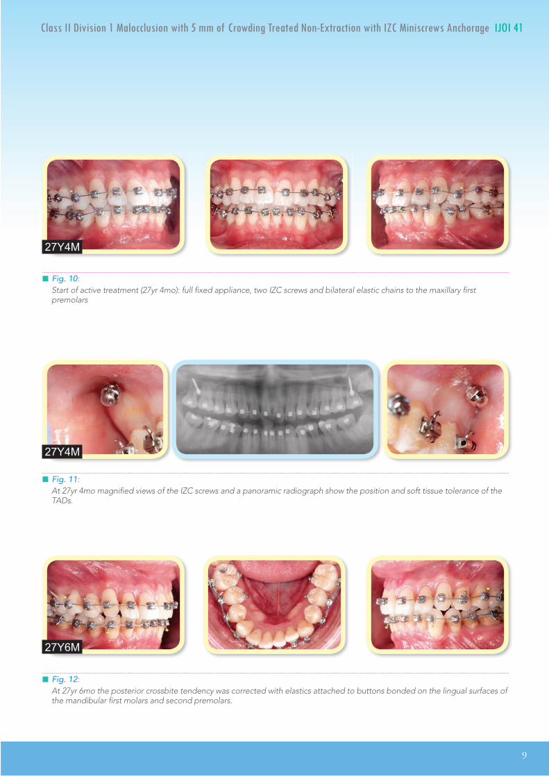
A full fixed .022" slot Damon Q® PSL appliance (Ormco, Glendora, CA) was bonded on teeth in both arches. All brackets were standard torque as specified by the manufacturer except for the lower anteriors, where low torque brackets were used to decrease labial proclination. The initial archwires were .014" CuNiTi in both arches, and 2x8 mm SS IZC miniscrews were installed buccal to the upper second molars, bilaterally. Upper arch retraction was initiated at the start of treatment by applying a chain of elastics from each maxillary TAD to the corresponding upper first premolar (Figs. 10 and 11).
Beginning two months into treatment, cross elastics were applied from the buttons bonded on the lingual of the lower 2nd premolars and 1st molars, to the buccal surface of the upper 1st and 2nd premolars to correct the posterior buccal crossbite. These cross elastics were used for about 9 months (Fig.
12). At four months into treatment, Class III elastics, from the IZC miniscrews to the lower canines, were used to retract the lower dentition to correct the
IJOI 41 LI E RO T E A TER
9
II D 1 T E I A IJOI 41
Fig. 11: At 27yr 4mo magnified views of the IZC screws and a panoramic radiograph show the position and soft tissue tolerance of the TADs.
Fig. 12: At 27yr 6mo the posterior crossbite tendency was corrected with elastics attached to buttons bonded on the lingual surfaces of the mandibular first molars and second premolars.
27Y4M
27Y6M
Fig. 10: Start of active treatment (27yr 4mo): full fixed appliance, two IZC screws and bilateral elastic chains to the maxillary first premolars
27Y4M

10
IJOI 41 LI E RO T E A TER II D 1 T E I A IJOI 41
excessive axial inclination of the lower incisors, as the arch was leveled and aligned (Fig. 13). After 6 months of differential retraction of both arches with IZC miniscrews, the buccal segments were near Class I (Fig. 14).
In the 12th month of treatment, bite opening stops (turbos) composed of glass Ionomer cement were bonded on the lingual surfaces of the upper central incisors. The bite turbos opened the bite, thereby providing an intrusive force on the upper and lower incisors, and also creating a posterior open bite to facilitate crossbite correction. As the arches were leveled and aligned, spaces were created distal to the upper lateral incisors by buccal segment retraction. Posts were crimped on the archwire distal to the lateral incisors, and the upper anterior segment was retracted with chains of elastics anchored by the IZC screws (Fig. 15).
In the 14th month of treatment, the bite turbos were removed and the upper archwire was cut mesial to the upper 2nd molars. Vertical elastics were used to extrude the upper second molars to improve occlusal contacts (Fig. 16). After 23 months of treatment, detailing and finishing is almost complete (Fig. 17).
Fig. 13: At 27yr 7mo Class III elastics are applied from the IZC screws to the lower canines.
27Y7M
Fig. 14: After 6 months of active treatment (27yr 10mo), posterior segments are near a Class I occlusion.
27Y10M

IJOI 41 LI E RO T E A TER
11
II D 1 T E I A IJOI 41
Fig. 15:At 28yr 3mo glass ionomer bite turbos are bonded on the lingual surface of upper central incisors to provide an intrusive force on the upper and lower incisors, in addition to opening the posterior bite to facilitate crossbite correction.
28Y3M
Fig. 16:At 28yr 6mo the glass ionomer bite turbos were removed and the upper archwire was cut distal to the the upper 1st molars, and vertical elastics were used to extrude the 2nd molars into occlusion.
28Y6M
Fig. 17: At 29yr 3mo bracket repositioning and archwire detailing were completed, immediately prior to debonding.
29Y3M
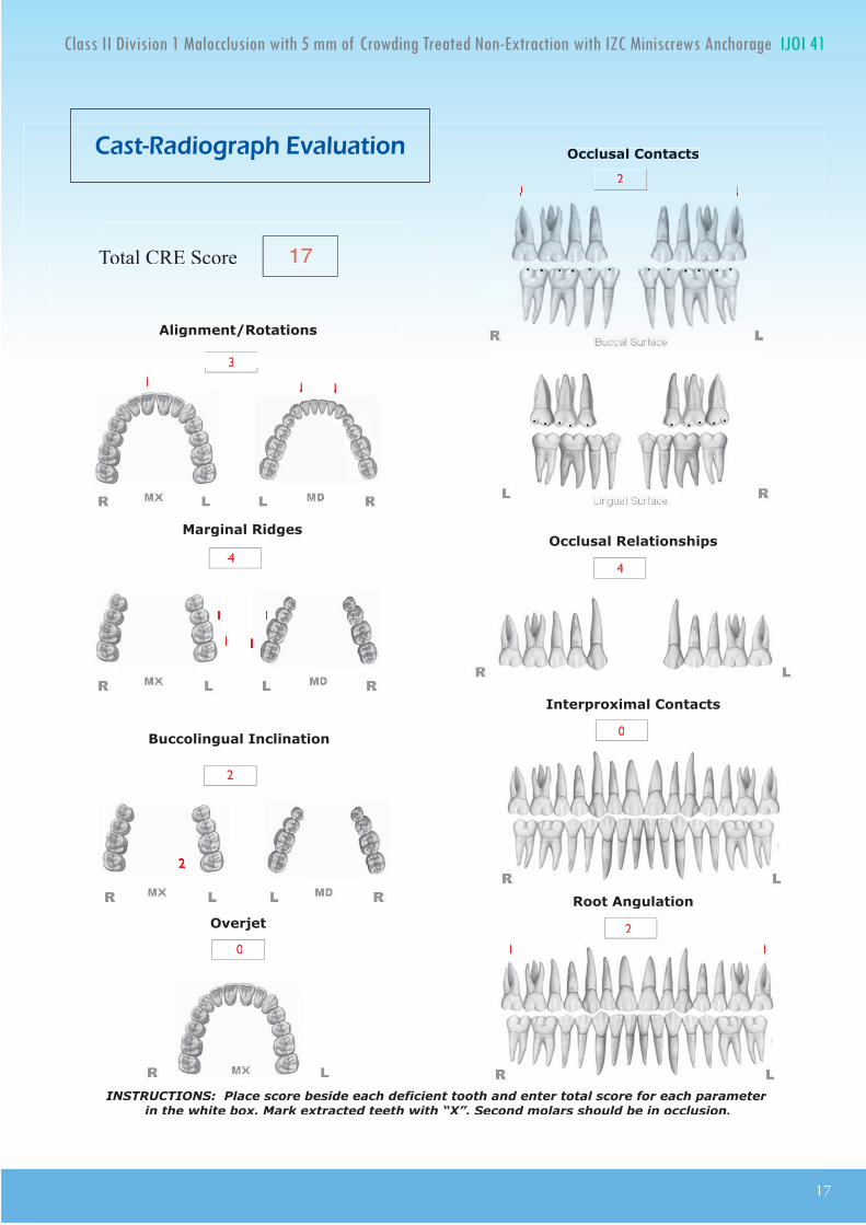
esult Ac ie ed
The American Board of Orthodontics (ABO) Cast-Radiograph Evaluation (CRE) was 17 as scored in the subsequent worksheet. This is an excellent result for a difficult malocclusion (DI 21). Post-treatment documentation is provided with clinical photographs (Figs. 4-6), radiographs (Fig. 8), cephalometric tracings
12
IJOI 41 LI E RO T E A TER II D 1 T E I A IJOI 41
(Fig. 9), and cephalometric measurements (Table 1). Despite the large overjet and deep overbite present initially, a near ideal incisal relationship was achieved (Figs. 5 and 6), and the buccal occlusal relationships were Class I bilaterally.
Maxilla (all three planes):
• A - P: Maintained
• Vertical: Maintained
• Transverse: Maintained
Mandible (all three planes):
• A - P: Maintained
• Vertical: Closed slightly as the mandible rotated
counter-clockwise
• Transverse: Maintained
Maxillary Dentition:
• A - P: Retracted
• Vertical: Intruded incisors
• Transverse: Expanded to resolve posterior crossbites
Mandibular Dentition:
• A - P: Slightly retracted lower arch
• Vertical: Intruded lower incisors
• Transverse: Expanded
Facial Esthetics:
• Both upper and lower lips are retracted to improve facial balance
• Mentalis strain is relieved
• Marked improvement in overall facial esthetics
etention
A Begg (wrap-around type) retainer was delivered for the well aligned maxillary arch, but the lower right central incisor was slightly rotated, so a spring retainer was required to complete lower anterior alignment. The patient was instructed to wear the retainers full time for the first 6 months and nights only thereafter. In addition, instructions were provided for proper home hygiene as well as for maintenance of the retainers.
inal aluation o reatment
Following the final alignment of the lower anterior region with the spring retainer, an excellent alignment was achieved, as evidenced by an ABO CRE score of 17 points. Residual deficiencies were alignment/rotations (3), marginal ridges (4), buccolingual inclination (2), occlusal contacts (2), occlusal relationships (4), and axial inclinations (2). Overall, the patient needs were well addressed, and he was quite satisfied with the treatment outcome.
iscussion
Class II malocclusions with moderate crowding can be well aligned with the passive self-ligating bracket systems, but the outcome is often marred by incisal flaring, lip protrusion and incompetent lips. If these problems are present prior to treatment, extraction of premolars is usually required, but the latter approach entails the risk of excessive incisal retraction and compromised facial esthetics. Posterior maxillary anchorage with IZC bone screws offers an attractive option for Class II patients, with

IJOI 41 LI E RO T E A TER
13
II D 1 T E I A IJOI 41
an excessive ANB angle and flared incisors in both arches. These TADs are well positioned to provide osseous anchorage for differential retraction of the dentition in both arches to simultaneously correct incisal inclinations and buccal interdigitation. In addition, IZC bone screws are effective intra-arch anchorage for lower arch retraction, using Class III elastics with a passive self-ligating appliance.1-3 The differential retraction of both arches with IZC bone screws is efficient mechanics for a variety of skeletal and dental malocclusions, particularly in conjunction with a low friction, passive self ligating appliance. Both arches can be retracted simultaneously as they are leveled and aligned.3
Interproximal enamel reduction (IPR) is effective therapy for a variety of problems, such as: 1. crowding, 2. a Bolton ratio discrepancy, 3. irregular tooth shape, 4. eliminating black triangles in the anterior segments, and 5. leveling of the Curve of Spee.4-8 For the present patient, the anterior Bolton ratio was 75.7%, which indicated 1 mm excess in the width of the upper anteriors.10,11 This problem precluded IPR to correct the black triangles in the lower anterior region, because reduction in the width of the mandibular incisors would probably result in excessive overjet and a deepbite. No IPR was performed because the upper arch was successfully retracted with bone screw anchorage, but if the IZC screws had failed and the patient declined extractions, IPR was a viable alternative. If IPR was performed in anterior segments of both arches, the black triangles would have been reduced in the lower arch, and the Bolton excess would been corrected in the upper arch. In addition to correcting tooth-size discrepancies, interproximal
enamel reduction is emerging as a viable alternative for correcting crowding. When mesial migration of the dentition is controlled, stripping 0.25 mm from all interproximal surfaces of 16 teeth in a full arch, results in 7.5 mm of arch length, which is approximately the width of a premolar. Thus, IPR and molar retraction with extra-alveolar TADs are a viable alternative to premolar extractions, that is consistent with optimal outcomes.
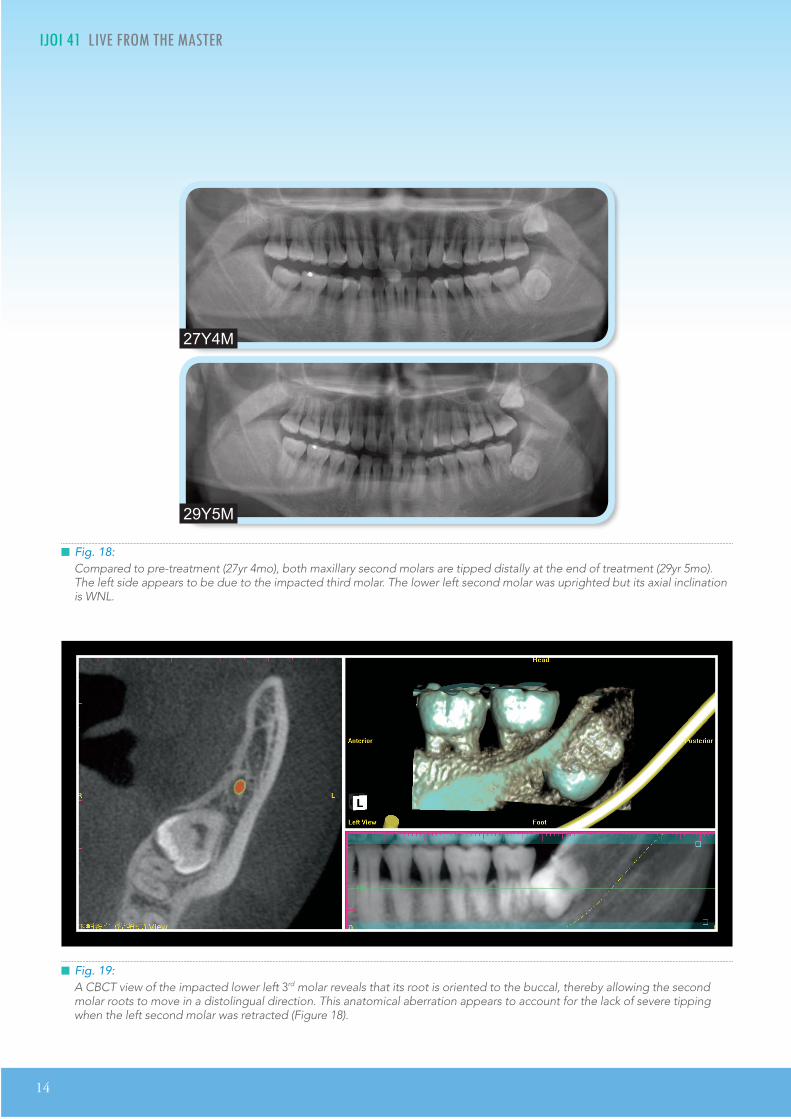
Impacted third molars are a concern when arches are retracted to correct a malocclusion (Fig. 7). It may be preferable to remove impactions prior to the initiation of arch retraction, but some patients and clinicians are resistant to surgical removal of impactions because of the post-operative morbidity, as well as the potential for damaging the adjacent second molars and nerves. Proceeding with arch retraction without removing the impactions risks root resorption and/or tipping of the second molars, as noted in the final panoramic film. Despite the impacted third molar, the axial inclination of the lower left second molar was WNL, but both maxillary second molars were distally inclined, and were scored at 1 point each on the CRE (Fig. 18). This was a surprising result because of the severe mesioapical orientation of the lower left third molar in 2D (Fig.
8) until a CBCT (Fig. 19) showed that the root of the impacted third molar was oriented to the buccal, which permitted the roots of the second molar to slip by in a distolingual direction. However, this favorable result is not predictable unless there is a pre-treatment CBCT. In general, third molar extraction should be performed before starting orthodontic treatment to retract the entire arch.12-
14 Fortunately, the current case had a favorable
14
IJOI 41 LI E RO T E A TER II D 1 T E I A IJOI 41
Fig. 19:A CBCT view of the impacted lower left 3rd molar reveals that its root is oriented to the buccal, thereby allowing the second molar roots to move in a distolingual direction. This anatomical aberration appears to account for the lack of severe tipping when the left second molar was retracted (Figure 18).
Fig. 18:Compared to pre-treatment (27yr 4mo), both maxillary second molars are tipped distally at the end of treatment (29yr 5mo). The left side appears to be due to the impacted third molar. The lower left second molar was uprighted but its axial inclination is WNL.
27Y4M
29Y5M

IJOI 41 LI E RO T E A TER
15
II D 1 T E I A IJOI 41
outcome and the 3rd molars can be extracted after orthodontics treatment (Fig. 19), which is the usual preference for most patients.
Another important consideration is to agree to an alternate treatment plan if one or more of the IZC TADs fail. Before starting treatment, patients should sign a consent form specifying the treatment alternative(s). If an IZC bone screw fails, it may be possible to successfully place another TAD in an adjacent location, but if that is unsuccessful, extraction treatment and/or extensive IPR may be the only reliable options.
onclusion
Extra-Alveolar (E-A) bone screws provide reliable a n c h o r a g e f o r w h o l e a r c h r e t r a c t i o n . T h e infrazygomatic crest (IZC) bone screws are E-A TADs that are located buccal to the maxillary molar roots, so they do not interfere with retraction of the entire arch, to correct excessive overjet and Class II buccal segments. In addition, IZC bone screws are reliable anchorage for Class III elastics to retract the lower dentition to correct incisal flaring, whether it is a manifestation of the original malocclusion or a side effect of the mechanics to level and align the lower arch. In addition to its role in correcting Bolton discrepancies, interproximal enamel reduction is a viable alternative to extraction of permanent teeth, particularly when combined with full arch retraction. E-A bone screws are emerging as effective anchorage for the conservative management of challenging malocclusions that previously required extractions and/or orthognathic surgery. As documented in this report, IZC TADs are effective for the differential retraction of both arches at the same time.
e erences
1. Zhang N, Bai Y, and Li S. Treatment of a Class II Division 1 malocclusion with miniscrew anchorage. Am J Orthod Dentofacial Orthop 2012;141:e85-e93.
2. Lin JJ. A new method of placing orthodontic bone screws in IZC. News & Trends in Orthodontics 2009;13:4-7.
3. Lin JJ. Creative Orthodontics: Blending the Damon system & TADs to manage difficult malocclusions. 2nd ed. 2010; Yong Chieh Enterprise Co, Ltd., Taiwan. p. 187-207.
4. Kurth J, Kokich V. Open gingival embrasures aer orthodontic treatment in adults; Prevalence and etiology. Am J Orthod Dentofacial Orthop 2001;120:116-23.
5. Tarnow, DP, Magmer, AW, Fletcher, P. e eect of the distance from the contact point to the crest of bone on the presence or absence of the interproximal dental papilla. J Periodontol 1992;63:995-96.
6. Frindel C. Clear thinking about interproximal stripping . J Dentofacial Anom Orthod 2010;13:187-99.
7. Zachrisson BU, Minster L, Ogaard B, Birkhed D. Dental health assessed after interproximal enamel reduction: Caries risk in posterior teeth. Am J Orthod Dentofacial Orthop 2011;139:90-8.
8. Germec D, Taner TU. Eects of extraion and nonextraion therapy with air - rotor stripping on facial esthetics in postadolescent borderline patients. Am J Orthod Den- tofacial Orhop 2008;133:539-49.
9. Jung MH. A comparison of second premolar extraction and mini-implant total arch distalization with interproximal stripping. Angle Orthod 2013;83:680-5.
10. Bolton WA. The clinical application of a tooth-size analysis. Am J of Orthod 1962;48:504-29.
11. Barbara WS, Joanna JO, Piotr S. Overall and anterior bolton ratio in Class I, II and III orthodontic patients. Eur J Orthod 2010;32:313-18.
12. Kim TW, Artun J, Behbehani F, Artese F. Prevalence of third molar impaion in orthodontic patients treated nonextraion and with extraion of 4 premolars. Am J Orthod Dentofacial Orthop 2003;123:138-45.
13. Janson G, Putrick LM, Henriques JF, de Freitas MR, Henriques RP. Maxillary third molar position in Class II malocclusions: the eect of treatment with and without maxillary premolar extraions. Eur J Orthod 2006;28:573-79.
14. Southard TE, Southard KA, Weeda LW. Mesial force from unerupted third molars. Am J Orthod Dentofacial Orthop 1991;99:220-25.
15

16
IJOI 41 LI E RO T E A TER II D 1 T E I A IJOI 41IJOI 41 LI E RO T E A TER
OVERJET
0 mm. (edge-to-edge) = 1 pt.1 Ð 3 mm. = 0 pts.3.1 Ð 5 mm. = 2 pts.5.1 Ð 7 mm. = 3 pts.7.1 Ð 9 mm. = 4 pts.> 9 mm. = 5 pts.
Negative OJ (x-bite) 1 pt. per mm. per tooth =
OVERBITE
0 Ð 3 mm. = 0 pts.3.1 Ð 5 mm. = 2 pts.5.1 Ð 7 mm. = 3 pts.Impinging (100%) = 5 pts.
ANTERIOR OPEN BITE
0 mm. (edge-to-edge), 1 pt. per tooth
then 1 pt. per additional full mm. per tooth
LATERAL OPEN BITE
2 pts. per mm. per tooth
CROWDING (only one arch)
1 Ð 3 mm. = 1 pt.3.1 Ð 5 mm. = 2 pts.5.1 Ð 7 mm. = 4 pts.> 7 mm. = 7 pts.
OCCLUSION
Class I to end on = 0 pts.End on Class II or III = 2 pts. per side pts.
Full Class II or III = 4 pts. per side pts.
Beyond Class II or III = 1 pt. per mm. pts.pts. additional
Total =
Total =
Total =
Total =
Total =
Total =
TOTAL D.I.D.I. SCORECORECORECORECORELINGUAL POSTERIOR X-BITE
1 pt. per tooth Total =
BUCCAL POSTERIOR X-BITE
2 pts. per tooth Total =
CEPHALOMETRICS (See Instructions)
ANB ≥ 6¡ or ≤ -2¡ = 4 pts.
SN-MP
≥ 38¡ = 2 pts.
Each degree > 38¡ Each degree > 38¡ x 2 pts. =x 2 pts. =
≤ 26¡ = 1 pt.
Each degree < 26¡ Each degree < 26¡ x 1 pt. =x 1 pt. =
1 to MP ≥ 99¡ = 1 pt.
Each degree > 99¡ Each degree > 99¡ x 1 pt. =x 1 pt. =
OTHER (See Instructions)
Supernumerary teeth x 1 pt. =
Ankylosis of perm. teeth x 2 pts. =
Anomalous morphology x 2 pts. =
Impaction (except 3rd molars)rd molars)rd x 2 pts. =
Midline discrepancy (≥3mm) @ 2 pts. =
Missing teeth (except 3rd molars)rd molars)rd x 1 pts. =
Missing teeth, congenital x 2 pts. =
Spacing (4 or more, per arch) x 2 pts. =
Spacing (Mx cent. diastema ≥ 2mm) @ 2 pts. =
Tooth transposition x 2 pts. =
Skeletal asymmetry (nonsurgical tx) @ 3 pts. =
Addl. treatment complexities Addl. treatment complexities x 2 pts. =x 2 pts. =
Identify:
Each degree > 6¡ Each degree > 6¡ x 1 pt. =x 1 pt. =
Each degree < -2¡ Each degree < -2¡ x 1 pt. =x 1 pt. =
Total =
Total =
2121
4
2
0
4
4
4
0
11
2
11 11
04
i cr panc n or t
IJOI 41 LI E RO T E A TER
17
II D 1 T E I A IJOI 41
17
INSTRUCTIONS: Place score beside each deficient tooth and enter total score for each parameter in the white box. Mark extracted teeth with ÒXÓ. Second molars should be in occlusion.
Alignment/Rotations
Marginal Ridges
Buccolingual Inclination
Overjet
Occlusal Contacts
Occlusal Relationships
Interproximal Contacts
Root Angulation
2
2
2
11
Total CRE Score 1
1
111
1
2
1
1
11 11
1 1
a t a io rap a ation

Join the iAOI, the future of dentistry!
How to join iAOI? Cert i f ied members of the Association are expected to complete the following three stages of requirements.
1. Member
Doctors can go to http://iaoi.pro to apply for membership to join iAOI. Registered members will have the right to purchase a workbook in preparation for the entry exam.
2. Board eligible
Al l reg is tered members c a n t a k e t h e e n t r y e x a m . Members will have an exclusive right to purchase a copy of iAOI workbook containing preparat ion mater ia l s for the certification exam. The examinees are expected to answer 100 randomly selected questions out of the 400 ones from the iAOl workbook. Those
who score 70 points or above can become board eligible.
3. Diplomate
Board eligible members are required to present three written case reports, one of which has to be deliberated verbally. Members successfully passing both written and verbal examination will then be certified as Diplomate of iAOI.
4. Ambassador
Diplomates will have the opportunity to be invited to present s ix ortho- implant combined cases in the iAOI annual meeting. Afterwards, they become Ambassador of iAOl and will be awarded with a special golden plaque as the highest level of recognition in appreciation for their special contribution.
I nternational
A ssociation of
O rthodontists
I mplantolo ists
For more information on benefits and re uirements of i members please isit our official website: http://iaoi.pro.
*International Journal of Orthodontics & Implantology (IJOI) is the official publication of International Association for Orthodontists & Implantologists (iAOI).
re uirements of i members please isit our official website: http://iaoi.pro.

Join the iAOI, the future of dentistry!
How to join iAOI? Cert i f ied members of the Association are expected to complete the following three stages of requirements.
1. Member
Doctors can go to http://iaoi.pro to apply for membership to join iAOI. Registered members will have the right to purchase a workbook in preparation for the entry exam.
2. Board eligible
Al l reg is tered members c a n t a k e t h e e n t r y e x a m . Members will have an exclusive right to purchase a copy of iAOI workbook containing preparat ion mater ia l s for the certification exam. The examinees are expected to answer 100 randomly selected questions out of the 400 ones from the iAOl workbook. Those
who score 70 points or above can become board eligible.
3. Diplomate
Board eligible members are required to present three written case reports, one of which has to be deliberated verbally. Members successfully passing both written and verbal examination will then be certified as Diplomate of iAOI.
4. Ambassador
Diplomates will have the opportunity to be invited to present s ix ortho- implant combined cases in the iAOI annual meeting. Afterwards, they become Ambassador of iAOl and will be awarded with a special golden plaque as the highest level of recognition in appreciation for their special contribution.
I nternational
A ssociation of
O rthodontists
I mplantolo ists
For more information on benefits and re uirements of i members please isit our official website: http://iaoi.pro.
*International Journal of Orthodontics & Implantology (IJOI) is the official publication of International Association for Orthodontists & Implantologists (iAOI).
22
IJOI 41 AOI A E RE ORT T 1 IJOI 41
istor and tiolog
A 15-year-5-month-old postmenarche female presented with a severely crowded, asymmetric Class II malocclusion (Figs. 1-3). Despite her challenging malocclusion (DI 41), a slight facial convexity (13º
facial angle) was within normal limits (WNL). Both the medical and dental history were non-contributory, and there was no evidence of contributing oral habits or temporomandibular dysfunction. The patient was treated to a pleasing result, as shown in Figs. 4-9.
Dr. Hui-Hwa Chen,Lecturer, Beethoven Orthodontic Course (Left)
Dr. Chris Chang, Founder, Beethoven Orthodontic Center
Publisher, International Journal of Orthodontics & Implantology (Middle)
Dr. W. Eugene Roberts,Chief consultant, International Journal of Orthodontics & Implantology (Right)
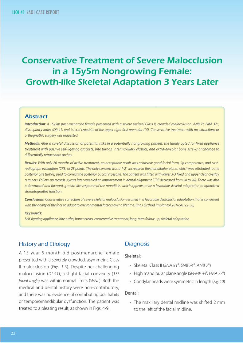
on r ati r atm nt o r a occ ionin a m on ro in ma
ro t i ta aptation ar at r
tract Introduction: A 15y5m post-menarche female presented with a severe skeletal Class II, crowded malocclusion: ANB 7º, FMA 37º, discrepancy index (DI) 41, and buccal crossbite of the upper right rst premolar ( #5). Conservative treatment with no extractions or orthognathic surgery was requested.
Methods: After a careful discussion of potential risks in a potentially nongrowing patient, the family opted for fixed appliance treatment with passive self-ligating brackets, bite turbos, intermaxillary elastics, and extra-alveolar bone screws anchorage to dierentially retract both arches.
Results: With only 20 months of active treatment, an acceptable result was achieved: good facial form, lip competence, and cast-radiograph evaluation (CRE) of 28 points. The only concern was a 1-2° increase in the mandibular plane, which was attributed to the posterior bite turbos, used to correct the posterior buccal crossbite. The patient was tted with lower 3-3 xed and upper clear overlay retainers. Follow-up records 3 years later revealed an improvement in dental alignment (CRE decreased from 28 to 20). There was also a downward and forward, growth-like response of the mandible, which appears to be a favorable skeletal adaptation to optimized stomatognathic function.
Conclusions: Conservative correction of severe skeletal malocclusion resulted in a favorable dentofacial adaptation that is consistent with the ability of the face to adapt to environmental factors over a lifetime. (Int J Orthod Implantol 2016;41:22-38)
Key words:Self-ligating appliance, bite turbo, bone screws, conservative treatment, long-term follow-up, skeletal adaptation
iagnosis
Skeletal:
• Skeletal Class II (SNA 81°, SNB 74°, ANB 7°)
• High mandibular plane angle (SN-MP 44°, FMA 37°)
• Condylar heads were symmetric in length (Fig. 10)
Dental:
• The maxillary dental midline was shifted 2 mm to the left of the facial midline.

IJOI 41 AOI A E RE ORT
23
T 1 IJOI 41
Dr. Hui-Hwa Chen,Lecturer, Beethoven Orthodontic Course (Left)
Dr. Chris Chang, Founder, Beethoven Orthodontic Center
Publisher, International Journal of Orthodontics & Implantology (Middle)
Dr. W. Eugene Roberts,Chief consultant, International Journal of Orthodontics & Implantology (Right)
Fig. 2: Pre-treatment intraoral photographs reveal severe crowding
Fig. 1: Pre-treatment facial photographs
Fig. 3: Pre-treatment study models (casts)
Fig. 4: Post-treatment facial photographs
Fig. 5: Post-treatment intraoral photographs
Fig. 6: Post-treatment study models (casts) reveal modest expansion in both arches.
24
IJOI 41 AOI A E RE ORT T 1 IJOI 41
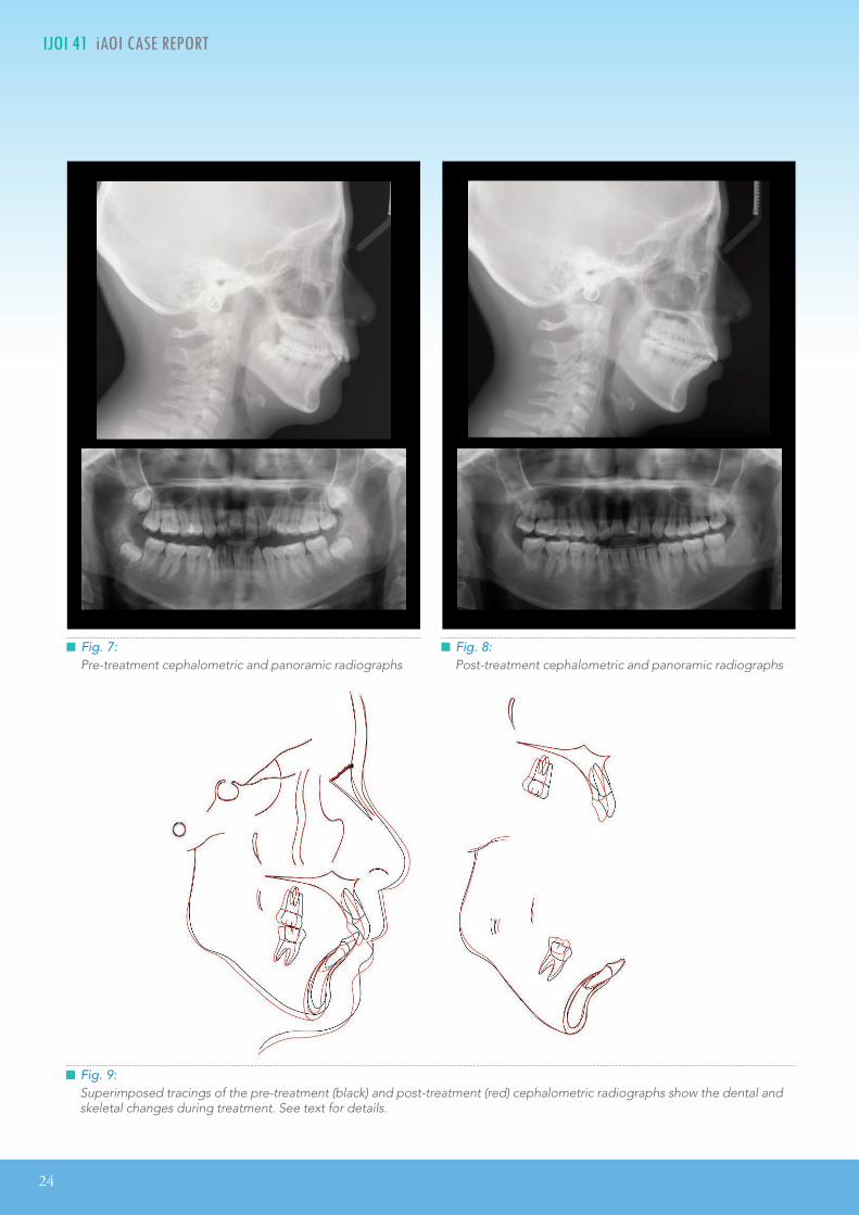
Fig. 9:Superimposed tracings of the pre-treatment (black) and post-treatment (red) cephalometric radiographs show the dental and skeletal changes during treatment. See text for details.
Fig. 7:Pre-treatment cephalometric and panoramic radiographs
Fig. 8:Post-treatment cephalometric and panoramic radiographs

IJOI 41 AOI A E RE ORT
25
T 1 IJOI 41
• Vertical: Maintain
• Transverse: Maintain
Mandible (all three planes):
• A - P: Maintain
• Vertical: Minimize opening with the bite turbos to
correct the #5 buccal crossbite
• Transverse: Maintain
Maxillary Dentition:
• A - P: Retract incisors and tip-back molars
• Vertical: Maintain
• Inter-molar / Inter-canine Width: Alignment over
the apical base of bone
Mandibular Dentition:
• A - P: Maintain
• Vertical: Maintain
• Inter-molar / Inter-canine Width: Alignment over
the apical base of bone
Facial Esthetics:
• Maintain
reatment lan
For informed consent, two treatment plans were offered.
Option A: Correct crowding by extracting bilateral upper first premolars and lower second premolars (Fig. 11).
Option B: Because of the severe crowding, non-extraction treatment would probably require an OrthoBoneScrew® (OBS) (2x12mm, Newton’s A Ltd,
Hsinchu, Taiwan)1 on the buccal surface of each first molar to retract both arches. This method is deemed extra-alveolar (E-A) OBS anchorage. Extraction of all
Fig. 10: The morphology for the condyle heads of the mandible were symmetrical.
• Bilateral Class II molar and canine relationships
• 5 mm space deficiency for the upper arch and 8 mm deficiency for the lower arch
• Maxillary right first premolar (#5) in buccal crossbite
Facial:
• Slightly convex profile (13° facial angle) was WNL
• Facial symmetry
• Acceptable incisal exposure when smiling
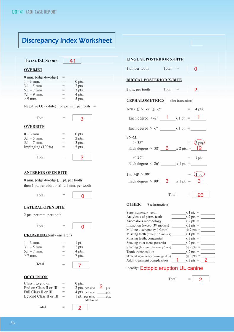
The American Board of Orthodontics (ABO) Discrepancy Index (DI) was 41 as shown in the subsequent worksheet.
eci ic Ob ecti es o reatment
Treatment objectives were: 1. correct the maxillary and mandibular crowding, 2. retract the dentition in both arches, 3 . achieve ideal overjet and overbite, 4. resolve intermaxillary sagittal and frontal discrepancies, and 5. achieve an excellent dentofacial finish with an ABO cast radiograph score (CRE) of no more than 30 points.
Maxilla (all three planes):
• A - P: Maintain

26
IJOI 41 AOI A E RE ORT T 1 IJOI 41
Fig. 11: Option A: Extraction of upper 1st and lower 2nd premolars
(#5, 12, 20, 29)
third molars is indicated if the arches are retracted (Fig. 12).
The patient and her family were informed about the pros and cons of each approach, and Option B was selected.
A liances and reatment rogress
An .022” slot Damon Q® bracket system (Ormco,
Glendale, CA) was selected. Low torque brackets were bonded on the maxillary and mandibular anterior teeth to resist the tendency toward bimaxi l lary protrusion as the crowding was corrected. The intraoral treatment sequence is
Fig. 12:Option B: Correct crowding by retracting all four buccal
segments with OrthoBoneScrew® anchorage.
A O I
A A A I
PRE-Tx POST-Tx DIFF.
SNA° 81° 80° 1°SNB° 74° 73° 1°ANB° 7° 7° 0°SN-MP° 44° 46° 2°FMA° 37° 39° 2°
A A A I
U1 TO NA mm 5 mm 2 mm 3 mmU1 TO SN° 102° 97° 5°
L1 TO NB mm 10 mm 10 mm 0 mmL1 TO MP° 101° 102° 1°A IA A A I
E-LINE UL -1 mm 1 mm 2 mmE-LINE LL -1.5 mm 0 mm 1.5 mm
Table 1: Cephalometric summary
illustrated in Figs. 13 and 14. Both arches were bonded and aligned with the following archwire sequence: .014” CuNiTi, .014x.025” CuNiTi, and .017x.025” TMA. To correct the buccal crossbite of the maxillary right 1st premolar (#5), a button was bonded on the lingual surface of the mandibular right 1st premolar (#28), for a cross elastic to be used between #5 and #28. Bite turbos, were constructed with Fuji II® type II glass ionomer cement (GC
America, Alsip, IL) on the occlusal surfaces of both mandibular 1st molars (#19 & 30) to open the bite for the correction of #5 buccal crossbite (Fig. 13). Bite turbos facilitated the crossbite correction but at the risk of increasing the overjet as the mandible rotated posteriorly. During the course of the treatment, Class II elastics were upgraded from 2 to 4.5oz to resolve the enhanced overjet which

IJOI 41 AOI A E RE ORT
27
T 1 IJOI 41
was probably a factor in increasing the mandibular plane angle, as noted in Fig. 9.
In the 5th month of treatment, the crowding was relieved and the crossbite was corrected, but there was a bimaxillary protrusion, loss of lip competence and anterior open bite (Fig. 14). Supplemental anchorage was clearly necessary, so four 2x12mm OBSs were installed bilaterally in the maxillary infrazygomatic crests and mandibular buccal shelves. Elastic chains were stretched between the miniscrews and the respective canines bilaterally. The four OBSs served as anchorage to retract and control the protrusion of both arches.
In the 9th month, the en masse retraction of the
upper dentition resulted in the infrazygomatic crest OBSs contacting the hooks on the upper molar brackets. The latter were removed with a high speed diamond bur to continue retraction of the dentition (Fig. 15).
In the 12th month, .017x.025” TMA archwires were placed and a figure-8 ligature was tied between upper 3-3 to maintain firm contact, and the bite turbos were removed. At 15 months the lower second molars were retracted into the retromolar soft tissue (Fig. 16).
In the 17th month, a 1 mm maxillary midline shift to the right side was noted. Elastics (Bear 1/4” 4.5
oz) were applied from the upper right canine (#6)
Fig. 13: Cross Bite Correction: a button was bonded on the lingual surface of #28, and a cross elastic was used from the buccal bracket on #5 to the lingual of #28. Bite turbos: were placed on the occlusal surfaces of both lower first molars to open the bite and avoid the occlusal interference blocking the correction of #5 buccal crossbite.
1M

28
IJOI 41 AOI A E RE ORT T 1 IJOI 41
to the lower left canine (#22), and from the upper left canine (#11) to the lower left 1st molar (#19) to detail the occlusion (Fig. 17). Because of inadequate retromolar space, all four 3rd molars were extracted in the 19th month of treatment.
Bracket repositioning was performed repeatedly as indicated by the sequential panoramic films. Wire bending was performed for detailing the occlusion during the final stages of the treatment. One month before the completion of the active treatment, the upper archwire was sectioned distally to the cuspids, and vertical (up and down) elastics were used for 2
Fig. 14:In reference to the initial malocclusion (0M), the #5 crossbite was corrected after 5 months of treatment (5M). However, bimaxillary protrusion and an anterior open bite were noted.
Fig. 15:In the 9th month, the en masse retraction of the upper dentition caused the infrazygomatic OrthoBoneScrews to hit the upper molar bracket hooks. The hooks were removed with a high speed diamond bur to facilitate further retraction.
Fig. 16:The space between the terminal molar and the external oblique ridge of the ascending ramus of the mandible limits the distance that the entire arch can be retracted.
0M 5M 5M
9M 9M
15M

IJOI 41 AOI A E RE ORT
29
T 1 IJOI 41
weeks to improve the articulation of the posterior teeth (Fig. 18).2 After 20 months of active treatment, the appliances were removed.
esults Ac ie ed
Maxilla (all three planes):
• A - P: A point retracted
• Vertical: Maintained
• Transverse: Maintained
Mandible (all three planes):
• A - P: Retracted
• Vertical: Increased mandibular plane angle due to posterior rotation
• Transverse: Maintained
Fig. 17:At 18 months (18M) elastics (Bear ¼” 4.5oz) were applied from the upper right canine ( #6) to lower left canine ( #22), and from upper left canine ( #11) to lower left 1st molar ( #19). By 20 months (20M) the midline was corrected.
Fig. 18:One month before the completion of active treatment, the upper archwire was sectioned distal to the cuspids, and up and down elastics (2oz) were used for 2 to 3 weeks to improve the articulation of the posterior teeth.2
Maxillary Dentition
• A - P: Anterior incisors were retracted and molars were
tipped distally
• Vertical: Incisors extruded
• Inter-molar / Inter-canine Width: Slight expansion
Mandibular Dentition
• A - P: Molars retracted (tipped distally)
• Vertical: Molars extruded
• Inter-molar / Inter-canine Width: Slight expansion
Facial Esthetics: More convex with increased lower facial height, lip protrusion WNL
etention
Fixed lingual retainers were bonded on all maxillary incisors, and from canine to canine in the mandibular arch. An upper clear overlay was delivered. The patient was instructed to wear it full time for the first 6 months and nights only thereafter. Instructions were provided for home hygiene as well as for maintenance of the retainers.
18M
20M

30
IJOI 41 AOI A E RE ORT T 1 IJOI 41
midlines were corrected. Although the facial profile was slightly more convex (Fig. 20), the lip protrusion was reduced, and the patient was satisfied with the result.
iscussion
Malocclusions with severe crowding usually require premolar extraction, but the current patient was opposed to any extractions except third molars. Nonextraction treatment presents a number of physiologic and esthetic challenges. To avoid incisal flaring and an unesthetic bimaxillary protrusion, there are three important biomechanics issues:
1. Bracket selection
Torque: Low torque anterior brackets were used in both arches to control incisal flaring during alignment, because that is more efficent than placing torque in the archwires.
inal aluation o t e reatment
Cephalometric analysis (Table 1), superimpositions (Fig. 9), and a cephalometric sequence (Fig. 19) show that the upper incisors and molars in both arches were retracted. The mandible was rotated posteriorly, resulting a 1-2° increase in the mandibular plane angle, and there was a 1° reduction in the SNA and SNB angles. The upper incisor to SN angle was decreased from 102° to 97°. The angle of the lower incisor to the mandibular plane was increased from 101° to 102°. Although lower facial height increased, photographs (Fig. 4) and cephalometric films (Fig. 8) after treatment are consistent with maintaining lip competence, which is an important objective for nonextraction alignment of crowding (Fig. 19).
The ABO Cast-Radiograph Evaluation (CRE) score was 28 points. The major discrepancies were marginal ridges (8 points), occlusal relationships (6 points), overjet (5 points), and alignment/rotations (5 points). Overall, the dentition was well aligned and the
Fig. 19:At the start of treatment (0) the axial inclinations are marked with blue lines. At five months (5) it was clear that bimaxillary protrusion was occurring so bilateral E-A miniscrews were placed lateral to the first molars in both arches. By sixteen months (16) the bimaxillary protrusion was reduced, and at twenty months (20) the final result was achieved. Note the near ideal facial profile and lip protrusion at end of active treatment.

IJOI 41 AOI A E RE ORT
31
T 1 IJOI 41
Fig. 20: The facial profile is shown at 0, 5, 15, and 20 months.
Position: The bonding protocols for nonextraction t r e a t m e n t w e r e d e v e l o p e d b a s e d o n t h e recommendations of Pitts,3 as modified by Chang and Roberts4 to compensate for tipping when retracting buccal segments. For example, the posttreatment panoramic radiograph (Fig . 8) , reveals distal tipping of the the lower right first molar (#30). This problem was due to inadequate counterclockwise rotation of the bracket, when #30 was bonded.
2. Bite turbos and vertical control
Bite turbos constructed with Fuj i I I® type I I glass ionomer cement on posterior occlusal or anterior palatal surfaces are useful for opening the interocclusal space to correct crossbites and to facilitate leveling.5 Posterior bite turbos prevent extrusion of buccal segments, but the bite opening rotates the mandible posteriorly (Fig. 9), creating more overjet and potential extrusion of the incisors. Correcting the large overjet, requires
extended use of Class II elastics, which extrudes and retracts the maxillary incisors, extrudes lower molars, and increases the axial inclination of the mandibular incisors. In retrospect, posterior rotation of the mandible may have been prevented by controlling the extrusion of the maxillary incisors by the simultaneous use of anterior and posterior bite turbos during the crossbite correction. A biomechanics option for simultaneously controlling retraction and intrusion of incisors is an overlay 3-piece base arch.6 If the extrusion of the maxillary incisors is prevented, the lower buccal segments can be intruded with the E-A OBS anchorage, thereby preventing or at least recovering the increase in the mandibular plane angle (Fig. 9).
3. Extra-Alveolar OrthoBoneScrew (E-A OBS) Anchorage
Temporary anchorage devices (TADs),7 peripheral to the alveolar arch, provide stable anchorage8 for increasing arch length to correct crowding.9
0M 5M 15M 20M
32
IJOI 41 AOI A E RE ORT T 1 IJOI 41
Furthermore, they can serve as skeletal anchorage for en masse retraction of entire arches.10-12 The limitation for retraction of the buccal segments is the amount of retromolar space. In the lower arch, this is the space between the terminal molar and the external oblique ridge of the ascending ramus. In the maxilla, the tuberosity limits the distance that the entire arch can be retracted (Fig. 19).
Cephalometric analysis (Table 1) indicated a slight increase in protrusion at the end of treatment. This was a pleasing result (Fig. 20) considering there was a
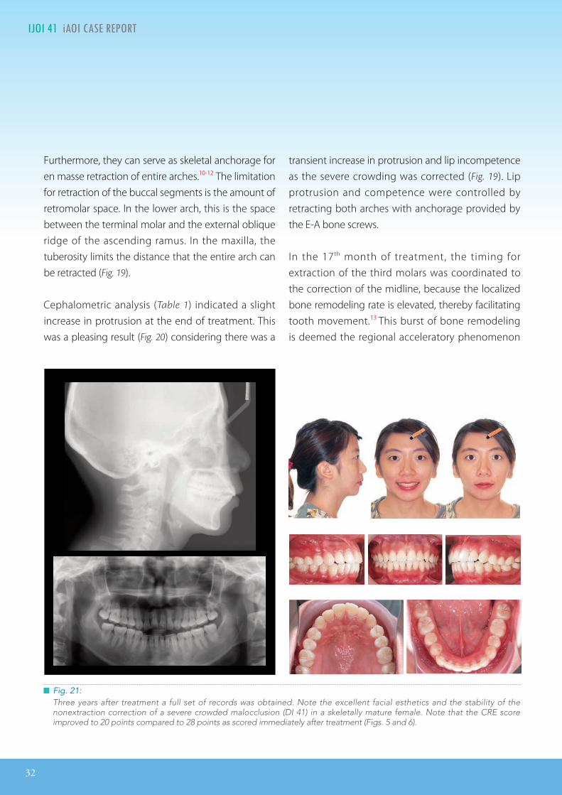
Fig. 21:Three years after treatment a full set of records was obtained. Note the excellent facial esthetics and the stability of the nonextraction correction of a severe crowded malocclusion (DI 41) in a skeletally mature female. Note that the CRE score improved to 20 points compared to 28 points as scored immediately after treatment (Figs. 5 and 6).
transient increase in protrusion and lip incompetence as the severe crowding was corrected (Fig. 19). Lip protrusion and competence were controlled by retracting both arches with anchorage provided by the E-A bone screws.
In the 17th month of treatment, the timing for extraction of the third molars was coordinated to the correction of the midline, because the localized bone remodeling rate is elevated, thereby facilitating tooth movement.13 This burst of bone remodeling is deemed the regional acceleratory phenomenon

IJOI 41 AOI A E RE ORT
33
T 1 IJOI 41
(RAP). To take advantage of the RAP, midline correction elastics were applied immediately after the extractions according to the following pattern: Elastics (Bear 1/4” 4.5oz) from the upper right canine (#6) to lower left canine (#22), and from the upper left canine (#11) to the lower left 1st molar (Fig. 17).
In the 18th month of the treatment, distal tipping of the upper left second molar was noted. That problem was corrected by repositioning the bracket, so that a straight archwire produces a root distal moment on the second molar. It is important to correct angulation problems as early in treatment as possible, because they may affect sagittal relationships of the dentition.
Fig. 22:Superimposed tracings of the post-treatment (red) and the 3-year follow up (green) cephalometric radiographs show the dental and skeletal changes during treatment.
Based on the cephalometric studies of Schudy,14 there was concern that distal movement of both arches may open the bite by retracting molars “into
the wedge.” Intrusive forces were applied in all four quadrants to control this potential problem.
A pleasing al ignment was achieved after 20 months of treatment (CRE 28). Three years later the dentofacial result was stable and both the lip balance and protrusion were improved (Figs. 21-23). The CRE score decreased to 20 points (Fig. 21) as the occlusion settled post-treatment.
An unanticipated, growth-like post-treatment change was the 2-3 mm increase in mandibular
34
IJOI 41 AOI A E RE ORT T 1 IJOI 41
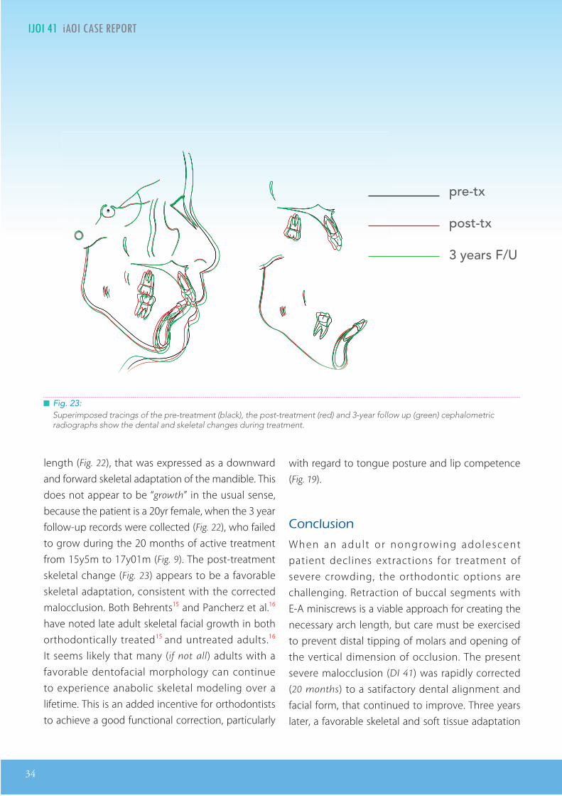
Fig. 23:Superimposed tracings of the pre-treatment (black), the post-treatment (red) and 3-year follow up (green) cephalometric radiographs show the dental and skeletal changes during treatment.
length (Fig. 22), that was expressed as a downward and forward skeletal adaptation of the mandible. This does not appear to be “growth” in the usual sense, because the patient is a 20yr female, when the 3 year follow-up records were collected (Fig. 22), who failed to grow during the 20 months of active treatment from 15y5m to 17y01m (Fig. 9). The post-treatment skeletal change (Fig. 23) appears to be a favorable skeletal adaptation, consistent with the corrected malocclusion. Both Behrents15 and Pancherz et al.16 have noted late adult skeletal facial growth in both orthodontically treated15 and untreated adults.16
It seems likely that many (if not all) adults with a favorable dentofacial morphology can continue to experience anabolic skeletal modeling over a lifetime. This is an added incentive for orthodontists to achieve a good functional correction, particularly
with regard to tongue posture and lip competence (Fig. 19).
onclusion
When an adul t o r nongrowing adolescent patient declines extractions for treatment of severe crowding, the orthodontic options are challenging. Retraction of buccal segments with E-A miniscrews is a viable approach for creating the necessary arch length, but care must be exercised to prevent distal tipping of molars and opening of the vertical dimension of occlusion. The present severe malocclusion (DI 41) was rapidly corrected (20 months) to a satifactory dental alignment and facial form, that continued to improve. Three years later, a favorable skeletal and soft tissue adaptation
pre-tx
post-tx
3 years F/U
IJOI 41 AOI A E RE ORT
35
T 1 IJOI 41
substanially improved facial esthetics. The results are consistent with a lifelong ability of humans to adapt to functional biomechanics.
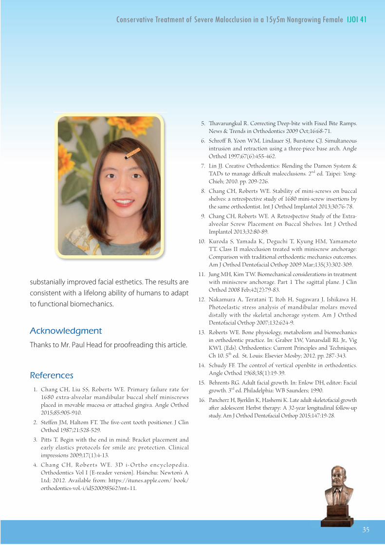
Ac nowledgment
Thanks to Mr. Paul Head for proofreading this article.
e erences
1. Chang CH, Liu SS, Roberts WE. Primary failure rate for 1680 extra-alveolar mandibular buccal shelf miniscrews placed in movable mucosa or aached gingiva. Angle Orthod 2015;85:905-910.
2. Steen JM, Haltom FT. e ve-cent tooth positioner. J Clin Orthod 1987;21:528-529.
3. Pitts T. Begin with the end in mind: Bracket placement and early elastics protocols for smile arc protection. Clinical impressions 2009;17(1):4-13.
4. Chang CH, R oberts WE. 3D i- Ortho encycloped ia . Orthodontics Vol I [E-reader version]. Hsinchu: Newton’s A Ltd; 2012. Available from: https://itunes.apple.com/ book/orthodontics-vol.-i/id520098562?mt=11.
5. avarungkul R. Correcting Deep-bite with Fixed Bite Ramps. News & Trends in Orthodontics 2009 Oct;16:68-71.
6. Schro B, Yoon WM, Lindauer SJ, Burstone CJ. Simultaneous intrusion and retraction using a three-piece base arch. Angle Orthod 1997;67(6):455-462.
7. Lin JJ. Creative Orthodontics: Blending the Damon System & TADs to manage dicult malocclusions. 2nd ed. Taipei: Yong-Chieh; 2010. pp. 209-226.
8. Chang CH, Roberts WE. Stability of mini-screws on buccal shelves: a retroective study of 1680 mini-screw insertions by the same orthodontist. Int J Orthod Implantol 2013;30:76-78.
9. Chang CH, Roberts WE. A Retroective Study of the Extra-alveolar Screw Placement on Buccal Shelves. Int J Orthod Implantol 2013;32:80-89.
10. Kuroda S, Yamada K, Deguchi T, Kyung HM, Yamamoto TT. Class II malocclusion treated with miniscrew anchorage: Comparison with traditional orthodontic mechanics outcomes. Am J Orthod Dentofacial Orthop 2009 Mar;135(3):302-309.
11. Jung MH, Kim TW. Biomechanical considerations in treatment with miniscrew anchorage. Part 1 The sagittal plane. J Clin Orthod 2008 Feb;42(2):79-83.
12. Nakamura A, Teratani T, Itoh H, Sugawara J, Ishikawa H. Photoelastic stress analysis of mandibular molars moved distally with the skeletal anchorage system. Am J Orthod Dentofacial Orthop 2007;132:624-9.
13. Roberts WE. Bone physiology, metabolism and biomechanics in orthodontic praice. In: Graber LW, Vanarsdall RL Jr., Vig KWL (Eds). Orthodontics: Current Principles and Techniques, Ch 10. 5th ed. St. Louis: Elsevier Mosby; 2012. pp. 287-343.
14. Schudy FF. The control of vertical openbite in orthodontics. Angle Orthod 1968;38(1):19-39.
15. Behrents RG. Adult facial growth. In: Enlow DH, editor: Facial growth. 3rd ed. Philadelphia: WB Saunders; 1990.
16. Pancherz H, Bjerklin K, Hashemi K. Late adult skeletofacial growth aer adolescent Herbst therapy: A 32-year longitudinal follow-up study. Am J Orthod Dentofacial Orthop 2015;147:19-28.
35
36
IJOI 41 AOI A E RE ORT T 1 IJOI 41
OVERJET
0 mm. (edge-to-edge) = 1 pt.1 Ð 3 mm. = 0 pts.3.1 Ð 5 mm. = 2 pts.5.1 Ð 7 mm. = 3 pts.7.1 Ð 9 mm. = 4 pts.> 9 mm. = 5 pts.> 9 mm. = 5 pts.
Negative OJ (x-bite) 1 pt. per mm. per tooth =
OVERBITE
0 Ð 3 mm. = 0 pts.3.1 Ð 5 mm. = 2 pts.5.1 Ð 7 mm. = 3 pts.Impinging (100%) = 5 pts.
ANTERIOR OPEN BITE
0 mm. (edge-to-edge), 1 pt. per tooth
then 1 pt. per additional full mm. per tooth
LATERAL OPEN BITE
2 pts. per mm. per tooth
CROWDING (only one arch)
1 Ð 3 mm. = 1 pt.3.1 Ð 5 mm. = 2 pts.5.1 Ð 7 mm. = 4 pts.> 7 mm. = 7 pts.
OCCLUSION
Class I to end on = 0 pts.End on Class II or III = 2 pts. per side pts.
Full Class II or III = 4 pts. per side pts.
Beyond Class II or III = 1 pt. per mm. pts.pts. additional
Total =
Total =
Total =
Total =
Total =
Total =
TOTAL D.I.D.I. SCORECORELINGUAL POSTERIOR X-BITE
1 pt. per tooth Total =
BUCCAL POSTERIOR X-BITE
2 pts. per tooth Total =
CEPHALOMETRICSCEPHALOMETRICS (See Instructions)(See Instructions)
ANB ≥ 6¡ or ≤ -2¡ = 4 pts.
SN-MP
≥ 38¡ = 2 pts.
Each degree > 38¡ Each degree > 38¡ x 2 pts. =x 2 pts. =
≤ 26¡ = 1 pt.
Each degree < 26¡ Each degree < 26¡ x 1 pt. =x 1 pt. =
1 to MP ≥ 99¡ = 1 pt.
Each degree > 99¡ x 1 pt. =
OTHER (See Instructions)
Supernumerary teeth x 1 pt. =
Ankylosis of perm. teeth x 2 pts. =
Anomalous morphology x 2 pts. =
Impaction (except 3rd molars)rd molars)rd x 2 pts. =
Midline discrepancy (≥3mm) @ 2 pts. =
Missing teeth (except 3rd molars)rd molars)rd x 1 pts. =
Missing teeth, congenital x 2 pts. =
Spacing (4 or more, per arch) x 2 pts. =
Spacing (Mx cent. diastema ≥ 2mm) @ 2 pts. =
Tooth transposition x 2 pts. =
Skeletal asymmetry (nonsurgical tx) @ 3 pts. =
Addl. treatment complexities x 2 pts. =
Identify:
Each degree > 6¡ Each degree > 6¡ x 1 pt. =x 1 pt. =
Each degree < -2¡ Each degree < -2¡ x 1 pt. =x 1 pt. =
Total =
Total =
4141
33
2
00
00
77
22
2
2323
222
6
33
1212
33
0
11 11
1 1 22 2 Ectopic eruption UL canine
i cr panc n or t

IJOI 41 AOI A E RE ORT
37
T 1 IJOI 41
INSTRUCTIONS: Place score beside each deficient tooth and enter total score for each parameter in the white box. Mark extracted teeth with ÒXÓ. Second molars should be in occlusion.
Alignment/Rotations
Marginal Ridges
Buccolingual Inclination
Overjet
Occlusal Contacts
Occlusal Relationships
Interproximal Contacts
Root Angulation
1
1
211
1
1
1
11
11
1
Total CRE Score 28
11
1
1
22
1 1
11
1
1
2
1
111
1
22 22
a t a io rap a ation

38
IJOI 41 AOI A E RE ORT
12 3
4
5 4
1 2
3
6
5
1
2
34 6
12 34
56
12 3
4
5 4
1 2
3
6
5
1
2
34 6
12 34
56
12 3
4
5 4
1 2
3
6
5
1
2
34 6
12 34
56
1. Pink Esthetic Score
in it t tic cor or r ica ro n n t nin
Total Score: = 6
2. White Esthetic Score ( for Micro-esthetics )
12 3
4
5 4
1 2
3
6
5
1
2
34 6
12 34
56
1. M & D Papilla 0 1 2
2. Keratinized Gingiva 0 1 2
3. Curvature of Gingival Margin 0 1 2
4. Level of Gingival Margin 0 1 2
5. Root Convexity ( Torque ) 0 1 2
6. Scar Formation 0 1 2
1. Midline 0 1 2
2. Incisor Curve 0 1 2
3. Axial Inclination (5 , 8 , 10 ) 0 1 2
4. Contact Area (50%, 40%, 30%) 0 1 2
5. Tooth Proportion (1:0.8) 0 1 2
6. Tooth to Tooth Proportion 0 1 2
Total = 2
Total = 4
時間:7/17~18, 2016( 日,一-演講與實作 workshop) 8/28, 2016( 日-視訊教學 )9/25~26, 2016( 日,一-演講與實作 workshop) 10/ 16 , 2016 ( 日-視訊教學 )11/20~21, 2016( 日,一-演講與實作 workshop) 12/11, 2016( 日-視訊教學 )2/6, 2017( 一-美國演講 ) 2/7, 2017( 二-美國演講 )2/8, 2017( 三 -美國可選修的 cadaver workshop) 2/9, 2017( 四 -美國可選修的 cadaver workshop)2/10~11, 2017( 五,六-美國演講,畢業典禮 ) 2/12, 2017( 日-美國可選修的 cadaver workshop)
地點:金牛頓藝術科技中心:新竹市建中一路 25號 2樓(2016年 7月到 12月 )Millennium Biltmore Hotel Los Angeles. 506 South Grand Avenue. Los Angeles, CA 90071-2607(2017年2月)
南加大植牙專科進修課程2016
USC 金牛頓藝術科技聯絡人: Julie
E-mail: [email protected]電話: +1-213-821-5281
聯絡人:朱央如E-mail: [email protected]
電話: (03)573-5676
講員陣容
Baldwin Marchack
HomaZadeh
FereidounDaftary
Bach Le
LyndonCooper
Kian Kar
Ilan Rotstein
Pascal Magne
AlirezaMoshaverinia
Mauricio Araujo
Yang Chai
Casey Chen

International Workshop
Damon
,
S & VISTA
T T SDr. Chris Chang
CEO, Beethoven Orthodontic and Implant Group. He received his PhD in bone physiology and Certificate in Orthodontics from Indiana University in 1996. As publisher of International Journal of Orthodontics & Implantology, he has been actively involved in the design and application of orthodontic bone screws.
Dr. John Lin
President of the Jin-Jong Lin Orthodontic Clinic. Dr. Lin received his MS. from Marquette University and is an internationally renowned lecturer. He’s also the author of Creative Orthodontics and consultant to International Journal of Orthodontics & Implantology.
Day 123
work-shophands-on
lecture
OBS Damonsurgeries
Class IIImini screws chair-side observation
Since , eethoven International Damon, S & VISTA orkshop has received over participants from more than countries. This three-day advanced hands-on course combines practical lectures and in-office clinical learning and has attracted orthodontic practitioners worldwide to strengthen their skills and knowledge in the Damon System, TADs and minimally invasive surgeries. In addition to clinical development, participants will be exposed to clinic management and staff training of a world-class orthodontic centre. The optional Keynote workshop will help improve your ability to master professional digital communication. Come join us and be part of a community of excellence.
Day 4 SD
VISTA
SD , Early bird rate off by ,
Early bird rate off by ,
tt o o eet o en t o e ne ton o te
For more information and registration, visit
Vertical Incision Subperiosteal Tunnel Access
T ne on
e on
KeynoteVISTADay 1
Course ScheduleChair-side observation
“The workshop, all and all was an wholesome experience and I would definitely recommend this course to my friends.”
“Truly inspirational”
“The best workshop in the world”
“Amazing experience”
“More than I expected”
“The best & smartest choice ever”
“Dr. Angle would be glad to know that contemporary orthodontics has a professional as Chris Chang!”
“Dr. Chris shared his knowledges in details and made the difficult cases look simple.”
Day 2Lecture,Model workshop, Chair-side observation
Day 3VISTA Lecture,Lecture by Dr. John Lin, VISTA workshop
Day 4 Keynote workshop
Dr. Sunish T DanielDubai
Prof. Dr. Paulo Fernandes RettoPortugal
Dr. Amr ElDalyAustralia
Dr. Alejandro RamírezSpain
Dr. Joanna LimSingapore
Dr. Chen YehongMalaysia
Dr. David NissanMexico
Dr. Lee Hye Jin SerenaArgentina
“If you think this is a computer course that will show you step-by-step how to use the application, please reconsider. If you want to improve communication in your practice, and with patients, this 8-hour course is definitely worth it."
Dr. Rungsi Thavarungkul, ThailandLecturer, Advanced Keynote Workshop
This 4-hour hands-on surgical workshop features minimally invasive procedures for impac-tions and soft tissue enhance-ment.
Topics include:
1. VISTA for Screw Placement 2. VISTA for Connective Tissue Graft 3. Suture Techniques
International Workshop

International Workshop
Damon
,
S & VISTA
T T SDr. Chris Chang
CEO, Beethoven Orthodontic and Implant Group. He received his PhD in bone physiology and Certificate in Orthodontics from Indiana University in 1996. As publisher of International Journal of Orthodontics & Implantology, he has been actively involved in the design and application of orthodontic bone screws.
Dr. John Lin
President of the Jin-Jong Lin Orthodontic Clinic. Dr. Lin received his MS. from Marquette University and is an internationally renowned lecturer. He’s also the author of Creative Orthodontics and consultant to International Journal of Orthodontics & Implantology.
Day 123
work-shophands-on
lecture
OBS Damonsurgeries
Class IIImini screws chair-side observation
Since , eethoven International Damon, S & VISTA orkshop has received over participants from more than countries. This three-day advanced hands-on course combines practical lectures and in-office clinical learning and has attracted orthodontic practitioners worldwide to strengthen their skills and knowledge in the Damon System, TADs and minimally invasive surgeries. In addition to clinical development, participants will be exposed to clinic management and staff training of a world-class orthodontic centre. The optional Keynote workshop will help improve your ability to master professional digital communication. Come join us and be part of a community of excellence.
Day 4 SD
VISTA
SD , Early bird rate off by ,
Early bird rate off by ,
tt o o eet o en t o e ne ton o te
For more information and registration, visit
Vertical Incision Subperiosteal Tunnel Access
T ne on
e on
KeynoteVISTADay 1
Course ScheduleChair-side observation
“The workshop, all and all was an wholesome experience and I would definitely recommend this course to my friends.”
“Truly inspirational”
“The best workshop in the world”
“Amazing experience”
“More than I expected”
“The best & smartest choice ever”
“Dr. Angle would be glad to know that contemporary orthodontics has a professional as Chris Chang!”
“Dr. Chris shared his knowledges in details and made the difficult cases look simple.”
Day 2Lecture,Model workshop, Chair-side observation
Day 3VISTA Lecture,Lecture by Dr. John Lin, VISTA workshop
Day 4 Keynote workshop
Dr. Sunish T DanielDubai
Prof. Dr. Paulo Fernandes RettoPortugal
Dr. Amr ElDalyAustralia
Dr. Alejandro RamírezSpain
Dr. Joanna LimSingapore
Dr. Chen YehongMalaysia
Dr. David NissanMexico
Dr. Lee Hye Jin SerenaArgentina
“If you think this is a computer course that will show you step-by-step how to use the application, please reconsider. If you want to improve communication in your practice, and with patients, this 8-hour course is definitely worth it."
Dr. Rungsi Thavarungkul, ThailandLecturer, Advanced Keynote Workshop
This 4-hour hands-on surgical workshop features minimally invasive procedures for impac-tions and soft tissue enhance-ment.
Topics include:
1. VISTA for Screw Placement 2. VISTA for Connective Tissue Graft 3. Suture Techniques
International Workshop

42
IJOI 41 AOI A E RE ORT II E O D L I IJOI 41
istor And tiolog
A 9 - y e a r - 1 1 - m o n t h f e m a l e p r e s e n t e d f o r orthodontics consultation with a chief concern of an everted upper lip associated with excessive incisal display at rest (Fig. 1). Clinical examination revealed a Class II malocclusion with a lip trap, impinging deep
bite, and a congenitally missing lower left lateral incisor. The patient had no known contributing habits, so the etiology of the malocclusion appeared to be an interaction of environmental (abnormal lip-
incisor posture) and hereditary (missing incisor) factors. To minimize active treatment time, the patient was placed on recall until the permanent buccal segments erupted. Three years later, she returned for consultation and began orthodontic treatment at the aged 13 years and 1 month (Figs. 2-4). The treatment was completed when she was 15 years 6 months of age (Figs. 5-7), and the total treatment time was 2 years and 5 months. Radiographic documentation of the pre-treatment condition and post-treatment results are provided in Figs. 8 and 9, respectively. The cephalometric values are summarized in Table 1, and Fig. 10 shows the superimposed cephalometric tracings.
Fig. 1: A lip trap, associated with a protrusive, everted maxillary lip, results in an unesthetic incisal display at rest.
Dr. Yi-Yang Su,Lecturer, Beethoven Orthodontic Course (Left)
Dr. Chris Chang, Founder, Beethoven Orthodontic Center
Publisher, International Journal of Orthodontics & Implantology (Middle)
Dr. W. Eugene Roberts,Chief consultant, International Journal of Orthodontics & Implantology (Right)
a c i r t an p itit a on nita i in o r nci or
tract A 9-year-11-month female was placed on recall until her buccal segments erupted. At 13-years of age she returned with a severe dentofacial malocclusion: (1) convex facial prole, (2) protrusive and everted upper lip, (3) Class II buccal segments, 5 mm on the right and 2 mm on the left (4) overjet 11 mm, (5) overbite 9 mm, and (6) a congenital missing lower left lateral incisor. The Discrepancy Index (DI) for this complex malocclusion was 22. Treatment involved extraction of both upper rst premolars as well as the lower left central incisor. The overjet was corrected by retraction with miniscrews placed in the infrazygomatic crest (IZC). The lower canines were moved into the lateral incisor positions (canine substitution). The treatment outcomes were excellent, as evidenced by the Cast Radiograph Evaluation (CRE) of 24 and a Pink and White dental esthetics score of 3. (Int J Orthod Implantol 2016;41:42-55)
Key words:Maxillary lip protrusion, severe overjet, deep bite, congenital missing lower incisor, mandibular canine substitution

IJOI 41 AOI A E RE ORT
43
II E O D L I IJOI 41
Dr. Yi-Yang Su,Lecturer, Beethoven Orthodontic Course (Left)
Dr. Chris Chang, Founder, Beethoven Orthodontic Center
Publisher, International Journal of Orthodontics & Implantology (Middle)
Dr. W. Eugene Roberts,Chief consultant, International Journal of Orthodontics & Implantology (Right)
Fig. 3: Pre-treatment intraoral photographs
Fig. 2: Pre-treatment facial photographs
Fig. 4: Pre-treatment study models (casts)
Fig. 5: Post-treatment facial photographs
Fig. 6: Post-treatment intraoral photographs
Fig. 7: Post-treatment study models (casts)

44
IJOI 41 AOI A E RE ORT II E O D L I IJOI 41
Fig. 8: Pre-treatment cephalometric and panoramic radiographs
Fig. 9: Post-treatment cephalometric and panoramic radiographs
Fig. 10: Superimposed start (black) and finish (red) cephalometric tracings are superimposed on the anterior cranial base (left), the maxilla (upper right) and mandible (lower right). The superimpositions show the treatment retracted and intruded the maxillary incisors, but only intruded the lower incisors. All the molars drifted mesially during orthodontic treatment. The mandible grew anteriorly and rotated in a counter-clockwise direction to improve the facial profile and lip protrusion (left).

IJOI 41 AOI A E RE ORT
45
II E O D L I IJOI 41
iagnosis
Skeletal Relationship
1. Bimaxillary Retrusive: SNA 79°, SNB 76°, ANB 3°
2. Mandibular plane angle (SN-MP 33°) was within normal limits (WNL)
Dental Relationship
1. Angle Molar Classification:
• Right side: End-on Class II
• Left side: Class I molar but with a Class II buccal
segment
2. Overjet: 11 mm (Fig. 11)
3. Overbite: 9 mm 100% overbite with gingival
impingement (Fig. 12)
4. Tooth Size to Arch Length Discrepancy:
• Maxillary: 5 mm
Fig. 11: Pretreatment overjet is 11 mm
Fig. 12: Pretreatment overbite is 9 mm, but it is impinging on gingiva (100% overbite).
A O I
A A A I
PRE-Tx POST-Tx DIFF.
SNA° 79° 79° 0°SNB° 76° 78° 2°ANB° 3° 1° 2°SN-MP° 33° 30° 3°FMA° 28° 26° 2°
A A A I
U1 TO NA mm 12 mm 5 mm 7 mmU1 TO SN° 117° 113° 4°
L1 TO NB mm 4.5 mm 3.5 mm 1 mmL1 TO MP° 96° 96° 0°A IA A A I
E-LINE UL 2 mm -3 mm 5 mmE-LINE LL 2 mm -2 mm 4 mm
Table 1: Cephalometric summary
• Mandibular: 6 mm
5. Crossbite
• Buccal crossbite of #5, upper right 1st premolar (UR4) (Fig. 13)
• Buccal crossbite of #13, upper left 2nd premolar (UL5) (Fig. 14)
6. Radiographic Evaluation
• Congenitally missing lower left lateral incisor (Fig. 15)

46
IJOI 41 AOI A E RE ORT II E O D L I IJOI 41
• All four third molars were present
Facial Relationship
1. Protrusive and everted maxillary lip
2. Lip trap
American Board of Orthodontics (ABO) Discrepancy Index (DI) was 22 as shown in the subsequent worksheet. 1, 2
eci ic Ob ecti es O reatment
Maxilla (all three planes):
• A - P: Maintain
• Vertical: Maintain
• Transverse: Maintain
Mandible (all three planes):
• A - P: Protract consistent with normal growth
• Vertical: Maintain
• Transverse: Maintain
Maxillary Dentition
• A - P: Protract molars, retract incisors
• Vertical: Intrude incisors
• Inter-molar Width: Maintain
• Inter-canine Width: Maintain
• Buccolingual Inclination: Correct crossbites
Fig. 15: An enlarged portion of the pretreatment panoramic radiograph (Fig. 8) indicates that the congenitally missing incisor is the lower left lateral incisor ( #23). Note that the adjacent canine ( #22) erupted into the adjacent missing incisor space, which subsequently resulted in mesially tipping of the first premolar ( #21) to fill the canine space.
Fig. 14: Pretreatment buccal crossbite of the upper left 2nd premolar ( #13)
Fig. 13: Pretreatment buccal crossbite of upper right 1st premolar ( #5)

IJOI 41 AOI A E RE ORT
47
II E O D L I IJOI 41
Fig. 16: Bite turbos composed of glass ionomer cement were bonded on the lower first molars.
Mandibular Dentition
• A - P: Protract molars on the right side to maintain the
midline
• Vertical: Maintain molars, intrude incisors
• Inter-molar Width: Maintain
• Inter-canine Width: Maintain
• Buccolingual Inclination: Correct buccal crossbites
• Canine substitution for the mandibular lateral incisors
• Improve the symmetry of the lower arch
Facial esthetics: Correct the lip-incisor relationship, reduce dentoalveolar protrusion
reatment lan
The Chang Decision Making Tree3 was utilized to plan and sequence the treatment.
Extract both upper first premolars and the lower right central incisor. Reshape the lower cuspids to simulate lateral incisors. Bond fixed appliances on both arches, and place anterior bite turbos on the upper central incisors. Use early light short elastics (ELSE) (Parrot 5/16”, 2oz) in conjunction with the anterior bite turbos to correct the Class II buccal relationships while intruding the upper and lower incisors. Place bilateral miniscrews in the infrazygomatic crests (IZC) to serve as anchorage to retract the maxillary anterior dentition.4 Apply Class II elastics as needed and detail the final occlusion. Retain with anterior fixed and clear overlay retainers.
A liances and reatment rocedures
Following extraction of the maxillary premolars
and the mandibular central incisor, Damon Q® .022” brackets (Ormco, Glendora, CA) were bonded on the upper arch, utilizing high torque brackets in the anterior segment.5 After 1 month of active treatment, the same series of brackets was bonded on the lower arch, using standard torque for the lower anterior teeth. To prevent bracket interference, posterior bite turbos were constructed with glass ionomer cement on the occlusal surfaces of the lower first molars (Fig. 16). Class II elastics (Parrot 5/16”,
2oz) were attached from the upper canines to the lower first molars to help resolve the sagittal occlusal discrepancy (Fig. 17). Elastomeric chains were used to close the mandibular anterior space. The wire sequence for the upper arch was .014” CuNiTi, .018” CuNiTi, .014x.025” CuNiTi, .016x.025” pre-torqued CuNiTi, .017x.025” TMA, and .019x.025” SS. The wire sequence for the lower arch was .014” CuNiTi, .016” CuNiTi, .018” CuNiTi, .014x.025” CuNiTi, .016x.025” pre-torqued CuNiTi, and .017x.025” TMA.
In the 4th month of treatment, bite turbos were bonded on the palatal surfaces of the upper central incisors to open the bite and serve as a guide planes
1M
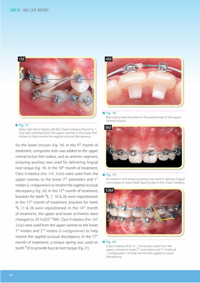
48
IJOI 41 AOI A E RE ORT II E O D L I IJOI 41
for the lower incisors (Fig. 18). In the 9th month of treatment, composite resin was added to the upper central incisor bite turbos, and an anterior segment, torquing auxiliary was used for delivering lingual root torque (Fig. 19). In the 10th month of treatment, Class II elastics (Fox 1/4”, 3.5oz) were used from the upper canines to the lower 2nd premolars and 1st molars (L-configuration) to resolve the sagittal occlusal discrepancy (Fig. 20). In the 12th month of treatment, brackets for teeth #6, 7, 10 & 26 were repositioned. In the 13th month of treatment, brackets for teeth #6, 11 & 26 were repositioned. In the 14th month of treatment, the upper and lower archwires were changed to .017x.025” TMA. Class II elastics (Fox 1/4”,
3.5oz) were used from the upper canines to the lower 1st molars and 2nd molars (L-configuration) to help resolve the sagittal occlusal discrepancy. In the 17th month of treatment, a torque spring was used on tooth #10 to provide buccal root torque (Fig. 21).
Fig. 20: Class II elastics (Fox ¼”, 3.5oz) were used from the upper canines to lower 2nd premolars and 1st molars (L - configuration ) to help resolve the sagittal occlusal discrepancy.
Fig. 18: Bite turbos were bonded on the palatal side of the upper central incisors.
Fig. 19: An anterior root torquing spring was used to delivery lingual root torque to resist distal tipping due to the Class II elastics.
Fig. 17: Early Light Short Elastics (ELSE): Class II elastics (Parrot 5⁄16”, 2oz) were attached from the upper canines to the lower first molars to help resolve the sagittal occlusal discrepancy.
4M
9M
10M
1M

IJOI 41 AOI A E RE ORT
49
II E O D L I IJOI 41
Fig. 21: A torque spring was used on tooth #10 to deliver buccal root torque.
Fig. 22: 1st order bends on teeth #6, 7, 9 & 10 were used to detail alignment.
Fig. 23: To improve the posterior occlusal contacts with vertical elastics, the maxillary arch wire was cut distal to the 2nd premolars.
In the 19th month of treatment, two bone screws (2x12mm OrthoBoneScrew®, Newton’s A Ltd, Hsinchu,
Taiwan) were inserted into the infrazygomatic crests to anchor elastomeric chains that were attached to the upper canines to retract the maxillary dentition. In the 23rd month of treatment, a panoramic film was taken and the brackets for teeth #22, 23 & 26 were repositioned. In the 24th month of treatment, Class II elastics (Bear 1/4”, 4.5oz) were used on the right side from the upper canine to lower 1st molar and 2nd molar (L-configuration) to resolve the sagittal occlusal discrepancy. In addition, 1st order detailing bends were used to detail teeth #6, 7, 9, 10, 23 & 26 (Fig. 22). Buccal root torque was added for teeth #3, 4, 5, 12, 13 & 14. In the 26th month of treatment, the IZC bone screws were removed. To improve the posterior occlusal contacts, the maxillary arch wire was cut distal to the 2nd premolars (Fig. 23), and Class II elastics (Kangaroo 3/16”, 4.5oz) were applied on the right side from the upper canine to the lower 1st molar. Class II elastics (triangular shape) were applied on the left side from the upper canine to lower 1st premolar
and 2nd premolar to detail the occlusion. A torquing spring was used on #11 to correct its axial inclination. Two lingual buttons were bonded on #23 & 27 to anchor an elastic chain for reciprocal rotation. In the final stage of treatment, subtle detailing adjustments were made for teeth #10, 18 & 19. In the 28th month of treatment, torque springs were used on teeth #22 & 27 for final adjustment of their axial inclinations.
26M
24M
17M

50
IJOI 41 AOI A E RE ORT II E O D L I IJOI 41
Fig. 24: The pretreatment lip profile (left) was retracted 5 mm (upper) and 4 mm (lower).
In the 29th month of treatment, all fixed appliances were removed and retainers were provided.
esults Ac ie ed
Maxilla (all three planes):
• A - P: Maintained
• Vertical: Maintained
• Transverse: Maintained
Mandible (all three planes):
• A - P: Increased protrusion
• Vertical: Maintained
• Transverse: Maintained
Maxillary Dentition
• A - P: Molars protracted, Incisors retracted
• Vertical: Molars maintained, Incisors intruded
• Inter-molar Width: Increased
• Inter-canine Width: Decreased
Mandibular Dentition
• A - P: Molars maintained, Incisors retracted
• Vertical: Molars maintained, Incisors intruded
• Inter-molar Width: Increased
• Inter-canine Width: Decreased
Facial esthetics:
• Upper lip retracted 5 mm
• Lower lip retracted 4 mm (Figs. 24)
• Chin appeared more prominent due to the mandibular growth and lip retraction
etention
1. Fixed 3-3 retainers were bonded on all anterior teeth in both arches.
2. Clear overlay retainers were delivered for both arches. The patient was instructed to wear the overlay retainers full time for the first 6 months and nights only thereafter. Home care and retainer maintenance instructions were provided.
inal aluation O reatment
The ABO CRE score was 24 points, as documented in the form that appears later in this report. 6
Significant discrepancies were:
1. Occlusal relationships (8 points)
2. Buccolingual inclination (7 points)
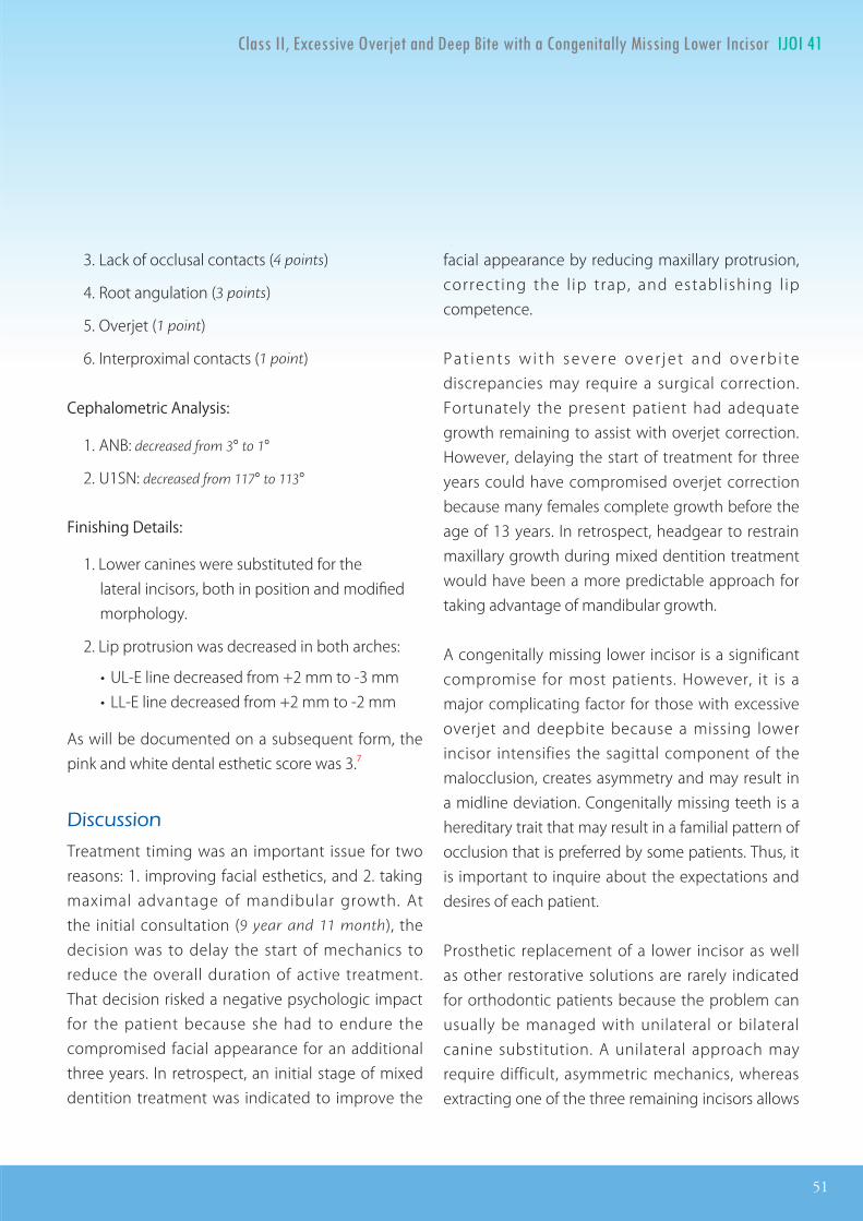
IJOI 41 AOI A E RE ORT
51
II E O D L I IJOI 41
3. Lack of occlusal contacts (4 points)
4. Root angulation (3 points)
5. Overjet (1 point)
6. Interproximal contacts (1 point)
Cephalometric Analysis:
1. ANB: decreased from 3° to 1°
2. U1SN: decreased from 117° to 113°
Finishing Details:
1. Lower canines were substituted for the lateral incisors, both in position and modified morphology.
2. Lip protrusion was decreased in both arches:
• UL-E line decreased from +2 mm to -3 mm • LL-E line decreased from +2 mm to -2 mm
As will be documented on a subsequent form, the pink and white dental esthetic score was 3.7
iscussion
Treatment timing was an important issue for two reasons: 1. improving facial esthetics, and 2. taking maximal advantage of mandibular growth. At the initial consultation (9 year and 11 month), the decision was to delay the start of mechanics to reduce the overall duration of active treatment. That decision risked a negative psychologic impact for the patient because she had to endure the compromised facial appearance for an additional three years. In retrospect, an initial stage of mixed dentition treatment was indicated to improve the
facial appearance by reducing maxillary protrusion, correcting the l ip trap, and establ ishing l ip competence.
P a t i e n t s w i t h s e v e r e o v e r j e t a n d o v e r b i t e discrepancies may require a surgical correction. Fortunately the present patient had adequate growth remaining to assist with overjet correction. However, delaying the start of treatment for three years could have compromised overjet correction because many females complete growth before the age of 13 years. In retrospect, headgear to restrain maxillary growth during mixed dentition treatment would have been a more predictable approach for taking advantage of mandibular growth.
A congenitally missing lower incisor is a significant compromise for most patients. However, it is a major complicating factor for those with excessive overjet and deepbite because a missing lower incisor intensifies the sagittal component of the malocclusion, creates asymmetry and may result in a midline deviation. Congenitally missing teeth is a hereditary trait that may result in a familial pattern of occlusion that is preferred by some patients. Thus, it is important to inquire about the expectations and desires of each patient.
Prosthetic replacement of a lower incisor as well as other restorative solutions are rarely indicated for orthodontic patients because the problem can usually be managed with unilateral or bilateral canine substitution. A unilateral approach may require difficult, asymmetric mechanics, whereas extracting one of the three remaining incisors allows

52
IJOI 41 AOI A E RE ORT II E O D L I IJOI 41
a symmetric approach to resolving the problem. In deciding which teeth to extract, there are three important dental considerations: 1. number of teeth in each quadrant, 2. arch symmetry, and 3. Angle molar relationship.
Two types of extraction patterns were considered for the present patient, but both approaches involved removing the maxillary first premolars. The option considered was to also extract one of the remaining three mandibular incisors to create a symmetric malocclusion, that could be corrected to a bilateral Class I molar relationship. Not extracting an incisor lessens the overjet discrepancy, which is favorable if there is no mandibular growth, but it results in difficult, unilateral mechanics that may produce an asymmetric result with a midline discrepancy. The problem with extraction of a lower incisor is the enhancement of the severe overjet. If the patient fails to grow, a functional appliance (Herbst etc.) or orthognathic surgery may be necessary.
Canine substitution is usually the best option for patients with a missing lower incisor, but there are three important considerations: position, morphology and torque. Positioning refers to the crown and root movement necessary to achieve ideal alignment. Morphology involves flattening the cusp tip and slenderizing, i.e. reducing the mesial‒distal dimension of the canine and flattening its buccal surface. It is wise to perform adjustments progressively and inform the patient that the process may cause slight discomfort.8 Torque is often required to achieve an optimal third order position to effectively simulate a lateral incisor. The
most common third order problem is lingual root torque.
onclusion
Adolescent patients with severe overjet and a deep impinging overbite require careful treatment planning to achieve an optimal result. A congenitally missing incisor significantly complicates the treatment of most malocclusions. The treatment ramifications may include orthognathic surgery, growth modification, extractions, implant-supported prostheses, canine substitution, and/or miniscrew anchorage.
e erences
1. Chang CH, Roberts WE. Orthodontics [E-reader version]. Hsinchu: Newton’s A Ltd; 2012.
2. Huang CL. e ABO Discrepancy Index - A Measure of Case Complexity. News & Trends in Orthodontics 2009;13:24.
3. Chang CH. Advanced Damon Course No. 1: Extraction Decision-making Tree. Beethoven Podcast Encyclopedia in Orthodontics [podcast]. Hsinchu: Newton’s A Ltd; 2011.
4. Lin JJ. Creative Orthodontics: Blending the Damon System and TADs to manage difficult malpositions. 2nd ed. Taipei: Yong-Chieh; 2010.
5. Pitts T. Begin with the end in mind: Bracket placement and early elastics protocols for smile arc protection. Clinical Impression 2009;17: 4-13.
6. Chang CH. Advanced Damon Course No. 6: CRE workshop. Beethoven Podcast Encyclopedia in Orthodontics [podcast]. Hsinchu: Newton’s A Ltd; 2011.
7. Su B. IBOI Pink & White esthetic score. Int J Ortho Implantol 2012;28:96-101.
8. Kokich VO Jr, Kinzer GA. Managing congenitally missing lateral incisors. Part I: Canine substitution. J Esthet Reor Dent 2005;17(1):5-10.

IJOI 41 AOI A E RE ORT
53
II E O D L I IJOI 41
OVERJET
0 mm. (edge-to-edge) = 1 pt.1 Ð 3 mm. = 0 pts.3.1 Ð 5 mm. = 2 pts.5.1 Ð 7 mm. = 3 pts.7.1 Ð 9 mm. = 4 pts.> 9 mm. = 5 pts.
Negative OJ (x-bite) Negative OJ (x-bite) 1 pt. per mm. per tooth 1 pt. per mm. per tooth =
OVERBITE
0 Ð 3 mm. = 0 pts.3.1 Ð 5 mm. = 2 pts.5.1 Ð 7 mm. = 3 pts.Impinging (100%) = 5 pts.
ANTERIOR OPEN BITE
0 mm. (edge-to-edge), 1 pt. per tooth
then 1 pt. per additional full mm. per tooth
LATERAL OPEN BITE
2 pts. per mm. per tooth
CROWDING (only one arch)
1 Ð 3 mm. = 1 pt.3.1 Ð 5 mm. = 2 pts.5.1 Ð 7 mm. = 4 pts.> 7 mm. = 7 pts.
OCCLUSION
Class I to end on = 0 pts.End on Class II or III = 2 pts. per side pts. pts.
Full Class II or III = 4 pts. per side pts. pts.
Beyond Class II or III = 1 pt. per mm. pts.pts. additional
TotalTotalT =
TotalTotalT =
TotalTotalT =
TotalTotalT =
TotalTotalT =
Total =
TOTAL D.I.D.I. SCORECORECORECORECORE
II E O D L I IJOI 41
LINGUAL POSTERIOR X-BITE
1 pt. per tooth Total =
BUCCAL POSTERIOR X-BITE
2 pts. per tooth Total =
CEPHALOMETRICS (See Instructions)
ANB ≥ 6¡ or ≤ -2¡ = 4 pts.
SN-MP
≥ 38¡ = 2 pts.
Each degree > 38¡ Each degree > 38¡ x 2 pts. =x 2 pts. =
≤ 26¡ = 1 pt.
Each degree < 26¡ Each degree < 26¡ x 1 pt. =x 1 pt. =
1 to MP ≥ 99¡ = 1 pt.
Each degree > 99¡ Each degree > 99¡ x 1 pt. =x 1 pt. =
OTHER (See Instructions)
Supernumerary teeth x 1 pt. =
Ankylosis of perm. teeth x 2 pts. =
Anomalous morphology x 2 pts. =
Impaction (except 3rd molars)rd molars)rd x 2 pts. =
Midline discrepancy (≥3mm) @ 2 pts. =
Missing teeth (except 3rd molars)rd molars)rd x 1 pts. =
Missing teeth, congenital x 2 pts. =
Spacing (4 or more, per arch) x 2 pts. =
Spacing (Mx cent. diastema ≥ 2mm) @ 2 pts. =
Tooth transposition x 2 pts. =
Skeletal asymmetry (nonsurgical tx) @ 3 pts. =
Addl. treatment complexities x 2 pts. =
Identify:
Each degree > 6¡ Each degree > 6¡ x 1 pt. =x 1 pt. =
Each degree < -2¡ Each degree < -2¡ x 1 pt. =x 1 pt. =
Total =
Total =
2222
55
55
0
0
44
2
00
4
00
22IMPLANT SITEIMPLANT SITELip line : Low (0 pt), Medium (1 pt), High (2 pts) = Gingival biotype : Low-scalloped, thick (0 pt), Medium-scalloped, medium-thick (1 pt), Low-scalloped, thick (0 pt), Medium-scalloped, medium-thick (1 pt),
High-scalloped, thin (2 pts) =Shape of tooth crowns : Rectangular (0 pt), Triangular (2 pts) =Bone level at adjacent teeth : ≦ 5 mm to contact point (0 pt), 5.5 to 6.5 mm to contact point (1 pt), ≧ 7mm to contact point (2 pts) = Bone anatomy of alveolar crest : H&V sufficient (0 pt), Deficient H, allow simultaneous augment (1 pt), Deficient H, require prior grafting (2 pts), Deficient V or Both
H&V (3 pts) = Soft tissue anatomy : Intact (0 pt), Defective ( 2 pts) =Infection at implant site : None (0 pt), Chronic (1 pt), Acute( 2 pts) =
0
11 1 22 2
2
i cr panc n or t

54
IJOI 41 AOI A E RE ORT II E O D L I IJOI 41
Total Score:
Case # Patient
0
1
11
71
1
4
22
8
3
xx
Alignment/Rotations
Marginal Ridges
Buccolingual Inclination
Overjet
Occlusal Contacts
Occlusal Relationships
Interproximal Contacts
INSTRUCTIONS: Place score beside each deficient tooth and enter total score for each parameter in the white box. Mark extracted teeth with ÒXÓ. Second molars should be in occlusion.
2
Root Angulation
0
2 2
1
22
1
11
22
1
1
1
11
1
1
1
1
xxxxxxx
x x
x x
x x x xxxxxx
x x
x x
1
x x
11 1
1
a t a io rap a ation

IJOI 41 AOI A E RE ORT
55
II E O D L I IJOI 41
124
5
5
1
2
4
124
5
5
1
2
4
124
5
5
1
2
4
1. Pink Esthetic Score
in it t tic cor or r ica ro n n t nin
Total Score: = 3
2. White Esthetic Score ( for Micro-esthetics )
124
5
5
1
2
4
1. Mesial Papilla 0 1 2
2. Distal Papilla 0 1 2
3. Curvature of Gingival Margin 0 1 2
4. Level of Gingival Margin 0 1 2
5. Root Convexity ( Torque ) 0 1 2
6. Scar Formation 0 1 2
1. Midline 0 1 2
2. Incisor Curve 0 1 2
3. Axial Inclination (5 , 8 , 10 ) 0 1 2
4. Contact Area (50%, 40%, 30%) 0 1 2
5. Tooth Proportion (1:0.8) 0 1 2
6. Tooth to Tooth Proportion 0 1 2
1. M & D Papilla 0 1 2
2. Keratinized Gingiva 0 1 2
3. Curvature of Gingival Margin 0 1 2
4. Level of Gingival Margin 0 1 2
5. Root Convexity ( Torque ) 0 1 2
6. Scar Formation 0 1 2
1. Midline 0 1 2
2. Incisor Curve 0 1 2
3. Axial Inclination (5 , 8 , 10 ) 0 1 2
4. Contact Area (50%, 40%, 30%) 0 1 2
5. Tooth Proportion (1:0.8) 0 1 2
6. Tooth to Tooth Proportion 0 1 2
Total = 1
Total = 2

2016.07.14
Dr. Kokich
Steve Jobs
Advanced Keynote
2016.08.0410大演 秘
令人目眩神迷的演 技巧2016.09.15
2016.10.22 - 24
高效簡報學習法2016 Keynote Workshop
位化潮流下的牙科 ,不 需要清晰的 床照片,也需要精的 表和流 的 吸引 ,而 秀的 化工具更使您
的演 一格且令人 忘。Keynote 456 程中,Dr. Rungsi 分享他利用Keynote 精美牙科插 的 , 一步步
教 您如何 想和草 建出令人 的成果。跟 美大 的 步,您也可以秀出 意、站上世界舞台!
名 有限,以 序 依 。生享特惠 惠 ,限 6名。
若取消 名,7/22前退款 扣除10%行政手 ,7/23 扣除30%行政手 。
。。。
金牛 科技 新竹市建中一路25號2 名 :03-5735676
名2016 程即 送2015及2016 程 。
看 太多充 文字和 表的幻 片, 就忘了的演 ?Keynote系列 程教你如何利用Mac 建Keynote, 作出令人目眩神迷、印象深刻的。透 小班教 , 身指 , 必 你在 程中 掌握Keynote的 技巧。
Keynote 101
Speaker: Dr. Rungsi
Newton’s A
K123
K456
:Dr. Rungsi Thavarungkul

Golf
(DE952213)
8mm 光纖管
.衛署醫器輸字第023384號
*本優惠專案僅適用於牙醫診所*本公司保留更改及終止活動辦法與條款之權利
加購價
$4,999元/支(限庫存售完為止)
(定價$14,500元/支)
限編號DE21020 (8mm Turbo)DE952213 (8mm Turbo Plus)
促銷價$25,000元/台Demi Plus
(定價$50,000元/台)
自2016/1/1-6/25止LED Light Curing System
Golf
(DE952213)
8mm 光纖管
.衛署醫器輸字第023384號
*本優惠專案僅適用於牙醫診所*本公司保留更改及終止活動辦法與條款之權利
加購價
$4,999元/支(限庫存售完為止)
(定價$14,500元/支)
限編號DE21020 (8mm Turbo)DE952213 (8mm Turbo Plus)
促銷價$25,000元/台Demi Plus
(定價$50,000元/台)
自2016/1/1-6/25止LED Light Curing System
Golf
(DE952213)
8mm 光纖管
.衛署醫器輸字第023384號
*本優惠專案僅適用於牙醫診所*本公司保留更改及終止活動辦法與條款之權利
加購價
$4,999元/支(限庫存售完為止)
(定價$14,500元/支)
限編號DE21020 (8mm Turbo)DE952213 (8mm Turbo Plus)
促銷價$25,000元/台Demi Plus
(定價$50,000元/台)
自2016/1/1-6/25止LED Light Curing System
Golf
(DE952213)
8mm 光纖管
.衛署醫器輸字第023384號
*本優惠專案僅適用於牙醫診所*本公司保留更改及終止活動辦法與條款之權利
加購價
$4,999元/支(限庫存售完為止)
(定價$14,500元/支)
限編號DE21020 (8mm Turbo)DE952213 (8mm Turbo Plus)
促銷價$25,000元/台Demi Plus
(定價$50,000元/台)
自2016/1/1-6/25止LED Light Curing System

Golf
(DE952213)
8mm 光纖管
.衛署醫器輸字第023384號
*本優惠專案僅適用於牙醫診所*本公司保留更改及終止活動辦法與條款之權利
加購價
$4,999元/支(限庫存售完為止)
(定價$14,500元/支)
限編號DE21020 (8mm Turbo)DE952213 (8mm Turbo Plus)
促銷價$25,000元/台Demi Plus
(定價$50,000元/台)
自2016/1/1-6/25止LED Light Curing System
Golf
(DE952213)
8mm 光纖管
.衛署醫器輸字第023384號
*本優惠專案僅適用於牙醫診所*本公司保留更改及終止活動辦法與條款之權利
加購價
$4,999元/支(限庫存售完為止)
(定價$14,500元/支)
限編號DE21020 (8mm Turbo)DE952213 (8mm Turbo Plus)
促銷價$25,000元/台Demi Plus
(定價$50,000元/台)
自2016/1/1-6/25止LED Light Curing System
Golf
(DE952213)
8mm 光纖管
.衛署醫器輸字第023384號
*本優惠專案僅適用於牙醫診所*本公司保留更改及終止活動辦法與條款之權利
加購價
$4,999元/支(限庫存售完為止)
(定價$14,500元/支)
限編號DE21020 (8mm Turbo)DE952213 (8mm Turbo Plus)
促銷價$25,000元/台Demi Plus
(定價$50,000元/台)
自2016/1/1-6/25止LED Light Curing System
Golf
(DE952213)
8mm 光纖管
.衛署醫器輸字第023384號
*本優惠專案僅適用於牙醫診所*本公司保留更改及終止活動辦法與條款之權利
加購價
$4,999元/支(限庫存售完為止)
(定價$14,500元/支)
限編號DE21020 (8mm Turbo)DE952213 (8mm Turbo Plus)
促銷價$25,000元/台Demi Plus
(定價$50,000元/台)
自2016/1/1-6/25止LED Light Curing System
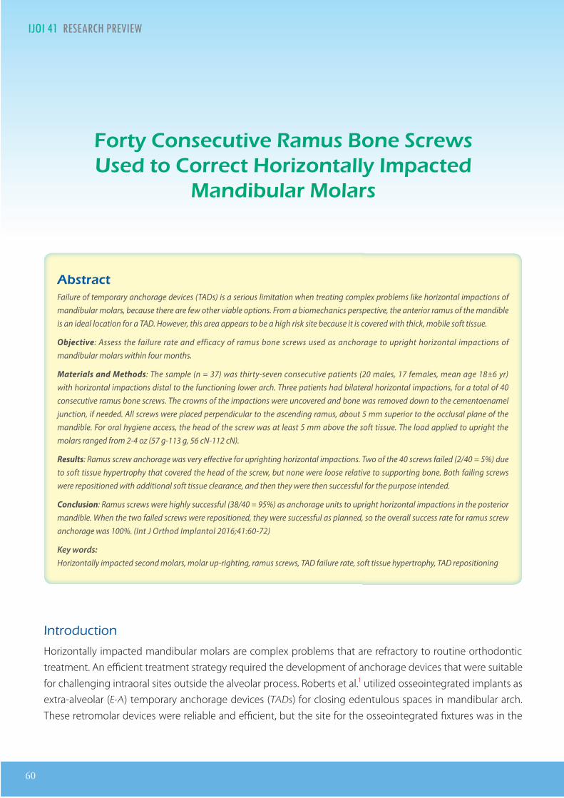
60
IJOI 41 RE EAR RE IE R I IJOI 41
Introduction
Horizontally impacted mandibular molars are complex problems that are refractory to routine orthodontic treatment. An efficient treatment strategy required the development of anchorage devices that were suitable for challenging intraoral sites outside the alveolar process. Roberts et al.1 utilized osseointegrated implants as extra-alveolar (E-A) temporary anchorage devices (TADs) for closing edentulous spaces in mandibular arch. These retromolar devices were reliable and efficient, but the site for the osseointegrated fixtures was in the
Dr. Chris Chang, Founder, Beethoven Orthodontic Center
Publisher, International Journal of Orthodontics& Implantology (Left)
Dr. Shih-Yung Lin, DDS,Editor, International Journal of Orthodontics & Implantology (Middle)
Dr. W. Eugene Roberts,Chief consultant, International Journal of Orthodontics & Implantology (Right)
ort on c ti am on crto orr ct ori onta mpact
an i ar o ar
tract Failure of temporary anchorage devices (TADs) is a serious limitation when treating complex problems like horizontal impactions of mandibular molars, because there are few other viable options. From a biomechanics perspective, the anterior ramus of the mandible is an ideal location for a TAD. However, this area appears to be a high risk site because it is covered with thick, mobile soft tissue.
Objective: Assess the failure rate and efficacy of ramus bone screws used as anchorage to upright horizontal impactions of mandibular molars within four months.
Materials and Methods: The sample (n = 37) was thirty-seven consecutive patients (20 males, 17 females, mean age 18±6 yr) with horizontal impactions distal to the functioning lower arch. Three patients had bilateral horizontal impactions, for a total of 40 consecutive ramus bone screws. The crowns of the impactions were uncovered and bone was removed down to the cementoenamel junction, if needed. All screws were placed perpendicular to the ascending ramus, about 5 mm superior to the occlusal plane of the mandible. For oral hygiene access, the head of the screw was at least 5 mm above the soft tissue. The load applied to upright the molars ranged from 2-4 oz (57 g-113 g, 56 cN-112 cN).
Results: Ramus screw anchorage was very eective for uprighting horizontal impactions. Two of the 40 screws failed (2/40 = 5%) due to soft tissue hypertrophy that covered the head of the screw, but none were loose relative to supporting bone. Both failing screws were repositioned with additional soft tissue clearance, and then they were then successful for the purpose intended.
Conclusion: Ramus screws were highly successful (38/40 = 95%) as anchorage units to upright horizontal impactions in the posterior mandible. When the two failed screws were repositioned, they were successful as planned, so the overall success rate for ramus screw anchorage was 100%. (Int J Orthod Implantol 2016;41:60-72)
Key words:Horizontally impacted second molars, molar up-righting, ramus screws, TAD failure rate, soft tissue hypertrophy, TAD repositioning

IJOI 41 RE EAR RE IE
61
R I IJOI 41
Fig. 1: A 2x14-mm stainless steel bone screw was designed to be inserted in the ramus as a self-drilling fixture.
same location as horizontally impacted molars, so they were unsuitable anchorage for their recovery. Subsequently, Kanomi2 and others3,4 introduced multiple types of titanium alloy (Ti) miniscrews that were placed in the alveolar process between the roots of teeth. These interradicular (I-R) devices were not well suited for complex problems like horizontal impactions, and they often had a high failure rate particularly in the posterior mandible (Table I). Furthermore, the I-R TADs had other limitations5-8 including damaging the roots of teeth, were not
Dr. Chris Chang, Founder, Beethoven Orthodontic Center
Publisher, International Journal of Orthodontics& Implantology (Left)
Dr. Shih-Yung Lin, DDS,Editor, International Journal of Orthodontics & Implantology (Middle)
Dr. W. Eugene Roberts,Chief consultant, International Journal of Orthodontics & Implantology (Right)
rigid (moved within the bone), and often interfered with the path of tooth movement, so they were not suitable for managing deep horizontal impactions.
Realizing that the first two generations of TADs (retromolar and I-R) lacked the versatility to manage horizontal impactions. Chang et al.5 expanded the E-A TAD concept by developing a 2 mm diameter stainless steel (SS) bone screw (Fig. 1) that was suitable for dense cortical bone sites, such as the mandibular buccal shelf (MBS). The MBS bone screw
Sharp Cutting Edge Easy to penetrate cortical bone,
no pre-drilling
Smooth Mushroom Head For comfort & retention of elastic chain
Double Neck Design Easy hygiene control & extra attachment
Stainless Steel High flexibility & resistance to fracture
4-way Rectangular Holes For lever arm to solve impacted
tooth
14 mm in Length Penetrate thicker soft and hard
tissue, more stability
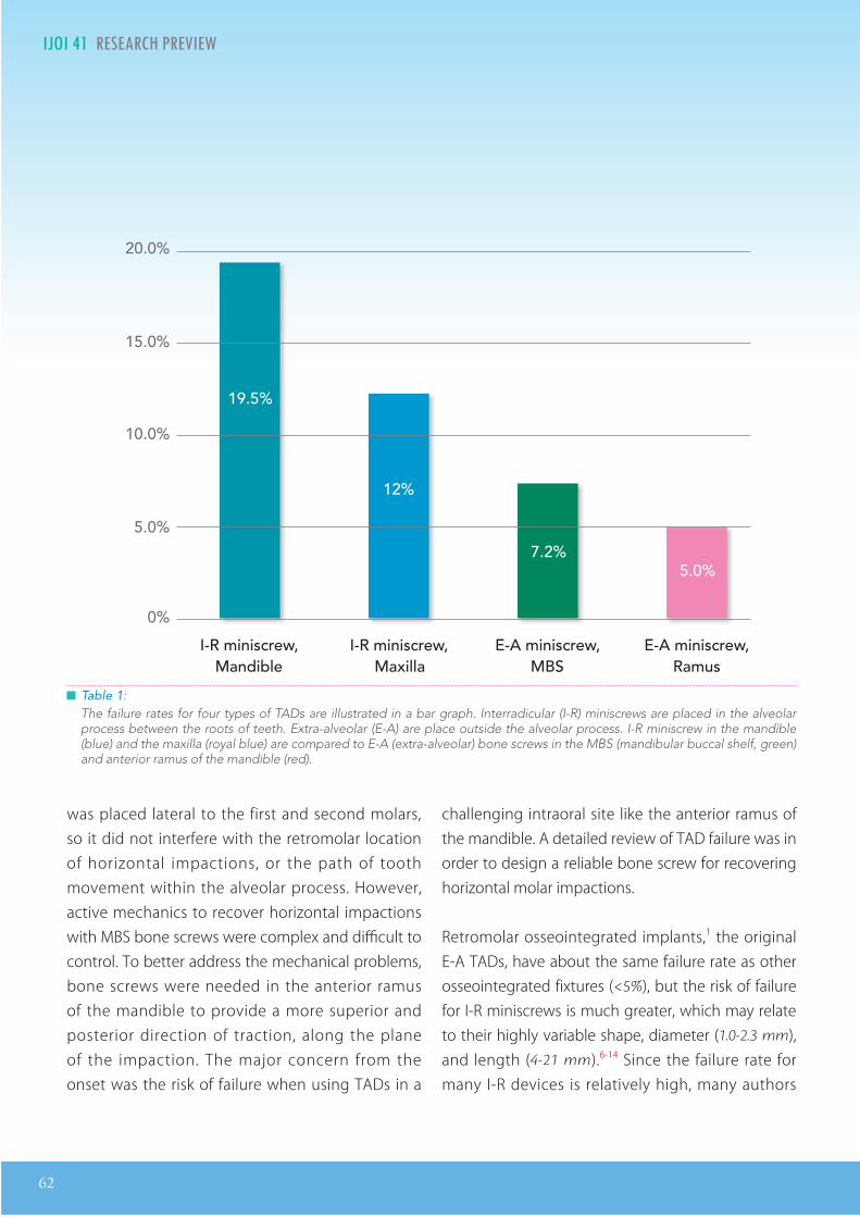
62
IJOI 41 RE EAR RE IE R I IJOI 41
was placed lateral to the first and second molars, so it did not interfere with the retromolar location of horizontal impactions, or the path of tooth movement within the alveolar process. However, active mechanics to recover horizontal impactions with MBS bone screws were complex and difficult to control. To better address the mechanical problems, bone screws were needed in the anterior ramus of the mandible to provide a more superior and posterior direction of traction, along the plane of the impaction. The major concern from the onset was the risk of failure when using TADs in a
challenging intraoral site like the anterior ramus of the mandible. A detailed review of TAD failure was in order to design a reliable bone screw for recovering horizontal molar impactions.
Retromolar osseointegrated implants,1 the original E-A TADs, have about the same failure rate as other osseointegrated fixtures (<5%), but the risk of failure for I-R miniscrews is much greater, which may relate to their highly variable shape, diameter (1.0-2.3 mm), and length (4-21 mm).6-14 Since the failure rate for many I-R devices is relatively high, many authors
15.0%
20.0%
10.0%
5.0%
0%
19.5%
12%
7.2%
I-R miniscrew, E-A miniscrew,I-R miniscrew,
5.0%
E-A miniscrew,
Table 1: The failure rates for four types of TADs are illustrated in a bar graph. Interradicular (I-R) miniscrews are placed in the alveolar process between the roots of teeth. Extra-alveolar (E-A) are place outside the alveolar process. I-R miniscrew in the mandible (blue) and the maxilla (royal blue) are compared to E-A (extra-alveolar) bone screws in the MBS (mandibular buccal shelf, green) and anterior ramus of the mandible (red).
Mandible Maxilla MBS Ramus

IJOI 41 RE EAR RE IE
63
R I IJOI 41
report the clinical experience as a “success rate” from 57-95%, with an average of about 84%.15-17 E-A SS miniscrews are used in the MBS and infrazygomatic crest (IZC) for retracting or protracting individual teeth or entire arches, to correct a wide variety of malocclusions.18,19 A large study of 1,680 consecutive MBS miniscrews reported a failure rate of only 7.2%,5 which is considerably lower than for I-R miniscrews in the mandible (19.3%) or the maxilla (12.0%) (Table 1).20-21
Failure of multiple osseointegrated implants in the maxilla of individual patients are associated with parafunction and psychologic factors,22 but those parameters have not been systematically studied relative to TADs. However, Chang et al.5 did note bilateral failures of MBS bone screws in multiple patients, suggesting that some patients are predisposed to TAD failure. Miniscrew failure may be due to a loss of stability, or to soft tissue inflammation, so primary stability is the critical factor for clinical success.23-25 The latter is enhanced by a larger diameter screw, smaller diameter pilot hole, and thicker cortical bone.23-26 Furthermore, the self-drilling protocol can also play a role.27,28 Screw design studies show a >70% success rate for I-R miniscrews with a diameter of ≥1.2 mm, and multiple studies show that success is directly related to the screw length.12-14,29 However, the probability of root damage is increased when a wider diameter I-R miniscrew screw is used.29 A recent review30 indicated that cortical bone thickness appears to be the most important factor for primary stability. The overall experience with I-R miniscrews indicated they were high risk TADs with little potential for managing complex problems like horizontal impactions in the posterior mandible.
Despite the obvious mechanical advantage of a ramus screw for uprighting a horizontally impacted molar, there are numerous concerns about this region as an E-A TAD site: 1. highly mobile alveolar mucosa, 2. relatively thick layer of unattached soft tissue, 3. underlying layer of active muscle some of which is attached to bone, and 4. difficult area for maintaining oral hygiene to control soft tissue hyperplasia.31 A 2x14 mm SS screw was designed as the best fit for the anatomical features of the anterior ramus region (Fig. 1). The objective for testing this screw was to assess its failure for any reason, in serving as adequate anchorage to recover a horizontal impaction(s). The null hypothesis is that ramus screws will have a high failure rate and low efficiency in recovering horizontal impactions of mandibular molars.
aterial and et ods
In this study, the ramus screws were inserted in 37 consecutive patients (20 males, 17 females, mean age
18±6 yr), presenting for treatment of horizontally impacted mandibular molars. Three of the patients had bilateral impactions, so a total of 40 stainless steel, self-drilling miniscrews (2x14 mm, Newton’s
A Ltd, Hsinchu City, Taiwan) were installed in the anterior ramus to upright the uncovered impactions. All the patients were treated over a three year period (2013-15) in a single private practice by the same orthodontist. The ramus screws were installed under local anesthesia, without flap elevation or pilot drilling.
The selection of the anatomical site and the screw
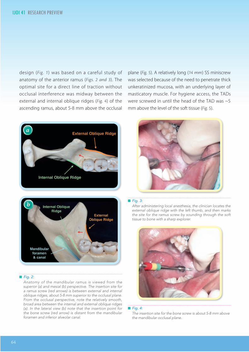
64
IJOI 41 RE EAR RE IE R I IJOI 41
design (Fig. 1) was based on a careful study of anatomy of the anterior ramus (Figs. 2 and 3). The optimal site for a direct line of traction without occlusal interference was midway between the external and internal oblique ridges (Fig. 4) of the ascending ramus, about 5-8 mm above the occlusal
plane (Fig. 5). A relatively long (14 mm) SS miniscrew was selected because of the need to penetrate thick unkeratinized mucosa, with an underlying layer of masticatory muscle. For hygiene access, the TADs were screwed in until the head of the TAD was ~5 mm above the level of the soft tissue (Fig. 5).
Fig. 2:Anatomy of the mandibular ramus is viewed from the superior (a) and mesial (b) perspective. The insertion site for a ramus screw (red arrows) is between external and internal oblique ridges, about 5-8 mm superior to the occlusal plane. From the occlusal perspective, note the relatively smooth, broad area between the internal and external oblique ridges (a). In the lateral view (b) note that the insertion point for the bone screw (red arrow) is distant from the mandibular foramen and inferior alveolar canal.
a
b Fig. 3:After administering local anesthesia, the clinician locates the external oblique ridge with the left thumb, and then marks the site for the ramus screw by sounding through the soft tissue to bone with a sharp explorer.
Fig. 4:The insertion site for the bone screw is about 5-8 mm above the mandibular occlusal plane.

IJOI 41 RE EAR RE IE
65
R I IJOI 41
Fig. 5:Left: after TAD placement, the screw head is about 5 mm above the soft tissue. Right: The average bone engagement for a ramus screw is ~3 mm.
5 mm
3 mm
All miniscrews were immediately loaded using pre-stretched elastomeric modules (power chains)32-34 attached to the button or eyelet bonded on the impacted teeth (Fig. 5). The patients were instructed in oral hygiene procedures to control soft tissue inflammation. For reactivation at monthly intervals, the traction force was increased by advancing one loop on the elastic chain and cutting it off every 4 weeks (Figs. 6 & 10). The stability of the ramus screws was regularly hand tested at 4 week intervals for 4 months, which was the maximum duration of the molar uprighting phase of treatment. At 5 months the previously impacted molars were bonded with a routine buccal bracket.
esults
Only 2 out of 40 ramus screws (5%) failed to serve as adequate anchorage for uprighting the horizontal impaction. Neither failed screws were loose, but
there was soft tissue overgrowth and severe inflammation around the TAD head. The failures occurred in different patients; one was on the right side of a 12 year-old boy and the other was on the left side of a 13 year-old girl. Both failed screws were removed, the hypertrophic soft tissue was removed, the bone screw was cleaned with alcohol, and then repositioned in an adjacent location, leaving at least 5 mm exposure for the screw head. Both of the initial failures were then clinically successful, so all 40 horizontally impacted molars were recovered and aligned except for one impaction, that had no bone on the distal surface of the root when it was uncovered.
iscussion
Extra-alveolar (E-A) bone screws are very effective for managing a variety of malocclusions including deeply impacted teeth.35 The most common impacted tooth
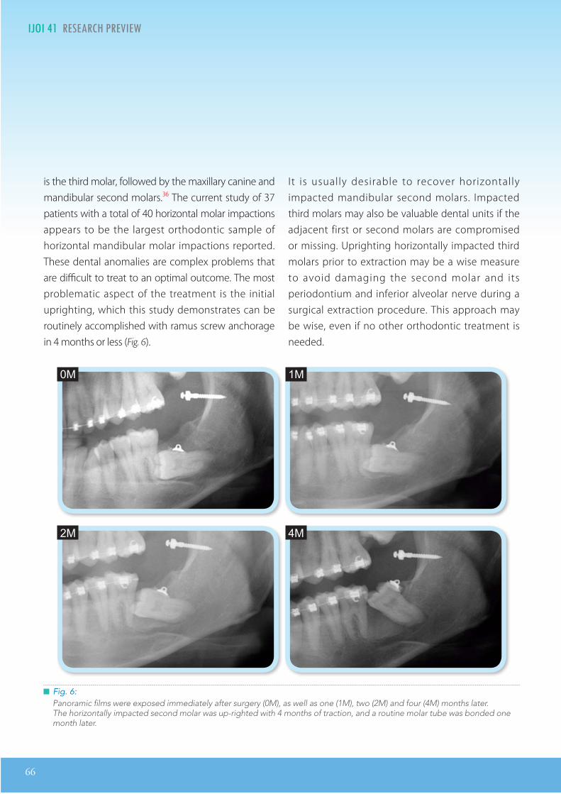
66
IJOI 41 RE EAR RE IE R I IJOI 41
is the third molar, followed by the maxillary canine and mandibular second molars.36 The current study of 37 patients with a total of 40 horizontal molar impactions appears to be the largest orthodontic sample of horizontal mandibular molar impactions reported. These dental anomalies are complex problems that are difficult to treat to an optimal outcome. The most problematic aspect of the treatment is the initial uprighting, which this study demonstrates can be routinely accomplished with ramus screw anchorage in 4 months or less (Fig. 6).
It is usually desirable to recover horizontally impacted mandibular second molars. Impacted third molars may also be valuable dental units if the adjacent first or second molars are compromised or missing. Uprighting horizontally impacted third molars prior to extraction may be a wise measure to avoid damaging the second molar and its periodontium and inferior alveolar nerve during a surgical extraction procedure. This approach may be wise, even if no other orthodontic treatment is needed.
Fig. 6:Panoramic films were exposed immediately after surgery (0M), as well as one (1M), two (2M) and four (4M) months later. The horizontally impacted second molar was up-righted with 4 months of traction, and a routine molar tube was bonded one month later.
0M 1M
4M2M

IJOI 41 RE EAR RE IE
67
R I IJOI 41
Fig. 7:The insertion sites for E-A bone screws are compared. a. A 2x12 mm screw is well secured in the bone (at least 3 mm) of the mandibular buccal shelf and there is still adequate
clearance (~5 mm) above the soft tissue for hygienic maintenance. b. The ramus screw must penetrate much thicker soft tissue to engage bone so a 2x14 mm SS screw is required.
amus as a A ite
An efficient, yet simple mechanism is required to recover deeply impacted or mesially tipped molars. Lin37 reviewed six different methods for recovering deeply impacted molars, and concluded that the most reliable and efficient approach was to surgically expose the deeply impacted molars and upright them with traction via a ramus bone screw.38,39 The current study validates that concept.
mm crews
Previous studies with mandibular buccal shelf bone screws,1,6,19 utilized 2x12 mm stainless steel screws (SS), because soft tissue was less than 3 mm thick. A 12 mm screw length was adequate to leave ~5 mm of clearance between soft tissue and the head of the screw after installation (Figs. 5 & 7). On the other
a b
hand, a ramus screw must penetrate much thicker soft tissue before engaging the dense cortical bone of the mandible. Thus, a 14 mm screw is necessary to provide at least 5 mm of soft tissue clearance, after the bone has been penetrated 3 mm or more (Fig. 8).40
om lications
The anatomical structure near the ramus, presenting the most serious risk for complications, is the neurovascular bundle in the inferior alveolar (m an dib u l ar ) canal (F i g . 2 b ) . Under normal circumstances, the ramus TAD site is about 15 to 20 mm away from the neurovascular bundle. Once the screws are inserted, postoperative panoramic films revealed that the screw tip may be within 5 to 8 mm of the mandibular canal (Figs. 7 - 9). Fig. 10 is a series

68
IJOI 41 RE EAR RE IE R I IJOI 41
Fig. 8:The muscle in the retromolar area is composed of the traversing fibers of the medial pterygoid (a) and the anterior fibers of the temporals that are inserting into the ramus surface (b).
Fig. 9:Panoramic films was taken immediately after 3 ramus screw insertions to evaluate the angulation of the screws, and estimate their proximity to the neurovascular bundle. None of the screws were closer than 5 mm to the inferior alveolar canal.
a b
of drawings that illustrate the details for utilizing a ramus screw to upright a horizontally impacted molar. If a clinician carefully follows the detailed instructions provided, the risk of complications is minimal.
crew ractures in t e Absence o re drilling
Fracture is a significant risk for small (<2 mm
diameter), brittle screws (Titanium or Titanium alloy) inserted into dense cortical bone with a self drilling

IJOI 41 RE EAR RE IE
69
R I IJOI 41
technique.41 A fractured screw is worrisome for the patient, may result in injury of adjacent tissue, or block the desired site for a TAD. Risk of screw fracture is decreased by increasing the diameter of the screw to at least 2 mm, using a tougher material such as stainless steel (SS), and drilling a pilot hole for the screw. The latter is not practical because of the thick soft tissue covering the bone, but using 2 mm diameter screws made of SS is a practical approach for decreasing fracture risk. On the contrary, increasing the length of a screw to 14 mm renders it more susceptible to a flexure-related fracture. All things considered, the 2x14 mm SS bone screw appears well suited as a ramus TAD, because to date none of the screws have fractured.
amus crew ailure
Based on the previous experience with buccal shelf bone screws,5 it's surprising that none of the ramus screws loosened during 4 months of traction. Only 2 of 40 screws failed to serve as adequate anchorage for uprighting molars, but those problems were because of soft tissue hyperplasia in adolescents with relatively poor oral hygiene. Both patients with the initial failures were successfully treated by removing the screws, resecting the hyperplastic tissue, and replacing it in an adjacent location. From these results it is clear that the success of ramus screws depends on appropriate hygiene measures. So it is very important to provide hygiene instructions and monitor soft tissue inflammation at each appointment.31
am le i e and Inclusion riteria
In collecting a group of patients to assess a clinical problem, it is important to avoid sampling bias. The patients selected may be a random or inclusive sample of all patients meeting the inclusion criteria within a given time frame.42,43 The current study is an inclusive sample of patients with a relatively rare condition, that was treated with 40 ramus bone screws in 37 patients, over a 3 year time frame. One patient was rejected because the impacted molar was periodontally compromised. Randomization is inappropriate for such a small number of patients. Although there were 40 ramus screw sites, the total sample size for the current study is only 37. The remaining three cases were bilateral applications of the same treatment, so they are not independent samples. However, bilateral samples are important in a clinical series because they provide information on patient predisposition to failure.
Although the sample size is small (n = 37), this study has provided a reliable initial estimate for the failure rate of ramus screws. None of the devices loosened from bone during the 4 month test interval, and the only failures were due to reversible soft tissue problems. It can be concluded the the ramus screw is a reliable option for recovering horizontal impactions, that have an adequate periodontium.
It is important to remember that one of the lower molar impactions, from a patient treatment planned for a ramus screw, was not recovered because it was periodontally compromised. That was the only
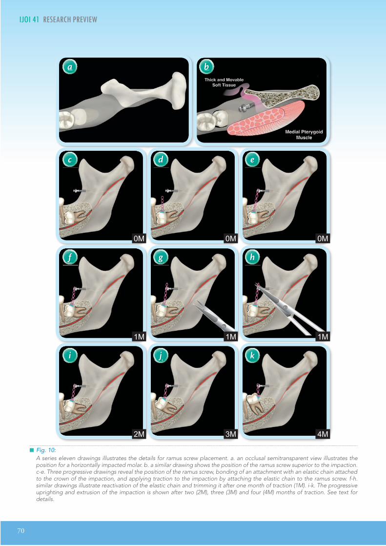
70
IJOI 41 RE EAR RE IE R I IJOI 41
Fig. 10:A series eleven drawings illustrates the details for ramus screw placement. a. an occlusal semitransparent view illustrates the position for a horizontally impacted molar. b. a similar drawing shows the position of the ramus screw superior to the impaction. c-e. Three progressive drawings reveal the position of the ramus screw, bonding of an attachment with an elastic chain attached to the crown of the impaction, and applying traction to the impaction by attaching the elastic chain to the ramus screw. f-h. similar drawings illustrate reactivation of the elastic chain and trimming it after one month of traction (1M). i-k. The progressive uprighting and extrusion of the impaction is shown after two (2M), three (3M) and four (4M) months of traction. See text for details.
a
c
f
i
d
g
j
e
h
k
b
0M
1M
2M
0M
1M
3M
0M
1M
4M

IJOI 41 RE EAR RE IE
71
R I IJOI 41
horizontal impaction of a mandibular molar that was excluded. Overall, this study provides a basis for the continuing study of ramus screw efficacy. Future cases will support or refute the conclusions reached with the present inclusive sample of 40 screws in 37 patients (n = 37).
onclusions
1. Deeply impacted, horizontal mandibular molars can be aligned by direct traction from 2x14 mm SS bone screws, inserted in the anterior ramus of the mandible.
2. The method is fast, efficient, and predictable.
3. It is critical to maintain at least 5 mm clearance from the soft tissue to the screw head to facilitate oral hygiene and control soft tissue irritation.
4. The failure rate of the E-A ramus screws (5%) is slightly better than buccal shelf bone screws (7.2%),5 but is much better than I-R miniscrews in the maxilla (12%) or in the mandible (19.5%).20,21
5. The two initial failures out of 40 specimens was due to a reversible soft tissue irritation. Both patients were retreated with the same method to a desirable outcome.
6. In effect, the ramus screw anchorage mechanism was 100% successful for recovering periodontally healthy, horizontally impacted mandibular molars.
Ac nowledgment
Thanks to Mr. Paul Head for proofreading this article and Dr. Rungsi Thavarungkul for the beautiful illustrations.
e erences
1. Roberts WE, Nelson CL, Goodacre CJ. Rigid implant anchorage to close a mandibular first molar extraction site. J Clin Orthod 1994;28(12):693-704.
2. Kanomi R. Mini-implant for orthodontic anchorage. J Clin Orthod 1997;31:763-767.
3. Costa A, Raffainl M, Melsen B. Miniscrews as orthodontic anchorage : a prel iminary report . Int J Adult Orthod Orthognath Surg 1998;13:201-209.
4. Bechtold TE, Kim JW, Choi TH, Park YC, Lee KJ. Distalization pattern of the maxillary arch depending on the number of orthodontic miniscrews. Angle Orthod 2013;83:266-273.
5. Chang CH, Sean SY Liu, Roberts WE. Primary failure rate for 1680 extra-alveolar mandibular buccal shelf mini-screws placed in movable mucosa or aached gingiva. Angle Orthod 2015;85:905-910.
6. Miyawaki S, Koyama I, Inoue M, Mishima K, Sugahara T, Takano-Yamamoto T. Factors associated with the stability of titanium screws placed in the posterior region for orthodontic anchorage. Am J Orthod Dentofacial Orthop 2003;124:373-378.
7. Cheng SJ, Tseng IY, Lee JJ, Kok SH. A prospective study of the risk factors associated with failure of mini implants used for orthodontic anchorage. Int J Oral Maxillofac Implants 2004;19:100-106.
8. Liou EJ, Pai BC, Lin JC. Do miniscrews remain stationary under orthodontic forces? Am J Orthod Dentofacial Orthop 2004;126:42-47.
9. Fritz U, Ehmer A, Diedrich P. Clinical suitability of titanium microscrews for orthodontic anchorage—prel iminary experiences. J Orofac Orthop 2004;65:410-418.
10. Park HS, Lee SK, Kwon OW. Group distal movement of teeth using microscrew implant anchorage. Angle Orthod 2005;75:602-609.
11. Motoyoshi M, Hirabayashi M, Uemura M, Shimizu N. Recommended placement torque when tightening an orthodontic mini-implant. Clin Oral Implants Res 2006;17:109-114.
12. Park HS, Jeong SH, Kwon OW. Factors affecting the clinical success of screw implants used as orthodontic anchorage. Am J Orthod Dentofacial Orthop 2006;130:18-25.
13. Chen CH, Chang CS, Hsieh CH, Tseng YC, Shen YS, Huang IY, et al. e use of microimplants in orthodontic anchorage. J Oral Maxillofac Surg 2006;64:1209-1213.
14. Tseng YC, Hsieh CH, Chen CH, Shen YS, Huang IY, Chen CM. The application of mini-implants for orthodontic anchorage. Int J Oral Maxillofac Surg 2006;35:704-707.
15. Berens A, Wiechmann D, Dempf R. Mini- and micro-screws for temporary skeletal anchorage in orthodontic therapy. J Orofac Orthop 2006;67:450-458.

72
IJOI 41 RE EAR RE IE
16. Viwaanatipa N, anakitcharu S, Uraravichien A, Pitiphat W. Survival analyses of surgical miniscrews as orthodontic anchorage. Am J Orthod Dentofacial Orthop 2009;136:29-36.
17. Schatzle M, Mannchen R, Zwahlen M, Lang NP. Survival and failure rates of orthodontic temporary anchorage devices: a systemic review. Clin Oral Implants Res 2009;20:1351-1359.
18. Chang CH, Roberts WE. Orthodontics. Taipei: Yong Chieh; 2012. p. 285-298.
19. Lin JJ, Liaw J, Chang CH, Roberts WE. Orthodontics: Class III Correction. Taipei: Yong Chieh; 2013.
20. Chen YJ, Chang HH, Huang CY, Hung HC, Lai EHH, Yao CCJ. A retrospective analysis of the failure rate of three different orthodontic skeletal anchorage systems. Clin Oral Implants Res 2007;18:768-775.
21. Moon CH, Lee DG, Lee HS, Im JS, Baek SH. Factors associated with the success rate of orthodontic miniscrews placed in the upper and lower posterior buccal region. Angle Orthod 2008;78:101-106.
22. Ekfeldt A, Christiansson U, Eriksson, Lindén U, Lundquist S, Rundcrantz T, Johansson LA, Nilner K, Billström C. A retrospective analysis of factors associated with multiple implant failures in the maxilla. Clin Oral Implants Res 2001;12:462-467.
23. Wilmes B, Rademacher C, Oltho G, Drescher D. Parameters affecting primary stability of orthodontic mini-implants. J Orofac Orthop 2006;67:162-174.
24. Huja SS, Litsky AS, Beck FM, Johnson KA, Larsen PE. Pullout strength of monocortical screws placed in the maxillae and mandibles of dogs. Am J Orthod Dentofacial Orthop 2005;127:307-313.
25. Ure DS, Oliver DR, Kim KB, Melo AC, Buchang PH. Stability changes of miniscrew implants over time: a pilot resonance frequency analysis. Angle Orthod 2011;81:994-1000.
26. Shank SB, Beck FM, D’Atri AM, Huja SS. Bone damage associated with orthodontic placement of miniscrew implants in an animal model. Am J Orthod Dentofacial Orthop 2012;141:412-418.
27. Florvaag B, Kneuertz P, Lazar F, Koebke J, Zoller JE, Braumann B, et al. Biomechanical properties of orthodontic mini-screws: an in-vitro study. J Orofac Orthop 2010;71:53-67.
28. Chen Y, Shin HI, Kyung HM. Biomechanical and histological comparison of self-drilling and self-tapping orthodontic micro-implants in dogs. Am J Orthod Dentofacial Orthop 2008;133:44-50.
29. Kuroda S, Sugawara Y, Deguchi T, Kyung HM, Takano Yamamoto T. Clinical use of miniscrew implants as orthodontic anchorage: success rates and postoperative discomfort. Am J Orthod Dentofacial Orthop 2007;131:9-15.
30. Marquezan M, Maos CT, Sant’Anna EF, de Souza MM, Maia LC. Does cortical thickness inuence the primary stability of miniscrews? A systematic review and meta-analysis. Angle Orthod 2014;84(6):1093-1103.
31. Lim HJ, Eun CS, Cho JH, Lee KH, Hwang HS. Factors associated with initial stability of miniscrews for orthodontic treatment. Am J Orthod Dentofacial Orthop 2009;136: 236-242.
32. Ash JL, Nikolai RJ. Relaxation of orthodontic elastomeric chains and modules in vitro and in vivo. J Dent Res 1978; 57:685-690.
33. Baty DL, Storie DJ, von Fraunhofer JA. Synthetic elastomeric chains: a literature review. Am J Orthod Dentofacial Orthop 1994;105:536-542.
34. Kin KH, Chung CH, Choy K, Lee JS, Vanarsdall RL. Eects of prestretching on force degradation of synthetic elasto-meric chains. Am J Orthod Dentofacial Orthop 2005;128:477-482.
35. Hsu YL, Chang CH, Roberts WE. Ortho Bone Screw. The dream screw for next generation’s orthodontists. Int J Ortho Implantol 2011;23:34-49.
36. Aitasalo K, Lehtinen R, Oksala E. An orthopantomographic study of prevalence of impacted teeth. Int J Oral Surg 1972;1:117-20.
37. Lin JJ. The wisdom of managing wisdom teeth-Part III. Methods of molar uprighting. Int J Ortho Implantol 2011;24:4-11.
38. Lee MC, Chang CH, Roberts WE. Compensated, Asymmetric Class II Malocclusion with Horizontal Impaction of Mandibular Second Molars. Int J Ortho Implantol 2014;33:50-62.
39. Lin SL, Chang CH, Roberts WE. Uprighting and Protraing a horizontally Impacted Lower Third Molar in an Adult. Int J Ortho Implantol 2014;34:58-77.
40. Lin SY, Chang CH, Roberts WE. Simple mechanics to upright horizontally impaed molars with ramus screws. Int J Ortho Implantol 2015;40:84-92.
41. Lin JJ. 2 mm Bone Screw v.s. MIA. Int J Ortho Implantol 2008;9:1-5.
42. Pinskaya Y, Hsieh TJ, Roberts WE, Hartsf ie ld JK Jr. Comprehensive clinical evaluation as an outcome assessment for a graduate orthodontics program. Am J Orthod Dentofac Orthop 2004;126(5):533-543.
43. Knierim K, Roberts WE, Hartseld Jr JK. Assessing treatment outcomes for a graduate orthodontics program: follow-up study for classes of 2001-2003. Am J Orthod Dentofac Orthop 2006;130(5)648-655, 655e 1-3.
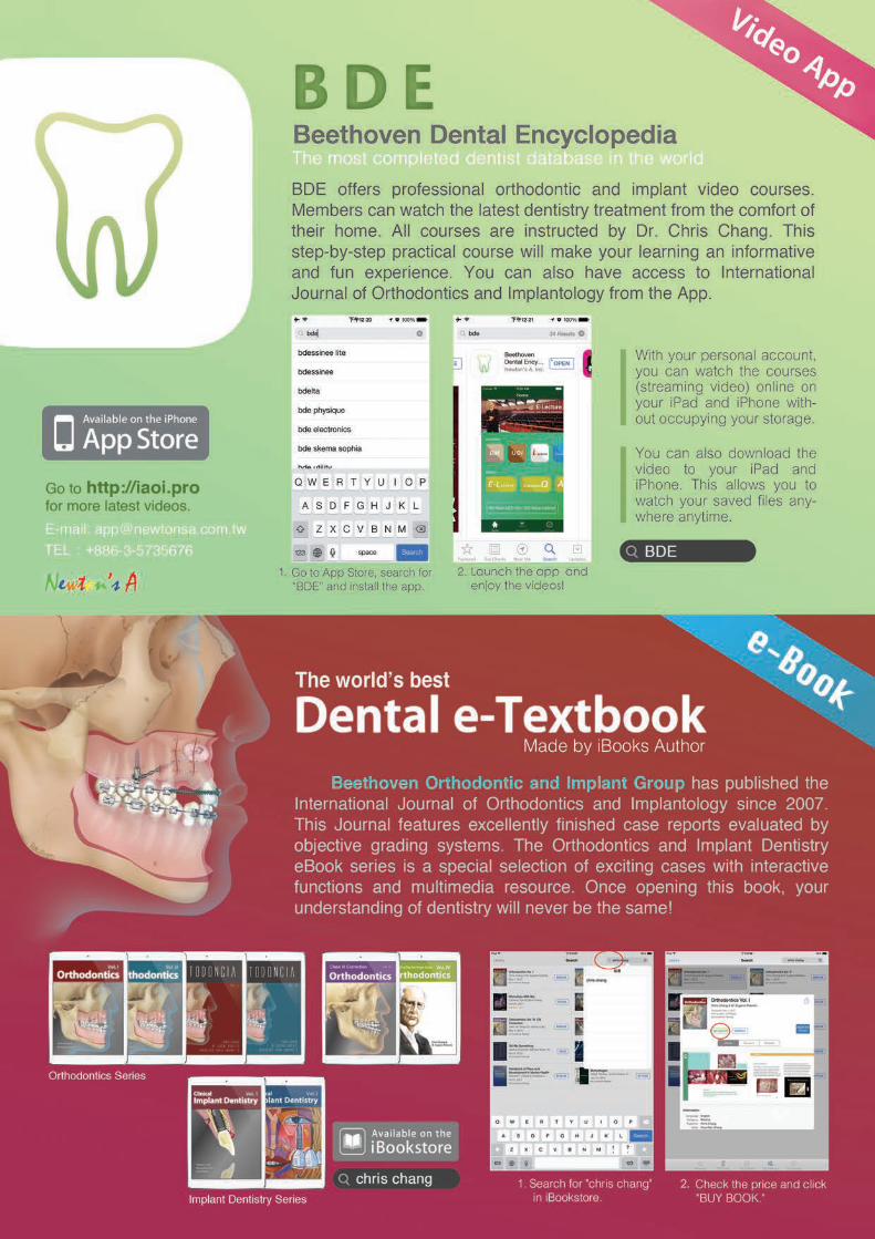
74
IJOI 41 RE EAR RE IE D A IJOI 41
Dr. Chris Chang, Founder, Beethoven Orthodontic Center
Publisher, International Journal of Orthodontics& Implantology (Left)
Dr. Chi Huang,Editor, International Journal of Orthodontics & Implantology (Middle)
Dr. W. Eugene Roberts,Chief consultant, International Journal of Orthodontics & Implantology (Right)
ortica on natom o t an i arcca a t to in it or
tra a o ar on cr to tr ata ma occ ion
tract
Objective: Assess the feasibility of a proposed bone screw site in the mandibular buccal shelf (MBS) region, relative to the orientation of the skeletal platform and quantity of the available cortical bone, for either perpendicular or angled bone screws.
Materials and Methods: CBCT images were obtained retrospectively for 12 Asian patients treated with bilateral MBS bone screws (n=24) for Class III skeletal malocclusion. None of the subjects had periodontal or buccal-lingual alignment problems. Cortical bone thickness adjacent to the first and second molars was measured on the mesial, midpoint and distal surfaces. Seven progressive sites were measured in frontal cuts of the CBCT image from the mesial of the first molar to the distal of the second molar. The angle was measured between a line that was the best fit of the MBS surface and the axial inclination of the adjacent molar. Cortical bone thickness was measured perpendicular and at a 30° angle along the surface of the MBS at 3, 5 and 7 mm apical to the alveolar crest of the molars.
Results: There was a statistically significant increase (t-test P<.0001) for cortical bone thickness for a 30° angled insertion, compared to a perpendicular measurement. The increase in cortical bone thickness for an angled insertion ranged from 0.56-1.24 mm. The median for cortical bone thickness at the 30° inclination ranged from 2.92-4.10 mm for all sites.
Discussion: Boxplots of the data indicated that the optimal location for a MBS bone screw is 5-7 mm below the alveolar bone crest, at approximately the plane between the mandibular first and second molars. At the recommended insertion angle of 30° cortical bone thickness lateral to the interproximal area between the molars ranged from 3.54-4.05 mm. This is a sufficient site for routinely achieving primary stability with MBS bone screws.
Conclusion: The MBS lateral to the first and second molars is an appropriate site for extra-alveolar (E-A) temporary anchorage devices (TADs) that are inserted at ~30° The most ideal skeletal location for the bone screw is about 5-7 mm below the alveolar crest. (Int J Orthod Implantol 2016;41:74-82)
Key words:Mandibular buccal shelf, miniscrews, CBCT, Skeletal anchorage, Cortical bone engagement, Extra-Alveolar orthodontic anchorage

IJOI 41 RE EAR RE IE
75
D A IJOI 41
Dr. Chris Chang, Founder, Beethoven Orthodontic Center
Publisher, International Journal of Orthodontics& Implantology (Left)
Dr. Chi Huang,Editor, International Journal of Orthodontics & Implantology (Middle)
Dr. W. Eugene Roberts,Chief consultant, International Journal of Orthodontics & Implantology (Right)
Introduction
There are numerous case reports1-3 indicating miniscrews in the mandibular buccal shelf (MBS) region are a reliable form of extra-alveolar (E-A) anchorage for retracting the entire mandibular arch to conservatively correct severe skeletal and dental malocclusions, without extractions or orthognathic surgery.4-7 Miniscrew temporary anchorage devices (TADs) are retained by mechanical conformation of bone at the implant interface rather than by osseointegration.8 Primary stability of the TAD is the critical factor for clinical success.9 A systematic review and meta-analysis indicates that there is a positive association between primary stability and cortical bone thickness.10 Inaba11 and Park et al.12 suggest placing the TAD at an angle to the bone surface in order to increase bone contact. To serve as anchorage to reliably retract the entire mandibular arch, a MBS bone screws should be placed lateral to the molar roots and as perpendicular to the occlusal plane as possible.4
The purpose of this study was to use measurements from cone-beam computed tomography (CBCT) scans to quantify the skeletal anatomy of the mandibular buccal shelf region in 12 Class III patients. The study quantified the MBS relative to: 1. its angle (slope), 2. the cortical bone thickness measured perpendicular to the surface, and 3. the amount of cortical bone engagement at a TAD interface when the screw was installed lateral to the molar roots, and approximately perpendicular to the occlusal plane (~30º angle to the bone
surface).
aterials and et ods
Patients with CBCT scans were retrospectively collected from the Beethoven Orthodontic Center in Hsinchu City, Taiwan, for a 19 month period ending in December 2015. Inclusion criteria were: 1. Class III malocclusion, 2. Asian heritage, 3. healthy periodontium, 4. no molar buccal-lingual alignment problems, and 5. MBS TADs were used to retract the entire mandibular arch. The inclusive sample of all patients with CBCT scans, who fit the inclusion criteria, was 12 subjects for a total of 24 MBS bone screw sites. The three-dimensional CBCT images selected for measurement were perpendicular to the sagittal plane (Fig. 1). To illustrate the post-

76
IJOI 41 RE EAR RE IE D A IJOI 41
Fig. 3: Measurements were performed on slices in the frontal plane inferior to the blue line.
operative position of a TAD in the area studied, the axial (Fig. 2) and frontal (Fig. 3) views are shown for a patient, who required a follow-up CBCT after TAD placement to ensure that a buccally oriented screw was lateral to the molar roots. As shown in Figure 4, the planes selected for bone measurement in the first molar (6) region were: 1. mesial (6M), 2. middle of the crown through the furcation area (6Middle), 3. through the crown at the posterior plane distal to the root (6D), 4. interradicular bone between the molars (6-7IR), 5. mesial plane of the second molar (7M), 6. middle of the second molar (7Middle), and 7. distal of the second molar (7D). The planes are color coded (Fig. 4) to correspond to the subsequent bone measurement data, collected in the frontal plane (Fig. 3).
Fig. 1:The axial plane (blue) was aligned at the mean mandibular alveolar crest level in the sagittal view.
Fig. 2:The sagittal plane (red) was aligned by bisecting the mandibular first and second molars symmetrically in the axial view.
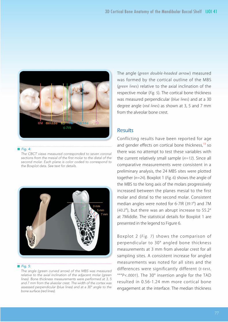
IJOI 41 RE EAR RE IE
77
D A IJOI 41
Fig. 4:The CBCT views measured corresponded to seven coronal sections from the mesial of the first molar to the distal of the second molar. Each plane is color coded to correspond to the Boxplot data. See text for details.
Fig. 5:The angle (green curved arrow) of the MBS was measured relative to the axial inclination of the adjacent molar (green lines). Bone thickness measurements were performed at 3, 5 and 7 mm from the alveolar crest. The width of the cortex was assessed perpendicular (blue lines) and at a 30° angle to the bone surface (red lines).
The angle (green double-headed arrow) measured was formed by the cortical outline of the MBS (green lines) relative to the axial inclination of the respective molar (Fig. 5). The cortical bone thickness was measured perpendicular (blue lines) and at a 30 degree angle (red lines) as shown at 3, 5 and 7 mm from the alveolar bone crest.
esults
Conflicting results have been reported for age and gender effects on cortical bone thickness,13 so there was no attempt to test these variables with the current relatively small sample (n=12). Since all comparative measurements were consistent in a preliminary analysis, the 24 MBS sites were plotted together (n=24). Boxplot 1 (Fig. 6) shows the angle of the MBS to the long axis of the molars progressively increased between the planes mesial to the first molar and distal to the second molar. Consistent median angles were noted for 6-7IR (39.1°) and 7M (40.2°), but there was an abrupt increase to 55.2° at 7Middle. The statistical details for Boxplot 1 are presented in the legend to Figure 6.
Boxplot 2 (F ig . 7 ) shows the comparison of perpendicular to 30° angled bone thickness measurements at 3 mm from alveolar crest for all sampling sites. A consistent increase for angled measurements was noted for all sites and the differences were significantly different (t-test ,
***P<.0001). The 30° insertion angle for the TAD resulted in 0.56-1.24 mm more cortical bone engagement at the interface. The median thickness
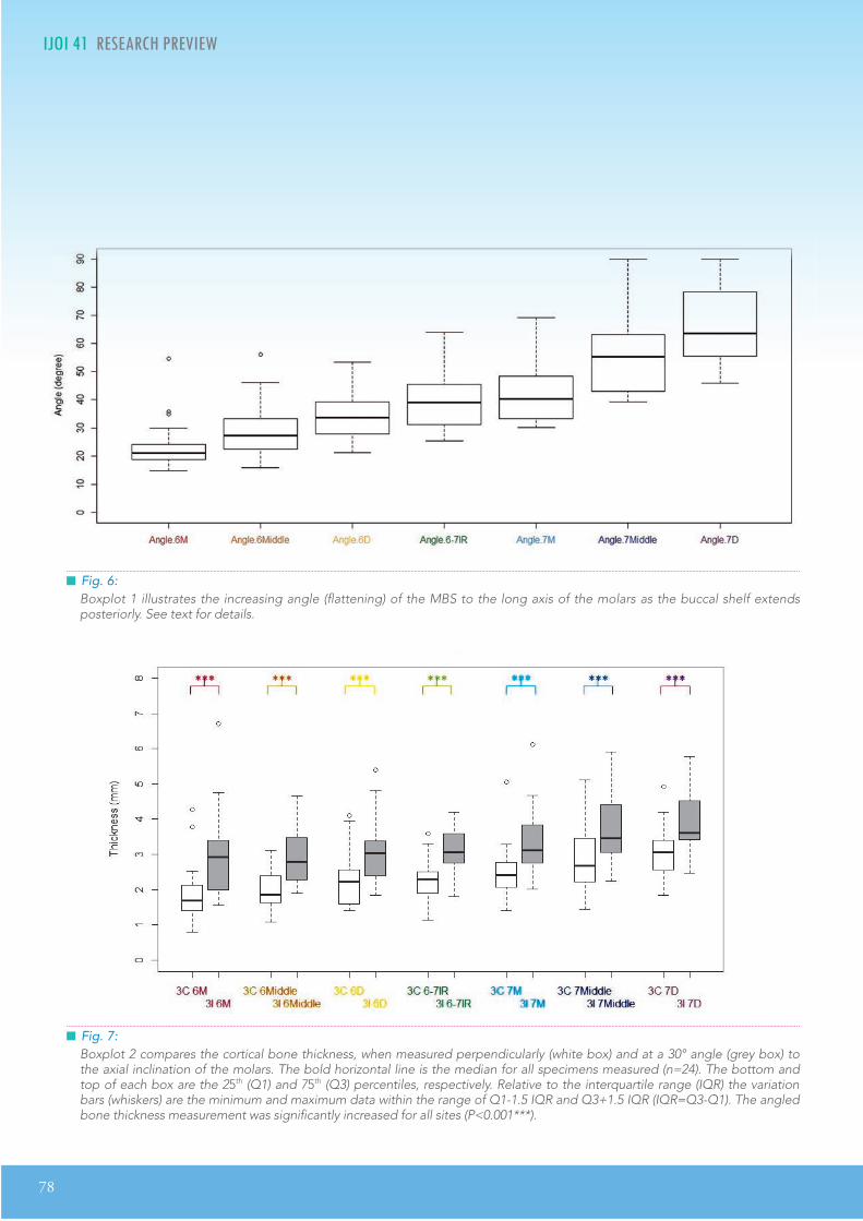
78
IJOI 41 RE EAR RE IE D A IJOI 41
Fig. 7:Boxplot 2 compares the cortical bone thickness, when measured perpendicularly (white box) and at a 30° angle (grey box) to the axial inclination of the molars. The bold horizontal line is the median for all specimens measured (n=24). The bottom and top of each box are the 25th (Q1) and 75th (Q3) percentiles, respectively. Relative to the interquartile range (IQR) the variation bars (whiskers) are the minimum and maximum data within the range of Q1-1.5 IQR and Q3+1.5 IQR (IQR=Q3-Q1). The angled bone thickness measurement was significantly increased for all sites (P<0.001***).
Fig. 6:Boxplot 1 illustrates the increasing angle (flattening) of the MBS to the long axis of the molars as the buccal shelf extends posteriorly. See text for details.
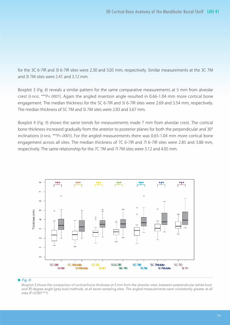
IJOI 41 RE EAR RE IE
79
D A IJOI 41
Fig. 8:Boxplot 3 shows the comparison of cortical bone thickness at 5 mm from the alveolar crest, between perpendicular (white box) and 30 degree angle (grey box) methods, at all seven sampling sites. The angled measurements were consistently greater at all sites (P<0.001***).
for the 3C 6-7IR and 3I 6-7IR sites were 2.30 and 3.05 mm, respectively. Similar measurements at the 3C 7M and 3I 7M sites were 2.41 and 3.12 mm.
Boxplot 3 (Fig. 8) reveals a similar pattern for the same comparative measurements at 5 mm from alveolar crest (t-test, ***P<.0001). Again the angled insertion angle resulted in 0.66-1.04 mm more cortical bone engagement. The median thickness for the 5C 6-7IR and 5I 6-7IR sites were 2.69 and 3.54 mm, respectively. The median thickness of 5C 7M and 5I 7M sites were 2.83 and 3.67 mm.
Boxplot 4 (Fig. 9) shows the same trends for measurements made 7 mm from alveolar crest. The cortical bone thickness increased gradually from the anterior to posterior planes for both the perpendicular and 30° inclinations (t-test, ***P<.0001). For the angled measurements there was 0.65-1.04 mm more cortical bone engagement across all sites. The median thickness of 7C 6-7IR and 7I 6-7IR sites were 2.85 and 3.88 mm, respectively. The same relationship for the 7C 7M and 7I 7M sites were 3.12 and 4.05 mm.

80
IJOI 41 RE EAR RE IE D A IJOI 41
Fig. 9:Boxplot 4 compares cortical bone thickness at 7 mm from the alveolar crest, between perpendicular (white box) and 30 degree angle (grey box) methods, at all seven sampling sites. The angled measurements were consistently greater at all sites (P<0.001***).
isussion
Angulation and bone thickness measurements from CBCT cuts documented that the MBS in Class III patients becomes progressively flatter from anterior to posterior. Figure 6 shows that the most consistent, relatively flat relationship was noted lateral to the interproximal area between the first and second molars (6-7IR and 7M). This site is the optimal location for an E-A bone screw that is also extra-radicular. The angulation of the MBS at the optimal TAD site is ~38 degrees (Fig. 6) which indicates that the bone screw should have the same angulation to the surface of the MBS to approximate the axial inclination of the molar. The latter is an important objective to avoid blocking the path of tooth movement when retracting the entire lower arch to conservatively treat Class III malocclusion.
Another factor favoring a superiorly angled insertion angle for a TAD is increased bone contact at its interface to achieve enhanced mechanical interlocking.9-11 Under ideal conditions the TAD angulation should be as close to the axial inclination of the adjacent molar as possible.

IJOI 41 RE EAR RE IE
81
D A IJOI 41
Inaba et al. suggest that the initial stability of miniscrews increases due to the extended bone contact when inserting at an inclined angle.11 Miniscrews are generally inserted at approximately 30 degrees to the line perpendicular to the bone contact. The present measurements at a 30° angle for sites 3-7 mm from the alveolar crest documented that angulating the TAD consistently increased bone contact from 0.56-1.23 mm, which was ~25-30% increase at all sites. This is an important consideration because even a 0.5 mm difference in cortical bone thickness (contact) can have a major impact on the success rate.14
The median for bone interface contract for an inclined TAD was 2.92-4.10 mm, and even the minimal value for the inclined cortical bone thickness measurement was 1.56 mm at 3I 6M. At least 1 mm of buccal cortical bone thickness is necessary to achieve primary stability.15,16 The abundant cortical bone in the MBS, up to 4 mm of bone thickness for an inclined miniscrew, is reflected in the high success rate for E-A TADs (~ 93%).17
Inserting MBS miniscrews at a 30° angle can be problematic. Pilot holes and changing the orientation of the TAD as it is screwed in have been suggested to consistently achieve a vertical orientation of the bone screw. However, pilot holes are also difficult to drill at an inclined angle, and rotating screws as they are inserted into dense cortical bone risks factoring the screw and/or creating a bone defect. Stainless-steel miniscrews with high flexibility and resistance
to fracture are indicated for the MBS.17 There are other factors which should be considered, including the mucogingival junction and the buccal impingement of the cheek. Chang et al.17 recommend a relatively vertical orientation for the bone screw, and found that penetrating moveable alveolar mucosa was not a problem, if the TADS had 5 mm of soft tissue clearance.
The present data (Figs. 6-9) was plotted with the Boxplot method because it is a convenient way of comparing groups of data according to their quartiles.18 Collectively the boxplots indicate that the optimal position for a MBS bone screw is 5-7 mm from alveolar crest and the TAD should be inserted lateral to the first and second molar interproximal area (6-7IR and 7M). The median for inc l ined cort ica l bone th ickness at the recommended sites ranged from 3.54 to 4.05 mm, which is more than sufficient for primary stability.15-17
onclusion
The mandibular buccal shelf is an appropriate skeletal site for extra-alveolar bone screws to retract molars for nonextraction treatment of mandibular crowding. They are also suitable anchorage for retracting the entire lower arch to conservatively correct Class III malocclusion. The optimal position for the TAD is lateral to the contact of the lower first and second molars, approximately 5-7 mm below the alveolar crest, and inserted at an orientation of about 30° to the bone surface.

82
IJOI 41 RE EAR RE IE
e erence
1. Huang S, Chang CH, Roberts WE. A severe skeletal Class III open bite malocclusion treated with non-surgical approach. Int J Orthod Implantol 2011;24:28-39.
2. Su B, Chang CH, Roberts WE. Conservative management of a severe Class III open bite malocclusion. Int J Orthod Implantol 2013;30:40-60.
3. Shih YH, Lin JJ, Roberts WE. Conservative correction of severe class III open bite: 3 force vectors to reverse the dysplasia by retracting and rotating the entire lower arch. Int J Orthod Implantol 2015;38:4-15.
4. Lin JJ. Treatment of severe Class III with buccal shelf miniscrews. News & Trends in Orthodontics 2010;18:4-13.
5. Chang CH, Roberts WE. Orthodontics. Taipei: Yong Chieh; 2012.
6. Lin JJ, Liaw JL, Chang CH, Roberts WE. Orthodontics: Class III correction. Taipei: Yong Chieh; 2013.
7. Park HS, Lee SK, Kwon OW. Group distal movement of teeth using microscrew implant anchorage. Angle Orthod 2005;75(4):602-9.
8. Crismani AG, Bertl MH, Celar AG, Bantleon H-P, Burstone CJ. Miniscrews in orthodontic treatment: review and analysis of published clinical trials. Am J Orthod Dentofacial Orthop 2010;137(1):108-13.
9. Wilmes B, Rademacher C, Oltho G, Drescher D. Parameters Affecting Primary Stability of Orthodontic Mini-implants. J Orofac Orthop / Fortschritte der Kieferorthopädie 2006;67(3):162-74.
10. Marquezan M, Maos CT, Sant’nna EF, de Souza MMG, Maia LC. Does cortical thickness inuence the primary stability of miniscrews?: A systematic review and meta-analysis. Angle Orthod 2014;84(6):1093-103.
11. Inaba M. Evaluation of primary stabi l ity of incl ined orthodontic mini-implants. J Oral Sci 2009;51(3):347-53.
12. Park HS, Jeong SH, Kwon OW. Factors affecting the clinical success of screw implants used as orthodontic anchorage. Am J Orthod Dentofac Orthop 2006;130(1):18-25.
13. Holmes PB, Wolf BJ, Zhou J. A CBCT atlas of buccal cortical bone thickness in interradicular spaces. Angle Orthod 2015;85(6):911-919. No. 150311070540000.
14. Motoyoshi M, Matsuoka M, Shimizu N. Application of orthodontic mini-implants in adolescents. Int J Oral Maxillofac Surg 2007;36(8):695-9.
15. Motoyoshi M, Inaba M, Ono a., Ueno S, Shimizu N. e eect of cortical bone thickness on the stability of orthodontic mini-implants and on the stress distribution in surrounding bone. Int J Oral Maxillofac Surg 2009;38:13-8.
16. Motoyoshi M, Yoshida T, Ono A, Shimizu N. Eect of cortical bone thickness and implant placement torque on stability of orthodontic mini-implants. Int J Oral Maxillofac Implants 22(5):779-84.
17. Chang CH, Liu SS, Roberts WE. Primary failure rate for 1680 extra-alveolar mandibular buccal shelf miniscrews placed in movable mucosa or aached gingiva. Angle Orthod 2015;85(6):905-910. No. 150120092518005.
18. Frigge M, Hoaglin DC, Iglewicz B. Some implications of the boxplot. American Statistician 1989;43(1):50-54.
Orthodontics Vol. I-IV and Implant Dentistry VoI. I-IIare now available on iBooks Store in total 52 countries:
Argentina, Australia, Austria, Belgium, Bolivia, Bra il, Bulgaria, Canada, Chile, China, Colombia, Costa ica, Cyprus, C ech epublic, Denmar , Dominican epublic, Ecuador, El Salvador, Estonia, inland, rance, Germany, Greece, Guatemala, Honduras, Hungary, Ireland, Italy, Japan, Latvia, Lithuania, Lu embourg, Malta, Me ico, etherlands, ew ealand, icaragua,
orway, Panama, Paraguay, Peru, Poland, Portugal, omania, Slova ia, Slovenia, Spain, Sweden, Swit erland, United ingdom, United States, and ene uela.
Chris Chang’s Angle Case Reports is a collection of cases submitted for the entrance examination into one of the most prestigious orthodontic group in the world, the Angle Society. This iBook collection documented step by step from start to finish with 3D dental casts, photographs, radiographs,treatment tips and video presentations to enhance the learning experience. Original reviewers’ remarks are also included as reference guides on treatment quality. In addition, it includes Chang’s recent study on the effect of buccal shelf screws. The preface also provides a fascinating account of Dr. Angle’s historyby Dr. Eugene Roberts. Written with a clinical focus, Angle Case Reports is recommended for practitioners to improve treatment quality and/or to prepare for board certification.


86
IJOI 41 T D IJOI 41
ip in o in c inica rrorana m nt o ir i o m nt
Wire dislodgment is a common issue found in routine appointments. Two of the primary causes include closing of extraction spaces and sliding of the main archwire. Doctors should perform a careful examination before cutting ush with the end of a tube. If wire dislodgment is caused by sliding, cutting the wire renders it short to engage all brackets. Therefore, a checklist is proposed to help clinicians rule out unintended sliding before cutting. (Int J Orthod Implantol 2016;41:86-87)
1. Check if an explorer can enter the molar tube.
2. Check if the molar is rotated.
3. Check if bilateral extraction spaces are not closed symmetrically.
4. Check if one or more resin stops are lost.
Fig. 1: Intra-oral photograph before adjustment.

IJOI 41 T
87
D IJOI 41
Dr. Angle Lee,Editor, International Journal of Orthodontics & Implantology (Left)
Dr. Chris Chang, Founder, Beethoven Orthodontic Center
Publisher, International Journal of Orthodontics & Implantology (Right)
The following is an example of how to apply this checklist to perform this assessment. Fig. 1 shows that the main archwire presents an excessive tail on the mandibular left side. One should first use an explorer to check if the opposite end of the archwire is fully engaged in the molar tube. When the tip of the explorer can enter the molar tube from the distal end, it is indicated that the wire is not fully engaged (Fig. 1A). Another indication of wire dislodgment is the counter-clockwise rotation of the molar (Figs. 1B & 2). Furthermore, a significant extraction space remains on the right side while the left one is closed. Such discrepancy is suspected to be caused by wire dislodgment, preventing the right molar tube from sliding along the archwire (Fig. 1C). Lastly, a resin stop on the left side is lost, which might contribute to the main archwire sliding (Fig. 1D).
With this list clinicians can easily and systematically analyze if the presence of an excessive tail should be cut flush or it is, in fact, a sign of wire dislodgment and should be re-engaged.
Fig. 3: After adjustment, resin stops are rebonded and elastomeric chains are used to close extraction spaces. The ends of the archwire are visible bilaterally, indicating the wire is fully engaged in the molar tubes.
Fig. 2: The relationship between long axis of the molar tube (purple dotted line) and the main archwire (green line) shows that the molar presents a counter-clockwise rotation.

F I N E S T D E N T A L I N S T R U M E N T SG E R M A N Y
德國精湛工藝
fluent perfectionfluent perfectionfluent perfectionfluent
F I N E S T D E N T A L I N S T R U M E N T S- S I N C E 1 9 1 6 -
G E R M A N Y
T H E N E W
SensiΩveG R I P.衛部醫器輸壹字第015200號
新品優惠價NT$148,000/組O B T U R A T I O N S Y S T E M
「 」
或
elementsfree / 1台含Heated Plugger .06 / 1支 23 Gauge Heavy Body G.P Cartridges / 2個
買
贈 Buchanan鎳鈦合金手動填壓器械 #1 #2 / 各1支
TFA馬來膠針 或 TF馬來膠針 / 任選5盒
子彈型純銀膠針 #23/二盒、#25 / ㄧ盒
.衛部醫器輸壹字第015275號.衛署醫器輸壹字第002755號.衛署醫器輸壹字第010742號.衛署醫器輸壹字第008363號
*本優惠專案僅適用於牙醫診所*本公司保留贈品更換之權利*本公司保留更改及終止活動辦法與條款之權利
自2016/1/1 - 3/25止
F I N E S T D E N T A L I N S T R U M E N T SG E R M A N Y
德國精湛工藝
fluent perfection
F I N E S T D E N T A L I N S T R U M E N T S- S I N C E 1 9 1 6 -
G E R M A N Y
T H E N E W
SensiΩveG R I P.衛部醫器輸壹字第015200號
新品優惠價NT$148,000/組O B T U R A T I O N S Y S T E M
「 」
或
elementsfree / 1台含Heated Plugger .06 / 1支 23 Gauge Heavy Body G.P Cartridges / 2個
買
贈 Buchanan鎳鈦合金手動填壓器械 #1 #2 / 各1支
TFA馬來膠針 或 TF馬來膠針 / 任選5盒
子彈型純銀膠針 #23/二盒、#25 / ㄧ盒
.衛部醫器輸壹字第015275號.衛署醫器輸壹字第002755號.衛署醫器輸壹字第010742號.衛署醫器輸壹字第008363號
*本優惠專案僅適用於牙醫診所*本公司保留贈品更換之權利*本公司保留更改及終止活動辦法與條款之權利
自2016/1/1 - 3/25止
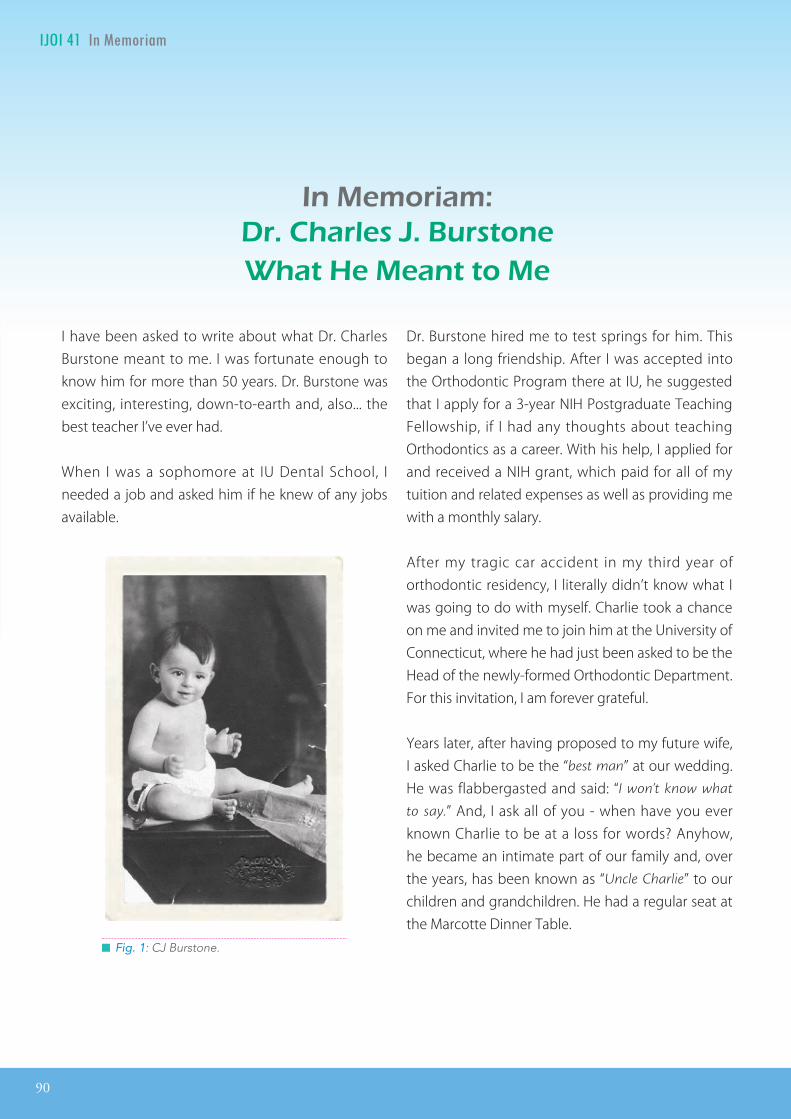
90
IJOI 41 I D J IJOI 41
n moriamr. ar . r tonat ant to
Fig. 1: CJ Burstone.
I have been asked to write about what Dr. Charles Burstone meant to me. I was fortunate enough to know him for more than 50 years. Dr. Burstone was exciting, interesting, down-to-earth and, also... the best teacher I’ve ever had.
When I was a sophomore at IU Dental School, I needed a job and asked him if he knew of any jobs available.
Dr. Burstone hired me to test springs for him. This began a long friendship. After I was accepted into the Orthodontic Program there at IU, he suggested that I apply for a 3-year NIH Postgraduate Teaching Fellowship, if I had any thoughts about teaching Orthodontics as a career. With his help, I applied for and received a NIH grant, which paid for all of my tuition and related expenses as well as providing me with a monthly salary.
After my tragic car accident in my third year of orthodontic residency, I literally didn’t know what I was going to do with myself. Charlie took a chance on me and invited me to join him at the University of Connecticut, where he had just been asked to be the Head of the newly-formed Orthodontic Department. For this invitation, I am forever grateful.
Years later, after having proposed to my future wife, I asked Charlie to be the “best man” at our wedding. He was flabbergasted and said: “I won’t know what
to say.” And, I ask all of you - when have you ever known Charlie to be at a loss for words? Anyhow, he became an intimate part of our family and, over the years, has been known as “Uncle Charlie” to our children and grandchildren. He had a regular seat at the Marcotte Dinner Table.
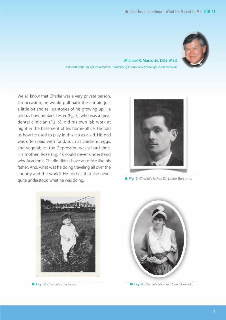
IJOI 41 I
91
D J IJOI 41
Fig. 2: Charlie’s childhood Fig. 4: Charlie's Mother, Rose Liberfarb.
Fig. 3: Charlie's father, Dr. Lester Burstone.
Michael R. Marcotte, DDS, MSDAssistant Professor of Orthodontics, University of Connecticut School of Dental Medicine
We all know that Charlie was a very private person. On occasion, he would pull back the curtain just a little bit and tell us stories of his growing up. He told us how his dad, Lester (Fig. 3), who was a great dental clinician (Fig. 5), did his own lab work at night in the basement of his home-office. He told us how he used to play in this lab as a kid. His dad was often paid with food, such as chickens, eggs, and vegetables; the Depression was a hard time. His mother, Rose (Fig. 4), could never understand why Academic Charlie didn’t have an office like his father. And, what was he doing traveling all over the country and the world? He told us that she never quite understood what he was doing.
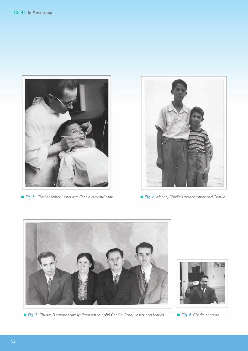
92
IJOI 41 I D J IJOI 41
IJOI In Memoriam
Fig. 5: Charlie’s father, Lester with Charlie in dental chair. Fig. 6: Marvin, Charlie’s older brother and Charlie.
Fig. 7: Charles Burstone’s family: (from left to right) Charlie, Rose, Lester, and Marvin. Fig. 8: Charlie at home.

IJOI 41 I
93
D J IJOI 41
Charlie was also very proud of his older brother, Marvin (Figs. 6 & 7, first from the right in Fig. 7), who was an NIH dentist-researcher and, according to Charlie, quite handsome. Charlie also taught Sunday School as a teenager and worked in a finger-nail polish factory in New Haven, where he lived with his aunt over a summer. He was a Boy Scout with his own Den of Cub Scouts. One of their projects didn’t go as planned. He had the boys using plaster and he forgot to put the separating medium on the bowls that he had borrowed from one of the mothers. Much to their dismay, the bowls had to be broken to remove the project.
Fig. 8: Charlie’s military life in Busan, Korea.
Fig. 9: Charlie (center) at Xian University, China in the early ‘70s.
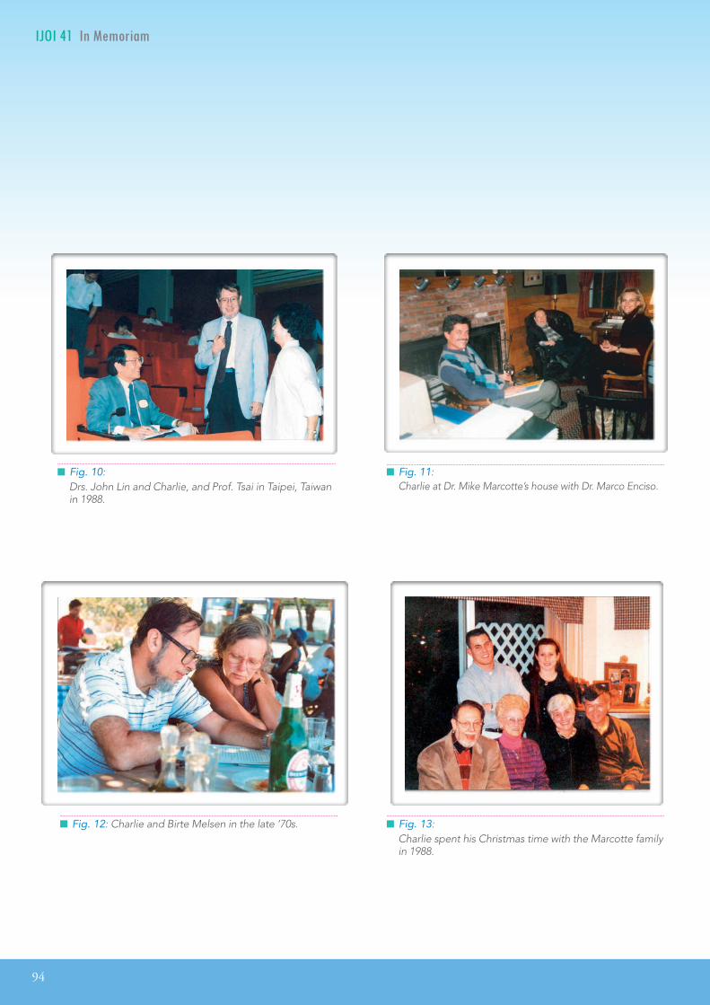
94
IJOI 41 I D J IJOI 41
Fig. 12: Charlie and Birte Melsen in the late ‘70s. Fig. 13: Charlie spent his Christmas time with the Marcotte family in 1988.
Fig. 11: Charlie at Dr. Mike Marcotte’s house with Dr. Marco Enciso.
Fig. 10: Drs. John Lin and Charlie, and Prof. Tsai in Taipei, Taiwan in 1988.

IJOI 41 I
95
D J IJOI 41
Charlie in Hawaii with Mike Marcotte. Charlie in Hawaii at Mike's Aunt's house.
Mike, Anita and Charlie in Vi
enna
( From left to right).
He would always start his stories with “Stop me if I’ve
told you this before.” Of course we never did because the stories were just as good or even funnier the second or third time around.
Charlie enjoyed many things in life. He was a lover of Classical music, especially the Wagnerian Operas, which he would take us to in New York City. He enjoyed coming to our home everytime we would have a piano recital. He loved art and we visited many museums around the world, places which we would have probably never gone to without him. And, he could always tell us interesting facts about the artist or the artwork. He was also a Nature lover; the three of us (my wife, myself and Charlie) often hiked together in Connecticut and elsewhere. He

96
IJOI 41 I D J IJOI 41
Charlie on a trip to Asia.could identify plants and trees and was never, ever
stumped. He loved to walk, whether it was in a city or in the countryside. Even toward the end of his life, he would take us walking on the trails of his retirement residence.
Charlie was always a welcomed guest at our home. Our children, grandchildren and “extended family” enjoyed his stories and sense of humor. Many of them mentioned to us, after he passed away, how he always tried to discover what was interesting to them and was never at a loss to find something to discuss with them.
Charlie on a trip to Asia.
Fig. 14: Charlie with Katherine Marcotte (Left) and Mike Marcotte (Right) on Thanksgiving, 2014.

IJOI 41 I
97
D J IJOI 41
Charlie on a trip to Asia.
Charlie on a trip to Asia.
Farewell Charlie until we meet aga in.
When our 6-year old grandson, Nicholas, who is learning to speak Chinese in school, was told of Charlie’s passing, he asked his dad, “Who’s going to
speak Chinese with me now?” Charlie had learned to speak Chinese on his first Sabbatical to China in the early ‘70s. Charlie mentioned to our daughter, Katherine (Fig. 14), that he enjoyed being at the table in her home because the place card at his seat, always said “Uncle Charlie” or even just “UC...” not Dr. Burstone. He especially enjoyed her “ice breakers” at the dinner table.
So you see, I can’t just talk about what Charlie means to me because he became a part of our family and meant so much to all of us.
He will be sorely missed by all of us; our dinners and holidays will certainly not be as lively. We were fortunate to have him while we did and we must always keep that in the forefront of our minds.
We will always remember him for his honesty, kindness, humor, and generosity. These traits carried him well during his life. He was truly a “Renaissance
man” - his was a life well-spent. Rest in peace, Charlie - you truly deserve it ...and... we miss you.

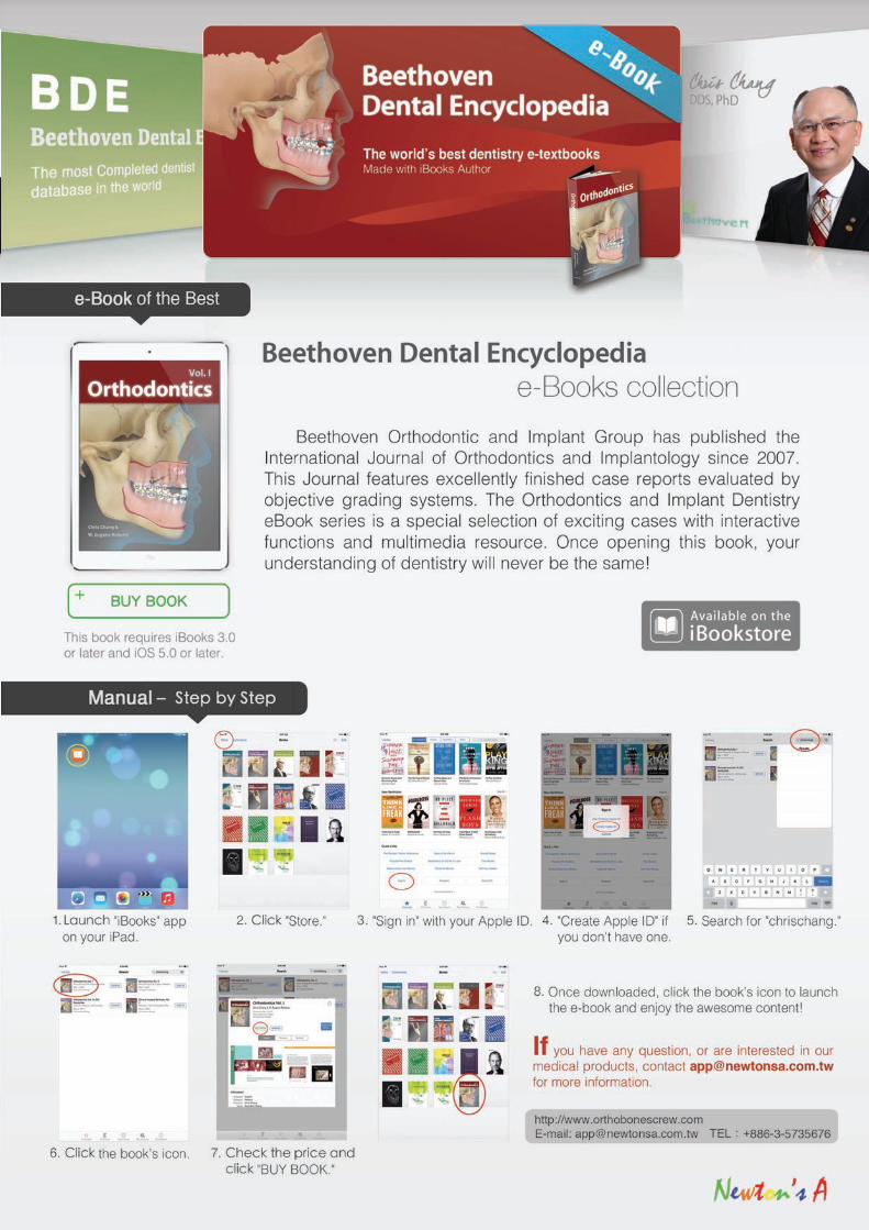

ac rom t t o nnt rnationa or op
The best course to learn how to deal with severe class III cases and impacted canines, using miniscrews and VISTA! An unforgettable experience!
All the best,Marina Portugal
It was indeed a wonderful experience to learn from Dr. Chris. I would highly recommend this course to everyone. Truely the best course I have ever attended. A big thanks to Dr. Chris, his wife and also his wonderful team for the amazing hospitality.
Regards,
Dr. Urumese Mampilly Orthodontist, Dubai
The lecture exceeded all my expectations so I can only consider it as an excellent one. I have been using micro-implants in my practice for more than 10 years and now I understand I can get even better results by changing the type of screws and their position of placement.
The practical part of the lecture was efficient and helps everyone to put it to practice in the future.
The VISTA protocol is extremely interesting, and with the practical component of the lecture I felt ready to use it straight away.
I thoroughly recommend the Keynote lectures, basic and advanced. It was very pleasant to seize the opportunity to make this trip and take the 3 lectures.
I would like to thank Dr. Chris Chang and his excellent team for the kind way they received me.
Best regards,
Carlos Mota Portugal
IJOI 41 EED A RO T E ORLD
100
EED A RO T E ORLD IJOI 41

ac rom i r
not 課程反饋
非常感谢你们的团队,你们的耐心与热情,给了我不
一样的学习体验,这次的 Keynote 课程的学习,收获颇
多,有机会一定还会再去请教学习。
趙玉瓊拜博口腔医疗集团 大連分部
你们团队很优秀,非常敬业,学习收获颇丰,期待有更
多的合作,谢谢。
黎 強拜博口腔医疗集团执行总裁
Dear Dr. Chris Chang:
Warm felt greetings!
I wanted to tell you that I have had two great mentors in my professional life as an orthodontist. They have made it possible for me to enjoy my profession with true PASSION, which has also influenced my personal life in a very positive way. The two mentors are Dr. Damon and You. I also acknowledge other great professionals in the Damon world. The two of you, however, have a profound impact in my life.
I wanted to share this case with you, because I worked it following your teachings and learning from your indications and procedures which I have seen and understood from your recorded lectures and videos repeadly. I continually learn a lot from them.
I have not had the privilege to personally participate in your training courses yet; but, believe me, that is my dream and my goal. I hope to see you soon in the Forum.
Best wishes for you, your wife and your family for the new year 2016.
With my appreciation and best regards,
José Ignacio Mesa. M Speaker Ormco, Latin America
IJOI 41 EED A RO T E ORLD EED A RO T E ORLD IJOI 41
101


2016.07.14简报圣经
Dr. Kokich
Steve Jobs
Advanced Keynote
2016.08.0410大演讲秘诀
令人目眩神迷的演讲技巧2016.09.15
2016.10.22 - 24
高效简报学习法2016 Keynote Workshop
数位化潮流下的牙科简报,不仅需要清晰的临床照片,也需要精确的图表和流畅的动画来吸引观众,而优秀的视觉化工具更使您的演讲独树一格且令人难忘。Keynote 456课程中,Dr. Rungsi 将分享他利用Keynote软体绘制精美牙科插图的经验,并一步步教会您如何从构想和草图创建出令人惊艳的成果。跟随简报美学大师的脚步,您也可以秀出创意、站上世界舞台!
名额有限,以缴费顺序为依据。旧生享特惠优惠价,限额6名。若取消报名,7/22前退款将扣除10%行政手续费,7/23后扣除30%行政手续费。
。。。
金牛顿艺术科技 新竹市建中一路25號2楼 报名专线:03-5735676
报名2016课程即赠送2015及2016课程视讯。
看过太多充满复杂文字和图表的幻灯片,听过就忘了的演讲吗?Keynote系列课程教你如何利用Mac内建软体Keynote,制作出令人目眩神迷、印象深刻的电脑简报。透过小班教学,贴身指导,务必让你在课程中轻松掌握Keynote的简报技巧。
Keynote 101
Speaker: Dr. Rungsi
Newton’s A
K123
K456
讲师:Dr. Rungsi Thavarungkul
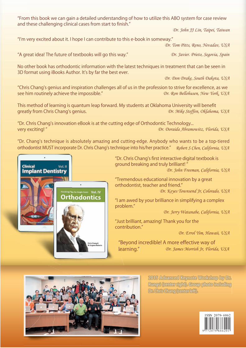
2015 Advanced Keynote Workshop by Dr. Rungsi (center right). Group photo including Dr. Chris Chang (center left).
“From this book we can gain a detailed understanding of how to utilize this ABO system for case review and these challenging clinical cases from start to finish.”
Dr. John JJ Lin, Taipei, Taiwan
“I’m very excited about it. I hope I can contribute to this e-book in someway.”Dr. Tom Pitts, Reno, Nevadav, USA
“A great idea! The future of textbooks will go this way.” Dr. Javier. Prieto, Segovia, Spain
No other book has orthodontic information with the latest techniques in treatment that can be seen in 3D format using iBooks Author. It's by far the best ever.
Dr. Don Drake, South Dakota, USA
“Chris Chang's genius and inspiration challenges all of us in the profession to strive for excellence, as we see him routinely achieve the impossible.” Dr. Ron Bellohusen, New York, USA
This method of learning is quantum leap forward. My students at Oklahoma University will benefit greatly from Chris Chang's genius. Dr. Mike Steffen, Oklahoma, USA
“Dr. Chris Chang's innovation eBook is at the cutting edge of Orthodontic Technology... very exciting! ” Dr. Doraida Abramowitz, Florida, USA
“Dr. Chang's technique is absolutely amazing and cutting-edge. Anybody who wants to be a top-tiered orthodontist MUST incorporate Dr. Chris Chang's technique into his/her practice.” Robert S Chen, California, USA
“Dr. Chris Chang's first interactive digital textbook is ground breaking and truly brilliant! ”
Dr. John Freeman, California, USA
“Tremendous educational innovation by a great orthodontist, teacher and friend.”
Dr. Keyes Townsend Jr, Colorado, USA
“I am awed by your brilliance in simplifying a complex problem.”
Dr. Jerry Watanabe, California, USA
“Just brilliant, amazing! Thank you for the contribution.”
Dr. Errol Yim, Hawaii, USA
“Beyond incredible! A more effective way of learning.” Dr. James Morrish Jr, Florida, USAlearning.”
Related Documents