Session Initiation Protocol (SIP) 2 IP Telephony Introduction A powerful alternative to H.323 More flexible, simpler Easier to implement Advanced features Better suited to the support of intelligent user devices A part of IETF multimedia data and control architecture SDP, RTSP (Real-Time Streaming Protocol), SAP (Session Announcement Protocol) 3 IP Telephony The Popularity of SIP Originally Developed in the MMUSIC (Multiparty Multimedia Session Control) A separate SIP working group RFC 2543 Many developers The latest version: RFC 3261 (June 2002 ) SIP + MGCP/MEGACO The VoIP signaling in the future “bake-offs” or SIP Interoperability Tests The development of SIP and its implementation by system developers has involved a number of events. Various vendors come together and test their products against each other to ensure that they have implemented the specification correctly to ensure compatibility with other implementations 4 IP Telephony SIP Architecture A signaling protocol The setup, modification, and tear-down of multimedia sessions SIP + SDP Describe the session characteristics to potential session participants Separate signaling and media streams Signaling may pass via one or more proxy or redirect servers Media stream takes a more direct path. SIP Signaling IP Network RTP Media Stream SIP User SIP User

Welcome message from author
This document is posted to help you gain knowledge. Please leave a comment to let me know what you think about it! Share it to your friends and learn new things together.
Transcript

Session Initiation Protocol (SIP)
2IP Telephony
Introduction
A powerful alternative to H.323
More flexible, simpler
Easier to implement
Advanced features
Better suited to the support of intelligent user devices
A part of IETF multimedia data and control architecture
SDP, RTSP (Real-Time Streaming Protocol), SAP (Session Announcement Protocol)
3IP Telephony
The Popularity of SIP
Originally Developed in the MMUSIC (Multiparty Multimedia Session Control)
A separate SIP working group
RFC 2543
Many developers
The latest version: RFC 3261 (June 2002 )
SIP + MGCP/MEGACOThe VoIP signaling in the future
“bake-offs” or SIP Interoperability TestsThe development of SIP and its implementation by system developers has involved a number of events.
Various vendors come together and test their products against each other
to ensure that they have implemented the specification correctly
to ensure compatibility with other implementations
4IP Telephony
SIP Architecture
A signaling protocolThe setup, modification, and tear-down of multimedia sessions
SIP + SDPDescribe the session characteristics to potential session participants
Separate signaling and media streamsSignaling may pass via one or more proxy or redirect servers
Media stream takes a more direct path.
SIP Signaling
IP Network
RTP Media Stream
SIP User SIP User

5IP Telephony
SIP Network Entities [1/4]
Clients
User agent clients
Application programs sending SIP requests
Servers
Responds to clients’ requests
Clients and servers may be in the same platform.
Proxy acts as both clients and servers
6IP Telephony
SIP Network Entities [2/4]
Four types of servers
Proxy servers
Act in a similar way to a proxy server used for web access
Handle requests or forward requests to other servers after some translation
Can be used for call forwarding, time-of-day routing, or follow-me services
[email protected] [email protected]
1.Request [email protected]
2.Request [email protected]
4.Response 3.Response
7IP Telephony
SIP Network Entities [3/4]
Redirect servers
Accept SIP requests
Map the destination address to zero or more new addresses
Return the new address(es) to the originator of the request
Redirect Server
1.Request [email protected]
2.Moved temporarily Contact: [email protected]
3.ACK
4.Request
5.Response
8IP Telephony
SIP Network Entities [4/4]
A user agent server
Accepts SIP requests and contacts the user
The user responds an SIP response
A SIP device
E.g., a SIP-enabled telephone
A registrar (location server)
Accepts SIP REGISTER requests
Indicating that the user is at a particular address
Personal mobility
Typically combined with a proxy or redirect server

9IP Telephony
SIP Call Establishment
A SIP call establishment is simple.
A number of interim responses may be made to the INVITE prior to the called party accepting the call.
a
b
c
d
e
f
g
INVITE
Ringing
OK
ACK
Conversation
BYE
OK
10IP Telephony
SIP Advantages
Attempt to keep the signaling as simple as possible
Offer a great deal of flexibility
Does not care what type of media is to be exchanged during a session or the type of transport to be used for the media
Various pieces of information can be included within the messages
Including non-standard information
Text-based encoding
Enable the users to make intelligent decisions
The control of the intelligent features is placed in the hands of the customer, not the network operator.
E.g., SUBJECT header
11IP Telephony
Call Completion to Busy Subscriber Service
a
b
c
d
e
f
gConversation
BYE
OK
ACK
OK
Ringing
INVITE
Busy (Try at 4pm)
INVITE
ACK
j
i
h
12IP Telephony
Overview of SIP Messaging Syntax
Text-basedSimilar to HTTP
Disadvantage – more bandwidth consumption
SIP messagesmessage = start-line
*message-header CRLF
[message-body]
start-line = request-line | status-line
Request-line specifies the type of request
The response line indicates the success or failure of a given request.

13IP Telephony
Message headersAdditional information of the request or response
E.g.,The originator and recipient
Retry-after header
Subject header
Message bodyDescribe the type of session
The most common structure for the message body is SDP (Session Description Protocol).
Could include an ISDN User Part message
Examined only at the two ends
14IP Telephony
SIP Requests [1/2]
Method SP Request-URI SP SIP-version CRLF
Request-URI
The SIP address of the destination
Methods
INVITE, ACK, OPTIONS, BYE, CANCLE, REGISTER
INVITE
Initiate a session
Information of the calling and called parties
The type of media
IAM (initial address message) of ISUP
ACK only when receiving the final response
15IP Telephony
SIP Requests [2/2]
BYE
Terminate a session
Can be issued by either the calling or called party
OPTIONS
Query a server as to its capabilities
To support a particular type of media
CANCEL
Terminate a pending request
Pending Request: an INVITE did not receive a final response
REGISTER
Log in and register the address with a SIP server
“all SIP servers” – multicast address (224.0.1.175)
Can register with multiple servers
Can have several registrations with one server
16IP Telephony
“One Number” Service
Registrar/Proxy CallerUser at Address 1User at Address 2
OK
Register (address 1)
Register (address 2)
OK
INVITE
Trying
INVITE
INVITE
OK
CANCEL
OK (for INVITE)
OK (for CANCEL)
ACK
ACK
Conversation

17IP Telephony
SIP INFO Method
Specified in RFC 2976
For transferring information during an ongoing session
The transfer of DTMF digits
The transfer of account balance information
Pre-paid service
The transfer of mid-call signaling information
18IP Telephony
SIP Responses
SIP Version SP Status Code SP Reason-Phrase CRLF
Reason-Phrase
A textual description of the outcome
Could be presented to the user
Status code
A three-digit number
1XX Informational
2XX Success (only code 200 is defined)
3XX Redirection
4XX Request Failure
5XX Server Failure
6XX Global Failure
All responses, except for 1XX, are considered final
Should be ACKed
19IP Telephony
SIP Addressing
SIP URLs (Uniform Resource Locators)
user@host
20IP Telephony
Message Headers
Provide further information about the message
E.g.,
To:header in an INVITE
The called party
From:header
The calling party
Four main categories
General, Request, Response, and Entity headers

21IP Telephony
General Headers
Used in both requests and responses
Basic information
E.g., To:, From:, Call-ID: (uniquely identifies a specific invitation to a session), …
Contact:
Provides a URL for use in future communication regarding a particular session
Examples 1: In a SIP INVITE, the Contact header might be different from the From header.
An third-party administrator initiates a multiparty session.
Example 2: Used in response, it is useful for directing further requests directly to the called user.
Example 3: It is used to indicate a more appropriate address if an INVITE issued to a given URI failed to reach the user.
22IP Telephony
Request HeadersApply only to SIP requests
Addition information about the request or the client
E.g.,Subject:
Priority: urgency of the request (emergency, urgent, normal, or non-urgent)
Response HeadersFurther information about the response that cannot be included in the status line
E.g.,Unsupported
Retry-After
23IP Telephony
Entity Headers
Indicate the type and format of information included in the message body
Content-Length: the length of the message body
Content-Type: the media type of the message body
E.g., application/sdp
Content-Encoding: for message compression
Content Disposition: how a message part should be interpreted
session, alert, render …
Examples of SIP Message Sequences
Via:
From: and To:
Call-ID:host-specific
Contact: (for future SIPmessage transmission)
*
Content-Length:Zero, no msg body
CSeq:A response to any request must use the same value of CSeq as used in the request.
Expires:TTL
0, unreg

Invitation
A two-party call
Subject:
optional
Content-Type:
application/sdp
A dialog ID
To identify a peer-to-peer relationship between two user agents
Tag in From
Tag in To
Call-ID
Termination of a Call
CSeq has changed.
Boss<sip:[email protected]>Daniel<sip:[email protected]>
BYE sip:[email protected] SIP/2.0Via: SIP/2.0/UDP station1.work.com; branch=z9hG4bK123Max-Forwards: 70From: Daniel<sip:[email protected]>; tag=44551To: Boss<sip:[email protected]>; tag=11222Call-ID: [email protected]: 2 BYEContent-Length: 0
a
bSIP/2.0 200 OKVia: SIP/2.0/UDP station1.work.com;branch=z9hG4bK123From: Daniel<sip:[email protected]>; tag=44551To: Boss<sip:[email protected]>; tag=11222Call-ID: [email protected]: 2 BYEContent-Length: 0
Redirect Servers
An alternative address302, Moved temporarily
Another INVITESame Call-ID
CSeq ++
28IP Telephony
Proxy Servers [1/2]
Sits between a user-agent client and the far-end user-agent server
Numerous proxies can reside in a chain between the caller and callee.
The most common scenario will have at least two proxies: one at the caller and one at the callee end.
It is likely that only the last proxy in the chain changes the Request-URI.
The other proxies in the chain would simply use the domain part of the received Request-URI as input to a location function (e.g., DNS) to determine the next hop.

29IP Telephony
Proxy Servers [2/2]
Via:
The path taken by a request
Loop detected, 482 (status code)
For a response
The first Via: header is checked and removed.
The second Via: header is checked.
If it exists, perform forwarding.
If not, the response is destined to the proxy itself.
The response finds its way back to the originator of the request.
Branch: used to distinguish between multiple responses to the same request
Forking Proxy: Issue a single request to multiple destinations
30IP Telephony
Proxy State [1/2]
Can be either stateless or stateful
If stateless, the proxy takes an incoming request, performs whatever translation and forwards the corresponding outgoing request and forgets anything.
Retransmission takes the same path (no change on retransmission).
If stateful, the proxy remembers incoming requests and corresponding outgoing request.
The proxy is able to act more intelligently on subsequent requests and responses related to the same session.
31IP Telephony
Proxy State [2/2]
Record-Route: and Route: Headers
The subsequent requests may not pass through the same path as the initial request/response.
E.g., use Contact:
A Proxy might require that it remains in the signaling path for all subsequent requests to provide some advanced service.
In particular for a stateful proxy
Insert its address into the Record-Route: header
The response includes the Record-Route: header
The information contained in the Record-Route: header is used in the subsequent requests related to the same call.
The Route: header is used to record the path that the request is enforced to pass.

34IP Telephony
Forking Proxy
A proxy can “fork” requests
A user is registered at several locations
;branch=xxx
In order to handle such forking, a proxy must be stateful.

Session Initiation Protocol (SIP)
2IP Telephony
The Session Description Protocol
The Most Common Message Body
Session information describing the media to be exchanged between the parties
SDP, RFC 2327 (initial publication)
A number of modifications to the protocol have been suggested.
SIP uses SDP in an answer/offer mode.
An agreement between the two parties as to the types of media they are willing to share
RFC 3264 (An Offer/Answer Model with SDP)
To describe how SDP and SIP should be used together
3IP Telephony
Usage of SDP with SIP
SIP and SDP make a wonderful partnership for the transmission of session information.
SIP provides the messaging mechanism for the establishment of multimedia sessions.
SDP provides a structured language for describing the sessions.
The entity headers identifies the message body.
4IP Telephony
The Structure of SDP
SDP simply provides a format for describing session information to potential session participants.
Text-based Protocol
The Structure of SDP
Session Level Info
Name of the session
Originator of the session
Time that the session is to be active
Media Level Info
Media type
Port number
Transport protocol
Media format
Originator and Session ID
Protocol Version
Session Name
Session Time
Media Name and Transport
Connection Information
Media Name and Transport
Connection Information
Session Description
Session Level Information
Media Description 1
Media Description 2

5IP Telephony
SDP Syntax
A number of lines of text
In each line
field=value
field is exactly one character (case-significant)
Session-level fields
Media-level fields
Begin with media description field (m=)
6IP Telephony
Mandatory Fields
v=(protocol version)
o=(session origin or creator)
s=(session name), a text string
For multicast conference
t=(time of the session), the start time and stop time
For pre-arranged multicast conference
m=(media)
Media type
The transport port
The transport protocol
The media format (typically an RTP payload format)
7IP Telephony
Optional Fields [1/3]
Some optional fields can be applied at both session and media levels.
The value applied at the media level overrides that at the session level
i=(session information)
A text description
At both session and media levels
It would be somewhat superfluous since SIP already supports the Subject header.
u=(URI of description)
Where further session information can be obtained
Only at session level
8IP Telephony
Optional Fields [2/3]
e=(e-mail address)
Who is responsible for the session
Only at the session level
p=(phone number)
Only at the session level
c=(connection information)
Network type, address type and connection address
At session or media level
b=(bandwidth information)
In kilobits per second
At session or media level

9IP Telephony
Optional Fields [3/3]
r=(repeat times)
For regularly scheduled session a session is to be repeated
How often and how many times
z=(timezone adjustments)
For regularly scheduled session
Standard time and daylight savings time
k=(encryption key)
An encryption key or a mechanism to obtain it for the purposes of encrypting and decrypting the media
At session or media level
a=(attributes)
Describe additional attributes
10IP Telephony
Ordering of Fields
Session Level
Protocol version (v)
Origin (o)
Session name (s)
Session information (i)
URI (u)
E-mail address (e)
Phone number (p)
Connection info (c)
Bandwidth info (b)
Time description (t)
Repeat info (r)
Time zone adjustments (z)
Encryption key (k)
Attributes (a)
Media level
Media description (m)
Media info (i)
Connection info (c)
Optional if specified at the session level
Bandwidth info (b)
Encryption key (k)
Attributes (a)
11IP Telephony
Subfields [1/3]
Field = <value of subfield1> <value of subfield2> <value of subfield3>
Origin
Username, the originator’s login id or “-”
Session ID
A unique ID
Make use of NTP timestamp
Version, a version number for this particular session
Network type
A text string
IN refers to Internet
Address type
IP4, IP6
Address, a fully-qualified domain name or the IP address
12IP Telephony
Subfields [2/3]
Connection DataThe network and address at which media data will be received
Network type
Address type
Connection address
Media InformationMedia type
Audio, video, data, or control
Port
FormatList the various types of media format that can be supported
According to the RTP audio/video profile
m= audio 45678 RTP/AVP 15 3 0G.728, GSM, G.711

13IP Telephony
Subfields [3/3]
Attributes
To enable additional information to be included
Property attribute
a=sendonly
a=recvonly
Value attribute
a=orient:landscape used in a shared whiteboard session
Rtpmap attribute
The use of dynamic payload type
a=rtpmap:<payload type> <encoding name>/<clock rate> [/<encoding parameters>].
m=video 54678 RTP/AVP 98
a=rtpmap 98 L16/16000/2
16-bit linear encoded stereo (2 channels) audio sampled at 16kHz
14IP Telephony
SIP Extensions and Enhancements
RFC 2543, March 1999
RFC 3261, June 2002
SIP has attracted enormous interest.
Traditional telecommunications companies, cable TV providers and ISP
A large number of extensions to SIP have been proposed.
SIP will be enhanced considerably before it becomes an Internet standard.
15IP Telephony
183 Session Progress
It has been included within the revised SIP spec.
To open one-way audio path from called end to calling end
Enable in-band call progress information to be transmitted
Tones or announcements
Interworking with SS7 network
ACM (Address Complete Message)
For SIP-PSTN-SIP connections
16IP Telephony
The Supported Header
The Base RFC 2543The Require: Header
In request (client ->server)A client indicates that a server must support certain extension.
The Unsupported HeaderIn response (server -> client)
420 (bad extension)
A cumbersome way of determining what extensions a server does or does not support
The Supported: Header (RFC 3261)May be included in OPTIONS request
Can also be included in responses421 (extension required)

17IP Telephony
SIP INFO Method
Be specified in RFC 2976
For transferring information during an ongoing session
DTMF digits, account-balance information, mid-call signaling information (from PSTN)
Application-layer information could be transferred in the middle of a call.
A powerful, flexible tool to support new services
18IP Telephony
SIP Event Notification
Several SIP-based applications have been devised based on the concept of a user being informed of some event.
E.g., Instant messaging
RFC 3265 has addressed the issue of event notification.
SUBSCRIBE and NOTIFY
The Event header
Subscriber Notifier
SUBSCRIBE
200 OK
NOTIFY
200 OK
NOTIFY
200 OK
a
b
c
d
e
f
Current stateinformation
Updated stateinformation
19IP Telephony
SIP for Instant Messaging
The IETF working group – SIP for Instant Messaging and Presence Leveraging Extensions (SIMPLE)
A new SIP method – MESSAGE
This request carries the actual message in a message body.
A MESSAGE request does not establish a SIP dialog.
20IP Telephony
Daniel<sip:[email protected]>Boss<sip:[email protected]> sip:Server.work.com
MESSAGE sip:[email protected] SIP/2.0Via: SIP/2.0/UDP pc1.home.net; branch=z9hG4bK7890Max-Forwards: 70From: Boss<sip:[email protected]> To: Daniel<sip:[email protected]>Call-ID: [email protected]: 1 MESSAGEContent-Type: text/plainContent-Length: 19Content-Disposition: render
Hello. How are you?
MESSAGE sip:[email protected] SIP/2.0Via: SIP/2.0/UDP server.work.com; branch=z9hG4bKxyz1Via: SIP/2.0/UDP pc1.home.net; branch=z9hG4bK7890Max-Forwards: 69From: Boss<sip:[email protected]> To: Daniel<sip:[email protected]>Call-ID: [email protected]: 1 MESSAGEContent-Type: text/plainContent-Length: 19Content-Disposition: render
Hello. How are you?
SIP/2.0 200 OKVia: SIP/2.0/UDP server.work.com; branch=z9hG4bKxyz1Via: SIP/2.0/UDP pc1.home.net; branch=z9hG4bK7890From: Boss<sip:[email protected]> To: Daniel<sip:[email protected]>Call-ID: [email protected]: 1 MESSAGEContent-Length: 0
SIP/2.0 200 OKVia: SIP/2.0/UDP pc1.home.net; branch=z9hG4bK7890From: Boss<sip:[email protected]> To: Daniel<sip:[email protected]>Call-ID: [email protected]: 1 MESSAGEContent-Length: 0
ab
c
d

21IP Telephony
Daniel<sip:[email protected]>Boss<sip:[email protected]> sip:Server.work.com
MESSAGE sip:[email protected] SIP/2.0Via: SIP/2.0/UDP station1.work.com; branch=z9hG4bK123Max-Forwards: 70From: Daniel<sip:[email protected]> To: Boss<sip:[email protected]> Call-ID: [email protected]: 1101 MESSAGEContent-Type: text/plainContent-Length: 22Content-Disposition: render
I’m fine. How are you?
MESSAGE sip:[email protected] SIP/2.0Via: SIP/2.0/UDP server.work.com; branch=z9hG4bKabcd
Via: SIP/2.0/UDP station1.work.com; branch=z9hG4bK123
Max-Forwards: 69From: Daniel<sip:[email protected]> To: Boss<sip:[email protected]> Call-ID: [email protected]: 1101 MESSAGEContent-Type: text/plainContent-Length: 22Content-Disposition: render
I’m fine. How are you?
SIP/2.0 200 OKVia: SIP/2.0/UDP server.work.com; branch=z9hG4bKabcd
Via: SIP/2.0/UDP station1.work.com; branch=z9hG4bK123
From: Daniel<sip:[email protected]> To: Boss<sip:[email protected]>Call-ID: [email protected] CSeq: 1101 MESSAGEContent-Length: 0
SIP/2.0 200 OKVia: SIP/2.0/UDP station1.work.com; branch=z9hG4bK123From: Daniel<sip:[email protected]> To: Boss<sip:[email protected]>Call-ID: [email protected] CSeq: 1101 MESSAGEContent-Length: 0
ef
g
h
22IP Telephony
SIP REFER Method
To enable the sender of the request to instruct the receiver to contact a third party
With the contact details for the third party included within the REFER request
For Call Transfer applications
The Refer-to: and Refer-by: Headers
The dialog between Mary and Joe remains established.Joe could return to the dialog after consultation with Susan.
23IP Telephony
sip:[email protected] sip:[email protected] sip:[email protected]
REFER sip:[email protected] SIP/2.0Via: SIP/2.0/UDP station1.work.com; branch=z9hG4bK789
Max-Forwards: 70From: Mary<sip:[email protected]>; tag=123456 To: Joe<sip:[email protected]>; tag=67890Contact: Mary<[email protected]>Refer-To: Sussan<sip:[email protected]>Call-ID: [email protected]: 123 REFERContent-Length: 0
SIP/2.0 202 AcceptedVia: SIP/2.0/UDP station1.work.com; branch=z9hG4bK789
From: Mary<sip:[email protected]>; tag=123456 To: Joe<sip:[email protected]>; tag=67890Contact: Joe<[email protected]>Call-ID: [email protected]: 123 REFERContent-Length: 0
INVITE sip:[email protected] SIP/2.0Via: SIP/2.0/UDP station2.work.com; branch=z9hG4bKxyz1
Max-Forwards: 70From: Joe<sip:[email protected]>; tag=abcxyzTo: Susan<sip:[email protected]>Contact: Joe<[email protected]>Call-ID: [email protected]: 567 INVITEContent-Type: application/sdpContent-Length: xxContent-Disposition: session{message body}
a
b
c
24IP Telephony
sip:[email protected] sip:[email protected] sip:[email protected]
e
f
g
SIP/2.0 200 OKVia: SIP/2.0/UDP station2.work.com; branch=z9hG4bKxyz1
From: Joe<sip:[email protected]>; tag=abcxyzTo: Susan<sip:[email protected]>; tag=123xyzCall-ID: [email protected]: 567 INVITEContent-Type: application/sdpContent-Length: xxContent-Disposition: session{message body}
ACK sip:[email protected] SIP/2.0Via: SIP/2.0/UDP station2.work.com; branch=z9hG4bKxyz1
Max-Forwards: 70From: Joe<sip:[email protected]>; tag=abcxyzTo: Susan<sip:[email protected]>; tag=123xyzCall-ID: [email protected]: 567 ACKContent-Length: 0
NOTIFY sip:[email protected] SIP/2.0Via: SIP/2.0/UDP station2.work.com; branch=z9hG4bK123
Max-Forwards: 70From: Joe<sip:[email protected]>To: Mary<sip:[email protected]>Contact: Joe<[email protected]>Call-ID: [email protected]: 124 NOTIFYContent-Type: message/sipfrag;version=2.0Content-Length: 15
SIP/2.0 200 OKVia: SIP/2.0/UDP station2.work.com; branch=z9hG4bK123
From: Joe<sip:[email protected]>To: Mary<sip:[email protected]>Call-ID: [email protected]: 124 NOTIFYContent-Length: 0
h

25IP Telephony
Reliability of Provisional Responses [1/2]
Provisional Responses
100 (trying), 180 (ringing), 183 (session in progress)
Are not answered with an ACK
If the messages is sent over UDP
Unreliable
Lost provisional response may cause problems when interoperating with other network
180, 183 Q.931 alerting or ISUP ACM
To drive a state machine
E.g., a call to an unassigned number
ACM to create a one-way path to relay an announcement such as “The number you have called has been changed”
If the provisional response is lost, the called might left in the dark and not understand why the call did not connect.
26IP Telephony
RFC 3262Reliability of Provisional Responses in SIP
Supported: 100rel
RSeq HeaderResponse Seq
+1, when retxm
RAck HeaderResponse ACK
In PRACK
RSeq+CSeq
PRACKProv. Resp. ACK
Should notApply to 100
Default timer value = 0.5 s
INVITE sip:[email protected] SIP/2.0
Via: SIP/2.0/UDP ClientA.network.com; branch=z9hG4bK7890123
Supported: 100rel
Require: 100rel
From: sip:[email protected]; tag=lmnop123
To: sip:[email protected]
Call-ID: [email protected]
CSeq: 1 INVITE
??SIP/2.0 180 Ringing
Via: SIP/2.0/UDP ClientA.network.com; branch=z9hG4bK7890123
Require: 100rel
RSeq: 567890
From: sip:[email protected]; tag=lmnop123
To: sip:[email protected]; tag = xyz123
Call-ID: [email protected]
CSeq: 1 INVITE
Response
Lost Response
Retransmit
[email protected] [email protected]
SIP/2.0 180 Ringing
Via: SIP/2.0/UDP ClientA.network.com; branch=z9hG4bK7890123
Require: 100rel
...
Reliability of Provisional Responses [2/2]
27IP Telephony 28IP Telephony
The SIP UPDATE Method
To enable the modification of session information before a final response to an INVITE is received
The dialog is in the early state (An INVITE that receives a 183 response that includes a message body)
The message body might establish a media stream from callee to caller for sending a ring tone or music while the called party is alerted.
The UPDATE method can be used to change the codec
Another important usage is when reserving network resources as part of a SIP session establishment.

29IP Telephony
Integration of SIP Signaling and Resource Management [1/2]
Ensuring that sufficient resources are available to handle a media stream is very important.
To provide a high-quality service for a carrier-grade network
The signaling might take a different path from the media.The successful transfer of signaling messages does not imply to a successful transfer of media.
Assume resource-reservation mechanisms are availableOn a per-session basis
End-to-end network resources are reserved as part of session establishment.
On an aggregate basisA certain amount of network resources are reserved in advance for a certain type of usage.
Policing functions at the edge of the network
Integration of SIP Signaling and Resource Management [2/2]
Reserving network resources in advance of altering the called user
A new draft –“Integration of Resource Management and SIP”
By using the provisional responses and UPDATE method
By involving extensions to SDP
INVITESession Description(with pre-condition attributes)
SIP/2.0 183 Session ProgressSession Description(with pre-condition attributes)
a
b
cPRACK
SIP/2.0 200(OK) (for PRACK)
Resource Reservation
UPDATESession Description(with updated pre-condition attributes)
SIP/2.0 200 (OK) (for UPDATE)Session Description(with updated pre-condition attributes)
SIP/2.0 180 (Ringing) (response to initial INVITE)
PRACK (for 180 response)
SIP/2.0 200(OK) (for PRACK)
SIP/2.0 200(OK) (for INVITE)
ACK
d
e
f
g
h
i
j
k
l
[email protected] [email protected]
31IP Telephony
Example of e2e Resource Reservation [1/2]
SDP for initial INVITEv=0o=userA 45678 001 IN IP4 stationA.network.coms=c=IN IP4 stationA.nework.comt=0 0m=audio 4444 RTP/AVP 0a=curr: qos e2e nonea=des: qos mandatory e2e sendrecv
SDP for 183 responsev=0o=userB 12345 001 IN IP4 stationB.network.coms=c=IN IP4 stationB.nework.comt=0 0m=audio 6666 RTP/AVP 0a=curr: qos e2e nonea=des: qos mandatory e2e sendrecva=conf: qos e2e recv
32IP Telephony
Example of e2e Resource Reservation [2/2]
SDP for UPDATEv=0o=userA 45678 001 IN IP4 stationA.network.coms=c=IN IP4 stationA.nework.comt=0 0m=audio 4444 RTP/AVP 0a=curr: qos e2e senda=des: qos mandatory e2e sendrecv
SDP for 200 responsev=0o=userB 12345 001 IN IP4 stationB.network.coms=c=IN IP4 stationB.nework.comt=0 0m=audio 6666 RTP/AVP 0a=curr: qos e2e sendrecva=des: qos mandatory e2e sendrecv

Example of Aggregate-based Reservation
Each participant deals with network access permission at its own end.
Mandatory means that the session can not continue unless the required resources are definitely available.
None is the initial situation and indicates that no effort to reserve resources has yet taken place.
Response 580(precondition failure)
34IP Telephony
Usage of SIP for Features/Services [1/2]
Call-transfer application (with REFER method)
Personal Mobility through the use of registration
One number service through forking proxy
Call-completion services by using Retry-After: header
To carry MIME content as well as an SDP description
To include a piece of text, an HTML document, an image and so on
SIP address is a URL
Click-to-call applications
The existing supplementary services in traditional telephony
Call waiting, call forwarding, multi-party calling, call screening
35IP Telephony
Usage of SIP for Features/Services [2/2]
Proxy invokes various types of advanced feature logic.
Policy server (call-routing, QoS)
Authentication server
Use the services of an IN SCP over INAP
The network might use the Parley Open Service Access (OSA) approach, utilizing application programming interfaces (APIs) between the nodes.
Call Forwarding
On busy
486, busy here
With the same To, User 3 can recognize that this call is a forwarded call, originally sent to User 2.
Contact: header in 200 response
Call-forwarding-on-no-answer
Timeout
CANCEL method

Consultation Hold
A SIP UPDATE
User A asks User B a question, and User B need to check with User C for the correct answer.
If User C needs to talk to User A directly, User B could use the REFER method to transfer the call to User C.
PSTN Interworking
PSTN Interworking
A SIP URL to a telephone number
A network gateway
Seamless interworkingbetween two different protocols is not quite easy.
One-to-one mapping between these protocols
PSTN – SIP – PSTN
MIME media types
For ISUP
SIP for Telephony (SIP-T)
The whole issue of interworking with SS7 is fundamental to the success of VoIP in the real world.
39IP Telephony
Interworking with H.323
SIP-H.323 interworking gateway
40IP Telephony

43IP Telephony
Summary
The future for signaling in VoIP networks
Simple, yet flexible
Easier to implement
Fit well with the media gateway control protocols
Coexisting with PSTN
SIP is the protocol of choice for the evolution of third-generation wireless networks.
SIP-based mobile devices will become available.
SIP-based network elements will be introduced within mobile networks.
1
NAT Traversal for VoIP
Ai-Chun Pang
Graduate Institute of Networking and Multimedia
Dept. of Comp. Sci. and Info. Engr.
National Taiwan University

2
References
“SIP, NAT and Firewalls”, Fredrik TherneliusBaruch Sterman and David Schwartz, “NATTraversal in SIP”, Deltathree“STUN – Simple Traversal of UDP Through Network Address Translators”, RFC 3489, IETF“An Extension to the SIP for Symmetric Response Routing”, RFC 3581, IETF“TURN – Traversal Using Relay NAT”, Internet Draft, IETF
3
Outline
Introduction
Problems of NAT Traversal for VoIP
Possible Solutions for VoIP over NAT
4
What is NAT?
NAT - Network Address Translation
Converts Network Address (and Port) between private and public realm
Works on IP layer
Transparent to Upper-layer Applications
RouterRouter
39.39.88.9
Packet
8765SP
80DP
54.38.54.4SA
39.39.88.9DA
Packet
80SP
8765DP
39.39.88.9SA
54.38.54.4DA
54.38.54.4

39.39.88.9
54.38.54.49
SPSADPDA
8765192.168.5.28039.39.88.9
SPSADPDA
8765192.168.5.28039.39.88.9
SPSADPDA
Packet
80SP
8765DP
39.39.88.9SA
192.168.5.2DA
192.168.5.2
Packet
8765SP
80DP
192.168.5.2SA
39.39.88.9DAPacket
8765SP
80DP
54.38.54.49SA
39.39.88.9DA
54.38.54.49
Packet
80SP
8765DP
39.39.88.9SA
54.38.54.49DA
7
Flavors of NAT [1/3]
Static NAT
Requires the same number of globally IP addresses as that of hosts in the private environment
Maps between internal IP addresses and external addresses is set manually
This mapping intends to stay for a long period of time
8
Flavors of NAT [2/3]
Dynamic NAT
Collect the public IP addresses into an IP address pool
A host connecting to the outside network is allocated an external IP address from the address pool managed by NAT
9
Flavors of NAT [3/3]
NAPT (Network Address and Port Translation)
A special case of Dynamic NAT
Use port numbers as the basis for the address translation
Most commonly used

10
Types of NAT
Full Cone
Restricted Cone
Port Restricted Cone
Symmetric
11
Full Cone NAT
Client sends a packet to public address A.
NAT allocates a public port (12345) for private port (21) on the client.
Any incoming packet (from A or B) to public port (12345) will dispatch to private port (21) on the client.
Client
IP: 10.0.0.1
Port: 21
NAT
IP: 202.123.211.25
Port: 12345
Mapping Table
10.0.0.1:21 <-> 12345
Computer A
IP: 222.111.99.1
Port: 20202
Computer B
IP: 222.111.88.2
Port: 10101
12
Restricted Cone NAT [1/2]
Client sends a packet to public address A.
NAT allocate a public port (12345) for private port (21) on the client.
Only incoming packet from A to public port (12345) will dispatch to private port (21) on the client.
Client
IP: 10.0.0.1
Port: 21
NAT
IP: 202.123.211.25
Port: 12345
Mapping Table
10.0.0.1:21 <-> 12345 (for A)
Computer A
IP: 222.111.99.1
Port: 20202
Computer B
IP: 222.111.88.2
Port: 10101
13
Restricted Cone NAT [2/2]
Client sends another packet to public address B.
NAT will reuse allocated public port (12345) for private port (21) on the client.
Incoming packet from B to public port (12345) will now dispatch to private port (21) on the client.
Client
IP: 10.0.0.1
Port: 21
NAT
IP: 202.123.211.25
Port: 12345
Mapping Table
10.0.0.1:21 <-> 12345 (for A)
10.0.0.1:21 <-> 12345 (for B)
Computer A
IP: 222.111.99.1
Port: 20202
Computer B
IP: 222.111.88.2
Port: 10101

14
Port Restricted Cone NAT
Client sends a packet to public address A at port 20202.
NAT will allocate a public port (12345) for private port (21) on the client.
Only incoming packet from address A and port 20202 to public port (12345) will dispatch to private port (21) on the client.
Client
IP: 10.0.0.1
Port: 21
NATIP: 202.123.211.25
Port: 12345
Mapping Table
10.0.0.1:21 <-> 12345 (for A : 20202)
10.0.0.1:21 <-> 12345 (for A : 30303)
Computer A
IP: 222.111.99.1
Port: 20202
Port: 30303
15
Symmetric NAT
NAT allocates a public port each time the client sends a packet to different public address and port
Only incoming packet from the original mapped public address and port will dispatch to private port on client
Client
IP: 10.0.0.1
Port: 21NAT
IP: 202.123.211.25
Port: 12345
Mapping Table
10.0.0.1:21 <-> 12345 (for A : 20202)
10.0.0.1:21 <-> 45678 ( for B : 10101)
Computer A
IP: 222.111.99.1
Port: 20202
Computer B
IP: 222.111.88.2
Port: 10101IP: 202.123.211.25
Port: 45678
16
VoIP Protocol and NAT
NAT converts IP addresses on IP layer
Problem 1:
SIP, H.323, Megaco and MGCP are application layer protocol but contain IP address/port info in messages, which is not translated by NAT
Problem 2:
Private client must send an outgoing packet first (to create a mapping on NAT) to receive incoming packets
17
Solving NAT Traversal Problems
ObjectivesTo discover the mapped public IP & port for a private IP & port
To use the mapped public IP & port in application layer message
To keep this mapping valid
IssuesNAT will automatically allocate a public port for a private address & port if needed.
NAT will release the mapping if the public port is “idle”
No TCP connection on the port
No UDP traffic on the port for a period
Keep a TCP connection to destination
Send UDP packets to destination every specified interval

18
NAT SolutionsIPv6 (Internet Protocol Version 6)
UPnP (Universal Plug-and-Play)UPnP Forum - http://www.upnp.org/
Proprietary protocol by NAT/FirewallSIP ALG (Application Level Gateway)
SIP extensions for NAT traversalRFC 3581
Works for SIP only, can not help RTP to pass through NAT
STUN (Simple Traversal of UDP Through Network Address Translators)
RFC 3489
Works except for symmetric NAT
TURN (Traversal Using Relay NAT)draft-rosenberg-midcom-turn-04
for symmetric NAT
19
Two Distinct Cases – NATDeployment [1/2]
Case I : SIP Provider is the IP Network Provider
20
Two Distinct Cases – NATDeployment [2/2]
Case II : SIP Provider is NOT IP Network Provider
21
Solution for Case I – ALG [1/2]
Separate Application Layer NAT from IP Layer NAT
SIP
Control
RTP
Proxy
Server/ALGFirewall/NAT
Packet Filter
Decomposed Firewall/NATLike MEGACO Decomposition
MG = Packet Filter
MGC = Control Proxy
Advantages
Better scaling
Load balancing
Low cost
22
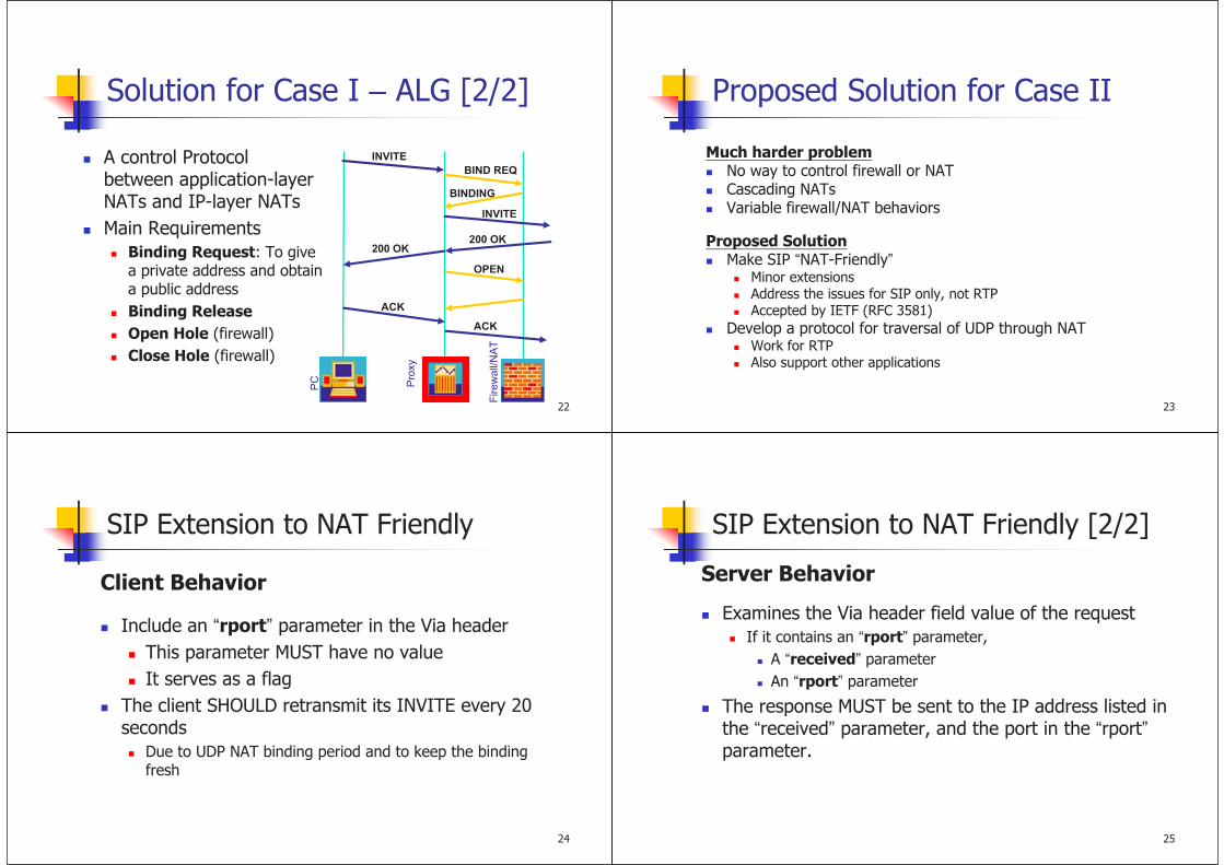
Solution for Case I – ALG [2/2]
INVITE
BIND REQ
BINDING
INVITE
200 OK200 OK
OPEN
ACK
ACK
Pro
xy
Firew
all/
NA
T
PC
A control Protocol between application-layer NATs and IP-layer NATs
Main Requirements
Binding Request: To give a private address and obtain a public address
Binding Release
Open Hole (firewall)
Close Hole (firewall)
23
Proposed Solution for Case II
Much harder problemNo way to control firewall or NATCascading NATsVariable firewall/NAT behaviors
Proposed SolutionMake SIP “NAT-Friendly”
Minor extensionsAddress the issues for SIP only, not RTPAccepted by IETF (RFC 3581)
Develop a protocol for traversal of UDP through NATWork for RTPAlso support other applications
24
SIP Extension to NAT Friendly
Client Behavior
Include an “rport” parameter in the Via header
This parameter MUST have no value
It serves as a flag
The client SHOULD retransmit its INVITE every 20 seconds
Due to UDP NAT binding period and to keep the binding fresh
25
SIP Extension to NAT Friendly [2/2]
Server Behavior
Examines the Via header field value of the request
If it contains an “rport” parameter,
A “received” parameter
An “rport” parameter
The response MUST be sent to the IP address listed in the “received” parameter, and the port in the “rport”parameter.

26
Example [1/2]
Client A: 10.1.1.1Proxy B: 68.44.10.3NAT C: 68.44.20.1
A issues requestINVITE sip:user@domain SIP/2.0Via: SIP/2.0/UDP 10.1.1.1:4540;rport
A C (mapping port 9988) BINVITE sip:user@domain SIP/2.0Via: SIP/2.0/UDP proxy.domain.comVia: SIP/2.0/UDP 10.1.1.1:4540;received=68.44.20.1;rport=9988;
27
Example [2/2]
Server B receives the responseSIP/2.0 200 OKVia: SIP/2.0/UDP proxy.domain.comVia: SIP/2.0/UDP 10.1.1.1:4540;received=68.44.20.1;rport=9988;
B (68.44.10.3:5060) C (68.44.20.1:9988) ASIP/2.0 200 OKVia: SIP/2.0/UDP 10.1.1.1:4540;received=68.44.20.1;rport=9988;
28
UPnP [1/2]
Universal Plug and Play
It is being pushed by MicrosoftWindows® Messenger
A UPnP-aware client can ask the UPnP-enabled NAT how it would map a particular IP:port through UPnP
It will not work in the case of cascading NATs
http://www.upnp.org/
29
UPnP [2/2]
A: Private Network
UPnP-aware Internet gateway device
The UPnP-enabled NAT allows “A” to be aware of its external IP
B: Public Internet
“B” and “A” can communicate with each other
UPnP-enabled
NAT
PublicInternet
B
PrivateNetwork
A

30
External Query
A server sits listening for packets (NAT probe)
When receiving a packet, it returns a message from the same port to the source containing the IP:portthat it sees
IP: 10.0.0.1Port: 8000
NAT
PublicInternet
NAT ProbeIP: 202.123.211.25Port: 12345
31
STUN
Simple Traversal of UDP Through NAT
RFC 3489
In Working Group IETF MIDCOM Group
Simple Protocol
Works with existing NATs
Main features
Allow Client to Discover Presence of NAT
Works in Multi-NAT Environments
Allow Client to Discover the Type of NAT
Allows Client to Discover the Binding Lifetimes
Stateless Servers
32
STUN Server
Allow client to discover if it is behind a NAT, what type of NAT it is, and the public address & port NAT will use.
A simple protocol, easy to implement, little load
Client
IP: 10.0.0.1
Port: 5060
IP: 202.123.211.25
Port: 12345 STUN Server
IP: 222.111.99.1
Port: 20202
NAT
Client wants to receive
packet at port 5060
Send a query to STUN
server from port 5060
STUN Server receives packet
from 202.123.211.25 port
12345
STUN Server send a response packet
to client. Tell him his public address is
202.123.211.25 port 12345
Binding Acquisition
STUN Server can be ANYWHERE on Public Internet
Call Flow Proceeds Normally

34
STUN Message [1/3]
TLV (type-length-value)
Start with a STUN header, followed by a STUN payload (a series of STUN attributes depending on the message type)
Format
STUN Payload (can have none to many blocks)
STUNHeader
35
STUN Message [2/3]
STUN Payload (can have none to many blocks)STUNHeader
Transaction ID (128 bits)
Message Length (16bits)Message Type (16 bits)
Message Types
0x0001: Binding Request 0x0101: Binding Response
0x0111: Binding Error Response
0x0002: Shared Secret Request 0x0102: Shared Secret Response
0x0112: Shared Secret Error Response
36
STUN Message [3/3]
STUN HeaderSTUN Payload (can have none to many blocks)
Attribute Value (Variable length)
Attribute Length (16bits)Attribute Type (16 bits)
Attribute Types
0x0001: MAPPED-ADDRESS 0x0002: RESPONSE-ADDRESS
0x0003: CHANGE-REQUEST 0x0004: SOURCE-ADDRESS
0x0005: CHANGED-ADDRESS 0x0006: USERNAME
0x0007: PASSWORD 0x0008: MESSAGE-INTEGRITY
0x0009: ERROR-CODE 0x000a: UNKNOWN-ATTRIBUTES
0x000b: REFLECTED-FROM
37
Automatic Detection of NAT Environment [1/2]
STUN ClientEnvironment
STUNServer
IP1
STUNServer
IP2
Port1
Port2
Port2
Port1
Test ITest II
Test IVTest III

38
Automatic Detection of NAT Environment [2/2]
Test I
Test II
Test III
Test IV
Resp?
Resp?
Resp?
Resp?
Yes
No
UDPBlocked
SameIP and Port as original?
Test II
YesNo
OpenInternet
SymUDP
Firewall
Yes
FullConeNAT
No
Yes
SameIP and Port as Test I?
SymmetricNAT
PortRestricted
NAT
RestrictedNAT
No
No
Yes
Yes
No
39
Binding Lifetime Determination
STUN
Clie
nt
NA
T
Bind Req.Bind (Pa, Pp)
Binding Resp.MAPPED-ADDRESS (Pa, Pp)
Start Timer T
If it receives Binding
Response on socket
X, the binding has not
expired.
Socket X
Socket YAnother Binding Request,
RESPONSE-ADDRESS is set to (Pa, Pp)
40
Binding Acquisition Procedure
STUN
Clie
nt 1
NA
T
Clie
nt 2
Control Media
SIP Message
RTP
Shared Secret Request
and Response
Binding Request and
Response (Pa, Pp)
Binding Request and
Response (Pa’, Pp’)
RESPONSE-
ADDRESS is
set to (Pa, Pp)
41
STUN - Pros and Cons
BenefitsNo changes required in NAT
No changes required in Proxy
Works through most residential NAT
DrawbacksDoesn’t allow VoIP to work through Symmetric NAT
RTCP may not work

42
Is STUN suitable for Symmetric NAT
Absolutely not
Client A
IP: 10.0.0.1
Port: 21NAT
IP: 202.123.211.25
Port: 12345
Mapping Table
10.0.0.1:21 <-> 12345 (for 222.111.99.1 : 20202)
STUN Server
IP: 222.111.99.1
Port: 20202
Client B
IP: 222.111.88.2
Port: 10101
43
Solutions for Symmetric NATs
Connection Oriented Media
RTP-Relay
44
Connection Oriented Media
The endpoint outside the NAT must wait until it receives a packet from the client before it can know where to replyAdd a line to the SDP message (coming from the client behind the NAT)a=direction:activeThe initiating client will “actively” set up the IP:port to which the endpoint should return RTP
The IP:port found in the SDP message should be ignored
45
Problem?
1) If the endpoint does not support the a=direction:active tag
2) If both endpoints are behind Symmetric NATs

46
RTP-Relay
For either of the cases considered in the previous slide, one solution is to have an RTP Relay in the middle of the RTP flow between endpoints.
The RTP Relay acts as the second endpoint to each of the actual endpoints that are attempting to communicate with each other.
47
Example
1
2 3 6
8
9
12
7
4
5
10
11UA
NAT Proxy
RTP Relay
Voice Gateway
NAT
The following is a typical call flow that might be instantiated between a User Agent behind a symmetric NAT and a voice gateway on the open Internet.
48
TURN
Traversal Using Relay NAT
draft-rosenberg-midcom-turn-06.txt
TURN
ClientNAT
TURN
Server
Public InternetPrivate NET
Obtaining a One Time Password
TURN
ClientNAT
TURN
Server
1.Client generates
and sends Shared
Secret Request
(with no attribute)
2.TURN Server reject it
with a Shared Secret
Error Response
(code=401,contain
NONCE and REALM)
3.Client generate a new
Shared Secret Request
(contain NONCE
REALM USERNAME)
4.TURN Server generate a
Shared Secret Response
(contain USERNAME and
PASSWORD)

Allocating a Binding
1.Client generates and sends Initial
Allocate Request (contain
BANDWIDTH LIFETIME
USERNAME MESSAGE_INTEGRITY )
TURN
Client NATTURN
Server
2.TURN Server generates and sends
Allocate Response (contain
MAPPED_ADDRESS LIFETIME
BANDWIDTH MESSAGE_INTEGRITY)
Refreshing a Binding
TURN
Client NATTURN
Server
1.Client generates and sends
Subsequent Allocate Request
(contain LIFETIME USERNAME
MESSAGE_INTEGRITY )
2.TURN Server generates and sends
Allocate Response (contain
MAPPED_ADDRESS LIFETIME
MESSAGE_INTEGRITY MAGIC_COOKIE)
Sending Data
PeerTURN
ClientNAT
TURN
Server
1.TURN Client generates and
sends Send Request (contain
DESTINATION_ADDRESS
DATA)
2.TURN Server set default destination
address to DESTINATION_ADDRESS, and
add this address to the list of permission.
Then TURN Server relay the data to Peer.
3.TURN Server generates and
sends Send Response to
TURN Client.
Receiving Packet
PeerTURN
ServerNATTURN
Client
1.Peer sends packet to the mapped
address of TURN Client.
2.TURN Server checks whether
the source IP address and port are
listed amongst the set of
permission for the binding or not.
3.TURN Server checks whether
the source IP address and port
are equal to the default
destination address or not.
4.TURN Server generates Data
Indication message to relay the
packet to TURN Client.

Tearing Down a Binding
TURN
Client NATTURN
Server
1.Client generates and sends
Subsequent Allocate Request
(contain LIFETIME=0)
2.TURN Server will tearing down
the binding.
55
TURN – Pros and Cons
Pros
No change required in NAT
Work through firewall and all kinds of NAT.
Cons
Long latency
Heavy load for TURN server
Media Gateway Control and the Softswitch Architecture
2IP Telephony
Outline
Introduction
Softswitch
Softswitch Architecture
Softswitch Operations
Media Gateway Control Protocols
MGCP
MEGACO

3IP Telephony
Next Generation Network
Internet Telecom & Wireless Communication
IP
MGCF
CSCF
SGW MGWMGW
WLAN
GPRS
CSCFSIP
Server
PSTN
InternetWireless App.Server
3rd Parties App.
4IP Telephony
Gateways in Next Generation Networks
CO
SCP
STP
PBX
H.323
GK
SS7/IN
PSTN IP Networks
SG
TGW
H.323
MG
MGC
MGC : Media Gateway Controller
SG : Signaling Gateway
TGW : Trunking Gateway
RGW : Residential Gateway
MGCP/MEGACO
H.323/SIP
SIGTRAN
RTP/RTCP
Analog Line
TrunkMGCP/MEGACO
PhonesRGW
H.323 Phones
5IP Telephony
H323/SIP VS. MGCP/MEGACO [1/2]
GWGK
MCU
GW : Gateway
GK : Gatekeeper
TN : Terminal
MCU : Multipoint Control Unit
TN
PSTN CA
TGW RGW
CA : Call Agent
TGW : Trunking Gateway
RGW : Residential Gateway
SG : Singling Gateway
SS7
PSTN CO
SG
RTP
MGCP
H.323
TNTN
GWGK
MCU
TN
TNTN
6IP Telephony
H323/SIP VS. MGCP/MEGACO [2/2]
H.323 , SIPpeer-to-peer
internet oriented
intelligent endpoint
optional GK
decentralized
Problemsmaintenance
cost & scalability of large systems
signaling & media
control are coupled
interoperability with SS7
MGCP/MEGACOclient-server
traditional telephony
intelligent server
“dumb” terminal
centralized
Conceptgateway decomposed
separate call control from media ports
CA (MGC), MG, SG
interoperability with
PSTN

7IP Telephony
Class 5
End Office Switch
The Telephone Network [1/2]
Circuit Switched Network
Intelligent
Peripheral
Signal
Transfer
Point
Service
Control
Point
Class 4
Tandem Switch
Service
Data
Point
+
Transport Layer
Control Layer
SS7 Signaling
ISUP Messages
INAP/TCAP Messages
8IP Telephony
The Telephone Network [2/2]
5 Basic Components in Intelligent Networks
SSP/Service Switching Point
switching, signaling, routing, service invocation
STP/Service Transfer Point
signaling, routing
SCP/Service Control Point
service logic execution
SDP/Service Data Point
subscriber data storage, access
IP/Intelligent Peripheral
resources such as customized voice announcement, voice recognition, DTMF digit collection
SSPSSP
SCPSCP
SDPSDP
STPSTPIP
IP
SSPSSP
STPSTP
TCAP messages
ISUP messages
Voice
9IP Telephony
Softswitch
The switching functions are handled by software.
International Softswitch Consortium (ISC)www.softswitch.org
To promote the softswitch concept and related technologies
Why the softswitch approach is popular?A distributed architecture
For network operatorsIt is possible to use different network components from different vendors.
For equipment vendorsIt is possible to focus on one area.
10IP Telephony
Abstract Softswitch Architecture
SIP is often used as the signaling protocol between the MGCs.

11IP Telephony
Softswitch/PSTN Interworking
Modem Bank
12IP Telephony
Softswitch Overview [1/3]
Softswitch: Emulating Circuit Switching in Software
IN/SCP
PSTN
Local Switch
PSTN
Local SwitchSTP SS7 Network
IP Network
RTP Streams
MGCMGC MGCMGC
TrunkTrunk
GatewayGatewayTrunkTrunk
GatewayGateway
SIP-T
SGSGSGSG
MEGACO
IP PhoneIP Phone
90009000 Personalized VoIP
Service System
Application ServerApplication Server
13IP Telephony
Softswitch Overview [2/3]
Softswitch Provides Open Layered Architecture
• Solutions in a proprietary box
• Expensive
• Little room for innovation
Circuit-Switched
Transport
Hardware
Call Control
& Switching
Services &
Applications
P
R
O
P
R
I
E
T
A
R
Y
• Solutions are open standards-based
• Customers choose best-in-class products
• Open standards enable lower cost for
innovation
Soft-Switched
Transport Hardware
Softswitch Call Control
Services, Applications &
Features (Management,
Provisioning and
Back Office)Open Protocols APIs
Open Protocols APIs
Open APIs for 3rd Party App develop.
Best-in-class Access Devices.
Scalable,Open Interfaces for Comm.
14IP Telephony
Softswitch Overview [3/3]
Softswitch Changes the Telecom Landscape
Integration/IncorporationConvergence of voice and data
Combination of telecom & internet technologies
Reuse PSTN database & IN services in packet networks
Multiple sources for app development & deployment
Decreased operating costs
StandardizationStandard interfaces (protocols) for communications
Open standards (APIs) for service creation
Customized services created by users themselves
Better scalability

15IP Telephony
Softswitch Architecture
CO
Switch
STP
SCP
CO
Switch
STP
SCP
Signaling Layer
Transport Layer
IP
SIP-T
Media
Server
RTP
SIP-?/
MGCP
SIP-TSI
Media
Gateway
Controller
MGCP/
MEGACO
Phones
App.
Server
Media
Gateway
Controller
SIGTRAN
SSA/SCTP
MGCP/MEGACOTrunking
Gateway
Signaling
(SS7)
Gateway
SS7 TCAP
ISUP/TCAP
16IP Telephony
Local
Switch
STP
SCP
STP STP STP
Local
Switch
STP
Local
Switch
Trunking
Gateway
Signaling
(SS7)
Gateway
Media
Gateway
Controller
Trunking
Gateway
Signaling
(SS7)
Gateway
Routing
Directory
Softswitch Operations [1/3]
Basic Call Control
12 ISUP ACM
13 ISUP
ANM
ISUP ACM
ISUP ANM
ISUP IAM ISUP IAM
1
23
4 5
6 7
8
910
14
11
SIGTRAN
MGCP/MEGACOVoice Voice
RTP
17IP Telephony
Softswitch Operations [2/3]
Inter-Softswitch Communications
Local
Switch
STP
Trunking
Gateway
Signaling
(SS7)
Gateway
Media
Gateway
Controller
STP
Trunking
Gateway
STP
Media
Gateway
Controller
Signaling
(SS7)
Gateway
STP STP
Domain A Domain B
Local
Switch
Routing
Directory
3
1
5
2
ISUP IAM
4
SIGTRAN
MGCP/MEGACO
6 SIP-T
7
9
16
Voice
RTP
8
ISUP IAM
12
13
Voice
10
11
14 ISUP ACM
15 ISUP
ANM
ISUP ACM
ISUP ANM
18IP Telephony
Softswitch Operations [3/3]
IP-PSTN Interworking for IN Services
Local
Switch
STP
SCP
STP STP STP
Local
Switch
STP
Local
Switch
Trunking
Gateway
Signaling
(SS7)
Gateway
Media
Gateway
Controller
Trunking
Gateway
Signaling
(SS7)
Gateway
Routing
Directory
ISUP IAM ISUP IAM
1
2
3
4
7
8 9
10
1112
13
SIGTRAN
MGCP/MEGACOVoice Voice
RTP
5
INAP/TCAP
16
6
14 ISUP ACM
15 ISUP
ANM
ISUP ACM
ISUP ANM

19IP Telephony
Introduction
Voice over IPLower cost of network implementation
Integration of voice and data applications
New service features
Reduced bandwidth
Replacing all traditional circuit-switched networks is not feasible.
VoIP and circuit-switching networks coexistInteroperation
Seamless interworking
20IP Telephony
Separation of Media and Call Control
GatewaysInterworking
To make the VoIP network appear to the circuit switched network as a native circuit-switched system and vice versa
Signaling path and media path are different in VoIP systems.
Media – directly (end-to-end)
Signaling – through H.323 gatekeepers (or SIP proxies)
SS7, Signaling System 7The logical separation of signaling and media
21IP Telephony
Separation of Media and Call Control
A network gateway has two related but separate functions.
Signaling conversion
The call-control entities use signaling to communicate.
Media conversion
A slave function (mastered by call-control entities)
Figure 6-1 illustrates the separation of call control and signaling from the media path.
22IP Telephony
Separation of Media and Call Control
Advantages of Separation
Media conversion close to the traffic source and sink
The call-handling functions is centralized.
A call agent (media gateway controller - MGC) can control multiple gateways.
New features can be added more quickly.
MGCP, Media Gateway Control Protocol
IETF
MEGACO/H.248
IETF and ITU-T Study Group 16

23IP Telephony
Requirements for Media Gateway Control [1/2]
RFC 2895Media Gateway Control Protocol Architecture and Requirements
RequirementThe creation, modification and deletion of media streams
Including the capability to negotiate the media formats
The specification of the transformations applied to media streams
Request the MG to report the occurrence of specified events within the media streams, and the corresponding actions
24IP Telephony
Requirements for Media Gateway Control [2/2]
Request the MG to apply tones or announcements
The establishment of media streams according to certain QoS requirements
Reporting QoS and billing/accounting statistics from an MG to an MGC
The management of associations between an MG and an MGC
In the case of failure of a primary MGC
A flexible and scalable architecture in which an MGC can control different MGs
Facilitate the independent upgrade of MGs and MGCs
25IP Telephony
Protocols for Media Gateway Control
The first protocol is MGCP
RFC 2705, informational
To be succeeded by MEGACO/H.248
Has be included in several product developments
MEGACO/H.248
A standards-track protocol
RFC 3015 is now the official version.
IPDC
SGCP
MGCP
MDCP
MEGACO
Telcodia (Bellcore)
Level 3 Communication
Lucent (by ITU-T)
IETF RFC 3015ITU-T H.248November 2000
IETF RFC 2705
October 1999
MGCP
1.0
IETF RFC 3435January 2003
26IP Telephony
Relation with H.323/SIP Standards

27IP Telephony
MGCP/
MEGACO
Phones
Trunking
Gateway
Signaling
Gateway
MGC
SIGTRAN
SSA/SCTP
RTP
MGCP/MEGACO
SS7 TCAP
ISUP/TCAP
Concept of MGCP/MEGACO
CO
Switch
STP
SCP
PSTN
Phones
Media
Gateway
MGC
Connection
Create
Delete
Modify
Event Notification
Request
Status
Query
Response
Success
Failure
Event
Notify
Status
Report
Dumb Client
Stateless
Intelligent
Server
28IP Telephony
MGCP
A master-slave protocol (A protocol for controlling media gateways)
Call agents (MGCs) control the operation of MGsCall-control intelligence
Related call signaling
MGsDo what the CA instructs
A line or trunk on circuit-switched side to an RTP port on the IP side
Types of Media GatewayTrunking Gateway to CO/Switches
Residential Gateway to PSTN Phones
Access Gateway to analog/digital PBX
Communication between call agentsLikely to be the SIP
29IP Telephony
The MGCP Model
Endpoints
Sources or sinks of media
Trunk interfaces
POTS line interfaces
Announcement endpoint
Connections
Allocation of IP resources to an endpoint
An ad hoc relationship is established from a circuited-switched line and an RTP port on the IP side.
A single endpoint can have several connections
30IP Telephony
GW’s Domain Name + Local Name
Local Name
A hierarchical form: X/Y/Z
trunk4/12/[email protected]
To identify DS0 number 7 within DS1 number 12 on DS3 number 4 at gateway.somenetwork.net
Wild-cards
$, any; *, all
e.g., trunk1/5/[email protected]
CA wants to create a connection on an endpoint in a gateway and does not really care which endpoint is used.
e.g., trunk1/5/*@gateway.somenetwork.net
CA requests statistical information related to all endpoints on a gateway.
Endpoint Identifier

31IP Telephony
MGCP Calls and Connections
A connectionRelationship established between a given endpoint and an RTP/IP session
A callA group of connections
The primary function of MGCP is to enableThe connections to be created
The session descriptions to be exchanged between the connections
1 2 3
4 5 6
7 8 9
* 8 #
1 2 3
4 5 6
7 8 9
* 8 #
32IP Telephony
Call Identifier (Call ID)
Created by CA
Unique within CA Scope
Connection ID
Created by GW
Unique under Its GW
Calls and Connections
Endpoint Endpoint
CA1. CRCX
3. MDCX
2. CRCX
IP, Port,
Packetization
RTP
33IP Telephony
9 commands to handle Connection/EndpointsEndpointConfiguration (coding characteristics)
NotificationRequest (requested events)
Notify (GW: detected events)
CreateConnection
ModifyConnection
DeleteConnection
AuditEndpoint
AuditConnection
RestartInProgress (GW : taken in/out of service)
All commands are acknowledged.
EPCF
RQNT
NTFY
CRCX
MDCX
DLCX
AUEP
AUCX
RSIP
MGCP Commands
34IP Telephony
Call Setup Using MGCP
iMac

iMac
Media Gateway Control Media Gateway Control
and the and the SoftswitchSoftswitch
ArchitectureArchitecture
2 IP Telephony
Call Flow for RGW to TGWCall Flow for RGW to TGW (1/18)(1/18)
CA
RGW TGW COInternet PSTN
A calls BA calls B
A: 5712826
B: 5721043
hrd3/15 card6/5
rgw.whatever.net
140.113.214.123
tgw.whatever.net
140.113.65.24
SG
140.113.65.24
DB
ACC
3 IP Telephony
Call Flow for RGW to TGWCall Flow for RGW to TGW (2/18)(2/18)
CA
RGW TGW COInternet PSTN
A calls BA calls B
A: 5712826
B: 5721043
hrd3 card6/5
rgw.whatever.net
140.113.214.123
tgw.whatever.net
140.113.65.24
SG
1
140.113.65.24
DB
ACC

4 IP Telephony
RQNT(1) : NotificationRequestRQNT 1201 *@rgw.whatever.net MGCP 1.0
N: [email protected]:5678
X: 0123456789AC
R: hd(E(R(hu(N)),S(dl),D/(D)))
D: (11x|080xxxxxx|57xxxxx|002x.T)
ACK to RQNT(1)
200 1201 OK
N: NotifyEntity
X: RequestIdentifier
R: RequestEvents
D: DigitMap
N: NotifyEntity
X: RequestIdentifier
R: RequestEvents
D: DigitMap
E: Embedded (enable) Request
R: Notification Request
S: Signal Request
N: Notify immediately (default)
D: Accumulate according to DigitMap
Clear current dialed string
E: Embedded (enable) Request
R: Notification Request
S: Signal Request
N: Notify immediately (default)
D: Accumulate according to DigitMap
Clear current dialed string
Call Flow for RGW to TGWCall Flow for RGW to TGW (3/18)(3/18)
5 IP Telephony
Call Flow for RGW to TGWCall Flow for RGW to TGW (4/18)(4/18)
CA
RGW TGW COInternet PSTN
A calls BA calls B
A: 5712826
B: 5721043
hrd3 card6/5
rgw.whatever.net
140.113.214.123
tgw.whatever.net
140.113.65.24
SG
2
Off-hook
Dial
5721043
140.113.65.24
DB
ACC
6 IP Telephony
NTFY(2) : Notify from RGW
NTFY 2002 [email protected] MGCP 1.0
N: [email protected]:5678
X: 0123456789AC
O: 5721043
ACK to NTFY(2)
200 2002 OK
N: NotifyEntity
X: RequestIdentifier
O: ObservedEvent
Reported in the detected order
N: NotifyEntity
X: RequestIdentifier
O: ObservedEvent
Reported in the detected order
Call Flow for RGW to TGWCall Flow for RGW to TGW (5/18)(5/18)
7 IP Telephony
Call Flow for RGW to TGWCall Flow for RGW to TGW (6/18)(6/18)
CA
RGW TGW COInternet PSTN
A calls BA calls B
A: 5712826
B: 5721043
hrd3 card6/5
rgw.whatever.net
140.113.214.123
tgw.whatever.net
140.113.65.24
SG
3
140.113.65.24
DB
ACC

8 IP Telephony
CRCX(3) : CreateConnection
CRCX 1204 [email protected] MGCP 1.0
C: A3C47F21456789F0
L: p:10, a: G.711; G.726-32
M: recvonly
X: 0123456789AD
R: hu
ACK to CRCX(3)
200 1204 OK
I: FDE234C8
Session Description
C: CallId
L: LocalCXOptions
p: packetize period(ms)
a: Compression Algo.
M: Mode
X: RequestIdentifier
R: RequestEvents
I: ConnectionId
C: CallId
L: LocalCXOptions
p: packetize period(ms)
a: Compression Algo.
M: Mode
X: RequestIdentifier
R: RequestEvents
I: ConnectionId
Call Flow for RGW to TGWCall Flow for RGW to TGW (7/18)(7/18)
9 IP Telephony
Session Description - ACK to CRCX(3)
Convey info about media streams
Use textual format, case sensitive
v=0
c=IN IP4 140.96.102.166
m=audio 3456 RTP/AVP 0 96
a=rtpmap:96 G726-32/8000
V=<protocol version>
C=<nw-type> <addr-type> <address>
M=<media> <port> <transport>
(A=<attribute> (:<value>))
V=<protocol version>
C=<nw-type> <addr-type> <address>
M=<media> <port> <transport>
(A=<attribute> (:<value>))
Call Flow for RGW to TGWCall Flow for RGW to TGW (8/18)(8/18)
10 IP Telephony
Call Flow for RGW to TGWCall Flow for RGW to TGW (9/18)(9/18)
CA
RGW TGW COInternet PSTN
A calls BA calls B
A: 5712826
B: 5721043
hrd3 card6/5
rgw.whatever.net
140.113.214.123
tgw.whatever.net
140.113.65.24
140.113.65.24
SG
4
DB
ACC
Query E.164
11 IP Telephony
CRCX(4) : CreateConnection
CRCX 1205 card6/[email protected] MGCP 1.0
C: A3C47F21456789F0
L: p:10, a: G.711; G.726-32
M: sendrecv
Session Description from ACK(3)
ACK to CRCX(4)
200 1205 OK
I: 32F345E2
Session Description
C: CallId
M: Mode
I: ConnectionId
C: CallId
M: Mode
I: ConnectionId
Call Flow for RGW to TGWCall Flow for RGW to TGW (10/18)(10/18)

12 IP Telephony
Call Flow for RGW to TGWCall Flow for RGW to TGW (11/18)(11/18)
CA
RGW TGW COInternet
PSTN
A calls BA calls B
A: 5712826
B: 5721043
hrd3 card6/5
rgw.whatever.net
140.113.214.123
tgw.whatever.net
140.113.65.24
SG
45
ISUP IAM
140.113.65.24
DB
ACC
13 IP Telephony
MDCX(5) : ModifyConnection
MDCX 1206 [email protected] MGCP 1.0
C: A3C47F21456789F0
I: FDE234C8
M: recvonly
Session Description from ACK(4)
ACK to MDCX(5)
200 1206 OK
C: CallId
I: ConnectionId
M: Mode
C: CallId
I: ConnectionId
M: Mode
Call Flow for RGW to TGWCall Flow for RGW to TGW (12/18)(12/18)
14 IP Telephony
CA
RGW TGW COInternet
PSTN
A calls BA calls B
A: 5712826
B: 5721043
hrd3 card6/5
rgw.whatever.net
140.113.214.123
tgw.whatever.net
140.113.65.24
SG
46
ISUP ACM
140.113.65.24
DB
ACC
Call Flow for RGW to TGWCall Flow for RGW to TGW (13/18)(13/18)
15 IP Telephony
RQNT(6) : NotificationRequest
RQNT 1207 [email protected] MGCP 1.0
N: [email protected]:5678
X: 012345789AE
R: hu
S: v (alerting)
ACK to RQNT(6)
200 1207 OK
N: NotifyEntity
X: RequestIdentifier
R: RequestEvents
S: SignalRequests
N: NotifyEntity
X: RequestIdentifier
R: RequestEvents
S: SignalRequests
Call Flow for RGW to TGWCall Flow for RGW to TGW (14/18)(14/18)

16 IP Telephony
CA
RGW TGW COInternet
PSTN
A calls BA calls B
A: 5712826
B: 5721043
hrd3 card6/5
rgw.whatever.net
140.113.214.123
tgw.whatever.net
140.113.65.24
SG
47
ISUP ANM
140.113.65.24
DB
ACC
Call Flow for RGW to TGWCall Flow for RGW to TGW (15/18)(15/18)
17 IP Telephony
MDCX(7) : ModifyConnection
MDCX 1209 [email protected] MGCP 1.0
C: A3C47F21456789F0
I: FDE234C8
M: sendrecv
X: 012345789AF
R: hu
S: (to stop alerting)
ACK to MDCX(7)
200 1209 OK
C: CallId
I: ConnectionId
M: Mode
S: SignalRequests
C: CallId
I: ConnectionId
M: Mode
S: SignalRequests
Call Flow for RGW to TGWCall Flow for RGW to TGW (16/18)(16/18)
18 IP Telephony
CA
RGW TGW COInternet
PSTN
A calls BA calls B
A: 5712826
B: 5721043
hrd3 card6/5
rgw.whatever.net
140.113.214.123
tgw.whatever.net
140.113.65.24
SG
98
ISUP REL
140.113.65.24
DB
ACC
Call Flow for RGW to TGWCall Flow for RGW to TGW (17/18)(17/18)
19 IP Telephony
DLCX(8) : DeleteConnection
DLCX 1210 [email protected] MGCP 1.0
C: A3C47F21456789F0
I: FDE234C8
ACK to DLCX(8)
200 1210 OK
P: PS=1245, OS=62345, PR=780, OR=45123, PL=10, JI=27, LA=48
C: CallId
I: ConnectionId
C: CallId
I: ConnectionId
PS: Packets sent
OS: Octets sent
PR: Packets received
OR: Octets received
PL: Packets lost
JI: Average Jitter (ms)
LA: Average Latency (ms)
PS: Packets sent
OS: Octets sent
PR: Packets received
OR: Octets received
PL: Packets lost
JI: Average Jitter (ms)
LA: Average Latency (ms)
Call Flow for RGW to TGWCall Flow for RGW to TGW (18/18)(18/18)

1
3G All IP Network
2
Outline
Mobile Technology Evolution
GPRS Overview
3GPP UMTS System (Release 99)
Introduction to VoIP Technologies• H.323
• SIP
• MGCP/MEGACO
• SIGTRAN
• Softswitch
3GPP All IP Network
3
Mobile Technology Evolution
1G – Analog System• AMPS (Advanced Mobile Phone System) : 090
2G – Digital System• GSM (Global System for Mobile Communication)
900MHz and 1.8GHz (DCS1800)
TDMA and FDMA Technologies
9.6K bps Data Rate (Shore Message Service; SMS)
160 Countries, 55% , 5
• CDMA (Code Division Multiple Access)
IS-95: Data Rate 14.4K bps (cdmaOne) IS-95B: Data Rate 64 Kbps
Qualcom
, 7,500
• D-AMPS
IS-1364
2.5G
GSM System
• High Speed Circuit Switch Data (HSCSD)
Up to 115.2 Kbps
• General Packet Radio Service (GPRS)
Up to 171.2 Kbps
• Enhanced Data rates for GSM Evolution (EDGE)
up to 384 Kbps (Also considered as 3G technology)
D-AMPS EDGE
cdma System
• cdma 1x
Up to 144 Kbps
Korea
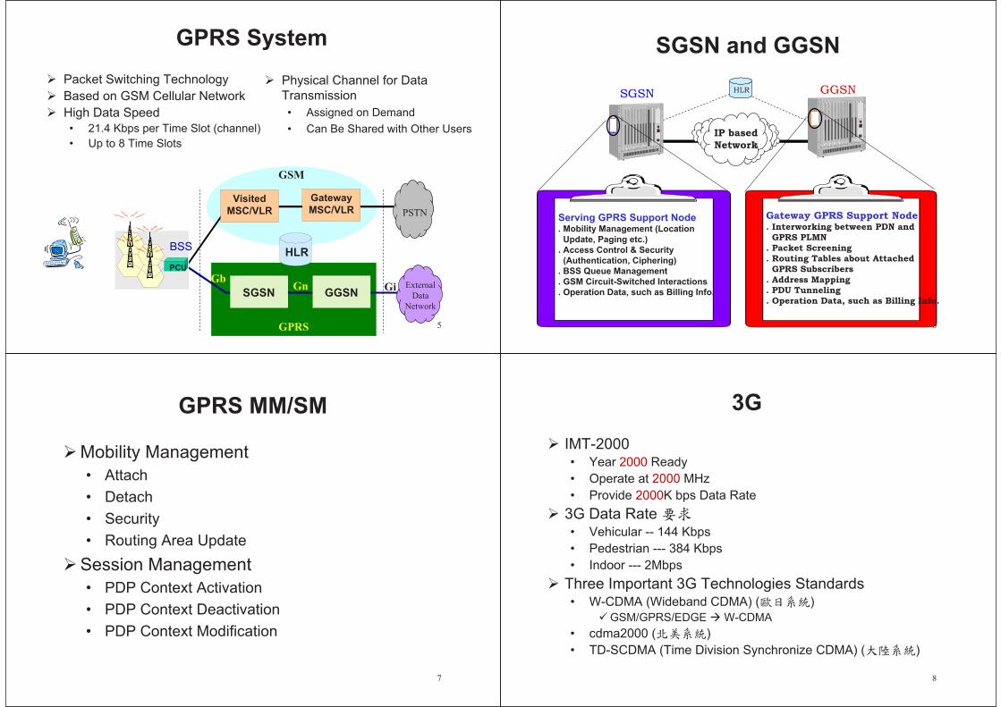
5
GPRS System
Packet Switching Technology
Based on GSM Cellular Network
High Data Speed
• 21.4 Kbps per Time Slot (channel)
• Up to 8 Time Slots
GPRS
External
Data
Network
PSTN
HLR
SGSN GGSN
GbGn Gi
GSM
PCU
BSS
Gateway
MSC/VLRVisited
MSC/VLR
Physical Channel for Data
Transmission
• Assigned on Demand
• Can Be Shared with Other Users
6
SGSN and GGSN
IP based
Network
SGSN GGSNHLR
Serving GPRS Support Node. Mobility Management (Location
Update, Paging etc.)
. Access Control & Security
(Authentication, Ciphering)
. BSS Queue Management
. GSM Circuit-Switched Interactions
. Operation Data, such as Billing Info.
Gateway GPRS Support Node. Interworking between PDN and
GPRS PLMN
. Packet Screening
. Routing Tables about Attached
GPRS Subscribers
. Address Mapping
. PDU Tunneling
. Operation Data, such as Billing Info.
7
GPRS MM/SM
Mobility Management
• Attach
• Detach
• Security
• Routing Area Update
Session Management
• PDP Context Activation
• PDP Context Deactivation
• PDP Context Modification
8
3G
IMT-2000• Year 2000 Ready
• Operate at 2000 MHz
• Provide 2000K bps Data Rate
3G Data Rate • Vehicular -- 144 Kbps
• Pedestrian --- 384 Kbps
• Indoor --- 2Mbps
Three Important 3G Technologies Standards• W-CDMA (Wideband CDMA) ( )
GSM/GPRS/EDGE W-CDMA
• cdma2000 ( )
• TD-SCDMA (Time Division Synchronize CDMA) ( )

9
From 2G to 3G
From Voice Service to Rich, Interactive Multimedia-based
Personal Communication Service
Permanent Network Connection with High Data Rate
• 384 Kbps to 2 Mbps
• Mobile Access to High-quality Video, Audio, Graphics and
Multimedia as Fixed Internet
Massive Increase in Network Capacity
• To Support Billions of Subscribers
Global Roaming
• To Use Single Terminal to Access Identical Services All Around
the World
10
3GPP UMTS System
Node B
Node B
Node B
Node B
RNC
RNC
Iub Iur
UTRAN
USIM
ME
UE
Cu
3GMSC/VLR
3G SGSN
GMSC
GGSN
HLR
External
Networks
PLMN,
PSTN, ISDN,...
Internet
Core Network
Uu Iu
Iu-PS Gn Gi
GrGc
D D
System Architecture of 3GPP Release 99
Gs
Iu-PS
Iu-CS
Iu-CS
11
All IP Architecture
Based on packet technologies and IP telephony
for real time and non real time services
An evolution from Release 99 specifications
• All IP core network should support release 99 CS
terminals.
Radio Access Network (RAN)
• GERAN and UTRAN
Core Network
• Based on the evolution of GPRS
12
3GPP All IP Network
RNC
Node B
Node B
MS
MS
SGSN
T-SGW
Internet
PSTN
MSC Server
GGSN
Legacy mobile
signaling network
CSCFHSS
MGWMGW
GMSC Server
R-SGW
MAP
MAP Mc
McGi
Gi
Nc
Nb
Iu_CS
(control part)
Mh
Gr Gc
Cx
Mm
Ms
GnIu_PS
Iu_CS
(user traffic)
Gi
Mc
MGCF
Mg
Gi
MrMRF
Signaling (SS7 or IP based)
Circuit
Packet (user traffic / signaling)
Call control function
Reference: CCL/ITRI

13
Circuit-Switched Services
RNC
Node B
Node B
MS
MS
T-SGW
PSTN
MSC Server
Legacy mobile
signaling network
HSS
MGWMGW
GMSC Server
R-SGW
MAP
MAP Mc
Nc
Nb
Iu_CS
(control part)
Mh
Gr
Iu_CS
(user traffic)
Mc
Signaling (SS7 or IP based)
Circuit
Packet (user traffic / signaling)
Call control function
Reference: CCL/ITRI14
Packet-Switched Services
RNC
Node B
Node B
MS
MS
SGSN InternetGGSN
HSS
Gi
Gr Gc
GnIu_PS
Gi
Signaling (SS7 or IP based)
Circuit
Packet (user traffic / signaling)
Call control function
Reference: CCL/ITRI
15
Real-Time PS Services
RNC
Node B
Node B
MS
MS
SGSN InternetGGSN
Legacy mobile
signaling network
CSCFHSS
R-SGW
Gi
Mh
Gr Gc
Cx
Mm
Ms
GnIu_PS
GiMg
Gi
MrMRF
Signaling (SS7 or IP based)
Circuit
Packet (user traffic / signaling)
Call control function
Reference: CCL/ITRI16
Interworking with PSTN
RNC
Node B
Node B
MS
MS
SGSN
T-SGW
Internet
PSTN
GGSN
Legacy mobile
signaling network
CSCFHSS
MGW
R-SGW
McGi
Gi
Mh
Gr Gc
Cx
Mm
Ms
GnIu_PS
Gi
MGCF
Mg
Gi
MrMRF
Signaling (SS7 or IP based)
Circuit
Packet (user traffic / signaling)
Call control function
Reference: CCL/ITRI

17
HSS
HSS (Home Subscriber Server) is the master database
for a given user.
Functionalities
• The HLR functionality required by the PS-Domain
• The circuit switched part of the HLR
• User control functions required by the IP multimedia
(IM) subsystem
HSS
MSC Server GMSC Server SGSN GGSN R-SGW CSCF
D C Gr Gc Mh Cx
18
CSCF [1/4]
Call State Control Function
ICGW (Incoming Call Gateway)• Acting as a first entry point to perform routing of incoming
calls
CCF (Call Control Function)• Call setup/termination and call state/event management
• Application level registration handling
SPD (Serving Profile Database)• Interacting with HSS to receive user profile information
AH (Address Handling)• Mapping between alias address (e.g., E.164 number) and
transport address
19
CSCF [2/4]
Proxy CSCF (P-CSCF) is the first contact point
within IM CN subsystem.
• Its address is discovered by UEs following PDP
context activation procedure.
• Behaving like a Proxy server defined in RFC2543
P-CSCF Discovery
• Use of DHCP (Dynamic Host Configuration Protocol)
• Transfer the P-CSCF address with the PDP Context
Activation signaling to the UE
20
CSCF [3/4]
Serving CSCF (S-CSCF) performs the session
control service for the UE.
• Maintaining a session state as needed by the
network operator for support of the services
Registration
• Behaving as a Registrar as defined in RFC2543
• It accepts registration requests and makes its
information available through the location server
(e.g., HSS).
Session Flow
• Interaction with service platform for support of
services

21
Service Platform Interface
SIP Application
Server
CAMEL Service
Environment
SIP+
OSA API
Cx
IM SSF
SIP+
OSA
Application
Server
S-CSCFOSA Service
Capability Server
(SCS)
HSSSIP+
CAP
MAP
22
CSCF [4/4]
Interrogating CSCF (I-CSCF) is the contact point within an operator’s network for all connections destined to • a subscriber of that network operator, or
• a roaming subscriber currently located within that network operator’s service area.
• That is,I-CSCF is the first contact point within an operator’s network for incoming call signaling.
Registration• Assigning a Serving CSCF to a user performing SIP
registration
Session Flow• Routing a SIP request received from another network
towards the S-CSCF(Serving Terminating UE)
• Obtaining the S-CSCF address from HSS
23
MGCF & MGW
Media Gateway Control Function
• Being PSTN signaling termination point
• Performing protocol conversion between the legacy
(e.g., ISUP) and the All-IP network call control
protocols
Media Gateway
• Being PSTN transport termination point
• Interfacing UTRAN over Iu
24
MSC Server
Mainly comprising the call control and mobility
control parts of a GSM/UMTS MSC
Performing the connection control for media
channels in a MGW
MSC server + MGW = MSC

25
MRF
Multimedia Resource Function
• Performing multi-party call and multi- media
conferencing functions
• The same function as an MCU in the H.323
network
26
T-SGW & R-SGW
Transport Signaling Gateway Function
• Mapping call related signaling from PSTN/PLMN on
an IP bearer and sending it to the MGCF
• Providing PSTN/PLMN IP transport level address
mapping
Roaming Signaling Gateway Function
• Providing communication with a 2G/R99 MSC/VLR
27
IM Subsystem
IP Multimedia (IM) CN subsystem
• Comprising all CN elements for provision of
multimedia services
The IM subsystem (IMS) utilizes the PS domain
to transport multimedia signaling and bearer
traffic.
The IMS attempts to be conformant to IETF
“Internet standards”.
• SIP (Session Initiation Protocol) has been selected
as the interfaces between the IM CN elements.
28
Registration
UE GPRSIP MM CN
Subsystem
1. Bearer Level Registration: GPRS
2. PDP Context Activation
3. P-CSCF Discovery
4. Application Level Registration

29
Application-level Registration
P-SCSFP-SCSF
S-CSCFS-CSCF
P-CSCFP-CSCF
GGSNGGSN
SGSNSGSN
Radio Access NetworkRadio Access Network
GGSNGGSN
SGSNSGSN
Radio Access NetworkRadio Access Network
I-CSCFI-CSCF
HSSHSS
3 4
5
76 8
11
22
Home Network
Visited Network
App.
Server
Reference: CCL/ITRI 30
Application Level Registration
I-CSCFP-CSCFUE HSS
1. Register
S-CSCF
Visited Network Home Network
2. Register
3. Cx-Query
3. Cx-Query Resp.
4. Cx-Select-Pull
4. Cx-Select-Pull Resp.
5. Register
6. Cx-Put
6. Cx-Put-Resp.
7. Cx-Pull
7. Cx-Pull-Resp.
8. 200 OK
9. 200 OK10. 200 OK
31
Call Setup Diagram
S-CSCFS-CSCF
P-CSCFP-CSCF
GGSNGGSN
SGSNSGSN
Radio Access NetworkRadio Access Network
I-CSCFI-CSCF
HSSHSS App.
Server
3
1
2
Originating Home Network
Visited/Home
Network
S-CSCFS-CSCFI-CSCFI-CSCF
HSSHSS
5 6
7
8
Terminating Home Network
4
P-CSCFP-CSCF
GGSNGGSN
SGSNSGSN
Radio Access NetworkRadio Access Network
10
9
App.
Server
Originating Terminating
Visited/Home
Network
Reference: CCL/ITRI
32
Session Flow Procedure
UE#1 S-CSCF#1 S-CSCF#2 UE#2
INVITE
Ringing
200 OK
ACK
SDP
Final SDP
Reserv Success

33
INVITE
P-CSCFP-CSCF
Home Network#1
INVITE+SDP
INVITE + SDP
I-CSCF#2 HSS S-CSCF#2S-CSCF#1
Home Network#2
UE#2
INVITE + SDP
Service Control
INVITE + SDP
Location Query
Response
INVITE + SDP
INVITE + SDP
100 trying
100 trying
100 trying
100 trying
100 trying
100 trying
Service Control
UE#1
Visited Network#1 Visited Network#2
34
183 Session Progress + PRACK
P-CSCFP-CSCFUE#1
Home Network#1Visited Network
I-CSCF#2 HSS S-CSCF#2S-CSCF#1 UE#2
183 (SDP)183 (SDP)
183 (SDP)183 (SDP)
183 (SDP)
183 (SDP)
PRACK (Final SDP)
PRACK (Final SDP)PRACK (Final SDP)
PRACK (Final SDP)
200 OK200 OK
200 OK 200 OK
Authorize QoS Resource
Authorize QoS Resource
200 OK
PRACK (Final SDP)
Home Network#2 Visited Network#2
35
Reserv Success (COMET)
P-CSCFP-CSCFUE#1
Home Network#1Visited Network
COMET
I-CSCF#2 HSS S-CSCF#2S-CSCF#1 UE#2
COMET
COMET
COMET
COMET
200 OK
200 OK
200 OK
200 OK
200 OK
Resource
Reservation
Resource
Reservation
Home Network#2 Visited Network#2
36
Ring (180 Ringing) +
200 OK (Hang Up) + ACK
P-CSCFP-CSCFUE#1
Home Network#1Visited Network
I-CSCF#2 HSS S-CSCF#2S-CSCF#1 UE#2Ring
RingRing
Ring
RingRing
Ringback
200 OK
200 OK
Service Control
200 OK 200 OKService Control
ACK
ACK
ACK ACKACK
200 OK
200 OK
Approval of QoS Commit
Approval of QoS Commit
Home Network#2 Visited Network#2
Related Documents