CompuCom Institute of Information Technology & Management Jaipur Department of Electronics & Communication Engineering A Practical Training Seminar on NTPC Kahalgaon Presented to: Presented by: Mr. Lokesh Kumar Arya VML Group (HOD, ECE Department) IVth year, ECE Department

Welcome message from author
This document is posted to help you gain knowledge. Please leave a comment to let me know what you think about it! Share it to your friends and learn new things together.
Transcript
CompuCom Institute of Information Technology & ManagementJaipur
Department of Electronics & Communication Engineering
A Practical Training Seminar on
NTPC Kahalgaon
Presented to: Presented by:Mr. Lokesh Kumar Arya VML Group
(HOD, ECE Department) IVth year, ECE Department
CONTENT
• Introduction
• History
• Process of Generation of Electricity
Coal to Steam
Steam to Mechanical Power
Power generation , Transmission & Distribution
• Electrical Equipment
• Rankin cycle
• Conclusion
• References
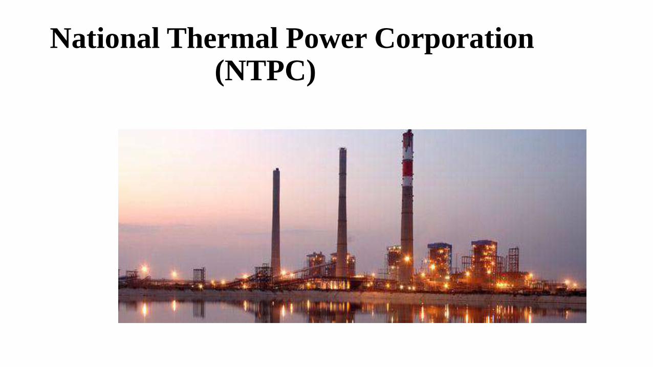
National Thermal Power Corporation(NTPC)
INTRODUCTION
• NTPC, the largest power Company in India, was setup in 1975 to accelerate power
development in the country.
• NTPC has installed capacity of 29,394 MW.
• It has 15 coal based power stations (23,395 MW)
• 7 gas based power stations (3,955 MW)
• 4 power stations in Joint Ventures (1,794 MW).
• The company has power generating facilities in all major regions of the country.
• It plans to be a 75,000 MW company by 2017.
HISTORY
India's largest power company, NTPC was set up in 1975 to accelerate power development.
NTPC is emerging as a diversified power major with presence in the entire value chain of the power generation business.
Apart from power generation, which is the mainstay of the company, NTPC has already ventured into consultancy, power trading, ash utilization and coal mining.
NTPC ranked 341st in the „2010, Forbes Global 2000‟ ranking of the World's biggest companies.
NTPC became a Maharatna company in May, 2010, one of the only four companies to be awarded this status in India.

NTPC KAHALGAON
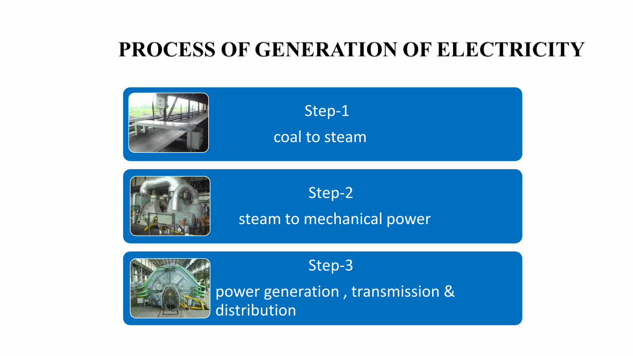
Step-1
coal to steam
Step-2
steam to mechanical power
Step-3
power generation , transmission & distribution

Step1:- Coal to Steam (Coal Handling Plant)
The coal is unloaded either manually or with the help of wagon tippler into the hopper to the conveyer belt.
Coal is passed through metal detectors in order to remove metals present in coal.
Stones from coal is removed manually in its journey through conveyer belt.
Then the coal is passed through vibrating screen where coal of 5mm is separated from large coals.
Then coal is crushed in crusher and passed through metal detectors to remove iron particles.
Coal is then supplied from coal bunker to mill. Coal dust comes out of this mill
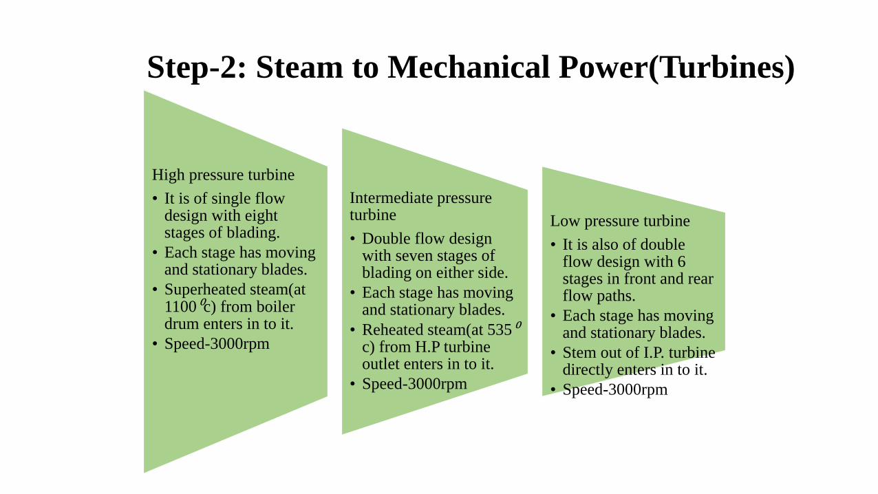
High pressure turbine
• It is of single flow design with eight stages of blading.
• Each stage has moving and stationary blades.
• Superheated steam(at 1100⁰c) from boiler drum enters in to it.
• Speed-3000rpm
Intermediate pressure turbine
• Double flow design with seven stages of blading on either side.
• Each stage has moving and stationary blades.
• Reheated steam(at 535⁰c) from H.P turbine outlet enters in to it.
• Speed-3000rpm
Low pressure turbine
• It is also of double flow design with 6 stages in front and rear flow paths.
• Each stage has moving and stationary blades.
• Stem out of I.P. turbine directly enters in to it.
• Speed-3000rpm
Step-2: Steam to Mechanical Power(Turbines)
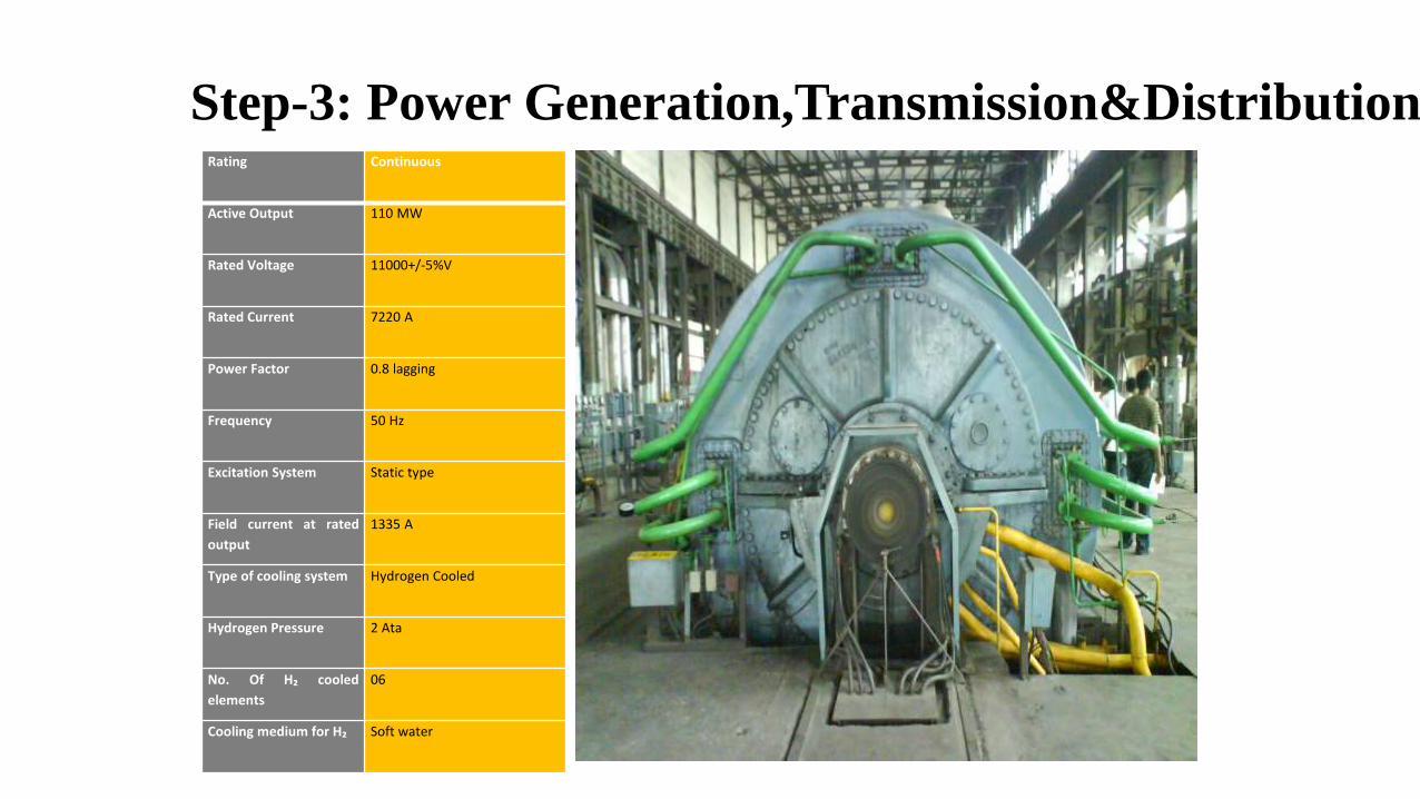
Rating Continuous
Active Output 110 MW
Rated Voltage 11000+/-5%V
Rated Current 7220 A
Power Factor 0.8 lagging
Frequency 50 Hz
Excitation System Static type
Field current at rated
output
1335 A
Type of cooling system Hydrogen Cooled
Hydrogen Pressure 2 Ata
No. Of H₂ cooled
elements
06
Cooling medium for H₂ Soft water
Step-3: Power Generation,Transmission&Distribution

GENERATION
Mechanical power produced at the shaft of the turbine is used to rotate rotor.
Rotating Magnetic flux produced by rotor cuts stator conductor and from electromagnetic induction, electricity is produced .
rotor runs at 3000 rpm, produces 3-phase voltage at 11kv , and of 50 HZ frequency.
Oil shielded hydrogen is used for the cooling purpose of generator.
In case of any fault if production of plants stops then bearing motor rotates rotor shaft of turbine continuously at 65 rpm. This is because if shaft doesn’t rotate then due to load it may bend.
TRANSMISSION
• NTPC has a capacity to generate 2340 MW of electricity.
• The transmission is done through 3-phase , double circuit system.
• With the help of station transformer 11kv is step up to 220 kv and fed to substation.

Voltmeter and ammeter
• As the names imply they are used for measuring voltage and current respectively.
Power meter
• Used to measure the power in standard unit of MW or KW.
Crt screen
• A computer arrangement in which current information about transmission line is seen.
Battery room
Consists of several batteries and chargers for emergency purpose.
DISTRIBUTION

Current transformer
• Used to reduce the current level such that it can be measured easily.
Bus isolators
• Used to isolate bus bars.
Lightning arrestor
• Used to protect the transmission line and connected equipment during lightening .
Wave trap wave trap which changes the frequency 50Hz to 500Hz can be used for communicate between power plants.
Electrical Equipments
AlternatorAn alternator is coupled to a steam turbine and converts mechanical energy of the turbine into electrical energy.It may be hydrogen or air cooled.The necessary excitation is provided by means of main and pilot exciters directly coupled to the alternator shaft.Transformers(a) main step-transformers, which steps-up generated voltage transmission of power(b) station transformers, general purpose(c) auxiliary transformers, which supply to individual unit-auxiliaries.Switchgearwhich locates fault on the system and isolate faulty part from healthy section.It contains circuit breakers, relays, switches and other control devices.
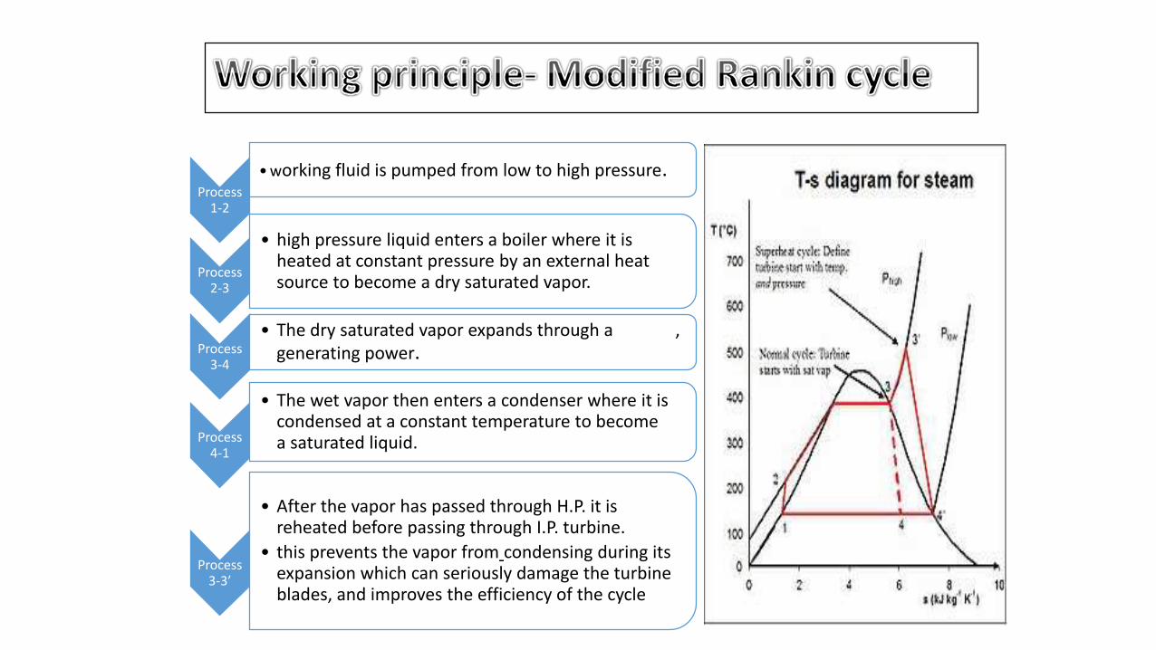
Process 1-2
•working fluid is pumped from low to high pressure.
Process 2-3
• high pressure liquid enters a boiler where it is heated at constant pressure by an external heat source to become a dry saturated vapor.
Process 3-4
• The dry saturated vapor expands through a turbine, generating power.
Process 4-1
• The wet vapor then enters a condenser where it is condensed at a constant temperature to become a saturated liquid.
Process 3-3’
• After the vapor has passed through H.P. it is reheated before passing through I.P. turbine.
• this prevents the vapor from condensing during its expansion which can seriously damage the turbine blades, and improves the efficiency of the cycle

CONCLUSIONS
Engineering students gain theoretical knowledge through books. It is volatile and not of much use without knowing its practical implementation.
Training is one of the important aspects for an engineering student's carrier to strengthen the practical concepts. It was an awesome experience in training as the things we all learnt in our previous year was seen implemented practically. We got to see the live performing equipment like Coal Handling Plant, Turbines, Switch Yard and many more in NTPC.

REFERENCES
• www.wikipedia.in/ntpc• www.goolge.co.images
• NTPC Guide Manual

ANY QUERY

THANK YOU
Related Documents


