Use of FTDI devices in life support and/or safety applications is entirely at the user’s risk, and the user agrees to defend, indemnify and hold harmless FTDI from any and all damages, claims, suits or expense resulting from such use. VM800B Datasheet Version 1.2 Document Reference No.: FT_000881 Clearance No.: FTDI# 348 FTDI Chip VM800B Datasheet Embedded Video Engine Basic module General Purpose Multi Media Controller 1 Introduction The VM800B is a development module for FTDI’s FT800, which is used to develop and demonstrate the functionality of the FT800 Embedded Video Engine, EVE. This module behaves as an SPI slave, and requires a SPI Master for proper micro- controller interfacing and system integration. VM800B modules support 3 different LCD panel size options and are designed for industrial or commercial environments with precision fitted bezels in either black (-BK) or pearl (-PL). VM800B35A-xx is the 3.5” LCD VM800B43A-xx is the 4.3” LCD VM800B50A-xx is the 5.0” LCD 1.1 Features The VM800B utilises the FTDI FT800 Embedded Video Engine, EVE. Graphic, audio and touch features of the FT800 chip can be accessed with the VM800B. For a full list of the FT800’s features please see the FT800 datasheet. The VM800B has the following features: Ready to use LCD module. Integrated with resistive touch screen LCD panel On board LCD backlight LED Driver On board audio power amplifier and micro speaker Flexible power supply. Powering the VM800B using either a 2.1mm power jack , SPI master connector or via USB Micro-B port 5 V tolerant buffers when used with a 5V SPI Master Precision fitted bezel in black(-BK) or pearl (-PL)

Welcome message from author
This document is posted to help you gain knowledge. Please leave a comment to let me know what you think about it! Share it to your friends and learn new things together.
Transcript

Use of FTDI devices in life support and/or safety applications is entirely at the user’s risk, and the user agrees to defend, indemnify and hold harmless FTDI from any and all damages, claims, suits or expense resulting
from such use.
VM800B Datasheet Version 1.2
Document Reference No.: FT_000881 Clearance No.: FTDI# 348
FTDI Chip
VM800B Datasheet
Embedded Video Engine
Basic module
General Purpose Multi Media Controller
1 Introduction
The VM800B is a development module for
FTDI’s FT800, which is used to develop and
demonstrate the functionality of the FT800
Embedded Video Engine, EVE.
This module behaves as an SPI slave, and
requires a SPI Master for proper micro-
controller interfacing and system integration.
VM800B modules support 3 different LCD
panel size options and are designed for
industrial or commercial environments with
precision fitted bezels in either black (-BK)
or pearl (-PL).
VM800B35A-xx is the 3.5” LCD
VM800B43A-xx is the 4.3” LCD
VM800B50A-xx is the 5.0” LCD
1.1 Features
The VM800B utilises the FTDI FT800 Embedded Video
Engine, EVE. Graphic, audio and touch features of the
FT800 chip can be accessed with the VM800B. For a full
list of the FT800’s features please see the FT800
datasheet. The VM800B has the following features:
Ready to use LCD module.
Integrated with resistive touch screen LCD panel
On board LCD backlight LED Driver
On board audio power amplifier and micro speaker
Flexible power supply. Powering the VM800B using
either a 2.1mm power jack , SPI master connector or
via USB Micro-B port
5 V tolerant buffers when used with a 5V SPI Master
Precision fitted bezel in black(-BK) or pearl (-PL)

2
Copyright © 2014 Future Technology Devices International Limited
VM800B Datasheet Version 1.2
Document Reference No.: FT_000881 Clearance No.: FTDI# 348
2 Ordering Information
Note that the kits below require a 5V/1A power supply. It is NOT provided in the development kit, but is offered as an optional accessory with the following part types:
Part No. Description
VM800B35A-BK VM800B module, supports 3.3/5v MCU Adapter Board, 3.5 inch TFT LCD display panel preinstalled, black bezel
VM800B43A-BK VM800B module, supports 3.3/5v MCU Adapter Board, 4.3 inch TFT LCD display panel preinstalled, black bezel
VM800B50A-BK VM800B module, supports 3.3/5v MCU Adapter Board, 5.0 inch TFT LCD display panel preinstalled, black bezel
VM800B35A-PL VM800B module, supports 3.3/5v MCU Adapter Board, 3.5 inch TFT LCD display panel preinstalled, pearl bezel
VM800B43A-PL VM800B module, supports 3.3/5v MCU Adapter Board, 4.3 inch TFT LCD display panel preinstalled, pearl bezel
VM800B50A-PL VM800B module, supports 3.3/5v MCU Adapter Board, 5.0 inch TFT LCD display panel preinstalled, pearl bezel
VA-PSU-UK1 Accessory - UK Model 5V/1A USB Power Supply (Mfr # JX-B0520C-1-B)
VA-PSU-US1 Accessory - US Model 5V/1A USB Power Supply (Mfr # JX-B0520B-1-B)
VA-PSU-EU1 Accessory - EU Model 5V/1A USB Power Supply (Mfr # JX-B0520A-1-B)
VA800A-SPI Accessory - High Speed Micro USB to SPI adapter for BASIC boards based on FT232H MPSSE design
VA-FC-1M-BKW Accessory - Flat USB A to Micro B Cable 1M- Black and White
VA-FC-1M-BLW Accessory - Flat USB A to Micro B Cable 1M- Blue and White
VA-FC-STYLUS1 Accessory - Resistive Touch Screen Pen Stylus
Table 2-1 – Ordering information
Note: 3.5” display resolution is 320 x 240 (QVGA).
4.3”/5.0” display resolution is 480 x 272 (WQVGA)

3
Copyright © 2014 Future Technology Devices International Limited
VM800B Datasheet Version 1.2
Document Reference No.: FT_000881 Clearance No.: FTDI# 348
Table of Contents
1 Introduction ................................................................................... 1
1.1 Features ........................................................................................................ 1
2 Ordering Information ..................................................................... 2
3 Hardware Description ..................................................................... 4
3.1 VM800B module ............................................................................................ 4
3.2 Physical Descriptions .................................................................................... 5
3.2.1 PCB layout ................................................................................................ 5
3.2.2 VM800B Connectors ................................................................................... 6
4 Board Schematics ........................................................................... 9
5 Hardware Setup Guide .................................................................. 13
5.1 Power Configuration ................................................................................... 13
5.2 MPSSE Setup ............................................................................................... 13
5.3 Arduino® Setup........................................................................................... 15
6 Assembling the Bezel and Panel Mounting ................................... 16
6.1 3.5” Dimensions .......................................................................................... 17
6.2 4.3” Dimensions .......................................................................................... 18
6.3 5.0” Dimensions .......................................................................................... 19
7 Specifications ............................................................................... 20
7.1 Optical Specification ................................................................................... 20
8 Contact Information ..................................................................... 23
Appendix A - References ....................................................................................... 23
Appendix B - List of Figures and Tables ................................................................. 24
Appendix C – Revision History ............................................................................... 25

4
Copyright © 2014 Future Technology Devices International Limited
VM800B Datasheet Version 1.2
Document Reference No.: FT_000881 Clearance No.: FTDI# 348
3 Hardware Description
Please refer to section 3.2.2 for connector settings. Some VM800B jumpers must be set to work properly with your system.
3.1 VM800B module
Figure 3-1 – VM800B module profile 3.5” display version
Figure 3-3 - VM800B module profile 5” display version
NOTE: Also available in pearl.
Figure 3-2 - VM800B module profile 4.3” display version

5
Copyright © 2014 Future Technology Devices International Limited
VM800B Datasheet Version 1.2
Document Reference No.: FT_000881 Clearance No.: FTDI# 348
The VM800B module is intended for direct use into existing applications that require a display. This
module is suitable for interfacing with an external microcontroller that has a SPI Master channel.
The VM800B module is available in multiple options: 3.5, 4.3 or 5.0 inch display options.
The main functions of the VM800B are as follows:
Micro USB connector
SPI connector
2-pin connector for power supply
3.3V regulator: Takes 5V input and outputs 3.3V for on-board circuits
LCD touch screen panel
5V tolerant buffers between the SPI master interface and the Slave interface of the FT800
o SPI timing requirements can be found in the FT800 datasheet. The on board level converter buffers introduce additional delay. The actual maximum SPI clock frequency
depends on the host system timing and connection cable length to the VM800B PCB.
3 stage audio filter and power amplifier
8Ω speaker
Audio line out option
Precision fitted bezel
3.2 Physical Descriptions
3.2.1 PCB layout
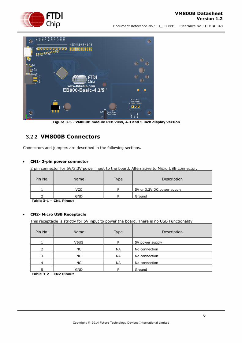
The VM800B module PCB layouts are illustrated in Figure 3-4 and Figure 3-5. Boards are four-layer, approximately 1.6 mm thickness.
Figure 3-4 - VM800B module PCB view, 3.5 inch display version
6
Copyright © 2014 Future Technology Devices International Limited
VM800B Datasheet Version 1.2
Document Reference No.: FT_000881 Clearance No.: FTDI# 348
Figure 3-5 - VM800B module PCB view, 4.3 and 5 inch display version
3.2.2 VM800B Connectors
Connectors and jumpers are described in the following sections.
CN1- 2-pin power connector
2 pin connector for 5V/3.3V power input to the board. Alternative to Micro USB connector.
Pin No. Name Type Description
1 VCC P 5V or 3.3V DC power supply
2 GND P Ground
Table 3-1 – CN1 Pinout
CN2- Micro USB Receptacle
This receptacle is strictly for 5V input to power the board. There is no USB Functionality
Pin No. Name Type Description
1 VBUS P 5V power supply
2 NC NA No connection
3 NC NA No connection
4 NC NA No connection
5 GND P Ground
Table 3-2 – CN2 Pinout

7
Copyright © 2014 Future Technology Devices International Limited
VM800B Datasheet Version 1.2
Document Reference No.: FT_000881 Clearance No.: FTDI# 348
J2 - Selection between Lineout and loop back into the power amplifier.
Selection between audio lineout and loop back into the power amplifier.
Jumper position Description
Short pin 1-2 Audio amp enabled (default)
Short pin 2-3 Audio amp mute, Audio lineout on pin 1
Table 3-3 – J2 Pin Options
J5- SPI Interface
This is the interface where the SPI control and data signals are routed too. There are also power and ground pins on this interface.
Pin No. Name Type Description
1 SCLK I SPI Clock input, 3.3V (5V tolerant)
2 MOSI I Master Out Slave in, 3.3V (5V tolerant)
3 MISO O Master In Slave out, 3.3V
4 CS# I Chip select , active low, 3.3V (5V tolerant)
5 INT# O Interrupt output active low, 3.3V
6 PD# I Power down control input, active low , 3.3V
(5V tolerant)
7 5V P 5V power supply
8 3.3V P 3.3V power supply
9 GND P Ground
10 GND P Ground
Table 3-4 – J5 Pinout
JP1- Audio Amplifier Power Select
This jumper provides the option to select the power supply voltage for the on-board power amplifier.
Jumper position Description
Short pin 1-2 3.3V selected (default)
Short pin 2-3 5V selected
Table 3-5 – JP1 Pin options
*This needs to be configured before audio can be heard. Default is 3.3V. Select 5V if wants to increase the maximum volume for the speaker.
JP2 – On board amplifier enable
Solder connection not fitted by default.
JP3 - On board amplifier mute
Solder connection not fitted by default.
SW1 – Power source select

8
Copyright © 2014 Future Technology Devices International Limited
VM800B Datasheet Version 1.2
Document Reference No.: FT_000881 Clearance No.: FTDI# 348
Jumper position Description
Short pin 1-2 Board power from CN1
Short pin 2-3 Board power from CN2 (default)
Table 3-6 – SW1 jumper options
9
Copyright © 2014 Future Technology Devices International Limited
VM800B Datasheet Version 1.2
Document Reference No.: FT_000881 Clearance No.: FTDI# 348
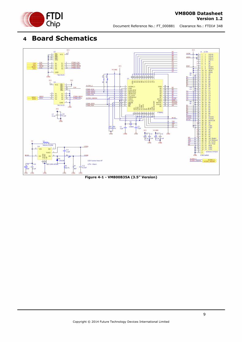
4 Board Schematics
FT800_PD#
FT800_INT#
VCC14
A12
GND7
OE11
Y13
A25
Y411
OE24
OE413
Y26
A412
A39
Y38
OE310
U2
74LCX125
3V3
GND
FT800_SCKFT800_MOSI
FT800_CS#
FT800_MISOMISO
CS#
SCK
VCC14
A12
GND7
OE11
Y13
A25
Y411
OE24
OE413
Y26
A412
A39
Y38
OE310
U3
74LCX125
PD#
INT#
3V3
GND
CS#
MOSI
INT#
PD#
MISO
SCK
MOSI
AUDIO_LAUDIO_LAUDIO_SHDN#
AUDIO_SHDN#
3V3
CS#AUDIO_L
1
GND2
SCKL/SCK3
MISO/SDA4
MOSI/SA05
CS_n/SA16
GPIO0/SA27
GPIO18
VCCIO9
MODE10
INT11
PD12
XT
I13
XT
O14
GN
D15
VC
C3V
316
VC
OR
E17
VC
C3V
318
XP
19
YP
20
XM
21
YM
22
GN
D23
BA
CK
LIG
HT
24
DE25
VSYNC26
HSYNC27
DISP28
DCLK29
B730
B631
B532
B433
B334
B235
GND36
G7
37
G6
38
G5
39
G4
40
G3
41
G2
42
R7
43
R6
44
R5
45
R4
46
R3
47
R2
48
GN
D4
9
U1
FT800Q
VCORE
3V3
GND
R2R3R4R5R6R7G2G3G4G5G6G7
B2B3B4B5B6B7DCLKDISPHSYNCVSYNCDE
BCKL
YMXMYPXP
Y1
12MHz C227pF
C127pF
GNDGND
AUDIO_L
FT800_SCKFT800_MISOFT800_MOSIFT800_CS#
GND
R447k
C3
4.7uF
C4
0.1uF
3V3
GND
C5
4.7uF
C6
0.1uF
GND
VCORE
AUDIO_SHDN#
FT800_PD#FT800_INT#
R347k
R2
47k
R1
47k
LEDK
R2
R4
R6
LEDA
R3
R5
R7
G2G3G4G5G6G7
B2B3B4B5B6B7
GND
R0R1
G0G1
B0B1
YMXMYP
XP
DCLK
DISP
HSYNCVSYNC
DE
LED-KLED-KLED-ALED-ANCNCNCRESETSPENASPCKSPDA
123456789101112131415161718192021222324252627282930313233343536373839404142434445464748495051525354
HSYNCVSYNCDOTCLKNCNCVDDVDDNCNCNCNCNCXRYDXL
DENGNDGND
YU
B0B1B2B3B4B5B6B7G0G1G2G3G4G5G6G7R0R1R2R3R4R5R6R7
[Left]
[Right][Bottom]
[Top]
LCD1
AT035GT-07ED3
11
22
33
44
55
66
77
88
99
1010
1111
1212
1313
1414
1515
1616
1717
1818
1919
2020
2121
2222
2323
2424
2525
2626
2727
2828
2929
3030
3131
3232
3333
3434
3535
3636
3737
3838
3939
4040
4141
4242
4343
4444
4545
4646
4747
4848
4949
5050
5151
5252
5353
5454
00
00
J1
0.5B-54PBX
3V3
GND
L1
NR3015T220M
C120.22uF
R54k7
C11
2.2nF
D1
1N4148
R6
10k/1%
VOUT1
VIN2
FB6
EN3
AG
ND
4
SW7
PG
ND
8
EP
9
U4
MIC2289-24YMLC9
10uF
C10
0.1uF
R7
4R7
LED Current Sense R7
4.7R :=20mA
5V
LEDK
LEDA
BCKL
GND GND GNDGND GND
C70.1uF
3V3
GND
C80.1uF
Figure 4-1 - VM800B35A (3.5” Version)

10
Copyright © 2014 Future Technology Devices International Limited
VM800B Datasheet Version 1.2
Document Reference No.: FT_000881 Clearance No.: FTDI# 348
FT800_PD#
FT800_INT#
VCC14
A12
GND7
OE11
Y13
A25
Y411
OE24
OE413
Y26
A412
A39
Y38
OE310
U2
74LCX125
3V3
GND
FT800_SCKFT800_MOSI
FT800_CS#
FT800_MISOMISO
CS#
SCK
VCC14
A12
GND7
OE11
Y13
A25
Y411
OE24
OE413
Y26
A412
A39
Y38
OE310
U3
74LCX125
PD#
INT#
3V3
GND
CS#
MOSI
INT#
PD#
MISO
SCK
MOSI
3V3
CS#AUDIO_L
1
GND2
SCKL/SCK3
MISO/SDA4
MOSI/SA05
CS_n/SA16
GPIO0/SA27
GPIO18
VCCIO9
MODE10
INT11
PD12
XT
I13
XT
O14
GN
D15
VC
C3V
316
VC
OR
E17
VC
C3V
318
XP
19
YP
20
XM
21
YM
22
GN
D23
BA
CK
LIG
HT
24
DE25
VSYNC26
HSYNC27
DISP28
DCLK29
B730
B631
B532
B433
B334
B235
GND36
G7
37
G6
38
G5
39
G4
40
G3
41
G2
42
R7
43
R6
44
R5
45
R4
46
R3
47
R2
48
GN
D4
9
U1
FT800Q
VCORE
3V3
GND
R2R3R4R5R6R7G2G3G4G5G6G7
B2B3B4B5B6B7DCLKDISPHSYNCVSYNCDE
BCKL
YMXMYPXP
Y1
12MHz C227pF
C127pF
GNDGND
AUDIO_L
FT800_SCKFT800_MISOFT800_MOSIFT800_CS#
GND
R447k
C3
4.7uF
C4
0.1uF
3V3
GND
C5
4.7uF
C6
0.1uF
GND
VCORE
AUDIO_SHDN#
FT800_PD#FT800_INT#
R347k
R2
47k
R1
47k
LEDK
R2
R4
R6
LEDA
R3
R5
R7
G2G3G4G5G6G7
B2B3B4B5B6B7
GND
R0R1
G0G1
B0B1
YMXMYP
XP
DCLKDISPHSYNCVSYNCDE
VLED-VLED+
12345678910111213141516171819202122232425262728293031323334353637383940
HSYNCVSYNC
PCLKDISP
NC
VDD
X1Y1X2
DE
GND
GND
Y2
R0R1R2R3R4R5R6R7G0G1G2G3G4G5G6G7B0B1B2B3B4B5B6B7
GND
[Left]
[Right][Bottom]
[Top]
LCD1
AT043B35-15l-10
11
22
33
44
55
66
77
88
99
1010
1111
1212
1313
1414
1515
1616
1717
1818
1919
2020
2121
2222
2323
2424
2525
2626
2727
2828
2929
3030
3131
3232
3333
3434
3535
3636
3737
3838
3939
4040
00
00
J1
0.5B-40PBS
3V3
GND
L1
NR3015T220M
C120.22uF
R54k7
C11
2.2nF
D1
1N4148
R6
10k/1%
VOUT1
VIN2
FB6
EN3
AG
ND
4
SW7
PG
ND
8
EP
9
U4
MIC2289-24YMLC9
10uF
C10
0.1uF
R7
3R
LED Current Sense R73R=32mA
5V
LEDK
LEDA
BCKL
GND GND GNDGND GND
C70.1uF
3V3
GND
C80.1uF
Figure 4-2 - VM800B43A/VM800B50A (4.3”/5.0” Version)

11
Copyright © 2014 Future Technology Devices International Limited
VM800B Datasheet Version 1.2
Document Reference No.: FT_000881 Clearance No.: FTDI# 348
Figure 4-3 – VM800B SPI Interface and IO
12
Copyright © 2014 Future Technology Devices International Limited
VM800B Datasheet Version 1.2
Document Reference No.: FT_000881 Clearance No.: FTDI# 348
SHDN1
BYPASS2
IN+3
IN-4
VO+5
VDD6
GND7
VO-8
GND9
U6
TPA6205A1
C20
1uF
R14
10k/1%
R1210k/1%
R15 20k/1%
R13 20k/1%
C18
0.47uF
C190.22uF
AGND
R1747k
C160.47uF
R91k
C13
4.7nF
R101k
C14
4.7nF
R111k
C15
4.7nF
AGND
AGND
AGND AGND
AUD_3V3
AUDIO_L
AUDIO_SHDN#
AGND
123
J2
Header 0.1"
SP-SP+
AUDIO_L_out
JP2-Audio Amp. Enabled
JP3-Audio Amp. Mute
1
2 4
35
OE
U5
SN74LVC1G125DBVR
AUD_3V3
AGND
R16 33R
C17
0.1uF
AUD_3V3
AGND
R8 33R
J4J3
AGND
SP1
1W/8Ohm
AUDIO_L
AUDIO_SHDN#
JP2
JP3
C220.1uF
AUD_3V3
C2310nF
C21100uF
AGNDMax peak current ~400mA for 8-ohm speakerGND
123
JP1
Jumper 2.0mm
5V
FB1
600R/1A
FB2
600R/1A
3V3
XL1
Shunt 2.0mm
AGND AGND
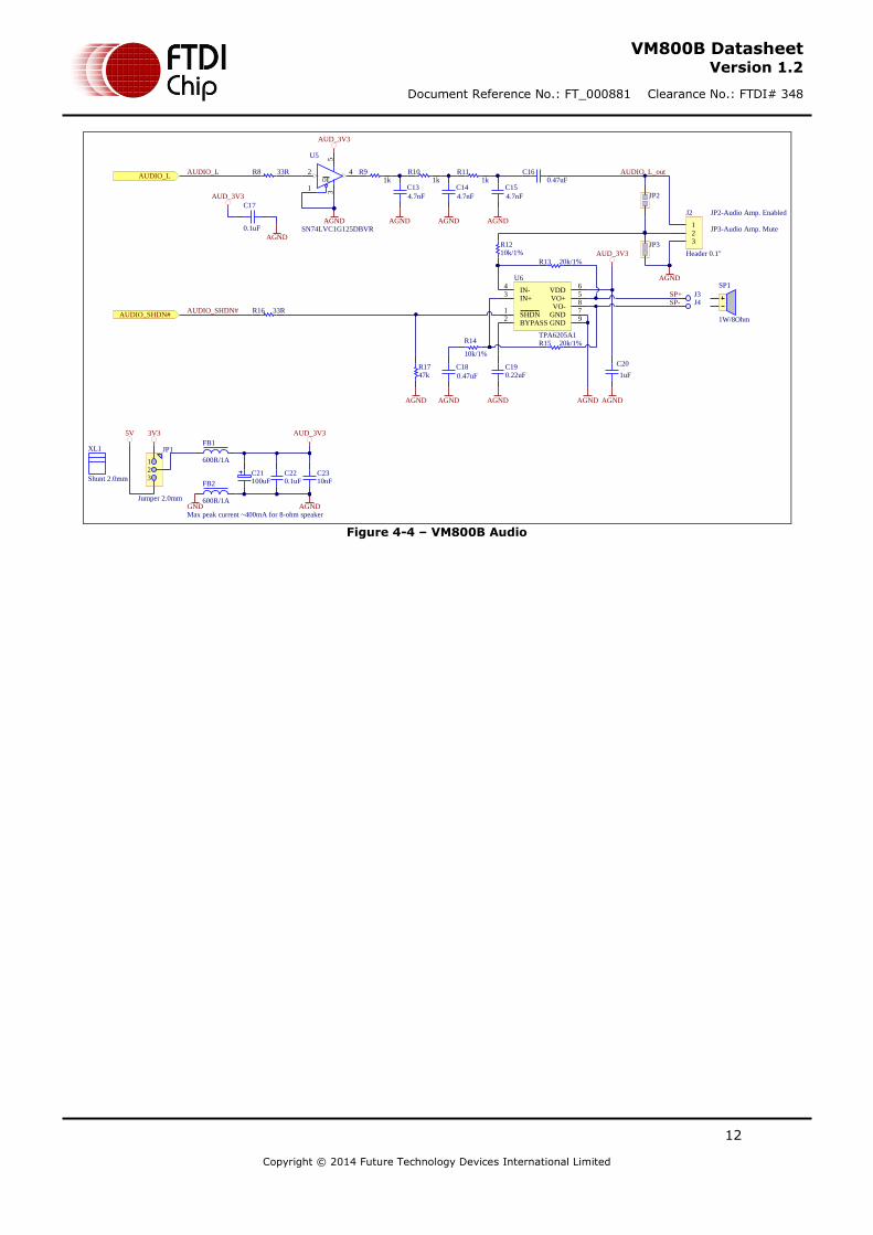
Figure 4-4 – VM800B Audio
13
Copyright © 2014 Future Technology Devices International Limited
VM800B Datasheet Version 1.2
Document Reference No.: FT_000881 Clearance No.: FTDI# 348
5 Hardware Setup Guide
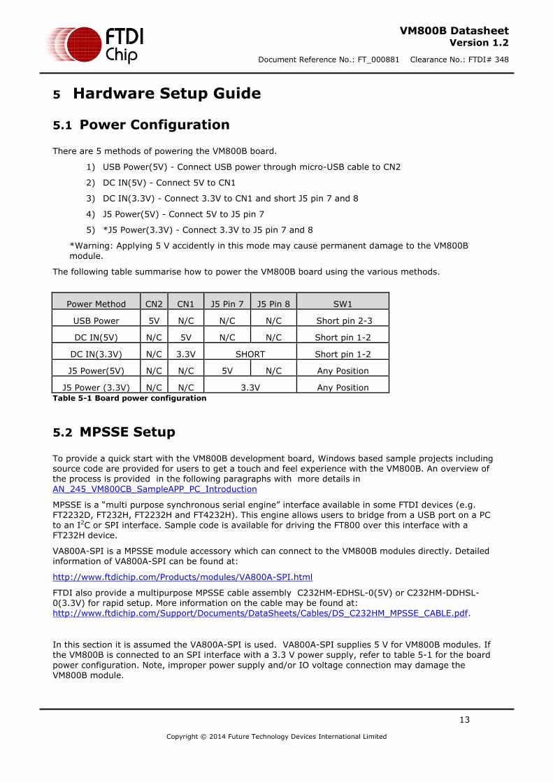
5.1 Power Configuration
There are 5 methods of powering the VM800B board.
1) USB Power(5V) - Connect USB power through micro-USB cable to CN2
2) DC IN(5V) - Connect 5V to CN1
3) DC IN(3.3V) - Connect 3.3V to CN1 and short J5 pin 7 and 8
4) J5 Power(5V) - Connect 5V to J5 pin 7
5) *J5 Power(3.3V) - Connect 3.3V to J5 pin 7 and 8
*Warning: Applying 5 V accidently in this mode may cause permanent damage to the VM800B
module.
The following table summarise how to power the VM800B board using the various methods.
Power Method CN2 CN1 J5 Pin 7 J5 Pin 8 SW1
USB Power 5V N/C N/C N/C Short pin 2-3
DC IN(5V) N/C 5V N/C N/C Short pin 1-2
DC IN(3.3V) N/C 3.3V SHORT Short pin 1-2
J5 Power(5V) N/C N/C 5V N/C Any Position
J5 Power (3.3V) N/C N/C 3.3V Any Position Table 5-1 Board power configuration
5.2 MPSSE Setup
To provide a quick start with the VM800B development board, Windows based sample projects including source code are provided for users to get a touch and feel experience with the VM800B. An overview of the process is provided in the following paragraphs with more details in
AN_245_VM800CB_SampleAPP_PC_Introduction
MPSSE is a “multi purpose synchronous serial engine” interface available in some FTDI devices (e.g. FT2232D, FT232H, FT2232H and FT4232H). This engine allows users to bridge from a USB port on a PC to an I2C or SPI interface. Sample code is available for driving the FT800 over this interface with a FT232H device.
VA800A-SPI is a MPSSE module accessory which can connect to the VM800B modules directly. Detailed information of VA800A-SPI can be found at:
http://www.ftdichip.com/Products/modules/VA800A-SPI.html
FTDI also provide a multipurpose MPSSE cable assembly C232HM-EDHSL-0(5V) or C232HM-DDHSL-0(3.3V) for rapid setup. More information on the cable may be found at:
http://www.ftdichip.com/Support/Documents/DataSheets/Cables/DS_C232HM_MPSSE_CABLE.pdf.
In this section it is assumed the VA800A-SPI is used. VA800A-SPI supplies 5 V for VM800B modules. If the VM800B is connected to an SPI interface with a 3.3 V power supply, refer to table 5-1 for the board
power configuration. Note, improper power supply and/or IO voltage connection may damage the VM800B module.

14
Copyright © 2014 Future Technology Devices International Limited
VM800B Datasheet Version 1.2
Document Reference No.: FT_000881 Clearance No.: FTDI# 348
Figure 5-1 – VM800B connects to PC through VA800A-SPI accessory.
Hardware Setup
Connect the VA800A-SPI to the VM800B module in the correct orientation (with J5-pin1 of VM800B board connected to CN1-pin1 of VA800A-SPI board).
Connect a USB cable (suggest FTDI accessory VA-FC-1M-BKW or VA-FC-1M-BLW) from the VA800A-SPI to the PC USB host port or self-powered hub port.
The VA800A-SPI will supply power to the VM800B after the MPSSE driver is properly loaded and the USB host completes USB device configuration.
NOTE: If using the C232HM-EDHSL-0(5V) MPSSE cable then the connection is as:
J5 Pin number J5 Signal MPSSE pin number MPSSE Signal MPSSE Cable Lead Colour
1 SCK 2 SK ORANGE
2 MOSI 3 DO YELLOW
3 MISO 4 DI GREEN
4 CS# 5 CS BROWN
5 INT# 7 GPIOL1 PURPLE
6 PD# 9 GPIOL3 BLUE
7 5V 1 VCC RED
8 3.3V - - -
9 GND 10 GND Black
10 GND - - -
Table 5-2 – MPSSE cable (C232HM-EDHSL-0) connection

15
Copyright © 2014 Future Technology Devices International Limited
VM800B Datasheet Version 1.2
Document Reference No.: FT_000881 Clearance No.: FTDI# 348
Software Setup
The following software setup steps apply to both the VA800A-SPI and MPSSE cable assembly.
Download the MPSSE software. MPSSE cable and driver information can be found at http://www.ftdichip.com/Products/Cables/USBMPSSE.htm.
Launch the demo application based on MPSSE from the PC
The demo application notes can be found at following link: AN_245_VM800CB_SampleAPP_PC_Introduction
5.3 Arduino® Setup
Sample code and demo applications are provided to users who want to connect the VM800B to a MCU. FTDI provides sample source code, sample application notes and a ready to run demo based on the
Arduino® platform. Detailed information can be found at: http://testwebsite/Products/modules/VM800B.html

16
Copyright © 2014 Future Technology Devices International Limited
VM800B Datasheet Version 1.2
Document Reference No.: FT_000881 Clearance No.: FTDI# 348
6 Assembling the Bezel and Panel Mounting
Figure 6-1 - VM800B Panel Mount (Front view)
Figure 6-2 - VM800B Panel Mount (Rear view)

17
Copyright © 2014 Future Technology Devices International Limited
VM800B Datasheet Version 1.2
Document Reference No.: FT_000881 Clearance No.: FTDI# 348
6.1 3.5” Dimensions
Figure 6-3 - VM800B 3.5” panel mount dimensions

18
Copyright © 2014 Future Technology Devices International Limited
VM800B Datasheet Version 1.2
Document Reference No.: FT_000881 Clearance No.: FTDI# 348
6.2 4.3” Dimensions
Figure 6-4 - VM800B 4.3” panel mount dimensions
19
Copyright © 2014 Future Technology Devices International Limited
VM800B Datasheet Version 1.2
Document Reference No.: FT_000881 Clearance No.: FTDI# 348
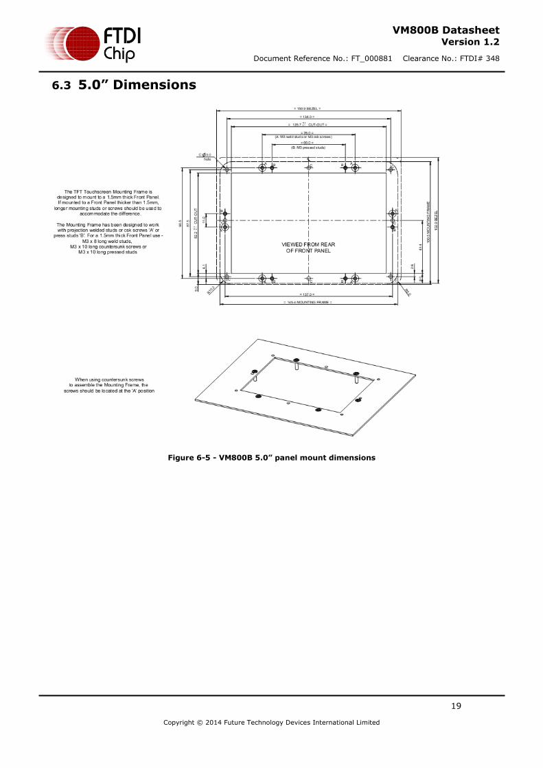
6.3 5.0” Dimensions
Figure 6-5 - VM800B 5.0” panel mount dimensions

20
Copyright © 2014 Future Technology Devices International Limited
VM800B Datasheet Version 1.2
Document Reference No.: FT_000881 Clearance No.: FTDI# 348
7 Specifications
7.1 Optical Specification
Table 7-1 - 3.5” TFT Optical specification

21
Copyright © 2014 Future Technology Devices International Limited
VM800B Datasheet Version 1.2
Document Reference No.: FT_000881 Clearance No.: FTDI# 348
Table 7-2 - 4.3” TFT Optical Specification

22
Copyright © 2014 Future Technology Devices International Limited
VM800B Datasheet Version 1.2
Document Reference No.: FT_000881 Clearance No.: FTDI# 348
Table 7-3 - 5” TFT Optical Specification

23
Copyright © 2014 Future Technology Devices International Limited
VM800B Datasheet Version 1.2
Document Reference No.: FT_000881 Clearance No.: FTDI# 348
8 Contact Information
Head Office – Glasgow, UK Unit 1, 2 Seaward Place, Centurion Business Park Glasgow G41 1HH United Kingdom Tel: +44 (0) 141 429 2777 Fax: +44 (0) 141 429 2758 E-mail (Sales) [email protected] E-mail (Support) [email protected] E-mail (General Enquiries) [email protected]
Branch Office – Taipei, Taiwan 2F, No. 516, Sec. 1, NeiHu Road Taipei 114 Taiwan , R.O.C. Tel: +886 (0) 2 8797 1330 Fax: +886 (0) 2 8751 9737 E-mail (Sales) [email protected] E-mail (Support) [email protected] E-mail (General Enquiries) [email protected]
Branch Office – Tigard, Oregon, USA 7130 SW Fir Loop Tigard, OR 97223 USA Tel: +1 (503) 547 0988 Fax: +1 (503) 547 0987 E-Mail (Sales) [email protected] E-Mail (Support) [email protected] E-Mail (General Enquiries) [email protected]
Branch Office – Shanghai, China Room 1103, No. 666 West Huaihai Road, Changning District, Shanghai, 200052 China Tel: +86 (0)21 6235 1596 Fax: +86 (0)21 6235 1595 E-mail (Sales) [email protected] E-mail (Support) [email protected] E-mail (General Enquiries) [email protected]
Web Site
http://ftdichip.com
Distributor and Sales Representatives
Please visit the Sales Network page of the FTDI Web site for the contact details of our distributor(s) and sales representative(s) in your country.
System and equipment manufacturers and designers are responsible to ensure that their systems, and any Future Technology Devices International Ltd (FTDI) devices incorporated in their systems, meet all applicable safety, regulatory and system-level performance requirements. All application-related information in this document (including application descriptions, suggested FTDI devices and other materials) is provided for reference only. While FTDI has taken care to assure it is accurate, this information is subject to customer confirmation, and FTDI disclaims all liability for system designs and for any applications assistance provided by FTDI. Use of FTDI devices in life support and/or safety applications is entirely at the user’s risk, and the user agrees to defend, indemnify and hold harmless FTDI from any and all damages, claims, suits or expense resulting from such use. This document is subject to change without notice. No freedom to use patents or other intellectual property rights is implied by the publication of this document. Neither the whole nor any part of the information contained in, or the product described in this document, may be adapted or reproduced in any material or electronic form without the prior written consent of the copyright holder. Future Technology Devices International Ltd, Unit 1, 2 Seaward Place, Centurion Business Park, Glasgow G41 1HH, United Kingdom. Scotland Registered Company Number: SC136640
23
Copyright © 2014 Future Technology Devices International Limited
VM800B Datasheet Version 1.2
Document Reference No.: FT_000881 Clearance No.: FTDI# 348
Appendix A - References
For module documentations, please refer to URL below:
http://testwebsite/Products/modules/VM800B.html
FT800 datasheet: DS_FT800_Embedded_Video_Engine
FT800 software programming guide: FT800_Programmer_Guide
FT800 sample application notes:
AN_245_VM800CB_SampleAPP_PC_Introduction
AN_246_VM800CB_SampleAPP_Arduino_Introduction
C232HM-EDHSL-0 datasheet:
http://www.ftdichip.com/Support/Documents/DataSheets/Cables/DS_C232HM_MPSSE_CABLE.pdf
D2xx Programmers Guide:
http://www.ftdichip.com/Support/Documents/ProgramGuides/D2XX_Programmer's_Guide(FT_000071).pdf
AN_108: Command Processor for MPSSE and MCU Host Bus Emulation Modes
http://www.ftdichip.com/Support/Documents/AppNotes/AN_108_Command_Processor_for_MPSSE_and_MCU_Host_Bus_Emulation_Modes.pdf

24
Copyright © 2014 Future Technology Devices International Limited
VM800B Datasheet Version 1.2
Document Reference No.: FT_000881 Clearance No.: FTDI# 348
Appendix B - List of Figures and Tables
List of Figures
Figure 3-1 – VM800B module profile 3.5” display version .......................................................................... 4
Figure 3-2 - VM800B module profile 4.3” display version ........................................................................... 4
Figure 3-2 - VM800B module profile 5” display version .............................................................................. 4
Figure 3-3 - VM800B module PCB view, 3.5 inch display version .............................................................. 5
Figure 3-4 - VM800B module PCB view, 4.3 and 5 inch display version .................................................... 6
Figure 4-1 - VM800B35A (3.5” Version) ......................................................................................................... 9
Figure 4-2 - VM800B43A/VM800B50A (4.3”/5.0” Version).......................................................................... 10
Figure 4-3 – VM800B SPI Interface and IO .................................................................................................. 11
Figure 4-4 – VM800B Audio .......................................................................................................................... 12
Figure 5-1 – VM800B connects to PC through VA800A-SPI accessory. .................................................. 14
Figure 6-2 - VM800B Panel Mount (Rear view) ........................................................................................... 16
Figure 6-3 - VM800B 3.5” panel mount dimensions ................................................................................... 17
Figure 6-4 - VM800B 4.3” panel mount dimensions ................................................................................... 18
Figure 6-5 - VM800B 5.0” panel mount dimensions ................................................................................... 19
List of Tables
Table 2-1 – Ordering information ................................................................................................................... 2
Table 3-1 – CN1 Pinout .................................................................................................................................... 6
Table 3-2 – CN2 Pinout .................................................................................................................................... 6
Table 3-4 – J2 Pin Options .............................................................................................................................. 7
Table 3-5 – J5 Pinout ....................................................................................................................................... 7
Table 3-6 – JP1 Pin options ............................................................................................................................ 7
Table 3-7 – SW1 jumper options .................................................................................................................... 8
Table 5-1 Board power configuration .......................................................................................................... 13
Table 5-2 – MPSSE cable (C232HM-EDHSL-0) connection ........................................................................ 14
Table 7-1 - 3.5” TFT Optical specification ................................................................................................... 20
Table 7-2 - 4.3” TFT Optical Specification ................................................................................................... 21
Table 7-3 - 5” TFT Optical Specification ...................................................................................................... 22

25
Copyright © 2014 Future Technology Devices International Limited
VM800B Datasheet Version 1.2
Document Reference No.: FT_000881 Clearance No.: FTDI# 348
Appendix C – Revision History
Document Title: DS_VM800B
Document Reference No.: FT_000881
Clearance No.: FTDI# 348
Product Page: http://www.ftdichip.com/eve.htm
Document Feedback: Send Feedback
Version 1.0 Initial Datasheet released 28/08/13
Version 1.1 Corrected dimensions for 4.3” mpounting in section 6.2 25/03/14
Version 1.2 Updated the optical characteristics for the 4.3” and 5” displays 12/06/14
Related Documents