Programming Guide VLT ® AutomationDrive FC 300 MAKING MODERN LIVING POSSIBLE

Welcome message from author
This document is posted to help you gain knowledge. Please leave a comment to let me know what you think about it! Share it to your friends and learn new things together.
Transcript
Rev. 2009-10-12
www.danfoss.com/drives
130R0334 MG33M802
*MG33M802*
MG
33M802
VLT ® Autom
ationDrive FC
300 Programm
ing Guide
Programming GuideVLT® AutomationDrive FC 300
MAKING MODERN LIVING POSSIBLE
Contents
1 Introduction 3
Approvals 3
Symbols 3
Abbreviations 4
Definitions 4
Electrical wiring - Control Cables 11
2 How to Programme 15
The Graphical and Numerical Local Control Panels 15
How to Programme on the Graphical LCP 15
The LCD-Display 15
Display Mode 18
Display Mode - Selection of Read-Outs 19
Parameter Set-Up 20
Quick Menu Key Functions 21
Main Menu Mode 23
Parameter Selection 23
Infinitely Variable Change of Numeric Data Value 24
Read-out and Programming of Indexed Parameters 25
How to Programme on the Numerical Local Control Panel 26
Local Control Keys 27
Initialisation to Default Settings 28
3 Parameter descriptions 29
Parameters: Operation and Display 30
Parameters: Load and Motor 45
Parameters: Brakes 65
Parameters: Reference/Ramps 71
Parameters: Limits/Warnings 85
Parameters: Digital In/Out 92
Parameters: Analog In/Out 116
Parameters: Controllers 128
Parameters: Communications and Options 135
Parameters: Profibus 150
Parameters: DeviceNet CAN Fieldbus 162
Parameters: Ethernet 169
Parameters: Smart Logic Control 176
Parameters: Special Functions 194
Parameters: Drive Information 205
Parameters: Data Read-outs 212
FC 300 Programming Guide Contents
MG.33.M8.02 - VLT® is a registered Danfoss trademark 1
Parameters: Encoder Input 221
Parameters: Data Readouts 2 224
Parameters: Sensor Input Option 229
4 Parameter Lists 233
Parameter Lists 233
5 Troubleshooting 255
Warnings/Alarm Messages 255
Index 264
Contents FC 300 Programming Guide
2 MG.33.M8.02 - VLT® is a registered Danfoss trademark
1 Introduction
Programming Guide
Software version: 6.0x
This Programming Guide can be used for all FC 300 frequency converters with software version 6.0x.
The software version number can be seen from par. 15-43 Software Version.
1.1.1 Approvals
1.1.2 Symbols
Symbols used in this guide.
NB!
Indicates something to be noted by the reader.
Indicates a general warning.
Indicates a high-voltage warning.
* Indicates default setting
FC 300 Programming Guide 1 Introduction
MG.33.M8.02 - VLT® is a registered Danfoss trademark 3
1
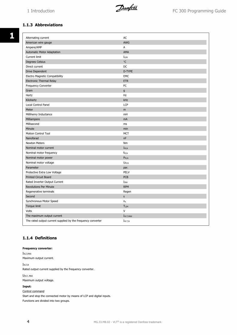
1.1.3 Abbreviations
Alternating current AC
American wire gauge AWG
Ampere/AMP A
Automatic Motor Adaptation AMA
Current limit ILIM
Degrees Celsius °CDirect current DC
Drive Dependent D-TYPE
Electro Magnetic Compatibility EMC
Electronic Thermal Relay ETR
Frequency Converter FC
Gram g
Hertz Hz
Kilohertz kHz
Local Control Panel LCP
Meter m
Millihenry Inductance mH
Milliampere mA
Millisecond ms
Minute min
Motion Control Tool MCT
Nanofarad nF
Newton Meters Nm
Nominal motor current IM,N
Nominal motor frequency fM,N
Nominal motor power PM,N
Nominal motor voltage UM,N
Parameter par.
Protective Extra Low Voltage PELV
Printed Circuit Board PCB
Rated Inverter Output Current IINV
Revolutions Per Minute RPM
Regenerative terminals Regen
Second s
Synchronous Motor Speed ns
Torque limit TLIM
Volts V
The maximum output current IVLT,MAX
The rated output current supplied by the frequency converter IVLT,N
1.1.4 Definitions
Frequency converter:
IVLT,MAX
Maximum output current.
IVLT,N
Rated output current supplied by the frequency converter.
UVLT, MAX
Maximum output voltage.
Input:
Control command
Start and stop the connected motor by means of LCP and digital inputs.
Functions are divided into two groups.
1 Introduction FC 300 Programming Guide
4 MG.33.M8.02 - VLT® is a registered Danfoss trademark
1
Functions in group 1 have higher priority than functions in group 2.Group 1 Reset, Coasting stop, Reset and Coasting
stop, Quick-stop, DC braking, Stop and the
"Off" key.
Group 2 Start, Pulse start, Reversing, Start reversing,
Jog and Freeze output
Motor:
Motor Running
Torque generated on output shaft and speed from zero rpm to max. speed on motor.
fJOG
Motor frequency when the jog function is activated (via digital terminals).
fM
Motor frequency.
fMAX
Maximum motor frequency.
fMIN
Minimum motor frequency.
fM,N
Rated motor frequency (nameplate data).
IM
Motor current (actual).
IM,N
Rated motor current (nameplate data).
nM,N
Rated motor speed (nameplate data).
ns
Synchronous motor speed
ns = 2 × par. 1 − 23 × 60 spar. 1 − 39
PM,N
Rated motor power (nameplate data in kW or HP).
TM,N
Rated torque (motor).
UM
Instantaneous motor voltage.
UM,N
Rated motor voltage (nameplate data).
FC 300 Programming Guide 1 Introduction
MG.33.M8.02 - VLT® is a registered Danfoss trademark 5
1
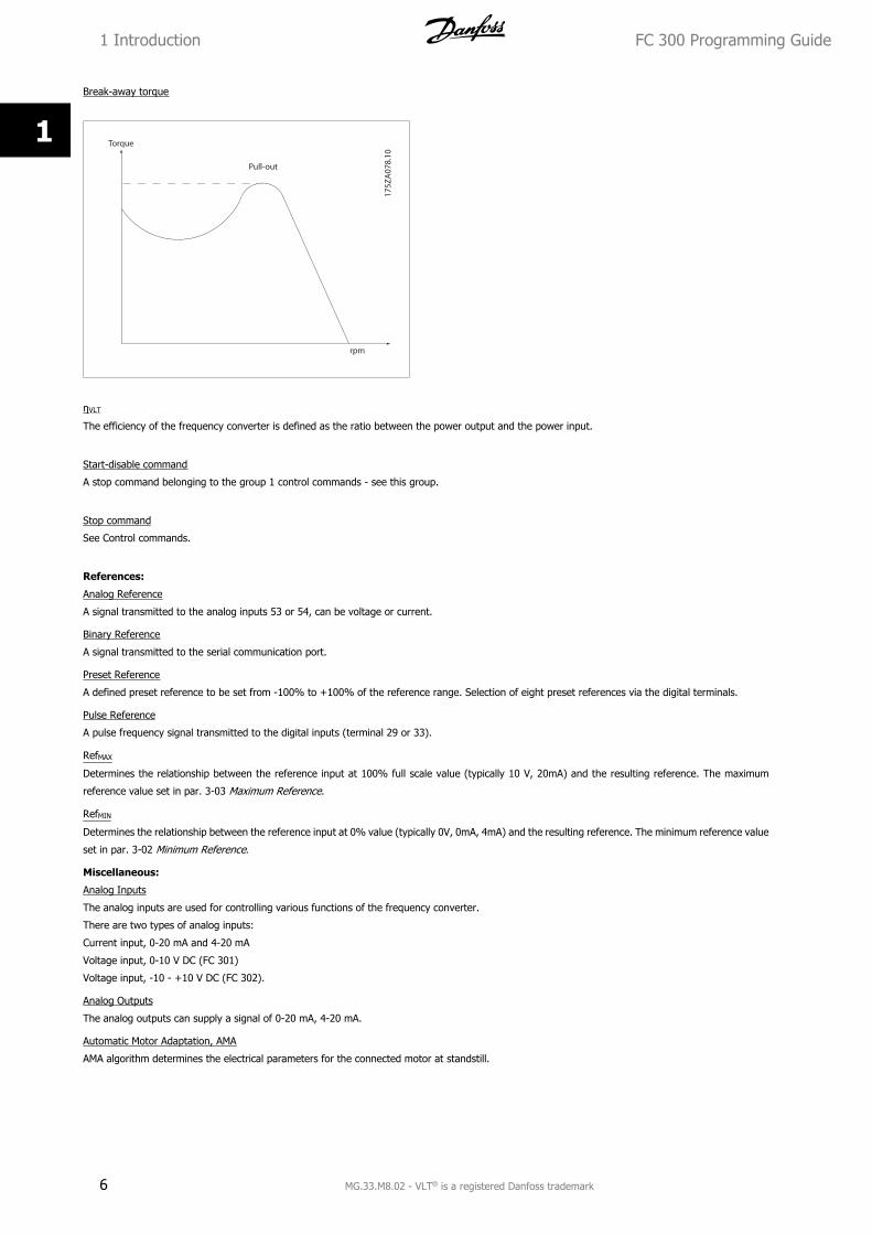
Break-away torque
ηVLT
The efficiency of the frequency converter is defined as the ratio between the power output and the power input.
Start-disable command
A stop command belonging to the group 1 control commands - see this group.
Stop command
See Control commands.
References:
Analog Reference
A signal transmitted to the analog inputs 53 or 54, can be voltage or current.
Binary Reference
A signal transmitted to the serial communication port.
Preset Reference
A defined preset reference to be set from -100% to +100% of the reference range. Selection of eight preset references via the digital terminals.
Pulse Reference
A pulse frequency signal transmitted to the digital inputs (terminal 29 or 33).
RefMAX
Determines the relationship between the reference input at 100% full scale value (typically 10 V, 20mA) and the resulting reference. The maximum
reference value set in par. 3-03 Maximum Reference.
RefMIN
Determines the relationship between the reference input at 0% value (typically 0V, 0mA, 4mA) and the resulting reference. The minimum reference value
set in par. 3-02 Minimum Reference.
Miscellaneous:
Analog Inputs
The analog inputs are used for controlling various functions of the frequency converter.
There are two types of analog inputs:
Current input, 0-20 mA and 4-20 mA
Voltage input, 0-10 V DC (FC 301)
Voltage input, -10 - +10 V DC (FC 302).
Analog Outputs
The analog outputs can supply a signal of 0-20 mA, 4-20 mA.
Automatic Motor Adaptation, AMA
AMA algorithm determines the electrical parameters for the connected motor at standstill.
1 Introduction FC 300 Programming Guide
6 MG.33.M8.02 - VLT® is a registered Danfoss trademark
1
Brake Resistor
The brake resistor is a module capable of absorbing the brake power generated in regenerative braking. This regenerative braking power increases the
intermediate circuit voltage and a brake chopper ensures that the power is transmitted to the brake resistor.
CT Characteristics
Constant torque characteristics used for all applications such as conveyor belts, displacement pumps and cranes.
Digital Inputs
The digital inputs can be used for controlling various functions of the frequency converter.
Digital Outputs
The frequency converter features two Solid State outputs that can supply a 24 V DC (max. 40 mA) signal.
DSP
Digital Signal Processor.
ETR
Electronic Thermal Relay is a thermal load calculation based on present load and time. Its purpose is to estimate the motor temperature.
Hiperface®
Hiperface® is a registered trademark by Stegmann.
Initialising
If initialising is carried out (par. 14-22 Operation Mode), the frequency converter returns to the default setting.
Intermittent Duty Cycle
An intermittent duty rating refers to a sequence of duty cycles. Each cycle consists of an on-load and an off-load period. The operation can be either
periodic duty or non-periodic duty.
LCP
The Local Control Panel makes up a complete interface for control and programming of the frequency converter. The control panel is detachable and can
be installed up to 3 metres from the frequency converter, i.e. in a front panel by means of the installation kit option.
lsb
Least significant bit.
msb
Most significant bit.
MCM
Short for Mille Circular Mil, an American measuring unit for cable cross-section. 1 MCM = 0.5067 mm2.
On-line/Off-line Parameters
Changes to on-line parameters are activated immediately after the data value is changed. Changes to off-line parameters are not activated until you enter
[OK] on the LCP.
Process PID
The PID control maintains the desired speed, pressure, temperature, etc. by adjusting the output frequency to match the varying load.
PCD
Process Data
Power Cycle
Switch off the mains until display (LCP) is dark – then turn power on again
Pulse Input/Incremental Encoder
An external, digital pulse transmitter used for feeding back information on motor speed. The encoder is used in applications where great accuracy in
speed control is required.
RCD
Residual Current Device.
Set-up
You can save parameter settings in four Set-ups. Change between the four parameter Set-ups and edit one Set-up, while another Set-up is active.
SFAVM
Switching pattern called Stator Flux oriented Asynchronous Vector Modulation (par. 14-00 Switching Pattern).
Slip Compensation
The frequency converter compensates for the motor slip by giving the frequency a supplement that follows the measured motor load keeping the motor
speed almost constant.
FC 300 Programming Guide 1 Introduction
MG.33.M8.02 - VLT® is a registered Danfoss trademark 7
1
Smart Logic Control (SLC)
The SLC is a sequence of user defined actions executed when the associated user defined events are evaluated as true by the Smart Logic Controller.
(Parameter group 13-** Smart Logic Control (SLC).
STW
Status Word
FC Standard Bus
Includes RS 485 bus with FC protocol or MC protocol. See par. 8-30 Protocol.
Thermistor:
A temperature-dependent resistor placed where the temperature is to be monitored (frequency converter or motor).
Trip
A state entered in fault situations, e.g. if the frequency converter is subject to an over-temperature or when the frequency converter is protecting the
motor, process or mechanism. Restart is prevented until the cause of the fault has disappeared and the trip state is cancelled by activating reset or, in
some cases, by being programmed to reset automatically. Trip may not be used for personal safety.
Trip Locked
A state entered in fault situations when the frequency converter is protecting itself and requiring physical intervention, e.g. if the frequency converter is
subject to a short circuit on the output. A locked trip can only be cancelled by cutting off mains, removing the cause of the fault, and reconnecting the
frequency converter. Restart is prevented until the trip state is cancelled by activating reset or, in some cases, by being programmed to reset automatically.
Trip may not be used for personal safety.
VT Characteristics
Variable torque characteristics used for pumps and fans.
VVCplus
If compared with standard voltage/frequency ratio control, Voltage Vector Control (VVCplus) improves the dynamics and the stability, both when the speed
reference is changed and in relation to the load torque.
60° AVM
Switching pattern called 60°Asynchronous Vector Modulation (par. 14-00 Switching Pattern).
Power Factor
The power factor is the relation between I1 and IRMS.Power factor =
3 x U x I1 cosϕ3 x U x IRMS
The power factor for 3-phase control:= I1 x cosϕ1
IRMS =
I1IRMS
since cosϕ1 = 1
The power factor indicates to which extent the frequency converter im-
poses a load on the mains supply.
The lower the power factor, the higher the IRMS for the same kW per-
formance.
IRMS = I12 + I5
2 + I72 + .. + In
2
In addition, a high power factor indicates that the different harmonic currents are low.
The frequency converters' built-in DC coils produce a high power factor, which minimizes the imposed load on the mains supply.
1.1.5 Safety Precautions
The voltage of the frequency converter is dangerous whenever connected to mains. Incorrect installation of the motor, frequency
converter or fieldbus may cause death, serious personal injury or damage to the equipment. Consequently, the instructions in this
manual, as well as national and local rules and safety regulations, must be complied with.
Safety Regulations
1. The mains supply to the frequency converter must be disconnected whenever repair work is to be carried out. Check that the mains supply has
been disconnected and that the necessary time has elapsed before removing motor and mains supply plugs.
2. The [OFF] button on the control panel of the frequency converterr does not disconnect the mains supply and consequently it must not be used
as a safety switch.
1 Introduction FC 300 Programming Guide
8 MG.33.M8.02 - VLT® is a registered Danfoss trademark
1
3. The equipment must be properly earthed, the user must be protected against supply voltage and the motor must be protected against overload
in accordance with applicable national and local regulations.
4. The earth leakage current exceeds 3.5 mA.
5. Protection against motor overload is not included in the factory setting. If this function is desired, set par. 1-90 Motor Thermal Protection to
data value ETR trip 1 [4] or data value ETR warning 1 [3].
6. Do not remove the plugs for the motor and mains supply while the frequency converter is connected to mains. Check that the mains supply has
been disconnected and that the necessary time has elapsed before removing motor and mains plugs.
7. Please note that the frequency converter has more voltage sources than L1, L2 and L3, when load sharing (linking of DC intermediate circuit)
or external 24 V DC are installed. Check that all voltage sources have been disconnected and that the necessary time has elapsed before
commencing repair work.
Warning against unintended start
1. The motor can be brought to a stop by means of digital commands, bus commands, references or a local stop, while the frequency converter
is connected to mains. If personal safety considerations (e.g. risk of personal injury caused by contact with moving machine parts following an
unintentional start) make it necessary to ensure that no unintended start occurs, these stop functions are not sufficient. In such cases the mains
supply must be disconnected or the Safe Stop function must be activated.
2. The motor may start while setting the parameters. If this means that personal safety may be compromised (e.g. personal injury caused by
contact with moving machine parts), motor starting must be prevented, for instance by use of the Safe Stop function or secure disconnection
of the motor connection.
3. A motor that has been stopped with the mains supply connected, may start if faults occur in the electronics of the frequency converter, through
temporary overload or if a fault in the power supply grid or motor connection is remedied. If unintended start must be prevented for personal
safety reasons (e.g. risk of injury caused by contact with moving machine parts), the normal stop functions of the frequency converter are not
sufficient. In such cases the mains supply must be disconnected or the Safe Stop function must be activated.
NB!
When using the Safe Stop function, always follow the instructions in the Safe Stop section of the VLT AutomationDrive FC 300 Design
Guide.
4. Control signals from, or internally within, the frequency converter may in rare cases be activated in error, be delayed or fail to occur entirely.
When used in situations where safety is critical, e.g. when controlling the electromagnetic brake function of a hoist application, these control
signals must not be relied on exclusively.
Touching the electrical parts may be fatal - even after the equipment has been disconnected from mains.
Also make sure that other voltage inputs have been disconnected, such as external 24 V DC, load sharing (linkage of DC intermediate
circuit), as well as the motor connection for kinetic back up.
Systems where frequency converters are installed must, if necessary, be equipped with additional monitoring and protective devices
according to the valid safety regulations, e.g law on mechanical tools, regulations for the prevention of accidents etc. Modifications on
the frequency converters by means of the operating software are allowed.
NB!
Hazardous situations shall be identified by the machine builder/ integrator who is responsible for taking necessary preventive means
into consideration. Additional monitoring and protective devices may be included, always according to valid national safety regulations,
e.g. law on mechanical tools, regulations for the prevention of accidents.
NB!
Crane, Lifts and Hoists:
The controlling of external brakes must always have a redundant system. The frequency converter can in no circumstances be the
primary safety circuit. Comply with relevant standards, e.g.
Hoists and cranes: IEC 60204-32
Lifts: EN 81
FC 300 Programming Guide 1 Introduction
MG.33.M8.02 - VLT® is a registered Danfoss trademark 9
1
Protection Mode
Once a hardware limit on motor current or dc-link voltage is exceeded the frequency converter will enter “Protection mode”. “Protection mode” means a
change of the PWM modulation strategy and a low switching frequency to minimize losses. This continues 10 sec after the last fault and increases the
reliability and the robustness of the frequency converter while re-establishing full control of the motor.
In hoist applications “Protection mode” is not usable because the frequency converter will usually not be able to leave this mode again and therefore it
will extend the time before activating the brake – which is not recommendable.
The “Protection mode” can be disabled by setting par. 14-26 Trip Delay at Inverter Fault to zero which means that the frequency converter will trip
immediately if one of the hardware limits is exceeded.
NB!
It is recommended to disable protection mode in hoisting applications (par. 14-26 Trip Delay at Inverter Fault = 0)
1 Introduction FC 300 Programming Guide
10 MG.33.M8.02 - VLT® is a registered Danfoss trademark
1
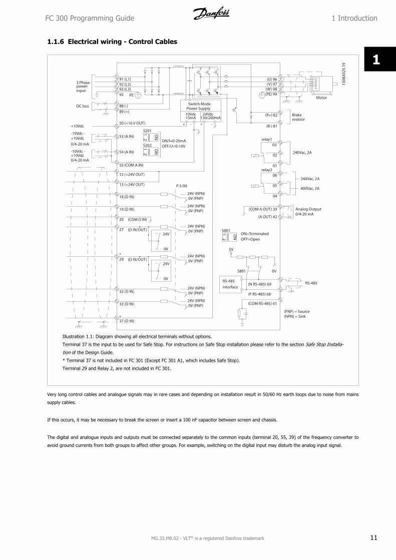
1.1.6 Electrical wiring - Control Cables
Illustration 1.1: Diagram showing all electrical terminals without options.
Terminal 37 is the input to be used for Safe Stop. For instructions on Safe Stop installation please refer to the section Safe Stop Installa-
tion of the Design Guide.
* Terminal 37 is not included in FC 301 (Except FC 301 A1, which includes Safe Stop).
Terminal 29 and Relay 2, are not included in FC 301.
Very long control cables and analogue signals may in rare cases and depending on installation result in 50/60 Hz earth loops due to noise from mains
supply cables.
If this occurs, it may be necessary to break the screen or insert a 100 nF capacitor between screen and chassis.
The digital and analogue inputs and outputs must be connected separately to the common inputs (terminal 20, 55, 39) of the frequency converter to
avoid ground currents from both groups to affect other groups. For example, switching on the digital input may disturb the analog input signal.
FC 300 Programming Guide 1 Introduction
MG.33.M8.02 - VLT® is a registered Danfoss trademark 11
1
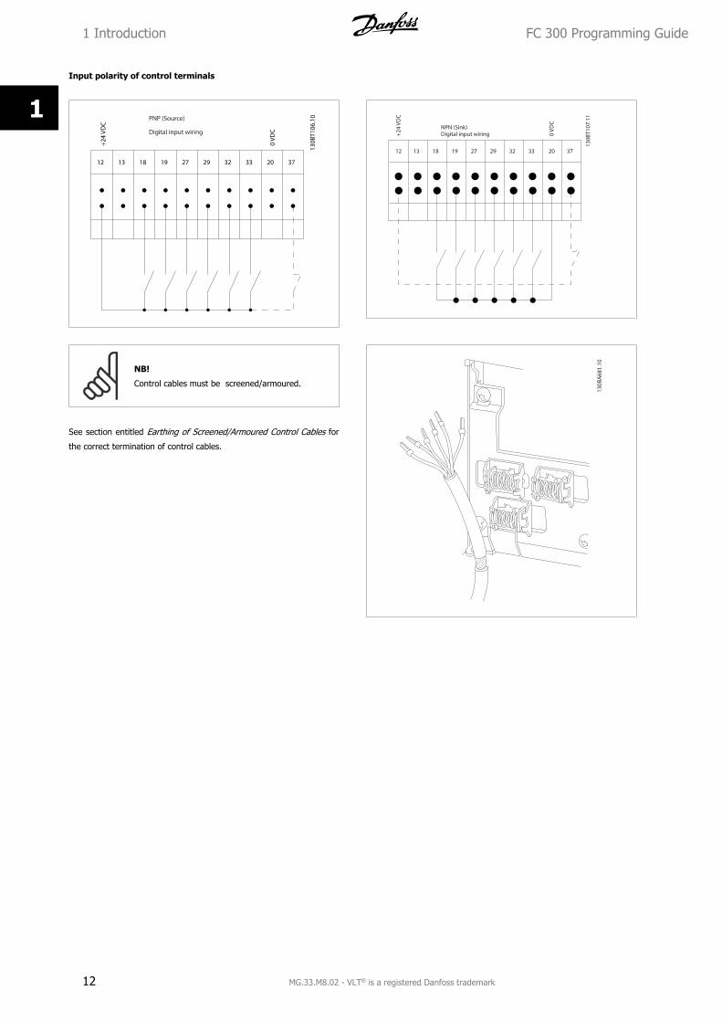
Input polarity of control terminals
NB!
Control cables must be screened/armoured.
See section entitled Earthing of Screened/Armoured Control Cables for
the correct termination of control cables.
1 Introduction FC 300 Programming Guide
12 MG.33.M8.02 - VLT® is a registered Danfoss trademark
1
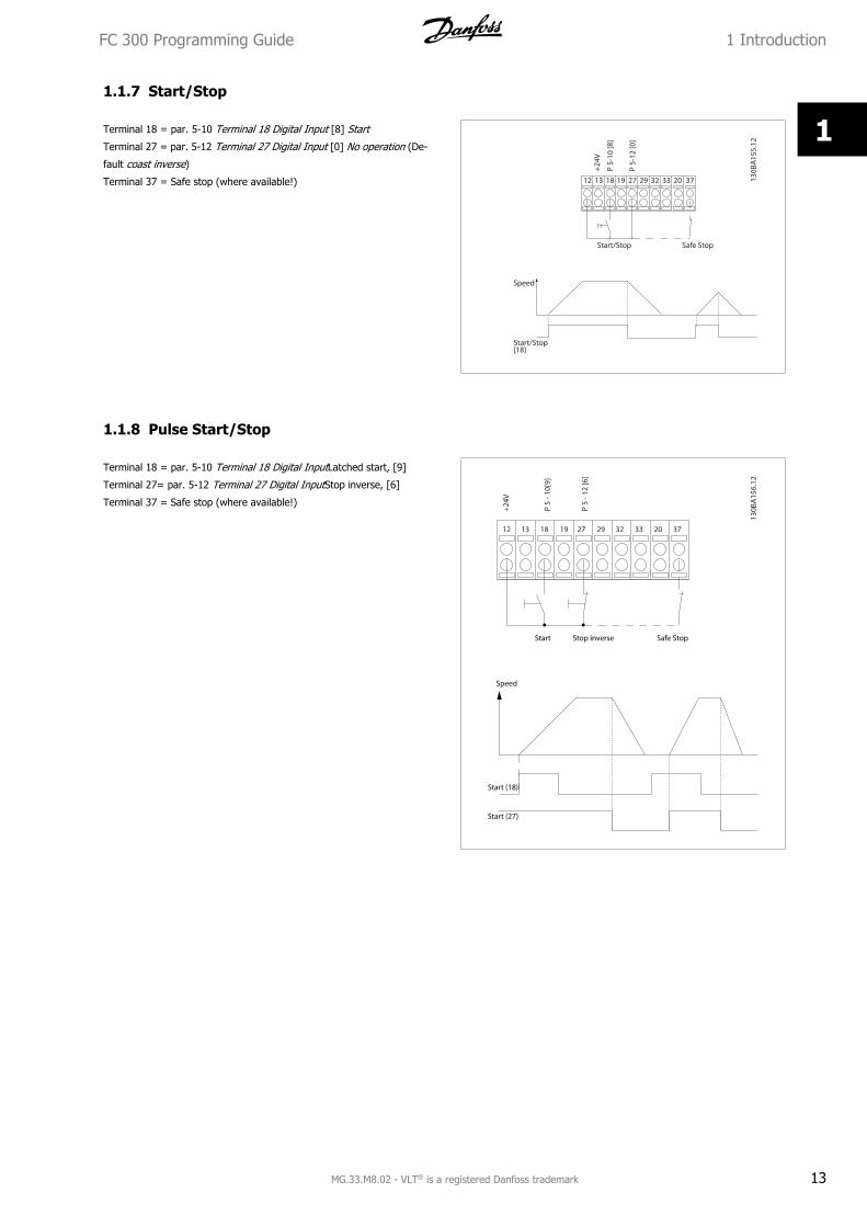
1.1.7 Start/Stop
Terminal 18 = par. 5-10 Terminal 18 Digital Input [8] Start
Terminal 27 = par. 5-12 Terminal 27 Digital Input [0] No operation (De-
fault coast inverse)
Terminal 37 = Safe stop (where available!)
1.1.8 Pulse Start/Stop
Terminal 18 = par. 5-10 Terminal 18 Digital InputLatched start, [9]
Terminal 27= par. 5-12 Terminal 27 Digital InputStop inverse, [6]
Terminal 37 = Safe stop (where available!)
FC 300 Programming Guide 1 Introduction
MG.33.M8.02 - VLT® is a registered Danfoss trademark 13
1
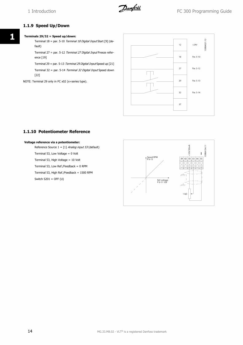
1.1.9 Speed Up/Down
Terminals 29/32 = Speed up/down:
Terminal 18 = par. 5-10 Terminal 18 Digital Input Start [9] (de-
fault)
Terminal 27 = par. 5-12 Terminal 27 Digital Input Freeze refer-
ence [19]
Terminal 29 = par. 5-13 Terminal 29 Digital Input Speed up [21]
Terminal 32 = par. 5-14 Terminal 32 Digital Input Speed down
[22]
NOTE: Terminal 29 only in FC x02 (x=series type).
1.1.10 Potentiometer Reference
Voltage reference via a potentiometer:
Reference Source 1 = [1] Analog input 53 (default)
Terminal 53, Low Voltage = 0 Volt
Terminal 53, High Voltage = 10 Volt
Terminal 53, Low Ref./Feedback = 0 RPM
Terminal 53, High Ref./Feedback = 1500 RPM
Switch S201 = OFF (U)
1 Introduction FC 300 Programming Guide
14 MG.33.M8.02 - VLT® is a registered Danfoss trademark
1
2 How to Programme
2.1 The Graphical and Numerical Local Control PanelsThe easiest programming of the frequency converter is performed by the Graphical LCP (LCP 102). It is necessary to consult the frequency converter
Design Guide, when using the Numeric Local Control Panel (LCP 101).
2.1.1 How to Programme on the Graphical LCP
The following instructions are valid for the graphical LCP (LCP 102):
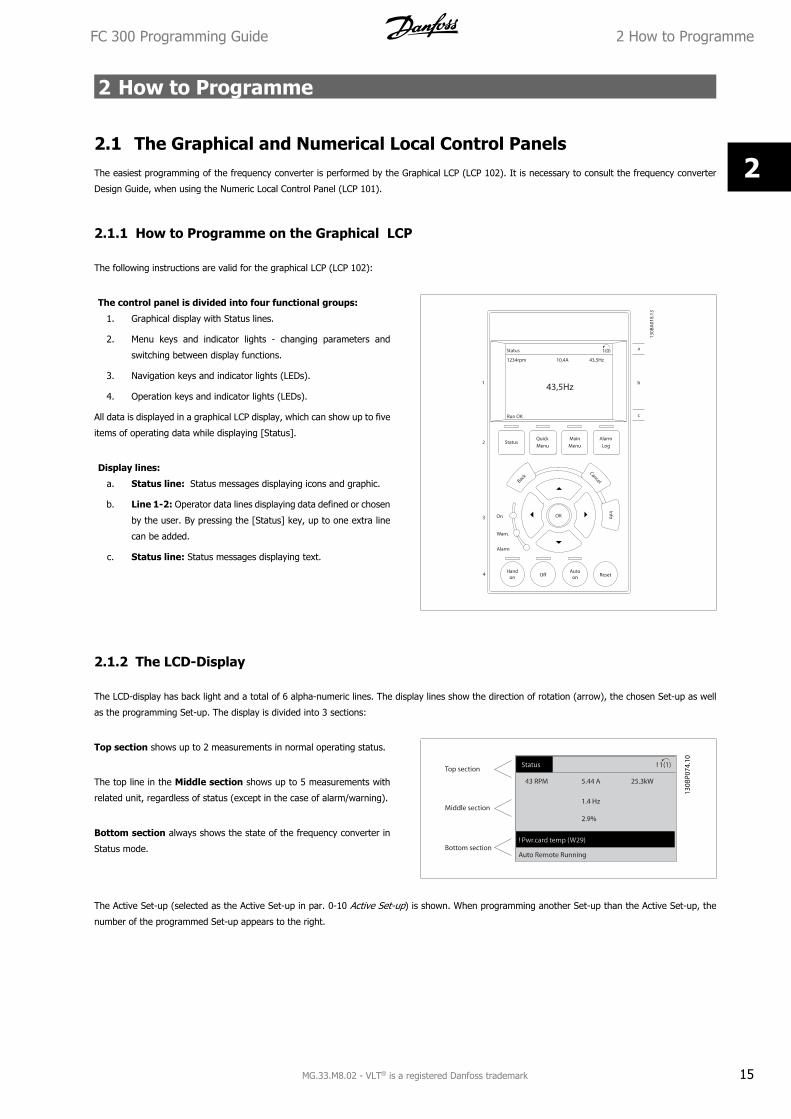
The control panel is divided into four functional groups:
1. Graphical display with Status lines.
2. Menu keys and indicator lights - changing parameters and
switching between display functions.
3. Navigation keys and indicator lights (LEDs).
4. Operation keys and indicator lights (LEDs).
All data is displayed in a graphical LCP display, which can show up to five
items of operating data while displaying [Status].
Display lines:
a. Status line: Status messages displaying icons and graphic.
b. Line 1-2: Operator data lines displaying data defined or chosen
by the user. By pressing the [Status] key, up to one extra line
can be added.
c. Status line: Status messages displaying text.
2.1.2 The LCD-Display
The LCD-display has back light and a total of 6 alpha-numeric lines. The display lines show the direction of rotation (arrow), the chosen Set-up as well
as the programming Set-up. The display is divided into 3 sections:
Top section shows up to 2 measurements in normal operating status.
The top line in the Middle section shows up to 5 measurements with
related unit, regardless of status (except in the case of alarm/warning).
Bottom section always shows the state of the frequency converter in
Status mode.
The Active Set-up (selected as the Active Set-up in par. 0-10 Active Set-up) is shown. When programming another Set-up than the Active Set-up, the
number of the programmed Set-up appears to the right.
FC 300 Programming Guide 2 How to Programme
MG.33.M8.02 - VLT® is a registered Danfoss trademark 15
2
Display Contrast Adjustment
Press [status] and [] for darker display
Press [status] and [] for brighter display
Most parameter set-ups can be changed immediately via the LCP, unless a password has been created via par. 0-60 Main Menu Password or via
par. 0-65 Quick Menu Password.
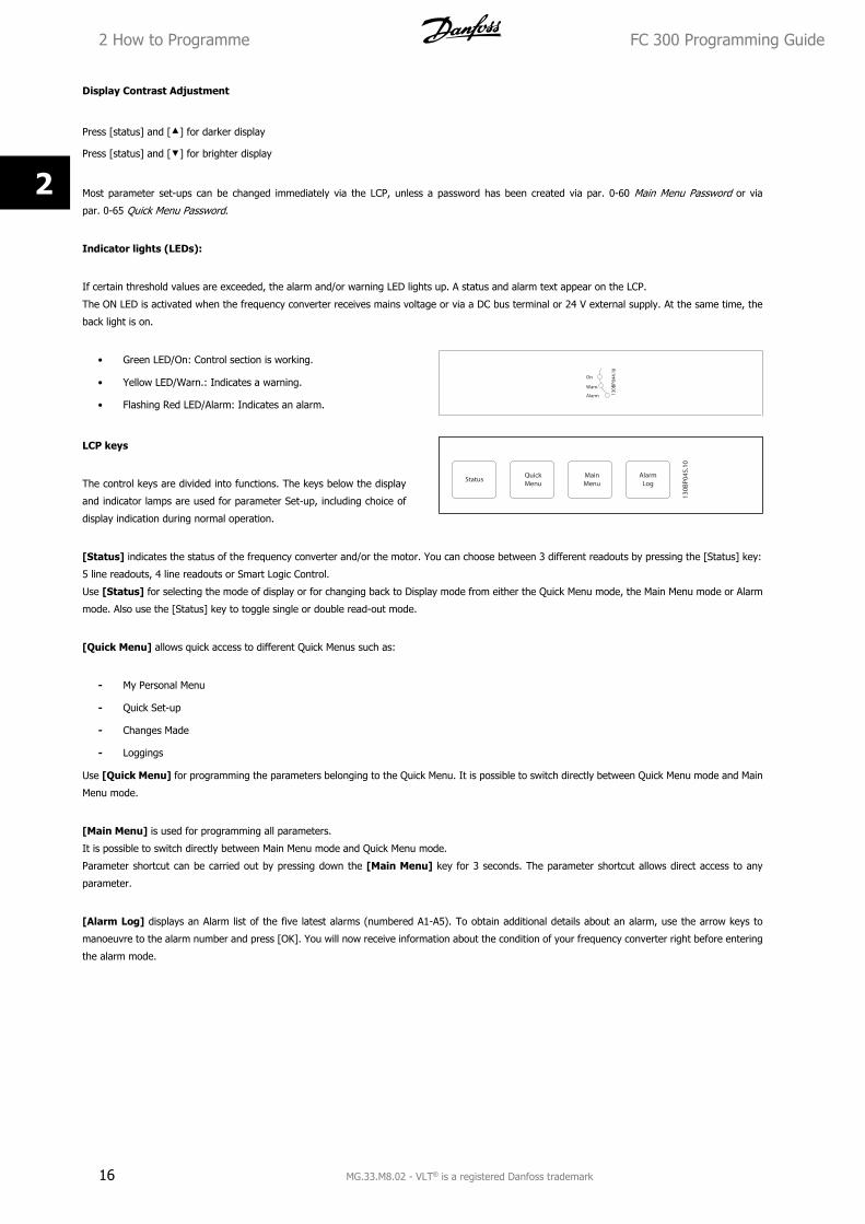
Indicator lights (LEDs):
If certain threshold values are exceeded, the alarm and/or warning LED lights up. A status and alarm text appear on the LCP.
The ON LED is activated when the frequency converter receives mains voltage or via a DC bus terminal or 24 V external supply. At the same time, the
back light is on.
• Green LED/On: Control section is working.
• Yellow LED/Warn.: Indicates a warning.
• Flashing Red LED/Alarm: Indicates an alarm.
130B
P 044
.1 0
On
Wam.
Alarm
LCP keys
The control keys are divided into functions. The keys below the display
and indicator lamps are used for parameter Set-up, including choice of
display indication during normal operation.
[Status] indicates the status of the frequency converter and/or the motor. You can choose between 3 different readouts by pressing the [Status] key:
5 line readouts, 4 line readouts or Smart Logic Control.
Use [Status] for selecting the mode of display or for changing back to Display mode from either the Quick Menu mode, the Main Menu mode or Alarm
mode. Also use the [Status] key to toggle single or double read-out mode.
[Quick Menu] allows quick access to different Quick Menus such as:
- My Personal Menu
- Quick Set-up
- Changes Made
- Loggings
Use [Quick Menu] for programming the parameters belonging to the Quick Menu. It is possible to switch directly between Quick Menu mode and Main
Menu mode.
[Main Menu] is used for programming all parameters.
It is possible to switch directly between Main Menu mode and Quick Menu mode.
Parameter shortcut can be carried out by pressing down the [Main Menu] key for 3 seconds. The parameter shortcut allows direct access to any
parameter.
[Alarm Log] displays an Alarm list of the five latest alarms (numbered A1-A5). To obtain additional details about an alarm, use the arrow keys to
manoeuvre to the alarm number and press [OK]. You will now receive information about the condition of your frequency converter right before entering
the alarm mode.
2 How to Programme FC 300 Programming Guide
16 MG.33.M8.02 - VLT® is a registered Danfoss trademark
2
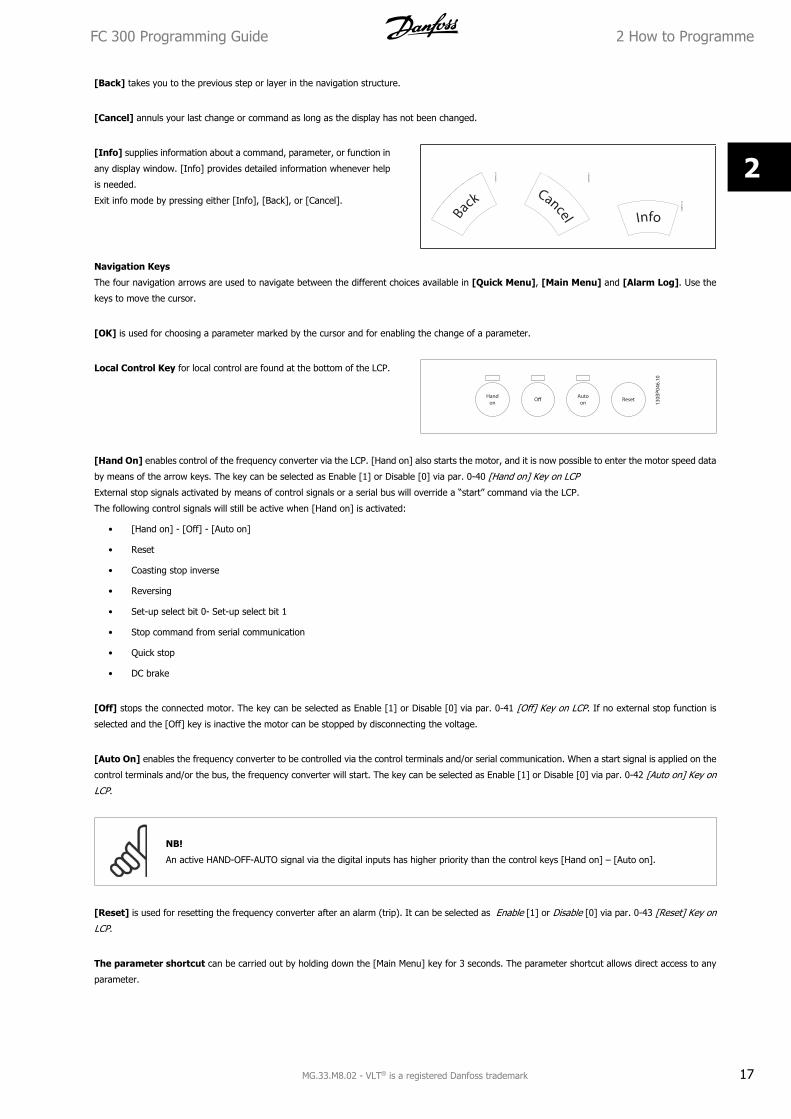
[Back] takes you to the previous step or layer in the navigation structure.
[Cancel] annuls your last change or command as long as the display has not been changed.
[Info] supplies information about a command, parameter, or function in
any display window. [Info] provides detailed information whenever help
is needed.
Exit info mode by pressing either [Info], [Back], or [Cancel].
Navigation Keys
The four navigation arrows are used to navigate between the different choices available in [Quick Menu], [Main Menu] and [Alarm Log]. Use the
keys to move the cursor.
[OK] is used for choosing a parameter marked by the cursor and for enabling the change of a parameter.
Local Control Key for local control are found at the bottom of the LCP.
[Hand On] enables control of the frequency converter via the LCP. [Hand on] also starts the motor, and it is now possible to enter the motor speed data
by means of the arrow keys. The key can be selected as Enable [1] or Disable [0] via par. 0-40 [Hand on] Key on LCP
External stop signals activated by means of control signals or a serial bus will override a “start” command via the LCP.
The following control signals will still be active when [Hand on] is activated:
• [Hand on] - [Off] - [Auto on]
• Reset
• Coasting stop inverse
• Reversing
• Set-up select bit 0- Set-up select bit 1
• Stop command from serial communication
• Quick stop
• DC brake
[Off] stops the connected motor. The key can be selected as Enable [1] or Disable [0] via par. 0-41 [Off] Key on LCP. If no external stop function is
selected and the [Off] key is inactive the motor can be stopped by disconnecting the voltage.
[Auto On] enables the frequency converter to be controlled via the control terminals and/or serial communication. When a start signal is applied on the
control terminals and/or the bus, the frequency converter will start. The key can be selected as Enable [1] or Disable [0] via par. 0-42 [Auto on] Key on
LCP.
NB!
An active HAND-OFF-AUTO signal via the digital inputs has higher priority than the control keys [Hand on] – [Auto on].
[Reset] is used for resetting the frequency converter after an alarm (trip). It can be selected as Enable [1] or Disable [0] via par. 0-43 [Reset] Key on
LCP.
The parameter shortcut can be carried out by holding down the [Main Menu] key for 3 seconds. The parameter shortcut allows direct access to any
parameter.
FC 300 Programming Guide 2 How to Programme
MG.33.M8.02 - VLT® is a registered Danfoss trademark 17
2
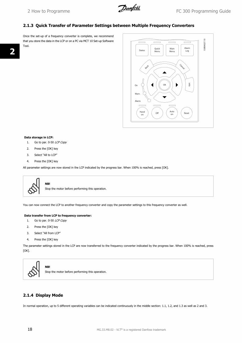
2.1.3 Quick Transfer of Parameter Settings between Multiple Frequency Converters
Once the set-up of a frequency converter is complete, we recommend
that you store the data in the LCP or on a PC via MCT 10 Set-up Software
Tool.
Data storage in LCP:
1. Go to par. 0-50 LCP Copy
2. Press the [OK] key
3. Select “All to LCP”
4. Press the [OK] key
All parameter settings are now stored in the LCP indicated by the progress bar. When 100% is reached, press [OK].
NB!
Stop the motor before performing this operation.
You can now connect the LCP to another frequency converter and copy the parameter settings to this frequency converter as well.
Data transfer from LCP to frequency converter:
1. Go to par. 0-50 LCP Copy
2. Press the [OK] key
3. Select “All from LCP”
4. Press the [OK] key
The parameter settings stored in the LCP are now transferred to the frequency converter indicated by the progress bar. When 100% is reached, press
[OK].
NB!
Stop the motor before performing this operation.
2.1.4 Display Mode
In normal operation, up to 5 different operating variables can be indicated continuously in the middle section: 1.1, 1.2, and 1.3 as well as 2 and 3.
2 How to Programme FC 300 Programming Guide
18 MG.33.M8.02 - VLT® is a registered Danfoss trademark
2
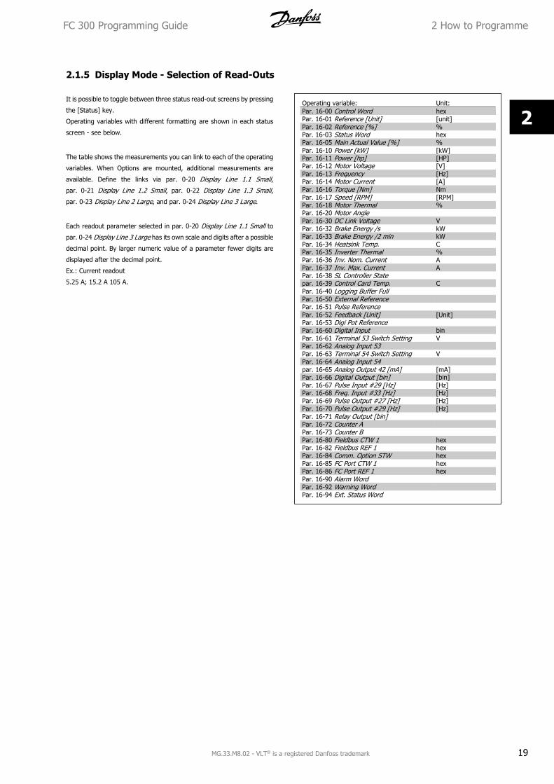
2.1.5 Display Mode - Selection of Read-Outs
It is possible to toggle between three status read-out screens by pressing
the [Status] key.
Operating variables with different formatting are shown in each status
screen - see below.
The table shows the measurements you can link to each of the operating
variables. When Options are mounted, additional measurements are
available. Define the links via par. 0-20 Display Line 1.1 Small,
par. 0-21 Display Line 1.2 Small, par. 0-22 Display Line 1.3 Small,
par. 0-23 Display Line 2 Large, and par. 0-24 Display Line 3 Large.
Each readout parameter selected in par. 0-20 Display Line 1.1 Small to
par. 0-24 Display Line 3 Large has its own scale and digits after a possible
decimal point. By larger numeric value of a parameter fewer digits are
displayed after the decimal point.
Ex.: Current readout
5.25 A; 15.2 A 105 A.
Operating variable: Unit:Par. 16-00 Control Word hexPar. 16-01 Reference [Unit] [unit]Par. 16-02 Reference [%] %Par. 16-03 Status Word hexPar. 16-05 Main Actual Value [%] %Par. 16-10 Power [kW] [kW]Par. 16-11 Power [hp] [HP]Par. 16-12 Motor Voltage [V]Par. 16-13 Frequency [Hz]Par. 16-14 Motor Current [A]Par. 16-16 Torque [Nm] NmPar. 16-17 Speed [RPM] [RPM]Par. 16-18 Motor Thermal %Par. 16-20 Motor AnglePar. 16-30 DC Link Voltage VPar. 16-32 Brake Energy /s kWPar. 16-33 Brake Energy /2 min kWPar. 16-34 Heatsink Temp. CPar. 16-35 Inverter Thermal %Par. 16-36 Inv. Nom. Current APar. 16-37 Inv. Max. Current APar. 16-38 SL Controller Statepar. 16-39 Control Card Temp. CPar. 16-40 Logging Buffer FullPar. 16-50 External Reference Par. 16-51 Pulse ReferencePar. 16-52 Feedback [Unit] [Unit]Par. 16-53 Digi Pot ReferencePar. 16-60 Digital Input binPar. 16-61 Terminal 53 Switch Setting VPar. 16-62 Analog Input 53 Par. 16-63 Terminal 54 Switch Setting VPar. 16-64 Analog Input 54 par. 16-65 Analog Output 42 [mA] [mA]Par. 16-66 Digital Output [bin] [bin]Par. 16-67 Pulse Input #29 [Hz] [Hz]Par. 16-68 Freq. Input #33 [Hz] [Hz]Par. 16-69 Pulse Output #27 [Hz] [Hz]Par. 16-70 Pulse Output #29 [Hz] [Hz]Par. 16-71 Relay Output [bin]Par. 16-72 Counter A Par. 16-73 Counter BPar. 16-80 Fieldbus CTW 1 hexPar. 16-82 Fieldbus REF 1 hexPar. 16-84 Comm. Option STW hexPar. 16-85 FC Port CTW 1 hexPar. 16-86 FC Port REF 1 hexPar. 16-90 Alarm WordPar. 16-92 Warning Word Par. 16-94 Ext. Status Word
FC 300 Programming Guide 2 How to Programme
MG.33.M8.02 - VLT® is a registered Danfoss trademark 19
2
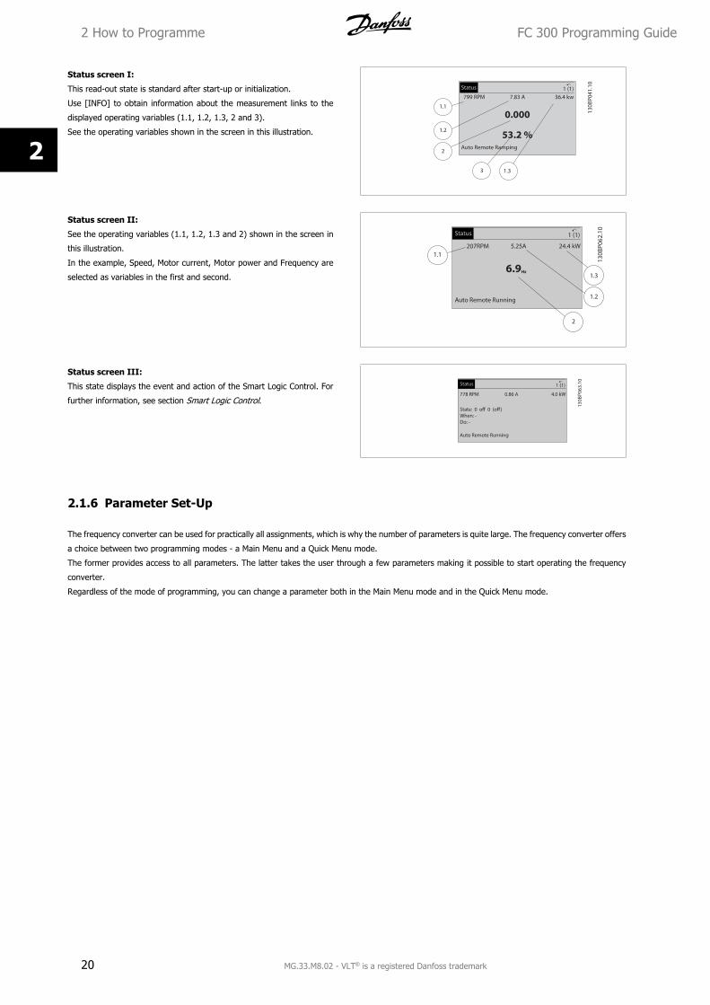
Status screen I:
This read-out state is standard after start-up or initialization.
Use [INFO] to obtain information about the measurement links to the
displayed operating variables (1.1, 1.2, 1.3, 2 and 3).
See the operating variables shown in the screen in this illustration.
Status screen II:
See the operating variables (1.1, 1.2, 1.3 and 2) shown in the screen in
this illustration.
In the example, Speed, Motor current, Motor power and Frequency are
selected as variables in the first and second.
Status screen III:
This state displays the event and action of the Smart Logic Control. For
further information, see section Smart Logic Control.
2.1.6 Parameter Set-Up
The frequency converter can be used for practically all assignments, which is why the number of parameters is quite large. The frequency converter offers
a choice between two programming modes - a Main Menu and a Quick Menu mode.
The former provides access to all parameters. The latter takes the user through a few parameters making it possible to start operating the frequency
converter.
Regardless of the mode of programming, you can change a parameter both in the Main Menu mode and in the Quick Menu mode.
2 How to Programme FC 300 Programming Guide
20 MG.33.M8.02 - VLT® is a registered Danfoss trademark
2
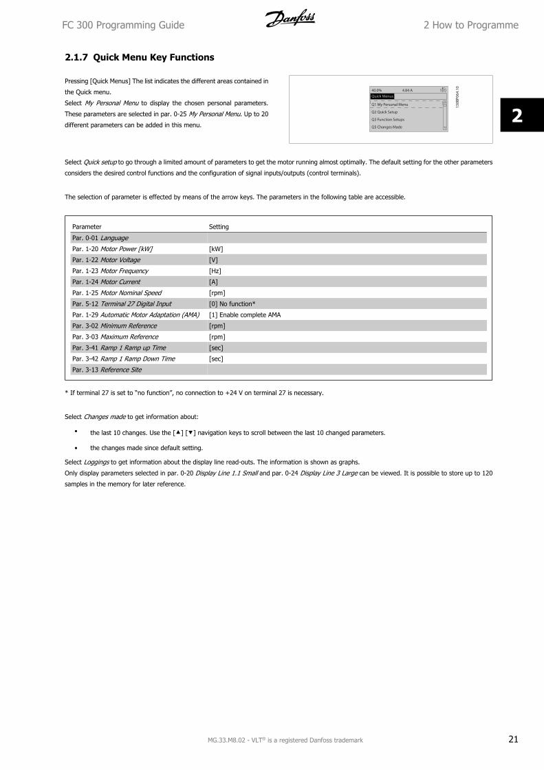
2.1.7 Quick Menu Key Functions
Pressing [Quick Menus] The list indicates the different areas contained in
the Quick menu.
Select My Personal Menu to display the chosen personal parameters.
These parameters are selected in par. 0-25 My Personal Menu. Up to 20
different parameters can be added in this menu.
Select Quick setup to go through a limited amount of parameters to get the motor running almost optimally. The default setting for the other parameters
considers the desired control functions and the configuration of signal inputs/outputs (control terminals).
The selection of parameter is effected by means of the arrow keys. The parameters in the following table are accessible.
Parameter Setting
Par. 0-01 Language
Par. 1-20 Motor Power [kW] [kW]
Par. 1-22 Motor Voltage [V]
Par. 1-23 Motor Frequency [Hz]
Par. 1-24 Motor Current [A]
Par. 1-25 Motor Nominal Speed [rpm]
Par. 5-12 Terminal 27 Digital Input [0] No function*
Par. 1-29 Automatic Motor Adaptation (AMA) [1] Enable complete AMA
Par. 3-02 Minimum Reference [rpm]
Par. 3-03 Maximum Reference [rpm]
Par. 3-41 Ramp 1 Ramp up Time [sec]
Par. 3-42 Ramp 1 Ramp Down Time [sec]
Par. 3-13 Reference Site
* If terminal 27 is set to “no function”, no connection to +24 V on terminal 27 is necessary.
Select Changes made to get information about:
• the last 10 changes. Use the [] [] navigation keys to scroll between the last 10 changed parameters.
• the changes made since default setting.
Select Loggings to get information about the display line read-outs. The information is shown as graphs.
Only display parameters selected in par. 0-20 Display Line 1.1 Small and par. 0-24 Display Line 3 Large can be viewed. It is possible to store up to 120
samples in the memory for later reference.
FC 300 Programming Guide 2 How to Programme
MG.33.M8.02 - VLT® is a registered Danfoss trademark 21
2
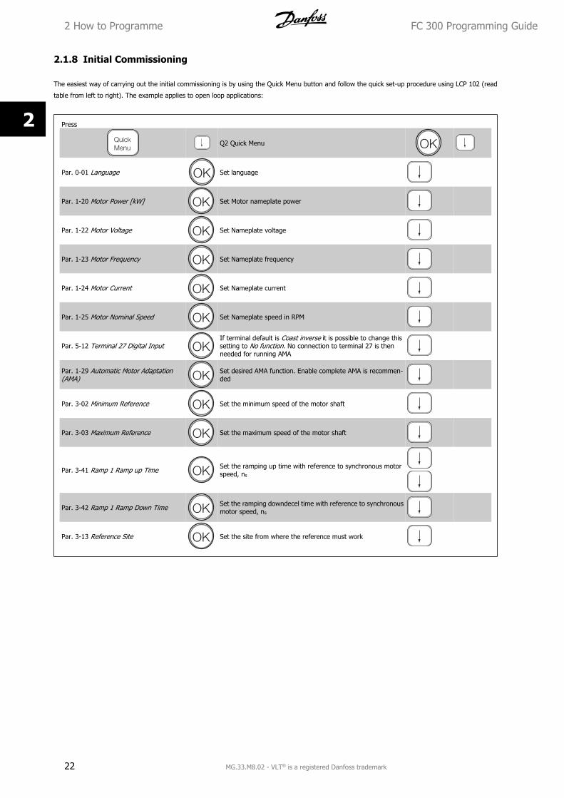
2.1.8 Initial Commissioning
The easiest way of carrying out the initial commissioning is by using the Quick Menu button and follow the quick set-up procedure using LCP 102 (read
table from left to right). The example applies to open loop applications:
Press
Q2 Quick Menu
Par. 0-01 Language Set language
Par. 1-20 Motor Power [kW] Set Motor nameplate power
Par. 1-22 Motor Voltage Set Nameplate voltage
Par. 1-23 Motor Frequency Set Nameplate frequency
Par. 1-24 Motor Current Set Nameplate current
Par. 1-25 Motor Nominal Speed Set Nameplate speed in RPM
Par. 5-12 Terminal 27 Digital InputIf terminal default is Coast inverse it is possible to change thissetting to No function. No connection to terminal 27 is thenneeded for running AMA
Par. 1-29 Automatic Motor Adaptation(AMA)
Set desired AMA function. Enable complete AMA is recommen-ded
Par. 3-02 Minimum Reference Set the minimum speed of the motor shaft
Par. 3-03 Maximum Reference Set the maximum speed of the motor shaft
Par. 3-41 Ramp 1 Ramp up Time Set the ramping up time with reference to synchronous motorspeed, ns
Par. 3-42 Ramp 1 Ramp Down Time Set the ramping downdecel time with reference to synchronousmotor speed, ns
Par. 3-13 Reference Site Set the site from where the reference must work
2 How to Programme FC 300 Programming Guide
22 MG.33.M8.02 - VLT® is a registered Danfoss trademark
2
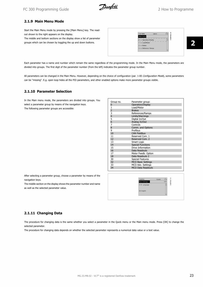
2.1.9 Main Menu Mode
Start the Main Menu mode by pressing the [Main Menu] key. The read-
out shown to the right appears on the display.
The middle and bottom sections on the display show a list of parameter
groups which can be chosen by toggling the up and down buttons.
Each parameter has a name and number which remain the same regardless of the programming mode. In the Main Menu mode, the parameters are
divided into groups. The first digit of the parameter number (from the left) indicates the parameter group number.
All parameters can be changed in the Main Menu. However, depending on the choice of configuration (par. 1-00 Configuration Mode), some parameters
can be "missing". E.g. open loop hides all the PID parameters, and other enabled options make more parameter groups visible.
2.1.10 Parameter Selection
In the Main menu mode, the parameters are divided into groups. You
select a parameter group by means of the navigation keys.
The following parameter groups are accessible:
Group no. Parameter group:0 Operation/Display1 Load/Motor2 Brakes3 References/Ramps4 Limits/Warnings5 Digital In/Out6 Analog In/Out7 Controls8 Comm. and Options9 Profibus10 CAN Fieldbus11 Reserved Com. 112 Reserved Com. 213 Smart Logic14 Special Functions15 Drive Information16 Data Readouts17 Motor Feedb. Option18 Data Readouts 230 Special Features32 MCO Basic Settings33 MCO Adv. Settings34 MCO Data Readouts
After selecting a parameter group, choose a parameter by means of the
navigation keys.
The middle section on the display shows the parameter number and name
as well as the selected parameter value.
2.1.11 Changing Data
The procedure for changing data is the same whether you select a parameter in the Quick menu or the Main menu mode. Press [OK] to change the
selected parameter.
The procedure for changing data depends on whether the selected parameter represents a numerical data value or a text value.
FC 300 Programming Guide 2 How to Programme
MG.33.M8.02 - VLT® is a registered Danfoss trademark 23
2
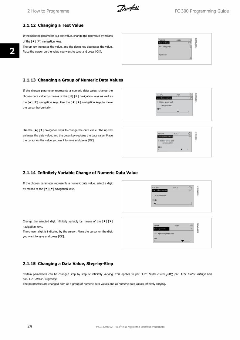
2.1.12 Changing a Text Value
If the selected parameter is a text value, change the text value by means
of the [] [] navigation keys.
The up key increases the value, and the down key decreases the value.
Place the cursor on the value you want to save and press [OK].
2.1.13 Changing a Group of Numeric Data Values
If the chosen parameter represents a numeric data value, change the
chosen data value by means of the [] [] navigation keys as well as
the [] [] navigation keys. Use the [] [] navigation keys to move
the cursor horizontally.
Use the [] [] navigation keys to change the data value. The up key
enlarges the data value, and the down key reduces the data value. Place
the cursor on the value you want to save and press [OK].
2.1.14 Infinitely Variable Change of Numeric Data Value
If the chosen parameter represents a numeric data value, select a digit
by means of the [] [] navigation keys.
Change the selected digit infinitely variably by means of the [] []
navigation keys.
The chosen digit is indicated by the cursor. Place the cursor on the digit
you want to save and press [OK].
2.1.15 Changing a Data Value, Step-by-Step
Certain parameters can be changed step by step or infinitely varying. This applies to par. 1-20 Motor Power [kW], par. 1-22 Motor Voltage and
par. 1-23 Motor Frequency.
The parameters are changed both as a group of numeric data values and as numeric data values infinitely varying.
2 How to Programme FC 300 Programming Guide
24 MG.33.M8.02 - VLT® is a registered Danfoss trademark
2

2.1.16 Read-out and Programming of Indexed Parameters
Parameters are indexed when placed in a rolling stack.
Par. 15-30 Fault Log: Error Code to par. 15-32 Alarm Log: Time contain a fault log which can be read out. Choose a parameter, press [OK], and use the
[] [] navigation keys to scroll through the value log.
Use par. 3-10 Preset Reference as another example:
Choose the parameter, press [OK], and use the [] [] navigation keys to scroll through the indexed values. To change the parameter value, select the
indexed value and press [OK]. Change the value by using the [] [] keys. Press [OK] to accept the new setting. Press [CANCEL] to abort. Press [Back]
to leave the parameter.
FC 300 Programming Guide 2 How to Programme
MG.33.M8.02 - VLT® is a registered Danfoss trademark 25
2
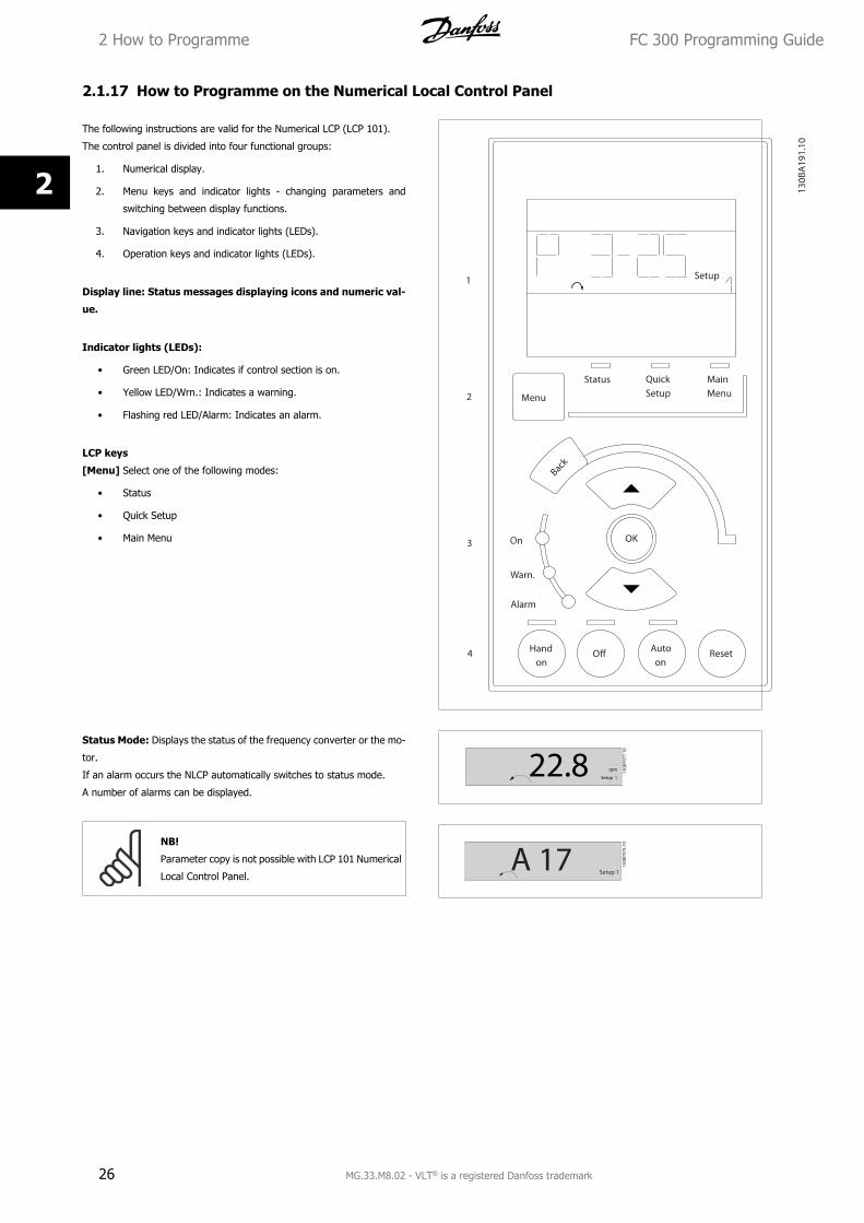
2.1.17 How to Programme on the Numerical Local Control Panel
The following instructions are valid for the Numerical LCP (LCP 101).
The control panel is divided into four functional groups:
1. Numerical display.
2. Menu keys and indicator lights - changing parameters and
switching between display functions.
3. Navigation keys and indicator lights (LEDs).
4. Operation keys and indicator lights (LEDs).
Display line: Status messages displaying icons and numeric val-
ue.
Indicator lights (LEDs):
• Green LED/On: Indicates if control section is on.
• Yellow LED/Wrn.: Indicates a warning.
• Flashing red LED/Alarm: Indicates an alarm.
LCP keys
[Menu] Select one of the following modes:
• Status
• Quick Setup
• Main Menu
Status Mode: Displays the status of the frequency converter or the mo-
tor.
If an alarm occurs the NLCP automatically switches to status mode.
A number of alarms can be displayed.
NB!
Parameter copy is not possible with LCP 101 Numerical
Local Control Panel.
2 How to Programme FC 300 Programming Guide
26 MG.33.M8.02 - VLT® is a registered Danfoss trademark
2
Main Menu/ Quick Setup is used for programming all parameters or
only the parameters in the Quick Meny (see also description of the LCP
102 earlier in this chapter).
The parameter values can be changed using the [] [] keys when the
value is flashing.
Select Main Menu by pressing [Menu] key a number of times.
Select the parameter group [xx-__] and press [OK]
Select the parameter [__-xx] and press [OK]
If the parameter is an array parameter select the array number and press
[OK]
Select the wanted data value and press [OK]
Parameters with functional choices display values such as [1], [2], etc.
For a description of the different choices, see the individual description
of the parameters in the Parameter Selection section
[Back] for stepping backwards
Arrow [] [] keys are used for manoeuvring between commands and
within parameters.
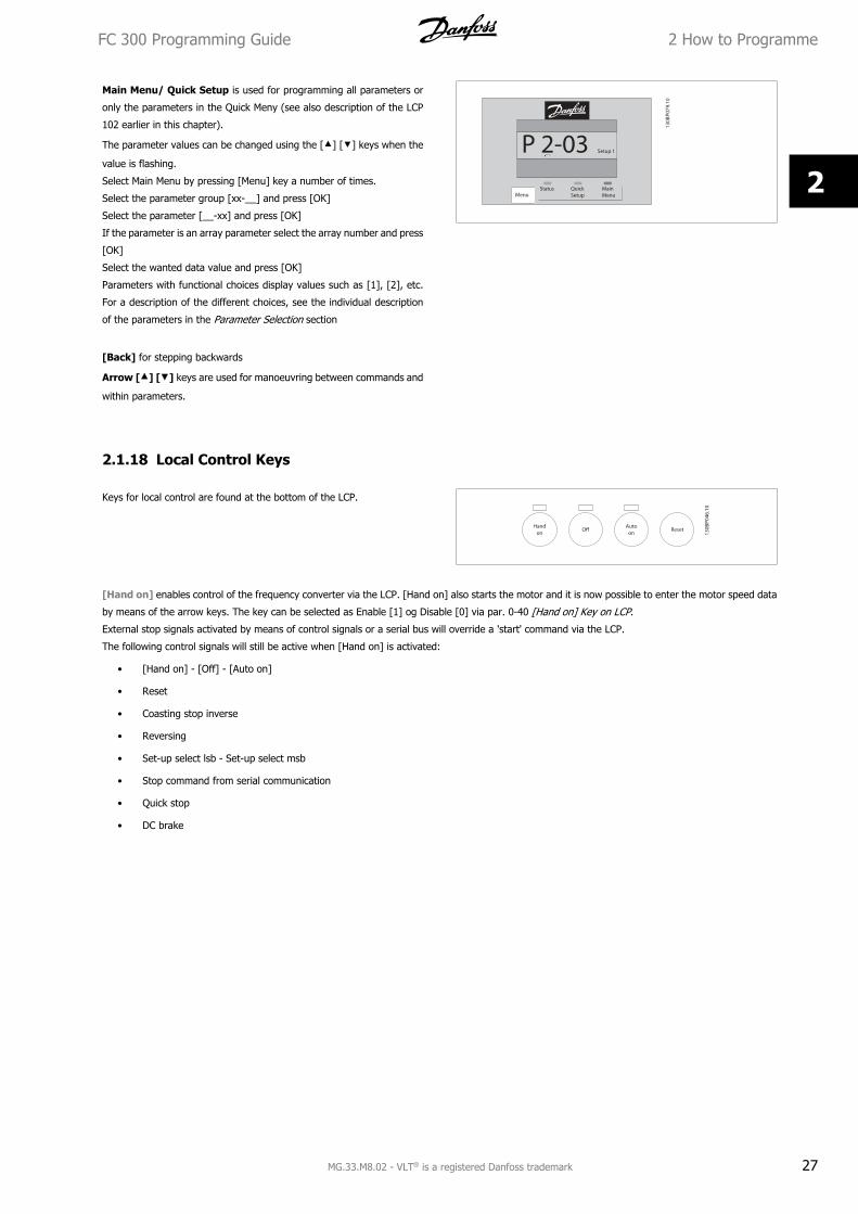
2.1.18 Local Control Keys
Keys for local control are found at the bottom of the LCP.
[Hand on] enables control of the frequency converter via the LCP. [Hand on] also starts the motor and it is now possible to enter the motor speed data
by means of the arrow keys. The key can be selected as Enable [1] og Disable [0] via par. 0-40 [Hand on] Key on LCP.
External stop signals activated by means of control signals or a serial bus will override a 'start' command via the LCP.
The following control signals will still be active when [Hand on] is activated:
• [Hand on] - [Off] - [Auto on]
• Reset
• Coasting stop inverse
• Reversing
• Set-up select lsb - Set-up select msb
• Stop command from serial communication
• Quick stop
• DC brake
FC 300 Programming Guide 2 How to Programme
MG.33.M8.02 - VLT® is a registered Danfoss trademark 27
2
[Off] stops the connected motor. The key can be selected as Enable [1] or Disable [0] via par. 0-41 [Off] Key on LCP .
If no external stop function is selected and the [Off] key is inactive the motor can be stopped by disconnecting the voltage.
[Auto on] enables the frequency converter to be controlled via the control terminals and/or serial communication. When a start signal is applied on the
control terminals and/or the bus, the frequency converter will start. The key can be selected as Enable [1] or Disable [0] via par. 0-42 [Auto on] Key on
LCP.
NB!
An active HAND-OFF-AUTO signal via the digital inputs has higher priority than the control keys [Hand on] [Auto on].
[Reset] is used for resetting the frequency converter after an alarm (trip). It can be selected as Enable [1] or Disable [0] via par. 0-43 [Reset] Key on
LCP.
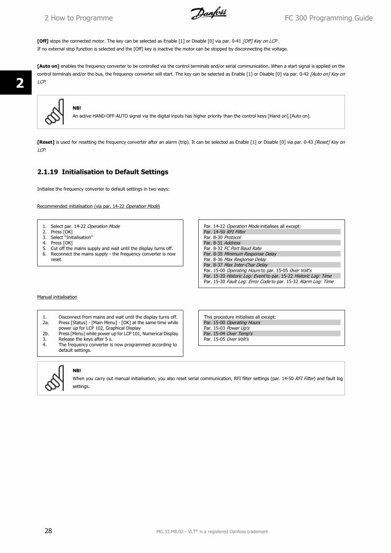
2.1.19 Initialisation to Default Settings
Initialise the frequency converter to default settings in two ways:
Recommended initialisation (via par. 14-22 Operation Mode)
1. Select par. 14-22 Operation Mode2. Press [OK]3. Select “Initialisation”4. Press [OK]5. Cut off the mains supply and wait until the display turns off.6. Reconnect the mains supply - the frequency converter is now
reset.
Par. 14-22 Operation Mode initialises all except:Par. 14-50 RFI FilterPar. 8-30 ProtocolPar. 8-31 AddressPar. 8-32 FC Port Baud RatePar. 8-35 Minimum Response DelayPar. 8-36 Max Response DelayPar. 8-37 Max Inter-Char DelayPar. 15-00 Operating Hours to par. 15-05 Over Volt'sPar. 15-20 Historic Log: Event to par. 15-22 Historic Log: TimePar. 15-30 Fault Log: Error Code to par. 15-32 Alarm Log: Time
Manual initialisation
1. Disconnect from mains and wait until the display turns off.2a. Press [Status] - [Main Menu] - [OK] at the same time while
power up for LCP 102, Graphical Display2b. Press [Menu] while power up for LCP 101, Numerical Display3. Release the keys after 5 s.4. The frequency converter is now programmed according to
default settings.
This procedure initialises all except:Par. 15-00 Operating HoursPar. 15-03 Power Up'sPar. 15-04 Over Temp'sPar. 15-05 Over Volt's
NB!
When you carry out manual initialisation, you also reset serial communication, RFI filter settings (par. 14-50 RFI Filter) and fault log
settings.
2 How to Programme FC 300 Programming Guide
28 MG.33.M8.02 - VLT® is a registered Danfoss trademark
2
3 Parameter descriptions
3.1 Parameter SelectionParameters for FC 300 are grouped into various parameter groups for easy selection of the correct parameters for optimized operation of the frequency
converter.
0-** Operation and Display parameters
• Basic Settings, set-up handling
• Display and Local Control Panel parameters for choosing readouts, setting up selections and copying functions
1-** Load and Motor parameters includes all load and motor related parameters
2-** Brake parameters
• DC brake
• Dynamic brake (Resistor brake)
• Mechanical brake
• Over Voltage Control
3-** References and ramping parameters includes DigiPot function
4-** Limits Warnings; setting of limits and warning parameters
5-** Digital inputs and outputs includes relay controls
6-** Analog inputs and outputs
7-** Controls; Setting parameters for speed and process controls
8-** Communication and option parameters for setting of FC RS485 and FC USB port parameters.
9-** Profibus parameters
10-** DeviceNet and CAN Fieldbus parameters
13-** Smart Logic Control parameters
14-** Special function parameters
15-** Drive information parameters
16-** Readout parameters
17-** Encoder Option parameters
18-** Readout 2 parameters
30-** Special Features
FC 300 Programming Guide 3 Parameter descriptions
MG.33.M8.02 - VLT® is a registered Danfoss trademark 29
3
3.2 Parameters: Operation and Display
3.2.1 0-** Operation / Display
Parameters related to the fundamental functions of the frequency converter, function of the LCP buttons and configuration of the LCP display.
3.2.2 0-0* Basic Settings
Parameter group for basic frequency converter settings.
0-01 Language
Option: Function:Defines the language to be used in the display. The frequency converter can be delivered with 4
different language packages. English and German are included in all packages. English cannot be
erased or manipulated.
[0] * English Part of Language packages 1 - 4
[1] Deutsch Part of Language packages 1 - 4
[2] Francais Part of Language package 1
[3] Dansk Part of Language package 1
[4] Spanish Part of Language package 1
[5] Italiano Part of Language package 1
Svenska Part of Language package 1
[7] Nederlands Part of Language package 1
[10] Chinese Part of Language package 2
Suomi Part of Language package 1
[22] English US Part of Language package 4
Greek Part of Language package 4
Bras.port Part of Language package 4
Slovenian Part of Language package 3
Korean Part of Language package 2
Japanese Part of Language package 2
Turkish Part of Language package 4
Trad.Chinese Part of Language package 2
Bulgarian Part of Language package 3
Srpski Part of Language package 3
Romanian Part of Language package 3
Magyar Part of Language package 3
Czech Part of Language package 3
Polski Part of Language package 4
3 Parameter descriptions FC 300 Programming Guide
30 MG.33.M8.02 - VLT® is a registered Danfoss trademark
3
Russian Part of Language package 3
Thai Part of Language package 2
Bahasa Indonesia Part of Language package 2
[99] Unknown
0-02 Motor Speed Unit
Option: Function:This parameter cannot be adjusted while the motor is running.
The display showing depends on settings in par. 0-02 Motor Speed Unit and par. 0-03 Regional
Settings. The default setting of par. 0-02 Motor Speed Unit and par. 0-03 Regional Settings depends
on which region of the world the frequency converter is supplied to, but can be re-programmed as
required.
NB!
Changing the Motor Speed Unit will reset certain parameters to their initial value.
It is recommended to select the motor speed unit first, before modifying other
parameters.
[0] RPM Selects display of motor speed variables and parameters (i.e. references, feedbacks and limits) in
terms of motor speed (RPM).
[1] * Hz Selects display of motor speed variables and parameters (i.e. references, feedbacks and limits) in
terms of output frequency to the motor (Hz).
0-03 Regional Settings
Option: Function:[0] * International Activates par. 1-20 Motor Power [kW] for setting the motor power in kW and sets the default value
of par. 1-23 Motor Frequency to 50 Hz.
[1] US Activates par. 1-20 Motor Power [kW] for setting the motor power in HP and sets the default value
of par. 1-23 Motor Frequency to 60 Hz.
This parameter cannot be adjusted while the motor is running.
0-04 Operating State at Power-up (Hand)
Option: Function:Selects the operating mode upon reconnection of the frequency converter to mains voltage after
power down in Hand (local) operation mode.
[0] Resume Restarts the frequency converter maintaining the same local reference and the same start/stop
settings (applied by [HAND ON/OFF]) as before the frequency converter was powered down.
[1] * Forced stop, ref=old Restarts the frequency converter with a saved local reference, after mains voltage reappears and
after pressing [HAND ON].
[2] Forced stop, ref=0 Resets the local reference to 0 upon restarting the frequency converter.
3.2.3 0-1* Set-up Operations
Define and control the individual parameter setups.
The frequency converter has four parameter setups that can be programmed independently of each other. This makes the frequency converter very
flexible and able to solve advanced control functionality problems, often saving the cost of external control equipment. For example these can be used
to program the frequency converter to operate according to one control scheme in one setup (e.g. motor 1 for horizontal movement) and another control
scheme in another setup (e.g. motor 2 for vertical movement). Alternatively they can be used by an OEM machine builder to identically program all their
factory fitted frequency converters for different machine types within a range to have the same parameters and then during production/commissioning
simply select a specific setup depending on which machine the frequency converter is installed on.
FC 300 Programming Guide 3 Parameter descriptions
MG.33.M8.02 - VLT® is a registered Danfoss trademark 31
3
The active setup (i.e. the setup in which the frequency converter is currently operating) can be selected in par. 0-10 Active Set-up and is displayed in
the LCP. Using Multi set-up it is possible to switch between setups with the frequency converter running or stopped, via digital input or serial communication
commands. If it is necessary to change setups whilst running, ensure par. 0-12 This Set-up Linked to is programmed as required. Using par. 0-11 Edit
Set-up it is possible to edit parameters within any of the setups whilst continuing the frequency converter operation in its Active Setup which can be a
different setup to that being edited. Using par. 0-51 Set-up Copy it is possible to copy parameter settings between the setups to enable quicker com-
missioning if similar parameter settings are required in different setups.
0-10 Active Set-up
Option: Function:Select the set-up to control the frequency converter functions.
[0] Factory setup Cannot be changed. It contains the Danfoss data set, and can be used as a data source when
returning the other set-ups to a known state.
[1] * Set-up 1 Set-up 1 [1] to Set-up 4 [4] are the four separate parameter set-ups within which all parameters
can be programmed.
[2] Set-up 2
[3] Set-up 3
[4] Set-up 4
[9] Multi Set-up Remote selection of set-ups using digital inputs and the serial communication port. This set-up uses
the settings from par. 0-12 This Set-up Linked to. Stop the frequency converter before making
changes to open- and closed loop functions
Use par. 0-51 Set-up Copy to copy a set-up to one or all other set-ups. Stop the frequency converter before switching between set-ups where parameters
marked ‘not changeable during operation’ have different values. To avoid conflicting settings of the same parameter within two different set-ups, link the
set-ups together using par. 0-12 This Set-up Linked to. Parameters which are ‘not changeable during operation’ are marked FALSE in the parameter lists
in the section Parameter Lists.
0-11 Edit Set-up
Option: Function:Select the set-up to be edited (i.e. programmed) during operation; either the active set-up or one
of the inactive set-ups.
[0] Factory setup Cannot be edited but it is useful as a data source to return the other set-ups to a known state.
[1] * Set-up 1 Set-up 1 [1] to Set-up 4 [4] can be edited freely during operation, independently of the active set-
up.
[2] Set-up 2
[3] Set-up 3
[4] Set-up 4
[9] Active Set-up Can also be edited during operation. Edit the chosen set-up from a range of sources: LCP, FC RS485,
FC USB or up to five fieldbus sites.
3 Parameter descriptions FC 300 Programming Guide
32 MG.33.M8.02 - VLT® is a registered Danfoss trademark
3
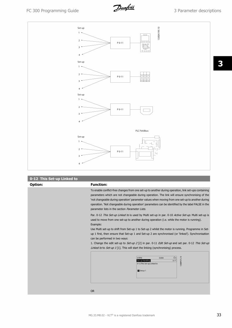
0-12 This Set-up Linked to
Option: Function:To enable conflict-free changes from one set-up to another during operation, link set-ups containing
parameters which are not changeable during operation. The link will ensure synchronising of the
‘not changeable during operation’ parameter values when moving from one set-up to another during
operation. ‘Not changeable during operation’ parameters can be identified by the label FALSE in the
parameter lists in the section Parameter Lists.
Par. 0-12 This Set-up Linked to is used by Multi set-up in par. 0-10 Active Set-up. Multi set-up is
used to move from one set-up to another during operation (i.e. while the motor is running).
Example:
Use Multi set-up to shift from Set-up 1 to Set-up 2 whilst the motor is running. Programme in Set-
up 1 first, then ensure that Set-up 1 and Set-up 2 are synchronised (or ‘linked’). Synchronisation
can be performed in two ways:
1. Change the edit set-up to Set-up 2 [2] in par. 0-11 Edit Set-up and set par. 0-12 This Set-up
Linked to to Set-up 1 [1]. This will start the linking (synchronising) process.
OR
FC 300 Programming Guide 3 Parameter descriptions
MG.33.M8.02 - VLT® is a registered Danfoss trademark 33
3
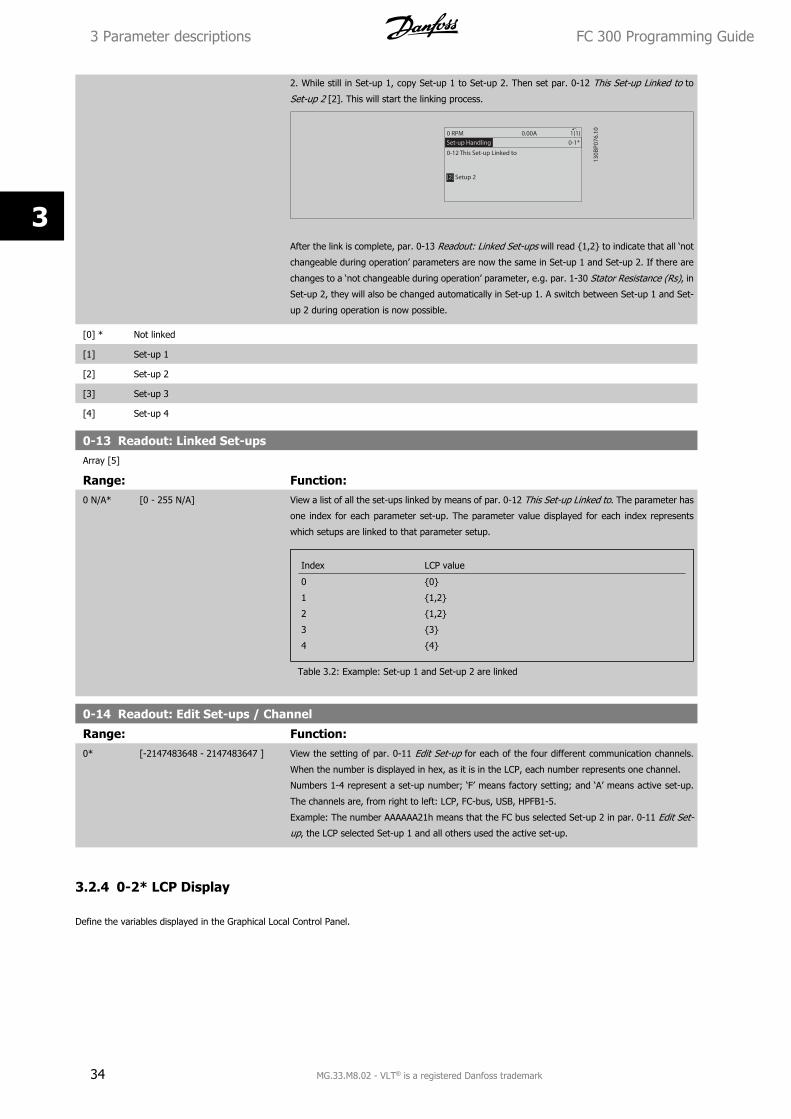
2. While still in Set-up 1, copy Set-up 1 to Set-up 2. Then set par. 0-12 This Set-up Linked to to
Set-up 2 [2]. This will start the linking process.
After the link is complete, par. 0-13 Readout: Linked Set-ups will read 1,2 to indicate that all ‘not
changeable during operation’ parameters are now the same in Set-up 1 and Set-up 2. If there are
changes to a ‘not changeable during operation’ parameter, e.g. par. 1-30 Stator Resistance (Rs), in
Set-up 2, they will also be changed automatically in Set-up 1. A switch between Set-up 1 and Set-
up 2 during operation is now possible.
[0] * Not linked
[1] Set-up 1
[2] Set-up 2
[3] Set-up 3
[4] Set-up 4
0-13 Readout: Linked Set-upsArray [5]
Range: Function:0 N/A* [0 - 255 N/A] View a list of all the set-ups linked by means of par. 0-12 This Set-up Linked to. The parameter has
one index for each parameter set-up. The parameter value displayed for each index represents
which setups are linked to that parameter setup.
Index LCP value
0 0
1 1,2
2 1,2
3 3
4 4
Table 3.2: Example: Set-up 1 and Set-up 2 are linked
0-14 Readout: Edit Set-ups / Channel
Range: Function:0* [-2147483648 - 2147483647 ] View the setting of par. 0-11 Edit Set-up for each of the four different communication channels.
When the number is displayed in hex, as it is in the LCP, each number represents one channel.
Numbers 1-4 represent a set-up number; ‘F’ means factory setting; and ‘A’ means active set-up.
The channels are, from right to left: LCP, FC-bus, USB, HPFB1-5.
Example: The number AAAAAA21h means that the FC bus selected Set-up 2 in par. 0-11 Edit Set-
up, the LCP selected Set-up 1 and all others used the active set-up.
3.2.4 0-2* LCP Display
Define the variables displayed in the Graphical Local Control Panel.
3 Parameter descriptions FC 300 Programming Guide
34 MG.33.M8.02 - VLT® is a registered Danfoss trademark
3
NB!
Please refer to par. 0-37 Display Text 1, par. 0-38 Display Text 2 and par. 0-39 Display Text 3 for information on how to write display
texts.
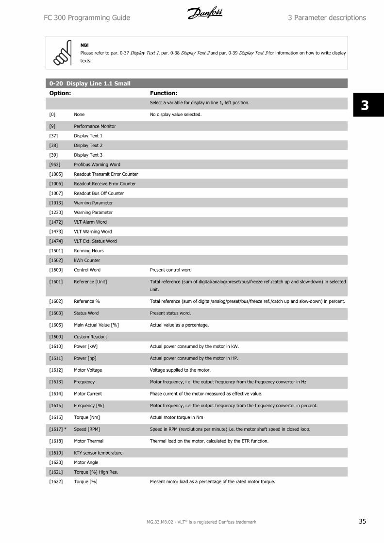
0-20 Display Line 1.1 Small
Option: Function:Select a variable for display in line 1, left position.
[0] None No display value selected.
[9] Performance Monitor
[37] Display Text 1
[38] Display Text 2
[39] Display Text 3
[953] Profibus Warning Word
[1005] Readout Transmit Error Counter
[1006] Readout Receive Error Counter
[1007] Readout Bus Off Counter
[1013] Warning Parameter
[1230] Warning Parameter
[1472] VLT Alarm Word
[1473] VLT Warning Word
[1474] VLT Ext. Status Word
[1501] Running Hours
[1502] kWh Counter
[1600] Control Word Present control word
[1601] Reference [Unit] Total reference (sum of digital/analog/preset/bus/freeze ref./catch up and slow-down) in selected
unit.
[1602] Reference % Total reference (sum of digital/analog/preset/bus/freeze ref./catch up and slow-down) in percent.
[1603] Status Word Present status word.
[1605] Main Actual Value [%] Actual value as a percentage.
[1609] Custom Readout
[1610] Power [kW] Actual power consumed by the motor in kW.
[1611] Power [hp] Actual power consumed by the motor in HP.
[1612] Motor Voltage Voltage supplied to the motor.
[1613] Frequency Motor frequency, i.e. the output frequency from the frequency converter in Hz
[1614] Motor Current Phase current of the motor measured as effective value.
[1615] Frequency [%] Motor frequency, i.e. the output frequency from the frequency converter in percent.
[1616] Torque [Nm] Actual motor torque in Nm
[1617] * Speed [RPM] Speed in RPM (revolutions per minute) i.e. the motor shaft speed in closed loop.
[1618] Motor Thermal Thermal load on the motor, calculated by the ETR function.
[1619] KTY sensor temperature
[1620] Motor Angle
[1621] Torque [%] High Res.
[1622] Torque [%] Present motor load as a percentage of the rated motor torque.
FC 300 Programming Guide 3 Parameter descriptions
MG.33.M8.02 - VLT® is a registered Danfoss trademark 35
3
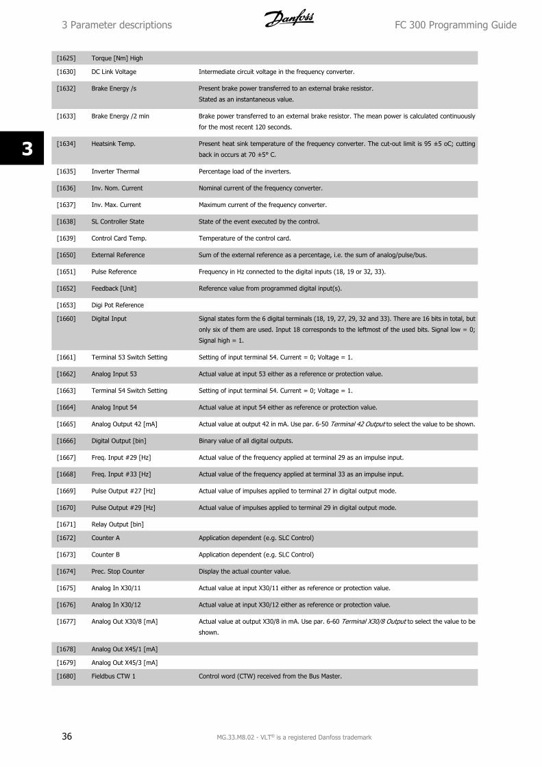
[1625] Torque [Nm] High
[1630] DC Link Voltage Intermediate circuit voltage in the frequency converter.
[1632] Brake Energy /s Present brake power transferred to an external brake resistor.
Stated as an instantaneous value.
[1633] Brake Energy /2 min Brake power transferred to an external brake resistor. The mean power is calculated continuously
for the most recent 120 seconds.
[1634] Heatsink Temp. Present heat sink temperature of the frequency converter. The cut-out limit is 95 ±5 oC; cutting
back in occurs at 70 ±5° C.
[1635] Inverter Thermal Percentage load of the inverters.
[1636] Inv. Nom. Current Nominal current of the frequency converter.
[1637] Inv. Max. Current Maximum current of the frequency converter.
[1638] SL Controller State State of the event executed by the control.
[1639] Control Card Temp. Temperature of the control card.
[1650] External Reference Sum of the external reference as a percentage, i.e. the sum of analog/pulse/bus.
[1651] Pulse Reference Frequency in Hz connected to the digital inputs (18, 19 or 32, 33).
[1652] Feedback [Unit] Reference value from programmed digital input(s).
[1653] Digi Pot Reference
[1660] Digital Input Signal states form the 6 digital terminals (18, 19, 27, 29, 32 and 33). There are 16 bits in total, but
only six of them are used. Input 18 corresponds to the leftmost of the used bits. Signal low = 0;
Signal high = 1.
[1661] Terminal 53 Switch Setting Setting of input terminal 54. Current = 0; Voltage = 1.
[1662] Analog Input 53 Actual value at input 53 either as a reference or protection value.
[1663] Terminal 54 Switch Setting Setting of input terminal 54. Current = 0; Voltage = 1.
[1664] Analog Input 54 Actual value at input 54 either as reference or protection value.
[1665] Analog Output 42 [mA] Actual value at output 42 in mA. Use par. 6-50 Terminal 42 Output to select the value to be shown.
[1666] Digital Output [bin] Binary value of all digital outputs.
[1667] Freq. Input #29 [Hz] Actual value of the frequency applied at terminal 29 as an impulse input.
[1668] Freq. Input #33 [Hz] Actual value of the frequency applied at terminal 33 as an impulse input.
[1669] Pulse Output #27 [Hz] Actual value of impulses applied to terminal 27 in digital output mode.
[1670] Pulse Output #29 [Hz] Actual value of impulses applied to terminal 29 in digital output mode.
[1671] Relay Output [bin]
[1672] Counter A Application dependent (e.g. SLC Control)
[1673] Counter B Application dependent (e.g. SLC Control)
[1674] Prec. Stop Counter Display the actual counter value.
[1675] Analog In X30/11 Actual value at input X30/11 either as reference or protection value.
[1676] Analog In X30/12 Actual value at input X30/12 either as reference or protection value.
[1677] Analog Out X30/8 [mA] Actual value at output X30/8 in mA. Use par. 6-60 Terminal X30/8 Output to select the value to be
shown.
[1678] Analog Out X45/1 [mA]
[1679] Analog Out X45/3 [mA]
[1680] Fieldbus CTW 1 Control word (CTW) received from the Bus Master.
3 Parameter descriptions FC 300 Programming Guide
36 MG.33.M8.02 - VLT® is a registered Danfoss trademark
3
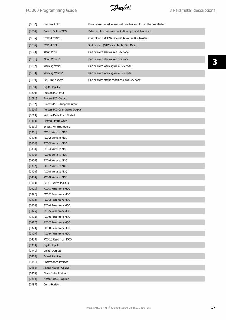
[1682] Fieldbus REF 1 Main reference value sent with control word from the Bus Master.
[1684] Comm. Option STW Extended fieldbus communication option status word.
[1685] FC Port CTW 1 Control word (CTW) received from the Bus Master.
[1686] FC Port REF 1 Status word (STW) sent to the Bus Master.
[1690] Alarm Word One or more alarms in a Hex code.
[1691] Alarm Word 2 One or more alarms in a Hex code.
[1692] Warning Word One or more warnings in a Hex code.
[1693] Warning Word 2 One or more warnings in a Hex code.
[1694] Ext. Status Word One or more status conditions in a Hex code.
[1860] Digital Input 2
[1890] Process PID Error
[1891] Process PID Output
[1892] Process PID Clamped Output
[1893] Process PID Gain Scaled Output
[3019] Wobble Delta Freq. Scaled
[3110] Bypass Status Word
[3111] Bypass Running Hours
[3401] PCD 1 Write to MCO
[3402] PCD 2 Write to MCO
[3403] PCD 3 Write to MCO
[3404] PCD 4 Write to MCO
[3405] PCD 5 Write to MCO
[3406] PCD 6 Write to MCO
[3407] PCD 7 Write to MCO
[3408] PCD 8 Write to MCO
[3409] PCD 9 Write to MCO
[3410] PCD 10 Write to MCO
[3421] PCD 1 Read from MCO
[3422] PCD 2 Read from MCO
[3423] PCD 3 Read from MCO
[3424] PCD 4 Read from MCO
[3425] PCD 5 Read from MCO
[3426] PCD 6 Read from MCO
[3427] PCD 7 Read from MCO
[3428] PCD 8 Read from MCO
[3429] PCD 9 Read from MCO
[3430] PCD 10 Read from MCO
[3440] Digital Inputs
[3441] Digital Outputs
[3450] Actual Position
[3451] Commanded Position
[3452] Actual Master Position
[3453] Slave Index Position
[3454] Master Index Position
[3455] Curve Position
FC 300 Programming Guide 3 Parameter descriptions
MG.33.M8.02 - VLT® is a registered Danfoss trademark 37
3
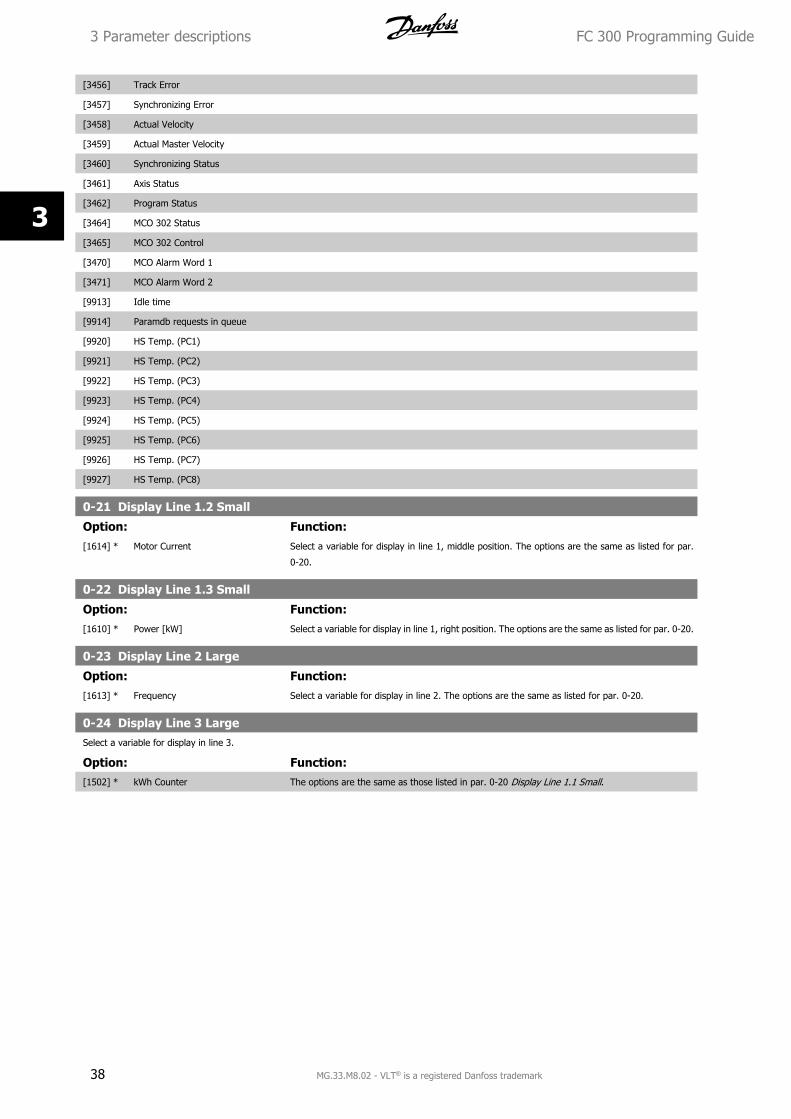
[3456] Track Error
[3457] Synchronizing Error
[3458] Actual Velocity
[3459] Actual Master Velocity
[3460] Synchronizing Status
[3461] Axis Status
[3462] Program Status
[3464] MCO 302 Status
[3465] MCO 302 Control
[3470] MCO Alarm Word 1
[3471] MCO Alarm Word 2
[9913] Idle time
[9914] Paramdb requests in queue
[9920] HS Temp. (PC1)
[9921] HS Temp. (PC2)
[9922] HS Temp. (PC3)
[9923] HS Temp. (PC4)
[9924] HS Temp. (PC5)
[9925] HS Temp. (PC6)
[9926] HS Temp. (PC7)
[9927] HS Temp. (PC8)
0-21 Display Line 1.2 Small
Option: Function:[1614] * Motor Current Select a variable for display in line 1, middle position. The options are the same as listed for par.
0-20.
0-22 Display Line 1.3 Small
Option: Function:[1610] * Power [kW] Select a variable for display in line 1, right position. The options are the same as listed for par. 0-20.
0-23 Display Line 2 Large
Option: Function:[1613] * Frequency Select a variable for display in line 2. The options are the same as listed for par. 0-20.
0-24 Display Line 3 LargeSelect a variable for display in line 3.
Option: Function:[1502] * kWh Counter The options are the same as those listed in par. 0-20 Display Line 1.1 Small.
3 Parameter descriptions FC 300 Programming Guide
38 MG.33.M8.02 - VLT® is a registered Danfoss trademark
3
0-25 My Personal Menu
Range: Function:Application
dependent*
[0 - 9999 ] Define up to 50 parameters to appear in the Q1 Personal Menu, accessible via the [Quick Menu]
key on the LCP. The parameters will be displayed in the Q1 Personal Menu in the order they are
programmed into this array parameter. Delete parameters by setting the value to ‘0000’.
For example, this can be used to provide quick, simple access to just one or up to 50 parameters
which require changing on a regular basis (e.g. for plant maintenance reasons) or by an OEM to
enable simple commissioning of their equipment.
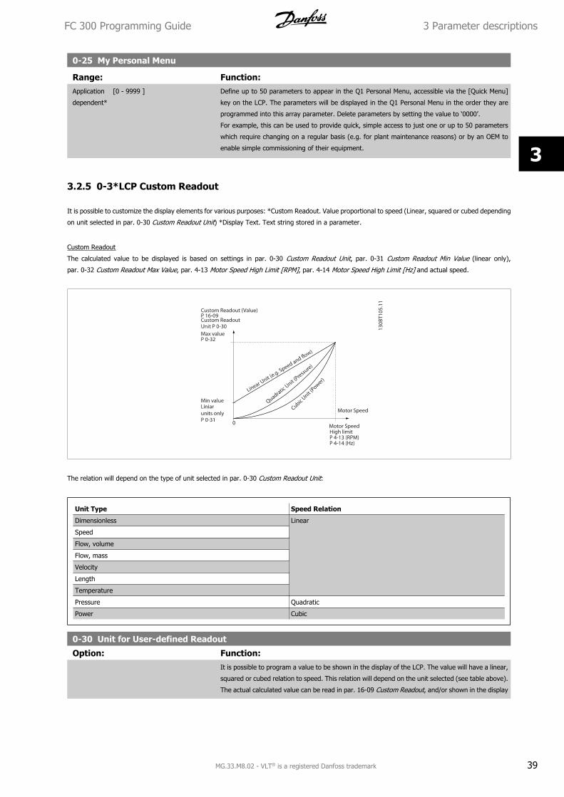
3.2.5 0-3*LCP Custom Readout
It is possible to customize the display elements for various purposes: *Custom Readout. Value proportional to speed (Linear, squared or cubed depending
on unit selected in par. 0-30 Custom Readout Unit) *Display Text. Text string stored in a parameter.
Custom Readout
The calculated value to be displayed is based on settings in par. 0-30 Custom Readout Unit, par. 0-31 Custom Readout Min Value (linear only),
par. 0-32 Custom Readout Max Value, par. 4-13 Motor Speed High Limit [RPM], par. 4-14 Motor Speed High Limit [Hz] and actual speed.
The relation will depend on the type of unit selected in par. 0-30 Custom Readout Unit:
Unit Type Speed Relation
Dimensionless Linear
Speed
Flow, volume
Flow, mass
Velocity
Length
Temperature
Pressure Quadratic
Power Cubic
0-30 Unit for User-defined Readout
Option: Function:It is possible to program a value to be shown in the display of the LCP. The value will have a linear,
squared or cubed relation to speed. This relation will depend on the unit selected (see table above).
The actual calculated value can be read in par. 16-09 Custom Readout, and/or shown in the display
FC 300 Programming Guide 3 Parameter descriptions
MG.33.M8.02 - VLT® is a registered Danfoss trademark 39
3
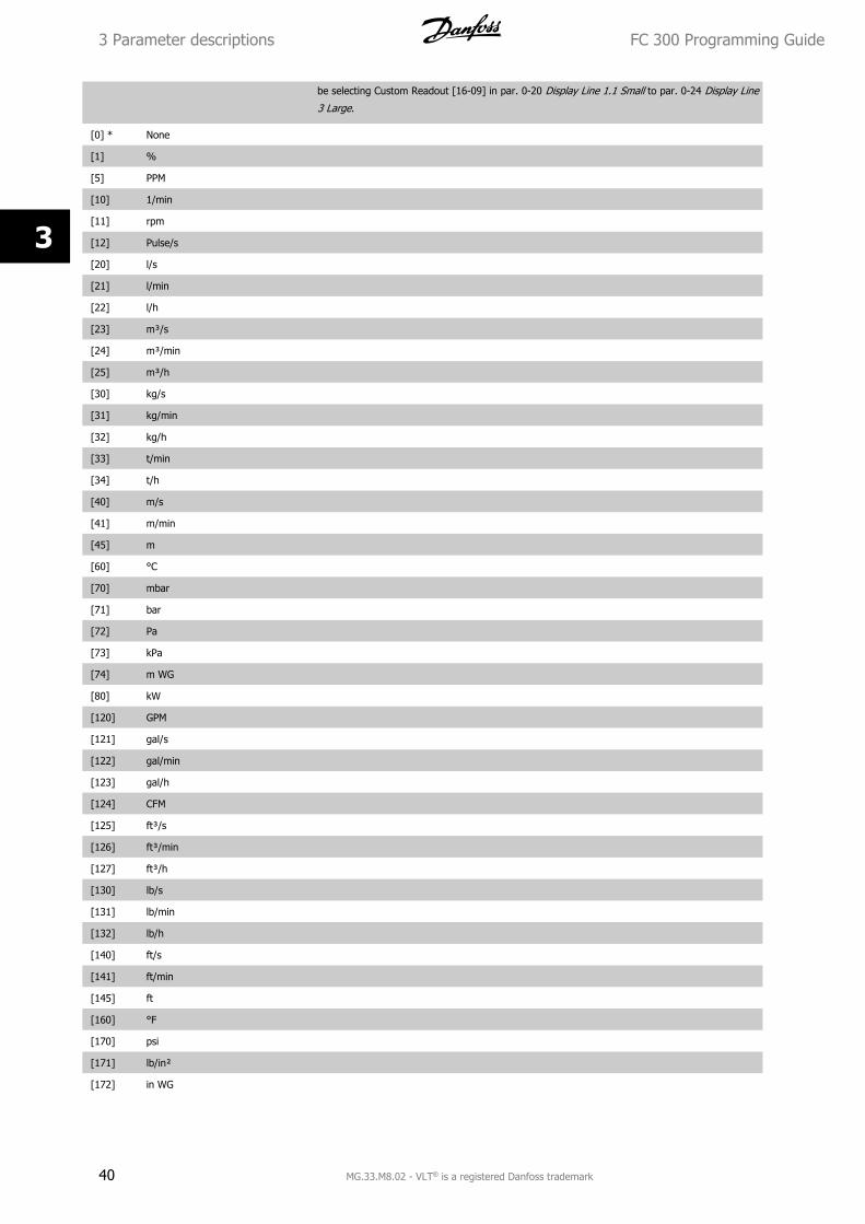
be selecting Custom Readout [16-09] in par. 0-20 Display Line 1.1 Small to par. 0-24 Display Line
3 Large.
[0] * None
[1] %
[5] PPM
[10] 1/min
[11] rpm
[12] Pulse/s
[20] l/s
[21] l/min
[22] l/h
[23] m³/s
[24] m³/min
[25] m³/h
[30] kg/s
[31] kg/min
[32] kg/h
[33] t/min
[34] t/h
[40] m/s
[41] m/min
[45] m
[60] °C
[70] mbar
[71] bar
[72] Pa
[73] kPa
[74] m WG
[80] kW
[120] GPM
[121] gal/s
[122] gal/min
[123] gal/h
[124] CFM
[125] ft³/s
[126] ft³/min
[127] ft³/h
[130] lb/s
[131] lb/min
[132] lb/h
[140] ft/s
[141] ft/min
[145] ft
[160] °F
[170] psi
[171] lb/in²
[172] in WG
3 Parameter descriptions FC 300 Programming Guide
40 MG.33.M8.02 - VLT® is a registered Danfoss trademark
3
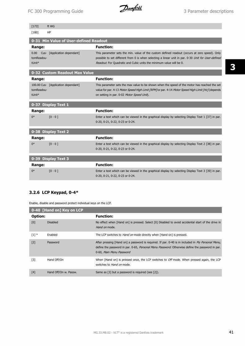
[173] ft WG
[180] HP
0-31 Min Value of User-defined Readout
Range: Function:0.00 Cus-
tomReadou-
tUnit*
[Application dependant] This parameter sets the min. value of the custom defined readout (occurs at zero speed). Only
possible to set different from 0 is when selecting a linear unit in par. 0-30 Unit for User-defined
Readout. For Quadratic and Cubic units the minimum value will be 0.
0-32 Custom Readout Max Value
Range: Function:100.00 Cus-
tomReadou-
tUnit*
[Application dependant] This parameter sets the max value to be shown when the speed of the motor has reached the set
value for par. 4-13 Motor Speed High Limit [RPM] or par. 4-14 Motor Speed High Limit [Hz] (depends
on setting in par. 0-02 Motor Speed Unit).
0-37 Display Text 1
Range: Function:0* [0 - 0 ] Enter a text which can be viewed in the graphical display by selecting Display Text 1 [37] in par.
0-20, 0-21, 0-22, 0-23 or 0-24.
0-38 Display Text 2
Range: Function:0* [0 - 0 ] Enter a text which can be viewed in the graphical display by selecting Display Text 2 [38] in par.
0-20, 0-21, 0-22, 0-23 or 0-24.
0-39 Display Text 3
Range: Function:0* [0 - 0 ] Enter a text which can be viewed in the graphical display by selecting Display Text 3 [39] in par.
0-20, 0-21, 0-22, 0-23 or 0-24.
3.2.6 LCP Keypad, 0-4*
Enable, disable and password protect individual keys on the LCP.
0-40 [Hand on] Key on LCP
Option: Function:[0] Disabled No effect when [Hand on] is pressed. Select [0] Disabled to avoid accidental start of the drive in
Hand on mode.
[1] * Enabled The LCP switches to Hand on mode directly when [Hand on] is pressed.
[2] Password After pressing [Hand on] a password is required. If par. 0-40 is in included in My Personal Menu,
define the password in par. 0-65, Personal Menu Password. Otherwise define the password in par.
0-60, Main Menu Password
[3] Hand Off/On When [Hand on] is pressed once, the LCP switches to Off mode. When pressed again, the LCP
switches to Hand on mode.
[4] Hand Off/On w. Passw. Same as [3] but a password is required (see [2]).
FC 300 Programming Guide 3 Parameter descriptions
MG.33.M8.02 - VLT® is a registered Danfoss trademark 41
3
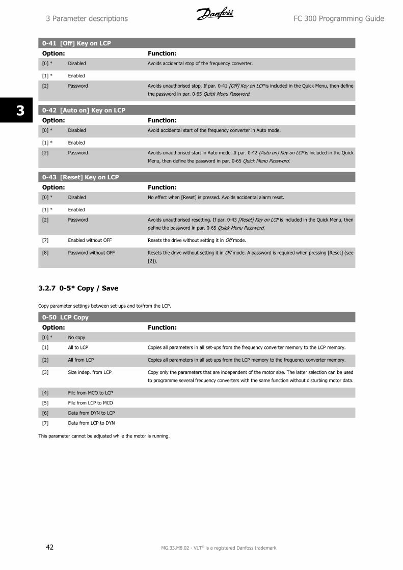
0-41 [Off] Key on LCP
Option: Function:[0] * Disabled Avoids accidental stop of the frequency converter.
[1] * Enabled
[2] Password Avoids unauthorised stop. If par. 0-41 [Off] Key on LCP is included in the Quick Menu, then define
the password in par. 0-65 Quick Menu Password.
0-42 [Auto on] Key on LCP
Option: Function:[0] * Disabled Avoid accidental start of the frequency converter in Auto mode.
[1] * Enabled
[2] Password Avoids unauthorised start in Auto mode. If par. 0-42 [Auto on] Key on LCP is included in the Quick
Menu, then define the password in par. 0-65 Quick Menu Password.
0-43 [Reset] Key on LCP
Option: Function:[0] * Disabled No effect when [Reset] is pressed. Avoids accidental alarm reset.
[1] * Enabled
[2] Password Avoids unauthorised resetting. If par. 0-43 [Reset] Key on LCP is included in the Quick Menu, then
define the password in par. 0-65 Quick Menu Password.
[7] Enabled without OFF Resets the drive without setting it in Off mode.
[8] Password without OFF Resets the drive without setting it in Off mode. A password is required when pressing [Reset] (see
[2]).
3.2.7 0-5* Copy / Save
Copy parameter settings between set-ups and to/from the LCP.
0-50 LCP Copy
Option: Function:[0] * No copy
[1] All to LCP Copies all parameters in all set-ups from the frequency converter memory to the LCP memory.
[2] All from LCP Copies all parameters in all set-ups from the LCP memory to the frequency converter memory.
[3] Size indep. from LCP Copy only the parameters that are independent of the motor size. The latter selection can be used
to programme several frequency converters with the same function without disturbing motor data.
[4] File from MCO to LCP
[5] File from LCP to MCO
[6] Data from DYN to LCP
[7] Data from LCP to DYN
This parameter cannot be adjusted while the motor is running.
3 Parameter descriptions FC 300 Programming Guide
42 MG.33.M8.02 - VLT® is a registered Danfoss trademark
3
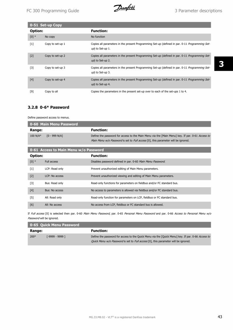
0-51 Set-up Copy
Option: Function:[0] * No copy No function
[1] Copy to set-up 1 Copies all parameters in the present Programming Set-up (defined in par. 0-11 Programming Set-
up) to Set-up 1.
[2] Copy to set-up 2 Copies all parameters in the present Programming Set-up (defined in par. 0-11 Programming Set-
up) to Set-up 2.
[3] Copy to set-up 3 Copies all parameters in the present Programming Set-up (defined in par. 0-11 Programming Set-
up) to Set-up 3.
[4] Copy to set-up 4 Copies all parameters in the present Programming Set-up (defined in par. 0-11 Programming Set-
up) to Set-up 4.
[9] Copy to all Copies the parameters in the present set-up over to each of the set-ups 1 to 4.
3.2.8 0-6* Password
Define password access to menus.
0-60 Main Menu Password
Range: Function:100 N/A* [0 - 999 N/A] Define the password for access to the Main Menu via the [Main Menu] key. If par. 0-61 Access to
Main Menu w/o Password is set to Full access [0], this parameter will be ignored.
0-61 Access to Main Menu w/o Password
Option: Function:[0] * Full access Disables password defined in par. 0-60 Main Menu Password.
[1] LCP: Read only Prevent unauthorized editing of Main Menu parameters.
[2] LCP: No access Prevent unauthorized viewing and editing of Main Menu parameters.
[3] Bus: Read only Read-only functions for parameters on fieldbus and/or FC standard bus.
[4] Bus: No access No access to parameters is allowed via fieldbus and/or FC standard bus.
[5] All: Read only Read-only function for parameters on LCP, fieldbus or FC standard bus.
[6] All: No access No access from LCP, fieldbus or FC standard bus is allowed.
If Full access [0] is selected then par. 0-60 Main Menu Password, par. 0-65 Personal Menu Password and par. 0-66 Access to Personal Menu w/o
Password will be ignored.
0-65 Quick Menu Password
Range: Function:200* [-9999 - 9999 ] Define the password for access to the Quick Menu via the [Quick Menu] key. If par. 0-66 Access to
Quick Menu w/o Password is set to Full access [0], this parameter will be ignored.
FC 300 Programming Guide 3 Parameter descriptions
MG.33.M8.02 - VLT® is a registered Danfoss trademark 43
3
0-66 Access to Quick Menu w/o Password
Option: Function:[0] * Full access Disables the password defined in par. 0-65 Quick Menu Password.
[1] LCP: Read only Prevents unauthorised editing of Quick Menu parameters.
[2] LCP: No access Prevents unauthorised viewing and editing of Quick Menu parameters.
[3] Bus: Read only Read only functions for Quick Menu parameters on fieldbus and/ or FC standard bus.
[4] Bus: No access No access to Quick Menu parameters is allowed via fieldbus and/ or FC standard bus.
[5] All: Read only read only function for Quick Menu parameters on LCP, fieldbus or FC standard bus.
[6] All: No access No access from LCP, fieldbus or FC standard bus is allowed.
If par. 0-61 Access to Main Menu w/o Password is set to Full access [0] then this parameter will be ignored.
0-67 Bus Password Access
Range: Function:0* [0 - 9999 ] Writing to this parameter enables users to unlock the frequency converter from bus/ MCT10.
3 Parameter descriptions FC 300 Programming Guide
44 MG.33.M8.02 - VLT® is a registered Danfoss trademark
3
3.3 Parameters: Load and Motor
3.3.1 1-0* General Settings
Define whether the frequency converter operates in speed mode or torque mode; and whether the internal PID control should be active or not.
1-00 Configuration Mode
Option: Function:Select the application control principle to be used when a Remote Reference (i.e. via analog input
or fieldbus) is active. A Remote Reference can only be active when par. 3-13 Reference Site is set
to [0] or [1].
[0] * Speed open loop Enables speed control (without feedback signal from motor) with automatic slip compensation for
almost constant speed at varying loads.
Compensations are active but can be disabled in the Load/Motor par. group 1-0*.
[1] Speed closed loop Enables encoder feedback from motor. Obtain full holding torque at 0 RPM.
For increased speed accuracy, provide a feedback signal and set the speed PID control.
[2] Torque Connects the encoder speed feedback signal to the encoder input. Only possible with “Flux with
motor feedback” option, par. 1-01 Motor Control Principle. FC 302 only.
[3] Process Enables the use of process control in the frequency converter. The process control parameters are
set in par. groups 7-2* and 7-3*.
[4] Torque open loop Enables the use of torque open loop in VVC+ mode (par. 1-01 Motor Control Principle). The torque
PID parameters are set in par. group 7-1*.
[5] Wobble Enables the wobble functionality in par. 30-00 Wobble Mode to par. 30-19 Wobble Delta Freq.
Scaled.
[6] Surface Winder Enables the surface winder control specific parameters in par. group 7-2* and 7-3*.
[7] Extended PID Speed OL Specific parameters in par. group 7-2* to 7-5*.
[8] Extended PID Speed CL Specific parameters in par. group 7-2* to 7-5*.
1-01 Motor Control Principle
Option: Function:Select which motor control principle to employ.
[0] * U/f special motor mode, for parallel connected motors in special motor applications. When U/f is se-
lected the characteristic of the control principle can be edited in par. 1-55 U/f Characteristic - U and
par. 1-56 U/f Characteristic - F.
[1] VVC+ Voltage Vector Control principle suitable for most applications. The main benefit of VVCplus operation
is that it uses a robust motor model.
[2] Flux sensorless Flux Vector control without encoder feedback, for simple installation and robustness against sudden
load changes. FC 302 only.
[3] Flux w/ motor feedb very high accuracy speed and torque control, suitable for the most demanding applications. FC 302
only.
The best shaft performance is normally achieved using either of the two Flux Vector control modes Flux sensorless [2] and Flux with encoder feedback
[3].
This parameter cannot be adjusted while the motor is running.
FC 300 Programming Guide 3 Parameter descriptions
MG.33.M8.02 - VLT® is a registered Danfoss trademark 45
3
Par. 1-00
Par. 1-01 [0] Speed
OL
[1] Speed
CL
[2] Torque [3] Process [4] Torque
OL
[5] Wobble [6] Surface
Wnd
[7] Ext. PID
OL
[8] Ext. PID
CL
[0] U/f
[1] VVCplus
[2] Flux sensorless
[3] Flux w/ motor feedback
Table 3.3: Overview of possible combinations of the settings in par. 1-00 Configuration Mode and par. 1-01 Motor Control Principle. The gray cells mark
the possible combinations.
1-02 Flux Motor Feedback Source
Option: Function:Select the interface at which to receive feedback from the motor.
[0] Motor feedb. P1-02
[1] * 24V encoder A and B channel encoder, which can be connected to the digital input terminals 32/33 only. Termi-
nals 32/33 must be programmed to No operation.
[2] MCB 102 Encoder module option which can be configured in par. group 17-1*
This parameter appears in FC 302 only.
[3] MCB 103 Optional resolver interface module which can be configured in par. group 17-5**
[5] MCO Encoder 2 encoder interface 2 of the optional programmable motion controller MCO 305.
[6] Analog input 53
[7] Analog input 54
[8] Frequency input 29
[9] Frequency input 33
This parameter cannot be adjusted while the motor is running.
1-03 Torque Characteristics
Option: Function:Select the torque characteristic required.
VT and AEO are both energy saving operations.
[0] * Constant torque Motor shaft output provides constant torque under variable speed control.
[1] Variable torque Motor shaft output provides variable torque under variable speed control. Set the variable torque
level in par. 14-40 VT Level.
[2] Auto Energy Optim. Automatically optimises energy consumption by minimising magnetisation and frequency via
par. 14-41 AEO Minimum Magnetisation and par. 14-42 Minimum AEO Frequency.
[5] Constant Power The function provide a constant power in field weakening area. Follows the formula:
Pconstant = Torque x RPM9550
This selection maybe unavailable depending on drive configuration.
This parameter cannot be adjusted while the motor is running.
1-04 Overload Mode
Option: Function:[0] * High torque Allows up to 160% over torque.
[1] Normal torque For oversized motor - allows up to 110% over torque.
This parameter cannot be adjusted while the motor is running.
3 Parameter descriptions FC 300 Programming Guide
46 MG.33.M8.02 - VLT® is a registered Danfoss trademark
3
1-05 Local Mode Configuration
Option: Function:Select which application configuration mode (par. 1-00 Configuration Mode), i.e. application control
principle, to use when a Local (LCP) Reference is active. A Local Reference can be active only when
par. 3-13 Reference Site is set to [0] or [2]. By default the local reference is active in Hand Mode
only.
[0] Speed open loop
[1] Speed closed loop
[2] * As mode par 1-00
1-06 Clockwise DirectionThis parameter defines the term “Clockwise” corresponding to the LCP direction arrow. Used for easy change of direction of shaft rotation without
swapping motor wires. (Valid from SW version 5.84)
Option: Function:[0] * Normal Motor shaft will turn in clockwise direction when frequency converter is connected U -> U; V -> V,
and W -> W to motor.
[1] Inverse Motor shaft will turn in counter clockwise direction when frequency converter is connected U -> U;
V -> V, and W -> W to motor.
This parameter cannot be changed while the motor is running.
3.3.2 1-1* Motor Selection
Parameter group for setting general motor data.
This parameter group cannot be adjusted while the motor is running.
1-10 Motor Construction
Option: Function:Select the motor construction type.
[0] * Asynchron For asynchronous motors.
[1] PM, non salient SPM For permanent magnet (PM) motors.
Note that PM motors are divided into two groups, with either surface mounted (non salient) or
interior (salient) magnets.
Motor construction can either be asynchronous or permanent magnet (PM) motor.
3.3.3 1-2* Motor Data
Parameter group 1-2* comprises input data from the nameplate on the connected motor.
Parameters in parameter group 1-2* cannot be adjusted while the motor is running.
NB!
Changing the value of these parameters affects the setting of other parameters.
1-20 Motor Power [kW]
Range: Function:Application
dependent*
[Application dependant] Enter the nominal motor power in kW according to the motor nameplate data. The default value
corresponds to the nominal rated output of the unit.
FC 300 Programming Guide 3 Parameter descriptions
MG.33.M8.02 - VLT® is a registered Danfoss trademark 47
3
This parameter cannot be adjusted while the motor is running. This parameter is visible in LCP if
par. 0-03 Regional Settings is International [0].
NB!
Four sizes down, one size up from nominal unit rating.
1-21 Motor Power [HP]
Range: Function:Application
dependent*
[Application dependant] Enter the nominal motor power in HP according to the motor nameplate data. The default value
corresponds to the nominal rated output of the unit. This parameter is visible in LCP if
par. 0-03 Regional Settings is US [1]
1-22 Motor Voltage
Range: Function:Application
dependent*
[Application dependant] Enter the nominal motor voltage according to the motor nameplate data. The default value corre-
sponds to the nominal rated output of the unit.
1-23 Motor Frequency
Range: Function:Application
dependent*
[20 - 1000 Hz] Min - Max motor frequency: 20 - 1000 Hz.
Select the motor frequency value from the motor nameplate data. If a value different from 50 Hz
or 60 Hz is selected, it is necessary to adapt the load independent settings in par. 1-50 Motor
Magnetisation at Zero Speed to par. 1-53 Model Shift Frequency. For 87 Hz operation with 230/400
V motors, set the nameplate data for 230 V/50 Hz. Adapt par. 4-13 Motor Speed High Limit
[RPM] and par. 3-03 Maximum Reference to the 87 Hz application.
1-24 Motor Current
Range: Function:Application
dependent*
[Application dependant] Enter the nominal motor current value from the motor nameplate data. The data are used for cal-
culating torque, motor protection etc.
1-25 Motor Nominal Speed
Range: Function:Application
dependent*
[10 - 60000 RPM] Enter the nominal motor speed value from the motor nameplate data. The data are used for cal-
culating motor compensations.
NB!
Motor speed must always be lower than synchronous speed.
1-26 Motor Cont. Rated Torque
Range: Function:Application
dependent*
[0.1 - 10000.0 Nm] Enter the value from the motor nameplate data. The default value corresponds to the nominal rated
output. This parameter is available when par. 1-10 Motor Construction is set to PM, non salient
SPM [1], i.e. the parameter is valid for PM and non-salient SPM motors only.
1-29 Automatic Motor Adaptation (AMA)
Option: Function:The AMA function optimises dynamic motor performance by automatically optimising the advanced
motor parameters (par. 1-30 Stator Resistance (Rs) to par. 1-35 Main Reactance (Xh)) at motor
standstill.
3 Parameter descriptions FC 300 Programming Guide
48 MG.33.M8.02 - VLT® is a registered Danfoss trademark
3
Activate the AMA function by pressing [Hand on] after selecting [1] or [2]. See also the section
Automatic Motor Adaptation in the Design Guide. After a normal sequence, the display will read:
"Press [OK] to finish AMA". After pressing the [OK] key the frequency converter is ready for oper-
ation.
This parameter cannot be adjusted while the motor is running.
[0] * Off
[1] Enable complete AMA Performs AMA of the stator resistance RS, the rotor resistance Rr, the stator leakage reactance X1,
the rotor leakage reactance X2 and the main reactance Xh. Do not select this option if an LC filter is
used between the frequency converter and the motor.
FC 301: The Complete AMA does not include Xh measurement for FC 301. Instead, the Xh value is
determined from the motor database. RS is the best adjustment method (see 1-3* Adv. Motor Da-
ta).
T4/T5 E and F Frames, T7 D, E and F Frames will only run a Reduced AMA when the complete AMA
is selected. It is recommended to obtain the Advanced Motor Data from the motor manufacturer to
enter into par. 1-31 through 1-36 for best performance.
[2] Enable reduced AMA Performs a reduced AMA of the stator resistance Rs in the system only.
Note:
• For the best adaptation of the frequency converter, run AMA on a cold motor.
• AMA cannot be performed while the motor is running.
• AMA cannot be performed on permanent magnet motors.
NB!
It is important to set motor par. 1-2* correctly, since these form part of the AMA algorithm. An AMA must be performed to achieve
optimum dynamic motor performance. It may take up to 10 min, depending on the power rating of the motor.
NB!
Avoid generating external torque during AMA.
NB!
If one of the settings in par. 1-2* is changed, par. 1-30 Stator Resistance (Rs) to par. 1-39 Motor Poles, the advanced motor parameters,
will return to default setting.
NB!
AMA will work problem-free on 1 motor size down, typically work on 2 motor sizes down, rarely work on 3 sizes down and never work
on 4 sizes down. Please keep in mind that the accuracy of the measured motor data will be poorer when you operate on motors smaller
than nominal VLT size.
FC 300 Programming Guide 3 Parameter descriptions
MG.33.M8.02 - VLT® is a registered Danfoss trademark 49
3
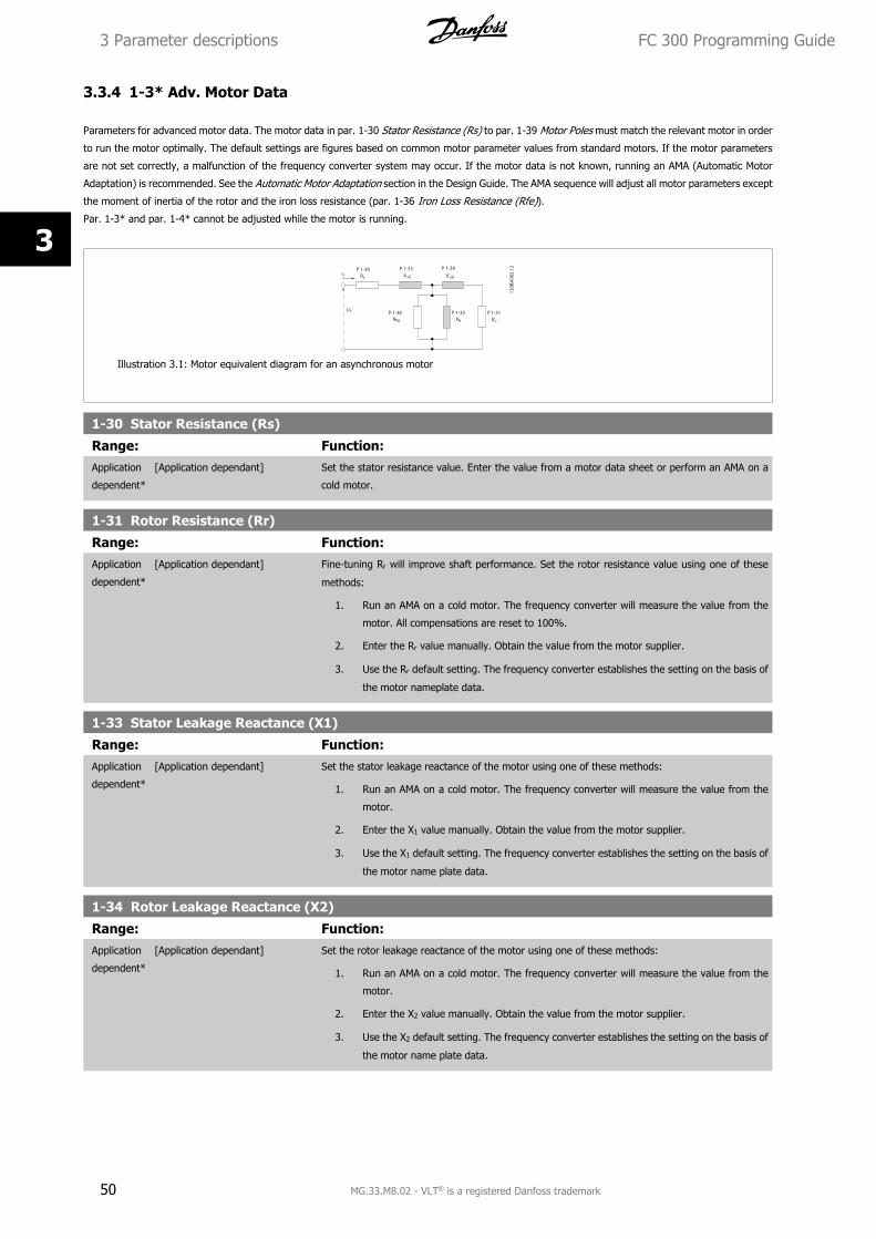
3.3.4 1-3* Adv. Motor Data
Parameters for advanced motor data. The motor data in par. 1-30 Stator Resistance (Rs) to par. 1-39 Motor Poles must match the relevant motor in order
to run the motor optimally. The default settings are figures based on common motor parameter values from standard motors. If the motor parameters
are not set correctly, a malfunction of the frequency converter system may occur. If the motor data is not known, running an AMA (Automatic Motor
Adaptation) is recommended. See the Automatic Motor Adaptation section in the Design Guide. The AMA sequence will adjust all motor parameters except
the moment of inertia of the rotor and the iron loss resistance (par. 1-36 Iron Loss Resistance (Rfe)).
Par. 1-3* and par. 1-4* cannot be adjusted while the motor is running.
Illustration 3.1: Motor equivalent diagram for an asynchronous motor
1-30 Stator Resistance (Rs)
Range: Function:Application
dependent*
[Application dependant] Set the stator resistance value. Enter the value from a motor data sheet or perform an AMA on a
cold motor.
1-31 Rotor Resistance (Rr)
Range: Function:Application
dependent*
[Application dependant] Fine-tuning Rr will improve shaft performance. Set the rotor resistance value using one of these
methods:
1. Run an AMA on a cold motor. The frequency converter will measure the value from the
motor. All compensations are reset to 100%.
2. Enter the Rr value manually. Obtain the value from the motor supplier.
3. Use the Rr default setting. The frequency converter establishes the setting on the basis of
the motor nameplate data.
1-33 Stator Leakage Reactance (X1)
Range: Function:Application
dependent*
[Application dependant] Set the stator leakage reactance of the motor using one of these methods:
1. Run an AMA on a cold motor. The frequency converter will measure the value from the
motor.
2. Enter the X1 value manually. Obtain the value from the motor supplier.
3. Use the X1 default setting. The frequency converter establishes the setting on the basis of
the motor name plate data.
1-34 Rotor Leakage Reactance (X2)
Range: Function:Application
dependent*
[Application dependant] Set the rotor leakage reactance of the motor using one of these methods:
1. Run an AMA on a cold motor. The frequency converter will measure the value from the
motor.
2. Enter the X2 value manually. Obtain the value from the motor supplier.
3. Use the X2 default setting. The frequency converter establishes the setting on the basis of
the motor name plate data.
3 Parameter descriptions FC 300 Programming Guide
50 MG.33.M8.02 - VLT® is a registered Danfoss trademark
3
1-35 Main Reactance (Xh)
Range: Function:Application
dependent*
[Application dependant] Set the main reactance of the motor using one of these methods:
1. Run an AMA on a cold motor. The frequency converter will measure the value from the
motor.
2. Enter the Xh value manually. Obtain the value from the motor supplier.
3. Use the Xh default setting. The frequency converter establishes the setting on the basis of
the motor name plate data.
1-36 Iron Loss Resistance (Rfe)
Range: Function:Application
dependent*
[Application dependant] Enter the equivalent iron loss resistance (RFe) value to compensate for iron loss in the motor.
The RFe value cannot be found by performing an AMA.
The RFe value is especially important in torque control applications. If RFe is unknown, leave
par. 1-36 Iron Loss Resistance (Rfe) on default setting.
1-37 d-axis Inductance (Ld)
Range: Function:Application
dependent*
[Application dependant] Enter the value of the d-axis inductance. Obtain the value from the permanent magnet motor data
sheet.
This parameter is only active when par. 1-10 Motor Construction has the value PM, non-salient
SPM [1] (Permanent Magnet Motor).
For a selection with one decimal, use this parameter. For a selection with three decimals, use
par. 30-80 d-axis Inductance (Ld).
This parameter is available for FC 302 only.
1-39 Motor Poles
Range: Function:Application
dependent*
[2 - 100 ] Enter the number of motor poles.
Poles ~nn@ 50 Hz ~nn@60 Hz2 2700 - 2880 3250 - 34604 1350 - 1450 1625 - 17306 700 - 960 840 - 1153
The table shows the number of poles for normal speed ranges of various motor types. Define motors designed for other frequencies separately. The
motor pole value is always an even number, because it refers to the total number of poles, not pairs of poles. The frequency converter creates the initial
setting of par. 1-39 Motor Poles based on par. 1-23 Motor Frequency and par. 1-25 Motor Nominal Speed.
1-40 Back EMF at 1000 RPM
Range: Function:Application
dependent*
[Application dependant] Set the nominal back EMF for the motor when running at 1000 RPM. This parameter is only active
when par. 1-10 Motor Construction is set to PM motor [1] (Permanent Magnet Motor).
This parameter is available for FC 302 only.
NB!
When using PM motors, it is recommended to use brake resistors.
1-41 Motor Angle Offset
Range: Function:0* [-32768 - 32767 ] Enter the correct offset angle between the PM motor and the index position (single-turn) of the
attached encoder or resolver. The value range of 0 - 32768 corresponds to 0 - 2 * pi (radians). To
FC 300 Programming Guide 3 Parameter descriptions
MG.33.M8.02 - VLT® is a registered Danfoss trademark 51
3
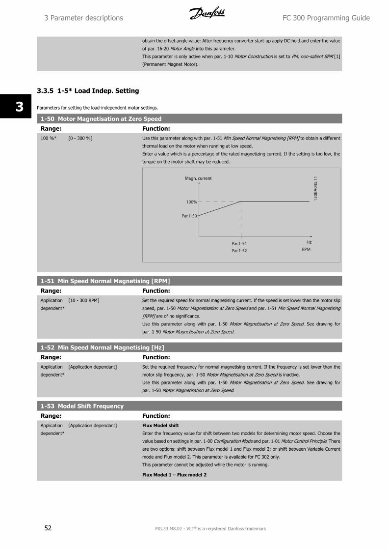
obtain the offset angle value: After frequency converter start-up apply DC-hold and enter the value
of par. 16-20 Motor Angle into this parameter.
This parameter is only active when par. 1-10 Motor Construction is set to PM, non-salient SPM [1]
(Permanent Magnet Motor).
3.3.5 1-5* Load Indep. Setting
Parameters for setting the load-independent motor settings.
1-50 Motor Magnetisation at Zero Speed
Range: Function:100 %* [0 - 300 %] Use this parameter along with par. 1-51 Min Speed Normal Magnetising [RPM] to obtain a different
thermal load on the motor when running at low speed.
Enter a value which is a percentage of the rated magnetizing current. If the setting is too low, the
torque on the motor shaft may be reduced.
1-51 Min Speed Normal Magnetising [RPM]
Range: Function:Application
dependent*
[10 - 300 RPM] Set the required speed for normal magnetising current. If the speed is set lower than the motor slip
speed, par. 1-50 Motor Magnetisation at Zero Speed and par. 1-51 Min Speed Normal Magnetising
[RPM] are of no significance.
Use this parameter along with par. 1-50 Motor Magnetisation at Zero Speed. See drawing for
par. 1-50 Motor Magnetisation at Zero Speed.
1-52 Min Speed Normal Magnetising [Hz]
Range: Function:Application
dependent*
[Application dependant] Set the required frequency for normal magnetising current. If the frequency is set lower than the
motor slip frequency, par. 1-50 Motor Magnetisation at Zero Speed is inactive.
Use this parameter along with par. 1-50 Motor Magnetisation at Zero Speed. See drawing for
par. 1-50 Motor Magnetisation at Zero Speed.
1-53 Model Shift Frequency
Range: Function:Application
dependent*
[Application dependant] Flux Model shift
Enter the frequency value for shift between two models for determining motor speed. Choose the
value based on settings in par. 1-00 Configuration Mode and par. 1-01 Motor Control Principle. There
are two options: shift between Flux model 1 and Flux model 2; or shift between Variable Current
mode and Flux model 2. This parameter is available for FC 302 only.
This parameter cannot be adjusted while the motor is running.
Flux Model 1 – Flux model 2
3 Parameter descriptions FC 300 Programming Guide
52 MG.33.M8.02 - VLT® is a registered Danfoss trademark
3
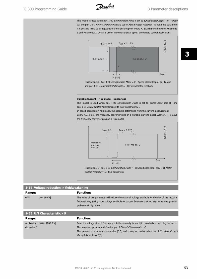
This model is used when par. 1-00 Configuration Mode is set to Speed closed loop [1] or Torque
[2] and par. 1-01 Motor Control Principle is set to Flux w/motor feedback [3]. With this parameter
it is possible to make an adjustment of the shifting point where FC 302 changes between Flux model
1 and Flux model 2, which is useful in some sensitive speed and torque control applications.
Illustration 3.2: Par. 1-00 Configuration Mode = [1] Speed closed loop or [2] Torque
and par. 1-01 Motor Control Principle = [3] Flux w/motor feedback
Variable Current - Flux model - Sensorless
This model is used when par. 1-00 Configuration Mode is set to Speed open loop [0] and
par. 1-01 Motor Control Principle is set to Flux sensorless [2].
In speed open loop in flux mode, the speed is determined from the current measurement.
Below fnorm x 0.1, the frequency converter runs on a Variable Current model. Above fnorm x 0.125
the frequency converter runs on a Flux model.
Illustration 3.3: par. 1-00 Configuration Mode = [0] Speed open loop, par. 1-01 Motor
Control Principle = [2] Flux sensorless
1-54 Voltage reduction in fieldweakening
Range: Function:0 V* [0 - 100 V] The value of this parameter will reduce the maximal voltage available for the flux of the motor in
fieldweakning, giving more voltage available for torque. Be aware that too high value may give stall
problems at high speed.
1-55 U/f Characteristic - U
Range: Function:Application
dependent*
[0.0 - 1000.0 V] Enter the voltage at each frequency point to manually form a U/f characteristic matching the motor.
The frequency points are defined in par. 1-56 U/f Characteristic - F.
This parameter is an array parameter [0-5] and is only accessible when par. 1-01 Motor Control
Principle is set to U/f [0].
FC 300 Programming Guide 3 Parameter descriptions
MG.33.M8.02 - VLT® is a registered Danfoss trademark 53
3
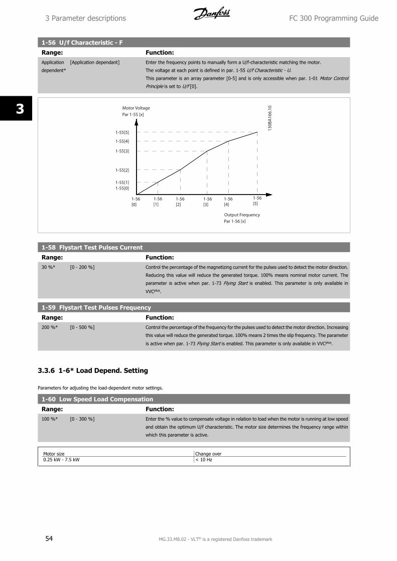
1-56 U/f Characteristic - F
Range: Function:Application
dependent*
[Application dependant] Enter the frequency points to manually form a U/f-characteristic matching the motor.
The voltage at each point is defined in par. 1-55 U/f Characteristic - U.
This parameter is an array parameter [0-5] and is only accessible when par. 1-01 Motor Control
Principle is set to U/f [0].
1-58 Flystart Test Pulses Current
Range: Function:30 %* [0 - 200 %] Control the percentage of the magnetizing current for the pulses used to detect the motor direction.
Reducing this value will reduce the generated torque. 100% means nominal motor current. The
parameter is active when par. 1-73 Flying Start is enabled. This parameter is only available in
VVCplus.
1-59 Flystart Test Pulses Frequency
Range: Function:200 %* [0 - 500 %] Control the percentage of the frequency for the pulses used to detect the motor direction. Increasing
this value will reduce the generated torque. 100% means 2 times the slip frequency. The parameter
is active when par. 1-73 Flying Start is enabled. This parameter is only available in VVCplus.
3.3.6 1-6* Load Depend. Setting
Parameters for adjusting the load-dependent motor settings.
1-60 Low Speed Load Compensation
Range: Function:100 %* [0 - 300 %] Enter the % value to compensate voltage in relation to load when the motor is running at low speed
and obtain the optimum U/f characteristic. The motor size determines the frequency range within
which this parameter is active.
Motor size Change over0.25 kW - 7.5 kW < 10 Hz
3 Parameter descriptions FC 300 Programming Guide
54 MG.33.M8.02 - VLT® is a registered Danfoss trademark
3
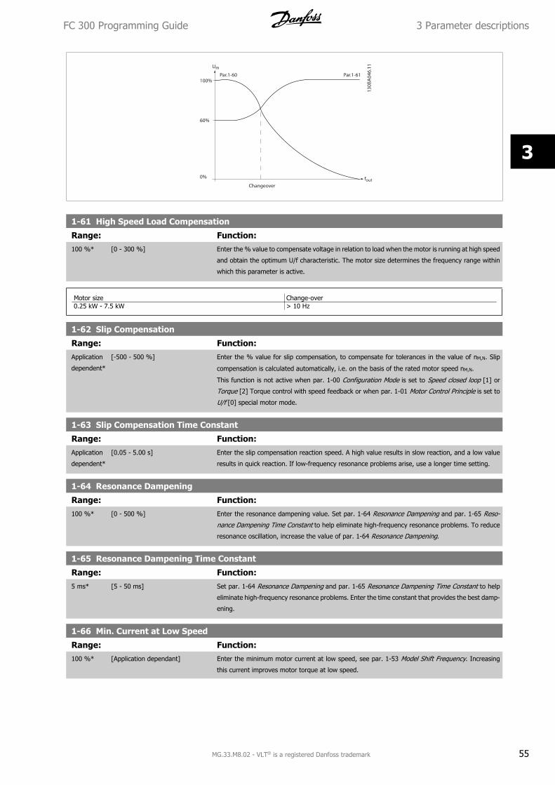
1-61 High Speed Load Compensation
Range: Function:100 %* [0 - 300 %] Enter the % value to compensate voltage in relation to load when the motor is running at high speed
and obtain the optimum U/f characteristic. The motor size determines the frequency range within
which this parameter is active.
Motor size Change-over0.25 kW - 7.5 kW > 10 Hz
1-62 Slip Compensation
Range: Function:Application
dependent*
[-500 - 500 %] Enter the % value for slip compensation, to compensate for tolerances in the value of nM,N. Slip
compensation is calculated automatically, i.e. on the basis of the rated motor speed nM,N.
This function is not active when par. 1-00 Configuration Mode is set to Speed closed loop [1] or
Torque [2] Torque control with speed feedback or when par. 1-01 Motor Control Principle is set to
U/f [0] special motor mode.
1-63 Slip Compensation Time Constant
Range: Function:Application
dependent*
[0.05 - 5.00 s] Enter the slip compensation reaction speed. A high value results in slow reaction, and a low value
results in quick reaction. If low-frequency resonance problems arise, use a longer time setting.
1-64 Resonance Dampening
Range: Function:100 %* [0 - 500 %] Enter the resonance dampening value. Set par. 1-64 Resonance Dampening and par. 1-65 Reso-
nance Dampening Time Constant to help eliminate high-frequency resonance problems. To reduce
resonance oscillation, increase the value of par. 1-64 Resonance Dampening.
1-65 Resonance Dampening Time Constant
Range: Function:5 ms* [5 - 50 ms] Set par. 1-64 Resonance Dampening and par. 1-65 Resonance Dampening Time Constant to help
eliminate high-frequency resonance problems. Enter the time constant that provides the best damp-
ening.
1-66 Min. Current at Low Speed
Range: Function:100 %* [Application dependant] Enter the minimum motor current at low speed, see par. 1-53 Model Shift Frequency. Increasing
this current improves motor torque at low speed.
FC 300 Programming Guide 3 Parameter descriptions
MG.33.M8.02 - VLT® is a registered Danfoss trademark 55
3
Par. 1-66 Min. Current at Low Speed is enabled when par. 1-00 Configuration Mode = Speed open
loop [0] only. The frequency converter runs with constant current through motor for speeds below
10 Hz.
For speeds above 10 Hz, the motor flux model in the frequency converter controls the motor.
par. 4-16 Torque Limit Motor Mode and / or par. 4-17 Torque Limit Generator Mode automatically
adjust par. 1-66 Min. Current at Low Speed. The parameter with the highest value adjusts
par. 1-66 Min. Current at Low Speed. The current setting in par. 1-66 Min. Current at Low Speed is
composed of the torque generating current and the magnetizing current.
Example: Set par. 4-16 Torque Limit Motor Mode to 100% and set par. 4-17 Torque Limit Generator
Mode to 60%. par. 1-66 Min. Current at Low Speed automatically adjusts to about 127%, depending
on the motor size.
This parameter is available for FC 302 only.
1-67 Load Type
Option: Function:[0] * Passive load For conveyers, fan and pump applications.
[1] Active load For hoisting applications, used in slip compensation at low speed. When Active Load [1] is selected,
set par. 1-66 Min. Current at Low Speed to a level which corresponds to maximum torque.
This parameter is available for FC 302 only.
1-68 Minimum Inertia
Range: Function:Application
dependent*
[Application dependant] Needed for average inertia calculation. Enter the minimum moment of inertia of the mechanical
system. Par. 1-68 Minimum Inertia and par. 1-69 Maximum Inertia are used for pre-adjustment of
the Proportional Gain in the speed control, see par. 30-83 Speed PID Proportional Gain.
This parameter is available for FC 302 only.
This parameter cannot be adjusted while motor is running.
1-69 Maximum Inertia
Range: Function:Application
dependent*
[Application dependant] Active in Flux Open Loop only. Used to compute the acceleration torque at low speed. Used in the
torque limit controller.
This parameter is available for FC 302 only.
This parameter cannot be adjusted while motor is running.
3.3.7 1-7* Start Adjustments
Parameters for setting special motor start features.
1-71 Start Delay
Range: Function:0.0 s* [0.0 - 10.0 s] This parameter refers to the start function selected in par. 1-72 Start Function.
Enter the time delay required before commencing acceleration.
1-72 Start Function
Option: Function:Select the start function during start delay. This parameter is linked to par. 1-71 Start Delay.
[0] DC Hold/delay time Energizes motor with a DC holding current (par. 2-00 DC Hold Current) during the start delay time.
[1] DC Brake/delay time Energizes motor with a DC braking current (par. 2-01 DC Brake Current) during the start delay time.
[2] * Coast/delay time Motor coasted during the start delay time (inverter off).
[3] Start speed cw Only possible with VVC+.
3 Parameter descriptions FC 300 Programming Guide
56 MG.33.M8.02 - VLT® is a registered Danfoss trademark
3
Connect the function described in par. 1-74 Start Speed [RPM] and par. 1-76 Start Current in the
start delay time.
Regardless of the value applied by the reference signal, the output speed applies the setting of the
start speed in par. 1-74 Start Speed [RPM] or par. 1-75 Start Speed [Hz] and the output current
corresponds to the setting of the start current in par. 1-76 Start Current. This function is typically
used in hoisting applications without counterweight and especially in applications with a Cone-mo-
tor, where the start is clockwise, followed by rotation in the reference direction.
[4] Horizontal operation Only possible with VVC+.
For obtaining the function described in par. 1-74 Start Speed [RPM] and par. 1-76 Start Current
during the start delay time. The motor rotates in the reference direction. If the reference signal
equals zero (0), par. 1-74 Start Speed [RPM] is ignored and the output speed equals zero (0). The
output current corresponds to the setting of the start current in par. 1-76 Start Current.
[5] VVC+/Flux clockwise for the function described in par. 1-74 Start Speed [RPM] only. The start current is calculated au-
tomatically. This function uses the start speed in the start delay time only. Regardless of the value
set by the reference signal, the output speed equals the setting of the start speed in par. 1-74 Start
Speed [RPM].Start speed/current clockwise [3] and VVCplus/Flux clockwise [5] are typically used in
hoisting applications. Start speed/current in reference direction [4] is particularly used in applica-
tions with counterweight and horizontal movement.
[6] Hoist Mech. Brake Rel For utilizing mechanical brake control functions, par. 2-24 Stop Delay to par. 2-28 Gain Boost Fac-
tor. This parameter is only active when par. 1-01 Motor Control Principle is set to [3] Flux w/ motor
feedback (FC 302 only).
[7] VVC+/Flux counter-cw
1-73 Flying Start
Option: Function:This function makes it possible to catch a motor which is spinning freely due to a mains drop-out.
[0] * Disabled No function
[1] Enabled Enables the frequency converter to “catch” and control a spinning motor.
When par. 1-73 Flying Start is enabled, par. 1-71 Start Delay and par. 1-72 Start Function have no
function.
[2] Enabled Always
This parameter cannot be adjusted while motor is running.
NB!
This function is not recommended for hoisting applications.
For power levels above 55kW, flux mode must be used to achieve the best performance.
1-74 Start Speed [RPM]
Range: Function:Application
dependent*
[0 - 600 RPM] Set a motor start speed. After the start signal, the output speed leaps to set value. Set the start
function in par. 1-72 Start Function to [3], [4] or [5], and set a start delay time in par. 1-71 Start
Delay.
1-75 Start Speed [Hz]
Range: Function:Application
dependent*
[Application dependant] This par can be used for hoist applications (cone rotor). Set a motor start speed. After the start
signal, the output speed leaps to set value. Set the start function in par. 1-72 Start Function to [3],
[4] or [5], and set a start delay time in par. 1-71 Start Delay.
FC 300 Programming Guide 3 Parameter descriptions
MG.33.M8.02 - VLT® is a registered Danfoss trademark 57
3
1-76 Start Current
Range: Function:0.00 A* [Application dependant] Some motors, e.g. cone rotor motors, need extra current/starting speed to disengage the rotor. To
obtain this boost, set the required current in par. 1-76 Start Current. Set par. 1-74 Start Speed
[RPM]. Set par. 1-72 Start Function to [3] or [4], and set a start delay time in par. 1-71 Start
Delay.
This parameter can be used for hoist applications (cone rotor).
3.3.8 1-8* Stop Adjustments
Parameters for setting special stop features for the motor.
1-80 Function at Stop
Option: Function:Select the frequency converter function after a stop command or after the speed is ramped down
to the settings in par. 1-81 Min Speed for Function at Stop [RPM].
[0] * Coast Leaves motor in free mode. The motor is disconnected from the frequency converter.
[1] DC hold Energizes motor with a DC holding current (see par. 2-00 DC Hold Current).
[2] Motor check Checks if a motor has been connected.
[3] Pre-magnetizing Builds up a magnetic field while the motor is stopped. The motor can now produce a quick torque
build-up at start. Asynchronous motors only.
[4] DC Voltage U0
[5] Coast at low reference
1-81 Min Speed for Function at Stop [RPM]
Range: Function:Application
dependent*
[0 - 600 RPM] Set the speed at which to activate par. 1-80 Function at Stop.
1-82 Min Speed for Function at Stop [Hz]
Range: Function:Application
dependent*
[Application dependant] Set the output frequency at which to activate par. 1-80 Function at Stop.
1-83 Precise Stop Function
Option: Function:[0] * Precise ramp stop Achieves high repetitive precision at the stopping point.
[1] Cnt stop with reset Runs the frequency converter from receipt of a pulse start signal until the number of pulses pro-
grammed by the user in par. 1-84 Precise Stop Counter Value has been received at input terminal
29 or input terminal 33.
An internal stop signal will activate the normal ramp down time (par. 3-42 Ramp 1 Ramp Down
Time, par. 3-52 Ramp 2 Ramp down Time, par. 3-62 Ramp 3 Ramp down Time or par. 3-72 Ramp
4 Ramp Down Time). The counter function is activated (starts timing) at the edge of the start signal
(when it changes from stop to start). After each precise stop the number of pulses counted during
ramp down 0 rpm is reset.
[2] Cnt stop w/o reset Same as [1] but the number of pulses counted during ramp down to 0 rpm is deducted from the
counter value in par. 1-84 Precise Stop Counter Value.
[3] Speed comp stop Stops at precisely the same point, regardless of the present speed, the stop signal is delayed in-
ternally when the present speed is lower than the maximum speed (set in par. 4-19 Max Output
Frequency).
3 Parameter descriptions FC 300 Programming Guide
58 MG.33.M8.02 - VLT® is a registered Danfoss trademark
3
[4] Com cnt stop w/rst Same as [3] but after each precise stop the number of pulses counted during ramp down 0 rpm is
reset.
[5] Comp cnt stop w/o r Same as [3] but the number of pulses counted during ramp down to 0 rpm is deducted from the
counter value in par. 1-84 Precise Stop Counter Value.
This parameter cannot be adjusted while the motor is running.
1-84 Precise Stop Counter Value
Range: Function:100000* [0 - 999999999 ] Enter the counter value to be used in the integrated precise stop function, par. 1-83 Precise Stop
Function.
The maximum permissible frequency at terminal 29 or 33 is 110 kHz.
1-85 Precise Stop Speed Compensation Delay
Range: Function:10 ms* [0 - 100 ms] Enter the delay time for sensors, PLCs, etc. for use in par. 1-83 Precise Stop Function. In speed
compensated stop mode, the delay time at different frequencies has a major influence on the stop
function.
3.3.9 1-9* Motor Temperature
Parameters for setting the temperature protection features for the motor.
1-90 Motor Thermal Protection
Option: Function:The frequency converter determines the motor temperature for motor protection in three different
ways:
• Via a thermistor sensor connected to one of the analog or digital inputs (par. 1-93 Ther-
mistor Source). See section PTC Thermistor Connection.
• Via a KTY sensor connected to an analog input (par. 1-96 KTY Thermistor Resource). See
section KTY Sensor Connection.
• Via calculation (ETR = Electronic Terminal Relay) of the thermal load, based on the actual
load and time. The calculated thermal load is compared with the rated motor current
IM,N and the rated motor frequency fM,N. The calculations estimate the need for a lower
load at lower speed due to less cooling from the fan incorporated in the motor.
[0] * No protection Continuously overloaded motor, when no warning or trip of the frequency converter is required.
[1] Thermistor warning Activates a warning when the connected thermistor or KTY-sensor in the motor reacts in the event
of motor over-temperature.
[2] Thermistor trip Stops (trips) frequency converter when connected thermistor or KTY sensor in the motor reacts in
the event of motor over-temperature.
The thermistor cut-out value must be > 3 kΩ.
Integrate a thermistor (PTC sensor) in the motor for winding protection.
[3] ETR warning 1 Please see detailed description below
[4] ETR trip 1
[5] ETR warning 2
[6] ETR trip 2
[7] ETR warning 3
[8] ETR trip 3
[9] ETR warning 4
[10] ETR trip 4
FC 300 Programming Guide 3 Parameter descriptions
MG.33.M8.02 - VLT® is a registered Danfoss trademark 59
3
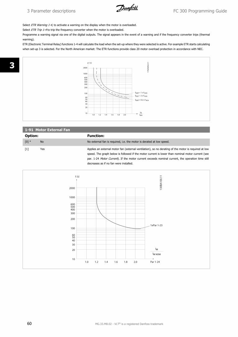
Select ETR Warning 1-4, to activate a warning on the display when the motor is overloaded.
Select ETR Trip 1-4 to trip the frequency converter when the motor is overloaded.
Programme a warning signal via one of the digital outputs. The signal appears in the event of a warning and if the frequency converter trips (thermal
warning).
ETR (Electronic Terminal Relay) functions 1-4 will calculate the load when the set-up where they were selected is active. For example ETR starts calculating
when set-up 3 is selected. For the North American market: The ETR functions provide class 20 motor overload protection in accordance with NEC.
1-91 Motor External Fan
Option: Function:[0] * No No external fan is required, i.e. the motor is derated at low speed.
[1] Yes Applies an external motor fan (external ventilation), so no derating of the motor is required at low
speed. The graph below is followed if the motor current is lower than nominal motor current (see
par. 1-24 Motor Current). If the motor current exceeds nominal current, the operation time still
decreases as if no fan were installed.
3 Parameter descriptions FC 300 Programming Guide
60 MG.33.M8.02 - VLT® is a registered Danfoss trademark
3
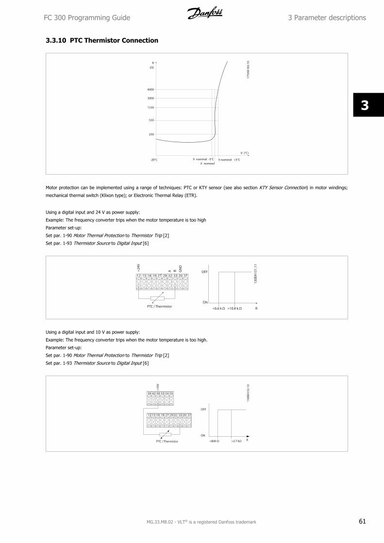
3.3.10 PTC Thermistor Connection
Motor protection can be implemented using a range of techniques: PTC or KTY sensor (see also section KTY Sensor Connection) in motor windings;
mechanical thermal switch (Klixon type); or Electronic Thermal Relay (ETR).
Using a digital input and 24 V as power supply:
Example: The frequency converter trips when the motor temperature is too high
Parameter set-up:
Set par. 1-90 Motor Thermal Protection to Thermistor Trip [2]
Set par. 1-93 Thermistor Source to Digital Input [6]
Using a digital input and 10 V as power supply:
Example: The frequency converter trips when the motor temperature is too high.
Parameter set-up:
Set par. 1-90 Motor Thermal Protection to Thermistor Trip [2]
Set par. 1-93 Thermistor Source to Digital Input [6]
FC 300 Programming Guide 3 Parameter descriptions
MG.33.M8.02 - VLT® is a registered Danfoss trademark 61
3
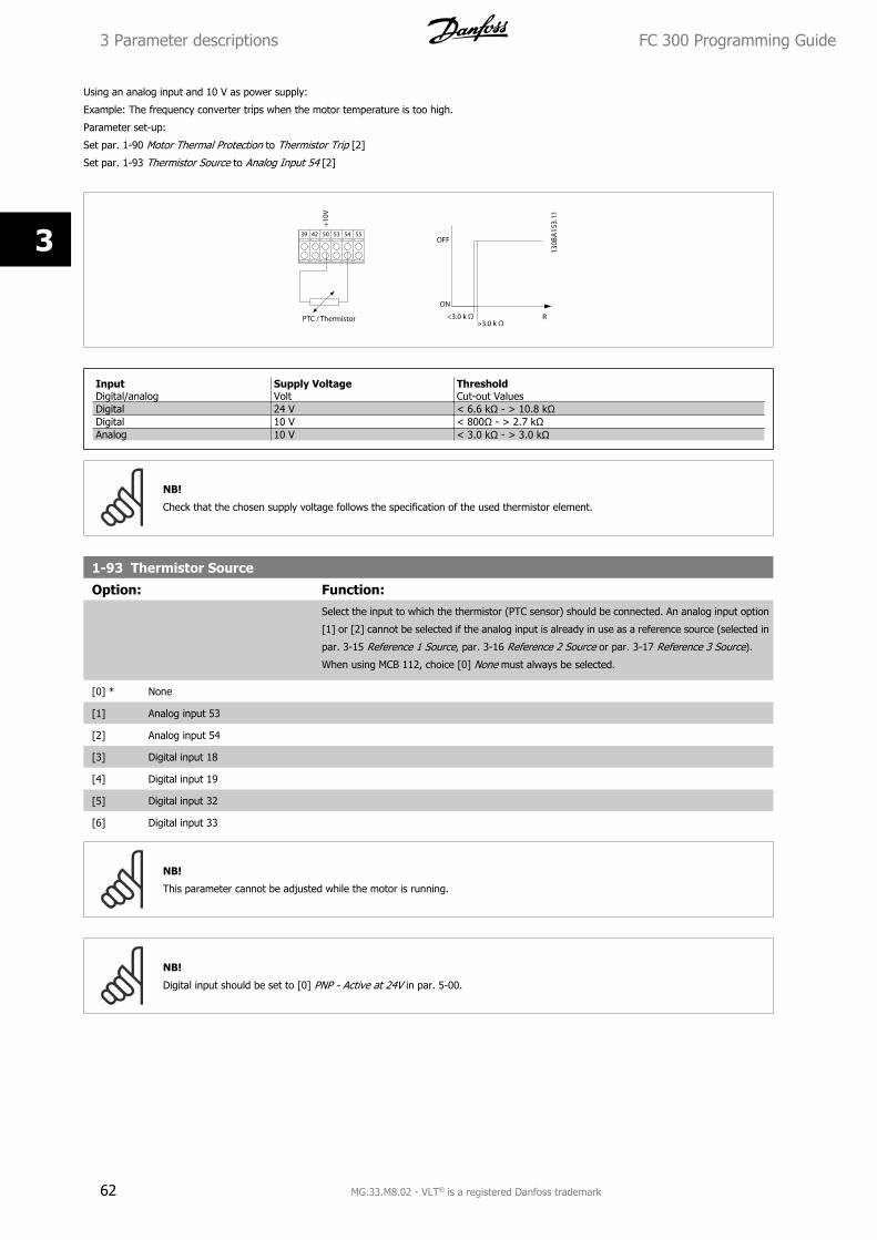
Using an analog input and 10 V as power supply:
Example: The frequency converter trips when the motor temperature is too high.
Parameter set-up:
Set par. 1-90 Motor Thermal Protection to Thermistor Trip [2]
Set par. 1-93 Thermistor Source to Analog Input 54 [2]
InputDigital/analog
Supply VoltageVolt
ThresholdCut-out Values
Digital 24 V < 6.6 kΩ - > 10.8 kΩDigital 10 V < 800Ω - > 2.7 kΩAnalog 10 V < 3.0 kΩ - > 3.0 kΩ
NB!
Check that the chosen supply voltage follows the specification of the used thermistor element.
1-93 Thermistor Source
Option: Function:Select the input to which the thermistor (PTC sensor) should be connected. An analog input option
[1] or [2] cannot be selected if the analog input is already in use as a reference source (selected in
par. 3-15 Reference 1 Source, par. 3-16 Reference 2 Source or par. 3-17 Reference 3 Source).
When using MCB 112, choice [0] None must always be selected.
[0] * None
[1] Analog input 53
[2] Analog input 54
[3] Digital input 18
[4] Digital input 19
[5] Digital input 32
[6] Digital input 33
NB!
This parameter cannot be adjusted while the motor is running.
NB!
Digital input should be set to [0] PNP - Active at 24V in par. 5-00.
3 Parameter descriptions FC 300 Programming Guide
62 MG.33.M8.02 - VLT® is a registered Danfoss trademark
3
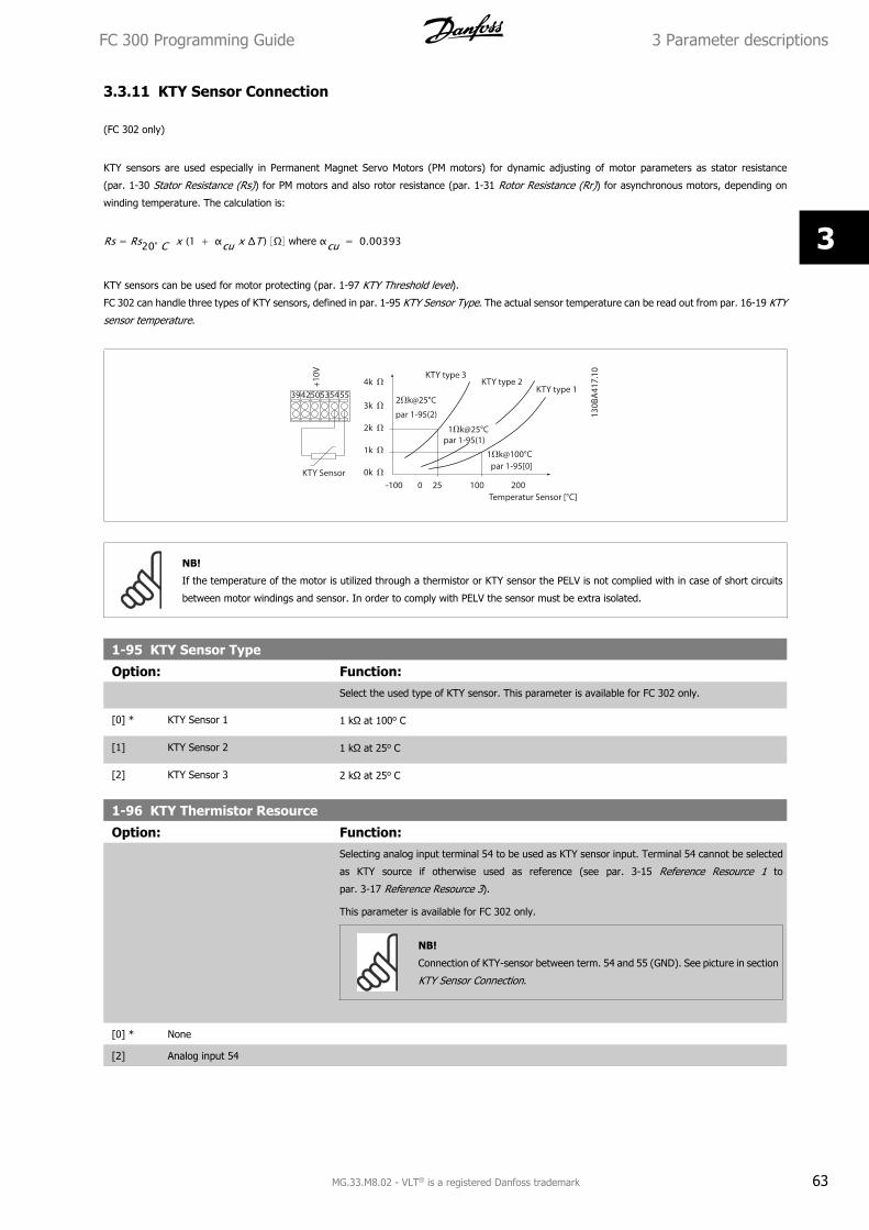
3.3.11 KTY Sensor Connection
(FC 302 only)
KTY sensors are used especially in Permanent Magnet Servo Motors (PM motors) for dynamic adjusting of motor parameters as stator resistance
(par. 1-30 Stator Resistance (Rs)) for PM motors and also rotor resistance (par. 1-31 Rotor Resistance (Rr)) for asynchronous motors, depending on
winding temperature. The calculation is:
Rs = Rs20° C x (1 + αcu x ΔT ) Ω where αcu = 0.00393
KTY sensors can be used for motor protecting (par. 1-97 KTY Threshold level).
FC 302 can handle three types of KTY sensors, defined in par. 1-95 KTY Sensor Type. The actual sensor temperature can be read out from par. 16-19 KTY
sensor temperature.
NB!
If the temperature of the motor is utilized through a thermistor or KTY sensor the PELV is not complied with in case of short circuits
between motor windings and sensor. In order to comply with PELV the sensor must be extra isolated.
1-95 KTY Sensor Type
Option: Function:Select the used type of KTY sensor. This parameter is available for FC 302 only.
[0] * KTY Sensor 1 1 kΩ at 100o C
[1] KTY Sensor 2 1 kΩ at 25o C
[2] KTY Sensor 3 2 kΩ at 25o C
1-96 KTY Thermistor Resource
Option: Function:Selecting analog input terminal 54 to be used as KTY sensor input. Terminal 54 cannot be selected
as KTY source if otherwise used as reference (see par. 3-15 Reference Resource 1 to
par. 3-17 Reference Resource 3).
This parameter is available for FC 302 only.
NB!
Connection of KTY-sensor between term. 54 and 55 (GND). See picture in section
KTY Sensor Connection.
[0] * None
[2] Analog input 54
FC 300 Programming Guide 3 Parameter descriptions
MG.33.M8.02 - VLT® is a registered Danfoss trademark 63
3
1-97 KTY Threshold level
Range: Function:80 C* [-40 - 140 C] Select the KTY sensor threshold level for motor thermal protection.
This parameter is available for FC 302 only.
3 Parameter descriptions FC 300 Programming Guide
64 MG.33.M8.02 - VLT® is a registered Danfoss trademark
3
3.4 Parameters: Brakes
3.4.1 2-** Brakes
Parameter group for setting brake features in the frequency converter.
3.4.2 2-0* DC-Brakes
Parameter group for configuring the DC brake and DC hold functions.
2-00 DC Hold Current
Range: Function:50 %* [Application dependant] Enter a value for holding current as a percentage of the rated motor current IM,N set in
par. 1-24 Motor Current. 100% DC holding current corresponds to IM,N.
This parameter holds the motor function (holding torque) or pre-heats the motor.
This parameter is active if DC hold is selected in par. 1-72 Start Function [0] or par. 1-80 Function
at Stop [1].
NB!
The maximum value depends on the rated motor current.
NB!
Avoid 100 % current for too long. It may damage the motor.
Low values of DC hold will produce larger than expected currents with larger motor power sizes. This error will increase as the motor
power increases.
2-01 DC Brake Current
Range: Function:50 %* [Application dependant] Enter a value for current as a percentage of the rated motor current IM,N, see par. 1-24 Motor
Current. 100% DC braking current corresponds to IM,N.
DC brake current is applied on a stop command, when the speed is lower than the limit set in
par. 2-03 DC Brake Cut In Speed [RPM]; when the DC Brake Inverse function is active; or via the
serial communication port. The braking current is active during the time period set in par. 2-02 DC
Braking Time.
NB!
The maximum value depends on the rated motor current.
NB!
Avoid 100 % current for too long. It may damage the motor.
2-02 DC Braking Time
Range: Function:10.0 s* [0.0 - 60.0 s] Set the duration of the DC braking current set in par. 2-01 DC Brake Current, once activated.
2-03 DC Brake Cut In Speed [RPM]
Range: Function:Application
dependent*
[Application dependant] Set the DC brake cut-in speed for activation of the DC braking current set in par. 2-01 DC Brake
Current, upon a stop command.
2-04 DC Brake Cut In Speed [Hz]
Range: Function:Application
dependent*
[Application dependant] Set the DC brake cut-in speed for activation of the DC braking current set in par. 2-01 DC Brake
Current, upon a stop command.
FC 300 Programming Guide 3 Parameter descriptions
MG.33.M8.02 - VLT® is a registered Danfoss trademark 65
3
3.4.3 2-1* Brake Energy Funct.
Parameter group for selecting dynamic braking parameters. Only valid for drives with brake chopper.
2-10 Brake Function
Option: Function:[0] * Off No brake resistor is installed.
[1] Resistor brake A brake resistor is incorporated in the system, for dissipation of surplus brake energy as heat. Con-
necting a brake resistor allows a higher DC link voltage during braking (generating operation). The
Resistor brake function is only active in frequency converters with an integral dynamic brake.
[2] AC brake Is selected to improve braking without using a brake resistor. This parameter controls an overmag-
netization of the motor when running with a generatoric load. This function can improve the OVC-
function. Increasing the electrical losses in the motor allows the OVC function to increase the braking
torque without exceeding the over voltage limit. Please note that AC brake is not as effective as
dynamic breaking with resistor.
AC brake is for VVC+ and flux mode in both open and closed loop.
2-11 Brake Resistor (ohm)
Range: Function:Application
dependent*
[Application dependant] Set the brake resistor value in Ohms. This value is used for monitoring the power to the brake
resistor in par. 2-13 Brake Power Monitoring. This parameter is only active in frequency converters
with an integral dynamic brake.
Use this parameter for values without decimals. For a selection with two decimals, use
par. 30-81 Brake Resistor (ohm).
2-12 Brake Power Limit (kW)
Range: Function:Application
dependent*
[Application dependant] Set the monitoring limit of the brake power transmitted to the resistor.
The monitoring limit is a product of the maximum duty cycle (120 sec.) and the maximum power
of the brake resistor at that duty cycle. See the formula below.
For 200 - 240 V units:Presistor = 3902 × dutytime
R × 120 [W]
For 380 - 480 V unitsPresistor = 7782 × dutytime
R × 120 [W]
For 380 - 500 V unitsPresistor = 8102 × dutytime
R × 120 [W]
For 575 - 600 V unitsPresistor = 9432 × dutytime
R × 120 [W]
This parameter is only active in frequency converters with an integral dynamic brake.
2-13 Brake Power Monitoring
Option: Function:This parameter is only active in frequency converters with an integral dynamic brake.
This parameter enables monitoring of the power to the brake resistor. The power is calculated on
the basis of the resistance (par. 2-11 Brake Resistor (ohm)), the DC link voltage, and the resistor
duty time.
[0] * Off No brake power monitoring required.
[1] Warning Activates a warning on the display when the power transmitted over 120 s exceeds 100% of the
monitoring limit (par. 2-12 Brake Power Limit (kW) ).
The warning disappears when the transmitted power falls below 80% of the monitoring limit.
3 Parameter descriptions FC 300 Programming Guide
66 MG.33.M8.02 - VLT® is a registered Danfoss trademark
3
[2] Trip Trips frequency converter and displays an alarm when the calculated power exceeds 100% of the
monitoring limit.
[3] Warning and trip Activates both of the above, including warning, trip and alarm.
If power monitoring is set to Off [0] or Warning [1], the brake function remains active, even if the monitoring limit is exceeded. This may lead to thermal
overload of the resistor. It is also possible to generate a warning via a relay/digital outputs. The measuring accuracy of the power monitoring depends
on the accuracy of the resistance of the resistor (better than ± 20%).
2-15 Brake Check
Option: Function:Select type of test and monitoring function to check the connection to the brake resistor, or whether
a brake resistor is present, and then display a warning or an alarm in the event of a fault.
NB!
The brake resistor disconnection function is tested during power-up. However the
brake IGBT test is performed when there is no braking. A warning or trip discon-
nects the brake function.
The testing sequence is as follows:
1. The DC link ripple amplitude is measured for 300 ms without braking.
2. The DC link ripple amplitude is measured for 300 ms with the brake turned on.
3. If the DC link ripple amplitude while braking is lower than the DC link ripple amplitude
before braking + 1 %: Brake check has failed by returning a warning or alarm.
4. If the DC link ripple amplitude while braking is higher than the DC link ripple amplitude
before braking + 1 %: Brake check is OK.
[0] * Off Monitors brake resistor and brake IGBT for a short-circuit during operation. If a short-circuit occurs,
warning 25 appears.
[1] Warning Monitors brake resistor and brake IGBT for a short-circuit, and runs a test for brake resistor dis-
connection during power-up.
[2] Trip Monitors for a short-circuit or disconnection of the brake resistor, or a short-circuit of the brake
IGBT. If a fault occurs, the frequency converter cuts out while displaying an alarm (trip locked).
[3] Stop and trip Monitors for a short-circuit or disconnection of the brake resistor, or a short-circuit of the brake
IGBT. If a fault occurs, the frequency converter ramps down to coast and then trips. A trip lock
alarm is displayed (e.g. warning 25, 27 or 28).
[4] AC brake Monitors for a short-circuit or disconnection of the brake resistor, or a short-circuit of the brake
IGBT. If a fault occurs, the frequency converter performs a controlled ramp-down. This option is
available for FC 302 only.
[5] Trip Lock
NB!
Remove a warning arising in connection with Off [0] or Warning [1] by cycling the mains supply. The fault must be corrected first. For
Off [0] or Warning [1], the frequency converter keeps running even if a fault is located.
This parameter is only active in frequency converters with an integral dynamic brake.
2-16 AC brake Max. Current
Range: Function:100.0 %* [Application dependant] Enter the maximum permissible current when using AC brake to avoid overheating of motor wind-
ings. The AC brake function is available in Flux mode only (FC 302 only).
FC 300 Programming Guide 3 Parameter descriptions
MG.33.M8.02 - VLT® is a registered Danfoss trademark 67
3
2-17 Over-voltage Control
Option: Function:Over-voltage control (OVC) reduces the risk of the frequency converter tripping due to an over
voltage on the DC link caused by generative power from the load.
[0] * Disabled No OVC required.
[1] Enabled (not at stop) Activates OVC except when using a stop signal to stop the frequency converter.
[2] Enabled Activates OVC.
NB!
OVC must not be enabled in hoisting applications.
2-18 Brake Check Condition
Range: Function:[0] * At Power Up Brake check will be performed at power up
[1] After Coast Situations Brake check will be performed after coast situations
2-19 Over-voltage Gain
Range: Function:100 %* [0 - 200 %] Select over-voltage gain.
3.4.4 2-2* Mechanical Brake
Parameters for controlling operation of an electro-magnetic (mechanical) brake, typically required in hoisting applications.
To control a mechanical brake, a relay output (relay 01 or relay 02) or a programmed digital output (terminal 27 or 29) is required. Normally this output
must be closed during periods when the frequency converter is unable to ‘hold’ the motor, e.g. due to an excessive load. Select Mechanical Brake
Control [32] for applications with an electro-magnetic brake in par. 5-40 Function Relay, par. 5-30 Terminal 27 Digital Output, or par. 5-31 Terminal 29
Digital Output. When selecting Mechanical brake control [32], the mechanical brake is closed from start up until the output current is above the level
selected in par. 2-20 Release Brake Current. During stop, the mechanical brake activates when the speed falls below the level specified in par. 2-21 Activate
Brake Speed [RPM]. If the frequency converter enters an alarm condition or an over-current or over-voltage situation, the mechanical brake immediately
cuts in. This is also the case during safe stop.
NB!
Protection mode and trip delay features (par. 14-25 Trip Delay at Torque Limit and par. 14-26 Trip Delay at Inverter Fault) may delay
the activation of the mechanical brake in an alarm condition. These features must be disabled in hoisting applications.
3 Parameter descriptions FC 300 Programming Guide
68 MG.33.M8.02 - VLT® is a registered Danfoss trademark
3
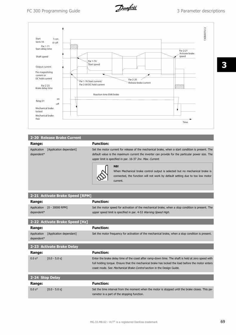
2-20 Release Brake Current
Range: Function:Application
dependent*
[Application dependant] Set the motor current for release of the mechanical brake, when a start condition is present. The
default value is the maximum current the inverter can provide for the particular power size. The
upper limit is specified in par. 16-37 Inv. Max. Current.
NB!
When Mechanical brake control output is selected but no mechanical brake is
connected, the function will not work by default setting due to too low motor
current.
2-21 Activate Brake Speed [RPM]
Range: Function:Application
dependent*
[0 - 30000 RPM] Set the motor speed for activation of the mechanical brake, when a stop condition is present. The
upper speed limit is specified in par. 4-53 Warning Speed High.
2-22 Activate Brake Speed [Hz]
Range: Function:Application
dependent*
[Application dependant] Set the motor frequency for activation of the mechanical brake, when a stop condition is present.
2-23 Activate Brake Delay
Range: Function:0.0 s* [0.0 - 5.0 s] Enter the brake delay time of the coast after ramp-down time. The shaft is held at zero speed with
full holding torque. Ensure that the mechanical brake has locked the load before the motor enters
coast mode. See Mechanical Brake Control section in the Design Guide.
2-24 Stop Delay
Range: Function:0.0 s* [0.0 - 5.0 s] Set the time interval from the moment when the motor is stopped until the brake closes. This pa-
rameter is a part of the stopping function.
FC 300 Programming Guide 3 Parameter descriptions
MG.33.M8.02 - VLT® is a registered Danfoss trademark 69
3
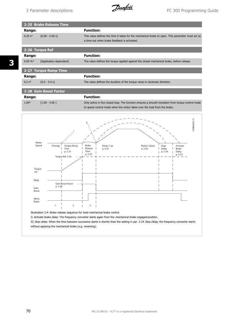
2-25 Brake Release Time
Range: Function:0.20 s* [0.00 - 5.00 s] This value defines the time it takes for the mechanical brake to open. This parameter must act as
a time-out when brake feedback is activated.
2-26 Torque Ref
Range: Function:0.00 %* [Application dependant] The value defines the torque applied against the closed mechanical brake, before release
2-27 Torque Ramp Time
Range: Function:0.2 s* [0.0 - 5.0 s] The value defines the duration of the torque ramp in clockwise direction.
2-28 Gain Boost Factor
Range: Function:1.00* [1.00 - 4.00 ] Only active in flux closed loop. The function ensures a smooth transition from torque control mode
to speed control mode when the motor takes over the load from the brake.
Illustration 3.4: Brake release sequence for hoist mechanical brake control
I) Activate brake delay: The frequency converter starts again from the mechanical brake engaged position.
II) Stop delay: When the time between successive starts is shorter than the setting in par. 2-24 Stop Delay, the frequency converter starts
without applying the mechanical brake (e.g. reversing).
3 Parameter descriptions FC 300 Programming Guide
70 MG.33.M8.02 - VLT® is a registered Danfoss trademark
3
3.5 Parameters: Reference/Ramps
3.5.1 3-** Reference/Reference Limits/Ramps
Parameters for reference handling, definition of limitations, and configuration of the reaction of the frequency converter to changes.
3.5.2 3-0* Reference Limits
Parameters for setting the reference unit, limits and ranges.
3-00 Reference Range
Option: Function:Select the range of the reference signal and the feedback signal. Signal values can be positive only,
or positive and negative. The minimum limit may have a negative value, unless Speed closed loop
[1] control or Process [3] is selected in par. 1-00 Configuration Mode.
[0] Min - Max Select the range of the reference signal and the feedback signal. Signal values can be positive only,
or positive and negative. The minimum limit may have a negative value, unless Speed closed loop
[1] control or Process [3] is selected in par. 1-00 Configuration Mode.
[1] * -Max - +Max For both positive and negative values (both directions, relative to par. 4-10 Motor Speed Direction).
3-01 Reference/Feedback Unit
Option: Function:Select the unit to be used in Process PID Control references and feedbacks. Par. 1-00 Configuration
Mode must be either [3] Process or [8] Extended PID Control.
[0] * None
[1] %
[2] RPM
[3] Hz
[4] Nm
[5] PPM
[10] 1/min
[12] Pulse/s
[20] l/s
[21] l/min
[22] l/h
[23] m³/s
[24] m³/min
[25] m³/h
[30] kg/s
[31] kg/min
[32] kg/h
[33] t/min
[34] t/h
[40] m/s
[41] m/min
[45] m
[60] °C
[70] mbar
FC 300 Programming Guide 3 Parameter descriptions
MG.33.M8.02 - VLT® is a registered Danfoss trademark 71
3
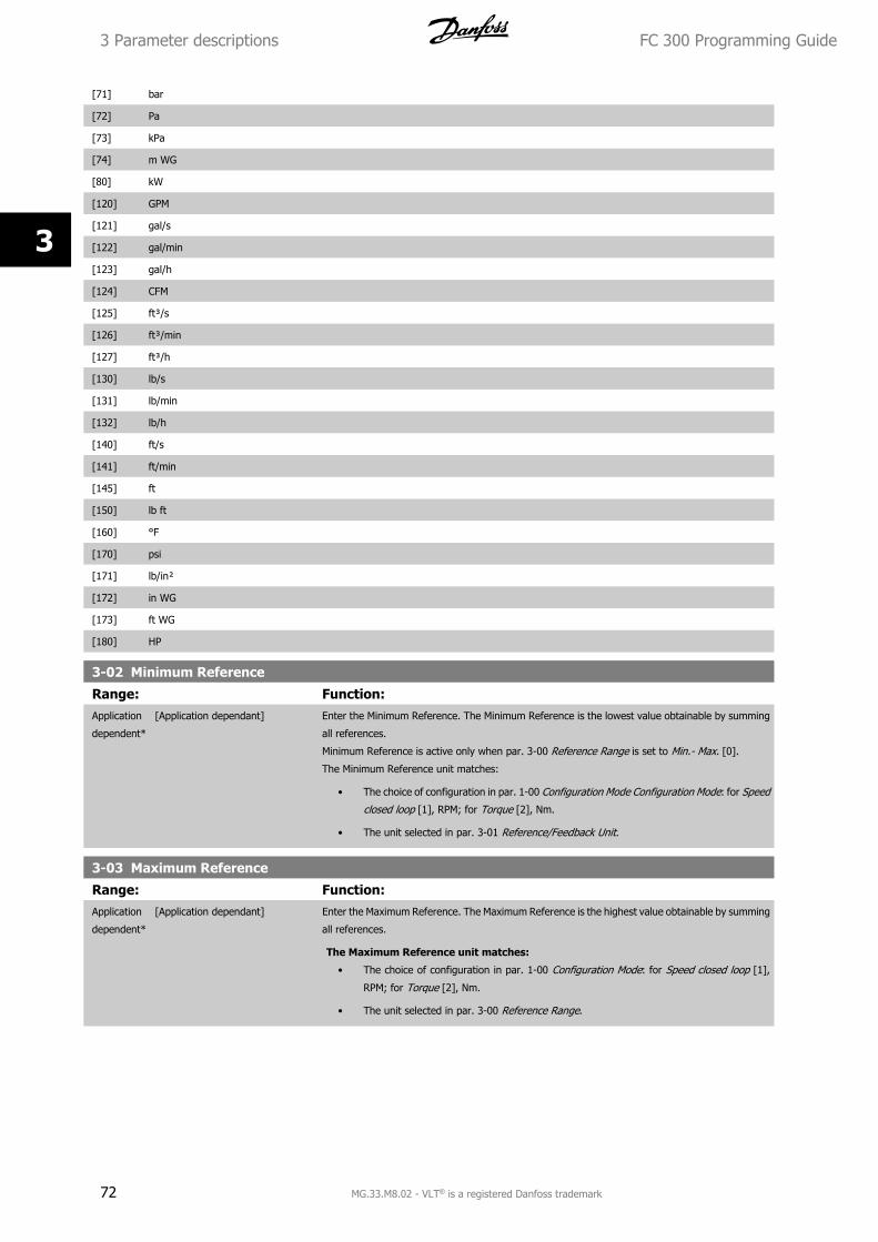
[71] bar
[72] Pa
[73] kPa
[74] m WG
[80] kW
[120] GPM
[121] gal/s
[122] gal/min
[123] gal/h
[124] CFM
[125] ft³/s
[126] ft³/min
[127] ft³/h
[130] lb/s
[131] lb/min
[132] lb/h
[140] ft/s
[141] ft/min
[145] ft
[150] lb ft
[160] °F
[170] psi
[171] lb/in²
[172] in WG
[173] ft WG
[180] HP
3-02 Minimum Reference
Range: Function:Application
dependent*
[Application dependant] Enter the Minimum Reference. The Minimum Reference is the lowest value obtainable by summing
all references.
Minimum Reference is active only when par. 3-00 Reference Range is set to Min.- Max. [0].
The Minimum Reference unit matches:
• The choice of configuration in par. 1-00 Configuration Mode Configuration Mode: for Speed
closed loop [1], RPM; for Torque [2], Nm.
• The unit selected in par. 3-01 Reference/Feedback Unit.
3-03 Maximum Reference
Range: Function:Application
dependent*
[Application dependant] Enter the Maximum Reference. The Maximum Reference is the highest value obtainable by summing
all references.
The Maximum Reference unit matches:
• The choice of configuration in par. 1-00 Configuration Mode: for Speed closed loop [1],
RPM; for Torque [2], Nm.
• The unit selected in par. 3-00 Reference Range.
3 Parameter descriptions FC 300 Programming Guide
72 MG.33.M8.02 - VLT® is a registered Danfoss trademark
3
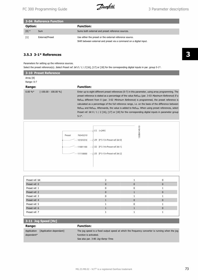
3-04 Reference Function
Option: Function:[0] * Sum Sums both external and preset reference sources.
[1] External/Preset Use either the preset or the external reference source.
Shift between external and preset via a command on a digital input.
3.5.3 3-1* References
Parameters for setting up the reference sources.
Select the preset reference(s). Select Preset ref. bit 0 / 1 / 2 [16], [17] or [18] for the corresponding digital inputs in par. group 5-1*.
3-10 Preset ReferenceArray [8]
Range: 0-7
Range: Function:0.00 %* [-100.00 - 100.00 %] Enter up to eight different preset references (0-7) in this parameter, using array programming. The
preset reference is stated as a percentage of the value RefMAX (par. 3-03 Maximum Reference) If a
RefMIN different from 0 (par. 3-02 Minimum Reference) is programmed, the preset reference is
calculated as a percentage of the full reference range, i.e. on the basis of the difference between
RefMAX and RefMIN. Afterwards, the value is added to RefMIN. When using preset references, select
Preset ref. bit 0 / 1 / 2 [16], [17] or [18] for the corresponding digital inputs in parameter group
5-1*.
Preset ref. bit 2 1 0
Preset ref. 0 0 0 0
Preset ref. 1 0 0 1
Preset ref. 2 0 1 0
Preset ref. 3 0 1 1
Preset ref. 4 1 0 0
Preset ref. 5 1 0 1
Preset ref. 6 1 1 0
Preset ref. 7 1 1 1
3-11 Jog Speed [Hz]
Range: Function:Application
dependent*
[Application dependant] The jog speed is a fixed output speed at which the frequency converter is running when the jog
function is activated.
See also par. 3-80 Jog Ramp Time.
FC 300 Programming Guide 3 Parameter descriptions
MG.33.M8.02 - VLT® is a registered Danfoss trademark 73
3
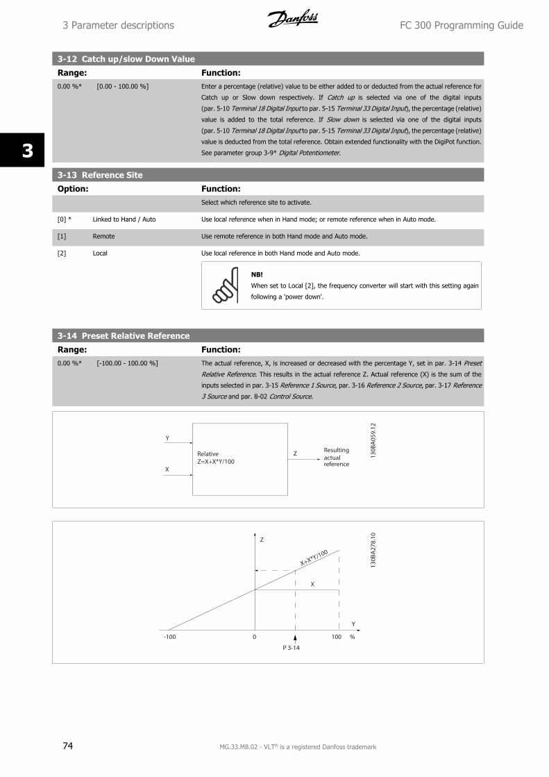
3-12 Catch up/slow Down Value
Range: Function:0.00 %* [0.00 - 100.00 %] Enter a percentage (relative) value to be either added to or deducted from the actual reference for
Catch up or Slow down respectively. If Catch up is selected via one of the digital inputs
(par. 5-10 Terminal 18 Digital Input to par. 5-15 Terminal 33 Digital Input), the percentage (relative)
value is added to the total reference. If Slow down is selected via one of the digital inputs
(par. 5-10 Terminal 18 Digital Input to par. 5-15 Terminal 33 Digital Input), the percentage (relative)
value is deducted from the total reference. Obtain extended functionality with the DigiPot function.
See parameter group 3-9* Digital Potentiometer.
3-13 Reference Site
Option: Function:Select which reference site to activate.
[0] * Linked to Hand / Auto Use local reference when in Hand mode; or remote reference when in Auto mode.
[1] Remote Use remote reference in both Hand mode and Auto mode.
[2] Local Use local reference in both Hand mode and Auto mode.
NB!
When set to Local [2], the frequency converter will start with this setting again
following a 'power down'.
3-14 Preset Relative Reference
Range: Function:0.00 %* [-100.00 - 100.00 %] The actual reference, X, is increased or decreased with the percentage Y, set in par. 3-14 Preset
Relative Reference. This results in the actual reference Z. Actual reference (X) is the sum of the
inputs selected in par. 3-15 Reference 1 Source, par. 3-16 Reference 2 Source, par. 3-17 Reference
3 Source and par. 8-02 Control Source.
3 Parameter descriptions FC 300 Programming Guide
74 MG.33.M8.02 - VLT® is a registered Danfoss trademark
3
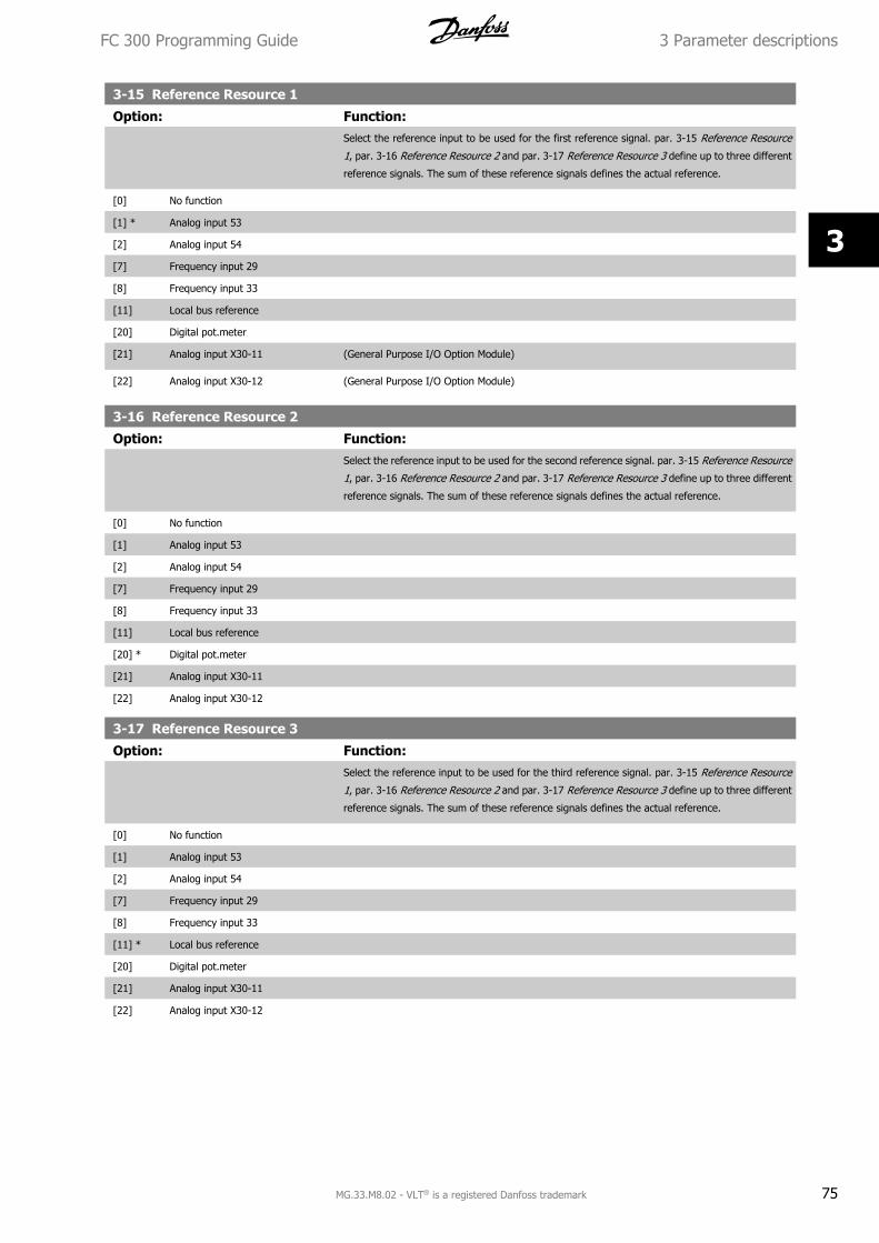
3-15 Reference Resource 1
Option: Function:Select the reference input to be used for the first reference signal. par. 3-15 Reference Resource
1, par. 3-16 Reference Resource 2 and par. 3-17 Reference Resource 3 define up to three different
reference signals. The sum of these reference signals defines the actual reference.
[0] No function
[1] * Analog input 53
[2] Analog input 54
[7] Frequency input 29
[8] Frequency input 33
[11] Local bus reference
[20] Digital pot.meter
[21] Analog input X30-11 (General Purpose I/O Option Module)
[22] Analog input X30-12 (General Purpose I/O Option Module)
3-16 Reference Resource 2
Option: Function:Select the reference input to be used for the second reference signal. par. 3-15 Reference Resource
1, par. 3-16 Reference Resource 2 and par. 3-17 Reference Resource 3 define up to three different
reference signals. The sum of these reference signals defines the actual reference.
[0] No function
[1] Analog input 53
[2] Analog input 54
[7] Frequency input 29
[8] Frequency input 33
[11] Local bus reference
[20] * Digital pot.meter
[21] Analog input X30-11
[22] Analog input X30-12
3-17 Reference Resource 3
Option: Function:Select the reference input to be used for the third reference signal. par. 3-15 Reference Resource
1, par. 3-16 Reference Resource 2 and par. 3-17 Reference Resource 3 define up to three different
reference signals. The sum of these reference signals defines the actual reference.
[0] No function
[1] Analog input 53
[2] Analog input 54
[7] Frequency input 29
[8] Frequency input 33
[11] * Local bus reference
[20] Digital pot.meter
[21] Analog input X30-11
[22] Analog input X30-12
FC 300 Programming Guide 3 Parameter descriptions
MG.33.M8.02 - VLT® is a registered Danfoss trademark 75
3
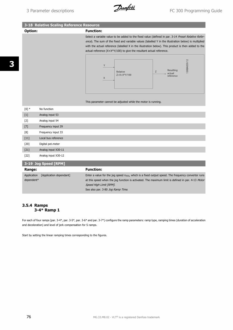
3-18 Relative Scaling Reference Resource
Option: Function:Select a variable value to be added to the fixed value (defined in par. 3-14 Preset Relative Refer-
ence). The sum of the fixed and variable values (labelled Y in the illustration below) is multiplied
with the actual reference (labelled X in the illustration below). This product is then added to the
actual reference (X+X*Y/100) to give the resultant actual reference.
This parameter cannot be adjusted while the motor is running.
[0] * No function
[1] Analog input 53
[2] Analog input 54
[7] Frequency input 29
[8] Frequency input 33
[11] Local bus reference
[20] Digital pot.meter
[21] Analog input X30-11
[22] Analog input X30-12
3-19 Jog Speed [RPM]
Range: Function:Application
dependent*
[Application dependant] Enter a value for the jog speed nJOG, which is a fixed output speed. The frequency converter runs
at this speed when the jog function is activated. The maximum limit is defined in par. 4-13 Motor
Speed High Limit [RPM].
See also par. 3-80 Jog Ramp Time.
3.5.4 Ramps3-4* Ramp 1
For each of four ramps (par. 3-4*, par. 3-5*, par. 3-6* and par. 3-7*) configure the ramp parameters: ramp type, ramping times (duration of acceleration
and deceleration) and level of jerk compensation for S ramps.
Start by setting the linear ramping times corresponding to the figures.
3 Parameter descriptions FC 300 Programming Guide
76 MG.33.M8.02 - VLT® is a registered Danfoss trademark
3
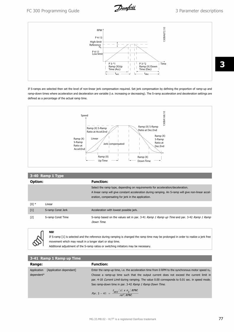
If S-ramps are selected then set the level of non-linear jerk compensation required. Set jerk compensation by defining the proportion of ramp-up and
ramp-down times where acceleration and deceleration are variable (i.e. increasing or decreasing). The S-ramp acceleration and deceleration settings are
defined as a percentage of the actual ramp time.
3-40 Ramp 1 Type
Option: Function:Select the ramp type, depending on requirements for acceleration/deceleration.
A linear ramp will give constant acceleration during ramping. An S-ramp will give non-linear accel-
eration, compensating for jerk in the application.
[0] * Linear
[1] S-ramp Const Jerk Acceleration with lowest possible jerk.
[2] S-ramp Const Time S-ramp based on the values set in par. 3-41 Ramp 1 Ramp up Time and par. 3-42 Ramp 1 Ramp
Down Time.
NB!
If S-ramp [1] is selected and the reference during ramping is changed the ramp time may be prolonged in order to realize a jerk free
movement which may result in a longer start or stop time.
Additional adjustment of the S-ramp ratios or switching initiators may be necessary.
3-41 Ramp 1 Ramp up Time
Range: Function:Application
dependent*
[Application dependant] Enter the ramp-up time, i.e. the acceleration time from 0 RPM to the synchronous motor speed nS.
Choose a ramp-up time such that the output current does not exceed the current limit in
par. 4-18 Current Limit during ramping. The value 0.00 corresponds to 0.01 sec. in speed mode.
See ramp-down time in par. 3-42 Ramp 1 Ramp Down Time.
Par. 3 − 41 = tacc s x ns RPM
ref RPM
FC 300 Programming Guide 3 Parameter descriptions
MG.33.M8.02 - VLT® is a registered Danfoss trademark 77
3
3-42 Ramp 1 Ramp Down Time
Range: Function:Application
dependent*
[Application dependant] Enter the ramp-down time, i.e. the deceleration time from the synchronous motor speed ns to 0
RPM. Choose a ramp-down time such that no over-voltage arises in the inverter due to regenerative
operation of the motor, and such that the generated current does not exceed the current limit set
in par. 4-18 Current Limit. The value 0.00 corresponds to 0.01 s in speed mode. See ramp-up time
in par. 3-41 Ramp 1 Ramp up Time.
Par. 3 − 42 = tdec s x ns RPM
ref RPM
3-45 Ramp 1 S-ramp Ratio at Accel. Start
Range: Function:50 %* [Application dependant] Enter the proportion of the total ramp-up time (par. 3-41 Ramp 1 Ramp up Time) in which the
acceleration torque increases. The larger the percentage value, the greater the jerk compensation
achieved, and thus the lower the torque jerks occurring in the application.
3-46 Ramp 1 S-ramp Ratio at Accel. End
Range: Function:50 %* [Application dependant] Enter the proportion of the total ramp-up time (par. 3-41 Ramp 1 Ramp up Time) in which the
acceleration torque decreases. The larger the percentage value, the greater the jerk compensation
achieved, and thus the lower the torque jerks in the application.
3-47 Ramp 1 S-ramp Ratio at Decel. Start
Range: Function:50 %* [Application dependant] Enter the proportion of the total ramp-down time (par. 3-42 Ramp 1 Ramp Down Time) where the
deceleration torque increases. The larger the percentage value, the greater the jerk compensation
achieved, and thus the lower the torque jerks in the application.
3-48 Ramp 1 S-ramp Ratio at Decel. End
Range: Function:50 %* [Application dependant] Enter the proportion of the total ramp-down time (par. 3-42 Ramp 1 Ramp Down Time) where the
deceleration torque decreases. The larger the percentage value, the greater the jerk compensation
achieved, and thus the lower the torque jerks in the application.
3.5.5 3-5* Ramp 2
Choosing ramp parameters, see 3-4*.
3-50 Ramp 2 Type
Option: Function:Select the ramp type, depending on requirements for acceleration/deceleration. A linear ramp will
give constant acceleration during ramping. An S-ramp will give non-linear acceleration, compen-
sating for jerk in the application.
[0] * Linear
[1] S-ramp Const Jerk Acceleration with lowest possible jerk
[2] S-ramp Const Time S-ramp based on the values set in par. 3-51 Ramp 2 Ramp up Time and par. 3-52 Ramp 2 Ramp
down Time
NB!
If S-ramp [1] is selected and the reference during ramping is changed the ramp time may be prolonged in order to realize a jerk free
movement which may result in a longer start or stop time.
Additional adjustment of the S-ramp ratios or switching initiators may be necessary.
3 Parameter descriptions FC 300 Programming Guide
78 MG.33.M8.02 - VLT® is a registered Danfoss trademark
3
3-51 Ramp 2 Ramp up Time
Range: Function:Application
dependent*
[Application dependant] Enter the ramp-up time, i.e. the acceleration time from 0 RPM to the rated motor speed ns. Choose
a ramp-up time such that the output current does not exceed the current limit in par. 4-18 Current
Limit during ramping. The value 0.00 corresponds to 0.01 sec. in speed mode. See ramp-down time
in par. 3-52 Ramp 2 Ramp down Time.
Par. 3 − 51 = tacc s x ns RPM
ref RPM
3-52 Ramp 2 Ramp down Time
Range: Function:Application
dependent*
[Application dependant] Enter the ramp-down time, i.e. the deceleration time from the rated motor speed ns to 0 RPM.
Choose a ramp-down time such that no over-voltage arises in the inverter due to regenerative
operation of the motor, and such that the generated current does not exceed the current limit set
in par. 4-18 Current Limit. The value 0.00 corresponds to 0.01 s in speed mode. See ramp-up time
in par. 3-51 Ramp 2 Ramp up Time.
Par. 3 − 52 = tdec s x ns RPM
ref RPM
3-55 Ramp 2 S-ramp Ratio at Accel. Start
Range: Function:50 %* [Application dependant] Enter the proportion of the total ramp-up time (par. 3-51 Ramp 2 Ramp up Time) in which the
acceleration torque increases. The larger the percentage value, the greater the jerk compensation
achieved, and thus the lower the torque jerks in the application.
3-56 Ramp 2 S-ramp Ratio at Accel. End
Range: Function:50 %* [Application dependant] Enter the proportion of the total ramp-up time (par. 3-51 Ramp 2 Ramp up Time) in which the
acceleration torque decreases. The larger the percentage value, the greater the jerk compensation
achieved, and thus the lower the torque jerks in the application.
3-57 Ramp 2 S-ramp Ratio at Decel. Start
Range: Function:50 %* [Application dependant] Enter the proportion of the total ramp-down time (par. 3-52 Ramp 2 Ramp down Time) where the
deceleration torque increases The larger the percentage value, the greater the jerk compensation
achieved, and thus the lower the torque jerks in the application.
3-58 Ramp 2 S-ramp Ratio at Decel. End
Range: Function:50 %* [Application dependant] Enter the proportion of the total ramp-down time (par. 3-52 Ramp 2 Ramp down Time) where the
deceleration torque decreases. The larger the percentage value, the greater the jerk compensation
achieved, and thus the lower the torque jerks in the application.
3.5.6 3-6* Ramp 3
Configure ramp parameters, see 3-4*.
3-60 Ramp 3 Type
Option: Function:Select the ramp type, depending on requirements for acceleration and deceleration. A linear ramp
will give constant acceleration during ramping. An S-ramp will give non-linear acceleration, com-
pensating for jerk in the application.
[0] * Linear
FC 300 Programming Guide 3 Parameter descriptions
MG.33.M8.02 - VLT® is a registered Danfoss trademark 79
3
[1] S-ramp Const Jerk Accelerates with lowest possible jerk.
[2] S-ramp Const Time S-ramp based on the values set in par. 3-61 Ramp 3 Ramp up Time and par. 3-62 Ramp 3 Ramp
down Time
NB!
If S-ramp [1] is selected and the reference during ramping is changed the ramp time may be prolonged in order to realize a jerk free
movement which may result in a longer start or stop time.
Additional adjustment of the S-ramp ratios or switching initiators may be necessary.
3-61 Ramp 3 Ramp up Time
Range: Function:Application
dependent*
[Application dependant] Enter the ramp-up time, i.e. the acceleration time from 0 RPM to the rated motor speed ns. Choose
a ramp-up time such that the output current does not exceed the current limit in par. 4-18 Current
Limit during ramping. The value 0.00 corresponds to 0.01 sec. in speed mode. See ramp-down time
in par. 3-62 Ramp 3 Ramp down Time.
3-62 Ramp 3 Ramp down Time
Range: Function:Application
dependent*
[Application dependant] Enter the ramp-down time, i.e. the deceleration time from the rated motor speed ns to 0 RPM.
Choose a ramp-down time such that no over-voltage arises in the inverter due to regenerative
operation of the motor, and such that the generated current does not exceed the current limit set
in par. 4-18 Current Limit. The value 0.00 corresponds to 0.01 s in speed mode. See ramp-up time
in par. 3-61 Ramp 3 Ramp up Time.
Par. 3 − 62 = tdec s x ns RPM
ref RPM
3-65 Ramp 3 S-ramp Ratio at Accel. Start
Range: Function:50 %* [Application dependant] Enter the proportion of the total ramp-up time (par. 3-61 Ramp 3 Ramp up Time) in which the
acceleration torque increases. The larger the percentage value, the greater the jerk compensation
achieved, and thus the lower the torque jerks in the application.
3-66 Ramp 3 S-ramp Ratio at Accel. End
Range: Function:50 %* [Application dependant] Enter the proportion of the total ramp-up time (par. 3-61 Ramp 3 Ramp up Time) in which the
acceleration torque decreases. The larger the percentage value, the greater the jerk compensation
achieved, and thus the lower the torque jerks in the application.
3-67 Ramp 3 S-ramp Ratio at Decel. Start
Range: Function:50 %* [Application dependant] Enter the proportion of the total ramp-down time (par. 3-62 Ramp 3 Ramp down Time) where the
deceleration torque increases. The larger the percentage value, the greater the jerk compensation
achieved, and thus the lower the torque jerks in the application.
3-68 Ramp 3 S-ramp Ratio at Decel. End
Range: Function:50 %* [Application dependant] Enter the proportion of the total ramp-downdecel time (par. 3-62 Ramp 3 Ramp down Time) where
the deceleration torque decreases. The larger the percentage value, the greater the jerk compen-
sation achieved, and thus the lower the torque jerks in the application.
3 Parameter descriptions FC 300 Programming Guide
80 MG.33.M8.02 - VLT® is a registered Danfoss trademark
3
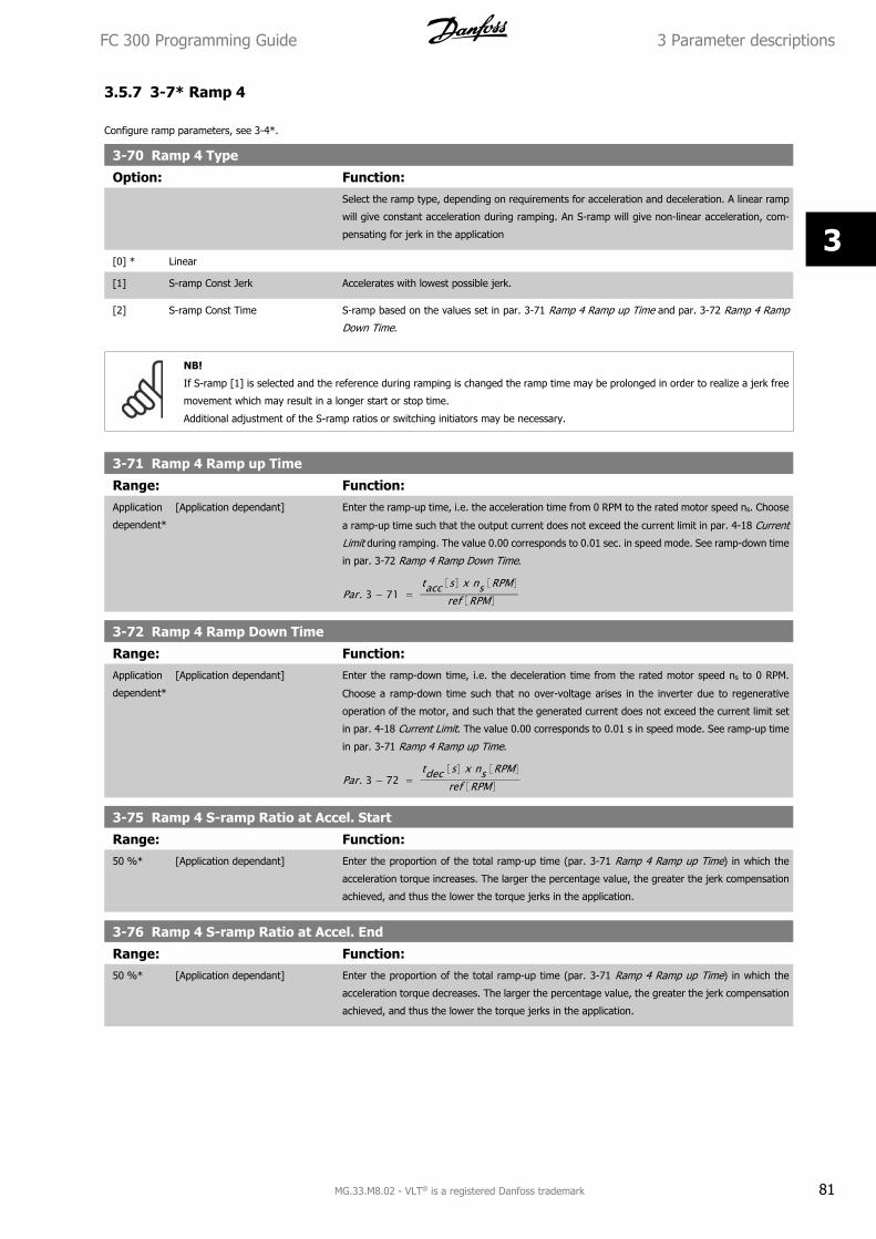
3.5.7 3-7* Ramp 4
Configure ramp parameters, see 3-4*.
3-70 Ramp 4 Type
Option: Function:Select the ramp type, depending on requirements for acceleration and deceleration. A linear ramp
will give constant acceleration during ramping. An S-ramp will give non-linear acceleration, com-
pensating for jerk in the application
[0] * Linear
[1] S-ramp Const Jerk Accelerates with lowest possible jerk.
[2] S-ramp Const Time S-ramp based on the values set in par. 3-71 Ramp 4 Ramp up Time and par. 3-72 Ramp 4 Ramp
Down Time.
NB!
If S-ramp [1] is selected and the reference during ramping is changed the ramp time may be prolonged in order to realize a jerk free
movement which may result in a longer start or stop time.
Additional adjustment of the S-ramp ratios or switching initiators may be necessary.
3-71 Ramp 4 Ramp up Time
Range: Function:Application
dependent*
[Application dependant] Enter the ramp-up time, i.e. the acceleration time from 0 RPM to the rated motor speed ns. Choose
a ramp-up time such that the output current does not exceed the current limit in par. 4-18 Current
Limit during ramping. The value 0.00 corresponds to 0.01 sec. in speed mode. See ramp-down time
in par. 3-72 Ramp 4 Ramp Down Time.
Par. 3 − 71 = tacc s x ns RPM
ref RPM
3-72 Ramp 4 Ramp Down Time
Range: Function:Application
dependent*
[Application dependant] Enter the ramp-down time, i.e. the deceleration time from the rated motor speed ns to 0 RPM.
Choose a ramp-down time such that no over-voltage arises in the inverter due to regenerative
operation of the motor, and such that the generated current does not exceed the current limit set
in par. 4-18 Current Limit. The value 0.00 corresponds to 0.01 s in speed mode. See ramp-up time
in par. 3-71 Ramp 4 Ramp up Time.
Par. 3 − 72 = tdec s x ns RPM
ref RPM
3-75 Ramp 4 S-ramp Ratio at Accel. Start
Range: Function:50 %* [Application dependant] Enter the proportion of the total ramp-up time (par. 3-71 Ramp 4 Ramp up Time) in which the
acceleration torque increases. The larger the percentage value, the greater the jerk compensation
achieved, and thus the lower the torque jerks in the application.
3-76 Ramp 4 S-ramp Ratio at Accel. End
Range: Function:50 %* [Application dependant] Enter the proportion of the total ramp-up time (par. 3-71 Ramp 4 Ramp up Time) in which the
acceleration torque decreases. The larger the percentage value, the greater the jerk compensation
achieved, and thus the lower the torque jerks in the application.
FC 300 Programming Guide 3 Parameter descriptions
MG.33.M8.02 - VLT® is a registered Danfoss trademark 81
3
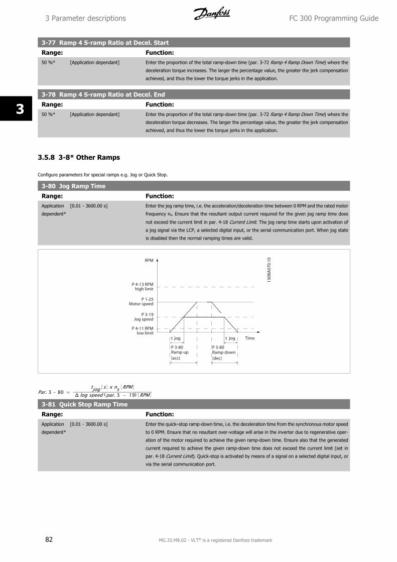
3-77 Ramp 4 S-ramp Ratio at Decel. Start
Range: Function:50 %* [Application dependant] Enter the proportion of the total ramp-down time (par. 3-72 Ramp 4 Ramp Down Time) where the
deceleration torque increases. The larger the percentage value, the greater the jerk compensation
achieved, and thus the lower the torque jerks in the application.
3-78 Ramp 4 S-ramp Ratio at Decel. End
Range: Function:50 %* [Application dependant] Enter the proportion of the total ramp-down time (par. 3-72 Ramp 4 Ramp Down Time) where the
deceleration torque decreases. The larger the percentage value, the greater the jerk compensation
achieved, and thus the lower the torque jerks in the application.
3.5.8 3-8* Other Ramps
Configure parameters for special ramps e.g. Jog or Quick Stop.
3-80 Jog Ramp Time
Range: Function:Application
dependent*
[0.01 - 3600.00 s] Enter the jog ramp time, i.e. the acceleration/deceleration time between 0 RPM and the rated motor
frequency ns. Ensure that the resultant output current required for the given jog ramp time does
not exceed the current limit in par. 4-18 Current Limit. The jog ramp time starts upon activation of
a jog signal via the LCP, a selected digital input, or the serial communication port. When jog state
is disabled then the normal ramping times are valid.
Par. 3 − 80 = tjog s x ns RPM
Δ log speed (par. 3 − 19) RPM
3-81 Quick Stop Ramp Time
Range: Function:Application
dependent*
[0.01 - 3600.00 s] Enter the quick–stop ramp-down time, i.e. the deceleration time from the synchronous motor speed
to 0 RPM. Ensure that no resultant over-voltage will arise in the inverter due to regenerative oper-
ation of the motor required to achieve the given ramp-down time. Ensure also that the generated
current required to achieve the given ramp-down time does not exceed the current limit (set in
par. 4-18 Current Limit). Quick-stop is activated by means of a signal on a selected digital input, or
via the serial communication port.
3 Parameter descriptions FC 300 Programming Guide
82 MG.33.M8.02 - VLT® is a registered Danfoss trademark
3
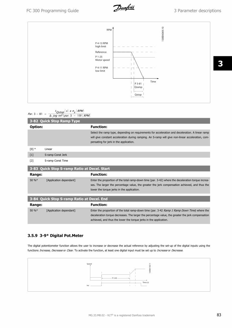
Par. 3 − 81 = tQstop s x ns RPM
Δ jog ref (par. 3 − 19) RPM
3-82 Quick Stop Ramp Type
Option: Function:Select the ramp type, depending on requirements for acceleration and deceleration. A linear ramp
will give constant acceleration during ramping. An S-ramp will give non-linear acceleration, com-
pensating for jerk in the application.
[0] * Linear
[1] S-ramp Const Jerk
[2] S-ramp Const Time
3-83 Quick Stop S-ramp Ratio at Decel. Start
Range: Function:50 %* [Application dependant] Enter the proportion of the total ramp-down time (par. 3-42) where the deceleration torque increa-
ses. The larger the percentage value, the greater the jerk compensation achieved, and thus the
lower the torque jerks in the application.
3-84 Quick Stop S-ramp Ratio at Decel. End
Range: Function:50 %* [Application dependant] Enter the proportion of the total ramp-down time (par. 3-42 Ramp 1 Ramp Down Time) where the
deceleration torque decreases. The larger the percentage value, the greater the jerk compensation
achieved, and thus the lower the torque jerks in the application.
3.5.9 3-9* Digital Pot.Meter
The digital potentiometer function allows the user to increase or decrease the actual reference by adjusting the set-up of the digital inputs using the
functions Increase, Decrease or Clear. To activate the function, at least one digital input must be set up to Increase or Decrease.
FC 300 Programming Guide 3 Parameter descriptions
MG.33.M8.02 - VLT® is a registered Danfoss trademark 83
3
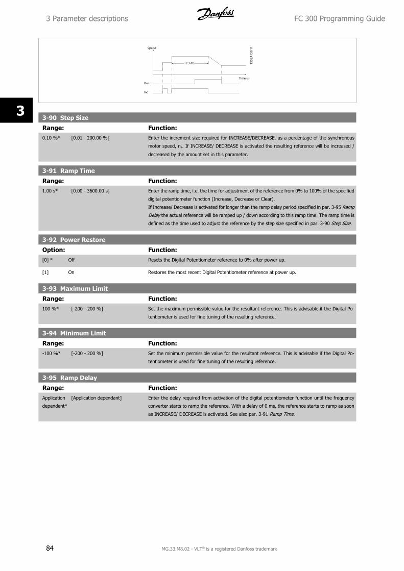
3-90 Step Size
Range: Function:0.10 %* [0.01 - 200.00 %] Enter the increment size required for INCREASE/DECREASE, as a percentage of the synchronous
motor speed, ns. If INCREASE/ DECREASE is activated the resulting reference will be increased /
decreased by the amount set in this parameter.
3-91 Ramp Time
Range: Function:1.00 s* [0.00 - 3600.00 s] Enter the ramp time, i.e. the time for adjustment of the reference from 0% to 100% of the specified
digital potentiometer function (Increase, Decrease or Clear).
If Increase/ Decrease is activated for longer than the ramp delay period specified in par. 3-95 Ramp
Delay the actual reference will be ramped up / down according to this ramp time. The ramp time is
defined as the time used to adjust the reference by the step size specified in par. 3-90 Step Size.
3-92 Power Restore
Option: Function:[0] * Off Resets the Digital Potentiometer reference to 0% after power up.
[1] On Restores the most recent Digital Potentiometer reference at power up.
3-93 Maximum Limit
Range: Function:100 %* [-200 - 200 %] Set the maximum permissible value for the resultant reference. This is advisable if the Digital Po-
tentiometer is used for fine tuning of the resulting reference.
3-94 Minimum Limit
Range: Function:-100 %* [-200 - 200 %] Set the minimum permissible value for the resultant reference. This is advisable if the Digital Po-
tentiometer is used for fine tuning of the resulting reference.
3-95 Ramp Delay
Range: Function:Application
dependent*
[Application dependant] Enter the delay required from activation of the digital potentiometer function until the frequency
converter starts to ramp the reference. With a delay of 0 ms, the reference starts to ramp as soon
as INCREASE/ DECREASE is activated. See also par. 3-91 Ramp Time.
3 Parameter descriptions FC 300 Programming Guide
84 MG.33.M8.02 - VLT® is a registered Danfoss trademark
3
3.6 Parameters: Limits/Warnings
3.6.1 4-** Limits and Warnings
Parameter group for configuring limits and warnings.
3.6.2 4-1* Motor Limits
Define torque, current and speed limits for the motor, and the reaction of the frequency converter when the limits are exceeded.
A limit may generate a message on the display. A warning will always generate a message on the display or on the fieldbus. A monitoring function may
initiate a warning or a trip, upon which the frequency converter will stop and generate an alarm message.
4-10 Motor Speed Direction
Option: Function:Select the motor speed direction(s) required. Use this parameter to prevent unwanted reversing.
When par. 1-00 Configuration Mode is set to Process [3], par. 4-10 Motor Speed Direction is set to
Clockwise [0] as default. The setting in par. 4-10 Motor Speed Direction does not limit options for
setting par. 4-13 Motor Speed High Limit [RPM].
This parameter cannot be adjusted while the motor is running.
[0] * Clockwise The reference is set to CW rotation. Reversing input (Default term 19) must be open.
[1] Counter clockwise The reference is set to CCW rotation. Reversing input (Default term 19) must be closed. If Reversing
is required with ‘Reverse’ input is open the motor direction can be changed by par. 1-06 Clockwise
Direction
[2] Both directions Allows the motor to rotate in both directions.
4-11 Motor Speed Low Limit [RPM]
Range: Function:Application
dependent*
[Application dependant] Enter the minimum limit for motor speed. The Motor Speed Low Limit can be set to correspond to
the manufacturer’s recommended minimum motor speed. The Motor Speed Low Limit must not
exceed the setting in par. 4-13 Motor Speed High Limit [RPM].
4-12 Motor Speed Low Limit [Hz]
Range: Function:Application
dependent*
[Application dependant] Enter the minimum limit for motor speed. The Motor Speed Low Limit can be set to correspond to
the minimum output frequency of the motor shaft. The Motor Speed Low Limit must not exceed the
setting in par. 4-14 Motor Speed High Limit [Hz].
Application
dependent*
[Application dependant] Enter the minimum limit for motor speed. The Motor Speed Low Limit can be set to correspond to
the minimum output frequency of the motor shaft. The Motor Speed Low Limit must not exceed the
setting in par. 4-14 Motor Speed High Limit [Hz].
4-13 Motor Speed High Limit [RPM]
Range: Function:Application
dependent*
[Application dependant] Enter the maximum limit for motor speed. The Motor Speed High Limit can be set to correspond to
the manufacturer’s maximum rated motor speed. The Motor Speed High Limit must exceed the
setting in par. 4-11 Motor Speed Low Limit [RPM].
NB!
Max. output frequency cannot exceed 10% of the inverter switching frequency (par. 14-01 Switching Frequency).
FC 300 Programming Guide 3 Parameter descriptions
MG.33.M8.02 - VLT® is a registered Danfoss trademark 85
3
4-14 Motor Speed High Limit [Hz]
Range: Function:Application
dependent*
[Application dependant] Enter the maximum limit for motor speed. The Motor Speed High Limit can be set to correspond to
the manufacturer’s recommended maximum of the motor shaft. The Motor Speed High Limit must
exceed the in par. 4-12 Motor Speed Low Limit [Hz]. Only par. 4-11 Motor Speed Low Limit
[RPM] or par. 4-12 Motor Speed Low Limit [Hz] will be displayed depending on other parameters in
the Main Menu and depending on default settings dependant on global location.
NB!
Max. output frequency cannot exceed 10% of the inverter switching frequency (par. 14-01 Switching Frequency).
4-16 Torque Limit Motor Mode
Range: Function:Application
dependent*
[Application dependant] This is a true torque limit function that can run into the oversynchronous range above nominal motor
speed.
Motor magnetisation drop is automatically compensated by a current increase.
Changing par. 4-16 Torque Limit Motor Mode when par. 1-00 Configuration Mode is set to Speed open loop [0], par. 1-66 Min. Current
at Low Speed is automatically readjusted.
NB!
The frequency converter is trigged on torque spikes, i.e. the torque limit is detected form internally in the drive and not from LCP or
fieldbus.
4-17 Torque Limit Generator Mode
Range: Function:100.0 %* [Application dependant] This is a true torque limit function that can run into the oversynchronous range above nominal motor
speed.
Motor magnetisation drop is automatically compensated by a current increase.
NB!
The frequency converter is trigged on torque spikes, i.e. the torque limit is detected form internally in the drive and not from LCP or
fieldbus.
4-18 Current Limit
Range: Function:Application
dependent*
[Application dependant] This is a true current limit function that continues in the oversynchronous range, however due to
field weakening the motor torque at current limit will drop accordingly when the voltage increase
stops above the synchronised speed of the motor.
4-19 Max Output Frequency
Range: Function:132.0 Hz* [1.0 - 1000.0 Hz] Provides a final limit on the output frequency for improved safety in applications where you want
to avoid accidental over-speeding. This limit is final in all configurations (independent of the setting
in par. 1-00 Configuration Mode).
3 Parameter descriptions FC 300 Programming Guide
86 MG.33.M8.02 - VLT® is a registered Danfoss trademark
3
NB!
Max. output frequency cannot exceed 10% of the inverter switching frequency (par. 14-01 Switching Frequency).
Par. 4-19 Max Output Frequency cannot be adjusted while the motor is running.
4-20 Torque Limit Factor Source
Option: Function:Select an analog input for scaling the settings in par. 4-16 Torque Limit Motor Mode and
par. 4-17 Torque Limit Generator Mode from 0% to 100% (or inverse). The signal levels corre-
sponding to 0% and 100% are defined in the analog input scaling, e.g. par. group 6-1*. This pa-
rameter is only active when par. 1-00 Configuration Mode is in Speed Open Loop or Speed Closed
Loop.
[0] * No function
[2] Analog in 53
[4] Analog in 53 inv
[6] Analog in 54
[8] Analog in 54 inv
[10] Analog in X30-11
[12] Analog in X30-11 inv
[14] Analog in X30-12
[16] Analog in X30-12 inv
4-21 Speed Limit Factor SourceOption
Option: Function:Select an analog input for scaling the settings in par. 4-19 from 0% to 100% (or vice versa). The
signal levels corresponding to 0% and 100% are defined in the analog input scaling, e.g. par. group
6-1*. This parameter is only active when par. 1-00 Configuration Mode is in Torque Mode.
[0] * No function
[2] Analog input 53
[4] Analog input 53 inv
[6] Analog input 54
[8] Analog input 54 inv
[10] Analog input X30-11
[12] Analog input X30-11 inv
[14] Analog input X30-12
[16] Analog input X30-12 inv
3.6.3 4-3* Motor Feedback Monitoring
The parameter group includes monitoring and handling of motor feedback devices as encoders, resolvers etc.
4-30 Motor Feedback Loss Function
Option: Function:Select which reaction the frequency converter should take if a feedback fault is detected Closed
Loop. The feedback fault is measured between the feedback (unfiltered) and the frequency that is
sent to the motor (16-13) - compensated for slip. The reaction will be activated if the measured
difference is more than specified in par. 4-31 Motor Feedback Speed Error for the time specified in
par. 4-32 Motor Feedback Loss Timeout.
[0] Disabled
FC 300 Programming Guide 3 Parameter descriptions
MG.33.M8.02 - VLT® is a registered Danfoss trademark 87
3
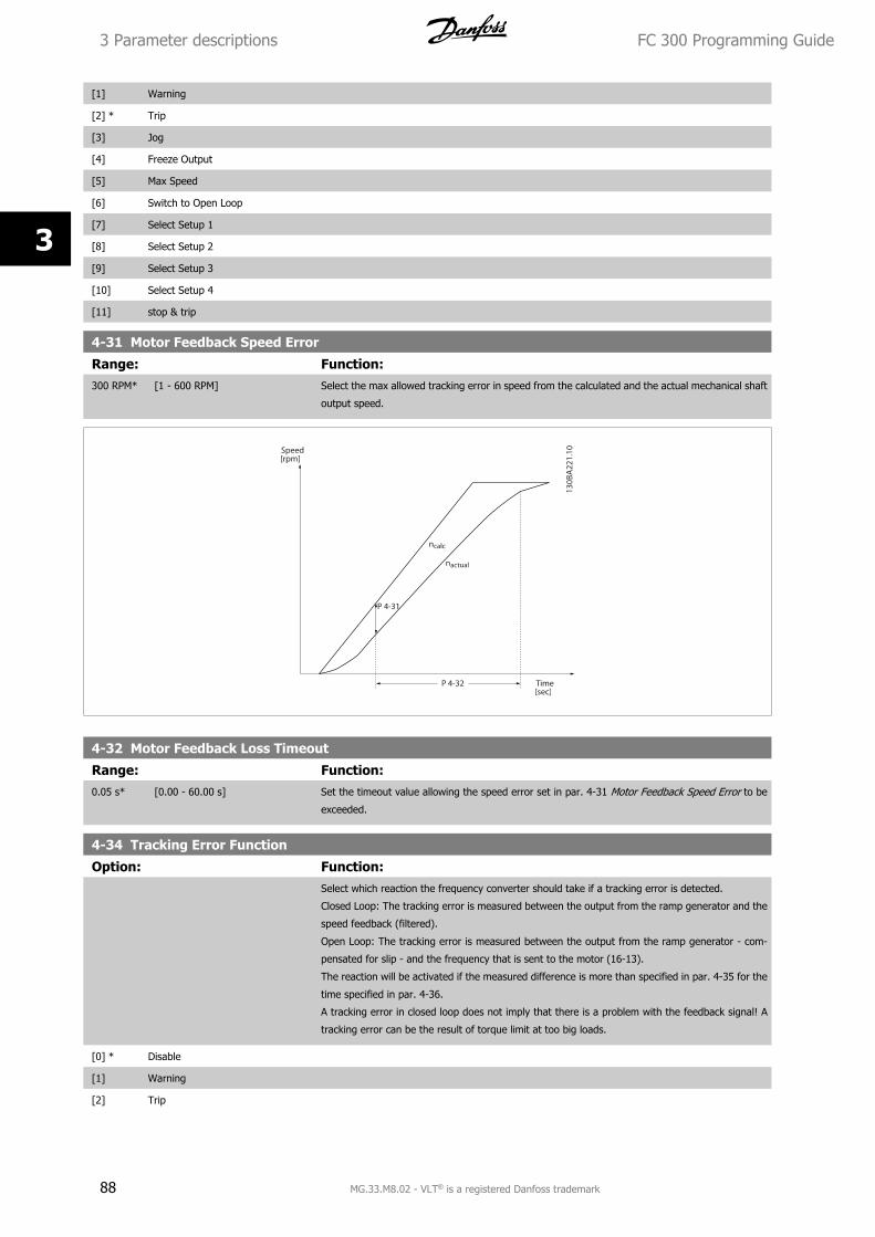
[1] Warning
[2] * Trip
[3] Jog
[4] Freeze Output
[5] Max Speed
[6] Switch to Open Loop
[7] Select Setup 1
[8] Select Setup 2
[9] Select Setup 3
[10] Select Setup 4
[11] stop & trip
4-31 Motor Feedback Speed Error
Range: Function:300 RPM* [1 - 600 RPM] Select the max allowed tracking error in speed from the calculated and the actual mechanical shaft
output speed.
4-32 Motor Feedback Loss Timeout
Range: Function:0.05 s* [0.00 - 60.00 s] Set the timeout value allowing the speed error set in par. 4-31 Motor Feedback Speed Error to be
exceeded.
4-34 Tracking Error Function
Option: Function:Select which reaction the frequency converter should take if a tracking error is detected.
Closed Loop: The tracking error is measured between the output from the ramp generator and the
speed feedback (filtered).
Open Loop: The tracking error is measured between the output from the ramp generator - com-
pensated for slip - and the frequency that is sent to the motor (16-13).
The reaction will be activated if the measured difference is more than specified in par. 4-35 for the
time specified in par. 4-36.
A tracking error in closed loop does not imply that there is a problem with the feedback signal! A
tracking error can be the result of torque limit at too big loads.
[0] * Disable
[1] Warning
[2] Trip
3 Parameter descriptions FC 300 Programming Guide
88 MG.33.M8.02 - VLT® is a registered Danfoss trademark
3
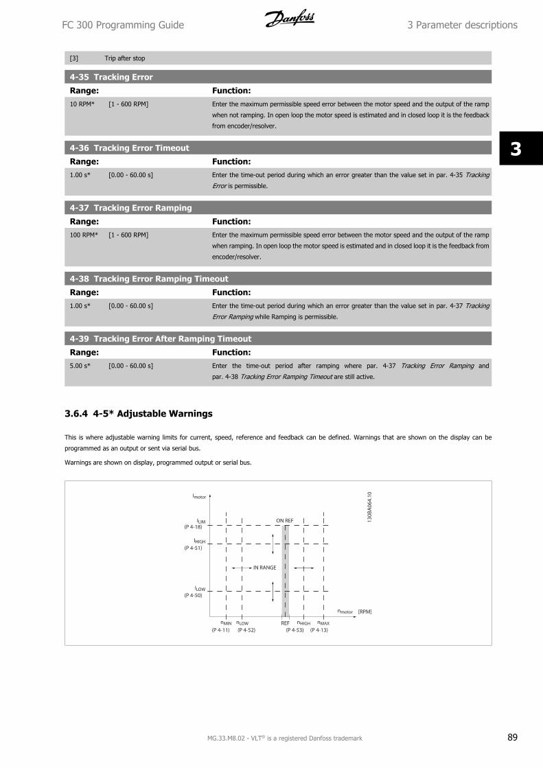
[3] Trip after stop
4-35 Tracking Error
Range: Function:10 RPM* [1 - 600 RPM] Enter the maximum permissible speed error between the motor speed and the output of the ramp
when not ramping. In open loop the motor speed is estimated and in closed loop it is the feedback
from encoder/resolver.
4-36 Tracking Error Timeout
Range: Function:1.00 s* [0.00 - 60.00 s] Enter the time-out period during which an error greater than the value set in par. 4-35 Tracking
Error is permissible.
4-37 Tracking Error Ramping
Range: Function:100 RPM* [1 - 600 RPM] Enter the maximum permissible speed error between the motor speed and the output of the ramp
when ramping. In open loop the motor speed is estimated and in closed loop it is the feedback from
encoder/resolver.
4-38 Tracking Error Ramping Timeout
Range: Function:1.00 s* [0.00 - 60.00 s] Enter the time-out period during which an error greater than the value set in par. 4-37 Tracking
Error Ramping while Ramping is permissible.
4-39 Tracking Error After Ramping Timeout
Range: Function:5.00 s* [0.00 - 60.00 s] Enter the time-out period after ramping where par. 4-37 Tracking Error Ramping and
par. 4-38 Tracking Error Ramping Timeout are still active.
3.6.4 4-5* Adjustable Warnings
This is where adjustable warning limits for current, speed, reference and feedback can be defined. Warnings that are shown on the display can be
programmed as an output or sent via serial bus.
Warnings are shown on display, programmed output or serial bus.
FC 300 Programming Guide 3 Parameter descriptions
MG.33.M8.02 - VLT® is a registered Danfoss trademark 89
3
4-50 Warning Current Low
Range: Function:0.00 A* [Application dependant] Enter the ILOW value. When the motor current falls below this limit, the display reads Current Low.
The signal outputs can be programmed to produce a status signal on terminal 27 or 29 (FC 302
only) and on relay output 01 or 02 (FC 302 only). Refer to the drawing in this section.
4-51 Warning Current High
Range: Function:Application
dependent*
[Application dependant] Enter the IHIGH value. When the motor current exceeds this limit, the display reads Current High.
The signal outputs can be programmed to produce a status signal on terminal 27 or 29 (FC 302
only) and on relay output 01 or 02 (FC 302 only). Refer to the drawing in this section.
4-52 Warning Speed Low
Range: Function:0 RPM* [Application dependant] Enter the nLOW value. When the motor speed exceeds this limit, the display reads Speed Low. The
signal outputs can be programmed to produce a status signal on terminal 27 or 29 (FC 302 only)
and on relay output 01 or 02 (FC 302 only).
4-53 Warning Speed High
Range: Function:Application
dependent*
[Application dependant] Enter the nHIGH value. When the motor speed exceeds this limit, the display reads Speed High. The
signal outputs can be programmed to produce a status signal on terminal 27 or 29 (FC 302 only)
and on relay output 01 or 02 (FC 302 only). Programme the upper signal limit of the motor speed,
nHIGH, within the normal working range of the frequency converter. Refer to the drawing in this
section.
4-54 Warning Reference Low
Range: Function:-999999.99
9*
[Application dependant] Enter the lower reference limit. When the actual reference falls below this limit, the display indicates
Ref Low. The signal outputs can be programmed to produce a status signal on terminal 27 or 29
(FC 302 only) and on relay output 01 or 02 (FC 302 only).
4-55 Warning Reference High
Range: Function:999999.999
*
[Application dependant] Enter the upper reference limit. When the actual reference exceeds this limit, the display reads Ref
High. The signal outputs can be programmed to produce a status signal on terminal 27 or 29 (FC
302 only) and on relay output 01 or 02 (FC 302 only).
4-56 Warning Feedback Low
Range: Function:-999999.99
9 Referen-
ceFeedback-
Unit*
[Application dependant] Enter the lower feedback limit. When the feedback falls below this limit, the display reads Feedb
Low. The signal outputs can be programmed to produce a status signal on terminal 27 or 29 (FC
302 only) and on relay output 01 or 02 (FC 302 only).
4-57 Warning Feedback High
Range: Function:999999.999
Reference-
FeedbackU-
nit*
[Application dependant] Enter the upper feedback limit. When the feedback exceeds this limit, the display reads Feedb High.
The signal outputs can be programmed to produce a status signal on terminal 27 or 29 (FC 302
only) and on relay output 01 or 02 (FC 302 only).
3 Parameter descriptions FC 300 Programming Guide
90 MG.33.M8.02 - VLT® is a registered Danfoss trademark
3
4-58 Missing Motor Phase FunctionDisplays an alarm in the event of a missing motor phase (alarm 30, 31 or 32). Select disabled for no missing motor phase alarm. It is strongly
recommended to make an active setting to avoid motor damage.
Option: Function:[0] Disabled No alarm is displayed if a missing motor phase occurs.
[1] Trip 100 ms Trips after 100ms. Select 100 ms for fast detection of missing motor phase.
[2] Trip 1000 ms Trips after 1000 ms. Select 1000 ms for slow detection of missing motor phase.
[3] Trip 100 ms lim 3 phase detec.
NB!
This parameter cannot be adjusted while the motor is running.
3.6.5 4-6* Speed Bypass
Define the Speed Bypass areas for the ramps.
Some systems call for avoiding certain output frequencies or speeds, due to resonance problems in the system. A maximum of four frequency or speed
ranges can be avoided.
4-60 Bypass Speed From [RPM]Array [4]
Range: Function:Application
dependent*
[Application dependant] Some systems call for avoiding certain output speeds due to resonance problems in the system.
Enter the lower limits of the speeds to be avoided.
4-61 Bypass Speed From [Hz]Array [4]
Range: Function:Application
dependent*
[Application dependant] Some systems call for avoiding certain output speeds due to resonance problems in the system.
Enter the lower limits of the speeds to be avoided.
4-62 Bypass Speed To [RPM]Array [4]
Range: Function:Application
dependent*
[Application dependant] Some systems call for avoiding certain output speeds due to resonance problems in the system.
Enter the upper limits of the speeds to be avoided.
4-63 Bypass Speed To [Hz]Array [4]
Range: Function:Application
dependent*
[Application dependant] Some systems call for avoiding certain output speeds due to resonance problems in the system.
Enter the upper limits of the speeds to be avoided.
FC 300 Programming Guide 3 Parameter descriptions
MG.33.M8.02 - VLT® is a registered Danfoss trademark 91
3
3.7 Parameters: Digital In/Out
3.7.1 5-** Digital In/Out
Parameter group for configuring the digital input and output.
3.7.2 5-0* Digital I/O Mode
Parameters for configuring the input and output using NPN and PNP.
5-00 Digital I/O Mode
Option: Function:Digital inputs and programmed digital outputs are pre-programmable for operation either in PNP or
NPN systems.
[0] * PNP Action on positive directional pulses (). PNP systems are pulled down to GND.
[1] NPN Action on negative directional pulses (). NPN systems are pulled up to + 24 V, internally in the
frequency converter.
NB!
Once this parameter has been changed, it must be activated by performing a power cycle.
This parameter cannot be adjusted while the motor is running.
5-01 Terminal 27 Mode
Option: Function:[0] * Input Defines terminal 27 as a digital input.
[1] Output Defines terminal 27 as a digital output.
Please note that this parameter cannot be adjusted while the motor is running.
5-02 Terminal 29 Mode
Option: Function:[0] * Input Defines terminal 29 as a digital input.
[1] Output Defines terminal 29 as a digital output.
This parameter is available for FC 302 only.
This parameter cannot be adjusted while the motor is running.
3 Parameter descriptions FC 300 Programming Guide
92 MG.33.M8.02 - VLT® is a registered Danfoss trademark
3
3.7.3 5-1* Digital Inputs
Parameters for configuring the input functions for the input terminals.
The digital inputs are used for selecting various functions in the frequency converter. All digital inputs can be set to the following functions:
Digital input function Select TerminalNo operation [0] All *term 32, 33Reset [1] AllCoast inverse [2] All *term 27Coast and reset inverse [3] AllQuick stop inverse [4] AllDC-brake inverse [5] AllStop inverse [6] AllStart [8] All *term 18Latched start [9] AllReversing [10] All *term 19Start reversing [11] AllEnable start forward [12] AllEnable start reverse [13] AllJog [14] All *term 29Preset reference on [15] AllPreset ref bit 0 [16] AllPreset ref bit 1 [17] AllPreset ref bit 2 [18] AllFreeze reference [19] AllFreeze output [20] AllSpeed up [21] AllSpeed down [22] AllSet-up select bit 0 [23] AllSet-up select bit 1 [24] AllPrecise stop inverse [26] 18, 19Precises start, stop [27] 18, 19Catch up [28] AllSlow down [29] AllCounter input [30] 29, 33Pulse input Edge Trigged [31] 29, 33Pulse input Time Based [32] 29, 33Ramp bit 0 [34] AllRamp bit 1 [35] AllMains failure inverse [36] AllLatched precise start [40] 18, 19Latched precise stop inverse [41] 18, 19DigiPot Increase [55] AllDigiPot Decrease [56] AllDigiPot Clear [57] AllDigipot Hoist [58] AllCounter A (up) [60] 29, 33Counter A (down) [61] 29, 33Reset Counter A [62] AllCounter B (up) [63] 29, 33Counter B (down) [64] 29, 33Reset Counter B [65] AllMech. Brake Feedb. [70] AllMech. Brake Feedb. Inv. [71] AllPID Error Inv. [72] AllPID Reset I-part [73] AllPID enable [74] AllPTC Card 1 [80] All
FC 300 standard terminals are 18, 19, 27, 29, 32 and 33. MCB 101 terminals are X30/2, X30/3 and X30/4.
Terminal 29 functions as an output only in FC 302.
Functions dedicated to only one digital input are stated in the associated parameter.
All digital inputs can be programmed to these functions:
[0] No operation No reaction to signals transmitted to the terminal.
[1] Reset Resets frequency converter after a TRIP/ALARM. Not all alarms can be reset.
[2] Coast inverse (Default Digital input 27): Coasting stop, inverted input (NC). The frequency converter leaves the
motor in free mode. Logic ‘0’ => coasting stop.
[3] Coast and reset inverse Reset and coasting stop Inverted input (NC). Leaves motor in free mode and resets frequency con-
verter. Logic ‘0’ => coasting stop and reset.
FC 300 Programming Guide 3 Parameter descriptions
MG.33.M8.02 - VLT® is a registered Danfoss trademark 93
3
[4] Quick stop inverse Inverted input (NC). Generates a stop in accordance with quick-stop ramp time set in par. 3-81 Quick
Stop Ramp Time. When motor stops, the shaft is in free mode. Logic ‘0’ => Quick-stop.
[5] DC-brake inverse Inverted input for DC braking (NC). Stops motor by energizing it with a DC current for a certain time
period. See par. 2-01 DC Brake Current to par. 2-03 DC Brake Cut In Speed [RPM]. The function is
only active when the value in par. 2-02 DC Braking Time is different from 0. Logic ’0’ => DC braking.
[6] Stop inverse Stop Inverted function. Generates a stop function when the selected terminal goes from logical level
‘1’ to ‘0’. The stop is performed according to the selected ramp time (par. 3-42 Ramp 1 Ramp Down
Time, par. 3-52 Ramp 2 Ramp down Time, par. 3-62 Ramp 3 Ramp down Time, par. 3-72 Ramp 4
Ramp Down Time).
NB!
When the frequency converter is at the torque limit and has received a stop
command, it may not stop by itself. To ensure that the frequency converter stops,
configure a digital output to Torque limit & stop [27] and connect this digital
output to a digital input that is configured as coast.
[8] Start (Default Digital input 18): Select start for a start/stop command. Logic ‘1’ = start, logic ‘0’ = stop.
[9] Latched start The motor starts, if a pulse is applied for min. 2 ms. The motor stops when Stop inverse is activated.
[10] Reversing (Default Digital input 19). Change the direction of motor shaft rotation. Select Logic ‘1’ to reverse.
The reversing signal only changes the direction of rotation. It does not activate the start function.
Select both directions in par. 4-10 Motor Speed Direction. The function is not active in process closed
loop.
[11] Start reversing Used for start/stop and for reversing on the same wire. Signals on start are not allowed at the same
time.
[12] Enable start forward Disengages the counterclockwise movement and allows for the clockwise direction.
[13] Enable start reverse Disengages the clockwise movement and allows for the counterclockwise direction.
[14] Jog (Default Digital input 29): Use to activate jog speed. See par. 3-11 Jog Speed [Hz].
[15] Preset reference on Shifts between external reference and preset reference. It is assumed that External/preset [1] has
been selected in par. 3-04 Reference Function. Logic '0' = external reference active; logic '1' = one
of the eight preset references is active.
[16] Preset ref bit 0 Preset ref. bit 0,1, and 2 enables a choice between one of the eight preset references according to
the table below.
[17] Preset ref bit 1 Same as Preset ref bit 0 [16].
[18] Preset ref bit 2 Same as Preset ref bit 0 [16].
Preset ref. bit 2 1 0
Preset ref. 0 0 0 0
Preset ref. 1 0 0 1
Preset ref. 2 0 1 0
Preset ref. 3 0 1 1
Preset ref. 4 1 0 0
Preset ref. 5 1 0 1
Preset ref. 6 1 1 0
Preset ref. 7 1 1 1
[19] Freeze ref Freezes the actual reference, which is now the point of enable/condition for Speed up and Speed
down to be used. If Speed up/down is used, the speed change always follows ramp 2
(par. 3-51 Ramp 2 Ramp up Time and par. 3-52 Ramp 2 Ramp down Time) in the range 0 -
par. 3-03 Maximum Reference.
[20] Freeze output Freezes the actual motor frequency (Hz), which is now the point of enable/condition for Speed up
and Speed down to be used. If Speed up/down is used, the speed change always follows ramp 2
(par. 3-51 Ramp 2 Ramp up Time and par. 3-52 Ramp 2 Ramp down Time) in the range 0 -
par. 1-23 Motor Frequency.
3 Parameter descriptions FC 300 Programming Guide
94 MG.33.M8.02 - VLT® is a registered Danfoss trademark
3
NB!
When Freeze output is active, the frequency converter cannot be stopped via a
low ‘start [8]’ signal. Stop the frequency converter via a terminal programmed
for Coasting inverse [2] or Coast and reset, inverse.
[21] Speed up Select Speed up and Speed down if digital control of the up/down speed is desired (motor poten-
tiometer). Activate this function by selecting either Freeze reference or Freeze output. When Speed
up/ down is activated for less than 400 msec. the resulting reference will be increased/ decreased
by 0.1 %. If Speed up/ down is activated for more than 400 msec. the resulting reference will follow
the setting in ramping up/ down parameter 3-x1/ 3-x2.
Shut down Catch up
Unchanged speed 0 0
Reduced by %-value 1 0
Increased by %-value 0 1
Reduced by %-value 1 1
[22] Speed down Same as Speed up [21].
[23] Set-up select bit 0 Select Set-up select bit 0 or Select Set-up select bit 1 to select one of the four set-ups. Set
par. 0-10 Active Set-up to Multi Set-up.
[24] Set-up select bit 1 (Default Digital input 32): Same as Set-up select bit 0 [23].
[26] Precise stop inv. Prolongs stop signal to give a precise stop independent of speed.
Sends an inverted stop signal when the precise stop function is activated in par. 1-83 Precise Stop
Function.
Precise stop inverse function is available for terminals 18 or 19.
[27] Precise start, stop Use when Precise ramp stop [0] is selected in par 1-83.
[28] Catch up Increases reference value by percentage (relative) set in par. 3-12 Catch up/slow Down Value.
[29] Slow down Reduces reference value by percentage (relative) set in par. 3-12 Catch up/slow Down Value.
[30] Counter input Precise stop function in par. 1-83 Precise Stop Function acts as Counter stop or speed compensated
counter stop with or without reset. The counter value must be set in par. 1-84 Precise Stop Counter
Value.
[31] Pulse edge triggered Edge triggered pulse input counts number of pulse flanks per sample time. This gives a higher
resolution at high frequencies, but is not as precise at lower frequencies. Use this pulse principle
for encoders with very low resolution (e.g. 30 ppr).
[32] Pulse time based Time based pulse input measures the duration between flanks. This gives a higher resolution at
lower frequencies, but is not as precise at higher frequencies. This principle has a cut-off frequency
which makes it unsuited for encoders with very low resolutions (e.g. 30 ppr) at low speeds.
FC 300 Programming Guide 3 Parameter descriptions
MG.33.M8.02 - VLT® is a registered Danfoss trademark 95
3
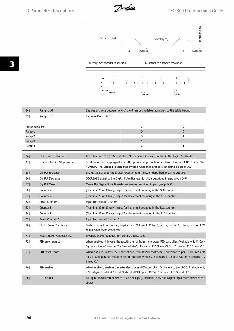
S p e e d [ r p m ] S p e e d [ r p m ]
T ime[sec] T ime[sec] a b
130B
B462
.10
a: very low encoder resolution b: standard encoder resolution
[34] Ramp bit 0 Enables a choice between one of the 4 ramps available, according to the table below.
[35] Ramp bit 1 Same as Ramp bit 0.
Preset ramp bit 1 0
Ramp 1 0 0
Ramp 2 0 1
Ramp 3 1 0
Ramp 4 1 1
[36] Mains failure inverse Activates par. 14-10 Mains Failure. Mains failure inverse is active in the Logic .0. situation.
[41] Latched Precise Stop inverse Sends a latched stop signal when the precise stop function is activated in par. 1-83 Precise Stop
Function. The Latched Precise stop inverse function is available for terminals 18 or 19.
[55] DigiPot Increase INCREASE signal to the Digital Potentiometer function described in par. group 3-9*
[56] DigiPot Decrease DECREASE signal to the Digital Potentiometer function described in par. group 3-9*
[57] DigiPot Clear Clears the Digital Potentiometer reference described in par. group 3-9*
[60] Counter A (Terminal 29 or 33 only) Input for increment counting in the SLC counter.
[61] Counter A (Terminal 29 or 33 only) Input for decrement counting in the SLC counter.
[62] Reset Counter A Input for reset of counter A.
[63] Counter B (Terminal 29 or 33 only) Input for increment counting in the SLC counter.
[64] Counter B (Terminal 29 or 33 only) Input for decrement counting in the SLC counter.
[65] Reset Counter B Input for reset of counter B.
[70] Mech. Brake Feedback Brake feedback for hoisting applications: Set par 1-01 to [3] flux w/ motor feedback; set par 1-72
to [6] Hoist mech brake Ref.
[71] Mech. Brake Feedback inv. Inverted brake feedback for hoisting applications
[72] PID error inverse When enabled, it inverts the resulting error from the process PID controller. Available only if "Con-
figuration Mode" is set to "Surface Winder", "Extended PID Speed OL" or "Extended PID Speed CL".
[73] PID reset I-part When enabled, resets the I-part of the Process PID controller. Equivalent to par. 7-40. Available
only if "Configuration Mode" is set to "Surface Winder", "Extended PID Speed OL" or "Extended PID
Speed CL".
[74] PID enable When enabled, enables the extended process PID controller. Equivalent to par. 7-50. Available only
if "Configuration Mode" is set "Extended PID Speed OL" or "Extended PID Speed CL".
[80] PTC Card 1 All Digital Inputs can be set to PTC Card 1 [80]. However, only one Digital Input must be set to this
choice.
3 Parameter descriptions FC 300 Programming Guide
96 MG.33.M8.02 - VLT® is a registered Danfoss trademark
3
5-10 Terminal 18 Digital Input
Option: Function:[8] * Start Functions are described under 5-1* Digital Inputs
5-11 Terminal 19 Digital Input
Option: Function:[10] * Reversing Functions are described under 5-1* Digital Inputs
5-12 Terminal 27 Digital Input
Option: Function:[2] * Coast inverse Functions are described under 5-1* Digital Inputs
5-13 Terminal 29 Digital Input
Option: Function:Select the function from the available digital input range and the additional options [60], [61], [63]
and [64]. Counters are used in Smart Logic Control functions.This parameter is available for FC 302
only.
[14] * Jog Functions are described under 5-1* Digital Inputs
5-14 Terminal 32 Digital Input
Option: Function:Select the function from the available digital input range and the additional options [60], [61], [63]
and [64]. Counters are used in Smart Logic Control functions.
[0] * No operation Functions are described under 5-1* Digital Inputs
5-15 Terminal 33 Digital Input
Option: Function:Select the function from the available digital input range and the additional options [60], [61], [63]
and [64]. Counters are used in Smart Logic Control functions.
[0] * No operation Functions are described under 5-1* Digital Inputs
5-16 Terminal X30/2 Digital Input
Option: Function:[0] * No operation This parameter is active when option module MCB101 is installed in the frequency converter. Func-
tions are described under 5-1* Digital Inputs
5-17 Terminal X30/3 Digital Input
Option: Function:[0] * No operation This parameter is active when option module MCB101 is installed in the frequency converter. Func-
tions are described under 5-1* Digital Inputs
5-18 Terminal X30/4 Digital Input
Option: Function:[0] * No operation This parameter is active when option module MCB101 is installed in the frequency converter. Func-
tions are described under 5-1* Digital Inputs
FC 300 Programming Guide 3 Parameter descriptions
MG.33.M8.02 - VLT® is a registered Danfoss trademark 97
3
5-19 Terminal 37 Safe Stop
Option: Function:[1] * Safe Stop Alarm Coasts frequency converter when safe stop is activated. Manual reset from LCP, digital input or
fieldbus.
[3] Safe Stop Warning Coasts frequency converter when safe stop is activated (T-37 off). When safe stop circuit is rees-
tablished, the frequency converter will continue without manual reset.
[4] PTC 1 Alarm Coasts frequency converter when safe stop is activated. Manual reset from LCP, digital input or
fieldbus. Choice 4 is only available when the MCB 112 PTC Thermistor Card is connected.
[5] PTC 1 Warning Coasts frequency converter when safe stop is activated (T-37 off). When safe stop circuit is rees-
tablished, the frequency converter will continue without manual reset, unless a Digital Input set to
PTC Card 1 [80] is still enabled. Choice 5 is only available when the MCB 112 PTC Thermistor Card
is connected.
[6] PTC 1 & Relay A This choice is used when the PTC option is gated together with a Stop button through a Safety relay
to T-37. Coasts frequency converter when safe stop is activated. Manual reset from LCP, digital
input or fieldbus. Choice 6 is only available when the MCB 112 PTC Thermistor Card is connected.
[7] PTC 1 & Relay W This choice is used when the PTC option is gated together with a Stop button through a Safety relay
to T-37. Coasts frequency converter when safe stop is activated (T-37 off). When safe stop circuit
is reestablished, the frequency converter will continue without manual reset, unless a Digital Input
set to PTC Card 1 [80] is (still) enabled. Choice 7 is only available when the MCB 112 PTC Thermistor
Card is connected.
[8] PTC 1 & Relay A/W This choice makes it possible to use a combination of Alarm and Warning. Choice 8 is only available
when the MCB 112 PTC Thermistor Card is connected.
[9] PTC 1 & Relay W/A This choice makes it possible to use a combination of Alarm and Warning. Choice 9 is only available
when the MCB 112 PTC Thermistor Card is connected.
Choises 4 - 9 are only available when the MCB 112 PTC Thermistor Card is connected.
NB!
When Auto Reset/ Warning is selected the frequency converter opens up for automatic restart.
Overview of functions, alarms and warnings
Function No. PTC RelayNo Function [0] - -Safe Stop Alarm [1]* - Safe Stop [A68]Safe Stop Warning [3] - Safe Stop [W68]PTC 1 Alarm [4] PTC 1 Safe Stop [A71] -PTC 1 Warning [5] PTC 1 Safe Stop [W71] -PTC 1 & Relay A [6] PTC 1 Safe Stop [A71] Safe Stop [A68]PTC 1 & Relay W [7] PTC 1 Safe Stop [W71] Safe Stop [W68]PTC 1 & Relay A/W [8] PTC 1 Safe Stop [A71] Safe Stop [W68]PTC 1 & Relay W/A [9] PTC 1 Safe Stop [W71] Safe Stop [A68]
W means warning and A means alarm. For further information, see Alarms and Warnings in section Troubleshooting in the Design Guide or the Operating
Instructions
A dangerous failure related to Safe Stop will give Alarm: Dangerous Failure [A72].
Please refer to the section Description of Alarm Word, Warning Word and extended Status Word in the chapter Troubleshooting.
5-20 Terminal X46/1 Digital Input
Option: Function:[0] * No operation This parameter is active when option module MCB 113 is installed in the frequency converter. Func-
tions are described under 5-1* Digital Inputs
3 Parameter descriptions FC 300 Programming Guide
98 MG.33.M8.02 - VLT® is a registered Danfoss trademark
3
5-21 Terminal X46/3 Digital Input
Option: Function:[0] * No operation This parameter is active when option moduleMCB 113 is installed in the frequency converter. Func-
tions are described under 5-1* Digital Inputs
5-22 Terminal X46/5 Digital Input
Option: Function:[0] * No operation This parameter is active when option moduleMCB 113 is installed in the frequency converter. Func-
tions are described under 5-1* Digital Inputs
5-23 Terminal X46/7 Digital Input
Option: Function:[0] * No operation This parameter is active when option moduleMCB 113 is installed in the frequency converter. Func-
tions are described under 5-1* Digital Inputs
5-24 Terminal X46/9 Digital Input
Option: Function:[0] * No operation This parameter is active when option module MCB 113 is installed in the frequency converter. Func-
tions are described under 5-1* Digital Inputs
5-25 Terminal X46/11 Digital Input
Option: Function:[0] * No operation This parameter is active when option moduleMCB 113 is installed in the frequency converter. Func-
tions are described under 5-1* Digital Inputs
5-26 Terminal X46/13 Digital Input
Option: Function:[0] * No operation This parameter is active when option module MCB 113 is installed in the frequency converter. Func-
tions are described under 5-1* Digital Inputs
3.7.4 5-3* Digital Outputs
Parameters for configuring the output functions for the output terminals. The 2 solid-state digital outputs are common for terminals 27 and 29. Set the
I/O function for terminal 27 in par. 5-01 Terminal 27 Mode, and set the I/O function for terminal 29 in par. 5-02 Terminal 29 Mode. These parameters
cannot be adjusted while the motor is running.
[0] No operation Default for all digital outputs and relay outputs
[1] Control ready The control card is ready. E.g.: Feedback from a drive where the control is supplied by an external
24 V (MCB107) and the main power to drive is not detected.
[2] Drive ready The frequency converter is ready for operation and applies a supply signal on the control board.
[3] Drive ready / remote control The frequency converter is ready for operation and is in Auto On mode.
[4] Enable / no warning Ready for operation. No start or stop command is been given (start/disable). No warnings are active.
[5] VLT running Motor is running and shaft torque present.
[6] Running / no warning Output speed is higher than the speed set in par. 1-81 Min Speed for Function at Stop [RPM]. The
motor is running and there are no warnings.
[7] Run in range / no warning Motor is running within the programmed current and speed ranges set in par. 4-50 Warning Current
Low to par. 4-53 Warning Speed High. There are no warnings.
[8] Run on reference / no warning Motor runs at reference speed. No warnings.
[9] Alarm An alarm activates the output. There are no warnings.
[10] Alarm or warning An alarm or a warning activates the output.
[11] At torque limit The torque limit set in par. 4-16 Torque Limit Motor Mode or par. 4-17 has been exceeded.
[12] Out of current range The motor current is outside the range set in par. 4-18 Current Limit.
FC 300 Programming Guide 3 Parameter descriptions
MG.33.M8.02 - VLT® is a registered Danfoss trademark 99
3
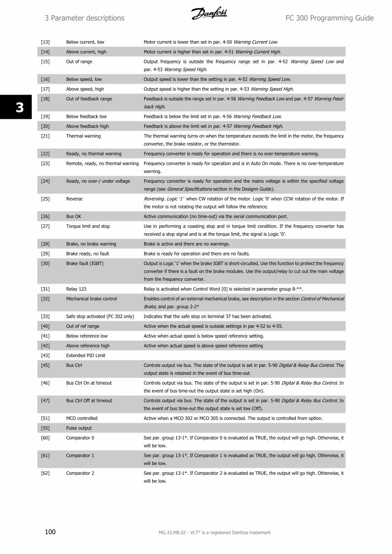
[13] Below current, low Motor current is lower than set in par. 4-50 Warning Current Low.
[14] Above current, high Motor current is higher than set in par. 4-51 Warning Current High.
[15] Out of range Output frequency is outside the frequency range set in par. 4-52 Warning Speed Low and
par. 4-53 Warning Speed High.
[16] Below speed, low Output speed is lower than the setting in par. 4-52 Warning Speed Low.
[17] Above speed, high Output speed is higher than the setting in par. 4-53 Warning Speed High.
[18] Out of feedback range Feedback is outside the range set in par. 4-56 Warning Feedback Low and par. 4-57 Warning Feed-
back High.
[19] Below feedback low Feedback is below the limit set in par. 4-56 Warning Feedback Low.
[20] Above feedback high Feedback is above the limit set in par. 4-57 Warning Feedback High.
[21] Thermal warning The thermal warning turns on when the temperature exceeds the limit in the motor, the frequency
converter, the brake resistor, or the thermistor.
[22] Ready, no thermal warning Frequency converter is ready for operation and there is no over-temperature warning.
[23] Remote, ready, no thermal warning Frequency converter is ready for operation and is in Auto On mode. There is no over-temperature
warning.
[24] Ready, no over-/ under voltage Frequency converter is ready for operation and the mains voltage is within the specified voltage
range (see General Specifications section in the Designn Guide).
[25] Reverse Reversing. Logic ‘1’ when CW rotation of the motor. Logic ‘0’ when CCW rotation of the motor. If
the motor is not rotating the output will follow the reference.
[26] Bus OK Active communication (no time-out) via the serial communication port.
[27] Torque limit and stop Use in performing a coasting stop and in torque limit condition. If the frequency converter has
received a stop signal and is at the torque limit, the signal is Logic ‘0’.
[28] Brake, no brake warning Brake is active and there are no warnings.
[29] Brake ready, no fault Brake is ready for operation and there are no faults.
[30] Brake fault (IGBT) Output is Logic ‘1’ when the brake IGBT is short-circuited. Use this function to protect the frequency
converter if there is a fault on the brake modules. Use the output/relay to cut out the main voltage
from the frequency converter.
[31] Relay 123 Relay is activated when Control Word [0] is selected in parameter group 8-**.
[32] Mechanical brake control Enables control of an external mechanical brake, see description in the section Control of Mechanical
Brake, and par. group 2-2*
[33] Safe stop activated (FC 302 only) Indicates that the safe stop on terminal 37 has been activated.
[40] Out of ref range Active when the actual speed is outside settings in par 4-52 to 4-55.
[41] Below reference low Active when actual speed is below speed reference setting.
[42] Above reference high Active when actual speed is above speed reference setting
[43] Extended PID Limit
[45] Bus Ctrl Controls output via bus. The state of the output is set in par. 5-90 Digital & Relay Bus Control. The
output state is retained in the event of bus time-out.
[46] Bus Ctrl On at timeout Controls output via bus. The state of the output is set in par. 5-90 Digital & Relay Bus Control. In
the event of bus time-out the output state is set high (On).
[47] Bus Ctrl Off at timeout Controls output via bus. The state of the output is set in par. 5-90 Digital & Relay Bus Control. In
the event of bus time-out the output state is set low (Off).
[51] MCO controlled Active when a MCO 302 or MCO 305 is connected. The output is controlled from option.
[55] Pulse output
[60] Comparator 0 See par. group 13-1*. If Comparator 0 is evaluated as TRUE, the output will go high. Otherwise, it
will be low.
[61] Comparator 1 See par. group 13-1*. If Comparator 1 is evaluated as TRUE, the output will go high. Otherwise, it
will be low.
[62] Comparator 2 See par. group 13-1*. If Comparator 2 is evaluated as TRUE, the output will go high. Otherwise, it
will be low.
3 Parameter descriptions FC 300 Programming Guide
100 MG.33.M8.02 - VLT® is a registered Danfoss trademark
3
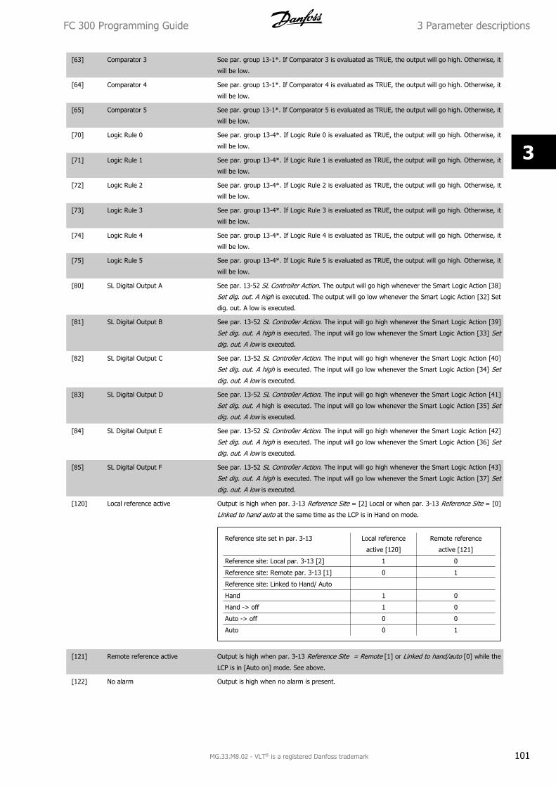
[63] Comparator 3 See par. group 13-1*. If Comparator 3 is evaluated as TRUE, the output will go high. Otherwise, it
will be low.
[64] Comparator 4 See par. group 13-1*. If Comparator 4 is evaluated as TRUE, the output will go high. Otherwise, it
will be low.
[65] Comparator 5 See par. group 13-1*. If Comparator 5 is evaluated as TRUE, the output will go high. Otherwise, it
will be low.
[70] Logic Rule 0 See par. group 13-4*. If Logic Rule 0 is evaluated as TRUE, the output will go high. Otherwise, it
will be low.
[71] Logic Rule 1 See par. group 13-4*. If Logic Rule 1 is evaluated as TRUE, the output will go high. Otherwise, it
will be low.
[72] Logic Rule 2 See par. group 13-4*. If Logic Rule 2 is evaluated as TRUE, the output will go high. Otherwise, it
will be low.
[73] Logic Rule 3 See par. group 13-4*. If Logic Rule 3 is evaluated as TRUE, the output will go high. Otherwise, it
will be low.
[74] Logic Rule 4 See par. group 13-4*. If Logic Rule 4 is evaluated as TRUE, the output will go high. Otherwise, it
will be low.
[75] Logic Rule 5 See par. group 13-4*. If Logic Rule 5 is evaluated as TRUE, the output will go high. Otherwise, it
will be low.
[80] SL Digital Output A See par. 13-52 SL Controller Action. The output will go high whenever the Smart Logic Action [38]
Set dig. out. A high is executed. The output will go low whenever the Smart Logic Action [32] Set
dig. out. A low is executed.
[81] SL Digital Output B See par. 13-52 SL Controller Action. The input will go high whenever the Smart Logic Action [39]
Set dig. out. A high is executed. The input will go low whenever the Smart Logic Action [33] Set
dig. out. A low is executed.
[82] SL Digital Output C See par. 13-52 SL Controller Action. The input will go high whenever the Smart Logic Action [40]
Set dig. out. A high is executed. The input will go low whenever the Smart Logic Action [34] Set
dig. out. A low is executed.
[83] SL Digital Output D See par. 13-52 SL Controller Action. The input will go high whenever the Smart Logic Action [41]
Set dig. out. A high is executed. The input will go low whenever the Smart Logic Action [35] Set
dig. out. A low is executed.
[84] SL Digital Output E See par. 13-52 SL Controller Action. The input will go high whenever the Smart Logic Action [42]
Set dig. out. A high is executed. The input will go low whenever the Smart Logic Action [36] Set
dig. out. A low is executed.
[85] SL Digital Output F See par. 13-52 SL Controller Action. The input will go high whenever the Smart Logic Action [43]
Set dig. out. A high is executed. The input will go low whenever the Smart Logic Action [37] Set
dig. out. A low is executed.
[120] Local reference active Output is high when par. 3-13 Reference Site = [2] Local or when par. 3-13 Reference Site = [0]
Linked to hand auto at the same time as the LCP is in Hand on mode.
Reference site set in par. 3-13 Local reference
active [120]
Remote reference
active [121]
Reference site: Local par. 3-13 [2] 1 0
Reference site: Remote par. 3-13 [1] 0 1
Reference site: Linked to Hand/ Auto
Hand 1 0
Hand -> off 1 0
Auto -> off 0 0
Auto 0 1
[121] Remote reference active Output is high when par. 3-13 Reference Site = Remote [1] or Linked to hand/auto [0] while the
LCP is in [Auto on] mode. See above.
[122] No alarm Output is high when no alarm is present.
FC 300 Programming Guide 3 Parameter descriptions
MG.33.M8.02 - VLT® is a registered Danfoss trademark 101
3
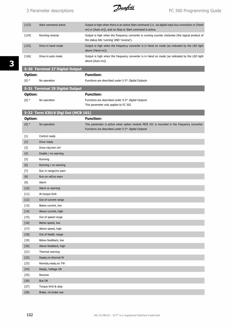
[123] Start command active Output is high when there is an active Start command (i.e. via digital input bus connection or [Hand
on] or [Auto on]), and no Stop or Start command is active.
[124] Running reverse Output is high when the frequency converter is running counter clockwise (the logical product of
the status bits ‘running’ AND ‘reverse’).
[125] Drive in hand mode Output is high when the frequency converter is in Hand on mode (as indicated by the LED light
above [Hand on]).
[126] Drive in auto mode Output is high when the frequency converter is in Hand on mode (as indicated by the LED light
above [Auto on]).
5-30 Terminal 27 Digital Output
Option: Function:[0] * No operation Functions are described under 5-3* Digital Outputs
5-31 Terminal 29 Digital Output
Option: Function:[0] * No operation Functions are described under 5-3* Digital Outputs
This parameter only applies to FC 302
5-32 Term X30/6 Digi Out (MCB 101)
Option: Function:[0] * No operation This parameter is active when option module MCB 101 is mounted in the frequency converter.
Functions are described under 5-3* Digital Outputs
[1] Control ready
[2] Drive ready
[3] Drive rdy/rem ctrl
[4] Enable / no warning
[5] Running
[6] Running / no warning
[7] Run in range/no warn
[8] Run on ref/no warn
[9] Alarm
[10] Alarm or warning
[11] At torque limit
[12] Out of current range
[13] Below current, low
[14] Above current, high
[15] Out of speed range
[16] Below speed, low
[17] Above speed, high
[18] Out of feedb. range
[19] Below feedback, low
[20] Above feedback, high
[21] Thermal warning
[22] Ready,no thermal W
[23] Remote,ready,no TW
[24] Ready, Voltage OK
[25] Reverse
[26] Bus OK
[27] Torque limit & stop
[28] Brake, no brake war
3 Parameter descriptions FC 300 Programming Guide
102 MG.33.M8.02 - VLT® is a registered Danfoss trademark
3
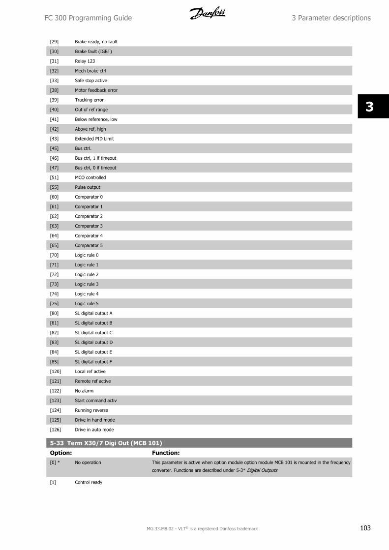
[29] Brake ready, no fault
[30] Brake fault (IGBT)
[31] Relay 123
[32] Mech brake ctrl
[33] Safe stop active
[38] Motor feedback error
[39] Tracking error
[40] Out of ref range
[41] Below reference, low
[42] Above ref, high
[43] Extended PID Limit
[45] Bus ctrl.
[46] Bus ctrl, 1 if timeout
[47] Bus ctrl, 0 if timeout
[51] MCO controlled
[55] Pulse output
[60] Comparator 0
[61] Comparator 1
[62] Comparator 2
[63] Comparator 3
[64] Comparator 4
[65] Comparator 5
[70] Logic rule 0
[71] Logic rule 1
[72] Logic rule 2
[73] Logic rule 3
[74] Logic rule 4
[75] Logic rule 5
[80] SL digital output A
[81] SL digital output B
[82] SL digital output C
[83] SL digital output D
[84] SL digital output E
[85] SL digital output F
[120] Local ref active
[121] Remote ref active
[122] No alarm
[123] Start command activ
[124] Running reverse
[125] Drive in hand mode
[126] Drive in auto mode
5-33 Term X30/7 Digi Out (MCB 101)
Option: Function:[0] * No operation This parameter is active when option module option module MCB 101 is mounted in the frequency
converter. Functions are described under 5-3* Digital Outputs
[1] Control ready
FC 300 Programming Guide 3 Parameter descriptions
MG.33.M8.02 - VLT® is a registered Danfoss trademark 103
3
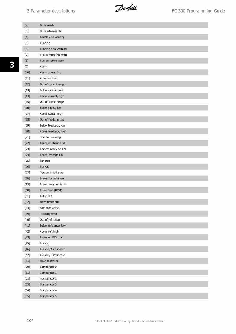
[2] Drive ready
[3] Drive rdy/rem ctrl
[4] Enable / no warning
[5] Running
[6] Running / no warning
[7] Run in range/no warn
[8] Run on ref/no warn
[9] Alarm
[10] Alarm or warning
[11] At torque limit
[12] Out of current range
[13] Below current, low
[14] Above current, high
[15] Out of speed range
[16] Below speed, low
[17] Above speed, high
[18] Out of feedb. range
[19] Below feedback, low
[20] Above feedback, high
[21] Thermal warning
[22] Ready,no thermal W
[23] Remote,ready,no TW
[24] Ready, Voltage OK
[25] Reverse
[26] Bus OK
[27] Torque limit & stop
[28] Brake, no brake war
[29] Brake ready, no fault
[30] Brake fault (IGBT)
[31] Relay 123
[32] Mech brake ctrl
[33] Safe stop active
[39] Tracking error
[40] Out of ref range
[41] Below reference, low
[42] Above ref, high
[43] Extended PID Limit
[45] Bus ctrl.
[46] Bus ctrl, 1 if timeout
[47] Bus ctrl, 0 if timeout
[51] MCO controlled
[60] Comparator 0
[61] Comparator 1
[62] Comparator 2
[63] Comparator 3
[64] Comparator 4
[65] Comparator 5
3 Parameter descriptions FC 300 Programming Guide
104 MG.33.M8.02 - VLT® is a registered Danfoss trademark
3
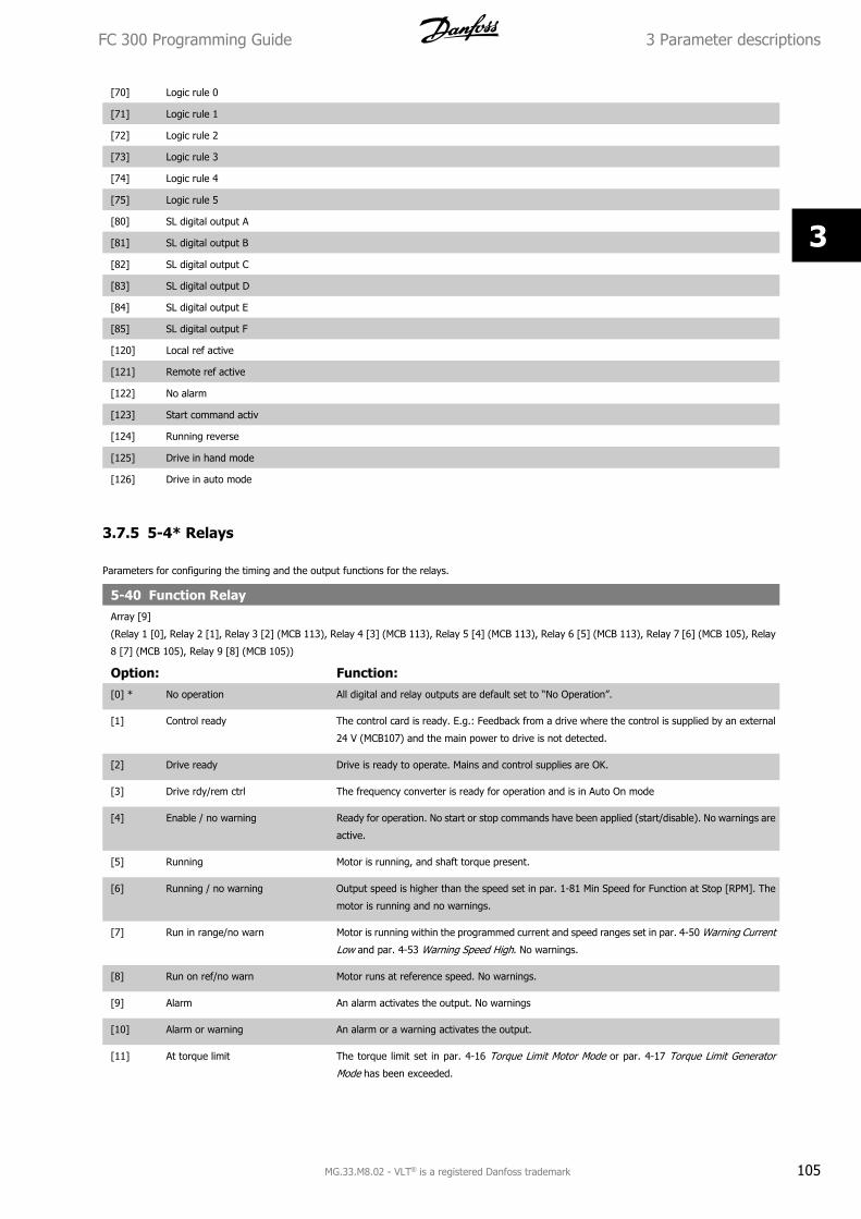
[70] Logic rule 0
[71] Logic rule 1
[72] Logic rule 2
[73] Logic rule 3
[74] Logic rule 4
[75] Logic rule 5
[80] SL digital output A
[81] SL digital output B
[82] SL digital output C
[83] SL digital output D
[84] SL digital output E
[85] SL digital output F
[120] Local ref active
[121] Remote ref active
[122] No alarm
[123] Start command activ
[124] Running reverse
[125] Drive in hand mode
[126] Drive in auto mode
3.7.5 5-4* Relays
Parameters for configuring the timing and the output functions for the relays.
5-40 Function RelayArray [9]
(Relay 1 [0], Relay 2 [1], Relay 3 [2] (MCB 113), Relay 4 [3] (MCB 113), Relay 5 [4] (MCB 113), Relay 6 [5] (MCB 113), Relay 7 [6] (MCB 105), Relay
8 [7] (MCB 105), Relay 9 [8] (MCB 105))
Option: Function:[0] * No operation All digital and relay outputs are default set to “No Operation”.
[1] Control ready The control card is ready. E.g.: Feedback from a drive where the control is supplied by an external
24 V (MCB107) and the main power to drive is not detected.
[2] Drive ready Drive is ready to operate. Mains and control supplies are OK.
[3] Drive rdy/rem ctrl The frequency converter is ready for operation and is in Auto On mode
[4] Enable / no warning Ready for operation. No start or stop commands have been applied (start/disable). No warnings are
active.
[5] Running Motor is running, and shaft torque present.
[6] Running / no warning Output speed is higher than the speed set in par. 1-81 Min Speed for Function at Stop [RPM]. The
motor is running and no warnings.
[7] Run in range/no warn Motor is running within the programmed current and speed ranges set in par. 4-50 Warning Current
Low and par. 4-53 Warning Speed High. No warnings.
[8] Run on ref/no warn Motor runs at reference speed. No warnings.
[9] Alarm An alarm activates the output. No warnings
[10] Alarm or warning An alarm or a warning activates the output.
[11] At torque limit The torque limit set in par. 4-16 Torque Limit Motor Mode or par. 4-17 Torque Limit Generator
Mode has been exceeded.
FC 300 Programming Guide 3 Parameter descriptions
MG.33.M8.02 - VLT® is a registered Danfoss trademark 105
3
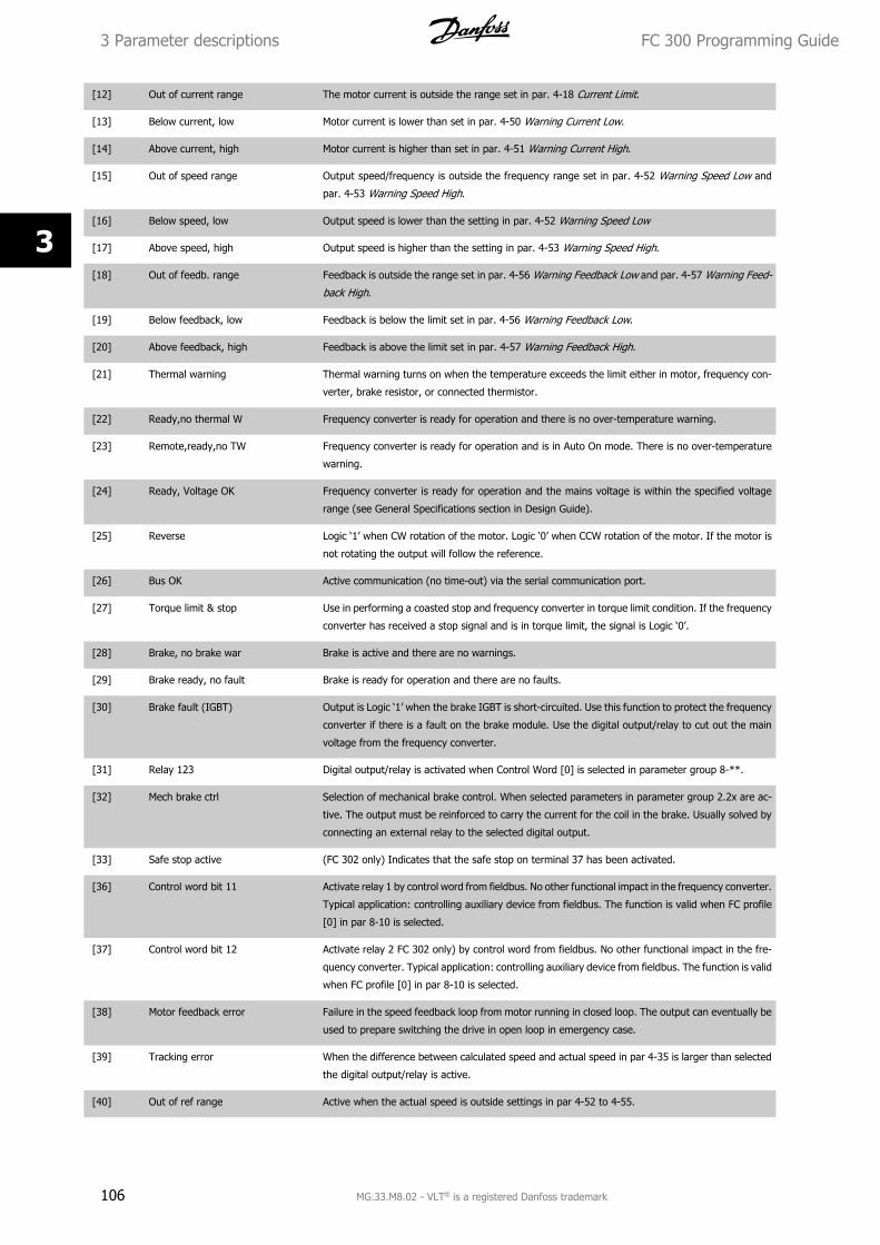
[12] Out of current range The motor current is outside the range set in par. 4-18 Current Limit.
[13] Below current, low Motor current is lower than set in par. 4-50 Warning Current Low.
[14] Above current, high Motor current is higher than set in par. 4-51 Warning Current High.
[15] Out of speed range Output speed/frequency is outside the frequency range set in par. 4-52 Warning Speed Low and
par. 4-53 Warning Speed High.
[16] Below speed, low Output speed is lower than the setting in par. 4-52 Warning Speed Low
[17] Above speed, high Output speed is higher than the setting in par. 4-53 Warning Speed High.
[18] Out of feedb. range Feedback is outside the range set in par. 4-56 Warning Feedback Low and par. 4-57 Warning Feed-
back High.
[19] Below feedback, low Feedback is below the limit set in par. 4-56 Warning Feedback Low.
[20] Above feedback, high Feedback is above the limit set in par. 4-57 Warning Feedback High.
[21] Thermal warning Thermal warning turns on when the temperature exceeds the limit either in motor, frequency con-
verter, brake resistor, or connected thermistor.
[22] Ready,no thermal W Frequency converter is ready for operation and there is no over-temperature warning.
[23] Remote,ready,no TW Frequency converter is ready for operation and is in Auto On mode. There is no over-temperature
warning.
[24] Ready, Voltage OK Frequency converter is ready for operation and the mains voltage is within the specified voltage
range (see General Specifications section in Design Guide).
[25] Reverse Logic ‘1’ when CW rotation of the motor. Logic ‘0’ when CCW rotation of the motor. If the motor is
not rotating the output will follow the reference.
[26] Bus OK Active communication (no time-out) via the serial communication port.
[27] Torque limit & stop Use in performing a coasted stop and frequency converter in torque limit condition. If the frequency
converter has received a stop signal and is in torque limit, the signal is Logic ‘0’.
[28] Brake, no brake war Brake is active and there are no warnings.
[29] Brake ready, no fault Brake is ready for operation and there are no faults.
[30] Brake fault (IGBT) Output is Logic ‘1’ when the brake IGBT is short-circuited. Use this function to protect the frequency
converter if there is a fault on the brake module. Use the digital output/relay to cut out the main
voltage from the frequency converter.
[31] Relay 123 Digital output/relay is activated when Control Word [0] is selected in parameter group 8-**.
[32] Mech brake ctrl Selection of mechanical brake control. When selected parameters in parameter group 2.2x are ac-
tive. The output must be reinforced to carry the current for the coil in the brake. Usually solved by
connecting an external relay to the selected digital output.
[33] Safe stop active (FC 302 only) Indicates that the safe stop on terminal 37 has been activated.
[36] Control word bit 11 Activate relay 1 by control word from fieldbus. No other functional impact in the frequency converter.
Typical application: controlling auxiliary device from fieldbus. The function is valid when FC profile
[0] in par 8-10 is selected.
[37] Control word bit 12 Activate relay 2 FC 302 only) by control word from fieldbus. No other functional impact in the fre-
quency converter. Typical application: controlling auxiliary device from fieldbus. The function is valid
when FC profile [0] in par 8-10 is selected.
[38] Motor feedback error Failure in the speed feedback loop from motor running in closed loop. The output can eventually be
used to prepare switching the drive in open loop in emergency case.
[39] Tracking error When the difference between calculated speed and actual speed in par 4-35 is larger than selected
the digital output/relay is active.
[40] Out of ref range Active when the actual speed is outside settings in par 4-52 to 4-55.
3 Parameter descriptions FC 300 Programming Guide
106 MG.33.M8.02 - VLT® is a registered Danfoss trademark
3
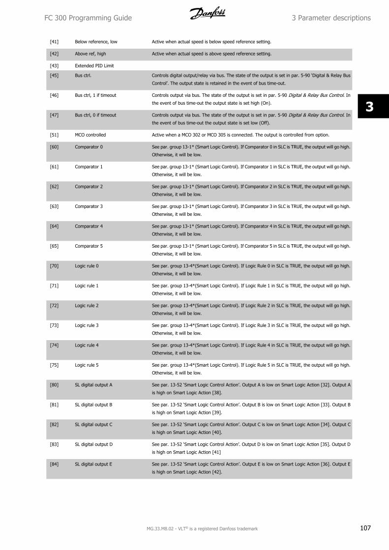
[41] Below reference, low Active when actual speed is below speed reference setting.
[42] Above ref, high Active when actual speed is above speed reference setting.
[43] Extended PID Limit
[45] Bus ctrl. Controls digital output/relay via bus. The state of the output is set in par. 5-90 ‘Digital & Relay Bus
Control’. The output state is retained in the event of bus time-out.
[46] Bus ctrl, 1 if timeout Controls output via bus. The state of the output is set in par. 5-90 Digital & Relay Bus Control. In
the event of bus time-out the output state is set high (On).
[47] Bus ctrl, 0 if timeout Controls output via bus. The state of the output is set in par. 5-90 Digital & Relay Bus Control. In
the event of bus time-out the output state is set low (Off).
[51] MCO controlled Active when a MCO 302 or MCO 305 is connected. The output is controlled from option.
[60] Comparator 0 See par. group 13-1* (Smart Logic Control). If Comparator 0 in SLC is TRUE, the output will go high.
Otherwise, it will be low.
[61] Comparator 1 See par. group 13-1* (Smart Logic Control). If Comparator 1 in SLC is TRUE, the output will go high.
Otherwise, it will be low.
[62] Comparator 2 See par. group 13-1* (Smart Logic Control). If Comparator 2 in SLC is TRUE, the output will go high.
Otherwise, it will be low.
[63] Comparator 3 See par. group 13-1* (Smart Logic Control). If Comparator 3 in SLC is TRUE, the output will go high.
Otherwise, it will be low.
[64] Comparator 4 See par. group 13-1* (Smart Logic Control). If Comparator 4 in SLC is TRUE, the output will go high.
Otherwise, it will be low.
[65] Comparator 5 See par. group 13-1* (Smart Logic Control). If Comparator 5 in SLC is TRUE, the output will go high.
Otherwise, it will be low.
[70] Logic rule 0 See par. group 13-4*(Smart Logic Control). If Logic Rule 0 in SLC is TRUE, the output will go high.
Otherwise, it will be low.
[71] Logic rule 1 See par. group 13-4*(Smart Logic Control). If Logic Rule 1 in SLC is TRUE, the output will go high.
Otherwise, it will be low.
[72] Logic rule 2 See par. group 13-4*(Smart Logic Control). If Logic Rule 2 in SLC is TRUE, the output will go high.
Otherwise, it will be low.
[73] Logic rule 3 See par. group 13-4*(Smart Logic Control). If Logic Rule 3 in SLC is TRUE, the output will go high.
Otherwise, it will be low.
[74] Logic rule 4 See par. group 13-4*(Smart Logic Control). If Logic Rule 4 in SLC is TRUE, the output will go high.
Otherwise, it will be low.
[75] Logic rule 5 See par. group 13-4*(Smart Logic Control). If Logic Rule 5 in SLC is TRUE, the output will go high.
Otherwise, it will be low.
[80] SL digital output A See par. 13-52 ‘Smart Logic Control Action’. Output A is low on Smart Logic Action [32]. Output A
is high on Smart Logic Action [38].
[81] SL digital output B See par. 13-52 ‘Smart Logic Control Action’. Output B is low on Smart Logic Action [33]. Output B
is high on Smart Logic Action [39].
[82] SL digital output C See par. 13-52 ‘Smart Logic Control Action’. Output C is low on Smart Logic Action [34]. Output C
is high on Smart Logic Action [40].
[83] SL digital output D See par. 13-52 ‘Smart Logic Control Action’. Output D is low on Smart Logic Action [35]. Output D
is high on Smart Logic Action [41]
[84] SL digital output E See par. 13-52 ‘Smart Logic Control Action’. Output E is low on Smart Logic Action [36]. Output E
is high on Smart Logic Action [42].
FC 300 Programming Guide 3 Parameter descriptions
MG.33.M8.02 - VLT® is a registered Danfoss trademark 107
3
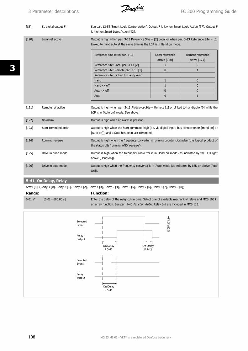
[85] SL digital output F See par. 13-52 ‘Smart Logic Control Action’. Output F is low on Smart Logic Action [37]. Output F
is high on Smart Logic Action [43].
[120] Local ref active Output is high when par. 3-13 Reference Site = [2] Local or when par. 3-13 Reference Site = [0]
Linked to hand auto at the same time as the LCP is in Hand on mode.
Reference site set in par. 3-13 Local reference
active [120]
Remote reference
active [121]
Reference site: Local par. 3-13 [2] 1 0
Reference site: Remote par. 3-13 [1] 0 1
Reference site: Linked to Hand/ Auto
Hand 1 0
Hand -> off 1 0
Auto -> off 0 0
Auto 0 1
[121] Remote ref active Output is high when par. 3-13 Reference Site = Remote [1] or Linked to hand/auto [0] while the
LCP is in [Auto on] mode. See above.
[122] No alarm Output is high when no alarm is present.
[123] Start command activ Output is high when the Start command high (i.e. via digital input, bus connection or [Hand on] or
[Auto on]), and a Stop has been last command.
[124] Running reverse Output is high when the frequency converter is running counter clockwise (the logical product of
the status bits ‘running’ AND ‘reverse’).
[125] Drive in hand mode Output is high when the frequency converter is in Hand on mode (as indicated by the LED light
above [Hand on]).
[126] Drive in auto mode Output is high when the frequency converter is in ‘Auto’ mode (as indicated by LED on above [Auto
On]).
5-41 On Delay, RelayArray [9], (Relay 1 [0], Relay 2 [1], Relay 3 [2], Relay 4 [3], Relay 5 [4], Relay 6 [5], Relay 7 [6], Relay 8 [7], Relay 9 [8])
Range: Function:0.01 s* [0.01 - 600.00 s] Enter the delay of the relay cut-in time. Select one of available mechanical relays and MCB 105 in
an array function. See par. 5-40 Function Relay. Relay 3-6 are included in MCB 113.
3 Parameter descriptions FC 300 Programming Guide
108 MG.33.M8.02 - VLT® is a registered Danfoss trademark
3
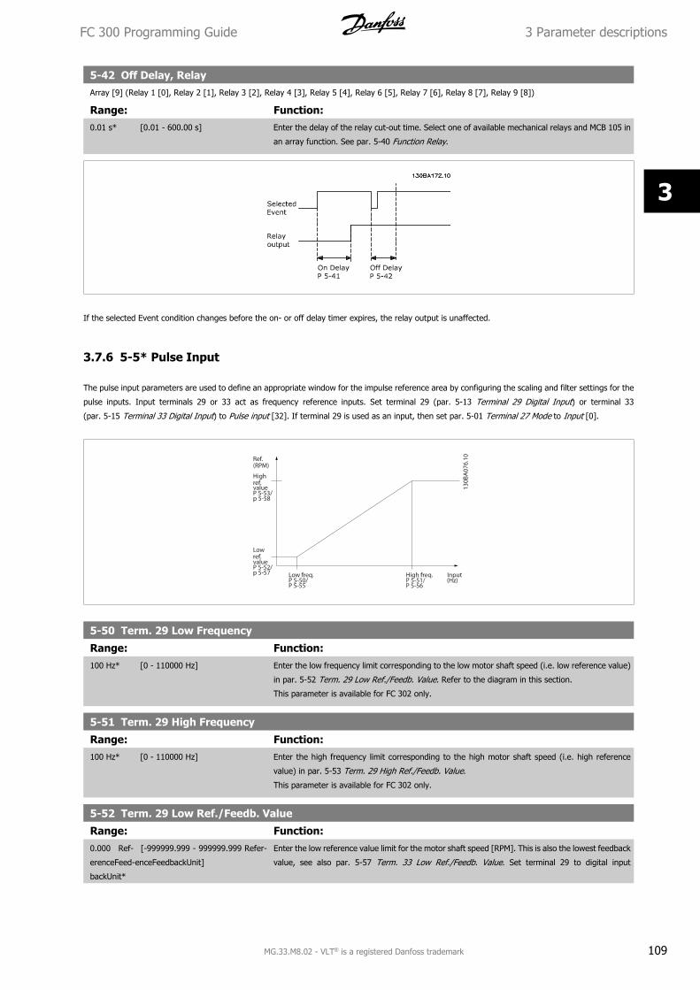
5-42 Off Delay, RelayArray [9] (Relay 1 [0], Relay 2 [1], Relay 3 [2], Relay 4 [3], Relay 5 [4], Relay 6 [5], Relay 7 [6], Relay 8 [7], Relay 9 [8])
Range: Function:0.01 s* [0.01 - 600.00 s] Enter the delay of the relay cut-out time. Select one of available mechanical relays and MCB 105 in
an array function. See par. 5-40 Function Relay.
If the selected Event condition changes before the on- or off delay timer expires, the relay output is unaffected.
3.7.6 5-5* Pulse Input
The pulse input parameters are used to define an appropriate window for the impulse reference area by configuring the scaling and filter settings for the
pulse inputs. Input terminals 29 or 33 act as frequency reference inputs. Set terminal 29 (par. 5-13 Terminal 29 Digital Input) or terminal 33
(par. 5-15 Terminal 33 Digital Input) to Pulse input [32]. If terminal 29 is used as an input, then set par. 5-01 Terminal 27 Mode to Input [0].
5-50 Term. 29 Low Frequency
Range: Function:100 Hz* [0 - 110000 Hz] Enter the low frequency limit corresponding to the low motor shaft speed (i.e. low reference value)
in par. 5-52 Term. 29 Low Ref./Feedb. Value. Refer to the diagram in this section.
This parameter is available for FC 302 only.
5-51 Term. 29 High Frequency
Range: Function:100 Hz* [0 - 110000 Hz] Enter the high frequency limit corresponding to the high motor shaft speed (i.e. high reference
value) in par. 5-53 Term. 29 High Ref./Feedb. Value.
This parameter is available for FC 302 only.
5-52 Term. 29 Low Ref./Feedb. Value
Range: Function:0.000 Ref-
erenceFeed-
backUnit*
[-999999.999 - 999999.999 Refer-
enceFeedbackUnit]
Enter the low reference value limit for the motor shaft speed [RPM]. This is also the lowest feedback
value, see also par. 5-57 Term. 33 Low Ref./Feedb. Value. Set terminal 29 to digital input
FC 300 Programming Guide 3 Parameter descriptions
MG.33.M8.02 - VLT® is a registered Danfoss trademark 109
3
(par. 5-02 Terminal 29 Mode =input [0] (default) and par. 5-13 Terminal 29 Digital Input = appli-
cable value).
This parameter is available for FC 302 only.
5-53 Term. 29 High Ref./Feedb. Value
Range: Function:Application
dependent*
[-999999.999 - 999999.999 Refer-
enceFeedbackUnit]
Enter the high reference value [RPM] for the motor shaft speed and the high feedback value, see
also par. 5-58 Term. 33 High Ref./Feedb. Value. Select terminal 29 as a digital input
(par. 5-02 Terminal 29 Mode =input [0] (default) and par. 5-13 Terminal 29 Digital Input = appli-
cable value).
This parameter is available for FC 302 only.
5-54 Pulse Filter Time Constant #29
Range: Function:100 ms* [1 - 1000 ms] Enter the pulse filter time constant. The pulse filter dampens oscillations of the feedback signal,
which is an advantage if there is a lot of noise in the system. A high time constant value results in
better dampening but also increases the time delay through the filter. This parameter is available
for FC 302 only.
This parameter cannot be adjusted while the motor is running.
5-55 Term. 33 Low Frequency
Range: Function:100 Hz* [0 - 110000 Hz] Enter the low frequency corresponding to the low motor shaft speed (i.e. low reference value) in
par. 5-57 Term. 33 Low Ref./Feedb. Value.
5-56 Term. 33 High Frequency
Range: Function:100 Hz* [0 - 110000 Hz] Enter the high frequency corresponding to the high motor shaft speed (i.e. high reference value) in
par. 5-58 Term. 33 High Ref./Feedb. Value.
5-57 Term. 33 Low Ref./Feedb. Value
Range: Function:0.000 N/A* [-999999.999 - 999999.999 N/A] Enter the low reference value [RPM] for the motor shaft speed. This is also the low feedback value,
see also par. 5-52 Term. 29 Low Ref./Feedb. Value.
5-58 Term. 33 High Ref./Feedb. Value
Range: Function:Application
dependent*
[-999999.999 - 999999.999 Refer-
enceFeedbackUnit]
Enter the high reference value [RPM] for the motor shaft speed. See also par. 5-53 Term. 29 High
Ref./Feedb. Value.
5-59 Pulse Filter Time Constant #33
Range: Function:100 ms* [1 - 1000 ms] Enter the pulse filter time constant. The low-pass filter reduces the influence on and dampens os-
cillations on the feedback signal from the control.
This is an advantage, e.g. if there is a great amount on noise in the system. This parameter cannot
be adjusted while the motor is running.
3 Parameter descriptions FC 300 Programming Guide
110 MG.33.M8.02 - VLT® is a registered Danfoss trademark
3
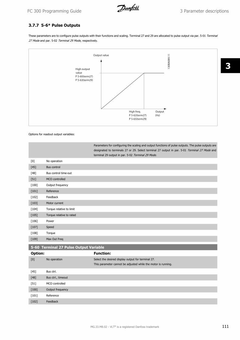
3.7.7 5-6* Pulse Outputs
These parameters are to configure pulse outputs with their functions and scaling. Terminal 27 and 29 are allocated to pulse output via par. 5-01 Terminal
27 Mode and par. 5-02 Terminal 29 Mode, respectively.
Options for readout output variables:
Parameters for configuring the scaling and output functions of pulse outputs. The pulse outputs are
designated to terminals 27 or 29. Select terminal 27 output in par. 5-01 Terminal 27 Mode and
terminal 29 output in par. 5-02 Terminal 29 Mode.
[0] No operation
[45] Bus control
[48] Bus control time-out
[51] MCO controlled
[100] Output frequency
[101] Reference
[102] Feedback
[103] Motor current
[104] Torque relative to limit
[105] Torque relative to rated
[106] Power
[107] Speed
[108] Torque
[109] Max Out Freq
5-60 Terminal 27 Pulse Output Variable
Option: Function:[0] No operation Select the desired display output for terminal 27.
This parameter cannot be adjusted while the motor is running.
[45] Bus ctrl.
[48] Bus ctrl., timeout
[51] MCO controlled
[100] Output frequency
[101] Reference
[102] Feedback
FC 300 Programming Guide 3 Parameter descriptions
MG.33.M8.02 - VLT® is a registered Danfoss trademark 111
3
[103] Motor current
[104] Torque rel to limit
[105] Torq relate to rated
[106] Power
[107] Speed
[108] Torque
[109] Max Out Freq
[119] Torque % lim
5-62 Pulse Output Max Freq #27
Range: Function:Application
dependent*
[0 - 32000 Hz] Set the maximum frequency for terminal 27, corresponding to the output variable selected in
par. 5-60 Terminal 27 Pulse Output Variable.
This parameter cannot be adjusted while the motor is running.
5-63 Terminal 29 Pulse Output Variable
Option: Function:[0] * No operation Select the desired display output for terminal 29. This parameter is available for FC 302 only.
This parameter cannot be adjusted while the motor is running.
[45] Bus ctrl.
[48] Bus ctrl., timeout
[51] MCO controlled
[100] Output frequency
[101] Reference
[102] Feedback
[103] Motor current
[104] Torque rel to limit
[105] Torq relate to rated
[106] Power
[107] Speed
[108] Torque
[109] Max Out Freq
[119] Torque % lim
5-65 Pulse Output Max Freq #29Set the maximum frequency for terminal 29 corresponding to the output variable set in par. 5-63 Terminal 29 Pulse Output Variable.
This parameter cannot be adjusted while the motor is running.
Range: Function:5000 Hz* [0 - 32000 Hz]
5-66 Terminal X30/6 Pulse Output VariableSelect the variable for read-out on terminal X30/6.
This parameter cannot be adjusted while the motor is running.
This parameter is active when option module MCB 101 is installed in the frequency converter.
Same options and functions as par. group 5-6*.
Option: Function:[0] * No operation
[45] Bus ctrl.
[48] Bus ctrl., timeout
[51] MCO controlled
3 Parameter descriptions FC 300 Programming Guide
112 MG.33.M8.02 - VLT® is a registered Danfoss trademark
3
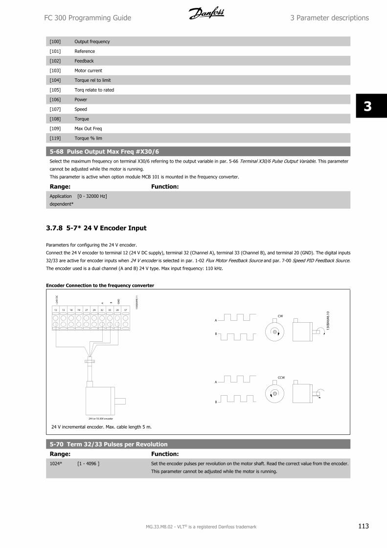
[100] Output frequency
[101] Reference
[102] Feedback
[103] Motor current
[104] Torque rel to limit
[105] Torq relate to rated
[106] Power
[107] Speed
[108] Torque
[109] Max Out Freq
[119] Torque % lim
5-68 Pulse Output Max Freq #X30/6Select the maximum frequency on terminal X30/6 referring to the output variable in par. 5-66 Terminal X30/6 Pulse Output Variable. This parameter
cannot be adjusted while the motor is running.
This parameter is active when option module MCB 101 is mounted in the frequency converter.
Range: Function:Application
dependent*
[0 - 32000 Hz]
3.7.8 5-7* 24 V Encoder Input
Parameters for configuring the 24 V encoder.
Connect the 24 V encoder to terminal 12 (24 V DC supply), terminal 32 (Channel A), terminal 33 (Channel B), and terminal 20 (GND). The digital inputs
32/33 are active for encoder inputs when 24 V encoder is selected in par. 1-02 Flux Motor Feedback Source and par. 7-00 Speed PID Feedback Source.
The encoder used is a dual channel (A and B) 24 V type. Max input frequency: 110 kHz.
Encoder Connection to the frequency converter
24 V incremental encoder. Max. cable length 5 m.
5-70 Term 32/33 Pulses per Revolution
Range: Function:1024* [1 - 4096 ] Set the encoder pulses per revolution on the motor shaft. Read the correct value from the encoder.
This parameter cannot be adjusted while the motor is running.
FC 300 Programming Guide 3 Parameter descriptions
MG.33.M8.02 - VLT® is a registered Danfoss trademark 113
3
5-71 Term 32/33 Encoder Direction
Option: Function:Change the detected encoder rotation direction without changing the wiring to the encoder.
[0] * Clockwise Sets channel A 90° (electrical degrees) behind channel B upon clockwise rotation of the encoder
shaft.
[1] Counter clockwise Sets channel A 90° (electrical degrees) ahead of channel B upon clockwise rotation of the encoder
shaft.
This parameter cannot be adjusted while the motor is running.
3.7.9 5-9*Bus Controlled
This parameter group selects digital and relay outputs via a fieldbus setting.
5-90 Digital & Relay Bus Control
Range: Function:0* [0 - 2147483647 ] This parameter holds the state of the digital outputs and relays that is controlled by bus.
A logical '1' indicates that the output is high or active.
A logical '0' indicates that the output is low or inactive.
Bit 0 Digital Output Terminal 27Bit 1 Digital Output Terminal 29Bit 2 Digital Output Terminal X 30/6Bit 3 Digital Output Terminal X 30/7Bit 4 Relay 1 output terminalBit 5 Relay 2 output terminalBit 6 Option B Relay 1 output terminalBit 7 Option B Relay 2 output terminalBit 8 Option B Relay 3 output terminalBit 9-15 Reserved for future terminalsBit 16 Option C Relay 1 output terminalBit 17 Option C Relay 2 output terminalBit 18 Option C Relay 3 output terminalBit 19 Option C Relay 4 output terminalBit 20 Option C Relay 5 output terminalBit 21 Option C Relay 6 output terminalBit 22 Option C Relay 7 output terminalBit 23 Option C Relay 8 output terminalBit 24-31 Reserved for future terminals
5-93 Pulse Out #27 Bus Control
Range: Function:0.00 %* [0.00 - 100.00 %] Set the output frequency transferred to the output terminal 27 when the terminal is configured as
'Bus Controlled' in par. 5-60 Terminal 27 Pulse Output Variable [45].
5-94 Pulse Out #27 Timeout Preset
Range: Function:0.00 %* [0.00 - 100.00 %] Set the output frequency transferred to the output terminal 27 when the terminal is configured as
'Bus Ctrl Timeout' in par. 5-60 Terminal 27 Pulse Output Variable [48]. And a time-out is detected.
5-95 Pulse Out #29 Bus Control
Range: Function:0.00 %* [0.00 - 100.00 %] Set the output frequency transferred to the output terminal 29 when the terminal is configured as
'Bus Controlled' in par. 5-63 Terminal 29 Pulse Output Variable [45].
This parameter only applies for FC 302.
3 Parameter descriptions FC 300 Programming Guide
114 MG.33.M8.02 - VLT® is a registered Danfoss trademark
3
5-96 Pulse Out #29 Timeout Preset
Range: Function:0.00 %* [0.00 - 100.00 %] Set the output frequency transferred to the output terminal 29 when the terminal is configured as
'Bus Ctrl Timeout' in par. 5-63 Terminal 29 Pulse Output Variable [48]. And a time-out is detected.
This parameter only applies for FC 302.
5-97 Pulse Out #X30/6 Bus Control
Range: Function:0.00 %* [0.00 - 100.00 %] Set the output frequency transferred to the output terminal X30/6 when the terminal is configured
as 'Bus Controlled' in par. 5-66 Terminal X30/6 Pulse Output Variable, Terminal X30/6 Pulse Output
Variable [45].
5-98 Pulse Out #X30/6 Timeout Preset
Range: Function:0.00 %* [0.00 - 100.00 %] Set the output frequency transferred to the output terminal X30/6 when the terminal is configured
as 'Bus Ctrl Timeout' in par. 5-66 Terminal X30/6 Pulse Output Variable [48]. And a time-out is
detected.
FC 300 Programming Guide 3 Parameter descriptions
MG.33.M8.02 - VLT® is a registered Danfoss trademark 115
3
3.8 Parameters: Analog In/Out
3.8.1 6-** Analog In/Out
Parameter group for configuration of the analog input and output.
3.8.2 6-0* Analog I/O Mode
The analog inputs can freely be allocated to be either voltage (FC 301: 0..10 V, FC 302: 0..+/- 10V) or current (FC 301/FC 302: 0/4..20 mA) input.
NB!
Thermistors may be connected to either an analog or a digital input.
6-00 Live Zero Timeout Time
Range: Function:10 s* [1 - 99 s] Enter the Live Zero Time-out time period. Live Zero Time-out Time is active for analog inputs, i.e.
terminal 53 or terminal 54, used as reference or feedback sources. If the reference signal value
associated with the selected current input falls below 50% of the value set in par. 6-10 Terminal 53
Low Voltage, par. 6-12 Terminal 53 Low Current, par. 6-20 Terminal 54 Low Voltage or
par. 6-22 Terminal 54 Low Current for a time period longer than the time set in par. 6-00 Live Zero
Timeout Time, the function selected in par. 6-01 Live Zero Timeout Function will be activated.
6-01 Live Zero Timeout Function
Option: Function:Select the time-out function. The function set in par. 6-01 Live Zero Timeout Function will be acti-
vated if the input signal on terminal 53 or 54 is below 50% of the value in par. 6-10 Terminal 53
Low Voltage, par. 6-12 Terminal 53 Low Current, par. 6-20 Terminal 54 Low Voltage or
par. 6-22 Terminal 54 Low Current for a time period defined in par. 6-00 Live Zero Timeout Time.
If several time-outs occur simultaneously, the frequency converter prioritises the time-out functions
as follows:
1. Par. 6-01 Live Zero Timeout Function
2. Par. 5-74
3. Par. 8-04 Control Word Timeout Function
[0] * Off
[1] Freeze output Frozen at the present value
[2] Stop Overruled to stop
[3] Jogging Overruled to jog speed
[4] Max. speed Overruled to max. speed
[5] Stop and trip Overruled to stop with subsequent trip
[20] Coast
[21] Coast and trip
3 Parameter descriptions FC 300 Programming Guide
116 MG.33.M8.02 - VLT® is a registered Danfoss trademark
3
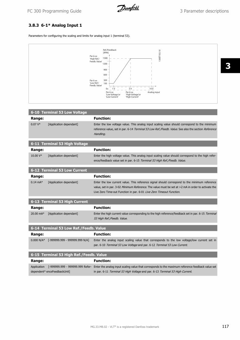
3.8.3 6-1* Analog Input 1
Parameters for configuring the scaling and limits for analog input 1 (terminal 53).
6-10 Terminal 53 Low Voltage
Range: Function:0.07 V* [Application dependant] Enter the low voltage value. This analog input scaling value should correspond to the minimum
reference value, set in par. 6-14 Terminal 53 Low Ref./Feedb. Value. See also the section Reference
Handling.
6-11 Terminal 53 High Voltage
Range: Function:10.00 V* [Application dependant] Enter the high voltage value. This analog input scaling value should correspond to the high refer-
ence/feedback value set in par. 6-15 Terminal 53 High Ref./Feedb. Value.
6-12 Terminal 53 Low Current
Range: Function:0.14 mA* [Application dependant] Enter the low current value. This reference signal should correspond to the minimum reference
value, set in par. 3-02 Minimum Reference. The value must be set at >2 mA in order to activate the
Live Zero Time-out Function in par. 6-01 Live Zero Timeout Function.
6-13 Terminal 53 High Current
Range: Function:20.00 mA* [Application dependant] Enter the high current value corresponding to the high reference/feedback set in par. 6-15 Terminal
53 High Ref./Feedb. Value.
6-14 Terminal 53 Low Ref./Feedb. Value
Range: Function:0.000 N/A* [-999999.999 - 999999.999 N/A] Enter the analog input scaling value that corresponds to the low voltage/low current set in
par. 6-10 Terminal 53 Low Voltage and par. 6-12 Terminal 53 Low Current.
6-15 Terminal 53 High Ref./Feedb. Value
Range: Function:Application
dependent*
[-999999.999 - 999999.999 Refer-
enceFeedbackUnit]
Enter the analog input scaling value that corresponds to the maximum reference feedback value set
in par. 6-11 Terminal 53 High Voltage and par. 6-13 Terminal 53 High Current.
FC 300 Programming Guide 3 Parameter descriptions
MG.33.M8.02 - VLT® is a registered Danfoss trademark 117
3
6-16 Terminal 53 Filter Time Constant
Range: Function:0.001 s* [0.001 - 10.000 s] Enter the time constant. This is a first-order digital low pass filter time constant for suppressing
electrical noise in terminal 53. A high time constant value improves dampening but also increases
the time delay through the filter.
This parameter cannot be adjusted while the motor is running.
3.8.4 6-2* Analog Input 2
Parameters for configuring the scaling and limits for analog input 2 (terminal 54).
6-20 Terminal 54 Low Voltage
Range: Function:0.07 V* [Application dependant] Enter the low voltage value. This analog input scaling value should correspond to the minimum
reference value, set in par. 3-02 Minimum Reference. See also the section Reference Handling.
6-21 Terminal 54 High Voltage
Range: Function:10.00 V* [Application dependant] Enter the high voltage value. This analog input scaling value should correspond to the high refer-
ence/feedback value set in par. 6-25 Terminal 54 High Ref./Feedb. Value.
6-22 Terminal 54 Low Current
Range: Function:0.14 mA* [Application dependant] Enter the low current value. This reference signal should correspond to the minimum reference
value, set in par. 3-02 Minimum Reference. The value must be set at >2 mA in order to activate the
Live Zero Time-out Function in par. 6-01 Live Zero Timeout Function.
6-23 Terminal 54 High Current
Range: Function:20.00 mA* [Application dependant] Enter the high current value corresponding to the high reference/feedback value set in
par. 6-25 Terminal 54 High Ref./Feedb. Value.
6-24 Terminal 54 Low Ref./Feedb. Value
Range: Function:0 Referen-
ceFeedback-
Unit*
[-999999.999 - 999999.999 Refer-
enceFeedbackUnit]
Enter the analog input scaling value that corresponds to the minimum reference feedback value set
in par. 3-02 Minimum Reference.
6-25 Terminal 54 High Ref./Feedb. Value
Range: Function:Application
dependent*
[-999999.999 - 999999.999 Refer-
enceFeedbackUnit]
Enter the analog input scaling value that corresponds to the maximum reference feedback value set
in par. 3-03 Maximum Reference.
6-26 Terminal 54 Filter Time Constant
Range: Function:0.001 s* [0.001 - 10.000 s] Enter the time constant. This is a first-order digital low pass filter time constant for suppressing
electrical noise in terminal 54. A high time constant value improves dampening but also increases
the time delay through the filter.
This parameter cannot be adjusted while the motor is running.
3 Parameter descriptions FC 300 Programming Guide
118 MG.33.M8.02 - VLT® is a registered Danfoss trademark
3
3.8.5 6-3* Analog Input 3 MCB 101
Parameter group for configuring the scale and limits for analog input 3 (X30/11) placed on option module MCB 101.
6-30 Terminal X30/11 Low Voltage
Range: Function:0.07 V* [Application dependant] Sets the analog input scaling value to correspond to the low reference/feedback value (set in
par. 6-34 Term. X30/11 Low Ref./Feedb. Value).
6-31 Terminal X30/11 High Voltage
Range: Function:10.00 V* [Application dependant] Sets the analog input scaling value to correspond to the high reference/feedback value (set in
par. 6-35 Term. X30/11 High Ref./Feedb. Value).
6-34 Term. X30/11 Low Ref./Feedb. Value
Range: Function:0.000 N/A* [-999999.999 - 999999.999 N/A] Sets the analog input scaling value to correspond to the low voltage value (set in par. 6-30 Terminal
X30/11 Low Voltage).
6-35 Term. X30/11 High Ref./Feedb. Value
Range: Function:100.000 N/
A*
[-999999.999 - 999999.999 N/A] Sets the analog input scaling value to correspond to the high voltage value (set in par. 6-31 Terminal
X30/11 High Voltage).
6-36 Term. X30/11 Filter Time Constant
Range: Function:0.001 s* [0.001 - 10.000 s] A 1st order digital low pass filter time constant for suppressing electrical noise on terminal X30/11.
Par. 6-36 Term. X30/11 Filter Time Constant cannot be changed while the motor is running.
3.8.6 6-4* Analog Input 4 MCB 101
Parameter group for configuring the scale and limits for analog input 4 (X30/12) placed on option module MCB 101.
6-40 Terminal X30/12 Low Voltage
Range: Function:0.07 V* [Application dependant] Sets the analog input scaling value to correspond to the low reference/feedback value set in
par. 6-44 Term. X30/12 Low Ref./Feedb. Value.
6-41 Terminal X30/12 High Voltage
Range: Function:10.00 V* [Application dependant] Sets the analog input scaling value to correspond to the high reference/feedback value set in
par. 6-45 Term. X30/12 High Ref./Feedb. Value.
6-44 Term. X30/12 Low Ref./Feedb. Value
Range: Function:0.000 N/A* [-999999.999 - 999999.999 N/A] Sets the analog output scaling value to correspond to the low voltage value set in par. 6-40 Terminal
X30/12 Low Voltage.
6-45 Term. X30/12 High Ref./Feedb. Value
Range: Function:100.000 N/
A*
[-999999.999 - 999999.999 N/A] Sets the analog input scaling value to correspond to the high voltage value set in par. 6-41 Terminal
X30/12 High Voltage.
FC 300 Programming Guide 3 Parameter descriptions
MG.33.M8.02 - VLT® is a registered Danfoss trademark 119
3
6-46 Term. X30/12 Filter Time Constant
Range: Function:0.001 s* [0.001 - 10.000 s] A 1st order digital low pass filter time constant for suppressing electrical noise on terminal X30/12.
Par. 6-46 Term. X30/12 Filter Time Constant cannot be changed while the motor is running.
3.8.7 6-5* Analog Output 1
Parameters for configuring the scaling and limits for analog output 1, i.e. Terminal 42. Analog outputs are current outputs: 0/4 – 20 mA. Common terminal
(terminal 39) is the same terminal and has the same electrical potential for analog common and digital common connection. Resolution on analog output
is 12 bit.
6-50 Terminal 42 Output
Option: Function:Select the function of Terminal 42 as an analog current output. Depending on the selection the
output is either a 0-20 mA or 4-20 mA output. The current value can be read out in LCP in
par. 16-65 Analog Output 42 [mA].
[0] * No operation When no signal on the analog output.
[52] MCO 0-20mA
[53] MCO 4-20mA
[100] Output frequency 0 Hz = 0 mA; 100 Hz = 20 mA.
[101] Reference Par. 3-00 Reference Range [Min - Max] 0% = 0 mA; 100% = 20 mA
Par. 3-00 Reference Range [-Max - Max] -100% = 0 mA; 0% = 10 mA; +100% = 20 mA
[102] Feedback
[103] Motor current Value is taken from par. 16-37 Inv. Max. Current. Inverter max. current (160% current) is equal to
20 mA.
Example: Inverter norm current (11 kW) = 24 A. 160 % = 38.4 A. Motor norm current = 22 A Read-
out 11.46 mA.
20 mA x 22 A38.4 A = 11.46 mA
In case the norm motor current is equal to 20 mA, the output setting of par. 6-52 Terminal 42 Output
Max Scale is:
IVLTMax x 100
IMotorNorm= 38.4 x 100
22 = 175 %
[104] Torque rel to limit The torque setting is related to setting in par. 4-16 Torque Limit Motor Mode
[105] Torq relate to rated The torque is related to the motor torque setting.
[106] Power Taken from par. 1-20 Motor Power [kW].
[107] Speed Taken from par. 3-03 Maximum Reference. 20 mA = value in par. 3-03 Maximum Reference
[108] Torque Torque reference related to 160% torque.
[109] Max Out Freq In relation to par. 4-19 Max Output Frequency.
[113] PID Clamped Output
[119] Torque % lim
[130] Output freq. 4-20mA 0 Hz = 4 mA, 100 Hz = 20 mA
[131] Reference 4-20mA Par. 3-00 Reference Range [Min-Max] 0% = 4 mA; 100% = 20 mA
Par. 3-00 Reference Range [-Max-Max] -100% = 4mA; 0% = 12 mA; +100% = 20 mA
[132] Feedback 4-20mA
3 Parameter descriptions FC 300 Programming Guide
120 MG.33.M8.02 - VLT® is a registered Danfoss trademark
3
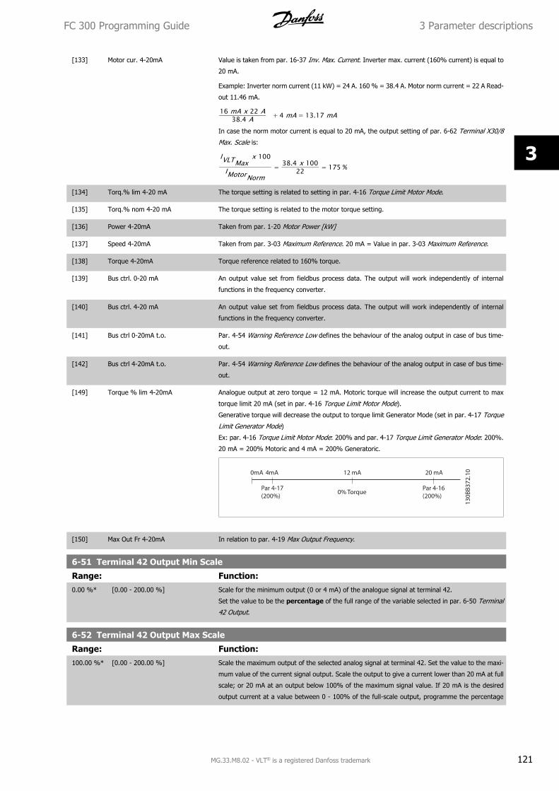
[133] Motor cur. 4-20mA Value is taken from par. 16-37 Inv. Max. Current. Inverter max. current (160% current) is equal to
20 mA.
Example: Inverter norm current (11 kW) = 24 A. 160 % = 38.4 A. Motor norm current = 22 A Read-
out 11.46 mA.
16 mA x 22 A38.4 A + 4 mA = 13.17 mA
In case the norm motor current is equal to 20 mA, the output setting of par. 6-62 Terminal X30/8
Max. Scale is:
IVLTMax x 100
IMotorNorm= 38.4 x 100
22 = 175 %
[134] Torq.% lim 4-20 mA The torque setting is related to setting in par. 4-16 Torque Limit Motor Mode.
[135] Torq.% nom 4-20 mA The torque setting is related to the motor torque setting.
[136] Power 4-20mA Taken from par. 1-20 Motor Power [kW]
[137] Speed 4-20mA Taken from par. 3-03 Maximum Reference. 20 mA = Value in par. 3-03 Maximum Reference.
[138] Torque 4-20mA Torque reference related to 160% torque.
[139] Bus ctrl. 0-20 mA An output value set from fieldbus process data. The output will work independently of internal
functions in the frequency converter.
[140] Bus ctrl. 4-20 mA An output value set from fieldbus process data. The output will work independently of internal
functions in the frequency converter.
[141] Bus ctrl 0-20mA t.o. Par. 4-54 Warning Reference Low defines the behaviour of the analog output in case of bus time-
out.
[142] Bus ctrl 4-20mA t.o. Par. 4-54 Warning Reference Low defines the behaviour of the analog output in case of bus time-
out.
[149] Torque % lim 4-20mA Analogue output at zero torque = 12 mA. Motoric torque will increase the output current to max
torque limit 20 mA (set in par. 4-16 Torque Limit Motor Mode).
Generative torque will decrease the output to torque limit Generator Mode (set in par. 4-17 Torque
Limit Generator Mode)
Ex: par. 4-16 Torque Limit Motor Mode: 200% and par. 4-17 Torque Limit Generator Mode: 200%.
20 mA = 200% Motoric and 4 mA = 200% Generatoric.
[150] Max Out Fr 4-20mA In relation to par. 4-19 Max Output Frequency.
6-51 Terminal 42 Output Min Scale
Range: Function:0.00 %* [0.00 - 200.00 %] Scale for the minimum output (0 or 4 mA) of the analogue signal at terminal 42.
Set the value to be the percentage of the full range of the variable selected in par. 6-50 Terminal
42 Output.
6-52 Terminal 42 Output Max Scale
Range: Function:100.00 %* [0.00 - 200.00 %] Scale the maximum output of the selected analog signal at terminal 42. Set the value to the maxi-
mum value of the current signal output. Scale the output to give a current lower than 20 mA at full
scale; or 20 mA at an output below 100% of the maximum signal value. If 20 mA is the desired
output current at a value between 0 - 100% of the full-scale output, programme the percentage
FC 300 Programming Guide 3 Parameter descriptions
MG.33.M8.02 - VLT® is a registered Danfoss trademark 121
3
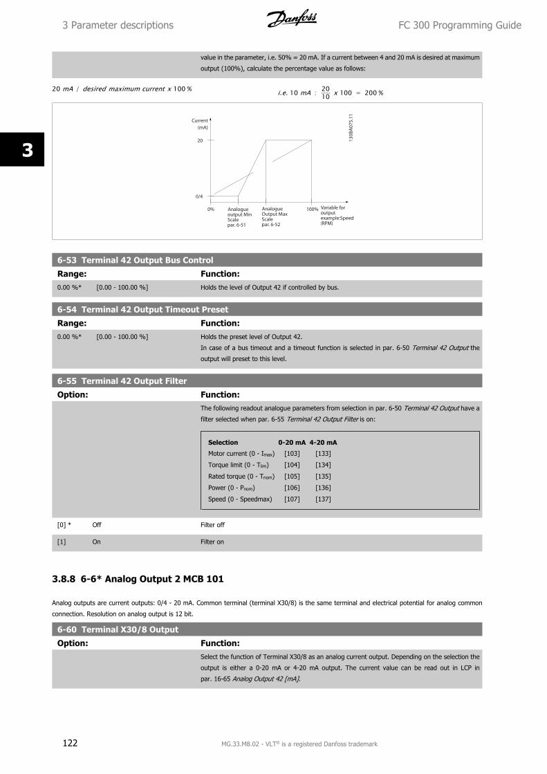
value in the parameter, i.e. 50% = 20 mA. If a current between 4 and 20 mA is desired at maximum
output (100%), calculate the percentage value as follows:
20 mA / desired maximum current x 100 % i.e. 10 mA : 2010 x 100 = 200 %
6-53 Terminal 42 Output Bus Control
Range: Function:0.00 %* [0.00 - 100.00 %] Holds the level of Output 42 if controlled by bus.
6-54 Terminal 42 Output Timeout Preset
Range: Function:0.00 %* [0.00 - 100.00 %] Holds the preset level of Output 42.
In case of a bus timeout and a timeout function is selected in par. 6-50 Terminal 42 Output the
output will preset to this level.
6-55 Terminal 42 Output Filter
Option: Function:The following readout analogue parameters from selection in par. 6-50 Terminal 42 Output have a
filter selected when par. 6-55 Terminal 42 Output Filter is on:
Selection 0-20 mA 4-20 mA
Motor current (0 - Imax) [103] [133]
Torque limit (0 - Tlim) [104] [134]
Rated torque (0 - Tnom) [105] [135]
Power (0 - Pnom) [106] [136]
Speed (0 - Speedmax) [107] [137]
[0] * Off Filter off
[1] On Filter on
3.8.8 6-6* Analog Output 2 MCB 101
Analog outputs are current outputs: 0/4 - 20 mA. Common terminal (terminal X30/8) is the same terminal and electrical potential for analog common
connection. Resolution on analog output is 12 bit.
6-60 Terminal X30/8 Output
Option: Function:Select the function of Terminal X30/8 as an analog current output. Depending on the selection the
output is either a 0-20 mA or 4-20 mA output. The current value can be read out in LCP in
par. 16-65 Analog Output 42 [mA].
3 Parameter descriptions FC 300 Programming Guide
122 MG.33.M8.02 - VLT® is a registered Danfoss trademark
3
[0] * No operation When no signal on the analog output.
[52] MCO 0-20mA
[100] Output frequency 0 Hz = 0 mA; 100 Hz = 20 mA.
[101] Reference Par. 3-00 Reference Range [Min - Max] 0% = 0 mA; 100% = 20 mA
Par. 3-00 Reference Range [-Max - Max] -100% = 0 mA; 0% = 10 mA; +100% = 20 mA
[102] Feedback
[103] Motor current Value is taken from par. 16-37 Inv. Max. Current. Inverter max. current (160% current) is equal to
20 mA.
Example: Inverter norm current (11 kW) = 24 A. 160 % = 38.4 A. Motor norm current = 22 A Read-
out 11.46 mA.
20 mA x 22 A38.4 A = 11.46 mA
In case the norm motor current is equal to 20 mA, the output setting of par. 6-62 Terminal X30/8
Max. Scale is:
IVLTMax x 100
IMotorNorm= 38.4 x 100
22 = 175 %
[104] Torque rel to limit The torque setting is related to setting in par. 4-16 Torque Limit Motor Mode.
[105] Torq relate to rated The torque is related to the motor torque setting.
[106] Power Taken from par. 1-20 Motor Power [kW].
[107] Speed Taken from par. 3-03 Maximum Reference. 20 mA = value in par. 3-03 Maximum Reference
[108] Torque Torque reference related to 160% torque.
[109] Max Out Freq In relation to par. 4-19 Max Output Frequency.
[113] PID Clamped Output
[119] Torque % lim
[130] Output freq. 4-20mA 0 Hz = 4 mA, 100 Hz = 20 mA
[131] Reference 4-20mA Par. 3-00 Reference Range [Min-Max] 0% = 4 mA; 100% = 20 mA
Par. 3-00 Reference Range [-Max-Max] -100% = 4mA; 0% = 12 mA; +100% = 20 mA
[132] Feedback 4-20mA
[133] Motor cur. 4-20mA Value is taken from par. 16-37 Inv. Max. Current. Inverter max. current (160% current) is equal to
20 mA.
Example: Inverter norm current (11 kW) = 24 A. 160 % = 38.4 A. Motor norm current = 22 A Read-
out 11.46 mA.
16 mA x 22 A38.4 A = 9.17 mA
In case the norm motor current is equal to 20 mA, the output setting of par. 6-62 Terminal X30/8
Max. Scale is:
IVLTMax x 100
IMotorNorm= 38.4 x 100
22 = 175 %
[134] Torq.% lim 4-20 mA The torque setting is related to setting in par. 4-16 Torque Limit Motor Mode.
[135] Torq.% nom 4-20 mA The torque setting is related to the motor torque setting.
[136] Power 4-20mA Taken from par. 1-20 Motor Power [kW]
[137] Speed 4-20mA Taken from par. 3-03 Maximum Reference. 20 mA = Value in par. 3-03 Maximum Reference.
[138] Torque 4-20mA Torque reference related to 160% torque.
[139] Bus ctrl. 0-20 mA An output value set from fieldbus process data. The output will work independently of internal
functions in the frequency converter.
FC 300 Programming Guide 3 Parameter descriptions
MG.33.M8.02 - VLT® is a registered Danfoss trademark 123
3
[140] Bus ctrl. 4-20 mA An output value set from fieldbus process data. The output will work independently of internal
functions in the frequency converter.
[141] Bus ctrl 0-20mA t.o. Par. 4-54 Warning Reference Low defines the behaviour of the analog output in case of bus time-
out.
[142] Bus ctrl 4-20mA t.o. Par. 4-54 Warning Reference Low defines the behaviour of the analog output in case of bus time-
out.
[149] Torque % lim 4-20mA Torque % Lim 4-20mA: Torque reference. par. 3-00 Reference Range [Min-Max] 0% = 4 mA; 100%
= 20mA
Par. 3-00 Reference Range [-Max - Max] -100% = 4 mA; 0% = 12mA; +100% = 20mA
[150] Max Out Fr 4-20mA In relation to par. 4-19 Max Output Frequency.
6-61 Terminal X30/8 Min. Scale
Range: Function:0.00 %* [0.00 - 200.00 %] Scales the minimum output of the selected analog signal on terminal X30/8. Scale the minimum
value as a percentage of the maximum signal value, i.e. 0 mA (or 0 Hz) is desired at 25% of the
maximum output value and 25% is programmed. The value can never be higher than the corre-
sponding setting in par. 6-62 Terminal X30/8 Max. Scale if value is below 100%.
This parameter is active when option module MCB 101 is mounted in the frequency converter.
6-62 Terminal X30/8 Max. Scale
Range: Function:100.00 %* [0.00 - 200.00 %] Scales the maximum output of the selected analog signal on terminal X30/8. Scale the value to the
desired maximum value of the current signal output. Scale the output to give a lower current than
20 mA at full scale or 20 mA at an output below 100% of the maximum signal value. If 20 mA is
the desired output current at a value between 0 - 100% of the ful-scale output, program the per-
centage value in the parameter, i.e. 50% = 20 mA. If a current between 4 and 20 mA is desired at
maximum output (100%), calculate the percentage value as follows:
20 mA / desired maximum current x 100 % i.e. 10 mA : 20 − 410 x 100 = 160 %
6-63 Terminal X30/8 Bus Control
Range: Function:0.00 %* [0.00 - 100.00 %] Holds the level of Output X30/8 if controlled by bus.
6-64 Terminal X30/8 Output Timeout Preset
Range: Function:0.00 %* [0.00 - 100.00 %] Holds the preset level of Output X30/8.
In case of a bus timeout and a timeout function is selected in par. 6-60 Terminal X30/8 Output, the
output will preset to this level.
3.8.9 6-7* Analog Output 3 MCB113
Parameters for configuring the scaling and limits for analog output 3, Terminal X45/1 and X45/2. Analog outputs are current outputs: 0/4 – 20 mA.
Resolution on analog output is 11 bit.
6-70 Terminal X45/1 Output
Option: Function:Select the function of Terminal X45/1 as an analog current output.
[0] No operation When no signal on the analog output.
[52] MCO 305 0-20 mA
[53] MCO 305 4-20 mA
[100] Output frequency 0-20 mA 0 Hz = 0 mA; 100 Hz = 20 mA.
3 Parameter descriptions FC 300 Programming Guide
124 MG.33.M8.02 - VLT® is a registered Danfoss trademark
3
[101] Reference 0-20 mA Par. 3-00 [Min - Max] 0% = 0 mA; 100% = 20 mA
Par. 3-00 [-Max - Max] -100% = 0 mA; 0% = 10 mA; +100% = 20 mA
[102] Feedback
[103] Motor current 0-20 mA Value is taken from par. 16-37. Inverter max. current (160% current) is equal to 20 mA.
Example: Inverter norm current (11 kW) = 24 A. 160 % = 38.4 A. Motor norm current = 22 A Read-
out 11.46 mA.
20 mA x 22 A38.4 A = 11.46 mA
In case the norm motor current is equal to 20 mA, the output setting of par. 6-52 is:
IVLTMax x 100
IMotorNorm= 38.4 x 100
22 = 175 %
[104] Torque rel to lim 0-20 mA The torque setting is related to setting in par. 4-16
[105] Torque rel to rated motor torque
0-20 mA
The torque is related to the motor torque setting.
[106] Power 0-20 mA Taken from par. 1-20.
[107] Speed 0-20 mA Taken from par. 3-03. 20 mA = value in par. 3-03
[108] Torque ref. 0-20 mA Torque reference related to 160% torque.
[109] Max Out Freq 0-20 mA In relation to par. 4-19.
[130] Output freq. 4-20 mA 0 Hz = 4 mA, 100 Hz = 20 mA
[131] Reference 4-20 mA Par. 3-00 [Min-Max] 0% = 4 mA; 100% = 20 mA
Par. 3-00 [-Max-Max] -100% = 4mA; 0% = 12 mA; +100% = 20 mA
[132] Feedback 4-20 mA
[133] Motor cur. 4-20 mA Value is taken from par. 16-37. Inverter max. current (160% current) is equal to 20 mA.
Example: Inverter norm current (11 kW) = 24 A. 160 % = 38.4 A. Motor norm current = 22 A Read-
out 11.46 mA.
16 mA x 22 A38.4 A = 9.17 mA
In case the norm motor current is equal to 20 mA, the output setting of par. 6-52 is:
IVLTMax x 100
IMotorNorm= 38.4 x 100
22 = 175 %
[134] Torque % lim. 4-20 mA The torque setting is related to setting in par. 4-16.
[135] Torque % nom 4-20 mA The torque setting is related to the motor torque setting.
[136] Power 4-20 mA Taken from par. 1-20
[137] Speed 4-20 mA Taken from par. 3-03. 20 mA = Value in par. 3-03.
[138] Torque 4-20 mA Torque reference related to 160% torque.
[139] Bus ctrl. 0-20 mA An output value set from fieldbus process data. The output will work independently of internal
functions in the frequency converter.
[140] Bus ctrl. 4-20 mA An output value set from fieldbus process data. The output will work independently of internal
functions in the frequency converter.
[141] Bus ctrl. 0-20 mA, timeout Par. 4-54 defines the behaviour of the analog output in case of bus time-out.
[142] Bus ctrl. 4-20 mA, timeout Par. 4-54 defines the behaviour of the analog output in case of bus time-out.
[150] Max Out Freq 4-20 mA In relation to par. 4-19.
6-71 Terminal X45/1 Output Min Scale
Range: Function:0.00%* [0.00 - 200.00%] Scale the minimum output of the selected analog signal at terminal X45/1, as a percentage of the
maximum signal value. E.g. if 0 mA (or 0 Hz) is desired at 25% of the maximum output value, then
programme 25%. Scaling values up to 100% can never be higher than the corresponding setting
in par. 6-72.
FC 300 Programming Guide 3 Parameter descriptions
MG.33.M8.02 - VLT® is a registered Danfoss trademark 125
3
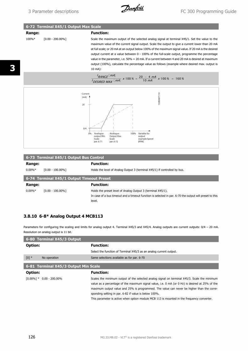
6-72 Terminal X45/1 Output Max Scale
Range: Function:100%* [0.00 - 200.00%] Scale the maximum output of the selected analog signal at terminal X45/1. Set the value to the
maximum value of the current signal output. Scale the output to give a current lower than 20 mA
at full scale; or 20 mA at an output below 100% of the maximum signal value. If 20 mA is the desired
output current at a value between 0 - 100% of the full-scale output, programme the percentage
value in the parameter, i.e. 50% = 20 mA. If a current between 4 and 20 mA is desired at maximum
output (100%), calculate the percentage value as follows (example where desired max. output is
10 mA):
IRANGE mAIDESIRED MAX mA x 100 % = 20 − 4 mA
10 mA x 100 % = 160 %
6-73 Terminal X45/1 Output Bus Control
Range: Function:0.00%* [0.00 - 100.00%] Holds the level of Analog Output 3 (terminal X45/1) if controlled by bus.
6-74 Terminal X45/1 Output Timeout Preset
Range: Function:0.00%* [0.00 - 100.00%] Holds the preset level of Analog Output 3 (terminal X45/1).
In case of a bus timeout and a timeout function is selected in par. 6-70 the output will preset to this
level.
3.8.10 6-8* Analog Output 4 MCB113
Parameters for configuring the scaling and limits for analog output 4. Terminal X45/3 and X45/4. Analog outputs are current outputs: 0/4 – 20 mA.
Resolution on analog output is 11 bit.
6-80 Terminal X45/3 Output
Option: Function:Select the function of Terminal X45/3 as an analog current output.
[0] * No operation Same selections available as for par. 6-70
6-81 Terminal X45/3 Output Min Scale
Option: Function:[0.00%] * 0.00 - 200.00% Scales the minimum output of the selected analog signal on terminal X45/3. Scale the minimum
value as a percentage of the maximum signal value, i.e. 0 mA (or 0 Hz) is desired at 25% of the
maximum output value and 25% is programmed. The value can never be higher than the corre-
sponding setting in par. 6-82 if value is below 100%.
This parameter is active when option module MCB 113 is mounted in the frequency converter.
3 Parameter descriptions FC 300 Programming Guide
126 MG.33.M8.02 - VLT® is a registered Danfoss trademark
3
6-82 Terminal X45/3 Output Max Scale
Option: Function:[0.00%] * 0.00 - 200.00% Scales the maximum output of the selected analog signal on terminal X45/3. Scale the value to the
desired maximum value of the current signal output. Scale the output to give a lower current than
20 mA at full scale or 20 mA at an output below 100% of the maximum signal value. If 20 mA is
the desired output current at a value between 0 - 100% of the ful-scale output, program the per-
centage value in the parameter, i.e. 50% = 20 mA. If a current between 4 and 20 mA is desired at
maximum output (100%), calculate the percentage value as follows (example where desired max.
output is 10 mA):
IRANGE mAIDESIRED MAX mA x 100 % = 20 − 4 mA
10 mA x 100 % = 160 %
6-83 Terminal X45/3 Output Bus Control
Option: Function:[0.00%] * 0.00 - 100.00% Holds the level of output 4 (X45/3) if controlled by bus.
6-84 Terminal X45/3 Output Timeout Preset
Option: Function:[0.00%] * 0.00 - 100.00% Holds the present level of output 4 (X45/3). In case of a bus timeout and a timeout function is
selected in par. 6-80 the output will preset to this level.
FC 300 Programming Guide 3 Parameter descriptions
MG.33.M8.02 - VLT® is a registered Danfoss trademark 127
3
3.9 Parameters: Controllers
3.9.1 7-** Controllers
Parameter group for configuring application controls.
3.9.2 7-0* Speed PID Ctrl.
Parameters for configuring the speed PID control.
7-00 Speed PID Feedback Source
Option: Function:Select the encoder for closed loop feedback.
The feedback may come from a different encoder (typically mounted on the application itself) than
the motor mounted encoder feedback selected in par. 1-02 Flux Motor Feedback Source.
This parameter cannot be adjusted while the motor is running.
[0] * Motor feedb. P1-02
[1] 24V encoder
[2] MCB 102
[3] MCB 103
[5] MCO Encoder 2
[6] Analog input 53
[7] Analog input 54
[8] Frequency input 29
[9] Frequency input 33
NB!
If separate encoders are used (FC 302 only) the ramp settings parameters in the following groups: 3-4*, 3-5*, 3-6*, 3-7* and 3-8*
must be adjusted according to the gear ratio between the two encoders.
7-02 Speed PID Proportional Gain
Range: Function:Application
dependent*
[0.000 - 1.000 ] Enter the speed controller proportional gain. The proportional gain amplifies the error (i.e. the de-
viation between the feedback signal and the set-point). This parameter is used with
par. 1-00 Configuration Mode Speed open loop [0] and Speed closed loop [1] control. Quick control
is obtained at high amplification. However if the amplification is too great, the process may become
unstable.
Use this parameter for values with three decimals. For a selection with four decimals, use
par. 3-83 Quick Stop S-ramp Ratio at Decel. Start.
7-03 Speed PID Integral Time
Range: Function:Application
dependent*
[2.0 - 20000.0 ms] Enter the speed controller integral time, which determines the time the internal PID control takes
to correct errors. The greater the error, the more quickly the gain increases. The integral time causes
a delay of the signal and therefore a dampening effect, and can be used to eliminate steady state
speed error. Obtain quick control through a short integral time, though if the integral time is too
short, the process becomes unstable. An excessively long integral time disables the integral action,
leading to major deviations from the required reference, since the process regulator takes too long
to regulate errors. This parameter is used with Speed open loop [0] and Speed closed loop [1]
control, set in par. 1-00 Configuration Mode.
3 Parameter descriptions FC 300 Programming Guide
128 MG.33.M8.02 - VLT® is a registered Danfoss trademark
3
7-04 Speed PID Differentiation Time
Range: Function:Application
dependent*
[0.0 - 200.0 ms] Enter the speed controller differentiation time. The differentiator does not react to constant error.
It provides gain proportional to the rate of change of the speed feedback. The quicker the error
changes, the stronger the gain from the differentiator. The gain is proportional with the speed at
which errors change. Setting this parameter to zero disables the differentiator. This parameter is
used with par. 1-00 Configuration Mode Speed closed loop [1] control.
7-05 Speed PID Diff. Gain Limit
Range: Function:5.0* [1.0 - 20.0 ] Set a limit for the gain provided by the differentiator. Since the differential gain increases at higher
frequencies, limiting the gain may be useful. For example, set up a pure D-link at low frequencies
and a constant D-link at higher frequencies. This parameter is used with par. 1-00 Configuration
Mode Speed closed loop [1] control.
7-06 Speed PID Lowpass Filter Time
Range: Function:Application
dependent*
[1.0 - 100.0 ms] Set a time constant for the speed control low-pass filter. The low-pass filter improves steady-state
performance and dampens oscillations on the feedback signal. This is an advantage if there is a
great amount on noise in the system, see illustration below. For example, if a time constant (τ) of
100 ms is programmed, the cut-off frequency for the low-pass filter will be 1/0.1= 10 RAD/sec.,
corresponding to (10/2 x π) = 1.6 Hz. The PID regulator only regulates a feedback signal that varies
by a frequency of less than 1.6 Hz. If the feedback signal varies by a higher frequency than 1.6 Hz,
the PID regulator does not react.
Practical settings of par. 7-06 Speed PID Lowpass Filter Time taken from the number of pulses per
revolutions from encoder:
Encoder PPR Par. 7-06 Speed PID Lowpass Filter Time
512 10 ms
1024 5 ms
2048 2 ms
4096 1 ms
Note that severe filtering can be detrimental to dynamic performance.
This parameter is used with par. 1-00 Configuration Mode Speed closed loop [1] and Torque [2]
control.
The filter time in flux sensorless must be adjusted to 3-5 ms.
FC 300 Programming Guide 3 Parameter descriptions
MG.33.M8.02 - VLT® is a registered Danfoss trademark 129
3
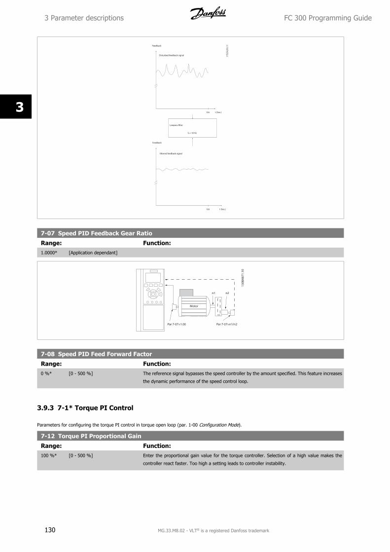
7-07 Speed PID Feedback Gear Ratio
Range: Function:1.0000* [Application dependant]
7-08 Speed PID Feed Forward Factor
Range: Function:0 %* [0 - 500 %] The reference signal bypasses the speed controller by the amount specified. This feature increases
the dynamic performance of the speed control loop.
3.9.3 7-1* Torque PI Control
Parameters for configuring the torque PI control in torque open loop (par. 1-00 Configuration Mode).
7-12 Torque PI Proportional Gain
Range: Function:100 %* [0 - 500 %] Enter the proportional gain value for the torque controller. Selection of a high value makes the
controller react faster. Too high a setting leads to controller instability.
3 Parameter descriptions FC 300 Programming Guide
130 MG.33.M8.02 - VLT® is a registered Danfoss trademark
3
7-13 Torque PI Integration Time
Range: Function:0.020 s* [0.002 - 2.000 s] Enter the integration time for the torque controller. Selection of a low value makes the controller
react faster. Too low a setting leads to control instability.
3.9.4 7-2* Process Ctrl. Feedb.
Select the feedback sources for the Process PID Control, and how this feedback should be handled.
7-20 Process CL Feedback 1 Resource
Option: Function:The effective feedback signal is made up of the sum of up to two different input signals.
Select which frequency converter input should be treated as the source of the first of these signals.
The second input signal is defined in par. 7-22 Process CL Feedback 2 Resource.
[0] * No function
[1] Analog input 53
[2] Analog input 54
[3] Frequency input 29
[4] Frequency input 33
[7] Analog input X30/11 (OPCGPIO)
[8] Analog input X30/12 (OPCGPIO)
7-22 Process CL Feedback 2 Resource
Option: Function:The effective feedback signal is made up of the sum of up to two different input signals. Select
which frequency converter input should be treated as the source of the second of these signals. The
first input signal is defined in par. 7-21.
[0] * No function
[1] Analog input 53
[2] Analog input 54
[3] Frequency input 29
[4] Frequency input 33
[7] Analog input X30/11 (OPCGPIO)
[8] Analog input X30/12 (OPCGPIO)
3.9.5 7-3* Process PID Ctrl.
Parameters for configuring the Process PID control.
7-30 Process PID Normal/ Inverse Control
Option: Function:Normal and inverse control are implemented by introducing a difference between the reference
signal and the feedback signal.
[0] * Normal Sets process control to increase the output frequency.
[1] Inverse Sets process control to reduce the output frequency.
FC 300 Programming Guide 3 Parameter descriptions
MG.33.M8.02 - VLT® is a registered Danfoss trademark 131
3
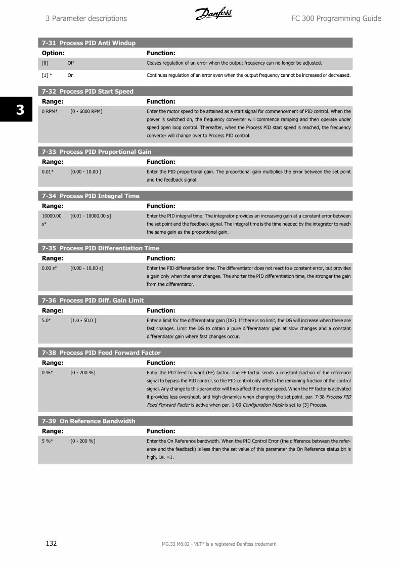
7-31 Process PID Anti Windup
Option: Function:[0] Off Ceases regulation of an error when the output frequency can no longer be adjusted.
[1] * On Continues regulation of an error even when the output frequency cannot be increased or decreased.
7-32 Process PID Start Speed
Range: Function:0 RPM* [0 - 6000 RPM] Enter the motor speed to be attained as a start signal for commencement of PID control. When the
power is switched on, the frequency converter will commence ramping and then operate under
speed open loop control. Thereafter, when the Process PID start speed is reached, the frequency
converter will change over to Process PID control.
7-33 Process PID Proportional Gain
Range: Function:0.01* [0.00 - 10.00 ] Enter the PID proportional gain. The proportional gain multiplies the error between the set point
and the feedback signal.
7-34 Process PID Integral Time
Range: Function:10000.00
s*
[0.01 - 10000.00 s] Enter the PID integral time. The integrator provides an increasing gain at a constant error between
the set point and the feedback signal. The integral time is the time needed by the integrator to reach
the same gain as the proportional gain.
7-35 Process PID Differentiation Time
Range: Function:0.00 s* [0.00 - 10.00 s] Enter the PID differentiation time. The differentiator does not react to a constant error, but provides
a gain only when the error changes. The shorter the PID differentiation time, the stronger the gain
from the differentiator.
7-36 Process PID Diff. Gain Limit
Range: Function:5.0* [1.0 - 50.0 ] Enter a limit for the differentiator gain (DG). If there is no limit, the DG will increase when there are
fast changes. Limit the DG to obtain a pure differentiator gain at slow changes and a constant
differentiator gain where fast changes occur.
7-38 Process PID Feed Forward Factor
Range: Function:0 %* [0 - 200 %] Enter the PID feed forward (FF) factor. The FF factor sends a constant fraction of the reference
signal to bypass the PID control, so the PID control only affects the remaining fraction of the control
signal. Any change to this parameter will thus affect the motor speed. When the FF factor is activated
it provides less overshoot, and high dynamics when changing the set point. par. 7-38 Process PID
Feed Forward Factor is active when par. 1-00 Configuration Mode is set to [3] Process.
7-39 On Reference Bandwidth
Range: Function:5 %* [0 - 200 %] Enter the On Reference bandwidth. When the PID Control Error (the difference between the refer-
ence and the feedback) is less than the set value of this parameter the On Reference status bit is
high, i.e. =1.
3 Parameter descriptions FC 300 Programming Guide
132 MG.33.M8.02 - VLT® is a registered Danfoss trademark
3
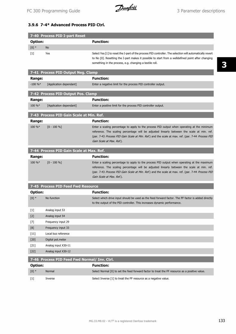
3.9.6 7-4* Advanced Process PID Ctrl.
7-40 Process PID I-part Reset
Option: Function:[0] * No
[1] Yes Select Yes [1] to reset the I-part of the process PID controller. The selection will automatically revert
to No [0]. Resetting the I-part makes it possible to start from a welldefined point after changing
something in the process, e.g. changing a textile roll.
7-41 Process PID Output Neg. Clamp
Range: Function:-100 %* [Application dependant] Enter a negative limit for the process PID controller output.
7-42 Process PID Output Pos. Clamp
Range: Function:100 %* [Application dependant] Enter a positive limit for the process PID controller output.
7-43 Process PID Gain Scale at Min. Ref.
Range: Function:100 %* [0 - 100 %] Enter a scaling percentage to apply to the process PID output when operating at the minimum
reference. The scaling percentage will be adjusted linearly between the scale at min. ref.
(par. 7-43 Process PID Gain Scale at Min. Ref.) and the scale at max. ref. (par. 7-44 Process PID
Gain Scale at Max. Ref.).
7-44 Process PID Gain Scale at Max. Ref.
Range: Function:100 %* [0 - 100 %] Enter a scaling percentage to apply to the process PID output when operating at the maximum
reference. The scaling percentage will be adjusted linearly between the scale at min. ref.
(par. 7-43 Process PID Gain Scale at Min. Ref.) and the scale at max. ref. (par. 7-44 Process PID
Gain Scale at Max. Ref.).
7-45 Process PID Feed Fwd Resource
Option: Function:[0] * No function Select which drive input should be used as the feed forward factor. The FF factor is added directly
to the output of the PID controller. This increases dynamic performance.
[1] Analog input 53
[2] Analog input 54
[7] Frequency input 29
[8] Frequency input 33
[11] Local bus reference
[20] Digital pot.meter
[21] Analog input X30-11
[22] Analog input X30-12
7-46 Process PID Feed Fwd Normal/ Inv. Ctrl.
Option: Function:[0] * Normal Select Normal [0] to set the feed forward factor to treat the FF resource as a positive value.
[1] Inverse Select Inverse [1] to treat the FF resource as a negative value.
FC 300 Programming Guide 3 Parameter descriptions
MG.33.M8.02 - VLT® is a registered Danfoss trademark 133
3
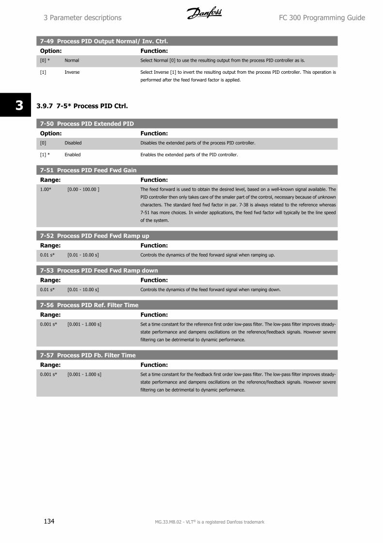
7-49 Process PID Output Normal/ Inv. Ctrl.
Option: Function:[0] * Normal Select Normal [0] to use the resulting output from the process PID controller as is.
[1] Inverse Select Inverse [1] to invert the resulting output from the process PID controller. This operation is
performed after the feed forward factor is applied.
3.9.7 7-5* Process PID Ctrl.
7-50 Process PID Extended PID
Option: Function:[0] Disabled Disables the extended parts of the process PID controller.
[1] * Enabled Enables the extended parts of the PID controller.
7-51 Process PID Feed Fwd Gain
Range: Function:1.00* [0.00 - 100.00 ] The feed forward is used to obtain the desired level, based on a well-known signal available. The
PID controller then only takes care of the smaler part of the control, necessary because of unknown
characters. The standard feed fwd factor in par. 7-38 is always related to the reference whereas
7-51 has more choices. In winder applications, the feed fwd factor will typically be the line speed
of the system.
7-52 Process PID Feed Fwd Ramp up
Range: Function:0.01 s* [0.01 - 10.00 s] Controls the dynamics of the feed forward signal when ramping up.
7-53 Process PID Feed Fwd Ramp down
Range: Function:0.01 s* [0.01 - 10.00 s] Controls the dynamics of the feed forward signal when ramping down.
7-56 Process PID Ref. Filter Time
Range: Function:0.001 s* [0.001 - 1.000 s] Set a time constant for the reference first order low-pass filter. The low-pass filter improves steady-
state performance and dampens oscillations on the reference/feedback signals. However severe
filtering can be detrimental to dynamic performance.
7-57 Process PID Fb. Filter Time
Range: Function:0.001 s* [0.001 - 1.000 s] Set a time constant for the feedback first order low-pass filter. The low-pass filter improves steady-
state performance and dampens oscillations on the reference/feedback signals. However severe
filtering can be detrimental to dynamic performance.
3 Parameter descriptions FC 300 Programming Guide
134 MG.33.M8.02 - VLT® is a registered Danfoss trademark
3
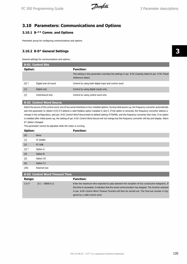
3.10 Parameters: Communications and Options
3.10.1 8-** Comm. and Options
Parameter group for configuring communications and options.
3.10.2 8-0* General Settings
General settings for communications and options.
8-01 Control Site
Option: Function:The setting in this parameter overrides the settings in par. 8-50 Coasting Select to par. 8-56 Preset
Reference Select.
[0] * Digital and ctrl.word Control by using both digital input and control word.
[1] Digital only Control by using digital inputs only.
[2] Controlword only Control by using control word only.
8-02 Control Word SourceSelect the source of the control word: one of two serial interfaces or four installed options. During initial power-up, the frequency converter automatically
sets this parameter to Option A [3] if it detects a valid fieldbus option installed in slot A. If the option is removed, the frequency converter detects a
change in the configuration, sets par. 8-02 Control Word Source back to default setting FC RS485, and the frequency converter then trips. If an option
is installed after initial power-up, the setting of par. 8-02 Control Word Source will not change but the frequency converter will trip and display: Alarm
67 Option Changed.
This parameter cannot be adjusted while the motor is running.
Option: Function:[0] None
[1] FC RS485
[2] FC USB
[3] * Option A
[4] Option B
[5] Option C0
[6] Option C1
[30] External Can
8-03 Control Word Timeout Time
Range: Function:1.0 s* [0.1 - 18000.0 s] Enter the maximum time expected to pass between the reception of two consecutive telegrams. If
this time is exceeded, it indicates that the serial communication has stopped. The function selected
in par. 8-04 Control Word Timeout Function will then be carried out. The time-out counter is trig-
gered by a valid control word.
FC 300 Programming Guide 3 Parameter descriptions
MG.33.M8.02 - VLT® is a registered Danfoss trademark 135
3
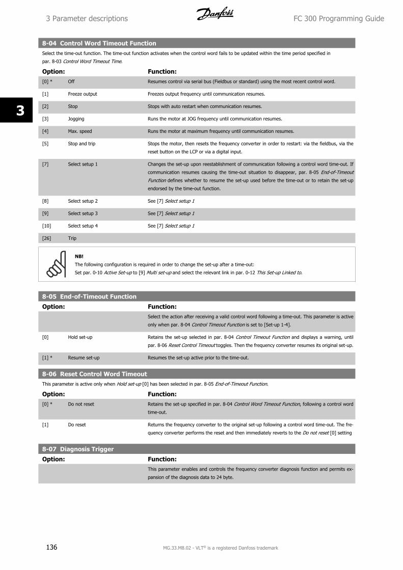
8-04 Control Word Timeout FunctionSelect the time-out function. The time-out function activates when the control word fails to be updated within the time period specified in
par. 8-03 Control Word Timeout Time.
Option: Function:[0] * Off Resumes control via serial bus (Fieldbus or standard) using the most recent control word.
[1] Freeze output Freezes output frequency until communication resumes.
[2] Stop Stops with auto restart when communication resumes.
[3] Jogging Runs the motor at JOG frequency until communication resumes.
[4] Max. speed Runs the motor at maximum frequency until communication resumes.
[5] Stop and trip Stops the motor, then resets the frequency converter in order to restart: via the fieldbus, via the
reset button on the LCP or via a digital input.
[7] Select setup 1 Changes the set-up upon reestablishment of communication following a control word time-out. If
communication resumes causing the time-out situation to disappear, par. 8-05 End-of-Timeout
Function defines whether to resume the set-up used before the time-out or to retain the set-up
endorsed by the time-out function.
[8] Select setup 2 See [7] Select setup 1
[9] Select setup 3 See [7] Select setup 1
[10] Select setup 4 See [7] Select setup 1
[26] Trip
NB!
The following configuration is required in order to change the set-up after a time-out:
Set par. 0-10 Active Set-up to [9] Multi set-up and select the relevant link in par. 0-12 This Set-up Linked to.
8-05 End-of-Timeout Function
Option: Function:Select the action after receiving a valid control word following a time-out. This parameter is active
only when par. 8-04 Control Timeout Function is set to [Set-up 1-4].
[0] Hold set-up Retains the set-up selected in par. 8-04 Control Timeout Function and displays a warning, until
par. 8-06 Reset Control Timeout toggles. Then the frequency converter resumes its original set-up.
[1] * Resume set-up Resumes the set-up active prior to the time-out.
8-06 Reset Control Word TimeoutThis parameter is active only when Hold set-up [0] has been selected in par. 8-05 End-of-Timeout Function.
Option: Function:[0] * Do not reset Retains the set-up specified in par. 8-04 Control Word Timeout Function, following a control word
time-out.
[1] Do reset Returns the frequency converter to the original set-up following a control word time-out. The fre-
quency converter performs the reset and then immediately reverts to the Do not reset [0] setting
8-07 Diagnosis Trigger
Option: Function:This parameter enables and controls the frequency converter diagnosis function and permits ex-
pansion of the diagnosis data to 24 byte.
3 Parameter descriptions FC 300 Programming Guide
136 MG.33.M8.02 - VLT® is a registered Danfoss trademark
3
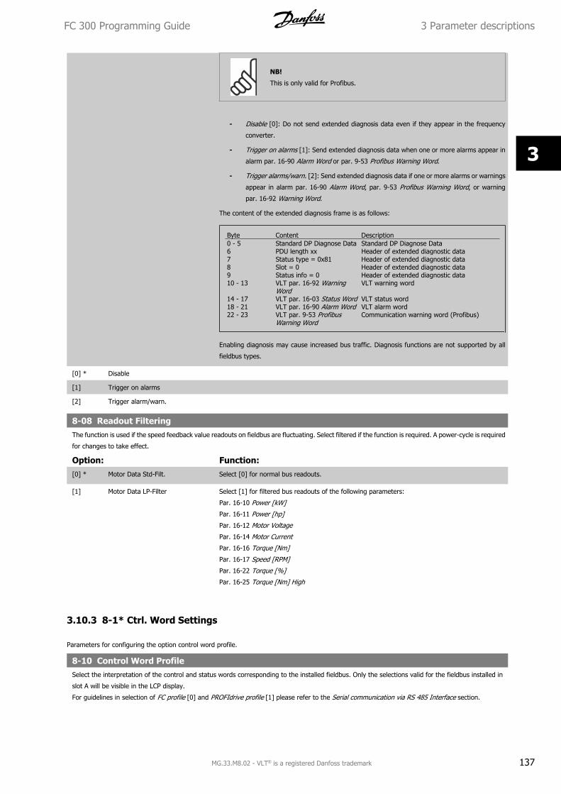
NB!
This is only valid for Profibus.
- Disable [0]: Do not send extended diagnosis data even if they appear in the frequency
converter.
- Trigger on alarms [1]: Send extended diagnosis data when one or more alarms appear in
alarm par. 16-90 Alarm Word or par. 9-53 Profibus Warning Word.
- Trigger alarms/warn. [2]: Send extended diagnosis data if one or more alarms or warnings
appear in alarm par. 16-90 Alarm Word, par. 9-53 Profibus Warning Word, or warning
par. 16-92 Warning Word.
The content of the extended diagnosis frame is as follows:
Byte Content Description0 - 5 Standard DP Diagnose Data Standard DP Diagnose Data6 PDU length xx Header of extended diagnostic data7 Status type = 0x81 Header of extended diagnostic data8 Slot = 0 Header of extended diagnostic data9 Status info = 0 Header of extended diagnostic data10 - 13 VLT par. 16-92 Warning
WordVLT warning word
14 - 17 VLT par. 16-03 Status Word VLT status word18 - 21 VLT par. 16-90 Alarm Word VLT alarm word22 - 23 VLT par. 9-53 Profibus
Warning WordCommunication warning word (Profibus)
Enabling diagnosis may cause increased bus traffic. Diagnosis functions are not supported by all
fieldbus types.
[0] * Disable
[1] Trigger on alarms
[2] Trigger alarm/warn.
8-08 Readout FilteringThe function is used if the speed feedback value readouts on fieldbus are fluctuating. Select filtered if the function is required. A power-cycle is required
for changes to take effect.
Option: Function:[0] * Motor Data Std-Filt. Select [0] for normal bus readouts.
[1] Motor Data LP-Filter Select [1] for filtered bus readouts of the following parameters:
Par. 16-10 Power [kW]
Par. 16-11 Power [hp]
Par. 16-12 Motor Voltage
Par. 16-14 Motor Current
Par. 16-16 Torque [Nm]
Par. 16-17 Speed [RPM]
Par. 16-22 Torque [%]
Par. 16-25 Torque [Nm] High
3.10.3 8-1* Ctrl. Word Settings
Parameters for configuring the option control word profile.
8-10 Control Word ProfileSelect the interpretation of the control and status words corresponding to the installed fieldbus. Only the selections valid for the fieldbus installed in
slot A will be visible in the LCP display.
For guidelines in selection of FC profile [0] and PROFIdrive profile [1] please refer to the Serial communication via RS 485 Interface section.
FC 300 Programming Guide 3 Parameter descriptions
MG.33.M8.02 - VLT® is a registered Danfoss trademark 137
3
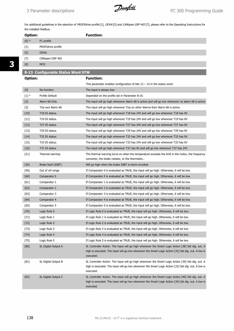
For additional guidelines in the selection of PROFIdrive profile [1], ODVA [5] and CANopen DSP 402 [7], please refer to the Operating Instructions for
the installed fieldbus.
Option: Function:[0] * FC profile
[1] PROFIdrive profile
[5] ODVA
[7] CANopen DSP 402
[8] MCO
8-13 Configurable Status Word STW
Option: Function:This parameter enables configuration of bits 12 – 15 in the status word.
[0] No function The input is always low.
[1] * Profile Default Depended on the profile set in Parameter 8-10.
[2] Alarm 68 Only The input will go high whenever Alarm 68 is active and will go low whenever no alarm 68 is active
[3] Trip excl Alarm 68 The input will go high whenever Trip on other Alarms then Alarm 68 is active.
[10] T18 DI status. The input will go high whenever T18 has 24V and will go low whenever T18 has 0V
[11] T19 DI status. The input will go high whenever T19 has 24V and will go low whenever T19 has 0V
[12] T27 DI status. The input will go high whenever T27 has 24V and will go low whenever T27 has 0V
[13] T29 DI status. The input will go high whenever T29 has 24V and will go low whenever T29 has 0V
[14] T32 DI status. The input will go high whenever T32 has 24V and will go low whenever T32 has 0V
[15] T33 DI status. The input will go high whenever T33 has 24V and will go low whenever T33 has 0V
[16] T37 DI status The input will go high whenever T37 has 0V and will go low whenever T37 has 24V
[21] Thermal warning The thermal warning turns on when the temperature exceeds the limit in the motor, the frequency
converter, the brake resistor, or the thermistor..
[30] Brake fault (IGBT) Will go high when the brake IGBT is short-circuited.
[40] Out of ref range If Comparator 0 is evaluated as TRUE, the input will go high. Otherwise, it will be low.
[60] Comparator 0 If Comparator 0 is evaluated as TRUE, the input will go high. Otherwise, it will be low.
[61] Comparator 1 If Comparator 1 is evaluated as TRUE, the input will go high. Otherwise, it will be low.
[62] Comparator 2 If Comparator 2 is evaluated as TRUE, the input will go high. Otherwise, it will be low.
[63] Comparator 3 If Comparator 3 is evaluated as TRUE, the input will go high. Otherwise, it will be low.
[64] Comparator 4 If Comparator 4 is evaluated as TRUE, the input will go high. Otherwise, it will be low.
[65] Comparator 5 If Comparator 5 is evaluated as TRUE, the input will go high. Otherwise, it will be low.
[70] Logic Rule 0 If Logic Rule 0 is evaluated as TRUE, the input will go high. Otherwise, it will be low.
[71] Logic Rule 1 If Logic Rule 1 is evaluated as TRUE, the input will go high. Otherwise, it will be low.
[72] Logic Rule 2 If Logic Rule 2 is evaluated as TRUE, the input will go high. Otherwise, it will be low.
[73] Logic Rule 3 If Logic Rule 3 is evaluated as TRUE, the input will go high. Otherwise, it will be low.
[74] Logic Rule 4 If Logic Rule 4 is evaluated as TRUE, the input will go high. Otherwise, it will be low.
[75] Logic Rule 5 If Logic Rule 5 is evaluated as TRUE, the input will go high. Otherwise, it will be low.
[80] SL Digital Output A SL Controller Action. The input will go high whenever the Smart Logic Action [38] Set dig. out. A
high is executed. The input will go low whenever the Smart Logic Action [32] Set dig. out. A low is
executed.
[81] SL Digital Output B SL Controller Action. The input will go high whenever the Smart Logic Action [39] Set dig. out. A
high is executed. The input will go low whenever the Smart Logic Action [33] Set dig. out. A low is
executed.
[82] SL Digital Output C SL Controller Action. The input will go high whenever the Smart Logic Action [40] Set dig. out. A
high is executed. The input will go low whenever the Smart Logic Action [34] Set dig. out. A low is
executed.
3 Parameter descriptions FC 300 Programming Guide
138 MG.33.M8.02 - VLT® is a registered Danfoss trademark
3
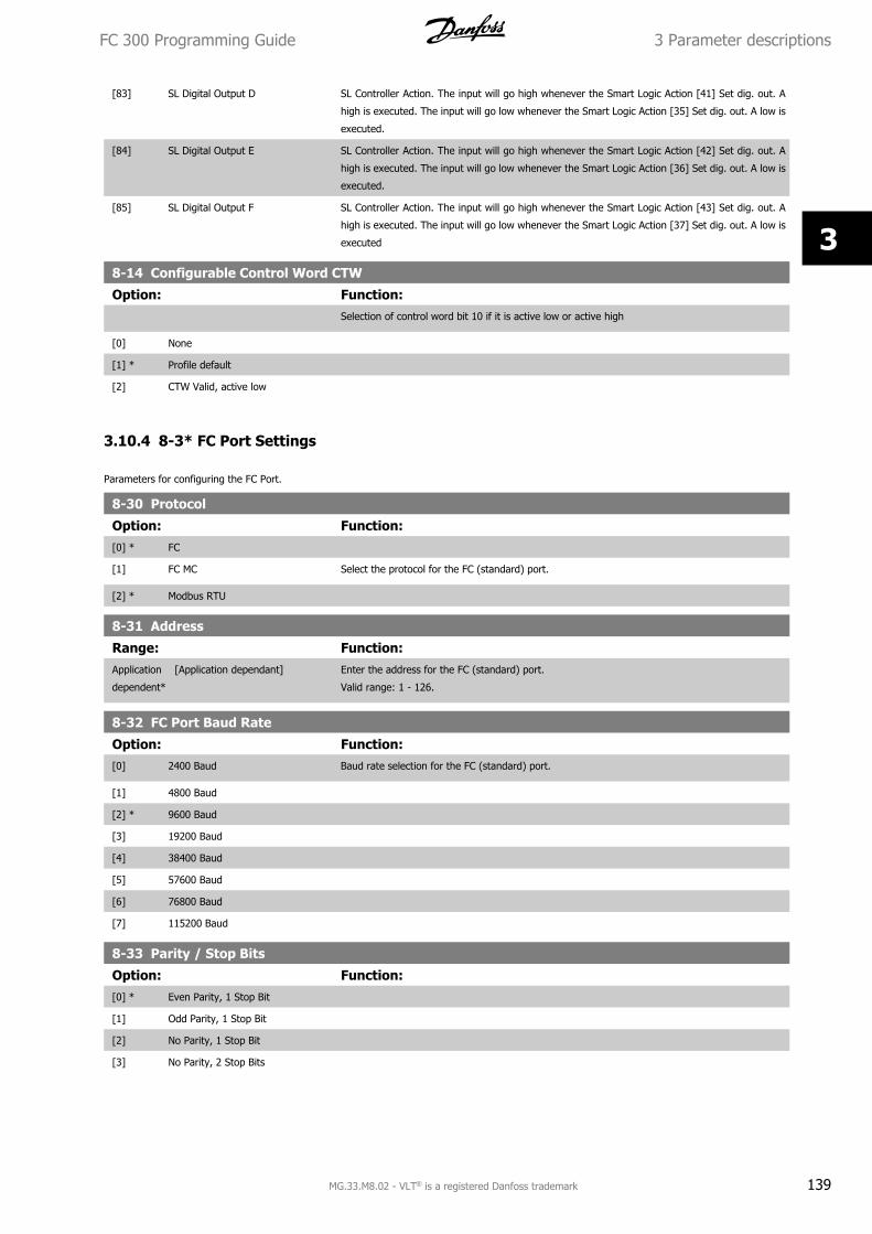
[83] SL Digital Output D SL Controller Action. The input will go high whenever the Smart Logic Action [41] Set dig. out. A
high is executed. The input will go low whenever the Smart Logic Action [35] Set dig. out. A low is
executed.
[84] SL Digital Output E SL Controller Action. The input will go high whenever the Smart Logic Action [42] Set dig. out. A
high is executed. The input will go low whenever the Smart Logic Action [36] Set dig. out. A low is
executed.
[85] SL Digital Output F SL Controller Action. The input will go high whenever the Smart Logic Action [43] Set dig. out. A
high is executed. The input will go low whenever the Smart Logic Action [37] Set dig. out. A low is
executed
8-14 Configurable Control Word CTW
Option: Function:Selection of control word bit 10 if it is active low or active high
[0] None
[1] * Profile default
[2] CTW Valid, active low
3.10.4 8-3* FC Port Settings
Parameters for configuring the FC Port.
8-30 Protocol
Option: Function:[0] * FC
[1] FC MC Select the protocol for the FC (standard) port.
[2] * Modbus RTU
8-31 Address
Range: Function:Application
dependent*
[Application dependant] Enter the address for the FC (standard) port.
Valid range: 1 - 126.
8-32 FC Port Baud Rate
Option: Function:[0] 2400 Baud Baud rate selection for the FC (standard) port.
[1] 4800 Baud
[2] * 9600 Baud
[3] 19200 Baud
[4] 38400 Baud
[5] 57600 Baud
[6] 76800 Baud
[7] 115200 Baud
8-33 Parity / Stop Bits
Option: Function:[0] * Even Parity, 1 Stop Bit
[1] Odd Parity, 1 Stop Bit
[2] No Parity, 1 Stop Bit
[3] No Parity, 2 Stop Bits
FC 300 Programming Guide 3 Parameter descriptions
MG.33.M8.02 - VLT® is a registered Danfoss trademark 139
3
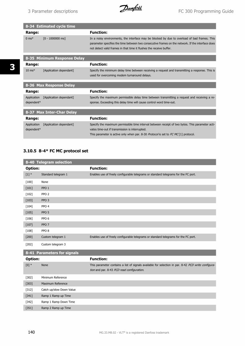
8-34 Estimated cycle time
Range: Function:0 ms* [0 - 1000000 ms] In a noisy environments, the interface may be blocked by due to overload of bad frames. This
parameter specifies the time between two consecutive frames on the network. If the interface does
not detect valid frames in that time it flushes the receive buffer.
8-35 Minimum Response Delay
Range: Function:10 ms* [Application dependant] Specify the minimum delay time between receiving a request and transmitting a response. This is
used for overcoming modem turnaround delays.
8-36 Max Response Delay
Range: Function:Application
dependent*
[Application dependant] Specify the maximum permissible delay time between transmitting a request and receiving a re-
sponse. Exceeding this delay time will cause control word time-out.
8-37 Max Inter-Char Delay
Range: Function:Application
dependent*
[Application dependant] Specify the maximum permissible time interval between receipt of two bytes. This parameter acti-
vates time-out if transmission is interrupted.
This parameter is active only when par. 8-30 Protocol is set to FC MC [1] protocol.
3.10.5 8-4* FC MC protocol set
8-40 Telegram selection
Option: Function:[1] * Standard telegram 1 Enables use of freely configurable telegrams or standard telegrams for the FC port.
[100] None
[101] PPO 1
[102] PPO 2
[103] PPO 3
[104] PPO 4
[105] PPO 5
[106] PPO 6
[107] PPO 7
[108] PPO 8
[200] Custom telegram 1 Enables use of freely configurable telegrams or standard telegrams for the FC port.
[202] Custom telegram 3
8-41 Parameters for signals
Option: Function:[0] * None This parameter contains a list of signals available for selection in par. 8-42 PCD write configura-
tion and par. 8-43 PCD read configuration.
[302] Minimum Reference
[303] Maximum Reference
[312] Catch up/slow Down Value
[341] Ramp 1 Ramp up Time
[342] Ramp 1 Ramp Down Time
[351] Ramp 2 Ramp up Time
3 Parameter descriptions FC 300 Programming Guide
140 MG.33.M8.02 - VLT® is a registered Danfoss trademark
3
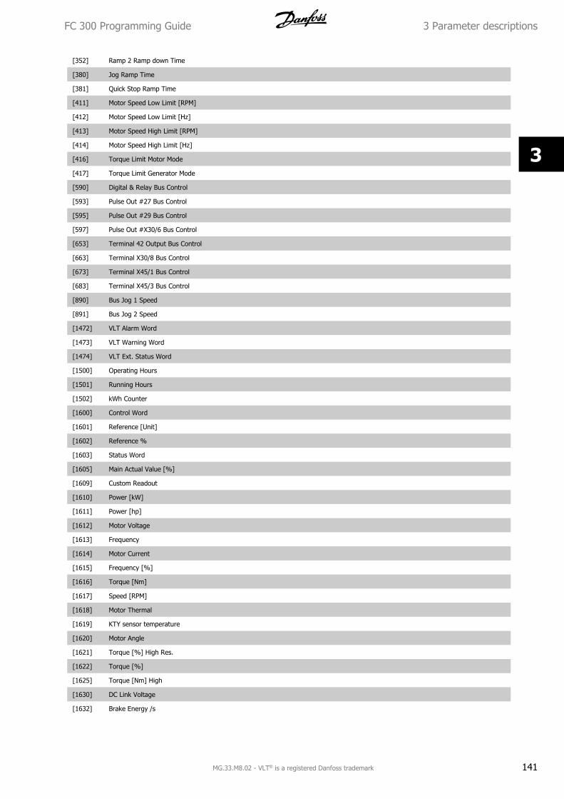
[352] Ramp 2 Ramp down Time
[380] Jog Ramp Time
[381] Quick Stop Ramp Time
[411] Motor Speed Low Limit [RPM]
[412] Motor Speed Low Limit [Hz]
[413] Motor Speed High Limit [RPM]
[414] Motor Speed High Limit [Hz]
[416] Torque Limit Motor Mode
[417] Torque Limit Generator Mode
[590] Digital & Relay Bus Control
[593] Pulse Out #27 Bus Control
[595] Pulse Out #29 Bus Control
[597] Pulse Out #X30/6 Bus Control
[653] Terminal 42 Output Bus Control
[663] Terminal X30/8 Bus Control
[673] Terminal X45/1 Bus Control
[683] Terminal X45/3 Bus Control
[890] Bus Jog 1 Speed
[891] Bus Jog 2 Speed
[1472] VLT Alarm Word
[1473] VLT Warning Word
[1474] VLT Ext. Status Word
[1500] Operating Hours
[1501] Running Hours
[1502] kWh Counter
[1600] Control Word
[1601] Reference [Unit]
[1602] Reference %
[1603] Status Word
[1605] Main Actual Value [%]
[1609] Custom Readout
[1610] Power [kW]
[1611] Power [hp]
[1612] Motor Voltage
[1613] Frequency
[1614] Motor Current
[1615] Frequency [%]
[1616] Torque [Nm]
[1617] Speed [RPM]
[1618] Motor Thermal
[1619] KTY sensor temperature
[1620] Motor Angle
[1621] Torque [%] High Res.
[1622] Torque [%]
[1625] Torque [Nm] High
[1630] DC Link Voltage
[1632] Brake Energy /s
FC 300 Programming Guide 3 Parameter descriptions
MG.33.M8.02 - VLT® is a registered Danfoss trademark 141
3
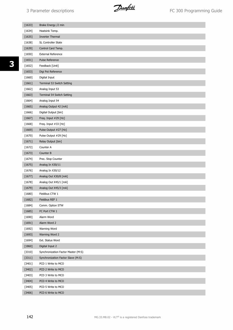
[1633] Brake Energy /2 min
[1634] Heatsink Temp.
[1635] Inverter Thermal
[1638] SL Controller State
[1639] Control Card Temp.
[1650] External Reference
[1651] Pulse Reference
[1652] Feedback [Unit]
[1653] Digi Pot Reference
[1660] Digital Input
[1661] Terminal 53 Switch Setting
[1662] Analog Input 53
[1663] Terminal 54 Switch Setting
[1664] Analog Input 54
[1665] Analog Output 42 [mA]
[1666] Digital Output [bin]
[1667] Freq. Input #29 [Hz]
[1668] Freq. Input #33 [Hz]
[1669] Pulse Output #27 [Hz]
[1670] Pulse Output #29 [Hz]
[1671] Relay Output [bin]
[1672] Counter A
[1673] Counter B
[1674] Prec. Stop Counter
[1675] Analog In X30/11
[1676] Analog In X30/12
[1677] Analog Out X30/8 [mA]
[1678] Analog Out X45/1 [mA]
[1679] Analog Out X45/3 [mA]
[1680] Fieldbus CTW 1
[1682] Fieldbus REF 1
[1684] Comm. Option STW
[1685] FC Port CTW 1
[1690] Alarm Word
[1691] Alarm Word 2
[1692] Warning Word
[1693] Warning Word 2
[1694] Ext. Status Word
[1860] Digital Input 2
[3310] Synchronization Factor Master (M:S)
[3311] Synchronization Factor Slave (M:S)
[3401] PCD 1 Write to MCO
[3402] PCD 2 Write to MCO
[3403] PCD 3 Write to MCO
[3404] PCD 4 Write to MCO
[3405] PCD 5 Write to MCO
[3406] PCD 6 Write to MCO
3 Parameter descriptions FC 300 Programming Guide
142 MG.33.M8.02 - VLT® is a registered Danfoss trademark
3
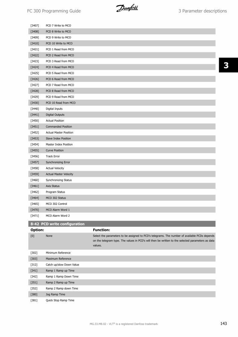
[3407] PCD 7 Write to MCO
[3408] PCD 8 Write to MCO
[3409] PCD 9 Write to MCO
[3410] PCD 10 Write to MCO
[3421] PCD 1 Read from MCO
[3422] PCD 2 Read from MCO
[3423] PCD 3 Read from MCO
[3424] PCD 4 Read from MCO
[3425] PCD 5 Read from MCO
[3426] PCD 6 Read from MCO
[3427] PCD 7 Read from MCO
[3428] PCD 8 Read from MCO
[3429] PCD 9 Read from MCO
[3430] PCD 10 Read from MCO
[3440] Digital Inputs
[3441] Digital Outputs
[3450] Actual Position
[3451] Commanded Position
[3452] Actual Master Position
[3453] Slave Index Position
[3454] Master Index Position
[3455] Curve Position
[3456] Track Error
[3457] Synchronizing Error
[3458] Actual Velocity
[3459] Actual Master Velocity
[3460] Synchronizing Status
[3461] Axis Status
[3462] Program Status
[3464] MCO 302 Status
[3465] MCO 302 Control
[3470] MCO Alarm Word 1
[3471] MCO Alarm Word 2
8-42 PCD write configuration
Option: Function:[0] None Select the parameters to be assigned to PCD's telegrams. The number of available PCDs depends
on the telegram type. The values in PCD's will then be written to the selected parameters as data
values.
[302] Minimum Reference
[303] Maximum Reference
[312] Catch up/slow Down Value
[341] Ramp 1 Ramp up Time
[342] Ramp 1 Ramp Down Time
[351] Ramp 2 Ramp up Time
[352] Ramp 2 Ramp down Time
[380] Jog Ramp Time
[381] Quick Stop Ramp Time
FC 300 Programming Guide 3 Parameter descriptions
MG.33.M8.02 - VLT® is a registered Danfoss trademark 143
3
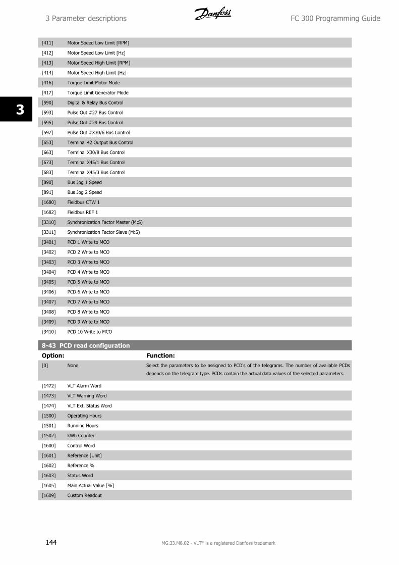
[411] Motor Speed Low Limit [RPM]
[412] Motor Speed Low Limit [Hz]
[413] Motor Speed High Limit [RPM]
[414] Motor Speed High Limit [Hz]
[416] Torque Limit Motor Mode
[417] Torque Limit Generator Mode
[590] Digital & Relay Bus Control
[593] Pulse Out #27 Bus Control
[595] Pulse Out #29 Bus Control
[597] Pulse Out #X30/6 Bus Control
[653] Terminal 42 Output Bus Control
[663] Terminal X30/8 Bus Control
[673] Terminal X45/1 Bus Control
[683] Terminal X45/3 Bus Control
[890] Bus Jog 1 Speed
[891] Bus Jog 2 Speed
[1680] Fieldbus CTW 1
[1682] Fieldbus REF 1
[3310] Synchronization Factor Master (M:S)
[3311] Synchronization Factor Slave (M:S)
[3401] PCD 1 Write to MCO
[3402] PCD 2 Write to MCO
[3403] PCD 3 Write to MCO
[3404] PCD 4 Write to MCO
[3405] PCD 5 Write to MCO
[3406] PCD 6 Write to MCO
[3407] PCD 7 Write to MCO
[3408] PCD 8 Write to MCO
[3409] PCD 9 Write to MCO
[3410] PCD 10 Write to MCO
8-43 PCD read configuration
Option: Function:[0] None Select the parameters to be assigned to PCD's of the telegrams. The number of available PCDs
depends on the telegram type. PCDs contain the actual data values of the selected parameters.
[1472] VLT Alarm Word
[1473] VLT Warning Word
[1474] VLT Ext. Status Word
[1500] Operating Hours
[1501] Running Hours
[1502] kWh Counter
[1600] Control Word
[1601] Reference [Unit]
[1602] Reference %
[1603] Status Word
[1605] Main Actual Value [%]
[1609] Custom Readout
3 Parameter descriptions FC 300 Programming Guide
144 MG.33.M8.02 - VLT® is a registered Danfoss trademark
3
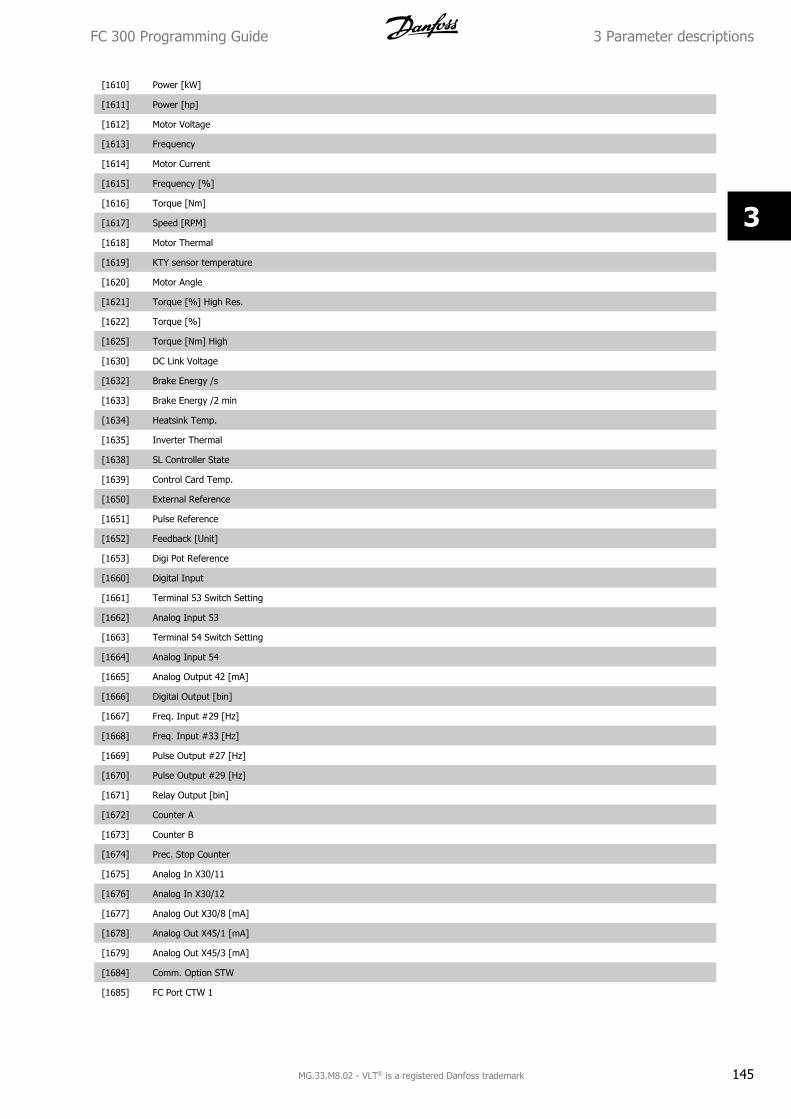
[1610] Power [kW]
[1611] Power [hp]
[1612] Motor Voltage
[1613] Frequency
[1614] Motor Current
[1615] Frequency [%]
[1616] Torque [Nm]
[1617] Speed [RPM]
[1618] Motor Thermal
[1619] KTY sensor temperature
[1620] Motor Angle
[1621] Torque [%] High Res.
[1622] Torque [%]
[1625] Torque [Nm] High
[1630] DC Link Voltage
[1632] Brake Energy /s
[1633] Brake Energy /2 min
[1634] Heatsink Temp.
[1635] Inverter Thermal
[1638] SL Controller State
[1639] Control Card Temp.
[1650] External Reference
[1651] Pulse Reference
[1652] Feedback [Unit]
[1653] Digi Pot Reference
[1660] Digital Input
[1661] Terminal 53 Switch Setting
[1662] Analog Input 53
[1663] Terminal 54 Switch Setting
[1664] Analog Input 54
[1665] Analog Output 42 [mA]
[1666] Digital Output [bin]
[1667] Freq. Input #29 [Hz]
[1668] Freq. Input #33 [Hz]
[1669] Pulse Output #27 [Hz]
[1670] Pulse Output #29 [Hz]
[1671] Relay Output [bin]
[1672] Counter A
[1673] Counter B
[1674] Prec. Stop Counter
[1675] Analog In X30/11
[1676] Analog In X30/12
[1677] Analog Out X30/8 [mA]
[1678] Analog Out X45/1 [mA]
[1679] Analog Out X45/3 [mA]
[1684] Comm. Option STW
[1685] FC Port CTW 1
FC 300 Programming Guide 3 Parameter descriptions
MG.33.M8.02 - VLT® is a registered Danfoss trademark 145
3
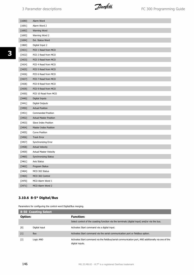
[1690] Alarm Word
[1691] Alarm Word 2
[1692] Warning Word
[1693] Warning Word 2
[1694] Ext. Status Word
[1860] Digital Input 2
[3421] PCD 1 Read from MCO
[3422] PCD 2 Read from MCO
[3423] PCD 3 Read from MCO
[3424] PCD 4 Read from MCO
[3425] PCD 5 Read from MCO
[3426] PCD 6 Read from MCO
[3427] PCD 7 Read from MCO
[3428] PCD 8 Read from MCO
[3429] PCD 9 Read from MCO
[3430] PCD 10 Read from MCO
[3440] Digital Inputs
[3441] Digital Outputs
[3450] Actual Position
[3451] Commanded Position
[3452] Actual Master Position
[3453] Slave Index Position
[3454] Master Index Position
[3455] Curve Position
[3456] Track Error
[3457] Synchronizing Error
[3458] Actual Velocity
[3459] Actual Master Velocity
[3460] Synchronizing Status
[3461] Axis Status
[3462] Program Status
[3464] MCO 302 Status
[3465] MCO 302 Control
[3470] MCO Alarm Word 1
[3471] MCO Alarm Word 2
3.10.6 8-5* Digital/Bus
Parameters for configuring the control word Digital/Bus merging.
8-50 Coasting Select
Option: Function:Select control of the coasting function via the terminals (digital input) and/or via the bus.
[0] Digital input Activates Start command via a digital input.
[1] Bus Activates Start command via the serial communication port or fieldbus option.
[2] Logic AND Activates Start command via the fieldbus/serial communication port, AND additionally via one of the
digital inputs.
3 Parameter descriptions FC 300 Programming Guide
146 MG.33.M8.02 - VLT® is a registered Danfoss trademark
3
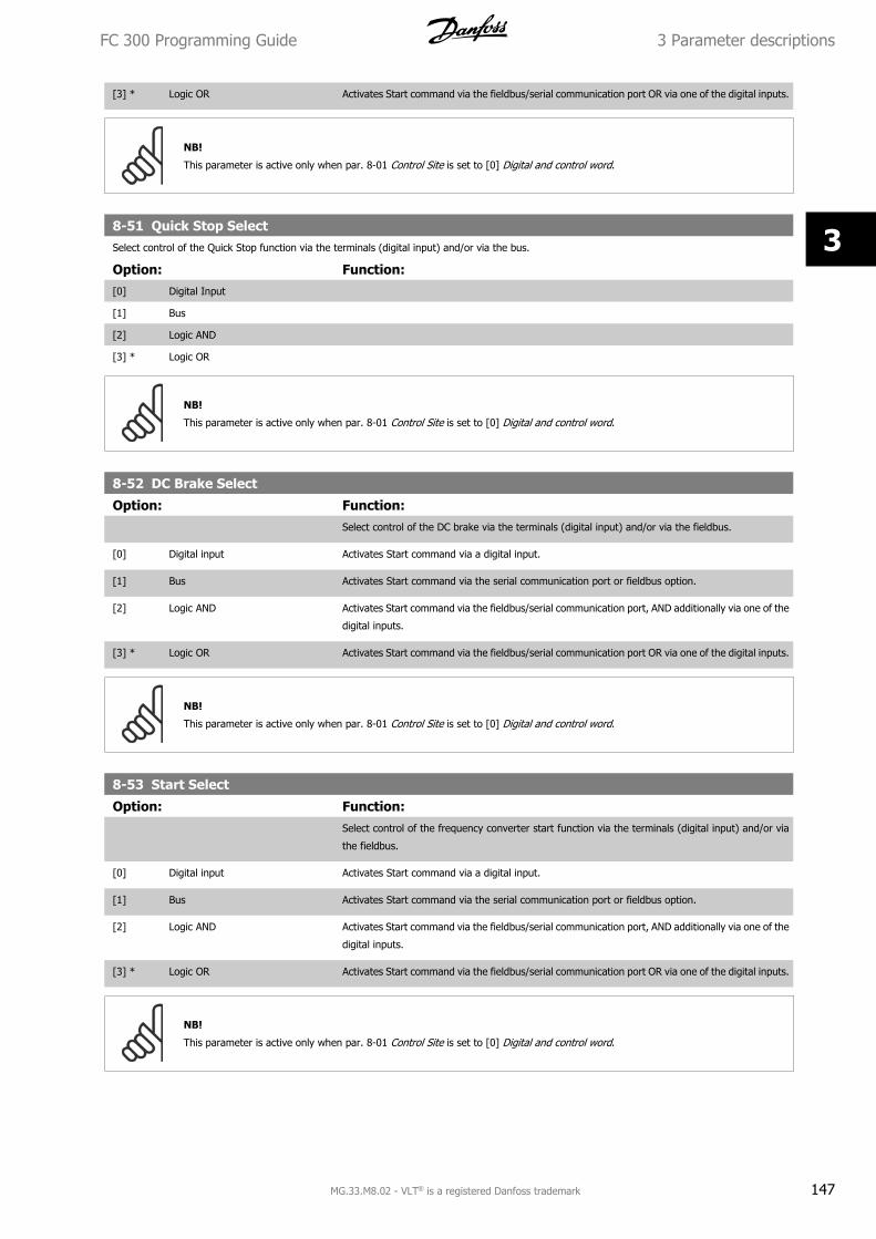
[3] * Logic OR Activates Start command via the fieldbus/serial communication port OR via one of the digital inputs.
NB!
This parameter is active only when par. 8-01 Control Site is set to [0] Digital and control word.
8-51 Quick Stop SelectSelect control of the Quick Stop function via the terminals (digital input) and/or via the bus.
Option: Function:[0] Digital Input
[1] Bus
[2] Logic AND
[3] * Logic OR
NB!
This parameter is active only when par. 8-01 Control Site is set to [0] Digital and control word.
8-52 DC Brake Select
Option: Function:Select control of the DC brake via the terminals (digital input) and/or via the fieldbus.
[0] Digital input Activates Start command via a digital input.
[1] Bus Activates Start command via the serial communication port or fieldbus option.
[2] Logic AND Activates Start command via the fieldbus/serial communication port, AND additionally via one of the
digital inputs.
[3] * Logic OR Activates Start command via the fieldbus/serial communication port OR via one of the digital inputs.
NB!
This parameter is active only when par. 8-01 Control Site is set to [0] Digital and control word.
8-53 Start Select
Option: Function:Select control of the frequency converter start function via the terminals (digital input) and/or via
the fieldbus.
[0] Digital input Activates Start command via a digital input.
[1] Bus Activates Start command via the serial communication port or fieldbus option.
[2] Logic AND Activates Start command via the fieldbus/serial communication port, AND additionally via one of the
digital inputs.
[3] * Logic OR Activates Start command via the fieldbus/serial communication port OR via one of the digital inputs.
NB!
This parameter is active only when par. 8-01 Control Site is set to [0] Digital and control word.
FC 300 Programming Guide 3 Parameter descriptions
MG.33.M8.02 - VLT® is a registered Danfoss trademark 147
3
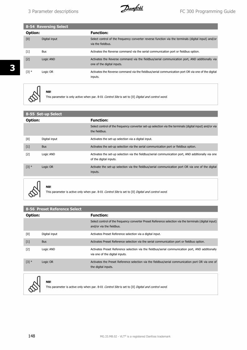
8-54 Reversing Select
Option: Function:[0] Digital input Select control of the frequency converter reverse function via the terminals (digital input) and/or
via the fieldbus.
[1] Bus Activates the Reverse command via the serial communication port or fieldbus option.
[2] Logic AND Activates the Reverse command via the fieldbus/serial communication port, AND additionally via
one of the digital inputs.
[3] * Logic OR Activates the Reverse command via the fieldbus/serial communication port OR via one of the digital
inputs.
NB!
This parameter is only active when par. 8-01 Control Site is set to [0] Digital and control word.
8-55 Set-up Select
Option: Function:Select control of the frequency converter set-up selection via the terminals (digital input) and/or via
the fieldbus.
[0] Digital input Activates the set-up selection via a digital input.
[1] Bus Activates the set-up selection via the serial communication port or fieldbus option.
[2] Logic AND Activates the set-up selection via the fieldbus/serial communication port, AND additionally via one
of the digital inputs.
[3] * Logic OR Activate the set-up selection via the fieldbus/serial communication port OR via one of the digital
inputs.
NB!
This parameter is active only when par. 8-01 Control Site is set to [0] Digital and control word.
8-56 Preset Reference Select
Option: Function:Select control of the frequency converter Preset Reference selection via the terminals (digital input)
and/or via the fieldbus.
[0] Digital input Activates Preset Reference selection via a digital input.
[1] Bus Activates Preset Reference selection via the serial communication port or fieldbus option.
[2] Logic AND Activates Preset Reference selection via the fieldbus/serial communication port, AND additionally
via one of the digital inputs.
[3] * Logic OR Activates the Preset Reference selection via the fieldbus/serial communication port OR via one of
the digital inputs.
NB!
This parameter is active only when par. 8-01 Control Site is set to [0] Digital and control word.
3 Parameter descriptions FC 300 Programming Guide
148 MG.33.M8.02 - VLT® is a registered Danfoss trademark
3
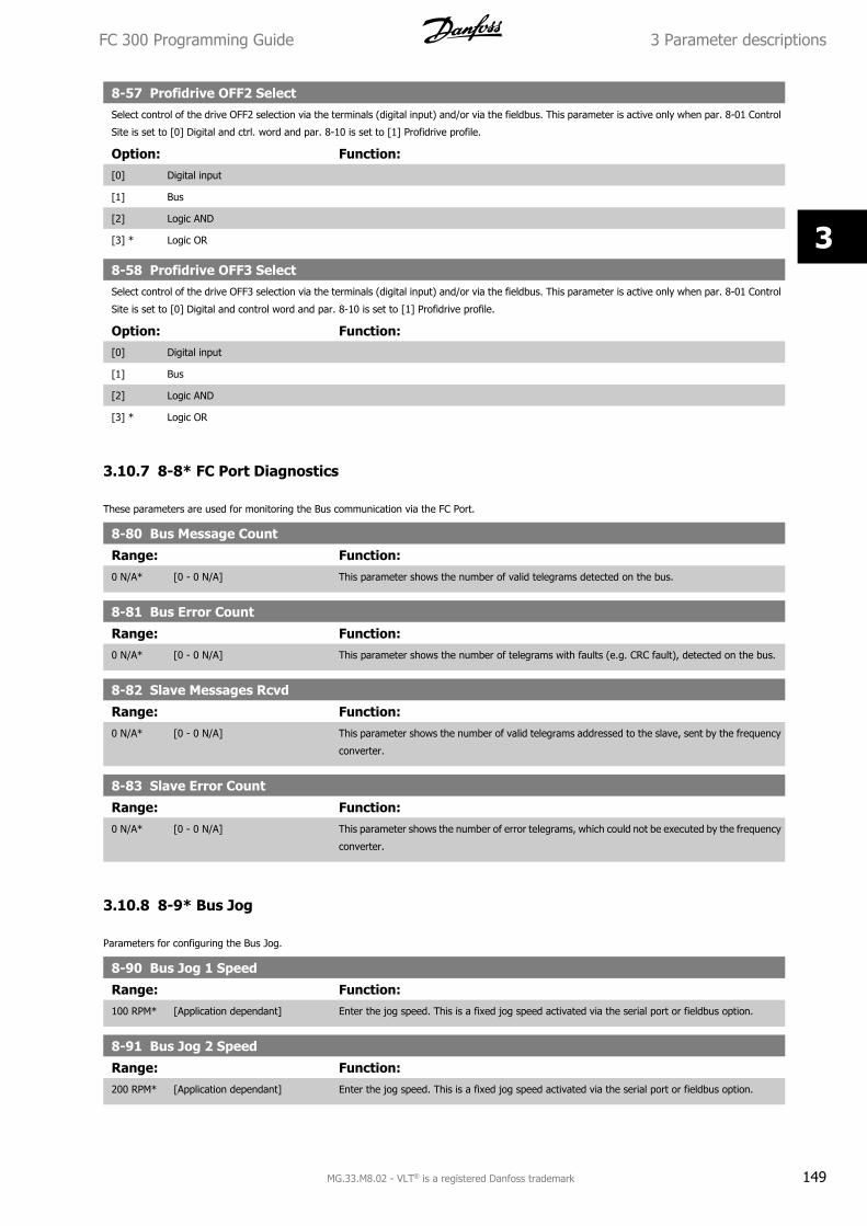
8-57 Profidrive OFF2 SelectSelect control of the drive OFF2 selection via the terminals (digital input) and/or via the fieldbus. This parameter is active only when par. 8-01 Control
Site is set to [0] Digital and ctrl. word and par. 8-10 is set to [1] Profidrive profile.
Option: Function:[0] Digital input
[1] Bus
[2] Logic AND
[3] * Logic OR
8-58 Profidrive OFF3 SelectSelect control of the drive OFF3 selection via the terminals (digital input) and/or via the fieldbus. This parameter is active only when par. 8-01 Control
Site is set to [0] Digital and control word and par. 8-10 is set to [1] Profidrive profile.
Option: Function:[0] Digital input
[1] Bus
[2] Logic AND
[3] * Logic OR
3.10.7 8-8* FC Port Diagnostics
These parameters are used for monitoring the Bus communication via the FC Port.
8-80 Bus Message Count
Range: Function:0 N/A* [0 - 0 N/A] This parameter shows the number of valid telegrams detected on the bus.
8-81 Bus Error Count
Range: Function:0 N/A* [0 - 0 N/A] This parameter shows the number of telegrams with faults (e.g. CRC fault), detected on the bus.
8-82 Slave Messages Rcvd
Range: Function:0 N/A* [0 - 0 N/A] This parameter shows the number of valid telegrams addressed to the slave, sent by the frequency
converter.
8-83 Slave Error Count
Range: Function:0 N/A* [0 - 0 N/A] This parameter shows the number of error telegrams, which could not be executed by the frequency
converter.
3.10.8 8-9* Bus Jog
Parameters for configuring the Bus Jog.
8-90 Bus Jog 1 Speed
Range: Function:100 RPM* [Application dependant] Enter the jog speed. This is a fixed jog speed activated via the serial port or fieldbus option.
8-91 Bus Jog 2 Speed
Range: Function:200 RPM* [Application dependant] Enter the jog speed. This is a fixed jog speed activated via the serial port or fieldbus option.
FC 300 Programming Guide 3 Parameter descriptions
MG.33.M8.02 - VLT® is a registered Danfoss trademark 149
3
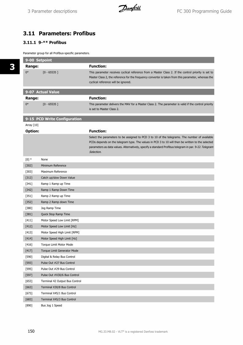
3.11 Parameters: Profibus
3.11.1 9-** Profibus
Parameter group for all Profibus-specific parameters.
9-00 Setpoint
Range: Function:0* [0 - 65535 ] This parameter receives cyclical reference from a Master Class 2. If the control priority is set to
Master Class 2, the reference for the frequency converter is taken from this parameter, whereas the
cyclical reference will be ignored.
9-07 Actual Value
Range: Function:0* [0 - 65535 ] This parameter delivers the MAV for a Master Class 2. The parameter is valid if the control priority
is set to Master Class 2.
9-15 PCD Write ConfigurationArray [10]
Option: Function:Select the parameters to be assigned to PCD 3 to 10 of the telegrams. The number of available
PCDs depends on the telegram type. The values in PCD 3 to 10 will then be written to the selected
parameters as data values. Alternatively, specify a standard Profibus telegram in par. 9-22 Telegram
Selection.
[0] * None
[302] Minimum Reference
[303] Maximum Reference
[312] Catch up/slow Down Value
[341] Ramp 1 Ramp up Time
[342] Ramp 1 Ramp Down Time
[351] Ramp 2 Ramp up Time
[352] Ramp 2 Ramp down Time
[380] Jog Ramp Time
[381] Quick Stop Ramp Time
[411] Motor Speed Low Limit [RPM]
[412] Motor Speed Low Limit [Hz]
[413] Motor Speed High Limit [RPM]
[414] Motor Speed High Limit [Hz]
[416] Torque Limit Motor Mode
[417] Torque Limit Generator Mode
[590] Digital & Relay Bus Control
[593] Pulse Out #27 Bus Control
[595] Pulse Out #29 Bus Control
[597] Pulse Out #X30/6 Bus Control
[653] Terminal 42 Output Bus Control
[663] Terminal X30/8 Bus Control
[673] Terminal X45/1 Bus Control
[683] Terminal X45/3 Bus Control
[890] Bus Jog 1 Speed
3 Parameter descriptions FC 300 Programming Guide
150 MG.33.M8.02 - VLT® is a registered Danfoss trademark
3
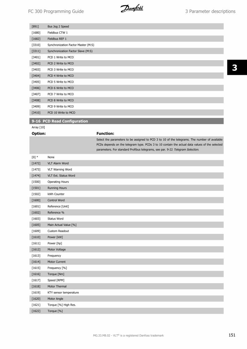
[891] Bus Jog 2 Speed
[1680] Fieldbus CTW 1
[1682] Fieldbus REF 1
[3310] Synchronization Factor Master (M:S)
[3311] Synchronization Factor Slave (M:S)
[3401] PCD 1 Write to MCO
[3402] PCD 2 Write to MCO
[3403] PCD 3 Write to MCO
[3404] PCD 4 Write to MCO
[3405] PCD 5 Write to MCO
[3406] PCD 6 Write to MCO
[3407] PCD 7 Write to MCO
[3408] PCD 8 Write to MCO
[3409] PCD 9 Write to MCO
[3410] PCD 10 Write to MCO
9-16 PCD Read ConfigurationArray [10]
Option: Function:Select the parameters to be assigned to PCD 3 to 10 of the telegrams. The number of available
PCDs depends on the telegram type. PCDs 3 to 10 contain the actual data values of the selected
parameters. For standard Profibus telegrams, see par. 9-22 Telegram Selection.
[0] * None
[1472] VLT Alarm Word
[1473] VLT Warning Word
[1474] VLT Ext. Status Word
[1500] Operating Hours
[1501] Running Hours
[1502] kWh Counter
[1600] Control Word
[1601] Reference [Unit]
[1602] Reference %
[1603] Status Word
[1605] Main Actual Value [%]
[1609] Custom Readout
[1610] Power [kW]
[1611] Power [hp]
[1612] Motor Voltage
[1613] Frequency
[1614] Motor Current
[1615] Frequency [%]
[1616] Torque [Nm]
[1617] Speed [RPM]
[1618] Motor Thermal
[1619] KTY sensor temperature
[1620] Motor Angle
[1621] Torque [%] High Res.
[1622] Torque [%]
FC 300 Programming Guide 3 Parameter descriptions
MG.33.M8.02 - VLT® is a registered Danfoss trademark 151
3
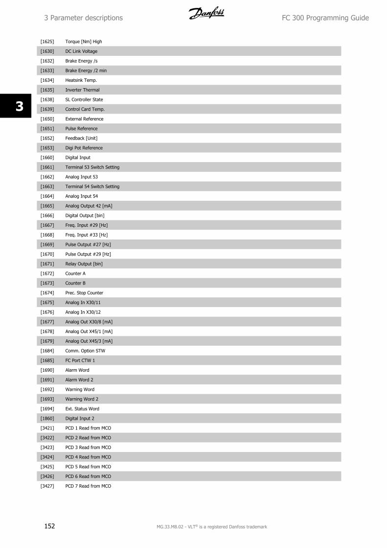
[1625] Torque [Nm] High
[1630] DC Link Voltage
[1632] Brake Energy /s
[1633] Brake Energy /2 min
[1634] Heatsink Temp.
[1635] Inverter Thermal
[1638] SL Controller State
[1639] Control Card Temp.
[1650] External Reference
[1651] Pulse Reference
[1652] Feedback [Unit]
[1653] Digi Pot Reference
[1660] Digital Input
[1661] Terminal 53 Switch Setting
[1662] Analog Input 53
[1663] Terminal 54 Switch Setting
[1664] Analog Input 54
[1665] Analog Output 42 [mA]
[1666] Digital Output [bin]
[1667] Freq. Input #29 [Hz]
[1668] Freq. Input #33 [Hz]
[1669] Pulse Output #27 [Hz]
[1670] Pulse Output #29 [Hz]
[1671] Relay Output [bin]
[1672] Counter A
[1673] Counter B
[1674] Prec. Stop Counter
[1675] Analog In X30/11
[1676] Analog In X30/12
[1677] Analog Out X30/8 [mA]
[1678] Analog Out X45/1 [mA]
[1679] Analog Out X45/3 [mA]
[1684] Comm. Option STW
[1685] FC Port CTW 1
[1690] Alarm Word
[1691] Alarm Word 2
[1692] Warning Word
[1693] Warning Word 2
[1694] Ext. Status Word
[1860] Digital Input 2
[3421] PCD 1 Read from MCO
[3422] PCD 2 Read from MCO
[3423] PCD 3 Read from MCO
[3424] PCD 4 Read from MCO
[3425] PCD 5 Read from MCO
[3426] PCD 6 Read from MCO
[3427] PCD 7 Read from MCO
3 Parameter descriptions FC 300 Programming Guide
152 MG.33.M8.02 - VLT® is a registered Danfoss trademark
3
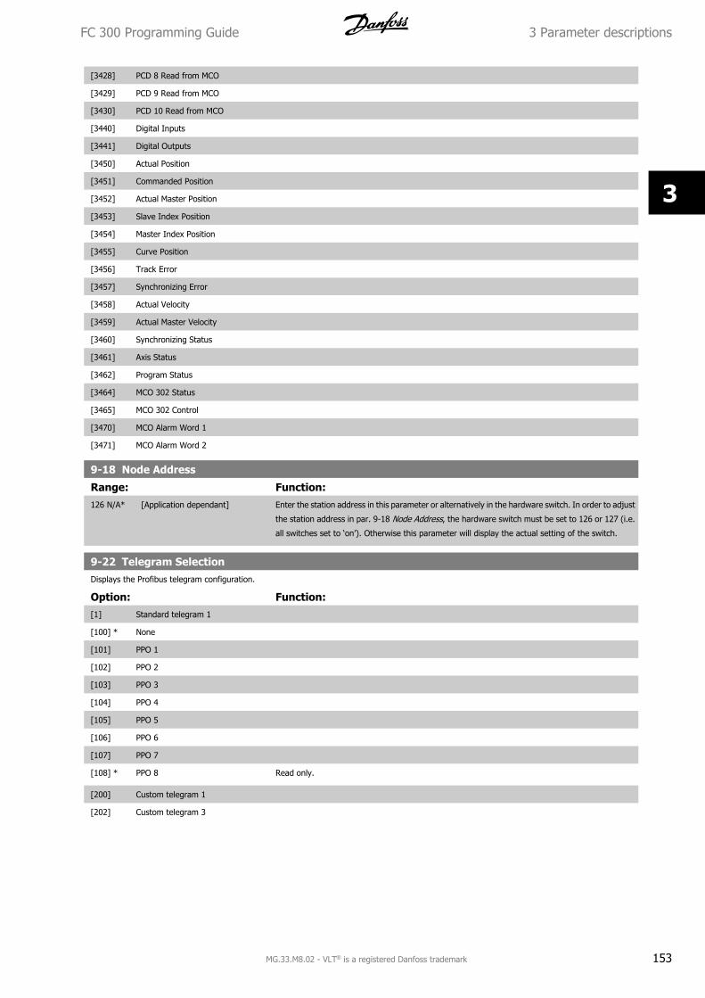
[3428] PCD 8 Read from MCO
[3429] PCD 9 Read from MCO
[3430] PCD 10 Read from MCO
[3440] Digital Inputs
[3441] Digital Outputs
[3450] Actual Position
[3451] Commanded Position
[3452] Actual Master Position
[3453] Slave Index Position
[3454] Master Index Position
[3455] Curve Position
[3456] Track Error
[3457] Synchronizing Error
[3458] Actual Velocity
[3459] Actual Master Velocity
[3460] Synchronizing Status
[3461] Axis Status
[3462] Program Status
[3464] MCO 302 Status
[3465] MCO 302 Control
[3470] MCO Alarm Word 1
[3471] MCO Alarm Word 2
9-18 Node Address
Range: Function:126 N/A* [Application dependant] Enter the station address in this parameter or alternatively in the hardware switch. In order to adjust
the station address in par. 9-18 Node Address, the hardware switch must be set to 126 or 127 (i.e.
all switches set to ‘on’). Otherwise this parameter will display the actual setting of the switch.
9-22 Telegram SelectionDisplays the Profibus telegram configuration.
Option: Function:[1] Standard telegram 1
[100] * None
[101] PPO 1
[102] PPO 2
[103] PPO 3
[104] PPO 4
[105] PPO 5
[106] PPO 6
[107] PPO 7
[108] * PPO 8 Read only.
[200] Custom telegram 1
[202] Custom telegram 3
FC 300 Programming Guide 3 Parameter descriptions
MG.33.M8.02 - VLT® is a registered Danfoss trademark 153
3
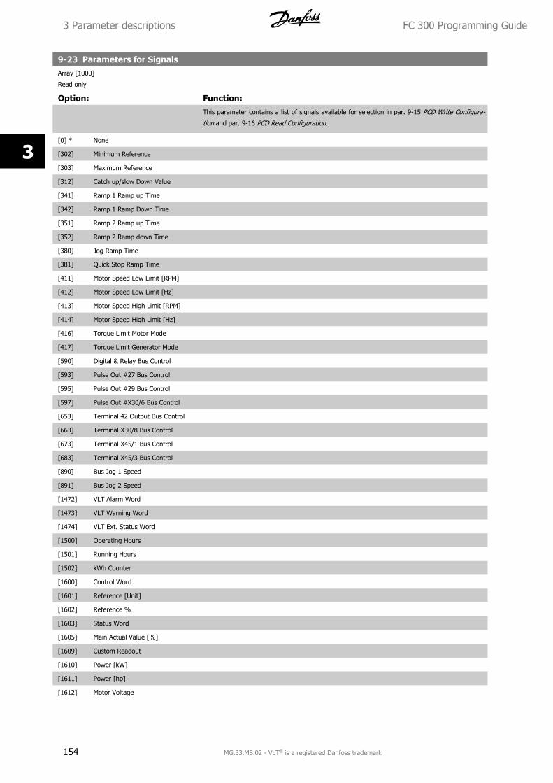
9-23 Parameters for SignalsArray [1000]
Read only
Option: Function:This parameter contains a list of signals available for selection in par. 9-15 PCD Write Configura-
tion and par. 9-16 PCD Read Configuration.
[0] * None
[302] Minimum Reference
[303] Maximum Reference
[312] Catch up/slow Down Value
[341] Ramp 1 Ramp up Time
[342] Ramp 1 Ramp Down Time
[351] Ramp 2 Ramp up Time
[352] Ramp 2 Ramp down Time
[380] Jog Ramp Time
[381] Quick Stop Ramp Time
[411] Motor Speed Low Limit [RPM]
[412] Motor Speed Low Limit [Hz]
[413] Motor Speed High Limit [RPM]
[414] Motor Speed High Limit [Hz]
[416] Torque Limit Motor Mode
[417] Torque Limit Generator Mode
[590] Digital & Relay Bus Control
[593] Pulse Out #27 Bus Control
[595] Pulse Out #29 Bus Control
[597] Pulse Out #X30/6 Bus Control
[653] Terminal 42 Output Bus Control
[663] Terminal X30/8 Bus Control
[673] Terminal X45/1 Bus Control
[683] Terminal X45/3 Bus Control
[890] Bus Jog 1 Speed
[891] Bus Jog 2 Speed
[1472] VLT Alarm Word
[1473] VLT Warning Word
[1474] VLT Ext. Status Word
[1500] Operating Hours
[1501] Running Hours
[1502] kWh Counter
[1600] Control Word
[1601] Reference [Unit]
[1602] Reference %
[1603] Status Word
[1605] Main Actual Value [%]
[1609] Custom Readout
[1610] Power [kW]
[1611] Power [hp]
[1612] Motor Voltage
3 Parameter descriptions FC 300 Programming Guide
154 MG.33.M8.02 - VLT® is a registered Danfoss trademark
3
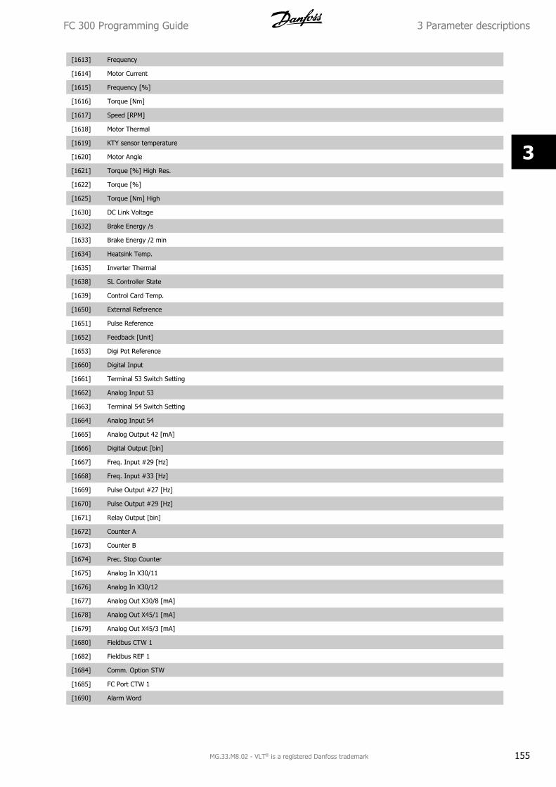
[1613] Frequency
[1614] Motor Current
[1615] Frequency [%]
[1616] Torque [Nm]
[1617] Speed [RPM]
[1618] Motor Thermal
[1619] KTY sensor temperature
[1620] Motor Angle
[1621] Torque [%] High Res.
[1622] Torque [%]
[1625] Torque [Nm] High
[1630] DC Link Voltage
[1632] Brake Energy /s
[1633] Brake Energy /2 min
[1634] Heatsink Temp.
[1635] Inverter Thermal
[1638] SL Controller State
[1639] Control Card Temp.
[1650] External Reference
[1651] Pulse Reference
[1652] Feedback [Unit]
[1653] Digi Pot Reference
[1660] Digital Input
[1661] Terminal 53 Switch Setting
[1662] Analog Input 53
[1663] Terminal 54 Switch Setting
[1664] Analog Input 54
[1665] Analog Output 42 [mA]
[1666] Digital Output [bin]
[1667] Freq. Input #29 [Hz]
[1668] Freq. Input #33 [Hz]
[1669] Pulse Output #27 [Hz]
[1670] Pulse Output #29 [Hz]
[1671] Relay Output [bin]
[1672] Counter A
[1673] Counter B
[1674] Prec. Stop Counter
[1675] Analog In X30/11
[1676] Analog In X30/12
[1677] Analog Out X30/8 [mA]
[1678] Analog Out X45/1 [mA]
[1679] Analog Out X45/3 [mA]
[1680] Fieldbus CTW 1
[1682] Fieldbus REF 1
[1684] Comm. Option STW
[1685] FC Port CTW 1
[1690] Alarm Word
FC 300 Programming Guide 3 Parameter descriptions
MG.33.M8.02 - VLT® is a registered Danfoss trademark 155
3
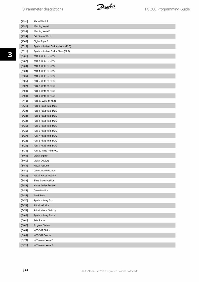
[1691] Alarm Word 2
[1692] Warning Word
[1693] Warning Word 2
[1694] Ext. Status Word
[1860] Digital Input 2
[3310] Synchronization Factor Master (M:S)
[3311] Synchronization Factor Slave (M:S)
[3401] PCD 1 Write to MCO
[3402] PCD 2 Write to MCO
[3403] PCD 3 Write to MCO
[3404] PCD 4 Write to MCO
[3405] PCD 5 Write to MCO
[3406] PCD 6 Write to MCO
[3407] PCD 7 Write to MCO
[3408] PCD 8 Write to MCO
[3409] PCD 9 Write to MCO
[3410] PCD 10 Write to MCO
[3421] PCD 1 Read from MCO
[3422] PCD 2 Read from MCO
[3423] PCD 3 Read from MCO
[3424] PCD 4 Read from MCO
[3425] PCD 5 Read from MCO
[3426] PCD 6 Read from MCO
[3427] PCD 7 Read from MCO
[3428] PCD 8 Read from MCO
[3429] PCD 9 Read from MCO
[3430] PCD 10 Read from MCO
[3440] Digital Inputs
[3441] Digital Outputs
[3450] Actual Position
[3451] Commanded Position
[3452] Actual Master Position
[3453] Slave Index Position
[3454] Master Index Position
[3455] Curve Position
[3456] Track Error
[3457] Synchronizing Error
[3458] Actual Velocity
[3459] Actual Master Velocity
[3460] Synchronizing Status
[3461] Axis Status
[3462] Program Status
[3464] MCO 302 Status
[3465] MCO 302 Control
[3470] MCO Alarm Word 1
[3471] MCO Alarm Word 2
3 Parameter descriptions FC 300 Programming Guide
156 MG.33.M8.02 - VLT® is a registered Danfoss trademark
3
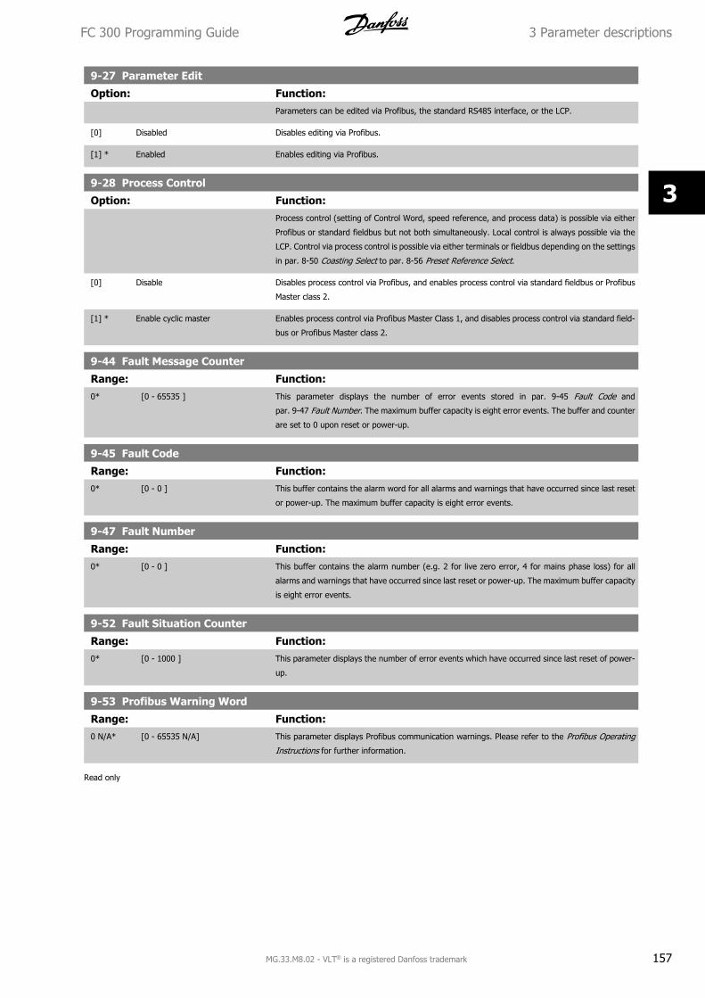
9-27 Parameter Edit
Option: Function:Parameters can be edited via Profibus, the standard RS485 interface, or the LCP.
[0] Disabled Disables editing via Profibus.
[1] * Enabled Enables editing via Profibus.
9-28 Process Control
Option: Function:Process control (setting of Control Word, speed reference, and process data) is possible via either
Profibus or standard fieldbus but not both simultaneously. Local control is always possible via the
LCP. Control via process control is possible via either terminals or fieldbus depending on the settings
in par. 8-50 Coasting Select to par. 8-56 Preset Reference Select.
[0] Disable Disables process control via Profibus, and enables process control via standard fieldbus or Profibus
Master class 2.
[1] * Enable cyclic master Enables process control via Profibus Master Class 1, and disables process control via standard field-
bus or Profibus Master class 2.
9-44 Fault Message Counter
Range: Function:0* [0 - 65535 ] This parameter displays the number of error events stored in par. 9-45 Fault Code and
par. 9-47 Fault Number. The maximum buffer capacity is eight error events. The buffer and counter
are set to 0 upon reset or power-up.
9-45 Fault Code
Range: Function:0* [0 - 0 ] This buffer contains the alarm word for all alarms and warnings that have occurred since last reset
or power-up. The maximum buffer capacity is eight error events.
9-47 Fault Number
Range: Function:0* [0 - 0 ] This buffer contains the alarm number (e.g. 2 for live zero error, 4 for mains phase loss) for all
alarms and warnings that have occurred since last reset or power-up. The maximum buffer capacity
is eight error events.
9-52 Fault Situation Counter
Range: Function:0* [0 - 1000 ] This parameter displays the number of error events which have occurred since last reset of power-
up.
9-53 Profibus Warning Word
Range: Function:0 N/A* [0 - 65535 N/A] This parameter displays Profibus communication warnings. Please refer to the Profibus Operating
Instructions for further information.
Read only
FC 300 Programming Guide 3 Parameter descriptions
MG.33.M8.02 - VLT® is a registered Danfoss trademark 157
3
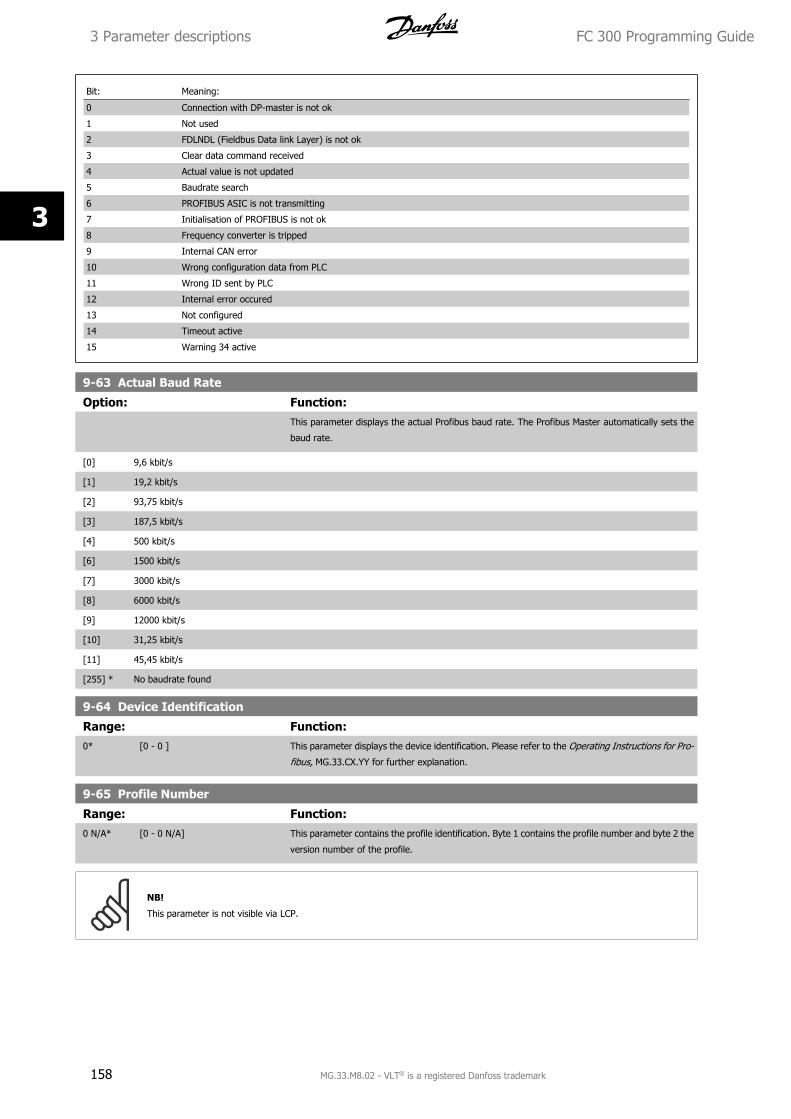
Bit: Meaning:
0 Connection with DP-master is not ok
1 Not used
2 FDLNDL (Fieldbus Data link Layer) is not ok
3 Clear data command received
4 Actual value is not updated
5 Baudrate search
6 PROFIBUS ASIC is not transmitting
7 Initialisation of PROFIBUS is not ok
8 Frequency converter is tripped
9 Internal CAN error
10 Wrong configuration data from PLC
11 Wrong ID sent by PLC
12 Internal error occured
13 Not configured
14 Timeout active
15 Warning 34 active
9-63 Actual Baud Rate
Option: Function:This parameter displays the actual Profibus baud rate. The Profibus Master automatically sets the
baud rate.
[0] 9,6 kbit/s
[1] 19,2 kbit/s
[2] 93,75 kbit/s
[3] 187,5 kbit/s
[4] 500 kbit/s
[6] 1500 kbit/s
[7] 3000 kbit/s
[8] 6000 kbit/s
[9] 12000 kbit/s
[10] 31,25 kbit/s
[11] 45,45 kbit/s
[255] * No baudrate found
9-64 Device Identification
Range: Function:0* [0 - 0 ] This parameter displays the device identification. Please refer to the Operating Instructions for Pro-
fibus, MG.33.CX.YY for further explanation.
9-65 Profile Number
Range: Function:0 N/A* [0 - 0 N/A] This parameter contains the profile identification. Byte 1 contains the profile number and byte 2 the
version number of the profile.
NB!
This parameter is not visible via LCP.
3 Parameter descriptions FC 300 Programming Guide
158 MG.33.M8.02 - VLT® is a registered Danfoss trademark
3
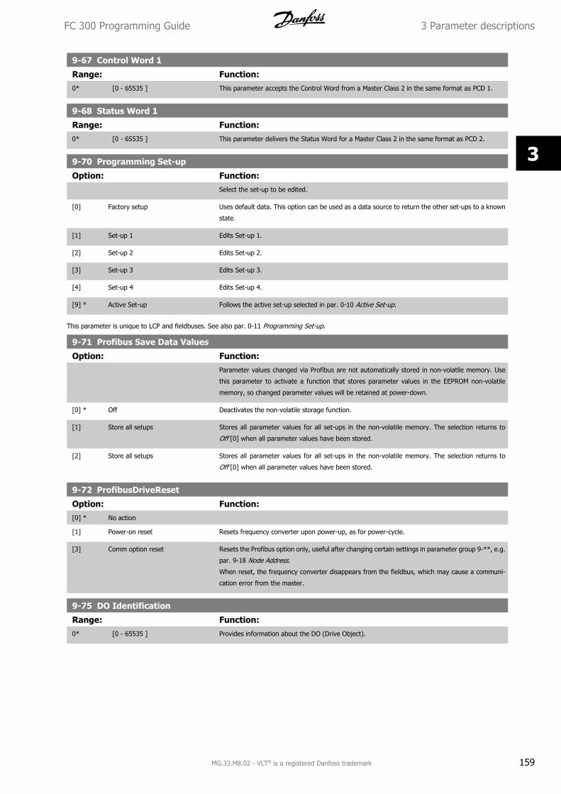
9-67 Control Word 1
Range: Function:0* [0 - 65535 ] This parameter accepts the Control Word from a Master Class 2 in the same format as PCD 1.
9-68 Status Word 1
Range: Function:0* [0 - 65535 ] This parameter delivers the Status Word for a Master Class 2 in the same format as PCD 2.
9-70 Programming Set-up
Option: Function:Select the set-up to be edited.
[0] Factory setup Uses default data. This option can be used as a data source to return the other set-ups to a known
state.
[1] Set-up 1 Edits Set-up 1.
[2] Set-up 2 Edits Set-up 2.
[3] Set-up 3 Edits Set-up 3.
[4] Set-up 4 Edits Set-up 4.
[9] * Active Set-up Follows the active set-up selected in par. 0-10 Active Set-up.
This parameter is unique to LCP and fieldbuses. See also par. 0-11 Programming Set-up.
9-71 Profibus Save Data Values
Option: Function:Parameter values changed via Profibus are not automatically stored in non-volatile memory. Use
this parameter to activate a function that stores parameter values in the EEPROM non-volatile
memory, so changed parameter values will be retained at power-down.
[0] * Off Deactivates the non-volatile storage function.
[1] Store all setups Stores all parameter values for all set-ups in the non-volatile memory. The selection returns to
Off [0] when all parameter values have been stored.
[2] Store all setups Stores all parameter values for all set-ups in the non-volatile memory. The selection returns to
Off [0] when all parameter values have been stored.
9-72 ProfibusDriveReset
Option: Function:[0] * No action
[1] Power-on reset Resets frequency converter upon power-up, as for power-cycle.
[3] Comm option reset Resets the Profibus option only, useful after changing certain settings in parameter group 9-**, e.g.
par. 9-18 Node Address.
When reset, the frequency converter disappears from the fieldbus, which may cause a communi-
cation error from the master.
9-75 DO Identification
Range: Function:0* [0 - 65535 ] Provides information about the DO (Drive Object).
FC 300 Programming Guide 3 Parameter descriptions
MG.33.M8.02 - VLT® is a registered Danfoss trademark 159
3
9-80 Defined Parameters (1)Array [116]
No LCP access
Read only
Range: Function:0 N/A* [0 - 9999 N/A] This parameter displays a list of all the defined frequency converter parameters available for Profi-
bus.
9-81 Defined Parameters (2)Array [116]
No LCP access
Read only
Range: Function:0 N/A* [0 - 9999 N/A] This parameter displays a list of all the defined frequency converter parameters available for Profi-
bus.
9-82 Defined Parameters (3)Array [116]
No LCP access
Read only
Range: Function:0 N/A* [0 - 9999 N/A] This parameter displays a list of all the defined frequency converter parameters available for Profi-
bus.
9-83 Defined Parameters (4)Array [116]
No LCP access
Read only
Range: Function:0 N/A* [0 - 9999 N/A] This parameter displays a list of all the defined frequency converter parameters available for Profi-
bus.
9-84 Defined Parameters (5)
Range: Function:0* [0 - 9999 ] This parameter displays a list of all the defined frequency converter parameters available for Profi-
bus.
9-90 Changed Parameters (1)Array [116]
No LCP access
Read only
Range: Function:0 N/A* [0 - 9999 N/A] This parameter displays a list of all the frequency converter parameters deviating from default set-
ting.
9-91 Changed Parameters (2)Array [116]
No LCP access
Read only
Range: Function:0 N/A* [0 - 9999 N/A] This parameter displays a list of all the frequency converter parameters deviating from default set-
ting.
3 Parameter descriptions FC 300 Programming Guide
160 MG.33.M8.02 - VLT® is a registered Danfoss trademark
3
9-92 Changed Parameters (3)Array [116]
No LCP access
Read only
Range: Function:0 N/A* [0 - 9999 N/A] This parameter displays a list of all the frequency converter parameters deviating from default set-
ting.
9-94 Changed Parameters (5)Array [116]
No LCP Address
Read only
Range: Function:0 N/A* [0 - 9999 N/A] This parameter displays a list of all the frequency converter parameters deviating from default set-
ting.
FC 300 Programming Guide 3 Parameter descriptions
MG.33.M8.02 - VLT® is a registered Danfoss trademark 161
3
3.12 Parameters: DeviceNet CAN Fieldbus
3.12.1 10-** DeviceNet and CAN Fieldbus
Parameter group for DeviceNet CAN fieldbus parameters.
3.12.2 10-0* Common Settings
Parameter group for configuring common settings for CAN fieldbus options.
10-00 CAN Protocol
Option: Function:[0] CANopen
[1] * DeviceNet View the active CAN protocol.
NB!
The options depend on installed option.
10-01 Baud Rate SelectSelect the fieldbus transmission speed. The selection must correspond to the transmission speed of the master and the other fieldbus nodes.
Option: Function:[16] 10 Kbps
[17] 20 Kbps
[18] 50 Kbps
[19] 100 Kbps
[20] * 125 Kbps
[21] 250 Kbps
[22] 500 Kbps
10-02 MAC ID
Range: Function:Application
dependent*
[Application dependant] Selection of station address. Every station connected to the same network must have an unambig-
uous address.
10-05 Readout Transmit Error Counter
Range: Function:0 N/A* [0 - 255 N/A] View the number of CAN control transmission errors since the last power-up.
10-06 Readout Receive Error Counter
Range: Function:0 N/A* [0 - 255 N/A] View the number of CAN control receipt errors since the last power-up.
10-07 Readout Bus Off Counter
Range: Function:0* [0 - 255 ] View the number of Bus Off events since the last power-up.
3 Parameter descriptions FC 300 Programming Guide
162 MG.33.M8.02 - VLT® is a registered Danfoss trademark
3
3.12.3 10-1* DeviceNet
Parameters specific to the DeviceNet fieldbus.
10-10 Process Data Type Selection
Option: Function:Select the Instance (telegram) for data transmission. The Instances available are dependent upon
the setting of par. 8-10 Control Profile.
When par. 8-10 Control Profile is set to [0] FC profile, par. 10-10 Process Data Type Selection options
[0] and [1] are available.
When par. 8-10 Control Profile is set to [5] ODVA, par. 10-10 Process Data Type Selection options
[2] and [3] are available.
Instances 100/150 and 101/151 are Danfoss-specific. Instances 20/70 and 21/71 are ODVA-specific
AC Drive profiles.
For guidelines in telegram selection, please refer to the DeviceNet Operating Instructions.
Note that a change to this parameter will be executed immediately.
[0] * INSTANCE 100/150
[1] INSTANCE 101/151
[2] INSTANCE 20/70
[3] INSTANCE 21/71
10-11 Process Data Config WriteSelect the process write data for I/O Assembly Instances 101/151. Elements [2] and [3] of this array can be selected. Elements [0] and [1] of the
array are fixed.
Option: Function:[0] None
[302] Minimum Reference
[303] Maximum Reference
[312] Catch up/slow Down Value
[341] Ramp 1 Ramp up Time
[342] Ramp 1 Ramp Down Time
[351] Ramp 2 Ramp up Time
[352] Ramp 2 Ramp down Time
[380] Jog Ramp Time
[381] Quick Stop Ramp Time
[411] Motor Speed Low Limit [RPM]
[412] Motor Speed Low Limit [Hz]
[413] Motor Speed High Limit [RPM]
[414] Motor Speed High Limit [Hz]
[416] Torque Limit Motor Mode
[417] Torque Limit Generator Mode
[590] Digital & Relay Bus Control
[593] Pulse Out #27 Bus Control
[595] Pulse Out #29 Bus Control
[597] Pulse Out #X30/6 Bus Control
[653] Terminal 42 Output Bus Control
[663] Terminal X30/8 Bus Control
[673] Terminal X45/1 Bus Control
[683] Terminal X45/3 Bus Control
[890] Bus Jog 1 Speed
FC 300 Programming Guide 3 Parameter descriptions
MG.33.M8.02 - VLT® is a registered Danfoss trademark 163
3
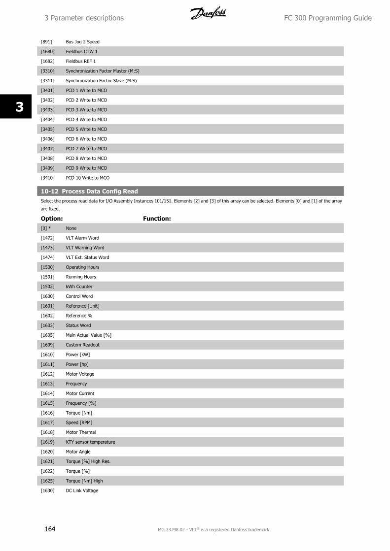
[891] Bus Jog 2 Speed
[1680] Fieldbus CTW 1
[1682] Fieldbus REF 1
[3310] Synchronization Factor Master (M:S)
[3311] Synchronization Factor Slave (M:S)
[3401] PCD 1 Write to MCO
[3402] PCD 2 Write to MCO
[3403] PCD 3 Write to MCO
[3404] PCD 4 Write to MCO
[3405] PCD 5 Write to MCO
[3406] PCD 6 Write to MCO
[3407] PCD 7 Write to MCO
[3408] PCD 8 Write to MCO
[3409] PCD 9 Write to MCO
[3410] PCD 10 Write to MCO
10-12 Process Data Config ReadSelect the process read data for I/O Assembly Instances 101/151. Elements [2] and [3] of this array can be selected. Elements [0] and [1] of the array
are fixed.
Option: Function:[0] * None
[1472] VLT Alarm Word
[1473] VLT Warning Word
[1474] VLT Ext. Status Word
[1500] Operating Hours
[1501] Running Hours
[1502] kWh Counter
[1600] Control Word
[1601] Reference [Unit]
[1602] Reference %
[1603] Status Word
[1605] Main Actual Value [%]
[1609] Custom Readout
[1610] Power [kW]
[1611] Power [hp]
[1612] Motor Voltage
[1613] Frequency
[1614] Motor Current
[1615] Frequency [%]
[1616] Torque [Nm]
[1617] Speed [RPM]
[1618] Motor Thermal
[1619] KTY sensor temperature
[1620] Motor Angle
[1621] Torque [%] High Res.
[1622] Torque [%]
[1625] Torque [Nm] High
[1630] DC Link Voltage
3 Parameter descriptions FC 300 Programming Guide
164 MG.33.M8.02 - VLT® is a registered Danfoss trademark
3
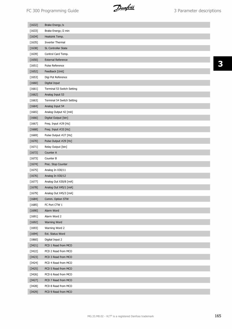
[1632] Brake Energy /s
[1633] Brake Energy /2 min
[1634] Heatsink Temp.
[1635] Inverter Thermal
[1638] SL Controller State
[1639] Control Card Temp.
[1650] External Reference
[1651] Pulse Reference
[1652] Feedback [Unit]
[1653] Digi Pot Reference
[1660] Digital Input
[1661] Terminal 53 Switch Setting
[1662] Analog Input 53
[1663] Terminal 54 Switch Setting
[1664] Analog Input 54
[1665] Analog Output 42 [mA]
[1666] Digital Output [bin]
[1667] Freq. Input #29 [Hz]
[1668] Freq. Input #33 [Hz]
[1669] Pulse Output #27 [Hz]
[1670] Pulse Output #29 [Hz]
[1671] Relay Output [bin]
[1672] Counter A
[1673] Counter B
[1674] Prec. Stop Counter
[1675] Analog In X30/11
[1676] Analog In X30/12
[1677] Analog Out X30/8 [mA]
[1678] Analog Out X45/1 [mA]
[1679] Analog Out X45/3 [mA]
[1684] Comm. Option STW
[1685] FC Port CTW 1
[1690] Alarm Word
[1691] Alarm Word 2
[1692] Warning Word
[1693] Warning Word 2
[1694] Ext. Status Word
[1860] Digital Input 2
[3421] PCD 1 Read from MCO
[3422] PCD 2 Read from MCO
[3423] PCD 3 Read from MCO
[3424] PCD 4 Read from MCO
[3425] PCD 5 Read from MCO
[3426] PCD 6 Read from MCO
[3427] PCD 7 Read from MCO
[3428] PCD 8 Read from MCO
[3429] PCD 9 Read from MCO
FC 300 Programming Guide 3 Parameter descriptions
MG.33.M8.02 - VLT® is a registered Danfoss trademark 165
3
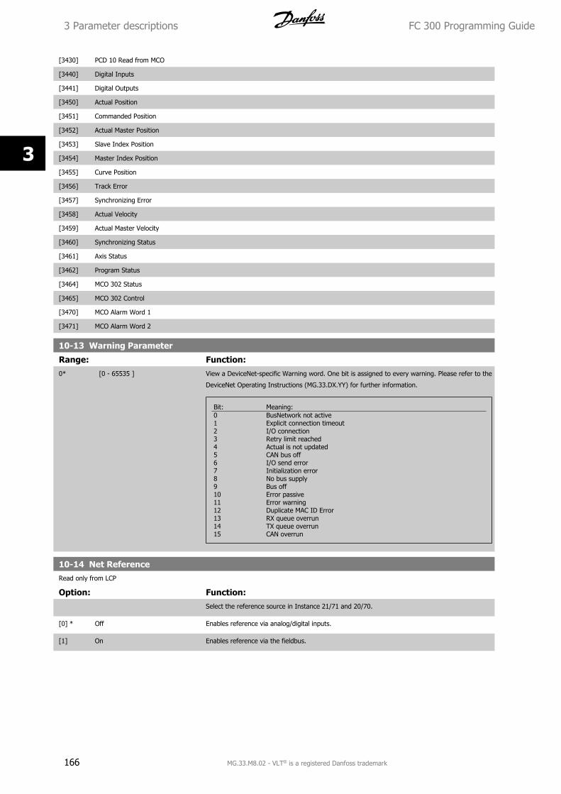
[3430] PCD 10 Read from MCO
[3440] Digital Inputs
[3441] Digital Outputs
[3450] Actual Position
[3451] Commanded Position
[3452] Actual Master Position
[3453] Slave Index Position
[3454] Master Index Position
[3455] Curve Position
[3456] Track Error
[3457] Synchronizing Error
[3458] Actual Velocity
[3459] Actual Master Velocity
[3460] Synchronizing Status
[3461] Axis Status
[3462] Program Status
[3464] MCO 302 Status
[3465] MCO 302 Control
[3470] MCO Alarm Word 1
[3471] MCO Alarm Word 2
10-13 Warning Parameter
Range: Function:0* [0 - 65535 ] View a DeviceNet-specific Warning word. One bit is assigned to every warning. Please refer to the
DeviceNet Operating Instructions (MG.33.DX.YY) for further information.
Bit: Meaning:0 BusNetwork not active1 Explicit connection timeout2 I/O connection3 Retry limit reached4 Actual is not updated5 CAN bus off6 I/O send error7 Initialization error8 No bus supply9 Bus off10 Error passive11 Error warning12 Duplicate MAC ID Error13 RX queue overrun14 TX queue overrun15 CAN overrun
10-14 Net ReferenceRead only from LCP
Option: Function:Select the reference source in Instance 21/71 and 20/70.
[0] * Off Enables reference via analog/digital inputs.
[1] On Enables reference via the fieldbus.
3 Parameter descriptions FC 300 Programming Guide
166 MG.33.M8.02 - VLT® is a registered Danfoss trademark
3
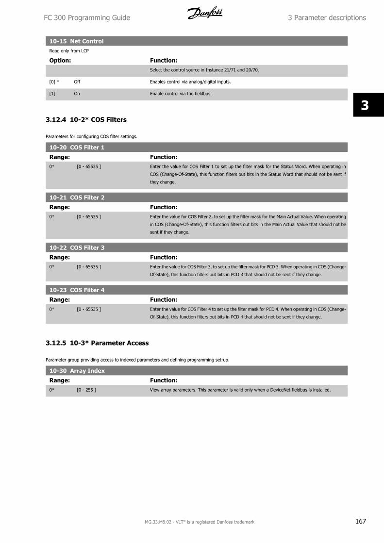
10-15 Net ControlRead only from LCP
Option: Function:Select the control source in Instance 21/71 and 20/70.
[0] * Off Enables control via analog/digital inputs.
[1] On Enable control via the fieldbus.
3.12.4 10-2* COS Filters
Parameters for configuring COS filter settings.
10-20 COS Filter 1
Range: Function:0* [0 - 65535 ] Enter the value for COS Filter 1 to set up the filter mask for the Status Word. When operating in
COS (Change-Of-State), this function filters out bits in the Status Word that should not be sent if
they change.
10-21 COS Filter 2
Range: Function:0* [0 - 65535 ] Enter the value for COS Filter 2, to set up the filter mask for the Main Actual Value. When operating
in COS (Change-Of-State), this function filters out bits in the Main Actual Value that should not be
sent if they change.
10-22 COS Filter 3
Range: Function:0* [0 - 65535 ] Enter the value for COS Filter 3, to set up the filter mask for PCD 3. When operating in COS (Change-
Of-State), this function filters out bits in PCD 3 that should not be sent if they change.
10-23 COS Filter 4
Range: Function:0* [0 - 65535 ] Enter the value for COS Filter 4 to set up the filter mask for PCD 4. When operating in COS (Change-
Of-State), this function filters out bits in PCD 4 that should not be sent if they change.
3.12.5 10-3* Parameter Access
Parameter group providing access to indexed parameters and defining programming set-up.
10-30 Array Index
Range: Function:0* [0 - 255 ] View array parameters. This parameter is valid only when a DeviceNet fieldbus is installed.
FC 300 Programming Guide 3 Parameter descriptions
MG.33.M8.02 - VLT® is a registered Danfoss trademark 167
3
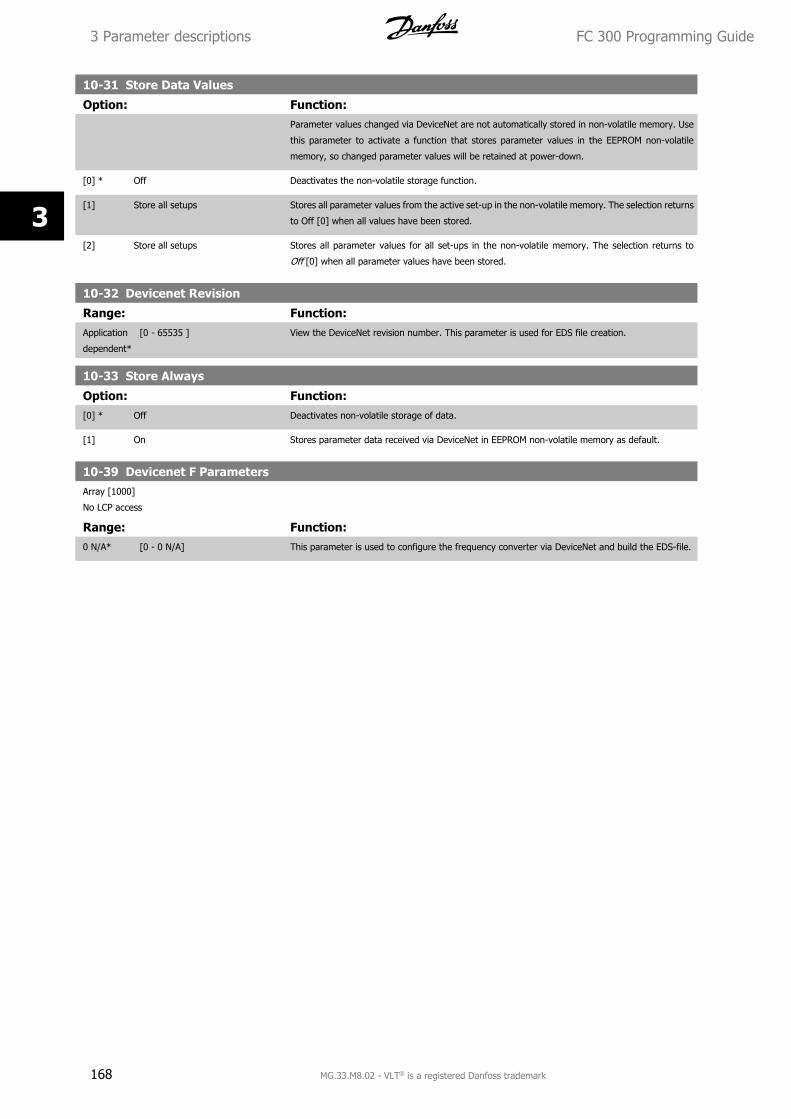
10-31 Store Data Values
Option: Function:Parameter values changed via DeviceNet are not automatically stored in non-volatile memory. Use
this parameter to activate a function that stores parameter values in the EEPROM non-volatile
memory, so changed parameter values will be retained at power-down.
[0] * Off Deactivates the non-volatile storage function.
[1] Store all setups Stores all parameter values from the active set-up in the non-volatile memory. The selection returns
to Off [0] when all values have been stored.
[2] Store all setups Stores all parameter values for all set-ups in the non-volatile memory. The selection returns to
Off [0] when all parameter values have been stored.
10-32 Devicenet Revision
Range: Function:Application
dependent*
[0 - 65535 ] View the DeviceNet revision number. This parameter is used for EDS file creation.
10-33 Store Always
Option: Function:[0] * Off Deactivates non-volatile storage of data.
[1] On Stores parameter data received via DeviceNet in EEPROM non-volatile memory as default.
10-39 Devicenet F ParametersArray [1000]
No LCP access
Range: Function:0 N/A* [0 - 0 N/A] This parameter is used to configure the frequency converter via DeviceNet and build the EDS-file.
3 Parameter descriptions FC 300 Programming Guide
168 MG.33.M8.02 - VLT® is a registered Danfoss trademark
3
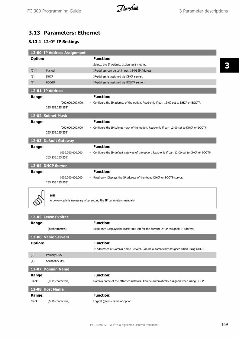
3.13 Parameters: Ethernet
3.13.1 12-0* IP Settings
12-00 IP Address Assignment
Option: Function:Selects the IP Address assignment method.
[0] * Manual IP-address can be set in par. 12-01 IP Address.
[1] DHCP IP-address is assigned via DHCP server.
[2] BOOTP IP-address is assigned via BOOTP server.
12-01 IP Address
Range: Function: [000.000.000.000 -
255.255.255.255]
Configure the IP address of the option. Read-only if par. 12-00 set to DHCP or BOOTP.
12-02 Subnet Mask
Range: Function: [000.000.000.000 -
255.255.255.255]
Configure the IP subnet mask of the option. Read-only if par. 12-00 set to DHCP or BOOTP.
12-03 Default Gateway
Range: Function: [000.000.000.000 –
255.255.255.255]
Configure the IP default gateway of the option. Read-only if par. 12-00 set to DHCP or BOOTP.
12-04 DHCP Server
Range: Function: [000.000.000.000 –
255.255.255.255]
Read only. Displays the IP address of the found DHCP or BOOTP server.
NB!
A power-cycle is necessary after setting the IP parameters manually.
12-05 Lease Expires
Range: Function: [dd:hh:mm:ss] Read only. Displays the lease-time left for the current DHCP-assigned IP address.
12-06 Name Servers
Option: Function:IP addresses of Domain Name Servers. Can be automatically assigned when using DHCP.
[0] Primary DNS
[1] Secondary DNS
12-07 Domain Name
Range: Function:Blank [0-19 characters] Domain name of the attached network. Can be automatically assigned when using DHCP.
12-08 Host Name
Range: Function:Blank [0-19 characters] Logical (given) name of option.
FC 300 Programming Guide 3 Parameter descriptions
MG.33.M8.02 - VLT® is a registered Danfoss trademark 169
3
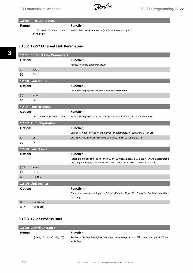
12-09 Physical Address
Range: Function: [00:1B:08:00:00:00 – 00:1B:
08:FF:FF:FF]
Read only Displays the Physical (MAC) address of the option.
3.13.2 12-1* Ethernet Link Parameters
12-1* Ethernet Link Parameters
Option: Function:Applies for whole parameter group.
[0] Port 1
[1] Port 2
12-10 Link Status
Option: Function:Read only. Displays the link status of the Ethernet ports.
[0] No link
[1] Link
12-11 Link Duration
Option: Function:Link Duration Port 1 (dd:hh:mm:ss) Read only. Displays the duration of the present link on each port in dd:hh:mm:ss.
12-12 Auto Negotiation
Option: Function:Configures Auto Negotiation of Ethernet link parameters, for each port: ON or OFF.
[0] Off Link Speed and Link Duplex can be configured in par. 12-13 and 12-14.
[1] On
12-13 Link Speed
Option: Function:Forces the link speed for each port in 10 or 100 Mbps. If par. 12-12 is set to: ON, this parameter is
read only and displays the actual link speed. “None” is displayed if no link is present.
[0] * None
[1] 10 Mbps
[2] 100 Mbps
12-14 Link Duplex
Option: Function:Forces the duplex for each port to Full or Half duplex. If par. 12-12 is set to: ON, this parameter is
read only.
[0] Half duplex
[1] * Full duplex
3.13.3 12-2* Process Data
12-20 Control Instance
Range: Function: [None, 20, 21, 100, 101, 103] Read only. Displays the originator-to-target connection point. If no CIP connection is present “None”
is displayed.
3 Parameter descriptions FC 300 Programming Guide
170 MG.33.M8.02 - VLT® is a registered Danfoss trademark
3
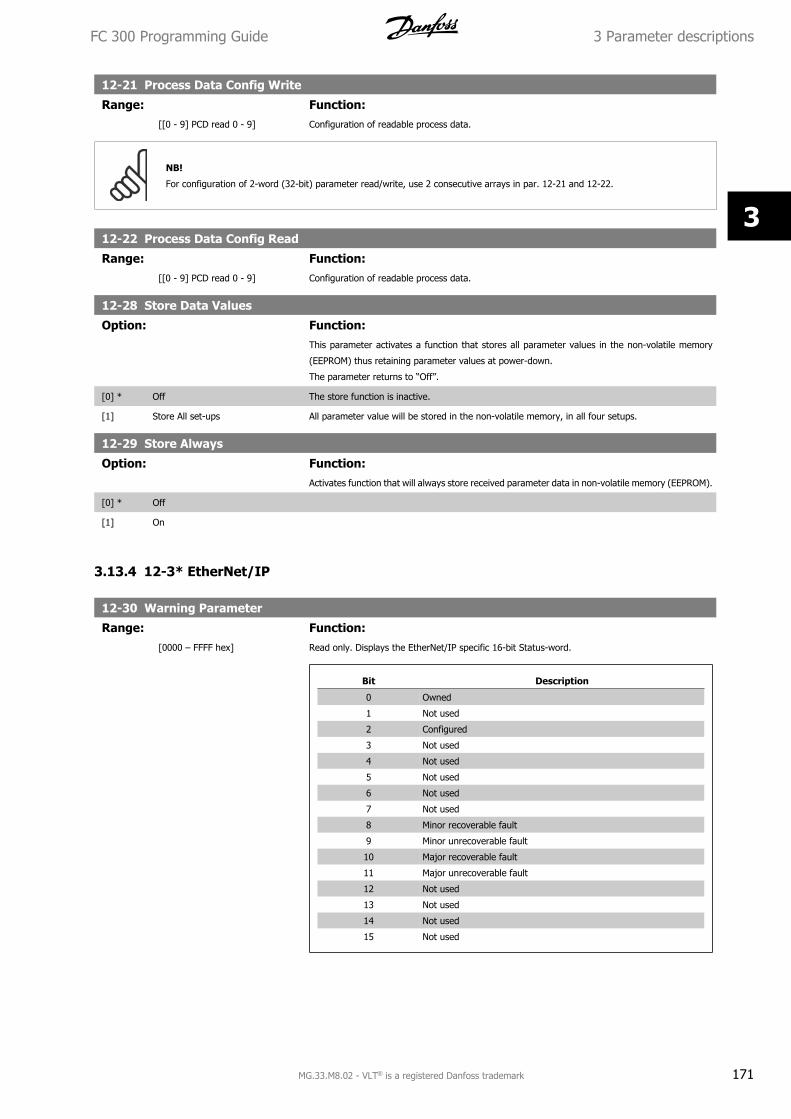
12-21 Process Data Config Write
Range: Function: [[0 - 9] PCD read 0 - 9] Configuration of readable process data.
NB!
For configuration of 2-word (32-bit) parameter read/write, use 2 consecutive arrays in par. 12-21 and 12-22.
12-22 Process Data Config Read
Range: Function: [[0 - 9] PCD read 0 - 9] Configuration of readable process data.
12-28 Store Data Values
Option: Function:This parameter activates a function that stores all parameter values in the non-volatile memory
(EEPROM) thus retaining parameter values at power-down.
The parameter returns to “Off”.
[0] * Off The store function is inactive.
[1] Store All set-ups All parameter value will be stored in the non-volatile memory, in all four setups.
12-29 Store Always
Option: Function:Activates function that will always store received parameter data in non-volatile memory (EEPROM).
[0] * Off
[1] On
3.13.4 12-3* EtherNet/IP
12-30 Warning Parameter
Range: Function: [0000 – FFFF hex] Read only. Displays the EtherNet/IP specific 16-bit Status-word.
Bit Description
0 Owned
1 Not used
2 Configured
3 Not used
4 Not used
5 Not used
6 Not used
7 Not used
8 Minor recoverable fault
9 Minor unrecoverable fault
10 Major recoverable fault
11 Major unrecoverable fault
12 Not used
13 Not used
14 Not used
15 Not used
FC 300 Programming Guide 3 Parameter descriptions
MG.33.M8.02 - VLT® is a registered Danfoss trademark 171
3
12-31 Net Reference
Option: Function:Read only. Displays the reference source in Instance 21/71.
[0] * Off Reference from the network is not active.
[1] On Reference from the network is active.
12-32 Net Control
Option: Function:Read only. Displays the control source in Instance 21/71.
[0] * Off Control via the network is not active.
[1] On Control via the network is active
12-33 CIP Revision
Option: Function:Read only. Displays the CIP-version of the option software.
[0] Major version (00 - 99)
[1] Minor version (00 - 99)
12-34 CIP Product Code
Range: Function:1100 (FC
302) 1110
(FC 301)*
[0 – 9999] Read only. Displays the CIP product code.
12-37 COS Inhibit Timer
Range: Function: [0 – 65.535 ms] Read only Change-Of-State inhibit timer. If the option is configured for COS operation, this inhibit
timer can be configured in the Forward Open telegram to prevent that continuously changing PCD
data generates extensive network traffic. The inhibit time is in milliseconds, 0 = disabled.
12-38 COS Filters
Range: Function: [[0 - 9] Filter 0 – 9 (0000 -
FFFFhex)]
Change-Of-State PCD filters. Sets up a filter mask for each word of process data when operating in
COS-mode. Single bits in the PCD’s can be filtered in/out.
3.13.5 12-8* Other Ethernet Services
12-80 FTP Server
Option: Function:[0] * Disable Disables the built-in FTP server.
[1] Enable Enables the built-in FTP server.
12-81 HTTP Server
Option: Function:[0] * Disable Disables the build-in HTTP (web) server.
[1] Enable Enables the build-in HTTP (web) server.
12-82 SMTP Service
Option: Function:[0] * Disable Disables the SMTP (e-mail) service on the option.
[1] Enable Enables the SMTP (e-mail) service on the option.
3 Parameter descriptions FC 300 Programming Guide
172 MG.33.M8.02 - VLT® is a registered Danfoss trademark
3
12-89 Transparent Socket Channel Port
Range: Function:0* [0 – 9999] Configures the TCP port-number for the transparent socket channel. This enables FC-telegrams to
be sent transparently on Ethernet via TCP. Default value is 4000, 0 means disabled.
3.13.6 12-9* Advanced Ethernet Settings
12-90 Cable Diagnostics
Option: Function:Enables/disables advanced Cable diagnosis function. If enabled, the distance to cable errors can be
read out in par. 12-93. The parameter resumes to the default setting of Disable after the diagnostics
have finished.
[0] * Disable
[1] Enable
NB!
The cable diagnostics function will only be issued on ports where there is no link (see par. 12-10, Link Status)
12-91 Auto Cross-Over
Option: Function:[0] Disable Disables the auto cross-over function.
[1] * Enable Enables the auto cross-over function.
NB!
Disabling of the auto cross-over function will require crossed Ethernet cables for daisy-chaining the options.
12-92 IGMP Snooping
Option: Function:This prevents flooding of the Ethernet protocol stack by only forwarding multicast packets to ports
that are a member of the multicast group
[0] Disable Disables the IGMP snooping function.
[1] * Enable Enables the IGMP snooping function.
12-93 Cable Error Length
Option: Function:If Cable Diagnostics is enabled in par. 12-90, the built-in switch is able via Time Domain Reflec-
tometry (TDR). This is a measurement technique which detects common cabling problems such as
open circuits, short circuits and impedance mismatches or breaks in transmission cables. The dis-
tance from the option to the error is displayed in meters with an accuracy of +/- 2m. The value 0
means no errors detected.
[0] Error length Port 1 (0 – 200m)
[1] Error length Port 2 (0 – 200m)
12-94 Broadcast Storm Protection
Option: Function:The built-in switch is capable of protecting the switch system from receiving too many broadcast
packages, which can use up network resources. The value indicates a percentage of the total band-
width that is allowed for broadcast messages.
FC 300 Programming Guide 3 Parameter descriptions
MG.33.M8.02 - VLT® is a registered Danfoss trademark 173
3
Example:
The “OFF” means that the filter is disabled –all broadcast messages will be passed through. The
value “0%” means that no broadcast messages will be passed through. A value of “10%” means
that 10% of the total bandwidth is allowed for broadcast messages, if the amount of broadcast
messages increases above the 10% threshold, they will be blocked.
[0] Protection Value Port 1 (*Off – 20%)
[1] Protection Value Port 2 (*Off – 20%)
12-95 Broadcast Storm Filter
Option: Function:Applies to par. 12-94; if the Broadcast Storm Protection should also include Multicast telegrams.
[0] Broadcast only
[1] Broadcast & Multicast
12-96 Port MirroringEnables/disables port-mirroring function. For troubleshooting with a network analyzer tool.
Option: Function:[0] * Disable No port-mirroring
[1] Port 1 to Port 2 All network traffic on port 1 will be mirrored to port 2.
[2] Port 2 to Port 1 All network traffic on port 2 will be mirrored to port 1.
[254] Int. Port to Port 1
[255] Int. Port to Port 2
12-98 Interface Counters
Option: Function:Read only. Advanced Interface counters, from build-in switch, can be used for low-level trouble-
shooting, The parameter shows a sum of port 1 + port 2.
[0] In Octets
[1] In Unicast Packets
[2] In Non-Unicast Packets
[3] In Discards
[4] In Errors
[5] In Unknown Protocols
[6] Out Octets
[7] Out Unicast Packets
[8] Out Non-Unicast Packets
[9] Out Discards
[10] Out Errors
3 Parameter descriptions FC 300 Programming Guide
174 MG.33.M8.02 - VLT® is a registered Danfoss trademark
3
12-99 Media Counters
Option: Function:Read only. Advanced Interface counters, from build-in switch, can be used for low-level trouble-
shooting, The parameter shows a sum of port 1 + port 2.
[0] Alignment Errors
[1] FCS Errors
[2] Single Collisions
[3] Multiple Collisions
[4] SQE Test Errors
[5] Deferred Errors
[6] Late Collisions
[7] Excessive Collisions
[8] MAC Transmit Errors
[9] Carrier Sense Errors
[10] Frame Too Long
[11] MAC Receive Errors
FC 300 Programming Guide 3 Parameter descriptions
MG.33.M8.02 - VLT® is a registered Danfoss trademark 175
3
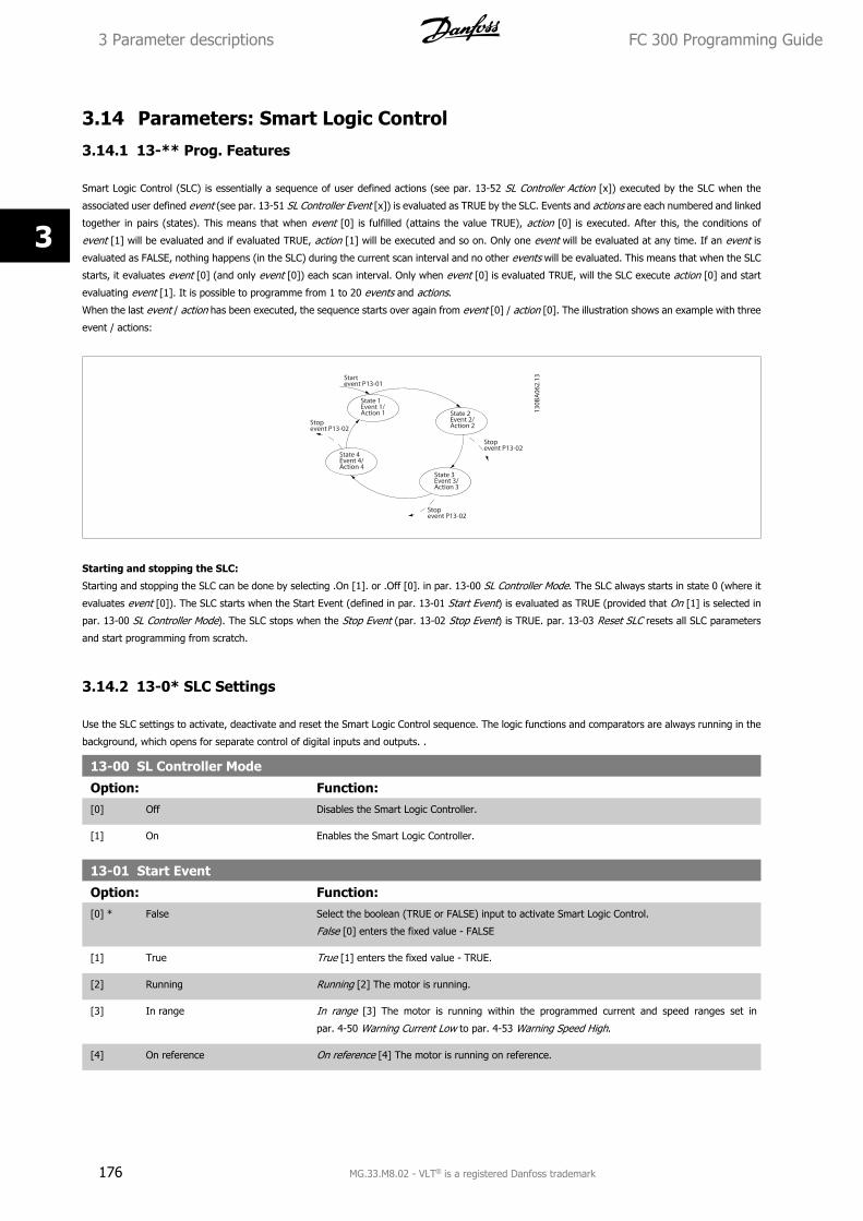
3.14 Parameters: Smart Logic Control
3.14.1 13-** Prog. Features
Smart Logic Control (SLC) is essentially a sequence of user defined actions (see par. 13-52 SL Controller Action [x]) executed by the SLC when the
associated user defined event (see par. 13-51 SL Controller Event [x]) is evaluated as TRUE by the SLC. Events and actions are each numbered and linked
together in pairs (states). This means that when event [0] is fulfilled (attains the value TRUE), action [0] is executed. After this, the conditions of
event [1] will be evaluated and if evaluated TRUE, action [1] will be executed and so on. Only one event will be evaluated at any time. If an event is
evaluated as FALSE, nothing happens (in the SLC) during the current scan interval and no other events will be evaluated. This means that when the SLC
starts, it evaluates event [0] (and only event [0]) each scan interval. Only when event [0] is evaluated TRUE, will the SLC execute action [0] and start
evaluating event [1]. It is possible to programme from 1 to 20 events and actions.
When the last event / action has been executed, the sequence starts over again from event [0] / action [0]. The illustration shows an example with three
event / actions:
Starting and stopping the SLC:
Starting and stopping the SLC can be done by selecting .On [1]. or .Off [0]. in par. 13-00 SL Controller Mode. The SLC always starts in state 0 (where it
evaluates event [0]). The SLC starts when the Start Event (defined in par. 13-01 Start Event) is evaluated as TRUE (provided that On [1] is selected in
par. 13-00 SL Controller Mode). The SLC stops when the Stop Event (par. 13-02 Stop Event) is TRUE. par. 13-03 Reset SLC resets all SLC parameters
and start programming from scratch.
3.14.2 13-0* SLC Settings
Use the SLC settings to activate, deactivate and reset the Smart Logic Control sequence. The logic functions and comparators are always running in the
background, which opens for separate control of digital inputs and outputs. .
13-00 SL Controller Mode
Option: Function:[0] Off Disables the Smart Logic Controller.
[1] On Enables the Smart Logic Controller.
13-01 Start Event
Option: Function:[0] * False Select the boolean (TRUE or FALSE) input to activate Smart Logic Control.
False [0] enters the fixed value - FALSE
[1] True True [1] enters the fixed value - TRUE.
[2] Running Running [2] The motor is running.
[3] In range In range [3] The motor is running within the programmed current and speed ranges set in
par. 4-50 Warning Current Low to par. 4-53 Warning Speed High.
[4] On reference On reference [4] The motor is running on reference.
3 Parameter descriptions FC 300 Programming Guide
176 MG.33.M8.02 - VLT® is a registered Danfoss trademark
3
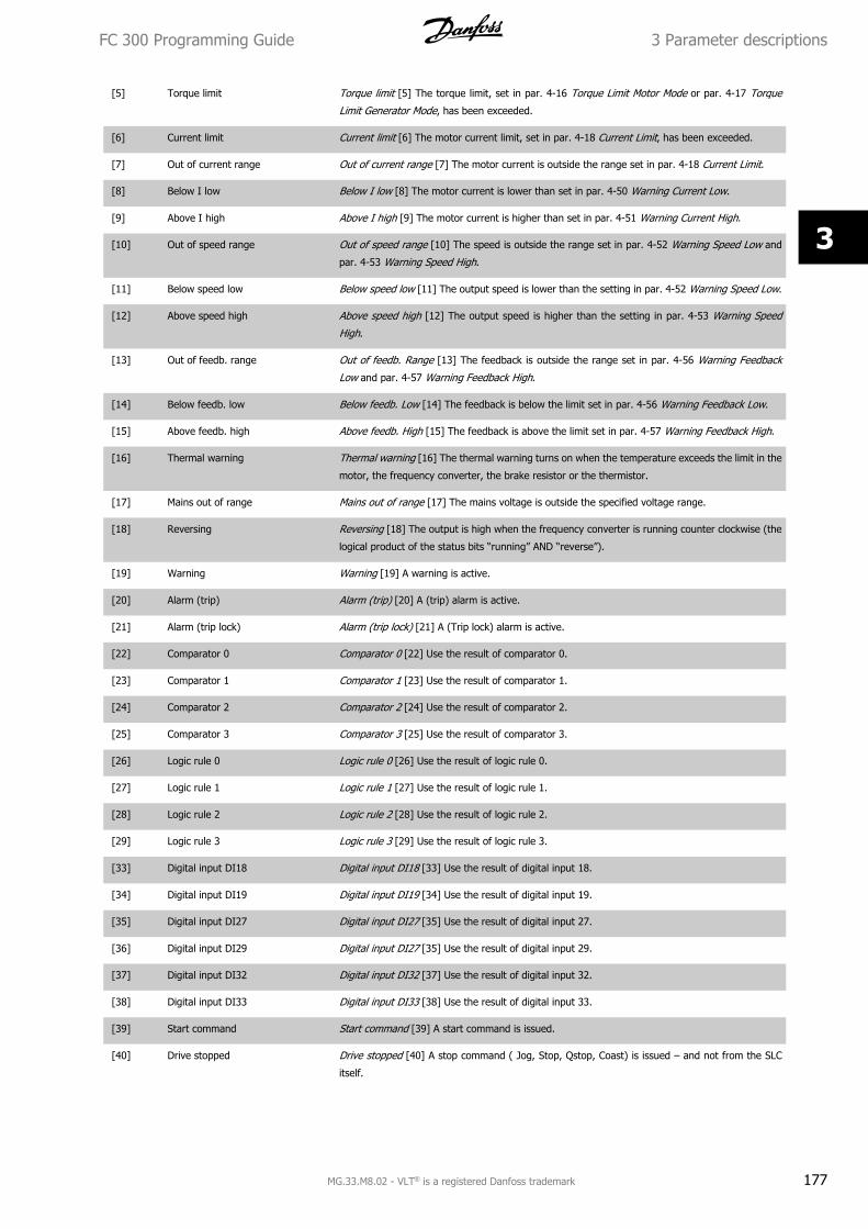
[5] Torque limit Torque limit [5] The torque limit, set in par. 4-16 Torque Limit Motor Mode or par. 4-17 Torque
Limit Generator Mode, has been exceeded.
[6] Current limit Current limit [6] The motor current limit, set in par. 4-18 Current Limit, has been exceeded.
[7] Out of current range Out of current range [7] The motor current is outside the range set in par. 4-18 Current Limit.
[8] Below I low Below I low [8] The motor current is lower than set in par. 4-50 Warning Current Low.
[9] Above I high Above I high [9] The motor current is higher than set in par. 4-51 Warning Current High.
[10] Out of speed range Out of speed range [10] The speed is outside the range set in par. 4-52 Warning Speed Low and
par. 4-53 Warning Speed High.
[11] Below speed low Below speed low [11] The output speed is lower than the setting in par. 4-52 Warning Speed Low.
[12] Above speed high Above speed high [12] The output speed is higher than the setting in par. 4-53 Warning Speed
High.
[13] Out of feedb. range Out of feedb. Range [13] The feedback is outside the range set in par. 4-56 Warning Feedback
Low and par. 4-57 Warning Feedback High.
[14] Below feedb. low Below feedb. Low [14] The feedback is below the limit set in par. 4-56 Warning Feedback Low.
[15] Above feedb. high Above feedb. High [15] The feedback is above the limit set in par. 4-57 Warning Feedback High.
[16] Thermal warning Thermal warning [16] The thermal warning turns on when the temperature exceeds the limit in the
motor, the frequency converter, the brake resistor or the thermistor.
[17] Mains out of range Mains out of range [17] The mains voltage is outside the specified voltage range.
[18] Reversing Reversing [18] The output is high when the frequency converter is running counter clockwise (the
logical product of the status bits “running” AND “reverse”).
[19] Warning Warning [19] A warning is active.
[20] Alarm (trip) Alarm (trip) [20] A (trip) alarm is active.
[21] Alarm (trip lock) Alarm (trip lock) [21] A (Trip lock) alarm is active.
[22] Comparator 0 Comparator 0 [22] Use the result of comparator 0.
[23] Comparator 1 Comparator 1 [23] Use the result of comparator 1.
[24] Comparator 2 Comparator 2 [24] Use the result of comparator 2.
[25] Comparator 3 Comparator 3 [25] Use the result of comparator 3.
[26] Logic rule 0 Logic rule 0 [26] Use the result of logic rule 0.
[27] Logic rule 1 Logic rule 1 [27] Use the result of logic rule 1.
[28] Logic rule 2 Logic rule 2 [28] Use the result of logic rule 2.
[29] Logic rule 3 Logic rule 3 [29] Use the result of logic rule 3.
[33] Digital input DI18 Digital input DI18 [33] Use the result of digital input 18.
[34] Digital input DI19 Digital input DI19 [34] Use the result of digital input 19.
[35] Digital input DI27 Digital input DI27 [35] Use the result of digital input 27.
[36] Digital input DI29 Digital input DI27 [35] Use the result of digital input 29.
[37] Digital input DI32 Digital input DI32 [37] Use the result of digital input 32.
[38] Digital input DI33 Digital input DI33 [38] Use the result of digital input 33.
[39] Start command Start command [39] A start command is issued.
[40] Drive stopped Drive stopped [40] A stop command ( Jog, Stop, Qstop, Coast) is issued – and not from the SLC
itself.
FC 300 Programming Guide 3 Parameter descriptions
MG.33.M8.02 - VLT® is a registered Danfoss trademark 177
3
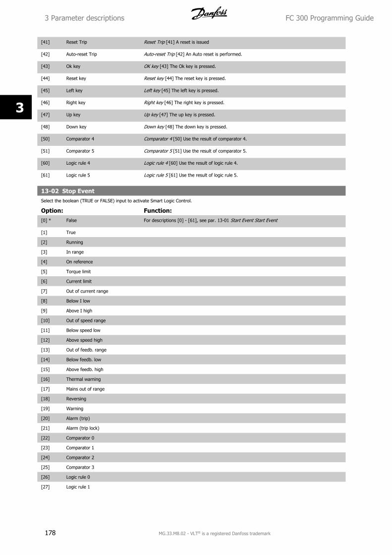
[41] Reset Trip Reset Trip [41] A reset is issued
[42] Auto-reset Trip Auto-reset Trip [42] An Auto reset is performed.
[43] Ok key OK key [43] The Ok key is pressed.
[44] Reset key Reset key [44] The reset key is pressed.
[45] Left key Left key [45] The left key is pressed.
[46] Right key Right key [46] The right key is pressed.
[47] Up key Up key [47] The up key is pressed.
[48] Down key Down key [48] The down key is pressed.
[50] Comparator 4 Comparator 4 [50] Use the result of comparator 4.
[51] Comparator 5 Comparator 5 [51] Use the result of comparator 5.
[60] Logic rule 4 Logic rule 4 [60] Use the result of logic rule 4.
[61] Logic rule 5 Logic rule 5 [61] Use the result of logic rule 5.
13-02 Stop EventSelect the boolean (TRUE or FALSE) input to activate Smart Logic Control.
Option: Function:[0] * False For descriptions [0] - [61], see par. 13-01 Start Event Start Event
[1] True
[2] Running
[3] In range
[4] On reference
[5] Torque limit
[6] Current limit
[7] Out of current range
[8] Below I low
[9] Above I high
[10] Out of speed range
[11] Below speed low
[12] Above speed high
[13] Out of feedb. range
[14] Below feedb. low
[15] Above feedb. high
[16] Thermal warning
[17] Mains out of range
[18] Reversing
[19] Warning
[20] Alarm (trip)
[21] Alarm (trip lock)
[22] Comparator 0
[23] Comparator 1
[24] Comparator 2
[25] Comparator 3
[26] Logic rule 0
[27] Logic rule 1
3 Parameter descriptions FC 300 Programming Guide
178 MG.33.M8.02 - VLT® is a registered Danfoss trademark
3
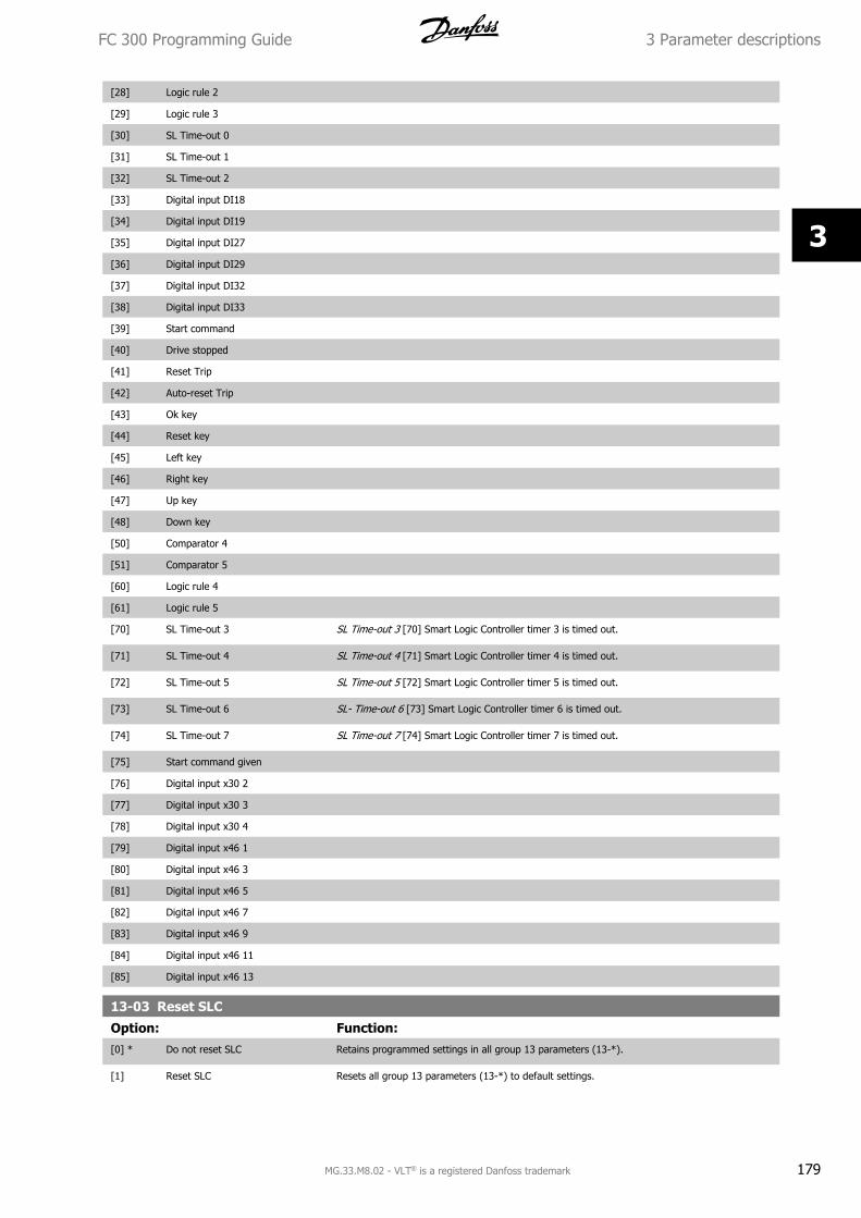
[28] Logic rule 2
[29] Logic rule 3
[30] SL Time-out 0
[31] SL Time-out 1
[32] SL Time-out 2
[33] Digital input DI18
[34] Digital input DI19
[35] Digital input DI27
[36] Digital input DI29
[37] Digital input DI32
[38] Digital input DI33
[39] Start command
[40] Drive stopped
[41] Reset Trip
[42] Auto-reset Trip
[43] Ok key
[44] Reset key
[45] Left key
[46] Right key
[47] Up key
[48] Down key
[50] Comparator 4
[51] Comparator 5
[60] Logic rule 4
[61] Logic rule 5
[70] SL Time-out 3 SL Time-out 3 [70] Smart Logic Controller timer 3 is timed out.
[71] SL Time-out 4 SL Time-out 4 [71] Smart Logic Controller timer 4 is timed out.
[72] SL Time-out 5 SL Time-out 5 [72] Smart Logic Controller timer 5 is timed out.
[73] SL Time-out 6 SL- Time-out 6 [73] Smart Logic Controller timer 6 is timed out.
[74] SL Time-out 7 SL Time-out 7 [74] Smart Logic Controller timer 7 is timed out.
[75] Start command given
[76] Digital input x30 2
[77] Digital input x30 3
[78] Digital input x30 4
[79] Digital input x46 1
[80] Digital input x46 3
[81] Digital input x46 5
[82] Digital input x46 7
[83] Digital input x46 9
[84] Digital input x46 11
[85] Digital input x46 13
13-03 Reset SLC
Option: Function:[0] * Do not reset SLC Retains programmed settings in all group 13 parameters (13-*).
[1] Reset SLC Resets all group 13 parameters (13-*) to default settings.
FC 300 Programming Guide 3 Parameter descriptions
MG.33.M8.02 - VLT® is a registered Danfoss trademark 179
3
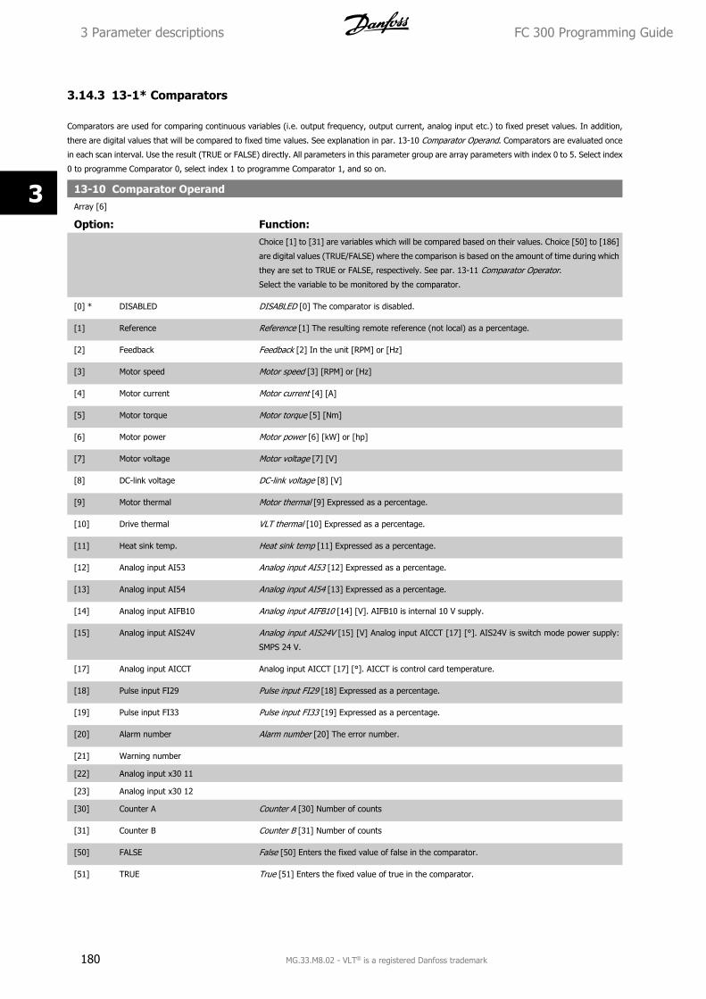
3.14.3 13-1* Comparators
Comparators are used for comparing continuous variables (i.e. output frequency, output current, analog input etc.) to fixed preset values. In addition,
there are digital values that will be compared to fixed time values. See explanation in par. 13-10 Comparator Operand. Comparators are evaluated once
in each scan interval. Use the result (TRUE or FALSE) directly. All parameters in this parameter group are array parameters with index 0 to 5. Select index
0 to programme Comparator 0, select index 1 to programme Comparator 1, and so on.
13-10 Comparator OperandArray [6]
Option: Function:Choice [1] to [31] are variables which will be compared based on their values. Choice [50] to [186]
are digital values (TRUE/FALSE) where the comparison is based on the amount of time during which
they are set to TRUE or FALSE, respectively. See par. 13-11 Comparator Operator.
Select the variable to be monitored by the comparator.
[0] * DISABLED DISABLED [0] The comparator is disabled.
[1] Reference Reference [1] The resulting remote reference (not local) as a percentage.
[2] Feedback Feedback [2] In the unit [RPM] or [Hz]
[3] Motor speed Motor speed [3] [RPM] or [Hz]
[4] Motor current Motor current [4] [A]
[5] Motor torque Motor torque [5] [Nm]
[6] Motor power Motor power [6] [kW] or [hp]
[7] Motor voltage Motor voltage [7] [V]
[8] DC-link voltage DC-link voltage [8] [V]
[9] Motor thermal Motor thermal [9] Expressed as a percentage.
[10] Drive thermal VLT thermal [10] Expressed as a percentage.
[11] Heat sink temp. Heat sink temp [11] Expressed as a percentage.
[12] Analog input AI53 Analog input AI53 [12] Expressed as a percentage.
[13] Analog input AI54 Analog input AI54 [13] Expressed as a percentage.
[14] Analog input AIFB10 Analog input AIFB10 [14] [V]. AIFB10 is internal 10 V supply.
[15] Analog input AIS24V Analog input AIS24V [15] [V] Analog input AICCT [17] [°]. AIS24V is switch mode power supply:
SMPS 24 V.
[17] Analog input AICCT Analog input AICCT [17] [°]. AICCT is control card temperature.
[18] Pulse input FI29 Pulse input FI29 [18] Expressed as a percentage.
[19] Pulse input FI33 Pulse input FI33 [19] Expressed as a percentage.
[20] Alarm number Alarm number [20] The error number.
[21] Warning number
[22] Analog input x30 11
[23] Analog input x30 12
[30] Counter A Counter A [30] Number of counts
[31] Counter B Counter B [31] Number of counts
[50] FALSE False [50] Enters the fixed value of false in the comparator.
[51] TRUE True [51] Enters the fixed value of true in the comparator.
3 Parameter descriptions FC 300 Programming Guide
180 MG.33.M8.02 - VLT® is a registered Danfoss trademark
3
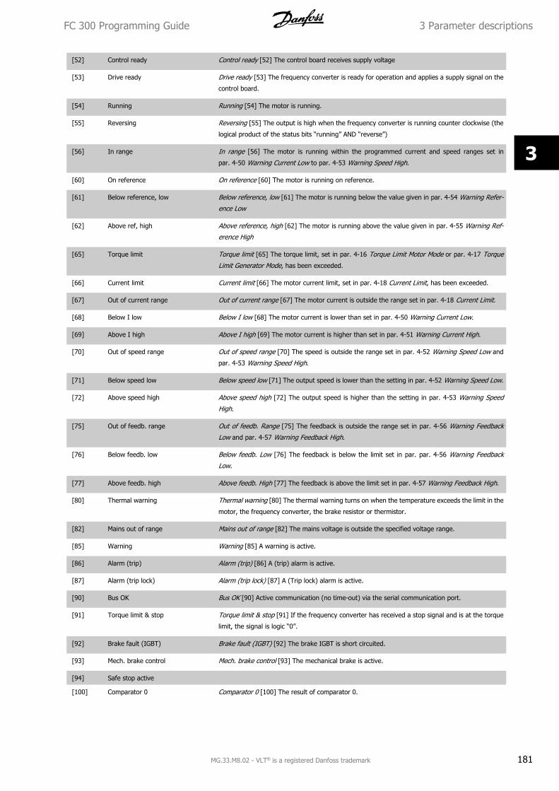
[52] Control ready Control ready [52] The control board receives supply voltage
[53] Drive ready Drive ready [53] The frequency converter is ready for operation and applies a supply signal on the
control board.
[54] Running Running [54] The motor is running.
[55] Reversing Reversing [55] The output is high when the frequency converter is running counter clockwise (the
logical product of the status bits “running” AND “reverse”)
[56] In range In range [56] The motor is running within the programmed current and speed ranges set in
par. 4-50 Warning Current Low to par. 4-53 Warning Speed High.
[60] On reference On reference [60] The motor is running on reference.
[61] Below reference, low Below reference, low [61] The motor is running below the value given in par. 4-54 Warning Refer-
ence Low
[62] Above ref, high Above reference, high [62] The motor is running above the value given in par. 4-55 Warning Ref-
erence High
[65] Torque limit Torque limit [65] The torque limit, set in par. 4-16 Torque Limit Motor Mode or par. 4-17 Torque
Limit Generator Mode, has been exceeded.
[66] Current limit Current limit [66] The motor current limit, set in par. 4-18 Current Limit, has been exceeded.
[67] Out of current range Out of current range [67] The motor current is outside the range set in par. 4-18 Current Limit.
[68] Below I low Below I low [68] The motor current is lower than set in par. 4-50 Warning Current Low.
[69] Above I high Above I high [69] The motor current is higher than set in par. 4-51 Warning Current High.
[70] Out of speed range Out of speed range [70] The speed is outside the range set in par. 4-52 Warning Speed Low and
par. 4-53 Warning Speed High.
[71] Below speed low Below speed low [71] The output speed is lower than the setting in par. 4-52 Warning Speed Low.
[72] Above speed high Above speed high [72] The output speed is higher than the setting in par. 4-53 Warning Speed
High.
[75] Out of feedb. range Out of feedb. Range [75] The feedback is outside the range set in par. 4-56 Warning Feedback
Low and par. 4-57 Warning Feedback High.
[76] Below feedb. low Below feedb. Low [76] The feedback is below the limit set in par. par. 4-56 Warning Feedback
Low.
[77] Above feedb. high Above feedb. High [77] The feedback is above the limit set in par. 4-57 Warning Feedback High.
[80] Thermal warning Thermal warning [80] The thermal warning turns on when the temperature exceeds the limit in the
motor, the frequency converter, the brake resistor or thermistor.
[82] Mains out of range Mains out of range [82] The mains voltage is outside the specified voltage range.
[85] Warning Warning [85] A warning is active.
[86] Alarm (trip) Alarm (trip) [86] A (trip) alarm is active.
[87] Alarm (trip lock) Alarm (trip lock) [87] A (Trip lock) alarm is active.
[90] Bus OK Bus OK [90] Active communication (no time-out) via the serial communication port.
[91] Torque limit & stop Torque limit & stop [91] If the frequency converter has received a stop signal and is at the torque
limit, the signal is logic “0”.
[92] Brake fault (IGBT) Brake fault (IGBT) [92] The brake IGBT is short circuited.
[93] Mech. brake control Mech. brake control [93] The mechanical brake is active.
[94] Safe stop active
[100] Comparator 0 Comparator 0 [100] The result of comparator 0.
FC 300 Programming Guide 3 Parameter descriptions
MG.33.M8.02 - VLT® is a registered Danfoss trademark 181
3
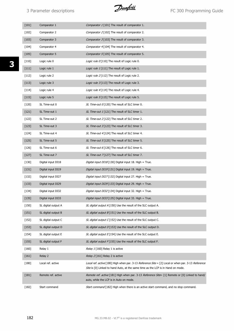
[101] Comparator 1 Comparator 1 [101] The result of comparator 1.
[102] Comparator 2 Comparator 2 [102] The result of comparator 2.
[103] Comparator 3 Comparator 3 [103] The result of comparator 3.
[104] Comparator 4 Comparator 4 [104] The result of comparator 4.
[105] Comparator 5 Comparator 5 [105] The result of comparator 5.
[110] Logic rule 0 Logic rule 0 [110] The result of Logic rule 0.
[111] Logic rule 1 Logic rule 1 [111] The result of Logic rule 1.
[112] Logic rule 2 Logic rule 2 [112] The result of Logic rule 2.
[113] Logic rule 3 Logic rule 3 [113] The result of Logic rule 3.
[114] Logic rule 4 Logic rule 4 [114] The result of Logic rule 4.
[115] Logic rule 5 Logic rule 5 [115] The result of Logic rule 5.
[120] SL Time-out 0 SL Time-out 0 [120] The result of SLC timer 0.
[121] SL Time-out 1 SL Time-out 1 [121] The result of SLC timer 1.
[122] SL Time-out 2 SL Time-out 2 [122] The result of SLC timer 2.
[123] SL Time-out 3 SL Time-out 3 [123] The result of SLC timer 3.
[124] SL Time-out 4 SL Time-out 4 [124] The result of SLC timer 4.
[125] SL Time-out 5 SL Time-out 5 [125] The result of SLC timer 5.
[126] SL Time-out 6 SL Time-out 6 [126] The result of SLC timer 6.
[127] SL Time-out 7 SL Time-out 7 [127] The result of SLC timer 7.
[130] Digital input DI18 Digital input DI18 [130] Digital input 18. High = True.
[131] Digital input DI19 Digital input DI19 [131] Digital input 19. High = True.
[132] Digital input DI27 Digital input DI27 [132] Digital input 27. High = True.
[133] Digital input DI29 Digital input DI29 [133] Digital input 29. High = True.
[134] Digital input DI32 Digital input DI32 [134] Digital input 32. High = True.
[135] Digital input DI33 Digital input DI33 [135] Digital input 33. High = True.
[150] SL digital output A SL digital output A [150] Use the result of the SLC output A.
[151] SL digital output B SL digital output B [151] Use the result of the SLC output B.
[152] SL digital output C SL digital output C [152] Use the result of the SLC output C.
[153] SL digital output D SL digital output D [153] Use the result of the SLC output D.
[154] SL digital output E SL digital output E [154] Use the result of the SLC output E.
[155] SL digital output F SL digital output F [155] Use the result of the SLC output F.
[160] Relay 1 Relay 1 [160] Relay 1 is active
[161] Relay 2 Relay 2 [161] Relay 2 is active
[180] Local ref. active Local ref. active [180] High when par. 3-13 Reference Site = [2] Local or when par. 3-13 Reference
Site is [0] Linked to hand Auto, at the same time as the LCP is in Hand on mode.
[181] Remote ref. active Remote ref. active [181] High when par. 3-13 Reference Site= [1] Remote or [0] Linked to hand/
auto, while the LCP is in Auto on mode.
[182] Start command Start command [182] High when there is an active start command, and no stop command.
3 Parameter descriptions FC 300 Programming Guide
182 MG.33.M8.02 - VLT® is a registered Danfoss trademark
3
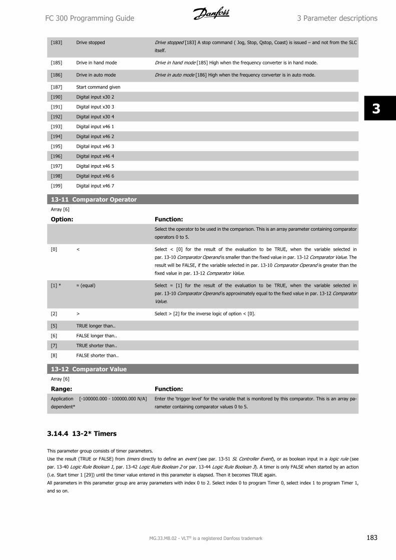
[183] Drive stopped Drive stopped [183] A stop command ( Jog, Stop, Qstop, Coast) is issued – and not from the SLC
itself.
[185] Drive in hand mode Drive in hand mode [185] High when the frequency converter is in hand mode.
[186] Drive in auto mode Drive in auto mode [186] High when the frequency converter is in auto mode.
[187] Start command given
[190] Digital input x30 2
[191] Digital input x30 3
[192] Digital input x30 4
[193] Digital input x46 1
[194] Digital input x46 2
[195] Digital input x46 3
[196] Digital input x46 4
[197] Digital input x46 5
[198] Digital input x46 6
[199] Digital input x46 7
13-11 Comparator OperatorArray [6]
Option: Function:Select the operator to be used in the comparison. This is an array parameter containing comparator
operators 0 to 5.
[0] < Select < [0] for the result of the evaluation to be TRUE, when the variable selected in
par. 13-10 Comparator Operand is smaller than the fixed value in par. 13-12 Comparator Value. The
result will be FALSE, if the variable selected in par. 13-10 Comparator Operand is greater than the
fixed value in par. 13-12 Comparator Value.
[1] * ≈ (equal) Select ≈ [1] for the result of the evaluation to be TRUE, when the variable selected in
par. 13-10 Comparator Operand is approximately equal to the fixed value in par. 13-12 Comparator
Value.
[2] > Select > [2] for the inverse logic of option < [0].
[5] TRUE longer than..
[6] FALSE longer than..
[7] TRUE shorter than..
[8] FALSE shorter than..
13-12 Comparator ValueArray [6]
Range: Function:Application
dependent*
[-100000.000 - 100000.000 N/A] Enter the ‘trigger level’ for the variable that is monitored by this comparator. This is an array pa-
rameter containing comparator values 0 to 5.
3.14.4 13-2* Timers
This parameter group consists of timer parameters.
Use the result (TRUE or FALSE) from timers directly to define an event (see par. 13-51 SL Controller Event), or as boolean input in a logic rule (see
par. 13-40 Logic Rule Boolean 1, par. 13-42 Logic Rule Boolean 2 or par. 13-44 Logic Rule Boolean 3). A timer is only FALSE when started by an action
(i.e. Start timer 1 [29]) until the timer value entered in this parameter is elapsed. Then it becomes TRUE again.
All parameters in this parameter group are array parameters with index 0 to 2. Select index 0 to program Timer 0, select index 1 to program Timer 1,
and so on.
FC 300 Programming Guide 3 Parameter descriptions
MG.33.M8.02 - VLT® is a registered Danfoss trademark 183
3
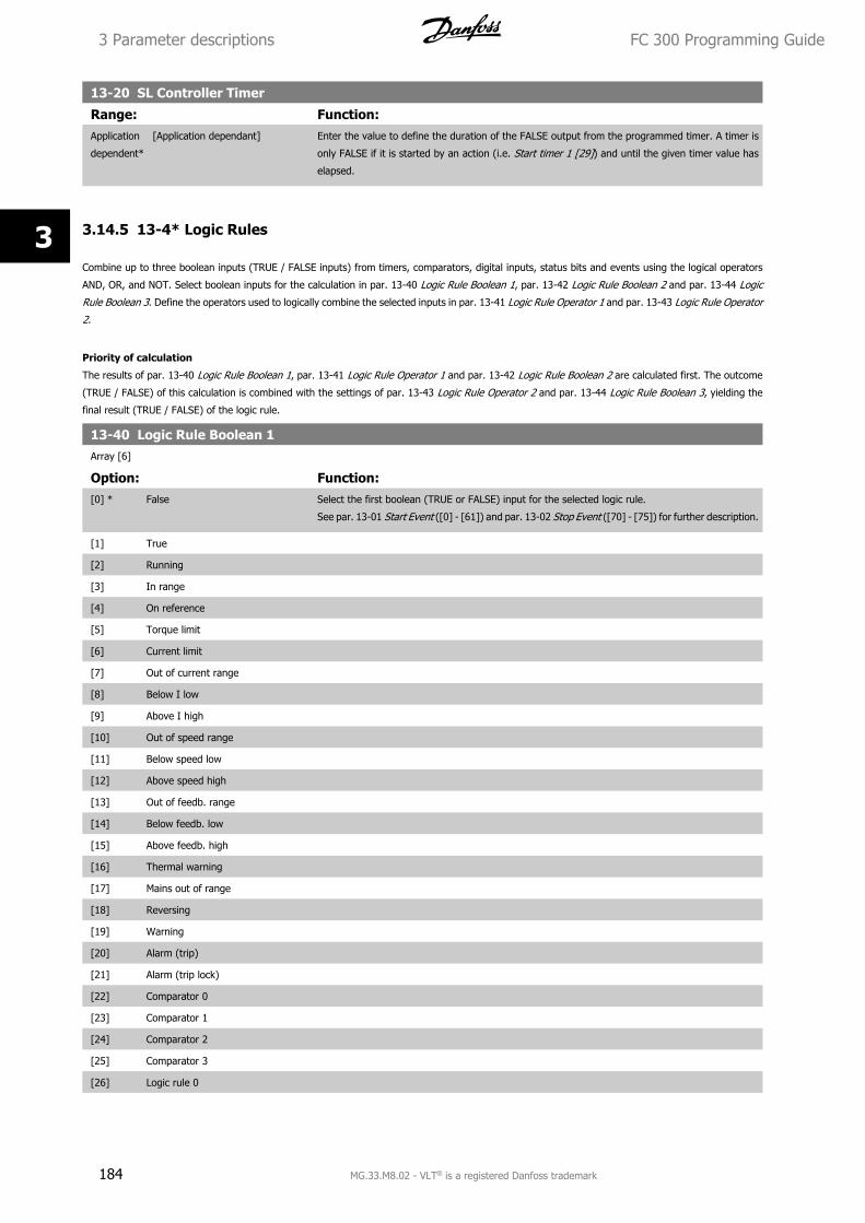
13-20 SL Controller Timer
Range: Function:Application
dependent*
[Application dependant] Enter the value to define the duration of the FALSE output from the programmed timer. A timer is
only FALSE if it is started by an action (i.e. Start timer 1 [29]) and until the given timer value has
elapsed.
3.14.5 13-4* Logic Rules
Combine up to three boolean inputs (TRUE / FALSE inputs) from timers, comparators, digital inputs, status bits and events using the logical operators
AND, OR, and NOT. Select boolean inputs for the calculation in par. 13-40 Logic Rule Boolean 1, par. 13-42 Logic Rule Boolean 2 and par. 13-44 Logic
Rule Boolean 3. Define the operators used to logically combine the selected inputs in par. 13-41 Logic Rule Operator 1 and par. 13-43 Logic Rule Operator
2.
Priority of calculation
The results of par. 13-40 Logic Rule Boolean 1, par. 13-41 Logic Rule Operator 1 and par. 13-42 Logic Rule Boolean 2 are calculated first. The outcome
(TRUE / FALSE) of this calculation is combined with the settings of par. 13-43 Logic Rule Operator 2 and par. 13-44 Logic Rule Boolean 3, yielding the
final result (TRUE / FALSE) of the logic rule.
13-40 Logic Rule Boolean 1Array [6]
Option: Function:[0] * False Select the first boolean (TRUE or FALSE) input for the selected logic rule.
See par. 13-01 Start Event ([0] - [61]) and par. 13-02 Stop Event ([70] - [75]) for further description.
[1] True
[2] Running
[3] In range
[4] On reference
[5] Torque limit
[6] Current limit
[7] Out of current range
[8] Below I low
[9] Above I high
[10] Out of speed range
[11] Below speed low
[12] Above speed high
[13] Out of feedb. range
[14] Below feedb. low
[15] Above feedb. high
[16] Thermal warning
[17] Mains out of range
[18] Reversing
[19] Warning
[20] Alarm (trip)
[21] Alarm (trip lock)
[22] Comparator 0
[23] Comparator 1
[24] Comparator 2
[25] Comparator 3
[26] Logic rule 0
3 Parameter descriptions FC 300 Programming Guide
184 MG.33.M8.02 - VLT® is a registered Danfoss trademark
3
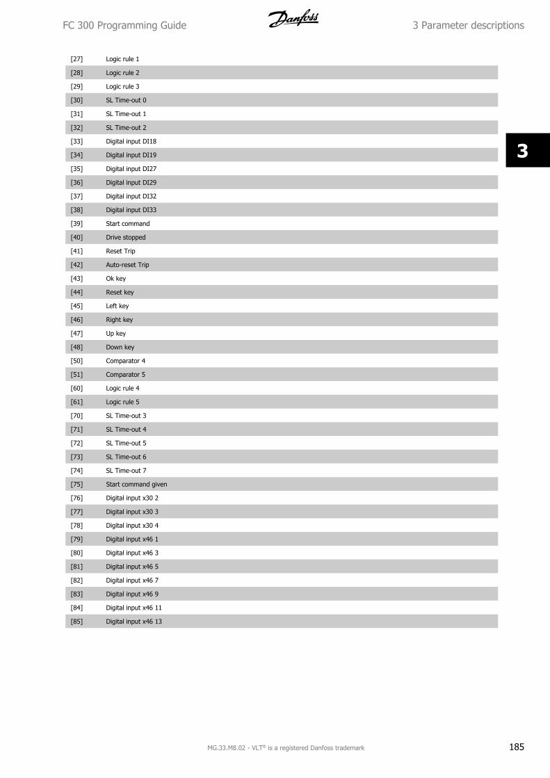
[27] Logic rule 1
[28] Logic rule 2
[29] Logic rule 3
[30] SL Time-out 0
[31] SL Time-out 1
[32] SL Time-out 2
[33] Digital input DI18
[34] Digital input DI19
[35] Digital input DI27
[36] Digital input DI29
[37] Digital input DI32
[38] Digital input DI33
[39] Start command
[40] Drive stopped
[41] Reset Trip
[42] Auto-reset Trip
[43] Ok key
[44] Reset key
[45] Left key
[46] Right key
[47] Up key
[48] Down key
[50] Comparator 4
[51] Comparator 5
[60] Logic rule 4
[61] Logic rule 5
[70] SL Time-out 3
[71] SL Time-out 4
[72] SL Time-out 5
[73] SL Time-out 6
[74] SL Time-out 7
[75] Start command given
[76] Digital input x30 2
[77] Digital input x30 3
[78] Digital input x30 4
[79] Digital input x46 1
[80] Digital input x46 3
[81] Digital input x46 5
[82] Digital input x46 7
[83] Digital input x46 9
[84] Digital input x46 11
[85] Digital input x46 13
FC 300 Programming Guide 3 Parameter descriptions
MG.33.M8.02 - VLT® is a registered Danfoss trademark 185
3
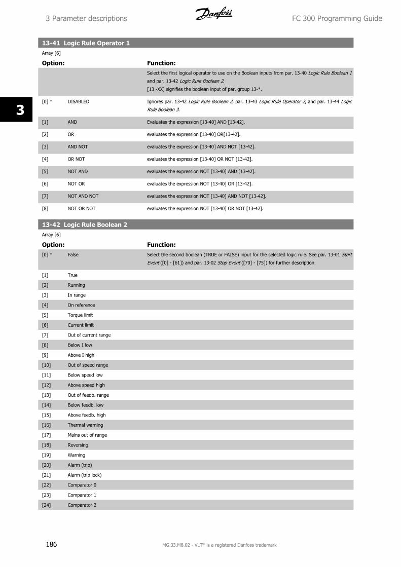
13-41 Logic Rule Operator 1Array [6]
Option: Function:Select the first logical operator to use on the Boolean inputs from par. 13-40 Logic Rule Boolean 1
and par. 13-42 Logic Rule Boolean 2.
[13 -XX] signifies the boolean input of par. group 13-*.
[0] * DISABLED Ignores par. 13-42 Logic Rule Boolean 2, par. 13-43 Logic Rule Operator 2, and par. 13-44 Logic
Rule Boolean 3.
[1] AND Evaluates the expression [13-40] AND [13-42].
[2] OR evaluates the expression [13-40] OR[13-42].
[3] AND NOT evaluates the expression [13-40] AND NOT [13-42].
[4] OR NOT evaluates the expression [13-40] OR NOT [13-42].
[5] NOT AND evaluates the expression NOT [13-40] AND [13-42].
[6] NOT OR evaluates the expression NOT [13-40] OR [13-42].
[7] NOT AND NOT evaluates the expression NOT [13-40] AND NOT [13-42].
[8] NOT OR NOT evaluates the expression NOT [13-40] OR NOT [13-42].
13-42 Logic Rule Boolean 2Array [6]
Option: Function:[0] * False Select the second boolean (TRUE or FALSE) input for the selected logic rule. See par. 13-01 Start
Event ([0] - [61]) and par. 13-02 Stop Event ([70] - [75]) for further description.
[1] True
[2] Running
[3] In range
[4] On reference
[5] Torque limit
[6] Current limit
[7] Out of current range
[8] Below I low
[9] Above I high
[10] Out of speed range
[11] Below speed low
[12] Above speed high
[13] Out of feedb. range
[14] Below feedb. low
[15] Above feedb. high
[16] Thermal warning
[17] Mains out of range
[18] Reversing
[19] Warning
[20] Alarm (trip)
[21] Alarm (trip lock)
[22] Comparator 0
[23] Comparator 1
[24] Comparator 2
3 Parameter descriptions FC 300 Programming Guide
186 MG.33.M8.02 - VLT® is a registered Danfoss trademark
3

[25] Comparator 3
[26] Logic rule 0
[27] Logic rule 1
[28] Logic rule 2
[29] Logic rule 3
[30] SL Time-out 0
[31] SL Time-out 1
[32] SL Time-out 2
[33] Digital input DI18
[34] Digital input DI19
[35] Digital input DI27
[36] Digital input DI29
[37] Digital input DI32
[38] Digital input DI33
[39] Start command
[40] Drive stopped
[41] Reset Trip
[42] Auto-reset Trip
[43] Ok key
[44] Reset key
[45] Left key
[46] Right key
[47] Up key
[48] Down key
[50] Comparator 4
[51] Comparator 5
[60] Logic rule 4
[61] Logic rule 5
[70] SL Time-out 3
[71] SL Time-out 4
[72] SL Time-out 5
[73] SL Time-out 6
[74] SL Time-out 7
[75] Start command given
[76] Digital input x30 2
[77] Digital input x30 3
[78] Digital input x30 4
[79] Digital input x46 1
[80] Digital input x46 3
[81] Digital input x46 5
[82] Digital input x46 7
[83] Digital input x46 9
[84] Digital input x46 11
[85] Digital input x46 13
FC 300 Programming Guide 3 Parameter descriptions
MG.33.M8.02 - VLT® is a registered Danfoss trademark 187
3
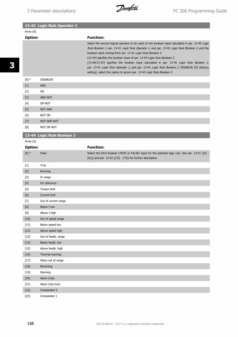
13-43 Logic Rule Operator 2Array [6]
Option: Function:Select the second logical operator to be used on the boolean input calculated in par. 13-40 Logic
Rule Boolean 1, par. 13-41 Logic Rule Operator 1, and par. 13-42 Logic Rule Boolean 2, and the
boolean input coming from par. 13-42 Logic Rule Boolean 2.
[13-44] signifies the boolean input of par. 13-44 Logic Rule Boolean 3.
[13-40/13-42] signifies the boolean input calculated in par. 13-40 Logic Rule Boolean 1,
par. 13-41 Logic Rule Operator 1, and par. 13-42 Logic Rule Boolean 2. DISABLED [0] (factory
setting). select this option to ignore par. 13-44 Logic Rule Boolean 3.
[0] * DISABLED
[1] AND
[2] OR
[3] AND NOT
[4] OR NOT
[5] NOT AND
[6] NOT OR
[7] NOT AND NOT
[8] NOT OR NOT
13-44 Logic Rule Boolean 3Array [6]
Option: Function:[0] * False Select the third boolean (TRUE or FALSE) input for the selected logic rule. See par. 13-01 ([0] -
[61]) and par. 13-02 ([70] - [75]) for further description.
[1] True
[2] Running
[3] In range
[4] On reference
[5] Torque limit
[6] Current limit
[7] Out of current range
[8] Below I low
[9] Above I high
[10] Out of speed range
[11] Below speed low
[12] Above speed high
[13] Out of feedb. range
[14] Below feedb. low
[15] Above feedb. high
[16] Thermal warning
[17] Mains out of range
[18] Reversing
[19] Warning
[20] Alarm (trip)
[21] Alarm (trip lock)
[22] Comparator 0
[23] Comparator 1
3 Parameter descriptions FC 300 Programming Guide
188 MG.33.M8.02 - VLT® is a registered Danfoss trademark
3
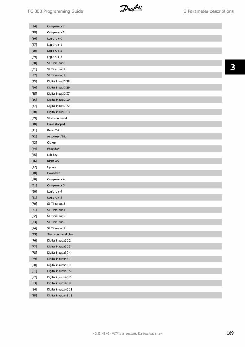
[24] Comparator 2
[25] Comparator 3
[26] Logic rule 0
[27] Logic rule 1
[28] Logic rule 2
[29] Logic rule 3
[30] SL Time-out 0
[31] SL Time-out 1
[32] SL Time-out 2
[33] Digital input DI18
[34] Digital input DI19
[35] Digital input DI27
[36] Digital input DI29
[37] Digital input DI32
[38] Digital input DI33
[39] Start command
[40] Drive stopped
[41] Reset Trip
[42] Auto-reset Trip
[43] Ok key
[44] Reset key
[45] Left key
[46] Right key
[47] Up key
[48] Down key
[50] Comparator 4
[51] Comparator 5
[60] Logic rule 4
[61] Logic rule 5
[70] SL Time-out 3
[71] SL Time-out 4
[72] SL Time-out 5
[73] SL Time-out 6
[74] SL Time-out 7
[75] Start command given
[76] Digital input x30 2
[77] Digital input x30 3
[78] Digital input x30 4
[79] Digital input x46 1
[80] Digital input x46 3
[81] Digital input x46 5
[82] Digital input x46 7
[83] Digital input x46 9
[84] Digital input x46 11
[85] Digital input x46 13
FC 300 Programming Guide 3 Parameter descriptions
MG.33.M8.02 - VLT® is a registered Danfoss trademark 189
3
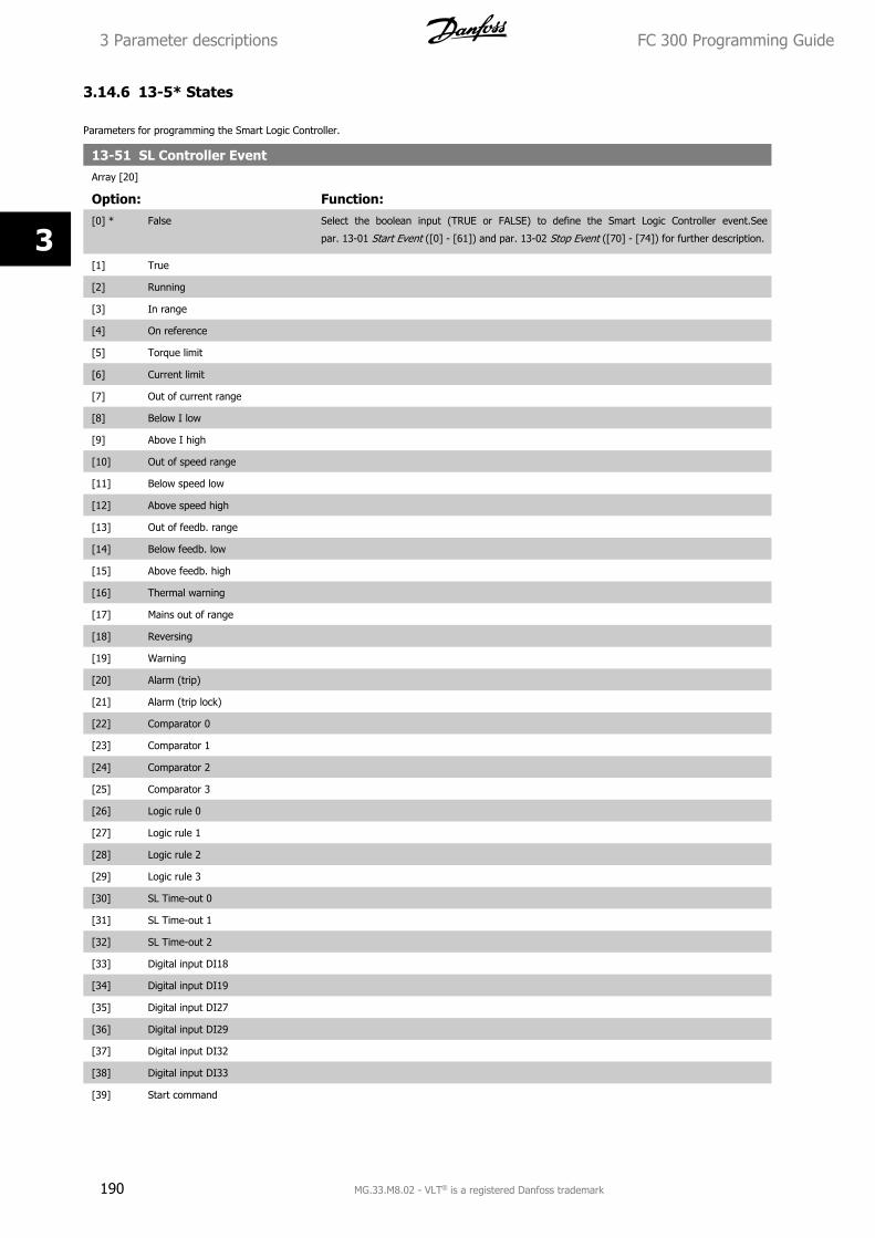
3.14.6 13-5* States
Parameters for programming the Smart Logic Controller.
13-51 SL Controller EventArray [20]
Option: Function:[0] * False Select the boolean input (TRUE or FALSE) to define the Smart Logic Controller event.See
par. 13-01 Start Event ([0] - [61]) and par. 13-02 Stop Event ([70] - [74]) for further description.
[1] True
[2] Running
[3] In range
[4] On reference
[5] Torque limit
[6] Current limit
[7] Out of current range
[8] Below I low
[9] Above I high
[10] Out of speed range
[11] Below speed low
[12] Above speed high
[13] Out of feedb. range
[14] Below feedb. low
[15] Above feedb. high
[16] Thermal warning
[17] Mains out of range
[18] Reversing
[19] Warning
[20] Alarm (trip)
[21] Alarm (trip lock)
[22] Comparator 0
[23] Comparator 1
[24] Comparator 2
[25] Comparator 3
[26] Logic rule 0
[27] Logic rule 1
[28] Logic rule 2
[29] Logic rule 3
[30] SL Time-out 0
[31] SL Time-out 1
[32] SL Time-out 2
[33] Digital input DI18
[34] Digital input DI19
[35] Digital input DI27
[36] Digital input DI29
[37] Digital input DI32
[38] Digital input DI33
[39] Start command
3 Parameter descriptions FC 300 Programming Guide
190 MG.33.M8.02 - VLT® is a registered Danfoss trademark
3
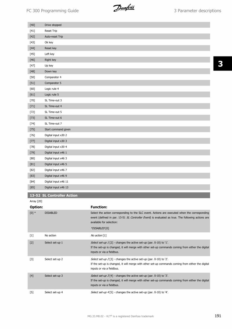
[40] Drive stopped
[41] Reset Trip
[42] Auto-reset Trip
[43] Ok key
[44] Reset key
[45] Left key
[46] Right key
[47] Up key
[48] Down key
[50] Comparator 4
[51] Comparator 5
[60] Logic rule 4
[61] Logic rule 5
[70] SL Time-out 3
[71] SL Time-out 4
[72] SL Time-out 5
[73] SL Time-out 6
[74] SL Time-out 7
[75] Start command given
[76] Digital input x30 2
[77] Digital input x30 3
[78] Digital input x30 4
[79] Digital input x46 1
[80] Digital input x46 3
[81] Digital input x46 5
[82] Digital input x46 7
[83] Digital input x46 9
[84] Digital input x46 11
[85] Digital input x46 13
13-52 SL Controller ActionArray [20]
Option: Function:[0] * DISABLED Select the action corresponding to the SLC event. Actions are executed when the corresponding
event (defined in par. 13-51 SL Controller Event) is evaluated as true. The following actions are
available for selection:
*DISABLED [0]
[1] No action No action [1]
[2] Select set-up 1 Select set-up 1 [2] - changes the active set-up (par. 0-10) to ‘1’.
If the set-up is changed, it will merge with other set-up commands coming from either the digital
inputs or via a fieldbus.
[3] Select set-up 2 Select set-up 2 [3] - changes the active set-up (par. 0-10) to ‘2’.
If the set-up is changed, it will merge with other set-up commands coming from either the digital
inputs or via a fieldbus.
[4] Select set-up 3 Select set-up 3 [4] - changes the active set-up (par. 0-10) to ‘3’.
If the set-up is changed, it will merge with other set-up commands coming from either the digital
inputs or via a fieldbus.
[5] Select set-up 4 Select set-up 4 [5] - changes the active set-up (par. 0-10) to ‘4’.
FC 300 Programming Guide 3 Parameter descriptions
MG.33.M8.02 - VLT® is a registered Danfoss trademark 191
3
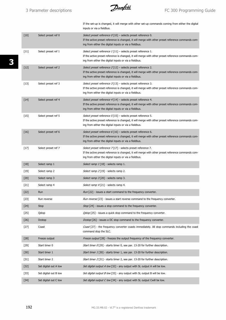
If the set-up is changed, it will merge with other set-up commands coming from either the digital
inputs or via a fieldbus.
[10] Select preset ref 0 Select preset reference 0 [10] – selects preset reference 0.
If the active preset reference is changed, it will merge with other preset reference commands com-
ing from either the digital inputs or via a fieldbus.
[11] Select preset ref 1 Select preset reference 1 [11] – selects preset reference 1.
If the active preset reference is changed, it will merge with other preset reference commands com-
ing from either the digital inputs or via a fieldbus.
[12] Select preset ref 2 Select preset reference 2 [12] – selects preset reference 2.
If the active preset reference is changed, it will merge with other preset reference commands com-
ing from either the digital inputs or via a fieldbus.
[13] Select preset ref 3 Select preset reference 3 [13] – selects preset reference 3.
If the active preset reference is changed, it will merge with other preset reference commands com-
ing from either the digital inputs or via a fieldbus.
[14] Select preset ref 4 Select preset reference 4 [14] – selects preset reference 4.
If the active preset reference is changed, it will merge with other preset reference commands com-
ing from either the digital inputs or via a fieldbus.
[15] Select preset ref 5 Select preset reference 5 [15] – selects preset reference 5.
If the active preset reference is changed, it will merge with other preset reference commands com-
ing from either the digital inputs or via a fieldbus.
[16] Select preset ref 6 Select preset reference 6 [16] – selects preset reference 6.
If the active preset reference is changed, it will merge with other preset reference commands com-
ing from either the digital inputs or via a fieldbus.
[17] Select preset ref 7 Select preset reference 7 [17] - selects preset reference 7.
If the active preset reference is changed, it will merge with other preset reference commands com-
ing from either the digital inputs or via a fieldbus.
[18] Select ramp 1 Select ramp 1 [18] - selects ramp 1.
[19] Select ramp 2 Select ramp 2 [19] - selects ramp 2.
[20] Select ramp 3 Select ramp 3 [20] - selects ramp 3.
[21] Select ramp 4 Select ramp 4 [21] - selects ramp 4.
[22] Run Run [22] - issues a start command to the frequency converter.
[23] Run reverse Run reverse [23] - issues a start reverse command to the frequency converter.
[24] Stop Stop [24] - issues a stop command to the frequency converter.
[25] Qstop Qstop [25] - issues a quick stop command to the frequency converter.
[26] Dcstop Dcstop [26] - issues a DC stop command to the frequency converter.
[27] Coast Coast [27] - the frequency converter coasts immediately. All stop commands including the coast
command stop the SLC.
[28] Freeze output Freeze output [28] - freezes the output frequency of the frequency converter.
[29] Start timer 0 Start timer 0 [29] - starts timer 0, see par. 13-20 for further description.
[30] Start timer 1 Start timer 1 [30] - starts timer 1, see par. 13-20 for further description.
[31] Start timer 2 Start timer 2 [31] - starts timer 2, see par. 13-20 for further description.
[32] Set digital out A low Set digital output A low [32] - any output with SL output A will be low.
[33] Set digital out B low Set digital output B low [33] - any output with SL output B will be low.
[34] Set digital out C low Set digital output C low [34] - any output with SL output Cwill be low.
3 Parameter descriptions FC 300 Programming Guide
192 MG.33.M8.02 - VLT® is a registered Danfoss trademark
3
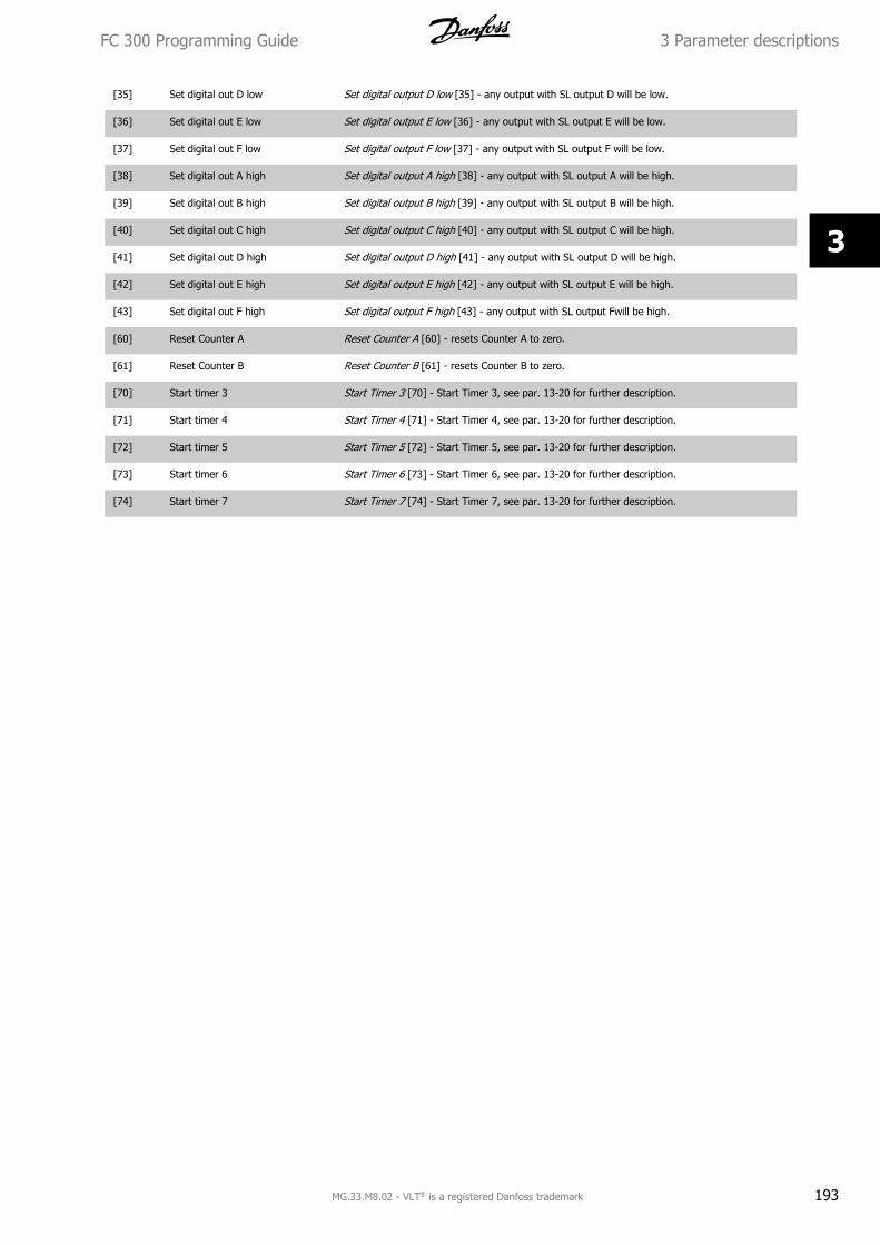
[35] Set digital out D low Set digital output D low [35] - any output with SL output D will be low.
[36] Set digital out E low Set digital output E low [36] - any output with SL output E will be low.
[37] Set digital out F low Set digital output F low [37] - any output with SL output F will be low.
[38] Set digital out A high Set digital output A high [38] - any output with SL output A will be high.
[39] Set digital out B high Set digital output B high [39] - any output with SL output B will be high.
[40] Set digital out C high Set digital output C high [40] - any output with SL output C will be high.
[41] Set digital out D high Set digital output D high [41] - any output with SL output D will be high.
[42] Set digital out E high Set digital output E high [42] - any output with SL output E will be high.
[43] Set digital out F high Set digital output F high [43] - any output with SL output Fwill be high.
[60] Reset Counter A Reset Counter A [60] - resets Counter A to zero.
[61] Reset Counter B Reset Counter B [61] - resets Counter B to zero.
[70] Start timer 3 Start Timer 3 [70] - Start Timer 3, see par. 13-20 for further description.
[71] Start timer 4 Start Timer 4 [71] - Start Timer 4, see par. 13-20 for further description.
[72] Start timer 5 Start Timer 5 [72] - Start Timer 5, see par. 13-20 for further description.
[73] Start timer 6 Start Timer 6 [73] - Start Timer 6, see par. 13-20 for further description.
[74] Start timer 7 Start Timer 7 [74] - Start Timer 7, see par. 13-20 for further description.
FC 300 Programming Guide 3 Parameter descriptions
MG.33.M8.02 - VLT® is a registered Danfoss trademark 193
3
3.15 Parameters: Special Functions
3.15.1 14-** Special Functions
Parameter group for configuring special frequency converter functions.
3.15.2 14-0* Inverter Switching
Parameters for configuring the inverter switching.
14-00 Switching Pattern
Option: Function:[0] * 60 AVM Select the switching pattern: 60° AVM or SFAVM.
[1] * SFAVM
NB!
The output frequency value of the frequency converter must never exceed 1/10 of the switching frequency. When the motor is running,
adjust the switching frequency in par. 4-11 Motor Speed Low Limit [RPM] until the motor is as noiseless as possible. See also
par. 14-00 Switching Pattern and the section Special conditions in the FC 300 Design Guide.
14-01 Switching FrequencySelect the inverter switching frequency. Changing the switching frequency can help to reduce acoustic noise from the motor. Default depend on power
size.
Option: Function:[0] 1.0 kHz
[1] 1.5 kHz Default switching frequency for 355-1200 kW, 690V
[2] 2.0 kHz Default switching frequency for 250-800 kW, 400V and 37-315 kW, 690V
[3] 2.5 kHz
[4] 3.0 kHz Default switching frequency for 18.5-37 kW, 200V and 37-200 kW, 400V
[5] 3.5 kHz
[6] 4.0 kHz Default switching frequency for 5.5 – 15 kW, 200V and 11-30 kW, 400V
[7] * 5.0 kHz Default switching frequency for 0.25 – 3,7 k W, 200V and 0.37-7.5 kW, 400V
[8] 6.0 kHz
[9] 7.0 kHz
[10] 8.0 kHz
[11] 10.0 kHz
[12] 12.0 kHz
[13] 14.0 kHz
[14] 16.0 kHz
NB!
The output frequency value of the frequency converter must never exceed 1/10 of the switching frequency. When the motor is running,
adjust the switching frequency in par. 4-11 Motor Speed Low Limit [RPM] until the motor is as noiseless as possible. See also
par. 14-00 Switching Pattern and the section Special conditions in the VLT AutomationDrive FC 300 Design Guide.
3 Parameter descriptions FC 300 Programming Guide
194 MG.33.M8.02 - VLT® is a registered Danfoss trademark
3
NB!
Switching frequencies higher than 5.0 kHz lead to automatic derating of the maximum output of the frequency converter.
14-03 Overmodulation
Option: Function:[0] Off Select On [1] to connect the overmodulation function for the output voltage, to obtain an output
voltage up to 15% greater than the mains voltage.
Select Off [0] for no overmodulation of the output voltage, in order to avoid torque ripple on the
motor shaft. This feature may be useful for applications such as grinding machines.
[1] * On
14-04 PWM Random
Option: Function:[0] * Off No change of the acoustic motor switching noise.
[1] On Transforms the acoustic motor switching noise from a clear ringing tone to a less noticeable ‘white’
noise. This is achieved by slightly and randomly altering the synchronism of the pulse width modu-
lated output phases.
14-06 Dead Time Compensation
Option: Function:[0] Off No compensation.
[1] * On Activates dead time compensation.
3.15.3 14-1* Mains On/Off
Parameters for configuring mains failure monitoring and handling. If a mains failure appears, the frequency converter will try to continue in a controlled
way until the power in the DC link has been exhausted.
14-10 Mains FailurePar. 14-10 Mains Failure is typically used where very short mains interruptions (voltage dips) are present. At 100% load and a short voltage interruption,
the DC voltage on the main capacitors drops quickly. For larger drives it only takes a few milliseconds before the DC level is down to about 373 V DC
and the main IGBT cuts off and looses the control over the motor. When the mains is restored, and the IGBT starts again, the output frequency and
voltage vector does not correspond to the speed/frequency of the motor, and the result is normally an overvoltage or overcurrent, mostly resulting in
a trip lock. Par. 14-10 Mains Failure can be programmed to avoid this situation.
Option: Function:Function: Select the function to which the frequency converter must act when the threshold in
par. 14-11 Mains Voltage at Mains Fault has been reached.
Par. 14-10 Mains Failure cannot be changed while motor is running.
Controlled ramp down:
The frequency converter will perform a controlled ramp down. If par. 2-10 Brake Function is Off [0]
or AC brake [2], the ramp will follow the Over Voltage Ramping. If par. 2-10 Brake Function is [1]
Resistor Brake the ramp will follow the setting in par. 3-81 Quick Stop Ramp Time.
Controlled ramp down [1]:
After power-up the frequency converter is ready for start. Controlled ramp down and trip [2]: After
power-up the frequency converter needs a reset for starting.
FC 300 Programming Guide 3 Parameter descriptions
MG.33.M8.02 - VLT® is a registered Danfoss trademark 195
3
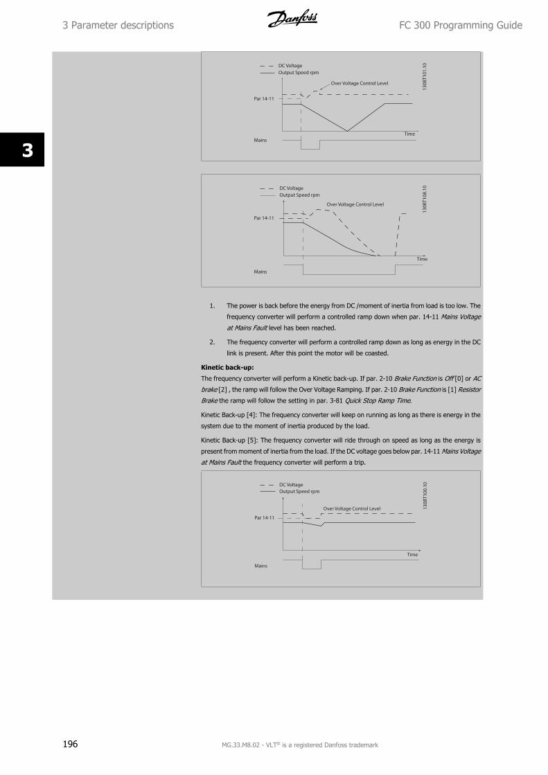
1. The power is back before the energy from DC /moment of inertia from load is too low. The
frequency converter will perform a controlled ramp down when par. 14-11 Mains Voltage
at Mains Fault level has been reached.
2. The frequency converter will perform a controlled ramp down as long as energy in the DC
link is present. After this point the motor will be coasted.
Kinetic back-up:
The frequency converter will perform a Kinetic back-up. If par. 2-10 Brake Function is Off [0] or AC
brake [2] , the ramp will follow the Over Voltage Ramping. If par. 2-10 Brake Function is [1] Resistor
Brake the ramp will follow the setting in par. 3-81 Quick Stop Ramp Time.
Kinetic Back-up [4]: The frequency converter will keep on running as long as there is energy in the
system due to the moment of inertia produced by the load.
Kinetic Back-up [5]: The frequency converter will ride through on speed as long as the energy is
present from moment of inertia from the load. If the DC voltage goes below par. 14-11 Mains Voltage
at Mains Fault the frequency converter will perform a trip.
3 Parameter descriptions FC 300 Programming Guide
196 MG.33.M8.02 - VLT® is a registered Danfoss trademark
3
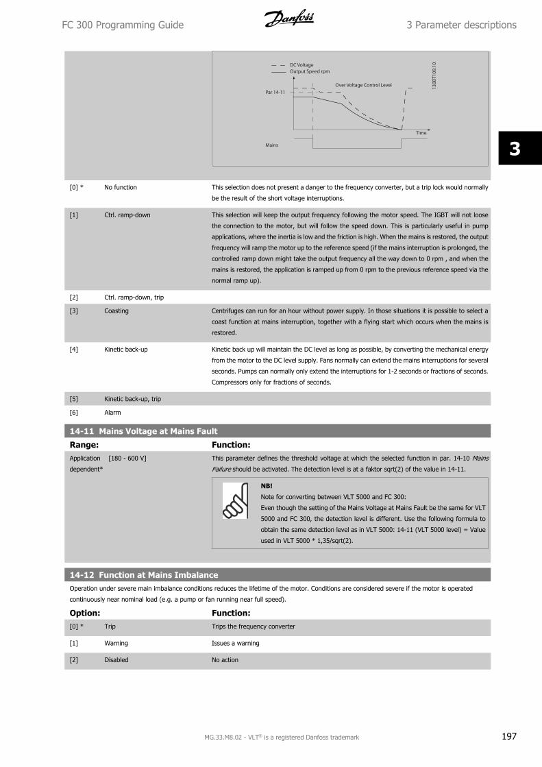
[0] * No function This selection does not present a danger to the frequency converter, but a trip lock would normally
be the result of the short voltage interruptions.
[1] Ctrl. ramp-down This selection will keep the output frequency following the motor speed. The IGBT will not loose
the connection to the motor, but will follow the speed down. This is particularly useful in pump
applications, where the inertia is low and the friction is high. When the mains is restored, the output
frequency will ramp the motor up to the reference speed (if the mains interruption is prolonged, the
controlled ramp down might take the output frequency all the way down to 0 rpm , and when the
mains is restored, the application is ramped up from 0 rpm to the previous reference speed via the
normal ramp up).
[2] Ctrl. ramp-down, trip
[3] Coasting Centrifuges can run for an hour without power supply. In those situations it is possible to select a
coast function at mains interruption, together with a flying start which occurs when the mains is
restored.
[4] Kinetic back-up Kinetic back up will maintain the DC level as long as possible, by converting the mechanical energy
from the motor to the DC level supply. Fans normally can extend the mains interruptions for several
seconds. Pumps can normally only extend the interruptions for 1-2 seconds or fractions of seconds.
Compressors only for fractions of seconds.
[5] Kinetic back-up, trip
[6] Alarm
14-11 Mains Voltage at Mains Fault
Range: Function:Application
dependent*
[180 - 600 V] This parameter defines the threshold voltage at which the selected function in par. 14-10 Mains
Failure should be activated. The detection level is at a faktor sqrt(2) of the value in 14-11.
NB!
Note for converting between VLT 5000 and FC 300:
Even though the setting of the Mains Voltage at Mains Fault be the same for VLT
5000 and FC 300, the detection level is different. Use the following formula to
obtain the same detection level as in VLT 5000: 14-11 (VLT 5000 level) = Value
used in VLT 5000 * 1,35/sqrt(2).
14-12 Function at Mains ImbalanceOperation under severe main imbalance conditions reduces the lifetime of the motor. Conditions are considered severe if the motor is operated
continuously near nominal load (e.g. a pump or fan running near full speed).
Option: Function:[0] * Trip Trips the frequency converter
[1] Warning Issues a warning
[2] Disabled No action
FC 300 Programming Guide 3 Parameter descriptions
MG.33.M8.02 - VLT® is a registered Danfoss trademark 197
3
14-14 Kin. Backup Time Out
Range: Function:60 s* [0 - 60 s] This parameter defines the Kinetic Backup Time Out in flux mode when running on low voltage grids.
If the supply voltage does not increase above the value defined in P14-11 + 5% within the specified
time, the drive will then automatically run a controlled ramp-down profile prior to stop.
3.15.4 14-2* Trip Reset
Parameters for configuring auto reset handling, special trip handling and control card self test or initialisation.
14-20 Reset Mode
Option: Function:Select the reset function after tripping. Once reset, the frequency converter can be restarted.
[0] * Manual reset Select Manual reset [0], to perform a reset via [RESET] or via the digital inputs.
[1] Automatic reset x 1 Select Automatic reset x 1…x20 [1]-[12] to perform between one and twenty automatic resets after
tripping.
[2] Automatic reset x 2
[3] Automatic reset x 3
[4] Automatic reset x 4
[5] Automatic reset x 5
[6] Automatic reset x 6
[7] Automatic reset x 7
[8] Automatic reset x 8
[9] Automatic reset x 9
[10] Automatic reset x 10
[11] Automatic reset x 15
[12] Automatic reset x 20
[13] Infinite auto reset Select Infinite Automatic Reset [13] for continuous resetting after tripping.
[14] Reset at power-up
NB!
The motor may start without warning. If the specified number of AUTOMATIC RESETs is reached within 10 minutes, the frequency
converter enters Manual reset [0] mode. After the Manual reset is performed, the setting of par. 14-20 Reset Mode reverts to the
original selection. If the number of automatic resets is not reached within 10 minutes, or when a Manual reset is performed, the internal
AUTOMATIC RESET counter returns to zero.
NB!
Automatic reset will also be active for resetting safe stop function in firmware version < 4.3x.
14-21 Automatic Restart Time
Range: Function:10 s* [0 - 600 s] Enter the time interval from trip to start of the automatic reset function. This parameter is active
when par. 14-20 Reset Mode is set to Automatic reset [1] - [13].
3 Parameter descriptions FC 300 Programming Guide
198 MG.33.M8.02 - VLT® is a registered Danfoss trademark
3
14-22 Operation Mode
Option: Function:Use this parameter to specify normal operation; to perform tests; or to initialise all parameters
except par. 15-03 Power Up's, par. 15-04 Over Temp's and par. 15-05 Over Volt's. This function is
active only when the power is cycled to the frequency converter.
Select Normal operation [0] for normal operation of the frequency converter with the motor in the
selected application.
Select Control card test [1] to test the analog and digital inputs and outputs and the +10 V control
voltage. The test requires a test connector with internal connections. Use the following procedure
for the control card test:
1. Select Control card test [1].
2. Disconnect the mains supply and wait for the light in the display to go out.
3. Set switches S201 (A53) and S202 (A54) = ‘ON’ / I.
4. Insert the test plug (see below).
5. Connect to mains supply.
6. Carry out various tests.
7. The results are displayed on the LCP and the frequency converter moves into an infinite
loop.
8. Par. 14-22 Operation Mode is automatically set to Normal operation. Carry out a power
cycle to start up in Normal operation after a control card test.
If the test is OK:
LCP read-out: Control Card OK.
Disconnect the mains supply and remove the test plug. The green LED on the Control Card will light
up.
If the test fails:
LCP read-out: Control Card I/O failure.
Replace the frequency converter or Control card. The red LED on the Control Card is turned on. Test
plugs (connect the following terminals to each other): 18 - 27 - 32; 19 - 29 - 33; 42 - 53 - 54
FC 300 Programming Guide 3 Parameter descriptions
MG.33.M8.02 - VLT® is a registered Danfoss trademark 199
3
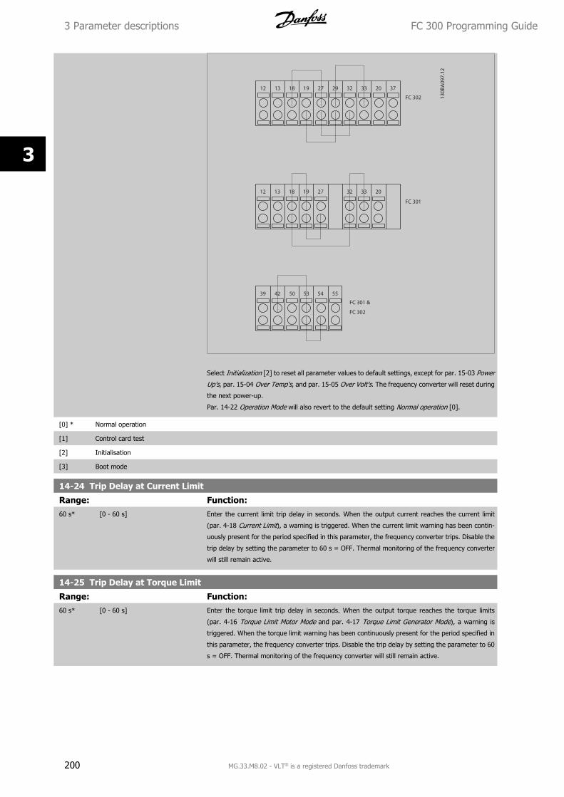
Select Initialization [2] to reset all parameter values to default settings, except for par. 15-03 Power
Up's, par. 15-04 Over Temp's, and par. 15-05 Over Volt's. The frequency converter will reset during
the next power-up.
Par. 14-22 Operation Mode will also revert to the default setting Normal operation [0].
[0] * Normal operation
[1] Control card test
[2] Initialisation
[3] Boot mode
14-24 Trip Delay at Current Limit
Range: Function:60 s* [0 - 60 s] Enter the current limit trip delay in seconds. When the output current reaches the current limit
(par. 4-18 Current Limit), a warning is triggered. When the current limit warning has been contin-
uously present for the period specified in this parameter, the frequency converter trips. Disable the
trip delay by setting the parameter to 60 s = OFF. Thermal monitoring of the frequency converter
will still remain active.
14-25 Trip Delay at Torque Limit
Range: Function:60 s* [0 - 60 s] Enter the torque limit trip delay in seconds. When the output torque reaches the torque limits
(par. 4-16 Torque Limit Motor Mode and par. 4-17 Torque Limit Generator Mode), a warning is
triggered. When the torque limit warning has been continuously present for the period specified in
this parameter, the frequency converter trips. Disable the trip delay by setting the parameter to 60
s = OFF. Thermal monitoring of the frequency converter will still remain active.
3 Parameter descriptions FC 300 Programming Guide
200 MG.33.M8.02 - VLT® is a registered Danfoss trademark
3
14-26 Trip Delay at Inverter Fault
Range: Function:Application
dependent*
[0 - 35 s] When the frequency converter detects an over-voltage in the set time trip will be effected after the
set time.
If value = 0, protection mode is disabled
NB!
It is recommended to disable protection mode in hoisting applications.
14-29 Service Code
Range: Function:0* [-2147483647 - 2147483647 ] For internal service only.
3.15.5 14-3* Current Limit Control
The frequency converter features an integral Current Limit Controller which is activated when the motor current, and thus the torque, is higher than the
torque limits set in par. 4-16 Torque Limit Motor Mode and par. 4-17 Torque Limit Generator Mode.
When the current limit is reached during motor operation or regenerative operation, the frequency converter will try to reduce torque below the preset
torque limits as quickly as possible without losing control of the motor.
While the current control is active, the frequency converter can only be stopped by setting a digital input to Coast inverse [2] or Coast and reset inv. [3].
Any signal on terminals 18 to 33 will not be active until the frequency converter is no longer near the current limit.
By using a digital input set to Coast inverse [2] or Coast and reset inv. [3], the motor does not use the ramp-down time, since the frequency converter
is coasted. If a quick stop is necessary, use the mechanical brake control function along with an external electro-mechanical brake attached to the
application.
14-30 Current Lim Ctrl, Proportional Gain
Range: Function:100 %* [0 - 500 %] Enter the proportional gain value for the current limit controller. Selection of a high value makes
the controller react faster. Too high a setting leads to controller instability.
14-31 Current Lim Ctrl, Integration Time
Range: Function:0.020 s* [0.002 - 2.000 s] Controls the current limit control integration time. Setting it to a lower value makes it react faster.
A setting too low leads to control instability.
14-32 Current Lim Ctrl, Filter Time
Range: Function:1.0 ms* [1.0 - 100.0 ms]
14-35 Stall Protection
Option: Function:Select Enable [1] to enable the stall protection in field-weakening in flux mode. Select Disable [0]
if you desire to disable it. This might cause the motor to be lost. Par. 14-35 Stall Protection is active
in Flux mode only.
[0] Disabled
[1] * Enabled
FC 300 Programming Guide 3 Parameter descriptions
MG.33.M8.02 - VLT® is a registered Danfoss trademark 201
3
3.15.6 14-4* Energy Optimising
Parameters for adjusting the energy optimisation level in both Variable Torque (VT) and Automatic Energy Optimization (AEO) mode in par. 1-03 Torque
Characteristics.
14-40 VT Level
Range: Function:66 %* [40 - 90 %] Enter the level of motor magnetisation at low speed. Selection of a low value reduces energy loss
in the motor, but also reduces load capability.
This parameter cannot be adjusted while the motor is running.
14-41 AEO Minimum Magnetisation
Range: Function:Application
dependent*
[40 - 75 %] Enter the minimum allowable magnetisation for AEO. Selection of a low value reduces energy loss
in the motor, but can also reduce resistance to sudden load changes.
14-42 Minimum AEO Frequency
Range: Function:10 Hz* [5 - 40 Hz] Enter the minimum frequency at which the Automatic Energy Optimisation (AEO) is to be active.
14-43 Motor Cosphi
Range: Function:Application
dependent*
[0.40 - 0.95 ] The Cos(phi) setpoint is automatically set for optimum AEO performance. This parameter should
normally not be altered. However in some situations it may be necessary to enter a new value to
fine-tune.
3.15.7 14-5* Environment
These parameters help the frequency converter to operate under special environmental conditions.
14-50 RFI Filter
Option: Function:[0] Off Select Off [0] only if the frequency converter is fed by an isolated mains source (IT mains).
In this mode, the internal RFI filter capacitors between chassis and the mains RFI filter circuit are
cut-out to reduce the ground capacity currents.
[1] * On Select On [1] to ensure that the frequency converter complies with EMC standards.
14-51 DC Link Compensation
Option: Function:[0] Off Disables DC Link Compensation.
[1] * On Enables DC Link Compensation.
14-52 Fan ControlSelect minimum speed of the main fan.
Select Auto [0] to run fan only when internal temperature in frequency converter is in range 35° C to approx. 55° C.
Fan runs at low speed below 35° C, and at full speed at approx. 55° C.
Option: Function:[0] * Auto
[1] On 50%
[2] On 75%
[3] On 100%
3 Parameter descriptions FC 300 Programming Guide
202 MG.33.M8.02 - VLT® is a registered Danfoss trademark
3
14-53 Fan Monitor
Option: Function:Select which reaction the frequency converter should take in case a fan fault is detected.
[0] Disabled
[1] * Warning
[2] Trip
14-55 Output Filter
Option: Function:Select the type of output filter connected. This parameter cannot be adjusted while motor is running.
[0] * No Filter
[1] Sine-Wave Filter
[2] Sine-Wave Filter Fixed
14-56 Capacitance Output FilterCompensation function of the LC-filter requires the per phase equivalent star connected capacitance of the filter (3 times the capacity between two
phases when capacitance is ’Delta’ connection).
Range: Function:2.0 uF* [0.1 - 6500.0 uF] Set the capacitance of the output filter. The value can be found on the filter label.
NB!
This is required for correct compensation in Flux mode (par. 1-01 Motor Control
Principle)
14-57 Inductance Output Filter
Range: Function:7.000 mH* [0.001 - 65.000 mH] Set the inductance of the output filter. The value can be found on the filter label.
NB!
This is required for correct compensation in Flux mode (par. 1-01 Motor Control
Principle)
3.15.8 14-7* Compatibility
The parameters in this group are for setting of compatibility for VLT 3000, VLT 5000 to FC 300
14-72 VLT Alarm Word
Option: Function:[0] 0 - 4294967295 Read out the alarm word corresponding to VLT 5000
14-73 VLT Warning Word
Option: Function:[0] 0 - 4294967295 Read out the warning word corresponding to VLT 5000
14-74 VLT Ext. Status Word
Range: Function:0* [0 - 4294967295 ] Read out the ext. status word corresponding to VLT 5000
FC 300 Programming Guide 3 Parameter descriptions
MG.33.M8.02 - VLT® is a registered Danfoss trademark 203
3
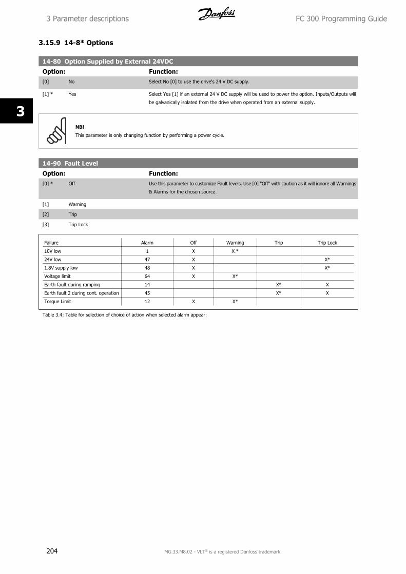
3.15.9 14-8* Options
14-80 Option Supplied by External 24VDC
Option: Function:[0] No Select No [0] to use the drive's 24 V DC supply.
[1] * Yes Select Yes [1] if an external 24 V DC supply will be used to power the option. Inputs/Outputs will
be galvanically isolated from the drive when operated from an external supply.
NB!
This parameter is only changing function by performing a power cycle.
14-90 Fault Level
Option: Function:[0] * Off Use this parameter to customize Fault levels. Use [0] "Off" with caution as it will ignore all Warnings
& Alarms for the chosen source.
[1] Warning
[2] Trip
[3] Trip Lock
Failure Alarm Off Warning Trip Trip Lock
10V low 1 X X *
24V low 47 X X*
1.8V supply low 48 X X*
Voltage limit 64 X X*
Earth fault during ramping 14 X* X
Earth fault 2 during cont. operation 45 X* X
Torque Limit 12 X X*
Table 3.4: Table for selection of choice of action when selected alarm appear:
3 Parameter descriptions FC 300 Programming Guide
204 MG.33.M8.02 - VLT® is a registered Danfoss trademark
3
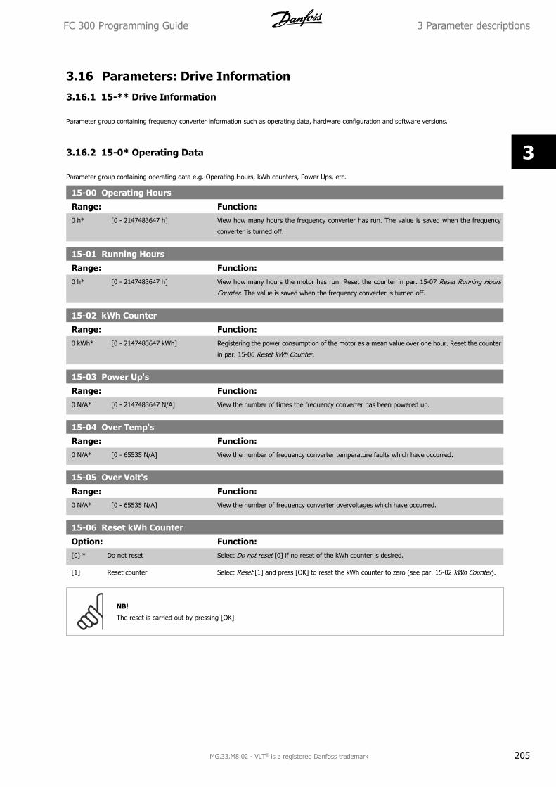
3.16 Parameters: Drive Information
3.16.1 15-** Drive Information
Parameter group containing frequency converter information such as operating data, hardware configuration and software versions.
3.16.2 15-0* Operating Data
Parameter group containing operating data e.g. Operating Hours, kWh counters, Power Ups, etc.
15-00 Operating Hours
Range: Function:0 h* [0 - 2147483647 h] View how many hours the frequency converter has run. The value is saved when the frequency
converter is turned off.
15-01 Running Hours
Range: Function:0 h* [0 - 2147483647 h] View how many hours the motor has run. Reset the counter in par. 15-07 Reset Running Hours
Counter. The value is saved when the frequency converter is turned off.
15-02 kWh Counter
Range: Function:0 kWh* [0 - 2147483647 kWh] Registering the power consumption of the motor as a mean value over one hour. Reset the counter
in par. 15-06 Reset kWh Counter.
15-03 Power Up's
Range: Function:0 N/A* [0 - 2147483647 N/A] View the number of times the frequency converter has been powered up.
15-04 Over Temp's
Range: Function:0 N/A* [0 - 65535 N/A] View the number of frequency converter temperature faults which have occurred.
15-05 Over Volt's
Range: Function:0 N/A* [0 - 65535 N/A] View the number of frequency converter overvoltages which have occurred.
15-06 Reset kWh Counter
Option: Function:[0] * Do not reset Select Do not reset [0] if no reset of the kWh counter is desired.
[1] Reset counter Select Reset [1] and press [OK] to reset the kWh counter to zero (see par. 15-02 kWh Counter).
NB!
The reset is carried out by pressing [OK].
FC 300 Programming Guide 3 Parameter descriptions
MG.33.M8.02 - VLT® is a registered Danfoss trademark 205
3
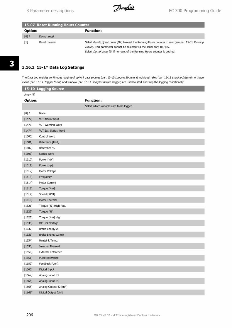
15-07 Reset Running Hours Counter
Option: Function:[0] * Do not reset
[1] Reset counter Select Reset [1] and press [OK] to reset the Running Hours counter to zero (see par. 15-01 Running
Hours). This parameter cannot be selected via the serial port, RS 485.
Select Do not reset [0] if no reset of the Running Hours counter is desired.
3.16.3 15-1* Data Log Settings
The Data Log enables continuous logging of up to 4 data sources (par. 15-10 Logging Source) at individual rates (par. 15-11 Logging Interval). A trigger
event (par. 15-12 Trigger Event) and window (par. 15-14 Samples Before Trigger) are used to start and stop the logging conditionally.
15-10 Logging SourceArray [4]
Option: Function:Select which variables are to be logged.
[0] * None
[1472] VLT Alarm Word
[1473] VLT Warning Word
[1474] VLT Ext. Status Word
[1600] Control Word
[1601] Reference [Unit]
[1602] Reference %
[1603] Status Word
[1610] Power [kW]
[1611] Power [hp]
[1612] Motor Voltage
[1613] Frequency
[1614] Motor Current
[1616] Torque [Nm]
[1617] Speed [RPM]
[1618] Motor Thermal
[1621] Torque [%] High Res.
[1622] Torque [%]
[1625] Torque [Nm] High
[1630] DC Link Voltage
[1632] Brake Energy /s
[1633] Brake Energy /2 min
[1634] Heatsink Temp.
[1635] Inverter Thermal
[1650] External Reference
[1651] Pulse Reference
[1652] Feedback [Unit]
[1660] Digital Input
[1662] Analog Input 53
[1664] Analog Input 54
[1665] Analog Output 42 [mA]
[1666] Digital Output [bin]
3 Parameter descriptions FC 300 Programming Guide
206 MG.33.M8.02 - VLT® is a registered Danfoss trademark
3
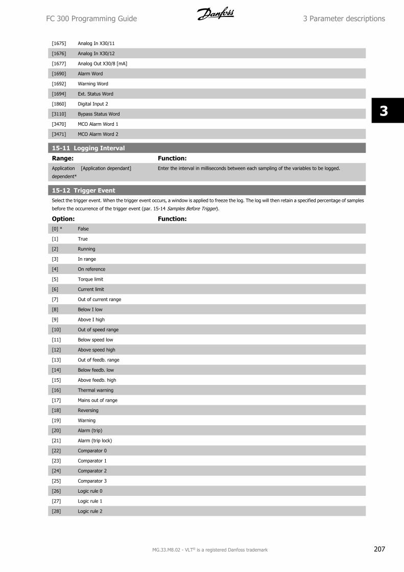
[1675] Analog In X30/11
[1676] Analog In X30/12
[1677] Analog Out X30/8 [mA]
[1690] Alarm Word
[1692] Warning Word
[1694] Ext. Status Word
[1860] Digital Input 2
[3110] Bypass Status Word
[3470] MCO Alarm Word 1
[3471] MCO Alarm Word 2
15-11 Logging Interval
Range: Function:Application
dependent*
[Application dependant] Enter the interval in milliseconds between each sampling of the variables to be logged.
15-12 Trigger EventSelect the trigger event. When the trigger event occurs, a window is applied to freeze the log. The log will then retain a specified percentage of samples
before the occurrence of the trigger event (par. 15-14 Samples Before Trigger).
Option: Function:[0] * False
[1] True
[2] Running
[3] In range
[4] On reference
[5] Torque limit
[6] Current limit
[7] Out of current range
[8] Below I low
[9] Above I high
[10] Out of speed range
[11] Below speed low
[12] Above speed high
[13] Out of feedb. range
[14] Below feedb. low
[15] Above feedb. high
[16] Thermal warning
[17] Mains out of range
[18] Reversing
[19] Warning
[20] Alarm (trip)
[21] Alarm (trip lock)
[22] Comparator 0
[23] Comparator 1
[24] Comparator 2
[25] Comparator 3
[26] Logic rule 0
[27] Logic rule 1
[28] Logic rule 2
FC 300 Programming Guide 3 Parameter descriptions
MG.33.M8.02 - VLT® is a registered Danfoss trademark 207
3
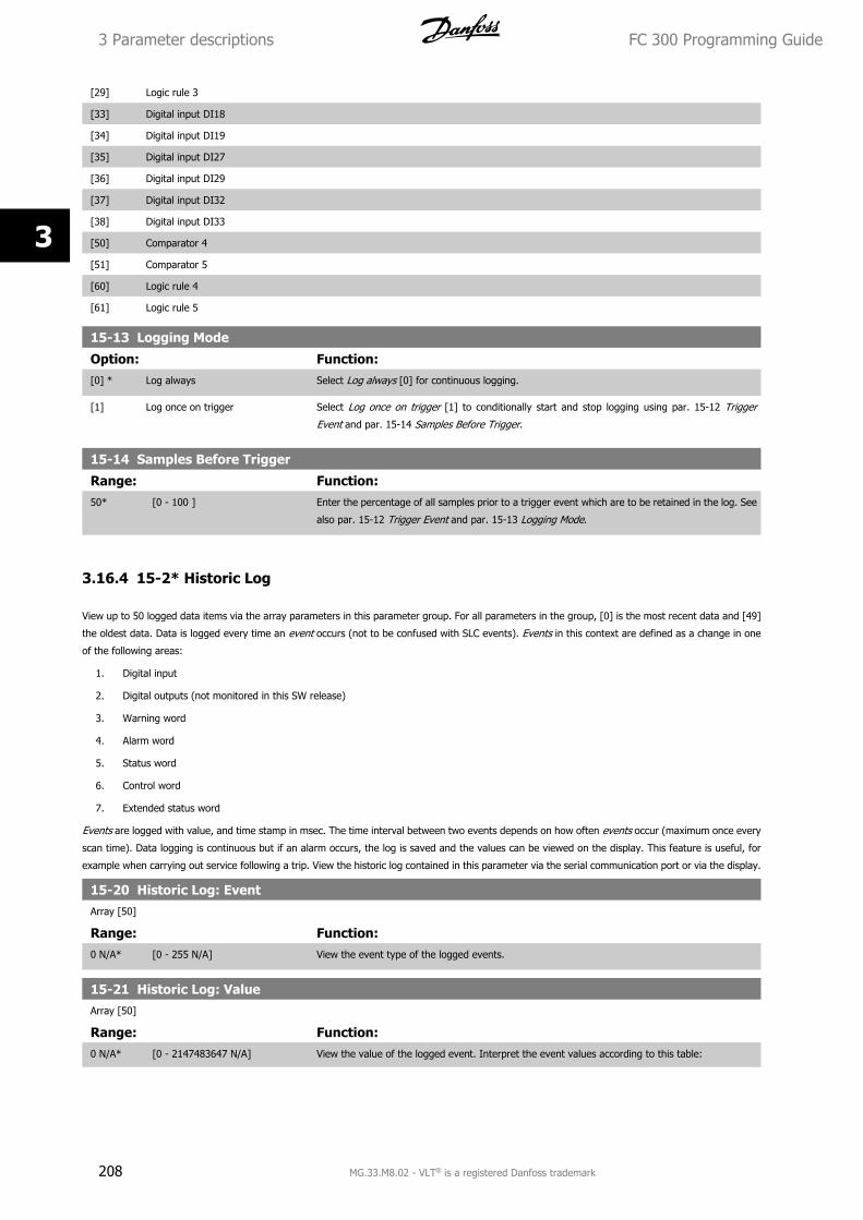
[29] Logic rule 3
[33] Digital input DI18
[34] Digital input DI19
[35] Digital input DI27
[36] Digital input DI29
[37] Digital input DI32
[38] Digital input DI33
[50] Comparator 4
[51] Comparator 5
[60] Logic rule 4
[61] Logic rule 5
15-13 Logging Mode
Option: Function:[0] * Log always Select Log always [0] for continuous logging.
[1] Log once on trigger Select Log once on trigger [1] to conditionally start and stop logging using par. 15-12 Trigger
Event and par. 15-14 Samples Before Trigger.
15-14 Samples Before Trigger
Range: Function:50* [0 - 100 ] Enter the percentage of all samples prior to a trigger event which are to be retained in the log. See
also par. 15-12 Trigger Event and par. 15-13 Logging Mode.
3.16.4 15-2* Historic Log
View up to 50 logged data items via the array parameters in this parameter group. For all parameters in the group, [0] is the most recent data and [49]
the oldest data. Data is logged every time an event occurs (not to be confused with SLC events). Events in this context are defined as a change in one
of the following areas:
1. Digital input
2. Digital outputs (not monitored in this SW release)
3. Warning word
4. Alarm word
5. Status word
6. Control word
7. Extended status word
Events are logged with value, and time stamp in msec. The time interval between two events depends on how often events occur (maximum once every
scan time). Data logging is continuous but if an alarm occurs, the log is saved and the values can be viewed on the display. This feature is useful, for
example when carrying out service following a trip. View the historic log contained in this parameter via the serial communication port or via the display.
15-20 Historic Log: EventArray [50]
Range: Function:0 N/A* [0 - 255 N/A] View the event type of the logged events.
15-21 Historic Log: ValueArray [50]
Range: Function:0 N/A* [0 - 2147483647 N/A] View the value of the logged event. Interpret the event values according to this table:
3 Parameter descriptions FC 300 Programming Guide
208 MG.33.M8.02 - VLT® is a registered Danfoss trademark
3
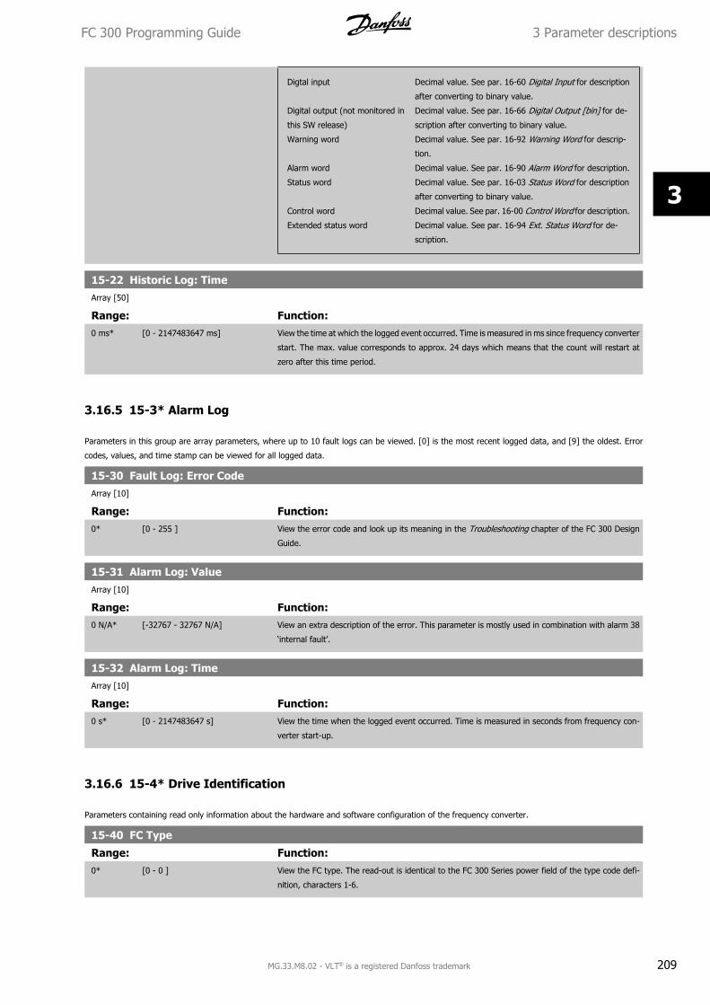
Digtal input Decimal value. See par. 16-60 Digital Input for description
after converting to binary value.
Digital output (not monitored in
this SW release)
Decimal value. See par. 16-66 Digital Output [bin] for de-
scription after converting to binary value.
Warning word Decimal value. See par. 16-92 Warning Word for descrip-
tion.
Alarm word Decimal value. See par. 16-90 Alarm Word for description.
Status word Decimal value. See par. 16-03 Status Word for description
after converting to binary value.
Control word Decimal value. See par. 16-00 Control Word for description.
Extended status word Decimal value. See par. 16-94 Ext. Status Word for de-
scription.
15-22 Historic Log: TimeArray [50]
Range: Function:0 ms* [0 - 2147483647 ms] View the time at which the logged event occurred. Time is measured in ms since frequency converter
start. The max. value corresponds to approx. 24 days which means that the count will restart at
zero after this time period.
3.16.5 15-3* Alarm Log
Parameters in this group are array parameters, where up to 10 fault logs can be viewed. [0] is the most recent logged data, and [9] the oldest. Error
codes, values, and time stamp can be viewed for all logged data.
15-30 Fault Log: Error CodeArray [10]
Range: Function:0* [0 - 255 ] View the error code and look up its meaning in the Troubleshooting chapter of the FC 300 Design
Guide.
15-31 Alarm Log: ValueArray [10]
Range: Function:0 N/A* [-32767 - 32767 N/A] View an extra description of the error. This parameter is mostly used in combination with alarm 38
‘internal fault’.
15-32 Alarm Log: TimeArray [10]
Range: Function:0 s* [0 - 2147483647 s] View the time when the logged event occurred. Time is measured in seconds from frequency con-
verter start-up.
3.16.6 15-4* Drive Identification
Parameters containing read only information about the hardware and software configuration of the frequency converter.
15-40 FC Type
Range: Function:0* [0 - 0 ] View the FC type. The read-out is identical to the FC 300 Series power field of the type code defi-
nition, characters 1-6.
FC 300 Programming Guide 3 Parameter descriptions
MG.33.M8.02 - VLT® is a registered Danfoss trademark 209
3
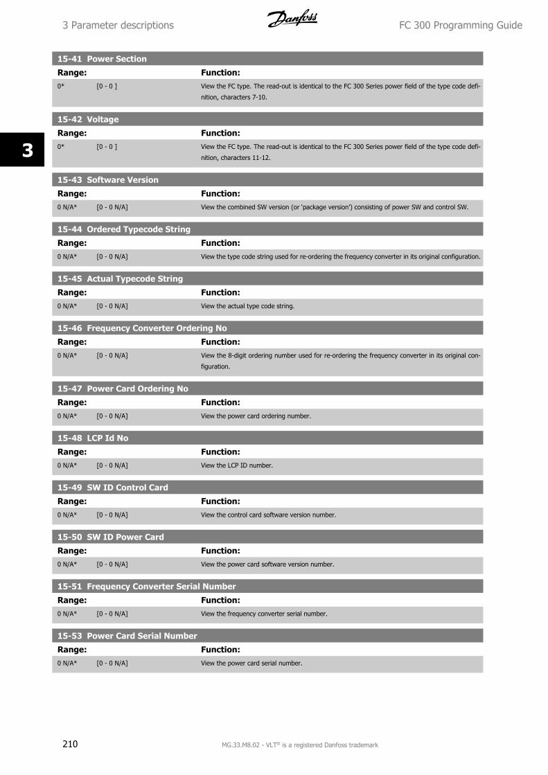
15-41 Power Section
Range: Function:0* [0 - 0 ] View the FC type. The read-out is identical to the FC 300 Series power field of the type code defi-
nition, characters 7-10.
15-42 Voltage
Range: Function:0* [0 - 0 ] View the FC type. The read-out is identical to the FC 300 Series power field of the type code defi-
nition, characters 11-12.
15-43 Software Version
Range: Function:0 N/A* [0 - 0 N/A] View the combined SW version (or ‘package version’) consisting of power SW and control SW.
15-44 Ordered Typecode String
Range: Function:0 N/A* [0 - 0 N/A] View the type code string used for re-ordering the frequency converter in its original configuration.
15-45 Actual Typecode String
Range: Function:0 N/A* [0 - 0 N/A] View the actual type code string.
15-46 Frequency Converter Ordering No
Range: Function:0 N/A* [0 - 0 N/A] View the 8-digit ordering number used for re-ordering the frequency converter in its original con-
figuration.
15-47 Power Card Ordering No
Range: Function:0 N/A* [0 - 0 N/A] View the power card ordering number.
15-48 LCP Id No
Range: Function:0 N/A* [0 - 0 N/A] View the LCP ID number.
15-49 SW ID Control Card
Range: Function:0 N/A* [0 - 0 N/A] View the control card software version number.
15-50 SW ID Power Card
Range: Function:0 N/A* [0 - 0 N/A] View the power card software version number.
15-51 Frequency Converter Serial Number
Range: Function:0 N/A* [0 - 0 N/A] View the frequency converter serial number.
15-53 Power Card Serial Number
Range: Function:0 N/A* [0 - 0 N/A] View the power card serial number.
3 Parameter descriptions FC 300 Programming Guide
210 MG.33.M8.02 - VLT® is a registered Danfoss trademark
3
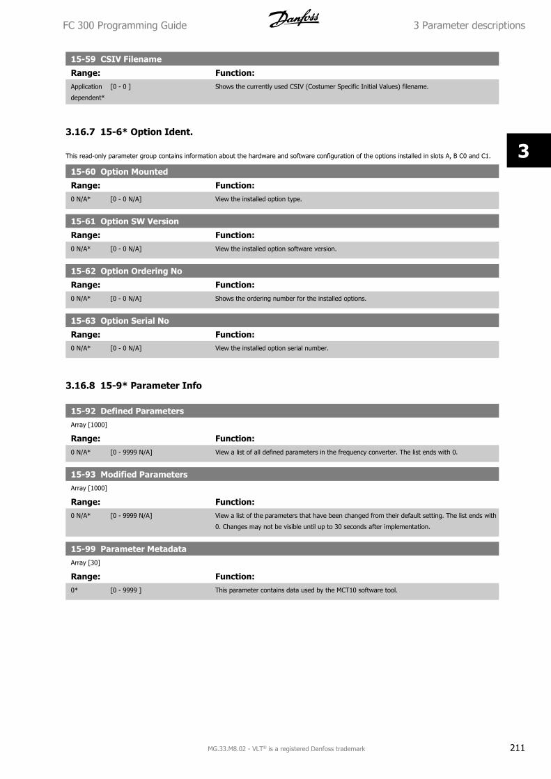
15-59 CSIV Filename
Range: Function:Application
dependent*
[0 - 0 ] Shows the currently used CSIV (Costumer Specific Initial Values) filename.
3.16.7 15-6* Option Ident.
This read-only parameter group contains information about the hardware and software configuration of the options installed in slots A, B C0 and C1.
15-60 Option Mounted
Range: Function:0 N/A* [0 - 0 N/A] View the installed option type.
15-61 Option SW Version
Range: Function:0 N/A* [0 - 0 N/A] View the installed option software version.
15-62 Option Ordering No
Range: Function:0 N/A* [0 - 0 N/A] Shows the ordering number for the installed options.
15-63 Option Serial No
Range: Function:0 N/A* [0 - 0 N/A] View the installed option serial number.
3.16.8 15-9* Parameter Info
15-92 Defined ParametersArray [1000]
Range: Function:0 N/A* [0 - 9999 N/A] View a list of all defined parameters in the frequency converter. The list ends with 0.
15-93 Modified ParametersArray [1000]
Range: Function:0 N/A* [0 - 9999 N/A] View a list of the parameters that have been changed from their default setting. The list ends with
0. Changes may not be visible until up to 30 seconds after implementation.
15-99 Parameter MetadataArray [30]
Range: Function:0* [0 - 9999 ] This parameter contains data used by the MCT10 software tool.
FC 300 Programming Guide 3 Parameter descriptions
MG.33.M8.02 - VLT® is a registered Danfoss trademark 211
3
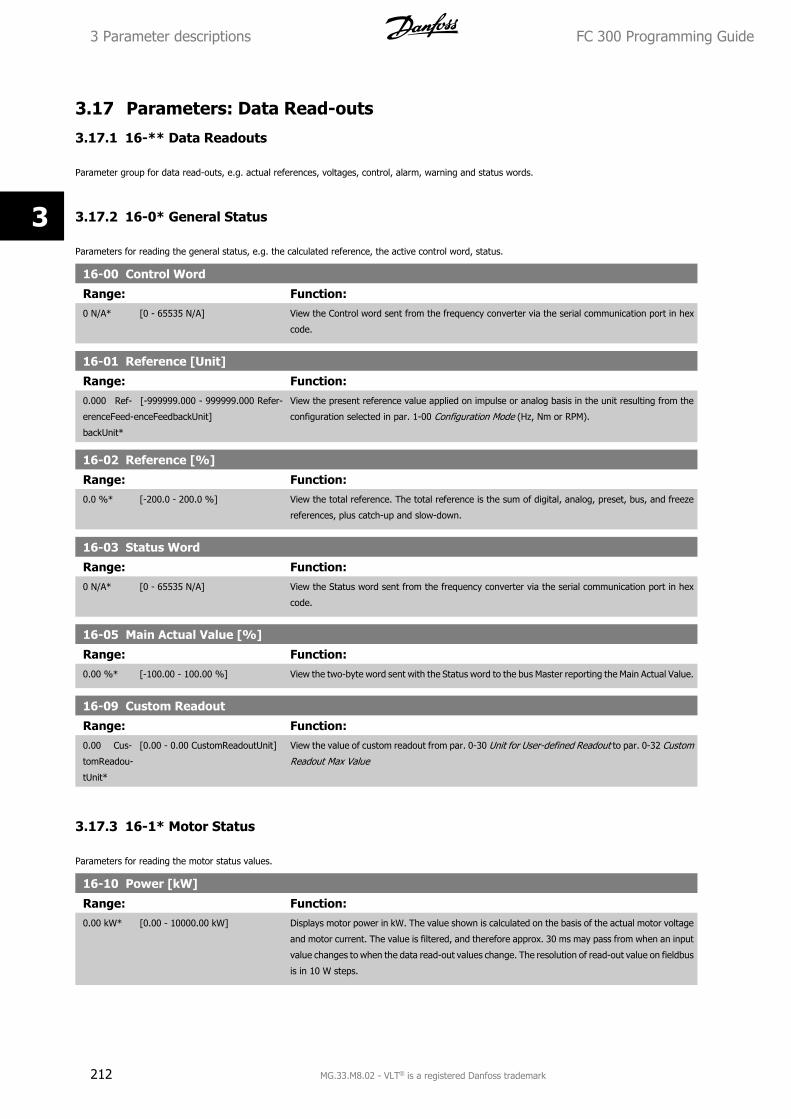
3.17 Parameters: Data Read-outs
3.17.1 16-** Data Readouts
Parameter group for data read-outs, e.g. actual references, voltages, control, alarm, warning and status words.
3.17.2 16-0* General Status
Parameters for reading the general status, e.g. the calculated reference, the active control word, status.
16-00 Control Word
Range: Function:0 N/A* [0 - 65535 N/A] View the Control word sent from the frequency converter via the serial communication port in hex
code.
16-01 Reference [Unit]
Range: Function:0.000 Ref-
erenceFeed-
backUnit*
[-999999.000 - 999999.000 Refer-
enceFeedbackUnit]
View the present reference value applied on impulse or analog basis in the unit resulting from the
configuration selected in par. 1-00 Configuration Mode (Hz, Nm or RPM).
16-02 Reference [%]
Range: Function:0.0 %* [-200.0 - 200.0 %] View the total reference. The total reference is the sum of digital, analog, preset, bus, and freeze
references, plus catch-up and slow-down.
16-03 Status Word
Range: Function:0 N/A* [0 - 65535 N/A] View the Status word sent from the frequency converter via the serial communication port in hex
code.
16-05 Main Actual Value [%]
Range: Function:0.00 %* [-100.00 - 100.00 %] View the two-byte word sent with the Status word to the bus Master reporting the Main Actual Value.
16-09 Custom Readout
Range: Function:0.00 Cus-
tomReadou-
tUnit*
[0.00 - 0.00 CustomReadoutUnit] View the value of custom readout from par. 0-30 Unit for User-defined Readout to par. 0-32 Custom
Readout Max Value
3.17.3 16-1* Motor Status
Parameters for reading the motor status values.
16-10 Power [kW]
Range: Function:0.00 kW* [0.00 - 10000.00 kW] Displays motor power in kW. The value shown is calculated on the basis of the actual motor voltage
and motor current. The value is filtered, and therefore approx. 30 ms may pass from when an input
value changes to when the data read-out values change. The resolution of read-out value on fieldbus
is in 10 W steps.
3 Parameter descriptions FC 300 Programming Guide
212 MG.33.M8.02 - VLT® is a registered Danfoss trademark
3
16-11 Power [hp]
Range: Function:0.00 hp* [0.00 - 10000.00 hp] View the motor power in HP. The value shown is calculated on the basis of the actual motor voltage
and motor current. The value is filtered, and therefore approximately 30 ms may pass from when
an input value changes to when the data read-out values change.
16-12 Motor Voltage
Range: Function:0.0 V* [0.0 - 6000.0 V] View the motor voltage, a calculated value used for controlling the motor.
16-13 Frequency
Range: Function:0.0 Hz* [0.0 - 6500.0 Hz] View the motor frequency, without resonance dampening.
16-14 Motor Current
Range: Function:0.00 A* [0.00 - 10000.00 A] View the motor current measured as a mean value, IRMS. The value is filtered, and thus approxi-
mately 30 ms may pass from when an input value changes to when the data read-out values change.
16-15 Frequency [%]
Range: Function:0.00 %* [-100.00 - 100.00 %] View a two-byte word reporting the actual motor frequency (without resonance dampening) as a
percentage (scale 0000-4000 Hex) of par. 4-19 Max Output Frequency. Set par. 9-16 PCD Read
Configuration index 1 to send it with the Status Word instead of the MAV.
16-16 Torque [Nm]
Range: Function:0.0 Nm* [-3000.0 - 3000.0 Nm] View the torque value with sign, applied to the motor shaft. Linearity is not exact between 160%
motor current and torque in relation to the rated torque. Some motors supply more than 160%
torque. Consequently, the min. value and the max. value will depend on the max. motor current as
well as the motor used. The value is filtered, and thus approx. 30 ms may pass from when an input
changes value to when the data read-out values change.
16-17 Speed [RPM]
Range: Function:0 RPM* [-30000 - 30000 RPM] View the actual motor RPM. In open loop or closed loop process control the motor RPM is estimated.
In speed closed loop modes the motor RPM is measured.
16-18 Motor Thermal
Range: Function:0 %* [0 - 100 %] View the calculated thermal load on the motor. The cut-out limit is 100%. The basis for calculation
is the ETR function selected in par. 1-90 Motor Thermal Protection.
16-19 KTY sensor temperature
Range: Function:0 C* [0 - 0 C] Returning the actual temperature on KTY sensor buil into the motor.
See par. 1-9*.
16-20 Motor Angle
Range: Function:0* [0 - 65535 ] View the current encoder/resolver angle offset relative to the index position. The value range of
0-65535 corresponds to 0-2*pi (radians).
FC 300 Programming Guide 3 Parameter descriptions
MG.33.M8.02 - VLT® is a registered Danfoss trademark 213
3
16-21 Torque [%] High Res.
Range: Function:0.0 %* [-200.0 - 200.0 %] The value shown is the torque in percent of nominal torque, with sign and 0.1% resolution, applied
to the motor shaft.
16-22 Torque [%]
Range: Function:0 %* [-200 - 200 %] Value shown is the torque in percent of nominal torque, with sign, applied to the motor shaft.
16-25 Torque [Nm] High
Range: Function:0.0 Nm* [-200000000.0 - 200000000.0 Nm] View the torque value with sign, applied to the motor shaft. Some motors supply more than 160%
torque. Consequently, the min. value and the max. value will depend on the max. motor current as
well as the motor used. This specific readout has been adapted to be able to show higher values
than the standard readout in par. 16-16 Torque [Nm].
3.17.4 16-3* Drive Status
Parameters for reporting the status of the frequency converter.
16-30 DC Link Voltage
Range: Function:0 V* [0 - 10000 V] View a measured value. The value is filtered with an 30 ms time constant.
16-32 Brake Energy /s
Range: Function:0.000 kW* [0.000 - 10000.000 kW] View the brake power transmitted to an external brake resistor, stated as an instantaneous value.
16-33 Brake Energy /2 min
Range: Function:0.000 kW* [0.000 - 10000.000 kW] View the brake power transmitted to an external brake resistor. The mean power is calculated on
an average basis for the most recent 120 seconds.
16-34 Heatsink Temp.
Range: Function:0 C* [0 - 255 C] View the frequency converter heatsink temperature. The cut-out limit is 90 ± 5 °C, and the motor
cuts back in at 60 ± 5 °C.
16-35 Inverter Thermal
Range: Function:0 %* [0 - 100 %] View the percentage load on the inverter.
16-36 Inv. Nom. Current
Range: Function:Application
dependent*
[0.01 - 10000.00 A] View the inverter nominal current, which should match the nameplate data on the connected motor.
The data are used for calculation of torque, motor protection, etc.
16-37 Inv. Max. Current
Range: Function:Application
dependent*
[0.01 - 10000.00 A] View the inverter maximum current, which should match the nameplate data on the connected
motor. The data are used for calculation of torque, motor protection, etc.
3 Parameter descriptions FC 300 Programming Guide
214 MG.33.M8.02 - VLT® is a registered Danfoss trademark
3
16-38 SL Controller State
Range: Function:0* [0 - 100 ] View the state of the event under execution by the SL controller.
16-39 Control Card Temp.
Range: Function:0 C* [0 - 100 C] View the temperature on the control card, stated in °C.
16-40 Logging Buffer Full
Option: Function:View whether the logging buffer is full (see parameter group 15-1*). The logging buffer will never
be full when par. 15-13 Logging Mode is set to Log always [0].
[0] * No
[1] Yes
16-49 Current Fault Source
Range: Function:0* [0 - 8 ] Value indicates source of current faults including short circuit, over current, and phase imbalance
(from left):
1-4 Inverter
5-8 Rectifier
0 No fault recorded
3.17.5 16-5* Ref. & Feedb.
Parameters for reporting the reference and feedback input.
16-50 External Reference
Range: Function:0.0* [-200.0 - 200.0 ] View the total reference, the sum of digital, analog, preset, bus and freeze references, plus catch-
up and slow-down.
16-51 Pulse Reference
Range: Function:0.0* [-200.0 - 200.0 ] View the reference value from programmed digital input(s). The read-out can also reflect the im-
pulses from an incremental encoder.
16-52 Feedback [Unit]
Range: Function:0.000 Ref-
erenceFeed-
backUnit*
[-999999.999 - 999999.999 Refer-
enceFeedbackUnit]
View the feedback unit resulting from the selection of unit and scaling in par. 3-00 Reference
Range, par. 3-01 Reference/Feedback Unit, par. 3-02 Minimum Reference and par. 3-03 Maximum
Reference.
16-53 Digi Pot Reference
Range: Function:0.00* [-200.00 - 200.00 ] View the contribution of the Digital Potentiometer to the actual reference.
FC 300 Programming Guide 3 Parameter descriptions
MG.33.M8.02 - VLT® is a registered Danfoss trademark 215
3
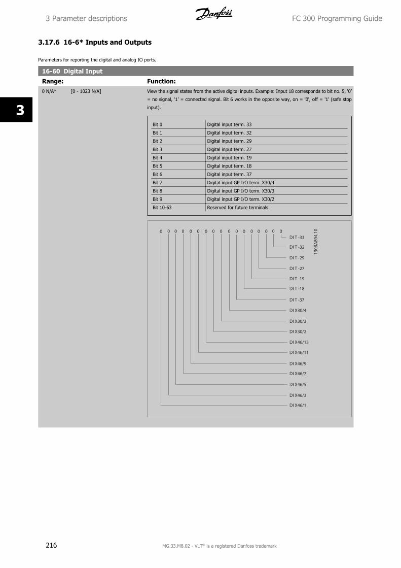
3.17.6 16-6* Inputs and Outputs
Parameters for reporting the digital and analog IO ports.
16-60 Digital Input
Range: Function:0 N/A* [0 - 1023 N/A] View the signal states from the active digital inputs. Example: Input 18 corresponds to bit no. 5, ‘0’
= no signal, ‘1’ = connected signal. Bit 6 works in the opposite way, on = '0', off = '1' (safe stop
input).
Bit 0 Digital input term. 33
Bit 1 Digital input term. 32
Bit 2 Digital input term. 29
Bit 3 Digital input term. 27
Bit 4 Digital input term. 19
Bit 5 Digital input term. 18
Bit 6 Digital input term. 37
Bit 7 Digital input GP I/O term. X30/4
Bit 8 Digital input GP I/O term. X30/3
Bit 9 Digital input GP I/O term. X30/2
Bit 10-63 Reserved for future terminals
3 Parameter descriptions FC 300 Programming Guide
216 MG.33.M8.02 - VLT® is a registered Danfoss trademark
3
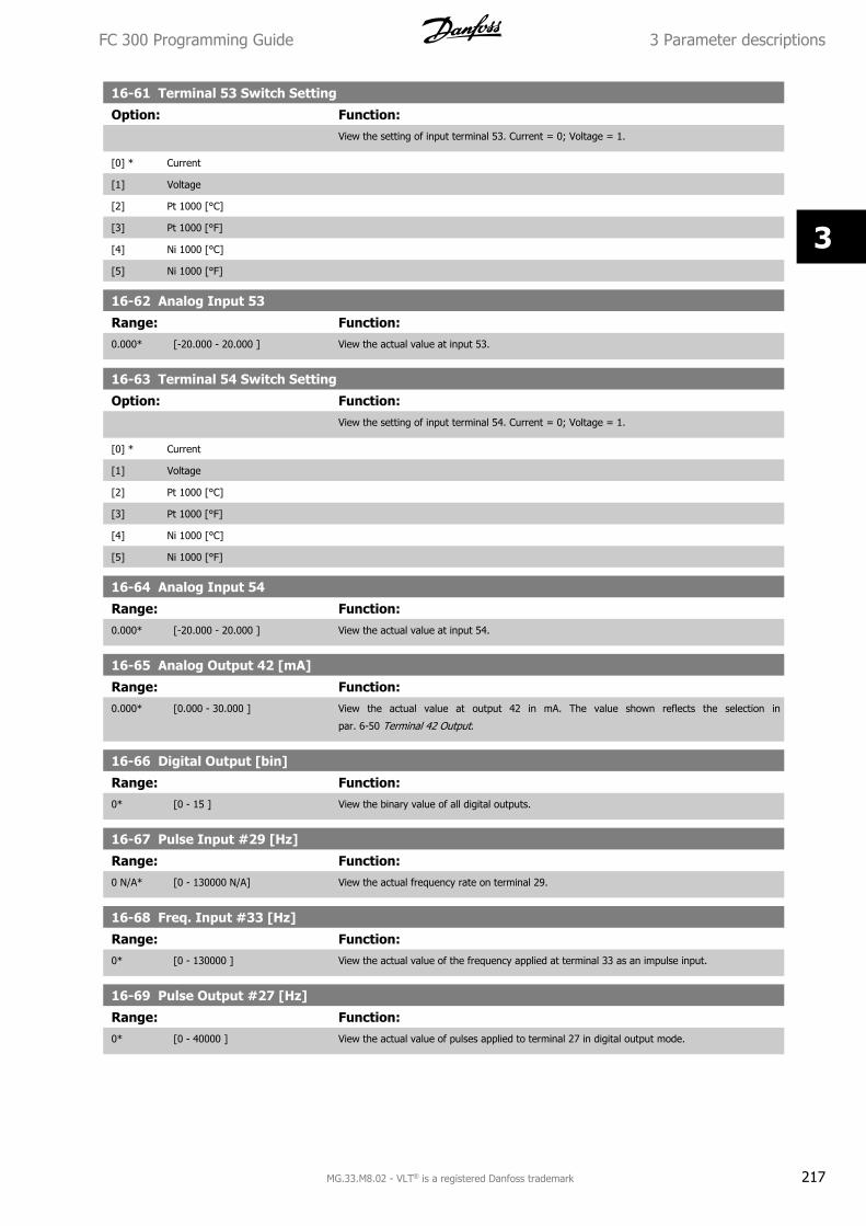
16-61 Terminal 53 Switch Setting
Option: Function:View the setting of input terminal 53. Current = 0; Voltage = 1.
[0] * Current
[1] Voltage
[2] Pt 1000 [°C]
[3] Pt 1000 [°F]
[4] Ni 1000 [°C]
[5] Ni 1000 [°F]
16-62 Analog Input 53
Range: Function:0.000* [-20.000 - 20.000 ] View the actual value at input 53.
16-63 Terminal 54 Switch Setting
Option: Function:View the setting of input terminal 54. Current = 0; Voltage = 1.
[0] * Current
[1] Voltage
[2] Pt 1000 [°C]
[3] Pt 1000 [°F]
[4] Ni 1000 [°C]
[5] Ni 1000 [°F]
16-64 Analog Input 54
Range: Function:0.000* [-20.000 - 20.000 ] View the actual value at input 54.
16-65 Analog Output 42 [mA]
Range: Function:0.000* [0.000 - 30.000 ] View the actual value at output 42 in mA. The value shown reflects the selection in
par. 6-50 Terminal 42 Output.
16-66 Digital Output [bin]
Range: Function:0* [0 - 15 ] View the binary value of all digital outputs.
16-67 Pulse Input #29 [Hz]
Range: Function:0 N/A* [0 - 130000 N/A] View the actual frequency rate on terminal 29.
16-68 Freq. Input #33 [Hz]
Range: Function:0* [0 - 130000 ] View the actual value of the frequency applied at terminal 33 as an impulse input.
16-69 Pulse Output #27 [Hz]
Range: Function:0* [0 - 40000 ] View the actual value of pulses applied to terminal 27 in digital output mode.
FC 300 Programming Guide 3 Parameter descriptions
MG.33.M8.02 - VLT® is a registered Danfoss trademark 217
3
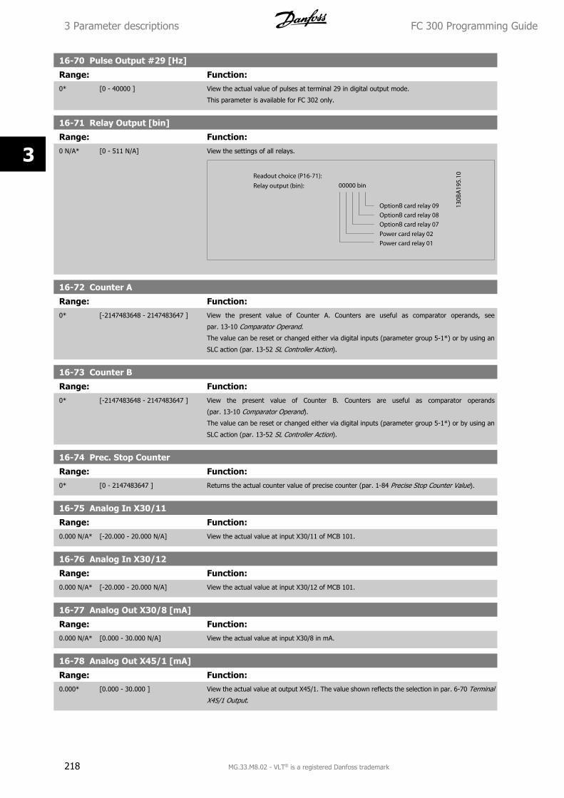
16-70 Pulse Output #29 [Hz]
Range: Function:0* [0 - 40000 ] View the actual value of pulses at terminal 29 in digital output mode.
This parameter is available for FC 302 only.
16-71 Relay Output [bin]
Range: Function:0 N/A* [0 - 511 N/A] View the settings of all relays.
16-72 Counter A
Range: Function:0* [-2147483648 - 2147483647 ] View the present value of Counter A. Counters are useful as comparator operands, see
par. 13-10 Comparator Operand.
The value can be reset or changed either via digital inputs (parameter group 5-1*) or by using an
SLC action (par. 13-52 SL Controller Action).
16-73 Counter B
Range: Function:0* [-2147483648 - 2147483647 ] View the present value of Counter B. Counters are useful as comparator operands
(par. 13-10 Comparator Operand).
The value can be reset or changed either via digital inputs (parameter group 5-1*) or by using an
SLC action (par. 13-52 SL Controller Action).
16-74 Prec. Stop Counter
Range: Function:0* [0 - 2147483647 ] Returns the actual counter value of precise counter (par. 1-84 Precise Stop Counter Value).
16-75 Analog In X30/11
Range: Function:0.000 N/A* [-20.000 - 20.000 N/A] View the actual value at input X30/11 of MCB 101.
16-76 Analog In X30/12
Range: Function:0.000 N/A* [-20.000 - 20.000 N/A] View the actual value at input X30/12 of MCB 101.
16-77 Analog Out X30/8 [mA]
Range: Function:0.000 N/A* [0.000 - 30.000 N/A] View the actual value at input X30/8 in mA.
16-78 Analog Out X45/1 [mA]
Range: Function:0.000* [0.000 - 30.000 ] View the actual value at output X45/1. The value shown reflects the selection in par. 6-70 Terminal
X45/1 Output.
3 Parameter descriptions FC 300 Programming Guide
218 MG.33.M8.02 - VLT® is a registered Danfoss trademark
3
16-79 Analog Out X45/3 [mA]
Range: Function:0.000* [0.000 - 30.000 ] View the actual value at output X45/3. The value shown reflects the selection in par. 6-80 Terminal
X45/3 Output.
3.17.7 16-8* Fieldbus & FC Port
Parameters for reporting the BUS references and control words.
16-80 Fieldbus CTW 1
Range: Function:0 N/A* [0 - 65535 N/A] View the two-byte Control word (CTW) received from the Bus-Master. Interpretation of the Control
word depends on the fieldbus option installed and the Control word profile selected in
par. 8-10 Control Profile.
For more information please refer to the relevant fieldbus manual.
16-82 Fieldbus REF 1
Range: Function:0 N/A* [-200 - 200 N/A] View the two-byte word sent with the control word form the Bus-Master to set the reference value.
For more information please refer to the relevant fieldbus manual.
16-84 Comm. Option STW
Range: Function:0 N/A* [0 - 65535 N/A] View the extended fieldbus comm. option status word.
For more information please refer to the relevant fieldbus manual.
16-85 FC Port CTW 1
Range: Function:0 N/A* [0 - 65535 N/A] View the two-byte Control word (CTW) received from the Bus-Master. Interpretation of the control
word depends on the fieldbus option installed and the Control word profile selected in
par. 8-10 Control Profile.
16-86 FC Port REF 1
Range: Function:0 N/A* [-200 - 200 N/A] View the two-byte Status word (STW) sent to the Bus-Master. Interpretation of the Status word
depends on the fieldbus option installed and the Control word profile selected in par. 8-10 Control
Profile.
3.17.8 16-9* Diagnosis Read-Outs
Parameters displaying alarm, warning and extended status words.
16-90 Alarm Word
Range: Function:0 N/A* [0 - 4294967295 N/A] View the alarm word sent via the serial communication port in hex code.
16-91 Alarm Word 2
Range: Function:0* [0 - 4294967295 ] View the alarm word sent via the serial communication port in hex code.
FC 300 Programming Guide 3 Parameter descriptions
MG.33.M8.02 - VLT® is a registered Danfoss trademark 219
3
16-92 Warning Word
Range: Function:0 N/A* [0 - 4294967295 N/A] View the warning word sent via the serial communication port in hex code.
16-93 Warning Word 2
Range: Function:0* [0 - 4294967295 ] View the warning word sent via the serial communication port in hex code.
16-94 Ext. Status Word
Range: Function:0* [0 - 4294967295 ] Returns the extended warning word sent via the serial communication port in hex code.
16-95 Ext. Status Word 2
Range: Function:0 N/A* [0 - 4294967295 N/A] Returns the extended warning word 2 sent via the serial communication port in hex code.
16-96 Maintenance Word
Range: Function:0 N/A* [0 - 4294967295 N/A]
3 Parameter descriptions FC 300 Programming Guide
220 MG.33.M8.02 - VLT® is a registered Danfoss trademark
3
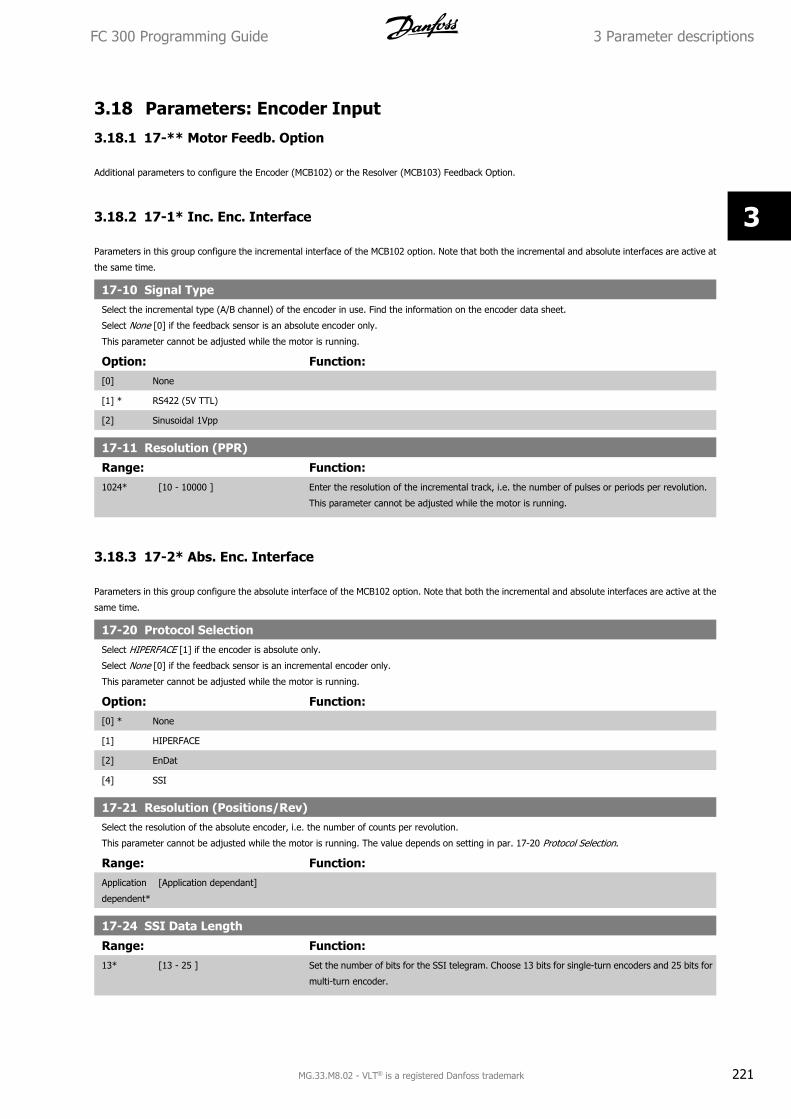
3.18 Parameters: Encoder Input
3.18.1 17-** Motor Feedb. Option
Additional parameters to configure the Encoder (MCB102) or the Resolver (MCB103) Feedback Option.
3.18.2 17-1* Inc. Enc. Interface
Parameters in this group configure the incremental interface of the MCB102 option. Note that both the incremental and absolute interfaces are active at
the same time.
17-10 Signal TypeSelect the incremental type (A/B channel) of the encoder in use. Find the information on the encoder data sheet.
Select None [0] if the feedback sensor is an absolute encoder only.
This parameter cannot be adjusted while the motor is running.
Option: Function:[0] None
[1] * RS422 (5V TTL)
[2] Sinusoidal 1Vpp
17-11 Resolution (PPR)
Range: Function:1024* [10 - 10000 ] Enter the resolution of the incremental track, i.e. the number of pulses or periods per revolution.
This parameter cannot be adjusted while the motor is running.
3.18.3 17-2* Abs. Enc. Interface
Parameters in this group configure the absolute interface of the MCB102 option. Note that both the incremental and absolute interfaces are active at the
same time.
17-20 Protocol SelectionSelect HIPERFACE [1] if the encoder is absolute only.
Select None [0] if the feedback sensor is an incremental encoder only.
This parameter cannot be adjusted while the motor is running.
Option: Function:[0] * None
[1] HIPERFACE
[2] EnDat
[4] SSI
17-21 Resolution (Positions/Rev)Select the resolution of the absolute encoder, i.e. the number of counts per revolution.
This parameter cannot be adjusted while the motor is running. The value depends on setting in par. 17-20 Protocol Selection.
Range: Function:Application
dependent*
[Application dependant]
17-24 SSI Data Length
Range: Function:13* [13 - 25 ] Set the number of bits for the SSI telegram. Choose 13 bits for single-turn encoders and 25 bits for
multi-turn encoder.
FC 300 Programming Guide 3 Parameter descriptions
MG.33.M8.02 - VLT® is a registered Danfoss trademark 221
3
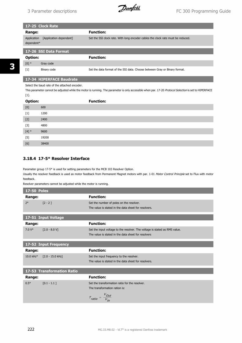
17-25 Clock Rate
Range: Function:Application
dependent*
[Application dependant] Set the SSI clock rate. With long encoder cables the clock rate must be reduced.
17-26 SSI Data Format
Option: Function:[0] * Gray code
[1] Binary code Set the data format of the SSI data. Choose between Gray or Binary format.
17-34 HIPERFACE BaudrateSelect the baud rate of the attached encoder.
This parameter cannot be adjusted while the motor is running. The parameter is only accessible when par. 17-20 Protocol Selection is set to HIPERFACE
[1].
Option: Function:[0] 600
[1] 1200
[2] 2400
[3] 4800
[4] * 9600
[5] 19200
[6] 38400
3.18.4 17-5* Resolver Interface
Parameter group 17-5* is used for setting parameters for the MCB 103 Resolver Option.
Usually the resolver feedback is used as motor feedback from Permanent Magnet motors with par. 1-01 Motor Control Principle set to Flux with motor
feedback.
Resolver parameters cannot be adjusted while the motor is running.
17-50 Poles
Range: Function:2* [2 - 2 ] Set the number of poles on the resolver.
The value is stated in the data sheet for resolvers.
17-51 Input Voltage
Range: Function:7.0 V* [2.0 - 8.0 V] Set the input voltage to the resolver. The voltage is stated as RMS value.
The value is stated in the data sheet for resolvers
17-52 Input Frequency
Range: Function:10.0 kHz* [2.0 - 15.0 kHz] Set the input frequency to the resolver.
The value is stated in the data sheet for resolvers.
17-53 Transformation Ratio
Range: Function:0.5* [0.1 - 1.1 ] Set the transformation ratio for the resolver.
The transformation ration is:
Tratio = VOutVIn
3 Parameter descriptions FC 300 Programming Guide
222 MG.33.M8.02 - VLT® is a registered Danfoss trademark
3
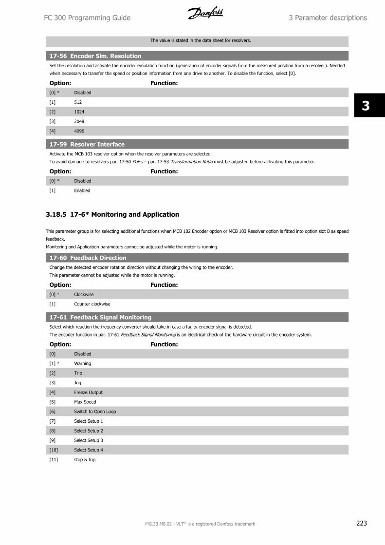
The value is stated in the data sheet for resolvers.
17-56 Encoder Sim. ResolutionSet the resolution and activate the encoder emulation function (generation of encoder signals from the measured position from a resolver). Needed
when necessary to transfer the speed or position information from one drive to another. To disable the function, select [0].
Option: Function:[0] * Disabled
[1] 512
[2] 1024
[3] 2048
[4] 4096
17-59 Resolver InterfaceActivate the MCB 103 resolver option when the resolver parameters are selected.
To avoid damage to resolvers par. 17-50 Poles – par. 17-53 Transformation Ratio must be adjusted before activating this parameter.
Option: Function:[0] * Disabled
[1] Enabled
3.18.5 17-6* Monitoring and Application
This parameter group is for selecting additional functions when MCB 102 Encoder option or MCB 103 Resolver option is fitted into option slot B as speed
feedback.
Monitoring and Application parameters cannot be adjusted while the motor is running.
17-60 Feedback DirectionChange the detected encoder rotation direction without changing the wiring to the encoder.
This parameter cannot be adjusted while the motor is running.
Option: Function:[0] * Clockwise
[1] Counter clockwise
17-61 Feedback Signal MonitoringSelect which reaction the frequency converter should take in case a faulty encoder signal is detected.
The encoder function in par. 17-61 Feedback Signal Monitoring is an electrical check of the hardware circuit in the encoder system.
Option: Function:[0] Disabled
[1] * Warning
[2] Trip
[3] Jog
[4] Freeze Output
[5] Max Speed
[6] Switch to Open Loop
[7] Select Setup 1
[8] Select Setup 2
[9] Select Setup 3
[10] Select Setup 4
[11] stop & trip
FC 300 Programming Guide 3 Parameter descriptions
MG.33.M8.02 - VLT® is a registered Danfoss trademark 223
3
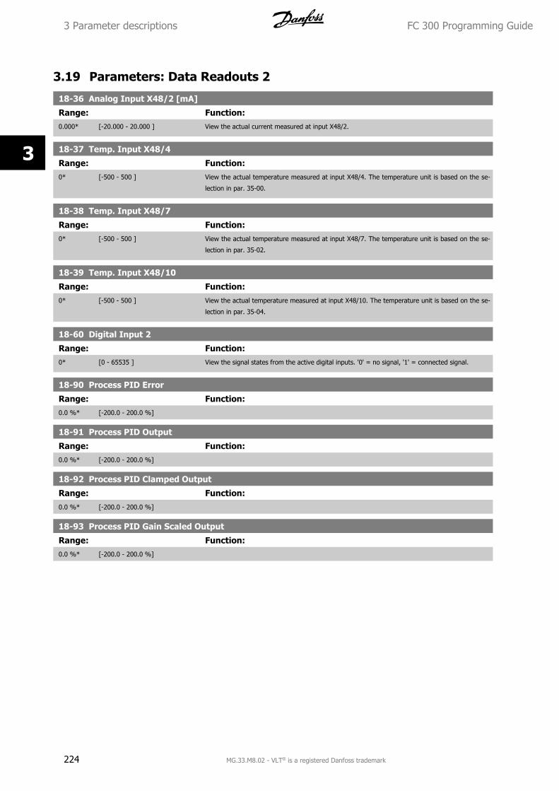
3.19 Parameters: Data Readouts 2
18-36 Analog Input X48/2 [mA]
Range: Function:0.000* [-20.000 - 20.000 ] View the actual current measured at input X48/2.
18-37 Temp. Input X48/4
Range: Function:0* [-500 - 500 ] View the actual temperature measured at input X48/4. The temperature unit is based on the se-
lection in par. 35-00.
18-38 Temp. Input X48/7
Range: Function:0* [-500 - 500 ] View the actual temperature measured at input X48/7. The temperature unit is based on the se-
lection in par. 35-02.
18-39 Temp. Input X48/10
Range: Function:0* [-500 - 500 ] View the actual temperature measured at input X48/10. The temperature unit is based on the se-
lection in par. 35-04.
18-60 Digital Input 2
Range: Function:0* [0 - 65535 ] View the signal states from the active digital inputs. '0' = no signal, '1' = connected signal.
18-90 Process PID Error
Range: Function:0.0 %* [-200.0 - 200.0 %]
18-91 Process PID Output
Range: Function:0.0 %* [-200.0 - 200.0 %]
18-92 Process PID Clamped Output
Range: Function:0.0 %* [-200.0 - 200.0 %]
18-93 Process PID Gain Scaled Output
Range: Function:0.0 %* [-200.0 - 200.0 %]
3 Parameter descriptions FC 300 Programming Guide
224 MG.33.M8.02 - VLT® is a registered Danfoss trademark
3
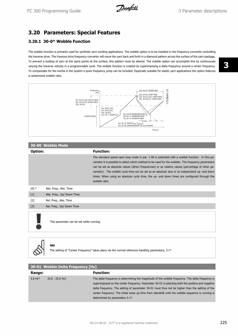
3.20 Parameters: Special Features
3.20.1 30-0* Wobble Function
The wobble function is primarily used for synthetic yarn winding applications. The wobble option is to be installed in the frequency converter controlling
the traverse drive. The traverse drive frequency converter will move the yarn back and forth in a diamond pattern across the surface of the yarn package.
To prevent a buildup of yarn at the same points at the surface, this pattern must be altered. The wobble option can accomplish this by continuously
varying the traverse velocity in a programmable cycle. The wobble function is created by superimposing a delta frequency around a center frequency.
To compensate for the inertia in the system a quick frequency jump can be included. Especially suitable for elastic yarn applications the option features
a randomized wobble ratio.
30-00 Wobble Mode
Option: Function:The standard speed open loop mode in par. 1-00 is extended with a wobble function . In this pa-
rameter it is possible to select which method to be used for the wobbler. The frequency parameters
can be set as absolute values (direct frequencies) or as relative values (percentage of other pa-
rameter) . The wobble cycle time can be set as an absolute alue or as independent up- and down
times. When using an absolute cycle time, the up- and down times are configured through the
wobble ratio.
[0] * Abs. Freq., Abs. Time
[1] Abs. Freq., Up/ Down Time
[2] Rel. Freq., Abs. Time
[3] Rel. Freq., Up/ Down Time
This parameter can be set while running.
NB!
The setting of “Center Frequency” takes place via the normal reference handling parameters, 3-1*
30-01 Wobble Delta Frequency [Hz]
Range: Function:5.0 Hz* [0.0 - 25.0 Hz] The delta frequency is determining the magnitude of the wobble frequency. The delta frequency is
superimposed on the center frequency. Parameter 30-01 is selecting both the positive and negative
delta frequency. The setting of parameter 30-01 must thus not be higher than the setting of the
center frequency. The initial ramp up time from standstill until the wobble sequence is running is
determined by parameters 3-1*.
FC 300 Programming Guide 3 Parameter descriptions
MG.33.M8.02 - VLT® is a registered Danfoss trademark 225
3
30-02 Wobble Delta Frequency [%]
Range: Function:25 %* [0 - 100 %] The delta frequency can also be expressed as percentage of the center frequency and can thus be
maximum 100%. The function is the same as for par. 30-01.
30-03 Wobble Delta Freq. Scaling Resource
Option: Function:Select which drive input should be used to scale the delta frequency setting.
[0] * No function
[1] Analog input 53
[2] Analog input 54
[3] Frequency input 29 FC 302 only
[4] Frequency input 33
[7] Analog input X30/11
[8] Analog input X30/12
30-04 Wobble Jump Frequency [Hz]
Range: Function:0.0 Hz* [Application dependant] The jump frequency is used to compensate for the inertia in the traverse system. If a jump in the
output frequency is required in the top and in the bottom of the wobble sequence, the frequency
jump is set in this parameter. If the traverse system has a very high inertia a high jump frequency
may create a torque limit warning or trip (warning/alarm 12) or an over voltage warning or trip
(warning/alarm 7). This parameter can only be changed in stop-mode
30-05 Wobble Jump Frequency [%]
Range: Function:0 %* [0 - 100 %] The jump frequency can also be expressed as percentage of the center frequency. The function is
the same as for par. 30-04.
30-06 Wobble Jump Time
Range: Function:Application
dependent*
[Application dependant] This parameter determines the slope of the jump ramp at the max. and min. wobble frequency.
30-07 Wobble Sequence Time
Range: Function:10.0 s* [1.0 - 1000.0 s] This parameter determines the wobble sequence period. This parameter can only be changed in
stop-mode.
Wobble time = tup + tdown
30-08 Wobble Up/ Down Time
Range: Function:5.0 s* [0.1 - 1000.0 s] Defines the individual up- and down times for each wobble cycle.
30-09 Wobble Random Function
Option: Function:[0] * Off
[1] On
3 Parameter descriptions FC 300 Programming Guide
226 MG.33.M8.02 - VLT® is a registered Danfoss trademark
3
30-10 Wobble Ratio
Range: Function:1.0* [Application dependant] If the ratio 0.1 is selected: tdown is 10 times greater than tup.
If the ratio 10 is selected: tup is 10 times greater than tdown.
30-11 Wobble Random Ratio Max.
Range: Function:10.0* [Application dependant] Enter the maximum allowed wobble ratio.
30-12 Wobble Random Ratio Min.
Range: Function:0.1* [Application dependant] Enter the minimum allowed wobble ratio.
30-19 Wobble Delta Freq. Scaled
Range: Function:0.0 Hz* [0.0 - 1000.0 Hz] Readout parameter. View the actual wobble delta frequency after scaling has been applied.
3.20.2 30-2* Adv. Start Adjust
30-20 High Starting Torque Time [s]
Range: Function:0.00 s* [0.00 - 0.50 s] High starting torque time for PM-Motor in Flux mode without feedback. This parameter is available
for FC 302 only.
30-21 High Starting Torque Current [%]
Range: Function:100.0 %* [Application dependant] High starting torque current for PM-Motor in Flux mode without feedback. This parameter is available
for FC 302 only.
30-22 Locked Rotor ProtectionLocked Rotor Protection for PM-Motor in Flux mode without feedback. This parameter is available for FC 302 only.
Option: Function:[0] * Off
[1] On
30-23 Locked Rotor Detection Time [s]Locked Rotor Detection Time for PM-Motor in Flux mode without feedback. This parameter is available for FC 302 only.
Range: Function:0.10 s* [0.05 - 1.00 s]
3.20.3 30-8* Compatibility
30-80 d-axis Inductance (Ld)
Range: Function:Application
dependent*
[Application dependant] Enter the value of the d-axis inductance. Obtain the value from the permanent magnet motor data
sheet. The d-axis inductance cannot be found by performing an AMA.
FC 300 Programming Guide 3 Parameter descriptions
MG.33.M8.02 - VLT® is a registered Danfoss trademark 227
3
30-81 Brake Resistor (ohm)
Range: Function:Application
dependent*
[Application dependant] Set the brake resistor value in Ohms. This value is used for monitoring the power to the brake
resistor in par. 2-13 Brake Power Monitoring. This parameter is only active in drives with an integral
dynamic brake.
30-83 Speed PID Proportional Gain
Range: Function:Application
dependent*
[0.0000 - 1.0000 ] Enter the speed controller proportional gain. Quick control is obtained at high amplification. However
if amplification is too great, the process may become unstable.
30-84 Process PID Proportional Gain
Range: Function:0.100* [0.000 - 10.000 ] Enter the process controller proportional gain. Quick control is obtained at high amplification. How-
ever if amplification is too great, the process may become unstable.
3 Parameter descriptions FC 300 Programming Guide
228 MG.33.M8.02 - VLT® is a registered Danfoss trademark
3
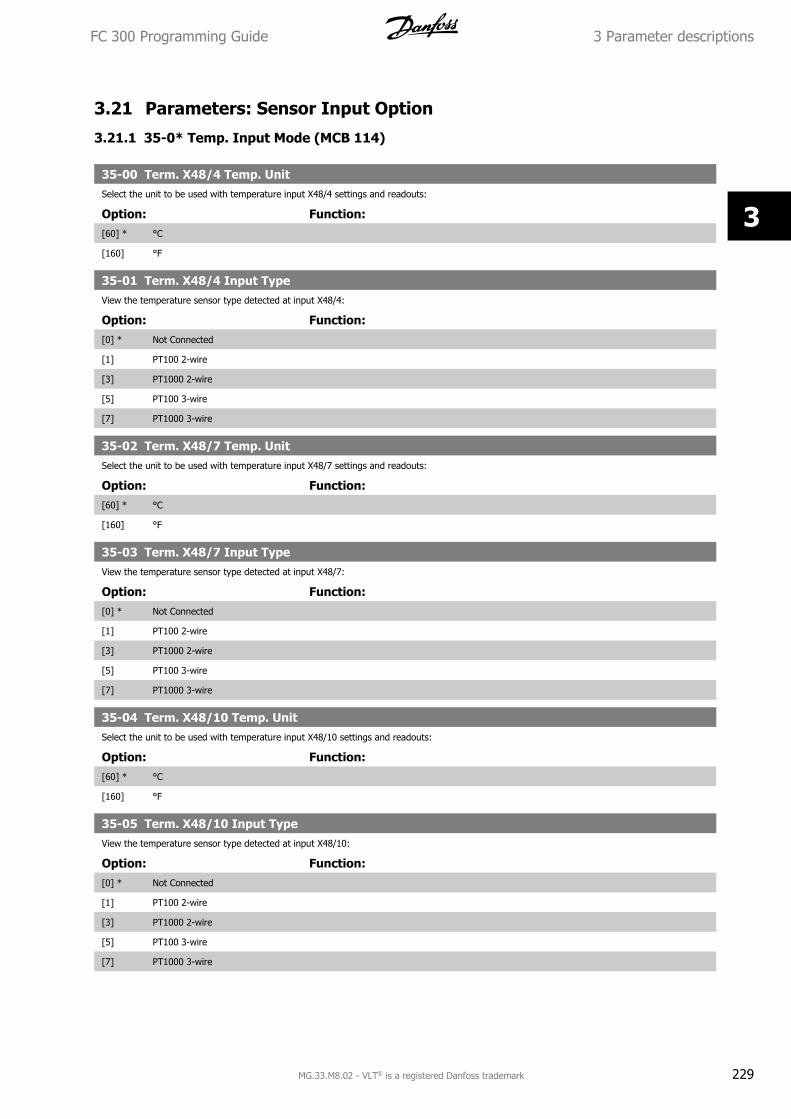
3.21 Parameters: Sensor Input Option
3.21.1 35-0* Temp. Input Mode (MCB 114)
35-00 Term. X48/4 Temp. UnitSelect the unit to be used with temperature input X48/4 settings and readouts:
Option: Function:[60] * °C
[160] °F
35-01 Term. X48/4 Input TypeView the temperature sensor type detected at input X48/4:
Option: Function:[0] * Not Connected
[1] PT100 2-wire
[3] PT1000 2-wire
[5] PT100 3-wire
[7] PT1000 3-wire
35-02 Term. X48/7 Temp. UnitSelect the unit to be used with temperature input X48/7 settings and readouts:
Option: Function:[60] * °C
[160] °F
35-03 Term. X48/7 Input TypeView the temperature sensor type detected at input X48/7:
Option: Function:[0] * Not Connected
[1] PT100 2-wire
[3] PT1000 2-wire
[5] PT100 3-wire
[7] PT1000 3-wire
35-04 Term. X48/10 Temp. UnitSelect the unit to be used with temperature input X48/10 settings and readouts:
Option: Function:[60] * °C
[160] °F
35-05 Term. X48/10 Input TypeView the temperature sensor type detected at input X48/10:
Option: Function:[0] * Not Connected
[1] PT100 2-wire
[3] PT1000 2-wire
[5] PT100 3-wire
[7] PT1000 3-wire
FC 300 Programming Guide 3 Parameter descriptions
MG.33.M8.02 - VLT® is a registered Danfoss trademark 229
3
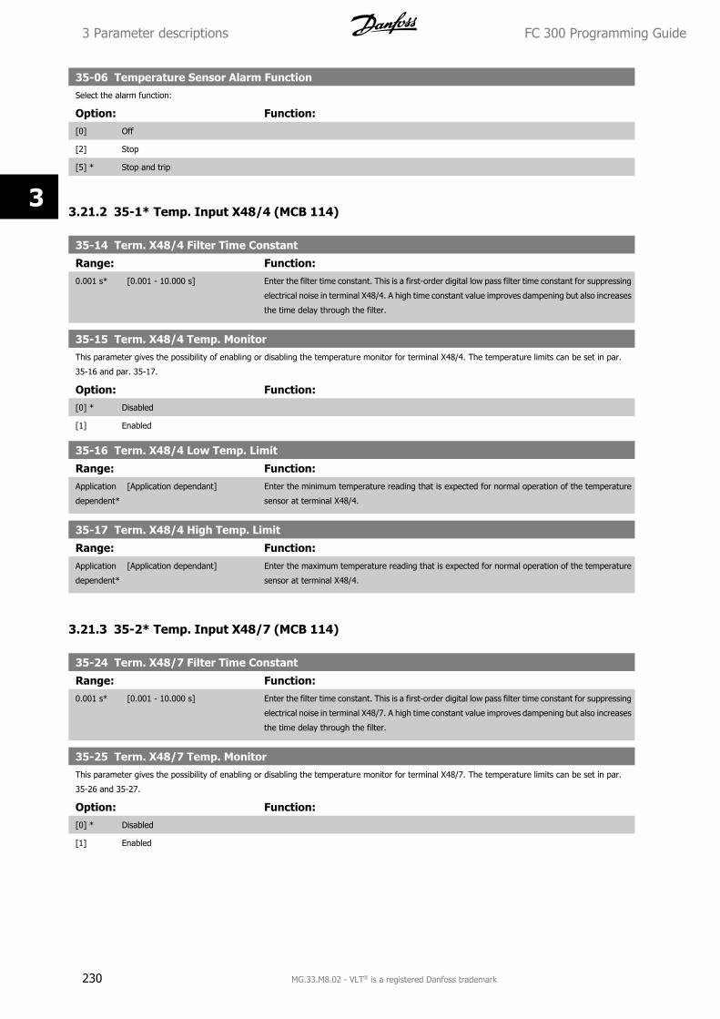
35-06 Temperature Sensor Alarm FunctionSelect the alarm function:
Option: Function:[0] Off
[2] Stop
[5] * Stop and trip
3.21.2 35-1* Temp. Input X48/4 (MCB 114)
35-14 Term. X48/4 Filter Time Constant
Range: Function:0.001 s* [0.001 - 10.000 s] Enter the filter time constant. This is a first-order digital low pass filter time constant for suppressing
electrical noise in terminal X48/4. A high time constant value improves dampening but also increases
the time delay through the filter.
35-15 Term. X48/4 Temp. MonitorThis parameter gives the possibility of enabling or disabling the temperature monitor for terminal X48/4. The temperature limits can be set in par.
35-16 and par. 35-17.
Option: Function:[0] * Disabled
[1] Enabled
35-16 Term. X48/4 Low Temp. Limit
Range: Function:Application
dependent*
[Application dependant] Enter the minimum temperature reading that is expected for normal operation of the temperature
sensor at terminal X48/4.
35-17 Term. X48/4 High Temp. Limit
Range: Function:Application
dependent*
[Application dependant] Enter the maximum temperature reading that is expected for normal operation of the temperature
sensor at terminal X48/4.
3.21.3 35-2* Temp. Input X48/7 (MCB 114)
35-24 Term. X48/7 Filter Time Constant
Range: Function:0.001 s* [0.001 - 10.000 s] Enter the filter time constant. This is a first-order digital low pass filter time constant for suppressing
electrical noise in terminal X48/7. A high time constant value improves dampening but also increases
the time delay through the filter.
35-25 Term. X48/7 Temp. MonitorThis parameter gives the possibility of enabling or disabling the temperature monitor for terminal X48/7. The temperature limits can be set in par.
35-26 and 35-27.
Option: Function:[0] * Disabled
[1] Enabled
3 Parameter descriptions FC 300 Programming Guide
230 MG.33.M8.02 - VLT® is a registered Danfoss trademark
3
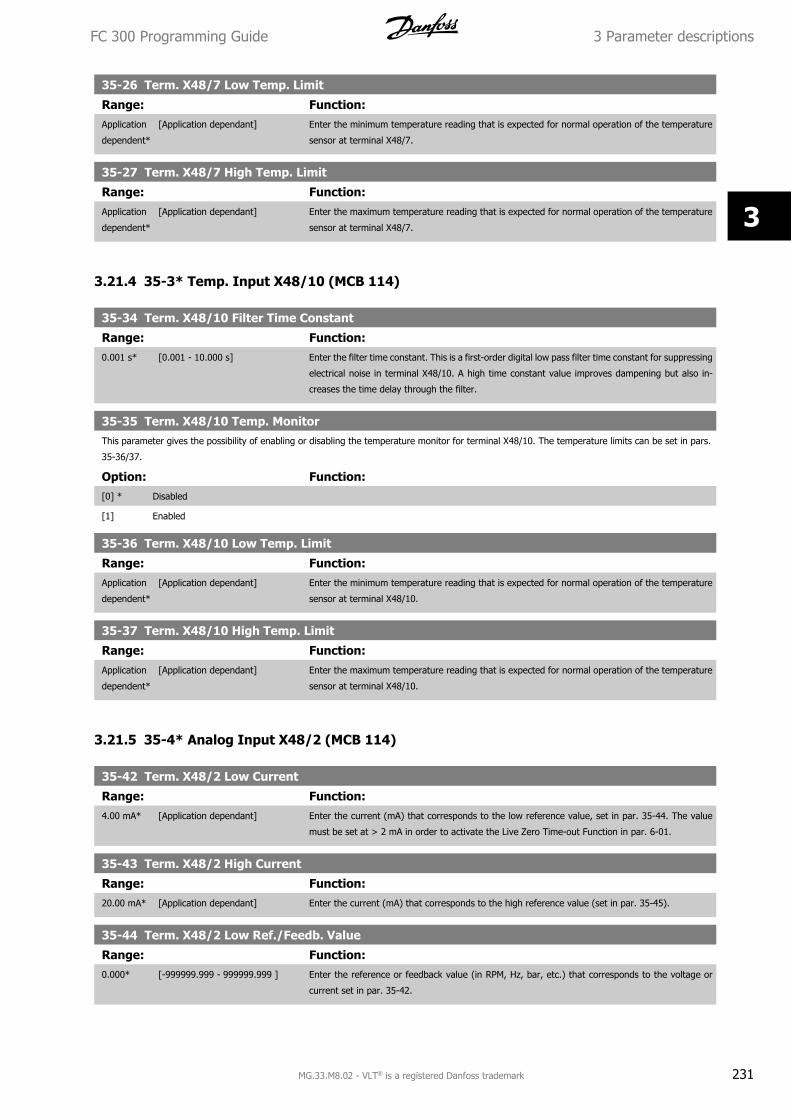
35-26 Term. X48/7 Low Temp. Limit
Range: Function:Application
dependent*
[Application dependant] Enter the minimum temperature reading that is expected for normal operation of the temperature
sensor at terminal X48/7.
35-27 Term. X48/7 High Temp. Limit
Range: Function:Application
dependent*
[Application dependant] Enter the maximum temperature reading that is expected for normal operation of the temperature
sensor at terminal X48/7.
3.21.4 35-3* Temp. Input X48/10 (MCB 114)
35-34 Term. X48/10 Filter Time Constant
Range: Function:0.001 s* [0.001 - 10.000 s] Enter the filter time constant. This is a first-order digital low pass filter time constant for suppressing
electrical noise in terminal X48/10. A high time constant value improves dampening but also in-
creases the time delay through the filter.
35-35 Term. X48/10 Temp. MonitorThis parameter gives the possibility of enabling or disabling the temperature monitor for terminal X48/10. The temperature limits can be set in pars.
35-36/37.
Option: Function:[0] * Disabled
[1] Enabled
35-36 Term. X48/10 Low Temp. Limit
Range: Function:Application
dependent*
[Application dependant] Enter the minimum temperature reading that is expected for normal operation of the temperature
sensor at terminal X48/10.
35-37 Term. X48/10 High Temp. Limit
Range: Function:Application
dependent*
[Application dependant] Enter the maximum temperature reading that is expected for normal operation of the temperature
sensor at terminal X48/10.
3.21.5 35-4* Analog Input X48/2 (MCB 114)
35-42 Term. X48/2 Low Current
Range: Function:4.00 mA* [Application dependant] Enter the current (mA) that corresponds to the low reference value, set in par. 35-44. The value
must be set at > 2 mA in order to activate the Live Zero Time-out Function in par. 6-01.
35-43 Term. X48/2 High Current
Range: Function:20.00 mA* [Application dependant] Enter the current (mA) that corresponds to the high reference value (set in par. 35-45).
35-44 Term. X48/2 Low Ref./Feedb. Value
Range: Function:0.000* [-999999.999 - 999999.999 ] Enter the reference or feedback value (in RPM, Hz, bar, etc.) that corresponds to the voltage or
current set in par. 35-42.
FC 300 Programming Guide 3 Parameter descriptions
MG.33.M8.02 - VLT® is a registered Danfoss trademark 231
3
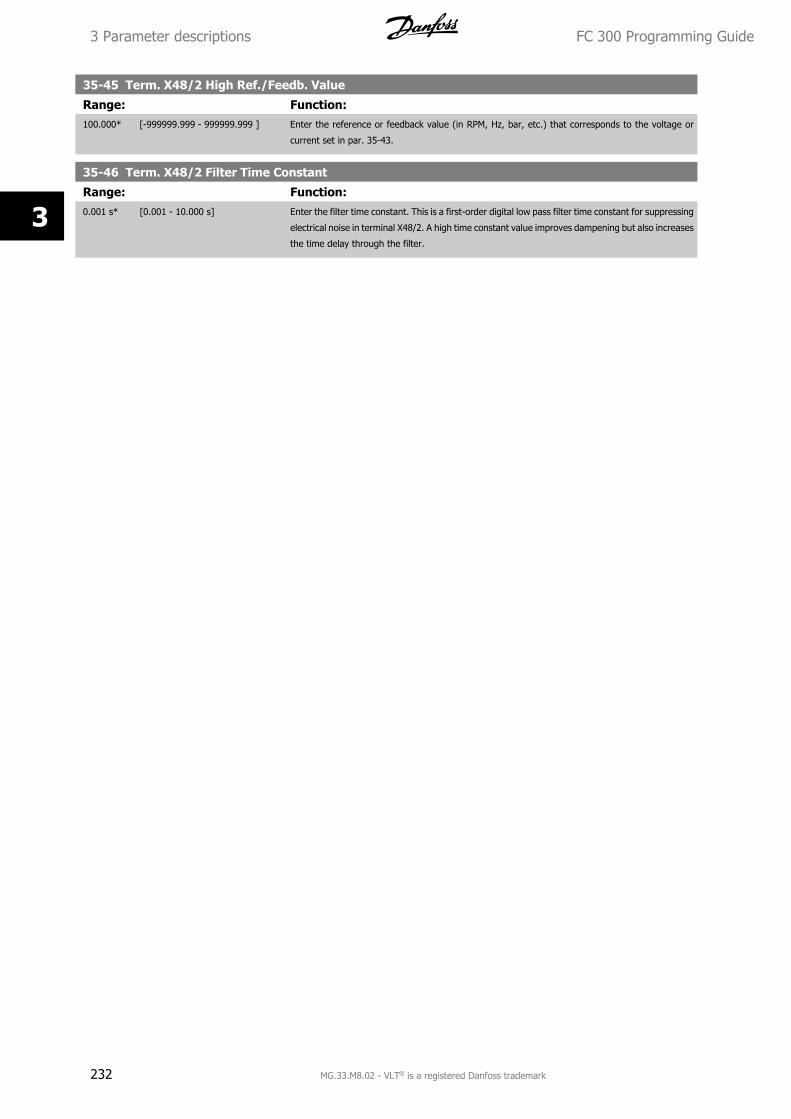
35-45 Term. X48/2 High Ref./Feedb. Value
Range: Function:100.000* [-999999.999 - 999999.999 ] Enter the reference or feedback value (in RPM, Hz, bar, etc.) that corresponds to the voltage or
current set in par. 35-43.
35-46 Term. X48/2 Filter Time Constant
Range: Function:0.001 s* [0.001 - 10.000 s] Enter the filter time constant. This is a first-order digital low pass filter time constant for suppressing
electrical noise in terminal X48/2. A high time constant value improves dampening but also increases
the time delay through the filter.
3 Parameter descriptions FC 300 Programming Guide
232 MG.33.M8.02 - VLT® is a registered Danfoss trademark
3
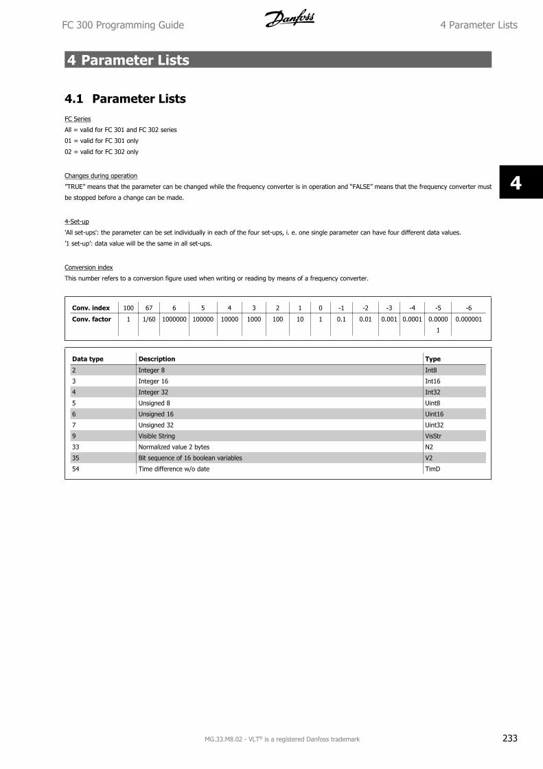
4 Parameter Lists
4.1 Parameter ListsFC Series
All = valid for FC 301 and FC 302 series
01 = valid for FC 301 only
02 = valid for FC 302 only
Changes during operation
”TRUE” means that the parameter can be changed while the frequency converter is in operation and “FALSE” means that the frequency converter must
be stopped before a change can be made.
4-Set-up
'All set-ups': the parameter can be set individually in each of the four set-ups, i. e. one single parameter can have four different data values.
’1 set-up’: data value will be the same in all set-ups.
Conversion index
This number refers to a conversion figure used when writing or reading by means of a frequency converter.
Conv. index 100 67 6 5 4 3 2 1 0 -1 -2 -3 -4 -5 -6
Conv. factor 1 1/60 1000000 100000 10000 1000 100 10 1 0.1 0.01 0.001 0.0001 0.0000
1
0.000001
Data type Description Type
2 Integer 8 Int8
3 Integer 16 Int16
4 Integer 32 Int32
5 Unsigned 8 Uint8
6 Unsigned 16 Uint16
7 Unsigned 32 Uint32
9 Visible String VisStr
33 Normalized value 2 bytes N2
35 Bit sequence of 16 boolean variables V2
54 Time difference w/o date TimD
FC 300 Programming Guide 4 Parameter Lists
MG.33.M8.02 - VLT® is a registered Danfoss trademark 233
4
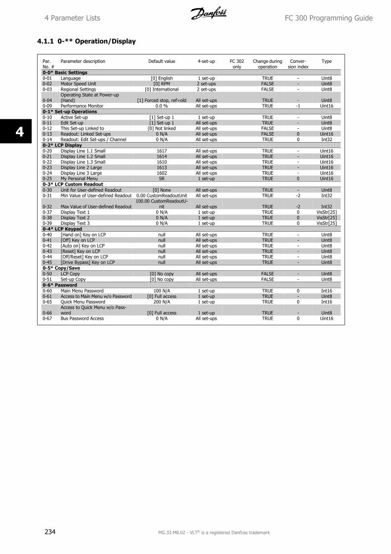
4.1.1 0-** Operation/Display
Par.No. #
Parameter description Default value 4-set-up FC 302only
Change duringoperation
Conver-sion index
Type
0-0* Basic Settings0-01 Language [0] English 1 set-up TRUE - Uint80-02 Motor Speed Unit [0] RPM 2 set-ups FALSE - Uint80-03 Regional Settings [0] International 2 set-ups FALSE - Uint8
0-04Operating State at Power-up(Hand) [1] Forced stop, ref=old All set-ups TRUE - Uint8
0-09 Performance Monitor 0.0 % All set-ups TRUE -1 Uint160-1* Set-up Operations0-10 Active Set-up [1] Set-up 1 1 set-up TRUE - Uint80-11 Edit Set-up [1] Set-up 1 All set-ups TRUE - Uint80-12 This Set-up Linked to [0] Not linked All set-ups FALSE - Uint80-13 Readout: Linked Set-ups 0 N/A All set-ups FALSE 0 Uint160-14 Readout: Edit Set-ups / Channel 0 N/A All set-ups TRUE 0 Int320-2* LCP Display0-20 Display Line 1.1 Small 1617 All set-ups TRUE - Uint160-21 Display Line 1.2 Small 1614 All set-ups TRUE - Uint160-22 Display Line 1.3 Small 1610 All set-ups TRUE - Uint160-23 Display Line 2 Large 1613 All set-ups TRUE - Uint160-24 Display Line 3 Large 1602 All set-ups TRUE - Uint160-25 My Personal Menu SR 1 set-up TRUE 0 Uint160-3* LCP Custom Readout0-30 Unit for User-defined Readout [0] None All set-ups TRUE - Uint80-31 Min Value of User-defined Readout 0.00 CustomReadoutUnit All set-ups TRUE -2 Int32
0-32 Max Value of User-defined Readout100.00 CustomReadoutU-
nit All set-ups TRUE -2 Int320-37 Display Text 1 0 N/A 1 set-up TRUE 0 VisStr[25]0-38 Display Text 2 0 N/A 1 set-up TRUE 0 VisStr[25]0-39 Display Text 3 0 N/A 1 set-up TRUE 0 VisStr[25]0-4* LCP Keypad0-40 [Hand on] Key on LCP null All set-ups TRUE - Uint80-41 [Off] Key on LCP null All set-ups TRUE - Uint80-42 [Auto on] Key on LCP null All set-ups TRUE - Uint80-43 [Reset] Key on LCP null All set-ups TRUE - Uint80-44 [Off/Reset] Key on LCP null All set-ups TRUE - Uint80-45 [Drive Bypass] Key on LCP null All set-ups TRUE - Uint80-5* Copy/Save0-50 LCP Copy [0] No copy All set-ups FALSE - Uint80-51 Set-up Copy [0] No copy All set-ups FALSE - Uint80-6* Password0-60 Main Menu Password 100 N/A 1 set-up TRUE 0 Int160-61 Access to Main Menu w/o Password [0] Full access 1 set-up TRUE - Uint80-65 Quick Menu Password 200 N/A 1 set-up TRUE 0 Int16
0-66Access to Quick Menu w/o Pass-word [0] Full access 1 set-up TRUE - Uint8
0-67 Bus Password Access 0 N/A All set-ups TRUE 0 Uint16
4 Parameter Lists FC 300 Programming Guide
234 MG.33.M8.02 - VLT® is a registered Danfoss trademark
4
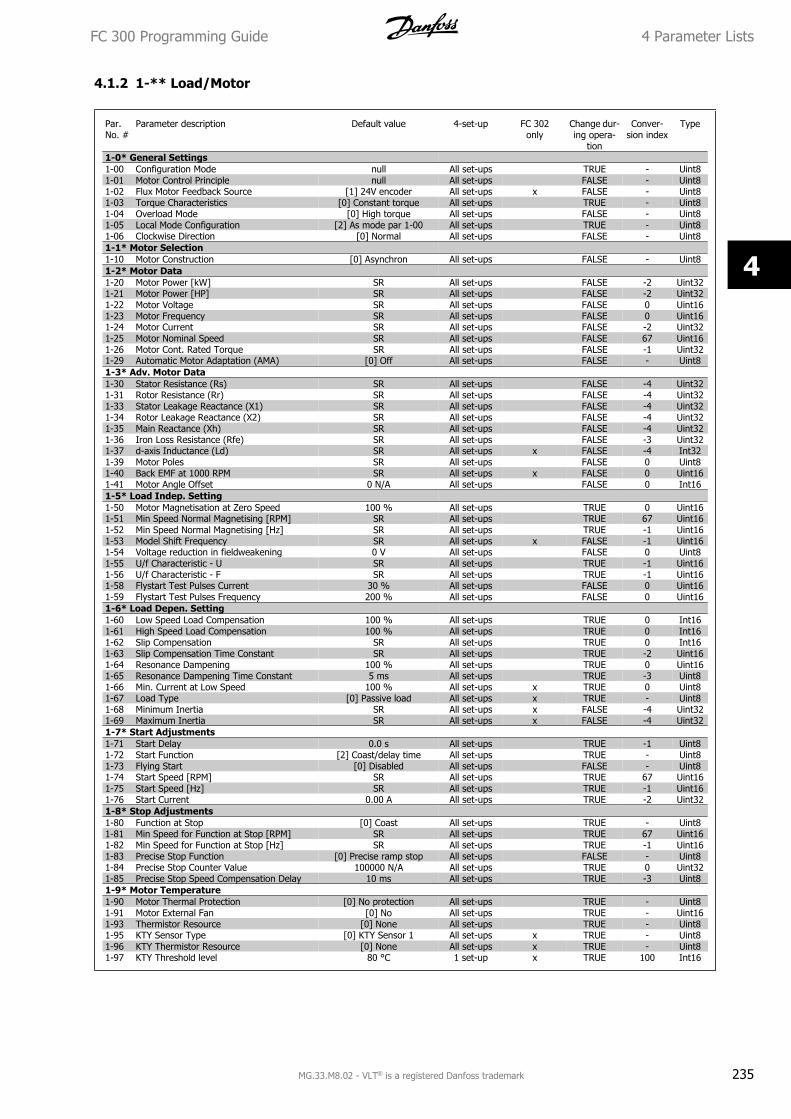
4.1.2 1-** Load/Motor
Par.No. #
Parameter description Default value 4-set-up FC 302only
Change dur-ing opera-
tion
Conver-sion index
Type
1-0* General Settings1-00 Configuration Mode null All set-ups TRUE - Uint81-01 Motor Control Principle null All set-ups FALSE - Uint81-02 Flux Motor Feedback Source [1] 24V encoder All set-ups x FALSE - Uint81-03 Torque Characteristics [0] Constant torque All set-ups TRUE - Uint81-04 Overload Mode [0] High torque All set-ups FALSE - Uint81-05 Local Mode Configuration [2] As mode par 1-00 All set-ups TRUE - Uint81-06 Clockwise Direction [0] Normal All set-ups FALSE - Uint81-1* Motor Selection1-10 Motor Construction [0] Asynchron All set-ups FALSE - Uint81-2* Motor Data1-20 Motor Power [kW] SR All set-ups FALSE -2 Uint321-21 Motor Power [HP] SR All set-ups FALSE -2 Uint321-22 Motor Voltage SR All set-ups FALSE 0 Uint161-23 Motor Frequency SR All set-ups FALSE 0 Uint161-24 Motor Current SR All set-ups FALSE -2 Uint321-25 Motor Nominal Speed SR All set-ups FALSE 67 Uint161-26 Motor Cont. Rated Torque SR All set-ups FALSE -1 Uint321-29 Automatic Motor Adaptation (AMA) [0] Off All set-ups FALSE - Uint81-3* Adv. Motor Data1-30 Stator Resistance (Rs) SR All set-ups FALSE -4 Uint321-31 Rotor Resistance (Rr) SR All set-ups FALSE -4 Uint321-33 Stator Leakage Reactance (X1) SR All set-ups FALSE -4 Uint321-34 Rotor Leakage Reactance (X2) SR All set-ups FALSE -4 Uint321-35 Main Reactance (Xh) SR All set-ups FALSE -4 Uint321-36 Iron Loss Resistance (Rfe) SR All set-ups FALSE -3 Uint321-37 d-axis Inductance (Ld) SR All set-ups x FALSE -4 Int321-39 Motor Poles SR All set-ups FALSE 0 Uint81-40 Back EMF at 1000 RPM SR All set-ups x FALSE 0 Uint161-41 Motor Angle Offset 0 N/A All set-ups FALSE 0 Int161-5* Load Indep. Setting1-50 Motor Magnetisation at Zero Speed 100 % All set-ups TRUE 0 Uint161-51 Min Speed Normal Magnetising [RPM] SR All set-ups TRUE 67 Uint161-52 Min Speed Normal Magnetising [Hz] SR All set-ups TRUE -1 Uint161-53 Model Shift Frequency SR All set-ups x FALSE -1 Uint161-54 Voltage reduction in fieldweakening 0 V All set-ups FALSE 0 Uint81-55 U/f Characteristic - U SR All set-ups TRUE -1 Uint161-56 U/f Characteristic - F SR All set-ups TRUE -1 Uint161-58 Flystart Test Pulses Current 30 % All set-ups FALSE 0 Uint161-59 Flystart Test Pulses Frequency 200 % All set-ups FALSE 0 Uint161-6* Load Depen. Setting1-60 Low Speed Load Compensation 100 % All set-ups TRUE 0 Int161-61 High Speed Load Compensation 100 % All set-ups TRUE 0 Int161-62 Slip Compensation SR All set-ups TRUE 0 Int161-63 Slip Compensation Time Constant SR All set-ups TRUE -2 Uint161-64 Resonance Dampening 100 % All set-ups TRUE 0 Uint161-65 Resonance Dampening Time Constant 5 ms All set-ups TRUE -3 Uint81-66 Min. Current at Low Speed 100 % All set-ups x TRUE 0 Uint81-67 Load Type [0] Passive load All set-ups x TRUE - Uint81-68 Minimum Inertia SR All set-ups x FALSE -4 Uint321-69 Maximum Inertia SR All set-ups x FALSE -4 Uint321-7* Start Adjustments1-71 Start Delay 0.0 s All set-ups TRUE -1 Uint81-72 Start Function [2] Coast/delay time All set-ups TRUE - Uint81-73 Flying Start [0] Disabled All set-ups FALSE - Uint81-74 Start Speed [RPM] SR All set-ups TRUE 67 Uint161-75 Start Speed [Hz] SR All set-ups TRUE -1 Uint161-76 Start Current 0.00 A All set-ups TRUE -2 Uint321-8* Stop Adjustments1-80 Function at Stop [0] Coast All set-ups TRUE - Uint81-81 Min Speed for Function at Stop [RPM] SR All set-ups TRUE 67 Uint161-82 Min Speed for Function at Stop [Hz] SR All set-ups TRUE -1 Uint161-83 Precise Stop Function [0] Precise ramp stop All set-ups FALSE - Uint81-84 Precise Stop Counter Value 100000 N/A All set-ups TRUE 0 Uint321-85 Precise Stop Speed Compensation Delay 10 ms All set-ups TRUE -3 Uint81-9* Motor Temperature1-90 Motor Thermal Protection [0] No protection All set-ups TRUE - Uint81-91 Motor External Fan [0] No All set-ups TRUE - Uint161-93 Thermistor Resource [0] None All set-ups TRUE - Uint81-95 KTY Sensor Type [0] KTY Sensor 1 All set-ups x TRUE - Uint81-96 KTY Thermistor Resource [0] None All set-ups x TRUE - Uint81-97 KTY Threshold level 80 °C 1 set-up x TRUE 100 Int16
FC 300 Programming Guide 4 Parameter Lists
MG.33.M8.02 - VLT® is a registered Danfoss trademark 235
4
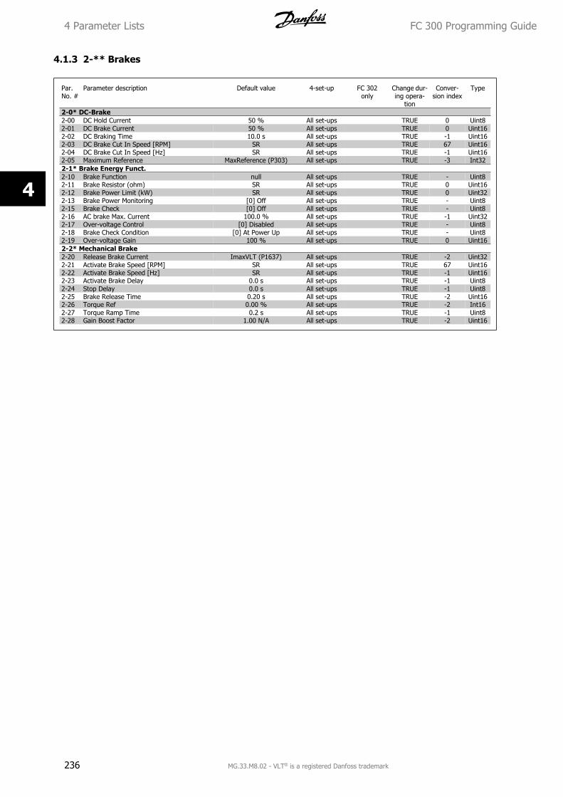
4.1.3 2-** Brakes
Par.No. #
Parameter description Default value 4-set-up FC 302only
Change dur-ing opera-
tion
Conver-sion index
Type
2-0* DC-Brake2-00 DC Hold Current 50 % All set-ups TRUE 0 Uint82-01 DC Brake Current 50 % All set-ups TRUE 0 Uint162-02 DC Braking Time 10.0 s All set-ups TRUE -1 Uint162-03 DC Brake Cut In Speed [RPM] SR All set-ups TRUE 67 Uint162-04 DC Brake Cut In Speed [Hz] SR All set-ups TRUE -1 Uint162-05 Maximum Reference MaxReference (P303) All set-ups TRUE -3 Int322-1* Brake Energy Funct.2-10 Brake Function null All set-ups TRUE - Uint82-11 Brake Resistor (ohm) SR All set-ups TRUE 0 Uint162-12 Brake Power Limit (kW) SR All set-ups TRUE 0 Uint322-13 Brake Power Monitoring [0] Off All set-ups TRUE - Uint82-15 Brake Check [0] Off All set-ups TRUE - Uint82-16 AC brake Max. Current 100.0 % All set-ups TRUE -1 Uint322-17 Over-voltage Control [0] Disabled All set-ups TRUE - Uint82-18 Brake Check Condition [0] At Power Up All set-ups TRUE - Uint82-19 Over-voltage Gain 100 % All set-ups TRUE 0 Uint162-2* Mechanical Brake2-20 Release Brake Current ImaxVLT (P1637) All set-ups TRUE -2 Uint322-21 Activate Brake Speed [RPM] SR All set-ups TRUE 67 Uint162-22 Activate Brake Speed [Hz] SR All set-ups TRUE -1 Uint162-23 Activate Brake Delay 0.0 s All set-ups TRUE -1 Uint82-24 Stop Delay 0.0 s All set-ups TRUE -1 Uint82-25 Brake Release Time 0.20 s All set-ups TRUE -2 Uint162-26 Torque Ref 0.00 % All set-ups TRUE -2 Int162-27 Torque Ramp Time 0.2 s All set-ups TRUE -1 Uint82-28 Gain Boost Factor 1.00 N/A All set-ups TRUE -2 Uint16
4 Parameter Lists FC 300 Programming Guide
236 MG.33.M8.02 - VLT® is a registered Danfoss trademark
4
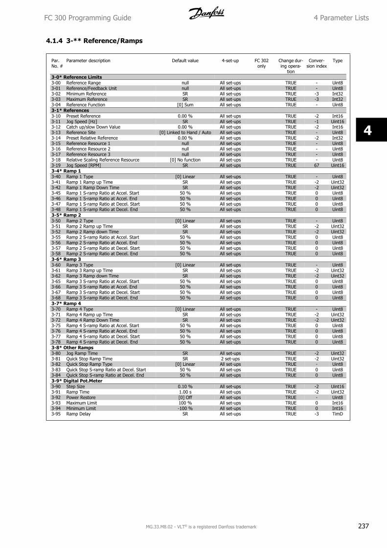
4.1.4 3-** Reference/Ramps
Par.No. #
Parameter description Default value 4-set-up FC 302only
Change dur-ing opera-
tion
Conver-sion index
Type
3-0* Reference Limits3-00 Reference Range null All set-ups TRUE - Uint83-01 Reference/Feedback Unit null All set-ups TRUE - Uint83-02 Minimum Reference SR All set-ups TRUE -3 Int323-03 Maximum Reference SR All set-ups TRUE -3 Int323-04 Reference Function [0] Sum All set-ups TRUE - Uint83-1* References3-10 Preset Reference 0.00 % All set-ups TRUE -2 Int163-11 Jog Speed [Hz] SR All set-ups TRUE -1 Uint163-12 Catch up/slow Down Value 0.00 % All set-ups TRUE -2 Int163-13 Reference Site [0] Linked to Hand / Auto All set-ups TRUE - Uint83-14 Preset Relative Reference 0.00 % All set-ups TRUE -2 Int323-15 Reference Resource 1 null All set-ups TRUE - Uint83-16 Reference Resource 2 null All set-ups TRUE - Uint83-17 Reference Resource 3 null All set-ups TRUE - Uint83-18 Relative Scaling Reference Resource [0] No function All set-ups TRUE - Uint83-19 Jog Speed [RPM] SR All set-ups TRUE 67 Uint163-4* Ramp 13-40 Ramp 1 Type [0] Linear All set-ups TRUE - Uint83-41 Ramp 1 Ramp up Time SR All set-ups TRUE -2 Uint323-42 Ramp 1 Ramp Down Time SR All set-ups TRUE -2 Uint323-45 Ramp 1 S-ramp Ratio at Accel. Start 50 % All set-ups TRUE 0 Uint83-46 Ramp 1 S-ramp Ratio at Accel. End 50 % All set-ups TRUE 0 Uint83-47 Ramp 1 S-ramp Ratio at Decel. Start 50 % All set-ups TRUE 0 Uint83-48 Ramp 1 S-ramp Ratio at Decel. End 50 % All set-ups TRUE 0 Uint83-5* Ramp 23-50 Ramp 2 Type [0] Linear All set-ups TRUE - Uint83-51 Ramp 2 Ramp up Time SR All set-ups TRUE -2 Uint323-52 Ramp 2 Ramp down Time SR All set-ups TRUE -2 Uint323-55 Ramp 2 S-ramp Ratio at Accel. Start 50 % All set-ups TRUE 0 Uint83-56 Ramp 2 S-ramp Ratio at Accel. End 50 % All set-ups TRUE 0 Uint83-57 Ramp 2 S-ramp Ratio at Decel. Start 50 % All set-ups TRUE 0 Uint83-58 Ramp 2 S-ramp Ratio at Decel. End 50 % All set-ups TRUE 0 Uint83-6* Ramp 33-60 Ramp 3 Type [0] Linear All set-ups TRUE - Uint83-61 Ramp 3 Ramp up Time SR All set-ups TRUE -2 Uint323-62 Ramp 3 Ramp down Time SR All set-ups TRUE -2 Uint323-65 Ramp 3 S-ramp Ratio at Accel. Start 50 % All set-ups TRUE 0 Uint83-66 Ramp 3 S-ramp Ratio at Accel. End 50 % All set-ups TRUE 0 Uint83-67 Ramp 3 S-ramp Ratio at Decel. Start 50 % All set-ups TRUE 0 Uint83-68 Ramp 3 S-ramp Ratio at Decel. End 50 % All set-ups TRUE 0 Uint83-7* Ramp 43-70 Ramp 4 Type [0] Linear All set-ups TRUE - Uint83-71 Ramp 4 Ramp up Time SR All set-ups TRUE -2 Uint323-72 Ramp 4 Ramp Down Time SR All set-ups TRUE -2 Uint323-75 Ramp 4 S-ramp Ratio at Accel. Start 50 % All set-ups TRUE 0 Uint83-76 Ramp 4 S-ramp Ratio at Accel. End 50 % All set-ups TRUE 0 Uint83-77 Ramp 4 S-ramp Ratio at Decel. Start 50 % All set-ups TRUE 0 Uint83-78 Ramp 4 S-ramp Ratio at Decel. End 50 % All set-ups TRUE 0 Uint83-8* Other Ramps3-80 Jog Ramp Time SR All set-ups TRUE -2 Uint323-81 Quick Stop Ramp Time SR 2 set-ups TRUE -2 Uint323-82 Quick Stop Ramp Type [0] Linear All set-ups TRUE - Uint83-83 Quick Stop S-ramp Ratio at Decel. Start 50 % All set-ups TRUE 0 Uint83-84 Quick Stop S-ramp Ratio at Decel. End 50 % All set-ups TRUE 0 Uint83-9* Digital Pot.Meter3-90 Step Size 0.10 % All set-ups TRUE -2 Uint163-91 Ramp Time 1.00 s All set-ups TRUE -2 Uint323-92 Power Restore [0] Off All set-ups TRUE - Uint83-93 Maximum Limit 100 % All set-ups TRUE 0 Int163-94 Minimum Limit -100 % All set-ups TRUE 0 Int163-95 Ramp Delay SR All set-ups TRUE -3 TimD
FC 300 Programming Guide 4 Parameter Lists
MG.33.M8.02 - VLT® is a registered Danfoss trademark 237
4
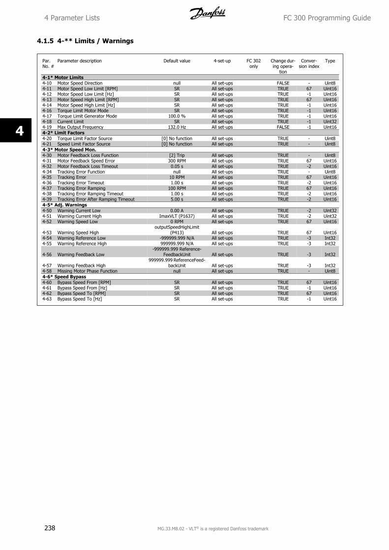
4.1.5 4-** Limits / Warnings
Par.No. #
Parameter description Default value 4-set-up FC 302only
Change dur-ing opera-
tion
Conver-sion index
Type
4-1* Motor Limits4-10 Motor Speed Direction null All set-ups FALSE - Uint84-11 Motor Speed Low Limit [RPM] SR All set-ups TRUE 67 Uint164-12 Motor Speed Low Limit [Hz] SR All set-ups TRUE -1 Uint164-13 Motor Speed High Limit [RPM] SR All set-ups TRUE 67 Uint164-14 Motor Speed High Limit [Hz] SR All set-ups TRUE -1 Uint164-16 Torque Limit Motor Mode SR All set-ups TRUE -1 Uint164-17 Torque Limit Generator Mode 100.0 % All set-ups TRUE -1 Uint164-18 Current Limit SR All set-ups TRUE -1 Uint324-19 Max Output Frequency 132.0 Hz All set-ups FALSE -1 Uint164-2* Limit Factors4-20 Torque Limit Factor Source [0] No function All set-ups TRUE - Uint84-21 Speed Limit Factor Source [0] No function All set-ups TRUE - Uint84-3* Motor Speed Mon.4-30 Motor Feedback Loss Function [2] Trip All set-ups TRUE - Uint84-31 Motor Feedback Speed Error 300 RPM All set-ups TRUE 67 Uint164-32 Motor Feedback Loss Timeout 0.05 s All set-ups TRUE -2 Uint164-34 Tracking Error Function null All set-ups TRUE - Uint84-35 Tracking Error 10 RPM All set-ups TRUE 67 Uint164-36 Tracking Error Timeout 1.00 s All set-ups TRUE -2 Uint164-37 Tracking Error Ramping 100 RPM All set-ups TRUE 67 Uint164-38 Tracking Error Ramping Timeout 1.00 s All set-ups TRUE -2 Uint164-39 Tracking Error After Ramping Timeout 5.00 s All set-ups TRUE -2 Uint164-5* Adj. Warnings4-50 Warning Current Low 0.00 A All set-ups TRUE -2 Uint324-51 Warning Current High ImaxVLT (P1637) All set-ups TRUE -2 Uint324-52 Warning Speed Low 0 RPM All set-ups TRUE 67 Uint16
4-53 Warning Speed HighoutputSpeedHighLimit
(P413) All set-ups TRUE 67 Uint164-54 Warning Reference Low -999999.999 N/A All set-ups TRUE -3 Int324-55 Warning Reference High 999999.999 N/A All set-ups TRUE -3 Int32
4-56 Warning Feedback Low-999999.999 Reference-
FeedbackUnit All set-ups TRUE -3 Int32
4-57 Warning Feedback High999999.999 ReferenceFeed-
backUnit All set-ups TRUE -3 Int324-58 Missing Motor Phase Function null All set-ups TRUE - Uint84-6* Speed Bypass4-60 Bypass Speed From [RPM] SR All set-ups TRUE 67 Uint164-61 Bypass Speed From [Hz] SR All set-ups TRUE -1 Uint164-62 Bypass Speed To [RPM] SR All set-ups TRUE 67 Uint164-63 Bypass Speed To [Hz] SR All set-ups TRUE -1 Uint16
4 Parameter Lists FC 300 Programming Guide
238 MG.33.M8.02 - VLT® is a registered Danfoss trademark
4
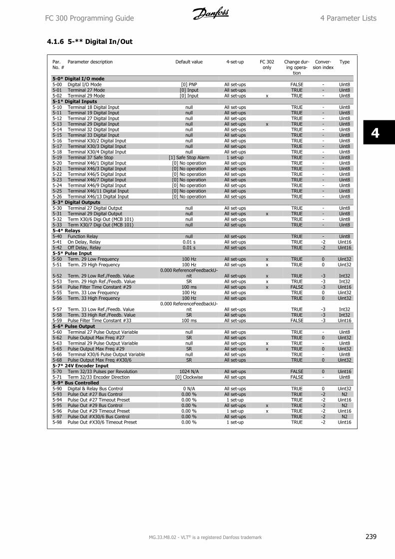
4.1.6 5-** Digital In/Out
Par.No. #
Parameter description Default value 4-set-up FC 302only
Change dur-ing opera-
tion
Conver-sion index
Type
5-0* Digital I/O mode5-00 Digital I/O Mode [0] PNP All set-ups FALSE - Uint85-01 Terminal 27 Mode [0] Input All set-ups TRUE - Uint85-02 Terminal 29 Mode [0] Input All set-ups x TRUE - Uint85-1* Digital Inputs5-10 Terminal 18 Digital Input null All set-ups TRUE - Uint85-11 Terminal 19 Digital Input null All set-ups TRUE - Uint85-12 Terminal 27 Digital Input null All set-ups TRUE - Uint85-13 Terminal 29 Digital Input null All set-ups x TRUE - Uint85-14 Terminal 32 Digital Input null All set-ups TRUE - Uint85-15 Terminal 33 Digital Input null All set-ups TRUE - Uint85-16 Terminal X30/2 Digital Input null All set-ups TRUE - Uint85-17 Terminal X30/3 Digital Input null All set-ups TRUE - Uint85-18 Terminal X30/4 Digital Input null All set-ups TRUE - Uint85-19 Terminal 37 Safe Stop [1] Safe Stop Alarm 1 set-up TRUE - Uint85-20 Terminal X46/1 Digital Input [0] No operation All set-ups TRUE - Uint85-21 Terminal X46/3 Digital Input [0] No operation All set-ups TRUE - Uint85-22 Terminal X46/5 Digital Input [0] No operation All set-ups TRUE - Uint85-23 Terminal X46/7 Digital Input [0] No operation All set-ups TRUE - Uint85-24 Terminal X46/9 Digital Input [0] No operation All set-ups TRUE - Uint85-25 Terminal X46/11 Digital Input [0] No operation All set-ups TRUE - Uint85-26 Terminal X46/13 Digital Input [0] No operation All set-ups TRUE - Uint85-3* Digital Outputs5-30 Terminal 27 Digital Output null All set-ups TRUE - Uint85-31 Terminal 29 Digital Output null All set-ups x TRUE - Uint85-32 Term X30/6 Digi Out (MCB 101) null All set-ups TRUE - Uint85-33 Term X30/7 Digi Out (MCB 101) null All set-ups TRUE - Uint85-4* Relays5-40 Function Relay null All set-ups TRUE - Uint85-41 On Delay, Relay 0.01 s All set-ups TRUE -2 Uint165-42 Off Delay, Relay 0.01 s All set-ups TRUE -2 Uint165-5* Pulse Input5-50 Term. 29 Low Frequency 100 Hz All set-ups x TRUE 0 Uint325-51 Term. 29 High Frequency 100 Hz All set-ups x TRUE 0 Uint32
5-52 Term. 29 Low Ref./Feedb. Value0.000 ReferenceFeedbackU-
nit All set-ups x TRUE -3 Int325-53 Term. 29 High Ref./Feedb. Value SR All set-ups x TRUE -3 Int325-54 Pulse Filter Time Constant #29 100 ms All set-ups x FALSE -3 Uint165-55 Term. 33 Low Frequency 100 Hz All set-ups TRUE 0 Uint325-56 Term. 33 High Frequency 100 Hz All set-ups TRUE 0 Uint32
5-57 Term. 33 Low Ref./Feedb. Value0.000 ReferenceFeedbackU-
nit All set-ups TRUE -3 Int325-58 Term. 33 High Ref./Feedb. Value SR All set-ups TRUE -3 Int325-59 Pulse Filter Time Constant #33 100 ms All set-ups FALSE -3 Uint165-6* Pulse Output5-60 Terminal 27 Pulse Output Variable null All set-ups TRUE - Uint85-62 Pulse Output Max Freq #27 SR All set-ups TRUE 0 Uint325-63 Terminal 29 Pulse Output Variable null All set-ups x TRUE - Uint85-65 Pulse Output Max Freq #29 SR All set-ups x TRUE 0 Uint325-66 Terminal X30/6 Pulse Output Variable null All set-ups TRUE - Uint85-68 Pulse Output Max Freq #X30/6 SR All set-ups TRUE 0 Uint325-7* 24V Encoder Input5-70 Term 32/33 Pulses per Revolution 1024 N/A All set-ups FALSE 0 Uint165-71 Term 32/33 Encoder Direction [0] Clockwise All set-ups FALSE - Uint85-9* Bus Controlled5-90 Digital & Relay Bus Control 0 N/A All set-ups TRUE 0 Uint325-93 Pulse Out #27 Bus Control 0.00 % All set-ups TRUE -2 N25-94 Pulse Out #27 Timeout Preset 0.00 % 1 set-up TRUE -2 Uint165-95 Pulse Out #29 Bus Control 0.00 % All set-ups x TRUE -2 N25-96 Pulse Out #29 Timeout Preset 0.00 % 1 set-up x TRUE -2 Uint165-97 Pulse Out #X30/6 Bus Control 0.00 % All set-ups TRUE -2 N25-98 Pulse Out #X30/6 Timeout Preset 0.00 % 1 set-up TRUE -2 Uint16
FC 300 Programming Guide 4 Parameter Lists
MG.33.M8.02 - VLT® is a registered Danfoss trademark 239
4
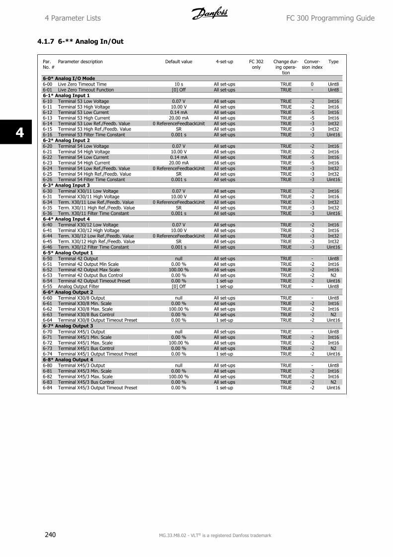
4.1.7 6-** Analog In/Out
Par.No. #
Parameter description Default value 4-set-up FC 302only
Change dur-ing opera-
tion
Conver-sion index
Type
6-0* Analog I/O Mode6-00 Live Zero Timeout Time 10 s All set-ups TRUE 0 Uint86-01 Live Zero Timeout Function [0] Off All set-ups TRUE - Uint86-1* Analog Input 16-10 Terminal 53 Low Voltage 0.07 V All set-ups TRUE -2 Int166-11 Terminal 53 High Voltage 10.00 V All set-ups TRUE -2 Int166-12 Terminal 53 Low Current 0.14 mA All set-ups TRUE -5 Int166-13 Terminal 53 High Current 20.00 mA All set-ups TRUE -5 Int166-14 Terminal 53 Low Ref./Feedb. Value 0 ReferenceFeedbackUnit All set-ups TRUE -3 Int326-15 Terminal 53 High Ref./Feedb. Value SR All set-ups TRUE -3 Int326-16 Terminal 53 Filter Time Constant 0.001 s All set-ups TRUE -3 Uint166-2* Analog Input 26-20 Terminal 54 Low Voltage 0.07 V All set-ups TRUE -2 Int166-21 Terminal 54 High Voltage 10.00 V All set-ups TRUE -2 Int166-22 Terminal 54 Low Current 0.14 mA All set-ups TRUE -5 Int166-23 Terminal 54 High Current 20.00 mA All set-ups TRUE -5 Int166-24 Terminal 54 Low Ref./Feedb. Value 0 ReferenceFeedbackUnit All set-ups TRUE -3 Int326-25 Terminal 54 High Ref./Feedb. Value SR All set-ups TRUE -3 Int326-26 Terminal 54 Filter Time Constant 0.001 s All set-ups TRUE -3 Uint166-3* Analog Input 36-30 Terminal X30/11 Low Voltage 0.07 V All set-ups TRUE -2 Int166-31 Terminal X30/11 High Voltage 10.00 V All set-ups TRUE -2 Int166-34 Term. X30/11 Low Ref./Feedb. Value 0 ReferenceFeedbackUnit All set-ups TRUE -3 Int326-35 Term. X30/11 High Ref./Feedb. Value SR All set-ups TRUE -3 Int326-36 Term. X30/11 Filter Time Constant 0.001 s All set-ups TRUE -3 Uint166-4* Analog Input 46-40 Terminal X30/12 Low Voltage 0.07 V All set-ups TRUE -2 Int166-41 Terminal X30/12 High Voltage 10.00 V All set-ups TRUE -2 Int166-44 Term. X30/12 Low Ref./Feedb. Value 0 ReferenceFeedbackUnit All set-ups TRUE -3 Int326-45 Term. X30/12 High Ref./Feedb. Value SR All set-ups TRUE -3 Int326-46 Term. X30/12 Filter Time Constant 0.001 s All set-ups TRUE -3 Uint166-5* Analog Output 16-50 Terminal 42 Output null All set-ups TRUE - Uint86-51 Terminal 42 Output Min Scale 0.00 % All set-ups TRUE -2 Int166-52 Terminal 42 Output Max Scale 100.00 % All set-ups TRUE -2 Int166-53 Terminal 42 Output Bus Control 0.00 % All set-ups TRUE -2 N26-54 Terminal 42 Output Timeout Preset 0.00 % 1 set-up TRUE -2 Uint166-55 Analog Output Filter [0] Off 1 set-up TRUE - Uint86-6* Analog Output 26-60 Terminal X30/8 Output null All set-ups TRUE - Uint86-61 Terminal X30/8 Min. Scale 0.00 % All set-ups TRUE -2 Int166-62 Terminal X30/8 Max. Scale 100.00 % All set-ups TRUE -2 Int166-63 Terminal X30/8 Bus Control 0.00 % All set-ups TRUE -2 N26-64 Terminal X30/8 Output Timeout Preset 0.00 % 1 set-up TRUE -2 Uint166-7* Analog Output 36-70 Terminal X45/1 Output null All set-ups TRUE - Uint86-71 Terminal X45/1 Min. Scale 0.00 % All set-ups TRUE -2 Int166-72 Terminal X45/1 Max. Scale 100.00 % All set-ups TRUE -2 Int166-73 Terminal X45/1 Bus Control 0.00 % All set-ups TRUE -2 N26-74 Terminal X45/1 Output Timeout Preset 0.00 % 1 set-up TRUE -2 Uint166-8* Analog Output 46-80 Terminal X45/3 Output null All set-ups TRUE - Uint86-81 Terminal X45/3 Min. Scale 0.00 % All set-ups TRUE -2 Int166-82 Terminal X45/3 Max. Scale 100.00 % All set-ups TRUE -2 Int166-83 Terminal X45/3 Bus Control 0.00 % All set-ups TRUE -2 N26-84 Terminal X45/3 Output Timeout Preset 0.00 % 1 set-up TRUE -2 Uint16
4 Parameter Lists FC 300 Programming Guide
240 MG.33.M8.02 - VLT® is a registered Danfoss trademark
4
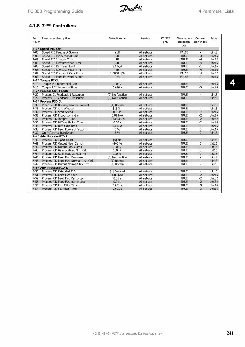
4.1.8 7-** Controllers
Par.No. #
Parameter description Default value 4-set-up FC 302only
Change dur-ing opera-
tion
Conver-sion index
Type
7-0* Speed PID Ctrl.7-00 Speed PID Feedback Source null All set-ups FALSE - Uint87-02 Speed PID Proportional Gain SR All set-ups TRUE -3 Uint167-03 Speed PID Integral Time SR All set-ups TRUE -4 Uint327-04 Speed PID Differentiation Time SR All set-ups TRUE -4 Uint167-05 Speed PID Diff. Gain Limit 5.0 N/A All set-ups TRUE -1 Uint167-06 Speed PID Lowpass Filter Time SR All set-ups TRUE -4 Uint167-07 Speed PID Feedback Gear Ratio 1.0000 N/A All set-ups FALSE -4 Uint327-08 Speed PID Feed Forward Factor 0 % All set-ups FALSE 0 Uint167-1* Torque PI Ctrl.7-12 Torque PI Proportional Gain 100 % All set-ups TRUE 0 Uint167-13 Torque PI Integration Time 0.020 s All set-ups TRUE -3 Uint167-2* Process Ctrl. Feedb7-20 Process CL Feedback 1 Resource [0] No function All set-ups TRUE - Uint87-22 Process CL Feedback 2 Resource [0] No function All set-ups TRUE - Uint87-3* Process PID Ctrl.7-30 Process PID Normal/ Inverse Control [0] Normal All set-ups TRUE - Uint87-31 Process PID Anti Windup [1] On All set-ups TRUE - Uint87-32 Process PID Start Speed 0 RPM All set-ups TRUE 67 Uint167-33 Process PID Proportional Gain 0.01 N/A All set-ups TRUE -2 Uint167-34 Process PID Integral Time 10000.00 s All set-ups TRUE -2 Uint327-35 Process PID Differentiation Time 0.00 s All set-ups TRUE -2 Uint167-36 Process PID Diff. Gain Limit 5.0 N/A All set-ups TRUE -1 Uint167-38 Process PID Feed Forward Factor 0 % All set-ups TRUE 0 Uint167-39 On Reference Bandwidth 5 % All set-ups TRUE 0 Uint87-4* Adv. Process PID I7-40 Process PID I-part Reset [0] No All set-ups TRUE - Uint87-41 Process PID Output Neg. Clamp -100 % All set-ups TRUE 0 Int167-42 Process PID Output Pos. Clamp 100 % All set-ups TRUE 0 Int167-43 Process PID Gain Scale at Min. Ref. 100 % All set-ups TRUE 0 Int167-44 Process PID Gain Scale at Max. Ref. 100 % All set-ups TRUE 0 Int167-45 Process PID Feed Fwd Resource [0] No function All set-ups TRUE - Uint87-46 Process PID Feed Fwd Normal/ Inv. Ctrl. [0] Normal All set-ups TRUE - Uint87-49 Process PID Output Normal/ Inv. Ctrl. [0] Normal All set-ups TRUE - Uint87-5* Adv. Process PID II7-50 Process PID Extended PID [1] Enabled All set-ups TRUE - Uint87-51 Process PID Feed Fwd Gain 1.00 N/A All set-ups TRUE -2 Uint167-52 Process PID Feed Fwd Ramp up 0.01 s All set-ups TRUE -2 Uint327-53 Process PID Feed Fwd Ramp down 0.01 s All set-ups TRUE -2 Uint327-56 Process PID Ref. Filter Time 0.001 s All set-ups TRUE -3 Uint167-57 Process PID Fb. Filter Time 0.001 s All set-ups TRUE -3 Uint16
FC 300 Programming Guide 4 Parameter Lists
MG.33.M8.02 - VLT® is a registered Danfoss trademark 241
4
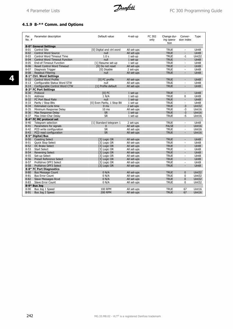
4.1.9 8-** Comm. and Options
Par.No. #
Parameter description Default value 4-set-up FC 302only
Change dur-ing opera-
tion
Conver-sion index
Type
8-0* General Settings8-01 Control Site [0] Digital and ctrl.word All set-ups TRUE - Uint88-02 Control Word Source null All set-ups TRUE - Uint88-03 Control Word Timeout Time 1.0 s 1 set-up TRUE -1 Uint328-04 Control Word Timeout Function null 1 set-up TRUE - Uint88-05 End-of-Timeout Function [1] Resume set-up 1 set-up TRUE - Uint88-06 Reset Control Word Timeout [0] Do not reset All set-ups TRUE - Uint88-07 Diagnosis Trigger [0] Disable 2 set-ups TRUE - Uint88-08 Readout Filtering null All set-ups TRUE - Uint88-1* Ctrl. Word Settings8-10 Control Word Profile [0] FC profile All set-ups TRUE - Uint88-13 Configurable Status Word STW null All set-ups TRUE - Uint88-14 Configurable Control Word CTW [1] Profile default All set-ups TRUE - Uint88-3* FC Port Settings8-30 Protocol [0] FC 1 set-up TRUE - Uint88-31 Address 1 N/A 1 set-up TRUE 0 Uint88-32 FC Port Baud Rate null 1 set-up TRUE - Uint88-33 Parity / Stop Bits [0] Even Parity, 1 Stop Bit 1 set-up TRUE - Uint88-34 Estimated cycle time 0 ms 2 set-ups TRUE -3 Uint328-35 Minimum Response Delay 10 ms All set-ups TRUE -3 Uint168-36 Max Response Delay SR 1 set-up TRUE -3 Uint168-37 Max Inter-Char Delay SR 1 set-up TRUE -5 Uint168-4* FC MC protocol set8-40 Telegram selection [1] Standard telegram 1 2 set-ups TRUE - Uint88-41 Parameters for signals 0 All set-ups FALSE - Uint168-42 PCD write configuration SR All set-ups TRUE - Uint168-43 PCD read configuration SR All set-ups TRUE - Uint168-5* Digital/Bus8-50 Coasting Select [3] Logic OR All set-ups TRUE - Uint88-51 Quick Stop Select [3] Logic OR All set-ups TRUE - Uint88-52 DC Brake Select [3] Logic OR All set-ups TRUE - Uint88-53 Start Select [3] Logic OR All set-ups TRUE - Uint88-54 Reversing Select [3] Logic OR All set-ups TRUE - Uint88-55 Set-up Select [3] Logic OR All set-ups TRUE - Uint88-56 Preset Reference Select [3] Logic OR All set-ups TRUE - Uint88-57 Profidrive OFF2 Select [3] Logic OR All set-ups TRUE - Uint88-58 Profidrive OFF3 Select [3] Logic OR All set-ups TRUE - Uint88-8* FC Port Diagnostics8-80 Bus Message Count 0 N/A All set-ups TRUE 0 Uint328-81 Bus Error Count 0 N/A All set-ups TRUE 0 Uint328-82 Slave Messages Rcvd 0 N/A All set-ups TRUE 0 Uint328-83 Slave Error Count 0 N/A All set-ups TRUE 0 Uint328-9* Bus Jog8-90 Bus Jog 1 Speed 100 RPM All set-ups TRUE 67 Uint168-91 Bus Jog 2 Speed 200 RPM All set-ups TRUE 67 Uint16
4 Parameter Lists FC 300 Programming Guide
242 MG.33.M8.02 - VLT® is a registered Danfoss trademark
4
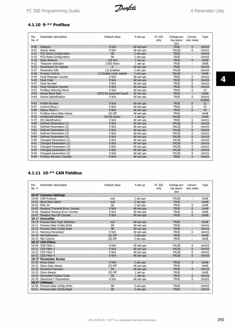
4.1.10 9-** Profibus
Par.No. #
Parameter description Default value 4-set-up FC 302only
Change dur-ing opera-
tion
Conver-sion index
Type
9-00 Setpoint 0 N/A All set-ups TRUE 0 Uint169-07 Actual Value 0 N/A All set-ups FALSE 0 Uint169-15 PCD Write Configuration SR 2 set-ups TRUE - Uint169-16 PCD Read Configuration SR 2 set-ups TRUE - Uint169-18 Node Address 126 N/A 1 set-up TRUE 0 Uint89-22 Telegram Selection [100] None 1 set-up TRUE - Uint89-23 Parameters for Signals 0 All set-ups TRUE - Uint169-27 Parameter Edit [1] Enabled 2 set-ups FALSE - Uint169-28 Process Control [1] Enable cyclic master 2 set-ups FALSE - Uint89-44 Fault Message Counter 0 N/A All set-ups TRUE 0 Uint169-45 Fault Code 0 N/A All set-ups TRUE 0 Uint169-47 Fault Number 0 N/A All set-ups TRUE 0 Uint169-52 Fault Situation Counter 0 N/A All set-ups TRUE 0 Uint169-53 Profibus Warning Word 0 N/A All set-ups TRUE 0 V29-63 Actual Baud Rate [255] No baudrate found All set-ups TRUE - Uint89-64 Device Identification 0 N/A All set-ups TRUE 0 Uint16
9-65 Profile Number 0 N/A All set-ups TRUE 0OctStr[
2]9-67 Control Word 1 0 N/A All set-ups TRUE 0 V29-68 Status Word 1 0 N/A All set-ups TRUE 0 V29-71 Profibus Save Data Values [0] Off All set-ups TRUE - Uint89-72 ProfibusDriveReset [0] No action 1 set-up FALSE - Uint89-75 DO Identification 0 N/A All set-ups TRUE 0 Uint169-80 Defined Parameters (1) 0 N/A All set-ups FALSE 0 Uint169-81 Defined Parameters (2) 0 N/A All set-ups FALSE 0 Uint169-82 Defined Parameters (3) 0 N/A All set-ups FALSE 0 Uint169-83 Defined Parameters (4) 0 N/A All set-ups FALSE 0 Uint169-84 Defined Parameters (5) 0 N/A All set-ups FALSE 0 Uint169-90 Changed Parameters (1) 0 N/A All set-ups FALSE 0 Uint169-91 Changed Parameters (2) 0 N/A All set-ups FALSE 0 Uint169-92 Changed Parameters (3) 0 N/A All set-ups FALSE 0 Uint169-93 Changed parameters (4) 0 N/A All set-ups FALSE 0 Uint169-94 Changed parameters (5) 0 N/A All set-ups FALSE 0 Uint169-99 Profibus Revision Counter 0 N/A All set-ups TRUE 0 Uint16
4.1.11 10-** CAN Fieldbus
Par.No. #
Parameter description Default value 4-set-up FC 302only
Change dur-ing opera-
tion
Conver-sion index
Type
10-0* Common Settings10-00 CAN Protocol null 2 set-ups FALSE - Uint810-01 Baud Rate Select null 2 set-ups TRUE - Uint810-02 MAC ID SR 2 set-ups TRUE 0 Uint810-05 Readout Transmit Error Counter 0 N/A All set-ups TRUE 0 Uint810-06 Readout Receive Error Counter 0 N/A All set-ups TRUE 0 Uint810-07 Readout Bus Off Counter 0 N/A All set-ups TRUE 0 Uint810-1* DeviceNet10-10 Process Data Type Selection null All set-ups TRUE - Uint810-11 Process Data Config Write SR All set-ups TRUE - Uint1610-12 Process Data Config Read SR All set-ups TRUE - Uint1610-13 Warning Parameter 0 N/A All set-ups TRUE 0 Uint1610-14 Net Reference [0] Off 2 set-ups TRUE - Uint810-15 Net Control [0] Off 2 set-ups TRUE - Uint810-2* COS Filters10-20 COS Filter 1 0 N/A All set-ups FALSE 0 Uint1610-21 COS Filter 2 0 N/A All set-ups FALSE 0 Uint1610-22 COS Filter 3 0 N/A All set-ups FALSE 0 Uint1610-23 COS Filter 4 0 N/A All set-ups FALSE 0 Uint1610-3* Parameter Access10-30 Array Index 0 N/A 2 set-ups TRUE 0 Uint810-31 Store Data Values [0] Off All set-ups TRUE - Uint810-32 Devicenet Revision SR All set-ups TRUE 0 Uint1610-33 Store Always [0] Off 1 set-up TRUE - Uint810-34 DeviceNet Product Code SR 1 set-up TRUE 0 Uint1610-39 Devicenet F Parameters 0 N/A All set-ups TRUE 0 Uint3210-5* CANopen10-50 Process Data Config Write. SR 2 set-ups TRUE - Uint1610-51 Process Data Config Read. SR 2 set-ups TRUE - Uint16
FC 300 Programming Guide 4 Parameter Lists
MG.33.M8.02 - VLT® is a registered Danfoss trademark 243
4
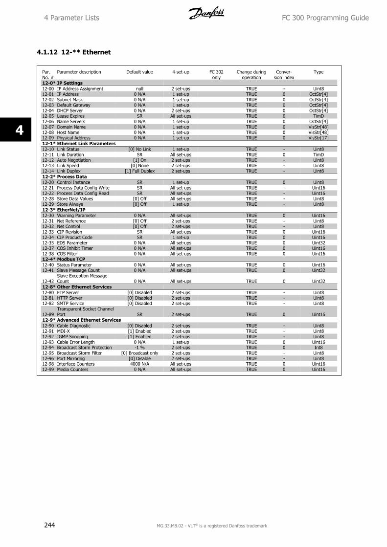
4.1.12 12-** Ethernet
Par.No. #
Parameter description Default value 4-set-up FC 302only
Change duringoperation
Conver-sion index
Type
12-0* IP Settings12-00 IP Address Assignment null 2 set-ups TRUE - Uint812-01 IP Address 0 N/A 1 set-up TRUE 0 OctStr[4]12-02 Subnet Mask 0 N/A 1 set-up TRUE 0 OctStr[4]12-03 Default Gateway 0 N/A 1 set-up TRUE 0 OctStr[4]12-04 DHCP Server 0 N/A 2 set-ups TRUE 0 OctStr[4]12-05 Lease Expires SR All set-ups TRUE 0 TimD12-06 Name Servers 0 N/A 1 set-up TRUE 0 OctStr[4]12-07 Domain Name 0 N/A 1 set-up TRUE 0 VisStr[48]12-08 Host Name 0 N/A 1 set-up TRUE 0 VisStr[48]12-09 Physical Address 0 N/A 1 set-up TRUE 0 VisStr[17]12-1* Ethernet Link Parameters12-10 Link Status [0] No Link 1 set-up TRUE - Uint812-11 Link Duration SR All set-ups TRUE 0 TimD12-12 Auto Negotiation [1] On 2 set-ups TRUE - Uint812-13 Link Speed [0] None 2 set-ups TRUE - Uint812-14 Link Duplex [1] Full Duplex 2 set-ups TRUE - Uint812-2* Process Data12-20 Control Instance SR 1 set-up TRUE 0 Uint812-21 Process Data Config Write SR All set-ups TRUE - Uint1612-22 Process Data Config Read SR All set-ups TRUE - Uint1612-28 Store Data Values [0] Off All set-ups TRUE - Uint812-29 Store Always [0] Off 1 set-up TRUE - Uint812-3* EtherNet/IP12-30 Warning Parameter 0 N/A All set-ups TRUE 0 Uint1612-31 Net Reference [0] Off 2 set-ups TRUE - Uint812-32 Net Control [0] Off 2 set-ups TRUE - Uint812-33 CIP Revision SR All set-ups TRUE 0 Uint1612-34 CIP Product Code SR 1 set-up TRUE 0 Uint1612-35 EDS Parameter 0 N/A All set-ups TRUE 0 Uint3212-37 COS Inhibit Timer 0 N/A All set-ups TRUE 0 Uint1612-38 COS Filter 0 N/A All set-ups TRUE 0 Uint1612-4* Modbus TCP12-40 Status Parameter 0 N/A All set-ups TRUE 0 Uint1612-41 Slave Message Count 0 N/A All set-ups TRUE 0 Uint32
12-42Slave Exception MessageCount 0 N/A All set-ups TRUE 0 Uint32
12-8* Other Ethernet Services12-80 FTP Server [0] Disabled 2 set-ups TRUE - Uint812-81 HTTP Server [0] Disabled 2 set-ups TRUE - Uint812-82 SMTP Service [0] Disabled 2 set-ups TRUE - Uint8
12-89Transparent Socket ChannelPort SR 2 set-ups TRUE 0 Uint16
12-9* Advanced Ethernet Services12-90 Cable Diagnostic [0] Disabled 2 set-ups TRUE - Uint812-91 MDI-X [1] Enabled 2 set-ups TRUE - Uint812-92 IGMP Snooping [1] Enabled 2 set-ups TRUE - Uint812-93 Cable Error Length 0 N/A 1 set-up TRUE 0 Uint1612-94 Broadcast Storm Protection -1 % 2 set-ups TRUE 0 Int812-95 Broadcast Storm Filter [0] Broadcast only 2 set-ups TRUE - Uint812-96 Port Mirroring [0] Disable 2 set-ups TRUE - Uint812-98 Interface Counters 4000 N/A All set-ups TRUE 0 Uint1612-99 Media Counters 0 N/A All set-ups TRUE 0 Uint16
4 Parameter Lists FC 300 Programming Guide
244 MG.33.M8.02 - VLT® is a registered Danfoss trademark
4
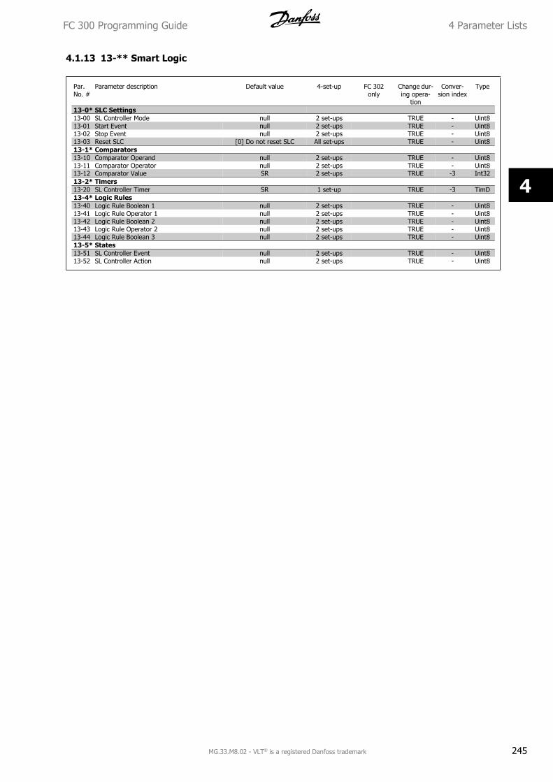
4.1.13 13-** Smart Logic
Par.No. #
Parameter description Default value 4-set-up FC 302only
Change dur-ing opera-
tion
Conver-sion index
Type
13-0* SLC Settings13-00 SL Controller Mode null 2 set-ups TRUE - Uint813-01 Start Event null 2 set-ups TRUE - Uint813-02 Stop Event null 2 set-ups TRUE - Uint813-03 Reset SLC [0] Do not reset SLC All set-ups TRUE - Uint813-1* Comparators13-10 Comparator Operand null 2 set-ups TRUE - Uint813-11 Comparator Operator null 2 set-ups TRUE - Uint813-12 Comparator Value SR 2 set-ups TRUE -3 Int3213-2* Timers13-20 SL Controller Timer SR 1 set-up TRUE -3 TimD13-4* Logic Rules13-40 Logic Rule Boolean 1 null 2 set-ups TRUE - Uint813-41 Logic Rule Operator 1 null 2 set-ups TRUE - Uint813-42 Logic Rule Boolean 2 null 2 set-ups TRUE - Uint813-43 Logic Rule Operator 2 null 2 set-ups TRUE - Uint813-44 Logic Rule Boolean 3 null 2 set-ups TRUE - Uint813-5* States13-51 SL Controller Event null 2 set-ups TRUE - Uint813-52 SL Controller Action null 2 set-ups TRUE - Uint8
FC 300 Programming Guide 4 Parameter Lists
MG.33.M8.02 - VLT® is a registered Danfoss trademark 245
4
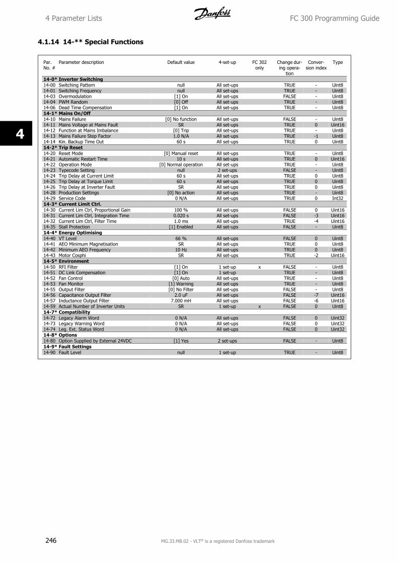
4.1.14 14-** Special Functions
Par.No. #
Parameter description Default value 4-set-up FC 302only
Change dur-ing opera-
tion
Conver-sion index
Type
14-0* Inverter Switching14-00 Switching Pattern null All set-ups TRUE - Uint814-01 Switching Frequency null All set-ups TRUE - Uint814-03 Overmodulation [1] On All set-ups FALSE - Uint814-04 PWM Random [0] Off All set-ups TRUE - Uint814-06 Dead Time Compensation [1] On All set-ups TRUE - Uint814-1* Mains On/Off14-10 Mains Failure [0] No function All set-ups FALSE - Uint814-11 Mains Voltage at Mains Fault SR All set-ups TRUE 0 Uint1614-12 Function at Mains Imbalance [0] Trip All set-ups TRUE - Uint814-13 Mains Failure Step Factor 1.0 N/A All set-ups TRUE -1 Uint814-14 Kin. Backup Time Out 60 s All set-ups TRUE 0 Uint814-2* Trip Reset14-20 Reset Mode [0] Manual reset All set-ups TRUE - Uint814-21 Automatic Restart Time 10 s All set-ups TRUE 0 Uint1614-22 Operation Mode [0] Normal operation All set-ups TRUE - Uint814-23 Typecode Setting null 2 set-ups FALSE - Uint814-24 Trip Delay at Current Limit 60 s All set-ups TRUE 0 Uint814-25 Trip Delay at Torque Limit 60 s All set-ups TRUE 0 Uint814-26 Trip Delay at Inverter Fault SR All set-ups TRUE 0 Uint814-28 Production Settings [0] No action All set-ups TRUE - Uint814-29 Service Code 0 N/A All set-ups TRUE 0 Int3214-3* Current Limit Ctrl.14-30 Current Lim Ctrl, Proportional Gain 100 % All set-ups FALSE 0 Uint1614-31 Current Lim Ctrl, Integration Time 0.020 s All set-ups FALSE -3 Uint1614-32 Current Lim Ctrl, Filter Time 1.0 ms All set-ups TRUE -4 Uint1614-35 Stall Protection [1] Enabled All set-ups FALSE - Uint814-4* Energy Optimising14-40 VT Level 66 % All set-ups FALSE 0 Uint814-41 AEO Minimum Magnetisation SR All set-ups TRUE 0 Uint814-42 Minimum AEO Frequency 10 Hz All set-ups TRUE 0 Uint814-43 Motor Cosphi SR All set-ups TRUE -2 Uint1614-5* Environment14-50 RFI Filter [1] On 1 set-up x FALSE - Uint814-51 DC Link Compensation [1] On 1 set-up TRUE - Uint814-52 Fan Control [0] Auto All set-ups TRUE - Uint814-53 Fan Monitor [1] Warning All set-ups TRUE - Uint814-55 Output Filter [0] No Filter All set-ups FALSE - Uint814-56 Capacitance Output Filter 2.0 uF All set-ups FALSE -7 Uint1614-57 Inductance Output Filter 7.000 mH All set-ups FALSE -6 Uint1614-59 Actual Number of Inverter Units SR 1 set-up x FALSE 0 Uint814-7* Compatibility14-72 Legacy Alarm Word 0 N/A All set-ups FALSE 0 Uint3214-73 Legacy Warning Word 0 N/A All set-ups FALSE 0 Uint3214-74 Leg. Ext. Status Word 0 N/A All set-ups FALSE 0 Uint3214-8* Options14-80 Option Supplied by External 24VDC [1] Yes 2 set-ups FALSE - Uint814-9* Fault Settings14-90 Fault Level null 1 set-up TRUE - Uint8
4 Parameter Lists FC 300 Programming Guide
246 MG.33.M8.02 - VLT® is a registered Danfoss trademark
4
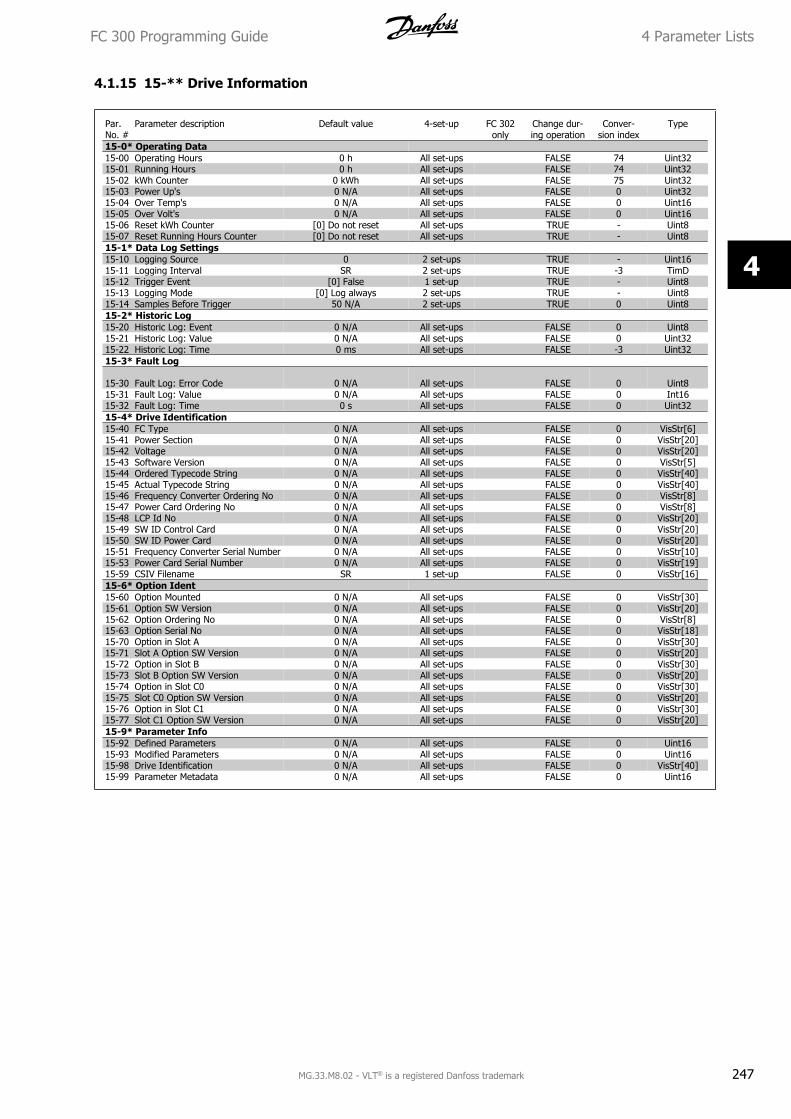
4.1.15 15-** Drive Information
Par.No. #
Parameter description Default value 4-set-up FC 302only
Change dur-ing operation
Conver-sion index
Type
15-0* Operating Data15-00 Operating Hours 0 h All set-ups FALSE 74 Uint3215-01 Running Hours 0 h All set-ups FALSE 74 Uint3215-02 kWh Counter 0 kWh All set-ups FALSE 75 Uint3215-03 Power Up's 0 N/A All set-ups FALSE 0 Uint3215-04 Over Temp's 0 N/A All set-ups FALSE 0 Uint1615-05 Over Volt's 0 N/A All set-ups FALSE 0 Uint1615-06 Reset kWh Counter [0] Do not reset All set-ups TRUE - Uint815-07 Reset Running Hours Counter [0] Do not reset All set-ups TRUE - Uint815-1* Data Log Settings15-10 Logging Source 0 2 set-ups TRUE - Uint1615-11 Logging Interval SR 2 set-ups TRUE -3 TimD15-12 Trigger Event [0] False 1 set-up TRUE - Uint815-13 Logging Mode [0] Log always 2 set-ups TRUE - Uint815-14 Samples Before Trigger 50 N/A 2 set-ups TRUE 0 Uint815-2* Historic Log15-20 Historic Log: Event 0 N/A All set-ups FALSE 0 Uint815-21 Historic Log: Value 0 N/A All set-ups FALSE 0 Uint3215-22 Historic Log: Time 0 ms All set-ups FALSE -3 Uint3215-3* Fault Log
15-30 Fault Log: Error Code 0 N/A All set-ups FALSE 0 Uint815-31 Fault Log: Value 0 N/A All set-ups FALSE 0 Int1615-32 Fault Log: Time 0 s All set-ups FALSE 0 Uint3215-4* Drive Identification15-40 FC Type 0 N/A All set-ups FALSE 0 VisStr[6]15-41 Power Section 0 N/A All set-ups FALSE 0 VisStr[20]15-42 Voltage 0 N/A All set-ups FALSE 0 VisStr[20]15-43 Software Version 0 N/A All set-ups FALSE 0 VisStr[5]15-44 Ordered Typecode String 0 N/A All set-ups FALSE 0 VisStr[40]15-45 Actual Typecode String 0 N/A All set-ups FALSE 0 VisStr[40]15-46 Frequency Converter Ordering No 0 N/A All set-ups FALSE 0 VisStr[8]15-47 Power Card Ordering No 0 N/A All set-ups FALSE 0 VisStr[8]15-48 LCP Id No 0 N/A All set-ups FALSE 0 VisStr[20]15-49 SW ID Control Card 0 N/A All set-ups FALSE 0 VisStr[20]15-50 SW ID Power Card 0 N/A All set-ups FALSE 0 VisStr[20]15-51 Frequency Converter Serial Number 0 N/A All set-ups FALSE 0 VisStr[10]15-53 Power Card Serial Number 0 N/A All set-ups FALSE 0 VisStr[19]15-59 CSIV Filename SR 1 set-up FALSE 0 VisStr[16]15-6* Option Ident15-60 Option Mounted 0 N/A All set-ups FALSE 0 VisStr[30]15-61 Option SW Version 0 N/A All set-ups FALSE 0 VisStr[20]15-62 Option Ordering No 0 N/A All set-ups FALSE 0 VisStr[8]15-63 Option Serial No 0 N/A All set-ups FALSE 0 VisStr[18]15-70 Option in Slot A 0 N/A All set-ups FALSE 0 VisStr[30]15-71 Slot A Option SW Version 0 N/A All set-ups FALSE 0 VisStr[20]15-72 Option in Slot B 0 N/A All set-ups FALSE 0 VisStr[30]15-73 Slot B Option SW Version 0 N/A All set-ups FALSE 0 VisStr[20]15-74 Option in Slot C0 0 N/A All set-ups FALSE 0 VisStr[30]15-75 Slot C0 Option SW Version 0 N/A All set-ups FALSE 0 VisStr[20]15-76 Option in Slot C1 0 N/A All set-ups FALSE 0 VisStr[30]15-77 Slot C1 Option SW Version 0 N/A All set-ups FALSE 0 VisStr[20]15-9* Parameter Info15-92 Defined Parameters 0 N/A All set-ups FALSE 0 Uint1615-93 Modified Parameters 0 N/A All set-ups FALSE 0 Uint1615-98 Drive Identification 0 N/A All set-ups FALSE 0 VisStr[40]15-99 Parameter Metadata 0 N/A All set-ups FALSE 0 Uint16
FC 300 Programming Guide 4 Parameter Lists
MG.33.M8.02 - VLT® is a registered Danfoss trademark 247
4
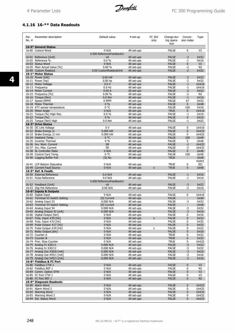
4.1.16 16-** Data Readouts
Par.No. #
Parameter description Default value 4-set-up FC 302only
Change dur-ing opera-
tion
Conver-sion index
Type
16-0* General Status16-00 Control Word 0 N/A All set-ups FALSE 0 V2
16-01 Reference [Unit]0.000 ReferenceFeedbackU-
nit All set-ups FALSE -3 Int3216-02 Reference % 0.0 % All set-ups FALSE -1 Int1616-03 Status Word 0 N/A All set-ups FALSE 0 V216-05 Main Actual Value [%] 0.00 % All set-ups FALSE -2 N216-09 Custom Readout 0.00 CustomReadoutUnit All set-ups FALSE -2 Int3216-1* Motor Status16-10 Power [kW] 0.00 kW All set-ups FALSE -2 Int3216-11 Power [hp] 0.00 hp All set-ups FALSE -2 Int3216-12 Motor Voltage 0.0 V All set-ups FALSE -1 Uint1616-13 Frequency 0.0 Hz All set-ups FALSE -1 Uint1616-14 Motor Current 0.00 A All set-ups FALSE -2 Int3216-15 Frequency [%] 0.00 % All set-ups FALSE -2 N216-16 Torque [Nm] 0.0 Nm All set-ups FALSE -1 Int1616-17 Speed [RPM] 0 RPM All set-ups FALSE 67 Int3216-18 Motor Thermal 0 % All set-ups FALSE 0 Uint816-19 KTY sensor temperature 0 °C All set-ups FALSE 100 Int1616-20 Motor Angle 0 N/A All set-ups TRUE 0 Uint1616-21 Torque [%] High Res. 0.0 % All set-ups FALSE -1 Int1616-22 Torque [%] 0 % All set-ups FALSE 0 Int1616-25 Torque [Nm] High 0.0 Nm All set-ups FALSE -1 Int3216-3* Drive Status16-30 DC Link Voltage 0 V All set-ups FALSE 0 Uint1616-32 Brake Energy /s 0.000 kW All set-ups FALSE 0 Uint3216-33 Brake Energy /2 min 0.000 kW All set-ups FALSE 0 Uint3216-34 Heatsink Temp. 0 °C All set-ups FALSE 100 Uint816-35 Inverter Thermal 0 % All set-ups FALSE 0 Uint816-36 Inv. Nom. Current SR All set-ups FALSE -2 Uint3216-37 Inv. Max. Current SR All set-ups FALSE -2 Uint3216-38 SL Controller State 0 N/A All set-ups FALSE 0 Uint816-39 Control Card Temp. 0 °C All set-ups FALSE 100 Uint816-40 Logging Buffer Full [0] No All set-ups TRUE - Uint8
16-41 LCP Bottom Statusline 0 N/A All set-ups TRUE 0VisStr[
50]16-49 Current Fault Source 0 N/A All set-ups x TRUE 0 Uint816-5* Ref. & Feedb.16-50 External Reference 0.0 N/A All set-ups FALSE -1 Int1616-51 Pulse Reference 0.0 N/A All set-ups FALSE -1 Int16
16-52 Feedback [Unit]0.000 ReferenceFeedbackU-
nit All set-ups FALSE -3 Int3216-53 Digi Pot Reference 0.00 N/A All set-ups FALSE -2 Int1616-6* Inputs & Outputs16-60 Digital Input 0 N/A All set-ups FALSE 0 Uint1616-61 Terminal 53 Switch Setting [0] Current All set-ups FALSE - Uint816-62 Analog Input 53 0.000 N/A All set-ups FALSE -3 Int3216-63 Terminal 54 Switch Setting [0] Current All set-ups FALSE - Uint816-64 Analog Input 54 0.000 N/A All set-ups FALSE -3 Int3216-65 Analog Output 42 [mA] 0.000 N/A All set-ups FALSE -3 Int1616-66 Digital Output [bin] 0 N/A All set-ups FALSE 0 Int1616-67 Freq. Input #29 [Hz] 0 N/A All set-ups x FALSE 0 Int3216-68 Freq. Input #33 [Hz] 0 N/A All set-ups FALSE 0 Int3216-69 Pulse Output #27 [Hz] 0 N/A All set-ups FALSE 0 Int3216-70 Pulse Output #29 [Hz] 0 N/A All set-ups x FALSE 0 Int3216-71 Relay Output [bin] 0 N/A All set-ups FALSE 0 Int1616-72 Counter A 0 N/A All set-ups TRUE 0 Int3216-73 Counter B 0 N/A All set-ups TRUE 0 Int3216-74 Prec. Stop Counter 0 N/A All set-ups TRUE 0 Uint3216-75 Analog In X30/11 0.000 N/A All set-ups FALSE -3 Int3216-76 Analog In X30/12 0.000 N/A All set-ups FALSE -3 Int3216-77 Analog Out X30/8 [mA] 0.000 N/A All set-ups FALSE -3 Int1616-78 Analog Out X45/1 [mA] 0.000 N/A All set-ups FALSE -3 Int1616-79 Analog Out X45/3 [mA] 0.000 N/A All set-ups FALSE -3 Int1616-8* Fieldbus & FC Port16-80 Fieldbus CTW 1 0 N/A All set-ups FALSE 0 V216-82 Fieldbus REF 1 0 N/A All set-ups FALSE 0 N216-84 Comm. Option STW 0 N/A All set-ups FALSE 0 V216-85 FC Port CTW 1 0 N/A All set-ups FALSE 0 V216-86 FC Port REF 1 0 N/A All set-ups FALSE 0 N216-9* Diagnosis Readouts16-90 Alarm Word 0 N/A All set-ups FALSE 0 Uint3216-91 Alarm Word 2 0 N/A All set-ups FALSE 0 Uint3216-92 Warning Word 0 N/A All set-ups FALSE 0 Uint3216-93 Warning Word 2 0 N/A All set-ups FALSE 0 Uint3216-94 Ext. Status Word 0 N/A All set-ups FALSE 0 Uint32
4 Parameter Lists FC 300 Programming Guide
248 MG.33.M8.02 - VLT® is a registered Danfoss trademark
4
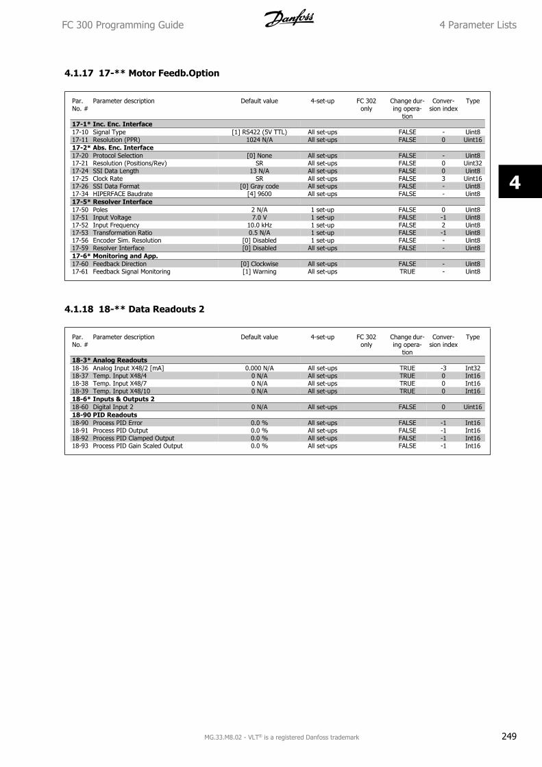
4.1.17 17-** Motor Feedb.Option
Par.No. #
Parameter description Default value 4-set-up FC 302only
Change dur-ing opera-
tion
Conver-sion index
Type
17-1* Inc. Enc. Interface17-10 Signal Type [1] RS422 (5V TTL) All set-ups FALSE - Uint817-11 Resolution (PPR) 1024 N/A All set-ups FALSE 0 Uint1617-2* Abs. Enc. Interface17-20 Protocol Selection [0] None All set-ups FALSE - Uint817-21 Resolution (Positions/Rev) SR All set-ups FALSE 0 Uint3217-24 SSI Data Length 13 N/A All set-ups FALSE 0 Uint817-25 Clock Rate SR All set-ups FALSE 3 Uint1617-26 SSI Data Format [0] Gray code All set-ups FALSE - Uint817-34 HIPERFACE Baudrate [4] 9600 All set-ups FALSE - Uint817-5* Resolver Interface17-50 Poles 2 N/A 1 set-up FALSE 0 Uint817-51 Input Voltage 7.0 V 1 set-up FALSE -1 Uint817-52 Input Frequency 10.0 kHz 1 set-up FALSE 2 Uint817-53 Transformation Ratio 0.5 N/A 1 set-up FALSE -1 Uint817-56 Encoder Sim. Resolution [0] Disabled 1 set-up FALSE - Uint817-59 Resolver Interface [0] Disabled All set-ups FALSE - Uint817-6* Monitoring and App.17-60 Feedback Direction [0] Clockwise All set-ups FALSE - Uint817-61 Feedback Signal Monitoring [1] Warning All set-ups TRUE - Uint8
4.1.18 18-** Data Readouts 2
Par.No. #
Parameter description Default value 4-set-up FC 302only
Change dur-ing opera-
tion
Conver-sion index
Type
18-3* Analog Readouts18-36 Analog Input X48/2 [mA] 0.000 N/A All set-ups TRUE -3 Int3218-37 Temp. Input X48/4 0 N/A All set-ups TRUE 0 Int1618-38 Temp. Input X48/7 0 N/A All set-ups TRUE 0 Int1618-39 Temp. Input X48/10 0 N/A All set-ups TRUE 0 Int1618-6* Inputs & Outputs 218-60 Digital Input 2 0 N/A All set-ups FALSE 0 Uint1618-90 PID Readouts18-90 Process PID Error 0.0 % All set-ups FALSE -1 Int1618-91 Process PID Output 0.0 % All set-ups FALSE -1 Int1618-92 Process PID Clamped Output 0.0 % All set-ups FALSE -1 Int1618-93 Process PID Gain Scaled Output 0.0 % All set-ups FALSE -1 Int16
FC 300 Programming Guide 4 Parameter Lists
MG.33.M8.02 - VLT® is a registered Danfoss trademark 249
4
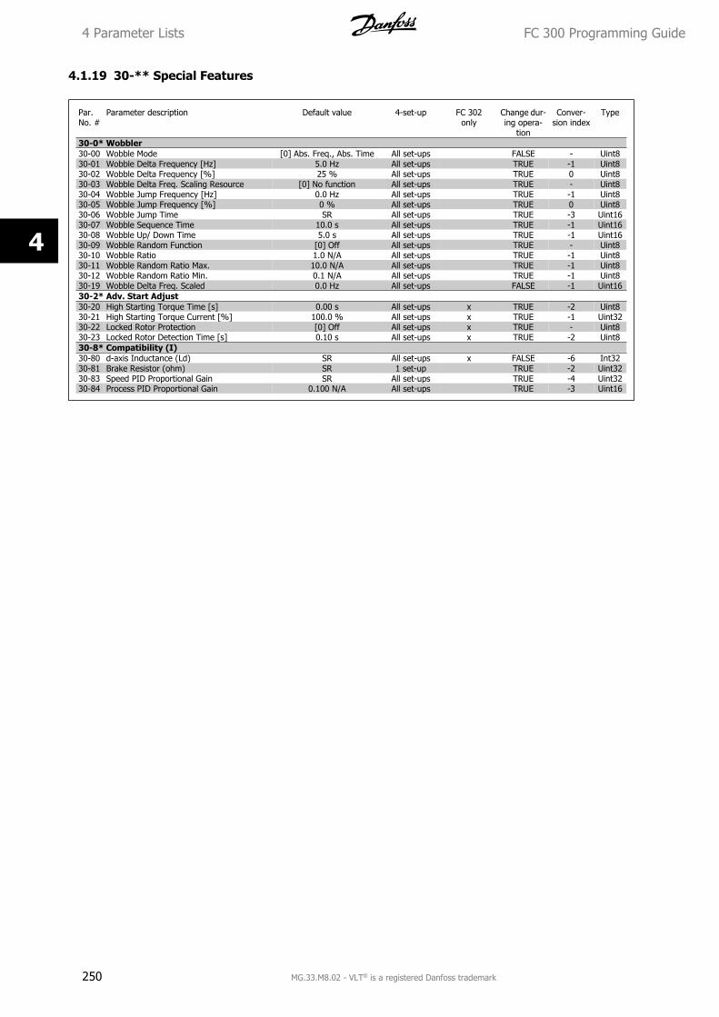
4.1.19 30-** Special Features
Par.No. #
Parameter description Default value 4-set-up FC 302only
Change dur-ing opera-
tion
Conver-sion index
Type
30-0* Wobbler30-00 Wobble Mode [0] Abs. Freq., Abs. Time All set-ups FALSE - Uint830-01 Wobble Delta Frequency [Hz] 5.0 Hz All set-ups TRUE -1 Uint830-02 Wobble Delta Frequency [%] 25 % All set-ups TRUE 0 Uint830-03 Wobble Delta Freq. Scaling Resource [0] No function All set-ups TRUE - Uint830-04 Wobble Jump Frequency [Hz] 0.0 Hz All set-ups TRUE -1 Uint830-05 Wobble Jump Frequency [%] 0 % All set-ups TRUE 0 Uint830-06 Wobble Jump Time SR All set-ups TRUE -3 Uint1630-07 Wobble Sequence Time 10.0 s All set-ups TRUE -1 Uint1630-08 Wobble Up/ Down Time 5.0 s All set-ups TRUE -1 Uint1630-09 Wobble Random Function [0] Off All set-ups TRUE - Uint830-10 Wobble Ratio 1.0 N/A All set-ups TRUE -1 Uint830-11 Wobble Random Ratio Max. 10.0 N/A All set-ups TRUE -1 Uint830-12 Wobble Random Ratio Min. 0.1 N/A All set-ups TRUE -1 Uint830-19 Wobble Delta Freq. Scaled 0.0 Hz All set-ups FALSE -1 Uint1630-2* Adv. Start Adjust30-20 High Starting Torque Time [s] 0.00 s All set-ups x TRUE -2 Uint830-21 High Starting Torque Current [%] 100.0 % All set-ups x TRUE -1 Uint3230-22 Locked Rotor Protection [0] Off All set-ups x TRUE - Uint830-23 Locked Rotor Detection Time [s] 0.10 s All set-ups x TRUE -2 Uint830-8* Compatibility (I)30-80 d-axis Inductance (Ld) SR All set-ups x FALSE -6 Int3230-81 Brake Resistor (ohm) SR 1 set-up TRUE -2 Uint3230-83 Speed PID Proportional Gain SR All set-ups TRUE -4 Uint3230-84 Process PID Proportional Gain 0.100 N/A All set-ups TRUE -3 Uint16
4 Parameter Lists FC 300 Programming Guide
250 MG.33.M8.02 - VLT® is a registered Danfoss trademark
4
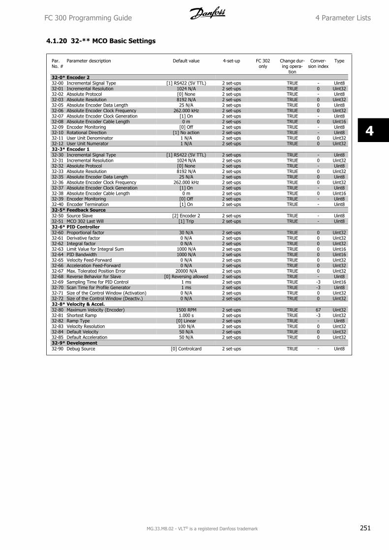
4.1.20 32-** MCO Basic Settings
Par.No. #
Parameter description Default value 4-set-up FC 302only
Change dur-ing opera-
tion
Conver-sion index
Type
32-0* Encoder 232-00 Incremental Signal Type [1] RS422 (5V TTL) 2 set-ups TRUE - Uint832-01 Incremental Resolution 1024 N/A 2 set-ups TRUE 0 Uint3232-02 Absolute Protocol [0] None 2 set-ups TRUE - Uint832-03 Absolute Resolution 8192 N/A 2 set-ups TRUE 0 Uint3232-05 Absolute Encoder Data Length 25 N/A 2 set-ups TRUE 0 Uint832-06 Absolute Encoder Clock Frequency 262.000 kHz 2 set-ups TRUE 0 Uint3232-07 Absolute Encoder Clock Generation [1] On 2 set-ups TRUE - Uint832-08 Absolute Encoder Cable Length 0 m 2 set-ups TRUE 0 Uint1632-09 Encoder Monitoring [0] Off 2 set-ups TRUE - Uint832-10 Rotational Direction [1] No action 2 set-ups TRUE - Uint832-11 User Unit Denominator 1 N/A 2 set-ups TRUE 0 Uint3232-12 User Unit Numerator 1 N/A 2 set-ups TRUE 0 Uint3232-3* Encoder 132-30 Incremental Signal Type [1] RS422 (5V TTL) 2 set-ups TRUE - Uint832-31 Incremental Resolution 1024 N/A 2 set-ups TRUE 0 Uint3232-32 Absolute Protocol [0] None 2 set-ups TRUE - Uint832-33 Absolute Resolution 8192 N/A 2 set-ups TRUE 0 Uint3232-35 Absolute Encoder Data Length 25 N/A 2 set-ups TRUE 0 Uint832-36 Absolute Encoder Clock Frequency 262.000 kHz 2 set-ups TRUE 0 Uint3232-37 Absolute Encoder Clock Generation [1] On 2 set-ups TRUE - Uint832-38 Absolute Encoder Cable Length 0 m 2 set-ups TRUE 0 Uint1632-39 Encoder Monitoring [0] Off 2 set-ups TRUE - Uint832-40 Encoder Termination [1] On 2 set-ups TRUE - Uint832-5* Feedback Source32-50 Source Slave [2] Encoder 2 2 set-ups TRUE - Uint832-51 MCO 302 Last Will [1] Trip 2 set-ups TRUE - Uint832-6* PID Controller32-60 Proportional factor 30 N/A 2 set-ups TRUE 0 Uint3232-61 Derivative factor 0 N/A 2 set-ups TRUE 0 Uint3232-62 Integral factor 0 N/A 2 set-ups TRUE 0 Uint3232-63 Limit Value for Integral Sum 1000 N/A 2 set-ups TRUE 0 Uint1632-64 PID Bandwidth 1000 N/A 2 set-ups TRUE 0 Uint1632-65 Velocity Feed-Forward 0 N/A 2 set-ups TRUE 0 Uint3232-66 Acceleration Feed-Forward 0 N/A 2 set-ups TRUE 0 Uint3232-67 Max. Tolerated Position Error 20000 N/A 2 set-ups TRUE 0 Uint3232-68 Reverse Behavior for Slave [0] Reversing allowed 2 set-ups TRUE - Uint832-69 Sampling Time for PID Control 1 ms 2 set-ups TRUE -3 Uint1632-70 Scan Time for Profile Generator 1 ms 2 set-ups TRUE -3 Uint832-71 Size of the Control Window (Activation) 0 N/A 2 set-ups TRUE 0 Uint3232-72 Size of the Control Window (Deactiv.) 0 N/A 2 set-ups TRUE 0 Uint3232-8* Velocity & Accel.32-80 Maximum Velocity (Encoder) 1500 RPM 2 set-ups TRUE 67 Uint3232-81 Shortest Ramp 1.000 s 2 set-ups TRUE -3 Uint3232-82 Ramp Type [0] Linear 2 set-ups TRUE - Uint832-83 Velocity Resolution 100 N/A 2 set-ups TRUE 0 Uint3232-84 Default Velocity 50 N/A 2 set-ups TRUE 0 Uint3232-85 Default Acceleration 50 N/A 2 set-ups TRUE 0 Uint3232-9* Development32-90 Debug Source [0] Controlcard 2 set-ups TRUE - Uint8
FC 300 Programming Guide 4 Parameter Lists
MG.33.M8.02 - VLT® is a registered Danfoss trademark 251
4
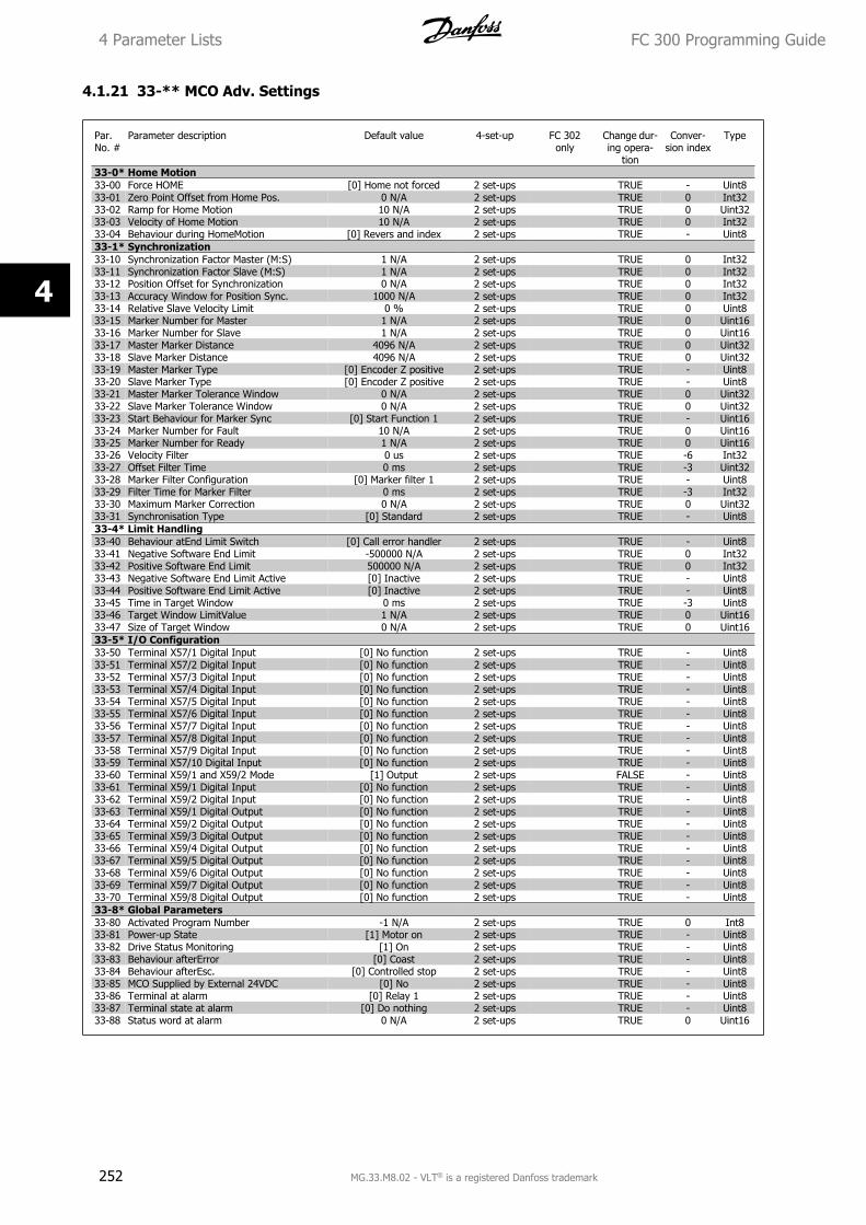
4.1.21 33-** MCO Adv. Settings
Par.No. #
Parameter description Default value 4-set-up FC 302only
Change dur-ing opera-
tion
Conver-sion index
Type
33-0* Home Motion33-00 Force HOME [0] Home not forced 2 set-ups TRUE - Uint833-01 Zero Point Offset from Home Pos. 0 N/A 2 set-ups TRUE 0 Int3233-02 Ramp for Home Motion 10 N/A 2 set-ups TRUE 0 Uint3233-03 Velocity of Home Motion 10 N/A 2 set-ups TRUE 0 Int3233-04 Behaviour during HomeMotion [0] Revers and index 2 set-ups TRUE - Uint833-1* Synchronization33-10 Synchronization Factor Master (M:S) 1 N/A 2 set-ups TRUE 0 Int3233-11 Synchronization Factor Slave (M:S) 1 N/A 2 set-ups TRUE 0 Int3233-12 Position Offset for Synchronization 0 N/A 2 set-ups TRUE 0 Int3233-13 Accuracy Window for Position Sync. 1000 N/A 2 set-ups TRUE 0 Int3233-14 Relative Slave Velocity Limit 0 % 2 set-ups TRUE 0 Uint833-15 Marker Number for Master 1 N/A 2 set-ups TRUE 0 Uint1633-16 Marker Number for Slave 1 N/A 2 set-ups TRUE 0 Uint1633-17 Master Marker Distance 4096 N/A 2 set-ups TRUE 0 Uint3233-18 Slave Marker Distance 4096 N/A 2 set-ups TRUE 0 Uint3233-19 Master Marker Type [0] Encoder Z positive 2 set-ups TRUE - Uint833-20 Slave Marker Type [0] Encoder Z positive 2 set-ups TRUE - Uint833-21 Master Marker Tolerance Window 0 N/A 2 set-ups TRUE 0 Uint3233-22 Slave Marker Tolerance Window 0 N/A 2 set-ups TRUE 0 Uint3233-23 Start Behaviour for Marker Sync [0] Start Function 1 2 set-ups TRUE - Uint1633-24 Marker Number for Fault 10 N/A 2 set-ups TRUE 0 Uint1633-25 Marker Number for Ready 1 N/A 2 set-ups TRUE 0 Uint1633-26 Velocity Filter 0 us 2 set-ups TRUE -6 Int3233-27 Offset Filter Time 0 ms 2 set-ups TRUE -3 Uint3233-28 Marker Filter Configuration [0] Marker filter 1 2 set-ups TRUE - Uint833-29 Filter Time for Marker Filter 0 ms 2 set-ups TRUE -3 Int3233-30 Maximum Marker Correction 0 N/A 2 set-ups TRUE 0 Uint3233-31 Synchronisation Type [0] Standard 2 set-ups TRUE - Uint833-4* Limit Handling33-40 Behaviour atEnd Limit Switch [0] Call error handler 2 set-ups TRUE - Uint833-41 Negative Software End Limit -500000 N/A 2 set-ups TRUE 0 Int3233-42 Positive Software End Limit 500000 N/A 2 set-ups TRUE 0 Int3233-43 Negative Software End Limit Active [0] Inactive 2 set-ups TRUE - Uint833-44 Positive Software End Limit Active [0] Inactive 2 set-ups TRUE - Uint833-45 Time in Target Window 0 ms 2 set-ups TRUE -3 Uint833-46 Target Window LimitValue 1 N/A 2 set-ups TRUE 0 Uint1633-47 Size of Target Window 0 N/A 2 set-ups TRUE 0 Uint1633-5* I/O Configuration33-50 Terminal X57/1 Digital Input [0] No function 2 set-ups TRUE - Uint833-51 Terminal X57/2 Digital Input [0] No function 2 set-ups TRUE - Uint833-52 Terminal X57/3 Digital Input [0] No function 2 set-ups TRUE - Uint833-53 Terminal X57/4 Digital Input [0] No function 2 set-ups TRUE - Uint833-54 Terminal X57/5 Digital Input [0] No function 2 set-ups TRUE - Uint833-55 Terminal X57/6 Digital Input [0] No function 2 set-ups TRUE - Uint833-56 Terminal X57/7 Digital Input [0] No function 2 set-ups TRUE - Uint833-57 Terminal X57/8 Digital Input [0] No function 2 set-ups TRUE - Uint833-58 Terminal X57/9 Digital Input [0] No function 2 set-ups TRUE - Uint833-59 Terminal X57/10 Digital Input [0] No function 2 set-ups TRUE - Uint833-60 Terminal X59/1 and X59/2 Mode [1] Output 2 set-ups FALSE - Uint833-61 Terminal X59/1 Digital Input [0] No function 2 set-ups TRUE - Uint833-62 Terminal X59/2 Digital Input [0] No function 2 set-ups TRUE - Uint833-63 Terminal X59/1 Digital Output [0] No function 2 set-ups TRUE - Uint833-64 Terminal X59/2 Digital Output [0] No function 2 set-ups TRUE - Uint833-65 Terminal X59/3 Digital Output [0] No function 2 set-ups TRUE - Uint833-66 Terminal X59/4 Digital Output [0] No function 2 set-ups TRUE - Uint833-67 Terminal X59/5 Digital Output [0] No function 2 set-ups TRUE - Uint833-68 Terminal X59/6 Digital Output [0] No function 2 set-ups TRUE - Uint833-69 Terminal X59/7 Digital Output [0] No function 2 set-ups TRUE - Uint833-70 Terminal X59/8 Digital Output [0] No function 2 set-ups TRUE - Uint833-8* Global Parameters33-80 Activated Program Number -1 N/A 2 set-ups TRUE 0 Int833-81 Power-up State [1] Motor on 2 set-ups TRUE - Uint833-82 Drive Status Monitoring [1] On 2 set-ups TRUE - Uint833-83 Behaviour afterError [0] Coast 2 set-ups TRUE - Uint833-84 Behaviour afterEsc. [0] Controlled stop 2 set-ups TRUE - Uint833-85 MCO Supplied by External 24VDC [0] No 2 set-ups TRUE - Uint833-86 Terminal at alarm [0] Relay 1 2 set-ups TRUE - Uint833-87 Terminal state at alarm [0] Do nothing 2 set-ups TRUE - Uint833-88 Status word at alarm 0 N/A 2 set-ups TRUE 0 Uint16
4 Parameter Lists FC 300 Programming Guide
252 MG.33.M8.02 - VLT® is a registered Danfoss trademark
4
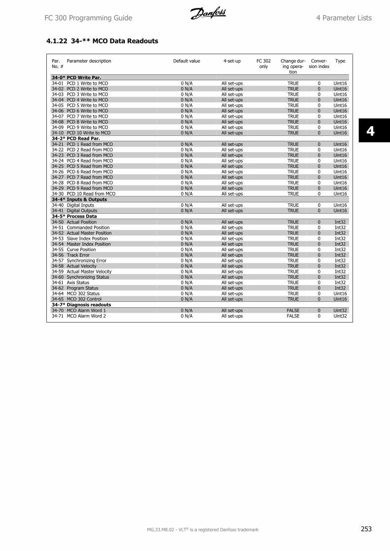
4.1.22 34-** MCO Data Readouts
Par.No. #
Parameter description Default value 4-set-up FC 302only
Change dur-ing opera-
tion
Conver-sion index
Type
34-0* PCD Write Par.34-01 PCD 1 Write to MCO 0 N/A All set-ups TRUE 0 Uint1634-02 PCD 2 Write to MCO 0 N/A All set-ups TRUE 0 Uint1634-03 PCD 3 Write to MCO 0 N/A All set-ups TRUE 0 Uint1634-04 PCD 4 Write to MCO 0 N/A All set-ups TRUE 0 Uint1634-05 PCD 5 Write to MCO 0 N/A All set-ups TRUE 0 Uint1634-06 PCD 6 Write to MCO 0 N/A All set-ups TRUE 0 Uint1634-07 PCD 7 Write to MCO 0 N/A All set-ups TRUE 0 Uint1634-08 PCD 8 Write to MCO 0 N/A All set-ups TRUE 0 Uint1634-09 PCD 9 Write to MCO 0 N/A All set-ups TRUE 0 Uint1634-10 PCD 10 Write to MCO 0 N/A All set-ups TRUE 0 Uint1634-2* PCD Read Par.34-21 PCD 1 Read from MCO 0 N/A All set-ups TRUE 0 Uint1634-22 PCD 2 Read from MCO 0 N/A All set-ups TRUE 0 Uint1634-23 PCD 3 Read from MCO 0 N/A All set-ups TRUE 0 Uint1634-24 PCD 4 Read from MCO 0 N/A All set-ups TRUE 0 Uint1634-25 PCD 5 Read from MCO 0 N/A All set-ups TRUE 0 Uint1634-26 PCD 6 Read from MCO 0 N/A All set-ups TRUE 0 Uint1634-27 PCD 7 Read from MCO 0 N/A All set-ups TRUE 0 Uint1634-28 PCD 8 Read from MCO 0 N/A All set-ups TRUE 0 Uint1634-29 PCD 9 Read from MCO 0 N/A All set-ups TRUE 0 Uint1634-30 PCD 10 Read from MCO 0 N/A All set-ups TRUE 0 Uint1634-4* Inputs & Outputs34-40 Digital Inputs 0 N/A All set-ups TRUE 0 Uint1634-41 Digital Outputs 0 N/A All set-ups TRUE 0 Uint1634-5* Process Data34-50 Actual Position 0 N/A All set-ups TRUE 0 Int3234-51 Commanded Position 0 N/A All set-ups TRUE 0 Int3234-52 Actual Master Position 0 N/A All set-ups TRUE 0 Int3234-53 Slave Index Position 0 N/A All set-ups TRUE 0 Int3234-54 Master Index Position 0 N/A All set-ups TRUE 0 Int3234-55 Curve Position 0 N/A All set-ups TRUE 0 Int3234-56 Track Error 0 N/A All set-ups TRUE 0 Int3234-57 Synchronizing Error 0 N/A All set-ups TRUE 0 Int3234-58 Actual Velocity 0 N/A All set-ups TRUE 0 Int3234-59 Actual Master Velocity 0 N/A All set-ups TRUE 0 Int3234-60 Synchronizing Status 0 N/A All set-ups TRUE 0 Int3234-61 Axis Status 0 N/A All set-ups TRUE 0 Int3234-62 Program Status 0 N/A All set-ups TRUE 0 Int3234-64 MCO 302 Status 0 N/A All set-ups TRUE 0 Uint1634-65 MCO 302 Control 0 N/A All set-ups TRUE 0 Uint1634-7* Diagnosis readouts34-70 MCO Alarm Word 1 0 N/A All set-ups FALSE 0 Uint3234-71 MCO Alarm Word 2 0 N/A All set-ups FALSE 0 Uint32
FC 300 Programming Guide 4 Parameter Lists
MG.33.M8.02 - VLT® is a registered Danfoss trademark 253
4
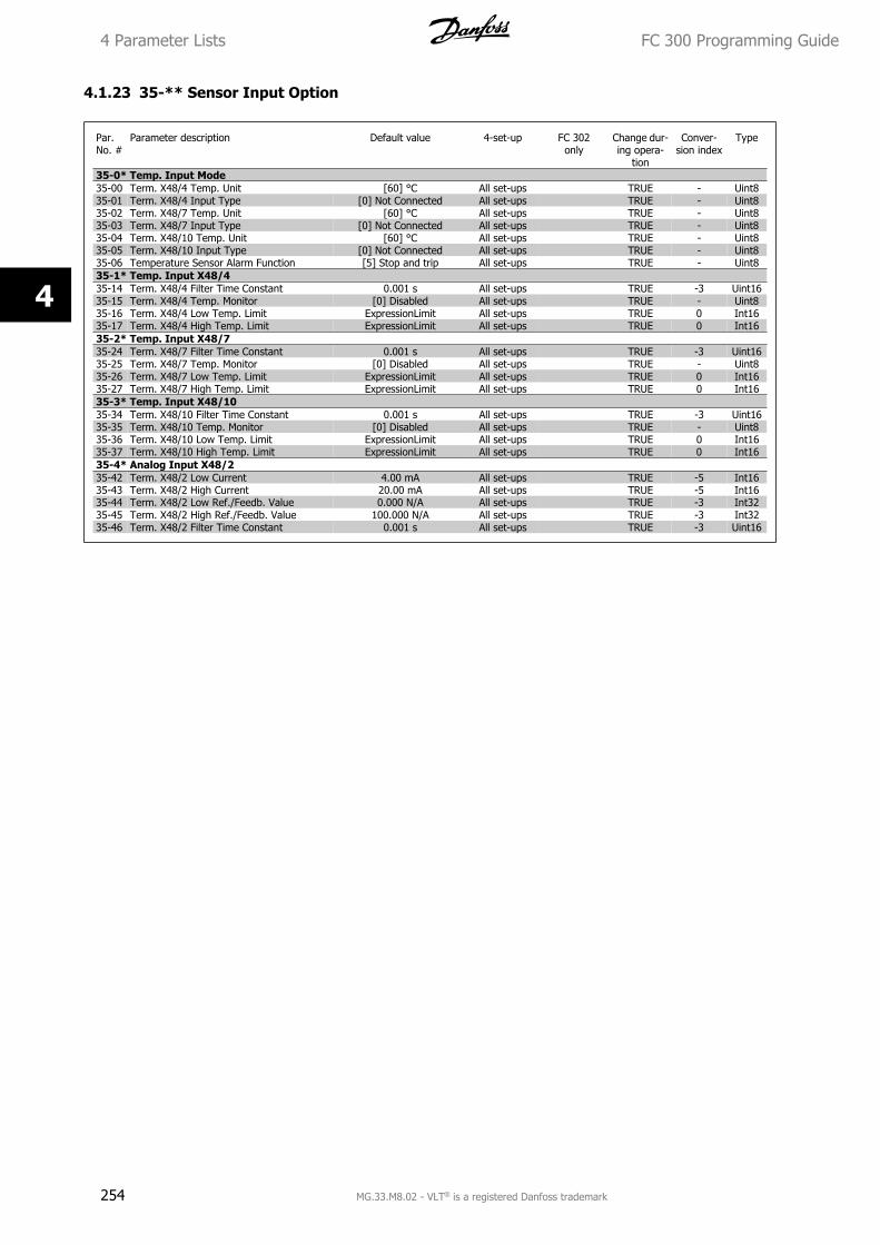
4.1.23 35-** Sensor Input Option
Par.No. #
Parameter description Default value 4-set-up FC 302only
Change dur-ing opera-
tion
Conver-sion index
Type
35-0* Temp. Input Mode35-00 Term. X48/4 Temp. Unit [60] °C All set-ups TRUE - Uint835-01 Term. X48/4 Input Type [0] Not Connected All set-ups TRUE - Uint835-02 Term. X48/7 Temp. Unit [60] °C All set-ups TRUE - Uint835-03 Term. X48/7 Input Type [0] Not Connected All set-ups TRUE - Uint835-04 Term. X48/10 Temp. Unit [60] °C All set-ups TRUE - Uint835-05 Term. X48/10 Input Type [0] Not Connected All set-ups TRUE - Uint835-06 Temperature Sensor Alarm Function [5] Stop and trip All set-ups TRUE - Uint835-1* Temp. Input X48/435-14 Term. X48/4 Filter Time Constant 0.001 s All set-ups TRUE -3 Uint1635-15 Term. X48/4 Temp. Monitor [0] Disabled All set-ups TRUE - Uint835-16 Term. X48/4 Low Temp. Limit ExpressionLimit All set-ups TRUE 0 Int1635-17 Term. X48/4 High Temp. Limit ExpressionLimit All set-ups TRUE 0 Int1635-2* Temp. Input X48/735-24 Term. X48/7 Filter Time Constant 0.001 s All set-ups TRUE -3 Uint1635-25 Term. X48/7 Temp. Monitor [0] Disabled All set-ups TRUE - Uint835-26 Term. X48/7 Low Temp. Limit ExpressionLimit All set-ups TRUE 0 Int1635-27 Term. X48/7 High Temp. Limit ExpressionLimit All set-ups TRUE 0 Int1635-3* Temp. Input X48/1035-34 Term. X48/10 Filter Time Constant 0.001 s All set-ups TRUE -3 Uint1635-35 Term. X48/10 Temp. Monitor [0] Disabled All set-ups TRUE - Uint835-36 Term. X48/10 Low Temp. Limit ExpressionLimit All set-ups TRUE 0 Int1635-37 Term. X48/10 High Temp. Limit ExpressionLimit All set-ups TRUE 0 Int1635-4* Analog Input X48/235-42 Term. X48/2 Low Current 4.00 mA All set-ups TRUE -5 Int1635-43 Term. X48/2 High Current 20.00 mA All set-ups TRUE -5 Int1635-44 Term. X48/2 Low Ref./Feedb. Value 0.000 N/A All set-ups TRUE -3 Int3235-45 Term. X48/2 High Ref./Feedb. Value 100.000 N/A All set-ups TRUE -3 Int3235-46 Term. X48/2 Filter Time Constant 0.001 s All set-ups TRUE -3 Uint16
4 Parameter Lists FC 300 Programming Guide
254 MG.33.M8.02 - VLT® is a registered Danfoss trademark
4
5 Troubleshooting
5.1.1 Warnings/Alarm Messages
A warning or an alarm is signalled by the relevant LED on the front of the frequency converter and indicated by a code on the display.
A warning remains active until its cause is no longer present. Under certain circumstances operation of the motor may still be continued. Warning messages
may be critical, but are not necessarily so.
In the event of an alarm, the frequency converter will have tripped. Alarms must be reset to restart operation once their cause has been rectified.
This may be done in three ways:
1. By using the [RESET] control button on the LCP.
2. Via a digital input with the “Reset” function.
3. Via serial communication/optional fieldbus.
NB!
After a manual reset using the [RESET] button on the LCP, the [AUTO ON] button must be pressed to restart the motor.
If an alarm cannot be reset, the reason may be that its cause has not been rectified, or the alarm is trip-locked (see also table on following page).
Alarms that are trip-locked offer additional protection, meaning that the mains supply must be switched off before the alarm can be reset. After being
switched back on, the frequency converter is no longer blocked and may be reset as described above once the cause has been rectified.
Alarms that are not trip-locked can also be reset using the automatic reset function in par. 14-20 Reset Mode (Warning: automatic wake-up is possible!)
If a warning and alarm is marked against a code in the table on the following page, this means that either a warning occurs before an alarm, or else that
you can specify whether it is a warning or an alarm that is to be displayed for a given fault.
This is possible, for instance, in par. 1-90 Motor Thermal Protection. After an alarm or trip, the motor carries on coasting, and the alarm and warning
flash. Once the problem has been rectified, only the alarm continues flashing until the frequency converter is reset.
FC 300 Programming Guide 5 Troubleshooting
MG.33.M8.02 - VLT® is a registered Danfoss trademark 255
5
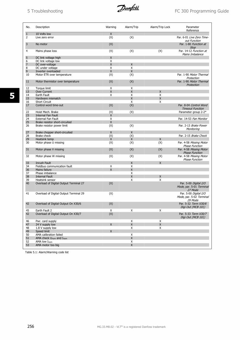
No. Description Warning Alarm/Trip Alarm/Trip Lock ParameterReference
1 10 Volts low X 2 Live zero error (X) (X) Par. 6-01 Live Zero Time-
out Function3 No motor (X) Par. 1-80 Function at
Stop4 Mains phase loss (X) (X) (X) Par. 14-12 Function at
Mains Imbalance5 DC link voltage high X 6 DC link voltage low X7 DC over-voltage X X 8 DC under voltage X X9 Inverter overloaded X X 10 Motor ETR over temperature (X) (X) Par. 1-90 Motor Thermal
Protection11 Motor thermistor over temperature (X) (X) Par. 1-90 Motor Thermal
Protection12 Torque limit X X13 Over Current X X X 14 Earth Fault X X X15 Hardware mismatch X X16 Short Circuit X X17 Control word time-out (X) (X) Par. 8-04 Control Word
Timeout Function22 Hoist Mech. Brake (X) (X) Parameter group 2-2*23 Internal Fan Fault X24 External Fan Fault X Par. 14-53 Fan Monitor25 Brake resistor short-circuited X26 Brake resistor power limit (X) (X) Par. 2-13 Brake Power
Monitoring27 Brake chopper short-circuited X X28 Brake check (X) (X) Par. 2-15 Brake Check29 Heatsink temp X X X30 Motor phase U missing (X) (X) (X) Par. 4-58 Missing Motor
Phase Function31 Motor phase V missing (X) (X) (X) Par. 4-58 Missing Motor
Phase Function32 Motor phase W missing (X) (X) (X) Par. 4-58 Missing Motor
Phase Function33 Inrush Fault X X34 Fieldbus communication fault X X36 Mains failure X X37 Phase imbalance X38 Internal Fault X X39 Heatsink sensor X X40 Overload of Digital Output Terminal 27 (X) Par. 5-00 Digital I/O
Mode, par. 5-01 Terminal27 Mode
41 Overload of Digital Output Terminal 29 (X) Par. 5-00 Digital I/OMode, par. 5-02 Terminal
29 Mode42 Overload of Digital Output On X30/6 (X) Par. 5-32 Term X30/6
Digi Out (MCB 101)45 Earth Fault 2 X X X42 Overload of Digital Output On X30/7 (X) Par. 5-33 Term X30/7
Digi Out (MCB 101)46 Pwr. card supply X X47 24 V supply low X X X48 1.8 V supply low X X49 Speed limit X50 AMA calibration failed X51 AMA check Unom and Inom X52 AMA low Inom X53 AMA motor too big X
Table 5.1: Alarm/Warning code list
5 Troubleshooting FC 300 Programming Guide
256 MG.33.M8.02 - VLT® is a registered Danfoss trademark
5
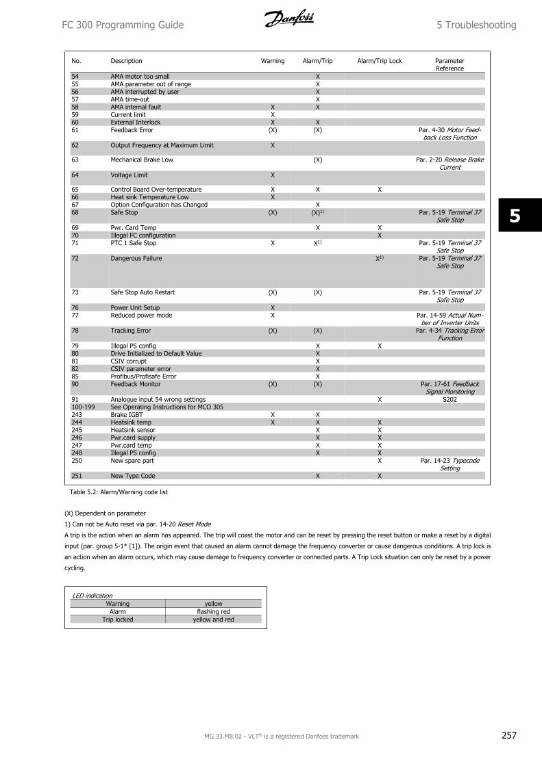
No. Description Warning Alarm/Trip Alarm/Trip Lock ParameterReference
54 AMA motor too small X55 AMA parameter out of range X56 AMA interrupted by user X57 AMA time-out X58 AMA internal fault X X59 Current limit X60 External Interlock X X61 Feedback Error (X) (X) Par. 4-30 Motor Feed-
back Loss Function62 Output Frequency at Maximum Limit X
63 Mechanical Brake Low (X) Par. 2-20 Release BrakeCurrent
64 Voltage Limit X
65 Control Board Over-temperature X X X66 Heat sink Temperature Low X67 Option Configuration has Changed X68 Safe Stop (X) (X)1) Par. 5-19 Terminal 37
Safe Stop69 Pwr. Card Temp X X70 Illegal FC configuration X71 PTC 1 Safe Stop X X1) Par. 5-19 Terminal 37
Safe Stop72 Dangerous Failure X1) Par. 5-19 Terminal 37
Safe Stop
73 Safe Stop Auto Restart (X) (X) Par. 5-19 Terminal 37Safe Stop
76 Power Unit Setup X77 Reduced power mode X Par. 14-59 Actual Num-
ber of Inverter Units78 Tracking Error (X) (X) Par. 4-34 Tracking Error
Function79 Illegal PS config X X80 Drive Initialized to Default Value X81 CSIV corrupt X82 CSIV parameter error X85 Profibus/Profisafe Error X90 Feedback Monitor (X) (X) Par. 17-61 Feedback
Signal Monitoring91 Analogue input 54 wrong settings X S202100-199 See Operating Instructions for MCO 305243 Brake IGBT X X244 Heatsink temp X X X245 Heatsink sensor X X246 Pwr.card supply X X247 Pwr.card temp X X248 Illegal PS config X X250 New spare part X Par. 14-23 Typecode
Setting251 New Type Code X X
Table 5.2: Alarm/Warning code list
(X) Dependent on parameter
1) Can not be Auto reset via par. 14-20 Reset Mode
A trip is the action when an alarm has appeared. The trip will coast the motor and can be reset by pressing the reset button or make a reset by a digital
input (par. group 5-1* [1]). The origin event that caused an alarm cannot damage the frequency converter or cause dangerous conditions. A trip lock is
an action when an alarm occurs, which may cause damage to frequency converter or connected parts. A Trip Lock situation can only be reset by a power
cycling.
LED indicationWarning yellowAlarm flashing red
Trip locked yellow and red
FC 300 Programming Guide 5 Troubleshooting
MG.33.M8.02 - VLT® is a registered Danfoss trademark 257
5
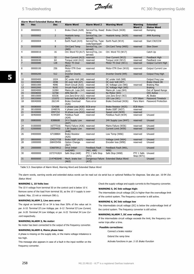
Alarm Word Extended Status WordBit Hex Dec Alarm Word Alarm Word 2 Warning Word Warning
Word 2ExtendedStatus Word
0 00000001 1 Brake Check (A28) ServiceTrip, Read/Write
Brake Check (W28) reserved Ramping
1 00000002 2 Heatsink temp.(A29)
ServiceTrip, (re-served)
Heatsink temp. (W29) reserved AMA Running
2 00000004 4 Earth Fault (A14) ServiceTrip, Type-code/Sparepart
Earth Fault (W14) reserved Start CW/CCW
3 00000008 8 Ctrl.Card Temp(A65)
ServiceTrip, (re-served)
Ctrl.Card Temp (W65) reserved Slow Down
4 00000010 16 Ctrl. Word TO (A17) ServiceTrip, (re-served)
Ctrl. Word TO (W17) Catch Up
5 00000020 32 Over Current (A13) reserved Over Current (W13) reserved Feedback High6 00000040 64 Torque Limit (A12) reserved Torque Limit (W12) reserved Feedback Low7 00000080 128 Motor Th Over
(A11)reserved Motor Th Over (W11) reserved Output Current High
8 00000100 256 Motor ETR Over(A10)
reserved Motor ETR Over (W10) reserved Output Current Low
9 00000200 512 Inverter Overld.(A9)
reserved Inverter Overld (W9) reserved Output Freq High
10 00000400 1024 DC under Volt (A8) reserved DC under Volt (W8) Output Freq Low11 00000800 2048 DC over Volt (A7) reserved DC over Volt (W7) Brake Check OK12 00001000 4096 Short Circuit (A16) reserved DC Voltage Low (W6) reserved Braking Max13 00002000 8192 Inrush Fault (A33) reserved DC Voltage High (W5) Braking14 00004000 16384 Mains ph. Loss (A4) reserved Mains ph. Loss (W4) Out of Speed Range15 00008000 32768 AMA Not OK reserved No Motor (W3) OVC Active16 00010000 65536 Live Zero Error (A2) reserved Live Zero Error (W2) AC Brake17 00020000 131072 Internal Fault (A38) KTY error 10V Low (W1) KTY Warn Password Timelock18 00040000 262144 Brake Overload
(A26)Fans error Brake Overload (W26) Fans Warn Password Protection
19 00080000 524288 U phase Loss (A30) ECB error Brake Resistor (W25) ECB Warn 20 00100000 1048576 V phase Loss (A31) reserved Brake IGBT (W27) reserved21 00200000 2097152 W phase Loss (A32) reserved Speed Limit (W49) reserved 22 00400000 4194304 Fieldbus Fault
(A34)reserved Fieldbus Fault (W34) reserved Unused
23 00800000 8388608 24 V Supply Low(A47)
reserved 24V Supply Low (W47) reserved Unused
24 01000000 16777216 Mains Failure (A36) reserved Mains Failure (W36) reserved Unused25 02000000 33554432 1.8V Supply Low
(A48)reserved Current Limit (W59) reserved Unused
26 04000000 67108864 Brake Resistor(A25)
reserved Low Temp (W66) reserved Unused
27 08000000 134217728 Brake IGBT (A27) reserved Voltage Limit (W64) reserved Unused28 10000000 268435456 Option Change
(A67)reserved Encoder loss (W90) reserved Unused
29 20000000 536870912 Drive Initial-ized(A80)
Feedback Fault(A61, A90)
Feedback Fault (W61,W90)
Unused
30 40000000 1073741824 Safe Stop (A68) PTC 1 Safe Stop(A71)
Safe Stop (W68) PTC 1 SafeStop (W71)
Unused
31 80000000 2147483648 Mech. brake low(A63)
Dangerous Failure(A72)
Extended Status Word Unused
Table 5.3: Description of Alarm Word, Warning Word and Extended Status Word
The alarm words, warning words and extended status words can be read out via serial bus or optional fieldbus for diagnose. See also par. 16-94 Ext.
Status Word.
WARNING 1, 10 Volts low:
The 10 V voltage from terminal 50 on the control card is below 10 V.
Remove some of the load from terminal 50, as the 10 V supply is over-
loaded. Max. 15 mA or minimum 590 Ω.
WARNING/ALARM 2, Live zero error:
The signal on terminal 53 or 54 is less than 50% of the value set in
par. 6-10 Terminal 53 Low Voltage, par. 6-12 Terminal 53 Low Current,
par. 6-20 Terminal 54 Low Voltage, or par. 6-22 Terminal 54 Low Cur-
rent respectively.
WARNING/ALARM 3, No motor:
No motor has been connected to the output of the frequency converter.
WARNING/ALARM 4, Mains phase loss:
A phase is missing on the supply side, or the mains voltage imbalance is
too high.
This message also appears in case of a fault in the input rectifier on the
frequency converter.
Check the supply voltage and supply currents to the frequency converter.
WARNING 5, DC link voltage high:
The intermediate circuit voltage (DC) is higher than the overvoltage limit
of the control system. The frequency converter is still active.
WARNING 6, DC link voltage low
The intermediate circuit voltage (DC) is below the undervoltage limit of
the control system. The frequency converter is still active.
WARNING/ALARM 7, DC over voltage:
If the intermediate circuit voltage exceeds the limit, the frequency con-
verter trips after a time.
Possible corrections:
Connect a brake resistor
Extend the ramp time
Activate functions in par. 2-10 Brake Function
5 Troubleshooting FC 300 Programming Guide
258 MG.33.M8.02 - VLT® is a registered Danfoss trademark
5
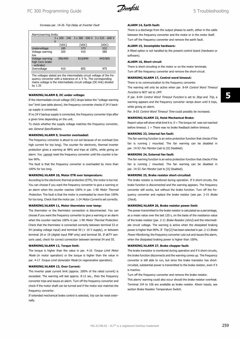
Increase par. 14-26 Trip Delay at Inverter Fault
Alarm/warning limits:3 x 200 - 240V
3 x 380 - 500 V 3 x 525 - 600 V
[VDC] [VDC] [VDC]Undervoltage 185 373 532Voltage warninglow
205 410 585
Voltage warninghigh (w/o brake- w/brake)
390/405 810/840 943/965
Overvoltage 410 855 975 The voltages stated are the intermediate circuit voltage of the fre-quency converter with a tolerance of ± 5 %. The correspondingmains voltage is the intermediate circuit voltage (DC-link) dividedby 1.35
WARNING/ALARM 8, DC under voltage:
If the intermediate circuit voltage (DC) drops below the “voltage warning
low” limit (see table above), the frequency converter checks if 24 V back-
up supply is connected.
If no 24 V backup supply is connected, the frequency converter trips after
a given time depending on the unit.
To check whether the supply voltage matches the frequency converter,
see General Specifications.
WARNING/ALARM 9, Inverter overloaded:
The frequency converter is about to cut out because of an overload (too
high current for too long). The counter for electronic, thermal inverter
protection gives a warning at 98% and trips at 100%, while giving an
alarm. You cannot reset the frequency converter until the counter is be-
low 90%.
The fault is that the frequency converter is overloaded by more than
100% for too long.
WARNING/ALARM 10, Motor ETR over temperature:
According to the electronic thermal protection (ETR), the motor is too hot.
You can choose if you want the frequency converter to give a warning or
an alarm when the counter reaches 100% in par. 1-90 Motor Thermal
Protection. The fault is that the motor is overloaded by more than 100%
for too long. Check that the motor par. 1-24 Motor Current is set correctly.
WARNING/ALARM 11, Motor thermistor over temp:
The thermistor or the thermistor connection is disconnected. You can
choose if you want the frequency converter to give a warning or an alarm
when the counter reaches 100% in par. 1-90 Motor Thermal Protection.
Check that the thermistor is connected correctly between terminal 53 or
54 (analog voltage input) and terminal 50 (+ 10 V supply), or between
terminal 18 or 19 (digital input PNP only) and terminal 50. If aKTY sen-
soris used, check for correct connection between terminal 54 and 55.
WARNING/ALARM 12, Torque limit:
The torque is higher than the value in par. 4-16 Torque Limit Motor
Mode (in motor operation) or the torque is higher than the value in
par. 4-17 Torque Limit Generator Mode (in regenerative operation).
WARNING/ALARM 13, Over Current:
The inverter peak current limit (approx. 200% of the rated current) is
exceeded. The warning will last approx. 8-12 sec., then the frequency
converter trips and issues an alarm. Turn off the frequency converter and
check if the motor shaft can be turned and if the motor size matches the
frequency converter.
If extended mechanical brake control is selected, trip can be reset exter-
nally.
ALARM 14, Earth fault:
There is a discharge from the output phases to earth, either in the cable
between the frequency converter and the motor or in the motor itself.
Turn off the frequency converter and remove the earth fault.
ALARM 15, Incomplete hardware:
A fitted option is not handled by the present control board (hardware or
software).
ALARM 16, Short-circuit
There is short-circuiting in the motor or on the motor terminals.
Turn off the frequency converter and remove the short-circuit.
WARNING/ALARM 17, Control word timeout:
There is no communication to the frequency converter.
The warning will only be active when par. 8-04 Control Word Timeout
Function is NOT set to OFF.
If par. 8-04 Control Word Timeout Function is set to Stop and Trip, a
warning appears and the frequency converter ramps down until it trips,
while giving an alarm.
Par. 8-03 Control Word Timeout Time could possibly be increased.
WARNING/ALARM 22, Hoist Mechanical Brake:
Report value will show what kind it is. 0 = The torque ref. was not reached
before timeout. 1 = There was no brake feedback before timeout.
WARNING 23, Internal fan fault:
The fan warning function is an extra protection function that checks if the
fan is running / mounted. The fan warning can be disabled in
par. 14-53 Fan Monitor (set to [0] Disabled).
WARNING 24, External fan fault:
The fan warning function is an extra protection function that checks if the
fan is running / mounted. The fan warning can be disabled in
par. 14-53 Fan Monitor (set to [0] Disabled).
WARNING 25, Brake resistor short-circuited:
The brake resistor is monitored during operation. If it short-circuits, the
brake function is disconnected and the warning appears. The frequency
converter still works, but without the brake function. Turn off the fre-
quency converter and replace the brake resistor (see par. 2-15 Brake
Check).
WARNING/ALARM 26, Brake resistor power limit:
The power transmitted to the brake resistor is calculated as a percentage,
as a mean value over the last 120 s, on the basis of the resistance value
of the brake resistor (par. 2-11 Brake Resistor (ohm)) and the intermedi-
ate circuit voltage. The warning is active when the dissipated braking
power is higher than 90%. If Trip [2] has been selected in par. 2-13 Brake
Power Monitoring, the frequency converter cuts out and issues this alarm,
when the dissipated braking power is higher than 100%.
WARNING/ALARM 27, Brake chopper fault:
The brake transistor is monitored during operation and if it short-circuits,
the brake function disconnects and the warning comes up. The frequency
converter is still able to run, but since the brake transistor has short-
circuited, substantial power is transmitted to the brake resistor, even if it
is inactive.
Turn off the frequency converter and remove the brake resistor.
This alarm/ warning could also occur should the brake resistor overheat.
Terminal 104 to 106 are available as brake resistor. Klixon inputs, see
section Brake Resistor Temperature Switch.
FC 300 Programming Guide 5 Troubleshooting
MG.33.M8.02 - VLT® is a registered Danfoss trademark 259
5
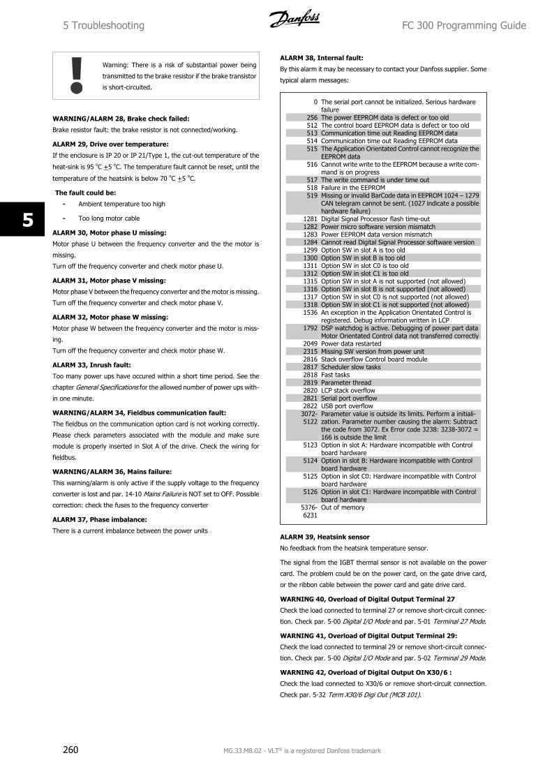
Warning: There is a risk of substantial power being
transmitted to the brake resistor if the brake transistor
is short-circuited.
WARNING/ALARM 28, Brake check failed:
Brake resistor fault: the brake resistor is not connected/working.
ALARM 29, Drive over temperature:
If the enclosure is IP 20 or IP 21/Type 1, the cut-out temperature of the
heat-sink is 95 ºC +5 ºC. The temperature fault cannot be reset, until the
temperature of the heatsink is below 70 ºC +5 ºC.
The fault could be:
- Ambient temperature too high
- Too long motor cable
ALARM 30, Motor phase U missing:
Motor phase U between the frequency converter and the the motor is
missing.
Turn off the frequency converter and check motor phase U.
ALARM 31, Motor phase V missing:
Motor phase V between the frequency converter and the motor is missing.
Turn off the frequency converter and check motor phase V.
ALARM 32, Motor phase W missing:
Motor phase W between the frequency converter and the motor is miss-
ing.
Turn off the frequency converter and check motor phase W.
ALARM 33, Inrush fault:
Too many power ups have occured within a short time period. See the
chapter General Specifications for the allowed number of power ups with-
in one minute.
WARNING/ALARM 34, Fieldbus communication fault:
The fieldbus on the communication option card is not working correctly.
Please check parameters associated with the module and make sure
module is properly inserted in Slot A of the drive. Check the wiring for
fieldbus.
WARNING/ALARM 36, Mains failure:
This warning/alarm is only active if the supply voltage to the frequency
converter is lost and par. 14-10 Mains Failure is NOT set to OFF. Possible
correction: check the fuses to the frequency converter
ALARM 37, Phase imbalance:
There is a current imbalance between the power units
ALARM 38, Internal fault:
By this alarm it may be necessary to contact your Danfoss supplier. Some
typical alarm messages:
0 The serial port cannot be initialized. Serious hardwarefailure
256 The power EEPROM data is defect or too old512 The control board EEPROM data is defect or too old513 Communication time out Reading EEPROM data514 Communication time out Reading EEPROM data515 The Application Orientated Control cannot recognize the
EEPROM data516 Cannot write write to the EEPROM because a write com-
mand is on progress517 The write command is under time out518 Failure in the EEPROM519 Missing or invalid BarCode data in EEPROM 1024 – 1279
CAN telegram cannot be sent. (1027 indicate a possiblehardware failure)
1281 Digital Signal Processor flash time-out1282 Power micro software version mismatch1283 Power EEPROM data version mismatch1284 Cannot read Digital Signal Processor software version1299 Option SW in slot A is too old1300 Option SW in slot B is too old1311 Option SW in slot C0 is too old1312 Option SW in slot C1 is too old1315 Option SW in slot A is not supported (not allowed)1316 Option SW in slot B is not supported (not allowed)1317 Option SW in slot C0 is not supported (not allowed)1318 Option SW in slot C1 is not supported (not allowed)1536 An exception in the Application Orientated Control is
registered. Debug information written in LCP1792 DSP watchdog is active. Debugging of power part data
Motor Orientated Control data not transferred correctly2049 Power data restarted2315 Missing SW version from power unit2816 Stack overflow Control board module2817 Scheduler slow tasks2818 Fast tasks2819 Parameter thread2820 LCP stack overflow2821 Serial port overflow2822 USB port overflow
3072-5122
Parameter value is outside its limits. Perform a initiali-zation. Parameter number causing the alarm: Subtractthe code from 3072. Ex Error code 3238: 3238-3072 =166 is outside the limit
5123 Option in slot A: Hardware incompatible with Controlboard hardware
5124 Option in slot B: Hardware incompatible with Controlboard hardware
5125 Option in slot C0: Hardware incompatible with Controlboard hardware
5126 Option in slot C1: Hardware incompatible with Controlboard hardware
5376-6231
Out of memory
ALARM 39, Heatsink sensor
No feedback from the heatsink temperature sensor.
The signal from the IGBT thermal sensor is not available on the power
card. The problem could be on the power card, on the gate drive card,
or the ribbon cable between the power card and gate drive card.
WARNING 40, Overload of Digital Output Terminal 27
Check the load connected to terminal 27 or remove short-circuit connec-
tion. Check par. 5-00 Digital I/O Mode and par. 5-01 Terminal 27 Mode.
WARNING 41, Overload of Digital Output Terminal 29:
Check the load connected to terminal 29 or remove short-circuit connec-
tion. Check par. 5-00 Digital I/O Mode and par. 5-02 Terminal 29 Mode.
WARNING 42, Overload of Digital Output On X30/6 :
Check the load connected to X30/6 or remove short-circuit connection.
Check par. 5-32 Term X30/6 Digi Out (MCB 101).
5 Troubleshooting FC 300 Programming Guide
260 MG.33.M8.02 - VLT® is a registered Danfoss trademark
5
WARNING 42, Overload of Digital Output On X30/7 :
Check the load connected to X30/7 or remove short-circuit connection.
Check par. 5-33 Term X30/7 Digi Out (MCB 101).
ALARM 45, Earth fault 2:
There is a discharge from the output phases to earth, either in the cable
between the frequency converter and the motor or in the motor it-
self.Turn off the frequency converter and remove the earth fault. This
alarm is detected under the start-up test sequence.
ALARM 46, Power card supply
The supply on the power card is out of range.
There are three power supplies generated by the switch mode power
supply (SMPS) on the power card: 24 V, 5V, +/- 18V. When powered with
24 VDC with the MCB 107 option, only the 24 V and 5 V supplies are
monitored. When powered with three phase mains voltage, all three sup-
plied are monitored.
WARNING 47, 24 V supply low:
The external 24 V DC backup power supply may be overloaded, otherwise
Contact your Danfoss supplier.
WARNING 48, 1.8 V supply low:
Contact your Danfoss supplier.
WARNING 49, Speed limit:
The speed is not within the specified range in par. 4-11 Motor Speed Low
Limit [RPM] and par. 4-13 Motor Speed High Limit [RPM].
ALARM 50, AMA calibration failed:
The motor is not suitable for the particular size of drive. Start the AMA
procedure once again by par. 1-29 Automatic Motor Adaptation (AMA),
eventually with a reduced AMA function. If still failing; check the motor
data.
ALARM 51, AMA check Unom and Inom:
The setting of motor voltage, motor current, and motor power is pre-
sumably wrong. Check the settings.
ALARM 52, AMA low Inom:
The motor current is too low. Check the settings.
ALARM 53, AMA motor too big:
The motor is too big for the AMA to be carried out.
ALARM 54, AMA motor too small:
The motor is too small for the AMA to be carried out.
ALARM 55, AMA par. out of range:
The motor parameter values found from the motor are outside acceptable
range.
ALARM 56, AMA interrupted by user:
The AMA has been interrupted by the user.
ALARM 57, AMA timeout:
Try to start the AMA again a number of times, until the AMA is carried
out. Please note that repeated runs may heat the motor to a level where
the resistance Rs and Rr are increased. In most cases, however, this is
not critical.
ALARM 58, AMA internal fault:
Contact your Danfoss supplier.
WARNING 59, Current limit:
The current is higher than the value in par. 4-18 Current Limit.
WARNING 60, External interlock
External interlock has been activated. To resume normal operation, apply
24 V DC to the terminal programmed for external interlock and reset the
frequency converter (via serial communication, digital I/O, or by pressing
reset button on keypad).
WARNING/ALARM 61, Feedback Error:
An error between calculated speed and speed measurement from feed-
back device. The function Warning/Alarm/Disabling setting is in
par. 4-30 Motor Feedback Loss Function. Accepted error setting in
par. 4-31 Motor Feedback Speed Error and the allowed time the error
occur setting in par. 4-32 Motor Feedback Loss Timeout. During a com-
missioning procedure the function may be effective.
WARNING 62, Output Frequency at Maximum Limit:
The output frequency is higher than the value set in par. 4-19 Max Output
Frequency. This is a warning in VVCplus mode and an alarm (trip) in Flux
mode.
ALARM 63, Mechanical Brake Low:
The actual motor current has not exceeded the “release brake” current
within the “Start delay” time window.
WARNING 64, Voltage Limit:
The load and speed combination demands a motor voltage higher than
the actual DC link voltage.
WARNING/ALARM/TRIP 65, Control Card Over Temperature:
Control card over temperature: The cut-out temperature of the control
card is 80° C.
WARNING 66, Heatsink Temperature Low:
The heat sink temperature is measured as 0° C. This could indicate that
the temperature sensor is defect and thus the fan speed is increased to
the maximum in case the power part or control card is very hot.
ALARM 67, Option Configuration has Changed:
One or more options has either been added or removed since the last
power down.
ALARM 68, Safe Stop:
Safe Stop has been activated. To resume normal operation, apply 24 V
DC to T-37. Press reset button on LCP.
WARNING 68, Safe Stop:
Safe Stop has been activated. Normal operation is resumed when Safe
Stop is disabled. Warning: Automatic Restart!
ALARM 69, Power card temperature
The temperature sensor on the power card is either too hot or too cold.
Troubleshooting:
Check the operation of the door fans.
Check that the filters for the door fans are not blocked.
Check that the gland plate is properly installed on IP 21 and IP
54 (NEMA 1 and NEMA 12) drives.
ALARM 70, Illegal FC Configuration:
Actual combination of control board and power board is illegal.
ALARM 71, PTC 1 Safe Stop:
Safe Stop has been activated from the MCB 112 PTC Thermistor Card
(motor too warm). Normal operation can be resumed when the MCB 112
applies 24 V DC to T-37 again (when the motor temperature reaches an
acceptable level) and when the Digital Input from the MCB 112 is deac-
tivated. When that happens, a reset signal must be is be sent (via Bus,
Digital I/O, or by pressing [RESET]).
FC 300 Programming Guide 5 Troubleshooting
MG.33.M8.02 - VLT® is a registered Danfoss trademark 261
5
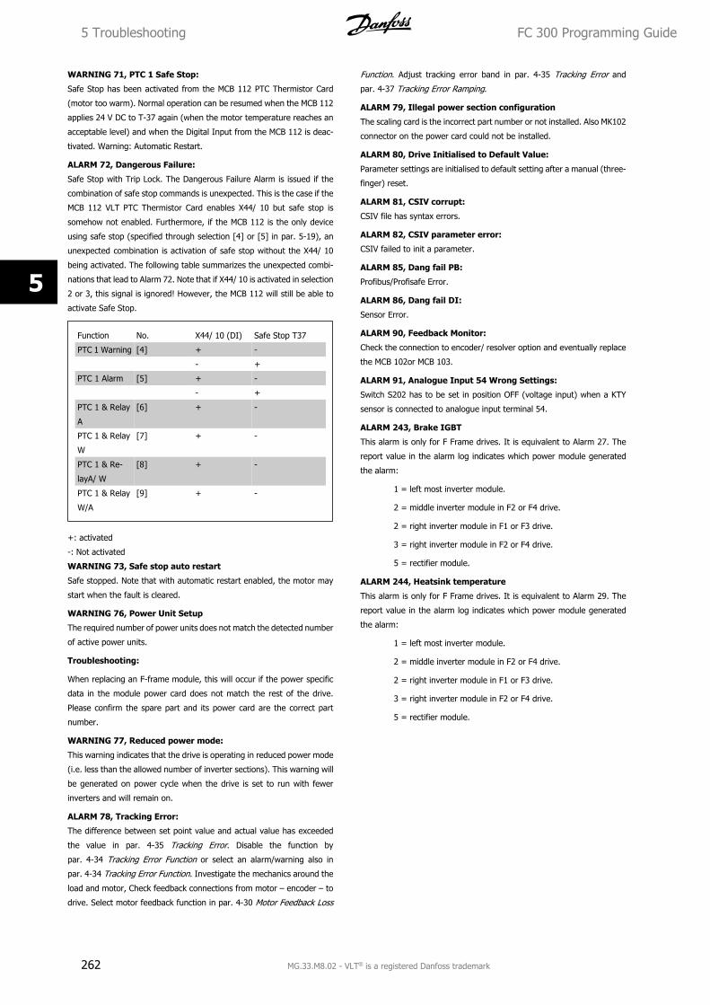
WARNING 71, PTC 1 Safe Stop:
Safe Stop has been activated from the MCB 112 PTC Thermistor Card
(motor too warm). Normal operation can be resumed when the MCB 112
applies 24 V DC to T-37 again (when the motor temperature reaches an
acceptable level) and when the Digital Input from the MCB 112 is deac-
tivated. Warning: Automatic Restart.
ALARM 72, Dangerous Failure:
Safe Stop with Trip Lock. The Dangerous Failure Alarm is issued if the
combination of safe stop commands is unexpected. This is the case if the
MCB 112 VLT PTC Thermistor Card enables X44/ 10 but safe stop is
somehow not enabled. Furthermore, if the MCB 112 is the only device
using safe stop (specified through selection [4] or [5] in par. 5-19), an
unexpected combination is activation of safe stop without the X44/ 10
being activated. The following table summarizes the unexpected combi-
nations that lead to Alarm 72. Note that if X44/ 10 is activated in selection
2 or 3, this signal is ignored! However, the MCB 112 will still be able to
activate Safe Stop.
Function No. X44/ 10 (DI) Safe Stop T37
PTC 1 Warning [4] + -
- +
PTC 1 Alarm [5] + -
- +
PTC 1 & Relay
A
[6] + -
PTC 1 & Relay
W
[7] + -
PTC 1 & Re-
layA/ W
[8] + -
PTC 1 & Relay
W/A
[9] + -
+: activated
-: Not activated
WARNING 73, Safe stop auto restart
Safe stopped. Note that with automatic restart enabled, the motor may
start when the fault is cleared.
WARNING 76, Power Unit Setup
The required number of power units does not match the detected number
of active power units.
Troubleshooting:
When replacing an F-frame module, this will occur if the power specific
data in the module power card does not match the rest of the drive.
Please confirm the spare part and its power card are the correct part
number.
WARNING 77, Reduced power mode:
This warning indicates that the drive is operating in reduced power mode
(i.e. less than the allowed number of inverter sections). This warning will
be generated on power cycle when the drive is set to run with fewer
inverters and will remain on.
ALARM 78, Tracking Error:
The difference between set point value and actual value has exceeded
the value in par. 4-35 Tracking Error. Disable the function by
par. 4-34 Tracking Error Function or select an alarm/warning also in
par. 4-34 Tracking Error Function. Investigate the mechanics around the
load and motor, Check feedback connections from motor – encoder – to
drive. Select motor feedback function in par. 4-30 Motor Feedback Loss
Function. Adjust tracking error band in par. 4-35 Tracking Error and
par. 4-37 Tracking Error Ramping.
ALARM 79, Illegal power section configuration
The scaling card is the incorrect part number or not installed. Also MK102
connector on the power card could not be installed.
ALARM 80, Drive Initialised to Default Value:
Parameter settings are initialised to default setting after a manual (three-
finger) reset.
ALARM 81, CSIV corrupt:
CSIV file has syntax errors.
ALARM 82, CSIV parameter error:
CSIV failed to init a parameter.
ALARM 85, Dang fail PB:
Profibus/Profisafe Error.
ALARM 86, Dang fail DI:
Sensor Error.
ALARM 90, Feedback Monitor:
Check the connection to encoder/ resolver option and eventually replace
the MCB 102or MCB 103.
ALARM 91, Analogue Input 54 Wrong Settings:
Switch S202 has to be set in position OFF (voltage input) when a KTY
sensor is connected to analogue input terminal 54.
ALARM 243, Brake IGBT
This alarm is only for F Frame drives. It is equivalent to Alarm 27. The
report value in the alarm log indicates which power module generated
the alarm:
1 = left most inverter module.
2 = middle inverter module in F2 or F4 drive.
2 = right inverter module in F1 or F3 drive.
3 = right inverter module in F2 or F4 drive.
5 = rectifier module.
ALARM 244, Heatsink temperature
This alarm is only for F Frame drives. It is equivalent to Alarm 29. The
report value in the alarm log indicates which power module generated
the alarm:
1 = left most inverter module.
2 = middle inverter module in F2 or F4 drive.
2 = right inverter module in F1 or F3 drive.
3 = right inverter module in F2 or F4 drive.
5 = rectifier module.
5 Troubleshooting FC 300 Programming Guide
262 MG.33.M8.02 - VLT® is a registered Danfoss trademark
5
ALARM 245, Heatsink sensor
This alarm is only for F Frame drives. It is equivalent to Alarm 39. The
report value in the alarm log indicates which power module generated
the alarm:
1 = left most inverter module.
2 = middle inverter module in F2 or F4 drive.
2 = right inverter module in F1 or F3 drive.
3 = right inverter module in F2 or F4 drive.
5 = rectifier module.
ALARM 246, Power card supply
This alarm is only for F Frame drives. It is equivalent to Alarm 46. The
report value in the alarm log indicates which power module generated
the alarm:
1 = left most inverter module.
2 = middle inverter module in F2 or F4 drive.
2 = right inverter module in F1 or F3 drive.
3 = right inverter module in F2 or F4 drive.
5 = rectifier module.
ALARM 247, Power card temperature
This alarm is only for F Frame drives. It is equivalent to Alarm 69. The
report value in the alarm log indicates which power module generated
the alarm:
1 = left most inverter module.
2 = middle inverter module in F2 or F4 drive.
2 = right inverter module in F1 or F3 drive.
3 = right inverter module in F2 or F4 drive.
5 = rectifier module.
ALARM 248, Illegal power section configuration
This alarm is only for F Frame drives. It is equivalent to Alarm 79. The
report value in the alarm log indicates which power module generated
the alarm:
1 = left most inverter module.
2 = middle inverter module in F2 or F4 drive.
2 = right inverter module in F1 or F3 drive.
3 = right inverter module in F2 or F4 drive.
5 = rectifier module.
ALARM 250, New Spare Part:
The power or Switch Mode Power Supply has been exchanged. The fre-
quency converter type code must be restored in the EEPROM. Select the
correct type code in par. 14-23 Typecode Setting according to the label
on unit. Remember to select ‘Save to EEPROM’ to complete.
ALARM 251, New Type Code:
The Frequency Converter has got a new type code.
FC 300 Programming Guide 5 Troubleshooting
MG.33.M8.02 - VLT® is a registered Danfoss trademark 263
5
Index
AAbbreviations 4
Ac Brake Max. Current 2-16 67
Access To Main Menu W/o Password 0-61 43
Access To Quick Menu W/o Password 0-66 44
Activate Brake Delay 2-23 69
[Activate Brake Speed Hz] 2-22 69
[Activate Brake Speed Rpm] 2-21 69
Active Set-up 0-10 32
Actual Baud Rate 9-63 158
Actual Typecode String 15-45 210
Actual Value 9-07 150
Address 8-31 139
Aeo Minimum Magnetisation 14-41 202
Alarm Log 209
Alarm Log: Time 15-32 209
Alarm Log: Value 15-31 209
Alarm Messages 255
Alarm Word 137
Alarm Word 16-90 219
Alarm Word 2 16-91 219
Analog In X30/11 16-75 218
Analog In X30/12 16-76 218
Analog Input 53 16-62 217
Analog Input 54 16-64 217
[Analog Input X48/2 Ma] 18-36 224
Analog Inputs 6
[Analog Out X30/8 Ma] 16-77 218
[Analog Out X45/1 Ma] 16-78 218
[Analog Out X45/3 Ma] 16-79 219
[Analog Output 42 Ma] 16-65 217
Array Index 10-30 167
[Auto On] Key On Lcp 0-42 42
Automatic Motor Adaptation (ama) 1-29 48
Automatic Restart Time 14-21 198
BBack Emf At 1000 Rpm 1-40 51
Baud Rate Select 10-01 162
Brake Check 2-15 67
Brake Check Condition 2-18 68
Brake Control 259
Brake Energy /2 Min 16-33 214
Brake Energy /s 16-32 214
Brake Function 2-10 66
Brake Power 7
Brake Power Limit (kw) 2-12 66
Brake Power Monitoring 2-13 66
Brake Release Time 2-25 70
Brake Resistor (ohm) 2-11 66, 228
Break-away Torque 6
Bus Controlled 114
Bus Error Count 8-81 149
Bus Jog 1 Speed 8-90 149
Bus Jog 2 Speed 8-91 149
Bus Message Count 8-80 149
Bus Password Access 0-67 44
[Bypass Speed From Hz] 4-61 91
[Bypass Speed From Rpm] 4-60 91
[Bypass Speed To Hz] 4-63 91
[Bypass Speed To Rpm] 4-62 91
Index FC 300 Programming Guide
264 MG.33.M8.02 - VLT® is a registered Danfoss trademark
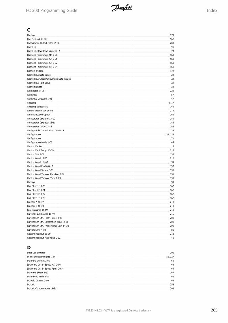
CCabling 173
Can Protocol 10-00 162
Capacitance Output Filter 14-56 203
Catch Up 95
Catch Up/slow Down Value 3-12 74
Changed Parameters (1) 9-90 160
Changed Parameters (2) 9-91 160
Changed Parameters (3) 9-92 161
Changed Parameters (5) 9-94 161
Change-of-state 172
Changing A Data Value 24
Changing A Group Of Numeric Data Values 24
Changing A Text Value 24
Changing Data 23
Clock Rate 17-25 222
Clockwise 57
Clockwise Direction 1-06 47
Coasting 5, 17
Coasting Select 8-50 146
Comm. Option Stw 16-84 219
Communication Option 260
Comparator Operand 13-10 180
Comparator Operator 13-11 183
Comparator Value 13-12 183
Configurable Control Word Ctw 8-14 139
Configuration 135, 138
Configuration 171
Configuration Mode 1-00 45
Control Cables 12
Control Card Temp. 16-39 215
Control Site 8-01 135
Control Word 16-00 212
Control Word 1 9-67 159
Control Word Profile 8-10 137
Control Word Source 8-02 135
Control Word Timeout Function 8-04 136
Control Word Timeout Time 8-03 135
Cooling 59
Cos Filter 1 10-20 167
Cos Filter 2 10-21 167
Cos Filter 3 10-22 167
Cos Filter 4 10-23 167
Counter A 16-72 218
Counter B 16-73 218
Csiv Filename 15-59 211
Current Fault Source 16-49 215
Current Lim Ctrl, Filter Time 14-32 201
Current Lim Ctrl, Integration Time 14-31 201
Current Lim Ctrl, Proportional Gain 14-30 201
Current Limit 4-18 86
Custom Readout 16-09 212
Custom Readout Max Value 0-32 41
DData Log Settings 206
D-axis Inductance (ld) 1-37 51, 227
Dc Brake Current 2-01 65
[Dc Brake Cut In Speed Hz] 2-04 65
[Dc Brake Cut In Speed Rpm] 2-03 65
Dc Brake Select 8-52 147
Dc Braking Time 2-02 65
Dc Hold Current 2-00 65
Dc Link 258
Dc Link Compensation 14-51 202
FC 300 Programming Guide Index
MG.33.M8.02 - VLT® is a registered Danfoss trademark 265
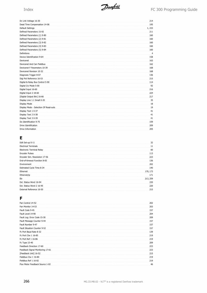
Dc Link Voltage 16-30 214
Dead Time Compensation 14-06 195
Default Settings 1, 233
Defined Parameters 15-92 211
Defined Parameters (1) 9-80 160
Defined Parameters (2) 9-81 160
Defined Parameters (3) 9-82 160
Defined Parameters (4) 9-83 160
Defined Parameters (5) 9-84 160
Definitions 4
Device Identification 9-64 158
Devicenet 163
Devicenet And Can Fieldbus 162
Devicenet F Parameters 10-39 168
Devicenet Revision 10-32 168
Diagnosis Trigger 8-07 136
Digi Pot Reference 16-53 215
Digital & Relay Bus Control 5-90 114
Digital I/o Mode 5-00 92
Digital Input 16-60 216
Digital Input 2 18-60 224
[Digital Output Bin] 16-66 217
Display Line 1.1 Small 0-20 35
Display Mode 18
Display Mode - Selection Of Read-outs 19
Display Text 1 0-37 41
Display Text 2 0-38 41
Display Text 3 0-39 41
Do Identification 9-75 159
Drive Identification 209
Drive Information 205
EEdit Set-up 0-11 32
Electrical Terminals 11
Electronic Terminal Relay 60
Encoder Pulses 113
Encoder Sim. Resolution 17-56 223
End-of-timeout Function 8-05 136
Environment 202
Estimated Cycle Time 8-34 140
Ethernet 170, 173
Ethernet/ip 171
Etr 213, 259
Ext. Status Word 16-94 220
Ext. Status Word 2 16-95 220
External Reference 16-50 215
FFan Control 14-52 202
Fan Monitor 14-53 203
Fault Code 9-45 157
Fault Level 14-90 204
Fault Log: Error Code 15-30 209
Fault Message Counter 9-44 157
Fault Number 9-47 157
Fault Situation Counter 9-52 157
Fc Port Baud Rate 8-32 139
Fc Port Ctw 1 16-85 219
Fc Port Ref 1 16-86 219
Fc Type 15-40 209
Feedback Direction 17-60 223
Feedback Signal Monitoring 17-61 223
[Feedback Unit] 16-52 215
Fieldbus Ctw 1 16-80 219
Fieldbus Ref 1 16-82 219
Flux Motor Feedback Source 1-02 46
Index FC 300 Programming Guide
266 MG.33.M8.02 - VLT® is a registered Danfoss trademark
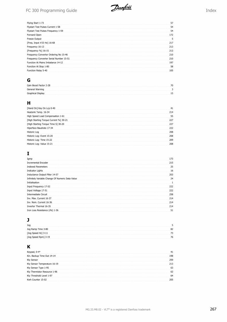
Flying Start 1-73 57
Flystart Test Pulses Current 1-58 54
Flystart Test Pulses Frequency 1-59 54
Forward Open 172
Freeze Output 5
[Freq. Input #33 Hz] 16-68 217
Frequency 16-13 213
[Frequency %] 16-15 213
Frequency Converter Ordering No 15-46 210
Frequency Converter Serial Number 15-51 210
Function At Mains Imbalance 14-12 197
Function At Stop 1-80 58
Function Relay 5-40 105
GGain Boost Factor 2-28 70
General Warning 3
Graphical Display 15
H[Hand On] Key On Lcp 0-40 41
Heatsink Temp. 16-34 214
High Speed Load Compensation 1-61 55
[High Starting Torque Current %] 30-21 227
[High Starting Torque Time S] 30-20 227
Hiperface Baudrate 17-34 222
Historic Log 208
Historic Log: Event 15-20 208
Historic Log: Time 15-22 209
Historic Log: Value 15-21 208
IIgmp 173
Incremental Encoder 215
Indexed Parameters 25
Indicator Lights 16
Inductance Output Filter 14-57 203
Infinitely Variable Change Of Numeric Data Value 24
Initialisation 1
Input Frequency 17-52 222
Input Voltage 17-51 222
Intermediate Circuit 258
Inv. Max. Current 16-37 214
Inv. Nom. Current 16-36 214
Inverter Thermal 16-35 214
Iron Loss Resistance (rfe) 1-36 51
JJog 5
Jog Ramp Time 3-80 82
[Jog Speed Hz] 3-11 73
[Jog Speed Rpm] 3-19 76
KKeypad, 0-4* 41
Kin. Backup Time Out 14-14 198
Kty Sensor 259
Kty Sensor Temperature 16-19 213
Kty Sensor Type 1-95 63
Kty Thermistor Resource 1-96 63
Kty Threshold Level 1-97 64
Kwh Counter 15-02 205
FC 300 Programming Guide Index
MG.33.M8.02 - VLT® is a registered Danfoss trademark 267
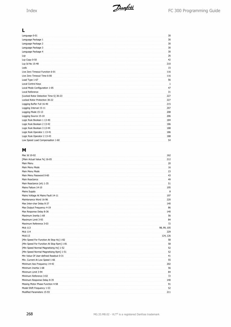
LLanguage 0-01 30
Language Package 1 30
Language Package 2 30
Language Package 3 30
Language Package 4 30
Lcp 26
Lcp Copy 0-50 42
Lcp Id No 15-48 210
Leds 15
Live Zero Timeout Function 6-01 116
Live Zero Timeout Time 6-00 116
Load Type 1-67 56
Local Control Keys 1
Local Mode Configuration 1-05 47
Local Reference 31
[Locked Rotor Detection Time S] 30-23 227
Locked Rotor Protection 30-22 227
Logging Buffer Full 16-40 215
Logging Interval 15-11 207
Logging Mode 15-13 208
Logging Source 15-10 206
Logic Rule Boolean 1 13-40 184
Logic Rule Boolean 2 13-42 186
Logic Rule Boolean 3 13-44 188
Logic Rule Operator 1 13-41 186
Logic Rule Operator 2 13-43 188
Low Speed Load Compensation 1-60 54
MMac Id 10-02 162
[Main Actual Value %] 16-05 212
Main Menu 20
Main Menu Mode 16
Main Menu Mode 23
Main Menu Password 0-60 43
Main Reactance 49
Main Reactance (xh) 1-35 51
Mains Failure 14-10 195
Mains Supply 8
Mains Voltage At Mains Fault 14-11 197
Maintenance Word 16-96 220
Max Inter-char Delay 8-37 140
Max Output Frequency 4-19 86
Max Response Delay 8-36 140
Maximum Inertia 1-69 56
Maximum Limit 3-93 84
Maximum Reference 3-03 72
Mcb 113 98, 99, 105
Mcb 114 229
Mcb113 124, 126
[Min Speed For Function At Stop Hz] 1-82 58
[Min Speed For Function At Stop Rpm] 1-81 58
[Min Speed Normal Magnetising Hz] 1-52 52
[Min Speed Normal Magnetising Rpm] 1-51 52
Min Value Of User-defined Readout 0-31 41
Min. Current At Low Speed 1-66 55
Minimum Aeo Frequency 14-42 202
Minimum Inertia 1-68 56
Minimum Limit 3-94 84
Minimum Reference 3-02 72
Minimum Response Delay 8-35 140
Missing Motor Phase Function 4-58 91
Model Shift Frequency 1-53 52
Modified Parameters 15-93 211
Index FC 300 Programming Guide
268 MG.33.M8.02 - VLT® is a registered Danfoss trademark
Motor Angle 16-20 213
Motor Angle Offset 1-41 51
Motor Construction 1-10 47
Motor Cont. Rated Torque 1-26 48
Motor Control Principle 1-01 45
Motor Cosphi 14-43 202
Motor Current 1-24 48, 213
Motor External Fan 1-91 60
Motor Feedback Loss Function 4-30 87
Motor Feedback Loss Timeout 4-32 88
Motor Feedback Speed Error 4-31 88
Motor Frequency 1-23 48
Motor Magnetisation At Zero Speed 1-50 52
Motor Nominal Speed 1-25 48
Motor Poles 1-39 51
[Motor Power Hp] 1-21 48
[Motor Power Kw] 1-20 47
Motor Protection 59
Motor Speed Direction 4-10 85
[Motor Speed High Limit Hz] 4-14 86
[Motor Speed High Limit Rpm] 4-13 85
[Motor Speed Low Limit Hz] 4-12 85
[Motor Speed Low Limit Rpm] 4-11 85
Motor Speed Unit 0-02 31
Motor Status 212
Motor Thermal 16-18 213
Motor Thermal Protection 1-90 59
Motor Voltage 1-22 48, 213
Multicast 174
My Personal Menu 0-25 39
NNet Control 10-15 167
Net Reference 10-14 166
Network 169, 172, 173
Node Address 9-18 153
Numerical Local Control Panel 26
OOff Delay, Relay 5-42 109
[Off] Key On Lcp 0-41 42
On Delay, Relay 5-41 108
On Reference Bandwidth 7-39 132
Operating Hours 15-00 205
Operating Mode 31
Operating State At Power-up (hand) 0-04 31
Operation Mode 14-22 199
Option Ident. 211
Option Mounted 15-60 211
Option Ordering No 15-62 211
Option Serial No 15-63 211
Option Supplied By External 24vdc 14-80 204
Option Sw Version 15-61 211
Ordered Typecode String 15-44 210
Output Filter 14-55 203
Output Speed 57
Over Temp's 15-04 205
Over Volt's 15-05 205
Overload Mode 1-04 46
Overmodulation 14-03 195
Over-voltage Control 2-17 68
Over-voltage Gain 2-19 68
PParameter Access 167
Parameter Edit 9-27 157
FC 300 Programming Guide Index
MG.33.M8.02 - VLT® is a registered Danfoss trademark 269
Parameter Info 211
Parameter Metadata 15-99 211
Parameter Selection 23
Parameter Set-up 20
Parameters For Signals 8-41 140
Parameters For Signals 9-23 154
Parity / Stop Bits 8-33 139
Pcd Read Configuration 8-43 144
Pcd Read Configuration 9-16 151
Pcd Write Configuration 8-42 143
Pcd Write Configuration 9-15 150
Poles 17-50 222
Port Mirroring 12-96 174
Potentiometer Reference 14
Power Card Ordering No 15-47 210
Power Card Serial Number 15-53 210
[Power Hp] 16-11 213
[Power Kw] 16-10 212
Power Restore 3-92 84
Power Section 15-41 210
Power Up's 15-03 205
Prec. Stop Counter 16-74 218
Precise Stop Counter Value 1-84 59
Precise Stop Function 1-83 58
Precise Stop Speed Compensation Delay 1-85 59
Preset Reference 3-10 73
Preset Reference Select 8-56 148
Preset Relative Reference 3-14 74
Process Cl Feedback 1 Resource 7-20 131
Process Cl Feedback 2 Resource 7-22 131
Process Control 9-28 157
Process Data Config Read 10-12 164
Process Data Config Write 10-11 163
Process Data Type Selection 10-10 163
Process Pid Anti Windup 7-31 132
Process Pid Clamped Output 18-92 224
Process Pid Diff. Gain Limit 7-36 132
Process Pid Differentiation Time 7-35 132
Process Pid Error 18-90 224
Process Pid Extended Pid 7-50 134
Process Pid Fb. Filter Time 7-57 134
Process Pid Feed Forward Factor 7-38 132
Process Pid Feed Fwd Gain 7-51 134
Process Pid Feed Fwd Normal/ Inv. Ctrl. 7-46 133
Process Pid Feed Fwd Ramp Down 7-53 134
Process Pid Feed Fwd Ramp Up 7-52 134
Process Pid Feed Fwd Resource 7-45 133
Process Pid Gain Scale At Max. Ref. 7-44 133
Process Pid Gain Scale At Min. Ref. 7-43 133
Process Pid Gain Scaled Output 18-93 224
Process Pid Integral Time 7-34 132
Process Pid I-part Reset 7-40 133
Process Pid Normal/ Inverse Control 7-30 131
Process Pid Output 18-91 224
Process Pid Output Neg. Clamp 7-41 133
Process Pid Output Normal/ Inv. Ctrl. 7-49 134
Process Pid Output Pos. Clamp 7-42 133
Process Pid Proportional Gain 7-33 132, 228
Process Pid Ref. Filter Time 7-56 134
Process Pid Start Speed 7-32 132
Profibus Save Data Values 9-71 159
Profibus Warning Word 9-53 157
Profibusdrivereset 9-72 159
Profidrive Off2 Select 8-57 149
Profidrive Off3 Select 8-58 149
Profile Number 9-65 158
Programming Set-up 9-70 159
Protection Mode 10
Index FC 300 Programming Guide
270 MG.33.M8.02 - VLT® is a registered Danfoss trademark
Protocol 8-30 139
Protocol Selection 17-20 221
Pulse Filter Time Constant #29 5-54 110
Pulse Filter Time Constant #33 5-59 110
[Pulse Input #29 Hz] 16-67 217
Pulse Out #27 Bus Control 5-93 114
Pulse Out #27 Timeout Preset 5-94 114
Pulse Out #29 Bus Control 5-95 114
Pulse Out #29 Timeout Preset 5-96 115
Pulse Out #x30/6 Bus Control 5-97 115
Pulse Out #x30/6 Timeout Preset 5-98 115
[Pulse Output #27 Hz] 16-69 217
[Pulse Output #29 Hz] 16-70 218
Pulse Output Max Freq #27 5-62 112
Pulse Output Max Freq #29 5-65 112
Pulse Output Max Freq #x30/6 5-68 113
Pulse Reference 16-51 215
Pulse Start/stop 13
Pwm Random 14-04 195
QQuick Menu 16, 21
Quick Menu Mode 16, 20
Quick Menu Password 0-65 43
Quick Stop Ramp Time 3-81 82
Quick Stop Ramp Type 3-82 83
Quick Stop S-ramp Ratio At Decel. End 3-84 83
Quick Stop S-ramp Ratio At Decel. Start 3-83 83
Quick Transfer Of Parameter Settings Between Multiple Frequency Converters 18
RRamp 1 Ramp Down Time 3-42 78
Ramp 1 Ramp Up Time 3-41 77
Ramp 1 S-ramp Ratio At Accel. End 3-46 78
Ramp 1 S-ramp Ratio At Accel. Start 3-45 78
Ramp 1 S-ramp Ratio At Decel. End 3-48 78
Ramp 1 S-ramp Ratio At Decel. Start 3-47 78
Ramp 1 Type 3-40 77
Ramp 2 Ramp Down Time 3-52 79
Ramp 2 Ramp Up Time 3-51 79
Ramp 2 S-ramp Ratio At Accel. End 3-56 79
Ramp 2 S-ramp Ratio At Accel. Start 3-55 79
Ramp 2 S-ramp Ratio At Decel. End 3-58 79
Ramp 2 S-ramp Ratio At Decel. Start 3-57 79
Ramp 2 Type 3-50 78
Ramp 3 Ramp Down Time 3-62 80
Ramp 3 Ramp Up Time 3-61 80
Ramp 3 S-ramp Ratio At Accel. End 3-66 80
Ramp 3 S-ramp Ratio At Accel. Start 3-65 80
Ramp 3 S-ramp Ratio At Decel. End 3-68 80
Ramp 3 S-ramp Ratio At Decel. Start 3-67 80
Ramp 3 Type 3-60 79
Ramp 4 Ramp Down Time 3-72 81
Ramp 4 Ramp Up Time 3-71 81
Ramp 4 S-ramp Ratio At Accel. End 3-76 81
Ramp 4 S-ramp Ratio At Accel. Start 3-75 81
Ramp 4 S-ramp Ratio At Decel. End 3-78 82
Ramp 4 S-ramp Ratio At Decel. Start 3-77 82
Ramp 4 Type 3-70 81
Ramp Delay 3-95 84
Ramp Time 3-91 84
Rated Motor Speed 5
Rcd 7
Readout Bus Off Counter 10-07 162
Readout Filtering 8-08 137
Readout Receive Error Counter 10-06 162
Readout Transmit Error Counter 10-05 162
FC 300 Programming Guide Index
MG.33.M8.02 - VLT® is a registered Danfoss trademark 271
Readout: Edit Set-ups / Channel 0-14 34
Readout: Linked Set-ups 0-13 34
Reference 171
[Reference %] 16-02 212
Reference Function 3-04 73
Reference Range 3-00 71
Reference Resource 1 3-15 75
Reference Resource 2 3-16 75
Reference Resource 3 3-17 75
Reference Site 3-13 74
[Reference Unit] 16-01 212
Reference/feedback Unit 3-01 71
Regional Settings 0-03 31
Relative Scaling Reference Resource 3-18 76
[Relay Output Bin] 16-71 218
Relay Outputs 99
Release Brake Current 2-20 69
Reset 17
Reset Control Word Timeout 8-06 136
Reset Kwh Counter 15-06 205
Reset Mode 14-20 198
Reset Running Hours Counter 15-07 206
Reset Slc 13-03 179
[Reset] Key On Lcp 0-43 42
Resolution (positions/rev) 17-21 221
Resolution (ppr) 17-11 221
Resolver Interface 17-59 223
Resonance Dampening 1-64 55
Resonance Dampening Time Constant 1-65 55
Reversing Select 8-54 148
Rfi Filter 14-50 202
Rotor Leakage Reactance (x2) 1-34 50
Rotor Resistance (rr) 1-31 50
Running Hours 15-01 205
SSafety Precautions 8
Samples Before Trigger 15-14 208
Screened/armoured 12
Serial Communication 6
Service Code 14-29 201
Setpoint 9-00 150
Set-up Copy 0-51 43
Set-up Select 8-55 148
Signal Type 17-10 221
Sl Controller Action 13-52 191
Sl Controller Event 13-51 190
Sl Controller Mode 13-00 176
Sl Controller State 16-38 215
Sl Controller Timer 13-20 184
Slave Error Count 8-83 149
Slave Messages Rcvd 8-82 149
Slip Compensation 1-62 55
Slip Compensation Time Constant 1-63 55
Software Version 15-43 210
Special Functions 194
Speed Pid Diff. Gain Limit 7-05 129
Speed Pid Differentiation Time 7-04 129
Speed Pid Feed Forward Factor 7-08 130
Speed Pid Feedback Gear Ratio 7-07 130
Speed Pid Feedback Source 7-00 128
Speed Pid Integral Time 7-03 128
Speed Pid Lowpass Filter Time 7-06 129
Speed Pid Proportional Gain 7-02 128, 228
[Speed Rpm] 16-17 213
Speed Up/down 14
Ssi Data Format 17-26 222
Index FC 300 Programming Guide
272 MG.33.M8.02 - VLT® is a registered Danfoss trademark
Ssi Data Length 17-24 221
Stall Protection 14-35 201
Start Current 1-76 58
Start Delay 56
Start Delay 1-71 56
Start Event 13-01 176
Start Function 56
Start Function 1-72 56
Start Select 8-53 147
[Start Speed Hz] 1-75 57
[Start Speed Rpm] 1-74 57
Start/stop 13
Stator Leakage Reactance 49
Stator Leakage Reactance (x1) 1-33 50
Stator Resistance (rs) 1-30 50
Status 16
Status Messages 15
Status Word 16-03 212
Status Word 1 9-68 159
Step Size 3-90 84
Step-by-step 24
Stop Delay 2-24 69
Stop Event 13-02 178
Store Always 10-33 168
Store Data Values 10-31 168
Sw Id Control Card 15-49 210
Sw Id Power Card 15-50 210
Switching Frequency 14-01 194
Switching Pattern 14-00 194
Synchronous Motor Speed 5
TTelegram Selection 8-40 140
Telegram Selection 9-22 153
Temp. Input X48/10 18-39 224
Temp. Input X48/4 18-37 224
Temp. Input X48/7 18-38 224
Temperature Sensor Alarm Function 35-06 230
Term 32/33 Encoder Direction 5-71 114
Term 32/33 Pulses Per Revolution 5-70 113
Term X30/6 Digi Out (mcb 101) 5-32 102
Term X30/7 Digi Out (mcb 101) 5-33 103
Term. 29 High Frequency 5-51 109
Term. 29 High Ref./feedb. Value 5-53 110
Term. 29 Low Frequency 5-50 109
Term. 29 Low Ref./feedb. Value 5-52 109
Term. 33 High Frequency 5-56 110
Term. 33 High Ref./feedb. Value 5-58 110
Term. 33 Low Frequency 5-55 110
Term. 33 Low Ref./feedb. Value 5-57 110
Term. X30/11 Filter Time Constant 6-36 119
Term. X30/11 High Ref./feedb. Value 6-35 119
Term. X30/11 Low Ref./feedb. Value 6-34 119
Term. X30/12 Filter Time Constant 6-46 120
Term. X30/12 High Ref./feedb. Value 6-45 119
Term. X30/12 Low Ref./feedb. Value 6-44 119
Term. X48/10 Filter Time Constant 35-34 231
Term. X48/10 High Temp. Limit 35-37 231
Term. X48/10 Input Type 35-05 229
Term. X48/10 Low Temp. Limit 35-36 231
Term. X48/10 Temp. Monitor 35-35 231
Term. X48/10 Temp. Unit 35-04 229
Term. X48/2 Filter Time Constant 35-46 232
Term. X48/2 High Current 35-43 231
Term. X48/2 High Ref./feedb. Value 35-45 232
Term. X48/2 Low Current 35-42 231
Term. X48/2 Low Ref./feedb. Value 35-44 231
FC 300 Programming Guide Index
MG.33.M8.02 - VLT® is a registered Danfoss trademark 273
Term. X48/4 Filter Time Constant 35-14 230
Term. X48/4 High Temp. Limit 35-17 230
Term. X48/4 Input Type 35-01 229
Term. X48/4 Low Temp. Limit 35-16 230
Term. X48/4 Temp. Monitor 35-15 230
Term. X48/4 Temp. Unit 35-00 229
Term. X48/7 Filter Time Constant 35-24 230
Term. X48/7 High Temp. Limit 35-27 231
Term. X48/7 Input Type 35-03 229
Term. X48/7 Low Temp. Limit 35-26 231
Term. X48/7 Temp. Monitor 35-25 230
Term. X48/7 Temp. Unit 35-02 229
Terminal 27 Mode 5-01 92
Terminal 27 Pulse Output Variable 5-60 111
Terminal 29 Mode 5-02 92
Terminal 29 Pulse Output Variable 5-63 112
Terminal 37 Safe Stop 5-19 98
Terminal 42 Output 6-50 120
Terminal 42 Output Bus Control 6-53 122
Terminal 42 Output Filter 6-55 122
Terminal 42 Output Max Scale 6-52 121
Terminal 42 Output Min Scale 6-51 121
Terminal 42 Output Timeout Preset 6-54 122
Terminal 53 Filter Time Constant 6-16 118
Terminal 53 High Current 6-13 117
Terminal 53 High Ref./feedb. Value 6-15 117
Terminal 53 High Voltage 6-11 117
Terminal 53 Low Current 6-12 117
Terminal 53 Low Ref./feedb. Value 6-14 117
Terminal 53 Low Voltage 6-10 117
Terminal 53 Switch Setting 16-61 217
Terminal 54 Filter Time Constant 6-26 118
Terminal 54 High Current 6-23 118
Terminal 54 High Ref./feedb. Value 6-25 118
Terminal 54 High Voltage 6-21 118
Terminal 54 Low Current 6-22 118
Terminal 54 Low Ref./feedb. Value 6-24 118
Terminal 54 Low Voltage 6-20 118
Terminal 54 Switch Setting 16-63 217
Terminal X30/11 High Voltage 6-31 119
Terminal X30/11 Low Voltage 6-30 119
Terminal X30/12 High Voltage 6-41 119
Terminal X30/12 Low Voltage 6-40 119
Terminal X30/6 Pulse Output Variable 5-66 112
Terminal X30/8 Bus Control 6-63 124
Terminal X30/8 Max. Scale 6-62 124
Terminal X30/8 Min. Scale 6-61 124
Terminal X30/8 Output 6-60 122
Terminal X30/8 Output Timeout Preset 6-64 124
Terminal X45/1 Output Min Scale, 6-71 125
Terminal X45/3 Output Min Scale, 6-81 126
Thermal Load 52, 213
Thermistor 59
Thermistor 8
Thermistor Source 1-93 62
This Set-up Linked To 0-12 33
[Torque %] 16-22 214
[Torque %] High Res. 16-21 214
Torque Characteristics 1-03 46
Torque Limit Factor Source 4-20 87
Torque Limit Generator Mode 4-17 86
Torque Limit Motor Mode 4-16 86
[Torque Nm] 16-16 213
[Torque Nm] High 16-25 214
Torque Pi Integration Time 7-13 131
Torque Pi Proportional Gain 7-12 130
Torque Ramp Time 2-27 70
Torque Ref 2-26 70
Index FC 300 Programming Guide
274 MG.33.M8.02 - VLT® is a registered Danfoss trademark
Tracking Error 4-35 89
Tracking Error After Ramping Timeout 4-39 89
Tracking Error Function 4-34 88
Tracking Error Ramping 4-37 89
Tracking Error Ramping Timeout 4-38 89
Tracking Error Timeout 4-36 89
Transformation Ratio 17-53 222
Trigger Event 15-12 207
Trip Delay At Current Limit 14-24 200
Trip Delay At Inverter Fault 14-26 201
Trip Delay At Torque Limit 14-25 200
Trip Reset 198
UU/f Characteristic - F 1-56 54
U/f Characteristic - U 1-55 53
Unit For User-defined Readout 0-30 39
VVlt Ext. Status Word 14-74 203
Voltage 15-42 210
Voltage Reduction In Fieldweakening 1-54 53
Voltage Reference Via A Potentiometer 14
Vt Level 14-40 202
Vvcplus 8
WWarning Current High 4-51 90
Warning Current Low 4-50 90
Warning Feedback High 4-57 90
Warning Feedback Low 4-56 90
Warning Parameter 10-13 166
Warning Reference High 4-55 90
Warning Reference Low 4-54 90
Warning Speed High 4-53 90
Warning Speed Low 4-52 90
Warning Word 137
Warning Word 16-92 220
Warning Word 2 16-93 220
Warnings 255
Wobble Delta Freq. Scaled 30-19 227
Wobble Delta Freq. Scaling Resource 30-03 226
[Wobble Delta Frequency %] 30-02 226
[Wobble Delta Frequency Hz] 30-01 225
[Wobble Jump Frequency %] 30-05 226
[Wobble Jump Frequency Hz] 30-04 226
Wobble Jump Time 30-06 226
Wobble Mode 30-00 225
Wobble Random Function 30-09 226
Wobble Random Ratio Max. 30-11 227
Wobble Random Ratio Min. 30-12 227
Wobble Ratio 30-10 227
Wobble Sequence Time 30-07 226
Wobble Up/ Down Time 30-08 226
FC 300 Programming Guide Index
MG.33.M8.02 - VLT® is a registered Danfoss trademark 275
Rev. 2009-10-12
www.danfoss.com/drives
130R0334 MG33M802
*MG33M802*
MG
33M802
VLT ® Autom
ationDrive FC
300 Programm
ing Guide
Programming GuideVLT® AutomationDrive FC 300
MAKING MODERN LIVING POSSIBLE
Related Documents