VK3YNG Sniffer 4 Instruction Manual (for V4.2 hardware) © 2020, Bryan Ackerly, VK3YNG Rev 4.2 Page 1 VK3YNG Foxhunt Sniffer Instruction Manual (Updated version for version 4.2 hardware and V4.2.01 or later firmware***) The VK3YNG Foxhunt Sniffer is a specially designed synthesised VHF direction finding receiver covering 120MHz and 144MHz bands. The receiver is designed for quickly finding the direction of beacons or hidden transmitters. Anything from distant weak signals to very close “sniffing” of transmitters running many watts of output power can be pin pointed accurately without suffering “overload” problems that plague other designs. Full auto-ranging operation allows the operator to quickly and intuitively locate the source of a signal without twiddling knobs or watching meters. The operator is freed to concentrate on more important things such as negotiating terrain or reading maps. ***Note: A number of features have changed since earlier versions of the sniffer were released. This manual reflects operation of version 4.2 hardware and cannot be used for all versions of the MK4 sniffer. For a copies of earlier sniffer manuals please refer to the VK3YNG foxhunt web site (see the end of this manual).

Welcome message from author
This document is posted to help you gain knowledge. Please leave a comment to let me know what you think about it! Share it to your friends and learn new things together.
Transcript
VK3YNG Sniffer 4 Instruction Manual (for V4.2 hardware)
© 2020, Bryan Ackerly, VK3YNG Rev 4.2 Page 1
VK3YNG Foxhunt Sniffer Instruction Manual (Updated version for version 4.2 hardware and V4.2.01 or later firmware***)
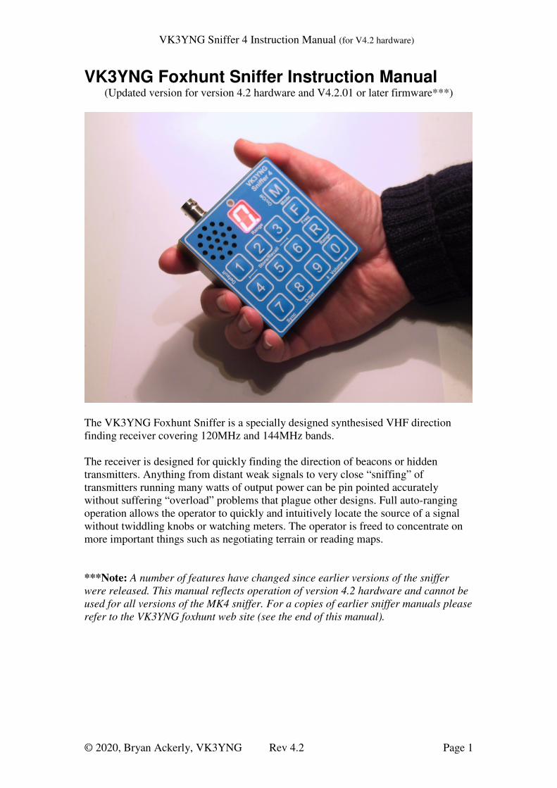
The VK3YNG Foxhunt Sniffer is a specially designed synthesised VHF direction
finding receiver covering 120MHz and 144MHz bands.
The receiver is designed for quickly finding the direction of beacons or hidden
transmitters. Anything from distant weak signals to very close “sniffing” of
transmitters running many watts of output power can be pin pointed accurately
without suffering “overload” problems that plague other designs. Full auto-ranging
operation allows the operator to quickly and intuitively locate the source of a signal
without twiddling knobs or watching meters. The operator is freed to concentrate on
more important things such as negotiating terrain or reading maps.
***Note: A number of features have changed since earlier versions of the sniffer
were released. This manual reflects operation of version 4.2 hardware and cannot be
used for all versions of the MK4 sniffer. For a copies of earlier sniffer manuals please
refer to the VK3YNG foxhunt web site (see the end of this manual).

VK3YNG Sniffer 4 Instruction Manual (for V4.2 hardware)
© 2020, Bryan Ackerly, VK3YNG Rev 4.2 Page 2
Introduction .................................................................................................................... 3
Auto Power Down.......................................................................................................... 4
Low Battery Indication .................................................................................................. 4
Display Brightness ......................................................................................................... 4
Reduced Functionality mode: ........................................................................................ 4
Quick Button Reference:................................................................................................ 5
Alternative Key Functions: ............................................................................................ 5
Detailed Button Operation ............................................................................................. 6
Mode/Power switch: .................................................................................................. 6
Power On: .............................................................................................................. 6
Mode Selection: ..................................................................................................... 6
FM Mute: ............................................................................................................... 6
Power Off: .............................................................................................................. 6
Memories ................................................................................................................... 7
Recall functions. .................................................................................................... 7
Store functions ....................................................................................................... 7
Sync Button ................................................................................................................ 8
ARDF Sync: ........................................................................................................... 8
Band Scan: ............................................................................................................. 8
Other functions: ..................................................................................................... 8
D-Set button ............................................................................................................... 9
Special note: “Dset 0” in “Scout” mode: ............................................................... 9
Uptime indication: ............................................................................................... 10
Relative Battery Voltage indication: .................................................................... 10
Firmware version indication: ............................................................................... 10
Volume Control ....................................................................................................... 11
Range Control .......................................................................................................... 11
Peak Hold Mode .................................................................................................. 11
Peak range memory.............................................................................................. 11
Frequency Entry ....................................................................................................... 11
Configuring the Sniffer ................................................................................................ 13
Tone (RSSI) Filtering: ............................................................................................. 13
Minimum filtering (1): ......................................................................................... 13
Medium Filtering (2): .......................................................................................... 13
Maximum Filtering (3): ....................................................................................... 13
Peak Extend mode Filtering (6): .......................................................................... 13
ARDF/Scan Mode:................................................................................................... 13
ARDF Mode (4): .................................................................................................. 13
Scan Ready (Non-ARDF) Mode (5): ................................................................... 13
Low Tone Mode (8): ................................................................................................ 14
Gambier Mode (9): .................................................................................................. 14
Display (and keypad) LED brightness (0): .............................................................. 14
Reduced Functionality Mode (F): ............................................................................ 15
Range Tones Announce (R): .................................................................................... 15
Function Reset (7): ................................................................................................... 15
Battery Selection and Maximizing Battery Life .......................................................... 15
Sample antenna designs ............................................................................................... 17
Specifications: .............................................................................................................. 18
Links: ........................................................................................................................... 18

VK3YNG Sniffer 4 Instruction Manual (for V4.2 hardware)
© 2020, Bryan Ackerly, VK3YNG Rev 4.2 Page 3
Introduction The VK3YNG sniffer is designed to allow quick, easy and accurate determination of
the direction of a transmitted signal in either the 120-123MHz or 143-150MHz bands.
The sniffer provides enough sensitivity to determine the direction of a signal from
many kilometres or miles away. This is useful for ARDF, Radio Sport and general
commercial or Civil Air Patrol use. It also provides enough attenuation to accurately
determine the direction of signals right up to the source of the signal without suffering
from overload or compression effects.
Attenuation (signal reduction) is provided automatically in steps of approximately
15dB each time a particular signal strength threshold is reached. The number of 15dB
steps of attenuation is shown on an LED display. For example, a display value of zero
indicates maximum sensitivity, where a value of 9 indicates a close or very strong
signal that requires approximately 135dB of attenuation.
Signal strength indication is provided by an audible tone that increases in frequency
(pitch) with increasing signal level. This is done because the human ear is a much
more sensitive to changes in pitch than sound level. There is also no inertia or
overshoot problems as tend to occur with signal meters. A special software algorithm
ensures that the received signal strength tone does not suffer from “compression”
effects that occur at higher signal levels with some designs.
VK3YNG Sniffer 4 Instruction Manual (for V4.2 hardware)
© 2020, Bryan Ackerly, VK3YNG Rev 4.2 Page 4
Auto Power Down The sniffer will automatically power down if either of the following two conditions
are met:
1) There has been no key pressed for at least 10 minutes.
2) There has been no “upward” progression in range for at least 10 minutes.
The sniffer will give five short beeps just before the unit powers down.
Low Battery Indication The sniffer functions accurately to supply voltages down to approximately 2.3 volts.
Below this the accuracy becomes compromised or the sniffer may power itself down.
When power has dropped to 2.3 volts or lower, the display decimal point is enabled to
warn the user that batteries are in need of replacement.
Display Brightness A high efficiency Seven Segment Orange LED is used for the range display. It has
two brightness settings, one for daytime use and a significantly reduced brightness
level for night use. A light sensor located immediately above the display
automatically determines the brightness level.
Reduced Functionality mode: This mode may be useful for children or first time operators. It allows the sniffer to be
used in its most basic format and hides all programmability options from the user.
This mode is very useful for scout foxhunting for example. For this reason, many
refer to this mode as “Scout Mode”. This mode also has some special features to aid
beginners.

VK3YNG Sniffer 4 Instruction Manual (for V4.2 hardware)
© 2020, Bryan Ackerly, VK3YNG Rev 4.2 Page 5
Quick Button Reference: The following table gives quick index to key functions in both normal and reduced
functionality modes.
Button Operation in Normal mode Operation in reduced
functionality mode
1 Recall channel 1 (Hold to store
frequency/mode)
Recall only channel 1
2 Recall channel 2 (Hold to store
frequency/mode)
Recall only channel 2
3 Recall channel 3 (Hold to store
frequency/mode)
Recall only channel 3
4 Recall channel 4 (Hold to store
frequency/mode)
Recall only channel 4
5 Recall channel 5 (Hold to store
frequency/mode)
Recall only channel 5
6 Recall channel 6 (Hold to store
frequency/mode)
Recall only channel 6
7 Band Scan or ARDF mode Start of cycle
Synchronisation function.
No function
8 Range down Delay Set/Display. 1 to 5 seconds.
0=peak hold mode. (7-9 are special functions)
Battery level
9 Volume Down Battery level
0 Volume Up No function
R Manual Range set/disable No function
F Frequency Entry (4 digits follow) No function
M Power/Audio Mode Select (Tone/AM/FM,
Hold for power off)
Power On/Off only
(instant power off)
Alternative Key Functions: The default operation mode of the sniffer can be reconfigured by holding down
certain keys while powering up the unit. The sniffer will maintain this operation mode
for subsequent power up/down cycles. Even if batteries are removed.
Button Display during
power-up
Function if pressed during power-up
1 N Filter “A”, Minimum Tone filtering. (fastest response)
2 O Filter “B”, Medium Tone filtering
3 P Filter “C”, Maximum Tone filtering (slowest
response)
4 A ARDF mode. Synchronised at power-up. Sync key is
used to re-sync the transmitter cycle.
5 C Scan mode. Sync key is used to scan for strongest
signal between frequency stored in channels 5 and 6.
6 J Filter “D”, Tone Extend Mode. Used for very short
duration signals.
7 H Normal operation. Resets all options below:
VK3YNG Sniffer 4 Instruction Manual (for V4.2 hardware)
© 2020, Bryan Ackerly, VK3YNG Rev 4.2 Page 6
8 L Low-Tone mode (RSSI tones at quarter frequency.
Resolution slightly reduced at low tone frequencies)
9 G Mt Gambier mode (10 fixed channels)
0 o,d,b,A LED display brightness mode (dull/bright/Auto)
F S Reduced key functionality mode (“scout” mode)
R T Enable morse code announcement tones
Detailed Button Operation
Mode/Power switch:
Power On:
Pressing this button once powers on the unit to the frequency and mode stored in
memory channel 1.
Mode Selection:
Pressing this button momentarily while the unit is powered up cycles the unit through
its operating modes and briefly displays the selection on the display. The modes cycle
through in the following sequence: “A” – AM reception, “U” – Unmuted FM
reception, “F” – Muted FM reception and “t” – Signal strength Tone. The cycle then
repeats. When headphones are used, one channel is always set to give signal strength
tone, while the other channel follows the selected mode. This is useful for hunting
different continuous carrier transmissions where the transmitters’ identification is
given using either AM of FM modulation.
FM Mute:
The Muted FM mode offers a pseudo FM mute function to mute all receiver audio
when the sniffer is not receiving a signal. This is a signal based (rather than noise
based) mute that activates whenever the received signal is below the lower range
threshold on ranges 1 upward and is always active on range 0.
Power Off:
Pressing and holding the Mode button for greater than 1 second will power down the
unit. In reduced functionality mode, the unit will power off immediately when the
Mode button is pressed. The mode switch operates only as a simple on/off switch in
reduced functionality mode.
M

VK3YNG Sniffer 4 Instruction Manual (for V4.2 hardware)
© 2020, Bryan Ackerly, VK3YNG Rev 4.2 Page 7
through
Memories
Buttons 1 through 6 allow storing and recalling of memory modes and frequencies.
Recall functions.
Pressing any of the buttons 1 through 6 in normal operation mode will recall the
frequency and mode stored in non-volatile memory. In normal operation mode, the
display will display the last 4 digits of the selected memories frequency in kilohertz.
For example, a stored frequency of 147.425MHz will flash up the sequence “7 4 2 5”.
The first two (100 and 10) megahertz digits are inferred by first entered digit as per
the following table:
Setting of “MHz” digit Band selection
0, 1, 2 120-122.995MHz
3 through 9 143-149.995MHz
The recalled frequency is not displayed in reduced functionality mode.
Store functions
Pressing and holding any of buttons 1 through 6 will result in the selected frequency
and mode being stored in the selected memory. The button must be pressed and held
until two short beeps are heard in succession. This confirms that the data has been
committed to memory.
The Store function is disabled in reduced functionality mode.
1 6

VK3YNG Sniffer 4 Instruction Manual (for V4.2 hardware)
© 2020, Bryan Ackerly, VK3YNG Rev 4.2 Page 8
Sync Button
ARDF Sync:
This facility is used to synchronise the receiver for use in international style (ARDF)
foxhunting for a one-minute cycle, five-transmitter system.
In ARDF mode this timer is automatically synchronized when the receiver is switched
on. Three short beeps are generated as confirmation of this mode. Pressing the Sync
button re-synchronises this timer. Three short beeps are given to confirm this button
has been pressed. The sync button should be pressed at the start of transmitter one’s
cycle.
At 50 seconds into the cycle, the sniffer will generate three short beeps giving 10
seconds warning that the current transmitter’s cycle is about to end. If the sniffer is
currently receiving at range 1 or lower, at four seconds before the completion of the
current transmitter cycle the sniffer broadcasts a number of beeps corresponding to
the number of the transmitter in the cycle which is about to commence. The pitch of
these beeps is set slightly lower than the “50-second” beeps. The display also briefly
flashes the number of the next transmitter. If a range down delay (d-Set) of zero is
selected and the sniffer is not currently configured for manual ranging, the sniffer will
automatically select range zero at the start of the next transmitters’ cycle regardless of
the current signal strength.
The ARDF sync mode is entered by pressing and holding the “4” button during
power-up. It is cancelled by returning to Scan mode.
Band Scan:
When ARDF mode is not selected, the “7” key performs a basic band scan operation
where the sniffer hunts for the highest signal between the two frequencies stored in
channel locations 5 and 6. The highest signal found is stored in channel 4. The scan
will ignore any signals within approximately 10KHz of the frequency stored for
channel 1 and the signal must be detectable at range 2 or higher to be stored.
This operation takes some time to complete, especially if there is large frequency
difference between channels 5 and 6. The scan function works best for continuous
signals and may not properly detect intermittent transmissions. Channel 5 must be
lower in frequency than channel 6 and both frequencies must be within the same band
(i.e. 120MHz or 140MHz)
The SCAN mode is entered by pressing and holding the “5” button during power-up.
It is cancelled by entering ARDF Sync mode. Scan mode is the factory default.
Other functions:
Holding the “7” key during power-up cancels the Low RSSI Tone mode, disables
Morse code tones, sets LED brightness to “auto” and disables Reduced Key
Functionality (scout) mode. In this mode the signal strength tones function normally
7

VK3YNG Sniffer 4 Instruction Manual (for V4.2 hardware)
© 2020, Bryan Ackerly, VK3YNG Rev 4.2 Page 9
and the maximum signal strength pitch is 8KHz. This mode is set as the factory
default. (*Note: this facility operates differently in older firmware versions)
This key is disabled in reduced functionality mode.
D-Set button
Ranging up on the sniffer happens automatically with minimal delay. To implement
short term peak detection, there is an intentional delay before the sniffer ranges down.
This delay is programmable between 1 and 5 seconds using the D-Set button. For
beginners, a value between 3 and 5 seconds is recommended. For more advanced
users, 1 or 2 seconds gives better results. When hunting intermittent and very short
duration transmissions such as those used on dog collars or wildlife, 5 seconds or
“peak hold” mode (see below) is recommended. The factory default is 2 seconds.
To set the range down delay, press the “D-Set” button. The display will respond by
displaying the letter “d”. Pressing buttons 0 through 5 will then set and store the new
range down delay.
Pressing the D-set (8) button twice will briefly display the current range down delay
in seconds. The display then reverts to displaying the current range.
Setting a range down delay of zero disables down ranging. In this case the sniffer
operates in a “peak hold” mode and down ranging is disabled. Manual ranging is
disabled and pressing the “range” button will reset the current peak hold range to
zero. This mode is useful when hunting extremely intermittent signals such as dog
collar, wildlife or model aircraft beacons.
Holding the “D-Set” key during power-up causes the sniffer to operate in lower tone
RSSI mode. This mode may prove useful to those who have difficulty hearing higher
audio frequencies. In this mode the signal strength tone frequencies are divided by 4.
The top tone pitch is limited to about 2KHz and resolution becomes slightly limited at
the lowest tone frequencies. (Note: this mode has no effect on the pitch of supervisory
beep and tone frequencies)
This key is disabled in reduced functionality mode.
Special note: “Dset 0” in “Scout” mode:
In version 3.0 or later, if peak hold mode (Dset 0) is selected before the sniffer is set
up for reduced functionality (“scout”) mode, the peak hold behavior behaves slightly
differently. If a strong signal disappears for more than 5 seconds, the sniffer will
range down by one range only. As with normal peak hold behavior it will stay there
until the range is reset or the channel or frequency is changed.
This operation was added to give beginners a second go at a signal source if they
happen “over shoot” it and the signal falls below the current peak range.
8

VK3YNG Sniffer 4 Instruction Manual (for V4.2 hardware)
© 2020, Bryan Ackerly, VK3YNG Rev 4.2 Page 10
Uptime indication:
Pressing the “D-Set” button then pressing “7” will display 4 digits indicating the
number of hours and minutes since the receiver was powered up. This can be useful
for ARDF events where the user may have forgotten to synchronise their watch.
Relative Battery Voltage indication:
Pressing the “D-Set” button then pressing “9” will display two digits giving an
indication of the relative battery capacity in percentage terms. 99% indicates a full
battery while 0% indicates the point where sniffer operation is significantly
compromised. The sniffer may power itself off before reaching 0%.
In reduced functionality (scout) mode, battery capacity is displayed by just one
pressing of the “D-Set” button. (Since in this mode D-Set options are NOT made
available to the user)
Firmware version indication:
Pressing the “D-Set” button and then pressing the “F” button will display 4 digits
which indicate the installed firmware version.

VK3YNG Sniffer 4 Instruction Manual (for V4.2 hardware)
© 2020, Bryan Ackerly, VK3YNG Rev 4.2 Page 11
Volume Control
During normal operation, the “9” and “0” buttons allow the setting of volume. The
display briefly shows the new level and reverts to displaying the current range when
the button is released. These buttons are disabled in reduced functionality mode.
Range Control
Normally the sniffer automatically selects the best range for the currently received
signal. In some situations it may be necessary to range the sniffer manually. The range
control button can be used for this purpose. This button also controls a number of
other features depending on the mode selected.
In auto-ranging mode, pressing this button briefly displays the letter “r” in the display,
and then the display reverts to displaying the current range. Pressing any digit then
manually selects the range. The display briefly displays “r” followed by the selected
range. The sniffer remains in manual ranging mode until defeated by pressing the “R”
button a second time. This re-enables auto-ranging.
Holding this key during power-up enables announcements of range, frequency and
various other functions using morse code. This feature has been added to assist blind
operators using the receiver. (Note: This is a new feature in version 4 and its
operation is subject to change. More information on its operation will be available on
the web site. Powering up with the “7”button pressed disables morse announcements.
See the section on the “Sync” button for more information.)
This key is disabled in reduced functionality mode.
Peak Hold Mode
This range button also resets the peak range hold function if the down range delay (D-
set) is set to zero. In peak hold mode, manual ranging is disabled.
Peak range memory
If the range button is pressed twice in succession, the display will briefly show the
maximum range the sniffer has achieved since power up or the last successful
frequency change. (In version 3.0 or later, pressing “Dset” and then “Range” also
performs this same operation)
In ARDF mode, (see Sync button section) the peak range value is automatically reset
near the end of the next transmitter cycle. This is very useful if there is a need to
check what range the sniffer got to just before the previous transmitter finished its
cycle.
This function is not available when Peak Hold mode (dSet=0) is selected.
Frequency Entry
F
R
9 0
VK3YNG Sniffer 4 Instruction Manual (for V4.2 hardware)
© 2020, Bryan Ackerly, VK3YNG Rev 4.2 Page 12
The sniffer can operate at any frequency in the range 120.000-122.995 and 143.000 -
149.995MHz* in 5KHz steps. Pressing the “F” button initiates frequency entry. The
display confirms this by displaying “F”. The sniffer then expects four digits to be
keyed in to set the desired frequency. If an error occurs while entering frequency, the
letter “E” is briefly displayed and the sniffer then reverts to the previous operation
frequency. The first digit sets both the 1MHz frequency and the band. 0 through 2 sets
the 120MHz band. 3 through 9 set the 140MHz band.
Factory default frequencies
Memory Frequency Mode
1 145.300MHz Tone
2 145.700MHz Tone
3 144.250MHz Tone
4 146.500MHz Tone
5 121.500MHz Tone
6 146.575MHz FM
Note: 121.5MHz is used as an international personal, maritime and aeronautical
distress beacon frequency. With an appropriate antenna, the sniffer can be used to
locate the homing frequency of PLB, ELT and EPIRB emergency beacons.
For the scan function to work correctly, the frequencies stored in channels 5 and 6
should be in the same band. This is not the case for the factory default configuration.
Direct frequency entry is not permitted in reduced functionality mode.
(*Note: Some special versions of the sniffer operate with different frequency ranges to
those indicated above. The label on the rear of your sniffer will indicate the frequency
range your sniffer covers.
Some special “narrowband” versions also allow 1kHz resolution. In this case the
fourth digit entered can be any number from “0” to “9” instead of only “0” or “5”.
2.5kHz resolution can be available for some special builds. In this case “2” and “7”
are also valid and correspond to xxx.xx25 MHz and xxx.xx75 MHz respectively.)
VK3YNG Sniffer 4 Instruction Manual (for V4.2 hardware)
© 2020, Bryan Ackerly, VK3YNG Rev 4.2 Page 13
Configuring the Sniffer The MK4 sniffer has a number of configurable features. Some of these have already
been described in the previous sections. The rest are explained here.
Tone (RSSI) Filtering:
There are four levels of filtering available on the MK4 sniffer. These are selected by
holding buttons 1, 2, 3 or 6 when powering up the sniffer. The sniffer will retain this
setting until the next time it is changed.
Minimum filtering (1):
This level of filtering is the same as the original MK4. It offers the fastest and most
accurate tracking of the received signal level. On transmitters with a high AM
component (Such as ARDF transmitters), the tone can become quite “thick” sounding
as the tone tries to partially track the modulation. In this case filter modes 2 or 3 are
recommended. Setting “1” is the factory default.
Medium Filtering (2):
This level of filtering offers the best compromise between response time and
Amplitude modulation (AM) filtering. This is the most recommended setting.
Maximum Filtering (3):
This mode provides maximum filtering of the received signal and is similar to that of
the VK3TJN/XAJ Ultra-sniffer. While this mode offers the best smoothing of
received signals it can significantly “blur” the definition of short duration pulses.
Peak Extend mode Filtering (6):
This is a special mode for use with very short duration repetitive signals such as those
emitted from dog collar, wildlife or model aircraft transmitters. The transmitters used
are typically very low power and transmit for around 40 milliseconds every second or
two. The tone pitch and therefore signal direction can be very hard to determine using
the above filtering modes.
This special mode extends the time of the peak level of the received signal so that the
user can easily compare the signal level from different directions.
ARDF/Scan Mode:
ARDF Mode (4):
Holding the “4” button while powering up puts the sniffer into ARDF mode. In this
mode the sniffer will power up giving three beeps and will synchronise the ARDF
timer. For more information see the section on the Sync Button.
Scan Ready (Non-ARDF) Mode (5):
Holding the “5” button while powering up puts the sniffer into scan ready mode and
disables ARDF mode. In this mode the sniffer gives a single beep during power up
and the sync button executes a band scan function. This is the factory default. For
more information see the section on the Sync Button.
VK3YNG Sniffer 4 Instruction Manual (for V4.2 hardware)
© 2020, Bryan Ackerly, VK3YNG Rev 4.2 Page 14
Low Tone Mode (8):
In this mode the signal strength tone frequencies are divided by 4. See the description
of the “Dset” button for more info.
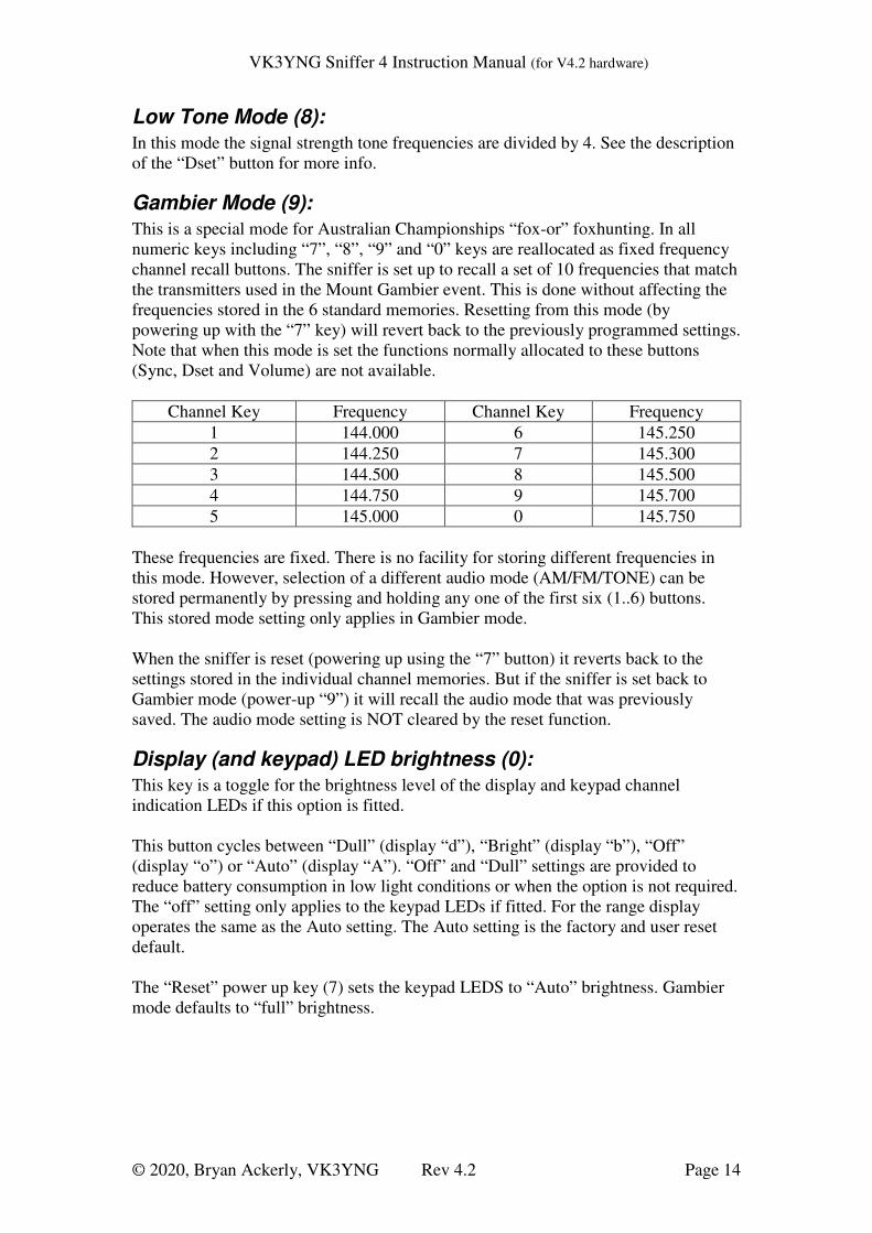
Gambier Mode (9):
This is a special mode for Australian Championships “fox-or” foxhunting. In all
numeric keys including “7”, “8”, “9” and “0” keys are reallocated as fixed frequency
channel recall buttons. The sniffer is set up to recall a set of 10 frequencies that match
the transmitters used in the Mount Gambier event. This is done without affecting the
frequencies stored in the 6 standard memories. Resetting from this mode (by
powering up with the “7” key) will revert back to the previously programmed settings.
Note that when this mode is set the functions normally allocated to these buttons
(Sync, Dset and Volume) are not available.
Channel Key Frequency Channel Key Frequency
1 144.000 6 145.250
2 144.250 7 145.300
3 144.500 8 145.500
4 144.750 9 145.700
5 145.000 0 145.750
These frequencies are fixed. There is no facility for storing different frequencies in
this mode. However, selection of a different audio mode (AM/FM/TONE) can be
stored permanently by pressing and holding any one of the first six (1..6) buttons.
This stored mode setting only applies in Gambier mode.
When the sniffer is reset (powering up using the “7” button) it reverts back to the
settings stored in the individual channel memories. But if the sniffer is set back to
Gambier mode (power-up “9”) it will recall the audio mode that was previously
saved. The audio mode setting is NOT cleared by the reset function.
Display (and keypad) LED brightness (0):
This key is a toggle for the brightness level of the display and keypad channel
indication LEDs if this option is fitted.
This button cycles between “Dull” (display “d”), “Bright” (display “b”), “Off”
(display “o”) or “Auto” (display “A”). “Off” and “Dull” settings are provided to
reduce battery consumption in low light conditions or when the option is not required.
The “off” setting only applies to the keypad LEDs if fitted. For the range display
operates the same as the Auto setting. The Auto setting is the factory and user reset
default.
The “Reset” power up key (7) sets the keypad LEDS to “Auto” brightness. Gambier
mode defaults to “full” brightness.

VK3YNG Sniffer 4 Instruction Manual (for V4.2 hardware)
© 2020, Bryan Ackerly, VK3YNG Rev 4.2 Page 15
Reduced Functionality Mode (F):
In this mode, most of the special features of the sniffer are disabled. This mode is
useful when a newcomer or a scout group etc uses the sniffer. (Hence why some users
call this “Scout Mode”) Memories can only be recalled and most of the other keys,
including volume control are disabled. The power button only acts as a simple on-off
and the mode of operation is defined by what is stored for each channel.
To set the sniffer in reduced functionality mode, press and hold the “F” button while
powering up.
To cancel reduced functionality mode, press and hold the “7” key while powering up.
Range Tones Announce (R):
Enables the “range tone announcement” mode. See the description of the Range key
for more info.
Function Reset (7):
This key resets or cancels the following modes if they are set:
1) Low Tone mode,
2) Range Tones (Morse) Announce,
3) Reduced Functionality (scout) mode,
4) Gambier Mode
5) Sets keypad LEDs to “dull” brightness (if option fitted)
6) ARDF mode. (V4.1.00+ firmware only)
Battery Selection and Maximizing Battery Life There are a number of solutions for extending battery life with the sniffer. The most
critical one is the volume setting. Battery life is reduced considerably when using the
internal speaker on a high volume level with a continuous signal. Use the lowest
volume level possible when using the internal speaker or use external headphones.
The display also operates at a higher intensity level for daytime use that puts more
load on the battery. Typically night time only operation increases alkaline battery life
by about 30%.
Zinc Carbon and General Purpose Manganese, or so called “Heavy Duty”
batteries are not recommended. The internal resistance of these batteries is too high
to get reliable operation from the sniffer. Also these batteries often leak when they go
flat and damage components. Use of these batteries will void the sniffers warranty.
This version of the sniffer can run off higher capacity NiMh batteries. These batteries
may be considered to save on battery costs if the sniffer is used very regularly. But
performance will not be as good as Alkaline. Because of the lower terminal voltage
(1.2V) the sniffer will always indicate these batteries as partially depleted, (normally
around 50%) even when fully charged. The battery “%” reading is based on the
Alkaline discharge curve. When the batteries go flat the sniffer will stop operating
abruptly with little or no warning. The sniffer also provides no means of charging
these batteries. They must always be removed for charging.
VK3YNG Sniffer 4 Instruction Manual (for V4.2 hardware)
© 2020, Bryan Ackerly, VK3YNG Rev 4.2 Page 16
AA Battery pairs discharged at 160mA
0
0.5
1
1.5
2
2.5
3
3.5
0 200 400 600 800 1000 1200(Minutes)
(V)
Alkaline
Lithium Disulphide
NiMH
(10Hr) (20Hr)
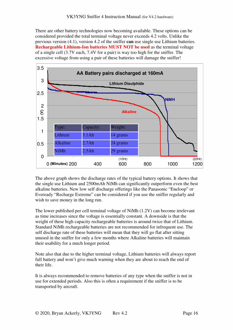
There are other battery technologies now becoming available. These options can be
considered provided the total terminal voltage never exceeds 4.2 volts. Unlike the
previous version (4.1), version 4.2 of the sniffer can use single use Lithium batteries.
Rechargeable Lithium-Ion batteries MUST NOT be used as the terminal voltage
of a single cell (3.7V each, 7.4V for a pair) is way too high for the sniffer. The
excessive voltage from using a pair of these batteries will damage the sniffer!
The above graph shows the discharge rates of the typical battery options. It shows that
the single use Lithium and 2500mAh NiMh can significantly outperform even the best
alkaline batteries. New low self discharge offerings like the Panasonic “Eneloop” or
Eveready “Recharge Extreme” can be considered if you use the sniffer regularly and
wish to save money in the long run.
The lower published per cell terminal voltage of NiMh (1.2V) can become irrelevant
as time increases since the voltage is essentially constant. A downside is that the
weight of these high capacity rechargeable batteries is around twice that of Lithium.
Standard NiMh rechargeable batteries are not recommended for infrequent use. The
self discharge rate of these batteries will mean that they will go flat after sitting
unused in the sniffer for only a few months where Alkaline batteries will maintain
their usability for a much longer period.
Note also that due to the higher terminal voltage, Lithium batteries will always report
full battery and won’t give much warning when they are about to reach the end of
their life.
It is always recommended to remove batteries of any type when the sniffer is not in
use for extended periods. Also this is often a requirement if the sniffer is to be
transported by aircraft.
Type: Capacity: Weight:
Lithium 3.1Ah 14 grams
Alkaline 2.7Ah 24 grams
NiMh 2.5Ah 29 grams

VK3YNG Sniffer 4 Instruction Manual (for V4.2 hardware)
© 2020, Bryan Ackerly, VK3YNG Rev 4.2 Page 17
Sample antenna designs The antenna design is largely a matter of personal choice. For portable use, designs
vary between two and four elements. More elements give better directivity and more
precise bearings but are more difficult to carry around. For most situations, three
elements offer a good compromise. Here is an example of antenna designs for 120
and 146MHz.
Director
Driven Element
Reflector
Frequency:
Director
Driven Element
Refelector
121MHz
1118
1178
1237
146MHz
930
981
1029
Tap Length 138 115
Element Spacing 373 311
Balun Length 815 680
Tap Length
25mm
(centre to centre)
A B
Sniffer Mounting Plate73 x 80mm
Element Lengths from Tip to Tip
All units in Millimetres (divide by 25.4 for inches)
Element Material: 10mm aluminium tubing
Tap lengths are typical and may require adjustement
Typical 3-element Beam Antenna (based on VK3VT design)
Balun(RG174 coax cable)
BNC Connector
VK3YNG Sniffer 4 Instruction Manual (for V4.2 hardware)
© 2020, Bryan Ackerly, VK3YNG Rev 4.2 Page 18
Specifications:
Frequency Coverage 120-122.995MHz, 143-149.995MHz in 5KHz steps
Channel Bandwidth 16KHz
Sensitivity Better than -120dBm
Maximum signal level +26dBm
Power Supply 3VDC (2xAA Alkaline or Lithium penlight cells)
Battery Life* Typically 3+ hours (alkaline), 14+ hours (Lithium)
Memories 6, programmable (stores mode and frequency) or 10 fixed.
Receive modes AM, FM, Signal strength Tone
Max RSSI frequency Programmable 2KHz or 8KHz
Size 76mm(W), 80mm(H), 25mm(D) not including BNC
connector
Antenna Connection BNC
Headphone Connection 3.5mm stereo
*Note: Battery life is dependant sound level and display intensity. See section on
battery life.
Links: More information on foxhunting and techniques can be found on these web sites:
Australian ARDF website:
http://www.ardf.org.au
Joe Moell’s Foxhunting website. (A very good foxhunters resource)
http://www.homingin.com
Author: Bryan Ackerly, VK3YNG
Web page: http://www.foxhunt.com.au
Email : [email protected] (use web site links!)
Phone +61 438 573 686
VCO
PLL
Atten RF
2nd L.O.
10.7MHz 455KHz
Detector
Regulator
CPU
Keypad
Pwr Supply
5V
3V
3V Batt
DAC
FMAM
Tone
RS
SI
LDR
GainTune
Ant.
120-150MHz 120-150MHz
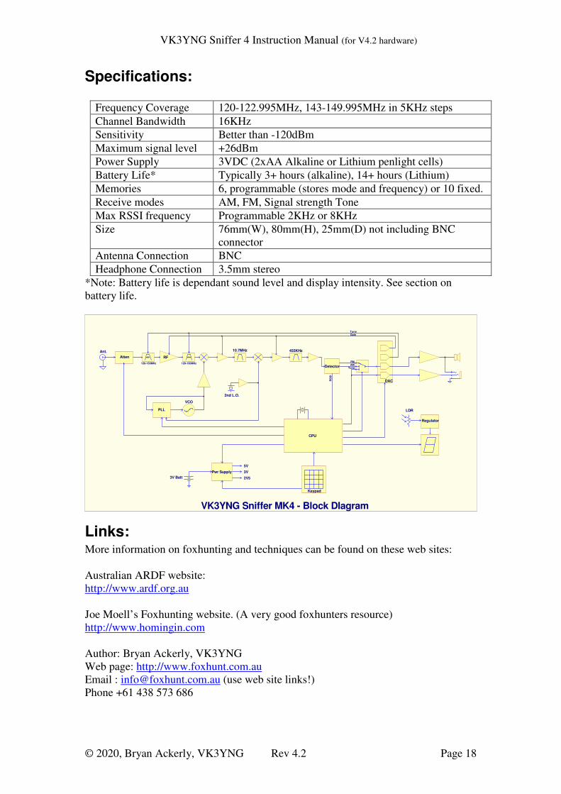
VK3YNG Sniffer MK4 - Block DIagram
2V5
Related Documents