11/11-01 PC 049249 VISUAL Installation manual

Welcome message from author
This document is posted to help you gain knowledge. Please leave a comment to let me know what you think about it! Share it to your friends and learn new things together.
Transcript

11/11-01 PC
049249
VISUALInstallation manual

2

VISUAL
Inst
alla
tion
man
ual
3
Contents1. VISUAL 4
1.1 Fundamental concepts 4
1.2 Connection mode 5
2. Hardwareandsoftwarerequirements 6
3. Installationandactivation 6
4. AreaDesign 74.1 Function selection menu 10
4.2 Project 13
4.2.1 Creating a project 13
4.2.2 Configuring a project 14
4.2.3 Project management 16
4.2.4 Automatic project startup 17
4.3 Objects 18
4.3.1 Object management and formatting 18
4.3.2 Graphical objects 20
4.3.3 SCS actuator object 22
4.3.4 Sensor object 22
4.3.5 Contact object 23
4.3.6 Scenario module object 24
4.3.7 SCS mover object 25
4.3.8 Web Server object 26
4.3.9 Camera object 27
4.3.10 Burglar-alarm unit object 28
4.3.11 Controlled load object (Load Control Actuator mode) 29
4.3.12 Controlled load object (Load Management Actuator mode) 30
4.3.13 StopAndGo object 32
4.3.14 Line/Interface object 34
4.3.15 99-zone temperature control central unit object 37
4.3.16 4-zone temperature control central unit object 43
4.3.17 A/C internal unit object 46
4.3.18 Temperature control sensor object 48
4.3.19 External probe object 49
4.3.20 Sound source object 50
4.3.21 Standard amplifier object 52
4.3.22 Power amplifier object 53
4.3.23 Open command object 55
4.3.24 Clock object 60
5. Checkconfiguration 61
6. MonitoringArea 626.1 Remote control 63
6.2 Alarms 64
6.3 Options 69
6.4 Tariffs 69
7. Projectexample 70
4
1.1 Fundamentalconcepts
The VISUAL software can create a synoptic page, i.e. a clear and ordered representation of the SCS system installation, to give a tool which can simulate and then command the system itself.Using a simple and intuitive interface various objects can be positioned in the design to recreate the reality of the system installed. You can:
• Check the configuration correctness.
• Send a comfort command (lighting, automation and scenarios), also to systems with logical extention.
• Manage the cameras.
• Display the alarms from the burglar-alarm system: burglar-alarm and auxiliaries Manage the electrical appliances (Load control unit).
• Manage the electrical appliances (Load control unit).
• Display the Web Server parameters.
• Send Open commands
• Manage the Temperature control and Sound systems
The VISUAL work area is divided into two parts:
DesignArea
This is the VISUAL area where a design can be created, configured and managed.
MonitoringArea
This is the VISUAL area where you can interact with the components installed in the system, by means of the objects already inserted in the Design area. In this area the appearance or configura-tion of the design and objects inserted cannot be edited.
1.VISUAL

VISUAL
Inst
alla
tion
man
ual
5
1.2 Connectionmode
One or more systems can be controlled (a HUB device or switch must be used if there are several sys-tems) via an Ethernet network card suitably configured for access to one or more installed Legrand Web Servers (5739 92).In this mode the command, safety and load control functions can be managed and, with item 5739 92, the CCTV function as well.
LANconnectionmode
LANconnectionmode(withextendedsystem)
Local PCAutomation
AutomationLighting
Lighting
Safety
Safety
CCTV
HUB Ethernet network
Ethernet network
Ethernet network
BUS SCS
Local PC
Automation
Automation
Lighting
Lighting
HUBEthernet network
Ethernet network
BUS SCS
035 62
M=2
OUT
IN
LOCAL BUS
Temperature control
Sound system
AutomationLighting
SafetyCCTV
BUS SCS
Temperature control
Sound system
Safety
5739 92
5739 92
BUS SCS
5739 92
5739 92
6
Systemrequirement*
• PC with Pentium processor, 2 GHz or equivalent
• CD-ROM drive
• Video resolution 1024 x 768, 256 colors
• Windows XP SP2 (32 bit or 64 bit), Windows Vista (32 bit or 64 bit) or Windows 7 (32 bit or 64 bit)
• RAM 512 MB (XP) - 1 GB (Vista/7)
• Hard disk Up to 100 MB of available space may be required
• Microsoft™ framework .NET 2.0
*The updated requirements can be found on the www.legrand.com
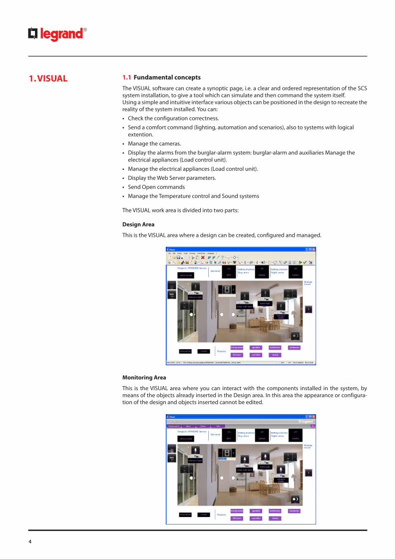
Follow the procedure step by step (by Internet or telephone) to activate and register VISUAL.If you cannot carry out the procedure immediately but want to do it later, click on the Cancel push button and VISUAL is opened. If the activation and registration procedure has not been performed by 30 days after the installation, VISUAL will be blocked.
2.Hardwareandsoftwarerequirements
To install the VISUAL program proceed as follows:1. Put the CD-Rom into its drive;2. When the main page is displayed in the web format, select “Install VISUAL”;3. At this point the installation program will copy the system files needed to run the VISUAL pro-
gram.
On starting VISUAL a window appears where you must activate and register the software to end the installation.
3.Installationandactivation
Caution: The hardware features are adapted depending on the complexity of the design to be made.The content of this program is covered by exclusive Legrand rights.

VISUAL
Inst
alla
tion
man
ual
7
Limitidiprogetto
Workingenvironment
The set up of the VISUAL work area makes designing a synoptic page easier and more efficient.You can move the bars and windows which make up the work area as you wish using “Drag and Drop”. The area can thus be customised as you wish.
The area shown above displays the Objectproperties and Exploreproject windows which, using Drag and Drop, have been moved to the right part of the area itself.
4.AreaDesignMax device limits
100 sheets60 Web Servers
60 cameras
Max objects per sheet limits60 cameras
200 Web Servers32 Burglar-alarm units
200 lines200 rectangles
200 pictures200 actuators200 movers
200 commands100 controlled loads
200 labels200 temperature control sensors
200 temperature control central units200 amplifiers
200 sound sources200 contact objects
60 clocks60 load control objects
Design management bar
System menu
Drawing bar
Interaction bar
Object properties movable window
Explore project movable window
State bar
Design bar
8
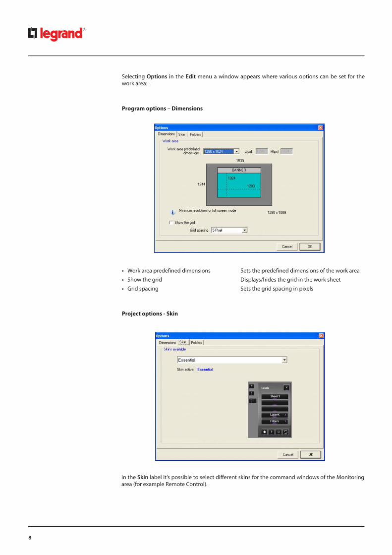
Selecting Options in the Edit menu a window appears where various options can be set for the work area:
Programoptions–Dimensions
Projectoptions-Skin
In the Skin label it’s possible to select different skins for the command windows of the Monitoring area (for example Remote Control).
• Work area predefined dimensions Sets the predefined dimensions of the work area
• Show the grid Displays/hides the grid in the work sheet
• Grid spacing Sets the grid spacing in pixels

VISUAL
Inst
alla
tion
man
ual
9
Projectoptions–Folders
The directory where the films recorded by the camera object can be set in Folders

10
4.1 Functionselectionmenu
The functions which can be run with VISUAL can be selected by means of the icons in the bars, or by opening the pull-down menu and selecting the items.
The pull-down menus have the following functions:
“File”menu
• New create a new project
• Open open an existing project
• Save save the current project
• Saveas save the project asking for the file name
• Importdata import a project created with YouProject
• Exit exit the program
“Edit”menu
• Copy copies the object selected
• Cut cuts the object selected
• Paste pastes the object selected
• Delete erases the object selected
• Options opens the options window
VISUAL
Inst
alla
tion
man
ual
11
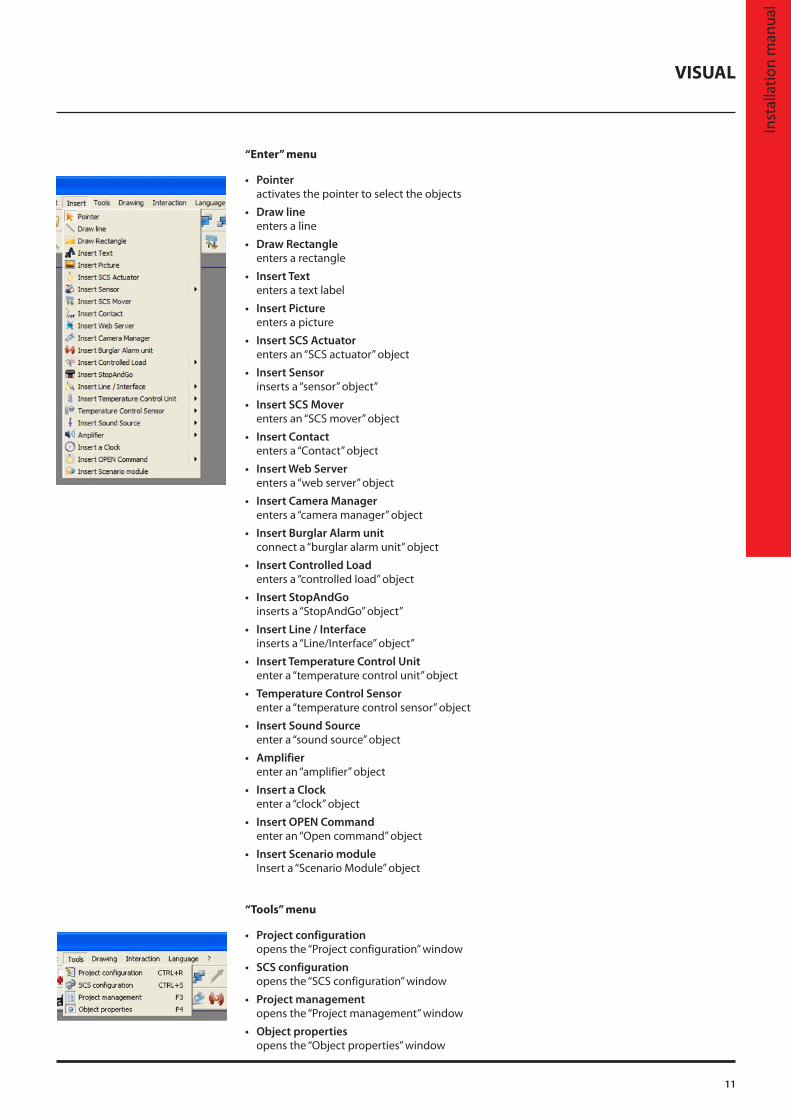
“Enter”menu
• Pointer activates the pointer to select the objects
• Drawline enters a line
• DrawRectangle enters a rectangle
• InsertText enters a text label
• InsertPicture enters a picture
• InsertSCSActuator enters an “SCS actuator” object
• InsertSensor inserts a “sensor” object”
• InsertSCSMover enters an “SCS mover” object
• InsertContact enters a “Contact” object
• InsertWebServer enters a “web server” object
• InsertCameraManager enters a “camera manager” object
• InsertBurglarAlarmunit connect a “burglar alarm unit” object
• InsertControlledLoad enters a “controlled load” object
• InsertStopAndGo inserts a “StopAndGo” object”
• InsertLine/Interface inserts a “Line/Interface” object”
• InsertTemperatureControlUnit enter a “temperature control unit” object
• TemperatureControlSensor enter a “temperature control sensor” object
• InsertSoundSource enter a “sound source” object
• Amplifier enter an “amplifier” object
• InsertaClock enter a “clock” object
• InsertOPENCommand enter an “Open command” object
• InsertScenariomodule Insert a “Scenario Module” object
“Tools”menu
• Projectconfiguration opens the “Project configuration” window
• SCSconfiguration opens the “SCS configuration” window
• Projectmanagement opens the “Project management” window
• Objectproperties opens the “Object properties” window

12
“Drawing”menu
• Putinfirstlayer puts the object selected in the first layer
• Putinsecondlayer puts the object selected in the second layer
• Capturecolour captures the colour of the object selected
• Align opens the “Align objects” menu
• Centre opens the “Centre objects” menu
• Resize resizes the objects selected
“Interaction”menu
• Start starts the monitoring and then enters the Monitoring area
• Projectvalidation checks the correct system configuration
• Layerfilter opens the “Layer manager” window
“Language”menu
• selects the VISUAL interface language
Menù“?”
• About displays some information on VISUAL
• Legrand connects to the Legrand web site
The state bar gives the following information:
CoordinatesCurrent file name
Number keypad active
Current date and time
Upper case active

VISUAL
Inst
alla
tion
man
ual
13
4.2 Project
In order to manage the objects making up the synoptic of our system, a project must be created.
4.2.1Creatingaproject
On entering VISUAL the following window appears:
In this window an existing project can be opened or a new one created. On selecting Createanewproject and clicking on OK the following window appears:
Enter the basic data to create a project:
• Type a name for the project
• Define the size of the work sheet
• Select if the management of the alarms is of the “Basic” or the “Advanced” typeIf “Basic” is selected some information in the Alarm window will not be available
At this point, either using the drawing tools or setting a picture (e.g. an apartment plan) as back-ground, the room where the system we want to manage with VISUAL is situated can be recreated graphically.

14
4.2.2Configuringaproject
On selecting Projectconfiguration from the Tool menu, a window appears where the project pa-rameters and the mode of connection with the system can be entered.
Projectconfiguration–Project
Projectconfiguration–Dimensions
• Project name enters a name for the project• Default sheet selects the basic project sheet• Enable password for design enables/enters the project password
If a password is set for the project, when VISUAL starts the Monitoring area is displayed directly. To enter the Design area type the password. This is to prevent an inexpert customer editing the project by mistake.
The project dimensions can be chosen from standard or customised dimensions. The dimensions set are valid for all the project sheets.
• Work area dimensions defines the size of the work sheet
• Perform in full screen mode display the project in the Monitoring Area in full screen
VISUAL
Inst
alla
tion
man
ual
15
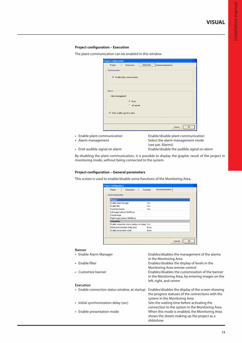
Projectconfiguration–Execution
The plant communication can be enabled in this window.
• Enable plant communication Enable/disable plant communication• Alarm management Select the alarm management mode
(see par. Alarms)• Emit audible signal on alarm Enable/disable the audible signal on alarm
By disabling the plant communication, it is possible to display the graphic result of the project in monitoring mode, without being connected to the system.
Projectconfiguration–Generalparameters
This screen is used to enable/disable some functions of the Monitoring Area..
Banner• Enable Alarm Manager Enables/disables the management of the alarms
in the Monitoring Area• Enable filter Enables/disables the display of levels in the
Monitoring Area remote control• Customize banner Enables/disables the customisation of the banner
in the Monitoring Area, by entering images on the left, right, and centre
Execution• Enable connection status window, at startup Enables/disables the display of the screen showing
the progress statuses of the connections with the system in the Monitoring Area
• Initial synchronisation delay (sec) Sets the waiting time before activating the connection to the system in the Monitoring Area.
• Enable presentation mode When this mode is enabled, the Monitoring Area shows the sheets making up the project as a slideshow.

16
4.2.3Projectmanagement
On selecting Projectmanagement from the Tool menu, the Exploreproject window is displayed. This allows a more ordered management of a project creating several work sheets (e.g. for apart-ments over several floors, create a “first floor” sheet and a “second floor” sheet).
On clicking on the sheet with the right mouse key, a menu appears where various operations can be performed on the project sheets.
Connectseveralworksheets
Inside a work sheet connections can be created to other sheets (link) by means of the objects: rec-tangle, text and picture.
> Enter one of these objects in the first sheet
> Set Link Type to “Link to a page”
> Set the sheet to be connected in the Associatedsheet properties
Importsheetsfromproject
It is possible to import sheets from another project into the current project. Select “Import sheets” from the “File” menu to open a window for the selection of the project from which to import sheets.
Click Project to select the project file
> Drag the sheet from Loaded Project to Current Project
> Click Confirm to import the sheet/s
> Click Yes to confirm

VISUAL
Inst
alla
tion
man
ual
17
In the Monitoring Area, click the object inserted to display the corresponding sheet.The “Link Type” function may be used to set other types of connections, for example Link to a Web page, or Start/Stop slideshow.For further information see the “Graphic Objects” section
4.2.4Automaticprojectstartup
A connection can be created to the project file and it can be positioned in Windows Start-up. In this way the file opens automatically when the operating system is started.
Create a connection to the project file (.mhv) to be opened when Windows starts, then drag it into the Start-up subfolder of the Window Programs folder.To ensure that at the opening of the project file the Monitoring Area of VISUAL is displayed automati-cally, the Autorun function and the communication towards the field must be enabled.

18
4.3 Objects
An VISUAL project is made up of a set of objects: some have a purely graphical function while others, correctly configured, have the function of generating commands and replicating command compo-nents really installed in the system.
4.3.1Objectmanagementandformatting
The properties of the objects entered in the project (identification, coordinates, appearance and configuration) can be set and the objects themselves can then be managed by windows (Layermanagement, SCSconfiguration).Also, the objects can be ordered and positioned as needed by means of the commands in the Draw-ing menu.In particular the objects can be selected by means of the Select tool in the Drawing menu. To select a group of objects, click on the objects keeping the Ctrl key pressed or keep the left mouse key pressed and drag the pointer until all the objects are included in the selection window.
Objectproperties
The objects which can be used to make the project are shown below. The object’s characteristic properties can be set in the Objectproperties window.The Identification and Coordinates properties are similar for all the objects, while the Appearance and Configuration properties are specific for each type of object and will be dealt with in the Ob-jects chapter.
Identification-Coordinates
The object is identified and positioned in this window.
Displays the type of object
Displays and sets the layer to which the object belongsSequential number which identifies the objects of the same typeSets the positioning of the object in the work area
VISUAL
Inst
alla
tion
man
ual
19
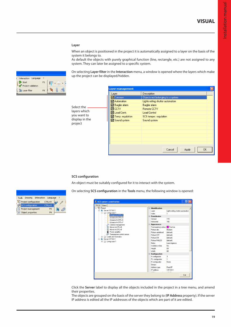
Layer
When an object is positioned in the project it is automatically assigned to a layer on the basis of the system it belongs to.As default the objects with purely graphical function (line, rectangle, etc.) are not assigned to any system. They can later be assigned to a specific system.
On selecting Layerfilter in the Interaction menu, a window is opened where the layers which make up the project can be displayed/hidden.
SCSconfiguration
An object must be suitably configured for it to interact with the system.
On selecting SCSconfiguration in the Tools menu, the following window is opened:
Click the Server label to display all the objects included in the project in a tree menu, and amend their properties.The objects are grouped on the basis of the server they belong to (IPAddress property). If the server IP address is edited all the IP addresses of the objects which are part of it are edited.
Select the layers which you want to display in the project

20
Click the Object label to open a screen showing the objects and their quantities.
4.3.2Graphicalobjects
These objects have a purely graphical function and can be used to reproduce the place where the system is installed graphically.
Graphic objects can also be used to create links to project and web pages, or to start/stop the sequential display of project sheets (slideshow): the time each sheet is displayed for is set in the “Project configuration” screen, “General Parameters” label, item “Enable presentation mode”.
Line object
Text objectRectangle object
Picture object
Sheet management
Slideshow managementWeb address link
Lineobject
Enters a line in the project.
Sets the colour
Sets the thickness
VISUAL
Inst
alla
tion
man
ual
21
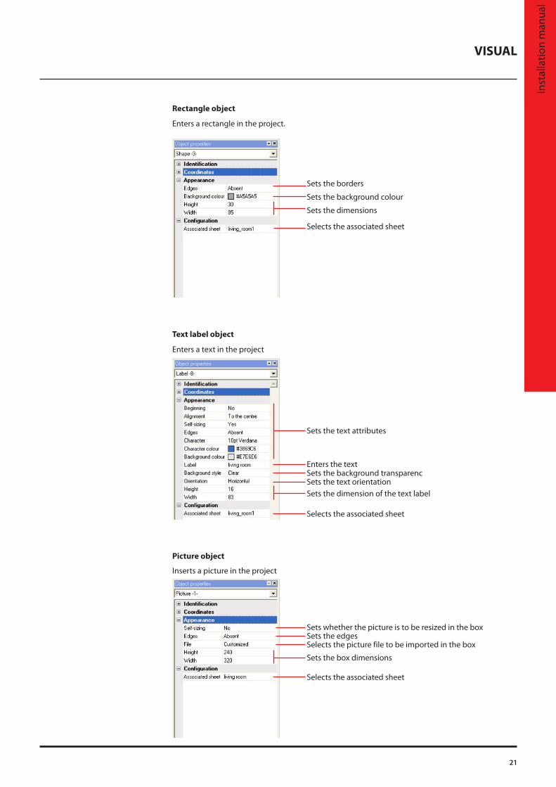
Rectangleobject
Enters a rectangle in the project.
Sets the dimensions
Selects the associated sheet
Sets the borders
Sets the background colour
Textlabelobject
Enters a text in the project
Sets the text attributes
Enters the textSets the background transparencSets the text orientationSets the dimension of the text label
Selects the associated sheet
Inserts a picture in the project
Pictureobject
Sets whether the picture is to be resized in the box
Sets the box dimensions
Sets the edgesSelects the picture file to be imported in the box
Selects the associated sheet

22
4.3.3SCSactuatorobject
This object configured as an actuator really present in the system gives a synchronised view of the state of the actuator itself.Then acting on the object in the project changes the state of the corresponding actuator in the system.
Actuator state
OFF-LINE/INDEFINITE STATE
OFF
ON
BULB BURNT OUT (dimmer only)
Changes the default pictures
Enters the actuator addressSets the mode (entering pul, the actuator is excluded from the general and room commands).
Sets whether it is a wire or radio actuatorSets the type of actuator (ON/OFF, dimmer)
Set a standard or customised dimension
Set the dimensions (only with picture dim. = Customised)Set if the object can be seen in the monitoring area
Sets the group the actuator belongs to.When the data entry field is clicked, the pushbutton ap-pears. Click on it to display the configuration screen.
4.3.4Sensorobject
This object, configured as sensor actually present in the system, provides a synchronised view of the status of the sensor itself.
Sensor state
OFF-LINE
OFF
ON
Enter the sensor address
Set the type of addressSet the server IP address

VISUAL
Inst
alla
tion
man
ual
23
4.3.5Contactobject
This object provides a synchronised view of the status of a contact connected to the system.Contact status
OFF-LINE
OFF
ON
Set the type of addressSet the server IP address
Set if an alarm connected to the status must be activated
Enter the address of the contact interface (from 1 to 201)
The sensor object can be of three types
Brightness/movement Brightness Movement
Brightness index (Lux)
Red: movement detectedMovement sensor
sensitivity level

24
4.3.6Scenariomoduleobject
When configured as Module of scenarios actually existing in the system, this object can be used to activate the scenarios saved in the module itself. New scenarios may also be created, or the existing ones amended.
In the monitoring area, click the scenario Module object to display the following screen, where it will be possible to enable the saved scenarios:
Module Status
OFF-LINE
OFF
ON
BEING AMENDED/CREATED
Scenario Module address
Scenario list
Scenario Management pushbuttons
Block/unblock the Management mode
List of scenario Modules
Enables/disables the saved scenario

VISUAL
Inst
alla
tion
man
ual
25
Click to enable the pushbuttons for the creation/amendment of scenarios.
After 20 sec. of inactivity the Management mode is blocked.
Starts the recording of a new scenario or adds actions to an existing scenario
Stops recording
Deletes the actions of the selected scenario
Deletes all scenarios (including the ones already in the Scenario Module).
Warning: press the key to delete all scenarios (including the ones already in the Scenario Module).
This object has three push buttons. Push the two left push buttons to perform the UP/DOWN commands and the right push button to perform the STOP command.
4.3.7SCSmoverobject
This object configured as an actuator really present in the system gives a synchronised view of the state of the mover itself.Then acting on the object in the project changes the state of the corresponding mover in the sys-tem.
Mover state
Changes the default pictures
Enters the actuator addressSets the mode (entering pul, the actuator is excluded from the general and room commands)
Sets whether it is a wire or radio actuator
OFF-LINE/INDEFINITE STATE
UP
DOWN
STOP
26
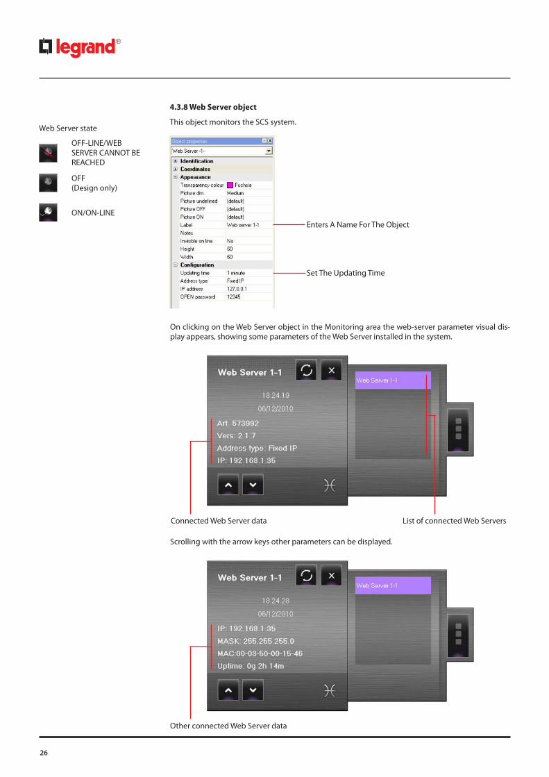
On clicking on the Web Server object in the Monitoring area the web-server parameter visual dis-play appears, showing some parameters of the Web Server installed in the system.
Scrolling with the arrow keys other parameters can be displayed.
Other connected Web Server data
Connected Web Server data List of connected Web Servers
4.3.8WebServerobject
This object monitors the SCS system.Web Server state
OFF-LINE/WEB SERVER CANNOT BE REACHED
OFF (Design only)
ON/ON-LINEEnters A Name For The Object
Set The Updating Time

VISUAL
Inst
alla
tion
man
ual
27
4.3.9Cameraobject
This object can control a camera in the system.
On clicking on the camera object in the Monitoring area the camera visual display appears, where photos can be taken, film clips recorded and the cameras switched ON/OFF.
The film clips are saved in the directory set in the Options/Folders window (see “Project options – folders” in the “Design Area” chapter).
Press the push button to take a film and the push button to stop it.
Camera state
OFF-LINE
OFF (Design only)
ON-LINE
Enters an identification number for the camera
Film folderPhoto folder Display photo/films
Cancel
Save photo
Rename film
Take picture
Record film
Stop filmSwitch camera off
Control picture
Camera list

28
4.3.10Burglar-alarmunitobject
This object can manage the alarms in a system which uses a burglar-alarm control unit.
In the Monitoring area on clicking on the burglar-alarm unit object a visual display appears, show-ing some data of the burglar-alarm system installed.
If an alarm is given a red indicator appears in the burglar-alarm object.
Click on “ALARM” to display the Alarm window, where the alarm in progress can be displayed and dealt with (see “Alarms” section).
Unit state
NOT INSERTED
INSERTED Enters a name for the object
OFF-LINE/INDEFINITE STATE
> Select a compression for the film clip
> Click OK
At the end of the filming the following window appears:
• State displays whether the burglar-alarm system is switched ON
• Battery displays whether the battery is working
• Zones controlled displays the active zones (purple background) and if there is an alarm the zone involved (zone number in red)
• Other zones displays the other zones (connectors, auxiliaries and the control unit)
• Technical displays the technical alarms
• System system IP address

VISUAL
Inst
alla
tion
man
ual
29
4.3.11Controlledloadobject(LoadControlActuatormode)
This object displays the state of a load. The load priority can be set, e.g. if the electricity supply is overloaded the load indicated with priority 1 is deactivated before a load identified with priority 2.
In the Monitoring area the state of the devices connected to a load control unit can be checked, avoiding problems of overloading the electricity supply.On clicking on a controlled load object the visual display appears:
If there is an overload, one of these devices may be disabled. Click on the push button at the right of the deactivated load to force the state to reactivate it.
OFF
ON
Enters a name for the object
Sets the priority of the load controlled by the object
Load state
OFF-LINE/INDEFINITE STATE
Priority
Load state Force load

30
4.3.12Controlledloadobject(LoadManagementActuatormode)
• This object gives the possibility of managing the new Load control system. It is in fact possible to:
• display the status of a load
• force its reactivation based on priority
• set the forcing time
• display the instantaneous consumption
Tariffconfiguration
In this window, the user can set the tariff to be applied to consumptions (in the case of the control-led load object, its electricity). The tariffs set are also used by other objects, e.g. Meter.
OFF
ON
Set if the load is controlled by a central unit. Otherwise the load cannot be reactivated.
Set if the load management is of the Basic type (load forcing and setting of forcing time), or of the Advanced type (load forcing, setting of forcing time, and instantaneous consumption display)
Set if the measured values are to be converted into currency based on the set tariff
Set tariff
Electricity tariff configuration
Load state
OFF-LINE/INDEFINITE STATE
Tariff ID, applicable to the whole project Tariff description Enters the value Enters the currency
Add a tariff Delete a tariff Save the tariff
VISUAL
Inst
alla
tion
man
ual
31
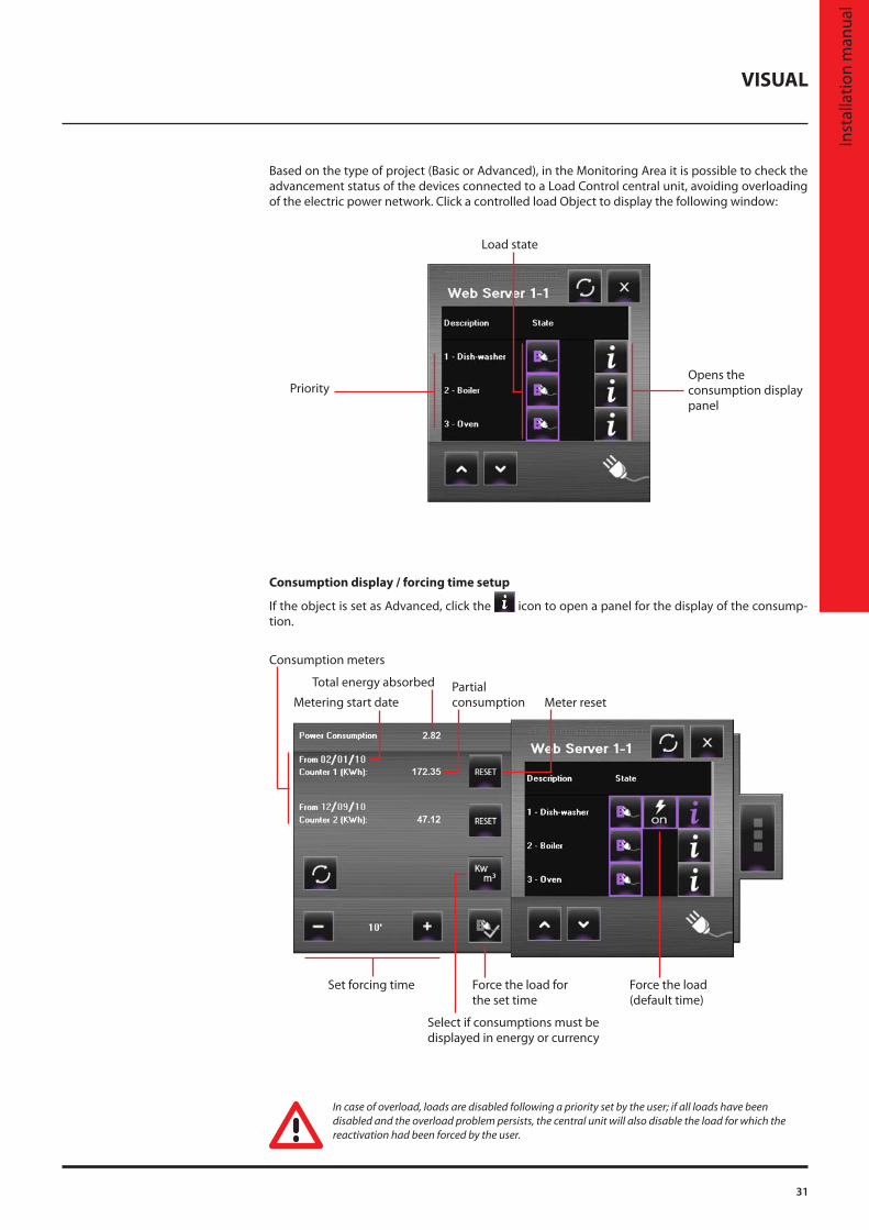
Consumptiondisplay/forcingtimesetup
If the object is set as Advanced, click the icon to open a panel for the display of the consump-tion.
Total energy absorbed
Set forcing time
Select if consumptions must be displayed in energy or currency
Force the load for the set time
Force the load (default time)
Metering start datePartial consumption Meter reset
Consumption meters
Based on the type of project (Basic or Advanced), in the Monitoring Area it is possible to check the advancement status of the devices connected to a Load Control central unit, avoiding overloading of the electric power network. Click a controlled load Object to display the following window:
Load state
PriorityOpens the consumption display panel
In case of overload, loads are disabled following a priority set by the user; if all loads have been disabled and the overload problem persists, the central unit will also disable the load for which the reactivation had been forced by the user.
32
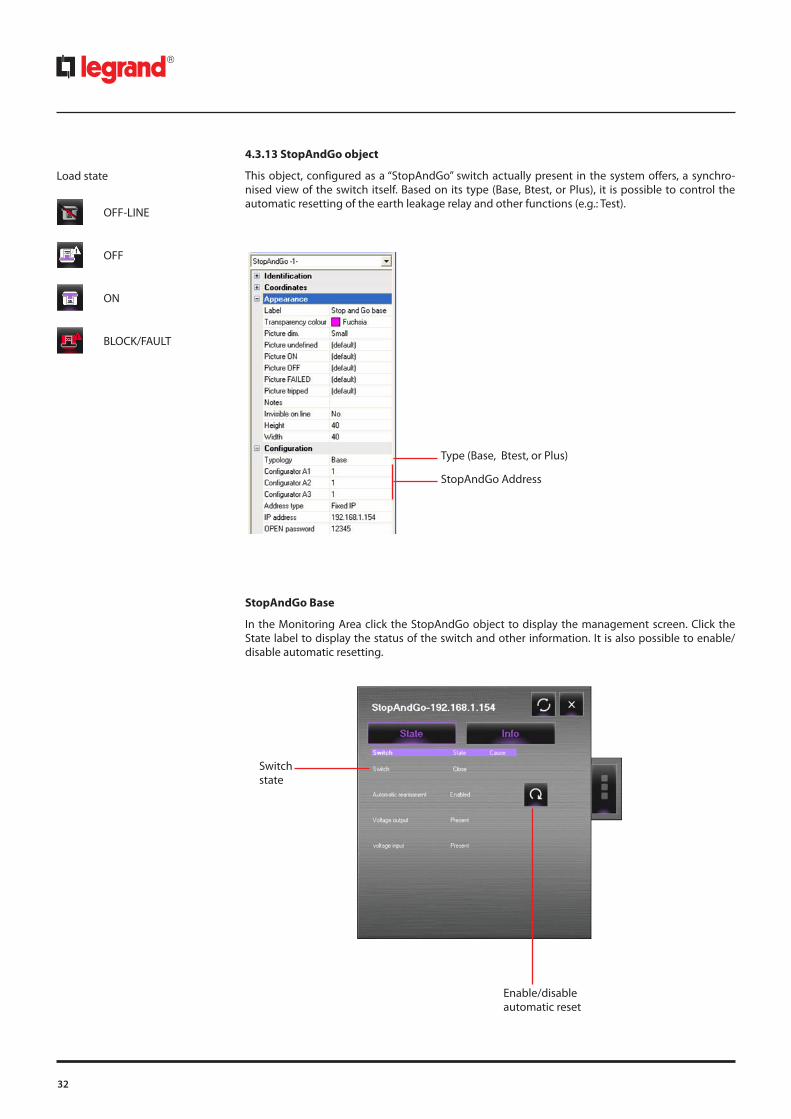
4.3.13StopAndGoobject
This object, configured as a “StopAndGo” switch actually present in the system offers, a synchro-nised view of the switch itself. Based on its type (Base, Btest, or Plus), it is possible to control the automatic resetting of the earth leakage relay and other functions (e.g.: Test).
OFF
ON
BLOCK/FAULT
Type (Base, Btest, or Plus)
StopAndGo Address
Load state
OFF-LINE
StopAndGoBase
In the Monitoring Area click the StopAndGo object to display the management screen. Click the State label to display the status of the switch and other information. It is also possible to enable/disable automatic resetting.
Switch state
Enable/disable automatic reset

VISUAL
Inst
alla
tion
man
ual
33
StopAndGoBtestIn this mode it is possible to enable automatic reset, the Autotest, and to enable/disable automatic reset
StopAndGoPlusIn this mode, it is possible to enable automatic reset, open or close the switch, and activate the system test.
Perform test
Enable/disable automatic reset
Enable Autotest
Close switch
Enable/disable automatic reset
Enable/disable system test
Click the Info label to obtain an indication of the number of device tripping events.
Request of data to system
34
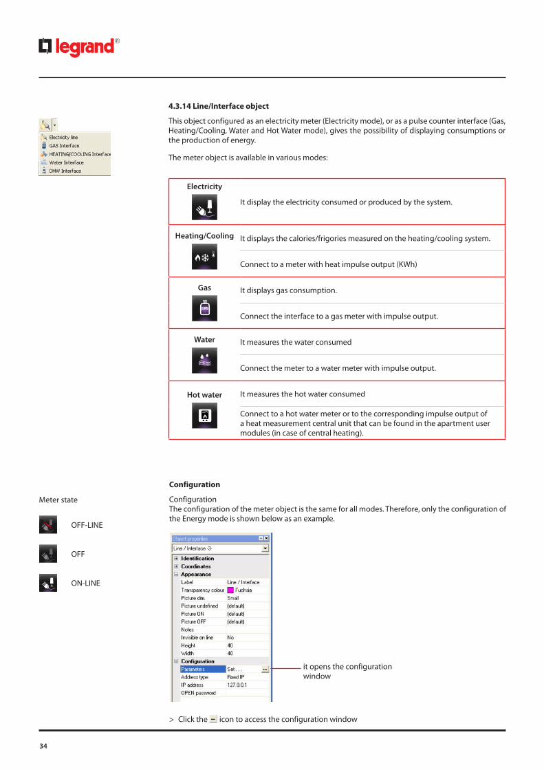
4.3.14Line/Interfaceobject
This object configured as an electricity meter (Electricity mode), or as a pulse counter interface (Gas, Heating/Cooling, Water and Hot Water mode), gives the possibility of displaying consumptions or the production of energy.
The meter object is available in various modes:
Configuration
ConfigurationThe configuration of the meter object is the same for all modes. Therefore, only the configuration of the Energy mode is shown below as an example.
> Click the icon to access the configuration window
Electricity
It display the electricity consumed or produced by the system.
Heating/Cooling It displays the calories/frigories measured on the heating/cooling system.
Connect to a meter with heat impulse output (KWh)
Gas It displays gas consumption.
Connect the interface to a gas meter with impulse output.
Water It measures the water consumed
Connect the meter to a water meter with impulse output.
Hotwater It measures the hot water consumed
Connect to a hot water meter or to the corresponding impulse output of a heat measurement central unit that can be found in the apartment user modules (in case of central heating).
Meter state
OFF-LINE
OFF
ON-LINE
it opens the configuration window
VISUAL
Inst
alla
tion
man
ual
35
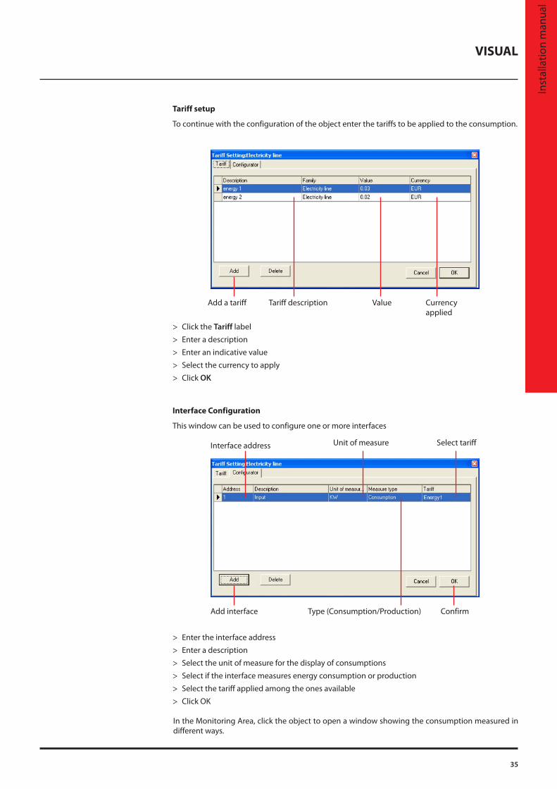
Tariffsetup
To continue with the configuration of the object enter the tariffs to be applied to the consumption.
> Click the Tariff label
> Enter a description
> Enter an indicative value
> Select the currency to apply
> Click OK
> Enter the interface address
> Enter a description
> Select the unit of measure for the display of consumptions
> Select if the interface measures energy consumption or production
> Select the tariff applied among the ones available
> Click OK
In the Monitoring Area, click the object to open a window showing the consumption measured in different ways.
Add a tariff
Add interface Type (Consumption/Production) Confirm
Interface address Unit of measure Select tariff
Tariff description Value Currency applied
InterfaceConfiguration
This window can be used to configure one or more interfaces

36
Consumptions may be displayed as daily, monthly, or annual consumptions; the user can also select the desired period of time using the arrows on the main panel, or a more precise range using the side panel. In both cases confirm by pressing OK.
Time mode selection pushbuttons Time mode selection pushbuttons
Selection (dd/mm/yy)
Precise selection panel
Total period measurement In month mode, it sets the x axis (time) as days/hoursAverage period measurement
Opens the panel to display data in a table format
Display the consumption in KW/m3 or in currency
In alternative to displaying consumption data’s in a chart format, these can also be displayed in a table format by opening the appropriate panel.
Time reference
Consumption
Consumption table
Exampleofgaschart

VISUAL
Inst
alla
tion
man
ual
37
4.3.1599-zonetemperaturecontrolcentralunitobject
This object can be used to control a temperature control central unit installed on the system.Control unit state
Enter an object name
Set the type of central unitOpen the label configuration windows
In this window the user can customise the description of the central unit Scenarios and programs
OFF(Design only)
OFF-LINE/UNDEFINED STATE
ON-LINE
In the Monitoring area, on clicking on the control unit object the following window appears in Control unit mode:
Control unit mode
System management push buttons
System mode of operation
In this mode the temperature can be set and the antifreeze/thermal protection mode switched OFF and set for the whole temperature control system.
38
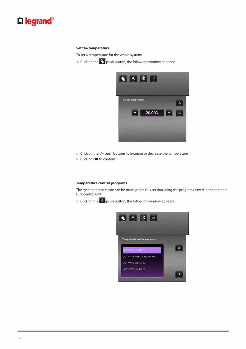
Setthetemperature
To set a temperature for the whole system:
> Click on the push button, the following window appears:
> Click on the -/+ push buttons to increase or decrease the temperature
> Click on OK to confirm
Temperaturecontrolprograms
The system temperature can be managed in this section using the programs saved in the tempera-ture control unit.
> Click on the push button, the following window appears:

VISUAL
Inst
alla
tion
man
ual
39
Activateholiday
This function can select a particular daily profile for a set period.
> Select ACTIVATEHOLIDAY
> Click on the push button to continue, the following window appears:
> Select a weekly program (3 heating + 3 air conditioning)
> Select date and time
> Confirm by pressing OK
The holiday program will be run until the date and time set, after which the weekly program chosen will be activated.
Weekly programs
Date Time
Activateweeklyprogram
This function can select a weekly program saved in the control unit.
> Select ACTIVATEWEEKLYPROGRAM

40
> Click on the push button to continue, the following window appears:
> Select a weekly program (3 heating + 3 air conditioning)
> Confirm by pressing OK
With this option the system works in automatic mode, following the programming set in the acti-vated weekly program.
Programs available
Last program activated
Activatescenario
This function can select a scenario from those saved in the control unit.
> Select ACTIVATESCENARIO

VISUAL
Inst
alla
tion
man
ual
41
> Click on the push button to continue, the following window appears:
Scenarios available
> Select a scenario (16 heating + 16 air conditioning)
> Confirm by pressing OK
In this mode different temperatures can be set in the various system zones with a single command.
Activateholidays
This function can set the holiday mode.
> Select ACTIVATEHOLIDAYS
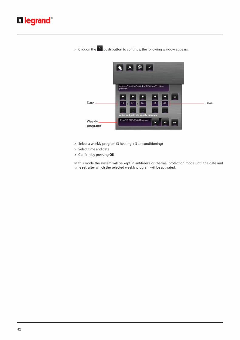
42
> Click on the push button to continue, the following window appears:
> Select a weekly program (3 heating + 3 air conditioning)
> Select time and date
> Confirm by pressing OK
In this mode the system will be kept in antifreeze or thermal protection mode until the date and time set, after which the selected weekly program will be activated.
Weekly programs
Date Time

VISUAL
Inst
alla
tion
man
ual
43
Control unit state
OFF(Design only)
OFF-LINE/UNDEFINED STATE
ON-LINE
4.3.164-zonetemperaturecontrolcentralunitobject
This object can be used to control a temperature control central unit installed on the system.
Enter an object name
Set the type of central unitOpen the label configuration window
In this window the user can customise the description of the Central unit programs
In the Monitoring area, on clicking on the control unit object the following window appears in Control unit mode:
Control unit mode
System management push buttons
System mode of operation
In this mode the temperature can be set and the antifreeze/thermal protection mode switched OFF and set for the whole temperature control system.
Because the 4-zone central unit also operates as temperature control sensor, it is recommended that a sensor object is entered near the central unit object, for displaying the temperature detected in the zone where the central unit is installed.
Temperature detected in the central unit zone

44
Setthetemperature
To set a temperature for the whole system:
> Click on the push button, the following window appears:
Timedoperationmode
It is possible to program the time during which the system maintains the set temperature; after this time, the system returns to the previously active mode.
> Click on the -/+ push buttons to increase or decrease the temperature
> Click on OK to confirm
Enable/disable timed operation
Set the temperature
Set the Timed operation mode period (hours/minutes, maximum 24hours and 59 min.)

VISUAL
Inst
alla
tion
man
ual
45
Temperaturecontrolprograms
In this section it is possible to manage the system temperature using programs saved inside the temperature control central unit. In this type of central unit it is not possible to manage the sce-narios. For the holiday and weekly programs see paragraph “99-zone central unit”.
Zones
This section is used to display the temperatures measured and set, detected by the system sensors. For the “Fan-coil” sensors, the fan-coil speed can also be set.
Measured temperature
Programmed temperature
Open fan-coil management (fan-coil only)
Set the fan-coil speed
46
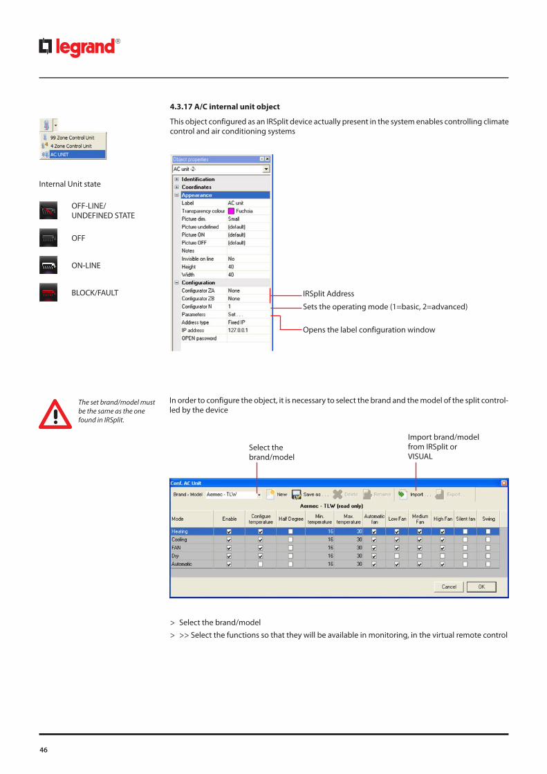
Internal Unit state
OFF
OFF-LINE/UNDEFINED STATE
ON-LINE
BLOCK/FAULT
4.3.17A/Cinternalunitobject
This object configured as an IRSplit device actually present in the system enables controlling climate control and air conditioning systems
IRSplit Address
Sets the operating mode (1=basic, 2=advanced)
Opens the label configuration window
In order to configure the object, it is necessary to select the brand and the model of the split control-led by the device
Select the brand/model
Import brand/model from IRSplit or VISUAL
> Select the brand/model
> >> Select the functions so that they will be available in monitoring, in the virtual remote control
The set brand/model must be the same as the one found in IRSplit.

VISUAL
Inst
alla
tion
man
ual
47
Customised brand/model
New model
Delete/rename model
Duplicate the existing model Export brand/
model for VISUAL
If the brand/model of the split is not included in the database, a customised one may be created.
> Select New
> Select the functions
> Click OK to confirm
In the monitoring area click the IRSplit object to open the virtual remote control, which can be used to send previously selected controls to the climate control unit.
Object On/Off
Temperature set
Sets the fan-coil speed
Swing On/Off
Swing
Increases/decreases the temperature
Operating mode
Fan-coil mode
Sets the operating mode (mode)

48
4.3.18Temperaturecontrolsensorobject
This object can control a temperature control sensor in the system.
In the Monitoring area, on clicking on the sensor object the following window appears in Zones mode:
This window can display the data on the sensors in the system and the mode of operation can be set, using the push buttons.
Sensormanagementpushbuttons
Master sensor state
ON
Slave sensor state
ON
OFF-LINE/UNDEFINED STATE
OFF(Design only)
OFF-LINE/UNDEFINED STATE
OFF(Design only)
Set the number of the zone controlled by the sensor
Set the sensor mode of operation (none = master, sla = slave)If the sensor is master set the number of the controlled sensors, if the sensor is slave, set the progressive number of the zone slave sensors
Set the type of sensor: Normal/External/Fan-coil
The operating modes shown below are only valid for sen-sors managed by a 99-zone central unit.For the 4-zone central unit functions see paragraph “4-zone temperature control Central unit”/”Zones”.
Zones modeSensor list (master only)
Sensor management push buttons
Temperature measured by the sensor
Temperature varied manually by the sensor (L/N/NT4692 only)
Programmed temperature
Sensor mode of operation
Return to the previously selected mode
Set the temperature manually
Set the antifreeze/thermal protection mode
Set the zone forced switching OFF
Set the Fan-coil sensor speed, if applicable
Caution: The OFF mode has the maximum priority. To exit this mode work from the same device from which it was set. If the OFF mode was set by the sensor object, to change mode, work from the object itself or from the temperature control unit (device).

VISUAL
Inst
alla
tion
man
ual
49
4.3.19Externalprobeobject
This object gives the possibility of displaying the temperature measured by an external probe.
Enter the external probe number
External probe state
ON
OFF-LINE/UNDEFINED STATE
OFF
In the Monitoring area, click the probe object to display the following screen in Zone mode:
Temperature measured by the probe

50
4.3.20Soundsourceobject
This object can control a sound source in the system (single-channel, or multichannel). The example shown is for a multichannel system.
In the Monitoring Area on clicking on the sound source object the following window appears:
Source state
ON
OFF-LINE/UNDEFINED STATE
OFF
Set the system type
Source configuration
Room customisation
Open/close the room management screen
Open/close source management window
List of sources
Back Next

VISUAL
Inst
alla
tion
man
ual
51
The various functions of the set source (in this case the source is a Radio Tuner) can be managed in this window.
The room management screen can be used to set in which rooms a sound source can be listened to.
TunedFrequency
Enable/disable room
Automatic frequency search
Manual frequency searchSave stations
Enable/disable all rooms
Saved stations
To save a station:
> Tune the frequency required
> Click on the MEM push button
> Click on the numerical push button where the station will be saved
52
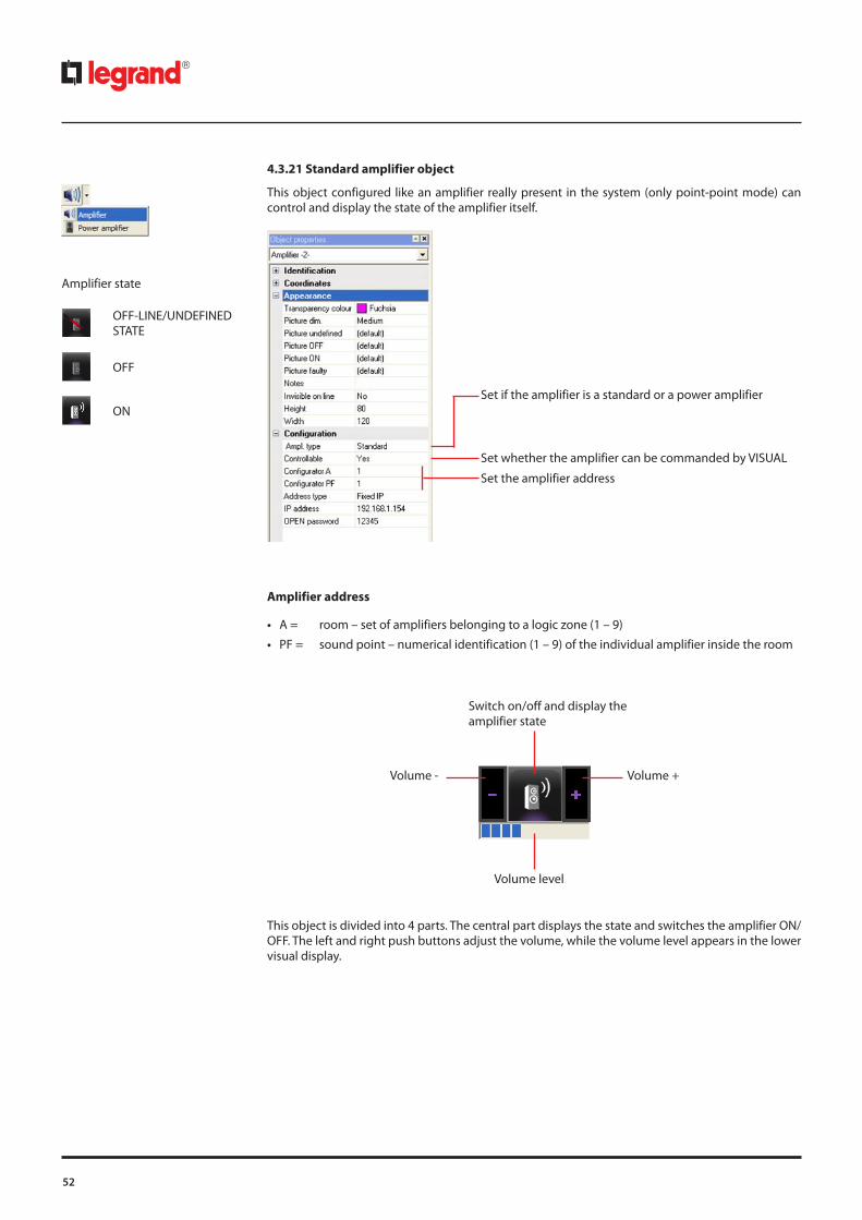
4.3.21Standardamplifierobject
This object configured like an amplifier really present in the system (only point-point mode) can control and display the state of the amplifier itself.
Amplifieraddress
• A = room – set of amplifiers belonging to a logic zone (1 – 9)
• PF = sound point – numerical identification (1 – 9) of the individual amplifier inside the room
This object is divided into 4 parts. The central part displays the state and switches the amplifier ON/OFF. The left and right push buttons adjust the volume, while the volume level appears in the lower visual display.
Set whether the amplifier can be commanded by VISUAL
Set if the amplifier is a standard or a power amplifier
Amplifier state
OFF
ON
Set the amplifier address
OFF-LINE/UNDEFINED STATE
Volume level
Volume - Volume +
Switch on/off and display the amplifier state

VISUAL
Inst
alla
tion
man
ual
53
4.3.22Poweramplifierobject
This object, configured as power amplifier really present in the system, provides the user with the possibility of controlling and displaying the amplifier status. Differently from the standard amplifier, it is possible (using the appropriate screens) to perform advanced sound adjustments.
Amplifieraddress
• A = room – set of amplifiers belonging to a logic zone (1 – 9)
• PF = sound point – numerical identification (1 – 9) of the individual amplifier inside the room
Amplifier status
Set whether the amplifier can be commanded by VISUAL
Set if the amplifier is a standard or a power amplifier
Set the amplifier address
Open the Adjustment screen = press and hold down
Switch on/off = click
Volume level
Volume - Volume +
Advancedsoundadjustments
While in the Monitoring area, click and hold down the central section of the amplifier for more than 5 seconds to display the following screen to perform several sound adjustments:
Volume adjustment
Bass adjustment
Treble adjustment
3D effect adjustment
Switch the amplifier on/off
Enable/disable “Loudness” modeOpen the Equalizer screen
Left/right channel balance adjustment
Selection of equalisation curves (preset or custom)
OFF
ON
OFF-LINE/UNDEFINED STATE

54
Click to display the following screen:
This screen can be used to save a customised curve: select a name, perform the appropriate adjust-
ments, and click . The customised curve is now active.
Name selection
Save curve
Advanced adjustments

VISUAL
Inst
alla
tion
man
ual
55
4.3.23Opencommandobject
This object can replicate a command really present in the system or open a new one, sending the system itself an Open command, based on the OpenWebNetcode*.
Opencommandconfiguration
In the “Open command configuration” window you can (by guided or manual entry) define the Open command to send to the system.Guided entry occurs by selecting the various options in the window, thus defining the push button type, the command and the receiver. Manual entry (“custom” entry) occurs instead by entering the Open Web Net code directly.
In the guided entry mode, the options available vary depending on the command function (e.g. lighting, automation, etc.) and on the basis of the selections made to define the command (e.g. single, double command etc.).
Open command type
Set the command appearance
Set the function of the Open command.On clicking in the data entry zone the push button appears. Clicking on it the configuration window appears.
* Open Web Net codeProtocol with which data can be exchanged and commands sent between a remote unit and the Legrand SCS system. The protocol is thought out to be independent of the means of communication used, considering being able to use DTMF tones on the normal telephone line as the minimum requirement.The code features a structure with fields of variable length separated by special characters (*) and closed with (##).
Push button type Function labelCommand Receiver

56
Openlightingcommand
Openautomationcommand
• Push button type select the push button type; the fields containing the various parameters are displayed depending on this selection
• Command select the command to be given
• Receiver select the address of the device which performs the command
• Push button type select the push button type. This selection influences the functions available in the “command” field
• Command select the command to be given
• Receiver select the address of the device which performs the command

VISUAL
Inst
alla
tion
man
ual
57
Openscenarioscommand
• Push button type select the push button type; the fields containing the various parameters are displayed depending on this selection
Scenario• Command select the scenario to be performed, saved in a
scenario module• Receiver select the address of the scenario module
CEN• Command select the scenario to performed, saved in the
scenario programmer• Receiver select the address of the CEN control
Scenario/CENPlusOpencommand
• Push button type select the push button type; the fields containing the various parameters are displayed depending on this selection
ScenarioPlus• Command select the adjustments to send to the system• Receiver select the address of the devices to which the
scenario should be sent to
CENPlus• Command select the scenario to perform, saved in the
scenario programmer• Receiver select the address of the CEN control
58
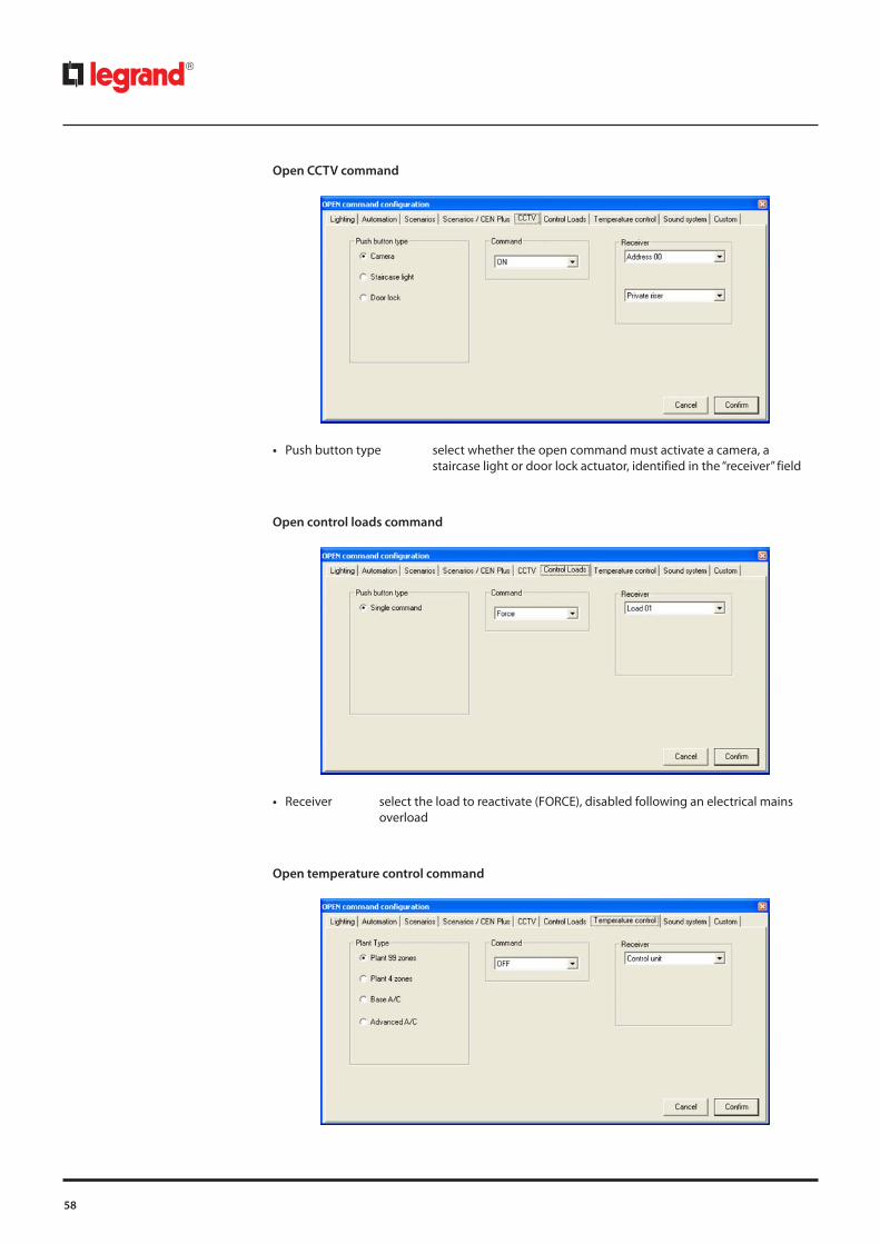
Opencontrolloadscommand
Opentemperaturecontrolcommand
• Receiver select the load to reactivate (FORCE), disabled following an electrical mains overload
OpenCCTVcommand
• Push button type select whether the open command must activate a camera, a staircase light or door lock actuator, identified in the “receiver” field

VISUAL
Inst
alla
tion
man
ual
59
Opensoundsystemcommand
Opencustomisedlabelcommand(customlabel)
• Push button type select the push button type. This selection influences the functions available in the “command” field
• Command select the command to be given
• Receiver select the address of the device which performs the command
• Command enter the Open Web Net code (more than one command can be entered by writing the code consecutively, e.g. *1*1*0##*2*1*0##)
• Plant Type select the type of system. This selection affects the options available in “control” field
99zones-4zones• Command select the type of command (OFF, ANTIFREEZE, THERMAL
PROTECTION) to send.• Receiver select whether the command previously set is addressed to
a control unit or to a temperature control sensor (zone xx) (99 zones)
A/CBase• Command select the no. of the control saved in an IRSplit, to be sent to
the climate control system• Receiver select an IRSplit address
AdvancedA/C• Command select the type of control to be sent to the system using the
IRSplit• Receiver select an IRSplit address

60
4.3.24Clockobject
This object displays/sets the system time.
If the object is set to display the system time, on clicking on it (Monitoring area) a window appears where the system time and date can be set.
> Set the date and time using the arrows
> Confirm by pressing OK
Set whether the pc time or the system time (Web Server time) should be displayed
Set the date/time format
Update all the system connected to the time and date set
Synchronise the Web Server time to the pc time
VISUAL
Inst
alla
tion
man
ual
61
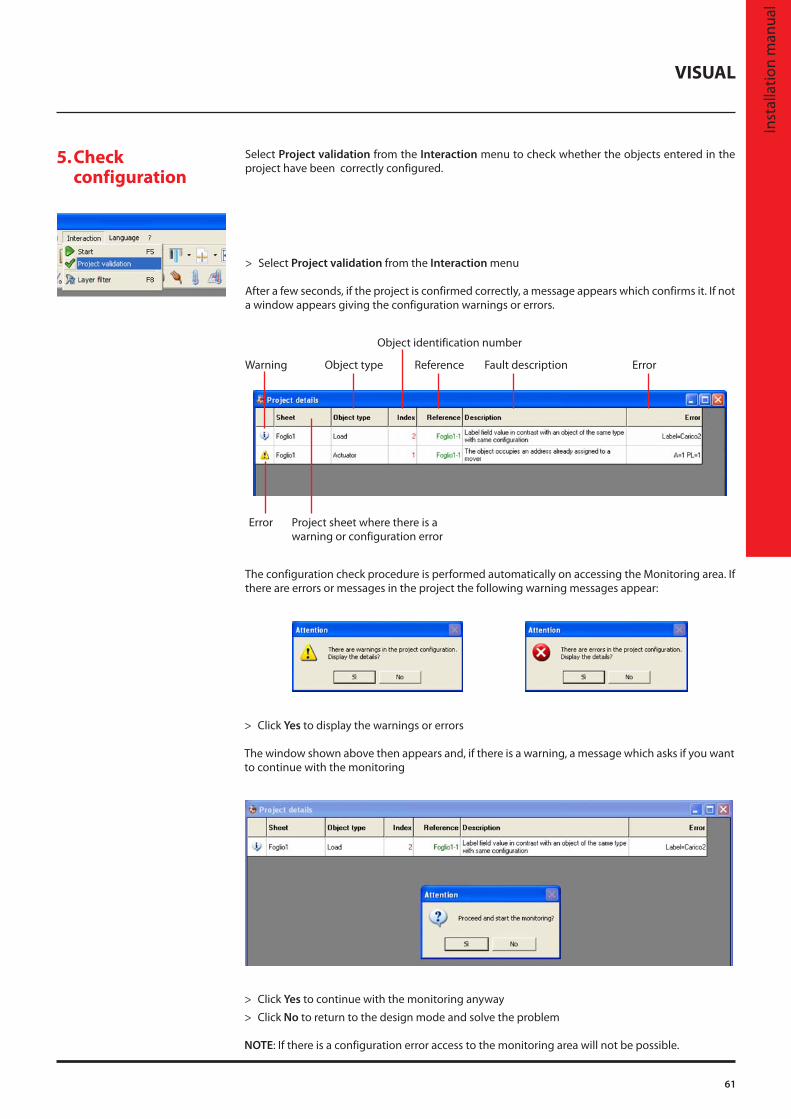
5.Checkconfiguration
Select Projectvalidation from the Interaction menu to check whether the objects entered in the project have been correctly configured.
> Select Projectvalidation from the Interaction menu
After a few seconds, if the project is confirmed correctly, a message appears which confirms it. If not a window appears giving the configuration warnings or errors.
The configuration check procedure is performed automatically on accessing the Monitoring area. If there are errors or messages in the project the following warning messages appear:
> Click Yes to display the warnings or errors
The window shown above then appears and, if there is a warning, a message which asks if you want to continue with the monitoring
> Click Yes to continue with the monitoring anyway
> Click No to return to the design mode and solve the problem
NOTE: If there is a configuration error access to the monitoring area will not be possible.
Error
Warning
Project sheet where there is a warning or configuration error
Object type
Object identification number
Reference Fault description Error

62
6.MonitoringArea “Monitoring” is the interactive part of VISUAL.The need to enter a design password stops an inexpert customer from quitting this area and return-ing to the Design area; then on entering VISUAL the design password will be requested for entry to the Design area, otherwise entry is directly to the Monitoring area..
Workarea
After connecting with the system you must enter the Monitoring area to interact with the compo-nents in the system. The VISUAL work area changes and specific tools appear.
In the Design area select Start from the Interaction menu to start monitoring the connected system.
The Monitoring area shows a screen displaying the various connection steps.
Once the procedure is completed, using the objects previously introduced and configured in the Design area, it will be possible to interact with the corresponding system components and check their status.
The state of the system components can be deduced from the type of icon displayed by the object entered in the project.
VISUAL
Inst
alla
tion
man
ual
63
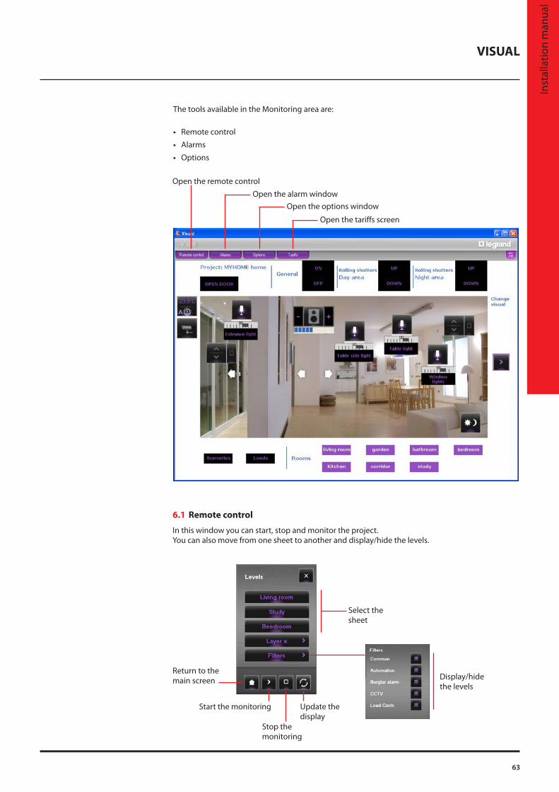
The tools available in the Monitoring area are:
• Remote control
• Alarms
• Options
Open the remote control
Open the alarm windowOpen the options window
Open the tariffs screen
6.1 Remotecontrol
In this window you can start, stop and monitor the project.You can also move from one sheet to another and display/hide the levels.
Select the sheet
Return to the main screen
Start the monitoring
Stop the monitoring
Update the display
Display/hide the levels

64
6.2 Alarms
When the system generates an alarm, a visual indication appears and a sound signal is played (if set in Options).The alarms can be generated by an object (SCS actuator or SCS mover, see relevant sections), or by the burglar-alarm system (see “Burglar-alarm unit object” section).The Alarm screen shows different functions based on the initial selection of the alarm management mode: “Basic” or “Advanced”.
Alarms–“Basic”
When the system has generated an alarm indication click on the Alarm icon. The Alarmbeinggiven window appears.
This window displays some data on the alarm. Decide which data must appear by clicking on the Selectcolumn pushbutton.
The Selectcolumn window selects which fields should be displayed in the columns, in both the Alarminprogress and Eventhistory windows. Various types of information on the event will be displayed depending on the fields selected.
Alarmindication
Flashing: in progressSteady: alarm to be dealt with/ closed
Alarm in progress
Alarm history
Alarm reset force
Select column
Icon legend
Stop the audible warning
VISUAL
Inst
alla
tion
man
ual
65
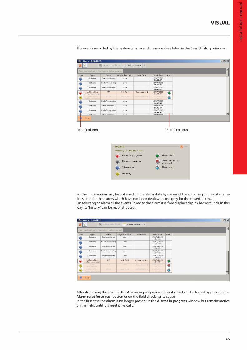
The events recorded by the system (alarms and messages) are listed in the Eventhistory window.
Further information may be obtained on the alarm state by means of the colouring of the data in the lines - red for the alarms which have not been dealt with and grey for the closed alarms.On selecting an alarm all the events linked to the alarm itself are displayed (pink background). In this way its “history” can be reconstructed.
After displaying the alarm in the Alarmsinprogress window its reset can be forced by pressing the Alarmresetforce pushbutton or on the field checking its cause.In the first case the alarm is no longer present in the Alarmsinprogress window but remains active on the field, until it is reset physically.
“Icon” column “State” column

66
Example:An SCS mover object has been configured to generate an alarm when it receives an UP command (rolling shutter raised); to end the alarm, send a STOP command or reset the alarm by pressing the Alarmresetforce key.If the alarm comes from a burglar alarm unit the unit must be switched off and on again.
In the first case (Alarm A) the alarm has been dealt with in the field (sending a STOP rolling shutter command) and thus the cause of the alarm has been dealt with. In fact the colouring is grey, which indicates that the alarm is closed.
In the second case (Alarm B) it has not been dealt with in the field, but a forced reset has been per-formed, so that the alarm has not been dealt with (red) and thus even if it is no longer present in the alarm window it is still open.
Alarm–“Advanced”sector
If the type of project has been set as “Advanced”, the alarms are managed differently. In fact the project also has the Alarmstomanage and Alarmhistory sections. There are new icons as well, as can be seen in the Legend window.
In this mode the alarm can be undertaken and then dealt with. The undertaken alarm becomes blue.
Start alarm (UP)End alarm (STOP)
BStart alarm (UP)Forced reset
A
Alarms to manage
Alarm history
Icon legend

VISUAL
Inst
alla
tion
man
ual
67
Following an alarm warning click on the pushbutton to enter the Alarmstomanage window.
Double clicking on the line of the alarm to be managed the following window appears:
• Cancel cancels the operation
• Change state changes the alarm state
• Confirm modification confirms the change of state
The alarms are displayed in the Alarmhistory window where the alarm state can be checked on the basis of the icon in the State column and the text colour.
Alarm data Alarm state Help
Icon field
In this window the alarm state can be changed by clicking on the Change state pushbutton and confirming the selection by clicking on the Confirmmodification pushbutton

68
Example: the burglar-alarm unit has given a burglar-alarm alarm in zone 1.
The “Alarms” window shows a visual indication and a warning sounds.
Click on the Alarm icon. The Alarmbeinggiven window appears showing the cause of the alarm and where it is coming from.Then enter the Alarmstomanage by clicking its key. Now follow the diagram below:
The Eventhistory window displays how the alarms have been managed.
Alarmstomanage
Double click
Changestate
Undertaken
Alarmsinprogress
Forced reset
System
Reset on the field
Changestate
Alarm closed
Changestate
Alarm closed
B
A
Start alarm
Reset from the fieldClose alarm
Start alarm
Undertaken
Undertaken
Close alarmReset forcing B
A
1 2 3
5 6
987
0
4
OK

VISUAL
Inst
alla
tion
man
ual
69
6.3 Options
The audible warning which is given following an alarm can be customised in the Options window.
Clicking on the Options pushbutton opens the following window:
Press the Change pushbutton to customise the audible warning. If not a predefined sound will be played.
> Select a .wav file
> Click on the Open pushbutton and then Ok
> Press the Design pushbutton to return to the design mode
> Press the Ok pushbutton to suspend monitoring without quitting.
QuittingtheMonitoringarea
The following window appears:
6.4 Tariffs
> Click the Tariffs pushbuttonThis screen displays the tariffs set by the user and applied to consumptions.

70
7.Projectexample Considering the variety of types of project which VISUAL can produce, this chapter gives a project example as an indication.
Project features:
• ”Basic” alarm management
• Control lighting, automation, controlled loads, burglar alarm, temperature control and sound systems
• • general, room, group and scenario commands
StartVISUALandcreateanewproject
the Projectconfiguration window appears
For project name enter “Residential”, for work area enter the size 1012 x 647 pixels, and select “Basic” alarm management.
Enable communication with the field.

VISUAL
Inst
alla
tion
man
ual
71
Create one or more sheets for each apartment room. For example 4 sheets for the living room in which later we will enter 4 different views.
In each sheet enter a picture* (drawing, photo etc.) which represents the room.
*Do not insert larges images in the working area: if necessary, reduce using graphic editors.

72
By means of the rectangle, text label and picture objects, enter connections to move from one view to another.
Enter objects and configure them like the devices in the system.

VISUAL
Inst
alla
tion
man
ual
73
Create general, room, and group Open commands and configure them following the indications of the corresponding paragraphs and then copy them for the other rooms.Using the text label objects, create links to move from one room to another.
Create a sheet where you can enter objects and commands (e.g. load control, Web Server, sound source, etc.) so that the whole apartment is kept under control in a single window.

74
From the Interaction menu select Projectvalidation to check that there are no configuration errors in the objects entered. Then, selecting Start, start monitoring the system.
At the end of the operation you can interact with the system in the Monitoring area.

VISUAL
Inst
alla
tion
man
ual
75
1.Oncethemonitoringhasstarted,withoutreceivingconfigurationwarningsorerrors,whycanInotactivatealightpoint?
You may have made one of the following errors:
a) entered an incorrect IP address,
b) set a configuration which does not correspond to the real one,
c) entered a mover instead of an actuator or vice versa,
d) configured the actuator as dimmer while the actuator on the field is not.
2.WhycanInotclosetheapplicationbyclickingontheclosewindowkey ?
You must display the remote control and stop the monitoring by clicking on the “stop” key .
Press OK and finally click on the close key .
3.Icannotstartthemonitoringandittellsmetochecktheconfiguration.Why?
You may have some problems with the connection to the ethernet network.
4.HowcanImakeamultipleselectionintheDesignarea?
Keeping the “shift” key pressed click with the left mouse key on all the objects to be selected or
click with the left mouse key on one point and move the mouse to enclose the objects of interest
in the outlined rectangle you are drawing.
5.AssoonasIstartthemonitoringsomeobjectsarenotonline.Why?
They are not effectively on line or it is an actuator which has been configured as PUL both on the
field and in the VISUAL project but not in the Web Server system configuration file.
6.WhathappensifIcreate2SCSobjects(SCSactuatororSCSmover)whicharenottotallyidenti-calintheSCSconfiguration?
VISUAL checks automatically when it starts the monitoring. If the configuration is correct the
project enters the monitoring mode and the two objects can be commanded. If not, depend-
ing on the type of fault found it may display warnings, which do not affect correct projection
operation, or alarms. In the latter case you must correct the errors found before continuing the
monitoring.
7.InaprojectIhaveconfiguredeverythingcorrectlybutIdonotfindeverythingonline.Why?
Web Server isn’t reachable or it has an OPEN password different from the project.
8.Ihave2actuatorsinthe“Design”areawhichIcannotputonthesamehorizontallinebymeansoftheup-downkeysinthecoordinatesareaofthe“Objectproperties”.Why?
Just manually edit the coordinates of one of them in relation to the other. The up-down command
in fact only moves the object by 5 pixels. Probably one of the two objects was configured manu-
ally, with the coordinates being entered directly.
9.AfterageneralorroomONcommandwhydoestheprogramshowalightasswitchedonevenifitisnot?
Check whether the actuator is configured as PUL both on the field and in the Web Server system
configuration file and the VISUAL project.
10. IhavesetanSCSdimmercommandobjectforaroombutwhenIvarythepercentageoneofthedimmersdoesnotrespond.Why?
The actuator is not a dimmer or it has been configured as PUL and not entered in the Web Server
system configuration file.
11. CanImakeaprojectstartautomaticallywhenWindowsstarts?
Yes, the project must be password protected (see paragraph “ Automatic project startup”).
12. HowdoIchangetheIPortheOPENpasswordforseveralobjectsatthesametime?
Make a multiple selection of similar objects and edit the data in the object properties window.
If, for example you do not find the IP the objects selected may contain an object which does not
have an IP in its configuration.
76
13. Whatisthedifferencebetween“Basic”and“Advanced”alarmmanagement?
The difference is that in “Basic” alarm management, the “Current alarm” (list of alarms which have
occurred and are not yet re-entered and where the alarm can be reset) and the “Event log” (list of
the alarm and system events). The “Advanced” type management also includes the “Alarm log” and
“Alarms to manage” lists, to enable to management of the alarm (reset, undertaken and closure).
14. CanIinteractwiththeVISUALprogramwithatouchscreenortabletPCaswell?
Yes, compatible with the hardware requirements.
15. WhenmonitoringdoIhavetousetheremotecontroltochangefromonesheettotheother?
No, you can also use the links between the various sheets if they have been created in the Design
phase.


World Headquarters andInternational Department87045 LIMOGES CEDEX FRANCE
: 33 5 55 06 87 87Fax : 33 5 55 06 74 55www.legrand.com
Legrand reserves at any time the right to modify the contents of this booklet and to communicate, in any form and modality, the changes brought to the same.
Related Documents