1 Copyright 2007 Luiz Roberto Monteiro de Oliveira All rights reserved www.luizmonteiro.com Visual Tutorial Pitot Static System Simulator Thank you for using the Pitot Static System Simulator from luizmonteiro.com . Please note that this tutorial is designed to help you understand how to use the simulator. Note that the results are only approximations and should never be used in real flight. Before you begin using the simulator, please make sure that your browser has the Adobe (formerly Macromedia) Flash version 8 or higher. If you do not have this you may go to the Adobe website at: http://www.adobe.com and go to the downloads section where you will be able to download and install the latest version. The Pitot Static System Simulator web page will also run a test (Flash Version Detector) to check which version is installed in your browser. If you have at least version 8 installed the following message will appear on the page right before the simulator section: If your browser has an older version which will not allow the simulator to function correctly the following message will appear: Adobe (formerly Macromedia) Flash Requirements Pitot Static System Simulator Application Parts Flash Version Detector Aircraft Altimeter Blue Graph Area Simulated System Simulator Settings Tutorial Version 1.01 © Pitot Static Conditions Outside Conditions Units Reference System

Welcome message from author
This document is posted to help you gain knowledge. Please leave a comment to let me know what you think about it! Share it to your friends and learn new things together.
Transcript
1 Copyright 2007 Luiz Roberto Monteiro de Oliveira All rights reserved
www.luizmonteiro.com
Visual Tutorial Pitot Static System Simulator
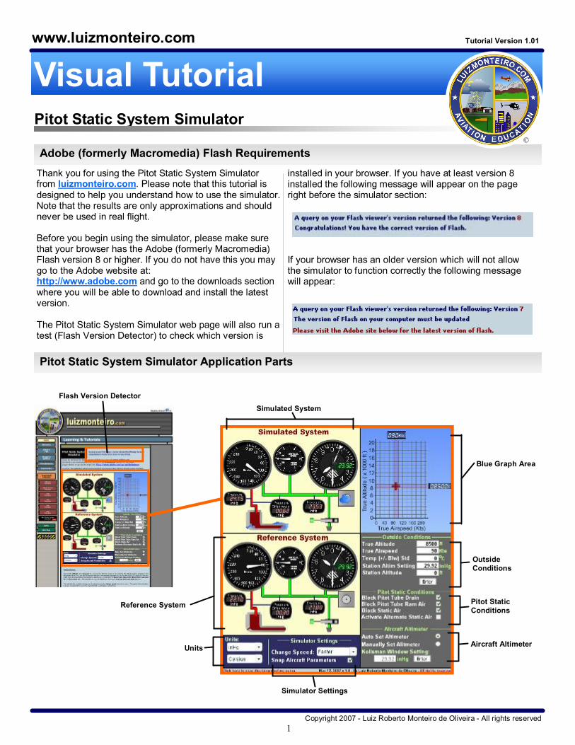
Thank you for using the Pitot Static System Simulator from luizmonteiro.com. Please note that this tutorial is designed to help you understand how to use the simulator. Note that the results are only approximations and should never be used in real flight.
Before you begin using the simulator, please make sure that your browser has the Adobe (formerly Macromedia) Flash version 8 or higher. If you do not have this you may go to the Adobe website at: http://www.adobe.com and go to the downloads section where you will be able to download and install the latest version.
The Pitot Static System Simulator web page will also run a test (Flash Version Detector) to check which version is
installed in your browser. If you have at least version 8 installed the following message will appear on the page right before the simulator section:
If your browser has an older version which will not allow the simulator to function correctly the following message will appear:
Adobe (formerly Macromedia) Flash Requirements
Pitot Static System Simulator Application Parts
Flash Version Detector
Aircraft Altimeter
Blue Graph Area
Simulated System
Simulator Settings
Tutorial Version 1.01
©
Pitot Static Conditions
Outside Conditions
Units
Reference System

2
Note that the Reference System has the same parts as the Simulated System except that you cannot block the Ram Air, Drain Hole or Static Air Port. Also the Kollsman Window is always set to the Station Altimeter Setting even if the Aircraft Altimeter Setting (Kollsman Window in the Simulated System) is manually set to a different setting. In addition to the Alternate Static Air Port does not engage in the Reference System.
The reason for this is that the Reference System is used to compare the readings with the Simulated System when these variables are introduced.
Copyright 2007 Luiz Roberto Monteiro de Oliveira All rights reserved
www.luizmonteiro.com
Pitot Static System Simulator Application Parts (cont.)
Ram Air Pressure Gauge
Airspeed Indicator
Vertical Speed Indicator (VSI) Altimeter
Ram Air Line
Static Air Lines
Unblocked Pitot Tube Drain
Blocked Pitot Tube Drain
Pitot Tube
Unblocked Pitot Tube Ram Air
Blocked Pitot Tube Ram Air
Pressure Difference (Ram AirStatic Air) Pressure Gauge
Alternate Static Air Port Closed
Alternate Static Air Port Activated
Unblocked Pitot Static Air Port
Blocked Pitot Static Air Port
Static Air Pressure Gauge
Alternate Static Air Filter (no simulation purpose)
Kollsman Window

3 Copyright 2007 Luiz Roberto Monteiro de Oliveira All rights reserved
www.luizmonteiro.com
Pitot Static System Simulator Application Parts (cont.)
Simulated System This is the Pitot Static System that applies blockages and the manually set altimeter setting.
Reference System This is the Pitot Static System that can be used as a reference to compare results from the Simulated System. The Reference System always has the correct Altimeter Setting and is not affected by blockages selected by the user.
Outside Conditions
True Altitude The actual altitude that the aircraft, and therefore the Pitot Static System is placed.
True Airspeed The actual airspeed that the aircraft, and therefore the Pitot Static System is moving in the air.
Temp (+/ Blw) Std The variation in temperature above or below the temperature in standard atmosphere.
Station Altim Setting The Altimeter Setting for a particular airport or station. This is the same Altimeter Setting that would be obtained on the ATIS (Airport Terminal Information Service). Note that unless Auto Set Altimeter is selected, the Kollsman window (i.e. the altimeter in the aircraft) will not be adjusted automatically in the Simulated System, simulating either the pilot forgetting to set the altimeter or the altimeter setting not being available. The Kollsman window in the Reference System will be set to the station altimeter setting regardless if Auto Set Altimeter is selected or not.
Station Altitude The altitude of the airport or station where the Altimeter Setting was obtained.
Pitot Static Conditions
Block Pitot Tube Drain Simulates the blockage of the Pitot Tube Drain.
Block Pitot Tube Ram Air Simulates the blockage of the Pitot Tube Ram Air.
Block Static Air Simulates the blockage of the Static Air Port.
Activate Alternate Static Air Simulates the activation of the Alternate Static Air Port. Typically as the aircraft increases in speed the static pressure using the Alternate Static Ports is typically slightly less than that of the actual Static Port outside the aircraft for nonpressurized aircraft.
Aircraft Altimeter
Auto Set Altimeter/Manually Set Altimeter Determines whether the Kollsman Window Setting is automatically adjusted if a different station altimeter setting is entered.
Kollsman Window Setting This setting is made by the pilot on the aircraft's altimeter.
Units This section allows the user to change pressure units from inHg (inches of mercury) to HPa (Hecto Pascal) or temperature from Celsius to Fahrenheit.
Change Speed The rate that the conditions change can be selected using the change speed drop down menu.
Snapped Aircraft Parameters If the Snapped Aircraft Parameters check box is selected, then altitude will be rounded to the nearest 500 feet and airspeed will be rounded to the next 5 knots. If this is not selected then altitude will be rounded to the nearest 100 feet and airspeed will be rounded to the nearest 1 knot. This happens regardless if the altitude and airspeed were entered manually or by dragging them using the cross in the blue graph.
Pitot Tube
Unblocked Pitot Tube Drain Blocked Pitot Tube Drain
Pitot Tube
Unblocked Pitot Tube Ram Air Blocked Pitot Tube Ram Air
Unblocked Pitot Static Air Port Blocked Pitot Static Air Port
Alternate Static Air Port Closed
Alternate Static Air Port Activated

4 Copyright 2007 Luiz Roberto Monteiro de Oliveira All rights reserved
www.luizmonteiro.com
Setting Aircraft Climb and Speed Profile
Set aircraft altitude and airspeed by moving the blinking cross or by entering the altitude and/or airspeed in the designated boxes. You can also change the altitude or the
airspeed separately by moving the digital LCD displays in the blue graph area.
Blinking Cross
True Altitude and True Airspeed can be entered here as well. Values remain in blue color and are only effective once you click <Enter>. Once entered the values turn black
Altitude Digital LCD Display
True Airspeed Digital LCD Display
Descent with increasing speed (Drag Blinking Cross in this direction)
Level with increasing speed (Drag Blinking Cross in this direction)
Constant speed climb (Drag Blinking Cross in this direction)
Climb with decaying speed (Drag Blinking Cross in this direction)
Constant speed climb or descent (Drag Altitude LCD in up or down) Level with decreasing speed
(Drag Blinking Cross in this direction)
Constant speed descent (Drag Blinking Cross in this direction)
Level with decreasing or increasing speed (Drag Airspeed LCD left or right)
Climb with increasing speed (Drag Blinking Cross in this direction)
Descent with decreasing speed (Drag Blinking Cross in this direction)
The rate that the conditions change can be selected using the Change Speed drop down menu. The speed of the simulation is always one second for every four seconds that would elapse in actual time.
If the Snap Aircraft Parameters check box is selected, then altitude will be rounded to the nearest 500 feet and airspeed will be rounded to the next 5 knots. If this is not selected then altitude will be rounded to the nearest 100 feet and airspeed will be rounded to the nearest 1 knot. This happens regardless if the altitude and airspeed were entered manually or by dragging them using the cross in the blue graph.

5 Copyright 2007 Luiz Roberto Monteiro de Oliveira All rights reserved
www.luizmonteiro.com
Example 1
An aircraft is flying at a True Altitude of 3000ft and at 95 Kts True Airspeed. According to the ATIS at a nearby airport located at 1500ft MSL the altimeter setting is 29.82 InHg. The pilot has entered that setting of 29.82 InHg in the aircraft’s altimeter Kollsman window. The outside temperature is 5°C below standard. The pilot is flying through icing conditions and the static port freezes. If a
vertical gust blows the aircraft 200ft up so that the true altitude is now 3200ft (True Altitude). 1) What happens to the pitot static instruments?
2) Can this condition cause an unwary pilot to get disoriented?
Step One: Set Initial Conditions
1) Enter 3000 ft here
2) Enter 95 ft here
3) Enter 5 °C ft here
4) Enter 28.92 InHg here
5) Enter 1500 ft here
6) Click the <Enter> button
Note that if Auto Set Altimeter is selected the aircraft’s altimeter Kollsman window will be set automatically with the Station’s Altimeter Setting
Kollsman window will be set automatically with the Station’s Altimeter Setting

6 Copyright 2007 Luiz Roberto Monteiro de Oliveira All rights reserved
www.luizmonteiro.com
Example 1 (continued)
Step Two: Set Pitot Static Conditions and New Conditions
2) Enter 3200 ft here
1) Apply blockage to Static Air Port
3) Click the <Enter> button
4) Notice that the Indicated Airspeed dropped about 25 Kts in just 200 ft even though the True Airspeed has not changed!
5) Notice that the VSI and Altimneter froze at the altitude that the blockage occurred, which makes sense since they depend solely on the Static Pressure
Conclusion If the Static Air is blocked while the Pitot Tube Ram Air and Drain Hole are unobstructed, the Airspeed indicator will indicate lower than the correct airspeed as altitude increases and greater as altitude decreases. The VSI and Altimeter stop at the altitude that the blockage occurred. The pilot can be disoriented quickly since the airspeed varies a lot with small changes in altitude.

7 Copyright 2007 Luiz Roberto Monteiro de Oliveira All rights reserved
www.luizmonteiro.com
Example 1 (further investigation part 1) Increasing speed to 115 shows that the Indicated Airspeed will increase but the value will be below the correct Indicated Airspeed value when above the altitude that the pitot static system froze.
Decreasing speed to 85 shows that the Indicated Airspeed will decrease but the value will be below the correct Indicated Airspeed value when above the altitude that the pitot static system froze.
Increasing speed to 115 shows that the Indicated Airspeed will increase but the value will be above the correct Indicated Airspeed value when below the altitude that the pitot static system froze.
Decreasing speed to 85 shows that the Indicated Airspeed will decrease but the value will be above the correct Indicated Airspeed value when below the altitude that the pitot static system froze.

8 Copyright 2007 Luiz Roberto Monteiro de Oliveira All rights reserved
www.luizmonteiro.com
Example 1 (further investigation part 2)
Remember: To correct for blocked Static Source activate the Alternate Static Air! Try it now on the Simulator and see the results.
When activating the Alternate Static Source the readings of Indicated Airspeed read only slightly higher as well as the Altimeter

9 Copyright 2007 Luiz Roberto Monteiro de Oliveira All rights reserved
www.luizmonteiro.com
Example 2
An aircraft is flying at a True Altitude of 6000ft and at 100 Kts True Airspeed. According to the ATIS at a nearby airport located at 2000 ft MSL the altimeter setting is 30.1 InHg. The pilot has entered that setting of 30.1 InHg in the aircraft’s altimeter Kollsman window. The outside temperature is standard. The pilot is flying through icing conditions and the Pitot Drain Hole freezes followed by the Pitot Ram Air freezing as well. If a vertical gust blows the
aircraft 200ft up so that the true altitude is now 6200ft (True Altitude).
1) What happens to the pitot static instruments?
2) Can this condition cause an unwary pilot to get disoriented?
Step One: Set Initial Conditions
1) Enter 6000 ft here
2) Enter 100 ft here
3) Enter 0 °C ft here
4) Enter 30.1 InHg here
5) Enter 2000 ft here
6) Click the <Enter> button
Note that if Auto Set Altimeter is selected the aircraft’s altimeter Kollsman window will be set automatically with the Station’s Altimeter Setting
Kollsman window will be set automatically with the Station’s Altimeter Setting

10 Copyright 2007 Luiz Roberto Monteiro de Oliveira All rights reserved
www.luizmonteiro.com
Example 2 (continued)
3) Enter 6200 ft here
2) Apply blockage to Static Air Port
4) Click the <Enter> button
5) Notice that the Indicated Airspeed raised about 20 Kts in just 200 ft even though the True Airspeed has not changed!
6) Notice that the VSI and Altimeter are normal since they are not affected by the Ram Air Pressure
1) Apply blockage to Pitot Tube Drain
Note that if the Ram Air Port is blocked before the Pitot Tube Drain the results will be quite different since the Ram Air pressure will escape through the Pitot Tube Drain and not get trapped. The result is the Indicated Airspeed dropping to zero at that altitude.
Step Two: Set Pitot Static Conditions and New Conditions

11 Copyright 2007 Luiz Roberto Monteiro de Oliveira All rights reserved
www.luizmonteiro.com
Example 2 (continued)
3) Enter 5800 ft here
4) Click the <Enter> button
5) Notice that the Indicated Airspeed dropped about 20 Kts in just 200 ft even though the True Airspeed has not changed!
6) Notice that the VSI and Altimeter are normal since they are not affected by the Ram Air Pressure
Step Three: Let’s see what happens now if the aircraft descends 200 ft
Conclusion If the Pitot Drain Hole freezes followed by the Pitot Ram Air while the Static Air Port remains unobstructed, the Airspeed Indicator will not respond to changes in Airspeed (since the Ram Air is blocked) and the Airspeed Indicator will freeze at the current indication at the altitude it blockage occurred, however if the aircraft climbs the Airspeed Indicator will increase and decrease if the aircraft descents. This makes it behave similarly to an Altimeter. Note that this is the opposite behavior that happens when the Static Port froze in the previous example.
As the altitude decreases and thus the Indicated Airspeed the disoriented pilot may be inclined to lower the nose into a dive to try to “regain airspeed”. This in actuality will cause the aircraft’s speed to increase possibly beyond the limits and the pilot may dive into the ground. In this case the pilot must recognize that the Altimeter is still working and should use a power setting for airspeed control and disregard any Indicated Airspeed value.

12 Copyright 2007 Luiz Roberto Monteiro de Oliveira All rights reserved
www.luizmonteiro.com
Example 2 (further investigation)
Increasing speed to 120 shows that the Indicated Airspeed will not change. This makes sense since the Ram Air is blocked.

13 Copyright 2007 Luiz Roberto Monteiro de Oliveira All rights reserved
www.luizmonteiro.com
Final Considerations
There are many more scenarios that can be simulated. These include placing the Pitot Static System at different altitudes and changing parameters such as Temperature, Station Altitudes, Station Altimeter Settings, and seeing how this affects the readings of the Altimeter and Airspeed Indicator. The Altitudes selected in the simulation are True Altitudes even though pilots don’t fly True Altitudes so that it is possible to compare the indicated results with something more concrete and real. This is the same reason why airspeeds selected are True Airspeeds.
Pressure gauges also allow users to study the effects that placing the Pitot Static System in a certain airflow and
altitudes have on the pressures being sensed by the instruments. The Airspeed Indicator, for example, basically measures the difference between Ram Air and Static Air calibrated to show True Airspeed in Standard Atmosphere Conditions and at Sea level. The Altimeter measures the Static Pressure and is calibrated to show True Altitude in Standard Atmospheric Conditions. When conditions depart from standard, corrections must be made or instrument interpretation will be erroneous.

14
End
Copyright 2007 Luiz Roberto Monteiro de Oliveira All rights reserved
www.luizmonteiro.com
©
Related Documents