Visual Traffic Monitoring Visual Traffic Monitoring Presenters: Presenters: N. Grammalidis (Researcher C N. Grammalidis (Researcher C ’ ’ ) and ) and T. Semertzidis (Researcher) T. Semertzidis (Researcher) ITI ITI - - CERTH CERTH UAM, Madrid June 2008 2 UAM, Madrid June 2008 Overview Overview Introduction in Road and Airport traffic monitoring (including A-SMGCS) Visual airport surface movement monitoring (A- SMGCS): The INTERVUSE project Results of INTERVUSE project A case study: Prague International Airport A novel intelligent software-based sensor Road tunnel and airport parking traffic visual monitoring: The TRAVIS project Results of TRAVIS project Conclusions and future work

Welcome message from author
This document is posted to help you gain knowledge. Please leave a comment to let me know what you think about it! Share it to your friends and learn new things together.
Transcript

Visual Traffic MonitoringVisual Traffic Monitoring
Presenters:Presenters:
N. Grammalidis (Researcher CN. Grammalidis (Researcher C’’) and) andT. Semertzidis (Researcher)T. Semertzidis (Researcher)
ITIITI--CERTHCERTH
UAM, Madrid
June 2008
2 UAM, Madrid June 2008
OverviewOverviewIntroduction in Road and Airport traffic monitoring
(including A-SMGCS)
Visual airport surface movement monitoring (A-
SMGCS): The INTERVUSE project
Results of INTERVUSE project
A case study: Prague International Airport
A novel intelligent software-based sensor
Road tunnel and airport parking traffic visual
monitoring: The TRAVIS project
Results of TRAVIS project
Conclusions and future work

3 UAM, Madrid June 2008
Road Traffic MonitoringRoad Traffic MonitoringLaser technology: A laser pulse is detected after its reflection from the vehicle. Accurate but is used only for detecting speed violations.
Microwave technology: Similar principle as laser. It can also be used to detect other violations, e.g. vehicles in bus lanes.
Induction loops: Coils of wire embedded in the road's surface. They detect a change of inductance in a large coil, which forms part of a resonant circuit, caused by the coil's proximity to a conductive (e.g. metal) object. Large installation, maintenance costs (asphalt has to be cut), small region
Magnetic sensors: Detection of the changes of a magnetic field (e.g. the earth magnetic field) through the physical influence of a ferromagnetic object in the vicinity of it.
Visual detection: Optical cameras using image processing and/or computer vision to detect moving objects, low-cost installation, larger area is monitored, different approaches
4 UAM, Madrid June 2008
Research and commercial visual Research and commercial visual traffic detection systemstraffic detection systems
Examples of research systems (traffic data collection and/or scene understanding):
- Video Surveillance and Monitoring (VSAM, US)
- SCOCA (Trento, IT) – also capable of accident analysis
- Many more, e.g.: V. Kastrinaki, M. Zervakis and K. Kalaitzakis, A survey of video processing techniques for traffic applications, Image and Vision Computing, Volume 21, Issue 4, 1 April 2003, Pages 359-381.
Inigo, R. M. (1985). Traffic monitoring and control using machine vision: A survey. IEEE Transactions on Industrial Electronics, 32(3), 177– 185.
Example commercial systems:
- Autoscope(Autoscope),
- QUIXOTE TRANSPORTATION (UniTrak / VideoTrak Systems), INVIS(ASCOM),
- MiTAC Integrated Highway Surveillance System,
- SMART EYE- Smart Traffic Data Sensor by Smart Systems, TRAFICON,
- CITILOG,
- EXCEL TECHNOLOGY GROUP

5 UAM, Madrid June 2008
Introduction to Airport (Surface) Introduction to Airport (Surface) Traffic MonitoringTraffic Monitoring
Air traffic management problems
Introduction to A-SMGCS
What sensors are used?
Related Commercial Systems
Related Research Projects
6 UAM, Madrid June 2008
Air Traffic Management ProblemsAir Traffic Management Problems
Number of flights is constantly rising (traffic is doubled
almost every 12 years)
Limited airspace usage caused by restricted airways and
corridors instead of free flight
Limited traffic on ground caused by insufficient technical
support with ground control systems
Large number of operations (refuel, passenger
transportations, etc) are simultaneously performed at the
airport surface, even under difficult weather conditions.
The highest risk for incidents and accidents is when the
aircraft is moving on the ground
7 UAM, Madrid June 2008
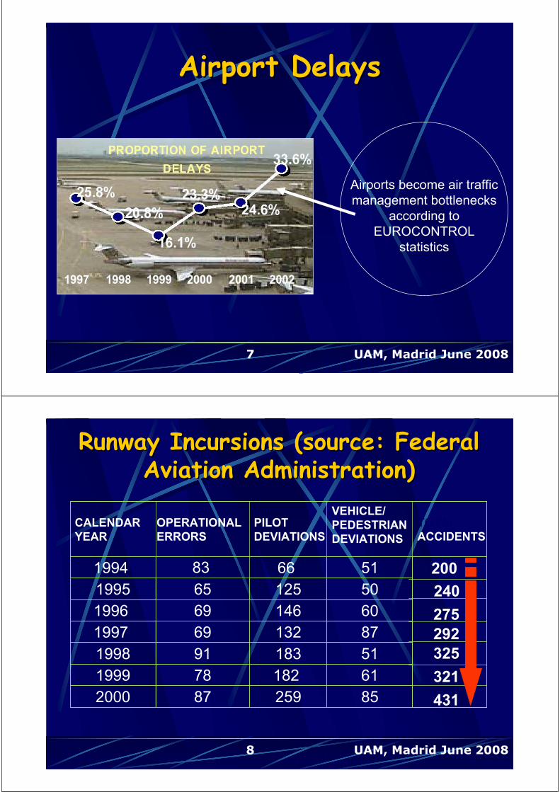
Airports become air traffic
management bottlenecks
according to
EUROCONTROL
statistics
Airport DelaysAirport Delays
8 UAM, Madrid June 2008
1994 83 66 51
1995 65 125 50
1996 69 146 60
1997 69 132 87
1998 91 183 51
1999 78 182 61
2000 87 259 85
200
240
275
292
325
321
431
TOTAL
ACCIDENTS
CALENDAR
YEAR
OPERATIONAL
ERRORS
PILOT
DEVIATIONS
VEHICLE/
PEDESTRIAN
DEVIATIONS
Runway Incursions Runway Incursions ((sourcesource:: FederalFederalAviation Administration)Aviation Administration)

9 UAM, Madrid June 2008
Place: Linate airport, Italy
Date: 8 October 2001
114 passengers killed and
4 people at the ground lost
their lives
Reason:
Limited visibility (225m).
The airport did not have
any means for surface
traffic monitoring
A tragic accident: Linate airportA tragic accident: Linate airport
10 UAM, Madrid June 2008
SurveillanceLevel 1 – basic surveillance
MonitoringLevel 2 – adds automated monitoring
Guidance (and Control)Level 3 - adds automated guidance
Planning/RoutingLevel 4 – adds automated planning
Solution: Use of ASolution: Use of A--SMGCSSMGCS(Advanced Surface movement (Advanced Surface movement Guidance and Control Systems)Guidance and Control Systems)
11 UAM, Madrid June 2008
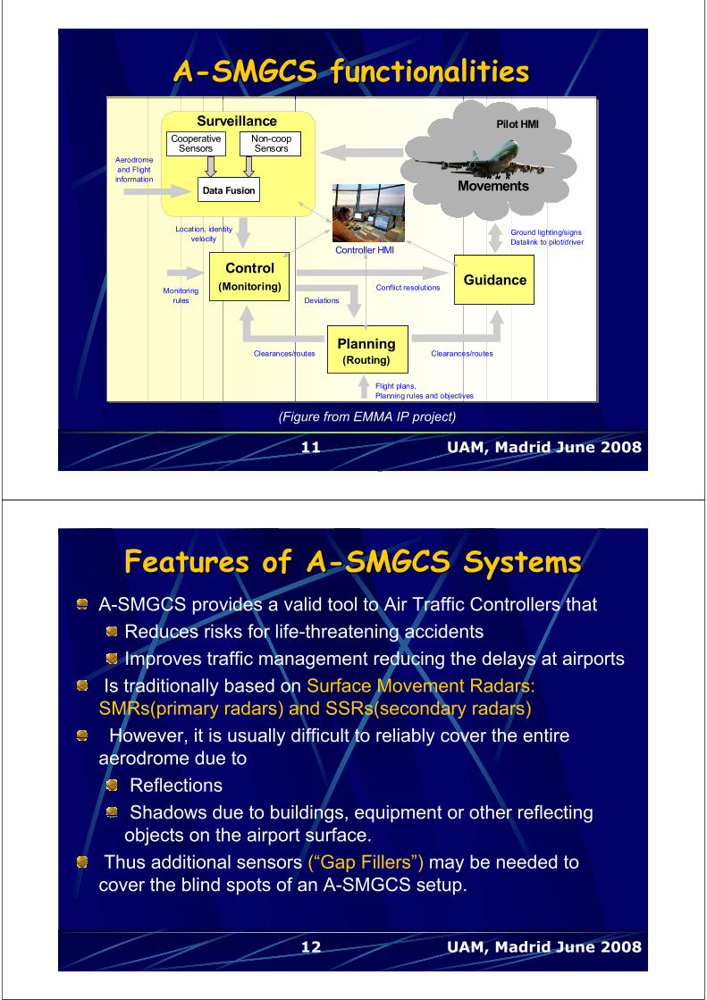
AA--SMGCS functionalitiesSMGCS functionalities
Movements
GuidanceMonitoring
/ Alerting
Control
(Monitoring)
Planning(Routing)
co-Cooperative
Sensors non co-opNon-coopSensors
fusionData Fusion
Surveillance
Location, identity
velocity
Clearances/routes
Deviations
Conflict resolutions
Ground lighting/signs
Datalink to pilot/driver
Monitoring
rules
Flight plans,
Planning rules and objectives
Aerodrome
and Flight
information
Controller HMI
Clearances/routes
Pilot HMI
(Figure from EMMA IP project)
12 UAM, Madrid June 2008
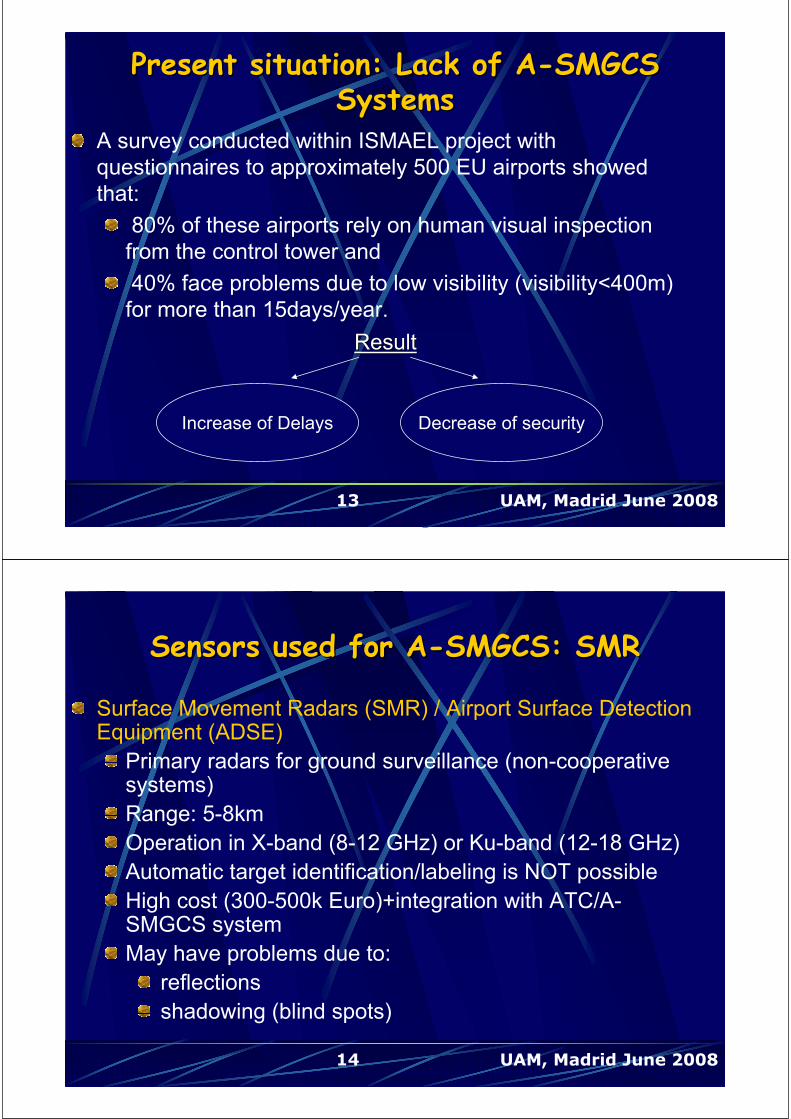
Features of AFeatures of A--SMGCS SystemsSMGCS SystemsA-SMGCS provides a valid tool to Air Traffic Controllers that
Reduces risks for life-threatening accidents
Improves traffic management reducing the delays at airports
Is traditionally based on Surface Movement Radars:
SMRs(primary radars) and SSRs(secondary radars)
However, it is usually difficult to reliably cover the entire
aerodrome due to
Reflections
Shadows due to buildings, equipment or other reflecting
objects on the airport surface.
Thus additional sensors (“Gap Fillers”) may be needed to
cover the blind spots of an A-SMGCS setup.
13 UAM, Madrid June 2008
A survey conducted within ISMAEL project with
questionnaires to approximately 500 EU airports showed
that:
80% of these airports rely on human visual inspection
from the control tower and
40% face problems due to low visibility (visibility<400m)
for more than 15days/year.
Increase of Delays Decrease of security
ResultResult
Present situation: Lack of APresent situation: Lack of A--SMGCSSMGCSSystemsSystems
14 UAM, Madrid June 2008
Surface Movement Radars (SMR) / Airport Surface Detection Equipment (ADSE)
Primary radars for ground surveillance (non-cooperative systems)
Range: 5-8km
Operation in X-band (8-12 GHz) or Ku-band (12-18 GHz)
Automatic target identification/labeling is NOT possible
High cost (300-500k Euro)+integration with ATC/A-SMGCS system
May have problems due to:
reflections
shadowing (blind spots)
Sensors used for ASensors used for A--SMGCS: SMRSMGCS: SMR

15 UAM, Madrid June 2008
ModeMode--S MultilaterationS MultilaterationSometimes they are supported by multilateration systems
that rely on Mode-S signals transmitted by the aircraft
transponder.
Multiple receivers to capture the “squitter” transmitted from
the Mode-S transponder. Then, by comparing the time
difference, the system calculates the position.
However:Cooperative systems (can only detect cooperative targets)
Aircraft transponder has to be ON: in case of a system/ malfunction or if the pilot switches it OFF, the accident risk increases
16 UAM, Madrid June 2008
Secondary Surveillance Radar (SSR) not only detects and measures the position of aircraft but also requests additional information from the aircraft itself such as its identity and altitude. These are provided in Mode-S signal by the aircraft transponder
Cooperative system
Allows automatic target identification/labeling
Similar problems as the SMR and multilateration, i.e.:
reflections
shadowing (blind spots)
if the transponder is switched off or malfunctions
Sensors used for ASensors used for A--SMGCS : SSRSMGCS : SSR

17 UAM, Madrid June 2008
Automatic Dependent Automatic Dependent SurveillanceSurveillance--Broadcast (ADSBroadcast (ADS--B)B)
Cooperative system
An ADS-B-out equipped aircraft determines its own
position using a global navigation satellite system
(GNSS) and periodically broadcasts this position and
other relevant information to potential ground stations
and other aircraft with ADS-B-in equipment.
ADS-B can be used over several different data link
technologies (e.g. Mode-S Extended Squitter, VHF data
link. etc).
18 UAM, Madrid June 2008
Commercial ACommercial A--SMGCSSMGCSsystemssystems
NOVA9000 (Park Air Systems, Norway/US),
STREAMS (THALES ATM, France/Italy),
ASDE-X (SENSIS, US),
A-SMGCS system (HITT Traffic, NL)
SurfTrack (NESS, US/Israel)
A-SMGCS system (Alenia Marconi Systems, IT)

19 UAM, Madrid June 2008
Recent Research Projects Recent Research Projects based on novel sensorsbased on novel sensors
INTERVUSE (FP5 IST) – optical sensors(cameras with embedded processors) of AutoscopeTM, which was very successful for road traffic detection and relatively low-cost,
ISMAEL (FP6 IST STREP) – novel developments in magnetic sensing technology, low-cost
AIRNET (FP6 IST STREP), EGNOS/GPS low-cost platform combined with wireless telecommunication systems (CDMA, WiFi, TETRA, VDL-4) for communicating results to control center.
SAFE-AIRPORT (FP6 IST STREP), rotating directional microphone arrays.
Design of an A-SMGCS Prototype at Barajas Airport / Airport surface surveillance based on video images: work by EPS Universidad Carlos III de Madrid.
AVITRACK project (FP6 AERO STREP): Aircraft surroundings, categorised Vehicles & Individuals Tracking for apRon's Activity model interpretation & ChecK
EMMA FP6 IP (European airport Movement Management by A-SMGCS)
20 UAM, Madrid June 2008
Comparison of AComparison of A--SMGCSSMGCStechnologiestechnologies
Technologies/Character
isticsVisual Magnetic
Radar
(primary)GPS Multilateration
Installation cost Low Medium High Low High
Operation cost Low Low Medium Low Medium
Ease of installations/
modificationsEasy Medium Hard Easy Hard
Influence from weather
conditionsYes
Temperature-
dependentNo No No
Active detection
(need for cooperative
targets)
No No No Yes Yes
People detection Yes No No No No
Target identificationNo (maybe
class)
No (maybe class)No Yes Yes

21 UAM, Madrid June 2008
Airport surface monitoring using Airport surface monitoring using intelligent optical sensors: The intelligent optical sensors: The
INTERVUSE projectINTERVUSE projectEC-funded
Objective: AGMGCS using a network of Intelligent optical sensors with
Partners:Center for Research and Technology Hellas (CERTH) / Informatics and Telematics Institute (Greece, Coordinator),
Park Air Systems (Norway),
DataCollect Verkehrsdatentechnik GmbH & Co.KG. (Germany),
Mannheim Airport, (Germany),
DFS Deutsche Flugsicherung (Germany, sub-contractor of CERTH),
“Macedonia” Airport of Thessaloniki (Greece, not an official partner)
22 UAM, Madrid June 2008
Project ObjectivesProject ObjectivesProvide a new position sensing technology for A-SMGCS by combination of ATC radar tracking, flight plan processing, state vector extraction based on video cameras.
Correlate and fuse these data to generate a synthetic ground situation display in an integrated SMGCS-ATC controller working position.
Develop and test two prototype systems at two European airports:Mannheim and Thessaloniki.
Study of the usability of the system as:
a low cost solution for A-SMGCS tasks at smaller airports (Mannheim tests)
solutions for limited A-SMGCS tasks (Thessaloniki tests)
contributions for larger A-SMGCS solutions at large airports to cover blind spots like hidden yards or taxiways

23 UAM, Madrid June 2008
System ArchitectureSystem Architecture
RS-485
CWP-3
APRON
Control
CWP-2
Airport
Authority
CWP-1
ATC
Tower
VSDF
Server SDS Server (Nova2000)
Approach
Radar
ASR
Flight Plan
Source
New components
Existing
Components
External components
-------------
Server
Side
-------------
Test
Analysis
Client
LAN link
ASTERIX
AFTNASTERIX
RPS
TECAMS
Video camera
network
-------------
Client
Side
-------------
24 UAM, Madrid June 2008
Autoscope® system uses machine vision
technology and an embedded processor to
produce highly accurate traffic
measurements:
speed data
estimation of traffic statistics (e.g. volume)
vehicle classification
Detection of incidents in highways.Each camera can be individually configured
with Virtual Detectors
Virtual Detectors: “Regions of Interest” that
can detect local motion (target presence) using
contrast recognition and learned patterns.
All cameras are addressable by a unique IP
address and are linked using serial cables
(RS-485 similar to RS-232 but suitable for
larger distances up to 1Km)
Autoscope SoloAutoscope Solo®® Wide Area Video Vehicle Wide Area Video Vehicle Detection SystemDetection System

25 UAM, Madrid June 2008
Demonstration of Camera Demonstration of Camera functionality (Thessaloniki Airport)functionality (Thessaloniki Airport)
••Camera 2Camera 2•Camera 1
26 UAM, Madrid June 2008
Video Sensor Data FusionVideo Sensor Data FusionPeriodically polls the event data (VD states) from the
cameras (constant cycle),
Processes the data received to detect and avoid
possible false alarms
Forms the observations (plots) that contain:
The time of the event
The ground position and size of the target (uses
calibration)
Additional information (e.g. velocity)
Sends observations to the tracker of the system (SDS)
in ASTERIX format (radar data exchange standard)
Supports an optional visualization window, which
shows VDs and observations on an airport map.

27 UAM, Madrid June 2008
The Surveillance Data ServerThe Surveillance Data ServerBased on NOVA2000
Interfaces to VSDF,
ASR, and flight plan data
sources; Additional
interfaces are available for
SMR, MLAT, ADS-B
Performs data fusion,
correlation, and multi-
sensor target tracking using
Kalman filtering
Distributes data to the
controller working positions
and other clients
Distribution Process
RIMCASFlight Plan
Database
ID
Process
Release
Process
Kalman
Filter
Correlation Process
TTT
Process
Video Sensor
Tracker
Input Processes - Normalisation
MST
Plots Tracks
Tracks
Surveillance Data Server
Clients
VSDFAFTN ASR
28 UAM, Madrid June 2008
Controller Working PositionsController Working Positions
A main traffic situation display
window showing the movement
area along with the tracked
surface movement targets
An inset window showing the
traffic situation in the air
Arrival and Departure flight plan lists
with manual labelling capability
A vehicle list with manual labelling
capability
Windows for presentation of alerts
and status information

29 UAM, Madrid June 2008
Two Prototype SystemsTwo Prototype Systems
Site 2: Thessaloniki Airport
Only a part of the main
taxiway was covered (800m)
Five cameras were installed
There were no gaps between
cameras.
All the area of the airport
was covered
Ten cameras were installed
There were gaps between
cameras.
Site 1: Mannheim AirportSite 1: Mannheim Airport
21
3
4
5678910
30 UAM, Madrid June 2008
Lessons LearnedLessons LearnedThe cameras should be installed as high as possible and close to the
area to be surveyed to reduce shadowing and occlusion effects and
improve calibration accuracy
One way to avoid occlusions is to place detectors
ONLY at the road closer to the sensor (lower in image)
VSDF constraints can be defined to resolve
specific problems, however errors may still occur.
The VSDF algorithm handles traffic in roads and crossings, but has
problems with more complex movements (e.g. APRON ), when target
tracks are not predefined
Camera movements/oscillations should be avoided
The existence of sky in the camera’s field of view should be avoided
since Autoscope sensors are sensitive to sudden illumination changes.

31 UAM, Madrid June 2008
The FoV of the sensors should cover the entire monitoredTWY/RWYs using small overlaps, so that
efficient use of the cameras is made
gaps (blind spots) are reduced or completely avoided.
Design of VD configuration:1. The ground length of detectors is determined by the resolution
requirement (approximately 15m).
2. Detectors are non-overlapping and consecutive detectors are adjacent, so that the probability of detection at any time instant is increased.
3. Adjusting the detector width is the ONLY means to control its sensitivity. The smallest possible width is selected that results to (almost) no false alarms, within a certain time period. This “optimal”detector width may depend on the existing wind conditions and the efficient mounting of cameras. Some algorithmic details about Autoscope VDs are still unknown (commercial product).
4. Local adjustments may be required for some detectors, depending on the camera viewing angle and/or their image content.
5. VDs can be placed in rows parallel to the road to be combined with OR operations to increase robustness to false alarms
Lessons Learned (2)Lessons Learned (2)
32 UAM, Madrid June 2008
TEST RESULTSTEST RESULTS
False detection error: 1.5%
Missed detection error: 4%
Theoretical obtainable accuracy
7.5m
Possibility to discriminate between
targets which are separated by
15m or more
Good Performance for velocities
between 0 and 100km

33 UAM, Madrid June 2008
ConclusionConclusion
Weaknesses
Limited coverage
Detection problems in heavy
fog
Problems/False detections
due to occlusions
due to sudden
illumination changes
Targets not moving for a
long period (e.g. 2mins)
Strengths
Lower cost
Higher update rate
No radiation
Configurable setup
Passive system
(Optional) Provision of
video image(s)
The results indicate that the INTERVUSE technology can
achieve most of the performance requirements of an SMR
34 UAM, Madrid June 2008
More Details on Video More Details on Video Sensor Data Fusion moduleSensor Data Fusion module
Camera Calibration
The VSDF Software
VSDF Demonstration
35 UAM, Madrid June 2008
Camera CalibrationCamera CalibrationFor each camera, a function to convert ground to image coordinate and vice versa is estimated.
Calibration is used to create a VSDF configuration file, which contains the ground coordinates of the four corners of each detector.
The detector centers (in ground coordinates) are then used for producing VSDF observations.
36 UAM, Madrid June 2008
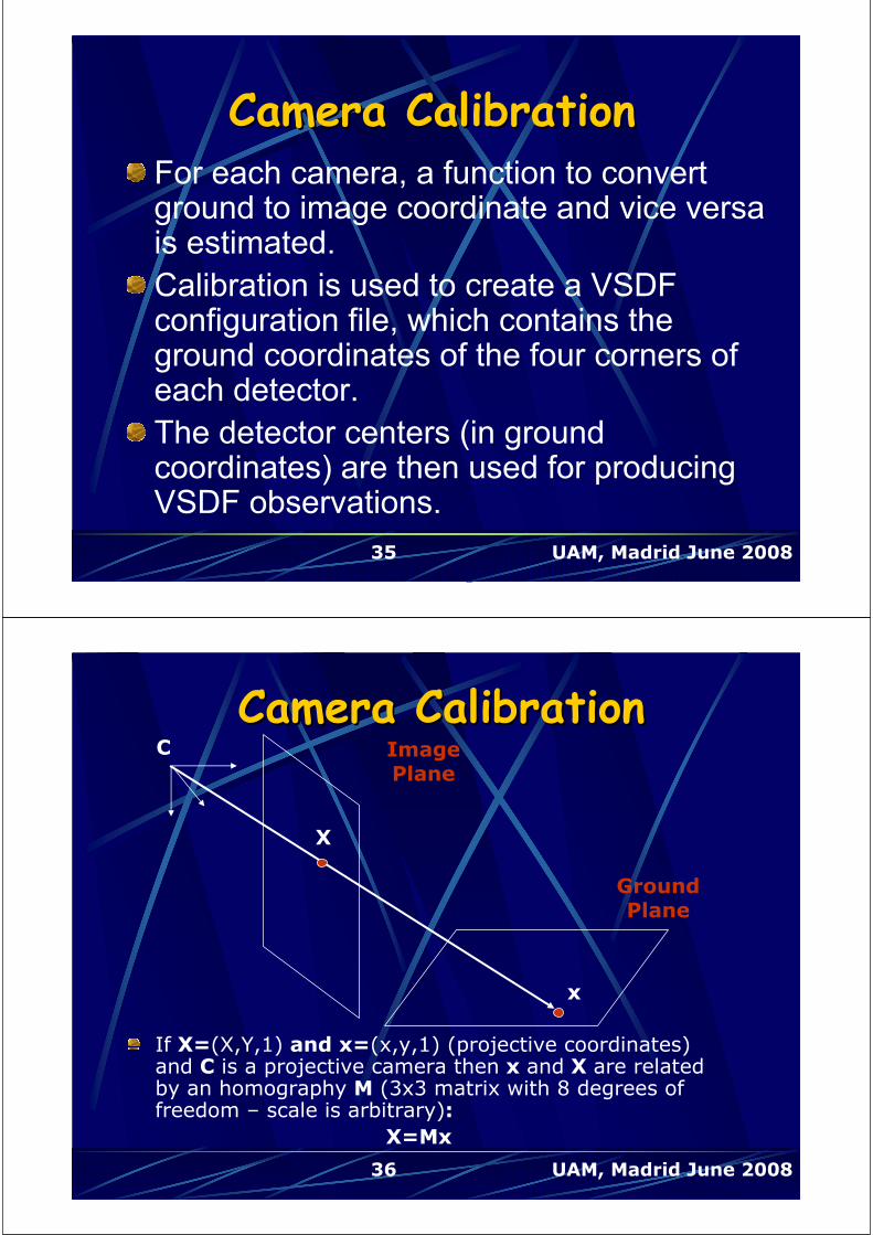
Camera CalibrationCamera Calibration
GroundPlane
ImagePlane
x
X
If X=(X,Y,1) and x=(x,y,1) (projective coordinates) and C is a projective camera then x and X are related by an homography M (3x3 matrix with 8 degrees of freedom – scale is arbitrary):
X=Mx
C

37 UAM, Madrid June 2008
Camera Calibration (2)Camera Calibration (2)We fix scale by setting M33=1
13231
232221
131211
MM
MMM
MMM
M
n 4 corresponding points (X,x) are marked both on the map (ground coordinates) and the image.
Calibration is then achieved by solving an over-determined system ofn equations and 8 unknowns, using least squares estimation.
[1] K.J.Bradshaw, I.D. Reid and D.W. Murray, “The Active Recovery of 3D Motion Trajectories and Their Use in Prediction,” IEEE Trans. on Pattern Analysis and Machine Intelligence, Vol. 19, No. 3, March 1997, pp 219-233.
38 UAM, Madrid June 2008
Camera Calibration (3)Camera Calibration (3)Line correspondences are usually easier to mark and may also be used, if available. Each line correspondence results to two additional equations (same as point correspondences).
Visualization of point and line correspondences (green) and calibration results (white).

39 UAM, Madrid June 2008
VSDF Server OverviewVSDF Server OverviewCollects data about the state of detectors
from all Autoscope sensors (AMVUs).
Processes this data in order to extract a set of
observations (plots). The position and size of
each observation is estimated.
The final results of the VSDF process are
encoded in ASTERIX Cat.10 format and sent
to the SDS for further process (tracking).
An optional visualization window of inputs
(VD states) and outputs (observations) is also
supported.
40 UAM, Madrid June 2008
VSDF Server ArchitectureVSDF Server Architecture
VSDF server (1. SDF)
AMV1
AMV2
AMV3
AMVn
AMVU-IA
AMVU-IA
AMVU-IA
AMVU-IA
VSDF
server
Direct DV
(via BNC
connection for
local AMVUs, or
via Autoscope
software)
AMVU
Configurator
(Autoscope
software)
User
To SDS
Autoscope
Communication
Server
41 UAM, Madrid June 2008
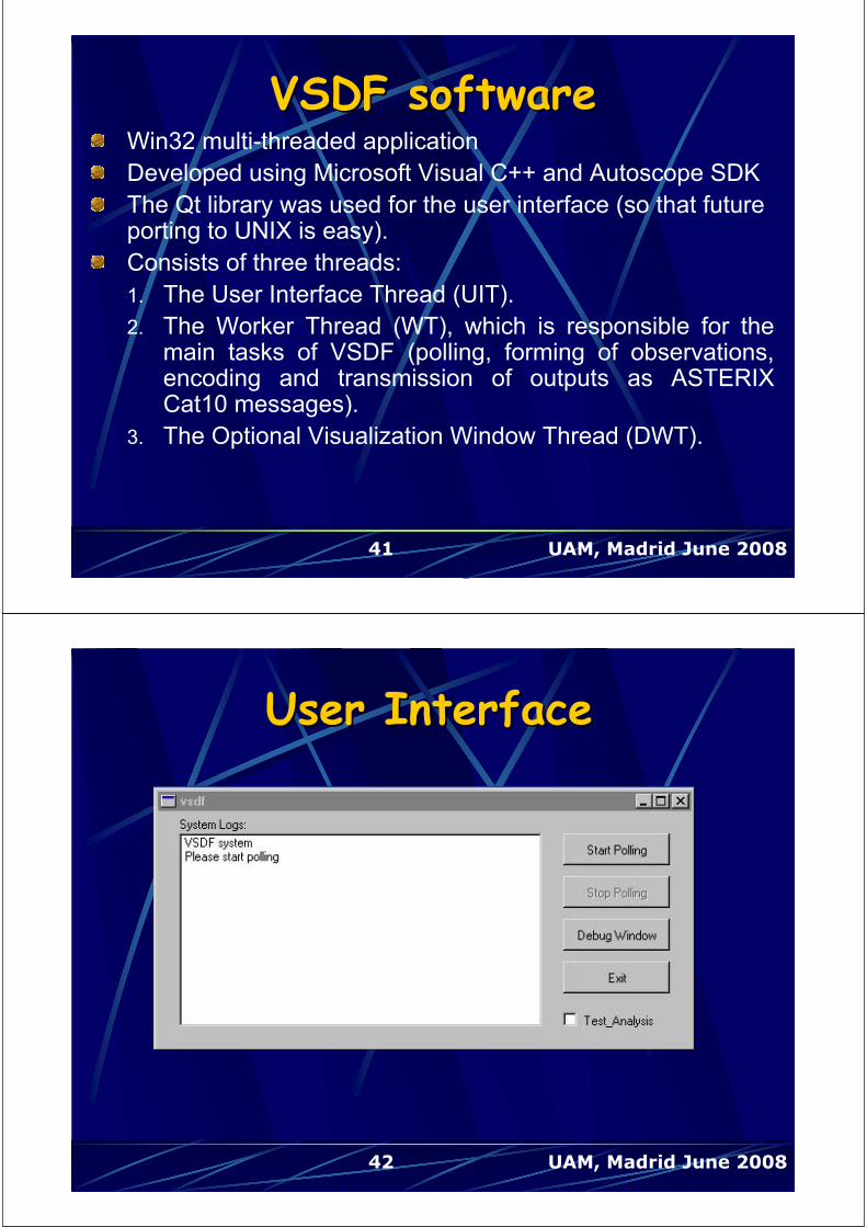
VSDF softwareVSDF softwareWin32 multi-threaded application
Developed using Microsoft Visual C++ and Autoscope SDK
The Qt library was used for the user interface (so that future porting to UNIX is easy).
Consists of three threads:
1. The User Interface Thread (UIT).
2. The Worker Thread (WT), which is responsible for the main tasks of VSDF (polling, forming of observations, encoding and transmission of outputs as ASTERIX Cat10 messages).
3. The Optional Visualization Window Thread (DWT).
42 UAM, Madrid June 2008
User Interface User Interface
43 UAM, Madrid June 2008
Polling of Virtual DetectorsPolling of Virtual Detectors
Polling is based on polling functions from
an Autoscope SDK.
Polling System Limitation: New data can
be provided by polling only after 1sec has
passed from the previous polling, which
causes some problems, when higher
update rates are needed.
44 UAM, Madrid June 2008
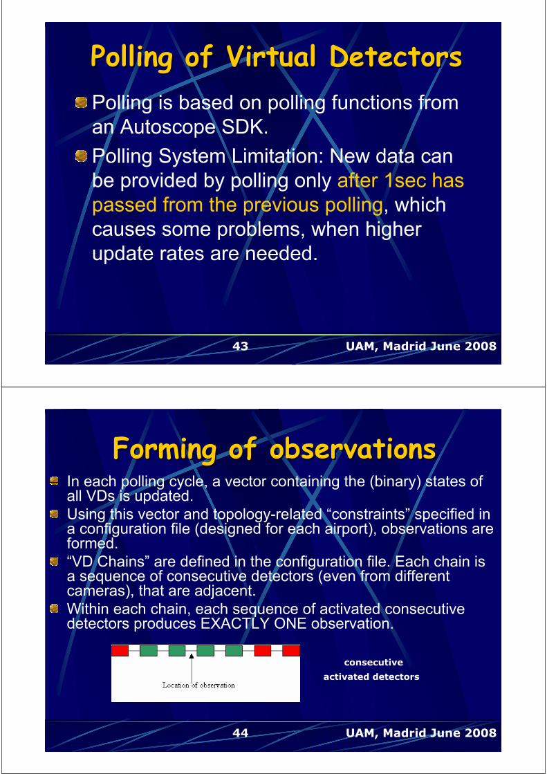
Forming of observationsForming of observationsIn each polling cycle, a vector containing the (binary) states of all VDs is updated.
Using this vector and topology-related “constraints” specified in a configuration file (designed for each airport), observations are formed.
“VD Chains” are defined in the configuration file. Each chain is a sequence of consecutive detectors (even from different cameras), that are adjacent.
Within each chain, each sequence of activated consecutive detectors produces EXACTLY ONE observation.
consecutive
activated detectors

45 UAM, Madrid June 2008
Additional constraints to handle occlusions
In this example setup, the tail of an aircraft passing from TWY may activate 4,5 leading to false results
Thus, an activation in the intersection layer is ACCEPTED ONLY IF NO detectors of the main layer (1,2,3) are activated.
This constraint correctly resolves occlusions from a plane at the TWY, however it still fails when two planes exist (one at the TWY and one at the intersecting road).
46 UAM, Madrid June 2008
Encoding into ASTERIX Cat10 messages Encoding into ASTERIX Cat10 messages and transmission to SDSand transmission to SDS
For each observation a data packet is generated and
transmitted (via UDP) as an ASTERIX Cat10 message
This message includes:
The position of the observation in Cartesian co-ordinates
The estimated target size using the distance between the first and
the last activated detector
The time and date obtained by the VSDF clock when sending the
message
In addition, to inform the SDS server about VSDF status,
a periodic system status data message is generated and
transmitted
47 UAM, Madrid June 2008
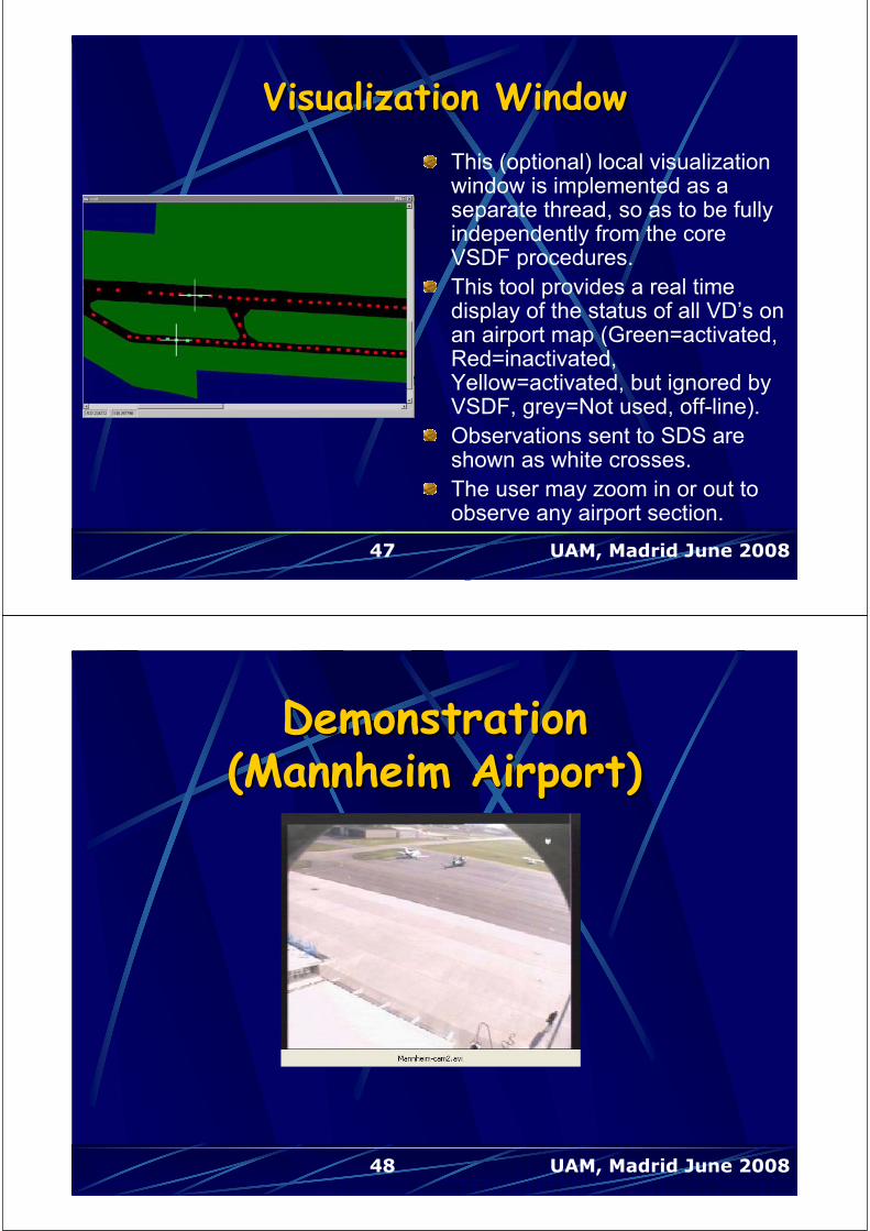
Visualization WindowVisualization Window
This (optional) local visualization window is implemented as a separate thread, so as to be fully independently from the core VSDF procedures.
This tool provides a real time display of the status of all VD’s on an airport map (Green=activated, Red=inactivated,Yellow=activated, but ignored by VSDF, grey=Not used, off-line).
Observations sent to SDS are shown as white crosses.
The user may zoom in or out to observe any airport section.
48 UAM, Madrid June 2008
DemonstrationDemonstration(Mannheim Airport)(Mannheim Airport)
49 UAM, Madrid June 2008
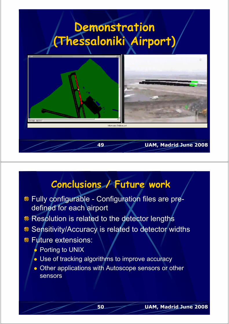
DemonstrationDemonstration(Thessaloniki Airport)(Thessaloniki Airport)
50 UAM, Madrid June 2008
Conclusions / Future workConclusions / Future work
Fully configurable - Configuration files are pre-
defined for each airport
Resolution is related to the detector lengths
Sensitivity/Accuracy is related to detector widths
Future extensions:
Porting to UNIX
Use of tracking algorithms to improve accuracy
Other applications with Autoscope sensors or other
sensors

51 UAM, Madrid June 2008
A GapA Gap--filler case study: filler case study: Prague airport Prague airport
Test of Gap-filler system at Prague
International airport within FP6 EMMA
IP project (European airport Movement
Management by A-SMGCS,
http://www.dlr.de/emma/)
52 UAM, Madrid June 2008
Prague Airport LayoutPrague Airport Layout

53 UAM, Madrid June 2008
SMR Shadow AreasSMR Shadow Areas
54 UAM, Madrid June 2008
Need of Gap-fillers

55 UAM, Madrid June 2008
SMR Blind SpotsSMR Blind Spots
56 UAM, Madrid June 2008
View North from TowerView North from Tower

57 UAM, Madrid June 2008
Installation Positions for Installation Positions for CamerasCameras
58 UAM, Madrid June 2008
Camera Locations amd FOVsCamera Locations amd FOVs
A
BC
SMR+
59 UAM, Madrid June 2008
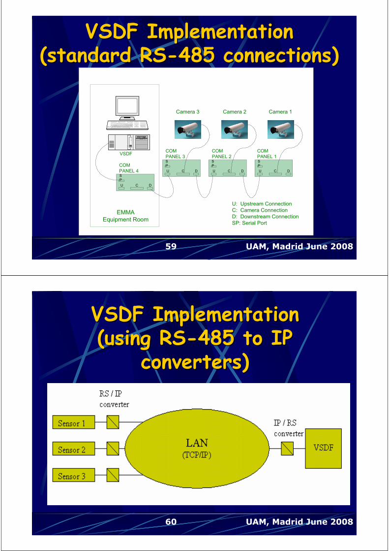
VSDF Implementation VSDF Implementation (standard RS(standard RS--485 connections)485 connections)
U C D
S
P
U C D
S
P
U C D
S
P
U C D
S
P
U: Upstream Connection
C: Camera Connection
D: Downstream Connection
SP: Serial Port
EMMA
Equipment Room
Camera 1Camera 2Camera 3
COM
PANEL 1
COM
PANEL 2
COM
PANEL 3
COM
PANEL 4
VSDF
U C D
S
P
U C D
S
P
U C D
S
P
U C D
S
P
U: Upstream Connection
C: Camera Connection
D: Downstream Connection
SP: Serial Port
EMMA
Equipment Room
Camera 1Camera 2Camera 3
COM
PANEL 1
COM
PANEL 2
COM
PANEL 3
COM
PANEL 4
VSDF
RS-485
60 UAM, Madrid June 2008
VSDF Implementation VSDF Implementation (using RS(using RS--485 to IP 485 to IP
converters)converters)

61 UAM, Madrid June 2008
Final VD setupFinal VD setup
62 UAM, Madrid June 2008
ExperimentalExperimentalResultsResults
63 UAM, Madrid June 2008
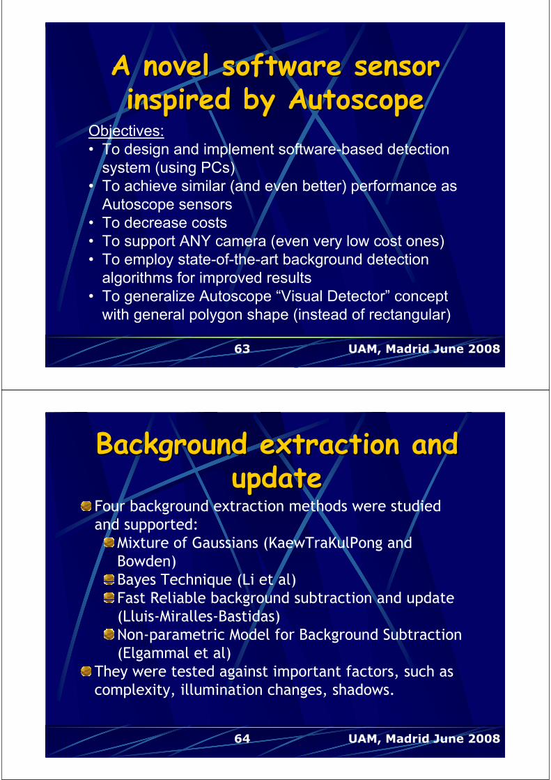
A novel software sensor A novel software sensor inspired by Autoscopeinspired by Autoscope
Objectives:
• To design and implement software-based detection
system (using PCs)
• To achieve similar (and even better) performance as
Autoscope sensors
• To decrease costs
• To support ANY camera (even very low cost ones)
• To employ state-of-the-art background detection
algorithms for improved results
• To generalize Autoscope “Visual Detector” concept
with general polygon shape (instead of rectangular)
64 UAM, Madrid June 2008
Background extraction and Background extraction and updateupdate
Four background extraction methods were studied
and supported:
Mixture of Gaussians (KaewTraKulPong and
Bowden)
Bayes Technique (Li et al)
Fast Reliable background subtraction and update
(Lluis-Miralles-Bastidas)
Non-parametric Model for Background Subtraction
(Elgammal et al)
They were tested against important factors, such as
complexity, illumination changes, shadows.

65 UAM, Madrid June 2008
Mixture of Gaussians modelMixture of Gaussians model
The probability density function for each pixel is modeled
as an adaptive mixture of Gaussian distributions.
The Expectation-Maximization (EM) algorithm is used to
fit the Gaussian mixture model. This is an iterative process
that guarantees convergence to a local maximum.
The Mixture of Gaussians model:
Copes well with illumination changes
Is robust to slowly moving objects in the background
Requires adjustment of a small number of parameters
66 UAM, Madrid June 2008
Bayes algorithmBayes algorithmA Bayes decision rule is applied for the classification of
background and foreground from selected feature vectors.
Stationary and moving background objects are identified by
selecting suitable features for each category
As a result, foreground objects are also identified.
Various strategies have been proposed for gradual or at-once
learning of background features.
The high computational cost of the method and the need for
high memory resources render the algorithm inappropriate for real
time applications

67 UAM, Madrid June 2008
LluisLluis--MirallesMiralles--BastidasBastidasalgorithmalgorithm
Fast and simple background estimation and update algorithm,
based on a moving average.
Optimization of results by using and estimating the “background
noise level” and by calculating automatically an optimal threshold.
Suitable for indoor or outdoor scenes with small environmental
changes (wind, illumination).
Fast adaptation in foreground changes giving advanced sensitivity
in detection of moving objects.
Low computational cost.
68 UAM, Madrid June 2008
NonNon--parametric modelingparametric modeling
The Probability Density Function (pdf) of the background for a
pixel is modeled from its N most recent values, using a kernel
function (e.g. a Gaussian)
The variance of each kernel function is estimated
A pixel is classified as background if the probability to belong to
background is higher than a total threshold T, which is properly
adjusted.
Optional shadow removal by studying color and illumination
information for each pixel.
Memory requirements may decrease by using a Lookup Table
for probability calculations

69 UAM, Madrid June 2008
Evaluation of Background Evaluation of Background Extraction Results Extraction Results
Road traffic sequence Airport sequence
70 UAM, Madrid June 2008
Background extraction (Road)Background extraction (Road)
Mixture of Gaussians Bayes
Fast technique (Lluis)Non parametric model + shadow
suppression (Elgammal)
71 UAM, Madrid June 2008
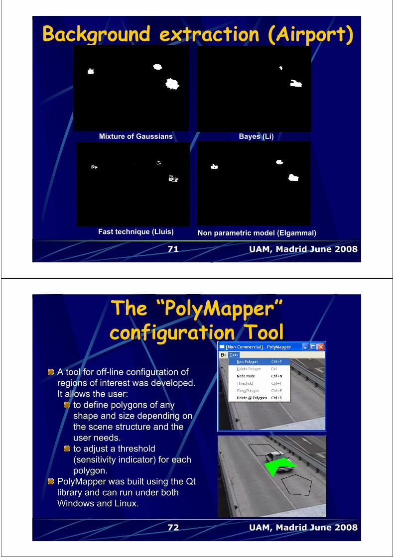
Background extraction (Airport)Background extraction (Airport)
Mixture of Gaussians Bayes (Li)
Fast technique (Lluis) Non parametric model (Elgammal)
72 UAM, Madrid June 2008
TheThe ““PolyMapperPolyMapper””configuration Toolconfiguration Tool
A tool for off-line configuration of
regions of interest was developed.
It allows the user:
to define polygons of any
shape and size depending on
the scene structure and the
user needs.
to adjust a threshold
(sensitivity indicator) for each
polygon.
PolyMapper was built using the Qt
library and can run under both
Windows and Linux.
73 UAM, Madrid June 2008
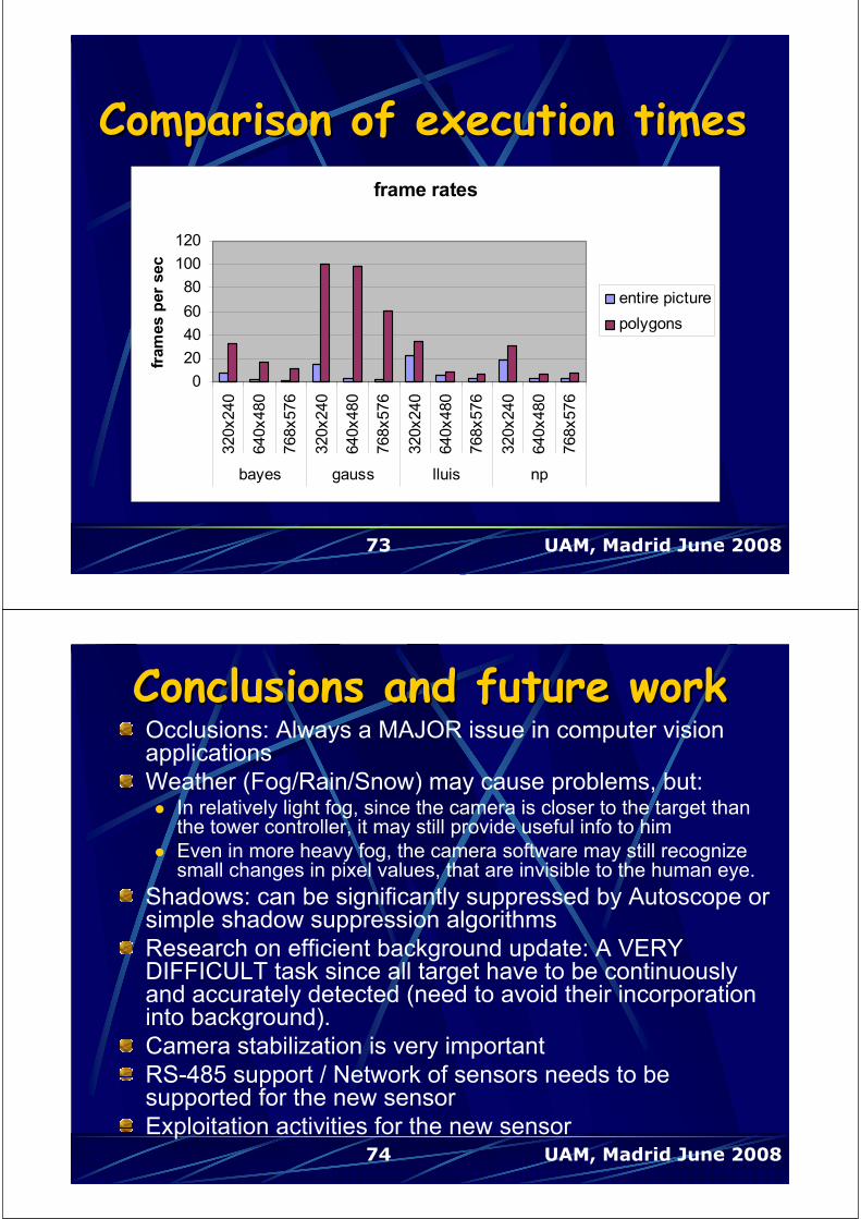
Comparison of execution timesComparison of execution times
frame rates
0
20
40
60
80
100
120320x240
640x480
768x576
320x240
640x480
768x576
320x240
640x480
768x576
320x240
640x480
768x576
bayes gauss lluis np
fram
es p
er
sec
entire picture
polygons
74 UAM, Madrid June 2008
Conclusions and future workConclusions and future workOcclusions: Always a MAJOR issue in computer vision applications
Weather (Fog/Rain/Snow) may cause problems, but:In relatively light fog, since the camera is closer to the target than the tower controller, it may still provide useful info to him
Even in more heavy fog, the camera software may still recognize small changes in pixel values, that are invisible to the human eye.
Shadows: can be significantly suppressed by Autoscope or simple shadow suppression algorithms
Research on efficient background update: A VERY DIFFICULT task since all target have to be continuously and accurately detected (need to avoid their incorporation into background).
Camera stabilization is very important
RS-485 support / Network of sensors needs to be supported for the new sensor
Exploitation activities for the new sensor

UAM, Madrid June 2008
TRAVISTRAVIS ––
An Efficient Traffic Visual An Efficient Traffic Visual
Monitoring SystemMonitoring System
Centre for Research and Technology HellasCentre for Research and Technology Hellas ((CERTHCERTH)) --
Informatics and Telematics InstituteInformatics and Telematics Institute ((ITIITI))
UAM, Madrid June 2008
OutlineOutline
Introduction
System Architecture
System modules and algorithms
Pilot applications
Experimental results
Demo videos
Conclusions

UAM, Madrid June 2008
Aims of TRAVIS systemAims of TRAVIS system
The fundamental goal is a moving target tracking system, based
on a network of cameras.
A fully scaled and parameterized system for use in a broad field
of applications
Two prototypes were developed:
A tunnel monitoring system able to trace events that can lead
to accidents. Installed at a tunnel near Piraeus harbor.
An alternative A-SMGCS for control of movements
occurring at the aircraft parking area (APRON). Installed at
Macedonia airport of Thessaloniki, Greece
UAM, Madrid June 2008
TRAVIS System ArchitectureTRAVIS System Architecture
Scalable network of
Autonomous Tracking Units
Sensor Data Fusion
server (SDF)
Video sensors
Detect foreground objects
Send results
Fuse observations from remote
ATUs
Track moving objects
Visualize moving objects
PROXY
SERVER &
µ
µ
# 1
PROXY
SERVER &
µ
µ
# 2
PROXY
SERVER &
µ
µ
# 3
PROXY
SERVER &
µ
µ
# n
µ
µ (SDF)
µ
µ
GLOSEC //
//
PROXY
SERVER &
µ
µ
# 1
PROXY
SERVER &
µ
µ
# 2
PROXY
SERVER &
µ
µ
# 3
PROXY
SERVER &
µ
µ
# n
µ
µ (SDF)
µ
µ
GLOSEC //
//
Wireless connection
Sensor Data Fusion server
(SDF)
airport
Control center
Wired
connection
autono
mous
tracking
unit # 1
autono
mous
tracking
unit # 2
autono
mous
tracking
unit # 3
autono
mous
tracking
unit # n
Control center / traffic management
Traffic
management

UAM, Madrid June 2008
Autonomous Tracking UnitAutonomous Tracking Unit
Background estimation
foreground segmentation
classification
3D observation extractionCamera
calibration
Feature
extraction
sensor 1 … sensor n
SDFATU
UAM, Madrid June 2008
Background extraction techniquesBackground extraction techniques
Four background extraction methods are supported:
Bayes Technique (Li et al)
Mixture of Gaussians (KaewTraKulPong and Bowden)
Reliable background subtraction and update (Lluis-Miralles-
Bastidas)
Non-parametric Model for Background Subtraction
(Elgammal et al)
They were tested against crucial factors, such as complexity,
illumination changes, shadows.
Based on experimental results, the Non-parametric Model for
Background Subtraction seems to be the most efficient one.

UAM, Madrid June 2008
ClassificationClassification
Targets are classified in four categories :
Human
Car
Large vehicle (track, bus)
Airplane (Airport) / Motorcycle (Tunnel)
For the implementation of classifier a Back Propagation
Neural Network was used.
UAM, Madrid June 2008
ClassificationClassification
The inputs of the Neural network in use are nine features of
the observation:
The size of the major and the minor axis of the
bounding ellipse of the observation in ground plane
which are indicative of the size of the target.
The 7 Hu moments of the blob, that describe the shape
of object and have the advantage of being independent of
translations and rotations of the object.

UAM, Madrid June 2008
These four values are normalized to have a sum of one.
For the training of the Neural Network, frame sequences
from “Macedonia” airport of Thessaloniki and a tunnel near
Piraeus harbor were used.
The Neural Network has one
hidden layer with 100 nodes and an
output layer with 4 outputs.
Every output is the probability the
observation to belong to this class.
ClassificationClassification
UAM, Madrid June 2008
Sensor Data Fusion server Sensor Data Fusion server ((SDF)SDF)
…
Network module
Scene Visualization
moduleStatistics
module
Graphical User
Interface
Data fusion
Multiple Hypothesis Tracker(MHT)
ATU#1 ATU#2 ATU#n
SDF

UAM, Madrid June 2008
Sensor Data Fusion server Sensor Data Fusion server ((SDF)SDF)
Collects information from all ATUs using a constant polling
cycle
Produces fused estimates of the position and velocity of each
moving target
Tracks the moving targets using a multi-target tracking
algorithm (Multiple Hypothesis Tracking – MHT)
Produces friendly User Interface that:
Generate a synthetic ground situation display and provide
alerts when specific situations (e.g. accidents) are detected.
Present the moving targets in real time
Present statistics of the observed scene
Give control to the User on the system as a whole
UAM, Madrid June 2008
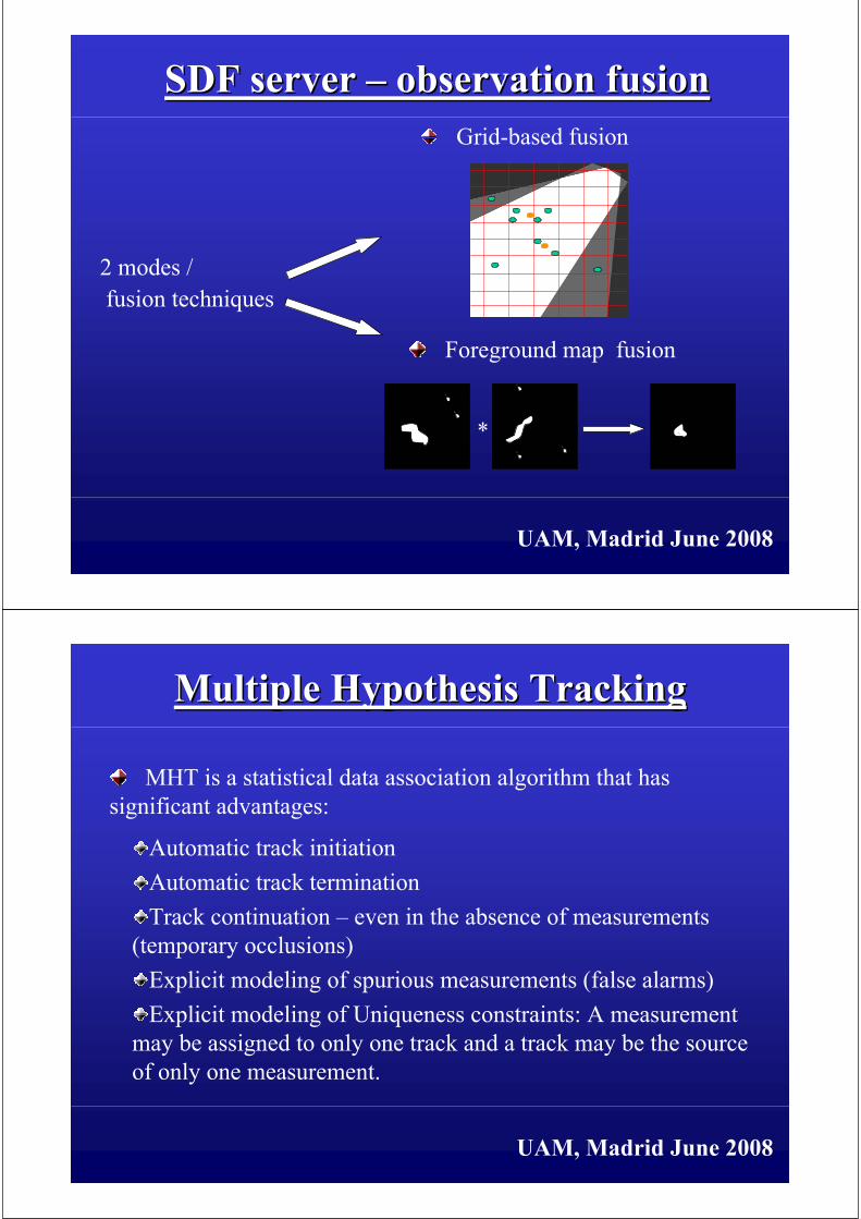
SDF server SDF server –– observation fusion observation fusion
Two fusion techniques
Grid – based techniqueSeparate the overlap area (in world coordinates) in cells
Observations belong to the same cell or to neighboring cells are grouped
together
Fused observations are produced be averaging the parameters
Foreground map fusion techniqueEach autonomous tracking unit determines the pixels in each video
sensor that are also visible by other video sensors
For these pixels foreground probability maps are generated
These maps are then transmitted to the SDF, where they are fused
together (warped to the ground plane and multiplied together)
UAM, Madrid June 2008
Grid-based fusion
SDF server SDF server –– observation fusion observation fusion
*
Foreground map fusion
2 modes /
fusion techniques
UAM, Madrid June 2008
Multiple Hypothesis TrackingMultiple Hypothesis Tracking
MHT is a statistical data association algorithm that has
significant advantages:
Automatic track initiation
Automatic track termination
Track continuation – even in the absence of measurements
(temporary occlusions)
Explicit modeling of spurious measurements (false alarms)
Explicit modeling of Uniqueness constraints: A measurement
may be assigned to only one track and a track may be the source
of only one measurement.

UAM, Madrid June 2008
Input
Data
Multiple Hypothesis TrackingMultiple Hypothesis Tracking
Filtering
and Prediction
Gating
Computations
Track
Maintenance
Observation
To Track
Association
Data Association
UAM, Madrid June 2008
An efficient implementation of MHT using a fast algorithm to generate the k-best hypothesis [Cox96] is used.
Slight delay is introduced, since a decision (selection of the best hypothesis) is delayed for N time instants (usually N=2,3).
If N=0, no delay is introduced and the algorithm behaves exactly like GNN (nearest neighbor).
Any Kalman filter model may be easily implemented.
Multiple Hypothesis TrackingMultiple Hypothesis Tracking
UAM, Madrid June 2008
Statistics per lane and per object class (Person, Car, Large
vehicle, Motorcycle. Other)
Minimum, Maximum and Average Velocity estimation
Traffic flow (Vehicles/h)
Traffic density (Vehicles/km)
Vehicle counters
Real time presentation of statistics and recording for post
processing and analysis
SDF server SDF server –– statisticsstatistics
UAM, Madrid June 2008
Data exchange and controlData exchange and control
Client – Server based architecture. TCP/IP network
Use of Network Time Protocol to synchronize the
interconnected computers (ATUs) with SDF clock
Appointment algorithm to have millisecond synchronization in
frame capture
Remote control of ATU network through SDF software using a
UDP signaling channel
Data packets contain plain text data or text and foreground maps
depending on the operation mode

UAM, Madrid June 2008
Mode
(1 byte)
Packet size
(2 bytes)
ASCII size
(2 bytes)
timestamp
(8 bytes)
ASCII
observations
(t_size bytes)
Deflated
foreground map
(im_size bytes)ATU data packet
ATU
SDF
Data exchange and controlData exchange and control
UAM, Madrid June 2008
Synchronization maintenance Synchronization maintenance
Capture cycle and processing time
window with no delays
ATU 2 exceed the given time for
processing and data transmission
UAM, Madrid June 2008
Secondary video streaming systemSecondary video streaming systemSecondary backup system from each ATU to control center
On Demand video streaming to assist:
Compressed video
Using unreal media streaming server
A number of compressed images (JPEG, JPEG2000)
Supported by the hardware of the Frame Grabber
Every ATU is able to stream:
Human operators
Decision makers
UAM, Madrid June 2008
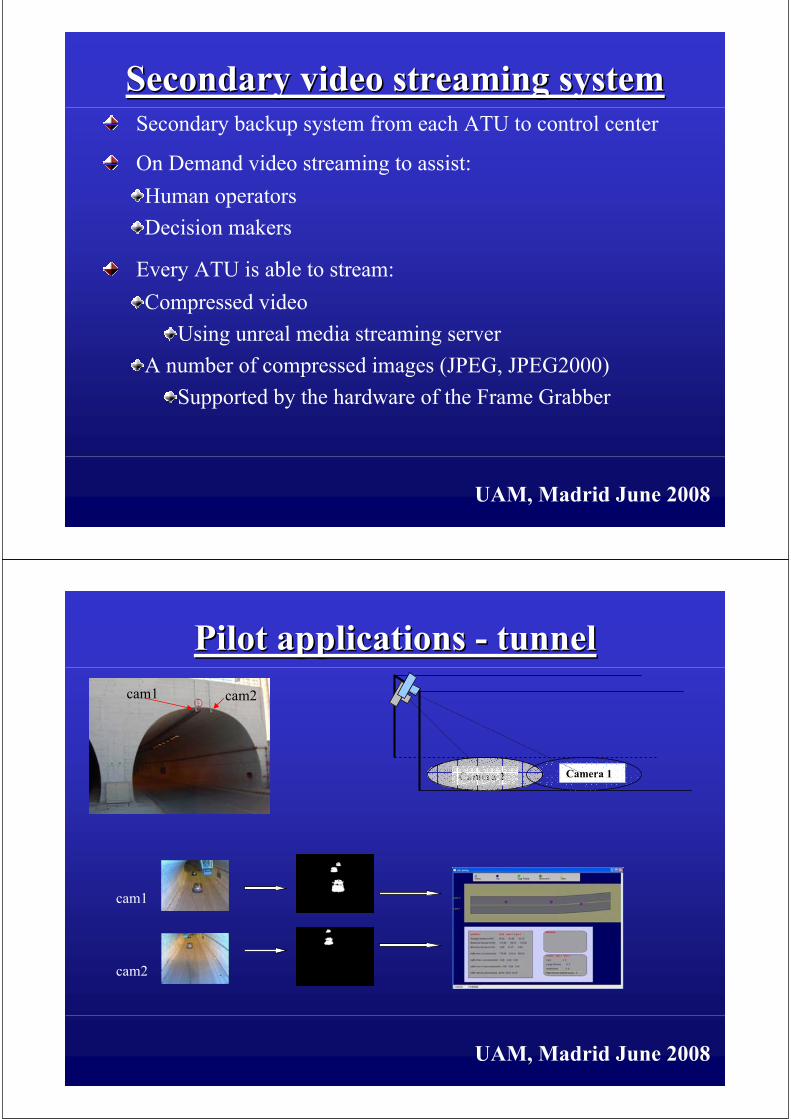
Pilot applications Pilot applications -- tunneltunnel
Camera 2 Camera 1
cam1
cam2
cam1 cam2

UAM, Madrid June 2008
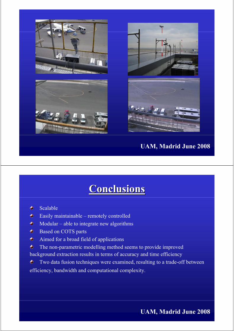
Pilot applications Pilot applications -- airportairport
Apron Taxiway
Camera 2
Camera 1
cam1
cam2
UAM, Madrid June 2008
ExperimentalExperimental resultsresults
Mixture of Gaussians mask Bayes algorithm mask
Lluis-Miralles-Bastidas mask Non-parametric model mask
Original image Moving objects
Method Resolution Time(s) FPS
BAYES
320x240 0.13 7.68
640x480 0.59 1.68
768x576 0.73 1.38
GAUSS
320x240 0.07 14.38
640x480 0.29 3.39
768x576 0.39 2.59
LLUIS
320x240 0.05 22.19
640x480 0.19 5.16
768x576 0.28 3.63
NON- PARAMETRIC
320x240 0.054 18.57
640x480 0.35 2.83
768x576 0.38 2.65

UAM, Madrid June 2008
Experimental resultsExperimental results
SDF foreground map
110.506626ms
SDF grid
1.227394ms
ATU foreground map
61.78666759ms
ATU grid
90.73470782ms
Tunnel installation:
fusion times grid-foreground map
SDF foreground map
45.184562ms
SDF grid
14.260328ms
ATU foreground map
43.56174ms
ATU grid
73.923166ms
Airport installation:
fusion times grid-foreground map
Bandwidth usage per mode for each pilot installation
0
2
4
6
8
10
12
14
16
Airport Tunnel
Grid mode
Foreground Map mode
Grid mode ~ 1KByte / frame
Foreground airport ~8 Kbytes / frame
Foreground tunnel ~15 Kbytes / frame
UAM, Madrid June 2008
ExperimentalExperimental resultsresults
SDF times (Foreground map mode)
Data fusion 70%
(31.70ms)
Tracker 1%
(0.22 ms)
Display 29%
(13.25ms)
SDF times (Grid mode)
Tracker 4% (0.55 ms)
Display 94% (13.36 ms)
Data Fusion 2% (0.33 ms)
ATU times
Observation
estimation 3%
(2.55ms)
Blob extraction
38% (27.80ms)
Background
extraction
59% (43.56ms)
UAM, Madrid June 2008
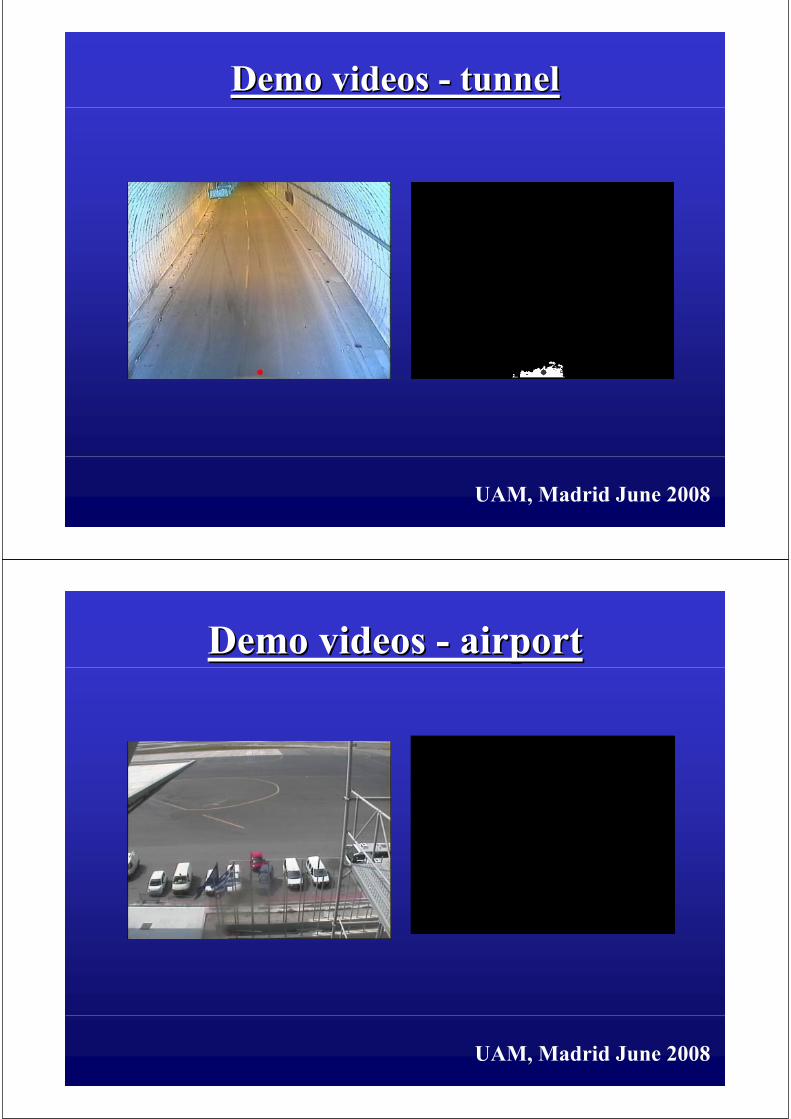
Demo videos Demo videos -- tunneltunnel
UAM, Madrid June 2008
Demo videos Demo videos -- airportairport

UAM, Madrid June 2008
SDFSDF
UAM, Madrid June 2008
UAM, Madrid June 2008
UAM, Madrid June 2008
ConclusionsConclusions
Scalable
Easily maintainable – remotely controlled
Modular – able to integrate new algorithms
Based on COTS parts
Aimed for a broad field of applications
The non-parametric modelling method seems to provide improved
background extraction results in terms of accuracy and time efficiency
Two data fusion techniques were examined, resulting to a trade-off between
efficiency, bandwidth and computational complexity.

UAM, Madrid June 2008
Future workFuture work
Support for additional efficient background extraction
algorithms
Research on background update algorithms to solve problems
caused by local and global illumination changes
Hardware implementation of ATUs based on DSP / FPGA
technologies
Implementation of ATU as Web Enabled Sensor, for use in
service oriented architectures
Exploitation of TRAVIS products (by VRSENSE spinoff
company
UAM, Madrid June 2008
Thank you for
your attention
Nikos Grammalidis
Electrical and Computer Engineer, Ph.D.
Centre for Research and Technology Hellas
Informatics and Telematics Institute
E-mail: [email protected]
Centre for Research and Technology HellasCentre for Research and Technology Hellas ((CERTHCERTH)) --
Informatics and Telematics InstituteInformatics and Telematics Institute ((ITIITI))
Theodoros Semertzidis
Electrical and Computer Engineer
Centre for Research and Technology Hellas
Informatics and Telematics Institute
E-mail: [email protected]
Questions?
Related Documents