Vision-based displacement measurement sensor using modified Taylor approximation approach Bingyou Liu Dashan Zhang Jie Guo Chang’an Zhu Bingyou Liu, Dashan Zhang, Jie Guo, Chang’an Zhu, “Vision-based displacement measurement sensor using modified Taylor approximation approach, ” Opt. Eng. 55(11), 114103 (2016), doi: 10.1117/1.OE.55.11.114103. Downloaded From: https://www.spiedigitallibrary.org/journals/Optical-Engineering on 30 Jan 2020 Terms of Use: https://www.spiedigitallibrary.org/terms-of-use

Welcome message from author
This document is posted to help you gain knowledge. Please leave a comment to let me know what you think about it! Share it to your friends and learn new things together.
Transcript
Vision-based displacementmeasurement sensor using modifiedTaylor approximation approach
Bingyou LiuDashan ZhangJie GuoChang’an Zhu
Bingyou Liu, Dashan Zhang, Jie Guo, Chang’an Zhu, “Vision-based displacement measurement sensorusing modified Taylor approximation approach,” Opt. Eng. 55(11), 114103 (2016),doi: 10.1117/1.OE.55.11.114103.
Downloaded From: https://www.spiedigitallibrary.org/journals/Optical-Engineering on 30 Jan 2020Terms of Use: https://www.spiedigitallibrary.org/terms-of-use
Vision-based displacement measurement sensor usingmodified Taylor approximation approach
Bingyou Liu,a,b Dashan Zhang,a Jie Guo,a,* and Chang’an Zhua
aUniversity of Science and Technology of China, Department of Precision Machinery and Precision Instrumentation, Huangshan Road No. 443,Shushan District, Hefei, AnHui 230027, ChinabAnhui Polytechnic University, Key Lab of Electric and Control of Anhui Province, Beijingzhong Road No. 8, Jiujiang District, Wuhu, AnHui 241000,China
Abstract. The development of image sensors and optics lenses has contributed to the rapidly increasing use ofvision-based methods as noncontact measurement methods in many areas. A high-speed camera system isdeveloped to realize the displacement measurement in real time. Conventional visual measurement algorithmsare commonly subjected to various shortcomings, such as complex processes, multiparameter adjustments, orinteger-pixel accuracy. Inspired from the combination of block-matching algorithm and simplified optical flow,a motion estimation algorithm that uses modified Taylor approximation is proposed and applied to the visionsensor system. Simplifying integer-pixel searching with a rounding-iterative operation enables the modified algo-rithm to rapidly accomplish one displacement extraction within 1 ms and yield satisfactory subpixel accuracy.The performance of the vision sensor is evaluated through a simulation test and two experiments on a gratingruler motion platform and a steering wheel system of a forklift. Experimental results show that the developedvision sensor can extract accurate displacement signals and accomplish the vibration measurement of engineer-ing structures. © The Authors. Published by SPIE under a Creative Commons Attribution 3.0 Unported License. Distribution or reproduction of thiswork in whole or in part requires full attribution of the original publication, including its DOI. [DOI: 10.1117/1.OE.55.11.114103]
Keywords: noncontact measurement; machine vision; high-speed vision sensor; subpixel accuracy; vibration analysis.
Paper 161320 received Aug. 24, 2016; accepted for publication Oct. 25, 2016; published online Nov. 14, 2016.
1 IntroductionNoncontact measure techniques, such as speckle photogra-phy,1 hologram interferometry,2 and laser Doppler vibrome-try,3 have been developed for years and well applied invarious fields. Compared to traditional measurement devices,such as accelerometer or linear displacement gauge, deviceswith noncontact approaches have a more flexible installationand provide intuitionistic exhibitions of the actual movementsof the target without affecting its behavior. In some environ-ments where traditional sensors do not have clear access orcannot work effectively, e.g., remote measurement targetsor fields with high temperature or strong magnetic, noncontactmeasurement devices obviously have great advantages overconventional ones. However, most noncontact equipmentrequires high cost and strict construction structures, thus limit-ing the wide use of such systems in practical applications.
Technological developments in image sensors and opticslens have contributed to the rapidly increasing use ofvision-based measurement methods as noncontact measure-ment methods in numerous research and industrial areas, suchas vibration analysis,4,5 condition monitoring,6–11 humanmotion,12,13 and underwater measurement.14 With a relativelylower cost and better flexibility in structure, optical devicesand cameras offer effective alternatives to noncontact equip-ment. Benefiting from the wide availability of affordablehigh-quality digital image sensors and high-performancecomputers, cheap high-resolution cameras have been growingused in many areas. Recently, vision-based techniques weresuccessfully used to measure various structures and get satis-factory results.15–24 Quan et al.25 achieved three-dimensional
displacement measurement based on two-dimensional (2-D)digital image correlation (DIC). Kim et al.26 proposed avision-based monitoring system that uses DIC to evaluatethe cable tensile force of a cable-stayed bridge. The samemethod was also applied in experimental mechanics for non-contact, full-field deformation measurement.27,28 Park et al.29
realized displacement measurement for high-rise buildingstructures using the partitioning approach. Wahbeh et al.30
realized the measurement of displacements and rotations ofthe Vincent Thomas Bridge in California by using a highlyaccurate camera in conjunction with a laser tracking reference.Fukuda et al.31 proposed a camera-based sensor system inwhich a robust object search algorithm was used to measurethe dynamic displacements of large-scale structures. Fenget al.32 developed a vision-based sensor that employed anup-sampled cross-correlation (UCC) algorithm for noncontactstructural displacement measurement, which can accuratelymeasure the displacements of bridges.33
The traditional camera system for displacement measure-ment is composed of commercial digital cameras and video-processing devices (normally computers). However, ordinarydigital cameras often have low video-sampling rate, whichlimits the application range of their vibration frequency.34
To overcome this restriction, a high-speed vision systemwith 1000 frames per second (fps) or even higher has beendeveloped and applied in practice.35 In the present paper, ahigh-speed camera sensor system composed of a zoom opti-cal lens, a high-speed camera body with a CCD receiver, anda notebook computer. A USB 3.0 interface is used to ensurestable data transfer between the camera body and the com-puter. On the notebook computer, the captured video can beprocessed by software to realize the tracking of an object andto extract motion information in real time.*Address all correspondence to: Jie Guo, E-mail: [email protected]
Optical Engineering 114103-1 November 2016 • Vol. 55(11)
Optical Engineering 55(11), 114103 (November 2016)
Downloaded From: https://www.spiedigitallibrary.org/journals/Optical-Engineering on 30 Jan 2020Terms of Use: https://www.spiedigitallibrary.org/terms-of-use
Similar to other measurement equipment, a vision-basedmeasurement system is mainly concerned with measurementof speed and accuracy, both of which significantly depend onthe performance of the image-processing algorithm. Owingto their high sampling rate, high-speed sensors have strictrequirements for motion-tracking algorithms on computingspeed to satisfy the demand of real-time signal processing.Conventional motion extraction algorithms based on tem-plate matching registration techniques [i.e., sum of absolutedifference (SAD) or normalized cross-correlation (NCC)]are mostly complex and have a heavy computation load.Moreover, template matching techniques can only achieveinteger-pixel resolution because the minimal unit in a videoimage is 1 pixel. Such accuracy is far from satisfactory innumerous practical applications, particularly for those wherethe vibrations of small structures are required. Various meth-ods have been proposed to refine measurement accuracy,including interpolation techniques and subpixel registra-tion,36–38 most of which improved accuracy indeed butexhibited low computational efficiency to some degree.
Chan et al.39 proposed a subpixel motion estimationmethod that uses a combination of classical block matchingand simplified optical flow. The method is tremendouslyfaster than any existing block-matching algorithm becauseno interpolation is needed. In the first step, a block-matchingalgorithm, such as three-step search (TSS) or cross-diamondsearch, is used to determine integer-pixel displacement. Theresult is then refined through local approximation using asimplified optical flow to subpixel level. In this paper, wesimplified Chan’s algorithm by replacing block matchingwith rounding-iterative Taylor approximation. With no sub-pixel interpolation needed during frame cutting in eachiteration, this modified algorithm runs much faster thanconventional iterative DIC optical flow. Given that theimprovement brings no additional parameter that requiresspecification, the modified algorithm naturally executeswith a high degree of automation. After several times ofoptimization, the computation time of one extraction inthe modified algorithm is reduced to less than 1 ms. Themodified algorithm is utilized in the high-speed camera sys-tem for its high efficiency and satisfactory subpixel accuracy.A simulation and two experiments under laboratory and real-istic conditions are carried out for performance verification.The positive results demonstrated the accuracy and effi-ciency of the camera sensor system in measuring dynamicdisplacement.
The rest of the paper is organized as follows. Section 2introduces the components and capability parameters ofthe high-speed vision sensor system. Section 3 presentsthe theory of motion estimation algorithm without interpo-lation and the modified Taylor algorithm. Section 4 evaluatesthe performance of the modified algorithm with a simulationtest. Section 5 presents two experiments for performanceverification. Section 6 discusses the results and outlook.
2 High-Speed Vision Sensor SystemTraditional camera systems for displacement measurementare commonly composed of commercial digital camerasand personal computers. However, commercial digital cam-eras usually have low frame rates (i.e., 100 fps), which limittheir application in vibration frequencies over 50 Hz. In thispaper, a high-speed sensor system composed of a notebook
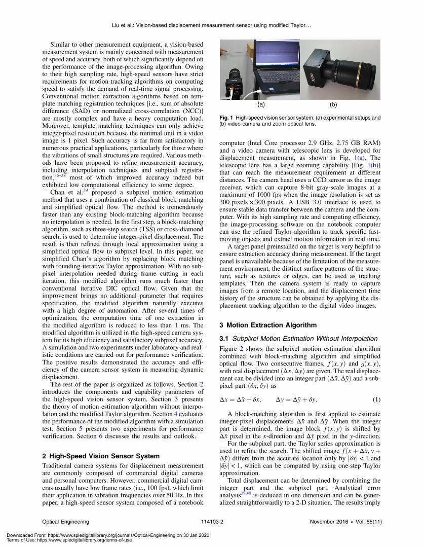
computer (Intel Core processor 2.9 GHz, 2.75 GB RAM)and a video camera with telescopic lens is developed fordisplacement measurement, as shown in Fig. 1(a). Thetelescopic lens has a large zooming capability [Fig. 1(b)]that can reach the measurement requirement at differentdistances. The camera head uses a CCD sensor as the imagereceiver, which can capture 8-bit gray-scale images at amaximum of 1000 fps when the image resolution is set as300 pixels × 300 pixels. A USB 3.0 interface is used toensure stable data transfer between the camera and the com-puter. With its high sampling rate and computing efficiency,the image-processing software on the notebook computercan use the refined Taylor algorithm to track specific fast-moving objects and extract motion information in real time.
A target panel preinstalled on the target is very helpful toensure extraction accuracy during measurement. If the targetpanel is unavailable because of the limitation of the measure-ment environment, the distinct surface patterns of the struc-ture, such as textures or edges, can be used as trackingtemplates. Then the camera system is ready to captureimages from a remote location, and the displacement timehistory of the structure can be obtained by applying the dis-placement tracking algorithm to the digital video images.
3 Motion Extraction Algorithm
3.1 Subpixel Motion Estimation Without Interpolation
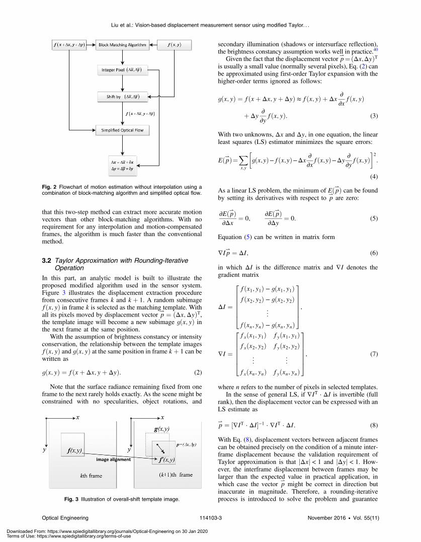
Figure 2 shows the subpixel motion estimation algorithmcombined with block-matching algorithm and simplifiedoptical flow. Two consecutive frames, fðx; yÞ and gðx; yÞ,with real displacement ðΔx;ΔyÞ are given. The real displace-ment can be divided into an integer part ðΔx;ΔyÞ and a sub-pixel part ðδx; δyÞ asEQ-TARGET;temp:intralink-;e001;326;243Δx ¼ Δxþ δx; Δy ¼ Δyþ δy: (1)
A block-matching algorithm is first applied to estimateinteger-pixel displacements Δx and Δy. When the integerpart is determined, the image block fðx; yÞ is shifted byΔx pixel in the x-direction and Δy pixel in the y-direction.
For the subpixel part, the Taylor series approximation isused to refine the search. The shifted image fðxþ Δx; yþΔyÞ differs from the accurate location only by jδxj < 1 andjδyj < 1, which can be computed by using one-step Taylorapproximation.
Total displacement can be determined by combining theinteger part and the subpixel part. Analytical erroranalysis39,40 is deduced in one dimension and can be gener-alized straightforwardly to a 2-D situation. The results imply
Fig. 1 High-speed vision sensor system: (a) experimental setups and(b) video camera and zoom optical lens.
Optical Engineering 114103-2 November 2016 • Vol. 55(11)
Liu et al.: Vision-based displacement measurement sensor using modified Taylor. . .
Downloaded From: https://www.spiedigitallibrary.org/journals/Optical-Engineering on 30 Jan 2020Terms of Use: https://www.spiedigitallibrary.org/terms-of-use
that this two-step method can extract more accurate motionvectors than other block-matching algorithms. With norequirement for any interpolation and motion-compensatedframes, the algorithm is much faster than the conventionalmethod.
3.2 Taylor Approximation with Rounding-IterativeOperation
In this part, an analytic model is built to illustrate theproposed modified algorithm used in the sensor system.Figure 3 illustrates the displacement extraction procedurefrom consecutive frames k and kþ 1. A random subimagefðx; yÞ in frame k is selected as the matching template. Withall its pixels moved by displacement vector p
⇀ ¼ ðΔx;ΔyÞT,the template image will become a new subimage gðx; yÞ inthe next frame at the same position.
With the assumption of brightness constancy or intensityconservation, the relationship between the template imagesfðx; yÞ and gðx; yÞ at the same position in frame kþ 1 can bewritten as
EQ-TARGET;temp:intralink-;e002;63;276gðx; yÞ ¼ fðxþ Δx; yþ ΔyÞ: (2)
Note that the surface radiance remaining fixed from oneframe to the next rarely holds exactly. As the scene might beconstrained with no specularities, object rotations, and
secondary illumination (shadows or intersurface reflection),the brightness constancy assumption works well in practice.40
Given the fact that the displacement vector p⇀¼ðΔx;ΔyÞT
is usually a small value (normally several pixels), Eq. (2) canbe approximated using first-order Taylor expansion with thehigher-order terms ignored as follows:EQ-TARGET;temp:intralink-;e003;326;686
gðx; yÞ ¼ fðxþ Δx; yþ ΔyÞ ≈ fðx; yÞ þ Δx∂∂x
fðx; yÞ
þ Δy∂∂y
fðx; yÞ: (3)
With two unknowns, Δx and Δy, in one equation, the linearleast squares (LS) estimator minimizes the square errors:
EQ-TARGET;temp:intralink-;e004;326;596Eðp⇀Þ¼Xx;y
�gðx;yÞ−fðx;yÞ−Δx
∂∂x
fðx;yÞ−Δy∂∂y
fðx;yÞ�2
:
(4)
As a linear LS problem, the minimum of Eðp⇀Þ can be foundby setting its derivatives with respect to p
⇀are zero:
EQ-TARGET;temp:intralink-;e005;326;512
∂Eðp⇀Þ∂Δx
¼ 0;∂Eðp⇀Þ∂Δy
¼ 0: (5)
Equation (5) can be written in matrix form
EQ-TARGET;temp:intralink-;e006;326;454∇Ip⇀ ¼ ΔI; (6)
in which ΔI is the difference matrix and ∇I denotes thegradient matrixEQ-TARGET;temp:intralink-;e007;326;397
ΔI ¼
2666664
fðx1; y1Þ − gðx1; y1Þfðx2; y2Þ − gðx2; y2Þ
..
.
fðxn; ynÞ − gðxn; ynÞ
3777775;
∇I ¼
2666664
fxðx1; y1Þ fyðx1; y1Þfxðx2; y2Þ fyðx2; y2Þ
..
. ...
fxðxn; ynÞ fyðxn; ynÞ
3777775; (7)
where n refers to the number of pixels in selected templates.In the sense of general LS, if ∇IT · ΔI is invertible (full
rank), then the displacement vector can be expressed with anLS estimate as
EQ-TARGET;temp:intralink-;e008;326;196p⇀ ¼ ½∇IT · ΔI�−1 · ∇IT · ΔI: (8)
With Eq. (8), displacement vectors between adjacent framescan be obtained precisely on the condition of a minute inter-frame displacement because the validation requirement ofTaylor approximation is that jΔxj < 1 and jΔyj < 1. How-ever, the interframe displacement between frames may belarger than the expected value in practical application, inwhich case the vector p
⇀might be correct in direction but
inaccurate in magnitude. Therefore, a rounding-iterativeprocess is introduced to solve the problem and guaranteeFig. 3 Illustration of overall-shift template image.
Fig. 2 Flowchart of motion estimation without interpolation using acombination of block-matching algorithm and simplified optical flow.
Optical Engineering 114103-3 November 2016 • Vol. 55(11)
Liu et al.: Vision-based displacement measurement sensor using modified Taylor. . .
Downloaded From: https://www.spiedigitallibrary.org/journals/Optical-Engineering on 30 Jan 2020Terms of Use: https://www.spiedigitallibrary.org/terms-of-use
accuracy. For each calculation step of p⇀j ¼ ðΔxj;ΔyjÞT,
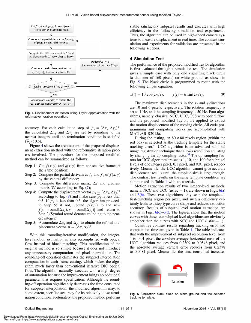
the calculated Δxj and Δyj are set by rounding to thenearest integers until the termination condition is satisfied(p⇀j < 0.5).Figure 4 shows the architecture of the proposed displace-
ment extraction method with the reformative iteration proc-ess involved. The procedure for the proposed modifiedmethod can be summarized as follows:
Step 1: Cut fðx; yÞ and gðx; yÞ from consecutive frames atthe same position;
Step 2: Compute the partial derivatives fx and fy of fðx; yÞby the central difference;
Step 3: Compute the difference matrix ΔI and gradientmatrix ∇I according to Eq. (7);
Step 4: Compute the displacement vector p⇀j ¼ ðΔxj;ΔyjÞT
according to Eq. (8) and make sure p⇀j is less than
0.5. If p⇀j is less than 0.5, the algorithm proceeds
to Step 5; if not, update fðx; yÞ to the newf½xþ roundðΔxjÞ; yþ roundðΔyjÞ� and return toStep 2 (Symbol round denotes rounding to the near-est integer);
Step 5: Accumulate Δxj and Δyj to obtain the refined dis-placement vector p
⇀ ¼ ðΔx;ΔyÞT.With this rounding-iterative modification, the integer-
level motion estimation is also accomplished with opticalflow instead of block matching. This modification of theoriginal method is so simple because it does not introduceany unnecessary computation and pixel interpolation. Therounding-off operation eliminates the subpixel interpolationcomputation in each frame cutting, which makes the algo-rithm much faster than conventional iterative DIC opticalflow. The algorithm naturally executes with a high degreeof automation because the improvement brings no additionalparameter that requires specification. Although the round-ing-off operation significantly decreases the time consumedfor subpixel interpolation, the modified algorithm may, tosome extent, sacrifice accuracy for its relatively loose termi-nation condition. Fortunately, the proposed method performs
stable satisfactory subpixel results and executes with highefficiency in the following simulation and experiments.Thus, the algorithm can be used in high-speed camera sys-tems to measure displacement in real time. The contrast sim-ulation and experiments for validation are presented in thefollowing sections.
4 Simulation TestThe performance of the proposed modified Taylor algorithmis first evaluated through a simulation test. The simulationgives a simple case with only one vignetting black circle(a diameter of 160 pixels) on white ground, as shown inFig. 5. The black circle is programmed to rotate with thefollowing ellipse equation:
EQ-TARGET;temp:intralink-;e009;326;597xðtÞ ¼ 10 cosð2πftÞ; yðtÞ ¼ 6 sinð2πftÞ: (9)
The maximum displacements in the x- and y-directionsare 10 and 6 pixels, respectively. The rotation frequency isset to 1 Hz, and the sampling frequency is 50 Hz. Four algo-rithms, namely, classical NCC, UCC, TSS with optical flow,and the proposed modified Taylor, are applied to extractthe motion displacement of the moving circle. All code pro-gramming and computing works are accomplished withMATLAB R2015a.
During the testing, an 80 × 80 pixels region (within thered box) is selected as the tracking template for the stabletracking error.41 UCC algorithm is an advanced subpixelimage registration technique that allows resolution adjustingby changing the up-sampling factor.34 The up-sampling fac-tors for UCC algorithm are set as 1, 10, and 100 for subpixellevels of one integer pixel, 0.1 pixel, and 0.01 pixel, respec-tively. Meanwhile, the UCC algorithm cannot give accuratedisplacement results until the template size is large enough.The contrast test results on the same template condition aresummarized in Table 1 with an asterisk.
Motion extraction results of two integer-level methods,namely, NCC and UCC (usfac ¼ 1), are shown in Figs. 6(a)and 6(b). These two algorithms only scan the template’sbest-matching region per pixel, and such a deficiency cer-tainly leads to a step-type curve shape and reduces extractionaccuracy. Results of subpixel level motion extraction areshown in Figs. 6(c)–6(f). The figures show that the motioncurves with these four subpixel level algorithms are obviouslysmoother than the curves with NCC and UCC (usfac ¼ 1).
Quantitive contrast results regarding tracking error andcomputation time are given in Table 1. The table indicatesthat with the improvement of subpixel resolution level from1 to 0.01 pixel, the absolute average horizontal error of theUCC algorithm reduces from 0.2309 to 0.0548 pixel, andthe absolute average vertical error reduces from 0.2378to 0.0481 pixel. Meanwhile, the time consumed increases
Fig. 4 Displacement extraction using Taylor approximation with thereformative iteration operation.
Fig. 5 Simulation black circle on white ground and the selectedtracking template.
Optical Engineering 114103-4 November 2016 • Vol. 55(11)
Liu et al.: Vision-based displacement measurement sensor using modified Taylor. . .
Downloaded From: https://www.spiedigitallibrary.org/journals/Optical-Engineering on 30 Jan 2020Terms of Use: https://www.spiedigitallibrary.org/terms-of-use
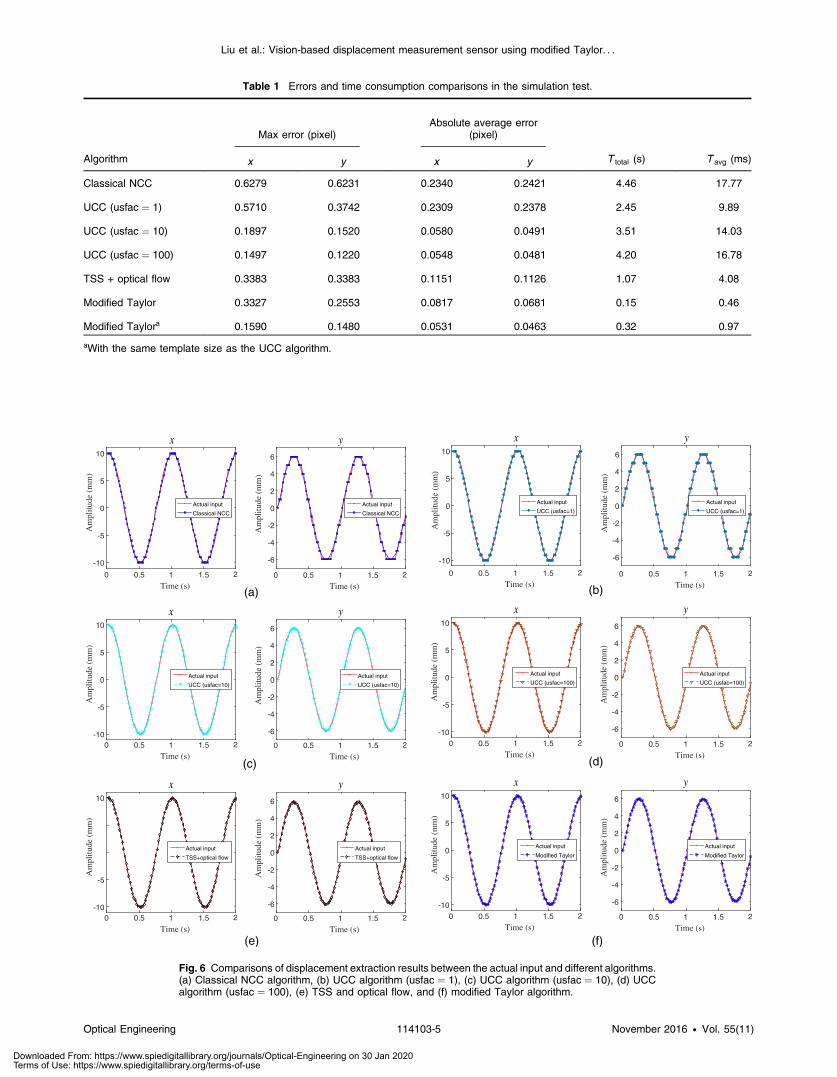
Table 1 Errors and time consumption comparisons in the simulation test.
Algorithm
Max error (pixel)Absolute average error
(pixel)
T total (s) T avg (ms)x y x y
Classical NCC 0.6279 0.6231 0.2340 0.2421 4.46 17.77
UCC (usfac ¼ 1) 0.5710 0.3742 0.2309 0.2378 2.45 9.89
UCC (usfac ¼ 10) 0.1897 0.1520 0.0580 0.0491 3.51 14.03
UCC (usfac ¼ 100) 0.1497 0.1220 0.0548 0.0481 4.20 16.78
TSS + optical flow 0.3383 0.3383 0.1151 0.1126 1.07 4.08
Modified Taylor 0.3327 0.2553 0.0817 0.0681 0.15 0.46
Modified Taylora 0.1590 0.1480 0.0531 0.0463 0.32 0.97
aWith the same template size as the UCC algorithm.
Time (s)0 0.5 1 1.5
Am
plitu
de (
mm
)
-10
-5
0
5
10
x
Actual input
Classical NCC
Am
plitu
de (
mm
)
-6
-4
-2
0
2
4
6
Am
plitu
de (
mm
)
-10
-5
0
5
10
Am
plitu
de (
mm
)
-6
-4
-2
0
2
4
6
y
Actual input
Classical NCC
(a)
Am
plitu
de (
mm
)
-10
-5
0
5
10
x
Actual input
UCC (usfac=1)
Am
plitu
de (
mm
)
-6
-4
-2
0
2
4
6
2
Am
plitu
de (
mm
)
-10
-5
0
5
0
5
10
Am
plitu
de (
mm
)
-6
-4
-2
0
2
4
6
y
Actual input
UCC (usfac=1)
(b)
x
Actual input
UCC (usfac=10)
y
Actual input
UCC (usfac=10)
(c)
x
Actual input
UCC (usfac=100)
y
Actual input
UCC (usfac=100)
(d)
x
Actual input
TSS+optical flow
y
Actual input
TSS+optical flow
(e)
x
Actual input
Modified Taylor
y
Actual input
Modified Taylor
(f)
Time (s)0 0.5 1 1.5 2
Time (s)0 0.5 1 1.5 2
Time (s)0 0.5 1 1.5 2
Time (s)0 0.5 1 1.5 2
Time (s)0 0.5 1 1.5 2
Time (s)0 0.5 1 1.5
Am
plitu
de (
mm
)
-10
-5
10
Am
plitu
de (
mm
)
-6
-4
-2
0
2
4
6
2
Am
plitu
de (
mm
)
-10
-5
10
Am
plitu
de (
mm
)
-6
-4
-2
0
2
4
6
Time (s)0 0.5 1 1.5 2
Time (s)0 0.5 1 1.5 2
Time (s)0 0.5 1 1.5 2
Time (s)0 0.5 1 1.5 2
Time (s)0 0.5 1 1.5 2
Fig. 6 Comparisons of displacement extraction results between the actual input and different algorithms.(a) Classical NCC algorithm, (b) UCC algorithm (usfac ¼ 1), (c) UCC algorithm (usfac ¼ 10), (d) UCCalgorithm (usfac ¼ 100), (e) TSS and optical flow, and (f) modified Taylor algorithm.
Optical Engineering 114103-5 November 2016 • Vol. 55(11)
Liu et al.: Vision-based displacement measurement sensor using modified Taylor. . .
Downloaded From: https://www.spiedigitallibrary.org/journals/Optical-Engineering on 30 Jan 2020Terms of Use: https://www.spiedigitallibrary.org/terms-of-use
from 14.03 to 16.78 ms∕frame. When subjected to therequirement of template size, the UCC algorithm does nothave the capability of giving dual attention to both accuracyand high efficiency. The error analysis of the combination ofTSS and optical flow reveals that the combination methodhas a clear advantage in time consumed (4.08 ms∕frame)with acceptable average errors (0.1151 pixel in the horizontaland 0.1126 pixel in the vertical). The proposed modifiedTaylor method is also observed to have the highest compu-tation efficiency among all the listed methods. The averageelapsed time of handling one frame costs only 0.46 ms with arelatively better error performance than the combined TSSand optical flow. Furthermore, with a large size template,the modified Taylor even gives a similar error performanceas UCC (usfac ¼ 100) with the elapsed time per frame of just1∕17 of the latter.
Owing to the satisfactory performances in time efficiencyand accuracy during displacement extraction in the simula-tion test, the modified Taylor algorithm was integrated intothe real-time vision sensor system mentioned in Sec. 2. Thesoftware contains several modules. The high-speed cameramodule can control the parameters of the digital camera,such as contrast, brightness, and exposure time. The calibra-tion part has the ability to compute the actual displacement ofone pixel based on a target with an already known size. Withthe image-capturing part, the streaming image data can beacquired in real time and sent to the template tracking mod-ule, where the modified Taylor algorithm is operating. Theentire sensor system is implemented based on the Qt andOpenCV libraries and is capable of realizing the displace-ment measurement of actual structures.
5 Experimental Verification
5.1 Case 1: Experiment on a Grating Ruler MotionPlatform
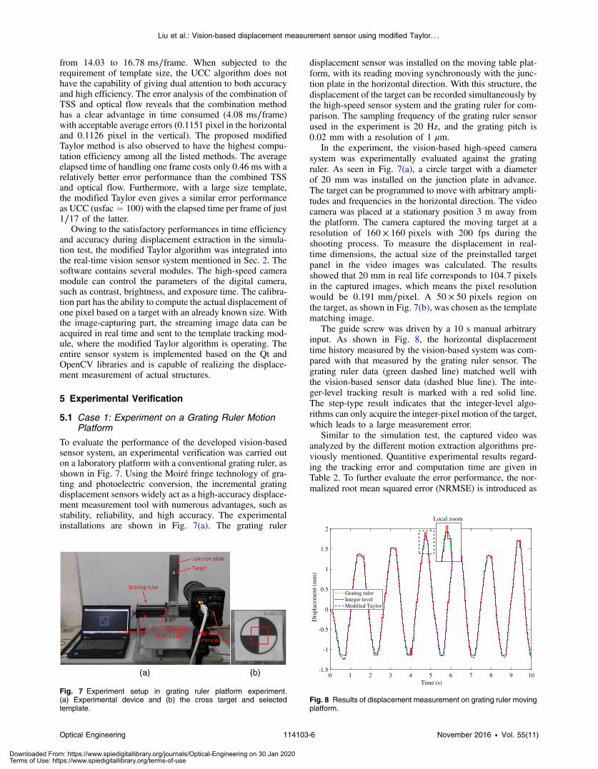
To evaluate the performance of the developed vision-basedsensor system, an experimental verification was carried outon a laboratory platform with a conventional grating ruler, asshown in Fig. 7. Using the Moiré fringe technology of gra-ting and photoelectric conversion, the incremental gratingdisplacement sensors widely act as a high-accuracy displace-ment measurement tool with numerous advantages, such asstability, reliability, and high accuracy. The experimentalinstallations are shown in Fig. 7(a). The grating ruler
displacement sensor was installed on the moving table plat-form, with its reading moving synchronously with the junc-tion plate in the horizontal direction. With this structure, thedisplacement of the target can be recorded simultaneously bythe high-speed sensor system and the grating ruler for com-parison. The sampling frequency of the grating ruler sensorused in the experiment is 20 Hz, and the grating pitch is0.02 mm with a resolution of 1 μm.
In the experiment, the vision-based high-speed camerasystem was experimentally evaluated against the gratingruler. As seen in Fig. 7(a), a circle target with a diameterof 20 mm was installed on the junction plate in advance.The target can be programmed to move with arbitrary ampli-tudes and frequencies in the horizontal direction. The videocamera was placed at a stationary position 3 m away fromthe platform. The camera captured the moving target at aresolution of 160 × 160 pixels with 200 fps during theshooting process. To measure the displacement in real-time dimensions, the actual size of the preinstalled targetpanel in the video images was calculated. The resultsshowed that 20 mm in real life corresponds to 104.7 pixelsin the captured images, which means the pixel resolutionwould be 0.191 mm∕pixel. A 50 × 50 pixels region onthe target, as shown in Fig. 7(b), was chosen as the templatematching image.
The guide screw was driven by a 10 s manual arbitraryinput. As shown in Fig. 8, the horizontal displacementtime history measured by the vision-based system was com-pared with that measured by the grating ruler sensor. Thegrating ruler data (green dashed line) matched well withthe vision-based sensor data (dashed blue line). The inte-ger-level tracking result is marked with a red solid line.The step-type result indicates that the integer-level algo-rithms can only acquire the integer-pixel motion of the target,which leads to a large measurement error.
Similar to the simulation test, the captured video wasanalyzed by the different motion extraction algorithms pre-viously mentioned. Quantitive experimental results regard-ing the tracking error and computation time are given inTable 2. To further evaluate the error performance, the nor-malized root mean squared error (NRMSE) is introduced as
Fig. 7 Experiment setup in grating ruler platform experiment.(a) Experimental device and (b) the cross target and selectedtemplate.
Time (s)0 1 2 3 4 5 6 7 8 9 10
Dis
plac
emen
t (m
m)
-1.5
-1
-0.5
0
0.5
1
1.5
2
Grating rulerInteger levelModified Taylor
Local zoom
Fig. 8 Results of displacement measurement on grating ruler movingplatform.
Optical Engineering 114103-6 November 2016 • Vol. 55(11)
Liu et al.: Vision-based displacement measurement sensor using modified Taylor. . .
Downloaded From: https://www.spiedigitallibrary.org/journals/Optical-Engineering on 30 Jan 2020Terms of Use: https://www.spiedigitallibrary.org/terms-of-use
EQ-TARGET;temp:intralink-;e010;63;543NRMSE ¼ffiffiffiffiffiffiffiffiffiffiffiffiffiffiffiffiffiffiffiffiffiffiffiffiffiffiffiffiffiffiffiffiffi1n
Pni¼1 ðai − biÞ2
qbmax − bmin
× 100%; (10)
where n denotes the frame number and a and b refer to thedisplacement data measured by the vision-based sensor andgrating ruler, respectively. The result indicates that the visionsensor system with modified Taylor algorithm has the lowestNRMSE of 0.75% and the fastest average computing timeper frame of 0.22 ms. The absolute average measuringerror of modified Taylor was 0.020 mm. With the pixelresolution of 0.191 mm∕pixel, the proposed sensor systemachieved 1∕9 the pixel accuracy of the experimentalmeasurement.
5.2 Case 2: Vibration Measurement of SteeringWheel System
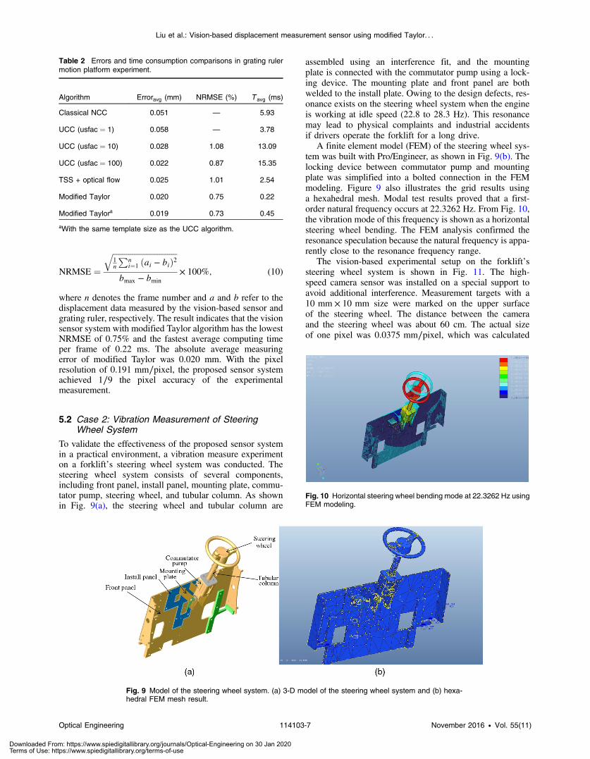
To validate the effectiveness of the proposed sensor systemin a practical environment, a vibration measure experimenton a forklift’s steering wheel system was conducted. Thesteering wheel system consists of several components,including front panel, install panel, mounting plate, commu-tator pump, steering wheel, and tubular column. As shownin Fig. 9(a), the steering wheel and tubular column are
assembled using an interference fit, and the mountingplate is connected with the commutator pump using a lock-ing device. The mounting plate and front panel are bothwelded to the install plate. Owing to the design defects, res-onance exists on the steering wheel system when the engineis working at idle speed (22.8 to 28.3 Hz). This resonancemay lead to physical complaints and industrial accidentsif drivers operate the forklift for a long drive.
A finite element model (FEM) of the steering wheel sys-tem was built with Pro/Engineer, as shown in Fig. 9(b). Thelocking device between commutator pump and mountingplate was simplified into a bolted connection in the FEMmodeling. Figure 9 also illustrates the grid results usinga hexahedral mesh. Modal test results proved that a first-order natural frequency occurs at 22.3262 Hz. From Fig. 10,the vibration mode of this frequency is shown as a horizontalsteering wheel bending. The FEM analysis confirmed theresonance speculation because the natural frequency is appa-rently close to the resonance frequency range.
The vision-based experimental setup on the forklift’ssteering wheel system is shown in Fig. 11. The high-speed camera sensor was installed on a special support toavoid additional interference. Measurement targets with a10 mm × 10 mm size were marked on the upper surfaceof the steering wheel. The distance between the cameraand the steering wheel was about 60 cm. The actual sizeof one pixel was 0.0375 mm∕pixel, which was calculated
Table 2 Errors and time consumption comparisons in grating rulermotion platform experiment.
Algorithm Erroravg (mm) NRMSE (%) T avg (ms)
Classical NCC 0.051 — 5.93
UCC (usfac ¼ 1) 0.058 — 3.78
UCC (usfac ¼ 10) 0.028 1.08 13.09
UCC (usfac ¼ 100) 0.022 0.87 15.35
TSS + optical flow 0.025 1.01 2.54
Modified Taylor 0.020 0.75 0.22
Modified Taylora 0.019 0.73 0.45
aWith the same template size as the UCC algorithm.
Fig. 9 Model of the steering wheel system. (a) 3-D model of the steering wheel system and (b) hexa-hedral FEM mesh result.
Fig. 10 Horizontal steering wheel bending mode at 22.3262 Hz usingFEM modeling.
Optical Engineering 114103-7 November 2016 • Vol. 55(11)
Liu et al.: Vision-based displacement measurement sensor using modified Taylor. . .
Downloaded From: https://www.spiedigitallibrary.org/journals/Optical-Engineering on 30 Jan 2020Terms of Use: https://www.spiedigitallibrary.org/terms-of-use
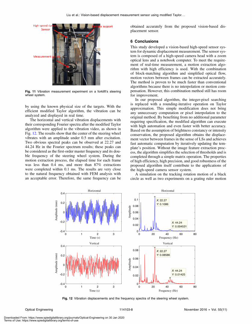
by using the known physical size of the targets. With theefficient modified Taylor algorithm, the vibration can beanalyzed and displayed in real time.
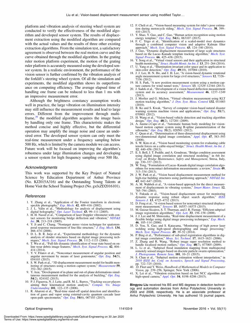
The horizontal and vertical vibration displacements withtheir corresponding Fourier spectra after the modified Tayloralgorithm were applied to the vibration video, as shown inFig. 12. The results show that the center of the steering wheelvibrates with an amplitude under 0.5 mm after excitation.Two obvious spectral peaks can be observed at 22.27 and44.24 Hz in the Fourier spectrum results; these peaks canbe considered as the first-order master frequency and its dou-ble frequency of the steering wheel system. During themotion extraction process, the elapsed time for each framewas less than 0.4 ms, and more than 87% extractionswere completed within 0.1 ms. The results are very closeto the natural frequency obtained with FEM analysis withan acceptable error. Therefore, the same frequency can be
obtained accurately from the proposed vision-based dis-placement sensor.
6 ConclusionsThis study developed a vision-based high-speed sensor sys-tem for dynamic displacement measurement. The sensor sys-tem is composed of a high-speed camera head with a zoomoptical lens and a notebook computer. To meet the require-ment of real-time measurement, a motion extraction algo-rithm with high efficiency is used. With the combinationof block-matching algorithm and simplified optical flow,motion vectors between frames can be extracted accurately.The method is proven to be much faster than conventionalalgorithms because there is no interpolation or motion com-pensation. However, this combination method still has roomfor improvement.
In our proposed algorithm, the integer-pixel searchingis replaced with a rounding-iterative operation on Taylorapproximation. This simple modification does not bringany unnecessary computation or pixel interpolation to theoriginal method. By benefiting from no additional parameterrequiring specification, the modified algorithm can executewith high automation and even faster with better accuracy.Based on the assumption of brightness constancy or intensityconservation, the proposed algorithm obtains the displace-ment vector between frames in the sense of LSs and achievesfast automatic computation by iteratively updating the tem-plate’s position. Without the image feature extraction proc-ess, the algorithm simplifies the selection of thresholds and iscompleted through a simple matrix operation. The propertiesof high efficiency, high precision, and good robustness of theproposed algorithm itself contribute to the applications ofthe high-speed camera sensor system.
A simulation on the tracking rotation motion of a blackcircle as well as two experiments on a grating ruler motion
Fig. 11 Vibration measurement experiment on a forklift’s steeringwheel system.
Time (s)0 1 2 3
Am
plitu
de (
mm
)
-0.4
-0.2
0
0.2
0.4Horizontal
Time (s)0 1 2 3
Am
plitu
de (
mm
)
-0.4
-0.2
0
0.2
0.4Vertical
Frequency (Hz)0 20 40 60 80
Am
plitu
de
0
0.02
0.04
0.06
0.08
0.1
Horizontal
Frequency (Hz)0 20 40 60 80
Am
plitu
de
0
0.02
0.04
0.06
0.08
Vertical
X: 22.27Y: 0.1086
X: 44.24Y: 0.004531
X: 22.27Y: 0.08586
X: 44.24Y: 0.01425
Fig. 12 Vibration displacements and the frequency spectra of the steering wheel system.
Optical Engineering 114103-8 November 2016 • Vol. 55(11)
Liu et al.: Vision-based displacement measurement sensor using modified Taylor. . .
Downloaded From: https://www.spiedigitallibrary.org/journals/Optical-Engineering on 30 Jan 2020Terms of Use: https://www.spiedigitallibrary.org/terms-of-use
platform and vibration analysis of steering wheel system areconducted to verify the effectiveness of the modified algo-rithm and developed sensor system. The results of displace-ment extraction using the modified algorithm are comparedwith the actual values and the results of three other existingextraction algorithms. From the simulation test, a satisfactoryagreement is observed between the real motion curve and thecurve obtained through the modified algorithm. In the gratingruler motion platform experiment, the motion of the gratingruler platform is accurately measured using the developed sen-sor system. In a realistic environment, the performance of thevision sensor is further confirmed by the vibration analysis ofthe forklift’s steering wheel system. Of all the simulation andexperiments, the modified algorithm shows its outperform-ance on computing efficiency. The average elapsed time ofhandling one frame can be reduced to less than 1 ms withan impressive measurement error.
Although the brightness constancy assumption workswell in practice, the large vibration on illumination intensitymay still influence the measurement results and lead to largeerrors. Different from the improvement through multi-frame,39 the modified algorithm acquires the image basisby handling only one frame. This characteristic makes themethod concise and highly effective, but the differentialoperation may amplify the image noise and cause an unde-sired error. The developed sensor system can only meet thereal-time measurement under a frequency sampling below500 Hz, which is limited by the camera module we can access.Future work will be focused on improving the algorithm’srobustness under large illumination changes and developinga sensor system for high frequency sampling over 500 Hz.
AcknowledgmentsThis work was supported by the Key Project of NaturalScience by Education Department of Anhui Province(No. KJ2015A316) and the Outstanding Young Talents atHome Visit the School Training Project (No. gxfxZD2016101).
References
1. Y. Zhang et al., “Application of the Fourier transform in electronicspeckle photography,” Exp. Mech. 42, 409–416 (2002).
2. J. L. Valin et al., “Methodology for analysis of displacement usingdigital holography,” Opt. Laser Technol. 43, 99–111 (2005).
3. H. H. Nassif et al., “Comparison of laser Doppler vibrometer with con-tact sensors for monitoring bridge deflection and vibration,” NDT&EInt. 38, 213–218 (2005).
4. Y. Ji and C. Chang, “Nontarget stereo vision technique for spatiotem-poral response measurement of line-like structure,” J. Eng. Mech. 134,466–474 (2008).
5. D. L. B. R. Jurjo et al., “Experimental methodology for the dynamicanalysis of slender structures based on digital image processing tech-niques,” Mech. Syst. Signal Process. 20, 1112–1133 (2006).
6. T. Wu et al., “Full-life dynamic identification of wear state based on on-line wear debris image features,” Mech. Syst. Signal Process. 42, 404–414 (2014).
7. Y. V. Filatov et al., “Noncontact measurement of angular position andangular movement by means of laser goniometer,” Opt. Eng. 54(5),054103 (2015).
8. S. W. Park et al., “3D displacement measurement model for health mon-itoring of structures using a motion capture system,” Measurement 59,352–362 (2015).
9. Y. Arai, “Development of in-plane and out-of-plane deformations simul-taneous measurement method for the analysis of buckling,” Opt. Eng.54(2), 024102 (2015).
10. P. J. Figueroa, N. J. Leite, and R. M. L. Barros, “Tracking soccer playersaiming their kinematical motion analysis,” Comput. Vis. ImageUnderstanding 101, 122–135 (2006).
11. R. Aharoni et al., “Real-time stand-off spatial detection and identifica-tion of gases and vapor using external-cavity quantum cascade laseropen-path spectrometer,” Opt. Eng. 54(6), 067103 (2015).
12. F. Cheli et al., “Vision-based measuring system for rider’s pose estima-tion during motorcycle riding,” Mech. Syst. Signal Process. 38, 399–410 (2013).
13. Y. Shao, Y. Guo, and C. Gao, “Human action recognition using motionenergy template,” Opt. Eng. 54(6), 063107 (2015).
14. F. C. Trigo et al., “Identification of a scaled-model riser dynamicsthrough a combined computer vision and adaptive Kalman filterapproach,” Mech. Syst. Signal Process. 43, 124–140 (2014).
15. J. Guo, “Dynamic displacement measurement of large scale structuresbased on the Lucas–Kanade template tracking algorithm,” Mech. Syst.Signal Process. 66, 425–436 (2015).
16. Y. Song et al., “Virtual visual sensors and their application in structuralhealth monitoring,” Struct. Health Monit. An Int. J. 13, 251–264 (2014).
17. U. Yang et al., “Illumination-invariant color space and its application toskin-color detection,” Opt. Eng. 49(10), 107004 (2010).
18. J. J. Lee, H. N. Ho, and J. H. Lee, “A vision-based dynamic rotationalangle measurement system for large civil structures,” Sensors 12, 7326–7336 (2012).
19. H. S. Park, “A new position measurement system using a motion-cap-ture camera for wind tunnel tests,” Sensors 13, 12329–12344 (2013).
20. J. Sadek et al., “Development of a vision based deflection measurementsystem and its accuracy assessment,” Measurement 46, 1237–1249(2013).
21. J. Morlier and G. Michon, “Virtual vibration measurement using KLTmotion tracking algorithm,” J. Dyn. Syst. Meas. Control 132, 011003(2010).
22. B. Ko and S. Kwak, “Survey of computer vision-based natural disasterwarning systems machine vision and applications,” Opt. Eng. 51(7),070901 (2012).
23. H. Wang et al., “Vision-based vehicle detection and tracking algorithmdesign,” Opt. Eng. 48(2), 127201 (2009).
24. A. Jaume-i-Capo et al., “Automatic human body modeling for vision-based motion capture system using B-spline parameterization of thesilhouette,” Opt. Eng. 51(2), 020501 (2012).
25. C. Quan et al., “Determination of three-dimensional displacement usingtwo-dimensional digital image correlation,” Appl. Opt. 47, 583–593(2008).
26. S. W. Kim et al., “Vision based monitoring system for evaluating cabletensile forces on a cable-stayed bridge,” Struct. Health Monit. An Int. J.12, 440–456 (2013).
27. E. S. Bell, J. T. Peddle, and A. Goudreau, “Bridge condition assessmentusing digital image correlation and structural modeling,” in 6th Int.Conf. on Bridge Maintenance, Safety and Management, Stresa, Italy,pp. 330–337 (2012).
28. W. Tong, “Formulation of Lucas–Kanade digital image correlation algo-rithms for noncontact deformation measurements: a review,” Strain 49,313–334 (2013).
29. J. W. Park et al., “Vision based displacement measurement method forhigh-rise building structures using partitioning approach,” NDT&E Int.43, 642–647 (2010).
30. A. M. Wahbeh et al., “A vision-based approach for the direct measure-ment of displacements in vibrating systems,” Smart Mater. Struct. 12,785–794 (2003).
31. Y. Fukuda et al., “Vision-based displacement sensor for monitoringdynamic response using robust object search algorithm,” IEEESensors J. 13, 4725–4732 (2013).
32. D. Feng et al., “Avision based sensor for noncontact structural displace-ment measurement,” Sensors 15, 16557–16575 (2015).
33. M. Guizar-Sicairos, S. T. Thurman, and J. R. Fienup, “Efficient subpixelimage registration algorithms,” Opt. Lett. 33, 156–158 (2008).
34. J. J. Lee and M. Shinozuka, “Real-time displacement measurement of aflexible bridge using digital image processing techniques,” Exp. Mech.46, 105–114 (2006).
35. D. You, X. Gao, and S. Katayama, “Monitoring of high power laserwelding using high-speed photographing and image processing,”Mech. Syst. Signal Process. 49, 39–52 (2014).
36. P. Bing et al., “Performance of sub-pixel registration algorithms in dig-ital image correlation,” Meas. Sci. Technol. 17, 1615–1621 (2006).
37. Z. Zhang and R. Wang, “Robust image super resolution method tohandle localized motion outliers,” Opt. Eng. 48(7), 077005 (2009).
38. L. Li et al., “Subpixel flood inundation mapping from multispectralremotely sensed images based on discrete particle swarm optimization,”J. Photogramm. Remote Sens. 101, 10–21 (2015).
39. S. Chan et al., “Subpixel motion estimation without interpolation,” in2010 IEEE Int. Conf. on Acoustics, Speech and Signal Processing,pp. 722–725 (2010).
40. .D. Fleet and Y. Weiss,Handbook of Mathematical Models in ComputerVision, pp. 239–256, Springer, New York (2006).
41. X. Lei et al., “Vibration extraction based on fast NCC algorithm andhigh-speed camera,” Appl. Opt. 54, 8198–8206 (2015).
Bingyou Liu received his BS and MS degrees in detection technol-ogy and automation devices from Anhui Polytechnic University in2003 and 2008, respectively. He is an associate professor atAnhui Polytechnic University. He has authored 15 journal papers.
Optical Engineering 114103-9 November 2016 • Vol. 55(11)
Liu et al.: Vision-based displacement measurement sensor using modified Taylor. . .
Downloaded From: https://www.spiedigitallibrary.org/journals/Optical-Engineering on 30 Jan 2020Terms of Use: https://www.spiedigitallibrary.org/terms-of-use

His current research interests include optoelectronic systems, intelli-gent control, and weak signal detection.
Dashan Zhang received his BS degree in mechanical engineeringfrom Guizhou University in 2012. Currently, he is a PhD candidatein the Department of Precision Machinery and Precision Instrumen-tation at the University of Science and Technology of China. Hisresearch interests include image processing and optical measurement.
Jie Guo received his BS and PhD degrees in mechanical engineeringfrom the University of Science and Technology of China, Hefei, China,in 2010 and 2015, respectively. Currently, he is a postdoctoral fellow
with the Department of Precision Machinery and Precision Instrumen-tation, University of Science and Technology of China. His currentresearch interests include machine vision, pattern recognition,machine learning, and fault diagnosis.
Chang’an Zhu received his BS degree from HeFei University ofTechnology in 1982, his MS degree from Xidian University in 1985,and his PhD from National University of Defense Technology in1989. He is a professor at the University of Science and Technologyof China. His current research interests include intelligent control, faultdiagnosis technology, and advanced manufacturing technology.
Optical Engineering 114103-10 November 2016 • Vol. 55(11)
Liu et al.: Vision-based displacement measurement sensor using modified Taylor. . .
Downloaded From: https://www.spiedigitallibrary.org/journals/Optical-Engineering on 30 Jan 2020Terms of Use: https://www.spiedigitallibrary.org/terms-of-use
Related Documents