VIPA System 300V CP | 341-1CH01 | Manual HB130E_CP | RE_341-1CH01 | Rev. 09/46 November 2009

Welcome message from author
This document is posted to help you gain knowledge. Please leave a comment to let me know what you think about it! Share it to your friends and learn new things together.
Transcript
VIPA System 300V
CP | 341-1CH01 | Manual HB130E_CP | RE_341-1CH01 | Rev. 09/46
November 2009
Copyright © VIPA GmbH. All Rights Reserved.
This document contains proprietary information of VIPA and is not to be disclosed or used except in accordance with applicable agreements.
This material is protected by the copyright laws. It may not be reproduced, distributed, or altered in any fashion by any entity (either internal or external to VIPA), except in accordance with applicable agreements, contracts or licensing, without the express written consent of VIPA and the business management owner of the material.
For permission to reproduce or distribute, please contact: VIPA, Gesellschaft für Visualisierung und Prozessautomatisierung mbH Ohmstraße 4, D-91074 Herzogenaurach,Germany Tel.: +49 (91 32) 744 -0 Fax.: +49 9132 744 1864 EMail: [email protected] http://www.vipa.de Note
Every effort has been made to ensure that the information contained in this document was complete and accurate at the time of publishing. Nevertheless, the authors retain the right to modify the information. This customer document describes all the hardware units and functions known at the present time. Descriptions may be included for units which are not present at the customer site. The exact scope of delivery is described in the respective purchase contract.
CE Conformity
Hereby, VIPA GmbH declares that the products and systems are in compliance with the essential requirements and other relevant provisions of the following directives:
• 2004/108/EC Electromagnetic Compatibility Directive • 2006/95/EC Low Voltage Directive
Conformity is indicated by the CE marking affixed to the product.
Conformity Information
For more information regarding CE marking and Declaration of Conformity (DoC), please contact your local VIPA customer service organization.
Trademarks
VIPA, SLIO, System 100V, System 200V, System 300V, System 300S, System 400V, System 500S and Commander Compact are registered trademarks of VIPA Gesellschaft für Visualisierung und Prozessautomatisierung mbH.
SPEED7 is a registered trademark of profichip GmbH.
SIMATIC, STEP, SINEC, S7-300 and S7-400 are registered trademarks of Siemens AG.
Microsoft und Windows are registered trademarks of Microsoft Inc., USA.
Portable Document Format (PDF) and Postscript are registered trademarks of Adobe Systems, Inc.
All other trademarks, logos and service or product marks specified herein are owned by their respective companies.
Information product support
Contact your local VIPA Customer Service Organization representative if you wish to report errors or questions regarding the contents of this document. If you are unable to locate a customer service center, contact VIPA as follows:
VIPA GmbH, Ohmstraße 4, 91074 Herzogenaurach, Germany
Telefax:+49 9132 744 1204 EMail: [email protected]
Technical support
Contact your local VIPA Customer Service Organization representative if you encounter problems with the product or have questions regarding the product. If you are unable to locate a customer service center, contact VIPA as follows:
VIPA GmbH, Ohmstraße 4, 91074 Herzogenaurach, Germany
Telephone: +49 9132 744 1150/1180 (Hotline) EMail: [email protected]
Manual VIPA System 300V Contents
HB130E - CP - RE_341-1CH01 - Rev. 09/46 i
Contents
About this manual .................................................................................... 1 Safety information.................................................................................... 2 Chapter 1 Basics .............................................................................. 1-1
Safety Information for Users................................................................. 1-2 General description of the System 300V .............................................. 1-3 Components......................................................................................... 1-4 ISO/OSI reference model ..................................................................... 1-5
Chapter 2 Assembly and installation guidelines............................ 2-1 Overview .............................................................................................. 2-2 Installation dimensions ......................................................................... 2-3 Installation at the profile rail.................................................................. 2-4 Cabling................................................................................................. 2-6 Installation Guidelines ........................................................................ 2-10
Chapter 3 Hardware description ..................................................... 3-1 Properties............................................................................................. 3-2 Structure .............................................................................................. 3-3 Technical data...................................................................................... 3-7
Chapter 4 Deployment CP 341 RS422/485 ...................................... 4-1 Fast introduction................................................................................... 4-2 Hardware configuration ........................................................................ 4-4 Communication with the user program................................................. 4-7 Firmware update ................................................................................ 4-12
Chapter 5 Communication protocols.............................................. 5-1 Overview .............................................................................................. 5-2 ASCII.................................................................................................... 5-3 3964(R) ................................................................................................ 5-8 Modbus - Overview ............................................................................ 5-14 Modbus Master - Parameterization..................................................... 5-15 Modbus Master - Functionality............................................................ 5-21 Modbus Master - Function codes ....................................................... 5-23 Modbus Slave - Parameterization....................................................... 5-29 Modbus Slave - Functionality.............................................................. 5-33 Modbus Slave - Communication with the user program...................... 5-35 Modbus Slave - Function codes ......................................................... 5-40
Chapter 6 Diagnostics and error behavior ..................................... 6-1 Diagnostics functions overview............................................................. 6-2 Diagnostics via FB-STATUS ................................................................ 6-3 Diagnostics via diagnostic buffer ........................................................ 6-14 Diagnostics by diagnostics interrupt ................................................... 6-15
Appendix ................................................................................................A-1 Index ....................................................................................................A-1

Contents Manual VIPA System 300V
ii HB130E - CP - RE_341-1CH01 - Rev. 09/46
Manual VIPA System 300V About this manual
HB130E - CP - RE_341-1CH01 - Rev. 09/46 1
About this manual
This manual describes the CP 341 with RS422/485 interface of the System 300V from VIPA. Here you may find every information for commissioning and operation.
Chapter 1: Basics With this basics there are safety information for the usage of System 300 modules. Here general information concerning the modules like dimensions and environment conditions will be found. This chapter ends with the description of the ISO/OSI reference model. Chapter 2: Assembly and installation guidelines In this chapter you will find all information, required for the installation and the cabling of a PLC with the components of the System 300. Chapter 3: Hardware description Here the hardware components of the CP 341 are more described. The technical data are to be found at the end of the chapter. Chapter 4: Deployment CP 341 RS422/485 Contents of this chapter is the hardware configuration and the parameterization of the CP. In addition the communication between CPU and CP 341 by means of function blocks is described. Chapter 5: Communication protocols Here every communication protocol is described, which is supported by the CP. Here the standard protocols like ASCII and 3964(R) are described as well as loadable protocols like Modbus Master ASCII/RTU, Modbus Slave RTU. Here the protocol specific parameters and if necessary the functionality of the corresponding protocol may be found. Chapter 6: Diagnostics and error behavior With the CP 341 a diagnostic interrupt entry may be released at the corresponding CPU. In this chapter the possibilities of diagnostics and the error behavior of the CP at deployment of the various protocols is more described.
Outline
About this manual Manual VIPA System 300V
2 HB130E - CP - RE_341-1CH01 - Rev. 09/46
The manual describes the CP 341 with RS422/485 interface from VIPA. It contains a description of the construction, project implementation and usage. This manual is part of the documentation package with order number HB130E_CP and relevant for: Product Order number as of state: CP HW CP FW CP 341 RS422/485 VIPA 341-1CH01 01 V131 The manual is targeted at users who have a background in automation technology.
The manual consists of chapters. Every chapter provides a self-contained description of a specific topic.
The following guides are available in the manual: • an overall table of contents at the beginning of the manual • an overview of the topics for every chapter • an index at the end of the manual.
The manual is available in: • printed form, on paper • in electronic form as PDF-file (Adobe Acrobat Reader)
Important passages in the text are highlighted by following icons and headings:
Danger! Immediate or likely danger. Personal injury is possible.
Attention! Damages to property is likely if these warnings are not heeded.
Note! Supplementary information and useful tips.
Objective and contents
Target audience
Structure of the manual
Guide to the document
Availability
Icons Headings
Manual VIPA System 300V Safety information
HB130E - CP - RE_341-1CH01 - Rev. 09/46 3
Safety information
The CP 341 RS422/485 is constructed and produced for: • all VIPA System 300 components • communication and process control • general control and automation applications • industrial applications • operation within the environmental conditions specified in the technical
data • installation into a cubicle
Danger! This device is not certified for applications in • in explosive environments (EX-zone)
The manual must be available to all personnel in the • project design department • installation department • commissioning • operation
The following conditions must be met before using or commissioning the components described in this manual: • Modification to the process control system should only be carried out
when the system has been disconnected from power! • Installation and modifications only by properly trained personnel • The national rules and regulations of the respective country must be
satisfied (installation, safety, EMC ...)
National rules and regulations apply to the disposal of the unit!
Applications conforming with specifications
Documentation
Disposal

Safety information Manual VIPA System 300V
4 HB130E - CP - RE_341-1CH01 - Rev. 09/46
Manual VIPA System 300V Chapter 1 Basics
HB130E - CP - RE_341-1CH01 - Rev. 09/46 1-1
Chapter 1 Basics
With this basics there are safety information for the usage of System 300 modules. Here general information concerning the modules like dimensions and environment conditions will be found. This chapter ends with the description of the ISO/OSI reference model.
Topic Page Chapter 1 Basics .............................................................................. 1-1
Safety Information for Users................................................................. 1-2 General description of the System 300V .............................................. 1-3 Components......................................................................................... 1-4 ISO/OSI reference model ..................................................................... 1-5
Overview
Content
Chapter 1 Basics Manual VIPA System 300V
1-2 HB130E - CP - RE_341-1CH01 - Rev. 09/46
Safety Information for Users
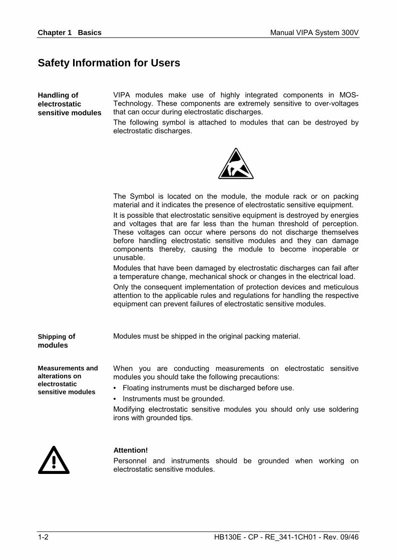
VIPA modules make use of highly integrated components in MOS-Technology. These components are extremely sensitive to over-voltages that can occur during electrostatic discharges. The following symbol is attached to modules that can be destroyed by electrostatic discharges.
The Symbol is located on the module, the module rack or on packing material and it indicates the presence of electrostatic sensitive equipment. It is possible that electrostatic sensitive equipment is destroyed by energies and voltages that are far less than the human threshold of perception. These voltages can occur where persons do not discharge themselves before handling electrostatic sensitive modules and they can damage components thereby, causing the module to become inoperable or unusable. Modules that have been damaged by electrostatic discharges can fail after a temperature change, mechanical shock or changes in the electrical load. Only the consequent implementation of protection devices and meticulous attention to the applicable rules and regulations for handling the respective equipment can prevent failures of electrostatic sensitive modules.
Modules must be shipped in the original packing material.
When you are conducting measurements on electrostatic sensitive modules you should take the following precautions: • Floating instruments must be discharged before use. • Instruments must be grounded. Modifying electrostatic sensitive modules you should only use soldering irons with grounded tips.
Attention! Personnel and instruments should be grounded when working on electrostatic sensitive modules.
Handling of electrostatic sensitive modules
Shipping of modules
Measurements and alterations on electrostatic sensitive modules
Manual VIPA System 300V Chapter 1 Basics
HB130E - CP - RE_341-1CH01 - Rev. 09/46 1-3
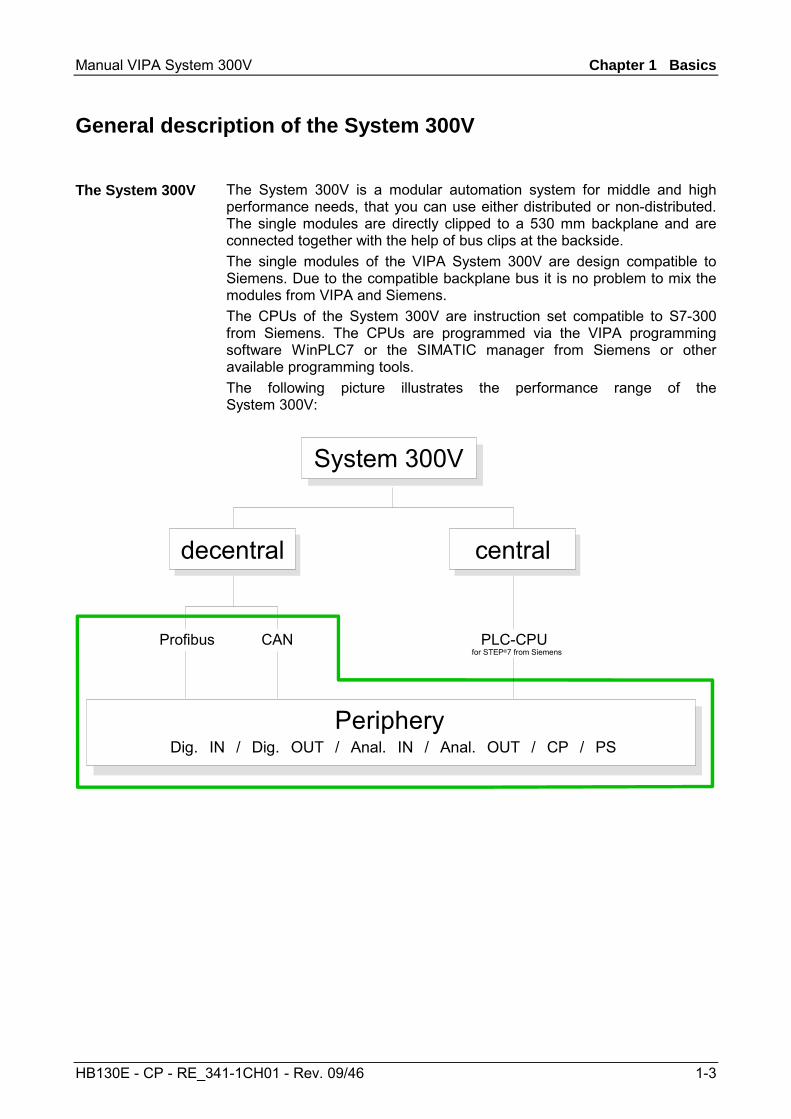
General description of the System 300V
The System 300V is a modular automation system for middle and high performance needs, that you can use either distributed or non-distributed. The single modules are directly clipped to a 530 mm backplane and are connected together with the help of bus clips at the backside. The single modules of the VIPA System 300V are design compatible to Siemens. Due to the compatible backplane bus it is no problem to mix the modules from VIPA and Siemens. The CPUs of the System 300V are instruction set compatible to S7-300 from Siemens. The CPUs are programmed via the VIPA programming software WinPLC7 or the SIMATIC manager from Siemens or other available programming tools. The following picture illustrates the performance range of the System 300V:
System 300V
decentral
Periphery
Profibus
Dig. IN / Dig. OUT / Anal. IN / Anal. OUT / CP / PS
central
for STEP®7 from SiemensPLC-CPUCAN
The System 300V
Chapter 1 Basics Manual VIPA System 300V
1-4 HB130E - CP - RE_341-1CH01 - Rev. 09/46
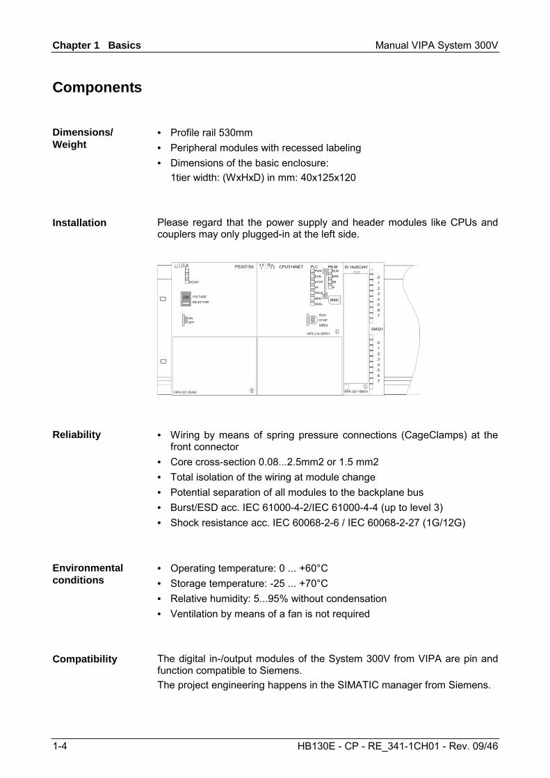
Components
• Profile rail 530mm • Peripheral modules with recessed labeling • Dimensions of the basic enclosure: 1tier width: (WxHxD) in mm: 40x125x120
Please regard that the power supply and header modules like CPUs and couplers may only plugged-in at the left side.
VIPA 321-1BH01
DI 16xDC24V
X 2
3 4
.0
.1
.2
.3
.4
.5
.6
.7
.0
.1
.2
.3
.4
.5
.6
.7
SM321
DC24V
ONOFF
X1X2 X3
PS307/5A
DC 24V+-+-
X 23 4VIPA 307-1EA00
VOLTAGE
SELECTOR230
PWR
RUN
STOP
SF
FRCE
MMC
DESL
RUN
ERR
DE
IF
MMC
RUN
STOP
MRES
PLC
X1
VIPA 314-3DP01
PB-M
X5
X2 X3
CPU314NET
X 23 4
DC 24V+-+-
• Wiring by means of spring pressure connections (CageClamps) at the front connector
• Core cross-section 0.08...2.5mm2 or 1.5 mm2 • Total isolation of the wiring at module change • Potential separation of all modules to the backplane bus • Burst/ESD acc. IEC 61000-4-2/IEC 61000-4-4 (up to level 3) • Shock resistance acc. IEC 60068-2-6 / IEC 60068-2-27 (1G/12G)
• Operating temperature: 0 ... +60°C • Storage temperature: -25 ... +70°C • Relative humidity: 5...95% without condensation • Ventilation by means of a fan is not required
The digital in-/output modules of the System 300V from VIPA are pin and function compatible to Siemens. The project engineering happens in the SIMATIC manager from Siemens.
Dimensions/ Weight
Installation
Reliability
Environmental conditions
Compatibility
Manual VIPA System 300V Chapter 1 Basics
HB130E - CP - RE_341-1CH01 - Rev. 09/46 1-5
ISO/OSI reference model
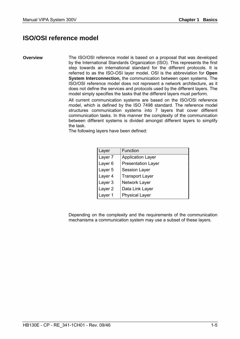
The ISO/OSI reference model is based on a proposal that was developed by the International Standards Organization (ISO). This represents the first step towards an international standard for the different protocols. It is referred to as the ISO-OSI layer model. OSI is the abbreviation for Open System Interconnection, the communication between open systems. The ISO/OSI reference model does not represent a network architecture, as it does not define the services and protocols used by the different layers. The model simply specifies the tasks that the different layers must perform. All current communication systems are based on the ISO/OSI reference model, which is defined by the ISO 7498 standard. The reference model structures communication systems into 7 layers that cover different communication tasks. In this manner the complexity of the communication between different systems is divided amongst different layers to simplify the task. The following layers have been defined:
Layer Function Layer 7 Application Layer Layer 6 Presentation Layer Layer 5 Session Layer Layer 4 Transport Layer Layer 3 Network Layer Layer 2 Data Link Layer Layer 1 Physical Layer
Depending on the complexity and the requirements of the communication mechanisms a communication system may use a subset of these layers.
Overview
Chapter 1 Basics Manual VIPA System 300V
1-6 HB130E - CP - RE_341-1CH01 - Rev. 09/46
The individual layers are as follows: Layer 1 Bit communication layer (physical layer) • Physical conditions for communication,
e.g. transmission medium, baud rate Layer 2 Security layer (data link layer) • Security procedure for the transmission • Access modes Layer 3 Network layer • Network connections • Addressing for communication between two partners. Layer 4 Transport layer • Error-recognition procedure • Debugging • Handshaking Layer 5 Session layer • Establishing communication • Data exchange management • Terminating communication Layer 6 Presentation layer • Conversion of the standard form of data representation of the
communication system into a device-specific form (data interpretation rules)
Layer 7 Application layer • Defining the communication task and the functions it requires
Layers
Manual VIPA System 300V Chapter 2 Assembly and installation guidelines
HB130E - CP - RE_341-1CH01 - Rev. 09/46 2-1
Chapter 2 Assembly and installation guidelines
In this chapter you will find all information, required for the installation and the cabling of a PLC with the components of the System 300.
Topic Page Chapter 2 Assembly and installation guidelines............................ 2-1
Overview .............................................................................................. 2-2 Installation dimensions ......................................................................... 2-3 Installation at the profile rail.................................................................. 2-4 Cabling................................................................................................. 2-6 Installation Guidelines ........................................................................ 2-10
Overview
Content
Chapter 2 Assembly and installation guidelines Manual VIPA System 300V
2-2 HB130E - CP - RE_341-1CH01 - Rev. 09/46
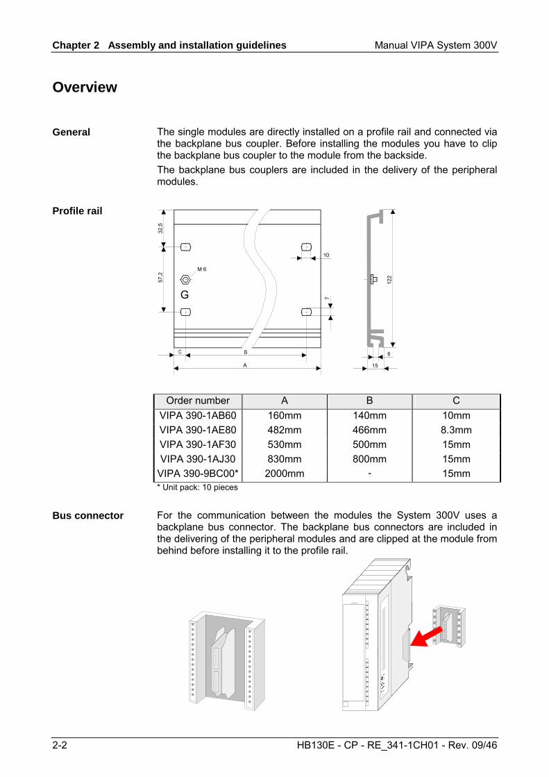
Overview
The single modules are directly installed on a profile rail and connected via the backplane bus coupler. Before installing the modules you have to clip the backplane bus coupler to the module from the backside. The backplane bus couplers are included in the delivery of the peripheral modules.
G
122
Order number A B C VIPA 390-1AB60 160mm 140mm 10mm VIPA 390-1AE80 482mm 466mm 8.3mm VIPA 390-1AF30 530mm 500mm 15mm VIPA 390-1AJ30 830mm 800mm 15mm
VIPA 390-9BC00* 2000mm - 15mm * Unit pack: 10 pieces
For the communication between the modules the System 300V uses a backplane bus connector. The backplane bus connectors are included in the delivering of the peripheral modules and are clipped at the module from behind before installing it to the profile rail.
General
Profile rail
Bus connector
Manual VIPA System 300V Chapter 2 Assembly and installation guidelines
HB130E - CP - RE_341-1CH01 - Rev. 09/46 2-3
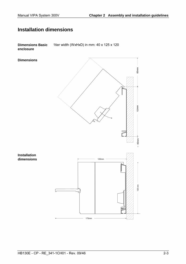
Installation dimensions
1tier width (WxHxD) in mm: 40 x 125 x 120
65m
m 4
0mm
122
mm
125
mm
120mm
175mm
Dimensions Basic enclosure Dimensions
Installation dimensions
Chapter 2 Assembly and installation guidelines Manual VIPA System 300V
2-4 HB130E - CP - RE_341-1CH01 - Rev. 09/46
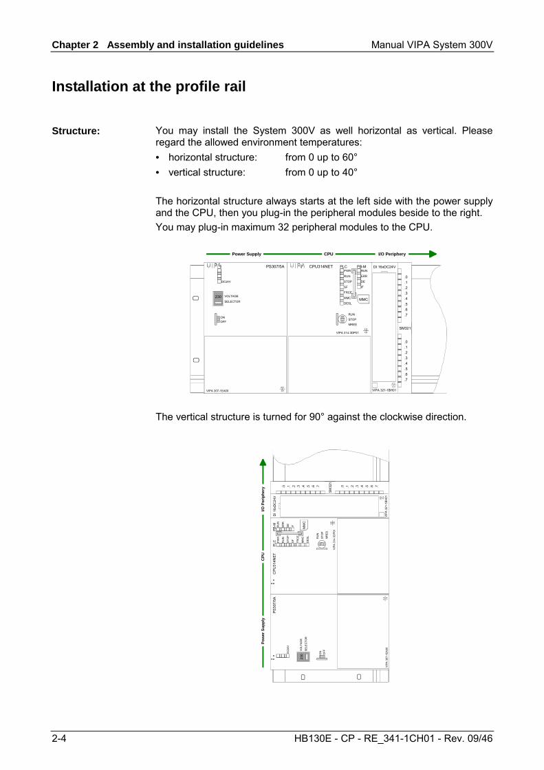
Installation at the profile rail
You may install the System 300V as well horizontal as vertical. Please regard the allowed environment temperatures: • horizontal structure: from 0 up to 60° • vertical structure: from 0 up to 40° The horizontal structure always starts at the left side with the power supply and the CPU, then you plug-in the peripheral modules beside to the right. You may plug-in maximum 32 peripheral modules to the CPU.
Power Supply I/O PeripheryCPU
VIPA 321-1BH01
DI 16xDC24V
X 2
3 4
.0
.1
.2
.3
.4
.5
.6
.7
.0
.1
.2
.3
.4
.5
.6
.7
SM321
DC24V
ONOFF
X1X2 X3
PS307/5A
DC 24V+-+-
X 23 4VIPA 307-1EA00
VOLTAGE
SELECTOR230
PWR
RUN
STOP
SF
FRCE
MMC
DESL
RUN
ERR
DE
IF
MMC
RUN
STOP
MRES
PLC
X1
VIPA 314-3DP01
PB-M
X5
X2 X3
CPU314NET
X 2
3 4
DC 24V+-+-
The vertical structure is turned for 90° against the clockwise direction.
Pow
er S
uppl
yI/O
Per
iphe
ryC
PU
VIPA
321
-1B
H01
DI 1
6xD
C24
V
X2
34
.0 .1 .2 .3 .4 .5 .6 .7 .0 .1 .2 .3 .4 .5 .6 .7
SM32
1
DC
24V
ON
OFF
X1X2
X3
PS30
7/5A
DC
24V
+ - + -X
2
34
VIPA
307
-1EA
00VOLT
AGE
SELE
CTO
R23
0
PW
R
RU
N
STO
P
SF
FRC
E
MM
C
DES
L
RU
N
ER
R
DE
IF MM
C
RU
N
STO
P
MR
ES
PLC
X1
VIPA
314
-3D
P01PB
-M
X5
X2X3
CPU
314N
ET
X2
34
DC
24V
+ - + -
Structure:
Manual VIPA System 300V Chapter 2 Assembly and installation guidelines
HB130E - CP - RE_341-1CH01 - Rev. 09/46 2-5
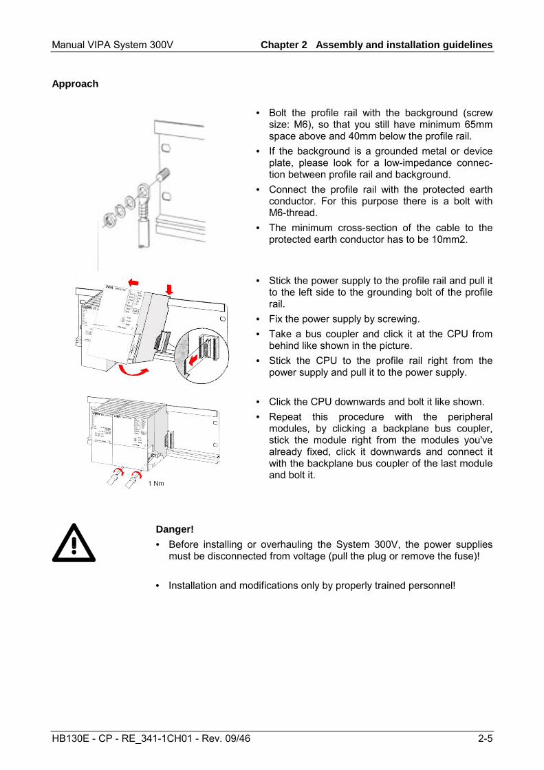
• Bolt the profile rail with the background (screw size: M6), so that you still have minimum 65mm space above and 40mm below the profile rail.
• If the background is a grounded metal or device plate, please look for a low-impedance connec-tion between profile rail and background.
• Connect the profile rail with the protected earth conductor. For this purpose there is a bolt with M6-thread.
• The minimum cross-section of the cable to the protected earth conductor has to be 10mm2.
• Stick the power supply to the profile rail and pull it to the left side to the grounding bolt of the profile rail.
• Fix the power supply by screwing. • Take a bus coupler and click it at the CPU from
behind like shown in the picture. • Stick the CPU to the profile rail right from the
power supply and pull it to the power supply.
• Click the CPU downwards and bolt it like shown. • Repeat this procedure with the peripheral
modules, by clicking a backplane bus coupler, stick the module right from the modules you've already fixed, click it downwards and connect it with the backplane bus coupler of the last module and bolt it.
Danger! • Before installing or overhauling the System 300V, the power supplies
must be disconnected from voltage (pull the plug or remove the fuse)! • Installation and modifications only by properly trained personnel!
Approach
Chapter 2 Assembly and installation guidelines Manual VIPA System 300V
2-6 HB130E - CP - RE_341-1CH01 - Rev. 09/46
Cabling
The power supplies and CPUs are exclusively delivered with CageClamp contacts. For the signal modules the front connectors are available from VIPA with screw contacts. In the following all connecting types of the power supplies, CPUs and input/output modules are described.
Danger! • Before installation or overhauling, the power supplies must be
disconnected from voltage (pull the plug or remove the fuse)! • Installation and modifications only by properly trained personnel!
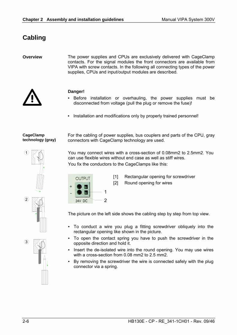
For the cabling of power supplies, bus couplers and parts of the CPU, gray connectors with CageClamp technology are used. You may connect wires with a cross-section of 0.08mm2 to 2.5mm2. You can use flexible wires without end case as well as stiff wires. You fix the conductors to the CageClamps like this:
1
2
[1] Rectangular opening for screwdriver [2] Round opening for wires
1
2
3
The picture on the left side shows the cabling step by step from top view. • To conduct a wire you plug a fitting screwdriver obliquely into the
rectangular opening like shown in the picture. • To open the contact spring you have to push the screwdriver in the
opposite direction and hold it. • Insert the de-isolated wire into the round opening. You may use wires
with a cross-section from 0.08 mm2 to 2.5 mm2. • By removing the screwdriver the wire is connected safely with the plug
connector via a spring.
Overview
CageClamp technology (gray)
Manual VIPA System 300V Chapter 2 Assembly and installation guidelines
HB130E - CP - RE_341-1CH01 - Rev. 09/46 2-7
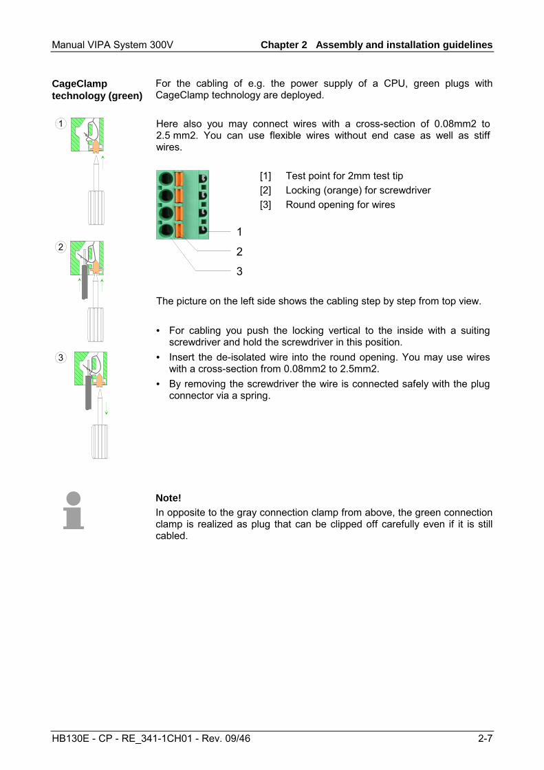
For the cabling of e.g. the power supply of a CPU, green plugs with CageClamp technology are deployed. Here also you may connect wires with a cross-section of 0.08mm2 to 2.5 mm2. You can use flexible wires without end case as well as stiff wires.
1
2
3
[1] Test point for 2mm test tip [2] Locking (orange) for screwdriver [3] Round opening for wires
1
2
3
The picture on the left side shows the cabling step by step from top view. • For cabling you push the locking vertical to the inside with a suiting
screwdriver and hold the screwdriver in this position. • Insert the de-isolated wire into the round opening. You may use wires
with a cross-section from 0.08mm2 to 2.5mm2. • By removing the screwdriver the wire is connected safely with the plug
connector via a spring.
Note! In opposite to the gray connection clamp from above, the green connection clamp is realized as plug that can be clipped off carefully even if it is still cabled.
CageClamp technology (green)
Chapter 2 Assembly and installation guidelines Manual VIPA System 300V
2-8 HB130E - CP - RE_341-1CH01 - Rev. 09/46
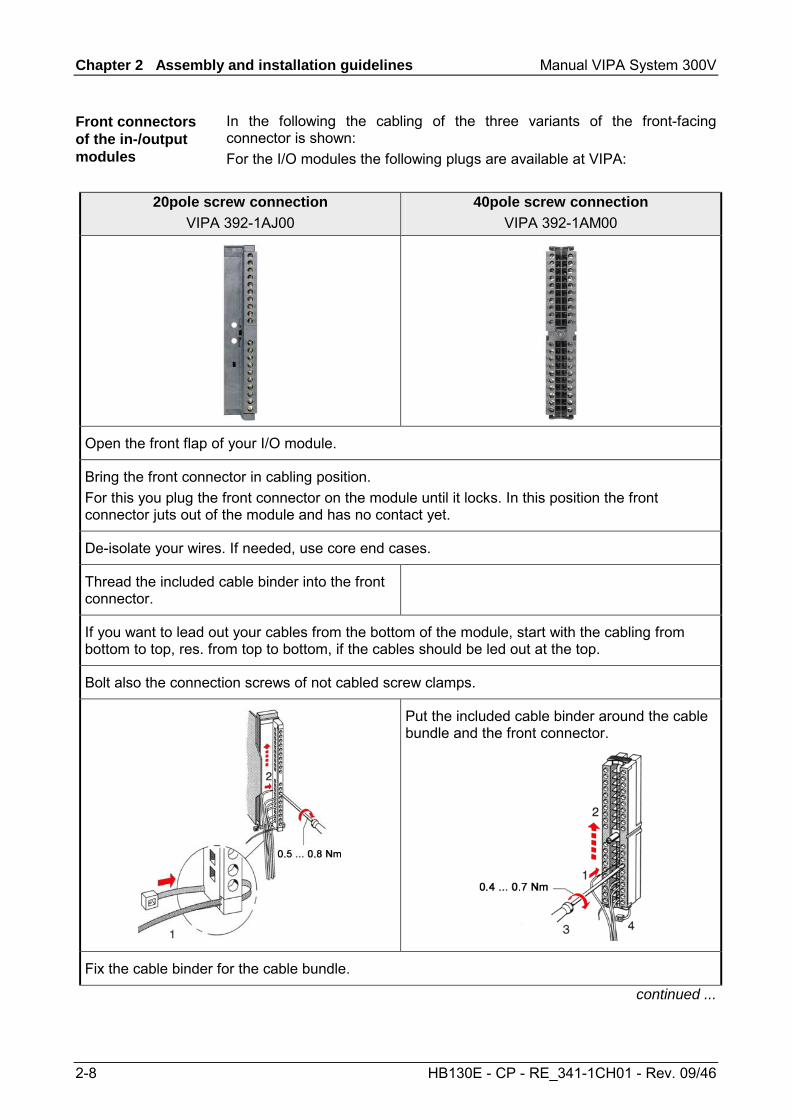
In the following the cabling of the three variants of the front-facing connector is shown: For the I/O modules the following plugs are available at VIPA:
20pole screw connection
VIPA 392-1AJ00 40pole screw connection
VIPA 392-1AM00
Open the front flap of your I/O module.
Bring the front connector in cabling position. For this you plug the front connector on the module until it locks. In this position the front connector juts out of the module and has no contact yet.
De-isolate your wires. If needed, use core end cases.
Thread the included cable binder into the front connector.
If you want to lead out your cables from the bottom of the module, start with the cabling from bottom to top, res. from top to bottom, if the cables should be led out at the top.
Bolt also the connection screws of not cabled screw clamps.
Put the included cable binder around the cable bundle and the front connector.
Fix the cable binder for the cable bundle.
continued ...
Front connectors of the in-/output modules
Manual VIPA System 300V Chapter 2 Assembly and installation guidelines
HB130E - CP - RE_341-1CH01 - Rev. 09/46 2-9
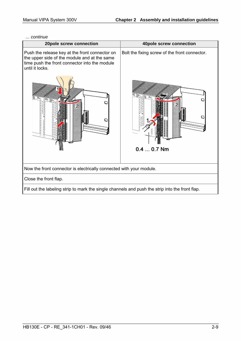
... continue 20pole screw connection 40pole screw connection
Push the release key at the front connector on the upper side of the module and at the same time push the front connector into the module until it locks.
Bolt the fixing screw of the front connector.
Now the front connector is electrically connected with your module.
Close the front flap.
Fill out the labeling strip to mark the single channels and push the strip into the front flap.
Chapter 2 Assembly and installation guidelines Manual VIPA System 300V
2-10 HB130E - CP - RE_341-1CH01 - Rev. 09/46
Installation Guidelines
The installation guidelines contain information about the interference free deployment of System 300V systems. There is the description of the ways, interference may occur in your control, how you can make sure the electromagnetic digestibility (EMC), and how you manage the isolation.
Electromagnetic digestibility (EMC) means the ability of an electrical device, to function error free in an electromagnetic environment without being interferenced res. without interferencing the environment. All System 300V components are developed for the deployment in hard industrial environments and fulfill high demands on the EMC. Nevertheless you should project an EMC planning before installing the components and take conceivable interference causes into account.
Electromagnetic interferences may interfere your control via different ways: • Fields • I/O signal conductors • Bus system • Current supply • Protected earth conductor Depending on the spreading medium (lead bound or lead free) and the distance to the interference cause, interferences to your control occur by means of different coupling mechanisms. One differs: • galvanic coupling • capacitive coupling • inductive coupling • radiant coupling
General
What means EMC?
Possible interference causes
Manual VIPA System 300V Chapter 2 Assembly and installation guidelines
HB130E - CP - RE_341-1CH01 - Rev. 09/46 2-11
In the most times it is enough to take care of some elementary rules to guarantee the EMC. Please regard the following basic rules when installing your PLC. • Take care of a correct area-wide grounding of the inactive metal parts
when installing your components. - Install a central connection between the ground and the protected
earth conductor system. - Connect all inactive metal extensive and impedance-low. - Please try not to use aluminum parts. Aluminum is easily oxidizing
and is therefore less suitable for grounding. • When cabling, take care of the correct line routing.
- Organize your cabling in line groups (high voltage, current supply, signal and data lines).
- Always lay your high voltage lines and signal res. data lines in separate channels or bundles.
- Route the signal and data lines as near as possible beside ground areas (e.g. suspension bars, metal rails, tin cabinet).
• Proof the correct fixing of the lead isolation. - Data lines must be laid isolated. - Analog lines must be laid isolated. When transmitting signals with
small amplitudes the one sided lying of the isolation may be favorable.
- Lay the line isolation extensively on an isolation/protected earth con-ductor rail directly after the cabinet entry and fix the isolation with cable clamps.
- Make sure that the isolation/protected earth conductor rail is connected impedance-low with the cabinet.
- Use metallic or metalized plug cases for isolated data lines. • In special use cases you should appoint special EMC actions.
- Wire all inductivities with erase links that are not addressed by the System 300V modules.
- For lightening cabinets you should prefer incandescent lamps and avoid luminescent lamps.
• Create a homogeneous reference potential and ground all electrical operating supplies when possible. - Please take care for the targeted employment of the grounding
actions. The grounding of the PLC is a protection and functionality activity.
- Connect installation parts and cabinets with the System 300V in star topology with the isolation/protected earth conductor system. So you avoid ground loops.
- If potential differences between installation parts and cabinets occur, lay sufficiently dimensioned potential compensation lines.
Basic rules for EMC
Chapter 2 Assembly and installation guidelines Manual VIPA System 300V
2-12 HB130E - CP - RE_341-1CH01 - Rev. 09/46
Electrical, magnetic and electromagnetic interference fields are weakened by means of an isolation, one talks of absorption. Via the isolation rail, that is connected conductive with the rack, interference currents are shunt via cable isolation to the ground. Hereby you have to make sure, that the connection to the protected earth conduc-tor is impedance-low, because otherwise the interference currents may appear as interference cause. When isolating cables you have to regard the following: • If possible, use only cables with isolation tangle. • The hiding power of the isolation should be higher than 80%. • Normally you should always lay the isolation of cables on both sides.
Only by means of the both-sided connection of the isolation you achieve a high quality interference suppression in the higher frequency area. Only as exception you may also lay the isolation one-sided. Then you only achieve the absorption of the lower frequencies. A one-sided isolation connection may be convenient, if: - the conduction of a potential compensating line is not possible - analog signals (some mV res. µA) are transferred - foil isolations (static isolations) are used.
• With data lines always use metallic or metalized plugs for serial couplings. Fix the isolation of the data line at the plug rack. Do not lay the isolation on the PIN 1 of the plug bar!
• At stationary operation it is convenient to de-isolate the isolated cable interruption free and lay it on the isolation/protected earth conductor line.
• To fix the isolation tangles use cable clamps out of metal. The clamps must clasp the isolation extensively and have well contact.
• Lay the isolation on an isolation rail directly after the entry of the cable in the cabinet. Lead the isolation further on to the System 300V module and don't lay it on there again!
Please regard at installation! At potential differences between the grounding points, there may be a compensation current via the isolation connected at both sides. Remedy: Potential compensation line
Isolation of conductors
Manual VIPA System 300V Chapter 3 Hardware description
HB130E - CP - RE_341-1CH01 - Rev. 09/46 3-1
Chapter 3 Hardware description
Here the hardware components of the CP 341 are more described. The technical data are to be found at the end of the chapter.
Topic Page Chapter 3 Hardware description ..................................................... 3-1
Properties............................................................................................. 3-2 Structure .............................................................................................. 3-3 Technical data...................................................................................... 3-7
Overview
Content
Chapter 3 Hardware description Manual VIPA System 300V
3-2 HB130E - CP - RE_341-1CH01 - Rev. 09/46
Properties
• RS422/485 interface isolated to back plane bus • Function compatibility to Siemens CP 341 (6ES7 341-1CH01-0AE0) • The following protocols are supported:
- ASCII - 3964(R) - Modbus Master ASCII / RTU (no hardware dongle necessary) - Modbus Slave RTU (no hardware dongle necessary)
• Parameterization via the parameterization package from Siemens: CP 341: Point-to-Point Communication, Parameter Assignment V5.0
• Up to 250 telegrams within the 1024byte sized receive and send buffer • Baud rate parameterizable up to 76.8kbit/s • Power supply via back plane bus
SF
S/F1
S/F2
S/F3
S/F4
S/F5
S/F6
S/F7
S/F8
VIPA 331-7KF00
AI 8x12Bit
X 2
3 4
SM331
VIPA 341-1CH01X 23 4
PWR
SF
TxD
RxD
CP341 RS422/485
Type Order number Description CP 341 RS422/485 VIPA 341-1CH01 CP 341 with RS422/485 interface
Protocols: ASCII, 3964(R), Modbus Master (ASCII / RTU), Modbus Slave (RTU)
CP 341 RS422/485 341-1CH01
Order data
Manual VIPA System 300V Chapter 3 Hardware description
HB130E - CP - RE_341-1CH01 - Rev. 09/46 3-3
Structure
SF
S/F1
S/F2
S/F3
S/F4
S/F5
S/F6
S/F7
S/F8
VIPA 331-7KF00
AI 8x12Bit
X 2
3 4
SM331
VIPA 341-1CH01
CP341 RS422/485
X 23 4
PWR
SF
TxD
RxD
RS 422/485
1
2
[1] [2]
LED status indicator 9pin serial D-type plug for RS422/485 communication
The communication processor is provided with 4 LEDs for the purpose of displaying the operating status. The following table shows the description and the color of these LEDs. Name Color Description PWR green Indicates that power is available SF red Group alarm or re-parameterization in progress
Group alarm lights up at: - Hardware fault - Firmware error - Parameterization error - BREAK (receive cable between CP and communication partner becomes disconnected)
TxD green Transmit data lights up when the CP is sending user data via the interface.
RxD green Receive data lights up when the CP is receiving user data via the interface.
At the corresponding CP the LEDs SF, TxD and RxD are on during firmware update. The firmware update is ready when TxD and RxD get off.
The communication is power supplied via the back plane bus. The current consumption is max. 160mA.
CP 341 RS422/485 341-1CH01
LEDs
Power supply
Chapter 3 Hardware description Manual VIPA System 300V
3-4 HB130E - CP - RE_341-1CH01 - Rev. 09/46
• Pin compatible to Siemens CP 341 (6ES7 341-1CH01-0AE0) • Logical conditions as voltage difference between 2 twisted lines • Serial bus connection
Full-duplex: Four-wire operation (RS422) Half-duplex: Two-wire operation (RS485)
• Line length: 250m at 76.8kbit/s ... 1200m at 19.2kbit/s
• Data transfer rate up to 76.8kbit/s 9pin D-type jack
Pin Designation Input/ Output
Signal description
1 n.c. --- 2 T(B)+ Output Send data (four-wire) 3 R(B)+
R(B)+/T(B)+ Input Input/Output
Receive data (four-wire) Receive/Send data (two-wire)
4 RTS Output Request to send: RTS "ON": CP ready to send RTS "OFF": CP is not sending
5 M5V (GND_ISO) Output Ground isolated 6 P5V (+5V_ISO) Output 5V isolated 7 T(A)- Output Send data (four-wire) 8 R(A)-
R(A)-/T(A)- Input Input/Output
Receive data (four-wire) Receive/Send data (two-wire)
5
4
3
2
1
9
8
7
6
9 n.c. ---
Note! Never connect the shield of the cable with GND_ISO, as this could destroy the interface!
Pin 6 (P5V) of the isolated interfaces carries the isolated 5V supply with the respective ground GND on pin 5 (M5V). You may use this isolated voltage to provide defined static voltage levels on the signaling lines by means of resistors and ensure that reflections are reduced to a minimum.
RS422/485 interface
Isolated voltages P5V, M5V
Manual VIPA System 300V Chapter 3 Hardware description
HB130E - CP - RE_341-1CH01 - Rev. 09/46 3-5
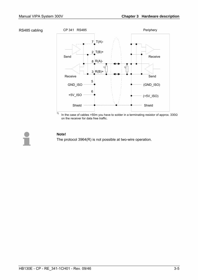
Shield
CP 341 RS485 Periphery
GND_ISO
+5V_ISO
5
6
7
2
8
3
Send
Receive
R(A)-
R(B)+
T(A)-
T(B)+
1)
(GND_ISO)
(+5V_ISO)
Shield
1)
Send
Receive
1) In the case of cables >50m you have to solder in a terminating resistor of approx. 330Ω on the receiver for data free traffic.
Note! The protocol 3964(R) is not possible at two-wire operation.
RS485 cabling
Chapter 3 Hardware description Manual VIPA System 300V
3-6 HB130E - CP - RE_341-1CH01 - Rev. 09/46
Shield
CP 341 RS422 Periphery
GND_ISO
+5V_ISO
5
6
7
2
8
3
Send
Receive
R(A)-
R(B)+
T(A)-
T(B)+
1)
(GND_ISO)
(+5V_ISO)
Shield
1)
Send
Receive
R(A)-
R(B)+
T(A)-
T(B)+
1) In the case of cables >50m you have to solder in a terminating resistor of approx. 330Ω on the receiver for data free traffic.
For a connection with minimum reflections and the wire-break recognition at RS422/485 operation, the lines may be preset with defined static voltage levels. At the CP interface the wiring of the receiver is realized as follows:
Parameter Description Wiring of the receiver None No preassignment of the
receiving lines. This setting only makes sense with bus-capable special drivers.
R(B) +
R(A) -
Signal R(A) 5Volt (Break evaluation) Signal R(B) 0Volt
With this preassignment break detection is possible at full-duplex operation (RS422).
0V
5V
R(B) +
R(A) -
Signal R(A) 0Volt Signal R(B) 5Volt
This preassignment corresponds to the idle state (no sender is activated) at half-duplex operation at RS485. Here wire-break recognition is not possible.
R(B) +
R(A) -
5V
0V
RS422 cabling
Defined static voltage levels by parameters
Manual VIPA System 300V Chapter 3 Hardware description
HB130E - CP - RE_341-1CH01 - Rev. 09/46 3-7
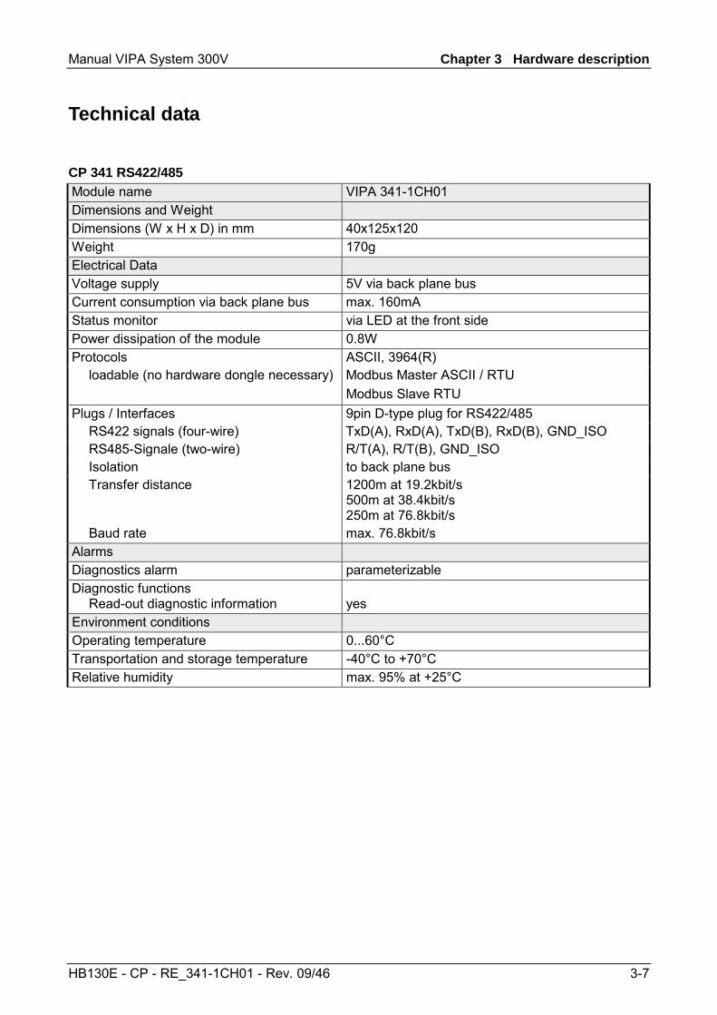
Technical data
Module name VIPA 341-1CH01 Dimensions and Weight Dimensions (W x H x D) in mm 40x125x120 Weight 170g Electrical Data Voltage supply 5V via back plane bus Current consumption via back plane bus max. 160mA Status monitor via LED at the front side Power dissipation of the module 0.8W Protocols ASCII, 3964(R) loadable (no hardware dongle necessary) Modbus Master ASCII / RTU
Modbus Slave RTU Plugs / Interfaces 9pin D-type plug for RS422/485 RS422 signals (four-wire) TxD(A), RxD(A), TxD(B), RxD(B), GND_ISO RS485-Signale (two-wire) R/T(A), R/T(B), GND_ISO Isolation to back plane bus Transfer distance 1200m at 19.2kbit/s
500m at 38.4kbit/s 250m at 76.8kbit/s
Baud rate max. 76.8kbit/s Alarms Diagnostics alarm parameterizable Diagnostic functions Read-out diagnostic information
yes
Environment conditions Operating temperature 0...60°C Transportation and storage temperature -40°C to +70°C Relative humidity max. 95% at +25°C
CP 341 RS422/485

Chapter 3 Hardware description Manual VIPA System 300V
3-8 HB130E - CP - RE_341-1CH01 - Rev. 09/46
Manual VIPA System 300V Chapter 4 Deployment CP 341 RS422/485
HB130E - CP - RE_341-1CH01 - Rev. 09/46 4-1
Chapter 4 Deployment CP 341 RS422/485
Contents of this chapter is the hardware configuration and the parameterization of the CP. In addition the communication between CPU and CP 341 by means of function blocks is described.
Topic Page Chapter 4 Deployment CP 341 RS422/485 ...................................... 4-1
Fast introduction................................................................................... 4-2 Hardware configuration ........................................................................ 4-4 Communication with the user program................................................. 4-7 Firmware update ................................................................................ 4-12
Overview
Content
Chapter 4 Deployment CP 341 RS422/485 Manual VIPA System 300V
4-2 HB130E - CP - RE_341-1CH01 - Rev. 09/46
Fast introduction
The integration of the CP into your SPS system should take place with the following proceeding: • Assembly and commissioning • Hardware configuration (integration CP in CPU) • Protocol parameter via parameter plugin • Communication with the user program
• Install your system 300 with a CPU 31x and the CP 341. • Wire the system by connecting cables for voltage supply, signals and
Ethernet. A detailed description is to be found in the chapter "Assembly and installation guidelines".
• Switch power ON. → After a short boot time the CP is in the system without any protocol.
• Start the Siemens SIMATIC manager with an online connection to the CPU. More about this may be found in the manual of the CPU.
• For hardware configuration jump within your project to the hardware configurator of the Siemens SIMATIC manager.
• Place a profile rail with the corresponding CPU and its modules. • Engineer in duty of the CP 341-1CH01 from VIPA the Siemens CP with
the order number 6ES7 341-1CH01-0AE0 to the corresponding slot. • Adjust the address by the properties dialog and the protocol for
transmission and its parameters by means of the parameter plugin "Point-to-Point-Communication, Parameter Assignment"
Note! Please regard that the address for input and output is identically. By means of this address you may access the CP from the user program.
Overview
Assembly and commissioning
Hardware configuration
Manual VIPA System 300V Chapter 4 Deployment CP 341 RS422/485
HB130E - CP - RE_341-1CH01 - Rev. 09/46 4-3
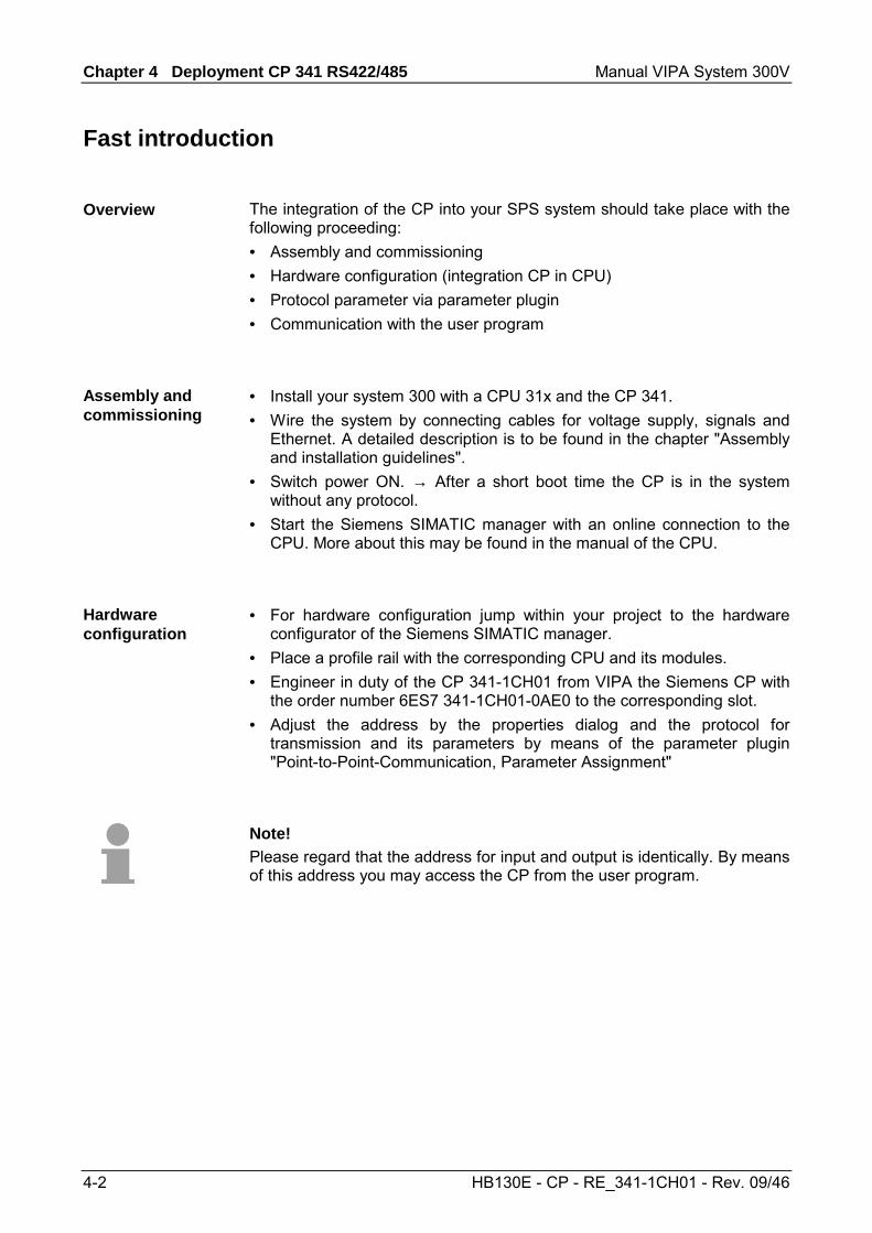
For parameterization of the protocol parameters the parameter plugin "Point-to-Point-Communication, Parameter Assignment" is necessary. This may be received by Siemens.
• The parameter plugin "Point-to-Point-Communication, Parameter
Assignment" is started from the properties dialog of the CP by the button [Parameter...].
• Set at "Protocol" the protocol you want.
• For parameterization of the protocol click at and set the wanted protocol parameters.
• Store the protocol specific parameters after changing them. • Return to the properties dialog of the CP, translate and store your
project. There is the possibility to extend the number of protocols of the parameter plugin by means of loadable protocol drivers. More may be found at the description of the corresponding protocol.
With the standard protocols the communication happens by means of the handling blocks FB 7 and FB 8, which were installed together with the parameter plugin. By a cyclic call of these blocks data may be sent and received by the CP. The conversion of the transfer protocols to the communication partner happens at the CP. For each of these FBs an instance DB is necessary. This is to be indicated at the call of the corresponding FB. The data for communication are to be stored in each case in a send respectively receive DB. To control the communication the FBs have control bits. Here the communication may be started, stopped or reset with the appropriate programming for the corresponding CP. There are status bits within the FBs for error evaluation. Please note with the loadable protocol Modbus Slave the FB 80 - MODB_341 is deployed for communication. Within this the FB 7 and FB 8 are called.
Protocol parameter
Loadable protocol driver
Communication with the user program
Chapter 4 Deployment CP 341 RS422/485 Manual VIPA System 300V
4-4 HB130E - CP - RE_341-1CH01 - Rev. 09/46
Hardware configuration
The description here refers to modules that are at the same bus together with the CPU. In order to address the installed modules individually, specific addresses in the CPU have to be assigned to them. The allocation of addresses and the configuration of the installed modules is a function of the Siemens SIMATIC manager. Here navigate within the hardware catalog to the according CP and place it at the S7-300 station.
• Start the Siemens SIMATIC Manager. • Swap to the hardware configurator. • Place a profile rail via drag&drop from the hardware catalog to the
project window. • Project the CPU and the corresponding modules. Place the corres-
ponding modules via drag&drop from the hardware catalog to the corresponding slot of the profile rail.
• To project the VIPA CP 341-1CH01 the Siemens CP 341 (6GK7 341-1CH01-0AE0) at the according slot is to be used.
• Adjust via the CP "properties" the transmission protocol and the protocol specific parameters (see protocol parameters). Note the address from which the CP is embedded. This value is necessary for the integration in your user program (see "communication with the user program").
• Save and translate your project and transfer it to the CPU.
Overview
Project engineering
Manual VIPA System 300V Chapter 4 Deployment CP 341 RS422/485
HB130E - CP - RE_341-1CH01 - Rev. 09/46 4-5
The properties of the CP may be accessed by a double click at the CP within your project in the hardware configurator. The parameters of the VIPA CP 341 may be modified by the registers in the following described. For parameterization the parameter plugin "Point-to-Point Communication, Parameter Assignment" is necessary. This may be received from Siemens. For installation you have to start it and follow the instructions.
The short description with the information below is identical to the shown Information in the "hardware catalog" window. Here the order number of the Siemens CP 341 is displayed. For project engineering of the VIPA CP 341-1CH01 the Siemens CP with order number 6GK7 341-1CH01-0AE0 is to be used. This displays the designation of the CP, which may be changed. If the designation is changed, the new designation appears in your project in the configuration table. In this part the purpose of the module may be entered.
By presetting a start address for the input respectively output area the beginning of the address area of the CPU may be determined, which is mapped by the CP. Here the CP occupies for input and output 16byte each. This value is necessary for integration in the user program. Please note with the CP that the base address for input and output are identical. With the process image a consistent image of the process signal may be accessed during the program cycle. If the field process image shows the entry "---" then the set address area is outside the process image. The entry "OB1-PA" indicates that the set address area is within the process image.
Here the interrupt behavior of the module may be adjusted. If "Yes" is set at CPU STOP (fix) an interrupt is released and the outputs are switched off immediately.
Properties CP 341-1CH01
General
Short Description
Order No.
Name
Comment
Addresses
Inputs / Outputs
Process image
Basic Parameters
Interrupt generation / Reaction to CPU STOP
Chapter 4 Deployment CP 341 RS422/485 Manual VIPA System 300V
4-6 HB130E - CP - RE_341-1CH01 - Rev. 09/46
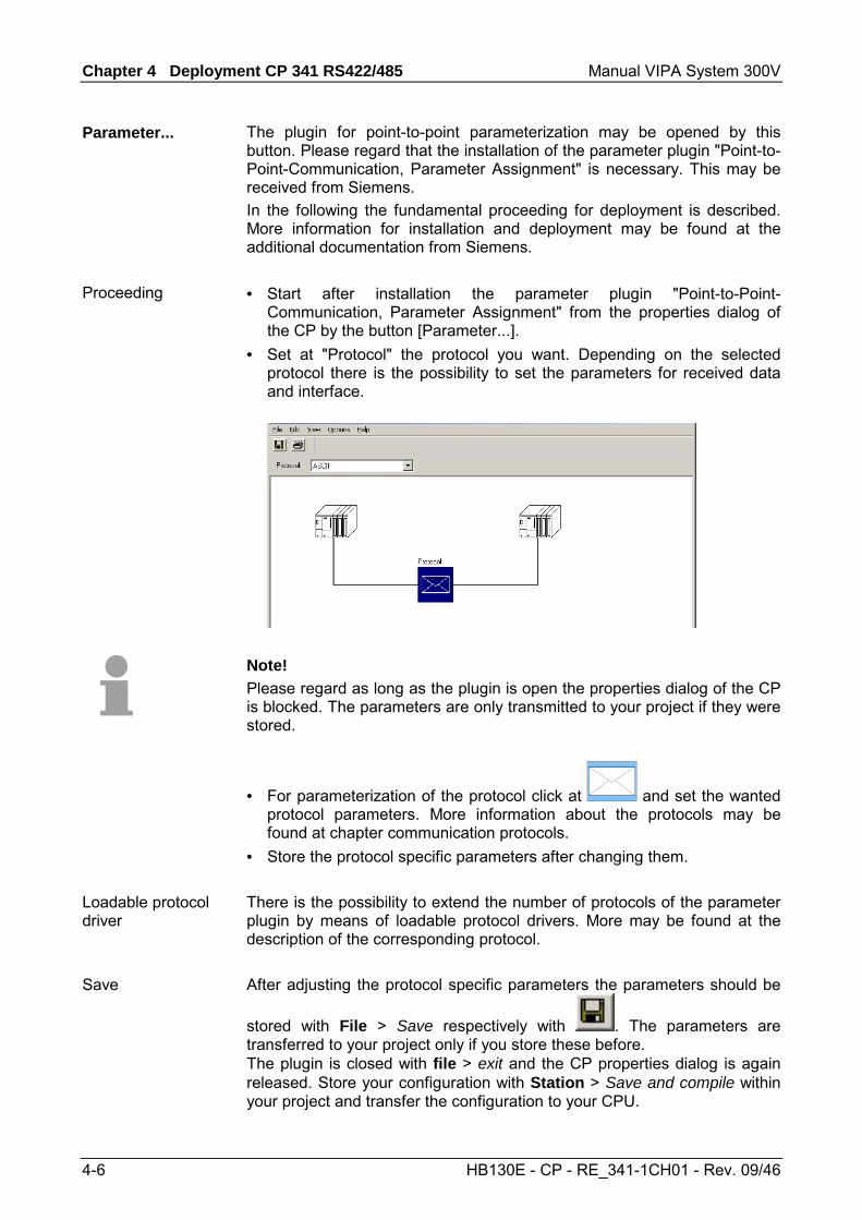
The plugin for point-to-point parameterization may be opened by this button. Please regard that the installation of the parameter plugin "Point-to-Point-Communication, Parameter Assignment" is necessary. This may be received from Siemens. In the following the fundamental proceeding for deployment is described. More information for installation and deployment may be found at the additional documentation from Siemens. • Start after installation the parameter plugin "Point-to-Point-
Communication, Parameter Assignment" from the properties dialog of the CP by the button [Parameter...].
• Set at "Protocol" the protocol you want. Depending on the selected protocol there is the possibility to set the parameters for received data and interface.
Note! Please regard as long as the plugin is open the properties dialog of the CP is blocked. The parameters are only transmitted to your project if they were stored.
• For parameterization of the protocol click at and set the wanted protocol parameters. More information about the protocols may be found at chapter communication protocols.
• Store the protocol specific parameters after changing them. There is the possibility to extend the number of protocols of the parameter plugin by means of loadable protocol drivers. More may be found at the description of the corresponding protocol. After adjusting the protocol specific parameters the parameters should be
stored with File > Save respectively with . The parameters are transferred to your project only if you store these before. The plugin is closed with file > exit and the CP properties dialog is again released. Store your configuration with Station > Save and compile within your project and transfer the configuration to your CPU.
Parameter...
Proceeding
Loadable protocol driver
Save
Manual VIPA System 300V Chapter 4 Deployment CP 341 RS422/485
HB130E - CP - RE_341-1CH01 - Rev. 09/46 4-7
Communication with the user program
For the processing of the connecting jobs at PLC side a user program is necessary in the CPU. Here the following blocks are used for communication between CPU, CP and a communication partner:
Block Symbol Comment FB 7 P_RCV_RK Standard FB for data receipt from a communication partner FB 8 P_SND_RK Standard FB for data send to a communication partner
Attention! Calling of these blocks within process or diagnostics interrupt is not allowed. Please regard this FBs do not have a parameter check, which means that if there are invalid parameters, the CPU may switch to STOP mode.
With the Modbus Slave protocol the communication FB 80 - MODB_341 is used. Within the FB 80 the blocks FB 7 and FB 8 are called. More about installation and deployment of the FB 80 may be found at Modbus Slave in Chapter "Communication protocols".
The function blocks are online available from Siemens together with the plugin "Point-to-Point-Communication, Parameter Assignment". The installation of the function blocks happens together with the plugin. Here insert the CD and follow the instructions. The FBs may be found in the block library after installation. The library may be opened in the Siemens SIMATIC manager by File > Open > "Libraries" and here "CP PtP" The blocks may be found at "Blocks" of the CP 341. For deployment of a block this is to be copied into your project.
The data consistency is limited by the block size of 32byte during communication between CPU and CP. For the consistent data communication of more than 32byte the following is to be considered: FB8 - P_SND_RK: Access the send DB only again if the data were completely transferred (DONE = 1). FB7 - P_RCV_RK Access the receive DB only again if the data were completely received (NDR = 1). After that the receive DB should be blocked (EN_R = 0) as long as the data were treated.
Overview
FB 80 - MODB_341 with Modbus Slave protocol
Installation
Data consistency
Chapter 4 Deployment CP 341 RS422/485 Manual VIPA System 300V
4-8 HB130E - CP - RE_341-1CH01 - Rev. 09/46
By a cyclic call of these blocks data may be sent and received by the CP. On the CP the transmission of the communication protocols to the communication partner takes place, which may be configured by the hardware configuration. In the following these blocks are described.
The FB 8 - P_SND_RK transfers a data block of a DB to the CP, specified by the parameters DB_NO, DBB_NO and LEN. For data transfer the FB is to be called either cyclically or statically by a timer-driven program. Information about the parameters, which were necessary for the loadable protocols may be found at the corresponding protocol description in the chapter "Communication protocols".
Parameter Declaration Data type Description SF Input CHAR S = Send, F = Fetch. At ASCII and 3964R the default
value "S" for Send may be used REQ Input BOOL Initiates request with positive edge R Input BOOL Aborts request - current request is aborted and sending is
blocked. LADDR Input INT Logical basic address of the CP - corresponds to the
address of the hardware configuration of the CP. DB_NO Input INT Data block number - number of the send DB, zero is not
allowed. DBB_NO Input INT Data byte number - transmitted data as of data byte
0 ≤ DBB_NO ≤ 8190 LEN Input INT Length of message frame to be sent in byte
1 ≤ LEN ≤ 1024 R_... Input - These parameters are not relevant for ASCII and 3964(R).
But they may be used by loadable protocols. With Modbus enter here "X".
DONE1) Output BOOL Request complete without errors, data sent Parameter STATUS = 00h
ERROR1) Output BOOL Request complete with error Parameter STATUS contains error details
STATUS1) Output WORD Specification of the error on ERROR = 1 1) Parameter is available until the next call of the FB.
The data transmission is initiated by a positive edge at the REQ input of FB 8 - P_SND_RK. A data transmission operation can run over several program cycles, depending on the amount of data involved. A running request may me canceled at any time with R = "1" then the FB is reset to the basic state. Please regard that data, which the CP still has received from the CPU, were sent to the communication partner. If the R input is statically showing the signal state "1", this means that sending is deactivated.
Communication principle
Send data FB 8 - P_SND_RK
Parameter
Release and cancel a request
Manual VIPA System 300V Chapter 4 Deployment CP 341 RS422/485
HB130E - CP - RE_341-1CH01 - Rev. 09/46 4-9
The FB 8 has a mechanism for startup-synchronization between CPU and CP, which is automatically executed at the first call of the FB. Before the CP can process an activated request after the CPU has changed from STOP to RUN mode, the CP CPU start-up mechanism must be completed. Any requests initiated in the meantime are transmitted once the start-up coordination with the CP is finished.
Note! A minimum pulse time is necessary for a signal change to be identified. Significant time periods are the CPU cycle time, the updating time on the CP and the response time of the communication partner.
The DONE output shows ”request completed without errors”. If there was an ERROR, the corresponding event number is displayed in the STATUS. If no error occurs the value of STATUS is "0". DONE and ERROR/STATUS are also output in response to a RESET of the FB. In the event of an error, the binary result BR is reset. If the block is terminated without errors, the binary result has the status ”1”. Please regard the parameter DONE, ERROR and STATUS are only available at one block call. For further evaluation these should be copied to a free data area.
With LADDR the address of the corresponding CP is specified. This is the address, which was specified by the hardware configuration of the CP. Please regard that the base address for input and output of the CP are identical.
The FB 8 - P_SND_RK deals with an Instanz-DB I_SND_RK. This has a length from 62byte. The DB no. is transmitted with the call. It is not allowed to access the data of an instance DB.
Mechanism for startup synchronization
Error indication
Addressing
Data area
Chapter 4 Deployment CP 341 RS422/485 Manual VIPA System 300V
4-10 HB130E - CP - RE_341-1CH01 - Rev. 09/46
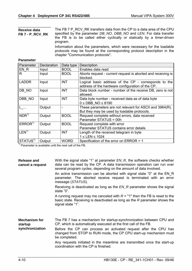
The FB 7 P_RCV_RK transfers data from the CP to a data area of the CPU specified by the parameter DB_NO, DBB_NO and LEN. For data transfer the FB is to be called either cyclically or statically by a timer-driven program. Information about the parameters, which were necessary for the loadable protocols may be found at the corresponding protocol description in the chapter "Communication protocols".
Parameter Declaration Data type Description EN_R Input BOOL Enables data read R Input BOOL Aborts request - current request is aborted and receiving is
blocked. LADDR Input INT Logical basic address of the CP - corresponds to the
address of the hardware configuration of the CP. DB_NO Input INT Data block number - number of the receive DB, zero is not
allowed. DBB_NO Input INT Data byte number - received data as of data byte
0 ≤ DBB_NO ≤ 8190 L_... Output - These parameters are not relevant for ASCII and 3964(R).
But they may be used by loadable protocols. NDR1) Output BOOL Request complete without errors, data received
Parameter STATUS = 00h ERROR1) Output BOOL Request complete with error
Parameter STATUS contains error details LEN1) Output INT Length of the received telegram in byte
1 ≤ LEN ≤ 1024 STATUS1) Output WORD Specification of the error on ERROR = 1
1) Parameter is available until the next call of the FB. With the signal state ”1” at parameter EN_R, the software checks whether data can be read by the CP. A data transmission operation can run over several program cycles, depending on the amount of data involved. An active transmission can be aborted with signal state ”0” at the EN_R parameter. The aborted receive request is terminated with an error message (STATUS). Receiving is deactivated as long as the EN_R parameter shows the signal state ”0”. A running request may me canceled with R = "1" then the FB is reset to the basic state. Receiving is deactivated as long as the R parameter shows the signal state ”1”.
The FB 7 has a mechanism for startup-synchronization between CPU and CP, which is automatically executed at the first call of the FB. Before the CP can process an activated request after the CPU has changed from STOP to RUN mode, the CP CPU start-up mechanism must be completed. Any requests initiated in the meantime are transmitted once the start-up coordination with the CP is finished.
Receive data FB 7 - P_RCV_RK
Parameter
Release and cancel a request
Mechanism for startup synchronization
Manual VIPA System 300V Chapter 4 Deployment CP 341 RS422/485
HB130E - CP - RE_341-1CH01 - Rev. 09/46 4-11
Note! A minimum pulse time is necessary for a signal change to be identified. Significant time periods are the CPU cycle time, the updating time on the CP and the response time of the communication partner.
The NDR output shows ”request completed without errors/data accepted”. If there was an ERROR, the corresponding event number is displayed in the STATUS. If no error occurs the value of STATUS is "0". NDR and ERROR/STATUS are also output in response to a RESET of the FB. In the event of an error, the binary result BR is reset. If the block is terminated without errors, the binary result has the status ”1”. Please regard the parameter NDR, ERROR and STATUS are only available at one block call. For further evaluation these should be copied to a free data area.
With LADDR the address of the corresponding CP is specified. This is the address, which was specified by the hardware configuration of the CP. Please regard that the base address for input and output of the CP are identical.
The FB 7 - P_RCV_RK deals with an Instanz-DB I_RCV_RK. This has a length from 60byte. The DB no. is transmitted with the call. It is not allowed to access the data of an instance DB.
Error indication
Addressing
Data area
Chapter 4 Deployment CP 341 RS422/485 Manual VIPA System 300V
4-12 HB130E - CP - RE_341-1CH01 - Rev. 09/46
Firmware update
For functional expansion and error recovery firmware updates can be uploaded to the operating-system memory of the CP. Subsequent loading of firmware updates with the parameterization interface "Point-to-Point Communication, Parameter Assignment". If you use a VIPA SPEED7 CPU of the System 300S starting with CPU firmware version V340 a firmware update may be executed by means of an accordingly prepared MMC.
With deployment of the Siemens parameterization tool the following preconditions for firmware update are: • Siemens STEP® 7 V. 4.02 or higher is installed • Parameterization tool "Point-to-Point Communication, Parameter
Assignment " V. 5.0 or higher is installed. • The CP is to be configured in the CPU with a valid project. • The CPU is online be connected to the configuring PC.
• Switch the CPU to STOP mode. • Start the parameterization tool "Point-to-point Communication,
Parameter Assignment". Double-click to the corresponding CP and click to [Parameter...] at the "Properties" dialog.
• Open the dialog for firmware update with Options > Firmware Update. As soon as the CP is reachable the current CP firmware is displayed at "Current module firmware status". If no firmware version may be determined (CP is offline) "-------" is displayed.
• Choose with the button [Find file...] the firmware to be loaded. The current CP firmware may be found in the service area of www.vipa.de.
• Please regard the firmware consists of 3 files. Here choose the file HEADER.UPD → the chosen firmware version is displayed at "Status of selected firmware".
• Click on the [Load firmware] button to start uploading to the CP. You are prompted for confirmation, after that the upload of the chosen firmware starts. The upload procedure is canceled immediately if you click on the [Cancel] button. Loading in progress is displayed by the LEDs SF, TxD and RxD. Before the basic firmware is deleted from the module, the firmware is checked if it is suitable for the CP.
• After the firmware upload the LEDs TxD and RxD get off. For activation of the new firmware version a PowerOFF/ON is necessary.
During firmware transfer the proceeding is displayed at "Done" in % as a bar. The LEDs SF, TxD und RxD are on at the corresponding CP.
Overview
Firmware update with Siemens parameterization tool
Procedure
Transfer indication
Manual VIPA System 300V Chapter 4 Deployment CP 341 RS422/485
HB130E - CP - RE_341-1CH01 - Rev. 09/46 4-13
By means of a MMC there is the opportunity to execute a firmware update at the CPU and its components. This functionality is available starting with CPU firmware V340. For update an accordingly prepared MMC must be in the CPU during the start-up. Thus a firmware file may be recognized and assigned with start-up, a pkg file name is reserved for each updateable component and hardware release, which begins with "px" and differs in a number with six digits. The pkg file name of every updateable component may be found at a label right down the front flap of the module. As soon as with start-up a pkg file is on the MMC, all the components at the bus and in the CPU, assigned to the pkg file, get the new firmware. The latest 2 firmware versions may be found in the service area at www.vipa.de.
Attention! Please regard that the version of the update firmware is different from the existing firmware otherwise no update is executed.
The SPEED7 CPU has an integrated web page that monitors information about firmware version of the connected components. The Ethernet PG/OP channel provides the access to this web page. To activate the PG/OP channel you have to enter according IP parameters. This can be made in Siemens SIMATIC manager either by a hardware configuration, loaded by MMC respectively MPI or via Ethernet by means of the MAC address with PLC > Assign Ethernet Address. After that you may access the PG/OP channel with a web browser via the IP address of the project engineering. More detailed information may be found in the manual of the CPU at "Access to Ethernet PG/OP channel and website".
• Go to Service at www.vipa.de. • Navigate to the Firmware area. • Choose the according CP and download the firmware Px......zip to your
PC. • Extract the zip-file and copy the extracted file to your MMC. • Following this approach, transfer all wanted firmware files to your MMC.
Firmware update at deployment of a SPEED7 CPU
Display the Firmware version of the SPEED7 CPU via web page
Load firmware and transfer it to MMC
Chapter 4 Deployment CP 341 RS422/485 Manual VIPA System 300V
4-14 HB130E - CP - RE_341-1CH01 - Rev. 09/46
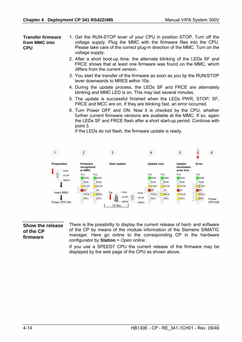
1. Get the RUN-STOP lever of your CPU in position STOP. Turn off the voltage supply. Plug the MMC with the firmware files into the CPU. Please take care of the correct plug-in direction of the MMC. Turn on the voltage supply.
2. After a short boot-up time, the alternate blinking of the LEDs SF and FRCE shows that at least one firmware was found on the MMC, which differs from the current version.
3. You start the transfer of the firmware as soon as you tip the RUN/STOP lever downwards to MRES within 10s.
4. During the update process, the LEDs SF and FRCE are alternately blinking and MMC LED is on. This may last several minutes.
5. The update is successful finished when the LEDs PWR, STOP, SF, FRCE and MCC are on. If they are blinking fast, an error occurred.
6. Turn Power OFF and ON. Now it is checked by the CPU, whether further current firmware versions are available at the MMC. If so, again the LEDs SF and FRCE flash after a short start-up period. Continue with point 3. If the LEDs do not flash, the firmware update is ready.
Power OFF/ON
RUN
STOP
MRES
RUN
STOP
MRES
PWR
RUN
STOP
SF
FRCE
MCC
PLCRUN
STOP
MRES
Insert MMC
PWR
RUN
STOP
SF
FRCE
MCC
PLC
10 Sec.
Tip
PWR
RUN
STOP
SF
FRCE
MCC
PLCPWR
RUN
STOP
SF
FRCE
MCC
PLC
Preparation Firmwarerecognizedat MMC
Start update Update runs
PWR
RUN
STOP
SF
FRCE
MCC
PLC
Updateterminateserror free
PWR
RUN
STOP
SF
FRCE
MCC
PLC
Error
1 2 3 4
PowerOFF/ON
5 6
There is the possibility to display the current release of hard- and software of the CP by means of the module information of the Siemens SIMATIC manager. Here go online to the corresponding CP in the hardware configurator by Station > Open online. If you use a SPEED7 CPU the current release of the firmware may be displayed by the web page of the CPU as shown above.
Transfer firmware from MMC into CPU
Show the release of the CP firmware
Manual VIPA System 300V Chapter 5 Communication protocols
HB130E - CP - RE_341-1CH01 - Rev. 09/46 5-1
Chapter 5 Communication protocols
Here every communiaction protocol is described, which is supported by the CP. Here the standard protocols like ASCII and 3964(R) are described as well as loadable protocols like Modbus Master ASCII/RTU, Modbus Slave RTU. Here the protocol specific parameters and if necessary the functionality of the corresponding protocol may be found.
Topic Seite Chapter 5 Communication protocols.............................................. 5-1
Overview .............................................................................................. 5-2 ASCII.................................................................................................... 5-3 3964(R) ................................................................................................ 5-8 Modbus - Overview ............................................................................ 5-14 Modbus Master - Parameterization..................................................... 5-15 Modbus Master - Functionality............................................................ 5-21 Modbus Master - Function codes ....................................................... 5-23 Modbus Slave - Parameterization....................................................... 5-29 Modbus Slave - Functionality.............................................................. 5-33 Modbus Slave - Communication with the user program...................... 5-35 Modbus Slave - Function codes ......................................................... 5-40
Overview
Content
Chapter 5 Communication protocols Manual VIPA System 300V
5-2 HB130E - CP - RE_341-1CH01 - Rev. 09/46
Overview
The simplest type of information exchange between two stations is the point-to-point link. Here the CP serves as interface for the CPU and a communication station. The data are serially transferred. During the serial data transfer the individual bits of one byte of an information are transferred after another in a fixed order. At bi-directional data transfer it is differentiated between full duplex and half duplex operation. At half duplex operation at one time data may be sent or received. A simultaneous data exchange is only possible at full duplex operation. Each character to be transferred is preceded by a synchronizing pulse as start bit. The end of the transferred character is formed by the stop bit. Beside the start and stop bit there are further parameterizable agreements between the communication partners necessary for serial data transfer. This character frame consists of the following elements: • Speed (Baudrate) • Character and acknowledgement delay time • Parity • Number of data bits • Number of stop bits
The CP serves for an automatic serial data transfer. To do this the CP is equipped with drivers for the following protocols: • ASCII • 3964(R) Please regard the computer interface RK512 is not supported by the VIPA CP. Additionally the following loadable protocol driver are supported: • Modbus master RTU • Modbus master ASCII • Modbus slave RTU In the following each supported protocol is described. Note! With deployment of loadable drivers for software technical reason the drivers from Siemens were transferred to the CP but not installed. Since in the CP VIPA specific drivers are installed, the Siemens usual hardware dongle are not necessary for operation.
Serial transfer of a character
Character frame
Protocols
Manual VIPA System 300V Chapter 5 Communication protocols
HB130E - CP - RE_341-1CH01 - Rev. 09/46 5-3
ASCII
ASCII data communication is one of the simple forms of data exchange that may be compared to a multicast/broadcast function. Individual messages are separated by means of character delay time (ZVZ). Within this time the transmitter must have sent its telegram to the receiver. A telegram is only passed on to the CPU if this was received completely. Additionally to the character delay there is a further possibility to define an end criterion by parameterization of the ASCII driver. Since during ASCII transmission apart from the usage of the parity bit no further step takes place for data protection, the data transfer is very efficiently however not secured. With the parity the inversion of one bit within a character may be secured. If two or more bits of a character are inverted, this error may no longer be detected.
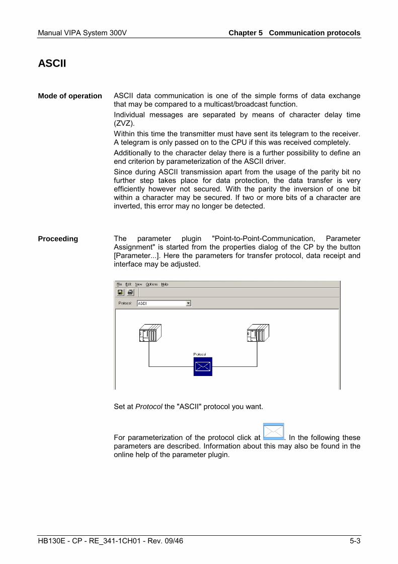
The parameter plugin "Point-to-Point-Communication, Parameter Assignment" is started from the properties dialog of the CP by the button [Parameter...]. Here the parameters for transfer protocol, data receipt and interface may be adjusted.
Set at Protocol the "ASCII" protocol you want.
For parameterization of the protocol click at . In the following these parameters are described. Information about this may also be found in the online help of the parameter plugin.
Mode of operation
Proceeding
Chapter 5 Communication protocols Manual VIPA System 300V
5-4 HB130E - CP - RE_341-1CH01 - Rev. 09/46
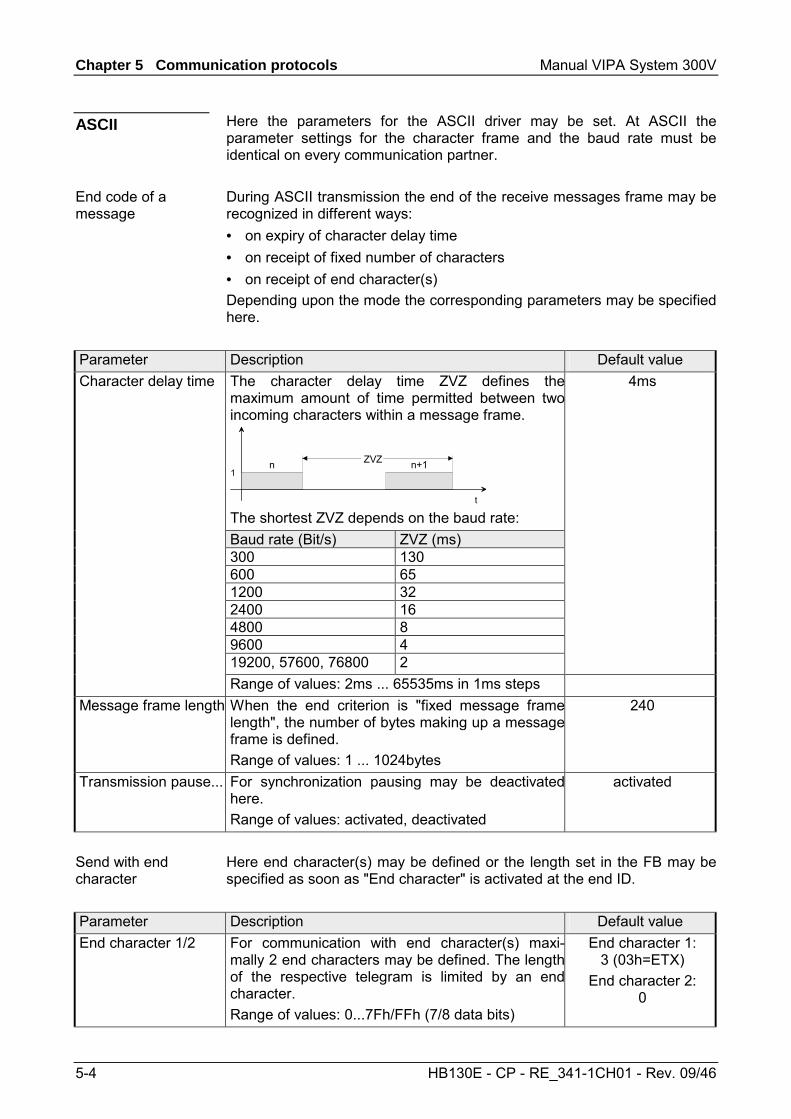
Here the parameters for the ASCII driver may be set. At ASCII the parameter settings for the character frame and the baud rate must be identical on every communication partner. During ASCII transmission the end of the receive messages frame may be recognized in different ways: • on expiry of character delay time • on receipt of fixed number of characters • on receipt of end character(s) Depending upon the mode the corresponding parameters may be specified here.
Parameter Description Default value Character delay time The character delay time ZVZ defines the
maximum amount of time permitted between twoincoming characters within a message frame.
1
t
ZVZn n+1
The shortest ZVZ depends on the baud rate:
4ms
Baud rate (Bit/s) ZVZ (ms) 300 130 600 65 1200 32 2400 16 4800 8 9600 4 19200, 57600, 76800 2 Range of values: 2ms ... 65535ms in 1ms steps Message frame length When the end criterion is "fixed message frame
length", the number of bytes making up a messageframe is defined. Range of values: 1 ... 1024bytes
240
Transmission pause... For synchronization pausing may be deactivatedhere. Range of values: activated, deactivated
activated
Here end character(s) may be defined or the length set in the FB may be specified as soon as "End character" is activated at the end ID.
Parameter Description Default value End character 1/2 For communication with end character(s) maxi-
mally 2 end characters may be defined. The lengthof the respective telegram is limited by an endcharacter. Range of values: 0...7Fh/FFh (7/8 data bits)
End character 1: 3 (03h=ETX)
End character 2: 0
ASCII
End code of a message
Send with end character
Manual VIPA System 300V Chapter 5 Communication protocols
HB130E - CP - RE_341-1CH01 - Rev. 09/46 5-5
Here the transfer speed may be selected from a selection list.
Parameter Description Default value Baud rate in bit/s Transfer speed in bit/s
Range of values: 300, 600, 1200, 2400, 4800,9600, 19200, 38400, 57600, 76800
9600
The data between the communication partners are transferred via the serial interface by means of a character frame. This means that each character may be recognized at the receiver and the transmission may be checked for errors. Please regard that all the following parameters must have the same settings on every communication partner:
Parameter Description Default value Data bits Number of bits onto which a character is mapped.
Range of values: 7, 8 8
Stop bits When data is transmitted, stop bits are appendedto each character to be sent in order to signal theend of a character. Range of values: 1, 2
1
Parity The addition of its value "0" or "1" brings the valueof all the bits (data bits and parity bit) up to adefined status. Range of values: none, odd, even
even
Data flow control synchronizes data transmission when one communication partner works faster than the other. Here the type of data flow control may be set and its associated parameters. Note! At half-duplex parameterization with RS485 data flow control is not possible.
Parameter Description Default value Data flow control Range of values: none, XON, XOFF none
Speed
Character frames
ASCII transmission
Data flow control
Chapter 5 Communication protocols Manual VIPA System 300V
5-6 HB130E - CP - RE_341-1CH01 - Rev. 09/46
Data flow control is only possible at full-duplex operation with RS422.
Parameter Description Default value XON code Code for XON at "XON/XOFF"
Range of values: 0...7Fh/FFh (7/8 data bits) 11(DC1)
XOFF code Code for XOFF at "XON/XOFF" Range of values: 0...7Fh/FFh (7/8 data bits)
13(DC3)
Wait for XON after XOFF (Wait time for CTS=ON)
Time for the CP to wait for XON=ON from thepartner when sending data. Range of values: 20 ... 65535ms in 10ms steps
20 000ms
Receipt telegrams are buffered in the CP at a ring buffer. Here the oldest telegram is always transferred by the CP to the CPU.
Parameter Description Default value Buffered receive message frames
Number of message frames, which are to bebuffered in the CP buffer. Range of values: 1 ... 250
250
Prevent overwriting
You can only deactivate this check box if theparameter "Buffered receive message frames" isset to "1". In this way a current telegram is alwaystransferred to the CPU. Range of values: activated, deactivated
activated
Data flow control parameters
ASCII Receiving data
Input buffer of the CP
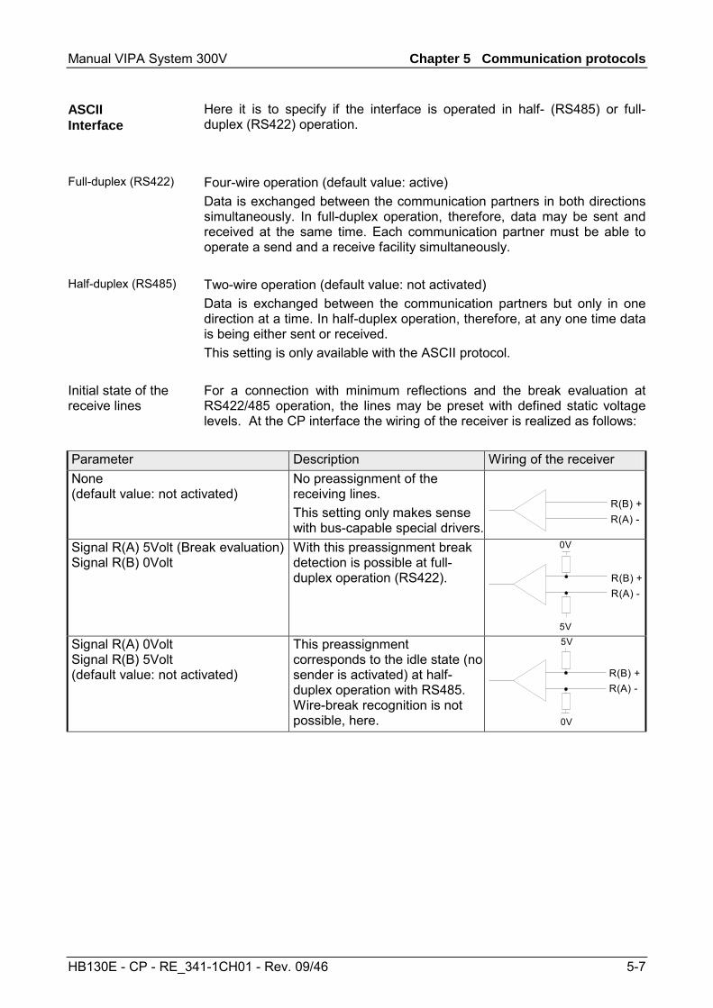
Manual VIPA System 300V Chapter 5 Communication protocols
HB130E - CP - RE_341-1CH01 - Rev. 09/46 5-7
Here it is to specify if the interface is operated in half- (RS485) or full-duplex (RS422) operation.
Four-wire operation (default value: active) Data is exchanged between the communication partners in both directions simultaneously. In full-duplex operation, therefore, data may be sent and received at the same time. Each communication partner must be able to operate a send and a receive facility simultaneously. Two-wire operation (default value: not activated) Data is exchanged between the communication partners but only in one direction at a time. In half-duplex operation, therefore, at any one time data is being either sent or received. This setting is only available with the ASCII protocol. For a connection with minimum reflections and the break evaluation at RS422/485 operation, the lines may be preset with defined static voltage levels. At the CP interface the wiring of the receiver is realized as follows:
Parameter Description Wiring of the receiver None (default value: not activated)
No preassignment of the receiving lines. This setting only makes sense with bus-capable special drivers.
R(B) +R(A) -
Signal R(A) 5Volt (Break evaluation) Signal R(B) 0Volt
With this preassignment break detection is possible at full-duplex operation (RS422).
0V
5V
R(B) +R(A) -
Signal R(A) 0Volt Signal R(B) 5Volt (default value: not activated)
This preassignment corresponds to the idle state (no sender is activated) at half-duplex operation with RS485. Wire-break recognition is not possible, here.
R(B) +R(A) -
5V
0V
ASCII Interface
Full-duplex (RS422)
Half-duplex (RS485)
Initial state of the receive lines
Chapter 5 Communication protocols Manual VIPA System 300V
5-8 HB130E - CP - RE_341-1CH01 - Rev. 09/46
3964(R)
During data transfer with 3964(R) control characters are added to the message. These control characters may be used by the communication partner to verify the complete and error free receipt. The following control characters are evaluated: • STX Start of Text • DLE Data Link Escape • ETX End of Text • NAK Negative Acknowledge • BCC Block Check Character (only for 3964R) It is differentiated between 3964R and 3964: • 3964R: The transfer happens with the block check character BCC. BCC
is the parity as XOR function of the whole length of every data bytes of a transferred block. Its calculation begins with the first byte of user data after the connection setup and ends after the DLE ETX code on connection release.
• 3964: The transfer happens without BCC. Here the designation 3964(R) is used when the descriptions and notes refer to both data transmission procedures. The high integrity on data line is achieved by means of a fixed message-frame setup and clearance as well as the use of BCC at 3964R.
Note! When a DLE is transferred as part of the information it is repeated to distinguish between data characters and DLE control characters that are used to establish and to terminate the connection (DLE duplication). The DLE duplication is reversed in the receiving station. 3964(R) requires that a lower priority is assigned to the communication partner. When communication partners issue simultaneous send commands the station with the lower priority will delay its send command.
Mode of operation
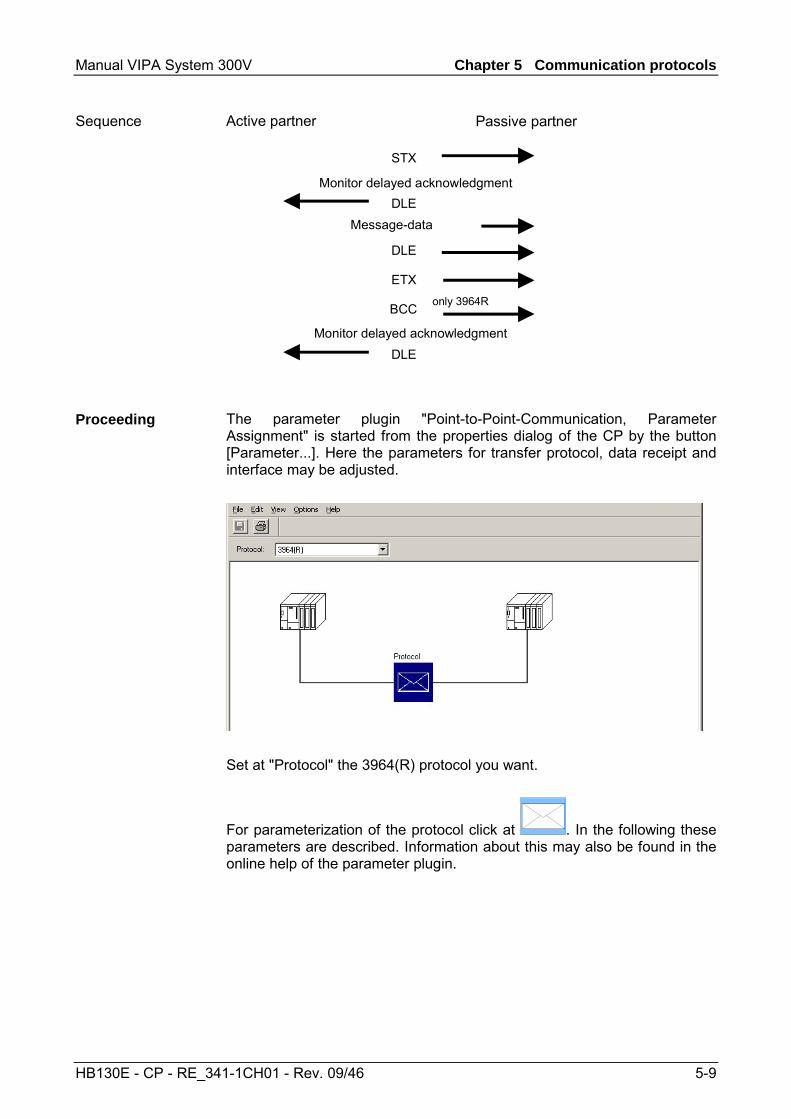
Manual VIPA System 300V Chapter 5 Communication protocols
HB130E - CP - RE_341-1CH01 - Rev. 09/46 5-9
only 3964R
STX
DLEMessage-data
DLE
ETX
BCC
Monitor delayed acknowledgmentDLE
Monitor delayed acknowledgment
Active partner Passive partner
The parameter plugin "Point-to-Point-Communication, Parameter Assignment" is started from the properties dialog of the CP by the button [Parameter...]. Here the parameters for transfer protocol, data receipt and interface may be adjusted.
Set at "Protocol" the 3964(R) protocol you want.
For parameterization of the protocol click at . In the following these parameters are described. Information about this may also be found in the online help of the parameter plugin.
Sequence
Proceeding
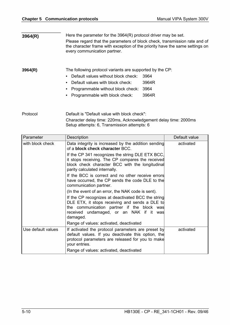
Chapter 5 Communication protocols Manual VIPA System 300V
5-10 HB130E - CP - RE_341-1CH01 - Rev. 09/46
Here the parameter for the 3964(R) protocol driver may be set. Please regard that the parameters of block check, transmission rate and of the character frame with exception of the priority have the same settings on every communication partner.
The following protocol variants are supported by the CP: • Default values without block check: 3964 • Default values with block check: 3964R • Programmable without block check: 3964 • Programmable with block check: 3964R
Default is "Default value with block check": Character delay time: 220ms, Acknowledgement delay time: 2000ms Setup attempts: 6, Transmission attempts: 6
Parameter Description Default value with block check Data integrity is increased by the addition sending
of a block check character BCC. If the CP 341 recognizes the string DLE ETX BCC,it stops receiving. The CP compares the receivedblock check character BCC with the longitudinalparity calculated internally. If the BCC is correct and no other receive errorshave occurred, the CP sends the code DLE to thecommunication partner. (In the event of an error, the NAK code is sent). If the CP recognizes at deactivated BCC the stringDLE ETX, it stops receiving and sends a DLE tothe communication partner if the block wasreceived undamaged, or an NAK if it wasdamaged. Range of values: activated, deactivated
activated
Use default values If activated the protocol parameters are preset bydefault values. If you deactivate this option, theprotocol parameters are released for you to makeyour entries. Range of values: activated, deactivated
activated
3964(R)
3964(R)
Protocol
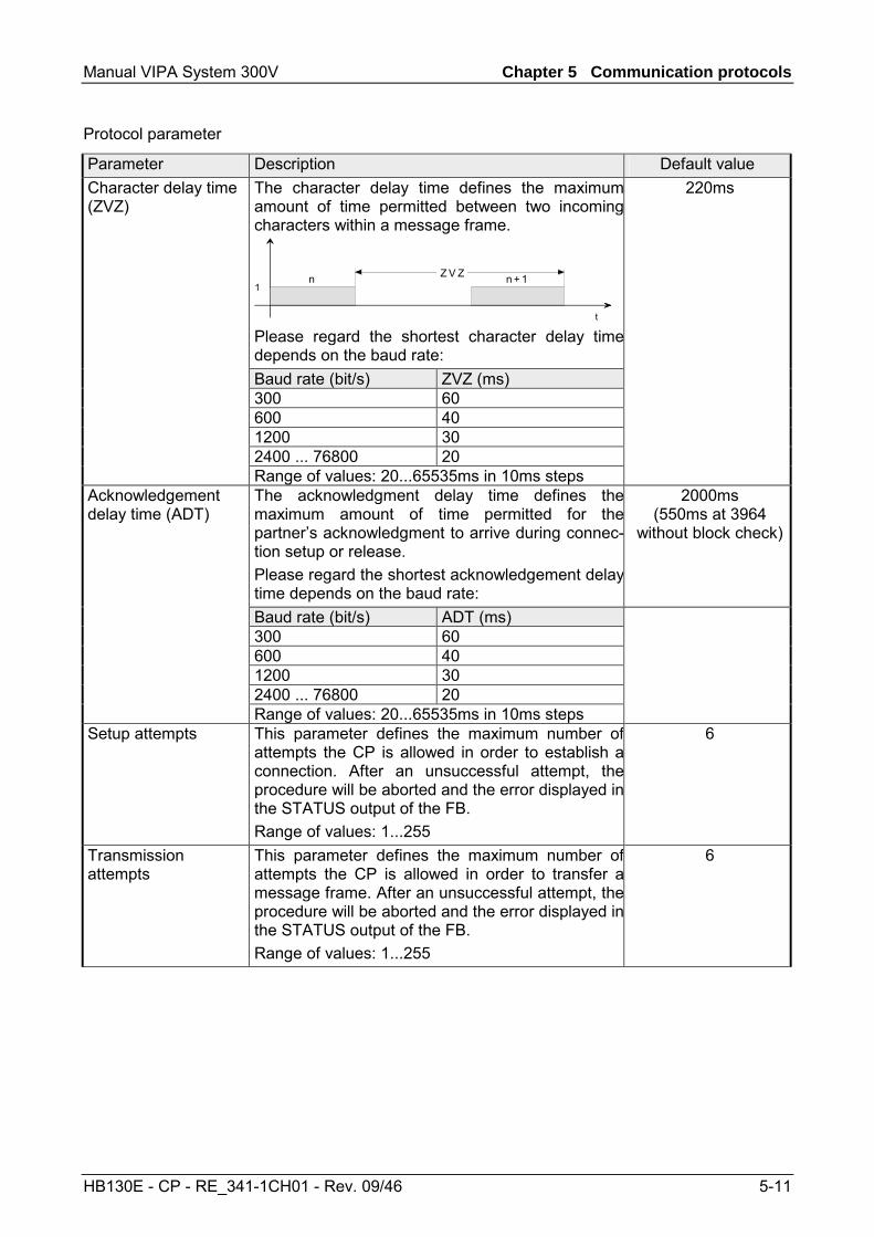
Manual VIPA System 300V Chapter 5 Communication protocols
HB130E - CP - RE_341-1CH01 - Rev. 09/46 5-11
Parameter Description Default value Character delay time (ZVZ)
The character delay time defines the maximumamount of time permitted between two incomingcharacters within a message frame.
1
t
Z V Zn n + 1
Please regard the shortest character delay timedepends on the baud rate:
220ms
Baud rate (bit/s) ZVZ (ms) 300 60 600 40 1200 30 2400 ... 76800 20 Range of values: 20...65535ms in 10ms steps Acknowledgement delay time (ADT)
The acknowledgment delay time defines themaximum amount of time permitted for thepartner’s acknowledgment to arrive during connec-tion setup or release. Please regard the shortest acknowledgement delaytime depends on the baud rate:
2000ms (550ms at 3964
without block check)
Baud rate (bit/s) ADT (ms) 300 60 600 40 1200 30 2400 ... 76800 20 Range of values: 20...65535ms in 10ms steps Setup attempts This parameter defines the maximum number of
attempts the CP is allowed in order to establish aconnection. After an unsuccessful attempt, theprocedure will be aborted and the error displayed inthe STATUS output of the FB. Range of values: 1...255
6
Transmission attempts
This parameter defines the maximum number ofattempts the CP is allowed in order to transfer amessage frame. After an unsuccessful attempt, theprocedure will be aborted and the error displayed inthe STATUS output of the FB. Range of values: 1...255
6
Protocol parameter
Chapter 5 Communication protocols Manual VIPA System 300V
5-12 HB130E - CP - RE_341-1CH01 - Rev. 09/46
Here the transfer speed may be selected from a selection list.
Parameter Description Default value Baud rate in bit/s Transfer speed in bit/s
Range of values: 300, 600, 1200, 2400, 4800,9600, 19200, 38400, 57600, 76800
9600
The data between the communication partners are transferred via the serial interface by means of a character frame. This means that each character may be recognized at the receiver and the transmission may be checked for errors. Please regard that all the following parameters must have the same settings on every communication partner:
Parameter Description Default value Data bits Number of bits onto which a character is mapped.
Range of values: 7, 8 8
Stop bits When data is transmitted, stop bits are appendedto each character to be sent in order to signal theend of a character. Range of values: 1, 2
1
Parity The addition of its value "0" or "1" brings the valueof all the bits (data bits and parity bit) up to adefined status. Range of values: none, odd, even
even
Priority If both communication partners issue a sentrequest at the same time, the partner with thelower priority temporarily withdraws its request. Fordata transmission you must set a lower priority atone communication partner and a higher one at theother.
high
Delete CP receive buffer on startup: (Default value: "Delete CP receive buffer at startup" deactivated) This parameter may not be activated. The receive buffer of the CP is not deleted when the CPU status goes from STOP to RUN (CPU startup).
Here it is to specify if the interface is operated in half- (RS485) or full-duplex (RS422) operation. Four-wire operation (default value: active) Data is exchanged between the communication partners in both directions simultaneously. In full-duplex operation, therefore, data may be sent and received at the same time. Each communication partner must be able to operate a send and a receive facility simultaneously. This setting is not available with 3964(R).
Speed
Character frames
3964(R) Receiving data
3964(R) Interface
Full-duplex (RS422)
Half-duplex (RS485)
Manual VIPA System 300V Chapter 5 Communication protocols
HB130E - CP - RE_341-1CH01 - Rev. 09/46 5-13
For a connection with minimum reflections and the break evaluation at RS422 operation, the lines may be preset with defined static voltage levels. At the CP interface the wiring of the receiver is realized as follows:
Parameter Description Wiring of the receiver None (Default value: not activated)
No preassignment of the receiving lines. This setting only makes sense with bus-capable special drivers.
R(B) +R(A) -
Signal R(A) 5Volt (Break evaluation) Signal R(B) 0Volt
With this preassignment wire break evaluation is possible at full-duplex operation with RS422.
0V
5V
R(B) +R(A) -
Signal R(A) 0Volt Signal R(B) 5Volt (Default value: not activated)
Here wire break evaluation is not possible.
R(B) +R(A) -
5V
0V
Initial state of the receive lines
Chapter 5 Communication protocols Manual VIPA System 300V
5-14 HB130E - CP - RE_341-1CH01 - Rev. 09/46
Modbus - Overview
The Modbus protocol is a communication protocol that defines a hierarchic structure between a master and several slaves. Physically, Modbus transmits via a serial half-duplex core as point-to-point connection with RS232 or as multi-point connection with RS485.
There are no bus conflicts for the master is only able to communicate with one slave at a time. After the master requested a message, it waits for an answer until an adjustable wait period has expired. During waiting is no other communication possible.
The request telegrams of the master and the respond telegrams of a slave has the same structure: Start ID Slave
address Function code
Data Flow control
End ID
A request may be addressed to a certain slave or sent as broadcast message to every slave. For identifying a broadcast message, the slave address 0 is set. Only write commands may be sent as broadcast.
The CP supports Modbus Master and Modbus Slave. Here there are the following 2 modes for data transfer as follows: • ASCII mode: Every Byte is transferred in 2-character ASCII code. A
start and an end ID mark the data. This enables high control at the transmission but needs time. The ASCII mode is only used at master operation.
• RTU mode: Every Byte is transferred as character. Thus enables a higher data throughput than the ASCII mode. Instead of start and end ID, RTU uses a time watcher.
The mode selection is at parameterization.
Overview
Master-Slave-Communication
Telegram-structure
Broadcast with slave address = 0
ASCII-, RTU-Modus
Manual VIPA System 300V Chapter 5 Communication protocols
HB130E - CP - RE_341-1CH01 - Rev. 09/46 5-15
Modbus Master - Parameterization
For deployment of Modbus Master on the CP a loadable driver is necessary. This may be downloaded from the Siemens Web site. With deployment of loadable drivers for software technical reason the drivers from Siemens were transferred to the CP but not installed. Since in the CP VIPA specific drivers are installed, the Siemens usual hardware dongles are not necessary for operation. For installation of the driver close the Siemens SIMATIC manager, open the driver file and follow the instructions.
Open the Siemens SIMATIC manager with your project after installation. The parameter plugin "Point-to-Point-Communication, Parameter Assignment" is started from the properties dialog of the CP by the button [Parameter...]. Here the parameters for transfer protocol, data receipt and interface may be adjusted.
Set at Protocol the Modbus protocol you want: Modbus Master RTU → "MODBUS Master" Modbus Master ASCII → "MODBUS ASCII Master"
For parameterization of the protocol click at . In the following these parameters are described. Information about this may also be found in the online help of the parameter plugin.
Modbus by loadable driver
Proceeding
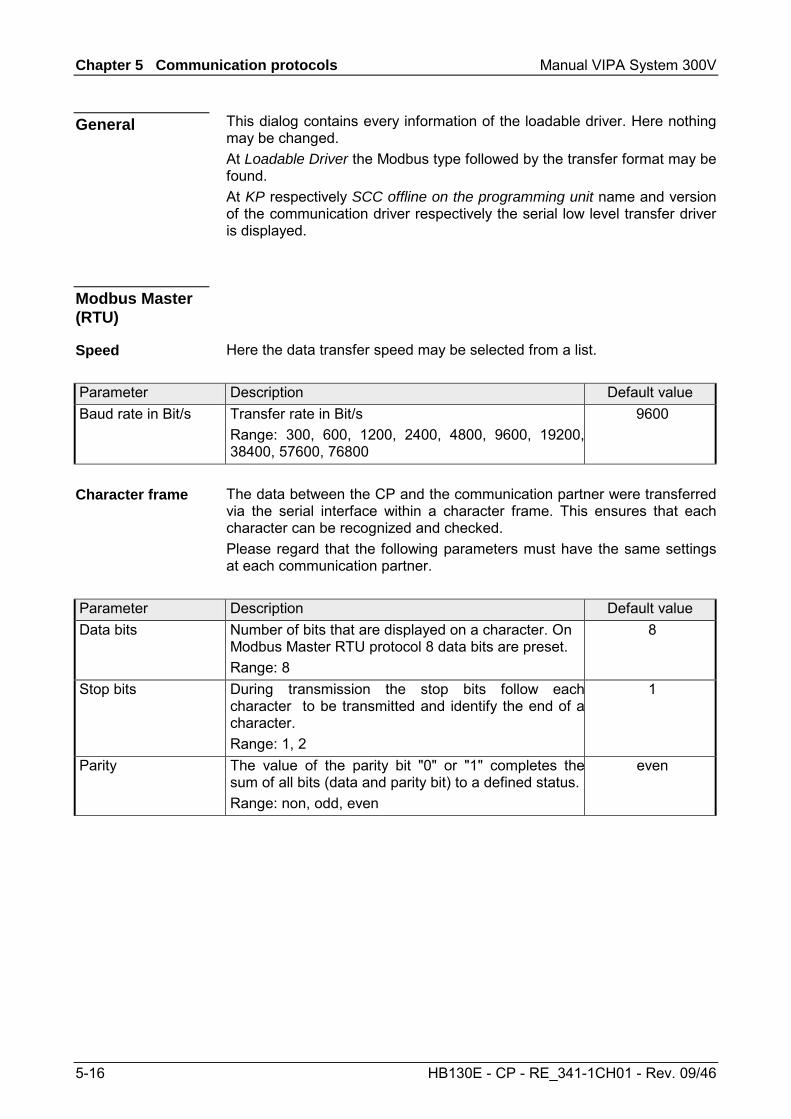
Chapter 5 Communication protocols Manual VIPA System 300V
5-16 HB130E - CP - RE_341-1CH01 - Rev. 09/46
This dialog contains every information of the loadable driver. Here nothing may be changed. At Loadable Driver the Modbus type followed by the transfer format may be found. At KP respectively SCC offline on the programming unit name and version of the communication driver respectively the serial low level transfer driver is displayed.
Here the data transfer speed may be selected from a list.
Parameter Description Default value Baud rate in Bit/s Transfer rate in Bit/s
Range: 300, 600, 1200, 2400, 4800, 9600, 19200,38400, 57600, 76800
9600
The data between the CP and the communication partner were transferred via the serial interface within a character frame. This ensures that each character can be recognized and checked. Please regard that the following parameters must have the same settings at each communication partner.
Parameter Description Default value Data bits Number of bits that are displayed on a character. On
Modbus Master RTU protocol 8 data bits are preset. Range: 8
8
Stop bits During transmission the stop bits follow eachcharacter to be transmitted and identify the end of acharacter. Range: 1, 2
1
Parity The value of the parity bit "0" or "1" completes thesum of all bits (data and parity bit) to a defined status. Range: non, odd, even
even
General
Modbus Master (RTU)
Speed
Character frame
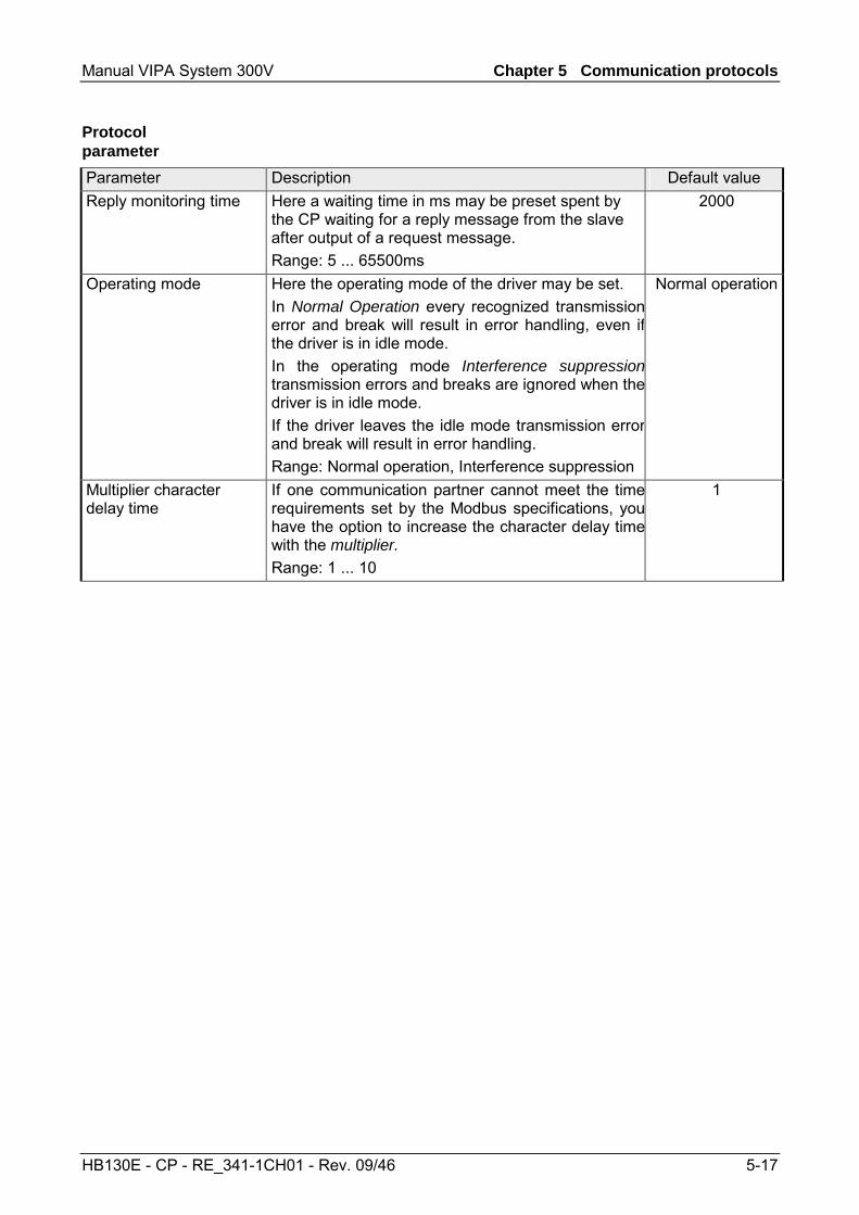
Manual VIPA System 300V Chapter 5 Communication protocols
HB130E - CP - RE_341-1CH01 - Rev. 09/46 5-17
Parameter Description Default value Reply monitoring time Here a waiting time in ms may be preset spent by
the CP waiting for a reply message from the slave after output of a request message. Range: 5 ... 65500ms
2000
Operating mode Here the operating mode of the driver may be set. In Normal Operation every recognized transmissionerror and break will result in error handling, even ifthe driver is in idle mode. In the operating mode Interference suppressiontransmission errors and breaks are ignored when thedriver is in idle mode. If the driver leaves the idle mode transmission errorand break will result in error handling. Range: Normal operation, Interference suppression
Normal operation
Multiplier character delay time
If one communication partner cannot meet the timerequirements set by the Modbus specifications, youhave the option to increase the character delay timewith the multiplier. Range: 1 ... 10
1
Protocol parameter
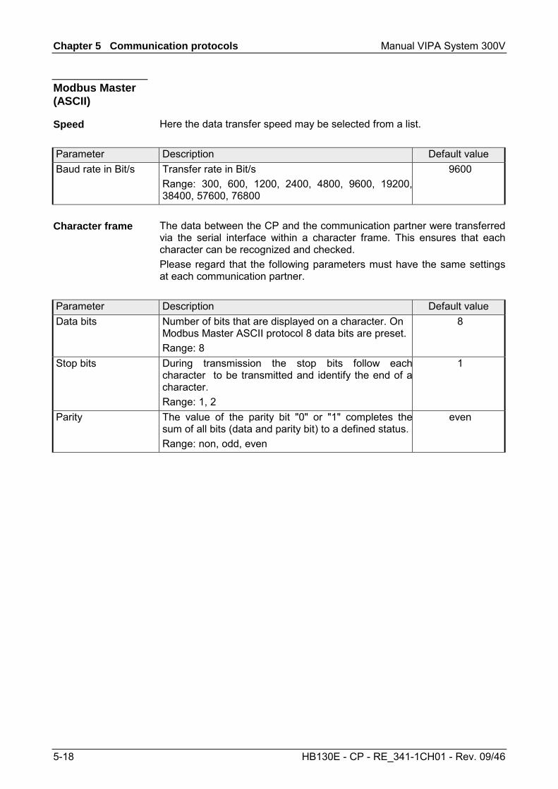
Chapter 5 Communication protocols Manual VIPA System 300V
5-18 HB130E - CP - RE_341-1CH01 - Rev. 09/46
Here the data transfer speed may be selected from a list.
Parameter Description Default value Baud rate in Bit/s Transfer rate in Bit/s
Range: 300, 600, 1200, 2400, 4800, 9600, 19200,38400, 57600, 76800
9600
The data between the CP and the communication partner were transferred via the serial interface within a character frame. This ensures that each character can be recognized and checked. Please regard that the following parameters must have the same settings at each communication partner.
Parameter Description Default value Data bits Number of bits that are displayed on a character. On
Modbus Master ASCII protocol 8 data bits are preset. Range: 8
8
Stop bits During transmission the stop bits follow eachcharacter to be transmitted and identify the end of acharacter. Range: 1, 2
1
Parity The value of the parity bit "0" or "1" completes thesum of all bits (data and parity bit) to a defined status. Range: non, odd, even
even
Modbus Master (ASCII)
Speed
Character frame
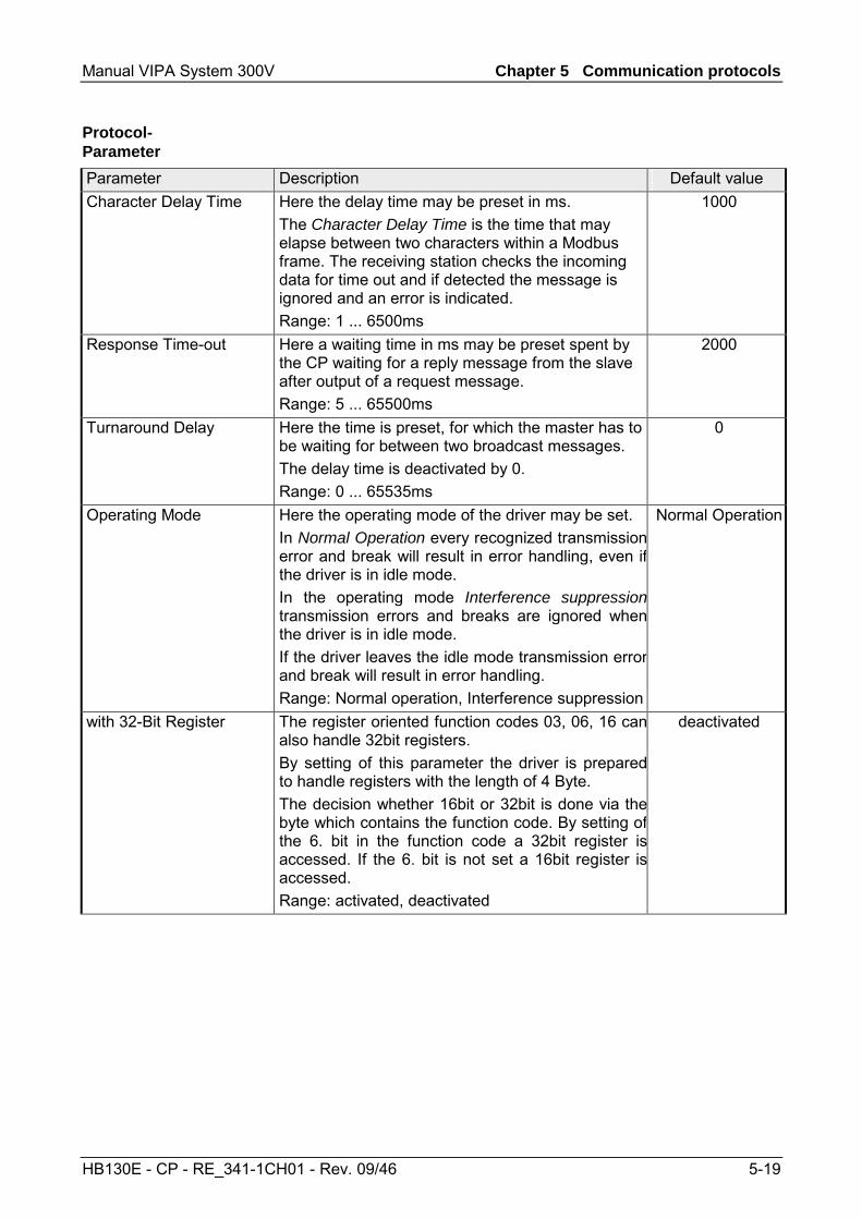
Manual VIPA System 300V Chapter 5 Communication protocols
HB130E - CP - RE_341-1CH01 - Rev. 09/46 5-19
Parameter Description Default value Character Delay Time Here the delay time may be preset in ms.
The Character Delay Time is the time that may elapse between two characters within a Modbus frame. The receiving station checks the incoming data for time out and if detected the message is ignored and an error is indicated. Range: 1 ... 6500ms
1000
Response Time-out Here a waiting time in ms may be preset spent by the CP waiting for a reply message from the slave after output of a request message. Range: 5 ... 65500ms
2000
Turnaround Delay Here the time is preset, for which the master has to be waiting for between two broadcast messages. The delay time is deactivated by 0. Range: 0 ... 65535ms
0
Operating Mode Here the operating mode of the driver may be set. In Normal Operation every recognized transmissionerror and break will result in error handling, even ifthe driver is in idle mode. In the operating mode Interference suppressiontransmission errors and breaks are ignored whenthe driver is in idle mode. If the driver leaves the idle mode transmission errorand break will result in error handling. Range: Normal operation, Interference suppression
Normal Operation
with 32-Bit Register The register oriented function codes 03, 06, 16 canalso handle 32bit registers. By setting of this parameter the driver is preparedto handle registers with the length of 4 Byte. The decision whether 16bit or 32bit is done via thebyte which contains the function code. By setting ofthe 6. bit in the function code a 32bit register isaccessed. If the 6. bit is not set a 16bit register isaccessed. Range: activated, deactivated
deactivated
Protocol-Parameter
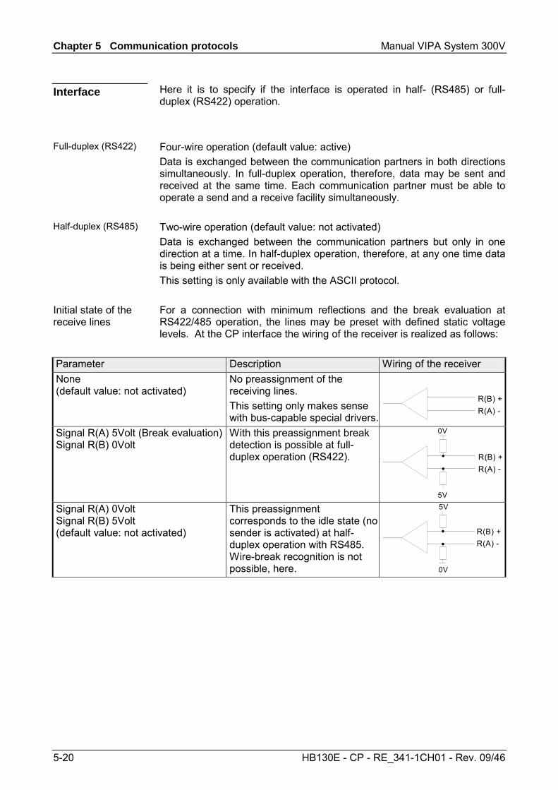
Chapter 5 Communication protocols Manual VIPA System 300V
5-20 HB130E - CP - RE_341-1CH01 - Rev. 09/46
Here it is to specify if the interface is operated in half- (RS485) or full-duplex (RS422) operation.
Four-wire operation (default value: active) Data is exchanged between the communication partners in both directions simultaneously. In full-duplex operation, therefore, data may be sent and received at the same time. Each communication partner must be able to operate a send and a receive facility simultaneously. Two-wire operation (default value: not activated) Data is exchanged between the communication partners but only in one direction at a time. In half-duplex operation, therefore, at any one time data is being either sent or received. This setting is only available with the ASCII protocol. For a connection with minimum reflections and the break evaluation at RS422/485 operation, the lines may be preset with defined static voltage levels. At the CP interface the wiring of the receiver is realized as follows:
Parameter Description Wiring of the receiver None (default value: not activated)
No preassignment of the receiving lines. This setting only makes sense with bus-capable special drivers.
R(B) +R(A) -
Signal R(A) 5Volt (Break evaluation) Signal R(B) 0Volt
With this preassignment break detection is possible at full-duplex operation (RS422).
0V
5V
R(B) +R(A) -
Signal R(A) 0Volt Signal R(B) 5Volt (default value: not activated)
This preassignment corresponds to the idle state (no sender is activated) at half-duplex operation with RS485. Wire-break recognition is not possible, here.
R(B) +R(A) -
5V
0V
Interface
Full-duplex (RS422)
Half-duplex (RS485)
Initial state of the receive lines
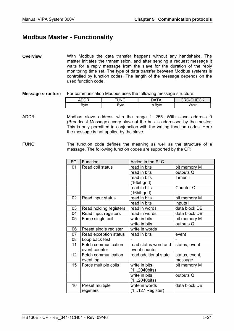
Manual VIPA System 300V Chapter 5 Communication protocols
HB130E - CP - RE_341-1CH01 - Rev. 09/46 5-21
Modbus Master - Functionality
With Modbus the data transfer happens without any handshake. The master initiates the transmission, and after sending a request message it waits for a reply message from the slave for the duration of the reply monitoring time set. The type of data transfer between Modbus systems is controlled by function codes. The length of the message depends on the used function code. For communication Modbus uses the following message structure:
ADDR FUNC DATA CRC-CHECK Byte Byte n Byte Word
Modbus slave address with the range 1...255. With slave address 0 (Broadcast Message) every slave at the bus is addressed by the master. This is only permitted in conjunction with the writing function codes. Here the message is not applied by the slave. The function code defines the meaning as well as the structure of a message. The following function codes are supported by the CP:
FC Function Action in the PLC 01 Read coil status read in bits bit memory M read in bits outputs Q read in bits
(16bit grid) Timer T
read in bits (16bit grid)
Counter C
02 Read input status read in bits bit memory M read in bits inputs I
03 Read holding registers read in words data block DB 04 Read input registers read in words data block DB 05 Force single coil write in bits bit memory M
write in bits outputs Q 06 Preset single register write in words 07 Read exception status read in bits event 08 Loop back test - - 11 Fetch communication
event counter read status word and event counter
status, event
12 Fetch communication event log
read additional state status, event, message
15 Force multiple coils write in bits (1...2040bits)
bit memory M
write in bits (1...2040bits)
outputs Q
16 Preset multiple registers
write in words (1...127 Register)
data block DB
Overview
Message structure
ADDR
FUNC
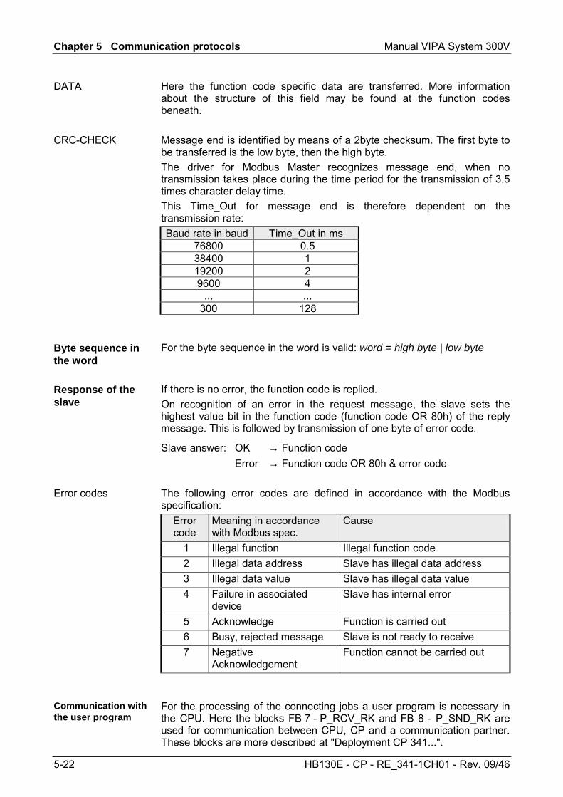
Chapter 5 Communication protocols Manual VIPA System 300V
5-22 HB130E - CP - RE_341-1CH01 - Rev. 09/46
Here the function code specific data are transferred. More information about the structure of this field may be found at the function codes beneath. Message end is identified by means of a 2byte checksum. The first byte to be transferred is the low byte, then the high byte. The driver for Modbus Master recognizes message end, when no transmission takes place during the time period for the transmission of 3.5 times character delay time. This Time_Out for message end is therefore dependent on the transmission rate: Baud rate in baud Time_Out in ms
76800 0.5 38400 1 19200 2 9600 4
... ... 300 128
For the byte sequence in the word is valid: word = high byte | low byte
If there is no error, the function code is replied. On recognition of an error in the request message, the slave sets the highest value bit in the function code (function code OR 80h) of the reply message. This is followed by transmission of one byte of error code.
Slave answer: OK → Function code Error → Function code OR 80h & error code The following error codes are defined in accordance with the Modbus specification:
Error code
Meaning in accordance with Modbus spec.
Cause
1 Illegal function Illegal function code 2 Illegal data address Slave has illegal data address 3 Illegal data value Slave has illegal data value 4 Failure in associated
device Slave has internal error
5 Acknowledge Function is carried out 6 Busy, rejected message Slave is not ready to receive 7 Negative
Acknowledgement Function cannot be carried out
For the processing of the connecting jobs a user program is necessary in the CPU. Here the blocks FB 7 - P_RCV_RK and FB 8 - P_SND_RK are used for communication between CPU, CP and a communication partner. These blocks are more described at "Deployment CP 341...".
DATA
CRC-CHECK
Byte sequence in the word
Response of the slave
Error codes
Communication with the user program
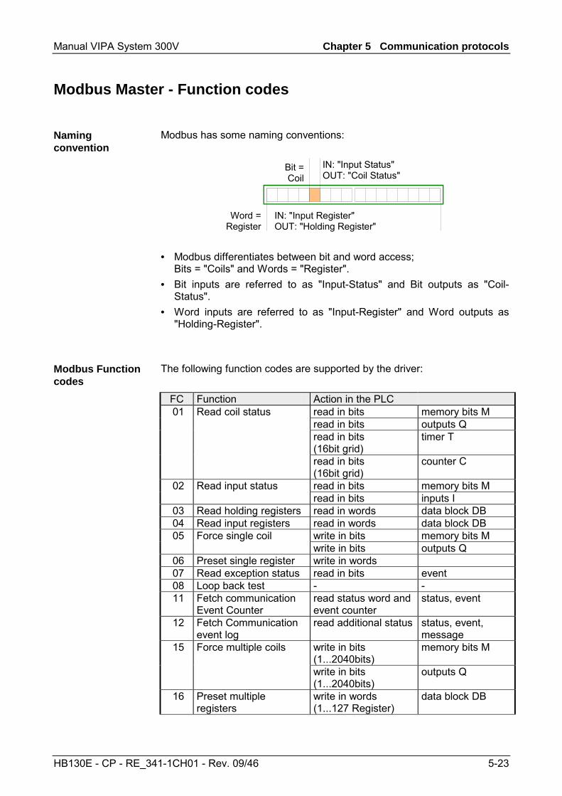
Manual VIPA System 300V Chapter 5 Communication protocols
HB130E - CP - RE_341-1CH01 - Rev. 09/46 5-23
Modbus Master - Function codes
Modbus has some naming conventions:
Word =Register
IN: "Input Register"OUT: "Holding Register"
Bit =Coil
IN: "Input Status"OUT: "Coil Status"
• Modbus differentiates between bit and word access;
Bits = "Coils" and Words = "Register". • Bit inputs are referred to as "Input-Status" and Bit outputs as "Coil-
Status". • Word inputs are referred to as "Input-Register" and Word outputs as
"Holding-Register". The following function codes are supported by the driver:
FC Function Action in the PLC 01 Read coil status read in bits memory bits M read in bits outputs Q read in bits
(16bit grid) timer T
read in bits (16bit grid)
counter C
02 Read input status read in bits memory bits M read in bits inputs I
03 Read holding registers read in words data block DB 04 Read input registers read in words data block DB 05 Force single coil write in bits memory bits M
write in bits outputs Q 06 Preset single register write in words 07 Read exception status read in bits event 08 Loop back test - - 11 Fetch communication
Event Counter read status word and event counter
status, event
12 Fetch Communication event log
read additional status status, event, message
15 Force multiple coils write in bits (1...2040bits)
memory bits M
write in bits (1...2040bits)
outputs Q
16 Preset multiple registers
write in words (1...127 Register)
data block DB
Naming convention
Modbus Function codes
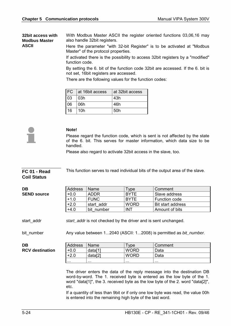
Chapter 5 Communication protocols Manual VIPA System 300V
5-24 HB130E - CP - RE_341-1CH01 - Rev. 09/46
With Modbus Master ASCII the register oriented functions 03,06,16 may also handle 32bit registers. Here the parameter "with 32-bit Register" is to be activated at "Modbus Master" of the protocol properties. If activated there is the possibility to access 32bit registers by a "modified" function code. By setting the 6. bit of the function code 32bit are accessed. If the 6. bit is not set, 16bit registers are accessed. There are the following values for the function codes: FC at 16bit access at 32bit access 03 03h 43h 06 06h 46h 16 10h 50h
Note! Please regard the function code, which is sent is not affected by the state of the 6. bit. This serves for master information, which data size to be handled. Please also regard to activate 32bit access in the slave, too.
This function serves to read individual bits of the output area of the slave. Address Name Type Comment +0.0 ADDR BYTE Slave address +1.0 FUNC BYTE Function code +2.0 start_addr WORD Bit start address +4.0 bit_number INT Amount of bits start_addr is not checked by the driver and is sent unchanged. Any value between 1...2040 (ASCII: 1...2008) is permitted as bit_number. Address Name Type Comment +0.0 data[1] WORD Data +2.0 data[2] WORD Data ... ... ... ... The driver enters the data of the reply message into the destination DB word-by-word. The 1. received byte is entered as the low byte of the 1. word "data[1]", the 3. received byte as the low byte of the 2. word "data[2]", etc. If a quantity of less than 9bit or if only one low byte was read, the value 00h is entered into the remaining high byte of the last word.
32bit access with Modbus Master ASCII
FC 01 - Read Coil Status
DB SEND source
start_addr
bit_number
DB RCV destination
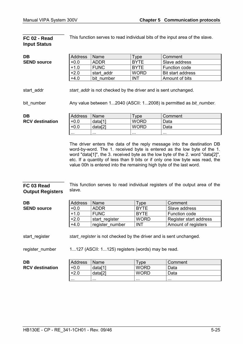
Manual VIPA System 300V Chapter 5 Communication protocols
HB130E - CP - RE_341-1CH01 - Rev. 09/46 5-25
This function serves to read individual bits of the input area of the slave. Address Name Type Comment +0.0 ADDR BYTE Slave address +1.0 FUNC BYTE Function code +2.0 start_addr WORD Bit start address +4.0 bit_number INT Amount of bits start_addr is not checked by the driver and is sent unchanged. Any value between 1...2040 (ASCII: 1...2008) is permitted as bit_number. Address Name Type Comment +0.0 data[1] WORD Data +0.0 data[2] WORD Data ... ... ... ... The driver enters the data of the reply message into the destination DB word-by-word. The 1. received byte is entered as the low byte of the 1. word "data[1]", the 3. received byte as the low byte of the 2. word "data[2]", etc. If a quantity of less than 9 bits or if only one low byte was read, the value 00h is entered into the remaining high byte of the last word.
This function serves to read individual registers of the output area of the slave. Address Name Type Comment +0.0 ADDR BYTE Slave address +1.0 FUNC BYTE Function code +2.0 start_register WORD Register start address +4.0 register_number INT Amount of registers start_register is not checked by the driver and is sent unchanged. 1...127 (ASCII: 1...125) registers (words) may be read. Address Name Type Comment +0.0 data[1] WORD Data +2.0 data[2] WORD Data ... ... ... ...
FC 02 - Read Input Status
DB SEND source
start_addr
bit_number
DB RCV destination
FC 03 Read Output Registers
DB SEND source
start_register
register_number
DB RCV destination
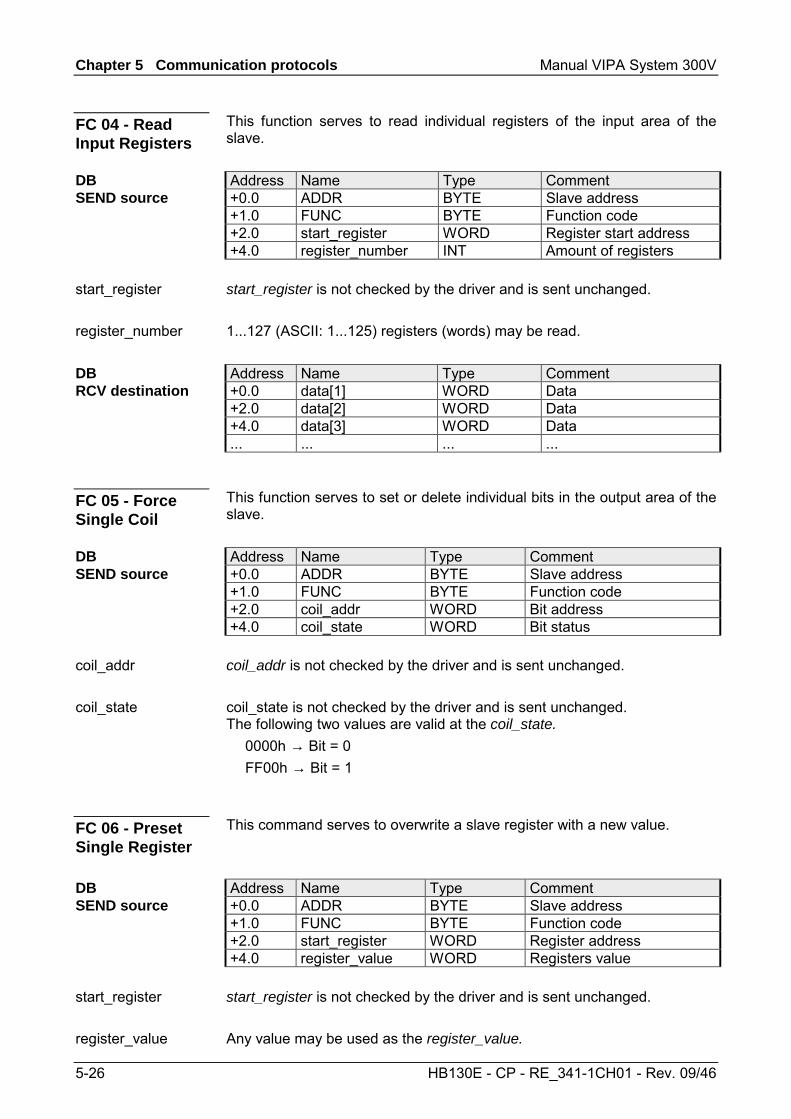
Chapter 5 Communication protocols Manual VIPA System 300V
5-26 HB130E - CP - RE_341-1CH01 - Rev. 09/46
This function serves to read individual registers of the input area of the slave. Address Name Type Comment +0.0 ADDR BYTE Slave address +1.0 FUNC BYTE Function code +2.0 start_register WORD Register start address +4.0 register_number INT Amount of registers start_register is not checked by the driver and is sent unchanged. 1...127 (ASCII: 1...125) registers (words) may be read. Address Name Type Comment +0.0 data[1] WORD Data +2.0 data[2] WORD Data +4.0 data[3] WORD Data ... ... ... ...
This function serves to set or delete individual bits in the output area of the slave. Address Name Type Comment +0.0 ADDR BYTE Slave address +1.0 FUNC BYTE Function code +2.0 coil_addr WORD Bit address +4.0 coil_state WORD Bit status coil_addr is not checked by the driver and is sent unchanged. coil_state is not checked by the driver and is sent unchanged. The following two values are valid at the coil_state. 0000h → Bit = 0 FF00h → Bit = 1
This command serves to overwrite a slave register with a new value. Address Name Type Comment +0.0 ADDR BYTE Slave address +1.0 FUNC BYTE Function code +2.0 start_register WORD Register address +4.0 register_value WORD Registers value start_register is not checked by the driver and is sent unchanged. Any value may be used as the register_value.
FC 04 - Read Input Registers
DB SEND source
start_register
register_number
DB RCV destination
FC 05 - Force Single Coil
DB SEND source
coil_addr
coil_state
FC 06 - Preset Single Register
DB SEND source
start_register
register_value
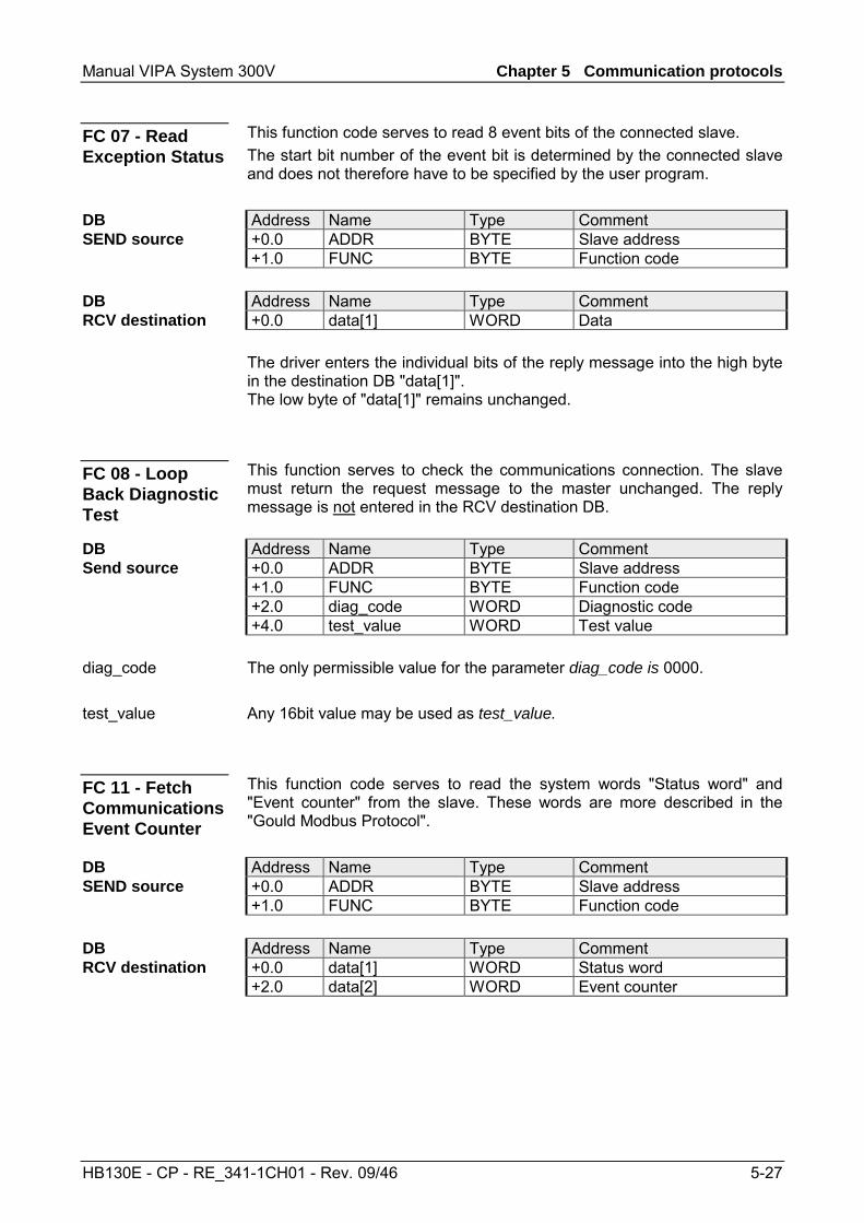
Manual VIPA System 300V Chapter 5 Communication protocols
HB130E - CP - RE_341-1CH01 - Rev. 09/46 5-27
This function code serves to read 8 event bits of the connected slave. The start bit number of the event bit is determined by the connected slave and does not therefore have to be specified by the user program. Address Name Type Comment +0.0 ADDR BYTE Slave address +1.0 FUNC BYTE Function code Address Name Type Comment +0.0 data[1] WORD Data The driver enters the individual bits of the reply message into the high byte in the destination DB "data[1]". The low byte of "data[1]" remains unchanged.
This function serves to check the communications connection. The slave must return the request message to the master unchanged. The reply message is not entered in the RCV destination DB. Address Name Type Comment +0.0 ADDR BYTE Slave address +1.0 FUNC BYTE Function code +2.0 diag_code WORD Diagnostic code +4.0 test_value WORD Test value The only permissible value for the parameter diag_code is 0000. Any 16bit value may be used as test_value.
This function code serves to read the system words "Status word" and "Event counter" from the slave. These words are more described in the "Gould Modbus Protocol". Address Name Type Comment +0.0 ADDR BYTE Slave address +1.0 FUNC BYTE Function code Address Name Type Comment +0.0 data[1] WORD Status word +2.0 data[2] WORD Event counter
FC 07 - Read Exception Status
DB SEND source
DB RCV destination
FC 08 - Loop Back Diagnostic Test
DB Send source
diag_code
test_value
FC 11 - Fetch Communications Event Counter
DB SEND source
DB RCV destination
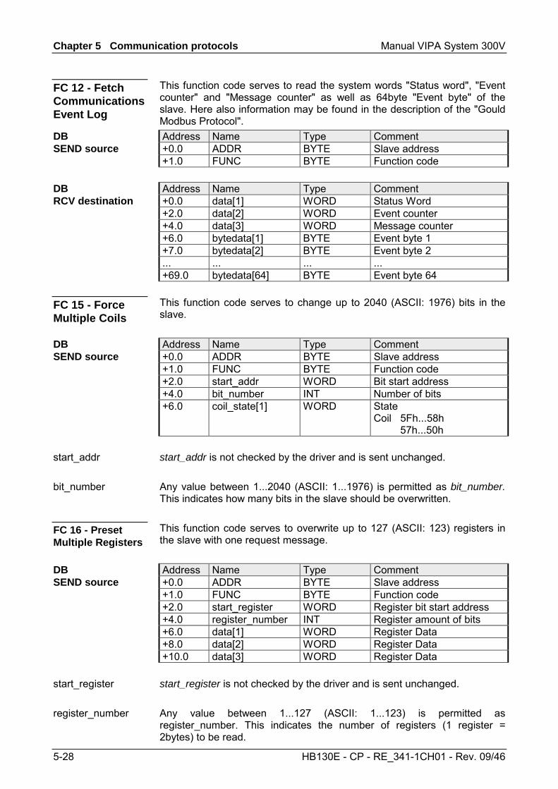
Chapter 5 Communication protocols Manual VIPA System 300V
5-28 HB130E - CP - RE_341-1CH01 - Rev. 09/46
This function code serves to read the system words "Status word", "Event counter" and "Message counter" as well as 64byte "Event byte" of the slave. Here also information may be found in the description of the "Gould Modbus Protocol". Address Name Type Comment +0.0 ADDR BYTE Slave address +1.0 FUNC BYTE Function code Address Name Type Comment +0.0 data[1] WORD Status Word +2.0 data[2] WORD Event counter +4.0 data[3] WORD Message counter +6.0 bytedata[1] BYTE Event byte 1 +7.0 bytedata[2] BYTE Event byte 2 ... ... ... ... +69.0 bytedata[64] BYTE Event byte 64 This function code serves to change up to 2040 (ASCII: 1976) bits in the slave. Address Name Type Comment +0.0 ADDR BYTE Slave address +1.0 FUNC BYTE Function code +2.0 start_addr WORD Bit start address +4.0 bit_number INT Number of bits +6.0 coil_state[1] WORD State
Coil 5Fh...58h 57h...50h
start_addr is not checked by the driver and is sent unchanged. Any value between 1...2040 (ASCII: 1...1976) is permitted as bit_number. This indicates how many bits in the slave should be overwritten. This function code serves to overwrite up to 127 (ASCII: 123) registers in the slave with one request message. Address Name Type Comment +0.0 ADDR BYTE Slave address +1.0 FUNC BYTE Function code +2.0 start_register WORD Register bit start address +4.0 register_number INT Register amount of bits +6.0 data[1] WORD Register Data +8.0 data[2] WORD Register Data +10.0 data[3] WORD Register Data start_register is not checked by the driver and is sent unchanged. Any value between 1...127 (ASCII: 1...123) is permitted as register_number. This indicates the number of registers (1 register = 2bytes) to be read.
FC 12 - Fetch Communications Event Log
DB SEND source
DB RCV destination
FC 15 - Force Multiple Coils
DB SEND source
start_addr
bit_number
FC 16 - Preset Multiple Registers
DB SEND source
start_register
register_number
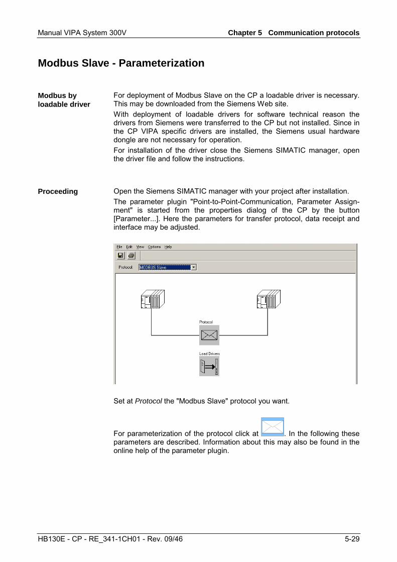
Manual VIPA System 300V Chapter 5 Communication protocols
HB130E - CP - RE_341-1CH01 - Rev. 09/46 5-29
Modbus Slave - Parameterization
For deployment of Modbus Slave on the CP a loadable driver is necessary. This may be downloaded from the Siemens Web site. With deployment of loadable drivers for software technical reason the drivers from Siemens were transferred to the CP but not installed. Since in the CP VIPA specific drivers are installed, the Siemens usual hardware dongle are not necessary for operation. For installation of the driver close the Siemens SIMATIC manager, open the driver file and follow the instructions.
Open the Siemens SIMATIC manager with your project after installation. The parameter plugin "Point-to-Point-Communication, Parameter Assign-ment" is started from the properties dialog of the CP by the button [Parameter...]. Here the parameters for transfer protocol, data receipt and interface may be adjusted.
Set at Protocol the "Modbus Slave" protocol you want.
For parameterization of the protocol click at . In the following these parameters are described. Information about this may also be found in the online help of the parameter plugin.
Modbus by loadable driver
Proceeding

Chapter 5 Communication protocols Manual VIPA System 300V
5-30 HB130E - CP - RE_341-1CH01 - Rev. 09/46
This dialog contains every information of the loadable driver. Here nothing may be changed. At Loadable Driver the Modbus type followed by the transfer format may be found. At KP respectively SCC offline on the programming unit name and version of the communication driver respectively the serial low level transfer driver is displayed.
Here the data transfer speed may be selected from a list.
Parameter Description Default value Baud rate in bit/s Transfer rate in bit/s
Range: 300, 600, 1200, 2400, 4800, 9600, 19200,38400, 57600, 76800
9600
The data between the CP and the communication partner were transferred via the serial interface within a character frame. This ensures that each character can be recognized and checked. Please regard that the following parameters must have the same settings at each communication partner.
Parameter Description Default value Data bits Number of bits that are displayed on a character. On
Modbus Slave RTU protocol 8 data bits are preset. Range: 8
8
Stop bits During transmission the stop bits follow eachcharacter to be transmitted and identify the end of acharacter. Range: 1, 2
1
Parity The value of the parity bit "0" or "1" completes thesum of all bits (data and parity bit) to a defined status. Range: non, odd, even
even
General
Modbus Slave
Speed
Character frame
Manual VIPA System 300V Chapter 5 Communication protocols
HB130E - CP - RE_341-1CH01 - Rev. 09/46 5-31
Parameter Description Default value Slave address Here the own slave address may be set, which the
CP has to respond to. Range: 1 ... 255
222
Operating mode Here the operating mode of the driver may be set. In Normal Operation every recognized transmissionerror and break will result in error handling, even ifthe driver is in idle mode. In the operating mode Interference suppressiontransmission errors and breaks are ignored when thedriver is in idle mode. If the driver leaves the idlemode transmission error and break will result in errorhandling. Range: Normal operation, Interference suppression
Normal operation
Multiplier character delay time
If on e communication partner cannot meet the timerequirements set by the Modbus specifications, youhave the option to increase the character delay timewith the multiplier. Range: 1 ... 10
1
In this dialog window the bit-oriented function codes 01, 05 and 15 may be assigned to address areas of the CPU. Bit memories, outputs, timer and counter of the CPU may be accessed by means of this function codes. With timer and counters the reading access is only possible with function code 01. With FC 02 a Modbus address area is assigned to bit memory and input area of the CPU, which is accessed by reading. The data blocks of the CPU may be accessed (R/W) by the register-oriented function codes 03, 06 and 16. Here you can indicate starting from which DB number the Modbus address starting with 0 is assigned. Up to 128 DB may be accessed in one block. With the register-oriented function code 04 data blocks of the CPU may only be accessed by reading. Here a further block of 128 DBs may be determined. More details may be found at the appropriate function codes. For the writing function codes 05, 06, 15 and 16 the access to the corresponding area must be enabled before. By default the whole output area of the CPU is disabled for write access, this means each value is 0. If the master tries to write to an output area of the CPU, which is outside the enabled area, the access is replied by a corresponding error message.
Protocol parameter
FC 01, 05, 15 FC 02
FC 03, 06, 16 FC 04
Limits

Chapter 5 Communication protocols Manual VIPA System 300V
5-32 HB130E - CP - RE_341-1CH01 - Rev. 09/46
Here it is to specify if the interface is operated in half- (RS485) or full-duplex (RS422) operation.
Four-wire operation (default value: active) Data is exchanged between the communication partners in both directions simultaneously. In full-duplex operation, therefore, data may be sent and received at the same time. Each communication partner must be able to operate a send and a receive facility simultaneously. Two-wire operation (default value: not activated) Data is exchanged between the communication partners but only in one direction at a time. In half-duplex operation, therefore, at any one time data is being either sent or received. This setting is only available with the ASCII protocol. For a connection with minimum reflections and the break evaluation at RS422/485 operation, the lines may be preset with defined static voltage levels. At the CP interface the wiring of the receiver is realized as follows:
Parameter Description Wiring of the receiver None (default value: not activated)
No preassignment of the receiving lines. This setting only makes sense with bus-capable special drivers.
R(B) +R(A) -
Signal R(A) 5Volt (Break evaluation) Signal R(B) 0Volt
With this preassignment break detection is possible at full-duplex operation (RS422).
0V
5V
R(B) +R(A) -
Signal R(A) 0Volt Signal R(B) 5Volt (default value: not activated)
This preassignment corresponds to the idle state (no sender is activated) at half-duplex operation with RS485. Wire-break recognition is not possible, here.
R(B) +R(A) -
5V
0V
Interface
Full-duplex (RS422)
Half-duplex (RS485)
Initial state of the receive lines
Manual VIPA System 300V Chapter 5 Communication protocols
HB130E - CP - RE_341-1CH01 - Rev. 09/46 5-33
Modbus Slave - Functionality
With Modbus the data transfer happens without any handshake. The master initiates the transmission, and after sending a request message it waits for a reply message from the slave for the duration of the reply monitoring time set. The type of data transfer between Modbus systems is controlled by function codes. At Modbus slave side the Modbus address of the message of the master is transformed to the memory area of the CPU by the protocol driver. The corresponding area assignment may be established by the parame-terization. Data transfer between CP and CPU happens by the Modbus commu-nication FB 80 - MODB_341. FB 7 - P_PRC_RK and FB 8 - P_SND_RK are internally called by this FB. At slave side FB 7 - P_PRC_RK and FB 8 - P_SND_RK are necessary for communication, so copy them to your project. For communication Modbus uses the following message structure:
ADDR FUNC DATA CRC-CHECK Byte Byte n Byte Word
Modbus slave address with the range 1...255. With slave address 0 (Broadcast Message) every slave at the bus is addressed by the master. This is only permitted in conjunction with the writing function codes. Here the message is not applied by the slave. The function code defines the meaning as well as the structure of a message. The following function codes are supported by the Modbus slave driver:
FC Function Action in the PLC 01 Read coil status read in bits bit memory M read in bits outputs Q read in bits
(16bit grid) Timer T
read in bits (16bit grid)
Counter C
02 Read input status read in bits bit memory M read in bits inputs I
03 Read holding registers read in words data block DB 04 Read input registers read in words data block DB 05 Force single coil write in bits bit memory M
write in bits outputs Q 06 Preset single register write in words 08 Loop back test - - 15 Force multiple coils write in bits
(1...2040bits) bit memory M
write in bits (1...2040bits)
outputs Q
16 Preset multiple registers
write in words (1...127 Register)
data block DB
Overview
Message structure
ADDR
FUNC
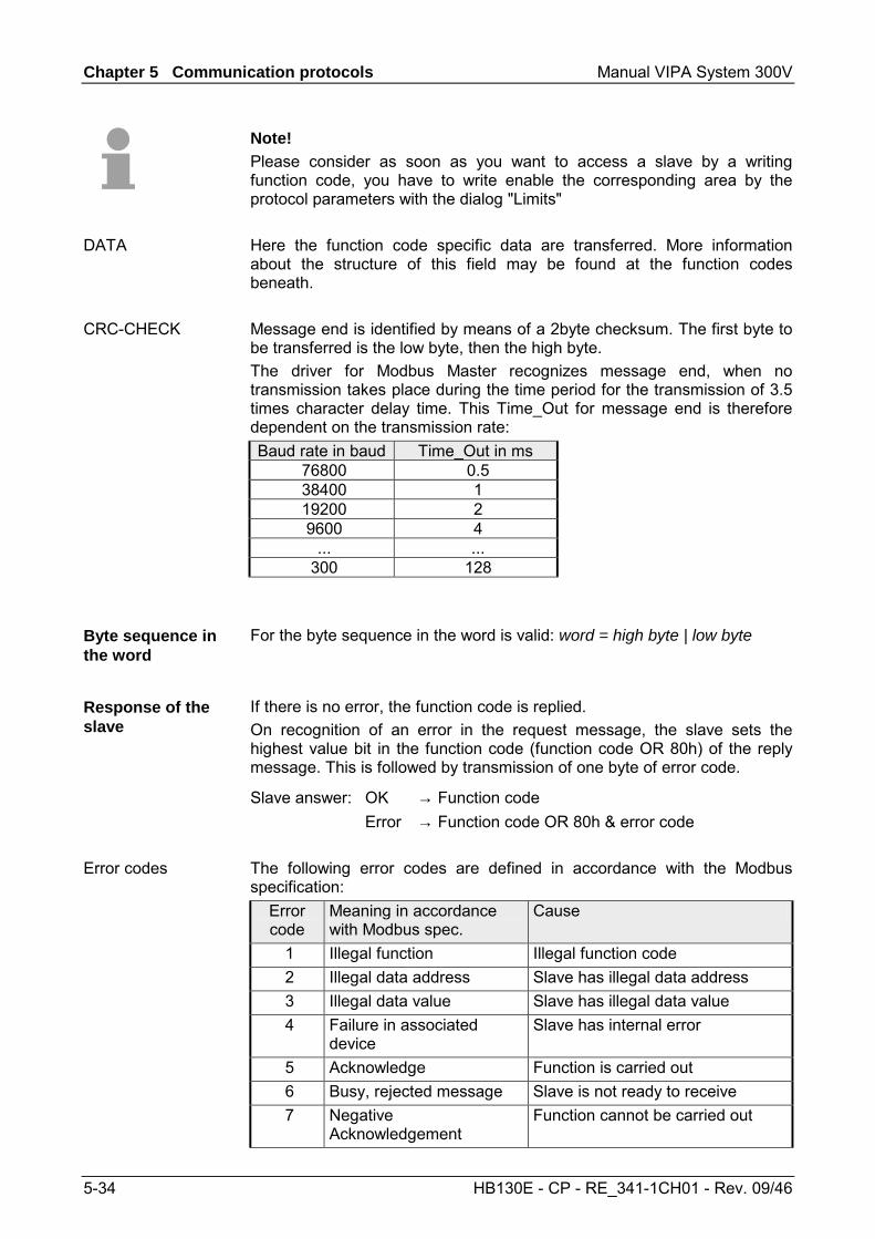
Chapter 5 Communication protocols Manual VIPA System 300V
5-34 HB130E - CP - RE_341-1CH01 - Rev. 09/46
Note! Please consider as soon as you want to access a slave by a writing function code, you have to write enable the corresponding area by the protocol parameters with the dialog "Limits" Here the function code specific data are transferred. More information about the structure of this field may be found at the function codes beneath. Message end is identified by means of a 2byte checksum. The first byte to be transferred is the low byte, then the high byte. The driver for Modbus Master recognizes message end, when no transmission takes place during the time period for the transmission of 3.5 times character delay time. This Time_Out for message end is therefore dependent on the transmission rate: Baud rate in baud Time_Out in ms
76800 0.5 38400 1 19200 2 9600 4
... ... 300 128
For the byte sequence in the word is valid: word = high byte | low byte
If there is no error, the function code is replied. On recognition of an error in the request message, the slave sets the highest value bit in the function code (function code OR 80h) of the reply message. This is followed by transmission of one byte of error code.
Slave answer: OK → Function code Error → Function code OR 80h & error code The following error codes are defined in accordance with the Modbus specification:
Error code
Meaning in accordance with Modbus spec.
Cause
1 Illegal function Illegal function code 2 Illegal data address Slave has illegal data address 3 Illegal data value Slave has illegal data value 4 Failure in associated
device Slave has internal error
5 Acknowledge Function is carried out 6 Busy, rejected message Slave is not ready to receive 7 Negative
Acknowledgement Function cannot be carried out
DATA
CRC-CHECK
Byte sequence in the word
Response of the slave
Error codes
Manual VIPA System 300V Chapter 5 Communication protocols
HB130E - CP - RE_341-1CH01 - Rev. 09/46 5-35
Modbus Slave - Communication with the user program
For the processing of the connecting jobs at slave side a user program is necessary in the CPU. The data transfer between CP and CPU happens by the Modbus communication FB 80 - MODB_341. By this FB 7 - P_RCV_RK and FB 8 - P_SND_RK are called internally. For communication at the slave side it is necessary to integrate FB 7 - P_RCV_RK and FB 8 - P_SND_RK to the project. Every for the Modbus communication FB 80 relevant data are located in an instance DB. This DB is the instance DB for the internally called blocks at the same time. Access to the instance DB is permitted only as read-only. Attention! Calling of the FB 80 - MODB_341 within diagnostic or process interrupt is not allowed. Please regard the FB does not have a parameter check; which means that if there are invalid parameters, the CPU may switch to STOP mode. The function block FB 80 is installed together with the protocol driver. If not already happen, finish the Siemens SIMATIC manager, start the installation file of the driver and follow the instructions FB 80 - MODB_341 may be found in the block library after installation The library may be opened in the Siemens SIMATIC manager by File > Open > "Libraries" and here "Modbus"
By a cyclic call of the FB 80 - MODB_341 request telegrams from the master may be received and data may be sent with the slave CP. The conversion of the corresponding Modbus address to the memory area of the CPU is made by the CP. The memory area allocation happens by the parameterization within the hardware configuration. FB 80 - MODB_341 is described at the following pages.
For the write function codes (FC 05, FC 15) is valid: Reaction time = AG cycle + time CP→CPU + time CPU→CP For the other function codes is valid: Reaction time = time CP→CPU + time CPU→CP The CP does not send the reply message to the master system until after the data transfer CPU→CP. In this instance the standard reply monitoring time of 2s can be kept
Overview
Installation
Communication principle
Reaction time
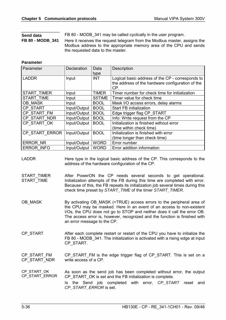
Chapter 5 Communication protocols Manual VIPA System 300V
5-36 HB130E - CP - RE_341-1CH01 - Rev. 09/46
FB 80 - MODB_341 may be called cyclically in the user program. Here it receives the request telegram from the Modbus master, assigns the Modbus address to the appropriate memory area of the CPU and sends the requested data to the master.
Parameter Declaration Data type
Description
LADDR Input INT Logical basic address of the CP - corresponds to the address of the hardware configuration of the CP.
START_TIMER Input TIMER Timer number for check time for initialization START_TIME Input S5TIME Timer value for check time OB_MASK Input BOOL Mask I/O access errors, delay alarms CP_START Input/Output BOOL Start FB initialization CP_START_FM Input/Output BOOL Edge trigger flag CP_START CP_START_NDR Input/Output BOOL Info: Write request from the CP CP_START_OK Input/Output BOOL Initialization is finished without error
(time within check time) CP_START_ERROR Input/Output BOOL Initialization is finished with error
(time longer than check time) ERROR_NR Input/Output WORD Error number ERROR_INFO Input/Output WORD Error addition information
Here type in the logical basic address of the CP. This corresponds to the address of the hardware configuration of the CP. After PowerON the CP needs several seconds to get operational. Initialization attempts of the FB during this time are completed with error. Because of this, the FB repeats its initialization job several times during this check time preset by START_TIME of the timer START_TIMER. By activating OB_MASK (=TRUE) access errors to the peripheral area of the CPU may be masked. Here in an event of an access to non-existent I/Os, the CPU does not go to STOP and neither does it call the error OB. The access error is, however, recognized and the function is finished with an error message to the CP. After each complete restart or restart of the CPU you have to initialize the FB 80 - MODB_341. The initialization is activated with a rising edge at input CP_START. CP_START_FM is the edge trigger flag of CP_START. This is set on a write access of a CP. As soon as the send job has been completed without error, the output CP_START_OK is set and the FB initialization is complete. Is the Send job completed with error, CP_START reset and CP_START_ERROR is set.
Send data FB 80 - MODB_341
Parameter
LADDR
START_TIMER START_TIME
OB_MASK
CP_START
CP_START_FM CP_START_NDR
CP_START_OK CP_START_ERROR
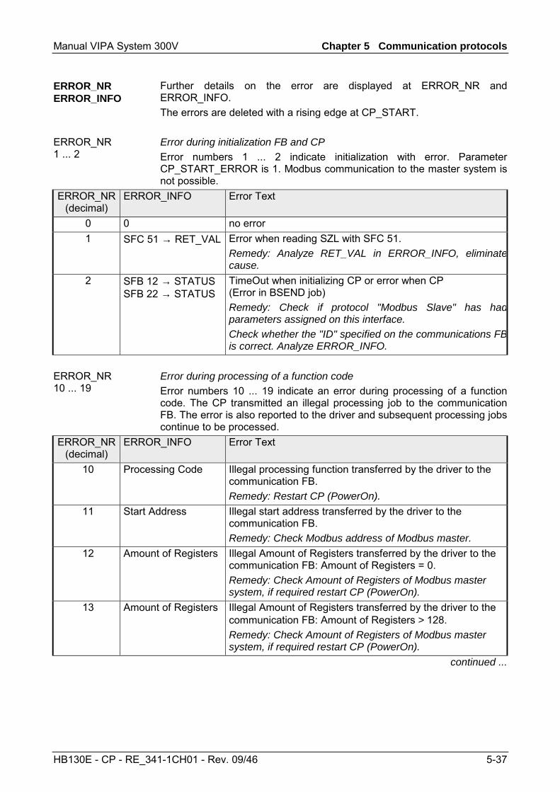
Manual VIPA System 300V Chapter 5 Communication protocols
HB130E - CP - RE_341-1CH01 - Rev. 09/46 5-37
Further details on the error are displayed at ERROR_NR and ERROR_INFO. The errors are deleted with a rising edge at CP_START. Error during initialization FB and CP Error numbers 1 ... 2 indicate initialization with error. Parameter CP_START_ERROR is 1. Modbus communication to the master system is not possible.
ERROR_NR (decimal)
ERROR_INFO Error Text
0 0 no error 1 SFC 51 → RET_VAL Error when reading SZL with SFC 51.
Remedy: Analyze RET_VAL in ERROR_INFO, eliminatecause.
2 SFB 12 → STATUS SFB 22 → STATUS
TimeOut when initializing CP or error when CP (Error in BSEND job) Remedy: Check if protocol "Modbus Slave" has hadparameters assigned on this interface. Check whether the "ID" specified on the communications FBis correct. Analyze ERROR_INFO.
Error during processing of a function code Error numbers 10 ... 19 indicate an error during processing of a function code. The CP transmitted an illegal processing job to the communication FB. The error is also reported to the driver and subsequent processing jobs continue to be processed.
ERROR_NR (decimal)
ERROR_INFO Error Text
10 Processing Code Illegal processing function transferred by the driver to the communication FB. Remedy: Restart CP (PowerOn).
11 Start Address Illegal start address transferred by the driver to the communication FB. Remedy: Check Modbus address of Modbus master.
12 Amount of Registers Illegal Amount of Registers transferred by the driver to the communication FB: Amount of Registers = 0. Remedy: Check Amount of Registers of Modbus master system, if required restart CP (PowerOn).
13 Amount of Registers Illegal Amount of Registers transferred by the driver to the communication FB: Amount of Registers > 128. Remedy: Check Amount of Registers of Modbus master system, if required restart CP (PowerOn).
continued ...
ERROR_NR ERROR_INFO
ERROR_NR 1 ... 2
ERROR_NR 10 ... 19
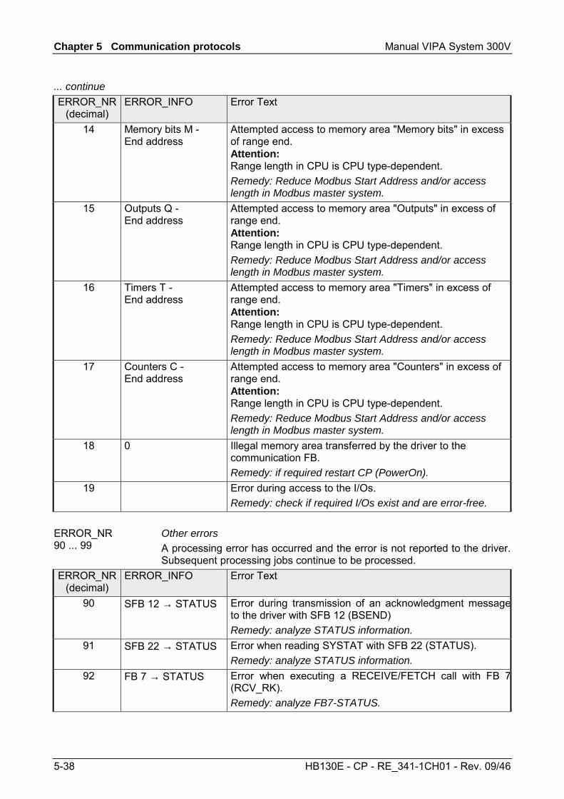
Chapter 5 Communication protocols Manual VIPA System 300V
5-38 HB130E - CP - RE_341-1CH01 - Rev. 09/46
... continue ERROR_NR
(decimal) ERROR_INFO Error Text
14 Memory bits M - End address
Attempted access to memory area "Memory bits" in excess of range end. Attention: Range length in CPU is CPU type-dependent. Remedy: Reduce Modbus Start Address and/or access length in Modbus master system.
15 Outputs Q - End address
Attempted access to memory area "Outputs" in excess of range end. Attention: Range length in CPU is CPU type-dependent. Remedy: Reduce Modbus Start Address and/or access length in Modbus master system.
16 Timers T - End address
Attempted access to memory area "Timers" in excess of range end. Attention: Range length in CPU is CPU type-dependent. Remedy: Reduce Modbus Start Address and/or access length in Modbus master system.
17 Counters C - End address
Attempted access to memory area "Counters" in excess of range end. Attention: Range length in CPU is CPU type-dependent. Remedy: Reduce Modbus Start Address and/or access length in Modbus master system.
18 0 Illegal memory area transferred by the driver to the communication FB. Remedy: if required restart CP (PowerOn).
19 Error during access to the I/Os. Remedy: check if required I/Os exist and are error-free.
Other errors A processing error has occurred and the error is not reported to the driver. Subsequent processing jobs continue to be processed.
ERROR_NR (decimal)
ERROR_INFO Error Text
90 SFB 12 → STATUS Error during transmission of an acknowledgment messageto the driver with SFB 12 (BSEND) Remedy: analyze STATUS information.
91 SFB 22 → STATUS Error when reading SYSTAT with SFB 22 (STATUS). Remedy: analyze STATUS information.
92 FB 7 → STATUS
Error when executing a RECEIVE/FETCH call with FB 7(RCV_RK). Remedy: analyze FB7-STATUS.
ERROR_NR 90 ... 99
Manual VIPA System 300V Chapter 5 Communication protocols
HB130E - CP - RE_341-1CH01 - Rev. 09/46 5-39
OB100 UN M 100.0 // set CP_START
S M 100.0 //
U M 100.1 // reset CP_START_FM
R M 100.1 //
OB1 Call FB 80 , DB80 // Modbus slave CP341 FB
LADDR :=256 // Basic address of CP
START_TIMER :=T120 // Timer startup
START_TIME :=S5T#5S // Time value startup
OB_MASK :=TRUE // Mask access errors
CP_START :=M100.0 // Initialization START
CP_START_FM :=M100.1 // Edge trigger flag
CP_NDR :=M100.2 // New write job CP
CP_START_OK :=M100.3 // Init. CP-FB without error
CP_START_ERROR :=M100.4 // Init. CP with error
CP_ERROR_NR :=MW102 // Error number
CP_ERROR_INFO :=MW104 // Error additional info
Data transfer between CPU and CP happens block-by-block by the function blocks FB 7 - P_RCV_RK and FB 8 - P_SND_RK. Here the block size is about 32byte. Data consistency is given only for a block size of 32byte. For larger amounts of data, the data is transferred in the listed block size with a time delay between each block. There is no consistency between these data blocks because the data may be processed by the user program at the same time. Access to the CPU memory area is carried out while the user program is running whenever the FB 7 - P_RCV_RK is passed. If data consistency is required when reading/writing registers or bits, the amount of data transferred by a single message must be limited to 32byte. For example a maximum of 16 registers with FC 03, 04, 16 or a maximum of 256bits with FC 01, 02, 15. Else you have to ensure the consistent processing of related data blocks by the user program.
Example program
Data consistency
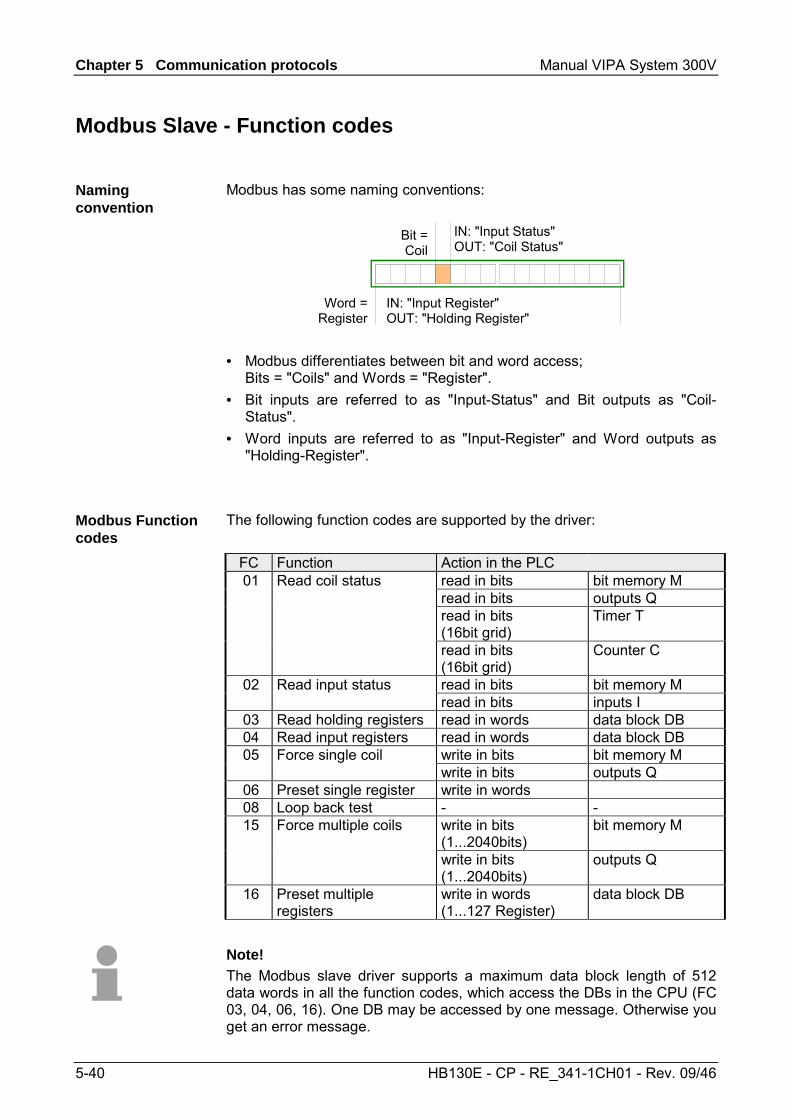
Chapter 5 Communication protocols Manual VIPA System 300V
5-40 HB130E - CP - RE_341-1CH01 - Rev. 09/46
Modbus Slave - Function codes
Modbus has some naming conventions:
Word =Register
IN: "Input Register"OUT: "Holding Register"
Bit =Coil
IN: "Input Status"OUT: "Coil Status"
• Modbus differentiates between bit and word access;
Bits = "Coils" and Words = "Register". • Bit inputs are referred to as "Input-Status" and Bit outputs as "Coil-
Status". • Word inputs are referred to as "Input-Register" and Word outputs as
"Holding-Register".
The following function codes are supported by the driver:
FC Function Action in the PLC 01 Read coil status read in bits bit memory M read in bits outputs Q read in bits
(16bit grid) Timer T
read in bits (16bit grid)
Counter C
02 Read input status read in bits bit memory M read in bits inputs I
03 Read holding registers read in words data block DB 04 Read input registers read in words data block DB 05 Force single coil write in bits bit memory M
write in bits outputs Q 06 Preset single register write in words 08 Loop back test - - 15 Force multiple coils write in bits
(1...2040bits) bit memory M
write in bits (1...2040bits)
outputs Q
16 Preset multiple registers
write in words (1...127 Register)
data block DB
Note! The Modbus slave driver supports a maximum data block length of 512 data words in all the function codes, which access the DBs in the CPU (FC 03, 04, 06, 16). One DB may be accessed by one message. Otherwise you get an error message.
Naming convention
Modbus Function codes

Manual VIPA System 300V Chapter 5 Communication protocols
HB130E - CP - RE_341-1CH01 - Rev. 09/46 5-41
This function serves to read individual bits of the output area of the CPU by the Modbus master.
Request message ADDR FUNC start_addr bit_number CRC
Reply message ADDR FUNC byte_count n n byte data CRC
The Modbus bit address start_addr contains the start of the area of the CPU, which is be accessed. The corresponding address allocation of the CPU memory area are established by the properties of "FC 01, 05, 15" in the parameterization of the CP. Here the "Modbus address in transmission message" briefly Param-start-address may be assigned to a "SIMATIC memory area" briefly PLC-area. Byte address = ((start_addr - Param-start-address) / 8) + PLC-area When accessing bit memories respectively outputs of the CPU, the remaining Rest-bit-number is calculated and used to address the relevant bit within the bit memory area respectively the output area. Rest-bit-number = (start_addr - Param-start-address) % 8 [Modulo 8] Word address = ((start_addr - Param-start-address) / 16) + PLC-area With the address calculation, it must be possible to divide the result start_addr - Param-start-address by 16 without having a left over value Word-by-word access may only start from word limit.
Values between 1 and 2040 are permitted as bit_number. This number of bits are read. When accessing timer and counters, it must be possible to divide the bit_number by 16. Maximally 16 timers and counters may be accessed.
FC 01 - Read Coil Status
start_addr
Conversion bit memories and outputs
Conversion counter and timer
bit_number
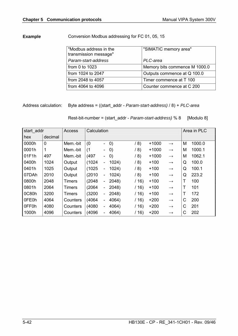
Chapter 5 Communication protocols Manual VIPA System 300V
5-42 HB130E - CP - RE_341-1CH01 - Rev. 09/46
Conversion Modbus addressing for FC 01, 05, 15 "Modbus address in the transmission message" Param-start-address
"SIMATIC memory area" PLC-area
from 0 to 1023 Memory bits commence M 1000.0 from 1024 to 2047 Outputs commence at Q 100.0 from 2048 to 4057 Timer commence at T 100 from 4064 to 4096 Counter commence at C 200 Byte address = ((start_addr - Param-start-address) / 8) + PLC-area Rest-bit-number = (start_addr - Param-start-address) % 8 [Modulo 8]
start_addr Access Calculation Area in PLC hex decimal 0000h 0 Mem.-bit (0 - 0) / 8) +1000 → M 1000.0 0001h 1 Mem.-bit (1 - 0) / 8) +1000 → M 1000.1 01F1h 497 Mem.-bit (497 - 0) / 8) +1000 → M 1062.1 0400h 1024 Output (1024 - 1024) / 8) +100 → Q 100.0 0401h 1025 Output (1025 - 1024) / 8) +100 → Q 100.1 07DAh 2010 Output (2010 - 1024) / 8) +100 → Q 223.2 0800h 2048 Timers (2048 - 2048) / 16) +100 → T 100 0801h 2064 Timers (2064 - 2048) / 16) +100 → T 101 0C80h 3200 Timers (3200 - 2048) / 16) +100 → T 172 0FE0h 4064 Counters (4064 - 4064) / 16) +200 → C 200 0FF0h 4080 Counters (4080 - 4064) / 16) +200 → C 201 1000h 4096 Counters (4096 - 4064) / 16) +200 → C 202
Example
Address calculation:
Manual VIPA System 300V Chapter 5 Communication protocols
HB130E - CP - RE_341-1CH01 - Rev. 09/46 5-43
This function enables the Modbus master to read individual bits from the input area of the CPU.
Request message ADDR FUNC start_addr bit_number CRC
Reply message ADDR FUNC byte_count n n byte data CRC
The Modbus bit address start_addr contains the start of the area of the CPU, which is be accessed. The corresponding address allocation of the CPU memory area is established by the properties of "FC 02" in the parameterization of the CP. Here the "Modbus address in transmission message" briefly Param-start-address may be assigned to a "SIMATIC memory area" briefly PLC-area. Byte address = ((start_addr - Param-start-address) / 8) + PLC-area When accessing bit memories respectively inputs of the CPU, the remaining Rest-bit-number is calculated and used to address the relevant bit within the bit memory area respectively the input area. Rest-bit-number = (start_addr - Param-start-address) % 8 [Modulo 8]
Values between 1 and 2040 are permitted as bit_number. This number of bits are read.
Conversion Modbus addressing for FC 02
"Modbus address in the transmission message" Param-start-address
"SIMATIC memory area" PLC-area
from 0 to 1023 Memory bits commence M 1000.0 from 1024 to 2047 Inputs commence at I 100.0
start_addr Access Calculation Area in PLC hex decimal 0000h 0 Mem.-bit (0 - 0) / 8) +1000 → M 1000.0 0001h 1 Mem.-bit (1 - 0) / 8) +1000 → M 1000.1 01F1h 497 Mem.-bit (497 - 0) / 8) +1000 → M 1062.1 0400h 1024 Input (1024 - 1024) / 8) +100 → I 100.0 0401h 1025 Input (1025 - 1024) / 8) +100 → I 100.1 07DAh 2010 Input (2010 - 1024) / 8) +100 → I 223.2
FC 02 - Read Input Status
start_addr
Calculation
bit_number
Example
Address calculation
Chapter 5 Communication protocols Manual VIPA System 300V
5-44 HB130E - CP - RE_341-1CH01 - Rev. 09/46
This function enables the Modbus master to read data words from a data block.
Request message ADDR FUNC start_register register_number CRC
Reply message ADDR FUNC byte_count n n/2-register data (High, Low) CRC
The Modbus register address start_register is interpreted by the driver as follows:
start_register 15 9 8 7 0
start_register-offset_DB_no. start_register-word_no. The DB of the CPU to be accessed, is defined by start_register. The corresponding address allocation of the CPU memory area are established by the properties of "FC 03, 06, 16" in the parameterization of the CP. Here the fixed "Modbus address in transmission message" 0 may be assigned to a Base-DB-Number in the "SIMATIC memory area". Data block DB = Base-DB-Number + start_register-offset_DB_no. Data word DBW = start_register-word_no. x 2 Providing the resulting DB and the corresponding DBW to be read from is known start_register may be calculated with the following formula: start_register = (DB - Base-DB-Number) x 512) + (DBW / 2) Please regard for DBW it is only allowed to use even numbered data word numbers.
Values between 1 and 127 are permitted as register_number. This number of registers are read. It is valid: Maximum register_number = 512 - start_register
FC 03 - Read Output Registers
start_register
Calculation
register_number
Manual VIPA System 300V Chapter 5 Communication protocols
HB130E - CP - RE_341-1CH01 - Rev. 09/46 5-45
Conversion Modbus addressing for FC 03, 06, 16 "Modbus address in the transmission message" Param-start-address
"SIMATIC memory area" PLC-area
from 0 Data blocks commence at DB 800 For e.g. start_register = 80 (0050h) the conversion takes place with the following approach:
start_register = 0050h 15 9 8 7 0
start_register-offset_DB_no. = 00h
start_register-word-no. = 50h
Data block DB = Base-DB-Number + start_register-offset_DB_no. Data block DB = 800 + 0 = 800 Data word DBW = start_register-word-no. x 2 Data word DBW = 80 x 2 = 160
start_register offset_ DB_no.
word_no. Base DB Number
DB DBW
hex decimal decimal hex decimal decimal decimal decimal 0000h 0 0 000h 0 800 800 0 01FAh 500 0 1F4h 500 800 800 1000 0384h 900 1 184h 388 800 801 776 03FFh 1023 1 1FFh 511 800 801 1022
This function is identical to FC 03. Here the data words of another data block may be accessed. The corresponding address allocation of the CPU memory area are established by the properties of "FC 04" in the parameterization of the CP. Here the fixed "Modbus address in transmission message" 0 may be assigned to a Base-DB-Number in the "SIMATIC memory area". For more information see FC 03.
Example
Conversion
Further values
FC 04 - Read Input Registers
Chapter 5 Communication protocols Manual VIPA System 300V
5-46 HB130E - CP - RE_341-1CH01 - Rev. 09/46
This function enables the Modbus master to set and erase individual bits in the output area of the CPU. Please consider as soon as you want to access an area by writing, you have to write enable the corresponding area by the protocol parameters with the dialog "Limits".
Request message ADDR FUNC coil_addr Data_on/off CRC
Reply message ADDR FUNC coil addr Data_on/off CRC
The Modbus bit address coil_addr contains the start of the area of the CPU, which is be accessed. The corresponding address allocation of the CPU memory area are established by the properties of "FC 01, 05, 15" in the parameterization of the CP. Here the "Modbus address in transmission message" briefly Param-start-address may be assigned to a "SIMATIC memory area" briefly PLC-area. Byte address = ((coil_addr - Param-start-address) / 8) + PLC-area When accessing bit memories respectively inputs of the CPU, the remaining Rest-bit-number is calculated and used to address the relevant bit within the bit memory area respectively the input area. Rest-bit-number = (coil_addr - Param-start-address) % 8 [Modulo 8] The following values are valid for Data_on/off: FF00h: set bit 0000h: erase bit
Conversion Modbus addressing for FC 01, 05, 15
"Modbus address in the transmission message" Param-start-address
"SIMATIC memory area" PLC-area
from 0 to 1023 Memory bits commence at M 1000.0from 1024 to 2047 Outputs commence at Q 100.0
start_addr Access Calculation Area in PLC hex decimal 0000h 0 Mem.-bit (0 - 0) / 8) +1000 → M 1000.0 0001h 1 Mem.-bit (1 - 0) / 8) +1000 → M 1000.1 01F1h 497 Mem.-bit (497 - 0) / 8) +1000 → M 1062.1 0400h 1024 Output (1024 - 1024) / 8) +100 → Q 100.0 0401h 1025 Output (1025 - 1024) / 8) +100 → Q 100.1 07DAh 2010 Output (2010 - 1024) / 8) +100 → Q 223.2
FC 05 - Force Single Coil
coil_addr
Calculation
Data_on/off
Example
Address calculation:
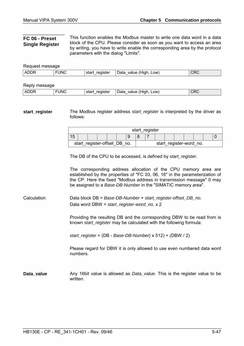
Manual VIPA System 300V Chapter 5 Communication protocols
HB130E - CP - RE_341-1CH01 - Rev. 09/46 5-47
This function enables the Modbus master to write one data word in a data block of the CPU. Please consider as soon as you want to access an area by writing, you have to write enable the corresponding area by the protocol parameters with the dialog "Limits".
Request message ADDR FUNC start_register Data_value (High, Low) CRC
Reply message ADDR FUNC start_register Data_value (High, Low) CRC
The Modbus register address start_register is interpreted by the driver as follows:
start_register 15 9 8 7 0
start_register-offset_DB_no. start_register-word_no. The DB of the CPU to be accessed, is defined by start_register. The corresponding address allocation of the CPU memory area are established by the properties of "FC 03, 06, 16" in the parameterization of the CP. Here the fixed "Modbus address in transmission message" 0 may be assigned to a Base-DB-Number in the "SIMATIC memory area". Data block DB = Base-DB-Number + start_register-offset_DB_no. Data word DBW = start_register-word_no. x 2 Providing the resulting DB and the corresponding DBW to be read from is known start_register may be calculated with the following formula: start_register = (DB - Base-DB-Number) x 512) + (DBW / 2) Please regard for DBW it is only allowed to use even numbered data word numbers.
Any 16bit value is allowed as Data_value. This is the register value to be written.
FC 06 - Preset Single Register
start_register
Calculation
Data_value
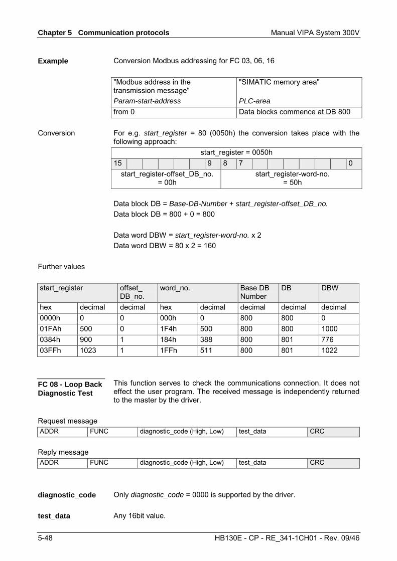
Chapter 5 Communication protocols Manual VIPA System 300V
5-48 HB130E - CP - RE_341-1CH01 - Rev. 09/46
Conversion Modbus addressing for FC 03, 06, 16 "Modbus address in the transmission message" Param-start-address
"SIMATIC memory area" PLC-area
from 0 Data blocks commence at DB 800 For e.g. start_register = 80 (0050h) the conversion takes place with the following approach:
start_register = 0050h 15 9 8 7 0
start_register-offset_DB_no. = 00h
start_register-word-no. = 50h
Data block DB = Base-DB-Number + start_register-offset_DB_no. Data block DB = 800 + 0 = 800 Data word DBW = start_register-word-no. x 2 Data word DBW = 80 x 2 = 160
start_register offset_ DB_no.
word_no. Base DB Number
DB DBW
hex decimal decimal hex decimal decimal decimal decimal 0000h 0 0 000h 0 800 800 0 01FAh 500 0 1F4h 500 800 800 1000 0384h 900 1 184h 388 800 801 776 03FFh 1023 1 1FFh 511 800 801 1022
This function serves to check the communications connection. It does not effect the user program. The received message is independently returned to the master by the driver.
Request message ADDR FUNC diagnostic_code (High, Low) test_data CRC
Reply message ADDR FUNC diagnostic_code (High, Low) test_data CRC
Only diagnostic_code = 0000 is supported by the driver. Any 16bit value.
Example
Conversion
Further values
FC 08 - Loop Back Diagnostic Test
diagnostic_code
test_data
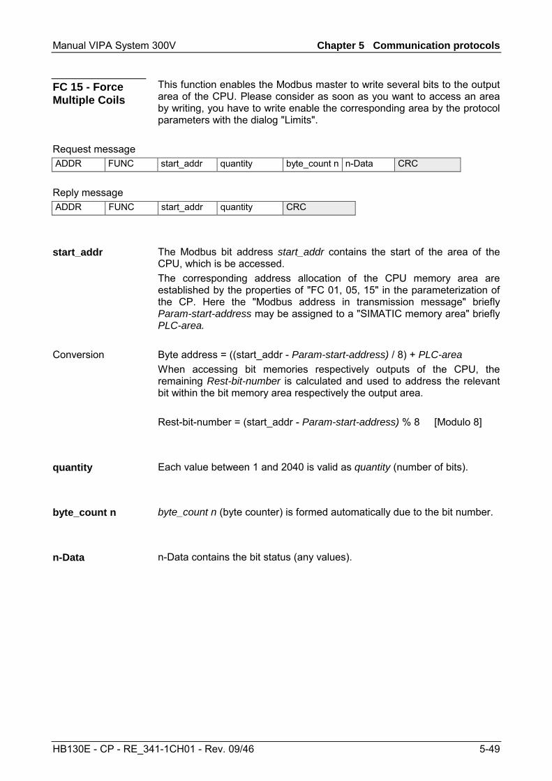
Manual VIPA System 300V Chapter 5 Communication protocols
HB130E - CP - RE_341-1CH01 - Rev. 09/46 5-49
This function enables the Modbus master to write several bits to the output area of the CPU. Please consider as soon as you want to access an area by writing, you have to write enable the corresponding area by the protocol parameters with the dialog "Limits".
Request message ADDR FUNC start_addr quantity byte_count n n-Data CRC
Reply message ADDR FUNC start_addr quantity CRC
The Modbus bit address start_addr contains the start of the area of the CPU, which is be accessed. The corresponding address allocation of the CPU memory area are established by the properties of "FC 01, 05, 15" in the parameterization of the CP. Here the "Modbus address in transmission message" briefly Param-start-address may be assigned to a "SIMATIC memory area" briefly PLC-area. Byte address = ((start_addr - Param-start-address) / 8) + PLC-area When accessing bit memories respectively outputs of the CPU, the remaining Rest-bit-number is calculated and used to address the relevant bit within the bit memory area respectively the output area. Rest-bit-number = (start_addr - Param-start-address) % 8 [Modulo 8]
Each value between 1 and 2040 is valid as quantity (number of bits).
byte_count n (byte counter) is formed automatically due to the bit number.
n-Data contains the bit status (any values).
FC 15 - Force Multiple Coils
start_addr
Conversion
quantity
byte_count n
n-Data
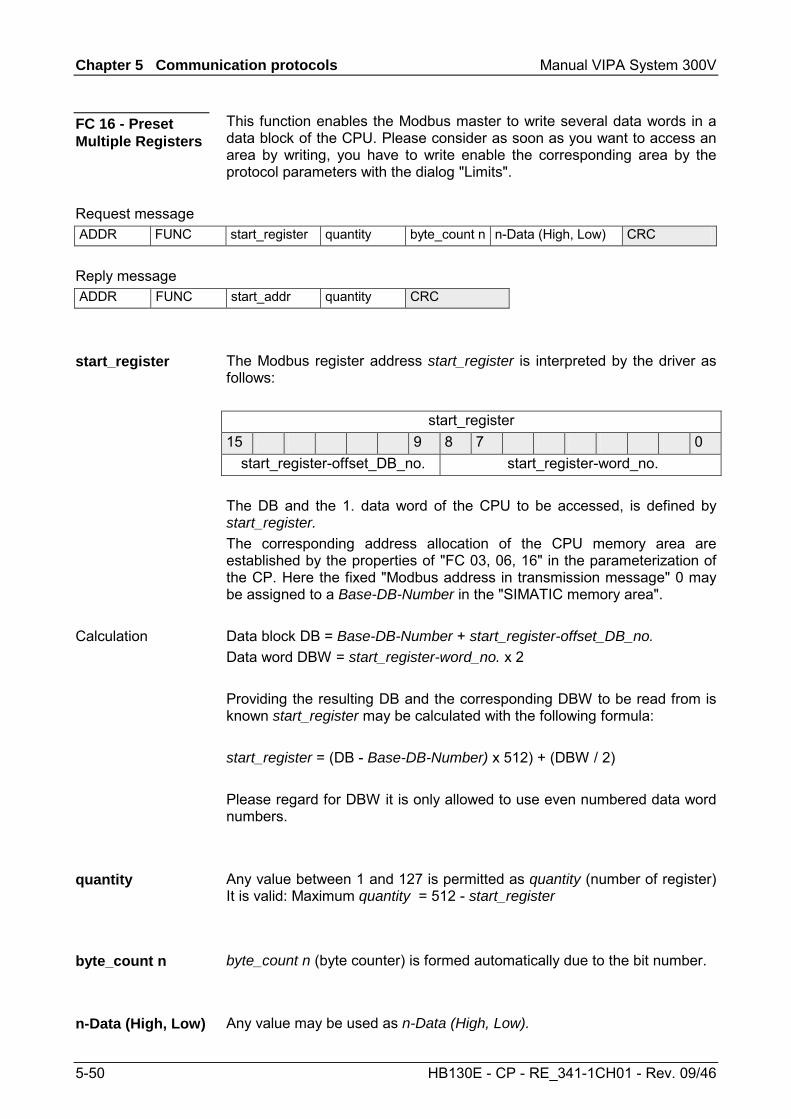
Chapter 5 Communication protocols Manual VIPA System 300V
5-50 HB130E - CP - RE_341-1CH01 - Rev. 09/46
This function enables the Modbus master to write several data words in a data block of the CPU. Please consider as soon as you want to access an area by writing, you have to write enable the corresponding area by the protocol parameters with the dialog "Limits".
Request message ADDR FUNC start_register quantity byte_count n n-Data (High, Low) CRC
Reply message ADDR FUNC start_addr quantity CRC
The Modbus register address start_register is interpreted by the driver as follows:
start_register 15 9 8 7 0
start_register-offset_DB_no. start_register-word_no. The DB and the 1. data word of the CPU to be accessed, is defined by start_register. The corresponding address allocation of the CPU memory area are established by the properties of "FC 03, 06, 16" in the parameterization of the CP. Here the fixed "Modbus address in transmission message" 0 may be assigned to a Base-DB-Number in the "SIMATIC memory area". Data block DB = Base-DB-Number + start_register-offset_DB_no. Data word DBW = start_register-word_no. x 2 Providing the resulting DB and the corresponding DBW to be read from is known start_register may be calculated with the following formula: start_register = (DB - Base-DB-Number) x 512) + (DBW / 2) Please regard for DBW it is only allowed to use even numbered data word numbers.
Any value between 1 and 127 is permitted as quantity (number of register) It is valid: Maximum quantity = 512 - start_register
byte_count n (byte counter) is formed automatically due to the bit number.
Any value may be used as n-Data (High, Low).
FC 16 - Preset Multiple Registers
start_register
Calculation
quantity
byte_count n
n-Data (High, Low)
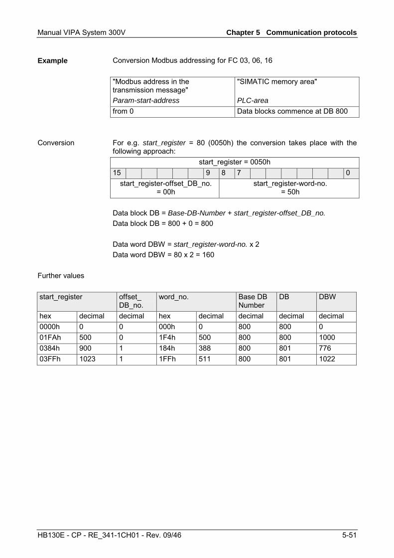
Manual VIPA System 300V Chapter 5 Communication protocols
HB130E - CP - RE_341-1CH01 - Rev. 09/46 5-51
Conversion Modbus addressing for FC 03, 06, 16 "Modbus address in the transmission message" Param-start-address
"SIMATIC memory area" PLC-area
from 0 Data blocks commence at DB 800 For e.g. start_register = 80 (0050h) the conversion takes place with the following approach:
start_register = 0050h 15 9 8 7 0
start_register-offset_DB_no. = 00h
start_register-word-no. = 50h
Data block DB = Base-DB-Number + start_register-offset_DB_no. Data block DB = 800 + 0 = 800 Data word DBW = start_register-word-no. x 2 Data word DBW = 80 x 2 = 160
start_register offset_ DB_no.
word_no. Base DB Number
DB DBW
hex decimal decimal hex decimal decimal decimal decimal 0000h 0 0 000h 0 800 800 0 01FAh 500 0 1F4h 500 800 800 1000 0384h 900 1 184h 388 800 801 776 03FFh 1023 1 1FFh 511 800 801 1022
Example
Conversion
Further values
Chapter 5 Communication protocols Manual VIPA System 300V
5-52 HB130E - CP - RE_341-1CH01 - Rev. 09/46
Manual VIPA System 300V Chapter 6 Diagnostics and error behavior
HB130E - CP - RE_341-1CH01 - Rev. 09/46 6-1
Chapter 6 Diagnostics and error behavior
With the CP 341 a diagnostic interrupt entry may be released at the corresponding CPU. In this chapter the possibilities of diagnostics and the error behavior of the CP at deployment of the various protocols is more described.
Topic Seite Chapter 6 Diagnostics and error behavior ..................................... 6-1
Diagnostics functions overview............................................................. 6-2 Diagnostics via FB-STATUS ................................................................ 6-3 Diagnostics via diagnostic buffer ........................................................ 6-14 Diagnostics by diagnostics interrupt ................................................... 6-15
Overview
Content
Chapter 6 Diagnostics and error behavior Manual VIPA System 300V
6-2 HB130E - CP - RE_341-1CH01 - Rev. 09/46
Diagnostics functions overview
The diagnostics functions enable you to quickly localize any errors, which occur. The following diagnostics options are available: • Diagnostics via the CP-LEDs • Diagnostics via FB-STATUS (function blocks) • Diagnostics via diagnostic buffer of the CP • Diagnostics via diagnostics interrupt
The CP-LEDs give you an initial overview of any internal or external errors as well as interface-specific errors. More information about the LEDs and their function may be found at "Components" of the chapter "Hardware description" and at "Firmware update".
The FB 7 - P_RCV_RK and FB 8 - P_SND_RK function blocks have a STATUS parameter for error diagnostics. Reading the STATUS output gives you information on errors, which have occurred during communication. The STATUS output may be evaluated by the user program. The diagnostics events on STATUS are also entered in the diagnostics buffer of the CP.
Every CP error is entered in the diagnostic buffer of the CP. In the same way as with the diagnostic buffer of the CPU, you can also use the PLC functions to display the information of the CP diagnostic buffer.
Note! An error message is only output if the ERROR bit (request completed with error) is set. In all other cases the STATUS word is zero.
The CP can trigger a diagnostic interrupt on the CPU assigned to it. The CP provides 4bytes of diagnostic information for the CPU. These data may be accessed by reading the diagnostics buffer of the CP respectively by reacting with OB 82 on the diagnostics. The diagnostics were also entered in the diagnostics buffer of the CP. When a diagnostic interrupt event occurs, the red SF LED lights up.
Overview
Diagnosis via the CP-LEDs
Diagnosis via STATUS of FBs
Diagnosis via diagnostic buffer of the CP
Diagnostics via diagnostic interrupt
Manual VIPA System 300V Chapter 6 Diagnostics and error behavior
HB130E - CP - RE_341-1CH01 - Rev. 09/46 6-3
Diagnostics via FB-STATUS
Each function block FB 7 - P_RCV_RK and FB 8 - P_SND_RK has a STATUS parameter for error diagnostics. The STATUS message always has the same meaning, irrespective of which function block is used. The STATUS word has the following structure:
15 ... 13 12 ... 8 7 ... 0Bit
reserved Event class Event number(Error number)
STATUS
The table below describes the various event classes and numbers:
Event class 00h "CP start-up" Event class / number Description
00 03h PtP parameter accepted 00 04h Parameter already on CP (timers match) 00 07h Status transition CPU to STOP 00 08h Status transition CPU to RUN/START-UP
Event class 01h "Hardware fault on CP" 01 01h Fault while testing operating system EPROM of CP
Remedy: CP defective and must be replaced. 01 02h RAM test of CP faulty
Remedy: CP defective and must be replaced. 01 03h Request interface of CP defective
Remedy: CP defective and must be replaced. 01 10h Fault in CP firmware
Remedy: Switch CP off and on again. If necessary, replace CP. Event class 02h "Initialization error"
02 0Fh Invalid parameterization detected at start of parameterized communication. Interface could not be parameterized. Please regard RK512 is not supported by the VIPA CP. This error message is displayed as soon as RK512 is parameterized. Remedy: Do not parameterize RK512. Correct the non-permissible parameterization and initialize a start-up.
continue ...
Overview
Event classes and numbers
Chapter 6 Diagnostics and error behavior Manual VIPA System 300V
6-4 HB130E - CP - RE_341-1CH01 - Rev. 09/46
... continued Event class 03h "Error parameterization of FBs" (not displayed in diagnostic buffer)
Event class / number Description 03 01h Invalid or no source/destination data type
Invalid area (start address, length) DB invalid or no DB (e.g. DB 0) or other data type invalid or missing. Remedy: Check parameterization on CPU and CP and correct if necessary.
Event class 04h "CP detected error in data traffic CP - CPU" 04 03h Incorrect, unknown or illegal data type
(e.g. wrong parameterization of FB) Remedy: Check program for incorrect parameterization of the FB.
04 07h Error during data transmission between CPU and CP. Remedy: If fault indication persists, check whether function blocks you have called in user program are parameterized correctly. If error is indicated immediately after PowerON, no connection has yet been set up to the CPU. In the case of ASCII driver and 3964(R), the receiving CP re-attempts data transfer until the data is transmitted to the CPU. If fault indication is sporadic in the course of data transfer, the CPU is temporarily unable to accept data. In the case of the ASCII driver and 3964(R) the receiving CP re-attempts data transfer until the data is transmitted to the CPU.
04 08h Error during data transmission between CPU and CP (reception). • CPU is temporarily overloaded, request queued for repetition. Remedy: Reduce number of communication calls • CPU data area temporarily unavailable for access, for example
because receive block is called too infrequently. Remedy: Call the receive block more frequently. • CPU data area temporarily unavailable for access, for example
because receive block is temporarily locked (EN = false). Remedy: Check whether the receive block is disabled for too long.
continue ...
Manual VIPA System 300V Chapter 6 Diagnostics and error behavior
HB130E - CP - RE_341-1CH01 - Rev. 09/46 6-5
... continued ... Event class 04h "CP detected error in data traffic CP - CPU"
Event class / number Description 04 09h Data cannot be received. Error during data transmission between CPU
and CP (reception). Request is canceled in 10s following multiple attempts, because: • Receive block is not called
Remedy: Check whether your user program runs the receive block. • Receive block is disabled
Remedy: Check whether the receive block is disabled. • Access to CPU data area denied
Remedy: check that the data area to which the data is to be transferred is available.
• CPU data area too short. Remedy: Check the length of the data area.
04 0Ah Error during data transmission between CPU and CP. Data transfer canceled by RESET because: • Destination DB is not available • Destination DB is too short • RESET bit set at FB. Remedy: Create destination DB in the user program or increase the length of the existing destination DB, as applicable.
Event class 05h "error while processing CPU request" 05 01h Current request aborted as a result of CP restart.
Remedy: No remedy is possible at PowerON. When re-parameteriza-tion of the CP from the programming device, before writing an interface you should ensure there are no more request running from the CPU.
05 02h Request not permitted in this operating mode of CP (e.g. device interface not parameterized). Remedy: Parameterize the device interface.
05 14h Specified start addresses too high for desired data type, or start address or DB/DX number too low. Remedy: Obtain from the request tables the permissible start addresses and DB/DX numbers that can be specified in the program.
05 17h Transmission length > 1kbyte too great for CP or too short for interface parameter. Remedy: Split the request up into several shorter requests.
05 18h with Modbus Master only Transmission length during transmission is too large (> 4kBytes) or transmission length for Send is too small. Remedy: Check the parameter LEN for SEND.
continue ...
Chapter 6 Diagnostics and error behavior Manual VIPA System 300V
6-6 HB130E - CP - RE_341-1CH01 - Rev. 09/46
... continued Event class 07h "Send error"
Event class / number Description 07 01h Transmission of the first repetition:
• An error was detected during transmission of the message frame • The partner requested a repetition by means of a negative
acknowledgment code (NAK) Remedy: A repetition is not an error, but it can be an indication that there are disturbances on the transmission line or that the partner device is behaving incorrectly. If the message frame still has not been transmitted after the maximum number of repetitions, an error number describing the first error that occurred is output.
07 02h with 3964(R) only Error during connection setup: after STX was send, NAK or any other code (except for DLE or STX) was received. Remedy: Check for malfunction at partner device, possible by using interface test device switched into the transmission line.
07 03h with 3964(R) only Acknowledgment delay time (ADT) exceeded: after STX was sent, no response came from partner within acknowledgement delay time. Remedy: Partner device is too slow or not ready to receive, or there is a break on the send line, for example. Check for malfunction at partner device, possible by using interface test device switched into the transmission line.
07 04h with 3964(R) only Termination by partner: during current send operation, one or more characters were received by partner. Remedy: Check whether the partner is also showing an error, possible because not all transmission data has arrived (e.g. due to break on line) or due to serious fault or because the partner device has malfunctioned. If necessary, use an interface test device switched into the transmission line for this purpose.
07 06h with 3964(R) only Error at end of connection: • Partner rejected message frame at end of connection with NAK or a
random string (except for DLE). • Acknowledgment code (DLE) received to early. Remedy: Check whether the partner is also showing an error, possible because not all transmission data has arrived (e.g. due to break on line) or due to serious faults or because the partner device has malfunctioned. If necessary, use an interface test device switched into the transmission line for this purpose.
continue ...
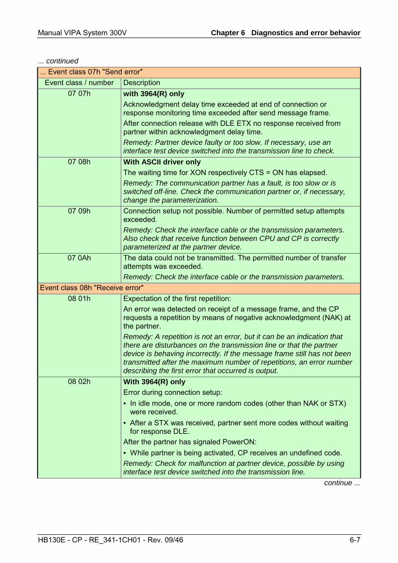
Manual VIPA System 300V Chapter 6 Diagnostics and error behavior
HB130E - CP - RE_341-1CH01 - Rev. 09/46 6-7
... continued ... Event class 07h "Send error"
Event class / number Description 07 07h with 3964(R) only
Acknowledgment delay time exceeded at end of connection or response monitoring time exceeded after send message frame. After connection release with DLE ETX no response received from partner within acknowledgment delay time. Remedy: Partner device faulty or too slow. If necessary, use an interface test device switched into the transmission line to check.
07 08h With ASCII driver only The waiting time for XON respectively CTS = ON has elapsed. Remedy: The communication partner has a fault, is too slow or is switched off-line. Check the communication partner or, if necessary, change the parameterization.
07 09h Connection setup not possible. Number of permitted setup attempts exceeded. Remedy: Check the interface cable or the transmission parameters. Also check that receive function between CPU and CP is correctly parameterized at the partner device.
07 0Ah The data could not be transmitted. The permitted number of transfer attempts was exceeded. Remedy: Check the interface cable or the transmission parameters.
Event class 08h "Receive error" 08 01h Expectation of the first repetition:
An error was detected on receipt of a message frame, and the CP requests a repetition by means of negative acknowledgment (NAK) at the partner. Remedy: A repetition is not an error, but it can be an indication that there are disturbances on the transmission line or that the partner device is behaving incorrectly. If the message frame still has not been transmitted after the maximum number of repetitions, an error number describing the first error that occurred is output.
08 02h With 3964(R) only Error during connection setup: • In idle mode, one or more random codes (other than NAK or STX)
were received. • After a STX was received, partner sent more codes without waiting
for response DLE. After the partner has signaled PowerON: • While partner is being activated, CP receives an undefined code. Remedy: Check for malfunction at partner device, possible by using interface test device switched into the transmission line.
continue ...
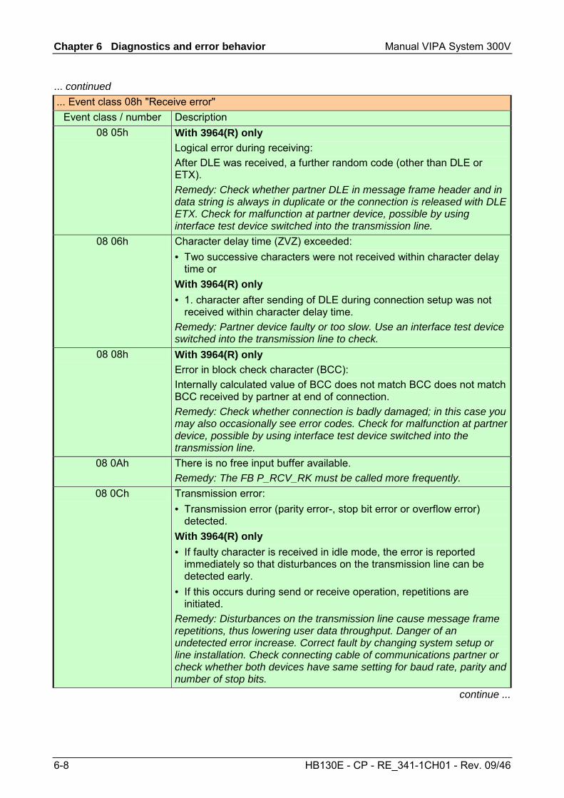
Chapter 6 Diagnostics and error behavior Manual VIPA System 300V
6-8 HB130E - CP - RE_341-1CH01 - Rev. 09/46
... continued ... Event class 08h "Receive error"
Event class / number Description 08 05h With 3964(R) only
Logical error during receiving: After DLE was received, a further random code (other than DLE or ETX). Remedy: Check whether partner DLE in message frame header and in data string is always in duplicate or the connection is released with DLE ETX. Check for malfunction at partner device, possible by using interface test device switched into the transmission line.
08 06h Character delay time (ZVZ) exceeded: • Two successive characters were not received within character delay
time or With 3964(R) only • 1. character after sending of DLE during connection setup was not
received within character delay time. Remedy: Partner device faulty or too slow. Use an interface test device switched into the transmission line to check.
08 08h With 3964(R) only Error in block check character (BCC): Internally calculated value of BCC does not match BCC does not match BCC received by partner at end of connection. Remedy: Check whether connection is badly damaged; in this case you may also occasionally see error codes. Check for malfunction at partner device, possible by using interface test device switched into the transmission line.
08 0Ah There is no free input buffer available. Remedy: The FB P_RCV_RK must be called more frequently.
08 0Ch Transmission error: • Transmission error (parity error-, stop bit error or overflow error)
detected. With 3964(R) only • If faulty character is received in idle mode, the error is reported
immediately so that disturbances on the transmission line can be detected early.
• If this occurs during send or receive operation, repetitions are initiated.
Remedy: Disturbances on the transmission line cause message frame repetitions, thus lowering user data throughput. Danger of an undetected error increase. Correct fault by changing system setup or line installation. Check connecting cable of communications partner or check whether both devices have same setting for baud rate, parity and number of stop bits.
continue ...
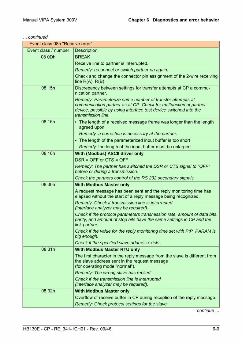
Manual VIPA System 300V Chapter 6 Diagnostics and error behavior
HB130E - CP - RE_341-1CH01 - Rev. 09/46 6-9
... continued ... Event class 08h "Receive error"
Event class / number Description 08 0Dh BREAK
Receive line to partner is interrupted. Remedy: reconnect or switch partner on again. Check and change the connector pin assignment of the 2-wire receiving line R(A), R(B).
08 15h Discrepancy between settings for transfer attempts at CP a commu-nication partner. Remedy: Parameterize same number of transfer attempts at communication partner as at CP. Check for malfunction at partner device, possible by using interface test device switched into the transmission line.
08 16h • The length of a received message frame was longer than the length agreed upon.
Remedy: a correction is necessary at the partner. • The length of the parameterized input buffer is too short Remedy: the length of the input buffer must be enlarged
08 18h With (Modbus) ASCII driver only DSR = OFF or CTS = OFF Remedy: The partner has switched the DSR or CTS signal to "OFF" before or during a transmission. Check the partners control of the RS 232 secondary signals.
08 30h With Modbus Master only A request message has been sent and the reply monitoring time has elapsed without the start of a reply message being recognized. Remedy: Check if transmission line is interrupted (interface analyzer may be required). Check if the protocol parameters transmission rate, amount of data bits, parity, and amount of stop bits have the same settings in CP and the link partner. Check if the value for the reply monitoring time set with PtP_PARAM is big enough. Check if the specified slave address exists.
08 31h With Modbus Master RTU only The first character in the reply message from the slave is different from the slave address sent in the request message (for operating mode "normal"). Remedy: The wrong slave has replied. Check if the transmission line is interrupted (interface analyzer may be required).
08 32h With Modbus Master only Overflow of receive buffer in CP during reception of the reply message. Remedy: Check protocol settings for the slave.
continue ...
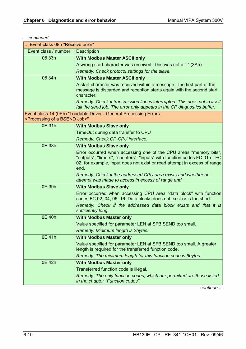
Chapter 6 Diagnostics and error behavior Manual VIPA System 300V
6-10 HB130E - CP - RE_341-1CH01 - Rev. 09/46
... continued ... Event class 08h "Receive error"
Event class / number Description 08 33h With Modbus Master ASCII only
A wrong start character was received. This was not a ":" (3Ah) Remedy: Check protocol settings for the slave.
08 34h With Modbus Master ASCII only A start character was received within a message. The first part of the message is discarded and reception starts again with the second start character. Remedy: Check if transmission line is interrupted. This does not in itself fail the send job. The error only appears in the CP diagnostics buffer.
Event class 14 (0Eh) "Loadable Driver - General Processing Errors <Processing of a BSEND Job>"
0E 31h With Modbus Slave only TimeOut during data transfer to CPU Remedy: Check CP-CPU interface.
0E 38h With Modbus Slave only Error occurred when accessing one of the CPU areas "memory bits", "outputs", "timers", "counters", "inputs" with function codes FC 01 or FC 02: for example, input does not exist or read attempt in excess of range end. Remedy: Check if the addressed CPU area exists and whether an attempt was made to access in excess of range end.
0E 39h With Modbus Slave only Error occurred when accessing CPU area "data block" with function codes FC 02, 04, 06, 16: Data blocks does not exist or is too short. Remedy: Check if the addressed data block exists and that it is sufficiently long.
0E 40h With Modbus Master only Value specified for parameter LEN at SFB SEND too small. Remedy: Minimum length is 2bytes.
0E 41h With Modbus Master only Value specified for parameter LEN at SFB SEND too small. A greater length is required for the transferred function code. Remedy: The minimum length for this function code is 6bytes.
0E 42h With Modbus Master only Transferred function code is illegal. Remedy: The only function codes, which are permitted are those listed in the chapter "Function codes".
continue ...
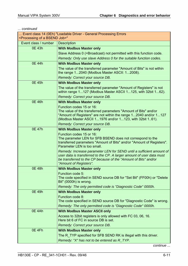
Manual VIPA System 300V Chapter 6 Diagnostics and error behavior
HB130E - CP - RE_341-1CH01 - Rev. 09/46 6-11
... continued ... Event class 14 (0Eh) "Loadable Driver - General Processing Errors <Processing of a BSEND Job>"
Event class / number Description 0E 43h With Modbus Master only
Slave Address 0 (=Broadcast) not permitted with this function code. Remedy: Only use slave Address 0 for the suitable function codes.
0E 44h With Modbus Master only The value of the transferred parameter "Amount of Bits" is not within the range 1...2040 (Modbus Master ASCII: 1...2008). Remedy: Correct your source DB.
0E 45h With Modbus Master only The value of the transferred parameter "Amount of Registers" is not within range 1...127 (Modbus Master ASCII 1...125, with 32bit 1...62). Remedy: Correct your source DB.
0E 46h With Modbus Master only Function codes 15 or 16: The value of the transferred parameters "Amount of Bits" and/or "Amount of Registers" are not within the range 1...2040 and/or 1...127 (Modbus Master ASCII 1...1976 and/or 1...123, with 32bit 1..61). Remedy: Correct your source DB.
0E 47h With Modbus Master only Function codes 15 or 16: The parameter LEN for SFB BSEND does not correspond to the transferred parameters "Amount of Bits" and/or "Amount of Registers". Parameter LEN is too small. Remedy: Increase parameter LEN for SEND until a sufficient amount of user data is transferred to the CP. A larger amount of user data must be transferred to the CP because of the "Amount of Bits" and/or "Amount of Registers".
0E 48h With Modbus Master only Function code 5: The code specified in SEND source DB for "Set Bit" (FF00h) or "Delete Bit" (0000h) is wrong. Remedy: The only permitted code is "Diagnostic Code" 0000h.
0E 49h With Modbus Master only Function code 8: The code specified in SEND source DB for "Diagnostic Code" is wrong.Remedy: The only permitted code is "Diagnostic Code" 0000h.
0E 4Ah With Modbus Master ASCII only Access to 32bit registers is only allowed with FC 03, 06, 16. Here bit 6 of FC in source DB is set. Remedy: Correct your source DB.
0E 4Fh With Modbus Master only The R_TYP specified for SFB SEND RK is illegal with this driver. Remedy: "X" has not to be entered as R_TYP.
continue ...
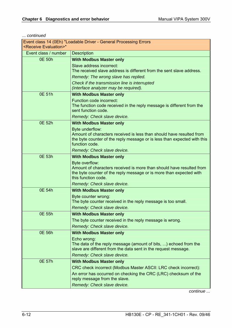
Chapter 6 Diagnostics and error behavior Manual VIPA System 300V
6-12 HB130E - CP - RE_341-1CH01 - Rev. 09/46
... continued Event class 14 (0Eh) "Loadable Driver - General Processing Errors <Receive Evaluation>"
Event class / number Description 0E 50h With Modbus Master only
Slave address incorrect: The received slave address is different from the sent slave address. Remedy: The wrong slave has replied. Check if the transmission line is interrupted (interface analyzer may be required).
0E 51h With Modbus Master only Function code incorrect: The function code received in the reply message is different from the sent function code. Remedy: Check slave device.
0E 52h With Modbus Master only Byte underflow: Amount of characters received is less than should have resulted from the byte counter of the reply message or is less than expected with this function code. Remedy: Check slave device.
0E 53h With Modbus Master only Byte overflow: Amount of characters received is more than should have resulted from the byte counter of the reply message or is more than expected with this function code. Remedy: Check slave device.
0E 54h With Modbus Master only Byte counter wrong: The byte counter received in the reply message is too small. Remedy: Check slave device.
0E 55h With Modbus Master only The byte counter received in the reply message is wrong. Remedy: Check slave device.
0E 56h With Modbus Master only Echo wrong: The data of the reply message (amount of bits, ...) echoed from the slave are different from the data sent in the request message. Remedy: Check slave device.
0E 57h With Modbus Master only CRC check incorrect (Modbus Master ASCII: LRC check incorrect): An error has occurred on checking the CRC (LRC) checksum of the reply message from the slave. Remedy: Check slave device.
continue ...
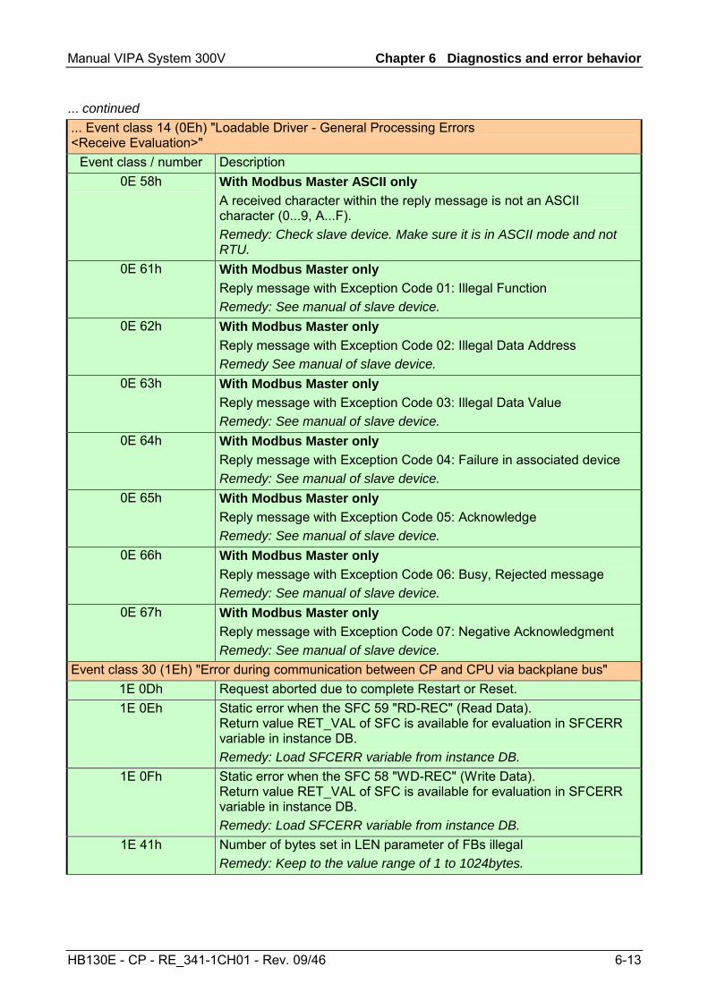
Manual VIPA System 300V Chapter 6 Diagnostics and error behavior
HB130E - CP - RE_341-1CH01 - Rev. 09/46 6-13
... continued ... Event class 14 (0Eh) "Loadable Driver - General Processing Errors <Receive Evaluation>"
Event class / number Description 0E 58h With Modbus Master ASCII only
A received character within the reply message is not an ASCII character (0...9, A...F). Remedy: Check slave device. Make sure it is in ASCII mode and not RTU.
0E 61h With Modbus Master only Reply message with Exception Code 01: Illegal Function Remedy: See manual of slave device.
0E 62h With Modbus Master only Reply message with Exception Code 02: Illegal Data Address Remedy See manual of slave device.
0E 63h With Modbus Master only Reply message with Exception Code 03: Illegal Data Value Remedy: See manual of slave device.
0E 64h With Modbus Master only Reply message with Exception Code 04: Failure in associated device Remedy: See manual of slave device.
0E 65h With Modbus Master only Reply message with Exception Code 05: Acknowledge Remedy: See manual of slave device.
0E 66h With Modbus Master only Reply message with Exception Code 06: Busy, Rejected message Remedy: See manual of slave device.
0E 67h With Modbus Master only Reply message with Exception Code 07: Negative Acknowledgment Remedy: See manual of slave device.
Event class 30 (1Eh) "Error during communication between CP and CPU via backplane bus" 1E 0Dh Request aborted due to complete Restart or Reset. 1E 0Eh Static error when the SFC 59 "RD-REC" (Read Data).
Return value RET_VAL of SFC is available for evaluation in SFCERR variable in instance DB. Remedy: Load SFCERR variable from instance DB.
1E 0Fh Static error when the SFC 58 "WD-REC" (Write Data). Return value RET_VAL of SFC is available for evaluation in SFCERR variable in instance DB. Remedy: Load SFCERR variable from instance DB.
1E 41h Number of bytes set in LEN parameter of FBs illegal Remedy: Keep to the value range of 1 to 1024bytes.
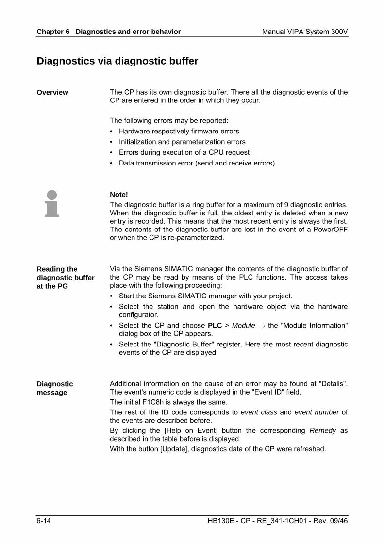
Chapter 6 Diagnostics and error behavior Manual VIPA System 300V
6-14 HB130E - CP - RE_341-1CH01 - Rev. 09/46
Diagnostics via diagnostic buffer
The CP has its own diagnostic buffer. There all the diagnostic events of the CP are entered in the order in which they occur. The following errors may be reported: • Hardware respectively firmware errors • Initialization and parameterization errors • Errors during execution of a CPU request • Data transmission error (send and receive errors)
Note! The diagnostic buffer is a ring buffer for a maximum of 9 diagnostic entries. When the diagnostic buffer is full, the oldest entry is deleted when a new entry is recorded. This means that the most recent entry is always the first. The contents of the diagnostic buffer are lost in the event of a PowerOFF or when the CP is re-parameterized.
Via the Siemens SIMATIC manager the contents of the diagnostic buffer of the CP may be read by means of the PLC functions. The access takes place with the following proceeding: • Start the Siemens SIMATIC manager with your project. • Select the station and open the hardware object via the hardware
configurator. • Select the CP and choose PLC > Module → the "Module Information"
dialog box of the CP appears. • Select the "Diagnostic Buffer" register. Here the most recent diagnostic
events of the CP are displayed.
Additional information on the cause of an error may be found at "Details". The event's numeric code is displayed in the "Event ID" field. The initial F1C8h is always the same. The rest of the ID code corresponds to event class and event number of the events are described before. By clicking the [Help on Event] button the corresponding Remedy as described in the table before is displayed. With the button [Update], diagnostics data of the CP were refreshed.
Overview
Reading the diagnostic buffer at the PG
Diagnostic message
Manual VIPA System 300V Chapter 6 Diagnostics and error behavior
HB130E - CP - RE_341-1CH01 - Rev. 09/46 6-15
Diagnostics by diagnostics interrupt
The CP can trigger a diagnostics alarm on the assign CPU, thus indicating a malfunction of the CP. You can specify at parameterization whether the CP is to trigger a diagnostics interrupt or not in the event of an error. As default Diagnostics interrupt is deactivated. At an activated interrupt the following events may release a diagnostics interrupt: • Wire break at RxD line • Error in parameterization
In the event of an error the CP provides diagnostics data on the backplane bus. These were read by the CPU and entered to its diagnostics buffer. At any time the CPU diagnostics buffer may be read with the PC by means of the PLC functions. When a diagnostics interrupt occurs, the SF LED lights up and the OB 82 is called.
As soon as an error occurs the OB 82 is called with the diagnostics data as start-up information. Here you have the possibility to react on the diagnostics by means of a corresponding programming. If there is no OB 82 inside the CPU, the CPU automatically changes to STOP mode.
The CP provides 4byte of diagnostics information. Depending on the event the 4byte are used as follows: Event Byte 0 Byte 1 Byte 2 Byte 3 Wire break at RxD 25h 0Ch 02h 00h Parameterization error 83h 0Ch 00h 00h
Overview
Diagnostics interrupt
OB 82
Diagnostics information
Chapter 6 Diagnostics and error behavior Manual VIPA System 300V
6-16 HB130E - CP - RE_341-1CH01 - Rev. 09/46
Manual VIPA System 300V Index
HB130E - CP - RE_341-1CH01 - Rev. 09/46 A-1
Appendix
A Index
3 3964(R)........................................... 5-8
Parameters ............................. 5-10
A ASCII .............................................. 5-3
Parameters ............................... 5-4 Assembly ........................................ 2-1
B Basics ............................................. 1-1
C Communication protocols .............. 5-1
3964(R)..................................... 5-8 ASCII ........................................ 5-3 Modbus Master....................... 5-15 Modbus Slave......................... 5-29
D Deployment .................................... 4-1
Fast introduction ....................... 4-2 Diagnostics ..................................... 6-1
Buffer ...................................... 6-14 Interrupt .................................. 6-15 Messages ................................. 6-3 Overview................................... 6-2
F FB 7 (P_RCV_RK) ....................... 4-10 FB 8 (P_SND_RK) ......................... 4-8 FB 80 (MODB_341) ..................... 5-35 FB-STATUS ................................... 6-3 Firmware update .......................... 4-12
H Hardware
Configuration ............................ 4-4 Description................................ 3-1
I Installation guidelines ..................... 2-1 ISO/OSI reference model............... 1-5
L LEDs............................................... 3-3
M Modbus......................................... 5-14
Master Function codes .................. 5-23 Functionality....................... 5-21 Parameterization................ 5-15 User program..................... 5-22
Slave Answer ...................... 5-22, 5-34 Function codes .................. 5-40 Functionality....................... 5-33 Parameterization................ 5-29 User program..................... 5-35
P Parameters .....................................4-5 Power supply............................2-6, 3-3 Properties........................................3-2
R RS422/485
Interface ................................... 3-4 static voltages.................... 3-4, 3-6
S Safety Information...........................1-2 Structure..........................................3-3 System 300V
Assembly.................................. 2-5 Bus connector .......................... 2-2 Cabling ..................................... 2-6
Front connectors.................. 2-8 Core cross-section ................... 1-4 EMC ....................................... 2-10
Basic rules ......................... 2-11 Environmental conditions ......... 1-4 Installation dimensions ............. 2-3 Installation guidelines ............. 2-10 Interference influences........... 2-10 Isolation of conductors ........... 2-12 Overview................................... 1-3 Structure................................... 2-4
T Technical data.................................3-7
U User program..................................4-7

Index Manual VIPA System 300V
A-2 HB130E - CP - RE_341-1CH01 - Rev. 09/46
M.Stich
Related Documents


