Option One Switch 2 Option Two Switch 4 Option Three Switch 2 and 4 Option Four Switch 6 Option Five Switch 8 Option Six Switch 4 and 8 ClassicLEDs LLC 1967 and 1968 Mustang Sequential LED System CLE30015S Thank you for your purchase. This is the latest design of our 1967 and 1968 Mustang sequential LED system. There have been several major changes. Our newest change allows you to customize the running lights. You will find a small additional control board covered with black heat shrink. This small board contains a small dip switch. You will be allowed to have the outer rings remain bright while the running lights are in operation. You will now be able to select five options of running lights. The running lights will now be much brighter and outline EACH section. Or, you may select to have the entire section remain dim as the OEM look has. OPTION ONE Select dip switch “2" to on. This is how the boards are shipped. The outer ring will remain bright with all other LEDs off OPTION TWO Select dip switch “4" to on. This allows the second ring of LEDs to remain bright with all other off OPTION THREE Select dip switch “2" AND “4" to on. This allows the outer and second ring of LEDs to remain bright with all others off OPTION FOUR ENSURE DIP SWITCH “2" AND “4" ARE IN THE OFF POSITION WITH “2" AND “4" AND “6" IN THE ON POSITION THE BRAKE LIGHTS WILL NOT BECOME BRIGHT With dip switch “2" and “4" in the OFF POSITION, select dip switch “6" to the on position This allows only the CENTER OF EACH SECTION to remain bright with the running lights on ENSURE DIP SWITCH “2" AND “4" ARE IN THE OFF POSITION WITH “2" AND “4" AND “6" IN THE ON POSITION THE BRAKE LIGHTS WILL NOT BECOME BRIGHT OPTION FIVE Select dip switch “8" to on. This allows the entire section of lights to be dim to allow the OEM running lights look. You may use this option with any option above. OPTION SIX Selection dip switch “4" AND switch “8" This allows the entire section to be lighted with one ring bright. TEST FOR PROPER OPERATION BEFORE DRIVING YOUR MUSTANG The boards are now a white material. This improves the reflective surface and the overall appearance of the LEDs. Our new wire harness allows you to hide the wires within the OEM or aftermarket wire covers. Or, you may tuck the harness under the light buckets. If you wish to push the OEM sockets into the hole (after removing the bulb), we suggest you use a round file to create an opening you can push the wires into. ENSURE you do not allow the socket to contact and cut the wires. You may be required to replace the older metal flasher with a new electronic flasher. A heavy duty is not required nor is a no load. These are available at your local parts store. ENSURE YOU REPLACE THE TURN SIGNAL FLASHER AND NOT THE EMERGENCY FLASHER Page 1 of 5

Welcome message from author
This document is posted to help you gain knowledge. Please leave a comment to let me know what you think about it! Share it to your friends and learn new things together.
Transcript
Option One Switch 2
Option Two Switch 4
Option Three Switch 2 and 4
Option Four Switch 6
Option Five Switch 8
Option Six Switch 4 and 8
ClassicLEDs LLC
1967 and 1968 Mustang
Sequential LED System CLE30015S
Thank you for your purchase.
This is the latest design of our 1967 and 1968 Mustang sequential LED system. There have been several majorchanges.
Our newest change allows you to customize the running lights. You will find a small additional control boardcovered with black heat shrink. This small board contains a small dip switch. You will be allowed to have the outerrings remain bright while the running lights are in operation.
You will now be able to select five options of running lights. The running lights will now be much brighter andoutline EACH section. Or, you may select to have the entire section remain dim as the OEM look has.
OPTION ONESelect dip switch “2" to on. This is how the boards are shipped.The outer ring will remain bright with all other LEDs off
OPTION TWOSelect dip switch “4" to on. This allows the second ring of LEDs to remain bright with all other off
OPTION THREESelect dip switch “2" AND “4" to on. This allows the outer and second ring of LEDs to remain bright withall others off
OPTION FOUR
ENSURE DIP SWITCH “2" AND “4" ARE IN THE OFF POSITIONWITH “2" AND “4" AND “6" IN THE ON POSITION THE BRAKE LIGHTS WILL
NOT BECOME BRIGHTWith dip switch “2" and “4" in the OFF POSITION, select dip switch “6" to the on positionThis allows only the CENTER OF EACH SECTION to remain bright with the running lights on
ENSURE DIP SWITCH “2" AND “4" ARE IN THE OFF POSITIONWITH “2" AND “4" AND “6" IN THE ON POSITION THE BRAKE LIGHTS WILL
NOT BECOME BRIGHTOPTION FIVE
Select dip switch “8" to on. This allows the entire section of lights to be dim to allow the OEM runninglights look. You may use this option with any option above.
OPTION SIXSelection dip switch “4" AND switch “8"This allows the entire section to be lighted with one ring bright.
TEST FOR PROPER OPERATION BEFORE DRIVING YOURMUSTANG
The boards are now a white material. This improves the reflective surface and the overall appearance of theLEDs.
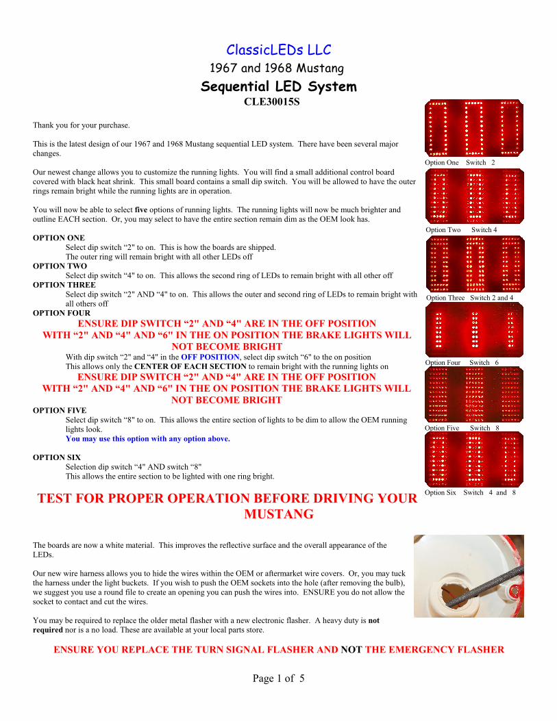
Our new wire harness allows you to hide the wires within the OEM or aftermarket wire covers. Or, you may tuckthe harness under the light buckets. If you wish to push the OEM sockets into the hole (after removing the bulb),we suggest you use a round file to create an opening you can push the wires into. ENSURE you do not allow thesocket to contact and cut the wires.
You may be required to replace the older metal flasher with a new electronic flasher. A heavy duty is notrequired nor is a no load. These are available at your local parts store.
ENSURE YOU REPLACE THE TURN SIGNAL FLASHER AND NOT THE EMERGENCY FLASHER
Page 1 of 5

Additionally, you will find a button coming out of the control unit. Due to numerous request, you may now stop the sequence mode. To stop thesequence operation: Ensure the turn signal handle is centered, (no turn signal) press the white button on the control unit once. Repeat steps to re-start the sequence mode. Ensure proper operation before driving.
You will also find an extra GREEN wire within the harness with the yellow tie. This wire is used if yourwire harness has a separate brake ONLY wire. If not, this wire is not used.Each board connects to the control unit thru the wire harness. The control unit is placed in the wire harness and is covered with a heat shrink wrap.Ensure you place this at a location it will not be covered when the trunk is loaded. Ensure the ends are clear. This allows air to flow freely over thecomputer chip and keeps the board dry.
Should the battery be located in the trunk or there is a CONSTANT 12 VOLT POWER SUPPLY, you may attach the cable there. A small inline isrecommended.
Ensure you install the fuse jumper (included) on the fused side of the taillight fuse.
ClassicLEDs is a small family owned business. We manufacture ALL our products in Oregon.
This system must be connected to a CONSTANT 12 VOLT POWER SUPPLY. Due to the size of the boardand number of LEDs, this is required to complete each electronic cycle of the turn signal
CHECK FOR POWER WITH THE KEY IN ON AND OFF POSITION
During installation, do not allow the LED boards to rest against metal portions of the body. The boards are coated to preventcorrosion, but allowing contact to the body during operation may cause a short circuit.
While installing the system, it is advised that after connecting the LED board INPUT wire to the OEM harness, you check for properoperation of each side before mounting boards.
Operation:The LED lamp substitutes for 1157 in the tail lamp. This kit is designed so the original OEM look is maintained until the board is litand in operation. The LED board operates as, tail, signal and brake lights.
During installation, do not allow back of LED boards to rest against metal portions of the body. The boards are coated to preventcorrosion, but allowing contact to the body during operation may cause a short circuit.
System will not operate properly without a front turn 1157 signal bulb installed.
Installation:No modification is necessary to install the LED boards
1. WIRE HARNESS OUTLINE
a. The system contains four wire harnesses leading out of the control unit which is covered in a shrink wrapb. Each harness is marked with a colored tie
i. Power supply(1) RED TIE
ii. OEM Wire harness connection(1) YELLOW TIE
iii. Right side LED board connection(1) BLACK TIE
iv. Left side LED board connection.(1) ORANGE TIE
2. CONTROL UNITa. the control unit is cover with a heat shrink warp for protection
i. although very little heat is generated, do not seal the endsii. the unit has been coated with a plastic spray for protectioniii. ensure the control unit is not installed where it may be damage while loading or unloading items within the
truck
Page 2 of 5

b. The control unit is placed between the light housings. i. It can be placed under the left housing
c. SMALL CONTROL UNITi. This contains a small control board with a dip switch.ii. This allows you to customize the running lightsiii. EACH RING OF LEDS outlined below may be turn on or off by themselves if you want only that
section to remain bright
USE THIS OPTION WHEN THE OUTER RINGS ARE NOT SWITCH TO THE “ON” POSITION AS THIS WILL OVERRIDE THE BRAKE LIGHTS WHEN THEY ARE IN OPERATION
TEST FOR PROPER OPERATION BEFORE DRIVING YOUR MUSTANG
3. POWER SUPPLY HARNESS
This system must be connected to a CONSTANT 12 VOLT POWER SUPPLY. Due to the size of the board and number ofLEDs, this is required to complete each electronic cycle of the turn signalCHECK FOR POWER WITH THE KEY IN ON AND OFF POSITION
a. This is the RED Tieb. Connect to a constant 12 volt supply
i. this provides power to the LEDsii. Red wire to positiveiii. Black to ground
c. Ensure you connect to a fused power supply.i. Your taillight fuse may be used if you wishii. A fuse tap is included
(1) if you attach directly to a trunk mounted battery/power supply, a small inline fuse isrecommended.
d. Any CONSTANT power supply in the rear area may be used.
YOU MUST ENSURE THIS IS A CONSTANT POWER SUPPLYCHECK FOR POWER WITH THE KEY IN THE OFF POSITION
THIS SYSTEM WILL NOT OPERATE WITHOUT POWER
e. If your LEDs do not operate when testing, ensure the power wires are connected properly.i. If installed backward, the control unit will not allow power to pass to the computer chip
4. CONNECTING TO THE OEM WIRE HARNESS
a. The OEM harness with the yellow tie attaches to the OEM wire harnessb. Beginning with the left turn/brake operationc. Place the turn signal handle in the down or left turn signal position with POWER ond. WHILE WORKING IN THE TRUNK
i. Find the LEFT TURN wire in the OEM harness nearest the new LED boardsii. TURN THE POWER OFFiii. tap the black wire into this wire
(1) this operates the brake and turn signale. Place the turn signal handle in the up or right turn signal position with POWER on
i. Find the RIGHT TURN wire in the OEM harness nearest the new LED boardsii. TURN THE POWER OFFiii. tap the RED wire into this wireiv. this operates the brake and turn signal
(1) test for operationf. Turn signal offg. Check for operationh. Turn running lights on
i. Find the wire carrying the running light POWERii. TURN THE POWER OFF
Page 3 of 5

iii. ATTACH THE YELLOW WIREiv. There is only one running light attachment
i. There is no grounding wire at this point(1) control unit is the grounding
j. Check for proper operationk. Should the right and left side operate backward
i. Change the red and black wire attachment pointl. Should the running lights not operate
i. Ensure the YELLOW wire is attached to a running light powered wire within the OEM harness5. After testing and ensuring the system works
a. ensure the control unit is not installed where it may be damage while loading or unloading items within the truck
LED BOARD INSTALLATION
6. Place board within housing and test for proper operationa. Each board is marked with an arrow and (L) LEFT or (R)RIGHT.
i. Mustang’s right or left looking forwardii. Install with the ARROWS and LETTER up
(1) should the board operate backward flip the board overb. After testing for proper operation
i. Note where the board fits within the housingii. Place a clear silicon adhesive within the housing where the LED board will sit.iii. Push the board into the silicon
(1) ensure board is level allowing the maximum light to shineiv. After placing the board in the siliconv. Place a bead around the board edge ensuring the board is attached on both sidesvi. Allow silicon to set before replacing lens and bezel
(1) see silicon instructions for details regarding time needed to setc. Ensure lens seals are in good condition.d. Proper operation of this system was tested prior to shipping.
7. NON SEQUENTIAL OPERATIONi. If you want to disable the sequence mode a white button has been added to the control unit
(1) ensure the turn signal handle is in the center position(2) Push the button once(3) This will turn the sequence mode off
(a) Check operationii. To return to sequential
(1) Repeat above operation(a) check to ensure the sequence operation in now active
iii. You will find two wires, these are held with a GREEN TIE.(1) is you wish to move the location of this button, attach these to a simple on/off button(2) ENSURE THE SEQUENCE MODE IS ON WHEN ATTACHING THIS BUTTON
8. Check lights for proper operation before securing the lens. a. Take care not to allow the board to contact metal, which will short out the system.b. Ensure brake, running lights and turn signal operate properly. c. The entire board lights for both tail and brake lights.
9. It is advised that the LED boards be check periodically for dampness, 10. Ensure proper operation prior permanently installing lens and gaskets.
a. As with all replacement parts, please ensure proper operation before driving on roads or highways.
ENSURE PROPER OPERATION PRIOR TO INSTALLING THE LENS INTO THE BUCKET
11. After installing LEDs into the housinga. Plug the boards into the control unit
i. After checking to ensure proper operationii. install the lens then housing
b. Check for proper operation12. After testing and ensuring the system works
a. Ensure the Light is visible behind your Mustang before driving13. Check local/state laws to ensure there are no restrictions regarding the operation of this system.
Page 4 of 5

14. Should there be a problem with the system, the rear lights will only flash. 15. Enjoy your new LED system!
Should you have any questions, please contact ClassicLEDs LLC at [email protected] or 541.463.7623
Limited WarrantyAll NorthWestMustang/ClassicLEDs LLC products are warranted against defective materials and/or workmanship to all originalconsumer owners from the date of original consumer purchase as long as original purchaser owns the vehicle. In the event of defectivematerials and /or workmanship, NorthWestMustang LLC. will, without charge, repair or replace, at its option, the defective product within 60 days from the receipt of the defective product at the following address: NorthWestMustang LLC, 3128 Marvin Dr. Eugene, OR 97404 attn Warranty Dept. Postage to NorthWestMustang paid by owner. Return postage paid by NorthWestMustang LLC.
The Warranty does not apply to damage not resulting from defective materials and/or workmanship while in the possession of the originalconsumer or to unreasonable use by the original consumer, which includes but is not limited to improper installation, failure to providereasonable and necessary maintenance, or commercial applications. NorthWestMustang/ClassicLEDs LLC. is not liable for any incidentalor consequential damages. Some states do not allow the exclusion or limitation of incidental or consequential damages, so the abovelimitation or exclusion may not apply to you.
Page 5 of 5
Related Documents