Welcome message from author
This document is posted to help you gain knowledge. Please leave a comment to let me know what you think about it! Share it to your friends and learn new things together.
Transcript
VIETNAM ELECTRICITY
ENVIRONMENTAL IMPACT ASSESSMENTProject:
VINH TAN 4 EXTEND THERMAL POWER PLANT – 1×600 MWAt Vinh Tan commune, Tuy Phong district, Binh Thuan province
(Adjusted according to Meeting of Appraisal Committeeon September 25th,2015)
Binh Thuan, October 2015
VIETNAM ELECTRICITY
ENVIRONMENTAL IMPACT ASSESSMENTProject:
VINH TAN 4 EXTEND THERMAL POWER PLANT – 1×600 MWAt Vinh Tan commune, Tuy Phong district, Binh Thuan province
(Adjusted according to Meeting of Appraisal Committeeon September 25th,2015)
THE OWNER CONSULTANT
POWER ENGINEERING &CONSULTING JS COMPANY 3
GENERAL DIRECTOR
Binh Thuan, October 2015
Vinh Tan 4 Ext TPP – 1×600MW
Feasibility Study
Table of contents
PECC3 i
TABLE OF CONTENTS
TABLE OF CONTENTS .......................................................................................... i
LIST OF ABBREVIATIONS .................................................................................. v
LIST OF TABLES ................................................................................................... vi
LIST OF FIGURES ................................................................................................ xii
PREFACE ................................................................................................................. 1
CHAPTER 1 SUMMARY DESCRIPTION OF THE PROJECT ...................... 13
1.1 PROJECT NAME ........................................................................................... 13
1.2 PROJECT OWNER ........................................................................................ 13
1.3 GEOGRAPHICAL LOCATION OF THE PROJECT .................................. 13
1.3.1 Location of the project ............................................................................ 13
1.3.2 Correlation of the project position compared with the surrounding
objects ................................................................................................................. 17
1.3.3 Plans of site selection for the project construction ................................. 20
1.3.4 Status of land management anduse of the project ................................... 21
1.4 MAJOR CONTENTS OF THE PROJECT ................................................... 22
1.4.1 Description of the project's objectives .................................................... 22
1.4.2 Quantity and scale of the project categories ........................................... 22
1.4.3 Methods of organization of construction, construction technology and
construction items of the project .......................................................................... 44
1.4.4 Technological solutions .......................................................................... 50
1.4.5 List of machines and equipment ............................................................. 51
1.4.6 Material, fuel (input) and types of product (output) of the project ......... 56
1.4.7 Schedule of the project ............................................................................ 59
1.4.8 Total investment cost .............................................................................. 62
1.4.9 Project management and implementation ............................................... 63
CHAPTER 2 STATUS OF NATURAL ENVIRONMENT AND SOCIO-
ECONOMIC CONDITIONS ..................................................................................... 67
2.1. NATURAL ENVIRONMENTAL CONDITION ........................................... 67
2.1.1 Topographical and geological conditions ............................................... 67
2.1.2 Topographical condition ......................................................................... 67
2.1.3 Meteorology conditions ............................................................................... 74
2.1.4 Hydrological and oceanographical conditions .................................................. 83
2.1.5 Current Situations of Environmental Quality in the Project Area ......................... 87
2.1.6 Biological resource situation ................................................................... 99

Vinh Tan 4 Ext TPP – 1×600MW
Feasibility Study
Table of contents
PECC3 ii
2.2 SOCIO-ECONOMIC SITUATION ............................................................. 106
2.2.1 Economic situation ................................................................................ 106
2.2.2 Social situation ...................................................................................... 107
2.2.3 Socio-economic situation of affected households ................................. 109
2.2.4 Infrastructure situation in the project area ............................................ 111
CHAPTER 3 ASSESSMENT AND FORECAST OF ENVIRONMENTAL
IMPACTS .......................................................................................................... 112
3.1 ASSESSMENT AND FORECAST OF ENVIRONMENTAL IMPACTS . 112
3.1.1 Assessment and forecast of impacts of the project in the pre-construction
phase ............................................................................................................... 112
3.1.2 Assessment and forecast of impacts of the project during the construction
phase ............................................................................................................... 117
3.1.3 Assessment and forecast of impacts during the operation phase .......... 144
3.1.4 Assessment of impacts due to risks and problems ................................ 195
3.1.5 Impacts on the environment and socio-economic situation .................. 204
3.2 COMMENTS ON DETAIL LEVEL AND RELIABILITY OF
ASSESSMENT RESULTS AND FORECAST .................................................... 207
3.2.1 Comments on reliability of methods used in the report ........................ 207
3.2.2 Comments on the reliability degree of the evaluation .......................... 209
CHAPTER 4 MEASURES FOR PREVENTION, AND MITIGATION TO
NEGATIVE IMPACTS, PREVENTION AND RESPONSE TO RISKS AND
INCIDENTS OF THE PROJECT ........................................................................... 213
4.1 PREVENTION AND MITIGATION MEASURES TO NEGATIVE
IMPACTS OF THE PROJECT ............................................................................ 213
4.1.1 Prevention and mitigation measures to the negative impacts of the project
in the pre-construction phase ............................................................................. 213
4.1.2 Prevention and mitigation measures to the negative impacts during the
construction phase .............................................................................................. 217
4.1.3 Prevention and mitigation measures to the negative impacts during the
operation phase ................................................................................................... 229
4.2 MEASURES FOR PREVENTING AND RESPONSE TO RISK AND
INCIDENT ............................................................................................................. 264
4.2.1 Measures to prevent and respond to incidents in the construction phase 264
4.2.2 Measures to prevent and respond to the environmental incidents during
the operational phase .......................................................................................... 267
CHAPTER 5 ENVIRONMENTAL MONITORING AND MANAGEMENT
PLAN .......................................................................................................... 279
5.1 ENVIRONMENTAL MANAGEMENT PLAN ........................................... 279
Vinh Tan 4 Ext TPP – 1×600MW
Feasibility Study
Table of contents
PECC3 iii
5.1.1 Organization structure ........................................................................... 279
5.1.2 Establishing a specialized division of environmental protection by the
project owner and Vinh Tan 4 Extension TPP ................................................... 280
5.1.3 Environmental Reporting System ......................................................... 280
5.1.4 Training and capacity improvement of environmental management for
the Environment and Safety Division ................................................................ 281
5.1.5 Organization system of implementing environmental management plan281
5.1.6 Enironmental management plan............................................................ 282
5.2 ENVIRONMENTAL MONITORING PLAN .............................................. 296
5.2.1 Types of environmental monitoring form ............................................. 296
5.2.2 Monitoring the implementation of measures and solutions to control
pollution and protect the environment of the project ......................................... 296
5.2.3 Environmental Monitoring Plan of the Project ..................................... 296
CHAPTER 6 PUBLIC CONSULTATION .......................................................... 309
6.1 SUMMARY OF THE IMPLEMENTATION PROCESS OF PUBLIC
CONSULTATION ................................................................................................. 309
6.1.1 Summary of the consultation process with commune People's Committee
and the organizations directly affected by the project ....................................... 309
6.1.2 Summary of the consultation process of the directly affected community
by the project ...................................................................................................... 310
6.2 RESULT OF PUBLIC CONSULTATION .................................................. 310
6.2.1 Feedbacks of People's Committee of Vinh Tan commune ................... 310
6.2.2 Feedbacks of Fatherland Front Committee of Vinh Tan commune ..... 311
6.2.3 Feedbacks of Management Board of Hon Cau MPA ........................... 311
6.2.4 Feedbacks of Binh Thuan Breeding Shrimp Association ..................... 312
6.2.5 Feedbacks and commitments of the project owner to the proposals,
recommendations and requests of the agencies, organizations and communities to
be consulted ........................................................................................................ 312
CONCLUSION, RECOMMENDATION AND COMMITMENTS
REFERENCES
ANNEXES
Annex 1: legal documents related to project approval
Annex 2: design drawings of the project
Annex 3: analysis results on background environment
Annex 4: copies of the documents related to the public consultation and sociological
questionnaires
Annex 5: some photos related to the project
Vinh Tan 4 Ext TPP – 1×600MW
Feasibility Study
Table of contents
PECC3 iv
Annex 6: cost in detail for compensation, assistance, resettlement
Annex 7: list of species in the project area
Annex 8: calculation of exhaust emissions and spread of cooling water
Vinh Tan 4 Ext TPP – 1×600MW
Feasibility Study
List of abbreviations
PECC3 v
LIST OF ABBREVIATIONS
APH : Air preheater
BOD : Biochemical Oxygen Demand
BMCR : Boiler Maximum Continious Rate
COD : Chemical Oxygen Demand
DO : Distillated oil
DONRE : Department of Natural Resources and Environment
DWT : Deadweight tonnage
EIA : Environmental impact assessment
EPA : United States Environmental Protection Agency
ESP : Electrostatic Precipitator
EVN : Viet Nam Electricity
FS : Feasibility Study
OFA : Over fire air
MONRE : Ministry of Natural Resources and Environment
PECC3 : Power Engineering & Consulting Joint-Stock Company No.3
PAH : Project affected household
VTPMU : Project Manager Unit Vinh Tan
RO : Reverse Osmosis
TDS : Total dissolved solids
TPP : Thermal Power Plant
GENCO3 : Power Generation Corporation 3
SWFGD : Flue Gas Desulfurization by sea water
VND : Vietnamese Dong
VOC : Volatile organic compounds
VT : Vinh Tan
VT 4 Ext : Vinh Tan 4 Extend
VTPC : Vinh Tan Power Complex
WHO : World Health Organization
Vinh Tan 4 Ext TPP – 1×600MW
Feasibility Study
List of tables
PECC3 vi
LIST OF TABLES
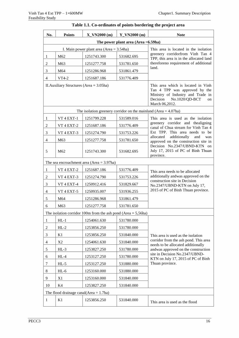
Table 1.1. Co-ordinates of points bordering the project area .......................... 16
Table 1.2. Status of land management and use of the project ......................... 21
Table 1.3 List of categories which are shared by Vinh Tan 4 Ext TPP with the
other projects of Vinh Tan Power Complex(VTPC) ....................................... 22
Table 1.4. List of the common categories of VT4 and Vinh Tan 4 Ext TPP .. 24
Table 1.5. Summary of the categoriesseparate or common of Vinh Tan 4 Ext
TPP ................................................................................................................... 27
Table 1.6. Exhaust gas treatment efficiency of VT1 TPP ............................... 29
Table 1.7. Exhaust gas treatment efficiency of VT2 TPP ............................... 29
Table 1.8. Exhaust gas treatment efficiency of VT3 TPP ............................... 30
Table 1.9. The treatment efficiency of exhaust emissions from Vinh Tan 4
TPP ................................................................................................................... 31
Table 1.10.Main parameters Boiler ................................................................. 31
Table 1.11.Main parameters Turbine............................................................... 32
Table 1.12. Main parameters Steam turbine genetor ....................................... 32
Table 1.13.Ash pond ........................................................................................ 37
Table 1.14.Volume of digging and backfilling for the project ........................ 49
Table 1.15. The source supply fill materials ................................................... 49
Table 1.16.The basic technological solutions .................................................. 50
Table 1.17. List of machines and equipment used in the construction stage .. 51
Table 1.18. List of machines and equipment for Vinh Tan 4 EXT TPP and its
port in the operation stage ................................................................................ 52
Table 1.19. Technical parameters of the coal fuel ........................................... 56
Table 1.20.The total coal consumption of Vinh Tan 4 Ext TPP include Vinh
Tan 4 TPP ........................................................................................................ 56
Table 1.21. DO fuel characteristics ................................................................. 57
Table 1.22.Fresh water demand of project ...................................................... 57
Table 1.23.The total ash volume of the plant .................................................. 59
Table 1.24.The ash characteristics of the plant ............................................... 59
Table 1.25. Schedule of the project ................................................................. 61
Table 1.26. Summarizes the main content of the project ................................ 62
Table 1.27.Total investment cost ..................................................................... 62
Table 1.28. The investment costs for environmental items ............................. 63
Table 2.1. Air temperature at Phan Rang station period 1993-2014 .............. 75
Vinh Tan 4 Ext TPP – 1×600MW
Feasibility Study
List of tables
PECC3 vii
Table 2.2. Relative humidity at Phan Rang station period 1993-2014 ............ 75
Table 2.3.Air pressure at Phan Rang station in period 1994-2014. ................ 75
Table 2.4. Frequency of wind in eight directions at Phan Rang station, period
1994-2014. ....................................................................................................... 77
Table 2.5. Designed wind velocity at Phan Rang station, period 1994 - 2014 77
Table 2.6. Rainfall and number of rainy days in Phan Rang station, period 1994 –
2014 (mm) ........................................................................................................ 78
Table 2.7. Rainfall and number of rainy days in Ca Na station, period 1994 – 2014
(mm) ................................................................................................................. 78
Table 2.8. Maximum rainfall for design calculations periodsin the project area
......................................................................................................................... 78
Table 2.9.Evaporation (Piche) of Phan Rang stations from 1994-2014(mm). 78
Table 2.10. Storms and tropical depressions inNinh Thuận - Bình Thuậnfrom 1978–
2014 .................................................................................................................. 79
Table 2.11. Frequency of tornados in Binh Thuan province in 1971 – 2014 .. 81
Table 2.12. Statistics of flood inBình Thuận from 1992 – 2014 ..................... 81
Table 2.13. Meteorological stations characterized at Phan Rang 2015 ........... 83
Table 2.14. Characteristic water levels at Vinh Tan station ( Vinh Tan 4
project area) ..................................................................................................... 84
Table 2.15. Characteristics of water level in Vung Tau station (in cm), during
1978-2014 ......................................................................................................... 84
Table 2.16. The maximum design wave height at Phu Quy station ................ 85
Table 2.17. Seawater temperature at Phu Quy station (°C), period (1979-2014)
......................................................................................................................... 86
Table 2.18. Seawater temperature at Vung Tau station (°C), period (1979-
2014) ................................................................................................................ 86
Table 2.19. Salinity at Phu Quy station in period 1979-2014 (‰) .................. 86
Table 2.20. Surveyed flood track of Chua spring ............................................ 86
Table 2.21. Water discharge of rivers in Tuy Phong District district .............. 87
Table 2.22. Results of air quality in the project area ....................................... 88
Table 2.23. Results of air quality monitoring of VT4 TPP during construction
phase ................................................................................................................ 89
Table 2.24. Results of water quality (runlets) ................................................. 91
Table 2.25. Results of coastal seawater quality of VT 4 EXT TPP ................ 93
Table 2.26. Results of coastal seawater quality of VT4 TPP during
construction phase............................................................................................ 94
Table 2.27. Results of groundwater quality ..................................................... 96
Table 2.28. Results of groundwater quality of VT4 TPP during construction
Vinh Tan 4 Ext TPP – 1×600MW
Feasibility Study
List of tables
PECC3 viii
phase ................................................................................................................ 97
Table 2.29. Results of soil quality ................................................................... 98
Table 2.30. Coordinates of survey stations sea grass and seaweed ............... 103
Table 2.31. Number of species of each phylum of seaweeds at study sites .. 105
Table 2.32. The status of the road network in the project area...................... 107
Table 3.1. The project impact sources in the pre-construction phase ........... 113
Table 3.2. Trees and crops affected by the project ........................................ 113
Table 3.3. Total area of required land by the project .................................... 114
Table 3.4. Houses/graves affected by the project .......................................... 115
Table 3.5. Structures/buildings affected by the project ................................. 115
Table 3.6. Impacts on the socioeconomic environment ................................ 117
Table 3.7. Impacts of the project during the construction phase .................. 117
Table 3.8. Transport quantity to the construction site ................................... 120
Table 3.9. Pollution coefficients of World Health Organization (WHO)
established for transport vehicles using diesel oil with load from 3.5 to 16.0
tons ................................................................................................................. 120
Table 3.10. Total load of pollutants in exhaust gas arisen from the means of
material transportation ................................................................................... 121
Table 3.11. Coefficients of Martin (1976) ..................................................... 121
Table 3.12. The atmospheric stability............................................................ 122
Table 3.13. The concentration of pollutants in the exhaust gas generated by the
means of material transport ........................................................................... 122
Table 3.14. Pollution coefficient caused by shipping activities .................... 123
Table 3.15. Quantity of pollutants arisen from shipping activities ............... 123
Table 3.16. Coefficient of exhaust emission generated by diesel engines .... 124
Table 3.17. Load of pollutants arisen from construction means ................... 124
Table 3.18. The concentration of exhaust gas arisen from construction
machinery and equipment .............................................................................. 125
Table 3.19. Concentration of pollutants in domestic wastewater .................. 128
Table 3.20. Discharge and load of pollutants arisen from the process of
cleaning and maintaining machinery and equipment at construction site ..... 129
Table 3.21. Runoff coefficient ....................................................................... 130
Table 3.22. Discharge of overflowing rainwater ........................................... 130
Table 3.23. The concentration of pollutants in the overflowing rainwater ... 131
Table 3.24. The amount of dirt accumulating in overflowing rainwater ....... 131
Table 3.25. Hazardous waste is expected to arise at the construction site .... 133
Vinh Tan 4 Ext TPP – 1×600MW
Feasibility Study
List of tables
PECC3 ix
Table 3.26. The noise level caused by the construction means related to
distance .......................................................................................................... 136
Table 3.27. Noise level is estimated according to the distance from the
roadside .......................................................................................................... 140
Table 3.28. Vibration level caused by some construction machines ............. 140
Table 3.29. Impacts of the project during the operation phase...................... 144
Table 3.30. National technical regulation on emission of thermal power plant
(mg/Nm3) ....................................................................................................... 147
Table 3.31. Environmental regulations on ambient air quality ..................... 148
Table 3.32. Parameters used for calculation of emission rate ....................... 148
Table 3.33. Emission rate and concentration of pollutants in exhaust gas .... 148
Table 3.34. Planned processing efficiency of a removal system of dust, SO2
and NOx .......................................................................................................... 149
Table 3.35. The status of emissions of thermal power plants in Vinh Tan
Power Complex.............................................................................................. 152
Table 3.36. Parameters of emission sources in Vinh Tan Power Complex .. 152
Table 3.37. Parameters in calculating emission of NOx ............................... 153
Table 3.38. Calculation result for emission of NO2 ...................................... 153
Table 3.39. Parameters in calculating emission of SO2 ................................. 155
Table 3.40. Calculation result for emission of SO2 ....................................... 155
Table 3.41. The scenarios of simulation for dust diffusion ........................... 156
Table 3.42. Calculation result for dust emission ........................................... 156
Table 3.43. Calculation result for pollutant emission from Vinh Tan 4
Extension TPP................................................................................................ 157
Table 3.44. Forecast impacts on the sensitive areas, ..................................... 158
Table 3.45. Emission coefficient due to burning DO .................................... 159
Table 3.46. Concentration of air pollutants in case of boiler start-up by DO 159
Table 3.47. The emission rate of VOC into the air ........................................ 160
Table 3.48. The emission rate of pollutants from barges conveying coal ..... 161
Table 3.49. Emission rate from the transport means ..................................... 162
Table 3.50. The concentration of pollutants in the exhaust gas generated from
the ash transport means .................................................................................. 165
Table 3.51. Calculation results of dust emissions from the ash pond ........... 167
Table 3.51. Types of waste water of the power plant .................................... 172
Table 3.52. Calculation results for heating spread and diffusion due to cooling
water discharge .............................................................................................. 178
Table 3.54. Statistics of the temperature affected areas due to cooling water
Vinh Tan 4 Ext TPP – 1×600MW
Feasibility Study
List of tables
PECC3 x
discharge from Vinh Tan 4 Extension TPP ................................................... 181
Table 3.55. The ash amount from VT4 & VT4 Ext ...................................... 183
Table 3.56. The heavy metal components in the ash ..................................... 183
Table 3.57. Hazardous waste generated in the plant ..................................... 184
Table 3.58. Reference to the noise in the area of Pha Lai 1 thermal power plant
....................................................................................................................... 185
Table 3.59. Noise level arisen from some major equipment in VT4 & VT4
Extension ........................................................................................................ 187
Table 3.60. Noise levels arisen from the activities on the port ..................... 188
Table 3.61. Some biological and ecological characteristics of prawn species
....................................................................................................................... 192
Table 3.62. Volume of greenhouse gas emission .......................................... 195
Table 3.63. Sea level rise (cm) compared with period of 1980-1999 ........... 195
Table 3.66. Calculation of SO2 Emission in case of FGD failure ................. 198
Table 3.67. Calculation result of SO2 Emission in case of incident .............. 198
Table 3.68. Calculation of dust emission in case of incident ........................ 198
Table 3.69. Calculation result of dust emission in case of incident .............. 198
Table 3.70. Summary of activities of the project can impact on the
environment and socio-economy ................................................................... 205
Table 3.71. Degree of reliability of EIA methods ......................................... 209
Table 3.72. Comments on the level of details and reliability of the assessment
....................................................................................................................... 210
Table 4.1. Synthesizing the aspirations of the affected people .................... 216
Table 4.2. The total cost of implementing compensation, support and
resettlement .................................................................................................... 216
Table 4.3. Exhaust emission treatment efficiency expected of the project ... 230
Table 4.4. Calculation details for water consumption ................................... 240
Table 4.5. Construction cost of a flood drainage canal in the ash pond ....... 277
Table 5.1. Implementaion agency .................................................................. 279
Table 5.2. Environmental reporting system ................................................... 281
Table 5.3. Responsibilities of the units in the implementation of environmental
management plan (EMP) ............................................................................... 281
Table 5.4. Environmental management plan ................................................. 283
Details of the ambient environmental monitoring program is presented in the
following table: .............................................................................................. 301
Table 5.5. The ambient environmental monitoring program in the operation
phase of Vinh Tan 4 Power Complex ............................................................ 302
Vinh Tan 4 Ext TPP – 1×600MW
Feasibility Study
List of tables
PECC3 xi
Location for monitoring the air during the operation phase of Vinh Tan Power
Complex is shown in the following table: ..................................................... 304
Bảng 5.6. Location of points for monitoring the air during the operation phase
of Vinh Tan Power Complex ......................................................................... 304
Location for monitoring the surface water during the operation phase of Vinh
Tan Power Complex is shown in the following table: ................................... 304
Table 5.7. Location of points for monitoring the surface water during the
operation phase of Vinh Tan Power Complex ............................................... 305
Location for monitoring the coastal water during the operation phase of Vinh
Tan Power Complex is shown in the following table: ................................... 305
Table 5.8. Location of points for monitoring the coastal water during the
operation phase of Vinh Tan Power Complex ............................................... 305
Table 5.9. Cost estimation for the environmental monitoring program. ....... 306
Table 5.10. Cost estimation for the trainning program ................................. 307
Table 5.11. Cost estimation of the project for EMP implementation (VND)
....................................................................................................................... 308

Vinh Tan 4 Ext TPP – 1×600MW
Feasibility Study
List of figures
PECC3 xii
LIST OF FIGURES
Figure 1.1. Location map of Vinh Tan Power Complex ................................. 14
Figure 1.2. Chart of boundary and control points of Vinh Tan 4 Ext TPP area
......................................................................................................................... 14
Figure 1.3. Chart of boundary and control points of the corridor for insulating
from the ash pond and the flood drainage canal .............................................. 15
Figure 1.4.Satellite image of Vinh Tan 4 Ext TPP area .................................. 15
Figure 1.5. Location of objects surrounding to the project which could be
affected. ............................................................................................................ 19
Figure 1.6. Place subdivision ash pond foot of the mountain Ho Dua - stage 1
......................................................................................................................... 36
Figure 1.7. Diagram supply water treatment from lake Long Song ................ 40
Figure 1.8. Diagram water treatment from sea level ....................................... 41
Figure 1.9. Diagram demineralised water treatment ....................................... 41
Figure 1.10. Technical diagram of Vinh Tan 4 Ext TPP ................................. 55
Figure 1.11. The construction organization chart of the project ..................... 64
Figure 1.12. Construction layout ..................................................................... 65
Figure 1.13. Management and operation model of the project ........................ 66
Figure 2.1. Models of elevation project area ................................................... 67
Figure 2.2. Project Location and Hydrometeorological station in and around
studied area ...................................................................................................... 76
Figure 3.3.Process of tides 11/2007 in Vinh Tan station ................................. 84
Figure 2.4.Process of tides 11/2007 in Vung Tau station ................................ 85
Figure 2.5. Map of air quality sampling location of VT 4 Ext TPP ................ 89
Figure 2.6.Map of surface water sampling location of VT 4 EXT TPP .......... 92
Figure 2.7. Map of coastal seawater sampling location of VT 4 EXT TPP .... 94
Figure 2.8. Map of groundwater sampling location in VT 4 EXT TPP .......... 97
Figure 2.9. Map of soil sampling location of VT 4 EXT TPP ........................ 99
Figure 2.10. Satilite image of VT 4 Ext TPP location with Hon Cau MPA . 103
Figure 2.11.Map of sea grass and seaweed stations survey the area, VT 4 EXT
TPP ................................................................................................................. 104
Figure 3.1. Distribution of maximum content of suspended sediment due to
sea encroachment activities ........................................................................... 136
Figure 3.2. Layout of noise generating sources in the construction area of VT4
& VT4 Ext ..................................................................................................... 137
Figure 3.3. The noise contour map at the construction site of Vinh Tan 4 TPP
and Vinh Tan 4 Ext TPP ................................................................................ 138
Vinh Tan 4 Ext TPP – 1×600MW
Feasibility Study
List of figures
PECC3 xiii
Figure 3.4. Concentration of NO2 emission with the average value for 1hour
....................................................................................................................... 154
Figure 3.5. Concentration of NO2 emission with the average value for 24hours.
....................................................................................................................... 154
Figure 3.6. Concentration of SO2 emission with the average highest value for
1hour .............................................................................................................. 155
Figure 3.7. Concentration of SO2 emission with the average highest value for
24 hours .......................................................................................................... 156
Figure 3.8. Emission concentration of Dust (TSP) with average value for 24
hours ............................................................................................................... 157
Figure 3.9. Locations of the sensitive areas ................................................... 158
Figure 3.10. Dust dispersion in Scenario 1: Averaging highest concentration of
dust for 1 hour ................................................................................................ 168
Figure 3.11. Dust dispersion in Scenario 2: Averaging highest concentration of
dust for 1 hour ................................................................................................ 169
Figure 3.12. Dust dispersion in Scenario 3: Averaging highest concentration of
dust for 1 hour ................................................................................................ 170
Figure 3.13. Points are extracted for the water level boundary of the model 178
Figure 3.14. Layout of outlet and intake works in Vinh Tan Power Complex
....................................................................................................................... 179
Figure 3.15. Waves spilling over the shallow sea area .................................. 179
Figure 3.16. The boundary around Vinh Tan Power Complex .................... 181
Figure 3.17 Heating spread in the project area of Vinh Tan 4 Extension TPP
....................................................................................................................... 182
Figure 3.18. Map of noise contours at Vinh Tan 4 and Vinh Tan 4 Extension
TPPs ............................................................................................................... 187
Figure 3.19 . Fireball model when there is an explosion of 1.500 m3 DO tank
....................................................................................................................... 203
Figure 4.1. Mobile toilets in the construction site of Vinh Tan 4 TPP ......... 219
Figure 4.2. Chart of collecting and treatment of domestic solid waste during
the construction phase. ................................................................................... 223
Figure 4.3. Wastebin in Vinh Tan 4 Extension TPP ..................................... 224
Figure 4.4. Chart of collecting and treatment of hazardous waste during the
construction phase.......................................................................................... 225
Figure 4.5. Chart of emission treatment of the power plant .......................... 230
Figure 4.6. System of low NOx burner.......................................................... 231
Figure 4.7. A typical ESP system .................................................................. 233
Figure 4.8. Diagram of flue gas desulfurization by seawater ........................ 235
Figure 4.9. Layout of wind screens in the area of loading coal ..................... 237
Vinh Tan 4 Ext TPP – 1×600MW
Feasibility Study
List of figures
PECC3 xiv
Figure 4.10. Specialized trucks used for conveying ash and the water trucks
for watering the internal routes in the ash pond area ..................................... 238
Figure 4.11. Washing down the trucks before leaving the ash pond and the
waste water collecting pit .............................................................................. 238
Figure 4.12. Dividing cells for pouring ash in the ash pond at the bottom of
Mount Ho Dua ............................................................................................... 239
Figure 4.13. Diagram of watering in the ash pond at the bottom of Mount Ho
Dua ................................................................................................................. 241
Figure 4.14. Watering and using tarpaulin to cover the ash pond surface at the
bottom of Mount Ho Dua. ............................................................................. 242
Figure 4.15. Diagram of chemical contaminated wastewater treatment system
....................................................................................................................... 245
Figure 4.16. Diagram of oil contaminated wastewater treatment system .... 245
Figure 4.17. The treatment system of coal contaminated waste water .......... 246
Figure 4.18. Schetch of a septic tank ............................................................. 248
Figure 4.19. Diagram of the treatment system of domestic waste water ...... 248
Figure 4.20. Diagram of the main waste water treatment system of Vinh Tan 4
Extension TPP................................................................................................ 250
Figure 4.21. The collecting direction of rainwater in the ash pond of VT2,VT4
& VT4 Extension ........................................................................................... 253
Figure 4.22. Option using compressed air to transport fly ash to the port. ... 256
Figure 4.23. Task of storing fly ash ............................................................... 256
Figure 4.24. Task of loading fly ash to the ships ........................................... 257
Figure 4.25. Expected location of the area for packaging and storing the fly
ash bags .......................................................................................................... 257
Figure 4.26. Chart of using up the residual heat of the boilers' backpass ..... 261
Figure 4.27. Regulations on warning signs to identify the chemical incidents
....................................................................................................................... 269
Figure 5.1. Location map for monitoring exhaust emissions and waste water
during the operation phase ............................................................................. 299
Figure 5.2. Location layout for monitoring the air during the operation phase
of Vinh Tan Power Complex ......................................................................... 304
Figure 5.3. Location layout for monitoring the surface water during the
operation phase of Vinh Tan Power Complex ............................................... 305
Figure 5.4. Location layout for monitoring the coastal water during the
operation phase of Vinh Tan Power Complex ............................................... 306
Figure 6.1. A meeting on public consulation ................................................. 310
Vinh Tan 4 Ext TPP– 1×600MW
Feasibility Study
Preface
PECC3 1
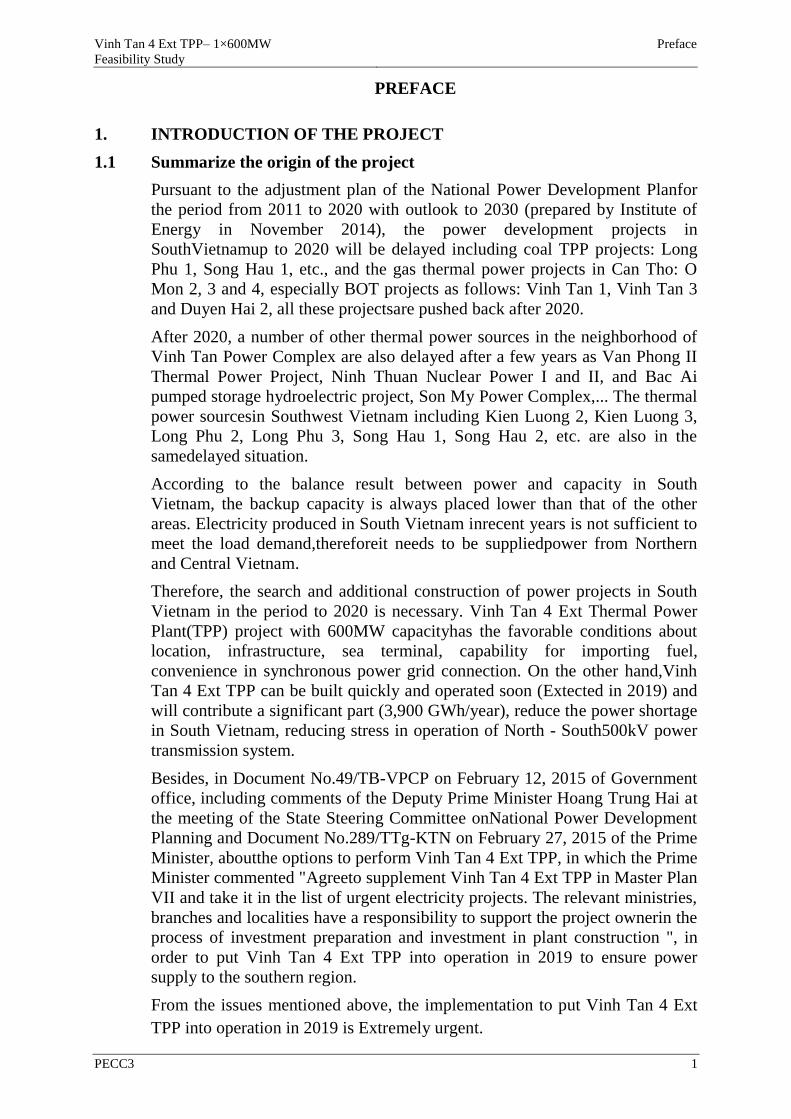
PREFACE
1. INTRODUCTION OF THE PROJECT
1.1 Summarize the origin of the project
Pursuant to the adjustment plan of the National Power Development Planfor
the period from 2011 to 2020 with outlook to 2030 (prepared by Institute of
Energy in November 2014), the power development projects in
SouthVietnamup to 2020 will be delayed including coal TPP projects: Long
Phu 1, Song Hau 1, etc., and the gas thermal power projects in Can Tho: O
Mon 2, 3 and 4, especially BOT projects as follows: Vinh Tan 1, Vinh Tan 3
and Duyen Hai 2, all these projectsare pushed back after 2020.
After 2020, a number of other thermal power sources in the neighborhood of
Vinh Tan Power Complex are also delayed after a few years as Van Phong II
Thermal Power Project, Ninh Thuan Nuclear Power I and II, and Bac Ai
pumped storage hydroelectric project, Son My Power Complex,... The thermal
power sourcesin Southwest Vietnam including Kien Luong 2, Kien Luong 3,
Long Phu 2, Long Phu 3, Song Hau 1, Song Hau 2, etc. are also in the
samedelayed situation.
According to the balance result between power and capacity in South
Vietnam, the backup capacity is always placed lower than that of the other
areas. Electricity produced in South Vietnam inrecent years is not sufficient to
meet the load demand,thereforeit needs to be suppliedpower from Northern
and Central Vietnam.
Therefore, the search and additional construction of power projects in South
Vietnam in the period to 2020 is necessary. Vinh Tan 4 Ext Thermal Power
Plant(TPP) project with 600MW capacityhas the favorable conditions about
location, infrastructure, sea terminal, capability for importing fuel,
convenience in synchronous power grid connection. On the other hand,Vinh
Tan 4 Ext TPP can be built quickly and operated soon (Extected in 2019) and
will contribute a significant part (3,900 GWh/year), reduce the power shortage
in South Vietnam, reducing stress in operation of North - South500kV power
transmission system.
Besides, in Document No.49/TB-VPCP on February 12, 2015 of Government
office, including comments of the Deputy Prime Minister Hoang Trung Hai at
the meeting of the State Steering Committee onNational Power Development
Planning and Document No.289/TTg-KTN on February 27, 2015 of the Prime
Minister, aboutthe options to perform Vinh Tan 4 Ext TPP, in which the Prime
Minister commented "Agreeto supplement Vinh Tan 4 Ext TPP in Master Plan
VII and take it in the list of urgent electricity projects. The relevant ministries,
branches and localities have a responsibility to support the project ownerin the
process of investment preparation and investment in plant construction ", in
order to put Vinh Tan 4 Ext TPP into operation in 2019 to ensure power
supply to the southern region.
From the issues mentioned above, the implementation to put Vinh Tan 4 Ext
TPP into operation in 2019 is Extremely urgent.
Vinh Tan 4 Ext TPP– 1×600MW
Feasibility Study
Preface
PECC3 2
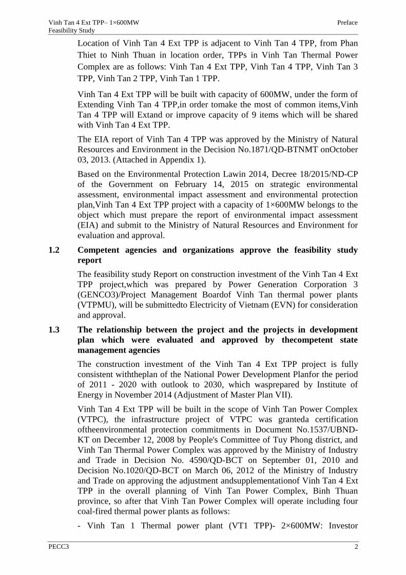
Location of Vinh Tan 4 Ext TPP is adjacent to Vinh Tan 4 TPP, from Phan
Thiet to Ninh Thuan in location order, TPPs in Vinh Tan Thermal Power
Complex are as follows: Vinh Tan 4 Ext TPP, Vinh Tan 4 TPP, Vinh Tan 3
TPP, Vinh Tan 2 TPP, Vinh Tan 1 TPP.
Vinh Tan 4 Ext TPP will be built with capacity of 600MW, under the form of
Extending Vinh Tan 4 TPP,in order tomake the most of common items,Vinh
Tan 4 TPP will Extand or improve capacity of 9 items which will be shared
with Vinh Tan 4 Ext TPP.
The EIA report of Vinh Tan 4 TPP was approved by the Ministry of Natural
Resources and Environment in the Decision No.1871/QD-BTNMT onOctober
03, 2013. (Attached in Appendix 1).
Based on the Environmental Protection Lawin 2014, Decree 18/2015/ND-CP
of the Government on February 14, 2015 on strategic environmental
assessment, environmental impact assessment and environmental protection
plan,Vinh Tan 4 Ext TPP project with a capacity of 1×600MW belongs to the
object which must prepare the report of environmental impact assessment
(EIA) and submit to the Ministry of Natural Resources and Environment for
evaluation and approval.
1.2 Competent agencies and organizations approve the feasibility study
report
The feasibility study Report on construction investment of the Vinh Tan 4 Ext
TPP project,which was prepared by Power Generation Corporation 3
(GENCO3)/Project Management Boardof Vinh Tan thermal power plants
(VTPMU), will be submittedto Electricity of Vietnam (EVN) for consideration
and approval.
1.3 The relationship between the project and the projects in development
plan which were evaluated and approved by thecompetent state
management agencies
The construction investment of the Vinh Tan 4 Ext TPP project is fully
consistent withtheplan of the National Power Development Planfor the period
of 2011 - 2020 with outlook to 2030, which wasprepared by Institute of
Energy in November 2014 (Adjustment of Master Plan VII).
Vinh Tan 4 Ext TPP will be built in the scope of Vinh Tan Power Complex
(VTPC), the infrastructure project of VTPC was granteda certification
oftheenvironmental protection commitments in Document No.1537/UBND-
KT on December 12, 2008 by People's Committee of Tuy Phong district, and
Vinh Tan Thermal Power Complex was approved by the Ministry of Industry
and Trade in Decision No. 4590/QD-BCT on September 01, 2010 and
Decision No.1020/QD-BCT on March 06, 2012 of the Ministry of Industry
and Trade on approving the adjustment andsupplementationof Vinh Tan 4 Ext
TPP in the overall planning of Vinh Tan Power Complex, Binh Thuan
province, so after that Vinh Tan Power Complex will operate including four
coal-fired thermal power plants as follows:
- Vinh Tan 1 Thermal power plant (VT1 TPP)- 2×600MW: Investor
Vinh Tan 4 Ext TPP– 1×600MW
Feasibility Study
Preface
PECC3 3
consortium including Chinese Southern Power Grid company (CSG) - Chinese
International Power Company (CPIH) and Vietnam National Coal - Mineral
Industry Group (Vinacomin), the project has started construction on July 18,
2015;
- Vinh Tan 2 Thermal power plant (VT2 TPP)- 2×622MW: the project owner
is EVN, VT2 TPP has been put into operation with Unit 1 on January30, 2015,
Unit 2 on March21, 2015.
- consortium including Chinese Southern Power Grid company (CSG) -
Chinese International Power Company (CPIH) and Vietnam National Coal -
Mineral Industry Group (Vinacomin), the project has started construction on
July 18, 2015;
- Vinh Tan 3 Thermal power plant (VT3 TPP) -3×660MW: the project owner
isVinh Tan 3/BOT Energy JSC, the project is making the relevant
proceduresto preparecommencement of construction;
- Vinh Tan 4 Thermal power plant (VT4 TPP)-2×600MW: the project owner
is EVN, the project is under construction and according to the plan Unit 1 will
be completedat the end of 2017, Unit 2 in 2018.
2. LEGAL BASIS AND TECHNIQUES OF EIA IMPLEMENTATION
2.1 Legal and technical documents
Research of this EIA is based on legal documents below:
Documents on the environment:
- Water Resources Law No.17/2012/QH13 was approvedby the National
Assembly of the Socialist Republic of Vietnam on June 21, 2012;
- Vietnam Sea Law No.18/2012/QH13was approvedby the National
Assembly of the Socialist Republic of Vietnam on June 21, 2012;
- Land Law No.45/2013/QH13 was approvedby the National Assembly of
the Socialist Republic of Vietnamon November 29, 2013;
- Environmental Protection Law No.55/2014/QH13 was approvedby the
National Assembly of the Socialist Republic of Vietnam on June 23, 2014;
- Decree No.201/2013/ND-CP on November 27, 2013 of the Government
detailing the implementation of some articles of the Law on Water
Resources;
- Decree No.43/2014/ND-CP on May 15, 2014 of the Government detailing
the implementation of some articles of theLand Law ;
- Decree No.47/2014/ND-CP on April 15, 2014 of the Government
regulating on compensation, support and resettlement when the State
recovers land;
- Decree No.18/2015/ND-CP of the Government on February 14, 2015
providing for strategic environmental assessment, environmental impact
assessment, environmental protection plan;
- Decree No.19/2015/ND-CP on February 14, 2015 of the Government

Vinh Tan 4 Ext TPP– 1×600MW
Feasibility Study
Preface
PECC3 4
detailing the implementation of a number of articles of the Law on
Environmental Protection;
- Decree No.38/2015/ND-CP on April 24, 2015 of the Government
providing for the management of waste and scrap;
- Circular No.27/2015/TT-BTNMT on May 29, 2015 of Ministry of Natural
Resources and Environment regulating on strategic environmental
assessment, environmental impact assessment and environmental
protection plan;
- - Circular No.37/2014/TT-BTNMT on June 30, 2014 of Ministry of
Natural Resources and Environment detailing on compensation, support
and resettlement when the State recovers land;
- Circular No.36/2015/TT-BTNMT on June 30, 2015of Ministry of Natural
Resources and Environment regulating on hazardous waste management;
- Decision No.23/QD-TTg on April 26, 2013 of the Government
promulgating the regulations on coordinating the integrated management
of natural resources and environmental protection of the sea and islands;
Documents related to the other fields:
- Law on Standards and Technical Regulations, Law No.68/2006/QH11 of
the National Assembly of the Socialist Republic of Vietnam approved on
June 29, 2006;
- Biodiversity Law No.20/2008/QH12 wasapprovedby the National
Assembly of the Socialist Republic of Vietnamon November 13, 2008;
- Law on amending and supplementing a number of articles of the Law on
Electricity No.24/2012/QH13 was adoptedby the National Assembly of the
Socialist Republic of Vietnamon November 20, 2012.
- Law of Natural DisasterPrevention and FightingNo.33/2013/QH13 was
approvedby the National Assembly of the Socialist Republic of Vietnamon
June 19, 2013;
- Law on amending and supplementing some articles of the Law on Fire
Prevention and Fighting, Law No.40/2013/QH13 was approvedby the
National Assembly of the Socialist Republic of Vietnam on November22,
2013;
- Decree No.15/2013/ND-CP on February 02, 2013 of the Government on
the quality management of construction works;
- Decree No.25/2013/ND-CP on March29, 2013 of the Government on
environmental protection charges for wastewater;
- Decree No.14/2014/ND-CP of the Government on February 26,
2014detailing the implementation of the Electrical Law on power safety
- Decree No.79/2014/ND-CP dated 31/07/2014 of the Government detailing
the implementation of some articles of the Law on Fire Prevention and Fire
and Law amending and supplementing some articles of the Law on Fire
Prevention and fighting;
Vinh Tan 4 Ext TPP– 1×600MW
Feasibility Study
Preface
PECC3 5
- Decree No.79/2014/ND-CP of the Government onJuly 31, 2014 detailing
the implementation of some articles of the Law on Fire Prevention and
Fighting andthe Law on amending and supplementing a number of articles
of the Law onFire Prevention and Fighting.
- Decision No.1696/QD-TTg on September 23, 2014 of the Government on
a number of implementation measures to process ash, slag and gypsum
from thermal power plants and fertilizerchemicalplantsto create raw
materials in production of construction materials.
Documents ofPeople's Committee of Binh Thuan province
- Decision No.2606/QD-UBND on November 15, 2010 of People's
Committee of Binh Thuan Provinceon construction of Hon Cau MPA;
- Decision No.2307/QD-UBNDon September 26, 2013 of People's
Committee of Binh Thuan Province on approval of land use planning up to
2020 andland use plan for 05 years (2011-2015) of Tuy Phong district;
- Decision No.59/2014/UBND on December26, 2014 of People's Committee
of Binh Thuan province on promulgating the regulations on land price
table in Binh Thuan province, it takes effect fromJanuary 01, 2015 to
December31, 2019;
- Decision No.05/2015/UBND on February 13, 2015of People's Committee
of Binh Thuan province on promulgatingthe regulations onthe principles
and compensation unit price for damages to the assets when the State
recovers land for construction of works in Binh Thuan province;
- Decision No.08/2015/UBND on March 02, 2015 of People's Committee of
Binh Thuan province on promulgating theregulations on compensation,
support and resettlement when the State recovers land; the procedures of
land acquisition, hand-over, lease and change of land use purpose and the
procedure thatthe project owner will negotiate with landholders to
implement the investment project in Binh Thuan province.
Documents related to the project
- Decision No.4590/QD-BCT onSeptember 01, 2010 of the Ministry of
Industry and Trade decided to approve the adjusted master plan ofVinh
Tan Power Complex, Binh Thuan Province;
- Decision No.1020/QD-BCT on March 06, 2012 of the Ministry of Industry
and Trade decided to approvethe adjustment, supplementation of Vinh Tan
4 Ext TPP in the overall planning of Vinh Tan Power Complex, Binh
Thuan province ;
- Decision No.2414/QD-TTg on December 14, 2013 of the Prime
Ministerdecided on amendments to the list and schedule of some power
projects and provided a number of specificmechanisms andpolicies to
invest the urgent power projects in the period from 2013 to 2020;
- Decision No.159/QD-EVN on September 15, 2015 of Vietnam Electricity
on investment decision for construction of Vinh Tan 4 Ext TPP project ;
Vinh Tan 4 Ext TPP– 1×600MW
Feasibility Study
Preface
PECC3 6
- Decision No.10746/QD-BCT October 6, 2015 of the Ministry of Industry
and Trade decided on approving the adjustment of planning on
construction locationof Vinh Tan Power Complex;
- Document No.5155/EVN-DT on December 17, 2014 of Vietnam
Electricity on Extanding Vinh Tan 4 TPP with an additional capacity of
600MW;
- Notice No.49/TB-VPCP on February 12, 2015 of the Government Office
informed the conclusions of the Deputy Prime Minister Hoang Trung Hai
at the meeting of the State Steering Committee for National Power
Development Planning ;
- Document No.289/TTg-KTN on February 27,2015 of the Prime Minister
on the implementation option of Vinh Tan 4 Ext TPP project ;
- Resolution No.77/HD-EVN on March 9, 2015 by the Member Board of
Vietnam Electricity - The second Session -2015;
- Document No.871/EVN-KH-DT-QLDT March 11, 2015 of Vietnam
Electricity on assigning the responsibility of implementation of Vinh Tan 4
Ext TPP project;
- Document No.1048/GENCO3-DT-XD March 12, 2015 of Power
Generation Corporation 3 on the implementation start of Vinh Tan 4 Ext
TPP project ;
- Notice No.101/TB-UBND on April 24, 2015 of People's Committee of
Binh Thuan Province on conclusions of the Chairman of Provincal People's
Committee based on the actual inspection work about the pollutionremedy
of Vinh Tan 2 TPP;
- Notice No.396/TB-UBND on May 04, 2015 of People's Committee of Tuy
Phong District onplan construction of the resettlement land arrangement
for relocation of the households in Hamlet 7, Vinh Phuc Village, Vinh Tan
commune;
- Notice No.404/TB-UBND on May 08, 2015 of People's Committee of Tuy
Phong District on review of land use planning and resettlement land
arrangement for relocation of the households living near the ash pond and
Extansion area of Vinh Tan 4 thermal power plant, Vinh Tan commune.
- Document No.03/2015/HHTG on April 02, 2015 of Binh Thuan
Association of Shrimp variety on consultations on the project "Vinh Tan 4
Ext TPP";
- Document No.15/BQLKBTBHC on April 06, 2015 of the Management
Board of Hon Cau MPAon consultation on preparing the report of
environmental impact assessment for Vinh Tan 4 Ext TPP;
- Document No.76/UBND-DC onApril 07, 2015 of People's Committee of
Vinh Tan Commune on consultation on the construction investment project
of Vinh Tan 4 Ext TPP ;
Vinh Tan 4 Ext TPP– 1×600MW
Feasibility Study
Preface
PECC3 7
- Document No.49CV/MT-VT on April07, 2015 of Fatherland Front
Committee of Vinh Tan Commune on consultation on the construction
investment project of Vinh Tan 4 Ext TPP;
- Document No.1471/SCT-QLD on July 15,2015 of the Department of
Industry and Trade of Binh Thuan Province on agreement of construction
locationof Vinh Tan 4 Ext TPP,whose project owner is Vietnam
Electricity;
- Decision No.2347/UBND-KTN on July 17, 2015 of People's Committee of
Binh Thuan province on agreement of construction location of Vinh Tan 4
Ext TPP;
- Minutes of the meeting on July 27, 2015 at the People's Committee of Tuy
Phong District, on agreement of infrastructure support funding for the
resettlement area and its construction location forVinh Tan 4 Ext TPP.
2.2 Theapplied environmental regulations
QCVN 03:2008/BTNMT - National technical regulation on the allowable
limits of heavy metals in the soil.
QCVN 05:2013/BTNMT – National technical regulation on ambient air
quality.
QCVN 07:2009/BTNMT – National technical regulation on hazardous
waste thresholds;
QCVN 08:2008/BTNMT - National technical regulation on surface water
quality.
QCVN 09:2008/BTNMT - National technical regulation on underground
water quality.
QCVN 10:2008/BTNMT – National technical regulation on coastal water
quality.;
QCVN 14:2008/BTNMT - National technical regulation on domestic
wastewater.
QCVN 19:2009/BTNMT – National technical regulation on industrial
emission of inorganic substances and dusts.
QCVN 20:2009/BTNMT –National Technical Regulation on industrial
emissions for dust and organic substances;
QCVN 22:2009/BTNMT – National technical regulation on emission of
thermal power industry.
QCVN 26:2010/BTNMT – National technical regulation on noise.
QCVN 27:2010/BTNMT – National technical regulation on vibration.
QCVN 40:2011/BTNMT – National technical regulation on industrial waste
water.
QCVN 43:2012/BTNMT – National Technical Regulation on sediment
quality;
Vinh Tan 4 Ext TPP– 1×600MW
Feasibility Study
Preface
PECC3 8
QCVN 50:2013/BTNMT – National technical regulation on hazardous
threshold for sludge from the water treatment process.
2.3 Data sources established by the project owner
- The report of topographic survey of Vinh Tan 4 Ext TPP project, PECC3,
07/2015;
- The report of the geological survey of Vinh Tan 4 Ext TPP project, PECC3,
07/2015;
- The Hydro-meteorological report of Vinh Tan 4 Ext TPP project, PECC3,
07/2015;
- The report of feasibility study of Vinh Tan 4 Ext TPP project, PECC3,
07/2015.
3 IMPLEMENTATION ORGANIZATIONS
3.1 Summary of the implementation arrangement and preparingthe EIA
report of the project owner
Perform collection of document: the feasibility studies on natural
environmental and socio-economic conditions, and some other documents
related to the project as well as the geographical location of the project, the
legal documents related to the implementation of the EIA;
Perform the surveys of thesituation of environmental components according to
standard methods including surveys of socio-economic conditions, the quality
of surface water, groundwater, air and aquatic life in the projectarea;
Based on the implementation of these steps, to assess the impacts of the
project on environmentaland socio-economicfactors ;
Proposethe environment protection solutions, environmental monitoring
programswith a scientific and feasible basis to limit the negative aspects andto
contribute to environmental protection during the project construction;
Prepareand Extlainthe EIA report before the evaluationcouncil ofthe EIA
report of Ministry of Natural Resources and Environment according to the
current regulations of the Laws on the environment protection.
3.2 Organizationfor implementing and preparing the EIA report
Representative of the project owner: Power Generation Corporation 3
(GENCO3)/VTPMU:will be responsible for presiding arrangement of making
the EIA report (Deputy director of VTPMU: Mr. Vo Minh Thang).
Consulting Agency: Power Engineering & Consulting Joint-Stock Company
No.3 (PECC3) ( Director General: Mr. Thai Tuan Tai, Address: No.32 Ngo
Thoi Nhiem Street, District 3, HCM City, Tel: 08.22211125, Fax:
08.39307938 – Department of Environment).
With the participation of some organizations as follows:
- Phuong Nam Center for EnvironmentalAnalysis and Measurement
(Director: Mr. Dinh Tan Thu, Main Headquarters: 15 Doan Thi Diem,
Ward 4, Vung Tau city, Ba Ria – Vung Tau province ).
Vinh Tan 4 Ext TPP– 1×600MW
Feasibility Study
Preface
PECC3 9
- Institute of Technology and Science, Management of Environment and
Resources (Vice-President: Mr. Huynh Tien Dat, address: 11, Road 42, Tan
Quy Ward, District 7, Ho Chi Minh city, Tel: 08.37752001).
With the help of some organizations as follows:
- People's Committee of Tuy Phong District, Binh Thuan Province;
- Project Management Board of Tuy Phong District ;
- Land Development Center of Tuy Phong District;
- Department of Agriculture and Rural Development of Tuy Phong District ;
- People's Committee of Vinh Tan Commune, Tuy Phong District, Binh
Thuan Province.
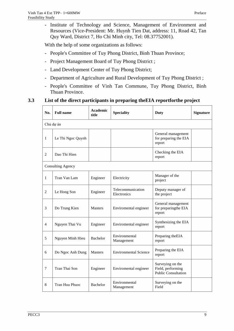
3.3 List of the direct participants in preparing theEIA reportforthe project
No. Full name Academic
title Speciality Duty Signature
Chủ dự án
1 Le Thi Ngoc Quynh
General management
for preparing the EIA
report
2 Dao Thi Hien Checking the EIA
report
Consulting Agency
1 Tran Van Lam Engineer Electricity Manager of the
project
2 Le Hong Son Engineer Telecommunication
Electronics
Deputy manager of
the project
3 Do Trung Kien Masters Enviromental engineer
General management
for preparingthe EIA
report
4 Nguyen Thai Vu Engineer Enviromental engineer Synthesizing the EIA
report
5 Nguyen Minh Hieu Bachelor Environmental
Management
Preparing theEIA
report
6 Do Ngoc Anh Dung Masters Environmental Science Preparing the EIA
report
7 Tran Thai Son Engineer Enviromental engineer
Surveying on the
Field, performing
Public Consultation
8 Tran Huu Phuoc Bachelor Environmental
Management
Surveying on the
Field
Vinh Tan 4 Ext TPP– 1×600MW
Feasibility Study
Preface
PECC3 10
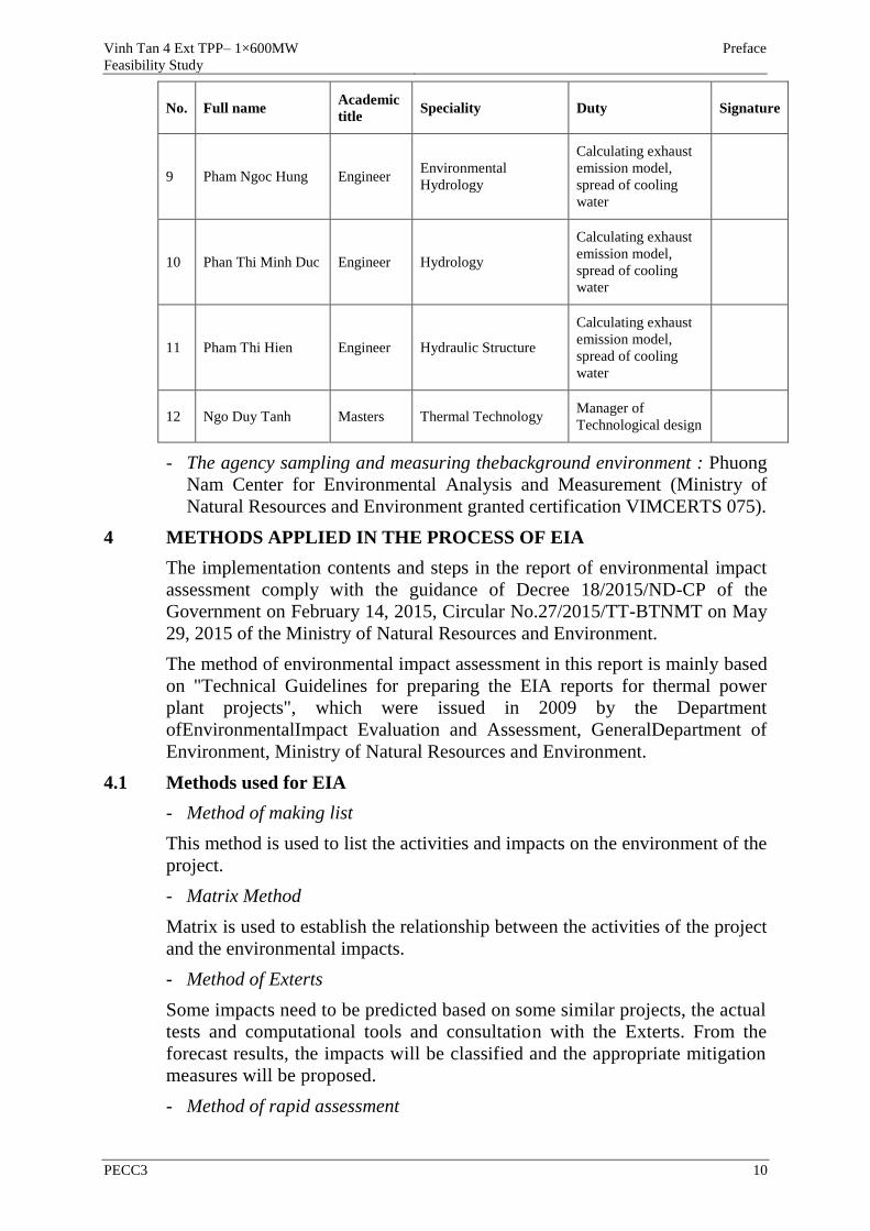
No. Full name Academic
title Speciality Duty Signature
9 Pham Ngoc Hung Engineer Environmental
Hydrology
Calculating exhaust
emission model,
spread of cooling
water
10 Phan Thi Minh Duc Engineer Hydrology
Calculating exhaust
emission model,
spread of cooling
water
11 Pham Thi Hien Engineer Hydraulic Structure
Calculating exhaust
emission model,
spread of cooling
water
12 Ngo Duy Tanh Masters Thermal Technology Manager of
Technological design
- The agency sampling and measuring thebackground environment : Phuong
Nam Center for Environmental Analysis and Measurement (Ministry of
Natural Resources and Environment granted certification VIMCERTS 075).
4 METHODS APPLIED IN THE PROCESS OF EIA
The implementation contents and steps in the report of environmental impact
assessment comply with the guidance of Decree 18/2015/ND-CP of the
Government on February 14, 2015, Circular No.27/2015/TT-BTNMT on May
29, 2015 of the Ministry of Natural Resources and Environment.
The method of environmental impact assessment in this report is mainly based
on "Technical Guidelines for preparing the EIA reports for thermal power
plant projects", which were issued in 2009 by the Department
ofEnvironmentalImpact Evaluation and Assessment, GeneralDepartment of
Environment, Ministry of Natural Resources and Environment.
4.1 Methods used for EIA
- Method of making list
This method is used to list the activities and impacts on the environment of the
project.
- Matrix Method
Matrix is used to establish the relationship between the activities of the project
and the environmental impacts.
- Method of Exterts
Some impacts need to be predicted based on some similar projects, the actual
tests and computational tools and consultation with the Exterts. From the
forecast results, the impacts will be classified and the appropriate mitigation
measures will be proposed.
- Method of rapid assessment
Vinh Tan 4 Ext TPP– 1×600MW
Feasibility Study
Preface
PECC3 11
The rapid assessment method was issued by the World Health Organization
(WHO) in 1993and theguide document of environmental impact assessment of
the World Bank in 1991. The basis of the rapid assessment method is based on
thecharacteristics of materials, technologies, laws of natural processes and
Exterience to quantify the pollutants.
- Method of maps
Using the maps to determinethe project location, the impact scope and levels.
This method requires a number of input datarelatively large and complicated
manipulation skills and processing.
- ModelingMethod
Modeling method is applied to simulate the pollutionspread from the
sources to the surroundings. The following models will be applied:
In order to forecast and evaluate the noise propagation during the
construction and operation of the plant, the project used dB Foresight
software. This software is designed to comply with ISO 9613-2, it allows
calculation of noise propagation of the industrial structures.
In order to calculate and predict the spread process of pollutants in the air,
the report used Breeze AERMOD Plus Pro softwareThis software is written
by Trinity company based on the AERMOD model proposed by Bureau of
environmental protection in the U.S. (U.S. Environmental Protection
Agency, EPA). AERMOD model replaced ISC3 (Industrial Source
Complex Model) of EPA (1995), it allows calculation of the concentration
of pollutants and deposition range from complex industrial discharge
sources.
Using Mike 3 FM modeldeveloped byDHI Water & Environment which uses a
cell-centred finite volumemethod to simulate heating spread due to the cooling
water in the receiving water.
4.2 Other Methods
- Method ofsurveying on the field
Performthe survey on the project construction area to assess the situation and
define specific objects which may be affected by the activities of the project.
- Method of taking samples in the field and analyzing in the laboratory:
Cooperating with specialized units to takethe quality samples of air,surface
water, groundwater, soil, aquatic organismto assess the environmental status
of the area before the project construction.
- Methods of making statistics and processing data
After surveying the field, data are made statistic with many methods such as
descriptive statistics, inference statistics, estimation and testing, analysis and
processing to analyse surveyed data on environmental factors (water, air, etc)
to serve to analyze the environmental situation and environmental impact
assessment.
Vinh Tan 4 Ext TPP– 1×600MW
Feasibility Study
Preface
PECC3 12
- Comparison method:
Based on theresults ofsurvey andmeasurement on the field and calculation
according to the theorycomparing with the Vietnamese nationalstandards
andtechnical regulations to determine the environmental quality in the
project construction area and assess the impacts.
Vinh Tan 4 Ext TPP – 1×600MW
Feasibility Study
Chapter1. Summary Description
PECC3 13
CHAPTER 1 SUMMARY DESCRIPTION OF THE PROJECT
1.1 PROJECT NAME
VINH TAN 4 EXT THERMAL POWER PLANT - 1×600MW.
1.2 PROJECT OWNER
Project owner: ELECTRICITY OF VIETNAM (EVN)
Director General: Mr. Dang Hoang An
Address: No.11 Cua Bac Street, Truc Bach Ward, Ba
Dinh District, Hanoi .
Tel: 04.6.6946789 Fax:04.6.6946666
Representative:
Power Generation Corporation 3
Director General: Mr. Dinh Quoc Lam
Address: Phu My 1 Industrial Zone, Phu My Town, Tan
Thanh District, Ba Ria - Vung Tau Province .
Tel: 064. 3876927 Fax:064.3876930
Project Management Board of Vinh Tan Thermal Power Plant
Deputy Director in charge: Mr. Vo Minh Thang
Address:: Hung Vuong Street, Phu Thuy Ward, Phan
Thiet City, Binh Thuan Province
Tel: 062.2461222 Fax:062.3739684
(VTPMU (Member Unit of GENCO3), will be resposible for management of
Vinh Tan 4 Ext TPP )
1.3 GEOGRAPHICAL LOCATION OF THE PROJECT
1.3.1 Location of the project
Vinh Tan 4 Ext TPP is one of the 05 power plants in Vinh Tan Thermal
Power Complex, built in Vinh Tan Commune - Tuy Phong District - Binh
Thuan province, about 25-30km from Phan Ri Town to the North-East; the
East Sea in the South, Vinh Hao commune in the southwest, Tuy Phong
District and the northeast borders Phuoc Diem commune, Ninh Phuoc district,
Ninh Thuan province. Relative geographical coordinates are as follows:
- Longitude : 108o48’ 00”
- Latitude : 11o20’ 00”
Vinh Tan Power Complex's terrain is sloping towards the coastto the north
east,the south - southeast of the project borders the East Sea, the northwest
borders Highway 1A, the southwest borders Vinh Hao commune, Tuy Phong
district, Binh Thuan province and the northeast borders Phuoc Diem
commune, Ninh Phuoc district, Ninh Thuan province.
Vinh Tan 4 Ext TPP – 1×600MW
Feasibility Study
Chapter1. Summary Description
PECC3 14
Vinh Tan 4 Ext Thermal power plant (VT4 Ext TPP), which belongs to Vinh
Tan Power Complex, will be built in Vinh Tan Commune, Tuy Phong District,
Binh Thuan Province. The project area has the geographical location as
follows:
- To the South: the East Sea;
- To the North: bordering Highway AH1;
- To the East: bordering Vinh Tan 4 TPP ;
- To the West: bordering the residential area of Vinh Tan commune.
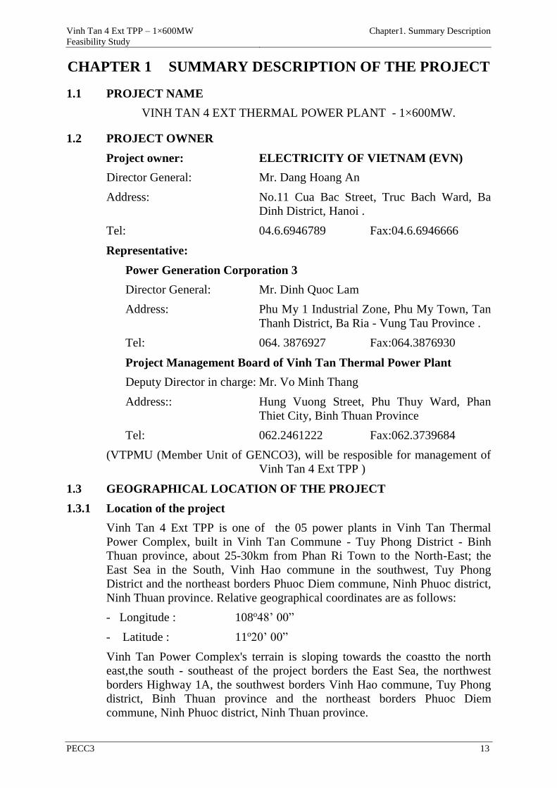
Figure 1.1. Location map of Vinh Tan Power Complex
Figure 1.2. Chart of boundary and control points of Vinh Tan 4 Ext TPP area
Land used as the greenery
corridor of VT4 S=3.54ha
and part of VT4 S= 3.05ha,
becoming land of Vinh Tan
4 Ext TPP
Land used as the greenery
corridor of VT4 S=3.54ha
and part of VT4 S= 3.05ha,
becoming land of Vinh Tan
4 Ext TPP
The area on the
coast 4.07ha
The area sea
encroachment
3.97ha
The area on the
coast 4.07ha
The area sea
encroachment 3.97ha
Vinh Tan 4 Ext TPP – 1×600MW
Feasibility Study
Chapter1. Summary Description
PECC3 15
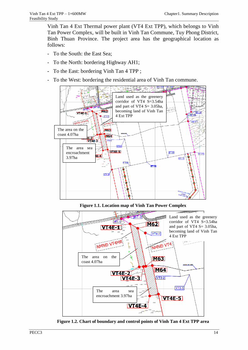
Figure1.3. Chart of boundary and control points of the corridor for insulating from the
ash pond and the flood drainage canal
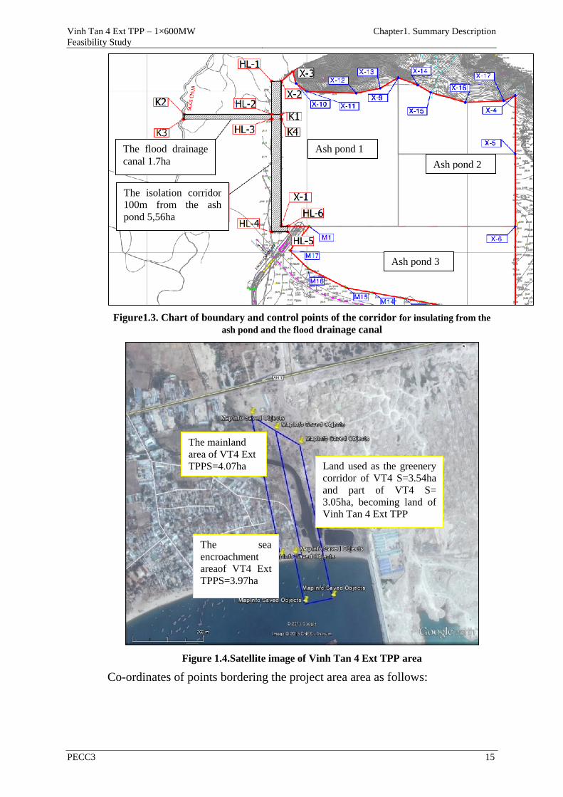
Figure 1.4.Satellite image of Vinh Tan 4 Ext TPP area
Co-ordinates of points bordering the project area area as follows:
Land used as the greenery
corridor of VT4 S=3.54ha
and part of VT4 S=
3.05ha, becoming land of
Vinh Tan 4 Ext TPP
The mainland
area of VT4 Ext
TPPS=4.07ha
The sea
encroachment
areaof VT4 Ext
TPPS=3.97ha
The isolation corridor
100m from the ash
pond 5,56ha
The flood drainage
canal 1.7ha
Ash pond 1
Ash pond 2
Ash pond 3
Vinh Tan 4 Ext TPP – 1×600MW
Feasibility Study
Chapter1. Summary Description
PECC3 16
Table 1.1. Co-ordinates of points bordering the project area
No. Points X_VN2000 (m) Y_VN2000 (m) Note
The power plant area (Area =6.59ha)
I. Main power plant area (Area = 3.54ha) This area is located in the isolation
greenery corridorfrom Vinh Tan 4
TPP, this area is in the allocated land
thereforeno requirement of additional
land.
1 M62 1251743.300 531682.695
2 M63 1251277.758 531781.650
3 M64 1251286.968 531861.479
4 VT4-2 1251687.186 531776.409
II.Auxiliary Structures (Area = 3.05ha) This area which is located in Vinh
Tan 4 TPP was approved by the
Ministry of Industry and Trade in
Decision No.1020/QD-BCT on
March 06,2012.
The isolation greenery corridor on the mainland (Area = 4.07ha)
1 VT 4 EXT-1 1251799.228 531589.016 This area is used as the isolation
greenery corridor and thealigning
canal of Chua stream for Vinh Tan 4
Ext TPP. This area needs to be
allocated additionally and was
approved on the construction site in
Decision No.2347/UBND-KTN on
July 17, 2015 of PC of Binh Thuan
province.
2 VT 4 EXT-2 1251687.186 531776.409
3 VT 4 EXT-3 1251274.790 531753.226
4 M63 1251277.758 531781.650
5 M62 1251743.300 531682.695
The sea encroachment area (Area = 3.97ha)
1 VT 4 EXT-2 1251687.186 531776.409 This area needs to be allocated
additionally andwas approved on the
construction site in Decision
No.2347/UBND-KTN on July 17,
2015 of PC of Binh Thuan province.
2 VT 4 EXT-3 1251274.790 531753.226
3 VT 4 EXT-4 1250912.416 531829.667
4 VT 4 EXT-5 1250935.007 531936.255
5 M64 1251286.968 531861.479
6 M63 1251277.758 531781.650
The isolation corridor 100m from the ash pond (Area = 5,56ha)
1 HL-1 1254061.630 531780.000
This area is used as the isolation
corridor from the ash pond. This area
needs to be allocated additionally
andwas approved on the construction
site in Decision No.2347/UBND-
KTN on July 17, 2015 of PC of Binh
Thuan province.
2 HL-2 1253856.250 531780.000
3 K1 1253856.250 531840.000
4 X2 1254061.630 531840.000
5 HL-3 1253827.250 531780.000
6 HL-4 1253127.250 531780.000
7 HL-5 1253127.250 531880.000
8 HL-6 1253160.000 531880.000
9 X1 1253160.000 531840.000
10 K4 1253827.250 531840.000
The flood drainage canal(Area = 1.7ha)
1 K1 1253856.250 531840.000 This area is used as the flood
Vinh Tan 4 Ext TPP – 1×600MW
Feasibility Study
Chapter1. Summary Description
PECC3 17
No. Points X_VN2000 (m) Y_VN2000 (m) Note
2 K2 1253856.250 531234.717 drainage canal for the ash pond. This
area needs to be allocated
additionally and was approved on the
construction site in Decision
No.2347/UBND-KTN on July 17,
2015 of PC of Binh Thuan province.
3 K3 1253827.250 531232.226
4 K4 1253827.250 531840.000
1.3.2 Correlation of the project position compared with the surrounding objects
1.3.2.1 The natural objects
- Location of the project is adjacent to Highway AH1 to the north, about
920m from North-South Railwayto the north, approximately 9,640m from
Ca Na platformto the northeast;
- Location of the project is adjacent to Chua Stream to the west 2,400m from
Ba Bon stream to the east, approximately 5,436m from Da Bac Reservoir to
the northwest, about 13,280m from Long Song Reservoir to the west,
approximately 11,420m from the Long Song River to thesouthwest, about
18,350m from Phan Dung Reservoir to the northwest, approximately
12,220m from Song Bieu Reservoir to the north, about 19,200m from Tan
Giang Reservoirto the north ;
- Location of the project is about 11,950m from the protective forest
managed by the Management Board of protective forest to the northwest,
about 4km from Mount Ho Duato the northand 5km fromMount Ong Do to
the north-east, about 8,130m fromMountTau to the southwest.
1.3.2.2 The socio-economic Objects
- Location of the project isapproximately 100m from the residential area of
Hamlet 7, Vinh Tan commune to the southwest, approximately 1.5km to the
residential area to the east, about 4km from Linh Son Pagoda to the north,
about 3,300km from the Ca Na resort to the east,about 5,200m from the
Vietnam - Cubatourist area to theeast,about 720m from the Vinh
TanMarketand Vinh Tan fishing port to the southwest;
- Location of the project isapproximately 1.5 km from thearea of aquaculture
zone (Shrimp variety) to the east, about 3.7km from Vinh Hao saltern
areato the west, 14,330m from Quan The saltern areato the northeast, about
21,465m from Phuoc Nam industrial zone to the northeast ;
- Location of the project is about 8,050m from Vinh Hao Mineral Water
Plant to the southwest, about 2,540m from Thong Thuan Ltd. Company to
the east.
1.3.2.3 The other surrounding objects
- Location of Vinh Tan 4 Ext TPP is adjacent to Vinh Tan 4 TPP, from Phan
Thiet to Ninh Thuan ,TPPs in Vinh Tan Thermal Power Complex are in
location orderas follows: Vinh Tan 4 Ext TPP, Vinh Tan 4 TPP, Vinh Tan 3
TPP, Vinh Tan 2 TPP, Vinh Tan 1 TPP.
- Location of the project is about 2,830m from People's Committee of Vinh
Tan Commune to the east, about 12,180m from the center of Lien Huong
Vinh Tan 4 Ext TPP – 1×600MW
Feasibility Study
Chapter1. Summary Description
PECC3 18
town to the southwest;
- Location of the project is about 10,100m from Hon Cau island to the
south,about 8km from the boundary of buffer zone 1 of Hon Cau MPA,
approximately 5.6km from the boundary of buffer zone 2 of Breda Sand
bar. (For more details, please see Section 2.1.6.2.2).
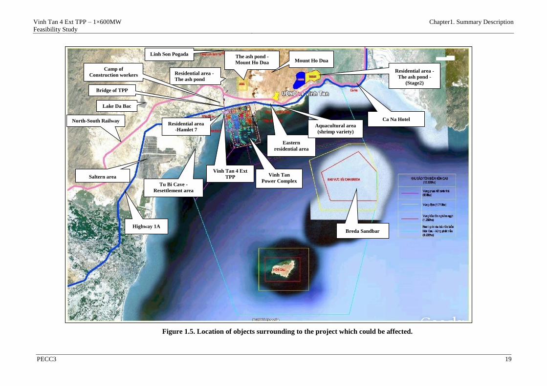
Vinh Tan 4 Ext TPP – 1×600MW
Feasibility Study
Chapter1. Summary Description
PECC3 19
Figure 1.5. Location of objects surrounding to the project which could be affected.
Linh Son Pogada The ash pond -
Mount Ho Dua
Residential area -
The ash pond -
(Stage2)
North-South Railway
Highway 1A
Residential area
-Hamlet 7
Eastern
residential area
Ca Na Hotel
Saltern area
Aquacultural area
(shrimp variety)
Breda Sandbar
Vinh Tan
Power Complex
Mount Ho Dua
Vinh Tan 4 Ext
TPP
Bridge of TPP
Residential area -
The ash pond
Tu Bi Cave -
Resettlement area
Camp of
Construction workers
4,54ha
Lake Da Bac
Vinh Tan 4 Ext TPP – 1×600MW
Feasibility Study
Chapter1. Summary Description
PECC3 20
1.3.3 Plans of site selection for the project construction
Location of Vinh Tan Power Complex is considered the best location
toconsider for Extanding the following specific conditions:
- Infrastructure: The power and water supplymeet the needs of construction;
- Land area in Vinh Tan 4 TPP is sufficient to allocate additionallyone
turbine of 600MW. Eligibility for land: land Extanded to the west about 80
m in the area Extected to plant trees, theisolation space from the power
plantunder the planning which has been approved by the Ministry of
Industry and Trade to negotiate with the local authorities. In addition, part
for planting trees used as the isolation area for the project was approved
byPeople's Committee of Binh Thuan province ;
- Coal berth : The whole of navigable channel, turning basin, break waters
and other auxiliary items were completely built to meet the requirements for
the coal supply. Regarding the coal berth which will be shared with Vinh
Tan 4 TPP, it only needs to changethe loading equipmentfrom type of
grabbucketto become type of continuously loading and unloading
equipment;
- 500kV Switchgear of Vinh Tan Thermal Power Complex: the bays
havebeen completed to connect to communication transformers and
outgoing feeders to Song May transmission line (circuit 1 & 2). Option of
building VT4 & VT4 Ext 500kV switch gear to connect to threegenerators
from VT4, VT4 Ext. This switchgear will connect to 500kV switch gear of
Vinh Tan Power Complex through two circuits of the 500kV transmission
line.
Therefore, this option will developone TPP × 600MW to the west of Vinh Tan
Power Complex which has been reviewed. Specific details are as follows:
- Main turbine room (including turbines, boilers, transformers, SCR, ESP,
FGD, stacks) will be invested and separately arranged. The main turbine
room of VT4 Ext will be allocated right nExt to the main turbine room of
Vinh Tan 4 TPP on the isolation area from the residential area of Vinh Tan
4 TPP project (this area was handed over to EVN). Thus, the entire boiler
house and turbine house will be connected to the boiler house and turbine
house of Vinh Tan 4 TPP, to optimize the common systemfortwo important
items, reduce the common investment cost for two projects;
- Depending the construction schedule ofitems of Vinh Tan 4 TPP and the
approved schedule of Vinh Tan 4 Ext TPP, the auxiliary systems will be
considered tobe shared with two power plants or to be usedseparately.
From the above characteristics, Vinh Tan 4 Ext TPP (600MW) has the
favorable conditions in location, infrastructure, port, capability of importing
fuel, ability of grid connection convenient and synchronous. On the other hand
Vinh Tan 4 Ext TPP can be built quickly, and will be put into operation early
(Extected in 2019) and will contribute a significant power (3900 GWh/year),
reduce the power shortage in South Vietnam, reducethe stress in operation of
the north - south 500kV transmission system.
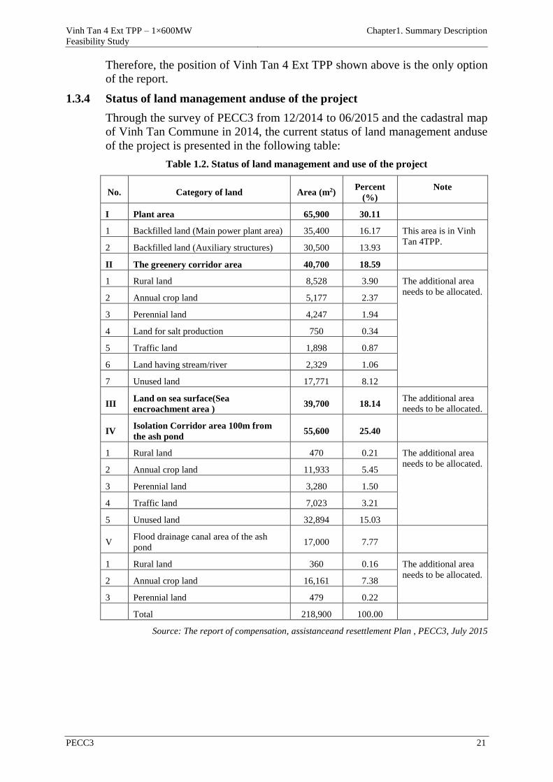
Vinh Tan 4 Ext TPP – 1×600MW
Feasibility Study
Chapter1. Summary Description
PECC3 21
Therefore, the position of Vinh Tan 4 Ext TPP shown above is the only option
of the report.
1.3.4 Status of land management anduse of the project
Through the survey of PECC3 from 12/2014 to 06/2015 and the cadastral map
of Vinh Tan Commune in 2014, the current status of land management anduse
of the project is presented in the following table:
Table 1.2. Status of land management and use of the project
No. Category of land Area (m2) Percent
(%)
Note
I Plant area 65,900 30.11
1 Backfilled land (Main power plant area) 35,400 16.17 This area is in Vinh
Tan 4TPP. 2 Backfilled land (Auxiliary structures) 30,500 13.93
II The greenery corridor area 40,700 18.59
1 Rural land 8,528 3.90 The additional area
needs to be allocated. 2 Annual crop land 5,177 2.37
3 Perennial land 4,247 1.94
4 Land for salt production 750 0.34
5 Traffic land 1,898 0.87
6 Land having stream/river 2,329 1.06
7 Unused land 17,771 8.12
III Land on sea surface(Sea
encroachment area ) 39,700 18.14
The additional area
needs to be allocated.
IV Isolation Corridor area 100m from
the ash pond 55,600 25.40
1 Rural land 470 0.21 The additional area
needs to be allocated. 2 Annual crop land 11,933 5.45
3 Perennial land 3,280 1.50
4 Traffic land 7,023 3.21
5 Unused land 32,894 15.03
V Flood drainage canal area of the ash
pond 17,000 7.77
1 Rural land 360 0.16 The additional area
needs to be allocated. 2 Annual crop land 16,161 7.38
3 Perennial land 479 0.22
Total 218,900 100.00
Source: The report of compensation, assistanceand resettlement Plan , PECC3, July 2015
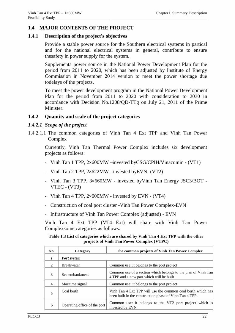
Vinh Tan 4 Ext TPP – 1×600MW
Feasibility Study
Chapter1. Summary Description
PECC3 22
1.4 MAJOR CONTENTS OF THE PROJECT
1.4.1 Description of the project's objectives
Provide a stable power source for the Southern electrical systems in partical
and for the national electrical systems in general, contribute to ensure
thesafety in power supply for the system.
Supplementa power source in the National Power Development Plan for the
period from 2011 to 2020, which has been adjusted by Institute of Energy
Commission in November 2014 version to meet the power shortage due
todelays of the projects.
To meet the power development program in the National Power Development
Plan for the period from 2011 to 2020 with consideration to 2030 in
accordance with Decision No.1208/QD-TTg on July 21, 2011 of the Prime
Minister.
1.4.2 Quantity and scale of the project categories
1.4.2.1 Scope of the project
1.4.2.1.1 The common categories of Vinh Tan 4 Ext TPP and Vinh Tan Power
Complex
Currently, Vinh Tan Thermal Power Complex includes six development
projects as follows:
- Vinh Tan 1 TPP, 2×600MW –invested byCSG/CPIH/Vinacomin - (VT1)
- Vinh Tan 2 TPP, 2×622MW - invested byEVN- (VT2)
- Vinh Tan 3 TPP, 3×660MW - invested byVinh Tan Energy JSC3/BOT -
VTEC - (VT3)
- Vinh Tan 4 TPP, 2×600MW - invested by EVN - (VT4)
- Construction of coal port cluster -Vinh Tan Power Complex-EVN
- Infrastructure of Vinh Tan Power Complex (adjusted) - EVN
Vinh Tan 4 Ext TPP (VT4 Ext) will share with Vinh Tan Power
Complexsome categories as follows:
Table 1.3 List of categories which are shared by Vinh Tan 4 Ext TPP with the other
projects of Vinh Tan Power Complex (VTPC)
No. Category The common projects of Vinh Tan Power Complex
I Port system
2 Breakwater Common use: it belongs to the port project
3 Sea embankment Common use of a section which belongs to the plan of Vinh Tan
4 TPP and a new part which will be built.
4 Maritime signal Common use: it belongs to the port project
5 Coal berth Vinh Tan 4 Ext TPP will use the common coal berth which has
been built in the construction phase of Vinh Tan 4 TPP.
6 Operating office of the port Common use: it belongs to the VT2 port project which is
invested by EVN
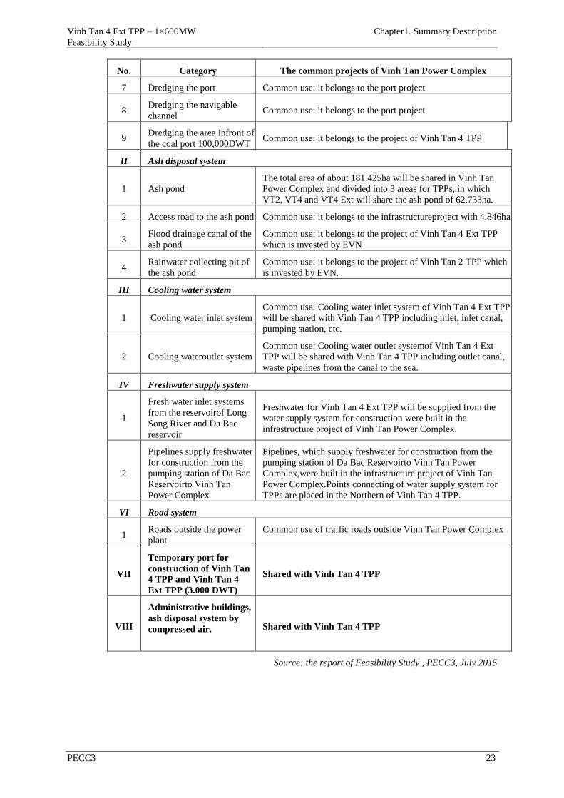
Vinh Tan 4 Ext TPP – 1×600MW
Feasibility Study
Chapter1. Summary Description
PECC3 23
No. Category The common projects of Vinh Tan Power Complex
7 Dredging the port Common use: it belongs to the port project
8 Dredging the navigable
channel Common use: it belongs to the port project
9 Dredging the area infront of
the coal port 100,000DWT Common use: it belongs to the project of Vinh Tan 4 TPP
II Ash disposal system
1 Ash pond
The total area of about 181.425ha will be shared in Vinh Tan
Power Complex and divided into 3 areas for TPPs, in which
VT2, VT4 and VT4 Ext will share the ash pond of 62.733ha.
2 Access road to the ash pond Common use: it belongs to the infrastructureproject with 4.846ha
3 Flood drainage canal of the
ash pond
Common use: it belongs to the project of Vinh Tan 4 Ext TPP
which is invested by EVN
4 Rainwater collecting pit of
the ash pond
Common use: it belongs to the project of Vinh Tan 2 TPP which
is invested by EVN.
III Cooling water system
1 Cooling water inlet system
Common use: Cooling water inlet system of Vinh Tan 4 Ext TPP
will be shared with Vinh Tan 4 TPP including inlet, inlet canal,
pumping station, etc.
2 Cooling wateroutlet system
Common use: Cooling water outlet systemof Vinh Tan 4 Ext
TPP will be shared with Vinh Tan 4 TPP including outlet canal,
waste pipelines from the canal to the sea.
IV Freshwater supply system
1
Fresh water inlet systems
from the reservoirof Long
Song River and Da Bac
reservoir
Freshwater for Vinh Tan 4 Ext TPP will be supplied from the
water supply system for construction were built in the
infrastructure project of Vinh Tan Power Complex
2
Pipelines supply freshwater
for construction from the
pumping station of Da Bac
Reservoirto Vinh Tan
Power Complex
Pipelines, which supply freshwater for construction from the
pumping station of Da Bac Reservoirto Vinh Tan Power
Complex,were built in the infrastructure project of Vinh Tan
Power Complex.Points connecting of water supply system for
TPPs are placed in the Northern of Vinh Tan 4 TPP.
VI Road system
1 Roads outside the power
plant
Common use of traffic roads outside Vinh Tan Power Complex
VII
Temporary port for
construction of Vinh Tan
4 TPP and Vinh Tan 4
Ext TPP (3.000 DWT)
Shared with Vinh Tan 4 TPP
VIII
Administrative buildings,
ash disposal system by
compressed air.
Shared with Vinh Tan 4 TPP
Source: the report of Feasibility Study , PECC3, July 2015
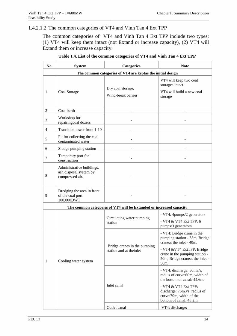
Vinh Tan 4 Ext TPP – 1×600MW
Feasibility Study
Chapter1. Summary Description
PECC3 24
1.4.2.1.2 The common categories of VT4 and Vinh Tan 4 Ext TPP
The common categories of VT4 and Vinh Tan 4 Ext TPP include two types:
(1) VT4 will keep them intact (not Extand or increase capacity), (2) VT4 will
Extand them or increase capacity.
Table 1.4. List of the common categories of VT4 and Vinh Tan 4 Ext TPP
No. System Categories Note
The common categories of VT4 are keptas the initial design
1 Coal Storage Dry coal storage;
Wind-break barrier
VT4 will keep two coal
storages intact.
VT4 will build a new coal
storage
2 Coal berth - -
3 Workshop for
repairingcoal dozers - -
4 Transition tower from 1-10 - -
5 Pit for collecting the coal
contaminated water - -
6 Sludge pumping station - -
7 Temporary port for
construction - -
8
Administrative buildings,
ash disposal system by
compressed air.
- -
9
Dredging the area in front
of the coal port
100,000DWT
- -
The common categories of VT4 will be Extanded or increased capacity
1 Cooling water system
Circulating water pumping
station
- VT4: 4pumps/2 generators
- VT4 & VT4 Ext TPP: 6
pumps/3 generators
Bridge cranes in the pumping
station and at theinlet
- VT4: Bridge crane in the
pumping station - 35m, Bridge
craneat the inlet - 40m.
- VT4 &VT4 ExtTPP: Bridge
crane in the pumping station -
50m, Bridge craneat the inlet -
56m.
Inlet canal
- VT4: discharge: 50m3/s,
radius of curve:60m, width of
the bottom of canal: 44.6m.
- VT4 & VT4 Ext TPP:
discharge: 75m3/s, radius of
curve:70m, width of the
bottom of canal: 48.2m.
Outlet canal VT4: discharge:

Vinh Tan 4 Ext TPP – 1×600MW
Feasibility Study
Chapter1. Summary Description
PECC3 25
No. System Categories Note
50m3/s,width of the bottom of
canal: 14m.
- VT4 & VT4 Ext TPP:
discharge: 75m3/s,, width of
the bottom of canal: 26m..
2 Coal handling system
Coal berth changes the
loading equipmentfrom type
of grab bucket to become type
of continuously loading and
unloading equipment
- VT4: grab bucket:
2×1,600t/h.
-VT4 & VT4 Ext TPP: :
type of continuously loading
and unloading
equipment2×1,600t/h.
Open coal storage, dry coal
storage;
- VT4: storing for 30 days,
Length of the dry coal
storage:54m;
- VT4 & VT4 Ext TPP:storing
for 30 days, Length of the dry
coal storage: 78m.
Coal conveyor, transition
tower, equipment for piling up
or piling out
- VT4: Piling up3,000t/h,
piling out1,200t/h;
- VT4 & VT4 Ext TPP: Piling
up 3,200t/h, piling out
1,800t/h.
Coal distribution corridor
forBunker -
3 DO system DO tank, oil pump
- VT4: FO, 2tanks x
1.000m3;
- VT4 & VT4 Ext: DO, 2tanks
x 1,500m3.
4 Raw water system Raw water pump, reservoir
- VT4: freshwater 220 m3/h,
sea water 578 m3/h;
- VT4 & VT4 Ext:freshwater
330 m3/h, sea water867 m3/h.
5 Gas system
Hydrogen production system
- VT4: High pressure tank
1,603Nm3;
- VT4 & VT4 Ext:High
pressure tank 2,100Nm3.
CO2Gas system
- VT4: 72 containers;
- VT4 & VT4 Ext: 108
containers.
N2Gas system No supplement
6 500 kV switchgear 500 kV switchgear, Control
room of switchgear
Supplement a connection
system to the switchgear from
Vinh Tan 4 Ext TPP
7 System for fire fighting
andprevention
Designed to share with VT4,
pump and main water supply
Supplement connection to the
pipelines for fire fighting
andprevention of VT4 and the
areas in Vinh Tan 4 Ext TPP.
8 Chlorine gas system Shared with VT4 Supplement equipment to
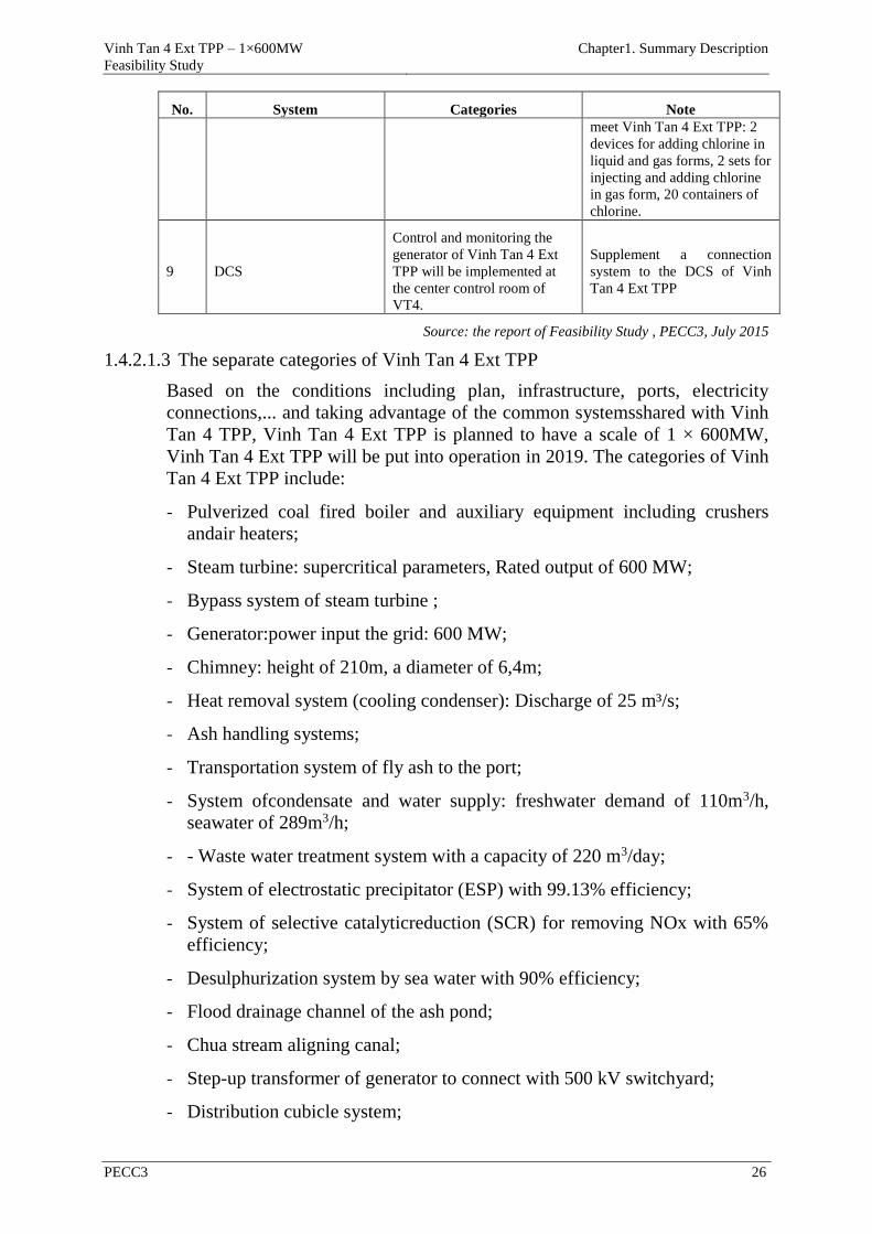
Vinh Tan 4 Ext TPP – 1×600MW
Feasibility Study
Chapter1. Summary Description
PECC3 26
No. System Categories Note
meet Vinh Tan 4 Ext TPP: 2
devices for adding chlorine in
liquid and gas forms, 2 sets for
injecting and adding chlorine
in gas form, 20 containers of
chlorine.
9 DCS
Control and monitoring the
generator of Vinh Tan 4 Ext
TPP will be implemented at
the center control room of
VT4.
Supplement a connection
system to the DCS of Vinh
Tan 4 Ext TPP
Source: the report of Feasibility Study , PECC3, July 2015
1.4.2.1.3 The separate categories of Vinh Tan 4 Ext TPP
Based on the conditions including plan, infrastructure, ports, electricity
connections,... and taking advantage of the common systemsshared with Vinh
Tan 4 TPP, Vinh Tan 4 Ext TPP is planned to have a scale of 1 × 600MW,
Vinh Tan 4 Ext TPP will be put into operation in 2019. The categories of Vinh
Tan 4 Ext TPP include:
- Pulverized coal fired boiler and auxiliary equipment including crushers
andair heaters;
- Steam turbine: supercritical parameters, Rated output of 600 MW;
- Bypass system of steam turbine ;
- Generator:power input the grid: 600 MW;
- Chimney: height of 210m, a diameter of 6,4m;
- Heat removal system (cooling condenser): Discharge of 25 m³/s;
- Ash handling systems;
- Transportation system of fly ash to the port;
- System ofcondensate and water supply: freshwater demand of 110m3/h,
seawater of 289m3/h;
- - Waste water treatment system with a capacity of 220 m3/day;
- System of electrostatic precipitator (ESP) with 99.13% efficiency;
- System of selective catalyticreduction (SCR) for removing NOx with 65%
efficiency;
- Desulphurization system by sea water with 90% efficiency;
- Flood drainage channel of the ash pond;
- Chua stream aligning canal;
- Step-up transformer of generator to connect with 500 kV switchyard;
- Distribution cubicle system;
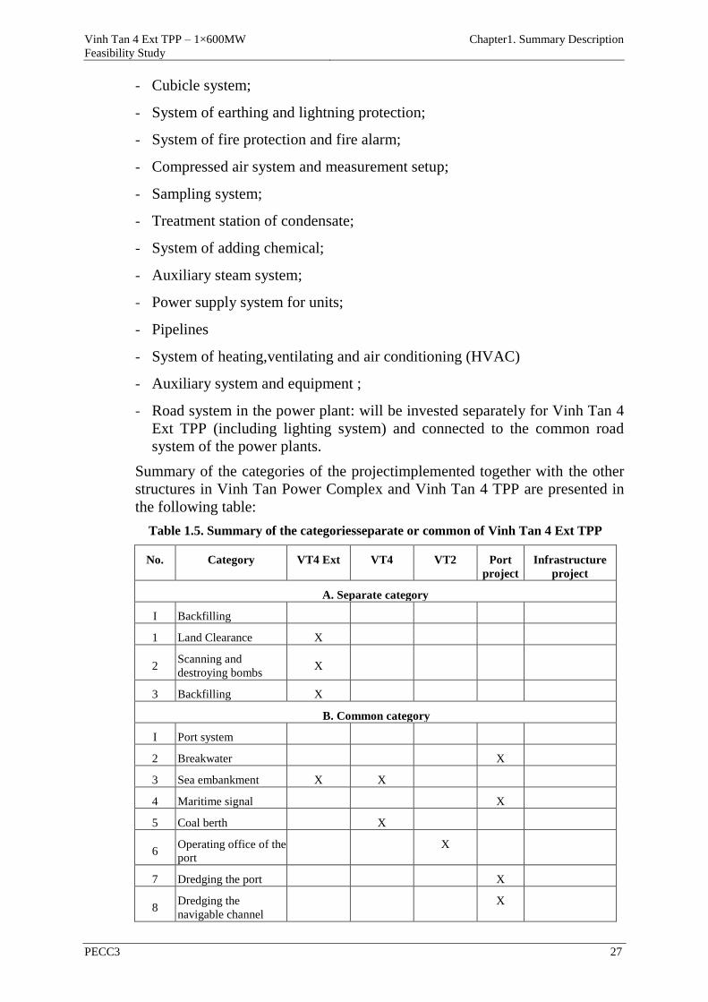
Vinh Tan 4 Ext TPP – 1×600MW
Feasibility Study
Chapter1. Summary Description
PECC3 27
- Cubicle system;
- System of earthing and lightning protection;
- System of fire protection and fire alarm;
- Compressed air system and measurement setup;
- Sampling system;
- Treatment station of condensate;
- System of adding chemical;
- Auxiliary steam system;
- Power supply system for units;
- Pipelines
- System of heating,ventilating and air conditioning (HVAC)
- Auxiliary system and equipment ;
- Road system in the power plant: will be invested separately for Vinh Tan 4
Ext TPP (including lighting system) and connected to the common road
system of the power plants.
Summary of the categories of the projectimplemented together with the other
structures in Vinh Tan Power Complex and Vinh Tan 4 TPP are presented in
the following table:
Table 1.5. Summary of the categoriesseparate or common of Vinh Tan 4 Ext TPP
No. Category VT4 Ext VT4 VT2 Port
project
Infrastructure
project
A. Separate category
I Backfilling
1 Land Clearance X
2 Scanning and
destroying bombs X
3 Backfilling X
B. Common category
I Port system
2 Breakwater X
3 Sea embankment X X
4 Maritime signal X
5 Coal berth X
6 Operating office of the
port
X
7 Dredging the port X
8 Dredging the
navigable channel
X
Vinh Tan 4 Ext TPP – 1×600MW
Feasibility Study
Chapter1. Summary Description
PECC3 28
No. Category VT4 Ext VT4 VT2 Port
project
Infrastructure
project
9
Dredging the area in
front of the coal port
100,000DWT
X
II Ash disposal system
1 Ash pond X
2 Access road to the ash
pond
X
3 Flood drainage canal
of the ash pond X
III Cooling water system
1 Cooling water inlet
system
X
2 Cooling water outlet
system
X
IV Freshwater supply system
1
Fresh water inlet
systems from the
reservoirof Long Song
River and Da Bac
reservoir
X
2
Pipelines supply
freshwater for
construction from the
pumping station of Da
Bac Reservoirto Vinh
Tan Power Complex
X
V Road system
1 Roads inside VT4
TPP X
2 Roads outside the
power plant
X
VI
Temporary port for
construction of VT4
and VT4 Ext TPP
(3,000 DWT)
X
1.4.2.2 Relevant Thermal power plants in Vinh Tan Power Complex
1.4.2.2.1 Vinh Tan 1 Thermal power plant
Vinh Tan 1 Thermal power plant with capacity of 2×600 MW isinvested by
CSG/CPIH/Vinacominthat is a consortium of investors.
Vinh Tan 1 Thermal power plant is located in the general planning area of
Vinh Tan Power Complex, the ash pond for VT1 will use the ash pond in Area
2 at the bottom of Mount Ho Dua with the area of 57.3ha.
Technology selected for VT1 is kind of traditional condenser thermal power
technology. According to the design, two units of the plant will be built with a
capacity of 600MW.

Vinh Tan 4 Ext TPP – 1×600MW
Feasibility Study
Chapter1. Summary Description
PECC3 29
Currently, Vinh Tan 1 TPP has been prepared to invest and will be put into
operation in 2019.
The environmental protection measures in Vinh Tan1 TPP:
- Cooling water: discharge is 45.36 m3/s.
- Exhaust emissions:
Table 1.6. Exhaust gas treatment efficiency of VT1 TPP
No. Parameter Concentration
before treatment
(mg/Nm3)
Treatment efficiency Concentration
after treatment
(mg/Nm3)
1 Dust 36,920 ESP with efficiency of99.7% 98
2 SO2 1,530 FGD with efficiency of 90.5% 144
3 NOx 2,400 SCR with efficiency of 87.5% 300
Source: The EIA report of VT1 TPP was approved by MONRE
1.4.2.2.2 Vinh Tan 2 Thermal power plant
VT2 TPP with capacity of 2×622 MW is invested by EVN.
Vinh Tan 2 Thermal power plant is located in the general planning area of
Vinh Tan Power Complex, the ash pond for VT2 will share with VT4 and
VT4 Ext the ash pond in Area 1 at the bottom of Mount Ho Dua with the area
62.733ha.
Technology selected for VT2 is kind of traditional condenser thermal power
technology. According to the design, two units of the plant will be built with a
capacity of 622MW.
Currently, VT2 has been put into operation, in which Unit 1 started operation
on January 30, 2015, Unit 2 started operation on March 21, 2015.
The environmental protection measures in Vinh Tan 2 TPP:
- Cooling water: discharge is 58 m3/s.
- Exhaust emissions:
Table 1.7. Exhaust gas treatment efficiency of VT2 TPP
No. Parameter Concentration before
treatment (mg/Nm3)
Treatment efficiency Concentration after
treatment (mg/Nm3)
The EIA report was approved
1 Dust 36,920 ESP with efficiency of 99.5% 148
2 SO2 1,530 FGD with efficiency of 90% 153
3 NOx 2,397 SCR with efficiency of 88.4% 278
Unit 1
1 Dust 38,425.8 ESP with efficiency of 99.89% 40.9
2 SO2 882.1 FGD with efficiency of 99.77% 2.04
3 NOx 884.3 SCR with efficiency of 94.3% 51
Unit 2
1 Dust 40.547,1 ESP with efficiency of 99.92% 32.9
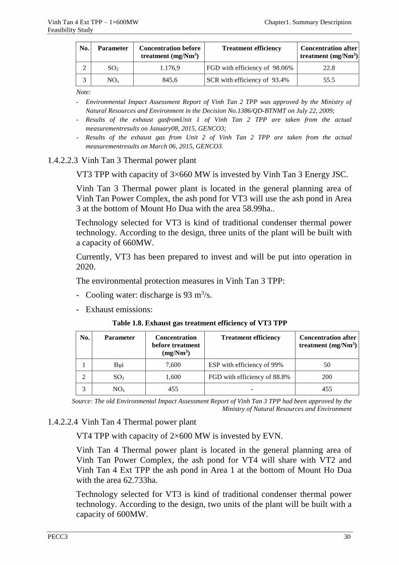
Vinh Tan 4 Ext TPP – 1×600MW
Feasibility Study
Chapter1. Summary Description
PECC3 30
No. Parameter Concentration before
treatment (mg/Nm3)
Treatment efficiency Concentration after
treatment (mg/Nm3)
2 SO2 1.176,9 FGD with efficiency of 98.06% 22.8
3 NOx 845,6 SCR with efficiency of 93.4% 55.5
Note:
- Environmental Impact Assessment Report of Vinh Tan 2 TPP was approved by the Ministry of
Natural Resources and Environment in the Decision No.1386/QD-BTNMT on July 22, 2009;
- Results of the exhaust gasfromUnit 1 of Vinh Tan 2 TPP are taken from the actual
measurementresults on January08, 2015, GENCO3;
- Results of the exhaust gas from Unit 2 of Vinh Tan 2 TPP are taken from the actual
measurementresults on March 06, 2015, GENCO3.
1.4.2.2.3 Vinh Tan 3 Thermal power plant
VT3 TPP with capacity of 3×660 MW is invested by Vinh Tan 3 Energy JSC.
Vinh Tan 3 Thermal power plant is located in the general planning area of
Vinh Tan Power Complex, the ash pond for VT3 will use the ash pond in Area
3 at the bottom of Mount Ho Dua with the area 58.99ha..
Technology selected for VT3 is kind of traditional condenser thermal power
technology. According to the design, three units of the plant will be built with
a capacity of 660MW.
Currently, VT3 has been prepared to invest and will be put into operation in
2020.
The environmental protection measures in Vinh Tan 3 TPP:
- Cooling water: discharge is 93 m3/s.
- Exhaust emissions:
Table 1.8. Exhaust gas treatment efficiency of VT3 TPP
No. Parameter Concentration
before treatment
(mg/Nm3)
Treatment efficiency Concentration after
treatment (mg/Nm3)
1 Bụi 7,600 ESP with efficiency of 99% 50
2 SO2 1,600 FGD with efficiency of 88.8% 200
3 NOx 455 - 455
Source: The old Environmental Impact Assessment Report of Vinh Tan 3 TPP had been approved by the
Ministry of Natural Resources and Environment
1.4.2.2.4 Vinh Tan 4 Thermal power plant
VT4 TPP with capacity of 2×600 MW is invested by EVN.
Vinh Tan 4 Thermal power plant is located in the general planning area of
Vinh Tan Power Complex, the ash pond for VT4 will share with VT2 and
Vinh Tan 4 Ext TPP the ash pond in Area 1 at the bottom of Mount Ho Dua
with the area 62.733ha.
Technology selected for VT3 is kind of traditional condenser thermal power
technology. According to the design, two units of the plant will be built with a
capacity of 600MW.
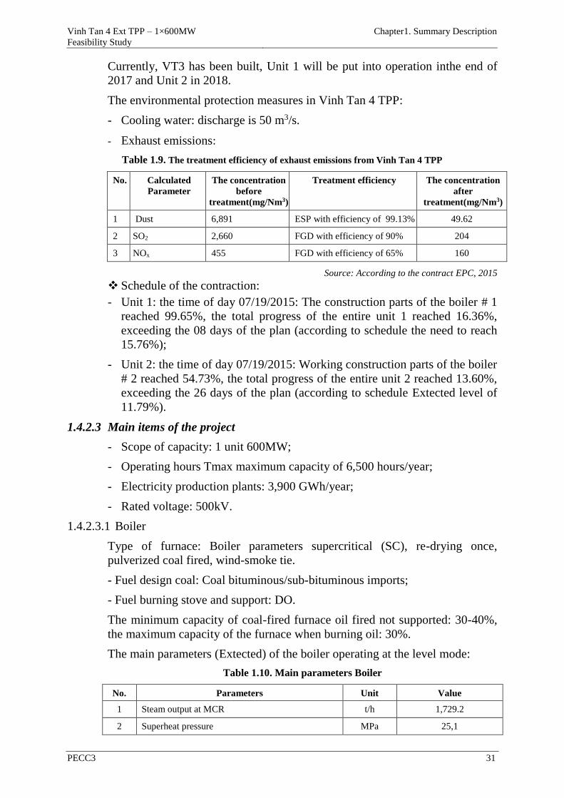
Vinh Tan 4 Ext TPP – 1×600MW
Feasibility Study
Chapter1. Summary Description
PECC3 31
Currently, VT3 has been built, Unit 1 will be put into operation inthe end of
2017 and Unit 2 in 2018.
The environmental protection measures in Vinh Tan 4 TPP:
- Cooling water: discharge is 50 m3/s.
- Exhaust emissions:
Table 1.9. The treatment efficiency of exhaust emissions from Vinh Tan 4 TPP
No. Calculated
Parameter
The concentration
before
treatment(mg/Nm3)
Treatment efficiency The concentration
after
treatment(mg/Nm3)
1 Dust 6,891 ESP with efficiency of 99.13% 49.62
2 SO2 2,660 FGD with efficiency of 90% 204
3 NOx 455 FGD with efficiency of 65% 160
Source: According to the contract EPC, 2015
Schedule of the contraction:
- Unit 1: the time of day 07/19/2015: The construction parts of the boiler # 1
reached 99.65%, the total progress of the entire unit 1 reached 16.36%,
exceeding the 08 days of the plan (according to schedule the need to reach
15.76%);
- Unit 2: the time of day 07/19/2015: Working construction parts of the boiler
# 2 reached 54.73%, the total progress of the entire unit 2 reached 13.60%,
exceeding the 26 days of the plan (according to schedule Extected level of
11.79%).
1.4.2.3 Main items of the project
- Scope of capacity: 1 unit 600MW;
- Operating hours Tmax maximum capacity of 6,500 hours/year;
- Electricity production plants: 3,900 GWh/year;
- Rated voltage: 500kV.
1.4.2.3.1 Boiler
Type of furnace: Boiler parameters supercritical (SC), re-drying once,
pulverized coal fired, wind-smoke tie.
- Fuel design coal: Coal bituminous/sub-bituminous imports;
- Fuel burning stove and support: DO.
The minimum capacity of coal-fired furnace oil fired not supported: 30-40%,
the maximum capacity of the furnace when burning oil: 30%.
The main parameters (Extected) of the boiler operating at the level mode:
Table 1.10. Main parameters Boiler
No. Parameters Unit Value
1 Steam output at MCR t/h 1,729.2
2 Superheat pressure MPa 25,1

Vinh Tan 4 Ext TPP – 1×600MW
Feasibility Study
Chapter1. Summary Description
PECC3 32
No. Parameters Unit Value
3 Superheat temperature oC 569.8
4 Flow of reheat steam t/h 1,375.5
5 Pressure of input/output reheat steam MPa 4.663/4.467
6 Temperature of input/output reheat steam oC 320/594.4
7 Water supply temperature oC 295.3
Source: General Disclosures, PECC3, 7/2015
BMCR operating mode will have a slightly higher volume of about 5%
compared with the steam flow above.
Boiler Efficiency (operating conditions, Extected): 86.7% (HHV).
1.4.2.3.2 Turbine
Turbine type: Parameter supercritical (SC), intermediate 1 was re-drying,
coaxial. The operating parameters of the turbine (Extected) as follows:
Table 1.11. Main parameters Turbine
STT Turbine parameters Unit Value
1 Power output MW 600
2 Pressure upstream main STOP valve MPa (abs) 24,2
3 Temperature upstream main STOP valve °C 566
4 Pressure of re-heat steam MPa 4,35
5 Temperature of re-heat steam °C 593
6 Rated speed RPM 3.000
7 Cooling water temperature °C 27,6
8 Back pressure kPa (abs) 6,58
9 Main steam flow t/h 1.729
10 Reheated steam flow t/h 1.375
11 Turbine heat rate kJ/kWh 7.533
12 Number of Extractions Set 8
13 Feedwater pumpWheel Drive
2×50% Turbine pumps +
1×30% Power pumps
Source: General Disclosures, PECC3, 7/2015
1.4.2.3.3 Steam turbine generator
The generator is connected directly to the turbine axis, the horizontal type,
synchronous, 3-phase, water-cooled systems and hydrogen.
Rated power of the transmitter is greater than the maximum capacity of the
turbine.
Table 1.12. Main parameters Steam turbine genetor
Type: 2 poles, totally enclosed casing, synchronous, 3-phase.
Raw Power play to the grid: Approximately 600MW
Capacity largest continuous: to be determined by the maximum power of the turbine.
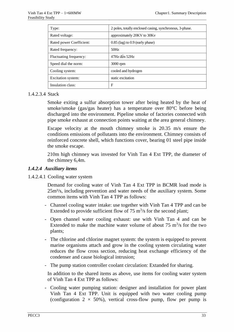
Vinh Tan 4 Ext TPP – 1×600MW
Feasibility Study
Chapter1. Summary Description
PECC3 33
Type: 2 poles, totally enclosed casing, synchronous, 3-phase.
Rated voltage: approximately 20KV to 30Kv
Rated power Coefficient: 0.85 (lag) to 0.9 (early phase)
Rated frequency: 50Hz
Fluctuating frequency: 47Hz đến 52Hz
Speed dial the norm: 3000 rpm
Cooling system: cooled and hydrogen
Excitation system: static excitation
Insulation class: F
1.4.2.3.4 Stack
Smoke exiting a sulfur absorption tower after being heated by the heat of
smoke/smoke (gas/gas heater) has a temperature over 80°C before being
discharged into the environment. Pipeline smoke of factories connected with
pipe smoke exhaust at connection points waiting at the area general chimney.
Escape velocity at the mouth chimney smoke is 20.35 m/s ensure the
conditions emissions of pollutants into the environment. Chimney consists of
reinforced concrete shell, which functions cover, bearing 01 steel pipe inside
the smoke escape.
210m high chimney was invested for Vinh Tan 4 Ext TPP, the diameter of
the chimney 6,4m.
1.4.2.4 Auxiliary items
1.4.2.4.1 Cooling water system
Demand for cooling water of Vinh Tan 4 Ext TPP in BCMR load mode is
25m³/s, including prevention and water needs of the auxiliary system. Some
common items with Vinh Tan 4 TPP as follows:
- Channel cooling water intake: use together with Vinh Tan 4 TPP and can be
Extended to provide sufficient flow of 75 m3/s for the second plant;
- Open channel water cooling exhaust: use with Vinh Tan 4 and can be
Extended to make the machine water volume of about 75 m3/s for the two
plants;
- The chlorine and chlorine magnet system: the system is equipped to prevent
marine organisms attach and grow in the cooling system circulating water
reduces the flow cross section, reducing heat exchange efficiency of the
condenser and cause biological intrusion;
- The pump station controller coolant circulation: Extanded for sharing.
In addition to the shared items as above, use items for cooling water system
of Vinh Tan 4 Ext TPP as follows:
- Cooling water pumping station: designer and installation for power plant
Vinh Tan 4 Ext TPP. Unit is equipped with two water cooling pump
(configuration 2 × 50%), vertical cross-flow pump, flow per pump is
Vinh Tan 4 Ext TPP – 1×600MW
Feasibility Study
Chapter1. Summary Description
PECC3 34
12,5m³/s. Equipment in the inlet are arranged outdoors. The pump and
butterfly valves are arranged room in the house;
- The coolant pipe and the auxiliary equipment pipe from the pump station to
the condenser: designed and installed for power plant Vinh Tan 4 Ext TPP.
- Pipelines cooling water discharged from the condenser to the open sewage
channels: designed and installed for power plant Vinh Tan 4 Ext TPP.
- Exhaust pipe cooling water discharged from the end of an open channel to
the sea: designed and installed for power plant Vinh Tan 4 Ext TPP with a
water flow of 25 m3/s.
- Each coolant pump is equipped with the relevant equipment: 1 set of
exhaust valves, drains, sewer grates, rotary and washing pump through,
while four trash racks will share a mobile trash rakes and is equipped with a
lifting device suitable for use in case of maintenance. Exhaust valve uses
one-way butterfly valves with hydraulic control. Net wash pumps are
centrifugal pumps.
1.4.2.4.2 Ash transportation system
(1) Bottom ash transportion system
Bottom ash system is designed to collect, remove slag from the bottom of
the boiler combustion chamber and transported to the silo bottom ash slag.
For projects in Vinh Tan 4 Ext TPP, recommendations dry slag waste
technology selected to coincide with Vinh Tan 4 TPP. The capacity of the
transportation system bottom ash about 5,6 t/h.
Bottom ash transportion system include items/equipment following:
- Conveyor scratch sink capacity of 5,6 t/h;
- Silo bottom ash: bottom ash silos are designed to ensure that it contains
approximately 48 hours. Design capacity is Extected to 1 × 450m3.
Bottom ash system will be automatically controlled via the monitoring
system control and data acquisition system are directed at the central
control room.
Electronic balance (weight trucks slag) were installed as part of the
transportation system to quantify ash ash sold, stored and invoices
(2) Fly ash transportion system
The transportation system is designed fly ash to recover and transport the
fly ash from the collection hopper of heating boilers, air heater, and the
electrostatic precipitator (ESP) to a fly ash silo. Fly ash recovered from the
collection hopper of the electrostatic precipitators will be transported by air
to a storage silo. The capacity of the fly ash transport system is about
18,9t/h.
The system consists of items/equipment following:
- Buckets collecting: Each collection hopper fitted panels to provide
fluidized blowing hot air (approximately 2300C) from fan to create
Vinh Tan 4 Ext TPP – 1×600MW
Feasibility Study
Chapter1. Summary Description
PECC3 35
fluidized 3 × 50%. The collection hopper is also equipped with electric
heaters to keep them on acid dewpoint temperature of the flue gas. The
bottom of the hopper receiver has a shutoff valve manually operated
slide and outlet controlled by electromagnetic ash. Sluice gates used to
control traffic coming ash handling system with compressed air.
- Transport systems with vacuum:
+ Ash from the ESP hopper will be transported by a vacuum recovery
system to the average withdrawal under ESP. Pool recoved includes a
closed vessel in combination with a bag filter to remove ash from the
gas transported to a compressed air conveying system special
challenge;
+ Buckets ESP ash discharged by a vacuum system, ash is discharged to
a pipeline through a one-way valve on the bottom of the hopper.
Allow air through a one-way valve prevents excessive loads solids
through pipelines by vacuum. Configure the system's vacuum pumps
3 × 50%, two operators and a backup.
- Compressed air transport systems
+ The ash from ESP to the main storage silo by a vacuum is not ensure
because it is necessary to blow ash. Ministry revoked configuration 3
× 50% ash separated from the vacuum system through the valve and
system recovery to transport by compressed air.
+ + The recovery of the filter bag is cleaned by a cleaning system on
compressed air.
+ Configuration of fan 3×50% fluidized bed, 2 operators and 1 to
reserve. Their function provides gas to the recovery and transport of
ash to fly ash silo.
- Silo ash: fly ash silos private investment projects and size ensures holds
fly ash in 48 hours. Fly ash silo capacity of about 1 × 1,700m3.
1.4.2.4.3 Ash pond
Ash pondof Vinh Tan 4 TPP and Vinh Tan 4 Ext TPP stage 1 used together
with Vinh Tan 2 TPP with an area of about 62.733ha, possibly containing
ash emissions from the two plants in about 5 years when these plants are not
sold ash. The use of ash in the production of building materials are now
relatively common in the world, including in countries such as
manufacturing cement additives, concrete additives, adobe leveled. When
consumed by ash, slag landfill requirements will decrease.
Stage 2 will be planning additional ash disposal sites in the mountain valley
Ong Do–Da Chet.
After pouring the ashes into the ash dumps, ash will be leveled by bulldozers,
then roller compacted in layers using a wheelchair.
Surface ash dumps will be sprayed with water regularly to prevent dust
flying back. Note the corners, where no flat and jetted into the appropriate
time to prevent dust flying. When ash is filled to a height designed to install
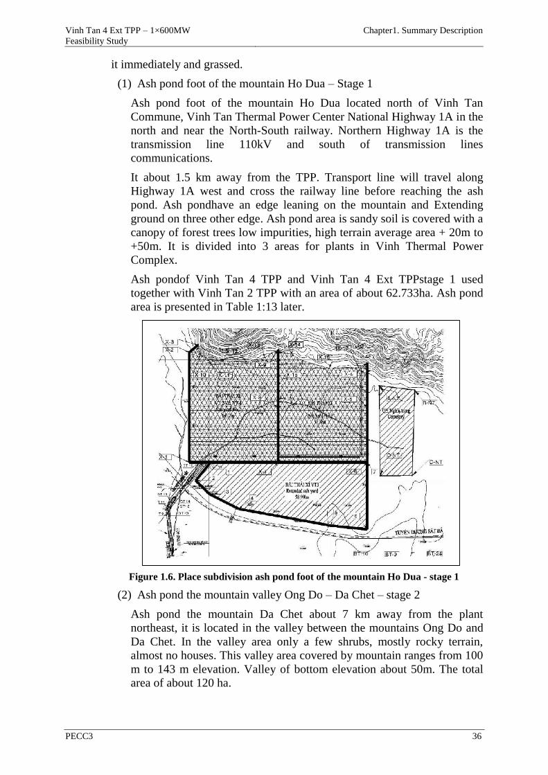
Vinh Tan 4 Ext TPP – 1×600MW
Feasibility Study
Chapter1. Summary Description
PECC3 36
it immediately and grassed.
(1) Ash pond foot of the mountain Ho Dua – Stage 1
Ash pond foot of the mountain Ho Dua located north of Vinh Tan
Commune, Vinh Tan Thermal Power Center National Highway 1A in the
north and near the North-South railway. Northern Highway 1A is the
transmission line 110kV and south of transmission lines
communications.
It about 1.5 km away from the TPP. Transport line will travel along
Highway 1A west and cross the railway line before reaching the ash
pond. Ash pondhave an edge leaning on the mountain and Extending
ground on three other edge. Ash pond area is sandy soil is covered with a
canopy of forest trees low impurities, high terrain average area + 20m to
+50m. It is divided into 3 areas for plants in Vinh Thermal Power
Complex.
Ash pondof Vinh Tan 4 TPP and Vinh Tan 4 Ext TPPstage 1 used
together with Vinh Tan 2 TPP with an area of about 62.733ha. Ash pond
area is presented in Table 1:13 later.
Figure 1.6. Place subdivision ash pond foot of the mountain Ho Dua - stage 1
(2) Ash pond the mountain valley Ong Do – Da Chet – stage 2
Ash pond the mountain Da Chet about 7 km away from the plant
northeast, it is located in the valley between the mountains Ong Do and
Da Chet. In the valley area only a few shrubs, mostly rocky terrain,
almost no houses. This valley area covered by mountain ranges from 100
m to 143 m elevation. Valley of bottom elevation about 50m. The total
area of about 120 ha.
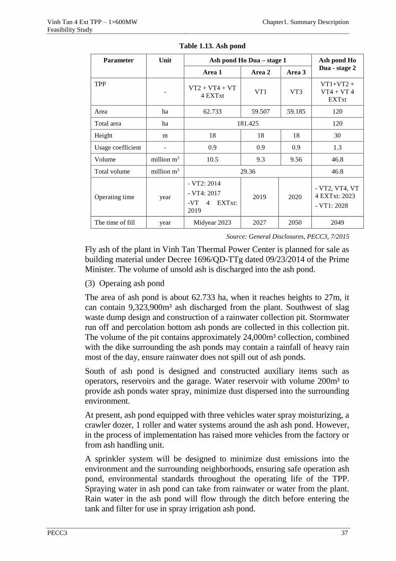
Vinh Tan 4 Ext TPP – 1×600MW
Feasibility Study
Chapter1. Summary Description
PECC3 37
Table 1.13. Ash pond
Parameter Unit Ash pond Ho Dua – stage 1 Ash pond Ho
Dua - stage 2 Area 1 Area 2 Area 3
TPP
- VT2 + VT4 + VT
4 EXTxt VT1 VT3
VT1+VT2 +
VT4 + VT 4
EXTxt
Area ha 62.733 59.507 59.185 120
Total area ha 181.425 120
Height m 18 18 18 30
Usage coefficient - 0.9 0.9 0.9 1.3
Volume million m3 10.5 9.3 9.56 46.8
Total volume million m3 29.36 46.8
Operating time year
- VT2: 2014
- VT4: 2017
-VT 4 EXTxt:
2019
2019 2020
- VT2, VT4, VT
4 EXTxt: 2023
- VT1: 2028
The time of fill year Midyear 2023 2027 2050 2049
Source: General Disclosures, PECC3, 7/2015
Fly ash of the plant in Vinh Tan Thermal Power Center is planned for sale as
building material under Decree 1696/QD-TTg dated 09/23/2014 of the Prime
Minister. The volume of unsold ash is discharged into the ash pond.
(3) Operaing ash pond
The area of ash pond is about 62.733 ha, when it reaches heights to 27m, it
can contain 9,323,900m³ ash discharged from the plant. Southwest of slag
waste dump design and construction of a rainwater collection pit. Stormwater
run off and percolation bottom ash ponds are collected in this collection pit.
The volume of the pit contains approximately 24,000m³ collection, combined
with the dike surrounding the ash ponds may contain a rainfall of heavy rain
most of the day, ensure rainwater does not spill out of ash ponds.
South of ash pond is designed and constructed auxiliary items such as
operators, reservoirs and the garage. Water reservoir with volume 200m³ to
provide ash ponds water spray, minimize dust dispersed into the surrounding
environment.
At present, ash pond equipped with three vehicles water spray moisturizing, a
crawler dozer, 1 roller and water systems around the ash ash pond. However,
in the process of implementation has raised more vehicles from the factory or
from ash handling unit.
A sprinkler system will be designed to minimize dust emissions into the
environment and the surrounding neighborhoods, ensuring safe operation ash
pond, environmental standards throughout the operating life of the TPP.
Spraying water in ash pond can take from rainwater or water from the plant.
Rain water in the ash pond will flow through the ditch before entering the
tank and filter for use in spray irrigation ash pond.
Vinh Tan 4 Ext TPP – 1×600MW
Feasibility Study
Chapter1. Summary Description
PECC3 38
At ash pond have designed podium to the truck wash. Trucks transporting
ash, machinery operators and instruments will be cleaned of coal dust at the
podium there before leaving the ash dumps.
A control station will be constructed near the ash dumps; This control station
will have the building (work) as garages, offices, public toilets and water
reservoirs.
(4) The structure of ash pond
Ash pond Ho Dua dike system stone surround. Dam roof outer slopes
Extected 1: 2.5 and pasture protection against erosion, inside about 1: 1.5.
The bottom and sides of the dam system liner layer of waterproofing
materials.
(5) Plan ash transport and safety measures for shipping
At present the choice of transportation planash unsold from factory by
specialized vehicles were dedicated ash, due to low-cost and take advantage
of the infrastructure and equipment available. Fly ash arising during the
operation were seized and contained in the silos. At the silos, dry ash will be
mixed water moisture content of 15 ÷ 20 %, into sealed dump trucks to limit
maximum dust in the process of moving and transporting the ash waste dump
operated by road transport of ash Vinh Tan Thermal Power Center, the
distance from the plant to the ash disposal area about 4km. Process of
implementation of ash like this:
- Ash/slag was created moisture about 15÷20% and be transported by
specialized vehicles to ash pond. Vehicles transporting ash will move to
area car wash to wash ash still clinging to and wheel around before
moving off ash pond.
- When to ash pond, the vehicles will move under the internal road system
to position dump, trucks will dump ash to ash pond. Caterpillar bulldozers
would level the ash heap 1 flat layer with thickness of 30 ÷ 40cm, dress
and conduct ash by bulldozers crawler with compaction factor K≥0,9
Moisture content of fly ash after compaction in the ash pond to
achieve K≥0,9, from 12% to 12.8%;
Moisture content of bottom ash after compaction in the ash pond to
achieve K≥0,9,from 17.8% to 26.3%.
- Ash pond is divided into 16 cells, each cell has an area of about 2.4ha
(150 × 150 m size). The cells are separated by internal road system for
vehicles carrying ash and other moving machinery. Accordingly, the
amount of ash discharged every day will be collected and transported to
the ash disposal site. At one time, only 1 in 16 cell box slag operation
(cell activity), ash will be dumped into the box operation. The remaining
15 cells (cells not working) was compacted, compacted and water spray
humidifier to avoid spreading dust surface. In addition, to ensure the
rapid start of fly ash dust smell wind will consider options to improve the
surface like canvas-covered, spray glue additives, ... to protect the
surface, depending on the actual conditions (temperature, wind );
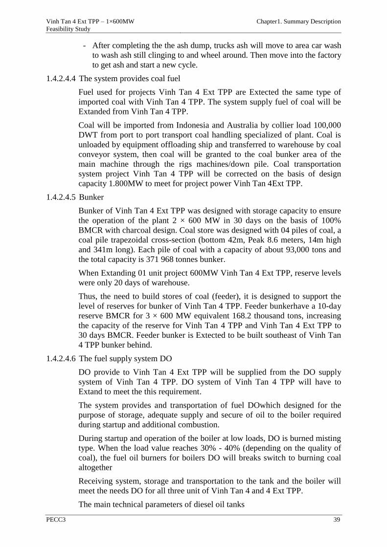
Vinh Tan 4 Ext TPP – 1×600MW
Feasibility Study
Chapter1. Summary Description
PECC3 39
- After completing the the ash dump, trucks ash will move to area car wash
to wash ash still clinging to and wheel around. Then move into the factory
to get ash and start a new cycle.
1.4.2.4.4 The system provides coal fuel
Fuel used for projects Vinh Tan 4 Ext TPP are Extected the same type of
imported coal with Vinh Tan 4 TPP. The system supply fuel of coal will be
Extanded from Vinh Tan 4 TPP.
Coal will be imported from Indonesia and Australia by collier load 100,000
DWT from port to port transport coal handling specialized of plant. Coal is
unloaded by equipment offloading ship and transferred to warehouse by coal
conveyor system, then coal will be granted to the coal bunker area of the
main machine through the rigs machines/down pile. Coal transportation
system project Vinh Tan 4 TPP will be corrected on the basis of design
capacity 1.800MW to meet for project power Vinh Tan 4Ext TPP.
1.4.2.4.5 Bunker
Bunker of Vinh Tan 4 Ext TPP was designed with storage capacity to ensure
the operation of the plant 2 × 600 MW in 30 days on the basis of 100%
BMCR with charcoal design. Coal store was designed with 04 piles of coal, a
coal pile trapezoidal cross-section (bottom 42m, Peak 8.6 meters, 14m high
and 341m long). Each pile of coal with a capacity of about 93,000 tons and
the total capacity is 371 968 tonnes bunker.
When Extanding 01 unit project 600MW Vinh Tan 4 Ext TPP, reserve levels
were only 20 days of warehouse.
Thus, the need to build stores of coal (feeder), it is designed to support the
level of reserves for bunker of Vinh Tan 4 TPP. Feeder bunkerhave a 10-day
reserve BMCR for 3 × 600 MW equivalent 168.2 thousand tons, increasing
the capacity of the reserve for Vinh Tan 4 TPP and Vinh Tan 4 Ext TPP to
30 days BMCR. Feeder bunker is Extected to be built southeast of Vinh Tan
4 TPP bunker behind.
1.4.2.4.6 The fuel supply system DO
DO provide to Vinh Tan 4 Ext TPP will be supplied from the DO supply
system of Vinh Tan 4 TPP. DO system of Vinh Tan 4 TPP will have to
Extand to meet the this requirement.
The system provides and transportation of fuel DOwhich designed for the
purpose of storage, adequate supply and secure of oil to the boiler required
during startup and additional combustion.
During startup and operation of the boiler at low loads, DO is burned misting
type. When the load value reaches 30% - 40% (depending on the quality of
coal), the fuel oil burners for boilers DO will breaks switch to burning coal
altogether
Receiving system, storage and transportation to the tank and the boiler will
meet the needs DO for all three unit of Vinh Tan 4 and 4 Ext TPP.
The main technical parameters of diesel oil tanks
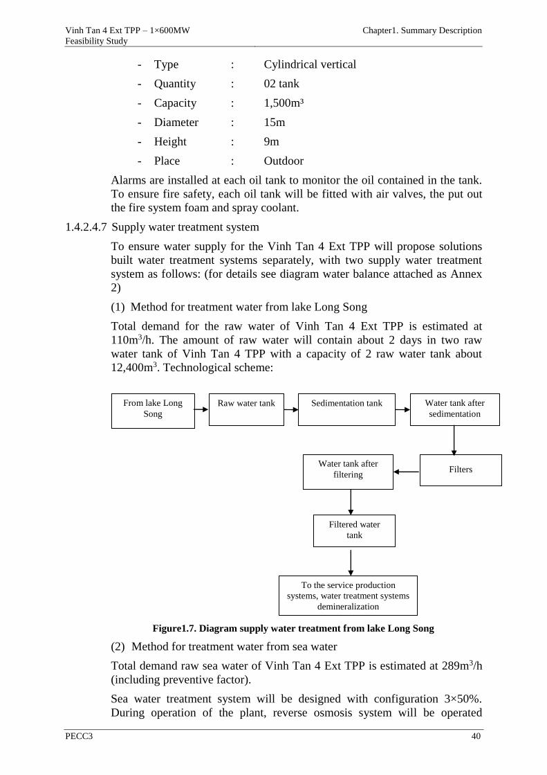
Vinh Tan 4 Ext TPP – 1×600MW
Feasibility Study
Chapter1. Summary Description
PECC3 40
- Type : Cylindrical vertical
- Quantity : 02 tank
- Capacity : 1,500m³
- Diameter : 15m
- Height : 9m
- Place : Outdoor
Alarms are installed at each oil tank to monitor the oil contained in the tank.
To ensure fire safety, each oil tank will be fitted with air valves, the put out
the fire system foam and spray coolant.
1.4.2.4.7 Supply water treatment system
To ensure water supply for the Vinh Tan 4 Ext TPP will propose solutions
built water treatment systems separately, with two supply water treatment
system as follows: (for details see diagram water balance attached as Annex
2)
(1) Method for treatment water from lake Long Song
Total demand for the raw water of Vinh Tan 4 Ext TPP is estimated at
110m3/h. The amount of raw water will contain about 2 days in two raw
water tank of Vinh Tan 4 TPP with a capacity of 2 raw water tank about
12,400m3. Technological scheme:
Figure1.7. Diagram supply water treatment from lake Long Song
(2) Method for treatment water from sea water
Total demand raw sea water of Vinh Tan 4 Ext TPP is estimated at 289m3/h
(including preventive factor).
Sea water treatment system will be designed with configuration 3×50%.
During operation of the plant, reverse osmosis system will be operated
From lake Long
Song
Raw water tank Sedimentation tank Water tank after
sedimentation
Filters Water tank after
filtering
Filtered water
tank
To the service production
systems, water treatment systems
demineralization
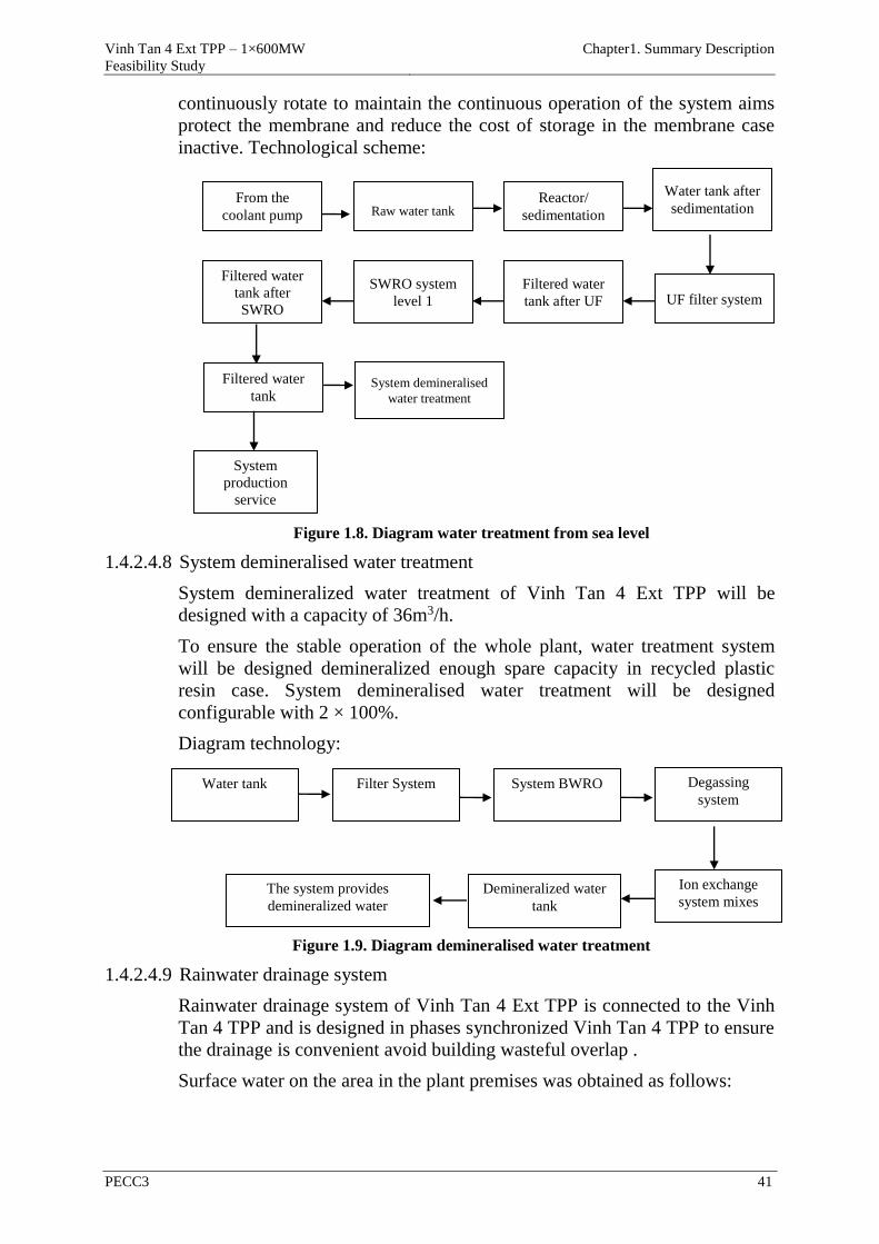
Vinh Tan 4 Ext TPP – 1×600MW
Feasibility Study
Chapter1. Summary Description
PECC3 41
continuously rotate to maintain the continuous operation of the system aims
protect the membrane and reduce the cost of storage in the membrane case
inactive. Technological scheme:
Figure 1.8. Diagram water treatment from sea level
1.4.2.4.8 System demineralised water treatment
System demineralized water treatment of Vinh Tan 4 Ext TPP will be
designed with a capacity of 36m3/h.
To ensure the stable operation of the whole plant, water treatment system
will be designed demineralized enough spare capacity in recycled plastic
resin case. System demineralised water treatment will be designed
configurable with 2 × 100%.
Diagram technology:
Figure 1.9. Diagram demineralised water treatment
1.4.2.4.9 Rainwater drainage system
Rainwater drainage system of Vinh Tan 4 Ext TPP is connected to the Vinh
Tan 4 TPP and is designed in phases synchronized Vinh Tan 4 TPP to ensure
the drainage is convenient avoid building wasteful overlap .
Surface water on the area in the plant premises was obtained as follows:
Water tank after
sedimentation From the
coolant pump Raw water tank Reactor/
sedimentation
Filtered water
tank after
SWRO
SWRO system
level 1
Filtered water
tank after UF UF filter system
Filtered water
tank System demineralised
water treatment
System
production
service
Water tank Filter System System BWRO Degassing
system
The system provides
demineralized water
Demineralized water
tank
Ion exchange
system mixes
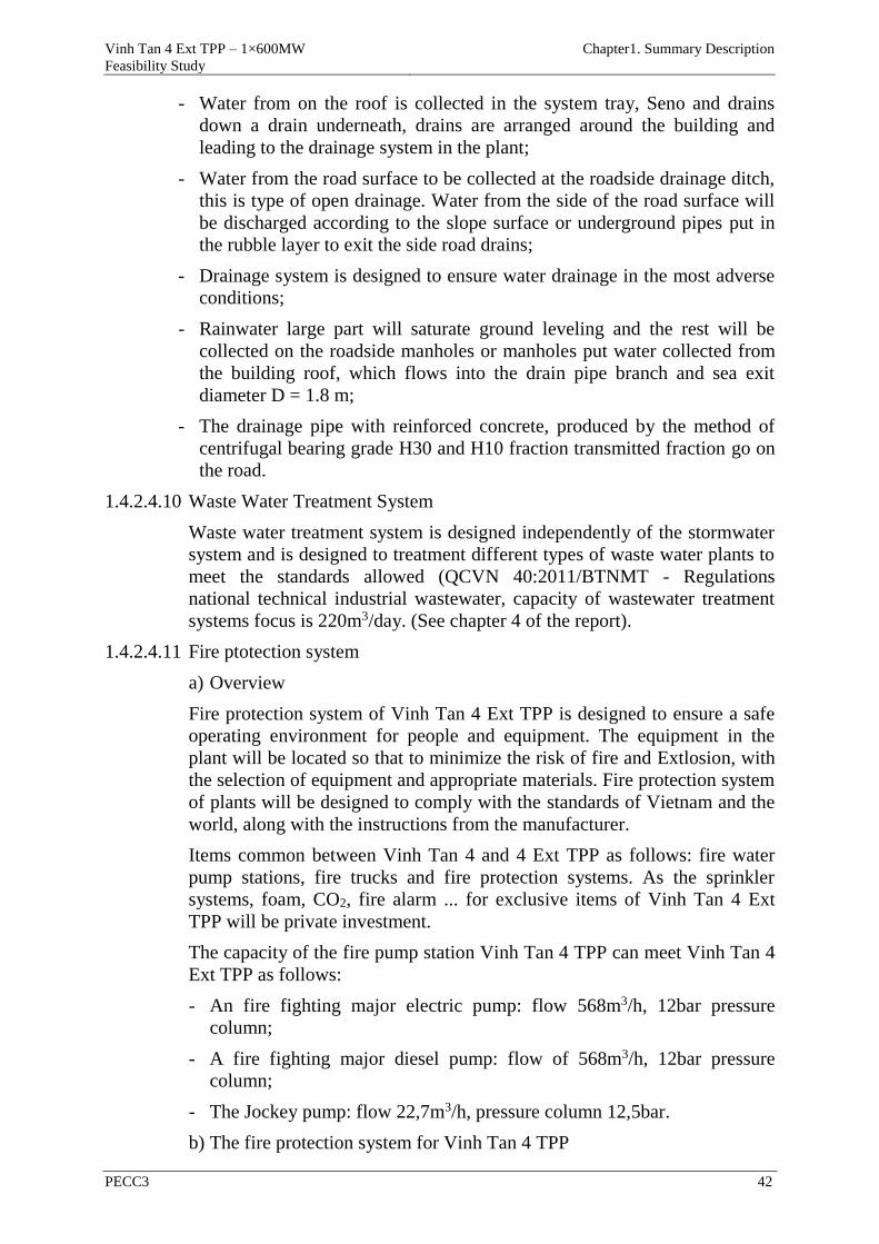
Vinh Tan 4 Ext TPP – 1×600MW
Feasibility Study
Chapter1. Summary Description
PECC3 42
- Water from on the roof is collected in the system tray, Seno and drains
down a drain underneath, drains are arranged around the building and
leading to the drainage system in the plant;
- Water from the road surface to be collected at the roadside drainage ditch,
this is type of open drainage. Water from the side of the road surface will
be discharged according to the slope surface or underground pipes put in
the rubble layer to exit the side road drains;
- Drainage system is designed to ensure water drainage in the most adverse
conditions;
- Rainwater large part will saturate ground leveling and the rest will be
collected on the roadside manholes or manholes put water collected from
the building roof, which flows into the drain pipe branch and sea exit
diameter D = 1.8 m;
- The drainage pipe with reinforced concrete, produced by the method of
centrifugal bearing grade H30 and H10 fraction transmitted fraction go on
the road.
1.4.2.4.10 Waste Water Treatment System
Waste water treatment system is designed independently of the stormwater
system and is designed to treatment different types of waste water plants to
meet the standards allowed (QCVN 40:2011/BTNMT - Regulations
national technical industrial wastewater, capacity of wastewater treatment
systems focus is 220m3/day. (See chapter 4 of the report).
1.4.2.4.11 Fire ptotection system
a) Overview
Fire protection system of Vinh Tan 4 Ext TPP is designed to ensure a safe
operating environment for people and equipment. The equipment in the
plant will be located so that to minimize the risk of fire and Extlosion, with
the selection of equipment and appropriate materials. Fire protection system
of plants will be designed to comply with the standards of Vietnam and the
world, along with the instructions from the manufacturer.
Items common between Vinh Tan 4 and 4 Ext TPP as follows: fire water
pump stations, fire trucks and fire protection systems. As the sprinkler
systems, foam, CO2, fire alarm ... for exclusive items of Vinh Tan 4 Ext
TPP will be private investment.
The capacity of the fire pump station Vinh Tan 4 TPP can meet Vinh Tan 4
Ext TPP as follows:
- An fire fighting major electric pump: flow 568m3/h, 12bar pressure
column;
- A fire fighting major diesel pump: flow of 568m3/h, 12bar pressure
column;
- The Jockey pump: flow 22,7m3/h, pressure column 12,5bar.
b) The fire protection system for Vinh Tan 4 TPP
Vinh Tan 4 Ext TPP – 1×600MW
Feasibility Study
Chapter1. Summary Description
PECC3 43
In addition to the common system, the fire protection system following will
be equipped for Vinh Tan 4 Ext TPP:
- The circuit outdoor fire water: connected with outdoor fire systems of
Vinh Tan 4 TPP;
- Fire protection systems for private-use items of Vinh Tan 4 Ext TPP:
+ Factory: turbines, boilers, ESP, FGD, SCR, fan, fan the smoke, the
center console, transformers, ...
+ DO Oil tanks.
+ The control ESP, FGD.
+ Diesel backup generators, ...
1.4.2.4.12 The emission control equipment
In power plants, emission control solutions are necessary to meet the
environmental requirements stipulated by each country.
For coal TPP plants, the emission control solutions dispersed into the
atmosphere around the following is required to be performed:
- Filter dust in the exhaust gas (ESP) with 99.13% efficiency;
- Apply measures to reduce NOx emission combustion, installation of
NOx reduction (SCR) with 65% efficiency;
- Seawater desulphurization (SWFGD) with 90% efficiency.
Details see chapter 4 of this report.
1.4.2.4.13 Dike sea reclamation
Dike sea reclamation in Vinh Tan 4 Ext TPP is responsible for protecting
the land construction of Vinh Tan 4 Ext TPP isolated corridor area.
Premises dike sea reclamation Vinh Tan 4 Ext TPP additional paragraph
P1'-P7'. Accordingly sea reclamation dike system complement Vinh Tan 4
Ext TPP is 454.8 m long dike which includes the dike section with 4 main
types of structures are designed and detailed with the following lengths:
- The P1'-P2'-P3' length of 30.4 m: it is the stable guard protect land for
regional stability corridor between trees separating plant area with
channel diversions Suoi Chua; Original dike sections to ensure long-term
stability of the dike;
- The P4'-P6' length 342.7m: the dike sections perpendicular to the
shoreline;
- The P6'- P7' length 121.7m: is the dike parallel to the shoreline.
1.4.2.4.14 Diversion channel Suoi Chua
Vinh Tan 4 Ext TPP when built will fill Suoi Chua. Therefore to ensure that
residential areas around the plant is not submerged during the flood should
do canal besides it to carry water from the basin above the sea Suoi Chua.
According to Table 4 TCVN 7957: 2008, the frequency of calculating the
Vinh Tan 4 Ext TPP – 1×600MW
Feasibility Study
Chapter1. Summary Description
PECC3 44
largest flood in 20 years (incidence of 5%), Q = 132.8 m3/s.
Natural ground at cardiac diversion channel lower from 0m elevation down
-1m. Suoi Chuadiversion channel is designed with trapezoidal cross-
section, the slope along the channel i = 0.002, discharge canal the first
bottom level -0,1m, discharge canal bottom elevation end -0,9m; Roof
channel coefficient m = 2.0; channel bottom slope i = 0.002, B = channel
bottom 14 m width, total channels L = 400m length.
Suoi Chua digging to the volume of approximately 16,711 m3, it is used for
leveling project.
1.4.2.4.15 Other auxiliary systems
- Compressed air;
- The provide Hydrogen;
- The cranes and lifting equipment;
- The steam;
- Ventilation and air conditioning;
- The administrative home.
1.4.2.4.16 Clearance and immigrant resettlement
As reported resettlement plan (RP) 07/2015, the number of compensation and
clearance of projects is as follows:
- Withdrawal of 153,000 m2 of land to build the kind of plant, isolated
corridor, ash pond drainage canal;
- 61 households displaced housing, construction by the project.
- There are about 4,481 trees inplant area, 3,080 trees isolated corridor ash
pond is Extected to be cut down.
Project owners coordination with the Compensation Committee of the local
implementation of the policy of compensation and assistance to households
affected by the project. Frame rates of compensation and assistance approved
by the provincial People's Committee based on proposals of the Compensation
Committee.
The total cost of compensation and assistance for households is estimated at
93 billion VND. Compensation and support for households affected are
completed as required.
1.4.3 Methods of organization of construction, construction technology and
construction items of the project
1.4.3.1 Organization of construction
1) Premises contruction
Premises construction organization is planning and design to ensure sufficient
layout area congt exam dumps and complex assembly equipment and
structures required and ensure all storage devices, structural as well as material
brought to the plant before it enters the formal assembly.
Vinh Tan 4 Ext TPP – 1×600MW
Feasibility Study
Chapter1. Summary Description
PECC3 45
Premises construction organization must meet the requirements and safety
regulations on construction, sanitation, anti-dust, noise, fire protection,
security, without affecting the surrounding area.
It is Extected that the yards construction organization Vinh Tan 4 Ext TPP
includes 2 main areas:
- Yard construction 1: the work site is located at the west area - North plant,
with an area of about 4.1ha (including isolation corridor and north area the
main plant is planned administrative buildings Vinh Tan 4 and 4 Ext TPP),
is used as a warehouse gathering supplies, materials and equipment as well
as the work site for the items in TPP. Warehouse construction area will be
leveled, compacted average height reached 2.2 m (2.5 to 1.7 m sloping
toward the sea) satisfactory use as a construction yards. Warehouse
construction land area after construction will be planting trees isolated
corridor.
- Yard construction 2: in case you need more land for warehouse
construction, contractors can hire temporary plantations near the
construction site. Typically, empty land of 4.54 hectares situated north of
the plant.
In addition, the plant area can make use of empty land within the main factory
to make yards of temporary construction, temporary construction yards
location is located near the construction site for the construction work is
convenient and effective.
Details of the arrangement of materials storage, materials as well as the work
site will be designed by the EPC contractor
2) Construction camps
The present, Vinh Tan 4 Ext TPP no organized workers' camp, the workers
themselves rent boarding house in the neighborhood of 7, so the construction
project Vinh Tan 4 and Vinh Tan 4 Ext TPP is the workers themselves rent
boarding house.
1.4.3.2 Method of contruction
1) The form of structural, architectural building, the height of buildings:
- Turbine steel frame structure, wall tole 39m height;
- Bunker coal steel frame structure 62m height;
- Boiler steel frame structure 88m height;
- Chimney shell reinforced concrete 210m height;
- The central control reinforced concrete structure 25m height;
- The auxiliary will have structural steel or concrete depending on the function
less than 20m height.
2) Solution ground leveling
Range ground leveling
- The major onshore plants and reclamation support areas: 6.19 ha
Vinh Tan 4 Ext TPP – 1×600MW
Feasibility Study
Chapter1. Summary Description
PECC3 46
- The administrative area: 1.32 ha
- The new bunker (located in the bunker feeder): 10ha
- The corridor of greenery and Suoi Chua: 4.07 ha
Elevation leveling:
- The zone plant, auxiliary facilities and new bunker was leveled to the
elevation of + 3.5m.
- The administrative area (opposite the station yard) was leveled to the
elevation of + 4.5m.
- Isolation Zone corridor trees and Suoi Chua is high ground leveling
averaging + 2.2 m (elevation change from 2.5m to 1.7m slope towards the
sea).
3) Construction of leveling
Because leveled area with shrimp ponds and Suoi Chua with large area, the
first step is to fill ponds, streams and creates temporary construction road to
transport sand to the sea. the location near the pond, used bulldozers gradually
fill board layers, the away location, using excavators with bucket <2,3m3 and
D155 bulldozers have mounted rear tillers to digging, then sand was put in the
car automobile self-shipping gradually fill the remaining pond. When leveled
reaches elevation above the sea level (about 1.65m), proceed compaction,
compactor used wheeled (18-25 tonnes) according to the process of
compaction soil compaction to achieve compaction.
To continue leveling and compacting pressed into layers accordance with to
the area of the pond and the lower area, parallel to this stage, the amount of
redundant sand is transported by automobile self-collecting coast area .
After leveling the sea encroachmentto reach the elevation of 1.65m, proceed in
accordance with the process of compaction to achieve the required density.
Continuing to use diggersto soil layer from coast to elevationof design +3.50m
height for area plant and bunker Ext andthe station courtyard + 4.50m height.
Continue transporting excess sand to the coast and leveling in layers with a
thickness not exceeding the thickness of the compaction test.
Create a slope, installing geotExtile, reinforced freestones and installation
milestone for regional monitoring sinking has reached a high design.
4) Apply the foundation soil
Backfill is done simultaneously with the training of other categories. The
advantage of such direct excavated reduce construction costs; Soil will be
leveled and compacted in layers thick 200 ~ 300mm.The packing material
was brought to the area covered by the dump truck and bulldozer
razed. Embankment compacted by rollers . Compacted sand by pumping sand
and water use spikes dress type, vibration.
5) Construction of foundation
Excavation work conducted by the motor to a high elevation design process
from 0.3 ~ 0.5m nail, then proceed to dig the ground to craft highly designed,
Vinh Tan 4 Ext TPP – 1×600MW
Feasibility Study
Chapter1. Summary Description
PECC3 47
compaction satisfactory foundation, positioning the axis and conduct
concreting line. Concrete lining layer to the correct size, height, and location
and flat.
Concrete work will be done to your nails after coffa satisfactory and
reinforced and approved. Concrete is transported to the location by concrete
mixer trucks poured dedicated. During concreting, coffa arrange personnel,
reinforced bolts etc ,, .. lookout for unusual incidents occur. Maintenance of
concrete with plastic coverings or hessian and watered regularly to keep the
concrete damp for the period of heat. Maintenance time not less than 7 days.
6) Piles
For items with large loads located near existing plants such as turbines, boilers
using pile plans. For items with medium weight piles using concrete plans
tensioning technology with lower construction method pile.
In addition you can apply the method of construction with new technologies
such pile drilling presses, drilling drop, bored piles precast concrete. These
plans have many advantages and overcomes the disadvantages of the different
methods of piles such as compatibility with all conditions geology,
stratigraphy; no shock, noise, minimize the impact of neighboring buildings ...
1.4.3.3 Source of equipment and materials
Materials and building materials to serve the construction of Vinh Tan 4 Ext
TTP prioritized using materials available locally or from sources in
neighboring provinces and to facilitate in providing and transportation, as well
as reducing the cost of building.
The construction materials like bricks and face bricks supplied from the brick
and tile factory in the locality and the surrounding area as Long Thanh, Bien
Hoa.
Source of cement can be obtained from Sao Mai cement Factory, Ha Tien and
Holcim ... For normal structural concrete proposals using PCB30 (or PCB40)
or other types of quality cement equivalent.
Source of of sand can be mined in the mine area Tuy Phong district away Vinh
Tan 4 Ext TPP about 18km northwest. Or sand located Song Dinh river away
Vinh Tan 4 Ext TPP about 45km to the north. In case of necessity, can
consider buying sand from Viet Phu mining company in Ham Duc commune,
Ham Thuan Bac district,away Vinh Tan 4 Ext TPPabout 105km with mining
capacity 60,000m3/year. In addition used for leveled sand resources can
consider mining dredging outside the harbor turning basin Vinh Tan 3 TPP
(source B3a, B3b in project infrastructure Vinh Tan Power Centre) however
quality unstable sand.
Stone can source of is mined from a quarries Phong Phu away works 25km
south, is located nExt to National Highway 1A, being mining and stone
crushing and screening provided for the construction of township Tuy Phong
and vicinity.
Structural steel ordinary items, construction steel for reinforced concrete
Vinh Tan 4 Ext TPP – 1×600MW
Feasibility Study
Chapter1. Summary Description
PECC3 48
structures can import from the major manufacturers in the market prestigious
Vietnam.
For specialized materials, with special technical requirements, or other
materials not in the water supply will use the resources of foreign materials.
All materials at the construction site must have originated, clear origin, obtain
quality testing, characteristics and technical requirements to ensure than the
technical requirements have been approved by investor.
1.4.3.4 Transportation of construction materials and equipment to the project site
The equipment and materials to be transported by specialized equipment,
depending on the type of equipment and material.
Light equipment, as well as the materials, construction materials serving
construction work Vinh Tan 4 Ext TPP will be transported to the plant by road
through National Highway 1A Factory on North. This route has 7-10m width,
asphalt-concrete structures with very good quality. After from National
Highway 1A will go into route number 4 to go to the beach area construction
and placement of plant material.
For devices imported from abroad are transported long distances by sea and
road to the location of works.
For super weight equipment shipped to Vinh Tan 4 MR TPP seaborne
temporarily docked at Vinh Tan 4 TPP. From Port these devices are
transported to the yards area construction and installation of the system
according to internal roads factory.
1.4.3.5 Vehicles and equipment for construction
Construction contractor must fully prepare installation media such as mobile
cranes, vehicles click drag, used trucks to install equipment. Future structure
of the machine can be used to install equipment in the powerhouse after
installation check and try nghiem. In items no cranes needed to use the crane
to the size and ability to lift loads suitable for assembly machinery.
1.4.3.6 Electricity construction
According to the the general planning of Vinh Tan Power Centre (the report
Vinh Tan 4 Ext TPP), the scope of the power system Vinh Tan 4 TPP includes
building 01 new substations of 110/22kV with about 40MVA and the on
transmission lines line from TBA 110 22kV/22kV to Vinh Tan Thermal
Power Center.
So the power system construction Vinh Tan 4 Ext TPP proposed construction
a transmission lines 22kV with the starting line at the construction area of
Vinh Tan 4 Ext TPP and end points connected to the substations of 110/22kV.
Contractor must be designed and approved by investors the number of low
voltage transformers and transmission lines, placement, installed capacity
consistent with construction requirements and ensure electrical safety.
1.4.3.7 Freshwater resources construction
Domestic demand for construction of Vinh Tan 4 Ext TPP: 180m3/h;
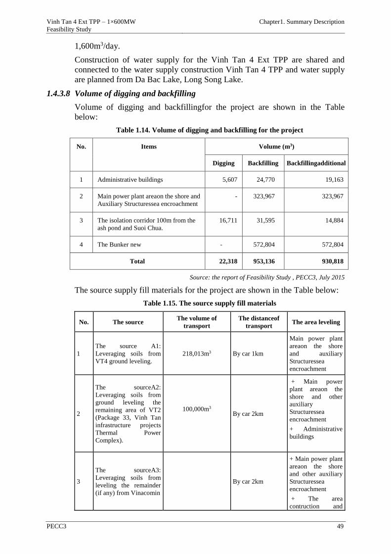
Vinh Tan 4 Ext TPP – 1×600MW
Feasibility Study
Chapter1. Summary Description
PECC3 49
1,600m3/day.
Construction of water supply for the Vinh Tan 4 Ext TPP are shared and
connected to the water supply construction Vinh Tan 4 TPP and water supply
are planned from Da Bac Lake, Long Song Lake.
1.4.3.8 Volume of digging and backfilling
Volume of digging and backfillingfor the project are shown in the Table
below:
Table 1.14. Volume of digging and backfilling for the project
No. Items Volume (m3)
Digging Backfilling Backfillingadditional
1 Administrative buildings 5,607 24,770 19,163
2 Main power plant areaon the shore and
Auxiliary Structuressea encroachment
- 323,967 323,967
3 The isolation corridor 100m from the
ash pond and Suoi Chua.
16,711 31,595 14,884
4 The Bunker new - 572,804 572,804
Total 22,318 953,136 930,818
Source: the report of Feasibility Study , PECC3, July 2015
The source supply fill materials for the project are shown in the Table below:
Table 1.15. The source supply fill materials
No. The source The volume of
transport
The distanceof
transport The area leveling
1
The source A1:
Leveraging soils from
VT4 ground leveling.
218,013m3 By car 1km
Main power plant
areaon the shore
and auxiliary
Structuressea
encroachment
2
The sourceA2:
Leveraging soils from
ground leveling the
remaining area of VT2
(Package 33, Vinh Tan
infrastructure projects
Thermal Power
Complex).
100,000m3
By car 2km
+ Main power
plant areaon the
shore and other
auxiliary
Structuressea
encroachment
+ Administrative
buildings
3
The sourceA3:
Leveraging soils from
leveling the remainder
(if any) from Vinacomin
By car 2km
+ Main power plant
areaon the shore
and other auxiliary
Structuressea
encroachment
+ The area
contruction and
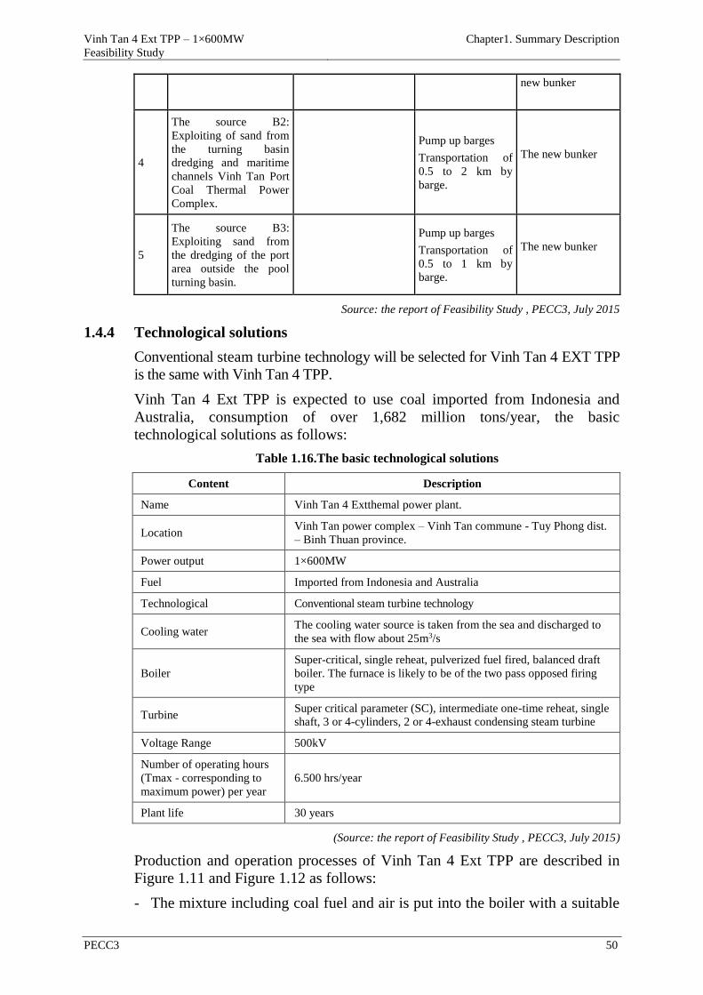
Vinh Tan 4 Ext TPP – 1×600MW
Feasibility Study
Chapter1. Summary Description
PECC3 50
new bunker
4
The source B2:
Exploiting of sand from
the turning basin
dredging and maritime
channels Vinh Tan Port
Coal Thermal Power
Complex.
Pump up barges
Transportation of
0.5 to 2 km by
barge.
The new bunker
5
The source B3:
Exploiting sand from
the dredging of the port
area outside the pool
turning basin.
Pump up barges
Transportation of
0.5 to 1 km by
barge.
The new bunker
Source: the report of Feasibility Study , PECC3, July 2015
1.4.4 Technological solutions
Conventional steam turbine technology will be selected for Vinh Tan 4 EXT TPP
is the same with Vinh Tan 4 TPP.
Vinh Tan 4 Ext TPP is expected to use coal imported from Indonesia and
Australia, consumption of over 1,682 million tons/year, the basic
technological solutions as follows:
Table 1.16.The basic technological solutions
Content Description
Name Vinh Tan 4 Extthemal power plant.
Location Vinh Tan power complex – Vinh Tan commune - Tuy Phong dist.
– Binh Thuan province.
Power output 1×600MW
Fuel Imported from Indonesia and Australia
Technological Conventional steam turbine technology
Cooling water The cooling water source is taken from the sea and discharged to
the sea with flow about 25m3/s
Boiler
Super-critical, single reheat, pulverized fuel fired, balanced draft
boiler. The furnace is likely to be of the two pass opposed firing
type
Turbine Super critical parameter (SC), intermediate one-time reheat, single
shaft, 3 or 4-cylinders, 2 or 4-exhaust condensing steam turbine
Voltage Range 500kV
Number of operating hours
(Tmax - corresponding to
maximum power) per year
6.500 hrs/year
Plant life 30 years
(Source: the report of Feasibility Study , PECC3, July 2015)
Production and operation processes of Vinh Tan 4 Ext TPP are described in
Figure 1.11 and Figure 1.12 as follows:
- The mixture including coal fuel and air is put into the boiler with a suitable
Vinh Tan 4 Ext TPP – 1×600MW
Feasibility Study
Chapter1. Summary Description
PECC3 51
rate in order to get the highest combustion efficiency. The steam generated
from the boilers is taken to the steam drum. The steam is then overheated
(increase the steam temperature) before passing the noise reduction and
decompression equipment. Finally, it runs into the high pressure turbine.
From here, the steam current with high pressure and temperature will be
dilated to generate forces which are used to rotate the turbine. The
temperature releasing from the high pressure turbine, which is lost their
temperature due to generating forces, is taking back to the boiler to overheat
before going the medium-pressure turbine. The steam releasing from the
medium pressure turbine after dilating is taken to the low pressure turbine.
The steam dilated and generating forces turns the turbine wings, which also
turns the electric generator and taken the power to the power grid. The
whole steam volume releasing is taken to the condenser that is an
equipment to condense steam. In order to condense the whole volume
releasing at the condenser, it is necessary to use the cooling tower or the
direct cooling water directly pumped from the sea. The steam after
condensing at the condenser is pumped through the low pressure overheated
champers to increase the steam temperature. To overheat the condensed
water, the steam at the turbines will be Extracted for the overheated
champers. The condensed water after pumped through the low pressure
overheated champers will be the gas remover to eliminate uncondensed
gases such as CO2, O2 … exiting in the condensed water. Because those
kinds of gases will corrode the pipes and turbine wings if they are exiting in
the water at high temperature and pressure. The condensed water after
degassing will be pumped the high pressure overheated champers. The
water is then transferred to the boiler. Finally, the water continues
generating steam and completing a periodic cycle.
- Smoke produced in the combustion includes harmful gases to the
environment such as NOx, SO2… will be evaluated and taken through the
ESP, the de-SOx system (SWFGD) to treat the flue gas to meet the
discharge standards at source. Part of unburnt coal (fly ash) will be taken to
the fly ash silo and transported to the ash pond.
- Industrial wastewater generated during operation process of the plant
includes wastewater from water treatment systems, wastewater from the
condensated water treatment system, coal contaminated wastewater from
the coal storage area, oil contaminated wastewater from oil tanks,
wastewater during the cleaning process of treatment equipment of dust and
flue gas, boiler and sanitary wastewater from workers.
1.4.5 List of machines and equipment
The main construction equipment includes as follows:
Table 1.17. List of machines and equipment used in the construction stage
No. Names Specifications Capacity Unit Quantit
y
Situation
1 Hydraulic crane FZQ2000 80t set 2 70-80%
2 Tower crane QZ80EA 80t.m set 1 70-80%

Vinh Tan 4 Ext TPP – 1×600MW
Feasibility Study
Chapter1. Summary Description
PECC3 52
No. Names Specifications Capacity Unit Quantit
y
Situation
3 Crawler Cranes M250S2 250t set 1 70-80%
4 Portal crane HC248 150t set 1 70-80%
5 Mobile crane NK-500E3 50t set 1 70-80%
6 Crane Model 300TM-D 30t/6t set 2 70-80%
7 Single crane 5t/10.5m 5t set 1 70-80%
8 Gantry crane 40t/10t/42m 40t/10t set 3 70-80%
9 Gantry crane 20t/5t/42m 20t/5t set 2 70-80%
10 Capstan STJ-A 1000kg 1000kg set 2 70-80%
11 Hydraulic hoisting
device GYT-200(II)type 200t set 4
70-80%
12 Electric winch DZS-Ⅲ set 1 70-80%
13 Excavator PC300 1,5m3 set 1 70-80%
14 Drilling machine set 4 70-80%
15 Bulldozer set 1 70-80%
16 Roller ZL50 3m3 set 1 70-80%
17 Concrete batch plant HZS90 90m3/h set 1 70-80%
18 Standby concrete
batch plant HZS50 50m3/h set 1
70-80%
19 Concrete mixer MR45-T 6m3 set 5 70-80%
20 Concrete pump HBT-60 60m3/h set 3 70-80%
21 Specializing devices JTGS1.6Q set 4 70-80%
22 Compactor HW120 set 10 70-80%
23 Hydraulic lift truck QGZH480 400t set 1 70-80%
24 Specializing truck SZG9200D 40t set 1 70-80%
25 Trolley SH273KA 30t set 2 70-80%
26 Specializing truck DJ250 25t set 2 70-80%
27 Truck CQ1260 15t set 3 70-80%
28 Skip truck ND2628 15t set 1 70-80%
29 Diesel truck F10D 1t set 10 70-80%
30 Caterpillar crane 5250 250t set 1 70-80%
31 Mobile crane TG-1500E 150t set 1 70-80%
32 Mast crane WT-4000B 400t set 1 70-80%
List of machines and equipments of Vinh Tan 4 Ext TPP and its port in the
operation stage are shown in the following table:
Table 1.18. List of machines and equipment for Vinh Tan 4 EXT TPP and its port in the
operation stage
No. Equipment Name Quantity Situation
1 Boiler 1 New 100%
2 Steam turbine 1 New 100%
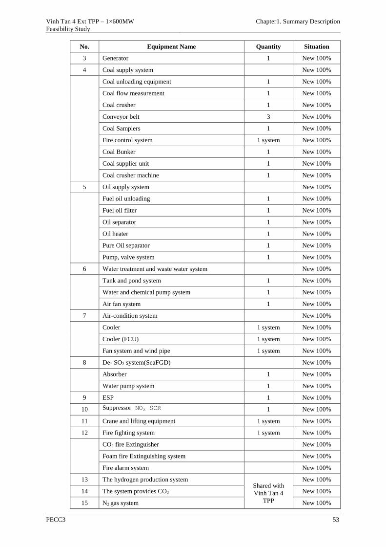
Vinh Tan 4 Ext TPP – 1×600MW
Feasibility Study
Chapter1. Summary Description
PECC3 53
No. Equipment Name Quantity Situation
3 Generator 1 New 100%
4 Coal supply system New 100%
Coal unloading equipment 1 New 100%
Coal flow measurement 1 New 100%
Coal crusher 1 New 100%
Conveyor belt 3 New 100%
Coal Samplers 1 New 100%
Fire control system 1 system New 100%
Coal Bunker 1 New 100%
Coal supplier unit 1 New 100%
Coal crusher machine 1 New 100%
5 Oil supply system New 100%
Fuel oil unloading 1 New 100%
Fuel oil filter 1 New 100%
Oil separator 1 New 100%
Oil heater 1 New 100%
Pure Oil separator 1 New 100%
Pump, valve system 1 New 100%
6 Water treatment and waste water system New 100%
Tank and pond system 1 New 100%
Water and chemical pump system 1 New 100%
Air fan system 1 New 100%
7 Air-condition system New 100%
Cooler 1 system New 100%
Cooler (FCU) 1 system New 100%
Fan system and wind pipe 1 system New 100%
8 De- SO2 system(SeaFGD) New 100%
Absorber 1 New 100%
Water pump system 1 New 100%
9 ESP 1 New 100%
10 Suppressor NOx SCR 1 New 100%
11 Crane and lifting equipment 1 system New 100%
12 Fire fighting system 1 system New 100%
CO2 fire Extinguisher New 100%
Foam fire Extinguishing system New 100%
Fire alarm system New 100%
13 The hydrogen production system Shared with
Vinh Tan 4
TPP
New 100%
14 The system provides CO2 New 100%
15 N2 gas system New 100%
Vinh Tan 4 Ext TPP – 1×600MW
Feasibility Study
Chapter1. Summary Description
PECC3 54
No. Equipment Name Quantity Situation
16 High-pressure compressor New 100%
17 Dry cooling equipment New 100%
18 Dry-type adsorption 1 system New 100%
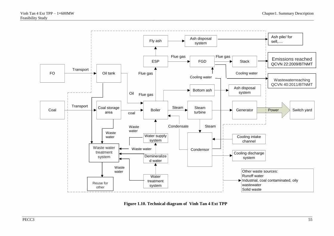
Vinh Tan 4 Ext TPP – 1×600MW
Feasibility Study
Chapter1. Summary Description
PECC3 55
PowerBoilerSteam
turbineGenerator
CondensorCooling discharge
system
Cooling intake
channel
Demineralize
d water
Steam
Steam
coal
Water
treatment
system
Switch yard
Water supply
system
Coal storage
areaCoal
Oil tankFO
ESP
Transport
Transport
Condensate
Oil
FGD Stack
Flue gas Flue gas
Bottom ash
Fly ashAsh disposal
system
Ash disposal
system
Other waste sources:
Runoff water
Industrial, coal contaminated, oily
wastewater
Solid waste
Flue gas
Flue gas
Figure 1.10. Technical diagram of Vinh Tan 4 Ext TPP
Waste water treatment system
Reuse for other
items
Waste water
Waste water
Waste water
Waste water
Ash pile/ for sell,....
Emissions reached QCVN 22:2009/BTNMT
Wastewaterreaching QCVN 40:2011/BTNMT
Cooling water Cooling water
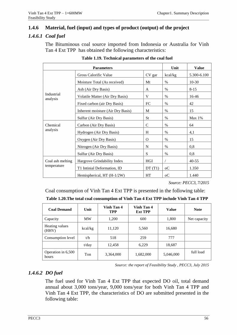
Vinh Tan 4 Ext TPP – 1×600MW
Feasibility Study
Chapter1. Summary Description
PECC3 56
1.4.6 Material, fuel (input) and types of product (output) of the project
1.4.6.1 Coal fuel
The Bituminous coal source imported from Indonesia or Australia for Vinh
Tan 4 Ext TPP has obtained the following characteristics:
Table 1.19. Technical parameters of the coal fuel
Parameters Unit Value
Industrial
analysis
Gross Calorific Value CV gar kcal/kg 5.300-6.100
Moisture Total (As received) Mt % 10-30
Ash (Air Dry Basis) A % 8-15
Volatile Matter (Air Dry Basis) V % 16-46
Fixed carbon (air Dry Basis) FC % 42
Inherent moisture (Air Dry Basis) M % 15
Sulfur (Air Dry Basis) St % Max 1%
Chemical
analysis
Carbon (Air Dry Basis) C % 64
Hydrogen (Air Dry Basis) H % 4,1
Oxygen (Air Dry Basis) O % 15
Nitrogen (Air Dry Basis) N % 0,8
Sulfur (Air Dry Basis) S % 0,8
Coal ash melting
temperature
Hargrove Grindability Index HGI / 40-55
T1 Intinial Deformation, ID DT (T1) oC 1.350
Hemispherical, HT (H-1/2W) HT oC 1.440
Source: PECC3, 7/2015
Coal consumption of Vinh Tan 4 Ext TPP is presented in the following table:
Table 1.20.The total coal consumption of Vinh Tan 4 Ext TPP include Vinh Tan 4 TPP
Coal Demand Unit Vinh Tan 4
TPP
Vinh Tan 4
Ext TPP Value Note
Capacity MW 1,200 600 1,800 Net capacity
Heating values
(HHV) kcal/kg 11,120 5,560 16,680
Consumption level t/h 518 259 777
t/day 12,458 6,229 18,687
Operation in 6,500
hours Ton 3,364,000 1,682,000 5,046,000
full load
Source: the report of Feasibility Study , PECC3, July 2015
1.4.6.2 DO fuel
The fuel used for Vinh Tan 4 Ext TPP that expected DO oil, total demand
annual about 3,000 tons/year, 9,000 tons/year for both Vinh Tan 4 TPP and
Vinh Tan 4 Ext TPP, the characteristics of DO are submitted presented in the
following table:

Vinh Tan 4 Ext TPP – 1×600MW
Feasibility Study
Chapter1. Summary Description
PECC3 57
Table 1.21. DO fuel characteristics
No. Parameters Unit Value Testing methods
1 Cetane Min. 45 ASTM D976-00
2 Temperature, 90% volume oC Max. 370 ASTM D86-00a
3 Copper strip corrosion (3h/50°C) Max. No.1 ASTM D130-94
4 Sulfur % wt Max. 0.5 ASTM D129-00
or D4294-98
5 Flash point oC Min. +50 ASTM D93-00
6 Kinematic viscosity at 40°C CSt 1.6 ~ 5.5 ASTM D445-97
7 Carbon ResidueConradson % wt Max. 0.3 ASTM D189-97
or D4530-00
8 Freezing point oC Max. +9 ASTM D97-96a
9 Ash content % wt Max. 0.01 ASTM D482-91
10 The water content and impurities % Vol. Max. 0.05 ASTM D2709-99
11 Density at 15°C kg/l To report
~ 0.85 ASTM D1289-99
12 Heat of raw kCal/kg To report
~10,821 ASTM D976-00
13 Evaluating lubricity, max μm 460 ASTM D6079-04
14 Particulate contaminant, max mg/l 10 ASTM D2276-00
Source: the report of Feasibility Study , PECC3, July 2015
Vinh Tan 4 Ext TPP has 2 storage tanks of DO oil with 2×1.500 m3 capacity.
1.4.6.3 Water demand
1) Fresh water demand
Water demand
Total fresh water demand for Vinh Tan 4 Ext TPP (1x600MW) is around
110m3/h. Details are shown below:
Table 1.22. Fresh water demand of project
STT Mục đích Đơn
vị
NMNĐ
VT4
NMNĐ
VT4MR
Tổng cộng Ghi chú
1 Demineralization
water system m3/h 36 72 108
2 Fresh water m3/h 1.35 2.7 4.05
3
Fresh water in
Demineralization
system and living
activity
m3/h 40.7 81.4 122.1
Including losses
coefficients
during discharge
and preventive
factor
4 Produce water m3/h
The water for the
transportation of
coal, spraying
m3/h 30.6 61.2 91.8
Water transport
ash m3/h 13 26 39
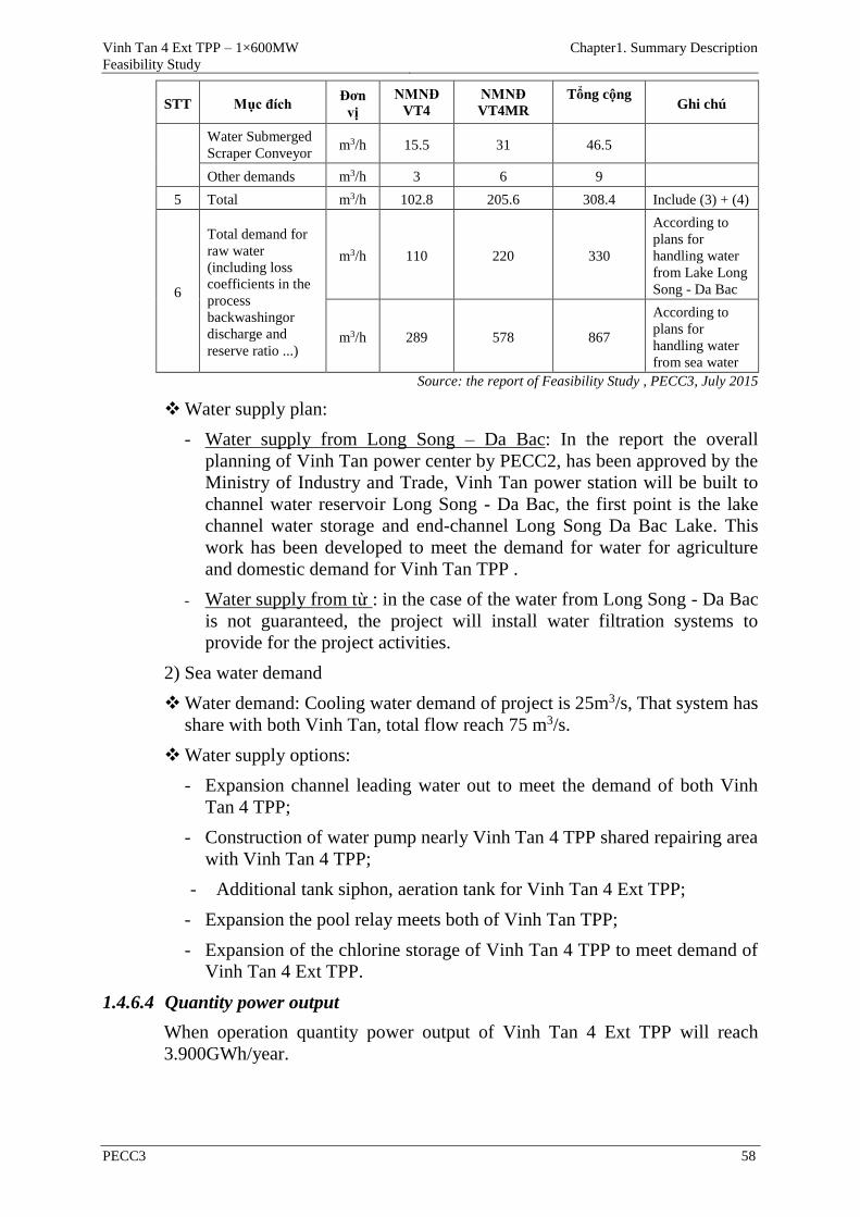
Vinh Tan 4 Ext TPP – 1×600MW
Feasibility Study
Chapter1. Summary Description
PECC3 58
STT Mục đích Đơn
vị
NMNĐ
VT4
NMNĐ
VT4MR
Tổng cộng Ghi chú
Water Submerged
Scraper Conveyor m3/h 15.5 31 46.5
Other demands m3/h 3 6 9
5 Total m3/h 102.8 205.6 308.4 Include (3) + (4)
6
Total demand for
raw water
(including loss
coefficients in the
process
backwashingor
discharge and
reserve ratio ...)
m3/h 110 220 330
According to
plans for
handling water
from Lake Long
Song - Da Bac
m3/h 289 578 867
According to
plans for
handling water
from sea water
Source: the report of Feasibility Study , PECC3, July 2015
Water supply plan:
- Water supply from Long Song – Da Bac: In the report the overall
planning of Vinh Tan power center by PECC2, has been approved by the
Ministry of Industry and Trade, Vinh Tan power station will be built to
channel water reservoir Long Song - Da Bac, the first point is the lake
channel water storage and end-channel Long Song Da Bac Lake. This
work has been developed to meet the demand for water for agriculture
and domestic demand for Vinh Tan TPP .
- Water supply from từ : in the case of the water from Long Song - Da Bac
is not guaranteed, the project will install water filtration systems to
provide for the project activities.
2) Sea water demand
Water demand: Cooling water demand of project is 25m3/s, That system has
share with both Vinh Tan, total flow reach 75 m3/s.
Water supply options:
- Expansion channel leading water out to meet the demand of both Vinh
Tan 4 TPP;
- Construction of water pump nearly Vinh Tan 4 TPP shared repairing area
with Vinh Tan 4 TPP;
- Additional tank siphon, aeration tank for Vinh Tan 4 Ext TPP;
- Expansion the pool relay meets both of Vinh Tan TPP;
- Expansion of the chlorine storage of Vinh Tan 4 TPP to meet demand of
Vinh Tan 4 Ext TPP.
1.4.6.4 Quantity power output
When operation quantity power output of Vinh Tan 4 Ext TPP will reach
3.900GWh/year.
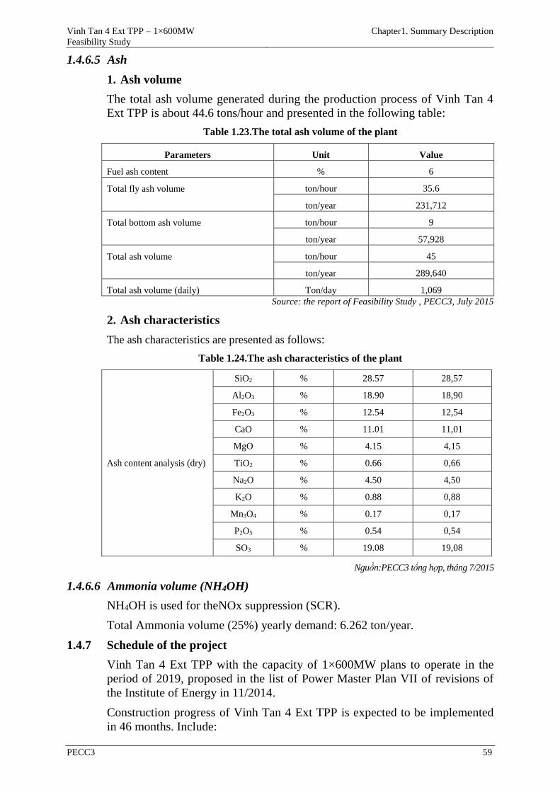
Vinh Tan 4 Ext TPP – 1×600MW
Feasibility Study
Chapter1. Summary Description
PECC3 59
1.4.6.5 Ash
1. Ash volume
The total ash volume generated during the production process of Vinh Tan 4
Ext TPP is about 44.6 tons/hour and presented in the following table:
Table 1.23.The total ash volume of the plant
Parameters Unit Value
Fuel ash content % 6
Total fly ash volume
ton/hour 35.6
ton/year 231,712
Total bottom ash volume
ton/hour 9
ton/year 57,928
Total ash volume
ton/hour 45
ton/year 289,640
Total ash volume (daily) Ton/day 1,069
Source: the report of Feasibility Study , PECC3, July 2015
2. Ash characteristics
The ash characteristics are presented as follows:
Table 1.24.The ash characteristics of the plant
Ash content analysis (dry)
SiO2 % 28.57 28,57
Al2O3 % 18.90 18,90
Fe2O3 % 12.54 12,54
CaO % 11.01 11,01
MgO % 4.15 4,15
TiO2 % 0.66 0,66
Na2O % 4.50 4,50
K2O % 0.88 0,88
Mn3O4 % 0.17 0,17
P2O5 % 0.54 0,54
SO3 % 19.08 19,08
Nguồn:PECC3 tổng hợp, tháng 7/2015
1.4.6.6 Ammonia volume (NH4OH)
NH4OH is used for theNOx suppression (SCR).
Total Ammonia volume (25%) yearly demand: 6.262 ton/year.
1.4.7 Schedule of the project
Vinh Tan 4 Ext TPP with the capacity of 1×600MW plans to operate in the
period of 2019, proposed in the list of Power Master Plan VII of revisions of
the Institute of Energy in 11/2014.
Construction progress of Vinh Tan 4 Ext TPP is expected to be implemented
in 46 months. Include:

Vinh Tan 4 Ext TPP – 1×600MW
Feasibility Study
Chapter1. Summary Description
PECC3 60
- Boiler section: 37 months;
- Turbine – generator section: 40 months;
- Auxiliary system: 42 months;
- Testing and synchronization: from month 41st - 46th
Detailed implementation progress by the EPC contractor will perform .
Project execution schedule is shown in the figure below:
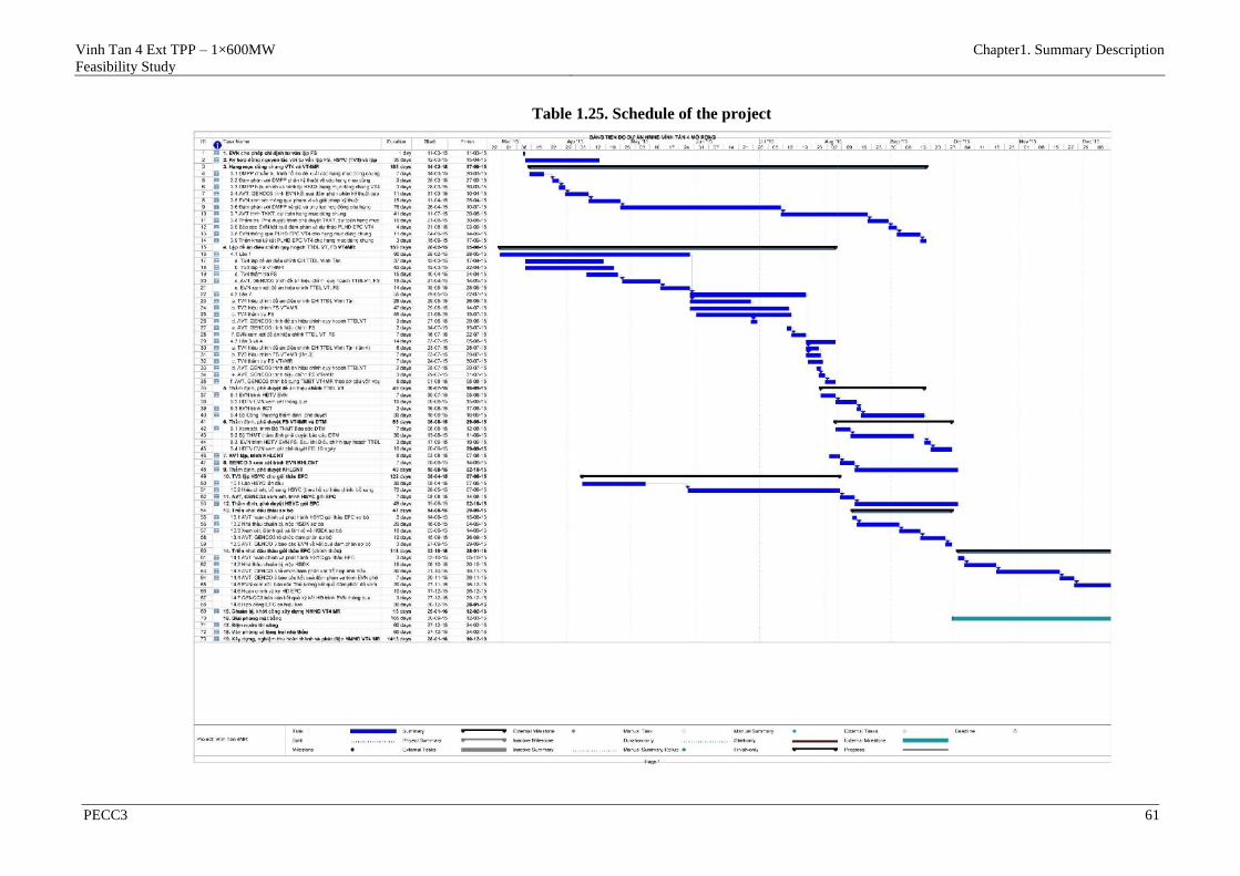
Vinh Tan 4 Ext TPP – 1×600MW
Feasibility Study
Chapter1. Summary Description
PECC3 61
Table 1.25. Schedule of the project
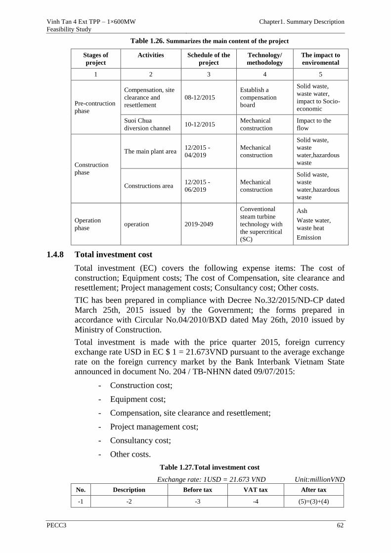
Vinh Tan 4 Ext TPP – 1×600MW
Feasibility Study
Chapter1. Summary Description
PECC3 62
Table 1.26. Summarizes the main content of the project
Stages of
project
Activities Schedule of the
project
Technology/
methodology
The impact to
enviromental
1 2 3 4 5
Pre-contruction
phase
Compensation, site
clearance and
resettlement
08-12/2015
Establish a
compensation
board
Solid waste,
waste water,
impact to Socio-
economic
Suoi Chua
diversion channel 10-12/2015
Mechanical
construction
Impact to the
flow
Construction
phase
The main plant area 12/2015 -
04/2019
Mechanical
construction
Solid waste,
waste
water,hazardous
waste
Constructions area 12/2015 -
06/2019
Mechanical
construction
Solid waste,
waste
water,hazardous
waste
Operation
phase operation 2019-2049
Conventional
steam turbine
technology with
the supercritical
(SC)
Ash
Waste water,
waste heat
Emission
1.4.8 Total investment cost
Total investment (EC) covers the following expense items: The cost of
construction; Equipment costs; The cost of Compensation, site clearance and
resettlement; Project management costs; Consultancy cost; Other costs.
TIC has been prepared in compliance with Decree No.32/2015/ND-CP dated
March 25th, 2015 issued by the Government; the forms prepared in
accordance with Circular No.04/2010/BXD dated May 26th, 2010 issued by
Ministry of Construction.
Total investment is made with the price quarter 2015, foreign currency
exchange rate USD in EC $ 1 = 21.673VND pursuant to the average exchange
rate on the foreign currency market by the Bank Interbank Vietnam State
announced in document No. 204 / TB-NHNN dated 09/07/2015:
- Construction cost;
- Equipment cost;
- Compensation, site clearance and resettlement;
- Project management cost;
- Consultancy cost;
- Other costs.
Table 1.27.Total investment cost
Exchange rate: 1USD = 21.673 VND Unit:millionVND
No. Description Before tax VAT tax After tax
-1 -2 -3 -4 (5)=(3)+(4)
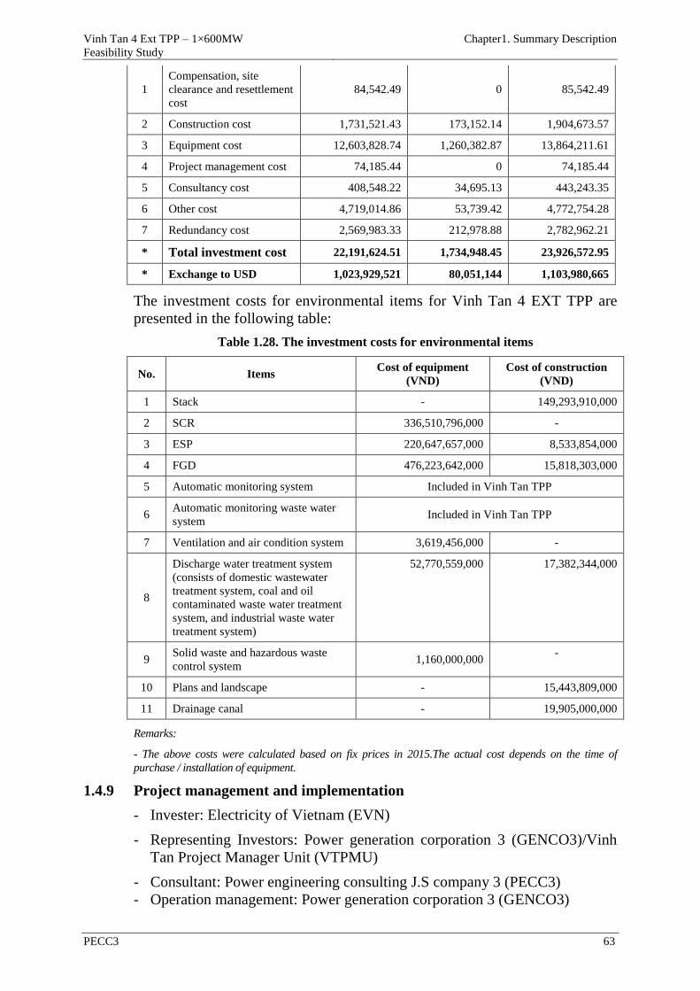
Vinh Tan 4 Ext TPP – 1×600MW
Feasibility Study
Chapter1. Summary Description
PECC3 63
1
Compensation, site
clearance and resettlement
cost
84,542.49 0 85,542.49
2 Construction cost 1,731,521.43 173,152.14 1,904,673.57
3 Equipment cost 12,603,828.74 1,260,382.87 13,864,211.61
4 Project management cost 74,185.44 0 74,185.44
5 Consultancy cost 408,548.22 34,695.13 443,243.35
6 Other cost 4,719,014.86 53,739.42 4,772,754.28
7 Redundancy cost 2,569,983.33 212,978.88 2,782,962.21
* Total investment cost 22,191,624.51 1,734,948.45 23,926,572.95
* Exchange to USD 1,023,929,521 80,051,144 1,103,980,665
The investment costs for environmental items for Vinh Tan 4 EXT TPP are
presented in the following table:
Table 1.28. The investment costs for environmental items
No. Items Cost of equipment
(VND)
Cost of construction
(VND)
1 Stack - 149,293,910,000
2 SCR 336,510,796,000 -
3 ESP 220,647,657,000 8,533,854,000
4 FGD 476,223,642,000 15,818,303,000
5 Automatic monitoring system Included in Vinh Tan TPP
6 Automatic monitoring waste water
system Included in Vinh Tan TPP
7 Ventilation and air condition system 3,619,456,000 -
8
Discharge water treatment system
(consists of domestic wastewater
treatment system, coal and oil
contaminated waste water treatment
system, and industrial waste water
treatment system)
52,770,559,000 17,382,344,000
9 Solid waste and hazardous waste
control system 1,160,000,000
-
10 Plans and landscape - 15,443,809,000
11 Drainage canal - 19,905,000,000
Remarks:
- The above costs were calculated based on fix prices in 2015.The actual cost depends on the time of
purchase / installation of equipment.
1.4.9 Project management and implementation
- Invester: Electricity of Vietnam (EVN)
- Representing Investors: Power generation corporation 3 (GENCO3)/Vinh
Tan Project Manager Unit (VTPMU)
- Consultant: Power engineering consulting J.S company 3 (PECC3) - Operation management: Power generation corporation 3 (GENCO3)
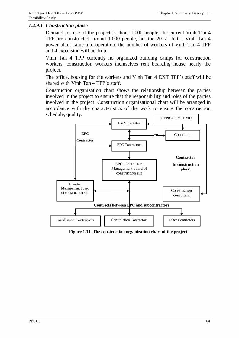
Vinh Tan 4 Ext TPP – 1×600MW
Feasibility Study
Chapter1. Summary Description
PECC3 64
1.4.9.1 Construction phase
Demand for use of the project is about 1,000 people, the current Vinh Tan 4
TPP are constructed around 1,000 people, but the 2017 Unit 1 Vinh Tan 4
power plant came into operation, the number of workers of Vinh Tan 4 TPP
and 4 expansion will be drop.
Vinh Tan 4 TPP currently no organized building camps for construction
workers, construction workers themselves rent boarding house nearly the
project.
The office, housing for the workers and Vinh Tan 4 EXT TPP’s staff will be
shared with Vinh Tan 4 TPP’s staff.
Construction organization chart shows the relationship between the parties
involved in the project to ensure that the responsibility and roles of the parties
involved in the project. Construction organizational chart will be arranged in
accordance with the characteristics of the work to ensure the construction
schedule, quality.
Figure 1.11. The construction organization chart of the project
EPC Contractors
EPC Contractors
Management board of
construction site
Construction Contractors
EVN Investor
Other Contractors Installation Contractors
Construction
consultant
Investor
Management board
of construction site
Consultant
Contracts between EPC and subcontractors
EPC
Contractor
Contractor
In construction
phase
GENCO3/VTPMU
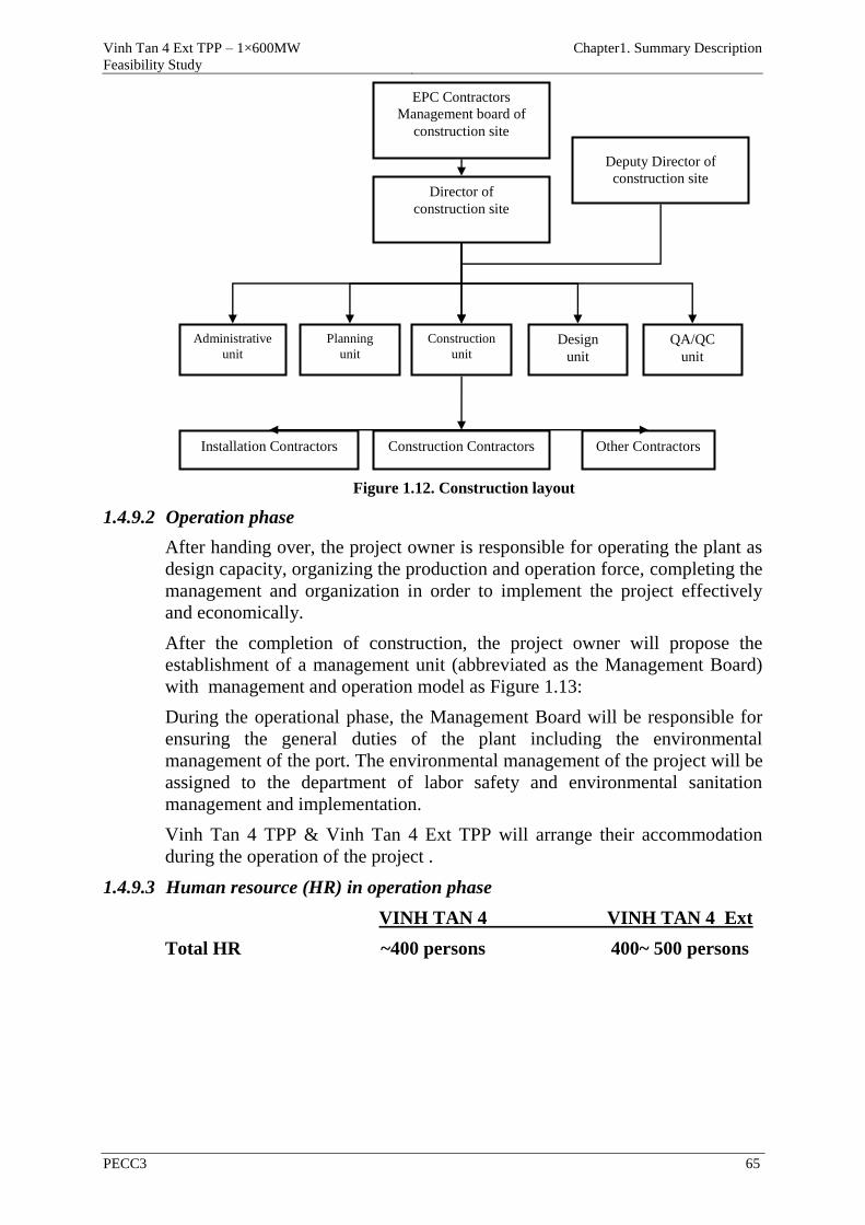
Vinh Tan 4 Ext TPP – 1×600MW
Feasibility Study
Chapter1. Summary Description
PECC3 65
Figure 1.12. Construction layout
1.4.9.2 Operation phase
After handing over, the project owner is responsible for operating the plant as
design capacity, organizing the production and operation force, completing the
management and organization in order to implement the project effectively
and economically.
After the completion of construction, the project owner will propose the
establishment of a management unit (abbreviated as the Management Board)
with management and operation model as Figure 1.13:
During the operational phase, the Management Board will be responsible for
ensuring the general duties of the plant including the environmental
management of the port. The environmental management of the project will be
assigned to the department of labor safety and environmental sanitation
management and implementation.
Vinh Tan 4 TPP & Vinh Tan 4 Ext TPP will arrange their accommodation
during the operation of the project .
1.4.9.3 Human resource (HR) in operation phase
VINH TAN 4 VINH TAN 4 Ext
Total HR ~400 persons 400~ 500 persons
EPC Contractors
Management board of
construction site
Construction Contractors Other Contractors Installation Contractors
Director of
construction site
Deputy Director of
construction site
Construction
unit Design
unit
QA/QC
unit
Planning
unit
Administrative
unit
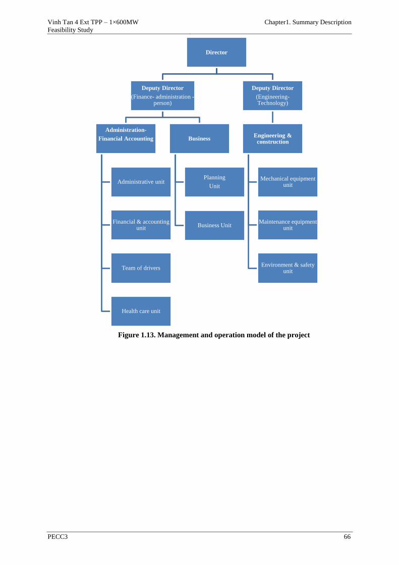
Vinh Tan 4 Ext TPP – 1×600MW
Feasibility Study
Chapter1. Summary Description
PECC3 66
Figure 1.13. Management and operation model of the project
Director
Deputy Director
(Finance- administration -person)
Administration-
Financial Accounting
Administrative unit
Financial & accounting unit
Team of drivers
Health care unit
Business
Planning
Unit
Business Unit
Deputy Director
(Engineering-Technology)
Engineering & construction
Mechanical equipment unit
Maintenance equipment unit
Environment & safety unit
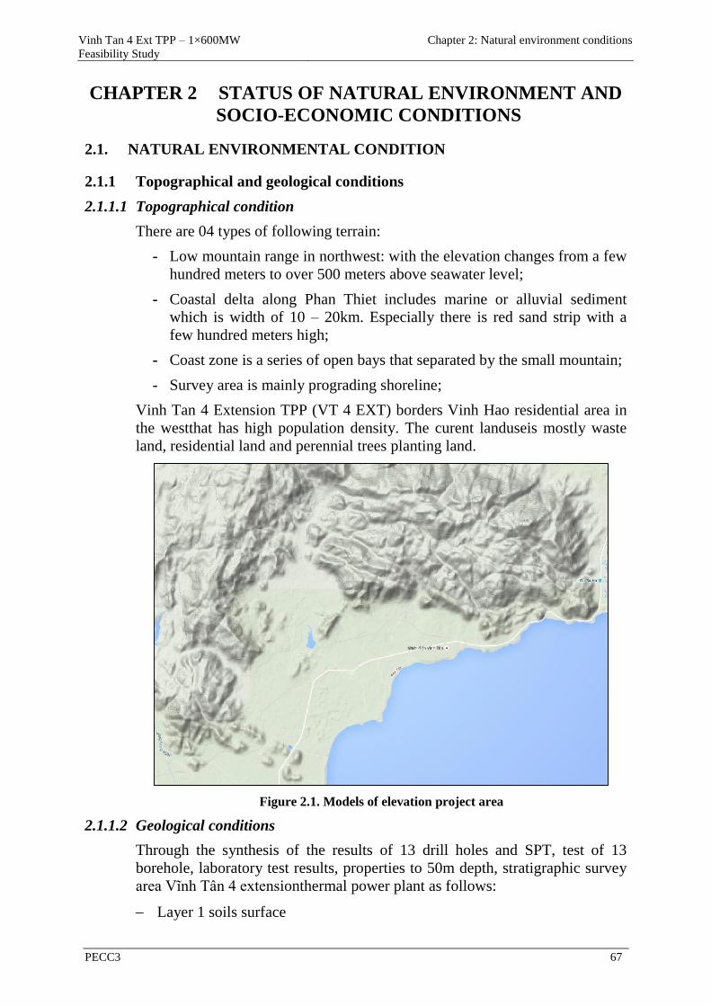
Vinh Tan 4 Ext TPP – 1×600MW
Feasibility Study
Chapter 2: Natural environment conditions
PECC3 67
CHAPTER 2 STATUS OF NATURAL ENVIRONMENT AND
SOCIO-ECONOMIC CONDITIONS
2.1. NATURAL ENVIRONMENTAL CONDITION
2.1.1 Topographical and geological conditions
2.1.1.1 Topographical condition
There are 04 types of following terrain:
- Low mountain range in northwest: with the elevation changes from a few
hundred meters to over 500 meters above seawater level;
- Coastal delta along Phan Thiet includes marine or alluvial sediment
which is width of 10 – 20km. Especially there is red sand strip with a
few hundred meters high;
- Coast zone is a series of open bays that separated by the small mountain;
- Survey area is mainly prograding shoreline;
Vinh Tan 4 Extension TPP (VT 4 EXT) borders Vinh Hao residential area in
the westthat has high population density. The curent landuseis mostly waste
land, residential land and perennial trees planting land.
Figure 2.1. Models of elevation project area
2.1.1.2 Geological conditions
Through the synthesis of the results of 13 drill holes and SPT, test of 13
borehole, laboratory test results, properties to 50m depth, stratigraphic survey
area Vĩnh Tân 4 extensionthermal power plant as follows:
Layer 1 soils surface
Vinh Tan 4 Ext TPP – 1×600MW
Feasibility Study
Chapter 2: Natural environment conditions
PECC3 68
Humus and coral dark gray, thickness from 0.4 m to 1.4 m; appear in the
borehole; VT4MR-09 from 0.0m to 1.0m;
Sand and coral light gray, appeared in borehole VT4MR from 0.0m to
0.5m; VT4MR-03 from 0.0m to 1.4m;
Layer 2:Very stiff to hard yellowish grey – reddish brown clayey sand–
sandy clay with quartz gravel and a small Sand containing coral with
quartz gravel, coarse grained size sand containing coral with quartz gravel;
Layer 2a: Medium bluish grey clayey sand. This layer occurs locally in
borehole VT4MR-09 from 6.3m to 8.5m depth;
Layer 2b: Very stiff bluish grey clayey sand – sandy clay. Appearing at
borehole VT4MR-12 from 7.6m to 9.6m depth, and in boreholes VT4MR-
13 from 7.4m to 11.8 m depth;
Layer 3: Sand contain coralcement, very hard reddish brown is brownish
gray. Core is lumps and bars of drill; few placesnot
yetfullycementshouldalsosandy in the form ofsandy clay – clayey sand
containingcoral, brownish gray, lightgrayvery hardtohardstate. Sandyclay –
clayey sand appears in bore hole VT4MR-03 from 15.1m-20.3m
andboreholeVT4MR-04from13.5 m-15.0m.
Layer 4: Stone coral, appearing in borehole VT4MR-01 from 17.6m to
19.2m depth;
Layers 4a: Very hard light grey –brownish grey sandstone – gristone.
Cores are splintering. Appearing at borehole VT4MR-12 from 20.8m to
22.0m depth, and at boreholes VT4MR-13 from 19.6m to 20.3m depth;
Layer 5a: IA1 – Very highly weathered zone: weathering rock to
Yellowish gray clayey sand and lumps,very hard state;
Layer 5b: IA2– Highly weathered zone: weathering rock to cores rock
brownish grey and grey clayey sand;
Layer 6: IB - Weathered zone:Close – medium grained granite biotite,
Close – medium grained granodiorite, medium grained plagiogranite
biotite solid, fractures. Rock surface iron oxide fillings;
Layer 6a: IIA – Light weathered zone: Close – medium grained granite
biotite, Close – medium grained granodiorite, medium grained
plagiogranite biotite solid, low fractures, core
Layer 7a: IA1 – Very highly weathered zone of diabase rock: coarse sand
mixed brown-gray, very hard;
Layer 7b: IA2– Highly weathered zone of diabase rock: very hard
Brownish grey coarse grained size sand with clay;
- Layer 8: IB - weathered zone of diabase rock: bluish grey diabase rock
highly rigid, average fractures.
The physical and mechanical properties of works foundation soil and rock
layers:
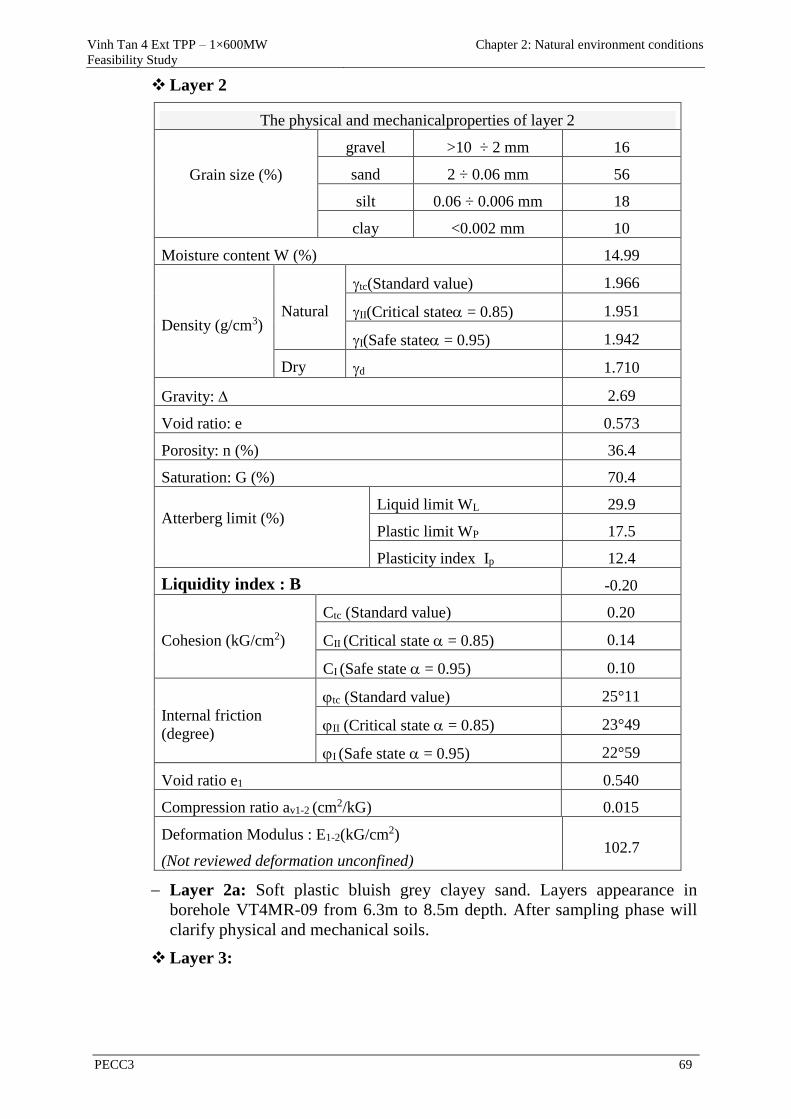
Vinh Tan 4 Ext TPP – 1×600MW
Feasibility Study
Chapter 2: Natural environment conditions
PECC3 69
Layer 2
The physical and mechanicalproperties of layer 2
Grain size (%)
gravel >10 ÷ 2 mm 16
sand 2 ÷ 0.06 mm 56
silt 0.06 ÷ 0.006 mm 18
clay <0.002 mm 10
Moisture content W (%) 14.99
Density (g/cm3) Natural
tc(Standard value) 1.966
II(Critical state= 0.85) 1.951
I(Safe state= 0.95) 1.942
Dry d 1.710
Gravity: 2.69
Void ratio: e 0.573
Porosity: n (%) 36.4
Saturation: G (%) 70.4
Atterberg limit (%)
Liquid limit WL 29.9
Plastic limit WP 17.5
Plasticity index Ip 12.4
Liquidity index : B -0.20
Cohesion (kG/cm2)
Ctc (Standard value) 0.20
CII (Critical state= 0.85) 0.14
CI (Safe state= 0.95) 0.10
Internal friction
(degree)
tc (Standard value) 25°11
II (Critical state= 0.85) 23°49
I (Safe state= 0.95) 22°59
Void ratio e1 0.540
Compression ratio av1-2 (cm2/kG) 0.015
Deformation Modulus : E1-2(kG/cm2)
(Not reviewed deformation unconfined) 102.7
Layer 2a: Soft plastic bluish grey clayey sand. Layers appearance in
borehole VT4MR-09 from 6.3m to 8.5m depth. After sampling phase will
clarify physical and mechanical soils.
Layer 3:
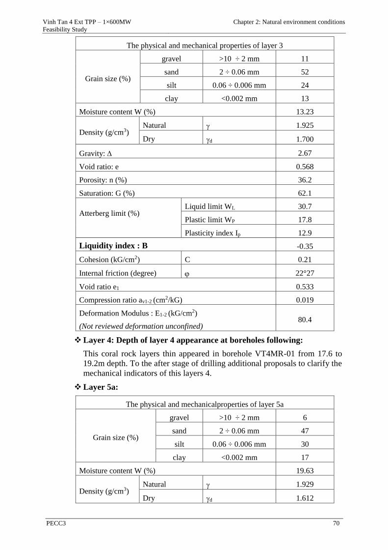
Vinh Tan 4 Ext TPP – 1×600MW
Feasibility Study
Chapter 2: Natural environment conditions
PECC3 70
The physical and mechanical properties of layer 3
Grain size (%)
gravel >10 ÷ 2 mm 11
sand 2 ÷ 0.06 mm 52
silt 0.06 ÷ 0.006 mm 24
clay <0.002 mm 13
Moisture content W (%) 13.23
Density (g/cm3) Natural 1.925
Dry d 1.700
Gravity: 2.67
Void ratio: e 0.568
Porosity: n (%) 36.2
Saturation: G (%) 62.1
Atterberg limit (%)
Liquid limit WL 30.7
Plastic limit WP 17.8
Plasticity index Ip 12.9
Liquidity index : B -0.35
Cohesion (kG/cm2) C 0.21
Internal friction (degree) 22°27
Void ratio e1 0.533
Compression ratio av1-2 (cm2/kG) 0.019
Deformation Modulus : E1-2 (kG/cm2)
(Not reviewed deformation unconfined) 80.4
Layer 4: Depth of layer 4 appearance at boreholes following:
This coral rock layers thin appeared in borehole VT4MR-01 from 17.6 to
19.2m depth. To the after stage of drilling additional proposals to clarify the
mechanical indicators of this layers 4.
Layer 5a:
The physical and mechanicalproperties of layer 5a
Grain size (%)
gravel >10 ÷ 2 mm 6
sand 2 ÷ 0.06 mm 47
silt 0.06 ÷ 0.006 mm 30
clay <0.002 mm 17
Moisture content W (%) 19.63
Density (g/cm3) Natural 1.929
Dry d 1.612
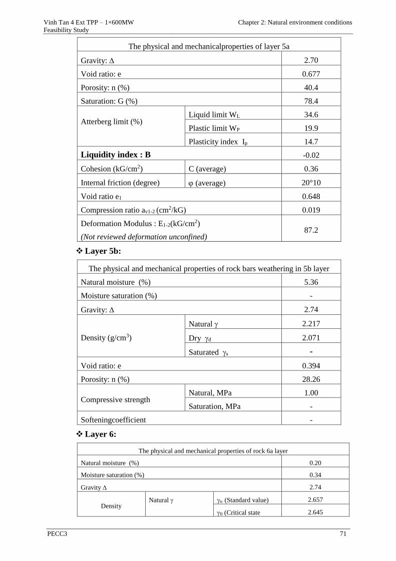
Vinh Tan 4 Ext TPP – 1×600MW
Feasibility Study
Chapter 2: Natural environment conditions
PECC3 71
The physical and mechanicalproperties of layer 5a
Gravity: 2.70
Void ratio: e 0.677
Porosity: n (%) 40.4
Saturation: G (%) 78.4
Atterberg limit (%)
Liquid limit WL 34.6
Plastic limit WP 19.9
Plasticity index Ip 14.7
Liquidity index : B -0.02
Cohesion (kG/cm2) C (average) 0.36
Internal friction (degree) (average) 20°10
Void ratio e1 0.648
Compression ratio av1-2 (cm2/kG) 0.019
Deformation Modulus : E1-2(kG/cm2)
(Not reviewed deformation unconfined) 87.2
Layer 5b:
The physical and mechanical properties of rock bars weathering in 5b layer
Natural moisture (%) 5.36
Moisture saturation (%) -
Gravity: 2.74
Density (g/cm3)
Natural 2.217
Dry d 2.071
Saturated s -
Void ratio: e 0.394
Porosity: n (%) 28.26
Compressive strength Natural, MPa 1.00
Saturation, MPa -
Softeningcoefficient -
Layer 6:
The physical and mechanical properties of rock 6a layer
Natural moisture (%) 0.20
Moisture saturation (%) 0.34
Gravity 2.74
Density Natural tc (Standard value) 2.657
II (Critical state 2.645
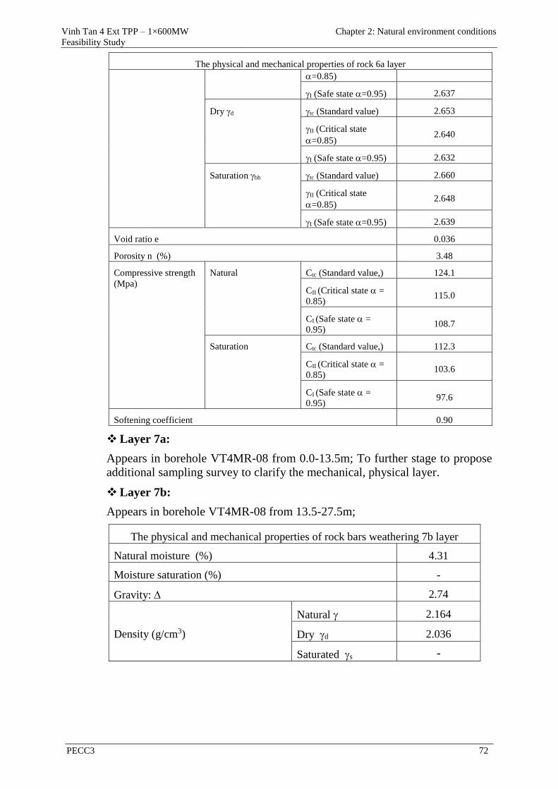
Vinh Tan 4 Ext TPP – 1×600MW
Feasibility Study
Chapter 2: Natural environment conditions
PECC3 72
The physical and mechanical properties of rock 6a layer
=0.85)
I (Safe state =0.95) 2.637
Dry d tc (Standard value) 2.653
II (Critical state
=0.85) 2.640
I (Safe state =0.95) 2.632
Saturation bh tc (Standard value) 2.660
II (Critical state
=0.85) 2.648
I (Safe state =0.95) 2.639
Void ratio e 0.036
Porosity n (%) 3.48
Compressive strength
(Mpa)
Natural Ctc (Standard value,) 124.1
CII (Critical state=
0.85) 115.0
CI (Safe state=
0.95) 108.7
Saturation Ctc (Standard value,) 112.3
CII (Critical state=
0.85) 103.6
CI (Safe state=
0.95) 97.6
Softening coefficient 0.90
Layer 7a:
Appears in borehole VT4MR-08 from 0.0-13.5m; To further stage to propose
additional sampling survey to clarify the mechanical, physical layer.
Layer 7b:
Appears in borehole VT4MR-08 from 13.5-27.5m;
The physical and mechanical properties of rock bars weathering 7b layer
Natural moisture (%) 4.31
Moisture saturation (%) -
Gravity: 2.74
Density (g/cm3)
Natural 2.164
Dry d 2.036
Saturated s -

Vinh Tan 4 Ext TPP – 1×600MW
Feasibility Study
Chapter 2: Natural environment conditions
PECC3 73
The physical and mechanical properties of rock bars weathering 7b layer
Void ratio: e 0.403
Porosity: n (%) 28.65
Compressive strength Natural, MPa 2.0
Saturation, MPa -
Softeningcoefficient -
Layer 8:
Appears in borehole VT4MR-08 from 27.5m to greater 30 m;
The physical and mechanical properties of rock 8 layer
Natural moisture (%) 0.26
Moisture saturation (%) 0.4
Gravity: 2.82
Density (g/cm3)
Natural 2.710
Dry d 2.706
Saturated s 2.712
Void ratio: e 0.045
Porosity: n (%) 4.29
Compressive strength Natural, MPa 104.0
Saturation, MPa 92.5
Softeningcoefficient 0.89
2.1.1.3 Land Resources
According to the investigation of land use planning of Tuy Phong district in 2009,
the district has 9 mainly soil groups, distributed on the specific terrain is
mountainous and coastal plains. Most of the soil is not high fertility.
Red soil group (Ferralsols): This group land has the largest proportion
compared with other group of land in the Binh Thuan province. In Tuy Phong
district, land area is 44493.59ha, which is equivalent to 56% of the natural
area..
Sandy soil: In Tuy Phong district, this area is about 9.023,38ha, accounting for
11.35% of the natural area. The sandy soil group includes white sand
dunes(Ct), yellowish white sand dunes (CtV), reddish sand dunes (Cđ)and sea
sand soil.
Alluvial soil (Fluvisols): The area is about 4.729,15 ha, which is equivalent to
1.07% of the natural area of Tuy Phong district. This land has a high rate clay
composition, holding capacity of water and humus is good. This land suitable
for rice, vegetables, short-term industrial crop sand fruit.
Gray soil: The area is about 3,693.64ha, which is equivalent to 4.64% of the
natural area of Tuy Phong district. Soil has light and medium mechanical

Vinh Tan 4 Ext TPP – 1×600MW
Feasibility Study
Chapter 2: Natural environment conditions
PECC3 74
composition, acidic soil, humus-poor. In some place they plant rice, crops, and
industrial crops with low productivity. Some areas are used for afforestation
against erosion.
Salty soil: The area is about 424,36ha, which is equivalent to 0,53% of the
natural area of Tuy Phong district.. The salty soil group includes the salty soil
of aegiceras species, low and medium salty soil (Salic -UmbricFluvisols), soil
with high salinity (Eutri -SalicFluvisols).Salty soil is found mostly in Tuy
Phong district. Soil has light and medium mechanical composition and is
acidic, and with high humus content, poor nutrient, medium total phosphorus.
This soil is suitable for agricultural production if is invested. At present the
most of land are being used to grow rice and vegetables
Saline alkali soil: The area is about 160,25ha, which is equivalent to 0.20% of
the natural area of Tuy Phong district. Characteristics of the soil is high salt
content Na2CO3 (> 9%) and NaHCO3, now it has been used to exploit NaOH
in the technology soap production. But this soil is also suitable for planting
crops and other upland crops.
Red-brown soil and gray in semi-arid regions (Livisols): an area isd9430.67 ha,
accounting for 11.68% of the natural area of the district. Land is divided into
gray-brown semi-arid regions (Rhodium - Haplic Lixisols), red-brown soil
semi-arid areas (Ferri - Haplic Lixisols). These soils mainly concentrated in
Tuy Phong district.Land withmechanical compositionof mildto moderate, less
acidic, humus content from medium to good, protein and total phosphorus is
poor. The ability of agricultural production on land is limited, in some small
area, this soil is used to plant crops and short-term crops.
Newly modified soil: an area is 204.3 ha, accounting for 11.68% of the natural
area of the district.
Eroded soil with bare rocks: an area is 1,226.73ha, accounting for 1.54% of the
natural area of the district.
Therefore, in the Tuy Phong District, there are 9 soil groups with 16 different soil
types. However, due to arid conditions, most of these soils are nutrient-poor, some
are eroded and there are signs of desertification in coastal areas.
2.1.2 Meteorology conditions
Because VT 4 EXT TPP abuts Ninh Thuan province, so the climatic
characteristics is similar to Ninh Thuan province. Therefore,the
meteorological data measured by Phan Rangweather station, Ninh Thuan
provincewould be used for designing VT 4 EXT TPP. String measurement
data from years 1994-2014
2.1.2.1 Air temperature
This is an area of high air temperature, the annual average temperature in period
1994-2011 is about 27.1°C, the highest temperature is 39.4°C. The lowest
temperature is 16.1°C.The temperatures between the months are not different
much. The average, maximum and minimum air temperatures at Phan Rang
station from 1994 – 2014 are shown in table below:
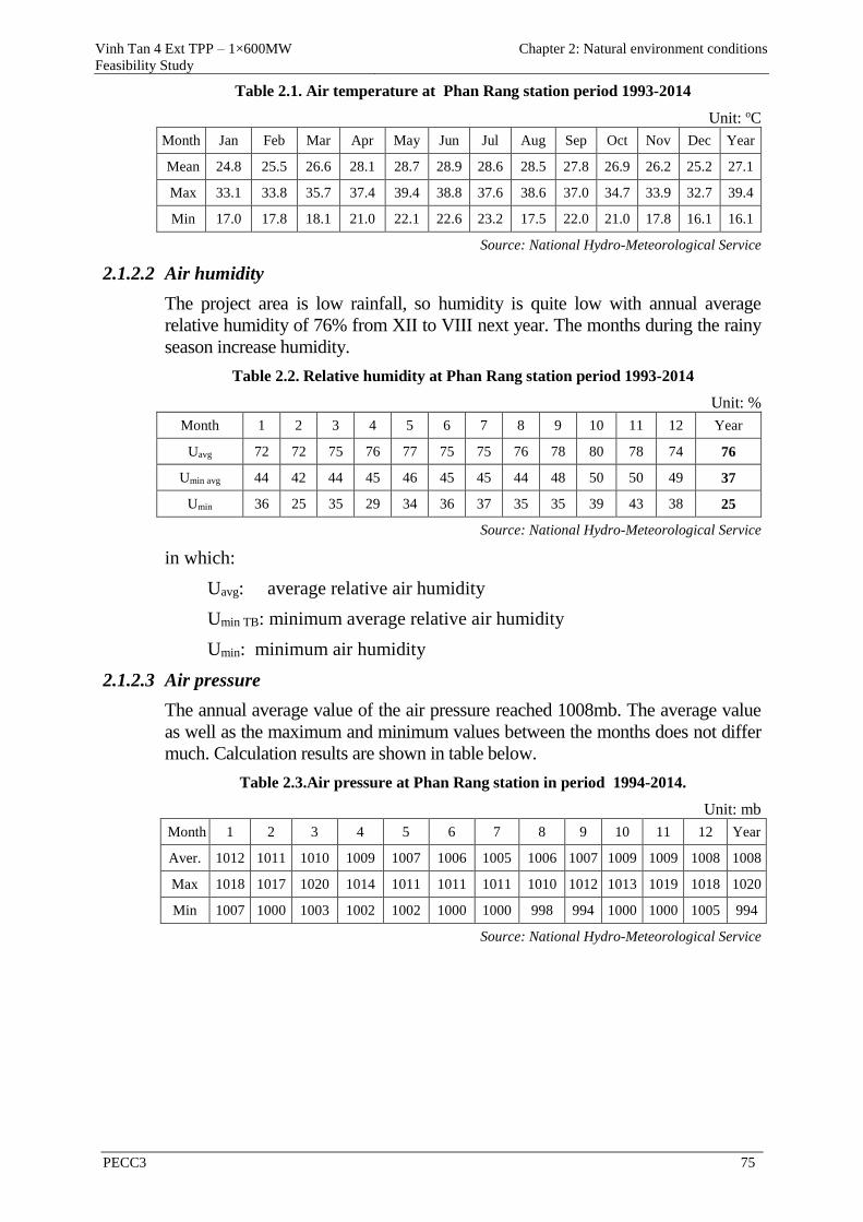
Vinh Tan 4 Ext TPP – 1×600MW
Feasibility Study
Chapter 2: Natural environment conditions
PECC3 75
Table 2.1. Air temperature at Phan Rang station period 1993-2014
Unit: oC
Month Jan Feb Mar Apr May Jun Jul Aug Sep Oct Nov Dec Year
Mean 24.8 25.5 26.6 28.1 28.7 28.9 28.6 28.5 27.8 26.9 26.2 25.2 27.1
Max 33.1 33.8 35.7 37.4 39.4 38.8 37.6 38.6 37.0 34.7 33.9 32.7 39.4
Min 17.0 17.8 18.1 21.0 22.1 22.6 23.2 17.5 22.0 21.0 17.8 16.1 16.1
Source: National Hydro-Meteorological Service
2.1.2.2 Air humidity
The project area is low rainfall, so humidity is quite low with annual average
relative humidity of 76% from XII to VIII next year. The months during the rainy
season increase humidity.
Table 2.2. Relative humidity at Phan Rang station period 1993-2014
Unit: %
Month 1 2 3 4 5 6 7 8 9 10 11 12 Year
Uavg 72 72 75 76 77 75 75 76 78 80 78 74 76
Umin avg 44 42 44 45 46 45 45 44 48 50 50 49 37
Umin 36 25 35 29 34 36 37 35 35 39 43 38 25
Source: National Hydro-Meteorological Service
in which:
Uavg: average relative air humidity
Umin TB: minimum average relative air humidity
Umin: minimum air humidity
2.1.2.3 Air pressure
The annual average value of the air pressure reached 1008mb. The average value
as well as the maximum and minimum values between the months does not differ
much. Calculation results are shown in table below.
Table 2.3.Air pressure at Phan Rang station in period 1994-2014.
Unit: mb
Month 1 2 3 4 5 6 7 8 9 10 11 12 Year
Aver. 1012 1011 1010 1009 1007 1006 1005 1006 1007 1009 1009 1008 1008
Max 1018 1017 1020 1014 1011 1011 1011 1010 1012 1013 1019 1018 1020
Min 1007 1000 1003 1002 1002 1000 1000 998 994 1000 1000 1005 994
Source: National Hydro-Meteorological Service
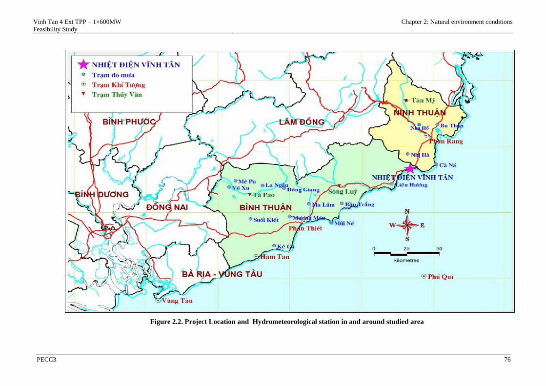
Vinh Tan 4 Ext TPP – 1×600MW
Feasibility Study
Chapter 2: Natural environment conditions
PECC3 76
Figure 2.2. Project Location and Hydrometeorological station in and around studied area
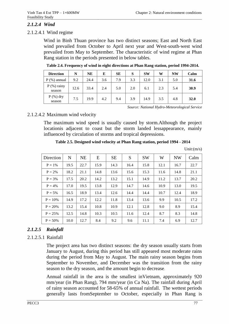
Vinh Tan 4 Ext TPP – 1×600MW
Feasibility Study
Chapter 2: Natural environment conditions
PECC3 77
2.1.2.4 Wind
2.1.2.4.1 Wind regime
Wind in Binh Thuan province has two distinct seasons; East and North East
wind prevailed from October to April next year and West-south-west wind
prevailed from May to September. The characteristic of wind regime at Phan
Rang station in the periods presented in below tables.
Table 2.4. Frequency of wind in eight directions at Phan Rang station, period 1994-2014.
Direction N NE E SE S SW W NW Calm
P (%) annual 9.2 24.4 3.6 7.9 3.3 12.0 3.1 5.0 31.6
P (%) rainy
season 12.6 33.4 2.4 5.0 2.0 6.1 2.3 5.4 30.9
P (%) dry
season 7.5 19.9 4.2 9.4 3.9 14.9 3.5 4.8 32.0
Source: National Hydro-Meteorological Service
2.1.2.4.2 Maximum wind velocity
The maximum wind speed is usually caused by storm.Although the project
locationis adjacent to coast but the storm landed lessappearance, mainly
influenced by circulation of storms and tropical depressions.
Table 2.5. Designed wind velocity at Phan Rang station, period 1994 - 2014
Unit:(m/s)
Direction N NE E SE S SW W NW Calm
P = 1% 19.5 22.7 15.9 14.3 16.4 15.8 12.1 16.7 22.7
P = 2% 18.2 21.1 14.8 13.6 15.6 15.3 11.6 14.8 21.1
P = 3% 17.5 20.2 14.2 13.2 15.1 14.9 11.2 13.7 20.2
P = 4% 17.0 19.5 13.8 12.9 14.7 14.6 10.9 13.0 19.5
P = 5% 16.5 18.9 13.4 12.6 14.4 14.4 10.7 12.4 18.9
P = 10% 14.9 17.2 12.2 11.8 13.4 13.6 9.9 10.5 17.2
P = 20% 13.2 15.4 10.8 10.9 12.1 12.8 9.0 8.9 15.4
P = 25% 12.5 14.8 10.3 10.5 11.6 12.4 8.7 8.3 14.8
P = 50% 10.0 12.7 8.4 9.2 9.6 11.1 7.4 6.9 12.7
2.1.2.5 Rainfall
2.1.2.5.1 Rainfall
The project area has two distinct seasons: the dry season usually starts from
January to August, during this period has still appeared most moderate rains
during the period from May to August. The main rainy season begins from
September to November, and December was the transition from the rainy
season to the dry season, and the amount begin to decrease.
Annual rainfall in the area is the smallest inVietnam, approximately 920
mm/year (in Phan Rang), 794 mm/year (in Ca Na). The rainfall during April
of rainy season accounted for 58-65% of annual rainfall. The wettest periods
generally lasts fromSeptember to October, especially in Phan Rang is
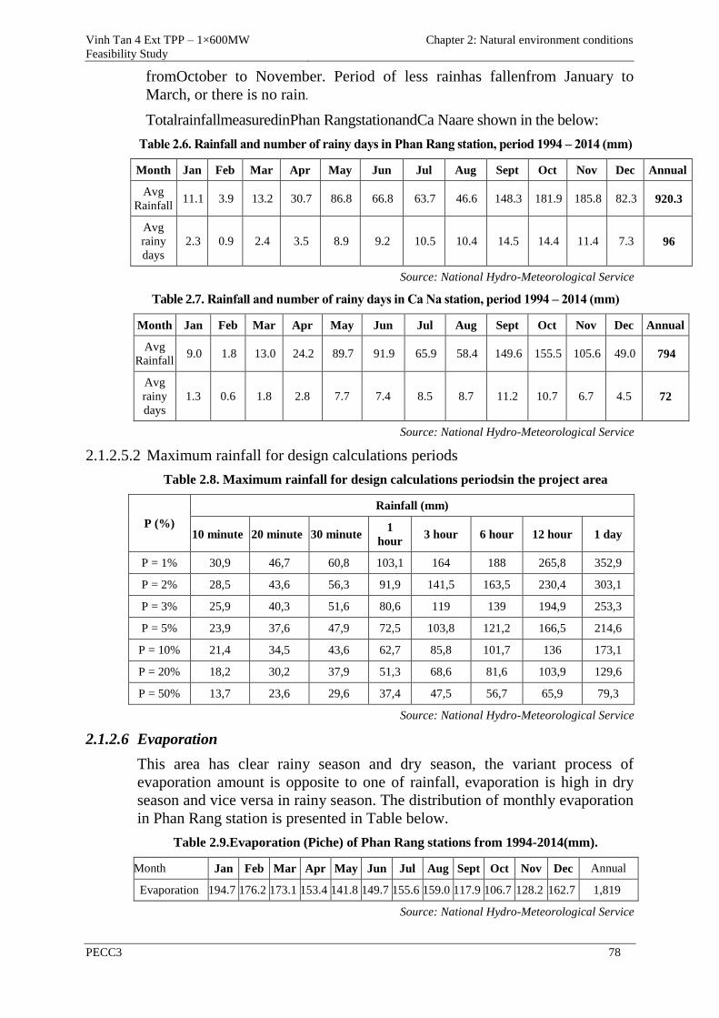
Vinh Tan 4 Ext TPP – 1×600MW
Feasibility Study
Chapter 2: Natural environment conditions
PECC3 78
fromOctober to November. Period of less rainhas fallenfrom January to
March, or there is no rain.
TotalrainfallmeasuredinPhan RangstationandCa Naare shown in the below:
Table 2.6. Rainfall and number of rainy days in Phan Rang station, period 1994 – 2014 (mm)
Month Jan Feb Mar Apr May Jun Jul Aug Sept Oct Nov Dec Annual
Avg
Rainfall 11.1 3.9 13.2 30.7 86.8 66.8 63.7 46.6 148.3 181.9 185.8 82.3 920.3
Avg
rainy
days
2.3 0.9 2.4 3.5 8.9 9.2 10.5 10.4 14.5 14.4 11.4 7.3 96
Source: National Hydro-Meteorological Service
Table 2.7. Rainfall and number of rainy days in Ca Na station, period 1994 – 2014 (mm)
Month Jan Feb Mar Apr May Jun Jul Aug Sept Oct Nov Dec Annual
Avg
Rainfall 9.0 1.8 13.0 24.2 89.7 91.9 65.9 58.4 149.6 155.5 105.6 49.0 794
Avg
rainy
days
1.3 0.6 1.8 2.8 7.7 7.4 8.5 8.7 11.2 10.7 6.7 4.5 72
Source: National Hydro-Meteorological Service
2.1.2.5.2 Maximum rainfall for design calculations periods
Table 2.8. Maximum rainfall for design calculations periodsin the project area
P (%)
Rainfall (mm)
10 minute 20 minute 30 minute 1
hour 3 hour 6 hour 12 hour 1 day
P = 1% 30,9 46,7 60,8 103,1 164 188 265,8 352,9
P = 2% 28,5 43,6 56,3 91,9 141,5 163,5 230,4 303,1
P = 3% 25,9 40,3 51,6 80,6 119 139 194,9 253,3
P = 5% 23,9 37,6 47,9 72,5 103,8 121,2 166,5 214,6
P = 10% 21,4 34,5 43,6 62,7 85,8 101,7 136 173,1
P = 20% 18,2 30,2 37,9 51,3 68,6 81,6 103,9 129,6
P = 50% 13,7 23,6 29,6 37,4 47,5 56,7 65,9 79,3
Source: National Hydro-Meteorological Service
2.1.2.6 Evaporation
This area has clear rainy season and dry season, the variant process of
evaporation amount is opposite to one of rainfall, evaporation is high in dry
season and vice versa in rainy season. The distribution of monthly evaporation
in Phan Rang station is presented in Table below.
Table 2.9.Evaporation (Piche) of Phan Rang stations from 1994-2014(mm).
Month Jan Feb Mar Apr May Jun Jul Aug Sept Oct Nov Dec Annual
Evaporation 194.7 176.2 173.1 153.4 141.8 149.7 155.6 159.0 117.9 106.7 128.2 162.7 1,819
Source: National Hydro-Meteorological Service
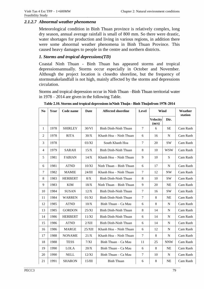
Vinh Tan 4 Ext TPP – 1×600MW
Feasibility Study
Chapter 2: Natural environment conditions
PECC3 79
2.1.2.7 Abnormal weather phenomena
Meteorological condition in Binh Thuan province is relatively complex, long
dry season, annual average rainfall is small of 800 mm. So there were drastic,
water shortages for production and living in various regions, in addition there
were some abnormal weather phenomena in Binh Thuan Province. This
caused heavy damages to people in the centre and northern districts.
1. Storms and tropical depressions(TD)
Coastal Ninh Thuan - Binh Thuan has appeared storms and tropical
depressionsannually. Storms occur especially in October and November.
Although the project location is closedto shoreline, but the frequency of
stormsmakelandfall is not high, mainly affected by the storms and depressions
circulation.
Storms and tropical depression occur in Ninh Thuan –Binh Thuan territorial water
in 1978 – 2014 are given in the following Table.
Table 2.10. Storms and tropical depressions inNinh Thuận - Bình Thuậnfrom 1978–2014
No Year Code name Date Affected shoreline Level Wind Weather
station
Velocity
(m/s)
Dir.
1 1978 SHIRLEY 30/VI Binh Dinh-Ninh Thuan 7 6 SE Cam Ranh
2 1978 RITA 30/X Khanh Hoa – Ninh Thuan 6 16 N Cam Ranh
3 1978 03/XI South Khanh Hoa 7 20 SW Cam Ranh
4 1979 SARAH 15/X Binh Dinh-Ninh Thuan 8 10 WSW Cam Ranh
5 1981 FABIAN 14/X Khanh Hoa – Ninh Thuan 9 10 S Cam Ranh
6 1981 ATND 10/XI Ninh Thuan – Binh Thuan 6 17 N Cam Ranh
7 1982 MAMIE 24/III Khanh Hoa – Ninh Thuan 7 12 NW Cam Ranh
8 1983 HERBERT 8/X Binh Dinh-Ninh Thuan 8 10 SW Cam Ranh
9 1983 KIM 18/X Ninh Thuan – Binh Thuan 9 20 NE Cam Ranh
10 1984 SUSAN 12/X Binh Dinh-Ninh Thuan 7 16 SW Cam Ranh
11 1984 WARREN 01/XI Binh Dinh-Ninh Thuan 7 8 NE Cam Ranh
12 1985 ATND 10/X Binh Thuan – Ca Mau 6 8 N Cam Ranh
13 1985 GORDON 25/XI Binh Dinh-Ninh Thuan 8 14 N Cam Ranh
14 1986 HERBERT 11/XI Binh Dinh-Ninh Thuan 6 14 N Cam Ranh
15 1986 ATND 2/XII Binh Dinh-Ninh Thuan 6 14 N Cam Ranh
16 1986 MARGE 25/XII Khanh Hoa – Ninh Thuan 6 12 N Cam Ranh
17 1988 NONAME 21/X Khanh Hoa – Ninh Thuan 7 8 N Cam Ranh
18 1988 TESS 7/XI Binh Thuan – Ca Mau 11 25 NNW Cam Ranh
19 1990 LOLA 20/X Binh Thuan – Ca Mau 6 8 NE Cam Ranh
20 1990 NELL 12/XI Binh Thuan – Ca Mau 7 10 N Cam Ranh
21 1991 SHARON 15/III Binh Thuan 6 8 NE Cam Ranh
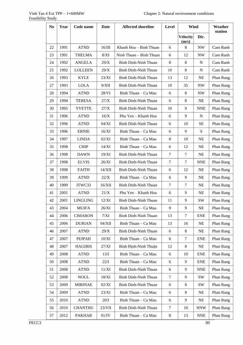
Vinh Tan 4 Ext TPP – 1×600MW
Feasibility Study
Chapter 2: Natural environment conditions
PECC3 80
No Year Code name Date Affected shoreline Level Wind Weather
station
Velocity
(m/s)
Dir.
22 1991 ATND 16/III Khanh Hoa – Binh Thuan 6 8 NW Cam Ranh
23 1991 THELMA 8/XI Ninh Thuan – Binh Thuan 6 12 NW Cam Ranh
24 1992 ANGELA 29/X Binh Dinh-Ninh Thuan 8 8 N Cam Ranh
25 1992 LOLLEEN 29/X Binh Dinh-Ninh Thuan 10 8 N Cam Ranh
26 1993 KYLE 23/XI Binh Dinh-Ninh Thuan 13 12 NE Phan Rang
27 1993 LOLA 9/XII Binh Dinh-Ninh Thuan 10 35 NW Phan Rang
28 1994 ATND 28/VI Binh Thuan – Ca Mau 6 8 NW Phan Rang
29 1994 TERESA 27/X Binh Dinh-Ninh Thuan 6 8 NE Phan Rang
30 1995 YVETTE 27/X Binh Dinh-Ninh Thuan 10 9 NNE Phan Rang
31 1996 ATND 16/X Phu Yen – Khanh Hoa 6 9 N Phan Rang
32 1996 ATND 04/XI Binh Dinh-Ninh Thuan 6 10 SE Phan Rang
33 1996 ERNIE 16/XI Binh Thuan – Ca Mau 6 9 S Phan Rang
34 1997 LINDA 02/XI Binh Thuan – Ca Mau 8 10 NE Phan Rang
35 1998 CHIP 14/XI Binh Thuan – Ca Mau 6 12 NE Phan Rang
36 1998 DAWN 19/XI Binh Dinh-Ninh Thuan 7 7 NE Phan Rang
37 1998 ELVIS 26/XI Binh Dinh-Ninh Thuan 7 7 NNE Phan Rang
38 1998 FAITH 14/XII Binh Dinh-Ninh Thuan 6 12 NE Phan Rang
39 1999 ATND 22/X Binh Thuan – Ca Mau 6 9 NE Phan Rang
40 1999 JTWC33 16/XII Binh Dinh-Ninh Thuan 7 7 NE Phan Rang
41 2001 ATND 21/X Phu Yen – Khanh Hoa 6 9 NE Phan Rang
42 2001 LINGLING 12/XI Binh Dinh-Ninh Thuan 11 9 SW Phan Rang
43 2004 MUIFA 26/XI Binh Thuan – Ca Mau 9 9 NE Phan Rang
44 2006 CIMARON 7/XI Binh Dinh-Ninh Thuan 13 7 ENE Phan Rang
45 2006 DURIAN 04/XII Binh Thuan – Ca Mau 13 16 NE Phan Rang
46 2007 ATND 29/X Binh Dinh-Ninh Thuan 6 8 NE Phan Rang
47 2007 PEIPAH 10/XI Binh Thuan – Ca Mau 6 7 ENE Phan Rang
48 2007 HAGIBIS 27/XI Bình Định-Ninh Thuận 12 8 NE Phan Rang
49 2008 ATND 13/I Binh Thuan – Ca Mau 6 10 ENE Phan Rang
50 2008 ATND 22/I Binh Thuan – Ca Mau 6 9 ENE Phan Rang
51 2008 ATND 11/XI Binh Dinh-Ninh Thuan 6 9 NNE Phan Rang
52 2008 NOUL 18/XI Binh Dinh-Ninh Thuan 7 9 SW Phan Rang
53 2009 MIRINAE 02/XI Binh Dinh-Ninh Thuan 6 8 SW Phan Rang
54 2009 ATND 23/XI Binh Thuan – Ca Mau 6 8 NE Phan Rang
55 2010 ATND 20/I Binh Thuan – Ca Mau 6 9 NE Phan Rang
56 2010 CHANTHU 23/VII Binh Dinh-Ninh Thuan 7 10 NNW Phan Rang
57 2012 PAKHAR 01/IV Binh Thuan – Ca Mau 8 13 NNE Phan Rang
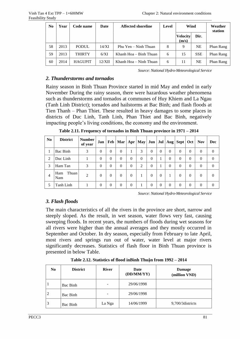
Vinh Tan 4 Ext TPP – 1×600MW
Feasibility Study
Chapter 2: Natural environment conditions
PECC3 81
No Year Code name Date Affected shoreline Level Wind Weather
station
Velocity
(m/s)
Dir.
58 2013 PODUL 14/XI Phu Yen – Ninh Thuan 8 9 NE Phan Rang
59 2013 THIRTY 6/XI Khanh Hoa – Binh Thuan 6 15 SSE Phan Rang
60 2014 HAGUPIT 12/XII Khanh Hoa – Ninh Thuan 6 11 NE Phan Rang
Source: National Hydro-Meteorological Service
2. Thunderstorms and tornados
Rainy season in Binh Thuan Province started in mid May and ended in early
November During the rainy season, there were hazardous weather phenomena
such as thunderstorms and tornados at communes of Huy Khiem and La Ngau
(Tanh Linh District); tornados and hailstorms at Bac Binh; and flash floods at
Tien Thanh – Phan Thiet. These resulted in heavy damages to some places in
districts of Duc Linh, Tanh Linh, Phan Thiet and Bac Binh, negatively
impacting people’s living conditions, the economy and the environment.
Table 2.11. Frequency of tornados in Binh Thuan province in 1971 – 2014
No District Number
of year Jan Feb Mar Apr May Jun Jul Aug Sept Oct Nov Dec
1 Bac Binh 3 0 0 0 1 3 0 0 0 0 0 0 0
2 Duc Linh 1 0 0 0 0 0 0 1 0 0 0 0 0
3 Ham Tan 3 0 0 0 0 2 0 1 0 0 0 0 0
4 Ham Thuan
Nam 2 0 0 0 0 1 0 0 1 0 0 0 0
5 Tanh Linh 1 0 0 0 0 1 0 0 0 0 0 0 0
Source: National Hydro-Meteorological Service
3. Flash floods
The main characteristics of all the rivers in the province are short, narrow and
steeply sloped. As the result, in wet season, water flows very fast, causing
sweeping floods. In recent years, the numbers of floods during wet seasons for
all rivers were higher than the annual averages and they mostly occurred in
September and October. In dry season, especially from February to late April,
most rivers and springs run out of water, water level at major rivers
significantly decreases. Statistics of flash floor in Binh Thuan province is
presented in below Table.
Table 2.12. Statistics of flood inBình Thuận from 1992 – 2014
No District River Date
(DD/MM/YY)
Damage
(million VND)
1 Bac Binh - 29/06/1998
2 Bac Binh - 29/06/1998
3 Bac Binh La Nga 14/06/1999 9,700/3districts
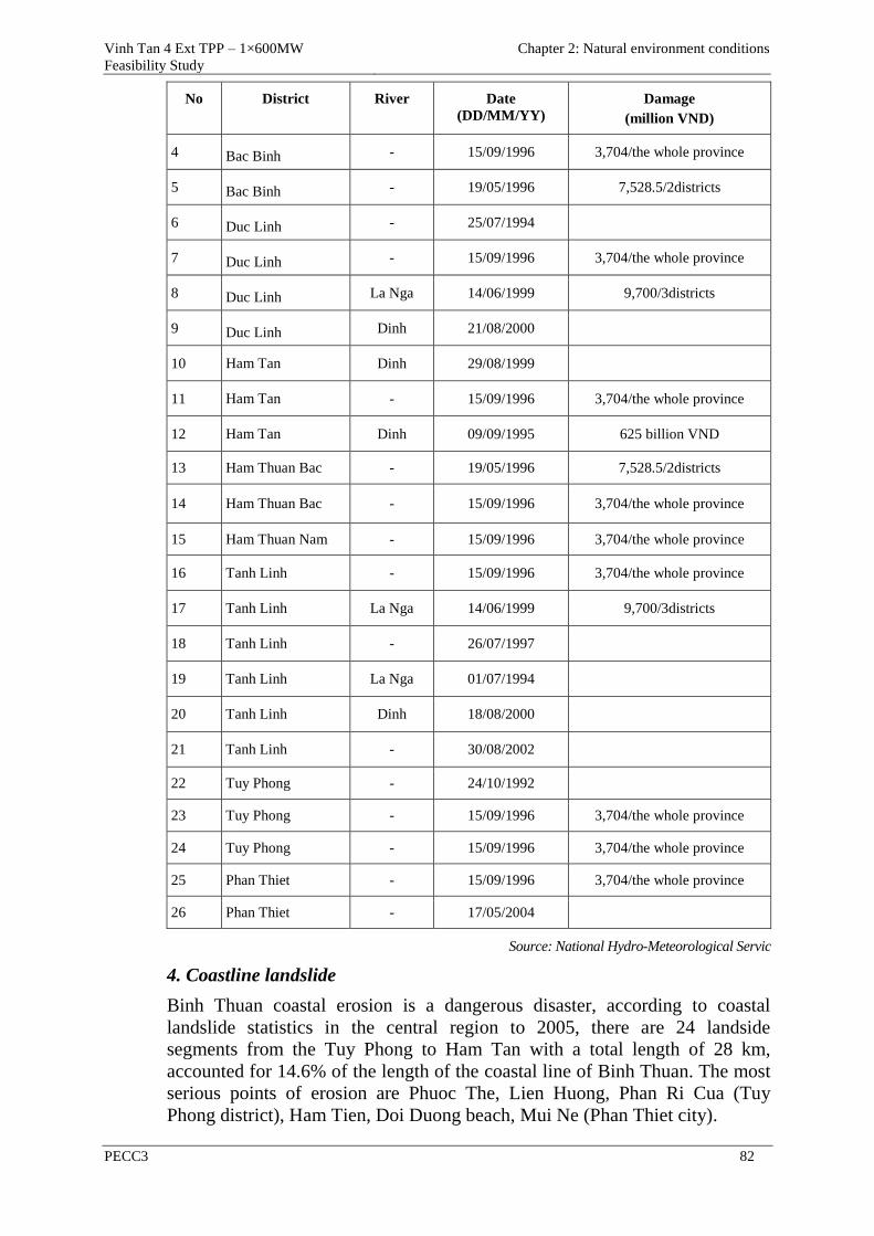
Vinh Tan 4 Ext TPP – 1×600MW
Feasibility Study
Chapter 2: Natural environment conditions
PECC3 82
No District River Date
(DD/MM/YY)
Damage
(million VND)
4 Bac Binh - 15/09/1996 3,704/the whole province
5 Bac Binh - 19/05/1996 7,528.5/2districts
6 Duc Linh - 25/07/1994
7 Duc Linh - 15/09/1996 3,704/the whole province
8 Duc Linh La Nga 14/06/1999 9,700/3districts
9 Duc Linh Dinh 21/08/2000
10 Ham Tan Dinh 29/08/1999
11 Ham Tan - 15/09/1996 3,704/the whole province
12 Ham Tan Dinh 09/09/1995 625 billion VND
13 Ham Thuan Bac - 19/05/1996 7,528.5/2districts
14 Ham Thuan Bac - 15/09/1996 3,704/the whole province
15 Ham Thuan Nam - 15/09/1996 3,704/the whole province
16 Tanh Linh - 15/09/1996 3,704/the whole province
17 Tanh Linh La Nga 14/06/1999 9,700/3districts
18 Tanh Linh - 26/07/1997
19 Tanh Linh La Nga 01/07/1994
20 Tanh Linh Dinh 18/08/2000
21 Tanh Linh - 30/08/2002
22 Tuy Phong - 24/10/1992
23 Tuy Phong - 15/09/1996 3,704/the whole province
24 Tuy Phong - 15/09/1996 3,704/the whole province
25 Phan Thiet - 15/09/1996 3,704/the whole province
26 Phan Thiet - 17/05/2004
Source: National Hydro-Meteorological Servic
4. Coastline landslide
Binh Thuan coastal erosion is a dangerous disaster, according to coastal
landslide statistics in the central region to 2005, there are 24 landside
segments from the Tuy Phong to Ham Tan with a total length of 28 km,
accounted for 14.6% of the length of the coastal line of Binh Thuan. The most
serious points of erosion are Phuoc The, Lien Huong, Phan Ri Cua (Tuy
Phong district), Ham Tien, Doi Duong beach, Mui Ne (Phan Thiet city).
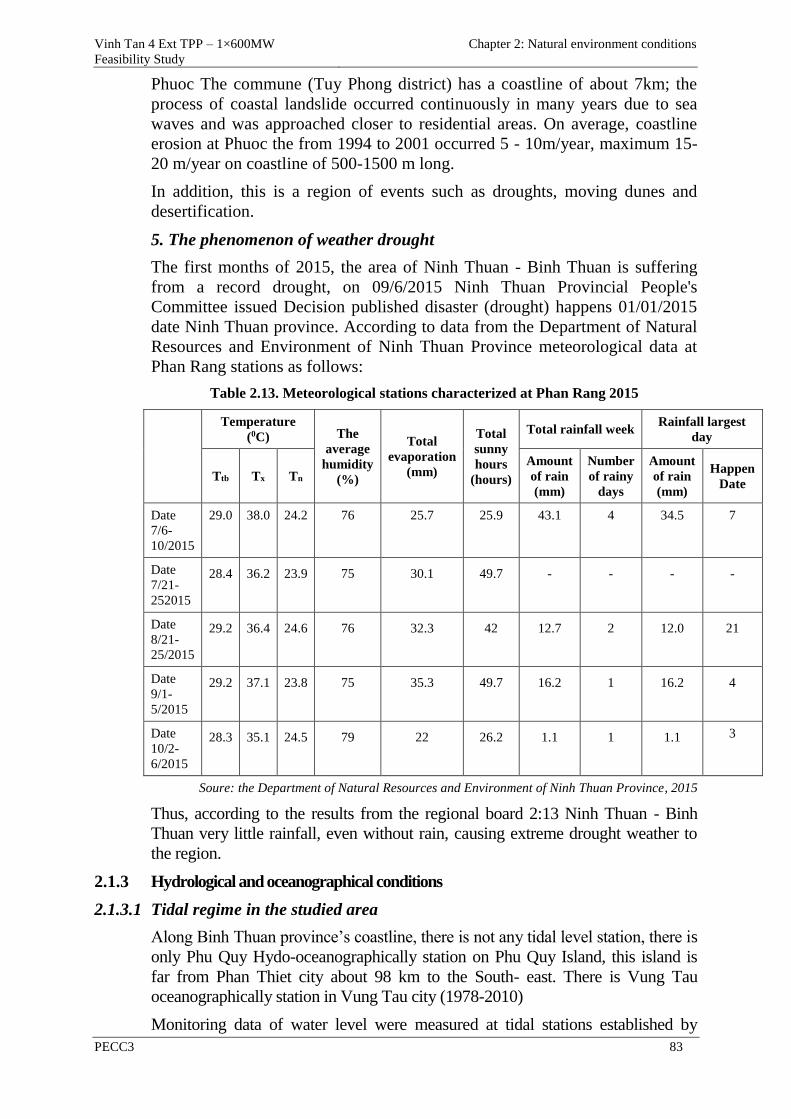
Vinh Tan 4 Ext TPP – 1×600MW
Feasibility Study
Chapter 2: Natural environment conditions
PECC3 83
Phuoc The commune (Tuy Phong district) has a coastline of about 7km; the
process of coastal landslide occurred continuously in many years due to sea
waves and was approached closer to residential areas. On average, coastline
erosion at Phuoc the from 1994 to 2001 occurred 5 - 10m/year, maximum 15-
20 m/year on coastline of 500-1500 m long.
In addition, this is a region of events such as droughts, moving dunes and
desertification.
5. The phenomenon of weather drought
The first months of 2015, the area of Ninh Thuan - Binh Thuan is suffering
from a record drought, on 09/6/2015 Ninh Thuan Provincial People's
Committee issued Decision published disaster (drought) happens 01/01/2015
date Ninh Thuan province. According to data from the Department of Natural
Resources and Environment of Ninh Thuan Province meteorological data at
Phan Rang stations as follows:
Table 2.13. Meteorological stations characterized at Phan Rang 2015
Temperature
(0C) The
average
humidity
(%)
Total
evaporation
(mm)
Total
sunny
hours
(hours)
Total rainfall week Rainfall largest
day
Ttb Tx Tn
Amount
of rain
(mm)
Number
of rainy
days
Amount
of rain
(mm)
Happen
Date
Date
7/6-
10/2015
29.0 38.0 24.2 76 25.7 25.9 43.1 4 34.5 7
Date
7/21-
252015
28.4 36.2 23.9 75 30.1 49.7 - - - -
Date
8/21-
25/2015
29.2 36.4 24.6 76 32.3 42 12.7 2 12.0 21
Date
9/1-
5/2015
29.2 37.1 23.8 75 35.3 49.7 16.2 1 16.2 4
Date
10/2-
6/2015
28.3 35.1 24.5 79 22 26.2
1.1 1 1.1 3
Soure: the Department of Natural Resources and Environment of Ninh Thuan Province, 2015
Thus, according to the results from the regional board 2:13 Ninh Thuan - Binh
Thuan very little rainfall, even without rain, causing extreme drought weather to
the region.
2.1.3 Hydrological and oceanographical conditions
2.1.3.1 Tidal regime in the studied area
Along Binh Thuan province’s coastline, there is not any tidal level station, there is
only Phu Quy Hydo-oceanographically station on Phu Quy Island, this island is
far from Phan Thiet city about 98 km to the South- east. There is Vung Tau
oceanographically station in Vung Tau city (1978-2010)
Monitoring data of water level were measured at tidal stations established by
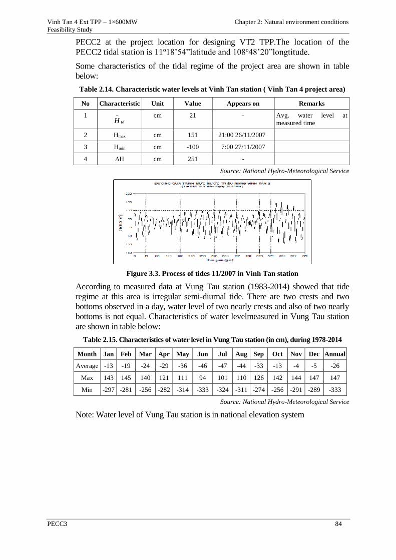
Vinh Tan 4 Ext TPP – 1×600MW
Feasibility Study
Chapter 2: Natural environment conditions
PECC3 84
PECC2 at the project location for designing VT2 TPP.The location of the
PECC2 tidal station is 11o18’54”latitude and 108o48’20”longtitude.
Some characteristics of the tidal regime of the project area are shown in table
below:
Table 2.14. Characteristic water levels at Vinh Tan station ( Vinh Tan 4 project area)
No Characteristic Unit Value Appears on Remarks
1 tdH
cm 21 - Avg. water level at
measured time
2 Hmax cm 151 21:00 26/11/2007
3 Hmin cm -100 7:00 27/11/2007
4 ∆H cm 251 -
Source: National Hydro-Meteorological Service
Figure 3.3. Process of tides 11/2007 in Vinh Tan station
According to measured data at Vung Tau station (1983-2014) showed that tide
regime at this area is irregular semi-diurnal tide. There are two crests and two
bottoms observed in a day, water level of two nearly crests and also of two nearly
bottoms is not equal. Characteristics of water levelmeasured in Vung Tau station
are shown in table below:
Table 2.15. Characteristics of water level in Vung Tau station (in cm), during 1978-2014
Month Jan Feb Mar Apr May Jun Jul Aug Sep Oct Nov Dec Annual
Average -13 -19 -24 -29 -36 -46 -47 -44 -33 -13 -4 -5 -26
Max 143 145 140 121 111 94 101 110 126 142 144 147 147
Min -297 -281 -256 -282 -314 -333 -324 -311 -274 -256 -291 -289 -333
Source: National Hydro-Meteorological Service
Note: Water level of Vung Tau station is in national elevation system
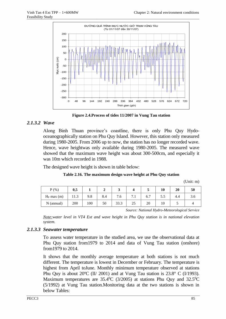
Vinh Tan 4 Ext TPP – 1×600MW
Feasibility Study
Chapter 2: Natural environment conditions
PECC3 85
Figure 2.4.Process of tides 11/2007 in Vung Tau station
2.1.3.2 Wave
Along Binh Thuan province’s coastline, there is only Phu Quy Hydo-
oceanographically station on Phu Quy Island. However, this station only measured
during 1980-2005. From 2006 up to now, the station has no longer recorded wave.
Hence, wave heightwas only available during 1980-2005. The measured wave
showed that the maximum wave height was about 300-500cm, and especially it
was 10m which recorded in 1988.
The designed wave height is shown in table below:
Table 2.16. The maximum design wave height at Phu Quy station
(Unit: m)
P (%) 0,5 1 2 3 4 5 10 20 50
HP max (m) 11.3 9.8 8.4 7.6 7.1 6.7 5.5 4.4 3.6
N (annual) 200 100 50 33.3 25 20 10 5 4
Source: National Hydro-Meteorological Service
Note:water level in VT4 Ext and wave height in Phu Quy station is in national elevation
system.
2.1.3.3 Seawater temperature
To assess water temperature in the studied area, we use the observational data at
Phu Quy station from1979 to 2014 and data of Vung Tau station (onshore)
from1979 to 2014.
It shows that the monthly average temperature at both stations is not much
different. The temperature is lowest in December or February. The temperature is
highest from April toJune. Monthly minimum temperature observed at stations
Phu Quy is about 20oC (II/ 2001) and at Vung Tau station is 23.8° C (I/1993).
Maximum temperatures are 35.40C (3/2005) at stations Phu Quy and 32.50C
(5/1992) at Vung Tau station.Monitoring data at the two stations is shown in
below Tables:
ĐƯỜNG QUÁ TRÌNH MỰC NƯỚC GIỜ TRẠM VŨNG TÀU
(Từ 01/11/07 đến 30/11/07)
-300
-250
-200
-150
-100
-50
0
50
100
150
200
0 48 96 144 192 240 288 336 384 432 480 528 576 624 672 720
Thời gian (giờ)
Mự
c nư
ớc
(cm
)
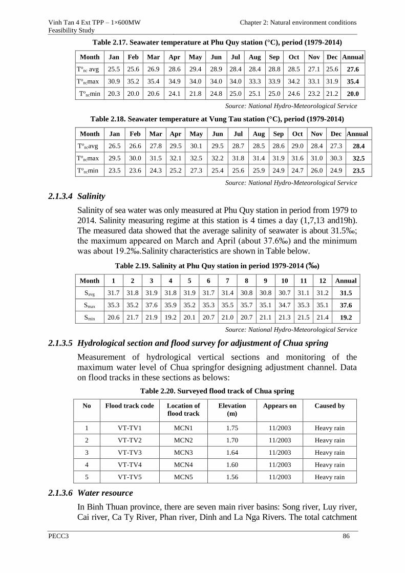
Vinh Tan 4 Ext TPP – 1×600MW
Feasibility Study
Chapter 2: Natural environment conditions
PECC3 86
Table 2.17. Seawater temperature at Phu Quy station (°C), period (1979-2014)
Month Jan Feb Mar Apr May Jun Jul Aug Sep Oct Nov Dec Annual
Tonc avg 25.5 25.6 26.9 28.6 29.4 28.9 28.4 28.4 28.8 28.5 27.1 25.6 27.6
Toncmax 30.9 35.2 35.4 34.9 34.0 34.0 34.0 33.3 33.9 34.2 33.1 31.9 35.4
Toncmin 20.3 20.0 20.6 24.1 21.8 24.8 25.0 25.1 25.0 24.6 23.2 21.2 20.0
Source: National Hydro-Meteorological Service
Table 2.18. Seawater temperature at Vung Tau station (°C), period (1979-2014)
Month Jan Feb Mar Apr May Jun Jul Aug Sep Oct Nov Dec Annual
Toncavg 26.5 26.6 27.8 29.5 30.1 29.5 28.7 28.5 28.6 29.0 28.4 27.3 28.4
Toncmax 29.5 30.0 31.5 32.1 32.5 32.2 31.8 31.4 31.9 31.6 31.0 30.3 32.5
Toncmin 23.5 23.6 24.3 25.2 27.3 25.4 25.6 25.9 24.9 24.7 26.0 24.9 23.5
Source: National Hydro-Meteorological Service
2.1.3.4 Salinity
Salinity of sea water was only measured at Phu Quy station in period from 1979 to
2014. Salinity measuring regime at this station is 4 times a day (1,7,13 and19h).
The measured data showed that the average salinity of seawater is about 31.5‰;
the maximum appeared on March and April (about 37.6‰) and the minimum
was about 19.2‰.Salinity characteristics are shown in Table below.
Table 2.19. Salinity at Phu Quy station in period 1979-2014 (‰)
Month 1 2 3 4 5 6 7 8 9 10 11 12 Annual
Savg 31.7 31.8 31.9 31.8 31.9 31.7 31.4 30.8 30.8 30.7 31.1 31.2 31.5
Smax 35.3 35.2 37.6 35.9 35.2 35.3 35.5 35.7 35.1 34.7 35.3 35.1 37.6
Smin 20.6 21.7 21.9 19.2 20.1 20.7 21.0 20.7 21.1 21.3 21.5 21.4 19.2
Source: National Hydro-Meteorological Service
2.1.3.5 Hydrological section and flood survey for adjustment of Chua spring
Measurement of hydrological vertical sections and monitoring of the
maximum water level of Chua springfor designing adjustment channel. Data
on flood tracks in these sections as belows:
Table 2.20. Surveyed flood track of Chua spring
No Flood track code Location of
flood track
Elevation
(m)
Appears on Caused by
1 VT-TV1 MCN1 1.75 11/2003 Heavy rain
2 VT-TV2 MCN2 1.70 11/2003 Heavy rain
3 VT-TV3 MCN3 1.64 11/2003 Heavy rain
4 VT-TV4 MCN4 1.60 11/2003 Heavy rain
5 VT-TV5 MCN5 1.56 11/2003 Heavy rain
2.1.3.6 Water resource
In Binh Thuan province, there are seven main river basins: Song river, Luy river,
Cai river, Ca Ty River, Phan river, Dinh and La Nga Rivers. The total catchment
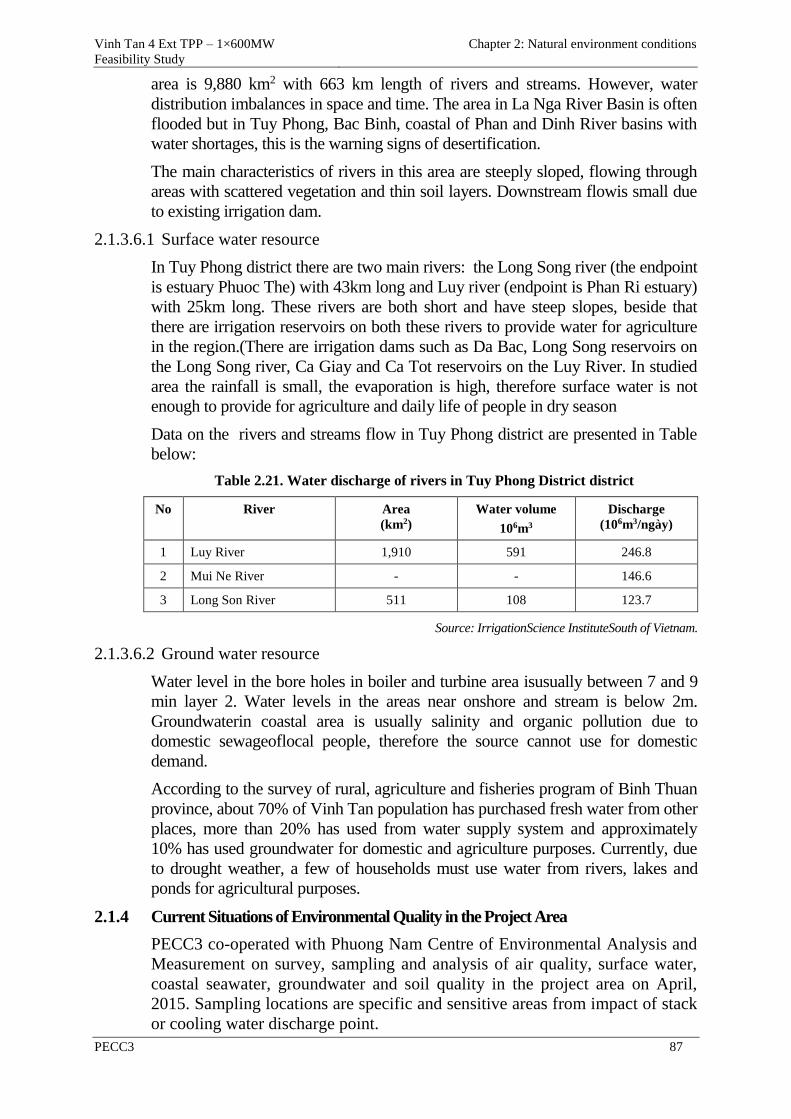
Vinh Tan 4 Ext TPP – 1×600MW
Feasibility Study
Chapter 2: Natural environment conditions
PECC3 87
area is 9,880 km2 with 663 km length of rivers and streams. However, water
distribution imbalances in space and time. The area in La Nga River Basin is often
flooded but in Tuy Phong, Bac Binh, coastal of Phan and Dinh River basins with
water shortages, this is the warning signs of desertification.
The main characteristics of rivers in this area are steeply sloped, flowing through
areas with scattered vegetation and thin soil layers. Downstream flowis small due
to existing irrigation dam.
2.1.3.6.1 Surface water resource
In Tuy Phong district there are two main rivers: the Long Song river (the endpoint
is estuary Phuoc The) with 43km long and Luy river (endpoint is Phan Ri estuary)
with 25km long. These rivers are both short and have steep slopes, beside that
there are irrigation reservoirs on both these rivers to provide water for agriculture
in the region.(There are irrigation dams such as Da Bac, Long Song reservoirs on
the Long Song river, Ca Giay and Ca Tot reservoirs on the Luy River. In studied
area the rainfall is small, the evaporation is high, therefore surface water is not
enough to provide for agriculture and daily life of people in dry season
Data on the rivers and streams flow in Tuy Phong district are presented in Table
below:
Table 2.21. Water discharge of rivers in Tuy Phong District district
No River Area
(km2)
Water volume
106m3
Discharge
(106m3/ngày)
1 Luy River 1,910 591 246.8
2 Mui Ne River - - 146.6
3 Long Son River 511 108 123.7
Source: IrrigationScience InstituteSouth of Vietnam.
2.1.3.6.2 Ground water resource
Water level in the bore holes in boiler and turbine area isusually between 7 and 9
min layer 2. Water levels in the areas near onshore and stream is below 2m.
Groundwaterin coastal area is usually salinity and organic pollution due to
domestic sewageoflocal people, therefore the source cannot use for domestic
demand.
According to the survey of rural, agriculture and fisheries program of Binh Thuan
province, about 70% of Vinh Tan population has purchased fresh water from other
places, more than 20% has used from water supply system and approximately
10% has used groundwater for domestic and agriculture purposes. Currently, due
to drought weather, a few of households must use water from rivers, lakes and
ponds for agricultural purposes.
2.1.4 Current Situations of Environmental Quality in the Project Area
PECC3 co-operated with Phuong Nam Centre of Environmental Analysis and
Measurement on survey, sampling and analysis of air quality, surface water,
coastal seawater, groundwater and soil quality in the project area on April,
2015. Sampling locations are specific and sensitive areas from impact of stack
or cooling water discharge point.
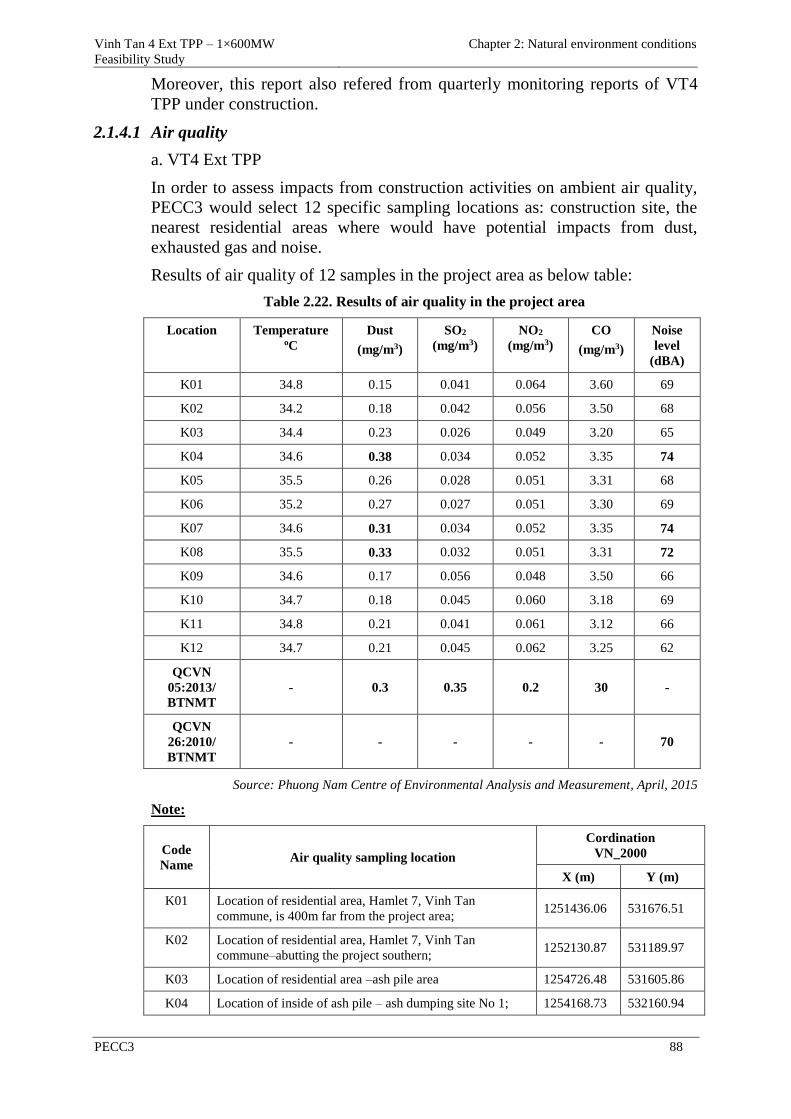
Vinh Tan 4 Ext TPP – 1×600MW
Feasibility Study
Chapter 2: Natural environment conditions
PECC3 88
Moreover, this report also refered from quarterly monitoring reports of VT4
TPP under construction.
2.1.4.1 Air quality
a. VT4 Ext TPP
In order to assess impacts from construction activities on ambient air quality,
PECC3 would select 12 specific sampling locations as: construction site, the
nearest residential areas where would have potential impacts from dust,
exhausted gas and noise.
Results of air quality of 12 samples in the project area as below table:
Table 2.22. Results of air quality in the project area
Location Temperature oC
Dust
(mg/m3)
SO2
(mg/m3)
NO2
(mg/m3)
CO
(mg/m3)
Noise
level
(dBA)
K01 34.8 0.15 0.041 0.064 3.60 69
K02 34.2 0.18 0.042 0.056 3.50 68
K03 34.4 0.23 0.026 0.049 3.20 65
K04 34.6 0.38 0.034 0.052 3.35 74
K05 35.5 0.26 0.028 0.051 3.31 68
K06 35.2 0.27 0.027 0.051 3.30 69
K07 34.6 0.31 0.034 0.052 3.35 74
K08 35.5 0.33 0.032 0.051 3.31 72
K09 34.6 0.17 0.056 0.048 3.50 66
K10 34.7 0.18 0.045 0.060 3.18 69
K11 34.8 0.21 0.041 0.061 3.12 66
K12 34.7 0.21 0.045 0.062 3.25 62
QCVN
05:2013/
BTNMT
- 0.3 0.35 0.2 30 -
QCVN
26:2010/
BTNMT
- - - - - 70
Source: Phuong Nam Centre of Environmental Analysis and Measurement, April, 2015
Note:
Code
Name Air quality sampling location
Cordination
VN_2000
X (m) Y (m)
K01 Location of residential area, Hamlet 7, Vinh Tan
commune, is 400m far from the project area; 1251436.06 531676.51
K02 Location of residential area, Hamlet 7, Vinh Tan
commune–abutting the project southern; 1252130.87 531189.97
K03 Location of residential area –ash pile area 1254726.48 531605.86
K04 Location of inside of ash pile – ash dumping site No 1; 1254168.73 532160.94
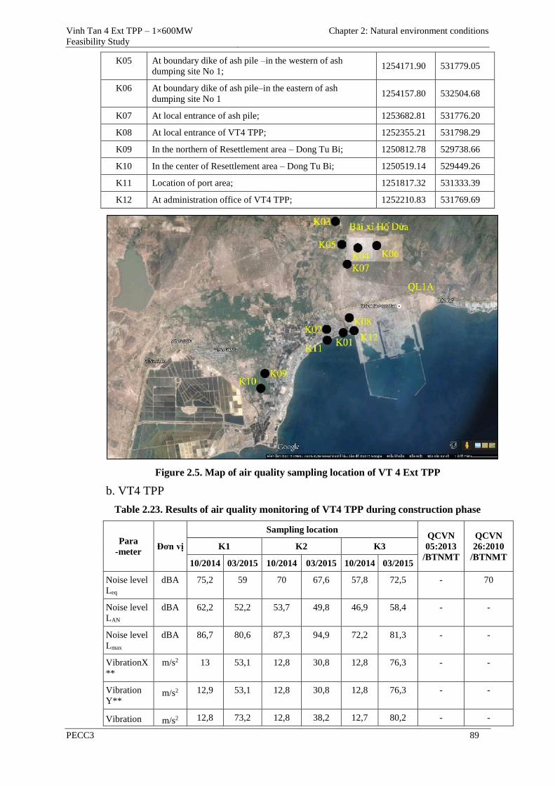
Vinh Tan 4 Ext TPP – 1×600MW
Feasibility Study
Chapter 2: Natural environment conditions
PECC3 89
K05 At boundary dike of ash pile –in the western of ash
dumping site No 1; 1254171.90 531779.05
K06 At boundary dike of ash pile–in the eastern of ash
dumping site No 1 1254157.80 532504.68
K07 At local entrance of ash pile; 1253682.81 531776.20
K08 At local entrance of VT4 TPP; 1252355.21 531798.29
K09 In the northern of Resettlement area – Dong Tu Bi; 1250812.78 529738.66
K10 In the center of Resettlement area – Dong Tu Bi; 1250519.14 529449.26
K11 Location of port area; 1251817.32 531333.39
K12 At administration office of VT4 TPP; 1252210.83 531769.69
Figure 2.5. Map of air quality sampling location of VT 4 Ext TPP
b. VT4 TPP
Table 2.23. Results of air quality monitoring of VT4 TPP during construction phase
Para
-meter Đơn vị
Sampling location QCVN
05:2013
/BTNMT
QCVN
26:2010
/BTNMT
K1 K2 K3
10/2014 03/2015 10/2014 03/2015 10/2014 03/2015
Noise level
Leq
dBA 75,2 59 70 67,6 57,8 72,5 - 70
Noise level
LAN
dBA 62,2 52,2 53,7 49,8 46,9 58,4 - -
Noise level
Lmax
dBA 86,7 80,6 87,3 94,9 72,2 81,3 - -
VibrationX
**
m/s2 13 53,1 12,8 30,8 12,8 76,3 - -
Vibration
Y** m/s2 12,9 53,1 12,8 30,8 12,8 76,3 - -
Vibration m/s2 12,8 73,2 12,8 38,2 12,7 80,2 - -
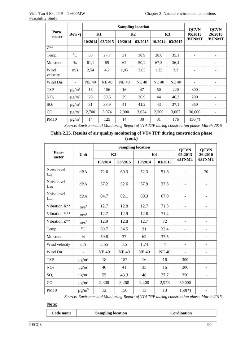
Vinh Tan 4 Ext TPP – 1×600MW
Feasibility Study
Chapter 2: Natural environment conditions
PECC3 90
Para
-meter Đơn vị
Sampling location QCVN
05:2013
/BTNMT
QCVN
26:2010
/BTNMT
K1 K2 K3
10/2014 03/2015 10/2014 03/2015 10/2014 03/2015
Z**
Temp. 0C 30 27,7 31 30,9 28,8 35,1 - -
Moisture % 61,1 59 62 50,2 67,3 36,4 - -
Wind
velocity
m/s 2,54 4,2 1,05 2,65 1,25 2,3 - -
Wind Dir. - NE 40 NE 40 NE 40 NE 40 NE 40 NE 40 - -
TSP µg/m3 16 156 16 47 50 220 300 -
NO2 µg/m3 29 50,6 29 26,9 44 46,2 200 -
SO2 µg/m3 31 38,9 41 41,2 43 37,1 350 -
CO µg/m3 2,700 3,074 2,900 3,024 2,300 3,067 30,000 -
PM10 µg/m3 14 125 14 38 31 176 150(*)
Source: Environmental Monitoring Report of VT4 TPP during construction phase, March 2015
Table 2.23. Results of air quality monitoring of VT4 TPP during construction phase
(cont.)
Para-
meter Unit
Sampling location QCVN
05:2013
/BTNMT
QCVN
26:2010
/BTNMT
K3 K4
10/2014 03/2015 10/2014 03/2015
Noise level
Leq dBA 72.6 69.3 52.3 51.6 - 70
Noise level
LAN dBA 57.2 52.6 37.9 37.8 - -
Noise level
Lmax dBA 84.7 82.1 69.3 67.9 - -
Vibration X** m/s2 12.7 12.8 12.7 71.3 - -
Vibration Y** m/s2 12.7 12.9 12.8 71.4 - -
Vibration Z** m/s2 12.9 12.8 12.7 72 - -
Temp. 0C 30.7 34.5 31 33.4 - -
Moisture % 59.8 37 62 37.5 - -
Wind velocity m/s 3.55 3.5 1.74 4 - -
Wind Dir. - NE 40 NE 40 NE 40 NE 40 - -
TSP µg/m3 18 187 16 16 300 -
NO2 µg/m3 40 41 33 16 200 -
SO2 µg/m3 55 43.3 48 27.7 350 -
CO µg/m3 2,300 3,260 2,400 2,978 30,000 -
PM10 µg/m3 12 150 13 13 150(*) -
Source: Environmental Monitoring Report of VT4 TPP during construction phase, March 2015
Note:
Code name Sampling location Cordination
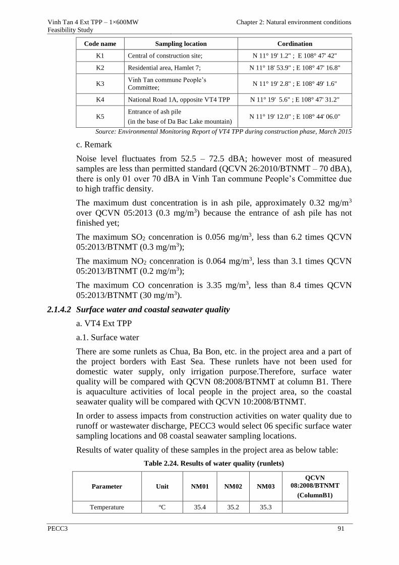
Vinh Tan 4 Ext TPP – 1×600MW
Feasibility Study
Chapter 2: Natural environment conditions
PECC3 91
Code name Sampling location Cordination
K1 Central of construction site; N 11° 19' 1.2" ; E 108° 47' 42"
K2 Residential area, Hamlet 7; N 11° 18' 53.9" ; E 108° 47' 16.8"
K3 Vinh Tan commune People’s
Committee; N 11° 19' 2.8" ; E 108° 49' 1.6"
K4 National Road 1A, opposite VT4 TPP N 11° 19' 5.6" ; E 108° 47' 31.2"
K5 Entrance of ash pile
(in the base of Da Bac Lake mountain) N 11° 19' 12.0" ; E 108° 44' 06.0"
Source: Environmental Monitoring Report of VT4 TPP during construction phase, March 2015
c. Remark
Noise level fluctuates from 52.5 – 72.5 dBA; however most of measured
samples are less than permitted standard (QCVN 26:2010/BTNMT – 70 dBA),
there is only 01 over 70 dBA in Vinh Tan commune People’s Committee due
to high traffic density.
The maximum dust concentration is in ash pile, approximately 0.32 mg/m3
over QCVN 05:2013 (0.3 mg/m3) because the entrance of ash pile has not
finished yet;
The maximum SO2 concenration is 0.056 mg/m3, less than 6.2 times QCVN
05:2013/BTNMT (0.3 mg/m3);
The maximum NO2 concenration is 0.064 mg/m3, less than 3.1 times QCVN
05:2013/BTNMT (0.2 mg/m3);
The maximum CO concenration is 3.35 mg/m3, less than 8.4 times QCVN
05:2013/BTNMT (30 mg/m3).
2.1.4.2 Surface water and coastal seawater quality
a. VT4 Ext TPP
a.1. Surface water
There are some runlets as Chua, Ba Bon, etc. in the project area and a part of
the project borders with East Sea. These runlets have not been used for
domestic water supply, only irrigation purpose.Therefore, surface water
quality will be compared with QCVN 08:2008/BTNMT at column B1. There
is aquaculture activities of local people in the project area, so the coastal
seawater quality will be compared with QCVN 10:2008/BTNMT.
In order to assess impacts from construction activities on water quality due to
runoff or wastewater discharge, PECC3 would select 06 specific surface water
sampling locations and 08 coastal seawater sampling locations.
Results of water quality of these samples in the project area as below table:
Table 2.24. Results of water quality (runlets)
Parameter Unit NM01 NM02 NM03
QCVN
08:2008/BTNMT
(ColumnB1)
Temperature oC 35.4 35.2 35.3
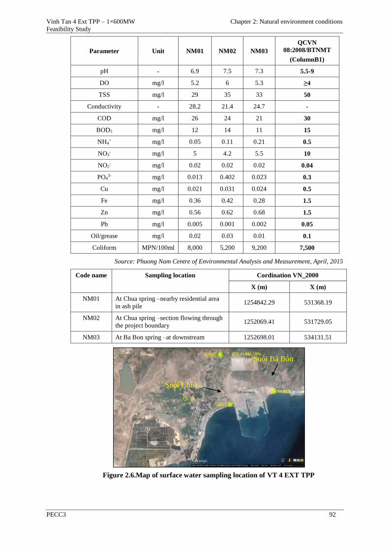
Vinh Tan 4 Ext TPP – 1×600MW
Feasibility Study
Chapter 2: Natural environment conditions
PECC3 92
Parameter Unit NM01 NM02 NM03
QCVN
08:2008/BTNMT
(ColumnB1)
pH - 6.9 7.5 7.3 5.5-9
DO mg/l 5.2 6 5.3 ≥4
TSS mg/l 29 35 33 50
Conductivity - 28.2 21.4 24.7 -
COD mg/l 26 24 21 30
BOD5 mg/l 12 14 11 15
NH4+ mg/l 0.05 0.11 0.21 0.5
NO3- mg/l 5 4.2 5.5 10
NO2- mg/l 0.02 0.02 0.02 0.04
PO43- mg/l 0.013 0.402 0.023 0.3
Cu mg/l 0.021 0.031 0.024 0.5
Fe mg/l 0.36 0.42 0.28 1.5
Zn mg/l 0.56 0.62 0.68 1.5
Pb mg/l 0.005 0.001 0.002 0.05
Oil/grease mg/l 0.02 0.03 0.01 0.1
Coliform MPN/100ml 8,000 5,200 9,200 7,500
Source: Phuong Nam Centre of Environmental Analysis and Measurement, April, 2015
Code name Sampling location Cordination VN_2000
X (m) X (m)
NM01 At Chua spring –nearby residential area
in ash pile 1254842.29 531368.19
NM02 At Chua spring –section flowing through
the project boundary 1252069.41 531729.05
NM03 At Ba Bon spring –at downstream 1252698.01 534131.51
Figure 2.6.Map of surface water sampling location of VT 4 EXT TPP
Suối Chùa
Suối Bà Bốn
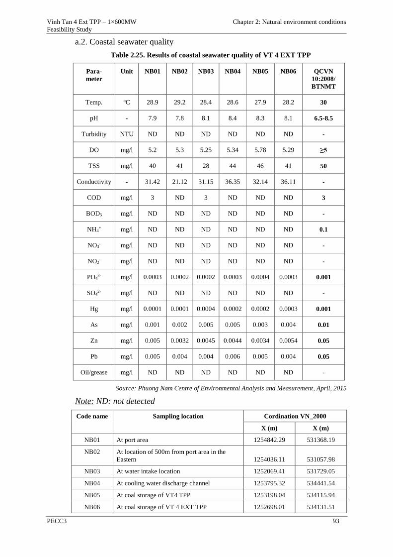
Vinh Tan 4 Ext TPP – 1×600MW
Feasibility Study
Chapter 2: Natural environment conditions
PECC3 93
a.2. Coastal seawater quality
Table 2.25. Results of coastal seawater quality of VT 4 EXT TPP
Para-
meter
Unit NB01 NB02 NB03 NB04 NB05 NB06 QCVN
10:2008/
BTNMT
Temp. oC 28.9 29.2 28.4 28.6 27.9 28.2 30
pH - 7.9 7.8 8.1 8.4 8.3 8.1 6.5-8.5
Turbidity NTU ND ND ND ND ND ND -
DO mg/l 5.2 5.3 5.25 5.34 5.78 5.29 ≥5
TSS mg/l 40 41 28 44 46 41 50
Conductivity - 31.42 21.12 31.15 36.35 32.14 36.11 -
COD mg/l 3 ND 3 ND ND ND 3
BOD5 mg/l ND ND ND ND ND ND -
NH4+ mg/l ND ND ND ND ND ND 0.1
NO3- mg/l ND ND ND ND ND ND -
NO2- mg/l ND ND ND ND ND ND -
PO43- mg/l 0.0003 0.0002 0.0002 0.0003 0.0004 0.0003 0.001
SO42- mg/l ND ND ND ND ND ND -
Hg mg/l 0.0001 0.0001 0.0004 0.0002 0.0002 0.0003 0.001
As mg/l 0.001 0.002 0.005 0.005 0.003 0.004 0.01
Zn mg/l 0.005 0.0032 0.0045 0.0044 0.0034 0.0054 0.05
Pb mg/l 0.005 0.004 0.004 0.006 0.005 0.004 0.05
Oil/grease mg/l ND ND ND ND ND ND -
Source: Phuong Nam Centre of Environmental Analysis and Measurement, April, 2015
Note: ND: not detected
Code name Sampling location Cordination VN_2000
X (m) X (m)
NB01 At port area 1254842.29 531368.19
NB02 At location of 500m from port area in the
Eastern 1254036.11 531057.98
NB03 At water intake location 1252069.41 531729.05
NB04 At cooling water discharge channel 1253795.32 534441.54
NB05 At coal storage of VT4 TPP 1253198.04 534115.94
NB06 At coal storage of VT 4 EXT TPP 1252698.01 534131.51
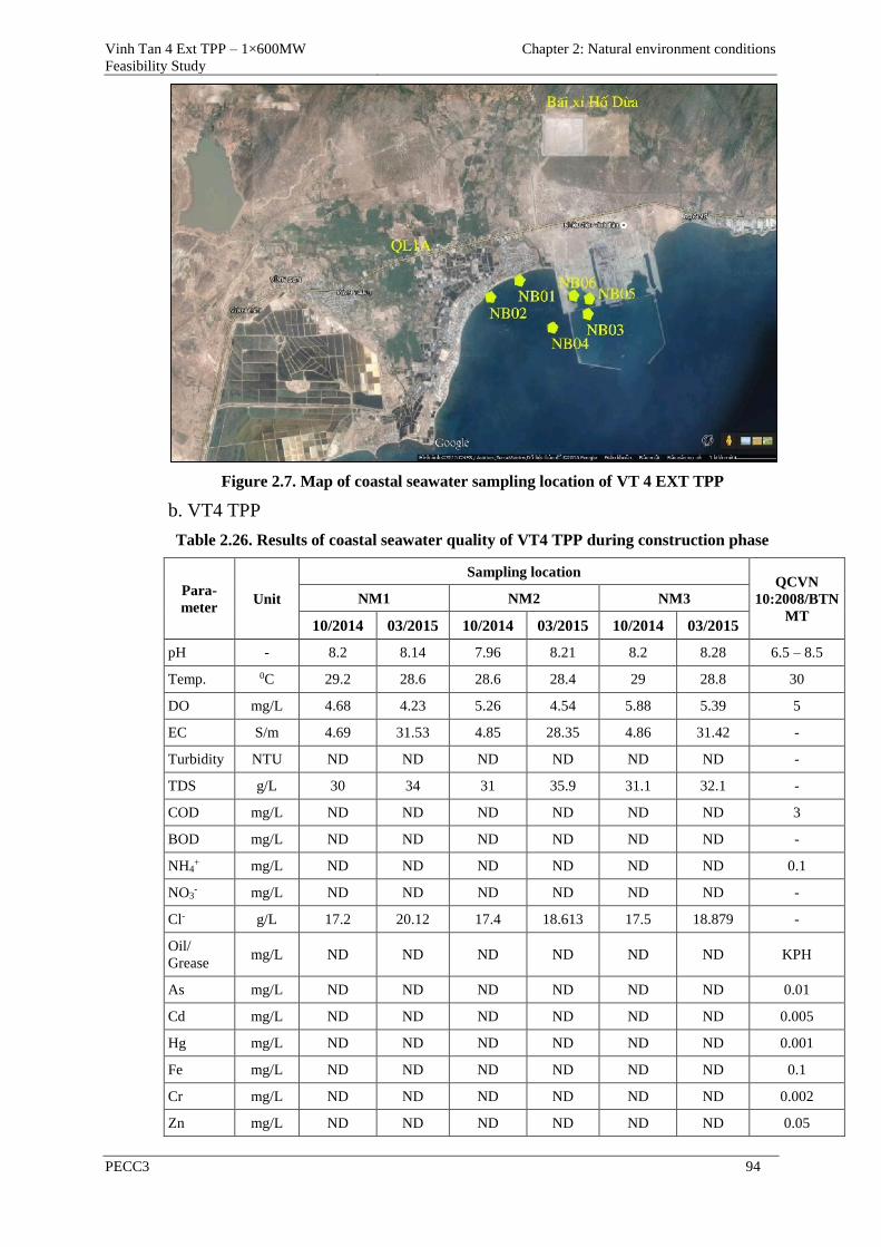
Vinh Tan 4 Ext TPP – 1×600MW
Feasibility Study
Chapter 2: Natural environment conditions
PECC3 94
Figure 2.7. Map of coastal seawater sampling location of VT 4 EXT TPP
b. VT4 TPP
Table 2.26. Results of coastal seawater quality of VT4 TPP during construction phase
Para-
meter Unit
Sampling location QCVN
10:2008/BTN
MT
NM1 NM2 NM3
10/2014 03/2015 10/2014 03/2015 10/2014 03/2015
pH - 8.2 8.14 7.96 8.21 8.2 8.28 6.5 – 8.5
Temp. 0C 29.2 28.6 28.6 28.4 29 28.8 30
DO mg/L 4.68 4.23 5.26 4.54 5.88 5.39 5
EC S/m 4.69 31.53 4.85 28.35 4.86 31.42 -
Turbidity NTU ND ND ND ND ND ND -
TDS g/L 30 34 31 35.9 31.1 32.1 -
COD mg/L ND ND ND ND ND ND 3
BOD mg/L ND ND ND ND ND ND -
NH4+ mg/L ND ND ND ND ND ND 0.1
NO3- mg/L ND ND ND ND ND ND -
Cl- g/L 17.2 20.12 17.4 18.613 17.5 18.879 -
Oil/
Grease mg/L ND ND ND ND ND ND KPH
As mg/L ND ND ND ND ND ND 0.01
Cd mg/L ND ND ND ND ND ND 0.005
Hg mg/L ND ND ND ND ND ND 0.001
Fe mg/L ND ND ND ND ND ND 0.1
Cr mg/L ND ND ND ND ND ND 0.002
Zn mg/L ND ND ND ND ND ND 0.05
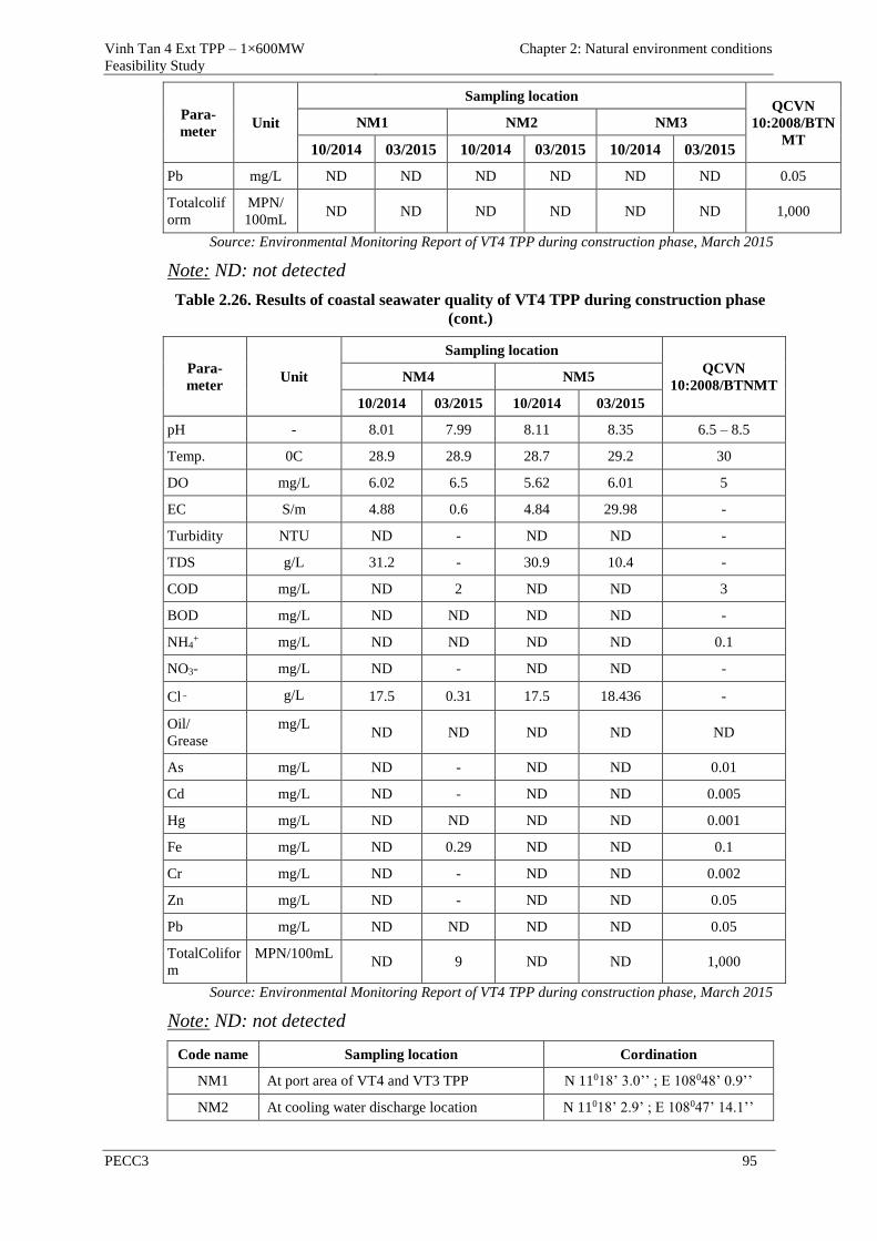
Vinh Tan 4 Ext TPP – 1×600MW
Feasibility Study
Chapter 2: Natural environment conditions
PECC3 95
Para-
meter Unit
Sampling location QCVN
10:2008/BTN
MT
NM1 NM2 NM3
10/2014 03/2015 10/2014 03/2015 10/2014 03/2015
Pb mg/L ND ND ND ND ND ND 0.05
Totalcolif
orm
MPN/
100mL ND ND ND ND ND ND 1,000
Source: Environmental Monitoring Report of VT4 TPP during construction phase, March 2015
Note: ND: not detected
Table 2.26. Results of coastal seawater quality of VT4 TPP during construction phase
(cont.)
Para-
meter Unit
Sampling location
QCVN
10:2008/BTNMT NM4 NM5
10/2014 03/2015 10/2014 03/2015
pH - 8.01 7.99 8.11 8.35 6.5 – 8.5
Temp. 0C 28.9 28.9 28.7 29.2 30
DO mg/L 6.02 6.5 5.62 6.01 5
EC S/m 4.88 0.6 4.84 29.98 -
Turbidity NTU ND - ND ND -
TDS g/L 31.2 - 30.9 10.4 -
COD mg/L ND 2 ND ND 3
BOD mg/L ND ND ND ND -
NH4+ mg/L ND ND ND ND 0.1
NO3- mg/L ND - ND ND -
Cl‑ g/L 17.5 0.31 17.5 18.436 -
Oil/
Grease
mg/L ND ND ND ND ND
As mg/L ND - ND ND 0.01
Cd mg/L ND - ND ND 0.005
Hg mg/L ND ND ND ND 0.001
Fe mg/L ND 0.29 ND ND 0.1
Cr mg/L ND - ND ND 0.002
Zn mg/L ND - ND ND 0.05
Pb mg/L ND ND ND ND 0.05
TotalColifor
m
MPN/100mL ND 9 ND ND 1,000
Source: Environmental Monitoring Report of VT4 TPP during construction phase, March 2015
Note: ND: not detected
Code name Sampling location Cordination
NM1 At port area of VT4 and VT3 TPP N 11018’ 3.0’’ ; E 108048’ 0.9’’
NM2 At cooling water discharge location N 11018’ 2.9’ ; E 108047’ 14.1’’
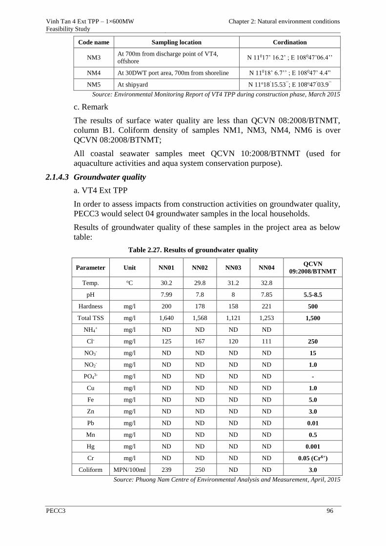
Vinh Tan 4 Ext TPP – 1×600MW
Feasibility Study
Chapter 2: Natural environment conditions
PECC3 96
Code name Sampling location Cordination
NM3 At 700m from discharge point of VT4,
offshore N 11017’ 16.2’ ; E 108047’06.4’’
NM4 At 30DWT port area, 700m from shoreline N 11018’ 6.7’’ ; E 108047’ 4.4”
NM5 At shipyard N 11o18’15.53’’; E 108o47’03.9’’
Source: Environmental Monitoring Report of VT4 TPP during construction phase, March 2015
c. Remark
The results of surface water quality are less than QCVN 08:2008/BTNMT,
column B1. Coliform density of samples NM1, NM3, NM4, NM6 is over
QCVN 08:2008/BTNMT;
All coastal seawater samples meet QCVN 10:2008/BTNMT (used for
aquaculture activities and aqua system conservation purpose).
2.1.4.3 Groundwater quality
a. VT4 Ext TPP
In order to assess impacts from construction activities on groundwater quality,
PECC3 would select 04 groundwater samples in the local households.
Results of groundwater quality of these samples in the project area as below
table:
Table 2.27. Results of groundwater quality
Parameter Unit NN01 NN02 NN03 NN04 QCVN
09:2008/BTNMT
Temp. oC 30.2 29.8 31.2 32.8
pH 7.99 7.8 8 7.85 5.5-8.5
Hardness mg/l 200 178 158 221 500
Total TSS mg/l 1,640 1,568 1,121 1,253 1,500
NH4+ mg/l ND ND ND ND
Cl- mg/l 125 167 120 111 250
NO3- mg/l ND ND ND ND 15
NO2- mg/l ND ND ND ND 1.0
PO43- mg/l ND ND ND ND -
Cu mg/l ND ND ND ND 1.0
Fe mg/l ND ND ND ND 5.0
Zn mg/l ND ND ND ND 3.0
Pb mg/l ND ND ND ND 0.01
Mn mg/l ND ND ND ND 0.5
Hg mg/l ND ND ND ND 0.001
Cr mg/l ND ND ND ND 0.05 (Cr6+)
Coliform MPN/100ml 239 250 ND ND 3.0
Source: Phuong Nam Centre of Environmental Analysis and Measurement, April, 2015
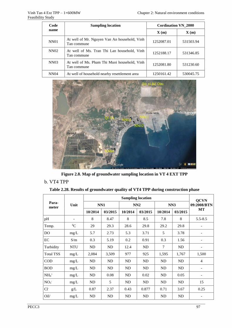
Vinh Tan 4 Ext TPP – 1×600MW
Feasibility Study
Chapter 2: Natural environment conditions
PECC3 97
Code
name
Sampling location Cordination VN_2000
X (m) X (m)
NN01 At well of Mr. Nguyen Van An household, Vinh
Tan commune 1252087.01 531503.94
NN02 At well of Ms. Tran Thi Lan household, Vinh
Tan commune 1252188.17 531346.85
NN03 At well of Ms. Pham Thi Muoi household, Vinh
Tan commune 1252081.80 531230.60
NN04 At well of household nearby resettlement area 1250161.42 530045.75
Figure 2.8. Map of groundwater sampling location in VT 4 EXT TPP
b. VT4 TPP
Table 2.28. Results of groundwater quality of VT4 TPP during construction phase
Para-
meter Unit
Sampling location QCVN
09:2008/BTN
MT
NN1 NN2 NN3
10/2014 03/2015 10/2014 03/2015 10/2014 03/2015
pH - 8 8.47 8 8.5 7.8 8 5.5-8.5
Temp. 0C 29 29.3 28.6 29.8 29.2 29.8 -
DO mg/L 5.7 2.73 5.3 3.71 5 3.78 -
EC S/m 0.3 5.19 0.2 0.91 0.3 1.56 -
Turbidity NTU ND ND 12.4 ND 7 ND -
Total TSS mg/L 2,084 3,509 977 925 1,595 1,767 1,500
COD mg/L ND ND ND ND ND ND 4
BOD mg/L ND ND ND ND ND ND -
NH4+ mg/L ND 0.08 ND 0.02 ND 0.05 -
NO3- mg/L ND 5 ND ND ND ND 15
Cl- g/L 0.87 2.37 0.43 0.877 0.71 3.67 0.25
Oil/ mg/L ND ND ND ND ND ND -
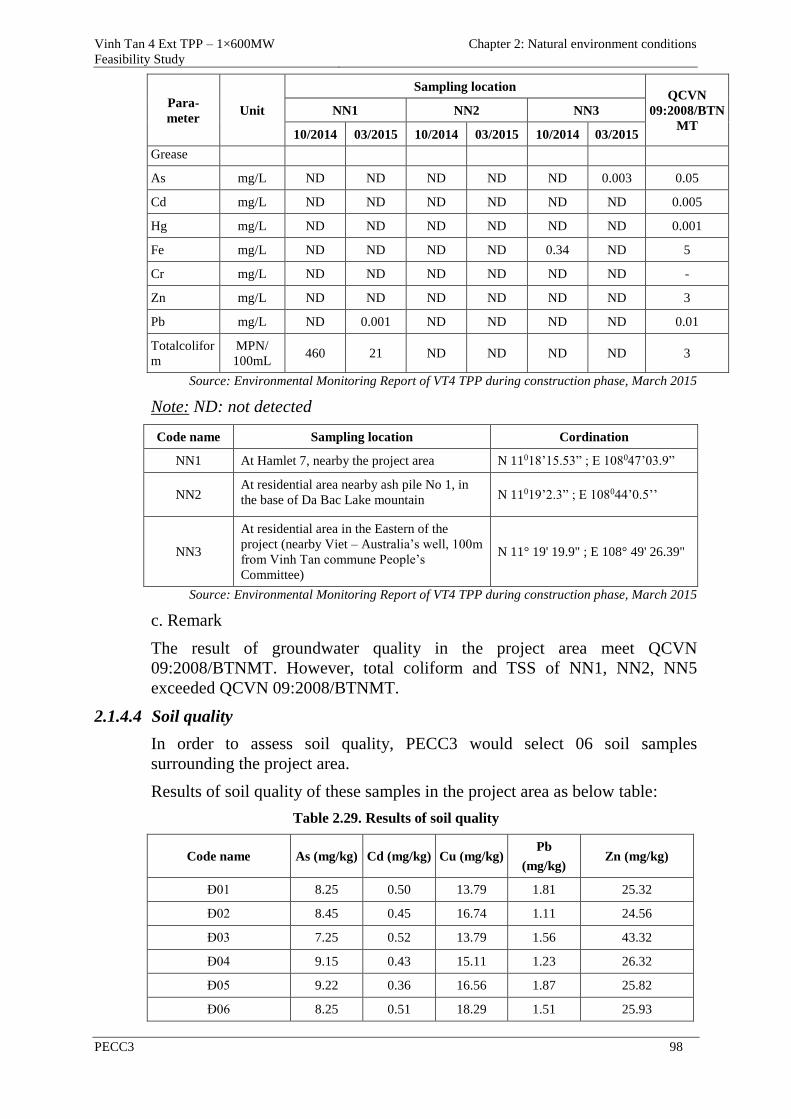
Vinh Tan 4 Ext TPP – 1×600MW
Feasibility Study
Chapter 2: Natural environment conditions
PECC3 98
Para-
meter Unit
Sampling location QCVN
09:2008/BTN
MT
NN1 NN2 NN3
10/2014 03/2015 10/2014 03/2015 10/2014 03/2015
Grease
As mg/L ND ND ND ND ND 0.003 0.05
Cd mg/L ND ND ND ND ND ND 0.005
Hg mg/L ND ND ND ND ND ND 0.001
Fe mg/L ND ND ND ND 0.34 ND 5
Cr mg/L ND ND ND ND ND ND -
Zn mg/L ND ND ND ND ND ND 3
Pb mg/L ND 0.001 ND ND ND ND 0.01
Totalcolifor
m
MPN/
100mL 460 21 ND ND ND ND 3
Source: Environmental Monitoring Report of VT4 TPP during construction phase, March 2015
Note: ND: not detected
Code name Sampling location Cordination
NN1 At Hamlet 7, nearby the project area N 11018’15.53” ; E 108047’03.9”
NN2 At residential area nearby ash pile No 1, in
the base of Da Bac Lake mountain N 11019’2.3” ; E 108044’0.5’’
NN3
At residential area in the Eastern of the
project (nearby Viet – Australia’s well, 100m
from Vinh Tan commune People’s
Committee)
N 11° 19' 19.9" ; E 108° 49' 26.39"
Source: Environmental Monitoring Report of VT4 TPP during construction phase, March 2015
c. Remark
The result of groundwater quality in the project area meet QCVN
09:2008/BTNMT. However, total coliform and TSS of NN1, NN2, NN5
exceeded QCVN 09:2008/BTNMT.
2.1.4.4 Soil quality
In order to assess soil quality, PECC3 would select 06 soil samples
surrounding the project area.
Results of soil quality of these samples in the project area as below table:
Table 2.29. Results of soil quality
Code name As (mg/kg) Cd (mg/kg) Cu (mg/kg) Pb
(mg/kg) Zn (mg/kg)
Đ01 8.25 0.50 13.79 1.81 25.32
Đ02 8.45 0.45 16.74 1.11 24.56
Đ03 7.25 0.52 13.79 1.56 43.32
Đ04 9.15 0.43 15.11 1.23 26.32
Đ05 9.22 0.36 16.56 1.87 25.82
Đ06 8.25 0.51 18.29 1.51 25.93
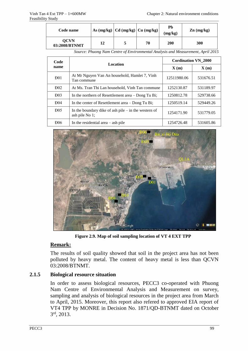
Vinh Tan 4 Ext TPP – 1×600MW
Feasibility Study
Chapter 2: Natural environment conditions
PECC3 99
Code name As (mg/kg) Cd (mg/kg) Cu (mg/kg) Pb
(mg/kg) Zn (mg/kg)
QCVN
03:2008/BTNMT 12 5 70 200 300
Source: Phuong Nam Centre of Environmental Analysis and Measurement, April 2015
Code
name Location
Cordination VN_2000
X (m) X (m)
Đ01 At Mr Nguyen Van An household, Hamlet 7, Vinh
Tan commune 12511980.06 531676.51
Đ02 At Ms. Tran Thi Lan household, Vinh Tan commune 1252130.87 531189.97
Đ03 In the northern of Resettlement area – Dong Tu Bi; 1250812.78 529738.66
Đ04 In the center of Resettlement area – Dong Tu Bi; 1250519.14 529449.26
Đ05 In the boundary dike of ash pile – in the western of
ash pile No 1; 1254171.90 531779.05
Đ06 In the residential area – ash pile 1254726.48 531605.86
Figure 2.9. Map of soil sampling location of VT 4 EXT TPP
Remark:
The results of soil quality showed that soil in the project area has not been
polluted by heavy metal. The content of heavy metal is less than QCVN
03:2008/BTNMT.
2.1.5 Biological resource situation
In order to assess biological resources, PECC3 co-operated with Phuong
Nam Centre of Environmental Analysis and Measurement on survey,
sampling and analysis of biological resources in the project area from March
to April, 2015. Moreover, this report also refered to approved EIA report of
VT4 TPP by MONRE in Decision No. 1871/QD-BTNMT dated on October
3rd, 2013.
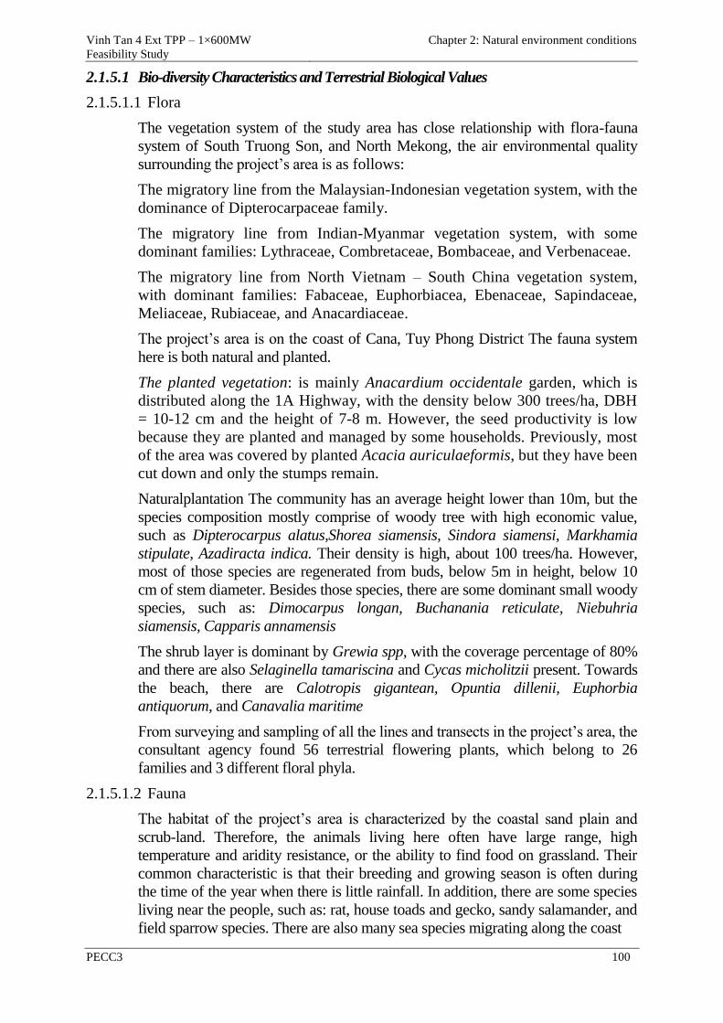
Vinh Tan 4 Ext TPP – 1×600MW
Feasibility Study
Chapter 2: Natural environment conditions
PECC3 100
2.1.5.1 Bio-diversity Characteristics and Terrestrial Biological Values
2.1.5.1.1 Flora
The vegetation system of the study area has close relationship with flora-fauna
system of South Truong Son, and North Mekong, the air environmental quality
surrounding the project’s area is as follows:
The migratory line from the Malaysian-Indonesian vegetation system, with the
dominance of Dipterocarpaceae family.
The migratory line from Indian-Myanmar vegetation system, with some
dominant families: Lythraceae, Combretaceae, Bombaceae, and Verbenaceae.
The migratory line from North Vietnam – South China vegetation system,
with dominant families: Fabaceae, Euphorbiacea, Ebenaceae, Sapindaceae,
Meliaceae, Rubiaceae, and Anacardiaceae.
The project’s area is on the coast of Cana, Tuy Phong District The fauna system
here is both natural and planted.
The planted vegetation: is mainly Anacardium occidentale garden, which is
distributed along the 1A Highway, with the density below 300 trees/ha, DBH
= 10-12 cm and the height of 7-8 m. However, the seed productivity is low
because they are planted and managed by some households. Previously, most
of the area was covered by planted Acacia auriculaeformis, but they have been
cut down and only the stumps remain.
Naturalplantation The community has an average height lower than 10m, but the
species composition mostly comprise of woody tree with high economic value,
such as Dipterocarpus alatus,Shorea siamensis, Sindora siamensi, Markhamia
stipulate, Azadiracta indica. Their density is high, about 100 trees/ha. However,
most of those species are regenerated from buds, below 5m in height, below 10
cm of stem diameter. Besides those species, there are some dominant small woody
species, such as: Dimocarpus longan, Buchanania reticulate, Niebuhria
siamensis, Capparis annamensis
The shrub layer is dominant by Grewia spp, with the coverage percentage of 80%
and there are also Selaginella tamariscina and Cycas micholitzii present. Towards
the beach, there are Calotropis gigantean, Opuntia dillenii, Euphorbia
antiquorum, and Canavalia maritime
From surveying and sampling of all the lines and transects in the project’s area, the
consultant agency found 56 terrestrial flowering plants, which belong to 26
families and 3 different floral phyla.
2.1.5.1.2 Fauna
The habitat of the project’s area is characterized by the coastal sand plain and
scrub-land. Therefore, the animals living here often have large range, high
temperature and aridity resistance, or the ability to find food on grassland. Their
common characteristic is that their breeding and growing season is often during
the time of the year when there is little rainfall. In addition, there are some species
living near the people, such as: rat, house toads and gecko, sandy salamander, and
field sparrow species. There are also many sea species migrating along the coast
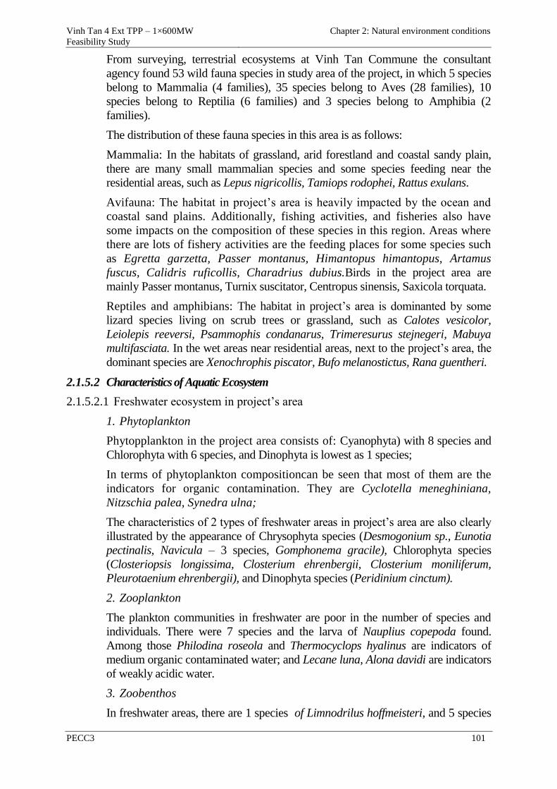
Vinh Tan 4 Ext TPP – 1×600MW
Feasibility Study
Chapter 2: Natural environment conditions
PECC3 101
From surveying, terrestrial ecosystems at Vinh Tan Commune the consultant
agency found 53 wild fauna species in study area of the project, in which 5 species
belong to Mammalia (4 families), 35 species belong to Aves (28 families), 10
species belong to Reptilia (6 families) and 3 species belong to Amphibia (2
families).
The distribution of these fauna species in this area is as follows:
Mammalia: In the habitats of grassland, arid forestland and coastal sandy plain,
there are many small mammalian species and some species feeding near the
residential areas, such as Lepus nigricollis, Tamiops rodophei, Rattus exulans.
Avifauna: The habitat in project’s area is heavily impacted by the ocean and
coastal sand plains. Additionally, fishing activities, and fisheries also have
some impacts on the composition of these species in this region. Areas where
there are lots of fishery activities are the feeding places for some species such
as Egretta garzetta, Passer montanus, Himantopus himantopus, Artamus
fuscus, Calidris ruficollis, Charadrius dubius.Birds in the project area are
mainly Passer montanus, Turnix suscitator, Centropus sinensis, Saxicola torquata.
Reptiles and amphibians: The habitat in project’s area is dominanted by some
lizard species living on scrub trees or grassland, such as Calotes vesicolor,
Leiolepis reeversi, Psammophis condanarus, Trimeresurus stejnegeri, Mabuya
multifasciata. In the wet areas near residential areas, next to the project’s area, the
dominant species are Xenochrophis piscator, Bufo melanostictus, Rana guentheri.
2.1.5.2 Characteristics of Aquatic Ecosystem
2.1.5.2.1 Freshwater ecosystem in project’s area
1. Phytoplankton
Phytopplankton in the project area consists of: Cyanophyta) with 8 species and
Chlorophyta with 6 species, and Dinophyta is lowest as 1 species;
In terms of phytoplankton compositioncan be seen that most of them are the
indicators for organic contamination. They are Cyclotella meneghiniana,
Nitzschia palea, Synedra ulna;
The characteristics of 2 types of freshwater areas in project’s area are also clearly
illustrated by the appearance of Chrysophyta species (Desmogonium sp., Eunotia
pectinalis, Navicula – 3 species, Gomphonema gracile), Chlorophyta species
(Closteriopsis longissima, Closterium ehrenbergii, Closterium moniliferum,
Pleurotaenium ehrenbergii), and Dinophyta species (Peridinium cinctum).
2. Zooplankton
The plankton communities in freshwater are poor in the number of species and
individuals. There were 7 species and the larva of Nauplius copepoda found.
Among those Philodina roseola and Thermocyclops hyalinus are indicators of
medium organic contaminated water; and Lecane luna, Alona davidi are indicators
of weakly acidic water.
3. Zoobenthos
In freshwater areas, there are 1 species of Limnodrilus hoffmeisteri, and 5 species
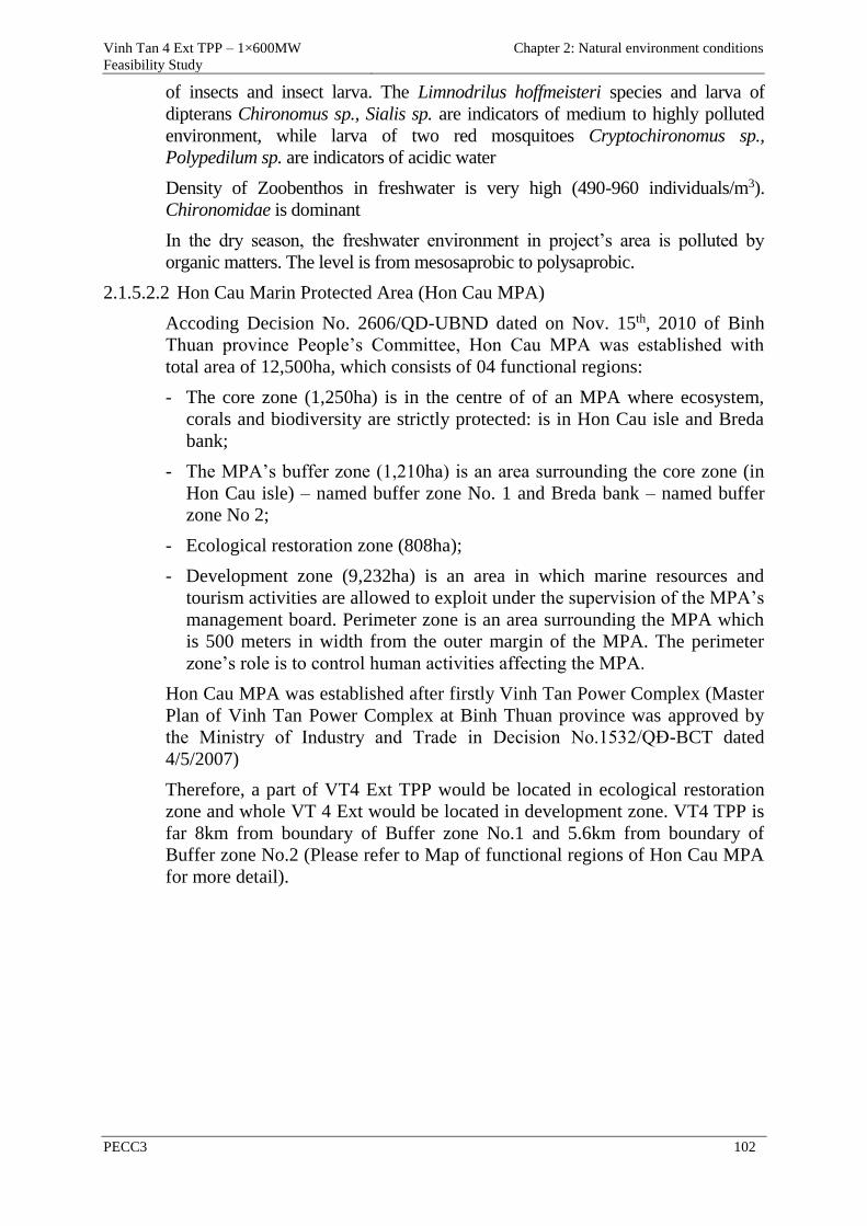
Vinh Tan 4 Ext TPP – 1×600MW
Feasibility Study
Chapter 2: Natural environment conditions
PECC3 102
of insects and insect larva. The Limnodrilus hoffmeisteri species and larva of
dipterans Chironomus sp., Sialis sp. are indicators of medium to highly polluted
environment, while larva of two red mosquitoes Cryptochironomus sp.,
Polypedilum sp. are indicators of acidic water
Density of Zoobenthos in freshwater is very high (490-960 individuals/m3).
Chironomidae is dominant
In the dry season, the freshwater environment in project’s area is polluted by
organic matters. The level is from mesosaprobic to polysaprobic.
2.1.5.2.2 Hon Cau Marin Protected Area (Hon Cau MPA)
Accoding Decision No. 2606/QD-UBND dated on Nov. 15th, 2010 of Binh
Thuan province People’s Committee, Hon Cau MPA was established with
total area of 12,500ha, which consists of 04 functional regions:
- The core zone (1,250ha) is in the centre of of an MPA where ecosystem,
corals and biodiversity are strictly protected: is in Hon Cau isle and Breda
bank;
- The MPA’s buffer zone (1,210ha) is an area surrounding the core zone (in
Hon Cau isle) – named buffer zone No. 1 and Breda bank – named buffer
zone No 2;
- Ecological restoration zone (808ha);
- Development zone (9,232ha) is an area in which marine resources and
tourism activities are allowed to exploit under the supervision of the MPA’s
management board. Perimeter zone is an area surrounding the MPA which
is 500 meters in width from the outer margin of the MPA. The perimeter
zone’s role is to control human activities affecting the MPA.
Hon Cau MPA was established after firstly Vinh Tan Power Complex (Master
Plan of Vinh Tan Power Complex at Binh Thuan province was approved by
the Ministry of Industry and Trade in Decision No.1532/QĐ-BCT dated
4/5/2007)
Therefore, a part of VT4 Ext TPP would be located in ecological restoration
zone and whole VT 4 Ext would be located in development zone. VT4 TPP is
far 8km from boundary of Buffer zone No.1 and 5.6km from boundary of
Buffer zone No.2 (Please refer to Map of functional regions of Hon Cau MPA
for more detail).
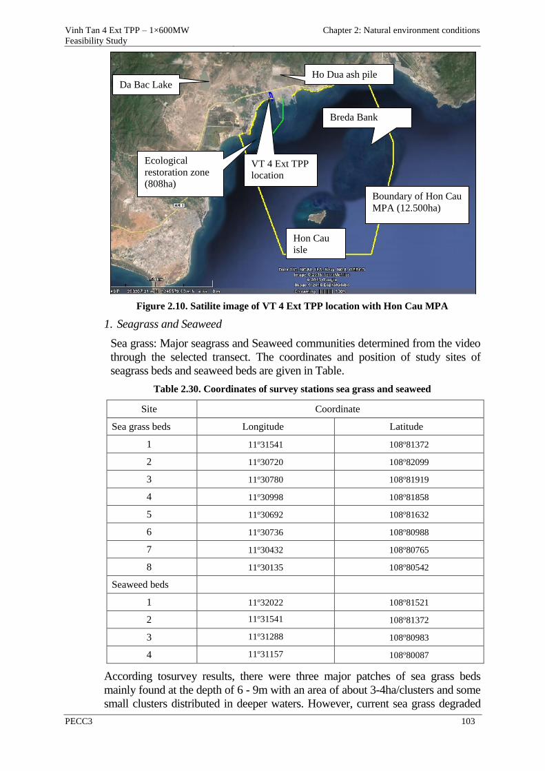
Vinh Tan 4 Ext TPP – 1×600MW
Feasibility Study
Chapter 2: Natural environment conditions
PECC3 103
Figure 2.10. Satilite image of VT 4 Ext TPP location with Hon Cau MPA
1. Seagrass and Seaweed
Sea grass: Major seagrass and Seaweed communities determined from the video
through the selected transect. The coordinates and position of study sites of
seagrass beds and seaweed beds are given in Table.
Table 2.30. Coordinates of survey stations sea grass and seaweed
Site Coordinate
Sea grass beds Longitude Latitude
1 11o31541 108o81372
2 11o30720 108o82099
3 11o30780 108o81919
4 11o30998 108o81858
5 11o30692 108o81632
6 11o30736 108o80988
7 11o30432 108o80765
8 11o30135 108o80542
Seaweed beds
1 11o32022 108o81521
2 11o31541 108o81372
3 11o31288 108o80983
4 11o31157 108o80087
According tosurvey results, there were three major patches of sea grass beds
mainly found at the depth of 6 - 9m with an area of about 3-4ha/clusters and some
small clusters distributed in deeper waters. However, current sea grass degraded
Boundary of Hon Cau
MPA (12.500ha)
Hon Cau
isle
Da Bac Lake Ho Dua ash pile
Breda Bank
Ecological
restoration zone
(808ha)
VT 4 Ext TPP
location

Vinh Tan 4 Ext TPP – 1×600MW
Feasibility Study
Chapter 2: Natural environment conditions
PECC3 104
by coral mining activities of the people and the construction activitiesin the region.
A total of 4 species of sea grass were found in the waters surrounding the Vinh
Tan Complex Site, including Halophila ovalis, Halophila decipiens, Halodule
pinifolia and Thalassia hemprichii. Halophila ovalis was common at almost study
site whereas Halodule pinifolia and Halophila decipiens were only found at one
study site (Plate 1). Thalassia hemprichii was only found at site 1 on coral reefs.
Thedistribution ofseagrassinthisareaare mostlyformed mono-specific species
dominating by Halophila ovalis. Average coverage is relatively high of 39.7%
Figure 2.11.Map of sea grass and seaweed stations survey the area, VT 4 EXT TPP
Seaweed:
There were some small patches of seaweeds found on coral reefs,
dominating by Sargassum, Padina, Ulva, Laurencia, Chnoospora and
Amphiroa. Seaweed beds of Sargassum, Laurencia, Chnoospora and
Amphiroa were mainly distributed in shallow waters of coral reefs close to
the shore at 2 – 4m depth. Padina and Ulva beds were found in deeper
waters (> 4m depth);
Analysis seaweed sample on coral reefs has identified 50 species belonging
to 34 genera and 4 phyla of macro-algae. Two phyla (Rhodophyta and
Phaeophyta) had the highest species (16 and 17 species respectively)
compared to that of Chlorophyta (14 species) and Cyanophyta (3 species).
Some common species of macro-algae found in this area included Gelidiella
acerosa, Acrochaetium sp., Turbinaria ornata, Padina boryana,
Dictyosphaeria cavernosa, Halimeda discoidea, Halimeda opuntia,
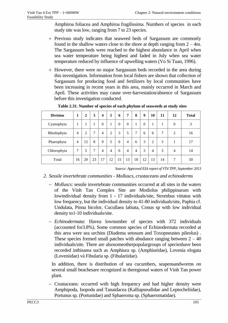
Vinh Tan 4 Ext TPP – 1×600MW
Feasibility Study
Chapter 2: Natural environment conditions
PECC3 105
Amphiroa foliacea and Amphiroa fragilissima. Numbers of species in each
study site was low, ranging from 7 to 23 species.
Previous study indicates that seaweed beds of Sargassum are commonly
found in the shallow waters close to the shore at depth ranging from 2 – 4m.
The Sargassum beds were reached to the highest abundance in April when
sea water temperature being highest and faded in July when sea water
temperature reduced by influence of upwelling waters (Vo Si Tuan, 1996).
However, there were no major Sargassum beds recorded in the area during
this investigation. Information from local fishers are shown that collection of
Sargassum for producing food and fertilizers by local communities have
been increasing in recent years in this area, mainly occurred in March and
April. These activities may cause over-harvestation/absence of Sargassum
before this investigation conducted.
Table 2.31. Number of species of each phylum of seaweeds at study sites
Division 1 2 3 4 5 6 7 8 9 10 11 12 Total
Cyanophyta 1 1 1 0 1 0 0 1 0 1 1 0 3
Rhodophyta 4 2 7 4 2 3 5 7 6 6 7 2 16
Phaeophyta 4 12 8 9 5 6 4 6 3 2 3 1 17
Chlorophyta 7 5 7 4 4 6 4 4 3 4 3 4 14
Total 16 20 23 17 12 15 13 18 12 13 14 7 50
Source: Approved EIA report of VT4 TPP, September 2013
2. Sessile invertebrate communities - Molluscs, crustaceans and echinoderms
Molluscs: sessile invertebrate communities occurred at all sites in the waters
of the Vinh Tan Complex Site are Modiolus philippinarum with
lowindividual density from 1 - 17 individuals/site, Strombus vittatus with
low frequency, but the individual density to 41-80 individuals/site, Paphia cf.
Undulata, Pinna bicolor, Cucullaea labiata, Conus sp with low individual
density to1-10 individuals/site.
Echinodermata: Havea lownumber of species with 372 individuals
(accounted for3.8%). Some common species of Echinodermata recorded at
this area were sea urchins (Diadema setosum and Toxopneustes pileolus) .
These species formed small patches with abudance ranging between 2 – 40
individuals/site. There are alsosomeotherpopulargroups of specieshave been
recorded inthisarea such as Amphiura sp. (Amphiuridae), Lovenia elogata
(Loveniidae) và Fibularia sp. (Fibulariidae).
In addition, there is distribution of sea cucumbers, seapensandworms on
several small beachesare recognized in theregional waters of Vinh Tan power
plant.
Crustaceans: occurred with high frequency and had higher density were
Amphipoda, Isopoda and Tanaidacea (Kalliapseudidae and Leptocheliidae),
Portunus sp. (Portunidae) and Sphaeroma sp. (Sphaeromatidae).
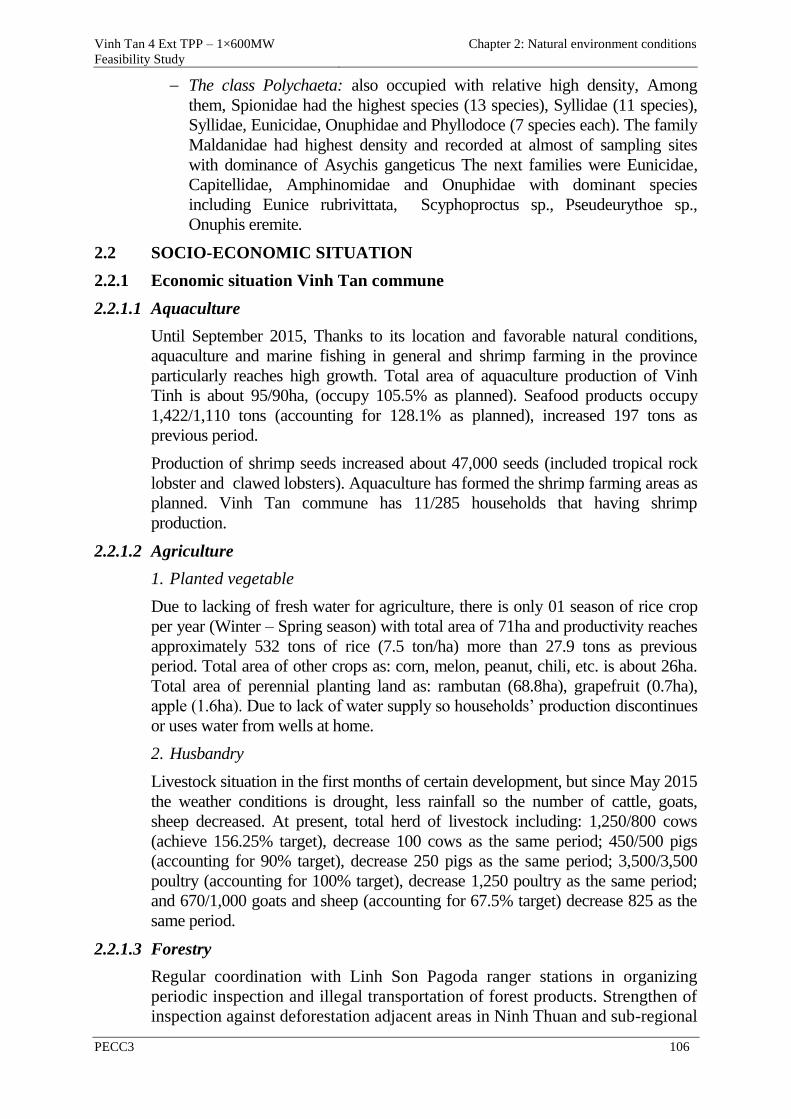
Vinh Tan 4 Ext TPP – 1×600MW
Feasibility Study
Chapter 2: Natural environment conditions
PECC3 106
The class Polychaeta: also occupied with relative high density, Among
them, Spionidae had the highest species (13 species), Syllidae (11 species),
Syllidae, Eunicidae, Onuphidae and Phyllodoce (7 species each). The family
Maldanidae had highest density and recorded at almost of sampling sites
with dominance of Asychis gangeticus The next families were Eunicidae,
Capitellidae, Amphinomidae and Onuphidae with dominant species
including Eunice rubrivittata, Scyphoproctus sp., Pseudeurythoe sp.,
Onuphis eremite.
2.2 SOCIO-ECONOMIC SITUATION
2.2.1 Economic situation Vinh Tan commune
2.2.1.1 Aquaculture
Until September 2015, Thanks to its location and favorable natural conditions,
aquaculture and marine fishing in general and shrimp farming in the province
particularly reaches high growth. Total area of aquaculture production of Vinh
Tinh is about 95/90ha, (occupy 105.5% as planned). Seafood products occupy
1,422/1,110 tons (accounting for 128.1% as planned), increased 197 tons as
previous period.
Production of shrimp seeds increased about 47,000 seeds (included tropical rock
lobster and clawed lobsters). Aquaculture has formed the shrimp farming areas as
planned. Vinh Tan commune has 11/285 households that having shrimp
production.
2.2.1.2 Agriculture
1. Planted vegetable
Due to lacking of fresh water for agriculture, there is only 01 season of rice crop
per year (Winter – Spring season) with total area of 71ha and productivity reaches
approximately 532 tons of rice (7.5 ton/ha) more than 27.9 tons as previous
period. Total area of other crops as: corn, melon, peanut, chili, etc. is about 26ha.
Total area of perennial planting land as: rambutan (68.8ha), grapefruit (0.7ha),
apple (1.6ha). Due to lack of water supply so households’ production discontinues
or uses water from wells at home.
2. Husbandry
Livestock situation in the first months of certain development, but since May 2015
the weather conditions is drought, less rainfall so the number of cattle, goats,
sheep decreased. At present, total herd of livestock including: 1,250/800 cows
(achieve 156.25% target), decrease 100 cows as the same period; 450/500 pigs
(accounting for 90% target), decrease 250 pigs as the same period; 3,500/3,500
poultry (accounting for 100% target), decrease 1,250 poultry as the same period;
and 670/1,000 goats and sheep (accounting for 67.5% target) decrease 825 as the
same period.
2.2.1.3 Forestry
Regular coordination with Linh Son Pagoda ranger stations in organizing
periodic inspection and illegal transportation of forest products. Strengthen of
inspection against deforestation adjacent areas in Ninh Thuan and sub-regional
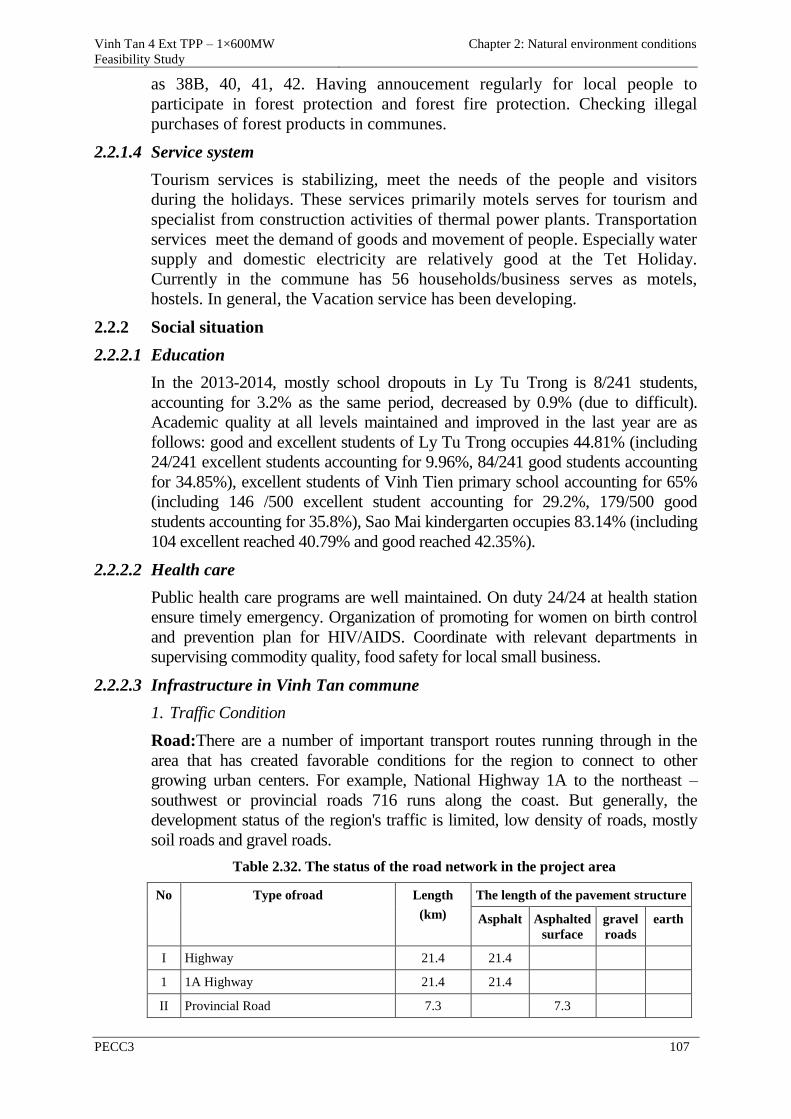
Vinh Tan 4 Ext TPP – 1×600MW
Feasibility Study
Chapter 2: Natural environment conditions
PECC3 107
as 38B, 40, 41, 42. Having annoucement regularly for local people to
participate in forest protection and forest fire protection. Checking illegal
purchases of forest products in communes.
2.2.1.4 Service system
Tourism services is stabilizing, meet the needs of the people and visitors
during the holidays. These services primarily motels serves for tourism and
specialist from construction activities of thermal power plants. Transportation
services meet the demand of goods and movement of people. Especially water
supply and domestic electricity are relatively good at the Tet Holiday.
Currently in the commune has 56 households/business serves as motels,
hostels. In general, the Vacation service has been developing.
2.2.2 Social situation
2.2.2.1 Education
In the 2013-2014, mostly school dropouts in Ly Tu Trong is 8/241 students,
accounting for 3.2% as the same period, decreased by 0.9% (due to difficult).
Academic quality at all levels maintained and improved in the last year are as
follows: good and excellent students of Ly Tu Trong occupies 44.81% (including
24/241 excellent students accounting for 9.96%, 84/241 good students accounting
for 34.85%), excellent students of Vinh Tien primary school accounting for 65%
(including 146 /500 excellent student accounting for 29.2%, 179/500 good
students accounting for 35.8%), Sao Mai kindergarten occupies 83.14% (including
104 excellent reached 40.79% and good reached 42.35%).
2.2.2.2 Health care
Public health care programs are well maintained. On duty 24/24 at health station
ensure timely emergency. Organization of promoting for women on birth control
and prevention plan for HIV/AIDS. Coordinate with relevant departments in
supervising commodity quality, food safety for local small business.
2.2.2.3 Infrastructure in Vinh Tan commune
1. Traffic Condition
Road:There are a number of important transport routes running through in the
area that has created favorable conditions for the region to connect to other
growing urban centers. For example, National Highway 1A to the northeast –
southwest or provincial roads 716 runs along the coast. But generally, the
development status of the region's traffic is limited, low density of roads, mostly
soil roads and gravel roads.
Table 2.32. The status of the road network in the project area
No Type ofroad Length
(km)
The length of the pavement structure
Asphalt Asphalted
surface
gravel
roads
earth
I Highway 21.4 21.4
1 1A Highway 21.4 21.4
II Provincial Road 7.3 7.3
Vinh Tan 4 Ext TPP – 1×600MW
Feasibility Study
Chapter 2: Natural environment conditions
PECC3 108
No Type ofroad Length
(km)
The length of the pavement structure
Asphalt Asphalted
surface
gravel
roads
earth
1 Provincial Road 716 7.3 7.3
III District roads
1 1A Highway, hamlet 7, Vinh Tan
commune
3.3 3.3
2 1A Highway, hamlet 8, Vinh Hao
commune
2.3 2.3
3 1A Highway, Da Bac reservoir- Vinh
Son Hamlet
4.0 4.0
4 1A Highway-Long Song river 1.5 1.5
IV RuralRoads 27.0 5.4 21.6
1 Vinh Hao commune 22.0 4.4 17.6
2 Vinh Tan commune 5.0 1.0 4.0
Source: Departmentof Trade and IndustryTuy Phong district, 2014
Railway:In addition, Vinh Tan commune has the north - south railway route going
through Vinh Hao Station. This station primarily used for the local operational
ships, avoiding vessels and a small part in the transport of goods in the region.
Water navigation: navigation in Tuy Phong district has not been developed; At
some river estuaries such as Phan Ri (Luy river), Lien Hương (Long Song river),
water transportation can only serve vessels entering and exiting fishing ports, and
these estuaries are the shelters for vessels to avoid storms.
At present, as transport planning of Binh Thuan province, deep-sea port serving
vessels with the load from 30,000-50,000 tons and providing coal to Vinh Tan
thermal power plant will be located in Tuy Phong and has now in the preparation
process. This will be a driving factor for the development of industry, the
formation of a large trade and service centre, contributing to the socio-economic
development of Tuy Phong.
2. Communication
Communications networks have developed widespread with quality of service
improved....Rate of phone and internet use increase; it will contribute to the
improvement of the use of telecommunications services and information
technology. By 2014, the density of telephone subscribers reaches 49 telephones
per 100 people (of which 22.9 fixed telephones per 100 people), rate of internet
users account for about 6% of the population.
3. Power supply system
Currently, in the Tuy Phong district, 100% ofcommunes havethe national grid.
Until now, theregionhas about32 kmof medium voltagelines, 20 kmof low voltage
lines and 16 substations. Percentage of households is using electricity reached to
100%.
In addition, electricityis also used for lighting in the administrative center, public
parks and along Highway 1A.
Vinh Tan 4 Ext TPP – 1×600MW
Feasibility Study
Chapter 2: Natural environment conditions
PECC3 109
4. Water supply system
Water supply and production activities in the area of Vinh Hao - Tan Vinh district
in particular and Tuy Phong in general are mainly from the use of surface and
ground water part. Until now, the whole region (permanent Tan Vinh Hao) have
two pumping stations with an average capacity of each station up to 200
m3/day/night; with a total length of pipes and water distribution around 12 km.
Combined with more than 50 wells and other precipitate process measures.
Percentage of households using clean water is over 95%, the percentage of
households using tap water is at 35%.
5. Drainage system
Drainage in Vinh Tan commune is natural and does not treat before being released
to the natural environment. Rain-water drainage is primarily via the ditches along
roads. Domestic wastewater is processed through a septic tank before escaping.
Thus, in the future there is a need to build wastewater treatment system to ensure
environmental safety, health and urban civilization.
3. Solid waste treatment establishments
In the Vinh Tan-Vinh Hao commune area have planned two landfills and waste
treatment (one in Vinh Hao is an area of 2ha and the other one is of 5ha in Vinh
Tan). Garbage will collected and treated simply to reduce doors.
4. Irrigation
In recent years, these systems of irrigation are invested. The irrigation works
including as Da Bac Lake has 394 ha of design capacity; the dam of Vinh Hao
designed to has a capacity of 100 ha and the irrigation canal system has been
gradually solidified. However, the water supply only for agricultural production,
water treatment activities and industrial production only meets a certain level.
2.2.3 Socio-economic situation of affected households
As socio-economic survey carried out by PECC3 on the project affected
households during December 2014 and June 2015, showed that:
2.2.3.1 Characteristics of population and project affected households
Kinh is dominated ethnicityoccupied with 99.3% in Vinh Tan commune, the rest
are minorities such as Ra Glai, Cham. Characteristics of the affected
households(HHs) as follows:
Average members of an affected HH: 4.42 persons/HH
- Male: 52.95 %
- Female: 47.05 %
Age
- From 1 – 17 years old: 28.15 %
- From 18 – 60 years old: 68.60 %
- Above 60 years old: 3.25 %
Genderof head of HH
Vinh Tan 4 Ext TPP – 1×600MW
Feasibility Study
Chapter 2: Natural environment conditions
PECC3 110
- Male: 85.40 %
- Female: 14.60 %
Educational situation of affected HHs
- University/Collegde/vocational: 0.15%
- High school: 4.70%
- Secondary school: 71.15%
- Literacy 15.20%
- Illiteracy: 8.8%
Occupation
- Farmer and wage earners: 90.00%
- Small bussiness: 1.50%
- Houses renting bussiness: 5.40%
- Others: 3.10%
Monthly average income: 5,000,000 VND/HH
Accommodation
- Affected HHs using electricity: 98.50%
- Affected HHs using well: 90.40%
- Affected HHs using telephone: 40.50%
- Affected HHs using TV set: 95.50%
- Affected HHs using refrigerator: 25.20%
- Affected HHs having motocycles: 95.50%
- Affected HHs having bikecycles: 90.55%
Annual average expenses of an affected HH:
Regular expense:
- Food demand: 53.78%
- Energy demand: 3.87%
- Expense for education and trainning: 7.31%
- Travel expense: 8.92%
- Others: 2.55%
____________
Sub-total 76.43%
Irregular expense
- Festival/Funeral 1.92%
Vinh Tan 4 Ext TPP – 1×600MW
Feasibility Study
Chapter 2: Natural environment conditions
PECC3 111
1.92%
Total expenses 78.35%
Religion
- Buddhism: 31.47%
- Catholicsm: 29.64%
- Islam : 12.14%
- Protestantism: 0.43%
- Caodaism: 0.54%
- Non-religiuos: 25.78%
2.2.3.2 Accommodation
According to Circular of Construction Ministry, there are 05house class:
Category 1, 2, 3, 4 and “Temp.”. As surveyed results carried out by PECC3
showed that affected HHs’ houses was mainly Cat. 3, 4 and “Temp.”, in
which:
Cat. 3: 0.63%
Cat. 4: 87.18%
Cat. “Temp”: 12.19%
2.2.4 Infrastructure situation in the project area
Infrastructure system as outside traffic system, water supply and electricity
system for construction activities consist of:
2.2.4.1 Traffic system
Road system in the project area is mainly National Road 1A (AH1). In
addition, the project location is nearby shoreline, so waterway is an advantage
for transportation of construction material and fuel during operation phase.
Designed traffic roads is type of secondary urban roads (Cat. 3) as: Road No 1
and No 4, etc. or Cat. 3 roads for plain area. These route would be built for
transportation of ash during operation phase for power plants of Vinh Tan
Power Complex.
2.2.4.2 Water supply for construction activities
At present, water supply has been used for VT2 TPP (under operation) and
construction activities of power plants of Vinh Tan Power Complex. Source of
water has been taken from Da Bac Lake which was invested by EVN with
total intake volume of 600m3/h.
2.2.4.3 Electricity supply for construction activities
Electricity supply for construction activities was invested by EVN, in which
scope of investment consists of a 22kV Ninh Phuoc – Vinh Tan double circuit
transmission line with a capacity of 14MVA, enough for construction of Vinh
Tan Power Complex.
Vinh Tan 4 Ext TPP – 1×600MW
Feasibility Study Report
Chapter 3: Environmental impact assessment
PECC3 112
CHAPTER 3 ASSESSMENT AND FORECAST OF
ENVIRONMENTAL IMPACTS
3.1 ASSESSMENT AND FORECAST OF ENVIRONMENTAL IMPACTS
Construction site of Vinh Tan 4 Extension TPP is on the expanding area of
Vinh Tan Power Complex.
Location of Vinh Tan 4 Extension TPP Project includes a part of area
(3.97ha) will be located in the ecological restoration area (808ha) and the
remaining area will be located entirely in the development area of Hon Cau
marine protected area (Hon Cau MPA), in which some reef areas destroyed and
biological source was depleted by exploitation activities, therefore recovery
solutions need to be implemented. The project will be 7.5 km from the
boundary of Buffer Zone 1 and approximately 4km from Buffer Zone 2 -
Breda Sandbar so it will not affect the buffer zones and core area of the
reserve.
Overall, the option of Vinh Tan 4 Extension TPP location has been carefully
considered to optimize the location advantages, and at the same time the
impact level on the population and the existing structures is the lowest. Vinh
Tan 4 Extension TPP will use advanced technologies and techniques to limit
the impacts on the ecosystems in the area. The HHs will receive compensation
in accordance with the regulations.
After Vinh Tan Power Complex in general and Vinh Tan 4 Extension TPP in
particular are put in operation, they will bring positive impacts to the local
economy and society in Binh Thuan province. Therefore, the impact due to
position option is small, it can be overcome by technical measures.
3.1.1 Assessment and forecast of impacts of the project in the pre-construction
phase
Land acquisition of the project consists of three areas:
- The power plant area: used to plant trees and to build an isolation corridor
(main plant area and the auxiliary structures belong to the land of Vinh Tan 4
TPP which has been cleared);
- The isolation corridor area from the ash pond : this area is used to isolate
for hygienic condition from the ash pond;
- The flood drainage canal of the ash pond: this area is used for building a
drainage canal to ensure flood will not overflow into the ash pond.
The activities in the pre-construction phase include:
- Resettlement for 3 areas including: (1) plant area, (2) isolation corridor area
from the ash pond, (3) Flood drainage canal area of the ash pond;
- Land clearance for these regions.
The project impact sources in the pre-construction phase are shown in the
following table:
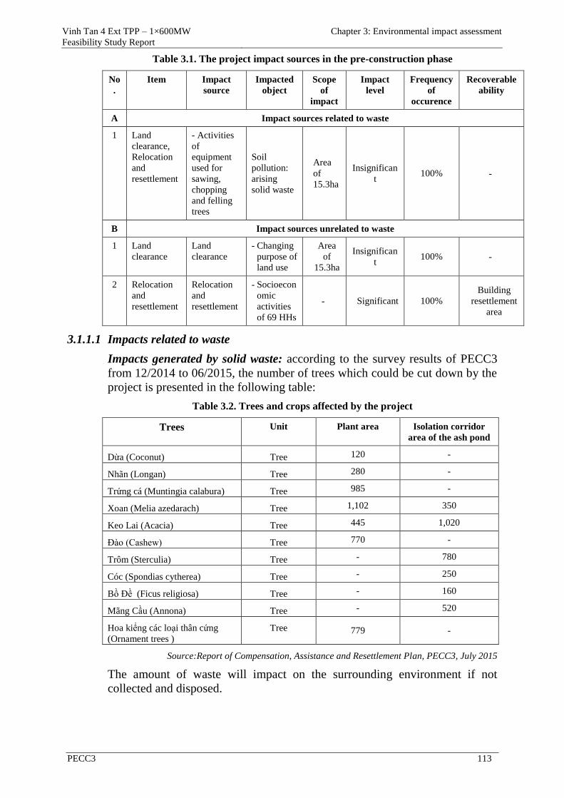
Vinh Tan 4 Ext TPP – 1×600MW
Feasibility Study Report
Chapter 3: Environmental impact assessment
PECC3 113
Table 3.1. The project impact sources in the pre-construction phase
No
.
Item Impact
source
Impacted
object
Scope
of
impact
Impact
level
Frequency
of
occurence
Recoverable
ability
A Impact sources related to waste
1 Land
clearance,
Relocation
and
resettlement
- Activities
of
equipment
used for
sawing,
chopping
and felling
trees
Soil
pollution:
arising
solid waste
Area
of
15.3ha
Insignifican
t 100% -
B Impact sources unrelated to waste
1 Land
clearance
Land
clearance
- Changing
purpose of
land use
Area
of
15.3ha
Insignifican
t 100% -
2 Relocation
and
resettlement
Relocation
and
resettlement
- Socioecon
omic
activities
of 69 HHs
- Significant 100%
Building
resettlement
area
3.1.1.1 Impacts related to waste
Impacts generated by solid waste: according to the survey results of PECC3
from 12/2014 to 06/2015, the number of trees which could be cut down by the
project is presented in the following table:
Table 3.2. Trees and crops affected by the project
Trees Unit Plant area Isolation corridor
area of the ash pond
Dừa (Coconut) Tree 120 -
Nhãn (Longan) Tree 280 -
Trứng cá (Muntingia calabura) Tree 985 -
Xoan (Melia azedarach) Tree 1,102 350
Keo Lai (Acacia) Tree 445 1,020
Đào (Cashew) Tree 770 -
Trôm (Sterculia) Tree - 780
Cóc (Spondias cytherea) Tree - 250
Bồ Đề (Ficus religiosa) Tree - 160
Mãng Cầu (Annona) Tree - 520
Hoa kiểng các loại thân cứng
(Ornament trees )
Tree 779 -
Source:Report of Compensation, Assistance and Resettlement Plan, PECC3, July 2015
The amount of waste will impact on the surrounding environment if not
collected and disposed.
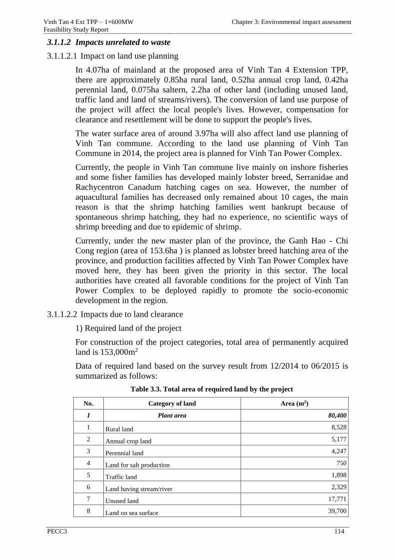
Vinh Tan 4 Ext TPP – 1×600MW
Feasibility Study Report
Chapter 3: Environmental impact assessment
PECC3 114
3.1.1.2 Impacts unrelated to waste
3.1.1.2.1 Impact on land use planning
In 4.07ha of mainland at the proposed area of Vinh Tan 4 Extension TPP,
there are approximately 0.85ha rural land, 0.52ha annual crop land, 0.42ha
perennial land, 0.075ha saltern, 2.2ha of other land (including unused land,
traffic land and land of streams/rivers). The conversion of land use purpose of
the project will affect the local people's lives. However, compensation for
clearance and resettlement will be done to support the people's lives.
The water surface area of around 3.97ha will also affect land use planning of
Vinh Tan commune. According to the land use planning of Vinh Tan
Commune in 2014, the project area is planned for Vinh Tan Power Complex.
Currently, the people in Vinh Tan commune live mainly on inshore fisheries
and some fisher families has developed mainly lobster breed, Serranidae and
Rachycentron Canadum hatching cages on sea. However, the number of
aquacultural families has decreased only remained about 10 cages, the main
reason is that the shrimp hatching families went bankrupt because of
spontaneous shrimp hatching, they had no experience, no scientific ways of
shrimp breeding and due to epidemic of shrimp.
Currently, under the new master plan of the province, the Ganh Hao - Chi
Cong region (area of 153.6ha ) is planned as lobster breed hatching area of the
province, and production facilities affected by Vinh Tan Power Complex have
moved here, they has been given the priority in this sector. The local
authorities have created all favorable conditions for the project of Vinh Tan
Power Complex to be deployed rapidly to promote the socio-economic
development in the region.
3.1.1.2.2 Impacts due to land clearance
1) Required land of the project
For construction of the project categories, total area of permanently acquired
land is 153,000m2
Data of required land based on the survey result from 12/2014 to 06/2015 is
summarized as follows:
Table 3.3. Total area of required land by the project
No. Category of land Area (m2)
I Plant area 80,400
1 Rural land 8,528
2 Annual crop land 5,177
3 Perennial land 4,247
4 Land for salt production 750
5 Traffic land 1,898
6 Land having stream/river 2,329
7 Unused land 17,771
8 Land on sea surface 39,700
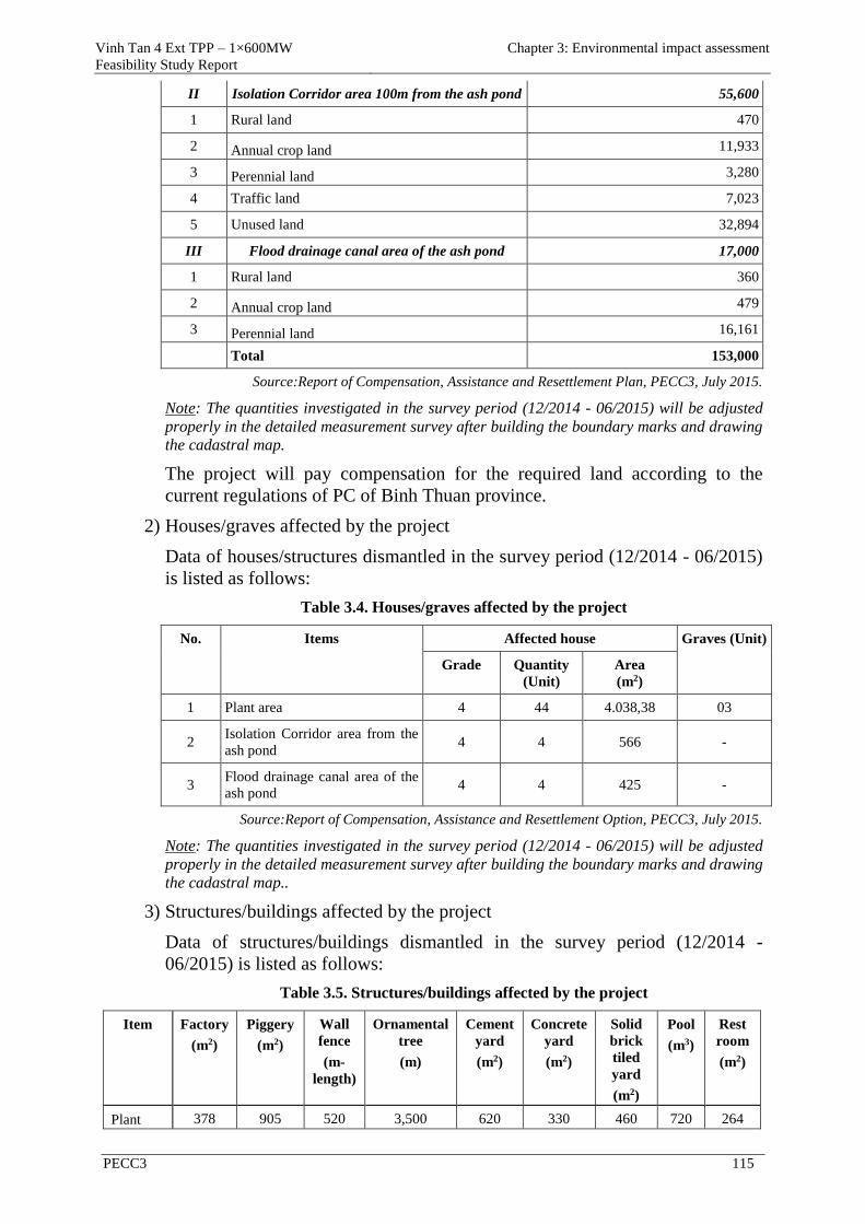
Vinh Tan 4 Ext TPP – 1×600MW
Feasibility Study Report
Chapter 3: Environmental impact assessment
PECC3 115
II Isolation Corridor area 100m from the ash pond 55,600
1 Rural land 470
2 Annual crop land 11,933
3 Perennial land 3,280
4 Traffic land 7,023
5 Unused land 32,894
III Flood drainage canal area of the ash pond 17,000
1 Rural land 360
2 Annual crop land 479
3 Perennial land 16,161
Total 153,000
Source:Report of Compensation, Assistance and Resettlement Plan, PECC3, July 2015.
Note: The quantities investigated in the survey period (12/2014 - 06/2015) will be adjusted
properly in the detailed measurement survey after building the boundary marks and drawing
the cadastral map.
The project will pay compensation for the required land according to the
current regulations of PC of Binh Thuan province.
2) Houses/graves affected by the project
Data of houses/structures dismantled in the survey period (12/2014 - 06/2015)
is listed as follows:
Table 3.4. Houses/graves affected by the project
No. Items Affected house Graves (Unit)
Grade Quantity
(Unit)
Area
(m2)
1 Plant area 4 44 4.038,38 03
2 Isolation Corridor area from the
ash pond 4 4 566 -
3 Flood drainage canal area of the
ash pond 4 4 425 -
Source:Report of Compensation, Assistance and Resettlement Option, PECC3, July 2015.
Note: The quantities investigated in the survey period (12/2014 - 06/2015) will be adjusted
properly in the detailed measurement survey after building the boundary marks and drawing
the cadastral map..
3) Structures/buildings affected by the project
Data of structures/buildings dismantled in the survey period (12/2014 -
06/2015) is listed as follows:
Table 3.5. Structures/buildings affected by the project
Item Factory
(m2)
Piggery
(m2)
Wall
fence
(m-
length)
Ornamental
tree
(m)
Cement
yard
(m2)
Concrete
yard
(m2)
Solid
brick
tiled
yard
(m2)
Pool
(m3)
Rest
room
(m2)
Plant 378 905 520 3,500 620 330 460 720 264
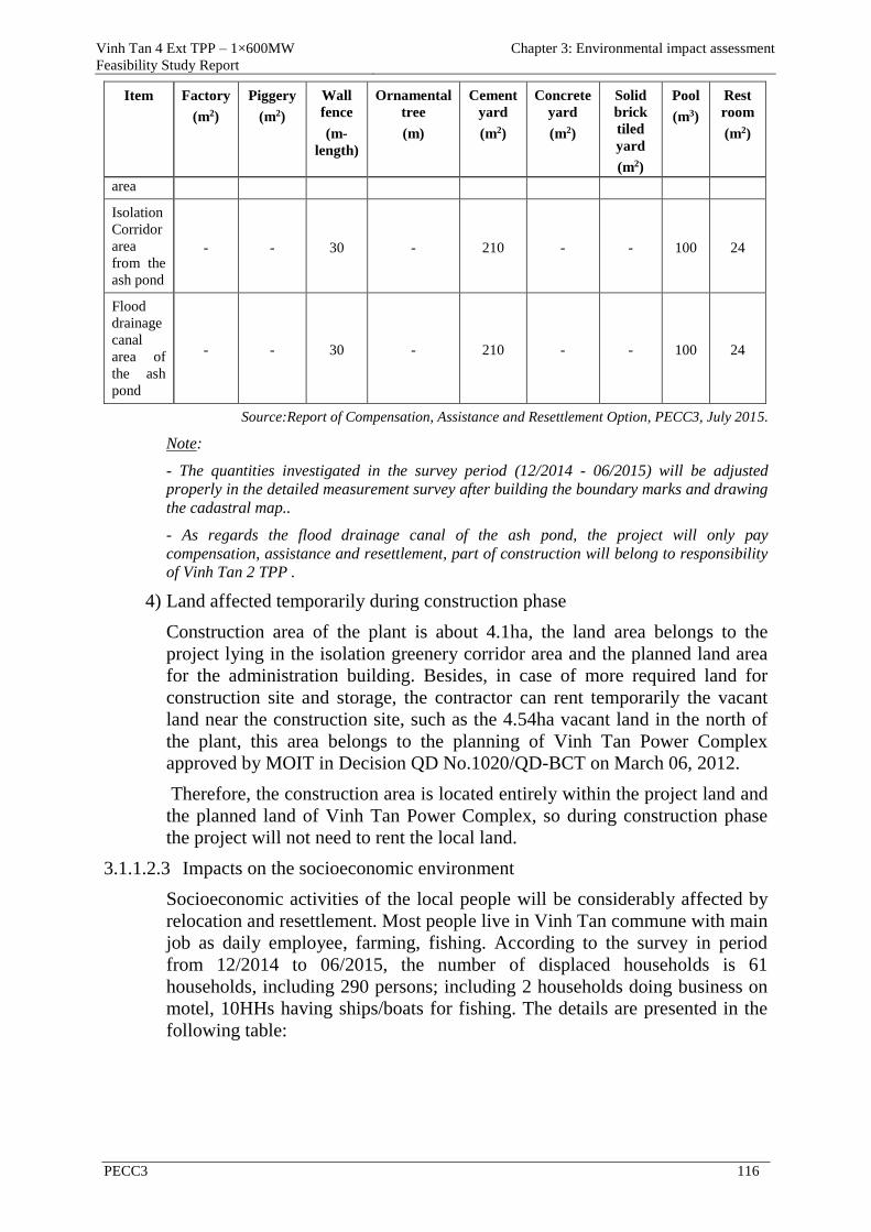
Vinh Tan 4 Ext TPP – 1×600MW
Feasibility Study Report
Chapter 3: Environmental impact assessment
PECC3 116
Item Factory
(m2)
Piggery
(m2)
Wall
fence
(m-
length)
Ornamental
tree
(m)
Cement
yard
(m2)
Concrete
yard
(m2)
Solid
brick
tiled
yard
(m2)
Pool
(m3)
Rest
room
(m2)
area
Isolation
Corridor
area
from the
ash pond
- - 30 - 210 - - 100 24
Flood
drainage
canal
area of
the ash
pond
- - 30 - 210 - - 100 24
Source:Report of Compensation, Assistance and Resettlement Option, PECC3, July 2015.
Note:
- The quantities investigated in the survey period (12/2014 - 06/2015) will be adjusted
properly in the detailed measurement survey after building the boundary marks and drawing
the cadastral map..
- As regards the flood drainage canal of the ash pond, the project will only pay
compensation, assistance and resettlement, part of construction will belong to responsibility
of Vinh Tan 2 TPP .
4) Land affected temporarily during construction phase
Construction area of the plant is about 4.1ha, the land area belongs to the
project lying in the isolation greenery corridor area and the planned land area
for the administration building. Besides, in case of more required land for
construction site and storage, the contractor can rent temporarily the vacant
land near the construction site, such as the 4.54ha vacant land in the north of
the plant, this area belongs to the planning of Vinh Tan Power Complex
approved by MOIT in Decision QD No.1020/QD-BCT on March 06, 2012.
Therefore, the construction area is located entirely within the project land and
the planned land of Vinh Tan Power Complex, so during construction phase
the project will not need to rent the local land.
3.1.1.2.3 Impacts on the socioeconomic environment
Socioeconomic activities of the local people will be considerably affected by
relocation and resettlement. Most people live in Vinh Tan commune with main
job as daily employee, farming, fishing. According to the survey in period
from 12/2014 to 06/2015, the number of displaced households is 61
households, including 290 persons; including 2 households doing business on
motel, 10HHs having ships/boats for fishing. The details are presented in the
following table:
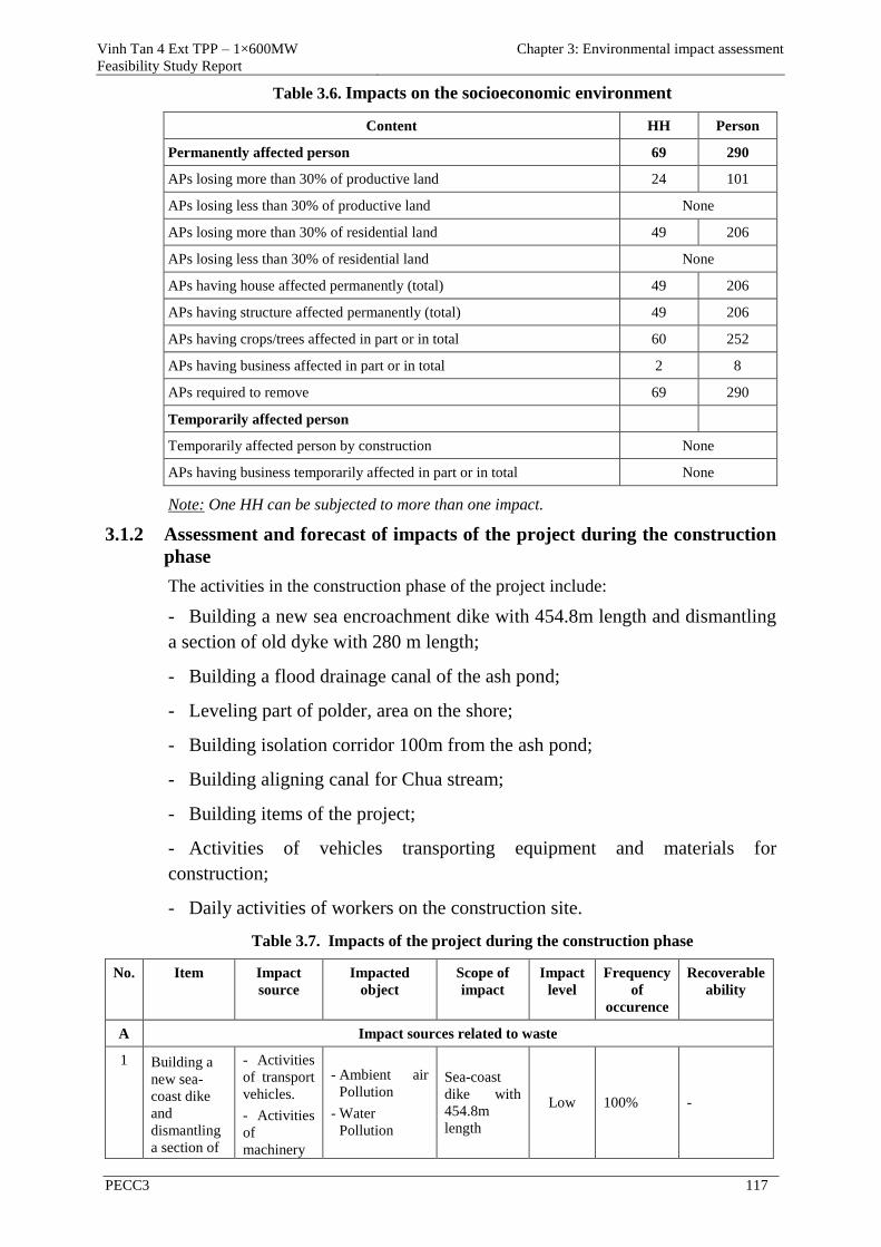
Vinh Tan 4 Ext TPP – 1×600MW
Feasibility Study Report
Chapter 3: Environmental impact assessment
PECC3 117
Table 3.6. Impacts on the socioeconomic environment
Content HH Person
Permanently affected person 69 290
APs losing more than 30% of productive land 24 101
APs losing less than 30% of productive land None
APs losing more than 30% of residential land 49 206
APs losing less than 30% of residential land None
APs having house affected permanently (total) 49 206
APs having structure affected permanently (total) 49 206
APs having crops/trees affected in part or in total 60 252
APs having business affected in part or in total 2 8
APs required to remove 69 290
Temporarily affected person
Temporarily affected person by construction None
APs having business temporarily affected in part or in total None
Note: One HH can be subjected to more than one impact.
3.1.2 Assessment and forecast of impacts of the project during the construction
phase
The activities in the construction phase of the project include:
Building a new sea encroachment dike with 454.8m length and dismantling
a section of old dyke with 280 m length;
Building a flood drainage canal of the ash pond;
Leveling part of polder, area on the shore;
Building isolation corridor 100m from the ash pond;
Building aligning canal for Chua stream;
Building items of the project;
Activities of vehicles transporting equipment and materials for
construction;
Daily activities of workers on the construction site.
Table 3.7. Impacts of the project during the construction phase
No. Item Impact
source
Impacted
object
Scope of
impact
Impact
level
Frequency
of
occurence
Recoverable
ability
A Impact sources related to waste
1 Building a
new sea-
coast dike
and
dismantling
a section of
- Activities
of transport
vehicles.
- Activities
of
machinery
- Ambient air
Pollution
- Water
Pollution
Sea-coast
dike with
454.8m
length
Low 100% -
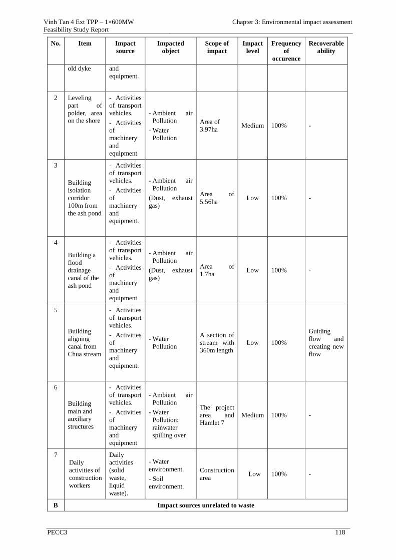
Vinh Tan 4 Ext TPP – 1×600MW
Feasibility Study Report
Chapter 3: Environmental impact assessment
PECC3 118
No. Item Impact
source
Impacted
object
Scope of
impact
Impact
level
Frequency
of
occurence
Recoverable
ability
old dyke and
equipment.
2 Leveling
part of
polder, area
on the shore
- Activities
of transport
vehicles.
- Activities
of
machinery
and
equipment
- Ambient air
Pollution
- Water
Pollution
Area of
3.97ha Medium 100% -
3
Building
isolation
corridor
100m from
the ash pond
- Activities
of transport
vehicles.
- Activities
of
machinery
and
equipment.
- Ambient air
Pollution
(Dust, exhaust
gas)
Area of
5.56ha Low 100% -
4
Building a
flood
drainage
canal of the
ash pond
- Activities
of transport
vehicles.
- Activities
of
machinery
and
equipment
- Ambient air
Pollution
(Dust, exhaust
gas)
Area of
1.7ha Low 100% -
5
Building
aligning
canal from
Chua stream
- Activities
of transport
vehicles.
- Activities
of
machinery
and
equipment.
- Water
Pollution
A section of
stream with
360m length
Low 100%
Guiding
flow and
creating new
flow
6
Building
main and
auxiliary
structures
- Activities
of transport
vehicles.
- Activities
of
machinery
and
equipment
- Ambient air
Pollution
- Water
Pollution:
rainwater
spilling over
The project
area and
Hamlet 7
Medium 100% -
7
Daily
activities of
construction
workers
Daily
activities
(solid
waste,
liquid
waste).
- Water
environment.
- Soil
environment.
Construction
area Low 100% -
B Impact sources unrelated to waste
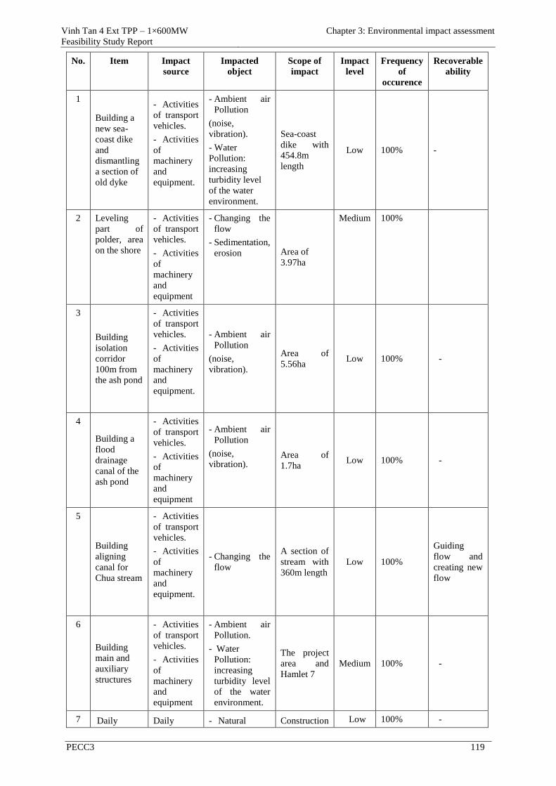
Vinh Tan 4 Ext TPP – 1×600MW
Feasibility Study Report
Chapter 3: Environmental impact assessment
PECC3 119
No. Item Impact
source
Impacted
object
Scope of
impact
Impact
level
Frequency
of
occurence
Recoverable
ability
1
Building a
new sea-
coast dike
and
dismantling
a section of
old dyke
- Activities
of transport
vehicles.
- Activities
of
machinery
and
equipment.
- Ambient air
Pollution
(noise,
vibration).
- Water
Pollution:
increasing
turbidity level
of the water
environment.
Sea-coast
dike with
454.8m
length
Low 100% -
2 Leveling
part of
polder, area
on the shore
- Activities
of transport
vehicles.
- Activities
of
machinery
and
equipment
- Changing the
flow
- Sedimentation,
erosion Area of
3.97ha
Medium 100%
3
Building
isolation
corridor
100m from
the ash pond
- Activities
of transport
vehicles.
- Activities
of
machinery
and
equipment.
- Ambient air
Pollution
(noise,
vibration).
Area of
5.56ha Low 100% -
4
Building a
flood
drainage
canal of the
ash pond
- Activities
of transport
vehicles.
- Activities
of
machinery
and
equipment
- Ambient air
Pollution
(noise,
vibration).
Area of
1.7ha Low 100% -
5
Building
aligning
canal for
Chua stream
- Activities
of transport
vehicles.
- Activities
of
machinery
and
equipment.
- Changing the
flow
A section of
stream with
360m length
Low 100%
Guiding
flow and
creating new
flow
6
Building
main and
auxiliary
structures
- Activities
of transport
vehicles.
- Activities
of
machinery
and
equipment
- Ambient air
Pollution.
- Water
Pollution:
increasing
turbidity level
of the water
environment.
The project
area and
Hamlet 7
Medium 100% -
7 Daily Daily - Natural Construction Low 100% -
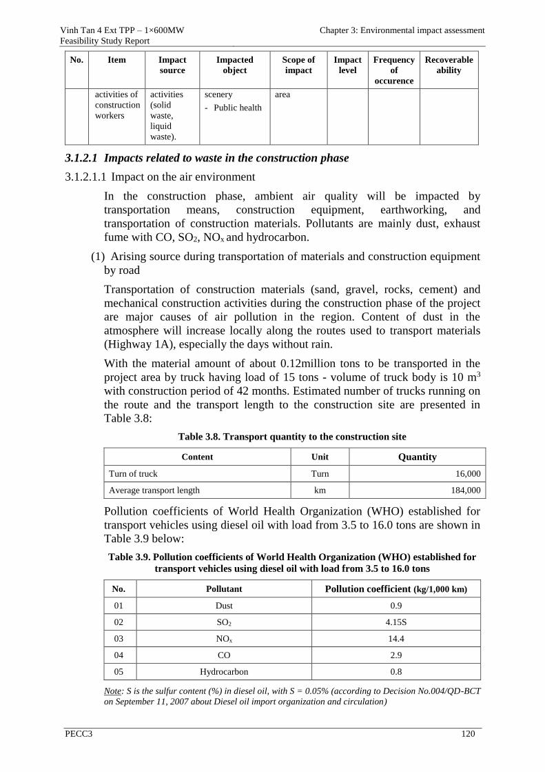
Vinh Tan 4 Ext TPP – 1×600MW
Feasibility Study Report
Chapter 3: Environmental impact assessment
PECC3 120
No. Item Impact
source
Impacted
object
Scope of
impact
Impact
level
Frequency
of
occurence
Recoverable
ability
activities of
construction
workers
activities
(solid
waste,
liquid
waste).
scenery
- Public health
area
3.1.2.1 Impacts related to waste in the construction phase
3.1.2.1.1 Impact on the air environment
In the construction phase, ambient air quality will be impacted by
transportation means, construction equipment, earthworking, and
transportation of construction materials. Pollutants are mainly dust, exhaust
fume with CO, SO2, NOx and hydrocarbon.
(1) Arising source during transportation of materials and construction equipment
by road
Transportation of construction materials (sand, gravel, rocks, cement) and
mechanical construction activities during the construction phase of the project
are major causes of air pollution in the region. Content of dust in the
atmosphere will increase locally along the routes used to transport materials
(Highway 1A), especially the days without rain.
With the material amount of about 0.12million tons to be transported in the
project area by truck having load of 15 tons - volume of truck body is 10 m3
with construction period of 42 months. Estimated number of trucks running on
the route and the transport length to the construction site are presented in
Table 3.8:
Table 3.8. Transport quantity to the construction site
Content Unit Quantity
Turn of truck Turn 16,000
Average transport length km 184,000
Pollution coefficients of World Health Organization (WHO) established for
transport vehicles using diesel oil with load from 3.5 to 16.0 tons are shown in
Table 3.9 below:
Table 3.9. Pollution coefficients of World Health Organization (WHO) established for
transport vehicles using diesel oil with load from 3.5 to 16.0 tons
No. Pollutant Pollution coefficient (kg/1,000 km)
01 Dust 0.9
02 SO2 4.15S
03 NOx 14.4
04 CO 2.9
05 Hydrocarbon 0.8
Note: S is the sulfur content (%) in diesel oil, with S = 0.05% (according to Decision No.004/QD-BCT
on September 11, 2007 about Diesel oil import organization and circulation)
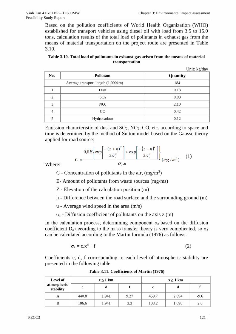
Vinh Tan 4 Ext TPP – 1×600MW
Feasibility Study Report
Chapter 3: Environmental impact assessment
PECC3 121
Based on the pollution coefficients of World Health Organization (WHO)
established for transport vehicles using diesel oil with load from 3.5 to 15.0
tons, calculation results of the total load of pollutants in exhaust gas from the
means of material transportation on the project route are presented in Table
3.10.
Table 3.10. Total load of pollutants in exhaust gas arisen from the means of material
transportation
Unit: kg/day
No. Pollutant Quantity
Average transport length (1,000km) 184
1 Dust 0.13
2 SO2 0.03
3 NOx 2.10
4 CO 0.42
5 Hydrocarbon 0.12
Emission characteristic of dust and SO2, NO2, CO, etc. according to space and
time is determined by the method of Sutton model based on the Gausse theory
applied for road source:
(1)
(1)
Where:
C - Concentration of pollutants in the air, (mg/m3)
E- Amount of pollutants from waste sources (mg/ms)
Z - Elevation of the calculation position (m)
h - Difference between the road surface and the surrounding ground (m)
u - Average wind speed in the area (m/s)
σz - Diffusion coefficient of pollutants on the axis z (m)
In the calculation process, determining component σz based on the diffusion
coefficient Dz according to the mass transfer theory is very complicated, so σz
can be calculated according to the Martin formula (1976) as follows:
σz = c.xd + f (2)
Coefficients c, d, f corresponding to each level of atmospheric stability are
presented in the following table:
Table 3.11. Coefficients of Martin (1976)
Level of
atmospheric
stability
x ≤ 1 km x ≥ 1 km
c d f c d f
A 440.8 1.941 9.27 459.7 2.094 -9.6
B 106.6 1.941 3.3 108.2 1.098 2.0
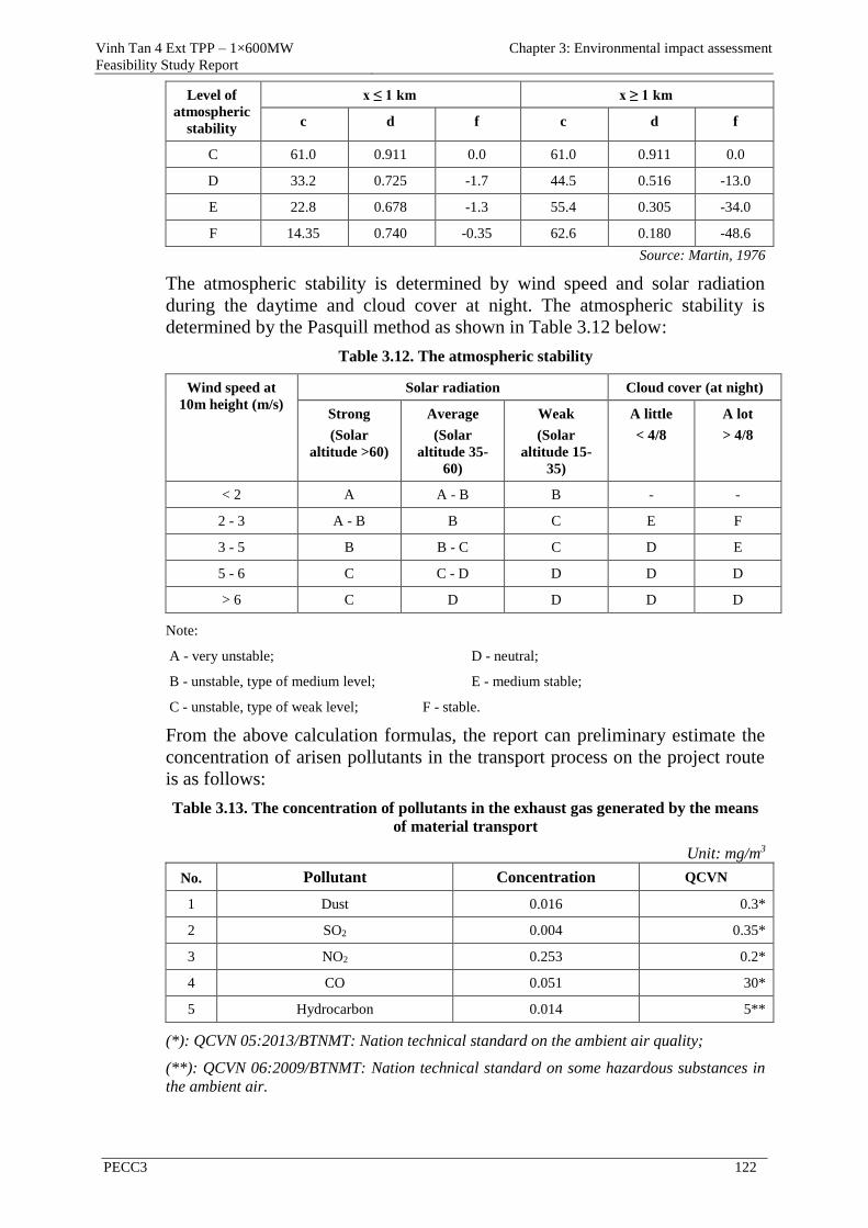
Vinh Tan 4 Ext TPP – 1×600MW
Feasibility Study Report
Chapter 3: Environmental impact assessment
PECC3 122
Level of
atmospheric
stability
x ≤ 1 km x ≥ 1 km
c d f c d f
C 61.0 0.911 0.0 61.0 0.911 0.0
D 33.2 0.725 -1.7 44.5 0.516 -13.0
E 22.8 0.678 -1.3 55.4 0.305 -34.0
F 14.35 0.740 -0.35 62.6 0.180 -48.6
Source: Martin, 1976
The atmospheric stability is determined by wind speed and solar radiation
during the daytime and cloud cover at night. The atmospheric stability is
determined by the Pasquill method as shown in Table 3.12 below:
Table 3.12. The atmospheric stability
Wind speed at
10m height (m/s)
Solar radiation Cloud cover (at night)
Strong
(Solar
altitude >60)
Average
(Solar
altitude 35-
60)
Weak
(Solar
altitude 15-
35)
A little
< 4/8
A lot
> 4/8
< 2 A A - B B - -
2 - 3 A - B B C E F
3 - 5 B B - C C D E
5 - 6 C C - D D D D
> 6 C D D D D
Note:
A - very unstable; D - neutral;
B - unstable, type of medium level; E - medium stable;
C - unstable, type of weak level; F - stable.
From the above calculation formulas, the report can preliminary estimate the
concentration of arisen pollutants in the transport process on the project route
is as follows:
Table 3.13. The concentration of pollutants in the exhaust gas generated by the means
of material transport
Unit: mg/m3
No. Pollutant Concentration QCVN
1 Dust 0.016 0.3*
2 SO2 0.004 0.35*
3 NO2 0.253 0.2*
4 CO 0.051 30*
5 Hydrocarbon 0.014 5**
(*): QCVN 05:2013/BTNMT: Nation technical standard on the ambient air quality;
(**): QCVN 06:2009/BTNMT: Nation technical standard on some hazardous substances in
the ambient air.
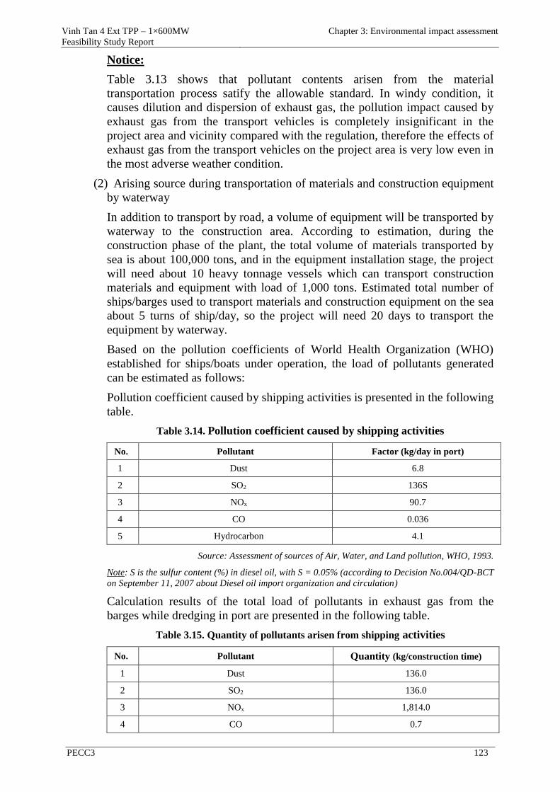
Vinh Tan 4 Ext TPP – 1×600MW
Feasibility Study Report
Chapter 3: Environmental impact assessment
PECC3 123
Notice:
Table 3.13 shows that pollutant contents arisen from the material
transportation process satify the allowable standard. In windy condition, it
causes dilution and dispersion of exhaust gas, the pollution impact caused by
exhaust gas from the transport vehicles is completely insignificant in the
project area and vicinity compared with the regulation, therefore the effects of
exhaust gas from the transport vehicles on the project area is very low even in
the most adverse weather condition.
(2) Arising source during transportation of materials and construction equipment
by waterway
In addition to transport by road, a volume of equipment will be transported by
waterway to the construction area. According to estimation, during the
construction phase of the plant, the total volume of materials transported by
sea is about 100,000 tons, and in the equipment installation stage, the project
will need about 10 heavy tonnage vessels which can transport construction
materials and equipment with load of 1,000 tons. Estimated total number of
ships/barges used to transport materials and construction equipment on the sea
about 5 turns of ship/day, so the project will need 20 days to transport the
equipment by waterway.
Based on the pollution coefficients of World Health Organization (WHO)
established for ships/boats under operation, the load of pollutants generated
can be estimated as follows:
Pollution coefficient caused by shipping activities is presented in the following
table.
Table 3.14. Pollution coefficient caused by shipping activities
No. Pollutant Factor (kg/day in port)
1 Dust 6.8
2 SO2 136S
3 NOx 90.7
4 CO 0.036
5 Hydrocarbon 4.1
Source: Assessment of sources of Air, Water, and Land pollution, WHO, 1993.
Note: S is the sulfur content (%) in diesel oil, with S = 0.05% (according to Decision No.004/QD-BCT
on September 11, 2007 about Diesel oil import organization and circulation)
Calculation results of the total load of pollutants in exhaust gas from the
barges while dredging in port are presented in the following table.
Table 3.15. Quantity of pollutants arisen from shipping activities
No. Pollutant Quantity (kg/construction time)
1 Dust 136.0
2 SO2 136.0
3 NOx 1,814.0
4 CO 0.7
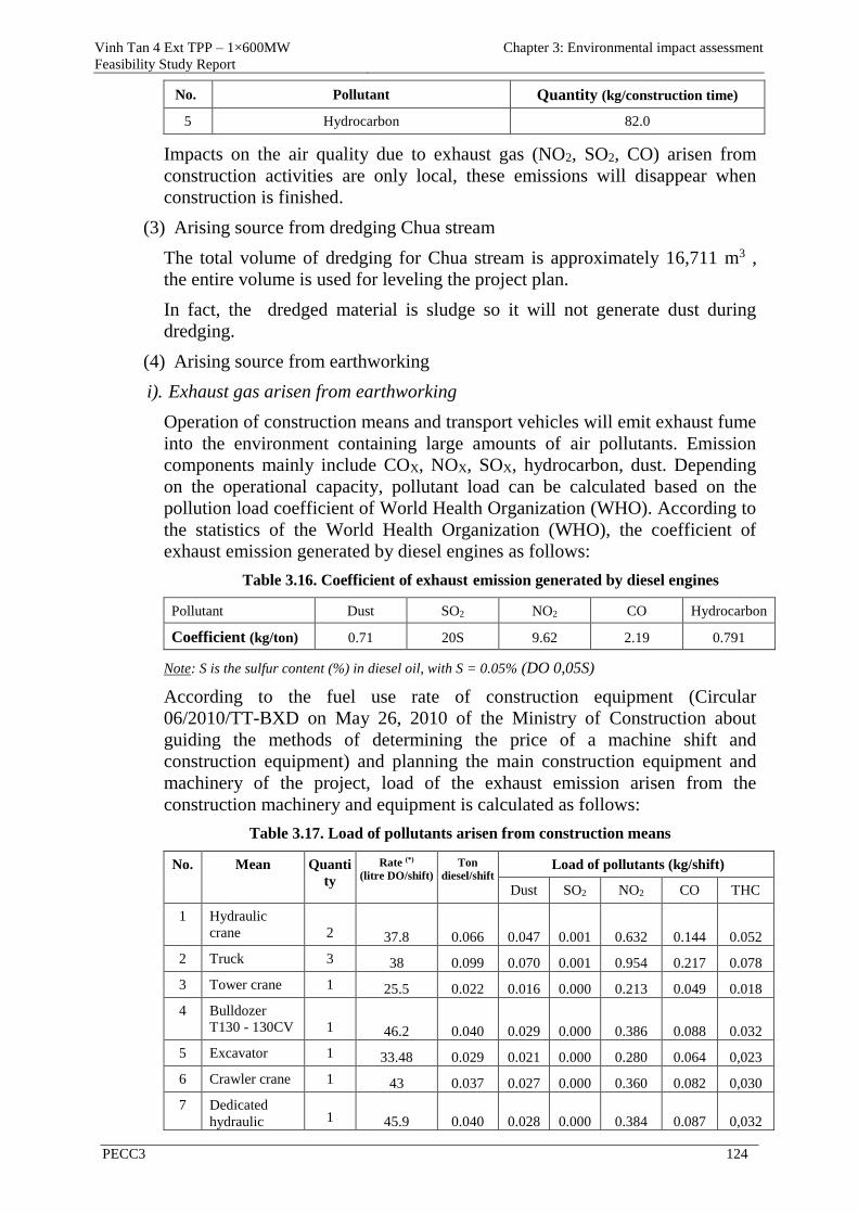
Vinh Tan 4 Ext TPP – 1×600MW
Feasibility Study Report
Chapter 3: Environmental impact assessment
PECC3 124
No. Pollutant Quantity (kg/construction time)
5 Hydrocarbon 82.0
Impacts on the air quality due to exhaust gas (NO2, SO2, CO) arisen from
construction activities are only local, these emissions will disappear when
construction is finished.
(3) Arising source from dredging Chua stream
The total volume of dredging for Chua stream is approximately 16,711 m3 ,
the entire volume is used for leveling the project plan.
In fact, the dredged material is sludge so it will not generate dust during
dredging.
(4) Arising source from earthworking
i). Exhaust gas arisen from earthworking
Operation of construction means and transport vehicles will emit exhaust fume
into the environment containing large amounts of air pollutants. Emission
components mainly include COX, NOX, SOX, hydrocarbon, dust. Depending
on the operational capacity, pollutant load can be calculated based on the
pollution load coefficient of World Health Organization (WHO). According to
the statistics of the World Health Organization (WHO), the coefficient of
exhaust emission generated by diesel engines as follows:
Table 3.16. Coefficient of exhaust emission generated by diesel engines
Pollutant Dust SO2 NO2 CO Hydrocarbon
Coefficient (kg/ton) 0.71 20S 9.62 2.19 0.791
Note: S is the sulfur content (%) in diesel oil, with S = 0.05% (DO 0,05S)
According to the fuel use rate of construction equipment (Circular
06/2010/TT-BXD on May 26, 2010 of the Ministry of Construction about
guiding the methods of determining the price of a machine shift and
construction equipment) and planning the main construction equipment and
machinery of the project, load of the exhaust emission arisen from the
construction machinery and equipment is calculated as follows:
Table 3.17. Load of pollutants arisen from construction means
No. Mean Quanti
ty
Rate (*)
(litre DO/shift)
Ton
diesel/shift Load of pollutants (kg/shift)
Dust SO2 NO2 CO THC
1 Hydraulic
crane 2 37.8 0.066 0.047 0.001 0.632 0.144 0.052
2 Truck 3 38 0.099 0.070 0.001 0.954 0.217 0.078
3 Tower crane 1 25.5 0.022 0.016 0.000 0.213 0.049 0.018
4 Bulldozer
T130 - 130CV 1 46.2 0.040 0.029 0.000 0.386 0.088 0.032
5 Excavator 1 33.48 0.029 0.021 0.000 0.280 0.064 0,023
6 Crawler crane 1 43 0.037 0.027 0.000 0.360 0.082 0,030
7 Dedicated
hydraulic 1 45.9 0.040 0.028 0.000 0.384 0.087 0,032
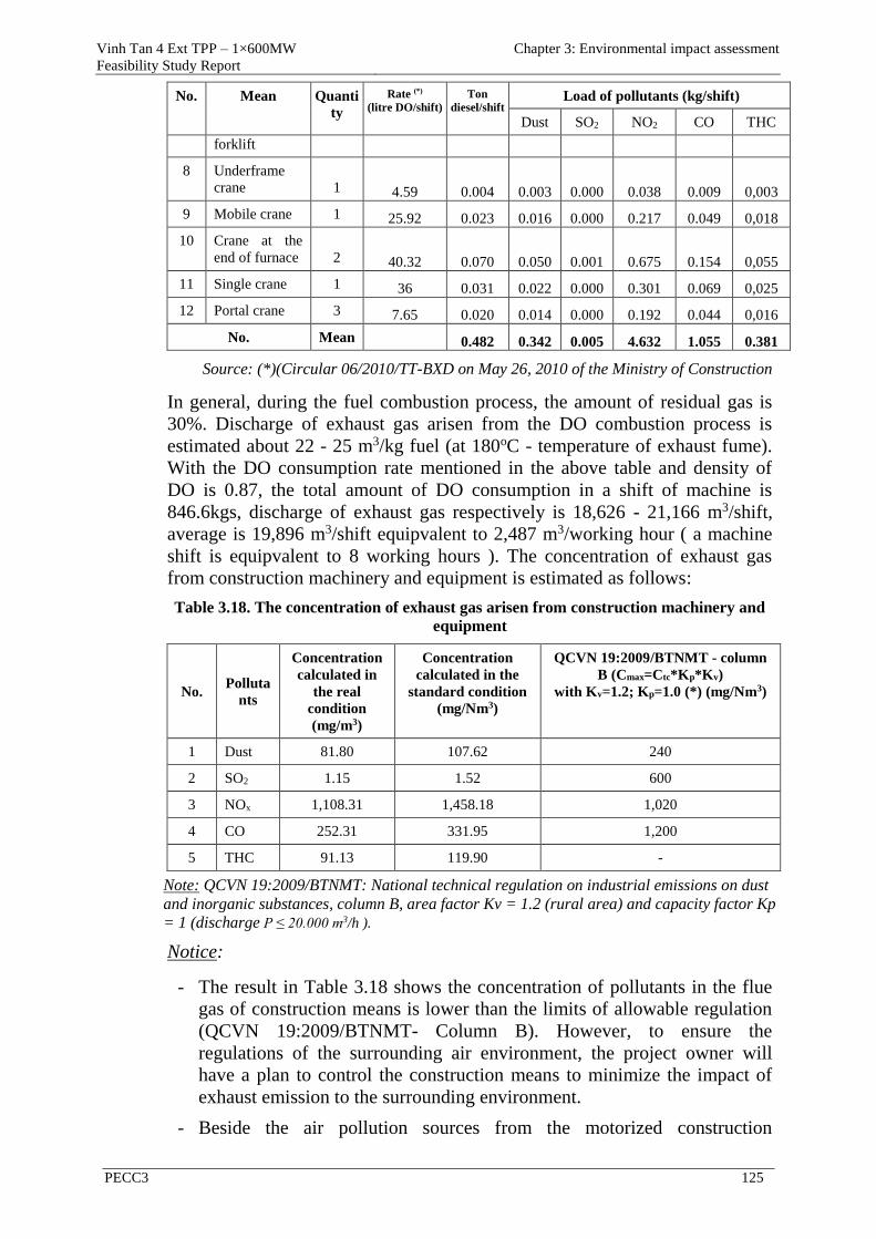
Vinh Tan 4 Ext TPP – 1×600MW
Feasibility Study Report
Chapter 3: Environmental impact assessment
PECC3 125
No. Mean Quanti
ty
Rate (*)
(litre DO/shift)
Ton
diesel/shift Load of pollutants (kg/shift)
Dust SO2 NO2 CO THC
forklift
8 Underframe
crane 1 4.59 0.004 0.003 0.000 0.038 0.009 0,003
9 Mobile crane 1 25.92 0.023 0.016 0.000 0.217 0.049 0,018
10 Crane at the
end of furnace 2 40.32 0.070 0.050 0.001 0.675 0.154 0,055
11 Single crane 1 36 0.031 0.022 0.000 0.301 0.069 0,025
12 Portal crane 3 7.65 0.020 0.014 0.000 0.192 0.044 0,016
No. Mean 0.482 0.342 0.005 4.632 1.055 0.381
Source: (*)(Circular 06/2010/TT-BXD on May 26, 2010 of the Ministry of Construction
In general, during the fuel combustion process, the amount of residual gas is
30%. Discharge of exhaust gas arisen from the DO combustion process is
estimated about 22 - 25 m3/kg fuel (at 180oC - temperature of exhaust fume).
With the DO consumption rate mentioned in the above table and density of
DO is 0.87, the total amount of DO consumption in a shift of machine is
846.6kgs, discharge of exhaust gas respectively is 18,626 - 21,166 m3/shift,
average is 19,896 m3/shift equipvalent to 2,487 m3/working hour ( a machine
shift is equipvalent to 8 working hours ). The concentration of exhaust gas
from construction machinery and equipment is estimated as follows:
Table 3.18. The concentration of exhaust gas arisen from construction machinery and
equipment
No. Polluta
nts
Concentration
calculated in
the real
condition
(mg/m3)
Concentration
calculated in the
standard condition
(mg/Nm3)
QCVN 19:2009/BTNMT - column
B (Cmax=Ctc*Kp*Kv)
with Kv=1.2; Kp=1.0 (*) (mg/Nm3)
1 Dust 81.80 107.62 240
2 SO2 1.15 1.52 600
3 NOx 1,108.31 1,458.18 1,020
4 CO 252.31 331.95 1,200
5 THC 91.13 119.90 -
Note: QCVN 19:2009/BTNMT: National technical regulation on industrial emissions on dust
and inorganic substances, column B, area factor Kv = 1.2 (rural area) and capacity factor Kp
= 1 (discharge P ≤ 20.000 m3/h ).
Notice:
- The result in Table 3.18 shows the concentration of pollutants in the flue
gas of construction means is lower than the limits of allowable regulation
(QCVN 19:2009/BTNMT- Column B). However, to ensure the
regulations of the surrounding air environment, the project owner will
have a plan to control the construction means to minimize the impact of
exhaust emission to the surrounding environment.
- Beside the air pollution sources from the motorized construction
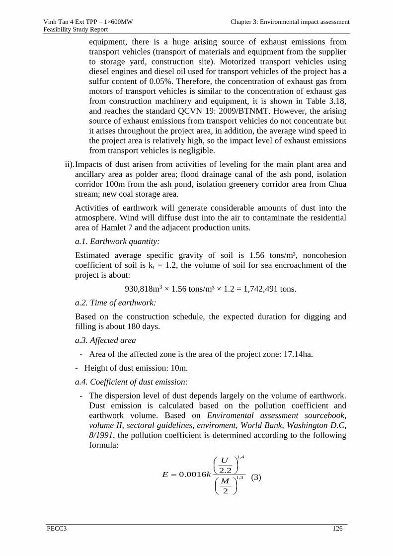
Vinh Tan 4 Ext TPP – 1×600MW
Feasibility Study Report
Chapter 3: Environmental impact assessment
PECC3 126
equipment, there is a huge arising source of exhaust emissions from
transport vehicles (transport of materials and equipment from the supplier
to storage yard, construction site). Motorized transport vehicles using
diesel engines and diesel oil used for transport vehicles of the project has a
sulfur content of 0.05%. Therefore, the concentration of exhaust gas from
motors of transport vehicles is similar to the concentration of exhaust gas
from construction machinery and equipment, it is shown in Table 3.18,
and reaches the standard QCVN 19: 2009/BTNMT. However, the arising
source of exhaust emissions from transport vehicles do not concentrate but
it arises throughout the project area, in addition, the average wind speed in
the project area is relatively high, so the impact level of exhaust emissions
from transport vehicles is negligible.
ii). Impacts of dust arisen from activities of leveling for the main plant area and
ancillary area as polder area; flood drainage canal of the ash pond, isolation
corridor 100m from the ash pond, isolation greenery corridor area from Chua
stream; new coal storage area.
Activities of earthwork will generate considerable amounts of dust into the
atmosphere. Wind will diffuse dust into the air to contaminate the residential
area of Hamlet 7 and the adjacent production units.
a.1. Earthwork quantity:
Estimated average specific gravity of soil is 1.56 tons/m³, noncohesion
coefficient of soil is kr = 1.2, the volume of soil for sea encroachment of the
project is about:
930,818m3 × 1.56 tons/m³ × 1.2 = 1,742,491 tons.
a.2. Time of earthwork:
Based on the construction schedule, the expected duration for digging and
filling is about 180 days.
a.3. Affected area
- Area of the affected zone is the area of the project zone: 17.14ha.
- Height of dust emission: 10m.
a.4. Coefficient of dust emission:
- The dispersion level of dust depends largely on the volume of earthwork.
Dust emission is calculated based on the pollution coefficient and
earthwork volume. Based on Enviromental assessment sourcebook,
volume II, sectoral guidelines, enviroment, World Bank, Washington D.C,
8/1991, the pollution coefficient is determined according to the following
formula:
3,1
4,1
2
2.20016.0
M
U
kE (3)
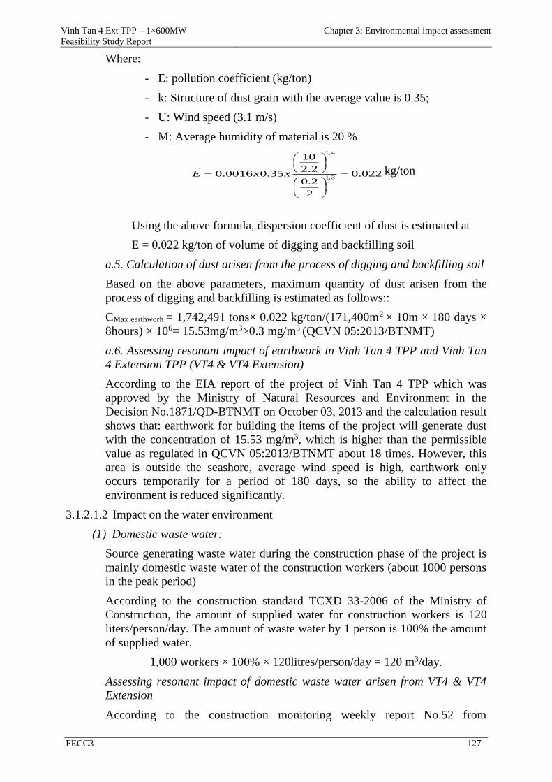
Vinh Tan 4 Ext TPP – 1×600MW
Feasibility Study Report
Chapter 3: Environmental impact assessment
PECC3 127
Where:
- E: pollution coefficient (kg/ton)
- k: Structure of dust grain with the average value is 0.35;
- U: Wind speed (3.1 m/s)
- M: Average humidity of material is 20 %
022.0
2
2.0
2.2
10
35.00016.03,1
4,1
xxE kg/ton
Using the above formula, dispersion coefficient of dust is estimated at
E = 0.022 kg/ton of volume of digging and backfilling soil
a.5. Calculation of dust arisen from the process of digging and backfilling soil
Based on the above parameters, maximum quantity of dust arisen from the
process of digging and backfilling is estimated as follows::
CMax earthworh = 1,742,491 tons× 0.022 kg/ton/(171,400m2 × 10m × 180 days ×
8hours) × 106= 15.53mg/m3>0.3 mg/m3 (QCVN 05:2013/BTNMT)
a.6. Assessing resonant impact of earthwork in Vinh Tan 4 TPP and Vinh Tan
4 Extension TPP (VT4 & VT4 Extension)
According to the EIA report of the project of Vinh Tan 4 TPP which was
approved by the Ministry of Natural Resources and Environment in the
Decision No.1871/QD-BTNMT on October 03, 2013 and the calculation result
shows that: earthwork for building the items of the project will generate dust
with the concentration of 15.53 mg/m3, which is higher than the permissible
value as regulated in QCVN 05:2013/BTNMT about 18 times. However, this
area is outside the seashore, average wind speed is high, earthwork only
occurs temporarily for a period of 180 days, so the ability to affect the
environment is reduced significantly.
3.1.2.1.2 Impact on the water environment
(1) Domestic waste water:
Source generating waste water during the construction phase of the project is
mainly domestic waste water of the construction workers (about 1000 persons
in the peak period)
According to the construction standard TCXD 33-2006 of the Ministry of
Construction, the amount of supplied water for construction workers is 120
liters/person/day. The amount of waste water by 1 person is 100% the amount
of supplied water.
1,000 workers × 100% × 120litres/person/day = 120 m3/day.
Assessing resonant impact of domestic waste water arisen from VT4 & VT4
Extension
According to the construction monitoring weekly report No.52 from
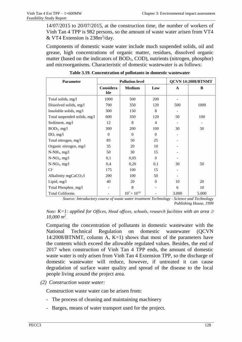
Vinh Tan 4 Ext TPP – 1×600MW
Feasibility Study Report
Chapter 3: Environmental impact assessment
PECC3 128
14/07/2015 to 20/07/2015, at the construction time, the number of workers of
Vinh Tan 4 TPP is 982 persons, so the amount of waste water arisen from VT4
& VT4 Extension is 238m3/day.
Components of domestic waste water include much suspended solids, oil and
grease, high concentrations of organic matter, residues, dissolved organic
matter (based on the indicators of BOD5, COD), nutrients (nitrogen, phosphor)
and microorganisms. Characteristic of domestic wastewater is as follows:
Table 3.19. Concentration of pollutants in domestic wastewater
Parameter Pollution level QCVN 14:2008/BTNMT
Considera
ble
Medium Low A B
Total solids, mg/l
Dissolved solids, mg/l
Insoluble solids, mg/l
Total suspended solids, mg/l
Sediment, mg/l
BOD5, mg/l
DO, mg/l
Total nitrogen, mg/l
Organic nitrogen, mg/l
N-NH3, mg/l
N-NO2, mg/l
N-NO3, mg/l
Cl-
Alkalinity mgCaCO3/l
Lipid, mg/l
Total Phosphor, mg/l
Total Coliforms
1000
700
300
600
12
300
0
85
35
50
0,1
0,4
175
200
40
-
-
500
350
150
350
8
200
0
50
20
30
0,05
0,20
100
100
20
8
107 ÷ 1010
200
120
8
120
4
100
0
25
10
15
0
0,1
15
50
0
-
-
-
500
-
50
-
30
-
-
-
-
-
30
-
-
10
6
3.000
1000
100
-
50
50
20
10
5.000
Source: Introductory course of waste water treatment Technology - Science and Technology
Publishing House, 1999
Note: K=1: applied for Offices, Head offices, schools, research facilities with an area
10,000 m2.
Comparing the concentration of pollutants in domestic wastewater with the
National Technical Regulation on domestic wastewater (QCVN
14:2008/BTNMT, column A, K=1) shows that most of the parameters have
the contents which exceed the allowable regulated values. Besides, the end of
2017 when construction of Vinh Tan 4 TPP ends, the amount of domestic
waste water is only arisen from Vinh Tan 4 Extension TPP, so the discharge of
domestic wastewater will reduce, however, if untreated it can cause
degradation of surface water quality and spread of the disease to the local
people living around the project area.
(2) Construction waste water:
Construction waste water can be arisen from:
- The process of cleaning and maintaining machinery
- Barges, means of water transport used for the project.
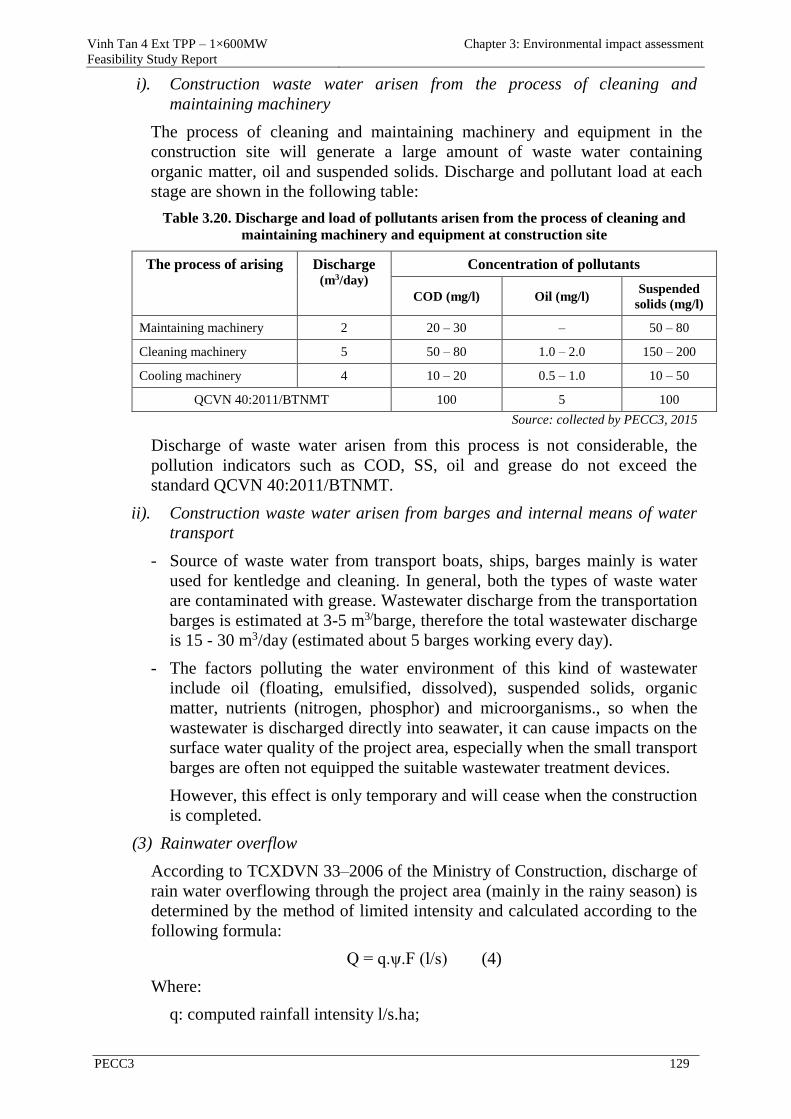
Vinh Tan 4 Ext TPP – 1×600MW
Feasibility Study Report
Chapter 3: Environmental impact assessment
PECC3 129
i). Construction waste water arisen from the process of cleaning and
maintaining machinery
The process of cleaning and maintaining machinery and equipment in the
construction site will generate a large amount of waste water containing
organic matter, oil and suspended solids. Discharge and pollutant load at each
stage are shown in the following table:
Table 3.20. Discharge and load of pollutants arisen from the process of cleaning and
maintaining machinery and equipment at construction site
The process of arising Discharge (m3/day)
Concentration of pollutants
COD (mg/l) Oil (mg/l) Suspended
solids (mg/l)
Maintaining machinery 2 20 – 30 – 50 – 80
Cleaning machinery 5 50 – 80 1.0 – 2.0 150 – 200
Cooling machinery 4 10 – 20 0.5 – 1.0 10 – 50
QCVN 40:2011/BTNMT 100 5 100
Source: collected by PECC3, 2015
Discharge of waste water arisen from this process is not considerable, the
pollution indicators such as COD, SS, oil and grease do not exceed the
standard QCVN 40:2011/BTNMT.
ii). Construction waste water arisen from barges and internal means of water
transport
- Source of waste water from transport boats, ships, barges mainly is water
used for kentledge and cleaning. In general, both the types of waste water
are contaminated with grease. Wastewater discharge from the transportation
barges is estimated at 3-5 m3/barge, therefore the total wastewater discharge
is 15 - 30 m3/day (estimated about 5 barges working every day).
- The factors polluting the water environment of this kind of wastewater
include oil (floating, emulsified, dissolved), suspended solids, organic
matter, nutrients (nitrogen, phosphor) and microorganisms., so when the
wastewater is discharged directly into seawater, it can cause impacts on the
surface water quality of the project area, especially when the small transport
barges are often not equipped the suitable wastewater treatment devices.
However, this effect is only temporary and will cease when the construction
is completed.
(3) Rainwater overflow
According to TCXDVN 33–2006 of the Ministry of Construction, discharge of
rain water overflowing through the project area (mainly in the rainy season) is
determined by the method of limited intensity and calculated according to the
following formula:
Q = q.ψ.F (l/s) (4)
Where:
q: computed rainfall intensity l/s.ha;
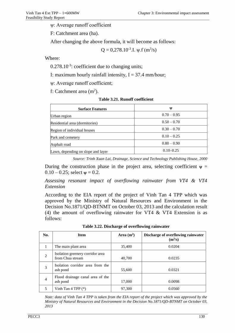
Vinh Tan 4 Ext TPP – 1×600MW
Feasibility Study Report
Chapter 3: Environmental impact assessment
PECC3 130
ψ: Average runoff coefficient
F: Catchment area (ha).
After changing the above formula, it will become as follows:
Q = 0,278.10-3.I. ψ.f (m3/s)
Where:
0.278.10-3: coefficient due to changing units;
I: maximum hourly rainfall intensity, I = 37.4 mm/hour;
ψ: Average runoff coefficient;
f: Catchment area (m2).
Table 3.21. Runoff coefficient
Surface Features ψ
Urban region 0.70 – 0.95
Residential area (dormitories) 0.50 – 0.70
Region of individual houses 0.30 – 0.70
Park and cemetery 0.10 – 0.25
Asphalt road 0.80 – 0.90
Lawn, depending on slope and layer 0.10–0.25
Source: Trinh Xuan Lai, Drainage, Science and Technology Publishing House, 2000
During the construction phase in the project area, selecting coefficient ψ =
0.10 – 0.25; select ψ = 0.2.
Assessing resonant impact of overflowing rainwater from VT4 & VT4
Extension
According to the EIA report of the project of Vinh Tan 4 TPP which was
approved by the Ministry of Natural Resources and Environment in the
Decision No.1871/QD-BTNMT on October 03, 2013 and the calculation result
(4) the amount of overflowing rainwater for VT4 & VT4 Extension is as
follows:
Table 3.22. Discharge of overflowing rainwater
No. Item Area (m2) Discharge of overflowing rainwater (m3/s)
1 The main plant area 35,400 0.0204
2 Isolation greenery corridor area
from Chua stream 40,700 0.0235
3 Isolation corridor area from the
ash pond 55,600 0.0321
4 Flood drainage canal area of the
ash pond 17,000 0.0098
5 Vinh Tan 4 TPP (*) 97,300 0.0560
Note: data of Vinh Tan 4 TPP is taken from the EIA report of the project which was approved by the
Ministry of Natural Resources and Environment in the Decision No.1871/QD-BTNMT on October 03,
2013
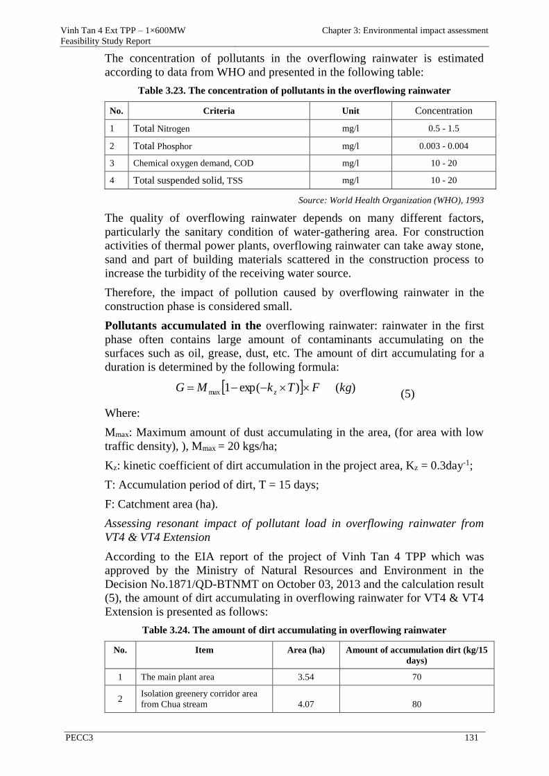
Vinh Tan 4 Ext TPP – 1×600MW
Feasibility Study Report
Chapter 3: Environmental impact assessment
PECC3 131
The concentration of pollutants in the overflowing rainwater is estimated
according to data from WHO and presented in the following table:
Table 3.23. The concentration of pollutants in the overflowing rainwater
No. Criteria Unit Concentration
1 Total Nitrogen mg/l 0.5 - 1.5
2 Total Phosphor mg/l 0.003 - 0.004
3 Chemical oxygen demand, COD mg/l 10 - 20
4 Total suspended solid, TSS mg/l 10 - 20
Source: World Health Organization (WHO), 1993
The quality of overflowing rainwater depends on many different factors,
particularly the sanitary condition of water-gathering area. For construction
activities of thermal power plants, overflowing rainwater can take away stone,
sand and part of building materials scattered in the construction process to
increase the turbidity of the receiving water source.
Therefore, the impact of pollution caused by overflowing rainwater in the
construction phase is considered small.
Pollutants accumulated in the overflowing rainwater: rainwater in the first
phase often contains large amount of contaminants accumulating on the
surfaces such as oil, grease, dust, etc. The amount of dirt accumulating for a
duration is determined by the following formula:
)()exp(1max kgFTkMG z (5)
Where:
Mmax: Maximum amount of dust accumulating in the area, (for area with low
traffic density), ), Mmax = 20 kgs/ha;
Kz: kinetic coefficient of dirt accumulation in the project area, Kz = 0.3day-1;
T: Accumulation period of dirt, T = 15 days;
F: Catchment area (ha).
Assessing resonant impact of pollutant load in overflowing rainwater from
VT4 & VT4 Extension
According to the EIA report of the project of Vinh Tan 4 TPP which was
approved by the Ministry of Natural Resources and Environment in the
Decision No.1871/QD-BTNMT on October 03, 2013 and the calculation result
(5), the amount of dirt accumulating in overflowing rainwater for VT4 & VT4
Extension is presented as follows:
Table 3.24. The amount of dirt accumulating in overflowing rainwater
No. Item Area (ha) Amount of accumulation dirt (kg/15
days)
1 The main plant area 3.54 70
2 Isolation greenery corridor area
from Chua stream 4.07 80
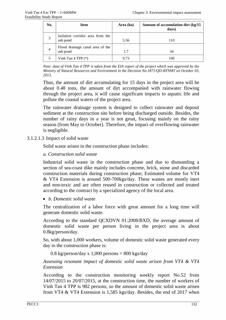
Vinh Tan 4 Ext TPP – 1×600MW
Feasibility Study Report
Chapter 3: Environmental impact assessment
PECC3 132
No. Item Area (ha) Amount of accumulation dirt (kg/15
days)
3 Isolation corridor area from the
ash pond 5.56 110
4 Flood drainage canal area of the
ash pond 1.7 34
5 Vinh Tan 4 TPP (*) 9.73 190
Note: data of Vinh Tan 4 TPP is taken from the EIA report of the project which was approved by the
Ministry of Natural Resources and Environment in the Decision No.1871/QD-BTNMT on October 03,
2013.
Thus, the amount of dirt accumulating for 15 days in the project area will be
about 0.48 tons, the amount of dirt accompanied with rainwater flowing
through the project area, it will cause significant impacts to aquatic life and
pollute the coastal waters of the project area.
The rainwater drainage system is designed to collect rainwater and deposit
sediment at the construction site before being discharged outside. Besides, the
number of rainy days in a year is not great, focusing mainly on the rainy
season (from May to October). Therefore, the impact of overflowing rainwater
is negligible.
3.1.2.1.3 Impact of solid waste
Solid waste arisen in the construction phase includes:
a. Construction solid waste
Industrial solid waste in the construction phase and due to dismantling a
section of sea-coast dike mainly includes concrete, brick, stone and discarded
construction materials during construction phase; Estimated volume for VT4
& VT4 Extension is around 500-700kgs/day. These wastes are mostly inert
and non-toxic and are often reused in construction or collected and treated
according to the contract by a specialized agency of the local area.
b. Domestic solid waste
The centralization of a labor force with great amount for a long time will
generate domestic solid waste.
According to the standard QCXDVN 01:2008/BXD, the average amount of
domestic solid waste per person living in the project area is about
0.8kg/person/day.
So, with about 1,000 workers, volume of domestic solid waste generated every
day in the construction phase is:
0.8 kg/person/day x 1,000 persons = 800 kgs/day
Assessing resonant impact of domestic solid waste arisen from VT4 & VT4
Extension
According to the construction monitoring weekly report No.52 from
14/07/2015 to 20/07/2015, at the construction time, the number of workers of
Vinh Tan 4 TPP is 982 persons, so the amount of domestic solid waste arisen
from VT4 & VT4 Extension is 1,585 kgs/day. Besides, the end of 2017 when
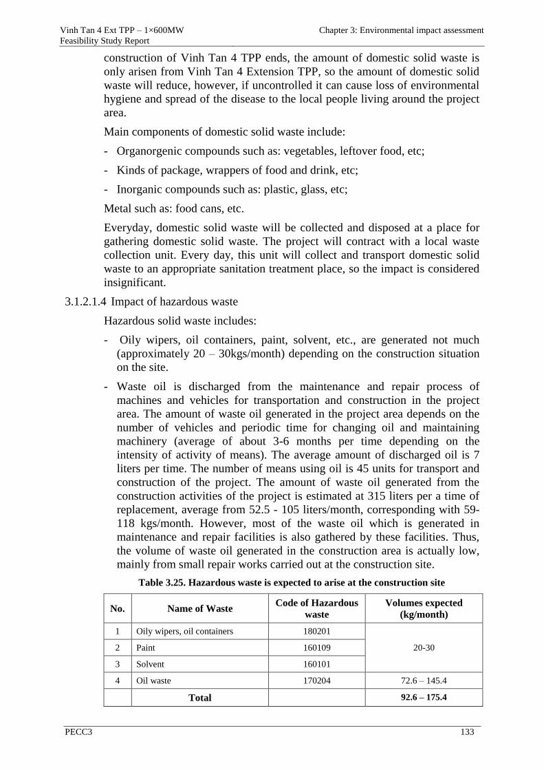
Vinh Tan 4 Ext TPP – 1×600MW
Feasibility Study Report
Chapter 3: Environmental impact assessment
PECC3 133
construction of Vinh Tan 4 TPP ends, the amount of domestic solid waste is
only arisen from Vinh Tan 4 Extension TPP, so the amount of domestic solid
waste will reduce, however, if uncontrolled it can cause loss of environmental
hygiene and spread of the disease to the local people living around the project
area.
Main components of domestic solid waste include:
- Organorgenic compounds such as: vegetables, leftover food, etc;
- Kinds of package, wrappers of food and drink, etc;
- Inorganic compounds such as: plastic, glass, etc;
Metal such as: food cans, etc.
Everyday, domestic solid waste will be collected and disposed at a place for
gathering domestic solid waste. The project will contract with a local waste
collection unit. Every day, this unit will collect and transport domestic solid
waste to an appropriate sanitation treatment place, so the impact is considered
insignificant.
3.1.2.1.4 Impact of hazardous waste
Hazardous solid waste includes:
- Oily wipers, oil containers, paint, solvent, etc., are generated not much
(approximately 20 – 30kgs/month) depending on the construction situation
on the site.
- Waste oil is discharged from the maintenance and repair process of
machines and vehicles for transportation and construction in the project
area. The amount of waste oil generated in the project area depends on the
number of vehicles and periodic time for changing oil and maintaining
machinery (average of about 3-6 months per time depending on the
intensity of activity of means). The average amount of discharged oil is 7
liters per time. The number of means using oil is 45 units for transport and
construction of the project. The amount of waste oil generated from the
construction activities of the project is estimated at 315 liters per a time of
replacement, average from 52.5 - 105 liters/month, corresponding with 59-
118 kgs/month. However, most of the waste oil which is generated in
maintenance and repair facilities is also gathered by these facilities. Thus,
the volume of waste oil generated in the construction area is actually low,
mainly from small repair works carried out at the construction site.
Table 3.25. Hazardous waste is expected to arise at the construction site
No. Name of Waste Code of Hazardous
waste
Volumes expected
(kg/month)
1 Oily wipers, oil containers 180201
20-30 2 Paint 160109
3 Solvent 160101
4 Oil waste 170204 72.6 – 145.4
Total 92.6 – 175.4
Vinh Tan 4 Ext TPP – 1×600MW
Feasibility Study Report
Chapter 3: Environmental impact assessment
PECC3 134
All hazardous waste arisen at the site will be collected, sorted and contained in
the containers with lids, labeled and placed in a safe position at the site.
According to the periods and after finishing construction, the project owner
and the contractor will contract with a competent unit (who has license for
transporting and disposing hazardous waste) for transporting and disposing the
entire amount of hazardous waste at the site. The process of collecting,
storing, transporting and disposing will comply with the regulations of
hazardous waste management, so this impact is small and can be controlled.
3.1.2.2 Impacts unrelated to waste in the construction phase
3.1.2.2.1 Impact from leveling the coastal area
1).Scope for leveling:
- The main plant area onshore and auxiliary area of sea encroachment are
about 6.19 ha, the auxiliary area of sea encroachment in particular is
3.97ha.
- The area of administrative building is about 1.32 ha.
- The new coal storage area (located in the transshipment coal storage ) is
about 10 ha.
- The isolation greenery corridor area from Chua stream is about 4.07 ha.
2). Elevation for leveling
- The main plant area, auxiliary area and new coal storage area will be
leveled up to elevation of +3,5m.
- The area of administrative building (opposite to the switchyard) will be
leveled up to elevation of +4,5m.
- The area of greenery corridor and Chua stream will be leveled up to the
average elevation of +2,2m sloping towards the sea.
3).Sea encroachment scope and calculation of leveling volume
Sea encroachment area for Vinh Tan 4 Extension TPP only includes 3.97 ha -
this is auxiliary part of the main plant. Total volume for leveling is 323,967m3.
4). Method of calculating aggradation, erosion due to the sea encroachment
activities
MIKE 21 MT (Mud Transport) is a cohesive sediment transport module used
to calculate erosion, dispersion, and deposition of cohesive sediment in
marine, brackish and freshwater areas. It requires a coupling to the
hydrodynamic solver and to the transport solver for passive components
(Advection Dispersion module). The erosion rate depends on the bed critical
shear stress (R.B. Krone 1962, Parchure and Mehta 1985, Partheniades, 1965).
The settling process can described in layers (usually including 3 layers such as
weak fluid mud, fluid mud and consolidated bed).
The factors are considered in the model including: settling velocity,
flocculation, hindered settling, suspended sediment concentration,
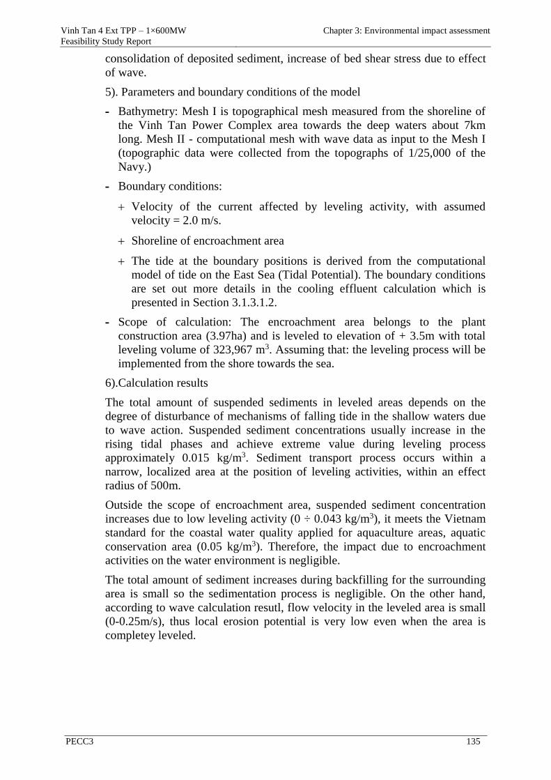
Vinh Tan 4 Ext TPP – 1×600MW
Feasibility Study Report
Chapter 3: Environmental impact assessment
PECC3 135
consolidation of deposited sediment, increase of bed shear stress due to effect
of wave.
5). Parameters and boundary conditions of the model
- Bathymetry: Mesh I is topographical mesh measured from the shoreline of
the Vinh Tan Power Complex area towards the deep waters about 7km
long. Mesh II - computational mesh with wave data as input to the Mesh I
(topographic data were collected from the topographs of 1/25,000 of the
Navy.)
- Boundary conditions:
Velocity of the current affected by leveling activity, with assumed
velocity = 2.0 m/s.
Shoreline of encroachment area
The tide at the boundary positions is derived from the computational
model of tide on the East Sea (Tidal Potential). The boundary conditions
are set out more details in the cooling effluent calculation which is
presented in Section 3.1.3.1.2.
- Scope of calculation: The encroachment area belongs to the plant
construction area (3.97ha) and is leveled to elevation of + 3.5m with total
leveling volume of 323,967 m3. Assuming that: the leveling process will be
implemented from the shore towards the sea.
6).Calculation results
The total amount of suspended sediments in leveled areas depends on the
degree of disturbance of mechanisms of falling tide in the shallow waters due
to wave action. Suspended sediment concentrations usually increase in the
rising tidal phases and achieve extreme value during leveling process
approximately 0.015 kg/m3. Sediment transport process occurs within a
narrow, localized area at the position of leveling activities, within an effect
radius of 500m.
Outside the scope of encroachment area, suspended sediment concentration
increases due to low leveling activity (0 ÷ 0.043 kg/m3), it meets the Vietnam
standard for the coastal water quality applied for aquaculture areas, aquatic
conservation area (0.05 kg/m3). Therefore, the impact due to encroachment
activities on the water environment is negligible.
The total amount of sediment increases during backfilling for the surrounding
area is small so the sedimentation process is negligible. On the other hand,
according to wave calculation resutl, flow velocity in the leveled area is small
(0-0.25m/s), thus local erosion potential is very low even when the area is
completey leveled.
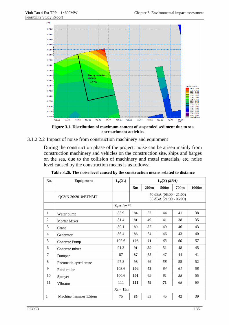
Vinh Tan 4 Ext TPP – 1×600MW
Feasibility Study Report
Chapter 3: Environmental impact assessment
PECC3 136
Figure 3.1. Distribution of maximum content of suspended sediment due to sea
encroachment activities
3.1.2.2.2 Impact of noise from construction machinery and equipment
During the construction phase of the project, noise can be arisen mainly from
construction machinery and vehicles on the construction site, ships and barges
on the sea, due to the collision of machinery and metal materials, etc. noise
level caused by the construction means is as follows:
Table 3.26. The noise level caused by the construction means related to distance
No. Equipment Lp(Xo) Lp(X) (dBA)
5m 200m 500m 700m 1000m
QCVN 26:2010/BTNMT 70 dBA (06:00 - 21:00)
55 dBA (21:00 - 06:00)
X0 = 5m (a)
1 Water pump 83.9 84 52 44 41 38
2 Mortar Mixer 81.4 81 49 41 38 35
3 Crane 89.1 89 57 49 46 43
4 Generator 86.4 86 54 46 43 40
5 Concrete Pump 102.6 103 71 63 60 57
6 Concrete mixer 91.3 91 59 51 48 45
7 Dumper 87 87 55 47 44 41
8 Pneumatic-tyred crane 97.8 98 66 58 55 52
9 Road roller 103.6 104 72 64 61 58
10 Sprayer 100.6 101 69 61 58 55
11 Vibrator 111 111 79 71 68 65
X0 = 15m
1 Machine hammer 1.5tons 75 85 53 45 42 39
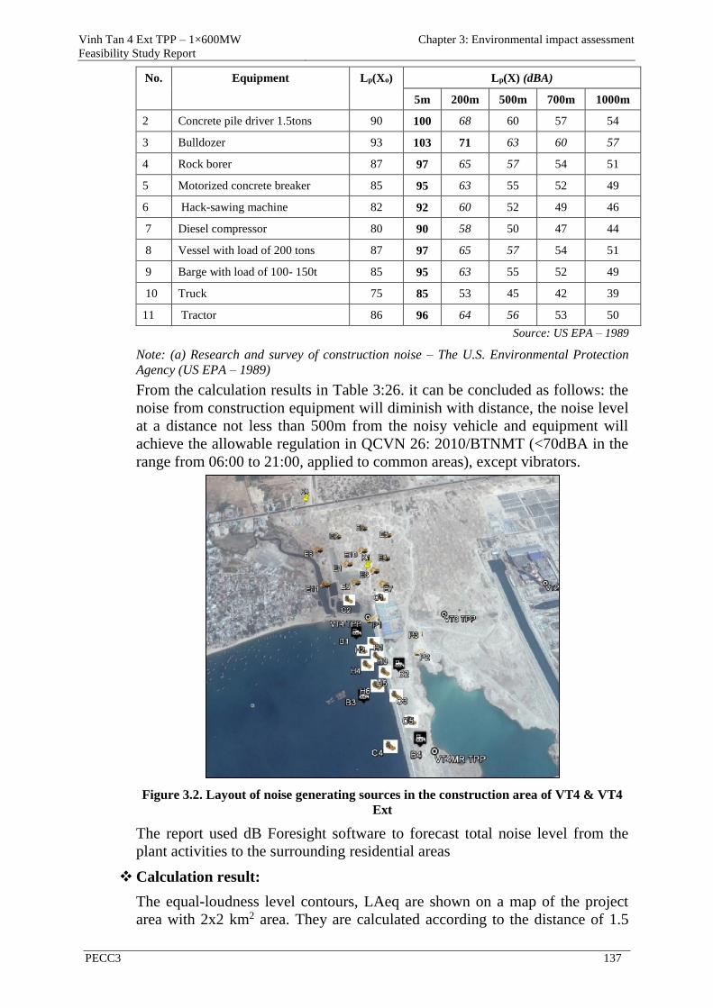
Vinh Tan 4 Ext TPP – 1×600MW
Feasibility Study Report
Chapter 3: Environmental impact assessment
PECC3 137
No. Equipment Lp(Xo) Lp(X) (dBA)
5m 200m 500m 700m 1000m
2 Concrete pile driver 1.5tons 90 100 68 60 57 54
3 Bulldozer 93 103 71 63 60 57
4 Rock borer 87 97 65 57 54 51
5 Motorized concrete breaker 85 95 63 55 52 49
6 Hack-sawing machine 82 92 60 52 49 46
7 Diesel compressor 80 90 58 50 47 44
8 Vessel with load of 200 tons 87 97 65 57 54 51
9 Barge with load of 100- 150t 85 95 63 55 52 49
10 Truck 75 85 53 45 42 39
11 Tractor 86 96 64 56 53 50
Source: US EPA – 1989
Note: (a) Research and survey of construction noise – The U.S. Environmental Protection
Agency (US EPA – 1989)
From the calculation results in Table 3:26. it can be concluded as follows: the
noise from construction equipment will diminish with distance, the noise level
at a distance not less than 500m from the noisy vehicle and equipment will
achieve the allowable regulation in QCVN 26: 2010/BTNMT (<70dBA in the
range from 06:00 to 21:00, applied to common areas), except vibrators.
Figure 3.2. Layout of noise generating sources in the construction area of VT4 & VT4
Ext
The report used dB Foresight software to forecast total noise level from the
plant activities to the surrounding residential areas
Calculation result:
The equal-loudness level contours, LAeq are shown on a map of the project
area with 2x2 km2 area. They are calculated according to the distance of 1.5
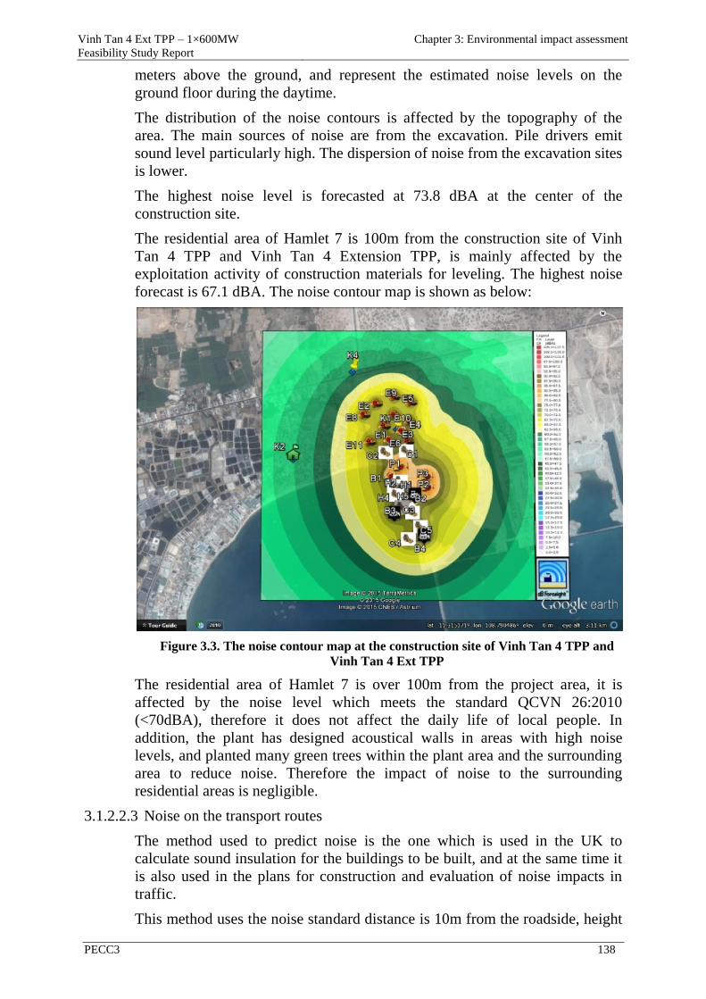
Vinh Tan 4 Ext TPP – 1×600MW
Feasibility Study Report
Chapter 3: Environmental impact assessment
PECC3 138
meters above the ground, and represent the estimated noise levels on the
ground floor during the daytime.
The distribution of the noise contours is affected by the topography of the
area. The main sources of noise are from the excavation. Pile drivers emit
sound level particularly high. The dispersion of noise from the excavation sites
is lower.
The highest noise level is forecasted at 73.8 dBA at the center of the
construction site.
The residential area of Hamlet 7 is 100m from the construction site of Vinh
Tan 4 TPP and Vinh Tan 4 Extension TPP, is mainly affected by the
exploitation activity of construction materials for leveling. The highest noise
forecast is 67.1 dBA. The noise contour map is shown as below:
Figure 3.3. The noise contour map at the construction site of Vinh Tan 4 TPP and
Vinh Tan 4 Ext TPP
The residential area of Hamlet 7 is over 100m from the project area, it is
affected by the noise level which meets the standard QCVN 26:2010
(<70dBA), therefore it does not affect the daily life of local people. In
addition, the plant has designed acoustical walls in areas with high noise
levels, and planted many green trees within the plant area and the surrounding
area to reduce noise. Therefore the impact of noise to the surrounding
residential areas is negligible.
3.1.2.2.3 Noise on the transport routes
The method used to predict noise is the one which is used in the UK to
calculate sound insulation for the buildings to be built, and at the same time it
is also used in the plans for construction and evaluation of noise impacts in
traffic.
This method uses the noise standard distance is 10m from the roadside, height
Vinh Tan 4 Ext TPP – 1×600MW
Feasibility Study Report
Chapter 3: Environmental impact assessment
PECC3 139
of 1.2 m above the ground, standard pavement. Prediction equation is as
follows:
30,6V
p51lg10
V
50040Vlg33Qlg10(1h)Leq
(dBA)
In which:
- Q : discharge of vehicles (the number of vehicles/hour).
- V : average velocity of traffic flow (km/h)
- p : the number of heavy trucks in a traffic flow in percentage (%)
This method is used for roads with good pavement and small slope. It has the
advantage in coordination with other transmission calculations, it can predict
the noise intensity at the calculated points fairly accurately, by taking into
account the influences of sound propagation as impact of distance, ground
surface, barriers and reflection. This method is especially good for use
calculation at road intersections and roads with many complicated sections.
To predict the noise for the project area, the input parameters are taken as
follows:
Average slope of the road: 6%;
- The average velocity of traffic flow: 40 km/h (design speed of the road);
If the typical loudness of the noise source is usually measured at the height
from 1.2 to 1.5 m above the road surface and at one determined point from the
noise source a defined distance of r1 meter ("r1" is 1 meter in case of industrial
noise source and 7.5 m for noise source as traffic flow), the attenuation of
noise level at point r2 (r2> r1 in distance) compared with noise level at point r1
is L (dBA) which is estimated based on the following formula:
- The noise source is a point : (dBA)r
r20lgΔL
a1
1
2
;
- The noise source is road : (dBA)r
r10lgΔL
a1
1
2
,
- In which: a is an effect coefficient of the ground topography concerning the
noise absorbability and reflection:
a = -0.1 with asphalt and concrete road;
a = 0 with bare ground without trees;
a = 0.1 with grazing land.
Forecast result of equal-loudness level Leq (dBA) will be attenuate with
distance which is begun from the roadside on the route. Noise level is
estimated according to the distance from the roadside based on discharge of
vehicles, the percentage of heavy trucks and is presented in the following
table:
Vinh Tan 4 Ext TPP – 1×600MW
Feasibility Study Report
Chapter 3: Environmental impact assessment
PECC3 140
Table 3.27. Noise level is estimated according to the distance from the roadside
Distance from the roadside (m)
10 20 30 40 50 60 70 80 90 100
Noise
level
125.41 152.70 121.11 109.99 94.12 82.40 67.80 57.28 53.82 46.41
QCVN 70 - 85 dBA
In our country there is no specific criteria about the noise level for the traffic.
However, according to the standards issued on the permitted noise level in the
labor sector (according to Decision 3733/2002/BYT) and the maximum limits
for allowable noise level in the community and residential area (QCVN 26:
2010/BTNMT), the noise level of 85 dBA in the construction area is the
biggest allowable level and the permitted noise level of 40 dBA in hospitals,
libraries, nursing homes, schools from 22:00 to 6:00 is the lowest. For
residential areas, the maximum allowable noise level will not exceed 70 dBA
(QCVN 26:2010/BTNMT).
3.1.2.2.4 Impact of vibration
During the construction phase, vibration can be caused by the operation of
vehicles and construction machinery mainly used for piling, compaction and
operation of transportation means. The level of vibration is dependent on many
factors, in which the most special importance is geological structure of the
project foundation.
The vibration level can be determined rapidly on the basis of data established by
USEPA (U.S. Environmental Protection Agency) in the following table:
Table 3.28. Vibration level caused by some construction machines
No. Equipment
Vibration level (according to the vertical axis Z, dB)
10m from the
vibration source
30m from the
vibration source
1 Excavator 80 71
2 Bulldozer 79 69
3 Truck 74 64
4 Roller 82 71
5 Drilling machine 63 55
6 Air compressor 81 71
7 Wheel excavator 85 73
8 Drilling pile Driver 98 83
9 Vibratory driver 83 83
Source: U.S. Environmental Protection Agency USEPA, 1971.
Assessment
- Operation of the pile drivers can cause vibration level to reach up to 83dB
at the position of 30m far from the source, it is higher than the value
Vinh Tan 4 Ext TPP – 1×600MW
Feasibility Study Report
Chapter 3: Environmental impact assessment
PECC3 141
specified in QCVN 27:2010/BTNMT (75dB), so it can affect the
construction workers at the site and the local people living around.
However, pile driving operation is only carried out for a short time, not
done during time-off, so its impact will end after the pile driving work is
finished. Therefore, this impact is medium.
- Vibration level caused by operation of vehicles and other construction
machinery is in the range of 55 - 71dB at the position of 30 meters from
the source, so at the location of 100m from the local people's nearest
house to the project area, the arisen vibration will be lower and satisfy the
standard QCVN 27:2010/BTNMT (75dB). Therefore, vibration impact
during the eartkwork and construction process of the project items is
small.
3.1.2.2.5 Impact on Hon Cau marine protected area during leveling for sea
encroachment
(1) Impact on Hon Cau marine protected area during leveling for sea
encroachment
As presented in Chapter 2, in the ecological restoration area there is the
presence of certain types of habitats, in which some seaweed areas and
biological resources are severely damaged due to exploitation activities. These
areas need to be recovered by proper measures.
The project is part (4.07 ha) in the ecological restoration area and is
completely located in the development zone of the Hon Cau MPA, so the
aquatic ecosystems in the project area will be affected to some extent due to
the construction activities of the project.
According to survey results, characteristics of marine ecosystems at Vinh Tan
Power Complex were surveyed in October 2010 (referred from the EIA report
of Vinh Tan sea port – phase 1 approved by MONRE in document
no.1448/QD-BTNMT dated 25/7/2011) and presented as follows:
Seaweed and sargassum
According to survey results, there is no clue of seaweed at leveling area of
Vinh Tan 4 TPP. All over the area, there are 3 patches of seaweed
scattering at the depth of 6 – 9m with the area of 3 - 4ha/patch; some
smaller patches at deeper layers.
On the other hand, no patch of sargassum was detected during the survey
period (sargassum is commonly found in shallow waters near the shore at
the depth from 2 to 4m [Vo Si Tuan, 1996]). Because the local people
probably have exploited sargassum to produce feedstuff and fertilizers for
recent years, especially from March to April every year.
In summary, leveling activities for sea encroachment of the project will affect
locally the marine ecosystems of Hon Cau MPA in the project area (ecological
development and restoration area) and absolutely will not affect the buffer
zone, and the strict conservation area of Hon Cau MPA.
(2) Impacts on the ecosystems due to increase in TSS content from sea
endroachment activities
Vinh Tan 4 Ext TPP – 1×600MW
Feasibility Study Report
Chapter 3: Environmental impact assessment
PECC3 142
According to the calculation result of model of suspended sediment transport
due to leveling activities for sea encroachment, it showed that the maximum
TSS is about 0.005-0.02 kg/m3 (5-20 mg/l). Meanwhile, TSS concentration at
Breda sandbar, Hon Cau island and the remaining areas in Cu Lao Cau island
MPA is still the same as before.
The maximum TSS concentration arisen from the leveling activities for sea
encroachment and dredging process is lower than the permissive value (40
mg/l), so that the seaweed areas at Hon Cau MPA will not be affected much
by increase of suspended sediments. The seaweed species will be adapted to
the new conditions. Some species can temporarily switch between autotrophy
(growth through photosynthesis) and heterotrophy (growth through filter
feeding) or adjust their respiratory demands to maintain a positive energy
balance in response to turbidity.
The increase of TSS concentration will affect the habitat of seaweed and
benthos because increase of turbidity will reduce the light penetration into
seawater and will lead to a decrease in productivity of photosynthesis and
indirectly affect nutritional source, reproduction speed and growth of seaweed
and benthos. However, the increase of TSS concentration due to leveling
activities for sea encroachment is insignificant and primarily in the project
area. This impact is assessed to be small and short-term (during construction
period) and the species will adapt to the environmental change.
Leveling activities for sea encroachment of the project will not affect the
buffer zone, and the strict conservation area of Hon Cau MPA.
(3) Impact on the ecosystems due to the construction activities of the main
plant and port on the sea
During the construction of the main plant and port, Hon Cau MPA can be
impacted by following sources:
Dust, soil scattering from construction activities and gathering material is
swept by rainwater running into the water source, which will increase the
turbidity of the surface water source of the sea and affect the ecosystems of
Hon Cau MPA.
Activities of ships, boats and equipment as well as the transport of material
during the construction phase may generate waste oil. The amount of waste
oil from these machines may harmfully affect the aquatic ecosystems at
Hon Cau MPA.
Besides, wastewater from construction barges and ships is also a significant
threat to the ecosystems of Hon Cau MPA
Such impacts are evaluated as significant and can cause impact on the local
marine ecosystems of Hon Cau marine protected area, however they can be
reduced and prevented by the appropriate control and management measures.
3.1.2.2.6 Impacts on local socio-economic environment
(1) Increase immigration

Vinh Tan 4 Ext TPP – 1×600MW
Feasibility Study Report
Chapter 3: Environmental impact assessment
PECC3 143
The project construction requires a large number of workers from the
surrounding areas with about 1,000 people. The project has policy to give
priority to recruitment of local labourers for the project, however, as described
above, the qualifications of the local labourers do not meet some professional
requirements of the project, therefore the project needs to employ a fairly large
number of workers from the other places to work for the Project.
Due to the centralization of a large number of workers from the local area and
from the other places, the risk of conflict between workers and local people
can happen because there are differences in lifestyle, viewpoint, income and
culture.
(2) Impacts on health and safety
Increasing the ability to spread infectious disease: the concentration of a large
number of workers in the construction site could create favorable conditions
for the spread of epidemic (cholera, dysentery, typhoid, diarrhea) or through
intermediate vectors (malaria, dengue...). these impacts are likely to happen if
there are no precaution measures.
The potential evils could increase in the surrounding areas of the project: so
far now in the Vinh Tan commune, Tuy Phong district, the rate of social evils
is relatively low. However, the concentration of hundreds of workers from
different areas to the limited area of the project may exacerbate the social evils
such as alcohol, drugs and others. These are negative impacts but they could
be controlled by appropriate measures.
According to the forecast, the concentration of a large number of workers
during the construction phase of the project can cause adverse impacts. Yet,
this issue also promotes the local economy, increases employment rate;
currently, the local people's income is quite low, some people do not have a
stable career.
(3) Impact on aquaculture
The construction works and operation of transport means on the sea in this
period will adversely affect to aquatic ecosystems and aquaculture.
The pile driving activities for construction of cooling water conduct will cause
disturbance and change of sea bottom and lead to a decline of pH in coastal
water. The increase of suspended sediment concentration in seawater due to
sedimentation in the basin near the construction positions will negatively
affect the benthos in these areas.
Besides, many fish species will be affected by the loss of food supply and
spawning places due to increase of turbidity of seawater. Thus, the
biodiversity in the area will be affected significantly. However according to
the planning of the PPC, shrimp farmers in the project area and surrounding
the project area will be relocated to other places ( Ganh Hao - Chi Cong area
according to the province planning) to handover the ground for Vinh Tan
Power Complex. Therefore the aquaculture activity around the project area is
only temporary. So, this impact is considered small.
(4) Impact on the local traffic
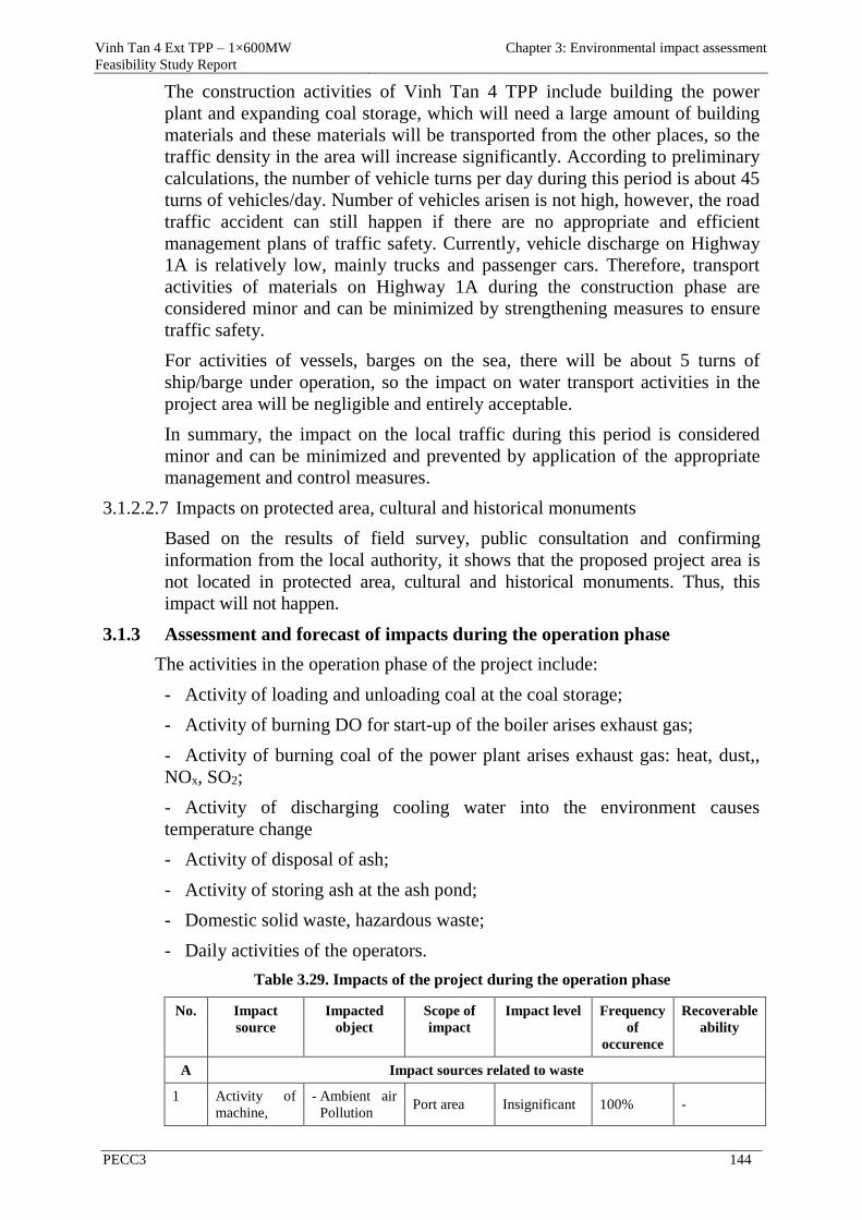
Vinh Tan 4 Ext TPP – 1×600MW
Feasibility Study Report
Chapter 3: Environmental impact assessment
PECC3 144
The construction activities of Vinh Tan 4 TPP include building the power
plant and expanding coal storage, which will need a large amount of building
materials and these materials will be transported from the other places, so the
traffic density in the area will increase significantly. According to preliminary
calculations, the number of vehicle turns per day during this period is about 45
turns of vehicles/day. Number of vehicles arisen is not high, however, the road
traffic accident can still happen if there are no appropriate and efficient
management plans of traffic safety. Currently, vehicle discharge on Highway
1A is relatively low, mainly trucks and passenger cars. Therefore, transport
activities of materials on Highway 1A during the construction phase are
considered minor and can be minimized by strengthening measures to ensure
traffic safety.
For activities of vessels, barges on the sea, there will be about 5 turns of
ship/barge under operation, so the impact on water transport activities in the
project area will be negligible and entirely acceptable.
In summary, the impact on the local traffic during this period is considered
minor and can be minimized and prevented by application of the appropriate
management and control measures.
3.1.2.2.7 Impacts on protected area, cultural and historical monuments
Based on the results of field survey, public consultation and confirming
information from the local authority, it shows that the proposed project area is
not located in protected area, cultural and historical monuments. Thus, this
impact will not happen.
3.1.3 Assessment and forecast of impacts during the operation phase
The activities in the operation phase of the project include:
Activity of loading and unloading coal at the coal storage;
Activity of burning DO for start-up of the boiler arises exhaust gas;
Activity of burning coal of the power plant arises exhaust gas: heat, dust,,
NOx, SO2;
Activity of discharging cooling water into the environment causes
temperature change
Activity of disposal of ash;
Activity of storing ash at the ash pond;
Domestic solid waste, hazardous waste;
Daily activities of the operators.
Table 3.29. Impacts of the project during the operation phase
No. Impact
source
Impacted
object
Scope of
impact
Impact level Frequency
of
occurence
Recoverable
ability
A Impact sources related to waste
1 Activity of
machine,
- Ambient air
Pollution Port area Insignificant 100% -
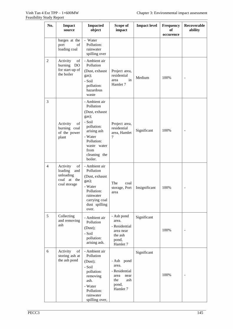
Vinh Tan 4 Ext TPP – 1×600MW
Feasibility Study Report
Chapter 3: Environmental impact assessment
PECC3 145
No. Impact
source
Impacted
object
Scope of
impact
Impact level Frequency
of
occurence
Recoverable
ability
barges at the
port of
loading coal
- Water
Pollution:
rainwater
spilling over
2 Activity of
burning DO
for start-up of
the boiler
- Ambient air
Pollution
(Dust, exhaust
gas);
- Soil
pollution:
hazardous
waste
Project area,
residential
area in
Hamlet 7
Medium 100% -
3
Activity of
burning coal
of the power
plant
- Ambient air
Pollution
(Dust, exhaust
gas);
- Soil
pollution:
arising ash
- Water
Pollution:
waste water
from
cleaning the
boiler.
Project area,
residential
area, Hamlet
7
Significant 100% -
4 Activity of
loading and
unloading
coal at the
coal storage
- Ambient air
Pollution
(Dust, exhaust
gas);
- Water
Pollution:
rainwater
carrying coal
dust spilling
over.
The coal
storage, Port
area
Insignificant 100% -
5 Collecting
and removing
ash
- Ambient air
Pollution
(Dust);
- Soil
pollution:
arising ash.
- Ash pond
area.
- Residential
area near
the ash
pond,
Hamlet 7
Significant
100% -
6 Activity of
storing ash at
the ash pond
- Ambient air
Pollution
(Dust);
- Soil
pollution:
removing
ash.
- Water
Pollution:
rainwater
spilling over,
- Ash pond
area.
- Residential
area near
the ash
pond,
Hamlet 7
Significant
100% -
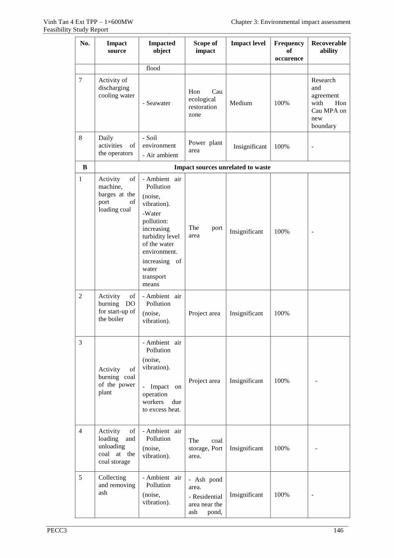
Vinh Tan 4 Ext TPP – 1×600MW
Feasibility Study Report
Chapter 3: Environmental impact assessment
PECC3 146
No. Impact
source
Impacted
object
Scope of
impact
Impact level Frequency
of
occurence
Recoverable
ability
flood
7 Activity of
discharging
cooling water
- Seawater
Hon Cau
ecological
restoration
zone
Medium 100%
Research
and
agreement
with Hon
Cau MPA on
new
boundary
8 Daily
activities of
the operators
- Soil
environment
- Air ambient
Power plant
area Insignificant 100% -
B Impact sources unrelated to waste
1 Activity of
machine,
barges at the
port of
loading coal
- Ambient air
Pollution
(noise,
vibration).
-Water
pollution:
increasing
turbidity level
of the water
environment.
increasing of
water
transport
means
The port
area Insignificant 100% -
2 Activity of
burning DO
for start-up of
the boiler
- Ambient air
Pollution
(noise,
vibration).
Project area Insignificant 100%
3
Activity of
burning coal
of the power
plant
- Ambient air
Pollution
(noise,
vibration).
- Impact on
operation
workers due
to excess heat.
Project area Insignificant 100% -
4 Activity of
loading and
unloading
coal at the
coal storage
- Ambient air
Pollution
(noise,
vibration).
The coal
storage, Port
area.
Insignificant 100% -
5 Collecting
and removing
ash
- Ambient air
Pollution
(noise,
vibration).
- Ash pond
area.
- Residential
area near the
ash pond,
Insignificant 100% -
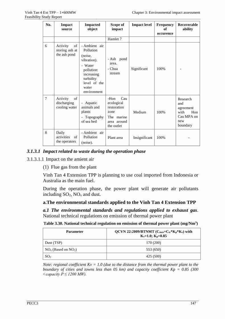
Vinh Tan 4 Ext TPP – 1×600MW
Feasibility Study Report
Chapter 3: Environmental impact assessment
PECC3 147
No. Impact
source
Impacted
object
Scope of
impact
Impact level Frequency
of
occurence
Recoverable
ability
Hamlet 7
6 Activity of
storing ash at
the ash pond
- Ambient air
Pollution
(noise,
vibration).
- Water
pollution:
increasing
turbidity
level of the
water
environment
- Ash pond
area.
- Chua
stream
Significant 100% -
7 Activity of
discharging
cooling water
- Aquatic
animals and
plants
- Topography
of sea bed
-Hon Cau
ecological
restoration
zone
The marine
area around
the outlet
Medium 100%
Research
and
agreement
with Hon
Cau MPA on
new
boundary
8 Daily
activities of
the operators
- Ambient air
Pollution
(noise).
Plant area Insignificant 100% -
3.1.3.1 Impact related to waste during the operation phase
3.1.3.1.1 Impact on the amient air
(1) Flue gas from the plant
Vinh Tan 4 Extension TPP is planning to use coal imported from Indonesia or
Australia as the main fuel.
During the operation phase, the power plant will generate air pollutants
including SO2, NOx and dust.
a.The environmental standards applied to the Vinh Tan 4 Extension TPP
a.1 The environmental standards and regulations applied to exhaust gas.
National technical regulations on emission of thermal power plant
Table 3.30. National technical regulation on emission of thermal power plant (mg/Nm3)
Parameter QCVN 22:2009/BTNMT (Cmax=Ctc*Kp*Kv) with
Kv=1.0; Kp=0.85
Dust (TSP) 170 (200)
NOx (Based on NO2) 553 (650)
SO2 425 (500)
Note: regional coefficient Kv = 1.0 (due to the distance from the thermal power plant to the
boundary of cities and towns less than 05 km) and capacity coefficient Kp = 0.85 (300
<capacity P ≤ 1200 MW).
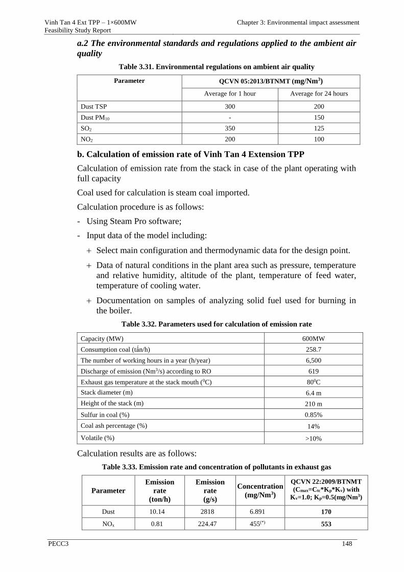
Vinh Tan 4 Ext TPP – 1×600MW
Feasibility Study Report
Chapter 3: Environmental impact assessment
PECC3 148
a.2 The environmental standards and regulations applied to the ambient air
quality
Table 3.31. Environmental regulations on ambient air quality
Parameter QCVN 05:2013/BTNMT (mg/Nm3)
Average for 1 hour Average for 24 hours
Dust TSP 300 200
Dust PM10 - 150
SO2 350 125
NO2 200 100
b. Calculation of emission rate of Vinh Tan 4 Extension TPP
Calculation of emission rate from the stack in case of the plant operating with
full capacity
Coal used for calculation is steam coal imported.
Calculation procedure is as follows:
- Using Steam Pro software;
- Input data of the model including:
Select main configuration and thermodynamic data for the design point.
Data of natural conditions in the plant area such as pressure, temperature
and relative humidity, altitude of the plant, temperature of feed water,
temperature of cooling water.
Documentation on samples of analyzing solid fuel used for burning in
the boiler.
Table 3.32. Parameters used for calculation of emission rate
Capacity (MW) 600MW
Consumption coal (tấn/h) 258.7
The number of working hours in a year (h/year) 6,500
Discharge of emission (Nm3/s) according to RO 619
Exhaust gas temperature at the stack mouth (0C) 800C
Stack diameter (m) 6.4 m
Height of the stack (m) 210 m
Sulfur in coal (%) 0.85%
Coal ash percentage (%) 14%
Volatile (%) >10%
Calculation results are as follows:
Table 3.33. Emission rate and concentration of pollutants in exhaust gas
Parameter
Emission
rate
(ton/h)
Emission
rate
(g/s)
Concentration
(mg/Nm3)
QCVN 22:2009/BTNMT
(Cmax=Ctc*Kp*Kv) with
Kv=1.0; Kp=0.5(mg/Nm3)
Dust 10.14 2818 6.891 170
NOx 0.81 224.47 455(*) 553
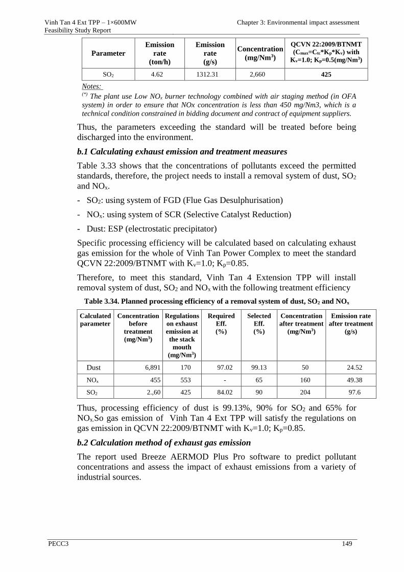
Vinh Tan 4 Ext TPP – 1×600MW
Feasibility Study Report
Chapter 3: Environmental impact assessment
PECC3 149
Parameter
Emission
rate
(ton/h)
Emission
rate
(g/s)
Concentration
(mg/Nm3)
QCVN 22:2009/BTNMT
(Cmax=Ctc*Kp*Kv) with
Kv=1.0; Kp=0.5(mg/Nm3)
SO2 4.62 1312.31 2,660 425
Notes: (*) The plant use Low NOx burner technology combined with air staging method (in OFA
system) in order to ensure that NOx concentration is less than 450 mg/Nm3, which is a
technical condition constrained in bidding document and contract of equipment suppliers.
Thus, the parameters exceeding the standard will be treated before being
discharged into the environment.
b.1 Calculating exhaust emission and treatment measures
Table 3.33 shows that the concentrations of pollutants exceed the permitted
standards, therefore, the project needs to install a removal system of dust, SO2
and NOx.
- SO2: using system of FGD (Flue Gas Desulphurisation)
- NOx: using system of SCR (Selective Catalyst Reduction)
- Dust: ESP (electrostatic precipitator)
Specific processing efficiency will be calculated based on calculating exhaust
gas emission for the whole of Vinh Tan Power Complex to meet the standard
QCVN 22:2009/BTNMT with Kv=1.0; Kp=0.85.
Therefore, to meet this standard, Vinh Tan 4 Extension TPP will install
removal system of dust, SO2 and NOx with the following treatment efficiency
Table 3.34. Planned processing efficiency of a removal system of dust, SO2 and NOx
Calculated
parameter
Concentration
before
treatment
(mg/Nm3)
Regulations
on exhaust
emission at
the stack
mouth
(mg/Nm3)
Required
Eff.
(%)
Selected
Eff.
(%)
Concentration
after treatment
(mg/Nm3)
Emission rate
after treatment
(g/s)
Dust 6,891 170 97.02 99.13 50 24.52
NOx 455 553 - 65 160 49.38
SO2 2.,60 425 84.02 90 204 97.6
Thus, processing efficiency of dust is 99.13%, 90% for SO2 and 65% for
NOx.So gas emission of Vinh Tan 4 Ext TPP will satisfy the regulations on
gas emission in QCVN 22:2009/BTNMT with Kv=1.0; Kp=0.85.
b.2 Calculation method of exhaust gas emission
The report used Breeze AERMOD Plus Pro software to predict pollutant
concentrations and assess the impact of exhaust emissions from a variety of
industrial sources.
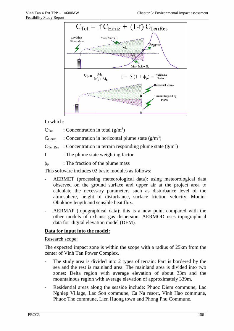
Vinh Tan 4 Ext TPP – 1×600MW
Feasibility Study Report
Chapter 3: Environmental impact assessment
PECC3 150
In which:
CTot : Concentration in total (g/m3)
CHoriz : Concentration in horizontal plume state (g/m3)
CTerrRes : Concentration in terrain responding plume state (g/m3)
f : The plume state weighting factor
p : The fraction of the plume mass
This software includes 02 basic modules as follows:
- AERMET (processing meteorological data): using meteorological data
observed on the ground surface and upper air at the project area to
calculate the necessary parameters such as disturbance level of the
atmosphere, height of disturbance, surface friction velocity, Monin-
Obukhov length and sensible heat flux.
- AERMAP (topographical data): this is a new point compared with the
other models of exhaust gas dispersion. AERMOD uses topographical
data for digital elevation model (DEM).
Data for input into the model:
Research scope:
The expected impact zone is within the scope with a radius of 25km from the
center of Vinh Tan Power Complex.
- The study area is divided into 2 types of terrain: Part is bordered by the
sea and the rest is mainland area. The mainland area is divided into two
zones: Delta region with average elevation of about 33m and the
mountainous region with average elevation of approximately 339m.
- Residential areas along the seaside include: Phuoc Diem commune, Lac
Nghiep Village, Lac Son commune, Ca Na resort, Vinh Hao commune,
Phuoc The commune, Lien Huong town and Phong Phu Commune.
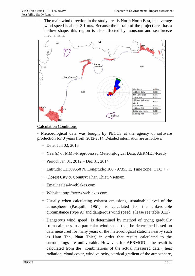
Vinh Tan 4 Ext TPP – 1×600MW
Feasibility Study Report
Chapter 3: Environmental impact assessment
PECC3 151
- The main wind direction in the study area is North North East, the average
wind speed is about 3.1 m/s. Because the terrain of the project area has a
hollow shape, this region is also affected by monsoon and sea breeze
mechanism.
Calculation Conditions
- Meteorological data was bought by PECC3 at the agency of software
production for 3 years from 2012-2014. Detailed information are as follows:
+ Date: Jun 02, 2015
+ Year(s) of MM5-Preprocessed Meteorological Data, AERMET-Ready
+ Period: Jan 01, 2012 – Dec 31, 2014
+ Latitude: 11.309558 N, Longitude: 108.797353 E, Time zone: UTC + 7
+ Closest City & Country: Phan Thiet, Vietnam
+ Email: [email protected]
+ Website: http://www.weblakes.com
+ Usually when calculating exhaust emissions, sustainable level of the
atmosphere (Pasquill, 1961) is calculated for the unfavorable
circumstance (type A) and dangerous wind speed (Please see table 3.12)
+ Dangerous wind speed is determined by method of trying gradually
from calmness to a particular wind speed (can be determined based on
data measured for many years of the meteorological stations nearby such
as Ham Tan, Phan Thiet) in order that results calculated to the
surroundings are unfavorable. However, for AERMOD - the result is
calculated from the combinations of the actual measured data ( heat
radiation, cloud cover, wind velocity, vertical gradient of the atmosphere,
Vinh Tan 4 Ext TPP – 1×600MW
Feasibility Study Report
Chapter 3: Environmental impact assessment
PECC3 152
roughness of the atmosphere, precipitation, evaporation, sunshine
duration, etc.) and are calculated continuously for every hour for 3 years
from 2012 to 2014. The most unfavorable result is extracted from the
result of this calculation.
- Topographic:
o Buffer Zone: DEM 90m - describes the mountainous terrain and the
areas far from the emission source.
o Core Zone: 30m DEM - finer for the central areas and sensitive areas
(residential areas, structures, etc.). However, consultants of PECC3 used
30m DEM terrain for the entire scope of calculation. 30m DEM data
have the best resolution in Vietnam - except for some special areas.
- Time for Simulation: 03 years (2012-2014), simulation time step is 1 hour.
The status of emissions of thermal power plants
Table 3.35. The status of emissions of thermal power plants in Vinh Tan Power
Complex
Parameter Vinh Tan 1
(mg/m3)
Vinh Tan 2 Vinh Tan 3
(mg/m3)
Vinh Tan 4
(mg/m3) Unit 1 (mg/m3) Unit 2 (mg/m3)
NOx 300 51 55.5 455 455
SO2 144 2.04 22.8 200 350
Dust (TSP) 98 40.9 32.9 50 50
Note:
- Vinh Tan 1 TPP: taken from the EIA report approved by the Ministry of Natural Resources and
Environment'
- Vinh Tan 2 TPP: from measured data at the stack mouth from January to March 2015, GENCO3;
- Vinh Tan 3 TPP: taken from the EIA report approved by the Ministry of Natural Resources and
Environment;
- Vinh Tan 4 TPP:
+ NOx, SO2 taken from the EIA report approved by the Ministry of Natural Resources and
Environment;
+ Dust: based on the requirements of the lender.
Parameters of the project and emission sources
To meet emission concentration of dust, SO2, NO2 on the ground, the
maximum average concentration for 1h and for 24 hours reach the standard
QCVN 05: 2013/BTNMT; the concentration of the parameters of dust, SO2,
NO2 in gas emissions from the power plants in Vinh Tan Power Complex after
through treatment equipment of ESP, FGD, SCR is shown in the following
table:
Table 3.36. Parameters of emission sources in Vinh Tan Power Complex
Parameters of emission
sources
Vinh Tan 1
TPP
Vinh Tan 2
TPP
Vinh Tan 3
TPP
Vinh Tan
4 TPP
Vinh Tan 4
Extension
TPP
Height of a stack (m) 210 210 210 210 210

Vinh Tan 4 Ext TPP – 1×600MW
Feasibility Study Report
Chapter 3: Environmental impact assessment
PECC3 153
Parameters of emission
sources
Vinh Tan 1
TPP
Vinh Tan 2
TPP
Vinh Tan 3
TPP
Vinh Tan
4 TPP
Vinh Tan 4
Extension
TPP
Number of stack 1 1 1 1 1
Diameter of a stack (m) 8.2 8.5 9.5 8.5 6.4
Temperature of flue gas after
treatment (oC) 70 80 70 80 80
Discharge of
emission
(m3/s)
Based on BMCR
(capacity = 105%
designed
capacity)
1,526 1,527 1,953 1,288 644
Based on RO
(capacity = 100%
designed
capacity))
1,453 1,455 1,860 1,237 619
Concentration
(mg/Nm3)
(after
treatment)
NOx 300 200 160 160 160
SO2 144 153 200 204 204
Dust (TSP) 98 148 50 50 50
Note:
- Vinh Tan 1 TPP: taken from the EIA report approved by the Ministry of Natural Resources and
Environment
- Vinh Tan 2 TPP: from measured data at the stack mouth from January to March 2015, GENCO3,
However, in order to anticipate the changes in coal quality and processing efficiency while
reducing emissions over time, so in the process of calculating emissions, model used data of Vinh
Tan 2 TPP, with parameters: SO2 = 153mg/Nm3, NOx = 200 mg/Nm3;
- Vinh Tan 3 TPP, Vinh Tan 4 TPP, Vinh Tan 4 Extension TPP: emissions calculated for the
plants in Vinh Tan reach the standards: QCVN 22:2009/BTNMT and QCVN 05:2013/BTNMT;
1. Calculation option and result of calculating emission of NO2 based on NOx
Table 3.37. Parameters in calculating emission of NOx
Emission of NOx Vinh Tan 1 Vĩnh Tân 2 Vinh Tan 3 Vinh Tan 4 Vinh Tan 4
Extension
Concentration
(mg/Nm3) 300 200 160 160 160
Table 3.38. Calculation result for emission of NO2
Emission of NO2 Result QCVN 05:2013/BTNMT
Average for 1h Average for 24h Average for 1h Average for 24h
Concentration (µg/m3) 182 19 200 100
Notice: Calculation result for concentrations of NO2 emission on the ground
with the average values for 1hour and for 24 hours which reach the standard
QCVN 05:2013/BTNMT.
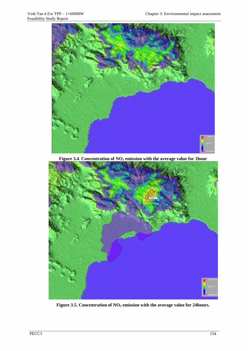
Vinh Tan 4 Ext TPP – 1×600MW
Feasibility Study Report
Chapter 3: Environmental impact assessment
PECC3 154
Figure 3.4. Concentration of NO2 emission with the average value for 1hour
Figure 3.5. Concentration of NO2 emission with the average value for 24hours.
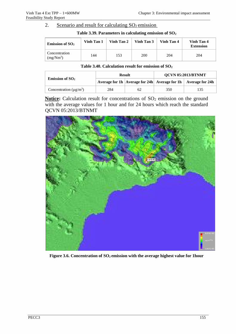
Vinh Tan 4 Ext TPP – 1×600MW
Feasibility Study Report
Chapter 3: Environmental impact assessment
PECC3 155
2. Scenario and result for calculating SO2 emission
Table 3.39. Parameters in calculating emission of SO2
Emission of SO2 Vinh Tan 1 Vinh Tan 2 Vinh Tan 3 Vinh Tan 4 Vinh Tan 4
Extension
Concentration
(mg/Nm3) 144 153 200 204 204
Table 3.40. Calculation result for emission of SO2
Emission of SO2 Result QCVN 05:2013/BTNMT
Average for 1h Average for 24h Average for 1h Average for 24h
Concentration (µg/m3) 284 62 350 135
Notice: Calculation result for concentrations of SO2 emission on the ground
with the average values for 1 hour and for 24 hours which reach the standard
QCVN 05:2013/BTNMT
Figure 3.6. Concentration of SO2 emission with the average highest value for 1hour
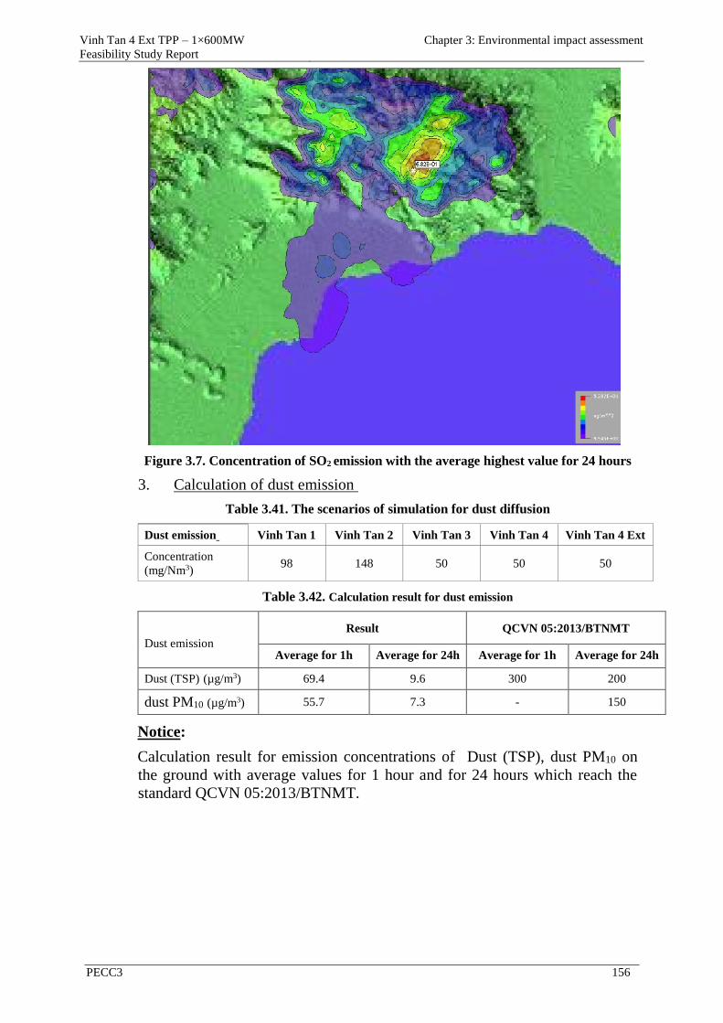
Vinh Tan 4 Ext TPP – 1×600MW
Feasibility Study Report
Chapter 3: Environmental impact assessment
PECC3 156
Figure 3.7. Concentration of SO2 emission with the average highest value for 24 hours
3. Calculation of dust emission
Table 3.41. The scenarios of simulation for dust diffusion
Dust emission Vinh Tan 1 Vinh Tan 2 Vinh Tan 3 Vinh Tan 4 Vinh Tan 4 Ext
Concentration
(mg/Nm3) 98 148 50 50 50
Table 3.42. Calculation result for dust emission
Dust emission Result QCVN 05:2013/BTNMT
Average for 1h Average for 24h Average for 1h Average for 24h
Dust (TSP) (µg/m3) 69.4 9.6 300 200
dust PM10 (µg/m3) 55.7 7.3 - 150
Notice:
Calculation result for emission concentrations of Dust (TSP), dust PM10 on
the ground with average values for 1 hour and for 24 hours which reach the
standard QCVN 05:2013/BTNMT.
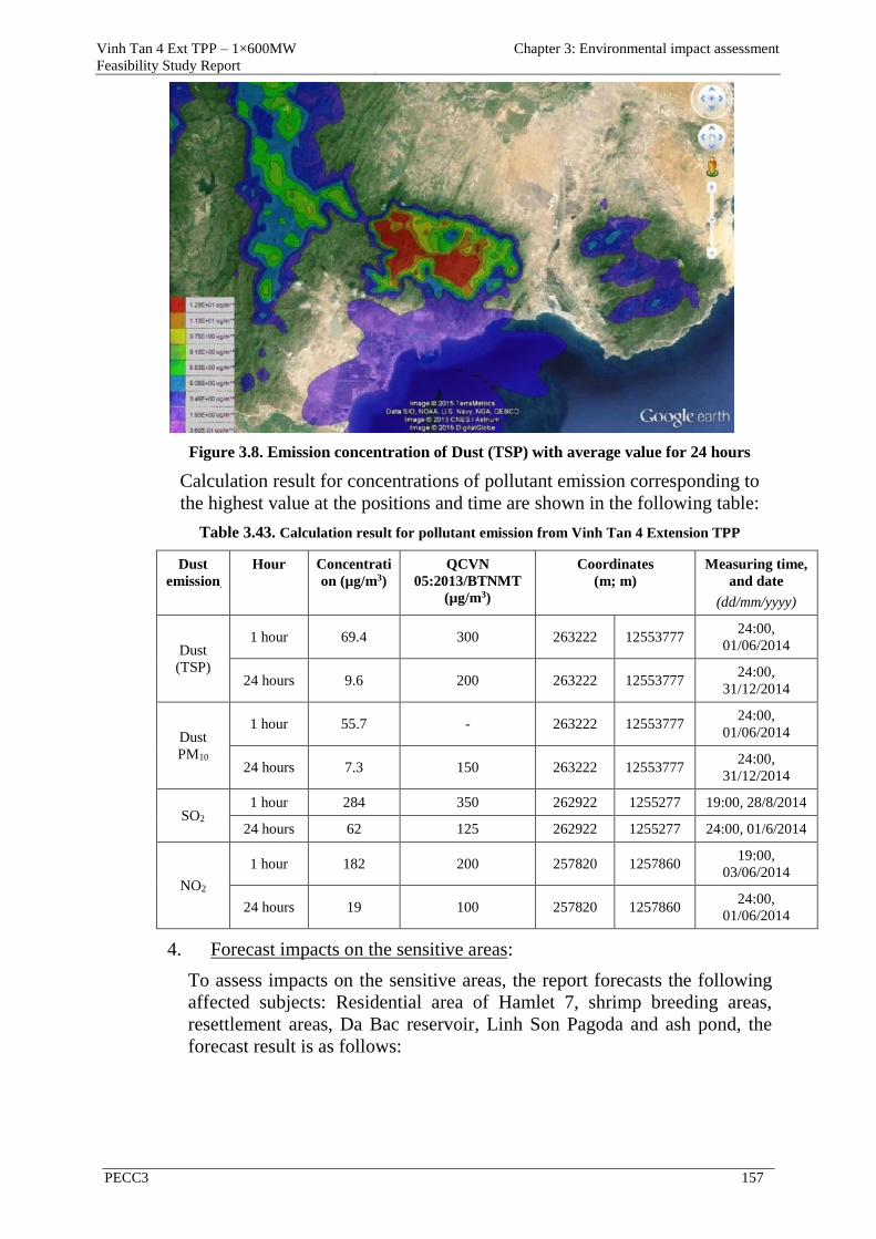
Vinh Tan 4 Ext TPP – 1×600MW
Feasibility Study Report
Chapter 3: Environmental impact assessment
PECC3 157
Figure 3.8. Emission concentration of Dust (TSP) with average value for 24 hours
Calculation result for concentrations of pollutant emission corresponding to
the highest value at the positions and time are shown in the following table:
Table 3.43. Calculation result for pollutant emission from Vinh Tan 4 Extension TPP
Dust
emission
Hour Concentrati
on (µg/m3)
QCVN
05:2013/BTNMT
(µg/m3)
Coordinates
(m; m)
Measuring time,
and date
(dd/mm/yyyy)
Dust
(TSP)
1 hour 69.4 300 263222 12553777 24:00,
01/06/2014
24 hours 9.6 200 263222 12553777 24:00,
31/12/2014
Dust
PM10
1 hour 55.7 - 263222 12553777 24:00,
01/06/2014
24 hours 7.3 150 263222 12553777 24:00,
31/12/2014
SO2 1 hour 284 350 262922 1255277 19:00, 28/8/2014
24 hours 62 125 262922 1255277 24:00, 01/6/2014
NO2
1 hour 182 200 257820 1257860 19:00,
03/06/2014
24 hours 19 100 257820 1257860 24:00,
01/06/2014
4. Forecast impacts on the sensitive areas:
To assess impacts on the sensitive areas, the report forecasts the following
affected subjects: Residential area of Hamlet 7, shrimp breeding areas,
resettlement areas, Da Bac reservoir, Linh Son Pagoda and ash pond, the
forecast result is as follows:
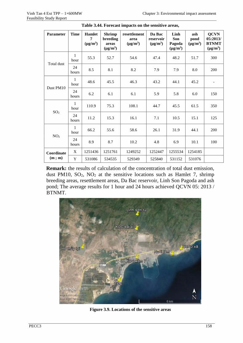
Vinh Tan 4 Ext TPP – 1×600MW
Feasibility Study Report
Chapter 3: Environmental impact assessment
PECC3 158
Table 3.44. Forecast impacts on the sensitive areas,
Parameter Time Hamlet
7
(µg/m3)
Shrimp
breeding
areas
(µg/m3)
resettlement
area
(µg/m3)
Da Bac
reservoir
(µg/m3)
Linh
Son
Pagoda
(µg/m3)
ash
pond
(µg/m3)
QCVN
05:2013/
BTNMT
(µg/m3)
Total dust
1
hour 55.3 52.7 54.6 47.4 48.2 51.7 300
24
hours 8.5 8.1 8.2 7.9 7.9 8.0 200
Dust PM10
1
hour 48.6 45.5 46.3 43.2 44.1 45.2 -
24
hours 6.2 6.1 6.1 5.9 5.8 6.0 150
SO2
1
hour 110.9 75.3 108.1 44.7 45.5 61.5 350
24
hours 11.2 15.3 16.1 7.1 10.5 15.1 125
NO2
1
hour 66.2 55.6 58.6 26.1 31.9 44.1 200
24
hours 8.9 8.7 10.2 4.8 6.9 10.1 100
Coordinate
(m ; m)
X 1251436 1251761 1249252 1252447 1255534 1254185
Y 531086 534535 529349 525840 531152 531076
Remark: the results of calculation of the concentration of total dust emission,
dust PM10, SO2, NO2 at the sensitive locations such as Hamlet 7, shrimp
breeding areas, resettlement areas, Da Bac reservoir, Linh Son Pagoda and ash
pond; The average results for 1 hour and 24 hours achieved QCVN 05: 2013 /
BTNMT.
Figure 3.9. Locations of the sensitive areas
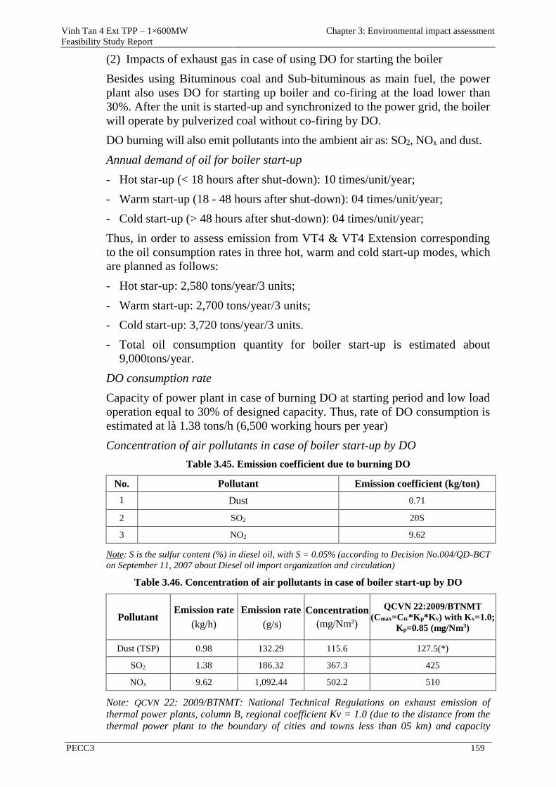
Vinh Tan 4 Ext TPP – 1×600MW
Feasibility Study Report
Chapter 3: Environmental impact assessment
PECC3 159
(2) Impacts of exhaust gas in case of using DO for starting the boiler
Besides using Bituminous coal and Sub-bituminous as main fuel, the power
plant also uses DO for starting up boiler and co-firing at the load lower than
30%. After the unit is started-up and synchronized to the power grid, the boiler
will operate by pulverized coal without co-firing by DO.
DO burning will also emit pollutants into the ambient air as: SO2, NOx and dust.
Annual demand of oil for boiler start-up
- Hot star-up (< 18 hours after shut-down): 10 times/unit/year;
- Warm start-up (18 - 48 hours after shut-down): 04 times/unit/year;
- Cold start-up (> 48 hours after shut-down): 04 times/unit/year;
Thus, in order to assess emission from VT4 & VT4 Extension corresponding
to the oil consumption rates in three hot, warm and cold start-up modes, which
are planned as follows:
- Hot star-up: 2,580 tons/year/3 units;
- Warm start-up: 2,700 tons/year/3 units;
- Cold start-up: 3,720 tons/year/3 units.
- Total oil consumption quantity for boiler start-up is estimated about
9,000tons/year.
DO consumption rate
Capacity of power plant in case of burning DO at starting period and low load
operation equal to 30% of designed capacity. Thus, rate of DO consumption is
estimated at là 1.38 tons/h (6,500 working hours per year)
Concentration of air pollutants in case of boiler start-up by DO
Table 3.45. Emission coefficient due to burning DO
No. Pollutant Emission coefficient (kg/ton)
1 Dust 0.71
2 SO2 20S
3 NO2 9.62
Note: S is the sulfur content (%) in diesel oil, with S = 0.05% (according to Decision No.004/QD-BCT
on September 11, 2007 about Diesel oil import organization and circulation)
Table 3.46. Concentration of air pollutants in case of boiler start-up by DO
Pollutant Emission rate
(kg/h)
Emission rate
(g/s)
Concentration
(mg/Nm3)
QCVN 22:2009/BTNMT
(Cmax=Ctc*Kp*Kv) with Kv=1.0;
Kp=0.85 (mg/Nm3)
Dust (TSP) 0.98 132.29 115.6 127.5(*)
SO2 1.38 186.32 367.3 425
NOx 9.62 1,092.44 502.2 510
Note: QCVN 22: 2009/BTNMT: National Technical Regulations on exhaust emission of
thermal power plants, column B, regional coefficient Kv = 1.0 (due to the distance from the
thermal power plant to the boundary of cities and towns less than 05 km) and capacity
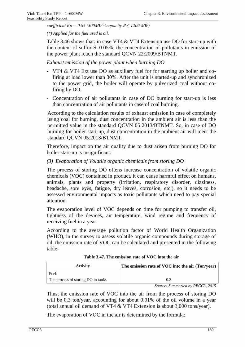
Vinh Tan 4 Ext TPP – 1×600MW
Feasibility Study Report
Chapter 3: Environmental impact assessment
PECC3 160
coefficient Kp = 0.85 (300MW <capacity P ≤ 1200 MW).
(*) Applied for the fuel used is oil.
Table 3.46 shows that: in case VT4 & VT4 Extension use DO for start-up with
the content of sulfur S=0.05%, the concentration of pollutants in emission of
the power plant reach the standard QCVN 22:2009/BTNMT.
Exhaust emission of the power plant when burning DO
- VT4 & VT4 Ext use DO as auxiliary fuel for for starting up boiler and co-
firing at load lower than 30%. After the unit is started-up and synchronized
to the power grid, the boiler will operate by pulverized coal without co-
firing by DO.
- Concentration of air pollutants in case of DO burning for start-up is less
than concentration of air pollutants in case of coal burning.
According to the calculation results of exhaust emission in case of completely
using coal for burning, dust concentration in the ambient air is less than the
permitted value in the standard QCVN 05:2013/BTNMT. So, in case of DO
burning for boiler start-up, dust concentration in the ambient air will meet the
standard QCVN 05:2013/BTNMT.
Therefore, impact on the air quality due to dust arisen from burning DO for
boiler start-up is insignificant.
(3) Evaporation of Volatile organic chemicals from storing DO
The process of storing DO oftens increase concentration of volatile organic
chemicals (VOC) contained in product, it can cause harmful effect on humans,
animals, plants and property (irritation, respiratory disorder, dizziness,
headache, sore eyes, fatigue, dry leaves, corrosion, etc.), so it needs to be
assessed environmental impacts as toxic pollutants which need to pay special
attention.
The evaporation level of VOC depends on time for pumping to transfer oil,
tightness of the devices, air temperature, wind regime and frequency of
receiving fuel in a year.
According to the average pollution factor of World Health Organization
(WHO), in the survey to assess volatile organic compounds during storage of
oil, the emission rate of VOC can be calculated and presented in the following
table:
Table 3.47. The emission rate of VOC into the air
Activity The emission rate of VOC into the air (Ton/year)
Fuel:
The process of storing DO in tanks
0.3
Source: Summaried by PECC3, 2015
Thus, the emission rate of VOC into the air from the process of storing DO
will be 0.3 ton/year, accounting for about 0.01% of the oil volume in a year
(total annual oil demand of VT4 & VT4 Extension is about 3,000 tons/year).
The evaporation of VOC in the air is determined by the formula:
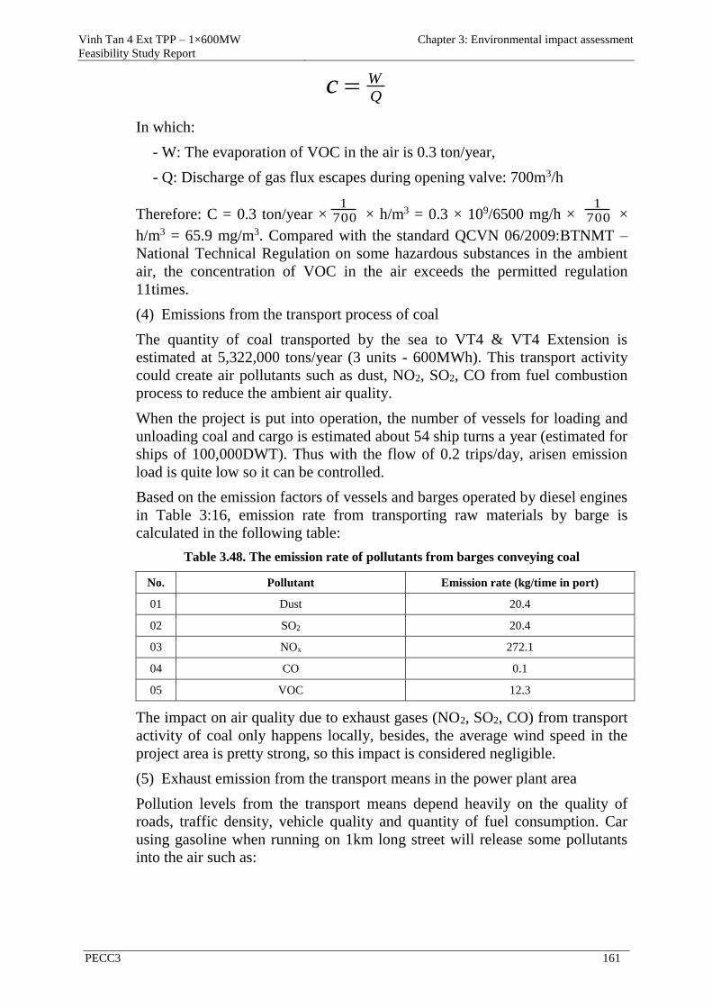
Vinh Tan 4 Ext TPP – 1×600MW
Feasibility Study Report
Chapter 3: Environmental impact assessment
PECC3 161
Q
Wc
In which:
- W: The evaporation of VOC in the air is 0.3 ton/year,
- Q: Discharge of gas flux escapes during opening valve: 700m3/h
Therefore: C = 0.3 ton/year × 7001
× h/m3 = 0.3 × 10⁹/6500 mg/h × 7001
×
h/m3 = 65.9 mg/m3. Compared with the standard QCVN 06/2009:BTNMT –
National Technical Regulation on some hazardous substances in the ambient
air, the concentration of VOC in the air exceeds the permitted regulation
11times.
(4) Emissions from the transport process of coal
The quantity of coal transported by the sea to VT4 & VT4 Extension is
estimated at 5,322,000 tons/year (3 units - 600MWh). This transport activity
could create air pollutants such as dust, NO2, SO2, CO from fuel combustion
process to reduce the ambient air quality.
When the project is put into operation, the number of vessels for loading and
unloading coal and cargo is estimated about 54 ship turns a year (estimated for
ships of 100,000DWT). Thus with the flow of 0.2 trips/day, arisen emission
load is quite low so it can be controlled.
Based on the emission factors of vessels and barges operated by diesel engines
in Table 3:16, emission rate from transporting raw materials by barge is
calculated in the following table:
Table 3.48. The emission rate of pollutants from barges conveying coal
No. Pollutant Emission rate (kg/time in port)
01 Dust 20.4
02 SO2 20.4
03 NOx 272.1
04 CO 0.1
05 VOC 12.3
The impact on air quality due to exhaust gases (NO2, SO2, CO) from transport
activity of coal only happens locally, besides, the average wind speed in the
project area is pretty strong, so this impact is considered negligible.
(5) Exhaust emission from the transport means in the power plant area
Pollution levels from the transport means depend heavily on the quality of
roads, traffic density, vehicle quality and quantity of fuel consumption. Car
using gasoline when running on 1km long street will release some pollutants
into the air such as:
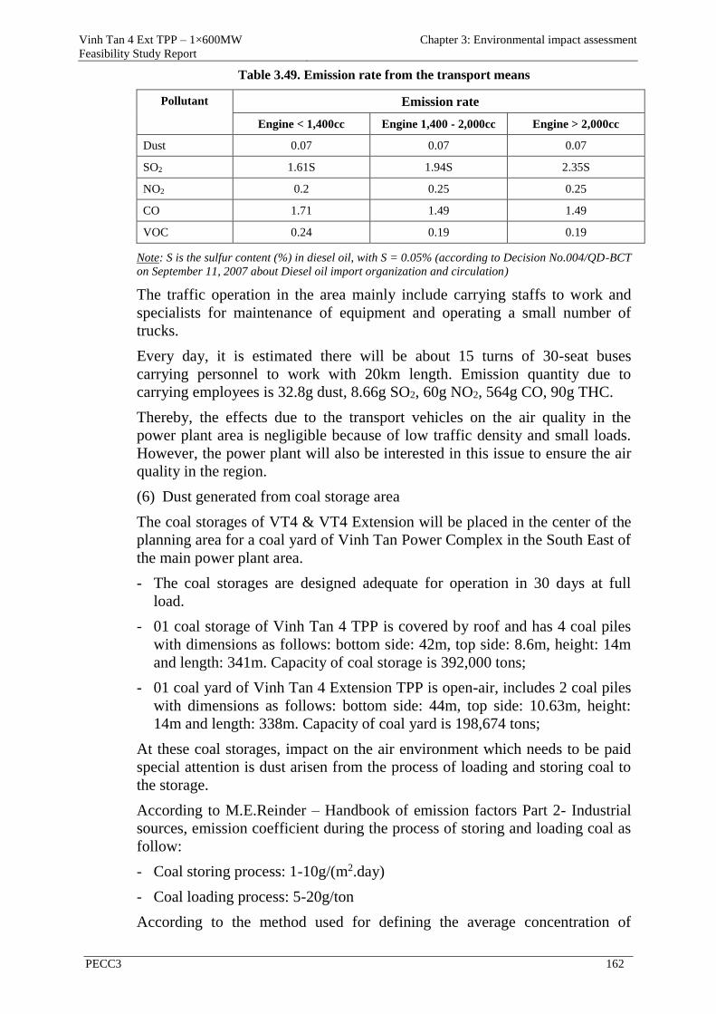
Vinh Tan 4 Ext TPP – 1×600MW
Feasibility Study Report
Chapter 3: Environmental impact assessment
PECC3 162
Table 3.49. Emission rate from the transport means
Pollutant Emission rate
Engine < 1,400cc Engine 1,400 - 2,000cc Engine > 2,000cc
Dust 0.07 0.07 0.07
SO2 1.61S 1.94S 2.35S
NO2 0.2 0.25 0.25
CO 1.71 1.49 1.49
VOC 0.24 0.19 0.19
Note: S is the sulfur content (%) in diesel oil, with S = 0.05% (according to Decision No.004/QD-BCT
on September 11, 2007 about Diesel oil import organization and circulation)
The traffic operation in the area mainly include carrying staffs to work and
specialists for maintenance of equipment and operating a small number of
trucks.
Every day, it is estimated there will be about 15 turns of 30-seat buses
carrying personnel to work with 20km length. Emission quantity due to
carrying employees is 32.8g dust, 8.66g SO2, 60g NO2, 564g CO, 90g THC.
Thereby, the effects due to the transport vehicles on the air quality in the
power plant area is negligible because of low traffic density and small loads.
However, the power plant will also be interested in this issue to ensure the air
quality in the region.
(6) Dust generated from coal storage area
The coal storages of VT4 & VT4 Extension will be placed in the center of the
planning area for a coal yard of Vinh Tan Power Complex in the South East of
the main power plant area.
- The coal storages are designed adequate for operation in 30 days at full
load.
- 01 coal storage of Vinh Tan 4 TPP is covered by roof and has 4 coal piles
with dimensions as follows: bottom side: 42m, top side: 8.6m, height: 14m
and length: 341m. Capacity of coal storage is 392,000 tons;
- 01 coal yard of Vinh Tan 4 Extension TPP is open-air, includes 2 coal piles
with dimensions as follows: bottom side: 44m, top side: 10.63m, height:
14m and length: 338m. Capacity of coal yard is 198,674 tons;
At these coal storages, impact on the air environment which needs to be paid
special attention is dust arisen from the process of loading and storing coal to
the storage.
According to M.E.Reinder – Handbook of emission factors Part 2- Industrial
sources, emission coefficient during the process of storing and loading coal as
follow:
- Coal storing process: 1-10g/(m2.day)
- Coal loading process: 5-20g/ton
According to the method used for defining the average concentration of
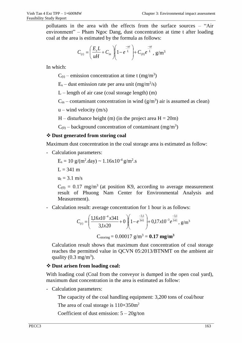
Vinh Tan 4 Ext TPP – 1×600MW
Feasibility Study Report
Chapter 3: Environmental impact assessment
PECC3 163
pollutants in the area with the effects from the surface sources – “Air
environment” – Pham Ngoc Dang, dust concentration at time t after loading
coal at the area is estimated by the formula as follows:
L
ut
L
ut
in
s
t eCeCuH
LEC
)0()( 1. , g/m3
In which:
C(t) – emission concentration at time t (mg/m3)
Es – dust emission rate per area unit (mg/m2/s)
L – length of air case (coal storage length) (m)
Cin – contaminant concentration in wind (g/m3) air is assumed as clean)
u – wind velocity (m/s)
H – disturbance height (m) (in the project area H = 20m)
C(0) – background concentration of contaminant (mg/m3)
Dust generated from storing coal
Maximum dust concentration in the coal storage area is estimated as follow:
- Calculation parameters:
Es = 10 g/(m2.day) ~ 1.16x10⁻⁴ g/m2.s
L = 341 m
ut = 3.1 m/s
C(0) = 0.17 mg/m3 (at position K9, according to average measurement
result of Phuong Nam Center for Environmental Analysis and
Measurement).
- Calculation result: average concentration for 1 hour is as follows:
341
1,3
3341
1,34
)( 1017,01.0201,3
3411016,1
exe
x
xxC t , g/m3
Cstoring = 0.00017 g/m3 = 0.17 mg/m3
Calculation result shows that maximum dust concentration of coal storage
reaches the permitted value in QCVN 05:2013/BTNMT on the ambient air
quality (0.3 mg/m3).
Dust arisen from loading coal:
With loading coal (Coal from the conveyor is dumped in the open coal yard),
maximum dust concentration in the area is estimated as follow:
- Calculation parameters:
The capacity of the coal handling equipment: 3,200 tons of coal/hour
The area of coal storage is 110×350m2
Coefficient of dust emission: 5 – 20g/ton
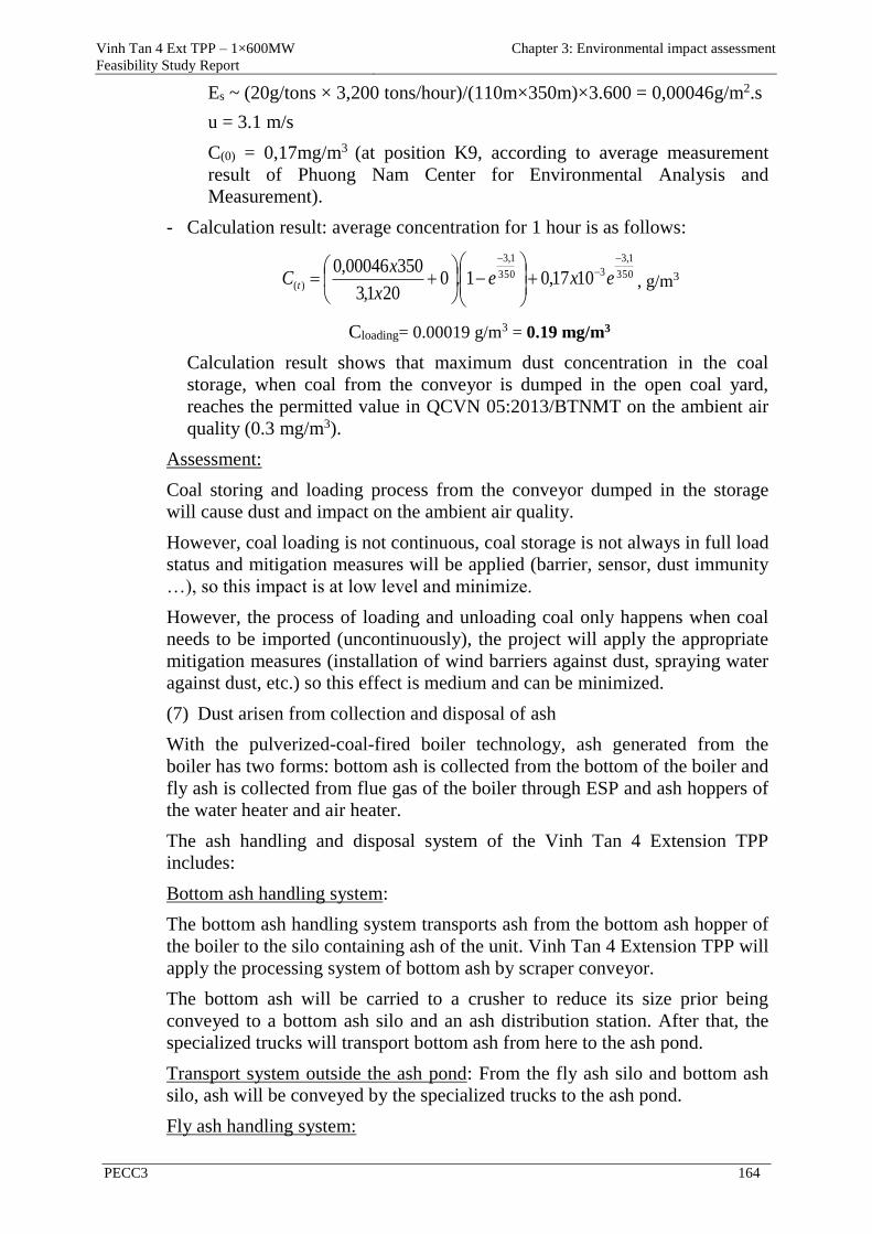
Vinh Tan 4 Ext TPP – 1×600MW
Feasibility Study Report
Chapter 3: Environmental impact assessment
PECC3 164
Es ~ (20g/tons × 3,200 tons/hour)/(110m×350m)×3.600 = 0,00046g/m2.s
u = 3.1 m/s
C(0) = 0,17mg/m3 (at position K9, according to average measurement
result of Phuong Nam Center for Environmental Analysis and
Measurement).
- Calculation result: average concentration for 1 hour is as follows:
350
1,3
3350
1,3
)( 1017,01.0201,3
35000046,0
exe
x
xC t , g/m3
Cloading= 0.00019 g/m3 = 0.19 mg/m3
Calculation result shows that maximum dust concentration in the coal
storage, when coal from the conveyor is dumped in the open coal yard,
reaches the permitted value in QCVN 05:2013/BTNMT on the ambient air
quality (0.3 mg/m3).
Assessment:
Coal storing and loading process from the conveyor dumped in the storage
will cause dust and impact on the ambient air quality.
However, coal loading is not continuous, coal storage is not always in full load
status and mitigation measures will be applied (barrier, sensor, dust immunity
…), so this impact is at low level and minimize.
However, the process of loading and unloading coal only happens when coal
needs to be imported (uncontinuously), the project will apply the appropriate
mitigation measures (installation of wind barriers against dust, spraying water
against dust, etc.) so this effect is medium and can be minimized.
(7) Dust arisen from collection and disposal of ash
With the pulverized-coal-fired boiler technology, ash generated from the
boiler has two forms: bottom ash is collected from the bottom of the boiler and
fly ash is collected from flue gas of the boiler through ESP and ash hoppers of
the water heater and air heater.
The ash handling and disposal system of the Vinh Tan 4 Extension TPP
includes:
Bottom ash handling system:
The bottom ash handling system transports ash from the bottom ash hopper of
the boiler to the silo containing ash of the unit. Vinh Tan 4 Extension TPP will
apply the processing system of bottom ash by scraper conveyor.
The bottom ash will be carried to a crusher to reduce its size prior being
conveyed to a bottom ash silo and an ash distribution station. After that, the
specialized trucks will transport bottom ash from here to the ash pond.
Transport system outside the ash pond: From the fly ash silo and bottom ash
silo, ash will be conveyed by the specialized trucks to the ash pond.
Fly ash handling system:
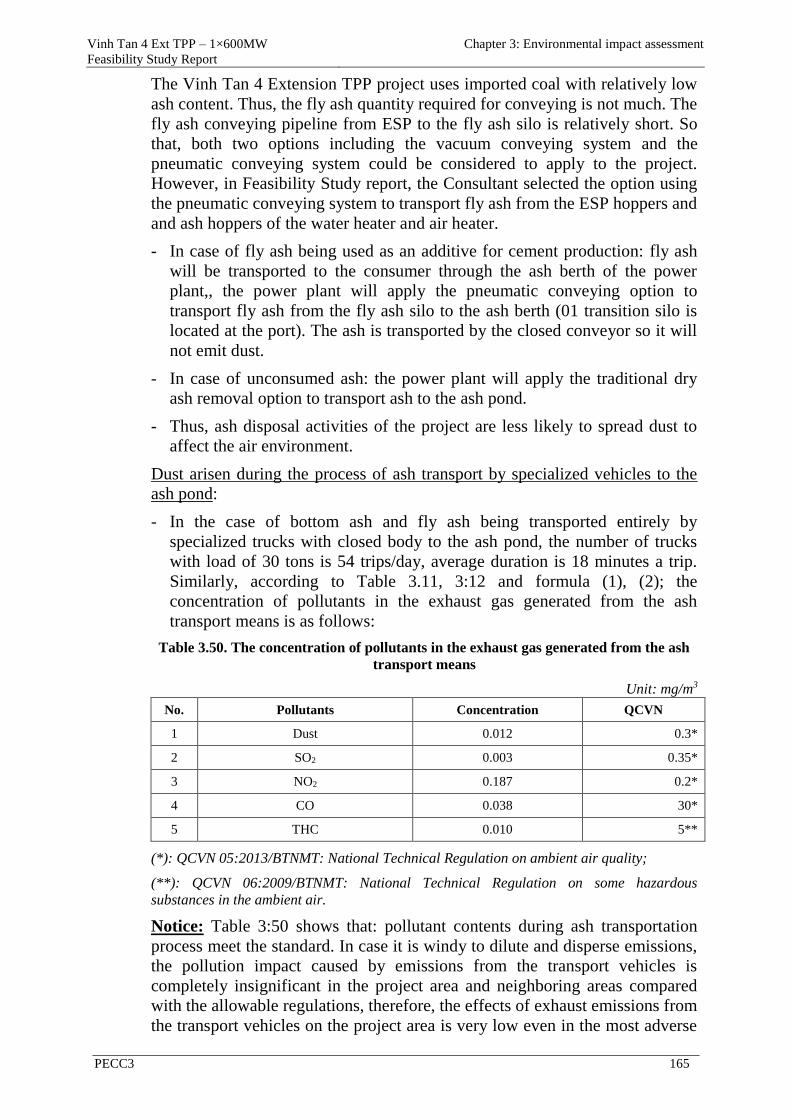
Vinh Tan 4 Ext TPP – 1×600MW
Feasibility Study Report
Chapter 3: Environmental impact assessment
PECC3 165
The Vinh Tan 4 Extension TPP project uses imported coal with relatively low
ash content. Thus, the fly ash quantity required for conveying is not much. The
fly ash conveying pipeline from ESP to the fly ash silo is relatively short. So
that, both two options including the vacuum conveying system and the
pneumatic conveying system could be considered to apply to the project.
However, in Feasibility Study report, the Consultant selected the option using
the pneumatic conveying system to transport fly ash from the ESP hoppers and
and ash hoppers of the water heater and air heater.
- In case of fly ash being used as an additive for cement production: fly ash
will be transported to the consumer through the ash berth of the power
plant,, the power plant will apply the pneumatic conveying option to
transport fly ash from the fly ash silo to the ash berth (01 transition silo is
located at the port). The ash is transported by the closed conveyor so it will
not emit dust.
- In case of unconsumed ash: the power plant will apply the traditional dry
ash removal option to transport ash to the ash pond.
- Thus, ash disposal activities of the project are less likely to spread dust to
affect the air environment.
Dust arisen during the process of ash transport by specialized vehicles to the
ash pond:
- In the case of bottom ash and fly ash being transported entirely by
specialized trucks with closed body to the ash pond, the number of trucks
with load of 30 tons is 54 trips/day, average duration is 18 minutes a trip.
Similarly, according to Table 3.11, 3:12 and formula (1), (2); the
concentration of pollutants in the exhaust gas generated from the ash
transport means is as follows:
Table 3.50. The concentration of pollutants in the exhaust gas generated from the ash
transport means
Unit: mg/m3
No. Pollutants Concentration QCVN
1 Dust 0.012 0.3*
2 SO2 0.003 0.35*
3 NO2 0.187 0.2*
4 CO 0.038 30*
5 THC 0.010 5**
(*): QCVN 05:2013/BTNMT: National Technical Regulation on ambient air quality;
(**): QCVN 06:2009/BTNMT: National Technical Regulation on some hazardous
substances in the ambient air.
Notice: Table 3:50 shows that: pollutant contents during ash transportation
process meet the standard. In case it is windy to dilute and disperse emissions,
the pollution impact caused by emissions from the transport vehicles is
completely insignificant in the project area and neighboring areas compared
with the allowable regulations, therefore, the effects of exhaust emissions from
the transport vehicles on the project area is very low even in the most adverse
Vinh Tan 4 Ext TPP – 1×600MW
Feasibility Study Report
Chapter 3: Environmental impact assessment
PECC3 166
weather condition.
(8) Dust arisen from the ash pond
The ash pond of VT4 & VT4 Extension is 2km from the main power plant to
the North, located in the ash pond of Vinh Tan Power Complex.
In case of unconsumed ash, ash from VT4 & VT4 Extension will be conveyed
to the ash pond by the traditional dry ash removal option.
Because three TPPs including Vinh Tan 2, Vinh Tan 4 and Vinh Tan 4
Extension share the ash pond in Area 1 of Ho Dua ash pond with area of
62.733ha. Therefore, calculation of dust emission from the ash pond will
include for 3 TPPs sharing the common ash pond.
i). Computation model
Concentration of exhaust emissions spreading into the environment, the report
uses Breeze AERMOD Plus Pro software. The AERMOD model replaces the
ISC3 model (Industrial Source Complex Model) of EPA (1995).
The software includes 02 basic modules:
- AERMET (processing meteorological data): receiving meteorological data
on the ground and upper-air at the project area to calculate the necessary
parameters as the disturbance of the atmosphere, surface roughtness length,
Monin-Obukov length and surface heat flux.
- AERMAP (topographic data): this is a new point for the other computational
models for exhaust emissions. AERMOD uses topographic data with the
digital elevation model (DEM)
ii). Basic data
a. Dust quantity
Data input for estimation of dust quantity
The number of vehicle trips for conveying ash: 19 trips/hour;
- Ash is sprayed wet before being transported to the ash pond with humidity
of 17%;
- Ash volume: 6,671 tons/day.
According to the United States Environmental Protection Agency (US
EPA), dust at the ash pond area is dispersed by the following reasons:
- The ash dumping process from trucks;
- Activities of ash dump trucks, tank trucks, compactors on the ash pond
area;
- Erosion due to wind.
b.Meteorological data
Similar to the calculation of exhaust emissions from the TPPs in Vinh Tan
Power Complex, meteorological data was also bought by PECC3 from the
software production agency in 3 years from 2012 to 2014.
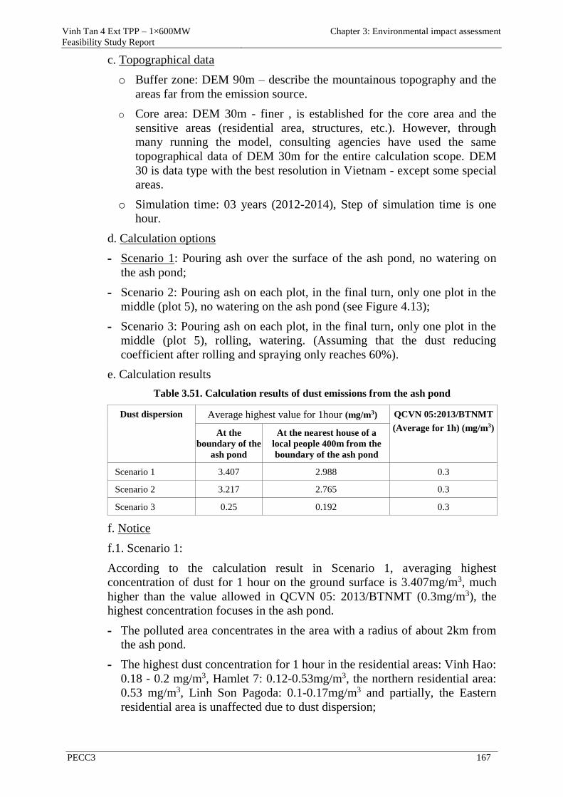
Vinh Tan 4 Ext TPP – 1×600MW
Feasibility Study Report
Chapter 3: Environmental impact assessment
PECC3 167
c. Topographical data
o Buffer zone: DEM 90m – describe the mountainous topography and the
areas far from the emission source.
o Core area: DEM 30m - finer , is established for the core area and the
sensitive areas (residential area, structures, etc.). However, through
many running the model, consulting agencies have used the same
topographical data of DEM 30m for the entire calculation scope. DEM
30 is data type with the best resolution in Vietnam - except some special
areas.
o Simulation time: 03 years (2012-2014), Step of simulation time is one
hour.
d. Calculation options
- Scenario 1: Pouring ash over the surface of the ash pond, no watering on
the ash pond;
- Scenario 2: Pouring ash on each plot, in the final turn, only one plot in the
middle (plot 5), no watering on the ash pond (see Figure 4.13);
- Scenario 3: Pouring ash on each plot, in the final turn, only one plot in the
middle (plot 5), rolling, watering. (Assuming that the dust reducing
coefficient after rolling and spraying only reaches 60%).
e. Calculation results
Table 3.51. Calculation results of dust emissions from the ash pond
Dust dispersion Average highest value for 1hour (mg/m3) QCVN 05:2013/BTNMT
(Average for 1h) (mg/m3)
At the
boundary of the
ash pond
At the nearest house of a
local people 400m from the
boundary of the ash pond
Scenario 1 3.407 2.988 0.3
Scenario 2 3.217 2.765 0.3
Scenario 3 0.25 0.192 0.3
f. Notice
f.1. Scenario 1:
According to the calculation result in Scenario 1, averaging highest
concentration of dust for 1 hour on the ground surface is 3.407mg/m3, much
higher than the value allowed in QCVN 05: 2013/BTNMT (0.3mg/m3), the
highest concentration focuses in the ash pond.
- The polluted area concentrates in the area with a radius of about 2km from
the ash pond.
- The highest dust concentration for 1 hour in the residential areas: Vinh Hao:
0.18 - 0.2 mg/m3, Hamlet 7: 0.12-0.53mg/m3, the northern residential area:
0.53 mg/m3, Linh Son Pagoda: 0.1-0.17mg/m3 and partially, the Eastern
residential area is unaffected due to dust dispersion;

Vinh Tan 4 Ext TPP – 1×600MW
Feasibility Study Report
Chapter 3: Environmental impact assessment
PECC3 168
- Thus, the results showed that the concentration of dust is higher than the
allowed regulations and dust only concentrates in the ash pond and part of
the residential area near Hamlet 7 and the residential area in the North of
the ash pond, while the concentration of dust in other neighborhoods still
meet the allowable regulations.
Figure 3.10. Dust dispersion in Scenario 1: Averaging highest concentration of dust for
1 hour
f.2. Scenario 2:
According to the calculation result in scenario 2, averaging highest
concentration of dust for 1 hour on the ground surface is 3.217mg/m3, much
higher than the value allowed in QCVN 05: 2013/BTNMT (0.3mg/m3), the
highest concentration focuses in the ash pond.
- - The polluted area concentrates in the area with a radius of about 2km from
the ash pond;
- The highest dust concentration for 1 hour in the residential areas: Vinh Hao:
0.18 - 0.2 mg/m3, Hamlet 7: 0.12-0.53mg/m3, the northern residential area:
0.53 mg/m3, Linh Son Pagoda: 0.1-0.17mg/m3 and partially, the Eastern
residential area is unaffected due to dust dispersion;
- Thus, the results showed that the concentration of dust is higher than the
allowed regulations and dust only concentrates in the ash pond and part of
Vinh Tan
Power
Complex
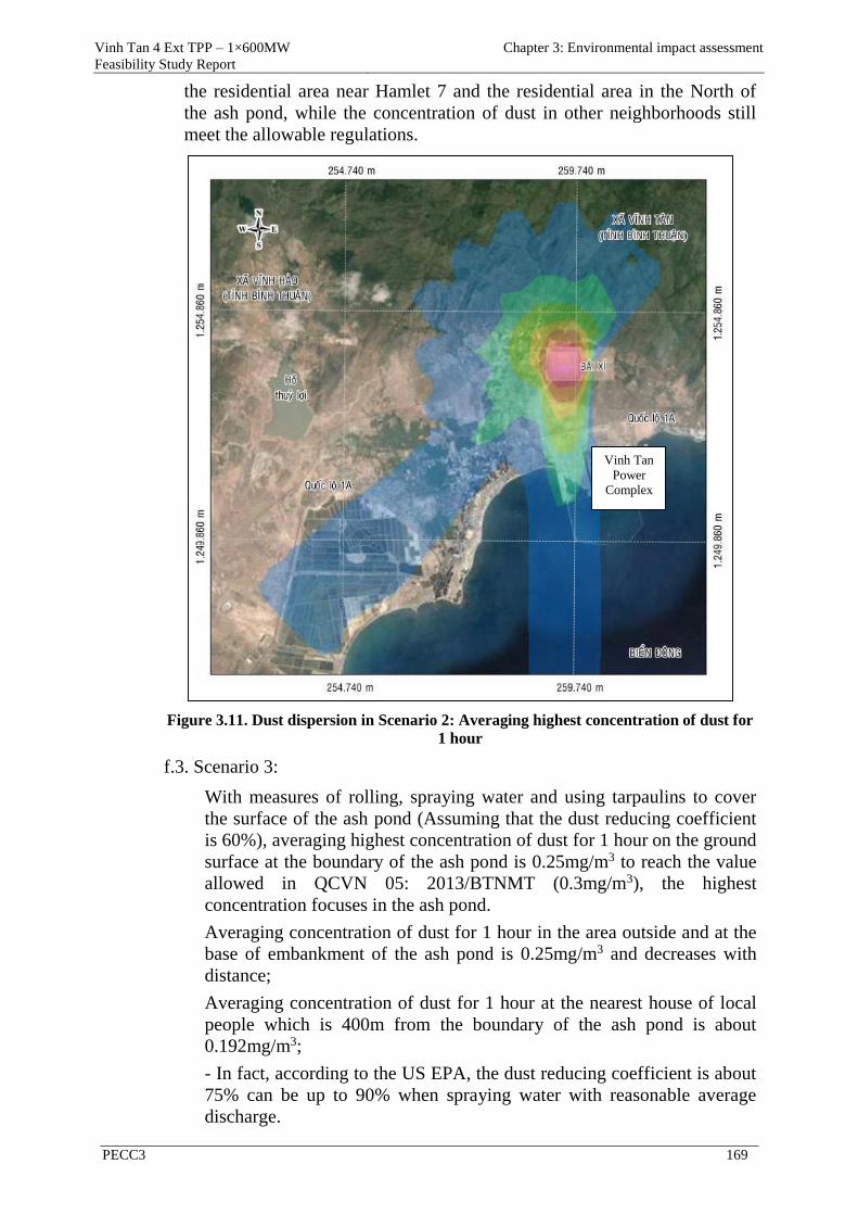
Vinh Tan 4 Ext TPP – 1×600MW
Feasibility Study Report
Chapter 3: Environmental impact assessment
PECC3 169
the residential area near Hamlet 7 and the residential area in the North of
the ash pond, while the concentration of dust in other neighborhoods still
meet the allowable regulations.
Figure 3.11. Dust dispersion in Scenario 2: Averaging highest concentration of dust for
1 hour
f.3. Scenario 3:
With measures of rolling, spraying water and using tarpaulins to cover
the surface of the ash pond (Assuming that the dust reducing coefficient
is 60%), averaging highest concentration of dust for 1 hour on the ground
surface at the boundary of the ash pond is 0.25mg/m3 to reach the value
allowed in QCVN 05: 2013/BTNMT (0.3mg/m3), the highest
concentration focuses in the ash pond.
Averaging concentration of dust for 1 hour in the area outside and at the
base of embankment of the ash pond is 0.25mg/m3 and decreases with
distance;
Averaging concentration of dust for 1 hour at the nearest house of local
people which is 400m from the boundary of the ash pond is about
0.192mg/m3;
- In fact, according to the US EPA, the dust reducing coefficient is about
75% can be up to 90% when spraying water with reasonable average
discharge.
Vinh Tan
Power
Complex
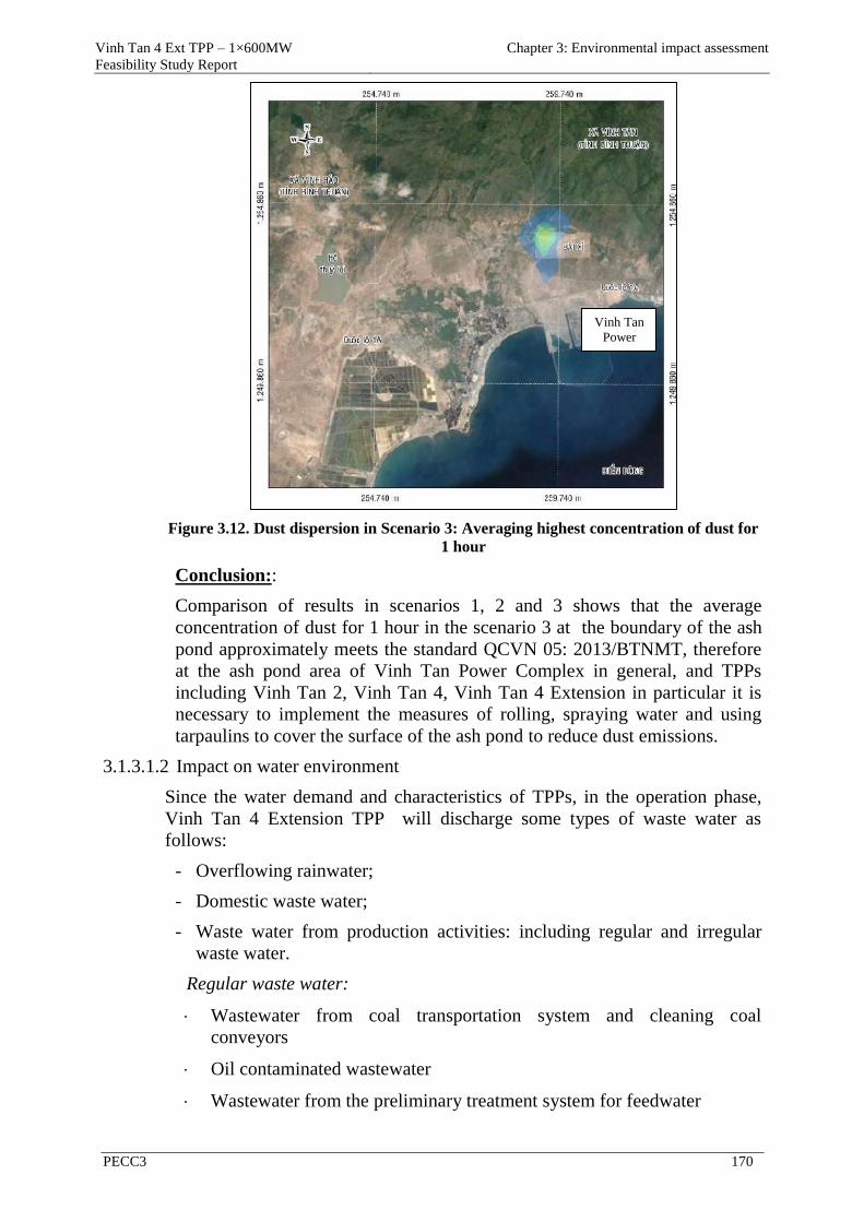
Vinh Tan 4 Ext TPP – 1×600MW
Feasibility Study Report
Chapter 3: Environmental impact assessment
PECC3 170
Figure 3.12. Dust dispersion in Scenario 3: Averaging highest concentration of dust for
1 hour
Conclusion::
Comparison of results in scenarios 1, 2 and 3 shows that the average
concentration of dust for 1 hour in the scenario 3 at the boundary of the ash
pond approximately meets the standard QCVN 05: 2013/BTNMT, therefore
at the ash pond area of Vinh Tan Power Complex in general, and TPPs
including Vinh Tan 2, Vinh Tan 4, Vinh Tan 4 Extension in particular it is
necessary to implement the measures of rolling, spraying water and using
tarpaulins to cover the surface of the ash pond to reduce dust emissions.
3.1.3.1.2 Impact on water environment
Since the water demand and characteristics of TPPs, in the operation phase,
Vinh Tan 4 Extension TPP will discharge some types of waste water as
follows:
- Overflowing rainwater;
- Domestic waste water;
- Waste water from production activities: including regular and irregular
waste water.
Regular waste water:
Wastewater from coal transportation system and cleaning coal
conveyors
Oil contaminated wastewater
Wastewater from the preliminary treatment system for feedwater
Vinh Tan
Power
Complex

Vinh Tan 4 Ext TPP – 1×600MW
Feasibility Study Report
Chapter 3: Environmental impact assessment
PECC3 171
Condensate treatment system;
Demineralised water treatment system;
Cooling wastewater;
Waste water from the system of SWFGD.
Irregular waste water:
Wastewater from washing chemicals of the boiler
Wastewater from washing system of ESP
Discharge, components and impact of the types of waste water from Vinh Tan
4 Ext TPP is presented in the following table:
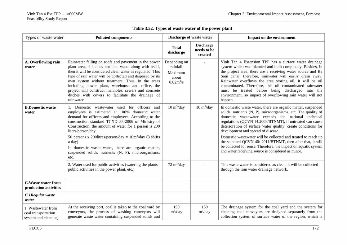
Vinh Tan 4 Ext TPP – 1×600MW
Feasibility Study Report
Chapter 3. Environmental Impact Assessment, Forecast
PECC3 172
Table 3.52. Types of waste water of the power plant
Types of waste water Polluted components Discharge of waste water Impact on the environment
Total
discharge
Discharge
needs to be
treated
A. Overflowing rain
water
Rainwater falling on roofs and pavement in the power
plant area, if it does not take waste along with itself,
then it will be considered clean water as regulated. This
type of rain water will be collected and disposed by its
own system without treatment. Thus, in the areas
including power plant, warehouse and office, the
project will construct manholes, sewers and concrete
ditches with covers to facilitate the drainage of
rainwater.
Depending on
rainfall
Maximum
about
0.02m3/s
- Vinh Tan 4 Extension TPP has a surface water drainage
system which was planned and built completely. Besides, in
the project area, there are a receiving water source and Ba
Sam canal, therefore, rainwater will easily drain away.
Rainwater overflows the area storing oil, it will be oil
contaminated. Therefore, this oil contaminated rainwater
must be treated before being discharged into the
environment, so impact of overflowing rain water will not
happen.
B.Domestic waste
water
1. Domestic wastewater used for officers and
employees is estimated at 100% domestic water
demand for officers and employees. According to the
construction standard TCXD 33-2006 of Ministry of
Construction, the amount of water for 1 person is 200
liters/person/day.
50 persons x 200litres/person/day = 10m3/day (3 shifts
a day)
In domestic waste water, there are organic matter,
suspended solids, nutrients (N, P), microorganisms,
etc.
10 m3/day 10 m3/day In domestic waste water, there are organic matter, suspended
solids, nutrients (N, P), microorganisms, etc. The quality of
domestic wastewater exceeds the national technical
regulations (QCVN 14:2008/BTNMT), if untreated can cause
deterioration of surface water quality, create conditions for
development and spread of disease.
Domestic wastewater will be collected and treated to reach up
the standard QCVN 40: 2011/BTNMT, then after that, it will
be collected for reuse. Therefore, the impact on aquatic system
and water receiving source is considered as minor.
2. Water used for public activities (watering the plants,
public activities in the power plant, etc.)
72 m3/day - This waste water is considered as clean, it will be collected
through the rain water drainage network.
C.Waste water from
production activities
C.1Regular waste
water
1. Wastewater from
coal transportation
system and cleaning
At the receiving port, coal is taken to the coal yard by
conveyors, the process of washing conveyors will
generate waste water containing suspended solids and
150
m3/day
150
m3/day
The drainage system for the coal yard and the system for
cleaning coal conveyors are designed separately from the
collection system of surface water of the region, which is
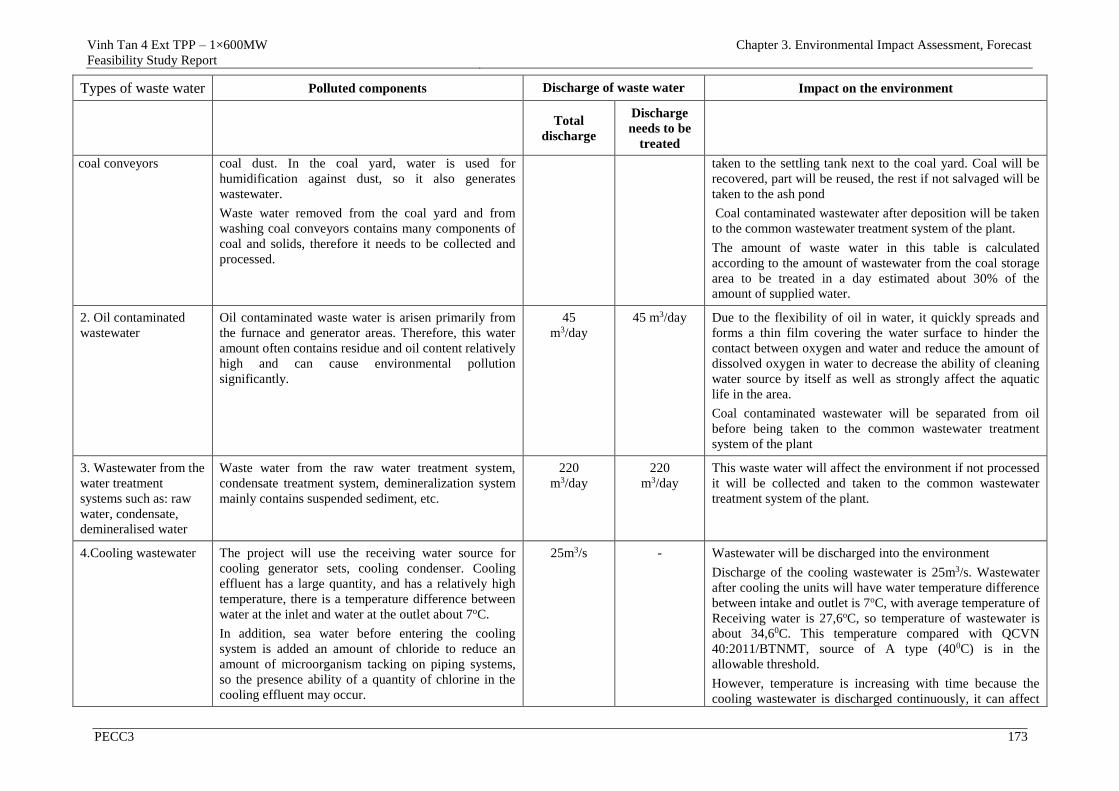
Vinh Tan 4 Ext TPP – 1×600MW
Feasibility Study Report
Chapter 3. Environmental Impact Assessment, Forecast
PECC3 173
Types of waste water Polluted components Discharge of waste water Impact on the environment
Total
discharge
Discharge
needs to be
treated
coal conveyors
coal dust. In the coal yard, water is used for
humidification against dust, so it also generates
wastewater.
Waste water removed from the coal yard and from
washing coal conveyors contains many components of
coal and solids, therefore it needs to be collected and
processed.
taken to the settling tank next to the coal yard. Coal will be
recovered, part will be reused, the rest if not salvaged will be
taken to the ash pond
Coal contaminated wastewater after deposition will be taken
to the common wastewater treatment system of the plant.
The amount of waste water in this table is calculated
according to the amount of wastewater from the coal storage
area to be treated in a day estimated about 30% of the
amount of supplied water.
2. Oil contaminated
wastewater
Oil contaminated waste water is arisen primarily from
the furnace and generator areas. Therefore, this water
amount often contains residue and oil content relatively
high and can cause environmental pollution
significantly.
45
m3/day
45 m3/day Due to the flexibility of oil in water, it quickly spreads and
forms a thin film covering the water surface to hinder the
contact between oxygen and water and reduce the amount of
dissolved oxygen in water to decrease the ability of cleaning
water source by itself as well as strongly affect the aquatic
life in the area.
Coal contaminated wastewater will be separated from oil
before being taken to the common wastewater treatment
system of the plant
3. Wastewater from the
water treatment
systems such as: raw
water, condensate,
demineralised water
Waste water from the raw water treatment system,
condensate treatment system, demineralization system
mainly contains suspended sediment, etc.
220
m3/day
220
m3/day
This waste water will affect the environment if not processed
it will be collected and taken to the common wastewater
treatment system of the plant.
4.Cooling wastewater The project will use the receiving water source for
cooling generator sets, cooling condenser. Cooling
effluent has a large quantity, and has a relatively high
temperature, there is a temperature difference between
water at the inlet and water at the outlet about 7oC.
In addition, sea water before entering the cooling
system is added an amount of chloride to reduce an
amount of microorganism tacking on piping systems,
so the presence ability of a quantity of chlorine in the
cooling effluent may occur.
25m3/s - Wastewater will be discharged into the environment
Discharge of the cooling wastewater is 25m3/s. Wastewater
after cooling the units will have water temperature difference
between intake and outlet is 7oC, with average temperature of
Receiving water is 27,6oC, so temperature of wastewater is
about 34,60C. This temperature compared with QCVN
40:2011/BTNMT, source of A type (400C) is in the
allowable threshold.
However, temperature is increasing with time because the
cooling wastewater is discharged continuously, it can affect
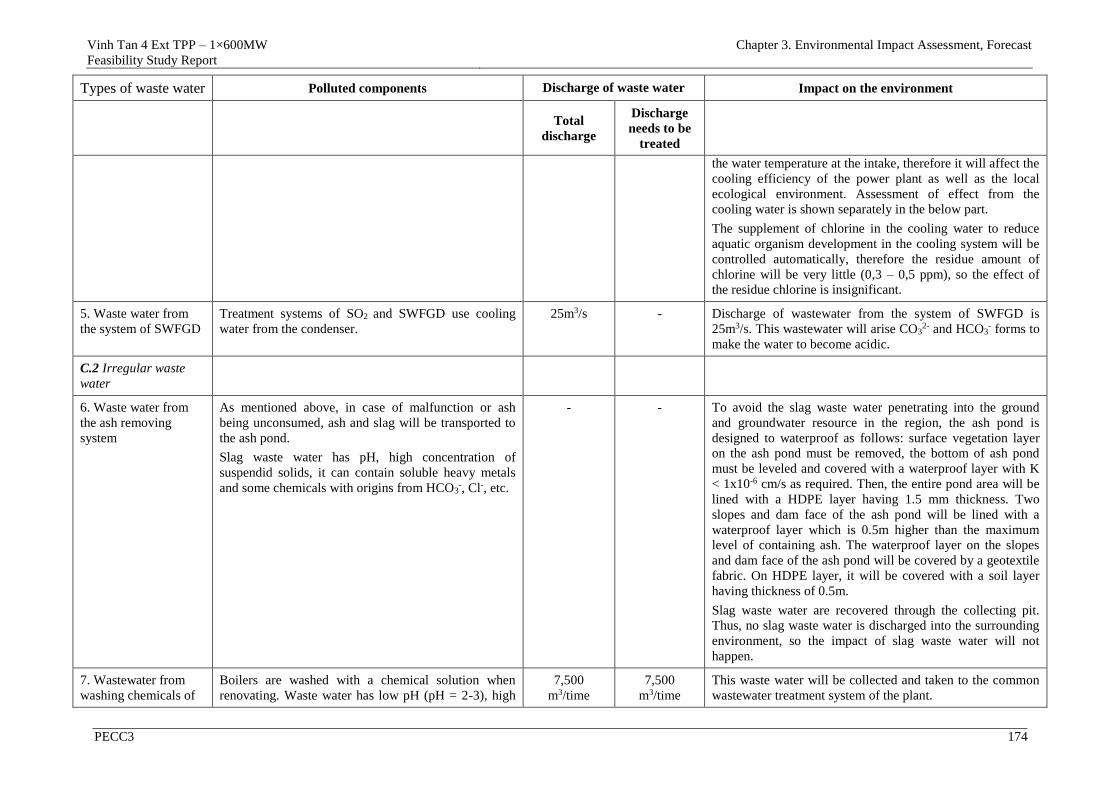
Vinh Tan 4 Ext TPP – 1×600MW
Feasibility Study Report
Chapter 3. Environmental Impact Assessment, Forecast
PECC3 174
Types of waste water Polluted components Discharge of waste water Impact on the environment
Total
discharge
Discharge
needs to be
treated
the water temperature at the intake, therefore it will affect the
cooling efficiency of the power plant as well as the local
ecological environment. Assessment of effect from the
cooling water is shown separately in the below part.
The supplement of chlorine in the cooling water to reduce
aquatic organism development in the cooling system will be
controlled automatically, therefore the residue amount of
chlorine will be very little (0,3 – 0,5 ppm), so the effect of
the residue chlorine is insignificant.
5. Waste water from
the system of SWFGD
Treatment systems of SO2 and SWFGD use cooling
water from the condenser.
25m3/s - Discharge of wastewater from the system of SWFGD is
25m3/s. This wastewater will arise CO32- and HCO3
- forms to
make the water to become acidic.
C.2 Irregular waste
water
6. Waste water from
the ash removing
system
As mentioned above, in case of malfunction or ash
being unconsumed, ash and slag will be transported to
the ash pond.
Slag waste water has pH, high concentration of
suspendid solids, it can contain soluble heavy metals
and some chemicals with origins from HCO3-, Cl-, etc.
- - To avoid the slag waste water penetrating into the ground
and groundwater resource in the region, the ash pond is
designed to waterproof as follows: surface vegetation layer
on the ash pond must be removed, the bottom of ash pond
must be leveled and covered with a waterproof layer with K
< 1x10⁻⁶ cm/s as required. Then, the entire pond area will be
lined with a HDPE layer having 1.5 mm thickness. Two
slopes and dam face of the ash pond will be lined with a
waterproof layer which is 0.5m higher than the maximum
level of containing ash. The waterproof layer on the slopes
and dam face of the ash pond will be covered by a geotextile
fabric. On HDPE layer, it will be covered with a soil layer
having thickness of 0.5m.
Slag waste water are recovered through the collecting pit.
Thus, no slag waste water is discharged into the surrounding
environment, so the impact of slag waste water will not
happen.
7. Wastewater from
washing chemicals of
Boilers are washed with a chemical solution when
renovating. Waste water has low pH (pH = 2-3), high
7,500
m3/time
7,500
m3/time
This waste water will be collected and taken to the common
wastewater treatment system of the plant.
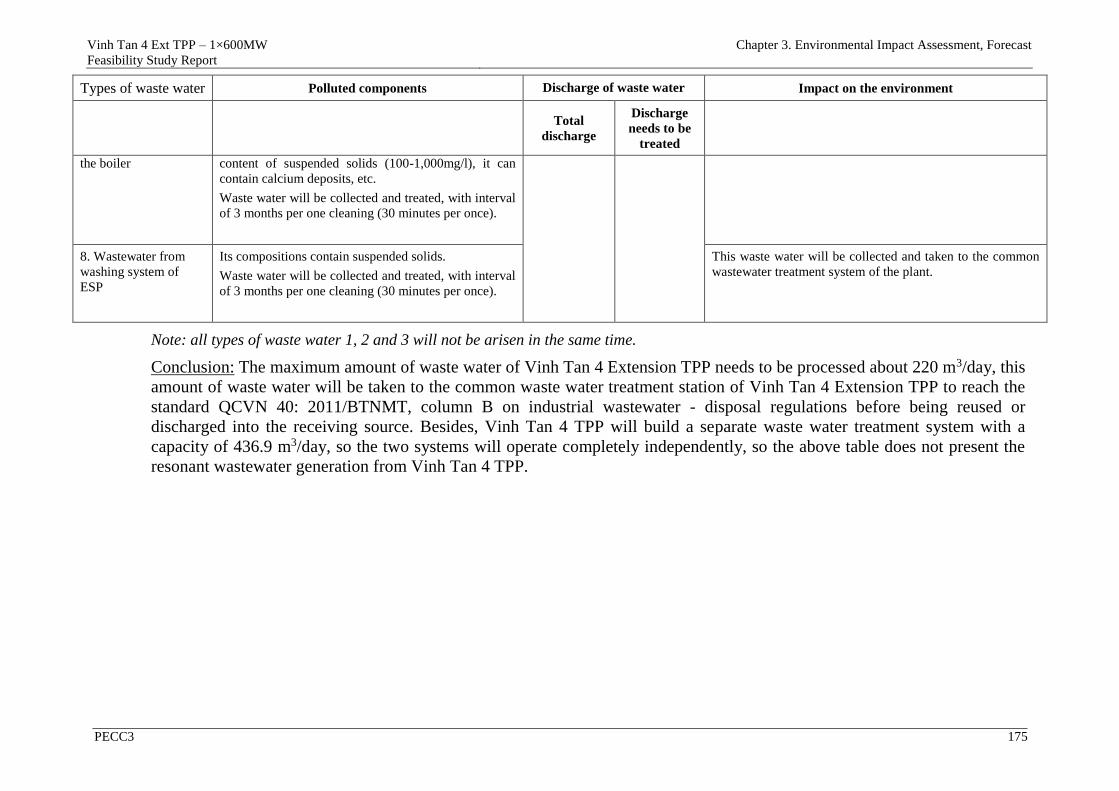
Vinh Tan 4 Ext TPP – 1×600MW
Feasibility Study Report
Chapter 3. Environmental Impact Assessment, Forecast
PECC3 175
Types of waste water Polluted components Discharge of waste water Impact on the environment
Total
discharge
Discharge
needs to be
treated
the boiler content of suspended solids (100-1,000mg/l), it can
contain calcium deposits, etc.
Waste water will be collected and treated, with interval
of 3 months per one cleaning (30 minutes per once).
8. Wastewater from
washing system of
ESP
Its compositions contain suspended solids.
Waste water will be collected and treated, with interval
of 3 months per one cleaning (30 minutes per once).
This waste water will be collected and taken to the common
wastewater treatment system of the plant.
Note: all types of waste water 1, 2 and 3 will not be arisen in the same time.
Conclusion: The maximum amount of waste water of Vinh Tan 4 Extension TPP needs to be processed about 220 m3/day, this
amount of waste water will be taken to the common waste water treatment station of Vinh Tan 4 Extension TPP to reach the
standard QCVN 40: 2011/BTNMT, column B on industrial wastewater - disposal regulations before being reused or
discharged into the receiving source. Besides, Vinh Tan 4 TPP will build a separate waste water treatment system with a
capacity of 436.9 m3/day, so the two systems will operate completely independently, so the above table does not present the
resonant wastewater generation from Vinh Tan 4 TPP.

Vinh Tan 4 Ext TPP – 1×600MW
Feasibility Study Report
Chapter 3: Environmental impact assessment
PECC3 176
To predict the effects of continuous cooling water discharge to the water
temperature of the receiving source, the report calculated cooling water
temperature spread of the plant to the receiving source as follows:
Calculation of the cooling water temperature spread
1. Calculation method: using the software of MIKE 21/3 Coupled Model FM
which was developed by DHI Water & Environment.
The MIKE 21/3 Coupled Model FM has been developed for complex
applications within oceanographic, coastal and estuarine environments. The
model includes the following modules:
Flow Model FM modules:
- Hydrodynamic Module, HD
- Transport Module, TR
- Ecology and water quality Module, ECO Lab
- Sand Transport Module, ST
- Mud Transport Module, MT
Wave module:
- Spectral Wave Module, SW
Flow Module and Spectral Wave Module are two basic components of MIKE
21/3 Coupled Model FM. This model allows to calculate Wave-current
interaction by using a combination of Flow Module and Spectral Wave
Module. The model can also calculate the variation of river morphology as
well as the seabed (combination of modules including Mud Transport Module,
Sand Transport Module, Flow Modules and Wave Module). The combination
of modules of the model allows to simulate the complete interaction of
changes in depth to calculate wave as well as flow, therefore the accuracy of
the model is also improved when compared with the other models.
- Flow Module MIKE 21 FM
MIKE 21 FM is a new general hydrodynamic flow modelling system based on
a finite volume method on an unstructured mesh (Flexible Mesh). The
modelling system has been developed for complex applications within
oceanographic, coastal and estuarine environments.. It simulates the water
level variations and flows in response to a variety of forcing functions on flood
plains, in lakes, estuaries and coastal areas.
Module consists of two equations is the continuity equation and momentum
equation.
- Spectral Wave Module MIKE 21 SW
- MIKE 21 SW is a state-of-the-art numerical modelling tool for prediction
and analysis of wave climates in offshore and coastal areas
The model simulates the growth, decay and transformation of wind- generated
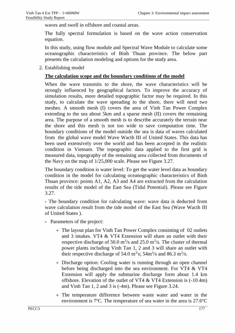
Vinh Tan 4 Ext TPP – 1×600MW
Feasibility Study Report
Chapter 3: Environmental impact assessment
PECC3 177
waves and swell in offshore and coastal areas.
The fully spectral formulation is based on the wave action conservation
equation.
In this study, using flow module and Spectral Wave Module to calculate some
oceanographic characteristics of Binh Thuan province. The below part
presents the calculation modeling and options for the study area.
2. Establishing model
The calculation scope and the boundary conditions of the model
When the wave transmits to the shore, the wave characteristics will be
strongly influenced by geographical factors. To improve the accuracy of
simulation results, more detailed topographic factor may be required. In this
study, to calculate the wave spreading to the shore, there will need two
meshes. A smooth mesh (I) covers the area of Vinh Tan Power Complex
extending to the sea about 5km and a sparse mesh (II) covers the remaining
area. The purpose of a smooth mesh is to describe accurately the terrain near
the shore and this mesh is not too wide to save computation time. The
boundary conditions of the model outside the sea is data of waves calculated
from the global wave model Wave Wacth III of United States. This data has
been used extensively over the world and has been accepted in the realistic
condition in Vietnam. The topographic data applied to the first grid is
measured data, topography of the remaining area collected from documents of
the Navy on the map of 1/25,000 scale. Please see Figure 3.27.
The boundary condition is water level: To get the water level data as boundary
condition in the model for calculating oceanographic characteristics of Binh
Thuan province: points A1, A2, A3 and A4 are extracted from the calculation
results of the tide model of the East Sea (Tidal Potential). Please see Figure
3.27.
- The boundary condition for calculating wave: wave data is deducted from
wave calculation result from the tide model of the East Sea (Wave Wacth III
of United States ).
- Parameters of the project:
The layout plan for Vinh Tan Power Complex consisting of 02 outlets
and 3 intakes. VT4 & VT4 Extension will share an outlet with their
respective discharge of 50.0 m3/s and 25.0 m3/s. The cluster of thermal
power plants including Vinh Tan 1, 2 and 3 will share an outlet with
their respective discharge of 54.0 m3/s; 54m3/s and 86.3 m3/s.
Discharge option: Cooling water is running through an open channel
before being discharged into the sea environment. For VT4 & VT4
Extension will apply the submarine discharge form about 1.4 km
offshore. Elevation of the outlet of VT4 & VT4 Extension is (-10.4m)
and Vinh Tan 1, 2 and 3 is (-4m). Please see Figure 3.24.
The temperature difference between waste water and water in the
environment is 7oC. The temperature of sea water in the area is 27.6oC
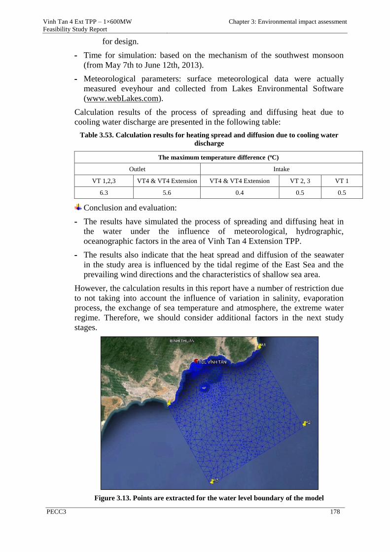
Vinh Tan 4 Ext TPP – 1×600MW
Feasibility Study Report
Chapter 3: Environmental impact assessment
PECC3 178
for design.
- Time for simulation: based on the mechanism of the southwest monsoon
(from May 7th to June 12th, 2013).
- Meteorological parameters: surface meteorological data were actually
measured eveyhour and collected from Lakes Environmental Software
(www.webLakes.com).
Calculation results of the process of spreading and diffusing heat due to
cooling water discharge are presented in the following table:
Table 3.53. Calculation results for heating spread and diffusion due to cooling water
discharge
The maximum temperature difference (oC)
Outlet Intake
VT 1,2,3 VT4 & VT4 Extension VT4 & VT4 Extension VT 2, 3 VT 1
6.3 5.6 0.4 0.5 0.5
Conclusion and evaluation:
- The results have simulated the process of spreading and diffusing heat in
the water under the influence of meteorological, hydrographic,
oceanographic factors in the area of Vinh Tan 4 Extension TPP.
- The results also indicate that the heat spread and diffusion of the seawater
in the study area is influenced by the tidal regime of the East Sea and the
prevailing wind directions and the characteristics of shallow sea area.
However, the calculation results in this report have a number of restriction due
to not taking into account the influence of variation in salinity, evaporation
process, the exchange of sea temperature and atmosphere, the extreme water
regime. Therefore, we should consider additional factors in the next study
stages.
Figure 3.13. Points are extracted for the water level boundary of the model
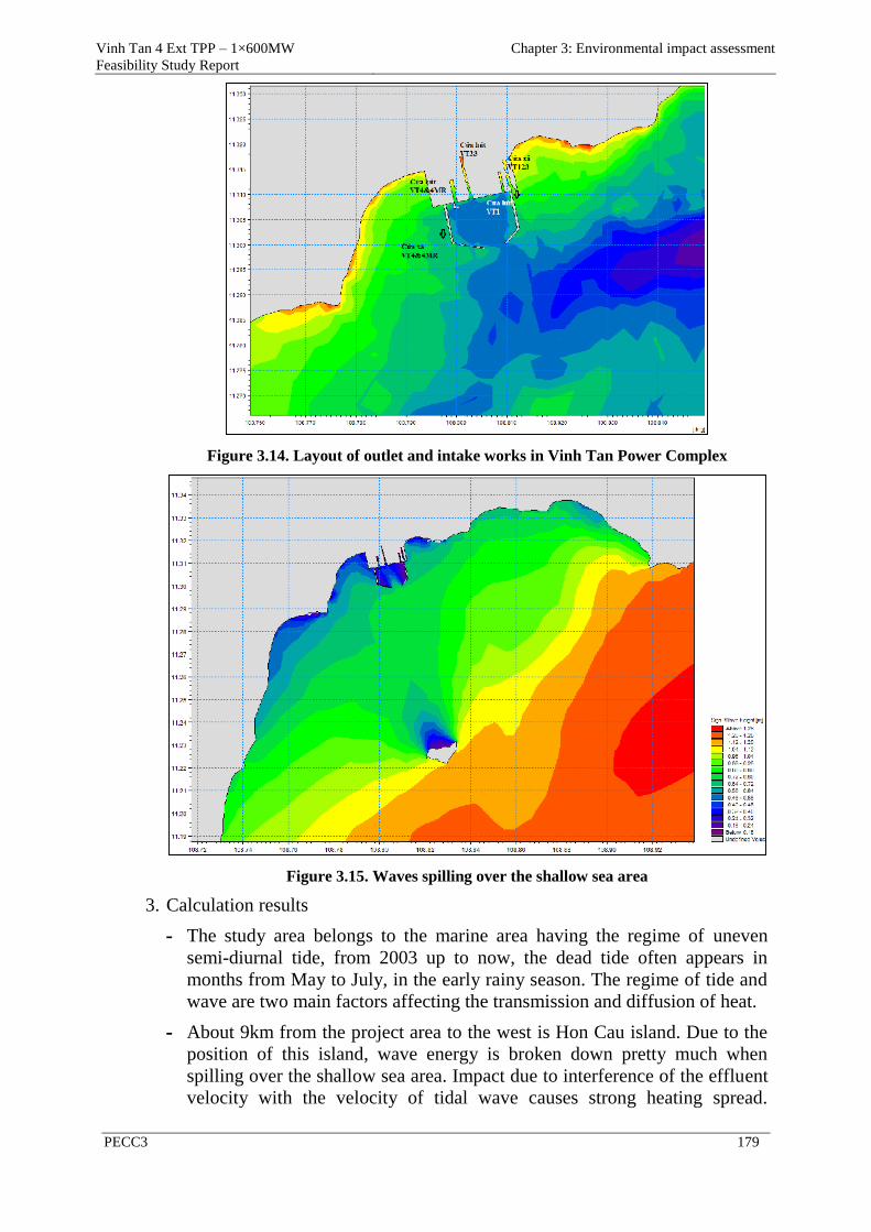
Vinh Tan 4 Ext TPP – 1×600MW
Feasibility Study Report
Chapter 3: Environmental impact assessment
PECC3 179
Figure 3.14. Layout of outlet and intake works in Vinh Tan Power Complex
Figure 3.15. Waves spilling over the shallow sea area
3. Calculation results
- The study area belongs to the marine area having the regime of uneven
semi-diurnal tide, from 2003 up to now, the dead tide often appears in
months from May to July, in the early rainy season. The regime of tide and
wave are two main factors affecting the transmission and diffusion of heat.
- About 9km from the project area to the west is Hon Cau island. Due to the
position of this island, wave energy is broken down pretty much when
spilling over the shallow sea area. Impact due to interference of the effluent
velocity with the velocity of tidal wave causes strong heating spread.
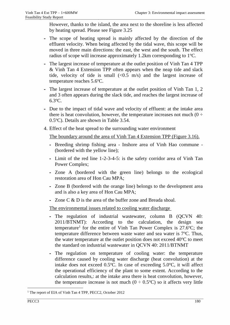
Vinh Tan 4 Ext TPP – 1×600MW
Feasibility Study Report
Chapter 3: Environmental impact assessment
PECC3 180
However, thanks to the island, the area next to the shoreline is less affected
by heating spread. Please see Figure 3.25
- The scope of heating spread is mainly affected by the direction of the
effluent velocity. When being affected by the tidal wave, this scope will be
moved in three main directions: the east, the west and the south. The effect
radius of scope will increase approximately 1.2km corresponding to 1oC.
- The largest increase of temperature at the outlet position of Vinh Tan 4 TPP
& Vinh Tan 4 Extension TPP often appears when the neap tide and slack
tide, velocity of tide is small (<0.5 m/s) and the largest increase of
temperature reaches 5.6oC.
- The largest increase of temperature at the outlet position of Vinh Tan 1, 2
and 3 often appears during the slack tide, and reaches the largest increase of
6.3oC.
- Due to the impact of tidal wave and velocity of effluent: at the intake area
there is heat convolution, however, the temperature increases not much (0 ÷
0.5oC). Details are shown in Table 3.54.
4. Effect of the heat spread to the surrounding water environment
The boundary around the area of Vinh Tan 4 Extension TPP (Figure 3.16).
- Breeding shrimp fishing area - Inshore area of Vinh Hao commune -
(bordered with the yellow line);
- Limit of the red line 1-2-3-4-5: is the safety corridor area of Vinh Tan
Power Complex;
- Zone A (bordered with the green line) belongs to the ecological
restoration area of Hon Cau MPA;
- Zone B (bordered with the orange line) belongs to the development area
and is also a key area of Hon Cau MPA;
- Zone C & D is the area of the buffer zone and Breada shoal.
The environmental issues related to cooling water discharge
- The regulation of industrial wastewater, column B (QCVN 40:
2011/BTNMT): According to the calculation, the design sea
temperature1 for the entire of Vinh Tan Power Complex is 27.6oC; the
temperature difference between waste water and sea water is 7oC. Thus,
the water temperature at the outlet position does not exceed 40oC to meet
the standard on industrial wastewater in QCVN 40: 2011/BTNMT
- The regulation on temperature of cooling water: the temperature
difference caused by cooling water discharge (heat convolution) at the
intake does not exceed 0.5oC. In case of exceeding 5.0oC, it will affect
the operational efficiency of the plant to some extent. According to the
calculation results,: at the intake area there is heat convolution, however,
the temperature increase is not much (0 ÷ 0.5oC) so it affects very little 1 The report of EIA of Vinh Tan 4 TPP, PECC2, October 2012
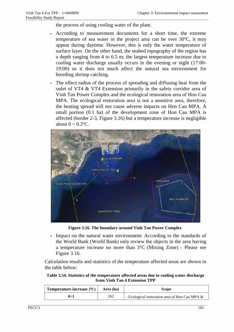
Vinh Tan 4 Ext TPP – 1×600MW
Feasibility Study Report
Chapter 3: Environmental impact assessment
PECC3 181
the process of using cooling water of the plant.
- According to measurement documents for a short time, the extreme
temperature of sea water in the project area can be over 30oC, it may
appear during daytime. However, this is only the water temperature of
surface layer. On the other hand, the seabed topography of the region has
a depth ranging from 4 to 6.5 m; the largest temperature increase due to
cooling water discharge usually occurs in the evening or night (17:00-
19:00) so it does not much affect the natural sea environment for
breeding shrimp catching.
- The effect radius of the process of spreading and diffusing heat from the
oulet of VT4 & VT4 Extension primarily in the safety corridor area of
Vinh Tan Power Complex and the ecological restoration area of Hon Cau
MPA. The ecological restoration area is not a sensitive area, therefore,
the heating spread will not cause adverse impacts on Hon Cau MPA. A
small portion (0.1 ha) of the development zone of Hon Cau MPA is
affected (border 2-3, Figure 3.16) but a temperature increase is negligible
about 0 ÷ 0.2oC.
Figure 3.16. The boundary around Vinh Tan Power Complex
- Impact on the natural water environment: According to the standards of
the World Bank (World Bank) only review the objects in the area having
a temperature increase no more than 3oC (Mixing Zone) - Please see
Figure 3.16.
Calculation results and statistics of the temperature affected areas are shown in
the table below:
Table 3.54. Statistics of the temperature affected areas due to cooling water discharge
from Vinh Tan 4 Extension TPP
Temperature increase (0C) Area (ha) Scope
0÷1 262 - Ecological restoration area of Hon Cau MPA &
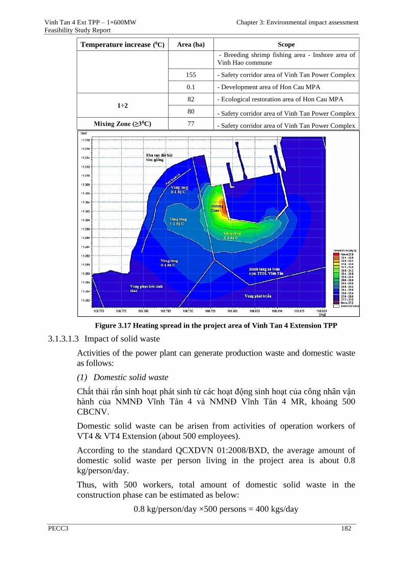
Vinh Tan 4 Ext TPP – 1×600MW
Feasibility Study Report
Chapter 3: Environmental impact assessment
PECC3 182
Temperature increase (0C) Area (ha) Scope
- Breeding shrimp fishing area - Inshore area of
Vinh Hao commune
155 - Safety corridor area of Vinh Tan Power Complex
0.1 - Development area of Hon Cau MPA
1÷2 82 - Ecological restoration area of Hon Cau MPA
80 - Safety corridor area of Vinh Tan Power Complex
Mixing Zone (≥30C) 77 - Safety corridor area of Vinh Tan Power Complex
Figure 3.17 Heating spread in the project area of Vinh Tan 4 Extension TPP
3.1.3.1.3 Impact of solid waste
Activities of the power plant can generate production waste and domestic waste
as follows:
(1) Domestic solid waste
Chất thải rắn sinh hoạt phát sinh từ các hoạt động sinh hoạt của công nhân vận
hành của NMNĐ Vĩnh Tân 4 và NMNĐ Vĩnh Tân 4 MR, khoảng 500
CBCNV.
Domestic solid waste can be arisen from activities of operation workers of
VT4 & VT4 Extension (about 500 employees).
According to the standard QCXDVN 01:2008/BXD, the average amount of
domestic solid waste per person living in the project area is about 0.8
kg/person/day.
Thus, with 500 workers, total amount of domestic solid waste in the
construction phase can be estimated as below:
0.8 kg/person/day ×500 persons = 400 kgs/day
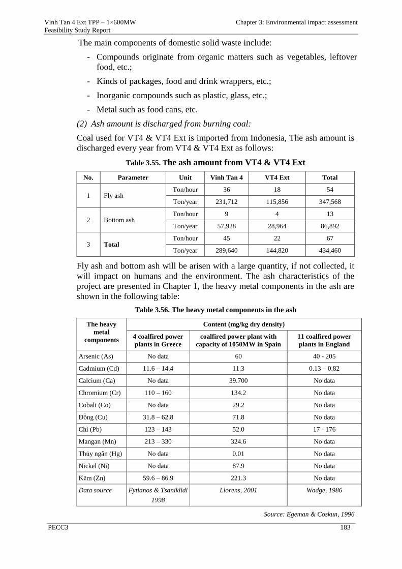
Vinh Tan 4 Ext TPP – 1×600MW
Feasibility Study Report
Chapter 3: Environmental impact assessment
PECC3 183
The main components of domestic solid waste include:
- Compounds originate from organic matters such as vegetables, leftover
food, etc.;
- Kinds of packages, food and drink wrappers, etc.;
- Inorganic compounds such as plastic, glass, etc.;
- Metal such as food cans, etc.
(2) Ash amount is discharged from burning coal:
Coal used for VT4 & VT4 Ext is imported from Indonesia, The ash amount is
discharged every year from VT4 & VT4 Ext as follows:
Table 3.55. The ash amount from VT4 & VT4 Ext
No. Parameter Unit Vinh Tan 4 VT4 Ext Total
1 Fly ash Ton/hour 36 18 54
Ton/year 231,712 115,856 347,568
2 Bottom ash Ton/hour 9 4 13
Ton/year 57,928 28,964 86,892
3 Total Ton/hour 45 22 67
Ton/year 289,640 144,820 434,460
Fly ash and bottom ash will be arisen with a large quantity, if not collected, it
will impact on humans and the environment. The ash characteristics of the
project are presented in Chapter 1, the heavy metal components in the ash are
shown in the following table:
Table 3.56. The heavy metal components in the ash
The heavy
metal
components
Content (mg/kg dry density)
4 coalfired power
plants in Greece
coalfired power plant with
capacity of 1050MW in Spain
11 coalfired power
plants in England
Arsenic (As) No data 60 40 - 205
Cadmium (Cd) 11.6 – 14.4 11.3 0.13 – 0.82
Calcium (Ca) No data 39.700 No data
Chromium (Cr) 110 – 160 134.2 No data
Cobalt (Co) No data 29.2 No data
Đồng (Cu) 31.8 – 62.8 71.8 No data
Chì (Pb) 123 – 143 52.0 17 - 176
Mangan (Mn) 213 – 330 324.6 No data
Thủy ngân (Hg) No data 0.01 No data
Nickel (Ni) No data 87.9 No data
Kẽm (Zn) 59.6 – 86.9 221.3 No data
Data source Fytianos & Tsaniklidi
1998
Llorens, 2001 Wadge, 1986
Source: Egeman & Coskun, 1996
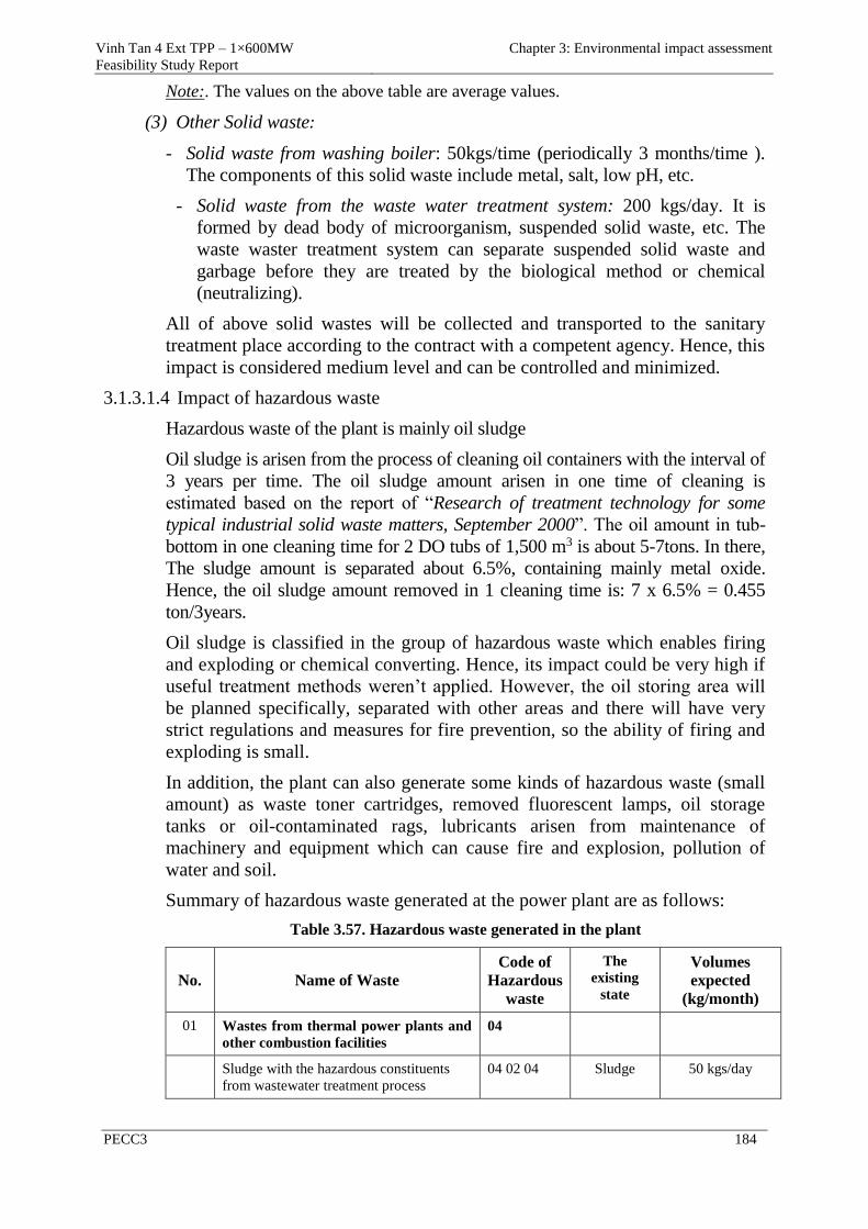
Vinh Tan 4 Ext TPP – 1×600MW
Feasibility Study Report
Chapter 3: Environmental impact assessment
PECC3 184
Note:. The values on the above table are average values.
(3) Other Solid waste:
- Solid waste from washing boiler: 50kgs/time (periodically 3 months/time ).
The components of this solid waste include metal, salt, low pH, etc.
- Solid waste from the waste water treatment system: 200 kgs/day. It is
formed by dead body of microorganism, suspended solid waste, etc. The
waste waster treatment system can separate suspended solid waste and
garbage before they are treated by the biological method or chemical
(neutralizing).
All of above solid wastes will be collected and transported to the sanitary
treatment place according to the contract with a competent agency. Hence, this
impact is considered medium level and can be controlled and minimized.
3.1.3.1.4 Impact of hazardous waste
Hazardous waste of the plant is mainly oil sludge
Oil sludge is arisen from the process of cleaning oil containers with the interval of
3 years per time. The oil sludge amount arisen in one time of cleaning is
estimated based on the report of “Research of treatment technology for some
typical industrial solid waste matters, September 2000”. The oil amount in tub-
bottom in one cleaning time for 2 DO tubs of 1,500 m3 is about 5-7tons. In there,
The sludge amount is separated about 6.5%, containing mainly metal oxide.
Hence, the oil sludge amount removed in 1 cleaning time is: 7 x 6.5% = 0.455
ton/3years.
Oil sludge is classified in the group of hazardous waste which enables firing
and exploding or chemical converting. Hence, its impact could be very high if
useful treatment methods weren’t applied. However, the oil storing area will
be planned specifically, separated with other areas and there will have very
strict regulations and measures for fire prevention, so the ability of firing and
exploding is small.
In addition, the plant can also generate some kinds of hazardous waste (small
amount) as waste toner cartridges, removed fluorescent lamps, oil storage
tanks or oil-contaminated rags, lubricants arisen from maintenance of
machinery and equipment which can cause fire and explosion, pollution of
water and soil.
Summary of hazardous waste generated at the power plant are as follows:
Table 3.57. Hazardous waste generated in the plant
No. Name of Waste
Code of
Hazardous
waste
The
existing
state
Volumes
expected
(kg/month)
01 Wastes from thermal power plants and
other combustion facilities
04
Sludge with the hazardous constituents
from wastewater treatment process
04 02 04 Sludge 50 kgs/day
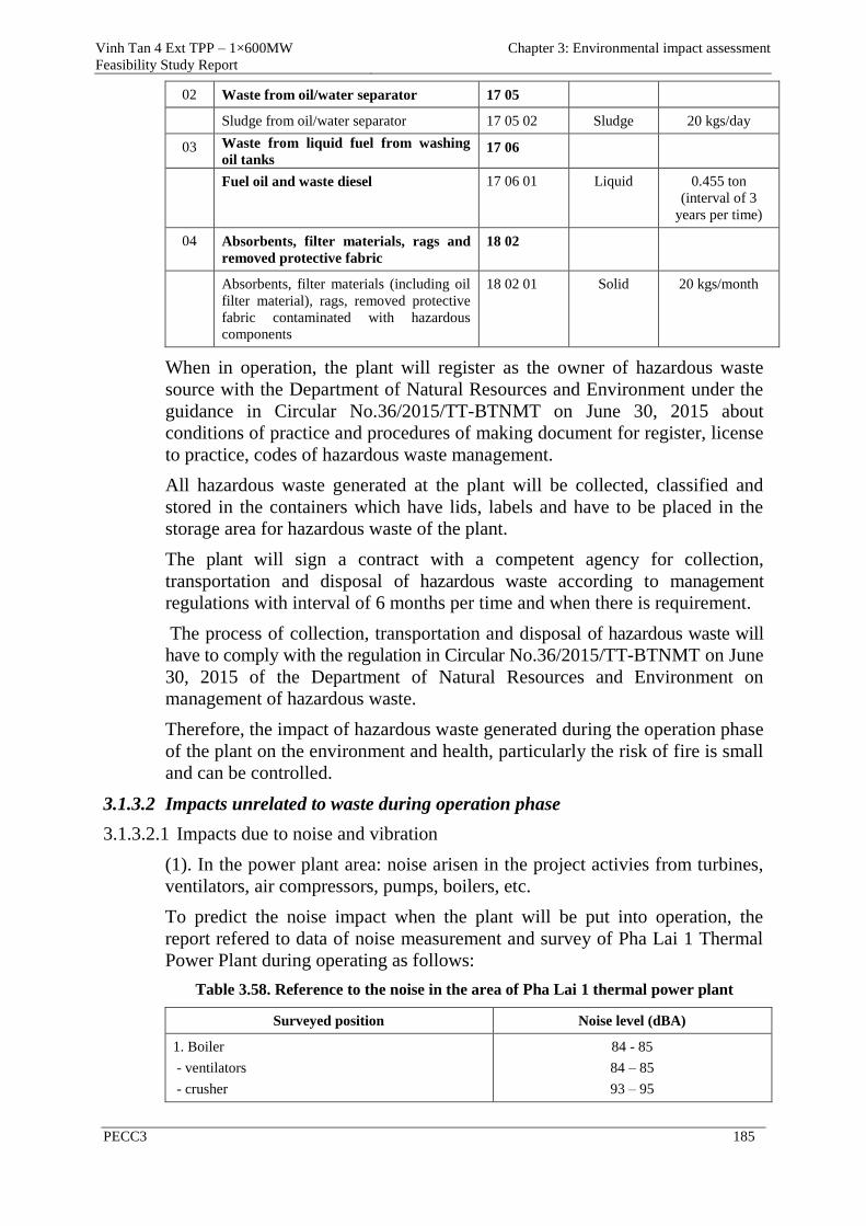
Vinh Tan 4 Ext TPP – 1×600MW
Feasibility Study Report
Chapter 3: Environmental impact assessment
PECC3 185
02 Waste from oil/water separator 17 05
Sludge from oil/water separator 17 05 02 Sludge 20 kgs/day
03 Waste from liquid fuel from washing
oil tanks 17 06
Fuel oil and waste diesel 17 06 01 Liquid 0.455 ton
(interval of 3
years per time)
04 Absorbents, filter materials, rags and
removed protective fabric
18 02
Absorbents, filter materials (including oil
filter material), rags, removed protective
fabric contaminated with hazardous
components
18 02 01 Solid 20 kgs/month
When in operation, the plant will register as the owner of hazardous waste
source with the Department of Natural Resources and Environment under the
guidance in Circular No.36/2015/TT-BTNMT on June 30, 2015 about
conditions of practice and procedures of making document for register, license
to practice, codes of hazardous waste management.
All hazardous waste generated at the plant will be collected, classified and
stored in the containers which have lids, labels and have to be placed in the
storage area for hazardous waste of the plant.
The plant will sign a contract with a competent agency for collection,
transportation and disposal of hazardous waste according to management
regulations with interval of 6 months per time and when there is requirement.
The process of collection, transportation and disposal of hazardous waste will
have to comply with the regulation in Circular No.36/2015/TT-BTNMT on June
30, 2015 of the Department of Natural Resources and Environment on
management of hazardous waste.
Therefore, the impact of hazardous waste generated during the operation phase
of the plant on the environment and health, particularly the risk of fire is small
and can be controlled.
3.1.3.2 Impacts unrelated to waste during operation phase
3.1.3.2.1 Impacts due to noise and vibration
(1). In the power plant area: noise arisen in the project activies from turbines,
ventilators, air compressors, pumps, boilers, etc.
To predict the noise impact when the plant will be put into operation, the
report refered to data of noise measurement and survey of Pha Lai 1 Thermal
Power Plant during operating as follows:
Table 3.58. Reference to the noise in the area of Pha Lai 1 thermal power plant
Surveyed position Noise level (dBA)
1. Boiler
- ventilators
- crusher
84 - 85
84 – 85
93 – 95
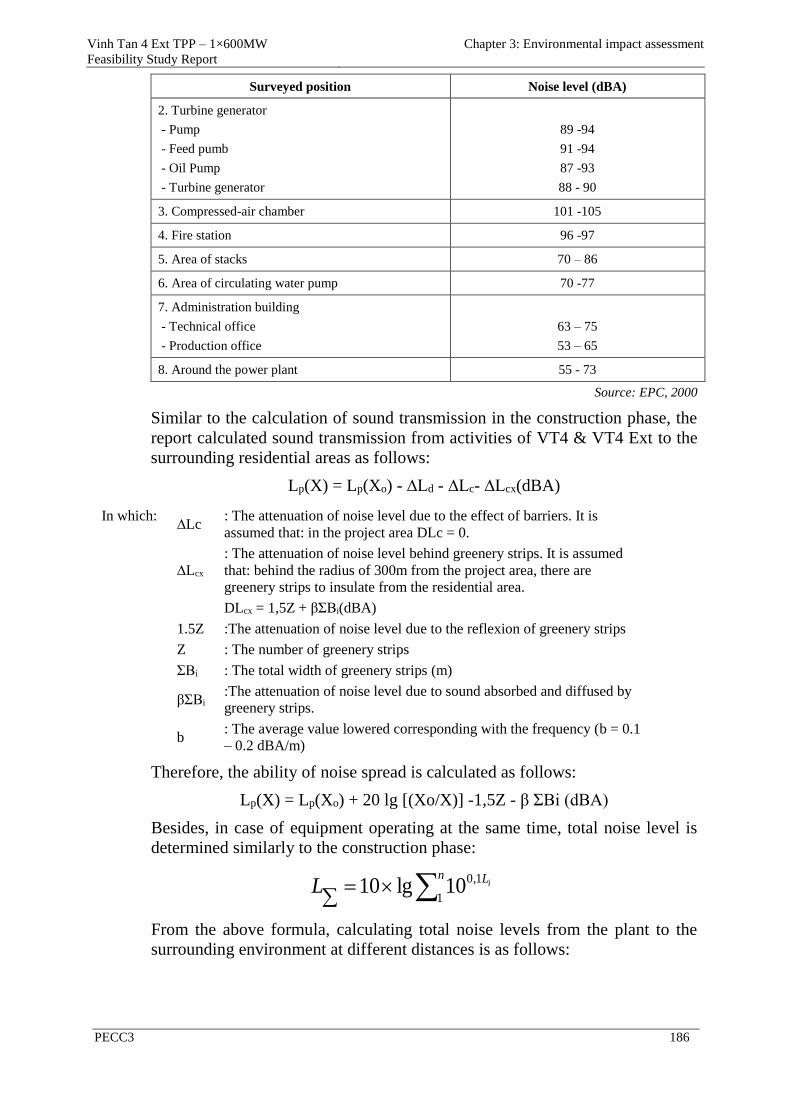
Vinh Tan 4 Ext TPP – 1×600MW
Feasibility Study Report
Chapter 3: Environmental impact assessment
PECC3 186
Surveyed position Noise level (dBA)
2. Turbine generator
- Pump
- Feed pumb
- Oil Pump
- Turbine generator
89 -94
91 -94
87 -93
88 - 90
3. Compressed-air chamber 101 -105
4. Fire station 96 -97
5. Area of stacks 70 – 86
6. Area of circulating water pump 70 -77
7. Administration building
- Technical office
- Production office
63 – 75
53 – 65
8. Around the power plant 55 - 73
Source: EPC, 2000
Similar to the calculation of sound transmission in the construction phase, the
report calculated sound transmission from activities of VT4 & VT4 Ext to the
surrounding residential areas as follows:
Lp(X) = Lp(Xo) - ∆Ld - ∆Lc- ∆Lcx(dBA)
In which: ∆Lc
: The attenuation of noise level due to the effect of barriers. It is
assumed that: in the project area DLc = 0.
∆Lcx
: The attenuation of noise level behind greenery strips. It is assumed
that: behind the radius of 300m from the project area, there are
greenery strips to insulate from the residential area.
DLcx = 1,5Z + βΣBi(dBA)
1.5Z :The attenuation of noise level due to the reflexion of greenery strips
Z : The number of greenery strips
ΣBi : The total width of greenery strips (m)
βΣBi :The attenuation of noise level due to sound absorbed and diffused by
greenery strips.
b : The average value lowered corresponding with the frequency (b = 0.1
– 0.2 dBA/m)
Therefore, the ability of noise spread is calculated as follows:
Lp(X) = Lp(Xo) + 20 lg [(Xo/X)] -1,5Z - β ΣBi (dBA)
Besides, in case of equipment operating at the same time, total noise level is
determined similarly to the construction phase:
n LiL1
1,010lg10
From the above formula, calculating total noise levels from the plant to the
surrounding environment at different distances is as follows:
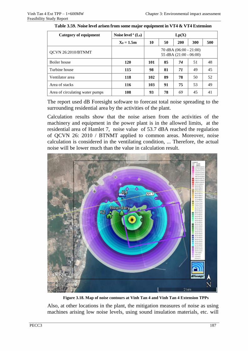
Vinh Tan 4 Ext TPP – 1×600MW
Feasibility Study Report
Chapter 3: Environmental impact assessment
PECC3 187
Table 3.59. Noise level arisen from some major equipment in VT4 & VT4 Extension
Category of equipment Noise level ª (L0) Lp(X)
X0 = 1.5m 10 50 200 300 500
QCVN 26:2010/BTNMT
70 dBA (06:00 - 21:00)
55 dBA (21:00 - 06:00)
Boiler house 120 101 85 74 51 48
Turbine house 115 98 81 71 49 45
Ventilator area 118 102 89 78 50 52
Area of stacks 116 103 91 75 53 49
Area of circulating water pumps 108 93 78 69 45 41
The report used dB Foresight software to forecast total noise spreading to the
surrounding residential area by the activities of the plant.
Calculation results show that the noise arisen from the activities of the
machinery and equipment in the power plant is in the allowed limits, at the
residential area of Hamlet 7, noise value of 53.7 dBA reached the regulation
of QCVN 26: 2010 / BTNMT applied to common areas. Moreover, noise
calculation is considered in the ventilating condition, ... Therefore, the actual
noise will be lower much than the value in calculation result.
Figure 3.18. Map of noise contours at Vinh Tan 4 and Vinh Tan 4 Extension TPPs
Also, at other locations in the plant, the mitigation measures of noise as using
machines arising low noise levels, using sound insulation materials, etc. will
Vinh Tan 4 Ext TPP – 1×600MW
Feasibility Study Report
Chapter 3: Environmental impact assessment
PECC3 188
be applied to ensure the noise levels at the working positions satisfy Decision
3722/BYT and will not affect the workers' health in the power plant.
(2). Operation activities on the port
Total noise level during operation at the port of VT4 & VT4 Extension is
calculated and presented in the following table:
Table 3.60. Noise levels arisen from the activities on the port
Category of equipment Noise level (L0)
Lp(X)
X0 = 1.5m 10 50 200 300 500
QCVN 26:2010/BTNMT 70 dBA (06:00 - 21:00)
55 dBA (21:00 - 06:00)
Activities of vessels 105 88 78 64 42 38
Operation of cranes 108 90 80 66 44 40
Activities of loading and
unloading materials 95 84 68 54 32 28
Air compressor 106 100 84 70 48 44
Generator 107 99 82 68 46 42
Calculation results show that the noise arisen from the activities of the
machinery and equipment on the port is in the allowed limits for the
construction site and the residential areas which are over 200m from the port
area according to the provisions of QCVN 26: 2010/BTNMT applied to the
common area.
The existing residential area is over 400m from the port of the power plant,
thus, the operating activities on the port will not affect the residential area and
administrative agencies.
For the area having high noise level may affect the operation workers of the
plant, these workers will be equipped with labor protection and noise-
protective capsules and plugs.
3.1.3.2.2 Excess heat (heat pollution)
Heat source arises mainly from the process of burning fuel (coal), in some
locations, such as the boiler, chimney area, temperature can rise up to 40°C.
Affected objects by heat pollution in the power plant are operators. When
working in the high temperature condition, the temperature of the direct
production worker is increased considerably because excess heat makes the
metabolism process in the worker's body produce more biological heat. When
the biological ability of the direct production worker's body is not sufficient to
neutralize the residual heat, it will cause a state of fatigue, increase the
likelihood of injury and possibly appear clinical symptoms of illness due to
high temperature. When working for long period in high temperature
condition, the physiological activities of the body will be disturbed and the
central nervous system will be directly affected. If this process lasts longer, it
can lead to chronic headaches.
Vinh Tan 4 Ext TPP – 1×600MW
Feasibility Study Report
Chapter 3: Environmental impact assessment
PECC3 189
However, the majority of operating workers and engineers will work in the
control room. Checking the equipment system under operation will be
performed at some time in a shift, on the other hand, mechanization in all
operation phases significantly reduces the harmful effects in the areas
generating high temperature to the operator's body.
3.1.3.2.3 Impact on the biological environment at Hon Cau MPA
The cooling water discharge of VT4 & VT4 Extension as well as Vinh Tan
Power Complex will increase the temperature of the sea water in Hon Cau
MPA, affect the ecosystems of Hon Cau MPA due to changes in habitat.
Impacts on aquatic species such as fish, seaweed and benthos are presented as
follows:
(1) Impact due to increasing temperature on fish
The temperature increase of the sea water will reduce the amount of dissolved
oxygen in the water and reduce the density of water. This significantly affects
to the physical nature of aquatic ecosystem, subsequently affects living
conditions of aquatic species in the area.
As the temperature of the sea water is higher than the maximum natural water
temperature some degrees, aquatic species having weak heat-resistant ability
will be killed. While some strong heat-resistant species will increase in
amount which leads to alteration in structure of the organism community, and
affect to the ecological balance.
At the high temperature, respiratory and development speed of aquatic life to
be changed leads to changes of nutrient absorption rate of organisms,
reproductive cycle and development speed.
For aquatic species, the temperature difference between the body with the
surrounding environment is usually from 0.5-1oC. Therefore, the water
temperature will strongly and directly impact on the metabolism process. The
fish species adapt to the environmental temperature change when the
temperature difference between winter and summer is from 0-30oC. However,
fish will be impacted when the temperature changes suddenly colder or
warmer in the range of 8-12oC depending on the species. In this case, fish will
die due to respiratory arrest or cardiac arrest. For young fish, this will occur
when the water temperature changes suddenly in the range of 1.5-3oC.
There are some studies on the direct or indirect impacts of the water
temperature for aquatic resources, especially aquatic species made by
Kennedy, and J.Mihursky (1967), and E.Raney, and B.Menzel, (1967).
However, most of the researches were taken place on the fish species such as
Cyprinus carpio, Carssius, Tinca tinca, Rutilus rutilus, Ctepharyngodon
idella, Hypothalmichthys molitrix, Perca fluviatilis, Exoslucius, etc.
In the Vinh Tan waters, most of the brackish water or salt water fish species
have not been studied in any document. According to the research results by
the model above, in most of the effect scope of the cooling effluent, the
temperature difference at the outlet and intake of VT4 & VT4 Extension is
Vinh Tan 4 Ext TPP – 1×600MW
Feasibility Study Report
Chapter 3: Environmental impact assessment
PECC3 190
only about 0.5oC, therefore the effect on the aquatic species in the region is
negligible.
When the temperature of sea water increases, respiration and pulse rate of fish
increases, the demand of oxygen required for the metabolism also increases.
Based on the implemented studies, for Caprio Ciprinus, the necssary amount
of oxygen is 0.5 mg/l at 1oC, but at 35°C, it can only survive when oxygen
concentration is above 1.5 mg/l. Some species living in warm waters can adapt
to the fluctuation of temperature from 12 - 15°C but it will be quickly affected
if the oscillation frequency of temperature is higher.
(2) The impact of temperature increase on seaweed
Data on seaweed presented Chapter 2 shows that:
Seaweed mainly concentrates in the marine area about 5 - 7 km from the
project area.
Seaweed mainly concentrates in the area along Hon Cau island
(approximately 10km from the project area to the south), and seaweed
concentrates in Breda sandbar (about 5km from the project area to the
southeast), only some kinds of small seaweed (the majority died within the
coastal areas of Vinh Hao, Phuoc The and Vinh Tan).
The cooling water discharge from VT4 & VT4 Extension will make the
ambient temperature warmer in the Vinh Tan marine area. The most
sensitive object to the temperature increase is likely to be seaweed. The
resistibility to the high temperature of seaweed will vary depending on the
ambient conditions. Many species of seaweed have been living in the
conditions close to the limit of its heat resistibility. Seaweed generally lives
in the temperature range of 25 - 35oC and can live in the intertidal zone
where the temperature is lower than 40oC.
According to the calculation results of heating spread model above show
that the cooling water of VT4 & VT4 Extension will be discharged through
the steel pipelines, the elevation of the outlet is over -10,4m, 1.4 km off
shore, the marine area (mixing zone) where the temperature is higher than
the average temperature more than 3oC only occupies about 0.77km2. The
temperature increase in this area is still in the resistibility threshold of
seaweeds in the tropical region and these seaweeds will soon adapt to these
new environmental conditions. The remaining area from Hamlet 7 and Vinh
Hao is unaffected by the temperature increase due to cooling water. Hon
Cau island and Breda sandbar will not be affected by the temperature
increase due to cooling water from VT4 & VT4 Extension.
Therefore, the impact of cooling water on seaweed is considered minor and
will be monitored periodically.
(3) The impact of temperature increase on the benthos
As presented above, the average temperature of the Vinh Tan seawater is
27.6oC, if the cooling water of the plant makes the seawater temperature
increase about 7oC, the highest temperature of the seawater will be 34.6oC,
Vinh Tan 4 Ext TPP – 1×600MW
Feasibility Study Report
Chapter 3: Environmental impact assessment
PECC3 191
this will not significantly impact on the benthos. Based on the experience of
the Institute of Tropical Biology in Ho Chi Minh City, some species such as
Artermis salina, Metapecnacus eusis, Macrobrachium rosenbergii, Mytilus
smargadimus, the lethal threshold for tropical animals is in the range of 40 -
42°C. In fact, temperature amplitude for the normal growth of tropical animal
species is 20 - 34°C, the optimum temperature is 25 - 28°C. This temperature
is consistent with the development of the species living on clinging,
specialized living near the coastal structures as Balamu amphitrite, Ostresa sp,
Limnoperna siamense. The metabolism process will be decreased at 35oC.
Above 37°C, the metabolism process will be significantly reduced. They will
be seriously affected at 40 - 42°C.
(4) The impact of temperature increase on the plankton
The water temperature increase will affect the growth of plankton, from 16 -
19oC, the biodiversity of microorganisms is highest. Biodiversity will be
decreased when the water temperature increases, but in regions with very large
number of individuals.
The scientific data above is only for reference, in Vietnam, there are no studies
to evaluate the effects of heat pollution due to cooling water of power plants.
However, when VT4 & VT4 Extension will be put into operation, it can cause
disturbance and changes of the ecosystems in the area, so the impact will be
monitored periodically.
Even though the temperature increase is unavoidable and according to the
forecast, it can impact on the aquatic ecosystem, although its level is not
serious.The seawater area having the temperature increase above 2ºC due to
the waste water of Vinh Tan 4 Extension TPP only occupies a small area of
about 0.2km2. Therefore, the impact of cooling water on the plankton in the
marine area of Vinh Tan is considered negligible. The change of temperature
for long periods at a level is not too large, aquatic species can adapt to new
conditions.
(5) The impact of erosion caused by the operation of cooling water discharge
The cooling water of VT4 & VT4 Extension with a flow of 75m3/s after
getting through the condensers, it will be taken to the siphon pit through the
steel pipelines and to the cooling water outlet through the box culverts. From
the outlet, the cooling effluent of VT4 & VT4 Extension will be discharged to
the sea at the position 1,400m off shore by the underground pipe with a
velocity smaller than 2.2 m/s, to the west of Vinh Tan Power Complex.
Therefore, the impact of the cooling water discharge to the erosion process in
the coastal area will not happen.
(6) Impact on the local tourism
As described in Chapter 1, the expected region is used to build the project
from Ca Na tourist area about 7km to the east so the operation of Vinh Tan 4
Extension TPP will not affect the tourism activities in the local area.
Currently, the coastal area of Vinh Tan commune, there are only some
households having business of food service to serve the local people in
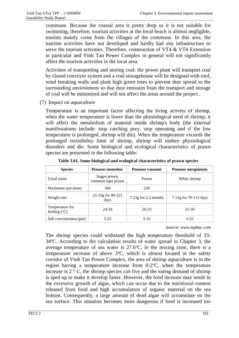
Vinh Tan 4 Ext TPP – 1×600MW
Feasibility Study Report
Chapter 3: Environmental impact assessment
PECC3 192
commune. Because the coastal area is pretty deep so it is not suitable for
swimming, therefore, tourism activities at the local beach is almost negligible,
tourists mainly come from the villages of the commune. In this area, the
tourism activities have not developed and hardly had any infrastructure to
serve the tourism activities. Therefore, construction of VT4 & VT4 Extension
in particular and Vinh Tan Power Complex in general will not significantly
affect the tourism activities in the local area.
Activities of transporting and storing coal: the power plant will transport coal
by closed conveyor system and a coal storagehouse will be designed with roof,
wind breaking walls and plant high green trees to prevent dust spread to the
surrounding environment so that dust emission from the transport and storage
of coal will be minimized and will not affect the areas around the project..
(7) Impact on aquaculture
Temperature is an important factor affecting the living activity of shrimp,
when the water temperature is lower than the physiological need of shrimp, it
will affect the metabolism of material inside shrimp's body (the external
manifestations include: stop catching prey, stop operating and if the low
temperature is prolonged, shrimp will die). When the temperature exceeds the
prolonged resistibility limit of shrimp, shrimp will endure physiological
disorders and die. Some biological and ecological characteristics of prawn
species are presented in the following table:
Table 3.61. Some biological and ecological characteristics of prawn species
Species Penaeus monodon Penaeus vanamei Penaeus merguiensis
Usual name Sugpo prawn,
common tiger prawn Prawn White shrimp
Maximum size (mm) 360 230
Weight rate 21-33g for 80-225
days 7-23g for 2.5 months 7-13g for 70-112 days
Temperature for
feeding (oC) 24-34 26-33 25-30
Salt concentration (ppt) 5-25 5-35 5-33
Source: www.tepbac.com
The shrimp species could withstand the high temperature threshold of 33-
34oC. According to the calculation results of water spread in Chapter 3, the
average temperature of sea water is 27.6oC, in the mixing zone, there is a
temperature increase of above 3oC, which is almost located in the safety
corridor of Vinh Tan Power Complex, the area of shrimp aquaculture is in the
region having a temperature increase from 0-2oC, when the temperature
increase is 2 ° C, the shrimp species can live and the eating demand of shrimp
is sped up to make it develop faster. However, the food increase may result in
the excessive growth of algae, which can occur due to the nutritional content
released from food and high accumulation of organic material on the sea
bottom. Consequently, a large amount of dead algae will accumulate on the
sea surface. This situation becomes more dangerous if food is increased too
Vinh Tan 4 Ext TPP – 1×600MW
Feasibility Study Report
Chapter 3: Environmental impact assessment
PECC3 193
much to facilitate toxin appearance as nitrite, vibrio and other pathogens
which rapidly increase and cause mass mortalities of shrimp. Therefore, the
best thing is to avoid feeding to shrimp when the water temperature is above
30oC.
The discharge of cooling water can cause disturbance to shrimp farming of the
shrimp breed centers in Vinh Tan commune. The discharge of cooling effluent
of VT4 & VT4 Extension only increases the temperature of the shrimp
farming area about 0-2oC, with this temperature, the shrimp species could
adapt to temperature changes.
The discharge of cooling water of Vinh Tan Power Complex can affect shrimp
in the high temperature field (above 33oC), but the temperature field only
focus primarily at the breakwater area, about less than 500m away from the
outlet to the south. Shrimp breeding area is from the high temperature area of
Vinh Tan Power Complex and movable rafts over 1.5km. Thus, this effect is
small. On the other hand, the shrimp breeding households on the shore will be
affected because of taking sea water to breed shrimp, however, these
households will get seawater in farther areas to ensure temperature for
breeding shrimp, so this impact can be minimized.
At present, Binh Thuan province has stopped providing land for the shrimp
farming projects in the project area to provide land for the power projects.
According to the provincial planning, Ganh Hao - Chi Cong area (153.6ha)
will be built into a shrimp breed production area of the province, and the
shrimp breed production facilities affected by the power plant construction
will be given priority to relocate to this area.
Aquacultural activities of people in Vinh Tan commune and the surrounding
communes (Vinh Hao, Phuoc The, etc.) have developed, mainly shrimp and
fish. From the VT4 & VT4 Extension about 1km to the west, there are about
15 rafts of shrimp or fish with a small area. The maintaining of fish cages on
the sea surface in the project area are on the mobile rafts, they are able to
move to the other areas. The project will support the tasks of moving these
cages in cash. Therefore, the discharge of cooling water will not cause much
impact on the fish cages in the sea area of Vinh Tan commune.
Thus, operation of VT4 & VT4 Extension in particular and Vinh Tan Power
Complex in general will not significantly affect shrimp farming, fish rafts of
the local people.
3.1.3.2.4 Impacts due to water transport activities
To meet the fuel demand for Vinh Tan Thermal Power Complex to operate at
full capacity of 6,224MW, every year there will be about 18.8 million tons
coal and 0.041 million tons oil to be transported to the port of Vinh Tan
Thermal Power Complex. Thus, the average total will be about 415 turns of
ship for one year, for VT4 & VT4 Extension in particular, there will be around
29 turns of ship/year. Thus, average for one day there will be a fuel ship to
harbor, so the traffic situation in the port area is considered stable.
Vinh Tan 4 Ext TPP – 1×600MW
Feasibility Study Report
Chapter 3: Environmental impact assessment
PECC3 194
However, activity of transport of raw materials of Vinh Tan Power Complex
in general and VT4 & VT4 Extension in particular will increase the density of
traffic on the waterway. Thereby, the ability of collisions between ships in the
area can be increased and affect humans and the surrounding environment.
3.1.3.2.5 The impact on the socio- economic environment
(1) The impact on population and population structure
The impact on population and population structure in the operation phase of
VT4 & VT4 Extension is the presence of a large number of workers.
Workforce of the power plant in the operational phase is about 500
people/day. Although the policies of the project is to focus on recruiting local
labourers. However, because the qualifications of the local people hardly meet
the requirements of the project, therefore it is neceesary to have a large
number of workers from other places to work for the Project. The impact due
to centralization of a large number of employees in the operation phase of the
project is expected to happen but at a lower level compared with the
construction phase of the Project.
(2) The issues of health and safety
The construction and operation of VT4 & VT4 Extension will create a positive
impact on the socio-economic development issues as well as improve the
efficiency in the land exploitation and settlement of jobs, providing full power
adequate and stable economic development, improve infrastructure systems
area
3.1.3.2.6 The impact on cultural relics and scenery
Linh Son Pagoda, Vinh Phuc village will not be directly affected by the
activities of VT4 & VT4 Extension. However, due to the appearance of the
project, especially the appearance and activities of the ash pond, therefore
access to the pagoda area will become more difficult. The cultural sites and
other relics in the project area will not be affected.
3.1.3.2.7 The impact due to climate change
(1) Emission of greenhouse gas
The burning of fossil fuel will arise greenhouse gas of CO2. The volume of
greenhouse gas emitted from the power plant will contribute to global
warming phenomenon, and can be estimated based on fuel consumption.
Under the guidance of the Intergovernmental Panel on Climate Change (IPCC)
in 2006 about calculating the greenhouse gas emission, the formula to
determine CO2 emission is as follows:
EmissionsCO2, fuel = Fuel consumptionfuel × Emission FactorCO2,fuel (6)
Trong đó:
+ EmissionsCO2, fuel : CO2 emission volume from fuel (kgCO2);
+ Fuel consumptionfuel: volume of fuel used for burning (TJ);
+ Emission FactorCO2,fuel: emission coefficient of CO2 corresponding to the
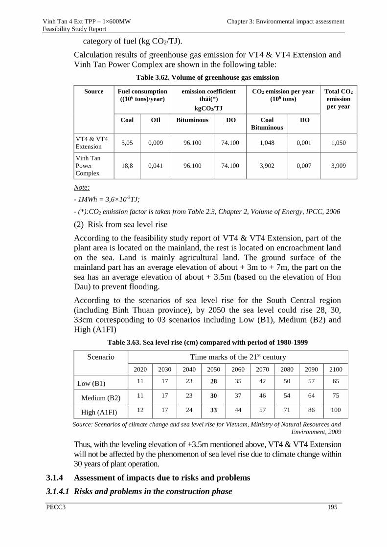
Vinh Tan 4 Ext TPP – 1×600MW
Feasibility Study Report
Chapter 3: Environmental impact assessment
PECC3 195
category of fuel (kg CO2/TJ).
Calculation results of greenhouse gas emission for VT4 & VT4 Extension and
Vinh Tan Power Complex are shown in the following table:
Table 3.62. Volume of greenhouse gas emission
Source Fuel consumption
((106 tons)/year)
emission coefficient
thải(*)
kgCO2/TJ
CO2 emission per year
(106 tons)
Total CO2
emission
per year
Coal OIl Bituminous DO Coal
Bituminous
DO
VT4 & VT4
Extension 5,05 0,009 96.100 74.100 1,048 0,001 1,050
Vinh Tan
Power
Complex
18,8 0,041 96.100 74.100 3,902 0,007 3,909
Note:
- 1MWh = 3,6×10⁻³TJ;
- (*):CO2 emission factor is taken from Table 2.3, Chapter 2, Volume of Energy, IPCC, 2006
(2) Risk from sea level rise
According to the feasibility study report of VT4 & VT4 Extension, part of the
plant area is located on the mainland, the rest is located on encroachment land
on the sea. Land is mainly agricultural land. The ground surface of the
mainland part has an average elevation of about + 3m to + 7m, the part on the
sea has an average elevation of about + 3.5m (based on the elevation of Hon
Dau) to prevent flooding.
According to the scenarios of sea level rise for the South Central region
(including Binh Thuan province), by 2050 the sea level could rise 28, 30,
33cm corresponding to 03 scenarios including Low (B1), Medium (B2) and
High (A1FI)
Table 3.63. Sea level rise (cm) compared with period of 1980-1999
Scenario Time marks of the 21st century
2020 2030 2040 2050 2060 2070 2080 2090 2100
Low (B1) 11 17 23 28 35 42 50 57 65
Medium (B2) 11 17 23 30 37 46 54 64 75
High (A1FI) 12 17 24 33 44 57 71 86 100
Source: Scenarios of climate change and sea level rise for Vietnam, Ministry of Natural Resources and
Environment, 2009
Thus, with the leveling elevation of +3.5m mentioned above, VT4 & VT4 Extension
will not be affected by the phenomenon of sea level rise due to climate change within
30 years of plant operation.
3.1.4 Assessment of impacts due to risks and problems
3.1.4.1 Risks and problems in the construction phase
Vinh Tan 4 Ext TPP – 1×600MW
Feasibility Study Report
Chapter 3: Environmental impact assessment
PECC3 196
3.1.4.1.1 Risks of fire and explosion
Environmental incidents during the construction phase are implicit in the fuel
storages. Ability of fuel leakage, fire and explosion when fuel leakage
associated with the construction activities such as welding or electric leakage is
a common reason to cause fire in buildings. The main reason causing the
problem in the fuel tank is primarily due to the corrosion of tanks or defects in
the manufacturing process, besides the inaccurate operation of the workers. So
the safety measures for the storages should be accurately implemented and
tightly controlled.
3.1.4.1.2 Accident at work
With a large construction work quantity and a long-term construction time,
labour accidents could happen easily, so the safety measures should be paid
attention as soon as possible and should be done seriously during
construction phase. Risks of labour accident which regularly happen during
construction phase consists of equipment installation at high positions,
installation of over-size and over-weight equipment. Like the conflict
between the workers and the local people, labor accidents is difficult to
avoid. However, the experience of professional contractors, along with strict
adherence to regulations on labour safety during construction as well as close
monitoring and timely response can reduce the impacts on people and
property to the minimum.
3.1.4.1.3 Incident when using vessels or barges for transporting oil, raw materials and
equipment
During the construction phase, activities of ships and barges transporting machinery
to serve the project could cause incidents of ship collision in the project area. In
case of accidents on the waterway, incidents of oil spills can negatively affect the
aquatic ecosystems at Hon Cau MPA. When the oil content in water is higher than
0.2 mg/l, water will be smelly. Oil pollution will reduce self-cleaning ability of
water because plankton, benthos as well as seaweed which engage in self-cleaning
process are killed. Oil contaminated effluent also causes oxygen depletion of water
source due to consumption of oxygen for oxidation of hydrocarbons and creates an
oil film to cover the free surface of water to impact on the process of reloading
oxygen from air into water, affect the respiratory process of the aquatic species in
Hon Cau MPA. This impact is considered negative, significant if it happens but it
can be prevented by technical solutions.
3.1.4.2 Impacts due to risks and problems in the operation phase
3.1.4.2.1 Leakage of chemicals
During operation, VT4 & VT4 Extension will use some chemicals to limit the
growth of algae and bacteria in the cooling system of the plant. These
chemicals include ammonia hydroxide, hydrazine and sodium hypochloride,
etc.
When chemical leakages occur, specially ammonia hydroxide (NH4OH) will
affect the health of workers and surrounding communities. People who had
inhalation or direct contact with NH4OH will have symptoms as follows:
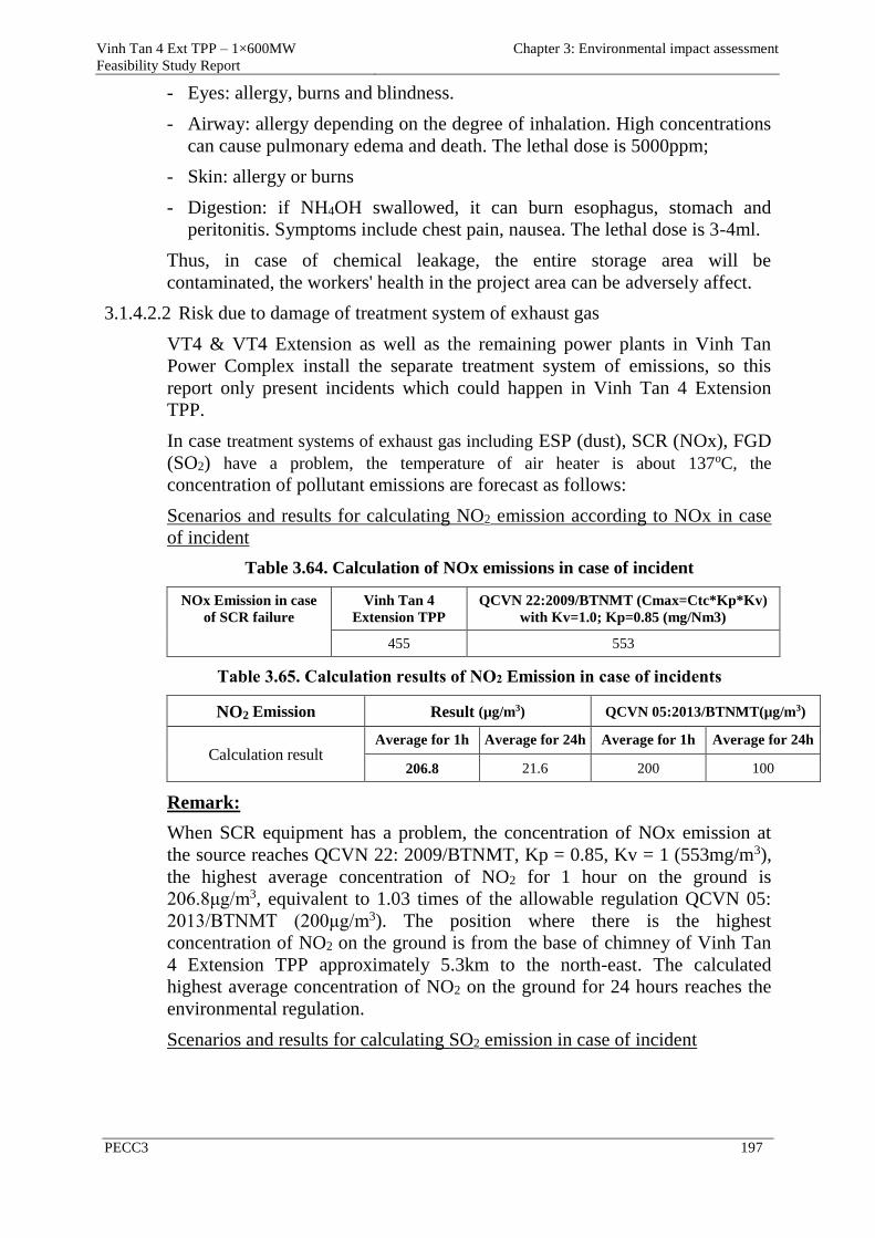
Vinh Tan 4 Ext TPP – 1×600MW
Feasibility Study Report
Chapter 3: Environmental impact assessment
PECC3 197
Eyes: allergy, burns and blindness.
Airway: allergy depending on the degree of inhalation. High concentrations
can cause pulmonary edema and death. The lethal dose is 5000ppm;
Skin: allergy or burns
Digestion: if NH4OH swallowed, it can burn esophagus, stomach and
peritonitis. Symptoms include chest pain, nausea. The lethal dose is 3-4ml.
Thus, in case of chemical leakage, the entire storage area will be
contaminated, the workers' health in the project area can be adversely affect.
3.1.4.2.2 Risk due to damage of treatment system of exhaust gas
VT4 & VT4 Extension as well as the remaining power plants in Vinh Tan
Power Complex install the separate treatment system of emissions, so this
report only present incidents which could happen in Vinh Tan 4 Extension
TPP.
In case treatment systems of exhaust gas including ESP (dust), SCR (NOx), FGD
(SO2) have a problem, the temperature of air heater is about 137oC, the
concentration of pollutant emissions are forecast as follows:
Scenarios and results for calculating NO2 emission according to NOx in case
of incident
Table 3.64. Calculation of NOx emissions in case of incident
NOx Emission in case
of SCR failure
Vinh Tan 4
Extension TPP
QCVN 22:2009/BTNMT (Cmax=Ctc*Kp*Kv)
with Kv=1.0; Kp=0.85 (mg/Nm3)
455 553
Table 3.65. Calculation results of NO2 Emission in case of incidents
NO2 Emission Result (µg/m3) QCVN 05:2013/BTNMT(µg/m3)
Calculation result Average for 1h Average for 24h Average for 1h Average for 24h
206.8 21.6 200 100
Remark:
When SCR equipment has a problem, the concentration of NOx emission at
the source reaches QCVN 22: 2009/BTNMT, Kp = 0.85, Kv = 1 (553mg/m3),
the highest average concentration of NO2 for 1 hour on the ground is
206.8μg/m3, equivalent to 1.03 times of the allowable regulation QCVN 05:
2013/BTNMT (200μg/m3). The position where there is the highest
concentration of NO2 on the ground is from the base of chimney of Vinh Tan
4 Extension TPP approximately 5.3km to the north-east. The calculated
highest average concentration of NO2 on the ground for 24 hours reaches the
environmental regulation.
Scenarios and results for calculating SO2 emission in case of incident
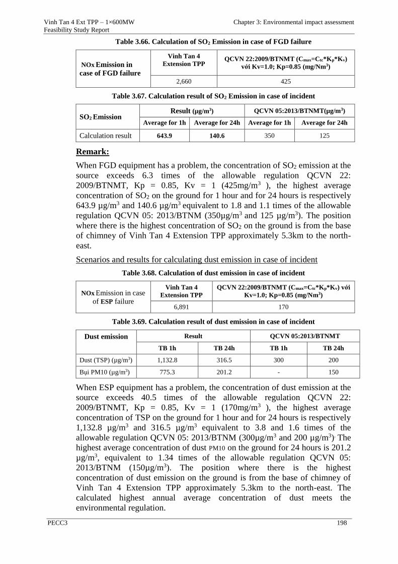
Vinh Tan 4 Ext TPP – 1×600MW
Feasibility Study Report
Chapter 3: Environmental impact assessment
PECC3 198
Table 3.66. Calculation of SO2 Emission in case of FGD failure
NOx Emission in
case of FGD failure
Vinh Tan 4
Extension TPP QCVN 22:2009/BTNMT (Cmax=Ctc*Kp*Kv)
với Kv=1.0; Kp=0.85 (mg/Nm3)
2,660 425
Table 3.67. Calculation result of SO2 Emission in case of incident
SO2 Emission Result (µg/m3) QCVN 05:2013/BTNMT(µg/m3)
Average for 1h Average for 24h Average for 1h Average for 24h
Calculation result 643.9 140.6 350 125
Remark:
When FGD equipment has a problem, the concentration of SO2 emission at the
source exceeds 6.3 times of the allowable regulation QCVN 22:
2009/BTNMT, Kp = 0.85, Kv = 1 (425mg/m3 ), the highest average
concentration of SO2 on the ground for 1 hour and for 24 hours is respectively
643.9 µg/m3 and 140.6 µg/m3 equivalent to 1.8 and 1.1 times of the allowable
regulation QCVN 05: 2013/BTNM (350µg/m3 and 125 µg/m3). The position
where there is the highest concentration of SO2 on the ground is from the base
of chimney of Vinh Tan 4 Extension TPP approximately 5.3km to the north-
east.
Scenarios and results for calculating dust emission in case of incident
Table 3.68. Calculation of dust emission in case of incident
NOx Emission in case
of ESP failure
Vinh Tan 4
Extension TPP
QCVN 22:2009/BTNMT (Cmax=Ctc*Kp*Kv) với
Kv=1.0; Kp=0.85 (mg/Nm3)
6,891 170
Table 3.69. Calculation result of dust emission in case of incident
Dust emission Result QCVN 05:2013/BTNMT
TB 1h TB 24h TB 1h TB 24h
Dust (TSP) (µg/m3) 1,132.8 316.5 300 200
Bụi PM10 (µg/m3) 775.3 201.2 - 150
When ESP equipment has a problem, the concentration of dust emission at the
source exceeds 40.5 times of the allowable regulation QCVN 22:
2009/BTNMT, Kp = 0.85, Kv = 1 (170mg/m3 ), the highest average
concentration of TSP on the ground for 1 hour and for 24 hours is respectively
1,132.8 µg/m3 and 316.5 µg/m3 equivalent to 3.8 and 1.6 times of the
allowable regulation QCVN 05: 2013/BTNM (300µg/m3 and 200 µg/m3). The
highest average concentration of dust PM10 on the ground for 24 hours is 201.2
µg/m3, equivalent to 1.34 times of the allowable regulation QCVN 05:
2013/BTNM (150µg/m3). The position where there is the highest
concentration of dust emission on the ground is from the base of chimney of
Vinh Tan 4 Extension TPP approximately 5.3km to the north-east. The
calculated highest annual average concentration of dust meets the
environmental regulation.
Vinh Tan 4 Ext TPP – 1×600MW
Feasibility Study Report
Chapter 3: Environmental impact assessment
PECC3 199
From the results show that in case the treatment system of exhaust gas has a
problem, the whole of Vinh Tan commune will be serious polluted by
emissions from the power plant with pollution level exceeding the permitted
value of QCVN 22: 2009/BTNMT, Kp = 0.85, Kv = 1 and QCVN 05:
2013/BTNMT. Therefore, in case the treatment system of exhaust gas fails,
the plant will cease operation until the problem is resolved and the treatment
system of exhaust gas may work again.
3.1.4.2.3 Incident of the treatment system of industrial waste water
In case the treatment system of waste water has a problem, it will adversely
affect the sea environment. The discharge of effluent is from 25- 220m3/day, it
can be contaminated by domestic waste, coal, chemicals or oil ( because these
types of waste water do not appear at the same time, if untreated, it can change
the concentration of pH, increase BOD, COD, turbidity, change the nature of
the receiving water source, affect human health and aquatic life in the waste
water outlet area and Hon Cau MPA. Oil pollution will make self-cleaning
ability of water to be reduded due to plankton, benthos be destroyed.. Oil film
prevents penetration of oxygen into the water.
3.1.4.2.4 Incidents of ships conveying fuel to be collided or sunk
To meet the fuel demand for Vinh Tan Thermal Power Complex to operate at
full capacity of 6,224MW, every year there will be about 415 turns of ship
conveying coal or oil going in and out the port, so the probability of collision
between ships is very small. However, the Ninh Thuan - Binh Thuan coastal
area is less affected by storms, but the ability of ships to be sunk can still
happen.
When there is incident of ship to be collided or sunk, the following impacts
can happen: coal will drop down the sea with a very large amount (several tens
of thousand tons), it will increase the turbidity of the sea, after a period of time
coal will settle to create a layer covering on the seabed. It will affect adversely
the quality of sea water because the turbidity of sea water will be increased to
affect the habitat of some aquatic species such as seaweed at Hon Cau MPA.
When coal settles, it will create a thick layer covering on the seabed to impede
the respiration of benthos, seaweed and can destroy these species. However,
coal on the carriers will be stored in closed compartments, therefore, the
quantity of coal scattered will be reduced very much in case of incident, the
process of salvage, response of incidents will be faster, mitigate the impacts on
the water environment.
In addition, when the ships collide in the port area, they can cause oil
spill to affect the ecosystems and water environment in the region.
The consequence of this impact includes pollution increase in the port
area and economic damage to the coal port management unit. The effects
of sinking ships and coal dropping into the sea will impact seriously on
the aquatic life at Hon Cau MPA, especially benthos if any incidents. It
is difficult to recover from this impact, but there is always backup

Vinh Tan 4 Ext TPP – 1×600MW
Feasibility Study Report
Chapter 3: Environmental impact assessment
PECC3 200
options.
3.1.4.2.5 Incident of oil spill
VT4 & VT4 Extension will get diesel oil from Vinh Tan 2 TPP, so the process
of transporting oil by ships belongs to the project of Vinh Tan 2 TPP.
Incidents of oil spill were assessed in detail in the EIA report of the coal berth
which belongs to Vinh Tan Power Complex - Phase 1, and approved by
MoNRE. In the scope of VT4 & VT4 Extension, only assess the impacts of oil
spill due to collision of ships carrying coal, oil pipelines to be burst.
Refer to the calculation results from the model of oil spread due to incident of
sinking ships in the EIA report of the coal berth which belongs to Vinh Tan
Power Complex - Phase 1, which shows that in case of oil spill from an
incident of ship of 1,000DWT, the affected coastal areas could be Ninh Thuan
- Binh Thuan extending to Ca Na - Phan Thiet, including Hon Cau MPA and
tourist areas, aquaculture areas.
When oil is leaked into the environment, oil and volatile organic compounds
are quickly converted to steam with the typical scent and diffuse into the
atmosphere. The agents cause air pollution in this case including hydrocarbon
derivatives that negatively affect human health in the definite range of
concentrations.
When oil spills to pollute the surface water source and significantly reduce the
density of phytoplankton in the region, may change partially community
structure of aquatic fauna in the sea, directly affect the quality of the water
environment and the food chain of the ecosystem.
When the oil content in water is higher than 0.2 mg/l, water will be smelly. Oil
pollution will reduce self-cleaning ability of water because plankton, benthos
as well as seaweed which engage in self-cleaning process are killed. Oil
contaminated effluent also causes oxygen depletion of water source due to
consumption of oxygen for oxidation of hydrocarbons and creates an oil film
to cover the free surface of water to impact on the process of reloading oxygen
from air into water, affect the respiratory process of the aquatic species in Hon
Cau MPA.
When the oil content in water is from 0.1-0.5mg/l, it will reduce the yield and
quality of fish. The standard content of oil in the fish farming waters do not
exceed 0.05 mg/l, the standard content of dissolved oxygen is ≥ 6 mg O2/l.
Oil in water will be transformed into toxic compounds on human and aquatic
organism such as phenol, chlorine derivatives of phenol. The standard content
of phenol for domestic water supply is 0.001 mg/l.
Oil and the decomposition products of oil seep into the soil to impact seriously
on plants or reduce the decomposition possibility of microorganism in the soil
which results in the decrease of porosity and fertility of the soil, indirectly
affect the yield of trees and crops.
This will be a serious impact on aquatic ecosystems at Hon Cau MPA and
economic sectors particularly fisheries and tourism. Therefore, prevention of
Vinh Tan 4 Ext TPP – 1×600MW
Feasibility Study Report
Chapter 3: Environmental impact assessment
PECC3 201
oil spills is an important task of the project and of the fuel transport
companies.
3.1.4.2.6 Fire incident
Because the project's activities always have to use and store some volume of
diesel oil which is stored in two tanks of 1.500m3 and gasoline for engines,
machinery, transportation means, etc. These types of fuel are very flammable
and can cause an explosion. The nature of fire causes can be divided into four
main groups:
- Group 1: fire can be caused by flammable materials such as: coal, the types
of packaging, paper, wood, garbage, etc.;
- Group 2: fire can be caused by inflammable liquid fuels such as gasoline, oil,
gas, and in case of tanks containing oil or petrol to be burst..
- Group 3: fire can be caused by malfunction of electrical equipment;
- Group 4: fire by lightning
The reasons of fire can include:
- Transportion raw materials and combustibles such as gasoline, oil going
through or near source of heat or spark;
- Storing the materials in improper places;
- Throwing cigarette butts or other ignition sources in areas containing gas, oil,
coal storage area, packaging, paper, wood, etc.;
- Electrical equipment being overloaded during operation, generating heat to
cause fire, or short-circuit in case of rainstorms;
- Lightning can result in fire, etc.
- When the incident happens, it will cause serious damage to the environment,
affect people, destroy property and technical equipment. The effects of fire or
explosion would be very serious, especially in the dry season, the incident
not only direct impacts to the infrastructure of the plant, but also spreads to
the neighboring areas.
- To assess risks in the most dangerous cases, the report reviewed and assessed
fire incident in the area of DO tanks with the case of 1,500m3 oil tank
explosion.
Incident of 1,500m3 oil tank explosion
In the project area, during the dry season, there is high air temperature and low
humidity so fire in the DO storehouse may occur, especially when the
concentration of hydrocarbons in the air is high and there is an ignition source.
Damage of one fire case is usually very dangerous. To build a scenario for oil
tank explosion case, the report used ALOHA model to assess risk, incident of
DO tank to be burst with capacity of 1,500 m3.
In the scope of environmental impact assessment of the project, the report only
mentioned and assessed corresponding to a hypothetical case to figure the
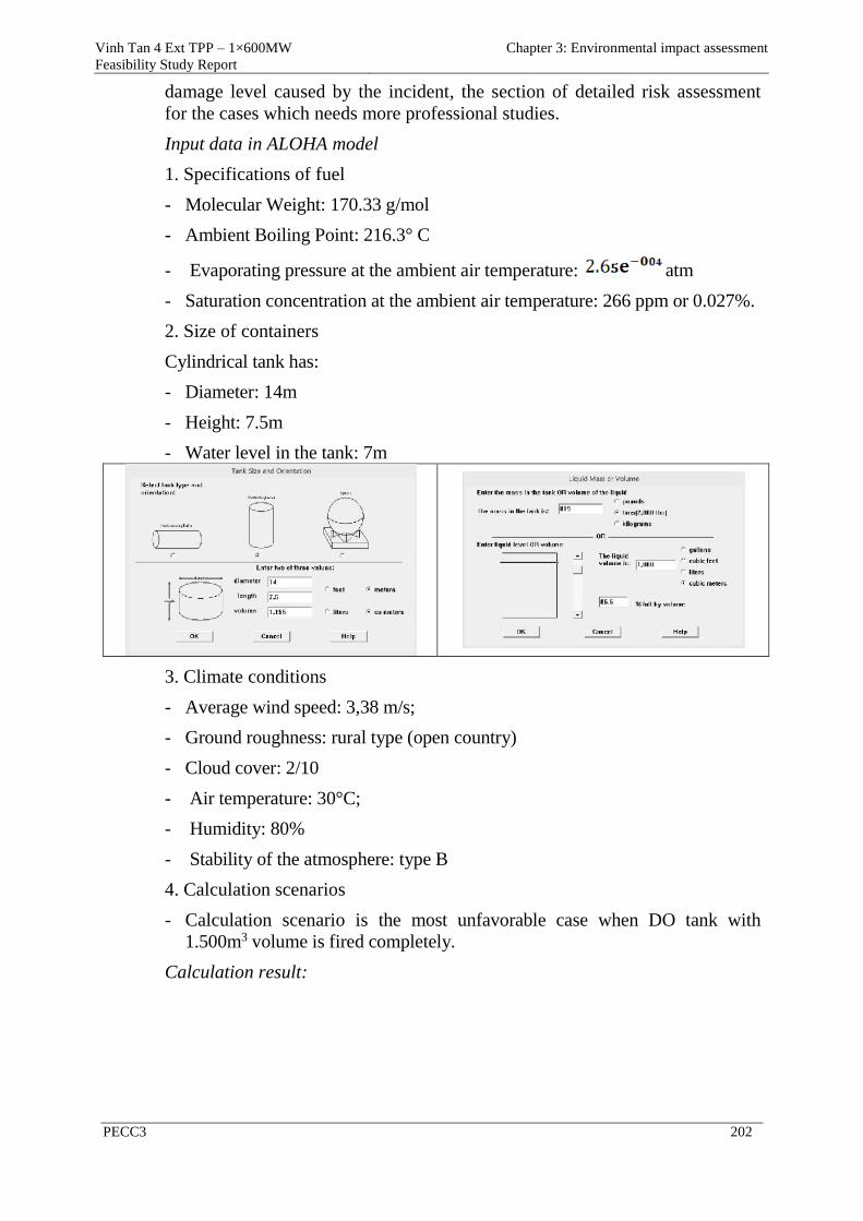
Vinh Tan 4 Ext TPP – 1×600MW
Feasibility Study Report
Chapter 3: Environmental impact assessment
PECC3 202
damage level caused by the incident, the section of detailed risk assessment
for the cases which needs more professional studies.
Input data in ALOHA model
1. Specifications of fuel
- Molecular Weight: 170.33 g/mol
- Ambient Boiling Point: 216.3° C
- Evaporating pressure at the ambient air temperature: atm
- Saturation concentration at the ambient air temperature: 266 ppm or 0.027%.
2. Size of containers
Cylindrical tank has:
- Diameter: 14m
- Height: 7.5m
- Water level in the tank: 7m
3. Climate conditions
- Average wind speed: 3,38 m/s;
- Ground roughness: rural type (open country)
- Cloud cover: 2/10
- Air temperature: 30°C;
- Humidity: 80%
- Stability of the atmosphere: type B
4. Calculation scenarios
- Calculation scenario is the most unfavorable case when DO tank with
1.500m3 volume is fired completely.
Calculation result:
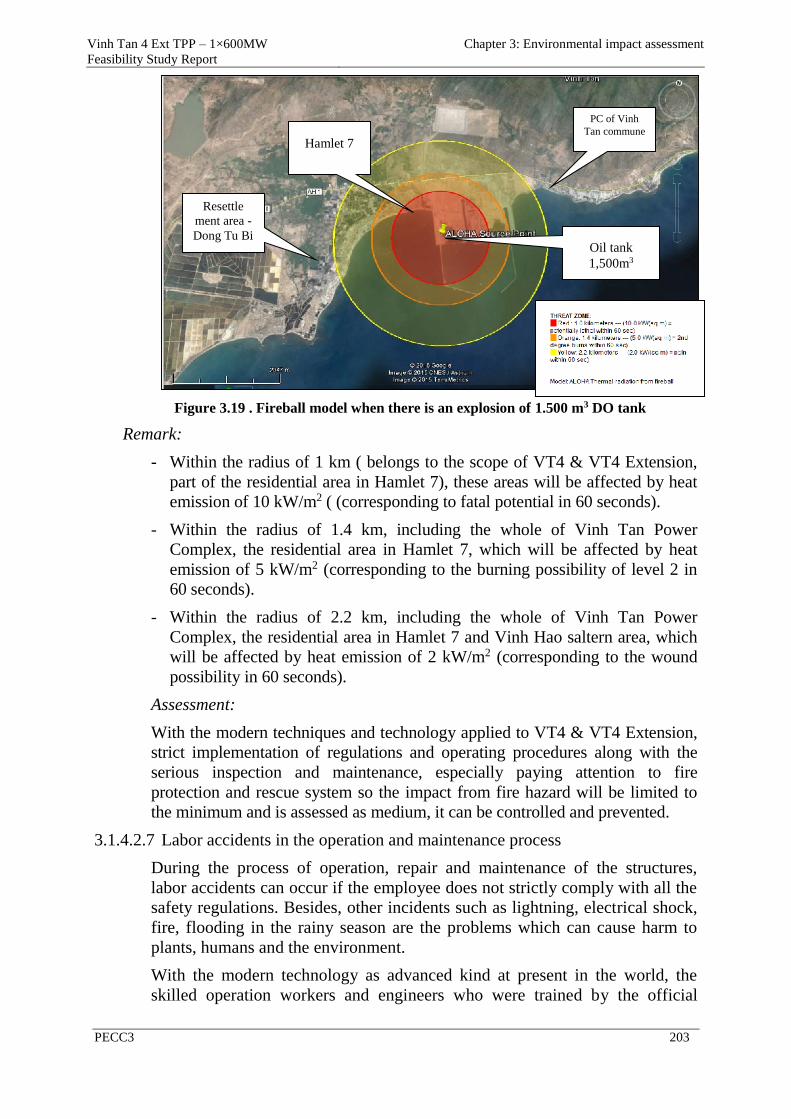
Vinh Tan 4 Ext TPP – 1×600MW
Feasibility Study Report
Chapter 3: Environmental impact assessment
PECC3 203
Figure 3.19 . Fireball model when there is an explosion of 1.500 m3 DO tank
Remark:
- Within the radius of 1 km ( belongs to the scope of VT4 & VT4 Extension,
part of the residential area in Hamlet 7), these areas will be affected by heat
emission of 10 kW/m2 ( (corresponding to fatal potential in 60 seconds).
- Within the radius of 1.4 km, including the whole of Vinh Tan Power
Complex, the residential area in Hamlet 7, which will be affected by heat
emission of 5 kW/m2 (corresponding to the burning possibility of level 2 in
60 seconds).
- Within the radius of 2.2 km, including the whole of Vinh Tan Power
Complex, the residential area in Hamlet 7 and Vinh Hao saltern area, which
will be affected by heat emission of 2 kW/m2 (corresponding to the wound
possibility in 60 seconds).
Assessment:
With the modern techniques and technology applied to VT4 & VT4 Extension,
strict implementation of regulations and operating procedures along with the
serious inspection and maintenance, especially paying attention to fire
protection and rescue system so the impact from fire hazard will be limited to
the minimum and is assessed as medium, it can be controlled and prevented.
3.1.4.2.7 Labor accidents in the operation and maintenance process
During the process of operation, repair and maintenance of the structures,
labor accidents can occur if the employee does not strictly comply with all the
safety regulations. Besides, other incidents such as lightning, electrical shock,
fire, flooding in the rainy season are the problems which can cause harm to
plants, humans and the environment.
With the modern technology as advanced kind at present in the world, the
skilled operation workers and engineers who were trained by the official
Oil tank
1,500m3
Hamlet 7
Resettle
ment area -
Dong Tu Bi
PC of Vinh
Tan commune
Vinh Tan 4 Ext TPP – 1×600MW
Feasibility Study Report
Chapter 3: Environmental impact assessment
PECC3 204
procedures, the design process which was very carefully studied including
characteristics of hydro-meteorology and geology of the project area,
maintenance and operational management mode strict and reasonable, so the
incidents can hardly happen.
3.1.5 Impacts on the environment and socio-economic situation
To get an overview of the environmental impacts as well as the impact level
of the entire project, the environmental impact assessment of the project was
performed based on the methods of making list, scoring and presented in the
form of a matrix.
The vertical axis of the matrix is used to express the activities of the project
and the horizontal axis is used to express the environmental aspects affected
by the project. The level of impact is shown in the cell across between
environmental aspect and activity of the project. The impact level is selected
including 4 levels from no impact to strong impact corresponding to scores
from 0 to 3. The impact level of each activity on every environmental aspect
is determined based on result of Environmental impact assessment shown
above. The overall impact from each activity of the project is the average
value of impact levels of activity on each environmental aspect. The results
of overall environmental impact assessment are shown in the table below.
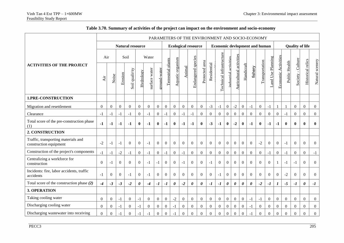
Vinh Tan 4 Ext TPP – 1×600MW
Feasibility Study Report
Chapter 3: Environmental impact assessment
PECC3 205
Table 3.70. Summary of activities of the project can impact on the environment and socio-economy
ACTIVITIES OF THE PROJECT
PARAMETERS OF THE ENVIRONMENT AND SOCIO-ECONOMY
Natural resource Ecological resource Economic devlopment and human Quality of life
Air Soil Water
Ter
rest
rial
pla
nts
Aq
uat
ic o
rgan
ism
An
imal
En
dan
ger
ed s
pec
ies
Pro
tect
ed a
rea
Res
iden
tial
com
mu
nit
ies
Tec
hn
ical
in
fras
tru
ctu
re
ind
ust
rial
act
ivit
ies
Ag
ricu
ltu
ral
acti
vit
ies
Han
dic
raft
fishery
Tra
nsp
ort
atio
n
Lan
d U
se P
lan
nin
g
Eco
no
mic
Act
ivit
ies
Pu
bli
c H
ealt
h
So
ciet
y -
Cu
ltu
re
His
tori
cal
reli
cs
Nat
ura
l sc
ener
y
Air
No
ise
Ero
sio
n
So
il q
ual
ir\t
y
Hy
dro
log
y
surf
ace
wat
er
gro
un
d-w
ater
1.PRE-CONSTRUCTION
Migration and resettlement 0 0 0 0 0 0 0 0 0 0 0 0 -3 -1 0 -2 0 -1 0 -1 1 1 0 0 0
Clearance -1 -1 -1 -1 0 -1 0 -1 0 -1 -1 0 0 0 0 0 0 0 0 0 0 -1 0 0 0
Total score of the pre-construction phase
(1) -1 -1 -1 -1 0 -1 0 -1 0 -1 -1 0 -3 -1 0 -2 0 -1 0 -1 -1 0 0 0 0
2. CONSTRUCTION
Traffic, transporting materials and
construction equipment -2 -1 -1 0 0 -1 0 0 0 0 0 0 0 0 0 0 0 0 -2 0 0 -1 0 0 0
Construction of the project's components -1 -1 -2 -1 0 -1 0 -1 0 -1 0 0 0 0 0 0 0 0 0 -1 0 -1 0 0 -1
Centralizing a workforce for
construction 0 -1 0 0 0 -1 -1 0 0 -1 0 0 -1 0 0 0 0 0 0 0 1 -1 -1 0 0
Incidents: fire, labor accidents, traffic
accidents -1 0 0 -1 0 -1 0 0 0 0 0 0 0 -1 0 0 0 0 0 0 0 -2 0 0 0
Total score of the construction phase (2) -4 -3 -3 -2 0 -4 -1 -1 0 -2 0 0 -1 -1 0 0 0 0 -2 -1 1 -5 -1 0 -1
3. OPERATION
Taking cooling water 0 0 -1 0 -1 0 0 0 -2 0 0 0 0 0 0 0 0 -1 -1 0 0 0 0 0 0
Discharging cooling water 0 0 -1 0 -1 0 0 0 -1 0 0 0 0 0 0 0 0 -1 0 0 0 0 0 0 0
Discharging wastewater into receiving 0 0 -1 0 -1 -1 0 0 -1 0 0 0 0 0 0 0 0 -1 0 0 0 0 0 0 0

Vinh Tan 4 Ext TPP – 1×600MW
Feasibility Study Report
Chapter 3: Environmental impact assessment
PECC3 206
ACTIVITIES OF THE PROJECT
PARAMETERS OF THE ENVIRONMENT AND SOCIO-ECONOMY
Natural resource Ecological resource Economic devlopment and human Quality of life
Air Soil Water
Ter
rest
rial
pla
nts
Aq
uat
ic o
rgan
ism
An
imal
En
dan
ger
ed s
pec
ies
Pro
tect
ed a
rea
Res
iden
tial
com
mu
nit
ies
Tec
hn
ical
in
fras
tru
ctu
re
ind
ust
rial
act
ivit
ies
Ag
ricu
ltu
ral
acti
vit
ies
Han
dic
raft
fishery
Tra
nsp
ort
atio
n
Lan
d U
se P
lan
nin
g
Eco
no
mic
Act
ivit
ies
Pu
bli
c H
ealt
h
So
ciet
y -
Cu
ltu
re
His
tori
cal
reli
cs
Nat
ura
l sc
ener
y
Air
No
ise
Ero
sio
n
So
il q
ual
ir\t
y
Hy
dro
log
y
surf
ace
wat
er
gro
un
d-w
ater
water source
Exhaust emissions -2 0 0 0 0 0 0 0 0 0 0 0 0 0 0 0 0 0 0 0 0 0 0 0 0
Receiving, transporting and storing coal -1 0 0 -1 0 -1 0 0 0 0 0 0 0 0 0 0 0 0 0 0 0 0 0 0 0
Collection and disposal of ash 1 0 0 -1 0 -1 0 0 0 0 0 0 0 0 0 0 0 0 0 0 0 0 0 0 0
Activities of operators 0 0 0 -1 0 -1 0 0 0 0 0 0 0 0 0 0 0 0 0 0 0 0 0 0 0
Solid waste from production activity 0 0 0 -1 0 -1 0 0 0 0 0 0 0 0 0 0 0 0 0 0 0 0 0 0 0
Excess heat -1 0 0 0 0 0 0 0 0 0 0 0 0 0 0 0 0 0 0 0 0 0 0 0 0
Oil spill, burst pipes -1 0 0 -1 0 -1 -1 -1 -1 0 0 0 0 0 0 0 0 -1 0 0 0 0 0 0 0
Fire, explosion, labor accidents and
other incidents -1 0 0 -1 0 -1 0 0 0 0 0 0 0 -1 0 0 0 0 0 0 0 -2 0 0 0
Operation of the power plant will impact
on the socio-economy 0 0 0 0 0 0 0 0 0 0 0 0 0 0 0 0 0 0 0 0 2 0 0 0 0
Total score of the operation phase (3) -6 0 -3 -6 -3 -7 -1 -1 -5 0 0 0 0 -1 0 0 0 -4 -1 0 0 -2 0 0 0
TOTAL SCORE (1), (2) VÀ (3) -11 -4 -6 -9 -3 -12 -2 -2 -6 -2 0 0 -1 -2 0 0 0 -4 -4 -1 3 -7 -1 0 -1
Note:
Scale value from 0 to 3; 0: that means no impact or insignificant; 1: low impact; 2: moderate impact; 3: strong impact; sign “-“ is negative
impact, “+” is positive impact.
Vinh Tan 4 Extension TPP – 1×600MW
Feasibility Report
Chapter 4. Measures for prevention and mitigation
PECC3 207
Based on the above matrix, the negative and positive impacts in every phase of
the project can be summarized as follows:
- During the pre-construction phase the significant negative impacts are air
pollution (-1) and surface water pollution (-1). However, during this period,
economic activities of the region will have positive impacts (1).
- During the construction phase the significant negative impacts are air
pollution (-4) and surface water pollution (-4). However, during this period,
economic activities of the region will have positive impacts (1).
- During the operation phase, the impacts are mainly on air quality (-11),
surface water quality (-12), and soil quality (-9).
3.2 COMMENTS ON DETAIL LEVEL AND RELIABILITY OF
ASSESSMENT RESULTS AND FORECAST
3.2.1 Comments on reliability of methods used in the report
Methods are used for EIA including:
3.2.1.1 Methods used for EIA
- Method of making list
This method is used to list the activities and impacts on the environment of the
project.
- Matrix Method
Matrix is used to establish the relationship between the activities of the project
and the environmental impacts.
- Method of experts
Some impacts need to be predicted based on some similar projects, the actual
tests and computational tools and consultation with the experts. From the
forecast results, the impacts will be classified and the appropriate mitigation
measures will be proposed.
This method is based on the theory and experience basis to guess, predict the
possible impacts, on that basis, consider the impact of the project on
environmental quality.
This method has subjectiveness, the results depend on the awareness and the
professional qualification of experts.
- Method of rapid assessment
- Based on the regulations of World Health Organization (WHO) and
documentation of environmental impact assessment of the World Bank in
1991 to determine the load of pollutants according to the pollution
coefficient corresponding to the components of the environment. This
method is used to quantify the pollutants generated by activities in the
construction and operation phases based on the information about the
project, such as the volume of building materials, the number of
construction machinery, the number of workers, etc. as well as information
on the current environmental situation in the region. This method is based
Vinh Tan 4 Extension TPP – 1×600MW
Feasibility Report
Chapter 4. Measures for prevention and mitigation
PECC3 208
on the statistical data on load and components of waste water, exhaust gas
and solid waste. Based on the results of calculations to classify the impacts
corresponding to the degree of influence on the environment. Therefore,
this evaluation method is suitable to evaluate the environmental impact of
the plant.
- Modeling Method
o In order to forecast and evaluate the noise propagation during the
construction and operation of the plant, the project used dB Foresight
software. This software is designed to comply with ISO 9613-2, it allows
calculation of noise propagation of the industrial structures.
o The report used Breeze AERMOD Plus Pro software to calculate and
predict the spread process of pollutants in the air. This software is written
by Trinity company based on the AERMOD model proposed by Bureau
of environmental protection in the U.S. (U.S. Environmental Protection
Agency, EPA). AERMOD model replaced ISC3 (Industrial Source
Complex Model) of EPA (1995), it allows calculation of the
concentration of pollutants and deposition range from complex industrial
discharge sources.
o Using Mike 3 FM model developed by DHI Water & Environment which
uses a cell-centred finite volume method to simulate heating spread due to
the cooling water in the receiving water.
o These methods have been studied and published in many specialized
materials, it has high accuracy, provides quite sufficient information
necessary to perform evaluation and forecast of the environmental
impacts, creates a basis pretty solid to build environmental monitoring
programs in the construction and operation phases of the project.
o However, in the process of calculating noise propagation, exhaust
emissions and heating spread of cooling effluent, emission figures are
not really accurate, since the plant has not been built and operated.
Therefore, when the project is put to construction and operation the
necessary data will be continuously collected to calibrate the model to
have a more accurate forecast of these processes.
3.2.1.2 Other Methods
- Method of field surveys:
Perform the fieldworks in the project area to assess the situation and define
specific objects which may be affected by the activities of the project.
- Method of sampling in the field and analysing in the laboratory:
Combining with specialized units to sample air quality, surface water,
groundwater, soil and aquatic samples to assess the environmental situation of
the area before the project commence.
- Method of statistics and data processing
Conducting surveys in communes and districts where the project goes through,
collecting data through the meetings and questionnaires, interviewing directly,
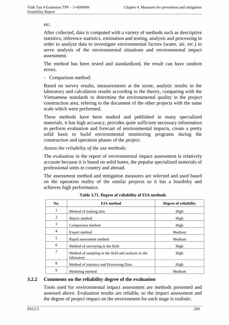
Vinh Tan 4 Extension TPP – 1×600MW
Feasibility Report
Chapter 4. Measures for prevention and mitigation
PECC3 209
etc.
After collected, data is computed with a variety of methods such as descriptive
statistics, inference statistics, estimation and testing, analysis and processing in
order to analyze data to investigate environmental factors (water, air, etc.) to
serve analysis of the environmental situations and environmental impact
assessment.
The method has been tested and standardized, the result can have random
errors.
- Comparison method:
Based on survey results, measurements at the scene, analytic results in the
laboratory and calculation results according to the theory, comparing with the
Vietnamese standards to determine the environmental quality in the project
construction area, refering to the document of the other projects with the same
scale which were performed.
These methods have been studied and published in many specialized
materials, it has high accuracy, provides quite sufficient necessary information
to perform evaluation and forecast of environmental impacts, create a pretty
solid basis to build environmental monitoring programs during the
construction and operation phases of the project.
Assess the reliability of the use methods:
The evaluation in the report of environmental impact assessment is relatively
accurate because it is based on solid bases, the popular specialized materials of
professional units in country and abroad.
The assessment method and mitigation measures are selected and used based
on the operation reality of the similar projects so it has a feasibilty and
achieves high performance.
Table 3.71. Degree of reliability of EIA methods
No. EIA method Degree of reliability
1 Method of making lists High
2 Matrix method High
3 Comparison method High
4 Expert method Medium
5 Rapid assessment method Medium
6 Method of surveying in the field High
7 Method of sampling in the field and analysis in the
laboratory
High
8 Method of statistics and Processing Data High
9 Modeling method Medium
3.2.2 Comments on the reliability degree of the evaluation
Tools used for environmental impact assessment are methods presented and
assessed above. Evaluation results are reliable, so the impact assessment and
the degree of project impact on the environment for each stage is realistic.
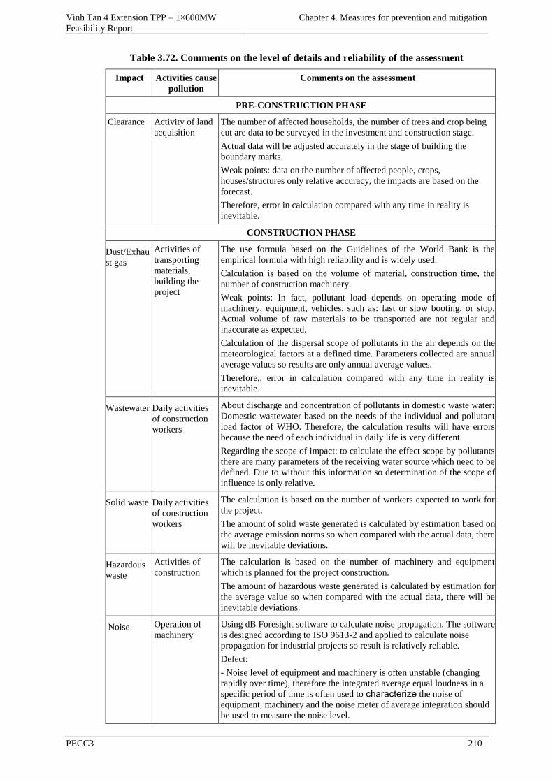
Vinh Tan 4 Extension TPP – 1×600MW
Feasibility Report
Chapter 4. Measures for prevention and mitigation
PECC3 210
Table 3.72. Comments on the level of details and reliability of the assessment
Impact Activities cause
pollution
Comments on the assessment
PRE-CONSTRUCTION PHASE
Clearance Activity of land
acquisition
The number of affected households, the number of trees and crop being
cut are data to be surveyed in the investment and construction stage.
Actual data will be adjusted accurately in the stage of building the
boundary marks.
Weak points: data on the number of affected people, crops,
houses/structures only relative accuracy, the impacts are based on the
forecast.
Therefore, error in calculation compared with any time in reality is
inevitable.
CONSTRUCTION PHASE
Dust/Exhau
st gas
Activities of
transporting
materials,
building the
project
The use formula based on the Guidelines of the World Bank is the
empirical formula with high reliability and is widely used.
Calculation is based on the volume of material, construction time, the
number of construction machinery.
Weak points: In fact, pollutant load depends on operating mode of
machinery, equipment, vehicles, such as: fast or slow booting, or stop.
Actual volume of raw materials to be transported are not regular and
inaccurate as expected.
Calculation of the dispersal scope of pollutants in the air depends on the
meteorological factors at a defined time. Parameters collected are annual
average values so results are only annual average values.
Therefore,, error in calculation compared with any time in reality is
inevitable.
Wastewater Daily activities
of construction
workers
About discharge and concentration of pollutants in domestic waste water:
Domestic wastewater based on the needs of the individual and pollutant
load factor of WHO. Therefore, the calculation results will have errors
because the need of each individual in daily life is very different.
Regarding the scope of impact: to calculate the effect scope by pollutants
there are many parameters of the receiving water source which need to be
defined. Due to without this information so determination of the scope of
influence is only relative.
Solid waste Daily activities
of construction
workers
The calculation is based on the number of workers expected to work for
the project.
The amount of solid waste generated is calculated by estimation based on
the average emission norms so when compared with the actual data, there
will be inevitable deviations.
Hazardous
waste
Activities of
construction
The calculation is based on the number of machinery and equipment
which is planned for the project construction.
The amount of hazardous waste generated is calculated by estimation for
the average value so when compared with the actual data, there will be
inevitable deviations.
Noise Operation of
machinery
Using dB Foresight software to calculate noise propagation. The software
is designed according to ISO 9613-2 and applied to calculate noise
propagation for industrial projects so result is relatively reliable.
Defect:
- Noise level of equipment and machinery is often unstable (changing
rapidly over time), therefore the integrated average equal loudness in a
specific period of time is often used to characterize the noise of
equipment, machinery and the noise meter of average integration should
be used to measure the noise level.
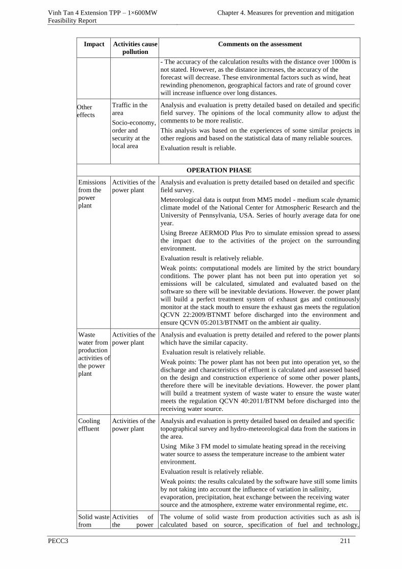
Vinh Tan 4 Extension TPP – 1×600MW
Feasibility Report
Chapter 4. Measures for prevention and mitigation
PECC3 211
Impact Activities cause
pollution
Comments on the assessment
- The accuracy of the calculation results with the distance over 1000m is
not stated. However, as the distance increases, the accuracy of the
forecast will decrease. These environmental factors such as wind, heat
rewinding phenomenon, geographical factors and rate of ground cover
will increase influence over long distances.
Other
effects
Traffic in the
area
Socio-economy,
order and
security at the
local area
Analysis and evaluation is pretty detailed based on detailed and specific
field survey. The opinions of the local community allow to adjust the
comments to be more realistic.
This analysis was based on the experiences of some similar projects in
other regions and based on the statistical data of many reliable sources.
Evaluation result is reliable.
OPERATION PHASE
Emissions
from the
power
plant
Activities of the
power plant
Analysis and evaluation is pretty detailed based on detailed and specific
field survey.
Meteorological data is output from MM5 model - medium scale dynamic
climate model of the National Center for Atmospheric Research and the
University of Pennsylvania, USA. Series of hourly average data for one
year.
Using Breeze AERMOD Plus Pro to simulate emission spread to assess
the impact due to the activities of the project on the surrounding
environment.
Evaluation result is relatively reliable.
Weak points: computational models are limited by the strict boundary
conditions. The power plant has not been put into operation yet so
emissions will be calculated, simulated and evaluated based on the
software so there will be inevitable deviations. However. the power plant
will build a perfect treatment system of exhaust gas and continuously
monitor at the stack mouth to ensure the exhaust gas meets the regulation
QCVN 22:2009/BTNMT before discharged into the environment and
ensure QCVN 05:2013/BTNMT on the ambient air quality.
Waste
water from
production
activities of
the power
plant
Activities of the
power plant
Analysis and evaluation is pretty detailed and refered to the power plants
which have the similar capacity.
Evaluation result is relatively reliable.
Weak points: The power plant has not been put into operation yet, so the
discharge and characteristics of effluent is calculated and assessed based
on the design and construction experience of some other power plants,
therefore there will be inevitable deviations. However. the power plant
will build a treatment system of waste water to ensure the waste water
meets the regulation QCVN 40:2011/BTNM before discharged into the
receiving water source.
Cooling
effluent
Activities of the
power plant
Analysis and evaluation is pretty detailed based on detailed and specific
topographical survey and hydro-meteorological data from the stations in
the area.
Using Mike 3 FM model to simulate heating spread in the receiving
water source to assess the temperature increase to the ambient water
environment.
Evaluation result is relatively reliable.
Weak points: the results calculated by the software have still some limits
by not taking into account the influence of variation in salinity,
evaporation, precipitation, heat exchange between the receiving water
source and the atmosphere, extreme water environmental regime, etc.
Solid waste
from
Activities of
the power
The volume of solid waste from production activities such as ash is
calculated based on source, specification of fuel and technology,
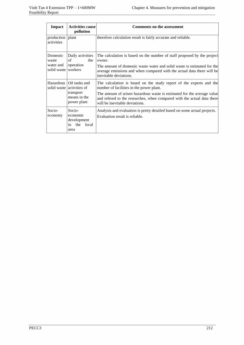
Vinh Tan 4 Extension TPP – 1×600MW
Feasibility Report
Chapter 4. Measures for prevention and mitigation
PECC3 212
Impact Activities cause
pollution
Comments on the assessment
production
activities
plant therefore calculation result is fairly accurate and reliable.
Domestic
waste
water and
solid waste
Daily activities
of the
operation
workers
The calculation is based on the number of staff proposed by the project
owner.
The amount of domestic waste water and solid waste is estimated for the
average emissions and when compared with the actual data there will be
inevitable deviations.
Hazardous
solid waste
Oil tanks and
activities of
transport
means in the
power plant
The calculation is based on the study report of the experts and the
number of facilities in the power plant.
The amount of arisen hazardous waste is estimated for the average value
and refered to the researches, when compared with the actual data there
will be inevitable deviations.
Socio-
economy
Socio-
economic
development
in the local
area
Analysis and evaluation is pretty detailed based on some actual projects.
Evaluation result is reliable.
Vinh Tan 4 Extension TPP – 1×600MW
Feasibility Report
Chapter 4. Measures for prevention and mitigation
PECC3 213
CHAPTER 4 MEASURES FOR PREVENTION, AND
MITIGATION TO NEGATIVE IMPACTS, PREVENTION
AND RESPONSE TO RISKS AND INCIDENTS OF THE
PROJECT
As evaluated and presented in Chapter 3, besides the positive impacts on the
socio-economy, the project of Vinh Tan 4 Extension TPP will cause some
environmental impacts during the construction and operation phases.
Therefore, the following mitigation measures will be implemented by the
project owner to prevent and mitigate the negative impacts which can happen
in the pre-construction, construction and operation phases, for environmental
protection, occupational safety, health of workers and local people. The
specific measures will be presented in the following sections.
4.1 PREVENTION AND MITIGATION MEASURES TO NEGATIVE
IMPACTS OF THE PROJECT
4.1.1 Prevention and mitigation measures to the negative impacts of the project
in the pre-construction phase
4.1.1.1 Impacs related to waste
Minimizing the impact of solid waste
As discussed in Chapter 3, the solid waste can be generated in the process of
cutting trees and clearing vegetation cover, the project owner will implement the
following measures to reduce solid waste including:
- Conduct building the boundary marks for the transmission line
corridor scope to carry out compensation and vegetation clearance;
- Minimize felling of unnecessary trees (which are outside the scope of
construction);
- Strictly prohibit workers do not chop down trees outside the necessary
scope, the construction units are responsible for management of their
workers;
- Using manual methods for clearing trees and avoid clearing by
machinery and herbicide use;
Advantages and disadvantages of mitigation measures:
- These mitigation measures are simple and easy to implement;
- If there is no independent monitoring, the construction contractors
often do not pay attention to the measures to minimize the environmental
impacts.
4.1.1.2 Mitigation measures unrelated to waste
4.1.1.2.1 Measures to minimize impacts on land use planning
The establishment of the project will change part of the land use planning in
Vinh Tan Commune, Tuy Phong district and will bring the impacts on the
trend of socio-economic development of the local area.
Vinh Tan 4 Extension TPP – 1×600MW
Feasibility Report
Chapter 4. Measures for prevention and mitigation
PECC3 214
The area used for the project implementation was planned for aquaculture
area (including breeding shrimp and industrial shrimp farming) therefore
when the project is built, it will affect the aquacultural sector in the local
area. At present, Binh Thuan province has stopped the land allocation for the
projects of shrimp farming in the project area.
According to the provincial planning, Ganh Hao - Chi Cong area ( with the
area of 153.6ha) will be built for breeding shrimp production area of the
province, the aquacultural households affected by the construction of Vinh
Tan Power Complex in general and Vinh Tan 4 Extension TPP in particular
will be given a priority for moving to this region. Therefore, the impact on
the aquacultural industry in the project area will be significantly reduced.
4.1.1.2.2 Minimize the impacts due to land acquisition and land clearance
The project owner will coordinate with the Compensation Council of the
local area to implement the policy of compensation and assistance for
households/businesses affected by the project. Frame of compensation and
assistance price approved by the provincial People's Committee will be based
on the proposal of the Compensation Council.
The project owner and the Compensation Council will carry out the
following tasks:
1) Compensation, support for land
Land acquired for the project construction will be compensated for the
value of land use rights as prescribed. Compensation rate will be based
on the decision of the Chairman of PPC issued.
2) Compensation, support for houses/structures
All trees and crops have been existing before announcing the project
implementation, if they are cut down for the project construction they
will be compensated. Specific compensation rate is stipulated by PPC for
the tree types
3) Implementation Plan for compensation due to land clearance
a) Inform the affected people
All the affected persons by the project will be fully informed of all
information related to benefit, compensation and support policies,
including: standards, benefits, compensation methods and plans,
locations and time of receiving compensation, as well as the guidances
on compensation and grievance procedures during the process of project
implementation.
b) Deadline for compensation payment
Payment of compensation for land and houses lost before cleaning up for
land acquisition will be completed by no later than 3 months; compensation
for trees and crops on the land and all other support of the project will be
paid by no later than a month before land acquisition.
The households who have to be relocated or transferred to another shelter
will be supported by the local authority and the project owner for
Vinh Tan 4 Extension TPP – 1×600MW
Feasibility Report
Chapter 4. Measures for prevention and mitigation
PECC3 215
moving the entire structures, assets on their land to the resettlement areas
or new places soon after completion of the construction of resettlement
areas.
c) Clean up and hand over the land
Those persons have houses or land affected when they received full
compensation and benefits, they will dismantle and relocate all assets on
the land affected they occupy within 15 days before starting the project
construction.
d) Redress complaints and grievances
During the project implementation, the complaints of affected people
will be redressed in accordance with the Vietnamese Law, the APs will
be guided and equal treated by the relevant competent agencies. There
are four steps to resolve complaints and inquiries of the affected persons
in commune, district and provincial levels, if the affected person is still
not satisfied with the decision on his/her complaint, that affected person
may submit an appeal to the Court.
The order of redressing complaints and grievances comprising the steps
described as follows:
Step1- Redress complaints and grievances in commune level
Any persons who have any complaints and grievances can report
verbally or in writing to their Ward/Commune People’s Committee
(CPC). Time for resolving their complaints is within 15 days from the
date after sending the complaints in Commune level.
- Step 2- Redress complaints and grievances in district level:
Any persons who are not satisfied with the resolution for their
complaints in Step1 can appeal to the People’s Committee and
Compensation council in District level who will give their decisions
within 15 days after receiving the complaints from Step 1.
- Step 3- Redress complaints and grievances in provincial level
Any persons who are still not satisfied with the resolution for their
complaints in Step2 can appeal to the provincial People’s Committee
who will receive the complaints from Step 2. Time for resolving the
complaints is within 15 days, after that the provincial People’s
Committee will combine with Compensation council in district level to
conduct resolving directly these complaints and grievances.
- Step 4 - Final Step
Any persons who are still not satisfied with the resolution for their
complaints in Step3 can appeal to the People's Court in the
district/provincial level according to the Civil Procedure Law and will
be resolved within 15 days after receiving the decision of the competent
authorities. The decision of the People's Court shall be the legal basis for
the compensation.
Vinh Tan 4 Extension TPP – 1×600MW
Feasibility Report
Chapter 4. Measures for prevention and mitigation
PECC3 216
4) Resettlement Plan
The allocation of resettlement for the households who have land required
will be done in two forms: centralization resettlement or dispersion
resettlement according to the demand of the affected people.
According to the survey of PECC3 from December 2014 to June 2015,
the aspirations of the affected people are synthesized in the following
table:
Table 4.1. Synthesizing the aspirations of the affected people
No. Category of land Disagreement
with relocation
Dispersion
resettlement Centralization
resettlement
1 Power plant area 1 7 44
2 Isolation corridor from the ash
pond. 0 0 13
3 The flood drainage canal of the
ash pond 0 0 4
Total 1 7 61
Source : the report of compensation, assistance and resettlement plan, PECC3, July 2015.
Note: The quantities investigated in the survey period (12/2014 - 06/2015) will be
adjusted properly in the stage of establishing the Compensation Council.
- Option 1: The affected households are expected to be arranged in the
Resettlement area in Dong Tu Bi area, Vinh Tien Village and Vinh Tan
commune, Tuy Phong district, Binh Thuan Province.
The project of Vinh Tan 4 Extension TPP has 69 households to be
relocated.
At present, Project Management Board of Tuy Phong district - the
project owner, who is planning the resettlement area at Dong Tu Bi area
with 17ha to arrange 200 houses for the APs, the project is expected to be
approved in September 2015.
- Option 2: The households will be paid compensation in cash, after that
they will find their new houses according to their demand.
The total cost of implementing compensation and support and
resettlement :
5) The total cost of compensation and support and resettlement is as
follows:
Table 4.2. The total cost of implementing compensation, support and resettlement
No. Content of cost Value (VND)
A Compensation,support 50,568,386,400
I Power plant area 31,229,553,725
1 Land 7,668,353,350
2 Houses, structures, crops and trees 18,733,897,000
3 Assistance 4,827,303,375
II Isolation corridor area 100m from the ash pond 14,928,300,175
Vinh Tan 4 Extension TPP – 1×600MW
Feasibility Report
Chapter 4. Measures for prevention and mitigation
PECC3 217
No. Content of cost Value (VND)
1 Land 10,188,480,050
2 Houses, structures, crops and trees 2,643,860,000
3 Assistance 2,095,960,125
III The flood drainage canal of the ash pond 4,410,532,500
1 Land 612,955,000
2 Houses, structures, crops and trees 2,184,390,000
3 Assistance 1,613,187,500
B
The investment cost of technical infrastructure, social
infrastructure of the resettlement areas 20,320,640,000
C Other costs 13,653,464,328
D Provision cost: 10%(a+b+c) 8,454,249,073
Total (A+B+C+D) 92,996,739,801
Source : the report of compensation, assistance and resettlement plan, PECC3, July 2015. :
Details of compensation, support and resettlement cost of the project is
attached in Annex VI.
Note: Calculated data is based on the topographical map with scale of 1/1,000 established
by PECC3 from 12/2014 to 06/2015 and the cadastral map of Vinh Tan Commune in 2014.
Data will be corrected properly in the next phases after establishing the compensation
council and land clearance for the project.
4.1.2 Prevention and mitigation measures to the negative impacts during the
construction phase
4.1.2.1 Mitigation measures related to the waste during the construction phase
To ensure the implementation of the measures proposed in the construction
phase, the mitigation measures will be included in the contract with the
contractor and inspected by the project owner.
4.1.2.1.1 Minimize the impacts on the air environment
- Air pollution will be one of the biggest problems in the construction phase
of the plant. The following measures are recommended to share with Vinh
Tan 4 TPP to reduce air pollution as follows:
- Building a plan to ensure environmental hygiene problems, occupational
safety and protection of human's health in the design phase for contractors
to perform;
- Organise transport vehicles going in and out the construction site in
accordance with the regulations, arrange reasonably traffic roads and
transport of supplies and equipment in the construction site;
- Vehicles transporting construction material have to be covered by the
closed canvas and move on the defined routes;
- Vehicles and construction machines must be periodically accredited by the
competent authorities to operate on the construction site. These inspection
measures are feasible, highly effective in reducing the pollution to the
surrounding environment in the region during the construction phase;
Vinh Tan 4 Extension TPP – 1×600MW
Feasibility Report
Chapter 4. Measures for prevention and mitigation
PECC3 218
- Do not allow vehicles to transport overload as specified;
- Regulating all transport means of construction materials (sand, gravel, soil,
stone, cement...) must be fully covered, before going out the construction
site, they must be washed clean. This method is feasible and brings high
efficiency in reducing pollution to the surrounding environment during the
construction phase;
- Wheels and the lower part of the trucks will be washed clean before leaving
the construction area to minimize dust on the road. This method is feasible
and brings high efficiency in reducing pollution to the surrounding
environment during the construction phase;
- Material yard must be covered to prevent dust from spreading, cover the
material in the storehouse by meshes to prevent dust during the construction
phase. This measure has high feasibility and effectiveness in reducing
pollution to the surrounding environment during the construction phase;
- The construction areas and roads to transport material near the project area
need to be sprayed water to control dust in the sunny days by the
construction contractors. The number of watering times per a day should be
enough to control dust pollution during transportation and construction.
This measure brings a high processing efficiency, have a high feasibility in
the construction phase;
If the above-mentioned mitigation measures are implemented fully and
seriously, they will minimize and control dust emissions and pollutant gases
generated by construction activities and transportation of materials in the
construction phase of the Project. These measures are feasible, simple, easy to
implement, consistent with the ability of contractors..
Strong points: these measures are feasible, simple, easy to implement,
consistent with the ability of the contractors, they have preventive feature
combining with mitigation of impacts, therefore they are highly effective in
the control aspect of air environmental quality.
Weak points: these measures can only mitigate the effect of dust but can not
completely eliminate this impact. However, the impact of exhaust emissions is
entirely acceptable when the mitigation measures outlined above are fully
implemented.
Implementation period: the above measures are implemented in parallel with
the construction works.
4.1.2.1.2 Minimize the impacts on the water environment
a. General management measures
- The project owner will closely manage the contractors, absolutely not
discharge waste water directly into the environment to cause pollution on
the water environment in the project area.
- No discharge solid waste (construction waste, sand, rock, etc.) and sludge
from the construction equipment into the water source. All waste must be
collected and transferred to the waste treatment area as prescribed.
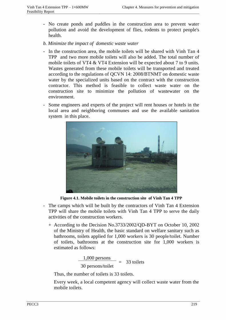
Vinh Tan 4 Extension TPP – 1×600MW
Feasibility Report
Chapter 4. Measures for prevention and mitigation
PECC3 219
- No create ponds and puddles in the construction area to prevent water
pollution and avoid the development of flies, rodents to protect people's
health.
b. Minimize the impact of domestic waste water
- In the construction area, the mobile toilets will be shared with Vinh Tan 4
TPP and two more mobile toilets will also be added. The total number of
mobile toilets of VT4 & VT4 Extension will be expected about 7 to 9 units.
Wastes generated from these mobile toilets will be transported and treated
according to the regulations of QCVN 14: 2008/BTNMT on domestic waste
water by the specialized units based on the contract with the construction
contractor. This method is feasible to collect waste water on the
construction site to minimize the pollution of wastewater on the
environment.
- Some engineers and experts of the project will rent houses or hotels in the
local area and neighboring communes and use the available sanitation
system in this place.
Figure 4.1. Mobile toilets in the construction site of Vinh Tan 4 TPP
- The camps which will be built by the contractors of Vinh Tan 4 Extension
TPP will share the mobile toilets with Vinh Tan 4 TPP to serve the daily
activities of the construction workers.
+ According to the Decision No.3733/2002/QD-BYT on October 10, 2002
of the Ministry of Health, the basic standard on welfare sanitary such as
bathrooms, toilets applied for 1,000 workers is 30 people/toilet. Number
of toilets, bathrooms at the construction site for 1,000 workers is
estimated as follows:
1,000 persons = 33 toilets
30 persons/toilet
Thus, the number of toilets is 33 toilets.
Every week, a local competent agency will collect waste water from the
mobile toilets.
Vinh Tan 4 Extension TPP – 1×600MW
Feasibility Report
Chapter 4. Measures for prevention and mitigation
PECC3 220
c. Minimize the impact of waste water from washing vehicles, equipment and
machinery.
Measures to reduce waste water from the process of washing vehicles,
equipment and machinery during the construction phase are shared with the
construction site of Vinh Tan 4 TPP, the waste water reaches QCVN 40:
2011/BTNMT before being discharged into the environment. These measures
are summarized as follows:
- At the construction site, a bridge used for washing vehicles will be
equipped to wash vehicles before leaving the construction site;
- Building a drainage ditch system surrounding the area of washing vehicles
to avoid stagnant water on the ground to affect construction;
- Waste water after washing the vehicles will be taken to drainage ditches in
the construction site to a deposition pit which is equipped with oil trap. The
water after being settled will be discharged into the receiving environment
(the sea). Part of sediment will be collected and treated periodically by a
competent agency according to the current laws.
- Regularly dredge the flow depending on the descending trend of the natural
terrain to control congestion, mud, etc.;
- Arrange the recovery devices fixed on the sea surface to recover oil and
solid waste arisen from barges, boats;
- The above-mentioned mitigation measures are commonly applied and
proved effective in controlling the wastewater in many construction
projects. When implemented fully and seriously, these measures will help
to minimize and control the amount of waste water generated during the
construction phase. These measures are feasible, simple, easy to implement,
consistent with the ability of contractors.
d. Minimize the impact of waste water from means of inland navigation
d.1. The wastewater from the activities of ships
Treatment of kentledge from large ships (about 2 tons/time of disposal to ship
of 3,000DWT) will have to comform to the current regulations of Vietnam
under Decree No.21/2012/ND-CP on March 21, 2012 on the management of
seaports and navigable channels, Article 78 of the Decree states that " Ships
when operating in the port must implement the regime of removing garbage,
dirty water and kentledge according to the regulations and instructions of the
port authority; and port enterprises or organizations, business units of
sanitation services for ships in the port, who must have means to receive
waste, waste water, water contaminated with oil sludge and other toxic liquids
from ships to handle or transfer to the competent agency to process, have
elgibility to collect service charges as prescribed by the law ".
- The project owner will establish the rules and regulations combining with
the strict and mandatory commitments for all ships' owners before their
ships/vessels/barges go into the port as follows:
- Regulating that the wastewater without treatment from the ships which are
Vinh Tan 4 Extension TPP – 1×600MW
Feasibility Report
Chapter 4. Measures for prevention and mitigation
PECC3 221
mooring in the construction process will not be allowed to discharge into
the sea ;
- If there is demand for wastewater treatment, the project owner will
cooperate with the local competent agencies to treat the wastewater;
- If the waste is oil sludge from vessels or waste water from washing ships
containing oil (in case ships require disposal of waste), the port authority
together with the specialized units are hired to collect and transport the
waste out of the port area.
d.2. Domestic waste water from the daily activities of workers on the ships
Treatment of domestic waste water from the daily activities of workers on the
ships must comply with Circular No.70/2011/TT-BGTVT issued on December
30, 2011 on National Technical Regulation "Regulation on Prevention of
Pollution from means of inland navigation "and Circular No.23/2010/TT-
BGTVT on August 25, 2010 of the Ministry of Communications and
Transportation issued the National Technical Regulation" Regulation on the
system to prevent pollution to the sea from ships "; According to Circular
70/2011/TT-BGTVT, to means of inland navigation, domestic waste water
from the sailors are collected in tanks and then transferred to the receiving
station.
The volume of a tank is calculated as follows:
V = f.n.q.t
In which:
V: volume of a tank (liters);
f: coefficients depending on the exploitation conditions;
f = 1 for ships operating over 8 hours in the prohibition area of waste
disposal.
f = 0.3 ÷ 0.5 for ships operating from 4 - 8 hours in the prohibition area of
waste disposal.
f = 0.1 for ships operating less than 4 hours in the prohibition area of
waste disposal
n: the number of regular persons on the ships or the number of animals
transported with the weight over 30kgs)
q: The amount of waste water calculated per a person (liters/day);
q = 50 liters/day for the ships ;
q = 200 liters/day for the cargo ships;
t: time (day) of operation of ships between transport trips of waste water to
the shore or far from the prohibition area of waste disposal .
c. Minimize the impact of rainwater overflowing
- The areas storing oil, materials nad machinery must be designed with roofs,
earthwork must be given priority to implement in the dry season for the
shortest period to minimize rainwater overflowing this area.
Vinh Tan 4 Extension TPP – 1×600MW
Feasibility Report
Chapter 4. Measures for prevention and mitigation
PECC3 222
- Arrange the material storehouses in the safe places to avoid oil spill and
have the methods to respond timely in case of incidents during the
construction phase to reduce rainwater overflow to cause pollution to the
surface water source.
Strong points: These measures are simple, easy to implement, consistent with
the ability of contractors
Weak points: : these measures mainly depends on the environmental
protection awareness of workers and construction contractors, therefore it is
necessary to combine the methods of education, reward and punishment and to
be controlled by the project owner.
Feasibility: The wastewater generated during construction is inevitable, and if
the mitigation measures are fully implemented, they will bring high efficiency
in limiting and controlling waste water to reduce the impact of waste water on
the surrounding areas.
Implementation period: the above measures are implemented in parallel and
synchronized with the construction works.
4.1.2.1.3 Minimize the impact of solid waste
To minimize the impact of construction solid waste and domestic solid waste
on the soil environment of the project the following measures for collecting
and handling will be shared with Vinh Tan 4 TPP :
a. Construction solid waste
- Brick, stone, rubble, etc. is given to the locals as material for levelling.
- Scrap of iron and steel removed, etc. will be reused or sold to the scrap
dealer.
b. Domestic solid waste
- The quantity of domestic solid waste generated in the construction site and
the worker camps will be collected and gathered in the disposal area every
day.
- Put domestic wastebaskets in the construction site and worker camps. The
number of waste containers is estimated as follows:
- The total quantity of domestic solid waste from 1,000 workers is
800kgs/day. With the specific density of domestic solid waste is 200 ÷
500kg/m3 (Management and treatment of solid waste - MA. Nguyen Xuan
Truong, 2012). Volume of domestic solid waste is estimated as follows:
800kgs/day/(200 ÷ 500kgs/m3 )= 1.6 ÷ 4 m3/day
The number of wastebins of 200 liters (coefficient of using a bin is 0.8)
is estimated as follows:
(1.6 ÷ 4) m3/0.8/200 liters = 10 ÷ 25 bins
Thus, the number of wastebins which will be placed in the construction site
and worker camps is about 25 bins of 200 liters (the accurate data will be
adjusted in the construction phase).
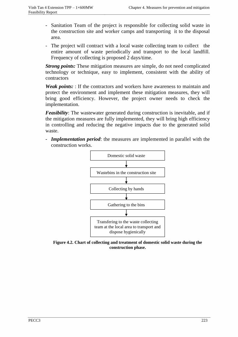
Vinh Tan 4 Extension TPP – 1×600MW
Feasibility Report
Chapter 4. Measures for prevention and mitigation
PECC3 223
- Sanitation Team of the project is responsible for collecting solid waste in
the construction site and worker camps and transporting it to the disposal
area.
- The project will contract with a local waste collecting team to collect the
entire amount of waste periodically and transport to the local landfill.
Frequency of collecting is proposed 2 days/time.
Strong points: These mitigation measures are simple, do not need complicated
technology or technique, easy to implement, consistent with the ability of
contractors
Weak points: : If the contractors and workers have awareness to maintain and
protect the environment and implement these mitigation measures, they will
bring good efficiency. However, the project owner needs to check the
implementation.
Feasibility: The wastewater generated during construction is inevitable, and if
the mitigation measures are fully implemented, they will bring high efficiency
in controlling and reducing the negative impacts due to the generated solid
waste.
- Implementation period: the measures are implemented in parallel with the
construction works.
Figure 4.2. Chart of collecting and treatment of domestic solid waste during the
construction phase.
Domestic solid waste
Wastebins in the construction site
Collecting by hands
Gathering to the bins
Transfering to the waste collecting
team at the local area to transport and
dispose hygienically
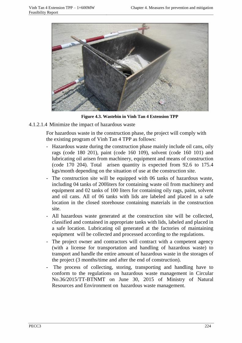
Vinh Tan 4 Extension TPP – 1×600MW
Feasibility Report
Chapter 4. Measures for prevention and mitigation
PECC3 224
Figure 4.3. Wastebin in Vinh Tan 4 Extension TPP
4.1.2.1.4 Minimize the impact of hazardous waste
For hazardous waste in the construction phase, the project will comply with
the existing program of Vinh Tan 4 TPP as follows:
- Hazardous waste during the construction phase mainly include oil cans, oily
rags (code 180 201), paint (code 160 109), solvent (code 160 101) and
lubricating oil arisen from machinery, equipment and means of construction
(code 170 204). Total arisen quantity is expected from 92.6 to 175.4
kgs/month depending on the situation of use at the construction site.
- The construction site will be equipped with 06 tanks of hazardous waste,
including 04 tanks of 200liters for containing waste oil from machinery and
equipment and 02 tanks of 100 liters for containing oily rags, paint, solvent
and oil cans. All of 06 tanks with lids are labeled and placed in a safe
location in the closed storehouse containing materials in the construction
site.
- All hazardous waste generated at the construction site will be collected,
classified and contained in appropriate tanks with lids, labeled and placed in
a safe location. Lubricating oil generated at the factories of maintaining
equipment will be collected and processed according to the regulations.
- The project owner and contractors will contract with a competent agency
(with a license for transportation and handling of hazardous waste) to
transport and handle the entire amount of hazardous waste in the storages of
the project (3 months/time and after the end of construction).
- The process of collecting, storing, transporting and handling have to
conform to the regulations on hazardous waste management in Circular
No.36/2015/TT-BTNMT on June 30, 2015 of Ministry of Natural
Resources and Environment on hazardous waste management.
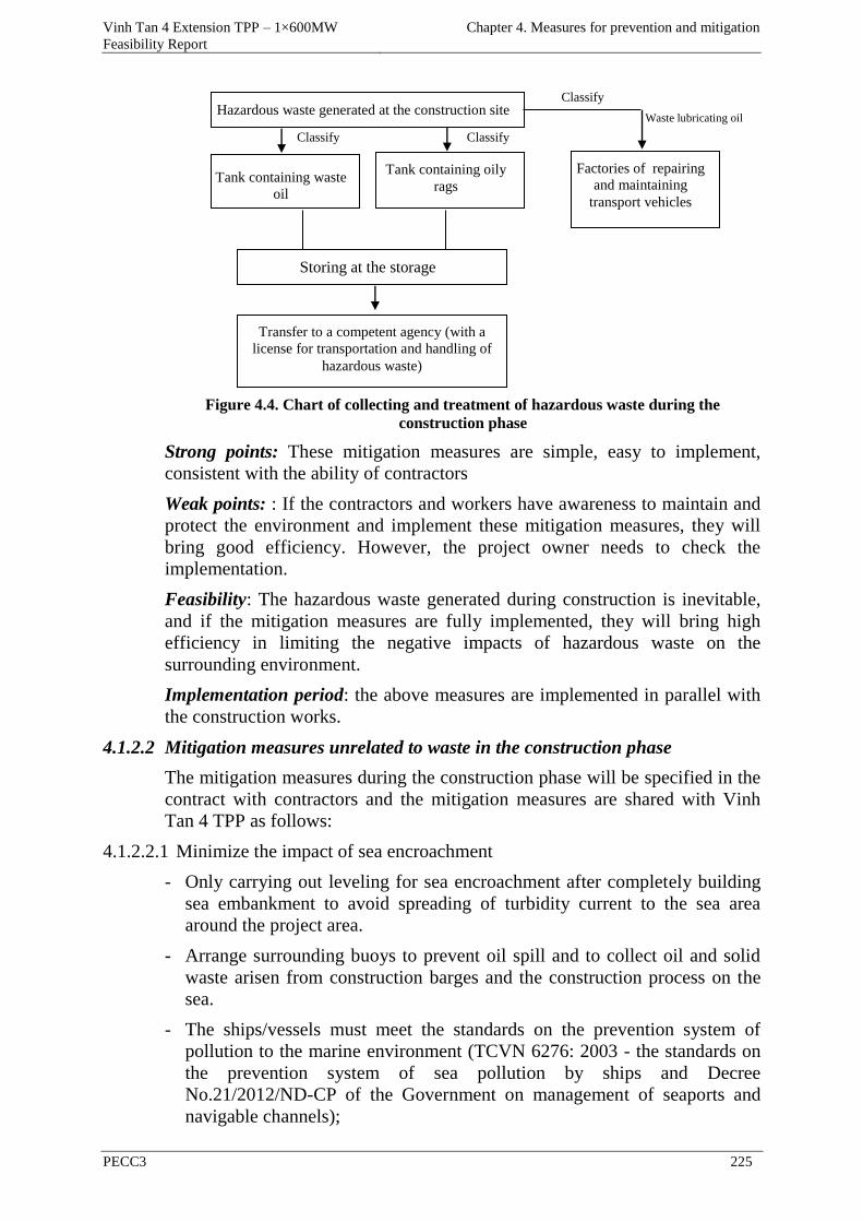
Vinh Tan 4 Extension TPP – 1×600MW
Feasibility Report
Chapter 4. Measures for prevention and mitigation
PECC3 225
Figure 4.4. Chart of collecting and treatment of hazardous waste during the
construction phase
Strong points: These mitigation measures are simple, easy to implement,
consistent with the ability of contractors
Weak points: : If the contractors and workers have awareness to maintain and
protect the environment and implement these mitigation measures, they will
bring good efficiency. However, the project owner needs to check the
implementation.
Feasibility: The hazardous waste generated during construction is inevitable,
and if the mitigation measures are fully implemented, they will bring high
efficiency in limiting the negative impacts of hazardous waste on the
surrounding environment.
Implementation period: the above measures are implemented in parallel with
the construction works.
4.1.2.2 Mitigation measures unrelated to waste in the construction phase
The mitigation measures during the construction phase will be specified in the
contract with contractors and the mitigation measures are shared with Vinh
Tan 4 TPP as follows:
4.1.2.2.1 Minimize the impact of sea encroachment
- Only carrying out leveling for sea encroachment after completely building
sea embankment to avoid spreading of turbidity current to the sea area
around the project area.
- Arrange surrounding buoys to prevent oil spill and to collect oil and solid
waste arisen from construction barges and the construction process on the
sea.
- The ships/vessels must meet the standards on the prevention system of
pollution to the marine environment (TCVN 6276: 2003 - the standards on
the prevention system of sea pollution by ships and Decree
No.21/2012/ND-CP of the Government on management of seaports and
navigable channels);
Waste lubricating oil
Classify
Classify
Hazardous waste generated at the construction site
Tank containing waste
oil
Storing at the storage
Transfer to a competent agency (with a
license for transportation and handling of
hazardous waste)
Tank containing oily
rags
Classify
Factories of repairing
and maintaining
transport vehicles
Vinh Tan 4 Extension TPP – 1×600MW
Feasibility Report
Chapter 4. Measures for prevention and mitigation
PECC3 226
- The reinforcement of slopes around the project area to avoid the erosion of
the filling material during the leveling process will reduce pollution to the
water environment;
The above-mentioned mitigation measures are popular and effective in many
construction projects, help control the effect on water quality and ecosystems
at Hon Cau MPA.
4.1.2.2.2 Minimize the impacts of noise and vibration
During the construction phase, high-density concentration of motorized
equipment and all kinds of construction machinery will cause pollution by
noise and vibration at high levels. Therefore, in this stage, the project will
apply the normal mitigation measures and other additional methods in order to
better control the impact of noise and vibration caused by the construction to
ensure noise and vibration to meet QCVN 26:2010/BTNMT about noise and
QCVN 27:2010/BTNMT on vibration in common areas as follows:
- The sources of loud noise such as concrete mixers, generators, etc. are
located far away from the sensitive areas (eg residential area) at least 200
meters.
- Carefully maintaining and repairing equipment used during construction.
This measure has high feasibility and effectiveness in reducing noise to the
surrounding environment during the construction phase;
- Limit driving piles by hammer at night (from 21:00 - 6:00) and no
construction during the time-off: from 11:30 to 13:00 and after 22:00. This
measure has high feasibility and effectiveness in reducing the noise effect
on the local people's health during the construction phase;
- For trucks: the construction contractors will require the drivers do not honk
indiscriminately when driving through the residential areas and limit
operating during the time-off of people (after 20:00). This measure has high
feasibility and effectiveness in reducing the noise effect on the local
people's health during the construction phase;
- Construction equipment and machinery have to be tested about technical
situation and will work in the best condition to achieve the standards for
noise and vibration generated for construction equipment. This measure has
high feasibility and effectiveness in reducing the noise effect on the
surrounding environment during the construction phase.
- The construction workers will be equipped with protective equipment and
noise-protective capsules and plugs in the work areas arising loud noise.
This measure has high feasibility and effectiveness in reducing the noise
effect on the health of workers during the construction phase;
- Arrangement of construction schedule for the activities that cause loud
noises are not implemented simultaneously in the same area. This measure
is highly feasible in the total noise reduction;
- Good management of activities of construction workers, avoid causing
noise to lose the quietness during the time-off of the locals;
Vinh Tan 4 Extension TPP – 1×600MW
Feasibility Report
Chapter 4. Measures for prevention and mitigation
PECC3 227
- In case the noise level lowering distance is not guaranteed, the noise wall
building measure will be applied. Wall with height from 3 to 4 m and is
made of fiber glass or wood with good noise reduction capabilities.
Depending on the selected materials to build noise wall that noise may be
reduced from 10 to 40 dBA infront and behind the noise wall respectively.
This measures is feasible and effective in reducing the noise effect on the
health of the local people during the construction phase;
The above-mentioned mitigation measures when fully implemented will
effectively limit the negative effects of noise, vibration from construction
activities of the project on the sensitive objects.
Strong points: These mitigation measures are simple, easy to implement,
consistent with the ability of contractors
Weak points: : These measures can only mitigate but not completely overcome
the impact and needs to be implemented by the contractors and checked by the
project owner.
Feasibility: These mitigation measures has high feasibility and effectiveness
in reducing noise and vibration to affect the health of construction workers and
the local people during the construction phase
Implementation period: the above measures are implemented in parallel with
the construction works.
4.1.2.2.3 Minimize the impact on the socio-economic environment
The measures to minimize the impact on the socio-economic environment of
the project will be shared with Vinh Tan 4 TPP as follows:
- PMB and contractors, construction units should implement management of
discipline, education of healthy lifestyle for workers.
- Need to promote the role of the mass organizations, ensure to resolve
conflicts between the locals and construction workers (if any) and build
cultural and spiritual life as organizing the exchange of views in order to
create a good relationship between workers with the locals.
- The workers who participate in the evils like theft, fights, or cause conflict
with the local people will be stopped their contracts, fired or handed over to
the local authorities or the law enforcement agencies to deal with.
Besides, to avoid conflicts between construction workers and the local people,
the following measures will be applied by the construction contractors:
- Make the most of the local labor force in Tuy Phong district and other
districts of Binh Thuan province for the simple construction jobs.
- Register the temporary presence for the construction workers to the police
of Vinh Tan commune.
- Periodically (2 months/time) holding discussions with Vinh Tan Commune
People's Committee and People's Committee of Tuy Phong district on
issues related to the relationship between workers and locals.
- Propagate and educate construction workers about the relationship with the
Vinh Tan 4 Extension TPP – 1×600MW
Feasibility Report
Chapter 4. Measures for prevention and mitigation
PECC3 228
locals.
- Moral and behavior education, management of workers to curb drink,
gamble, theft, fights between workers and between workers and local
people.
- To prevent the spread of infectious diseases such as infectious disease
through the water environment, infectious diseases by mediate agents
(insects, bugs, etc.), HIV/AIDS and other social diseases, etc. between the
workers and local people and vice versa, the following measures will be
implemented by the construction contractors:
- The project owner will require the construction contractors arrange a health
unit at the construction site with 2-3 nurses to timely provide medicine,
health care, first aid, etc. for the workers when they are sick or when the
occupational accidents happen.
- Education for construction workers on the measures to prevent and destroy
pathogens such as flies, mosquitoes, larvae, etc.
- Organize the training courses on occupational safety for construction
workers.
- Coordinate with the health center of commune in health care and disease
prevention, organize periodic health examination (1 time/year) for
construction workers.
The above-mentioned mitigation measures are necessary to minimize conflicts
arising between construction workers of the project with local people, reduce
social evils, maintain public order.
The advantage of these measures tends toward management, simple and easy
to implement
However, these measures should be combined with educational measures on
environmental awareness for workers and require the close collaboration
between the project owner, contractors and local authorities. In addition, these
activities should be checked regularly by the project owner.
4.1.2.2.4 The issue of workers' health
- The following measures should be taken to ensure the environmental
hygiene in construction activities:
- The contractor will build (or rent) housing area for construction workers
with good hygienic conditions, including: housing, toilets, canteen.
- Housing area must be spacious and airy, ensure living conditions, sanitation
and recreation for workers.
- Water supplied to workers must ensure to reach the standard on drinking
water to avoid digestive diseases for workers.
- Solid waste from daily activities (from the canteen area, housing) mainly
including organic components will be collected and transported by the
sanitation workers to the disposal area.
- Education and propaganda of awareness about the environmental sanitation
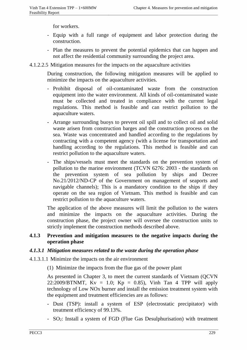
Vinh Tan 4 Extension TPP – 1×600MW
Feasibility Report
Chapter 4. Measures for prevention and mitigation
PECC3 229
for workers.
- Equip with a full range of equipment and labor protection during the
construction.
- Plan the measures to prevent the potential epidemics that can happen and
not affect the residential community surrounding the project area.
4.1.2.2.5 Mitigation measures for the impacts on the aquaculture activities
During construction, the following mitigation measures will be applied to
minimize the impacts on the aquaculture activities.
- Prohibit disposal of oil-contaminated waste from the construction
equipment into the water environment. All kinds of oil-contaminated waste
must be collected and treated in compliance with the current legal
regulations. This method is feasible and can restrict pollution to the
aquaculture waters.
- Arrange surrounding buoys to prevent oil spill and to collect oil and solid
waste arisen from construction barges and the construction process on the
sea. Waste was concentrated and handled according to the regulations by
contracting with a competent agency (with a license for transportation and
handling according to the regulations. This method is feasible and can
restrict pollution to the aquaculture waters.
- The ships/vessels must meet the standards on the prevention system of
pollution to the marine environment (TCVN 6276: 2003 - the standards on
the prevention system of sea pollution by ships and Decree
No.21/2012/ND-CP of the Government on management of seaports and
navigable channels); This is a mandatory condition to the ships if they
operate on the sea region of Vietnam. This method is feasible and can
restrict pollution to the aquaculture waters.
The application of the above measures will limit the pollution to the waters
and minimize the impacts on the aquaculture activities. During the
construction phase, the project owner will oversee the construction units to
strictly implement the construction methods described above.
4.1.3 Prevention and mitigation measures to the negative impacts during the
operation phase
4.1.3.1 Mitigation measures related to the waste during the operation phase
4.1.3.1.1 Minimize the impacts on the air environment
(1) Minimize the impacts from the flue gas of the power plant
As presented in Chapter 3, to meet the current standards of Vietnam (QCVN
22:2009/BTNMT, Kv = 1.0; Kp = 0.85), Vinh Tan 4 TPP will apply
technology of Low NOx burner and install the emission treatment system with
the equipment and treatment efficiencies are as follows:
- Dust (TSP): install a system of ESP (electrostatic precipitator) with
treatment efficiency of 99.13%.
- SO2: Install a system of FGD (Flue Gas Desulphurisation) with treatment
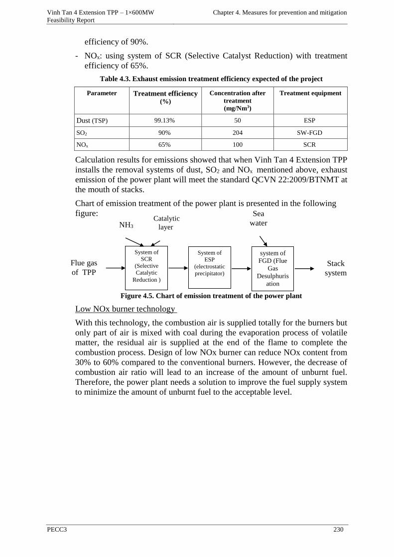
Vinh Tan 4 Extension TPP – 1×600MW
Feasibility Report
Chapter 4. Measures for prevention and mitigation
PECC3 230
efficiency of 90%.
- NOx: using system of SCR (Selective Catalyst Reduction) with treatment
efficiency of 65%.
Table 4.3. Exhaust emission treatment efficiency expected of the project
Parameter Treatment efficiency (%)
Concentration after
treatment
(mg/Nm3)
Treatment equipment
Dust (TSP) 99.13% 50 ESP
SO2 90% 204 SW-FGD
NOx 65% 100 SCR
Calculation results for emissions showed that when Vinh Tan 4 Extension TPP
installs the removal systems of dust, SO2 and NOx mentioned above, exhaust
emission of the power plant will meet the standard QCVN 22:2009/BTNMT at
the mouth of stacks.
Chart of emission treatment of the power plant is presented in the following
figure:
Figure 4.5. Chart of emission treatment of the power plant
Low NOx burner technology
With this technology, the combustion air is supplied totally for the burners but
only part of air is mixed with coal during the evaporation process of volatile
matter, the residual air is supplied at the end of the flame to complete the
combustion process. Design of low NOx burner can reduce NOx content from
30% to 60% compared to the conventional burners. However, the decrease of
combustion air ratio will lead to an increase of the amount of unburnt fuel.
Therefore, the power plant needs a solution to improve the fuel supply system
to minimize the amount of unburnt fuel to the acceptable level.
Flue gas
of TPP
System of
SCR
(Selective
Catalytic
Reduction )
System of
ESP
(electrostatic precipitator)
system of
FGD (Flue
Gas Desulphuris
ation
Stack
system
NH3 Catalytic
layer
Sea
water
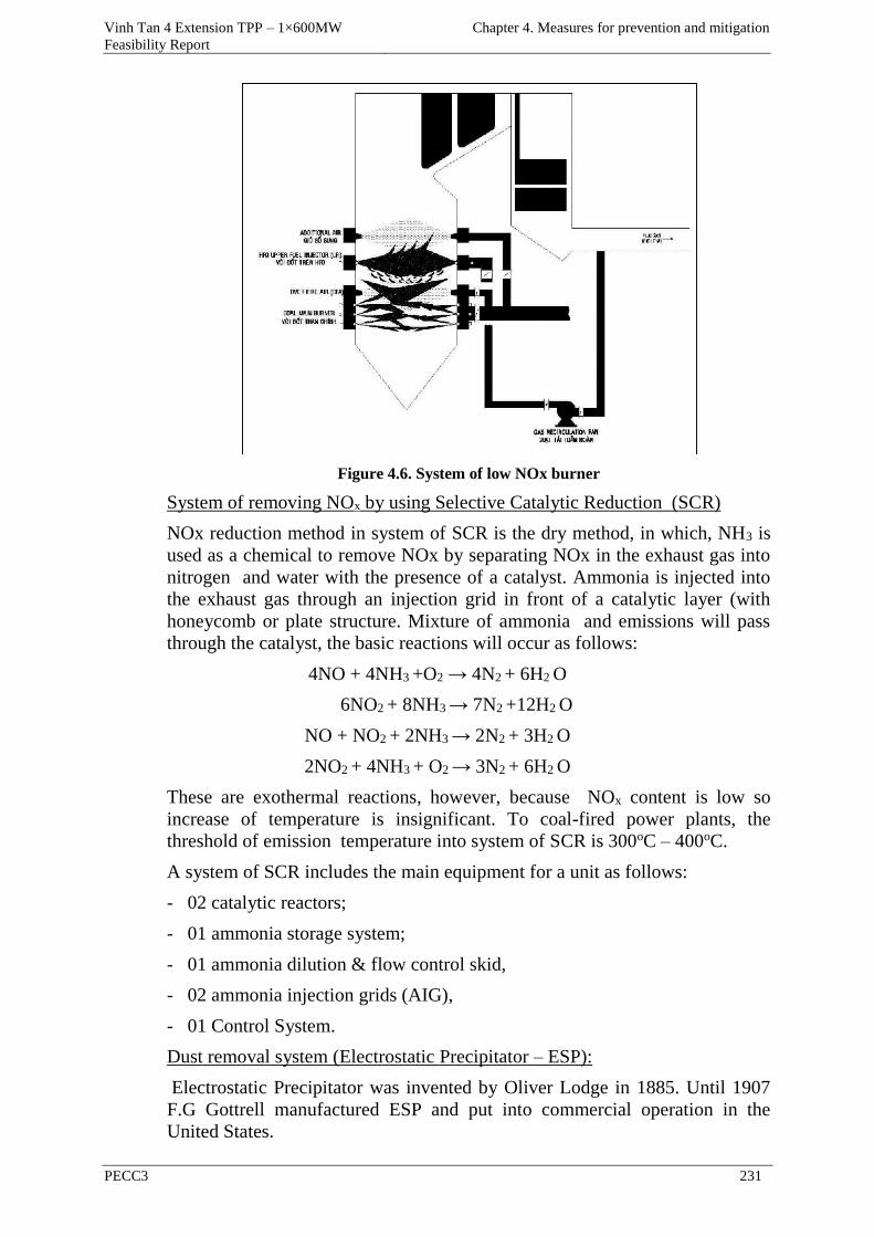
Vinh Tan 4 Extension TPP – 1×600MW
Feasibility Report
Chapter 4. Measures for prevention and mitigation
PECC3 231
Figure 4.6. System of low NOx burner
System of removing NOx by using Selective Catalytic Reduction (SCR)
NOx reduction method in system of SCR is the dry method, in which, NH3 is
used as a chemical to remove NOx by separating NOx in the exhaust gas into
nitrogen and water with the presence of a catalyst. Ammonia is injected into
the exhaust gas through an injection grid in front of a catalytic layer (with
honeycomb or plate structure. Mixture of ammonia and emissions will pass
through the catalyst, the basic reactions will occur as follows:
4NO + 4NH3 +O2 → 4N2 + 6H2 O
6NO2 + 8NH3 → 7N2 +12H2 O
NO + NO2 + 2NH3 → 2N2 + 3H2 O
2NO2 + 4NH3 + O2 → 3N2 + 6H2 O
These are exothermal reactions, however, because NOx content is low so
increase of temperature is insignificant. To coal-fired power plants, the
threshold of emission temperature into system of SCR is 300oC – 400oC.
A system of SCR includes the main equipment for a unit as follows:
- 02 catalytic reactors;
- 01 ammonia storage system;
- 01 ammonia dilution & flow control skid,
- 02 ammonia injection grids (AIG),
- 01 Control System.
Dust removal system (Electrostatic Precipitator – ESP):
Electrostatic Precipitator was invented by Oliver Lodge in 1885. Until 1907
F.G Gottrell manufactured ESP and put into commercial operation in the
United States.
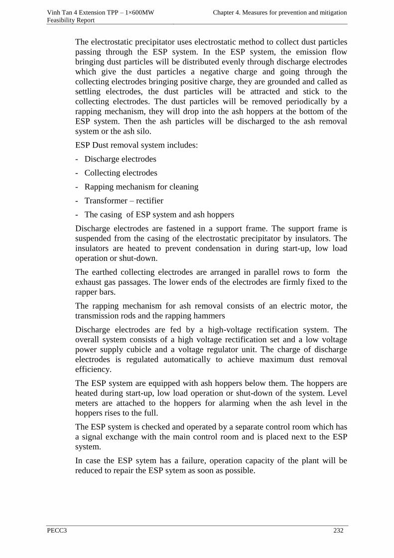
Vinh Tan 4 Extension TPP – 1×600MW
Feasibility Report
Chapter 4. Measures for prevention and mitigation
PECC3 232
The electrostatic precipitator uses electrostatic method to collect dust particles
passing through the ESP system. In the ESP system, the emission flow
bringing dust particles will be distributed evenly through discharge electrodes
which give the dust particles a negative charge and going through the
collecting electrodes bringing positive charge, they are grounded and called as
settling electrodes, the dust particles will be attracted and stick to the
collecting electrodes. The dust particles will be removed periodically by a
rapping mechanism, they will drop into the ash hoppers at the bottom of the
ESP system. Then the ash particles will be discharged to the ash removal
system or the ash silo.
ESP Dust removal system includes:
- Discharge electrodes
- Collecting electrodes
- Rapping mechanism for cleaning
- Transformer – rectifier
- The casing of ESP system and ash hoppers
Discharge electrodes are fastened in a support frame. The support frame is
suspended from the casing of the electrostatic precipitator by insulators. The
insulators are heated to prevent condensation in during start-up, low load
operation or shut-down.
The earthed collecting electrodes are arranged in parallel rows to form the
exhaust gas passages. The lower ends of the electrodes are firmly fixed to the
rapper bars.
The rapping mechanism for ash removal consists of an electric motor, the
transmission rods and the rapping hammers
Discharge electrodes are fed by a high-voltage rectification system. The
overall system consists of a high voltage rectification set and a low voltage
power supply cubicle and a voltage regulator unit. The charge of discharge
electrodes is regulated automatically to achieve maximum dust removal
efficiency.
The ESP system are equipped with ash hoppers below them. The hoppers are
heated during start-up, low load operation or shut-down of the system. Level
meters are attached to the hoppers for alarming when the ash level in the
hoppers rises to the full.
The ESP system is checked and operated by a separate control room which has
a signal exchange with the main control room and is placed next to the ESP
system.
In case the ESP sytem has a failure, operation capacity of the plant will be
reduced to repair the ESP sytem as soon as possible.
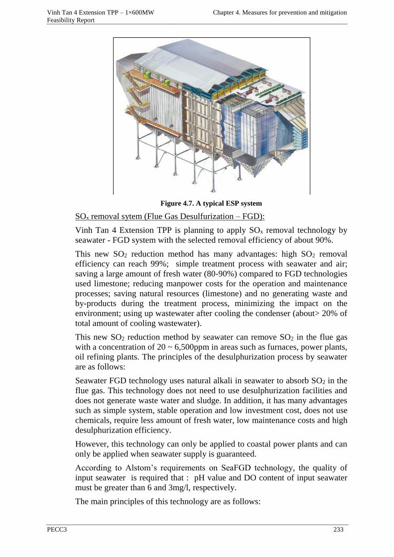
Vinh Tan 4 Extension TPP – 1×600MW
Feasibility Report
Chapter 4. Measures for prevention and mitigation
PECC3 233
Figure 4.7. A typical ESP system
SOx removal sytem (Flue Gas Desulfurization – FGD):
Vinh Tan 4 Extension TPP is planning to apply SOx removal technology by
seawater - FGD system with the selected removal efficiency of about 90%.
This new SO2 reduction method has many advantages: high SO2 removal
efficiency can reach 99%; simple treatment process with seawater and air;
saving a large amount of fresh water (80-90%) compared to FGD technologies
used limestone; reducing manpower costs for the operation and maintenance
processes; saving natural resources (limestone) and no generating waste and
by-products during the treatment process, minimizing the impact on the
environment; using up wastewater after cooling the condenser (about> 20% of
total amount of cooling wastewater).
This new SO2 reduction method by seawater can remove SO2 in the flue gas
with a concentration of 20 ~ 6,500ppm in areas such as furnaces, power plants,
oil refining plants. The principles of the desulphurization process by seawater
are as follows:
Seawater FGD technology uses natural alkali in seawater to absorb SO2 in the
flue gas. This technology does not need to use desulphurization facilities and
does not generate waste water and sludge. In addition, it has many advantages
such as simple system, stable operation and low investment cost, does not use
chemicals, require less amount of fresh water, low maintenance costs and high
desulphurization efficiency.
However, this technology can only be applied to coastal power plants and can
only be applied when seawater supply is guaranteed.
According to Alstom’s requirements on SeaFGD technology, the quality of
input seawater is required that : pH value and DO content of input seawater
must be greater than 6 and 3mg/l, respectively.
The main principles of this technology are as follows:
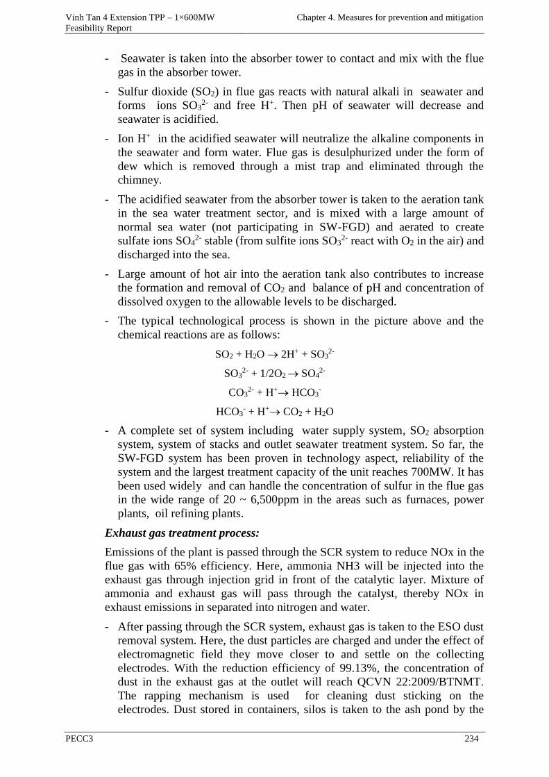
Vinh Tan 4 Extension TPP – 1×600MW
Feasibility Report
Chapter 4. Measures for prevention and mitigation
PECC3 234
- Seawater is taken into the absorber tower to contact and mix with the flue
gas in the absorber tower.
- Sulfur dioxide (SO2) in flue gas reacts with natural alkali in seawater and
forms ions SO32- and free H+. Then pH of seawater will decrease and
seawater is acidified.
- Ion H+ in the acidified seawater will neutralize the alkaline components in
the seawater and form water. Flue gas is desulphurized under the form of
dew which is removed through a mist trap and eliminated through the
chimney.
- The acidified seawater from the absorber tower is taken to the aeration tank
in the sea water treatment sector, and is mixed with a large amount of
normal sea water (not participating in SW-FGD) and aerated to create
sulfate ions SO42- stable (from sulfite ions SO3
2- react with O2 in the air) and
discharged into the sea.
- Large amount of hot air into the aeration tank also contributes to increase
the formation and removal of CO2 and balance of pH and concentration of
dissolved oxygen to the allowable levels to be discharged.
- The typical technological process is shown in the picture above and the
chemical reactions are as follows:
SO2 + H2O 2H+ + SO32-
SO32- + 1/2O2 SO4
2-
CO32- + H+ HCO3
-
HCO3- + H+ CO2 + H2O
- A complete set of system including water supply system, SO2 absorption
system, system of stacks and outlet seawater treatment system. So far, the
SW-FGD system has been proven in technology aspect, reliability of the
system and the largest treatment capacity of the unit reaches 700MW. It has
been used widely and can handle the concentration of sulfur in the flue gas
in the wide range of 20 ~ 6,500ppm in the areas such as furnaces, power
plants, oil refining plants.
Exhaust gas treatment process:
Emissions of the plant is passed through the SCR system to reduce NOx in the
flue gas with 65% efficiency. Here, ammonia NH3 will be injected into the
exhaust gas through injection grid in front of the catalytic layer. Mixture of
ammonia and exhaust gas will pass through the catalyst, thereby NOx in
exhaust emissions in separated into nitrogen and water.
- After passing through the SCR system, exhaust gas is taken to the ESO dust
removal system. Here, the dust particles are charged and under the effect of
electromagnetic field they move closer to and settle on the collecting
electrodes. With the reduction efficiency of 99.13%, the concentration of
dust in the exhaust gas at the outlet will reach QCVN 22:2009/BTNMT.
The rapping mechanism is used for cleaning dust sticking on the
electrodes. Dust stored in containers, silos is taken to the ash pond by the
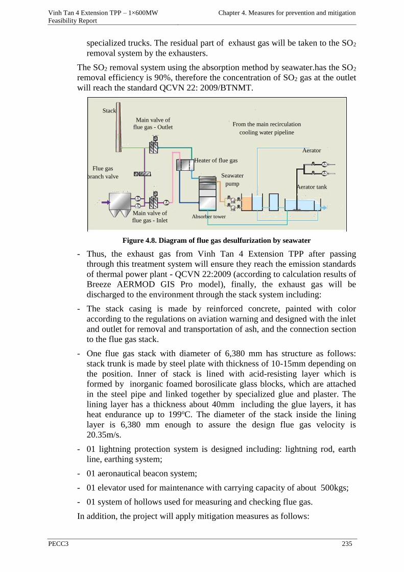
Vinh Tan 4 Extension TPP – 1×600MW
Feasibility Report
Chapter 4. Measures for prevention and mitigation
PECC3 235
specialized trucks. The residual part of exhaust gas will be taken to the SO2
removal system by the exhausters.
The SO2 removal system using the absorption method by seawater.has the SO2
removal efficiency is 90%, therefore the concentration of SO2 gas at the outlet
will reach the standard QCVN 22: 2009/BTNMT.
Figure 4.8. Diagram of flue gas desulfurization by seawater
- Thus, the exhaust gas from Vinh Tan 4 Extension TPP after passing
through this treatment system will ensure they reach the emission standards
of thermal power plant - QCVN 22:2009 (according to calculation results of
Breeze AERMOD GIS Pro model), finally, the exhaust gas will be
discharged to the environment through the stack system including:
- The stack casing is made by reinforced concrete, painted with color
according to the regulations on aviation warning and designed with the inlet
and outlet for removal and transportation of ash, and the connection section
to the flue gas stack.
- One flue gas stack with diameter of 6,380 mm has structure as follows:
stack trunk is made by steel plate with thickness of 10-15mm depending on
the position. Inner of stack is lined with acid-resisting layer which is
formed by inorganic foamed borosilicate glass blocks, which are attached
in the steel pipe and linked together by specialized glue and plaster. The
lining layer has a thickness about 40mm including the glue layers, it has
heat endurance up to 199oC. The diameter of the stack inside the lining
layer is 6,380 mm enough to assure the design flue gas velocity is
20.35m/s.
- 01 lightning protection system is designed including: lightning rod, earth
line, earthing system;
- 01 aeronautical beacon system;
- 01 elevator used for maintenance with carrying capacity of about 500kgs;
- 01 system of hollows used for measuring and checking flue gas.
In addition, the project will apply mitigation measures as follows:
Nước thải
Stack
Absorber tower
Aerator
Aerator tank
Main valve of
flue gas - Inlet
Flue gas
branch valve Seawater
pump
From the main recirculation
cooling water pipeline
Main valve of
flue gas - Outlet
Heater of flue gas
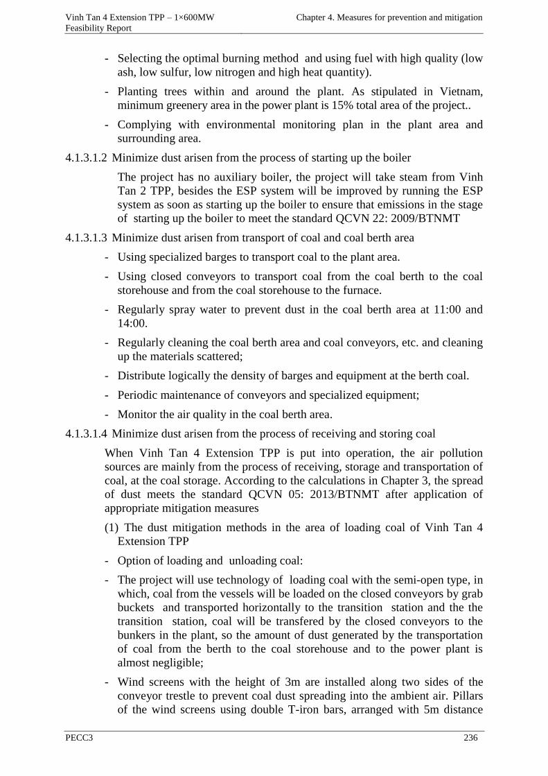
Vinh Tan 4 Extension TPP – 1×600MW
Feasibility Report
Chapter 4. Measures for prevention and mitigation
PECC3 236
- Selecting the optimal burning method and using fuel with high quality (low
ash, low sulfur, low nitrogen and high heat quantity).
- Planting trees within and around the plant. As stipulated in Vietnam,
minimum greenery area in the power plant is 15% total area of the project..
- Complying with environmental monitoring plan in the plant area and
surrounding area.
4.1.3.1.2 Minimize dust arisen from the process of starting up the boiler
The project has no auxiliary boiler, the project will take steam from Vinh
Tan 2 TPP, besides the ESP system will be improved by running the ESP
system as soon as starting up the boiler to ensure that emissions in the stage
of starting up the boiler to meet the standard QCVN 22: 2009/BTNMT
4.1.3.1.3 Minimize dust arisen from transport of coal and coal berth area
- Using specialized barges to transport coal to the plant area.
- Using closed conveyors to transport coal from the coal berth to the coal
storehouse and from the coal storehouse to the furnace.
- Regularly spray water to prevent dust in the coal berth area at 11:00 and
14:00.
- Regularly cleaning the coal berth area and coal conveyors, etc. and cleaning
up the materials scattered;
- Distribute logically the density of barges and equipment at the berth coal.
- Periodic maintenance of conveyors and specialized equipment;
- Monitor the air quality in the coal berth area.
4.1.3.1.4 Minimize dust arisen from the process of receiving and storing coal
When Vinh Tan 4 Extension TPP is put into operation, the air pollution
sources are mainly from the process of receiving, storage and transportation of
coal, at the coal storage. According to the calculations in Chapter 3, the spread
of dust meets the standard QCVN 05: 2013/BTNMT after application of
appropriate mitigation measures
(1) The dust mitigation methods in the area of loading coal of Vinh Tan 4
Extension TPP
- Option of loading and unloading coal:
- The project will use technology of loading coal with the semi-open type, in
which, coal from the vessels will be loaded on the closed conveyors by grab
buckets and transported horizontally to the transition station and the the
transition station, coal will be transfered by the closed conveyors to the
bunkers in the plant, so the amount of dust generated by the transportation
of coal from the berth to the coal storehouse and to the power plant is
almost negligible;
- Wind screens with the height of 3m are installed along two sides of the
conveyor trestle to prevent coal dust spreading into the ambient air. Pillars
of the wind screens using double T-iron bars, arranged with 5m distance
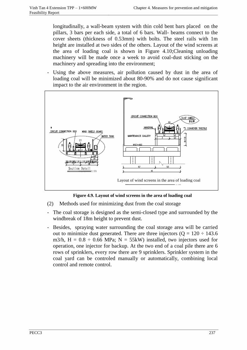
Vinh Tan 4 Extension TPP – 1×600MW
Feasibility Report
Chapter 4. Measures for prevention and mitigation
PECC3 237
longitudinally, a wall-beam system with thin cold bent bars placed on the
pillars, 3 bars per each side, a total of 6 bars. Wall- beams connect to the
cover sheets (thickness of 0.53mm) with bolts. The steel rails with 1m
height are installed at two sides of the others. Layout of the wind screens at
the area of loading coal is shown in Figure 4.10;Cleaning unloading
machinery will be made once a week to avoid coal-dust sticking on the
machinery and spreading into the environment;
- Using the above measures, air pollution caused by dust in the area of
loading coal will be minimized about 80-90% and do not cause significant
impact to the air environment in the region.
Figure 4.9. Layout of wind screens in the area of loading coal
(2) Methods used for minimizing dust from the coal storage
- The coal storage is designed as the semi-closed type and surrounded by the
windbreak of 18m height to prevent dust.
- Besides, spraying water surrounding the coal storage area will be carried
out to minimize dust generated. There are three injectors (Q = 120 ÷ 143.6
m3/h, H = 0.8 ÷ 0.66 MPa; N = 55kW) installed, two injectors used for
operation, one injector for backup. At the two end of a coal pile there are 6
rows of sprinklers, every row there are 9 sprinklers. Sprinkler system in the
coal yard can be controled manually or automatically, combining local
control and remote control.
Layout of wind screens in the area of loading coal
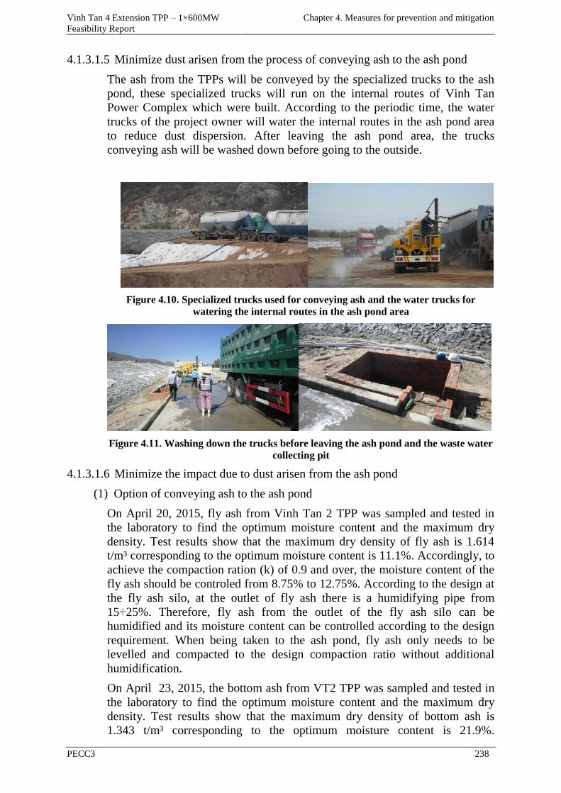
Vinh Tan 4 Extension TPP – 1×600MW
Feasibility Report
Chapter 4. Measures for prevention and mitigation
PECC3 238
4.1.3.1.5 Minimize dust arisen from the process of conveying ash to the ash pond
The ash from the TPPs will be conveyed by the specialized trucks to the ash
pond, these specialized trucks will run on the internal routes of Vinh Tan
Power Complex which were built. According to the periodic time, the water
trucks of the project owner will water the internal routes in the ash pond area
to reduce dust dispersion. After leaving the ash pond area, the trucks
conveying ash will be washed down before going to the outside.
Figure 4.10. Specialized trucks used for conveying ash and the water trucks for
watering the internal routes in the ash pond area
Figure 4.11. Washing down the trucks before leaving the ash pond and the waste water
collecting pit
4.1.3.1.6 Minimize the impact due to dust arisen from the ash pond
(1) Option of conveying ash to the ash pond
On April 20, 2015, fly ash from Vinh Tan 2 TPP was sampled and tested in
the laboratory to find the optimum moisture content and the maximum dry
density. Test results show that the maximum dry density of fly ash is 1.614
t/m³ corresponding to the optimum moisture content is 11.1%. Accordingly, to
achieve the compaction ration (k) of 0.9 and over, the moisture content of the
fly ash should be controled from 8.75% to 12.75%. According to the design at
the fly ash silo, at the outlet of fly ash there is a humidifying pipe from
15÷25%. Therefore, fly ash from the outlet of the fly ash silo can be
humidified and its moisture content can be controlled according to the design
requirement. When being taken to the ash pond, fly ash only needs to be
levelled and compacted to the design compaction ratio without additional
humidification.
On April 23, 2015, the bottom ash from VT2 TPP was sampled and tested in
the laboratory to find the optimum moisture content and the maximum dry
density. Test results show that the maximum dry density of bottom ash is
1.343 t/m³ corresponding to the optimum moisture content is 21.9%.
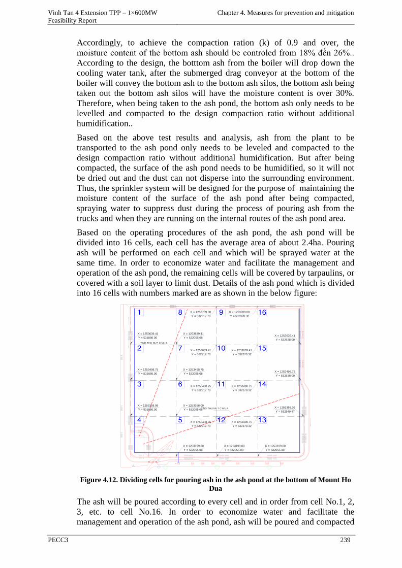
Vinh Tan 4 Extension TPP – 1×600MW
Feasibility Report
Chapter 4. Measures for prevention and mitigation
PECC3 239
Accordingly, to achieve the compaction ration (k) of 0.9 and over, the
moisture content of the bottom ash should be controled from 18% đến 26%..
According to the design, the botttom ash from the boiler will drop down the
cooling water tank, after the submerged drag conveyor at the bottom of the
boiler will convey the bottom ash to the bottom ash silos, the bottom ash being
taken out the bottom ash silos will have the moisture content is over 30%.
Therefore, when being taken to the ash pond, the bottom ash only needs to be
levelled and compacted to the design compaction ratio without additional
humidification..
Based on the above test results and analysis, ash from the plant to be
transported to the ash pond only needs to be leveled and compacted to the
design compaction ratio without additional humidification. But after being
compacted, the surface of the ash pond needs to be humidified, so it will not
be dried out and the dust can not disperse into the surrounding environment.
Thus, the sprinkler system will be designed for the purpose of maintaining the
moisture content of the surface of the ash pond after being compacted,
spraying water to suppress dust during the process of pouring ash from the
trucks and when they are running on the internal routes of the ash pond area.
Based on the operating procedures of the ash pond, the ash pond will be
divided into 16 cells, each cell has the average area of about 2.4ha. Pouring
ash will be performed on each cell and which will be sprayed water at the
same time. In order to economize water and facilitate the management and
operation of the ash pond, the remaining cells will be covered by tarpaulins, or
covered with a soil layer to limit dust. Details of the ash pond which is divided
into 16 cells with numbers marked are as shown in the below figure:
? NG THU NU? C MUA
? NG THU NU? C MUA
1
X = 1253639.41
Y = 532538.00
X = 1253639.41
Y = 531880.00
X = 1253789.00
Y = 532370.32
X = 1253789.00
Y = 532212.70
X = 1253639.41
Y = 532055.08
X = 1253639.41
Y = 532212.70
X = 1253639.41
Y = 532370.32
X = 1253498.75
Y = 532538.00
X = 1253498.75
Y = 531880.00
X = 1253498.75
Y = 532055.08
X = 1253498.75
Y = 532212.70
X = 1253498.75
Y = 532370.32
X = 1253358.09
Y = 532549.47
X = 1253358.09
Y = 531880.00
X = 1253358.09
Y = 532055.08
X = 1253498.75
Y = 532212.70
X = 1253498.75
Y = 532370.32
X = 1253199.80
Y = 532055.08
X = 1253199.80
Y = 532055.08
X = 1253199.80
Y = 532055.08
2
3
4
8
7
6
5
9
10
11
12
16
15
14
13
Figure 4.12. Dividing cells for pouring ash in the ash pond at the bottom of Mount Ho
Dua
The ash will be poured according to every cell and in order from cell No.1, 2,
3, etc. to cell No.16. In order to economize water and facilitate the
management and operation of the ash pond, ash will be poured and compacted
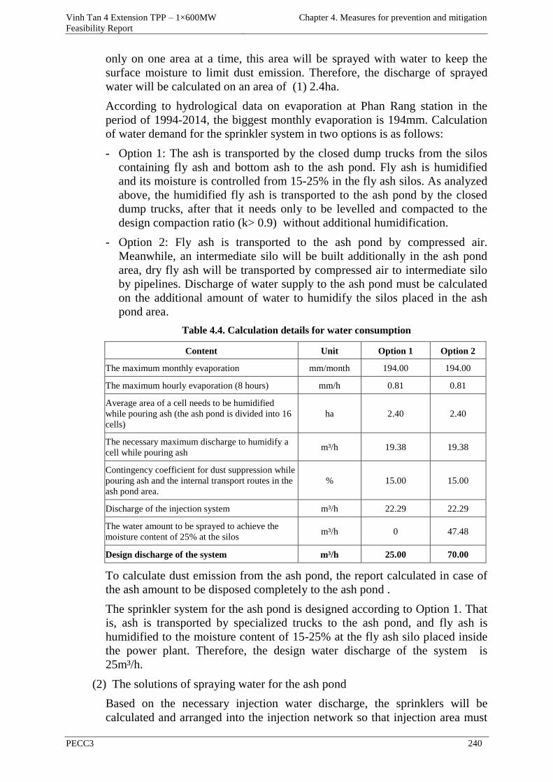
Vinh Tan 4 Extension TPP – 1×600MW
Feasibility Report
Chapter 4. Measures for prevention and mitigation
PECC3 240
only on one area at a time, this area will be sprayed with water to keep the
surface moisture to limit dust emission. Therefore, the discharge of sprayed
water will be calculated on an area of (1) 2.4ha.
According to hydrological data on evaporation at Phan Rang station in the
period of 1994-2014, the biggest monthly evaporation is 194mm. Calculation
of water demand for the sprinkler system in two options is as follows:
- Option 1: The ash is transported by the closed dump trucks from the silos
containing fly ash and bottom ash to the ash pond. Fly ash is humidified
and its moisture is controlled from 15-25% in the fly ash silos. As analyzed
above, the humidified fly ash is transported to the ash pond by the closed
dump trucks, after that it needs only to be levelled and compacted to the
design compaction ratio (k> 0.9) without additional humidification.
- Option 2: Fly ash is transported to the ash pond by compressed air.
Meanwhile, an intermediate silo will be built additionally in the ash pond
area, dry fly ash will be transported by compressed air to intermediate silo
by pipelines. Discharge of water supply to the ash pond must be calculated
on the additional amount of water to humidify the silos placed in the ash
pond area.
Table 4.4. Calculation details for water consumption
Content Unit Option 1 Option 2
The maximum monthly evaporation mm/month 194.00 194.00
The maximum hourly evaporation (8 hours) mm/h 0.81 0.81
Average area of a cell needs to be humidified
while pouring ash (the ash pond is divided into 16
cells)
ha 2.40 2.40
The necessary maximum discharge to humidify a
cell while pouring ash m³/h 19.38 19.38
Contingency coefficient for dust suppression while
pouring ash and the internal transport routes in the
ash pond area.
% 15.00 15.00
Discharge of the injection system m³/h 22.29 22.29
The water amount to be sprayed to achieve the
moisture content of 25% at the silos m³/h 0 47.48
Design discharge of the system m³/h 25.00 70.00
To calculate dust emission from the ash pond, the report calculated in case of
the ash amount to be disposed completely to the ash pond .
The sprinkler system for the ash pond is designed according to Option 1. That
is, ash is transported by specialized trucks to the ash pond, and fly ash is
humidified to the moisture content of 15-25% at the fly ash silo placed inside
the power plant. Therefore, the design water discharge of the system is
25m³/h.
(2) The solutions of spraying water for the ash pond
Based on the necessary injection water discharge, the sprinklers will be
calculated and arranged into the injection network so that injection area must
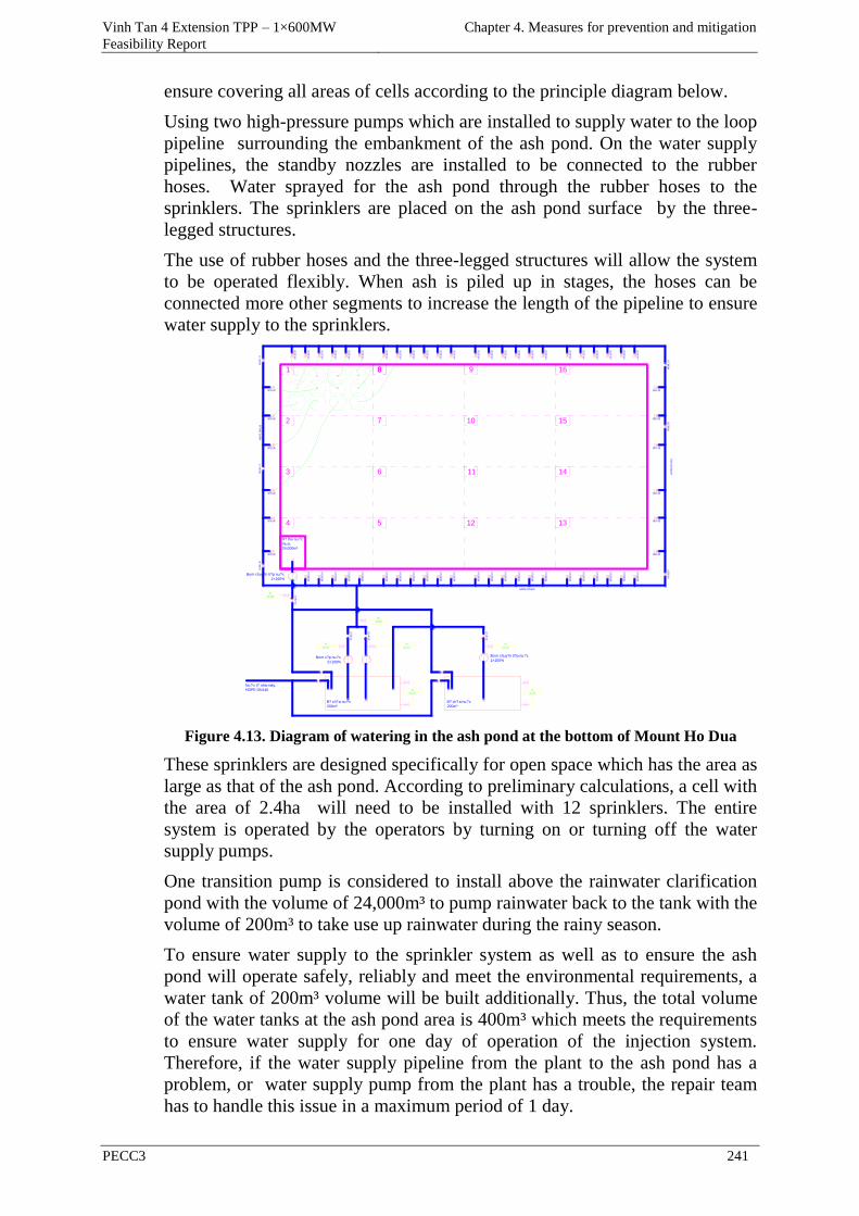
Vinh Tan 4 Extension TPP – 1×600MW
Feasibility Report
Chapter 4. Measures for prevention and mitigation
PECC3 241
ensure covering all areas of cells according to the principle diagram below.
Using two high-pressure pumps which are installed to supply water to the loop
pipeline surrounding the embankment of the ash pond. On the water supply
pipelines, the standby nozzles are installed to be connected to the rubber
hoses. Water sprayed for the ash pond through the rubber hoses to the
sprinklers. The sprinklers are placed on the ash pond surface by the three-
legged structures.
The use of rubber hoses and the three-legged structures will allow the system
to be operated flexibly. When ash is piled up in stages, the hoses can be
connected more other segments to increase the length of the pipeline to ensure
water supply to the sprinklers.
Bom c?p nu?c
2×100%
HDPE DN110
B? ch?a nu?c
200m³
H? thu nu?c
mua,
24,000m³
HD
PE
DN
110
HD
PE
DN
110
Nu?c t? nhà máy,
HDPE DN140
Bom chuy?n ti?p nu?c
1×100%
81
2
3
4 5
6
8
7
9
10
11
12 13
14
15
16
B? ch?a nu?c
200m³
Bom chuy?n ti?p nu?c
1×100%
Figure 4.13. Diagram of watering in the ash pond at the bottom of Mount Ho Dua
These sprinklers are designed specifically for open space which has the area as
large as that of the ash pond. According to preliminary calculations, a cell with
the area of 2.4ha will need to be installed with 12 sprinklers. The entire
system is operated by the operators by turning on or turning off the water
supply pumps.
One transition pump is considered to install above the rainwater clarification
pond with the volume of 24,000m³ to pump rainwater back to the tank with the
volume of 200m³ to take use up rainwater during the rainy season.
To ensure water supply to the sprinkler system as well as to ensure the ash
pond will operate safely, reliably and meet the environmental requirements, a
water tank of 200m³ volume will be built additionally. Thus, the total volume
of the water tanks at the ash pond area is 400m³ which meets the requirements
to ensure water supply for one day of operation of the injection system.
Therefore, if the water supply pipeline from the plant to the ash pond has a
problem, or water supply pump from the plant has a trouble, the repair team
has to handle this issue in a maximum period of 1 day.
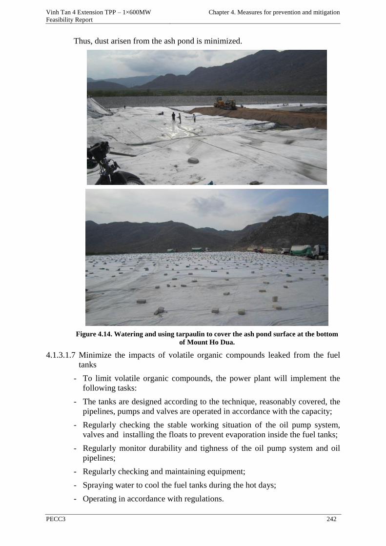
Vinh Tan 4 Extension TPP – 1×600MW
Feasibility Report
Chapter 4. Measures for prevention and mitigation
PECC3 242
Thus, dust arisen from the ash pond is minimized.
Figure 4.14. Watering and using tarpaulin to cover the ash pond surface at the bottom
of Mount Ho Dua.
4.1.3.1.7 Minimize the impacts of volatile organic compounds leaked from the fuel
tanks
- To limit volatile organic compounds, the power plant will implement the
following tasks:
- The tanks are designed according to the technique, reasonably covered, the
pipelines, pumps and valves are operated in accordance with the capacity;
- Regularly checking the stable working situation of the oil pump system,
valves and installing the floats to prevent evaporation inside the fuel tanks;
- Regularly monitor durability and tighness of the oil pump system and oil
pipelines;
- Regularly checking and maintaining equipment;
- Spraying water to cool the fuel tanks during the hot days;
- Operating in accordance with regulations.
Vinh Tan 4 Extension TPP – 1×600MW
Feasibility Report
Chapter 4. Measures for prevention and mitigation
PECC3 243
The measures to minimize the impacts on the air environment will bring high
efficiency to minimize the impacts of the project on the environment and
humans. However, the implementation cost is pretty high.
4.1.3.1.8 Minimize the impacts on the water environment
The entire effluent arisen from Vinh Tan 4 Extension TPP will be collected
and treated to meet the standard QCVN 40: 2011/BTNMT, column B before
reuse or being discharged into the receiving water source. All the amount of
waste water after treatment except rainwater flowing through the unpolluted
area will not be taken to the final collection tank to control the quality of
treated water before being discharged to the environment. The wastewater
treatment system of Vinh Tan 4 Extension TPP will be designed and invested
separately, its position will be on the land part of Vinh Tan 4 Extension TPP.
Vinh Tan 4 Extension TPP will use the treatment technology of wastewater
similar to that of Vinh Tan 4 TPP, the amount of wastewater generated in the
power plant is as follows:
- Domestic wastewater;
- Wastewater from the coal transportation system and cleaning the coal
conveyors;
- Waste water contaminated with oil;
- Wastewater from the feedwater preliminary treatment system ;
- Condensate treatment system;
- Waste water from demineralization system;
- Wastewater from washing chemicals for the boiler;
- Wastewater from washing the ESP system.
(1) Waste water contaminated with chemicals from production activities in
the power plant
Waste water is frequently contaminated by chemicals (including waste water
from the raw water treatment system, condensate treatment system, waste
water from demineralization system) and the infrequent waste water
(wastewater from washing chemicals for the boilers and from washing the
ESP system) will be taken to the separate waste water collecting tanks. The
tanks are designed and built properly to contain the wastewater discharge
generated in the processes of medium repair and overhaul of the plant.
Wastewater at the waste water tank is frequently taken to the neutralization
tank and is processed continuously according to the next treatment procedure.
At the infrequent waste water tank, aeration is carried out to regulate the
concentration of waste water and to avoid sedimentation, the solution of
NaOH or HCl is added in order to adjust the value of pH to create the optimal
condition for the reaction of Fe2+ → Fe3+ to happen, the amount of iron (Fe2+)
existing in the soluble form in the waste water will turn into iron (Fe3+) and
settle to the bottom of the tank. The infrequent waste water tank is designed
with a slope of about 2%, so that the sediment is collected in the sediment
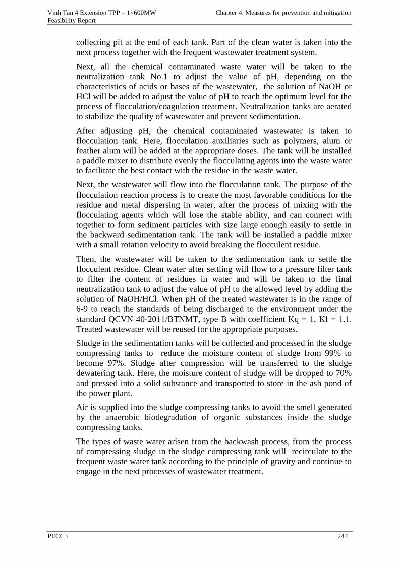
Vinh Tan 4 Extension TPP – 1×600MW
Feasibility Report
Chapter 4. Measures for prevention and mitigation
PECC3 244
collecting pit at the end of each tank. Part of the clean water is taken into the
next process together with the frequent wastewater treatment system.
Next, all the chemical contaminated waste water will be taken to the
neutralization tank No.1 to adjust the value of pH, depending on the
characteristics of acids or bases of the wastewater, the solution of NaOH or
HCl will be added to adjust the value of pH to reach the optimum level for the
process of flocculation/coagulation treatment. Neutralization tanks are aerated
to stabilize the quality of wastewater and prevent sedimentation.
After adjusting pH, the chemical contaminated wastewater is taken to
flocculation tank. Here, flocculation auxiliaries such as polymers, alum or
feather alum will be added at the appropriate doses. The tank will be installed
a paddle mixer to distribute evenly the flocculating agents into the waste water
to facilitate the best contact with the residue in the waste water.
Next, the wastewater will flow into the flocculation tank. The purpose of the
flocculation reaction process is to create the most favorable conditions for the
residue and metal dispersing in water, after the process of mixing with the
flocculating agents which will lose the stable ability, and can connect with
together to form sediment particles with size large enough easily to settle in
the backward sedimentation tank. The tank will be installed a paddle mixer
with a small rotation velocity to avoid breaking the flocculent residue.
Then, the wastewater will be taken to the sedimentation tank to settle the
flocculent residue. Clean water after settling will flow to a pressure filter tank
to filter the content of residues in water and will be taken to the final
neutralization tank to adjust the value of pH to the allowed level by adding the
solution of NaOH/HCl. When pH of the treated wastewater is in the range of
6-9 to reach the standards of being discharged to the environment under the
standard QCVN 40-2011/BTNMT, type B with coefficient Kq = 1, Kf = 1.1.
Treated wastewater will be reused for the appropriate purposes.
Sludge in the sedimentation tanks will be collected and processed in the sludge
compressing tanks to reduce the moisture content of sludge from 99% to
become 97%. Sludge after compression will be transferred to the sludge
dewatering tank. Here, the moisture content of sludge will be dropped to 70%
and pressed into a solid substance and transported to store in the ash pond of
the power plant.
Air is supplied into the sludge compressing tanks to avoid the smell generated
by the anaerobic biodegradation of organic substances inside the sludge
compressing tanks.
The types of waste water arisen from the backwash process, from the process
of compressing sludge in the sludge compressing tank will recirculate to the
frequent waste water tank according to the principle of gravity and continue to
engage in the next processes of wastewater treatment.
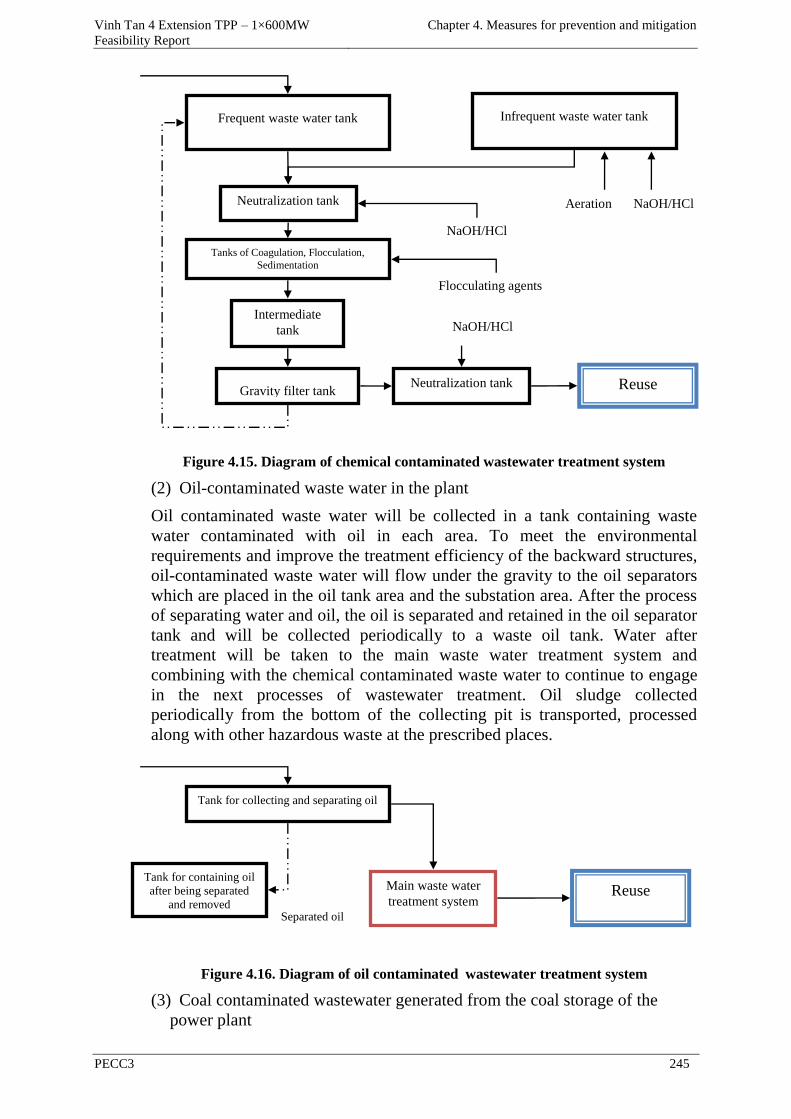
Vinh Tan 4 Extension TPP – 1×600MW
Feasibility Report
Chapter 4. Measures for prevention and mitigation
PECC3 245
Figure 4.15. Diagram of chemical contaminated wastewater treatment system
(2) Oil-contaminated waste water in the plant
Oil contaminated waste water will be collected in a tank containing waste
water contaminated with oil in each area. To meet the environmental
requirements and improve the treatment efficiency of the backward structures,
oil-contaminated waste water will flow under the gravity to the oil separators
which are placed in the oil tank area and the substation area. After the process
of separating water and oil, the oil is separated and retained in the oil separator
tank and will be collected periodically to a waste oil tank. Water after
treatment will be taken to the main waste water treatment system and
combining with the chemical contaminated waste water to continue to engage
in the next processes of wastewater treatment. Oil sludge collected
periodically from the bottom of the collecting pit is transported, processed
along with other hazardous waste at the prescribed places.
Figure 4.16. Diagram of oil contaminated wastewater treatment system
(3) Coal contaminated wastewater generated from the coal storage of the
power plant
Tank for collecting and separating oil
Reuse Tank for containing oil
after being separated
and removed Separated oil
Main waste water
treatment system
Frequent waste water tank
Neutralization tank
Tanks of Coagulation, Flocculation,
Sedimentation
Intermediate
tank
Gravity filter tank
Neutralization tank
Reuse
NaOH/HCl
Flocculating agents
NaOH/HCl
Infrequent waste water tank
NaOH/HCl Aeration
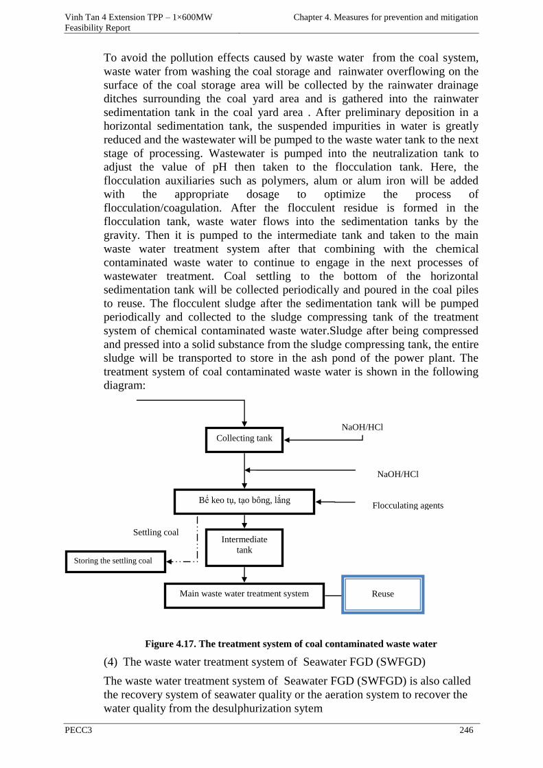
Vinh Tan 4 Extension TPP – 1×600MW
Feasibility Report
Chapter 4. Measures for prevention and mitigation
PECC3 246
To avoid the pollution effects caused by waste water from the coal system,
waste water from washing the coal storage and rainwater overflowing on the
surface of the coal storage area will be collected by the rainwater drainage
ditches surrounding the coal yard area and is gathered into the rainwater
sedimentation tank in the coal yard area . After preliminary deposition in a
horizontal sedimentation tank, the suspended impurities in water is greatly
reduced and the wastewater will be pumped to the waste water tank to the next
stage of processing. Wastewater is pumped into the neutralization tank to
adjust the value of pH then taken to the flocculation tank. Here, the
flocculation auxiliaries such as polymers, alum or alum iron will be added
with the appropriate dosage to optimize the process of
flocculation/coagulation. After the flocculent residue is formed in the
flocculation tank, waste water flows into the sedimentation tanks by the
gravity. Then it is pumped to the intermediate tank and taken to the main
waste water treatment system after that combining with the chemical
contaminated waste water to continue to engage in the next processes of
wastewater treatment. Coal settling to the bottom of the horizontal
sedimentation tank will be collected periodically and poured in the coal piles
to reuse. The flocculent sludge after the sedimentation tank will be pumped
periodically and collected to the sludge compressing tank of the treatment
system of chemical contaminated waste water.Sludge after being compressed
and pressed into a solid substance from the sludge compressing tank, the entire
sludge will be transported to store in the ash pond of the power plant. The
treatment system of coal contaminated waste water is shown in the following
diagram:
Figure 4.17. The treatment system of coal contaminated waste water
(4) The waste water treatment system of Seawater FGD (SWFGD)
The waste water treatment system of Seawater FGD (SWFGD) is also called
the recovery system of seawater quality or the aeration system to recover the
water quality from the desulphurization sytem
Collecting tank
Bể keo tụ, tạo bông, lắng
Intermediate
tank
Main waste water treatment system
Reuse
Flocculating agents
NaOH/HCl
NaOH/HCl
Storing the settling coal
Settling coal
Vinh Tan 4 Extension TPP – 1×600MW
Feasibility Report
Chapter 4. Measures for prevention and mitigation
PECC3 247
Water used in the SWFGD system is seawater. Sea water is taken from the sea
water of the cooling water system. SO2 in emissions reacts with the alkaline
components in seawater and forms ion SO32- and ion H+ and reduces pH of
sea water and sea water is acidified (pH = 3 ~ 4).
Sea water treatment system includes water line, distribution tank, aeration
tank, waste water line, aeration system. Aeration tank is divided into two
areas: mixing area and aeration area. With seawater having a good alkaline
indicator, sea water from the siphon pit of the circulating cooling water system
flows in the distribution tank and mixes with just enough to neutralize the
acidified sea water (pH = 3 ~ 4) in the absorber tower, after that the mixed sea
water will be aerated in the aeration tank area.
A perforated pipe row system is installed at the bottom of the aeration tank
and a sufficient amount of gas will be put into by the bubbler to create air
bubbles to provide dissolved oxygen until reaching saturation and unstable
sulfite forms to become stable sulfate forms. The aeration process will also
neutralize ions CO32- and HCO3 with ion H+ from the absorber tower and
release CO2 to recover the pH original value of seawater to meet the emission
requirements. A spillway is also installed at the outlet of the aeration tank and
sea water will spill over it into the waste water lines. Sea water after treatment
will return the open waste water pit and finally be discharged into the sea.
(5) Domestic wastewater in the power plant
Domestic wastewater in the plant will be disintegrated partially by the septic
tanks. The effects of septic tanks are settling solids, anaerobic decomposition
of organic matters and containing sediment. Average treatment efficiency
based on the concentration of suspended solids, COD chemical oxygen
demand, biochemical oxygen demand BOD5 from 50 to 70%. The treated
waste water in the septic tanks will be taken to the domestic wastewater
collection tank by the gravity runoff principle. In this tank, ventilation pipes
will be installed to regulate the effluent concentration and avoid
sedimentation. From there, the waste water will be pumped into the
preliminary sedimentation tank to remove the residual suspended solids after
flowing the septic tanks. Next, the waste water will be taken into the
biological filter to decompose the remaining organic matter in the wastewater.
In the biological filter, organic matter is oxidized by microorganisms (mostly
bacteria) including aerobic, anaerobic and arbitrary anaerobic microorganisms
in the biological film attaching to the filter material. Part of the clear water
after filtered will go into the disinfection tank to kill bacteria, pathogenic
bacteria in wastewater, and will reach the standard QCVN 14: 2008/BTNMT,
type B, K = 1.2 before being discharged into the receiving water.
Sludge in the sedimentation tanks will be collected and pumped to the sludge
compressing tank in the chemical contaminated wastewater treatment system
to reduce the moisture content of sludge from 99% to become 97%. Sludge
after compression will be transferred to the sludge dewatering tank. Here, the
moisture content of sludge will be dropped to 70% and pressed into a solid
substance and transported to store in the ash pond of the power plant.
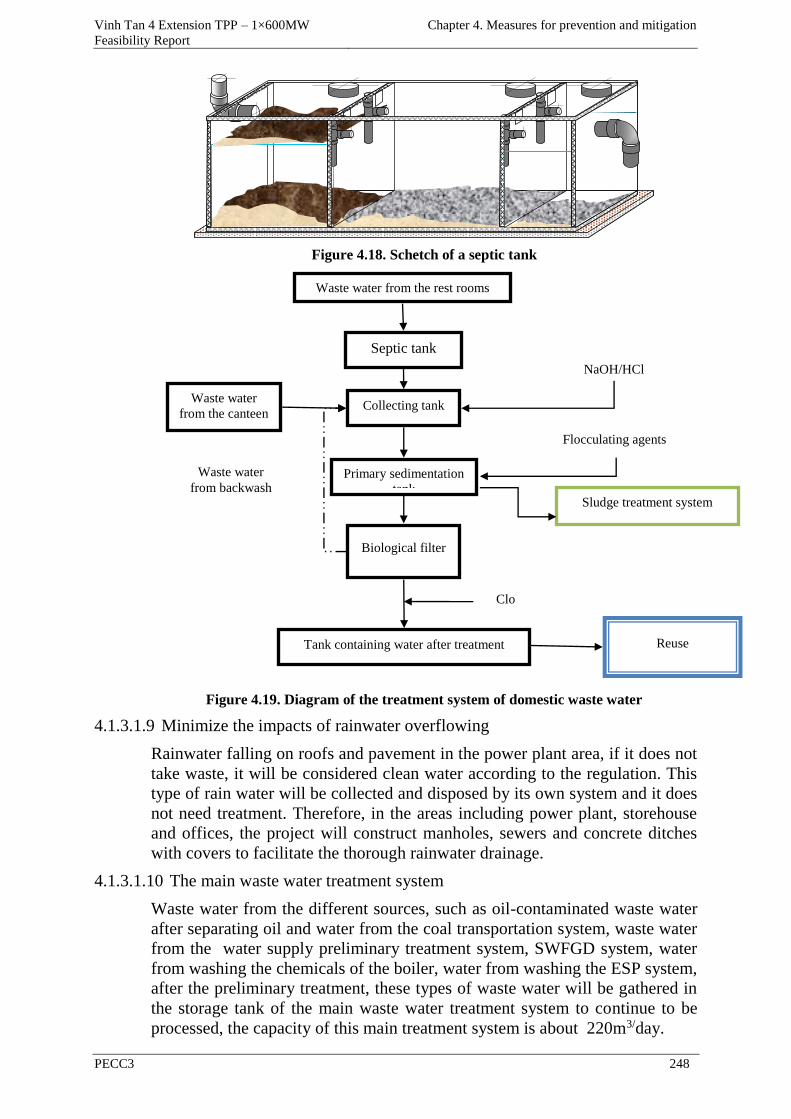
Vinh Tan 4 Extension TPP – 1×600MW
Feasibility Report
Chapter 4. Measures for prevention and mitigation
PECC3 248
Figure 4.18. Schetch of a septic tank
Figure 4.19. Diagram of the treatment system of domestic waste water
4.1.3.1.9 Minimize the impacts of rainwater overflowing
Rainwater falling on roofs and pavement in the power plant area, if it does not
take waste, it will be considered clean water according to the regulation. This
type of rain water will be collected and disposed by its own system and it does
not need treatment. Therefore, in the areas including power plant, storehouse
and offices, the project will construct manholes, sewers and concrete ditches
with covers to facilitate the thorough rainwater drainage.
4.1.3.1.10 The main waste water treatment system
Waste water from the different sources, such as oil-contaminated waste water
after separating oil and water from the coal transportation system, waste water
from the water supply preliminary treatment system, SWFGD system, water
from washing the chemicals of the boiler, water from washing the ESP system,
after the preliminary treatment, these types of waste water will be gathered in
the storage tank of the main waste water treatment system to continue to be
processed, the capacity of this main treatment system is about 220m3/day.
Septic tank
Collecting tank
Primary sedimentation
tank
Biological filter
Tank containing water after treatment Reuse
Clo
Flocculating agents
Waste water
from backwash
NaOH/HCl
Sludge treatment system
Waste water
from the canteen
Waste water from the rest rooms
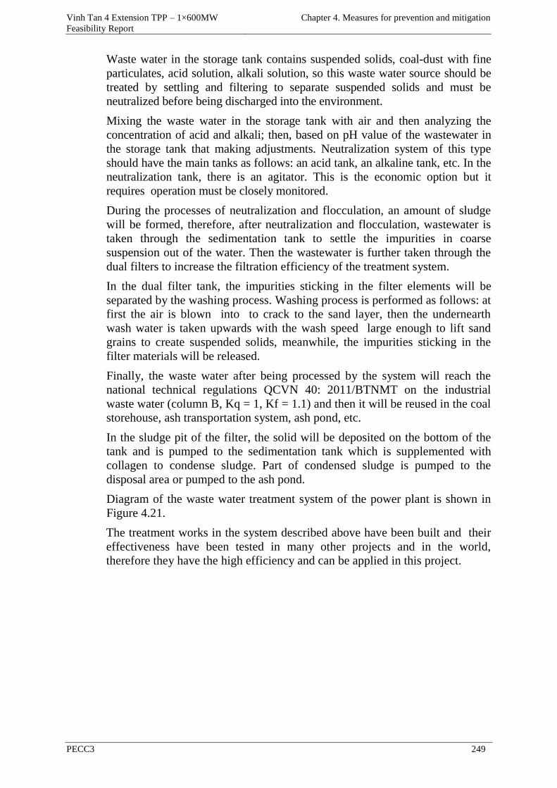
Vinh Tan 4 Extension TPP – 1×600MW
Feasibility Report
Chapter 4. Measures for prevention and mitigation
PECC3 249
Waste water in the storage tank contains suspended solids, coal-dust with fine
particulates, acid solution, alkali solution, so this waste water source should be
treated by settling and filtering to separate suspended solids and must be
neutralized before being discharged into the environment.
Mixing the waste water in the storage tank with air and then analyzing the
concentration of acid and alkali; then, based on pH value of the wastewater in
the storage tank that making adjustments. Neutralization system of this type
should have the main tanks as follows: an acid tank, an alkaline tank, etc. In the
neutralization tank, there is an agitator. This is the economic option but it
requires operation must be closely monitored.
During the processes of neutralization and flocculation, an amount of sludge
will be formed, therefore, after neutralization and flocculation, wastewater is
taken through the sedimentation tank to settle the impurities in coarse
suspension out of the water. Then the wastewater is further taken through the
dual filters to increase the filtration efficiency of the treatment system.
In the dual filter tank, the impurities sticking in the filter elements will be
separated by the washing process. Washing process is performed as follows: at
first the air is blown into to crack to the sand layer, then the undernearth
wash water is taken upwards with the wash speed large enough to lift sand
grains to create suspended solids, meanwhile, the impurities sticking in the
filter materials will be released.
Finally, the waste water after being processed by the system will reach the
national technical regulations QCVN 40: 2011/BTNMT on the industrial
waste water (column B, Kq = 1, Kf = 1.1) and then it will be reused in the coal
storehouse, ash transportation system, ash pond, etc.
In the sludge pit of the filter, the solid will be deposited on the bottom of the
tank and is pumped to the sedimentation tank which is supplemented with
collagen to condense sludge. Part of condensed sludge is pumped to the
disposal area or pumped to the ash pond.
Diagram of the waste water treatment system of the power plant is shown in
Figure 4.21.
The treatment works in the system described above have been built and their
effectiveness have been tested in many other projects and in the world,
therefore they have the high efficiency and can be applied in this project.
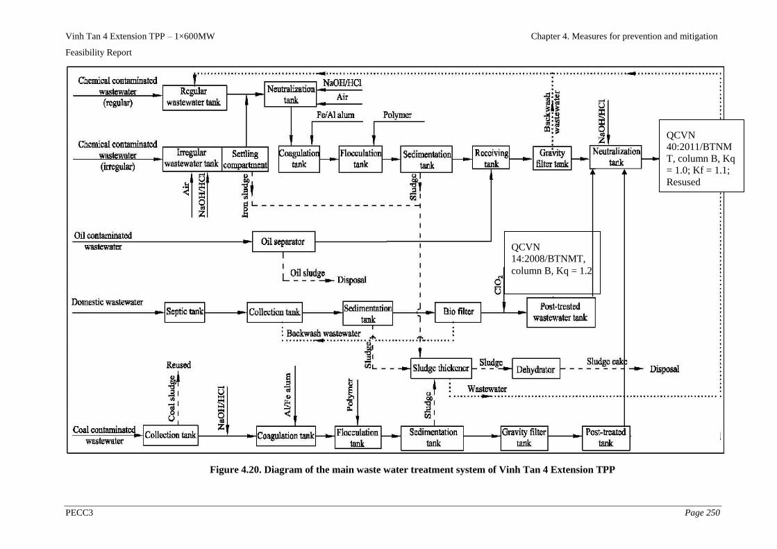
Vinh Tan 4 Extension TPP – 1×600MW Chapter 4. Measures for prevention and mitigation
Feasibility Report
PECC3 Page 250
Figure 4.20. Diagram of the main waste water treatment system of Vinh Tan 4 Extension TPP
QCVN
40:2011/BTNM
T, column B, Kq
= 1.0; Kf = 1.1;
Resused
QCVN
14:2008/BTNMT,
column B, Kq = 1.2
Vinh Tan 4 Extension TPP – 1×600MW
Feasibility Report
Chapter 4. Measures for prevention and mitigation
PECC3 251
4.1.3.1.11 Minimize the impacts of the cooling effluent
Minimize the impacts of taking cooling water on the aquatic system,
runoff and deposition
To minimize the impacts on the aquatic species due to taking cooling water,
the following measures will be implemented:
- Design the appropriate inlet: mouth of the inlet is designed to have the runoff
velocity at the inlet <0.2 m/s in order not to affect the ability of moving and
reproduction of aquatic animals as well as runoff and the processes of
sedimentation and erosion along the shoreline.
- Install the behavioral barriers to prevent the aquatic species being swept into
the inlet.
The behavioral barriers
The behavioral barriers use one or a few stimulation factors to let fish move
toward the desire direction. They are designed based on the characteristics of
behaviors of fish as the reflexes to sound, light, flow or electromagnetic fields.
The barriers use the air bubble flow from the compressed air supply with high
efficiency. Fish tend to avoid the sudden changes of the horizontal flow, but
can adapt to the changes of the vertical flow. This principle can be applied to
the design of shields or deflector plates to reduce the collision of fish at the
inlet.
Generally, the behavior barriers depend on aquatic species and physical
factors such as temperature, radiation, sound and stratification.
Vinh Tan 4 Extension TPP will be installed the screens (traveling screens, fish
bucket screen) to prevent aquatic organism being swept in. Besides, because
the collecting discharge of cooling water is insignificant compared with the
discharge of the receiving water source, so the amount of aquatic organism
dragged into is small compared with the abundance of aquatic species in the
area.
Method of installing barriers is very feasible, it has worked well in many
projects such as in the similar thermal power plants and ensures the technical
specifications for the collection of cooling water for the project.
• Minimize the effects of adding chlorine in the cooling water
To protect the cooling system, chlorine will be added in the cooling water to
reach a concentration of about 0.3 - 0.5ppm. The process of chlorination will
be controlled automatically by the sensors for controlling the concentration of
chlorine in the cooling water and the cooling effluent. With this method, it will
ensure the concentration of residual chlorine in cooling water at the outlet
mouth will achieve the national technical regulations QCVN 40:
2011/BTNMT, column B, Kq = 1; Kf = 1.1 (2mg/l).
Minimizing the impact of cooling wastewater disposal on the aquatic
system and aquaculture activities
Vinh Tan 4 Extension TPP will use and release the cooling water discharge of
75m3/s, the difference between water temperature at the inlet and input water
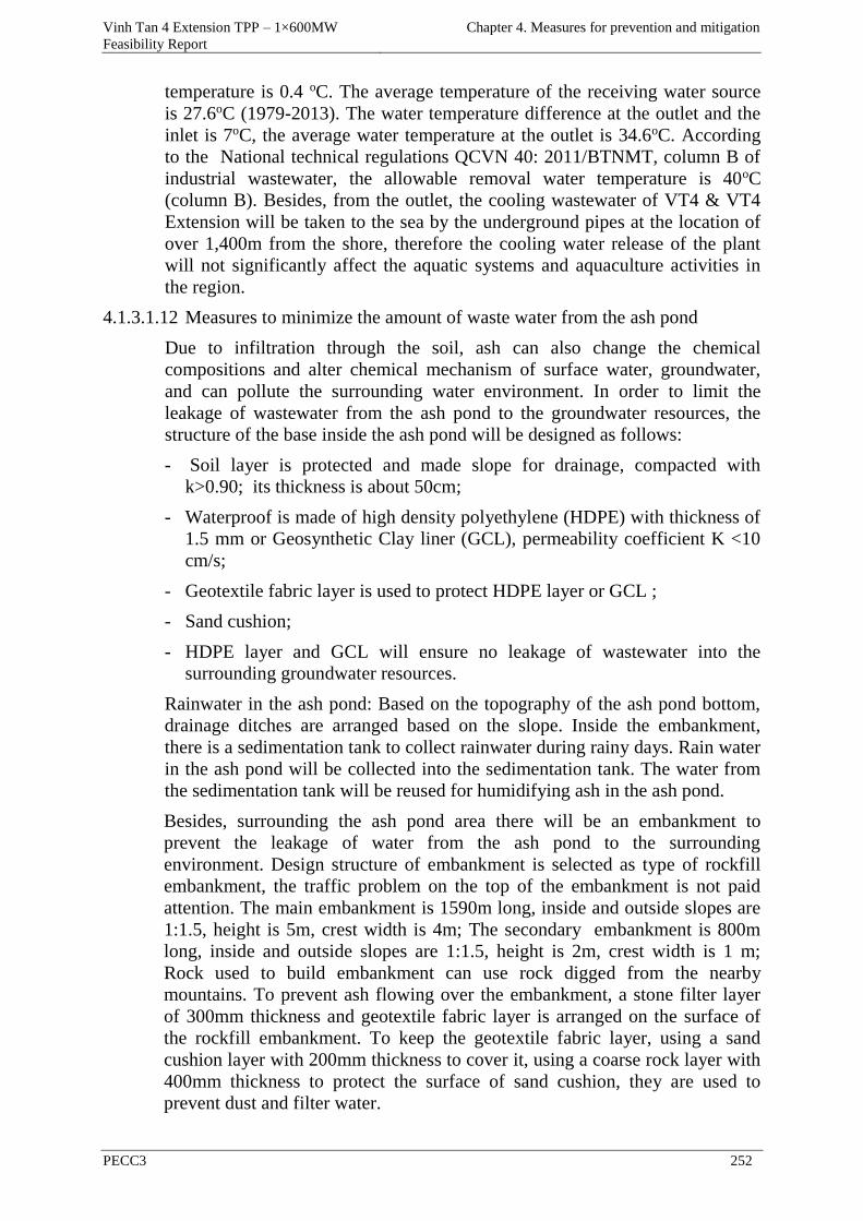
Vinh Tan 4 Extension TPP – 1×600MW
Feasibility Report
Chapter 4. Measures for prevention and mitigation
PECC3 252
temperature is 0.4 oC. The average temperature of the receiving water source
is 27.6oC (1979-2013). The water temperature difference at the outlet and the
inlet is 7oC, the average water temperature at the outlet is 34.6oC. According
to the National technical regulations QCVN 40: 2011/BTNMT, column B of
industrial wastewater, the allowable removal water temperature is 40oC
(column B). Besides, from the outlet, the cooling wastewater of VT4 & VT4
Extension will be taken to the sea by the underground pipes at the location of
over 1,400m from the shore, therefore the cooling water release of the plant
will not significantly affect the aquatic systems and aquaculture activities in
the region.
4.1.3.1.12 Measures to minimize the amount of waste water from the ash pond
Due to infiltration through the soil, ash can also change the chemical
compositions and alter chemical mechanism of surface water, groundwater,
and can pollute the surrounding water environment. In order to limit the
leakage of wastewater from the ash pond to the groundwater resources, the
structure of the base inside the ash pond will be designed as follows:
- Soil layer is protected and made slope for drainage, compacted with
k>0.90; its thickness is about 50cm;
- Waterproof is made of high density polyethylene (HDPE) with thickness of
1.5 mm or Geosynthetic Clay liner (GCL), permeability coefficient K <10
cm/s;
- Geotextile fabric layer is used to protect HDPE layer or GCL ;
- Sand cushion;
- HDPE layer and GCL will ensure no leakage of wastewater into the
surrounding groundwater resources.
Rainwater in the ash pond: Based on the topography of the ash pond bottom,
drainage ditches are arranged based on the slope. Inside the embankment,
there is a sedimentation tank to collect rainwater during rainy days. Rain water
in the ash pond will be collected into the sedimentation tank. The water from
the sedimentation tank will be reused for humidifying ash in the ash pond.
Besides, surrounding the ash pond area there will be an embankment to
prevent the leakage of water from the ash pond to the surrounding
environment. Design structure of embankment is selected as type of rockfill
embankment, the traffic problem on the top of the embankment is not paid
attention. The main embankment is 1590m long, inside and outside slopes are
1:1.5, height is 5m, crest width is 4m; The secondary embankment is 800m
long, inside and outside slopes are 1:1.5, height is 2m, crest width is 1 m;
Rock used to build embankment can use rock digged from the nearby
mountains. To prevent ash flowing over the embankment, a stone filter layer
of 300mm thickness and geotextile fabric layer is arranged on the surface of
the rockfill embankment. To keep the geotextile fabric layer, using a sand
cushion layer with 200mm thickness to cover it, using a coarse rock layer with
400mm thickness to protect the surface of sand cushion, they are used to
prevent dust and filter water.

Vinh Tan 4 Extension TPP – 1×600MW
Feasibility Report
Chapter 4. Measures for prevention and mitigation
PECC3 253
- In addition, to ensure the collection of rainwater from the ash pond, Vinh
Tan 2 TPP has been using the measures to collect rainwater as follows:
- The distance from the ash surface level inside the ash pond to the crest of
the embankment must be over 1m to prevent ash spilling over during heavy
rain;
- The ash dumping task is carried out so that the collecting direction of
rainwater is maintained towards the collecting pit with about 24,000m3
volume in the southwest of the ash pond;
- Regularly monitoring the water level in the collecting pit of 24,000m3
during the rainy season in the first operation years of the ash pond to assess
the possibility of water collecting into the installed underground pipelines
(by osmosis) to consider the measures to prevent spilling from the
collecting pit by installing a valve at the output of underground pipe in the
rainwater collecting pit if necessary (or close completely these underground
pipelines and install new collecting pipelines when the ash surface level
inside the ash pond nearly the same as the initial crest level of the
embankment to facilitate operation);
- Use up the rainwater in the collecting pit to spray water to reduce dust for
the ash pond.
Figure 4.21. The collecting direction of rainwater in the ash pond of VT2,VT4 & VT4
Extension
4.1.3.1.13 Minimize the impacts due to the arisen solid waste
(1) Minimize the impacts of domestic solid waste
As mentioned above, domestic solid waste from the activities of the operating
personnel is about 400 kgs/day.
All departments of the plant are equipped with dustbins, to facilitate the
collection and classification of waste at source:
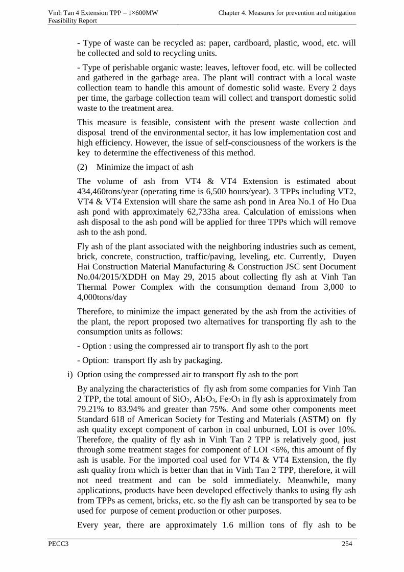
Vinh Tan 4 Extension TPP – 1×600MW
Feasibility Report
Chapter 4. Measures for prevention and mitigation
PECC3 254
- Type of waste can be recycled as: paper, cardboard, plastic, wood, etc. will
be collected and sold to recycling units.
- Type of perishable organic waste: leaves, leftover food, etc. will be collected
and gathered in the garbage area. The plant will contract with a local waste
collection team to handle this amount of domestic solid waste. Every 2 days
per time, the garbage collection team will collect and transport domestic solid
waste to the treatment area.
This measure is feasible, consistent with the present waste collection and
disposal trend of the environmental sector, it has low implementation cost and
high efficiency. However, the issue of self-consciousness of the workers is the
key to determine the effectiveness of this method.
(2) Minimize the impact of ash
The volume of ash from VT4 & VT4 Extension is estimated about
434,460tons/year (operating time is 6,500 hours/year). 3 TPPs including VT2,
VT4 & VT4 Extension will share the same ash pond in Area No.1 of Ho Dua
ash pond with approximately 62,733ha area. Calculation of emissions when
ash disposal to the ash pond will be applied for three TPPs which will remove
ash to the ash pond.
Fly ash of the plant associated with the neighboring industries such as cement,
brick, concrete, construction, traffic/paving, leveling, etc. Currently, Duyen
Hai Construction Material Manufacturing & Construction JSC sent Document
No.04/2015/XDDH on May 29, 2015 about collecting fly ash at Vinh Tan
Thermal Power Complex with the consumption demand from 3,000 to
4,000tons/day
Therefore, to minimize the impact generated by the ash from the activities of
the plant, the report proposed two alternatives for transporting fly ash to the
consumption units as follows:
- Option : using the compressed air to transport fly ash to the port
- Option: transport fly ash by packaging.
i) Option using the compressed air to transport fly ash to the port
By analyzing the characteristics of fly ash from some companies for Vinh Tan
2 TPP, the total amount of SiO2, Al2O3, Fe2O3 in fly ash is approximately from
79.21% to 83.94% and greater than 75%. And some other components meet
Standard 618 of American Society for Testing and Materials (ASTM) on fly
ash quality except component of carbon in coal unburned, LOI is over 10%.
Therefore, the quality of fly ash in Vinh Tan 2 TPP is relatively good, just
through some treatment stages for component of LOI <6%, this amount of fly
ash is usable. For the imported coal used for VT4 & VT4 Extension, the fly
ash quality from which is better than that in Vinh Tan 2 TPP, therefore, it will
not need treatment and can be sold immediately. Meanwhile, many
applications, products have been developed effectively thanks to using fly ash
from TPPs as cement, bricks, etc. so the fly ash can be transported by sea to be
used for purpose of cement production or other purposes.
Every year, there are approximately 1.6 million tons of fly ash to be
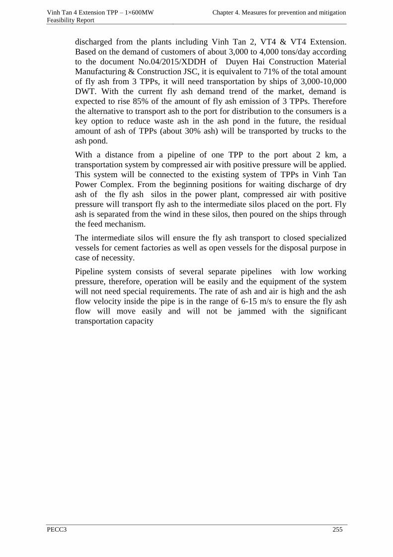
Vinh Tan 4 Extension TPP – 1×600MW
Feasibility Report
Chapter 4. Measures for prevention and mitigation
PECC3 255
discharged from the plants including Vinh Tan 2, VT4 & VT4 Extension.
Based on the demand of customers of about 3,000 to 4,000 tons/day according
to the document No.04/2015/XDDH of Duyen Hai Construction Material
Manufacturing & Construction JSC, it is equivalent to 71% of the total amount
of fly ash from 3 TPPs, it will need transportation by ships of 3,000-10,000
DWT. With the current fly ash demand trend of the market, demand is
expected to rise 85% of the amount of fly ash emission of 3 TPPs. Therefore
the alternative to transport ash to the port for distribution to the consumers is a
key option to reduce waste ash in the ash pond in the future, the residual
amount of ash of TPPs (about 30% ash) will be transported by trucks to the
ash pond.
With a distance from a pipeline of one TPP to the port about 2 km, a
transportation system by compressed air with positive pressure will be applied.
This system will be connected to the existing system of TPPs in Vinh Tan
Power Complex. From the beginning positions for waiting discharge of dry
ash of the fly ash silos in the power plant, compressed air with positive
pressure will transport fly ash to the intermediate silos placed on the port. Fly
ash is separated from the wind in these silos, then poured on the ships through
the feed mechanism.
The intermediate silos will ensure the fly ash transport to closed specialized
vessels for cement factories as well as open vessels for the disposal purpose in
case of necessity.
Pipeline system consists of several separate pipelines with low working
pressure, therefore, operation will be easily and the equipment of the system
will not need special requirements. The rate of ash and air is high and the ash
flow velocity inside the pipe is in the range of 6-15 m/s to ensure the fly ash
flow will move easily and will not be jammed with the significant
transportation capacity
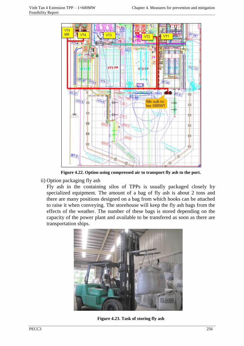
Vinh Tan 4 Extension TPP – 1×600MW
Feasibility Report
Chapter 4. Measures for prevention and mitigation
PECC3 256
Figure 4.22. Option using compressed air to transport fly ash to the port.
ii) Option packaging fly ash
Fly ash in the containing silos of TPPs is usually packaged closely by
specialized equipment. The amount of a bag of fly ash is about 2 tons and
there are many positions designed on a bag from which hooks can be attached
to raise it when conveying. The storehouse will keep the fly ash bags from the
effects of the weather. The number of these bags is stored depending on the
capacity of the power plant and available to be transfered as soon as there are
transportation ships.
Figure 4.23. Task of storing fly ash
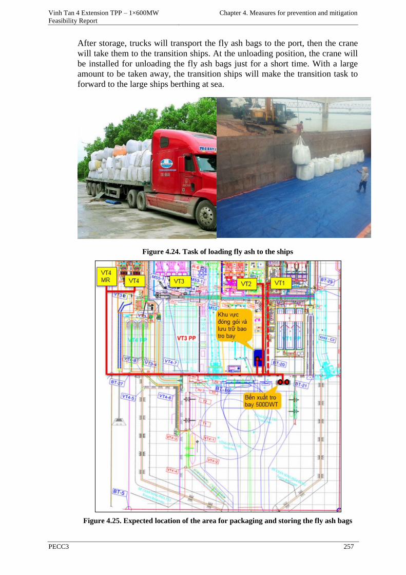
Vinh Tan 4 Extension TPP – 1×600MW
Feasibility Report
Chapter 4. Measures for prevention and mitigation
PECC3 257
After storage, trucks will transport the fly ash bags to the port, then the crane
will take them to the transition ships. At the unloading position, the crane will
be installed for unloading the fly ash bags just for a short time. With a large
amount to be taken away, the transition ships will make the transition task to
forward to the large ships berthing at sea.
Figure 4.24. Task of loading fly ash to the ships
Figure 4.25. Expected location of the area for packaging and storing the fly ash bags
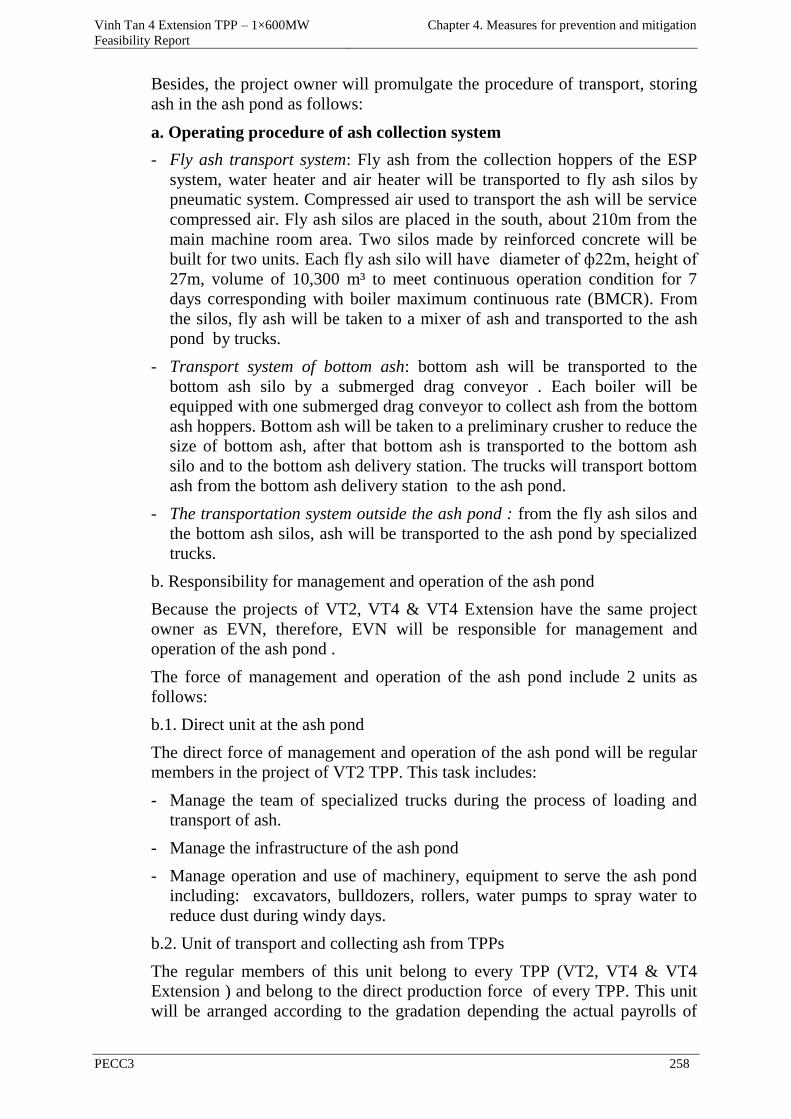
Vinh Tan 4 Extension TPP – 1×600MW
Feasibility Report
Chapter 4. Measures for prevention and mitigation
PECC3 258
Besides, the project owner will promulgate the procedure of transport, storing
ash in the ash pond as follows:
a. Operating procedure of ash collection system
- Fly ash transport system: Fly ash from the collection hoppers of the ESP
system, water heater and air heater will be transported to fly ash silos by
pneumatic system. Compressed air used to transport the ash will be service
compressed air. Fly ash silos are placed in the south, about 210m from the
main machine room area. Two silos made by reinforced concrete will be
built for two units. Each fly ash silo will have diameter of ф22m, height of
27m, volume of 10,300 m³ to meet continuous operation condition for 7
days corresponding with boiler maximum continuous rate (BMCR). From
the silos, fly ash will be taken to a mixer of ash and transported to the ash
pond by trucks.
- Transport system of bottom ash: bottom ash will be transported to the
bottom ash silo by a submerged drag conveyor . Each boiler will be
equipped with one submerged drag conveyor to collect ash from the bottom
ash hoppers. Bottom ash will be taken to a preliminary crusher to reduce the
size of bottom ash, after that bottom ash is transported to the bottom ash
silo and to the bottom ash delivery station. The trucks will transport bottom
ash from the bottom ash delivery station to the ash pond.
- The transportation system outside the ash pond : from the fly ash silos and
the bottom ash silos, ash will be transported to the ash pond by specialized
trucks.
b. Responsibility for management and operation of the ash pond
Because the projects of VT2, VT4 & VT4 Extension have the same project
owner as EVN, therefore, EVN will be responsible for management and
operation of the ash pond .
The force of management and operation of the ash pond include 2 units as
follows:
b.1. Direct unit at the ash pond
The direct force of management and operation of the ash pond will be regular
members in the project of VT2 TPP. This task includes:
- Manage the team of specialized trucks during the process of loading and
transport of ash.
- Manage the infrastructure of the ash pond
- Manage operation and use of machinery, equipment to serve the ash pond
including: excavators, bulldozers, rollers, water pumps to spray water to
reduce dust during windy days.
b.2. Unit of transport and collecting ash from TPPs
The regular members of this unit belong to every TPP (VT2, VT4 & VT4
Extension ) and belong to the direct production force of every TPP. This unit
will be arranged according to the gradation depending the actual payrolls of
Vinh Tan 4 Extension TPP – 1×600MW
Feasibility Report
Chapter 4. Measures for prevention and mitigation
PECC3 259
TPPs according to the professional and streamline mode to ensure the safe
conditions on the environment.
b.3. Responsibility for the ash pond management
- Responsibility for the ash pond management belongs to Technical Director
of VT2 TPP which is the first power plant using the ash pond.
- Ash of VT4 & VT4 Extension to be discharged in the ash pond will be
managed by Technical Director of VT2 TPP.
- Responsibility for transporting ash from the plants of VT2, VT4 & VT4
Extension belongs to management and coordination of each TPP.
(3) Minimize the impact of solid residues from washing boilers and waste
water treatment systems
- Solid residues from the process of washing boilers (50 kgs/3 months) will
be collected separately every time washing boilers. Waste will be stored in
containers with lids, which are waterproof and collected and processed by a
competent agency according to the regulations.
- The amount of sludge from the wastewater treatment process (200kgs/day)
will be transfered to a competent agency for collecting and disposal in
accordance with the regulations.
4.1.3.1.14 Minimize the impacts generated by hazardous waste
As presented in the previous sections, the hazardous waste from the power
plant is sludge generated during the process of washing oil tanks, lubricating
oil removed from the maintenance process for vehicles and machinery, oily
rags, toner cartridges removed, etc. with the quantity of 635 kgs/year.
When being put into operation, the plant will register as the owner of
hazardous waste source with the Department of Natural Resources and
Environment according to the Guidance 36/2015/TT-BTNMT on June 30,
2015 on practice conditions and procedures of making the register document,
granting a license to practice, codes of hazardous waste management.
All hazardous waste generated at the plant will be collected, classified and
contained in the containers with lids, labeled and placed in a storage area for
hazardous waste of the plant.
The hazardous waste storehouse of Vinh Tan 4 Extension TPP will be shared
with the Vinh Tan 4 TPP and will be built in the construction phase of Vinh
Tan 4 TPP.
The power plant will contract with a competent agency for collecting and
disposal in accordance with the regulations on hazardous waste. Task of
collecting and disposal will be carried out periodically for 6 months per time
and when necessary.
The process of collecting, storing, transporting and processing must comply
with the regulations 36/2015/TT-BTNMT on June 30, 2015 of Ministry of
Natural Resources and Environment on the management of hazardous waste.
Similar to the collection of domestic solid waste, the classification and
Vinh Tan 4 Extension TPP – 1×600MW
Feasibility Report
Chapter 4. Measures for prevention and mitigation
PECC3 260
collection at source for the production solid waste and hazardous solid waste
are suitable measures and have high feasibility.
4.1.3.2 Mitigation measures unrelated to waste during the operation phase
4.1.3.2.1 Minimize the impacts of noise and vibration
- At the coal berth: in order to limit noise and vibration, the project will
apply the following measures:
- Activities of unloading means and conveyors from barges into the storage
should be carried out during daytime and ended before 22:00. In case of
necessity, the activities must be performed after 22:00, the project owner
must limit time for construction to avoid affecting the local residents.
- Planting greenery surounding the area to reduce noise transmission
- Have a plan to monitor and maintain (check lubricating oil, replace parts
damaged,...) for all the equipment and operation of the coal berth.
At the power plant area, noise pollution arisen from the operation of
machinery and equipment in the areas such as the boiler, turbine of generator,
compressed air chamber, stacks,... The following measures will be applied:
- Diameter of the stack is calculated so that the velocity of smoke is 20-
25m/s to ensure not to cause noise too big nor too small to avoid smoke
whirling.
- Minimize the noise at source: install silencers in vents, exhaust valves,
regularly inspect, maintain and ensure that the noise reducers are always in
good working condition.
- Isolate the areas generating noise (boilers, pumps, pneumatic chambers,
etc.) by the technical measures such as 100 mm brick wall, ceiling made of
10 mm plywood (with these measures which will reduce noise about 6-
8dBA) or tile another wall layer with thickness of 100mm, then fill in the
blank with the acoustic materials such as glass-wool, paddy shell, coconut
fiber, dry sand, etc. (with this solution, it will reduce noise about 12-15
dBA).
- Arrange properly machinery to avoid concentrating the equipment which
can cause noise in the narrow area.
- Noise pads are placed under the bases of blowers and air compressors
- The equipment causing strong vibration will be installed on wide base and
deep foundation and will use the damping measures.
- Check the wear on machine parts and regularly replace lubricating oil or
damaged details to minimize noise.
- Comply with the technical regulations when operating equipment.
- Soundproof the areas where the operational staffs are working, equip with
anti-noise devices for workers as noise-protective capsules and plugs and
force workers to use when working in the areas with high noise levels.
- Planting trees inside and around the plant to prevent and reduce noise.
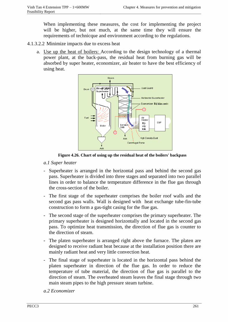
Vinh Tan 4 Extension TPP – 1×600MW
Feasibility Report
Chapter 4. Measures for prevention and mitigation
PECC3 261
When implementing these measures, the cost for implementing the project
will be higher, but not much, at the same time they will ensure the
requirements of technicque and environment according to the regulations.
4.1.3.2.2 Minimize impacts due to excess heat
a. Use up the heat of boilers: According to the design technology of a thermal
power plant, at the back-pass, the residual heat from burning gas will be
absorbed by super heater, economizer, air heater to have the best efficiency of
using heat.
Figure 4.26. Chart of using up the residual heat of the boilers' backpass
a.1 Super heater
- Superheater is arranged in the horizontal pass and behind the second gas
pass. Superheater is divided into three stages and separated into two parallel
lines in order to balance the temperature difference in the flue gas through
the cross-section of the boiler.
- The first stage of the superheater comprises the boiler roof walls and the
second gas pass walls. Wall is designed with heat exchange tube-fin-tube
construction to form a gas-tight casing for the flue gas.
- The second stage of the superheater comprises the primary superheater. The
primary superheater is designed horizontally and located in the second gas
pass. To optimize heat transmission, the direction of flue gas is counter to
the direction of steam.
- The platen superheater is arranged right above the furnace. The platen are
designed to receive radiant heat because at the installation position there are
mainly radiant heat and very little convection heat.
- The final stage of superheater is located in the horizontal pass behind the
platen superheater in direction of the flue gas. In order to reduce the
temperature of tube material, the direction of flue gas is parallel to the
direction of steam. The overheated steam leaves the final stage through two
main steam pipes to the high pressure steam turbine.
a.2 Economizer
Vinh Tan 4 Extension TPP – 1×600MW
Feasibility Report
Chapter 4. Measures for prevention and mitigation
PECC3 262
- An economizer is designed to heat the feed water coming from the last high
pressure feedwater heater by extracting heat from the low temperature flue
gas behind the superheater and reheater. Thus the flue gas temperature will
be reduced to the required temperature of the flue gas input the airheater
(about 380-400oC).
- The economizer consists of tubes absorbing low temperature convection
heat arranged in horizontal range and in the lower section of the rear pass.
The tubes are arranged in-line to minimize the likelihood of erosion,
adsorption of fly ash, and easily cleaning soot by blowing steam.
- To enhance heat transfer capability for feed water, the economizer is
designed with finned tubes, the fins are vertically arranged on the tubes but
no spirally finned tubes. The water direction in the economizer flows
upward and thus will go counter to the flue gas direction, this will increase
the average temperature difference between water and flue gas and reduce
the heat exchange surface area of the economizer. The economizer is
designed so that water will not be vaporized before going to the evaporator.
A pipeline with shut-off valve connected to the water-steam separator inlet
is used for venting of the economizer during start-up.
- a.3 Air heater
- The air heater is designed in the absorption form of convective heat and
mixture of convective heat and radiant heat. The air heater is designed in
the form of pendant and horizontal tube bundles. In order to optimize the air
reheating process, steam from the turbine will go into the horizontal tube
bundles before passing the pendant tube bundles arranged in the horizontal
gas pass behind the final superheater stage according to the flue gas
direction.
b. Minimize the impact of residual heat
The project impact due to excess heat on the operating personnel is small, the
project will also strengthen the measures for natural and forced ventilation to
improve the working conditions of workers.
Ventilation and air conditioning systems will be installed for the rooms,
machine room, workshops in order to create a suitable working environment
for people, equipment and machinery.
When designing the ventilation and air conditioning systems, the possibility
risk of fire in each area is considered to design the exits and to reduce the risk
of damage to people and equipment.
The ventilation system is installed in places without the air-conditioning
system to ensure that temperature at site is not higher than the environmental
temperature 10oC and always lower than 35oC.
The ventilation system can be equipped with appropriate filters to ensure no
dust penetrating inside.
All areas of electrical and electronic equipment will be kept at a temperature
of about 20oC despite the environmental conditions.
Vinh Tan 4 Extension TPP – 1×600MW
Feasibility Report
Chapter 4. Measures for prevention and mitigation
PECC3 263
In all areas where people have to work continuously, the temperature will be
maintained at 20 - 25oC.
The ventilation and air-conditioning systems are designed on the average basis
of the maximum environmental conditions in summer and vice versa in winter,
they are designed on the average basis of the minimum environment
conditions.
Outdoor design conditions:
- Temperature: 330C
- Humidity: 80%
Indoor design conditions:
- Temperature at the areas of turbines, auxiliary equipments, hydrogen
production (if any): is higher than the environment temperature 50C.
Temperature at the areas of main control, internal control, relay,
administration, electric devices, etc. is 250C, humidity is 80%.
Ventilation and air-conditioning in the power plant is necessary to ensure the
best working environment for workers, equipments and machines. Cost of
investment and operation is not high, so this measure is feasible and easy to
implement.
4.1.3.2.3 Minimize the impacts on the waterway and road traffic in the region
- There are enough traffic signs complied with the regulations
- Regulate, organize means going in and out the power plant and port
logically, control them to move on the right lane or the right navigable
channel.
- Means (vehicles, ships, barges) must not carry overload.
- Control ships or barges when revolving must be complied with the
technical regulations and must be in the roadstead scope, if necessary, there
must be tug boats to support.
- Regularly check and maintain the systems of headlights, indicating lights
on board. Prepare availably the backup devices for timely replacement in
case of incident.
- Regularly monitor the meteorological forecasts to establish the proper
schedule for ships and barges.
4.1.3.2.4 Minimize the impacts on the local socio-economy
The operating unit of the power plant will coordinate closely with the local
authority in administration management of employees, adequate registration of
temporary residence and temporary absence for the employees.
The operating unit of the power plant will use the local laborers in the suitable
jobs in Vinh Tan 4 Extension TPP.
Educate the employees to keep discipline, habits and customs and create a
good relationship with the local people.
Vinh Tan 4 Extension TPP – 1×600MW
Feasibility Report
Chapter 4. Measures for prevention and mitigation
PECC3 264
4.2 MEASURES FOR PREVENTING AND RESPONSE TO RISK AND
INCIDENT
4.2.1 Measures to prevent and respond to incidents in the construction phase
4.2.1.1 Prevention and response to fire incidents
a. Fire prevention system
During the construction process, in the areas where risk of fire could happen,
they need to be installed preventive equipment such as equipment used for
measuring, reducing the gas concentrations, measuring the temperature,
lowering the temperature, cooling the structures, fire partitions, fire barriers,
mobile fire extinguisher, etc.
b. Fire alarm system
Fire alarm system is designed as an automatic system: including the detectors
as heat detectors, smoke detectors, optical detectors, etc.
Central cabinet: including equipment used for receiving and processing the
signals reliably and accurately. Therefore, this system will detect fire risk
timely and accurately in the whole construction area of the power plant.
c. Fire-fighting system
To extinguish the fires in time, fire-fighting systems are designed and built
synchronously with the methods, equipment and supplies for fire fighting with
full ability for extinguishing fire newly arisen, including many different
system as follows:
- Fire fighting system using CO2
- Fire fighting system using foam.
- Fire fighting system using water.
- Fixed extinguishing systems.
- Mobile fire fighting system .
d. Explosion prevention system
In order to prevent and restrict explosion phenomena that may happen, the
construction area of the main plant will be equipped with the detector systems
including gas concentration detector, pressure detector and modern devices to
timely prevent the risks of explosion that may happen.
In order to mitigate risks of fire, the project will:
- Plan for fuel storage area to be protected and covered, spray water for this
area during hot weather.
- Regularly inspect and maintain, ensure there will be no leakage to happen.
- Design the system of embankments for oil tank area between two tanks
which have enough volume to contain oil in case of incident from one or 2
tanks.
- Prepare a plan, vehicles, fire protection materials and rescue incidents in
case of explosion or fire.
Vinh Tan 4 Extension TPP – 1×600MW
Feasibility Report
Chapter 4. Measures for prevention and mitigation
PECC3 265
Plans for preventing and fighting fire are prepared in a separate report and
approved by the rescue and fire fighting polices before starting construction
and operation of the project. Therefore, these measures have high feasibility.
However, to achieve the high efficiency, the measures will be combined with
training and enhancing awareness of employees about preventing and responding
to incidents.
4.2.1.2 Prevention and response to working accidents
To ensure safety for the workers during working, the project will establish,
disseminate and require workers to adhere to the labor safety regulations.
There are some special attentions as follows:
- Commit to perform construction work in accordance with the provisions on
the basic construction of the state.
- Establish a committee of occupational safety and environmental protection
at the construction site.
- The construction machinery and equipment must have certificate of origin,
their technical parameters must be inspected and monitored regularly.
- Absolutely comply with the safety regulations on transportation,
installation and operation of electrical equipment. The workers who have to
transport and install electrical equipment must be trained in the safety
regulations for transport and installation of electrical equipment;
- Moving and installing electrical equipment will use specialized tools to
anchor or fasten, do not use types of steel wire, chains to tie the insulators,
the tangential points of the base holes;
- For the formwork, reinforcing and concrete works, it is necessary to check
reliability and stability of the scaffolding system regularly. Arrangement of
stairs and railings to avoid falling out. When workers who have to work at
the high positions, must have safety belts;
- When scrubing steel rust, workers must wear glasses to protect their eyes.
When installing steel rods into the formworks, workers must stand on the
scaffold and shouldnot stand on the formworks;
- For the building tasks, the plans must be reasonably arranged, it is
necessary to pay attention to the safety of scaffold tasks. Workers must be
equipped with appropriate safety equipment, during construction of the
upstairs wall, do not go under it to avoid hazard due to materials falling;
- When the construction of oil pipelines and other related works, it is
necessary to pay attention to fire prevention work and arrange fire fighting
equipment at the construction site;
- Regulating the rules on working at the construction site, including the rules
of going in or out the construction site, and working at the construction site;
the rules on labor protection outfits; using equipment; electrical safety; and
traffic safety;
- When using hand tools operated by electricity or compressed air, workers
should not stand on the ladder to manipulate, they must stand on the support
Vinh Tan 4 Extension TPP – 1×600MW
Feasibility Report
Chapter 4. Measures for prevention and mitigation
PECC3 266
to ensure safety. For heavy instruments it is necessary to make pendants or
other means to ensure safety;
- - Workers who have to directly build and operate the construction machine
must be trained and practiced for proper manipulation.
- Monitor occupational accidents, identify accident reasons in time and apply
timely remedy measures to prevent the repetition of similar accidents;
- Install signs for warning people must not enter in the hazardous areas;
- The system of wires, point contacts, circuit breakers which can cause sparks
must be arranged in a very safe place;
- Arrange the portable fire extinguishers in the most appropriate locations for
convenient use, fire fighting vehicles will be always checked and prepared
availbly.
- When construction and erection of scaffolds and equipment on high
positions, the workers must be equipped with safety straps;
- - Making the health care team and medicine cabinets on site for timely first
aid in the case of serious accident ;
- The construction equipment must be disconnected to the power when not in
use, trouble, lost power to avoid accidents when power suddenly comes
back;
- In case fire happens due to electrical problem, immediately report to the
management unit to cut off the power and then follow the fire fighting
procedure;
- There must be a regular staff to inspect the implementation of regulations
on occupational safety in the construction site.
- The above measures can be fully implemented, if they are strictly followed
they can bring high effectiveness, however they also depend largely on the
self-consciousness and observance of workers.
4.2.1.3 Mitigation measures in case of incidents during waterway transport
Ships and vessels have to ensure safety of navigation in accordance with
Decree No.21/2012/ND-CP of the government on management of seaports and
navigable channels.
The transportation of large quantities of raw materials by sea will increase the
density of water traffic on the coastal area, this can easily lead to incidents like
the collision of vessels, to minimize this problem, PMU should perform some
measures such as:
- Arrange the marking buoys near the navigable channels into the port ;
- To control the volume of transported materials should not exceed the
allowed weight of ships, barges;
- The operators of the ships and barges must always control them to move in
the proper navigable channels according to the regulations, regularly
observe and detect the obstacles to move in the appropriate navigable
Vinh Tan 4 Extension TPP – 1×600MW
Feasibility Report
Chapter 4. Measures for prevention and mitigation
PECC3 267
channels. When the ships are being operated at night, they must have
headlight system to detect and avoid obstacles, at the same time they also
must have signal lights which can be seen by the other ships ;
- The anchored ships and barges at the port, which must be equipped with
the signal lights at night to avoid collisions with other ships while passing
through the area at night;
- Being fully equipped with rescue equipment to be able to respond in time in
case of incidents.
- These are measures to be applied to many projects to prevent accidents on
the waterways, these measures have technical characteristics and high
effectiveness in controlling and preventing incidents on the waterway
during filling and building for sea encroachment.
4.2.2 Measures to prevent and respond to the environmental incidents during
the operational phase
4.2.2.1 Measures to minimize the incidents caused by chemicals during the
operational phase
In order to minimize the chemical incidents which can cause the effects on the
environment and people's health, the project will implement the following
measures :
4.2.2.1.1 Preserving chemicals
- Types of chemicals need to have separate storages according to the
regulations, which must be dry, clear, ventilative and they can avoid the
direct sunshine and heat sources.
- There must have separate areas for special dangerous chemicals such as
concentrated acids and alkali, flammable substances, etc.;
- Chemicals stored must be clearly labeled with full of information:
chemical name, concentration and date of receiving (or day of preparation).
These toxic chemicals have special marks and dangerous marks;
- Chemicals without labels must not be used, can only be used after checking
accurately by the analytical methods and confirmation records;
- Instruments, chemicals and equipment for working must be arranged in the
neat and tidy condition and according to the defined positions. Workplaces
are always kept clean and dry, the floor may not have water or oil if there
are water or oil being scattered, it needs immediately to be cleaned and
wiped thoroughly.
- When acid is poured to the floor, do not use water to flush it immediately,
use lime to cover it then sweep, after that use water to flush it and wipe
thoroughly;
- Containers/instruments containing dangerous chemicals are hazardous
waste, they must not be washed and used for other purposes;
- The chemical storages must be equipped with the suitable protection means
for hazardous properties of chemicals and compliance with the regulations
Vinh Tan 4 Extension TPP – 1×600MW
Feasibility Report
Chapter 4. Measures for prevention and mitigation
PECC3 268
on chemical safety in accordance with Decree No.108/2008/ND - CP on
October 7, 2008;
- Prohibit generating heat sources, sparks and open flames such as welding,
smoking, works causing strong clashes to create friction ignition, etc.,
vehicles and motors operating must be separate from the chemical storage
at least10m ;
- Regularly check the safety of the tanks, cans of containing fuel and
materials promptly to repair, replace and overcome leakage of fuel.
4.2.2.1.2 Chemical Transportation
- Before transporting chemicals, it is necessary to observe the ways which
have not any obstacles to impede the chemical transport path;
- If the chemical cans weigh 10 kg or more, they must be equipped with
devices or vehicles to carry, not carry them by hand;
- When transporting acid, alkali with dense concentration and quantity which
is greater than 5 kg: it needs to be carried or use a trolley. Acid and alkali
must be stored in closed reliable containers, if they are put in trolleys, they
need to be inserted by materials for steadiness.
4.2.2.1.3 Using chemicals
- When using, contacting to chemicals, the workers must use appropriate
protective equipment, workplaces need to have the appropriate ventilation
measures;
- Toxic substances, volatile matters, the reactions creating the toxic
substances which can impact on the people's health, they must be taken into
the toxic substance absorber;
- When repairing the equipment containing alkali or acid solution, the
workers have discharge it out, use tap water to wash or turn on water flow
to wash tube (if any) and then repair;
- When washing the equipment containing the toxic substances, the workers
must fill them with water two to three times to release the residual in the
equipment. When filling with water, the workers must turn their heads to
the other direction to avoid inhaling toxic fumes;
- Absolutely no eating while working with chemicals, especially toxic
chemicals; do not leave food in the work area. Only eating after washing
hands many times and thoroughly with soap and out of workplace;
- Smoking is prohibited or using heat sources which could cause fires at
workplace with flammable substances. If the stoves must be used, they need
to be isolated and heat-insulated;
- Regulating the warning labels, signs to identify the chemicals used in the
plant according to the following table:
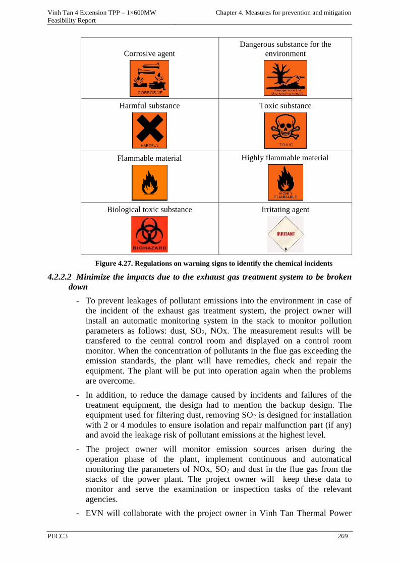
Vinh Tan 4 Extension TPP – 1×600MW
Feasibility Report
Chapter 4. Measures for prevention and mitigation
PECC3 269
Corrosive agent
Dangerous substance for the
environment
Harmful substance
Toxic substance
Flammable material
Highly flammable material
Biological toxic substance
Irritating agent
Figure 4.27. Regulations on warning signs to identify the chemical incidents
4.2.2.2 Minimize the impacts due to the exhaust gas treatment system to be broken
down
- To prevent leakages of pollutant emissions into the environment in case of
the incident of the exhaust gas treatment system, the project owner will
install an automatic monitoring system in the stack to monitor pollution
parameters as follows: dust, SO2, NOx. The measurement results will be
transfered to the central control room and displayed on a control room
monitor. When the concentration of pollutants in the flue gas exceeding the
emission standards, the plant will have remedies, check and repair the
equipment. The plant will be put into operation again when the problems
are overcome.
- In addition, to reduce the damage caused by incidents and failures of the
treatment equipment, the design had to mention the backup design. The
equipment used for filtering dust, removing SO2 is designed for installation
with 2 or 4 modules to ensure isolation and repair malfunction part (if any)
and avoid the leakage risk of pollutant emissions at the highest level.
- The project owner will monitor emission sources arisen during the
operation phase of the plant, implement continuous and automatical
monitoring the parameters of NOx, SO2 and dust in the flue gas from the
stacks of the power plant. The project owner will keep these data to
monitor and serve the examination or inspection tasks of the relevant
agencies.
- EVN will collaborate with the project owner in Vinh Tan Thermal Power
Vinh Tan 4 Extension TPP – 1×600MW
Feasibility Report
Chapter 4. Measures for prevention and mitigation
PECC3 270
Complex (the project owner of VT1 and VT3 TPPs) to stop operation of the
unit failed when emissions exceed the standard of Vietnam (QCVN).
These are measures to be applied to many projects to prevent incidents of the
exhaust gas treatment system in the power plant, they are technical measures,
consistent with the ability of the plant and highly effective in control and
prevention of incidents in the plant.
4.2.2.3 Minimize the impacts due to the incident of the waste water treatment system
For waste water treatment system, Vinh Tan 4 Extension TPP will design two
chain lines for waste water treatment, a capacity of each line is 220m3/day. If
the important equipment in the wastewater treatment system as settling tanks,
filtering tanks, pumps, etc. have a trouble, the plant will switch to the backup
devices for processing, therefore these troubles will not affect the environment
and operation of the plant.
However, in case the main treatment system has incidents, the waste
concentration in the outlet is greater than the design criteria, the project owner
will apply the following specific measures:
- Regularly check the system of equipment, valves, pipelines to find any
failure (if any) to replace and repair in time;
- Machinery and equipment of the waste water treatment system when design
calculations, it is necessary to involve the backup amount, especially the
pumps;
- All pipelines must be equipped with the shut-off valves at two ends
including inlet and outlet ;
- The designed capacity of the structures is larger than the actual capacity
about 10 - 20%;
According to the design, the waste water treatment system of Vinh Tan 4
Extension TPP will be designed with 2 × 100% capacity to operate, when a
system is failed, the backup wastewater treatment system will be operated to
treat wastewater generated in the plant. In addition, the chemical contaminated
waste water treatment system has been built a tank with volume of over
7,500m3 to contain infrequent wastewater . However, the infrequent waste
water appears very little (about 3-5 years/time), so in case of incident, the
volume of these tanks will contain enough total frequent wastewater
discharge, therefore the waste water treatment system will not need to build
another waste water tank.
4.2.2.4 Measures to prevent oil spills
When the collision between ships transporting raw materials happens, the
most ominous problem is the large amount of fuel on vessels (specially ships
carrying large load) will be poured into the sea. In case of a serious incident
the amount of oil poured into the sea for every time can be up to hundreds of
cubic meters. The amount of oil can cause serious marine pollution. Therefore,
the plan for prevention and timely response to oil spills will be developed and
implemented seriously during the operation phase of the port.
Vinh Tan 4 Extension TPP – 1×600MW
Feasibility Report
Chapter 4. Measures for prevention and mitigation
PECC3 271
The project of Vinh Tan 4 TPP ( including the port of VT4 & VT4 Extension)
and the project of the coal import port in Vinh Tan Power Complex - Phase 1:
Vinh Tan 2 Port are two projects which Vietnam Electricity delivered to Vinh
Tan Thermal Power Project Management Board who has been directly
managing and operating the projects. Therefore, the response plan for oil spills
of Vinh Tan 4 TPP will be held and implemented combining with the project
of the coal import port of Vinh Tan Power Complex - Phase 1: Vinh Tan 2
Port.
The rescue plan for oil spills of the project of the coal import port in Vinh Tan
Power Complex - Phase 1: Vinh Tan 2 Port is presented in detail in the EIA
report of the project of the coal import port in Vinh Tan Power Complex -
Phase 1: Vinh Tan 2 Port, which was approved by the Ministry of Natural
Resources and Environment in Document No.1448/QD-BTNMT on July 25,
2011. Some main contents of the response plan for oil spill are as follows:
- All ships, vessels operating on the rivers or the sea of Vietnam must
comply with the regulations on maritime safety equipment and pollution
prevention for the environment which are installed on Vietnam ships
operating on the internal waterways by the Ministry of Transport issued in
Decree No.21/2012/ND-CP on March 21, 2012 and the rules for the system
to prevent the marine pollution of ships, vessels (ISO 6276: 2003), Rules
for safety equipment of ships (TCVN 6278: 2003);
- Establish a committee of Safety and Environment under the PMU to
coordinate with the specialized units of the state and the local People's
Committees for oil spill response;
- Collaborate with the rescue centers for oil spills (belongs to National Search
and Rescue Committee) in the Central Region ( based in Da Nang) and the
South (based in Vung Tau) in the planning tasks for oil spill response,
training staff and implementing the rescue activities when there is oil spill
in the harbor and surrounding areas;
- Options, specific plans for the oil spill response will be submitted to the
competent authority for approval (People's Committee of Binh Thuan
province) according to the current legislation;
- The rescue plan for oil spills of the project of the coal import port in Vinh
Tan Power Complex - Phase 1: Vinh Tan 2 Port will be implemented with
the following contents:
4.2.2.4.1 The rescue areas
To facilitate the assessment, due to differences in environmental conditions as
well as the necessary rescue equipment for the oil spill locations, the rescue
areas are divided into the following categories:
- Areas near the coast: require the necessary rescue equipment for the
shallow waters, with conditions of weather and sea situation better than
offshore.
- Areas which have a large flow: need special equipment used for area with
large flow, limited operating scope (ie, the oil collection system can not
Vinh Tan 4 Extension TPP – 1×600MW
Feasibility Report
Chapter 4. Measures for prevention and mitigation
PECC3 272
follow the runoff to achieve the relative difference between the surrounding
buoy velocity and the runoff velocity lower than 0.5 m/s).
- The area on the shore: need the devices for cleaning the coast, temporary
storing devices.
4.2.2.4.2 Equipment for rescue
To operate effectively in rescue, Vinh Tan 2 port will equip with a system of
buoys surrounding oil, oil collection equipment to prevent oil spreading into
other areas. The port of VT4 & VT4 Extension will also share the same
devices when doing the rescue works of oil spill.
Also, when the incident happens on the port, the port of VT4 & VT4
Extension will coordinate with the rescue centers for oil spills in the Central
Region and the South Region to resolve the incident. The rescue centers for oil
spills have all kinds of equipment, means and supplies primarily as follows:
- Specialized vessels, high-speed canoes
- Protective clothing for participants to rescue.
4.2.2.4.3 Organization and procedures for oil spill response
Fuel is transported is coal, therefore oil spill is primarily fuel oil of ships, so
the level of oil spill is only type 1 (≤ 200 tons). Therefore, Vinh Tan 2 Port (
Port of VT4 & VT4 Extension) will not need to establish a dedicated
organization to rescue oil spills separately, it will coordinate with the rescue
centers for oil spills in the Central and South Regions to resolve incident.
PMU will be responsible for oil spill response in the activities of the port, with
the participation of forces: the rescue centers for oil spills in the Central and
South Regions, police, military, local authorities, professional agencies on the
environment, the sectors of fishery, agriculture, judiciary, etc.
4.2.2.4.4 Treatment and response of oil spill
In case of oil spill, besides the arrangement of assignment for conducting
response to the incident, Port Management Board must promptly notify to the
local authorities and neighboring regions to cooperate and notify to all
households, facilities whose economic activities are likely to be affected by
the oil spills such as aquaculture, tourism, etc. in the surrounding areas to alert
and assist these households and facilities in implementing to protect shrimp
farms, the beach, etc. and vice versa, these facilities will also support or create
favorable conditions for the Port Management Board during the incident
rescue process.
However, in the cases where the rescue activities are not effective or not fully
effective, these problems may affect the beach, therefore the treatment
procedure of oil pollution on the beach can be done as follows:
- Process oil pollution in the surface of soil, sand;
- Sprinkle Enretech microorganism preparations to absorb and destroy oil
over the entire surface of soil, sand where there is oil spill;
Vinh Tan 4 Extension TPP – 1×600MW
Feasibility Report
Chapter 4. Measures for prevention and mitigation
PECC3 273
- Plow, rake or hoe the areas with oil contaminated soil to make Enretech
microorganism preparations to be mixed with oil contaminated soil;
- When these preparations contact to oil, the biodegradation process of oil
(already isolated) by microorganism will happen immediately, 70-80% of
the adsorbed oil amount will be decomposed after 2 months. In the suitable
conditions, 80% of hydrocarbons will be decomposed after 30 days;
- Hydrocarbons are completely decomposed for a duration much shorter than
the decomposition time of Enretech, therefore they will not cause harm to
the environment;
- For the treatment of oil contaminated soil to a depth of 0.5m, mix Enretech-
1 with the soil by a harrow. If the contaminated soil layer is deeper than
0.5m, the power plant must use an excavator to dig all the contaminated soil
layer for mixing or creating the furrows.
The above measures can be completely feasible and highly effective in
preventing oil spills during the operation phase of the power plant.
4.2.2.5 Fire prevention - Plans for preventing and fighting fire
4.2.2.5.1 Area of oil tanks
The oil tanks are made based on the safety standards by a highly specialized
unit and are checked by a competent agency before being put into use.
In the use process there will be proper maintenance modes including the tasks
such as removing the sludge and cleaning tanks periodically to remove
accumulated sediment sticking the bottom of tanks for a long time.
During the use process, the tanks' safety will be tested periodically to detect
early failure (if any) and have the appropriate treatment measures.
Build the embankments to prevent oil spill around the oil tank area, the
volume of the inside area is more than 1.1 times the tanks' volume.
4.2.2.5.2 VT4 & VT4 Extension TPP area
In the area of the plant, a system of fire prevention and fire fighting will be
designed and built. This system includes fire sensors, early warning devices,
fire alarms, fire signals and fire extinguishing system. Fire extinguishing
system will include fire pumps, underground fire pipelines, water tanks,
carbon dioxide fire extinguishers, foam fire extinguishers, powder fire
extinguishers, sprinkler system, fire hydrants, induction system and automatic
fire alarms.
Fire alarm system will be installed at the central control room, the system will
be connected to the UPS system to prevent unexpected power interruptions.
Fire protection system for the plant is designed to ensure a safe operating
environment for people and equipment. With the appropriate selection of
equipment and materials, the equipment in the plant will be arranged to
minimize the risk of fire and explosion,. Particularly pay attention to the areas
such as the boiler, system of storing and transporting coal, oil operation tank
and lubricating oil tank, hydrogen production system, air heater, etc.
Vinh Tan 4 Extension TPP – 1×600MW
Feasibility Report
Chapter 4. Measures for prevention and mitigation
PECC3 274
Detection and fire alarm systems by hand and automatic will be installed, fire-
alarm signaling devices will be selected in accordance with the levels of risk.
The control system is designed to ensure operation and the operators can
determine completely and accurately the information about fire happening.
Fire extinguishing system by hand and automatic will be installed in the main
areas of the plant. Foam fire extinguishing system will be supplied and
installed in the oil tank area.
Portable fire extinguishers will be installed for the administrative area,
warehouse and workshop, water treatment area beside the fixed fire-fighting
system.
The fire hydrants and hose reels will be placed inside the building. The
foaming equipment will be equipped in the areas with the fire hazard arisen
from oil.
The fire hydrants will be arranged to cover the entire power plant, the fire
hydrants will be located in the convenient locations for fire trucks to get
water.
Fire fighting system of the plant is designed and built to meet the international
standards as well as the State provisions on fire prevention and fighting.
Fire prevention and fighting system of the plan is decribed below:
4.2.2.5.3 Water supply system
Fire water is supplied from a fire water tank of the power plant. The capacity
of the water tank is designed and constructed to ensure the amount of water
supply for the fire fighting system to operate continuously with a capacity of
100% for 2 hours.
4.2.2.5.4 Fire pumps
The plant will equip with two fire pump systems, an electric pump system and
a diesel system (for backup). The detailed design of these systems will be
implemented in the engineering design phase of the project based on the
evaluation on the fire disaster in the widest range which could occur in the
plant area. The operation of the pump systems will be controlled by interlock
under the fire water pressure in the pipeline. Fire electric pumps will start
automatically if the water pressure in the pipeline drops. In case this pump
system does not maintain the pressure in the pipeline system, the diesel pump
system will be started. Diesel pumps will be used in case the electric pumps
can not start. The fire pumps will be switched off manually.
The water pressure in the pipeline system is maintained by a low power pump.
The pump will start automatically when the pressure drop occurs and
automatically turn off after a period until the pressure in the system is
stabilized.
Power for the electric pump system will be taken from the power supply for
normal activities of the plant. Oil for the diesel pumps will be contained in the
tank arranged next to the pumps. Oil tank and oil pipeline will be arranged to
Vinh Tan 4 Extension TPP – 1×600MW
Feasibility Report
Chapter 4. Measures for prevention and mitigation
PECC3 275
ensure the prevention of fire incidents, when oil spill occurs, a ditch system is
designed to recover the entire amount of oil spilled from this oil tank.
4.2.2.5.5 Underground fire water pipeline system
Fire water pipeline system is placed underground and designed, installed
according to the regulations of the Fire Prevention and Fighting Department or
the international standards.
4.2.2.5.6 System of fire hydrants and fire hydrant standpipes
System of fire hydrants and fire hydrant standpipes are placed over the areas
where the fire hazard can happen. The number of fire hydrants and fire
hydrant standpipes is designed and constructed to ensure fire water can reach
all areas of the plant.
4.2.2.5.7 Induction system and fire alarms
The system including sensors, fire alarms and fire-alarm signaling devices
will be designed and installed in accordance with the international standards.
A main control panel will be located in the control room to monitor, alert,
detect and restart all sensors, turn on the fire alarms and switch the state of fire
pumps to the available state when there is fire signal in the plant area.
All sensors, fire alarms, fire alarm signals will be checked regularly to ensure
the operational situation is always good. All issues of this system (if any) will
be promptly remedied. Fire alarm system is designed to emit a special sound.
4.2.2.5.8 Fire extinguishing equipment
The fire fighting equipment will be placed in all areas in the plant. The
locations of the fire fighting equipment will ensure convenient use in case of
fire. Location arrangement will comply with the provisions of the Fire
Prevention and Fighting Department.
4.2.2.5.9 Area of 100,000DWT coal berth of VT4 & VT4 Extension TPPs
For the port exploitation activities, the fire prevention and fighting issue is
indispensable. Fire protection and safety work in this area must absolutely
comply with the fire prevention and fighting regulations of Vietnam.
All activities of the loading facilities have to comply with the rules on fire
safety, occupational safety. The vessels only use the insulated cables to avoid
creating sparks.
The port will equip with the following fire prevention system:
Water fire extinguishing system: the system provides independent fire water
with high pressure which will be placed in the port and a water pipeline
system will be installed in the port connecting to the main pipeline system
from VT4 & VT4 Extension TPPs.
- Detection and fire alarm system ;
- Fire water supply loop system;
- Deluge system;
- Fixed foam fire extinguishing system;
Vinh Tan 4 Extension TPP – 1×600MW
Feasibility Report
Chapter 4. Measures for prevention and mitigation
PECC3 276
- Automatical CO2 fire extinguishing system;
- Portable and trolley fire fighting equipment ;
- Fire engines, flameproof clothing and other specialized rescue instruments.
To ensure fire safety, the Port should equip with the fire fighting means and
tools at all important and sensitive systems in the area. Including:
-The transition tower area: installing the fire alarm system, and sprinkler
system, indoor fire hydrants by hand;
- Electrical system: equipped with fire alarm system, sprinkler system;
These are measures to be applied to many projects to prevent fire incidents in
the power plants, they are feasible and highly effective in the control and
prevention of fire incidents.
4.2.2.6 Measures to overcome damage, incident happening during the operation
phase related to the coastal ecosystem
VT4 & VT4 Extension will implement properly the operation phase of the
power plant, comply with the implementation of plans for dealing with waste
water, exhaust gas, solid waste, hazardous waste and safety in road traffic as
well as water navigation to restrict the environmental incidents.
However, in case there is a problem to affect Hon Cau MPA, the project will
implement the remedy and mitigation measures as follows:
- To implement the corrective measures, prevention measures of incidents
proposed. Measures for preventing oil spills, chemicals, fire have been
presented in detail in the sections above;
- Urgently alert the local authorities and related agencies;
- In case of incident, use the measures to prevent or surround oil and
contaminants from the polluting sources spreading into the surroundings;
- In case of a collision of tanker, rapidly using by all means to take the
residual oil amount and move it to a safe location;
- Implement the procedures to treat oil spill on the sea by using Enretech
microorganism preparations and treat chemical spill by using sand and
sawdust, etc.
4.2.2.7 Preventing incident due to flood into the ash pond
North embankment: because the area between the base of embankment and the
base of Mount Ho Dua is pretty wide and sloping according to the northeast -
southwest. Flood will naturally flow through this area to the west towards the
common drainage point of the whole region. To prevent erosion due to the
runoff, the base and slopes of North embankment will be strengthened by a
rock-fill layer with 0.7m thickness, with a minimum diameter of rock is: 0.3m.
East embankment: flood will flow on the ground leveled of Vinh Tan 1 ash
pond, part of the runoff will run along the east embankment base. To prevent
erosion due to the runoff, base and slopes of East embankment will be
strengthened by a rock-fill layer with 0.7m thickness, with a minimum
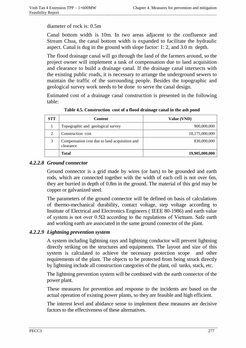
Vinh Tan 4 Extension TPP – 1×600MW
Feasibility Report
Chapter 4. Measures for prevention and mitigation
PECC3 277
diameter of rock is: 0.5m
Canal bottom width is 10m. In two areas adjacent to the confluence and
Stream Chua, the canal bottom width is expanded to facilitate the hydraulic
aspect. Canal is dug in the ground with slope factor: 1: 2, and 3.0 m depth.
The flood drainage canal will go through the land of the farmers around, so the
project owner will implement a task of compensation due to land acquisition
and clearance to build a drainage canal. If the drainage canal intersects with
the existing public roads, it is necessary to arrange the underground sewers to
maintain the traffic of the surrounding people. Besides the topographic and
geological survey work needs to be done to serve the canal design.
Estimated cost of a drainage canal construction is presented in the following
table:
Table 4.5. Construction cost of a flood drainage canal in the ash pond
STT Content Value (VND)
1 Topographic and geological survey 900,000,000
2 Construction cost 18,175,000,000
3 Compensation cost due to land acquisition and
clearance
830,000,000
Total 19,905,000,000
4.2.2.8 Ground connector
Ground connector is a grid made by wires (or bars) to be grounded and earth
rods, which are connected together with the width of each cell is not over 6m,
they are burried in depth of 0.8m in the ground. The material of this grid may be
copper or galvanized steel.
The parameters of the ground connector will be defined on basis of calculations
of thermo-mechanical durability, contact voltage, step voltage according to
Institute of Electrical and Electronics Engineers ( IEEE 80-1986) and earth value
of system is not over 0.5Ω according to the regulations of Vietnam. Safe earth
and working earth are associated in the same ground connector of the plant.
4.2.2.9 Lightning prevention system
A system including lightning rays and lightning conductor will prevent lightning
directly striking on the structures and equipments. The layout and size of this
system is calculated to achieve the necessary protection scope and other
requirements of the plant. The objects to be protected from being struck directly
by lightning include all construction categories of the plant, oil tanks, stack, etc.
The lightning prevention system will be combined with the earth connector of the
power plant.
These measures for prevention and response to the incidents are based on the
actual operation of existing power plants, so they are feasible and high efficient.
The interest level and abidance sense to implement these measures are decisive
factors to the effectiveness of these alternatives.
Vinh Tan 4 Extension TPP – 1×600MW
Feasibility Report
Chapter 4. Measures for prevention and mitigation
PECC3 278
4.2.2.10 Safety and hygiene at workplace
Monitoring microclimate elements twice a year together with monitoring the
environment. The plant will conform to the environmental standards in the
workplace issued by Ministry of Public Health.
The workers and staffs of the plant have to examine their health periodically
to detect timely diseases (including occupational diseases).
Workers and staffs working at places with high noise level will be equipped
with protective clothing and other safety equipments (including noise-
protective capsules and plugs). Workers and staffs working at places with
high and medium voltage lines and risk of electric shock will be equipped
with specialized equipments such as clothing, shoes, gloves and helmets to
prevent electric shock.
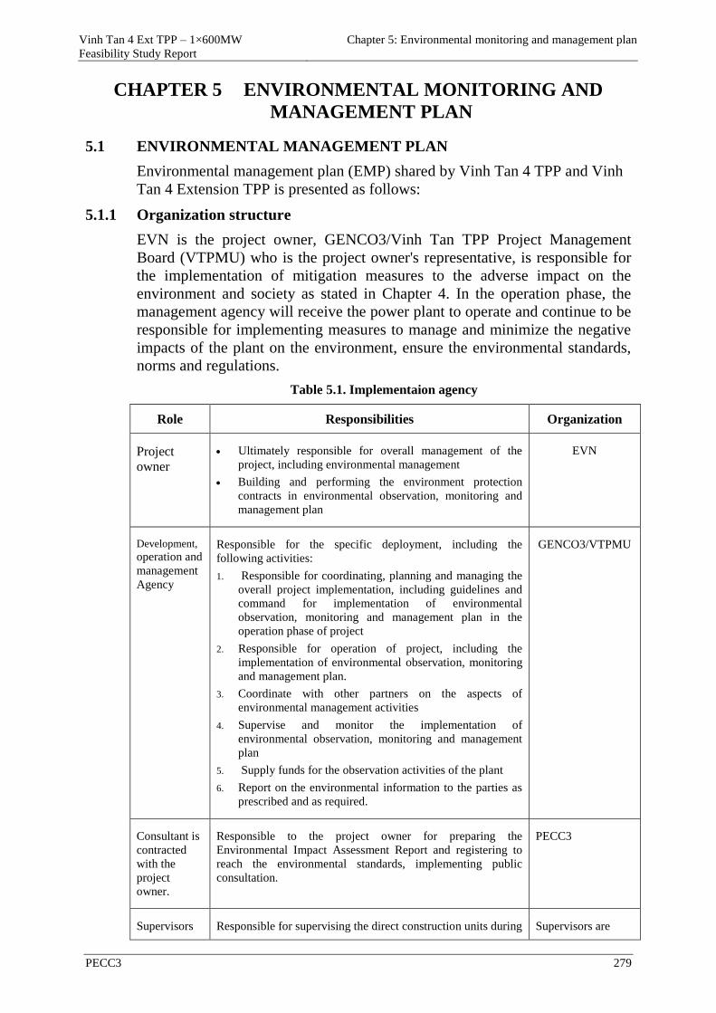
Vinh Tan 4 Ext TPP – 1×600MW
Feasibility Study Report
Chapter 5: Environmental monitoring and management plan
PECC3 279
CHAPTER 5 ENVIRONMENTAL MONITORING AND
MANAGEMENT PLAN
5.1 ENVIRONMENTAL MANAGEMENT PLAN
Environmental management plan (EMP) shared by Vinh Tan 4 TPP and Vinh
Tan 4 Extension TPP is presented as follows:
5.1.1 Organization structure
EVN is the project owner, GENCO3/Vinh Tan TPP Project Management
Board (VTPMU) who is the project owner's representative, is responsible for
the implementation of mitigation measures to the adverse impact on the
environment and society as stated in Chapter 4. In the operation phase, the
management agency will receive the power plant to operate and continue to be
responsible for implementing measures to manage and minimize the negative
impacts of the plant on the environment, ensure the environmental standards,
norms and regulations.
Table 5.1. Implementaion agency
Role Responsibilities Organization
Project
owner
Ultimately responsible for overall management of the
project, including environmental management
Building and performing the environment protection
contracts in environmental observation, monitoring and
management plan
EVN
Development,
operation and
management
Agency
Responsible for the specific deployment, including the
following activities:
1. Responsible for coordinating, planning and managing the
overall project implementation, including guidelines and
command for implementation of environmental
observation, monitoring and management plan in the
operation phase of project
2. Responsible for operation of project, including the
implementation of environmental observation, monitoring
and management plan.
3. Coordinate with other partners on the aspects of
environmental management activities
4. Supervise and monitor the implementation of
environmental observation, monitoring and management
plan
5. Supply funds for the observation activities of the plant
6. Report on the environmental information to the parties as
prescribed and as required.
GENCO3/VTPMU
Consultant is
contracted
with the
project
owner.
Responsible to the project owner for preparing the
Environmental Impact Assessment Report and registering to
reach the environmental standards, implementing public
consultation.
PECC3
Supervisors Responsible for supervising the direct construction units during Supervisors are
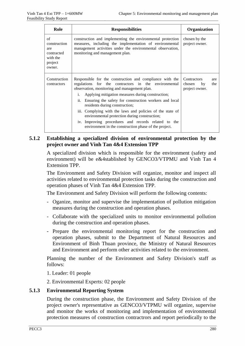
Vinh Tan 4 Ext TPP – 1×600MW
Feasibility Study Report
Chapter 5: Environmental monitoring and management plan
PECC3 280
Role Responsibilities Organization
of
construction
are
contracted
with the
project
owner.
construction and implementing the environmental protection
measures, including the implementation of environmental
management activities under the environmental observation,
monitoring and management plan.
chosen by the
project owner.
Construction
contractors
Responsible for the construction and compliance with the
regulations for the contractors in the environmental
observation, monitoring and management plan.
i. Applying mitigation measures during construction;
ii. Ensuring the safety for construction workers and local
residents during construction;
iii. Complying with the laws and policies of the state of
environmental protection during construction;
iv. Improving procedures and records related to the
environment in the construction phase of the project.
Contractors are
chosen by the
project owner.
5.1.2 Establishing a specialized division of environmental protection by the
project owner and Vinh Tan 4&4 Extension TPP
A specialized division which is responsible for the environment (safety and
environment) will be e&4stablished by GENCO3/VTPMU and Vinh Tan 4
Extension TPP.
The Environment and Safety Division will organize, monitor and inspect all
activities related to environmental protection tasks during the construction and
operation phases of Vinh Tan 4&4 Extension TPP.
The Environment and Safety Division will perform the following contents:
- Oganize, monitor and supervise the implementation of pollution mitigation
measures during the construction and operation phases.
- Collaborate with the specialized units to monitor environmental pollution
during the construction and operation phases.
- Prepare the environmental monitoring report for the construction and
operation phases, submit to the Department of Natural Resources and
Environment of Binh Thuan province, the Ministry of Natural Resources
and Environment and perform other activities related to the environment.
Planning the number of the Environment and Safety Division's staff as
follows:
1. Leader: 01 people
2. Environmental Experts: 02 people
5.1.3 Environmental Reporting System
During the construction phase, the Environment and Safety Division of the
project owner's representative as GENCO3/VTPMU will organize, supervise
and monitor the works of monitoring and implementation of environmental
protection measures of construction contractrors and report periodically to the
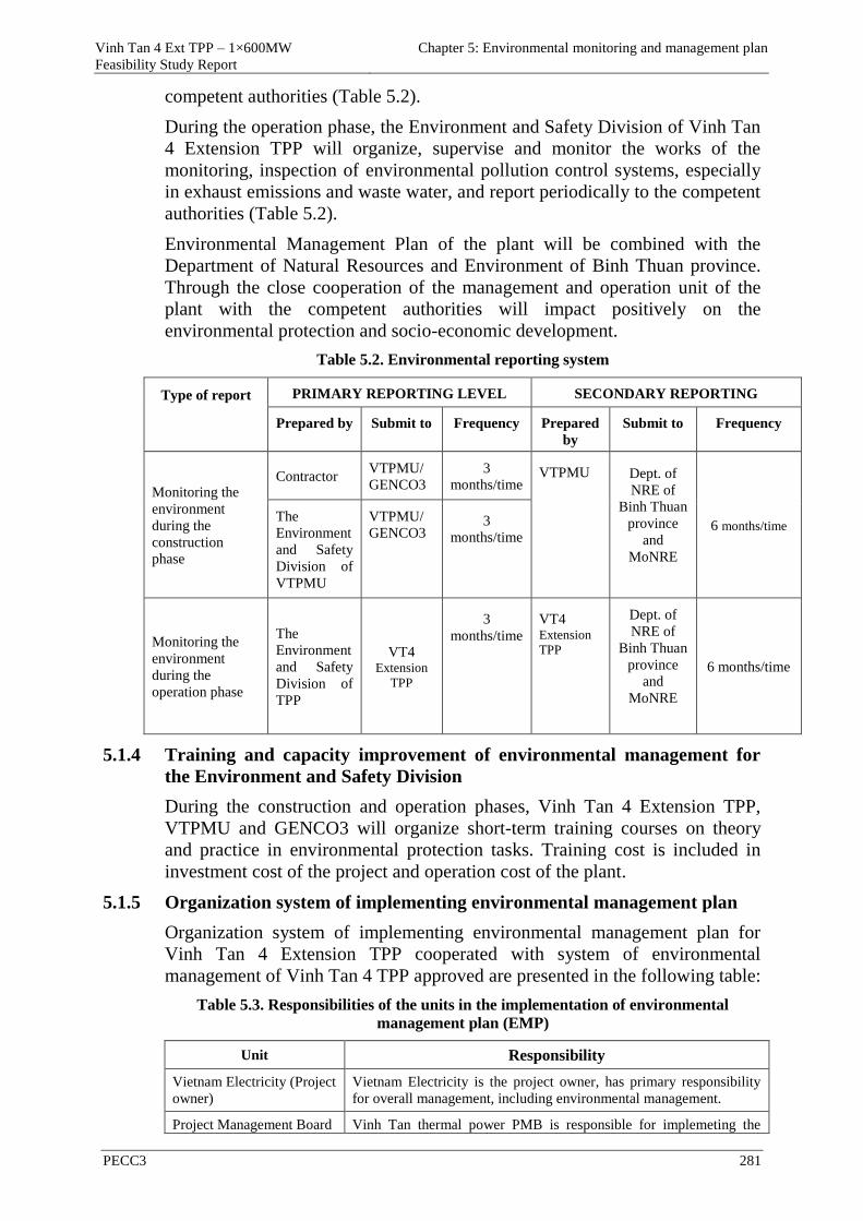
Vinh Tan 4 Ext TPP – 1×600MW
Feasibility Study Report
Chapter 5: Environmental monitoring and management plan
PECC3 281
competent authorities (Table 5.2).
During the operation phase, the Environment and Safety Division of Vinh Tan
4 Extension TPP will organize, supervise and monitor the works of the
monitoring, inspection of environmental pollution control systems, especially
in exhaust emissions and waste water, and report periodically to the competent
authorities (Table 5.2).
Environmental Management Plan of the plant will be combined with the
Department of Natural Resources and Environment of Binh Thuan province.
Through the close cooperation of the management and operation unit of the
plant with the competent authorities will impact positively on the
environmental protection and socio-economic development.
Table 5.2. Environmental reporting system
Type of report PRIMARY REPORTING LEVEL SECONDARY REPORTING
Prepared by Submit to Frequency Prepared
by
Submit to Frequency
Monitoring the
environment
during the
construction
phase
Contractor VTPMU/
GENCO3
3
months/time VTPMU Dept. of
NRE of
Binh Thuan
province
and
MoNRE
6 months/time The
Environment
and Safety
Division of
VTPMU
VTPMU/
GENCO3 3
months/time
Monitoring the
environment
during the
operation phase
The
Environment
and Safety
Division of
TPP
VT4 Extension
TPP
3
months/time
VT4 Extension
TPP
Dept. of
NRE of
Binh Thuan
province
and
MoNRE
6 months/time
5.1.4 Training and capacity improvement of environmental management for
the Environment and Safety Division
During the construction and operation phases, Vinh Tan 4 Extension TPP,
VTPMU and GENCO3 will organize short-term training courses on theory
and practice in environmental protection tasks. Training cost is included in
investment cost of the project and operation cost of the plant.
5.1.5 Organization system of implementing environmental management plan
Organization system of implementing environmental management plan for
Vinh Tan 4 Extension TPP cooperated with system of environmental
management of Vinh Tan 4 TPP approved are presented in the following table:
Table 5.3. Responsibilities of the units in the implementation of environmental
management plan (EMP)
Unit Responsibility
Vietnam Electricity (Project
owner)
Vietnam Electricity is the project owner, has primary responsibility
for overall management, including environmental management.
Project Management Board Vinh Tan thermal power PMB is responsible for implemeting the
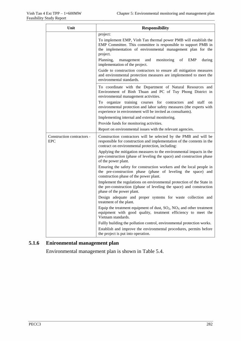
Vinh Tan 4 Ext TPP – 1×600MW
Feasibility Study Report
Chapter 5: Environmental monitoring and management plan
PECC3 282
Unit Responsibility
project:
To implement EMP, Vinh Tan thermal power PMB will establish the
EMP Committee. This committee is responsible to support PMB in
the implementation of environmental management plan for the
project.
Planning, management and monitoring of EMP during
implementation of the project.
Guide to construction contractors to ensure all mitigation measures
and environmental protection measures are implemented to meet the
environmental standards.
To coordinate with the Department of Natural Resources and
Environment of Binh Thuan and PC of Tuy Phong District in
environmental management activities.
To organize training courses for contractors and staff on
environmental protection and labor safety measures (the experts with
experience in environment will be invited as consultants).
Implementing internal and external monitoring.
Provide funds for monitoring activities.
Report on environmental issues with the relevant agencies.
Construction contractors -
EPC
Construction contractors will be selected by the PMB and will be
responsible for construction and implementation of the contents in the
contract on environmental protection, including:
Applying the mitigation measures to the environmental impacts in the
pre-construction (phase of leveling the space) and construction phase
of the power plant.
Ensuring the safety for construction workers and the local people in
the pre-construction phase (phase of leveling the space) and
construction phase of the power plant.
Implement the regulations on environmental protection of the State in
the pre-construction ((phase of leveling the space) and construction
phase of the power plant.
Design adequate and proper systems for waste collection and
treatment of the plant.
Equip the treatment equipment of dust, SO2, NOX and other treatment
equipment with good quality, treatment efficiency to meet the
Vietnam standards.
Fullly building the pollution control, environmental protection works.
Establish and improve the environmental procedures, permits before
the project is put into operation.
5.1.6 Enironmental management plan
Environmental management plan is shown in Table 5.4.
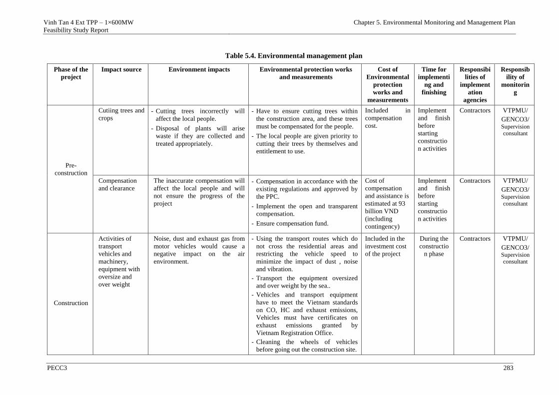
Vinh Tan 4 Ext TPP – 1×600MW
Feasibility Study Report
Chapter 5. Environmental Monitoring and Management Plan
PECC3 283
Table 5.4. Environmental management plan
Phase of the
project
Impact source Environment impacts Environmental protection works
and measurements
Cost of
Environmental
protection
works and
measurements
Time for
implementi
ng and
finishing
Responsibi
lities of
implement
ation
agencies
Responsib
ility of
monitorin
g
Pre-
construction
Cutiing trees and
crops - Cutting trees incorrectly will
affect the local people.
- Disposal of plants will arise
waste if they are collected and
treated appropriately.
- Have to ensure cutting trees within
the construction area, and these trees
must be compensated for the people.
- The local people are given priority to
cutting their trees by themselves and
entitlement to use.
Included in
compensation
cost.
Implement
and finish
before
starting
constructio
n activities
Contractors VTPMU/
GENCO3/Supervision consultant
Compensation
and clearance
The inaccurate compensation will
affect the local people and will
not ensure the progress of the
project
- Compensation in accordance with the
existing regulations and approved by
the PPC.
- Implement the open and transparent
compensation.
- Ensure compensation fund.
Cost of
compensation
and assistance is
estimated at 93
billion VND
(including
contingency)
Implement
and finish
before
starting
constructio
n activities
Contractors VTPMU/
GENCO3/Supervision consultant
Construction
Activities of
transport
vehicles and
machinery,
equipment with
oversize and
over weight
Noise, dust and exhaust gas from
motor vehicles would cause a
negative impact on the air
environment.
- Using the transport routes which do
not cross the residential areas and
restricting the vehicle speed to
minimize the impact of dust , noise
and vibration.
- Transport the equipment oversized
and over weight by the sea..
- Vehicles and transport equipment
have to meet the Vietnam standards
on CO, HC and exhaust emissions,
Vehicles must have certificates on
exhaust emissions granted by
Vietnam Registration Office.
- Cleaning the wheels of vehicles
before going out the construction site.
Included in the
investment cost
of the project
During the
constructio
n phase
Contractors VTPMU/
GENCO3/Supervision consultant
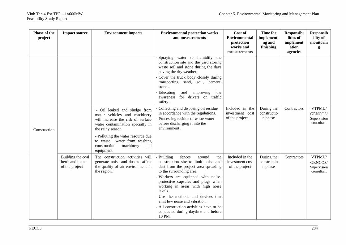
Vinh Tan 4 Ext TPP – 1×600MW
Feasibility Study Report
Chapter 5. Environmental Monitoring and Management Plan
PECC3 284
Phase of the
project
Impact source Environment impacts Environmental protection works
and measurements
Cost of
Environmental
protection
works and
measurements
Time for
implementi
ng and
finishing
Responsibi
lities of
implement
ation
agencies
Responsib
ility of
monitorin
g
Construction
- Spraying water to humidify the
construction site and the yard storing
waste soil and stone during the days
having the dry weather.
- Cover the truck body closely during
transporting sand, soil, cement,
stone...
- Educating and improving the
awareness for drivers on traffic
safety.
- Oil leaked and sludge from
motor vehicles and machinery
will increase the risk of surface
water contamination specially in
the rainy season.
- Polluting the water resource due
to waste water from washing
construction machinery and
equipment
- Collecting and disposing oil residue
in accordance with the regulations.
- Processing residue of waste water
before discharging it into the
environment .
Included in the
investment cost
of the project
During the
constructio
n phase
Contractors VTPMU/
GENCO3/Supervision consultant
Building the coal
berth and items
of the project
The construction activities will
generate noise and dust to affect
the quality of air environment in
the region.
- Building fences around the
construction site to limit noise and
dust from the project area spreading
to the surrounding area.
- Workers are equipped with noise-
protective capsules and plugs when
working in areas with high noise
levels.
- Use the methods and devices that
emit low noise and vibration.
- All construction activities have to be
conducted during daytime and before
10 PM.
Included in the
investment cost
of the project
During the
constructio
n phase
Contractors VTPMU/
GENCO3/Supervision consultant
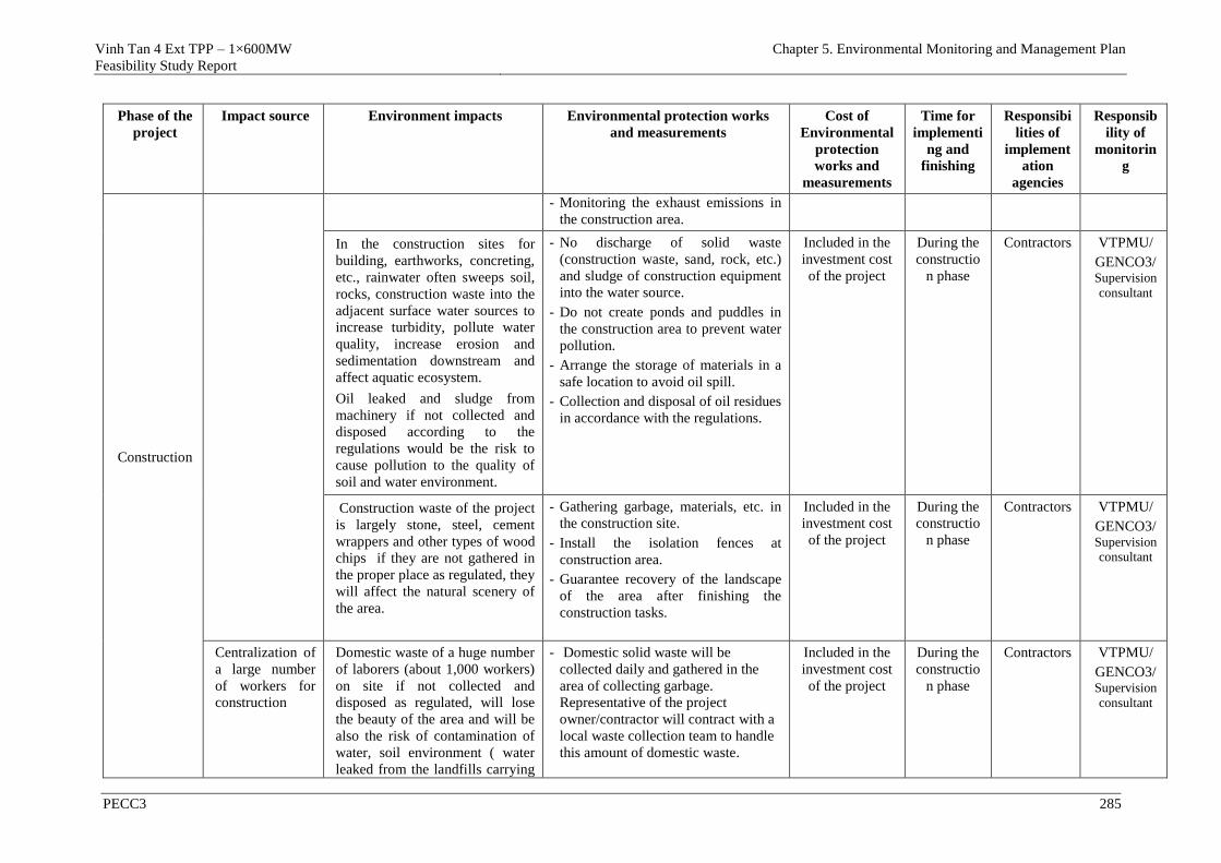
Vinh Tan 4 Ext TPP – 1×600MW
Feasibility Study Report
Chapter 5. Environmental Monitoring and Management Plan
PECC3 285
Phase of the
project
Impact source Environment impacts Environmental protection works
and measurements
Cost of
Environmental
protection
works and
measurements
Time for
implementi
ng and
finishing
Responsibi
lities of
implement
ation
agencies
Responsib
ility of
monitorin
g
Construction
- Monitoring the exhaust emissions in
the construction area.
In the construction sites for
building, earthworks, concreting,
etc., rainwater often sweeps soil,
rocks, construction waste into the
adjacent surface water sources to
increase turbidity, pollute water
quality, increase erosion and
sedimentation downstream and
affect aquatic ecosystem.
Oil leaked and sludge from
machinery if not collected and
disposed according to the
regulations would be the risk to
cause pollution to the quality of
soil and water environment.
- No discharge of solid waste
(construction waste, sand, rock, etc.)
and sludge of construction equipment
into the water source.
- Do not create ponds and puddles in
the construction area to prevent water
pollution.
- Arrange the storage of materials in a
safe location to avoid oil spill.
- Collection and disposal of oil residues
in accordance with the regulations.
Included in the
investment cost
of the project
During the
constructio
n phase
Contractors VTPMU/
GENCO3/Supervision
consultant
Construction waste of the project
is largely stone, steel, cement
wrappers and other types of wood
chips if they are not gathered in
the proper place as regulated, they
will affect the natural scenery of
the area.
- Gathering garbage, materials, etc. in
the construction site.
- Install the isolation fences at
construction area.
- Guarantee recovery of the landscape
of the area after finishing the
construction tasks.
Included in the
investment cost
of the project
During the
constructio
n phase
Contractors VTPMU/
GENCO3/Supervision consultant
Centralization of
a large number
of workers for
construction
Domestic waste of a huge number
of laborers (about 1,000 workers)
on site if not collected and
disposed as regulated, will lose
the beauty of the area and will be
also the risk of contamination of
water, soil environment ( water
leaked from the landfills carrying
- Domestic solid waste will be
collected daily and gathered in the
area of collecting garbage.
Representative of the project
owner/contractor will contract with a
local waste collection team to handle
this amount of domestic waste.
Included in the
investment cost
of the project
During the
constructio
n phase
Contractors VTPMU/
GENCO3/Supervision
consultant
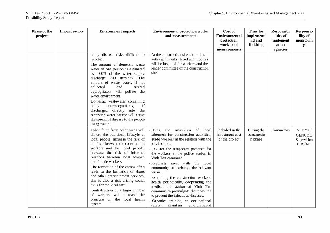
Vinh Tan 4 Ext TPP – 1×600MW
Feasibility Study Report
Chapter 5. Environmental Monitoring and Management Plan
PECC3 286
Phase of the
project
Impact source Environment impacts Environmental protection works
and measurements
Cost of
Environmental
protection
works and
measurements
Time for
implementi
ng and
finishing
Responsibi
lities of
implement
ation
agencies
Responsib
ility of
monitorin
g
many disease risks difficult to
handle).
The amount of domestic waste
water of one person is estimated
by 100% of the water supply
discharge (200 liters/day). The
amount of waste water, if not
collected and treated
appropriately will pollute the
water environment.
Domestic wastewater containing
many microorganisms, if
discharged directly into the
receiving water source will cause
the spread of disease to the people
using water.
- At the construction site, the toilets
with septic tanks (fixed and mobile)
will be installed for workers and the
leader committee of the construction
site.
Labor force from other areas will
disturb the traditional lifestyle of
local people, increase the risk of
conflicts between the construction
workers and the local people,
increase the risk of informal
relations between local women
and female workers.
The formation of the camps often
leads to the formation of shops
and other entertainment services,
this is also a risk arising social
evils for the local area.
Centralization of a large number
of workers will increase the
pressure on the local health
system.
- Using the maximum of local
labourers for construction activities,
guide workers in the relation with the
local people.
- Register the temporary presence for
the workers at the police station in
Vinh Tan commune.
- Regularly meet with the local
community to exchange the relevant
issues.
- Examining the construction workers'
health periodically, cooperating the
medical aid station of Vinh Tan
commune to promulgate the measures
to prevent the infectious diseases.
- Organize training on occupational
safety, maintain environmental
Included in the
investment cost
of the project
During the
constructio
n phase
Contractors VTPMU/
GENCO3/Supervision
consultant
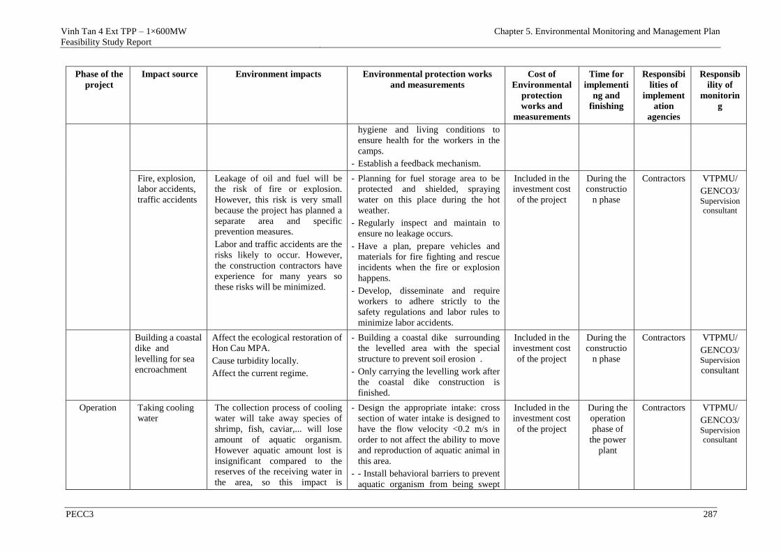
Vinh Tan 4 Ext TPP – 1×600MW
Feasibility Study Report
Chapter 5. Environmental Monitoring and Management Plan
PECC3 287
Phase of the
project
Impact source Environment impacts Environmental protection works
and measurements
Cost of
Environmental
protection
works and
measurements
Time for
implementi
ng and
finishing
Responsibi
lities of
implement
ation
agencies
Responsib
ility of
monitorin
g
hygiene and living conditions to
ensure health for the workers in the
camps.
- Establish a feedback mechanism.
Fire, explosion,
labor accidents,
traffic accidents
Leakage of oil and fuel will be
the risk of fire or explosion.
However, this risk is very small
because the project has planned a
separate area and specific
prevention measures.
Labor and traffic accidents are the
risks likely to occur. However,
the construction contractors have
experience for many years so
these risks will be minimized.
- Planning for fuel storage area to be
protected and shielded, spraying
water on this place during the hot
weather.
- Regularly inspect and maintain to
ensure no leakage occurs.
- Have a plan, prepare vehicles and
materials for fire fighting and rescue
incidents when the fire or explosion
happens.
- Develop, disseminate and require
workers to adhere strictly to the
safety regulations and labor rules to
minimize labor accidents.
Included in the
investment cost
of the project
During the
constructio
n phase
Contractors VTPMU/
GENCO3/Supervision consultant
Building a coastal
dike and
levelling for sea
encroachment
Affect the ecological restoration of
Hon Cau MPA.
Cause turbidity locally.
Affect the current regime.
- Building a coastal dike surrounding
the levelled area with the special
structure to prevent soil erosion .
- Only carrying the levelling work after
the coastal dike construction is
finished.
Included in the
investment cost
of the project
During the
constructio
n phase
Contractors VTPMU/
GENCO3/Supervision consultant
Operation
Taking cooling
water
The collection process of cooling
water will take away species of
shrimp, fish, caviar,... will lose
amount of aquatic organism.
However aquatic amount lost is
insignificant compared to the
reserves of the receiving water in
the area, so this impact is
- Design the appropriate intake: cross
section of water intake is designed to
have the flow velocity <0.2 m/s in
order to not affect the ability to move
and reproduction of aquatic animal in
this area.
- - Install behavioral barriers to prevent
aquatic organism from being swept
Included in the
investment cost
of the project
During the
operation
phase of
the power
plant
Contractors VTPMU/
GENCO3/Supervision consultant
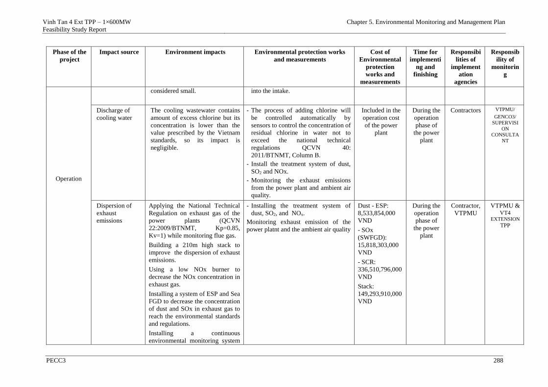
Vinh Tan 4 Ext TPP – 1×600MW
Feasibility Study Report
Chapter 5. Environmental Monitoring and Management Plan
PECC3 288
Phase of the
project
Impact source Environment impacts Environmental protection works
and measurements
Cost of
Environmental
protection
works and
measurements
Time for
implementi
ng and
finishing
Responsibi
lities of
implement
ation
agencies
Responsib
ility of
monitorin
g
Operation
considered small. into the intake.
Discharge of
cooling water
The cooling wastewater contains
amount of excess chlorine but its
concentration is lower than the
value prescribed by the Vietnam
standards, so its impact is
negligible.
- The process of adding chlorine will
be controlled automatically by
sensors to control the concentration of
residual chlorine in water not to
exceed the national technical
regulations QCVN 40:
2011/BTNMT, Column B.
- Install the treatment system of dust,
SO2 and NOx.
- Monitoring the exhaust emissions
from the power plant and ambient air
quality.
Included in the
operation cost
of the power
plant
During the
operation
phase of
the power
plant
Contractors VTPMU/
GENCO3/
SUPERVISI
ON CONSULTA
NT
Dispersion of
exhaust
emissions
Applying the National Technical
Regulation on exhaust gas of the
power plants (QCVN
22:2009/BTNMT, Kp=0.85,
Kv=1) while monitoring flue gas.
Building a 210m high stack to
improve the dispersion of exhaust
emissions.
Using a low NOx burner to
decrease the NOx concentration in
exhaust gas.
Installing a system of ESP and Sea
FGD to decrease the concentration
of dust and SOx in exhaust gas to
reach the environmental standards
and regulations.
Installing a continuous
environmental monitoring system
- Installing the treatment system of
dust, SO2, and NOx.
Monitoring exhaust emission of the
power platnt and the ambient air quality
Dust - ESP:
8,533,854,000
VND
- SOx
(SWFGD):
15,818,303,000
VND
- SCR:
336,510,796,000
VND
Stack:
149,293,910,000
VND
During the
operation
phase of
the power
plant
Contractor,
VTPMU
VTPMU & VT4
EXTENSION TPP
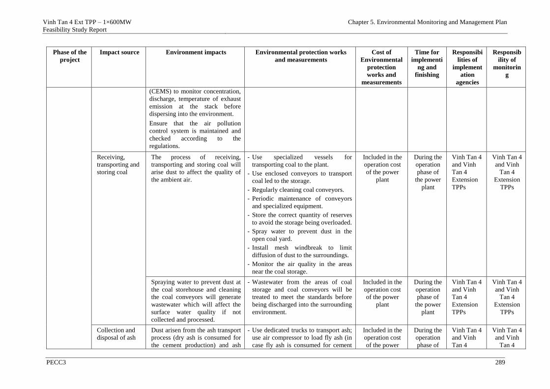
Vinh Tan 4 Ext TPP – 1×600MW
Feasibility Study Report
Chapter 5. Environmental Monitoring and Management Plan
PECC3 289
Phase of the
project
Impact source Environment impacts Environmental protection works
and measurements
Cost of
Environmental
protection
works and
measurements
Time for
implementi
ng and
finishing
Responsibi
lities of
implement
ation
agencies
Responsib
ility of
monitorin
g
(CEMS) to monitor concentration,
discharge, temperature of exhaust
emission at the stack before
dispersing into the environment.
Ensure that the air pollution
control system is maintained and
checked according to the
regulations.
Receiving,
transporting and
storing coal
The process of receiving,
transporting and storing coal will
arise dust to affect the quality of
the ambient air.
- Use specialized vessels for
transporting coal to the plant.
- Use enclosed conveyors to transport
coal led to the storage.
- Regularly cleaning coal conveyors.
- Periodic maintenance of conveyors
and specialized equipment.
- Store the correct quantity of reserves
to avoid the storage being overloaded.
- Spray water to prevent dust in the
open coal yard.
- Install mesh windbreak to limit
diffusion of dust to the surroundings.
- Monitor the air quality in the areas
near the coal storage.
Included in the
operation cost
of the power
plant
During the
operation
phase of
the power
plant
Vinh Tan 4
and Vinh
Tan 4
Extension
TPPs
Vinh Tan 4
and Vinh
Tan 4
Extension
TPPs
Spraying water to prevent dust at
the coal storehouse and cleaning
the coal conveyors will generate
wastewater which will affect the
surface water quality if not
collected and processed.
- Wastewater from the areas of coal
storage and coal conveyors will be
treated to meet the standards before
being discharged into the surrounding
environment.
Included in the
operation cost
of the power
plant
During the
operation
phase of
the power
plant
Vinh Tan 4
and Vinh
Tan 4
Extension
TPPs
Vinh Tan 4
and Vinh
Tan 4
Extension
TPPs
Collection and
disposal of ash
Dust arisen from the ash transport
process (dry ash is consumed for
the cement production) and ash
- Use dedicated trucks to transport ash;
use air compressor to load fly ash (in
case fly ash is consumed for cement
Included in the
operation cost
of the power
During the
operation
phase of
Vinh Tan 4
and Vinh
Tan 4
Vinh Tan 4
and Vinh
Tan 4
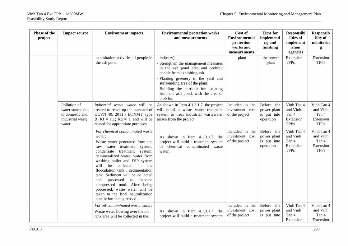
Vinh Tan 4 Ext TPP – 1×600MW
Feasibility Study Report
Chapter 5. Environmental Monitoring and Management Plan
PECC3 290
Phase of the
project
Impact source Environment impacts Environmental protection works
and measurements
Cost of
Environmental
protection
works and
measurements
Time for
implementi
ng and
finishing
Responsibi
lities of
implement
ation
agencies
Responsib
ility of
monitorin
g
exploitation activities of people in
the ash pond.
industry).
- Strengthen the management measures
in the ash pond area and prohibit
people from exploiting ash.
- Planting greenery in the yard and
surrounding area of the plant.
- Building the corridor for isolating
from the ash pond, with the area of
5.56 ha.
plant the power
plant
Extension
TPPs
Extension
TPPs
Pollution of
water source due
to domestic and
industrial waste
water .
Industrial waste water will be
treated to reach up the standard of
QCVN 40: 2011 / BTNMT, type
B, Kf = 1.1; Kq = 1, and will be
reused for appropriate purposes.
As shown in Item 4.1.3.1.7, the project
will build a waste water treatment
system to treat industrial wastewater
arisen from the project.
Included in the
investment cost
of the project
Before the
power plant
is put into
operation
Vinh Tan 4
and Vinh
Tan 4
Extension
TPPs
Vinh Tan 4
and Vinh
Tan 4
Extension
TPPs
For chemical contaminated waste
water:
Waste water generated from the
raw water treatment system,
condensate treatment system,
demineralized water, water from
washing boiler and ESP system
will be collected in the
flocculation tank , sedimentation
tank. Sediment will be collected
and processed to become
compressed mud. After being
processed, waste water will be
taken to the final neutralization
tank before being reused.
As shown in Item 4.1.3.1.7, the
project will build a treatment system
of chemical contaminated waste
water.
Included in the
investment cost
of the project
Before the
power plant
is put into
operation
Vinh Tan 4
and Vinh
Tan 4
Extension
TPPs
Vinh Tan 4
and Vinh
Tan 4
Extension
TPPs
For oil-contaminated waste water:
Waste water flowing over the oil
tank area will be collected in the
As shown in Item 4.1.3.1.7, the
project will build a treatment system
Included in the
investment cost
of the project
Before the
power plant
is put into
Vinh Tan 4
and Vinh
Tan 4
Extension
Vinh Tan 4
and Vinh
Tan 4
Extension
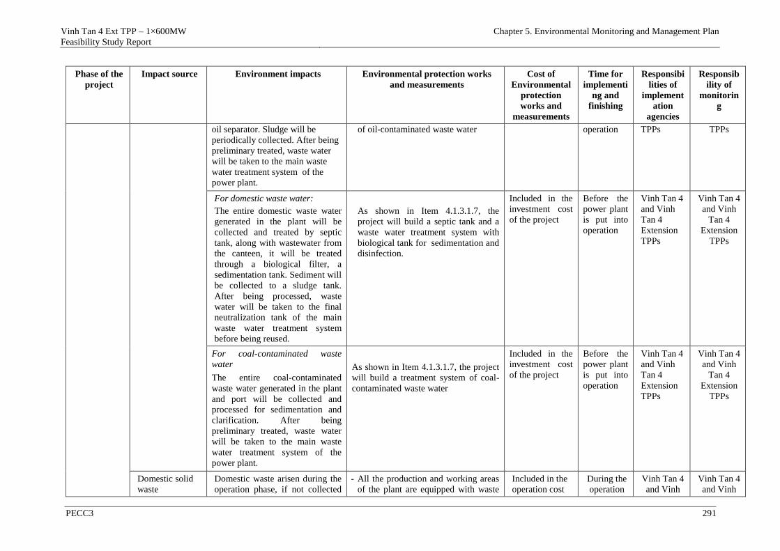
Vinh Tan 4 Ext TPP – 1×600MW
Feasibility Study Report
Chapter 5. Environmental Monitoring and Management Plan
PECC3 291
Phase of the
project
Impact source Environment impacts Environmental protection works
and measurements
Cost of
Environmental
protection
works and
measurements
Time for
implementi
ng and
finishing
Responsibi
lities of
implement
ation
agencies
Responsib
ility of
monitorin
g
oil separator. Sludge will be
periodically collected. After being
preliminary treated, waste water
will be taken to the main waste
water treatment system of the
power plant.
of oil-contaminated waste water operation TPPs TPPs
For domestic waste water:
The entire domestic waste water
generated in the plant will be
collected and treated by septic
tank, along with wastewater from
the canteen, it will be treated
through a biological filter, a
sedimentation tank. Sediment will
be collected to a sludge tank.
After being processed, waste
water will be taken to the final
neutralization tank of the main
waste water treatment system
before being reused.
As shown in Item 4.1.3.1.7, the
project will build a septic tank and a
waste water treatment system with
biological tank for sedimentation and
disinfection.
Included in the
investment cost
of the project
Before the
power plant
is put into
operation
Vinh Tan 4
and Vinh
Tan 4
Extension
TPPs
Vinh Tan 4
and Vinh
Tan 4
Extension
TPPs
For coal-contaminated waste
water
The entire coal-contaminated
waste water generated in the plant
and port will be collected and
processed for sedimentation and
clarification. After being
preliminary treated, waste water
will be taken to the main waste
water treatment system of the
power plant.
As shown in Item 4.1.3.1.7, the project
will build a treatment system of coal-
contaminated waste water
Included in the
investment cost
of the project
Before the
power plant
is put into
operation
Vinh Tan 4
and Vinh
Tan 4
Extension
TPPs
Vinh Tan 4
and Vinh
Tan 4
Extension
TPPs
Domestic solid
waste
Domestic waste arisen during the
operation phase, if not collected
- All the production and working areas
of the plant are equipped with waste
Included in the
operation cost
During the
operation
Vinh Tan 4
and Vinh
Vinh Tan 4
and Vinh
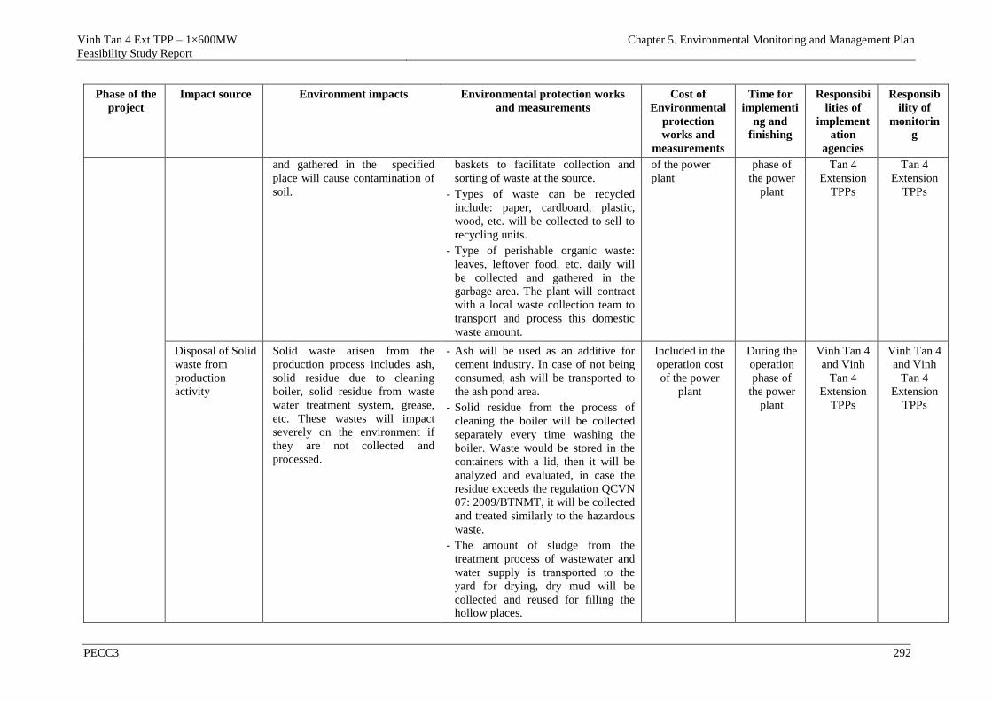
Vinh Tan 4 Ext TPP – 1×600MW
Feasibility Study Report
Chapter 5. Environmental Monitoring and Management Plan
PECC3 292
Phase of the
project
Impact source Environment impacts Environmental protection works
and measurements
Cost of
Environmental
protection
works and
measurements
Time for
implementi
ng and
finishing
Responsibi
lities of
implement
ation
agencies
Responsib
ility of
monitorin
g
and gathered in the specified
place will cause contamination of
soil.
baskets to facilitate collection and
sorting of waste at the source.
- Types of waste can be recycled
include: paper, cardboard, plastic,
wood, etc. will be collected to sell to
recycling units.
- Type of perishable organic waste:
leaves, leftover food, etc. daily will
be collected and gathered in the
garbage area. The plant will contract
with a local waste collection team to
transport and process this domestic
waste amount.
of the power
plant
phase of
the power
plant
Tan 4
Extension
TPPs
Tan 4
Extension
TPPs
Disposal of Solid
waste from
production
activity
Solid waste arisen from the
production process includes ash,
solid residue due to cleaning
boiler, solid residue from waste
water treatment system, grease,
etc. These wastes will impact
severely on the environment if
they are not collected and
processed.
- Ash will be used as an additive for
cement industry. In case of not being
consumed, ash will be transported to
the ash pond area.
- Solid residue from the process of
cleaning the boiler will be collected
separately every time washing the
boiler. Waste would be stored in the
containers with a lid, then it will be
analyzed and evaluated, in case the
residue exceeds the regulation QCVN
07: 2009/BTNMT, it will be collected
and treated similarly to the hazardous
waste.
- The amount of sludge from the
treatment process of wastewater and
water supply is transported to the
yard for drying, dry mud will be
collected and reused for filling the
hollow places.
Included in the
operation cost
of the power
plant
During the
operation
phase of
the power
plant
Vinh Tan 4
and Vinh
Tan 4
Extension
TPPs
Vinh Tan 4
and Vinh
Tan 4
Extension
TPPs
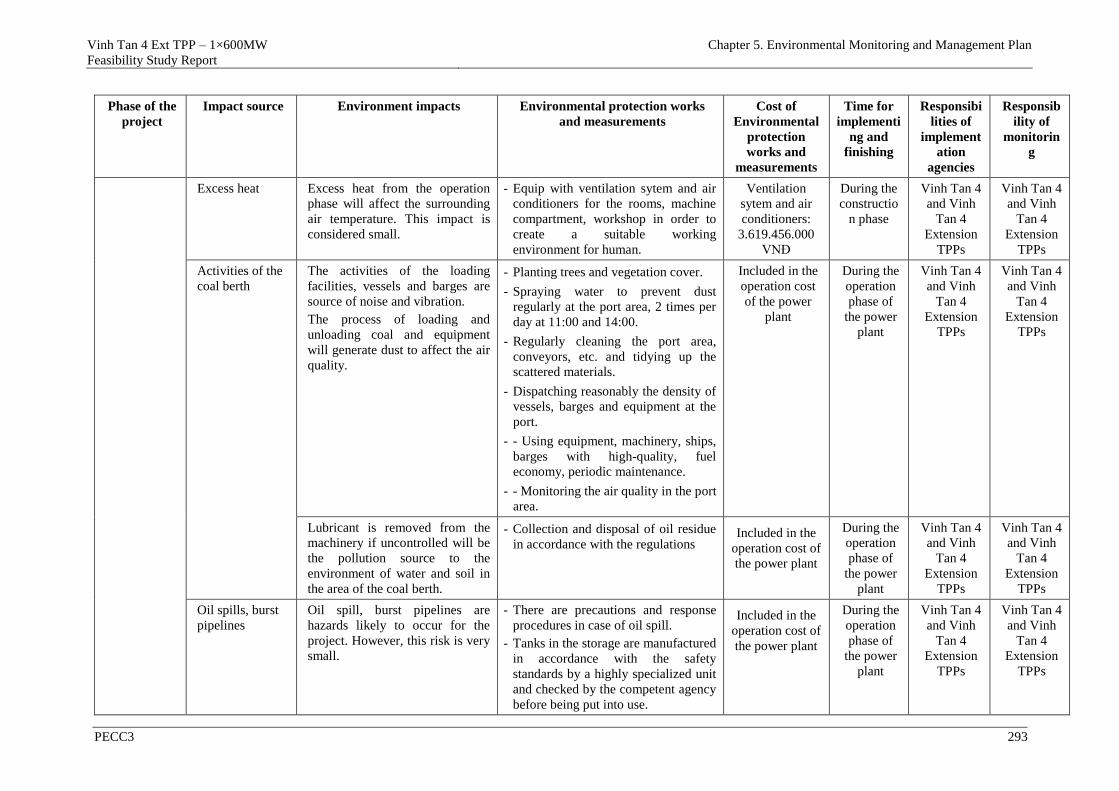
Vinh Tan 4 Ext TPP – 1×600MW
Feasibility Study Report
Chapter 5. Environmental Monitoring and Management Plan
PECC3 293
Phase of the
project
Impact source Environment impacts Environmental protection works
and measurements
Cost of
Environmental
protection
works and
measurements
Time for
implementi
ng and
finishing
Responsibi
lities of
implement
ation
agencies
Responsib
ility of
monitorin
g
Excess heat Excess heat from the operation
phase will affect the surrounding
air temperature. This impact is
considered small.
- Equip with ventilation sytem and air
conditioners for the rooms, machine
compartment, workshop in order to
create a suitable working
environment for human.
Ventilation
sytem and air
conditioners:
3.619.456.000
VNĐ
During the
constructio
n phase
Vinh Tan 4
and Vinh
Tan 4
Extension
TPPs
Vinh Tan 4
and Vinh
Tan 4
Extension
TPPs
Activities of the
coal berth
The activities of the loading
facilities, vessels and barges are
source of noise and vibration.
The process of loading and
unloading coal and equipment
will generate dust to affect the air
quality.
- Planting trees and vegetation cover.
- Spraying water to prevent dust
regularly at the port area, 2 times per
day at 11:00 and 14:00.
- Regularly cleaning the port area,
conveyors, etc. and tidying up the
scattered materials.
- Dispatching reasonably the density of
vessels, barges and equipment at the
port.
- - Using equipment, machinery, ships,
barges with high-quality, fuel
economy, periodic maintenance.
- - Monitoring the air quality in the port
area.
Included in the
operation cost
of the power
plant
During the
operation
phase of
the power
plant
Vinh Tan 4
and Vinh
Tan 4
Extension
TPPs
Vinh Tan 4
and Vinh
Tan 4
Extension
TPPs
Lubricant is removed from the
machinery if uncontrolled will be
the pollution source to the
environment of water and soil in
the area of the coal berth.
- Collection and disposal of oil residue
in accordance with the regulations Included in the
operation cost of
the power plant
During the
operation
phase of
the power
plant
Vinh Tan 4
and Vinh
Tan 4
Extension
TPPs
Vinh Tan 4
and Vinh
Tan 4
Extension
TPPs
Oil spills, burst
pipelines
Oil spill, burst pipelines are
hazards likely to occur for the
project. However, this risk is very
small.
- There are precautions and response
procedures in case of oil spill.
- Tanks in the storage are manufactured
in accordance with the safety
standards by a highly specialized unit
and checked by the competent agency
before being put into use.
Included in the
operation cost of
the power plant
During the
operation
phase of
the power
plant
Vinh Tan 4
and Vinh
Tan 4
Extension
TPPs
Vinh Tan 4
and Vinh
Tan 4
Extension
TPPs
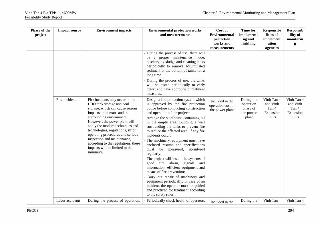
Vinh Tan 4 Ext TPP – 1×600MW
Feasibility Study Report
Chapter 5. Environmental Monitoring and Management Plan
PECC3 294
Phase of the
project
Impact source Environment impacts Environmental protection works
and measurements
Cost of
Environmental
protection
works and
measurements
Time for
implementi
ng and
finishing
Responsibi
lities of
implement
ation
agencies
Responsib
ility of
monitorin
g
- During the process of use, there will
be a proper maintenance mode,
discharging sludge and cleaning tanks
periodically to remove accumulated
sediment at the bottom of tanks for a
long time.
- During the process of use, the tanks
will be tested periodically to early
detect and have appropriate treatment
measures.
Fire incidents Fire incidents may occur in the
LDO tank storage and coal
storage, which can cause serious
impacts on humans and the
surrounding environment.
However, the power plant will
apply the modern techniques and
technologies, regulations, strict
operating procedures and serious
inspection and maintenance,
according to the regulations, these
impacts will be limited to the
minimum.
- Design a fire protection system which
is approved by the fire protection
police before conducting construction
and operation of the project;
- Arrange the storehouse containing oil
in the empty area. Building a wall
surrounding the tanks to prevent fire
to reduce the affected area, if any fire
incidents occur;
- The machinery, equipment must have
enclosed resume and specifications
must be measured, monitored
regularly;
- The project will install the systems of
good fire alarm, signals and
information, efficient equipment and
means of fire prevention;
- Carry out repair of machinery and
equipment periodically. In case of an
incident, the operator must be guided
and practiced for treatment according
to the safety rules.
Included in the
operation cost of
the power plant
During the
operation
phase of
the power
plant
Vinh Tan 4
and Vinh
Tan 4
Extension
TPPs
Vinh Tan 4
and Vinh
Tan 4
Extension
TPPs
Labor accidents During the process of operation, - Periodically check health of operators Included in the During the Vinh Tan 4 Vinh Tan 4
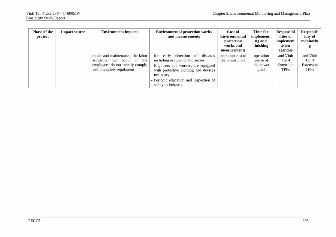
Vinh Tan 4 Ext TPP – 1×600MW
Feasibility Study Report
Chapter 5. Environmental Monitoring and Management Plan
PECC3 295
Phase of the
project
Impact source Environment impacts Environmental protection works
and measurements
Cost of
Environmental
protection
works and
measurements
Time for
implementi
ng and
finishing
Responsibi
lities of
implement
ation
agencies
Responsib
ility of
monitorin
g
repair and maintenance, the labor
accidents can occur if the
employees do not strictly comply
with the safety regulations.
for early detection of diseases
including occupational diseases.
- Engineers and workers are equipped
with protective clothing and devices
necessary.
- Periodic education and inspection of
safety technique .
operation cost of
the power plant operation
phase of
the power
plant
and Vinh
Tan 4
Extension
TPPs
and Vinh
Tan 4
Extension
TPPs
Vinh Tan 4 Ext TPP – 1×600MW
Feasibility Study Report
Chapter 5. Environmental Monitoring and Management Plan
PECC3 296
5.2 ENVIRONMENTAL MONITORING PLAN
To ensure effective implementation of measures to minimize the negative
impacts of the project, an Environmental Monitoring Program for the project
will be implemented in three phases: pre-construction, construction and
operation.
5.2.1 Types of environmental monitoring form
The project will be implemented simultaneously two types of environmental
monitoring form.
- Monitor in place the implementation of measures to minimize the
environmental impacts: Check and evaluate the implementation and
effectiveness of mitigation measures implemented by the project owner in
3 phases including pre-construction, construction and operation.
- Monitor the environmental quality: sampling, analysing the quality of
environmental components in the process of project implementation to
assess the level to meet the environmental standards/regulations of
Vietnam.
- The units will engage to implement the environmental monitoring
program for the project including:
+ Representatives of the Project owner (GENCO3/VTPMB) (internal
monitoring)
+ Department of Natural Resouces and Environment in Binh Thuan
province will supervise the environment according to the state
management function.
5.2.2 Monitoring the implementation of measures and solutions to control
pollution and protect the environment of the project
Content of monitoring, monitored objects and areas, compliance of the project
owner to the requirements related to pollution control and environmental
protection in 3 phases including pre-construction, construction and operation
of Vinh Tan 4 Extension TPP presented in Table 5.1. Responsibilities of the
project owner (internal monitoring) and the agency of environmental
management in Binh Thuan province have been identified in this table.
- Fund for internal monitoring is guaranteed by the project owner.
- Fund for monitoring the environment according to the state management
function: is guaranteed by the State based on the requirement of the
Department of Natural Resources and Environment of Binh Thuan province.
5.2.3 Environmental Monitoring Plan of the Project
5.2.3.1 Monitoring waste
5.2.3.1.1 During the pre-construction phase
Monitoring the situation of collecting, processing solid waste
- Monitoring: felling, collecting and processing trees and crops;
- Frequency of inspection: includes 02 stages: at the start and at the end of
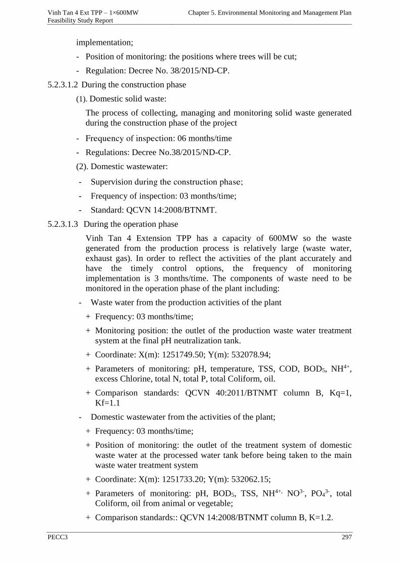
Vinh Tan 4 Ext TPP – 1×600MW
Feasibility Study Report
Chapter 5. Environmental Monitoring and Management Plan
PECC3 297
implementation;
- Position of monitoring: the positions where trees will be cut;
- Regulation: Decree No. 38/2015/ND-CP.
5.2.3.1.2 During the construction phase
(1). Domestic solid waste:
The process of collecting, managing and monitoring solid waste generated
during the construction phase of the project
- Frequency of inspection: 06 months/time
- Regulations: Decree No.38/2015/ND-CP.
(2). Domestic wastewater:
- Supervision during the construction phase;
- Frequency of inspection: 03 months/time;
- Standard: QCVN 14:2008/BTNMT.
5.2.3.1.3 During the operation phase
Vinh Tan 4 Extension TPP has a capacity of 600MW so the waste
generated from the production process is relatively large (waste water,
exhaust gas). In order to reflect the activities of the plant accurately and
have the timely control options, the frequency of monitoring
implementation is 3 months/time. The components of waste need to be
monitored in the operation phase of the plant including:
- Waste water from the production activities of the plant
+ Frequency: 03 months/time;
+ Monitoring position: the outlet of the production waste water treatment
system at the final pH neutralization tank.
+ Coordinate: X(m): 1251749.50; Y(m): 532078.94;
+ Parameters of monitoring: pH, temperature, TSS, COD, BOD5, NH4+,
excess Chlorine, total N, total P, total Coliform, oil.
+ Comparison standards: QCVN 40:2011/BTNMT column B, Kq=1,
Kf=1.1
- Domestic wastewater from the activities of the plant;
+ Frequency: 03 months/time;
+ Position of monitoring: the outlet of the treatment system of domestic
waste water at the processed water tank before being taken to the main
waste water treatment system
+ Coordinate: X(m): 1251733.20; Y(m): 532062.15;
+ Parameters of monitoring: pH, BOD5, TSS, NH4+, NO3-, PO43-, total
Coliform, oil from animal or vegetable;
+ Comparison standards:: QCVN 14:2008/BTNMT column B, K=1.2.
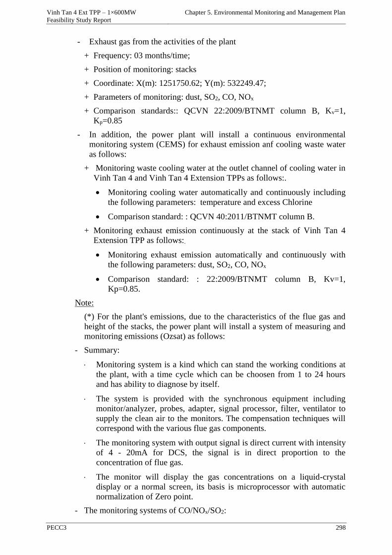
Vinh Tan 4 Ext TPP – 1×600MW
Feasibility Study Report
Chapter 5. Environmental Monitoring and Management Plan
PECC3 298
- Exhaust gas from the activities of the plant
+ Frequency: 03 months/time;
+ Position of monitoring: stacks
+ Coordinate: X(m): 1251750.62; Y(m): 532249.47;
+ Parameters of monitoring: dust, SO2, CO, NOx
+ Comparison standards:: QCVN 22:2009/BTNMT column B, Kv=1,
Kp=0.85
- In addition, the power plant will install a continuous environmental
monitoring system (CEMS) for exhaust emission anf cooling waste water
as follows:
+ Monitoring waste cooling water at the outlet channel of cooling water in
Vinh Tan 4 and Vinh Tan 4 Extension TPPs as follows:.
Monitoring cooling water automatically and continuously including
the following parameters: temperature and excess Chlorine
Comparison standard: : QCVN 40:2011/BTNMT column B.
+ Monitoring exhaust emission continuously at the stack of Vinh Tan 4
Extension TPP as follows:.
Monitoring exhaust emission automatically and continuously with
the following parameters: dust, SO2, CO, NOx
Comparison standard: : 22:2009/BTNMT column B, Kv=1,
Kp=0.85.
Note:
(*) For the plant's emissions, due to the characteristics of the flue gas and
height of the stacks, the power plant will install a system of measuring and
monitoring emissions (Ozsat) as follows:
- Summary:
Monitoring system is a kind which can stand the working conditions at
the plant, with a time cycle which can be choosen from 1 to 24 hours
and has ability to diagnose by itself.
The system is provided with the synchronous equipment including
monitor/analyzer, probes, adapter, signal processor, filter, ventilator to
supply the clean air to the monitors. The compensation techniques will
correspond with the various flue gas components.
The monitoring system with output signal is direct current with intensity
of 4 - 20mA for DCS, the signal is in direct proportion to the
concentration of flue gas.
The monitor will display the gas concentrations on a liquid-crystal
display or a normal screen, its basis is microprocessor with automatic
normalization of Zero point.
- The monitoring systems of CO/NOx/SO2:
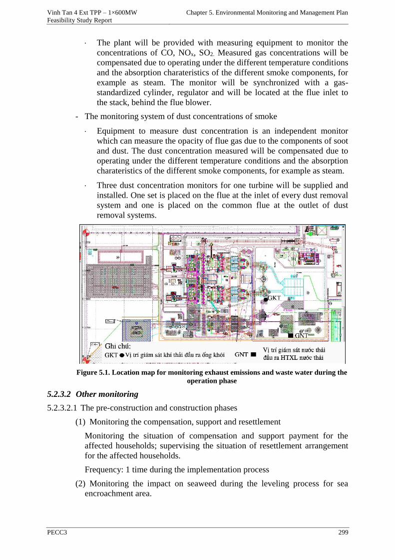
Vinh Tan 4 Ext TPP – 1×600MW
Feasibility Study Report
Chapter 5. Environmental Monitoring and Management Plan
PECC3 299
The plant will be provided with measuring equipment to monitor the
concentrations of CO, NOx, SO2. Measured gas concentrations will be
compensated due to operating under the different temperature conditions
and the absorption charateristics of the different smoke components, for
example as steam. The monitor will be synchronized with a gas-
standardized cylinder, regulator and will be located at the flue inlet to
the stack, behind the flue blower.
- The monitoring system of dust concentrations of smoke
Equipment to measure dust concentration is an independent monitor
which can measure the opacity of flue gas due to the components of soot
and dust. The dust concentration measured will be compensated due to
operating under the different temperature conditions and the absorption
charateristics of the different smoke components, for example as steam.
Three dust concentration monitors for one turbine will be supplied and
installed. One set is placed on the flue at the inlet of every dust removal
system and one is placed on the common flue at the outlet of dust
removal systems.
Figure 5.1. Location map for monitoring exhaust emissions and waste water during the
operation phase
5.2.3.2 Other monitoring
5.2.3.2.1 The pre-construction and construction phases
(1) Monitoring the compensation, support and resettlement
Monitoring the situation of compensation and support payment for the
affected households; supervising the situation of resettlement arrangement
for the affected households.
Frequency: 1 time during the implementation process
(2) Monitoring the impact on seaweed during the leveling process for sea
encroachment area.
Vinh Tan 4 Ext TPP – 1×600MW
Feasibility Study Report
Chapter 5. Environmental Monitoring and Management Plan
PECC3 300
During the leveling process for sea encroachment area of the plant, the
impact on seaweed in the area of Vinh Tan commune outside the project
scope will be tested, supervised strictly.
Frequency: 1 time during the implementation process
(3) Monitoring deposition/erosion
During the construction phase, monitoring deposition/erosion at the sea
encroachment area of the project area must be carried out to examine and
monitor the extent of deposition/erosion to have the mitigation measures
promptly.
Frequency: 1 time during the implementation process.
5.2.3.2.2 The operation phase
(1) Monitoring socio-economic situation
Assessing the impact of the project on the socio-economic situation of the
surrounding residential area. Providing data for environmental management
and project activities, forecasting the impacts due to the plant to the residential
areas.
Frequency of monitoring: 1 year/time
(2) Monitoring the variation of aquatic ecosystems in the area affected by heat
of cooling water.
During the operation phase of the power plant, the discharge activity of
cooling wastewater may affect aquatic ecosystems, so the project will monitor
the the variation of aquatic ecosystems.
Frequency of monitoring: 1 year/time.
5.2.4 Monitoring program of the ambient environment for the whole of Vinh
Tan Power Complex
To detect and control pollution from activities of Vinh Tan Power Complex,
EVN will establish a monitoring program of the ambient environment as
follows :
The objectives of the monitoring program of the ambient environment are as
follows :
Assess the environmental quality in the project area during the operation phase
of power plant;
- To provide data for the works of environmental management and forecasting
changes in the environmental quality caused by operating activities;
- Positions of the points of monitoring the environment of air, surface water,
coastal water in Vinh Tan Power Complex area are selected in the sensitive
areas where can be potentially affected by the operation phase of the power
plants as follows:
+ To the air environment: Positions of monitoring air are selected in
residential areas, saltern, shrimp breeding area near Vinh Tan Power
Complex where can be potentially affected by exhaust gas, dust during
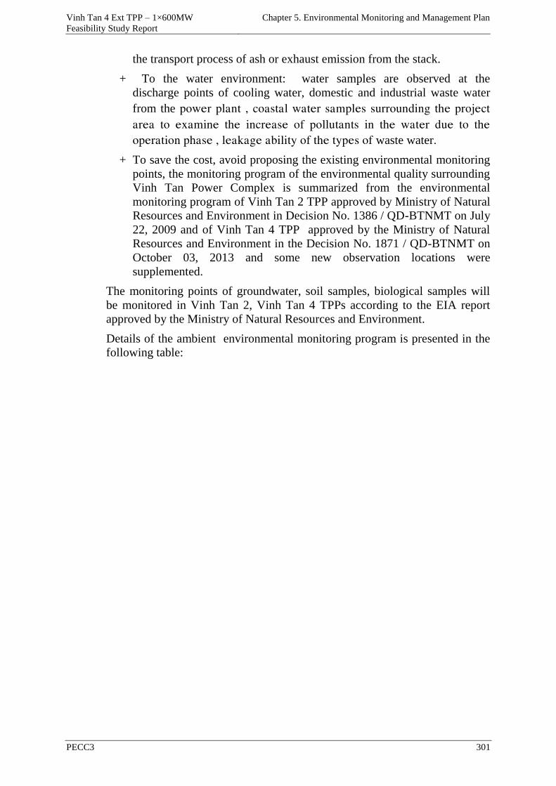
Vinh Tan 4 Ext TPP – 1×600MW
Feasibility Study Report
Chapter 5. Environmental Monitoring and Management Plan
PECC3 301
the transport process of ash or exhaust emission from the stack.
+ To the water environment: water samples are observed at the
discharge points of cooling water, domestic and industrial waste water
from the power plant , coastal water samples surrounding the project
area to examine the increase of pollutants in the water due to the
operation phase , leakage ability of the types of waste water.
+ To save the cost, avoid proposing the existing environmental monitoring
points, the monitoring program of the environmental quality surrounding
Vinh Tan Power Complex is summarized from the environmental
monitoring program of Vinh Tan 2 TPP approved by Ministry of Natural
Resources and Environment in Decision No. 1386 / QD-BTNMT on July
22, 2009 and of Vinh Tan 4 TPP approved by the Ministry of Natural
Resources and Environment in the Decision No. 1871 / QD-BTNMT on
October 03, 2013 and some new observation locations were
supplemented.
The monitoring points of groundwater, soil samples, biological samples will
be monitored in Vinh Tan 2, Vinh Tan 4 TPPs according to the EIA report
approved by the Ministry of Natural Resources and Environment.
Details of the ambient environmental monitoring program is presented in the
following table:
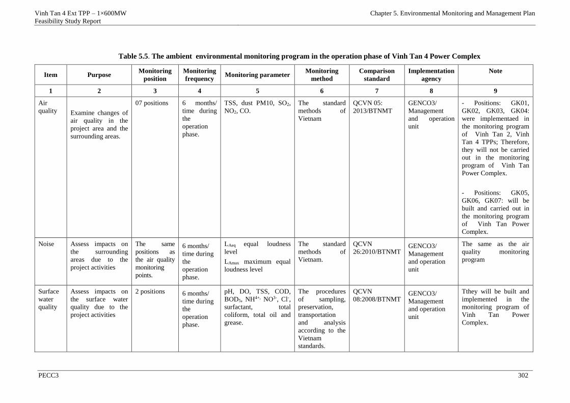
Vinh Tan 4 Ext TPP – 1×600MW
Feasibility Study Report
Chapter 5. Environmental Monitoring and Management Plan
PECC3 302
Table 5.5. The ambient environmental monitoring program in the operation phase of Vinh Tan 4 Power Complex
Item Purpose Monitoring
position
Monitoring
frequency Monitoring parameter
Monitoring
method
Comparison
standard
Implementation
agency
Note
1 2 3 4 5 6 7 8 9
Air
quality
Examine changes of
air quality in the
project area and the
surrounding areas.
07 positions 6 months/
time during
the
operation
phase.
TSS, dust PM10, SO2,
NO2, CO.
The standard
methods of
Vietnam
QCVN 05:
2013/BTNMT
GENCO3/
Management
and operation
unit
- Positions: GK01,
GK02, GK03, GK04:
were implementaed in
the monitoring program
of Vinh Tan 2, Vinh
Tan 4 TPPs; Therefore,
they will not be carried
out in the monitoring
program of Vinh Tan
Power Complex.
- Positions: GK05,
GK06, GK07: will be
built and carried out in
the monitoring program
of Vinh Tan Power
Complex.
Noise Assess impacts on
the surrounding
areas due to the
project activities
The same
positions as
the air quality
monitoring
points.
6 months/
time during
the
operation
phase.
LAeq equal loudness
level
LAmax maximum equal
loudness level
The standard
methods of
Vietnam.
QCVN
26:2010/BTNMT
GENCO3/
Management
and operation
unit
The same as the air
quality monitoring
program
Surface
water
quality
Assess impacts on
the surface water
quality due to the
project activities
2 positions 6 months/
time during
the
operation
phase.
pH, DO, TSS, COD,
BOD5, NH4+, NO3-, Cl-,
surfactant, total
coliform, total oil and
grease.
The procedures
of sampling,
preservation,
transportation
and analysis
according to the
Vietnam
standards.
QCVN
08:2008/BTNMT GENCO3/
Management
and operation
unit
Tthey will be built and
implemented in the
monitoring program of
Vinh Tan Power
Complex.
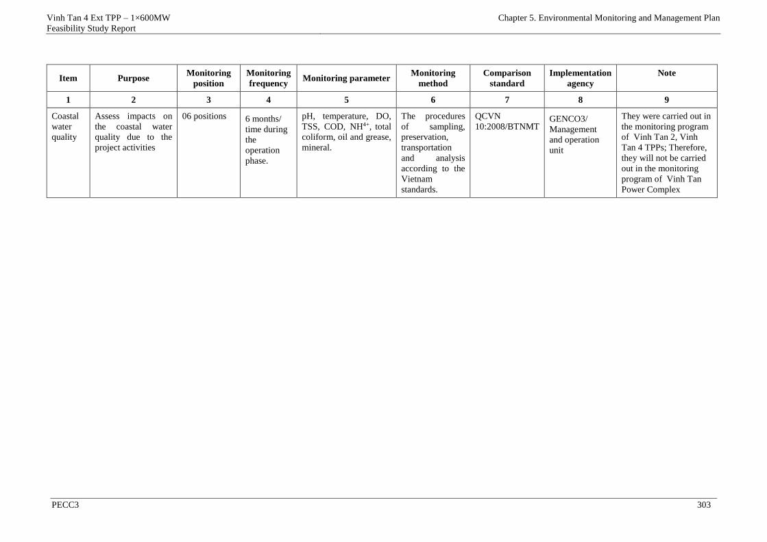
Vinh Tan 4 Ext TPP – 1×600MW
Feasibility Study Report
Chapter 5. Environmental Monitoring and Management Plan
PECC3 303
Item Purpose Monitoring
position
Monitoring
frequency Monitoring parameter
Monitoring
method
Comparison
standard
Implementation
agency
Note
1 2 3 4 5 6 7 8 9
Coastal
water
quality
Assess impacts on
the coastal water
quality due to the
project activities
06 positions 6 months/
time during
the
operation
phase.
pH, temperature, DO,
TSS, COD, NH4+, total
coliform, oil and grease,
mineral.
The procedures
of sampling,
preservation,
transportation
and analysis
according to the
Vietnam
standards.
QCVN
10:2008/BTNMT GENCO3/
Management
and operation
unit
They were carried out in
the monitoring program
of Vinh Tan 2, Vinh
Tan 4 TPPs; Therefore,
they will not be carried
out in the monitoring
program of Vinh Tan
Power Complex
Vinh Tan 4 Ext TPP – 1×600MW
Feasibility Study Report
Chapter 5: Environmental monitoring and management plan
PECC3 304
5.2.4.1 Location for monitoring the air during the operation phase
Location for monitoring the air during the operation phase of Vinh Tan Power
Complex is shown in the following table:
Bảng 5.6. Location of points for monitoring the air during the operation phase of Vinh
Tan Power Complex
Symbol Location of sampling the air VN_2000 Coordinate
X (m) Y (m)
GK01 At the entrance of People's Committee of Vinh Tan
commune.
1252220 534840
GK02 At the ash pond 1254168 532160
GK03 At the entrance of Linh Sơn Pagoda 1255054 530988
GK04 In the existing residential area of Hamlet 7, in the
west of the project area 1252130 531189
GK05 At the saltern - Vinh Hao commune. 1248805 525691
GK06 At the breeding shrimp production area 1251148 533680
GK07 At the Vinh Tan 4 Ext TPP . 1251692 531853
Figure 5.2. Location layout for monitoring the air during the operation phase of Vinh
Tan Power Complex
5.2.4.2 Location for monitoring the surface water during the operation phase
Location for monitoring the surface water during the operation phase of Vinh
Tan Power Complex is shown in the following table:
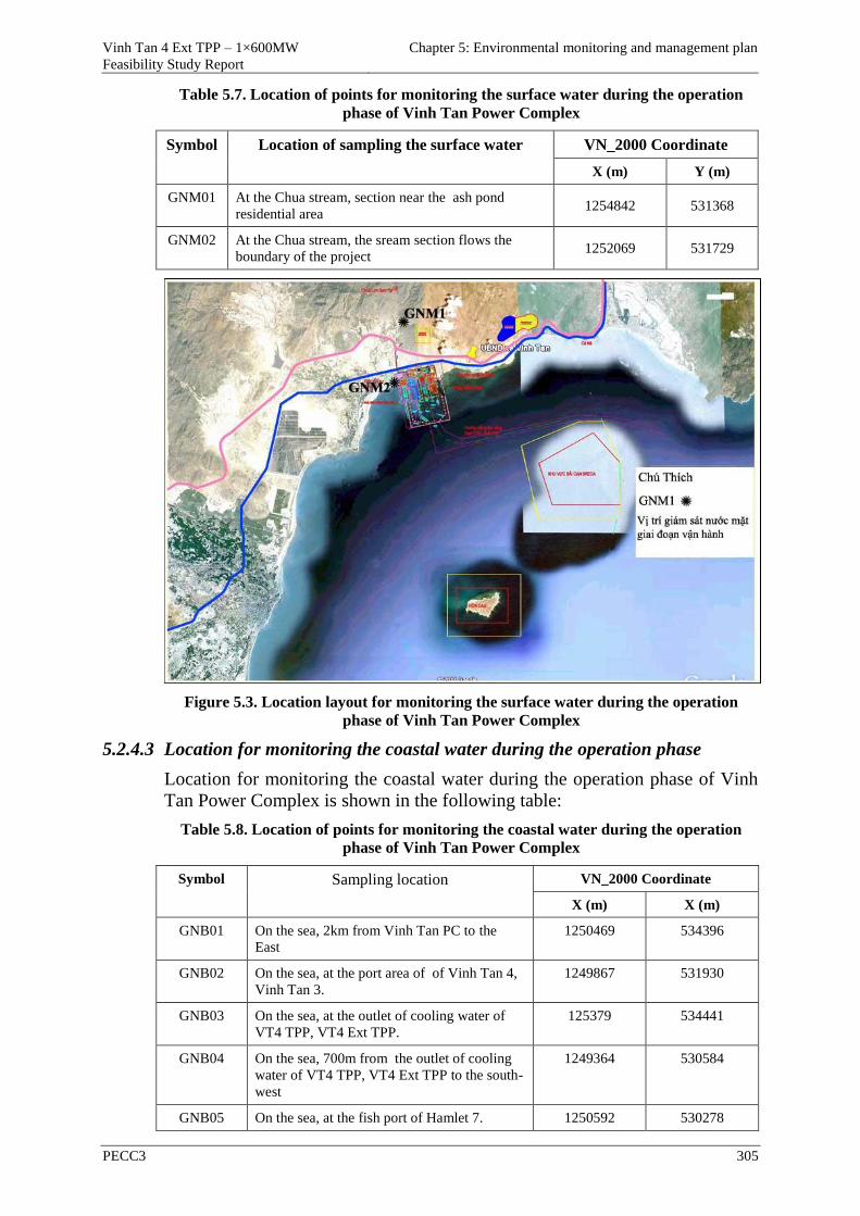
Vinh Tan 4 Ext TPP – 1×600MW
Feasibility Study Report
Chapter 5: Environmental monitoring and management plan
PECC3 305
Table 5.7. Location of points for monitoring the surface water during the operation
phase of Vinh Tan Power Complex
Symbol Location of sampling the surface water VN_2000 Coordinate
X (m) Y (m)
GNM01 At the Chua stream, section near the ash pond
residential area 1254842 531368
GNM02 At the Chua stream, the sream section flows the
boundary of the project 1252069 531729
Figure 5.3. Location layout for monitoring the surface water during the operation
phase of Vinh Tan Power Complex
5.2.4.3 Location for monitoring the coastal water during the operation phase
Location for monitoring the coastal water during the operation phase of Vinh
Tan Power Complex is shown in the following table:
Table 5.8. Location of points for monitoring the coastal water during the operation
phase of Vinh Tan Power Complex
Symbol Sampling location VN_2000 Coordinate
X (m) X (m)
GNB01 On the sea, 2km from Vinh Tan PC to the
East
1250469 534396
GNB02 On the sea, at the port area of of Vinh Tan 4,
Vinh Tan 3.
1249867 531930
GNB03 On the sea, at the outlet of cooling water of
VT4 TPP, VT4 Ext TPP.
125379 534441
GNB04 On the sea, 700m from the outlet of cooling
water of VT4 TPP, VT4 Ext TPP to the south-
west
1249364 530584
GNB05 On the sea, at the fish port of Hamlet 7. 1250592 530278
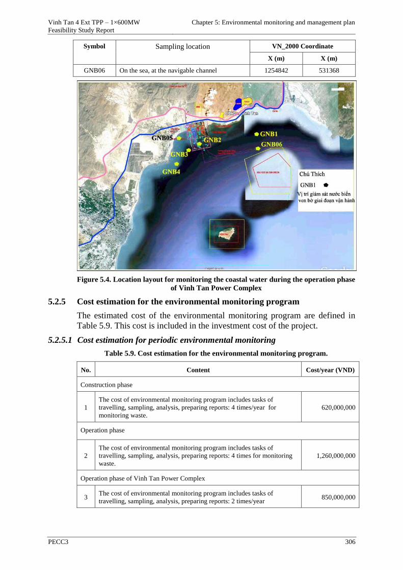
Vinh Tan 4 Ext TPP – 1×600MW
Feasibility Study Report
Chapter 5: Environmental monitoring and management plan
PECC3 306
Symbol Sampling location VN_2000 Coordinate
X (m) X (m)
GNB06 On the sea, at the navigable channel 1254842 531368
Figure 5.4. Location layout for monitoring the coastal water during the operation phase
of Vinh Tan Power Complex
5.2.5 Cost estimation for the environmental monitoring program
The estimated cost of the environmental monitoring program are defined in
Table 5.9. This cost is included in the investment cost of the project.
5.2.5.1 Cost estimation for periodic environmental monitoring
Table 5.9. Cost estimation for the environmental monitoring program.
No. Content Cost/year (VND)
Construction phase
1
The cost of environmental monitoring program includes tasks of
travelling, sampling, analysis, preparing reports: 4 times/year for
monitoring waste.
620,000,000
Operation phase
2
The cost of environmental monitoring program includes tasks of
travelling, sampling, analysis, preparing reports: 4 times for monitoring
waste.
1,260,000,000
Operation phase of Vinh Tan Power Complex
3 The cost of environmental monitoring program includes tasks of
travelling, sampling, analysis, preparing reports: 2 times/year 850,000,000
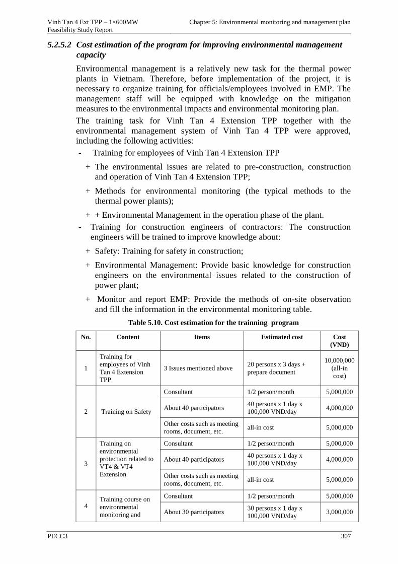
Vinh Tan 4 Ext TPP – 1×600MW
Feasibility Study Report
Chapter 5: Environmental monitoring and management plan
PECC3 307
5.2.5.2 Cost estimation of the program for improving environmental management
capacity
Environmental management is a relatively new task for the thermal power
plants in Vietnam. Therefore, before implementation of the project, it is
necessary to organize training for officials/employees involved in EMP. The
management staff will be equipped with knowledge on the mitigation
measures to the environmental impacts and environmental monitoring plan.
The training task for Vinh Tan 4 Extension TPP together with the
environmental management system of Vinh Tan 4 TPP were approved,
including the following activities:
- Training for employees of Vinh Tan 4 Extension TPP
+ The environmental issues are related to pre-construction, construction
and operation of Vinh Tan 4 Extension TPP;
+ Methods for environmental monitoring (the typical methods to the
thermal power plants);
+ + Environmental Management in the operation phase of the plant.
- Training for construction engineers of contractors: The construction
engineers will be trained to improve knowledge about:
+ Safety: Training for safety in construction;
+ Environmental Management: Provide basic knowledge for construction
engineers on the environmental issues related to the construction of
power plant;
+ Monitor and report EMP: Provide the methods of on-site observation
and fill the information in the environmental monitoring table.
Table 5.10. Cost estimation for the trainning program
No. Content Items Estimated cost Cost
(VND)
1
Training for
employees of Vinh
Tan 4 Extension
TPP
3 Issues mentioned above 20 persons x 3 days +
prepare document
10,000,000
(all-in
cost)
2 Training on Safety
Consultant 1/2 person/month 5,000,000
About 40 participators 40 persons x 1 day x
100,000 VND/day 4,000,000
Other costs such as meeting
rooms, document, etc. all-in cost 5,000,000
3
Training on
environmental
protection related to
VT4 & VT4
Extension
Consultant 1/2 person/month 5,000,000
About 40 participators 40 persons x 1 day x
100,000 VND/day 4,000,000
Other costs such as meeting
rooms, document, etc. all-in cost 5,000,000
4 Training course on
environmental
monitoring and
Consultant 1/2 person/month 5,000,000
About 30 participators 30 persons x 1 day x
100,000 VND/day 3,000,000
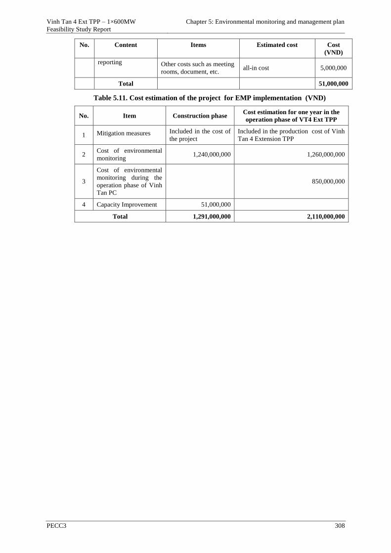
Vinh Tan 4 Ext TPP – 1×600MW
Feasibility Study Report
Chapter 5: Environmental monitoring and management plan
PECC3 308
No. Content Items Estimated cost Cost
(VND)
reporting Other costs such as meeting
rooms, document, etc. all-in cost 5,000,000
Total 51,000,000
Table 5.11. Cost estimation of the project for EMP implementation (VND)
No. Item Construction phase Cost estimation for one year in the
operation phase of VT4 Ext TPP
1 Mitigation measures Included in the cost of
the project
Included in the production cost of Vinh
Tan 4 Extension TPP
2 Cost of environmental
monitoring 1,240,000,000 1,260,000,000
3
Cost of environmental
monitoring during the
operation phase of Vinh
Tan PC
850,000,000
4 Capacity Improvement 51,000,000
Total 1,291,000,000 2,110,000,000
Vinh Tan 4 Ext TPP – 1×600MW
Feasibility Study Report
Chapter 6: Public consultation
PECC3 309
CHAPTER 6 PUBLIC CONSULTATION
According to the guidance of Decree No.29/2011/ND-CP on April 18, 2011,
Decree No.18/2015/ND-CP on February 14, 2015, Circular 26/2011/TT-
BTNMT on July 18, 2011 and Circular No.27/2015/TT-BTNMT on May 29,
2015 of Ministry of Natural Resources and Environment, Vinh Tan PMB had
Document No.0388A/ANDVT-KTAT on March 12, 2015 on delegation in
holding consultation to prepare the EIA report for the project of "Vinh Tan 4
Extension TPP - 1 × 600MW", PECC3 had Document No.1531/TVD3-MTG
on March 12, 2015, and Document No.1587/TVD3-MTG on March 16, 2015
and Document No.1588/TVD3-MTG on March 16, 2015 about "consultations
in the process of preparing the environmental impact assessment report for the
project of Vinh Tan 4 Extension TPP "(attached the summary report of
environmental impact assessment of the project) sent to the People's
Committee, Fatherland Front Committee of commune, Management Board of
Hon Cau MPA and Breeding Shrimp Association of Binh Thuan province, in
which clearly stating influence of the whole project area, the environmental
and socio-economic impacts caused by the project and mitigation measures
and other contents, which had been sent to the localities and units affected by
the project.
6.1 SUMMARY OF THE IMPLEMENTATION PROCESS OF PUBLIC
CONSULTATION
6.1.1 Summary of the consultation process with commune People's Committee
and the organizations directly affected by the project
6.1.1.1 Consultation with PC of Vinh Tan commune
PECC3 sent Document No.1531/TVD3-MTG on March 12, 2015 about
consultation during the process of preparing the EIA report for the project of
"Vinh Tan 4 Extension TPP". And PECC3 received the written feedbacks
from the People's Committee of Vinh Tan Commune, Tuy Phong district, Binh
Thuan province in Document No.76/UBND-DC on April 07, 2015.
6.1.1.2 Consultation with Fatherland Front Committee of Vinh Tan commune
PECC3 sent Document No.1531/TVD3-MTG on March 12, 2015 about
consultation during the process of preparing the EIA report for the project of
"Vinh Tan 4 Extension TPP". And PECC3 received the written feedbacks
from Fatherland Front Committee of Vinh Tan Commune, Tuy Phong district,
Binh Thuan province in Document No.49CV/MT-VT on April 07, 2015.
6.1.1.3 Consultation with Management Board of Hon Cau MPA
PECC3 sent Document No.0393//TVD3-MTG on January 19, 2015 about
consultation during the process of preparing the EIA report for the project of
"Vinh Tan 4 Extension TPP". And PECC3 received the written feedbacks
from Management Board of Hon Cau MPA in Document
No.15/BQLKBTBHC on April 16, 2015.
6.1.1.4 Consultation with Breeding Shrimp Association of Binh Thuan province
Vinh Tan 4 Ext TPP – 1×600MW
Feasibility Study Report
Chapter 6: Public consultation
PECC3 310
PECC3 sent Document No.1588//TVD3-MTG on March 16, 2015 about
consultation during the process of preparing the EIA report for the project of
"Vinh Tan 4 Extension TPP". And PECC3 received the written feedbacks
from Binh Thuan Breeding Shrimp Association in Document
No.03/2015/HHTG on April 02, 2015.
6.1.2 Summary of the consultation process of the directly affected community
by the project
On January 19, 2015 PECC3 sent Document to PC of Vinh Tan commune
about consultation during the process of preparing the EIA report for the
project of "Vinh Tan 4 Extension TPP" and suggested holding a meeting on
public consultation.
On June 10, 2015, PECC3 and PC of Vinh Tan commune held a meeting on
consulation with the participation of the representatives of People's Committee
of Vinh Tan commune and the affected households.
Figure 6.1. A meeting on public consulation
6.2 RESULT OF PUBLIC CONSULTATION
6.2.1 Feedbacks of People's Committee of Vinh Tan commune
Feedbacks on the environmental issues of the People's Committee of Vinh Tan
Commune, Tuy Phong district, Binh Thuan province in document
No.76/UBND-DC on April 07, 2015 (Annex 4) are as follows:
- The project owner should be interested in using local labourers to limit the
number of people from other places to avoid loss of public order due to
conflicts about the customs, culture, etc. between the local people and the
outside;
- The project owner should coordinate with the local authority in
administrative management to avoid loss of public order due to centralization
of a large number of workers;
- The technological solutions and techniques must be applied effectively in
the construction phase as well as in the operation phase to reduce the
environmental pollution caused by dust, noise, vibration, wastewater, solid
waste and ensure people's health and the ecological environment including air,
soil, surface water, groundwater at Vinh Tan commune;
- Be responsible for participating in positive contribution for the programs to
improve community awareness and community environmental protection;
- Be responsible for compensation for damages to the environment, health
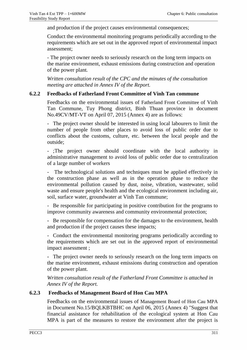
Vinh Tan 4 Ext TPP – 1×600MW
Feasibility Study Report
Chapter 6: Public consultation
PECC3 311
and production if the project causes environmental consequences;
Conduct the environmental monitoring programs periodically according to the
requirements which are set out in the approved report of environmental impact
assessment;
- The project owner needs to seriously research on the long term impacts on
the marine environment, exhaust emissions during construction and operation
of the power plant.
Written consultation result of the CPC and the minutes of the consultation
meeting are attached in Annex IV of the Report.
6.2.2 Feedbacks of Fatherland Front Committee of Vinh Tan commune
Feedbacks on the environmental issues of Fatherland Front Committee of Vinh
Tan Commune, Tuy Phong district, Binh Thuan province in document
No.49CV/MT-VT on April 07, 2015 (Annex 4) are as follows:
- The project owner should be interested in using local labourers to limit the
number of people from other places to avoid loss of public order due to
conflicts about the customs, culture, etc. between the local people and the
outside;
- ;The project owner should coordinate with the local authority in
administrative management to avoid loss of public order due to centralization
of a large number of workers
- The technological solutions and techniques must be applied effectively in
the construction phase as well as in the operation phase to reduce the
environmental pollution caused by dust, noise, vibration, wastewater, solid
waste and ensure people's health and the ecological environment including air,
soil, surface water, groundwater at Vinh Tan commune;
- Be responsible for participating in positive contribution for the programs to
improve community awareness and community environmental protection;
- Be responsible for compensation for the damages to the environment, health
and production if the project causes these impacts;
- Conduct the environmental monitoring programs periodically according to
the requirements which are set out in the approved report of environmental
impact assessment ;
- The project owner needs to seriously research on the long term impacts on
the marine environment, exhaust emissions during construction and operation
of the power plant.
Written consultation result of the Fatherland Front Committee is attached in
Annex IV of the Report.
6.2.3 Feedbacks of Management Board of Hon Cau MPA
Feedbacks on the environmental issues of Management Board of Hon Cau MPA
in Document No.15/BQLKBTBHC on April 06, 2015 (Annex 4) "Suggest that
financial assistance for rehabilitation of the ecological system at Hon Cau
MPA is part of the measures to restore the environment after the project is
Vinh Tan 4 Ext TPP – 1×600MW
Feasibility Study Report
Chapter 6: Public consultation
PECC3 312
completed".
Written consultation result of Management Board of Hon Cau MPA is attached
in Annex IV of the Report.
6.2.4 Feedbacks of Binh Thuan Breeding Shrimp Association
Feedbacks on the environmental issues of Binh Thuan Breeding Shrimp
Association in Document No.03/2015/HHTG on April 02, 2015 (Annex 4) are
as follows:
- Be responsible for compensation for the damages to the environment and
economy if the environmental pollution problems happen during the project
implementation process particularly the impacts on production activities of
breeding shrimp in the local area where the project is being implemented;
- Be responsible for strict implementation and compliance with the legal
regulations in the process of building Vinh Tan 4 Extension TPP to minimize
the impacts on the coastal waters.
Written consultation result of Binh Thuan Breeding Shrimp Association is
attached in Annex IV of the Report.
6.2.5 Feedbacks and commitments of the project owner to the proposals,
recommendations and requests of the agencies, organizations and
communities to be consulted
- The project owner's representative ( Management Board of Vinh Tan
thermal power plant project) received the feedbacks of the People's Committee
and Fatherland Front Committee of Vinh Tan Commune, Management Board
of Hon Cau MPA and Binh Thuan Breeding Shrimp Association and
committed to good implementation of the following issues:
- The project owner evaluated thoroughly the impacts of the plant on the
environment, economy and society, and specified the mitigation and
prevention measures and specific responses in the EIA report.
- The project owner commits to good implementation of the environmental
protection works, effective control of the impact sources, treatment of wastes
arisen from the Project, and at the same time, implementation of management
measures and technical measures to prevent oil spill and minimize the
negative impacts on the natural environment and socio-economy of the local
area as forecast in the EIA report.
- The project owner will support the local people some social works and
compensate for the damages caused by the project in accordance with the legal
provisions.
- The project owner undertakes to comply strictly with the regulations on
environmental protection in the Environmental Protection Act in 2014.
- The project owner undertakes to comply strictly with the Vietnamese
Environmental Standards (TCVN) and National Technical Regulations
(QCVN) on the environment which were issued.
- - The project owner undertakes to control and treat domestic waste water
Vinh Tan 4 Ext TPP – 1×600MW
Feasibility Study Report
Chapter 6: Public consultation
PECC3 313
generated in the construction phase to reach QCVN before discharging into
the environment.
- The project owner commits to control and comply with the construction
measures in the process of building the sea encroachment.
- The project owner commits to fulfill the environmental protection
categories as well as the treatment systems of waste water, exhaust gas,
management system of solid waste before the project is put into operation.
- The project owner commits to build storage-yard, treat and transport ash in
accordance with the regulations, avoid scattering ash.
- The project owner commits to control the temperature of cooling water
according to the design before discharging the cooling water into the
environment.
- The project owner commits to strictly implement the environmental
protection measures as proposed in the report.
- The project owner will prioritize recruitment of local laborers who are
professional to meet the demand of the plant.
- The project owner commits to monitor waste water, exhaust gas and solid
waste generated during the construction and operation phases of the plant,
implement monitoring continuously and automatically parameters including
discharge, temperature, residual chlorine for cooling effluent and the
concentration of CO, NOx, SO2, dust in exhaust emissions from the chimneys
of the power plant. The project owner will keep these data to monitor and
support the inspection of the competent agencies.
- The project owner commits to implement the programs for training the
employees to respond promptly to incidents, risks which can happen during
the construction and operation phases of the project.
- The project owner will have plans to organize seminars on the operation of
the plant as well as the measures to protect the environment of the plant and
consider expanding the participation components.
Vinh Tan 4 Ext TPP – 1×600MW
Feasibility Study Report
Conclusion, recommendation and commitments
PECC3
CONCLUSION, RECOMMENDATION AND COMMITMENTS
1. CONCLUSION
The power projects all over the country in general and in the Southern in
particular have been delayed while the economy is being recovered, so
electricity demand is increasing in near future.
VT 4 EXT TPP with a capacity of 1x600MW is proposed to be operated in
2019 that plays a role as a replacement power source for others which being
delayed and would contribute in solving lack of electricity in the Southern
after 2020.
With advantages of available infrastructures, seaport, sources of fuel,
synchronous power grid, and time for negotiation with contractors would be
shortened and therefore, the operation of VT 4 EXT will meet this schedule.
VT 4 EXT TPP will play an important role in securing the supply of electricity
for the socio-economic development of the provinces in the South of Central
Vietnam as well as the national energy source..
However, there will be some unavoidable negative impacts on environment
during construction and operation phase. In addition, the project would be
considered and applied measures of management, mitigation, etc. in order to
meet current National standards or regulations of environment.
1. Location of VT 4 Ext was considered as advantages because of:
- Closing to loads that lacking of electricity;
- Belonging to Vinh Tan Power Complex, so this is advantages of fuel
transportation, taking and discharging of cooling water;;
2. Thermal Recirculation Process for VT 4 Ext will meet QCVN
40:2011/BTNMT, Column B (maximum as 35.6oC < 40oC), so there is
inconsideration impact on aquatic life as well as surface water quality.
3. The wastewater of the power plant will not be discharged into the
environment but it will be reused for the categories of the project, the
wastewater will be treated by the main wastewater treatment system to
achieve the national technical regulation of QCVN 40:2011/BTNMT,
Column B with Kq = 1, Kf = 1.1.
4. With coal as main fuel, VT 4 EXT TPP has some impacts on air quality. In
order to meet National Regulation QCVN 22:2009/BTNMT on exhausted
gas of power plants and QCVN 05:2013/BTNMT on ambient air quality
for all plants of Vinh Tan Power Complex, it is necessary to install an
exhausted gas treatment system with efficiency as below::
- Dust: installing the dust removal system (ESP) with treatment
efficiency as 99.13%.
- SO2: installing the SO2 removal system (FGD) with treatment efficiency
as 90%.
- NOx: installing the NOx removal system (SCR) with treatment
Vinh Tan 4 Ext TPP – 1×600MW
Feasibility Study Report
Conclusion, recommendation and commitments
PECC3
efficiency as 65%.
Thus, impacts on air quality and the locals are insignificant.
5. Solid waste: will be collected, classified, recycled and conctracted with a
local waste collection unit to treat or transport to landfill. For hazardous
waste, the project will contract with a specific company to treat as
regulation. The process of collection, storage, transportation, treatment and
purchase must be complied with the current regulations of solid waste and
hazardous waste management
6. The project’s negative impacts can be minimized completely and
controlled by mitigation measures which mentioned in the report.
Environmental targets at output of technological process of the plant meet
the current environmental standards.
7. The project owner committed implementing mitigation measures,
environmental management and monitoring program in construction and
operation phases mentioned in the report. The project complied seriously
Vietnamese legal and the International Convention on environmental
protection in management and treatment of waste caused by production
activities.
2. PROPOSITION
Because the urgency of the project must be operated in 2019 and ensure that
electricity power must be supplied for Southern in time. In addition, impacts
caused by electricity production of VT 4 Ext TPP on the environment can be
controlled and minimized, and the project is very necessary and will contribute
to national economy. It playes an important role to promote development of
the region.
Therefore, Investor suggests the relevant authorities to consider of advantage
conditions for implementation of the project as steering of Vice Minister
Hoang Trung Hai at Document No. 49/TB-VPCP dated on Feb. 12th, 2015.
3. COMMITMENT
1. The project owner commites implementing mitigation measures for
negative impacts described in chapter 4. In additional, project owner
commites implementing all measures, regulations on environmental
protection related to project developement and implementation
2. National Regulations are applied in this EIA report as:
- QCVN 05:2013/BTNMT - National Technical Regulation on the
ambient air quality;
- QCVN 14:2008/BTNMT – National technical regulation on domestic
waste water.
- QCVN 07:2009/BTNMT – National Technical Regulation on
Hazardous Waste Thresholds.
- QCVN 19:2009/BTNMT – National technical regulation on industrial
emission of inorganic substances and dusts.
Vinh Tan 4 Ext TPP – 1×600MW
Feasibility Study Report
Conclusion, recommendation and commitments
PECC3
- QCVN 22:2009/BTNMT – National technical regulation on emission of
thermal power industry.
- QCVN 40:2011/BTNMT – National technical regulation on industrial
waste water.
3. Treatment works will be constructed in the construction phase and finished
completely before the operation.
4. Environmental supervision, monitoring program and training program on
environmental safety will be implemented in construction and operation
phases; and their budget will be ensured by the project owner.
5. Commitment on continuous monitoring of dust, SO2, NO2 and CO of
exhaust emission at the mouth of stack and excess Chlorine, temperature
of the waste cooling water . The budget of treatment system, monitoring
the environment and training courses will be ensured by the project owner.
6. The project owner ensures that information of environmental incident will
be announced on time and will compensate for damages caused by the
project.
7. The project owner commits not to cause depression on surface water
quality of receiving source and not to violate other projects’ operation, and
co-operate with other owners for solving the arisen issues.
8. The project owner commits to build a fly-ash recycle system and/or find
fly-ash consumers in the project area and vicinities. In case of non-use, the
owner commits to transport and dispose fly-ash according to the current
regulations to ensure that soil and underground water quality will not be
affected.
9. The project owner commits to coordinate with other power plants in Vinh
Tan Power Complex to ensure emissions from each plant achieve the
standard of QCVN 22:2009/BTNMT and the ambient environmental
quality at the areas affected by Vinh Tan PC achieve the standard of
QCVN 05:2013/BTNMT.
10. The project owner commits to coordinate with other projects in Vinh Tan
Power Complex to stop activities of compartments and sections in case of
incident which can cause the environmental pollution to exceed the
standard of QCVN 22:2009/BTNMT , and at the same time, commits to
coordinate with the local authorities to define the reasons and implement
the respective solutions when the ambient environmental quality at the
areas affected by Vinh Tan PC exceeds the standard of QCVN
05:2013/BTNMT.
11. The project owner commits to carry out the full content in the EIA report
approved and the mandatory requirements in the EIA approval decision.
12. The owner commits to prepare and submit the report to prove the
completion of structures and environmental measures prior to the official
operation of the plant.
13. The project owner commits not to use chemicals, microorganisms
prohibited by the regulations of Vietnam and international conventions.
Vinh Tan 4 Ext TPP – 1×600MW
Feasibility Study Report
References
PECC3
REFERENCES
- Topographic survey report of Vinh Tan 4 Extension TPP project , PECC3,
July 2015.
- Geological survey report of Vinh Tan 4 Extension TPP project, PECC3,
July 2015.
- Hydro-meteorological report of Vinh Tan 4 Extension TPP project, PECC3,
July 2015.
- Feasibility study report of Vinh Tan 4 Extension TPP project, PECC3, July
2015.
- Report of Environmental Impact Assessment of Vinh Tan 2 TPP project
was approved by Ministry of Natural Resources and Environment in
Decision No.1386/QD-BTNMT on July 22, 2009.
- Report of Environmental Impact Assessment of Vinh Tan 4 TPP project
was approved by Ministry of Natural Resources and Environment in
Decision No.1871/QD-BTNMT on October 03, 2013.
- Report on the situation of the natural environment in the project area of
Vinh Tan 4 Extension TPP, Phuong Nam Center of Environmental Analysis
and measurement, May 2015.
- Report on the situation of the ecological environment in the project area,
Institute foe Environmental Science and Technology, March-April 2015.
- Report on the situation of socio-economic implementation for the first 9
months of 2015, People's Committee of Vinh Tan Commune, Tuy Phong
district.
- Ministry of Natural Resources and Environment, scenarios on climate
change and sea level rise for Vietnam, 06/2009.
- The technical documents of the World Health Organization (WHO) and
World Bank (WB) on making report of environmental impact assessment.
- The document on determining pollutant load.
- Air pollution and exhaust gas treatment, Volume 1, Science and Technique
Publishing house , Professor. Dr. Tran Ngoc Chan, 2000.
- Treatment of waste water, Hoang Hue, 2002.
- EPA AERMOD Model Formulations, United States Environmental
Protection Agency, September 2004.
- Rapid Assessment of Sources of Air, Water, and Land Pollution, WHO,
1993
- IPCC. 2006. Volume 2: Energy (instructions for calculating greenhouse gas
emissions from the energy sector).
Vinh Tan 4 Ext TPP – 1×600MW
Feasibility Study Report
Annexes
PECC3
ANNEXES
ANNEX 1: LEGAL DOCUMENTS RELATED TO PROJECT
APPROVAL
ANNEX 2: DESIGN DRAWINGS OF THE PROJECT
ANNEX 3: ANALYSIS RESULTS ON BACKGROUND
ENVIRONMENT
ANNEX 4: COPIES OF THE DOCUMENTS RELATED TO THE
PUBLIC CONSULTATION AND SOCIOLOGICAL
QUESTIONNAIRES
ANNEX 5: SOME PHOTOS RELATED TO THE PROJECT
ANNEX 6: COST IN DETAIL FOR COMPENSATION,
ASSISTANCE, RESETTLEMENT
ANNEX 7: LIST OF SPECIES IN THE PROJECT AREA
ANNEX 8: CALCULATION OF EXHAUST EMISSIONS AND
SPREAD OF COOLING WATER
Vinh Tan 4 Ext TPP – 1×600MWFeasibility Study Report
Annexes
ANNEX 1: LEGAL DOCUMENTS RELATED TO PROJECTAPPROVAL
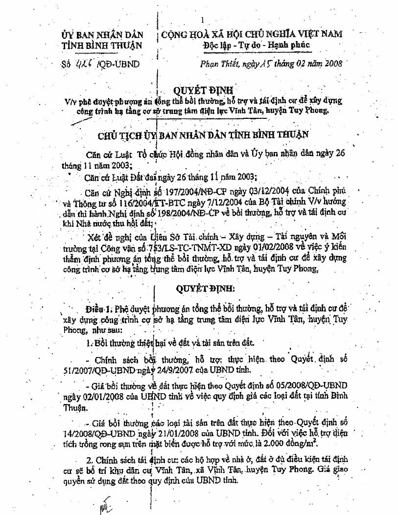
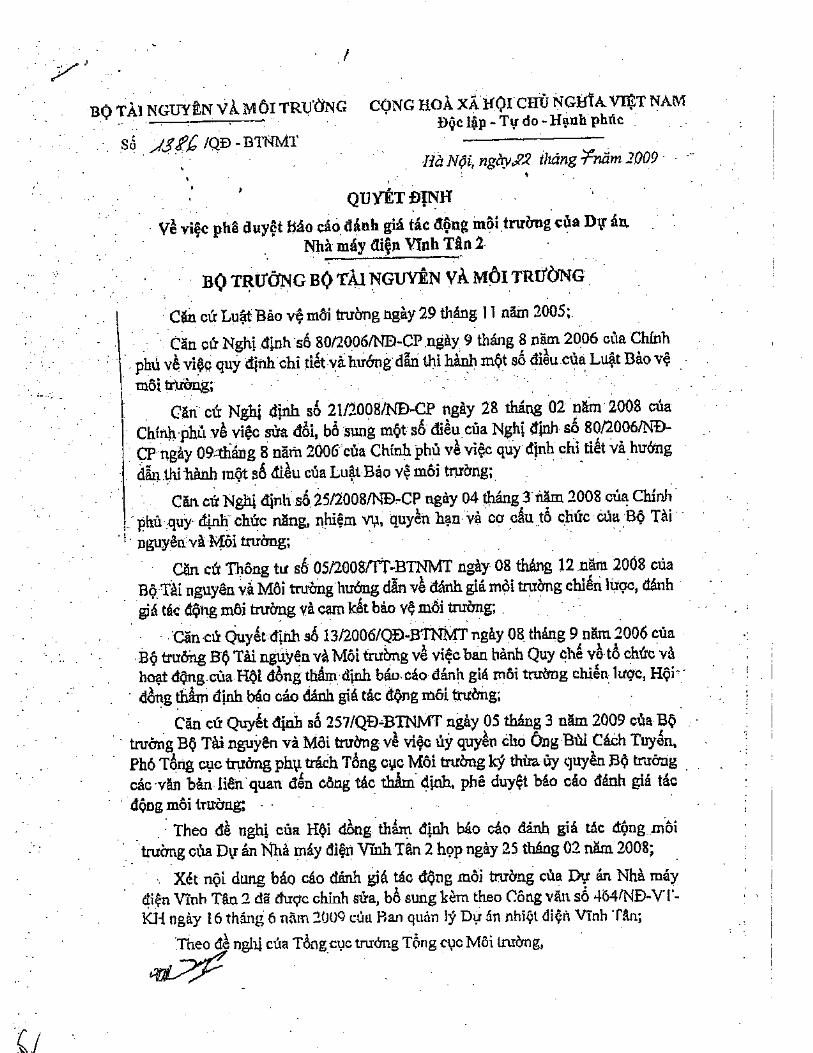
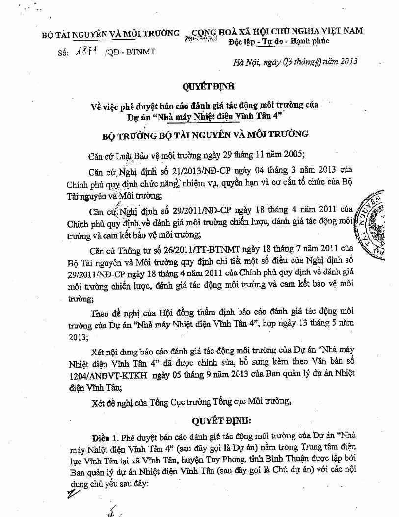
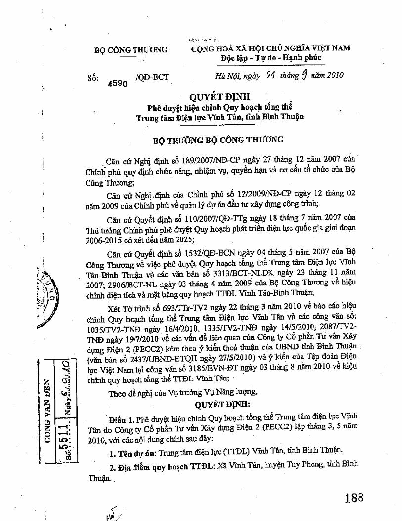
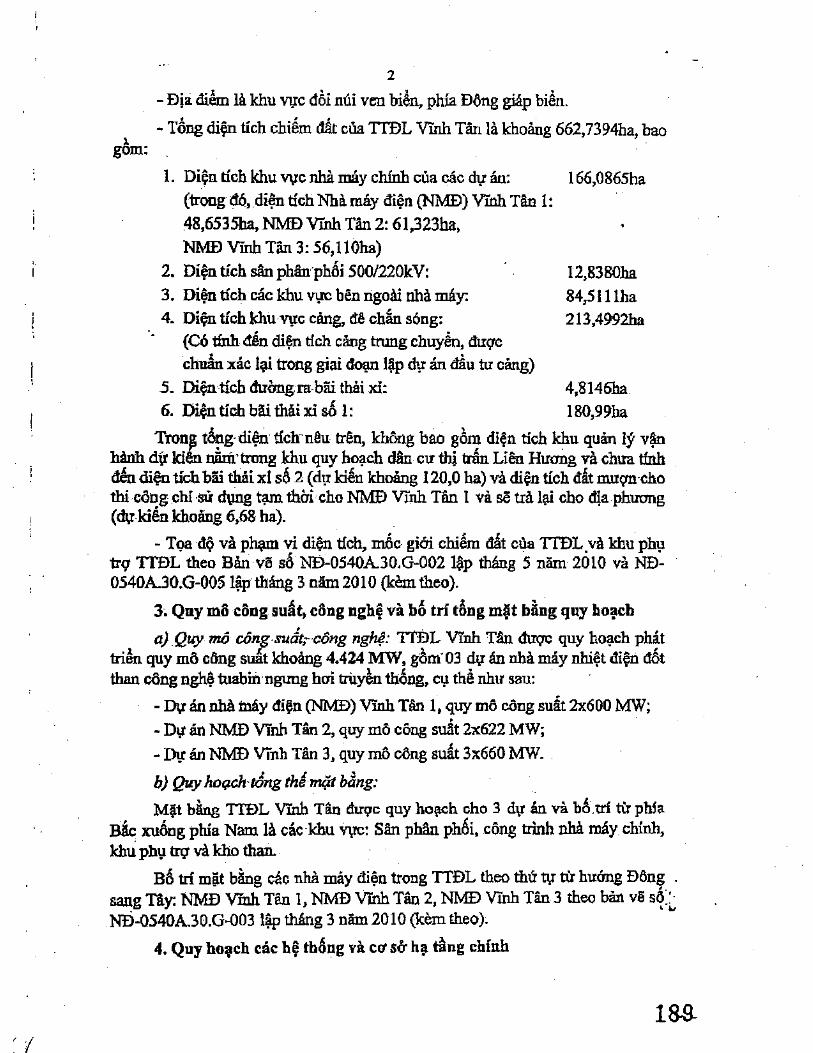
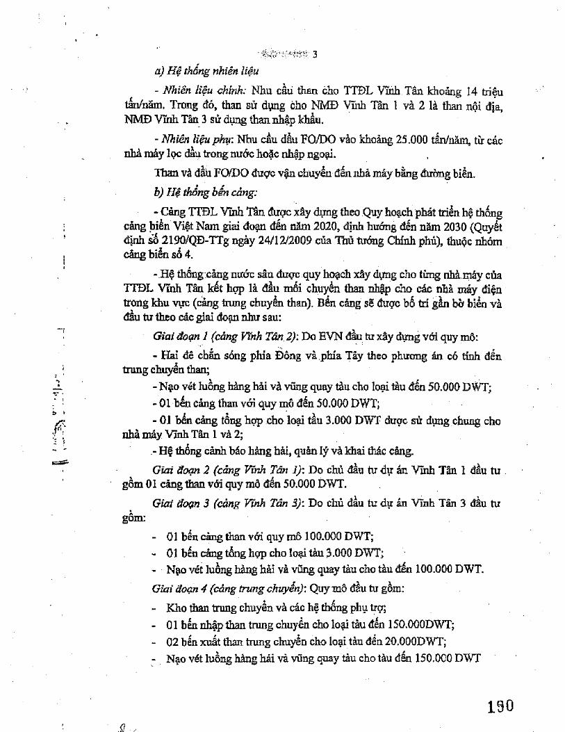
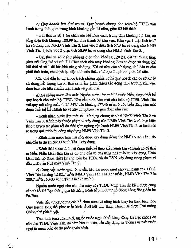
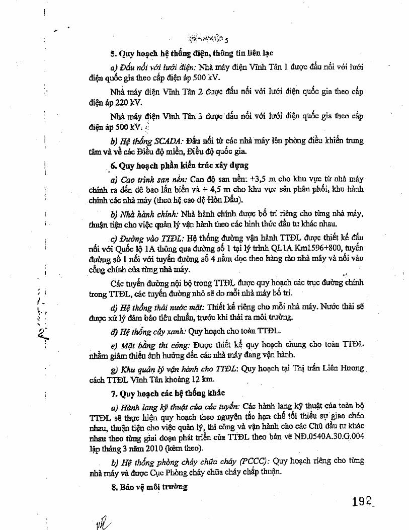
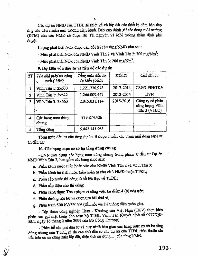
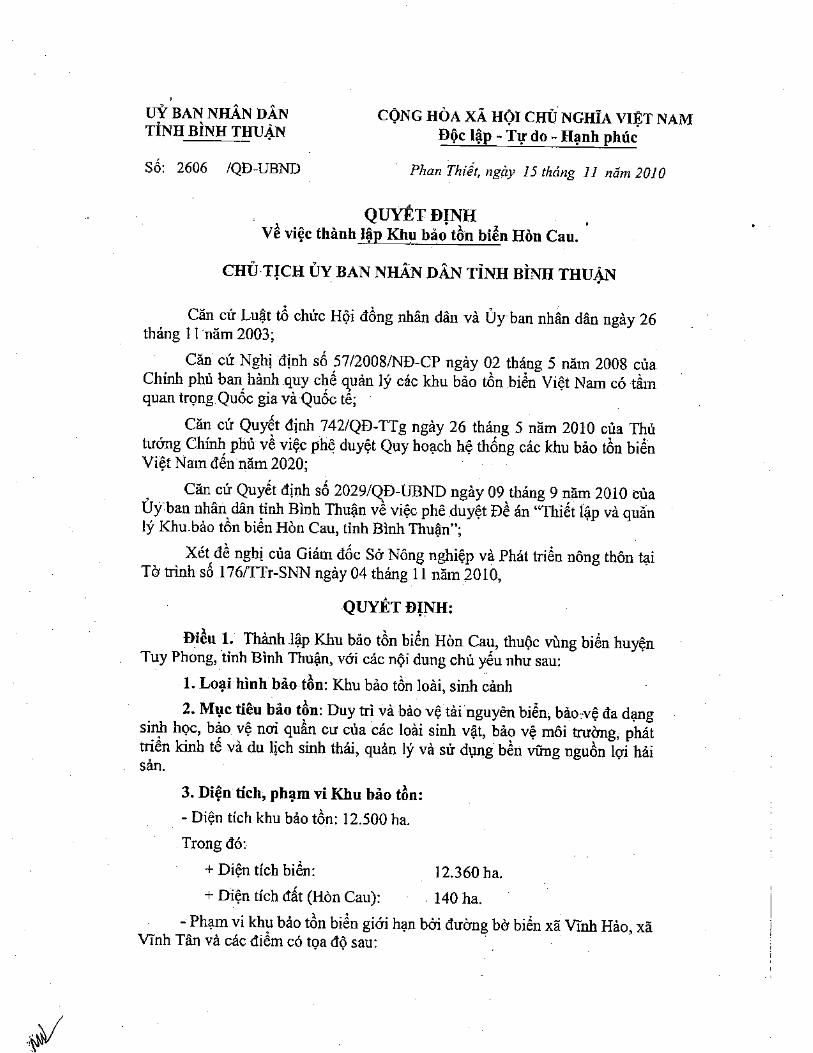

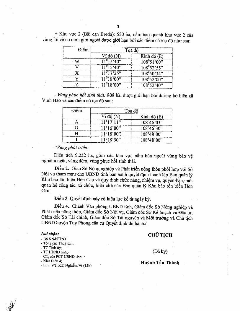
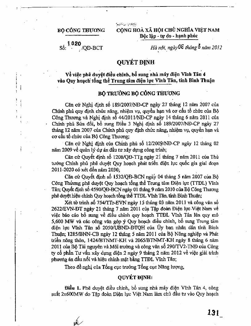
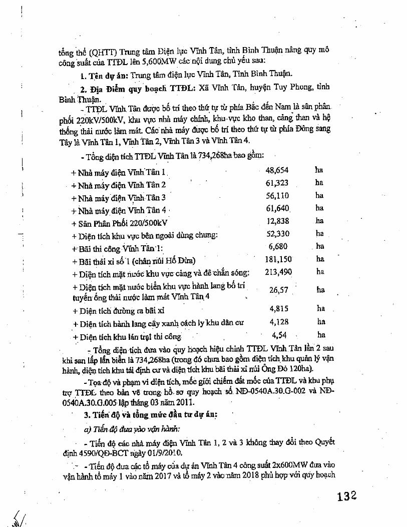
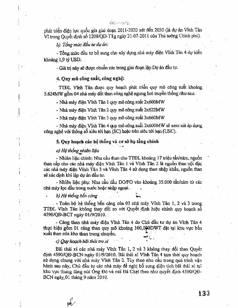

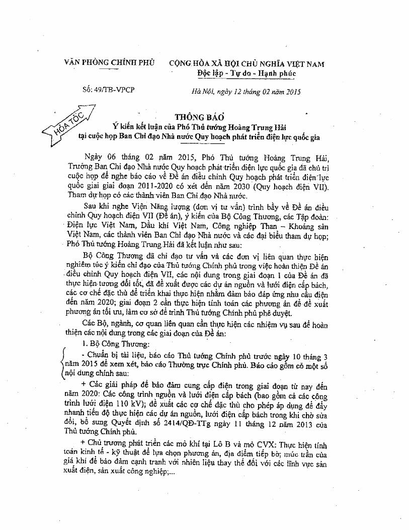
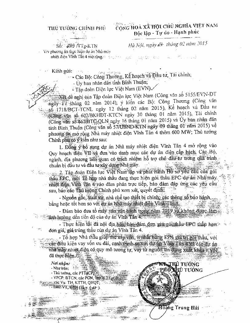
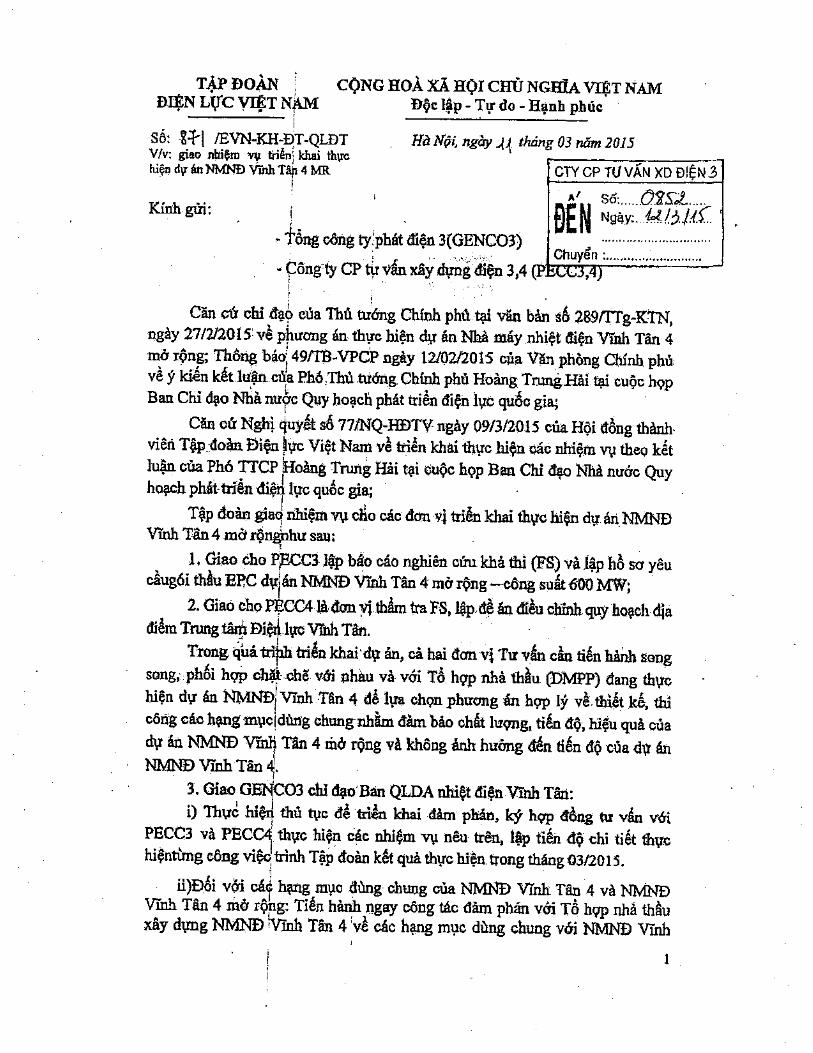
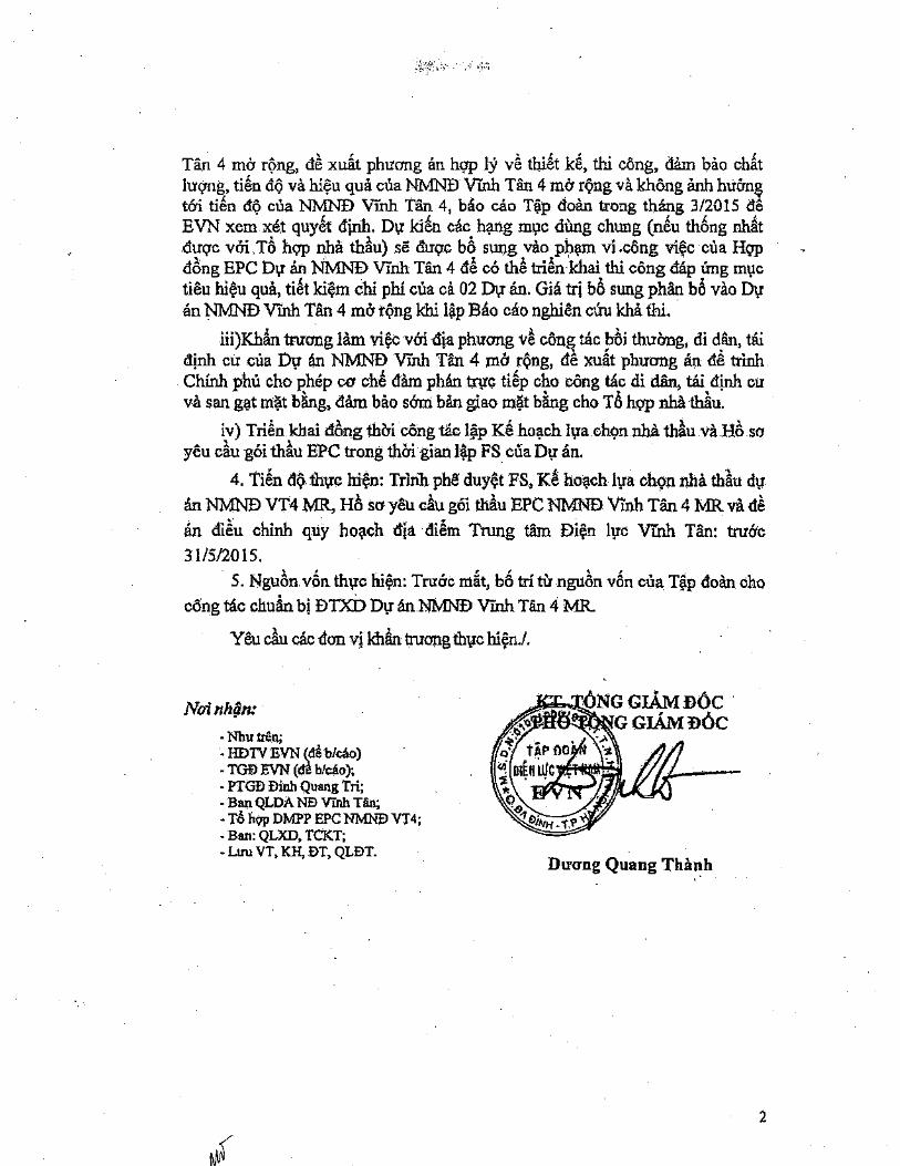
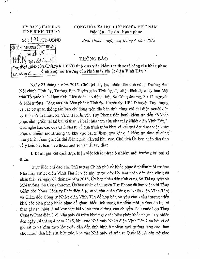
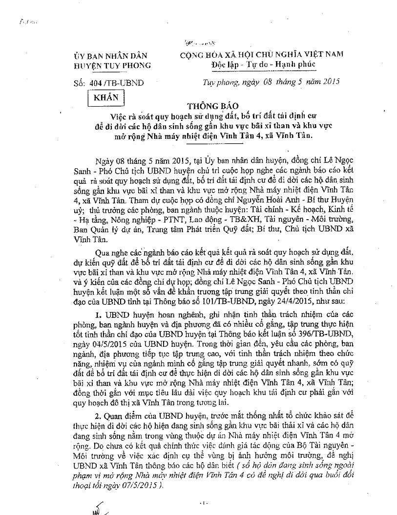
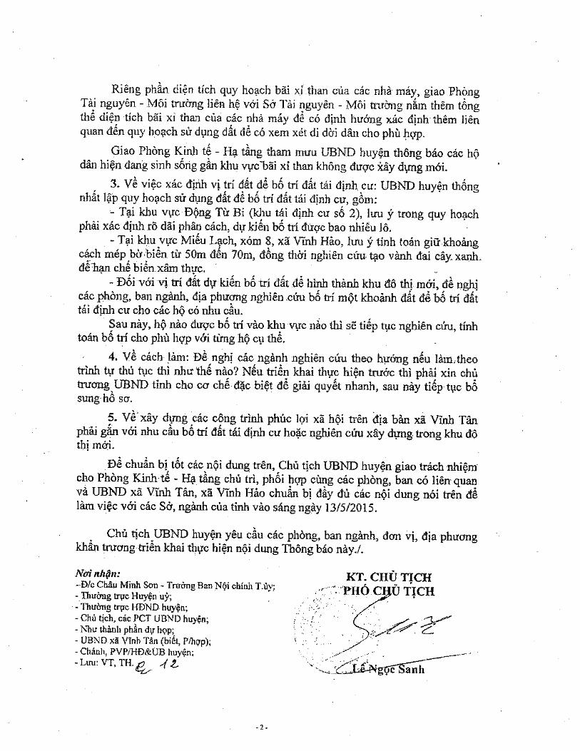
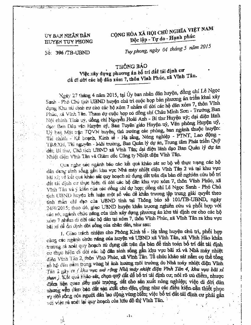

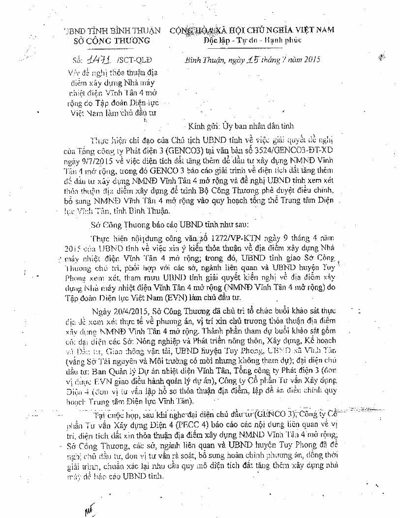
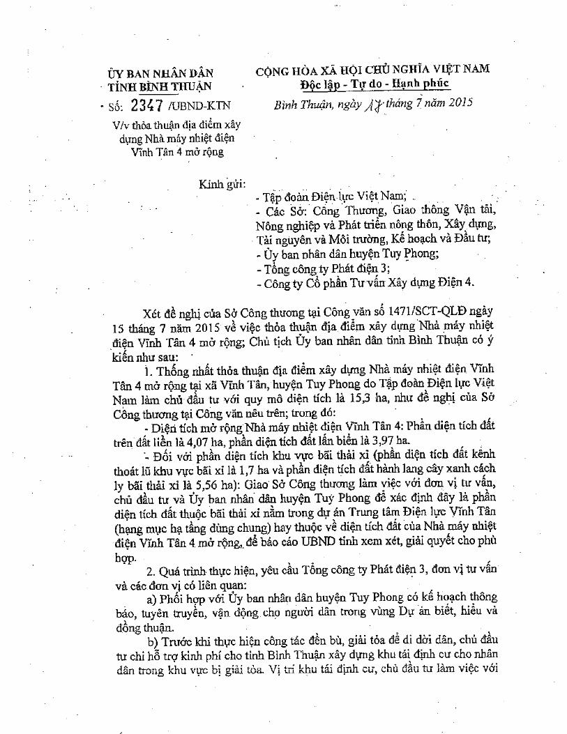
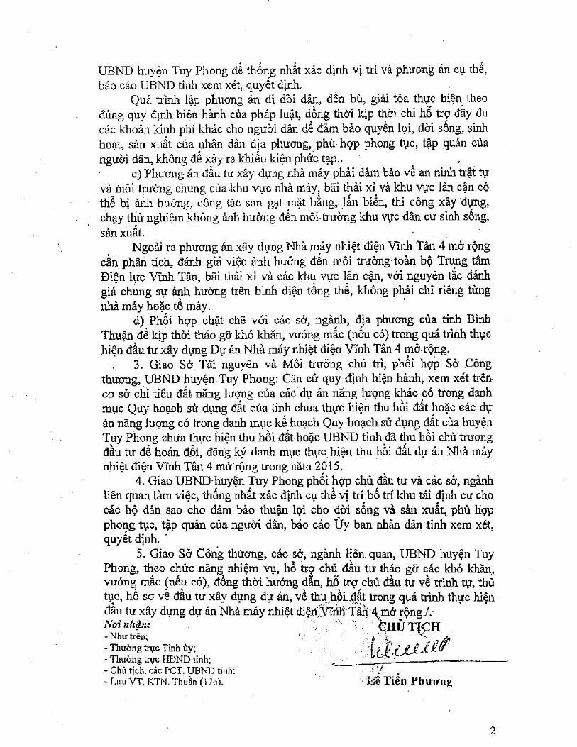


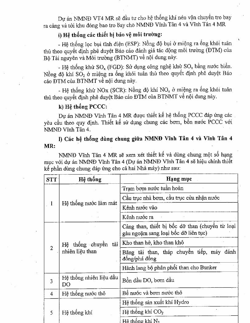
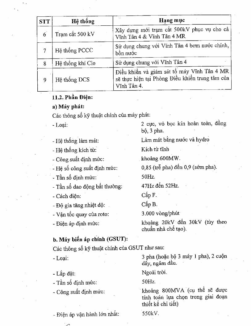
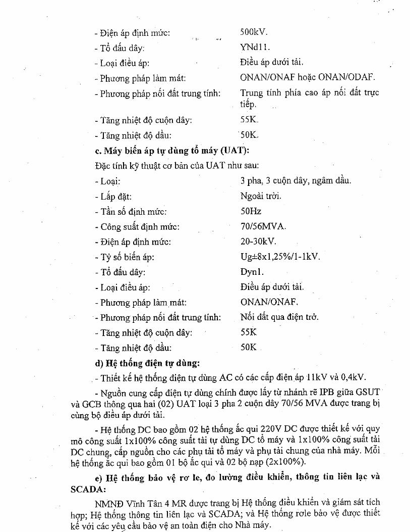
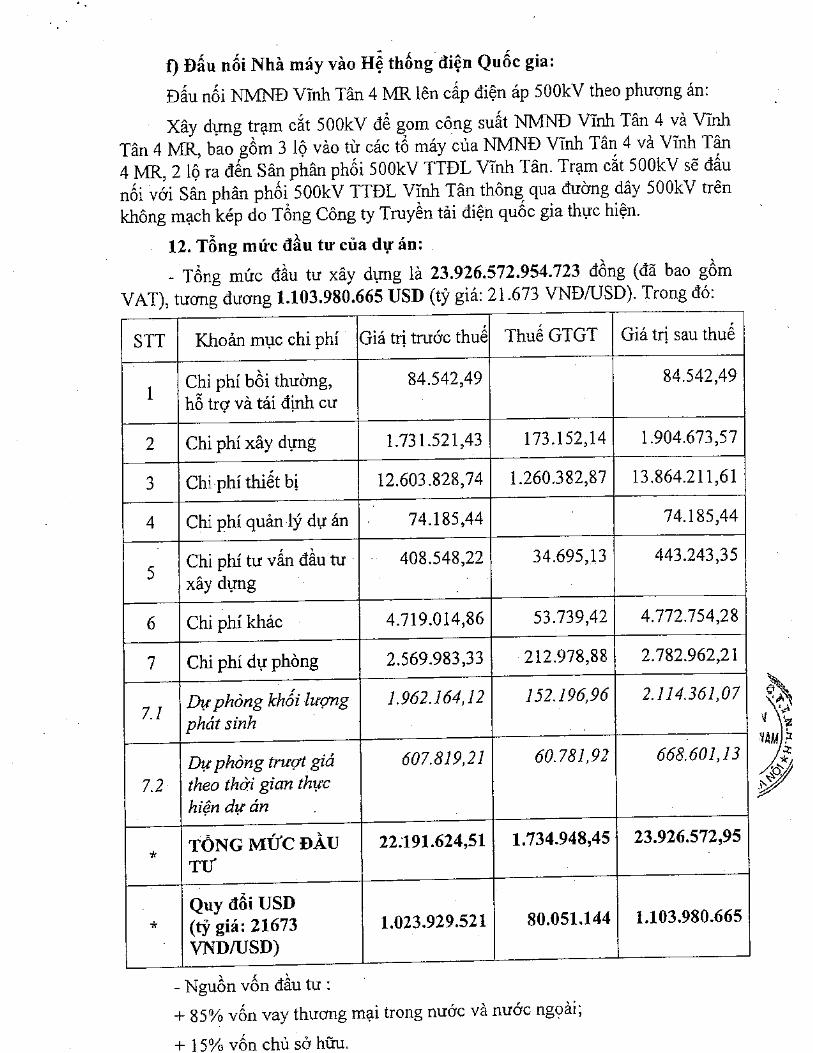
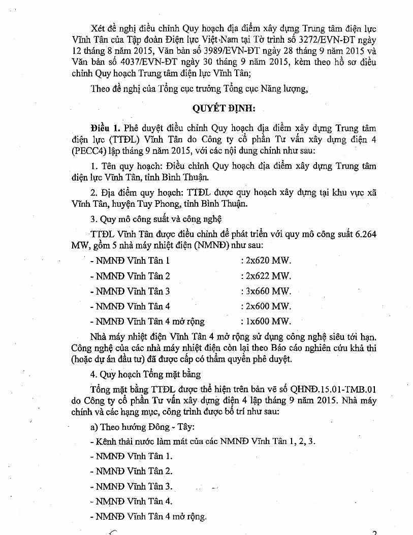
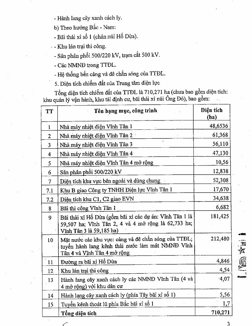
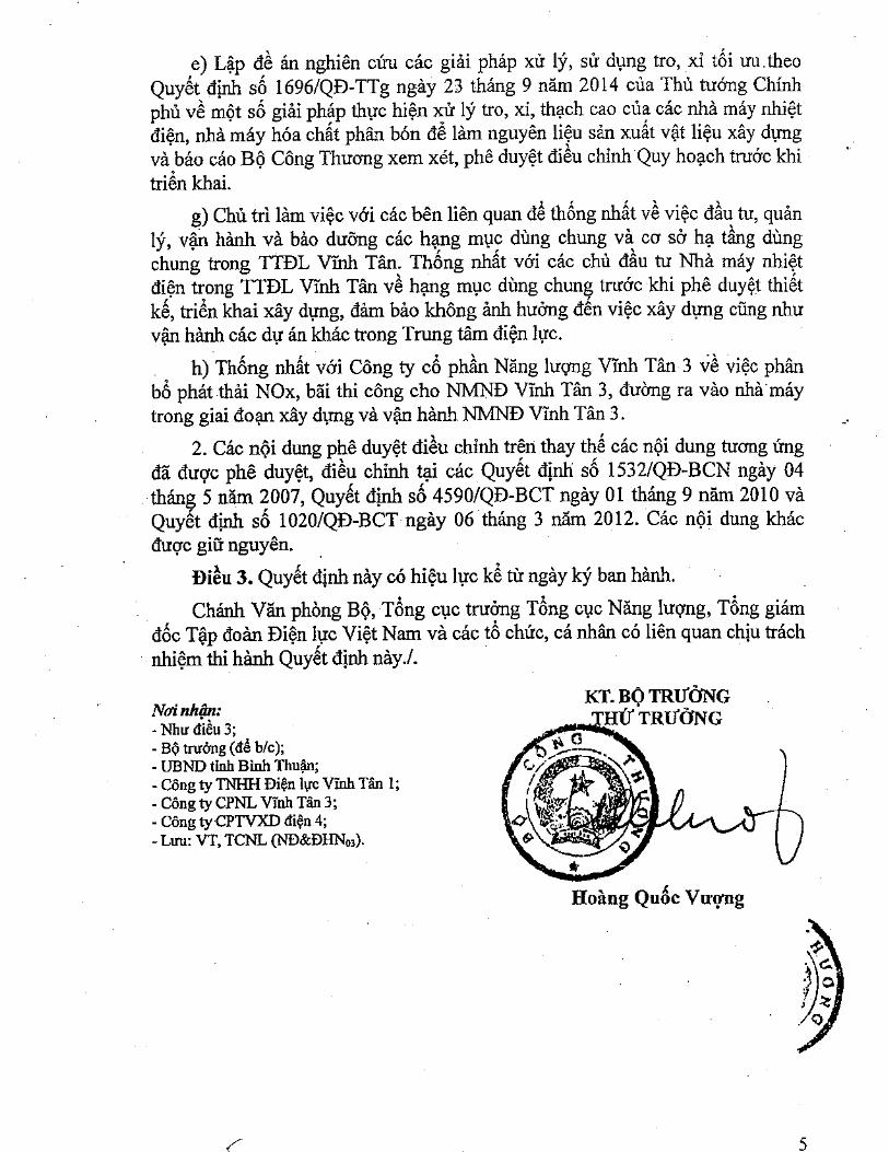
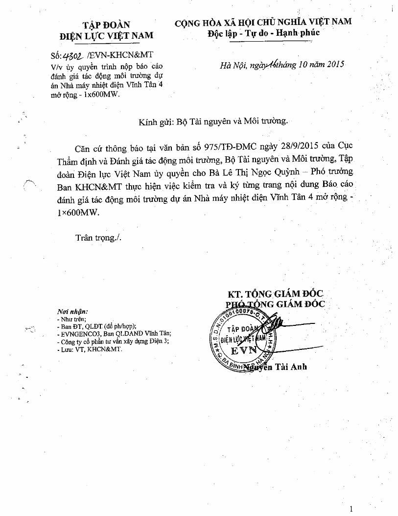

Vinh Tan 4 Ext TPP – 1×600MWFeasibility Study Report
Annexes
ANNEX 2: DESIGN DRAWINGS OF THE PROJECT

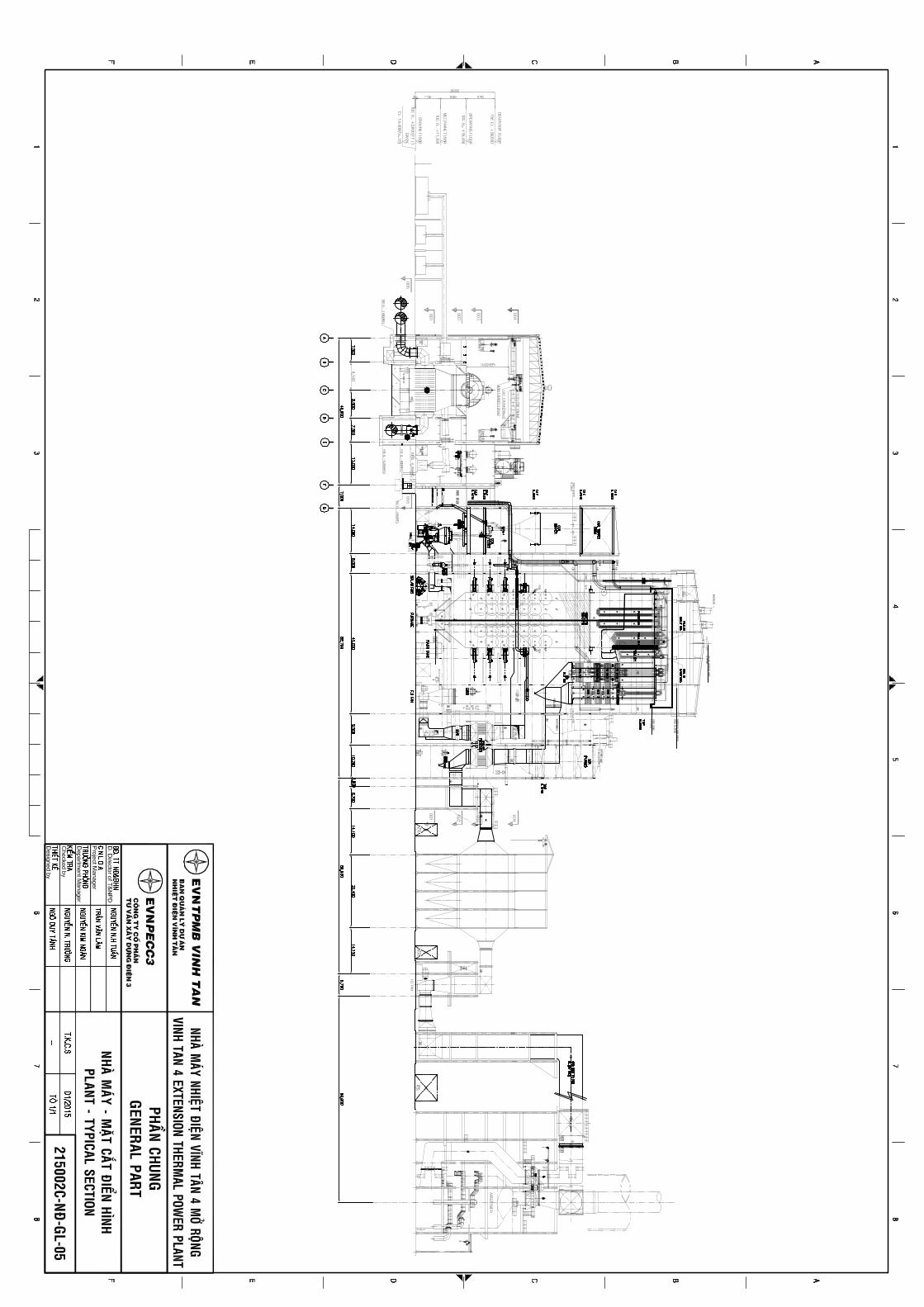
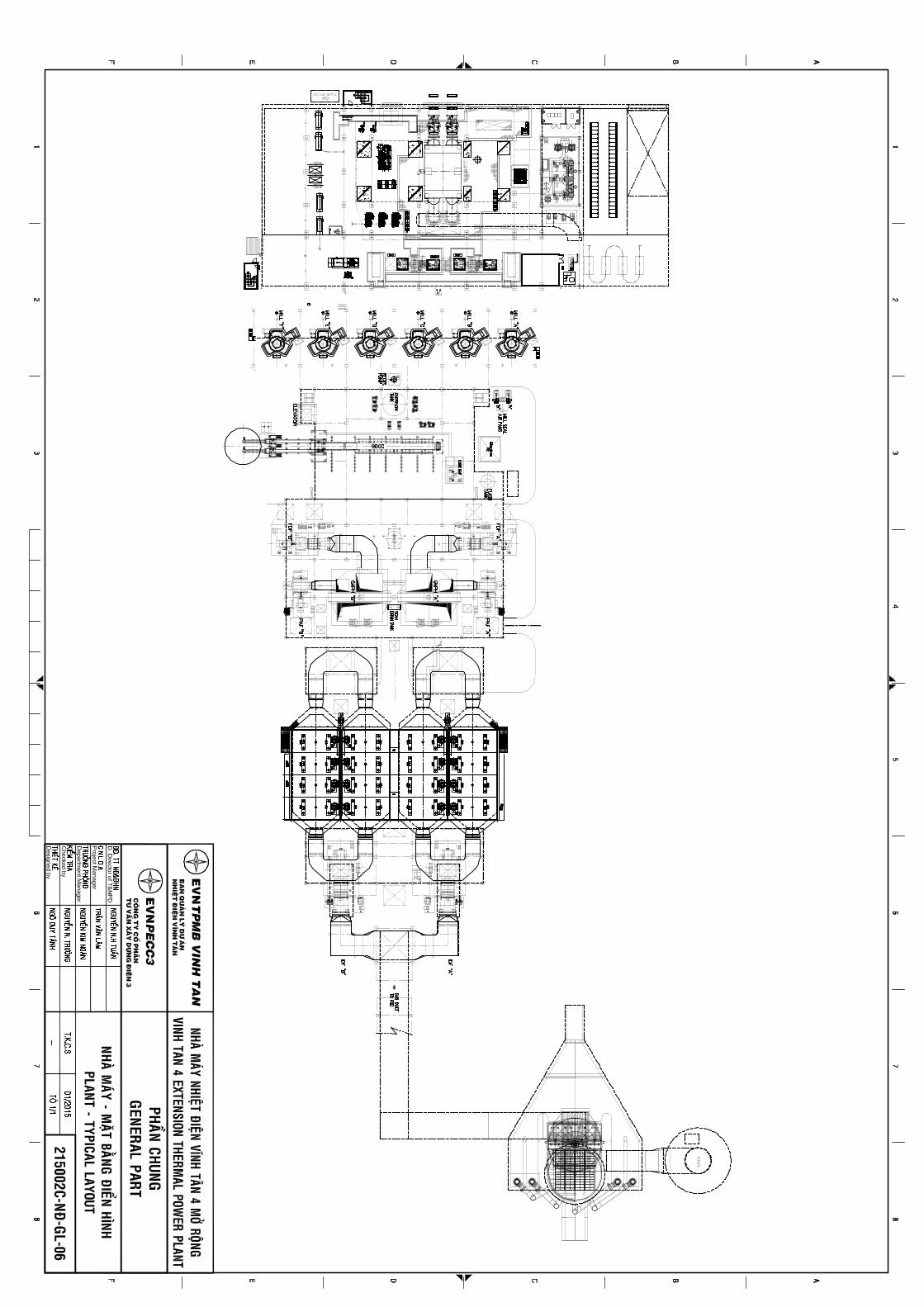
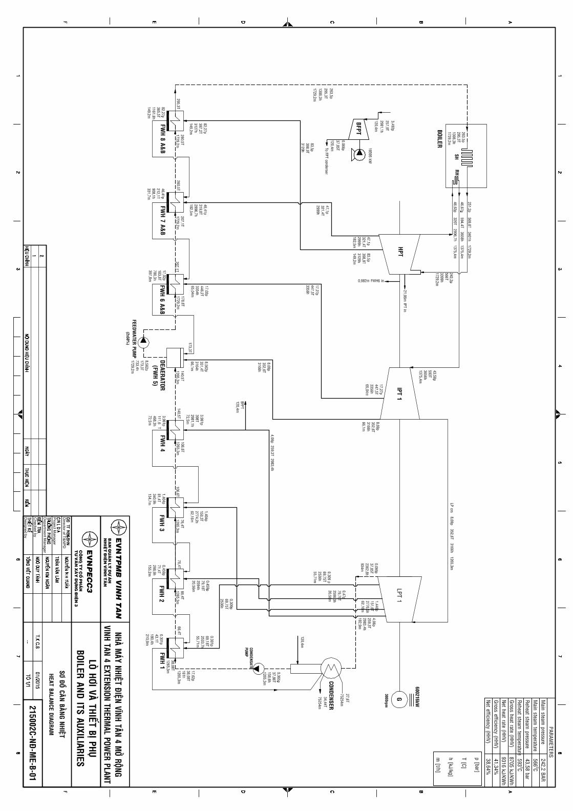

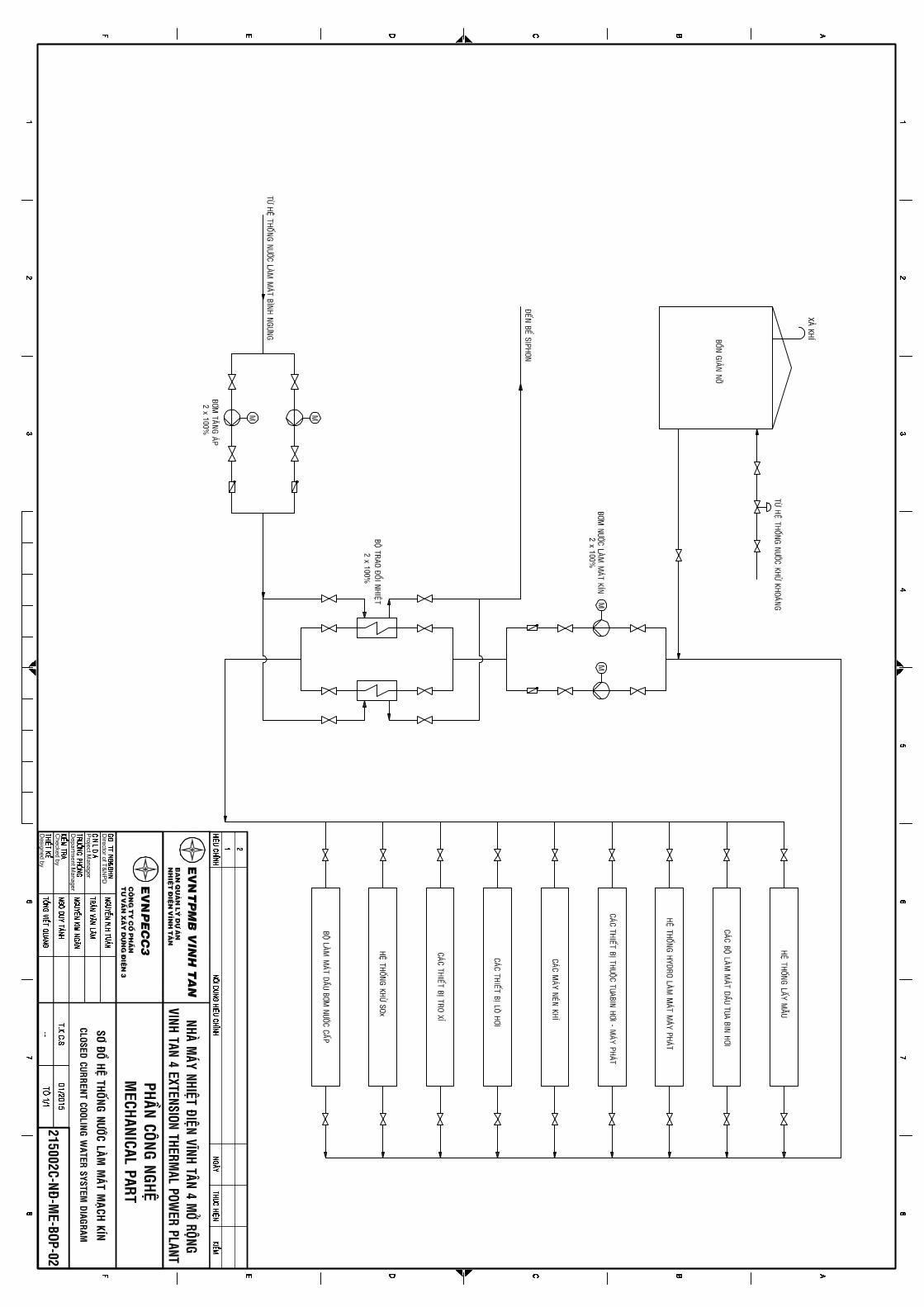
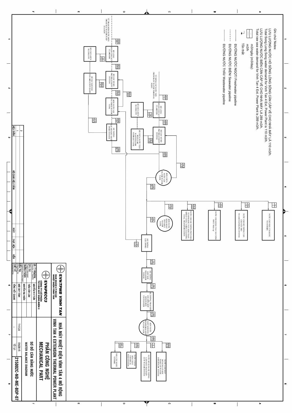

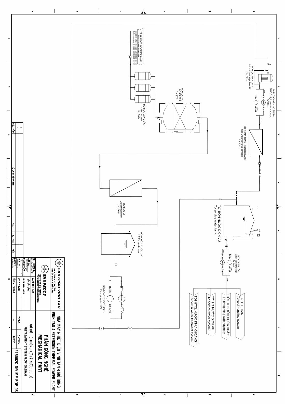
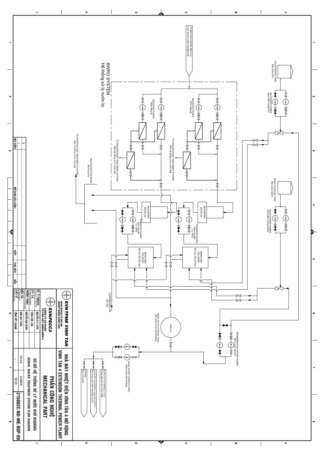
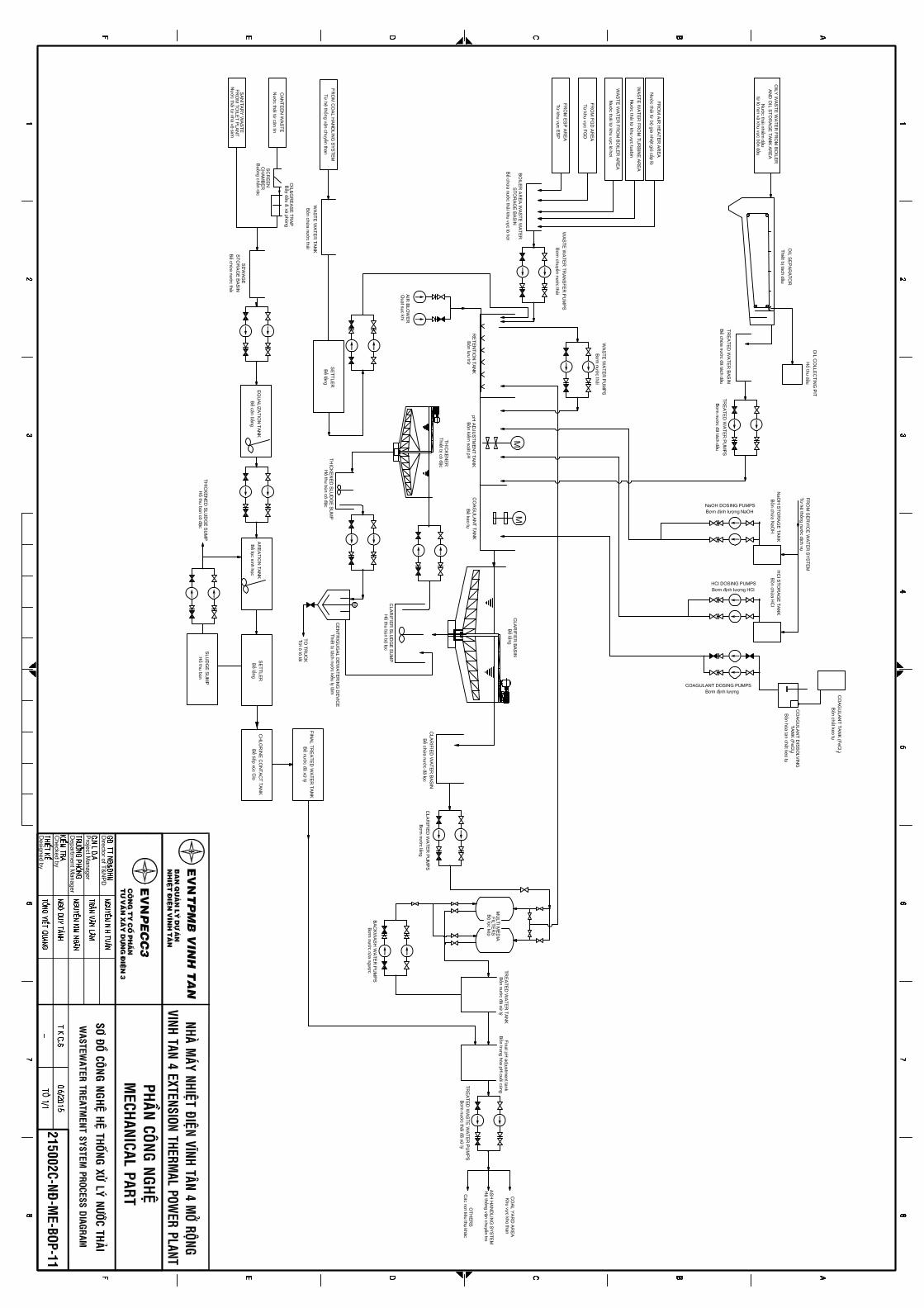
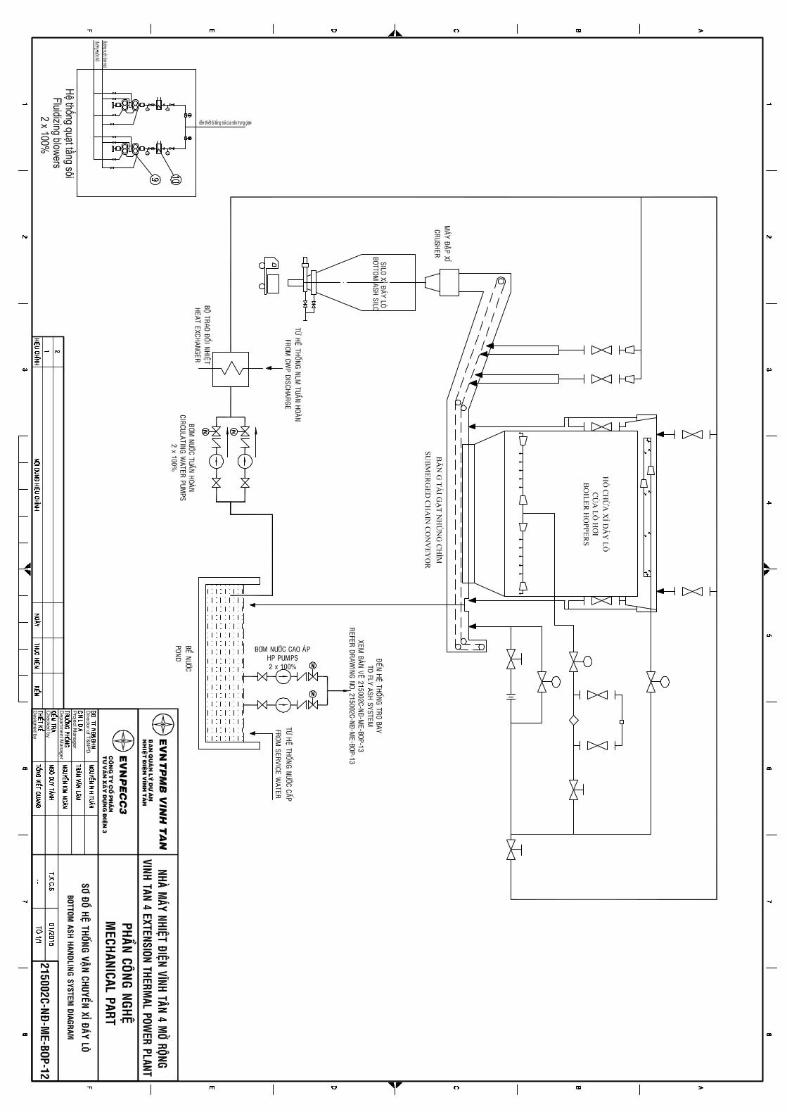
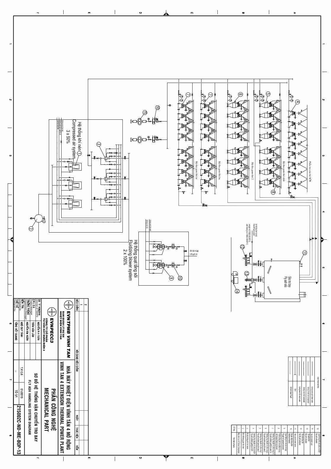
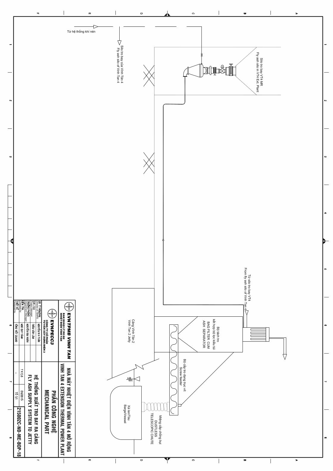
Vinh Tan 4 Ext TPP – 1×600MWFeasibility Study Report
Annexes
ANNEX 3: ANALYSIS RESULTS ON BACKGROUNDENVIRONMENT
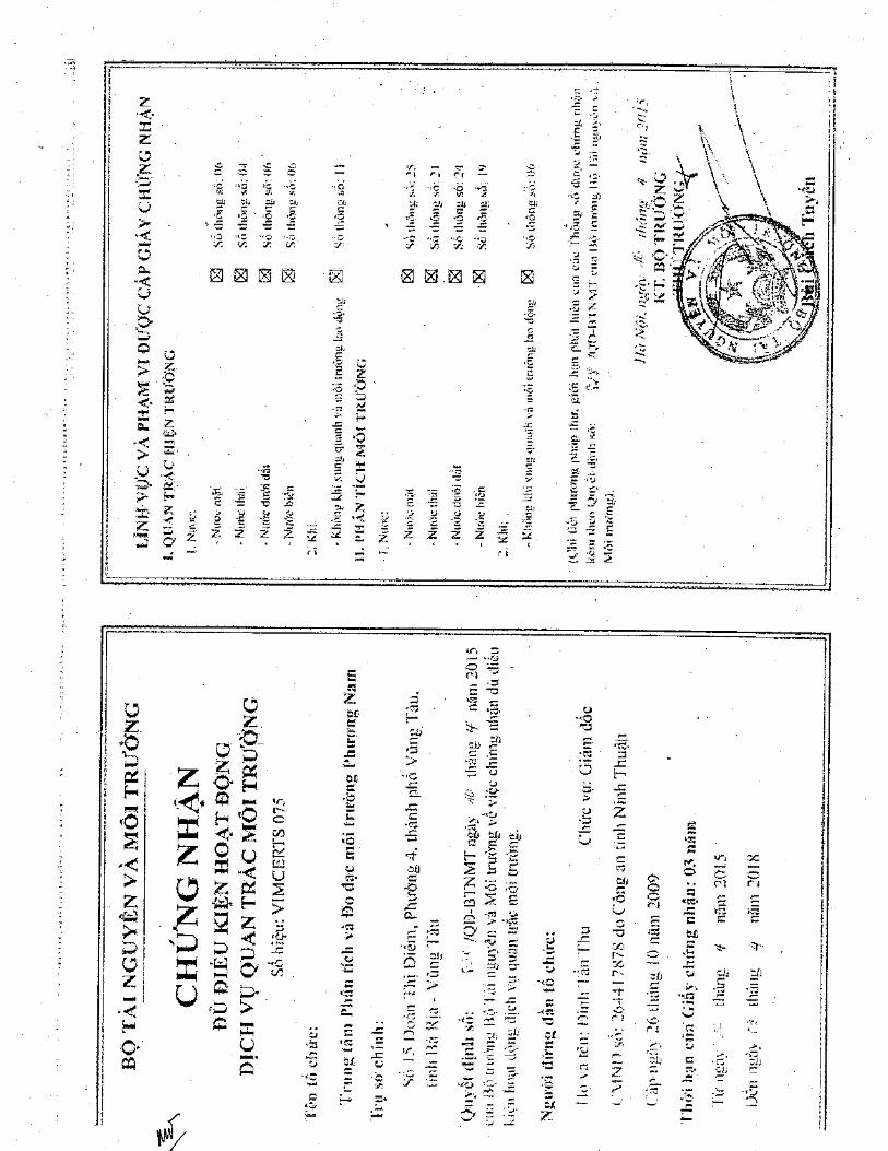

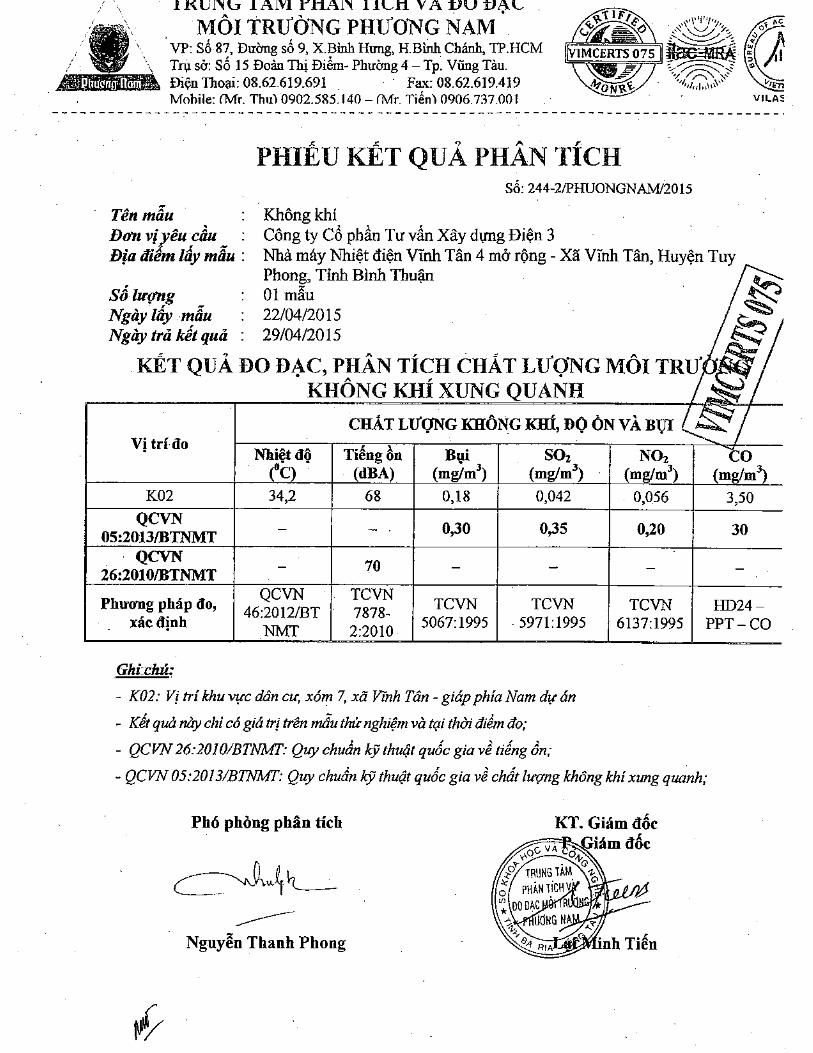
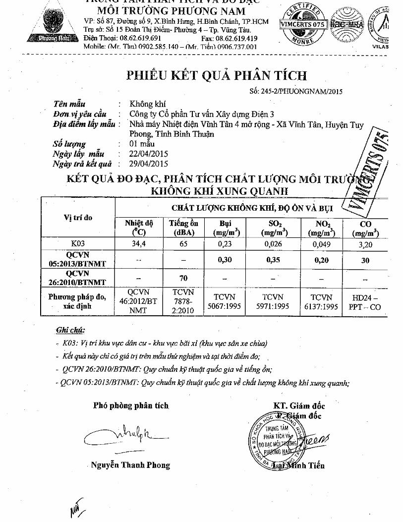
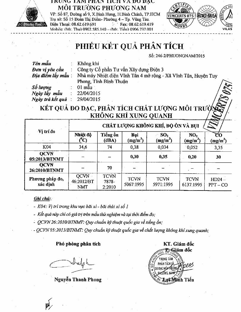
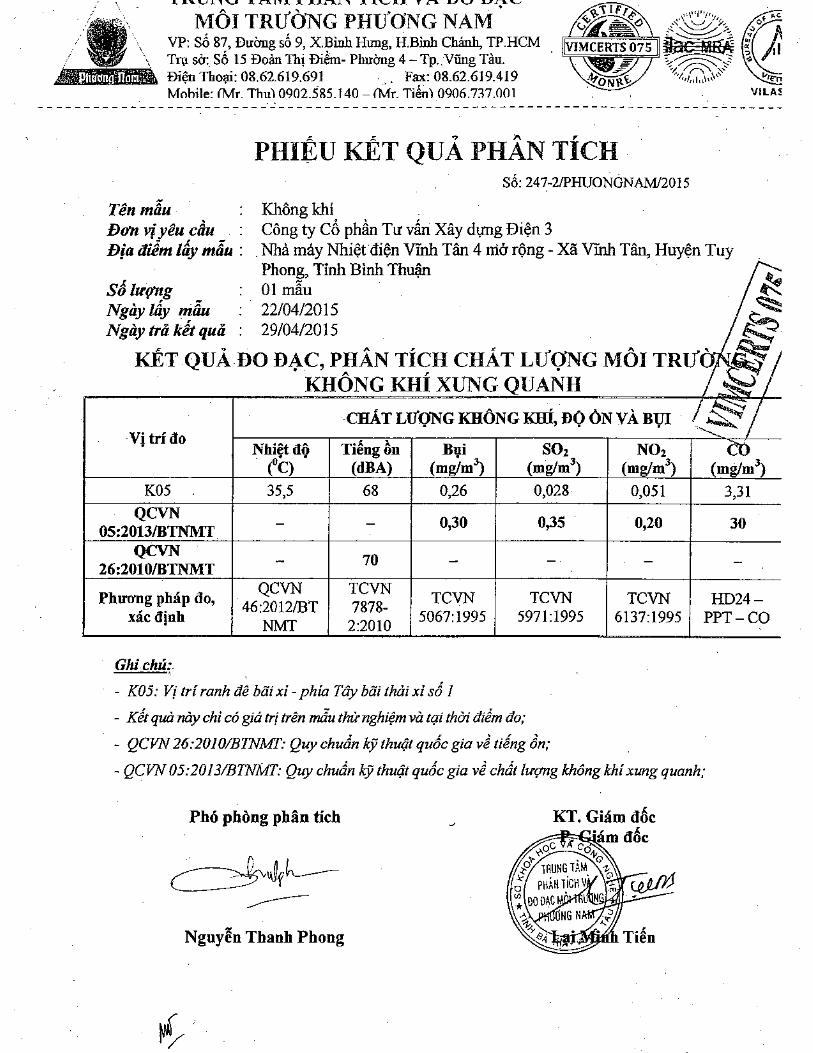
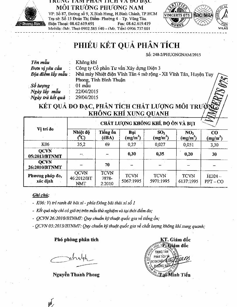
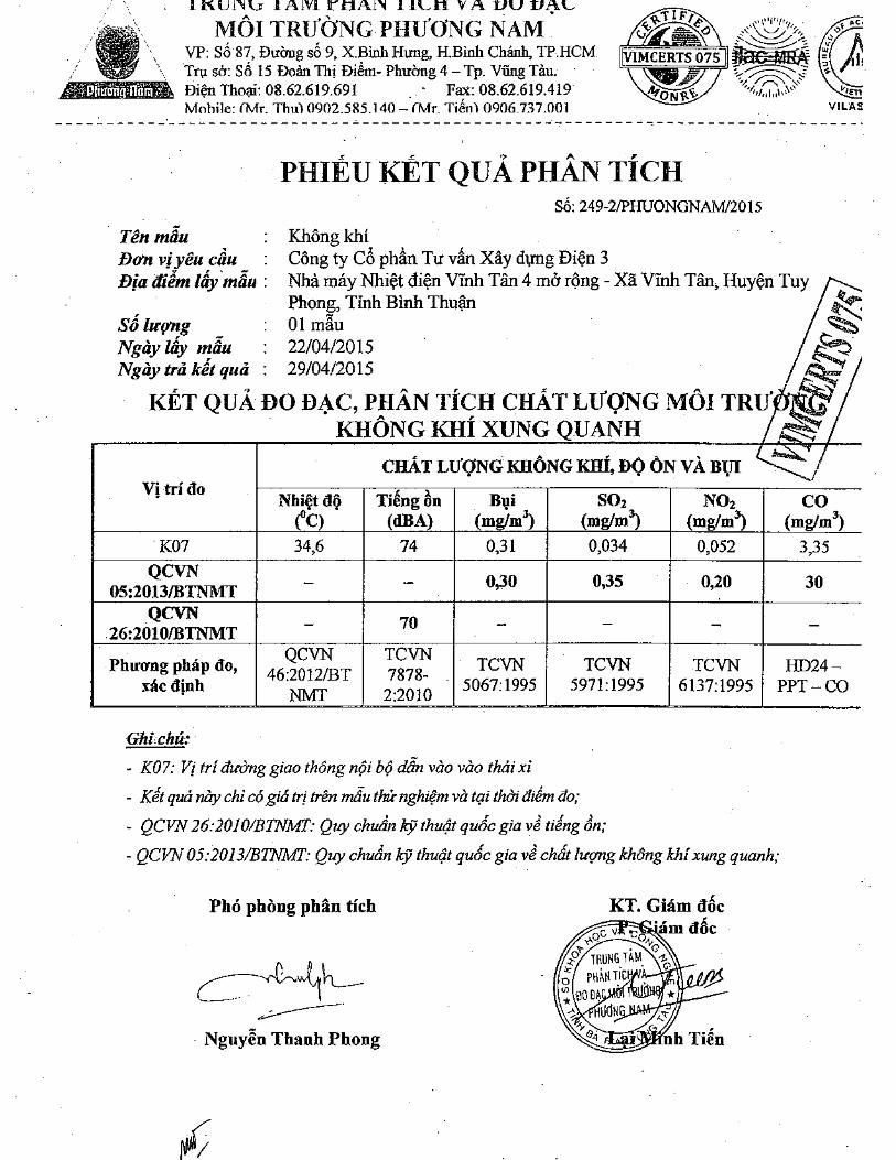

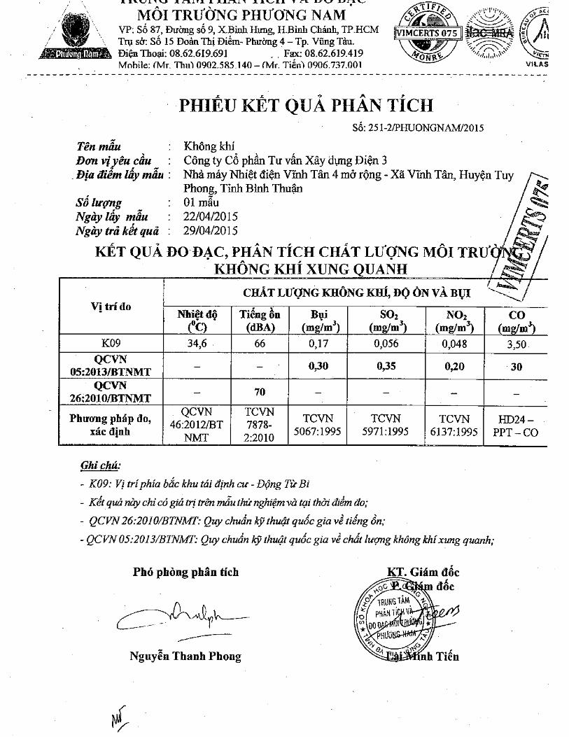
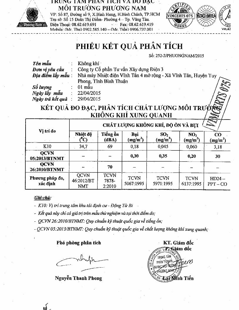
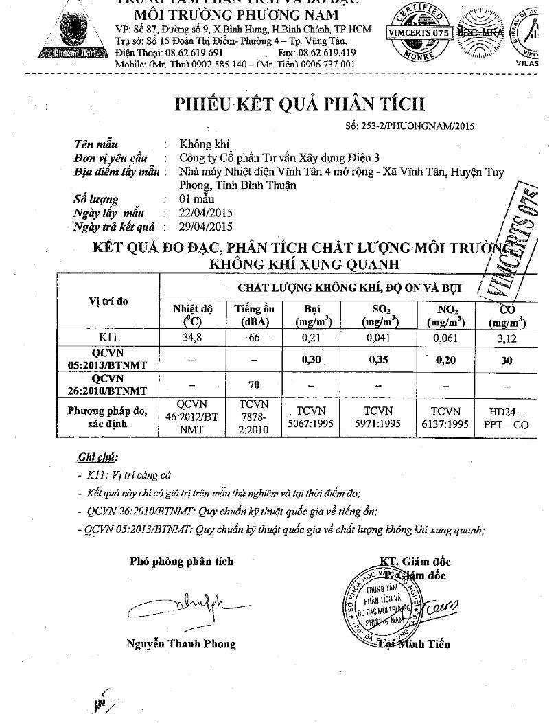

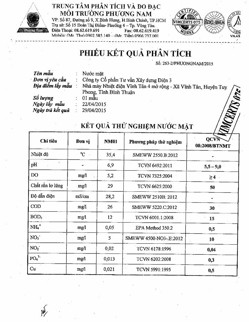
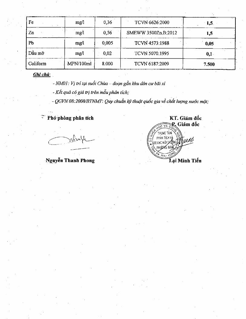

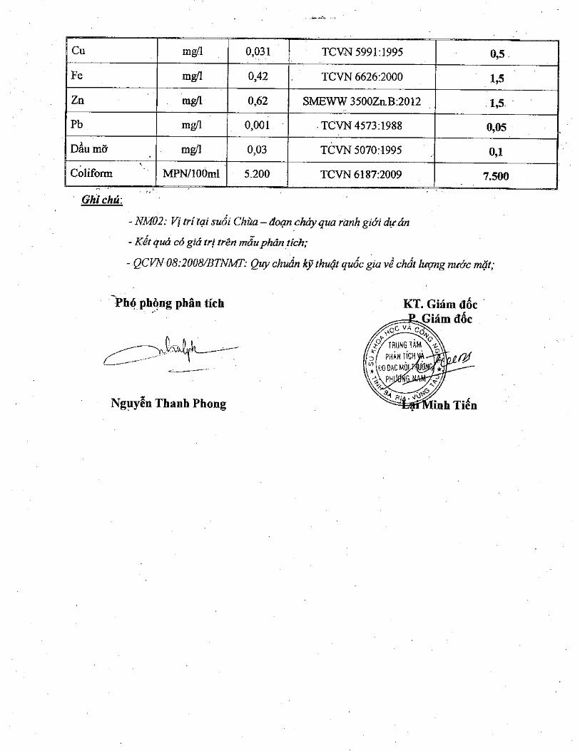
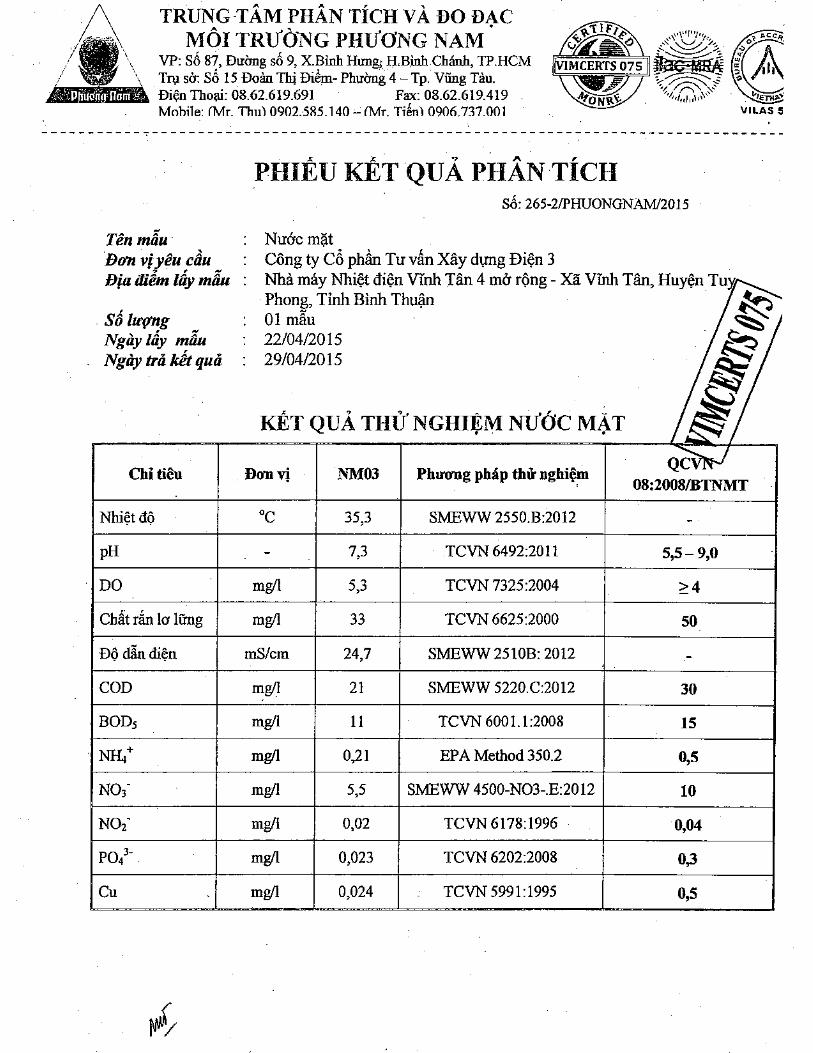
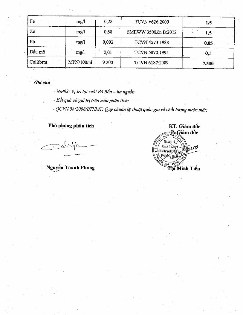
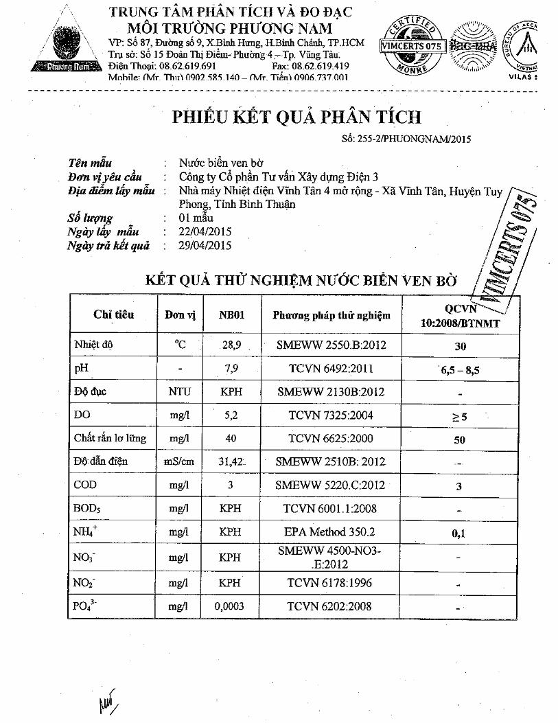
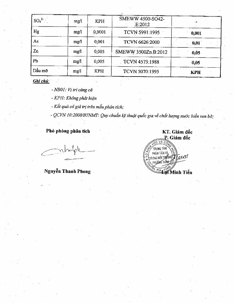

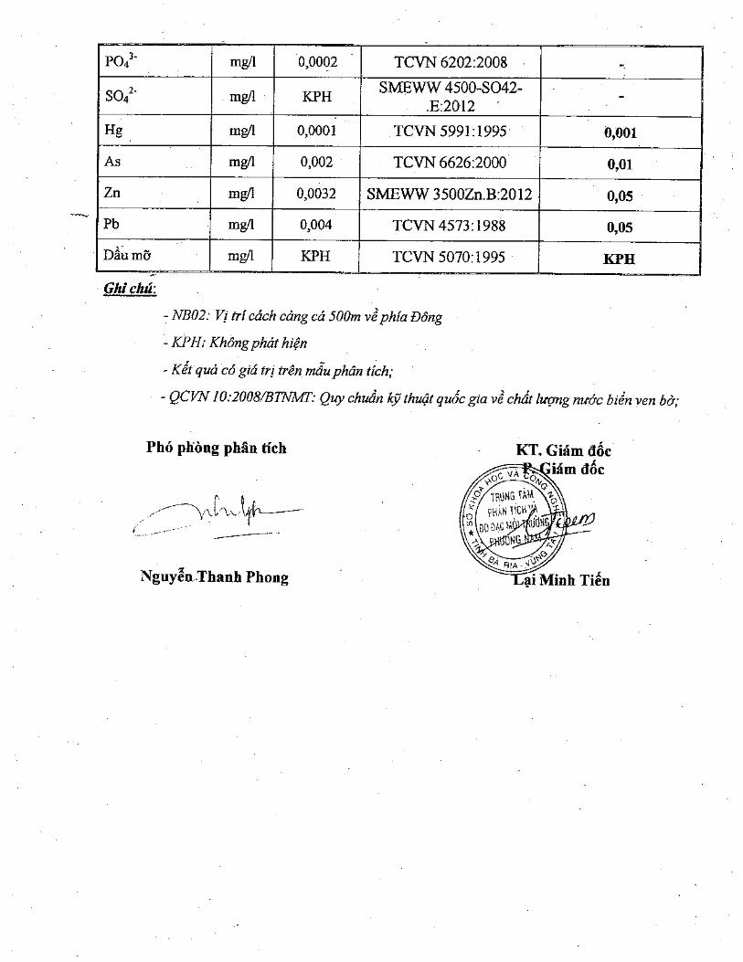
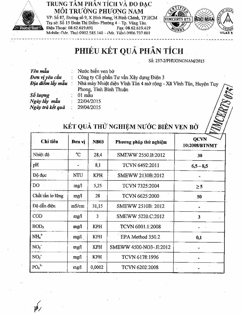
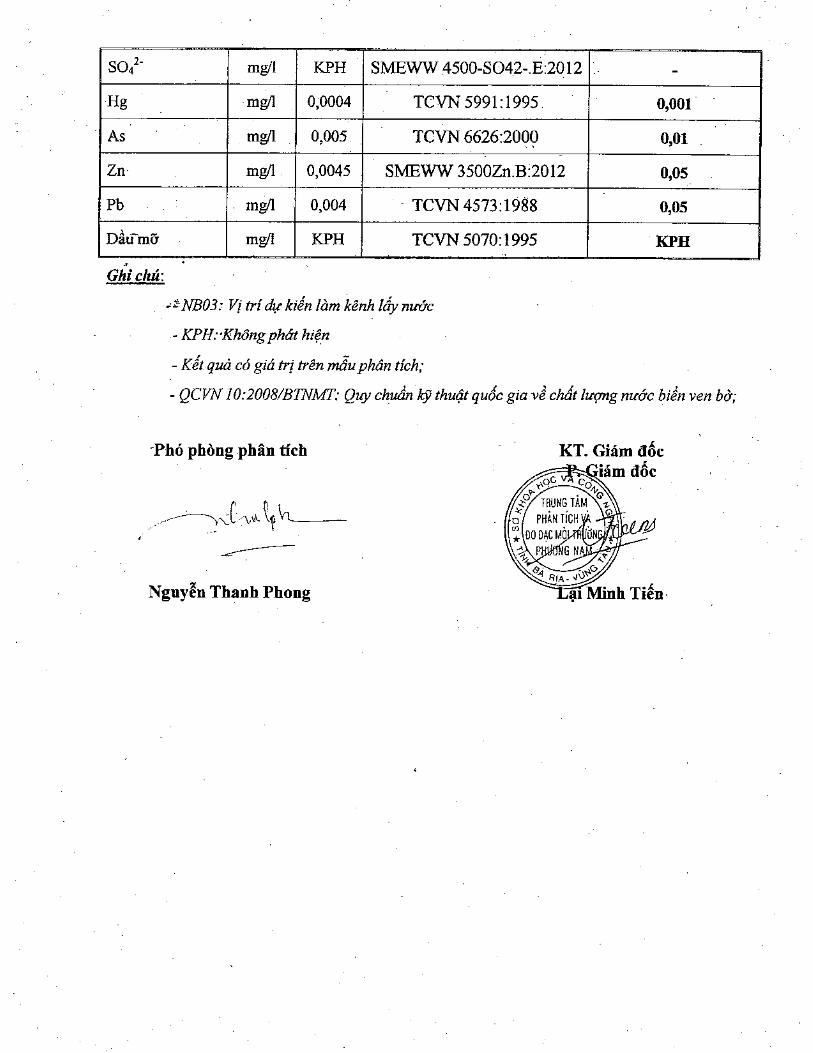
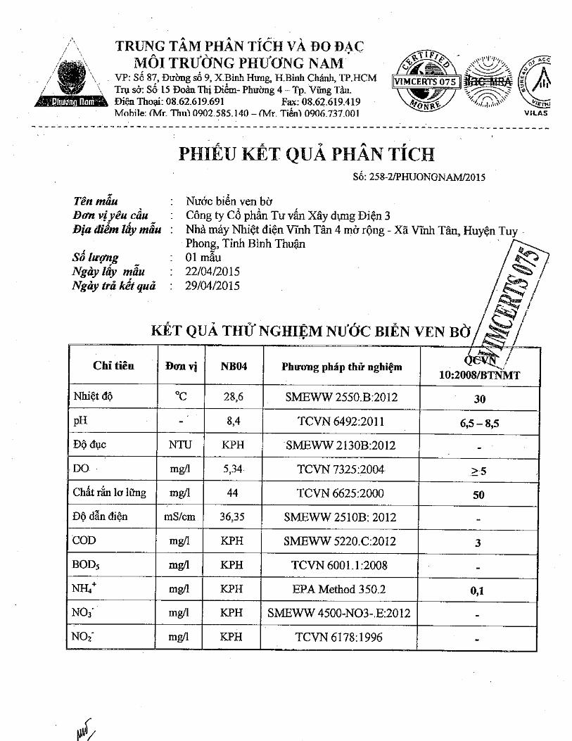
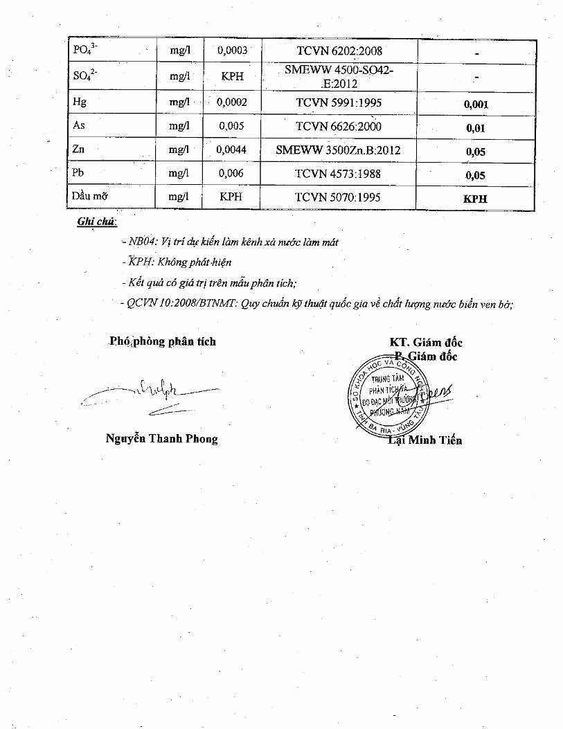
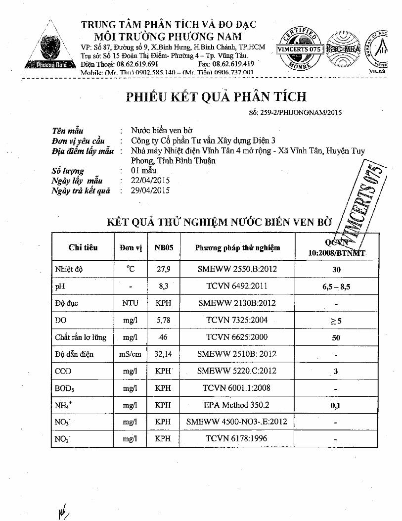
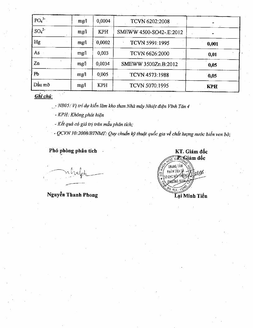
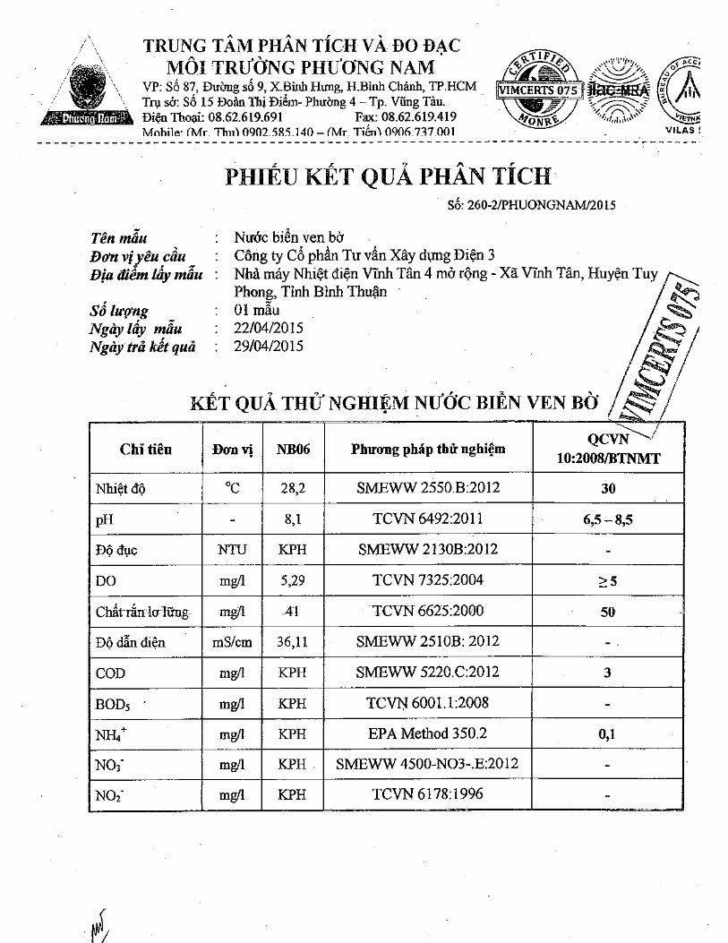
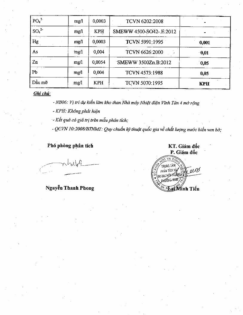
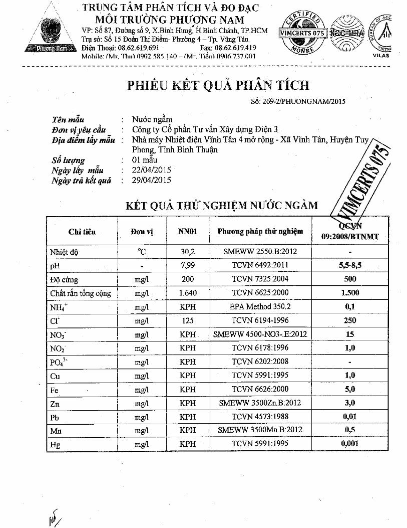
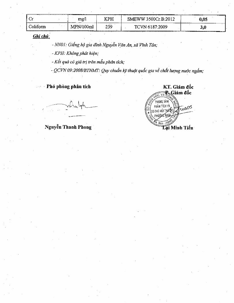

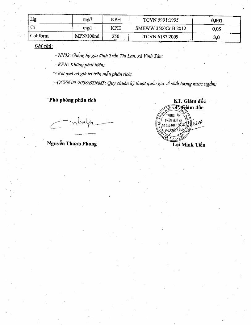
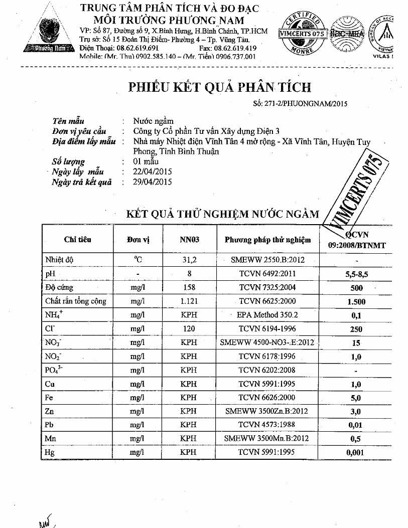

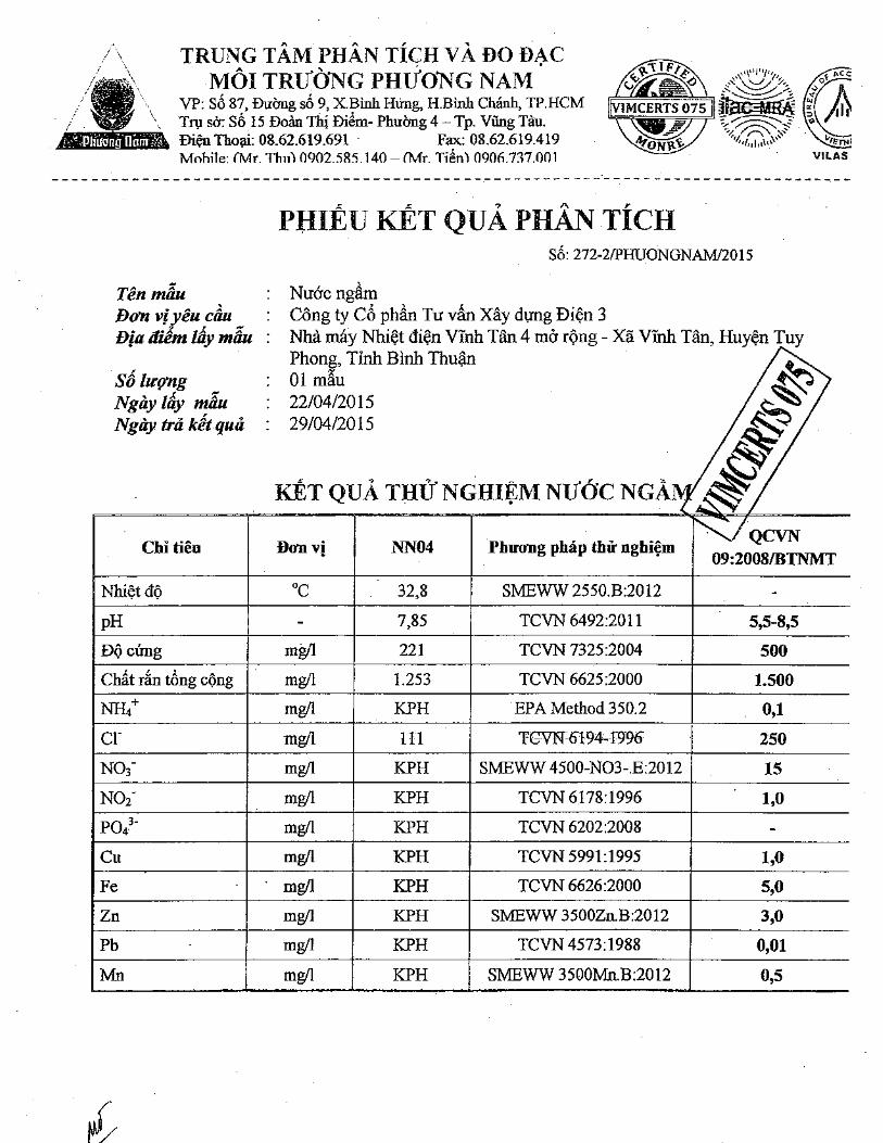
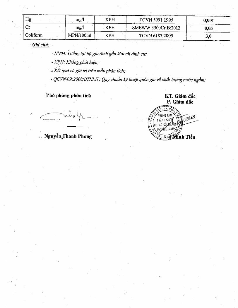
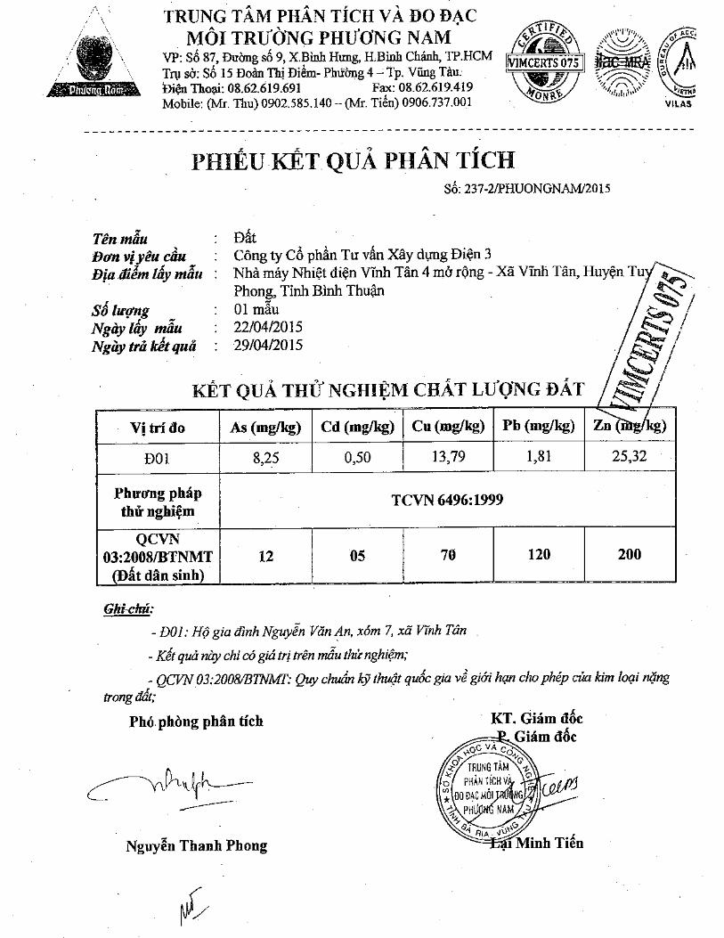

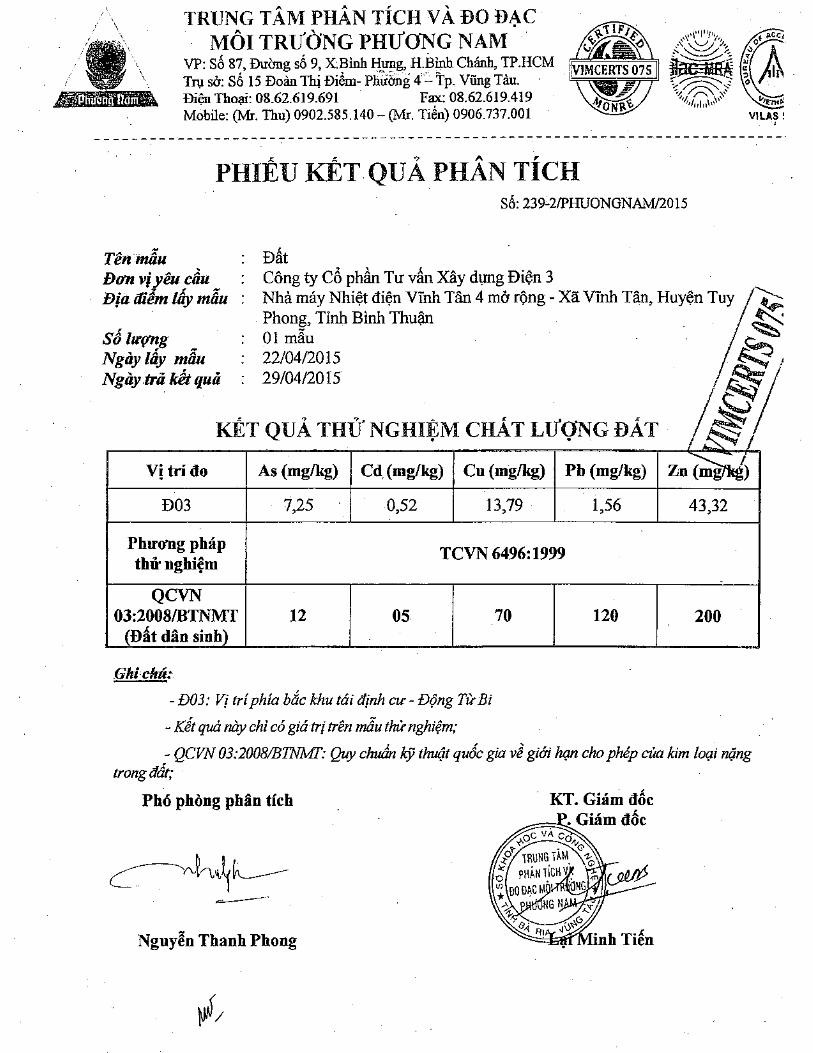
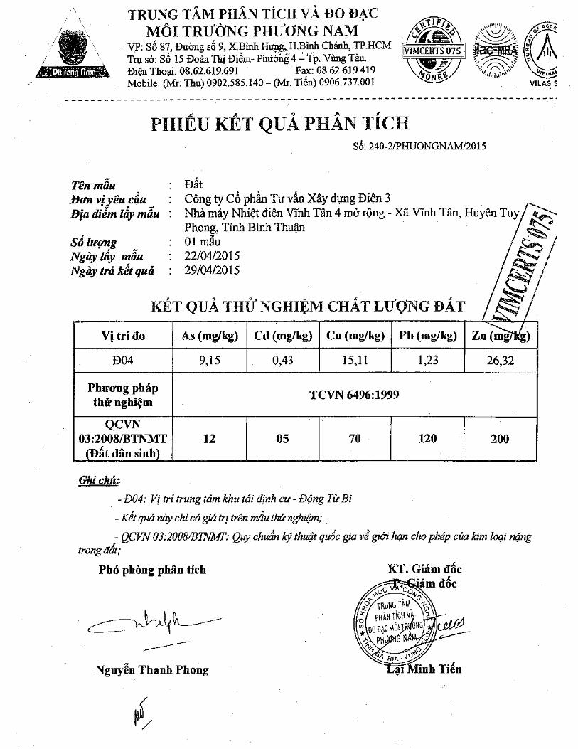

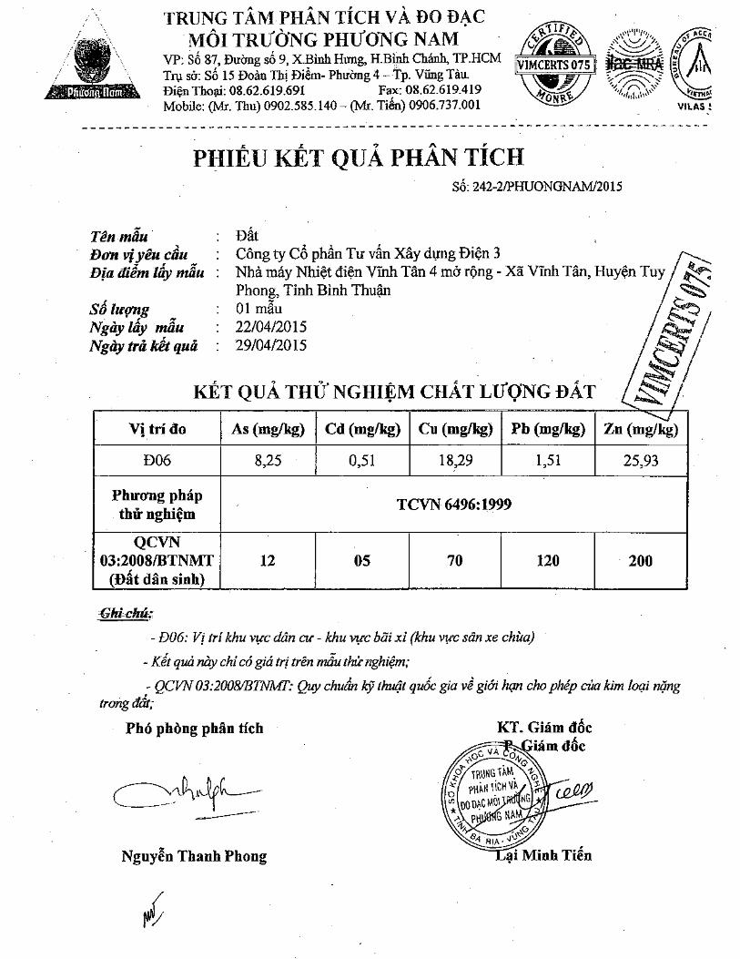
Vinh Tan 4 Ext TPP – 1×600MWFeasibility Study Report
Annexes
ANNEX 4: COPIES OF THE DOCUMENTS RELATED TO THEPUBLIC CONSULTATION AND SOCIOLOGICALQUESTIONNAIRES
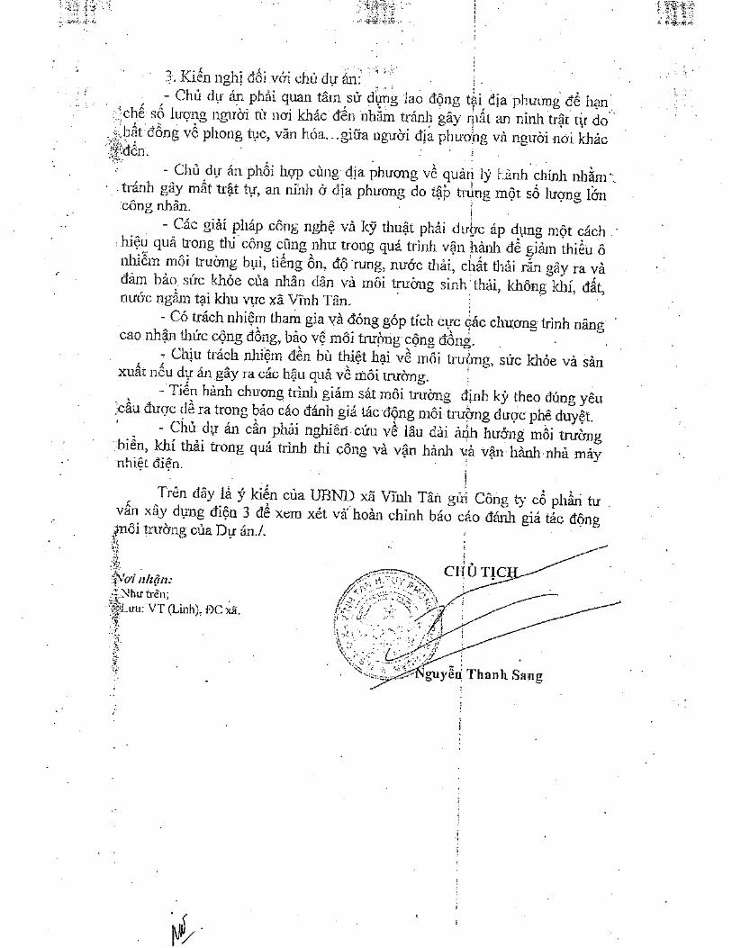
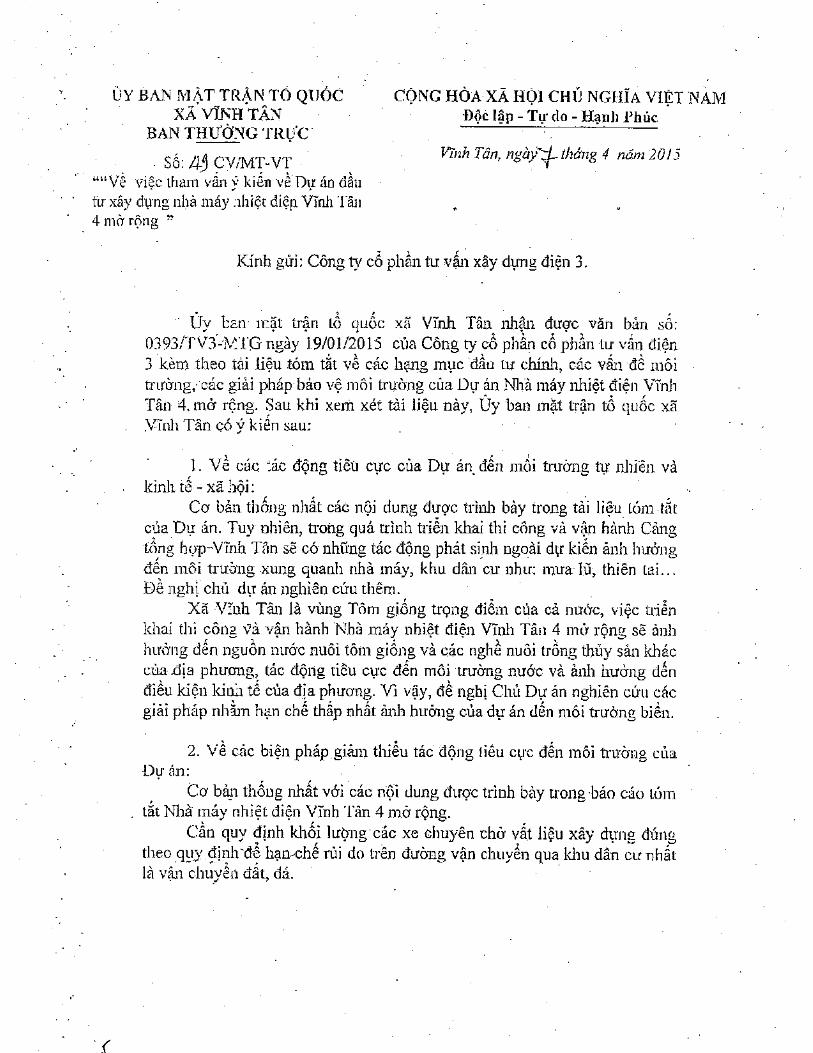
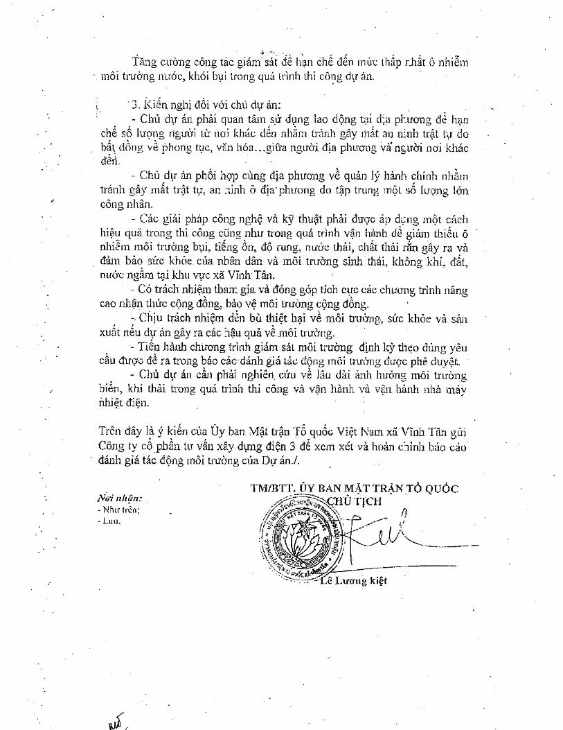
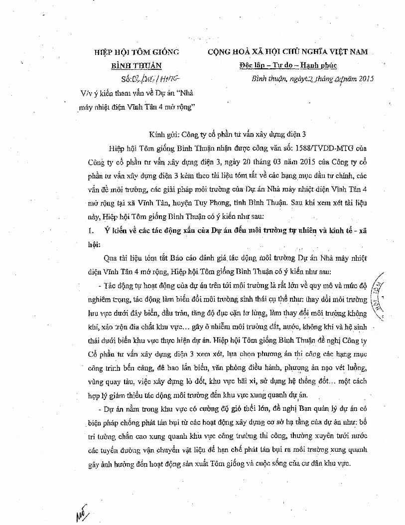
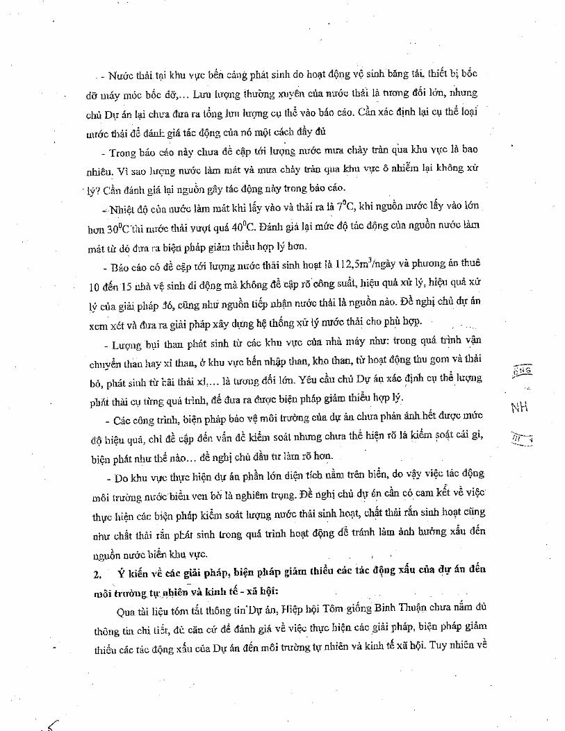

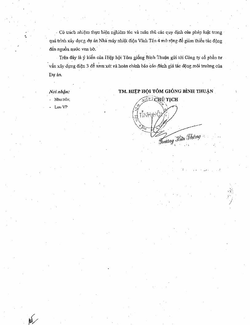
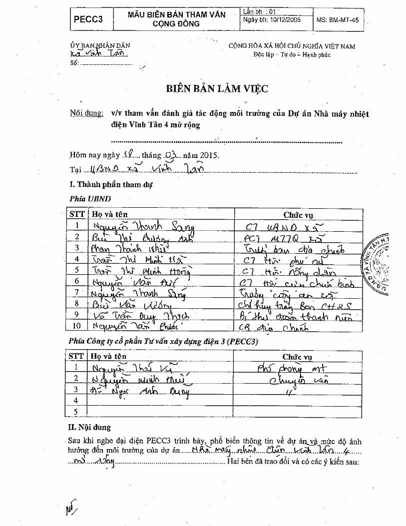
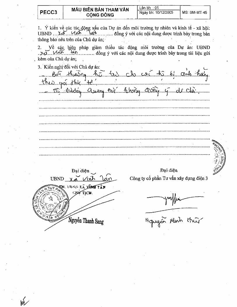
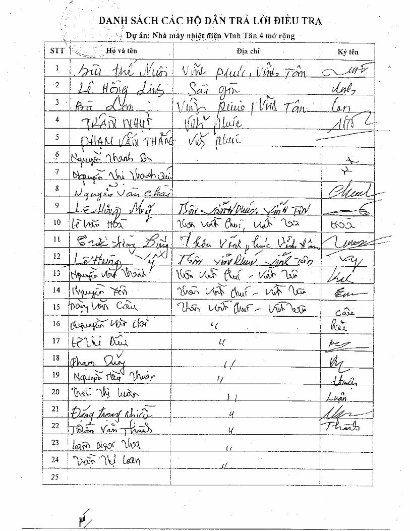
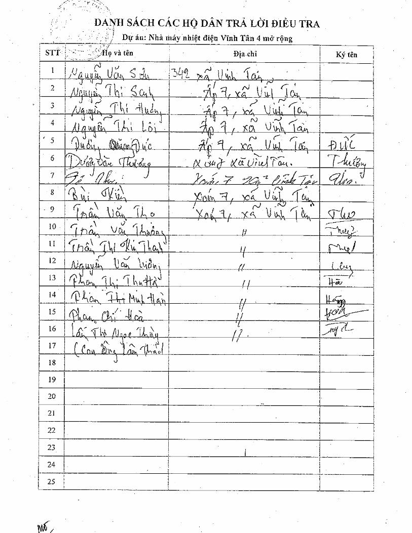
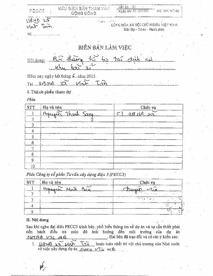
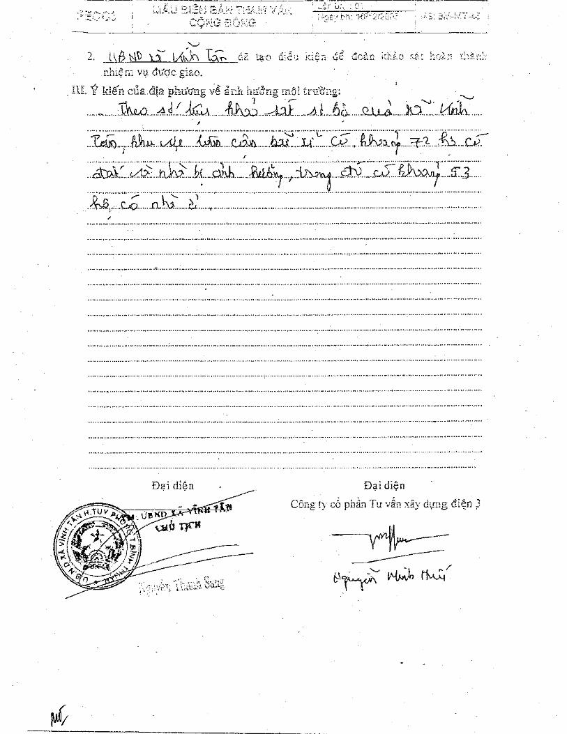
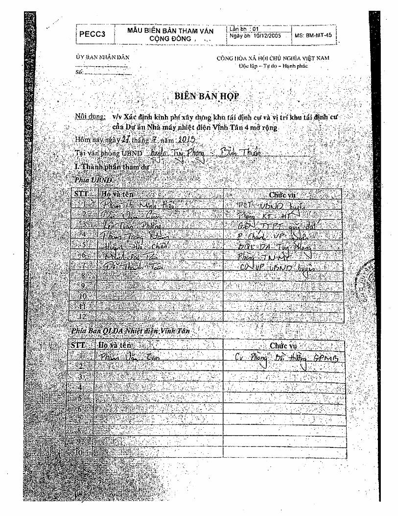
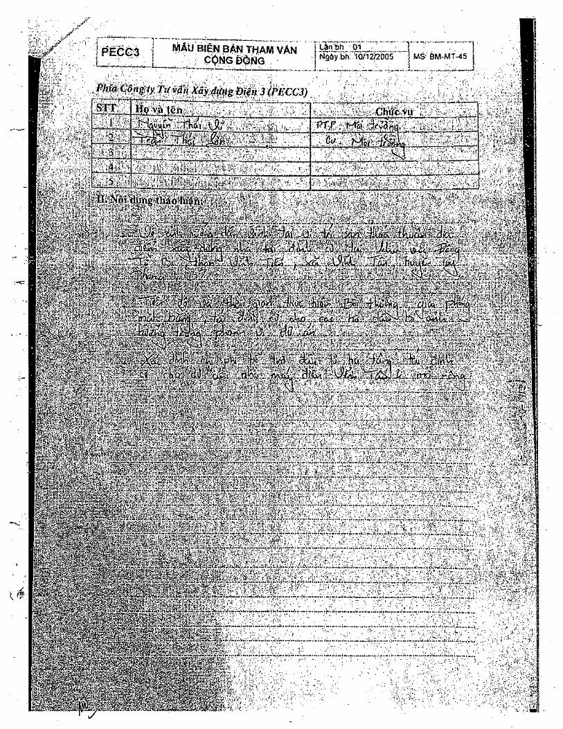
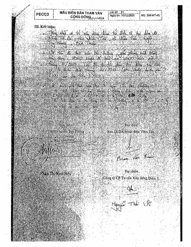
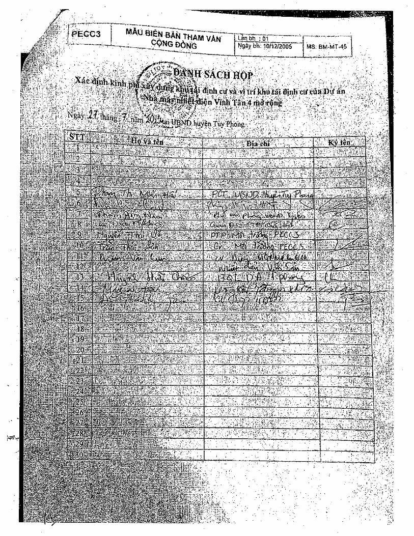
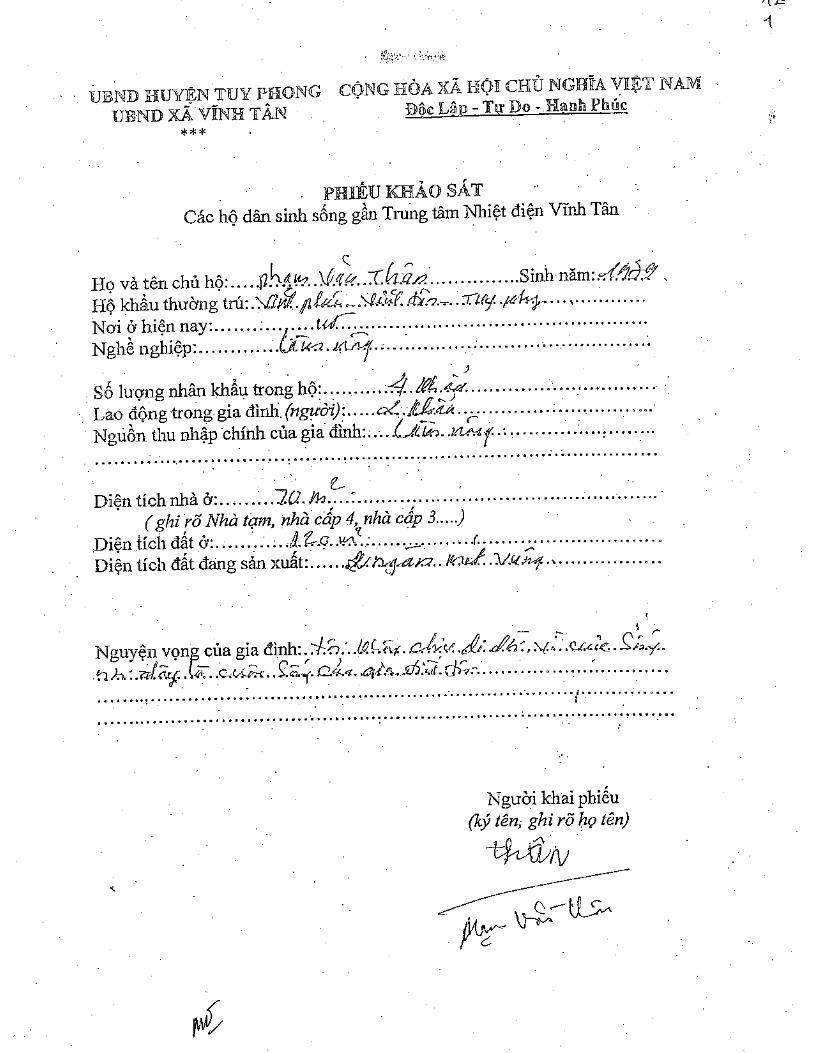
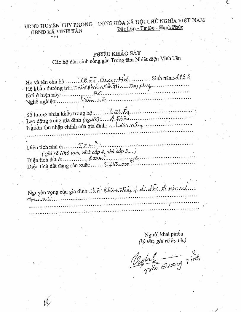
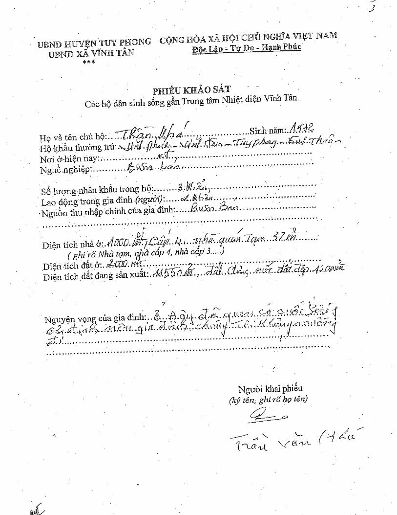
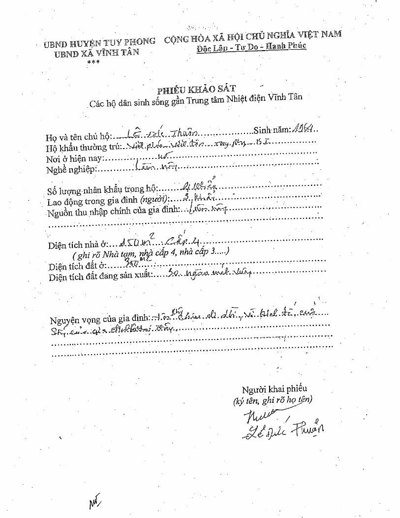
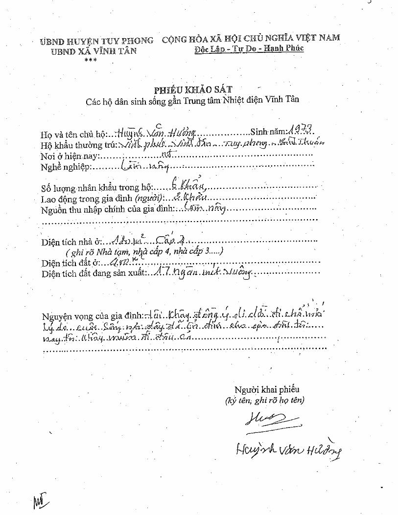
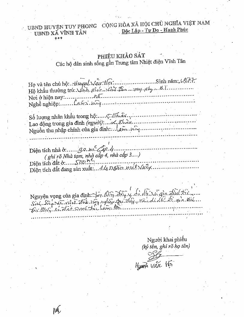
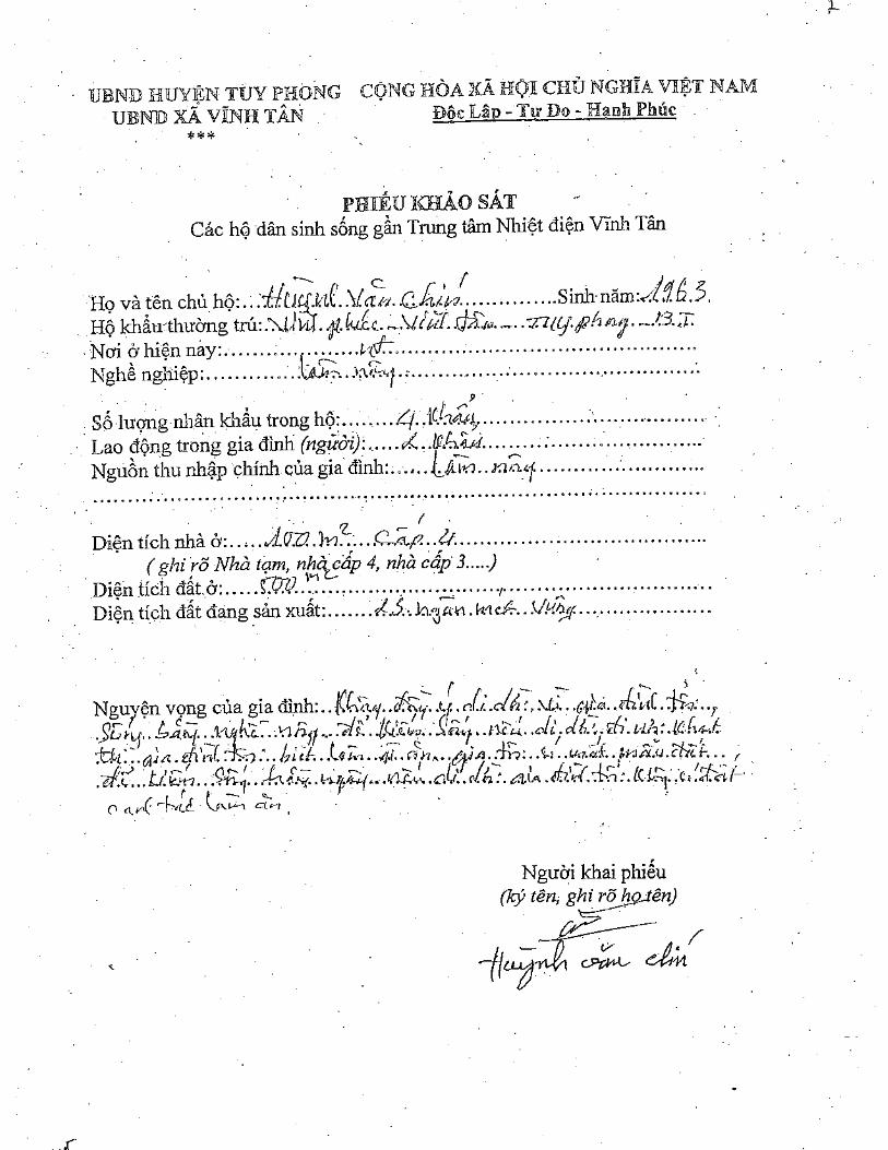
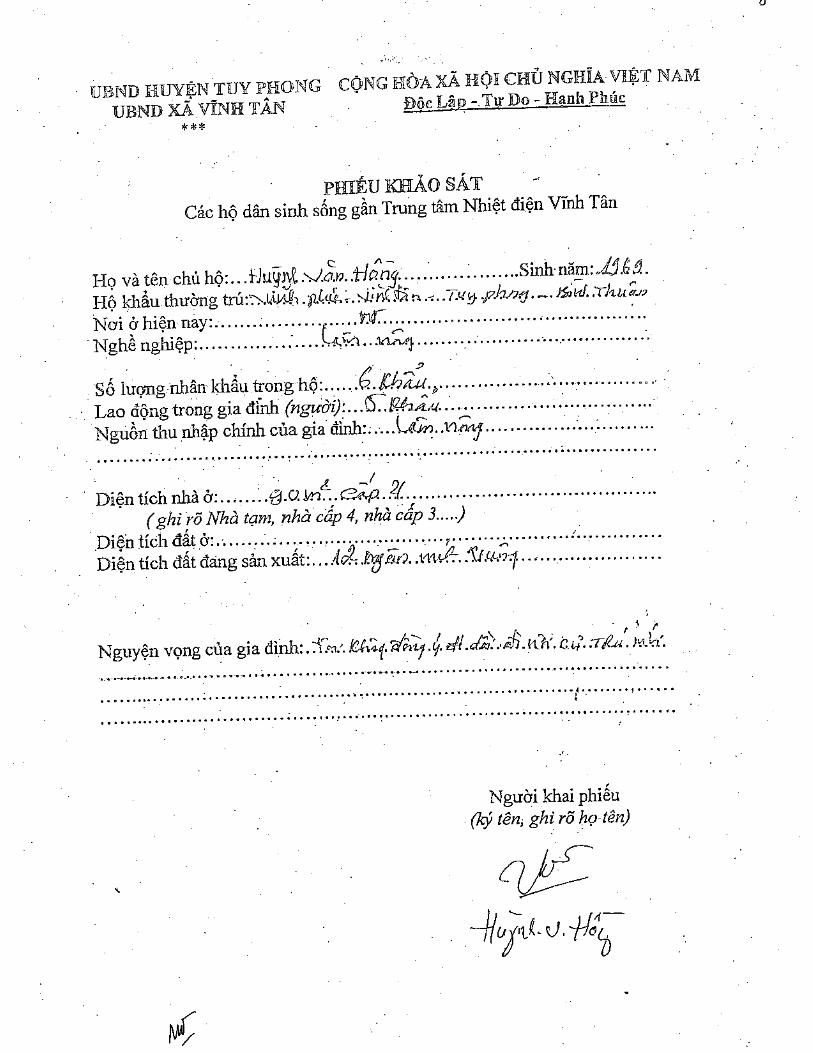
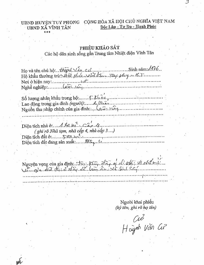
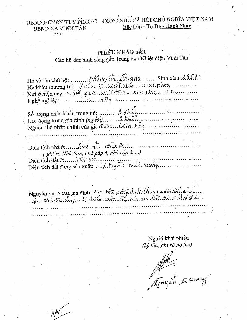
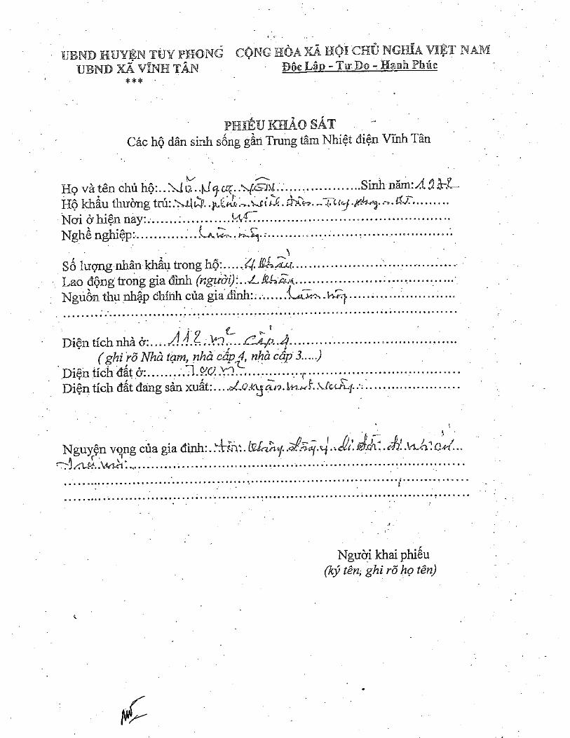
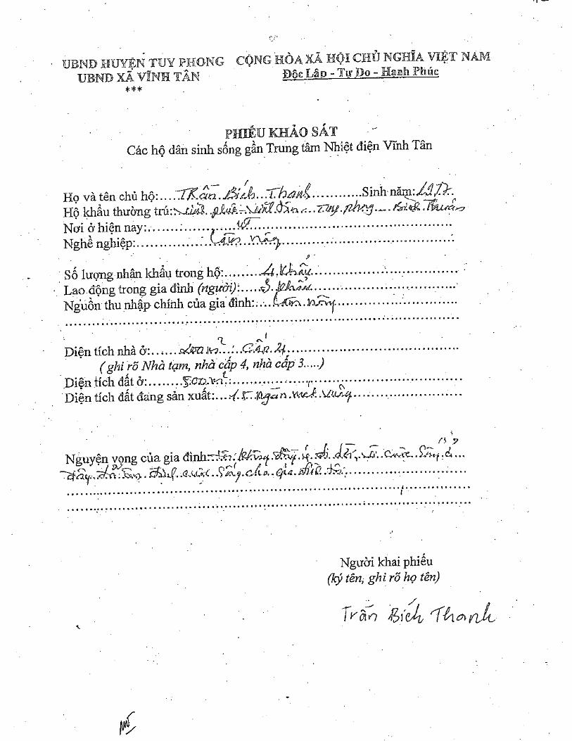
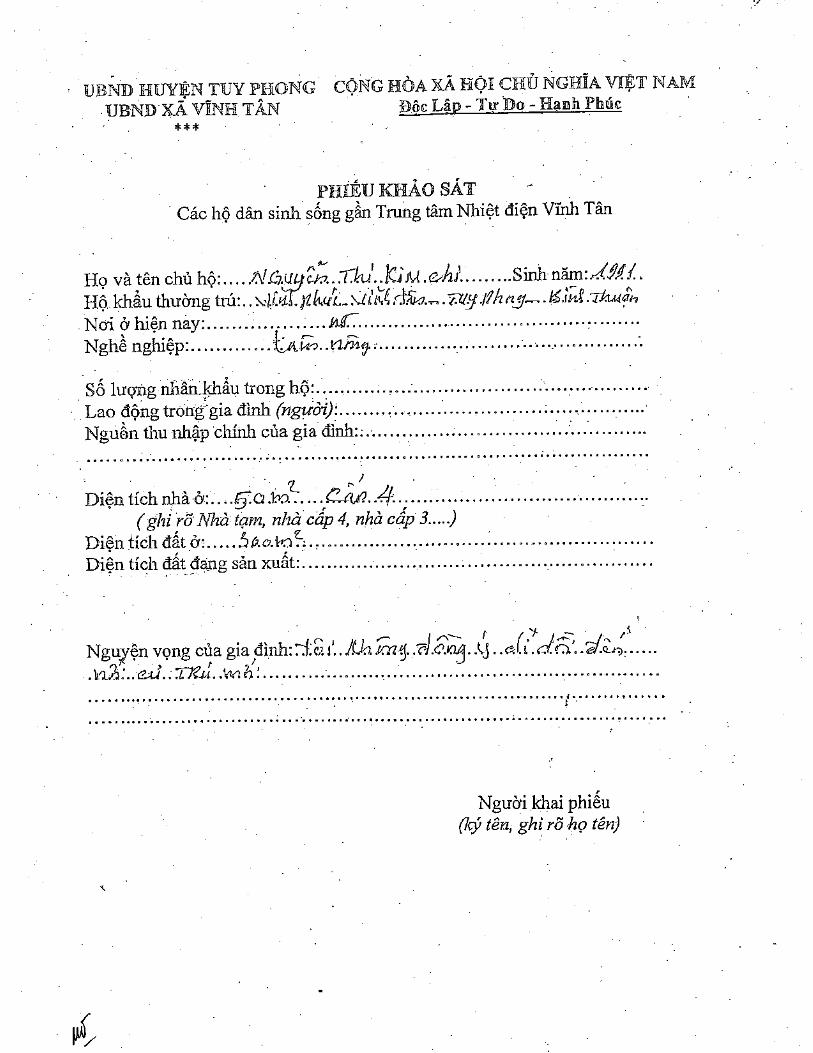
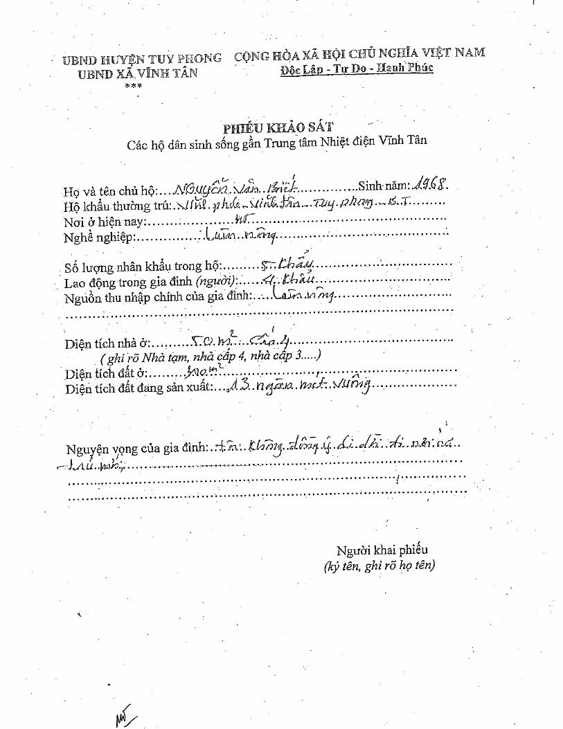
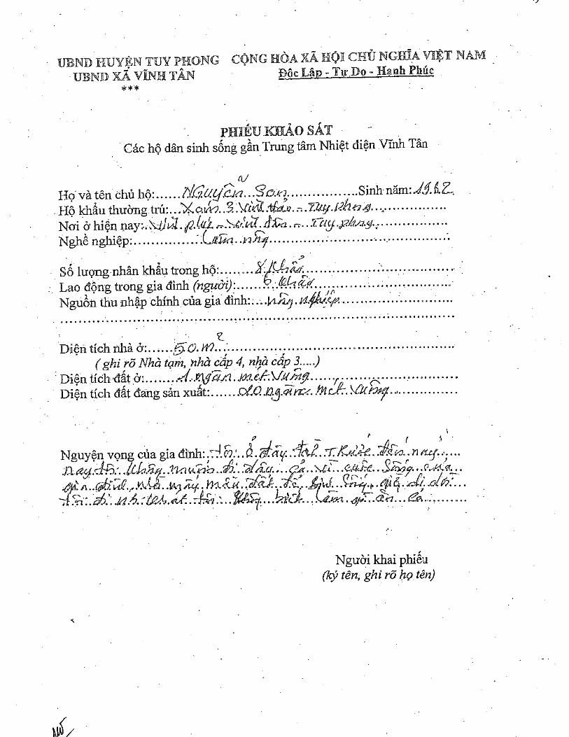
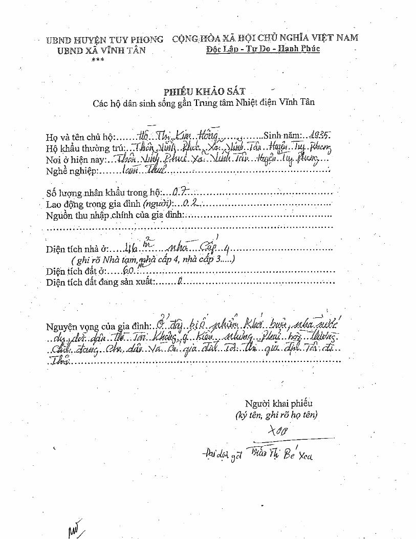
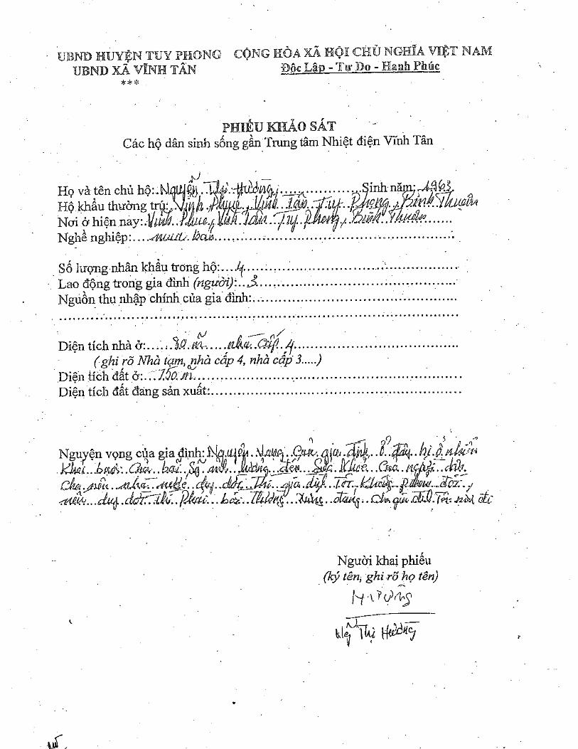
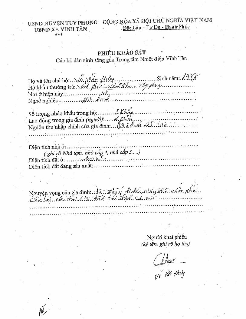
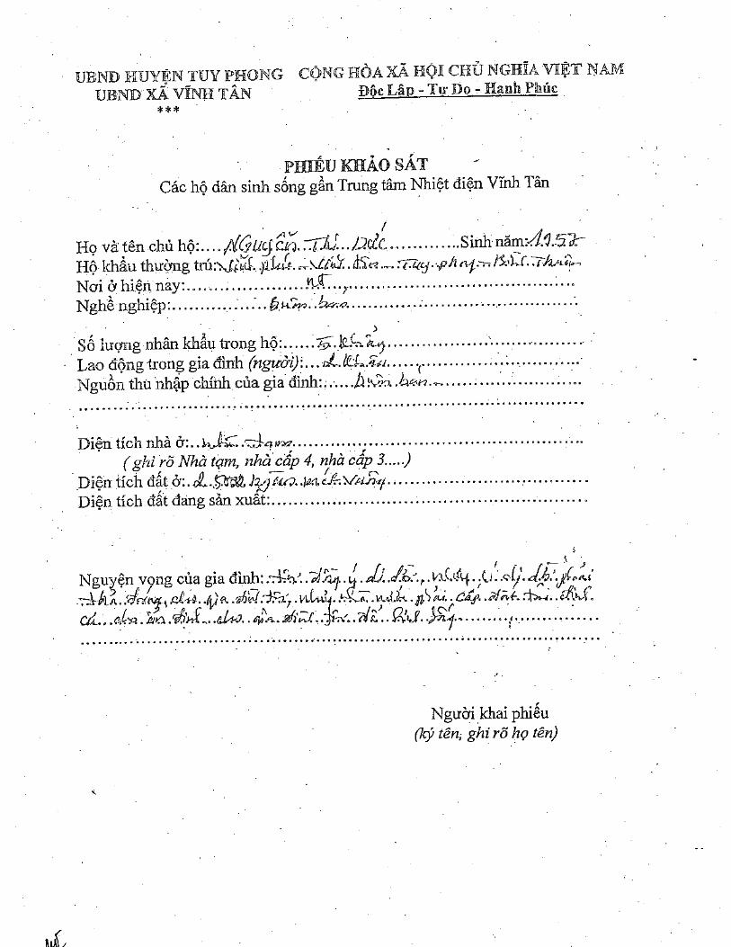

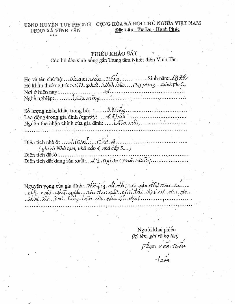
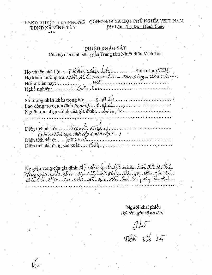
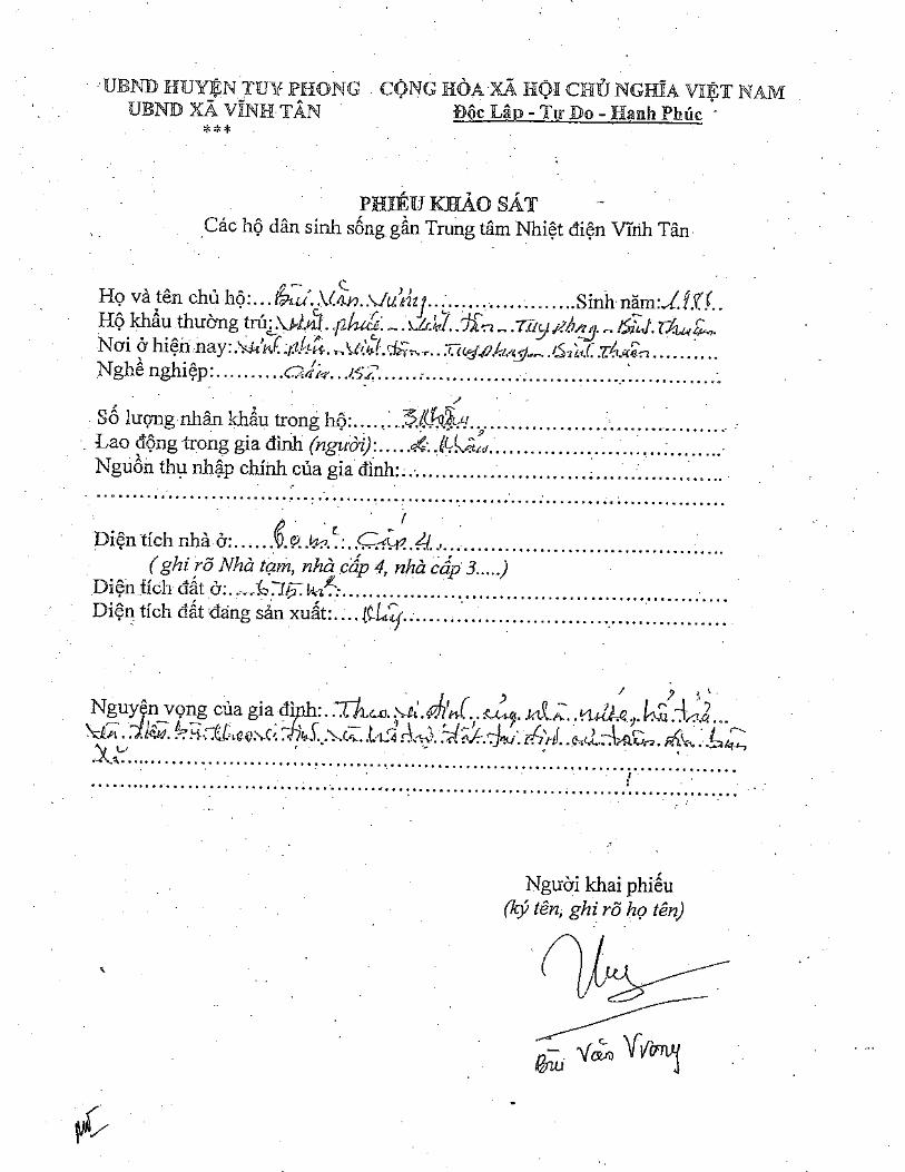
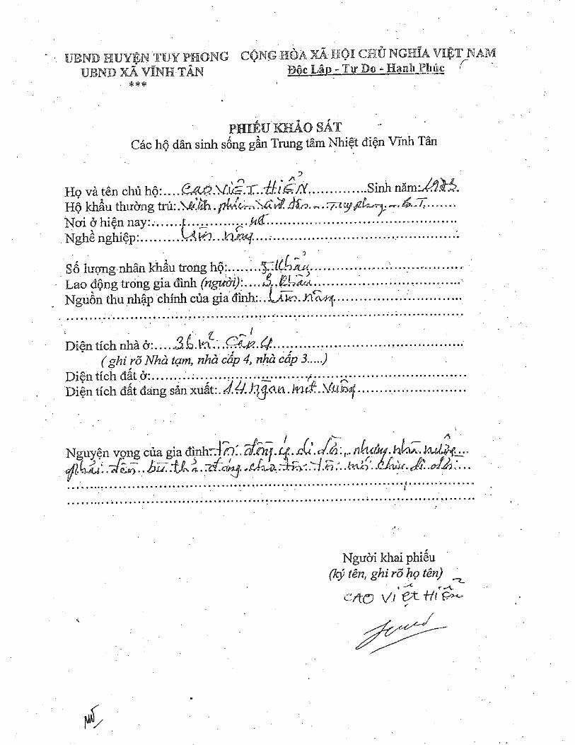
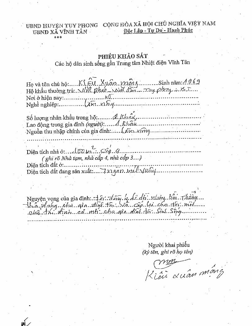
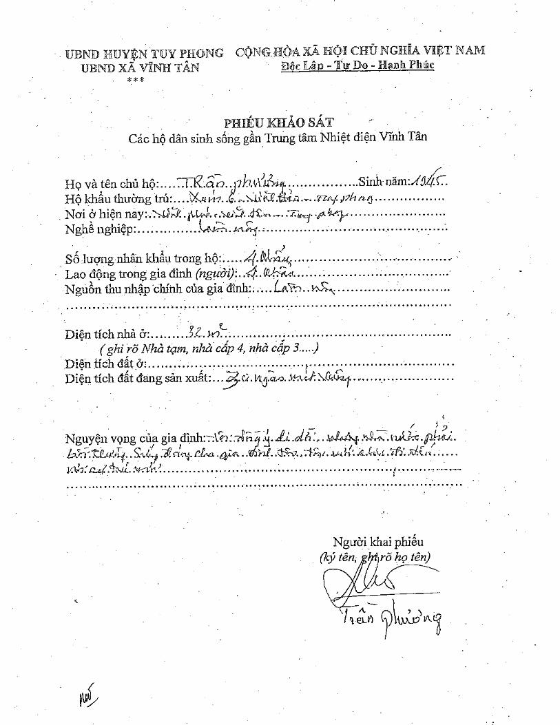
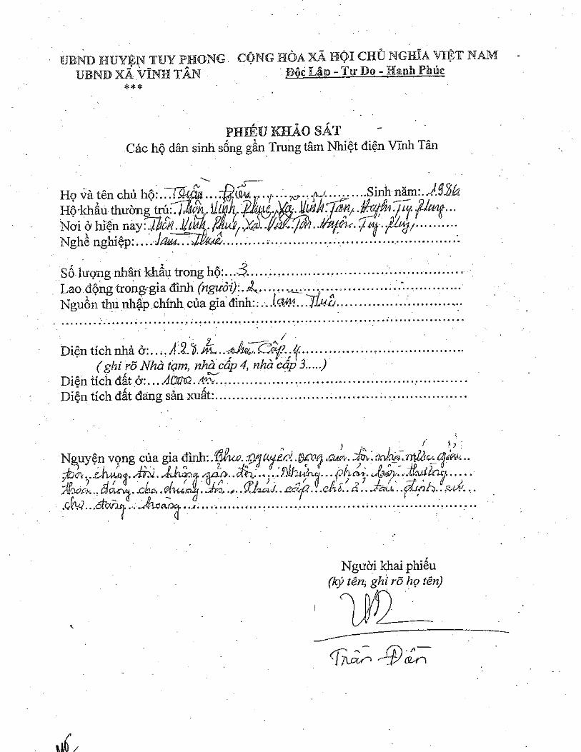
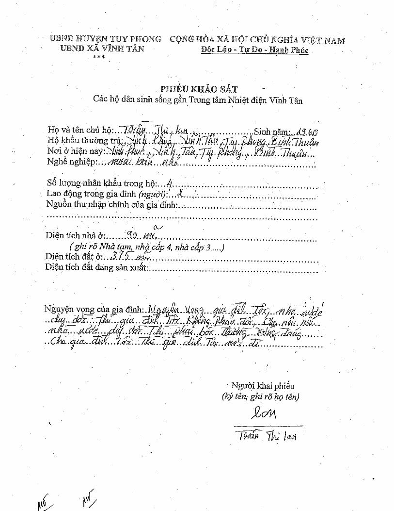
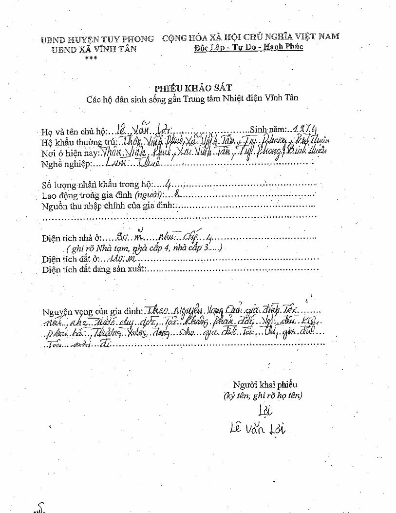
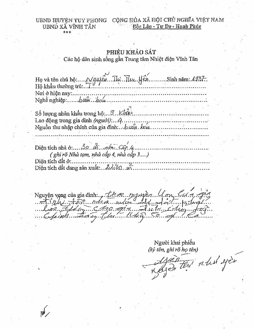
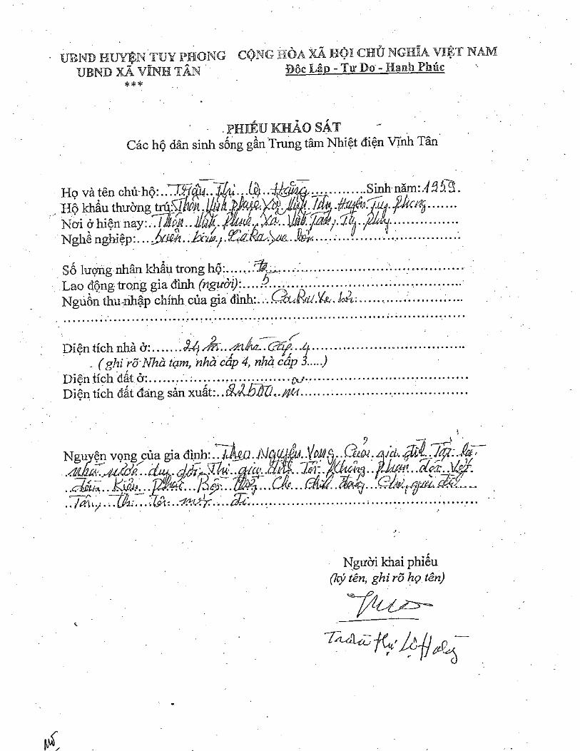
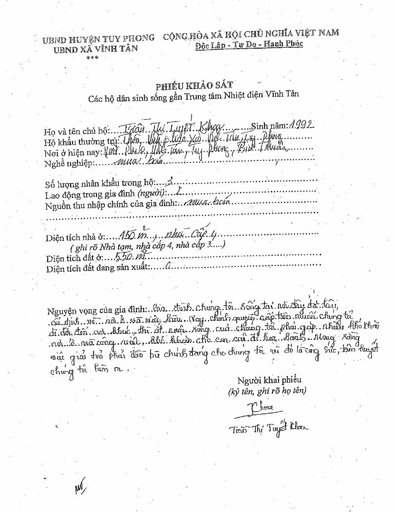
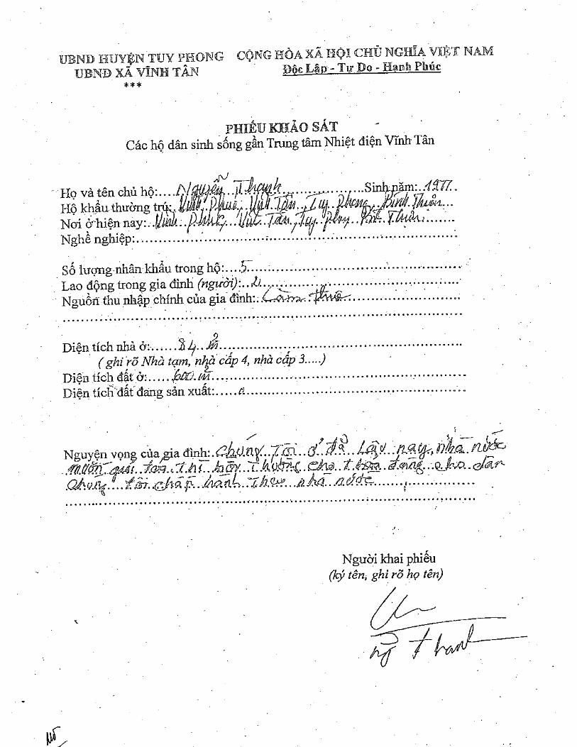
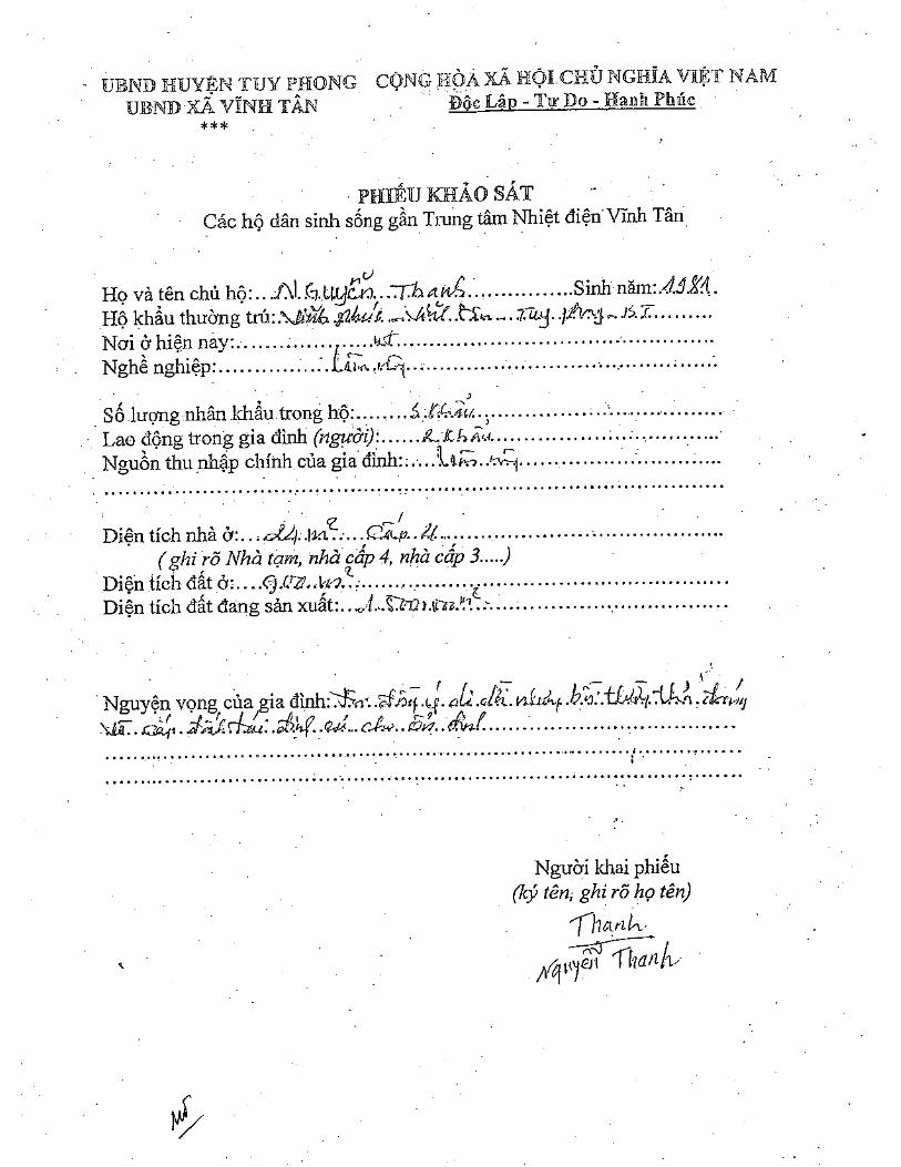
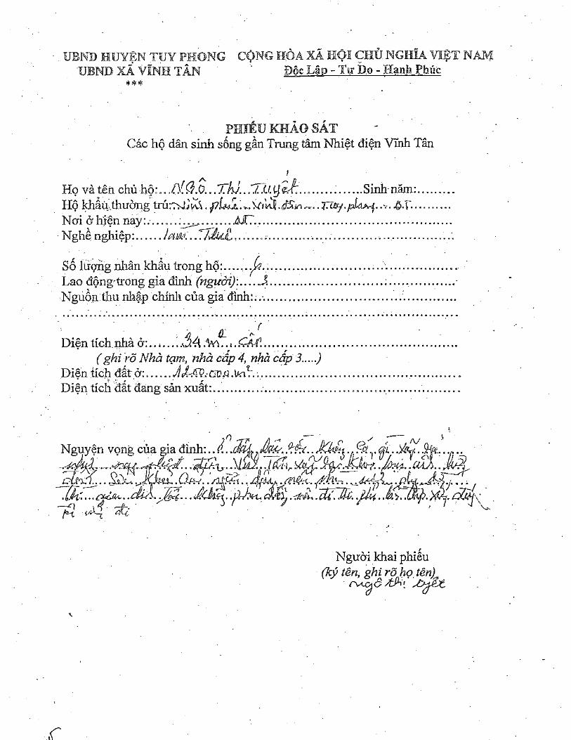
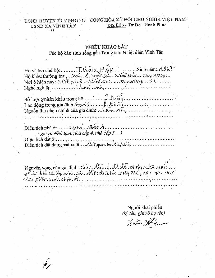
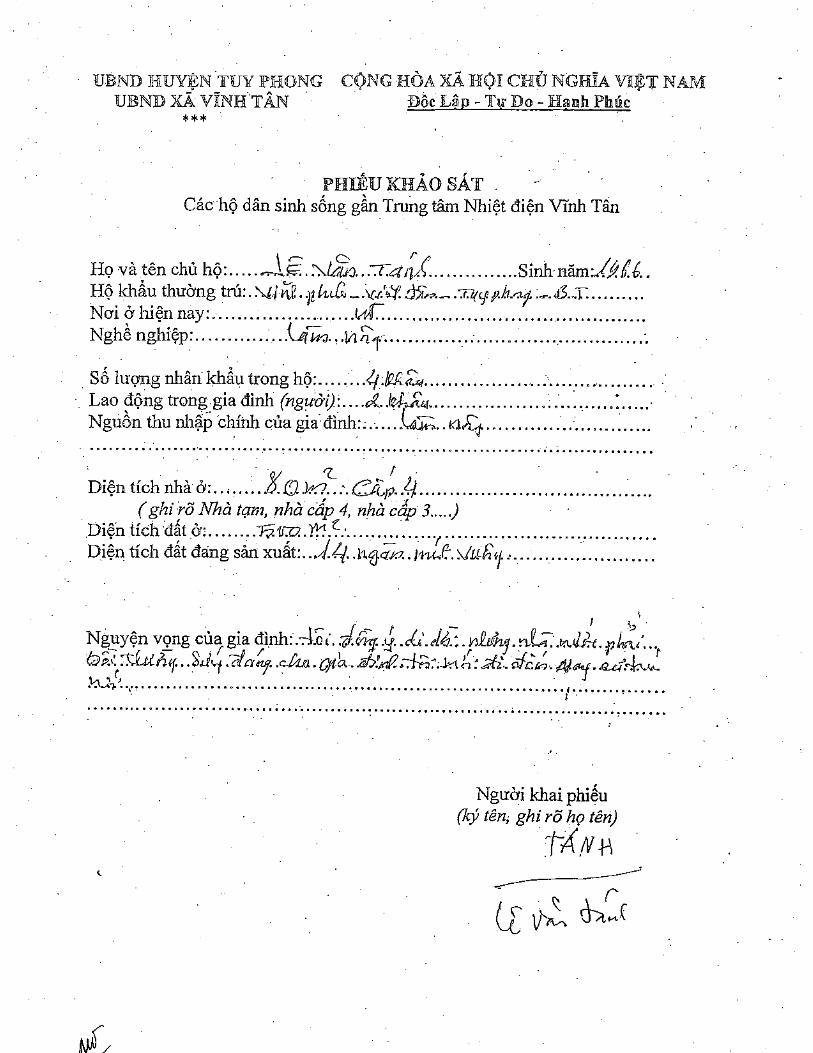
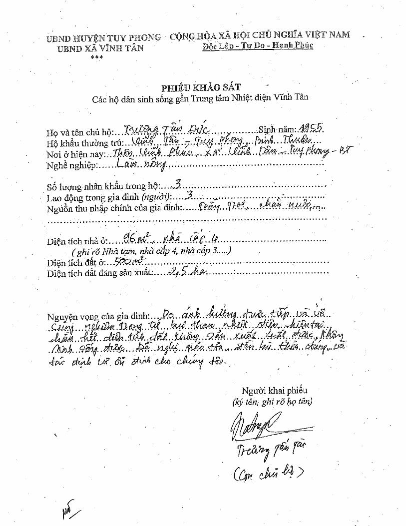
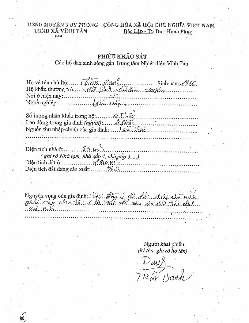
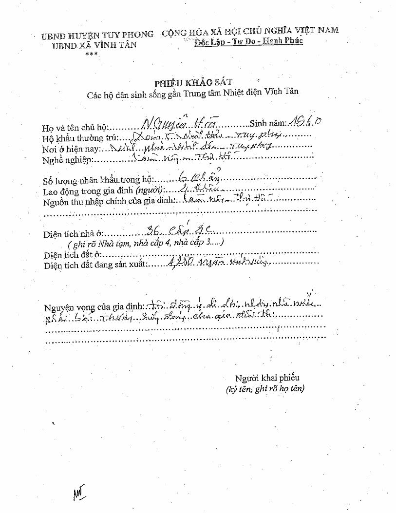
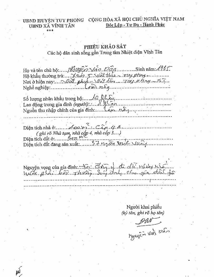
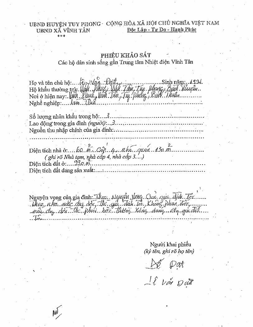
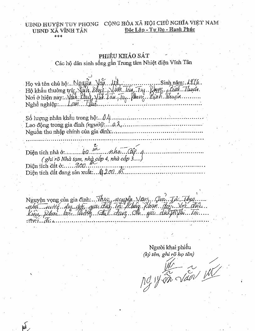
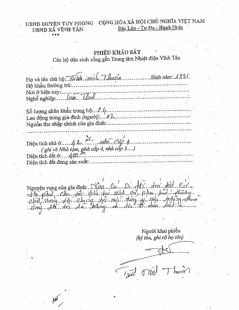
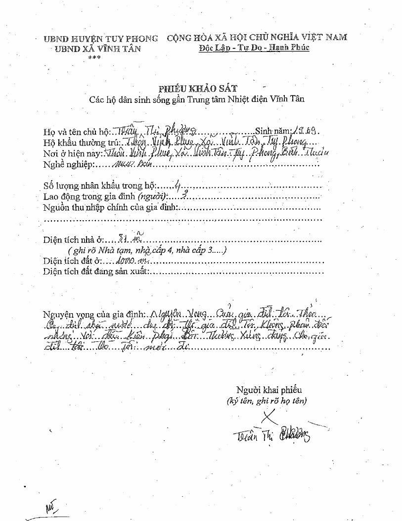
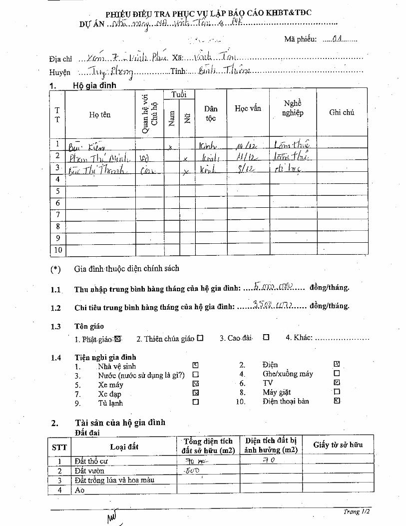

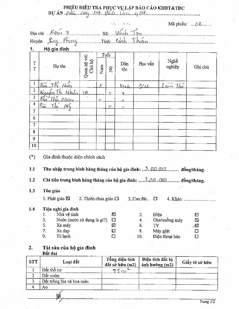

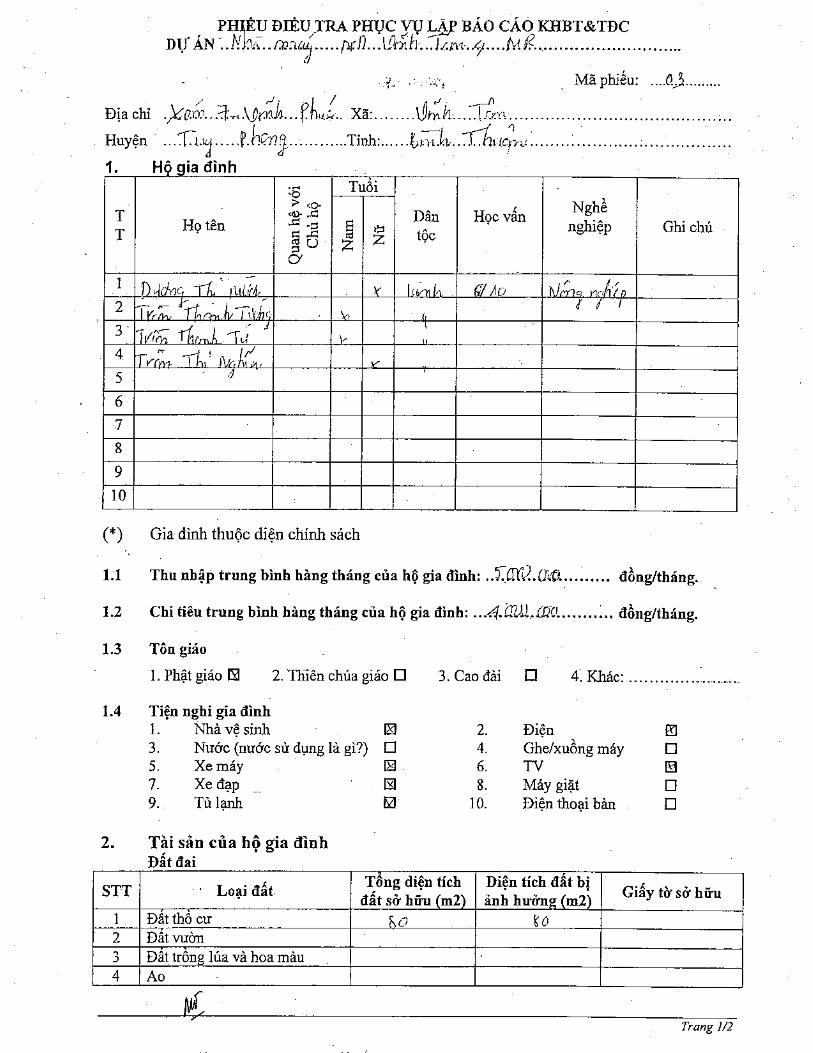

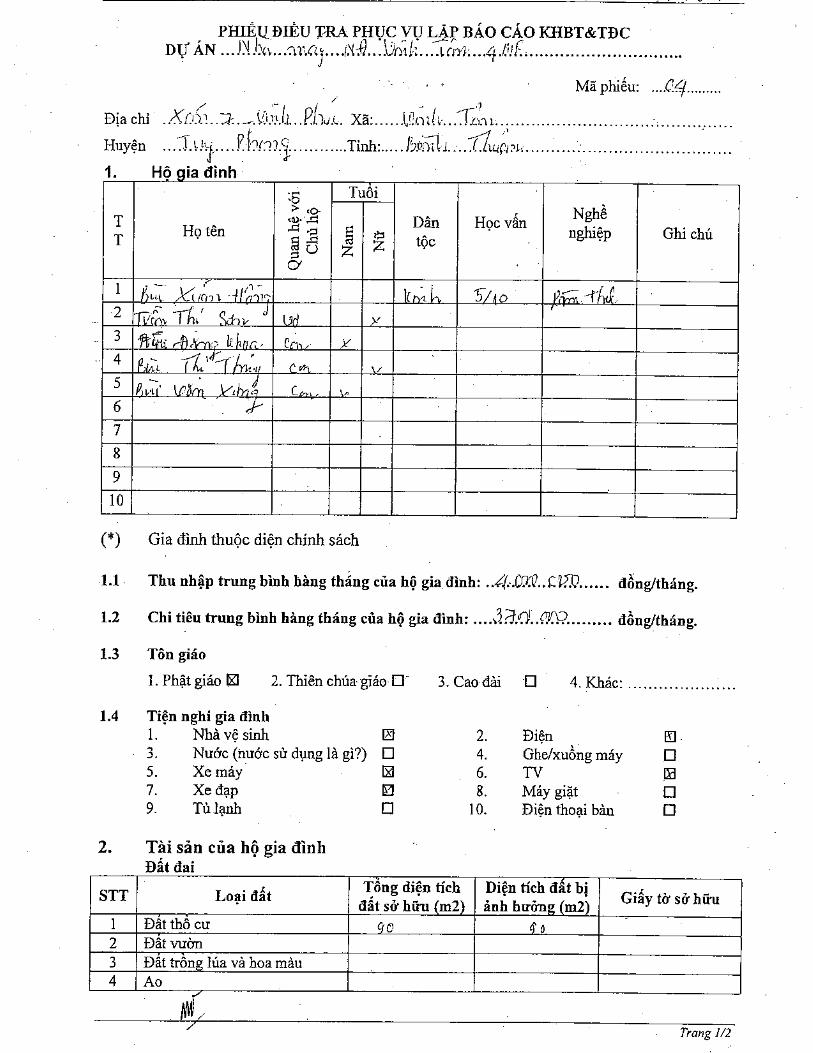
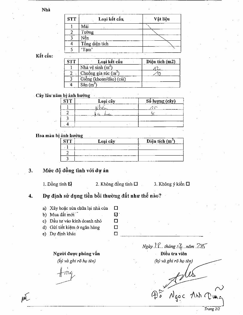
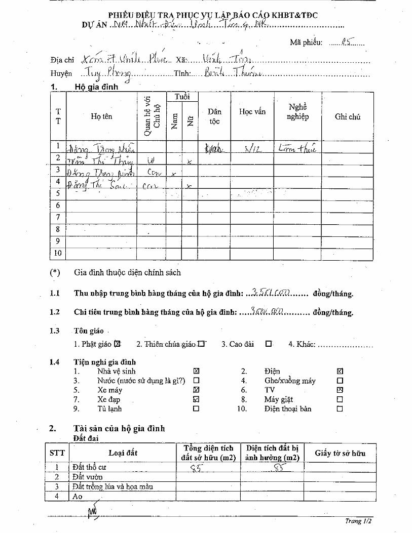

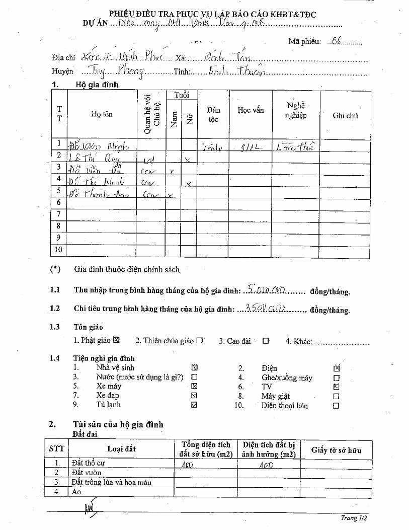
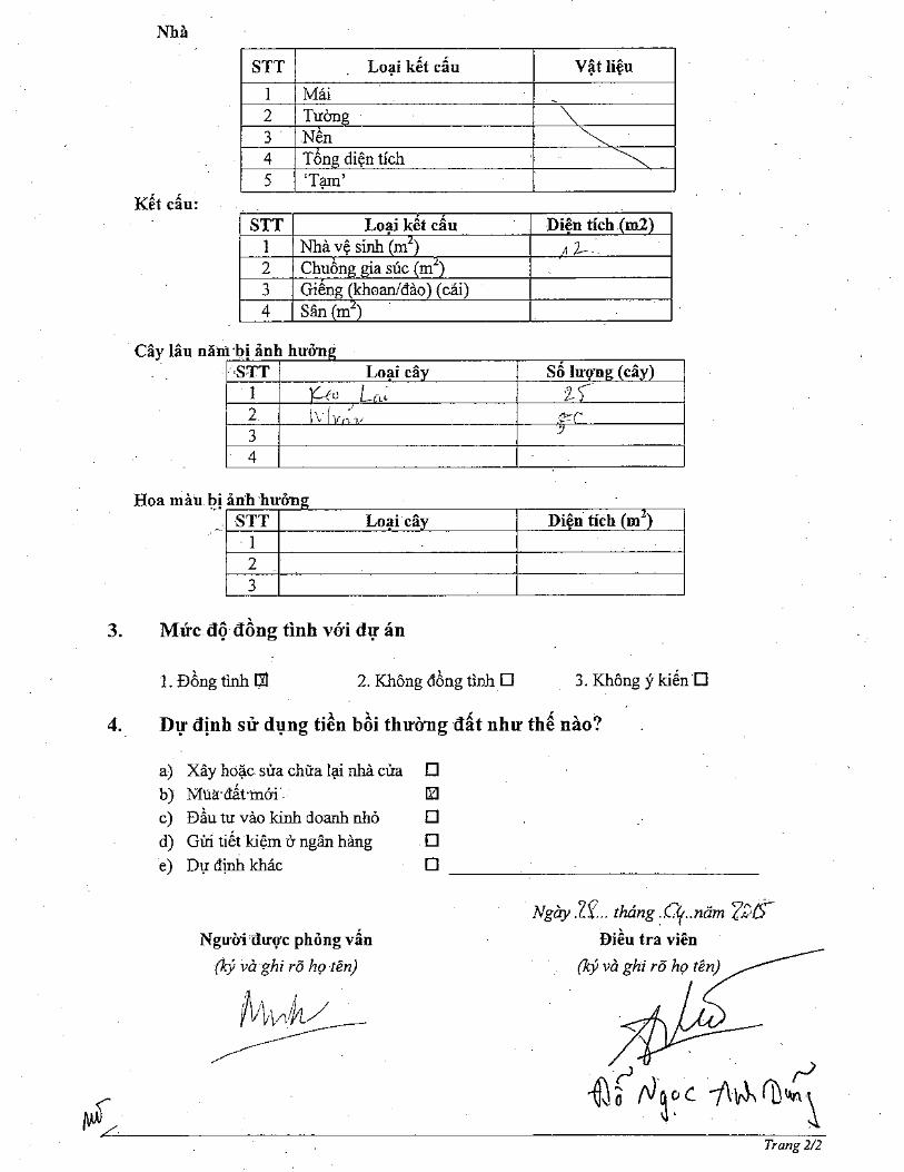
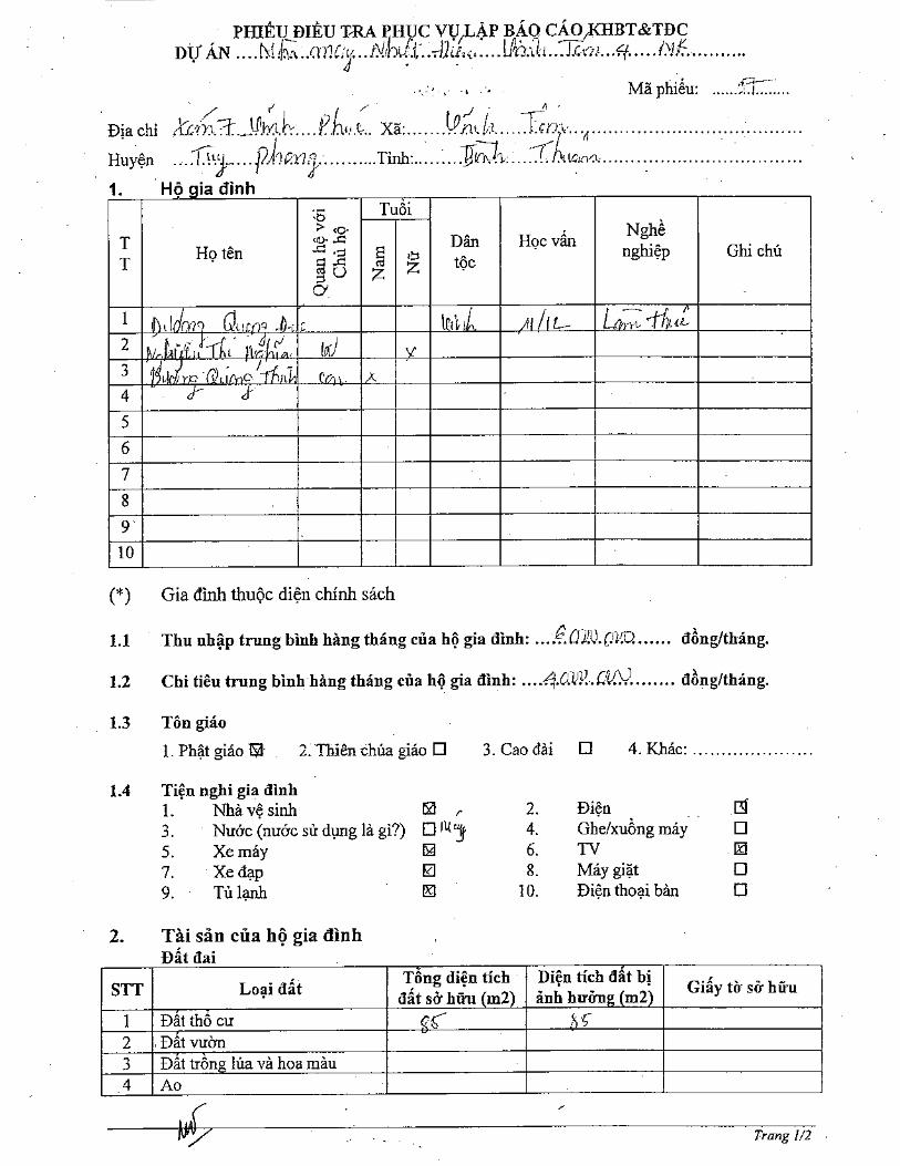
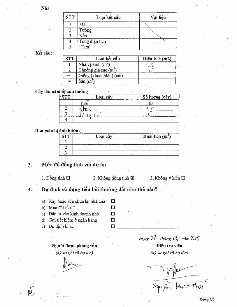


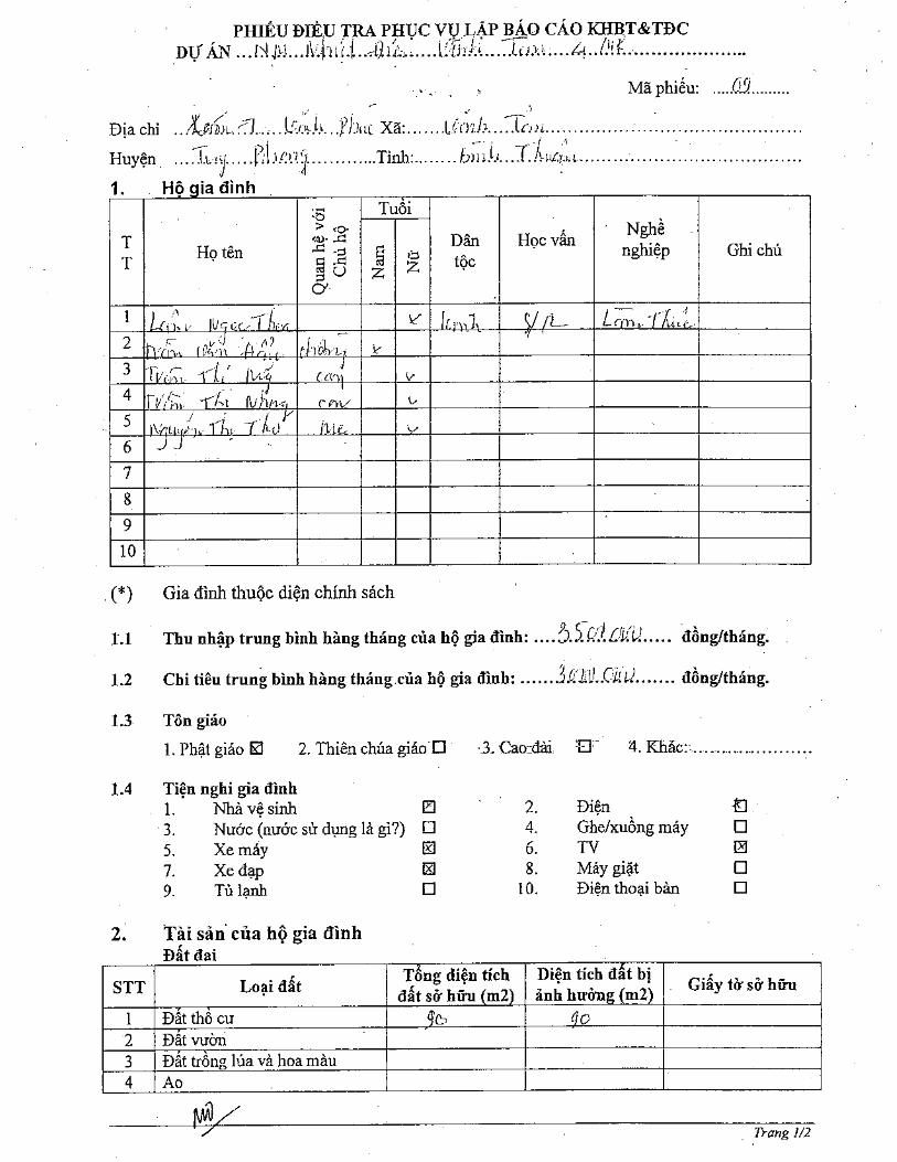
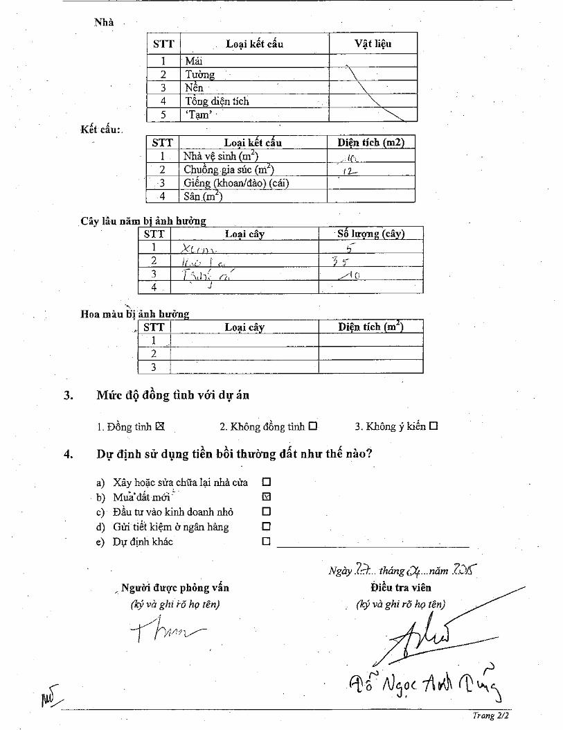
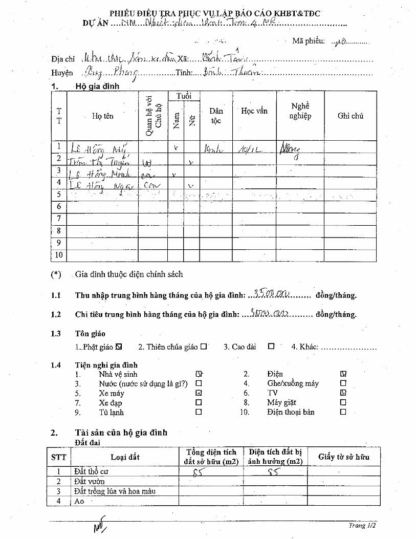


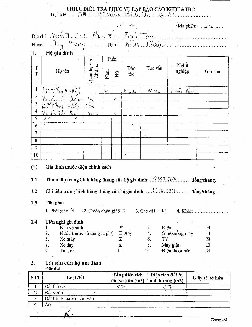


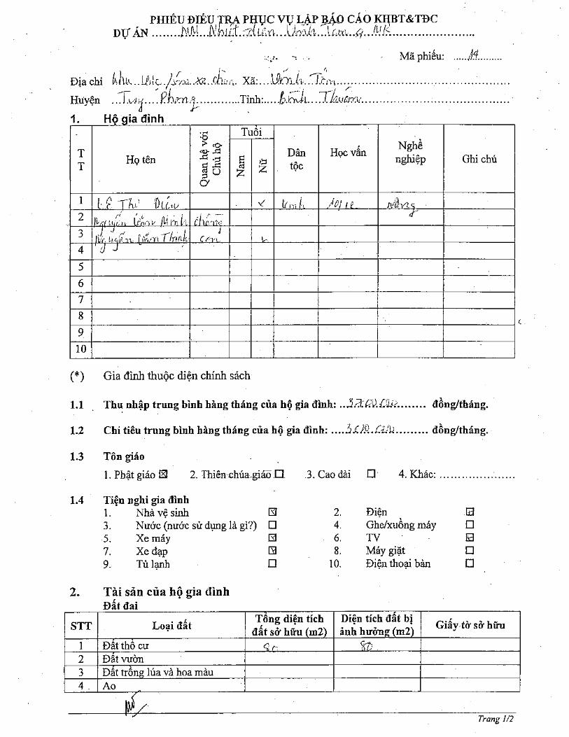

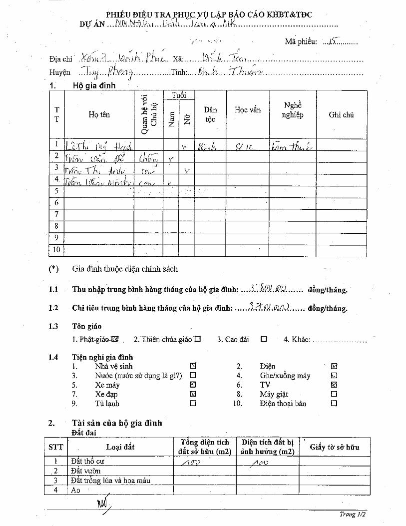

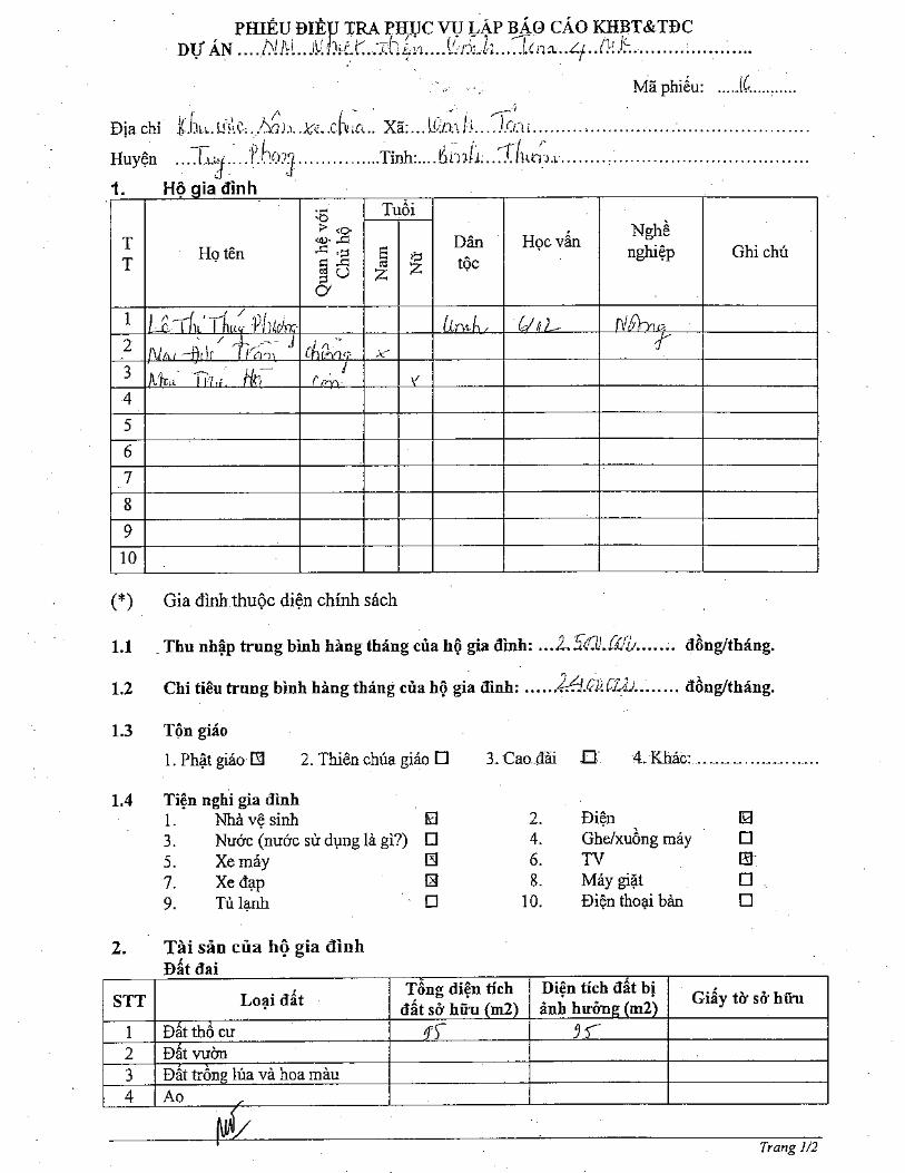
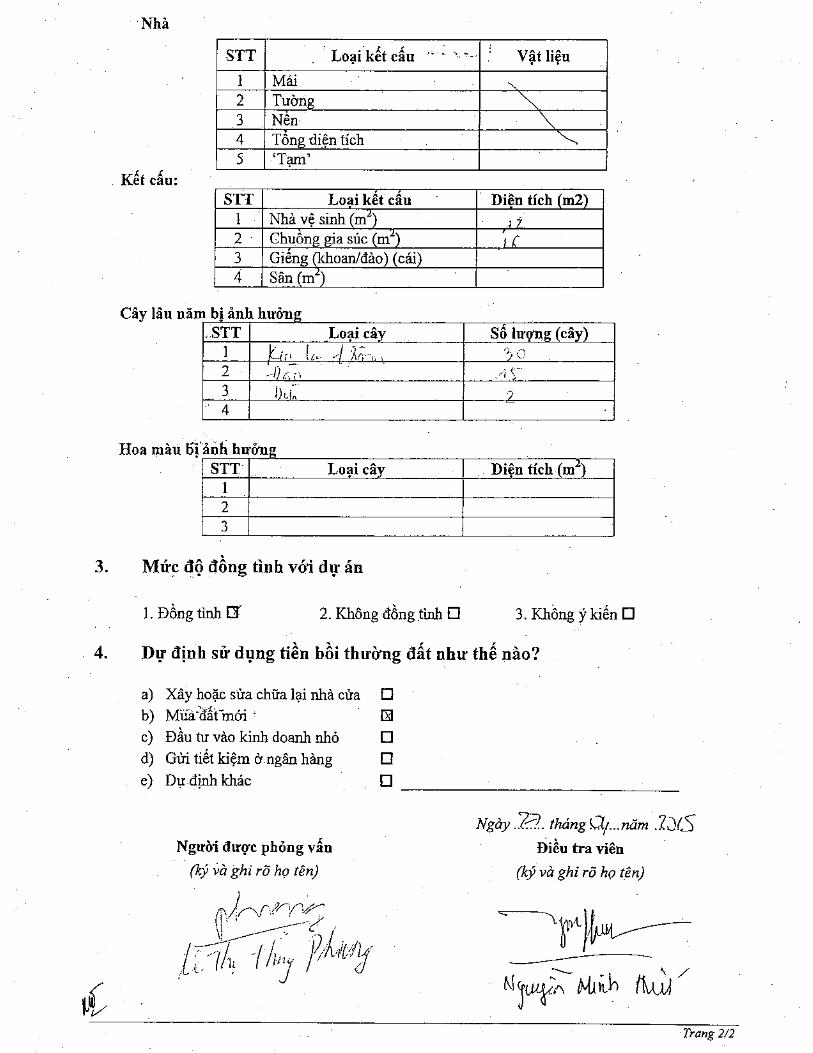
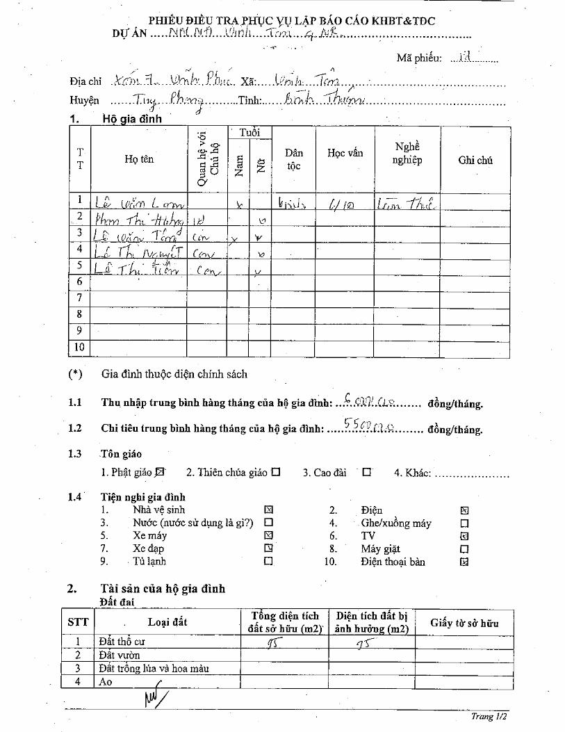

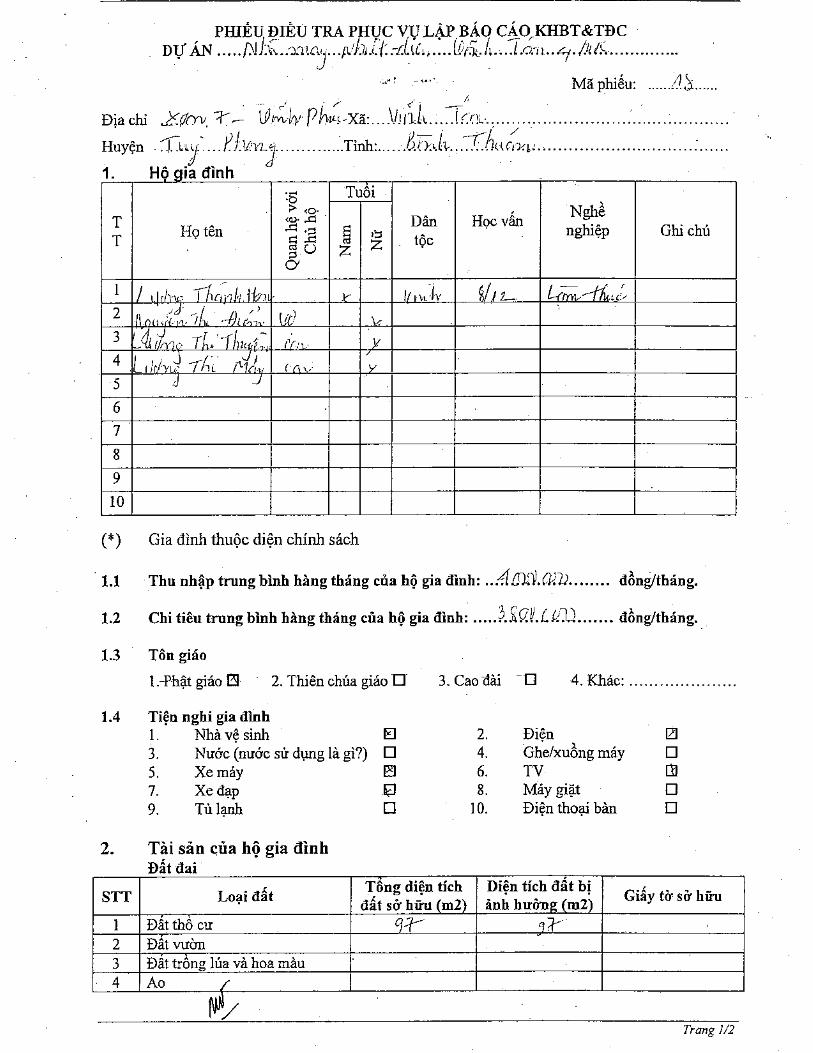

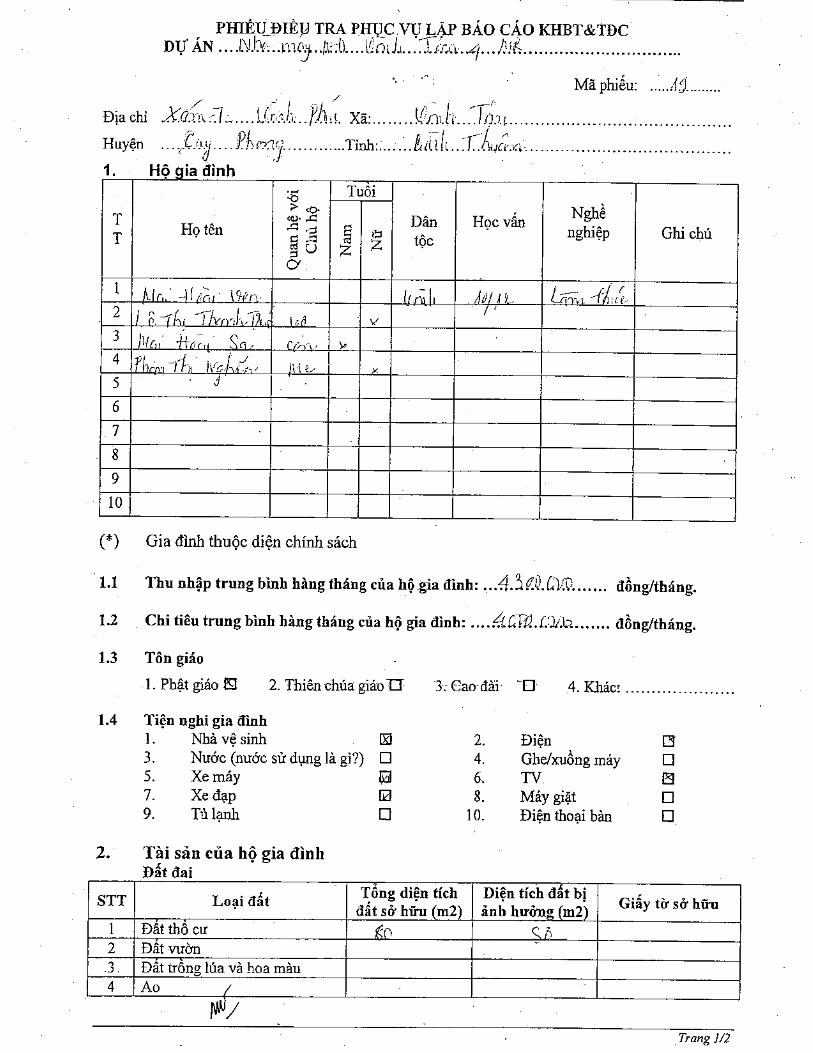
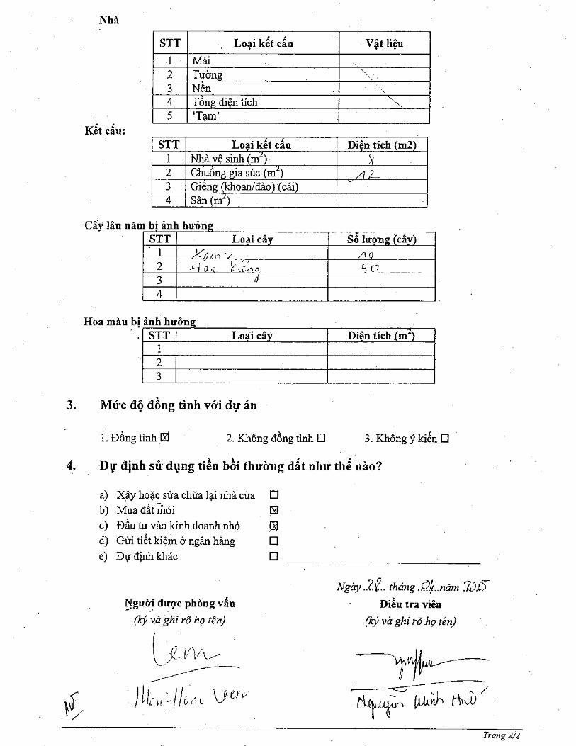
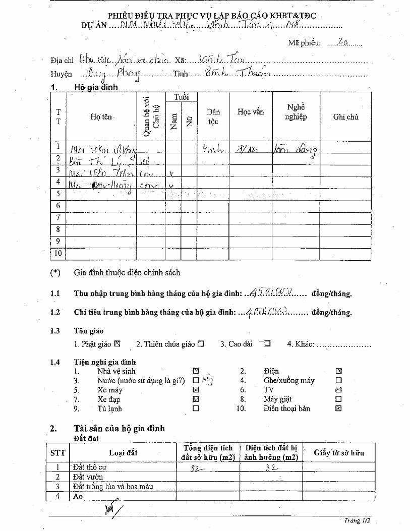
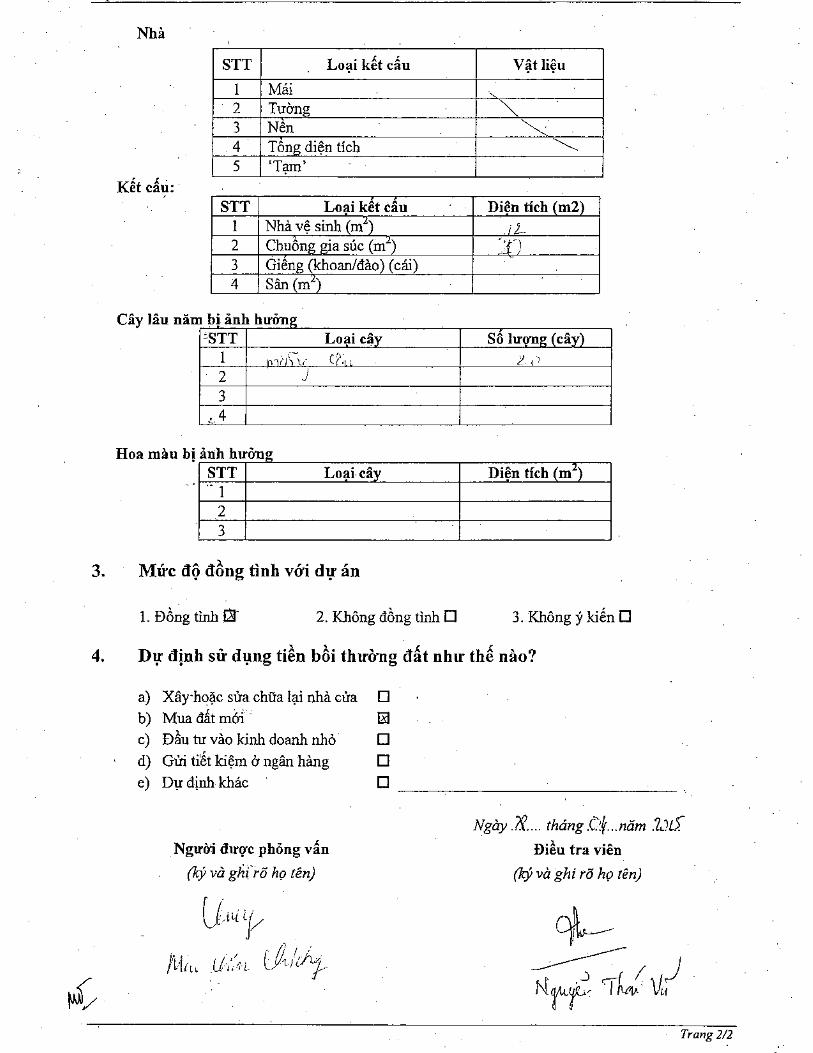


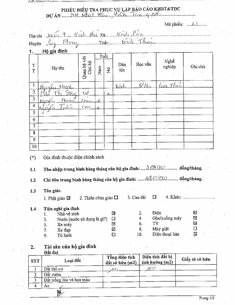

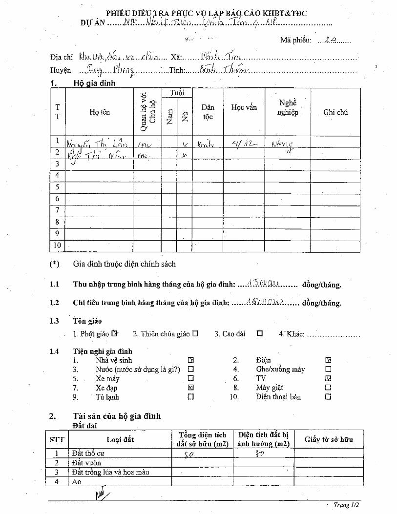

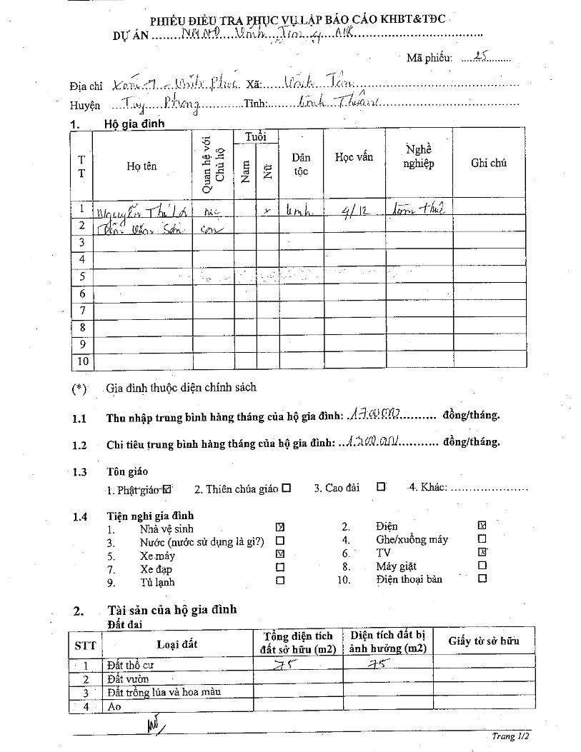

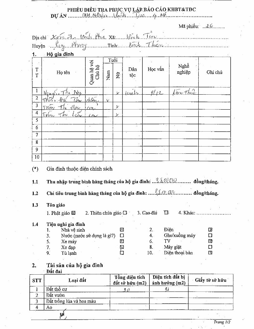
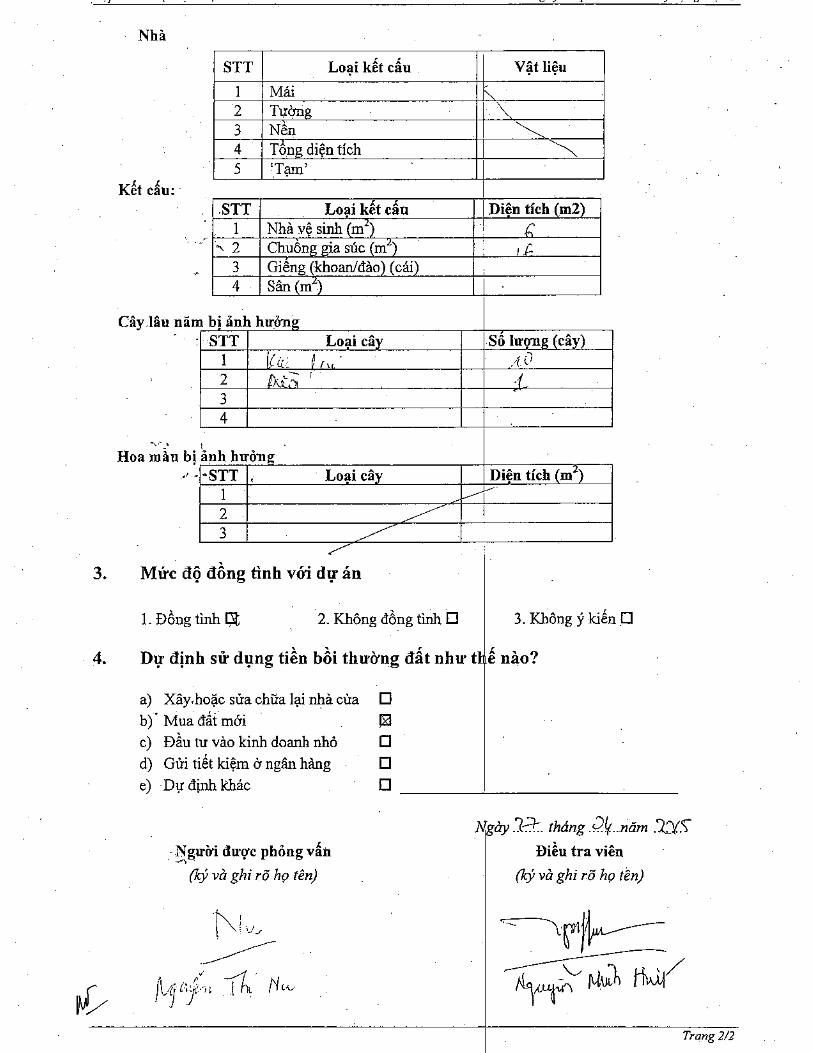
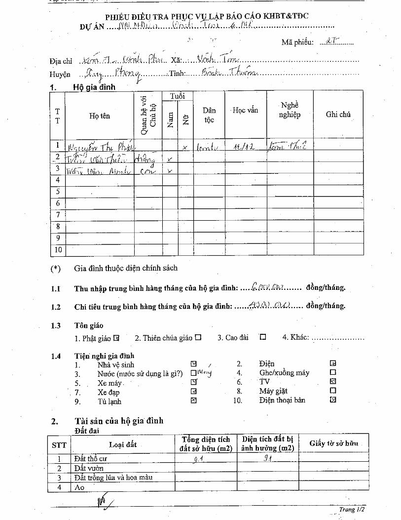


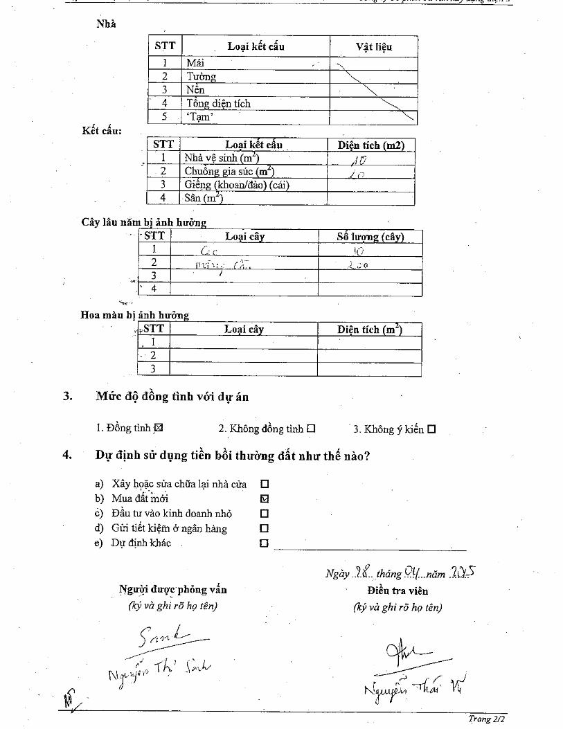


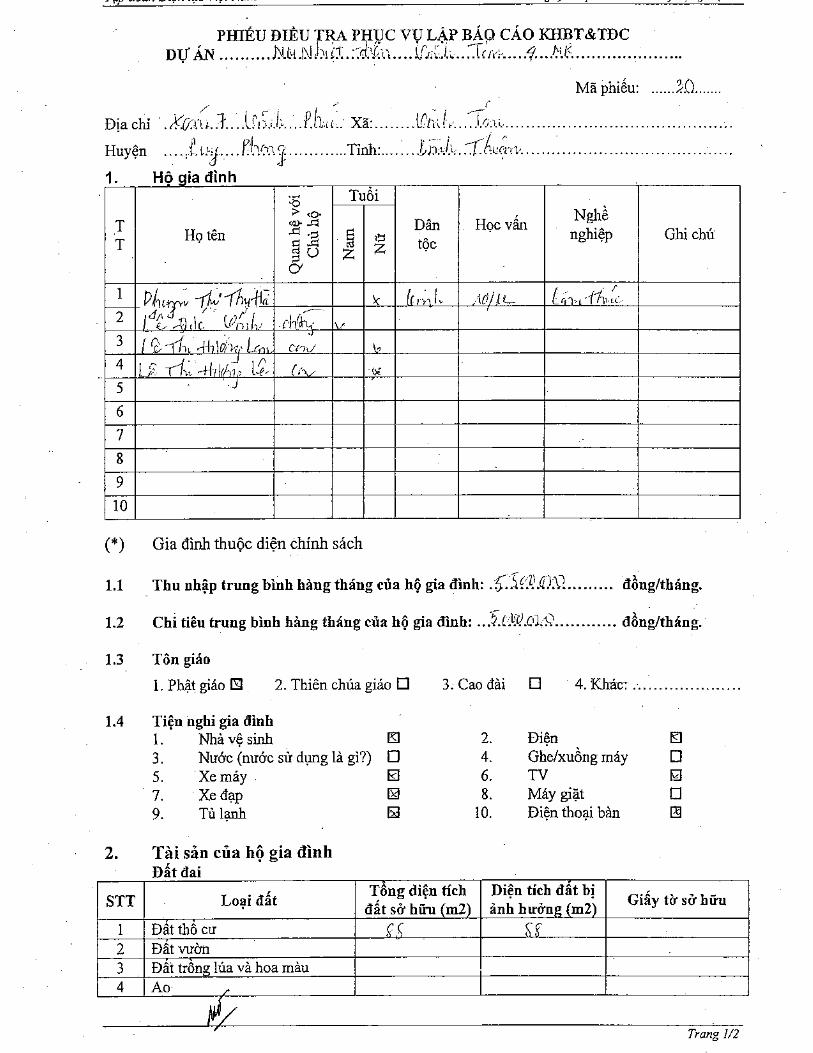

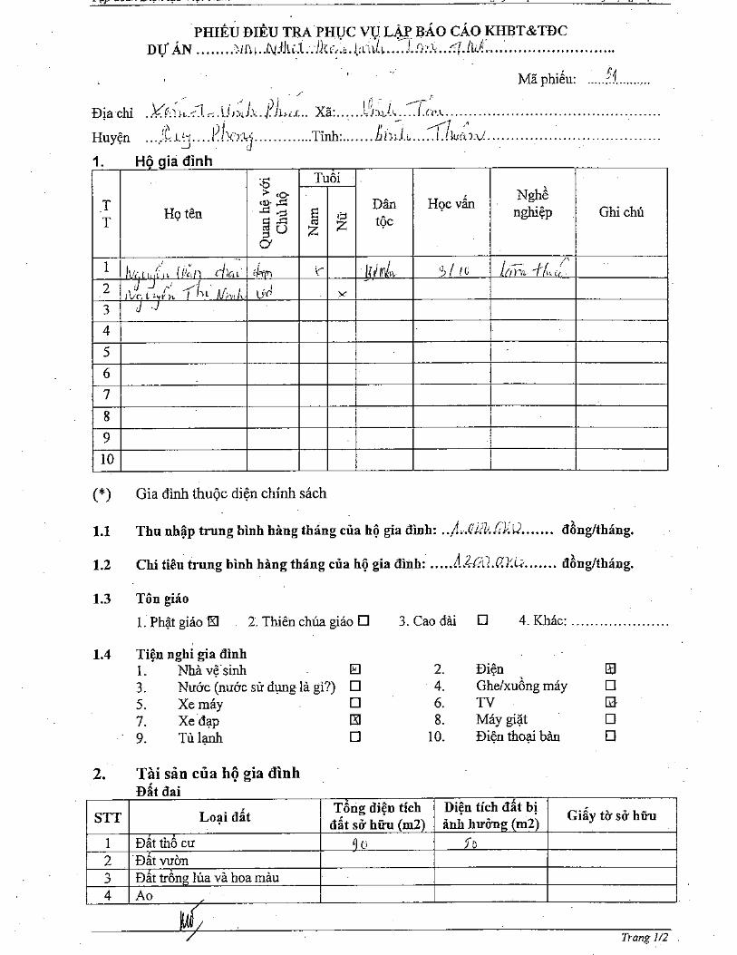

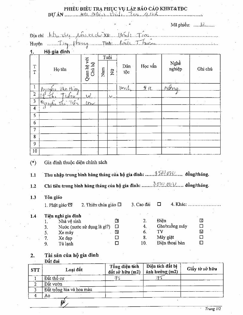

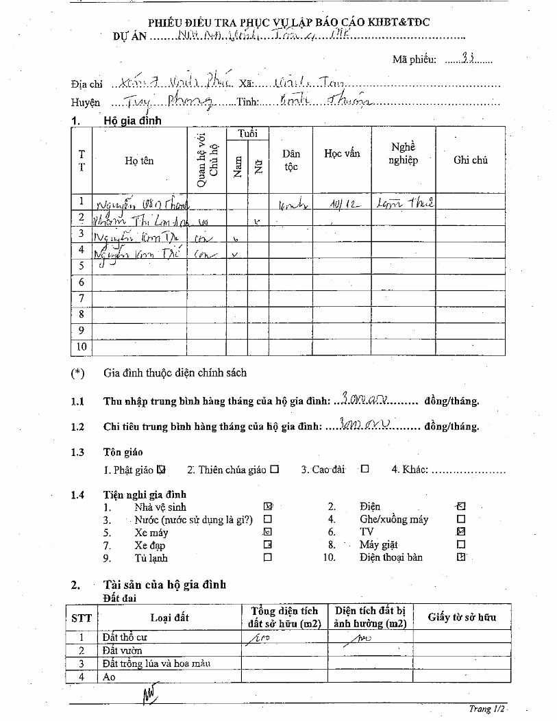
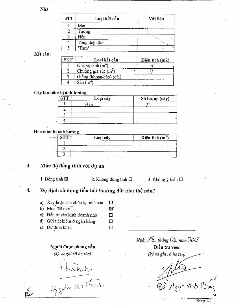
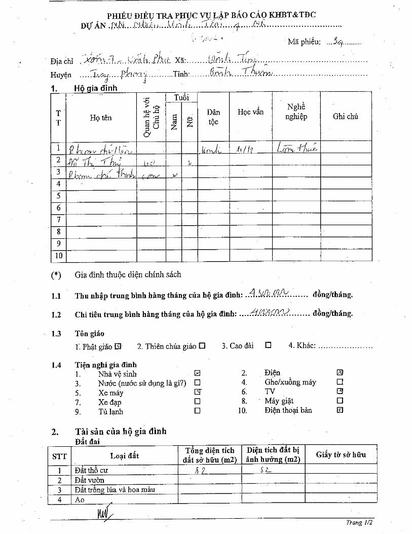

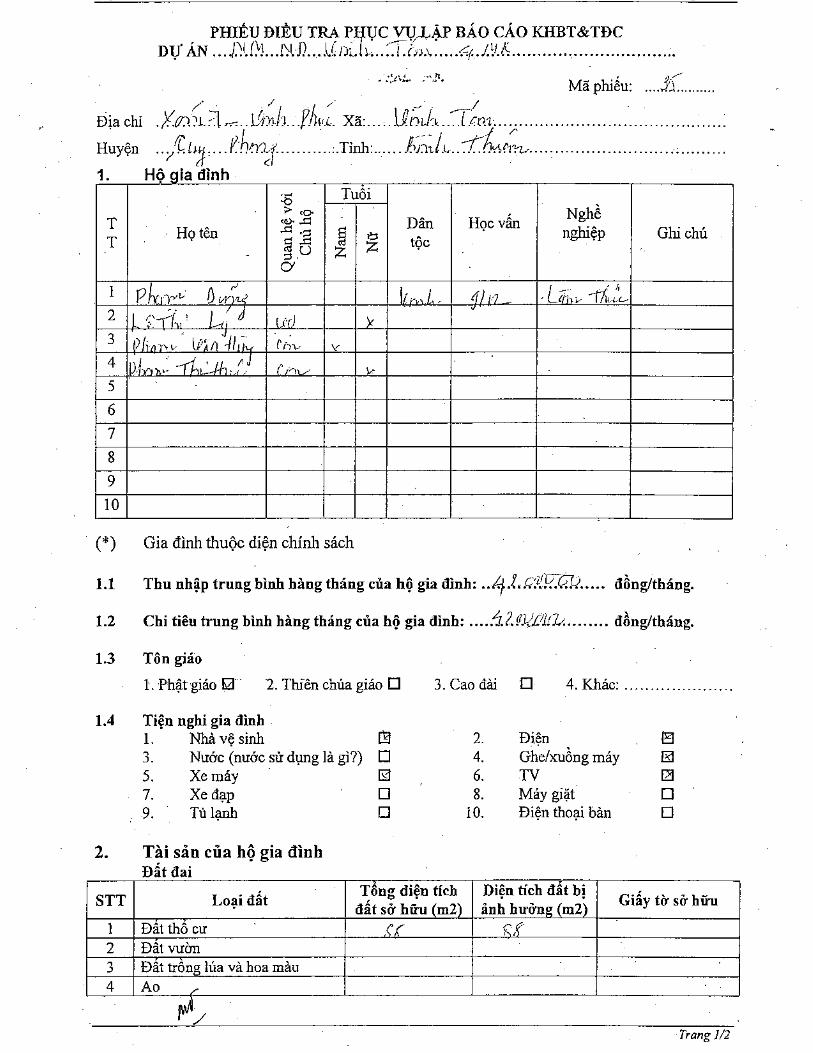

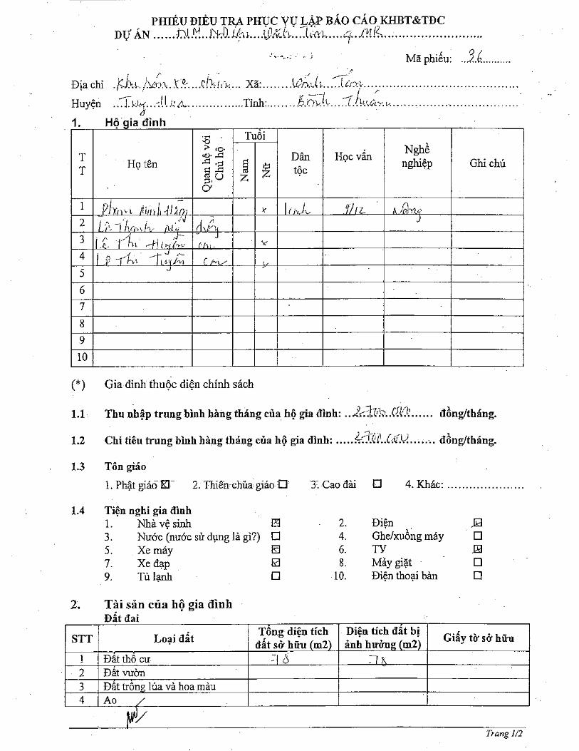
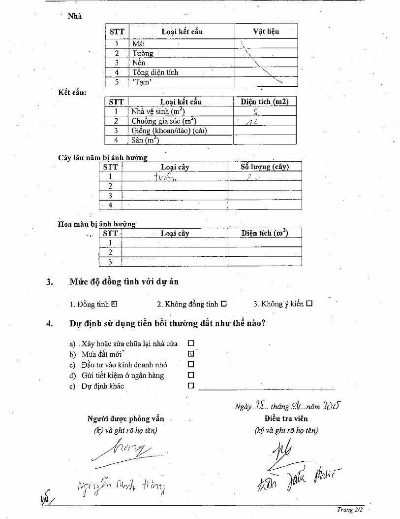
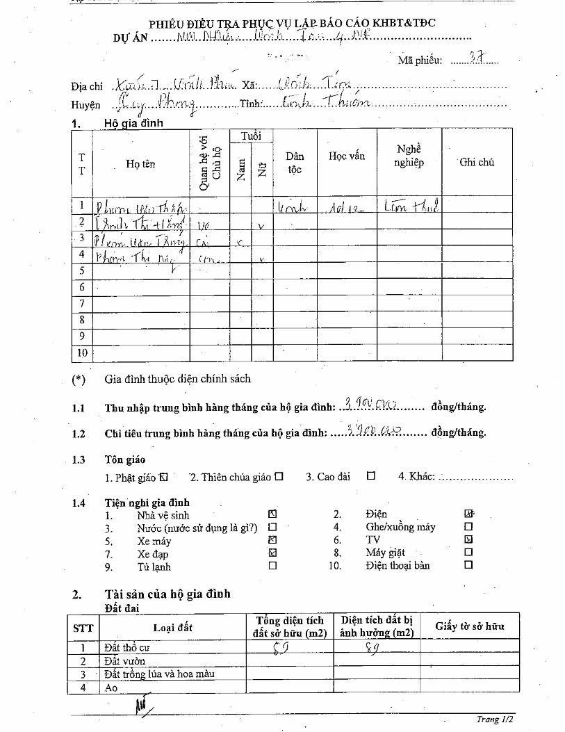
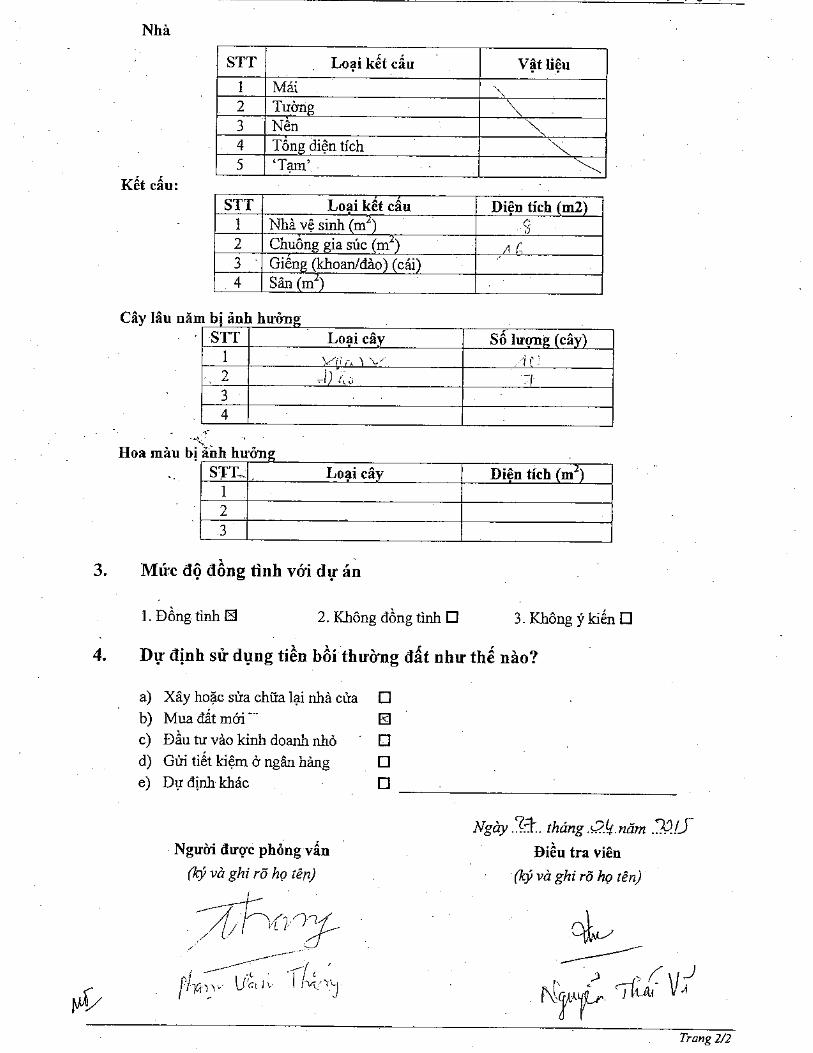
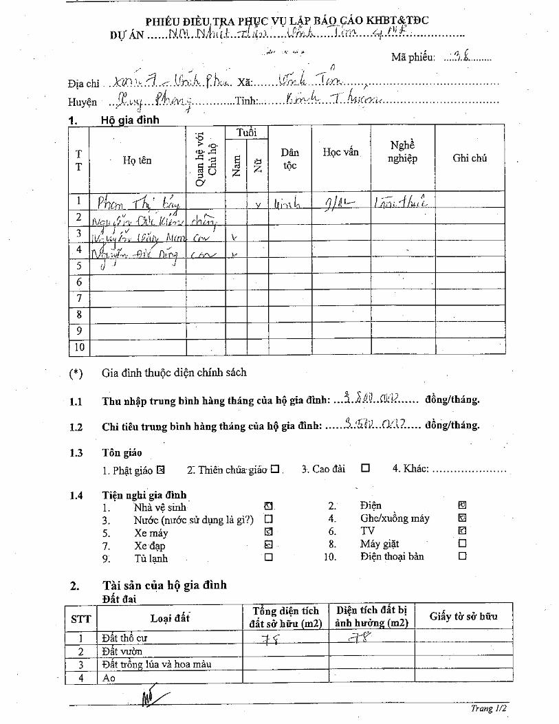
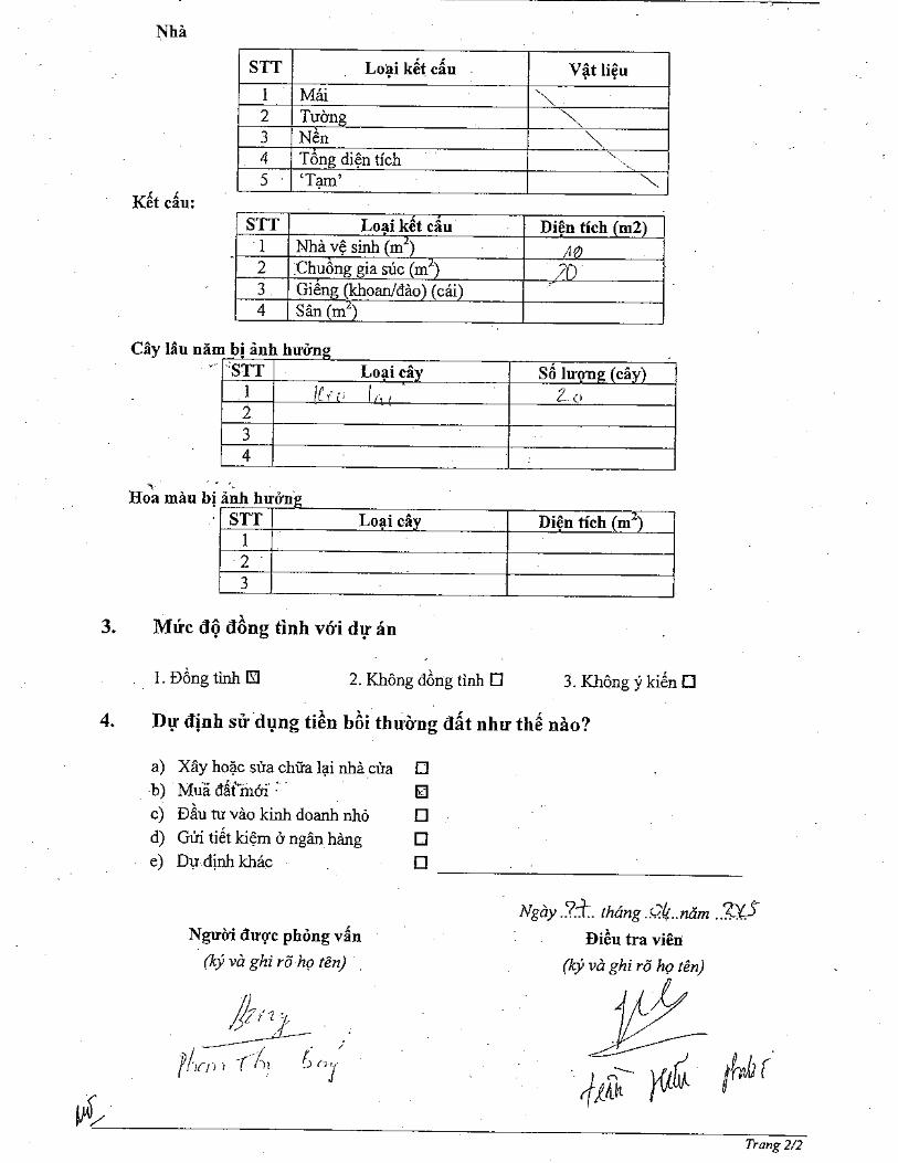
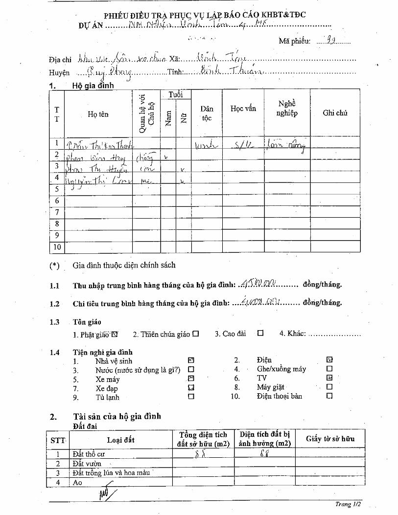

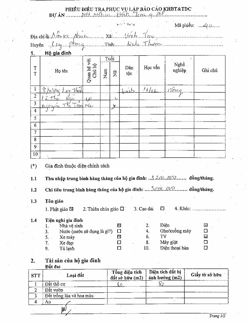

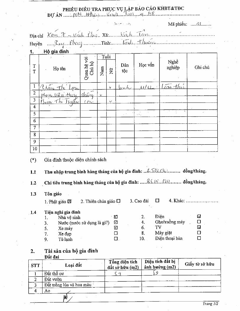

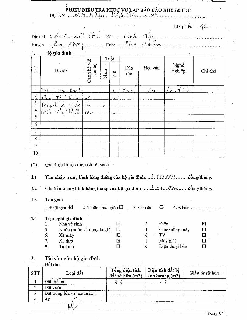
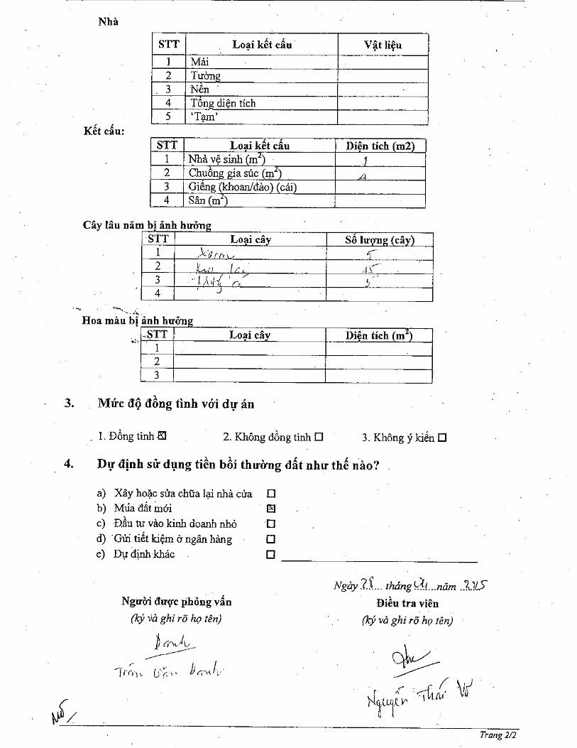
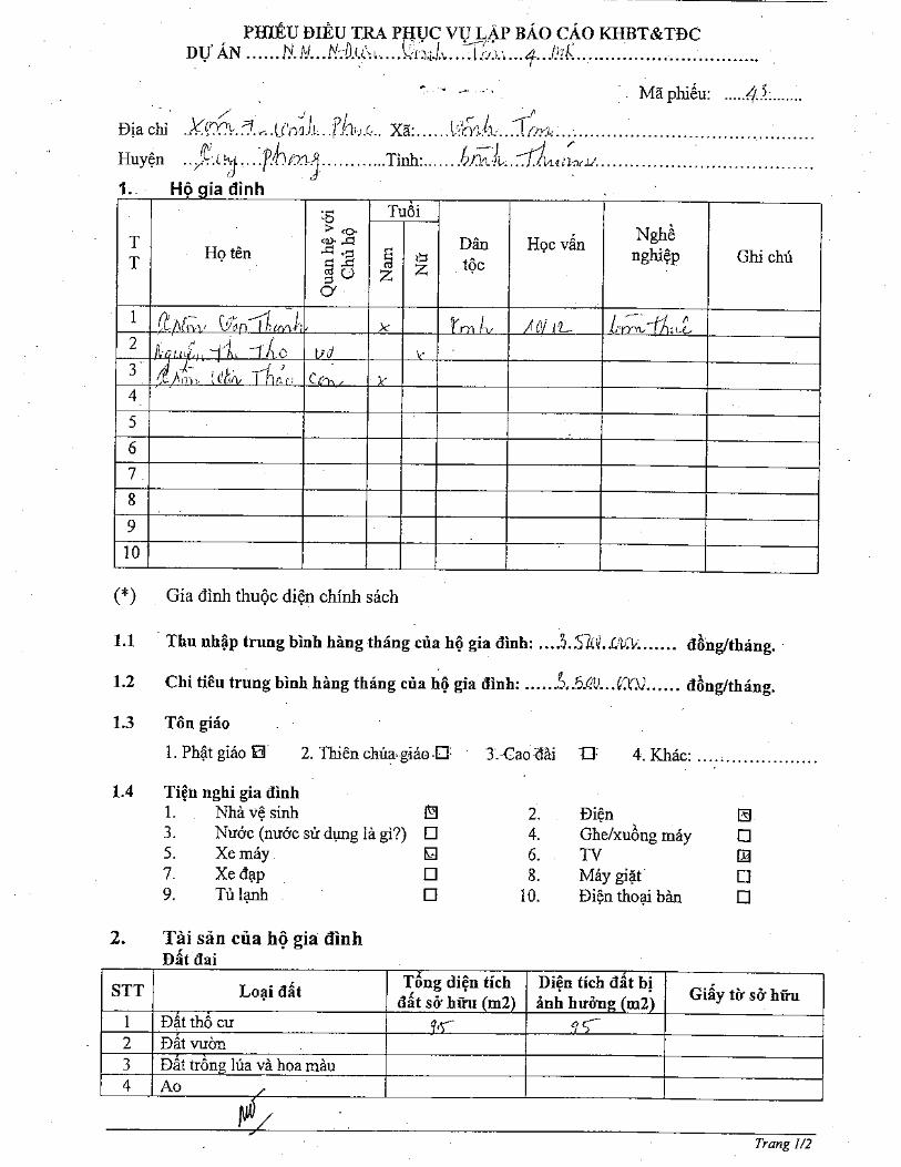
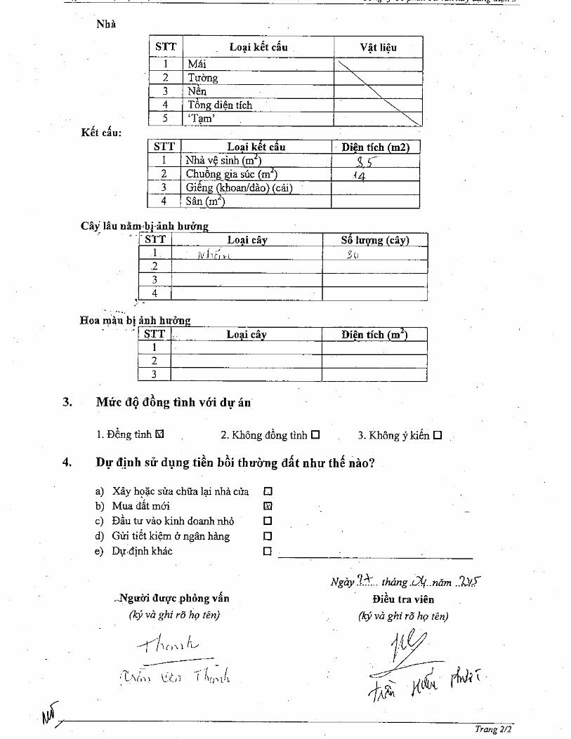
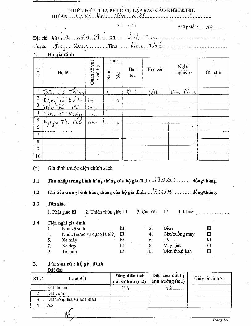

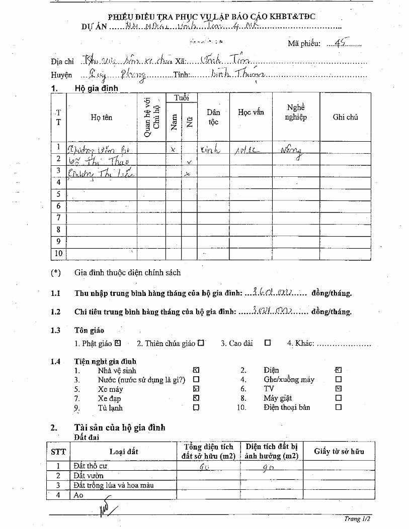

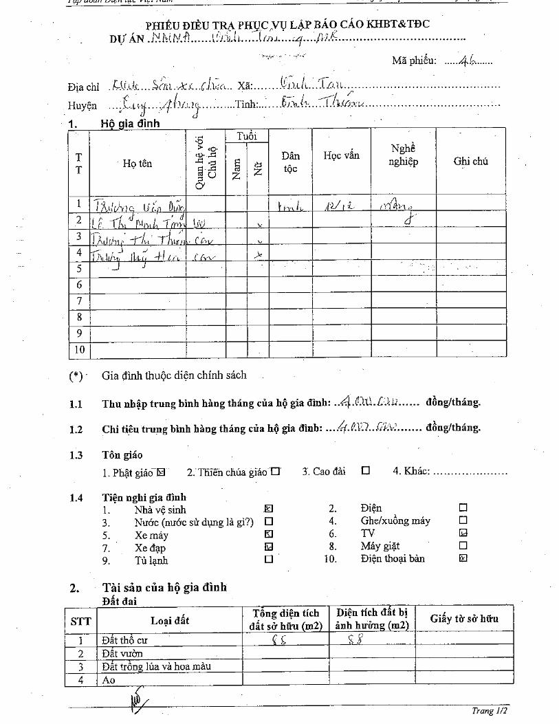

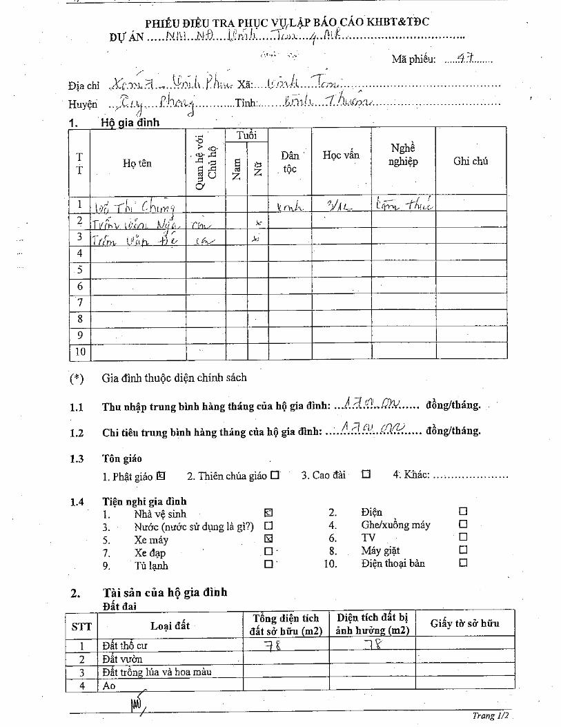
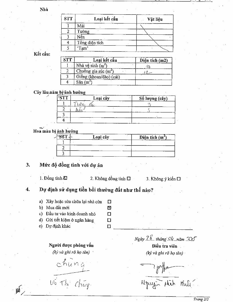
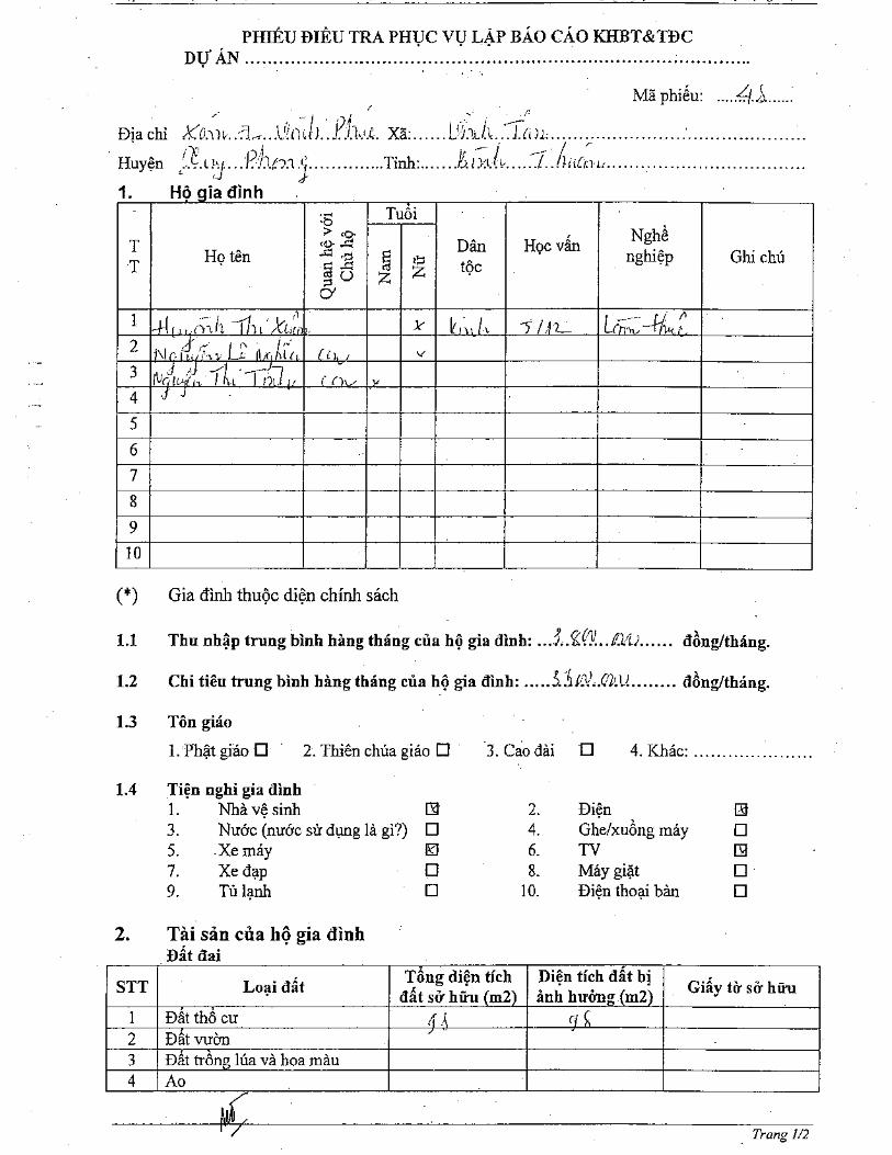
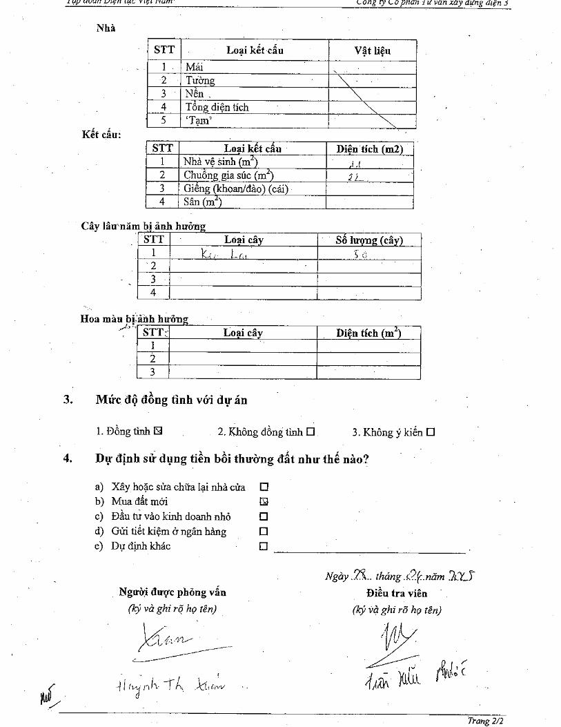
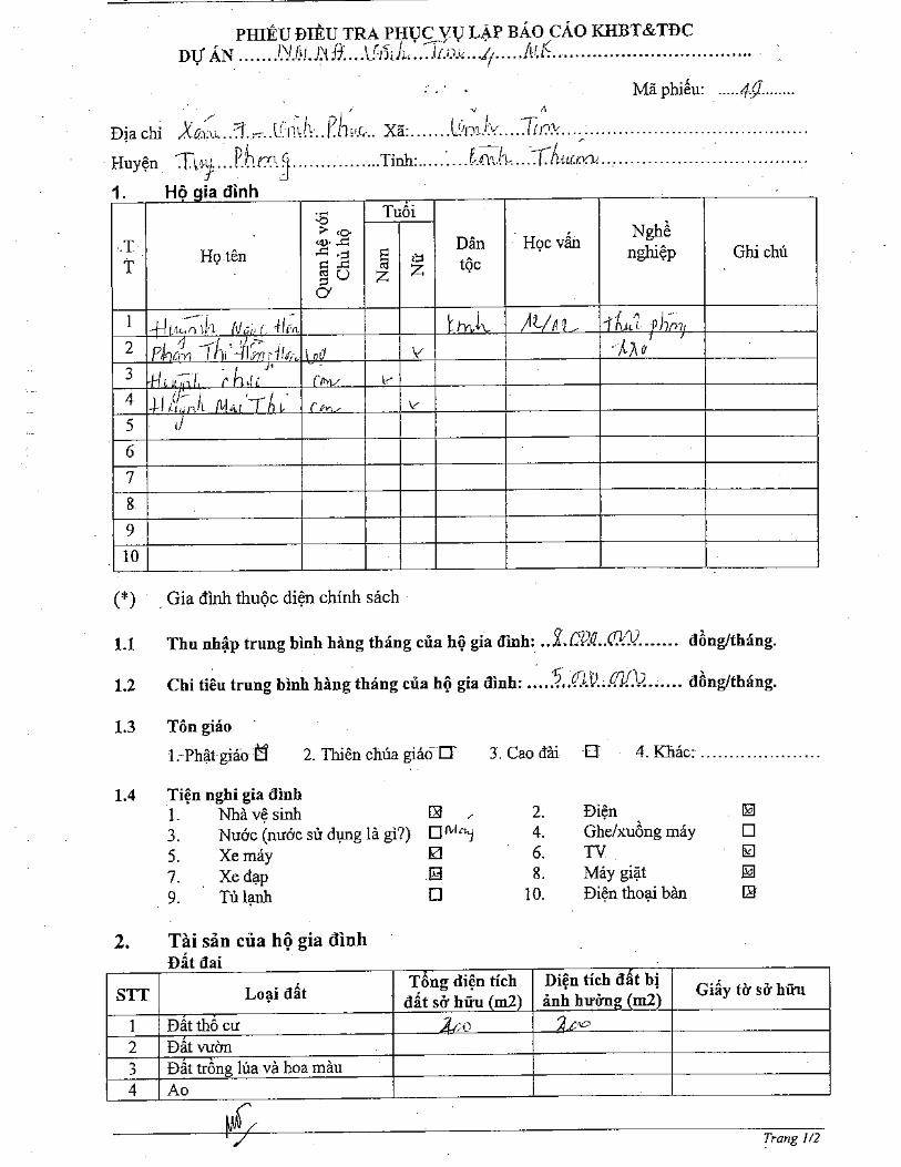

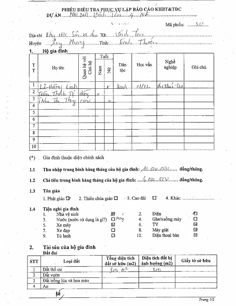


Vinh Tan 4 Ext TPP – 1×600MWFeasibility Study Report
Annexes
ANNEX 5: SOME PHOTOS RELATED TO THE PROJECT
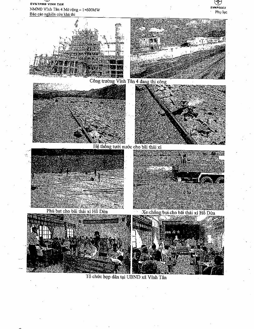
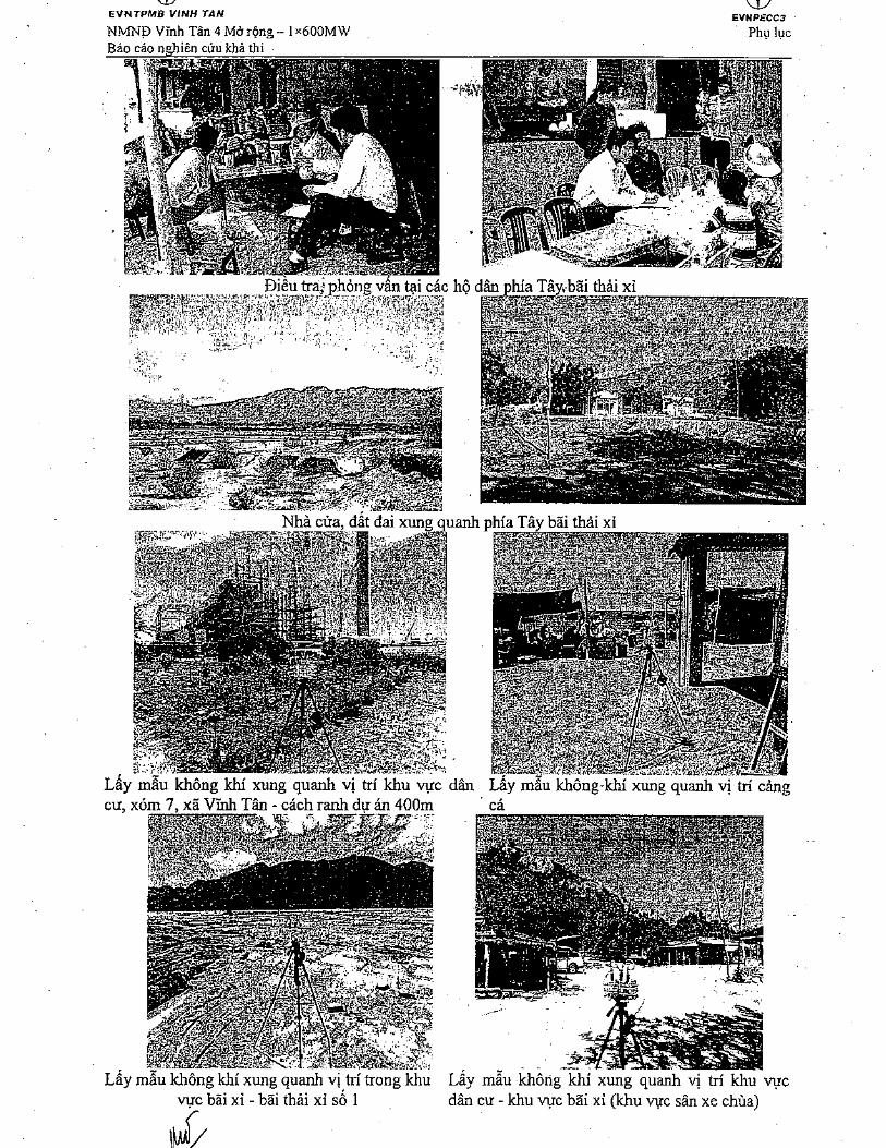

Vinh Tan 4 Ext TPP – 1×600MWFeasibility Study Report
Annexes
ANNEX 6: COST IN DETAIL FOR COMPENSATION,ASSISTANCE, RESETTLEMENT
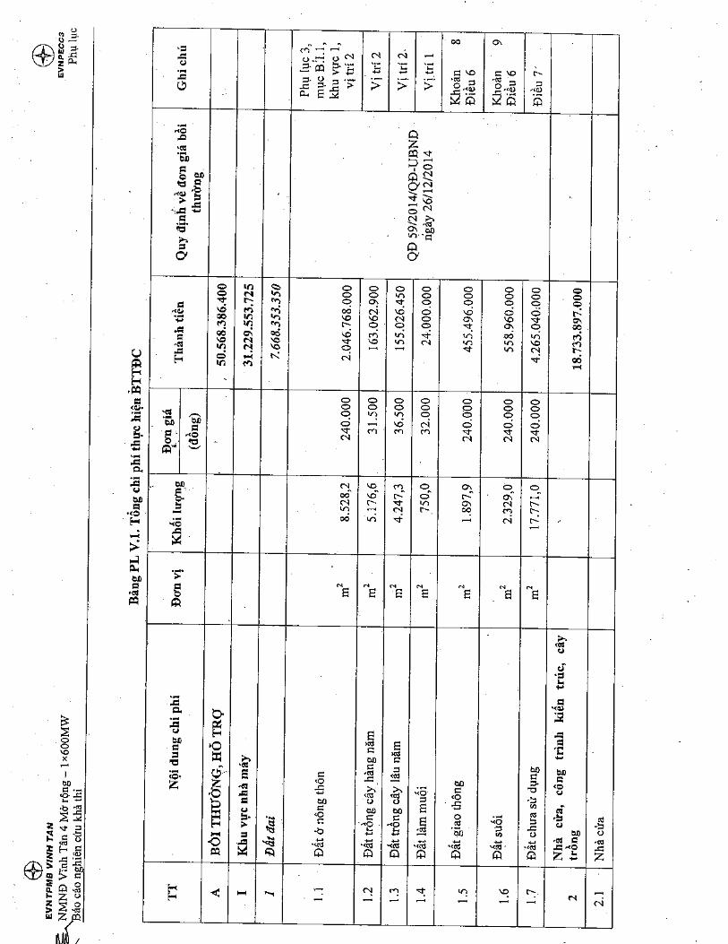
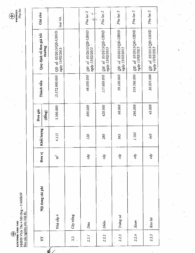
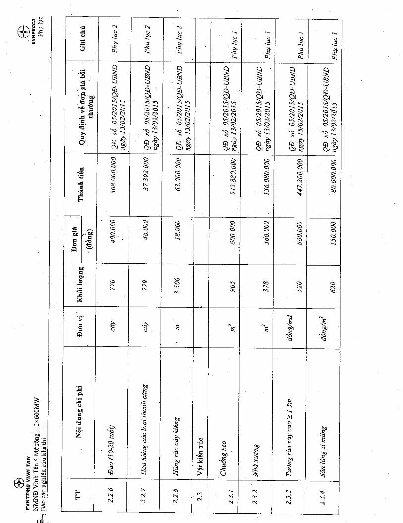
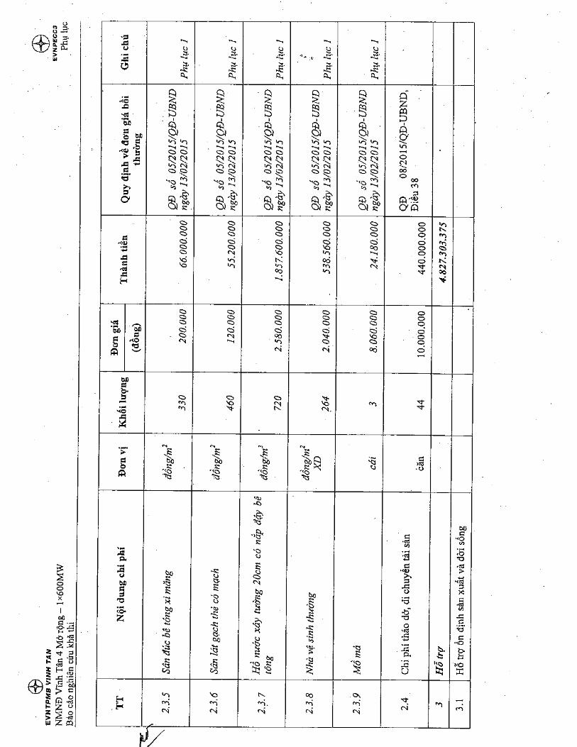
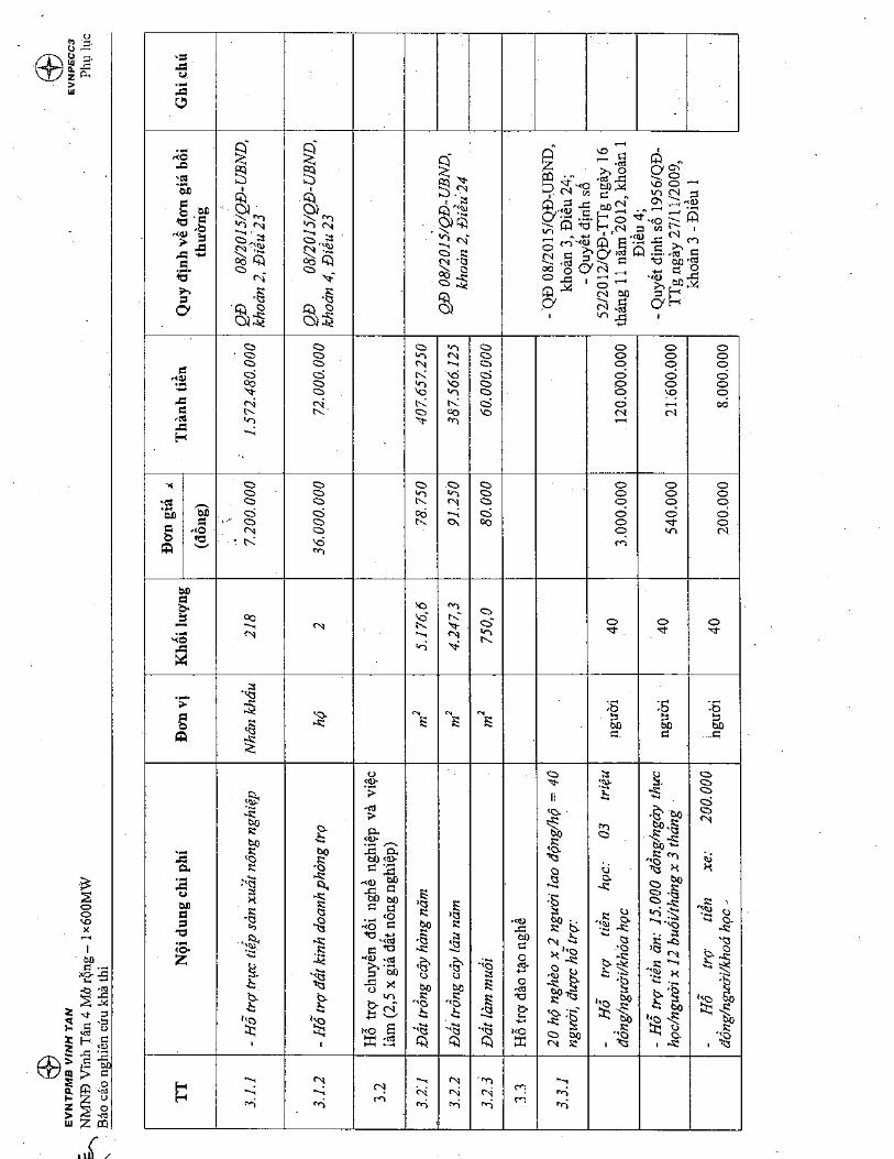
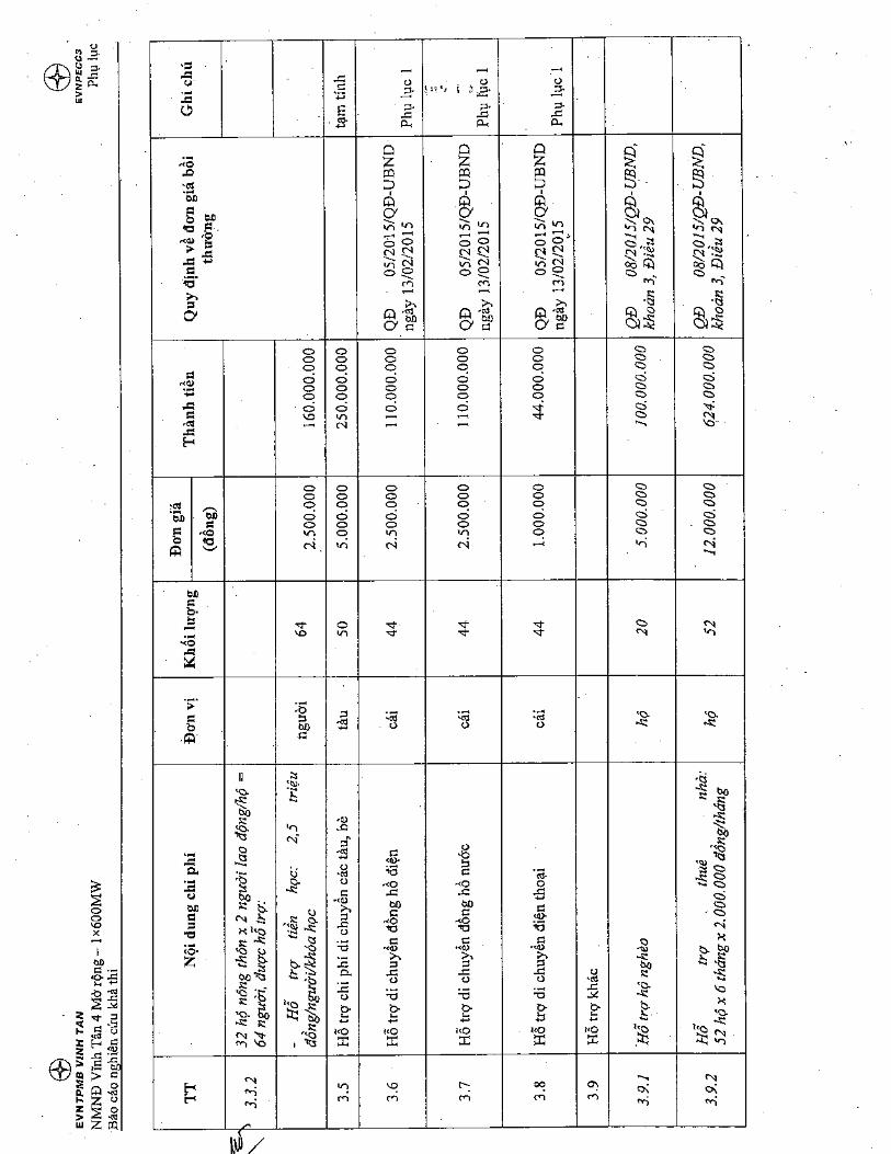
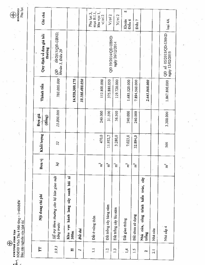
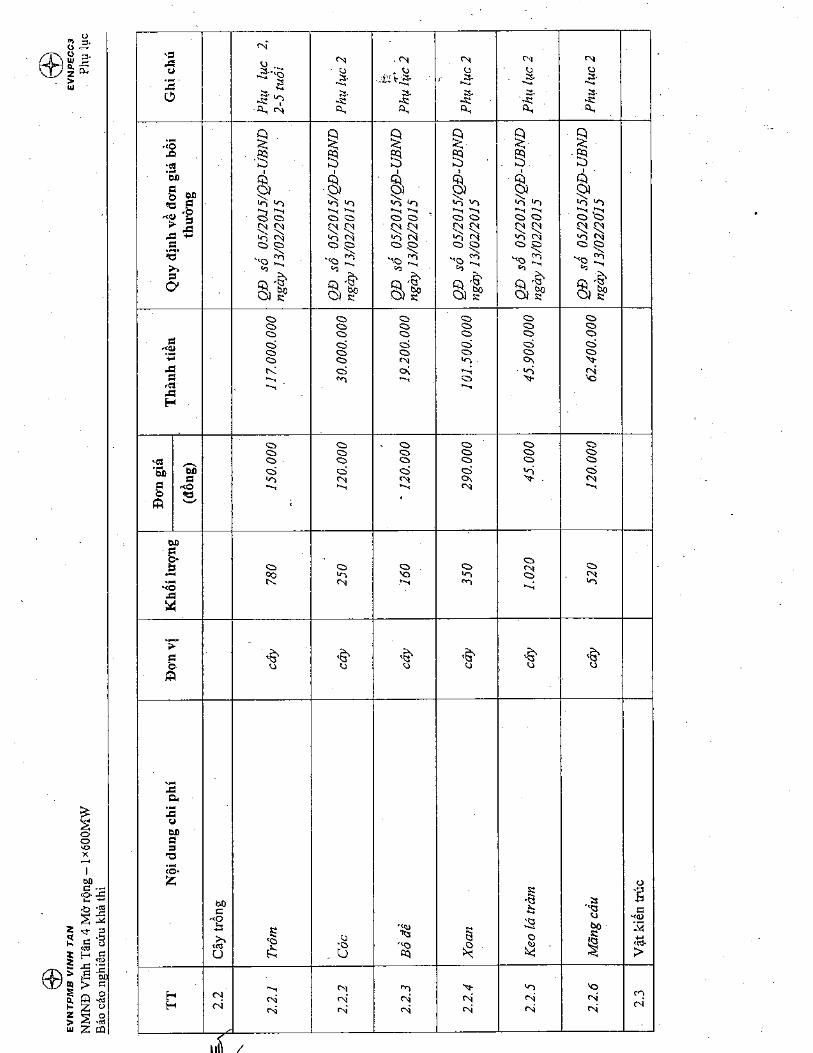
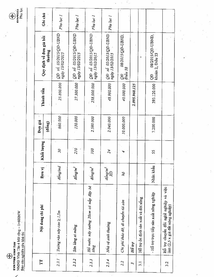
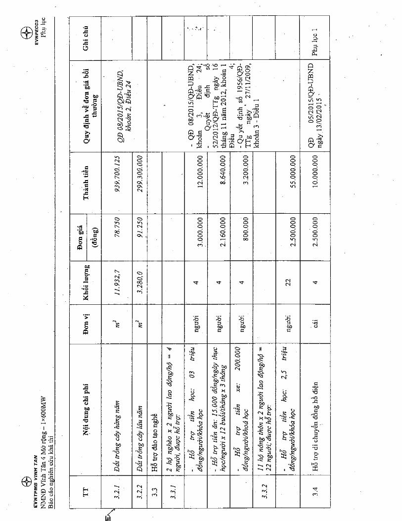
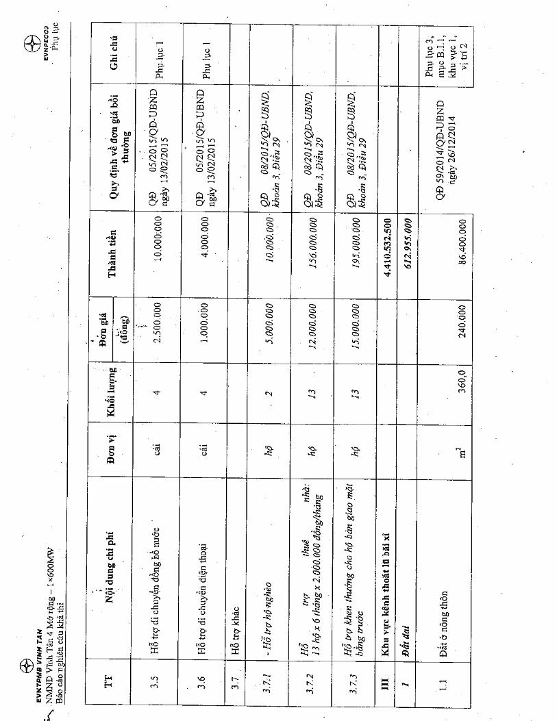
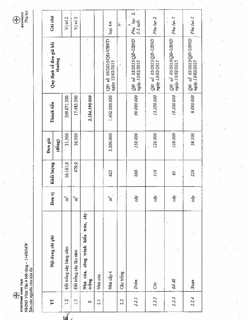

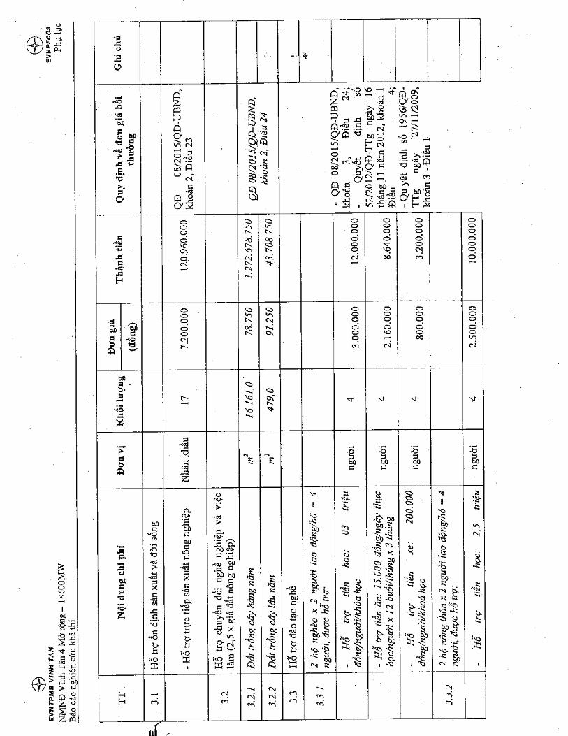
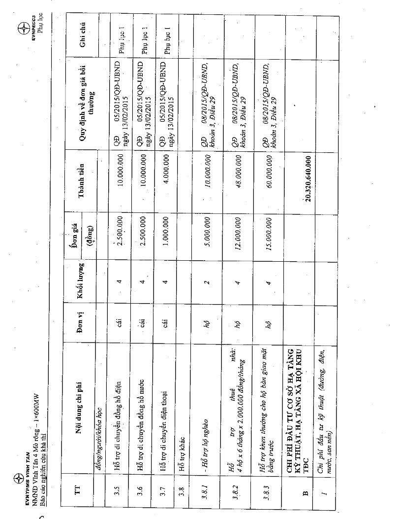
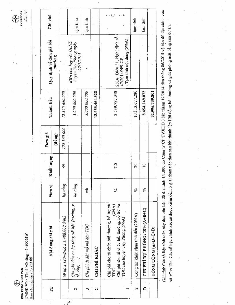

Vinh Tan 4 Ext TPP – 1×600MWFeasibility Study Report
Annexes
ANNEX 7: LIST OF SPECIES IN THE PROJECT AREA
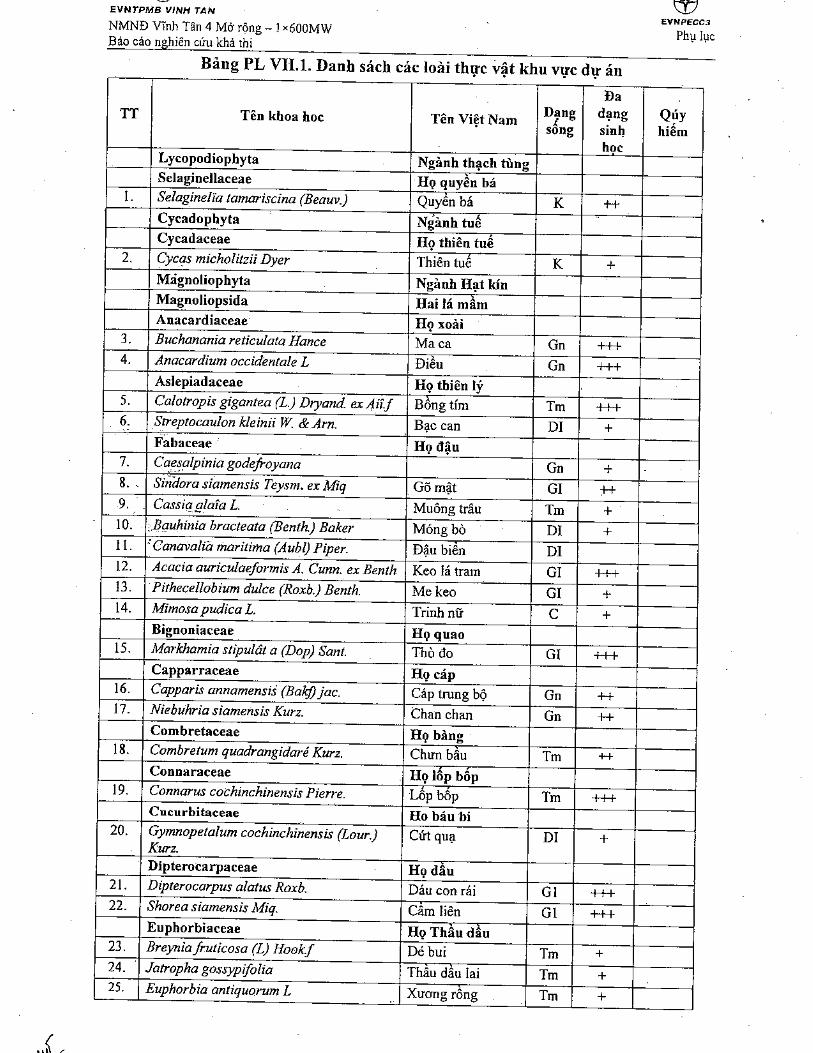
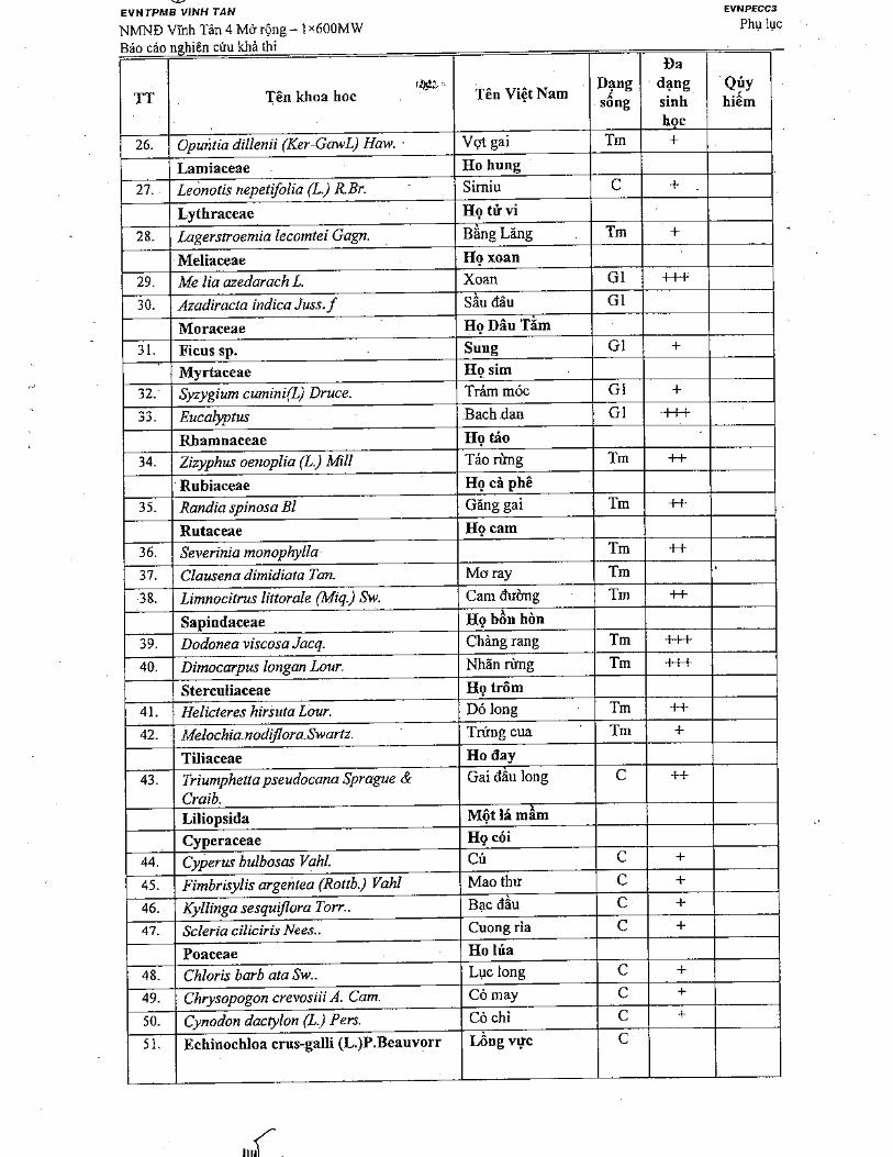
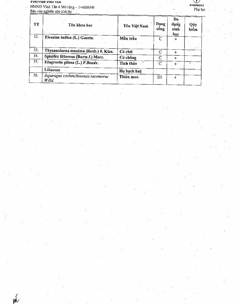
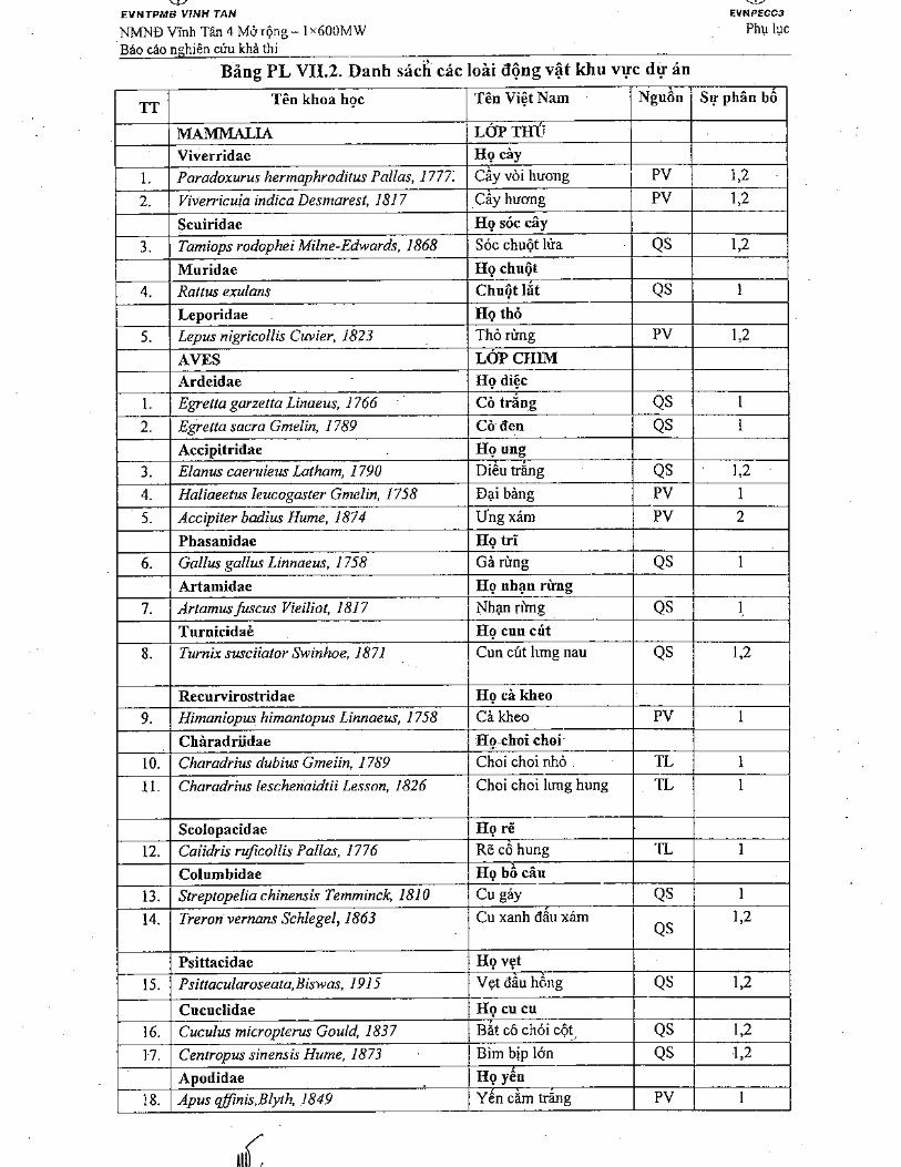
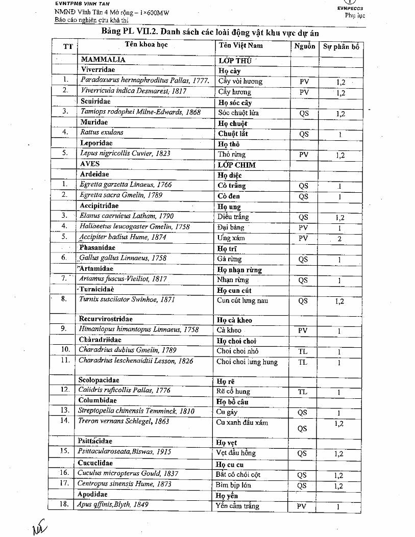
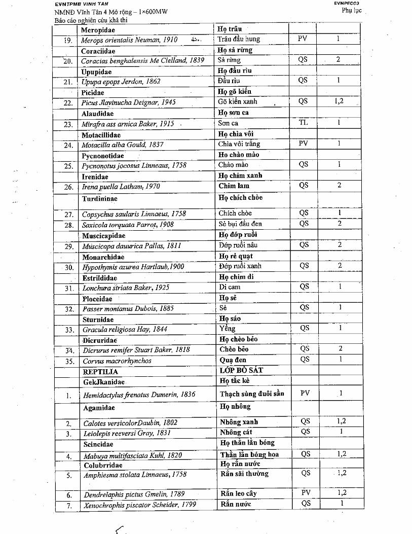
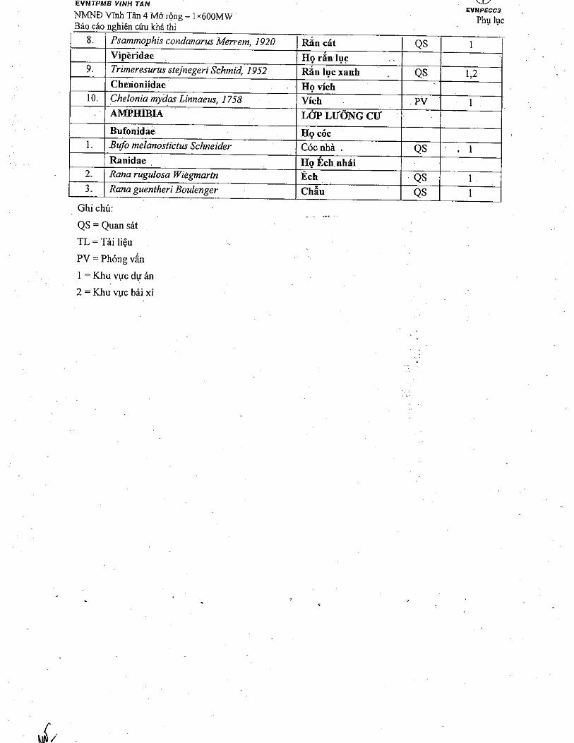
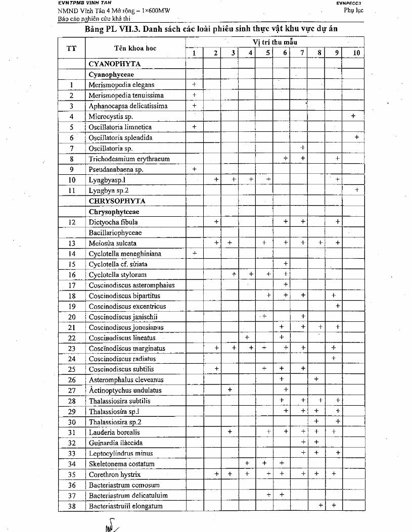
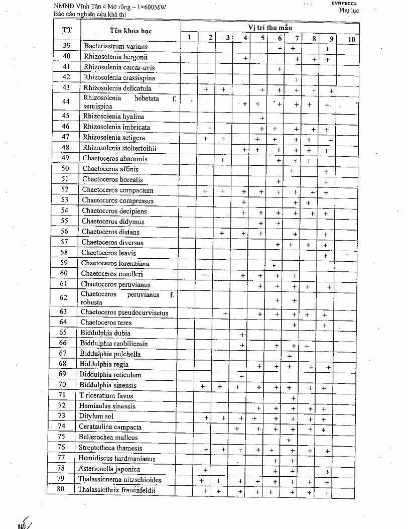
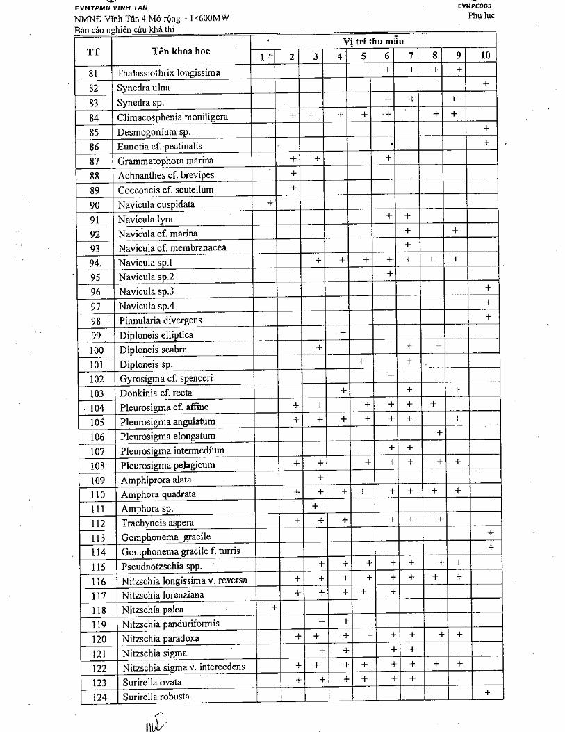
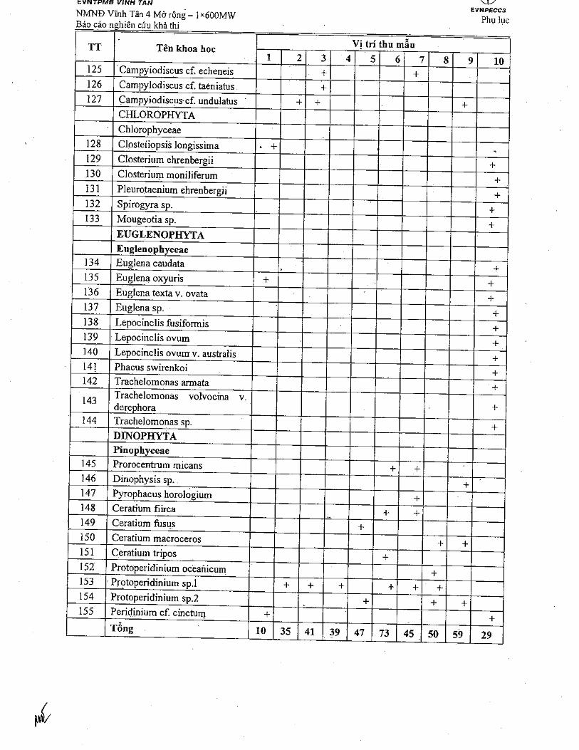
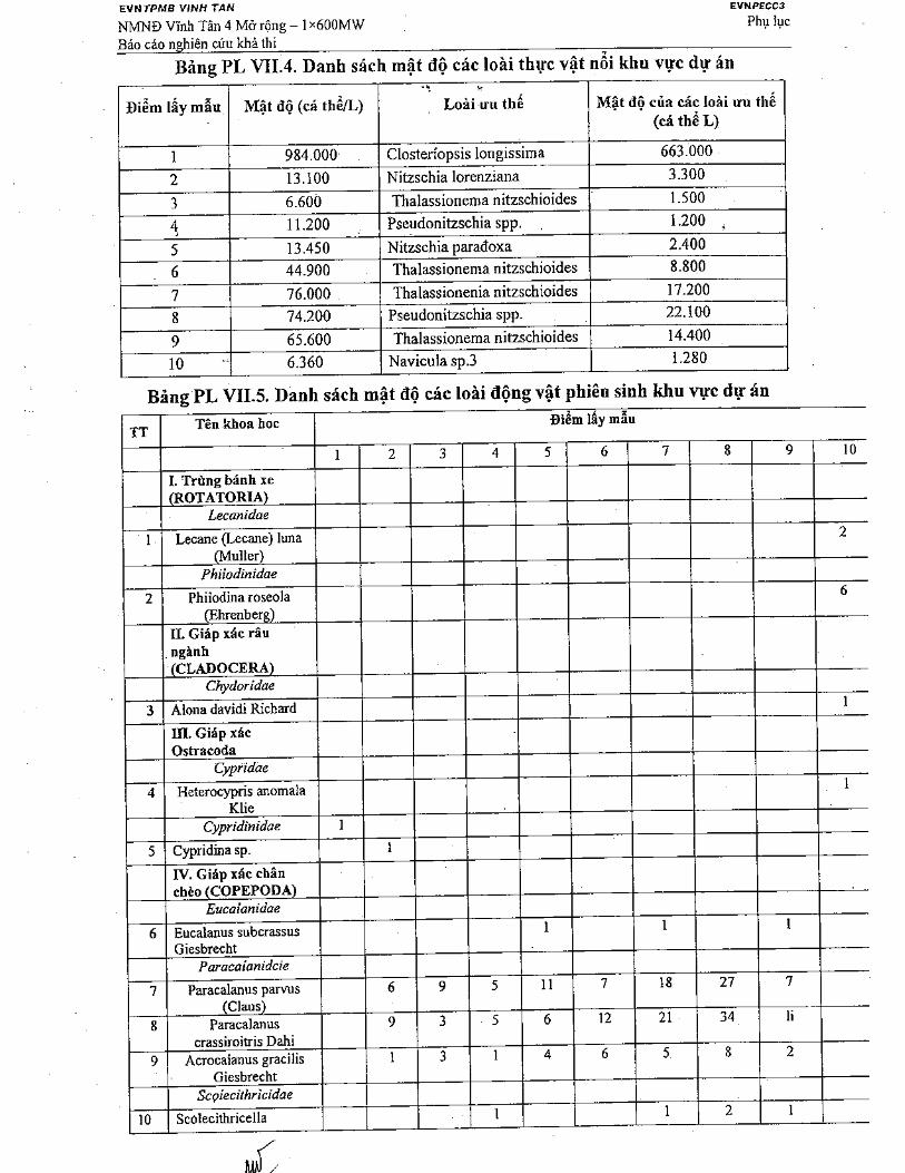

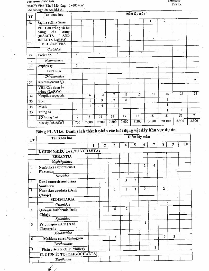
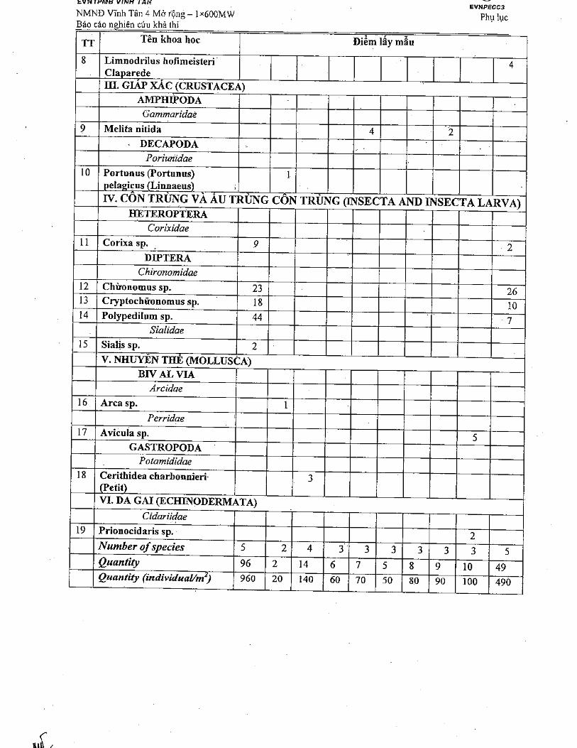
Vinh Tan 4 Ext TPP – 1×600MWFeasibility Study Report
Annexes
ANNEX 8: CALCULATION OF EXHAUST EMISSIONS ANDSPREAD OF COOLING WATER
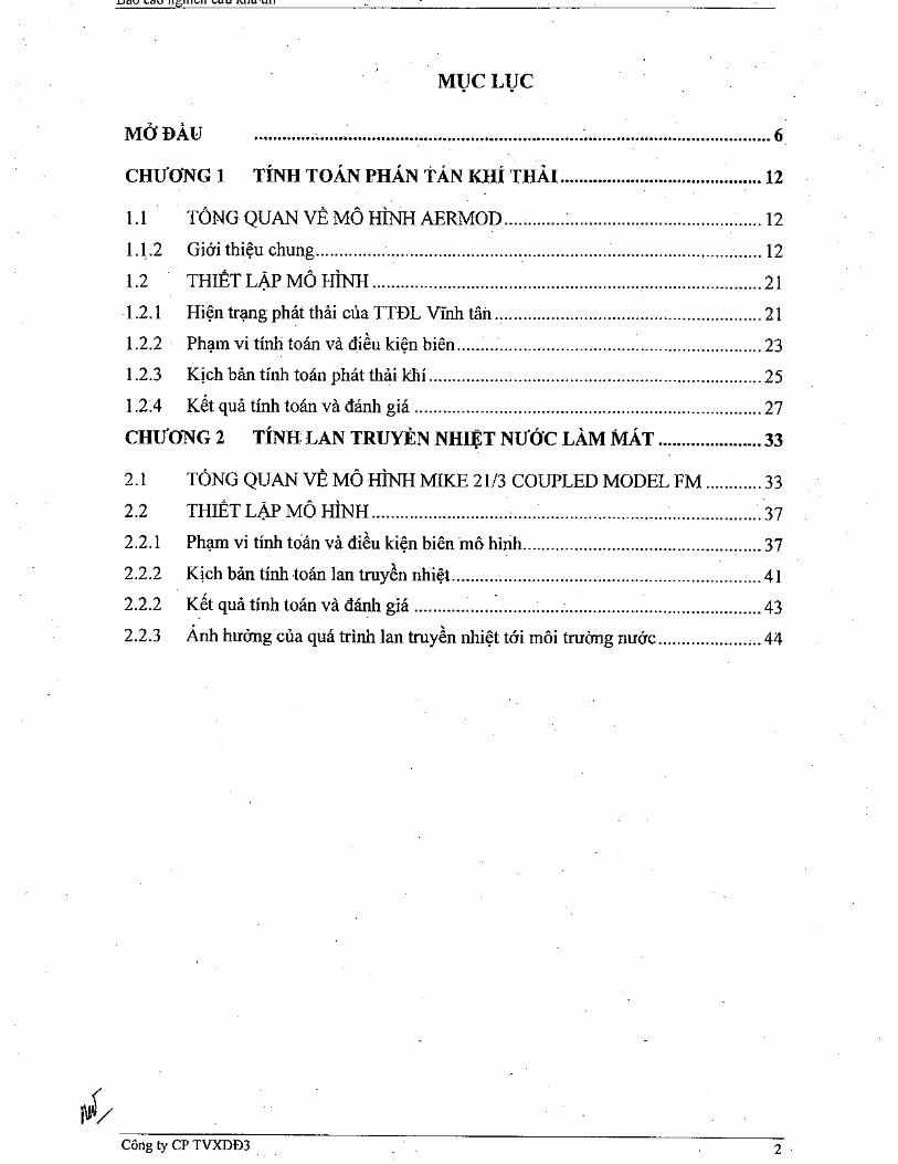
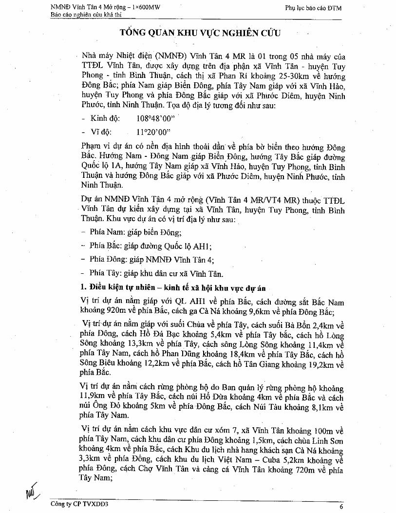
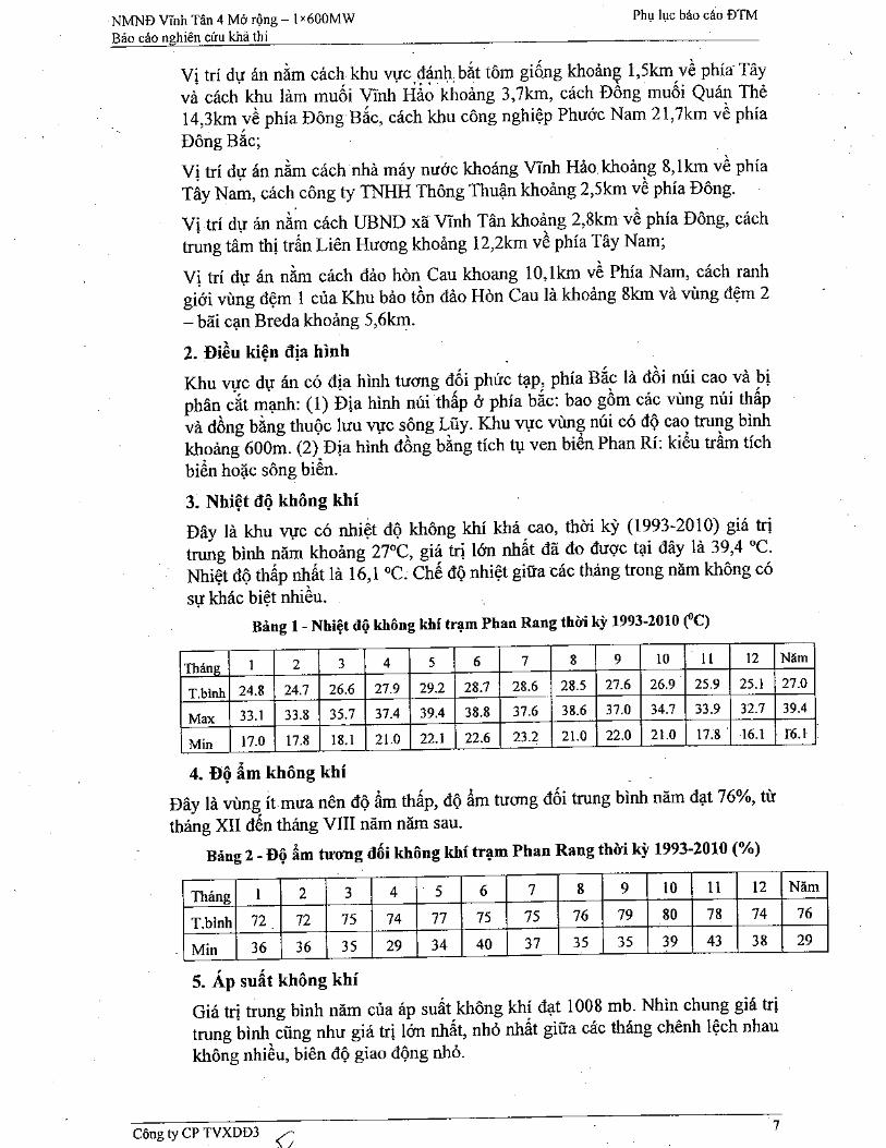
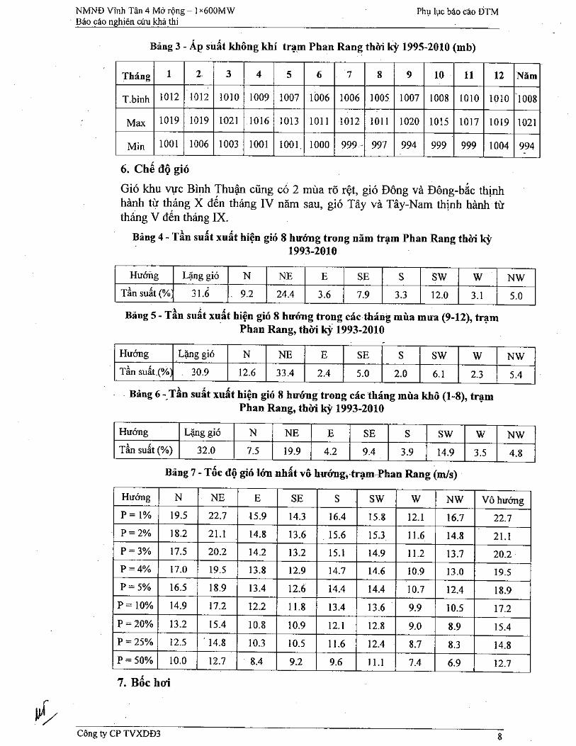
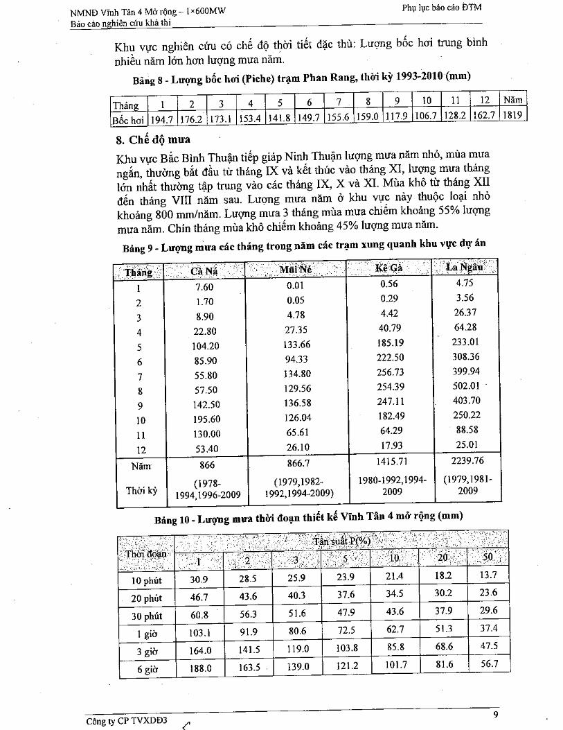
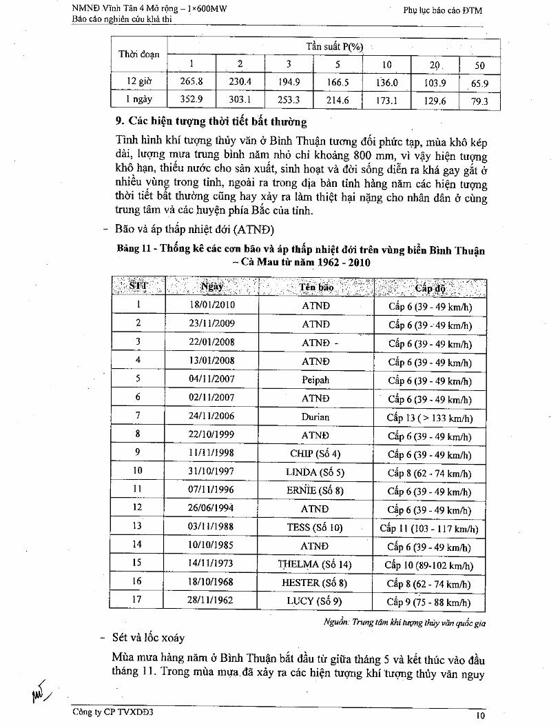
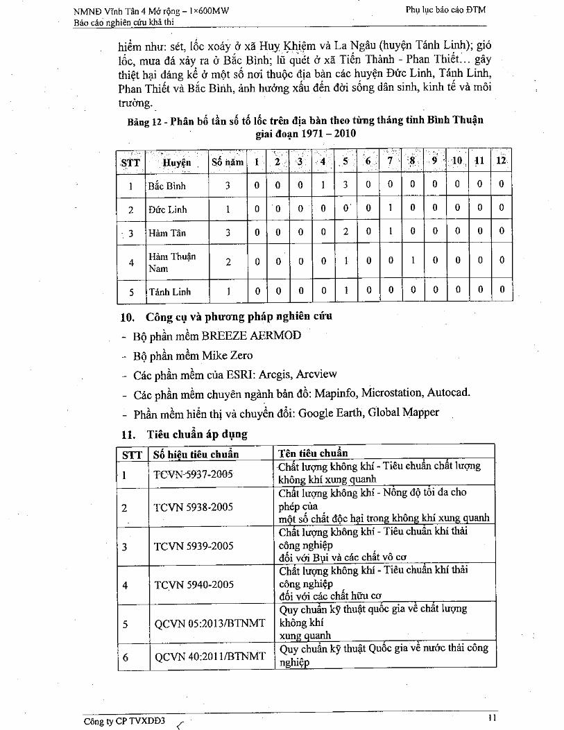
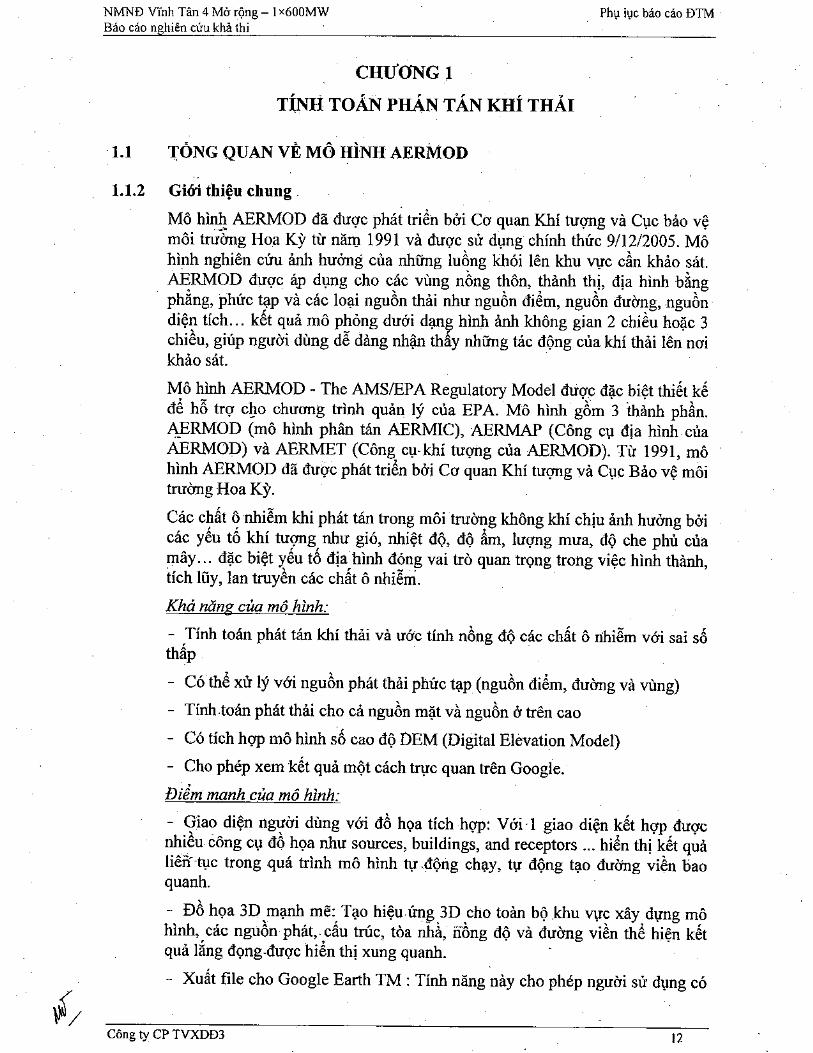
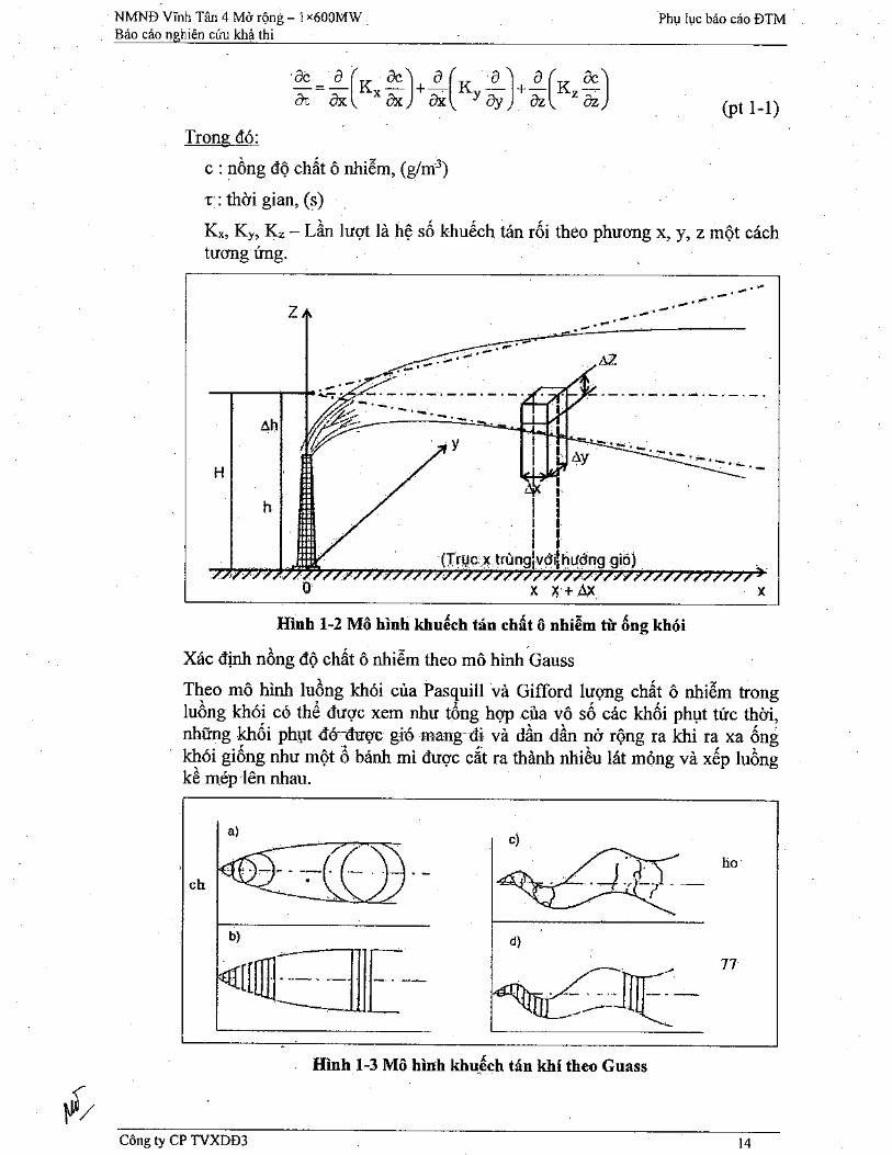
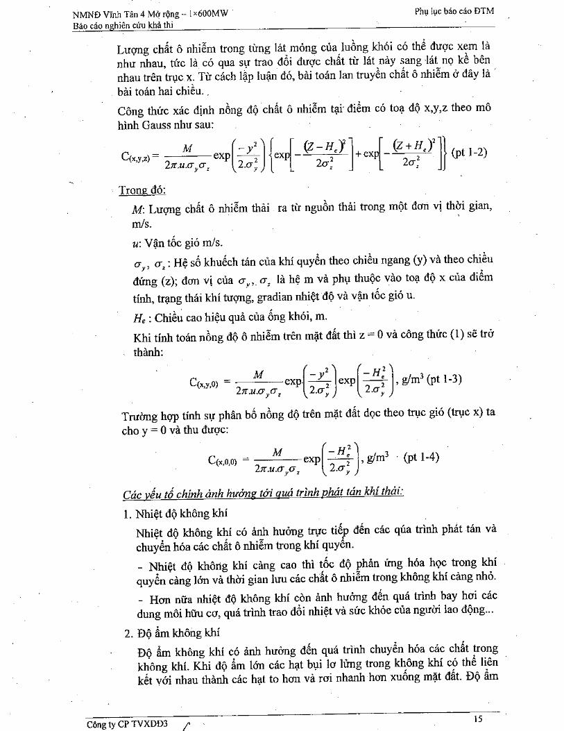
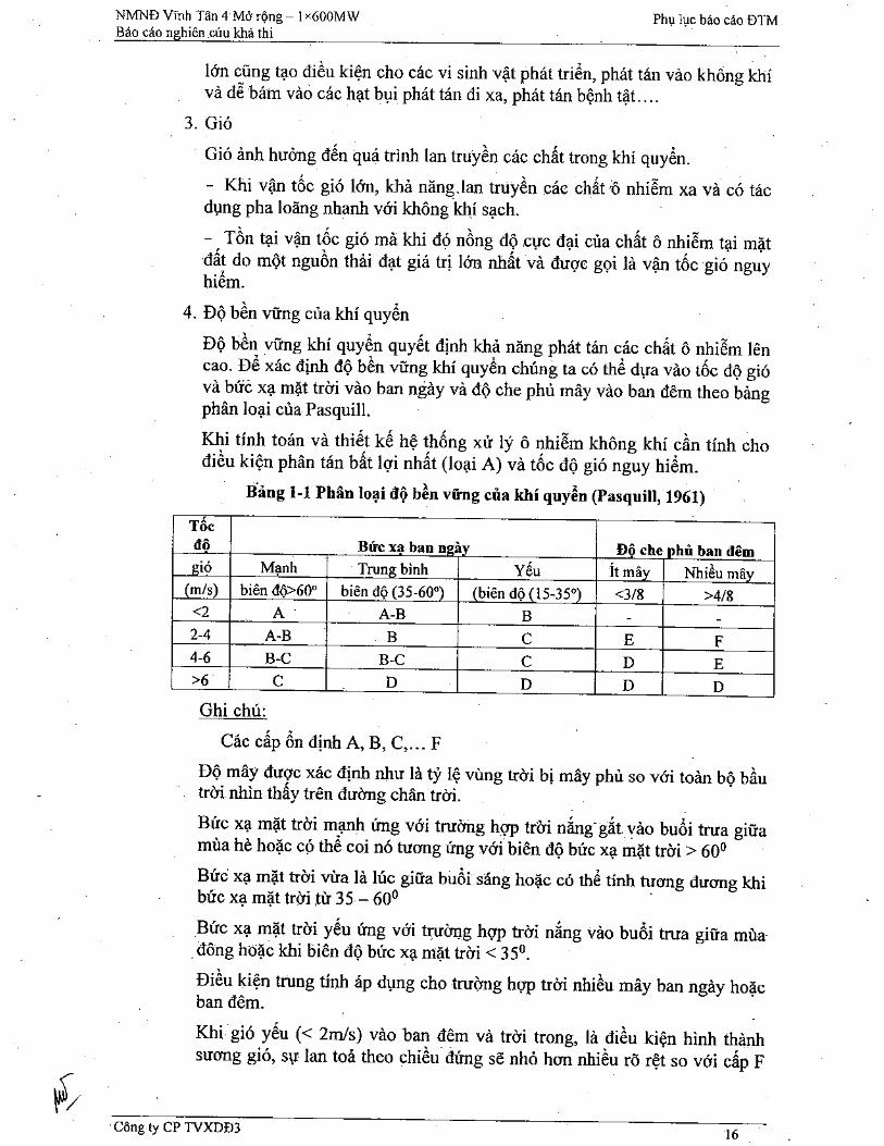
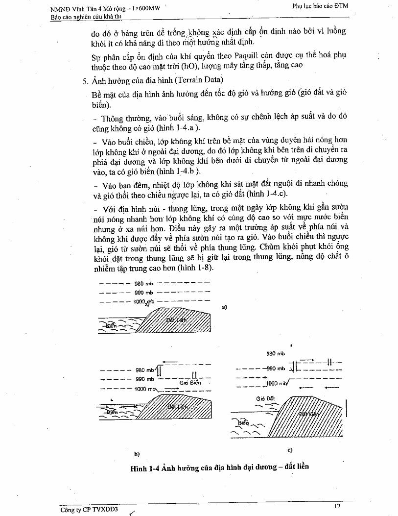
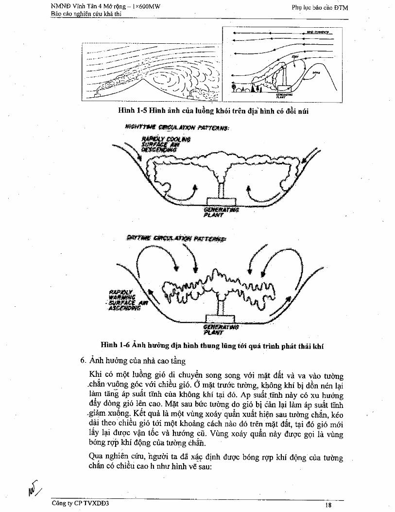
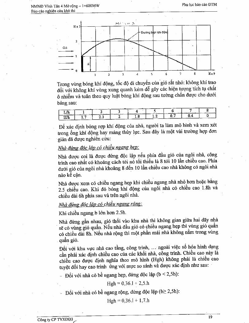

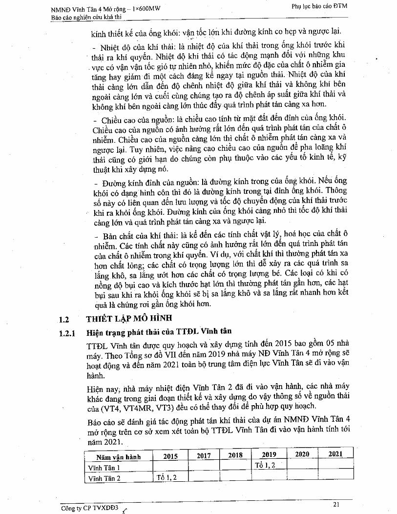
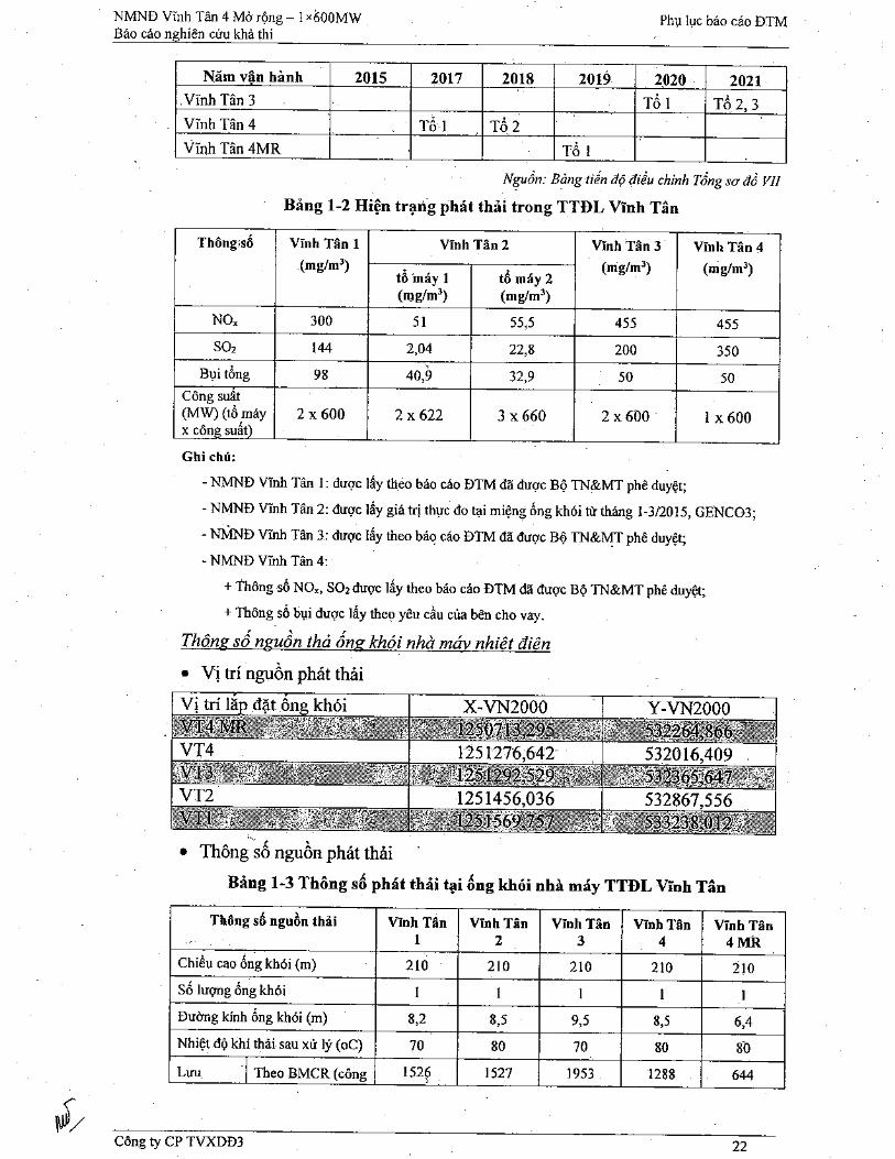
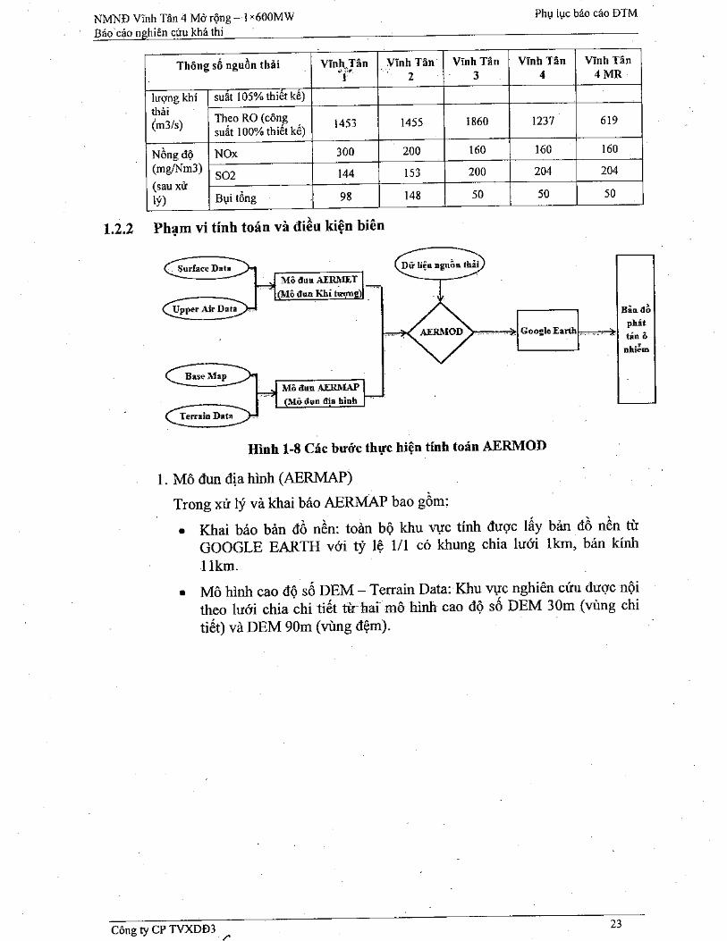
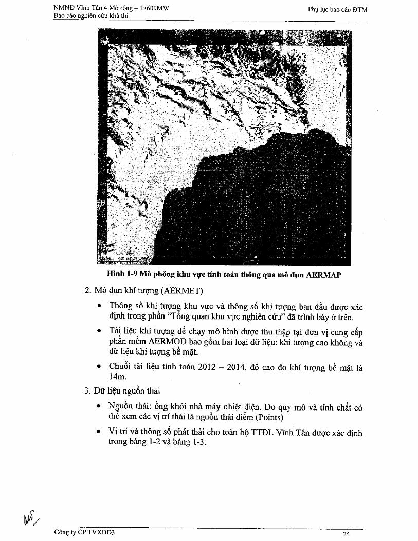
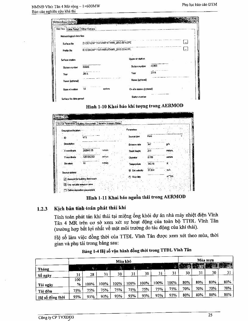
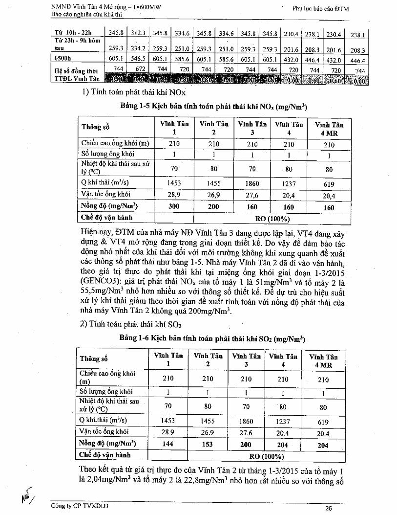
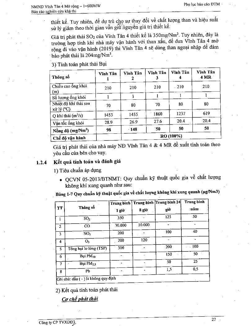

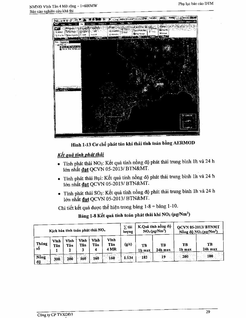
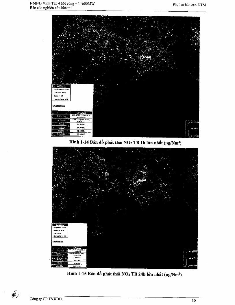
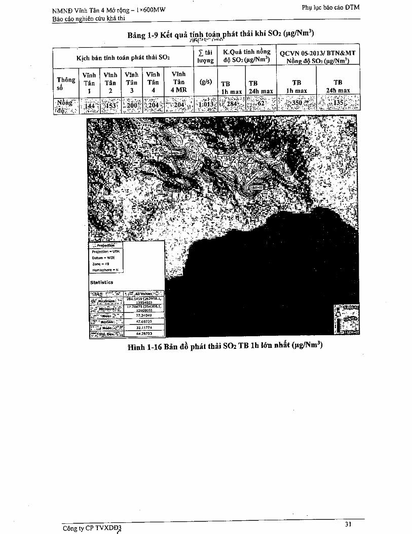
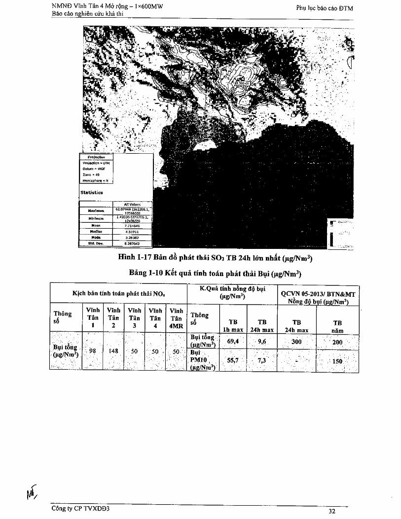
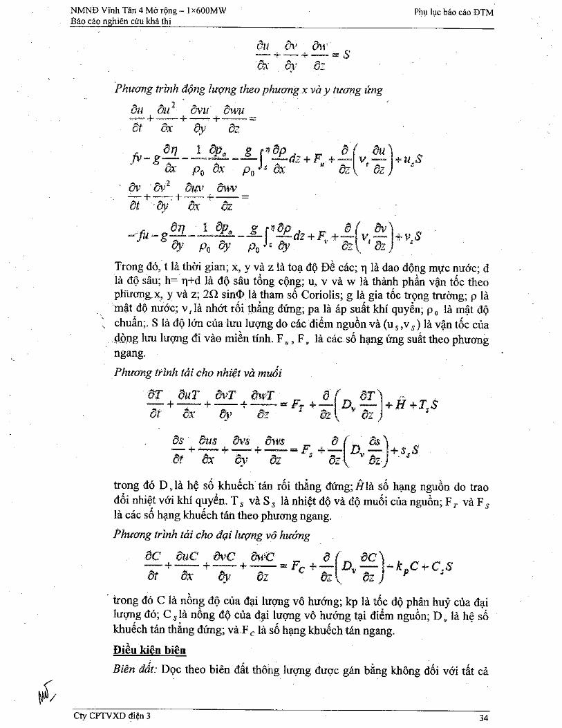
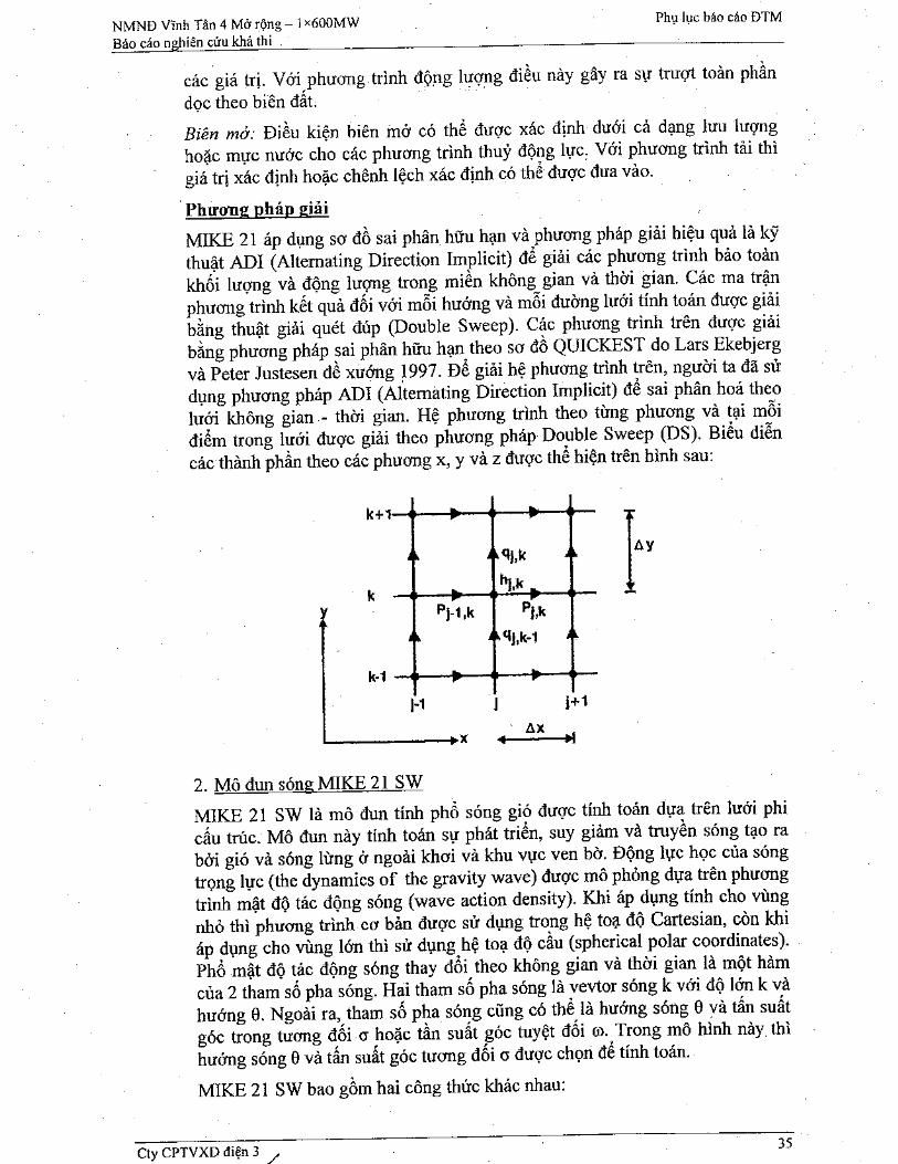
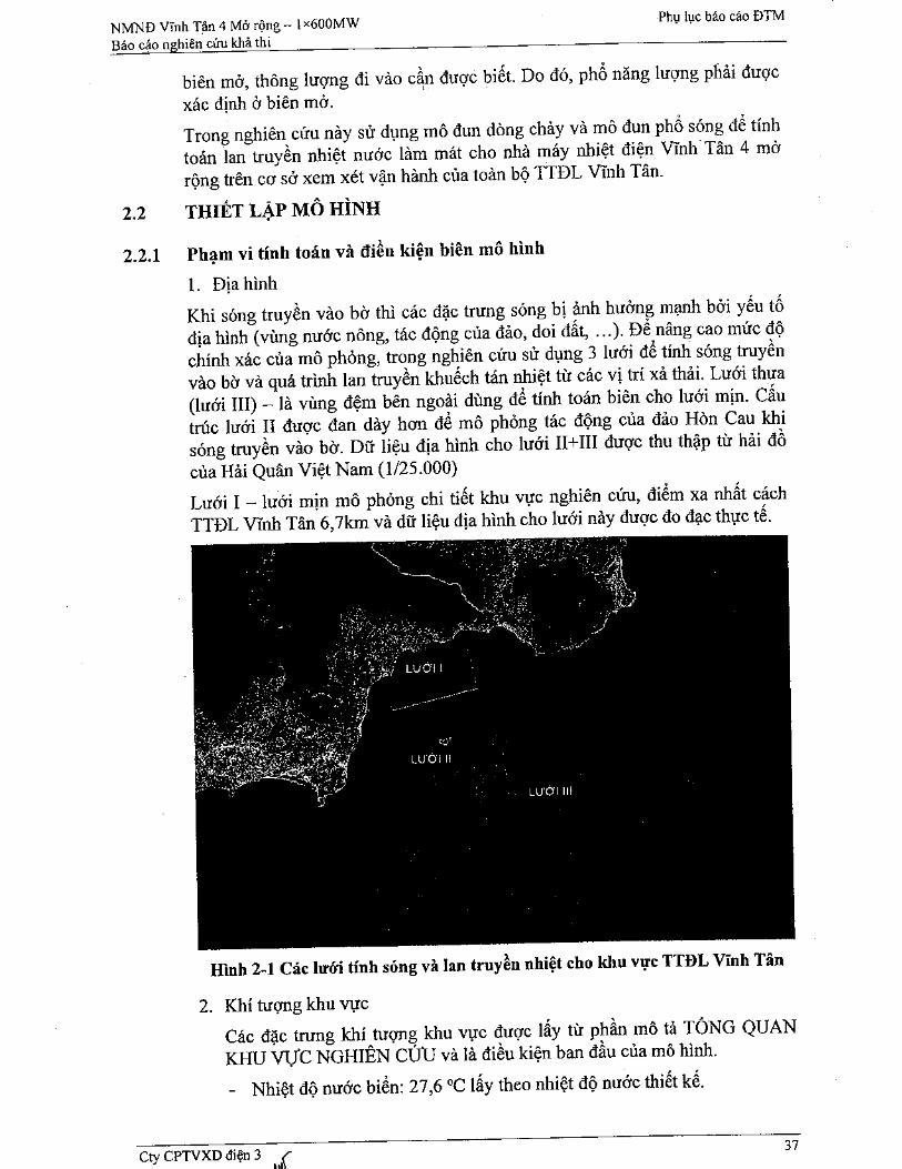
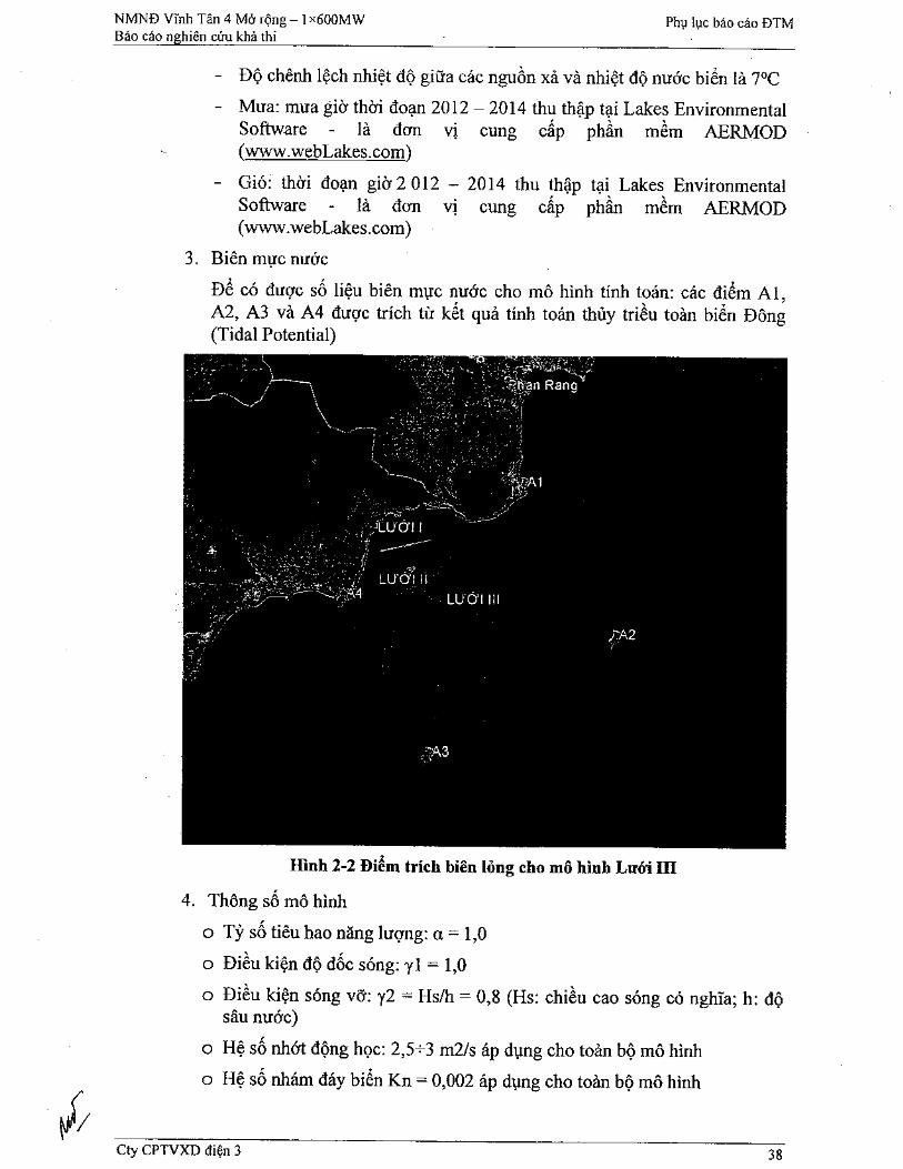
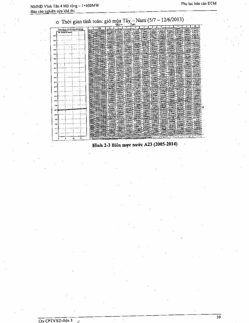
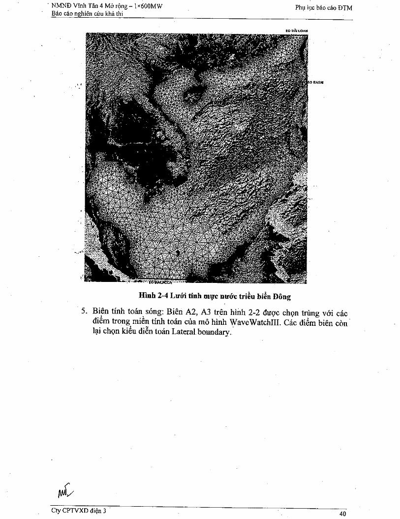
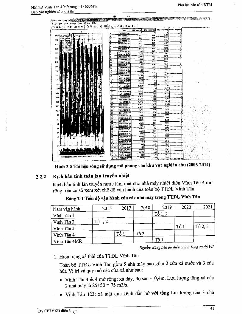
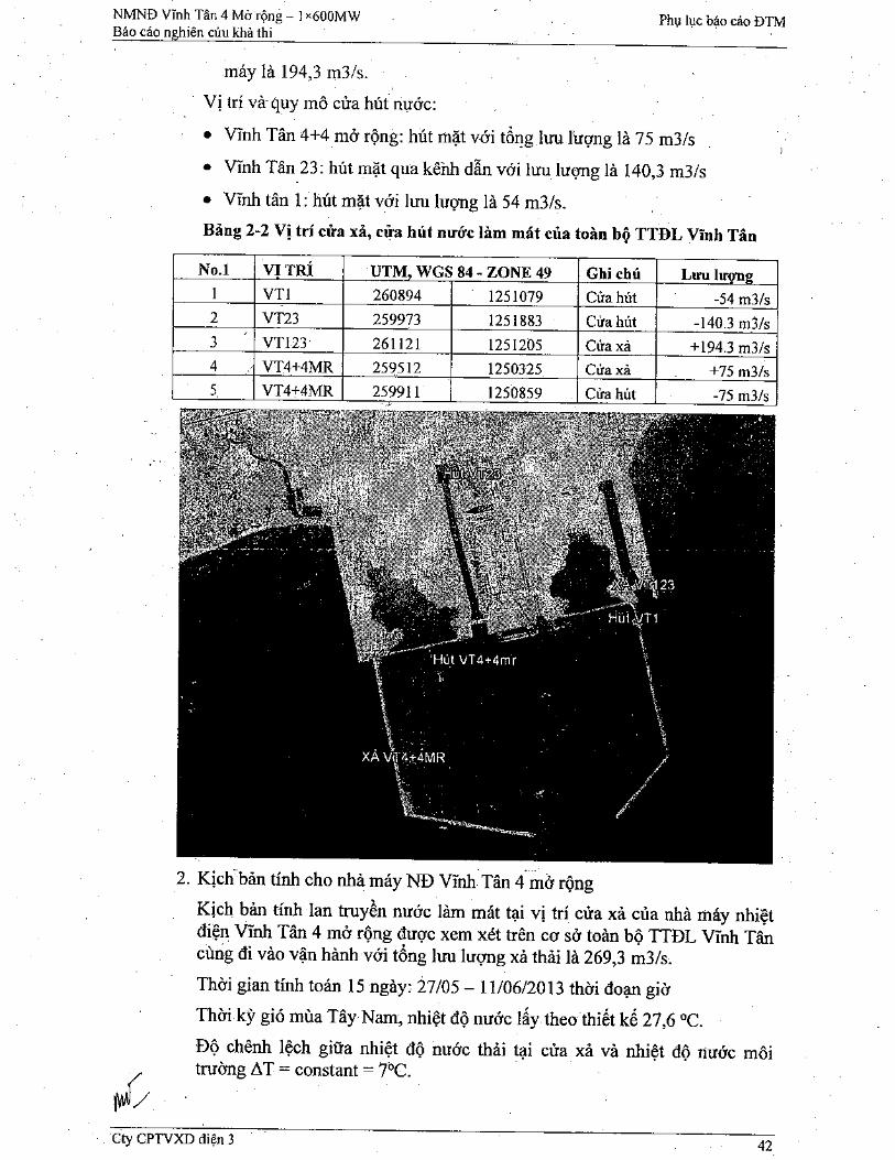
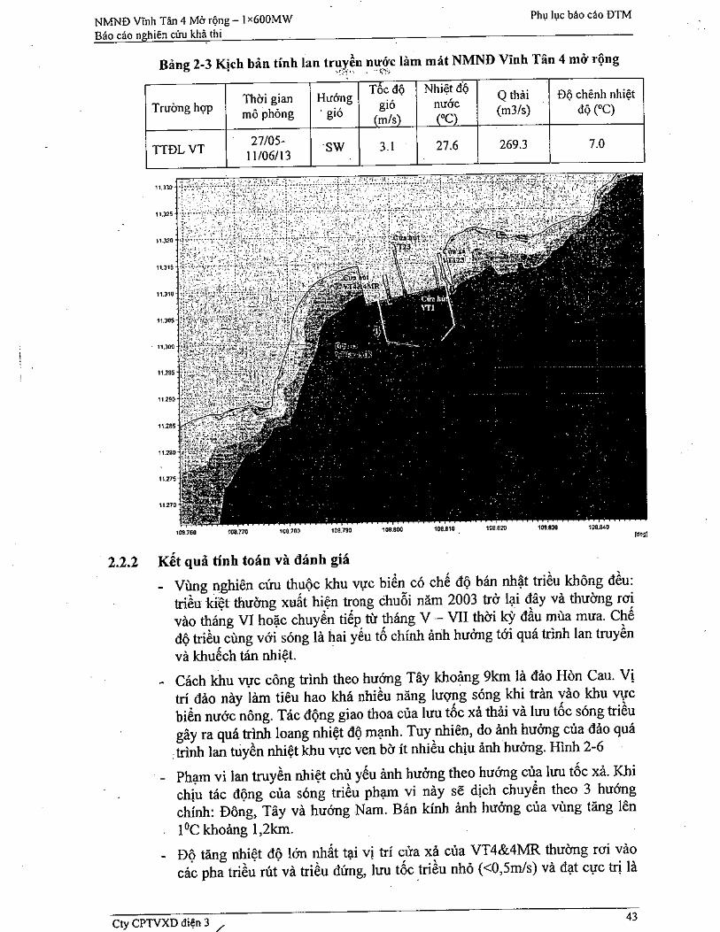
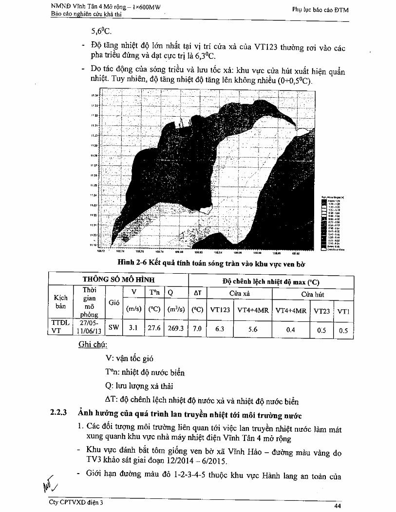

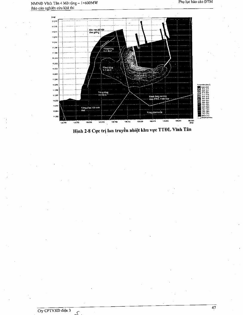
Related Documents