PROJECT / TRAINING REPORT ( PROJECT / TRAINING PERIOD MARCH– JUNE ) BTPS, NTPC BADARPUR ,NEW DELHI-110044 Submitted In Partial fulfillment of the requirement for the degree of BACHELOR OF TECHNOLOGY (B.TECH) UNDER THE GUIDANCE OF Internal Suprvisor : External Supervisor: Dinesh Jhakar Brahm Shanker H.O.D ME DEPT. (ACME) TRAINER (BTPS) SUBMITTED BY VIKAS SINGH ROLL NO. : 12BTME47 APPLIED COLLEGE OF MANAGEMENT AND ENGINEERING MAHARSHI DAYANAND UNIVERSITY, (ROHTAK-124001)

Welcome message from author
This document is posted to help you gain knowledge. Please leave a comment to let me know what you think about it! Share it to your friends and learn new things together.
Transcript
PROJECT / TRAINING REPORT
( PROJECT / TRAINING PERIOD MARCH– JUNE )
BTPS, NTPC BADARPUR ,NEW DELHI-110044
Submitted In Partial fulfillment of the requirement for the degree of
BACHELOR OF TECHNOLOGY (B.TECH)
UNDER THE GUIDANCE OF
Internal Suprvisor : External Supervisor:
Dinesh Jhakar Brahm Shanker
H.O.D ME DEPT. (ACME) TRAINER (BTPS)
SUBMITTED BY
VIKAS SINGH
ROLL NO. : 12BTME47
APPLIED COLLEGE OF MANAGEMENT AND ENGINEERING
MAHARSHI DAYANAND UNIVERSITY, (ROHTAK-124001)

ABSTRACT
India’s largest power company, NTPC was set up in 1975 to accelerate power development
in India. NTPC is emerging as a diversified power major with presence in the entire value
chain of the power generation business. Apart from power generation, which is the mainstay
of the company, NTPC has already ventured into consultancy, power trading, ash utilization
and coal mining. NTPC ranked 34 in the 2010 Forbes Global 2000 ranking of the World’s
biggest companies. NTPC became a Maharatna company in May, 2010, one of the only four
companies to be awarded this status.
BADARPUR THERMAL POWER STATION was established on 1973 and it was the part
of Central Government. On 01/04/1978 is was given as No Loss No Profit Plant of NTPC.
Since then operating performance of NTPC has been considerably above the national
average. The availability factor for coal stations has increased from 85.03 % in 1997-98 to
90.09 % in 2006-07, which compares favorably with international standards. The PLF has
increased from 75.2% in1997-98 to 89.4% during the year 2006-07 which is the highest since
the inception of NTPC. Badarpur thermal power station started with a single 95 mw unit.
There were 2 more units (95 MW each) installed in next 2 consecutive years. Now it has total five
units with total capacity of 720 MW. Ownership of BTPS was transferred to NTPC with effect from
01.06.2006 through GOIs Gazette Notification . The power is supplied to a 220 KV network
that is a part of the northern grid. The ten circuits through which the power is evacuated from
the plant are:
1. Mehrauli 2. Okhla
3. Ballabgarh 4. Indraprastha
5. UP (Noida) 6. Jaipur

ACKNOWLEDGEMENT
It has been a great honor and privilege to undergo training at NTPC Limited, Badarpur,
DELHI, India. I am very grateful to Mr. A K SINGH (DGM HR) & Mr. BRAHM
SHANKER (SUPERVISOR) for giving their valuable time and constructive guidance
in preparing the internship report for Internship. It would not have been possible to
complete this report in short period of time without their kind encouragement and
valuable guidance.
I am also thankful to PROF. DINESH JAKHAR, H.O.D., Department of Mechanical
Engineering, ACME, for his constant support and encouragement.
I would also like to render heartiest thanks to my brother & sister who’s ever helping nature
and support has helped me complete this present work
VIKAS SINGH
ROLL NO. - 12BTME47
8th
Semester, B. Tech
TABLE OF CONTENTS
LIST OF FIGURES
CHAPTER 1
1.1 COMPANY AND PROFILE 1
1.2 VISSION AND MISSION 1
1.3 POWER GENERATION IN INDIA 1
1.4 EVOLUTION 3
1.5 NTPC HEADQUARTERS 4
1.6 NTPC PLANTS 5
1.8 FUTURE GOALS 7
1.9 ENVIRONMENTAL MANAGEMENT 7
CHAPTER 2
2.1 ABOUT BADARPUR THERMAL POWER STATION 8
2.2 FROM COAL TO ELECRICITY PROCESS 11
2.3 MAIN GENERATOR 13
2.4 MAIN TURBINE DATA 14
CHAPTER 3
3.1 OPERATION 19
3.2 COAL HANDLING PLANT (C.H.P.) & NEW COAL HANDLING PLANT
(N.C.H.P) 34
3.3 GENERATOR AND AUXILIARIES 40

3.4 TRANSFORMER 47
3.5 INSTRUMENT SEEN 51
3.6 POLLUTION CONTROL SYSTEM 51
3.7 CONTROL AND MONITORING MECHANISM 54
3.8 SOLUTION TO THE PROBLEM 54
REFERENCES
LIST OF FIGURES
Figure 1: Total Power Generation
Figure 2: Top View BTPS
Figure 3: Flow Chart Of Coal To Electricity
Figure 4: Components Of A Coal Fired Thermal Plant
Figure 5: Strategies Of Ntpc
Figure 6: Parts Of Powerplant
Figure7: External View Of Boiler
Figure8: External View Of Id, Pa & Fd Fans
Figure 9: Coal Cycle
Figure 10: Wagon Trippler
Figure 11: Conveyor
Figure 12: Crushers
Figure 13: Cross-Sectional View Of A Generator
Figure 14: A 95 Mw Generator
Figure 15: Transformer
Industrial Training Report 2016
APPLIED COLLEGE OF MANAGEMENT AND ENGINEERING Page 1
CHAPTER-1 COMPANY PROFILE
NTPC Limited is the largest thermal power generating company of India. A public sector
company, it was incorporated in the year 1975 to accelerate power development in the
country as a wholly owned company of the Government of India. At present, Government
of India holds 89.5% of the total equity shares of the company and FIIs, Domestic Banks,
Public and others hold the balance 10.5%. Within a span of 31 years, NTPC has emerged
as a truly national power company, with power generating facilities in all the major
regions of the country.
VISION AND MISSION
Vision
“To be the world’s largest and best power producer, powering India’s growth.”
Mission
“Develop and provide reliable power, related products and services at competitive prices,
integrating multiple energy sources with innovative and eco-friendly technologies and
contribute to society.”
POWER GENERATION IN INDIA
NTPC’s core business is engineering, construction and operation of power generating
plants. It also provides consultancy in the area of power plant constructions and power
generation to companies in India and abroad. As on date the installed capacity of NTPC is
27,904 MW through its 15 coal based (22,895 MW), 7 gas based (3,955 MW) and 4 Joint
Venture Projects (1,054 MW). NTPC acquired 50% equity of the SAIL Power Supply

Industrial Training Report 2016
APPLIED COLLEGE OF MANAGEMENT AND ENGINEERING Page 2
Corporation Ltd. (SPSCL). This JV Company operates the captive power plants of
Durgapur (120 MW), Rourkela (120 MW) and Bhilai (74 MW). NTPC also has 28.33%
stake in Ratnagiri Gas & Power Private Limited (RGPPL) a joint venture company
between NTPC, GAIL, Indian Financial Institutions and Maharashtra SEB Co Ltd.
Figure 1: TOTAL POWER GENERATION
NTPC has set new benchmarks for the power industry both in the area of power plant
construction and operations. Its providing power at the cheapest average tariff in the
country..
NTPC is committed to the environment, generating power at minimal environmental cost
and preserving the ecology in the vicinity of the plants. NTPC has undertaken massive a
forestation in the vicinity of its plants. Plantations have increased forest area and reduced
barren land. The massive a forestation by NTPC in and around its Ramagundam Power
station (2600 MW) have contributed reducing the temperature in the areas by about 3°c.
Industrial Training Report 2016
APPLIED COLLEGE OF MANAGEMENT AND ENGINEERING Page 3
NTPC has also taken proactive steps for ash utilization. In 1991, it set up Ash Utilization
Division
A "Centre for Power Efficiency and Environment Protection (CENPEEP)" has been
established in NTPC with the assistance of United States Agency for International
Development (USAID). Cenpeep is efficiency oriented, eco-friendly and eco-nurturing
initiative - a symbol of NTPC's concern towards environmental protection and continued
commitment to sustainable power development in India.
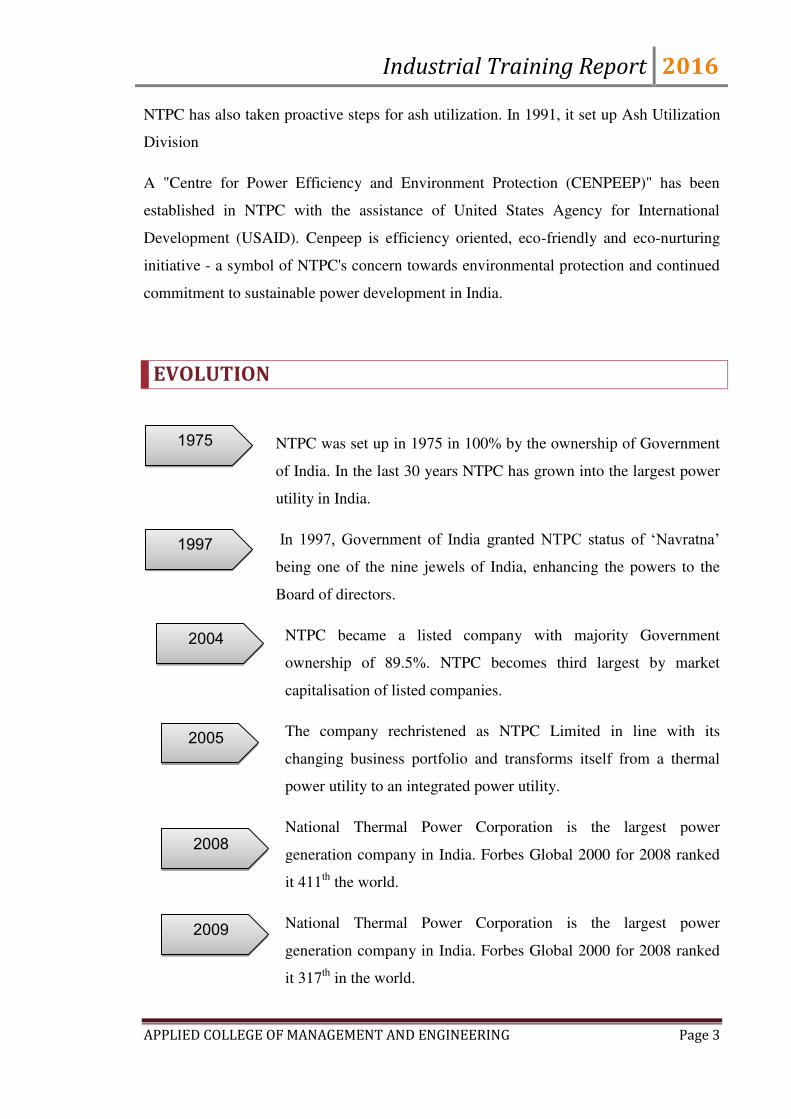
EVOLUTION
NTPC was set up in 1975 in 100% by the ownership of Government
of India. In the last 30 years NTPC has grown into the largest power
utility in India.
In 1997, Government of India granted NTPC status of ‘Navratna’
being one of the nine jewels of India, enhancing the powers to the
Board of directors.
NTPC became a listed company with majority Government
ownership of 89.5%. NTPC becomes third largest by market
capitalisation of listed companies.
The company rechristened as NTPC Limited in line with its
changing business portfolio and transforms itself from a thermal
power utility to an integrated power utility.
National Thermal Power Corporation is the largest power
generation company in India. Forbes Global 2000 for 2008 ranked
it 411th
the world.
National Thermal Power Corporation is the largest power
generation company in India. Forbes Global 2000 for 2008 ranked
it 317th
in the world.
1975
1997
2004
2005
2008
2009
Industrial Training Report 2016
APPLIED COLLEGE OF MANAGEMENT AND ENGINEERING Page 4
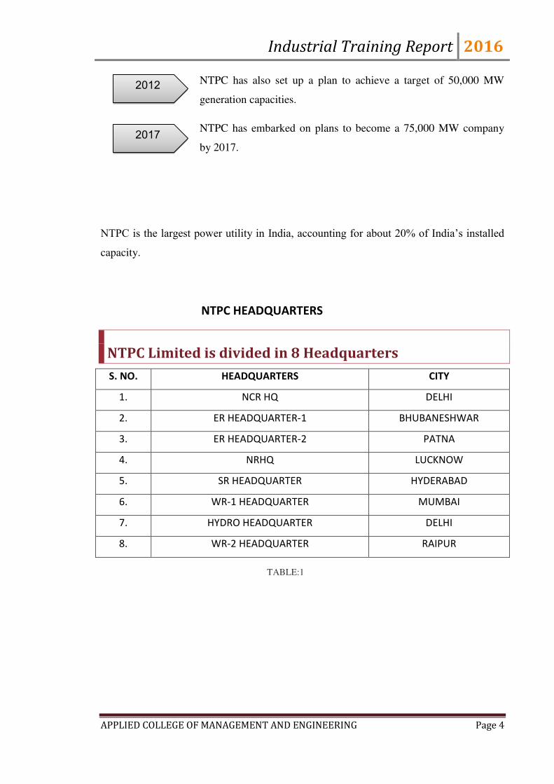
NTPC has also set up a plan to achieve a target of 50,000 MW
generation capacities.
NTPC has embarked on plans to become a 75,000 MW company
by 2017.
NTPC is the largest power utility in India, accounting for about 20% of India’s installed
capacity.
NTPC HEADQUARTERS
NTPC Limited is divided in 8 Headquarters
S. NO. HEADQUARTERS CITY
1. NCR HQ DELHI
2. ER HEADQUARTER-1 BHUBANESHWAR
3. ER HEADQUARTER-2 PATNA
4. NRHQ LUCKNOW
5. SR HEADQUARTER HYDERABAD
6. WR-1 HEADQUARTER MUMBAI
7. HYDRO HEADQUARTER DELHI
8. WR-2 HEADQUARTER RAIPUR
2012
2017
TABLE:1
Industrial Training Report 2016
APPLIED COLLEGE OF MANAGEMENT AND ENGINEERING Page 5
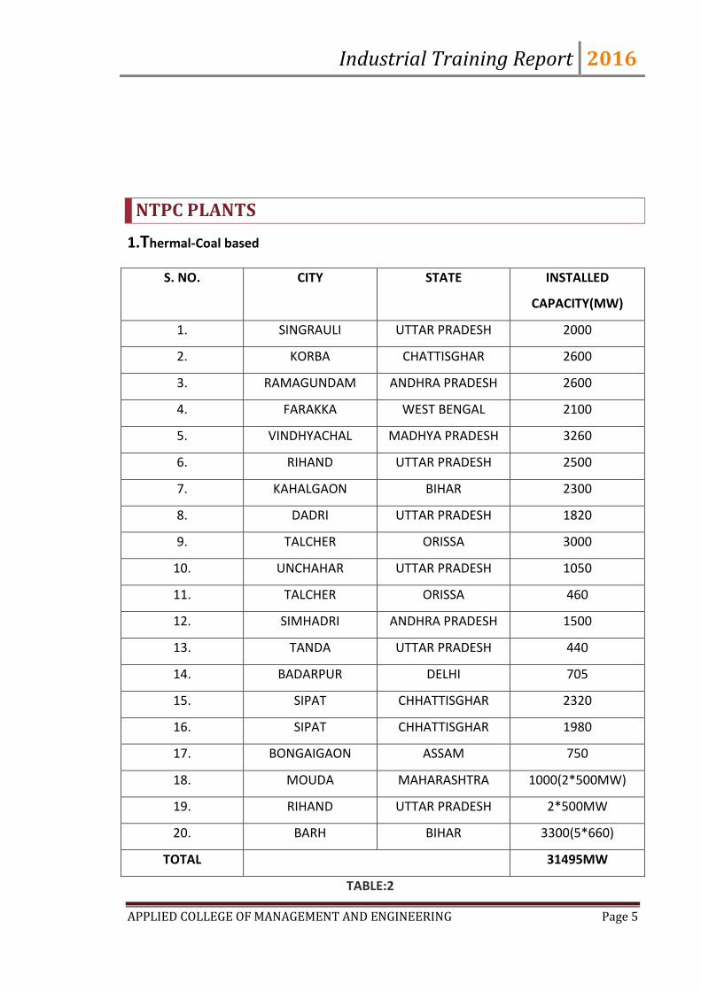
NTPC PLANTS
1.Thermal-Coal based
S. NO. CITY STATE INSTALLED
CAPACITY(MW)
1. SINGRAULI UTTAR PRADESH 2000
2. KORBA CHATTISGHAR 2600
3. RAMAGUNDAM ANDHRA PRADESH 2600
4. FARAKKA WEST BENGAL 2100
5. VINDHYACHAL MADHYA PRADESH 3260
6. RIHAND UTTAR PRADESH 2500
7. KAHALGAON BIHAR 2300
8. DADRI UTTAR PRADESH 1820
9. TALCHER ORISSA 3000
10. UNCHAHAR UTTAR PRADESH 1050
11. TALCHER ORISSA 460
12. SIMHADRI ANDHRA PRADESH 1500
13. TANDA UTTAR PRADESH 440
14. BADARPUR DELHI 705
15. SIPAT CHHATTISGHAR 2320
16. SIPAT CHHATTISGHAR 1980
17. BONGAIGAON ASSAM 750
18. MOUDA MAHARASHTRA 1000(2*500MW)
19. RIHAND UTTAR PRADESH 2*500MW
20. BARH BIHAR 3300(5*660)
TOTAL 31495MW
TABLE:2
Industrial Training Report 2016
APPLIED COLLEGE OF MANAGEMENT AND ENGINEERING Page 6
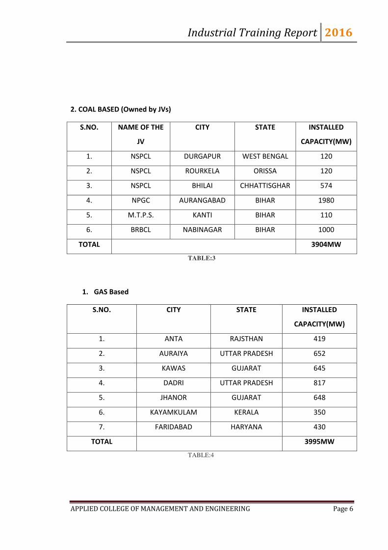
2. COAL BASED (Owned by JVs)
S.NO. NAME OF THE
JV
CITY STATE INSTALLED
CAPACITY(MW)
1. NSPCL DURGAPUR WEST BENGAL 120
2. NSPCL ROURKELA ORISSA 120
3. NSPCL BHILAI CHHATTISGHAR 574
4. NPGC AURANGABAD BIHAR 1980
5. M.T.P.S. KANTI BIHAR 110
6. BRBCL NABINAGAR BIHAR 1000
TOTAL 3904MW
TABLE:3
1. GAS Based
S.NO. CITY STATE INSTALLED
CAPACITY(MW)
1. ANTA RAJSTHAN 419
2. AURAIYA UTTAR PRADESH 652
3. KAWAS GUJARAT 645
4. DADRI UTTAR PRADESH 817
5. JHANOR GUJARAT 648
6. KAYAMKULAM KERALA 350
7. FARIDABAD HARYANA 430
TOTAL 3995MW
TABLE:4
Industrial Training Report 2016
APPLIED COLLEGE OF MANAGEMENT AND ENGINEERING Page 7
NTPC HYDEL
The company has also stepped up its hydroelectric power (hydel) projects
implementation. Currently the company is mainly interested in the North-east India
wherein the Ministry of Power in India has projected a hydel power feasibility of 3000
MW.Loharinag Pala Hydro Power Project by NTPC Ltd: In Loharinag Pala Hydro Power
Project with a capacity of 600 MW (150 MW x 4 Units). The main package has been
awarded. The present executives' strength is 100+. The project is located on river
Bhagirathi (a tributory of the Ganges) in Uttarkashi district of Uttarakhand state. This is
the first project downstream from the origin of the Ganges at Gangotri.Tapovan
Vishnugad 520MW Hydro Power Project by NTPC Ltd: In Joshimath town.#Lata
Tapovan 130MW Hydro Power Project by NTPC Ltd: is further upstream to Joshimath
(under environmental revision) Koldam Hydro Power Project 800 MW in Himachal
Pradesh .
FUTURE GOALS
The company has also set a serious goal of having 50000 MW of installed capacity by
2012 and 75000 MW by 2017. NTPC will invest about Rs 20,000 crore to set up a 3,900-
megawatt (MW) coal-based power project in Madhya Pradesh. Company will also start
coal production from its captive mine in Jharkhand in 2011–12, for which the company
will be investing about 18 billion. ALSTOM would be a part of its 660-MW supercritical
projects for Solapur II and Mouda II in Maharashtra.ALSTOM would execute turnkey
station control and instrumentation (C&I) for this project.
ENVIRONMET MANAGEMENT, OCCUPATIONAL
HEALTH and SAFETY SYSTEMS
NTPC has actively gone for adoption of best international practices on environment,
occupational health and safety areas. The organization has pursued the Environmental
Management System (EMS) ISO 14001 and the Occupational Health and Safety
Assessment System OHSAS 18001 at its different establishments. As a result of pursuing
these practices, all NTPC power stations have been certified for ISO 14001 & OHSAS
18001 by reputed national and international Certifying Agencies.

Industrial Training Report 2016
APPLIED COLLEGE OF MANAGEMENT AND ENGINEERING Page 8
CHAPTER 2
ABOUT BADARPUR THERMAL POWER STATION
Figure 2: Top View BTPS
Badarpur Thermal Power Station is located at Badarpur area in NCT Delhi. The power
plant is one of the coal based power plants of NTPC. The National Power Training
Institute (NPTI) for North India Region under Ministry of Power, Government of India
was established at Badarpur in 1974, within the Badarpur Thermal power plant (BTPS)
complex.It is situated in south east corner of Delhi on Mathura Road near Faridabad. It
was the first central sector power plant conceived in India, in 1965. It was originally
conceived to provide power to neighbouring states of Haryana, Punjab, Jammu and
Kashmir,U.P., Rajasthan, and Delhi.But since year 1987 Delhi has become its sole
beneficiary.

Industrial Training Report 2016
APPLIED COLLEGE OF MANAGEMENT AND ENGINEERING Page 9
The power is supplied to a 220 KV network that is a part of the northern grid. The ten
circuits through which the power is evacuated from the plant are:
1. Mehrauli 2. Okhla
3. Ballabgarh 4. Indraprastha
5. UP (Noida) 6. Jaipur

Industrial Training Report 2016
APPLIED COLLEGE OF MANAGEMENT AND ENGINEERING Page 10
Badarpur is situated only 20 km away from Delhi. The plant is located on the left side of
the National Highway (Delhi-Mathura Road) and it comprises of 430 hectares (678 acres)
bordered by the Agra Canal from East and by Mathura-Delhi Road from West. However,
the area for ash disposal is done in the Delhi Municipal limit and is maintained with the
help of Delhi Development Authority.
Basic Steps of Electricity Generation
a) Coal to steam
b) Steam to mechanical power
c) Mechanical power to electrical power
No of plants
Capacity (MW)
NTPC Owned
1. Coal 16 31,855
2. Gas / Liquid Fuel 7 3,955
Total 23 35,810
Owned by Joint Ventures
3. Coal & Gas 7 5364
Grand Total 30 41,174

Industrial Training Report 2016
APPLIED COLLEGE OF MANAGEMENT AND ENGINEERING Page 11
FROM COAL TO ELECTRICITY PROCESS
Figure 3: FLOW CHART of COAL TO ELECTRICITY
Coal to Steam
Coal from the coal wagons is unloaded in the coal handling plant. This Coal is
transported up to the raw coal bunkers with the help of belt conveyors. Coal is
transported to Bowl mills by Coal Feeders. The coal is pulverized in the Bowl Mill,
where it is ground to powder form. The mill consists of a round metallic table on
which coal particles fall. This table is rotated with the help of a motor. There are
three large steel rollers, which are spaced 120 apart. When there is no coal, these
rollers do not rotate but when the coal is fed to the table it pack up between roller
and the table and ths forces the rollers to rotate. Coal is crushed by the crushing
action between the rollers and the rotating table. This crushed coal is taken away to
the furnace through coal pipes with the help of hot and cold air mixture from P.A. Fan.

Industrial Training Report 2016
APPLIED COLLEGE OF MANAGEMENT AND ENGINEERING Page 12
P.A. Fan takes atmospheric air, a part of which is sent to Air-Preheaters for heating
while a part goes directly to the mill for temperature control. Atmospheric air from F.D.
Fan is heated in the air heaters and sent to the furnace as combustion air.
Water from the boiler feed pump passes through economizer and reaches the boiler
drum. Water from the drum passes through down comers and goes to the bottom ring
header. Water from the bottom ring header is divided to all the four sides of the
furnace. Due to heat and density difference, the water rises up in the water wall tubes.
Water is partly converted to steam as it rises up in the furnace. This steam and water
mixture is again taken to thee boiler drum where the steam is separated from water.
water follows the same path while the steam is sent to superheaters for superheating.
The superheaters are located inside the furnace and the steam is superheated (540 oC)
and finally it goes to the turbine.Flue gases from the furnace are extracted by induced
draft fan, which maintains balance draft in the furnace (-5 to –10 mm of wcl) with
forced draft fan. These flue gases emit their heat energy to various super heaters in the
pent house and finally pass through air-preheaters and goes to electrostatic precipitators
where the ash particles are extracted. Electrostatic Precipitator consists of metal
plates, which are electrically charged. Ash particles are attracted on to these
plates, so that they do not pass through the chimney to pollute t he atmosphere.
Regular mechanical hammer blows cause the accumulation of ash to fall to the bottom
of the precipitator where they are collected in a hopper for disposal.
Industrial Training Report 2016
APPLIED COLLEGE OF MANAGEMENT AND ENGINEERING Page 13
Steam to Mechanical Power
From the boiler, a steam pipe conveys steam to the turbine through a stop valve
(which can be used to shut-off the steam in case of emergency) and through control
valves that automatically regulate the supply of steam to the turbine. Stop valve and
control valves are located in a steam chest and a governor, driven from the main
turbine shaft, operates the control valves to regulate the amount of steam used. (This
depends upon the speed of the turbine and the amount of electricity required from the
generator).
Steam from the control valves enters the high pressure cylinder of the turbine, where it
passes through a ring of stationary blades fixed to the cylinder wall. These act as
nozzles and direct the steam into a second ring of moving blades mounted on a disc
secured to the turbine shaft. The second ring turns the shafts as a result of the force of
steam. The stationary and moving blades together constitute a „stage‟ of turbine and in
practice many stages are necessary, so that the cylinder contains a number of rings of
stationary blades with rings of moving blades arranged between them. The steam passes
through each stage in turn until it reaches the end of the high-pressure cylinder and in
its passage some of its heat energy is changed into mechanical energy.
The steam leaving the high pressure cylinder goes back to the boiler for reheating and
returns by a further pipe to the intermediate pressure cylinder. Here it passes through
another series of stationary and moving blades.
Finally, the steam is taken to the low-pressure cylinders, each of which enters at the
centre flowing outwards in opposite directions through the rows of turbine blades
through an arrangement called the „double flow‟- to the extremities of the cylinder. As
the steam gives up its heat energy to drive the turbine, its temperature and pressure
fall and it expands. Because of this expansion the blades are much larger and longer
towards the low pressure ends of the turbine.
Industrial Training Report 2016
APPLIED COLLEGE OF MANAGEMENT AND ENGINEERING Page 14
Mechanical Power to Electrical Power
As the blades of turbine rotate, the shaft of the generator, which is coupled to tha
of t he turbine, also rotates. It results in rotation of the coil of the generator, which
causes induced electricity to be produced.
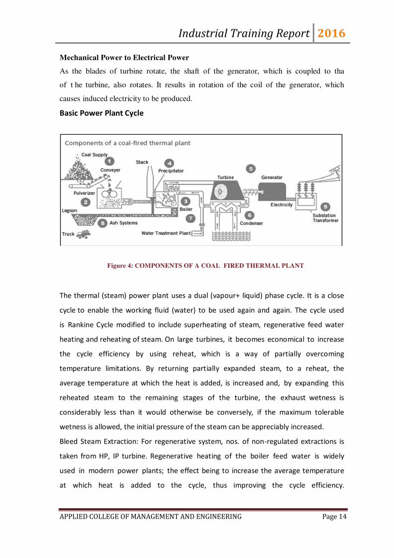
Basic Power Plant Cycle
Figure 4: COMPONENTS OF A COAL FIRED THERMAL PLANT
The thermal (steam) power plant uses a dual (vapour+ liquid) phase cycle. It is a close
cycle to enable the working fluid (water) to be used again and again. The cycle used
is Rankine Cycle modified to include superheating of steam, regenerative feed water
heating and reheating of steam. On large turbines, it becomes economical to increase
the cycle efficiency by using reheat, which is a way of partially overcoming
temperature limitations. By returning partially expanded steam, to a reheat, the
average temperature at which the heat is added, is increased and, by expanding this
reheated steam to the remaining stages of the turbine, the exhaust wetness is
considerably less than it would otherwise be conversely, if the maximum tolerable
wetness is allowed, the initial pressure of the steam can be appreciably increased.
Bleed Steam Extraction: For regenerative system, nos. of non-regulated extractions is
taken from HP, IP turbine. Regenerative heating of the boiler feed water is widely
used in modern power plants; the effect being to increase the average temperature
at which heat is added to the cycle, thus improving the cycle efficiency.

Industrial Training Report 2016
APPLIED COLLEGE OF MANAGEMENT AND ENGINEERING Page 15
On large turbines, it becomes economical to increase the cycle efficiency by using
reheat, which is a way of partially overcoming temperature limitations. By returning
partially expanded steam, to a reheat, the average temperature at which the heat is
added, is increased and, by expanding this reheated steam to the remaining stages of
the turbine, the exhaust wetness is considerably less than it would otherwise be
conversely, if the maximum tolerable wetness is allowed, the initial pressure of the steam
can be appreciably increased.
Bleed Steam Extraction: For regenerative system, nos. of non-regulated extractions is
taken from HP, IP turbine. Regenerative heating of the boiler feed water is widely used
in modern power plants; the effect being to increase the average temperature at which
heat is added to the cycle, thus improving the cycle efficiency.
TABLE: 6
MAIN TURBINE DATA
Rated output of Turbine 210 MW
Rated speed of turbine 3000 rpm
Rated pressure of steam before emergency 130 kg/cm^2
Stop valve rated live steam temperature 535 o Celsius
Industrial Training Report 2016
APPLIED COLLEGE OF MANAGEMENT AND ENGINEERING Page 16
Rated steam temperature after reheat at inlet to receptor valve 535 o Celsius
Steam flow at valve wide open condition 670 tons/hour
Rated quantity of circulating water through condenser 27000 cm/hour
1. For cooling water temperature (o Celsius) 24,27,30,33
2. Steam flow required for 210 MW in ton/hour 68,645,652,662
MAIN GENERATOR
Maximum continuous KVA rating 24700KVA
Maximum continuous KW 210000KW
Rated terminal voltage 15750V
Rated Stator current 9050 A
Rated Power Factor 0.85 lag
Excitation current at MCR Condition 2600 A
Slip-ring Voltage at MCR Condition 310 V
Rated Speed 3000 rpm
Rated Frequency 50 Hz
Short circuit ratio 0.49
Direction of rotation viewed Anti Clockwise
Phase Connection Double Star
Number of terminals brought out 9(6 neutral and 3 phases)
Industrial Training Report 2016
APPLIED COLLEGE OF MANAGEMENT AND ENGINEERING Page 17
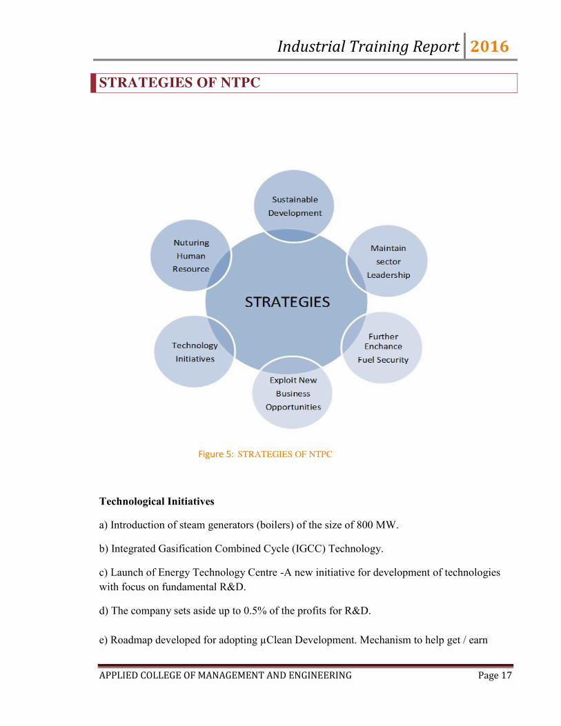
STRATEGIES OF NTPC
Figure 5: STRATEGIES OF NTPC
Technological Initiatives
a) Introduction of steam generators (boilers) of the size of 800 MW.
b) Integrated Gasification Combined Cycle (IGCC) Technology.
c) Launch of Energy Technology Centre -A new initiative for development of technologies
with focus on fundamental R&D.
d) The company sets aside up to 0.5% of the profits for R&D.
e) Roadmap developed for adopting µClean Development. Mechanism to help get / earn
Industrial Training Report 2016
APPLIED COLLEGE OF MANAGEMENT AND ENGINEERING Page 18
µCertified Emission Reduction.
Corporate Social Responsibility
As a responsible corporate citizen NTPC has taken up number of CSR initiatives.
a) NTPC Foundation formed to address Social issues at national level
b) NTPC has framed Corporate Social Responsibility Guidelines committing up to0.5% of
net profit annually for Community Welfare.
c) The welfare of project affected persons and the local population around
NTPC projects are taken care of through well drawn Rehabilitation and Resettlement policies.
d) The company has also taken up distributed generation for remote rural areas.
Partnering government in various initiatives
a) Consultant role to modernize and improvise several plants across the country.
b) Disseminate technologies to other players in the sector.
c) Consultant role ³Partnership in Excellence´ Programme for improvement of PLF of 15
Power Stations of SEBs.
d) Rural Electrification work under Rajiv Gandhi Garmin Vidyutikaran.

Industrial Training Report 2016
APPLIED COLLEGE OF MANAGEMENT AND ENGINEERING Page 19
CHAPTER 3
OPERATION OF POWER PLANT/ (PROJECT)
BASIC PRINCIPLE
As per FARADAY‟s Law-“Whenever the amount of magnetic flux linked with a circuit
changes, an EMF is produced in the circuit. Generator works on the principle of
producing electricity. To change the flux in the generator turbine is moved in a great
speed with steam.” To produce steam, water is heated in the boilers by burning the coal.
In a Badarpur Thermal PowerStation, steam is produced and used to spin a turbine that
operates a generator. Water is heated, turns into steam and spins a steam turbine which
drives an electrical generator. After it passes through the turbine, the steam is condensed
in a condenser; this is known as a Rankine cycle.
The electricity generated at the plant is sent to consumers through high-voltage power
lines The Badarpur Thermal Power Plant has Steam Turbine-Driven Generators which
has a collective capacity of 705MW. The fuel being used is Coal which is supplied from
the Jharia Coal Field in Jharkhand. Water supply is given from the Agra Canal.
THERMAL POWER PLANT
A Thermal Power Station comprises all of the equipment and a subsystem required to
produce electricity by using a steam generating boiler fired with fossil fuels or biofuels to
drive an electrical generator. Some prefer to use the term ENERGY CENTER because such
facilities convert forms of energy, like nuclear energy, gravitational potential energy or heat
energy (derived from the combustion of fuel) into electrical energy. However, POWER

Industrial Training Report 2016
APPLIED COLLEGE OF MANAGEMENT AND ENGINEERING Page 20
PLANT is the most common term in the united state; While POWER STATION prevails in
many Commonwealth countries and especially in the United Kingdom.
Such power stations are most usually constructed on a very large scale and designed for
continuous operation.
Figure 6: parts of powerplant
Typical elements of a coal fired thermal power station
1. cooling tower
Industrial Training Report 2016
APPLIED COLLEGE OF MANAGEMENT AND ENGINEERING Page 21
2. Cooling water pump
3. Three -phase transmission line
4. Step up transformer
5. Electrical Generator
6. Low pressure turbine
7. Boiler feed water pump
8. Surface condenser
9. Intermediate pressure steam turbine
10. Steam control valve
11. High pressure steam turbine
12. Deaerator
13.Feed water heater
14. Coal conveyor
15. Coal hopper
16. Coal pulverizer
17. Boiler drum
18. Bottom ash hoper
19. Super heater
20. Forced draught (draft) fan
21. Reheater
22. Combustion air intake
Industrial Training Report 2016
APPLIED COLLEGE OF MANAGEMENT AND ENGINEERING Page 22
23. Economizer
24. Air preheater
25. Precipitator
26. Induced draught (draft) fan
27. Fuel gas stack
The description of some of the components written above is described as follows:
1. Cooling towers
Cooling Towers are evaporative coolers used for cooling water or other working medium to
near the ambivalent web-bulb air temperature. Cooling towers use evaporation of water to
reject heat from processes such as cooling the circulating water used in oil refineries,
Chemical plants, power plants and building cooling, for example. The tower vary in size
from small roof-top units to very large hyperboloid structures that can be up to 200 meters
tall and 100 meters in diameter, or rectangular structure that can be over 40 meters tall and 80
meters long. Smaller towers are normally factory built, while larger ones are constructed on
site.
The primary use of large, industrial cooling tower system is to remove the heat absorbed in
the circulating cooling water systems used in power plants, petroleum refineries,
petrochemical and chemical plants, natural gas processing plants and other industrial
facilities. The absorbed heat is rejected to the atmosphere by the evaporation of some of the
cooling water in mechanical forced-draft or induced draft towers or in natural draft
hyperbolic shaped cooling towers as seen at most nuclear power plants.
2. Cooling Water Pump
it pumps the water from the cooling tower which goes to the condenser
3. Three phase transmission line

Industrial Training Report 2016
APPLIED COLLEGE OF MANAGEMENT AND ENGINEERING Page 23
Three phase electric power is a common method of electric power transmission. It is a type
of polyphase system mainly used to power motors and many other devices. A Three phase
system uses less conductor material to transmit electric power than equivalent single phase,
two phase, or direct current system at the same voltage. In a three phase system, three circuits
reach their instantaneous peak values at different times. Taking one conductor as the
reference, the other two current are delayed in time by one-third and two-third of one cycle
of the electrical current. This delay between “phases” has the effect of giving constant power
transfer over each cycle of the current and also makes it possible to produce a rotating
magnetic field in an electric motor.
At the power station, an electric generator converts mechanical power into a set of electric
currents, one from each electromagnetic coil or winding of the generator. The current are
sinusoidal functions of time, all at the same frequency but offset in time to give different
phases. In a three phase system the phases are spaced equally, giving a phase separation of
one-third one cycle. Generators output at a voltage that ranges from hundreds of volts to
30,000 volts. At the power station, transformers: step-up” this voltage to one more suitable
for transmission.
4. Unit transformer (3-phase)
At the power station, transformers step-up this voltage to one more suitable for
transmission. After numerous further conversions in the transmission and distribution
network the power is finally transformed to the standard mains voltage (i.e. the
“household” voltage). The power may already have been split into single phase at this
point or it may still be three phase. Where the step-down is 3 phase, the output of this
transformer is usually star connected with the standard mains voltage being the phase-
neutral voltage. Another system commonly seen in North America is to have a delta
connected secondary with a center tap on one of the windings supplying the ground and
neutral. This allows for 240 V three phase as well as three different single phase voltages(
120 Vbetween two of the phases and neutral , 208 V between the third phase ( or wild leg)
and neutral and 240 V between any two phase) to be available from the same supply.
5. Electrical generator

Industrial Training Report 2016
APPLIED COLLEGE OF MANAGEMENT AND ENGINEERING Page 24
An Electrical generator is a device that converts kinetic energy to electrical energy, generally
using electromagnetic induction. The task of converting the electrical energy into mechanical
energy is accomplished by using a motor. The source of mechanical energy may be a
reciprocating or turbine steam engine, , water falling through the turbine are made in a
variety of sizes ranging from small 1 hp (0.75 kW) units (rare) used as mechanical drives for
pumps, compressors and other shaft driven equipment , to 2,000,000 hp(1,500,000 kW)
turbines used to generate electricity. There are several classifications for modern steam
turbines.
Steam turbines are used in all of our major coal fired power stations to drive the generators or
alternators, which produce electricity. The turbines themselves are driven by steam generated
in ‘Boilers’ or ‘steam generators’ as they are sometimes called.
Electrical power stations use large steam turbines driving electric generators to produce most
(about 86%) of the world’s electricity. These centralized stations are of two types: fossil fuel
power plants and nuclear power plants. The turbines used for electric power generation are
most often directly coupled to their-generators .As the generators must rotate at constant
synchronous speeds according to the frequency of the electric power system, the most
common speeds are 3000 r/min for 50 Hz systems, and 3600 r/min for 60 Hz systems. Most
large nuclear sets rotate at half those speeds, and have a 4-pole generator rather than the more
common 2-pole one.
Energy in the steam after it leaves the boiler is converted into rotational energy as it passes
through the turbine. The turbine normally consists of several stage with each stages
consisting of a stationary blade (or nozzle) and a rotating blade. Stationary blades convert the
potential energy of the steam into kinetic energy into forces, caused by pressure drop, which
results in the rotation of the turbine shaft. The turbine shaft is connected to a generator,
which produces the electrical energy.
6. Low Pressure Turbine
Energy in the steam after it leaves the boiler is converted into rotational energy as it
passes through the turbine. The turbine normally consists of several stages with each
stages consisting of a stationary blade (or nozzle) and a rotating blade. Stationary blades

Industrial Training Report 2016
APPLIED COLLEGE OF MANAGEMENT AND ENGINEERING Page 25
convert the potential energy of the steam into kinetic energy and direct the flow onto the
rotating blades. The rotating blades convert the kinetic energy into impulse and reaction
forces, caused by pressure drop, which results in the rotation of the turbine shaft. The
turbine shaft is connected to a generator, which produces the electrical energy.
Low Pressure Turbine (LPT) consists of 4x2 stages. After passing through Intermediate
Pressure Turbine steam is passed through LPT which is made up of two parts- LPC
REAR & LPC FRONT. As water gets cooler here it gathers into a HOTWELL placed in
lower parts of turbine.
7. Condensation Extraction Pump
A Boiler feed water pump is a specific type of pump used to pump water into a steam
boiler. The water may be freshly supplied or returning condensation of the steam
produced by the boiler. These pumps are normally high pressure units that use suction
from a condensate return system and can be of the centrifugal pump type or positive
displacement type.
Construction and operation:
Feed water pumps range in size up to many horsepower and the electric motor is usually
separated from the pump body by some form of mechanical coupling. Large industrial
condensate pumps may also serve as the feed water pump. In either case, to force the
water into the boiler, the pump must generate sufficient pressure to overcome the steam
pressure developed by the boiler. This is usually accomplished through the use of a
centrifugal pump. Feed water pumps usually run intermittently and are controlled by a
float switch or other similar level-sensing device energizing the pump when it detects a
lowered liquid level in the boiler. Some pumps contain a two-stage switch. As liquid
lowers to the trigger point of the first stage, the pump is activated. If the liquid continues
to drop, (perhaps because the pump has failed, its supply has been cut off or exhausted, or
its discharge is blocked) the second stage will be triggered. This stage may switch off the
boiler equipment (preventing the boiler from running dry and overheating), trigger an
alarm, or both.
Industrial Training Report 2016
APPLIED COLLEGE OF MANAGEMENT AND ENGINEERING Page 26
8. Condenser
The steam coming out from the Low Pressure Turbine (a little above its boiling pump) is
brought into thermal contact with cold water (pumped in from the cooling tower) in the
condenser, where it condenses rapidly back into water, creating near Vacuum-like
conditions inside the condenser chest.
9. Intermediate Pressure Turbine
Intermediate Pressure Turbine (IPT) consists of 11 stages. When the steam has been passed
through HPT it enters into IPT. IPT has two ends named as FRONT & REAR.
Steam enters through front end and leaves from Rear end.
10. Steam Governor Valve
Steam locomotives and the steam engines used on ships and stationary applications such
as power plants also required feed water pumps. In this situation, though, the pump was
often powered using a small steam engine that ran using the steam produced by the boiler
a means had to be provided, of course, to put the initial charge of water into the boiler
(before steam power was available to operate the steam-powered feed water pump).The
pump was often a positive displacement pump that had steam valves and cylinders at one
end and feed water cylinders at the other end; no crankshaft was required. In thermal
plants, the primary purpose of surface condenser is to condense the exhaust steam from a
steam turbine to obtain maximum efficiency and also to convert the turbine exhaust
steam into pure water so that it may be reused in the steam generator or boiler as boiler
feed water. By condensing the exhaust steam of a turbine at a pressure below atmospheric
pressure, the steam pressure drop between the inlet and exhaust of the turbine is
increased, which increases the amount heat available for conversion to mechanical
power.
11.High Pressure Turbine
Steam coming from Boiler directly feeds into HPT at a temperature of 540°C and at a
pressure of 136 kg/cm2. Here it passes through 12 different stages due to which its

Industrial Training Report 2016
APPLIED COLLEGE OF MANAGEMENT AND ENGINEERING Page 27
temperature goes down to 329°C and pressure as 27 kg/cm2. This line is also called as
CRH – COLD REHEAT LINE. It is now passed to a REHEATER where its temperature
rises to 540°C and called as HRH-HOT REHEATED LINE.
12. Deaerator
A Deaerator is a device for air removal and used to remove dissolved gases (an alternate
would be the use of water treatment chemicals) from boiler feed water to make it non-
corrosive. A dearator typically includes a vertical domed deaeration section as the
deaeration boiler feed water tank. A Steam generating boiler requires that the circulating
steam, condensate, and feed water should be devoid of dissolved gases, particularly
corrosive ones and dissolved or suspended solids. The gases will give rise to corrosion of
the metal. The solids will deposit on the heating surfaces giving rise to localized heating
and tube ruptures due to overheating. Under some conditions it may give rise to stress
corrosion cracking. Deaerator level and pressure must be controlled by adjusting control
valves the level by regulating condensate flow and the pressure by regulating steam flow.
13. Feed water heater
A Feed water heater is a power plant component used to pre-heat water delivered to a
steam generating boiler. Preheating the feed water reduces the irreversibility involved in
steam generation and therefore improves the thermodynamic efficiency of the system.
This reduces plant operating costs and also helps to avoid thermal shock to the boiler
metal when the feed water is introduced back into the steam cycle. In a steam power
(usually modelled as a modified Rankine cycle), feed water heaters allow the feed water
to be brought up to the saturation temperature very gradually. This minimizes the
inevitable irreversibility associated with heat transfer to the working fluid (water).
14. Coal conveyor
Coal conveyors are belts which are used to transfer coal from its storage place to Coal
Hopper. A belt conveyor consists of two pulleys, with a continuous loop of material- the
conveyor Belt – that rotates about them. The pulleys are powered, moving the belt and
Industrial Training Report 2016
APPLIED COLLEGE OF MANAGEMENT AND ENGINEERING Page 28
the material on the belt forward.Conveyor belts are extensively used to transport industrial
and agricultural material, such as grain, coal, ores etc.
15. Coal Hopper
Coal Hoppers are the places which are used to feed coal to Fuel Mill. It also has the
arrangement of entering Hot Air at 200°C inside it which solves our two purposes:-
1. If our Coal has moisture content then it dries it so that a proper combustion takes place.
2. It raises the temperature of coal so that its temperature is more near to its Ignite
Temperature so that combustion is easy
16. Pulverized Fuel Mill
A pulveriser is a device for grinding coal for combustion in a furnace in a fossil fuel
power plant.
17. Boiler feed water pump
A Boiler feed water pump is a specific type of pump used to pump water into a steam
boiler. The water may be freshly supplied or retuning condensation of the steam produced
by the boiler. These pumps are normally high pressure units that use suction from a
condensate return system and can be of the centrifugal pump type or positive displacement
type.

Industrial Training Report 2016
APPLIED COLLEGE OF MANAGEMENT AND ENGINEERING Page 29
Figure7: EXTERNAL VIEW OF BOILER
Construction and operation:
Feed water pumps range in size up to many horsepower and the electric motor is usually
separated from the pump body by some form of mechanical coupling. Large industrial
condensate pumps may also serve as the feed water pump. In either case, to force the
water into the boiler; the pump must generate sufficient pressure to overcome the steam
pressure developed by the boiler. This is usually accomplished through the use of a
centrifugal pump.
Feed water pumps usually run intermittently and are controlled by a float switch or other
similar level-sensing device energizing the pump when it detects a lowered liquid level in
the boiler is substantially increased. Some pumps contain a two-stage switch. As liquid
lowers to the trigger point of the first stage, the pump is activated. I f the liquid continues to
drop (perhaps because the pump has failed, its supply has been cut off or exhausted, or its
discharge is blocked); the second stage will be triggered.
18. Ash Hopper
A steam drum is used in the company of a mud-drum/feed water drum which is located at
a lower level.So that it acts as a sump for the sludge or sediments which have a tendency to
Industrial Training Report 2016
APPLIED COLLEGE OF MANAGEMENT AND ENGINEERING Page 30
accumulate at the bottom.
19. Super Heater
A Super heater is a device in a steam engine that heats the steam generated by the boiler
again increasing its thermal energy. Super heaters increase the efficiency of the steam
engine, and were widely adopted. Steam which has been superheated is logically known
as superheated steam; non- superheated steam is called saturated steam or wet steam.
Super heaters were applied to steam locomotives in quantity from the early 20th century,
to most steam vehicles, and also stationary steam engines including power stations.
20. Force Draught Fan
External fans are provided to give sufficient air for combustion. The forced draught fan
takes air from the atmosphere and, warms it in the air preheater for better combustion,
injects it via the air nozzles on the furnace wall.
21. Reheater
Reheater is a heater which is used to raise the temperature of steam which has fallen from
the intermediate pressure turbine.
22. Air Intake
Air is taken from the environment by an air intake tower which is fed to the fuel.
23. Economizers
Economizer, or in the UK economizer, are mechanical devices intended to reduce energy
consumption, or to perform another useful function like preheating a fluid. The term
economizer is used for other purposes as well-Boiler, power plant, heating, ventilating
and air-conditioning. In boilers, economizer are heat exchange devices that heat fluids ,
usually water, up to but not normally beyond the boiling point of the fluid. Economizers
are so named because they can make use of the enthalpy and improving the boiler‟s
efficiency. They are devices fitted to a boiler which save energy by using the exhaust
gases from the boiler to preheat the cold water used to fill it (the feed water). Modern day

Industrial Training Report 2016
APPLIED COLLEGE OF MANAGEMENT AND ENGINEERING Page 31
boilers, such as those in cold fired power stations, are still fitted with economizer which
is decedents of Green‟s original design. In this context there are turbines before it is
pumped to the boilers. A common application of economizer in steam power plants is to
capture the waste heat from boiler stack gases (flue gas) and transfer thus it to the boiler
feed water thus lowering the needed energy input , in turn reducing the firing rates to
accomplish the rated boiler output . Economizer lower stack temperatures which may
cause condensation of acidic combustion gases and serious equipment corrosion damage
if care is not taken in their design and material selection.
24. Air Preheater
Air preheater is a general term to describe any device designed to heat air before another
process (for example, combustion in a boiler). The purpose of the air preheater is to
recover the heat from the boiler flue gas which increases the thermal efficiency of the
boiler by reducing the useful heat lost in the flue gas. As a consequence, the flue gases
are also sent to the flue gas stack (or chimney) at a lower temperature allowing simplified
design of the ducting and the flue gas stack. It also allows control over the temperature of
gases leaving the stack.
25. Precipitator
An Electrostatic precipitator (ESP) or electrostatic air cleaner is a particulate device that
removes particles from a flowing gas (such As air) using the force of an induced electrostatic
charge. Electrostatic precipitators are highly efficient filtration devices, and can easily
remove fine particulate matter such as dust and smoke from the air steam.
ESP’s o ti ue to e e elle t de i es for o trol of a i dustrial parti ulate e issio s,
including smoke from electricity-generating utilities (coal and oil fired), salt cake collection
from black liquor boilers in pump mills, and catalyst collection from fluidized bed catalytic
crackers from several hundred thousand ACFM in the largest coal-fired boiler application.
The original parallel plate-Weighted wire design (described above) has evolved as more
efficient ( and robust) discharge electrode designs were developed, today focusing on rigid
Industrial Training Report 2016
APPLIED COLLEGE OF MANAGEMENT AND ENGINEERING Page 32
discharge electrodes to which many sharpened spikes are attached , maximizing corona
production. Transformer –rectifier systems apply voltages of 50-100 Kilovolts at relatively
high current densities. Modern controls minimize sparking and prevent arcing, avoiding
damage to the components. Automatic rapping systems and hopper evacuation systems
remove the collected parti ulate atter hile o li e allo i g ESP’s to sta i operatio for
years at a time.
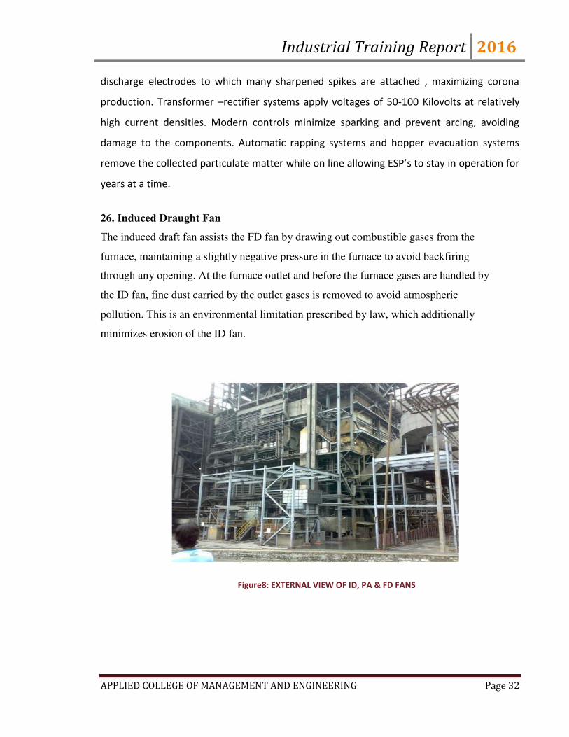
26. Induced Draught Fan
The induced draft fan assists the FD fan by drawing out combustible gases from the
furnace, maintaining a slightly negative pressure in the furnace to avoid backfiring
through any opening. At the furnace outlet and before the furnace gases are handled by
the ID fan, fine dust carried by the outlet gases is removed to avoid atmospheric
pollution. This is an environmental limitation prescribed by law, which additionally
minimizes erosion of the ID fan.
Figure8: EXTERNAL VIEW OF ID, PA & FD FANS

Industrial Training Report 2016
APPLIED COLLEGE OF MANAGEMENT AND ENGINEERING Page 33
27. Fuel gas stack
A Fuel gas stack is a type of chimney, a vertical pipe, channel or similar structure through
which combustion product gases called fuel gases are exhausted to the outside air. Fuel gases
are produced when coal, oil, natural gas, wood or any other large combustion device. Fuel
gas is usually composed of carbon dioxide (CO2) and water vapor as well as nitrogen and
excess oxygen remaining from the intake combustion air. It also contains a small percentage
of pollutants such as particulates matter, carbon mono oxide, nitrogen oxides and sulfur
oxides. The flue gas stacks are often quite tall, up to 400 meters (1300 feet) or more, so as to
disperse the exhaust pollutants over a greater aria and thereby reduce the concentration of the
pollutants to the levels required by governmental environmental policies and regulations.
When the fuel gases exhausted from stoves, ovens, fireplaces or other small sources within
residential abodes, restaurants , hotels or other stacks are referred to as chimneys.
Industrial Training Report 2016
APPLIED COLLEGE OF MANAGEMENT AND ENGINEERING Page 34
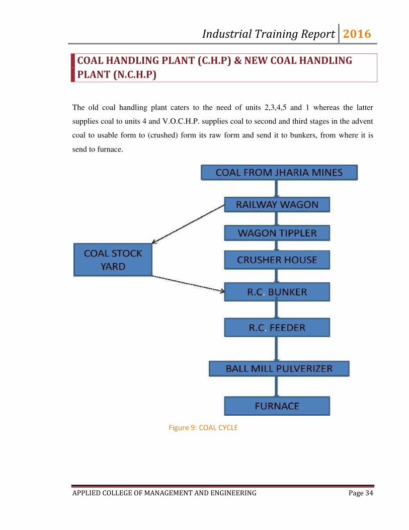
COAL HANDLING PLANT (C.H.P) & NEW COAL HANDLING
PLANT (N.C.H.P)
The old coal handling plant caters to the need of units 2,3,4,5 and 1 whereas the latter
supplies coal to units 4 and V.O.C.H.P. supplies coal to second and third stages in the advent
coal to usable form to (crushed) form its raw form and send it to bunkers, from where it is
send to furnace.
Figure 9: COAL CYCLE
Industrial Training Report 2016
APPLIED COLLEGE OF MANAGEMENT AND ENGINEERING Page 35
Major Components
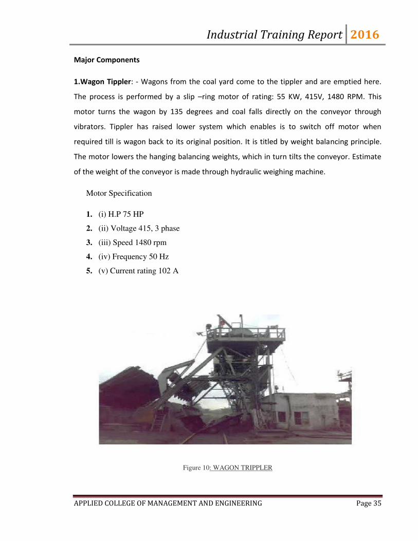
1.Wagon Tippler: - Wagons from the coal yard come to the tippler and are emptied here.
The process is performed by a slip –ring motor of rating: 55 KW, 415V, 1480 RPM. This
motor turns the wagon by 135 degrees and coal falls directly on the conveyor through
vibrators. Tippler has raised lower system which enables is to switch off motor when
required till is wagon back to its original position. It is titled by weight balancing principle.
The motor lowers the hanging balancing weights, which in turn tilts the conveyor. Estimate
of the weight of the conveyor is made through hydraulic weighing machine.
Motor Specification
1. (i) H.P 75 HP
2. (ii) Voltage 415, 3 phase
3. (iii) Speed 1480 rpm
4. (iv) Frequency 50 Hz
5. (v) Current rating 102 A
Figure 10: WAGON TRIPPLER
Industrial Training Report 2016
APPLIED COLLEGE OF MANAGEMENT AND ENGINEERING Page 36
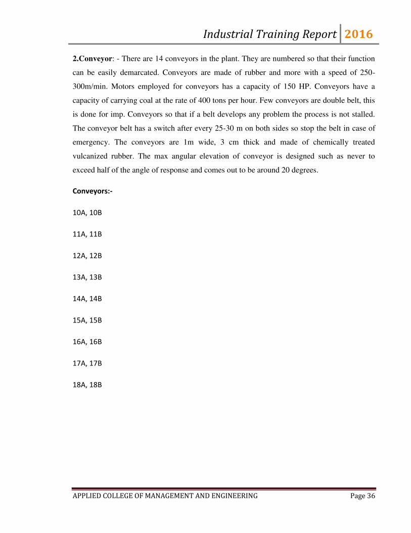
2.Conveyor: - There are 14 conveyors in the plant. They are numbered so that their function
can be easily demarcated. Conveyors are made of rubber and more with a speed of 250-
300m/min. Motors employed for conveyors has a capacity of 150 HP. Conveyors have a
capacity of carrying coal at the rate of 400 tons per hour. Few conveyors are double belt, this
is done for imp. Conveyors so that if a belt develops any problem the process is not stalled.
The conveyor belt has a switch after every 25-30 m on both sides so stop the belt in case of
emergency. The conveyors are 1m wide, 3 cm thick and made of chemically treated
vulcanized rubber. The max angular elevation of conveyor is designed such as never to
exceed half of the angle of response and comes out to be around 20 degrees.
Conveyors:-
10A, 10B
11A, 11B
12A, 12B
13A, 13B
14A, 14B
15A, 15B
16A, 16B
17A, 17B
18A, 18B
Industrial Training Report 2016
APPLIED COLLEGE OF MANAGEMENT AND ENGINEERING Page 37
FIGURE 11: CONVEYOR
3. Metal Separators: - As the belt takes coal to the crusher, No metal pieces should go along
with coal. To achieve this objective, we use metal separators. When coal is dropped to the
crusher hoots, the separator drops metal pieces ahead of coal. It has a magnet and a belt
and the belt is moving, the pieces are thrown away. The capacity of this device is around 50
kg. .The CHP is supposed to transfer 600 tons of coal/hr, but practically only 300-400 tons
coal is transfer.
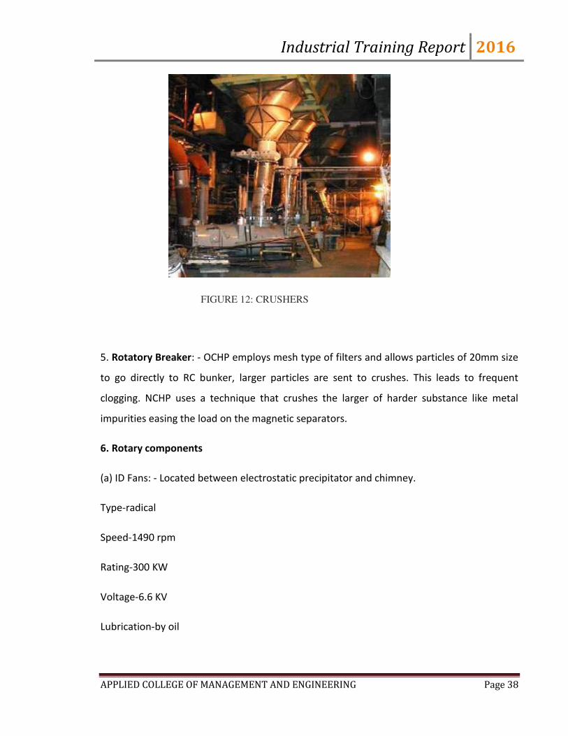
4. Crusher: - Both the plants use TATA crushers powered by BHEL. Motors. The crusher is of
ring type and motor ratings are 400 HP, 606 KV. Crusher is designed to crush the pieces to
20 mm size i.e. practically considered as the optimum size of transfer via conveyor.
Industrial Training Report 2016
APPLIED COLLEGE OF MANAGEMENT AND ENGINEERING Page 38
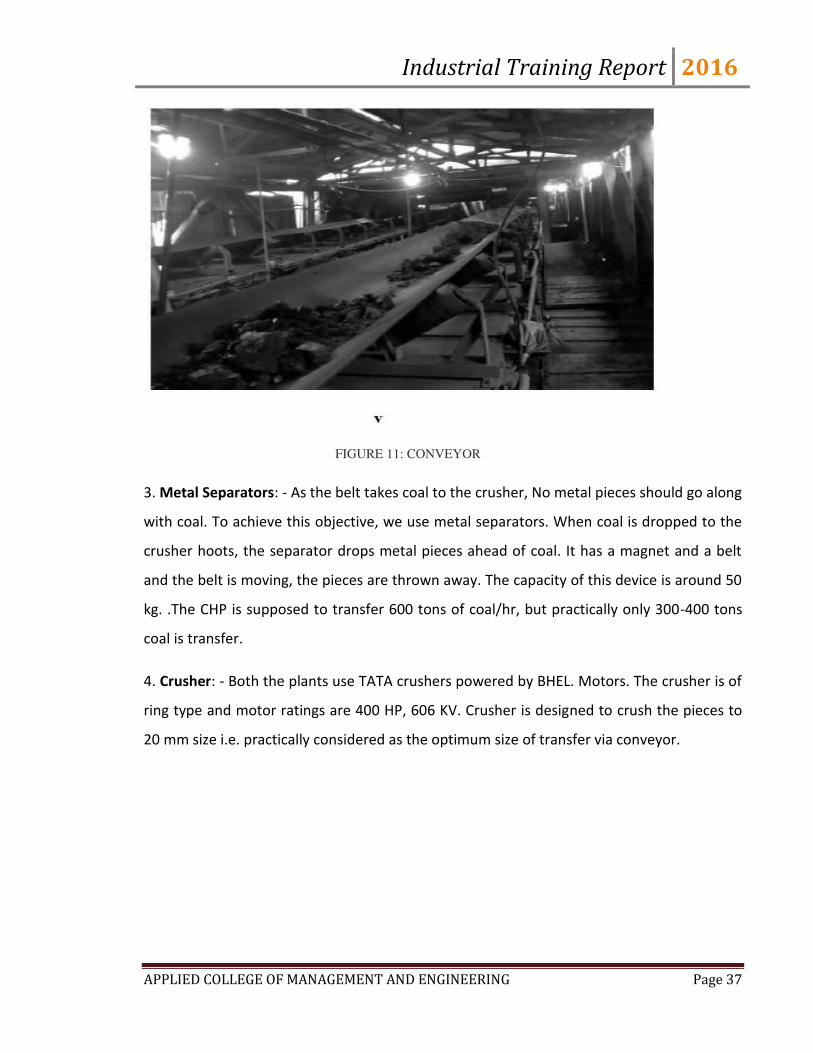
FIGURE 12: CRUSHERS
5. Rotatory Breaker: - OCHP employs mesh type of filters and allows particles of 20mm size
to go directly to RC bunker, larger particles are sent to crushes. This leads to frequent
clogging. NCHP uses a technique that crushes the larger of harder substance like metal
impurities easing the load on the magnetic separators.
6. Rotary components
(a) ID Fans: - Located between electrostatic precipitator and chimney.
Type-radical
Speed-1490 rpm
Rating-300 KW
Voltage-6.6 KV
Lubrication-by oil

Industrial Training Report 2016
APPLIED COLLEGE OF MANAGEMENT AND ENGINEERING Page 39
(b) FD Fans: - Designed to handle secondary air for boiler. 2 in number and provide ignition
of coal.
Type-axial
Speed-990 rpm
Rating-440 KW
Voltage-6.6 KV
(c)Primary Air Fans: - Designed for handling the atmospheric air up to 50 degrees Celsius, 2
in numberAnd they transfer the powered coal to burners to firing.
Type-Double suction radial
Rating-300 KW
Voltage-6.6 KV
Lubrication-by oil
Type of operation-continuous
7. Coal feed to plant:
Feeder motor specification
(i) Horse power 15 HP
(ii) Voltage 415V, 3 phase
(iii) Speed 1480 rpm
Industrial Training Report 2016
APPLIED COLLEGE OF MANAGEMENT AND ENGINEERING Page 40
Generator and Auxiliaries
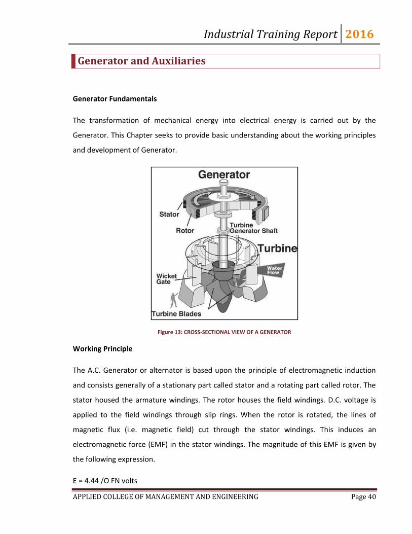
Generator Fundamentals
The transformation of mechanical energy into electrical energy is carried out by the
Generator. This Chapter seeks to provide basic understanding about the working principles
and development of Generator.
Figure 13: CROSS-SECTIONAL VIEW OF A GENERATOR
Working Principle
The A.C. Generator or alternator is based upon the principle of electromagnetic induction
and consists generally of a stationary part called stator and a rotating part called rotor. The
stator housed the armature windings. The rotor houses the field windings. D.C. voltage is
applied to the field windings through slip rings. When the rotor is rotated, the lines of
magnetic flux (i.e. magnetic field) cut through the stator windings. This induces an
electromagnetic force (EMF) in the stator windings. The magnitude of this EMF is given by
the following expression.
E = 4.44 /O FN volts

Industrial Training Report 2016
APPLIED COLLEGE OF MANAGEMENT AND ENGINEERING Page 41
0 = Stre gth of ag eti field i We er’s.
F = Frequency in cycles per second or Hertz.
N = Number of turns in a coil of stator winding
F = Frequency = P*n/120
Where P = Number of poles
n = revolutions per second of rotor.
From the expression it is clear that for the same frequency, number of poles increases with
decrease in speed and vice versa. Therefore, low speed hydro turbine drives generators
have 14 to 20 poles were as high speed steam turbine driven generators have generally 2
poles.
Figure 14: A 95 MW GENERATOR
Generator component
This deals with the two main components of the Generator viz. Rotor, its winding &
balancing and stator, its frame, core & windings.

Industrial Training Report 2016
APPLIED COLLEGE OF MANAGEMENT AND ENGINEERING Page 42
Rotor
The electrical rotor is the most difficult part of the generator to design. It revolves in most
modern generators at a speed of 3,000 revolutions per minute. The problem of
guaranteeing the dynamic strength and operating stability of such a rotor is complicated by
the fact that a massive non-uniform shaft subjected to a multiplicity of differential stresses
must operate in oil lubricated sleeve bearings supported by a structure mounted on
foundations all of which possess complex dynamic be behavior peculiar to them. It is also an
electromagnet and to give it the necessary magnetic strength
The windings must carry a fairly high current. The passage of the current through the
windings generates heat but the temperature must not be allowed to become so high,
otherwise difficulties will be experienced with insulation. To keep the temperature down,
the cross section of the conductor could not be increased but this would introduce another
problems. In order to make room for the large conductors, body and this would cause
mechanical weakness. The problem is really to get the maximum amount of copper into the
windings without reducing the mechanical strength. With good design and great care in
construction this can be achieved. The rotor is a cast steel ingot, and it is further forged and
machined. Very often a hole is bored through the centre of the rotor axially from one end of
the other for inspection. Slots are then machined for windings and ventilation.
Rotor winding
Silver bearing copper is used for the winding with mica as the insulation between
conductors. A mechanically strong insulator such as micanite is used for lining the slots.
Later designs of windings for large rotor incorporate combination of hollow conductors with
slots or holes arranged to provide for circulation of the cooling gas through the actual
conductors. When rotating at high speed. Centrifugal force tries to lift the windings out of
the slots and they are contained by wedges. The end rings are secured to a turned recess in
the rotor body, by shrinking or screwing and supported at the other end by fittings carried
Industrial Training Report 2016
APPLIED COLLEGE OF MANAGEMENT AND ENGINEERING Page 43
by the rotor body. The two ends of windings are connected to slip rings, usually made of
forged steel, and mounted on insulated sleeves.
Stator
Stator frame: The stator is the heaviest load to be transported. The major part of this load is
the stator core. This comprises an inner frame and outer frame. The outer frame is a rigid
fabricated structure of welded steel plates, within this shell is a fixed cage of girder built
circular and axial ribs. The ribs divide the yoke in the compartments through which
hydrogen flows into radial ducts in the stator core and circulate through the gas coolers
housed in the frame. The inner cage is usually fixed in to the yoke by an arrangement of
springs to dampen the double frequency vibrations inherent in 2 pole generators. The end
shields of hydrogen cooled generators must be strong enough to carry shaft seals. In large
generators the frame is constructed as two separate parts. The fabricated inner cage is
inserted in the outer frame after the stator core has been constructed and the winding
completed. Stator core: The stator core is built up from a large number of 'punching" or
sections of thin steel plates. The use of cold rolled grain-oriented steel can contribute to
reduction in the weight of stator core for two main reasons:
a) There is an increase in core stacking factor with improvement in lamination cold Rolling
and in cold buildings techniques.
b) The advantage can be taken of the high magnetic permeance of grain-oriented steels of
work the stator core at comparatively high magnetic saturation without fear or excessive
iron loss of two heavy a demand for excitation ampere turns from the generator rotor.
Stator Windings
Each stator conductor must be capable of carrying the rated current without overheating.
The insulation must be sufficient to prevent leakage currents flowing between the phases to
earth. Windings for the stator are made up from copper strips wound with insulated tape
which is impregnated with varnish, dried under vacuum and hot pressed to form a solid

Industrial Training Report 2016
APPLIED COLLEGE OF MANAGEMENT AND ENGINEERING Page 44
insulation bar. These bars are then place in the stator slots and held in with wedges to form
the complete winding which is connected together at each end of the core forming the end
turns. These end turns are rigidly braced and packed with blocks of insulation material to
withstand the heavy forces which might result from a short circuit or other fault conditions.
The generator terminals are usually arranged below the stator. On recent generators (210
MW) the windings are made up from copper tubes instead of strips through which water is
circulated for cooling purposes. The water is fed to the windings through plastic tubes.
Generator Cooling System
The 200/210 MW Generator is provided with an efficient cooling system to avoid excessive
heating and consequent wear and tear of its main components during operation. This
Chapter deals with the rotor-hydrogen cooling system and stator water cooling system
along with the shaft sealing and bearing cooling systems.
Rotor Cooling System
The rotor is cooled by means of gap pick-up cooling, wherein the hydrogen gas in the air gap
is sucked through the scoops on the rotor wedges and is directed to flow along the
ventilating canals milled on the sides of the rotor coil, to the bottom of the slot where it
takes a turn and comes out on the similar canal milled on the other side of the rotor coil to
the hot zone of the rotor. Due to the rotation of the rotor, a positive suction as well as
discharge is created due to which a certain quantity of gas flows and cools the rotor. This
method of cooling gives uniform distribution of temperature. Also, this method has an
inherent advantage of eliminating the deformation of copper due to varying temperatures.
Hydrogen Cooling System
Hydrogen is used as a cooling medium in large capacity generator in view of its high heat
arr i g apa it a d lo de sit . But i ie of it’s for i g a e plosi e i ture ith
oxygen, proper arrangement for filling, purging and maintaining its purity inside the
Industrial Training Report 2016
APPLIED COLLEGE OF MANAGEMENT AND ENGINEERING Page 45
generator have to be made. Also, in order to prevent escape of hydrogen from the
generator casing, shaft sealing system is used to provide oil sealing.
The hydrogen cooling system mainly comprises of a gas control stand, a drier, an liquid level
indicator, hydrogen control panel, gas purity measuring and indicating instruments,
The system is capable of performing the following functions:
I. Filling in and purging of hydrogen safely without bringing in contact with air.
II. Maintaining the gas pressure inside the machine at the desired value at all the times.
III. Provide indication to the operator about the condition of the gas inside the machine
i.e. its pressure, temperature and purity.
IV. Continuous circulation of gas inside the machine through a drier in order to remove
any water vapor that may be present in it.
V. Indication of liquid level in the generator and alarm in case of high level.
Stator Cooling System
The stator winding is cooled by distillate.
Turbo generators require water cooling arrangement over and above the usual hydrogen
cooling arrangement. The stator winding is cooled in this system by circulating
demineralised water (DM water) through hollow conductors. The cooling water used for
cooling stator winding calls for the use of very high quality of cooling water. For this
purpose DM water of proper specific resistance is selected. Generator is to be loaded within
a very short period if the specific resistance of the cooling DM water goes beyond certain
preset values. The system is designed to maintain a constant rate of cooling water flow to
the stator winding at a nominal inlet water temperature of 400C.
Industrial Training Report 2016
APPLIED COLLEGE OF MANAGEMENT AND ENGINEERING Page 46
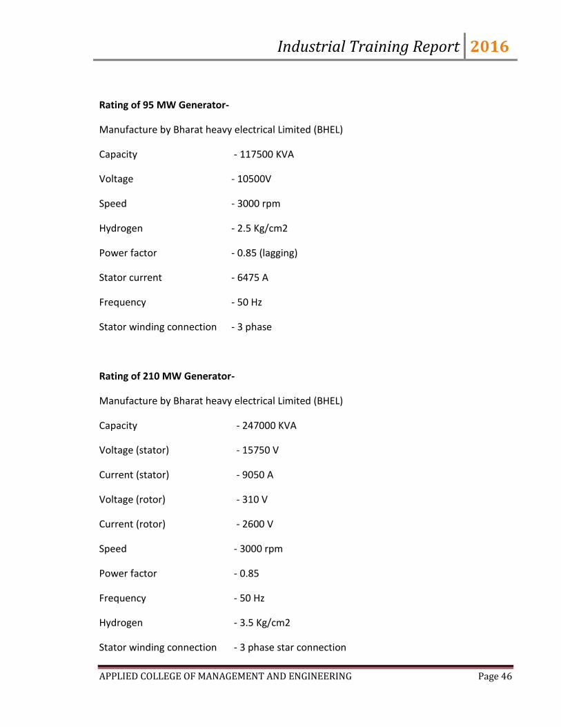
Rating of 95 MW Generator-
Manufacture by Bharat heavy electrical Limited (BHEL)
Capacity - 117500 KVA
Voltage - 10500V
Speed - 3000 rpm
Hydrogen - 2.5 Kg/cm2
Power factor - 0.85 (lagging)
Stator current - 6475 A
Frequency - 50 Hz
Stator winding connection - 3 phase
Rating of 210 MW Generator-
Manufacture by Bharat heavy electrical Limited (BHEL)
Capacity - 247000 KVA
Voltage (stator) - 15750 V
Current (stator) - 9050 A
Voltage (rotor) - 310 V
Current (rotor) - 2600 V
Speed - 3000 rpm
Power factor - 0.85
Frequency - 50 Hz
Hydrogen - 3.5 Kg/cm2
Stator winding connection - 3 phase star connection

Industrial Training Report 2016
APPLIED COLLEGE OF MANAGEMENT AND ENGINEERING Page 47
TRANSFORMER
A transformer is a device that transfers electrical energy from one circuit to another by
magnetic coupling without requiring relative motion between its parts. It usually comprises
two or more coupled windings, and in most cases, a core to concentrate magnetic flux. An
alternating voltage applied to one winding creates a time-varying magnetic flux in the core,
which includes a voltage in the other windings. Varying the relative number of turns
between primary and secondary windings determines the ratio of the input and output
voltages, thus transforming the voltage by stepping it up or down between circuits. By
transforming electrical power to a high-voltage, _low-current form and back again, the
transformer greatly reduces energy losses and so enables the economic transmission of
power over long distances. It has thus shape the electricity supply industry, permitting
generation to be located remotely from point of demand.
FIGURE 15: TRANSFORMER
WORKING PRINCIPLE:
It works on FARADAY‟S LAW OF ELECTROMAGNETIC INDUCTION (self
or mutual induction depending on the type of transformer).
Industrial Training Report 2016
APPLIED COLLEGE OF MANAGEMENT AND ENGINEERING Page 48
MAIN PARTS
CONSERVATOR
It is used generally to conserve the insulating property of the oil from deterioration&
protect the transformer against failure on account of bad quality of oil.
SILICAGEL DEHYDRATING BREATHER
It is used to prevent entry of moisture inside the transformer tank. The breather
consists of silica gel.
GAS OPERATED RALAY
It is a gas actuated relay used for protecting oil immersed transformer against all
types of faults. It indicates presence of gases in case of some minor fault & take
out the transformer out of circuit in case of serious fault.
BUSHING
It is made from highly insulating material to insulate & to bring out the terminals
of the transformer from the container. The bushings are of 3 types:
a). Porcelain bushings used for low voltage transformer
b). Oil filled bushings used for voltage up to 33KV.
c). Condensed type bushings used for voltage above 33KV
OIL GAUGE
Every transformer with an oil guage to indicate the oil level. The oil guage may be
provided with the alarm contacts which gave an alarm the oil level has dropped
beyond permissible height due to oil leak etc.
TAPPINGS
Industrial Training Report 2016
APPLIED COLLEGE OF MANAGEMENT AND ENGINEERING Page 49
The transformer are usually provided with few tappings on secondary side so
that output voltage can be varied for constant input voltage.
RADIATOR
It increases the surface area of the tank & more heat is thus radiated in less time.
CONSTRUCTIONAL FEATURES
a) 3 phase transformer is constructed in the core type construction
b) For reducing losses a smaller thickness of lamination is used.
c) For the above reason it is also called cold-rolled steel instead hot-rolled steel is
used.
d) High flux densities (1.4 to 1.7 Wb/sq m) are used in the core of power transformer
which carry load throughout.
e)For high voltage winding, disc type coils are used.
CLASSIFICATION
(I) ACCORDING TO THE CORE
a)Core type transformer
b)Shell type transformer
c)Berry type transformer
(II) ACCORDING TO THE PHASES
a)1phase transformer
b)3phase transformer
COOLING OF TRANSFORMERS :
As size of transformer becomes large, the rate of the oil circulating becomes insufficient
to dissipate all the heat produced & artificial means of increasing the circulation by
electric pumps. In very large transformers, special coolers with water circulation may
have to be employed.
Industrial Training Report 2016
APPLIED COLLEGE OF MANAGEMENT AND ENGINEERING Page 50
TYPES OF COOLING
AIR COOLING
a) Air Natural
b)Air Forced
OIL IMMERSED COOLING
a) Oil Natural Air Cooling
b)Oil Natural Force Cooling
c)Oil Forced Air Natural Cooling
d) Oil Forced Air Forced Cooling
MAIN PARTS OF TRANSFORMER
1.Primary Winding
2.Secondry Winding
3.Oil Level
4.Conservator
5.Breather
6.Drain Cocks
7.Cooling Tubes
8.Transformer Oil
9.Earth Point
10.Explosion Vent
11.Temperature Gauge
12.Secondary Terminal
13.Primary Terminal
14.Buchholz Relay
Rating of transformer
No load voltage (HV) - 229 KV

Industrial Training Report 2016
APPLIED COLLEGE OF MANAGEMENT AND ENGINEERING Page 51
No load Voltage (LV) -10.5 KV
Line current (HV) -315.2 A
Line current (LV) - 873.2 A
Temp rise - 45 Celsius
Oil quantity - 40180 lit
Weight of oil - 34985 Kg
Total weight - 147725 Kg
Core & winding - 84325 Kg
Phase -3
Frequency - 50 Hz
INSTRUMENTS SEEN
1. MICROMETER
This instrument is used for measuring inside as well as outside diameter of bearing.
2. MEGGAR
This instrument is used for measuring insulation resistance.
3. VIBRATION TESTER
It measures the vibration of the motor. It is measured in three dimensions-axial, vertical and
horizontal.
POLLUTION CONTROL SYSTEMS:
While deciding the appropriate technology for its projects, NTPC integrates many
environmental provisions into the plant design. In order to ensure that NTPC complies
with all the stipulated environment norms, various state-of-the-art pollution control
Industrial Training Report 2016
APPLIED COLLEGE OF MANAGEMENT AND ENGINEERING Page 52
systems / devices as discussed below have been installed to control air and water
pollution.
Electrostatic Precipitators:
The ash left behind after combustion of coal is arrested in high efficiency Electrostatic
Precipitators (ESPs) and particulate emission is controlled well within the stipulated
norms. The ash collected in the ESPs is disposed to Ash Ponds in slurry form.
Flue Gas Stacks:
Tall Flue Gas Stacks have been provided for wide dispersion of the gaseous emissions
(SOX, NOX etc.) into the atmosphere.
Low-NOX Burners:
In gas based NTPC power stations, NOX emissions are controlled by provision of Low-
NOX Burners (Dry or wet type) and in coal fired stations, by adopting best combustion
practices.
Neutralization Pits:
Neutralization pits have been provided in the Water Treatment Plant (WTP) for pH
correction of the Effluents before discharge into Effluent Treatment Plant (ETP) for
further treatment and use.
Coal Settling Pits / Oil Settling Pits:
In these Pits, coal dust and oil are removed from the effluents emanating from the Coal
Handling Plant (CHP), coal yard and Fuel Oil Handling areas before discharge into ETP.
DE & DS Systems:
Dust Extraction (DE) and Dust Suppression (DS) systems have been installed in all coal
fired power stations in NTPC to contain and extract the fugitive dust released in the Coal
Handling Plant (CHP).

Industrial Training Report 2016
APPLIED COLLEGE OF MANAGEMENT AND ENGINEERING Page 53
Cooling Towers:
Cooling Towers have been provided for cooling the hot Condenser cooling water in
closed cycle, Condenser Cooling Water (CCW) Systems. This helps in reduction in
thermal pollution and conservation of fresh water.
Ash Dykes & Ash Disposal systems:
Ash ponds have been provided at all coal based stations except Dadri where Dry Ash
Disposal System has been provided. Ash Ponds have been divided into lagoons and
provided with garlanding arrangement for changeover of the ash slurry feed points for
even filling of the pond and for effective settlement of the ash particles.
Ash in slurry form is discharged into the lagoons where ash particles get settled from the
slurry and clear effluent water is discharged from the ash pond. The discharged effluents
conform to standards specified by CPCB and the same is regularly monitored.
At its Dadri Power Station, NTPC has set up a unique system for dry ash collection and
disposal facility with Ash Mound formation. This has been envisaged for the first time in
Asia which has resulted in progressive development of green belt besides far less
requirement of land and less water requirement as compared to the wet ash disposal
system.
Ash Water Recycling System:
Further, in a number of NTPC stations, as a proactive measure, Ash Water Recycling
System (AWRS) has been provided. In the AWRS, the effluent from ash pond is
circulated back to the station for further ash sluicing to the ash pond. This helps in
savings of fresh water requirements for transportation of ash from the plant.
The ash water recycling system has already been installed and is in operation at
Ramagundam, Simhadri, Rihand, Talcher Kaniha, Talcher Thermal, Kahalgaon, Korba
and Vindhyachal. The scheme has helped stations to save huge quantity of fresh water
required as make-up water for disposal of ash.
Liquid Waste Treatment Plants & Management System:

Industrial Training Report 2016
APPLIED COLLEGE OF MANAGEMENT AND ENGINEERING Page 54
The objective of industrial liquid effluent treatment plant (ETP) is to discharge lesser and
cleaner effluent from the power plants to meet environmental regulations. After primary
treatment at the source of their generation, the effluents are sent to the ETP for further
treatment. The composite liquid effluent treatment plant has been designed to treat all
liquid effluents which originate within the power station e.g. Water Treatment Plant
(WTP), Condensate Polishing Unit (CPU) effluent, Coal Handling Plant (CHP) effluent,
floor washings, service water drains etc. The scheme involves collection of various
effluents and their appropriate treatment centrally and re-circulation of the treated
effluent for various plant uses.
NTPC has implemented such systems in a number of its power stations such as
Ramagundam, Simhadri, Kayamkulam, Singrauli, Rihand, Vindhyachal, Korba, Jhanor
Gandhar, Faridabad, Farakka, Kahalgaon and Talcher Kaniha. These plants have helped
to control quality and quantity of the effluents discharged from the stations.
Sewage Treatment Plants & Facilities:
Sewage Treatment Plants (STPs) sewage treatment facilities have been provided at all
NTPC stations to take care of Sewage Effluent from Plant and township areas. In a
number of NTPC projects modern type STPs with Clarifloculators, Mechanical Agitators,
sludge drying beds, Gas Collection Chambers etc. have been provided to improve the
effluent quality. The effluent quality is monitored regularly and treated effluent
conforming to the prescribed limit is discharged from the station. At several stations
treated effluents of STPs are being used for horticulture purpose.
CONTROL & MONITORING MECHANISMS
SOLUTION TO THE PROBLEMS
There are basically two types of Problems faced in a Power Plant
1. Metallurgical
2. Mechanical

Industrial Training Report 2016
APPLIED COLLEGE OF MANAGEMENT AND ENGINEERING Page 55
Mechanical Problem can be related to Turbines that is the max speed permissible for a
turbine is3000 rpm so speed should be monitored and maintained at that level.
Metallurgical Problem can be view as the max Inlet Temperature for Turbine is 1060°
C so temperature should be below the limit. Monitoring of all the parameters is necessary
for the safety of both:
1. Employees
2. Machines
So the Parameters to be monitored are
1. Speed
2. Temperature
3. Current
4. Voltage
5. Pressure
6. Eccentricity
7. Flow of Gases
8. Vacuum Pressure
9. Valves
10. Level
11. Vibration
Industrial Training Report 2016
APPLIED COLLEGE OF MANAGEMENT AND ENGINEERING Page 56
REFERNCES
1.Library of BTPS
2.Supporting Staff
3.Books
Related Documents