VIII Jornadas sobre Programaci´ on y Lenguajes Almendros-Jim´ enez y Su´ arez-Cabal Eds. Gij´ on, del 8 al 10 de Octubre de 2008 A Framework for Model Transformation in Logic Programming Jes´ us M. Almendros-Jim´ enez 1,2 Luis Iribarne 1,2 Dpto. de Lenguajes y Computaci´ on. Universidad de Almer´ ıa. Abstract In this paper we will present a framework for using logic programming (in particular, Prolog) for specifying model transformations in the context of UML. Our approach describes how the UML metamodel can be represented in Prolog, and how model transformations can be expressed by means of Prolog rules. It uses rules for specifying queries in source models and rules for expressing how to build the target model. Therefore we can distinguish between a model query language and a transformation language.Our approach will be applied to a well-known example of model transformation in which an UML class diagram for a database can be transformed into an UML diagram representing a relational database. Keywords: Logic programming, Model transformation, UML 1 Introduction Model transformation [20,11,14,8] is a key tool of the Model-driven development pro- cess. According to the Model Driven Architecture (MDA) initiative of the Object Management Group (OMG) [16], model transformation provides developers with tools for transforming their models. A simple definition of a model transformation tool is that it is able to mutate one model into another. We can take as an example of model transformation the code generation from a visual model for representing the architecture of a software system. For instance, most of UML (Unified Modeling Language) software development tools are able to generate code from UML class diagrams. In such a model transformation tool, the source model is the class dia- gram and the target model is code in a certain programming language. However, model transformation is a more general technique of transformation of models. In fact, usually Model-to-model (M2M) and Model-to-Code (M2C) transformations are considered. 1 The author’s work has been partially supported by the EU (FEDER) and the Spanish MEC under grant TIN2005-09207-C03-02 and TIN2007-61497, respectively. 2 Email: [email protected] [email protected]

Welcome message from author
This document is posted to help you gain knowledge. Please leave a comment to let me know what you think about it! Share it to your friends and learn new things together.
Transcript

VIII Jornadas sobre Programacion y Lenguajes
Almendros-Jimenez y Suarez-Cabal Eds.
Gijon, del 8 al 10 de Octubre de 2008
A Framework forModel Transformationin Logic Programming
Jesus M. Almendros-Jimenez1,2 Luis Iribarne1,2
Dpto. de Lenguajes y Computacion. Universidad de Almerıa.
Abstract
In this paper we will present a framework for using logic programming (in particular, Prolog) for specifyingmodel transformations in the context of UML. Our approach describes how the UML metamodel can berepresented in Prolog, and how model transformations can be expressed by means of Prolog rules. Ituses rules for specifying queries in source models and rules for expressing how to build the target model.Therefore we can distinguish between a model query language and a transformation language.Our approachwill be applied to a well-known example of model transformation in which an UML class diagram for adatabase can be transformed into an UML diagram representing a relational database.
Keywords: Logic programming, Model transformation, UML
1 Introduction
Model transformation [20,11,14,8] is a key tool of the Model-driven development pro-cess. According to the Model Driven Architecture (MDA) initiative of the ObjectManagement Group (OMG) [16], model transformation provides developers withtools for transforming their models. A simple definition of a model transformationtool is that it is able to mutate one model into another. We can take as an exampleof model transformation the code generation from a visual model for representingthe architecture of a software system. For instance, most of UML (Unified ModelingLanguage) software development tools are able to generate code from UML classdiagrams. In such a model transformation tool, the source model is the class dia-gram and the target model is code in a certain programming language. However,model transformation is a more general technique of transformation of models. Infact, usually Model-to-model (M2M) and Model-to-Code (M2C) transformations areconsidered.
1 The author’s work has been partially supported by the EU (FEDER) and the Spanish MEC under grantTIN2005-09207-C03-02 and TIN2007-61497, respectively.2 Email: [email protected] [email protected]
30 Almendros-Jimenez, Jesus M. and Iribarne, Luis30 Almendros-Jimenez, Jesus M. and Iribarne, Luis30 Almendros-Jimenez, Jesus M. and Iribarne, Luis
In this context, model transformation needs formal techniques for specifying thetransformation. In particular, in most of cases transformations can be expressed bymeans of some kind of rules. The rules have to express how any given model canbe transformed into another one. Let us now focus our attention in UML, whichcan be considered the standard of model specification. In the context of UML thereare recent proposals of languages whose aim is the specification of transformationsof UML models. In order to describe transformations such languages have to moveto the UML metamodel [16] in which UML itself is defined by means of UML.By expressing transformations of the UML metamodel, any UML model can betransformed into another UML model.
The languages for transforming models range from imperative to declarativeones, but also there are hybrid proposals. Basically, any transformation languagehas to be able to traverse a model, has to define a certain set of rules, and has tocreate a new model. In other words, a transformation language should be equippedwith a model query language, a rule-based language, and a model updating/creationlanguage. The imperative part is usually responsible of the creation of the targetmodel. The declarative part specifies how to query the source model and how tomatch the source model into the target model. Finally, some kind of mechanismfor rule application (i.e. matching, rule ordering and chaining) is assumed, enablingthe generation of new models.
In the context of the MOF (Meta Object Facility) metamodeling architecture, theQVT (Query-View-Transformation) language [16] has been proposed as standardfor model transformation. QVT is a hybrid proposal involving a graphical syntaxtogether with an imperative syntax, and the help of OCL (Object Constraint Lan-guage). However, there are some other proposals of transformation languages. Forinstance, the language ATL (ATLAS transformation language) [10] provides declar-ative and imperative constructs. The declarative part of ATL is based on rules.Such rules consist of a source pattern matched over source models and of a targetpattern that creates target models for each match. Tefkat [13,12] is a declarativelanguage whose syntax and execution resemble Prolog (without function symbols),but allowing the user to assert new elements to the target model. There are alsograph transformation languages. This is the case of VIATRA2 [5], GReAT [1] andAGG [19], among others. Graph transformation languages describe transformationsby rewriting graphs. Usually, these languages consist in rules whose match with agraph provides a transformation on the graph, in particular, deleting and addingnew elements to the graph. RubyTL [18] is an object-oriented language with hybridnature. It provides declarative and imperative constructs to define transformations.The rules of RubyTL can express mappings from source models into target modelsin which a filter can be added to select certain elements of the source model. TheMT model transformation language [21] is also a case of hybrid language in whichdeclarative patterns are combined with imperative code.
In this paper we will present a framework for using logic programming (in par-ticular, Prolog) for specifying model transformations in the context of UML. Ourapproach describes how the UML metamodel can be represented in Prolog, andhow model transformations can be expressed by means of Prolog rules. It uses rulesfor specifying queries in source models and rules for expressing how to build the
VIII Jornadas sobre Programacion y Lenguajes, PROLE 2008 31VIII Jornadas sobre Programacion y Lenguajes, PROLE 2008 31VIII Jornadas sobre Programacion y Lenguajes, PROLE 2008 31
target model. Therefore we can distinguish between a model query language anda transformation language. Our approach will be applied to a well-known exampleof model transformation in which an UML class diagram for a database can betransformed into an UML diagram representing a relational database.
The motivation of our approach is the use of a well-known programming languagefor expressing model transformations. A Prolog programmer will be able to writehis/her own transformations. He/she only needs to know how Prolog stores theUML metamodel and he/she can run transformations with the support of a Prologtool. With respect to how to integrate UML with a Prolog tool, UML models can beexported in most of UML tools in the so-called XMI (XML Metadata Interchange)[16] a dialect of XML. Therefore a Prolog tool should be able to import XMI, moreconcretely XML (most of Prolog tools have a XML library), and it should be ableto export XML (and therefore XMI). When importing a XMI document, a Prologprogram can generate a Prolog representation of the UML model to be transformed.The Prolog rules representing the model transformation will generate the Prologrepresentation of a new UML model, which is exported to a XMI document to beloaded from an UML tool. Therefore the loading and creation/update of models canbe considered as separate tasks, in which a separate Prolog program is responsiblefor loading of XMI documents and the generation of facts, and another Prologprogram is responsible of the execution of the Prolog rules and generation of newfacts for creating/updating a XMI document.
Our approach contributes to the framework of model transformation with declar-ative languages. Declarative languages have been already used in this context insome works. One of the most relevant is [9], which describes the attempts to use sev-eral technologies for model transformation including logic programming. In partic-ular, they use as examples the Mercury and F-Logic logic languages. The languageTefkat [13,12] is a declarative language whose syntax resembles a logic languagewith some differences (for instance, it uses forall construct for traversing models).The work of [22] is also a contribution to the research line by using inductive logicprogramming for deriving rules for model transformation.
Some declarative languages have been also used in the context of UML. Thelanguage Maude [6] has been used in several works for UML model and metamodelrepresentation. This is the case of [4] in which structural and behavioural dia-grams are integrated by means of Maude, and in [17] in which UML models andmetamodels are formalized.
The structure of the paper is as follows. Section 2 presents the UML metamodel.Section 3 introduces the model transformation of UML models. Section 4 describesthe approach of model transformation with logic programming. Finally, Section 5concludes and presents future work.
2 UML Metamodel
The question now is how to describe model transformations. Fortunately, UMLmodels, that is, instances of UML diagrams, can be mapped into instances of theso-called UML metamodel. The UML metamodel is a (UML) representation of
32 Almendros-Jimenez, Jesus M. and Iribarne, Luis32 Almendros-Jimenez, Jesus M. and Iribarne, Luis32 Almendros-Jimenez, Jesus M. and Iribarne, Luis
Metamodel
name : StringType
name : StringParameter
name : String type : String isComposite : Boolean = false isUnique : Boolean = true lower : Integer[0..1] = 1 upper : Boolean[0..1] = 1
Property
Extension
name : StringAssociation
name : StringClass
name : StringOperation
name : StringStereotype
extension
class
*0..1
paramoperation
navigableOwnedEnd
association
1
1 stereotype
extension
*
0..1 ownedAttribute
class
*
1
*
0..1 ownedOperation
class
2..*0..1memberEnd
association
**
typeoperation
type
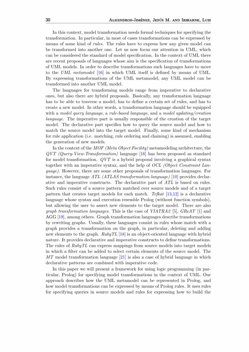
Fig. 1. UML metamodel for the UML class diagram
Model A
DB_CoursesDB_Students
id_course : int title : String credits : float
Course id_student : int name : String old : int
Student
id_course id_course id_student id_student
*
1
the_courses
**register
is registered
*
1
the_students
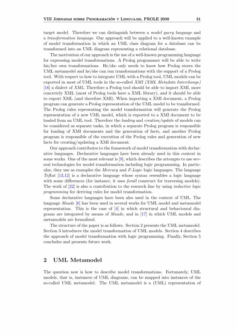
Fig. 2. Example of UML class diagram
the UML elements. As an example, the UML metamodel in Figure 1 3 representsthe elements of the UML class diagram of Figure 2. In such UML metamodel,the elements to be included in an UML class diagram are specified by means of anUML class diagram itself 4 . For instance, a class can include a name and attributes,represented by the role ownedAttribute, which belongs to the class Property. A classcan also include operations, represented by the role ownedOperation, which can havetyped parameters and a type (the returned type from the operation). Finally, aclass can be linked to extensions which are stereotypes. Stereotypes can representparticular cases of classes like interfaces, tables, etc. Some of the properties of aclass can represent the membership of the class to an association (represented bythe role memberEnd). The role navigableownedEnd specifies which of the classesinvolved in an association are navigable. Each property is described by means of thename, the type, whether it is composite or not (whose value is true for compositions),whether it is unique or not (for keys), and the lower and upper bound of the numberof elements of the associations (’0..*’, ’1..*’,’1..3’, etc). Therefore, basically, theUML metamodel defines the required (the lower bound of the multiplicity is 1)and optional elements (the lower bound of the multiplicity is 0) of an UML classdiagram.
3 This is a simplified version of the UML metamodel of [15].4 In fact, all the UML elements are described in the UML metamodel by means of an UML class diagram.
VIII Jornadas sobre Programacion y Lenguajes, PROLE 2008 33VIII Jornadas sobre Programacion y Lenguajes, PROLE 2008 33VIII Jornadas sobre Programacion y Lenguajes, PROLE 2008 33
For instance, the UML class diagram of the Figure 2 conforms to the UML meta-model in Figure 1, given that the elements included in such UML class diagram areclasses (DB Students, DB Courses, Student and Course) including attributes (for in-stance, Student includes id student, name and old) and there are three associations.The associations have the roles the students, the courses, register and is registeredwhich are properties of the corresponding classes in the UML metamodel. In theassociation between Student and Course there are two external keys (i.e. id studentand id course) taken from DB Students and DB Courses containers. The associa-tion between DB students and Student is a navigable composed association. Thesame can be said for the association between DB courses and Course. Stereotypeshave not been used in this UML class diagram, and the same can be said for oper-ations.
Metamodel object A
navigableOwnedEndclass
ownedAttributeclass
ownedAttribute
memberEnd
associationclassclass
memberEnd memberEnd
associationassociation
navigableOwnedEndmemberEnd
association
memberEnd
associationnavigableOwnedEnd
ownedAttribute
ownedAttributeownedAttribute
ownedAttribute
ownedAttributeownedAttributeownedAttributeownedAttributeownedAttributeownedAttributeclass class
name = "credits"type = "Float"isUnique = false
: Property
name = "title"type = "String"isUnique = false
: Property
name = "id_course"type = "Int"isUnique = true
: Property
name = "Course"
: Class
name = "DB_Courses"
: Class
isComposite = truelower = 1upper = 1
: Property
name = "the_courses"lower = 1upper = *
: Property
: Association
name = "old"type = "Int"isUnique = false
: Property
name = "name"type = "String"isUnique = false
: Property
name = "id_student"type = "Int"isUnique = true
: Property
name = "is_registered"lower = 1upper = *
: Property
name = "register"lower = 1upper = *
: Property
name = "Student"
: Class : Association
name = DB_Students
: Class
isComposite = truelower = 1upper = 1
: Property
name = "the_students"lower = 1upper = *
: Property
: Association
class
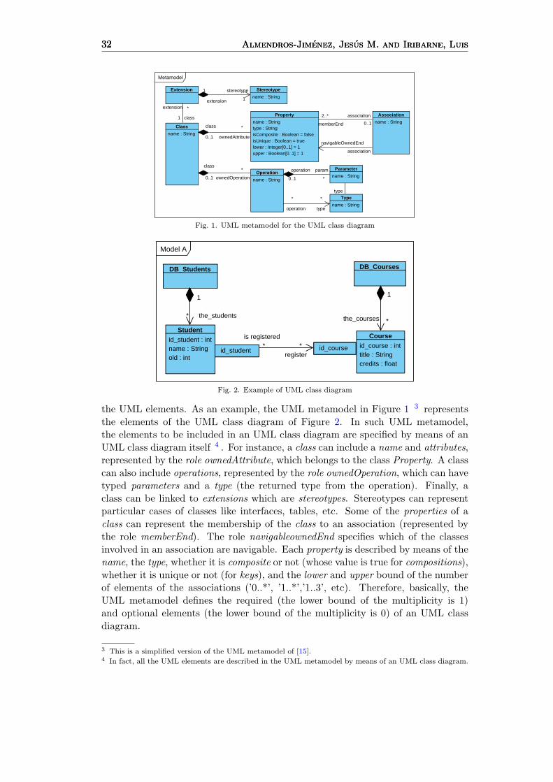
Fig. 3. Object Diagram of the Example
Now, we will show how the UML class diagram of the Figure 2, can be rep-resented by means of an UML object diagram which is an instance of the UMLmetamodel of the Figure 1. It can be seen in Figure 3. From top to bottom,we can see how by means of objects, the associations with roles the students andthe courses, and the association with roles is registered and register are representedas links to the corresponding classes. In the bottom of the Figure 3, each classStudent and Course is linked to properties representing the associated attributes.Finally, the role navigableOwnedEnd specifies that the courses, the students andregister are navigable.
3 Model Transformation
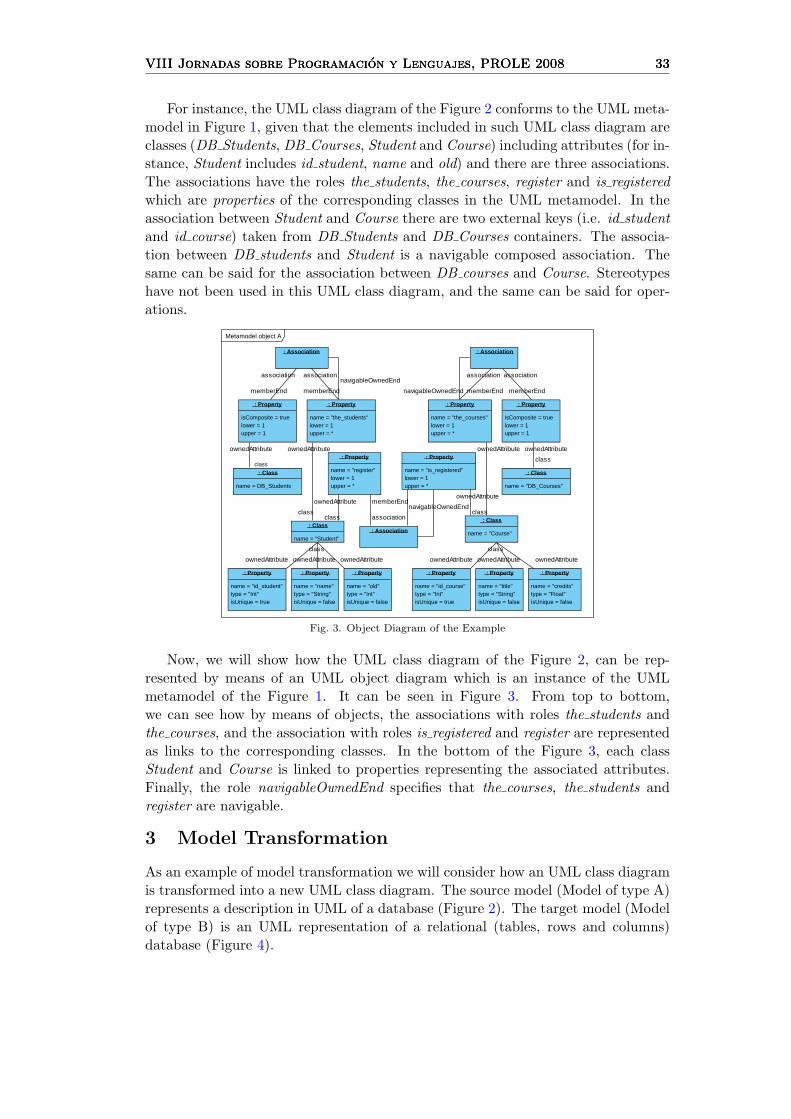
As an example of model transformation we will consider how an UML class diagramis transformed into a new UML class diagram. The source model (Model of type A)represents a description in UML of a database (Figure 2). The target model (Modelof type B) is an UML representation of a relational (tables, rows and columns)database (Figure 4).
34 Almendros-Jimenez, Jesus M. and Iribarne, Luis34 Almendros-Jimenez, Jesus M. and Iribarne, Luis34 Almendros-Jimenez, Jesus M. and Iribarne, Luis
Model B
type : Int
<<column>>id_student
type : Int
<<column>>id_course
type : Int
<<column>> id_course
type : Int
<<column>> id_student
type : Float
<<column>>credits
type : String
<<column>>title
type : String
<<column>>old
type : String
<<column>>name
<<row>> Course
<<row>> Student
<<table>>register
<<table>>the_students
<<table>>the_courses
<<row>> Course
11
*line
1 1
1
1
1
1
** lineline
keycol
col
keykey
col
key col
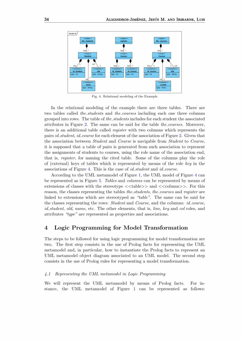
Fig. 4. Relational modeling of the Example
In the relational modeling of the example there are three tables. There aretwo tables called the students and the courses including each one three columnsgrouped into rows. The table of the students includes for each student the associatedattributes in Figure 2. The same can be said for the table the courses. Moreover,there is an additional table called register with two columns which represents thepairs id student, id course for each element of the association of Figure 2. Given thatthe association between Student and Course is navigable from Student to Course,it is supposed that a table of pairs is generated from such association to representthe assignments of students to courses, using the role name of the association end,that is, register, for naming the cited table. Some of the columns play the roleof (external) keys of tables which is represented by means of the role key in theassociations of Figure 4. This is the case of id student and id course.
According to the UML metamodel of Figure 1, the UML model of Figure 4 canbe represented as in Figure 5. Tables and columns can be represented by means ofextensions of classes with the stereotype <<table>> and <<column>>. For thisreason, the classes representing the tables the students, the courses and register arelinked to extensions which are stereotyped as “table”. The same can be said forthe classes representing the rows: Student and Course, and the columns: id course,id student, old, name, etc. The other elements, that is, line, key and col roles, andattributes “type” are represented as properties and associations.
4 Logic Programming for Model Transformation
The steps to be followed for using logic programming for model transformation aretwo. The first step consists in the use of Prolog facts for representing the UMLmetamodel and, in particular, how to instantiate the Prolog facts to represent anUML metamodel object diagram associated to an UML model. The second stepconsists in the use of Prolog rules for representing a model transformation.
4.1 Representing the UML metamodel in Logic Programming
We will represent the UML metamodel by means of Prolog facts. For in-stance, the UML metamodel of Figure 1 can be represented as follows:

VIII Jornadas sobre Programacion y Lenguajes, PROLE 2008 35VIII Jornadas sobre Programacion y Lenguajes, PROLE 2008 35VIII Jornadas sobre Programacion y Lenguajes, PROLE 2008 35
Metamodel object B
name = "line"lower = 1upper = *
: Property
ownatt
ownatt
ownatt
ownatt
ownatt
ext ext
ownatt
class
class
class
class
class
class
class
class
mEndassocassoc
assocassoc
assoc
assoc assoc
assoc
assoc assoc
assocassoc
assocassoc
assocassoc
mEnd
mEnd
mEnd
mEnd
mEnd
mEnd
mEnd
mEnd
mEnd
mEnd
mEnd
mEnd
mEnd
mEnd mEnd
ownatt
ownatt
ownatt
ownatt
ownatt
ownatt
ownatt
ownatt
ownatt
ownatt
ownatt
ownatt
ownatt
ownatt
ownatt
ownatt
ownatt
ownatt
ownatt
ownatt
ownatt
class
class
class
class
class
class
class
class
class
class
class
class
class
class
class
class
class
class
class classclass
class
class
class class
classclass
assoc assoc
assoc assoc
mEndmEnd
mEndmEnd
mEndmEnd
assoc assoc
ownatt
ownatt
ownatt
class
class
class
class
class
ext
class
stereo
ext
stereo
ext
stereoext
name = "line"lower = 1upper = *
: Property
isComposite = truelower = 1upper = 1
: Property
: Association
isComposite = truelower = 1upper = 1
: Property
: Association
name = "line"lower = 1upper = *
: Property
isComposite = truelower = 1upper = 1
: Property
: Association
name = "row"
: Stereotype
: Extension
name = "col"lower = 1upper = 1
: Property
name = "col"lower = 1upper = 1
: Property
name = "col"lower = 1upper = 1
: Property
name = "col"lower = 1upper = 1
: Property
name = "Course"
: Class
name = "type"
: Property
name = "type"
: Property
name = "key"lower = 1upper = 1
: Property : Association
isComposite = truelower = 1upper = 1
: Property
: Association
isComposite = truelower = 1upper = 1
: Property
name = "type"
: Property
name = "type"
: Property
: Association
isComposite = truelower = 1upper = 1
: Property
name = "key"lower = 1upper = 1
: Property : Association
isComposite = truelower = 1upper = 1
: Property
name = "Student"
: Class
name = "type"
: Property
name = "type"
: Property
: Association
isComposite = truelower = 1upper = 1
: Property
: Association
isComposite = truelower = 1upper = 1
: Property
name = "id_course"
: Class
name = "credits"
: Class
name = "title"
: Class
name = "id_student"
: Class
name = "name"
: Class
name = "Course"
: Class
name = "type"
: Property
name = "type"
: Property
name = "id_student"
: Class
name = "key"lower = 1upper = 1
: Property : Association
isComposite = truelower = 1upper = 1
: Property
name = "id_course"
: Class
name = "key"lower = 1upper = 1
: Property : Association
isComposite = truelower = 1upper = 1
: Property
name = "old"
: Class
name = "column"
: Stereotype
: Extension
name = "the_Courses"
: Class
name = "the_Students"
: Class
name = "register"
: Class
name = "table"
: Stereotype : Extension
Fig. 5. Object Diagram of the Relational Modeling of the Example
class(Name,Id class).
extension(Id extension).
stereotype(Name,Id stereotype).
property(Name,Type,IsComposite,IsUnique,Lower,Upper,Id property).
association(Name,Id association).
associationEnds(ownedAttribute,Id class,Id property).
associationEnds(extension,Id class,Id extension).
associationEnds(stereotype,Id extension,Id stereotype).
associationEnds(memberEnd,Id association,Id property).
associationEnds(navigableOwnedEnd,Id association,Id property).
...
where each element of the metamodel is represented by means of a fact. In partic-ular, each class is represented by means of a fact of the form class(Name,Id class)where Name represents the attribute “name” of each class, and Id class representsan identifier for each object of type class. This identifier has to be added to the Pro-log representation in order to be able to distinguish each object of the type class. Wewill assume that the identifier in the case of classes is the name itself. Extensions,stereotypes, associations and properties are also represented by means of facts in-cluding the attributes as parameters of the predicates, adding also an identifier foreach object. The associations in the metamodel: ownedAttribute,class,extension,etc, are also represented by means of facts called associationEnds in which thefirst parameter indicates the role of the association, and they have two additionalparameters representing (the identifiers of) each pair of objects belonging to theassociation.
This UML metamodel representation can be instantiated by means of an
36 Almendros-Jimenez, Jesus M. and Iribarne, Luis36 Almendros-Jimenez, Jesus M. and Iribarne, Luis36 Almendros-Jimenez, Jesus M. and Iribarne, Luis
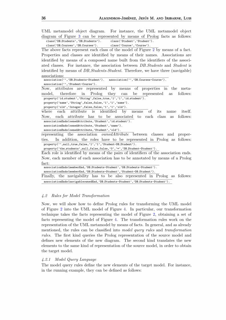
UML metamodel object diagram. For instance, the UML metamodel objectdiagram of Figure 3 can be represented by means of Prolog facts as follows:
class(’DB Students’,’DB Students’).
class(’DB Courses’,’DB Courses’).
class(’Student’,’Student’).
class(’Course’,’Course’).
The above facts represent each class of the model of Figure 2 by means of a fact.Properties and classes are identified by means of their names. Associations areidentified by means of a composed name built from the identifiers of the associ-ated classes. For instance, the association between DB Students and Student isidentified by means of DB Students-Student. Therefore, we have three (navigable)associations:association(’’,’DB Students-Student’). association(’’,’DB Courses-Course’).
association(’’,’Student-Course’).
Now, attributes are represented by means of properties in the meta-model, therefore in Prolog they can be represented as follows:property(’id student’,’String’,false,true,’1’,’1’,’id student’).
property(’name’,’String’,false,false,’1’,’1’,’name’).
property(’old’,’Integer’,false,false,’1’,’1’,’old’).
where each attribute is identified by means of its name itself.Now, each attribute has to be associated to each class as follows:associationEnds(ownedAttribute,’Student’,’id student’).
associationEnds(ownedAttribute,’Student’,’name’).
associationEnds(ownedAttribute,’Student’,’old’).
representing the association ownedAttribute between classes and proper-ties. In addition, the roles have to be represented in Prolog as follows:property(’’,null,true,false,’1’,’1’,’Student-DB Student’).
property(’the students’,null,false,false,’0’,’*’,’DB Student-Student’).
Each role is identified by means of the pairs of identifiers of the association ends.Now, each member of each association has to be annotated by means of a Prologfact:associationEnds(memberEnd,’DB Students-Student’,’DB Students-Student’).
associationEnds(memberEnd,’DB Students-Student’,’Student-DB Student’).
Finally, the navigability has to be also represented in Prolog as follows:associationEnds(navigableownedEnd,’DB Students-Student’,’DB Students-Student’).
4.2 Rules for Model Transformation
Now, we will show how to define Prolog rules for transforming the UML modelof Figure 2 into the UML model of Figure 4. In particular, our transformationtechnique takes the facts representing the model of Figure 2, obtaining a set offacts representing the model of Figure 4. The transformation rules work on therepresentation of the UML metamodel by means of facts. In general, and as alreadymentioned, the rules can be classified into model query rules and transformationrules. The first kind queries the Prolog representation of the source model anddefines new elements of the new diagram. The second kind translates the newelements to the same kind of representation of the source model, in order to obtainthe target model.
4.2.1 Model Query LanguageThe model query rules define the new elements of the target model. For instance,in the running example, they can be defined as follows:
VIII Jornadas sobre Programacion y Lenguajes, PROLE 2008 37VIII Jornadas sobre Programacion y Lenguajes, PROLE 2008 37VIII Jornadas sobre Programacion y Lenguajes, PROLE 2008 37
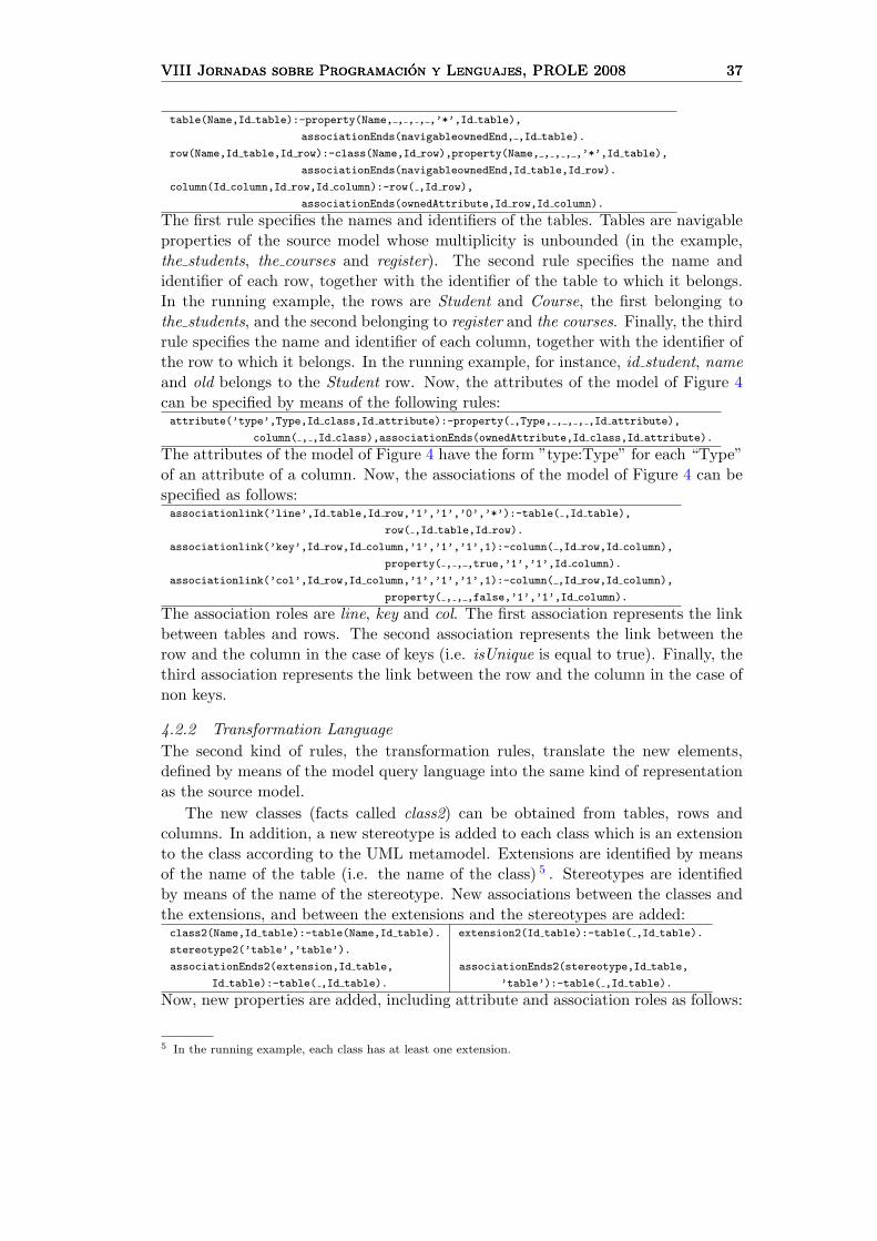
table(Name,Id table):-property(Name, , , , ,’*’,Id table),
associationEnds(navigableownedEnd, ,Id table).
row(Name,Id table,Id row):-class(Name,Id row),property(Name, , , , ,’*’,Id table),
associationEnds(navigableownedEnd,Id table,Id row).
column(Id column,Id row,Id column):-row( ,Id row),
associationEnds(ownedAttribute,Id row,Id column).
The first rule specifies the names and identifiers of the tables. Tables are navigableproperties of the source model whose multiplicity is unbounded (in the example,the students, the courses and register). The second rule specifies the name andidentifier of each row, together with the identifier of the table to which it belongs.In the running example, the rows are Student and Course, the first belonging tothe students, and the second belonging to register and the courses. Finally, the thirdrule specifies the name and identifier of each column, together with the identifier ofthe row to which it belongs. In the running example, for instance, id student, nameand old belongs to the Student row. Now, the attributes of the model of Figure 4can be specified by means of the following rules:attribute(’type’,Type,Id class,Id attribute):-property( ,Type, , , , ,Id attribute),
column( , ,Id class),associationEnds(ownedAttribute,Id class,Id attribute).
The attributes of the model of Figure 4 have the form ”type:Type” for each “Type”of an attribute of a column. Now, the associations of the model of Figure 4 can bespecified as follows:associationlink(’line’,Id table,Id row,’1’,’1’,’0’,’*’):-table( ,Id table),
row( ,Id table,Id row).
associationlink(’key’,Id row,Id column,’1’,’1’,’1’,1):-column( ,Id row,Id column),
property( , , ,true,’1’,’1’,Id column).
associationlink(’col’,Id row,Id column,’1’,’1’,’1’,1):-column( ,Id row,Id column),
property( , , ,false,’1’,’1’,Id column).
The association roles are line, key and col. The first association represents the linkbetween tables and rows. The second association represents the link between therow and the column in the case of keys (i.e. isUnique is equal to true). Finally, thethird association represents the link between the row and the column in the case ofnon keys.
4.2.2 Transformation LanguageThe second kind of rules, the transformation rules, translate the new elements,defined by means of the model query language into the same kind of representationas the source model.
The new classes (facts called class2) can be obtained from tables, rows andcolumns. In addition, a new stereotype is added to each class which is an extensionto the class according to the UML metamodel. Extensions are identified by meansof the name of the table (i.e. the name of the class) 5 . Stereotypes are identifiedby means of the name of the stereotype. New associations between the classes andthe extensions, and between the extensions and the stereotypes are added:class2(Name,Id table):-table(Name,Id table). extension2(Id table):-table( ,Id table).
stereotype2(’table’,’table’).
associationEnds2(extension,Id table,
Id table):-table( ,Id table).
associationEnds2(stereotype,Id table,
’table’):-table( ,Id table).
Now, new properties are added, including attribute and association roles as follows:
5 In the running example, each class has at least one extension.
38 Almendros-Jimenez, Jesus M. and Iribarne, Luis38 Almendros-Jimenez, Jesus M. and Iribarne, Luis38 Almendros-Jimenez, Jesus M. and Iribarne, Luis
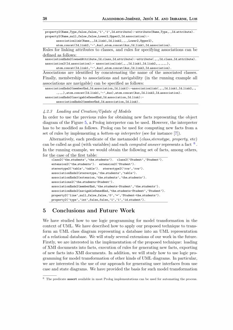
property2(Name,Type,false,false,’1’,’1’,Id attribute):-attribute(Name,Type, ,Id attribute).
property2(Name,null,false,false,Lower2,Upper2,Id association):-
associationlink(Name, ,Id link1,Id link2, , ,Lower2,Upper2),
atom concat(Id link2,’-’,Aux),atom concat(Aux,Id link1,Id association).
Rules for linking attributes to classes, and rules for specifying associations can bedefined as follows:associationEnds2(ownedAttribute,Id class,Id attribute):-attribute( , ,Id class,Id attribute).
association2(Id association):- associationlink( , ,Id link1,Id link2, , , , ),
atom concat(Id link1,’-’,Aux),atom concat(Aux,Id link2,Id association).
Associations are identified by concatenating the name of the associated classes.Finally, membership to associations and navigability (in the running example allassociations are navigable) can be specified as follows:associationEnds2(memberEnd,Id association,Id link1):-associationlink( , ,Id link1,Id link2, ,
, , ),atom concat(Id link1,’-’,Aux),atom concat(Aux,Id link2,Id association).
associationEnds2(navigableOwnedEnd,Id association,Id link):-
associationEnds2(memberEnd,Id association,Id link).
4.2.3 Loading and Creation/Update of ModelsIn order to use the previous rules for obtaining new facts representing the objectdiagram of the Figure 5, a Prolog interpreter can be used. However, the interpreterhas to be modified as follows. Prolog can be used for computing new facts from aset of rules by implementing a bottom-up interpreter (see for instance [7]).
Alternatively, each predicate of the metamodel (class,stereotype, property, etc)can be called as goal (with variables) and each computed answer represents a fact 6 .In the running example, we would obtain the following set of facts, among others,for the case of the first table:
class2(’the students’,’the students’). class2(’Student’,’Student’).
extension2(’the students’). extension2(’Student’).
stereotype2(’table’,’table’). stereotype2(’row’,’row’).
associationEnds2(stereotype,’the students’,’table’).
associationEnds2(extension,’the students’,’the students’).
associations2(’the students-Student’).
associationEnds2(memberEnd,’the students-Student’,’the students’).
associationEnds2(navigableOwnedEnd,’the students-Student’,’Student’).
property2(’line’,null,false,false,’0’,’*’,’Student-the students’).
property2(’type’,’int’,false,false,’1’,’1’,’id student’).
5 Conclusions and Future Work
We have studied how to use logic programming for model transformation in thecontext of UML. We have described how to apply our proposed technique to trans-form an UML class diagram representing a database into an UML representationof a relational database. We will study several extensions of our work in the future.Firstly, we are interested in the implementation of the proposed technique: loadingof XMI documents into facts, execution of rules for generating new facts, exportingof new facts into XMI documents. In addition, we will study how to use logic pro-gramming for model transformation of other kinds of UML diagrams. In particular,we are interested in the use of our approach for generating user interfaces from usecase and state diagrams. We have provided the basis for such model transformation
6 The predicate assert available in most Prolog implementations can be used for automating the process.
VIII Jornadas sobre Programacion y Lenguajes, PROLE 2008 39VIII Jornadas sobre Programacion y Lenguajes, PROLE 2008 39VIII Jornadas sobre Programacion y Lenguajes, PROLE 2008 39
in previous works [3,2]. Finally, we believe that the integration of UML models andlogic programming can lead to the development of a logic based tool for verificationand validation of UML models and transformations.
References
[1] A. Agrawal. Graph rewriting and transformation (GReAT): a solution for the model integratedcomputing (MIC) bottleneck. Automated Software Engineering, 2003. Proceedings. 18th IEEEInternational Conference on, pages 364–368, 6-10 Oct. 2003.
[2] J. M. Almendros-Jimenez and L. Iribarne. Designing GUI Components for UML Use Cases. In12th IEEE International Conference and Workshops on the Engineering of Computer-Based Systems(ECBS’05), pages 210–217. IEEE Computer Society Press, 2005.
[3] J. M. Almendros-Jimenez and L. Iribarne. An Extension of UML for the Modeling of WIMP UserInterfaces. Journal of Visual Languages and Computing, Elsevier, in press, 2008.
[4] N. Aoumeur and G. Saake. Integrating and Rapid-Prototyping UML Structural and BehaviouralDiagrams Using Rewriting Logic. In Procs. of CAiSE, pages 296–310. LNCS 2348, Springer, 2002.
[5] A. Balogh and D. Varro. The Model Transformation Language of the VIATRA2 Framework. Scienceof Programming, 68(3):187–207, October 2007.
[6] Manuel Clavel, Francisco Duran, Steven Eker, Patrick Lincoln, Narciso Martı-Oliet, Jose Meseguer, andCarolyn Talcott. The Maude 2.0 System. In Robert Nieuwenhuis, editor, Rewriting Techniques andApplications (RTA 2003), number 2706 in Lecture Notes in Computer Science, pages 76–87. Springer-Verlag, June 2003.
[7] Michael Codish. Efficient goal directed bottom-up evaluation of logic programs. J. Log. Program.,38(3):355–370, 1999.
[8] Krzysztof Czarnecki and Simon Helsen. Classification of Model Transformation Approaches. InOOPSLA03 Workshop on Generative Techniques in the Context of Model-Driven Architecture, 2003.
[9] A. Gerber, M. Lawley, K. Raymond, J. Steel, and A. Wood. Transformation: The Missing Link ofMDA. In ICGT ’02: Proceedings of the First International Conference on Graph Transformation,pages 90–105, London, UK, 2002. LNCS 2505, Springer.
[10] F. Jouault and I. Kurtev. On the architectural alignment of ATL and QVT. In SAC ’06: Proceedingsof the 2006 ACM Symposium on Applied Computing, pages 1188–1195, New York, NY, USA, 2006.ACM.
[11] Frederic Jouault and Ivan Kurtev. On the interoperability of model-to-model transformation languages.Sci. Comput. Program., 68(3):114–137, 2007.
[12] M. Lawley and J. Steel. Practical Declarative Model Transformation with Tefkat. In MoDELS SatelliteEvents, pages 139–150. LNCS 3844, Springer, 2006.
[13] Michael Lawley and Kerry Raymond. Implementing a practical declarative logic-based modeltransformation engine. In SAC ’07: Proceedings of the 2007 ACM Symposium on Applied Computing,pages 971–977, New York, NY, USA, 2007. ACM.
[14] Tom Mens and Pieter Van Gorp. A Taxonomy of Model Transformation. Electr. Notes Theor. Comput.Sci., 152:125–142, 2006.
[15] OMG. Unified Modeling Language Specification, version 2.0. Technical report, Object ManagementGroup, 2005.
[16] OMG. Object Management Group. Technical report, www.omg.org, 2008.
[17] J. R. Romero, J. E. Rivera, F. Duran, and A. Vallecillo. Formal and tool support for model drivenengineering with Maude. Journal of Object Technology, 6(9):187–207, October 2007.
[18] J. Sanchez-Cuadrado, J. Garcıa-Molina, and M. Menarguez-Tortosa. RubyTL: A Practical, ExtensibleTransformation Language. In Procs of Model Driven Architecture - Foundations and Applications,pages 158–172. LNCS 4066, Springer, 2006.
[19] Gabriele Taentzer. AGG: A Graph Transformation Environment for Modeling and Validation ofSoftware. In AGTIVE, pages 446–453, 2003.
[20] Laurence Tratt. Model transformations and tool integration. Software and System Modeling, 4(2):112–122, 2005.
[21] Laurence Tratt. The MT model transformation language. In SAC ’06: Proceedings of the 2006 ACMSymposium on Applied Computing, pages 1296–1303, New York, NY, USA, 2006. ACM.
[22] D. Varro and Z. Balogh. Automating model transformation by example using inductive logicprogramming. In SAC ’07: Proceedings of the 2007 ACM Symposium on Applied Computing, pages978–984, New York, NY, USA, 2007. ACM.
Related Documents