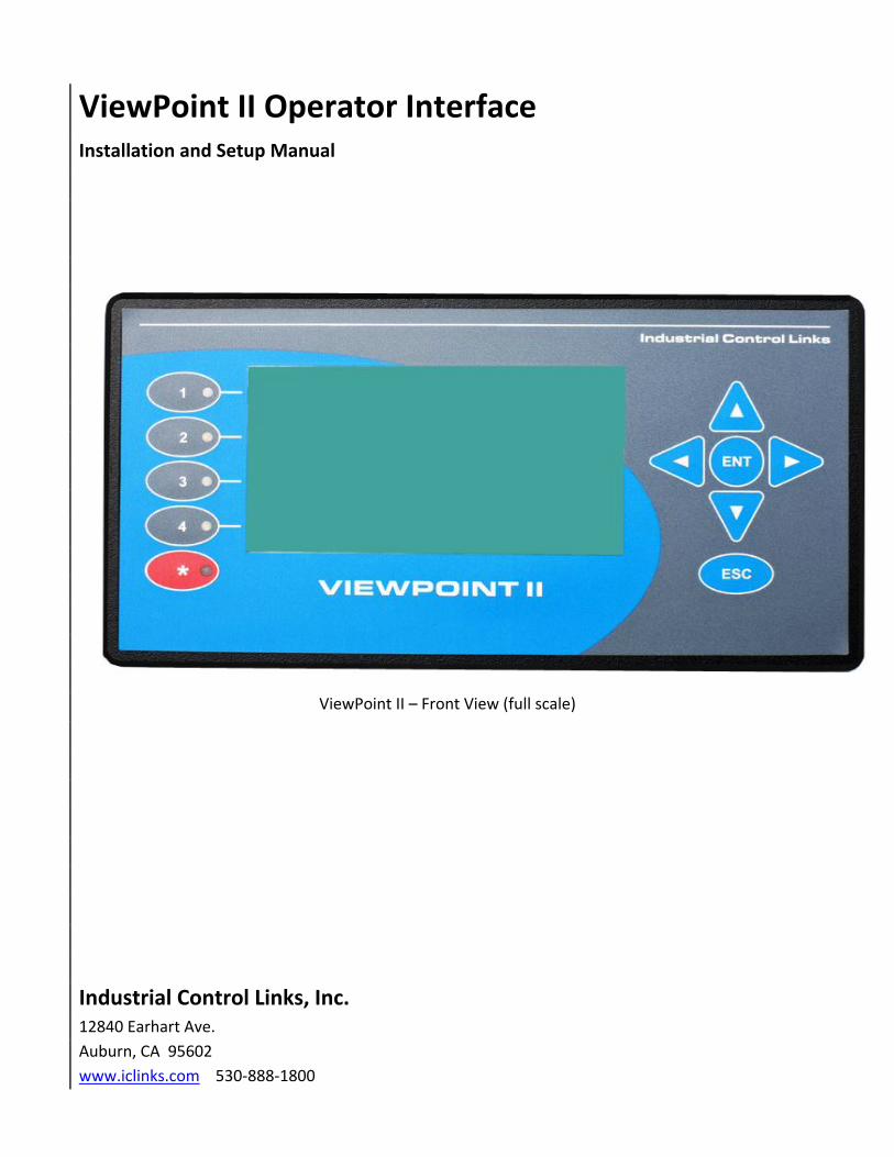
ViewPoint II Operator Interface Installation and Setup Manual ViewPoint II – Front View (full scale) Industrial Control Links, Inc. 12840 Earhart Ave. Auburn, CA 95602 www.iclinks.com 530-888-1800

Welcome message from author
This document is posted to help you gain knowledge. Please leave a comment to let me know what you think about it! Share it to your friends and learn new things together.
Transcript
ViewPoint II Operator Interface Installation and Setup Manual
ViewPoint II – Front View (full scale)
Industrial Control Links, Inc. 12840 Earhart Ave.
Auburn, CA 95602
www.iclinks.com 530-888-1800
ViewPoint II Operator Interface Installation and Setup Manual ©2011 Industrial Control Links, Inc. All Rights Reserved 2
ViewPoint II Operator Interface Installation Manual
©2011 Industrial Control Links, Inc.
All Rights Reserved
ViewPoint II Operator Interface Installation and Setup Manual ©2011 Industrial Control Links, Inc. All Rights Reserved 3
Contents
Overview ..................................................................................................................................................... 5
Additional Documentation ......................................................................................................................... 6
Important Safety Information ..................................................................................................................... 7
ViewPoint II Mechanical Installation .......................................................................................................... 8
ViewPoint II Wiring ..................................................................................................................................... 9
USB Connection .......................................................................................................................................... 9
USB cables for Viewpoint II HMI Terminals ......................................................................................... 9
Ethernet Connection ................................................................................................................................. 10
Ethernet cables for ViewPoint II ........................................................................................................ 10
Configuration ............................................................................................................................................ 11
Display Settings Configuration .............................................................................................................. 12
Ethernet Settings Configuration ............................................................................................................ 14
Profiles Configuration ............................................................................................................................ 15
Information ........................................................................................................................................... 19
Connecting ................................................................................................................................................ 20
ViewPoint II Specifications ........................................................................................................................ 21

ViewPoint II Operator Interface Installation and Setup Manual ©2011 Industrial Control Links, Inc. All Rights Reserved 4
ViewPoint II Operator Interface Installation and Setup Manual ©2011 Industrial Control Links, Inc. All Rights Reserved 5
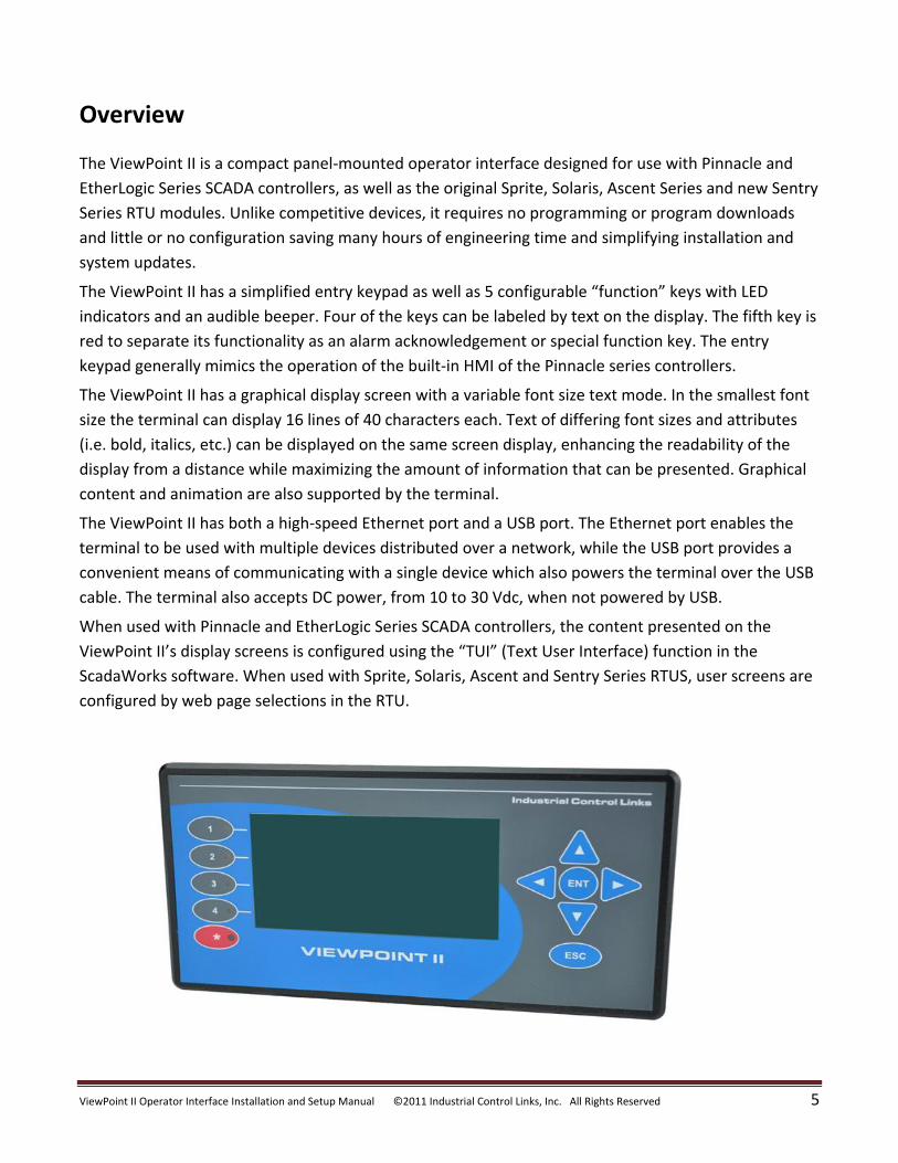
Overview
The ViewPoint II is a compact panel-mounted operator interface designed for use with Pinnacle and
EtherLogic Series SCADA controllers, as well as the original Sprite, Solaris, Ascent Series and new Sentry
Series RTU modules. Unlike competitive devices, it requires no programming or program downloads
and little or no configuration saving many hours of engineering time and simplifying installation and
system updates.
The ViewPoint II has a simplified entry keypad as well as 5 configurable “function” keys with LED
indicators and an audible beeper. Four of the keys can be labeled by text on the display. The fifth key is
red to separate its functionality as an alarm acknowledgement or special function key. The entry
keypad generally mimics the operation of the built-in HMI of the Pinnacle series controllers.
The ViewPoint II has a graphical display screen with a variable font size text mode. In the smallest font
size the terminal can display 16 lines of 40 characters each. Text of differing font sizes and attributes
(i.e. bold, italics, etc.) can be displayed on the same screen display, enhancing the readability of the
display from a distance while maximizing the amount of information that can be presented. Graphical
content and animation are also supported by the terminal.
The ViewPoint II has both a high-speed Ethernet port and a USB port. The Ethernet port enables the
terminal to be used with multiple devices distributed over a network, while the USB port provides a
convenient means of communicating with a single device which also powers the terminal over the USB
cable. The terminal also accepts DC power, from 10 to 30 Vdc, when not powered by USB.
When used with Pinnacle and EtherLogic Series SCADA controllers, the content presented on the
ViewPoint II’s display screens is configured using the “TUI” (Text User Interface) function in the
ScadaWorks software. When used with Sprite, Solaris, Ascent and Sentry Series RTUS, user screens are
configured by web page selections in the RTU.
ViewPoint II Operator Interface Installation and Setup Manual ©2011 Industrial Control Links, Inc. All Rights Reserved 6
Additional Documentation
Additional documentation on using the ViewPoint II terminal is found in the following documents.
The ScadaWorks Programming Manual describes the use of the TUI (Textual User Interface)
configuration tool to set up the screen information displayed on the terminal, and the action of the
function keys and LED indicators.
The Sentry Series Technical Reference Manual describes the HMI web pages built into the Sentry RTUs
and how they are used to configure the information displayed on the Viewpoint.

ViewPoint II Operator Interface Installation and Setup Manual ©2011 Industrial Control Links, Inc. All Rights Reserved 7
Important Safety Information
Power, input and output (I/O) wiring must be in accordance with Class I, Division 2 wiring methods
Article 501-4(b) of the National Electrical Code, NFPA 70 for installations in the U.S., or as specified in
Section 18-1J2 of the Canadian Electrical Code for installations within Canada and in accordance with
the authority having jurisdiction.
WARNING - EXPLOSION HAZARD – Do not disconnect equipment unless power has been removed or
the area is known to be non-hazardous.
WARNING - EXPLOSION HAZARD – Substitution of any components may impair suitability for Class I,
Division 2.
WARNING - EXPLOSION HAZARD – The area must be known to be non-hazardous before
servicing/replacing the unit and before installing.
WARNING –EXPLOSION HAZARD – “The USB connectors are for temporary connection only. Do not
use, connect, or disconnect unless area is known to be non-hazardous. Connection or disconnection in
an explosive atmosphere could result in an explosion."
ViewPoint II Operator Interface Installation and Setup Manual ©2011 Industrial Control Links, Inc. All Rights Reserved 8
3.00"
7.15"
3.85"
6.30"
1.00"
Mounting
Thumbscrew
Panel Mounting Clamp
Sealing
Gasket
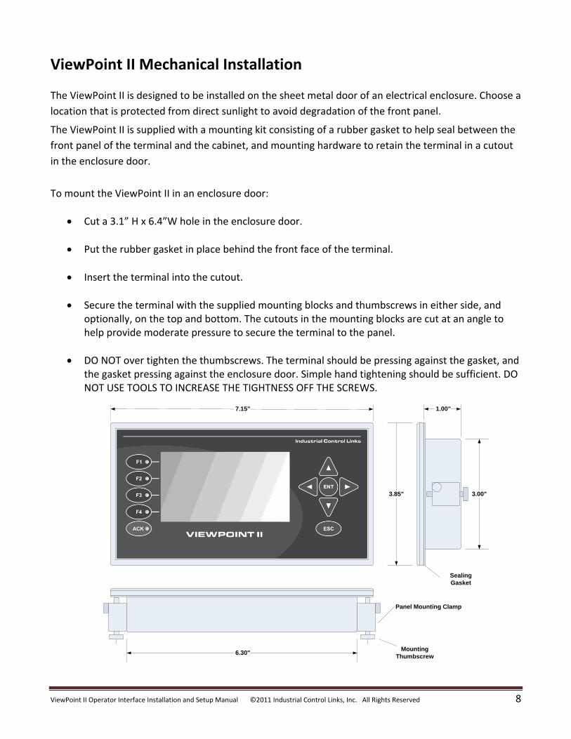
ViewPoint II Mechanical Installation
The ViewPoint II is designed to be installed on the sheet metal door of an electrical enclosure. Choose a
location that is protected from direct sunlight to avoid degradation of the front panel.
The ViewPoint II is supplied with a mounting kit consisting of a rubber gasket to help seal between the
front panel of the terminal and the cabinet, and mounting hardware to retain the terminal in a cutout
in the enclosure door.
To mount the ViewPoint II in an enclosure door:
Cut a 3.1” H x 6.4”W hole in the enclosure door.
Put the rubber gasket in place behind the front face of the terminal.
Insert the terminal into the cutout.
Secure the terminal with the supplied mounting blocks and thumbscrews in either side, and optionally, on the top and bottom. The cutouts in the mounting blocks are cut at an angle to help provide moderate pressure to secure the terminal to the panel.
DO NOT over tighten the thumbscrews. The terminal should be pressing against the gasket, and the gasket pressing against the enclosure door. Simple hand tightening should be sufficient. DO NOT USE TOOLS TO INCREASE THE TIGHTNESS OFF THE SCREWS.

ViewPoint II Operator Interface Installation and Setup Manual ©2011 Industrial Control Links, Inc. All Rights Reserved 9
ViewPoint II Wiring
The ViewPoint II terminal uses either of two power and data wiring configurations; a point-to-point USB connection or an Ethernet networked connection. The terminal power can either be provided by the USB cable or via a supplied power cable with DC power in the range of 10Vdc to 30Vdc. Both types of connections are available on the rear panel of the terminal.
Rear Panel of ViewPoint II
USB Connection
A point-to-point USB connection may be used when connecting to a single Pinnacle SCADA controller.
The advantage is a single plug-in cable provides both power and data communications. The
appropriate USB cable is a “Type A to Type B” USB cable. The part numbers are listed below by length:
USB cables for Viewpoint II HMI Terminals 99-4001 USB 2.0 Type A to Type B Cable Assembly, 1 ft. (Pinnacle to Viewpoint II)
99-4002 USB 2.0 Type A to Type B Cable Assembly, 3 ft. (Pinnacle to Viewpoint II)
99-4003 USB 2.0 Type A to Type B Cable Assembly, 6 ft. (Pinnacle to Viewpoint II)
99-4005 USB 2.0 Type A to Type B Cable Assembly, 10 ft. (Pinnacle to Viewpoint II)
99-4007 USB 2.0 Type A to Type B Cable Assembly, 15 ft. (Pinnacle to Viewpoint II)
An Ethernet and separate power cable are not required when the USB cable is used for both a data and
power connection. A USB cable can also be used to supply power only in conjunction with an Ethernet
data connection.
USB
Latch
Rear View (when
plugged in)
+-
v
Ethernet
DC Power
Latch
Rear View (when
plugged in)
+- v
ViewPoint II Operator Interface Installation and Setup Manual ©2011 Industrial Control Links, Inc. All Rights Reserved 10
Ethernet Connection
An Ethernet data connection may be used to connect a Viewpoint II terminal to one or more Pinnacle
or EtherLogic Controllers, or to any Sentry Series, Sprite, Solaris or Ascent RTU. An Ethernet network
can be used to share a single Viewpoint II Terminal with multiple controllers and RTUs. When Ethernet
is used, the terminal must be powered separately, either using the supplied power cable, or a USB
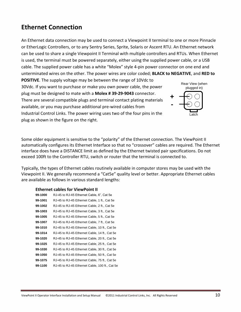
cable. The supplied power cable has a white “Molex” style 4-pin power connector on one end and
unterminated wires on the other. The power wires are color coded; BLACK to NEGATIVE, and RED to
POSITIVE. The supply voltage may be between the range of 10Vdc to
30Vdc. If you want to purchase or make you own power cable, the power
plug must be designed to mate with a Molex # 39-29-9043 connector.
There are several compatible plugs and terminal contact plating materials
available, or you may purchase additional pre-wired cables from
Industrial Control Links. The power wiring uses two of the four pins in the
plug as shown in the figure on the right.
Some older equipment is sensitive to the “polarity” of the Ethernet connection. The ViewPoint II automatically configures its Ethernet Interface so that no “crossover” cables are required. The Ethernet interface does have a DISTANCE limit as defined by the Ethernet twisted pair specifications. Do not exceed 100ft to the Controller RTU, switch or router that the terminal is connected to. Typically, the types of Ethernet cables routinely available in computer stores may be used with the Viewpoint II. We generally recommend a “Cat5e” quality level or better. Appropriate Ethernet cables are available as follows in various standard lengths:
Ethernet cables for ViewPoint II 99-1000 RJ-45 to RJ-45 Ethernet Cable, 6”, Cat 5e
99-1001 RJ-45 to RJ-45 Ethernet Cable, 1 ft., Cat 5e
99-1002 RJ-45 to RJ-45 Ethernet Cable, 2 ft., Cat 5e
99-1003 RJ-45 to RJ-45 Ethernet Cable, 3 ft., Cat 5e
99-1005 RJ-45 to RJ-45 Ethernet Cable, 5 ft., Cat 5e
99-1007 RJ-45 to RJ-45 Ethernet Cable, 7 ft., Cat 5e
99-1010 RJ-45 to RJ-45 Ethernet Cable, 10 ft., Cat 5e
99-1014 RJ-45 to RJ-45 Ethernet Cable, 14 ft., Cat 5e
99-1020 RJ-45 to RJ-45 Ethernet Cable, 20 ft., Cat 5e
99-1025 RJ-45 to RJ-45 Ethernet Cable, 25 ft., Cat 5e
99-1030 RJ-45 to RJ-45 Ethernet Cable, 30 ft., Cat 5e
99-1050 RJ-45 to RJ-45 Ethernet Cable, 50 ft., Cat 5e
99-1075 RJ-45 to RJ-45 Ethernet Cable, 75 ft., Cat 5e
99-1100 RJ-45 to RJ-45 Ethernet Cable, 100 ft., Cat 5e
Latch
Rear View (when
plugged in)
+-
ViewPoint II Operator Interface Installation and Setup Manual ©2011 Industrial Control Links, Inc. All Rights Reserved 11
Configuration
Once a ViewPoint II terminal is mechanically installed and wired, it should be configured. All
configuration is done using the terminals keys and display. No external computer is required.
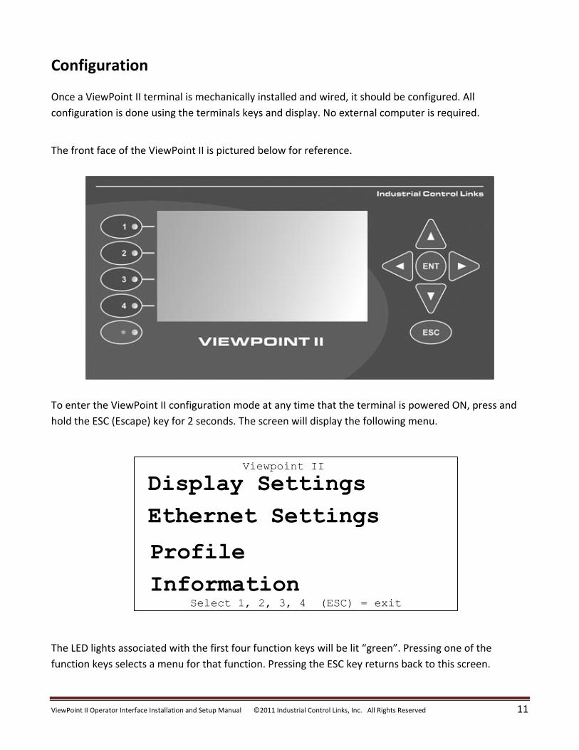
The front face of the ViewPoint II is pictured below for reference.
To enter the ViewPoint II configuration mode at any time that the terminal is powered ON, press and
hold the ESC (Escape) key for 2 seconds. The screen will display the following menu.
The LED lights associated with the first four function keys will be lit “green”. Pressing one of the
function keys selects a menu for that function. Pressing the ESC key returns back to this screen.
Viewpoint II
Display Settings
Ethernet Settings
Profile
InformationSelect 1, 2, 3, 4 (ESC) = exit
ViewPoint II Operator Interface Installation and Setup Manual ©2011 Industrial Control Links, Inc. All Rights Reserved 12
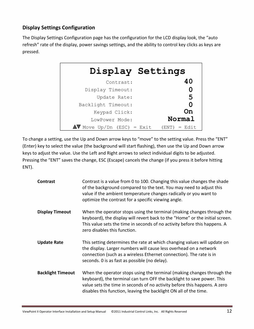
Display Settings Configuration
The Display Settings Configuration page has the configuration for the LCD display look, the “auto
refresh” rate of the display, power savings settings, and the ability to control key clicks as keys are
pressed.
To change a setting, use the Up and Down arrow keys to “move” to the setting value. Press the “ENT”
(Enter) key to select the value (the background will start flashing), then use the Up and Down arrow
keys to adjust the value. Use the Left and Right arrows to select individual digits to be adjusted.
Pressing the “ENT” saves the change, ESC (Escape) cancels the change (if you press it before hitting
ENT).
Contrast Contrast is a value from 0 to 100. Changing this value changes the shade
of the background compared to the text. You may need to adjust this value if the ambient temperature changes radically or you want to optimize the contrast for a specific viewing angle.
Display Timeout When the operator stops using the terminal (making changes through the
keyboard), the display will revert back to the “Home” or the initial screen. This value sets the time in seconds of no activity before this happens. A zero disables this function.
Update Rate This setting determines the rate at which changing values will update on
the display. Larger numbers will cause less overhead on a network connection (such as a wireless Ethernet connection). The rate is in seconds. 0 is as fast as possible (no delay).
Backlight Timeout When the operator stops using the terminal (making changes through the
keyboard), the terminal can turn OFF the backlight to save power. This value sets the time in seconds of no activity before this happens. A zero disables this function, leaving the backlight ON all of the time.
Contrast:
Display Settings40
Move Up/Dn (ESC) = Exit (ENT) = Edit
Display Timeout:
Update Rate:
Backlight Timeout:
Keypad Click:
LowPower Mode:
05
OnNormal
0
ViewPoint II Operator Interface Installation and Setup Manual ©2011 Industrial Control Links, Inc. All Rights Reserved 13
Keypad Click This setting enables or disables making an audible click when a keypad key is pressed.
Low Power Mode This setting controls the extent of power saving implemented in the
terminal. There are two settings for this mode. In the “Extra” mode, the CPU speed is slowed down and the Ethernet Interface is turned OFF when the terminal is inactive in order to further reduce the terminal’s power consumption. Use this mode for solar and battery operated systems. In the “Normal” mode, the CPU speed and Ethernet controller are left alone.
ViewPoint II Operator Interface Installation and Setup Manual ©2011 Industrial Control Links, Inc. All Rights Reserved 14
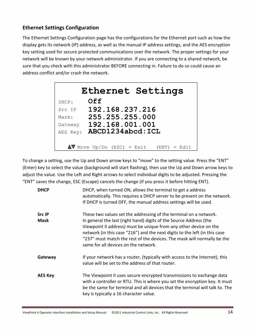
Ethernet Settings Configuration
The Ethernet Settings Configuration page has the configurations for the Ethernet port such as how the
display gets its network (IP) address, as well as the manual IP address settings, and the AES encryption
key setting used for secure protected communications over the network. The proper settings for your
network will be known by your network administrator. If you are connecting to a shared network, be
sure that you check with this administrator BEFORE connecting in. Failure to do so could cause an
address conflict and/or crash the network.
To change a setting, use the Up and Down arrow keys to “move” to the setting value. Press the “ENT”
(Enter) key to select the value (background will start flashing), then use the Up and Down arrow keys to
adjust the value. Use the Left and Right arrows to select individual digits to be adjusted. Pressing the
“ENT” saves the change, ESC (Escape) cancels the change (if you press it before hitting ENT).
DHCP DHCP, when turned ON, allows the terminal to get a address automatically. This requires a DHCP server to be present on the network. If DHCP is turned OFF, the manual address settings will be used.
Src IP These two values set the addressing of the terminal on a network. Mask In general the last (right hand) digits of the Source Address (the
Viewpoint II address) must be unique from any other device on the network (in this case “216”) and the next digits to the left (in this case “237” must match the rest of the devices. The mask will normally be the same for all devices on the network.
Gateway If your network has a router, (typically with access to the Internet), this
value will be set to the address of that router. AES Key The Viewpoint II uses secure encrypted transmissions to exchange data
with a controller or RTU. This is where you set the encryption key. It must be the same for terminal and all devices that the terminal will talk to. The key is typically a 16 character value.
DHCP:
Ethernet SettingsOff
Move Up/Dn (ESC) = Exit (ENT) = Edit
Src IP
Mask:
Gateway
AES Key:
192.168.237.216255.255.255.000
ABCD1234abcd:ICL192.168.001.001
ViewPoint II Operator Interface Installation and Setup Manual ©2011 Industrial Control Links, Inc. All Rights Reserved 15
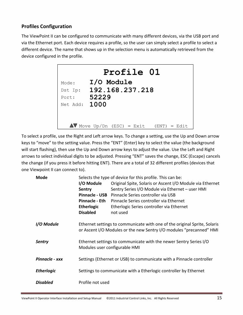
Profiles Configuration
The ViewPoint II can be configured to communicate with many different devices, via the USB port and
via the Ethernet port. Each device requires a profile, so the user can simply select a profile to select a
different device. The name that shows up in the selection menu is automatically retrieved from the
device configured in the profile.
To select a profile, use the Right and Left arrow keys. To change a setting, use the Up and Down arrow
keys to “move” to the setting value. Press the “ENT” (Enter) key to select the value (the background
will start flashing), then use the Up and Down arrow keys to adjust the value. Use the Left and Right
arrows to select individual digits to be adjusted. Pressing “ENT” saves the change, ESC (Escape) cancels
the change (if you press it before hitting ENT). There are a total of 32 different profiles (devices that
one Viewpoint II can connect to).
Mode Selects the type of device for this profile. This can be: I/O Module Original Spite, Solaris or Ascent I/O Module via Ethernet Sentry Sentry Series I/O Module via Ethernet – user HMI Pinnacle - USB Pinnacle Series controller via USB Pinnacle - Eth Pinnacle Series controller via Ethernet Etherlogic Etherlogic Series controller via Ethernet Disabled not used
I/O Module Ethernet settings to communicate with one of the original Sprite, Solaris
or Ascent I/O Modules or the new Sentry I/O modules “precanned” HMI Sentry Ethernet settings to communicate with the newer Sentry Series I/O
Modules user configurable HMI Pinnacle - xxx Settings (Ethernet or USB) to communicate with a Pinnacle controller Etherlogic Settings to communicate with a Etherlogic controller by Ethernet Disabled Profile not used
Mode:
Profile 01I/O Module
Move Up/Dn (ESC) = Exit (ENT) = Edit
Dst Ip:
Port:
Net Add:
192.168.237.218522291000
ViewPoint II Operator Interface Installation and Setup Manual ©2011 Industrial Control Links, Inc. All Rights Reserved 16
Profiles
The following describes each of the possible device profile selections under “Profiles Configuration”.
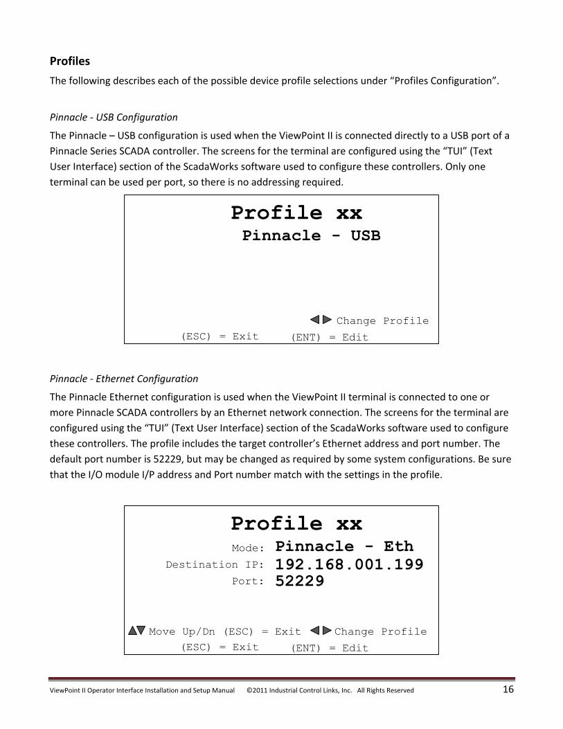
Pinnacle - USB Configuration
The Pinnacle – USB configuration is used when the ViewPoint II is connected directly to a USB port of a
Pinnacle Series SCADA controller. The screens for the terminal are configured using the “TUI” (Text
User Interface) section of the ScadaWorks software used to configure these controllers. Only one
terminal can be used per port, so there is no addressing required.
Profile xxPinnacle - USB
(ESC) = Exit (ENT) = Edit
Change Profile
Pinnacle - Ethernet Configuration
The Pinnacle Ethernet configuration is used when the ViewPoint II terminal is connected to one or
more Pinnacle SCADA controllers by an Ethernet network connection. The screens for the terminal are
configured using the “TUI” (Text User Interface) section of the ScadaWorks software used to configure
these controllers. The profile includes the target controller’s Ethernet address and port number. The
default port number is 52229, but may be changed as required by some system configurations. Be sure
that the I/O module I/P address and Port number match with the settings in the profile.
Mode:
Profile xxPinnacle - Eth
(ESC) = Exit
Destination IP:
Port:
192.168.001.19952229
(ENT) = Edit
Move Up/Dn (ESC) = Exit Change Profile
ViewPoint II Operator Interface Installation and Setup Manual ©2011 Industrial Control Links, Inc. All Rights Reserved 17
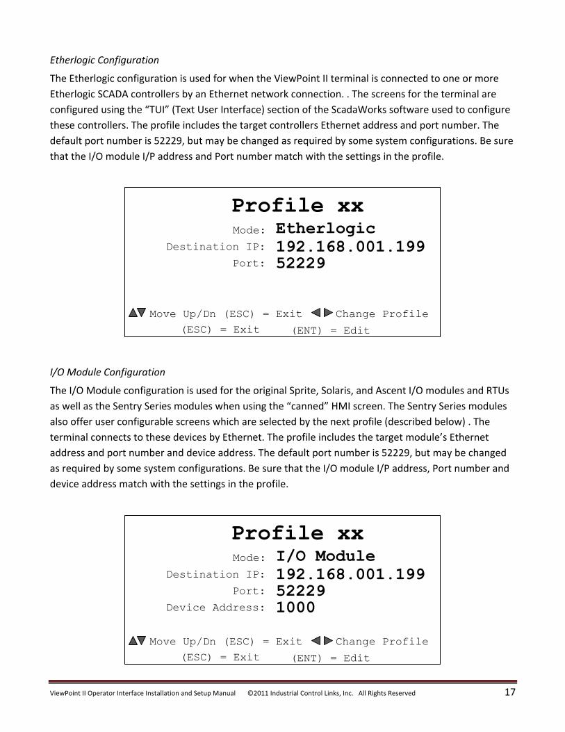
Etherlogic Configuration
The Etherlogic configuration is used for when the ViewPoint II terminal is connected to one or more
Etherlogic SCADA controllers by an Ethernet network connection. . The screens for the terminal are
configured using the “TUI” (Text User Interface) section of the ScadaWorks software used to configure
these controllers. The profile includes the target controllers Ethernet address and port number. The
default port number is 52229, but may be changed as required by some system configurations. Be sure
that the I/O module I/P address and Port number match with the settings in the profile.
Mode:
Profile xxEtherlogic
(ESC) = Exit
Destination IP:
Port:
192.168.001.19952229
(ENT) = Edit
Move Up/Dn (ESC) = Exit Change Profile
I/O Module Configuration
The I/O Module configuration is used for the original Sprite, Solaris, and Ascent I/O modules and RTUs
as well as the Sentry Series modules when using the “canned” HMI screen. The Sentry Series modules
also offer user configurable screens which are selected by the next profile (described below) . The
terminal connects to these devices by Ethernet. The profile includes the target module’s Ethernet
address and port number and device address. The default port number is 52229, but may be changed
as required by some system configurations. Be sure that the I/O module I/P address, Port number and
device address match with the settings in the profile.
Mode:
Profile xxI/O Module
(ESC) = Exit
Destination IP:
Port:
Device Address:
192.168.001.199522291000
(ENT) = Edit
Move Up/Dn (ESC) = Exit Change Profile
ViewPoint II Operator Interface Installation and Setup Manual ©2011 Industrial Control Links, Inc. All Rights Reserved 18
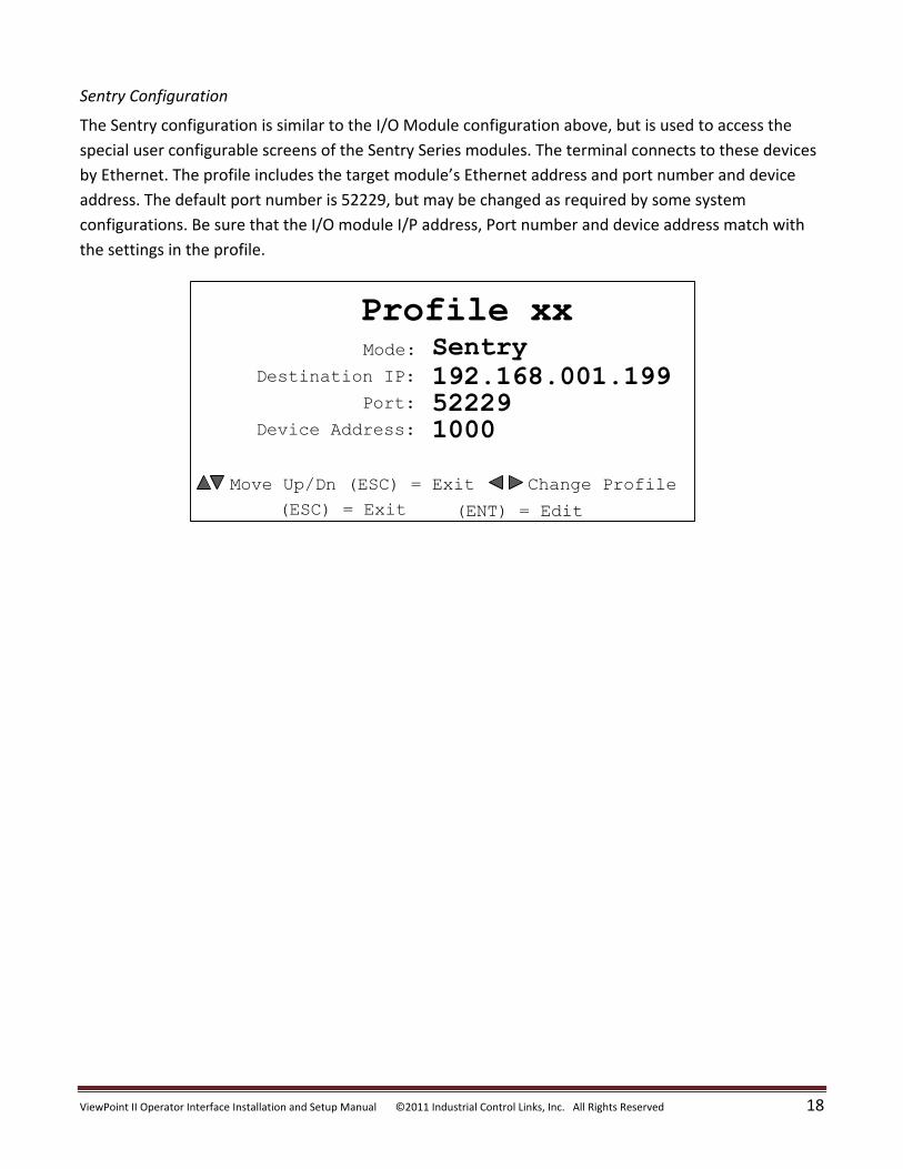
Sentry Configuration
The Sentry configuration is similar to the I/O Module configuration above, but is used to access the
special user configurable screens of the Sentry Series modules. The terminal connects to these devices
by Ethernet. The profile includes the target module’s Ethernet address and port number and device
address. The default port number is 52229, but may be changed as required by some system
configurations. Be sure that the I/O module I/P address, Port number and device address match with
the settings in the profile.
Mode:
Profile xxSentry
(ESC) = Exit
Destination IP:
Port:
Device Address:
192.168.001.199522291000
(ENT) = Edit
Move Up/Dn (ESC) = Exit Change Profile
ViewPoint II Operator Interface Installation and Setup Manual ©2011 Industrial Control Links, Inc. All Rights Reserved 19
Serial #:
Information82990
(ESC) = Exit
Mfg ID:
Mfg Date
Software:
57400806/23/111.01.01
Current Profile:
MAC Address: 00-50-C2-CE-01-50
1
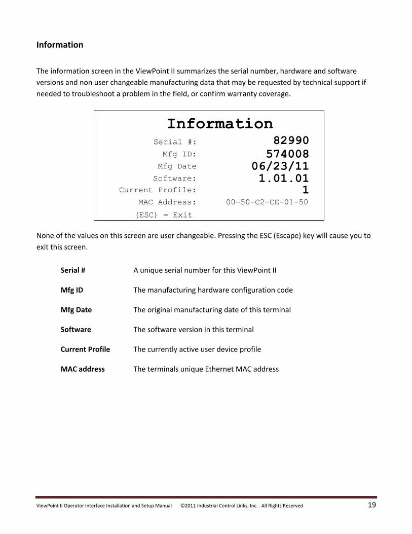
Information
The information screen in the ViewPoint II summarizes the serial number, hardware and software
versions and non user changeable manufacturing data that may be requested by technical support if
needed to troubleshoot a problem in the field, or confirm warranty coverage.
None of the values on this screen are user changeable. Pressing the ESC (Escape) key will cause you to
exit this screen.
Serial # A unique serial number for this ViewPoint II Mfg ID The manufacturing hardware configuration code Mfg Date The original manufacturing date of this terminal Software The software version in this terminal Current Profile The currently active user device profile MAC address The terminals unique Ethernet MAC address
ViewPoint II Operator Interface Installation and Setup Manual ©2011 Industrial Control Links, Inc. All Rights Reserved 20
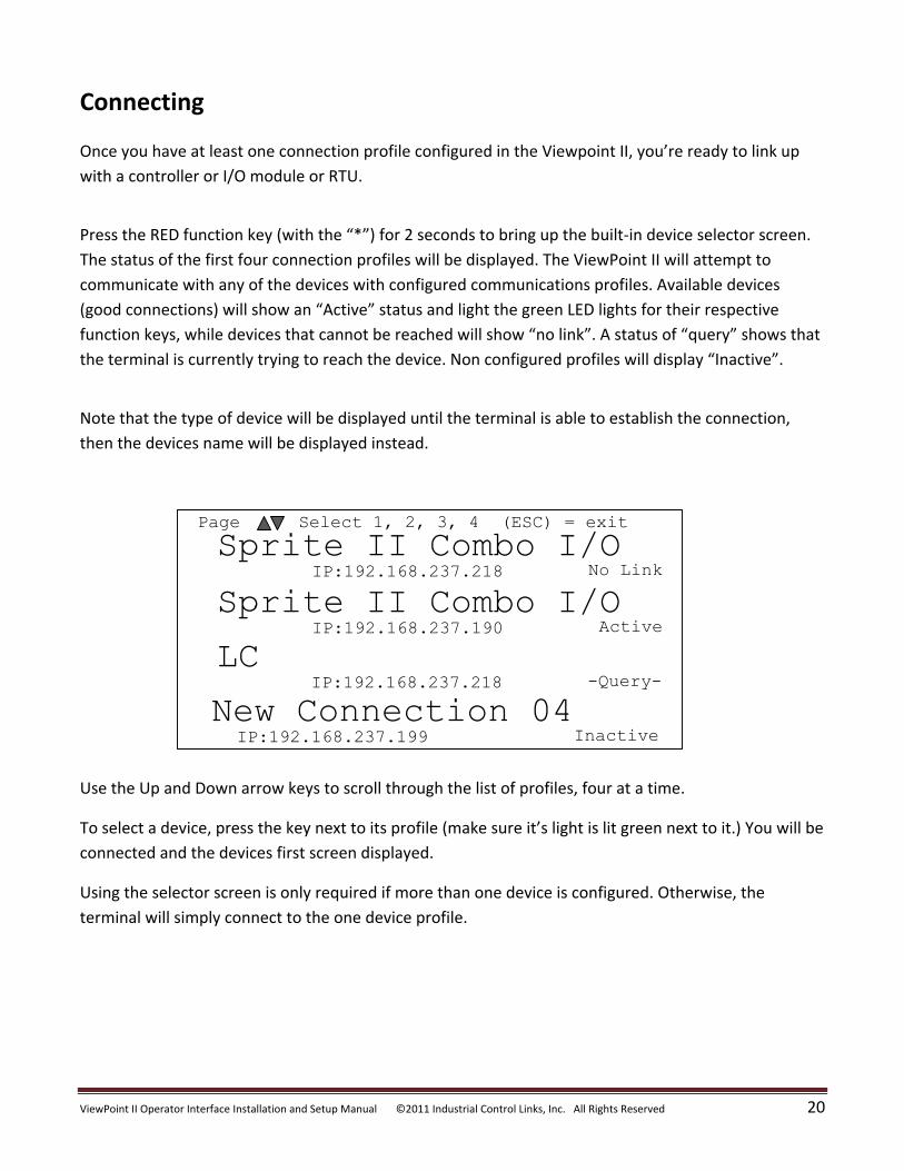
Connecting
Once you have at least one connection profile configured in the Viewpoint II, you’re ready to link up
with a controller or I/O module or RTU.
Press the RED function key (with the “*”) for 2 seconds to bring up the built-in device selector screen.
The status of the first four connection profiles will be displayed. The ViewPoint II will attempt to
communicate with any of the devices with configured communications profiles. Available devices
(good connections) will show an “Active” status and light the green LED lights for their respective
function keys, while devices that cannot be reached will show “no link”. A status of “query” shows that
the terminal is currently trying to reach the device. Non configured profiles will display “Inactive”.
Note that the type of device will be displayed until the terminal is able to establish the connection,
then the devices name will be displayed instead.
IP:192.168.237.218
Sprite II Combo I/ONo Link
IP:192.168.237.190
Sprite II Combo I/OActive
IP:192.168.237.218
LC-Query-
IP:192.168.237.199
New Connection 04Inactive
Select 1, 2, 3, 4 (ESC) = exitPage
Use the Up and Down arrow keys to scroll through the list of profiles, four at a time.
To select a device, press the key next to its profile (make sure it’s light is lit green next to it.) You will be
connected and the devices first screen displayed.
Using the selector screen is only required if more than one device is configured. Otherwise, the
terminal will simply connect to the one device profile.
ViewPoint II Operator Interface Installation and Setup Manual ©2011 Industrial Control Links, Inc. All Rights Reserved 21
3.00"
7.15"
3.85"
6.30"
1.00"
Mounting
Thumbscrew
Panel Mounting Clamp
Sealing
Gasket
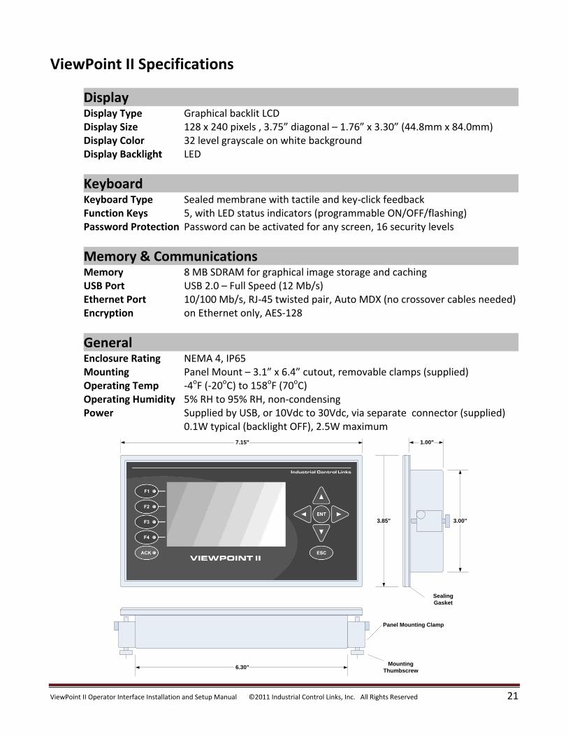
ViewPoint II Specifications
Display Display Type Graphical backlit LCD Display Size 128 x 240 pixels , 3.75” diagonal – 1.76” x 3.30” (44.8mm x 84.0mm) Display Color 32 level grayscale on white background Display Backlight LED
Keyboard Keyboard Type Sealed membrane with tactile and key-click feedback Function Keys 5, with LED status indicators (programmable ON/OFF/flashing) Password Protection Password can be activated for any screen, 16 security levels
Memory & Communications Memory 8 MB SDRAM for graphical image storage and caching USB Port USB 2.0 – Full Speed (12 Mb/s) Ethernet Port 10/100 Mb/s, RJ-45 twisted pair, Auto MDX (no crossover cables needed) Encryption on Ethernet only, AES-128
General Enclosure Rating NEMA 4, IP65 Mounting Panel Mount – 3.1” x 6.4” cutout, removable clamps (supplied) Operating Temp -4oF (-20oC) to 158oF (70oC) Operating Humidity 5% RH to 95% RH, non-condensing Power Supplied by USB, or 10Vdc to 30Vdc, via separate connector (supplied) 0.1W typical (backlight OFF), 2.5W maximum

ViewPoint II Operator Interface Installation and Setup Manual ©2011 Industrial Control Links, Inc. All Rights Reserved 22
Related Documents