UNIT 1 INTRODUCTION- THEORY AND BEHAVIOUR 1.a) What are the advantages & disadvantages of Prestressed Concrete. Advantage of Prestressed Concrete 1. The use of high strength concrete and steel in prestressed members results in lighter and slender members than is possible with RC members. 2. In fully prestressed members the member is free from tensile stresses under working loads, thus whole of the section is effective. 3. In prestressed members, dead loads may be counter-balanced by eccentric prestressing. 4. Prestressed concrete member posses better resistance to shear forces due to effect of compressive stresses presence or eccentric cable profile. 5. Use of high strength concrete and freedom from cracks, contribute to improve durability under aggressive environmental conditions. 6. Long span structures are possible so that saving in weight is significant & thus it will be economic. 7. Factory products are possible. 8. Prestressed members are tested before use. 9. Prestressed concrete structure deflects appreciably before ultimate failure, thus giving ample warning before collapse. 10. Fatigue strength is better due to small variations in prestressing steel, recommended to dynamically loaded structures. Disadvantages of Prestressed Concrete 1. The availability of experienced builders is scanty. 2. Initial equipment cost is very high. 3. Availability of experienced engineers is scanty. 4. Prestressed sections are brittle

Welcome message from author
This document is posted to help you gain knowledge. Please leave a comment to let me know what you think about it! Share it to your friends and learn new things together.
Transcript

UNIT 1INTRODUCTION- THEORY AND BEHAVIOUR
1.a) What are the advantages & disadvantages of Prestressed Concrete.Advantage of Prestressed Concrete 1. The use of high strength concrete and steel in prestressed members results in lighter and slender members than is possible with RC members. 2. In fully prestressed members the member is free from tensile stresses under working loads, thus whole of the section is effective. 3. In prestressed members, dead loads may be counter-balanced by eccentric prestressing. 4. Prestressed concrete member posses better resistance to shear forces due to effect of compressive stresses presence or eccentric cable profile. 5. Use of high strength concrete and freedom from cracks, contribute to improve durability under aggressive environmental conditions. 6. Long span structures are possible so that saving in weight is significant & thus it will be economic. 7. Factory products are possible. 8. Prestressed members are tested before use. 9. Prestressed concrete structure deflects appreciably before ultimate failure, thus giving ample warning before collapse. 10. Fatigue strength is better due to small variations in prestressing steel, recommended to dynamically loaded structures. Disadvantages of Prestressed Concrete 1. The availability of experienced builders is scanty. 2. Initial equipment cost is very high. 3. Availability of experienced engineers is scanty. 4. Prestressed sections are brittle 5. Prestressed concrete sections are less fire resistant.
b) Describe briefly Fressinet system of post tensioningPrinciples of post-tensioning:In post-tensioning, the concrete units are first cast by incorporating ductsor grooves to house the tendons. When the concrete attains sufficient strength, the high tensile wires are tensioned by means of jack bearing on the end face of the member and anchorags by wedges or nuts.Freyssinet system of post tensioning:The Freyssinet system of post-tensioning anchorages which wasdeveloped in 1939.The Freyssinet anchorage system, which is widely used in Europe andIndia, consists of a cylinder with a conical interior through which the high-tensile wirespass and against the walls of which the wires are wedged by a conical plug lined

longitudinally with grooves to house the wires. The main advantages of the Freyssinetsystem is that a large number of wires or strands can be simultaneously tensioned usingthe double-acting hydraulic jack.
2.Types of Prestressing
Prestressing of concrete can be classified in several ways. The following classifications are discussed.
Source of prestressing force
This classification is based on the method by which the prestressing force is generated.
There are four sources of prestressing force: Mechanical, hydraulic, electrical and
chemical.
External or internal prestressing
This classification is based on the location of the prestressing tendon with respect to the
concrete section.
Pre-tensioning or post-tensioning
This is the most important classification and is based on the sequence of casting the
concrete and applying tension to the tendons.
Linear or circular prestressing
This classification is based on the shape of the member prestressed.
Full, limited or partial prestressing
Based on the amount of prestressing force, three types of prestressing are defined.
Uniaxial, biaxial or multi-axial prestressing
As the names suggest, the classification is based on the directions of prestressing a
member.
Source of Prestressing Force
Hydraulic Prestressing
This is the simplest type of prestressing, producing large prestressing forces. The
hydraulic jack used for the tensioning of tendons, comprises of calibrated pressure

gauges which directly indicate the magnitude of force developed during the tensioning.
Mechanical Prestressing
In this type of prestressing, the devices includes weights with or without lever
transmission, geared transmission in conjunction with pulley blocks, screw jacks with or
without gear drives and wire-winding machines. This type of prestressing is adopted for
mass scale production.
Electrical Prestressing
In this type of prestressing, the steel wires are electrically heated and anchored before
placing concrete in the moulds. This type of prestressing is also known as thermoelectric
prestressing.
External or Internal Prestressing
External Prestressing
When the prestressing is achieved by elements located outside the concrete, it is called
external prestressing. The tendons can lie outside the member (for example in I-girders
or walls) or inside the hollow space of a box girder. This technique is adopted in
bridges and strengthening of buildings. In the following figure, the box girder of a bridge
is prestressed with tendons that lie outside the concrete.
Internal Prestressing
When the prestressing is achieved by elements located inside the concrete member
(commonly, by embedded tendons), it is called internal prestressing. Most of the
applications of prestressing are internal prestressing. In the following figure, concrete
will be cast around the ducts for placing the tendons.
Pre-tensioning or Post-tensioning
Pre-tensioning
The tension is applied to the tendons before casting of the concrete. The precompression
is transmitted from steel to concrete through bond over the transmission
length near the ends.
Post-tensioning
The tension is applied to the tendons (located in a duct) after hardening of the concrete.
The pre-compression is transmitted from steel to concrete by the anchorage device (at
the end blocks)..
Linear or Circular Prestressing
Linear Prestressing
When the prestressed members are straight or flat, in the direction of prestressing, the
prestressing is called linear prestressing. For example, prestressing of beams, piles,
poles and slabs. The profile of the prestressing tendon may be curved.
Circular Prestressing
When the prestressed members are curved, in the direction of prestressing, the
prestressing is called circular prestressing. For example, circumferential prestressing of
tanks, silos, pipes and similar structures.
Full, Limited or Partial Prestressing
Full Prestressing
When the level of prestressing is such that no tensile stress is allowed in concrete under
service loads, it is called Full Prestressing (Type 1, as per IS:1343 - 1980).
Limited Prestressing
When the level of prestressing is such that the tensile stress under service loads is
within the cracking stress of concrete, it is called Limited Prestressing (Type 2).
Partial Prestressing
When the level of prestressing is such that under tensile stresses due to service loads,
the crack width is within the allowable limit, it is called Partial Prestressing (Type 3).
Uniaxial, Biaxial or Multiaxial Prestressing
Uniaxial Prestressing
When the prestressing tendons are parallel to one axis, it is called Uniaxial Prestressing.
For example, longitudinal prestressing of beams.

Biaxial Prestressing
When there are prestressing tendons parallel to two axes, it is called Biaxial
Prestressing. The following figure shows the biaxial prestressing of slabs.das
Multiaxial Prestressing
When the prestressing tendons are parallel to more than two axes, it is called Multiaxial
Prestressing. For example, prestressing of domes.
3. Differences of Prestressed Concrete Over Reinforced Concrete:
1. In prestress concrete member steel plays active role. The stress in steel prevails whether external load is there or not. But in R.C.C., steel plays a passive role. The stress in steel in R.C.C members depends upon the external loads. i.e., no external load, no stress in steel.
2. In prestress concrete the stresses in steel is almost constant where as in R.C.C the stress in steel is variable with the lever arm.
3. Prestress concrete has more shear resistance, where as shear resistance of R.C.C is less. 4. In prestress concrete members, deflections are less because the eccentric prestressing
force will induce couple which will cause upward deflections, where as in R.C.C., deflections are more.
5. In prestress concrete fatigue resistance is more compare to R.C.C. because in R.C.C. stress in steel is external load dependent where as in P.S.C member it is load independent.
6. Prestress concrete is more durable as high grade of concrete is used which are more dense in nature. R.C.C. is less durable.
7. In prestress concrete dimensions are less because external stresses are counterbalance by the internal stress induced by prestress. Therefore reactions on column & footing are less as a whole the quantity of concrete is reduced by 30% and steel reduced by about 60 to 70%. R.C.C. is uneconomical for long span because in R.C.C. dimension of sections are large requiring more concrete & steel. Moreover as self-weight increases more reactions acted on columns & footings, which requires higher sizes.
4. a) Discuss about the importance of control of deflections and the factors influencing the deflection of PSC beams

IMPORTANCE OF CONTROL OF DEFLECTION:The structural concrete members should be designed to have adequate stiffness tolimit deflections, which may adversely affect the strength or serviceability oof thestructure at working loads.Suitable control on deflection is very essential for the following reasons:
Excessive, sagging of principal structural members is not only unsightly,but at times, also renders the floor unsuitable for the intended use.
Large deflections under dynamic effects and under the influence ofvariable loads may cause discomfort to the users.
Excessive deflections are likely to cause damage to finishes, partitionsand associated structures.
FACTORS INFLUENCING DEFLECTIONS:The deflections of prestressed concrete members are influenced byy the followingsalient factors:
Imposed load and self weight Magnitude of the prestressing force Cable profile Second moment of area of cross section Modulus of elasticity of concrete Shrinkage, creep and relaxation of steel stress Span of the member Fixity conditions
b) Describe the various types of losses in prestress. What steps may be taken to reducethese losses
LOSS DUE TO ELASTIC DEFORMATION OF CONCRETE:The loss of prestress due to elastic deformation of concrete depends on themodular ratio and the average stress in concrete at the level of steel.If fc= prestress in concrete at the level of steel.Es= modulus of elasticity of steel.Ec= modulus of elasticity of concrete.αe= Es/ Ec = modular ratio.Strain in concrete at the level of steel = (fc/ Ec)Stress in steel corresponding to this strain = (fc/ Ec) EsLoss of stress in steel = αe fc
If the initial stress in steel is known, the percentage loss of stress due to theelastic deformation of concrete can be computed.
LOSS DUE TO SHRINKAGE OF CONCRETE:The shrinkage of concrete in prestressed members results in a shorteningof tensioned wires and hence contributes to the loss of stress. Theshrinkage of concrete is influenced by the type of cement and aggregatesand the method of curing used. Use of high-strength concrete with low

water cement ratios result in a reduction in shrinkage and consequent lossof prestress.According IS1343 for the loss of prestress due to the shrinkage ofconcreteЄcs = total residual shrinkage strain having values of 300x106 for pretensioning and [200x106/log10(t+2)]Where, t = age of concrete at transfer in days.The loss of stress in steel due to the shrinkage of concrete is estimated as,Loss of stress = Єcs x Es
LOSS DUE TO CREEP OF CONCRETE:The sustained prestress in the concrete of a prestressed member results increep of concrete which effectively reduces the stress in high-tensile steel.The loss of stress in steel due to creep of concrete can be estimated if themagnitude of ultimate creep strain or creep coefficient is known.ULTIMATE CREEP STRAIN METHOD:If Єcc = ultimate creep strain for a sustained unit stressfc = Compressive stress in concrete at the level of steel.Es = modulus of elasticity of steel.Loss of stress in steel due to creep of concrete = Єcc fc EsCREEP COEFFICIENT METHOD:If = creep coefficientЄc = creep strainЄe = elastic strainαe = modular ratiofc = stress in concreteEs = modulus of elasticity of steel.Ec = modulus of elasticity of concrete.Creep coefficient( ) = (Єc/ Єe)Loss of stress in steel = fc αe
LOSS DUE TO RELAXATION OF STRESS INN STEEL:Most of the code provides for the loss of stress due to relaxation of steel asa percentage of the initial stress in steel. The Indian standard coderecommends a value varying from 0 to 90 N/mm2 for stress in wirevarying from 0.5 fup to 0.8 fup .
LOSS OF STRESS DUE TO FRICTION:On tensioning the curved tendons, loss of stress occurs in the posttensionedmembers due to friction between the tendons and thesurrounding concrete ducts. The magnitude of this loss is of the followingtypes:(a) Loss of stress due to the curvature effects, which depends uponthe tendon from or alignment which generally follows a curved profile along the

length of the beam. (b) Loss of stress due to the wobble effect, which depends uponthe local deviation in the alignment of the cable. The wobble or wave effect is theresult of accidental or unavoidable misalignment, since ducts or sheaths cannot beperfectly located to follow predetermined profile throughout the length of thebeam.Px = Poe-(μα+ kx)
LOSS DUE TO ANCHORAGE SLIP:In most post-tensioned system, when the cable is tensioned and the jack isreleased to transfer prestress to concrete, the friction wedges, employed togrip the wires, slip over a small distance before the wires are firmlyhoused between the wedges. The magnitude of slip depends upon the typeof wedge and the stress in the wire.Δ = (PL/AEs)Where Δ = slip of anchorage, mmL = length of the cable,mmA = cross sectional area of the cable, mm2
Es = modulus of elasticity of steel.P = Prestressed force in the cable
5. A S.S beam has a span of 10m and is 300x600mm in section. It is prestressed with an initial prestress of 700kN, which is located at 100mm from the soffit. The beam is required to carry a load of 12kN/m. in addition to its self weight. Assuming a loss of prestress as 15%. Calculate the stresses at the extreme fibers of the midspan section.
Given data:
L = 10m
Pi = 700kN
Wl = 12kN/m
Loss = 15%
Solution:
P = ηPi
η = (100-15)/100
= 0.85
P = 0.85 x 700

= 595 kN
A = 300 x 600
A = 18 x 104 mm2
e = -200mm
I = (bd3)/12
= (300 x 6003)/ 12
I = 5.4 x 109 mm4
Yt = (+)300mm
Yb = (-)300mm
Md = wdl2/8
Wd = area x density
= 18x104x24 / 10002
= 4.32 kN/m
Md = (4.32 x 10²) / 8 = 54kNm
Ml = (12x 102) / 8 = 150kNm
At initial or transfer condition:
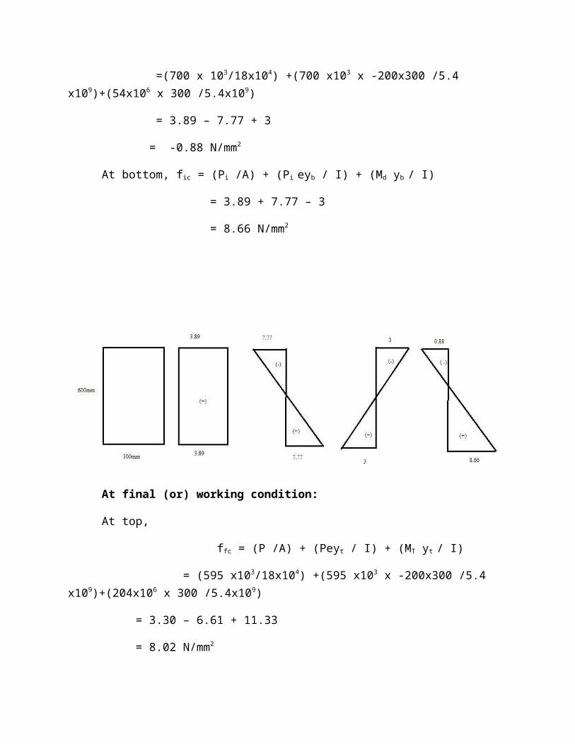
At top, fit = (Pi /A) + (Pi eyt / I) + (Md yt / I)
=(700 x 103/18x104) +(700 x103 x -200x300 /5.4 x109)+(54x106 x 300 /5.4x109)
= 3.89 – 7.77 + 3
= -0.88 N/mm2
At bottom, fic = (Pi /A) + (Pi eyb / I) + (Md yb / I)
= 3.89 + 7.77 – 3
= 8.66 N/mm2

At final (or) working condition:
At top,
ffc = (P /A) + (Peyt / I) + (MT yt / I)
= (595 x103/18x104) +(595 x103 x -200x300 /5.4 x109)+(204x106 x 300 /5.4x109)
= 3.30 – 6.61 + 11.33
= 8.02 N/mm2
At bottom,
fft = 3.30 + 6.61 - 11.33
= -1.42 N/mm2

6.Cross section of the post tensioned beam of span 18m designed for a live load of 25 kN/m adopting M30 grade concrete as the following dimension.
Top flange = 950mm x 150mm
Web = 1250mm x 130mm
Bottom flange = 700mm x 250mm
Cable is parabolic with zero eccentricity at supports and 550mm at midspan section. Initial prestressing is 1720 kN. Examine whether the beam is safe. Irrespective to stress at initial & final condition. Check the stresses at mid span section and quarter span section. Loss of prestress is 22%.
Given Data:
L = 18m
Pi = 1720 kN
Wl = 25 kN/m
Loss = 22%
Solution:
P = ηPi
η = (100-22)/100
= 0.78
P = 0.78 x 700
= 1341.60 kN
A = (950 x150) + (1250 x 130) + (700 x 250)
= 48 x 104 mm2
Yt = (a1y1 + a2y2 + a3y3) / (a1 + a2 + a3 )
= ((950 x 150 x 75) + (1250 x 130 x 775) + (700 x 250 x 1525)) / (48 x 104 )
= 840.625mm
Yb = 809.37mm

Wd = 11.52 kN/m
I = 1.885 x 1011 mm4
At initial or transfer condition: (mid span)
At top, fit = (Pi /A) + (Pi eyt / I) + (Md yt / I)
= (1720 x 103/48x104) +(1720 x103 x -550x840.625 /1.8 x1011)
+(466.56x106 x 840.625 /1.8x1011)
= 3.58 – 4.22 + 2.081
= 1.44 N/mm2
At bottom, fic = (Pi /A) + (Pi eyb / I) + (Md yb / I)
=3.54 + 4.06 -2
= 5.64 N/mm2
At final (or) working condition:
At top,
ffc = (P /A) + (Peyt / I) + (MT yt / I)
= (1341.6 x103/48x104) +(1341.6 x103 x -550x840.625 /1.8 x1011)
+(1479.06x106 x 840.625 /1.8x1011)
= 2.795 – 3.29 +6.596
= 6.1N/mm2
At bottom,
fft =2.795 + 3.17 - 6.351
= -0.38 N/mm2
At initial or transfer condition: (quarter span)
Md = 11.52 x 4.5 x (18-4.5) / 2 = 349.92 kNm
Ml = 25 x 4.5 x (18-4.5) / 2 = 759.4 kNm
Mt = Md + Ml = 1109.2 kNm

e 1 = (4r/ l2) (a x l-a)
e 1 = 412.5mm
At top, fit = (Pi /A) + (Pi eyt / I) + (Md yt / I)
= (1720 x 103/48x104) +(1720 x103 x -412.5x840.625 /1.8 x1011)
+(349.92x106 x 840.625 /1.8x1011)
= 3.58 – 3.16 + 1.56
= 1.98 N/mm2
At bottom, fic = (Pi /A) + (Pi eyb / I) + (Md yb / I)
=3.58 + 3.04 -1.5
= 5.12 N/mm2
At final (or) working condition:
At top,
ffc = (P /A) + (Peyt / I) + (MT yt / I)
= (1341.6 x103/48x104) +(1341.6 x103 x -412.5x840.625 /1.8 x1011)
+(1109.2x106 x 840.625 /1.8x1011)
= 2.795 – 2.46 +4.95
= 5.28N/mm2
At bottom,
fft =2.795 + 2.37 – 4.76
= 0.42 N/mm2

7.A pretensioned beam 200mm wide and 300mm deep is prestressed by 10 wires of 7mm dia initially stressed to 1200N/mm2 with their centroids loaded 100mm from the soffit. find the maximum stress in concrete immediately after transfer allowing only for elastic shortening of concrete.
If the concrete undergoes a further shortening due to creep and shrinkage, while there is a relaxation of 5% of steel wires stress, estimate the final percentage loss of stress in the wires using IS1343 – 2012.
Es = 210 kN/ mm2
Ec = 36900N/ mm2
εsh = 3 x 10⁻⁴
Given Data:
Asc = 384.85 mm2
fsi = 1200 N/mm2
Pi = 461.82 x 10³
Es = 210 kN/ mm2
Ec = 36900N/ mm2
εsh = 3 x 10⁻⁴
Solution:
(i)Elastic Deformation of concrete:
Loss = mPc
m = Es / Ec
= (2.1 x 10⁵) /(36900)
= 5.69
Pc = (Pi / A) + (Pi e2 / I)
= (461.82 x 10³ / 200x300) + (461.82 x 10³ x -502 / 450 x 106)
= 10.26 N/mm2
Loss = 5.69 x 10.26
= 58.39 N/mm2

(ii) shrinkage:
Loss = εsh x Es
= 3 x 10-4 x 2.1 x 105
= 63 N/mm2
(iii) creep:
Loss = ØmPc
= 1.6 x 5.69 x 10.26
= 93.41 N/mm2
(iv) Relaxation of stress in steel:
Loss = (5/100) x 1200
= 60 N/mm2
Total loss = 274.8 N/mm2
Losses of prestress = (274.8 / 1200) x 100
= 22.9%
Final stress in steel, P = fse x A
= 356.06kN
8.A prestressed concrete beam 200mm x 300mm is prestressed with wires area 160mm2 loaded at a constant eccentricity of 50mm carrying an initial stress of 1000 N/mm2. The span of the beam is 10m . calculate the percentage loss of stress in wires. The beam is post tensioned.
Es = 2.1x 10⁵ N/ mm2
Ec = 3.5 x 10⁴ N/ mm2
εsh = 200 x 10-4
εcc = 20 x 10-6
slip at anchorage = 1mmfriction co eff for wave effect, k = 0.0015
Solution:
(i)Elastic Deformation of concrete:
Loss = mPc / 2
m = Es / Ec
= (2.1 x 10⁵) /(3.5 x 104)
= 6
Pc = (Pi / A) + (Pi e2 / I)
= (16 x 104 / 200x300) + (16 x 104 x 502 / 450 x 106)
= 3.56 N/mm2
Loss = 6 x 3.56 / 2
= 10.68 N/mm2
(ii) shrinkage:
Loss = εsh x Es
= 200 x 10-6 x 2.1 x 105
= 42 N/mm2
(iii) creep:
Loss = εcc x Es x Pc
= 20 x 10-6 x 2.1 x 105 x 3.56
= 14.95 N/mm2
(iv) Relaxation of stress in steel:
Loss = (5/100) x 1000
= 50 N/mm2
(v) Friction:
(μα + kL) fsi = (0 + 0.0015 x 10 x1000)
= 15 N/mm2
(vi) Anchorage slip:
Loss = (1 x 2.1 x 105) / 10000 = 21 N/mm2

Total loss = 153.63N/mm2
Losses of prestress = (153.63/ 1000) x 100
= 15.36%
9.A prestressed concrete beam with a rectangular section 120mm x 300mm supports a udl 0f 4kN/m, which includes the self weight of the beam. The effective span of the beam is 6m. the beam is concentrically prestressed by a cable carrying a force of 180 kN. Locate the position of the pressure line in the beam.
Given data:Size = 120mm x 300mmUdl = 4 kN/mL = 6mP = 180 kNe = 0
Solution:A = 120 x 300 = 36 x 103 mm2
I = (120 x 3003 /12) = 270 x 106 mm4
M = 4 x 62 /8 = 18kNmyt = 150mmyb = 150mm
Mid span:Resultant stresses at top,
ffc = (P /A) + (Peyt / I) + (MT yt / I)
= (180 x103/36x104) +(180 x103 x 0x300 /270 x106)+(18x106 x 150 /270x106)
= 5 + 10
= 15 N/mm2
At bottom,
fft =5 - 10
= -5 N/mm2
Shift of pressure line from cable line,
M/P = (18 x 106) /(180 x 103)
= 100mm

10.A rectangular concrete beam of c/s 150mm x 300mm is s.s over a span of 8m and is prestressed by means of a symmetric parabolic cable, at a distance of 75mm from the bottom of the beam at mid span and 125mm from the top of the beam at support sections. If the force in the cable is 350kN and the modulus of elasticity of concrete is 38 kN/mm2, calculate,
i) The deflection at mid – span when the beam is supporting its own weight, and
ii) The concentrated load which must be applied at mid span to restore it to the level of supports.
Given data:
Size = 150mm x 300mm
Span = 8m
P = 350 kN
Ec = 38 kN/mm2
e1 = 75mm
e2 = 25mm
solution:
Deflection due to prestressing force,
δp = (PL2 / 48EI) x (-5 e1 + e2)
= (350 x 103 x 80002 / 48x38x103x3375x105)(-5x75+25)

δp = 12.7mm (upwards)
self weight of the beam, wd = 150x300x24/10002
= 1.08N/mm
Downward deflection due to self weight,
δd = 5wdl4 / 384EI
= (5x 1.08 x80004) / (384 x 38 x 103x3375x105)
= 4.5mm (downward)
(i) Deflection due to prestress + self wt = -12.7 + 4.5
= -8.2mm(ii) If Q = concentrated load reqd at the centre of span,
Wl3/48EI = 8.2
W = (8.2 x 48 x38x103x 3375 x105) / 80003
= 9.9kN
Related Documents