Power Survey International Welcome

Welcome message from author
This document is posted to help you gain knowledge. Please leave a comment to let me know what you think about it! Share it to your friends and learn new things together.
Transcript
Power Survey International
Welcome

Power Survey International
Power Survey International – Company profile
• Established since 1948
• Manufacturer of low and medium voltage products:• Power Factor correction system• Harmonic Filter system• Steel Cabinet – customized to your needs• Other products to come….
• Sales throughout United States, Canada, South America, Middle East and the rest of the world.
Power Survey International
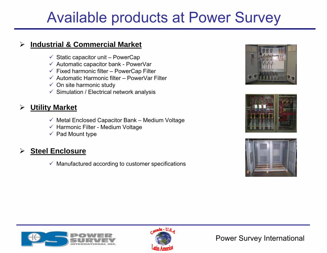
Available products at Power Survey Industrial & Commercial Market
Static capacitor unit – PowerCap Automatic capacitor bank - PowerVar Fixed harmonic filter – PowerCap Filter Automatic Harmonic filter – PowerVar Filter On site harmonic study Simulation / Electrical network analysis
Utility Market Metal Enclosed Capacitor Bank – Medium Voltage Harmonic Filter - Medium Voltage Pad Mount type
Steel Enclosure Manufactured according to customer specifications
Power Survey International
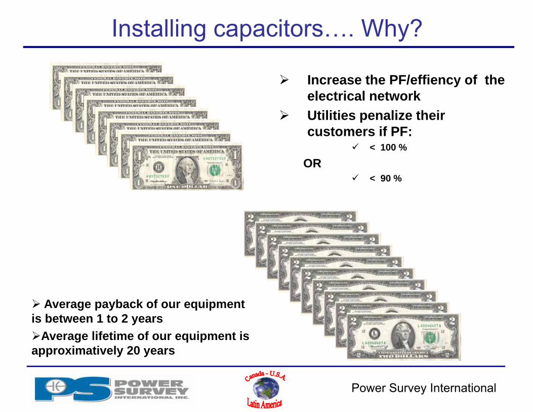
Installing capacitors…. Why?
Increase the PF/effiency of the electrical network
Utilities penalize their customers if PF:
< 100 %
OR < 90 %
Average payback of our equipment is between 1 to 2 yearsAverage lifetime of our equipment is approximatively 20 years
Power Survey International
Installing capacitor - technically?
Savings of $$ through power factor penalties,
• Usually less than 2 year payback• Most Utilities requires a 90% or higher PF
Voltage improvement,Reduced system losses through cables
and transformers, Increases power transmission capacity in
cables, Increases transformer capacity

Power Survey International
Introduction
What is power factor and related formulas:
P.F. = Active Power = KWApparent Power KVA
KVA = √(kW)² + (kvar)²

Power Survey International
Phase diagram of voltage and current
V
I V
I
V
I
Inductive current Capacitive current
Resistive current

Power Survey International
Power Factor – phase angle
PF=Cos0 130 0,86660 0,590 0
2
3
1V
I

Power Survey International
Q (kvar) varies depending on phase angle
• From this figure:
QQQ Lc
)( 21 TanTanPQc
KPQc *
2
1LQ
Q
CQ
P
1S
2S
Power Factor – Phase Angle
• Mathematically:
• Simple calculation:

Power Survey International
Reactive power formulas (kVAR)
2
1LQ
Q
CQ
P
1S
2S
21
11 costgcostg FPFPkWkVAR
kWkVARtg
tg*kWkVAR
CosFP FPCos 1
FPCoskWkVAR 1tg*
kWkVAR1tg

Power Survey International
Voltage and current sine wave
Capacitor current leads the voltage sinewave
Resistive current is in phase with voltage sinewave
Power Survey International
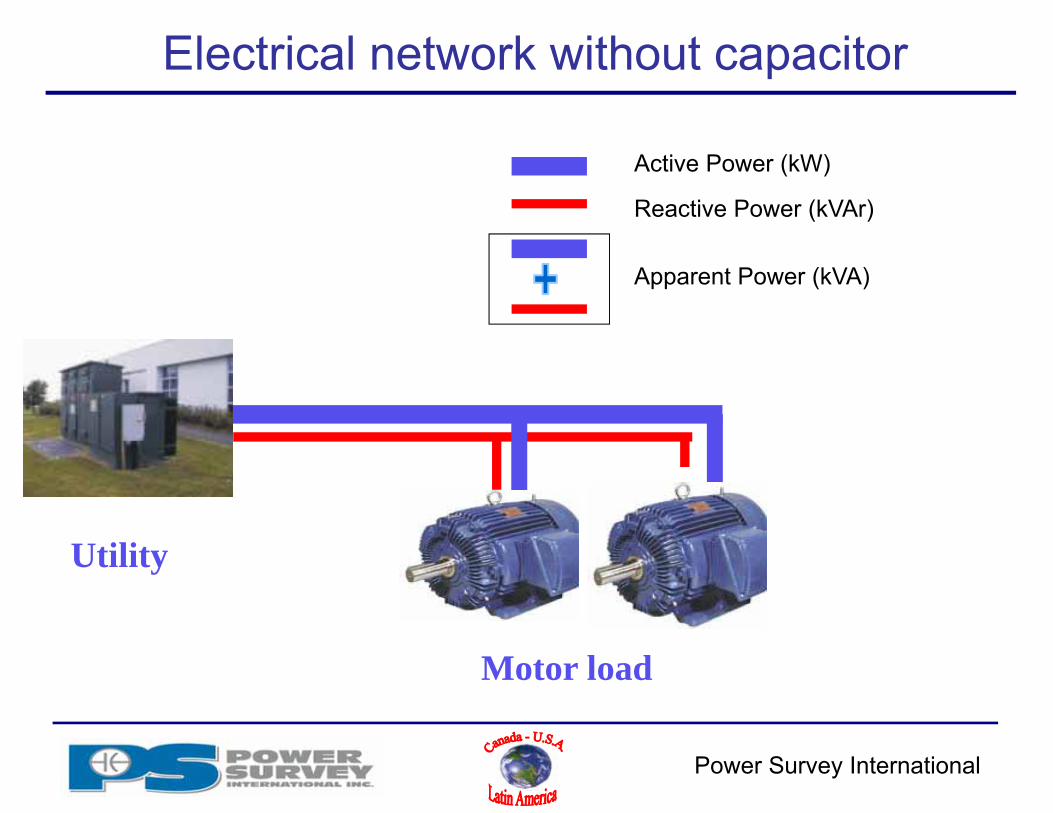
Electrical network without capacitor
Utility
Motor load
Active Power (kW)
Reactive Power (kVAr)
Apparent Power (kVA)

Power Survey International
Electrical network with capacitor
Utility
Motor load
Active Power (kW)
Reactive Power (kVAr)
Apparent Power (kVA)
Power Cap

Power Survey International
Power Factor & Buck of beer!!
Power Survey International
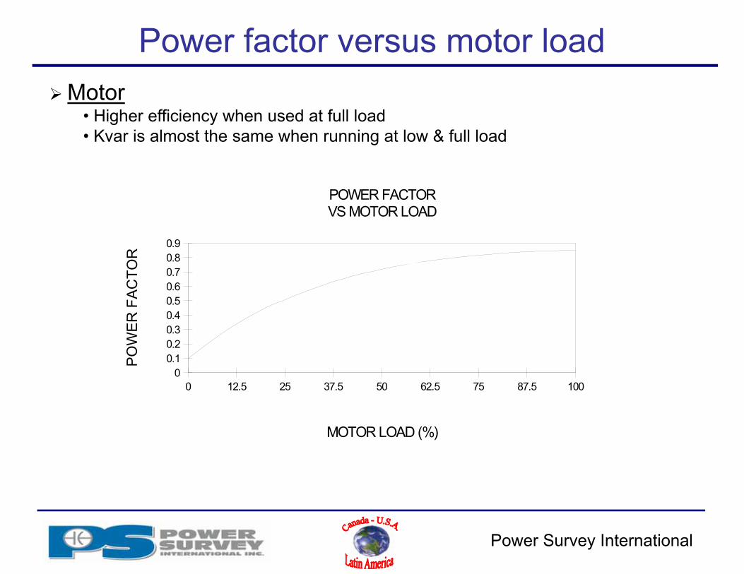
Power factor versus motor load
12.5 25 37.5 50 62.5 75 87.5 100
0.10.20.30.40.50.60.70.80.9
MOTOR LOAD (%)
PO
WE
R F
AC
T OR
POWER FACTORVS MOTOR LOAD
00
Motor• Higher efficiency when used at full load• Kvar is almost the same when running at low & full load
Power Survey International
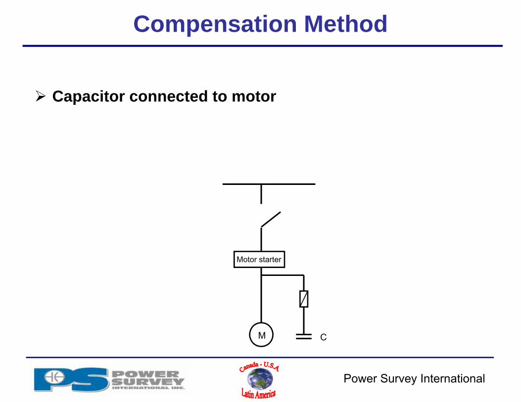
Compensation Method
Capacitor connected to motor
Motor starter
M C

Power Survey International
Compensation Method
Fixed capacitor connected to a PDC or MCC
Motor starter
M
Motor starter
M
C

Power Survey International
Motor compensation
Power Survey Rule of thumb:
Kvar = 1/3 of size of HP
Kvar = 40% of motor kW
Selection of a capacitor for a specific motor requires HP and RPM of motor:
Use following table

Power Survey International
Capacitor selection as per motor size
Power Survey International
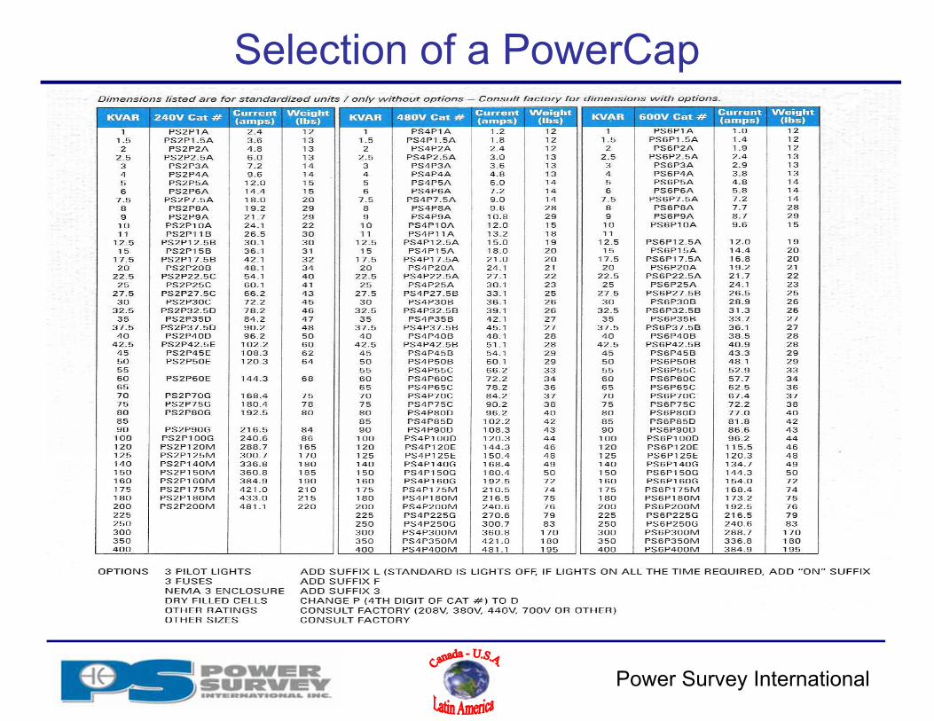
Selection of a PowerCap

Power Survey International
Back to back switching and reactor selection for inrush current
Transient Current calculation.lnk
Requirements• Transient current kept below 10 kA due to equipment rating( fuses, vacuum switches, etc)
Transient capacitor current•Inrush current from capacitor upon energization
Back to back switching• Charged capacitor discharging into newly energized capacitor
Power Survey International
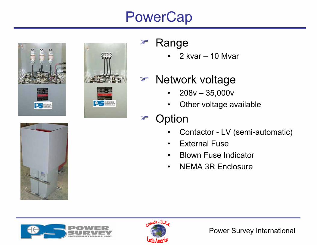
PowerCap
Range• 2 kvar – 10 Mvar
Network voltage• 208v – 35,000v• Other voltage available
Option• Contactor - LV (semi-automatic)• External Fuse• Blown Fuse Indicator• NEMA 3R Enclosure
Power Survey International
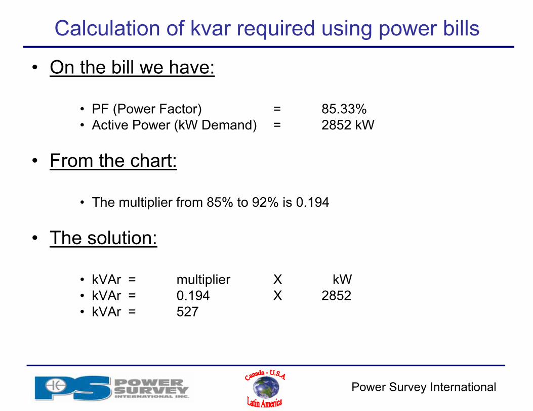
Calculation of kvar required using power bills
• On the bill we have:
• PF (Power Factor) = 85.33%• Active Power (kW Demand) = 2852 kW
• From the chart:
• The multiplier from 85% to 92% is 0.194
• The solution:
• kVAr = multiplier X kW• kVAr = 0.194 X 2852• kVAr = 527

Power Survey International
Before & After PF chart
Power Survey International
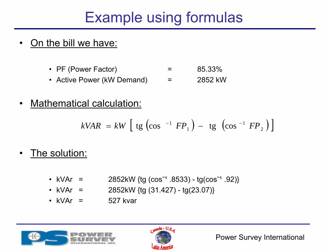
Example using formulas• On the bill we have:
• PF (Power Factor) = 85.33%• Active Power (kW Demand) = 2852 kW
• Mathematical calculation:
• The solution:
• kVAr = 2852kW {tg (cos¯¹ .8533) - tg(cos¯¹ .92)}• kVAr = 2852kW {tg (31.427) - tg(23.07)}• kVAr = 527 kvar
21
11 costgcostg FPFPkWkVAR
Power Survey International
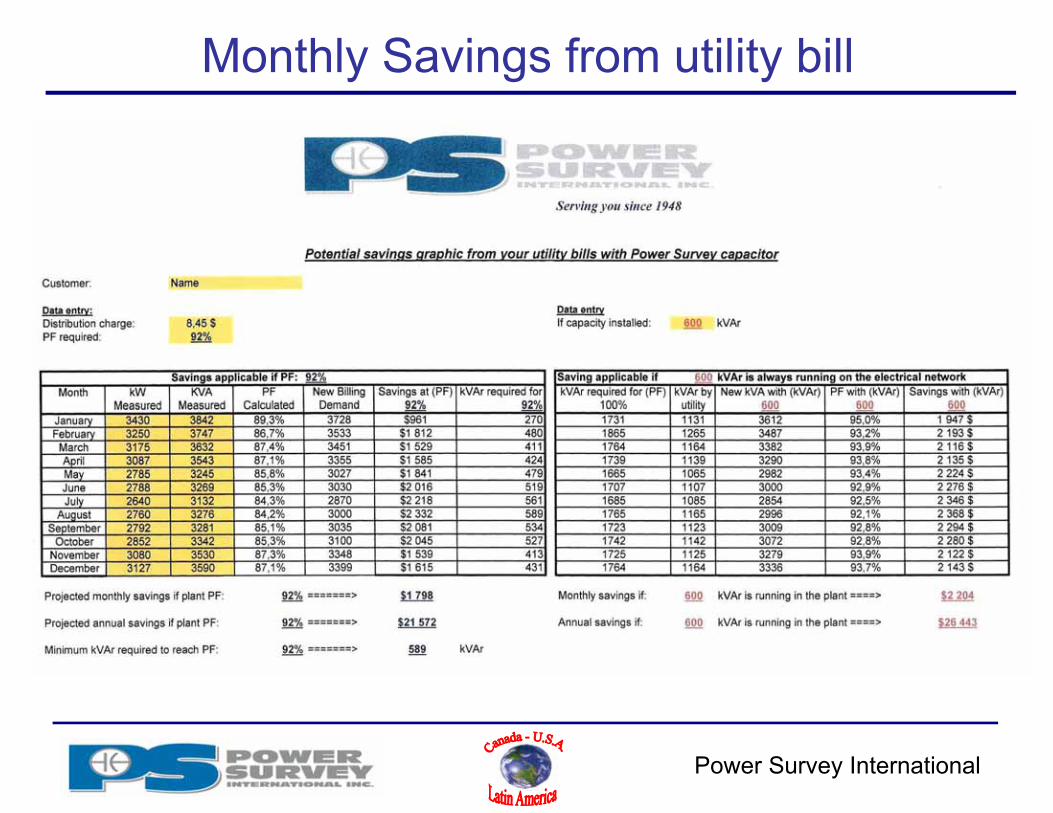
Monthly Savings from utility bill

Power Survey International
Solution to increase PF to 92%
• Propose an automatic capacitor bank:
Type: PowerVar Required power: 589 kVAr Suggested power: 600 kVAr Number of steps: 6 Power per step: 100
Power Survey International
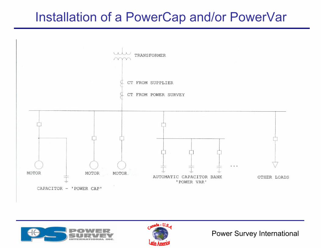
Installation of a PowerCap and/or PowerVar
Power Survey International
Required data for PFCC
The last 12 months electrical billing history and Rate structureMotors lists (HP Ratings, speed and type of
starters)Single line diagrams including:
Details on Non linear loads Transformer data (KVA , Z% ) Harmonic distortion data from measurement, if available

Power Survey International
PowerVar
Capacity• 50 kvar – 20 Mvar
Network voltage• 208v – 35,000v• Other voltages available
Option• NEMA 12 & 3R enclosure• Main breaker• Main disconnect• Main fuse disconnect• Ground switch• Blown fuse indicator• Capacitor Life Indicator

Power Survey International
Power Factor Controller
• Power Survey• PF indication and number of step• Energization sequence - FIFO• Manual and automatic selection• Up to 12 steps • Alarm if harmonic are overloaded• Power and Harmonic Measurement
Power Survey International
Harmonics !!
• Harmonic producing equipment:
• AC & DC Drive• Welder• Induction furnaces• Arc furnaces• Any equipment with thyristor• AC & DC rectifier• Etc
Power Survey International
Harmonics
By definition
• It is a current or voltage of a frequency that is a multiple of the fundamental (60HZ)
• 5th harmonic = 5 * 60 Hz = 300 Hz• It is NOT a TRANSIENT phenomenon
Power Survey International
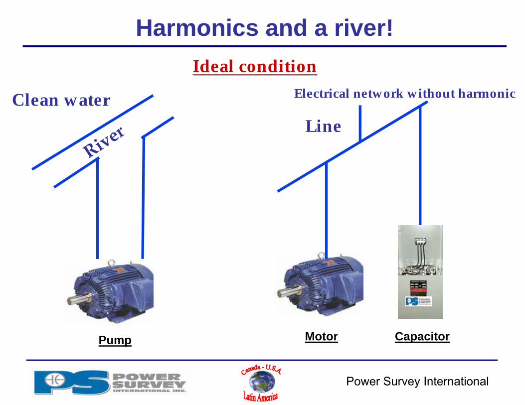
Ideal condition
Clean water Electrical network without harmonic
Line
Harmonics and a river!
Pump Motor Capacitor

Power Survey International
Polluted water
Polluted electrical network
Filterin
series
Reactorin
series
Protection of the installation
Non-ideal condition
Harmonic and a river!
Water pumpCapacitor
Power Survey International
Capacitor and harmonic
• Power Survey rule of thumb!
• Be careful! Is the total non linear load exceeding 20% of the total load?
– If not, ex. (100 HP of drive versus 1000 HP total [10%]):We will propose a PowerCap or PowerVar
– If yes, ex. (500 HP of drive versus 1000 HP total [50%]):We will propose a PowerCap filter or PowerVar filter
because of the high harmonic content
Power Survey International
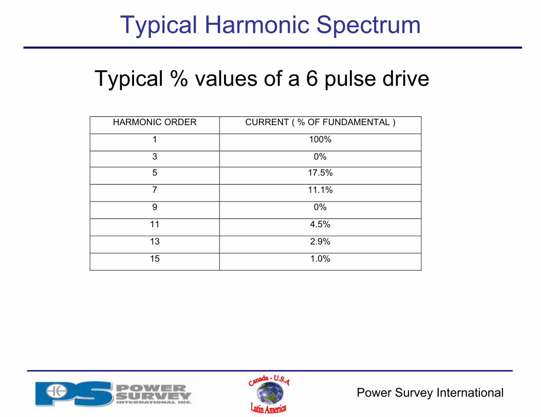
Typical Harmonic Spectrum
Typical % values of a 6 pulse drive
HARMONIC ORDER CURRENT ( % OF FUNDAMENTAL )
1 100%
3 0%
5 17.5%
7 11.1%
9 0%
11 4.5%
13 2.9%
15 1.0%
Power Survey International
Effect of harmonic distortions
Current distortion Equipment overheating and additional losses
• Transformers (eddy losses)• Cables (skin effect)• Capacitors (low impedance)• Resulting voltage distortion
Power Survey International
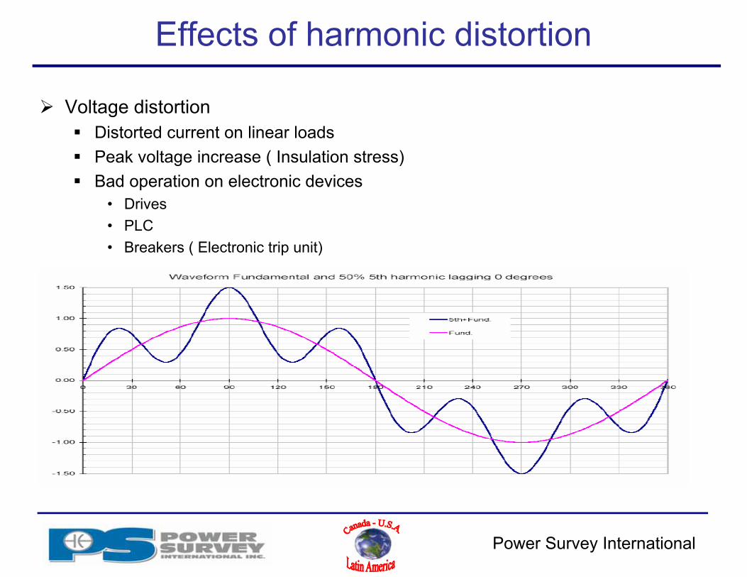
Effects of harmonic distortion
Voltage distortion Distorted current on linear loads Peak voltage increase ( Insulation stress) Bad operation on electronic devices
• Drives• PLC• Breakers ( Electronic trip unit)
Power Survey International
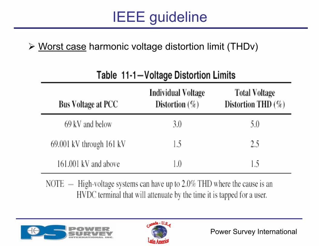
IEEE guideline
Worst case harmonic voltage distortion limit (THDv)
Power Survey International
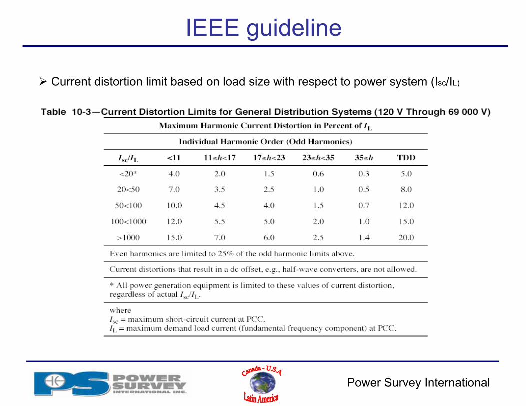
IEEE guideline
Current distortion limit based on load size with respect to power system (Isc/IL)

Power Survey International
Effects of harmonics distortion Parallel resonance
Occurs when system inductance reactance and capacitor reactance are equal at some frequency (5th, 7th, etc) Thus creating amplification of harmonic
currents between shunt capacitor and the power system reactance
Consequences Increase current harmonic distortion on
capacitor and transformer Increase voltage distortion throughout the
network
Results Burns fuses Capacitor failure or premature degradation Transformer overheating
Power Survey International
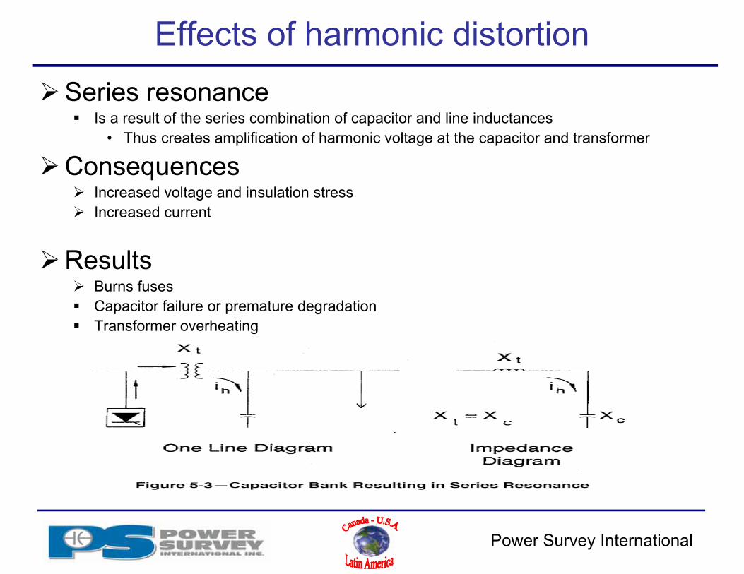
Effects of harmonic distortionSeries resonance
Is a result of the series combination of capacitor and line inductances• Thus creates amplification of harmonic voltage at the capacitor and transformer
Consequences Increased voltage and insulation stress Increased current
Results Burns fuses Capacitor failure or premature degradation Transformer overheating
Power Survey International
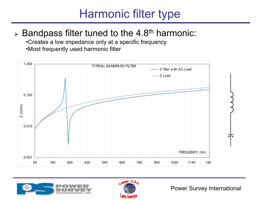
Harmonic filter type Bandpass filter tuned to the 4.8th harmonic:
•Creates a low impedance only at a specific frequency•Most frequently used harmonic filter
TYPICAL BANDPASS FILTER
0.001
0.010
0.100
1.000
60 180 300 420 540 660 780 900 1020 1140 126
FREQUENCY (Hz)
Z (O
hm)
Z f ilter w ith AC Load
Z Load
Power Survey International
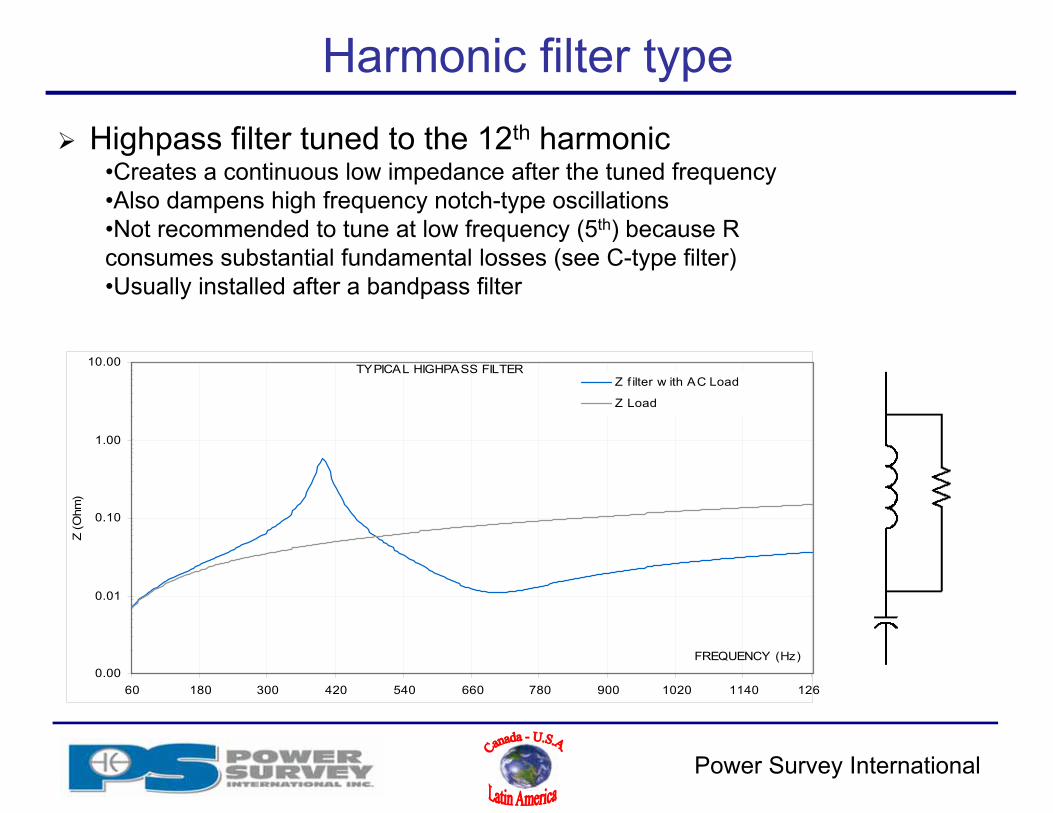
Harmonic filter type Highpass filter tuned to the 12th harmonic
•Creates a continuous low impedance after the tuned frequency•Also dampens high frequency notch-type oscillations•Not recommended to tune at low frequency (5th) because R consumes substantial fundamental losses (see C-type filter)•Usually installed after a bandpass filter
TYPICAL HIGHPASS FILTER
0.00
0.01
0.10
1.00
10.00
60 180 300 420 540 660 780 900 1020 1140 126
FREQUENCY (Hz)
Z (O
hm)
Z f ilter w ith AC Load
Z Load

Power Survey International
Harmonic filter type C-Type filter tuned to the 2nd harmonic:
•Similar performances characteristics to the highpass filter•Used for low tuning frequency•R consumes no fundamental losses at nominal parameters•Usually for arc furnace and cycloconverter application avoidingamplification of low order harmonic
TYPICAL C-TYPE FILTER
1.00
10.00
100.00
60 180 300 420 540 660 780 900 1020 1140 126
FREQUENCY (Hz)
Z (O
hm)
Z f ilter w ith AC Load
Z Load

Power Survey International
PFCC in presence of harmonics
Parallel resonance between system reactance (transformer + utility impedance) and the capacitor
Important: the natural frequency of the oscillating circuit must not correspond to the harmonic currents generated by the non linear loads

Power Survey International
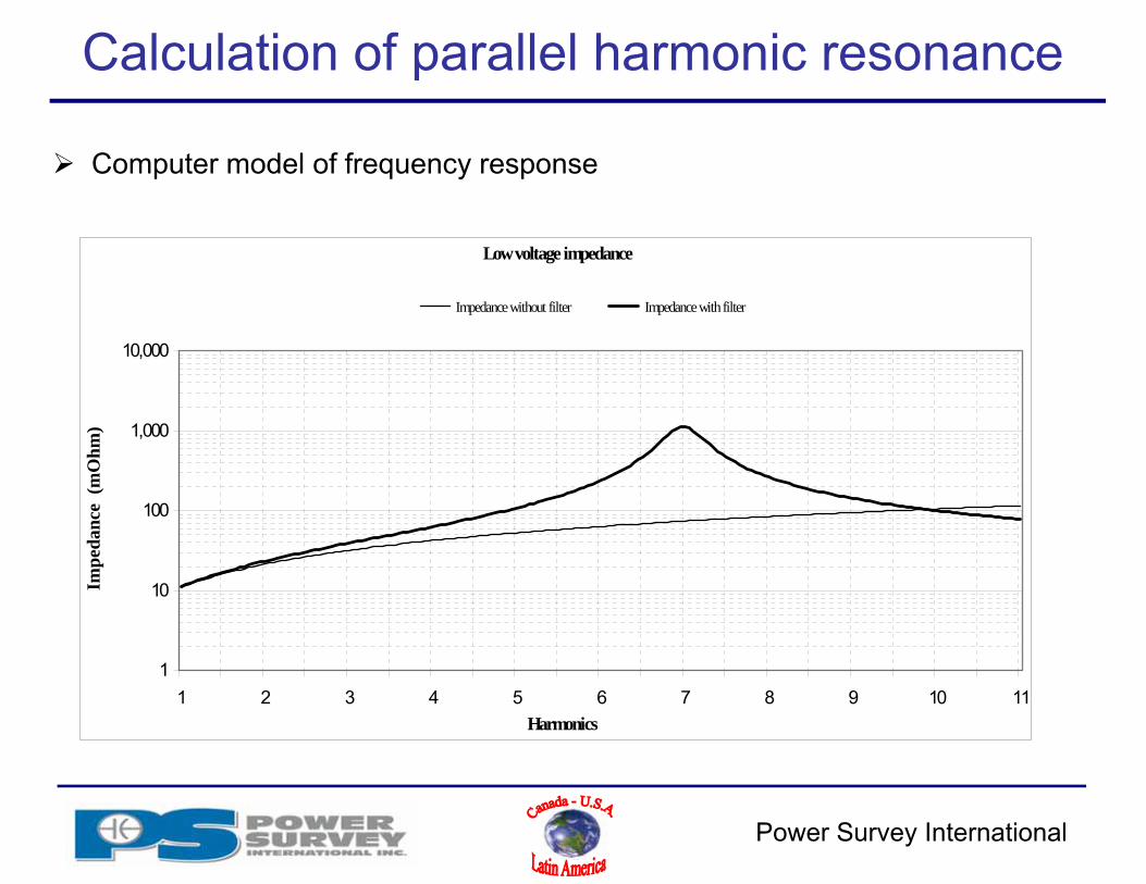
Calculation of parallel harmonic resonance
Electrical network equipment characteristics:• Transformer: 2000 KVA, 5.8%• Capacitor: 700 kvar to be installed• Drives: non linear loads consists of 50% of total load
Calculation using simple method• Fr = √{KVAsc / kvar}• Fr = √{(2000 KVA / .058)/700 kvar}• Fr = 7.02th harmonic
Harmonic resonance is precisely on the 7th harmonic:• Strong potential of harmonic problems
Power Survey International
Calculation of parallel harmonic resonance
Computer model of frequency response
Low voltage impedance
1
10
100
1,000
10,000
1 2 3 4 5 6 7 8 9 10 11Harmonics
Impe
danc
e (m
Ohm
)
Impedance without filter Impedance with filter

Power Survey International
Eliminating harmonic current resonance
Band pass filter:• Capacitor in series with a reactor
•Absorbs harmonic currents•Controls parallel resonance•Increase voltage at the capacitor bushing due to reactor:
(Nominal frequency/tuned frequency)²

Power Survey International
Eliminating harmonic current resonance
Computer model using a band pass filter tuned to 4.8th harmonic
TYPICAL BANDPASS FILTER
0.001
0.010
0.100
1.000
60 180 300 420 540 660 780 900 1020 1140 126
FREQUENCY (Hz)
Z (O
hm)
Z f ilter w ith AC Load
Z Load

Power Survey International
Potential harmonic problems: Yes/No?
Power Survey rule of thumb:
Resonance frequency calculation:• Fr = Should not be close to the 5th, 7th, 11th & 13th harmonic• Fr > 15th should be OK• Fr = Between 8th & 15th low potential problems• Fr < 8th high potential problems
Comparing non linear load vs total connected load• Non linear load vs total load > 20 % Be careful• Non linear load vs total load < 20 % Should be OK

Power Survey International
Flow of harmonic current
Power Survey International
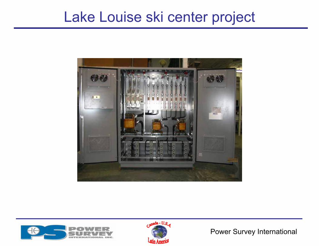
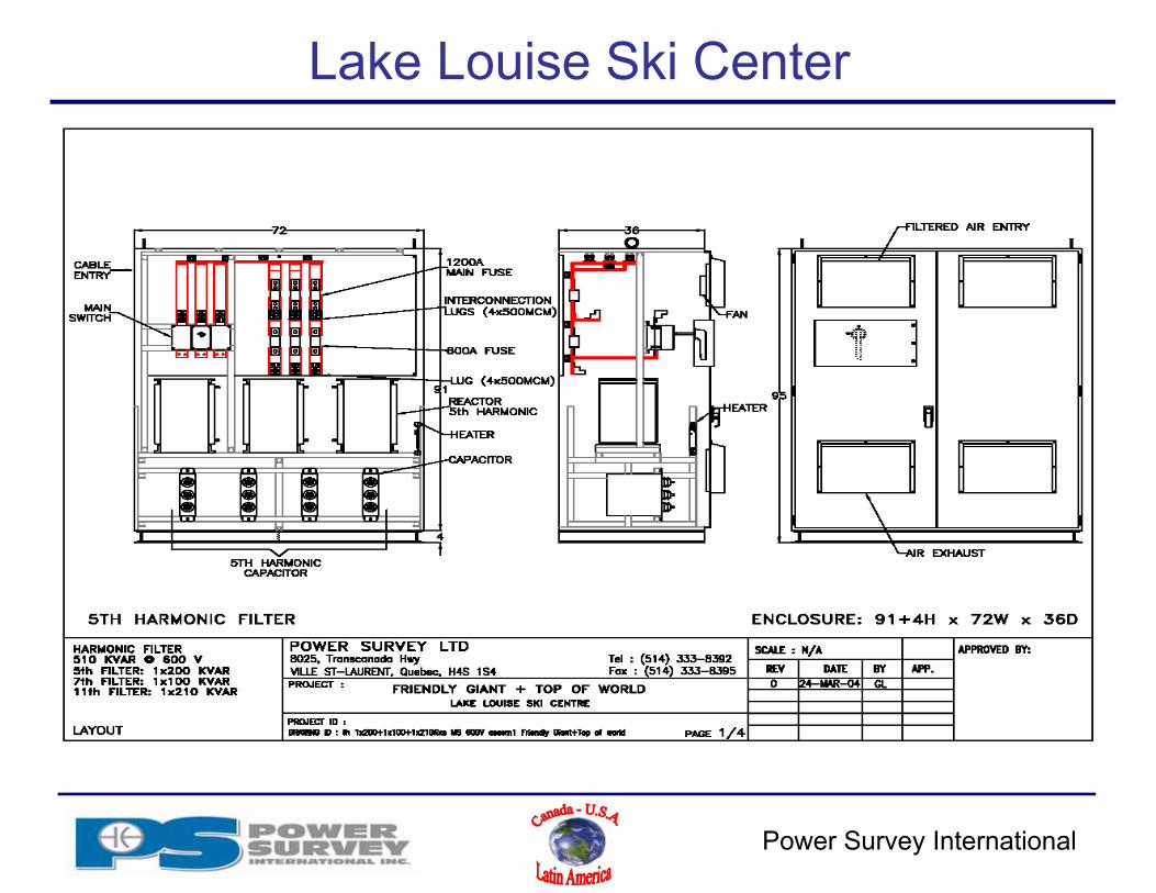
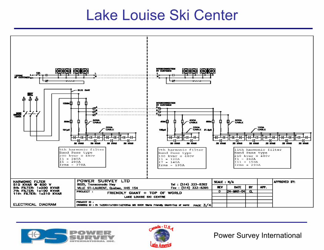
Lake Louise ski center project

Power Survey International
Lake Louise ski center projectETAP simulation
Power Survey International
Lake Louise Ski Center
Power Survey International
Lake Louise Ski Center

Power Survey International
Lake Louise Ski Center

Power Survey International
Harmonic filter components ratings - Capacitor
Capacitor Assemblies Rated in uF for harmonic filter application (not in kVAR) Standard capacitor rating:
• Voltage o Minimum 110% of Vn
• Current* o Minimum 130% of In for LVo Minimum 170% of In for MV
* Filter application – capacitor must withstand (Irms = √{I1² + I2² + I3² + I4² + I5²…..}• Current of an individual harmonic could be greater than I1
Tolerances should be kept to minimum (0 – 3%) because it will be added to L tolerance Internally fused MV capacitor
• Internal fuse operation causes less detuning Externally fused MV Capacitor
• Internal fault takes out the complete capacitor unit which can result in severe detuning and/or unbalance conditions when few units in //
• External fuse can be made of 50 kA current limiting and be equipped with an indicator transient and short time over voltage rating per IEEE 1036
Operating temperature; especially for Metal enclosed construction• Capacitor lifetime are affected by over temperature
Power Survey International
Harmonic filter components ratings - Capacitor
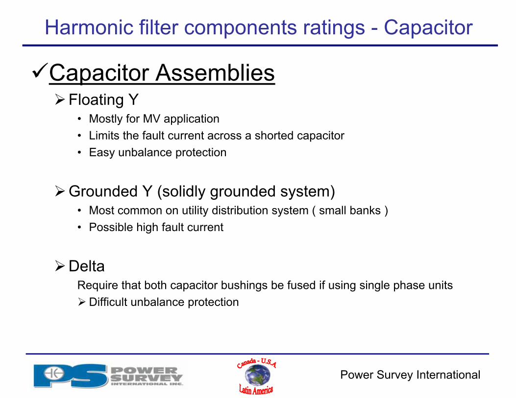
Capacitor AssembliesFloating Y
• Mostly for MV application• Limits the fault current across a shorted capacitor• Easy unbalance protection
Grounded Y (solidly grounded system)• Most common on utility distribution system ( small banks )• Possible high fault current
DeltaRequire that both capacitor bushings be fused if using single phase unitsDifficult unbalance protection

Power Survey International
Internally fused and externally fused capacitor

Power Survey International
Harmonic filter components ratings - Reactor
Reactor Assemblies Rated in uHy (not in kVAR or %) and tolerance ( 0 - 3% ) Calculation:
• Ftuned = 1/{(2π√(LC)}• L = {1/ 2πf}² * {1/C}
Rating:• Irms according to current to be absorbed by filter (Irms = √{I1² + I2² + I3² + I4² + I5²…..} • Current of an individual harmonic could be greater than I1
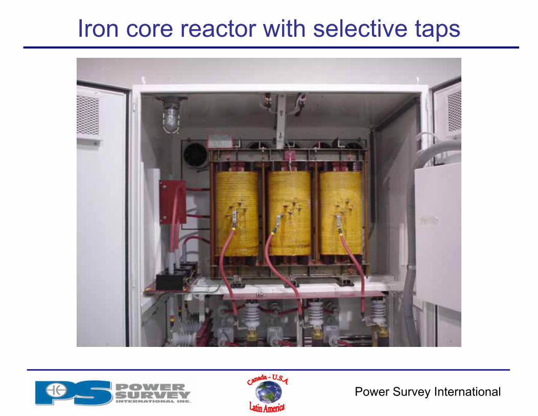
Iron core ( single phase or three phase )• More compact design and does not require magnetic clearance• More practical and cost effective with small banks where uHy value is high and space
limited.• Three phase reactor construction might show a slightly different B phase inductance, if fine
tuning is required single phase reactors should be considered. Air core
• Magnetic clearance makes it non practical for metal enclosed design• Usually more practical for large banks where current is high and uHy value is less
BIL rating for coil to ground and across the coil Q Factor should be specified at tuning frequency and at the fundamental ( most
reactor are only tested at 60 Hz ). Tolerance on Q Factor is typically of ±20% Taps are often practical for either fine tuning or provision for expansion
Power Survey International
Iron core reactor with selective taps
Power Survey International
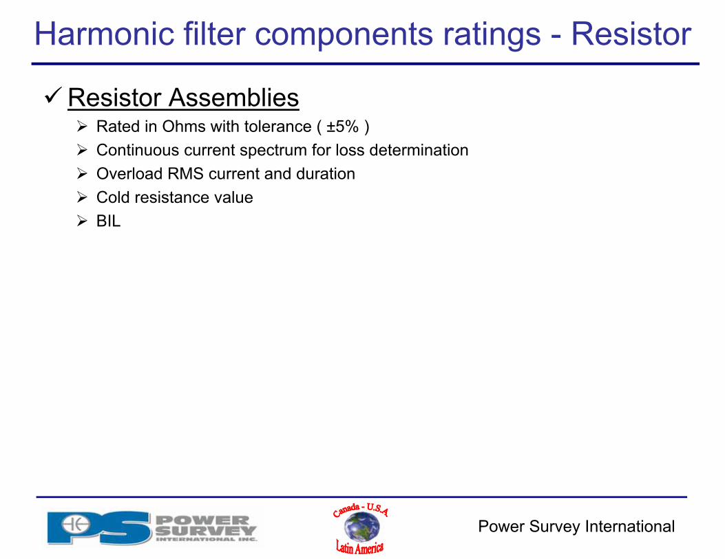
Harmonic filter components ratings - Resistor
Resistor Assemblies Rated in Ohms with tolerance ( ±5% ) Continuous current spectrum for loss determination Overload RMS current and duration Cold resistance value BIL
Power Survey International
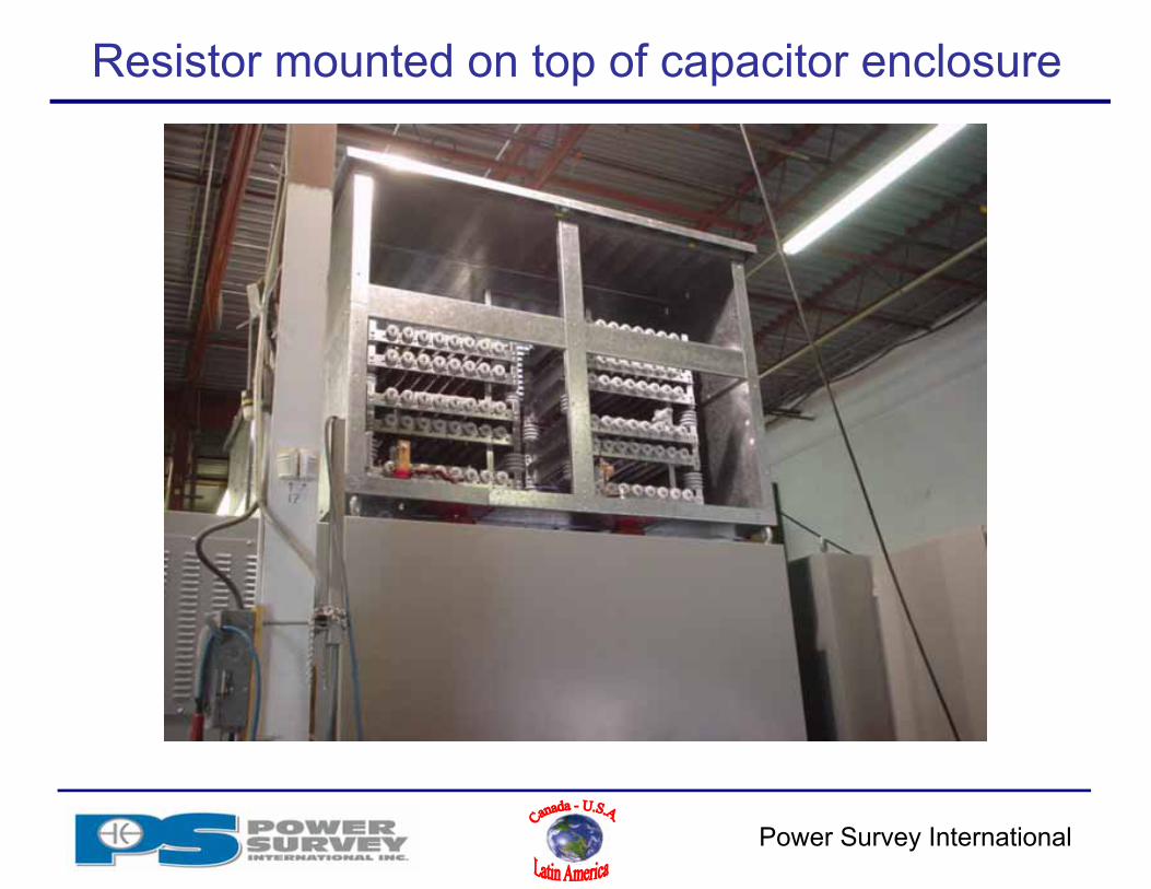
Resistor mounted on top of capacitor enclosure
Power Survey International
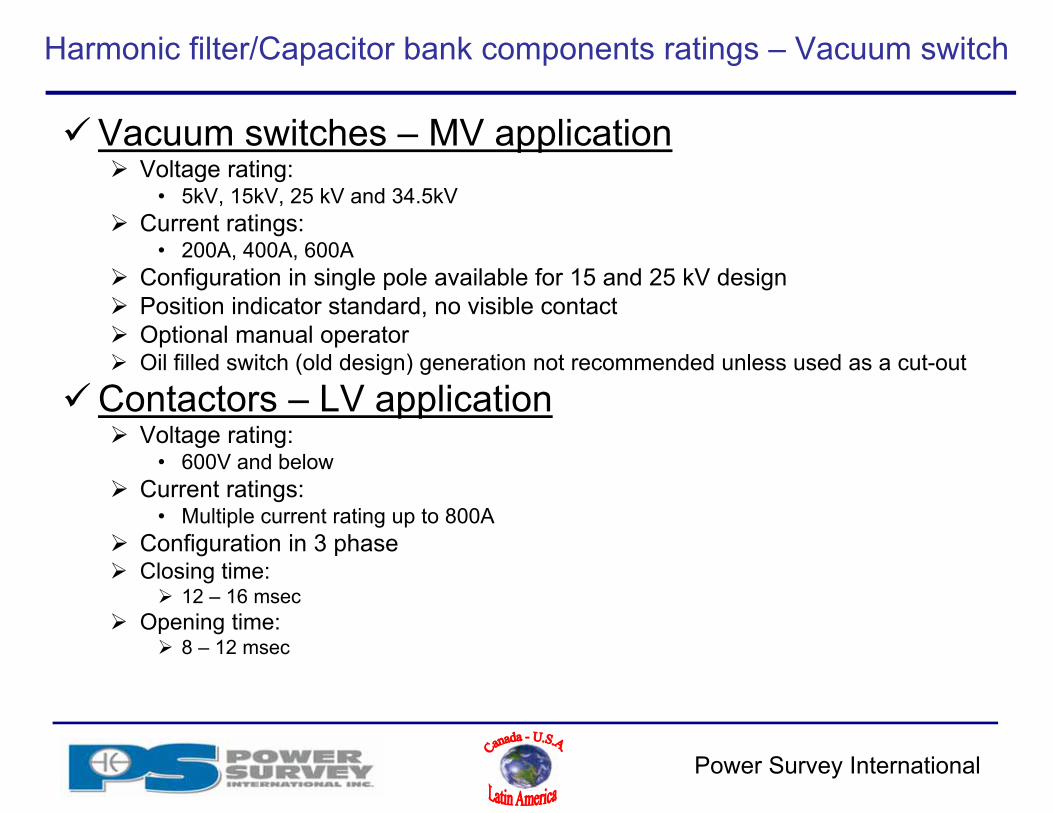
Harmonic filter/Capacitor bank components ratings – Vacuum switch
Vacuum switches – MV application Voltage rating:
• 5kV, 15kV, 25 kV and 34.5kV Current ratings:
• 200A, 400A, 600A Configuration in single pole available for 15 and 25 kV design Position indicator standard, no visible contact Optional manual operator Oil filled switch (old design) generation not recommended unless used as a cut-out
Contactors – LV application Voltage rating:
• 600V and below Current ratings:
• Multiple current rating up to 800A Configuration in 3 phase Closing time:
12 – 16 msec Opening time:
8 – 12 msec
Power Survey International
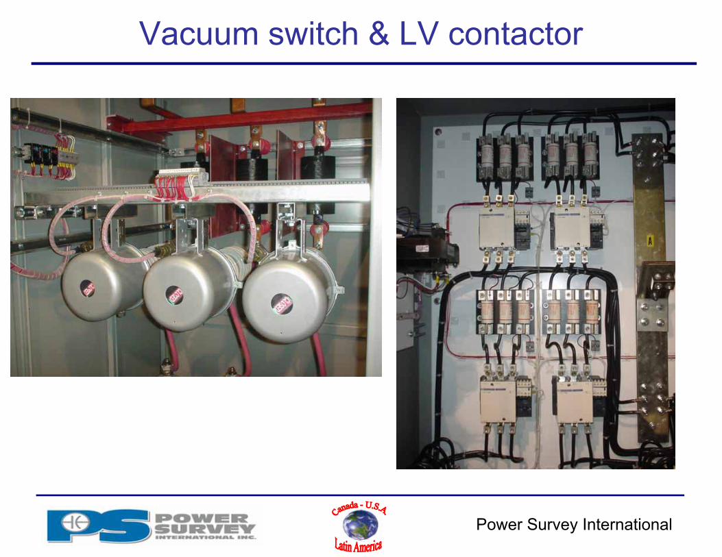
Vacuum switch & LV contactor
Power Survey International
Harmonic filter/Capacitor bank components ratings – Main & Ground switch
Main switch (LV & MV application) Rating:
• Minimum of 135% of Irms (could be up to 165% of In) MV switches usually has very low capacitive breaking current capability
• Vacuum switch is then used to open the capacitor circuit Used as an isolation switch and/or visible opening It can be fused for short circuit protection Kirk key interlock for safety reasons is normally provided between:
• vacuum switch• main switch• ground switch• cubicle doors
Ground Switch (MV application) Ground switch is provided as a safety features and insure full discharge of capacitors
Breaker (LV application) Rating:
• Minimum of 135% of Irms (LV application) Requires to know the short circuit capacity of network If it operate (trips) only needs to switch it back to ON

Power Survey International
LV main breaker & MV switch

Power Survey International
Harmonic filter/Capacitor bank components ratings – Fuse
Main fuse protection Rating:
• Usually 165% of In for capacitor application• Up to 250% of Irms for harmonic filter application
Provides short circuit protection only
Does not protect against overload
Stage fuse protection Rating:
• Usually 165% of In for capacitor application• Up to 250% of Irms for harmonic filter application
Stages or branches should be protected individually against short circuit MV fuses always have a visual trip indication and can be equipped with a
remote trip contact.
Power Survey International
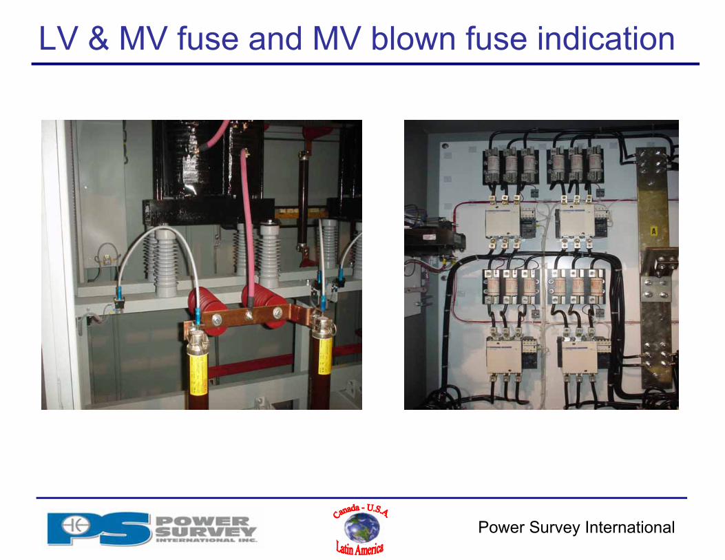
LV & MV fuse and MV blown fuse indication

Power Survey International
Safety – Capacitor / Filter protection
Overcurrent protection Relays used for overcurrent protection have to be true RMS style
• Electromechanical relays cannot be used. Tripping signal must be sent to either:
• main breaker• vacuum switches• never to a load break with shunt trip.
Thermal sensors imbedded in the reactors can also be used to detect filter overloading.
Over voltage current relaying Over voltage protection is rarely provided as it is usually part of the bus protection
Unbalance and detuning protection On loss of capacitance unbalance occurs through:
• neutral voltage sensing on floating Y capacitor where loss of capacitance will happens in large portion ( i.e. externally fused capacitors )
• Neutral current sensing used in a double floating Y configuration

Power Survey International
Neutral CT in a floating Y-Y
Power Survey International
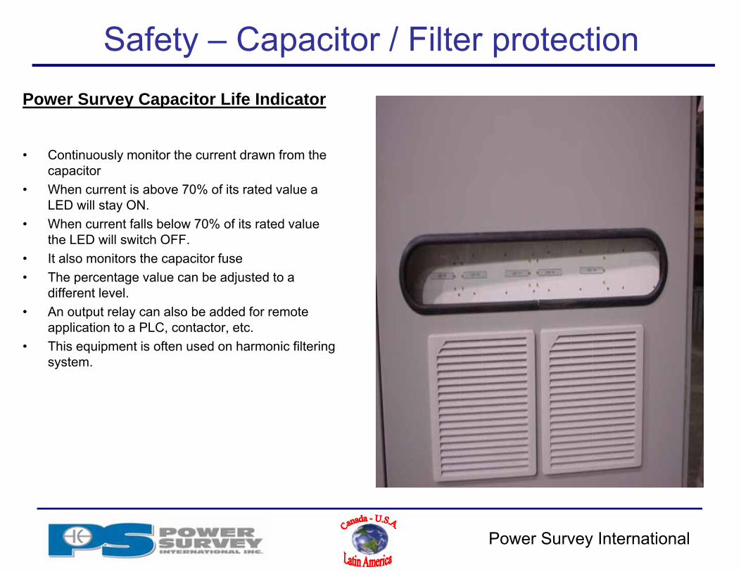
Safety – Capacitor / Filter protection
• Continuously monitor the current drawn from the capacitor
• When current is above 70% of its rated value a LED will stay ON.
• When current falls below 70% of its rated value the LED will switch OFF.
• It also monitors the capacitor fuse • The percentage value can be adjusted to a
different level.• An output relay can also be added for remote
application to a PLC, contactor, etc.• This equipment is often used on harmonic filtering
system.
Power Survey Capacitor Life Indicator
Power Survey International
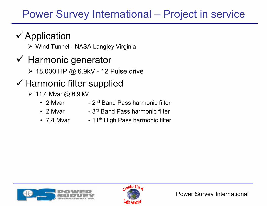
Power Survey International – Project in service
Application Wind Tunnel - NASA Langley Virginia
Harmonic generator 18,000 HP @ 6.9kV - 12 Pulse drive
Harmonic filter supplied 11.4 Mvar @ 6.9 kV
• 2 Mvar - 2nd Band Pass harmonic filter• 2 Mvar - 3rd Band Pass harmonic filter• 7.4 Mvar - 11th High Pass harmonic filter

Power Survey International
Power Survey International – Project in service
• NASA Langley Virginia Wind Tunnel

Power Survey International
Power Survey International – Project in service
Customer Tennessee Valley Authority - TVA
Harmonic filter supplied 13.5 Mvar @ 13.8 kV
• 5.2 Mvar – 5th Band Pass harmonic filter• 4 Mvar – 7th Band Pass harmonic filter• 2.3 Mvar - 11th Band Pass harmonic filter• 2 Mvar - 13th Band Pass harmonic filter

Power Survey International
Power Survey International – Project in service
• Tennessee Valley Authority - TVA
Power Survey International
Power Survey International – Project in service
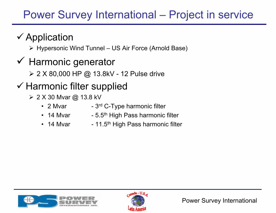
Application Hypersonic Wind Tunnel – US Air Force (Arnold Base)
Harmonic generator 2 X 80,000 HP @ 13.8kV - 12 Pulse drive
Harmonic filter supplied 2 X 30 Mvar @ 13.8 kV
• 2 Mvar - 3rd C-Type harmonic filter• 14 Mvar - 5.5th High Pass harmonic filter• 14 Mvar - 11.5th High Pass harmonic filter
Power Survey International
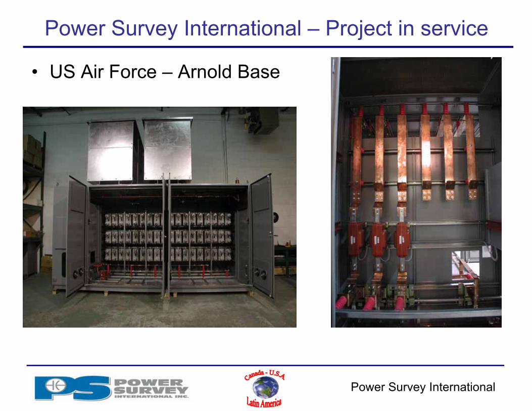
Power Survey International – Project in service
• US Air Force – Arnold Base

Power Survey International
Power Survey International – Project in service
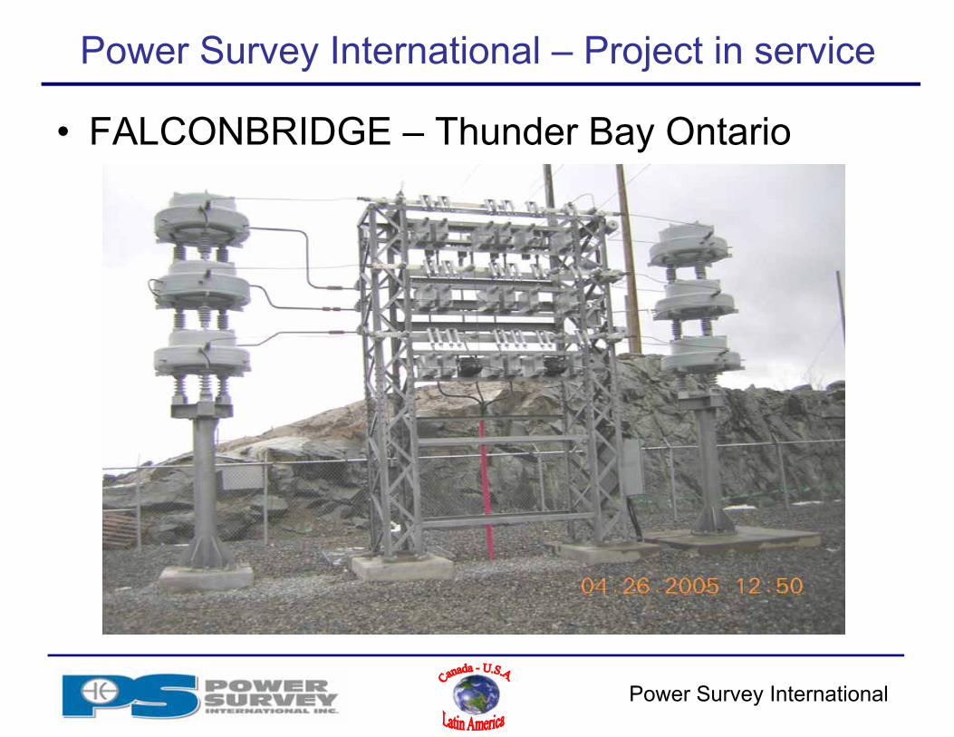
Customer Falconbridge zinc Mine – Thunder Bay, Ontario
Harmonic filter supplied – Rack mount type 3.8 Mvar @ 13.8 kV
• 1.9 Mvar – 4.9th Band Pass harmonic filter (fixed)• 1.9 Mvar – 4.9th Band Pass harmonic filter (switched)
Power Survey International
Power Survey International – Project in service
• FALCONBRIDGE – Thunder Bay Ontario

Power Survey International
Power Survey Harmonic filter
Capacity• 50 kvar to 20 Mvar
Network voltage• 208v – 35,000v• Other voltages available
Option• NEMA 12 & 3R enclosure• Main breaker• Main disconnect• Main fuse disconnect• Ground switch (MV application)• Capacitor Life indicator• Blown fuse indicator

Power Survey International
Capacitor and harmonic filter references/standard
IEEE 1531• Guide for Application and Specification of Harmonic Filters
IEEE 18• Standard for Shunt Power Capacitors
IEEE C37.99• Guide for Protection of Shunt Capacitor Banks
IEEE 519• Recommended Practices and Requirements for Harmonic Control in
Electrical Power Systems
IEEE 1036• Guide for Application of Shunt Power Capacitors
IEEE C37.012 • Application Guide for Capacitance Current Switching
Power Survey International
Potential Market - Industrial
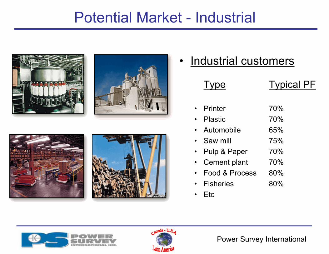
• Industrial customers
Type Typical PF
• Printer 70%• Plastic 70%• Automobile 65%• Saw mill 75%• Pulp & Paper 70%• Cement plant 70%• Food & Process 80%• Fisheries 80%• Etc

Power Survey International
Potential Market - Commercial
• Commercial customers
Type Typical PF
• Office tower 85%• Shopping center 80%• Grocery store 80%• Arena 75%• Pump station 75%• Hospital 80%• Etc
Power Survey International
References
• Falconbridge• Québécor printing• Nortel• Kruger• Canadian Forest Products• Johnson & Johnson• NASA• Olympic stadium• US Air Force, Arnold Base• JFK Airport
• Chrysler• Hyundai• Vancouver WWTP• Lafarge• US Navy• Shell• Good Year• Bowater• Etc

Power Survey International
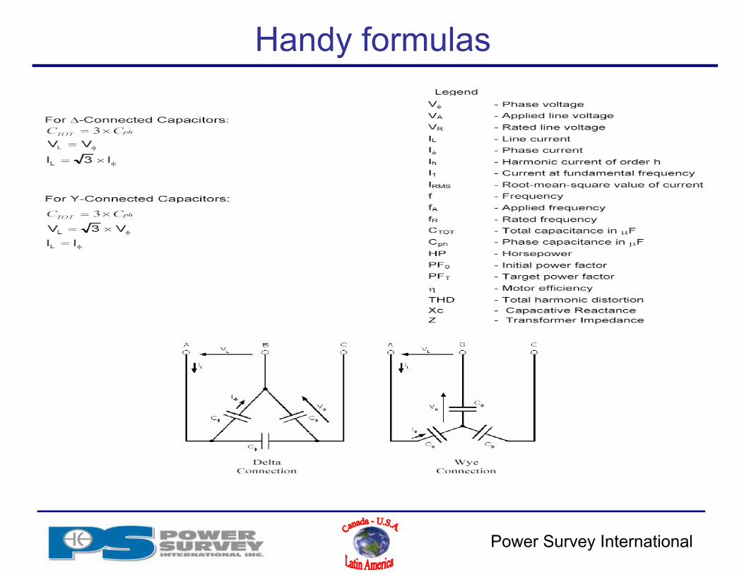
Handy formulas
Power Survey International
Handy formulas
Power Survey International
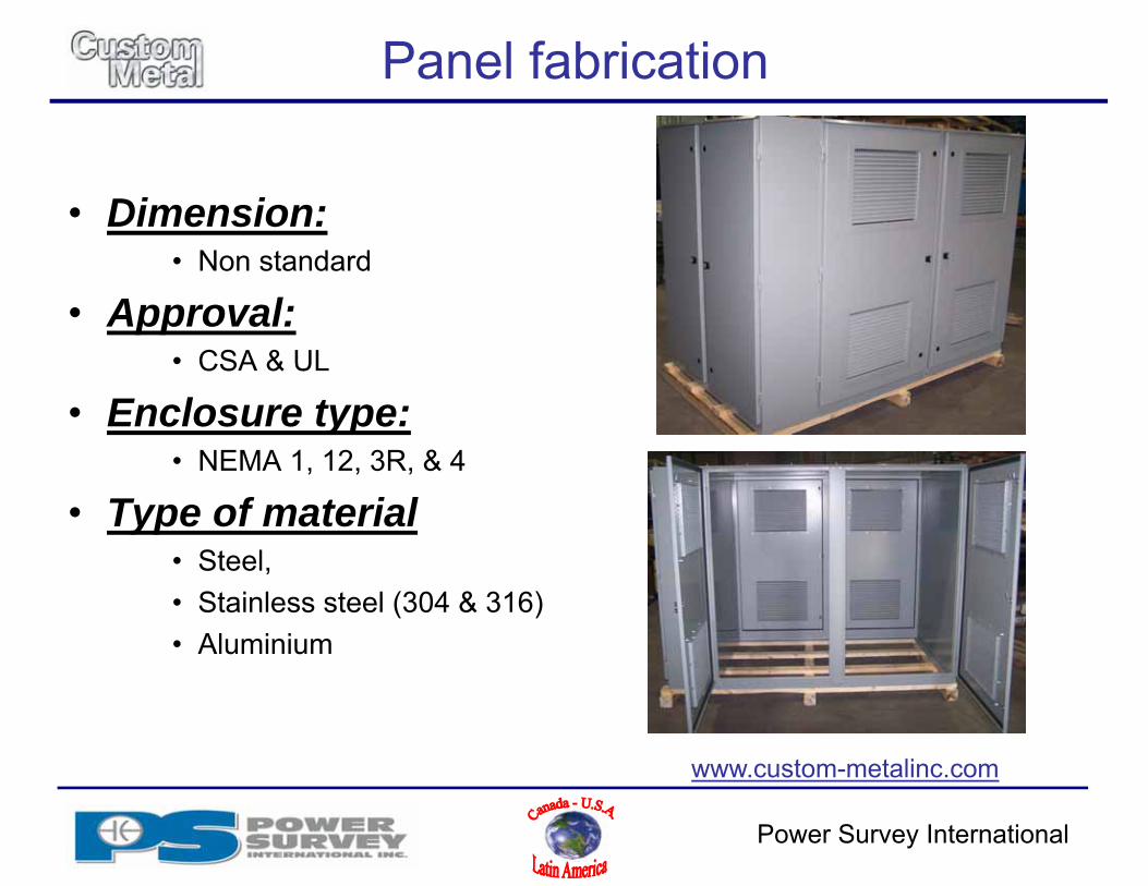
Panel fabrication
• Dimension:• Non standard
• Approval:• CSA & UL
• Enclosure type:• NEMA 1, 12, 3R, & 4
• Type of material• Steel,• Stainless steel (304 & 316)• Aluminium
www.custom-metalinc.com
Related Documents


![Introduction to KZ mechanism[File: Viewgraphs New/KibbleZurek/KZ- MechanismIntro.ai]](https://static.cupdf.com/doc/110x72/5697bf9c1a28abf838c9308b/introduction-to-kz-mechanismfile-viewgraphs-newkibblezurekkz-mechanismintroai.jpg)