0 0 ) PART 2- GENERAL CONSTRUCTION WORK ) J 0

Welcome message from author
This document is posted to help you gain knowledge. Please leave a comment to let me know what you think about it! Share it to your friends and learn new things together.
Transcript

0
0
)
PART 2- GENERAL CONSTRUCTION WORK)
J
0
()

SECTION 02070 - SELECTIVE DEMOLITION
PART 1 -GENERAL
1.1 RELATED DOCUMENTS
A. Drawings and general provisions of the Contract, including General and Supplementary Conditions and Division 1 Specification Sections, apply to this Section.
1.2 DESCRIPTION OF WORK0
A. Extent of selective demolition work is indicated on drawings.
B. Types of Selective Demolition Work : Demolition requires the selective removal and subsequent offsite disposal of the following:
0 1. Portion(s) of building structure, as indicated on drawings and as required, toaccommodate new construction.
2. Removal of suspended acoustical tiles (grid to remain), as indicated on drawings.
J 3. Removal of flooring, base and adhesives, as indicated on drawings.
4. Removal of exhibition boards, paper towel dispensers, wall mounted shelving, etc.,as .
indicated on drawings and turn over to the Owner.
5. Removal and protection of existing fixtures and equipment items indicated as "salvage".
C. Removal Work Specified Elsewhere :
1. Roofing repair work is the responsibility of this contract. This contract is responsible to have the roofing contractor (separate contract) perform the work.
2. Cutting non-structural concrete floors for underground piping is included with the workof the respective mechanical Division 15 specification sections.
D. Related Work Specified Elsewhere:
1. Remodeling construction work and patching is included within the respective sections)
of specifications, including removal of materials for re-use and incorporated intoremodeling or new construction.
1.3 SUBMITIALS
0 A. Proposed Demolition Activities: Submit schedule indicating proposed methods andsequence of operations for selective demolition work to Owner's Representative for reviewprior to commencement of work. Provide starting and ending dates for each activity as appropriate.
1. Include coordination for shut-off, capping, and continuation of utility services asu required, together with details for dust and noise control protection.
FVHD-4810 2:02070-1
(J

,,
)2. Provide detailed sequence of demolition and removal work to ensure uninterrupted
progress of Owner's on-site operations.
3. Sequence construction so as to minimize obstruction of exits and provide temporaryalternate exits, as required by authorities having jurisdiction.
4. Coordinate with Owner's continuing occupation of portions of existing building, andwith Owner's reduced usage during summer months.
B. Photographs: Photograph existing conditions of structure, surfaces, equipment or surrounding properties which could be misconstrued as damage resulting from selective demolition work; file with Owner's Representative prior to starting work.
C. Project Record Documents:
1. Indicate unanticipated structural, electrical, or mechanical conditions.
1.4 JOB CONDITIONS
A. Occupancy: Owner will be continuously occupying areas of the building immediately adjacent to areas of selective demolition. Conduct selective demolition work in manner that will minimize need for disruption of Owner's normal operations. Provide minimum of 72hours advance notice to Owner of demolition activities which will severely impact Owner's )normal operations.
B. Condition of Structures: Owner assumes no responsibility for actual condition of items or strqctures to be demolished.
1. Conditions existing at time of commencement of contract will be maintained by Owner insofar as practicable. However, variations within structure may occur by Owner's removal and salvage operations prior to start of selective demolition work.
C. Protections: Provide temporary barricades and other forms of protection as required toprotect Owner's personnel and general public from injury due to selective demolition work. )
1. Provide protective measures as required to provide free and safe passage of Owner's personnel and general public to and from occupied portions of building.
2. Protect existing finish work, from being damaged during the project, which is to remain in place and becomes exposed during demolition operations .
3. Protect floors with suitable coverings so as to leave the flooring in same condition atend of job.
4. Construct temporary insulated solid dustproof partitions, where required, to separate areas where noisy or extensive dirt or dust operations are performed. Equip partitions with dustproof doors and security locks, if required.
5. Remove protections at completion of work.
D. Damages: Promptly repair damages caused to adjacent facilities by demolition work at no cost to Owner, including but not limited to concealed interior and exterior utility lines not properly investigated by the contractor, prior to commencement of demolition work. .
FVHD-4810 2:02070-2

E. Traffic: Conduct selective demolition operations and debris removal in a manner to ensure minimum interference with roads, streets, walks, and other adjacent occupied or used facilities.
1. Do not close, block or otherwise obstruct streets, walks or other occupied or used facilities without written permission from authorities having jurisdiction. Provide alternate routes around closed or obstructed traffic ways if required by governing regulations.
F. Explosives: Use of explosives will not be permitted.
G. Utility Services: Maintain existing utilities indicated to remain, keep in service, and protectagainst damage during demolition operations.
1. Do not interrupt existing utilities serving occupied or used facilities, except whenauthorized in writing by authorities having jurisdiction. Provide temporary services
0 during interruptions to existing utilities, as acceptable to governing authorities.
PART 2 ·PRODUCTS (Not Applicable).
PART 3 ·EXECUTION
3.1 INSPECTION
A. Prior to commencement of selective demolition work, inspect areas in which work ilL be performed.
)
1. Photograph existing conditions of structure, surfaces, equipment or surrounding properties which could be misconstrued as damage resulting from selective demolition work; file with Owner's Representative prior to starting work.
2. Commencement of work shall constitute acceptance of conditions. Any necessary remedial work required to correct any unsatisfactory conditions, found after the start of installation, will be provided at no cost to the Owner.
3. Prior to the commencement of work review the demolition activities with the Owner's representative to identify additional salvage items requested by the Owner.
3.2 PREPARATION
A. Cover and protect furniture, equipment and fixtures to remain from soiling or damage when demolition work is performed in rooms or areas from which such items have not been removed.
0B. Erect and maintain dust-proof partitions and closures as required to prevent spread of dust
or fumes to occupied portions of the building.
t,.) .1. Where selective demolition occurs immediately adjacent to occupied portions of the
building, construct dust-proof partitions of minimum 4" studs, 5/8" drywall (joints taped) on occupied side, 1/2'' fire-retardant plywood on demolition side, and fill partition cavity with sound-deadening insulation.
FVHD-4810 2:02070·3
(J

)
2. Provide weatherproof closures for exterior openings resulting from demolition work.
C. Locate, identify, stub off and disconnect utility services that are not indicated to remain.
1. Provide by-pass connections as necessary to maintain continuity of service to occupied · )areas of building. Provide minimum of 72 hours advance notice to Owner if shut-down of service is necessary during change-over.
3.3 DEMOLITION
A. Perform selective demolition work in a systematic manner. Use such methods as required Jto complete work indicated on Drawings in accordance with demolition schedule andgoverning regulations.
1. Demolish concrete and masonry in small sections. Cut concrete and masonry at junctures with construction to remain using power-driven masonry saw or hand tools; do not use power-driven impact tools.
a. The Contractor shall use caution when cutting into existing masonry construction (eg.:concrete slabs, single wythe and cavitywall construction) as there may be un- · documented utilities within the cavity or built into the cores of emu wall
· construction or under the floor slab. The contractor shall perform all necessaryinvestigation prior to demolition work to determine the presence of existingutilities within construction to be demolished, including but not limited to radar, thermal, impact echo, etc. The Contractor shall pay for restoring I repairing theexisting construction if utilities are cut and proper selective demolitioninvestigation work was not pe.rformed. Refer to Section 01050.
2. Locate demolition equipment throughout structur e and promptly remove debris toavoid imposing excessive loads on supporting walls, floors or framing.
3. Provide services for effective air andwater pollution controls as required by authoritieshaving jurisdiction. )
4. For interior slabs on grade, use removal methods that will not crack or structurallydisturb adjacent slabs or partitions. Use power saw where possible.
5. Completely fill below-grade areas and voids resulting from demolition work. ·Provide fill consisting of approved earth, gravel or sand, free of trash and debris, stones over 6" diameter, roots or other organic matter.
B. If unanticipated mechanical, electrical or structural elements which conflict with intended function or design are encountered, investigate and measure both natur e and extent of the conflict. Submit report to Owner's Representative I Architect in written, accurate detail.Pending receipt of directive from Owner's Representative I Architect rearrange selectivedemolition schedule as necessary to continue overall job progress without delay.
3.4 SALVAGE MATERIALS
A. Salvage Items: Where indicated on Drawings as "Salvage-Deliver to Owner", carefully remove indicated items, clean,store and turn over to Owner and obtain receipt.
FVHD-4810 2:02070-4

1. Unless otherwise indicated all materials, items, equipment, etc. resulting fromdemolition work shall be removed from the site at the Contractor's expense.
B. Historic artifacts, including cornerstones and their contents, commemorative plaques andtablets, antiques, and other articles of historic significance remain the property of the Owner.
0 Notify Owner's Representative if such items are encountered and obtain acceptanceregarding method of removal and salvage for Owner.
3.5 DISPOSAL OF DEMOLISHED MATERIALS
A. Remove debris, rubbish and other materials resulting from demolition operations from(1 building site. Transport and legally dispose of materials off site.
B. If hazardous materials are encountered during demolition operations, notify the Owner's Representative immediately, comply with applicable regulations, laws, and ordinances concerning removal, handling and protection against exposure or environmental pollution.
0 C. Burning of removed materials is not permitted on project site.
3.6 CLEAN-UP AND REPAIR
A. Upon completion of demolition work, remove tools, equipment and demolished materials(J from site. Remove protections and leave interior areas broom clean.
B. Repair demolition performed in excess of that required. Return structures and surfaces to remain to condition existing prior to commencement of selective demolition work. Repair adjacent construction or surfaces soiled or dama_ged by selective demolition work.
)
END OF SECTION 02070
(
(J
0
0
FVHD-4810 2:02070·5
0

)
)
)
)
)
()
)

0
SECTION 03300 ·CONCRETE WORK
PART 1 ·GENERAL
() 1.1 RELATED DOCUMENTS
A. Drawings and general provisions of Contract, including General and Supplementary Conditions and Division-1 Specification sections, apply to work of this section.
1.2 SUMMARY0
A. Extent of concrete floor slab infill work is shown on the drawings.
1.3 SUBMITTALS
A. Product Data: Submit data for proprietary materials and items, including reinforcement andforming accessories, admixt ures, patching compounds and others as required by Architect.
B. Samples: Submit samples of materials as requested by Architect, including names, sources and descriptions.
0 C. Laboratory Test Reports: Submit laboratory test reports for concrete materials and mix designtest.
D. Materials Certificates: Provide materials certificates in lieu of materials laboratory test reports when permitted. by Architect. Materials certificates shall be signed by manufacturer and Contractor, certifying that each material item compli s with, or exceeds, specified
) requirements. Provide certification from admixture manufacturers that chloride contentcomplies with specification requirements.
E. Shop Drawings: Reinforcement: Submit shop drawings for fabrication, bending and placement of concrete reinforcement. Comply with ACI 315 "Manual of Standard Practice for Detailing Reinforced Concrete Structures" showing bar schedules, stirrup spacing diagrams of bent bars, arrangement of concrete reinforcement.
1.4 QUALITY ASSURANCE
A. Codes and Standards: Comply with provisions of following codes, specifications andstandards, except where more stringent requirements are shown or specified :
ASTM C94/C94M "Specification for Ready-Mixed Concrete"
ACI 117 "Tolerances for Concrete Construction and Materials"
0 ACI 211.1 "Standard Practice for Selecting Proportions for Normal, Heavyweight, and Mass Concrete"
ACI 301/301M "Structural Concrete for Buildings."
ACI 302.1R "Guide for Concrete Floor and Slab Construction"0
ACI 304R-OO "Guide for Measuring, Mixing, Transporting and Placing Concrete"
FVHD-4810 2:03300-1
0

)ACI305R "Hot Weather Concreting"
ACI 308.1 "Standard Specification for Curing Concrete"
ACI 3 11.1R "ACI Manual of Concrete Inspection (SP-2)")
A CI3 11.4R "Guide for Concrete Inspection"
ACI 3 18 "Building Code Requirements for Reinforced Concrete", except as modified in accordance with International Building Code.
Concrete Reinforcing Steel Institute, "Manual of Standard Practice." }
B. Concrete Testing Service:The Contractor shall engage a testing laboratory acceptable toArchitect to perform material evaluation tests and to design concrete mixes.
C. Materials and installed work may require testing and retesting at anytime during progress of work. Tests, including retesting of rejected materials for installed work, shall be done at Contractor's expense.
D. Installation of Vapor Barrier: Installation shall be in accordance with manufacturer's direction and in compliance with ASTM E 1745 "Standard Practice for Installation of Water Vapor Retarders Used in Contact with Earth or Granular Fill Under Concrete Slabs".
PART 2 -PRODUCTS
2.1 REINFORCING MATERIALS
A Reinforcing Bars: ASTM A 615, Grade 60, deformed.
B. Steel Wire: ASTM A 82, plain, cold-drawn steel.
C. Welded Wire Fabric: ASTM A 185, welded steel wire fabric .
D. Welded Deformed SteelWire Fabric: ASTM A 497.
E. Supports for Reinforcement: Bolsters, chairs, spacers and other devices for spacing, supporting and fastening reinforcing bars and welded wire fabric in place. Use wire bar type supports complying with CRSI specifications.
2.2 CONCRETE MATERIALS
A Portland Cement: ASTM C 150,Type I or Type II.
1. Use one brand of cement throughout project, unless otherwise acceptable to Architect.
B. Normal Weight Aggregates: ASTM C 33, and as herein specified. Provide aggregates froma single source for exposed concrete.
C. Water: Drinkable.)
FVHD-4810 2:03300-2
)

(}D. Water-Reducing Admixture: ASTM C 494, Type A, and containing not more than 0.05
percent chloride ions.
1. Products: Subject to compliance with requirements, provide one of the following:
(} "WRDA" Hycol"; W.R. Grace."Eucon WR-75" or "Eucon WR-89"; Euclid Chemical Co. "Pozzolith 322N"; Master Builders."Piastocrete"; Sika Corp.
E. Water-Reducing, Non·Chloride Accelerator Admixture: ASTM C 494, Type E, and containing0 not more than 0.024 percent chloride ions.
1. Products: Subject to compliance with requirements, provide one of the following:
"Accelguard 80"; Euclid Chemical Co.
() "Daraset"; W.R. Grace
F. Water-Reducing, Retarding Admixture: ASTM C 494, Type D and containing not more than0.05 percent chloride ions.
1. Products: Subject to compliance with requirements, provide one of the following:)
"Pozzolith Retarder"; Master Builders. "Eucon Retarder 75"; Euclid Chemical Co. "Daratard 17"; W.R. Grace."Piastocrete 161R";·Sika Corporation.
} G. Prohibited Admixtures: Calcium chloride thyocyanates or admixtures containing more than0.05 percent chloride ions are not permitted.
2.4 RELATED MATERIALS
( A. Non-Shrink Grout: CRD-C 621, factory pre·mixed grout.
1. Subject to compliance with requirements, products which may be incorporated in thework include, but are not limited to, the following:
a. Non-metallic:
"Masterflow 713"; Master Builders "Euco-NS"; Euclid Chemical Co."Five Star Grout"; U.S. Grout Corporation.
B. Absorptive Cover: Burlap cloth made from jute or kenaf weighing approximately 9 oz. per0 sq. yd., comply ing with AASHTO M 182, Class 2.
C Moisture-Retaining Cover: One of the following, complying with ASTM C 171.
1. Waterproof paper.2. Polyethylene film.
0 3. Polyethylene-coated burlap.
FVHD-4810 2:03300-3
0

D Vapor Barrier: Provide vapor barrier cover over prepared base material where indicated. Use only materials which are resistant to decay when tested in accordance with the following:
1. Thickness: 15 mils.
2. Permeance: ASTM E 96; .01 perms before and after conditioning and in accordance with ASTM E 1745 Class A requirements and ATM E 154 for mandatory conditioning tests.
3. Puncture Resistance: ASTM D 1 709; 2200 grams.
4. Chemical Resistance: ASTM E 154, unaffected.)
5. Life Expectancy: ASTM E 154, indefinite.
6. Subject to compliance with requirements, products which may be incorporated in thework include, but are not limited to, the following:
)a. "Wrap 15·mil "Vapor Barrier; Stego Industries, LLC.b. "Perm inator 15-mil", W.R. Meadows;.c. "Viper Vaporcheck® II 15-mil", Insulation Solutions, Inc.d. or approved equal.
7. Accessories: Seam tape; ASTM E 96, 0.3 perms or lower.
8. Vapor barrier sheets with seams overlapped not less than 12".
9. All penetrations must be sealed using a combination of the manufacturer's tape and/or mastic.
10. Installation shall be in accordance with manufacturer's direction and in compliance with ASTM E 1643-98 "Standard Practice for Installation of Water Vapor Retarders Used in Contact with Earth or Granular Fill Under Concrete Slabs". Include manufacturer's recommended adhesive or pressure-sensitive tape.
G. joint-Filler Strips: ASTM D 1752, cork or self-expanding cork.
2.5 PROPORTIONING AND DESIGN OF MIXES
A. Prepare design mixes for each type and strength of concrete by either laboratory trial batch or field experience methods as specified in ACI 301. If trial batch method used, use an independent testing facility acceptable to Architect for preparing and reporting proposed mix designs. The testing facility shall not be the same as used for field quality control testing.
B. Submit written reports to Architect of each proposed mix for each class of concrete at least 15 days prior to start of work. Do not begin concrete production until mixes have been reviewed by Architect.
C. Design mixes to provide normal weight concrete with the following properties, as indicated on drawings and schedules:
D. 3500 psi 28-day compress ive strength; W/C ratio, 0.47 maximum.
FVHD-4810 2:03300·4


· E. Adjustment to Concrete Mixes: Mix design adjustments may be requested by Contractor when characteristics of materials, job conditions, weather, test results or other circumstances warrant; at no additional cost to Owner and as accepted by Architect. Laboratory test data for revised mix design and strength results must be admitted to and accepted by Architect before using in work.
0F. Admixtures:
1. Use water-reducing admixture or high range water-reducing admixture (super plasticizer) in concrete as required for placement and workability.
() 2. Use high-range water-reducing admixture in pumped concrete, concrete for industrial slabs, architectural concrete, parking structure slabs, concrete required to be watertight and concrete with water/cement ratios below 0.50.
3. Use admixtures for water-reducing and set-control in strict compliance with
() manufacturer's directions.
4. Use air-entraining admixture in exterior exposed concrete, unless otherwise indicated.Add air-entraining admixture at manufacturer's prescribed ra:te to result in concrete atpoint of placement having air content within following limits.
a. 5% for maximum 2" aggregateb. 6% for maximum 3/4" aggregatec. 7% for maximum 1/2" aggregate
G. Slump Limits: Proportion and design mixes to result in concrete slump at point of placementas follows:
)
1. Ramps, slabs and sloping surfaces: Not more than 3".2. Other concrete: Not less than 1" nor more than 4"
2.6 CONCRETE MIXING
(A. Ready-Mix Concrete: Comply with requirements of ASTM C 94, and as herein specified.
B. During hot weather, or under conditions contributing to rapid setting of concrete, a shortermixing time than specified in ASTM C 94 may be required.
)PART 3 -EXECUTION
3.1 PLACING REINFORCEMENT
A. Comply with Concrete Reinforcing Steel Institute's recommended practice for "Placing( Reinforcing Bars", for details and methods of reinforcement placement and supports, and as
herein specified.
1. Avoiding cutting or puncturing vapor retarder during reinforcement placement and concreting operations.
B. Clean reinforcement of loose rust and mill scale, earth, ice and other materials which reduce
or destroy bond with concrete.
FVHD-4810 2:03300-5
C. Accurately position, support and secure reinforcement against displacement by formwork, construction, or concrete placement operations. Locate and support reinforcing by metal chairs, runners, bolsters, spacers and hangers, as required.
D. Place reinforcement to obtain at least minimum coverages for concrete protection. Arrange,space and securely tie bars and bar supports to hold reinforcement in position during )
concrete placement operations. Set wire ties so ends are directed into concrete, not toward exposed concrete surfaces .
E. Install welded wire fabric in as long lengths as practicable. lap adjoining pieces at least onefull mesh and lace splices with wire. Offset end laps in adjacent widths to prevent continuouslaps in either direction. )
3.2 jOINTS
A. Construction joints: locate and install construction joints as indicated or, if not indicated,
locate at a maximum spacing of 90 feet, so as not to impair strength and appearance of the )structure, as acceptable to Architect.
B. Control joints: locate and install control joints as indicated or at a maximum spacing of 30 feet. Locate at a spacing which does not impair appearance of the structure as acceptable to Architect.
C. Joint filler and sealant materials are specified in Division-7 sections of these specifications.
3.3 INSTALLATION OF EMBEDDED ITEMS
A. General: Set and build into work anchorage devices and other embedded items required for other work that is attached to, or supported by, cast-in-place concrete. Use setting drawings, diagrams, instructions and directions provided by suppliers of items to be attached thereto.
B. Edge Forms and Screed Strips for Slabs: Set edge forms, or bulkheads and intermediate screed strips for slabs to obtain required elevations and contours in finished slab surface. Provide and secure units sufficiently strong to support types of screed strips by use of strike-off templates or accepted compacting type screeds.
C. Installation of Vapor Barrier: Install materials in accordance with manufacturer's direction and in compliance with ASTM 1643-98 "Standard Practice for Installation of Water Vapor Retarders Used in Contact with Earth or Granular Fill Under Concrete Slabs".
1. Seal all slab penetrations with manufacturer's approved or recommended tapes, sealants, adhesives, and other materials to achieve indicated testing requirements.
2. Protect vapor barrier materials during construction operation, repair or replace damaged material with new materials.
3.4 CONCRETE PLACEMENT
A. Preplacement inspection: Before placing concrete, inspect reinforcing steel and items to be embedded or cast-in. Notify other crafts to permit installation of their work; cooperate with other trades in setting such work.
FVHD-4810 2:03300-6
J

1. Apply temporary protective covering to lower 2' of finished walls adjacent to poured floor slabs and similar conditions, and guard against spattering during placement.
B. General: Comply with ACI 304R-OO "Guide for Measuring, Mixing, Transporting and Placing Concrete", and as herein specified.
C. Deposit concrete continuously or in layers of such thickness that no concrete will be placed on concrete which has hardened sufficiently to cause the formation of seams or planes of weakness. If a section cannot be placed continuously, provide construction joints as herein specified. Deposit concrete as nearly as practicable to its final location to avoid segregation.
D. Placing Concrete Slabs: Deposit and consolidate concrete slabs in a continuous operation, within limits of construction joints, until the placing of a panel or section is completed.
E. Consolidate concrete during placing operations so that concrete is thoroughly worked aroundreinforcement and other embedded items and into corners.
()F. Bring slab surfaces to correct level with straightedge and strikeoff. Use bull floats or darbies
to smooth surface, free of humps or hollows. Do not disturb slab surfaces prior to beginningfinishing operations.
G. Maintain reinforcing in proper position during concrete placement operations.
0H. Do not use calcium chloride, salt and other materials containing antifreeze agents or
chemicalaccelerators, unless otherwise accepted in mix designs.
I. Hot Weather Placing: When hot weather conditions exist that would seriously impair qualityand strength of concrete, place concrete in compliance with ACI 305R.
)3.5 MONOLITHIC SLAB FINISHES
A. Float Finish: Apply float finish to monolithic slab surfaces to receive trowel finish and other finishes as hereinafter specified, and slab surfaces which are to be covered with membrane or elastic waterproofing, membrane or elastic roofing, or sand-bed terrazzo, and as otherwise indicated.
B. After screeding, consolidating and leveling concrete slabs, do not work surface until ready for floating. Begin floating when surface water has disappeared or when concrete has stiffened sufficiently. Consolidate surface by hand-floating. Check and level surface plane to tolerances
) as follows:
1. Ff 21 - Fl 15 For thin-set flooring
Cut down high spots and fill low spots. Uniformly slope surfaces to drains. Immediately afterleveling, refloat surface to a uniform, smooth, granular texture.
C. Trowel Finish: Apply trowel finish to monolithic slab surfaces to be exposed-to-view, and slab surfaces to be covered with resilient flooring, or other thin film finish coating system.
D. After floating, begin first trowel finish operation. Begin final troweling when surface produces a ringing sound as trowel is moved over surface. Consolidate concrete surface by final hand troweling operation, free of trowel marks, uniform in texture and appearance, and with surface leveled to tolerances as follows:
FVHD-4810 2:03300·7

)1. Ff 35 - Fl 25 For thin-set flooring
Grind smooth surface defects which would telegraph through supplied floor covering system.
3.6 CONCRETE CURING AND PROTECTION)
A. General: Protect freshly placed concrete from premature drying and excessive cold or hot temperatures.
B. Start initial curing as soon as free water has disappeared from concrete surface after placingand finishing. Weather permitting, keep continuously moist for not less than 7 days.
)
C. Begin final curing procedur es immediately following initial curing and before concrete has dried. Continue final curing for at least 7 days in accordance with ACI 308 (latest edition) procedures. Avoid rapid drying at end of final curing period.
D. Curing Methods: Perform curing of concrete by curing and sealing compound, by moistcuring, by moisture-retaining cover curing and by combinations thereof, as herein specified.
E. Provide moisture curing by following methods.
1. Keep concrete surface continuously wet by covering with water.
2. Continuous water-fog spray.
3. Covering concrete surface with specified absorptive cover, thoroughly saturating cover with water and keeping continuously wet. Place absorptive cover to .provide coverage of concrete surfaces and edges, with 12" lap over adjacent absorptiye covers.
F. Provide moisture-cover curing as follows:
1. Cover concrete surfaces with moisture-retaining cover for curing concrete, place in widest practicable width with sides and ends lapped at least 12" and sealed by waterproof tape or adhesive. Immediately repair any holes or tears during curing period using cover material and waterproof tape.
G. Do not use membrane curing compounds on surfaces which are to be covered with coating material applied directly to concrete, flooring (such as ceramic or quarry tile, glue-down carpet), and other coatings and finish materials, unless otherwise acceptable to Architect.
H. Curing Unformed Surfaces: Cure unformed surfaces, such as slabs, floor topping, and otherflat surfaces ·by application of appropriate curing method.
I. Final cure concrete surfaces to receive liquid floor hardener or finish flooring by use ofmoisture retaining cover, unless otherwise directed.
3.7 CONCRETE SURFACE REPAIRS
A. Repair of Unformed Surfaces: Test unformed surfaces, such as monolithic slabs, for smoothness and verify surface plane to tolerances specified for each surface and finish. Correct low and high areas as herein specified. Test unformed surfaces sloped to drain for trueness of slope, in addition to smoothness using a template having required slope.
FVHD-4810 2:03300-8

B. Repair finished unformed surfaces that contain defects which affect durability of concrete.Surface defects, as such, include crazing, cracks in excess of 0.01" wide or which penetrate to reinforcement or completely through non-reinforced sections regardless of width, spalling, pop-outs, honeycomb, rock pockets and other objectionable conditions.
0 C. Correct high areas in unformed surfaces by grinding, after concrete has cured at least 14 days.
D. Correct low areas in unformed surfaces during or immediately after completion of surface finishing operations by cutting out low areas and replacing with fresh concrete. Finish repaired areas to blend into adjacent concrete. Proprietary patching compounds may be
n used when acceptable to Architect.
E. Underlayment Application: Leveling of floors for subsequent finishes may be achieved by use of specified underlayment material.
3.8 QUALITY CONTROl TESTING DURING CONSTRUCTION)
A. The Contractor will employ and pay for a testing laboratory to perform the following tests,inspect formwork and reinforcement placement and to submit test reports. Testing laboratory must be pre-approved by the Architect.
B. Sampling and testing for quality control during placement of concrete may include theJ following, as directed by Architect.
C. Sampling Fresh Concrete: ASTM C 172, except modified for slump to comply with ASTM C 94.
1. Slump: ASTM C 143; one test at point of discharge for each day's pour of each type of) concrete; additional tests when concrete consistency seems to have changed.
2. Air Content: ASTM C 173, volumetric method for lightweight or normal weight concrete; ASTM C 231 pressure method for normal weight concrete; one for each day's pour of each type of air-entrained concrete.
)D. Compression Test Specimen: ASTM C 31; one set of 4 standard <;:ylinders for each
compressive strength test, unless otherwise directed. Mold and store cylinders for laboratorycured test specimens except when field-cure test specimens are required.
E. Compressive Strength Tests: ASTM C 39; one set for each day's pour exceeding 5 cu. yds. plus additional sets for each 50 cu. yds. over and above the first 25 cu. yds. of each concrete class placed in any one day; one specimen tested at 7 days, two specimens tested at 28 days, and one specimen retained in reserve for later testing if required.
F. When frequency of testing will provide less than 5 strength tests for a given class of concrete, conduct testing from at least 5 randomly selected batches or from each batch if fewer than 5 are used.
G. Test results will be reported in writing to Architect, Structural Engineer and Contractor within24 hours after tests. Reports of compressive strength tests shall contain the project identification name and number, date of concrete placement, name of concrete testing service, concrete type and class, location of concrete batch in structure, design compressive strength at 28 days, concrete mix proportions and materials; compressive breaking strength and type of break for both 7-day tests and 28-day tests.
FVHD-4810 2:03300-9

H. Nondestructive Testing: Impact hammer, sonoscope or other nondestructive device may be permitted but shall not be used as the sole basis for acceptance or rejection.
I. Additional Tests: The testing service will make additionaltests of in-place concrete when test results indicate specified concrete strengths and other characteristics have not been attained in the structure, as directed by Architect. Testing service may conduct tests to determine adequacy of concrete by cored cylinders complying with ASTM C 42, or by other methods as directed. Contractor shall pay for such tests when unacceptable concrete is verified.
END OF SECTION 03300)
)
FVHD-4810 2:03300-10

SECTION 03450- SELF-DRYING FINISHING UNDERLAYMENT
PART 1 -GENERAL
0 1.1 RELATED DOCUMENTS
A. Drawings and general provisions of the Contract, including General and Supplementary Conditions and Division 1 Specification Sections, apply to this Section.
1.2 2 SUMMARY)
A. Section Includes:
1. Extent of Self Drying Cement - Based Finishing Underlayment for flooring work as indicated on drawings.
0B. Related Section:
1. Section 09650: Resilient Flooring
1.3 DEFINITIONS0
A. Self-Drying Finishing Underlayment for flooring includes systems which consist of materialsspecially formulated, portland cement self-smoothing, rapid hardening compound to level andrepair existing interior concrete slabs.
1.4 SUBMITIALS)
A. Product Data: Submit manufacturer's specifications, installation instructions, and general recommendations for each major product required. Include data substantiating that products to be furnished comply with requirements of the contract documents.
B. Test Reports: Submit results of testing specified.)
1. Certificates: Submit manufacturer's test data certifying compliance with specified performance requirements.
2. Test reports: Submit test data for moisture content and hydrostatic pressure of existing concrete slab.
C. Certificates: Submit manufacturer's certification that products comply with requirements of the contract documents.
1.5 QUALITY ASSURANCE
A. Manufacturer Qualifications: Obtain required products from a single manufacturer.
B. Manufacturer Experience: Provide products of this sectio n by companies which havesuccessfully specialized in production of this type of work for not less than 5 years.
u
FVHD-4810 2:03450-1
0

nC. Installer's Qualifications: All work of this section shall be performed by an experienced
applicators, licensed by the manufacturer of the system and successfully completed this typeof work for the last 2 years.
D. Codes and Standards: Comply with requirements of the contract documents or of governingcodes and authorities having jurisdiction.
E. Mock-up: Prior to installation of work of this section, erect sample at location directed by or acceptable to the Architect, using specified materials and workmanship to be expected in the completed work. Once mock-up has been approved by the Architect, retain until the work has been completed and accepted.
1. Configuration : Approximately 4 feet by 4 feet.
2. Mock-up may not be incorporated into the final work; demolish and remove from sitewhen directed by the Architect.
F. Pre-installation Conference: Prior to installation of work of this section, conduct a meeting at the project site to discuss quality assurance requirements. In addition to the contractor and the installer, arrange for attendance of the following:
1. Other installers affected by the work of this section.2. The Owner's representative.3. The Architect.4. Manufacturer's representative .5. Supplier.
G. Allowable Tolerances:
1. Variation from Level: Do not exceed 1/4 inch in any bay or 10 feet in distance.
1.6 DELIVERY, STORAGE, AND HANDLING
A. Keep materials dry at all times. Protect against exposure to weather and against contact with damp or wet surfaces.
B. Store materials on one site to maintain proper separation and grading integrity. Covermaterials to prevent excessive accumulation of moisture.
C. Protect materials from excessive moisture in shipment, storage, and handling. Deliver materials in manufacturer's unopened packages, and store in dry place with adequate air circulation.
D. Storage: Stack products of this section carefully to provide air circulation within stacks.
1.7 PROJECT CONDITIONS
A. Environmental Requirements: Do not proceed with installation when air temperatures are below 40°F, or above 95°F, unless protective measures acceptable to the manufacturer are taken.
FVHD-4810 2:03450·2

B. Do not proceed with installation until temperature and relative humidity have been stabilized and will be maintained within values established by the manufacturer for optimum quality control.
C. Provide adequate ventilation to prevent accumul tion of hazardous fumes during application of components in enclosed spaces, and maintain ventilation until materials have thoroughly cured.
1.8 SEQUENCING AND SCHEDULING
A. Coordinate work of this section with other trades and installation of special construction and0 equipment.
1.9 WARRANTY
A. Special Project Warranty: Submit a written warranty signed by the manufacturer, the contractor, and the installer, guaranteeing to correct failures in materials and workmanship which occur within the warranty period, including those attributable to abnormal aging, without reducing or otherwise limiting any other rights to correction which the Owner may have under the contractdocuments.
) 1. The warranty shall include responsibility for removing and replacing other work asnecessary to accomplish repairs or replacement of materials covered by the warranty.
a. Warranty period: Minimum two (2) years after date of substantial completion.
) PART 2- PRODUCTS
2.1 MIXES
A. Basis of Design: "Ardex Feather Finish" Self-Drying, Cement -Based Finishing Underlayment,
) as manufactured by ARDEX Engineered Cements, Aliquippa, PA, Tel.# 888.512.7339, www.ardex.com; or comparable product from one of the following companies:
1. Mapei, South River, Nj, Tel.# 732.254.8001.2. CMP Specialty Products, Horsham, PA, Tel.# 215.672.6384.3. Or approved equal.
B. Follow the manufacturer's printed instructions, procedures and recommended equipment formixing the components.
1. Mixing Ratio: 2112 quarts of water per 10 lbs.bag at 70°F.
) a. For smaller batches, use 2 parts powder to 1 part water by volume .
C. Compressive Strength: ASTM C 109, 4200 psi, minimum.
D. VOC : 0
u
FVHD-4810 2:03450-3
()

PART 3- EXECUTION
3.1 EXAMINATION
A. Inspect substrates and conditions under which the work of this section will be performed, andverify that installation properly may commence. Do not proceed with the work until )unsatisfactory conditions have been resolved fully.
1. Commencement of work shall constitute acceptance of conditions. Any necessary remedial work required to correct any unsatisfactory conditions, found after the startof installation, will be provided at no cost to the Owner.
)B. Testing: Perform required testing of existing concrete slab, for hydrostatic pressure and
moisture content. Follow manufacturer's recommended procedures for testing slab. Do not proceed with the work until unsatisfactory conditions have been resolved fully.
3.2 PREPARATION
A. Clean substrate, removing projections, all loose material and substances detrimental to the work; comply with recommendations of manufacturer of products to be installed for proper preparation procedures.
B. Prepare substrate in accordance with recommendations of manufacturer for optimuminstalled performance.
C. Mask off or otherwise protect adjacent surfaces not scheduled to receive products of thissection.
D. Coordinate installation with other trades, report conditions inwriting to the Owner/Architect.Do not proceed with application work until any unsatisfactory conditions have beencorrected.
3.3 APPLICATION
A. General: Comply with manufacturer's instructions, except where more stringent requirements are shown or specified, and except where project conditions require extra precautions or provisions to ensure satisfactory performance of the work.
1. Apply materials to the substrate with flat side of a steel trowel to obtain a solid mechanical bond. Apply sufficient pressure to fill all defects and to feather the product into the subfloor surface and to suit existing substrate conditions .
3.4 CLEANING
A. Upon completion, clean all surfaces which have become soiled or coated as a result of work of this section, using proper methods which will not scratch or otherwise damage finished surfaces .
B. For cleaning, use only products and techniques acceptable to manufacturer of products being cleaned.
FVHD-4810 2:03450-4

3.5 PROTECTION
A. General: Institute protective procedures and install protective materials as required to ensure that work of this section will be without damage or deterioration.
()END OF SECTION 03450
0
)
)
)
)
)
)
FVHD-4810 2:03450-5
l

1
)

SECTION 04200 - UNIT MASONRY
PART 1 -GENERAL
1.1 .RELATED DOCUMENTS
A. Drawings and general provisions of the Contract, including General and Supplementary Conditions and Division 1 Specification Sections, apply to this Section.
1.2 DESCRIPTION OF WORK0
A. Extent of each type of masonry work is indicated on drawings and schedule.
B. Type of masonry work required includes:
1. Concrete unit masonry.)
2. Brick masonry.3. Concrete masonry lintels.4. Mortar and grout.5. Accessories .6. Concealed Flashing
0 7. Installation of miscellaneous loose steel lintels, plates and other steel fabrications .
C. Related Work:
1. Section 05400 - Miscellaneous Structural Steel2. Section 05500 - Metal Fabrications
) 3. Section 07200- Cavity insulation4. Section 07900 -Joint Sealer Assemblies.5. Section 09900 - Painting of exposed to view CMU surfaces.6. Division 15 - Mechanical Work (specification on drawings for louver)
1.3 QUALITY ASSURANCE
A. Single Source Responsibility for Masonry Units: Obtain exposed masonry units of uniform texture and color, or a uniform blend within the ranges accepted for these characteristics, from one manufacturer for each different product required for each continuous surface or visually related surfaces.
JB. Single Source Responsibility for Mortar Materials: Obtain mortar ingredients of uniform
quality, including color for exposed masonry, from one manufacturer for each cementitious component and from one source and producer for each aggregate.
C. Field Constructed Mock-Ups: Prior to installation of masonry work, erect sample wall panels) to further verify selections made for color and textural characteristics, under sample
submittals of masonry units and mortar, and to represent completed masonry work for qualities of appearance,materials and construction.
D. Build mock-up(s) in size of approximately 18" long by 18" high, brick panel to confirm selection of brick and mortar match.
u
FVHD-4810 2:04200-1
u

)E. Source Quality Control: Materials and fabrication procedures are subject to inspection and
tests in mill, shop, and filed, conducted by a qualified inspection agency. Such inspections and tests will not relieve Contractor of responsibility for providing materials and fabrication procedures in compliance with specified requirements.
F. Masonry Pre-Installation Meeting: Prior to installation of any above-grade masonry work, there shall be a Masonry Pre-Installation Meeting between the General Construction Work Contractor, all masonry Subcontractors (if any), and the Architect. At this meeting, all masonry construction products and procedures shall be reviewed.
1.4 SUBMITTALS)
A. Product Data: Submit manufacturer's product data for each type of masonry unit, accessory, and other manufactured products, including certifications that each type complies with specified requirements.
B. Samples for Verification Purposes: Submit the following samples :
1. For selection of brick, submit products of all local manufacturers that the manufacturers consider to be their closest match. Resubmit until match meets approval of Architect.
2. Colored masonry mortar samples for each color required showing the full range of color which can be expected in the finished work. Label samples to indicate type and amount of colorant used.
C. Shop Drawings: Submit shop drawings {or the following:. .
1. All locations of Vertical Control Joints for interior concrete masonry unit walls includingcontrol joints.
1.5 DELIVERY, STORAGE, AND HANDLING
A. Deliver masonry materials to project in undamaged condition.
B. Store and handle masonry units to prevent their deterioration or damage due to moisture,temperature changes, contaminants, corrosion or other causes.
C. Limit moisture absorption of concrete masonry units during delivery and until time of installation to the maximum percentage specified for Type I units for the average annual relative humidity as reported by the U.S. Weather Bureau Station nearest project site.
D. Store cernentitious materials off the ground, under cover and in dry location.
E. Store aggregates where grading and other required characteristics can be maintained.
F. Store masonry accessories including metal items to prevent deterioration by corrosion and accumulation of dirt.
1.6 REFERENCE STANDARDS
A. Comply with the current applicable provisions of all codes, regulations, industry standards and specifications referenced in this section, unless otherwise modified by the requirements of the Contract Documents, including but not limited to the following:
FVHD-4810 2:04200·2
1. ACI 531 Building Code Requirements for Masonry Structures.2. ACI 531 Commentary on Building Code Requirements for Masonry Structures.3. ACI 530.1 Specification for Masonry Construction.4. ASTM C-90 Load Bearing Masonry Units.5. ASTM C-129 Non-Load Bearing Masonry Units.6. ASTM C 140 Testing Concrete Masonry Units.7. ASTM C 216 Testing Facing Brick (Solid Masonry Units Made from Clay or Shale).8. ASTM C 270 Standard Specification for Mortar for Unit Masonry9. ASTM C 780 Test Method for ?reconstruction and Construction Evaluation of
Mortars for Plain and Reinforced Unit Masonry.10. ASTM C 1586 Standard Guide for Quality Assurance of Mortars.
0 11. ASTM E- 119 Fire Tests with Building Construction and Materials.12. BIA Technical Notes on Brick Construction.13. BIA Technical Notes on Brick Construction: Technical Note #46
"Maintenance of Brick Masonry.14.
0 15.16.
NCMAASTM E2178ASTM E2357
TEK Bulletins.Standard Test Method for Air Permeance of Building Materials Standard Test Method for Determining the Air Leakage of Air Barrier Assemblies.
17. ASTM E96
Water Vapor Transmission of Materials.
1.7 PROjECT CONDITIONS()
A. Protection of Work: During erection, cover top of walls with waterproof sheeting at end ofeach day's work. Cover partially completed structures when work is not in progress.
1. Extend cover down both sides and hold cover securely in place.
) B. Do not apply uniform floor or roof loading for at least 12 hours after building masonry walls.
C. Do not apply concentrated loads for at least 3 days after building masonry walls.
D. Staining: Prevent grout or mortar from staining the face of masonry to be left exposed.Remove immediately grout or mortar in contact with such masonry.
0E. Protect sills, ledges and projections from droppings of mortar.
F. Perform the following construction procedures while masonry work is progressing.Temperature ranges indicated below apply to air temperatures existing at time of installationexcept for grout.
)
1.8 WARRANTY
A. The Contractor shall warrant the exterior walls to be free from leakage due to any natural cause for a period of five (5) years from date of final acceptance of the building and he shall, within such period at his own expense, upon written notification from the Owner, pursue such remedial measures as may be necessary to correct any condition of leakage and damage incidental thereto that may develop. The Contractor in signing this Contract accepts the above conditions. In so doing, he also agrees either that the materials and methods specified herein are such as to insure the results required or that he will, at no additional expense, furnish such additional or alternative items of labor and materials (or both) as may
u be necessary to accomplish the stated intent of the Contract.
FVHD-4810 2:04200-3
)PART 2 -PRODUCTS
2.1 GENERAL
A. Manufacturer: Obtain masonry units from one manufacturer, of uniform texture and color for each kind required, for each continuous area and visually related areas.
1. Brick: Subject to compliance with requirements, manufacturers of brick units which may be incorporated in the work include, but are not limited to, the following:
a. Church Brick Company.b. Consolidated Brick. )
c. Diener Brick Company.d. Tri-State Brick & Building Materials, Inc.e. The Belden Brick Company.f. or approved equal.
)2. Concrete Masonry Units:Subject to compliance with requirements, manufacturers of
concrete masonry units which may be incorporated in the work include, but are riot limited to, the following:
a. Anchor Concrete Products Inc.b. Clayton Block Co., Inc. )c. EP Henry Corporation.d. or approved equal.
3. Masonry AccessoriE!!s, etc.: Subject to compliance with require111ents, manufacturers of masonry anchors, joint reinforcing, accessories which may be incorporated in the work include, but are not limited to, the following: ·
a. Heckman Building Products, Inc.b. Hohmann & Barnard, Inc.c. or approved equal.
2.2 BRICK MADE FROM CLAY OR SHALE
A. General: Comply with referenced standards and other requirements indicated belowapplicable to each form of brick required.
B. Size: Provide bricks manufactured to the following actual dimensions :
1. Match existing.
C. Facing Brick: ASTM C 216, and as follows.
1. Grade SW.2. Type : FBS.3. Compressive Strength: 8,000 psi, average, per ASTM C 67.4. Application: Use where brick is exposed, unless otherwise indicated.5. Texture and Color: Match existing.6. Wherever shown to "match existing", provide face brick of matching color, texture and
size as existing adjacent brickwork.
FVHD-4810 2:04200-4

D. Efflorescence: Provide brick tested and rated in compliance with ASTM C67.
2.3 CONCRETE MASONRY UNITS
A. General: Comply with referenced standards and other requirements indicated belowapplicable to each form of concrete masonry unit required.
B. Concrete Block: Provide units complying with characteristics indicated below for face size,exposed face and under each form of block included, for weight classification .
C. Size: Manufacturer's standard units with nominal face dimensions of 16" long x 8" high0 (15-5/8" x 7-5/8" actual) x thicknesses indicated.
D. Hollow Loadbearing Block: ASTM C 90 and as follows:
1. Weight Classification: Lightweight.
0 2.4 CONCRETE LINTELS
A. General: Provide the following:
1. Concrete Lintels: Precast concrete lintel(s) complying with requirements in Section
) 03300 "Cast-in-Place Concrete," and with reinforcing bars indicated.
2.5 MORTAR AND GROUT MATERIALS
A. General: Do not add admixtures including. coloring pigments, air-entraining agents, accelerators, retarders, water repellent agents, ahti-freeze compounds or other·admixtures,
) unless otherwise indicated.
1. Do not use calcium chloride in mortar or grout.
B. Limit cementitious materials in mortar to portland cement-lime .
0 C. Portland Cement: ASTM C 150, Type 1, except Type Ill may be used for cold weather construction. Provide natural color or white cement as required to produce required mortar color.
D. For colored aggregate mortars use masonry cement, ASTM C 91, of natural color or whiteas required to produce mortar colors required.
E. Hydrated Lime: ASTM C 207, TypeS.
F. Aggregate for Mortar: ASTM C 144, except for joints less than 1/4 inch use aggregate graded with 100% passing the No. 16 sieve.
j1. White Mortar Aggregates: Natural white sand or ground white stone.
2. Colored Mortar Pigments: Natural and synthetic iron oxides and chromium oxides, compounded for use in mortar mixes. Use only pigments with record of satisfactory performance in masonry mortars.
u
FVHD-4810 2:04200-5
u

G. Mortar: ASTM C387, Type N. Provide mortar for face brick and accessories to match original mortar in color, texture, strength and hardness (density and porosity). Determine existing mortar mix constituents and ratios by analysis. Review laboratory evaluations with Architect before proceeding with the work. Match color of existing mortar by use of aggregates matching original aggregate color where possible. Use inorganic coloringpigments if satisfactory color match cannot be attained with natural materials. )
1. Use Type S mortar for exterior, above-grade loadbearing and non-loadbearing CMU walls; for interior loadbearing CMU walls; and for other applications where another type is not indicated.
H. Mortar for Unit Masonry: Comply with ASTM C 270, Proportion Specification, for types of mortar required, unless otherwise indicated.
I. Grout for Unit Masonry:Comply with ASTM C 476.
1. Provide grout with a slump of 8 to 11 inches as measured according to ASTM C 143. )
J. The proper use of ASTM C 270 and Test Method ASTM C 780 for evaluating masonry mortars produced in the laboratory and the construction site is in accordance with ASTM C 1586.
K. Aggregate for Grout: ASTM C 404.
L. Water: Clean and potable.
M. Colored Aggregate Mortar: Proquce mortar of color required by use of colored aggregatesin combination with selected cementitious materials.
1. Color as selected by the Architect from manufacturer's available full range of colors.
2.5 CONCEALED FLASHING MATERIALS
A. :Thru-Wall Copper Fabric Flashing (Asphalt-Free) : (At the head of window, door and unit ventilator masonry openings, existing columns in masonry cavity wall or where indicated). Provide end dams where shown, or as required.
1. Basis of Design: "Multi Flash 500 Series", as manufactured by York Manufacturing, Inc.,Sanford, ME, Tel.# 800.551.2828 I www.yorkmfg.com; or approved equal.
a. Subject to compliance with requirements of the Contract Documents, manufacturers offering products which may be incorporated in work include the following:
1) Advanced Building Products Inc., Springvale, ME, Tel.# 800.252.2306 Iwww.advancedbuildingproducts.com
2) Sandell Manufacturing Company, Inc., Schenectady, NY,Tel.# 800.283.3888 or 518.357.9757 jwww.sandellmfg.com
3) or approved equal.
FVHD-4810 2:04200-6

2. Type: Copper sheet bonded with rubber based adhesive, between two layers of fiberglass fabric weighing not less than 0.3 ozflayer with a minimum of 10x 20 threads per inch.
a. Copper Type: CDA Alloy 110,060 temper in accordance with ASTM B370-98.b. Copper Weight: 5 oz. per square foot.
3. Fabric: Fiberglass fabric; laminated to each face of copper core with core weight manufacturer identified on product with color coded laminate.
4. Adhesive: Non-asphalt for laminating adhesive.0
5. Size: Manufacturer's standard roll width and length.
6. Mastic or Sealant: manufacturer's standard for specified flashing.
7. Termination Bar: Where indicated, or required, provide manufacturer's standard 1"0 wide, minimum by 1/8" thick, minimum by continuous length pre-punched stainless
steel bar or composite material bar complete with stainless-steel fasteners.
a. Subject to compliance with requirements of the Contract Documents,manufacturers offering products which may be incorporated in work include the
0 following:
1) Heckmann Building Products, Inc., Melrose Park, IL, Tel.# 800.621.4140 / www.heckmannbuildingprods.com
2) Hohmann & Barnard,· ln.c., Hauppauge, NY, Tel.# 800.645.0616 or 631.234.0600 / www.h-b.com
3) or approved equal.
8. Provide specially fabricated units and interior corner conditions. Lap flashing a minimum of 4-inches and seal laps with mastic, or as recommended by manufacturer.
()B. :Thru-Wall Spandrel Steel Beam I Lintel Flashing: (At spandrel steel beams, steel lintels
above doors and windows, at steel columns and/or where indicated).
1. Basis of Design: "Perm-A-Barrier Wall Flashing", as manufactured by W.R .Grace & Co.,Grace Construction Products, Cambridge, MA, Tel.# 866.333.3726,
0 www.graceconstruction.com, or approved equal.
a. 40 mil (1 mm) total thickness self-adhesive, cold applied tape consisting of 32 mils(0.8 MM) of rubberized asphalt integrally bonded to a 8 mil (0.2 mm) high density,cross laminated polyethylene film. Rolls are interwound with disposable silicone
u coated release sheet.
b. Provide specially premolded units at exterior and interior corner conditions. Lap flashing a minimum of 4-inches and seal laps with Bituthene mastic or as recommended by manufacturer.
u c. Conditioning and Priming: Use "Perma-A-Barier WB Primer" to enhance adhesion on dusty cementitious substrates.
FVHD-4810 2:04200·7

u

1) Use "Bituthene Primer B2" to prime green concrete or damp substrates.
2. Subject to compliance with requirements of the Contract Documents, manufacturers offering products which may be incorporated in work include the following:
a. W.R. Meadows.
b. Hohmann & Barnard, Inc.,Hauppauge, NY, Tel.# 800.645.0616 I 631.234.0600, www.h-b.com .
c. or approved equal.
2.6 MISCElLANEOUS MASONRY ACCESSORIES
A. Non-Metallic Expansion Joint Strips : Premolded, flexible cellular neoprene rubber filler strips complying with ASTM D 1056, Grade 2A 1,capable of compression up to 35%, of width andthickness indicated.
)
B. Weepholes: Provide the following for weepholes:
1. Plastic, Rectangular with screen: Item # 342 W/S; Hohmann & Barnard, Inc.
a. Medium density polyethylene 3/8 inch x 1-1/2 inch x 3-1/2 inch clear color plastic )with stainless steel screens and cotton wicks.
2.7 CAVITY INSULATION: See Section 07200.
PART3- EXECUTION
3.1 INSTALLATION, GENERAL
A. Wetting Clay Brick: Wet brick made from clay or shale which have ASTM C 67 initial rates of absorption (suction) of more than 30 grams per 30 sq. in. per minute. Use wetting methods which ensure each clay masonry unit being nearly saturated but surface dry when laid.
B. Do not wet concrete masonry units.
C. Cleaning Reinforcing: Before placing, remove loose rust, ice and other coatings from , )reinforcing.
D. Thickness: Build cavity and composite walls, floors and other masonry construction to the full thickness shown. Build single-wythe walls (if any) to the actual thickness of the masonry units, using units of nominal thickness indicated.
E. Build chases and recesses as shown or required for the work of other trades. Provide not less than 8 inch of masonry between chase or recess and jamb of openings, and between adjacent chases and recesses.
F. Leave openings for equipment to be installed before completion of masonry work. After installation of equipment, complete masonry work to match work immediately adjacent to the opening.
FVHD-4810 2:04200-8

G. Cut masonry units using motor-driven saws to provide clean, sharp, unchipped edges. Cut units as required to provide continuous pattern and to fit adjoining work. Use full-size units without cutting where possible. No discoloration of units caused by cutting will be acceptable.
0 H. Pattern Bond:
1. Brick: Running bond, unless otherwise shown.2. Concrete masonry units: Running bond, unless otherwise shown.3. Lay concealed masonry with all units in a wythe bonded by lapping not less than 2
inches.0
I. All concrete masonry units and courses below grade shall be filled solid with grout.
3.2 CONSTRUCTION TOLERANCES
1) A. Variation from Plumb: For vertical lines and surfaces of columns, walls and arises do not exceed 1/4 inch in 10 feet, or 3/8 inch in a story height not to exceed 20 feet, nor 1/2 inch in 40 feet or more. For external corners, expansion joints, control joints and otherconspicuous lines, do not exceed 1/4 inch in any story or 20 feet maximum, nor 1/2 inch in40 feet or more. For vertical alignment of head joints do not exceed plus or minus 1/4 inch in 10 feet, 1/2 inch maximum.
B. Variation from Level: For bed joints and lines of exposed lintels, sills, parapets, horizontal grooves and other conspicuous lines, do not exceed 1/4 inch in any bay or 20 feet maximum, nor 1/2 inch in 40 feet or more. For top surface of bearing walls do not exceed 1/8 inc between adjacent floor elements in 10 feet or 1/16 inch within width of a single unit.
) C. Variation of Linear Building Line: For position shown in plan and related portion of columns, walls and partitions, do not exceed 1/2 inch in any bay or 20 feet maximum, nor 3/4 inch in 40 feet or more.
D. Variation in Cross-Sectional Dimensions: For columns and thickness of walls, from
(dimensions shown, do not exceed minus 1/4 inch nor plus 1/2 inch.
E. Variation in Mortar Joint Thickness : Do not exceed bed joint thickness indicated by more than plus or minus 1/8 inch, with a maximum thickness limited to 1/2 inch. Do not exceed head joint thickness indicated by more than plus or minus 1/8 inch.
3.3 LAYING MASONRY WALLS
A. Layout walls in advance for accurate spacing of surface bond patterns with uniform joint widths and to accurately locate openings, movement-type joints, returns and offsets. Avoid the use of less-than-half-size units at corners, jambs and wherever possible at other locations.
! ) B. Lay-up walls to comply with specified construction tolerances, with courses accurately spacedand coordinated with other work.
C. Stopping and Resuming Work: Rack back 112-unit length in each course; do not tooth. Cleanexposed surfaces of set masonry, wet units lightly (if required) and remove loose masonry
u units and mortar prior to laying fresh masonry.

FVHD-4810 2:04200-9
u

)D. Built-in Work: As the work progresses, build-in items specified under this and other sections
of these specifications. Fill in solidly with masonry around built-in items.
1. Fill space between hollow metal frames and masonry solidly with mortar, unless otherwise indicated.
n2. Where built-in items are to be embedded in cores of hollow masonry units, place a
layer of metal lath in the joint below and rod mortar or grout into core.
3. Fill cores in hollow concrete masonry units with grout 3 courses (24 inches) under bearing plates, beams, lintels, posts and similar items, unless otherwise indicated.
lE. Extend all interior walls full height to underside of structure of deck, unless otherwise
indicated. Include compressib le insulation at top to completely close space between wall and structure above.
F. Support and protect masonry, indicated to remain, which surrounds removal area.
1. Refer to BIA, Technical Note #46: "Maintenance of Brick Masonry", www.gobrick.com/Portals/25/docs/Technicai%20Notes/TN46.pdf, for two recommended methods to properly support existing brickwork when installing new mechanically keyed through wall flashing, and as indicated below:
a. Method 1: Remove alternate sections of masonry in 2'-0" to S'.O" (610 mm to 1.52m) lengths.
b. Method 2: Temporary braces can be installed to permit the removal of longer sections of masonry.
Note: The replaced masonry should be properly cured (5 to 7 days) before theintermediate masonry sections or supports are removed.
3.4 MORTAR BEDDING AND JOINTING
A. Lay solid brick size masonry units with completely filled bed and head joint;butter ends withsufficient mortar to fill head joints and shove into place. Do not slush head joints.
B. Lay hollow concrete masonry units with full mortar coverage on horizontal and vertical face shells. Bed webs in mortar in starting course on footings and in all courses of piers, columns and pilasters, and where adjacent to cells or cavities to be reinforced or filled with concrete or grout. For starting course on footings where cells are not grouted, spread out full mortar bed including areas under cells.
C. Maintain joint widths shown, except for minor variations required to maintain bondalignment. If not shown, lay walls with 3/8 inch joints.
D. Cut joints flush for masonry walls which are to be concealed or to be covered by othermaterials, unless otherwise indicated.
E. Tool exposed joints slightly concave using a jointer larger than joint thickness, unlessotherw ise indicated.
FVHD-4810 2:04200·10

F. Remove masonry units disturbed after laying; clean and reset in fresh mortar. Do not pound corners or jambs to shift adjacent stretcher units which have been set in position. If adjustments are required, remove units, clean off mortar and reset in fresh mortar.
3.5 CAVITY WALLS
A. Keep cavity clean of mortar droppings and other materials during construction. Strike joints facing cavity flush.
B. Tie exterior wythe to back-up with continuous horizontal joint reinforcing, installed in mortar joints at not more than 16" o.c. vertically.
0C. Provide weep holes in exterior wythe of cavity wall located immediately above ledges and
flashing, spaced 2'-0" o.c., unless otherwise indicated.
D. Provide concealed flashing in cavity walls at all required locations and as indicated hereinafter.
E. On units of plastic insulation, install small pads of mastic spaced approximately 1'-0" o.c. both ways on inside face, as recommended by manufacturer. Fit courses of insulation between wall ties and other confining obstructions in cavity, with edges butted tightly both ways. Press units firmly against inside wythe of masonry or other construction as shown.
J3.6 ANCHORING MASONRY WORK
A. Provide anchoring devices of the type indicated. If not indicated, provide standard type forfacing and back-up involved.
) 3.7 LINTELS
A. Install loose lintels weighing 200 lbs. or less of steel and other materials where shown . Steel lintels weighing more than 200 lbs. will be installed by Structural Steel (Sub)Contractor.
B. Provide masonry lintels where shown and wherever openings of more than 1'-0" are shown) without structural steel or other supporting lintels. Provide precast or formed-in-place
masonry lintels. Precast lintels shall be scored to simulate adjacent blockwork. Cure precastlintels before handling and installation. Temporarily support formed-in-place lintels.
C. Provide minimum bearing of 8 inches at each jamb, unless otherwise indicated.
3.8 FLASHING OF MASONRY WORK
A. NOTE: When Contractor must remove a portion of the existing masonry wall veneer in order to install through wall flashing or other work, the Contractor MUST follow the Brick Industry Association (Technical Note #46) and the Concrete Masonry Industry
0 methodology to support and protect the existing adjacent masonry, indicated to remain, which surrounds removal area. The Contractor shall remove the proper length of masonryand leave adjacent masonry in place to support existing masonry above the work in lengths indicated below.
1. Refer to BIA, Technical Note #46: "Maintenance of Brick0 www.gobrick.com/Portals/25/docs/Technicai%20Notes/TN46.pdf,
Masonry",for two
FVHD-4810 2:04200·11

)

recommended methods to properly support existing brickwork when installing new mechanically keyed through wall flashing, and as indicated below :
a. Method 1: Remove alternate sections of masonry in 2'-0" to 5'-0" (610 mm to 1.52m) lengths.
b. Method 2: Temporary braces can be installed to permit the removal of longer sections of masonry.
Note: The replaced masonry should be properly cured (5 to 7 days) before the intermediate masonry sections or supports are removed .
lB. General: Provide concealed flashing in masonry work at, or above, shelf angles, lintels,
ledges and the base of perimeter cavity walls and other obstructions to the downward flow of water in the wall so as to divert such water to the exterior. Prepare masonry surfaces smooth and free from projections which could puncture flashing. Place through-wall flashing in wall and cover with mortar. Seal penetrations in flashing with mastic before covering with mortar. Extend flashings through exterior face of masonry and turn down to form drip.
1. Contractor shall provide concealed flashing in masonry at all required conditions, whether shown or not, and shall be typical and/or similar for all building conditions when details and notes are shown on drawings.
2. Contractor shall provide spandrel beam membrane flashings for all steel beams exposed to cavity, whether shown or not, and shall b typical and/or similar for all building conditions when details and notes are shown on drawings.
C. Extend flashing the full length of ledges. Lap all flashing a minimum of 4 inches and seal laps with mastic or as recommended by manufacturer. Extend flashing from exterior face of outer wythe of masonry, through the outer wythe, turned up a minimum of 8 inches, and through the inner wythe to within third of width of the inner wythe as indicated on drawings.
D. Extend flashing the full length of lintels and shelf angles and minimum of 4 inches into masonry each end. Extend flashing from exterior face of outer wythe of masonry, through the outer wythe, turned up a minimum of 8 inches, and through the inner wythe to within W' of the interior face of the wall in exposed work. Where interior surface of inner wythe is concealed by furring, carry flashing completely through the inner wythe and turn up approximately 2 inches.
1. At heads and sills flashing shall extend 6 inches beyond each side of the opening and to be turned up at the sides/ends not less than 2 inches to form a pan, (end dam). All corners shall be folded, not cut.
E. Lap all flashing a minimum of 4 inches and seal laps· with mastic or as recommended by manufacturer.
F. Provide weep holes in the head joints of the same course of masonry bedder in the flashingmortar. Space 24 inches o.c., unless otherwise indicated.
G. Install reglets and nailers for flashing and other related work where shown to be built into masonry work.
FVHD-4810 2:04200-12

3.9 QUALITY CONTROL TESTING
A. Engage an independent testing and inspection agency to inspect engineered masonry andto perform tests and prepare test reports.
1. Perform tests for condition, size, location and spacing of reinforcement and anchorageof engineered masonry assemblies.
B. Testing agency shall conduct and interpret tests and state in each report whether test specimens comply with design requirements and indicated standards, and specifically state any deviations therefrom.
01. Provide access for testing agency to places where structural steel reinforcement and
anchorage work is being fabricated or produced so that required inspection and testingcan be accomplished.
2. Testing agency may inspect structural steel reinforcement and anchorage work at plant before shipment; however, Architect reserves right, at any time before final acceptance, to reject material not complying with specified requirements.
C. Correct deficiencies in structural steel reinforcement and anchorage work which inspectionsand laboratory test reports have indicated to be not in compliance with requirements.
J1. Perform additional tests, at Contractor's expense, as may be necessary to reconfirm
anynon-complian ce of original work, and as may be necessary to show compliance ofcorrected work.
3.10 REPAIR, POINTING AND CLEANING0
A. Remove and replace masonry units which are loose, chipped, broken, stained or otherwisedamaged, or if units do not match adjoining units as intended. Provide new units to match adjoining units and install in fresh mortar or grout, pointed to eliminate evidence of replacement.
() B. Pointing: During the tooling of joints, enlarge any voids or holes, except weep holes,and completely fill with mortar. Point-up all joints including corners, openings and adjacent work to provide a neat, uniform appearance, prepared for application of sealants.
C. Clean exposed brick masonry surfaces by the bucket and brush hand cleaning method or by high pressure water method. Comply with requirements of BIA Technical Notes No. 20 "Cleaning Brick Masonry".
1. Use commercial cleaning agents in accordance with manufacturer's instructions.
D. Clean exposed CMU masonry by dry brushing at the end of each day's work and after final
u pointing to remove mortar spots and droppings . Comply with recommendations in NCMATEK Bulletin No. 28.
1. Prepare exposed to view CMU surfaces to receive paint coatings in accordance withSection 09900.
0 END OF SECTION 04200
FVHD-4810 2:04200-13
)

)

.G
C)
0
SECTION 05400 - MISCELLANEOUS STRUCTURAL STEEL
PART 1 -GENERAL
1.1 RELATED DOCUMENTS
A. Drawings and general provisions of the Contract, including General and Supplementary Conditions and Division 1 Specification Sections, apply to this Section.
1.2 DESCRIPTION OF WORK
A. Definition: Miscellaneous structural steel include items made from iron and steel shapes, plates, bars, strips, tubes, pipes and castings which are not a part of Structural Steel or other metal fabric ation systems specified elsewhere.
B. Extent of miscellaneous structural steel fabrications is indicated on drawings and schedules.
1. Work of this section shall include miscellaneous structural steel framing and supportsfor wall and roof openings whether or not shown on architectural drawings.
a. Refer to architectural, mechanical and electrical drawings for the following:
1) Locations and sizes of roof penetrations, roof top supported mechanical and electrical equipment, etc.
2) Locations and sizes of wall penetrations, louvers, etc.
) b. All miscellaneous structural steel supports shall be in accordance with typical structural steel details and schedules shown on architectural drawings and/or as directed by the Architect.
c. All miscellaneous structural steel supports shall meet indicated load requirementsand/or as directed by the Architect.
0d. In existing building where alterations and renovations work are indicated refer to
Division 1 sections for miscellaneous structural steel framing and supports which may be assigned to other trades.
C. Type of work in this section includes metal fabrications for:
1. Loose Steel lintels, bearing and leveling plates and miscellaneous steel framing and supports
D. Related Sections:0
1. Section 01400 - Testing Laboratory Service.2. Section 04200- Unit Masonry3·. Section 05500 - Metal Fabrications4. Section 09900 - Painting
0
FVHD-4810 2:05400-1
.)

1.3 QUALITY ASSURANCE
A. Field Measurements: Take field measurements prior to preparation of shop drawings and fabrication, where possible. Do not delay job progress; allow for trimming and fitting where taking field measurements before fabrications might delay work.
B. Shop Assembly: Preassemble items in shop to greatest extent possible to minimize field splicing and assembly. Disassemble units only as necessary for shipping and handling limitations. Clearly mark units for reassembly and coordinated installation.
C. Delegated Design:
1. . Performance and Design Criteria: Where professional design services or certifications by a design professional are specifically required of Contractor by the Contract Documents, provide products and systems complying with specific performance and design criteria indicated. Designated Design includes, but is not limited to:
Ja. Miscellaneous steelframing, metal framing,hangers, clips, brackets, bearing plates
and other components.
2. Professional Engineer Qualifications: A professional engineer legally authorized to practice in the jurisdiction where Project is located, (State of New jersey), and experienced in providing engineer ing services of the kind indicated that have resulted in the installation of structural assemblies, similar to this Project in material, design, and extent and that has a record of successful in-service performance. Provide analysis data and signed & sealed documents.
3. Conform to all applicable State and Local Codes for 9esign loads and all other requirements.
4. Refer to paragraph 1.4- SUBMITTALS (below).
D. Welding: Qualify procedures and personnel according to AWS D1.1, "Structural WeldingCode-Steel," and AWS D1.3, "Structural Welding Code-Sheet Steel."
1.4 SUBMITTALS
A. Product Data: Submit manufacturer's specifications, anchor details and installation instructions for products used in miscellaneous metal fabrications, including paint products and grout.
B. Shop Drawings: Submit shop drawings for fabrication and erection of miscellaneous steel fabrications. Include plans, elevations and details of sections and connections. Show anchorage and accessory items. Provide templates for anchor and bolt installation by others.
1. Submit shop drawings for miscellaneous steelframing and supports. Signed and sealed shop drawings shall be submitted by a qualified professional Structural Engineer, licenced in the state where project is located.
C. Where materials or fabrications are indicated to comply with certain requirements for design loadings, include structuralcomputations, material properties and other information needed for structural analysis.
FVHD-4810 2:05400-2

D. Samples: Submit 2 sets of representative samples of materials and finished products as may be requested by Architect.
PART 2 ·PRODUCTS0
2.1 MATERIALS
A. Metal Surfaces, General: For fabrication of miscellaneous structural steel work which will be exposed to view, use only materials which are smooth and free of surface blemishes including pitting, seam marks, roller marks, rolled trade names and roughness.
B. Steel
1. Steel Plates, Shapes and Bars: ASTM A 36.
) 2. Steel Tubing: Cold-formed, ASTM A 500; or hot-rolled, ASTM A 501.
3. Structural Steel Sheet: Hot-rolled, ASTM A 570; or cold-rolled ASTM A 611, Class 1;of grade required for design loading.
4. Galvanized Structural Steel Sheet: ASTM A 446, of grade required for design loading.Coating design ation as indicated, or if not indicated, G90.
5. Steel Pipe: ASTM A 53; Type and grade (if applicable) as selected by fabricator and as required for design loading; black finish unless galvanizing is indicated; standard weight (schedul e 40), unless otherwise indic().ted.
) 6. Gray Iron Castings: ASTM A 48, Class 30.
7. Malleable Iron Castings: ASTM A 47, grade as selected by fabricator.
C. Brackets, Flanges and Anchors: Cast or formed metal of the same type material and finish as
0S!Jpported rails, unless oth erwise indicated.
D. Grout:
1. Metallic Non-Shrink Grout: Pre-mixed, factory-packaged, ferrous aggregate grout complying with CE CRD-C588, Type M.
)2. Non-Shrink Non-M etallic Grout: Pre-mixed, factory-packaged, n on-staining,
non-corrosive, non-gaseous grout complying with CE CRD-C621. Provide grout specifically recommended by manufacturer for interior and exterior applications of type specif ied in this secti on.
u E. Fasteners:
(_)
1. General: Provide zinc-coated fasteners for exterior use or where built into exteriorwalls. Select fasteners for the type, grade and class required.
2. Bolts and Nuts: Regular h exagon head type, ASTM A 307, Grade A.3. Lag Bolts: Square head type, FS FF-B-561.4. Machine Screws: Cadmium plated steel, FS FF-S-92.5. Wood Screws: Flat head carbon steel, FS FF-S-111.
FVH0-4810 2:05400·3
()

6.7.
F. Paint:
Plain Washers: Round, carbon steel, FS FF-W-92.Masonry Anchor age Devices: Expansion shields, FS FF-S-325.
1. Surface Preparation: SSPC-2P6 commercial Blast Cleaning.2. Primer: Tnemec Series 90-97 Tneme-Zinc, or equal,@ 2.5- 3.5 mils (dry)3. Primer selected must be compatible with finish coats of paint. Coordinate selection of
metal primer with finish paint requirements specified in Section 09900.
2.2 FABRICATION, GENERAL
A. Workmanship: Use materials of size and thickness indicated, or if not indicated, as required to produce strength and durability in finished product for use intended. Work to dimensions indicated or accepted on shop drawings, using proven details of fabrication and support. Use type of materials indicated or specified for various components of work.
lB. Form exposed work true to line and levelwith accurate angles and surfaces and straight sharp
edges. Ease exposed edges to a radius of approximately 1/32" unless otherwise indicated. Form bent-metal corners to smallest radius possible without causing grain separation or otherwise impairing work.
C. Weld corners and seams continuously, complying with AWS recommendations. At exposed connections, grind exposed welds smooth and flush to match and blend with adjoining surfaces.
D. Form exposed connections with hairline joints, flush and smooth, using concealed fasteners wherever possible. Use exposed fasteners of type indicated or, if not indicated, Phillips flat-head (countersunk) screws or bolts.
E. Provide for anchorage of type indicated, coordinated with supporting structure. Fabricateand space anchoring devices to provide adequate support for intended use.
F. Galvanizing:
1. Provide a zinc coating for exterior items and those items indicated or specified to begalvanized, as follows:
a. ASTM A 153 for galvanizing iron and steel hardware.
b. ASTM A 123 for galvanized rolled, pressed and forged steel shapes, plates, barsand strip 1/8" thick and heavier.
c. ASTM A 386 for galvanizing assembled steel products.
G. Fabricate joints which will be exposed to weather in a manner to exclude water or provideweep holes where water may accumulate.
H. Shop Painting
1. Shop paint miscellaneous structural steel, except members or portions of members to be embedded in concrete or masonry, surfaces and edges to be field welded, and galvanized surfaces, unless otherwise indicated.
FVHD-4810 2:05400·4

2. Remove scale, rust and other deleterious materials before applying shop coat. Clean off heavy rust and loose mill scale in accordance with SSPC SP-6.
3. Immediately after surface preparation, brush or spray on primer in accordance with manufacturer's instructions. Use painting methods which will result in full coverage of joints, corners, edges and exposed surfaces.
4. Apply one shop coat to fabricated metal items, except apply two coats of paint to surfaces inaccessible after assembly or erection. Change color of second coat to distinguish it from the first.
PART 3- EXECUTION
3.1 PREPARATION
) A. Coordinate and furnish anchorages, setting drawings, diagrams, templates, instructions, and directions for installation of anchorages, such as anchor bolts and miscellaneous items havingintegral anchors, which are to be embedded in masonry construction. Coordinate delivery of such items to project site.
1.
0 2.
3.
Coordinate work of this section with other work affected by other trades.Obtain locations, opening sizes, weighs and other required information from affected trades.Comply with coordination requirements indicated in Division 1 Sections.
3.2 INSTAI:,LATION
A. Fastening to In-Place Construction: Provide anchorage devices and fasteners where necessary for securing miscellaneous metal fabrications to in-place construction; including, threaded fasteners for masonry inserts, toggle bolts, through-bolts, lag bolts, wood screws and other connectors as required.
() B. Cutting, Fitting and Placement: Perform cutting, drilling and fitting required for installation of
miscellaneous metal fabricat ions. Set work accurately in location, alignment and elevation,plus, level, true and free of rack, measured from established lines and levels. Provide temporary bracing or anchors in formwork for items which are to be built into masonry or similar construction.
C. Fit exposed connections accurately together to form tight hairline joints. Weld connections which are not to be left as exposed joints, but cannot be shop welded because of shipping size limitations. Grind exposed joints smooth and touch-up shop paint coat. Do not weld, cut or abrade the surfaces of exteri·or units which have been hot-dip galvanized after fabrication, and are intended for bolted or screwed field connections.
u D. Field Welding: Comply with AWS Code for procedures of manual shielded metal-arc welding, appearance and quality of welds made, and methods used in correcting welding work.
E. Set loose lintels weighing more than 200 pounds, leveling and grouting as for plates. Deliver loose lintels weighing less than 200 pounds to the General Construction Contractor, allow()sufficient time for scheduling his installations.
FVHD-4810 2:05400-5

3.3 ADJUST AND CLEAN
A. Touch -Up Painting: Immediately after erection, clean field welds, bolted connections, and abraded areas of shop paint, and paint exposed areas with same material as used for shop painting.
B. Apply by brush or spray to provide a minimum dry film thickness of 2.0 mils.
C. For galvanize surfaces: Clean field welds, bolted connections and abraded areas and apply galvanizing repair paint to comply with ASTM A 780.
END OF SECTION 05400
FVHD-4810 2:05400·6

0SECTION 05500- METAL FABRICATIONS
PART 1 -GENERAL
J 1.1 RELATED DOCUMENTS
A. Drawings and general provisions of the Contract, including General and SupplementaryConditions and Division 1 Specification Sections, apply to this Section.
1.2 DESCRIPTION OF WORK
A. Definition: Metal fabrications include items made from iron and steel shapes, plates, bars, strips, tubes, pipes and castings which are not a part of structural steel or other metal systems specified elsewhere and non-ferrous items listed herein.
) B. Types of work in this section include metal fabrications for assemblies which include but are not limited to the following:
1. Rough hardware .2. Miscellaneous structural shapes.3. Post installed anchors
C. Related Work:
1. Miscellaneous Structural Steel: Section 05400.2.. Concrete work : Section 03300.3. Painting: Section 09900.
1.3 QUALITY ASSURANCE
A. Codes and Standards:
ASTM A 108-99 - Standard Specification for Steel Bars, Carbon, Cold-Finished, StandardQuality.ASTM A307- Standard Specification for Carbon Steel Bolts and Studs, 60,000 PSI TensileStrength.ASTM ASOO - Standard Specification for Cold-Formed Welded and Seamless Carbon SteelStructural Tubing in Rounds and Shapes.ASTM A563-00 ·Standard Specification for Carbon and Alloy Steel Nuts.ASTM A569/A569M-91 a- Standard Specification for Steel, Carbon (.15 Maximum, Percent), Hot-Rolled Sheet and Strip Commercial Quality (supersed ed by A 1011) .ASTM A1011/A1011M-03 ·Standard Specification for Steel, Sheet and Strip, Hot-Rolled ,
c Carbon, Structural, High-Strength Low-Alloy and High-Strength Low-Alloy with ImprovedFormability.ASTM F844-00 ·. Standard Specification for Washers, Steel, Plain (Flat), Unhardened forGeneral Use.AWS D1.1/D1.1 M: Structural Welding Code- Steel, Welding qualification procedures and
u personnel.
FVHD-4810 2:05500-1

B. Field Measurements: Take field measurements prior to preparation of shop drawings and fabrication, where possible. Do not delay job progress; allow for trimming and fitting where taking field measurements before fabrications might delay work.
C. Shop Assembly: Preassemble items in shop to greatest extent possible to minimize fieldsplicing and assembly. Disassemble units only as necessary for shipping and handling )
limitations. Clearly mark units for reassembly and coordinated installation.
1.4 SUBMilTAlS
A. Product Data: Submit manufacturer's specifications, anchor details and installation instructions for products used in miscellaneous metal fabrications, including paint products and grout.
B. Shop Drawings: Submit shop drawings for fabrication and erection of miscellaneous metalfabrications. Include plans, elevations and details of sections and connections. Showanchorage and accessory items. Provide templates for anchor and bolt installation by others. )
C. Wh ere materials or fabric ations are indicated to comply with certain requirements for design loadings, include structural computations, material properties and other information needed for structural analysis.
D. Samples: Submit 2 sets of representative samples of materials and finished products as may be requested by Architect.
E. Mill test reports: Reports indicating metals to be furnished comply with project requirements.
PART 2 -PRODUCTS
2.1 . MATERIAlS
A. Metal Surfaces, General: For fabrication of miscellaneous metal work which will be exposed to view, use only materials which are smooth and free of surface blemishes including pitting, seam marks, roller marks, rolled trade names and roughness.
B. Aluminum: Comply with the following standards for the forms and types of aluminum for the required items of work.
1. Alloy and Temp er: Provide alloy and temper as recommended by the aluminum producer or finisher, with not less than the strength and durability properties specified in ASTM B 632/B 632 M,alloy 6061-T6.
2. Welding Electrodes and Filler Metal: Type and alloy of filler metal and electrodes as recommended by producer of the metal to be welded, and as required for color match, strength and compatibility in the fabricated items.
3. Fasteners: Finish of basic metal and alloy, matching finished color and texture as the. metal being fastened, unless otherwise indicated. Unless otherwise shown, provide Phillips flat-head screws for exposed fasteners.
4. Bituminous Paint: SSPC-Paint (cold-applied asphalt mastic).
FVHD-4810 2:05500-2

5. Protective Lacquer: Clear non-yellowing, of type recommended by metal producer for protection of the finished metal surfaces.
6.0
7.
8.
c. Steel0
1.
2.
0 3.
4.
0
Aluminum Pipe and Tube: ASTM B 429, Alloy 6063-T6.
Aluminum Extrusions: ASTM B 221, Alloy 6063-T6.
Aluminum Castings: ASTM B 26/B 26M, Alloy 443.0-F.
Steel Plates, Shapes and Bars: ASTM A 36/A 36M.
Steel Tubing: Cold-formed, ASTM A 500; or hot-rolled, ASTM A 501.
Structural Steel Sheet: Hot-rolled, ASTM A 570; or cold-rolled ASTM A 611, Class 1;of grade required for design loading.
Steel Pipe: ASTM A 53; Type and grade (if applicable) as selected by fabricator and as required for design loading; black finish unless galvanizing is indicated; standard weight (schedule 40), unless otherwise indicated.
D. Gray Iron Castings: ASTM A 48, Class 30.
E. Malleable Iron Castings: ASTM A 47, grade as selected by fabricator.
F. Brackets,.Flanges and Anchors: Cast or formed metal of the same type material and finish asCJ supported rails, unless otherwise indicated.
G. Concrete Inserts: Threaded or wedge type; galvanized ferrous castings, either malleable iron, ASTM A 47, or cast steel, ASTM A 27. Provide bolts, washers and shims as required, hot-dip galvanized, ASTM A 153.
H. Grout:
1. Non-Shrink, Metallic Grout: Pre-mixed, factory-packaged, ferrous-aggregate grout complying with CE CRD-C588, Type M, and ASTM C 1107, specifically recommended by manufacturer for heavy-duty loading applications and not to be used in wet areas or on exterior applications.
2. Non-Shrink, Non-Metallic Grout: Pre-mixed, factory-packaged, non-staining, non corrosive, non-gaseous grout complying with CE CRD-C621, and ASTM C 1107. Provide grout specifically recommended by manufacturer for interior and exterior applications of type specified in this section.
0I. Fasteners:
1. General: Provide zinc-plated fasteners complying with ASTM B 633, Class Fe/Zn 5, forexterior use or where built into exterior walls. Select fasteners for the type, grade and
0 class required.
FVHD-4810
u2:05500-3

2. Steel Bolts and Nuts: Regular hexagon-head bolts, ASTM A 307, Grade A, with hex nuts, ASTM A 563; and where needed, flat washers.
3. Weathering Steel Bolts and Nuts: Regular hexagon-head bolts, ASTM A 325, Type 3,with hex nuts, ASTM A 563, Grade C3; and where needed, flat washers.
}4. Lag Screws: Square head type, ASME B 18.2.1.
5. Machine Screws: Cadmium plated steel, ASME B18.6.3.
6. Wood Screws: Flat head, carbon steel, ASME B 18.6.1.
7. Plain Washers : Round, carbon steel, ASME B18.22.1.
8. Masonry Anchorage Devices: Expansion shields, FS FF-S-325.
9. Expansion Anchors: Anchor bolt and sleeve assembly; Carbon-steel components zinc plated to comply with ASTM B 633, Class Fe/Zn 5.
10. Toggle Bolts: Tumble-wing type, FS FF-B-588, type, class and style as needed.
11. Lock Washers: Helical, spring type, carbon steel, ASME B 18.21.1.
12. Eyebolts: ASTM A 489.
13. Anchor Bolts: ASTM F 1554, Grade 36, of dimension indicated; with nuts, ASTM A 563;and where indicated, flat washers.
j. Anchors, General: Anchors capable of sustaining, without failure, a load equal to six times the load imposed when installed in unit masonry and four times the load imposed when installed in concrete, as determined by testing according to ASTM E 488, conducted by a qualified independent testing agency.
K . Cast-in-Place in Concrete: Either threaded type or wedge type unless otherwise indicated; galvanized ferrous castings, either ASTM A 47/A 47M malleable iron or ASTM A 27/A 27M cast steel. Provide bolts, washers, and shims as needed, all hot-dip galvanized per ASTM F 2329.
L. Post-Installed Anchors:
1. Material for Interior Locations: Carbon-steel components zinc plated to comply with ASTM B 633, Class Fe/Zn 5, unless otherwise indicated.
2. Material for Exterior Locations and Where Stainless Steel is indicated: Alloy Group 1 (A 1) stainless-steel bolts, ASTM F 593 and nuts, ASTM F 594.
M. . Paint:
1. Metal Primer Paint: Red lead mixed pigment, alkyd varnish, linseed oil paint, FS TT-P- 861, Type II; or red lead iron oxide, raw linseed oil, alkyd paint, Steel Structures PaintingCouncil (SSPC) Paint 2-64; or basic lead silica chromate base iron oxide, linseed oil, ,.)alkyd paint, FS TT-P-615, Type II.
FVHD-4810 2:05500-4

(
0
0
(J
2. Primer selected must be compatible with finish coats of paint. Coordinate selection of metal primer with finish paint requirements specified in Section 09900.
3. Galvanizing Repair Paint: High-zinc-dust content paint for regalvanizing welds in} galvanized steel, complying with the Military Specifications MIL-P-21035 (Ships) or
SSPC-Paint-20 and compatible with paints specified to be used over it.
2.2 FABRICATION, GENERAl
A. Workmanship
1. Use materials of size and thickness indicated, or if not indicated, as required to produce strength and durability in finished product for use intended. Work to dimensions indicated or accepted on shop drawings, using proven details of fabrication and support. Use type of materials indicated or specified for various components of work.
2. Form exposed work true to line and level with accurate angles and surfaces and straight sharp edges. Ease exposed edges to a radius of approximately 1/32" unless otherwise indicated. Form bent-metal corners to smallest radius possible without causing grain separation or otherwise impairing work.
3. Weld corners and seams continuously, complying with AWS recommendations. At exposed connections, grind exposed welds smooth and flush to match and blend with adjoining surfaces.
4. Form exposed connections with hairline joints, flush and smooth, using concealed fasteners wherever possible. Use exposed fasteners of type indicated or, if not indicated, Phillips flat-head (countersunk) screws or bolts.
5. Provide for anchorage of type shown, coordinated with supporting structure. Fabricateand space anchoring devices to provide adequate support for intended use.
() 6. Cut, reinforce, drill and tap miscellaneous metal work as indicated to receive finish hardware and similar items.
B. Fabricate joints which will be exposed to weather in a manner to exclude water or provideweep holes where water may accumulate.
u C. Shop Painting
1. Shop paint miscellaneous metal work, unless otherwise indicated.
2. Remove scale, rust and other deleterious materials before applying shop coat. Clean off heavy rust and loose mill scale in accordance with SSPC SP-2 "Hand Tool Cleaning",
(I or SSPC SP-3 "Power Tool Cleaning", or SSPC SP-7 "Brush-Off Blast Cleaning".
3. Remove oil, grease and similar contaminants in accordance with SSPC SP-1 "SolventCleaning".
(J 4. Immediately after surface preparation, brush or spray on primer in accordance with manufacturer's instructions, and at a rate to provide uniform dry film thickness of 2.0
FVHD-4810 2:05500-5

mils for each coat. Use painting methods which will result in full coverage of joints,corners, edges and exposed surfaces.
5. Apply one shop coat to fabricated metal items, except apply two (2) coats of paint to surfaces inaccessible after assembly or erection. Change color of second coat to distinguish it from the first.
2.3 MISCELLANEOUS METAL FABRICATIONS
A. Rough Hardware
1. Furnish bent or otherwise custom fabricated bolts, plates, anchors, hangers, dowels and other miscellaneous steel and iron shapes as required for framing and supporting woodwork ,and for anchoring or securing woodwork to concrete or other structures. Straight bolts and other stock rough hardware items as specified in Division-6 sections.
2. Fabricate items to sizes, shapes and dimensions required. Furnish malleable-iron washers for heads and nuts which bear on wood structural connections; elsewhere, furnish steel washers.
B. Miscellaneous Structural Shapes, Framing and Supports,Etc.
1. Provide miscellaneous steel framing and supports which are not a part of structuralsteel framework, as required to complete work.
2. Fabricate miscellaneous units to sizes, shapes and profiles indicated or, if not indicated, of required dimensions to receive adjacent other work to be retained by framing. Except as otherwise indicated, fabricated from structural steel shapes, plates and steel bars of welded construction using miteredjoints for field connection. Cut,drill and tap units to receive hardware and similar items.
3. Equip units with integrally welded anchors for casting into concrete or building into masonry. Furnish inserts if units must be installed after concrete is placed.
4. Galvanize exterior miscellaneous frames and supports.
2.4 MISCELLANEOUS MATERIALS
A. Injectable Mortar:Provide and install injectable mortar at all post-installed anchors,as follows:
1. Except where indicated on the drawings, post-installed anchors shall consist of the following anchor types as provided by Hilti, Inc., Tel.# 800.879.8000; or approved equal.
a. Anchorage to Solid Grouted Masonry
1) Adhesive A nchors:a) Hilti HIT-HY 70 Masonry Adhesive Anchoring System (ICC pending).b) Steel anchor element shall be Hilti HAS-E Continuously Threaded
Rod or continuously deformed steel rebar.
FVHD-4810 2:05500·6

0
u
{}2) Mechanical Anchors:
a) Hilti KWIK HUS-EZ Screw Anchor per ICC ESR-3056.b) Hilti KWIK BOLT-3 Expansion Anchors per ICC ESR-1385.
b. Anchorage to Hollow/Multi-Wythe Masonry
1) Adhesive Anchors:a) Hilti HIT-HY 70 Masonry Adhesive Anchoring System per ICC
ESR-3342.b) Steel anchor element shall be Hilti HAS-E Continuously Threaded
Rodor continuously deformed steel rebar.
c) The appropriate size screen tube shall be used per adhesiveManufacturer's recommendation.
2. Anchor capacity used in design shall be based on the technical data published by Hilti or such other method as approved by the Architect. Substitution requests for alternate products must be approved in writing by the Architect. Contractor shall provide calculations demonstrating that the substituted product is capable of achieving the performance values of the specified product. Substitutions will be evaluated by their having an ICC ESR showing compliance with the relevant building code for seismic uses, load resistance, installation category, and availability of comprehensive installation instructions. Adhesive anchor evaluation will also consider creep, in-service temperature and installation temperature.
3. Install anchors per the manufacturer instructions, as included in the anchor packaging.
4. Overhead adhesive anchors must be installed using the Hilti Profi System .
5. The Contractor shall arrange an anchor manufacturer's representative to provide onsite installation training for all of their anchoring products specified. The Architect must receive documented confirmation that all of the Contractor's personnel who install anchors are trained prior to the commencement of installing anchors.
6. Anchor capacity is dependant upon spacing between adjacent anchors and proximity of anchors to edge of concrete. Install anchors in accordance with spacing and edge clearances indicated on the drawings.
7. Existing reinforcing bars in the concrete structure may conflict with specific anchor locations. Unless noted on the drawings that the bars can be cut, the Contractor shall review the existing structural drawings (if available) and shall undertake to locate the position of the reinforcing bars at the locations of the concrete anchors, by Hilti Ferroscan, GPR, X-Ray, chipping or other means.
( ')
PART 3- EXECUTION
3.1 PREPARATION
A. Coordinate and furnish anchorages, setting drawings, diagrams, templates, instructions, and directions for installation of anchorages, such as concrete inserts, sleeves, anchor bolts and miscellaneous items having integral anchors, which are to be embedded in concrete or masonry construction. Coordinate delivery of such items to project site.
FVHD-4810 2:05500·7

3.2 INSTALLATION
A. General
1. Fastening to In-Place Construction: Provide anchorage devices and fasteners where necessary for securing miscellaneous metal fabrications to in-place construction; incl.uding, threaded fasteners for concrete and masonry inserts, toggle bolts, through bolts, lag bolts, wood screws and other connectors as required.
2. Cutting, Fitting and Placement: Perform cutting, drilling and fitting required for installation of miscellaneous metal fabrications. Set work accurately in location, alignment and elevation, plus; level, true and free of rack, measured from established lines and levels. Provide temporary bracing or anchors in formwork for items which are to be built into concrete, masonry or similar construction.
3. Fit exposed connections accurately together to form tight hairline joints. Weld )connections which are not to be left as exposed joints, but cannot be shop weldedbecause of shipping size limitations. Grind exposed joints smooth and touch-up shop paint coat. Do not weld, cut or abrade the surfaces of exterior units which have been hot-dip galvanized after fabrication, and are intended for bolted or screwed field connections.
)4. Field Welding: Comply with AWS Code for procedures of manual shielded metal-
arc welding, appearance and quality of welds made, and methods used in correcting welding work .
3.3. ADJUST AND CLEAN0 }
A. Touch-Up Painting: Immediately after erection, clean field welds, bolted connections, and abraded areas of shop paint, and paint exposed areas with same material as used for shop painting. Apply by brush or spray to provide a minimum dry film thickness of 2.8 mils.
B. For galvanize surfaces: Clean field welds, bolted connections and abraded areas and applygalvanizing repair paint.
END OF SECTION 05500
FVHD-4810 2:05500-8
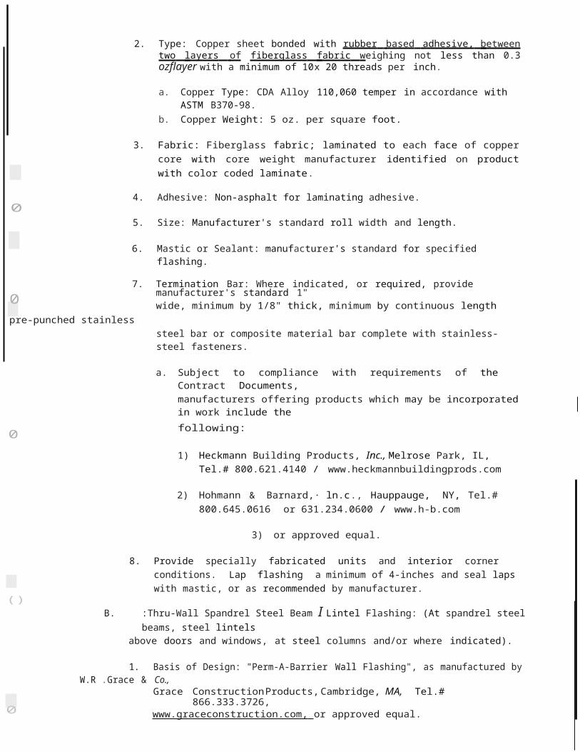
0SECTION 06100 - CARPENTRY
PART 1 -GENERAl
) 1.1 RElATED DOCUMENTS
A. Drawings and general provisions of the Contract, including General and SupplementaryConditions and Division 1 Specification Sections, apply to this Section.
G1.2 SUMMARY
A. Types of work in this section include rough carpentry for:
1. Wood nailers and blocking.2. Rough hardware.
} 3. Construction panels.
1.3 SUBMITTAlS
A. Material Certificates: Where dimensional lumber is provided to comply with minimum allowable unit stresses, submit listing of species and grade selected for each use, and submit evidence of compliance with specified requirements. Compliance may be in form of a signed copy of applicable portion of lumber producer's grading rules showing design values for selected species and grade. Design values shall be as approved by the Board of Review of American Lumber Standards Committee.
B. Wood Treatment Data: Submit chemical treatment manufacturer's instructions for handling,)
storing, installation and finishing of treated material.
C. Fire-Retardant Treatment: Include certification by treating plant that treated materialcomplies with specified standard and other requirements.
) 1.4 PRODUCT HANDliNG
A. Delivery and Storage: Keep materials under cover and dry. Protect against exposure to weather and contact with damp or wet surfaces. Stack lumber as well as plywood; provide for air circulation within and around stacks and under temporary coverings including polyethylene and similar materials.
B. Do not deliver finish carpentry materials, until painting, wet work, grinding and similar operations which could damage, soil or deteriorate woodwork have been completed in installation areas. If, due to unforseen circumstances, finish carpentry materials must be stored in other than installation areas, store only in areas meeting requirements specified for installation areas.
1.5 PROJECT CONDITIONS
A. Coordination: Fit carpentry work to other work; scribe and cope as required for accuratefit. Correlate location of furring, nailers, blocking, grounds and similar supports to allow
u attachment of other work.
FVHD-4810 2:06100-1

)
B. Maintain temperature and humidity in installation areas as required to maintain moisture content of installed finish carpentry within a 1.0 percent tolerance of optimum moisture content, from date of installation through remainder of construction period. The fabricator of woodwork shall determine optimum moisture content and required temperature andhumidity conditions.
l
PART 2- PRODUCTS
2.1 LUMBER, GENERAL
A. lumber Standards: Manufacture lumber to comply with PS 20 "American Softwood Lumber Standard" and with applicable grading rules of inspection agencies certified by American Lumber Standards Committee's (ALSC) Board of Review.
B. Inspection Agencies: Inspection agencies and the abbreviations used to reference with lumber grades and species include the following:
WWPA - Western Wood Products Association.
C. Factory-mark each piece of lumber with type, grade, mill and grading agency, except omit marking from surfaces to be exposed with transparent finish or without finish.
D. Nominal sizes are indicated, except as shown by detail dimensions. Provide actual sizes as required by PS 20, for moisture content specified for each use.
E. Provide dressed lumber, S4S, unless otherwise indicated.
F. Provide seasoned lumber with 19 percent maximum moisture content at time of dressing.
2.2 MISCELLANEOUS LUMBER
· A. Provide wood for support or attachment of other work including nailers, blocking and similar members. Provide lumber of sizes indicated, worked into shapes shown, and as follows:
1. Moisture content: 19 percent maximum for lumber items not specified to receive wood preservative treatment.
2. Grade: Construction Grade light framing size lumber of any species or board size lumber as required. Provide construction grade boards or No. 2 Boards.
2.3 CONSTRUCTION PANELS
A. Construction Panel Standards: Comply with PS 1 "U.S. Product Standard for Construction and Industrial Plywood" for plywood panels and, for products not manufactured under PS 1 provisions, with American Plywood Association {APA) "Performance Standard and Policies for Structural-Use Panels", Form No. E445.
B. Trademark: Factory-mark each construction panel with APA trademark evidencing compliance with grade requirements.
c. Concealed APA Performance-Rated Panels: Where construction panels will be used for the following concealed types of applications, provide APA Performance-Rated Panels
FVHD-4810 2:06100-2

(}complying with requirements indicated for grade designation, span rating, exposuredurability classification, edge detail (where applicable) and thickness.
D. APA RATED SHEATHING
0 1. Exposure Durability Classification: EXTERIOR.
a. Span Rating: As required to suit joist spacing indicated.
2.4 MISCELLANEOUS MATERIALS
A. Fasteners and Anchorages : Provide size, type, material and finish as indicated and as recommended by applicable standards, complying with applicable Federal Specifications for nails, staples, screws, bolts, nuts, washers and anchoring devices. Provide metal hangers and framing anchors of the size and type recommended by the manufacturer for each use including recommended nails.
)B. Where rough carpentry work is exposed to weather, in ground contact, or in area of
high relative humidity, provide fasteners and anchorages with a hot-dip zinc coating (ASTM A 153).
C. Building Paper: ASTM D 226, Type I; asphalt saturated felt, non-perforated, 15-lb. type.J
2.5 WOOD TREATMENT 'BY PRESSURE PROCESS
A. Fire-Retardant Treatment: Where fire-retardant treated wood ("FRT") is indicated or required,·pressure impregnate lumber and plywood with fire-retardant chemicals to· comply with AWPA C20 and C27, respectively, identify "FRT" lumber with appropriate classification marking of Underwriters Laboratories, Inc.,U.S.Testing, Timber Products Inspection or other testing and inspecting agency acceptable to authorities having jurisdiction.
1. Fire treated wood shall have a flame spread of 25 or less and shall be dried to 19% moisture content for lumber and 15% for plywood. Exposed wood or wood subject to high humidity conditions shall be identified that the moisture content shall not exceed 28% when tested at 92% relative humidity in accordance with ASTM D3201.
2. Treatment products: The following products, provided they comply with requirementsof the contract documents will be among those considered acceptable:
a. "Dricon"; Hickson Corporation.b. "Flame Proof LHC"; Osmose Wood Preserving, Inc.c. "Pyro-Guard"; Hoover Treated Wood Products, Inc.
3. Treat members shown on drawings and/or as required to meet the code requirements.
(
PART 3 -EXECUTION
3.1 INSTALLATION, GENERAL
0 A. Discard units of material with defects which might impair quality of work, and units which are too small to use in fabricating work with minimum joints or optimum joint arra,ngement.
FVI-ID-4810 2:06100-3

<...)

')B. Set carpentry work to required levels and lines, with members plumb and true to line and
cut and fitted.
c. Securely attach carpentry work to substrate by anchoring and fastening as shown and as required by recognized standards.
D. Countersink nail heads on exposed carpentry work and fill holes.
E. Use common wire nails, except as otherwise indicated. Use finishing nails for finish work Select fasteners of size that will not penetrate members where opposite side will be exposedto view or will receive finish materials. Make tight connections between members. Install )fasteners without splitting of wood; predrill as required.
3.2 WOOD NAilERS AND BlOCKING
A. Provide wherever shown and where required for screeding or attachment of other workForm to shapes as shown and cut as required for true line and level of work to be attached. )Coordinate location with other work involved.
B. Attach to substrates as required to support applied loading. Countersink bolts and nuts flush with surfaces, unless otherwise indicated. Build into masonry during installation of masonry work. Where possible, anchor to formwork before concrete placement.
)3.3 INSTAllATION OF CONSTRUCTION PANElS
A. General: Comply with applicable recommendations contained in Form No. E 30F, "APA Design/Construction Guide- Residential & Commercial," for types of construction panels and applications indicated.
B. Fastening Methods: Fasten panels as indicated below:
1. Sheathing: Screw to framing or substrates.
END OF SECTION 06100
)
FVHD-4810 2:06100-4

SECTION 06400- ARCHITECTURAL WOODWORK
PART 1 -GENERAL
) 1.1 RELATED DOCUMENTS
A. Drawings and general provisions of the Contract, including General and SupplementaryConditions and Division 1 Specification Sections, apply to this Section.
1.2 DESCRIPTION OF WORK0
A. Extent of each type of architectural woodwork is indicated on drawings and in schedules.
B. Type of architectural woodwork includes the following:
0 1. St nding and running trim .
C. Manufactured cabinet and casework of stock design is specified in Division 11.
1.3 QUALITY ASSURANCE
I A. AWl Quality Standard: Comply with applicable requirements of "Architectural WoodworkQuality Standards" published by the Architectural Woodwork Institute (AWl), except asotherwise indicated.
B. Special Project Warranty: Provide Manufacturer's I Installer's I Contractor's warrantees against delamin'ation, warping, hardwar.e and support system failure and deterioration of finish.
1. Warranty period shall be for one (1) year which shall start from approved date of substantial completion of work .
1.4 REFERENCES
A. AWl Quality Marking: Mark each assembled unit of architectural woodwork with manufacturer's identification and grade mark evidencing compliance with indicated AWl quality grade. Locate grade mark on surfaces which will not be exposed after installation. For other items requiring field assembly, a certification of compliance may be substituted for marking of individual pieces.
1.5 SUBMITTALS
A. Product Data: Submit manufacturer's product data for each product and process specifiedas work of this section and incorporated into items of architectural woodwork during
( fabrication, finishing, and installation.
B. Quality Certification: Submit woodwork Manufacturer's (Fabricator's) certification, stating that fabricated woodwork complies with quality grades and other requirements indicated.
c. Shop Drawings : Submit shop drawings showing location of each item, dimensioned plans
0 and elevations, large scale details, attachment devices and other components.
FVHD-4810 2:06400-1

0

D. Samples: Submit the following samples:
1. Lumber with or for transparent finish; set of 3 pieces 6" x 3/4" x 18", for each species and cut, finished on one side and one edge.
1.6 DELIVERY, STORAGE, AND HANDLING )
A. Protect woodwork during transit, delivery, storage and handling to prevent damage, soiling and deterioration.
B. Do not deliver woodwork, until painting, wet work, grinding and similar operations which could damage, soil or deteriorate woodwork have been completed in installation areas. If, due to unforeseen circumstances, woodwork must be stored in other than installation areas, store only in areas meeting requirements specified for installation areas.
1.7 PROJECT CONDITIONS)
A. Conditioning: Do not install woodwork until required temperature and relative humidityhave been stabilized and will be maintained in installation areas.
B. Maintain temperature and humidity in installation area, as required, to maintain moisture content of installed woodwork within a 1.0% tolerance of optimum moisture content, from date of installation through remainder of construction period. Require Woodwork Manufacturer to establish optimum moisture content and required temperature and humidity conditions .
PART 2- PRODUCTS
2.1 BASIC MATERIALS AND FABRICATION METHODS
A General: Except as otherwise indicated, comply with the following requirements for architectural woodwork not specifically indicated as prefabricated or prefinished standard products ..
B. Wood Moisture Content: Provide kiln-dried lumber with an average moisture content range of 9% to 13% for exterior work and 6% to 11% for interior work. Maintain temperature and relative humidity during fabrication, storage and finishing operations so that moisture content values for woodwork at time of installation do not exceed the following:
1. Interior Wood finish: 5%- 10%.
C. Interior Wood for Opaque Finish:
1. Solid Wood: Any closed grain hardwood complying with requirements for specified woodwork grade.
2. Solid Wood: Clear- Pine
2.2 FABRICATION
A. Quality Standards: For following types of architectur al woodwork; comply with indicatedstandards as applicable .
FVHD-4810 2:06400-2

01. Standing and Running Trim: AWl Section 300
B. Design and Construction Features: Comply with details shown for profile and construction of architectural woodwork; and, where not otherwise shown, comply with applicable Quality Standards, with alternate details as approved by Architect.
)C. Measurements: Before proceeding with fabrication of woodwork required to be fitted to
other construction, obtain field measurements and verify dimensions and shop drawing details as required for accurate fit.
1. Where sequence of measuring substrates before fabrication would delay the project,0 proceed with fabrication (without field measurements) and provide ample borders and
edges to allow for subsequent scribing and trimming of woodwork for accurate fit.
2.3 INTERIOR ARCHITECTURAL WOODWORK
() A. Quality Standard: Comply with AWl Section 300.
B. Standing and Running Trim:
1. Grade: Premium
) 2. Fabricate standing and running trim including jambs and board type paneling (if any) to dimensions, profiles and details shown. Rout or groove reverse side (backed-out) of trim members to be applied to flat surface, except for members with ends exposed in finish work.
3. . Plant assemble miters unless otherwise indicated.
PART 3 -EXECUTION
3.1 PREPARATION
() A. Condition woodwork to average prevailing humidity conditions in installation areas prior to installing.
B. Pre-Installation Meeting: Meet at project site prior to delivery of architectural woodwork and review coordination and environmental controls required for proper installation and ambient conditioning in areas to receive work . Include in meeting the Contractor; Architect and
other Owner Representatives (if any); installers of architectural woodwork,wet work such as plastering, other finishes, painting, mechanical work and electrical work; and
firms or persons responsible for continued operation (whether temporary or permanent) of HVACR system as required to maintain temperature and humidity conditions.
Proceed with woodwork installation only when everyone concerned agrees that required ambient
( conditions can be maintained.
C. Deliver masonry inserts and similar anchoring devices to be built into substrates, well inadvance of time substrates are to be built.
D. Prior to installation of architectural woodwork, examine shop fabricated work for0 completion, and complete work as required, including back priming and removal of packing.
FVHD-4810

2:06400-3

3.2 INSTALLATION
A. Install woodwork plumb, level, true and straight with no distortions. Shim as required using concealed shims. Install to a tolerance of 1/8" in 8'-0" for plumb and level (including tops); and with no variations in flushness of adjoining surfaces.
'}B. Scribe and cut woodwork to fit adjoining work, and refinish cut surfaces or repair damaged
finish at cuts.
C. Standing and Running Trim: Install with minimum number of joints possible, using full-length pieces (from maximum length of lumber available) to the greatest extent possible. Staggerjoints in adjacent and related members. Cope at returns, miter at corners and comply with
)
referenced Quality Standards for joinery .
D. Anchor woodwork to anchors or blocking built-in or directly attached to substrates. Secure to grounds, stripping and blocking with countersunk, concealed fasteners and blind nailingas required for a complete installation. Except where prefinished matching fasteners heads )are required, use fine finishing nails for exposed nailing, countersunk and filled flush withwoodwork, and matching final finish where transparent finish is indicated.
3.3 ADJUSTMENT, CLEANING, FINISHING, AND PROTECTION
A. Repair damaged and defective woodwork where possible to eliminate defects functionally )and visually; where not possible to repair replace woodwork . Adjust joinery for uniform appearance .
B. Clean woodwork on exposed and semi-exposed sulfaces. Touch-up shop-applied .finishes to restore damaged or soiled areas.
C. Complete the finishing work specified as work of this section, to whatever extent notcompleted at shop or prior to installation of woodwork.
D. Refer to the Division-9 sections for final finishing of installed architectural woodwork.
E. Provide final protection and maintain conditions, in a manner acceptable to Fabricator andInstaller, which ensures architectural woodwork being without damage or deterioration at time of substantial completion. .
END OF SECTION 06400
FVHD-4810 2:06400-4

SECTION 06650·- SOLID POLYMER FABRICATIONS
PART 1 -GENERAl
l 1.1 RElATED DOCUMENTS
A Drawings and general provisions of the Contract, including General and SupplementaryConditions and Division 1 Specification Sections, apply to this Section.
1.2 SUMMARYJ
A. Section Includes:
1. Countertops.
1.3 SUBMITTAlS0
A. Product Data: Written technical information for unit specified. Indicate product description, fabrication information and compliance with specified performance requirements.
B. Shop Drawings:
)1. Submit rough-in drawings. Include the following details and all other information
necessary to demonstrate compliance with contract documents:
a. Dimensions.b. Required clearances.c. Methods of assembling components .d. Anchorages.e. Coordination requirements with adjacent work.
C. Samples: Submit minimum 2 inch by 2 inch samples. Indicate full range of color and patternvariation. Approved samples will be retained as a standard for work.
(}D. Certificates: Submit certification that work complies with requirements of contract
documents.
E. Manufacturer's Instructions: Submit for each product specified in this section.
u 1. Include installation instructions and instructions for examination, preparation, and protection of adjacent work.
F. Maintenance Data: Submit manufacturer's care and maintenance data, including care, repairand cleaning instructions and maintenance video.
01. Provide maintenance kit for indicated finishes. Include in project close-out
documents.
1.4 DEliVERY, STORAGE AND HANDliNG:
u A. Deliver no components to project site until areas are ready for installation. Store indoors.
FVHD-4810 2:06650·1

r}B. Handle materials to prevent damage to finished surfaces. Provide protective coverings to
prevent physical damage or staining following installation for duration of project.
1.5 QUALITY ASSURANCE:
A. Allowable Tolerances: )
1. Variation in component size: ±1/8 inch.
1.6 WARRANTY:
A. Provide manufacturer's warranty against defects in materials, fabrication and installation, _)
excluding damages caused by physical or chemical abuse or excessive heat. Warranty shall provide for replacement or repair of material and labor for a period of ten (10) years, beginning at Date of Substantial Completion.
1. For fabrications with installed warranty coverage, identify by affixing manufacturer's )fabrication/installation source plate.
PART 2 -PRODUCTS
2.1 SOLID POLYMER FABRICATIONS:
A. Basis of Design: Corian Surfaces as manufactured by DuPont De Nemours & Co., Inc., Tel.#800.426.7426.
B. Subject to compliance with indicated requirem nts manufacturers offering products whichmay be incorporated in the work include the following: .
1. Meganite Inc., Fessenden Hall Inc.,Tel.# 800.220.2233.2. LG Solid Surfaces, Tel.# 609 495-4081 .3. Wilsonart, Tel.# 800.433.3222.4. Avonite Surfaces, Tel.# 800.428.6648.5. or approved equal.
C. Material: Cast, filled, acrylic; not coated, laminated or of composite construction, meetingANSIZ124 1980, Type Six, and FS WW-P-541 E/GEN dated August 1, 1980.
2.2 PERFORMANCE CHARACTERISTICS:
PROPERTY REQUIREMENT(min/max)
TEST PROCEDURE
Tens ile Strength
5000 psi min
6
ASTM D638
Tensile Modulus 1.0 x 10
psi min
ASTM D638
Flexural Strength Flexural Modulus ElongationStrain at Break
7000 psi min6
1.0 X 100.3% min. 0.8%min.
ASTM D790 ASTM D790 ASTM D638 ASTM D638

FVHD-4810 2:06650-2

0
()Hardness 90-Rockweii"M" scale ASTM 0758
52-Barcollmpressor min.
Thermal Expansion 3.5 x 1o·6 in/in/deg C max ASTM 0696
1.95 x 10'6 in/in/deg F max0
Color Stability No change, NEMA l03-3.10min. 100 hours
Wear and Cleanability Passes ANSI Z124.3)
Abrasion Resistance No loss of pattern Weight NEMA l03-3.01 ANSIloss (1000 cycles)=0.9 g. Z124.3max.
()Boiling water Surface No Change NEMA l03-3.05Resistance
High Temperature No Change NEMA l03-3.06Resistance
)
Conductive Heat No Change NEMA l03-3.08Resistance
Impact Resistance1 Notched lzod 0.24 ft.-lbs.fin . of ASTM 0256, Method A
notch min.Gardner 9.0 ft-lbs min. ASTM 03029
Ball drop NEMA L03-3031/4" sheet 36" min. with 1/2 lb ball,
no failure1/2" sheet 140" min. with 1/2 lb ball,
no failure3/4"sheet 200" min. with 1/2 lb ball,
no failure
u
Stain Resistance Passes ANSI Z124.3
0 Weather ability No change, ASTM 01499-84min. 1000 hours
Fungi and Bacteria No Attack ASTM G21, ASTM G22
Specific Gravity 1.6 min.0
FVHD-4810 2:06650·3

()
Water Absorption 24 hrs. Long Term ASTM D570 Weight(%max.) 0.05 (1/4") max. 0.50 (1/4") max.
0.10 (3/4") max. 0.90 (3/4") max.d
Flammability ASTM E84Solid Colors
1/4" 1/2" 3/4"Flame spread
25 max 25 max 25 max )
SmokeDeveloped 30 max 30 max 30 max
Class )
Particulate Patterns
1/4" 1/2" 3/4"
Flame spread25 max 25 max 25 max
SmokeDeveloped 30 max 30 max 30 max
Class 1
Pittsburgh Protocol Toxicity (as used by NY state) solids-80 grams min.
particulate patterns-65grams min.
"LC50" Test
2.3 ACCESSORY PRODUCTS
A. Joint Adhesive : Manufacturer's standard two-pa rt adhesive kit to create incon spicuous, non porous joints by chemical bond.
B. Panel Adhesive: Manufacturer's standard neoprene-based panel adhesive complying with ANSI A 136.1-1 967, UL listed.
C. Sealant: Manufacturer's standard mildew-resistant, FDA, UL listed silicone sealant in colors matching components.
2.4 FABRICATION:
A. Factory fabricate components to greatest extent practical to sizes and shapes indicated, in accordance with approved shop drawings and manufacturer's printed Instructions andtech nical bu lletin s. )
FVHD-4810 2:06650-4

B. Form joints between components using manufacturer's standard joint adhesive; withoutconspicuous joints. Reinforce with strip of solid polymer material, 2" wide.
C. Rout and finish component edges with clean, sharp returns. Rout cutouts, radii and contours to template. Smooth edges. Repair or reject defective and inaccurate work.
(}D. Countertops: 1/2-inch thick solid polymer material, adhesively joined with inconspicuous
seams, edge as indicated on the drawings, unless otherwise shown on the Drawings.
1. Provide surfaces with a uniform finish, Matte, Gloss range of 5-20. Color to be selectedfrom manufacturer's standard colors.
0
PART 3- EXECUTION
3.1 GENERAL REQUIREMENTS
)A. Prior to final approval of shop drawings, erect at project site one full size mock-up of
each component required, for Architect's review.
B. Should mock-up not be approved, re-fabricate and reinstall until approval is secured. Remove rejected units from project site.
0C. Approved mock-ups may remain as part of finished work.
3.2 INSTALLATION. .
A. Install components plumb, level and rigid, scribed to adjacenffinishes, in accordance with) approved shop drawings and product data.
B. Form field joints using manufacturer's recommended adhesive, with joints inconspicuous infinished work. Reinforce joints as required.
C. Perform installation in accordance with manufacturer's instructions, except where more0 stringent requirements are shown or specified, and except where project conditions require
extra precautions or provisions to ensure satisfactory performance of the work.
3.3 CLEANING
0 A. Clean shop finished surfaces, touch-up as required, and remove or refinish damaged or soiled areas, as acceptable to Architect.
3.4 PROTECTION
A. Contractor to take all precautions as recommended by the manufacturer for protection of
0 installed countertops from damage by work of other trades.
END OF SECTION 06650
0
FVHD-4810 2:06650-5
()


)SECTION 07200- BUILDING INSULATION
PART 1 -GENERAL
1.1 RELATED DOCUMENTS
A Drawings and general provisions of the Contract, including General and Supplementary Conditions and Division 1 Specification Sections, apply to this Section.
1.2 DESCRIPTION OF WORK)
A Work included in this Contract: Contractor shall include all labor, materials, services, installation, equipment, etc., necessary to complete all building insulation (except roof insulation) to achieve complete and tight building thermal barrier to prevent the passage of exterior air into conditioned spaces and prohibit the form ation of condensation.
0 1. Provide indicated types of insulation as shown on drawings, as specified herein, and/or as required by all job conditions and building assemblies, whether clearly shown or not to achieve included work.
)
J
0
<.)
0
2. Insulation types include but are not limited to the following:
a. Blanket type building insulation with foil facing for concealed application,b. Rigid board type cavity wall insulation,c. Fire safing insulation with UL approved coating,
3. Related Work:
a. Section 04200 - Unit Masonry,b. Section 07600- Roof Accessories,c. Section 07840- Through-P enetration Firestop Systems,
1.3 QUALITY ASSURANCE
A Thermal Conductivity: Thicknesses shown are for thermal conductivity (k-value at 75°F) specified for each material. Provide adjusted thicknesses as directed for equivalent use of material having a different thermal conductivity. Where insulation is identified by "R" value, provide appropriate thicknesses.
B. Fire-Test-Response Characteristics: Provide insulation and related materials with the fire-test-response characteristics indicated, as determined by testing identical products per test method indicated below by UL or another testing and inspecting agency acceptable toauthorities having jurisdi ction. Identify materials with appropriate markings of applicabletesting and inspecting agency.
1. Surface-Burning Characteristics:2. Fire-Resistance Ratings:3. Combustion Characteristics:
ASTM E 84.ASTM E 119.ASTM E 136.
c. Fire and Insurance Ratings: Comply with fire-resistance, flammability and insurance ratingsC) indicated, and comply with governing regulations as interpreted by authorities.
FVHD-4810 2:07200-1
0

1.4 SUBMITTALS
A. Product Data: Submit manufacturer's product literature and installation instructions for each type of insulation required. Include data substantiating that materials comply with specified requirements.
B. Samples: Submit triplicate samples of the following listed items, in accordance with Contract Documents. Obtain Architect's approval before proceeding with ordering or fabrication of items of this section:
1. Each type of insulation specified - 12 inches square.)
1.5 DELIVERY, STORAGE, AND HANDLING
A. General Protection and Handling: Protection from Deterioration: Do not allow insulationmaterials to become wet, soiled, or covered with ice or snow. Comply with manufacturer'srecommendations for handling, storage and protection during installation. )
PART 2- PRODUCTS
2.1 MANUFACTURERS)
A. Subject to compliance with requirements, manufacturers offering products that may beincorporated into the Work include, but are not limited to, the fo.llowing:
1. Extruded-Polystyrene Board Insulation:
a. DiversiFoam Products.b. Dow Chemical Company.c. Owens Corning.d. Tenneco Building Products.e. or approved equal.
2. Glass-Fiber Insulation:
a. CertainTeed Corporation.b. johns Manville.c. Owens Corning.d. Guardian Building Products, Inc.e. Knauf Insulation.f. or approved equal.
3. Fire Safing Insulation:
a. Industrial Insulation Group, LLCb. Fibrex Insulations.c. lsolatek International.d. Owens Corning.e. Thermafiber.f. or approved equal. ,,
FVHD-4810 2:07200-2

0
0
)
0
)
0
B. Mineral/Glass Fiber Blanket/Batt Insulation
1. Inorganic fibers formed into flexible resilient blankets or semi-rigid resilient sheets:
a. Reinforced-Foil-Faced, Glass-Fiber Blanket Insulation: ASTM C 665, Type Ill (reflective faced), Class A (faced surface with a flame-spread index of 25 or less); Category 1 (membrane is a vapor barrier), faced with foil scrim, foil-scrim kraft, or foil-scrim polyethylen e.
C. Mineral-Wool Board Insulation:
1. Unfaced, Mineral-Wool Board Insulation: ASTM C 612; with a flame-spread index of 15 and a smoke-developed index of zero, per ASTM E 84; passing ASTM E 136 for combustion characteristics.
a. Nominal density of Bib/cu. ft., Type Ill, thermal resistivity of 4.35°F x h x sq. ft./BtuX in. at 75°F.
2 . At all rated masonry and wallboard walls and partitions, rated slabs and exterior wall panels, the fire safing insulation shall be coated with 3M Firedam products, or approved equat to achieve indicated UL design requirements.
D. Rigid Insulation (cavity wall insulation)
1. Rigid, moisture resistant, closed-cell extruded polystyrene insulation board; ASTM C578, Type IV, 25 psi compressive strength; 1.1 perm-inch maximum vapor transmission; 0.1% maximum water absorption; manufacturer's standard lengths and widths. Provide insulation complying with a flame spread rating of 1 0 and smoke developed of 160, when tested in accordance with ASTM E84.
a. Basis of Design: Provide "Cavitymate Ultra", by Dow Chemical U.S.A.
1) Subject to compliance with requirements, manufacturers offering products that may be incorporated into the Work include, but are not limited to, the following:
a) DiversiFoam Products.b) Owens Corning.
c) Tenneco Building Products.
Jb. R value of 5.6 per inch; ASTM C518.
c. Thickness: 1-3/4", unless indicated otherwise.
0 PART 3 ·EXECUTION
3.1 INSTALLATION, GENERAl
A. Comply with manufacturer's instructions for particular conditions of installation in each case.If printed instructions are not available or do not apply to project conditions, consult
0 manufacturer's technical representative for specific recommendations before proceedingwith work.
FVHD-4810 2:07200-3
()

(B. Extend insulation full thickness as shown over entire area to be insulated. Cut and fit tightly
around obstructions, and fill voids with insulation. Remove projections which interfere withplacement.
1. Apply a single layer of insulation of required thickness, unless otherwise shown orrequired to make up total thickness. ()
2. Provide complete and tight building thermal barrier, to prevent the passage of exterior air into conditioned spaces and prohibit the formation of condensation.
3. Provide indicated types of insulation as shown on drawings, as specified herein, and/oras required by all job conditions, building assemblies, and whether clearly shown or )
not.
C. Batt Insulation
1. General: )
a. Set vapor barrier faced units with vapor barrier to warm side of construction.
b. Tape joints and ruptures in vapor barriers, and seal each continuous area ofinsulation to surrounding construction to ensure vapor-tight installation.
c. Insert and secure insulation to fill voids to create barrier to prevent the pass of air and moisture.
D. Cavity Wall Insulation
1. On units of plastic insulation, install small pads of mortar or mastic spaced approximately 1'-0" on center both ways on inside face, as recommended by manufacturer. Press courses of insulation between wall ties and other confining obstructions in the cavity, with edges butted tightly both ways. Press units firmly against inside wythe of masonry or other construction as shown.
a. Wedge insulation from outside wythe of construct ion with small fragments ofmasonry materials spaced 2'-0" on center both ways.
E. Fire Safing Insulation
1. Install fire safing insulation at all indicated locations, as required by authorities havingjurisdiction and in accordance with manufacturer's instructions.
2. Provide sealant material and type required for indicated applications. Provide fire rated type at rated assemblies .
3. Provide coating materials at indicated UL. Rated assemblies.
F. All installations of insulation and work of this section shall meet approval of Architect and allcode authorities having jurisdiction at no additional cost to the Owner.
END OF SECTION 07200 C'
FVHD-4810 · 2:07200-4

SECTION 07600- FLASHING, SHEET METAL AND ROOF ACCESSORIES
PART 1 -GENERAL
0 1.1 RELATED DOCUMENTS
A. Drawings and general provisions of the Contract, including General and SupplementaryConditions and Division 1 Specification Sections, apply to this Section.
)
A. Section Includes:
1. Pre·manufactured metal flashing and counterflashing. 2. Miscellaneous sheet metal accessories.3. Exposed metal field and shop fabricated sheet trim and fascia units, where indicated.4. Pipe curb assembly.
B. Related Sections :
1. Wood nailers and blocking: Section 06100.
0 2. Roof Specialties and Accessories: Section 07800.3. joint Sealer Assemblies: Section 07900.4. Mechanical Work: Specifications on drawings
1.3 PERFORMANCE REQUIREMENTS
) A. Structural Requirements: Design and install work of this section, including attachment to the structure, to safely withstand dead, live and wind loads prescribed by the International Building Code.
B. Environmental Requirements: Provide for expansion and contraction of system components due to air temperature and solar heat gain. Provide systems which will accommodate0 movement due to temperature change without buckling, failure of seals, undue stress onstructural elements, reduction of performance, or other detrimental effects.
1. Anticipated air temperature range: Minus 10°F to +1OS °F.
1.4 REFERENCES
A. Architectural Sheet Metal Manual; Sheet Metal and Air Conditioning Contractors National Association, Inc. {SMACNA).
B. ASTM B 32; Standard Specification for Solder Metal.0
C. ASTM B 209; Standard Specification for Aluminum and Aluminum-Alloy Sheet and Plate.
D. Aluminum Association, Design System for Aluminum Finishes (AA).
u E. American Architectural Manufacturers Association (AMMA), standards as referenced herein.
F. ANSI/SPRI ES-1 Wind Design Standard for Edge Systems Used with Low Slope Roof Systems.
FVHD-4810 2:07600-1
(.)

t)
1.5 SUBMIITALS
A. Product Data: Manufacturer's specifications, standard details, and installation recommendations.
0B. Shop Drawings: Submit manufacturer's shop drawings showing material types, thickness,
sizes, shapes, connections, layout, joining, profiles and anchorage of fabricated work and relation to adjacent work. edited product data or shop drawings, or a combination thereof, as required to accurately describe products to be provided. Show elevations, field measurements, reinforcement, expansion provisions, installation accessories, and detail sections of composite members. Draw layouts at scale of 1/4 inch per foot, details at scale of 3 inches per foot.
1. Provide shop drawings for, but not limited to, the following:
a. Covering on minor flat, pitched or curved surfaces. )b. Base flashing and counterflashing.c. All other sheet metal work requiring fabrication.d. Details of all joints for above.
2. Sheet metal shop drawings shall be prepared to reflect SMACNA detail standards andin accordance with ANSI/SPRI ES-1 Test Protocols. )
C. Samples for Color Selection of Coated Finishes: .Coating manufacturer's color selection data.
D. Samples for Color Verification of Coated Finishe.s: For each type and color of coated finish submit 12-inch-long sections of extrusions and formed sections and 6-inch-square sheets.
E. Pre-engineered fabricated and pre-finished sheet metal manufacturer's product literature, finish specification and sample finish warranty.
F. Sheet metal fabricators and installers qualifications.
1.6 QUALITY ASSURANCE
A. listing- Roof Perimeter Flashing System: Provide system listed in Factory Mutual System's "Approval Guide," classified for Zone 2 {1-90 windstorm resistance).
B. Fabricator I Installer: A firm having a minimum of 5 years of successful experience in fabrication and installation of sheet metal work of type and scope equivalent, to work of this section.
C. Fabricate and install sheet metal work in accordance with indicated reference standards .
1.7 DELIVERY, STORAGE, AND HANDLING
A. Store materials off ground, under cover. Protect from damage and deterioration .
B. Handle materials to prevent damage to surfaces, edges and ends of sheet metal items.Damaged material shall be rejected and removed from the site.
FVHD-4810 2:07600-2

(
0
0
0
0
PART 2 -PRODUCTS
2.1 MANUFACTURERS
A. Manufacturers : Subject to compliance with requirements, provide pre-engineered) manufactured products approved by the roofing system manufacturer(s) which may
include but not limited to the following:
1. Formed-Aluminum Gravel Stops, Metal Edging, Copings and Fascia:
a. Hickman: W.P. Hickman Co.,Tel.# 828.676.1700,www.wph.com.b. Metal-Era, Inc.,Tel.# 800.558.2162, www.metalera.com .c. Southern Aluminum Finishing Co., Tel.# 800.241.7429, www.saf.com.
2. Aluminum Reglets:
a. Fry Reglet Corporation, Tel.# 800.237.9773, www.fryreglet.com.b.c.
Hickman: W.P. Hickman Co., Tel.# 828.676.1700, www.wph .com.Keystone Flashing Company, Tel.# 800.526.8348, www.keystoneflashing .com
2.2 METALS
A. Type "C"; Aluminum: Alloy and temper recommended by aluminum producer and finisher for type of use and finish indicated and with not less than the strength and durability of alloy and temper designated below:
1. Type "C-4"; Factory-Painted Aluminum Sheet: ASTM B 209, 3003-H 14,with a minimum thickness of 0.040 inch,unless otherwise indicated.
2.3 REGLETS
A. General: Provide reglets of type, material, and profile indicated, compatible with flashing.Form to securely interlock with counterflashing.
1. Type - 5: Roof Top Equipment Curb: Provide "MA" springlok Reglet by Fry Reglet Corp., or approved equal.
a. 0.040" thick aluminum, with 1-1/2" top flange, color as selected by Architect.b. Provide 3" minimum lap joints.
2. Counterflashing Wind-Restraint Clips: Provide clips to be installed beforecounterflashing to prevent wind uplift of the counterflashing's lower edge.
2.4 COUNTERFLASHING
0 A. Provide springlok counterflashing by Fry Reglet Corp.; Metal-Era; Xtreme Trim or approved
equal.
1. 0.040" thick aluminum, as indicated on the drawings.2. Provide inside and outside corners including special angle where required.
u
FVHD-4810 2:07600-3

0

t)2.5 MISCELLANEOUS MATERIALS AND ACCESSORIES
A. GENERAL REQUIREMENTS:
1. All miscellaneous materials, accessories or other items essential to the completion ofsheet metal installation, though not specifically shown or specified, must be provided. 0
2. All such items, unless otherwise indicated on drawings or specified herein, shall be applied using sheet metal gauges which conform to recognized industry standards of sheet metal practices and without additional cost to the Owner. For sheet metal andpre-manufactured units, provide type of solder, ASTM B23, and corrosion-resistantmetal as recommended by the producer of the metal sheets for fabrication and
)
installation.
3. Provide sheet metal clips, straps, anchoring devices and similar accessory units as required for installation of work, matching or compatible with material being installed, non-corrosive, size and gauge required for performance.
B. Fasteners: Same metal as flashing/sheet metal, as indicated or other non-corrosive metal as recommended by sheet manufacturer. Match finish of exposed heads with material being fastened.
C. Bituminous Coating: FS TI-C-494 or SSPC - Paint 12, solvent type bituminous mastic, )nominally free of sulfur, compounded for 15-mil dry film thickness per coat.
D. Mastic Sealant: Polyisobutylene; non-hardening, non-skinning, non-drying, non-migrating sealant.
E. Elastomeric Sealant: Generic type recommended by manufacturer of metal and fabricator of components being sealed; comply with FS TI-S-00227, TI-S-00230, or TI-S-001543 .
F. Epoxy Seam Sealer: 2-part non-corrosive metal seam cementing compound, recommended by metal manufacturer for exterior/interior non-moving joints including riveted jo ints.
G. Paper Slip Sheet: 15-lb. rosin-sized building paper.
H. Polyethylene ·underlayment: 6-mil carbonated polyethylene film; FS L-P-512.
I. Prefabricated Accessories: Provide prefabricated accessories by Metal-Era, Roof Edge Systems, or approved equal.
1. Exposed Termination Bar: 0.05 x W' x 1W' x W' aluminum channel or 1" x 3/16" aluminum bar as manufactured by Metal-Era Inc., or approved equal. Provide fastening at 8" o.c.
J. Pipe Curb Assembly :
1. Manufacturer: Products of the following manufacturers, provided they comply with requirements of the contract documents, will be among those considered acceptable:
a. Pipe Portal Systems as manufactured by Portals Plus, Inc., Tel.# 800.624.8642. (b. The Pate Company, Tel.# 800.243.3018 or 630.705.1920.c. ThyCurb, Tel.# 216.762 .0061.

FVHD-4810 2:07600-4

2.6 FABRICATION, GENERAL
A. Sheet Metal Fabrication Standard: Fabricate sheet metal flashing and trim to comply with recommendations of SMACNA's "Architectural Sheet Metal Manual" that apply to the design,
() dimensions, metal, and other characteristics of the item indicated. .
B. Comply with details shown to fabricate sheet metal flashing and trim that fit substrates and result in waterproof and weather-resistant performance once installed. Verify shapes and dimensions of surfaces to be covered before fabricating sheet metal.
) C. Form exposed sheet metal Work that is without excessive oil canning, buckling, and tool marks and that is true to line and levels indicated, with exposed edges folded back to form hems.
1. Seams (Metal other than Aluminum) : Fabricate nonmoving seams in sheet metal with
0 flat-lock seams. Tin edges to be seamed, form seams, and solder.
2. Seams (Aluminum): Fabricate nonmoving seams in aluminum with flat-lock seams.Form seams and seal with epoxy seam sealer. Rivet joints for additional strength.
3. Expansion Provisions: Space movement joints at maximum of 10 feet with no joints) allowed within 24 inches of corner or intersection. Where lapped or bayonet-type
expansion provisions in Work cannot be used or would not be sufficiently weatherproof and waterproof, form expansion joints of intermeshing hooked flanges, not less than 1 inch deep, filled with mastic sealant (concealed within joints).
4. Sealed Joints: Form nonexpansion, but movable, joints in metal to accommodate() elastomeric sealant to comply with SMACNA standards.
5. Separate metal from noncompatible metal or corrosive substrates by coating concealed surfaces at locations of contact with asphalt mastic or other permanent separation as recommended by manufacturer.
6. Conceal fasteners and expansion provisions where possible. Exposed fasteners are not allowed on faces of sheet metal exposed to public view.
7. Fabricate cleats and attachment devices from same material as sheet metal component being anchored or from compatible, noncorrosive metal recommended by sheet metal manufacturer.
B. Size: As recommended by SMACNA manual or sheet metal manufacturer forapplication but never less than thickness of metal being secured.
D. SHEET METAL FABRICATIONSr
1. General: Fabricate sheet metal items in thickness or weight needed to comply with performance requirements.
2.7 ALUMINUM FINISH
0 A. General: Comply with Aluminum Association's (AA) "Designation System for Aluminum Finishes" for finish designations and application recommendations.
FVHD-4810 2:07600-5

()

B. High-Performance Organic Coating Finish: AA-C12C42R1x (Chemical Finish: cleaned with inhibited chemicals; Chemical Finish: acid chromate-fluoride-phosphate conversion coating; Organic Coating: as specified below). Prepare, pretreat, and apply coating to exposed metal surfaces to comply with coating and resin manufacturer's instructions.
1. Fluoropolymer 2-Coat Coating System: Manufacturer's standard 2-coat, thermocured system composed of specially formulated inhibitive primer and fluoropolymer color topcoat containing not less than 70 percent polyvinylidene fluoride resin by weight; complying with AAMA 605.2.
)a. Color(s): As selected by the Architect from manufacturer's available full range of
colors including custom colors.
PART 3 -EXECUTION
3.1 EXAMINATION
A. Examine substrates and conditions under which sheet metal flashing and trim are to beinstalled and verify that Work may properly commence.
B. Verify that substrates and openings are rigidly set, at proper lines and elevation, properlysized, and ready to receive units.
C. Do not proceed with installation until conditions detrimental to proper installation have been corrected.
D. Coordinate installation with roofing work and other adjacent elements of building envelopeto ensure watertight construction.
3.2 PREPARATION
A. Verify shapes and dimensions of surfaces to be covered before fabricating sheet metal.
B. Isolate all dissimilar metals by means of a heavy bituminous coating, approved paint coating, approved paint coating, adhered polyethylene sheet, or other means recommended by SMACNA.
3.3 INSTALLATION
A. General: Except as otherwise indicated, comply with manufacturer's installation instructions and recommendations, and with SMACNA "Architectural Sheet Metal Manual." Anchor units of work securely in place by methods indicated, providing for thermal expansion in metal units. Set units true to line and level indicated. Install work with laps, joints, and seams permanently weatherproof and watertight.
B. Sealed Joints: Form minimum 1-inch hookedjoints and embed flange into sealant or adhesive.Form metal to completely conceal sealant or adhesive.
1. Use joint adhesive for nonmoving joints specified not to be soldered. (
FVHD-4810 2:07600-6
'

02. MovingJoints: When ambient temperature is moderate (40-70°F) at time of installation,
· set joined members for 50% movement either way. Adjust setting position of joined members proportionally for temperatures above 70°F. Do not install sealant at temperatures below 40°F. Refer to section on sealants elsewhere in Division 7 for handling and installation requirements for joint sealers.
0C. Workmanship :Install sheet metal work with lines, arises, and angles sharp and true.
Exposed surfaces shall be free from visible waive, warp, buckle, and tool marks. Exposed edges shall be folded back neatly to form a V2-inch hem on the concealed side. Sheet metal exposed to the weather shall be watertight with provisions for expansion and contraction.
) D. Nailing: Nailing of sheet metal shall be confined generally to sheet metal having a maximum width of 18 inches. Nailing of flashings shall be confined to one edge only. Nails shall be evenly spaced not over 3 inches on centers and approximately 112-inch from edge unless otherwise specified or indicated. Face nailing will not be permitted. Where sheet metal is applied to other than wood surfaces, detailed shop drawings shall include locations for
) sleepers and nailing strips required to properly secure the work.
E. Cleats: Provide cleats for sheet metal 18 inches and over in width. Space cleats evenly not over 12 inches on centers unless otherwise specified or indicated. Unless otherwise specified, cleats shall be not less than 2 inches wide by 3 inches long, and of the same material and thickness as the sheet metal being installed. One end of the cleat shall be
) secured with two nails and the cleat folded back over the nailheads. The other end shall be
folded back over the nailheads. The other end shall be locked into the seam. Cleats forsoldered seams shall be pretinned.
F. Bolts, Rivets and Screws: Install bolts, rivets, and screws where·indicated or required. Provide
() watertight connection.
G. Seams; General: Comply with SMACNA, Figures 3-2 & 3-3, Tables 2-1 & 3-1 R, and otherapplicable designs to specific installation.
0 1. Seams: straight and uniform in width and height with no solder showing on the face.
2. Flat-lock Seams for All Non-Moving Seams; Finish not less than 3/4-inch wide.
3. Loose-lock Expansion Seams: Not less than 3 inches wide, and shall provide minimum one-inch movement within the joint. Joint shall be completely filled with the specified sealant, applied at no less than 1/8 inch thick bed. Sealants are specified in Section 07900- Joint Sealer Assemblies and shall be completely concealed.
4. Flat Seams: Make seams in the direction of the flow.
0 apply to copper and lead coated copper and galvanized metal items.
1. Soldering: Cretin edges of sheet metals, except lead coated material, before soldering is begun. Soldering shall be done slowly with well heated soldering irons, so as to thoroughly heat the seams and completely sweat the solder through the full width of
0 the seam. Edges of lead-coated material to be soldered shall be scraped or wirebrushes to produce a bright surface, and seams shall have a liberal amount of fluxbrushed in before soldering is begun.
FVHD-4810 2:07600-7

I. Counterflashing: Except where indicated or specified otherwise, insert counterflashing receiver in horizontal saw cut joints locations as indicated. Snap counterflashing in receiver and extend down vertical surfaces over upturned vertical leg or base flashings not less than4 inches. Exposed edges of counterflashing shall be folded 112-inch. End laps incounterflashings shall be overlapped 6", and shall be made weathertight with sealant. )
1. Lengths of metal counterflashings shall not exceed 10 feet. The flashings shall be formed to the required shapes before installation. Corners shall be factory-formed with joints not less than 24 inches from the angle.
)2. Flashing receivers shall be secured in the horizontal joint with lead wedges spaced not
to exceed 12 inches apart; on short runs, wedges shall be placed closer together.
3. ·counterflashing receiver joints shall be filled with caulking compound. Caulking is covered in Section 07900- Joint Sealer Assemblies.
3.4 PROTECTION FROM CONTACT OF DISSIMILAR MATERIAL
A. Copper or Copper-Bearing Alloys: Surfaces in contract with dissimilar metal shall be painted with heavy bodied bituminous paint, or shall be separated by means of moisture-proof building felts.
B. Aluminum: Surfaces shall not contact other metals except stainless steel,zinc, or zinc coating.Where aluminum contacts another metal, the dissimilar metal shall be painted with a primer followed by two coats of aluminum paint.
C. A ll Metal: Sur.faces in contact with mortar, concrete, or other masonry materials shall be painted with alkali-resistant coatings such as heavy-bodied bituminous paint.
D. Wood or Other Absorptive Materials: Surfaces that may become repeatedly wet and in contact with metal shall be painted with two coats of aluminum paint or a coat of heavybodied bituminous paint. or a coat of heavy-bodied bituminous paint.
E. Dissimilar Metal: Paint with a non-lead pigmented paint if drainage from it passes over aluminum.
F. All fasteners shall be compatible with the metal with which it is connected.
3.5 PROTECTION OF ROOFING
A. Protection of Applied Insulation: Completely cover each day's installation with finished roofing specified. Protect open spaces between insulation and parapets or other walls and spaces at curbs, scuttles, and expansion joints, until permanent roofing and flashing is applied. Storing, walking, wheeling, or trucking will not be permitted directly on insulation or on roofed surfaces. Provide smooth, clean board or plank walkways, runways, and platforms near suppo rts, as necessary to distribute weight to conform to indicated live load limits of roof construction.
B. Upon completion of roofing work (including associated work) Installer shall advise Contractor of recommended procedures for surveillance and protection of roofing during remainder of construction period. At end of construction period, or at a time when remaining construction work will in no way affect or endanger roofing (at Contractor's option), Installer shall make
FVHD-4810 2:07600-8

0a final inspection of roofing and prepare a written report to Contractor with copy to Owner)describing nature and extend of deterioration or damage found in the work.
c. Installer shall repair or replace (as required) deteriorated or defective work found at time offinal inspection. Installer shall be engaged by Contractor to repair damages to roofing which
l occurred subsequent to roofing installation and prior to final inspection.
D.
)3.6
A.
Repair or replace the roofing and associated work to a condition free of damage and deterioration at time of substantial completion.
CLEAN-UP
Clean exposed metal surfaces, removing substances which might cause corrosion of metal or deterioration of finishes.
B. Upon completion of the specified work, remove all waste, debris, unused material and
0 equipment from the site. Remove all misplaced material from nearby surfaces. Leave the job in a clean condition, acceptable to Owner.
c. Advise Contractors of required procedures for surveillance and protection of flashings and sheet metal work during construction to ensure that work will be without damage or deterioration, other than natural weathering, at time of substantial completion.
)
END OF SECTION 07600
0
0
FVHD-4810 2:07600-9

(>

)

0SECTION 07800 - ROOF SPECIALTIES AND ACCESSORIES
PART 1 -GENERAl
1.1 RElATED DOCUMENTS0
A. Drawings and general provisions of the Contract, including General and SupplementaryConditions and Division 1 Specification Sections, apply to this Sectif>n.
1.2 DESCRIPTION OF WORK
) A. Extent and location of roof accessories is indicated on the drawings and by provisions of thissection.
B. Type of unit specified in this section includes the following:
0 1. Prefabricated curb and support units.
C. Related Sections:
1. Section 06100: Carpentry.2. Division 15: Mechanical Work (specifications on drawings).
01.3 SUBMITTAlS
A. Product Data; Roof Accessories: Submit manufacturer's technical product data, rough-in diagrams, details, installation instructions and general product recommendations.
0 B. Samples; Roof Accessories: Submit 2 samples, min. 8" square, of each exposed metal and plastic sheet materials, and 2 samples, min. 24" long, of fanned or extruded exposed metal member; color and finish as specified.
C. Coordination Drawings: Submit coordination drawings for items interfacing with or
) supporting mechanical equipment. Indicate dimensions and locations of items provided under this section, together with relationships and methods of attachment to adjacentconstruction and to mechanical/electrical items.
1.4 QUAliTY ASSURANCE
) A. Standards: Comply with SMACNA "Architectural Sheet Metal Manual" details for fabrication of units, including flanges and cap-flashing to coordinate with type of roofing indicated. Comply with "NRCA Roofing and Waterproofing Manual" details for installation of units.
B. Test Reports: Certified test reports showing compliance with specified performancecharacteristics and physical properties.
0PART 2 -PRODUCTS
2.1 GENERAl PRODUCT REQUIREMENTS
A. Provide manufacturers' standard units, modified as necessary to comply with requirements.0 Shop fabricate each unit to greatest extent possible.
FVHD-4810 2:07800-1

()

2.2 MATERIALS, GENERAL
A. Zinc-Coated Steel: Commercial quality with 0.20 percent copper, ASTM A 525, G90 hot-dip galvanized, mill phosphatized.
B. Stainless Steel: AISI TYPE 302/304, ASTM A 167, 20 annealed finish except as otherwise )indicated, temper as required for forming and performance.
C. Aluminum Sheet: ASTM B 209, alloy 3003, temper as required for forming and performance;anodized finish, except mill finish prepared for painting where indicated for field painting.
D. Extruded Aluminum: Manufacturers standard extrusions of sizes and general profiles indicated, alloy 6063 T6, architectural grade aluminum; 0.078 inch minimum thickness for primary framing and curb member legs and 0.062 inch for dome retaining angle.
E. Insulation: Manufacturer's standard rigid polyisocyanurate or semi-rigid board of glass fiberof thicknesses indicated.
F. Wood Nailers : Softwood lumber, fire retardant treated wood, not less than 1-1/2" thick.Refer to Specification Section 06100.
G. Fasteners: Same metal as metals being fastened, or nonmagnetic stainless steel or other noncorrosive metal as recommended by manufacturer. Match finish of exposed fasteners with finish of material being fastened.
1. Where removal of exterior exposed fasteners affords access to building, provide non removable fastener heads.
H. Gaskets: Tubular or fingered design of neoprene or polyvinyl chloride, or block design of sponge neoprene.
I. Bituminous Coating: FS TI-C-494A or SSPC-Paint 12, solvent type bituminous mastic, nominally free of sulfur, compounded for 15-mil dry film thickness per coating.
J. Mastic Sealant: Polyisobutylene; non-hardening, non-skinning, non-drying, non-migratingsealant.
K. Elastomeric Sealant: Generic type recommended by unit manufacturer, which is compatible with joint surfaces; comply with FS TI-S-00227E, TI-S-00230C, or TI-S-001543A.
2.3 PREFABRICATED EQUIPMENT SUPPORTS
A. Comply with loading and strength requirements as indicated where units support other work.Coordinate dimensions with rough-in sheets or shop drawings of equipment to be supported. Fabricate of structural quality sheet steel (ASTM A 570, Grade as required) which has been prepared for painting and factory-primed and painted with 2-mil thickness of baked-on synthetic enamel, after fabrication .
1. Fabricate with welded or sealed mechanical corner joints. Provide complete with cant strips and base profile coordinated with roof insulation thickness. Provide preservative treated wood nailers at tops of curbs, coordinate with thickness of insulation and roof flashing as indicated, tapered as necessary to compensate for roof deck slopes of 1/4" per ft. and less.
FVHD-4810 2:07800-2

2. Except as otherwise indicated or required for strength, fabricate units of minimum 14-gauge (0.0747") metal, and to minimum height of 12".
3. Sloping Roofs: Where slope of roof deck exceeds 1/4" per ft., fabricate curb/supportunits with height tapered to match slope, to result in level installation of tops of units.
0B. Manufacturers: Subject to compliance with requirements, manufacturers offering
prefabricated thermally broken curbs/equipment supports which may be incorporated in the work include the following:
1. Custom Curb, Inc.; Chattanooga, TN)
2. The Pate Company; Broadview, IL3. ThyCurb Div.fThyBar Corp.; Addison, IL4. or approved equal.
2.4 AlUMINUM FINISH
0A General: Comply with Aluminum Association's (AA) "Designation System for Aluminum
Finishes" for finish designations and application recommendations.
B. Class I, Clear Anodic Finish: AA-C22A41 (Chemical Finish: etched, medium matte; Anodic Coating: Architectural Class I, clear coating 0.018 mm or thicker) complying with
) AAMA 607.1.
C. High-Performance Organic Coating Finish: AA-C12C42R1x (Chemical Finish: cleaned with inhibited chemicals; Chemical Finish: acid chromate-fluoride-phosphate conversion coating; Organic Coating: as specified below). Prepare, pretreat, and apply coating to exposed metalsurfaces to comply with coating and resin manufacturer's instructions.
)
1. Fluoropolymer 2-Coat Coating System: Manufacturer's standard 2-coat, thermocured system composed of specially formulated inhibitive primer and fluoropolymer color topcoat containing not less than 70 percent polyvinylidene fluoride resin by weight; complying with AAMA 605.2.
)a. Color and Gloss: As selected by Architect from manufacturer's full range of
choices for color and gloss.
PART 3 -EXECUTION
3.1 INSTAllATION
A General: Comply with manufacturer's instructions and recommendations. Coordinate with installation of roof deck and other substrates to receive accessory units, and vapor barriers, roof insulation, roofing and flashing; as required to ensure that each element of the work performs properly, and that combined elements are waterproof and weathertight. Anchor
0 units securely to supporting structural substrates, adequate to withstand lateral and thermal
stresses as well as inward and outward loading pressures.
B. Except as otherwise indicated install roof accessory items in accordance with constructiondetails of "NRCA Roofing and waterproofing Manual".
0C. Isolation: Where metal surfaces of units are to be installed in.contact with non-
compatible metal or corrosive substrates, including wood, apply bituminous coating on concealed metal
FVHD-4810 2:07800-3

)surfaces, or provide other permanent separation.
D. Flange Seals: Except as otherwise indicated, set flanges of accessory units in a thick bed ofroofing cement, to form a seal.
E. Cap Flashing: Where cap flashing is required as component of accessory, install to provide [)adequate waterproof overlap with roofing or roof flashing (as counter-flashing) . Seal withthick bead of mastic sealant, except where overlap is indicated to be left open for ventilation.
3.2 CLEANING AND PROTECTION
A. Clean exposed metal surfaces in accordance with manufacturer's instructions. Touch up )
damaged metal coatings.
END OF SECTION 07800
FVHD-4810 2:07800-4

SECTION 07840- THROUGH-PENETRATION FIRESTOP SYSTEMS
PART 1 -GENERAl
1.1 RElATED DOCUMENTS0
A. Drawings and general provisions of the Contract, including General and SupplementaryConditions and Division 1 Specification Sections, apply to this Section.
1.2 SUMMARY
) A. This Section includes through-penetration firestop systems for penetrations through the following fire-resistance-rated assemblies, including both empty openings and openings containing penetrating items:
1. Walls and partitions.2. Smoke barriers.
()3. Construction enclosing compartmentalized areas.
B. Related Sections include the following:
1. Division ·7 Section "Building Insulation" for safing insulation and accessories.
2. Division 7 Section "Sprayed Fire-Resistive Materials."
4. Division 15 Sections specifying piping penetrations and fire top systems to beperformed by the Plumbing Subcontractor .
0 1.3 PERFORMANCE REQUIREMENTS
A. General : For the following constructions, provide through-penetration firestop systems that are produced and installed to resist spread of fire according to requirements indicated, resist passage of smoke and other gases, and maintain original fire-resistance rating of assembly penetrated.
1. Fire-resistance-rated load-bearing walls, including partitions, with fire-protection-ratedopenings.
2. Fire-resistance-rated non-load-bearing walls, including partitions, with fire-protection-rated openings.
3. Fire-resistance-rated floor assemblies.
4. Fire-resistance-rated roof assemblies.
0 B. F-Rated Systems: Provide through-penetration firestop systems with F-ratings indicated, as determined per ASTM E 814, but not less than that equaling or exceeding fire-resistance rating of constructions penetrated.
C. T-Rated Systems: For the following conditions, provide through-penetration firestop systems with T-ratings indicated, as well as F-ratings, as determined per ASTM E 814, where systems
) protect penetrating items exposed to potential contact with adjacent materials in occupiable
floor areas:
FVHD-4810 2:07840·1

0

1. Penetrations located outside wall cavities.2. Penetrations located outside fire-resistive shaft enclosures.3. Penetrations located in construction containing fir e-protection-rated openings.4. Penetrating items larger than 4-inch- diameter nominal pipe or 16 sq. in. in overall
cross-sectional area.)
D. For through-p enetration firestop systems exposed to view, traffic, moisture, and physical damage, provide products that after curing do not deteriorate when exposed to these conditions both during and after construction.
1. For piping penetrations for plumbing systems, provide moisture-resistantthrough-p enetration firestop systems.
)
2. For penetrations involving insulated p1pmg, provide through-p enetration firestopsystems not requiring removal of insulation.
E. For through-penetration fir estop systems exposed to view, provide products with flame-spread ratings of less than 25 and smoke-developed ratings of less than 450, as determined per ASTM E 84.
1.4 SUBMITTALS
A. Product Data: For each type of through-p enetration firestop system product indicated.
B. Shop .Drawings: For each through-p enetration firestop system, show each kind of construction condition penetrated, relationships to adjoining construction, and kind of penetra.ting item. Include fir estop design designation of testing and inspecting agency acceptable to authorities havingjurisdiction that evidences compliance with requirements for each condition indicated.
1. Submit documentation, including illustrations, from a qualified testing and inspecting agency that is applicable to each through-penetration firestop system configuration for construction and penetrating items.
2. Where Project conditions require modification of qualified testing and inspecting agency's illustration to suit a particular through-penetration firestop condition, submit illustration, with modifications marked, approved by through-pen etration firestop system manufactur er's fir e-protection engineer.
C. Qualification Data: For firms and persons specified in "Quality Assurance " Article to demonstrate their capabilities and experience. Include lists of completed projects with project names and addresses, names and addresses of architects and owners, and other information specified.
D. Product Certificates: Signed by manufacturers of through-penetration firestop systemproducts certifying that products furnished comply with requireme nts.
E. Product Test Reports: From a qualified testing agency indicating through-penetration fir estopsystem complies with requirements, based on comprehensive testing of current products.
1.5 QUALITY ASSURANCE
A. Installer Qualifications: An experien ed installer who has completed through-penetration
FVHD-4810 2:07840-2

firestop systems similar in material, design, and extent to that indicated for this Project and whose work has resulted in construction with a record of successful in-service performance.
B. Installer Qualifications: An experienced installer who is qualified by having the necessaryexperience, staff, and training to install manufacturer's products per specified requirements.
0 A manufacturer's willingness to sell its through-penetration firestop system products toContractor or to an installer engaged by Contractor does not in itself confer qualification onbuyer.
C. Source Limitations : Obtain through-penetration firestop systems, for each kind of penetrationand construction condition indicated, from a single manufacturer.
D. Fire-Test-Response Characteristics: Provide through-penetration firestop systems that comply with the following requirements and those specified in "Performance Requirements" Article:
1. Firestopping tests are performed by a qualified testing and inspecting agency. A qualified testing and inspecting agency is UL. or another agency performing testing and
) follow-up inspection services for firestop systems acceptable to authorities havingjurisdiction.
2. Through-penetration firestop systems are identical to those tested per ASTM E 814.Provide rated systems complying with the following requirements:.
) a. Through-penetration firestop system products bear classification marking ofqualified testing and inspecting agency.
b. Through-penetration firestop systems correspond to those indicated by reference to through-penetration firestop system designations listed by the following:
0 1) UL in "Fire Resistance Directory."
E. Preinstallation Conference: Conduct conference at Project site to comply with requirements in Division 1 Section "Project Meetings."
' ) 1.6 DELIVERY, STORAGE, AND HANDLING
A. Deliver through-penetration firestop system products to Project site in original, unopened containers or packages with intact and legible manufacturers' labels identifying product and manufacturer; date of manufacture; lot number; shelf life, if applicable; qualified testing and inspecting agency's classification marking applicable to Project; curing time; and mixing
) instructions for multi component materials.
B. Store and handle materials for through-penetration firestop systems to prevent their deterioration or damage due to moisture, temperature changes, contaminants, or other causes.
0 1.7 PROJECT CONDITIONS
A. Environmental Limitations: Do not install through-penetration firestop systems when ambient or substrate temperatures are outside limits permitted by through-penetration firestop system manufacturers or when substrates are wet due to rain, frost, condensation, or other causes.
B. Ventilate through-penetration firestop systems per manufacturer's written instructions by natural means or, where this is inadequate, forced-air circulation.
FVHD-4810 2:07840-3

0

1.8 COORDINATION
A. Coordinate construction of openings and penetrating items to ensure that
)
through-penetration firestop systems are installed according to specified requirements.
B. Coordinate sizing of sleeves, openings, core-drilled holes, or cut openings to accommodate )through-penetration firestop systems.
C. Notify Contractor's I Owner's inspecting agency at least seven days in advance of through-penetration firestop system installations; confirm dates and times on days preceding each series of installations.
)
D. Do not cover up through-penetration firestop system installations that will become concealed behind other construction until Owner's inspecting agency and building inspector, if required by authorities having jurisdiction, have examined each installation.
PART 2- PRODUCTS
2.1PRODUCTS/ MANUFACTURERS
A. Products: Subject to compliance with requirements, provide one of the through-penetration firestop systems indicated for each application in the Through-Penetration Firestop System Schedule at the end of Part 3. and as shown on drawings and as produced by one of the following manufacturers:
B. Manufacturers: Subject to compliance with requirements, provide products by one of the fol!owing:
1. Hilti Construction Chemicals, Inc. )
2. lsolatek International.3. Nelson Firestop Products.4. 3M Fire Protection Products.
2.2 FIRESTOPPING, GENERAL)
A. Compatibility: Provide through-penetration firestop systems that are compatible with one another, with the substrates forming openings, and with the items, if any, penetrating through-penetration firestop systems, under conditions of service and application, as demonstrated by through-penetration firestop system manufacturer based on testing and field experience.
B. Accessories: Provide components for each through-penetration firestop system that are needed to install fill materials and to comply with "Performance Requirements" Article. Use only components specified by through-penetration firestop system manufacturer and approved by the qualified testing and inspecting agency for firestop systems indicated. Accessor ies include, but are not limited to, the following items:
1. Permanent forming/damming/backing materials, including the following:a. Slag-/rock-wool-fiber insulation.b. Sealants used in combination with other forming/damming/backing materials
to prevent leakage of fill materials in liquid state.c. Fire-rated form board.d. Fillers for sealants.
FVHD-4810 2:07840-4

2. Temporary forming materials.3. Substrate primers.4. Collars.5. Steel sleeves.
0 2.3 FILL MATERIALS
A. General: Provide through-penetration firestop systems containing the types of fill materials indicated in the Through-Penetration Firestop System Schedule at the end of Part 3 by reference to the types of materials described in this Article. Fill materials are those referred to in directories of the referenced testing and inspecting agencies as fill, void, or cavity materials.
B. Cast-in-Place Firestop Devices: Factory-assembled devices for use in cast-in-place concrete floors and consisting of an outer metallic sleeve lined with an intumescent strip, a radial extended flange attached to one end of the sleeve for fastening to concrete formwork, and
) a neoprene gasket.
c. Latex Sealants: Single-component latex formulations that after cure do notre-emulsify during exposure to moisture.
D. Firestop Devices: Factory-assembled collars formed from galvanized steel and lined with) intumescent material sized to fit specific diameter of penetrant.
E. Intumescent Composite Sheets: Rigid panels consisting of aluminum-foil-faced elastomeric sheet bonded to galvanized steel sheet.
F. Intumescent Putties: Nonhardening dielectric, water-resistant putties containing no solvents,inorganic fibers, or silicone compounds.
G. Intumescent Wrap Strips: Single-component intumescent elastomeric sheets with aluminum foil on one side.
H. Mortars: Prepackaged, dry mixes consisting of a blend of inorganic binders, hydraulic()
cement, fillers, and lightweight aggregate formulated for mixing with water at Project site to
form a nonshrinking, homogeneous mortar.
I. Pillows/Bags: Reusable, heat-expanding pillows/bags consisting of glass-fiber cloth cases filled with a combination of mineral-fiber, water-insoluble expansion agents and fire-retardant
) additives·.
J. Silicone Foams: Multi component, silicone-based liquid elastomers that, when mixed, expand and cure in place to produce a flexible, nonshrinking foam.
K. Silicone Sealants: Moisture-curing, single-component, silicone-based, neutral-curingu elastomeric sealants of grade indicated below:
1. Grade: Pourable (self-leveling) formulation for openings in floors and other horizontal surfaces and nonsag formulation for openings in vertical and other surfaces requiring a nonslumping, gunnable sealant, unless indicated firestop system limits use to nonsaggrade for both opening conditions.
J

FVHD-4810 2:07840-5
(

2. Grade for Horizontal Surfaces : Pourable (self-leveling) formulation for openings in floors and other horizontal surfaces.
3. Grade for Vertical Surfaces : Nonsag formulation for openings in vertical and othersurfaces.
)2.4 MIXING
A. For those products requiring mixing before application, comply with through-penetration firestop system manufacturer's written instructions for accurate proportioning of materials, water (if required), type of mixing equipment, selection of mixer speeds, mixing containers,mixing time, and other items or procedures needed to produce products of uniform quality )
with optimum performance characteristics for application indicated.
PART 3- EXECUTION
3.1 EXAMINATION
A. Examine substrates and conditions, with Installer present, for compliance with requirements for opening configurations, penetrating items, substrates, and other conditions affecting performance.
B. Proceed with installation only after unsatisfactory conditions have been corrected.
3.2 PREPARATION
A. Surface Cleaning: Clean out openings immediately before installing through-penetration firestop systems to comply with written recommendations of firestop system manufacturer and the following requirements:
1. Remove from surfaces of opening substrates and from penetrating items foreign materials that could interfere with adhesion of through-penetration firestop systems.
2. Clean opening substrates and penetrating items to produce clean, sound surfaces capable of developing optimum bond with through-penetration firestop systems. Remove loose particles remaining from cleaning operation.
3. Remove laitance and form-release agents from concrete.
B. Priming: Prime substrates where recommended in writing by through-penetration firestop system manufacturer using that manufacturer's recommended products and methods. Confine primers to areas of bond; do not allow spillage and migration onto exposed surfaces.
C. Masking Tape: Use masking tape to prevent through-penetration firestop systems from contacting adjoining surfaces that will remain exposed on completion of Work and that would otherwise be permanently stained or damaged by such contact or by cleaning methods used to remove smears from firestop system materials. Remove tape as soon as possible without disturbing firestop system's seal with substrates.
FVHD-4810 2:07840·6

3.3 THROUGH-PENETRATION FIRESTOP SYSTEM INSTALLATION
A. General: Install through-penetration firestop systems to comply with "Performance Requirements" Article and firestop system manufacturer's written installation instructions and published drawings for products and applications indicated.
0B. Install forming/damming/backing materials and other accessories of types required to support
fill materials during their application and in the position needed to produce cross-sectional shapes and depths required to achieve fire ratings indicated.
1. After installing fill materials, remove combustible forming materials and other0 accessories not indicated as permanent components of firestop systems.
C. Install fill materials for firestop systems by proven techniques to produce the following results:
1. Fill voids and cavities formed by openings, forming materials, accessories, and
0 penetrating items as required to achieve fire-resistance ratings indicated.
2. Apply materials so they contact and adhere to substrates formed by openings and penetrating items.
3. For fill materials that will remain exposed after completing Work, finish to produce) smooth, uniform surfaces that are flush with adjoining finishes.
3.4 FIELD QUALITY CONTROL
A. Inspecting Agency : .The Contractor will engage a qualified independent inspecting agencyto inspect through-penetration firestop systems and to prepare.test reports.
)
1. Inspecting agency will state in each report whether inspected through-penetration firestop systems comply with or deviate from requirements.
B. Proceed with enclosing through-penetration firestop systems with other construction only
()after inspection reports are issued.
C. Where deficiencies are found, repair or replace through-penetration firestop systems so theycomply with requirements.
3.5 IDENTIFICATION
A. Identify through-penetration firestop systems with pressure-sensitive, self-adhesive, preprinted vinyl labels. Attach labels permanently to surfaces of penetrated construction on both sides of each firestop system installation where labels will be visible to anyone seeking to remove penetrating items or firestop systems. Include the following information on labels:
1. The words: "Warning-Through-Penetration Firestop System-Do Not Disturb. NotifyBuilding Management of Any Damage."
2. Contractor's name, address, and phone number.
3. Through-penetration firestop system designation of applicable testing and inspecting(l
agency.
FVHD-4810 2:07840-7

4. Date of installation.
5. Through-penetration firestop system manufacturer's name.
6. Installer's name.)
3.6 CLEANING AND PROTECTION
A. Clean off excess fill materials adjacent to openings as Work progresses by methods and with cleaning materials that are approved in writing by through-p enetration firestop systemmanufactur ers and that do not damage materials in which openings occur.
)
B. Provide final protection and maintain conditions during and after installation that ensure through-penetration firestop systems are without damage or deterioration at time of Substantial Completion. If,despite such protection,damage or deterioration occurs, cut out and remove damaged or deteriorated through-penetration fir estop systems immediately and install new materials to produce through-penetration firestop systems complying with specified requirements.
3.7 THROUGH-PENETRATION FIRESTOP SYSTEM SCHEDULE
A. Where UL-classified systems are indicated, they refer to the alpha-alpha-numeric designationslisted in UL's "Fire Resistance Directory" under product Category XHEZ.
1. Firestop Systems with No Penetrating Items: Comply with the following:
a. Latex sealant.b. Silicone sealant.c. Intumescent putty.d. Mortar.
END OF SECTION 07840
FVHD-4810 2:07840-8

SECTION 07900 -JOINT SEALER ASSEMBLIES
PART 1 -GENERAL
1.1 RELATED DOCUMENTS0
A. Drawings and general provisions of the Contract, including General and SupplementaryConditions and Part 1 through Part 6 Specification Sections, apply to this Section.
1.2 SUMMARY
) A. This Section includes joint sealant assemblies for the following applications which include performances of materials, installation requirements, as indicated herein in this specification and as specified by cross - references in other Parts 1 through 6 specification sections.
B. Exterior joints in the following vertical surfaces and nontraffic horizontal surfaces:)
1. Joints, as indicated.
C. Exterior joints in the following horizontal traffic surfaces:
1. Joints, as indicated.)
D. Interior joints in the following vertical surfaces and horizontal nontraffic surfaces:
1. Perimeter joints of non-rated pipe pene rations, where indicated or required.
2. Vertical control joints on exposed surfaces of interior unit masonry partitions.)
a. Joints, as indicated.
3. Interior joints in the following horizontal traffic surfaces:
a. Control and expansion joints in cast-in-place concrete slabs.. ) b. Other joints, as indicated.
E. Preparation of all joints to be sealed.
F. Exterior joints in vertical surfaces and nontraffic horizontal surfaces as indicated below:
J 1. Cutting out as needed to give proper depth.2. Installation of proper back up material for each joint.3. Cleaning to remove all dust, dirt, oil films, loose material etc.4. Masking of adjacent surfaces.5. Priming of joint surfaces.
1.3 QUAliTY ASSURANCE
A. VOC Content of Interior Sealants and Sealant Primers: Comply with the following limitswhen calculated according to 40 CFR 59, Subpart D (EPA Method 24):
u 1. Sealants:Not more than 250 g/L.2. Sealant Primers for Nonporous Substrates: Not more than 250 g/L.
FVHD-4810 2:07900·1

3. Sealant Primers for Porous Substrates: Not more than 775 g/L.
B. Installer Qualifications : An experienced installer who has specialized in installing joint sealants similar in material, design, and extent to those indicated for this Project and whose work has resulted in joint-sealant installations with a record of successful in-serviceperformance. )
1. Source Limitations: Obtain each type of joint sealant through one source from a singlemanufacturer.
2. Preconstruction Compatibility and Adhesion Testing: Submit to joint sealant manufacturers, for testing indicated below, samples of materials that will contact or )
affect joint sealants.
a. Use manufacturers standard test methods to determine whether priming and other specific joint preparation techniques are required to obtain rapid, optimum adhesion of joint sealants to joint substrates.
b. Testing will not be required ifjoint sealant manufacturers submit joint preparation data that are based on previous testing of current sealant products for adhesion to, and compatibility with, joint substrates and other materials matching those submitted.
c. Preconstruction Field-Adhesion Testing: Before installing elastomeric sealants,field test their adhesion to joint substrates as follows:
(1) Locate test joints where indicated or, if not indicated, _ as directed by Architect.
(2) Conduct field tests for each application indicated below:
(a) Each type of elastomeric sealant and joint substrate indicated.(b) Each type of nonelastomeric sealant and joint substrate indicated.
(3) Notify Architect seven days in advance of dates and times when test joints will be erected.
(4) Sealant Manufacturer Responsibility:
(a) Manufacturer shall provide Technical Representative to perform Sealant joint Field Pull Test. Manufacturer Sales representative is not acceptable to perform Field Pull Test.
(b) Technical Representative performing Field Pull Test must be an employee of the Sealant Manufacturer. Outside Sales Agent or Contract Technical Representative is not acceptable to perform Field Pull Test.
(5) Test Method: Test joint sealants by hand-pull method described below:
(a) Install joint sealants in 60-inch long joints using same materials and methods for joint preparation and joint-sealant installation required for the completed Work. Allow sealants to cure fully before testing.
FVHD-4810 2:07900·2

()(b) Make knife cuts from one side of joint to the other, followed by two
cuts approximately 2 inches long at sides of joint and meeting cross cut at one end. Place a mark 1 inch from cross-cut end of 2-inch piece.
(c) Use fingers to grasp 2-inch piece of sealant between cross-cut end and
0 1-inch mark; pull firmly at a 90-degree angle or more in direction of side cuts while holding a ruler along side of sealant. Pull sealant out of joint to the distance recommended by sealant manufacturer for testingadhesive capability, but not less than that equaling specified maximum movement capability in extension; hold this position for 10 seconds.
0 (d) For joints with dissimilar substrates, check adhesion to each substrate separately. Do this by extending cut along one side, checking adhesion to opposite side, and then repeating this procedure for opposite side.
(6) Report whether sealant in joint connected to pulled-out portion failed to
()adhere to joint substrates or tore cohesively. Include data on pull distanceused to test each type of product and joint substrate. For sealants that failadhesively, retest until satisfactory adhesion is obtained.
(7) Evaluation of Preconstruction Field-Adhesion-Test Results: Sealants notevidencing adhesive failure from testing, in absence of other indications of
) noncompliance with requirements, will be considered satisfactory. Do notuse sealants that fail to adhere to joint substrates during testing.
3. Mockups: Before installingjoint sealants, apply elastomeric sealants as follows to verify selections made under sample Submittals and to demonstrate aesthetic effects and qualities of materials and execution:
Ja. Joints in mockups of assemblies specified in other Sections that are indicated to
receive elastomeric joint sealants, which are specified by reference to this Section.
b. Preinstallation Conference: Conduct conference at Project site to comply with requirements in Division 1 Section "Project Meetings."
)
4. PROJECT CONDITIONS
a. Environmental Limitations: Do not proceed with installation of joint sealantsunder the following conditions:
(1) When ambient and substrate temperature conditions are outside limits permitted by joint sealant manufacturer.
(2) When ambient and substrate temperature conditions are outside limitspermitted by joint sealant manufacturer or are below 40°F.
(3) When joint substrates are wet.
b. Joint-Width Conditions: Do not proceed with installation of joint sealants where joint widths are less than those allowed by joint sealant manufacturer for applications indicated.

FVHD-4810 2:07900·3
c. joint-Substrat e Conditions: Do not proceed with installation ofjoint sealants until contaminants capable of interfering with adhesion are removed from joint substrates.
C. Special Proj ect Warrantee and Guarantee: )
1. Special Installer's Warranty : Written warranty, signed by Installer agreeing to repair or replace elastomeric joint sealants that do not comply with performance and other requirements specified in this Section within specified warranty period.
a. Warranty Period: Five {5) years from approved date of Substantial Completion. )
2. Special Manufacturer's Warranty: Written warranty, signed by elastomeric sealant manufacturer agreeing to furnish elastomeric joint sealants to repair or replace those that do not comply with performance and other requirements specified in this Section within specified warranty period.
a. Warranty Period: Five {5) years fr om approv ed date of Substantial Completion.
3. Guarantee shall further state that all exterior sealant will be guaranteed against:
a. Adhesive or cohesive failure in joints where movement is under maximum 25% extension or compression.
b. Any crazing greater than 3 mils in depth developing on surface of material.
1.4 SUBMITIAlS
A. Product Data from manufacturers for each joint sealer product required, including instructions for joint preparation andjoint sealer application,include color samples showing full range of colors available, for each product exposed to view.
1. Product Certificates: Signed by manufacturers of joint sealants certifying that products furnished comply with requirements and are suitable for the use indicated.
B. Product Test Reports: From a qualified testing agency indicating sealants comply with requirements, based on comprehensive testing of current product formulations.
1.5 DELIVERY, STORAGE, AND HANDLING
A. Deliver materials to Project site in original unopened containers or bundles with labels informing about manufacturer, product name and designation,color,expiration period for use, pot life,curing time, and mixing instructions for multi-component materials.
B. Store and handle materials in compliance with manufacturers' recommendations to prevent their deterioration or damage due to moisture, high or low temperatures,contaminants, or other causes.
1.6 PROJECT CONDITIONS
A. Environmental Conditions: Do not proceed with installation of joint sealers under the following conditions:
FVHD-4810 2:07900·4

()1. When ambient and substrate temperature conditions are outside the limits permitted
by joint sealer manufacturers.
2. When ambient and substrate temperature conditions are outside the limits permitted by joint sealer manufacturer or below 40°F (4.4°C).
3. When joint substrates are wet due to rain, frost, condensation, or other causes.
B. joint Width Conditions : Do not proceed with installation of joint sealers where joint widthsare less than allowed by joint sealer manufacturer for application indicated.
0 C. joint Substrate Conditions: Do not proceed with installation of joint sealers untilcontaminants capable of interfering with their adhesion are removed from joint substrates .
PART 2- PRODUCTS
) 2.1 MATERIALS, GENERAL
A. Compatibility: Provide joint sealers, joint fillers and other related materials that are compatible with one another and with joint substrates under conditions of service and application, as demonstrated by sealant manufacturer based on testing and field experience.
) B. Colors: Provide color of exposed joint sealers indicated or, if not otherwise indicated, asselected by Architect from manufacturer's available full range of standard and optional colors.
C. Grade of Sealant: For each application, provide the grade of sealant (nonsag, self-leveling, no track, knife grade, etc.) as recommended by the manufacturer for the particular condition of installation (location, joint shape, ambient temperature, and similar conditions) to achieve
) the best possible overall performance. Grades specified herein are for normal condition ofinstallation.
2.2 MISCELLANEOUS MATERIALS
A. joint Primer/Sealer: Provide the type of joint primer/sealer recommended by the sealant manufacturer of the joint surfaces to be primed or sealed.
B. Bond-Breaker Tape: Polyethylene tape or other plastic tape as recommended by sealant manufacturer for preventing sealant from adhering to rigid, inflexible joint filler materials or joint surfaces at back of joint where such adhesion would result in sealant failure. Provide
) self-adhesive tape where applicable.
C. Sealant Backer Rod: Provide materials which are in compliance with ASTM D 1056; compressible rod stock of polyethylene foam, polyethylene jacketed polyurethane foam. butyl rubber foam, neoprene foam or other flexible, permanent, durable non-absorptive material as recommended for compatibility with sealant by the sealant manufacturer.
1. Materials shall be capable of remaining resilient at temperatures down to minus 26 °F.
D. Joint Fillers:
1. Joint Fillers for Interior Concrete Slabs: Provide "Ceramar" flexible foam expansion)
joint, as manufactured by W.R. Meadows, Inc., Hampshire, IL, Tel.# 800.342.5976,www.wrmeadows.com; or approved equal.
FVHD-4810 2:07900-5

)
a. Flexible foam expansion joint filler composed of a·unique synthetic foam of isomeric polymers in a very small, closed-cell structure. Gray in color, Ceramar is a lightweight, flexible, highly resilient material offering recovery qualities of over 99%. The compact, closed-cell structure will absorb almost no water.
)b. Non-impregnated and will not stain or bleed.
c. Non-gassing.
d Complies with:)
(1) ASTM D 5249, Type 2,(2) ASTM D 1752, Sections 5.1 - 5.4, with compression requirement modified
to 10 psi minimum and 25 psi maximum,(3) ASTM D 7174-05 .
)2.3 SEALANTS
A. Sealant Type 1: For all control and expansion joints in concrete slabs on grade, two-part, self leveling polyurethane traffic grade sealant, complying with, and ASTM C 920 and ASTM D 1850.
1. Products: Subject to compliance with requirements, provide one of the following:
a. "NR-200 Urexpan"; Pecora Corporation.b. "THC 900/901"; Trem o, an RPM Co.c. "Sikaflex-2c SL"; Sika Corporation.
2. Color to be selected by the Architect.
B. Sealant Type 2: For sealing exterior joints, provide a Single-Component, Nonsag, Neutral-Curing Silicone joint Sealant: ASTM C 920, Type S, Grade NS, Class 100/50, for Use NT.
1. Products: Subject to compliance with requirements, provide one of the following:
a. "Spectrum 1 f Spectrum 800"; Tremco, an RPM Co.b. "SikaSil - WS290"; Sika Corporationc. "Dow Corning 790 Silicone Building Sealant; Dow Corning
C. Sealant Type 4: For all joints at plumbing fixtures, provide one-part, neutral-curing, silicone rubber sanitary sealant, complying with ASTM C920; and containing fungicide for mildew resistance recommended by manufacturer for use at joints for plumbing fixtures; tub and shower, sinks countertops, appliances, etc.
1. Products: Subject to compliance with requirements, provide one of the following:
a. "898 silicone"; Pecora Corporation.b. "Tremsil 200"; Tremco, an RPM Co.c. "786 Mildew Resistant"; Dow Corning.d. "Sikasil N-Pius"; Sika Corporation.
FVHD-4810 2:07900-6

D. Sealant Type 5: For all interior joints between drywall partitions, CMU walls, hollow metal framing, cabinet heater, other metal mechanical or electrical assemblies, (sealant work performed by other trades and cross- referenced to the work of this section),etc.,where all adjacent surfaces will receive paint:
1. Latex Sealant: Non-elastomeric, one part, non-sag, paintable latex sealant recommended for exposed joints applications, complying with ASTM C 834, Type P (opaque sealants),Grade NF.
2. Products: Subject to compliance with requirements, provide one of the following:
a. "AC-20 plus silicone"; Pecora Corporation.b. "Tremflex 834"; Tremco, an RPM Co.c. "Sonolastic Sonolac"; Sonneborn Building Products Div., ChemRex, Inc.d. or approved equal.
)PART 3 ·EXECUTION
3.1 EXAMINATION
A Examine joints indicated to receive joint sealers, with Installer present, compliance with () requirements for joint configuration, installation tolerances and other conditions
affecting joint sealer -performance. Do not proceed with installation of joint sealers untilunsatisfactory conditions have been corrected.
3.2 INSTALLATION
) A Surface Cleaning of Joints: Clean out joints immediately before installing joint sealers to
comply with recommendations ofjoint sealer manufacturers and the following requirements:
B. Remove allforeign material fromjoint substrates which could interfere with adhesion ofjoint sealer,including dust; paints, except for permanent, protective coatings tested and approved
. ) for sealant adhesion and compatibility by sealant manufacturer; old joint sealers; oil;grease;
waterproofing; water repellants; water; surface dirt; and frost.
C. Clean concrete, masonry,unglazed surfaces of ceramic tile and similar porousjoint substrate surfaces, by brushing, grinding, blast cleaning, mechanical abrading, or a combination of these methods to produce a clean, sound substrate capable of developing optimum bond
) with j oint sealers. Remove loose particles remaining from above cleaning operations byvacuuming or blowing out joints with oil-free compressed air.
D. Remove laitance and form release agents from concrete.
E. Clean metal,glass, porcelain enamel,glazed surfaces of ceramic tile; and other nonporous) surfaces by chemical cleaners or other means which are not harmful to subst rates or
leaveresidues capable of interfering with adhesion of joint sealers.
F. Joint Priming: Primejointsubstrates where indicated or where recommended byjoint sealer manufacturer based on preconstruction joint sealer-substrate tests or prior experience. Apply primer to comply with joint sealer manufacturer's recommendations. Confine primers to areas of joint sealer bond,do not allow spillage or migration onto adjoining surfaces.
FVHD-4810 2:07900·7
)

G. Masking Tape: Use masking tape where required to prevent contact of sealant with adjoining surfaces which otherwise would be permanently stained or damaged by such contact or by cleaning methods required to remove sealant smears. Remove tape immediately after tooling without disturbing joint seal.
H. Install joint fillers of type indicated to provide support of sealants during application and at )position required to produce the cross-sectional shapes and depths of installed sealantsrelative to joint widths which allow optimum sealant movement capability.
1. Do not leave gaps between ends of joint fillers.2. Do not stretch, twist, puncture, or tear joint fillers.3. Remove absorbent joint fillers which have become wet prior to sealant application
)
and replace with dry material.
I. Install bond breaker tape between sealants and joint fillers, compression seals, or back of joints where adhesion of sealant to surfaces at back of joints would result in sealant failure.
)J. Install compressible seals serving as sealant backings to comply with requirements indicated
above for joint fillers.
K. Installation of Sealants: Install sealants by proven techniques that result in sealants directly contacting and fully wetting joint substrates, completely filling recesses provided for eachjoint configuration, and providing uniform, cross-sectional shapes and depths relative to joint )widths which allow optimum sealant movement capability.
3.3 CLEANING
A. Clean off excess sealants or sealant smear adjacent to joints as work progresses by methodsand with cleaning materials approved by manufacturers of joint sealers and of products in )
which joints occur.
END OF SECTION 07900
FVHD-4810 2:07900-8
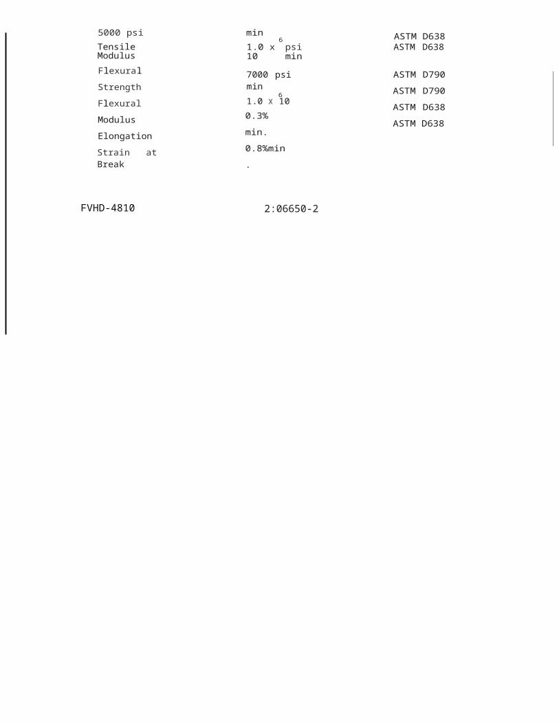
SECTION 09510- ACOUSTICAL CEILINGS
PART 1 -GENERAL
(} 1.1 RELATED DOCUMENTS
A. Drawings and general provisions of the Contract, including General and SupplementaryConditions and Division 1 Specification Sections, apply to this Section.
1.2 SUMMARY0
A. Extent of acoustical ceiling is shown and scheduled on the drawings.
B. Type of acoustical ceilings specified in this section includes the following:
1. Lay in acoustical ceiling board in existing exposed suspension system (to remain).0
1.3 QUALITY ASSURANCE
A. Installer: Firm with not less than three years of successful experience in installation ofacoustical ceilings similar to requirements for this project and which is acceptable to
() manufacturer of acoustical units, as shown by current written statement from manufacturer.
B. Fire Resistance Ratings: As indicated by reference to design designation in UL "Fire Resistance Directory" for floor, roof or beam assemblies inwhich acoustical ceilings function as a fire protective membrane; tested per ASTM E 119. Provide protection materials for lighting fixtures and air ducts to comply with requirements indicated for rated assembly.
)C. Surface Burning Characteristics: As follows, tested per ASTM E 84.
1. Flame Spread: 25 or less.2. Smoke Developed: 50 or less.
() D. All acoustical ceilings shall be installed to conform to the requirements of International Building Code for Category C and the recommendation of the Ceiling and Interior Systems Construction Association (CISCA) for Zone 2 seismic design and comply with installation requirements for areas subject to light to moderate seismic activity.
) E. General Contractor shall provide adequate ventilation and humidity control before, duringand after ceiling installation to prevent damage (sagging, etc.) to ceilings prior to Owner'sacceptance of building.
F. Warranty:
) 1. Provide manufacturer's special project warranty against sagging or warping of acoustic ceiling boards for a period of thirty (30) years which starts on approved date of substantial completion.
G. Unless otherwise approved by the Architect, all Acoustic al Ceiling Board type shall be by a single manufacturer .
u
FVHD-4810 2:09510-1

)1.4 SUBMITIALS
A. Product Data: Submit manufacturer's technical data for type of acoustical ceiling unit required including certified test reports to show compliance with requirements of these specifications.
)1. Include manufacturer's recommendations for cleaning and refinishing acoustical units,
including precautions against materials and methods which may be detrimental to finishes and acoustical performance.
B. Samples: Submit manufacturer's standard size samples of acoustical units, but not less than6" square. Provide samples showing full range of colors, textures and patterns available for )
type of component required.
C. Shop Drawings: Submit shop drawings for acoustical ceiling.
D. Certificates: Submit certificates from manufacturers of acoustical ceiling units attesting that )their products comply with specification requirements.
E. Testing Reports: Submit testing reports which indicate compliance with indicated requirements.
F. Deliver extra materials to Owner. Furnish extra materials described below matching )products installed, packaged with protective covering for storage and identified with appropriate labels.
1. Acoustical Ceiling Units: Furnish quantity of full size units equal to 2.0% of each type. of acoustical unit and suspension system installed.
1.5 PROJECT CONDITIONS
A. Space Enclosure : Do not install interior acoustical ceilings until space is enclosed and weatherproof, wet-work in space is completed and nominally dry, work above ceilings is complete, and ambient conditions of temperature and humidity will be continuously maintained at values near those indicated for final occupancy.
PART 2- PRODUCTS
2.1 MANUFACTURERS
A. Basis of Design: Provide Acoustical Ceiling Board (ACB) as manufactured by Armstrong World Industries; United States Gypsum Co. or approved equal.
B. Products specified herein have been selected because of their quality of construction, configuration, design, function, available finishes, components, accessories, dimensions, shape and style.
1. Comparable products of the follow ing manufacturers will be considered if it can be clearly shown that their products are equal to or will exceed the construction quality requirements and other design attributes listed as performance of the "Basis of Design" Systems.
FVHD-4810 2:09510·2

na. Armstrong World Industries,b. USG Corporation,c. CertainTeed Ceilings.d. or approved equal.
() 2. The use of one manufacturer's catalog numbers, and the specific requirements set forth in drawings and specifications, are not intended to preclude the use of other manufacturer's products or procedures which may be equivalent, but are given for the purpose of establishing a standard of design and quality for materials, construction and workmanship.
() c. Substitute products will be considered for substitution only when submitted to the Architect as per the requirements of Specification Section 00800.
2.2 ACOUSTICAL CEILING BOARDS
0 A. See reflected ceiling plans for sizes and locations.
B. Where ACB-1 is indicated: 24" x 48" x 3/4" thick, square edge, NRC .70; CAC 40 light reflectance 85%, sag resistance; Humiguard Plus Performance. Armstrong Fine Fissured{Item# 1714); USG Radar ClimaPius- High NRC/High CAC (Item# 22441), or approved equal.
)
PART 3- EXECUTION
3.1 INSPECTION
) A. Examine conditions under which acoustical ceiling work is to be performed and notify Architect in writing of unsatisfactory conditions. Do not proceed with work until unsatisfactory conditions have been corrected in an acceptable manner.
3.2 INSTALLATION
() A. General: Install materials in accordance with manufacturer's printed instructions, and to
comply with governing regulations, fire-resistance rating requirements as indicated, and CISCA standards applicable to work.
B. Cooperate with other trades and Contracts for installation of their materials and equipment,
u particularly with those installing the ductwork, ceiling diffusers and lighting fixtures so thatdiffusers, lighting fixtures.
3.3 CLEANING
A. Clean exposed surfaces of acoustical ceilings, including trim, edge moldings, and suspension members; comply with manufacturer's instructions for cleaning and touch-up of minor finish damage. General Contractor is responsible for cleaning or replacement of all damaged tile, regardless of how the damage was caused and regardless of by which Contractor.
END OF SECTION 09510u
FVHD-4810 2:09510·3

u

)
)
)
)
)
J

SECTION 09650 - RESILIENT FLOORING
PART 1 -GENERAl
1.1 RElATED DOCUMENTS
A Drawings and general provisions of the Contract, including General and Supplementary Conditions and Division 1 Specification Sections, apply to this Section.
1.2 DESCRIPTION OF WORK0
A Extent of resilient flooring and accessories is shown on drawings and in schedules.
1. Vinyl composition tile (VCT).2. Rubber resilient wall base.
0 1.3 RElATED SECTIONS
A Section 01455- Testing Concrete Slabs.
B. Section 03300- Cast in Place Concrete Slabs on Grade.()
C. Section 03450 - Self-Drying Finishing Underlayment.
D. Section 07900 -joint Sealer Assemblies .
1.4 QUAliTY ASSURAN E
A Codes and Standards: Comply with provisions of following codes, specifications and standards, except where more stringent requirements are shown or specified:
1. ASTM F 2170-02 Standard Test Method for Determining Relative Humidity inConcrete Floor Slabs Using in situ Probes.
()
2. ASTM F 1869-98 Standard Test Method Using Anhydrous Calcium Chloride.
3. ASTM F 1861 Type TS, Group 1 Performance Requirements for Resilient Rubber Wall Base.
0 4. ASTM F 137 Standard Test Method for Flexibility of Resilient Flooring Materials protocol for Resilient Rubber Wall Base.
5. ASTM F 1515 Standard Test Method for Measuring light Stability of Resilient Flooring protocols for Resilient Rubber Wall Base.
uB. Moisture vapor emission testing in accordance with ASTM F 1869-11. Test results should
not exceed 3 pounds per 1,000 square feet per 24 hours, unless otherwise specified by the flooring or adhesive manufacturer.
1. ASTM Standard also states that relative humidity inside of the concrete slab should notu exceed 75%, per ASTM F21 70-11, unless otherwise specified by the flooring or
adhesive manufacturer.
FVHD-4810 2:09650·1
l)

C. Manufacturer: Provide each type of resilient flooring and accessories as produced by a single manufacturer, including recommended primers, adhesives, sealants, and leveling compounds .
1. Wherever possible, provide each type of required resilient flooring and accessories produced by a single manufacturer.
D. Fire Test Performance: Provide resilient flooring which complies with the following fire test performance criteria as determined by an independent testing laboratory acceptable to authorities having jurisdiction.
1. ASTM E 84, Standard Test Method for Surface Burning Characteristics of Building}
Materials, Class A, Smoke <450.
2. ASTM E648, Standard Test Method for Critical Radiant Flux of 0.45 watts/cm 2 orgreater, Class 1.
)E. Flooring: Comply with the ADA Protocol Brungraber Mark I COF, International Building
Code, ICC/ANSI A 117.1, for Static Coefficient of Friction (COF); of 0.6 or better for flat andlevel flooring surfaces and 0.8 for sloped ramp surfaces.
1.5 SUBMIITALS
A. Product Data: Submit manufacturer's technical data for each type of resilient flooring and accessory.
B. Samples for Verification Purposes: Submit the following samples in trrplicate of each type, color, and pattern of resilient flooring required, showing full-range of color and pattern variations.
1. Full size tile samples.
2. For initial selection of colors and patterns submit, prior to above, samples in form of actual sections of resilient flooring, including accessories, showing full range of colors and patterns available, for each type of resilient flooring required.
C. Certification for Fire Test Performance: Submit certification from an independent testing laboratory acceptable to authorities having jurisdiction that resilient flooring complies with fire test performance requirements.
D. Testing of Substrate:
1. Submit test reports of testing the concrete or other floor substrate, indicating compliance with manufacturer's requirements for moisture and alkalinity percentage of contents. Tests shall be performed in accordance with requirements of Section 01455.
E. Maintenance Instructions: Submit 2 copies of manufacturer's recommended maintenancepractices for each type of resilient flooring and accessory required.
F. Replacement Material: After completion of work, deliver to project site replacementmaterials from same manufactured lot as materials installed, and as follows:
FVHD-4810 2:09650-2

1. Tile flooring, not less than one box for each 50 boxes or fraction thereof, for each type,size and color installed.
1.6 PROJECT CONDITIONS
0 A. Maintain minimum temperature of 65°F (18°<:;) or more than 85°F (29°C) in spaces to receive resilient flooring for at least 48 hours prior to installation, during installation, and for not less than 48 hours after installation.
1. Store resilient flooring materials in spaces where they will be installed for at least 48 hours before beginning installation.
0B. Maintain the ambient relative humidity between 40% and 60% during installation.
C. Install resilient flooring and accessories after other finishing operations, including painting, have been completed.
()D. Until Substantial Completion, maintain ambient temperatures within range
recommended by manufacturer, but not less than 55°F (13°C) or more than 85°F (29°C).
E. Do not install resilient flooring over concrete slabs until the latter have been cured and are sufficiently dry to achieve bond with adhesive as determined by resilient flooring
() manufacturers and their recommendation for bond and maximum levels of moisture and pH per testing as performed under requirements of Section 01455.
1.7 WARRANTY
A. Vinyl Composition Tile:)
1. Manufacturer warrants its regular (first quality) commercial floor products to be freefrom manufacturing defects for five (5) years from date of purchase.
a) Within One Year: If a defect covered by this warranty is reported to themanufacturer in writing within one year of purchase, Manufacturer will supply
) new material of the same or similar grade sufficient to repair or replace thedefective material. Manufacturer will also pay reasonable labor costs.
b) Within Two Years: If a defect covered by this warranty is reported to the manufacturer in writing after one year but within two years of purchase, Manufacturer will supply new material of the same or similar grade sufficient to repair or replace the defective material. Manufacturer will also pay fifty (SO%) percent of reasonable labor costs.
c) After Two Years: If a defect covered by this warranty is reported to the manufacturer in writing after two years but within five years of purchase, Manufacturer will supply new material of the same or similar grade sufficient to repair or replace the defective material. Manufacturer will not pay for labor costs.
d) Manufacturer does notwarrant the installers' workmanship. Workmanship errors should be addressed to the contractor who installed the floor.
u
FVH0-4810 2:09650-3

u

PART 2 -PRODUCTS
2.1 MANUFACTURERS
A Subject to compliance with requirements, manufacturers offering products which may beincorporated in the work include but not limited to the following: )
1. Vinyl Composition Tile (VCT); provide the following:
a. "Standard Excelon Imperial Texture" and "Standard Excelon MultiColor", asmanufactured by Armstrong World Industries;
b. "Essentials, Designer Essential and Inspiration", as manufactured by Mannington )
Commercial;c. "Cortina Classics", as manufactured by Johnsonite (a Tarkett Co., Azrock
Collection);d. or approved equal.
)2. Rubber Resilient Wall Base and Accessories:
a. "Pinnacle", as manufactured by Rappe Corporation;b. "BaseWorks Thermoset Rubber Wall Base", as manufactured by johnsonite,c. "RubberMyt e" as manufactured by Burke Mercer Flooring Product,d. or approved equal. )
B. Products specified herein have b en selected because of their quality of construction, configuration, design, function, available finishes, components, accessories, dimensions, shape and style.
1. The use of one manufacturer's catalog numbers,and the specific requirements set forth )
in drawings and specifications, are not intended to preclude the use of other products by other manufacturer's or which may be equivalent, but are given for the purpose of estab lishing a standard of design and quality for materials, construction and workmanship.
C. Comparable products of other manufacturers will be considered if it can be clearly shown that their products are equal to or will exceed the construction quality requirements, intended performances and all other design attributes listed above and provided that deviations in dimensions and profiles are minor and do not materially detract from the design concept or intended performances as judged solely by the Architect/Owner.
)2.2 VINYL COMPOSITION TILE FLOORING
A Vinyl Composition Tile:ASTM F 1066, Class 2, through pattern, 12" x 12" unless otherwiseindicated, and as follows:
1. Asbestos-free.2. Gauge: 1/8 inch.
B. Provide vinyl composition tile to meet indicated "Basis of Design" products and qualityassurance requirements indicated in Articles 1.2 and 2.1 of this specifications.
FVHD-4810 2:09650-4

2.3 ACCESSORIES
A. Wall Base: Provide rubber base complying with ASTM F-1861, Type TS, Group 1.Vulcanized SBR rubber with matching preformed corner units, and as follows:
0 1. Height: 4-inches, unless otherwise indicated on the drawings.2. Thickness: 1/8 inch gauge.3. Style: Standard top-set cove.4. Finish I Colors: Matte finishes in colors as selected by Architect from manufacturer's
available full range of colors. Allow for more than one color in any given area.5. Color Stability: Meets or exceeds ASTM F 1861 requirements for color stability when
0 tested to ASTM F 1515 Standard Test Method for Measuring Light Stability of Resilient Flooring protocols.
6. Phthalate, chlorine and halogen free.
B. Adhesives (Cements): Water resistant, stabilized type as recommended by flooring
0 manufacturer to suit material and substrate conditions.
1. Adhesives to be used for resilient floor applications shall not generate any odor orunpleasant smell.
C. Concrete Slab Primer: Non-staining type as recommended by flooring manufacturer.0
D. Leveling and Patching Compounds: Latex types as recommended by flooring manufacturer.
E. Slip Retardant Polish: Provide slip-retardant polish as recommended by resilient tile manufacturer.
u 1. POLISH FOR RESILIENT FLOORING
a. Floor Polish: Contractor shall provide floor polish to achieve the Static Coefficient of Friction; per ASTM D 2047, of 0.5 or better for level surfaces and as per requirements of state and local codes having jurisdictions.
ub. Contractor shall provide the Owner with maintenance instructions for application
of polish to maintain a Static Coefficient of Friction of 0.5, or more per ASTM D 2047.
2.4 COlORS, TEXTURES AND PATTERNS0
A. Colors, textures and patterns shall be as selected and directed by the Architect. Patterns shallbe defined as using not more than five (5) different colors of tile in any given area, applied in boarders, stripes, diagonals, checkerboard patterns and other designs as indicated, or if not indicated, shall be as directed by the Architect.
1. All selections shall be made from manufacturer's full product lines, for all products and accessories, (including premium textures and colors).
u
FVHD-4810 2:09650-5
u

PART 3 ·EXECUTION
3.1 EXAMINATION
A. General: Inspect substrates and conditions of installation to verify that work may properly commence. Do not proceed with the work until unsatisfactory conditions have been corrected.
B. Concrete Substrates: Perform concrete relative humidity and pH testing and to comply with manufacturer's recommended moisture tests before beginning installation, to verify that concrete surfaces have cured sufficiently to allow adhesive bond to resilient flooring.
1. Commencement of work shall constitute acceptance of conditions. Any necessary remedial work required to correct any unsatisfactory conditions, found after the start of installation, will be provided at no cost to the Owner.
3.2 PREPARATION)
A. Perform moisture content testing as required by manufacturer's instructions to ensure pH readings and moisture transmission are acceptable. Perform testing in accordance with requirements of Section 01455.
1. If values exceed this level, follow manufacturer's recommendations for moisture )transmission mitigation. Do not proceed until unsatisfactory conditions have beencorrected.
B. Broom clean or vacuum surfaces to be covered, and inspect subfloor.
1. Use leveling and patching compounds as recommended by resilient flooring manufacturer for filling small cracks, holes and depressions in subfloors.
2. Apply concrete slab primer and/or sealer, as recommended by flooring manufacturer, prior to application of adhesive. Apply in compliance with manufacturer's directions.
3. Remove paint, curing compounds, and other materials that could interfere withadhesion of resilient produ<:;ts.
3.3 GENERAL INSTALLATION REQUIREMENTS
A. Comply with manufacturer's published recommendations for installation in the area, extending resilient flooring into spaces which are partially concealed. Cut and fit tightly to fixtures, pipes, and other obstructions, as well as to walls and partitions.
B. Access Covers: Install resilient flooring tightly to removable access covers in field of flooring, taking care that pattern will match when covers are in closed position.
C. Tightly adhere resilient flooring to substrate with no open joints or cracks, and without raised or blistered areas. Spread adhesive evenly, so that final installation will be without telegraphed markings from adhesive or substrate.
D. Extend resilient flooring into toe spaces, door reveals, and into closets and similar openings.
FVHD-4810 2:09650-6

(
)
0
0
}E. Scribe, cut, and fit resilient flooring to permanent fixtures, built-in furnitur e and cabinets,
pipes, outlets and permanent columns,walls and partitions.
F. Maintain reference markers, holes, or openings that are in place or plainly marked for future cutting by repeating on finish flooring as marked on subfloor. Use chalk or other
0 non-permanent marking device.
G. Install resilient flooring on covers for telephone and electrical ducts, and similar _ items occurring within finish ed floor areas. Maintain overall continuity of color and pattern with pieces of flooring installed on these covers. Tightly cement edges to perimeter of flooraround covers and to covers.
0H. Tightly cement resilient flooring to subbase without open cracks, voids, raising and
puckering at joints, telegraphin g of adhesive spreader marks, or other surface imperfections. Hand roll resilient flooring at perimeter of each covered area to assure adhesion.
3.4 INSTALLATION OF TILE FLOORS
A. Lay tile from center marks established with principal walls, discounting minor offsets, so that tile at opposite edges of room area of equal width. Adjust as necessary to avoid use of cut widths less than 1/2 tile at room perimeters. Lay tile square to room axis, unless otherwise shown.
B. Match tiles for color and pattern by using tile from cartons in same sequence as manufactured and packaged if so numbered. Cut tile neatly around all fixtures. Broken, cracked, chipped, or deformed tiles are not acceptable.
1. Lay tile in pattern shown or as directed by Archite ct.
C. Adhere tile flooring to substrates using full spread of adhesive applied in compliance with flooring manufacturer's directions.
D. Expansion Joints : Locate expansion joints an·d other sealant filled joints, including control, contraction and isolation joints, where indicated or where joints occur in substrate. Do not saw cut joint s.
3.5 INSTALLATION OF ACCESSORIES
A. Apply wall base to walls,columns, pilasters, casework and other permanent fixtures in rooms
) or areas where base is required. Install base in lengths as long as practicable,with preformed corner units, or fabricated from base materials with mitered or coped inside corners. Tightly bond base to substrate throughout length of each piece, with continuous contact at horizontal and ver tical surfaces .
1. Job-formed Corners:0
a. Outside Corners: Form by bending without producing discoloration (whitening) at bends.
b. Inside Corners: Butt one piece to corner, then scribe next piece to fit.
uB. On masonry surfaces, or other similar irregular substrates, fill voids along top edge of resilient
wall base with manufacturer's recommended adhesive filler material.
FVHD-4810 2:09650·7

J
3.6 CLEANING AND PROTECTION
A Perform following operations immediately upon completion of resilient flooring:
1. Sweep or vacuum floor thoroughly.)
2. Do not wash floor until time period recommended by resilient flooring manufacturer has elapsed to allow resilient flooring to become well-sealed in adhesive.
3. Damp-mop floor being careful to remove black marks and excessive soil.
4. Remove any excess adhesive or other surface blemishes, using appropriate cleaner recommended by resilient flooring manufacturers.
B. Protect flooring against damage during construction period to comply with resilient flooringmanufacturer's directions.
1. Apply protective floor polish to resilient flooring surfaces free from soil, excess adhesive or surface blemishes. Use commercially available metal cross-linked acrylic product acceptable to resilient flooring manufacturer.
2. Protect resilient flooring against damage from rolling loads for initial period following installation by covering with plywood or hardboard. Use dollies to move stationary equipment or furnishings across floors . ·
3. Cover resilient flooring with undyed, untreated building paper until inspection for substantial completion.
C. Clean resilient flooring not more than·4 days prior to date scheduled for inspections intended to establish date of substantial completion in each area of project. Clean resilient flooring by method recommended by resilient flooring manufacturer.
D: Strip protective floor polish, which was applied after completion of installation, prior to cleaning.
1. Reapply floor polish after cleaning.
3.7 EXTRA STOCK
A Deliver stock of maintenance materials to Owner. Furnish maintenance materials from same manufactured lot as materials installed and enclosed in protective packaging with appropriate identifying labels.
1. Tile Flooring: Furnish not less than one box for each 50 boxes or fraction thereof, foreach type, color, pattern and size selected and installed.
2. Accessories: Furnish not less than 2% of each type, size and color selected and installed.
END OF SECTION 09650
FVHD-4810 2:09650·8

.
SECTION 09900- PAINTING
PART 1 -GENERAl
1.1 RElATED DOCUMENTS
A. Drawings and general provisions of the Contract, including General and SupplementaryConditions and Division 1 Specification Sections, apply to this Section.
B. Related Sections:0
1. Section 04200 - Unit Masonry.2. Section 05400 - Miscellaneous Structural Steel.3. Section 05500- Metal Fabrications.4. Mechanical Work- Specifications on drawings
) 1.2 DESCRIPTION OF WORK
A. Extent of painting work is indicated on drawings and schedules, and as herein specified.
B. Work includes painting and finishing of interior and exterior exposed items and surfaces() throughout project, except as otherwise indicated.
1. Surface preparation, priming and coats of paint specified are in addition toshop-priming and surface treatment specified under other sections of work.
c. "Paint" as used herein means all coating systems materials, including primers, emulsion , enamels, stains, sealers and fillers, and other applied materials whether used as prime, intermediate or finish coats.
D. Surfaces to be Painted: Except where natural finish of material is specifically noted as a surface not to be painted, paint exposed surfaces whether or not colors are designated in"schedules". Where items or surfaces are not specifically mentioned, paint the same as
0 similar adjacent materials or areas. If color or finish is not designated, Architect will select
these from standard colors or finishes available.
E. Following categories of work are not included as part of field-applied finish work.
0 1. Shop Priming: Unless otherwise specified, shop priming of ferrous metal items is included under various sections for structural steel, steel windows, miscellaneous metal,hollow metal work, and similar items. Also, for fabricated components such as architectural woodwork, wood casework, and shop fabricated or factory built mechanical and electrical equipment or accessories. This is in addition to the primecoat specified herein.
)
2. Pre-Finished Items: Unless otherwise indicated, do not include painting when factory-finishing or installer-finishing is specified for such items as (but not limited to) metal toilet enclosures, prefinished partition systems, acoustic materials, architectural woodwork and casework, and shop fabricated or factory built mechanical and electricalequipment, including light fixtures, switchgear and distribution cabinets.
()
FVHD-4810 2:09900-1

3. Concealed Surfaces: Unless otherwise indicated, painting is not required on surfaces such as walls or ceilings in concealed areas and generally inaccessible areas, foundation spaces, furred areas, utility tunnels, pipe spaces, duct shafts and elevator shafts.
4. Finished Metal Surfaces: Unless otherwise indicated, metal surfaces of anodizedaluminum, stainless steel, chromium plate, copper, bronze and similar finished materials ')
will not require finish painting.
5. Operating Parts: Unless otherwise indicated, moving parts of operating units, mechanical and electrical parts, such as valve and damper operators, linkages, sinkages, sensing devices, motor and fan shafts will not require finish painting.
6. Do not paint over any code-required labels, such as Underwriters' Laboratories and Factory Mutual, or any equipment, identification, performance rating, name, or nomenclature plates.
F. Mechanical and Electrical Work : Painting of mechanical and electrical work is specified )herein.
1. Painting of mechanical and electrical work is limited to those items exposed to view.
2. Mechanical items to be painted include, but are not limited to, the following:
a. Piping, pipe hangers and supports.b. Ductwork, insulation.c. Access doors and service panels.
3. Electrical items to be painted include, but are not limited to, the following:
a. Conduit and fittings.b. Backboxes.c. Junction boxes.
1.3 QUALITY ASSURANCE
A. Single Source Responsibility: Provide primers and other undercoat paint produced by same manufacturer as finish coats. Use only thinners approved by paint manufacturer, and use only within recommende d limits.
B. Coordination of Work: Review other sections of these specifications in which prime paints are to be provided to ensure compatibility of total coatings system for various substrates. Upon request from other trades, furnish information or characteristics of finish materials provided for use, to ensure compatible prime coats are used.
C. Industry Standards: Comply with industry standard established by the Painting and Decorating Contractors of Am erica PDCA for applications, methods and recommendations and use of tools and equipment for paint and stain coatings, primers and block fillers.
D. Lead and Chromate Contents:
1. All paint products must be free of any lead or chromate contents.
FVHD-4810 2:09900-2

0
E. Volatile Organic Compound Compliant (VOC.):
1. All paint products must meet the State VOC environmental regulations (OTCRegulation compliant) and the following:
a. Chemical Components of Interior Paints and Coatings: Provide products that comply with the following limits for VOC content when calculated according to 40 CFR 59, Subpart D (EPA Method 24) and the following chemical restrictions:
(1) Primer, Sealer and Undercoater: VOC content of not more than 200 g/L.
<D (2) Specialty Primer, Sealer and Undercoater : VOC content of not more than350 g/L.
(3) Rust Preventative Coating: VOC content of not more than 400 g/L.
(4) Flat Paints and Coatings: VOC content of not more than 100 g/L.
(5) Non-Flat Paints and Coatings: VOC content of not more than 150 g/L.
(6) Nonflat High Gloss Coatings: VOC content of not more than 250 g/L.
) (7) Varnishes and Sanding Sealers: VOC content of not more than 350 g/L.
(8) Stains: VOC content of not more than 250 g/L.
(9) Aromatic Compounds: Paints and coatings shall not contain more than 1.0percent by weight of total aromatic compounds (hydrocarbon compounds containing one or more benzene rings).
F. Paint Coordination: Provide finish coats which are compatible with prime paints used.Review other sections of these specifications in which prime paints are .to be provided toensure compatibility of total coatings system for various substrates. Upon request from other
( trades, furnish information on characteristics of finish materials proposed for use, to ensure compatible prime coats are used. Provide barrier coats over incompatible primers orremove and reprime as required. Notify Architect in writing of any anticipated problems using specified coating systems with substrates primed by others.
1. At galvanized surfaces, primer shall be a zinc dust-zinc oxide coating.
1.4 SUBMIITALS
A. Product Data: Submit manufacturer's technical information including paint label analysis and application instructions for each material proposed for use.
B. Samples: Prior to beginning work, Contractor shall furnish color chips (2 fan decks) for surfaces to be painted. Use representative colors when preparing samples for review. Submit samples for Architect's review of color and texture only. Provide a listing of material and application for each coat of each finish sample.
1. On 12"x 12" hardboard, provide two samples of each color and material, with texture to simulate actual conditions. Resubmit samples as requested by Architect until acceptable sheen, color, and texture is achieved.
FVHD-4810 2:09900-3

!
)C. Acknowledgment of Contract Documents: Contractor j Installer shall submit to the Architect
certifications signed by each of the Contractor and Installer attesting acknowledgment of requirements of the Contract Documents for specific project requirements indicated in this specifications.
1. Installer shall submit proof of evidence, (this project specification section) with his letter lof certificate.
2. Contractor I Installer shall not proceedwith painting work of this section until submittal of required certifications are completed.
( }3. Any work performed prior to completion of this submittal shall be subject to total
rejection by the Architect. All rejected work shall be rectified without any additional cost to the Owner.
E. Coating Maintenance Manual: Upon conclusion of the project, the contractor in conjunction with the coating manufacturer shall furnish a coating maintenance manual such as the Sherwin-Williams" Custodian Project Color and Product Information" report or equal. Manual shall include an area summary with finish schedule, area detail designating where each product/color/finish was used, product data pages, SDS pages, care and cleaning instructions, touch up procedures and color samples of each color and finish used.
1.5 DELIVERY AND STORAGE
A. Deliver materials to job site in original, new and unopened packages and containers bearingmanufacturer's name and label, and following information:
Name or title of material.Fed. Spec. number, if applicable.Manufacturer's stock number and date of manufacturer. Manufacturer's name.Contents by volume,for major pigment and vehicle constituents.Thinning instructions. Application instructions. Color name and number.
1.6 JOB CONDITIONS
A. Apply solvent-thinned paints only when temperature of surfaces to be painted and surrounding air temperatures are between 45°F (rC) and 95°F (35 °C), unless otherwise permitted by paint manufacturer's printed instructions.
B. Do not apply paint in snow, rain, fog or mist, or when relative humidity exceeds 85%, or to damp or wet surfaces, unless otherwise permitted by paint manufacturer's printed instructions.
C. Painting may be continued during inclement weather if areas and surfaces to be painted are enclosed and heated within temperature limits specified by paint manufacturer during application and drying periods.
D. Provide sufficient temporary illumination producing overall space/room mrmmum illumination level of 50 ft. candles while preparing or painting of surfaces and to assure the production of quality finishes.
FVHD-4810 2:09900-4

PART 2 -PRODUCTS
2.1 MANUFACTURERS
A. Subject to compliance with requirements, manufacturers offering products which may be incorporated in the work include but are not limited to the following:
1. M A B2. Benjamin Moore3. PPG Architectural Coatings4. The Sherwin-Williams Company
02.2 COlORS AND FINISHES
A. Prior to beginning work, Contractor shall furnish color chips for surfaces to be painted from manufacturers full line of products. This shall include custom colors.
0
\.)
1. Contractor shall allow for a total of 20 different colors of each type of paint, (excluding graphics and for art work as indicated) with change of color within a room or space occurring either on a horizontal or vertical line, [allow for multiple (6) colors at each room unless otherwise shown). Where roof structure is exposed, steel beams, steel joists and metal decking will be painted with different colors, as selected by the Architect.
2. Contractor shall allow for split frames at all new and existing hollow metal door frames to be painted.
3. Final acceptance of colors will be from samples supplied on the job.
B. Color Pigments: Pure, non-fading, applicable types to suit substrates and service indicated.
2.3 MATERIAlS
A. Material Quality: Provide best quality grade of various types of coatings as regularly manufactured by acceptable paint materials manufacturers. Materials not displaying manufacturer's identification as a standard, best-grade product will not be acceptable.
B.
0
2.4
A.
' )B.
0
Provide undercoat paint recommended and produced by the same manufacturer as the finish coats. Use only thinners approved by the paint manufacturer, and use only within recommended limits.
EXTERIOR PAINT SCHEDUlE
Basis of Design: Provide the following paint systems for the various substrates. Other equalpaint products by indicated manufacturers will be acceptable:
High-Gloss Enamel (Water-base Polyester Urethane Finish)
1. 1st Coat: Sherwin-Williams, Pro Industrial Pro-Cryl Universal Primer, B66W310.
2. 2nd Coat: Sherwin-Williams, Hydrogloss 1K Water-based Urethane,B65-180.
FVHD-4810 2:09900-5
u

3. 3rd Coat: Sherwin-Williams, Hydrogloss 1K Water-based Urethane, B65-180.
4. Apply to the following exterior surfaces : Lintels, ferrous metal and other exterior assemblies to receive paint.
5. Apply as many coats as necessary to produce a uniform substrate and finish )appearance.
2.5 INTERIOR PAINT SCHEDULE
A. Semi-Gloss (Satin) Enamel:0
1. 1st Coat: Sherwin-Williams, Pro Industrial Pro-Cryl Universal Primer, B66W310.
2. 2nd Coat: Acrylic Enamel, Sherwin-Williams, Pro Industrial HP Acrylic, B66-650.
3. 3rd Coat: Acrylic Enamel, Sherwin-Williams, Pro Industrial HP Acrylic, B66-650. )
4. Apply to following interior surfaces : Hollow metal work, metal lites for wood doors,miscellaneous steel and ferrous metal fabrications .
5. Apply as many coats as necessary to produce a uniform substrate and finish appearance.
B. Egg-Shell I Satin Enamel -Acrylic Latex:
1. Base Coats: Enamel Undercoat; Primer-Sealer to suit s1,1bstrate or Loxon Block Surfacer, A24 for Concrete Masonry/CMU Block.
* Block Filler shall be Level 3 - Premium Fill; one or multiple coats for high
performance block filler in accordance with PDCA industry standards. Apply
mock-up to confirm appearance before application of finish coats.
2. 2nd Coat: Sherwin-Williams, ProMar 200 Zero VOC Eg-Shel, B20-2600 Series.
3. 3rd Coat: Sherwin-Williams, ProMar 200 Zero VOC Eg-Shel, B20-2600 Series.
4. Apply to the following interior surfaces: Concrete masonry units, gypsum drywall and other interior assemblies to receive paint.
)5. Apply as many coats as necessary to produce a uniform substrate and finish
appearance.
C. Flat- Acrylic Latex:
1. 1st Coat: Sherwin Williams ProMar 200 Zero VOC Interior Latex Primer,B28W02600.
2. 2nd Coat: Sherwin Williams, ProMar 200 Zero VOC Flat Interior Latex Flat, B30- 2600.
3. 3rd Coat: Sherwin Williams, ProMar 200 Zero VOC Flat Interior Latex Flat, B30-2600.
FVHD-4810 2:09900·6

(}
4. Apply to following interior surfaces: Interior surfaces of ducts, where visible throughregisters or grilles, etc.
5. . Apply as many coats as necessary to produce a uniform substrate and finish() appearance.
2.6 EXTRA STOCK
A. Contractor shall provide one gallon of extra stock for each color/type selected for use on the project. Provide unopened containers clearly marked with manufacturers color number and name.
PART 3 -EXECUTION
3.1 INSPECTION
A. Applic ator must examine areas and conditions under which painting work is to be applied and notify Contractor in writing of conditions detrimental to proper and timely completion of work. Do not proceed with work until unsatisfactory conditions, included rotted or otherwise defective materials, have been observed by all concerned and corrected in a
) manner acceptable to Applicator.
B. Starting of painting work will be construed as Applicator's acceptance of surfaces and·conditions within any particular area.
c. Do not paint over dirt, rust, scale, grease, moisture, scuffed surfaces, or conditions otherwise() detrimental to formation of a durable paint film.
3.2 SURFACE PREPARATION
A. General:
0 1. Perform preparation and cleaning procedures in accordance with paint manufacturer's instructions and as herein specified, for each particular substrate condition.
2. Provide barrier coats over incompatible primers or remove and reprime as required.Notify Architect in writing of any anticipated problems in using the specified coating
) systems with substrates primed by others.
3. Remove hardware, hardware accessories, machined surfaces, plates, lighting fixtures, and similar items in place and not to be finish-painted, or provide surface-applied protection prior to surface preparation and painting operations . Remove, if necessary, for complete painting of items and adjacent surfaces. Following completion of painting
u of each space or area, reinstall removed items.
4. Clean surfaces to be painted before applying paint or surface treatments. Remove oil and grease prior to mechanical cleaning. Program cleaning and painting so that contaminants from cleaning process will not fall onto wet, newly-painted surfaces.
0 5. Painting of materials shall commence only when the moisture content of the materials
complies with manufacturer's recommendations as follows:

FVHD-4810 2:09900-7
(_)

a. Concrete and masonry- 22% maximum.b. Gypsum drywall - 12% maximum.c. Plaster- 15% maximum.d. Wood (interior) - 8% maximum.
B. Cementitious Materials:
1. Prepare cementitious surfaces of concrete, concrete block, cement plaster and gypsum drywall board to be painted by removing efflorescence, chalk, dust, dirt, grease, oils, and by roughening as required to remove glaze.
2. Determine alkalinity and moisture content of surfaces to be painted by performing lappropriate tests. If surfaces are found to be sufficiently alkaline to cause blistering and burning of finish paint, correct this condition before application of paint. Do not paint over surfaces where moisture content exceeds that permitted in manufacturer's printed directions.
C. Wood :
1. Clean wood surfaces to be painted of dirt, oil, or other foreign substances with scrapers, mineral spirits, and sandpaper, as required. Sandpaper smooth those finished surfaces exposed to view, and dust off. Scrape and clean small, dry, seasoned knots and apply a thin coat of white shellac or other recommended knot sealer, before application of priming coat. After priming, fill holes and imperfections in finish surfaces with putty or plastic wood-filler. Sandpaper smooth when dried.
2. Prime, stain, or seal wood required to be job-painted immediately upon delivery to job .Prime edges, ends, faces, undersides, and backsides of such wood, including cabinets,counters, cases, paneling.
)
3. When transparent finish is required, use spar varnish for backpriming.
D. Ferrous Metals:
1. Clean ferrous surfaces, which are not galvanized or shop-coated, of oil, grease, dirt, loose mill scale and other foreign substances by solvent or mechanical cleaning.
2. Touch-up shop-applied prime coats wherever damaged or bare, where required byother sections of these specifications .Clean and touch-up with same type shop primer.
3. Galvanized Surfaces: Clean free of oil and surface contaminants with non-petroleumbased solvent.
3.3 MATERIALS PREPARATION
A. Mix and prepare painting materials in accordance with manufacturer's directions. (
B. Maintain containers used in mixing and application of paint in a clean condition, free offoreign materials and residue.
c. Stir materials before application to produce a mixture of uniform density, and stir as required (
during application. Do not stir surface film into material. Remove film and, if necessary, strain material before using.
FVHD-4810 2:09900-8

D. Tinting: Tint each undercoat a lighter shade to simplify identification of each coat when multiple coats of same material are applied. Tint undercoats to match the color of the finish coat, but provide sufficient differences in shade of undercoats to distinguish each separate coat.
0 3.4 APPLICATION
A. General: Apply paint in accordance with manufacturer's directions. Use applicators and techniques best suited for substrate and type of material being applied.
B. Where finish schedule calls for walls, floors or ceilings to be painted, paint all new and existing surfaces in same area. Paint from corner to corner on walls, floors, or ceilings, or to a major change in direction of surface to be painted. Provide crisp, clean, sharp lines where new painted surfaces abut existing painted surfaces.
c. Apply additional coats when undercoats, stains or other conditions show through final coat of paint, until paint film is of uniform finish, color and appearance. Give special attention to insure that surfaces, including edges, corners, crevices, welds, and exposed fasteners receive a dry film thickness equivalent to that of flat surfaces.
D. Paint interior surfaces of ducts, where visible through registers or grilles, with a flat,non-specular black paint.
)E. Sand lightly between each succeeding enamel coat.
F. Scheduling Painting: Apply first-coat material to surfaces that have been cleaned, pretreated or otherwise prepared for painting as soon as practicable after preparation and·. before subsequent surface deterioration.
(
G. Allow sufficient time between successive coatings to permit proper drying. Do not recoat until paint has dried to where it feels firm, does not deform or feel sticky under moderate thumb pressure, and application of another coat of paint does not cause lifting or loss of adhesion of the undercoat.
0 H. Minimum Coating Thickness: Apply materials at not less than manufacturer's recommended spreading rate, to establish a total dry film thickness as recommended by coating manufacturer and an acceptable finished appearance in finish, color and appearance as determined by the Architect.
) I. Primer Coat: Apply primer coat of material which is required to be painted or finished, and
which has not been prime coated by others.
1. Re-coat primed and sealed surfaces where there is evidence of suction spots or unsealed areas in first coat, to assure a finish coat with no burn-through or other defects due to insufficient sealing.
j. Block Fillers: Apply block fillers using manufacturer's recommend ed application techniques with sufficient material and coats to achieve a pinhole-fre e, "level3 ·Premium Fill Surface", and in accordance with PDCA 's industry standards.
K. Pigmented (Opaque) Finishes: Completely cover to provide an opaque, smooth surface of0 uniform finish, color, appearance and coverage. Cloudiness, spotting, holidays, laps, brush
marks, runs, sags, ropiness or other surface imperfections will not be acceptable.
FVHD-4810 2:09900-9

L. Completed Work: Match approved samples for color, texture and coverage. Remove,refinish or repaint work not in compliance with specified requirements.
3.5 CLEAN·UP AND PROTECTION
A. Clean-Up : During progress of work, remove from site discarded paint materials, rubbish,cans and rags at end of each work day.
B. Upon completion of painting work, clean all paint-spattered surfaces. Remove spattered paint by proper methods of washing and scraping, using care not to scratch or otherwise damage finished surfaces.
)
C. Protection: Protect work of other trades, whether to be painted or not, against damage by painting and finishing work. Correct any damage by cleaning, repairing or replacing, and repainting, as acceptable to Architect.
1. Provide "Wet Paint" signs as required to protect newly-painted finishes. Remove )temporary protective wrappings provided by others for protection of their work, aftercompletion of painting operations.
2. At completion of work of other trades, touch-up and restore all damaged or defaced painted surfaces.
)
END OF SECTION 09900
)
)
FVHD-4810 2:09900-10

M. GREENGUARD Indoor Air Quality Certified.
N. GREENGUARD Children and Schools Indoor Air Quality Certified.
SECTION 10100 - DRY MARKERBOARDS AND EXHIBITION BOARDS
PART 1 -GENERAL
1.1
A.
1.20
A.
B.
)
RELATED DOCUMENTS
Drawings and general provisions of the Contract, including General and SupplementaryConditions and Division 1 Specification Sections, apply to this Section.
DESCRIPTION OF WORK
Extent of dry markerboards and exhibition boards is indicated on the drawings.
Types of dry markerboards and exhibition boards specified in this section include the following :
1. Porcelain enamel dry marker boards.2. Fabricork fabric faced cork exhibition boards.3. Factory applied trim.
1.3 REFERENCES0
A. ASTM E84 Standard Test Method for Surface Burning Characteristics for BuildingMaterials.
B. ASTM C540 Gloss for ceramic materials.
0 C. ASTM C614 for alkali resistance.
D. ASTM D2244 evaluation of color differences.
E. ASTM B221 Standard Specification for Aluminum and Aluminum Alloy Extruded Bars, Rods, Wires, Profiles and Tubes.
0F. ASTM C208-72 for cellulosic fiberboard.
G. ANSI A208.1-79 for particleboard.
H. ANSI H35.1-82 for aluminum temper and alloy.
I. HNSI A424-80 for steel for porcelain enameling.
j. FS LLL-B-810 for tempered hardboard.
K. PEI-1002 Manual and Performance Specification for Porcelain Enamel Writing Surfaces .
L. BYK-Gardner Surface Distortion.
0
FVHD-4810
'

2:10100-1

1.4 QUALITY ASSURANCE
A Manufacturer : Furnish all dry markerboards and exhibition boards by a single manufacturer for the entire project.
B. Surface Burning Characteristics: Provide exhibition board surfaces which are identical in composition to those with surface burning characteristics indicated below, as determined by testing in compliance with ASTM E84. Use only exhibition boards which are certified to meet the following standards:
t.J
1. Flame Spread:2. Smoke Developed:
Not more than 25. 0Not more than 40.
C. Uniformity of color, corrosion, temperature, alkali,water, range of gloss test, uniform texture,light reflectance and cleanability are requirements for all groups and have specific ranges foreach. )
D. Product Certifications: Provide GREENGUARD Indoor Air Quality Certified and GREENGUARD Children and Schools Indoor Air Quality Certificates for markerboards.
E. Reflectivity of LCSII ceramicstee lMarkerboard writing surfaces shall not exceed the following:
1. Gloss Range I 60° Gloss meter GU (Gloss Units)
a. LCSII ceramicstee l for Markerboard 68 -76% (low gloss surface).
b. LCSII ceramicsteel or writing surfaces - Surface Distortion reduction and theoptimum improvement to performance characteristics.
2. Contrast/waviness for Markerboards (light and dark effects) shall be no greater than 15 [Scale 0 - 30) when tested with BYK - Gardner Wave Scan 5+ Measuring device showing visual acuity (contrast sensitivity) to the human eye at distances greater than 3 meters (10'- 0").
3. Resolution (visual acuity) shall be based on 3 lines per degree and be visibly maintained beyond the current standard of 3 meters. [Byk-Gardner Wave Scan 5+ Measuring device].
4. Surface distort ion ("orange peel"/surface peaks and valleys) as tested by the BYK Gardner Wave Scan 5+ Measuring device [Scale 0- 60).Values are established by the difference in the highpoint/low point of the Markerboard test surfaces.P 3 ceramicsteel shall establishe the lowest range of distortion from 11.7 - 16.02.
1.5 SUBMIITALS
A. Samples and colors for each:
1. Face sheet materials2. Cork materials3. Vinyl materials4. Aluminum trim or wood trim types and profiles.
FVHD-481 0 2:10100-2

()B. Shop Drawings: Submit shop drawings for each type of drymarker and exhibition board.
Include sections of typical trim members and dimensioned elevations. Show anchors,grounds, reinforcement, accessories, layout and installation details.
1. Drawings shall indicate location and actual material lengths of each unit. Room elevations shall indicate joint locations and include dimension from floor and adjacent side walls, cross-sections for trim, backing, face and core materials, fastener spacing and types of units provided.
C. Product Data: Submit manufacturer's technical data and installation instructions for each material and component part, including data substantiating that materials comply with
0 requirements.
D. Certification: Submit the manufacturer's certification that materials furnished for the projectcomply with the specified requirements.
) E. Manufacturer's Product Warranty: Submit manufacturer's product and accessories warranty and certificate of authenticity from manufacturer.
F. Product use, regular cleaning, stain removal and precautions information in the operation andmaintenance instructions.
) 1.6 SPECIAL PRODUCT WARRANTY
A. Submit a "Life of Building" warranty, stating that under normal usage and maintenance, and when installed in accordance with manufacturer's instructions and recommendations, porcelain enamel steel markerboard writing surfaces are guaranteed for the Life of the Building. Guarantee covers replacemen.t of defective boards, but does not include cost of
u removal or reinstallation .
B. Submit a standard warranty, stating that when installed in accordance with manufacturer's instructions and recommendations, exhibition boards are guaranteed for one (1) year against defects in materials and workmanship. Guarantee does not cover normal wear and tear, improper handling, any misuse, or any defects caused by vandalism or subsequent abuse.()Guarantee covers replacement of defective material, but does not include cost of removalor reinstallation.
C. Writing Surface Warranty Period: Lifetime of the building commencing on the Date of Substantial Completion.
PART 2 -PRODUCTS
2.1 MANUFACTURERS
0 A. Basis of Design:"Series 1", as manufactured by Claridge Products and Equipment, Inc., Tel.#800.434.461 0, or approved equal.
1. Finishes and Colors: Shall be selected by the Architect from manufacturer's availablefull range of finishes and colors including painted aluminum colors.
0 B. Subject to compliance with requirements, manufacturers offering products which may be incorporated in the work include, but are not limited to, the following:
FVHD-4810 2:10100·3

)
1. Manufacturers of Porcelain Enamel Dry Markerboards and Exhibition Boards:
a. Educational Equipment.b. Platinum Visual Systemsc. or approved equal
2.2 MARKERBOARD MATERIALS
A. Porcelain Enamel: Provide balanced, high pressure laminated porcelain enamel marker boards of 3-ply construction consisting of facing sheet, core material and backing.
) '1. Face Sheet: LCS-11 Porcelain Enamel for Markerboard, as indicated on drawings ..
a. Coat the exposed face with a 3-coat process consisting of primer, ground coat and color cover coat, and the concealed face with a 2-coat process consisting ofprimer and ground coat. )
b. Fuse cover and ground coats to the steel at the manufacturer's firing temperatures, but not l ess that 1,200 deg.F (649°C).
c. LCS-11 Porcelain Enamel for Markerboard with improved writing and erasing surface (3 colors low gloss and 3 colors high gloss)
d. Facing sheet construction:
1) 1.7-2.5 mils enameled ground coat on face minimum thickness.2) 3.0- 4.0 mils enameled cover (color) coat for markerboard.3) 1.7-2.5 mils enameled minimum ground coat on back of facing.4) Firing temperatures shall be a minimum of 1200°F for LCSII Markerboard.
2. Core: 7/16" thick nominal Duracore.
a. Units over 12'-0" in length and longer will require H-bar at center.
3. Moisture backer shall be factory laminated to core material. A 0.005" thick Aluminum backer shall be provided standard on all chalkboards and markerboards.
4. Perimeter trim shall be as indicated on architectural drawings.
5. Markerboard tray shall be 2-3/4" with %" radius corners and include box tray.
6. Maprail:shall be provided on all markerboards and will be either 1" or 2", as indicatedon the architectura l drawings/details .
a. Cork insert to be Claridge Cork, color as selected by Architect.
7. Accessories:
a. Flag holder (one per room).
1) Provide separate wall mount flagholder, as required. Coordinate location with location of projection screen.
FVHD-4810 2:10100-4

J
(\
8. Lamination:
a. Factory machine type only.b. Specially formulated adhesives.
02.3 EXHIBITION BOARD MATERIALS
A. Fabricork: #1380 Vinyl fabric on natural cork underlay with Duracore backing.
B. Thickness: Total laminated thickness of core and covering is W'. All thicknesses are nominal.0
C. Vinyl Fabric: 15 oz/ln yd.
D. Lamination: Factory machine type with specially formulated adhesive.
E. Metal Trim and Accessories: Factory fabricated frames and trim of not less than 0.062" thick aluminum alloy, size and shape as indicated, to suit type of installation. Provide straight, single length units wherever possible; keep joints to a minimum. Miter corners to a neat, hairline closure . Plastic accessories will not be accepted.
2.4 FABRICATION0
A. Assembly: Provide factory assembled dry markerboard and exhibition board units, exceptwhere field assembled units are required.
B. Make joints only where the total length exceeds the maximum manufactured length.Fabricate with the minimum number of joints, bal.anced around the center of the board, as
) acceptable to the Architect.
1. Provide the manufacturer's standard vertical joint system between abutting sections ofdry markerboard.
0 PART 3- EXECUTION
3.1 PREPARATION
A. Field Measurements: Take field measurements prior to the preparation of shop drawings and
)fabrication where possible, to ensure proper fitting of the work. Allow for trimming and fitting wherever taking of field measurements before fabrication might delay work.
B. Prior to all work of this section, carefully inspect the installed work of all other trades and verify that all such work is complete to the point where this installation may properly commence.
03.2 INSTALLATION
A. Deliver factory-built dry markerboard and exhibition board units completely assembled in one piece without joints, wherever possible. Wher e dimensions exceed panel size, provide 2 or more pieces of equal length as acceptable to the Architect. When overall dimensions require
0 delivery in separate units, prefit components at the factory, disassemble for delivery, andmake final joints at the site. Use splines at joints to maintain surface alignment.
FVHD-4810 2:10100-5

()

B. Install units in locations and at mounting heights indicated and in accordance with the manufacturer's instructions. Keep perimeter lines straight, plumb and level. Provide all grounds, clips, backing materials, adhesives, brackets, anchors, trim and accessories necessary for a complete installation.
1. Anchor all components securely using tamperproof fasteners, where accessible. 0
2. Install all dry markerboards and exhibition boards with completely concealed continuous hangers.
3. Where wall mount flagholders is required install units where directed by the Architect/Owner. )
C. Provide factory-trained installers.
D. Apply manufacturers' adhesive behind each board using roughly 1/4 cup @ 16" on center.
)E. Mounting heights from the floor for each room shall be as follows:
Consult with the Architect I Owner before start of installation:
1. Tenth and up grades 36"
F. Provide covering for H-moldings to match vinyl-covered boards.G. Clean boards using manufacturers' recommended procedures and install cleaning labels for
each room.
H. Locate accessories on each board as specified.
I. Provide mitered and wrapped hairline joints for all trims.
j. Provide fasteners at perimeter trims 16" - 24" and 12" - 16" on trays.
3.3 ADJUST AND CLEAN
A. Verify that accessories required for each unit have been properly installed and that operating units function properly.
B. Clean units in accordance with the manufacturer's instructions. Break-in markerboards onlyas recommended by the manufacturer.
C. Repair or replace all damaged units and surfaces to the approval of the Architect at no additional cost to Owner.
END OF SECTION 10100
FVHD-4810 2:10100·6

()SECTION 10522- FIRE EXTINGUISHERS, CABINETS, AND ACCESSORIES
PART 1 -GENERAL
0 1.1 RELATED DOCUMENTS
A. Drawings and general provisions of the Contract, including General and Supplementary Conditions and Division 1 Specification Sections, apply to this Section.
1.2 DESCRIPTION OF WORK0
A. Extent of fire extinguishers, cabinets and accessories is indicated on drawings.
B. Definition: "Fire Extinguishers" as used in this section refers to units which can be hand-carried as opposed to those which are equipped with wheels or to fixed fire extinguishing systems.
C. Type of product required includes:
1. Fire Extinguisher and blanket in combination cabinet
) 1.3 QUALITY ASSURANCE
A. Single Source Responsibility: Obtain products in this section from one manufacturer.
B. Coordination : Verify that fire extinguisher cabinets are sized to accommodate fireextinguisher s. of type and capacity indicated.
0C. UL-Listed Products: Provide new portable fire extinguisher which is UL-Iisted and bear UL
"Listing Mark" for type, rating, and classification of extinguisher indicated.
1.4 SUBMITTALS
0 A. Product Data: Submit product data for each type of product included in this section. For fire extinguisher cabinets include roughing-in dimensions and details showing mounting methods, relationships of box and trim to surrounding construction, door hardware, cabinet type and materials, trim style and door construction, and panelstyle and materials.
0 PART 2- PRODUCTS
2.1 MANUFACTURERS
A. Subject to compliance with requirements,manufacturers offering products which may be
0 incorporated in the work includes, but is not limited to the following:
1. J .L. Industries.2. Larsen's Mfg. Co.3. Potter Roemer4. or approved equal.
0
FVHD-4810 2:10522·1

0

l2.2 FIRE EXTINGUISHER
A. General: Provide fire extinguisher for location indicated, in color and finish selected by Architect from manufacturer's standard which comply with requirements of governing authorities.
B. Fill and service extinguishers to comply with requirements of governing authorities and manufacturer's requirements.
c. Multi-Purpose Dry Chemical Type: UL-rated 2-A:1O:B:C, S ibs. nominalcapacity, in enameled steel container,for Class A,Class B and Class C fires.
}
2.3 COMBINATION FIRE BLANKET/EXTINGUISHER CABINET
A. Fire Blanket: 62" x 84", fabricated of 100% reprocessed woo l, treated with fire resistantchemical.
)B. Combination Cabinet, Larsen FB 36 12 Series, or approved equal, with solid door. "Fire
Extinguisher" and "Fire Blanket" lettering, red baked enamel finish.
1. Provide Larsen FB 1016 for surface mount fire blanket cabinets.
PART 3 -EXECUTION
3.1 INSTALLATION
A. Install items included in this section in locations and at mounting heights indicated,or if not indicated, at heights to comply with applicable regulations of governing authorities.
3.2 IDENTIFICATION
A. Identify existence of fire extinguisher in cabinet with die cut vertical lettering spelling "FIRE EXTINGUISHER" applied to door. Provide lettering to comply with requirements indicated for letter style, color, size,spacing and location or,if not otherwise indicated, as selected by A rchitect from manufacturer's standard vertical arrangements.
B. Identify bracket-mounted extinguishers with red letter decals spelling "FIRE EXTINGUISHER" applied to wall surface. Letter size,style and location as selected by Architect.
END OF SECTION 10522
FVHD-4810 2:10522-2

()SECTION 10605- WIRE MESH PARTITIONS
PART 1 -GENERAL
1.1 RELATED DOCUMENTSn
A. Drawings and general provisions of the Contract, including General and SupplementaryConditions and Division 1 Specification Sections, apply to this Section.
1.2 SUMMARY
0 A. This Section includes Heavy-duty wire mesh partitions.
1.3 DEFINITIONS
A.. The types of weaves for the wire mesh specified in this Section are as illustrated and defined
0 in ASTM E 437 and its Appendix X4.2:
1. Plain Weave: Wires pass over one and under the next adjacent wire in both directions.
2. Lock Crimped: Deep crimps at points of intersection to lock the wires securely in place.
03. lntercrimped: Similar to plain weave with extra crimps between the intersections.
1.4 4SUBMITTALS
A. General: Submit each item in this Article according to the Conditions of the Contract and0 Division 1 Specification Sections.
1. Product Data for each type of product specified, consisting of manufacturer's specification, technical data, and installation instructions.
0 2. Shop Drawings showing fabrication and installation of wire mesh partitions, including plans, elevations, and large-scale details showing anchorage and accessory items.Provide location template drawings for items supported or anchored to permanentconstruction.
3. Samples of a ·1 2-by-1 2-inch (300-by-300-mm) wire mesh panel constructed of specified
0 fr ame members, wire mesh, and color charts.
1.5 QUALITY ASSURANCE
A. Manufacturer Qualifications: Engage a firm experienced in manufacturing wire meshpartitions similar to those indicated for this Project and that have a record of successful
0 in-service performance.
1.6 PROJECT CONDITIONS
A. Field Measurements: Check actual locations for wire mesh products by accurate field
0 measurements before fabrication and show recorded measurements on Shop Drawings.Coordinate fabrication and delivery schedules with construction progress to avoid delayingthe Work.
FVHD-4810 2:10605-1

0

)
B. Where field measurements cannot be made without delaying the Work, guarantee locationdimensions and proceed with fabricating wire mesh products without field measurements.Coordinate wall, column, floor, and ceiling construction to ensure that actual locationdimensions correspond to guaranteed dimensions. )
PART 2- PRODUCTS
2.1 MANUFACTURERS)
A Available Manufacturers: Subject to compliance with requirements, manufacturers offer ingproducts that may be incorporated in the Work include, but are not limited to, the following:
B. Manufacturers: Subject to compliance with requirements, provide products by one of the following:
1. Acorn Wire and Iron Works, Inc.2. G-S Company {The).3. Hoosier Fence Co., Inc. {The).4. Indiana Wire Products, Inc.5. Kentucky Metal Products Co.6. King Wire Partitions, Inc.7. Lakeside Wire and Iron Co.8. Miller Wire Works, ·Inc.9. SpaceGuard Products.10. Wire and Iron Products, Inc.11. Or approved equal.
2.2 MATERIALS
A Steel Wire: ASTM A 853.
B. Steel Channels, Angles, Plates, and Bars: ASTM A 36 (ASTM A 36M). (
C. Steel Sheet: ASTM A 568 (ASTM A 568M).
D. Cold-Rolled Steel Channels: Formed from steelsheet.
E. Square SteelTubing: Cold-formed structural steel tubing, ASTM A 500.
2.3 HEAVY-DUTY MESH PARTITIONS
A Mesh: 0.192-inch- (4.9-mm-) diameter, intercrimped steel wire woven into 2-inch (50-mm)diamond mesh, securely clinched to frame members.
B. Frames: Provide cutouts for pipes, ducts, beams, and other items shown or necessary for partition installation. Finish edges cif cutouts to provide a neat, protective edge.
C. Frame Members: 1-1/2-by-3/4-inch (38-by-19-mm) cold-rolled steel channels with 3/8-inch(9.5-mm-) diameter bolt holes approximately 18 inches (450 mm) o.c.
FVHD-4810 2:10605-2

D. Horizontal Reinforcing Members: 1-1/2-by-3/4-by-1 /8-inch (38-by-19-by-3-mm) cold-rolled steel channels with wire woven through or two 1-by-1/2-inch (25-by-13-mm) steel channels bolted or riveted toe to toe through mesh,and secured to vertical members. Provide number of horizontal reinforcing members to suit panel height as recommended by partitionmanufacturer.
0E. Stiffening Bars: Provide flat steel bar stiffener posts between abutting panel frames. Size
as recommended by partition manufacturer for partition height required. Increase size of stiffening bars,if required, to maintain partition rigidity.
) F. Top Capping Bars: 3-inch (75-rnm) by 4.1-lb (1.9-kg) steel channels, secured to top framingmember with 1/4-inch- (6-mrn-) diam eter "U" bolts spaced not more than 28 inches (700 rnm)o.c.
G. Corner Posts: 2-by-2-by-1/8-inch (50-by-50-by-3-mm) steel angles with floor shoe and3/8-inch- (9.5-rnm-) diameter bolt holes to align with bolt holes in vertical frame members.
0H. Line Posts: Where partition runs exceed 20 feet (6 rn) without intersecting or connecting to
overhead framing, furnish 3-inch (75-mm) by 4.1-lb (1.9-kg) steel channel line posts with 5-by-18-by-1j 4-inch (125-by-450-by-6-rnm) steelbase plates located at recommended intervals to ensure partition rigidity and stability.
) I. Intersection Posts: Where 3- or 4-way intersections occur, use 2-by-2-inch (50-by-50-mrn) tubular steel posts with floor shoe and 3/8-inch- (9.5-mrn-) diameter bolt holes aligned for bolting to adjacent panels. ·
a. For other than 90-degree intersections, use manufacturer's recommended tubular steelcorner posts and installation accesso ries.
j. Floor Shoes: Cast metal, sized to suit vertical framing and to provide approximate ly 3 inches (75 mm) of clear space between finished floor and bottom horizontal frame members. Furnish units with set screws for leveling adjustment.
0 2.5 DOOR
A. Hinged Door: Door frame of 1-1/2-by-3/4-by-1/8-inch (38-by-19-by-3-mm) steelchannels with 1-1/2-by-1/8-inch (38-by-3-mm) flat steel bar cover plates on 3 sides, and 1/8-inch- (3-mm-) thick strike bar on lock side. Provide 1-1/2 pairs of 3-1/2-by-3-1/2-inch (89-by-89-mm) butt hinges riveted or welded to door and frame, and mortise-type cylinder lock operated by key outside with recessed knob inside. Align bottom of door with bottom of adjacent panels.
B. Provide manufacturer's standard cylinders for lock.
2.6 FABRICATION
A. Do not use components less than sizes indicated. Use larger-size components as recommended by partition component manufacturer.
B. Provide bolts,hardware, and accesso ries for complete installation.
0 C. Finish: Manufacturer's standard,shop-applied enamel finish. Color selected by Architect.

FVHD-4810 2:10605-3
0

)PART 3- EXECUTION
3.1 PREPARATION
A. Coordinate and furnish anchorages, setting drawings, diagr ams,templates, instructions, and·directions for installing anchorages, including concrete inserts, sleeves, anchor bolts, and 0miscellaneous items having integral anchors embedded in concrete or masonry construction.Coordinate delivery of such items to Project site.
3.2 INSTALLATIONr )
A. Erect partitions plumb, rigid, properly aligned, and securely fastened in place, complying withDrawings and manufacturer's recommendations.
B. Provide additional field bracing as shown or necessary for rigid, secure installation. Installer to provide additional clips and bracing as required.
)3.3 ADJUSTING AND CLEANING
A. Adjust moving components for smooth operation without binding.
B. Touch up damaged finish after completing installation using field-applied paint to match color of shop-applied finish.
END OF SECTION 10605
(
)
)
. FVHD-4810 2:10605-4

0
SECTION 10670- METAL SHELVING
PART 1·GENERAL
() 1.1 RELATED DOCUMENTS
A. Drawings and general provisions of the Contract, including General and Supplementary Conditions and Division 1 Specification Sections,apply to this Section.
1.2 DESCRIPTION OF WORK0
A. Extent of work included is shown on the drawings.
1. Storage Room shelving.
1.3 QUALITY ASSURANCE
A. Uniformity: Provide each type of metal shelving as produced by a single manufacturer,including necessary mounting accessories,fittings and fastenings.
1.4 SUBMITTALS)
A. Product Data: Submit manufactur er's technical data and installation instructions.
B. Samples: Submit color samples for Architect's selection.
C. Shop Drawings: Submit shop drawings verifying dimensions affecting in-stallations. Show in0 detail, method of installation and accessor ies.
1.5 JOB CONDITIONS
A. Protect from damage during delivery, handling, storage and installation.
0PART 2- PRODUCTS
2.1 MANUFACTURERS
A. Basis of Design: Clip shelving as manufactur ed by Republic Storage Products, LLC,Uniontown, OH, Tel.# 800.477.1255; or approved equal.
B. Subject to compliance with requirements, manufacturers offering products which may beincorporated in the work include, but are not limited to, the following:
1. Provide "Clipper Conventional Flange Shelving" as manufactured by Penco ProductsInc., or approved equal.
a. Capacity: Provide metal shelving which shall meet or exceed the Basis of Design indicated load capacity Class.
FVHD-4810 2:10670-1
0

2.2 STORAGE ROOM SHELVING
A. Shelving System:
1. Single angle end posts, double angle intermediate posts, 7'-3" high.
2. Number and sizes as shown, 36 inches wide or as required, 18 gauge, with reinforcing bar, front and rear {Class 2B). For shelves 18 inches deep and deeper, provide Class 3 shelves.
3. Include sway braces at rear and at end uprights. Include also a label holder for eachshelf. )
4. Baked enamel finish, colors as selected by Architect from manufacturer's available fullrange of standard and optional colors.
5. Provide metal bracket, lead anchor and screws for fastening shelving units to wall. )Provide anchors for each shelving unit.
PART 3- EXECUTION
3.1 INSTALLATION
A. Install metal shelving at location(s) shown in accordance with manufacturer's instructions forplumb, level, rigid, and flush installation.
B. Anchor shelving to walls and floors.
3.2 ADJUST AND CLEAN
A. Touch up marred finishes, but replace units which cannot be restored to factory-finished appearance. Use only materials and procedures recommended or furnished by shelving manufacturer.
END OF SECTION 10670
()
FVHD-4810 2:10670-2

()SECTION 10900- MISCELLANEOUS EQUIPMENT AND FURNISHINGS
PART 1- GENERAl
) 1.1 RELATED DOCUMENTS
A. Drawings and general provisions of the Contract, including General and SupplementaryConditions and Part 1 through Part 6 Specification Sections, apply to this Section.
1.2 DESCRIPTION OF WORK
A. Extent of each type of equipment is shown on drawings.
) B.
1.3
1. Spray Booth
Include installation, except that mechanical and electrical connections will be by Mechanicaland Electrical Subcontractors, respectively.
SUBMITTALS
A. Product Data: Submit manufacturer's specifications, installation instructions, and general
0 recommendations, including data wh ich substantiates that materials comply withrequirements.
B. Shop Drawings: Submit shop drawings for fabrication and erection of miscellaneous metal fabrications and steel support for securing TV/VCR brackets to existing steel or .concrete structure above acoustical ceilings: Include plans, elevations and details of se tions and
() connections . Show anchorage and accessory items. Provide templates for anchor and bolt
installation by others.
c. Provide roughing-in drawings to Mechanical and Electrical Subcontractors, as required.
() PART 2- PRODUCTS
2.1 CUBICLE CURTAINS
A. Basis of Design: Products as manufactured by Construction Specialties, Inc. Tel.#
() 800.233.8493, www . c -sg r oup.com; or approved equal.
1. Tracks: Suspended extruded aluminum box-channel, ceiling mounted track not less than 3/4" by 1-3/8", aluminum alloy 6063-T4, having smooth internal double raceway designed for uninterrupted operation of curtain carriers on both straight and curved installations.
0a. Finish: Natural anodized.
(1) Curtain Carriers: Two wheel nylon, polyethylene or delrin trolleys having center pendant fitted with bright plated - 0.148 diameter wire open hookproviding an overall drop of 2" from bottom or rod.
0
FVHD-4810

2:10900·1
0
·)2. Curtains: Provide: curtain fabrics as manufactured by Construction Specialties.
a. Subject to compliance with requirements, manufacturers offering products andaccessories which may be incorporated in the work include the following:
1) Cubicle Curtain Factory2) COVOC Corp.3) or approved equal.
b. Provide permanently flame resistant type fabric for the life of the fabric .
1) Products had been tested to meet or exceeds NFPA, Bulletin 701 and the )
International Building Code, for smoke developing and flame spreadrequirements.
2) Provide polyester reinforced, anti-bacterial vinyl fabric, stain resistant, self sanitizing, and easy to maintain. Fabric is strong, fluid proof, stain resistant lightweight, with resistance to wear, tear and abrasion.
c. Colors/patterns: As selected by the architect from manufacturer's full range of allavailable colors, after award of contract.
d. Top Hem: Triple thickness of cloth, not less than 1" and not more than 1-1/2" )wide, reinforced with integral web and double stitched, fitted with machine-set rustproof grommets spaced 6" o.c.
e. Bottom and Side Hems: Triple thickness of cloth, not less than 1" wide, single stitched.
)
f. Seams: Not less than W' wide double turned and double stitched.
g. Fullness: Not less than 10 percent.
h. Curtain Tieback: At each termination.
i. Fiber Content: 100% FR Polyester.
3. Provide separate curtain for each compartment, extending from track to within 12"- 15"of floor.
4. Install track in one continuous "L" shaped length for each cubicle wherever possible, with perfectly formed 12" radius bends at changes in direction.
5. Where splicing is necessary, use special formed splice sleeve at least 8" long and of same material and finish as track. Locate splices at least 12" from radius bends.
6. Secure track to steel frame, as indicated on the drawings.
2.2 SPRAY BOOTH
A. Basis of Design: Model No. AMS-24-XPBW, as manufactured by Air Master Systems; or (approved equal.
FVHD-4810 2:10900-2
)

0
0
1. Unit is fabricated od 18-gauge steel with a corrosion resistant, powder coat baked epoxy finish.
2. Upper booth enclosure includes a standard vapor-proof light as well as two filters setin an easy to change flange bracket system.
3. Globed interior light is mounted and wired to a common junction box.
4. The blower operates at an RPM designed to provide 100 LFM and approximately 3/4"of static pressure.
5. Both the light and blower shall be pre-wired to switches in the front post area of the booth.
6. Coordinate electrical and mechanical requirements with electrical and mechanicaltrades.
0B. Subject to compliance with requirements of the Contract Documents, manufacturers
offeringproducts which may be incorporated in work include the following:
1. Shain, by Diversified Woodcrafts;2. Sheldon;3. or approved equal.
PART 3 -EXECUTION
3.1 INSTAllATION
A. Demonstrate proper operation of the equipment to Architect's satisfaction. Adjust asrequired for smooth,efficient operation.
B Provide instructions for Owner's personnel, with manufacturer's use and maintenancemanuals.
C. Protect equipment from damage until acceptance of the entire project by the Owner.
D. Install equipment and materials in accor dance with manufacturer's recommendations and
instructions for installation.
0END OF SECTION 10900
()
FVHD-4810 2:10900-3
0

'l
)

(}SECTION 11000 ·GENERAL REQUIREMENTS - CASEWORK AND EQUIPMENT WORK
PART 1 ·GENERAL
1.1 RELATED DOCUMENTS
A Drawings and general provisions of the Contract, including General and SupplementaryConditions and Specification Sections, apply to this Section.
1.2 DESCRIPTION OF WORK)
A Casework and Equipment Work includes all items listed on schedules. All generalrequirements of this section apply to all equipme'nt Contracts.
1.3 QUALITY ASSURANCE
0A Products of individual manufacturers are scheduled to establish type and standard of
quality.Products of other manufacturers proposed to be used shall meet the published specifications of the specified product as to materials, finishes, design and fabrication, to the satisfaction of the Architect.
) B. Compatibility: Provide each type of equipment by a single manufacturer, including accessories. It is of the utmost importance that a stability of design and interchangeability of parts and pieces be provided, and it shall be specifically understood that a miscellaneous assortment of equipment assembled by dealers or agents will not be considered as meeting requirements of the specification.
) C. Casework and/or Equipment Work specified herein and other Division 11 specification sections have been selected because of their quality of construction, configuration, design, function, available finishes, components, accessories, dimensions, shape and style.
1. Comparable products of other manufacturers will be considered only if itcan be clearly shown that their products are equal to or will exceed the construction quality0 requirements and other design attributes listed by manufacturers for indicated modelnumbers.
2. The General Contractor will not award subcontract for Casework or Equipment supplierunless the Architect has approved that supplier's samples, certificates, individual
() product drawings, and proof of ability to perform.
1.4 SUBMITTALS
A Submit manufacturer's technical data, catalog cuts and installation instructions for each type of furniture and equipment.
0B. Samples: Submit, for verification purposes, samples of each exposed material from which
equipment units and accessories are composed, in each color, finish, pattern and texture indicated. If these qualities are not indicated, submit, for initial selection, manufacturer's color charts or samples of actual materials showing full range of standard colors, and finishes available. Include samples of the following:
FVHD-4810 2:11000-1

1. Baked enamel finishes for metal components2. Wood and plywood materials and finishes3. Molded plastic and fiberglass4. Exposed fasteners
c. Submit full-size samples of finished units when complete with hardware, doors, adjustable )
shelves, etc., when requested by Architect. Acceptable sample units will be used for comparison inspection at project. Unless otherwise directed, acceptable sample units may be incorporated in the work. Notify Architect of their exact locations. If not incorporated in the work, retain acceptable sample units in the building until completion and acceptanceof the work. Remove sample units from the premises when directed by Architect.
)
D. Shop Drawings
1. Submit shop drawings showing plans, elevations, ends cross-sections. Show details and location of anchorages and fitting to floors, walls and base. Include layout of units with relation to surrounding walls, doors, windows, and other building components.
2. Coordinate shop drawings with other work
involved. 1.5PRODUCT HANDLING
A. Deliver casework only after wet operations in building are complete.
B. Store completed equipment in ventilated place, protected from the weather, with relative humidity therein of 50% or less at 70°F.
C. Protect sanded and finished s urfaces from soiling and damage during handling andinstallation. Keep covered with polyethylene film or other protective coating.
1.6 JOB CONDITIONS
A. Advise Architect of requirements for maintaining heating, cooling and ventilation in installation areas as required to reach relative humidity necessary to maintain optimum moisture content.
B. Examination of Substrate and Conditions
1. Field measurements shall be taken to verify that the equipment will fit into the designated space. Entry ways, corridors and door openings shall be verified to ensure that the equipment be manufactured in a matter to permit it to be moved through properly into place.
2. Examine the substrate and the conditions under which the work under this section is to be performed, including condition of substrate to which equipment is to be attached, and notify the Architect, in writing, of unsatisfactory conditions Do not proceed with work under this section until satisfactory conditions have been corrected in an acceptable manner.
1.7 QUALIFICATION OF SUPPLIERS OF CASEWORK AND EQUIPMENT
A. That it owns and operates a factory or factories adequate for and devoted to themanufacture of casework, equipment or material which is proposed to furnish and maintains
FVHD-4810 2:11000-2

0
0strict inspection and quality control over the various manufacturing operations performedto produce a satisfactory end product of the standard and quality set forth in the detailedspecification.
1. That is at the time of submitting products and equipment and had been engaged in the ·0 manufacturing of casework or equipment for at least the last 10 consecutive years
and has maintained during this time a published catalog of such specialized equipment,including a line similar to the specified.
2. That the manufacturer or his franchised representative shall have a major installation of equipment delivered and installed during the last 10 years conforming to the design
() and quality specified herein.
1.8 VARIATION FROM MATERIALS, PRODUCTS AND EQUIPMENT SPECIFIED
A. The designs, materials, finishes, and functions have been selected by the Owner on the advise of the Architect with intention of creating an integrated building design. For this reason, no variations from the plans, specifications and design guide will be permitted except as noted below.
1. Whenever and wherever in any of the contract documents an article, material or equipment is defined by describing a proprietary product or by using the statement, "as
) manufactured by", it is the intent that this shall describe by reference the materialsdesired; craftsmanship and method of manufacture, as well as the size and dimensions rather than detailing all of these requirements herein. It is not the intention to limit the bidding on such items, but merely to indicate that the item must conform to these standards.
2. Any Bidder submitting a quotation on casework or equipment at variance with the specifications shall enclose, in writing, an explanation, describing fully and in detail all particulars in which his standards vary from those specified. Such deviations shall not affect the quality, character, appearance, performance or operation requirements specified.
0 a. The acceptance of such deviation by the Owner shall not be mandatory for any reason.
b. All variations to the specified shall be noted at time of bid submittal.
0 3. Any laboratory Casework manufacturer requesting equivalence must submit test report from a Scientific Equipment and Furniture Association (SEFA) approvedindependent testing facility showing compliance with SEFA-8 standards. Failure to provide the required information is cause for rejection.
PART 2 ·PRODUCTSu
2.1 See Schedules on Drawings.
2.2 GENERAL REQUIREMENTS (As applicable for each Contract)
A. FOR REFERENCE AND BASIS OF DESIGN, CATALOG NUMBERS REFER TO CAMPBELLu RHEA CASEWORK CATALOG, ETC. UNLESS OTHERWISE SHOWN, SEE PARAGRAPH 1.2
ABOVE.
FVHD-4810 2:11000-3
0

'lB. ALL CASEWORK DOORS AND DRAWERS TO HAVE LOCKS KEYED ALIKE AND MASTER
KEYED.
1. The Contractor shall package keys and identify the room number on the package anddeliver to the Owner's representative.
C. TOPS SHALL BE AS INDICATED ON THE DRAWINGS {MAPLE AND SOLID SURFACE).
D. ALL BACKSPLASHES SHALL BE THE SAME MATERIAL AS THE COUNTERTOP (UNLESS NOTED OTHERWISE).
E. ALL FURNITURE, CASEWORK AND EQUIPMENT SHOWN DOTIED AND/OR ISINDICATED AS (N.I.C.} IS NOT IN CONTRACT.
F. UNLESS OTHERWISE SHOWN, THE CASEWORK AND EQUIPMENT WORKSUBCONTRACTOR SHALL SUPPLY AND DELIVER ALL SINKS, TAILPIECES, FAUCETS, ANDSTRA INERS, IN CASEWORK TO THE PLUMBING SUBCONTRACTOR. )
1. PLUMBING SUBCONTRACTOR SHALL SUPPLY AND INSTALL ALL TRAPS, VALVES ETC AND SHALL MAKE FINAL CONNECTIONS TO ALL WASTE/VENTS, AND WATER ETC., AS REQUIRED TO MAKE SYSTEMS FULLY FUNCTIONAL.
2. UNLESS OTHERWISE SHOWN, CASEWORK AND EQUIPMENT SUBCONTRACTOR SHALL MAKE SINK CUT-OUTS.
3. SINK CABINETS TO BE INSTALLED BEFORE THE INSTALLATION OF ADJACENTCABINETS.
G. ALL CONTRACTORS TO FIELD VERIFY ALL EXISTING CONDITIONS PRIOR TO CONSTRUCT ION AND NOTIFY ARCHITECT IN WRITIEN FORM OF ANY DISCREPANCIES.
I. PROVIDE ALL FILLERS AS REQUIRED. FINISH TO MATCH CASEWORK.
). UNLESS OTHERWISE SHOWN, RUBBER BASE ON ALL CASEWORK BY G.C.
PART 3 -EXECUTION
3.1 PREPARATION
A. Condition casework to average prevailing humidity conditions in installation areas prior toinstalling.
3.2 INSTALLATION
A. Deliver, uncrate, set in place and install plumb, level,true and straight with no distortions.Shim as required, using concealed shims. Where casework abuts other finished work, scribe and cut for accurate fit. . Before making cutouts, drill pilot holes in corners .
B. Trim and Moldings: Install in single, unjointed lengths for openings and for runs less than maximum length of lumber available. For longer runs, use only one piece less than maximum length available in any straight run. Stagger joints in adjacent members.
FVHD-4810 2:11000-4

()c. Adjust casework and hardware so that doors and drawers operate smoothly without warp
or bind. Lubricate operating hardware as recommended by manufacturer.
D. Adjust shelving, tables and chair heights (if applicable), as required and as directed by the Architect/Owner .
0E. Inspect for dents, scratches, stains, holes, etc. Replace any items showing damage, loose
joints or other defects.
3.3 CLEANING AND PROTECTION
0 A. Clean and polish all items, remove packing cases and debris from the site.
B. Protection: Perform all procedures and precautions for protection of materials and installed casework from damage by the work of other trades until acceptance of the work by the Owner.
0 c. Cover casework with 4-mil polyethylene film for protection against soiling and deterioration during remainder of construction period.
END OF SECTION 11000)
0
0
J
0
0
FVHD-4810 2:11000-5
0

')
0
)
)
(

u
0 SECTION 11011 -CASEWORK AND EQUIPMENT
PART 1 -GENERAL
1.1 DESCRIPTION OF WORK
A. Section Includes: Wood Casework and related equipment.
1. Premanufactured wood casework and equipment, covered by this specification and accompanying drawings, are manufactured or supplied by one manufacturer to avoid divided responsibility.
()B. Work included in this section:
1. Furnish all items of equipment as listed in the specifications, equipment schedule and/or as shown on the drawings, including delivery to the building, unpacking, setting in place,
) leveling, and scribing to walls and floors as required.
2. Furnishing: Equipment subcontractor shall make cutouts, holes and openings in countertops so as to be ready for installation of fixtures by the Plumbing Work Subcontractor.
) a. The Casework and Equipment subcontractor(s) shall turn over to the Plumbing Subcontractor in a package, all sinks, fixtures, faucets, tailpieces, strainers, etc., and nipples and locknuts, etc., for installation and final connection by the PlumbingSubcontractor.
3. The Casework and Equipment Subcontractor shall provide an itemized lists and a0 designated site location for the transfer of the above referenced materials to the
Plumbing Subcontractor. The list shall have a description of the items and quantity along with a sign-off line for the Plumbing Subcontractor.
a. A copy of the signed list is to be submitted to the Architect/Owner prior to billing for this equipment.
()
4. All debris, dirt and rubbish accumulated as a result of this installation shall be removed and the premises left clean and orderly.
5. All contractors shall familiarize themselves with the job conditions and building
0 measurements in order to coordinate the planning, design, connections, delivery and erection of the fixed casework and related equipment furnished under thesespecifications with other related and associated work during the term of this contract.
C. Work included under the work of other contracts:
0 1. The connection of sinks, tailpieces, traps, service lines, drainlines, and piping within the equipment and through, under or along the backs of working surfaces as required by the specifications and/or as shown on the drawing shall be by the Plumbing and DrainageWork Subcontractor in accordance with Part-4 specifications sections.
2. The furnishing of any framing or reinforcements for walls, floors, or ceilings to support any equipment, General Construction Work Contractor in accordance with Part-2 specifications sections.

FVHD-4810 2:11011-1
0

1.2 QUAliTY ASSURANCE
A. Provide all Casework (for integration with tops, sinks and service fixtures, as required) manufactured or furnished by the same company for single responsibility.
)
B. The design is based on the following product:
1. "Campbell Rhea - Classic Oak Series", as manufactured by Institutional Casework, Inc., Paris Tennessee.
C. Products specified herein have been selected because of their quality of construction, ,)
configuration, design, function, available finishes, components, accessories, dimensions, shapeand style.
1. Comparable products of the follo ing manufacturers will be considered if it can beclearly shown that their products are equal to or will exceed the construction quality )requirements and other design attributes listed above.
a. Wood-Metallndustri es.b. Diversified Woodcraft.
2. The use of one manufactur er's catalog numbers, and the specific requirements set forth in drawings and specifications, are not intended to preclude the use of other manufacturer's products or procedures which may be equivalent, but are given for the purpose of establishing a standard of design and quality for materials, construction and workmanship.
3. Substitute products will be considered for substitution only when submitted to theArchitect as per the requirements of Speci.fication Section 00800.
4. Substituted product shall be meet the following minimum requirements:
a. All four corners of drawer boxes must be dove-tailed together, and the bottom of all drawer boxes must be let in to the sides, front and back, to be "fully captured." Applied drawer bottoms will not be permitted.
b. All drawer front shall be fabricated from solid red oak lumber.
c. All cabinet doors shall be framed with solid oak rails on four sides. Doors constructed of plywood or particleboard, edge-banded with oak will not be permitted.
5. The General Contractor will not award subcontract to a wood laboratory casework supplier who is not on the approved list, unless the Architect has approved that supplier's samples, certificates, individual product drawings, and proof of ability to perform.
1.3 SUBMITIALS
A. Submit two copies of manufactur er's data and installation instructions for each type of
equipment.FVHD-4810 2:11011-2

0B. Samples:
1. Submit one full size sample of finished base cabinet unit complete with hardware, doorsand drawers, without finish top.
0 2. Submit one full size sample of finished wall mounted cabinet unit complete withhardware, doors and adjustable shelves.
3. Acceptable sample units will be used for comparison inspections at project. Unless otherwise directed, acceptable sample units may be incorporated in the work. Notify Architect of their exact locations. If not incorporated in the work, retain acceptable0 sample units in the building until completion and acceptance of the work.
4. Remove sample units from the premises when directed by the Architect.
C. Shop Drawings)
1. Submit shop drawings showing plans, elevations, ends, cross-sections, service runspaces, locations and type of service fixtures with lines thereto . Show details and location of anchorages and fitting to floors, walls and base. Include layout of units with relation to surrounding walls, doors, windows, and other building components.
) 2. Coordinate shop drawings with other work involved.
D. Test Reports- Certifications:
1. ·. Submit the following:
0 a. Test reports certifying that the casework finish complies with chemical and other resistance requirements of the specifications.
b. Performance test reports from an independent testing lab on each specified topmaterial.
0 1.4 PRODUCT HANDliNG
A Deliver casework only after wet operations in building are complete.
B. Store completed wood furniture in ventilated place, protected from the weather, with relative humidity therein of 50% or less at 70°F.
C. Protect sanded and finished surfaces from soiling and damage during handling and installation.Keep covered with polyethylene film or other protective coating.
1.5 JOB CONDITIONS0
A. Advise Architect of requirements for maintaining heating, cooling and ventilation in installation areas as required to reach relative humidity necessary to maintain optimum moisture content.
B. Examination of Substrate and Conditions
)1. Field measurements shall be taken to verify that the equipment will fit into the
designated space. Entry ways, corridors and door openings shall be verified to ensure
FVHD·4810 2:11011-3

0

that the 'equipment be manufactured in a matter to permit it to be moved through properly into place.
2. Examine the substrate and the conditions under which the work under this section is to be performed, and notify the Architect, in writing, of unsatisfactory conditions. Do not proceed with work under this section until satisfactory conditions have been correctedin an acceptable manner.
1.6 WARRANTY
A. Manufacturer shall warrant the casework to be free from defects in materials andworkmanship, under normal use and service, for three (3) years from date of delivery.
1. Within the warranty period, manufacturer shall repair, replace, or refund the purchase price of defective casework.
PART 2- PRODUCTS
2.1 GENERAL
A. The best cabinet making practices for casework construction shall be followed. All cabinets shall be integral units, each completely enclosed without the use of common partitions unless otherwise specified.
2.2 MATERIALS
A. Lumber:
1. Oak lumber is red oak, grade FAS or better, air dried and kiln dried to a 6 percent moisture content, then tempered to 7-8 percent prior to fabrication. Red oak lumber exposed to view, is free of stains, splits, shakes, season checks and other similar defects.
2. Other hardwoods are grade FAS or better, air dried to a 6 percent moisture content, then tempered to 7-8 percent prior to fabrication. Other hardwoods are used in semi-exposed, or unexposed, areas and comply with NHLA grading for FAS or better lumber.
B. Plywood:
1. Oak plywood is red oak, grade A-2, plain sliced, book-matched, crossbanded,and hasa solid core.
a. 3/4 inch is a minimum of 7-ply.b. 112 inch is a minimum of 5-ply.c. 1/4 inch is a minimum of 3-ply.d. 3/32 inch is a minimum of 3-ply.
2. Other hardwood plywoods are sound grade, have a solid core and are suitable forsemi-exposed or unexposed areas.
a. 3/4 inch is a minimum of 7-ply.b. 112 inch is a minimum of 5-ply.c. 1/4 inch is a minimum of 3-ply.d. 3/32 inch is a minimum of 3-ply.
FVHD-4810 2:11011·4

C. Hardboard :
1. Hardboard is service tempered and consists of steam-exploded wood fibers, highly compressed into a hard, dense, 1/4 inch thick, homogeneous sheet, using natural resins
0 and other added binders .
2. Physical properties:
a. Average modulus of rupture is 5,300 lbs.jsq. inchb. Density is 50 to 60 lbs.jcu. foot
0 c. Tensile strength of 3,500 lbs.jsq. inch.
D. Particleboard:
1. Particleboard is industrial grade.0
2. Physical properties:
a. Density, 46 to 50 lbs.jcu. ft.b. Modulus of rupture, minimum, 2,200 psic. Modulus of elasticity, minimum, 450,000 psi.
)E. Service Fixtures:
1. Water, or other services: Triple chrome plated, have heavy-duty construction and are specifically designed for laboratory ·use .
0 a. Water Faucets- Hot and Cold: Faucets are cast from red brass, and have four-arm type handles with color coded indexes. Faucets h ave serrated hose nozzles. Faucets have patented REX unit ceramic disc cartridges, and replaceable seats. The stem is brass, with full Acme threads, and has a brass cap nut. Goosenecks are rigid. Fixture outlets are tapped 3/8 inch I.P.S. for aerators, vacuum breakers, hose
0 connections, and or other accessories. Provide vacuum breakers.
(1) Provide lever handle type faucet control for barrier free applications inaccordance with sink notes indicated on drawings.
b. Vacuum Breakers: Watts NLF-9, or comparable, vacuum breakers are brass with polished chrome plating, screw-in type with stainless steel working parts, and durable rubber diaphragm and disc. Vacuum breaker is for hot or cold faucet and has a primary valve with a soft disc that seats against mating part. The secondary check valve utilizes a soft disc to metal seating. Breaker is tapped 3/8 inch N .P.T.
2. Sinks and Sink Outlets:0
a. Stainless steel sinks have a satin finish . They are 18 gauge, type 304, 18-8 stainless steel, with heavily undercoateq bottoms and positive pitch drains. Outlets are chrome plated brass. Drain holes are 3-1/2 inch diameter for 4-1/2 inch stainless steel cup strainers. The cup strainer has a neoprene stopper. Provide necessary
) tail pieces to tie into plumbing roughing, typical.
NOTE: Coordinate with Plumbing Drawings and Specifications.
FVHD-4810 2:11011-5

0

)F. Tops (See Equipment Schedule):
1. Maple
a. Natural maple top composed of laminated strips of electronically glued, select hardmaple. Top surface is finished with two coats of UV cured, penetrating acrylic lsealer; and the bottom surface receives one coat. Standard thickness is 1-3/4" andthe curb is 4" high and 3/4" thick.
5. Solid Surface : Refer to Section 06650.
G. Hardware and Acc essories:)
1. Pulls: Shall be selected by the Architect from manufacturer's available standard andcustom units at no additional cost to the Owner.
2. Handles :
a. Latching handle LH-1 is die cast zinc alloy, 4-1/4 inches long, has a dull chrome plated finish. Handle operates with 1/4 turn. Double door cases have latching handles on the right door and dummy handles on the left door. The rods are 5/16 inch in diameter and move in nylon guides attached to the back of the door. The middle of the door is secured by a latch plate which engages the side of the case, or latches behind the left door on cases with double doors.
b. Locking handle LK-1 is a latching handle with a lock mechanism incorporated into the handle head. On double door cases, the left door has a dummy handle, and the right door has the locking handle. Lock is laboratory grade with a 5-disc tumbler mechanism and a dull chrome plated face. Tumblers and keys are brass, while the plug and cylinder are die cast zinc alloy. Locks are keyed differently, master keyed and furnished with 2 keys per lock.
3. Locks:
a. Lock SL-1 is a laboratory grade, cylinder cam lock, with a 5-disc tumbler mechanism, and a dull chrome plated face.Tumblers and keys are brass, while plug and cylinder are die cast zinc alloy. Lock operates with a 180 degree turn of the key.There are 500 key changes standard. Locks are keyed differently, master keyed and furnished with 2 keys per lock.
b. Locks are to be 'furnished on all doors and drawers.
4. Hinges:
a. Hinge CP-1 is heavy duty, institutional type,5-knuckle hospital tipped, and made from .095 inch thick,chrome plated mild steel. Hinge is wrap around style, and 2- 3/4 inches high. The wing for mounting to end panel has 4 holes, two of which areslotted for adjustability; wing for the door has 5 holes,two of which are slotted foradjustability.
b. Elbow catch is a steel, spring loaded catch that releases with finger pressure. Thecatch and steel strike plate are mounted with screws. Strike plate screw holes areslotted for adjustability and pin hole is provided to help anchor its position.
FVHD-4810 2:11011-6

()5. Drawer Slides:
a. Drawer slides DS-1 are electrostatically epoxy powder coated, cold rolled steel, heavy-duty, side mounted, and have a 150ib. load capacity. They are equipped with heavy-duty, ball bearing nylon rollers for smooth effortless operation. Slides have automatic positive stop levers to prevent accidental drawer removal, but allow quick removal without tools.
b. File drawer slides FD-1 are zinc plated, cold rolled steel, heavy-duty, side mounted, and have a 100 lb. load capacity. They are equipped with heavy-duty, ball bearing nylon rollers. Slides are full extension with a positive stop, and a lift out disconnect.
06. Shelf Clips:
a. Shelf support clips shall be "seismic" twin pin type for mounting on interior of cabinet work. Clips shall be corrosion resistant and shall retain shelves from
0 accidental removal. Shelves in all cabinets are adjustable on 32mm centers.
1) Single pin support clips and surface mounted metal support strips and clipssubject to corrosion are not acceptable.
2.3 FABRICATION)
A ·Factory assembly of casework in the largest components possible aids in the installation.Mortise and tenon construction with glued and screwed joints is used for maximum strength;and the use of precision jigs and clamps ensures square corners and plumb vertical surfaces.
B. Fabr(cation of laboratory casework and equipment is completed to dimensions in the final,) approved copy of shop drawings.
C. Base Cabinets:
1. All base cabinets are rigidly constructed, integral un.its with the strongest most advanced joinery methods utilized of bored, doweled, dadoed, glued and screwed construction.
0 Each base cabinet is completely enclosed without the use of common partitions, and has
flush construction with overlapping doors and drawers, which provides a dust resistantinterior. A base cabinet has a full horizontal top frame with bored, doweled and glued joints, intermediate front rails and a 3/4 inch plywood bottom; rear horizontal parting rails and separators are provided as required. Horizontal top frame, intermediate parting rails and the bottom are bored, doweled and glued. Separators where indicated, are let into routed intermediate rails. Backs are recessed and encapsulated into dadoed end panels and further secured with glue blocks on each side, except where they need to be removable for access to plumbing. Backs are screwed to the top frame and further secured with glue blocks on each side. An enclosed toe space, 2-1/4 inches by 4 inches, is furnished with the toe rail bored, doweled and glued to end panels.
D. Wall and Upper Cases:
1. All wall and upper cases are rigidly constructed, integral units with the strongest most advanced joinery methods utilized of bored, doweled, dadoed, glued and screwed construction. Each case is completely enclosed without the use of common partitions,
J and has flush construction with overlapping doors, which provides a dust resistantinterior. Top panel is bored, doweled and glued into end panels. Bottom panel is bored,
FVH0-4810 2:11011·7

0

doweled and glued into end panels; and glued and screwed to the back. Backs are 'lrecessed and encapsulated into dadoed end panels, and further secured with glueblocks on each side. Exterior hanger rails, at the top of the back, are glued to the backand then screwed to the top panel and bored, doweled and glued into end panels.Exterior hanger rails, at the bottom of the back, are glued to the back and then screwedto the bottom panel and bored, doweled and glued into end panels. Adjustable shelves )
are supported on "seismic" twin pin type shelf clips, which fit into holes drilled 32 mmon centers, in the case end panels.
E. Drawers :
1. Components: )
a. Drawer front: 13/16 inch oak lumber.
b. Drawer sides and back: 1/2 inch hardwood lumber.)
c. Drawer bottom: 1/4 inch service tempered hardboard.
d. Construction: All four corners of the drawer are dovetailed and glued. Edges of the drawer front are machine radiused to form a lip and overlap the opening 1/4 inch on all sides. Drawer fronts are one piece of lumber, providing consistency in colorand grain within each drawer front. The back perimeter of the drawer front is )
routed so drawer front is recessed into the opening and projects 13/32 of an inch.The top edge of drawer sides and back are radiused. The bottom is let into the box on four sides and securely glued underneath with a continuous bead of glue around the perimeter of the drawer bottoin. In cabinets 24 inches or l ss in width, drawers have one, AL-1 aluminum pull which is surface mounted with 2 screws, 4 inches on centers. In cabinets over 24 inches wide, drawers have two AL-1 aluminum pulls. Drawers are supported on DS-1 slides which are side mounted, heavy duty, electrostatically epoxy powder coated, cold rolled steel, and have a 150ib. load capacity. Slides are equipped with heavy-duty, ball bearing nylon rollers for smooth effortless operation. DS-1 slides have automatic, positive stop levers to prevent drawer's accidental removal, but allow for quick removal without tools. File drawers are supported on side mounted FD-1 full extension steel slides. File drawers have an interior, screw mounted, metal bottom track and an adjustable metal file follower. Lock SL-1 is furnished when indicated .
F. Doors :
1. Hinged solid doors, 48 inches or less in height :
a.
b.
Core ply: Solid oak rails on four edges framing a particleboard core.
Hardwood plywood crossbands: Four; two laminated on each side of core ply.
c. Red oak veneer: Face plys; one applied to each side.
d. Construction: Hinged solid doors, 48 inches or less in height, are 13/16 inch thickand have solid oak rails on the four edges. Doors overlap the opening 1/4 inch onall sides and have machined radiused edges. Doors have one aluminum pull whichis surface mounted with two screws. Doors have two, CP-1 chrome plated, heavyduty, institutional type, 5-knuckle hospital tipped hinges, each attached with 5
FVHD-4810 2:11011-8

(}tempered steel screws into solid oak framing of door, and 4 Euro screws into theend panel. Doors are secured by zinc plated steel, friction roller catches, with positive action, spring cushioned, polyethylene roller, and a metal strike plate. Catch and steel strike plate are attached with screws. On lockable.double door cabinets, the left door is secured with a steel, spring loaded, elbow catch that
0 releases with finger pressure. The catch and the strike plate are attached withscrews. Strike plate screw holes are slotted for adjustability and a pin hole isprovided to help anchor plate's position. Lock SL-1 is furnished when indicated.
G. .Casework Finishes:
1. Surfaces to be Finished: Exposed exterior and exposed interior surfaces of cabinets receive the full finishing process. The unexposed interior surfaces of cupboards, drawers, wall cases, upper cases receive a baked on protective coat of moisture and chemical resistant catalyzed sealer, and a top coat of clear, catalyzed conversion varnish. Other unexposed surfaces are processed through standard finishing steps, and receive a baked
0 on protective coat of moisture and chemical resistant catalyzed sealer.
2. Finishing Process: Prior to assembly lumber for doors, drawers and cabinets, and plywood for cabinets, are machine sanded with 120 grit, 180 grit, and finally, 220 grit sand paper. Flat surfaces receive two additional machine sandings: one in an orbital crossbe lt sander with 40 micron and 60 micron grit sanding belts; and, one through a
0 rotary polisher with 1SO grit sand paper. Door and drawer front edges are machinesanded to a very smooth surface through a profile edge sander utilizing a 100 grit anda 1SO grit paper. After assembly, drawers, doors, and casework are thoroughly examined and fine-finished by hand to provide a consistently smooth surface. Prior to the first application in the finishing process, items are placed in the dust-off booth where compressed air is used to remove loose fibers and dust. Selected surfaces are stained
) with NGR stain to the desired color and allowed to dry. Next a protective coat ofmoisture and chemical resistant, catalyzed sealer is applied. After flash drying, items are oven baked at 130°F. Following a cool down period, surfaces that receive the final top coat are carefully hand sanded and wiped clean. A top coat of clear, catalyzed, conversion varnish is applied, allowed to dry, and then oven baked at 130°F. The final
) top coat provides chemicalresistance, toughness, durability, and excellent color stability with a smooth finish and high-gloss lustre.
PART 3- EXECUTION
3.1 PREPARATION
A. Condition casework and furniture to average prevailing humidity conditions in installation areas prior to installing.
3.2 INSTALLATION
) A. Install plumb, level, true and straight with no distortions. Shim as required, using concealed shims. Where casework abuts other finished wo rk, scribe and cut for accurate fit. Before making cutouts, drill pilot holes at corners. Install wall cabinets in accordance with details on drawings.

B. Trim and Moldings: Install in single, unjointed lengths for openings and for runs less than maximum length of lumber available. For longer runs, use only one piece less than maximum length available in any straight run. Stagger joints in adjacent members.
FVHD-4810 2:11011-9
0

C. Adjust casework and hardware so that doors and drawers operate smoothly without warp orbind. Lubricate operating hardware as recommended by manufacturer.
3.3 CLEANING AND PROTECTION
A. Repair or remove and replace defective work as directed upon completion of installation.
B. Protection: Perform all procedures and precautions for protection of materials and installed casework from damage by the work of other trades until acceptance of the work by the Owner. Advise HVACR Subcontractor of the required temperature/humidity conditions which
must be maintained during the remainder of the construction period.)
C. Cover casework with 4-mil polyethylene film for protection against soiling and deteriorationduring remainder of construction period.
D. Clean up cut out pieces, sawdust and debris, packing cases, etc. Leave areas in broom clean condition. Remove all debris as a result of work of this Contract.
END OF SECTION 11011
FVHD-4810 2:11011-10

SECTION 11132 - PROJECTION SCREENS
PART 1 -GENERAL
1.1
A
1.20
A
B.
0
RELATED DOCUMENTS
Drawings and general provisions of the Contract, including General and SupplementaryConditions and Specification Sections, apply to this Section.
DESCRIPTION OF WORK
Projection screen is shown on the drawings.
Type of projection screen required includes:
1. Front projection screens, manually operated.
1.3 QUALITY ASSURANCE
A Single Source Responsibility: Obtain each type of projection screen required from a single manufacturer as complete units, including necessary mounting hardware and accessor ies.
01.4 SUBMITTALS
A Product Data: Submit manufacturer's product data for each type of screen indicated.
1.5 DELIVERY, STORAGE, AND HANDLING0
A Do not deliver projection screen until other work within space where screen will be installed
is substantially complete, and installation of screen is ready to take place.
B. Protect screen from damage during delivery, handling, storage and installation.
)
PART 2- PRODUCTS
2.1 MANUALLY-OPERATED FRONT PROJECTION SCREENS
J A General: Provide manufacturer's standard units consisting of case, screen, mountingaccessories and other compon ents as required for a complete installation and complyingwith descriptive requirements indicated below.
B. Spring-Roller-Operated Projection Screens: Units designed and fabricated for wallinstallation and complying with the following requirements:
1. Screen Case: Fabricated in one piece from not less than 22-gage steel with flat back design, vinyl-covered or baked-enamel finish, and end caps with integral roller brackets and furnished with universal mounting brackets in finish matching end caps to enable attachment to wall or ceiling.
u 2. Screen: Mildew- and flame-resistant vinyl reflective surface laminated to tear-resistant woven fiberglass complying with requirements indicated below, with top edge

FVHD-4810 2:11132-1
)

mounted on, and securely anchored to, a 3" diameter rigid steel spring roller and bottom edge formed into a pocket holding a tubular metal slat, with ends of rod protected by plastic caps containing a scr w-attached saddle and pull.
a. Size of Viewing Surface: As shown.)
b. Type of Viewing Surface: Fiberglass Matte-w hite viewing surface with gain characteristics complying with FS GG-S-001720(1) for Type A screen surface.
(1) Edge Treatment: Black masking borders.
c. Subject to compliance with requirements, product which may be incorporated in the work)
includes, but are not limited to, the following:
1. Spring-Roller-Operated Projection Screens:
a. Series 500 Auditorium; Bretford /Knox Manufacturing Co. )b. "Vidio" C; Da-Lite Screen Co.,Inc.c. Luma 2; Draper Shade & Screen Co.
PART 3- EXECUTION)
3.1 INSTALLATION
A. General: Install projection screen at location indicated in compliance with screen manufa<;turer's instructions.
1. Install front projection screen with screen case in position and relationship to adjoining work indicated, securely anchored to structure above, and in manner which produces a smoothly operating screen with plumb and straight vertical edges and plumb and flat viewing surfaces when lowered.
3.2 PROTECTION AND CLEANING
A. Protect projection screen after installation from damage during construction. If despite such protection, damage occurs, remove and replace damaged components or entire unit as required to restore units to their original, undamaged condition.
END OF SECTION 11132
FVHD-4810 2:11132-2
Related Documents


![[XLS]rmsaindia.gov.inrmsaindia.gov.in/.../schools_covered_Assam.xlsx · Web view0 1 18240204908 2 18240410813 3 18240406905 4 18240128704 5 18050402504 6 18050400509 7 18050416602](https://static.cupdf.com/doc/110x72/5b1897e97f8b9a37258bfc5f/xls-web-view0-1-18240204908-2-18240410813-3-18240406905-4-18240128704-5-18050402504.jpg)

