Abstract We change the behavior of actors in a video. For instance, the outcome of a 100-meter race in the Olympic game can be falsified. We track objects and segment motions using a mod- ified mean shift mechanism. The resulting video layers can be played in different speeds and at different reference points with respect to the original video. In order to obtain a smooth movement of target objects, a motion interpolation mechanism is proposed based on continuous stick figures (i.e., a video of human skeleton) and video inpainting. The video inpainting mechanism is performed in a quasi-3D space via guided 3D patch matching for filling. Interpolated target objects and background layers are fused by using graph cut. It is hard to tell whether a falsified video is the original. We demonstrate the original and the falsified videos in our website at http://www.mine.tku.edu.tw/video_demo/ ). The proposed technique can be used to create special effects in movie in- dustry. Keywords: motion interpolation, video inpainting, image completion, graph cut, mean shift, video special effect 1. Introduction The behavior of people in a video can be altered. Although this research may create a potential sociological problem, it is interesting and challenge to investigate video falsifying tech- nology if it is used in good intend (e.g., special effects of a movie). To change the content of video, issues such as object tracking, motion interpolation, video inpainting, and video layer fusing need to be implemented. Object tracking has been studied for a while. For instance, adaptive block matching [4] could be used to track objects efficiently. Contributions of the investigations of motion interpolation are mostly found in computer graphics. However, it is difficult to interpolate video motions. One approach to solve the problem starts from the investigation of video inpainting technologies [11, 12], which could rely on an image completion mechanism. Image in- painting/image completion [3] is a technique to re- store/complete the area of a removed object which is manually selected by the users. Image inpainting techniques can com- plete holes based on both spatial and frequency features. Structural properties, such as edges of a house are extracted from spatial domain and used to complete an object with its structural property extended [3]. On the other hand, textural information can be propagated from the surrounding areas toward the center of hole such that a seamless natural scene can be recovered [7]. In an inpainting process, the user has to select a target object to be removed (and thus the hole is cre- ated). In general, the problem of image completion can be defined as the following. Assuming that the original image I is de- composed into two parts, I = Φ ∪ Ω, where Ω is a target area/hole manually identified by the user, and Φ is a source area with information to be used to complete Ω. And, there is no overlap between the target area and the source area. These terms (i.e., I, Φ, and Ω) are commonly used in most articles discussing inpainting algorithms. However, when dealing with removing objects from a video, several issues should be fur- ther considered. Manually selecting a target area is impossible due to the number of frames. Also, human recommended structural/textural information is difficult to obtain, even with edge detections. Therefore, video inpainting needs to incor- porate with a robust tracking mechanism and an effective structural/textural propagation mechanism. Given the target object, one approach to complete the hole in video is to directly apply the techniques used in image completion, i.e., treating each video frame as an independent image. Most image completion techniques are based on one assumption – the target object, Ω, has a similar texture and continuous structure from the source area Φ. Therefore, the source and target areas are divided into equal-size patches, with the size of a patch being small (e.g., 3 by 3 or 5 by 5 pixels). Patches from the source area, using a sophisticated matching mechanism, are selected to fill-in holes in the target area. Two important measurements are used: priority and confidence values [3]. Priorities of patches which lay on the boundary of source and target areas are computed according to spatial properties of the patches. Confidence values indicate the degree of reliable information of a patch inpainted onto the target area. The fill-in process is repeated from the outer boundary of the target area toward the inner boundary, until the target area is completed. The Original Video The Falsified Video Figure 1. Video Falsifying (In the same video, speed of the two runners in the red boxes are changed. The rest are intact.) The video inpainting algorithm discussed in [9] adopts the image completion approach proposed in [3] with static camera assumption. A moving target in a stationary video can be Video Falsifying by Motion Interpolation and Inpainting Timothy K. Shih, Nick C. Tan, Joseph C. Tsai and Hsing-Ying Zhong Department of Computer Sci. and Information Engineering Tamkang University, Taiwan [email protected] 978-1-4244-2243-2/08/$25.00 ©2008 IEEE

Welcome message from author
This document is posted to help you gain knowledge. Please leave a comment to let me know what you think about it! Share it to your friends and learn new things together.
Transcript
Abstract We change the behavior of actors in a video. For instance, the outcome of a 100-meter race in the Olympic game can be falsified. We track objects and segment motions using a mod-ified mean shift mechanism. The resulting video layers can be played in different speeds and at different reference points with respect to the original video. In order to obtain a smooth movement of target objects, a motion interpolation mechanism is proposed based on continuous stick figures (i.e., a video of human skeleton) and video inpainting. The video inpainting mechanism is performed in a quasi-3D space via guided 3D patch matching for filling. Interpolated target objects and background layers are fused by using graph cut. It is hard to tell whether a falsified video is the original. We demonstrate the original and the falsified videos in our website at http://www.mine.tku.edu.tw/video_demo/). The proposed technique can be used to create special effects in movie in-dustry. Keywords: motion interpolation, video inpainting, image completion, graph cut, mean shift, video special effect 1. Introduction
The behavior of people in a video can be altered. Although this research may create a potential sociological problem, it is interesting and challenge to investigate video falsifying tech-nology if it is used in good intend (e.g., special effects of a movie). To change the content of video, issues such as object tracking, motion interpolation, video inpainting, and video layer fusing need to be implemented. Object tracking has been studied for a while. For instance, adaptive block matching [4] could be used to track objects efficiently. Contributions of the investigations of motion interpolation are mostly found in computer graphics. However, it is difficult to interpolate video motions. One approach to solve the problem starts from the investigation of video inpainting technologies [11, 12], which could rely on an image completion mechanism. Image in-painting/image completion [3] is a technique to re-store/complete the area of a removed object which is manually selected by the users. Image inpainting techniques can com-plete holes based on both spatial and frequency features. Structural properties, such as edges of a house are extracted from spatial domain and used to complete an object with its structural property extended [3]. On the other hand, textural information can be propagated from the surrounding areas toward the center of hole such that a seamless natural scene can be recovered [7]. In an inpainting process, the user has to
select a target object to be removed (and thus the hole is cre-ated).
In general, the problem of image completion can be defined as the following. Assuming that the original image I is de-composed into two parts, I = Φ ∪ Ω, where Ω is a target area/hole manually identified by the user, and Φ is a source area with information to be used to complete Ω. And, there is no overlap between the target area and the source area. These terms (i.e., I, Φ, and Ω) are commonly used in most articles discussing inpainting algorithms. However, when dealing with removing objects from a video, several issues should be fur-ther considered. Manually selecting a target area is impossible due to the number of frames. Also, human recommended structural/textural information is difficult to obtain, even with edge detections. Therefore, video inpainting needs to incor-porate with a robust tracking mechanism and an effective structural/textural propagation mechanism.
Given the target object, one approach to complete the hole in video is to directly apply the techniques used in image completion, i.e., treating each video frame as an independent image. Most image completion techniques are based on one assumption – the target object, Ω, has a similar texture and continuous structure from the source area Φ. Therefore, the source and target areas are divided into equal-size patches, with the size of a patch being small (e.g., 3 by 3 or 5 by 5 pixels). Patches from the source area, using a sophisticated matching mechanism, are selected to fill-in holes in the target area. Two important measurements are used: priority and confidence values [3]. Priorities of patches which lay on the boundary of source and target areas are computed according to spatial properties of the patches. Confidence values indicate the degree of reliable information of a patch inpainted onto the target area. The fill-in process is repeated from the outer boundary of the target area toward the inner boundary, until the target area is completed.
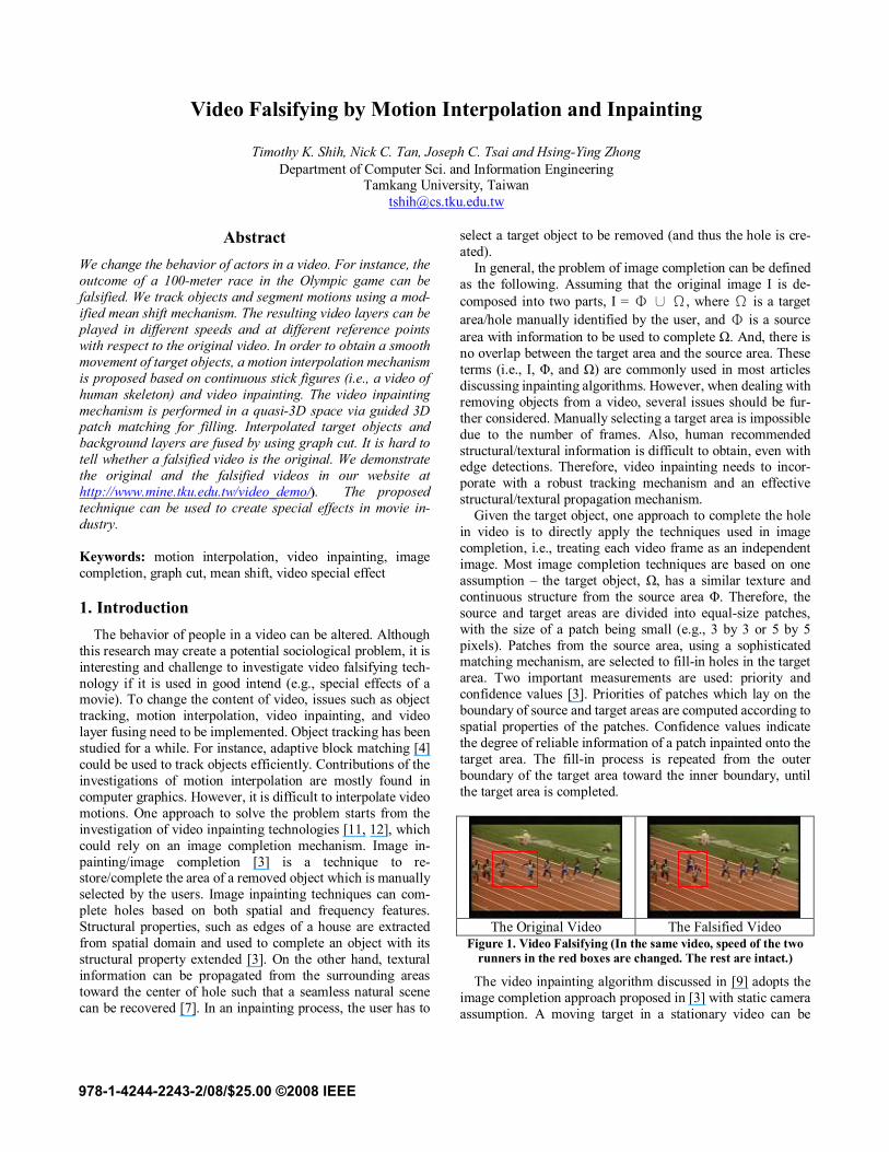
The Original Video The Falsified Video
Figure 1. Video Falsifying (In the same video, speed of the two runners in the red boxes are changed. The rest are intact.)
The video inpainting algorithm discussed in [9] adopts the image completion approach proposed in [3] with static camera assumption. A moving target in a stationary video can be
Video Falsifying by Motion Interpolation and Inpainting
Timothy K. Shih, Nick C. Tan, Joseph C. Tsai and Hsing-Ying Zhong Department of Computer Sci. and Information Engineering
Tamkang University, Taiwan [email protected]
978-1-4244-2243-2/08/$25.00 ©2008 IEEE
removed by filling-in exemplar patches in the same frame onto the missing background. Since the moving target can be par-tially occluded by another moving object, an inter-frame search is needed to find the best candidate patch. Only the portion of moving foreground in the selected patch is copied. The priority of the rest pixels in the background is adjusted to zero such that background is not changed. The video in-painting algorithm for still camera [9] is further extended to cope with non-stationary videos under restricted camera mo-tions [10]. Background and foreground of video are separated, with optical-flow mosaics generated. A similar priority con-cept used in [9] is also used in [10], to find the highest priority filling-in patches in the foreground. After foregrounds of all frames are inpainted, the remaining background holes are filled using patches directly from adjacent frames and texture synthesis. A few assumptions are made in [10], e.g., camera motion is parallel to the plane of frames (i.e., no intrinsic camera rotations). And, a moving object may not change its size (i.e., no zooming). Another paper [14] uses a motion layer segmentation algorithm to separate a video sequences to sev-eral layers according to the amount of motion. Each separated layer is completed by applying motion compensation and image completion algorithms. Except the layer with objects to be removed, all the rest of layers are combined in order to restore the final video. However, temporal consistency among inpainted areas between adjacent frames was not taken care of in [14]. The work discussed in [7] also removes objects from video frame by a priority scheme. Fragments (i.e., patches) on the boundary of the target area are selected with a higher pri-ority. However, a fragment is completed using texture syn-thesis instead of copying from a similar source. A graph cut algorithm is used to maintain the smooth boundary between two fragments. To maintain a smooth temporal continuity between two target fragments, two continuous source frag-ments are selected with a preference. However, complex camera motion is not considered in [7].
The article [13] looks at the problem from a 3-D perspective, which includes pixel positions (2-D) and frame numbers (time). The algorithm optimizes searching of patches at dif-ferent resolution level. The inpainting results are visually pleasant. The only drawback is that the work [13] assumes the missing hole of every video frame is provided. Therefore, there is no tracking mechanism used to identify the object to be removed. The inpainting algorithm discussed in [5] repairs static background as well as moving foreground. The algo-rithm takes a two-phase approach, sampling phase and alignment phase, to predict motion of moving foreground and to align the repaired foreground with the damaged background. Since the algorithm can be extended to use a reference video mosaic, with proper alignment, the algorithm discussed in [5] can also work for different intrinsic camera motions. However, the background video generated based on the reference video mosaic is important. Mistreatment of a generated background video will result in ghost shadows of the repaired video. In [6], the same group of authors [5] further extends their algorithm to deal with variable illumination. Although part of the process (i.e., layer separation and moving foreground sampling) is semi-automatic, the completion process is automatic.
In one earlier investigation [11], the authors analyze tem-poral continuities based on stationary and non-stationary video
with slow or fast foreground. The authors use a modified exemplar-based image completion mechanism. More specifi-cally, for stationary videos, patches can be searched from different frames and copied to fill in a target area, which is tracked by a simple computation of optical flow. For non-stationary video, tracking mechanism can be extended to deal with fast or slow moving objects. However, complicated video motions degrade the inpainting performance, due to the problem of “ghost shadows.” That is, due to the temporal discontinuity of inpainted area, flickers can be produced and lead to a visual-annoyance.
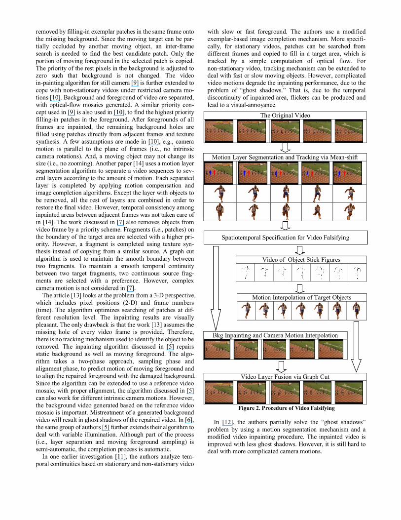
Figure 2. Procedure of Video Falsifying In [12], the authors partially solve the “ghost shadows”
problem by using a motion segmentation mechanism and a modified video inpainting procedure. The inpainted video is improved with less ghost shadows. However, it is still hard to deal with more complicated camera motions.
The Original Video
Motion Layer Segmentation and Tracking via Mean-shift
Video of Object Stick Figures
Motion Interpolation of Target Objects
Bkg Inpainting and Camera Motion Interpolation
Video Layer Fusion via Graph Cut
Spatiotemporal Specification for Video Falsifying
Video inpainting mechanism can be used to produce special effects (e.g., hollow man) in movie industry. We further use video inpainting and a newly proposed motion interpolation technique to create special effects. For instance, the behavior of a person in a video can be altered (e.g., speed of walking, direction of running, height of jumping, etc). An example of video falsifying is shown in Figure 1. We changed the winner of a 100-meter running race. A series of challenge issues in video technology need to be solved, such as tracking and video layer separation, motion interpolation and re-positioning, and video layer fusion. In order to precisely model the spatio-temporal behavior of each video layer (and object), we con-sider a video as a spatiotemporal fluctuated domain. That is, different video space (layer) can be run in different speed and screen position. We define a spatiotemporal fluctuation func-tion which is used as a user specification to alter a video.
The procedure of video falsifying is illustrated in figure 2. Given a spatiotemporal specification for video falsifying, the original video is subdivided into several layers. We use a modified mean shift algorithm [2] to separate foregrounds from the video. The stick figures of foreground objects are obtained in each frame to produce an object stick video, which is used as guidance in our motion interpolation procedure. Motion of objects can be interpolated by using a guided qua-si-3D video inpainting mechanism. Depending on the relative time of a viewer (i.e., the speed of seeing a video), background motion (i.e., due to camera motion) can also be interpolated. Finally, we adjust the relative position (optional) of each ob-ject and use a graph cut mechanism to fuse video layers. 1.1. Our Contributions The procedure of video falsifying is challenge. A series of mechanisms needs to be investigated. Our contributions in-clude the following:
A guided quasi-3D video inpainting mechanism is pro-posed – exempla-based inpainting is extended to 2D plus time.
A new motion interpolation mechanism is proposed based on stick figures and guided inpainting.
A spatiotemporal fluctuation function is defined and im-plemented on video examples to justify our approach.
Although the proposed mechanism can be used to produce
special effects of movies, it is also possible to create fake video. We have to deal with a problem of video forensics in the fu-ture.
2. Motion Layer Segmentation and Tracking
In order to change the behavior of actors in a video, the video falsifying procedure needs to separate actors from the background. In fact, a mechanism for video layer separation is necessary. We adopt the Mean Shift feature space analysis algorithm [2] for color region segmentation in each frame. This step allows an initial segmentation of objects from their background. Color region segmentation is then combined with motion segmentation for video layer separation.
To deal with motion segmentation, we use a block searching algorithm to compute motion map based on HSI color space. To estimate the similarities among blocks of size 5 by 5 (fixed in our algorithm), we use Sum of Absolute Dif-ferences (SAD) based on the HSI color components separately and the differences are accumulated.
1 1
( , ) 10 0
( , ) ( , ) ( , )p q
SAD i j n na b
H dx dy H i a j b H i a dx j b dy− −
+= =
= + + − + + + +∑∑1 1
( , ) 10 0
( , ) ( , ) ( , )p q
SAD i j n na b
S dx dy S i a j b S i a dx j b dy− −
+= =
= + + − + + + +∑∑1 1
( , ) 10 0
( , ) ( , ) ( , )p q
SAD i j n na b
I dx dy I i a j b I i a dx j b dy− −
+= =
= + + − + + + +∑∑
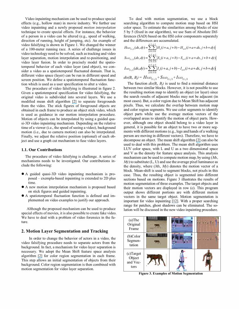
dis(Bi, Bj) = ( , )SAD i jH + ( , )SAD i jS + ( , )SAD i jI The function dis(Bi, Bj) is used to find a minimal distance between two similar blocks. However, it is not possible to use the resulting motion map to identify an object (or layer) since the search results of adjacent blocks may not be adjacent (in most cases). But, a color region due to Mean Shift has adjacent pixels. Thus, we calculate the overlap between motion map and color region segments. We use color segments to identify object parts while use the average motion vectors of the overlapped areas to identify the motion of object parts. How-ever, although one object should belong to a video layer in general, it is possible for an object to have two or more seg-ments with different motions (e.g., legs and hands of a walking person are moving in different vectors). Therefore, we have to decompose an object. The mean shift algorithm [2] can also be used to deal with this problem. The mean shift algorithm uses LUV color space, with L and U as a two dimensional space and V as the density for feature space analysis. This analysis mechanism can be used to compute motion map, by using (Mx, My) to substitute (L, U) and use the average pixel luminance as the density, where (Mx, My) denotes the motion vector of a block. Mean-shift is used to segment blocks, not pixels in this case. Thus, the resulting object is segmented into different sections based on motions. Figure 3 illustrates the results of motion segmentation of three examples. The target objects and their motion vectors are displayed in row (c). This program output shows different portions are with different motion vectors in the same target object. Motion segmentation is important for video inpainting [12]. With a proper searching range for patches, ghost shadows can be eliminated. The so-lution will be discussed in the new video inpainting procedure.
(a)The Original Frame
(b)Color Segmen-
tation (c)Target
Object and Vec-
tors
Figure 3. Examples of Motion Segmentation
3. Spatiotemporal Video Falsifying After video layers are identified and the target objects are
selected, the user needs to specify the spatiotemporal specifi-cation for video falsifying. For instance, the user can select a target layer (or object) to slow down its temporal property, change the spatial position, or even to reverse the action in time. The specification needs to define the behavior of each layer, although the default follows the original video property. A model for spatiotemporal decomposition is necessary, which is discussed below.
A two-dimensional video space, S, is regarded as a partial projection of scene from the 3-D world onto a 2-D screen. The discrete time of S, denoted as T, is represented as a sequence of frame indices. That is, the model for spatiotemporal de-composition is regarded as (S × T) where S and T are discrete domains representing 2D video space and frame index, re-spectively.
3.1. Spatial Decomposition The 2D video space, S, can be decomposed in spatial do-
main. We define S = ∪i = 1, …, l Li,p,
where Li,p is the i-th layer of S at a relative position p to the screen origin. The default relative position p = (0, 0) (i.e., no transformation of layer Li,p). In general, a transformation (in-cluding translation, scaling, rotation, and other functions) can be applied to a layer or the entire video space. In this paper, however, we only deal with translation and reflection. And, ∪i = 1, …, l is a layer composition function which takes l layers and compose the 2-D video space.
We further define Γ as a time function, which takes a layer (or the entire 2-D video space) and extract the time indices [t1, t2, …, tk] = T. Thus,
Γ(Li,p) = [t1, t2, …, tk], and for all i = 1, …, l, by default, Γ(Li,p) =Γ(S).
That is, by default, the spatial decomposition of S has all layers with the same time indices. However, the number of indices, k, could be different between layers when temporal decomposi-tion is applied. 3.2. Temporal Decomposition A video can be decomposed in temporal domain. We define a temporal projection function, ↓, which takes a layer (or a video space) and one of its time index, x, and extract an object (or frame). That is, fx = S ↓ x = (∪i = 1, …, l Li,p) ↓ x = ∪i = 1, …, l (Li,p) ↓ x Thus, fx is a frame of video space S which is composed from all layers projected simultaneously at time x. In this case, the layer composition function ∪i = 1, …, l is applied to all l layers at time x. However, the relative position p of each later Li,p could be adjusted.
3.3. Spatiotemporal Fluctuation In an ordinary situation, Γ(Li,p) = [t1, t2, …, tk]. That is, layer
Li,p has k frames. We denote the time indices of Li,p as [t1, t2, …, tk]L i,p. It is reasonable to define a temporal fluctuation function F, which is applied to the time indices,
F(Γ(Li,p))= F([t1, t2, …, tk]L i,p)= [tm, tm+1, …, tn]L i,p
where tm, tm+1, …, tn are temporal fluctuation indices with respect to layer Li,p. For example,
F([t1, t2, …, tk]L i,p)= [t1, t2, t3], i.e., object in the first three frames are extracted (i.e., truncated video). Or, F([t1, t2, …, tk]L
i,p)= [t1, t3, t2j+1], i.e., objects in odd frames are extracted (i.e., to create fast motion video).
We can further generalize F to a spatiotemporal fluctuation function,
$F(S) = $F(∪i = 1, …, l Li,p) = ∪i = 1, …, l (F1(Γ(L1,p1)), F2(Γ(L2,p2)),…Fl(Γ(Ll,pl)) ).
Thus, F1, F2, ..., Fl are different temporal fluctuation functions applied to different layers (and objects) with different relative positions. These functions (i.e., F1, F2, ..., Fl) are defined by the user. Note that, it is possible for a projection (Li,p) ↓ t to be evaluated to an empty object, if the video layer fails to match t with common time indices of all layers. In this case, an object is not displayed in the video and background inpainting is necessary. It is interesting to design the spatiotemporal fluctuation function $F. For instance, $F could skip a section of layers, reverse the time indices of a layer, change the positions of layers, or enlarge objects in layers. In order to compute the result of the spatiotemporal fluctuation function, motion in-terpolation and inpainting techniques are required. 4. Motion Interpolation Using Inpainting Motion of the target object needs to be interpolated. In some situation, motion interpolation may create background holes due to different shape of objects that are removed. Thus, video inpainting to these holes are required. 4.1. Motion Interpolation of Target Objects
A target object can be segmented into a layer Li,p of S. To produce a fast animation of the layer, a temporal fluctuation function such as F([t1, t2, …, tk]L i,p)= [t1, t3, t2j+1] can sample the object in odd frames to be displayed in a normal speed. However, to produce a slow motion of the target layer Li,p, motion interpolation is required. In figures 4(a) and 4(d), Γ(Li,p) = [tn, tn+3]. Figures 4(b) and 4(c) are interpolated motions. The resulting video can be played in three times slower than the original video.
In order to obtain the interpolated figures, we use a new video inpainting technique. This new mechanism uses a rule-based thinning algorithm [1] to obtain the stick figures of target objects. The stick figures are used to guide the selection of patches, which are copied from the original video to fill the interpolated objects.
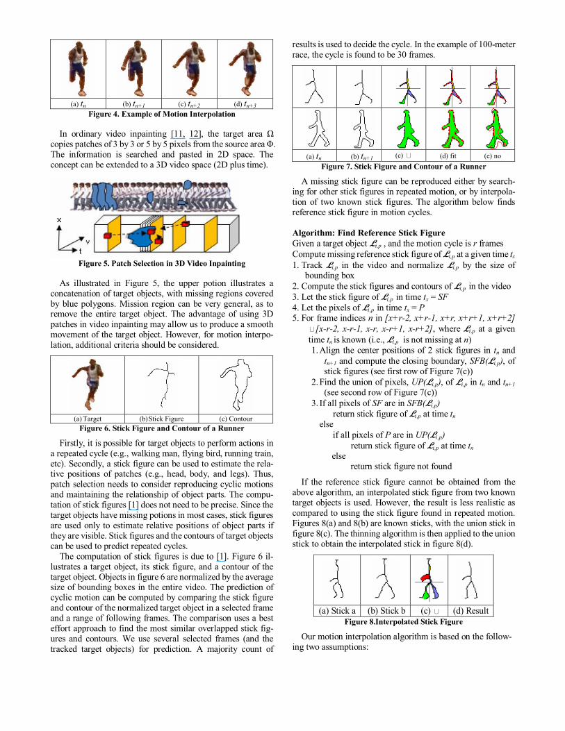
(a) tn (b) tn+1 (c) tn+2 (d) tn+3
Figure 4. Example of Motion Interpolation
In ordinary video inpainting [11, 12], the target area Ω copies patches of 3 by 3 or 5 by 5 pixels from the source area Φ. The information is searched and pasted in 2D space. The concept can be extended to a 3D video space (2D plus time).
Figure 5. Patch Selection in 3D Video Inpainting
As illustrated in Figure 5, the upper potion illustrates a concatenation of target objects, with missing regions covered by blue polygons. Mission region can be very general, as to remove the entire target object. The advantage of using 3D patches in video inpainting may allow us to produce a smooth movement of the target object. However, for motion interpo-lation, additional criteria should be considered.
(a) Target (b) Stick Figure (c) Contour
Figure 6. Stick Figure and Contour of a Runner
Firstly, it is possible for target objects to perform actions in a repeated cycle (e.g., walking man, flying bird, running train, etc). Secondly, a stick figure can be used to estimate the rela-tive positions of patches (e.g., head, body, and legs). Thus, patch selection needs to consider reproducing cyclic motions and maintaining the relationship of object parts. The compu-tation of stick figures [1] does not need to be precise. Since the target objects have missing potions in most cases, stick figures are used only to estimate relative positions of object parts if they are visible. Stick figures and the contours of target objects can be used to predict repeated cycles.
The computation of stick figures is due to [1]. Figure 6 il-lustrates a target object, its stick figure, and a contour of the target object. Objects in figure 6 are normalized by the average size of bounding boxes in the entire video. The prediction of cyclic motion can be computed by comparing the stick figure and contour of the normalized target object in a selected frame and a range of following frames. The comparison uses a best effort approach to find the most similar overlapped stick fig-ures and contours. We use several selected frames (and the tracked target objects) for prediction. A majority count of
results is used to decide the cycle. In the example of 100-meter race, the cycle is found to be 30 frames.
(a) tn (b) tn+1 (c) ∪ (d) fit (e) no
Figure 7. Stick Figure and Contour of a Runner
A missing stick figure can be reproduced either by search-ing for other stick figures in repeated motion, or by interpola-tion of two known stick figures. The algorithm below finds reference stick figure in motion cycles. Algorithm: Find Reference Stick Figure Given a target object Li,p , and the motion cycle is r frames Compute missing reference stick figure of Li,p at a given time tx 1. Track Li,p in the video and normalize Li,p by the size of
bounding box 2. Compute the stick figures and contours of Li,p in the video 3. Let the stick figure of Li,p in time tx = SF 4. Let the pixels of Li,p in time tx = P 5. For frame indices n in [x+r-2, x+r-1, x+r, x+r+1, x+r+2]
∪[x-r-2, x-r-1, x-r, x-r+1, x-r+2], where Li,p at a given time tn is known (i.e., Li,p is not missing at n) 1. Align the center positions of 2 stick figures in tn and
tn+1 and compute the closing boundary, SFB(Li,p), of stick figures (see first row of Figure 7(c))
2. Find the union of pixels, UP(Li,p), of Li,p in tn and tn+1 (see second row of Figure 7(c))
3. If all pixels of SF are in SFB(Li,p) return stick figure of Li,p at time tn
else if all pixels of P are in UP(Li,p)
return stick figure of Li,p at time tn
else return stick figure not found
If the reference stick figure cannot be obtained from the above algorithm, an interpolated stick figure from two known target objects is used. However, the result is less realistic as compared to using the stick figure found in repeated motion. Figures 8(a) and 8(b) are known sticks, with the union stick in figure 8(c). The thinning algorithm is then applied to the union stick to obtain the interpolated stick in figure 8(d).
(a) Stick a (b) Stick b (c) ∪ (d) Result
Figure 8.Interpolated Stick Figure
Our motion interpolation algorithm is based on the follow-ing two assumptions:
The missing region Ω has a similar texture and color rep-
resentation to the source region Φ; and The missing target region has a continuous motion with
respect to the source region. The first assumption encourages us to extend an ordinary video inpainting or image completion algorithm. The second assumption allow us to consider a video, (S × T), as a 2D plus time domain. For fast motion video, given a limited sampling frame rate, our motion interpolation may not obtain good results. This is the limitation of our mechanism. However, the problem can be solved if a high speed video recording device is used. Finally, we present our motion interpolation algorithm. Assume that (S × T) = I3 = Φ3 ∪ Ω3, where Φ3 is a source space and Ω3 is a target space, and Φ3 ∩ Ω3 = ∮ (i.e., an empty set). The notation of our 3D video inpainting algorithm fol-lows one discussed in [3]. However, new concepts are used in our mechanism:
Patches on the reference stick figures will be copied as guidance before the inpainting algorithm starts. This is an important achievement to ensure that motion is properly interpolated.
Patches copied should be obtained from a corresponding relative position from the source (i.e., copy patches from head to head, from legs to legs). Information of relative position is obtained while we track objects via the mean shift mechanism. The separation of patch search not only guarantees the visual quality but also improves the speed of inpainting procedure, since search space is reduced for each individual portion.
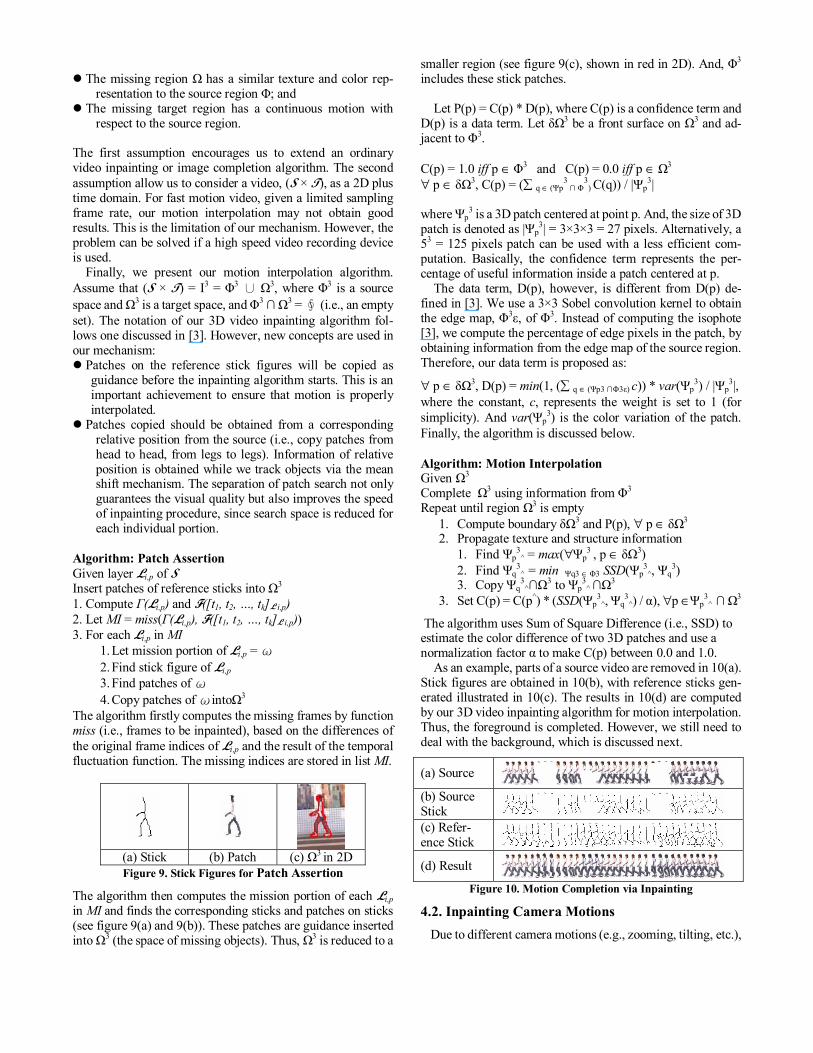
Algorithm: Patch Assertion Given layer Li,p of S Insert patches of reference sticks into Ω3 1. Compute Γ(Li,p) and F([t1, t2, …, tk]L i,p) 2. Let MI = miss(Γ(Li,p), F([t1, t2, …, tk]L i,p)) 3. For each Li,p in MI
1. Let mission portion of Li,p = ω 2. Find stick figure of Li,p 3. Find patches of ω 4. Copy patches of ωintoΩ3
The algorithm firstly computes the missing frames by function miss (i.e., frames to be inpainted), based on the differences of the original frame indices of Li,p and the result of the temporal fluctuation function. The missing indices are stored in list MI.
(a) Stick (b) Patch (c) Ω3 in 2D Figure 9. Stick Figures for Patch Assertion
The algorithm then computes the mission portion of each Li,p in MI and finds the corresponding sticks and patches on sticks (see figure 9(a) and 9(b)). These patches are guidance inserted into Ω3 (the space of missing objects). Thus, Ω3 is reduced to a
smaller region (see figure 9(c), shown in red in 2D). And, Φ3 includes these stick patches.
Let P(p) = C(p) * D(p), where C(p) is a confidence term and D(p) is a data term. Let δΩ3 be a front surface on Ω3 and ad-jacent to Φ3. C(p) = 1.0 iff p ∈ Φ3 and C(p) = 0.0 iff p ∈ Ω3 ∀ p ∈ δΩ3, C(p) = (∑ q ∈ (Ψp
3 ∩ Φ
3) C(q)) / |Ψp
3| where Ψp
3 is a 3D patch centered at point p. And, the size of 3D patch is denoted as |Ψp
3| = 3×3×3 = 27 pixels. Alternatively, a 53 = 125 pixels patch can be used with a less efficient com-putation. Basically, the confidence term represents the per-centage of useful information inside a patch centered at p. The data term, D(p), however, is different from D(p) de-fined in [3]. We use a 3×3 Sobel convolution kernel to obtain the edge map, Φ3ε, of Φ3. Instead of computing the isophote [3], we compute the percentage of edge pixels in the patch, by obtaining information from the edge map of the source region. Therefore, our data term is proposed as:
∀ p ∈ δΩ3, D(p) = min(1, (∑ q ∈ (Ψp3 ∩Φ3ε) c)) * var(Ψp3) / |Ψp
3|, where the constant, c, represents the weight is set to 1 (for simplicity). And var(Ψp
3) is the color variation of the patch. Finally, the algorithm is discussed below. Algorithm: Motion Interpolation Given Ω3 Complete Ω3 using information from Φ3 Repeat until region Ω3 is empty
1. Compute boundary δΩ3 and P(p), ∀ p ∈ δΩ3 2. Propagate texture and structure information
1. Find Ψp3
^ = max(∀Ψp3
, p ∈ δΩ3) 2. Find Ψq
3^ = min Ψq3 ∈ Φ3 SSD(Ψp
3^, Ψq
3) 3. Copy Ψq
3^∩Ω3 to Ψp
3^ ∩Ω3
3. Set C(p) = C(p^) * (SSD(Ψp3
^, Ψq3
^) / α), ∀p ∈Ψp3
^ ∩ Ω3
The algorithm uses Sum of Square Difference (i.e., SSD) to estimate the color difference of two 3D patches and use a normalization factor α to make C(p) between 0.0 and 1.0.
As an example, parts of a source video are removed in 10(a). Stick figures are obtained in 10(b), with reference sticks gen-erated illustrated in 10(c). The results in 10(d) are computed by our 3D video inpainting algorithm for motion interpolation. Thus, the foreground is completed. However, we still need to deal with the background, which is discussed next.
(a) Source (b) Source Stick (c) Refer-ence Stick
(d) Result Figure 10. Motion Completion via Inpainting
4.2. Inpainting Camera Motions Due to different camera motions (e.g., zooming, tilting, etc.),
video inpainting is difficult. To inpaint background video with constraint motions, we do not use the mosaic approach as discussed in [10]. Instead, we use a mechanism [12] to seg-ment motions into different regions. Depending on the oc-cluded objects, the background can be inpainted properly [12]. In addition, depending on the speed of viewing the video, interpolation of background may be needed. To create fast video (i.e., similar to fast forwarding a video tape), we down sample the video frames. However, to create slow video, we interpolate video frames. The mechanism to segment motion regions discussed in [12] is further extended to estimate in-terpolated frames. These interpolated frames are produced after target objects are removed in each frame. Thus, our in-painting mechanism uses a multiple pass approach to process all video frames.
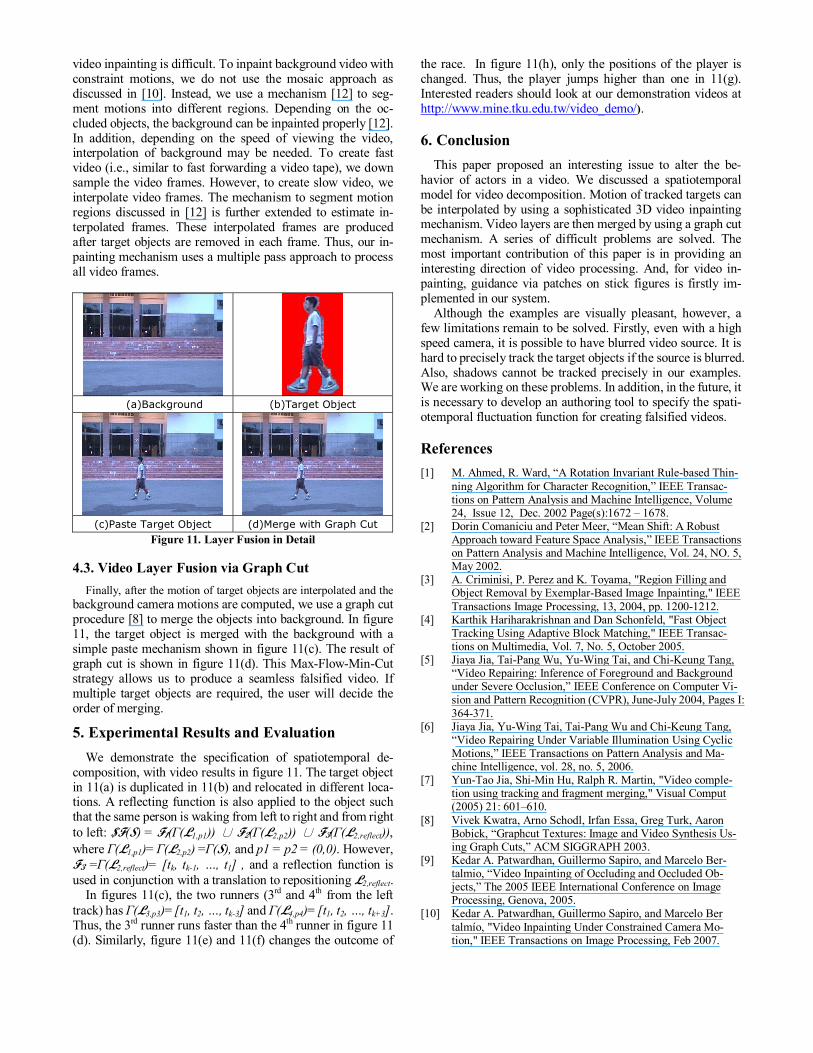
(a)Background (b)Target Object
(c)Paste Target Object (d)Merge with Graph Cut
Figure 11. Layer Fusion in Detail 4.3. Video Layer Fusion via Graph Cut Finally, after the motion of target objects are interpolated and the background camera motions are computed, we use a graph cut procedure [8] to merge the objects into background. In figure 11, the target object is merged with the background with a simple paste mechanism shown in figure 11(c). The result of graph cut is shown in figure 11(d). This Max-Flow-Min-Cut strategy allows us to produce a seamless falsified video. If multiple target objects are required, the user will decide the order of merging.
5. Experimental Results and Evaluation We demonstrate the specification of spatiotemporal de-
composition, with video results in figure 11. The target object in 11(a) is duplicated in 11(b) and relocated in different loca-tions. A reflecting function is also applied to the object such that the same person is waking from left to right and from right to left: $F(S) = F1(Γ(L1,p1)) ∪ F2(Γ(L2,p2)) ∪ F3(Γ(L2,reflect)), where Γ(L1,p1)= Γ(L2,p2) =Γ(S), and p1 = p2 = (0,0). However, F3 =Γ(L2,reflect)= [tk, tk-1, …, t1] , and a reflection function is used in conjunction with a translation to repositioning L2,reflect.
In figures 11(c), the two runners (3rd and 4th from the left track) has Γ(L3,p3)= [t1, t2, …, tk-3] and Γ(L4,p4)= [t1, t2, …, tk+3]. Thus, the 3rd runner runs faster than the 4th runner in figure 11 (d). Similarly, figure 11(e) and 11(f) changes the outcome of
the race. In figure 11(h), only the positions of the player is changed. Thus, the player jumps higher than one in 11(g). Interested readers should look at our demonstration videos at http://www.mine.tku.edu.tw/video_demo/). 6. Conclusion
This paper proposed an interesting issue to alter the be-havior of actors in a video. We discussed a spatiotemporal model for video decomposition. Motion of tracked targets can be interpolated by using a sophisticated 3D video inpainting mechanism. Video layers are then merged by using a graph cut mechanism. A series of difficult problems are solved. The most important contribution of this paper is in providing an interesting direction of video processing. And, for video in-painting, guidance via patches on stick figures is firstly im-plemented in our system.
Although the examples are visually pleasant, however, a few limitations remain to be solved. Firstly, even with a high speed camera, it is possible to have blurred video source. It is hard to precisely track the target objects if the source is blurred. Also, shadows cannot be tracked precisely in our examples. We are working on these problems. In addition, in the future, it is necessary to develop an authoring tool to specify the spati-otemporal fluctuation function for creating falsified videos. References [1] M. Ahmed, R. Ward, “A Rotation Invariant Rule-based Thin-
ning Algorithm for Character Recognition,” IEEE Transac-tions on Pattern Analysis and Machine Intelligence, Volume 24, Issue 12, Dec. 2002 Page(s):1672 – 1678.
[2] Dorin Comaniciu and Peter Meer, “Mean Shift: A Robust Approach toward Feature Space Analysis,” IEEE Transactions on Pattern Analysis and Machine Intelligence, Vol. 24, NO. 5, May 2002.
[3] A. Criminisi, P. Perez and K. Toyama, "Region Filling and Object Removal by Exemplar-Based Image Inpainting," IEEE Transactions Image Processing, 13, 2004, pp. 1200-1212.
[4] Karthik Hariharakrishnan and Dan Schonfeld, "Fast Object Tracking Using Adaptive Block Matching," IEEE Transac-tions on Multimedia, Vol. 7, No. 5, October 2005.
[5] Jiaya Jia, Tai-Pang Wu, Yu-Wing Tai, and Chi-Keung Tang, “Video Repairing: Inference of Foreground and Background under Severe Occlusion,” IEEE Conference on Computer Vi-sion and Pattern Recognition (CVPR), June-July 2004, Pages I: 364-371.
[6] Jiaya Jia, Yu-Wing Tai, Tai-Pang Wu and Chi-Keung Tang, “Video Repairing Under Variable Illumination Using Cyclic Motions,” IEEE Transactions on Pattern Analysis and Ma-chine Intelligence, vol. 28, no. 5, 2006.
[7] Yun-Tao Jia, Shi-Min Hu, Ralph R. Martin, "Video comple-tion using tracking and fragment merging," Visual Comput (2005) 21: 601–610.
[8] Vivek Kwatra, Arno Schodl, Irfan Essa, Greg Turk, Aaron Bobick, “Graphcut Textures: Image and Video Synthesis Us-ing Graph Cuts,” ACM SIGGRAPH 2003.
[9] Kedar A. Patwardhan, Guillermo Sapiro, and Marcelo Ber-talmio, “Video Inpainting of Occluding and Occluded Ob-jects,” The 2005 IEEE International Conference on Image Processing, Genova, 2005.
[10] Kedar A. Patwardhan, Guillermo Sapiro, and Marcelo Ber talmío, "Video Inpainting Under Constrained Camera Mo-tion," IEEE Transactions on Image Processing, Feb 2007.
[11] Timothy K. Shih, Nick C. Tang, Wei-Sung Yeh, Ta-Jen Chen, and Wonjun Lee, "Video Inpainting and Implant via Diversi-fied Temporal Continuations," 2006 ACM Multimedia Con-ference, Santa Barbara, California, USA, October 23-27, 2006.
[12] Timothy K. Shih, Nick C. Tang, and Jenq-Neng Hwang, "Ghost Shadow Removal in Multi-Layered Video Inpainting," in proceedings of the IEEE 2007 International Conference on Multimedia & Expo (ICME 2007), Beijing, China, July 2-5, 2007.
[13] Y. Wexler, E. Shechtman, M. Irani, “Space-Time Completion of Video,” IEEE Transactions on Pattern Analysis and Ma-chine Intelligence, Volume 29, Issue 3, March 2007 Page(s):463 – 476.
[14] Yunjun Zhang, Jiangjian Xiao, and Mubarak Shah, “Motion Layer Based Object Removal in Videos,” The Seventh IEEE Workshops on Application of Computer Vision, 2005, pp. 516-521.
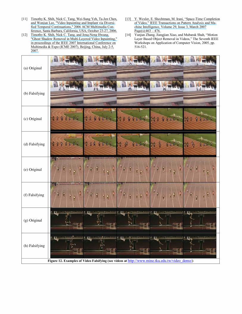
(a) Original
(b) Falsifying
(c) Original
(d) Falsifying
(e) Original
(f) Falsifying
(g) Original
(h) Falsifying
Figure 12. Examples of Video Falsifying (see videos at http://www.mine.tku.edu.tw/video_demo/)
Related Documents