TRANSPORTATION RESEARCH RECORD 1329 27 Video Evaluation of Highway Drainage Systems ROBERT F. STEFFES, VERNON J. MARKS, AND KERMIT L. DIRKS Since 1978 the concept of longitudinal edge drains along Iowa primary and Interstate highways has accepted. as. a cost- effective way of prolonging pavement hfe. Edge-dram mstalla- tions have increased over the years, reaching a total of nearly 3,000 mi by 1989. With so many miles of edge drain installed, the development of a system for inspection and evaluation of the drains became essential. Equipment was purchased to evaluate 4-in.-diameter and geocomposite edge drains. Initial at various sites supported the need for a postconstruct1on m- spection program to ensure that edge-drain were in accord with plans and specifications. Information disclosed by video inspections in edge drains and in culverts was on videotape to be used as an informative tool for person_nel m the design, construction, and maintenance departments. Video eval- uations have influenced changes in maintenance, design, and con- struction inspection for highway drainage systems in Iowa. The Iowa Department of Transportation has determined that longitudinal edge drains are cost-effective in removal of un- derslab moisture and prevention of premature pavement fail- ures. Before 1978 a minimal number of longitudinal edge drains had been installed in areas with severe moisture problems. In 1978 approximately 167,000 ft of 4-in.-diameter longi- tudinal drain was installed along primary and Interstate high- ways in Iowa. Since then, the annual installation had increased to a peak of approximately 3.5 million ft in 1988 (Figure 1). By 1989 a total of more than 14 million ft of longitudinal edge drain had been installed (Figure 2). The average cost for installation of edge drains has de- creased, in general, since 1987. Some cost fluctuations were due to changes in specifications. The average cost per foot installed over the years is shown in Figure 3, with a current cost of approximately $4.00/foot installed. Even though a very large number of edge drains was in place by 1989 (Table 1), there was no inspection program or positive method to evaluate the condition of drains other than the visual inspection of the outlets. OBJECTIVE The objective of this paper is to describe the benefit of a video evaluation of highway drainage systems and to present the results of the evaluation. HISTORY OF EDGE DRAINS IN IOWA An initial 1978 edge-drain installation was placed as a reha- bilitation effort for 28 mi of deteriorating 10-in. portland ce- Highway Division, Iowa Department of Transportation, Ames, Iowa 50010. ment concrete (PCC) pavement on I-80 in Poweshiek County. At that time, this roadway carried approximately 6,500 heavy trucks a day, and pavement pumping was a severe problem. The drain design used a 6-in. polyethylene slotted pipe placed at the pavement edge in a trench 24-in. deep measured from the top of the pavement. Slot size and porous backfill were designed according to FHWA implementation package 76-9. Filter criteria assumed a sandy silt AASHTO A-4-3 soil clas- sification. The trench was 12 in. wide and the porous backfill was placed in contact with and 2 in. above the bottom of the pavement. A 3-in. bedding was placed under the pipe, and flow lines were controlled by the grade line of existing pave- ment to minimize costs. The entire system was designed to be constructed using a "one-pass" mechanical system. Drain outlets at approximately 1,000-ft intervals were constructed using earth backfill and metal pipe aprons. This drain system rapidly developed problems. Consider- able localized plugging of the backfill and drain pipe occurred. During the first winter, a near-disastrous outlet freeze-up oc- curred; as a result, a substantial amount of water flowed from the top of the drain trench and froze on the pavement. To eliminate that problem, the outlets were reconstructed the following spring by placing full-depth porous backfill so that it would daylight on the foreslope and removing the metal aprons. No further winter freeze-up problems have occurred with this design. The 1979 designs used a 30-in. trench depth for similar Interstate highways, and the Iowa nondestructive pavement deflection testing (Road Rater) program indicated that there was a small but significant improvement in subgrade strength. Localized backfill plugging also decreased significantly. Of most significance was the discovery that most outflow was now occurring through the porous backfill bedding and that the pipe functioned only during periods of heavy rain. This alleviated many concerns for poor pipe flow line control and failures due to poor construction, which have been verified by excavation. On the basis of the improvements from early design changes, 1981 designs increased the trench depths to 48 in. and reduced the pipe size to 4 in. and the trench width to 10 in., as shown in Figure 4. It was discovered that subgrade strengths again increased and that localized porous backfill plugging was re- duced to areas of complete pavement failure. Subsequently, it was determined by excavation and laboratory testing that the material plugging the backfill consisted primarily of ce- ment dust. It was typical to find less than 10 percent clay in these extracted fines. This meant that permeability in excess of 200 ft per day remained and that the plugging material would flush through the system after the pavement problem had been corrected. It also proved that the system could ac-

Welcome message from author
This document is posted to help you gain knowledge. Please leave a comment to let me know what you think about it! Share it to your friends and learn new things together.
Transcript
TRANSPORTATION RESEARCH RECORD 1329 27
Video Evaluation of Highway Drainage Systems
ROBERT F. STEFFES, VERNON J. MARKS, AND KERMIT L. DIRKS
Since 1978 the concept of longitudinal edge drains along Iowa primary and Interstate highways has b~en accepted. as. a costeffective way of prolonging pavement hfe. Edge-dram mstallations have increased over the years, reaching a total of nearly 3,000 mi by 1989. With so many miles of edge drain installed, the development of a system for inspection and evaluation of the drains became essential. Equipment was purchased to evaluate 4-in.-diameter and geocomposite edge drains. Initial eval~ati~ns at various sites supported the need for a postconstruct1on mspection program to ensure that edge-drain installati~ns were in accord with plans and specifications. Information disclosed by video inspections in edge drains and in culverts was compil~d on videotape to be used as an informative tool for person_nel m the design, construction, and maintenance departments. Video evaluations have influenced changes in maintenance, design, and construction inspection for highway drainage systems in Iowa.
The Iowa Department of Transportation has determined that longitudinal edge drains are cost-effective in removal of underslab moisture and prevention of premature pavement failures. Before 1978 a minimal number of longitudinal edge drains had been installed in areas with severe moisture problems.
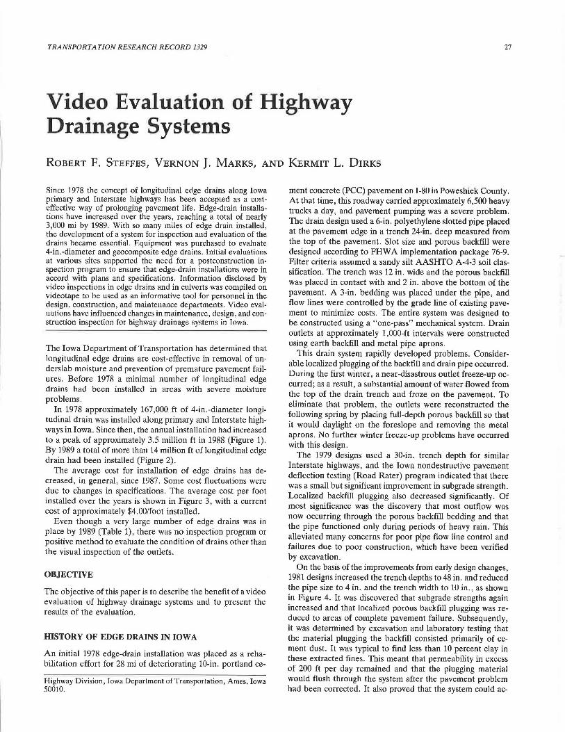
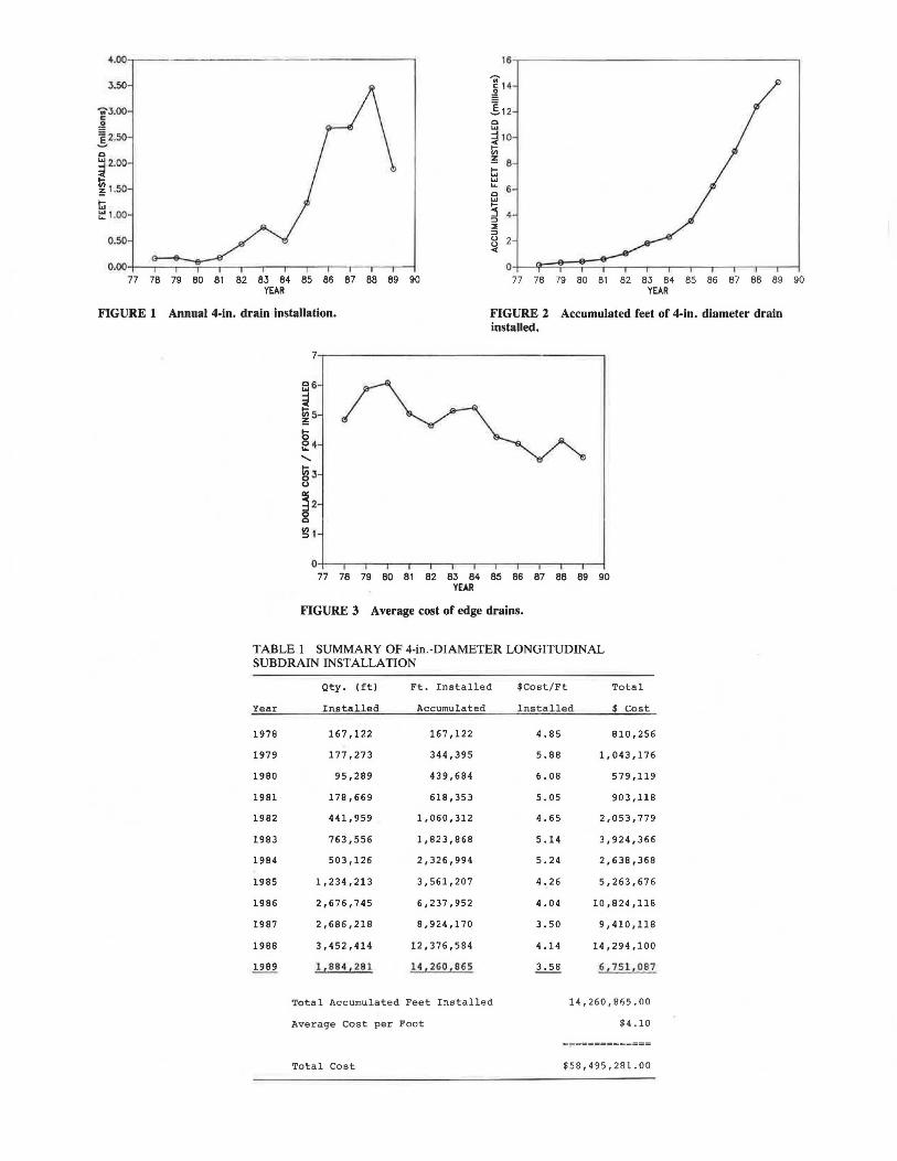
In 1978 approximately 167,000 ft of 4-in.-diameter longitudinal drain was installed along primary and Interstate highways in Iowa. Since then, the annual installation had increased to a peak of approximately 3.5 million ft in 1988 (Figure 1). By 1989 a total of more than 14 million ft of longitudinal edge drain had been installed (Figure 2).
The average cost for installation of edge drains has decreased, in general, since 1987. Some cost fluctuations were due to changes in specifications. The average cost per foot installed over the years is shown in Figure 3, with a current cost of approximately $4.00/foot installed.
Even though a very large number of edge drains was in place by 1989 (Table 1), there was no inspection program or positive method to evaluate the condition of drains other than the visual inspection of the outlets.
OBJECTIVE
The objective of this paper is to describe the benefit of a video evaluation of highway drainage systems and to present the results of the evaluation.
HISTORY OF EDGE DRAINS IN IOWA
An initial 1978 edge-drain installation was placed as a rehabilitation effort for 28 mi of deteriorating 10-in. portland ce-
Highway Division, Iowa Department of Transportation, Ames, Iowa 50010.
ment concrete (PCC) pavement on I-80 in Poweshiek County. At that time, this roadway carried approximately 6,500 heavy trucks a day, and pavement pumping was a severe problem. The drain design used a 6-in. polyethylene slotted pipe placed at the pavement edge in a trench 24-in. deep measured from the top of the pavement. Slot size and porous backfill were designed according to FHWA implementation package 76-9. Filter criteria assumed a sandy silt AASHTO A-4-3 soil classification. The trench was 12 in. wide and the porous backfill was placed in contact with and 2 in. above the bottom of the pavement. A 3-in. bedding was placed under the pipe, and flow lines were controlled by the grade line of existing pavement to minimize costs. The entire system was designed to be constructed using a "one-pass" mechanical system. Drain outlets at approximately 1,000-ft intervals were constructed using earth backfill and metal pipe aprons.
This drain system rapidly developed problems. Considerable localized plugging of the backfill and drain pipe occurred. During the first winter, a near-disastrous outlet freeze-up occurred; as a result, a substantial amount of water flowed from the top of the drain trench and froze on the pavement. To eliminate that problem, the outlets were reconstructed the following spring by placing full-depth porous backfill so that it would daylight on the foreslope and removing the metal aprons. No further winter freeze-up problems have occurred with this design.
The 1979 designs used a 30-in. trench depth for similar Interstate highways, and the Iowa nondestructive pavement deflection testing (Road Rater) program indicated that there was a small but significant improvement in subgrade strength. Localized backfill plugging also decreased significantly. Of most significance was the discovery that most outflow was now occurring through the porous backfill bedding and that the pipe functioned only during periods of heavy rain. This alleviated many concerns for poor pipe flow line control and failures due to poor construction, which have been verified by excavation.
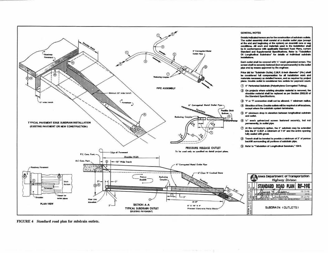
On the basis of the improvements from early design changes, 1981 designs increased the trench depths to 48 in. and reduced the pipe size to 4 in. and the trench width to 10 in., as shown in Figure 4. It was discovered that subgrade strengths again increased and that localized porous backfill plugging was reduced to areas of complete pavement failure. Subsequently, it was determined by excavation and laboratory testing that the material plugging the backfill consisted primarily of cement dust. It was typical to find less than 10 percent clay in these extracted fines. This meant that permeability in excess of 200 ft per day remained and that the plugging material would flush through the system after the pavement problem had been corrected. It also proved that the system could ac-
J.60
"'1'3.00 c ,g .'.§.2.50
c ~ 2.00
~ 1.50 t:; ~ 1.00
0.50
77 7B 79 BO B1 B2 B3 B4 B5 B6 B7 BB B9 90 YEAR
77 78 79 BO 81 B2 83 B4 B5 B6 87 BB 89 90 YEAR
FIGURE 1 Annual 4-ln. drain installation. FIGURE 2 Accumulated feet of 4-ln. diameter drain installed.
77 7B 79 BO 81 82 B3 B4 85 86 87 BB B9 90 YEAR
FIGURE 3 Average cost of edge drains.
TABLE 1 SUMMARY OF 4-in.-DIAMETER LONGITUDINAL SUBDRAIN INSTALLATION
Qty. (ft) Ft. Installed $Cost/Ft Total
Year .Installed Accumulated Installed $ Cost
1978 167,122 167,122 4.85 810,256
1979 177 ,273 344,395 5.88 1,043,176
1980 95,289 439,684 6.08 579,119
1981 178,669 618,353 5.05 903I118
1982 441,959 1,060,312 4.65 2,053,779
1983 763,556 1,823,868 5.14 3,924,366
1984 503,126 2,326,994 5.24 2,638,368
1985 1,234,213 3,561,207 4.26 5,263,676
1986 2,676,745 6,237,952 4.04 10,824,118
1987 2,686,218 8,924,170 3.50 9,410,118
1988 3,452,414 12,376,584 4.14 14,294,100
1989 1,884,281 14,260,865 3.58 6,751,087
Total Accumulated Feet Installed 14,260,865.00
Average Cost per Foot $4.10
=;::============
Total Cost $58,495,281.00
TYPICAL PAVEMENT EDGE SUBDRAIN INSTALLATION
(EXISTING PAVEMENT OR NEW CONSTRUCTION)
..... _ PLANVEW
..... ... ._
1t9"Cft tor --· FIGURE 4 Standard road plan for subdrain outlets.
PIPE ASSEleLY
PRESSURE RELEASE OUTLET To be used only m specified on detail proi9d planL
c:=:=:>
SECTION A-A TYPICAL SUBDRAIN OUTLET
(EXISTNG PAVEMENT)
6" ~ - °"""' p;p.
6" -0on 'A' Cnrlilecl Stone
GENERAL NOTES
.,.........._,__ ...... Ille COlllhclon oloubdnln-. The ...- _....., ..... --DI• - ...- pipe (Hcepl 81 Ille - - .......... DI Ille oywlom) on ....,_ runa or "811 ....-O...Al ____ lnh..--...,-
bllln_wllll.......,__R_P18n8,CllfNlll
- - &.:;plamem.I llpecl-.. Reier lo "T......_
Of ~ llulldnln8" "" - ol - -~
E.8Ch ...- ........ cowred ..... y,· -~--The _ ........ ........,.-....(bulnol.....,.._.,)loh-
...... -by ..... ....-by Ille......,_,
Pllc:e bid lor "Subdr9n Ouu.t, C.M.P • .__ ...,_.. (No.) .....
be ~ 1111 compel- lor .. ""'8lelloll - -____ ....._,, __ ,.._.., .......... ,..,... Double ......... .....-..i two - lor -·count. G.) 4" ~ Subcnln (Palyelllrtei11 Comlpllcl Tubing).
@ On praj8c:ta ""919 ...... .........,...-18111 NlllCINd, h lhodd8r _.. ..... be...,._ - per - 2502.115 ol Ille - Speclftc8lkM ..
@ Tor T CCllllllCllon - nol bll ........_ 1' -m -. @ -ol-~-..... rwqulNcl .... ---. .. ...,._ ... _.,...,,._ @ ··-c1n1p1n....-.-~--@ 'lo" meah gelHnlzed OCl'fffl l•ltned MCurely, bul nol
,.........11y, 1o ....... pipe.
CV Al Ille _,.,_., opllon, 1111 4" -- ...., ... ·lnlo 1111 6" C.11111.P. I ............ ol NI" - Ille - -*Ill i..,-*" ..... grout.
@ T __ bll_to.,.-1-ol3"ot.,..._
- _,..,,...itng .. .....- ol oubdnln ....... @ Relerlo"T--ol ~ ._....,. , __
A 1owa Department Of Transportation ~ Highway Division
PlAN I RF-19E • ~II' $~~ ........... ~~~ ..... 1'--#'-"-~~~....L~~~~--1 ! i OS-23-'!0 'i 0-f
-. t - OS-23-'lO l=i . W' '
H .i~ I!! n
SUBORAIN ·IOUTLETSl
30
commodate recycled crushed PCC and provided the emphasis for the development of the present drainable base system, which uses crushed recycled PCC almost exclusively.
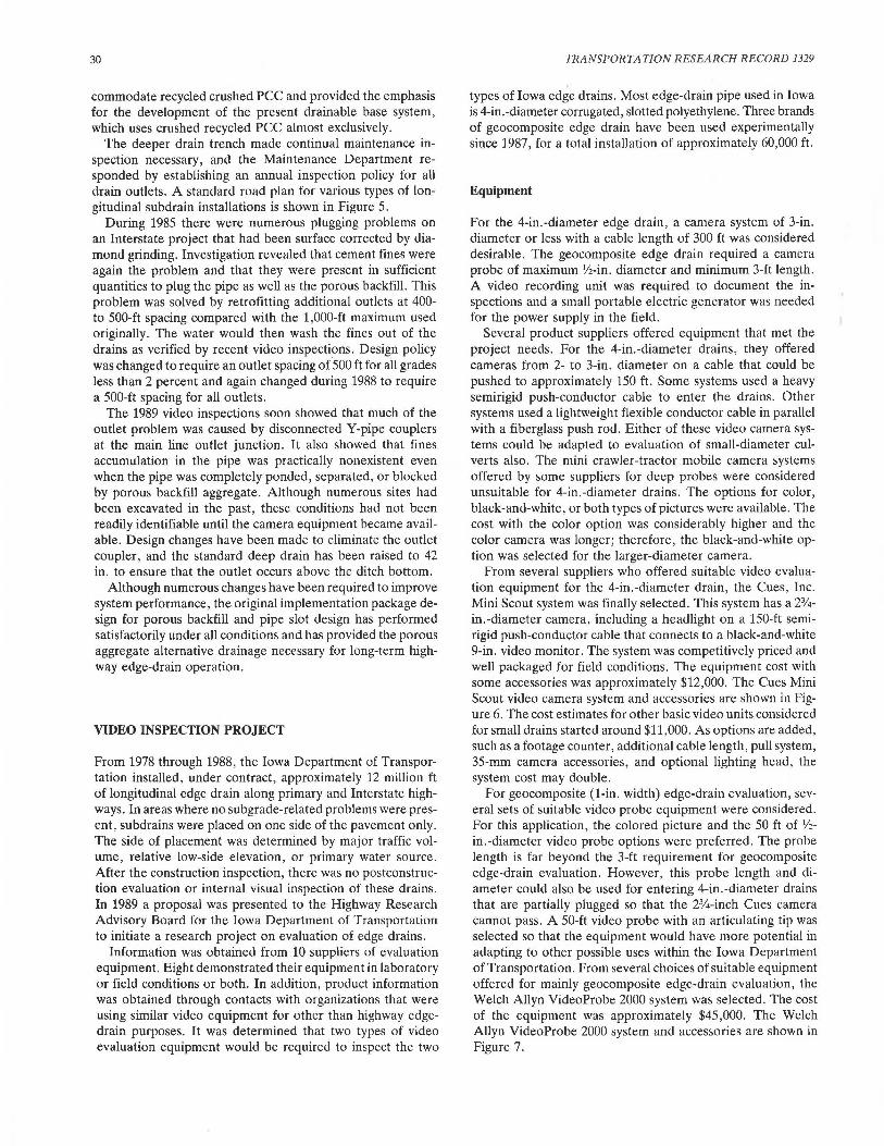
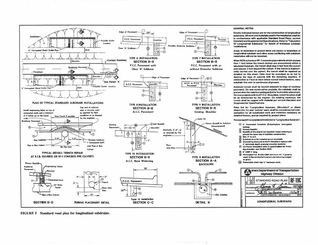
The deeper drain trench made continual maintenance inspection necessary, and the Maintenance Department responded by establishing an annual inspection policy for all drain outlets. A standard road plan for various types of longitudinal subdrain installations is shown in Figure 5.
During 1985 there were numerous plugging problems on an Interstate project that had been surface corrected by diamond grinding. Investigation revealed that cement fines were again the problem and that they were present in sufficient quantities to plug the pipe as well as the porous backfill. This problem was solved by retrofitting additional outlets at 400-to 500-ft spacing compared with the 1,000-ft maximum used originally. The water would then wash the fines out of the drains as verified by recent video inspections. Design policy was changed to require an outlet spacing of 500 ft for all grades less than 2 percent and again changed during 1988 to require a 500-ft spacing for all outlets.
The 1989 video inspections soon showed that much of the outlet problem was caused by disconnected Y-pipe couplers at the main line outlet junction. It also showed that fines accumulation in the pipe was practically nonexistent even when the pipe was completely ponded, separated, or blocked by porous backfill aggregate. Although numerous sites had been excavated in the past, these conditions had not been readily identifiable until the camera equipment became available. Design changes have been made to eliminate the outlet coupler, and the standard deep drain has been raised to 42 in. to ensure that the outlet occurs above the ditch bottom.
Although numerous changes have been required to improve system performance, the original implementation package design for porous backfill and pipe slot design has performed satisfactorily under all conditions and has provided the porous aggregate alternative drainage necessary for long-term highway edge-drain operation.
VIDEO INSPECTION PROJECT
From 1978 through 1988, the Iowa Department of Transportation installed, under contract, approximately 12 million ft of longitudinal edge drain along primary and Interstate highways. In areas where no subgrade-related problems were present, subdrains were placed on one side of the pavement only. The side of placement was determined by major traffic volume, relative low-side elevation, or primary water source. After the construction inspection, there was no postconstruction evaluation or internal visual inspection of these drains. In 1989 a proposal was presented to the Highway Research Advisory Board for the Iowa Department of Transportation to initiate a research project on evaluation of edge drains.
Information was obtained from 10 suppliers of evaluation equipment. Eight demonstrated their equipment in laboratory or field conditions or both. In addition, product information was obtained through contacts with organizations that were using similar video equipment for other than highway edgedrain purposes. It was determined that two types of video evaluation equipment would be required to inspect the two
TRANSPORTATION RESEARCH RECORD 1329
types of Iowa edge drains. Most edge-drain pipe used in Iowa is 4-in.-diameter corrugated, slotted polyethylene. Three brands of geocomposite edge drain have been used experimentally since 1987, for a total installation of approximately 60,000 ft.
Equipment
For the 4-in.-diameter edge drain, a camera system of 3-in. diameter or less with a cable length of 300 ft was considered desirable. The geocomposite edge drain required a camera probe of maximum Yz-in. diameter and minimum 3-ft length. A video recording unit was required to document the inspections and a small portable electric generator was needed for the power supply in the field.
Several product suppliers offered equipment that met the project needs. For the 4-in.-diameter drains, they offered cameras from 2- to 3-in. diameter on a cable that could be pushed to approximately 150 ft. Some systems used a heavy semirigid push-conductor cable to enter the drains. Other systems used a lightweight flexible conductor cable in parallel with a fiberglass push rod. Either of these video camera systems could be adapted to evaluation of small-diameter culverts also. The mini crawler-tractor mobile camera systems offered by some suppliers for deep probes were considered unsuitable for 4-in.-diameter drains. The options for color, black-and-white, or both types of pictures were available. The cost with the color option was considerably higher and the color camera was longer; therefore, the black-and-white option was selected for the larger-diameter camera.
From several suppliers who offered suitable video evaluation equipment for the 4-in.-diameter drain, the Cues, Inc. Mini Scout system was finally selected. This system has a 2%in.-diameter camera, including a headlight on a 150-ft semirigid push-conductor cable that connects to a black-and-white 9-in. video monitor. The system was competitively priced and well packaged for field conditions. The equipment cost with some accessories was approximately $12,000. The Cues Mini Scout video camera system and accessories are shown in Figure 6. The cost estimates for other basic video units considered for small drains started around $11,000. As options are added, such as a footage counter, additional cable length, pull system, 35-mm camera accessories, and optional lighting head, the system cost may double.
For geocomposite (1-in. width) edge-drain evaluation, several sets of suitable video probe equipment were considered. For this application, the colored picture and the 50 ft of V2-in.-diameter video probe options were preferred. The probe length is far beyond the 3-ft requirement for geocomposite edge-drain evaluation. However, this probe length and diameter could also be used for entering 4-in.-diameter drains that are partially plugged so that the 2%-inch Cues camera cannot pass. A 50-ft video probe with an articulating tip was selected so that the equipment would have more potential in adapting to other possible uses within the Iowa Department of Transportation. From several choices of suitable equipment offered for mainly geocomposite edge-drain evaluation, the Welch Allyn VideoProbe 2000 system was selected. The cost of the equipment was approximately $45,000. The Welch Allyn VideoProbe 2000 system and accessories are shown in Figure 7.
aoclcolo~• A--'f-<f T-[r~ ~ [ T ' TJf tp~,;~. O~M
L~_L ! l I _LI Loca6on
.tYiI~-4 x 'tr:-, ~WH f
-t-- r fomlop•
PLAN OF TYPICAL STANDARD SUBDRAIN INSTALLATIONS
Cap end of subdroin pipe or provide outle:
"' ,._;..d bv 6eld
I .... ...,, ,,_ ....... .-w...... I conditions~ as~
"""'"--· Install .ngineering fal::nc on top of compacted ~ mtel a lftinimum of 2 inches up on the trench wmls. ......, __ ;'\ ~
:--+-- h -~ -~~~~ ;c I .
~ Slop SuiOOn
~ i Pipe or Box CulMft -J=:= No Pay h•m
TYPICAL DETAILS TRENCH REPAIR
over Pipe or Box
Cuivert
AT R.C.B. CULVERTS OR RF-1 CONCRETE PIPE CULVERTS
Roadway
lO"Wae r ..... h
..__~
3 .. 3"
SECTl>N D-D TUBING PLACEMENT DETAIL
FIGURE 5 Standard road plan for longitudinal subdrains.
Edge of Povem•nt -
P.C.C. Pavement with
Class 'A' Subbase
TYPE 8 INSTALLATION SECTION B-B A.C.C. Pavement
TYPE 10 INSTALLATION
SECTION B-B A.C.C. Base Widening
I 35· •
1 I n
P.C.C. Pa1vemen1
(?)
0
Type 12 lnt1tall•llan SECTION C-C
Edge of POY•ITl •nJ--e
•n;i_inHf''--- --i
Flow
---~ Shoulder
TYPE 7 INSTAUATION
SECTION B-B P.C.C. Pavement with or
without Granular Subbase
Shoulder
TYPE 9 INSTALLATION
SECTION B-B Existing Shoulder
TYPE 11 INSTAUATION
SECTION A-A BACKSLOPE
(i)
DETAIL 'A'
GENERAL NOTES:
Dot.all• Indicated hereon are lor Ille construction ol longl\udlftal aubdrelna. All wort. .nd moterl•I• uoed II\ the lnllalletlon •hall be In conformance with •ppllcable Standard RO..S Pl1na, currant Standonl and Supplemental Spedlle11Uona. Reier lo "Tol>ulatlon 01 Longltudlnal Subdralna" lor detall1 ol lndlvtduel 1ubdraln lnataill•tlorus.
Are•• of ahouldeq In project llmlb not ahown In UbuleUon of longUudin•I aubdr•ln end other are•• conflicting with aubdr11ln lnllallatlon wlll not be trenched.
When RCB culverta or RF· 1 concrete pipe culverts which •re Ins 11\on 1 loot beloW the trench bottom are encount•red wll.hln • tabulated Subdraln, the trench •h•ll olop 3 feet lrom Ille cui.ert and resume 3 leet beyond the cui.ert. II the trench i. lnt1dnrlently carried ower the cui.ert, the trench 1hall be r-INd aa detaHed on this aheet. Care must be eserciHd 90 as not to de1lroy the lops ol culverts with the trenching machine. II obstruction la 1 tool or more below normal trench bottom, carry subdrain Une over In continuous alignment.
Subdraln trench shall be located •dlacenl to edge of roadway pavement On new construction projects, the subdraln •hall be placed after the malnllne paving and prior lo ahoulder plAcement. On new proJecl• with lied P .C.C. Shouldera, trench locatlon sh•ll be es determined by the,enginer. On exiating roadwaya, the trench •hall be c•pped with material per current Standard and Supplemental SpecHlcationa.
Price bid tor .. Longltudin•I Subdraln, (Shoulder)" or (Back Slope) (lin. H.) and "outlets" each, ahall be considered lull com· penaation for all Installation work end material& neceu1ry •• detailed hereon, end u required by project plH•.
Porou1 bac:l<!lll la cona1clered lnddental to "t.ongltudlnlll Subdnlln" •
(i) 4" Pet10<- Subd'"ln (Palyelhylene corrug.otod lubing).
@ Porous BDflll. @ Bllddlll ol thl• .,.. I• nol required II bale widening ..
placed the um• day of subdr.ln construction.
I Mln..l"tow/2. Subdniln ta to be lnatalled u cut proeeedl. On existing Gr11nul•r or E•rth Shoulden rwplmcewhh 4 .. minimum depth granular 1houlder m•lerlal.
<l) 01'11 P.wed Shoulden refer to apeclftcetlon tor tlnl .. ll'llg shoulder, ... Sed.lon 2502.
@ O" CMP 2' long. ® Pertor•led P.E. tH lnlo CMP minimum 12" It grout I•
uMd. Al the eontr11ctor'1 opllon u1e reducing coupt.r MgrouL
@ A•monble mnh cmp 'Ir" hardw•re cloth.
"3,t& IOwa Department Of Transportation ....,,., Highway Dhdslon
LONGITUDINAL SUBDRAINS

1. Monitor 1. Video Recorder 2. Videoprocessor 2. Cues Monitor/Power Control 3. Articulation Control Stick 3. Cues push/conductor cable with camera and 4. Pneumatic Controller
storage reel (300') 5. Video Recorder 4. Fiberglass push rod 3/s" dia. and storage cage (300') 6. Articulating VideoProbe 5. Cues Camera 7. VideoProbe Cable 1h" Dia. (50') 6. Portable Generator 8. Data Input Keyboard FIGURE 6 Cues Mini Scout video camera system and accessories. 9. Air Supply for Camera Head Articulation
FIGURE 7 Welch Allyn VideoProbe 2000 system and accessories.
Steffes et al.
Some accessories were purchased for the project:
• Small portable electric generator, • Videotape recorder, and •Fiberglass push rod (300 ft of 3/s in.).
The total project expenditure was approximately $60,000.
Modifications
Cues 2314-in. Mini Scout Video Camera System
The standard Cues Mini Scout system has 150 feet of semirigid push-conductor cable. A modification of cable length to 300 ft was made at the time of purchase. Under normal conditions, the camera could be pushed approximately 125 ft into 4-in.diameter drain before cable buckling would occur. With the addition of a 3/s-in.-diameter fiberglass push rod, the camera can be pushed 300 ft into a drain ..
The option to replace the semirigid push-conductor cable with a flexible conductor cable also exists. That would reduce cable weight from 100 to 30 lb and reduce friction and manpower required to push the camera. With that option, the fiberglass push rod is required.
For small culvert evaluations a skid assembly with batterypowered, waterproof lights is added to the camera. This modification raises the camera off the culvert floor and the extra lights assist in illuminating culvert walls. For evaluations beyond 75 ft, a push rod consisting of 10-ft sections of 1-in.diameter polyvinylchloride pipes is assembled and used to advance the camera.
For bridge pier evaluation a camera position holder and a guide pole are required.
Welch Allyn VideoProbe 2000 System
To improve visibility of a picture on the video monitor in outdoor sunlight, a sun shield was required.
The addition of a 1/16-in. fiberglass push rod attached parallel to the 50-ft video probe was essential for probe rigidity. The fiberglass rod changed the length that could be utilized in 4-in.-diameter drains from 15 to 50 ft.
VIDEO EVALUATION AND OBSERVATIONS
Initially the sites for video evaluation of edge drains were selected randomly. As the research project and the use of the equipment received more publicity, requests were received for evaluation of specific problems or suspected problem areas.
Both types of equipment were transported to each evaluation site. The 2%-in.-diameter camera was used in most cases. When a partially buried outlet was encountered, the %-in.diameter video probe was used. In some cases, the outlet pipe was found completely plugged or buried. With the porous backfill extending to the outlet, as in a french drain, water can still flow around any plugged or buried outlet pipe.
The random drain inspections did expose some problems:
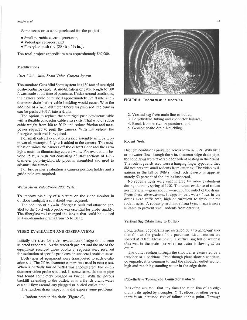
1. Rodent nests in the drain (Figure 8),
33
FIGURE 8 Rodent nests in subdrains.
2. Vertical sag from main line to outlet, 3. Polyethylene tubing and connector failures, 4. Break from stretch or puncture, and 5. Geocomposite drain J-buckling.
Rodent Nests
Drought conditions prevailed across Iowa in 1989. With little or no water flow through the 4-in.-diameter edge-drain pipe, the conditions were favorable for rodent nesting in the drains. The rodent guards used were a hanging finger type, and they did not prevent small rodents from entering. The video evaluations in the fall of 1989 showed rodent nests in approximately 50 percent of the drains inspected.
No rodents nests were encountered by video evaluations during the rainy spring of 1990. There was evidence of rodent nest material-grass and fur-around the outlet of the drain. From these observations, it appears that water flows in the drains were sufficiently high or turbulent to flush out the rodent nests. A rodent guard made from 1/z-in. mesh is more suitable to prevent small rodents from entering.
Vertical Sag (Main Line to Outlet)
Longitudinal edge drains are installed by a trencher-installer that follows the grade of the pavement. Drain outlets are spaced at 500 ft. Occasionally, a vertical sag full of water is observed in the main line when no water is flowing at the outlet.
The outlet section through the shoulder is excavated by a trencher or a backhoe. Even though plans show a continual downgrade, it is common to find the shoulder outlet section high and retaining standing water in the edge drain.
Polyethylene Tubing and Connector Failures
It is often assumed that any time the main line of an edge drain is disrupted by a coupler, Y, T, elbow, or other device, there is an increased risk of failure at that point. Through
34
video evaluations, that assumption can be, to some degree, confirmed. Occasionally, a blockage from porous backfill is found inside the drain at the point of a connection.
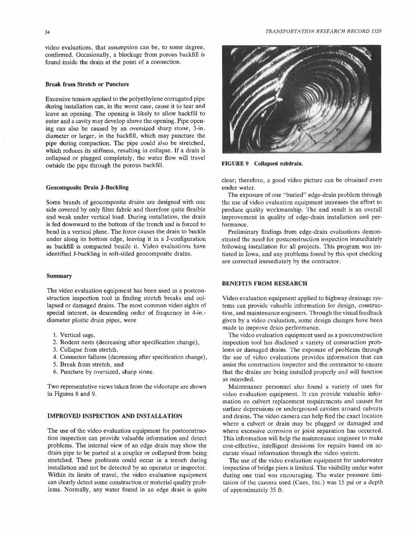
Break from Stretch or Puncture
Excessive tension applied to the polyethylene corrugated pipe during installation can, in the worst case, cause it to tear and leave an opening. The opening is likely to allow backfill to enter and a cavity may develop above the opening. Pipe opening can also be caused by an oversized sharp stone, 3-in. diameter or larger, in the backfill, which may puncture the pipe during compaction. The pipe could also be stretched, which reduces its stiffness, resulting in collapse. If a drain is collapsed or plugged completely, the water flow will travel outside the pipe through the porous backfill.
Geocomposite Drain J-Buckling
Some brands of geocomposite drains are designed with one side covered by only filter fabric and therefore quite flexible and weak under vertical load. During installation, the drain is fed downward to the bottom of the trench and is forced to bend in a vertical plane. The force causes the drain to buckle under along its bottom edge, leaving it in a J-configuration as backfill is compacted beside it. Video evaluations have identified J-buckling in soft-sided geocomposite drains.
Summary
The video evaluation equipment has been used as a postconstruction inspection tool in finding stretch breaks and collapsed or damaged drains. The most common video sights of special interest, in descending order of frequency in 4-in.diameter plastic drain pipes, were
1. Vertical sags , 2. Rodent nests (decreasing after specification change), 3. Collapse from stretch, 4. Connector failures (decreasing after specification change), 5. Break from stretch, and 6. Puncture by oversized, sharp stone .
Two representative views taken from the videotape are shown in Figures 8 and 9.
IMPROVED INSPECTION AND INSTALLATION
The use of the video evaluation equipment for postconstruction inspection can provide valuable information and detect problems. The internal view of an edge drain may show the drain pipe to be parted at a coupler or collapsed from being stretched. These problems could occur in a trench during installation and not be detected by an operator or inspector. Within its limits of travel, the video evaluation equipment can clearly detect some construction or material quality problems. Normally, any water found in an edge drain is quite
TRANSPORTATION RESEARCH RECORD 1329
FIGURE 9 Collapsed subdrain.
clear; therefore, a good video picture can be obtained even under water.
The exposure of one "buried" edge-drain problem through the use of video evaluation equipment increases the effort to produce quality workmanship. The end result is an overall improvement in quality of edge-drain installation and performance.
Preliminary findings from edge-drain evaluations demonstrated the need for postconstruction inspection immediately following installation for all projects. This program was initiated in Iowa, and any problems found by this spot checking are corrected immediately by the contractor.
BENEFITS FROM RESEARCH
Video evaluation equipment applied to highway drainage systems can provide valuable information for design, construction, and maintenance engineers. Through the visual feedback given by a video evaluation, some design changes have been made to improve drain performance.
The video evaluation equipment used as a postconstruction inspection tool has disclosed a variety of construction problems or damaged drains. The exposure of problems through the use of video evaluations provides information that can assist the construction inspector and the contractor to ensure that the drains are being installed properly and will function as intended.
Maintenance personnel also found a variety of uses for video evaluation equipment. It can provide valuable information on culvert replacement requirements and causes for surface depressions or underground cavities around culverts and drains. The video camera can help find the exact location where a culvert or drain may be plugged or damaged and where excessive corrosion or joint separation has occurred. This information will help the maintenance engineer to make cost-effective, intelligent decisions for repairs based on accurate visual information through the video system.
The use of the video evaluation equipment for underwater inspection of bridge piers is limited. The visibility under water during one trial was encouraging. The water pressure limitation of the camera used (Cues , Inc.) was 15 psi or a depth of approximately 35 ft.
Steffes et al.
Specific benefits derived from this research cannot be calculated in terms of exact dollars. Information obtained from the video inspections and evaluations has played a part in changes in design and improvements in installation of edge drains. As a result, some improvement is expected in the overall performance and effective life of the edge drains and, in tum, in extended pavement life. Evaluations of culverts 14- to 30-in. in diameter have influenced maintenance and replacement decisions. It can be stated that the research project was cost-effective. The video evaluation equipment has more than paid for itself through internal views and information it provided concerning highway drainage systems. Some of these views were compiled into a 10-min videotape that is being used as an educational tool for design, construction, maintenance, and inspection personnel involved with highway drainage systems.
CONCLUSIONS
The research on video evaluation of highway drainage systems supports the following conclusions:
35
1. The video evaluation equipment can be used as an effective tool to obtain internal views in 4-in.-diameter edgedrain pipes, geocomposite edge drains, and small-diameter culverts.
2. Information obtained through video inspection of highway drainage systems aids the design, construction, and maintenance engineers with engineering decisions based on visual observations.
3. Video evaluations of edge drains have resulted in design modifications and improved construction inspection.
ACKNOWLEDGMENTS
The authors wish to express their appreciation to the Highway Research Advisory Board for their recommendation of the research and to the Iowa Department of Transportation Highway Division for funding the project. Appreciation is also expressed to Richard Smith, Todde Folkerts, and Gary Harris for their assistance with field evaluations. Kathy Davis and Todde Folkerts were very helpful in preparing the paper.
Related Documents