G-103 UPDATED 6/2009 G-103 UPDATED 6/2009 General Catalog Victaulic General Catalog

VictaulicGeneralCatalogue
Mar 11, 2016
V ic t a u li c g e n e r a l C a t a lo g g -1 0 3 Updated 6/2009 Updated 6/2009
Welcome message from author
This document is posted to help you gain knowledge. Please leave a comment to let me know what you think about it! Share it to your friends and learn new things together.
Transcript

VICTAULIC GLOBAL CONTACT INFORMATION
US & WORLD HEADQUARTERS
P.O. Box 31Easton, PA 18044-0031 USA
4901 Kesslersville RoadEaston, PA 18040 USA 1-800-PICK-VIC (+1-800-742-5842) (within North America) +1-610-559-3300 +1-610-250-8817 (fax) [email protected]
www.victaulic.com
UNITED KINGDOM
Units B1 & B2, SG1 Industrial ParkCockerell CloseGunnels Wood RoadStevenageHertfordshire, SG1 2NB (UK)+44-(0)-1438-310-690+44-(0)-1438-310-699 (fax)0124-60219 (direct to Ireland within the UK) [email protected]
CENTRAL AND SOUTH AMERICA
P.O. Box 31Easton, PA 18044-0031 USA
4901 Kesslersville RoadEaston, PA 18040 USA
+1-610-559-3300+1-610-559-3608 (fax)[email protected]
ASIA
Unit 06-10, Floor 3A A Mansion 291 Fumin Road Shanghai, China 200031 +86-21-6170-1222+86-21-6170-1221 (fax)[email protected]
MIDDLE EAST
P.O. Box 17683Unit XB 8Jebel Ali Free ZoneDubai United Arab Emirates+971-4-883-88-70+971-4-883-88-60 (fax)
CANADA
123 Newkirk RoadRichmond Hill, ON L4C 3G5+1-905-884-7444+1-905-884-9774 (fax)[email protected]
EUROPE
Prijkelstraat 369810 Nazareth, Belgium+32-9-381-15-00+32-9-380-44-38 (fax)[email protected]
g-103Updated 6/2009
piping. Systems. Solutions.
g-103
Up
date
d 6
/20
09
general Catalog
Victaulic general C
atalog
Updated 6/2009 g-103 0798 reV MVictaulic is a registered trademark of Victaulic company. © 2009 Victaulic company. all rights reserVed.
www.victaulic.comthe Victaulic website is an information resource that can help you with your piping projects. among the many resources available at the site:
• fully searchable product and project databases • free product submittals • free product literature • piping software demos and modules • information on new product innovations • support services, and more...

19-2
Standing alongside every Victaulic product and mechanical piping system solution is a service and support team ready to assist you with your next project.
Our staff of experienced sales representatives, on-site training personnel and engineering professionals are a phone call away for help in facilitating the evaluation, planning and fulfillment of your piping system needs.
1-800-pick-VicFor immediate answers to your engineering or technical questions call 1-800-PICK-VIC (in the US only) or email [email protected] Monday through Thursday from 8:00 am to 7:30 pm EST/EDT and Friday from 8:00 am to 4:30 pm EST/EDT.
www.victaulic.comFor additional information about our products and services including a library of global projects to view, visit us on the web. From there you can easily access the most up-to-date product informa-tion organized by market and by product type.
piping. Systems. Solutions.World Class Service and Support
Value-added services
construction piping services (cps)our construction piping services group can help you make effective and efficient use of Victaulic piping systems through its estimating, project management and drawing package expertise and services. in the us cps can be reached at 1-610-559-3488 or by email at [email protected]. cps offers the following:
ValUe analySiS
analyzing contract drawings provided by you, cps will develop cost/pricing and cost comparison summaries of Victaulic systems versus welded, flanged, threaded and other mechanical pipe joining systems using current street prices for materials and recent labor times calculated from trade association standards.
projeCt management
cps can provide quotes for preparation of detailed piping drawings for fabrication and erection, including pipe routing layout; sectional views and isometric draw-ings; and cut sheets and bills of material. a cps project coordinator is assigned to begin tracking all the necessary documentation, including organizing the delivery of material according to your construction schedule.
Field SerViCe
Victaulic is the only mechanical piping systems manufacturer with 200+ factory-trained piping specialists worldwide to service your needs.
engineered prodUCtS
through our engineered products services, special attention is paid to projects that require special alloys, non-ferrous materials, special coatings or non-standard or special code applications. call us for an evaluation.
Worldwide leader in mechanical pipe joining solutions
piping. Systems. Solutions.
Welcome to Victaulic. the worldwide leader in mechanical pipe joining solutions. since pioneering grooved end technology for mechanical pipe joining in 1925, Victaulic has been providing customers the world over with innovative, reliable piping systems solutions for multiple applications and markets.
headquartered in the us with offices in canada, europe, the middle east, united kingdom, china and Belgium, Victaulic works closely with facility owners, engineers and contractors, in the installation of systems that compress schedules, reduce risk, improve productivity and facilitate system maintenance and expansion.
technology timelinesince 1925, Victaulic has been at the forefront of mechanical piping systems innovation with over 1,500 patents for piping related products.
1925Victaulic introduces the first grooved end coupling, the “Victory Joint”
1930 aWWa-size ductile iron system introduced
1946 first field-grade cut groovers brought to market
1957 Victaulic introduces roll grooving
1979first mechanical coupling for joining high density polyethylene (hdpe) pipe
1983 first angled-bolt pad rigid coupling introduced
1991 Victaulic introduces first small diameter ips-size pipe press connect system
2005advance groove system large diameter pipe joining system introduced
2006Victaulic introduces installation-ready technology

table of contents ii Global Solutions
iv Grooved End Technology
vi Approvals and Industry Standards
viii Design Data
18-1 Product Index
19-2 Support and Services
Products
1-1 Couplings
2-1 Fittings
3-1 Valves
4-1 Accessories
5-1 Advanced Groove System
6-1 Hole Cut Piping System
7-1 Plain End Piping System
8-1 Grooved System for Stainless Steel Pipe
9-1 Pressfit System for Stainless Steel Pipe
10-1 Plain End Piping System for HDPE Pipe
11-1 Grooved Copper
12-1 PermaLynx System for Copper Tube
13-1 Grooved AWWA Ductile Iron Pipe
14-1 Victaulic Depend-O-Lok® System
15-1 Aquamine® Reusable PVC Products
16-1 Gaskets
17-1 Pipe Preparation Tools
19-1 Piping Software
Multiple markets servedVictaulic piping systems solutions span many markets. Our piping systems are found around the world in thousands of applications – from commercial comfort piping systems; industrial process and utility piping; residential and commercial fire protection systems; oil and offshore drilling platforms; coal and mineral mining operations; and water and wastewater plants and facilities.
Victaulic facilities worldwideOur global presence as a company ensures that our worldwide customers are served with speed and efficiency. Victaulic engineering and sales support personnel are ready to assist you with the details of your project, regardless of the location.
Manufacturing facilities in the US, Poland, China, and Canada combined with a worldwide distribution and delivery system means Victaulic products are accessible from virtually any location around the world. Please consult the back of this catalog or our website for worldwide contact information.
Piping systems innovationOur customers know us for bringing a steady stream of product innovations to the marketplace year after year – innovations that significantly improve piping system performance; improve user productivity; and meet the specific design criteria of very complex piping system design challenges.
Victaulic ingenuity is driven in part from listening to our customers, and our commitment to finding practical solutions to the world’s most demanding engineering and system installation challenges.
i

Global solutions
our solutions are truly global. Victaulic piping systems solutions are found in some of the world’s most stunning and challenging engineering projects – buildings that arguably “push the design and construction envelope.”
Custom solutions for demanding challengesWhether new construction or retrofit, Victaulic delivers a level of versatility unmatched in
mechanical piping systems technology for today’s engineering marvels.
Victaulic solutions provide superior design flexibility, the ability to accommodate
seismic moments, noise and vibration attenuation, system access, system scalability, installation-friendly products and service, and more.
A world of applications at work
The projects illustrated here are just a few of the many buildings around the world for which Victaulic has provided innovative piping solutions.
For additional information on these and many other projects around the world, click on Global Projects from the home page of our website.
Projects spanning the globe
ii

united states
Hoover Dam
united arab emirates
Jumeirah Burj Al Arab and Beach Hotels
china
Beijing National Stadium
canada
La Chateau Frontenac
france
La Grande Arche de la Défense
malaysia
Petronas Twin Towers
united states
canada
euroPe
central & south america
middle east
asia Pacific
iii

Grooved end technology
The worldwide standard in mechanical piping systems
Gasket
housinG
Groove
bolt/nut
Groove
The Victaulic grooved end piping system is the most versatile, economical and reliable piping system available. It is significantly faster to install than welded systems, while providing design versatility other systems cannot provide.
The system is designed for roll grooved or cut grooved standard pipe or roll grooved light wall pipe. A complete line of grooving tools is available to quickly and efficiently groove pipe in the shop or at the job site.
iv

Reinventing InnovationThe result of continuous research and development, today’s Victaulic system has evolved since it was first introduced in 1925. But the basic concept hasn’t changed.
Product innovation is a Victaulic hallmark. We are dedicated to finding faster, easier and more reliable ways to mechanically join pipe.
features
riGidity
Rigidity is achieved with standard couplings. The unique angled pad design of Zero-Flex and other couplings provides positive clamping of the pipe to resist torsional and flexural loads.
Exaggerated for clarity
noise and vibration attenuation
The basic design of indepen-dently grooved pipe sections reduces noise and vibration transmission, thus delivering superior vibration attenuation throughout the system.
system maintenance and exPansion
Coupling disassembly provides easy access for maintenance or system expansion. Victaulic butterfly valves provide “dead-end” shut-off service to isolate equipment.
Contraction
De�ection
flexibility
The Victaulic grooved end solution accommodates expan-sion/contraction/deflection and enables designing that takes advantage of these built-in system features.
EndLoad
End Load
seismic stress absorPtion
The full engagement of the housing keys into grooves around the pipe circumference provides significant pressure restraint and end load capability to withstand pipe movement from internal and external sources.
aliGnment ease
The grooved system allows full rotation of the pipe and system components before tightening so that proper alignment can be achieved.
v
accepted Worldwide
Victaulic grooved end, plain end, Pressfit® and other piping system components are tested and accepted for a variety of services throughout the world by the primary code and approval bodies.
A partial listing of the many agencies, associations, code group laboratories and organizations which have accepted, listed and tested Victaulic products are shown on the facing page. Copies of specific standards can be obtained by contacting your local Victaulic representative, or by requesting publication 02.02.
vi

nfPa National Fire Protection Association
nk Nippon Kaiji Kyokai
nsf/ansi 61Standard 61 for potable water service
ny-mea New York Materials and Equipment Acceptance
ÖvGWÖsterreichische Vereinigung für das Gas- und Wasserfach
Ped CE 97/23
PZhPanstwowy Zaklad Higieny
rina Registro Italiano Navale
sbcci Southern Building Code Congress International – Standard Plumbing and Mechanical Code
sbsc Svensk Brand & Säkerhets Certifiering AB
sriPs Service de Recherche et d'Ingéniérie en Protection Sanitaire
ssl Scientific Services Laboratory
Standards Australia
svGW Schweizerischer Verein des Gas- und Wasserfaches
tsu Technický Skúšobný Ústav Pieštany, š.p.
ul Underwriter’s Laboratories, Inc. – Listed for fire protection services
ulc Underwriter’s Laboratories of Canada – Listed for fire protection services
VdS
vds Verband der Schadenverhütung GmBH
General code GrouPs, associations, laboratories and aPProval bodies
abs American Bureau of Shipping
ansi American National Standards Institute
ansi/aWWa American Water Works Association – C-606
aPi American Petroleum Institute – API Std. 5L, Sect. 7.5
as AS4041-1992 Australian Standard (3.24.10)
ashrae American Society of Heating, Refrigerating and Air Conditioning Engineers
asme American Society of Mechanical Engineers • PowerPiping,B-31.1 • ChemicalPlantandPetroleum Refinery Piping, B-31.3 • RefrigerationPiping,B-31.5 • BuildingServicesPiping,B-31.9 • SlurryPipelines,B-31.11
astm American Society of Testing and Materials• F-1476Couplings • F-1548Fittings • F-1155Shipbuilding
bba British Board of Agrément
boca Building Officials and Code Administrators
bv Bureau Veritas
cccf China Certification Center for Fire Products
0026 ce Certification to the European Directive for Pressure Equipment
cnboP Centrum Naukowo-Badawcze Ochrony Przeciwpozarowej
cnPP aPsad Centre National de Prévention et de Protection
csa Canadian Standards Association – B-242, registered to CAN 3-Z299.3
culus Underwriter's Laboratories, Inc. - Listed for the fire protection services
din GÖst tÜvZertifizerungssystem für Produkte
dnv Det Norske Veritas
dvGW Deutscher Verein des Gas- und Wasserfaches e.V.
emi Epitesugyi Minosegellenorzo Innovacious
FMAPPROVED
fm FM Approvals – Approved for fire protection services
Gl Germanischer Lloyd
Gost r
hdb Singapore Housing Development Board
Hong Kong Fire Services Board
iaPmo International Association of Plumbing & Mechanical Officials
Korean Registry of Shipping
Krajska Hygienicka
instal • AT/2000 • AT/2002 • AT/2003
lloyd’s Lloyd’s Register of Shipping
lPcb Loss Prevention Certification Board
New Zealand Insurance Council
New Zealand Building Act (1991)
VKF Vereinigung Kantonaler Feuerversicherungen
W Standards Australia Watermark Certification
Wras Water Regulations Advisory Scheme
Government aGencies
Bureau of Marine Inspection – Salt and fresh water, oil transfer
Bureau of Public Roads – Div. of Bridges – Drain lines and bridge crossings
Canadian Coast Guard
U.S. Coast Guard – Approves each vessel individually
coe Corps of Engineers – CEGS 15000
faa Federal Aviation Administration – HVAC, Plumbing, Fire Protection Federal Code of Regulations – • A-A-52598–Couplings • A-A-52592–Fittings
fha Federal Housing Administration
Gsa General Services Administration – 15000 Series
mil Military Specifications• MILP-10388Fittings • MIL-C-10387Couplings • MIL-P-11087A(CE) Steel Pipe, Grooved • MIL-I-45208InspectionProcedure
nasa National Aeronautics and Space Administration – 15000 Series
navfac Naval Facilities Engineering Command – NFGS 15000 Series
nih National Institute of Health (Dept. of Health) – 15000 Series
tva Tennessee Valley Authority – Fire protection, storm drains
va Veterans Affairs – 15000 Series
vii
Introduction This Victaulic General Catalog has been written for the piping system installer, designer, specification writer and owner as a basic reference guide for data about Victaulic mechanical piping methods. This catalog is organized to provide information in the context and form most readily usable. For easy identification of major sections of interest, see the condensed table of contents on pg. i, for a fully detailed index, see pg. 18-1. For more detailed information, consult Design Data, Section 26.01.
Important Information
Victaulic has developed, in over 80 years in mechanical piping, variations of piping practice for use on a wide variety of piping materials.
Victaulic standard grooved pipe couplings are designed for use with pipe grooved to meet Victaulic groove specifications and Victaulic grooved end fittings, valves, and related grooved end components only. They are not intended for use with plain end pipe and/or fittings. Victaulic plain end couplings are designed for use only with plain end or beveled end steel pipe (unless otherwise indicated) and Victaulic plain end fittings. Victaulic plain end couplings must not be used with grooved end or threaded end pipe and/or fittings. Nor are they intended for use with Advanced Groove System (AGS) components used on 14 – 24"/350 – 600 mm pipe sizes.
Pipe must be prepared to meet Victaulic specifications outlined for each specific product style. Performance data listed herein is based on proper pipe preparation. The proper gasket must be selected for the service intended. It should be noted that there are various services for which Victaulic gaskets are not recommended. Reference should always be made to the latest Victaulic Gasket Selection Guide (request publication 05.01) for specific gasket service recommendations and for a listing of services which are not recommended. Gaskets for Victaulic products always must be lubricated for proper assembly. Gasket lubricant must meet manufacturer's specifications. Thorough lubrication of the gasket exterior, including the lips and/or pipe ends and housing interiors, is essential to prevent gasket pinching. Lubrication assists proper gasket seating and alignment during installation.
Victaulic has a complete line of tools for preparing pipe to Victaulic specifications. Use of these tools is recommended in preparing pipe to receive Victaulic products. Always read and understand the Tool Operating Instructions supplied with every Victaulic tool prior to using any tools. All data contained herein, is subject to change without notice.
www.VIctAulIc.comviii
Design DataD
eSI
GN
DAt
A

Notice The technical and performance data, weights, dimensions and specifications published in this catalog supersede all previously published data.
Victaulic Company maintains a policy of continual product improvement and, therefore, reserves the right to change product specifications, designs, and standard equipment without notice and without incurring obligation.
For the most up-to-date Victaulic product information, please visit www.victaulic.com.
The material presented in this catalog is intended for piping design reference in utilization of Victaulic products for their intended application. It is not intended as a substitute for competent, professional assistance which is an obvious requisite to any specific application.
Reference should always be made to the specific Victaulic Field Installation Handbook for the product you are installing. The following is a list of handbooks that can be requested for free from Victaulic: I-100 General Handbook I-300 AWWA Products Handbook I-500 Pressfit System Handbook I-600 Copper Products Handbook I-900 HDPE Products Handbook
Handbooks are included with each shipment of Victaulic products for complete installation and assembly data, and are available in PDF format on our website at www.victaulic.com.
All rights reserved. No part of this Victaulic catalog may be reproduced, stored in a retrieval system, or transmitted, in any form or by any means, electronic, mechanical, photocopy, recording or otherwise, without the prior written permission of Victaulic Company.© Copyright 2009, Victaulic Company.® Registered trademark of Victaulic Company.
Design Reference should always be made to design information available at no charge on request from Victaulic. Good piping practices should always prevail. Specific pressures, temperatures, external or internal loads, performance standards and tolerances must never be exceeded. Many applications require recognition of special conditions, code requirements and use of safety factors. Qualified engineers must make these decisions.
while every effort has been made to ensure its accuracy, Victaulic company, its subsidiaries and affiliated companies, make no express or implied warranty of any kind respecting the information contained in this catalog or the material referred to herein.
Anyone making use of the information or material contained herein does so at their own risk and assumes any and all liability resulting from such use.
Installation
www.VIctAulIc.com ix
Design DataD
eSIG
N D
AtA

Nominal Imperial Inches – Size Group
outside Diameter mm/Spec Ref
DIN mm
JIS mm
ANSI inches
china Standard (GB) mm
1/2 21.3 mm 15 15 A/21.7 mm ½ 15*/21.3 mm
¾ 26.7 mm 20/26.9 mm 20 A/27.2 mm ¾ 20*/26.9 mm
1 33.4 mm 25/33.7 mm 25 A/34 mm 1 25*/33.7 mm
1 1/4 42.2 mm 32/42.4 mm 32 A/42.7 mm 1 1/4 32*/42.4 mm
1 1/2 48.3 mm 40 40 A/48.6 mm 1 1/2 40*/48.3 mm
2 60.3 mm DN & ISO 50 50 A/60.5 mm 2 50*/60.3 mm
2 1/2 73.1 mm — — 2 ½ —
3 76.1 mm DIN/ISO (3 OD) DN & ISO 65 65 A/76.3 mm — 65*/76.1 mm
88.9 mm DN & ISO 80 JIS 80 A 3 80*/88.9 mm
4 108 mm China and old DIN DIN 108 mm — — 108 mm
114.3 mm DN & ISO 100 JIS 100 A 4 100*/114.3 mm
5 133 mm China and old DIN DIN 133 mm — — 133 mm
139.7 mm DIN/ISO (5.5 OD) DN & ISO 125 125 A/139.8 mm — 125*/139.7 mm
141.3 mm — — 5 —
6 159 mm China and old DIN DIN 159 mm — — 159 mm
165.1 mm JIS (6.5 OD) — 150 A/165.2 mm — —
168.3 mm DN & ISO 150 — 6 150*/168.3 mm
8 216.3 JIS — JIS 200 A — —
219.1 mm DN 200 — 8 219.1 mm
10 267.4 JIS — JIS 250 A — —
273 mm DN 250 — 10 273 mm
12 318.5 JIS — JIS 300 A — —
323.9 mm DN 300 — 12 323.9 mm
14 355.6 mm DN 350 JIS 350 A 14 355.6 mm
377 mm China — — — 377 mm
16 406.4 mm DN 400 JIS 400 A 16 406.4 mm
426 mm China — — — 426 mm
18 457.2 mm DN 450 JIS 450 A 18 457.2 mm
480 mm China — — — 480 mm
20 508 mm DN 500 JIS 500 A 20 508 mm
530 mm China — — — 530 mm
22 558.8 mm — JIS 550 A 22 559 mm
24 610 mm DN 600 JIS 600 A 24 610 mm
630 mm China — — — 630 mm
26 660 mm — JIS 650 A 26 660 mm
28 711 mm DN 700 — 28 711 mm
30 762 mm — — 30 762 mm
32 813 mm DN 800 — 32 813 mm
34 864 mm — — 34 864 mm
36 914 mm DN 900 — 36 914 mm
40 1016 mm DN 1000 — 40 1016 mm
42 1067 mm DN 1050 — 42 1067 mm
44 1118 mm DN 1100 — 44 1118 mm
46 1168 mm DN 1150 — 46 1168 mm
48 1219 mm DN 1200 — 48 1219 mm
IMPORTANT NOTE: Nominal designations are used where the actual OD of the pipe matches the ANSI size. Otherwise both the nominal and actual OD are listed. China sizes are listed as actual OD in mm. China sizes in orange are tubing sizes.* Nominal sizes
Global Pipe Size Designations
Victaulic product data is utilized worldwide and all technical data is shown in both imperial (U.S.) and metric terms. The following chart shows a comparison between typical metric and IPS pipe sizes.
www.VIctAulIc.comx
Design DataD
eSI
GN
DAt
A

convert Imperial (u.S.) to metric
convert metric to Imperial (u.S.)
25.4 × Inches (In.)
Millimeters (mm) × 0.03937
0.3048 × Feet (Ft.)
Meters (m) × 3.281
0.4536 × Pounds (Lbs.)
Kilograms (kg) × 2.205
28.35 × Ounces (Oz.)
Grams (g) × 0.03527
6.894 × Pressure (psi)
Kilopascals (kPa) × 0.145
.069 × Pressure Bar × 14.5
4.45 × End Load (Lbs.)
Newtons (N) × 0.2248
1.356 × Torque (Lb. Ft.)
Newton Meters (N•m) × 0.738
F – 32 ÷ 1.8 Temp. (°F)
Celsius (°C) C + 17.78 × 1.8
745.7 × Horsepower (hp)
Watts (w) × 1.341 × 10⁻³
3.785 × Gal. per Min. (GPM)
Liters per min. (L/M) × 0.2642
3.7865 × 10⁻³ Gal. per Min. (GPM)
Cubic Meters per min. (m3/m) × 264.2
This chart is provided as a guide for converting imperial and metric measurements provided within this catalog.
Imperial (U.S.)/Metric Conversion Chart
www.VIctAulIc.com xi
Design DataD
eSIG
N D
AtA

VdS
VdS
VdS
Zero-Flex® Rigid CouplingStyle 07, pg. 1-6 AgS Style w07, pg. 5-3
• Victaulic,theoriginatorandinnovatorofgroovedcouplingtechnology,offersavarietyofcouplingsizesandstylesforalmostanypipingapplication.
• Consistingofthreebasiccomponents—thehousing,thegasket,andboltsandnuts—Victauliccouplingsprovideasimple,economicalmethodforjoiningcarbonsteel,copper,stainlesssteel,ductileiron,aluminum,HDPEandPVCplasticpipingsystems.
• Victauliccouplingsprovidedesignerswithversatilitynotfoundinotherpipejoiningmethods.Victaulicrigidandflexiblecouplingscanbecombinedtoallowforthermalgrowthwithinthesystem.Additionally,theuseofthreeconsecutive flexiblecouplingsreducesnoiseandvibrationandeliminatescostlyspecialtynoisedampeners.
LargeDiameter PipeCouplingStyle 770, pg. 1-10
VdS
StandardFlexible CouplingStyle 77, pg. 1-8 AgS Style w77, pg. 5-3
Flexible CouplingStyle 75, pg. 1-9
Vic-Flange®AdapterANSIClass150/PN10Style 741, pg. 1-11 AgS Style w741, pg. 5-5
Vic-FlangeAdapter ANSIClass300/PN16Style 743, pg. 1-12
Reducing CouplingStyle 750, pg. 1-13
Snap-Joint® CouplingStyle 78, pg. 1-14
AdvancedGrooveSystem
For14–24"/350–600mmpipingsystemsVictaulicoffersAdvancedGrooveSystem(AGS)couplings,seepg.5-1.
QuickVic® Rigid CouplingStyle 107, pg. 1-5
QuickVic® FlexibleCouplingStyle 177, pg. 1-7
www.victAulic.com1-1
couplingsc
ou
pli
ng
S
™TM

GasketType Style 107
Style 117
Style 07
Style 77
Style 75
Style 770
Style 750
Style 78
Style 72 †
Style 791
Style Hp-70
Style Hp-70eS
StAndArd • • • • • • • •
inStAllAtion- reAdy • •
reducing •
FluSHSeAl • • • • • •
endSeAl •
† Separate gasket specifically designed for outlet couplings.
Outlet CouplingStyle 72, pg. 1-15
Vic-Boltless® CouplingStyle 791 And Style 792 ASSembly tool, pg. 1-16
Availablewithfemale threadedoutlets(shown) andgroovedoutlets
Rigid CouplingStyle Hp-70, pg. 1-17
Endseal®CouplingforPlasticCoatedPipeStyle Hp-70eS, pg. 1-19
HighPressureCouplingStyle 808, pg. 1-18
EndSealFittingsfor PlasticCoatedPipepg. 1-20
productS
1-1 couplings
2-1 Fittings
3-1 Valves
4-1 Accessories
5-1 AdvancedGrooveSystem
6-1 HoleCutPipingSystem
7-1 PlainEndPipingSystem
8-1 GroovedSystemforStainlessSteelPipe
9-1 PressfitSystemforStainlessSteelPipe
10-1 PlainEndPipingSystemforHDPEPipe
11-1 GroovedCopper
12-1 PermaLynxSystem forCopperTube
13-1 GroovedAWWA DuctileIronPipe
14-1 VictaulicDepend-O-Lok®
System
15-1 AquamineReusable PVCProducts
16-1 Gaskets
17-1 PipePreparationTools
18-1 ProductIndex
19-1 PipingSoftware
GasketTypes
EndSealproductsarespecificallydesignedtomeetthe stringentrequirementsofoilfieldpipingsystems.Thespecialgrooveprofileandgasketdesignof“ES”productscontribute tohigherpressureratingsandlongerlifeservice.
www.victAulic.com 1-2
couplingsc
ou
plin
gS

SizeAllow. pipe end Sep.
nominal Size
inches mm
Actual outside diameter
inches mm
inches mm
3/4 1.050 0.0520 26.9 1.2
1 1.315 0.0525 33.7 1.2
1 1/4 1.660 0.0532 42.4 1.2
1 1/2 1.900 0.0540 48.3 1.2
2 2.375 0.0750 60.3 1.7
2 1/2 2.875 0.0765 73.0 1.7
76.1 mm 3.000 0.0776.1 1.7
3 3.500 0.0780 88.9 1.7
108.0 mm 4.250 0.16108.0 4.1
4 4.500 0.16100 114.3 4.1
133.0 mm 5.250 0.16133.0 4.1
139.7 mm 5.500 0.16139.7 4.1
§ Except for HP-70 and HP-70ES coupling which have the following allowable pipe end separation:
HP-70: 2 – 4"/50 – 100 mm sizes: 0.14"/3.6 mm 6 – 12"/150 – 300 mm sizes: 0.25"/6.4 mm
HP-70ES: 2 – 4"/50 – 100 mm sizes: 0.19"/4.8 mm 6 – 8"/150 – 200 mm sizes: 0.27/6.7 mm 10 – 12"/250 – 300 mm sizes: 0.28"/7.1 mm
* These figures do NOT apply to 14 – 24"/350 – 600 mm Style W07 AGS rigid couplings. Allowable pipe end separation is 0.25"/6.9 mm for all sizes of Style W07.
SizeAllow. pipe end Sep.
nominal Size
inches mm
Actual outside diameter
inches mm
inches mm
5 5.563 0.16125 141.3 4.1
159.0 mm 6.250 0.16159.0 4.1
165.1 mm 6.500 0.16165.1 4.1
6 6.625 0.16150 168.3 4.1
8 8.625 0.19200 219.1 4.8
10 10.750 0.13250 273.0 3.3
12 12.750 0.13300 323.9 3.3
14* 14.000 0.13350 355.6 3.3
16* 16.000 0.13400 406.4 3.3
18* 18.000 0.13450 457.0 3.3
20* 20.000 0.13500 559.0 3.3
24* 24.000 0.13600 610.0 3.3
IMPORTANT NOTES: ONLY FLEXIBLE couplings are recommended for the installation of expansion loops as stated in Calculating and Accommodating Pipe Line Thermal Growth Section 26.02. All eight couplings assembling the four elbows of the loop must be flexible. The use of rigid couplings to install the straight run adjacent to the expansion loop is a recommended practice.This also applies to couplings installed on the perpendicular leg(s) at the end(s) of a straight pipe run or on pipe line offsets. If system movement is to be accommodated, flexible couplings must be utilized.Rigid couplings must NOT be utilized to accommodate any system movement.Should you have any questions regarding the proper use of our products, contact Engineering Services at [email protected].
RigidCouplingSystemsandPerformance§
Rigidcouplingshaveaunique,patentedangledpaddesignwhichconstrictsthehousingkeysintothegroovearoundthefullcircumferencetocreatearigidjoint.Thehousingsslideontheangledpadsratherthanmatingsquarely.
Thisslidingmovementalsoforcesthekeysectionsintoopposedcontactontheinsideandtheoutsidegrooveedges,whichlocksthecouplingontothepipeends andcreatesarigidconnection.
wArning
depressurize and drain the piping system before attempting to install, remove, or adjust any victaulic piping products. Failure to do so could result in personal injury, property damage, joint leakage and/or joint failure.
Theserigidcouplingsprovidearigidjointallowing noexpansion/contractionorlinearmovement. Thecouplingswillpositionthepipeendssothatthere isafixedpipeendseparationthatmaybeconsidered duringdesignandinstallation(seechartbelow).
Rigidcouplingscreatearigidjoint,usefulforrisers,mechanicalroomsandotherareaswhereflexibilityisnotdesired.QuickVicStyle107,Zero-FlexStyle07andStyleW07AGScouplingsaredesignedtoproviderigiditytopermithangingtoASMEB31.1PowerPipingCode,ASMEB31.9BuildingServicesPipingCodeandNFPA13SprinklerSystems.
www.victAulic.com1-3
couplingsc
ou
pli
ng
S
SizeAllow. pipe end Sep. † deflect. Fr. cl †
nominal Size
inches mm
Actual outside diameter
inches mm
inches mm
degrees per coupling
pipe in./Ft. mm/m
3/4 1.050 0 – 0.06 3° 24' 0.7220 26.9 0 – 1.6 60
1 1.315 0 – 0.06 2° 43' 0.5725 33.7 0 – 1.6 48
1 1/4 1.660 0 – 0.06 2° 10' 0.4532 42.4 0 – 1.6 38
1 1/2 1.900 0 – 0.06 1° 56' 0.4040 48.3 0 – 1.6 33
2 2.375 0 – 0.06 1° 31' 0.3250 60.3 0 – 1.6 27
2 1/2 2.875 0 – 0.06 1° 15' 0.2665 73.0 0 – 1.6 22
76.1 mm 3.000 0 – 0.06 1° 12' 0.2676.1 0 – 1.6 22
3 3.500 0 – 0.06 1° 2' 0.2280 88.9 0 – 1.6 18
3 1/2 4.000 0 – 0.06 0° 54' 0.1990 101.6 0 – 1.6 16
108.0 mm 4.250 0 – 0.13 1° 41' 0.35108.0 0 – 3.2 29
4 4.500 0 – 0.13 1° 36' 0.34100 114.3 0 – 3.2 28
4 1/2 5.000 0 – 0.13 1° 26' 0.25120 127.0 0 – 3.2 21
133.0 mm 5.250 0 – 0.13 1° 21' 0.28133.0 0 – 3.2 23
139.7 mm 5.500 0 – 0.13 1° 18' 0.28139.7 0 – 3.2 23
5 5.563 0 – 0.13 1° 18' 0.27125 141.3 0 – 3.2 22
152.4 mm 6.000 0 – 0.13 1° 12' 0.21152.4 0 – 3.2 17
§ Except for Style 72 outlet couplings. Contact Victaulic for details.† NOTE: These values are based on standard roll grooved pipe. Figures for standard cut grooved pipe may be doubled. See notes below.@ Allowable pipe end separation for Style W77 AGS flexible couplings in this size range are 0.125 – 0.375"/3.1 – 9.5 mm.
SizeAllow. pipe end Sep. † deflect. Fr. cl †
nominal Size
inches mm
Actual outside diameter
inches mm
inches mm
degrees per coupling
pipe in./Ft. mm/m
159.0 mm 6.250 0 – 0.13 1° 9' 0.24159.0 0 – 3.2 20
165.1 mm 6.500 0 – 0.13 1° 6' 0.23165.1 0 – 3.2 19
6 6.625 0 – 0.13 1° 5' 0.23150 168.3 0 – 3.2 19
203.2 mm 8.000 0 – 0.13 0° 54' 0.16203.2 0 – 3.2 13
8 8.625 0 – 0.13 0° 50' 0.18200 219.1 0 – 3.2 15
254.0 mm 10.000 0 – 0.13 0° 43' 0.15254.0 0 – 3.2 13
10 10.750 0 – 0.13 0° 40' 0.14250 273.0 0 – 3.2 12
304.8 mm 12.000 0 – 0.13 0° 36' 0.13304.8 0 – 3.2 11
12 12.750 0 – 0.13 0° 34' 0.12300 323.9 0 – 3.2 10
14 @ 14.000 0 – 0.13 0° 31' 0.11350 355.6 0 – 3.2 9
15 15.000 0 – 0.13 0° 29' 0.10375 381.0 0 – 3.2 8
16 @ 16.000 0 – 0.13 0° 27' 0.10400 406.4 0 – 3.2 8
18 @ 18.000 0 – 0.13 0° 24' 0.08450 457.0 0 – 3.2 7
20 @ 20.000 0 – 0.13 0° 22' 0.08 500 508.0 0 – 3.2 7
22 22.000 0 – 0.13 0° 19' 0.07550 559.0 0 – 3.2 6
24 @ 24.000 0 – 0.13 0° 18' 0.07600 610.0 0 – 3.2 6
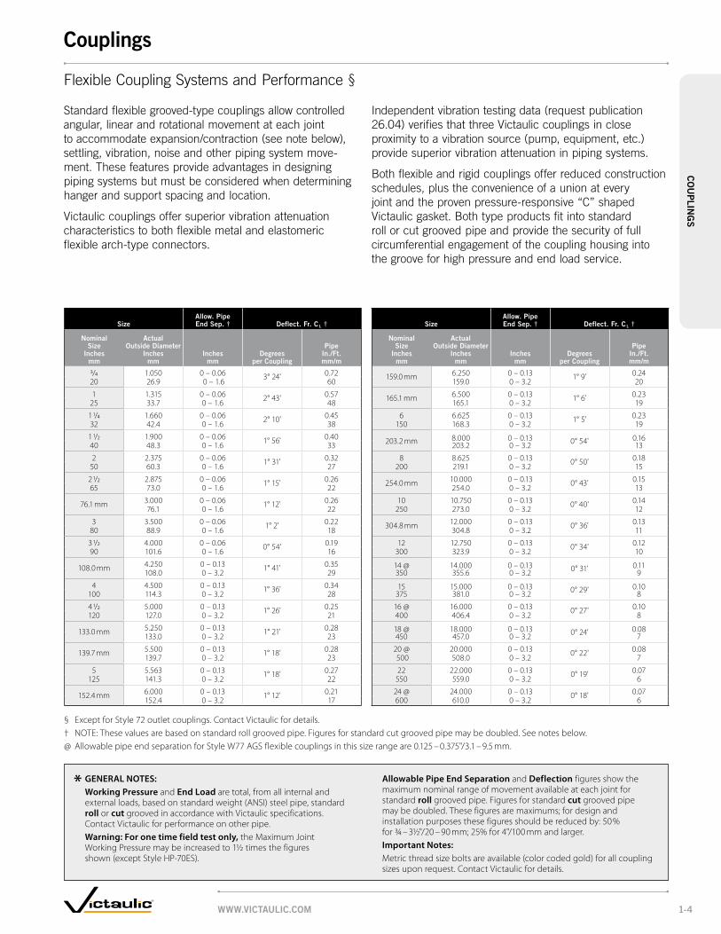
FlexibleCouplingSystemsandPerformance§
Standardflexiblegrooved-typecouplingsallowcontrolledangular,linearandrotationalmovementateachjoint toaccommodateexpansion/contraction(seenotebelow), settling,vibration,noiseandotherpipingsystemmove-ment.Thesefeaturesprovideadvantagesindesigning pipingsystemsbutmustbeconsideredwhendetermininghangerandsupportspacingandlocation.
Victauliccouplingsoffersuperiorvibrationattenuation characteristicstobothflexiblemetalandelastomeric flexiblearch-typeconnectors.
GENERAl NOTES: Working Pressure and End load are total, from all internal and
external loads, based on standard weight (ANSI) steel pipe, standard roll or cut grooved in accordance with Victaulic specifications. Contact Victaulic for performance on other pipe.
Warning: For one time field test only, the Maximum Joint Working Pressure may be increased to 1½ times the figures shown (except Style HP-70ES).
Allowable Pipe End Separation and Deflection figures show the maximum nominal range of movement available at each joint for standard roll grooved pipe. Figures for standard cut grooved pipe may be doubled. These figures are maximums; for design and installation purposes these figures should be reduced by: 50% for ¾ – 3½"/20 – 90 mm; 25% for 4"/100 mm and larger.
Important Notes: Metric thread size bolts are available (color coded gold) for all coupling sizes upon request. Contact Victaulic for details.
Independentvibrationtestingdata(requestpublication26.04)verifiesthatthreeVictauliccouplingsinclose proximitytoavibrationsource(pump,equipment,etc.) providesuperiorvibrationattenuationinpipingsystems.
Bothflexibleandrigidcouplingsofferreducedconstructionschedules,plustheconvenienceofaunionatevery jointandtheprovenpressure-responsive“C”shapedVictaulicgasket.Bothtypeproductsfitintostandard rollorcutgroovedpipeandprovidethesecurityoffull circumferentialengagementofthecouplinghousingintothegrooveforhighpressureandendloadservice.
www.victAulic.com 1-4
couplingsc
ou
plin
gS

Size
Allow. pipe end Sep. † @ bolt/nut dimensions inches/mm
Approx. wgt. each
nominal Size
inches/ mm
Actual outside
dia. inches/
mminches/
mm
no. – Size inches/
mm
preassembled (installation-ready
condition) Joint Assembledlbs/ KgX y X y Z
2 2.375 0.12 2 – 1 1/2 x 3 4.08 6.15 3.66 5.98 1.93 2.750 60.3 3.1 M12 x 3 104 156 93 152 49 1.2
2 1/2 2.875 0.12 2 – 1 1/2 x 3 4.61 6.77 4.16 6.54 1.94 3.165 73.0 3.1 M12 x 3 117 172 106 166 49 1.4
76.1 mm 3.000 0.12 2 – M12 x 3 4.74 6.99 4.38 6.82 1.94 3.376.1 3.1 120 178 111 173 49 1.5
3 3.500 0.12 2 – 1 1/2 x 3 5.18 7.42 4.82 7.13 1.94 3.580 88.9 3.1 M12 x 3 132 188 122 181 49 1.6
4 4.500 0.21 2 – 1 1/2 x 3 6.43 8.84 6.03 8.43 2.13 5.1100 114.3 5.3 M12 x 3 163 225 153 214 54 2.3
139.7 mm 5.500 0.26 2 – M16 x 3 1/4 7.58 10.52 7.33 10.40 2.13 6.0139.7 6.60 190 264 172 260 54 2.7
5 5.563 0.21 2 – 5/8 x 3 1/4 7.48 10.50 7.06 10.91 2.13 6.8125 141.3 5.3 M16 x 3 1/4 190 267 180 277 54 3.1
6 6.625 0.21 2 – 5/8 x 3 1/4 8.65 11.54 8.21 11.12 2.13 8.2150 168.3 5.3 220 293 209 282 54 3.7
165.1 mm 6.500 0.2 2 – M16 x 3 1/4 8.7 11.65 8.46 11.57 2.13 7.9165.1 5.08 221 296 215 294 54 3.6
8 8.625 0.21 2 – 5/8 x 4 10.55 13.74 10.17 13.62 2.67 9.1200 219.1 5.30 M16 x 4 268 349 258 346 68 4.1
† The allowable pipe separation dimension shown is for system layout purposes only. Style 107 QuickVic rigid couplings are considered rigid connections and will not accommodate expansion or contraction of the piping system.@ Number of bolts required equals number of housing segments. WARNING: Depressurize and drain piping system before attempting to install, remove or adjust any Victaulic piping products.
QuickVic® Rigid CouplingStyle 107
ForCompleteInformation RequestPublication06.19
• Installationreadydesign
• Angled-paddesignforrigidity
• Pressureratedupto 580psi/4000kPa
• Sizesfrom2–8"/ 50–200mm
X
ZY
STYLE 107 PRE-ASSEMBLED(INSTALLATION-READY CONDITION)
X
ZY
STYLE 107 JOINT ASSEMBLED
* Working Pressure and End Load are total from all internal and external loads grooved in steel pipe in accordance with Victaulic specifications. Contact Victaulic for performance on other pipe. Refer to notes on pg. 1-4. WARNING: FOR ONE TIME FIELD TEST ONLY, the Maximum Joint Working Pressure may be increased to 1 ½ times the figures shown.
Size Schedule 10 Schedule 40
nominal inches/
mm
Actual outside
dia. inches/
mm
wall thick. inches/
mm
max. * Joint work. press. psi/kpa
max. * permis.
end load
lbs./n
wall thick. inches/
mm
max. * Joint work. press. psi/kpa
max. * permis.
end load
lbs./n
2 2.375 0.109 500 2215 0.154 580 257050 60.3 2.77 3450 9857 3.91 4000 11437
2 1/2 2.875 0.120 400 2600 0.203 580 376565 73.0 3.05 2750 11570 5.15 4000 16754
3 3.500 0.120 400 3850 0.216 580 558080 88.9 3.05 2750 17133 5.49 4000 24831
4 4.500 0.120 400 6360 0.237 580 9220100 114.3 3.05 2750 28302 6.02 4000 41029
5 5.563 0.134 300 7290 0.258 580 14100125 141.3 3.40 2070 32428 6.55 4000 62720
6 6.625 0.134 360 12410 0.280 580 19990150 168.3 3.40 2480 55225 7.11 4000 88956
8 8.625 0.148 250 14607 0.322 580 33887200 219.1 3.76 1725 64975 8.18 4000 150737
ANSI STANDARD
www.victAulic.com1-5
couplingsc
ou
pli
ng
S

Sizemax. work pressure *
max. end load *
Allow. pipe end Sep. * dimensions
Approx. wgt. each
nominal Size
inches mm
Actual outside dia.
inches mm
psi kpa
lbs. n
inches mm
X inches
mm
y inches
mm
Z inches
mmlbs. kg
1 1.315 750 650 0.05 2.36 4.22 1.84 1.625 33.7 5175 2890 1.2 60 107 47 0.7
1 1/4 1.660 750 1,620 0.05 2.69 4.62 1.84 1.632 42.4 5175 7210 1.2 68 117 47 0.7
1 1/2 1.900 750 2,130 0.05 2.94 5.81 1.84 1.640 48.3 5175 9480 1.2 75 148 47 0.7
2 2.375 750 3,320 0.07 3.35 5.78 1.84 2.350 60.3 5175 14775 1.7 85 147 47 1.0
2 1/2 2.875 750 4,875 0.07 3.88 6.38 1.84 2.665 73.0 5175 21695 1.7 98 162 47 1.2
76.1 mm 3.000 750 5,300 0.07 4.21 6.61 1.84 3.676.1 5175 23585 1.7 107 168 47 1.6
3 3.500 750 7,215 0.07 4.54 6.81 1.84 3.080 88.9 5175 32105 1.7 115 173 47 1.4
4 4.500 750 11,925 0.16 5.81 8.21 2.07 5.3100 114.3 5175 53065 4.1 148 209 53 2.4
108.0 mm 4.250 750 10,635 0.16 5.56 7.98 2.07 5.2108.0 5175 47325 4.1 141 203 53 2.4
5 5.563 750 18,225 0.16 7.03 9.89 2.07 7.4125 141.3 5175 81100 4.1 179 251 53 3.4
133.0 mm 5.250 700 15,145 0.16 6.69 9.60 2.07 7.4133.0 4825 67395 4.1 170 244 53 3.4
139.7 mm 5.500 700 16,625 0.16 6.94 9.82 2.07 7.6139.7 4825 73980 4.1 176 249 53 3.4
6 6.625 700 24,130 0.16 8.26 10.83 2.07 8.3150 168.3 4825 107380 4.1 210 275 53 3.8
159.0 mm 6.250 700 21,465 0.16 7.84 10.54 2.07 9.2159.0 4825 95520 4.1 199 268 53 4.2
165.1 mm 6.500 700 23,225 0.16 8.13 10.84 2.07 8.3165.1 4825 103305 4.1 207 275 53 3.8
8 § 8.625 600 35,000 0.19 10.54 13.74 2.51 15.1200 219.1 4130 155750 4.8 268 349 64 6.8
10 § 10.750 500 45,400 0.13 12.86 16.98 2.56 23.5250 273.0 3450 202030 3.3 327 431 65 10.7
12 § 12.750 400 51,000 0.13 14.86 18.88 2.56 28.2300 323.9 2750 226950 3.3 377 480 65 12.8
14 – 24 350 – 600
For 14 – 24"/350 – 600 mm sizes victaulic offers the Advanced groove System (AgS) line of products, pg. 5-3. request publication 20.02 for information on the rigid w07 AgS coupling.
§ Couplings 8"/200 mm, 10"/250 mm, 12"/300 mm sizes are available to JIS standards. Refer to Publication 06.17 for details.* Refer to General Notes on pg. 1-4.
IMPORTANT NOTES: Metric thread size bolts are available (color coded gold) for all coupling sizes upon request. Contact Victaulic for details.
Y
X
Z
VdS
Zero-Flex Rigid CouplingStyle 07
ForCompleteInformationRequestPublication06.02
• Angled-paddesignforrigidity
• Resistsflexuraland torsionalloads
• Pressureratedupto 750 psi/5170 kPa
• Sizesfrom 1–12"/25–300mm
typicAl For All SiZeS
www.victAulic.com 1-6
couplingsc
ou
plin
gS
™TM

QuickVic FlexibleCouplingStyle 177
ForCompleteInformation RequestPublication06.20
• Installation-readydesignwith noloosecomponents
• Pressureratedupto1000 psi/6900kPa
• Sizesfrom2-6”/50-150mm
Size
pipe end Sep.
inches mm
bolt/nut no. – Size dimensions – inches/mm
Aprx. wgt. ea.
nominal Size
inches mm
Actual outside diameter inches
mm(1) min
(2) max
(3) max
inches mm
pre-assembled (installation-ready
condition) Joint Assembled lbs.
kgX y X y Z
2 2.375 0.13 0.19 0.25 2 – ³⁄₈ x 2 ½ 3.87 5.59 3.56 5.39 2.05 2.050 60.3 3.2 4.8 6.4 98 142 90 1.37 52 0.921/2 2.875 0.13 0.19 0.25 2 – ³⁄₈ x 2 ½
4.36 6.13 4.05 5.89 2.05 2.465 73.0 3.2 4.8 6.4 111 156 103 150 52 1.13 3.500 0.13 0.19 0.25 2 – ½ x 3
5.00 7.05 4.68 6.81 2.04 3.180 88.9 3.2 4.8 6.4 127 179 119 173 52 1.44 4.500 0.13 0.25 0.38 2 – ½ x 3
5.98 8.24 5.61 7.92 2.15 3.7100 114.3 3.2 6.4 9.5 152 209 142 201 54 1.7
6 6.625 0.13 0.25 0.38 2 – ⁵⁄₈ x 3 ¼8.23 11.18 7.95 10.92 2.09 6.3
150 168.3 3.2 6.4 9.5 209 284 202 277 53 2.9 (1) The minimum pipe end separation as required by the gasket center leg for roll or cut grooved pipe. See illustrations below.
(2 & 3) Maximum pipe end separation to be used for determining overall piping system movement for roll (2) or cut (3) groove pipe. For design and installation purposes, the minimum and maximum pipe end separations should be reduced to the values shown in the table below. These design and installation considerations include thermal growth, settlement, installation misalignment and offsets. See illustrations below.
MinimumPipeSeparation(1) RollandCutGroove
MaximumPipeSeparation(2) RollGroove
Exaggeratedforclarity
MaximumPipeSeparation(3)CutGroove
Style 177 Joint ASSembled
Style 177 pre-ASSembled(inStAllAtion-reAdy condition)
X
Y Z
X
Y Z
X
Y Z
X
Y Z
Size Schedule 10 (Steel pipe) Schedule 40 (Steel pipe)
nominal inches
Actual mm
Actual outside
diameter inches
mm
wall thick. inches
mm
max. * Joint work. press. psi/kpa
max. * permis.
end load
lbs./n
wall thick. inches
mm
max. * Joint work. press. psi/kpa
max. * permis.
end load
lbs./n
2 2.375 0.109 580 2569 0.154 1000 443050 60.3 2.77 4000 11432 3.91 6900 1971421/2 2.875 0.120 580 3765 0.230 1000 649260 73.0 3.05 4000 16754 5.84 6900 288893 3.500 0.120 580 5580 0.216 1000 9621
75 88.9 3.05 4000 24831 5.49 6900 428134 4.500 0.120 363 5773 0.237 580 9225
100 114.3 3.05 2500 25690 6.02 4000 410516 6.625 0.134 285 9824 0.28 580 19994
150 168.3 3.40 1965 43717 7.11 4000 88973
WARNING: Depressurize and drain the piping system before attempting to install, remove or adjust any Victaulic piping products.* Working Pressure and End Load are total, from all internal and external loads, based on (ANSI) steel pipe, grooved in accordance with Victaulic specifications. Contact Victaulic for performance on other pipe.WARNING: FOR ONE TIME FIELD TEST ONLY, the Maximum Joint Working Pressure may be increased to 1 ½ times the figures shown.
www.victAulic.com1-7
couplingsc
ou
pli
ng
S

Sizemax. work pressure *
max. end load *
Allow. pipe end Sep. * dimensions
Approx. wgt. each
nominal Size
inches mm
Actual outside dia.
inches mm
psi kpa
lbs. n
inches mm
X inches
mm
y inches
mm
Z inches
mmlbs. kg
3/4 1.050 1000 865 0 – 0.06 2.13 4.00 1.75 1.120 26.7 6900 3850 0 – 1.6 54 102 44 0.5
1 1.315 1000 1,360 0 – 0.06 2.38 4.12 1.75 1.225 33.4 6900 6050 0 – 1.6 61 105 44 0.5
1 1/4 1.660 1000 2,160 0 – 0.06 2.65 5.00 1.88 2.032 42.2 6900 9610 0 – 1.6 67 127 48 0.9
1 1/2 1.900 1000 2,835 0 – 0.06 3.13 5.38 1.88 2.140 48.3 6900 12615 0 – 1.6 79 137 48 1.0
2 2.375 1000 4,430 0 – 0.06 3.63 5.88 1.88 2.650 60.3 6900 19715 0 – 1.6 92 149 48 1.2
2 1/2 2.875 1000 6,490 0 – 0.06 4.25 6.50 1.88 3.165 73.0 6900 28880 0 – 1.6 108 165 48 1.4
76.1 mm 3.000 1000 7,070 0 – 0.06 4.38 6.63 1.88 3.276.1 6900 31460 0 – 1.6 111 168 48 1.5
3 3.500 1000 9,620 0 – 0.06 5.00 7.13 1.88 3.7 80 88.9 6900 46810 0 – 1.6 127 181 48 1.7
3 1/2 4.000 1000 12,565 0 – 0.06 5.63 8.25 1.88 5.690 101.6 6900 55915 0 – 1.6 143 210 48 2.5
4 4.500 1000 15,900 0 – 0.13 6.13 8.88 2.13 6.7100 114.3 6900 70755 0 – 3.2 156 226 54 3.0
108.0 mm 4.250 1000 14,180 0 – 0.13 6.00 8.63 2.13 11.0108.0 6900 63100 0 – 3.2 152 219 54 5.0
5 5.563 1000 24,300 0 – 0.13 7.75 10.65 2.13 10.6125 141.3 6900 108135 0 – 3.2 197 270 54 4.8
133.0 mm 5.250 1000 21,635 0 – 0.13 7.63 10.38 2.13 10.0133.0 6900 96275 0 – 3.2 194 264 54 4.5
139.7 mm 5.500 1000 23,745 0 – 0.13 8.63 10.65 2.13 10.0139.7 6900 105665 0 – 3.2 219 270 54 4.5
6 6.625 1000 34,470 0 – 0.13 8.63 11.88 2.13 12.0150 168.3 6900 153390 0 – 3.2 219 302 54 5.4
159.0 mm 6.250 1000 30,665 0 – 0.13 8.63 11.50 2.13 13.2159.0 6900 136460 0 – 3.2 219 292 54 6.0
165.1 mm 6.500 1000 33,185 0 – 0.13 8.88 11.63 2.13 13.2165.1 6900 147660 0 – 3.2 226 295 54 6.0
8 § 8.625 800 46,740 0 – 0.13 11.00 14.75 2.50 20.8200 219.1 5500 207995 0 – 3.2 279 375 63 9.4
10 § 10.750 800 73,280 0 – 0.13 13.63 17.13 2.63 31.1250 273.0 5500 326100 0 – 3.2 346 435 67 14.1
12 § 12.750 800 102,000 0 – 0.13 15.63 19.25 2.63 27.8300 323.9 5500 453900 0 – 3.2 397 489 67 12.6
14# 14.000 300 46,180 0 – 0.13 16.63 19.88 2.88 35.6350 355.6 2065 205500 0 – 3.2 422 505 73 16.1
16# 16.000 300 60,320 0 – 0.13 19.00 22.13 3.00 51.1400 406.4 2065 268425 0 – 3.2 482 562 76 23.2
18# 18.000 300 76,340 0 – 0.13 21.38 24.50 3.13 64.4450 457.2 2065 339710 0 – 3.2 543 622 80 29.2
20# 20.000 300 94,000 0 – 0.13 23.63 27.25 3.13 91.2500 508.0 2065 418300 0 – 3.2 600 692 80 41.4
22# 22.000 300 114,000 0 – 0.13 25.75 29.50 3.13 92.0550 559.0 2065 507300 0 – 3.2 654 749 80 41.7
24# 24.000 250 113,000 0 – 0.13 27.75 31.25 3.13 94.0600 609.6 1725 502850 0 – 3.2 704 794 80 42.6
14 – 24 350 – 600
For 14 – 24"/350 – 600 mm sizes victaulic offers the Advanced groove System (AgS) line of products, pg. 5-3. request publication 20.03 for information on the flexible w77 AgS coupling.
§ Couplings 8"/200 mm, 10"/250 mm, 12"/300 mm sizes are available to JIS standards. Refer to Publication 06.17 for details.# For use on cut groove systems only. For roll grooved systems Victaulic offers the Advanced Groove System (AGS),
see pg. 5-1. For cut groove fittings in this size contact our Engineered Products Group at 610-559-3300.* Refer to General Notes on pg. 1-4.
Y
X
Z
X
Y Z Y Z
X
StandardFlexible CouplingStyle 77
ForCompleteInformationRequestPublication06.04
• Cross-ribbed constructiondesign
• Providesflexibilityfor expansion,contraction, anddeflection
• Pressureratedupto 1000psi/6900kPa
• Sizesfrom3/4-12"/20-600mmforrollorcutgroovedsystems.Sizesfrom14-24"/350-600mmforcutgroovedsystemsonly.
• For14–24"/350–600mm AGSrollgroovesystems, seepg.5-1
typicAl ¾ – 12"/20 – 300 mm SiZeS typicAl 14 – 22"/350 – 550 mm SiZeS typicAl 24"/600 mm SiZeS
www.victAulic.com 1-8
couplingsc
ou
plin
gS
™TM

www.victAulic.com1-9
couplingsc
ou
pli
ng
S
Sizemax. work pressure *
max. end load *
Allow. pipe end Sep. * dimensions
Approx. wgt. each
nominal Size
inches mm
Actual outside dia.
inches mm
psi kpa
lbs. n
inches mm
X inches
mm
y inches
mm
Z inches
mmlbs. kg
1 1.315 500 680 0 – 0.06 2.38 4.27 1.77 1.325 33.4 3450 3025 0 – 1.6 61 108 45 0.6
1 1/4 1.660 500 1,080 0 – 0.06 2.68 4.61 1.77 1.432 42.2 3450 4805 0 – 1.6 68 117 45 0.6
1 1/2 1.900 500 1,420 0 – 0.06 2.91 4.82 1.77 1.540 48.3 3450 6320 0 – 1.6 74 122 45 0.6
2 2.375 500 2,215 0 – 0.06 3.43 5.22 1.88 1.750 60.3 3450 9860 0 – 1.6 87 133 48 0.8
2 1/2 2.875 500 3,245 0 – 0.06 3.88 5.68 1.88 1.965 73.0 3450 14440 0 – 1.6 98 144 48 0.9
76.1 mm 3.000 500 3,535 0 – 0.06 4.00 5.90 1.88 1.976.1 3450 15730 0 – 1.6 102 150 48 0.9
3 3.500 500 4,800 0 – 0.06 4.50 7.00 1.88 2.980 88.9 3450 21360 0 – 1.6 114 178 48 1.3
3 1/2 4.000 500 6,300 0 – 0.06 5.00 7.50 1.88 2.990 101.6 3450 28035 0 – 1.6 127 191 48 1.3
4 4.500 500 7,950 0 – 0.13 5.80 8.03 2.13 4.1100 114.3 3450 35380 0 – 3.2 147 204 54 1.9
108.0 mm 4.250 450 6,380 0 – 0.13 5.55 7.79 2.13 3.7108.0 3100 28395 0 – 3.2 141 198 54 1.7
4 1/2 5.000 450 8,820 0 – 0.13 6.13 9.43 2.13 5.5120 127.0 3100 39250 0 – 3.2 156 240 54 2.5
5 5.563 450 10,935 0 – 0.13 6.88 10.07 2.13 5.8125 141.3 3100 48660 0 – 3.2 175 256 54 2.6
133.0 mm 5.250 450 9,735 0 – 0.13 6.55 9.37 2.13 6.0133.0 3100 43325 0 – 3.2 166 238 54 2.7
139.7 mm 5.500 450 10,665 0 – 0.13 6.80 9.59 2.13 6.3139.7 3100 47460 0 – 3.2 173 244 54 2.9
6 6.625 450 15,525 0 – 0.13 8.00 11.07 2.13 7.0150 168.3 3100 69085 0 – 3.2 203 281 54 3.2
159.0 mm 6.250 450 13,800 0 – 0.13 7.63 10.49 2.13 6.8159.0 3100 61405 0 – 3.2 194 266 54 3.1
165.1 mm 6.500 450 14,940 0 – 0.13 7.84 10.66 2.06 7.2165.1 3100 66483 0 – 3.2 199 271 52 3.3
8 8.625 450 26,280 0 – 0.13 10.34 13.97 2.32 12.4200 219.1 3100 116945 0 – 3.2 263 355 59 5.6
203.2 mm# 8.000 450 22,635 0 – 0.13 9.72 13.33 2.31 12.6203.2 3100 100725 0 – 3.2 247 339 58 5.7
254.0 mm# 10.000 350 27,500 0 – 0.13 12.16 15.81 2.53 20.8254.0 2400 122375 0 – 3.2 309 402 64 9.4
304.8 mm# 12.000 350 39,500 0 – 0.13 14.16 17.69 2.53 23.6304.8 2400 175775 0 – 3.2 360 449 64 10.7
# Style 74 Couplings. * Refer to General Notes on pg. 1-4.
IMPORTANT NOTES: Metric thread size bolts are available (color coded gold) for all coupling sizes upon request. Contact Victaulic for details.
ZY
X
VdS
FlexibleCouplingStyle 75
ForCompleteInformationRequestPublication06.05
• Forusewheremoderatepressuresareexpected andweightconsiderationsareafactor
• 50%lighterinweight thanStyle77
• Housingscastintwo identicalpiecesinallsizes
• Pressureratedupto 500 psi/3450 kPa
• Sizesfrom 1–12"/25–304.8 mm
typicAl For All SiZeS

Sizemax. work pressure *
max. end load * coupling dimensions
nominal range of linear movement ‡
Approx. wgt. each
nominal Size
inches mm
Actual outside dia.
inches mm
psi kpa
lbs. n
X inches
mm
y inches
mm
Z inches
mm
minimum inches
mm
maximum inches
mmlbs. kg
26 26.000 375 199,099 29.75 34.25 5.00 0 0.38 150.0650 660.4 2580 885990 756 870 127 0 9.7 68.0
28 28.000 330 203,199 31.75 36.33 5.00 0 0.38 175.0700 711.0 2270 904236 807 923 127 0 9.7 78.0
30 30.000 300 212,058 33.75 38.32 5.00 0 0.38 200.0750 762.0 2065 943658 857 973 127 0 9.7 90.7
32 32.000 260 209,105 35.75 40.43 5.00 0 0.38 225.0800 813.0 1790 930517 908 1027 127 0 9.7 102.1
36 36.000 200 203,575 39.75 44.33 5.00 0 0.38 250.0900 914.0 1380 905909 1010 1126 127 0 9.7 113.4
42 42.000 145 200,890 45.75 51.56 5.76 0.31 0.69 400.01050 1067.0 1000 893961 1162 1310 146 7.9 17.5 181.4
* Refer to General Notes on pg. 1-4.‡ Nominal linear movement and deflection are dependent upon pipe properly roll or cut grooved
to Victaulic specifications. Maximum allowable linear movement is the difference between minimum and maximum pipe end separation subject to tolerances (Request Publication 26.01).
Y
X
Z
X
Y Z
LargeDiameter PipeCouplingStyle 770
ForCompleteInformationRequestPublication06.03
• Idealforcarbonsteel, galvanizedorstainless steelpipe
• Pressureratedupto 375 psi/2580 kPa
• Sizesfrom 26–42"/650–1050 mm typicAl 26 – 36"/
650 – 900 mm SiZeStypicAl 42"/1050 mm SiZeS
www.victAulic.com 1-10
couplingsc
ou
plin
gS
Sizemax. work pressure *
max. end load *
Sealing Surface dimensions
Approx. wgt. each
nominal Size
inches mm
Actual outside dia.
inches mm
psi kpa
lbs. n
A max.
inches mm
b min.
inches mm
w inches
mm
Z inches
mmlbs. kg
2 2.375 300 1,330 2.38 3.41 6.75 0.75 3.150 60.3 2065 5920 60 87 172 19 1.4
2 1/2 2.875 300 1,950 2.88 3.91 7.87 0.88 4.865 73.0 2065 8680 73 99 200 22 2.1
3 3.500 300 2,885 3.50 4.53 8.29 0.94 5.380 88.9 2065 12840 89 115 211 24 2.4
4 4.500 300 4,770 4.50 5.53 9.87 0.94 7.4100 114.3 2065 21225 114 141 251 24 3.4
5 5.563 300 7,290 5.56 6.71 10.90 1.00 8.6125 141.3 2065 32440 141 171 277 25 3.9
6 6.625 300 10,350 6.63 7.78 11.90 1.00 9.9150 168.3 2065 46060 168 198 302 25 4.5
165.1 mm 6.500 300 9,960 6.50 7.66 11.92 1.00 10.0165.1 2065 44320 165 195 303 25 4.5
8 8.625 300 17,500 8.63 9.94 14.50 1.13 16.6200 219.1 2065 77875 219 252 368 29 7.5
10 10.750 300 27,215 10.75 12.31 17.24 1.19 24.2250 273.0 2065 121110 273 313 438 30 11.0
12 12.750 300 38,285 12.75 14.31 20.25 1.25 46.8300 323.9 2065 170270 324 364 514 32 21.2
14# 14.000 300 46,180 14.00 16.39 24.50 1.44 62.0350 355.6 2065 205500 356 416 622 37 28.1
16# 16.000 300 60,300 16.00 18.39 27.12 1.44 79.0400 406.4 2065 268335 406 467 689 37 35.8
18# 18.000 300 76,340 18.00 20.00 29.00 1.56 82.3450 457.0 2065 339700 457 508 737 40 37.3
20# 20.000 300 94,250 20.00 22.50 31.50 1.69 103.3500 508.0 2065 419400 508 572 800 43 46.9
24# 24.000 300 135,700 24.00 27.75 36.00 1.94 142.0600 610.0 2065 603865 610 705 914 49 64.4
14 – 24 350 – 600
For 14 – 24"/350 – 600 mm sizes victaulic offers the Advanced groove System (AgS) line of products, pg. 5-5. request publication 20.03 for information on the flexible w741 AgS coupling.
* Refer to Publication 06.06 for more details.# For cut groove systems only. For 14 – 24"/350 – 600 mm roll groove systems, AGS (Advanced Groove System)
products are used. Style 741 is not compatible with the AGS system.
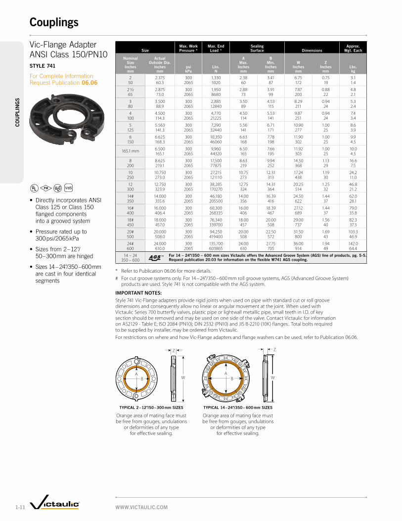
IMPORTANT NOTES: Style 741 Vic-Flange adapters provide rigid joints when used on pipe with standard cut or roll groove dimensions and consequently allow no linear or angular movement at the joint. When used with Victaulic Series 700 butterfly valves, plastic pipe or lightwall metallic pipe, small teeth in I.D. of key section should be removed and may be used on one side of the valve. Contact Victaulic for information on AS2129 - Table E; ISO 2084 (PN10); DIN 2532 (PN10) and JIS B-2210 (10K) flanges.. Total bolts required to be supplied by installer, may be ordered from Victaulic.For restrictions on where and how Vic-Flange adapters and flange washers can be used, refer to Publication 06.06.
Z
WA
B
VdS
Vic-FlangeAdapter ANSIClass150/PN10Style 741
ForCompleteInformationRequestPublication06.06
• DirectlyincorporatesANSIClass125orClass150flangedcomponents intoagroovedsystem
• Pressureratedupto 300 psi/2065 kPa
• Sizesfrom2–12"/ 50–300 mmarehinged
• Sizes14–24"/350–600 mmarecastinfouridentical segments
typicAl 2 – 12"/50 – 300 mm SiZeS
Orange area of mating face must be free from gouges, undulations
or deformities of any type for effective sealing.
typicAl 14 – 24"/350 – 600 mm SiZeS
Orange area of mating face must be free from gouges, undulations
or deformities of any type for effective sealing.
W
Z
AB
www.victAulic.com1-11
couplingsc
ou
pli
ng
S
™TM
Sizemax. work pressure *
max. end load *
Sealing Surface dimensions
Approx. wgt. each
nominal Size
inches mm
Actual outside dia.
inches mm
psi kpa
lbs. n
A max.
inches mm
b min.
inches mm
w inches
mm
Z inches
mmlbs. kg
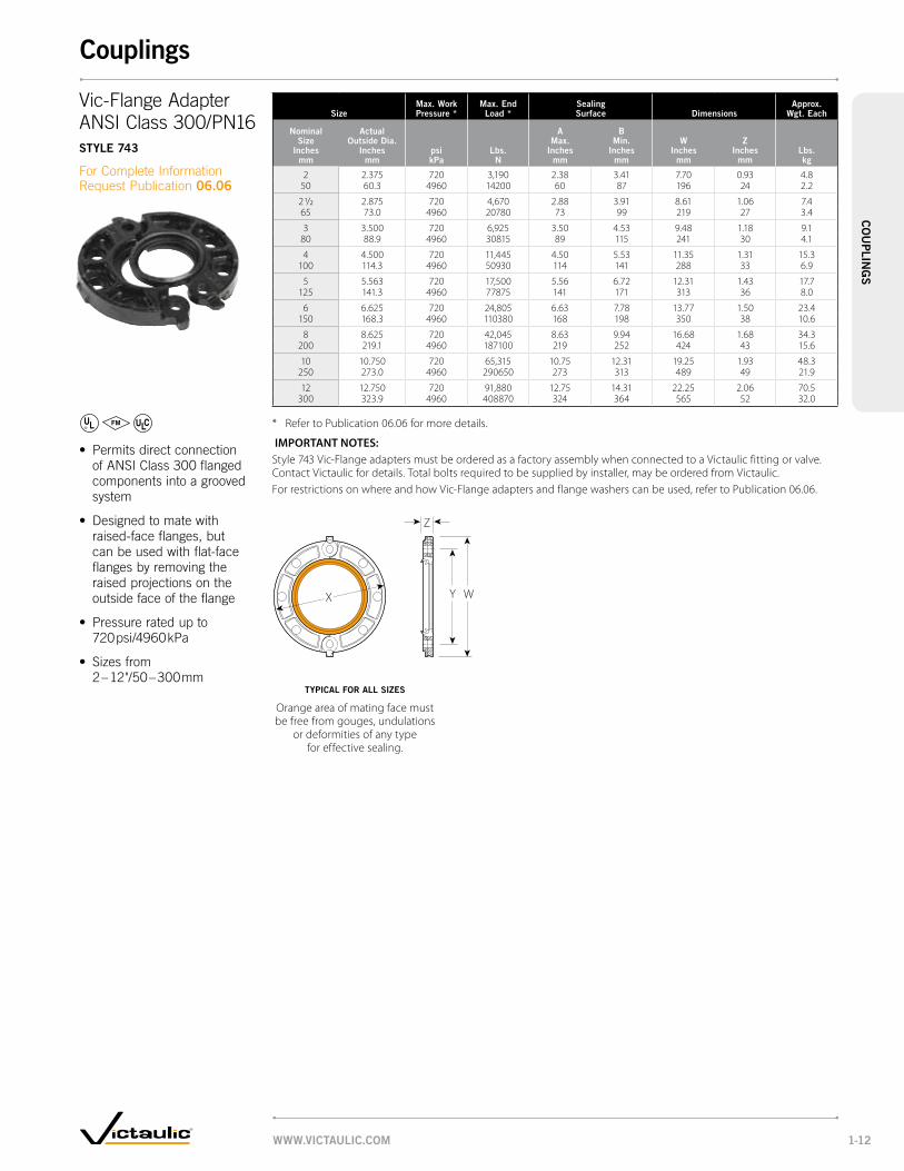
2 2.375 720 3,190 2.38 3.41 7.70 0.93 4.850 60.3 4960 14200 60 87 196 24 2.2
2 1/2 2.875 720 4,670 2.88 3.91 8.61 1.06 7.465 73.0 4960 20780 73 99 219 27 3.4
3 3.500 720 6,925 3.50 4.53 9.48 1.18 9.180 88.9 4960 30815 89 115 241 30 4.1
4 4.500 720 11,445 4.50 5.53 11.35 1.31 15.3100 114.3 4960 50930 114 141 288 33 6.9
5 5.563 720 17,500 5.56 6.72 12.31 1.43 17.7125 141.3 4960 77875 141 171 313 36 8.0
6 6.625 720 24,805 6.63 7.78 13.77 1.50 23.4150 168.3 4960 110380 168 198 350 38 10.6
8 8.625 720 42,045 8.63 9.94 16.68 1.68 34.3200 219.1 4960 187100 219 252 424 43 15.6
10 10.750 720 65,315 10.75 12.31 19.25 1.93 48.3250 273.0 4960 290650 273 313 489 49 21.9
12 12.750 720 91,880 12.75 14.31 22.25 2.06 70.5300 323.9 4960 408870 324 364 565 52 32.0
* Refer to Publication 06.06 for more details.
IMPORTANT NOTES: Style 743 Vic-Flange adapters must be ordered as a factory assembly when connected to a Victaulic fitting or valve. Contact Victaulic for details. Total bolts required to be supplied by installer, may be ordered from Victaulic.For restrictions on where and how Vic-Flange adapters and flange washers can be used, refer to Publication 06.06.
WY
Z
X
• PermitsdirectconnectionofANSIClass300flangedcomponentsintoagroovedsystem
• Designedtomatewithraised-faceflanges,but canbeusedwithflat-faceflangesbyremovingtheraisedprojectionsonthe outsidefaceoftheflange
• Pressureratedupto 720 psi/4960 kPa
• Sizesfrom 2–12"/50–300 mm
Vic-FlangeAdapter ANSIClass300/PN16Style 743
ForCompleteInformationRequestPublication06.06
typicAl For All SiZeS
Orange area of mating face must be free from gouges, undulations
or deformities of any type for effective sealing.
www.victAulic.com 1-12
couplingsc
ou
plin
gS

Sizemax. work pressure *
max. end load *
Allow. pipe end Sep. * dimensions
Approx. wgt. each
nominal Size
inches mm
psi kpa
lbs. n
inches mm
X inches
mm
y inches
mm
Z inches
mmlbs. kg
2 × 1 350 1,000 0 – 0.07 3.38 5.28 1.88 2.750 25 2400 4450 0 – 1.8 85 134 48 1.2
1 1/2 350 1,000 0 – 0.07 3.38 5.28 1.88 2.040 2400 4450 0 – 1.8 85 134 48 1.0
2 1/2 × 2 500 2,215 0 – 0.07 4.00 5.93 1.88 3.165 50 3450 9850 0 – 1.8 102 151 48 1.4
76.1 × 2 350 1,550 0 – 0.07 4.38 6.63 1.88 4.650 2410 6900 0 – 1.8 111 168 48 2.1
3 × 2 350 1,550 0 – 0.07 4.75 7.13 1.88 4.980 50 2410 6900 0 – 1.8 121 181 48 2.2
2 1/2 500 3,250 0 – 0.07 4.75 7.13 1.88 4.365 3450 14460 0 – 1.8 121 181 48 2.0
88.9 × 76.1 350 2,275 0 – 0.07 4.75 7.13 1.88 4.22410 10125 0 – 1.8 121 181 48 1.9
4 × 2 350 1,550 0 – 0.13 6.25 8.90 2.25 8.1100 50 2410 6900 0 – 3.2 159 226 57 3.7
2 1/2 350 2,275 0 – 0.13 6.25 8.90 2.25 8..665 2410 10125 0 – 3.2 159 226 57 3.9
3 500 4,810 0 – 0.13 6.00 8.90 2.25 6.780 3450 21400 0 – 3.2 152 226 57 3.0
114.3 × 76.1 350 2,275 0 – 0.13 6.25 8.90 2.25 6.92410 10125 0 – 3.2 159 226 57 3.1
5 × 4 350 5,565 0 – 0.13 7.18 10.70 2.13 11.2125 100 2410 24765 0 – 3.2 182 272 54 5.1
6 × 4 350 5,565 0 – 0.13 8.63 11.90 2.25 16.7150 100 2410 24765 0 – 3.2 219 302 57 7.6
5 350 8,500 0 – 0.13 8.31 11.90 2.25 12.9125 2410 37825 0 – 3.2 211 302 57 5.9
165.1 × 4 350 5,565 0 – 0.13 8.63 11.90 2.25 15.2100 2410 24765 0 – 3.2 219 302 57 6.9
8 × 6 350 12,000 0 – 0.13 10.81 14.88 2.50 22.4200 150 2410 53400 0 – 3.2 275 378 64 10.2
* Refer to General Notes on pg. 1-4.
IMPORTANT NOTES: Style 750 reducing couplings should not be used with end caps (No. 60) in systems where a vacuum may be developed. Contact Victaulic for details.
X
ZY
ReducingCouplingStyle 750
ForCompleteInformationRequestPublication06.08
• Directreductionon thepipingrun
• Designedtoreplace twocouplingsand areducingfitting
• Specialreducinggasketforpressureresponsivesealing
• Pressureratedupto 500psi/3450kPa
• Sizesfrom 2×1"/50×25 mmthrough 8×6"/200×150 mm
typicAl For All SiZeS
www.victAulic.com1-13
couplingsc
ou
pli
ng
S
VdS

Sizemax. work pressure *
max. end load *
Allow. pipe end Sep. * dimensions
Approx. wgt. each
nominal Size
inches mm
Actual outside dia.
inches mm
psi kpa
lbs. n
inches mm
X inches
mm
y inches
mm
Z inches
mmlbs. kg
1 1.315 300 410 0 – 0.06 2.75 3.25 1.75 0.825 33.4 2065 1825 0 – 1.6 70 83 44 0.4
1 1/4 1.660 300 650 0 – 0.06 3.13 3.75 1.88 1.132 42.2 2065 2890 0 – 1.6 79 95 48 0.5
1 1/2 1.900 300 850 0 – 0.06 3.50 4.50 1.88 1.740 48.3 2065 3780 0 – 1.6 89 114 48 0.8
2 2.375 300 1,330 0 – 0.06 4.00 4.75 1.88 1.750 60.3 2065 5920 0 – 1.6 102 121 48 0.8
2 1/2 2.875 300 1,950 0 – 0.06 4.75 5.88 1.88 2.565 73.0 2065 8680 0 – 1.6 121 149 48 1.1
3 3.500 300 2,885 0 – 0.06 5.38 6.25 1.88 2.880 88.9 2065 12840 0 – 1.6 137 159 48 1.34 4.500 300 4,770 0 – 0.13 6.88 7.75 2.13 5.5
100 114.3 2065 21225 0 – 3.2 175 197 54 2.5
5 5.563 300 7,290 0 – 0.13 8.75 9.50 2.13 9.8125 141.3 2065 32440 0 – 3.2 222 241 54 4.4
6 6.625 300 10,350 0 – 0.13 9.88 10.63 2.13 10.7150 168.3 2065 46060 0 – 3.2 251 270 54 4.9
8 8.625 300 17,500 0 – 0.13 12.25 13.00 2.38 15.3200 219.1 2065 77875 0 – 3.2 311 330 60 6.9
* Refer to General Notes on pg .1-4.
IMPORTANT NOTES: Refer to Victaulic Pocket Handbook I-100 for special safety precautions when used for concrete pumping.
Z Y
X
Snap-JointCouplingStyle 78
ForCompleteInformationRequestPublication 06.09
• Designedforquick disconnectservice
• Matedhousingsarehingedwithanattachedlockinghandleforassembly
• Pressureratedupto 300 psi/2065 kPa
• Sizesfrom 1–8"/25–200 mm
typicAl For All SiZeS
www.victAulic.com 1-14
couplingsc
ou
plin
gS

Sizemax. work pressure *
Allow. pipe end Sep. * dimensions
Approx. wgt. each
run × reducing outlet
nominal Size inches/mm
psi kpa
inches mm
t † inches
mm
v § inches
mm
X inches
mm
y inches
mm
Z inches
mmlbs. kg
1 1/2 × 1/2 500 0.75 – 0.88 2.06 2.63 2.94 4.50 2.75 1.440 15 3450 19 – 22 52 67 75 114 70 0.6
3/4 500 0.75 – 0.88 2.06 2.63 2.94 4.50 2.75 1.420 3450 19 – 22 52 67 75 114 70 0.6
1 500 0.75 – 0.88 1.94 2.63 2.94 4.50 2.75 1.425 3450 19 – 22 49 67 75 114 70 0.6
2 × 1/2 500 0.81 – 0.88 2.47 3.03 3.38 5.00 2.75 3.550 15 3450 20 – 22 63 77 86 127 70 1.6
3/4 500 0.81 – 0.88 2.47 3.03 3.38 5.00 2.75 2.520 3450 20 – 22 63 77 86 127 70 1.1
1 500 0.81 – 0.88 2.34 3.03 3.38 5.00 2.75 2.525 3450 20 – 22 60 77 86 127 70 1.1
2 1/2 × 1/2 500 0.81 – 0.88 2.56 3.13 3.88 6.00 2.75 4.565 15 3450 20 – 22 65 79 98 152 70 2.0
3/4 500 0.81 – 0.88 2.56 3.13 3.88 6.00 2.75 4.620 3450 20 – 22 65 79 98 152 70 2.1
1 500 0.81 – 0.88 2.44 3.13 3.88 6.00 2.75 4.625 3450 20 – 22 62 79 98 152 70 2.1
1 1/4 500 1.25 – 1.50 3.00 3.69 4.06 6.88 3.25 5.032 3450 32 – 38 76 94 103 175 83 2.3
1 1/2 500 1.25 – 1.50 — 3.69 4.06 6.88 3.25 5.040 3450 32 – 38 94 103 175 83 2.3
3 × 3/4 500 0.50 – 0.63 2.75 3.31 4.50 7.00 2.38 3.480 20 3450 13 – 16 70 84 114 178 60 1.5
1 500 1.25 – 1.50 4.06 4.75 4.75 8.00 3.25 7.025 3450 32 – 38 103 121 121 203 83 3.2
1 1/4 500 1.25 – 1.50 4.06 4.75 4.75 8.00 3.25 7.032 3450 32 – 38 103 121 121 203 83 3.2
1 1/2 500 1.25 – 1.50 — 4.25 4.75 8.00 3.25 7.040 3450 32 – 38 108 121 203 83 3.2
4 × 3/4 500 0.44 – 0.63 3.25 3.81 5.69 8.38 2.50 6.8100 20 3450 11 – 16 83 97 145 213 64 3.1
1 500 0.44 – 0.63 — 3.81 5.69 8.38 2.50 6.825 3450 11 – 16 97 145 213 64 3.1
1 1/2 400 1.63 – 1.81 3.91 4.59 6.13 9.00 3.69 11.440 2750 41 – 46 99 117 156 229 94 5.2
2 400 1.63 – 1.81 — 4.59 6.13 9.00 3.69 11.450 2750 41 – 46 117 156 229 94 5.2
6 × 1 400 1.63 – 1.81 6.19 6.88 8.13 12.00 3.69 18.0150 25 2750 41 – 46 157 175 206 305 94 8.2
1 1/2 400 1.63 – 1.81 6.19 6.88 8.13 12.00 3.69 18.040 2750 41 – 46 157 175 206 305 94 8.2
2 400 1.63 – 1.81 — 6.06 8.13 12.00 3.69 18.050 2750 41 – 46 154 206 305 94 8.2
* Refer to General Notes on pg. 1-4.§ Center of run to end of fittings. † Center of run to the engaged pipe end. Female threaded outlet only (dimensions approximate).
IMPORTANT NOTES: No. 60 Cap is not for use in vacuum services with Style 72 or 750 couplings. No. 61 bull plug should be used.
VT
Y Z
X
OutletCouplingStyle 72
ForCompleteInformationRequestPublication06.10
• Servesdualpurpose asacouplingandoutlet
• Designedtosealonthejoinedpipeendsandin theneckoftheoutlet
• Pressureratedupto 500 psi/3450 kPa
• Sizesfrom 1½×½"/40×15 mmthrough 6×2"/150×50 mm
typicAl For All SiZeS
www.victAulic.com1-15
couplingsc
ou
pli
ng
S

Sizemax. work pressure *
max. end load *
Allow. pipe end Sep. *
locking pin Size dimensions
Approx. wgt. each
nominal Size
inches mm
Actual outside dia.
inches mm
psi kpa
lbs. n
inches mm
dia. × length inches
mm
X inches
mm
y inches mm
Z inches
mmlbs. kg
2 2.375 700 3,100 0 – 0.06 5/16 × 1 7/8 3.56 4.71 1.84 1.850 60.3 4825 13795 0 – 1.6 8 × 48 90 120 47 0.8
2 1/2 2.875 700 4,540 0 – 0.06 3/8 × 1 7/8 4.09 5.48 1.84 2.765 73.0 4825 20205 0 – 1.6 10 × 48 104 139 47 1.2
3 3.500 700 6,730 0 – 0.06 3/8 × 1 7/8 4.72 6.15 1.84 2.680 88.9 4825 29950 0 – 1.6 10 × 48 120 156 47 1.2
4 4.500 700 11,130 0 – 0.13 7/16 × 2 6.06 7.62 1.93 4.8100 114.3 4825 49530 0 – 3.2 11 × 51 154 194 49 2.2
6 6.625 600 20,675 0 – 0.13 1/2 × 2 1/16 8.24 10.18 2.06 6.3150 168.3 4135 92005 0 – 3.2 13 × 52 209 259 51 2.9
8 8.625 500 29,200 0 – 0.13 1/2 × 2 5/16 10.52 12.50 2.31 12.0200 219.1 3450 129940 0 – 3.2 13 × 59 267 318 59 5.4
* Refer to General Notes on pg.1-4.
IMPORTANT NOTES: Complete coupling includes one-piece hinged housing, gasket and locking pin only. Assembly tool Style 792 is required for assembly (one tool fits all size couplings). Please see Publication 06.11 for tool clearance dimensions.
X
Z
NOTE Assembly Tool Clearance
Y
• One-piecehingedcoupling
• Featureslockingpin installationwithaseparatetool(Style792)designedforassemblyanddisassembly
• Providessecure,tamperresistant,lowprofilejoint
• Pressureratedupto 700 psi/4825 kPa
• Sizesfrom 2–8"/50–200 mm
Vic-BoltlessCouplingStyle 791 And Style 792 ASSembly tool
ForCompleteInformationRequestPublication06.11
typicAl For All SiZeS
www.victAulic.com 1-16
couplingsc
ou
plin
gS

Sizemax. work pressure *
max. end load *
Allow. pipe end Sep. * dimensions
Approx. wgt. each
nominal Size
inches mm
Actual outside dia.
inches mm
psi kpa
lbs. n
inches mm
X inches
mm
y inches
mm
Z inches
mmlbs. kg
2 2.375 1000 4,430 0.14 3.50 6.68 2.00 3.250 60.3 6900 19715 3.6 89 168 51 1.5
2 1/2 2.875 1000 6,490 0.14 4.13 7.13 2.00 4.065 73.0 6900 28881 3.6 105 181 51 1.8
3 3.500 1000 9,620 0.14 4.75 7.75 2.00 4.480 88.9 6900 42810 3.6 121 197 51 2.0
4 4.500 1000 15,900 0.25 6.00 9.63 2.13 7.5100 114.3 6900 70755 6.4 152 245 54 3.4
6 6.625 1000 34,470 0.25 8.63 12.68 2.50 16.0150 168.3 6900 153390 6.4 219 321 64 7.3
8 8.625 800 46,740 0.25 11.00 15.00 2.75 26.1200 219.1 5500 207995 6.4 279 381 70 11.8
10 10.750 800 72,640 0.25 13.50 17.25 3.00 32.8250 273.0 5500 323250 6.4 343 438 76 14.9
12 12.750 800 102,000 0.25 15.63 19.13 3.13 46.0300 323.9 5500 453900 6.4 397 486 80 20.9
14 # 14.000 600 92,360 0.25 16.75 22.00 3.88 64.0350 355.6 4100 410800 6.4 425 559 99 29.0
16 # 16.000 600 120,600 0.25 18.75 24.13 3.88 72.0400 406.4 4100 536400 6.4 476 613 99 32.7
# These sizes are not UL Listed or FM Approved. These sizes are not intended for use on AGS roll groove pipe.* Refer to General Notes on pg. 1-4.
Y Z
X
X
Y Z
Rigid CouplingStyle Hp-70
ForCompleteInformationRequestPublication06.12
• Designedwithheavy housingforhigh pressureservices
• Housingkeyiswider thanstandard
• Couplinghousingis designedtoclampthe bottomofthegroove
• Essentiallyrigidjoint
• Pressureratedupto 1000 psi/6900 kPa
• Sizesfrom 2–16"/50–400 mm
typicAl 2 – 12"/50 – 300 mm SiZeS typicAl 14 – 16"/350 – 400 mm SiZeS
www.victAulic.com1-17
couplingsc
ou
pli
ng
S

HighPressureCouplingStyle 808
ForCompleteInformationRequestPublication15.01.
• Style808providessuperior jointintegrityathigh pressureswhilemaintaining adegreeofflexibilityto facilitatejoining.
• Couplingsengagedirectlyinto doublegroovedpipewithout theneedforspecialweld-on nipplesorcollars.
• Availablefor6-12”/150- 300mm
• Pressureratedupto 4000psi/27586kPa
dimenSionS
typical for all sizes
Y
X
Z
pipe Size dimensions – inches/mm bolt/nut
min.
bolt torque @
Approx.
wgt. each
nominal Size
inches mm
Actual outside
diameter inches
mm X y Z no.diameter X
length
lb. Ft.
N•m
lbs.
kg
6 6.625 8.75 13.81 5.00 4 1 x 5 450 36.0150 168.3 222 351 127 610 16.3
8 8.625 11.18 16.08 5.75 4 1 1⁄8 x 6 500 70.0200 219.1 284 408 146 678 31.8
10 10.750 13.44 18.68 6.38 4 1 1⁄8 x 6 500 85.0250 273.0 341 473 162 678 38.6
12* 12.750 — — — — — — —300 323.9
@ To achieve adequate tension on the bolts this is the minimum torque which must be applied.*Available as special order item. Please contact Victaulic Engineered Products.
perFormAnce dAtA
1 2 3 4 5 6 7 8 9
pipe Size
nominal Steel pipe dimension
inches mm
A max. Joint
work. press.
max. permiss. end load
b, c pipe end Sep.
Standard gasket min. – max.
b, c pipe end Sep. “eS” gasket min. – max.
b, c max. deflection
From center line
nominal Size
inches
mm
Actual outside
diameter inches
mm
wall
thick.
Sched.
no.
psi
kpa
lbs.
n
inches
mm
inches
mm
degrees
per cplg.
pipe
in./Ft.
mm/m
6 6.625 0.432 80 3000 103.410 0.258 – 0.438 0.298 – 0.478
1° – 33´
0.35150 168.3 11.0 20690 459968 6.6 – 11.1 7.6 – 12.1 29.2
6 6.625 0.719 160 4000 137.880 0.258 – 0.438 0.298 – 0.478 0.35150 168.3 18.3 27586 613290 6.6 – 11.1 7.6 – 12.1 29.2
8 8.625 0.500 80 2500 146.060 0.188 – 0.438 0.260 – 0.510
1° – 39´
0.35200 219.1 12.7 17241 649675 4.8 – 11.1 6.6 – 13.0 29.2
8 8.625 0.906 160 3500 204.490 0.188 – 0.438 0.260 – 0.510 0.35200 219.1 23.0 24138 909572 4.8 – 11.1 6.6 – 13.0 29.2
10 10.750 0.593 80 2500 226.900 0.188 – 0.438 0.260 – 0.510
1° – 20´
0.28250 273.0 15.1 17241 1009251 4.8 – 11.1 6.6 – 13.0 23.3
10 10.750 1.125 160 3000 272.280 0.188 – 0.438 0.260 – 0.510 0.28250 273.0 28.6 20690 1211101 4.8 – 11.1 6.6 – 13.0 23.3
12 12.750 0.688 80 2000 255.350 0.188 – 0.438 0.260 – 0.510
1° – 07”
0.24300 323.9 17.5 13793 1135797 4.8 – 11.1 6.6 – 13.0 20.0
12 12.750 1.312 160 2500 319.190 0.188 – 0.438 0.260 – 0.510 0.24300 323.9 33.3 17241 1419757 4.8 – 11.1 6.6 – 13.0 20.0
COlUMN 1 – Victaulic couplings are identified by nominal pipe size.COlUMN 2 – Nominal pipe wall thickness. For data with other wall thicknesses contact Victaulic.COlUMN 3 – Pipe wall thickness schedule as established by ANSI Standard B36.10.COlUMN 4 – Maximum line pressure, including surge, to which a joint should be subjected. This figure provides a nominal safety factor of 3. Working pressure ratings are based on pipe prepared in accordance with Victaulic double cut groove specifications. Maximum allowable working pressures for other pipe schedules or grades must be determined by applicable code requirements.NOTE A: ONE TIME FIElD TEST ONlY. The Maximum Joint Working Pressure may be increased to 1 ½ times the figures shown.COlUMN 5 – Maximum end load from all internal and/or external forces to which the joint should be subjected under working conditions.COlUMNS 6 & 7 – Range of pipe end separation normally available on double cut grooved steel pipe. Maximum allowable movement is the difference between minimum and maximum pipe end separation subject to tolerances (see Design Data).COlUMNS 8 & 9 – Maximum allowable deflection of pipe from centerline, subject to tolerances (see Design Data). See Note B.NOTE B: Maximum Pipe Movement will be reduced by Deflection (Col. 8 & 9) and vice versa.NOTE C: Refer to Design Data for information on tolerances and pipe gap settings.
www.victAulic.com 1-18
couplingsc
ou
plin
gS

Sizemax. work pressure *
max. end load *
Allow. pipe end Sep. * dimensions
Approx. wgt. each
nominal Size
inches mm
Actual outside dia.
inches mm
psi kpa
lbs. n
inches mm
X inches
mm
y inches
mm
Z inches
mmlbs. kg
2 2.375 2500 11,000 0.19 3.44 6.51 1.88 3.250 60.3 17250 48950 4.8 87 765 48 1.5
2 1/2 2.875 2500 16,200 0.19 4.00 7.10 1.88 4.065 73.0 17250 72090 4.8 102 180 48 1.8
3 3.500 2500 25,400 0.19 4.69 7.74 1.88 4.680 88.9 17250 113030 4.8 119 197 48 2.1
4 4.500 2500 39,000 0.19 5.94 9.54 2.13 8.2100 114.3 17250 173550 4.8 151 242 54 3.7
6 6.625 2000 68,800 0.27 8.50 12.61 2.38 16.4150 168.3 13800 306160 6.7 216 320 60 7.4
8 8.625 1500 87,500 0.27 10.94 14.97 2.75 26.0200 219.1 10350 389375 6.7 278 380 70 11.810 10.750 1250 114,500 0.28 13.43 17.22 2.88 37.2
250 273.0 8600 509525 7.1 341 437 73 16.912 12.750 1250 160,800 0.28 15.56 19.06 3.00 42.0
300 323.9 8600 715560 7.1 395 484 76 19.1
* Refer to General Notes on pg. 1-4.
IMPORTANT NOTES: HP-70ES couplings must always be used with pipe or fittings grooved to Victaulic “ES” dimensions. HP-70ES couplings cannot be used with Victaulic Series 700 butterfly valves.
Y Z
X
• Speciallyformulatedandcompoundedoil-resistantnitrilegasket
• ESgasketdesignhasintegral centrallegthatpositionsbetweenthepipeends forusewithplastic-coated orcement-linedpipe
• Designedforhigher pressuresystemsrated upto2500 psi/17250 kPa
• Sizesfrom 2–12"/50–300 mm
EndsealCouplingforPlasticCoatedPipeStyle Hp-70eS
ForCompleteInformationRequestPublication06.13
typicAl For All SiZeS
www.victAulic.com1-19
couplingsc
ou
pli
ng
S

Sizeno. 62-eS 90º elbow
no. 63-eS* 45º elbow
no. 64-eS* tee
no. 35-eS* cross
no. 22-eS Header tee
nominal Size
inches mm
Actual outside diameter
inches mm
c to e inches
mm
Approx. weight each
lbs. kg
c to e inches
mm
Approx. weight each
lbs. kg
c to e inches
mm
Approx. weight each
lbs. kg
c to e inches
mm
Approx. weight each
lbs. kg
c to e inches
mm
Approx. weight each
lbs. kg
2 2.375 3.25 2.5 2.00 1.8 3.25 4.2 3.25 3.9 — —50 60.3 83 1.1 51 0.8 83 1.9 83 1.8
2 1/2 2.875 3.75 5.0 2.25 2.9 3.75 7.9 3.75 6.6 — —65 73.0 95 2.3 57 1.3 95 3.6 95 3.0
2 – 3 2.375 – 3.500 — — — — — — — — 4.25 3.450 – 90 60.3 – 88.9 108 1.5
2 – 4 2.375 – 4.500 — — — — — — — — 5.00 4.150 – 100 60.3 – 114.3 127 1.9
3 3.500 4.25 6.0 2.50 4.3 4.25 16.0 4.25 14.2 — —80 88.9 108 2.7 64 1.9 108 7.3 108 6.4
4 4.500 5.00 10.3 3.00 8.5 5.00 23.5 5.00 15.8 — —100 114.3 127 4.7 76 3.9 127 10.7 127 7.2
6 † 6.625 6.50 27.2 3.50 16.5 6.50 27.0 6.50 46.0 — —150 168.3 165 12.3 89 7.5 165 12.2 165 20.9
* Steel Fabricated - Cast Full Flow. † For sizes to 12"/300 mm consult Victaulic.
IMPORTANT NOTES: Steel Full Flow elbows available with longer center to end dimensions. Contact Victaulic for details.
C to E
C to E C to E
CtoE
C to E
CtoE
CtoE
C to EC to E
Cto E
• Extraheavywallthickness– Schedule80
• “ES”EndSealgroovesforusewithHP-70EScouplingsonly
• Specialheaderteesforoilproductionheadersdesignedwithtop(test)lineis2"/50 mmandbottompro-ductionlineis3"/80 mmor4"/100 mm
• Sizesfrom2–6"/50–150 mm
EndSealFittingsforPlasticCoatedPipeno. 62-eS 90ºElbowno. 63-eS 45ºElbowno. 64-eS Teeno. 35-eS Crossno. 22-eS HeaderTee
ForCompleteInformation RequestPublication07.03
no. 62-eS no. 63-eS no. 64-eS no. 35-eS no. 22-eS
www.victAulic.com 1-20
couplingsc
ou
plin
gS
couplings – endSeal Fittings

Tees, Crosses, Wyes, and Laterals
TeeNo. 20, pg. 2-6 AgS No. W20, pg. 5-6
CrossNo. 35, pg. 2-6 AgS No. W35, pg. 5-6
True WyeNo. 33, pg. 2-6 AgS No. W33, pg. 5-6
Tees with Threaded BranchNo. 29M, pg. 2-6
Reducing TeeNo. 25, pgS. 2-7, 8 AgS No. W25, pg. 5-6
Reducing Tee with Threaded BranchNo. 29, pgS. 2-7, 8
™TM• Fittingsavailableinsizesthrough48"/1200mm
• Standardfittingpressureratingsconformtoratings ofinstalledcoupling
• Allfittingssuppliedwithgroovesorshoulders forfastinstallation
• Groovedesignpermitsflexibilityforeasyalignment (thesefittingsarenotintendedforusewithVictaulic couplingsforplainendpipe–refertoPublication 14.04forfittingsavailableforplainendpipe)
• Paintedorangeenamelwithoptionalgalvanizedfinish
• Whenconnectingwaferorlug-typebutterflyvalvesdirectly toVictaulicfittingswithStyle741or743Vic-Flangeadapters, checkdiskclearancedimensionswithI.D.dimensionoffitting
• RequestPublication07.01
AdvancedGrooveSystem
For14–24"/350–600mmpipingsystemsVictaulicoffersAdvancedGrooveSystem(AGS)fittings,seepg5-1.
Elbows
90°ElbowNo. 10, pg. 2-3 AgS No. W10, pg. 5-6
45°ElbowNo. 11, pg. 2-3 AgS No. W11, pg. 5-6
22½°ElbowNo. 12, pg. 2-3 AgS No. W12, pg. 5-6
90°1½DLong RadiusElbowNo. 100, pg. 2-3 AgS No. W100, pg. 5-6
45°1½DLong RadiusElbowNo. 110, pg. 2-3 AgS No. W110, pg. 5-6
90°3DLong RadiusElbowNo. 100-3D, pg. 2-4
45°3DLong RadiusElbowNo. 110-3D, pg. 2-4
Reducing Base SupportElbow Grv.×Grv.No. R-10g, pg. 2-4
90°AdapterElbowNo.18, pg. 2-5
45°AdapterElbowNo. 19, pg. 2-5
11¼ºElbowNo. 13, pg. 2-3 AgS No. W13, pg. 5-6
Reducing Base SupportElbow Grv.×FlangeNo. R-10F, pg. 2-4
DrainElbowNo. 10-DR, pg. 2-4
StandpipeTeeNo. 27, pg. 2-8
Bullhead TeeNo. 21, pg. 2-8
45°LateralNo. 30, pg. 2-9 AgS No. W30, pg. 5-7
45°ReducingLateralNo. 30-R, pg. 2-9 AgS No. W30-R, pg. 5-7
Tee Wye No. 32, pg. 2-10
Reducing Tee WyeNo. 32-R, pg. 2-10
WWW.victAulic.coM2-1
FittingsFi
ttiN
gS

Adapters,Nipples,Caps,andPlugs Reducers
AdapterNipple Grv.×Bev.No. 42, pg. 2-11 AgS No. W42, pg. 5-9
CapNo. 60, pg. 2-11 AgS No. W60, pg. 5-9
FlatFaceFlanged AdapterNippleNo. 41, No. 45F, No. 46F, pg. 2-12
RaisedFaceFlangedAdapterNippleNo. 45R, No. 46R, pg. 2-12 AgS No. W45R, pg. 5-9
SwagedNipple Grv.×Grv.No. 53, pg. 2-13
BullPlugNo. 61, pg. 2-8
FemaleThreadedAdapterNo. 80, pg. 2-14
HoseNippleNo. 48, pg. 2-14
Concentric ReducerNo. 50, pg. 2-15 AgS No. W50, pg. 5-10
SmallThreadedReducerNo. 52, pg. 2-16
AdapterNipple Grv.×Grv.No. 43, pg. 2-11 AgS No. W43, pg. 5-9 AgS No. W49, pg. 5-9
AdapterNipple Grv.×Thd.No. 40, pg. 2-11
SwagedNipple Grv.×Thd.No. 54, pg. 2-13
SwagedNipple Thd.×Grv.No. 55, pg. 2-13
Eccentric ReducerNo. 51, pg. 2-15 AgS No. W51, pg. 5-10
pRoDuctS
1-1 Couplings
2-1 Fittings
3-1 Valves
4-1 Accessories
5-1 AdvancedGrooveSystem
6-1 HoleCutPipingSystem
7-1 PlainEndPipingSystem
8-1 GroovedSystemforStainlessSteelPipe
9-1 PressfitSystemfor StainlessSteelPipe
10-1 PlainEndPipingSystem forHDPEPipe
11-1 GroovedCopper
12-1 PermaLynxSystem forCopperTube
13-1 GroovedAWWA DuctileIronPipe
14-1 VictaulicDepend-O-Lok®
System
15-1 AquamineReusable PVCProducts
16-1 Gaskets
17-1 PipePreparationTools
18-1 ProductIndex
19-1 PipingSoftware
FoR AbRASioN ReSiStANce oNly FoR coRRoSioN AND/oR AbRASioN ReSiStANce
AlternateStyleFittingsMachinedforRubberorUrethaneLining•Forsevereabrasiveservices
•Fittingmayberubberorurethanelined
•RefertoPublication25.03forspecificdetails
WWW.victAulic.coM 2-2
FittingsFittiN
gS

SizeNo. 10
90º elbowNo. 11
45º elbowNo. 12
22½° elbowNo. 13
11¼° elbowNo. 100 (1½ D)
90° long Radius elbowNo. 110 (1½ D)
45° long Radius elbow
Nominal Size
inches mm
Actual outside Dia.
inches mm
c to e inches
mm
Approx. Wgt. each
lbs. kg
c to e inches
mm
Approx. Wgt. each
lbs. kg
c to e inches
mm
Approx. Wgt. each
lbs. kg
c to e inches
mm
Approx. Wgt. each
lbs. kg
c to e inches
mm
Approx. Wgt. each
lbs. kg
c to e inches
mm
Approx. Wgt. each
lbs. kg
3/4 1.050 2.25 0.5 1.50 0.5 1.63 (sw) — 1.38 (sw) — — — — —20 26.9 57 0.2 38 0.2 41 35
1 1.315 2.25 0.6 1.75 0.6 3.25 @ 0.6 1.38 (sw) 0.3 — — — —25 33.7 57 0.3 44 0.3 83 0.3 35 0.1
1 1/4 1.660 2.75 1.0 1.75 0.9 1.75 0.8 1.38 (sw) 0.5 — — — —32 42.4 70 0.5 44 0.4 44 0.4 35 0.2
1 1/2 1.900 2.75 1.2 1.75 0.9 1.75 0.8 1.38 (sw) 0.5 — — — —40 48.3 70 0.5 44 0.4 44 0.4 35 0.2
2 2.375 3.25 1.8 2.00 1.3 3.75 @ 1.4 1.38 1.0 4.38 2.5 2.75 1.850 60.3 83 0.8 51 0.6 95 0.6 35 0.5 111 1.1 70 0.8
2 1/2 2.875 3.75 3.2 2.25 2.2 4.00 @ 2.3 1.50 1.1 5.13 4.1 3.00 2.865 73.0 95 1.5 57 1.0 102 1.0 38 0.5 130 1.9 76 1.3
76.1 mm 3.000 3.75 3.7 2.25 3.4 2.24 — 1.50 — — — — —76.1 95 1.7 57 1.5 57 38
3 3.500 4.25 4.5 2.50 3.1 4.50 @ 3.1 1.50 2.1 5.88 6.0 3.38 4.980 88.9 108 2.0 64 1.4 114 1.4 38 1.0 149 2.7 86 2.2
3 1/2 4.000 4.50 5.6 2.75 4.3 2.50 (sw) 4.0 1.75 (sw) 2.7 — — — —90 101.6 114 2.5 70 2.0 64 1.8 44 1.2
4 4.500 5.00 7.1 3.00 5.6 2.88 5.6 1.75 3.6 7.50 12.3 4.00 7.3100 114.3 127 3.2 76 2.5 73 2.5 44 1.6 191 5.6 102 3.3
108.0 mm 4.250 5.00 11.0 3.00 5.6 — — — — — — — —108.0 127 5.0 76 2.5
4 1/2 5.000 5.25 (sw) 10.0 3.13 (sw) 6.0 3.50 6.6 1.88 (sw) 4.2 — — — —120 127.0 133 4.5 79 2.7 89 3.0 48 1.9
5 5.563 5.50 11.7 3.25 8.3 2.88 (sw) 7.8 2.00 (sw) 5.0 + 18.2 + 14.8125 141.3 140 5.3 83 3.8 73 3.5 51 2.2 8.3 6.7
133.0 mm 5.250 5.50 11.7 3.25 8.3 — — — — — — — —133.0 140 5.3 83 3.8
139.7 mm 5.500 5.50 11.7 3.25 8.3 2.87 — 2.00 — — — — —139.7 140 5.3 83 3.8 73 51
6 6.625 6.50 17.2 3.50 10.8 6.25 @ 12.2 2.00 7.0 10.75 30.4 5.50 17.4150 168.3 165 7.8 89 4.9 159 5.5 51 3.2 273 13.8 140 7.9
159.0 mm 6.250 6.50 18.6 3.50 10.8 — — — — — — — —159.0 165 8.4 89 4.9
165.1 mm 6.500 6.50 15.5 3.50 9.8 3.13 11.4 2.00 7.4 10.75 29.0 5.50 19.0165.1 165 7.0 89 4.4 79 5.2 51 3.4 273 13.2 140 8.6
8 8.625 7.75 29.9 4.25 20.4 7.75 @ 20.0 2.00 10.1 14.25 66.0 7.25 36.0200 219.1 197 13.6 108 9.3 197 9.1 51 4.6 362 30.0 184 16.3
10 10.750 9.00 63.3 4.75 37.5 4.38 (sw) 30.0 2.13 (sw) 11.8 15.00 107.0 6.25 57.0250 273.0 229 28.7 121 17.0 111 13.6 54 5.3 381 48.5 159 25.9
12 12.750 10.00 74.0 5.25 66.7 4.88 (sw) 40.0 2.25 (sw) 29.3 18.00 156.0 7.50 90.0300 323.9 254 33.6 133 30.3 124 18.1 57 13.3 457 70.8 191 40.8
14 – 24 350 – 600 See AgS Roll groove Fittings, pg. 5-2; for 14 – 24"/350 – 600 mm cut groove Systems Request publication 07.01
@ Gooseneck design, end-to-end dimension.+ Contact Victaulic for details.# Ductile iron except those marked (sw) which are segmentally welded steel.
C to E
C to E
C to E
Cto E
C to E
E to E
No. 10 No. 11 No. 12 No. 13
C to E
No. 100
C to E
No. 110
™TM
ElbowsNo. 10 90ºElbowNo. 11 45ºElbowNo. 12 22½ºElbowNo. 13 11¼ºElbowNo. 100 90ºLRElbowNo. 110 45ºLRElbow(DuctileIron#)
ForCompleteInformationRequestPublication07.01
WWW.victAulic.coM2-3
FittingsFi
ttiN
gS

SizeNo. R-10
Reducing base Support elbowApprox.
Weight each
Nominal Size
inches mm
c to e inches
mm
H inches
mm
b Diameter inches
mm
grv. × grv. lbs. kg
grv. × Flange lbs. kg
6 × 4 9.00 1.25 1.50 19.0 33.0150 100 229 32 38 8.6 15.0
5 9.00 1.50 1.50 23.0 38.0125 229 38 38 10.4 17.2
8 × 6 10.50 2.13 1.50 33.0 52.0200 150 267 54 38 15.0 23.6
10 × 8 12.00 2.40 1.50 61.0 88.0250 200 305 61 38 27.7 39.9
Size Dimensions inches/mmNominal Size inches mm
Actual outside Dia. inches mm c to e H p
2 1/2 2.875 3.75 2.75 1.6865 73.0 95.3 69.9 42.7
3 3.500 4.25 2.75 2.1080 88.9 108.0 69.9 53.3
4 4.500 5.00 2.75 2.60100 114.3 127.0 69.9 66.0
6 6.625 6.50 2.75 3.65150 168.3 165.1 69.9 89
NOTE: The drain is drilled and tapped for a 1-inch/25-mm NPT outlet.
C to E
H
B Dia.
C to E
H
B Dia.
Size Wall thicknessNo. 100-3D
90º long Radius elbowNo. 110-3D
45º long Radius elbow
Nominal Size
inches mm
Actual outside Diameter
inches mm
in Non-critical Area
inches mm
At back Wear Area
inches mm
extra inches
mm
c to e inches
mm
Approx. Weight each
lbs. kg
c to e inches
mm
Approx. Weight each
lbs. kg
2 2.375 0.184 0.309 0.125 10.00 5.0 6.50 4.750 60.3 4.67 7.85 3.18 254 2.3 165 2.1
3 3.500 0.246 0.371 0.125 13.00 16.0 7.75 10.480 88.9 6.25 9.42 3.18 330 7.3 197 4.7
4 4.500 0.267 0.455 0.188 16.00 25.5 9.00 17.2100 114.3 6.78 11.56 4.78 406 11.6 229 7.8
6 6.625 0.310 0.560 0.250 24.00 70.0 13.50 45.0150 168.3 7.87 14.22 6.35 610 31.8 343 20.4
C to E
C to E
No. 100-3D No. 110-3D
LongRadiusElbow3DWith added wall thickness atbendforabrasiveservices.
No. 100-3D 90ºLongRadiusElbow3DNo. 110-3D 45ºLongRadiusElbow3D(DuctileIron)
ForCompleteInformation RequestPublication07.01
ReducingBaseSupportElbowNo. R-10g Grv.×Grv.No. R-10F Grv.×Flange(DuctileIron)
ForCompleteInformation RequestPublication07.01 No. R-10g No. R-10F
No.10-DRDrainElbowNo. 10-DR DrainElbow(DuctileIron)
ForCompleteInformation RequestPublication10.05
No. 10-DR
USA
C to EH
Cto E
P
WWW.victAulic.coM 2-4
FittingsFittiN
gS

SizeNo. 18
90° Adapter elbow @ No. 19
45° Adapter elbow @
Nominal Size
inches mm
Actual outside Diameter
inches mm
c to ge inches
mm
c to te inches
mm
Approx. Weight each
lbs. kg
c to ge inches
mm
c to te inches
mm
Approx. Weight each
lbs. kg
3/4 1.050 2.25 2.25 0.5 1.50 1.50 0.520 26.9 57 57 0.2
1 1.315 2.25 2.25 0.5 — — —25 33.7 57 57 0.2
1 1/4 1.660 2.75 2.75 0.9 — — —32 42.4 70 70 0.4
1 1/2 1.900 2.75 2.75 1.1 1.75 1.75 0.940 48.3 70 70 0.5 44 44 0.4
2 2.375 3.25 4.25 2.5 — — —50 60.3 83 108 1.1
2 1/2 2.875 3.75 3.75 3.0 2.25 2.25 2.365 73.0 95 95 1.4 57 57 1.0
3 3.500 4.25 6.00 5.8 2.50 4.25 5.080 88.9 108 152 2.6 64 108 2.3
3 1/2 4.000 4.50 6.25 8.0 5.25 5.25 8.890 101.6 114 159 3.6 133 133 4.0
6 6.625 6.50 6.50 17.6 3.50 3.50 12.7150 168.3 165 165 8.0 89 89 5.8
@ Available with British Standard Pipe Threads, specify “BSP” clearly on order.
C toGE
C toTE C to
TE
C toGE
No. 19No. 18
AdapterElbowNo. 18 90ºAdapterElbowNo. 19 45ºAdapterElbow(DuctileIron)
ForCompleteInformation RequestPublication07.01
WWW.victAulic.coM2-5
FittingsFi
ttiN
gS

SizeNo. 20
teeNo. 35
cross (sw)No. 33
true Wye (sw)No. 29M
tee with threaded branch
Nominal Size
inches mm
Actual outside Dia.
inches mm
c to e inches
mm
Approx. Weight each
lbs. kg
c to e inches
mm
Approx. Weight each
lbs. kg
c to le inches
mm
c to Se inches
mm
Approx. Weight each
lbs. kg
c to ge inches
mm
c to te inches
mm
Approx. Weight each
lbs. kg
3/4 1.050 2.25 0.6 2.25 0.9 — — — 2.25 2.25 0.620 26.9 57 0.3 57 0.4 57 57 0.3
1 1.315 2.25 1.0 2.25 1.3 2.25 2.25 1.1 — — —25 33.7 57 0.5 57 0.6 57 57 0.5
1 1/4 1.660 2.75 1.5 2.75 2.1 2.75 2.50 1.5 2.75 2.75 1.532 42.4 70 0.7 70 1.0 70 64 0.7 70 70 0.7
1 1/2 1.900 2.75 2.0 2.75 2.5 2.75 2.75 1.8 2.75 2.75 2.040 48.3 70 0.9 70 1.1 70 70 0.8 70 70 0.9
2 2.375 3.25 3.0 3.25 3.8 3.25 2.75 2.5 3.25 4.25 3.0050 60.3 83 1.4 83 1.7 83 70 1.1 83 108 1.4
2 1/2 2.875 3.75 4.3 3.75 6.1 3.75 3.00 4.3 — — —65 73.0 95 2.0 95 2.8 95 76 2.0
76.1 mm 3.000 3.75 5.2 — — — — — 3.75(sw) 3.75 5.276.1 95 2.4 95 95 2.4
3 3.500 4.25 6.8 4.25 10.5 4.25 3.25 6.1 — — —80 88.9 108 3.0 108 4.8 108 83 2.8
3 1/2 4.000 4.50 (sw) 7.9 4.50 11.5 4.50 3.50 9.6 4.50(sw) 4.50 7.9 90 101.6 114 3.6 114 5.2 114 89 4.4 114 114 3.6
4 4.500 5.00 11.9 5.00 15.8 5.00 3.75 10.0 5.00 7.25 11.9100 114.3 127 5.4 127 7.2 127 95 4.5 127 184 5.4
108.0 mm 4.250 5.00 15.5 — — — — — 5.00 5.00 15.5108.0 127 7.0 127 127 7.0
4 1/2 5.000 5.25 (sw) 15.0 5.25 18.5 — — — 5.25(sw) 5.25 15.0 120 127.0 133 6.8 133 8.4 133 133 6.8
5 5.563 5.50 17.8 5.50 20.0 5.50 4.00 15.0 5.50(sw) 5.50 17.8125 141.3 140 8.1 140 9.1 140 102 6.8 140 140 8.1
133.0 mm 5.250 5.50 17.8 — — — — — 5.50 5.50 17.8133.0 140 8.1 140 140 8.1
139.7 mm 5.500 5.50 17.8 — — — — — 5.50 5.50 17.8139.7 140 8.1 140 140 8.1
6 6.625 6.50 25.7 6.50 28.0 6.50 4.50 22.3 6.50(sw) 6.50 25.7150 168.3 165 11.7 165 12.7 165 114 10.1 165 165 11.7
159.0 mm 6.250 6.50 27.1 — — — — — 6.50 6.50 27.1159.0 165 12.3 165 165 12.3
165.1 mm 6.500 6.50 22.0 6.50 28.0 — — — 6.50 6.50 22.0165.1 165 10.0 165 12.7 165 165 10.0
8 8.625 7.75 47.6 7.75 48.0 7.75 6.00 36.0 7.75(sw) 7.75 47.6200 219.1 197 21.6 197 21.8 197 152 16.3 197 197 21.6
10 10.750 9.00 99.0 9.00 121.5 9.00 6.50 69.9 9.00 9.00 73.0250 273.0 229 44.9 229 55.1 229 155 31.7 229 229 33.1
12 12.750 10.00 133.0 10.00 110.0 10.00 7.00 80.0 10.00 10.00 99.0300 323.9 254 60.3 254 49.9 254 178 36.3 254 254 44.9
14 – 24 350 – 600 See AgS Roll groove Fittings, pg. 5-2; for 14 – 24"/350 – 600 mm cut groove Systems Request publication 07.01
# Ductile iron except those marked (sw) which are segmentally welded steel.
IMPORTANT NOTE: Fittings size 26 – 48"/650 – 1050 mm are available roll grooved for installation with Style 770 large diameter pipe couplings, Contact Victaulic for details.
™TM
C to E
CtoE
No. 20
C to E
No. 35
C to LE
C toSE
No. 33
C toGE
C to TE
No. 29M
Tees, Crosses and True WyesNo. 20 Tee No. 35 CrossNo. 33 True WyeNo. 29M Tee with Threaded Branch(DuctileIron#)
ForCompleteInformation RequestPublication07.01
WWW.victAulic.coM 2-6
FittingsFittiN
gS

SizeNo. 25
Std.No. 29t
w/ thd. branchApprox.
Weight each
Nominal Size
inches mm
c to e inches
mm
c to e inches
mm
lbs. kg
1 × 1 × 3/4 + + 1.025 25 20 0.5
1 1/4 × 1 1/4 × 1 + + 1.332 32 25 0.6
1 1/2 1 1/2 3/4 + + 1.540 × 40 × 20 0.7
1 + + 1.525 0.7
1 1/4 + + 1.732 0.8
2 × 2 × 3/4 3.25 3.25 2.550 50 20 83 83 1.1
1 3.25 3.25 2.725 83 83 1.2
1 1/4 + + 1.832 0.8
1 1/2 3.25 3.25 (sw) 3.040 83 83 1.4
2 1/2 × 2 1/2 × 3/4 + + 3.965 65 20 1.8
1 3.75 3.75 (sw) 3.825 95 95 1.7
1 1/4 + + 4.232 1.7
1 1/2 3.75 3.75 3.940 95 95 1.8
2 3.75 3.75 (sw) 4.550 95 95 2.0
3 × 3 × 3/4 + + 5.780 80 20 2.6
1 4.25 4.25 6.125 108 108 2.8
1 1/4 + + 8.032 3.6
1 1/2 4.25 4.25 (sw) 6.540 108 108 2.9
2 4.25 4.25 (sw) 6.250 108 108 2.8
2 1/2 4.25 4.25 (sw) 6.465 108 108 2.9
4 × 4 × 3/4 + + 8.0100 100 20 3.6
1 5.00 5.00 7.825 127 127 3.5
1 1/4 + + 9.632 4.4
1 1/2 5.00 5.00 10.240 127 127 4.6
2 5.00 5.00 11.250 127 127 5.1
2 1/2 5.00 5.00 11.465 127 127 5.2
3 5.00 5.00 11.680 127 127 5.3
SizeNo. 25
Std.No. 29t
w/ thd. branchApprox.
Weight each
Nominal Size
inches mm
c to e inches
mm
c to e inches
mm
lbs. kg
5 × 5 × 1 + + 14.0125 125 25 6.4
1 1/2 + + 14.340 6.5
2 5.50 (sw) 5.50 (sw) 14.550 140 140 6.6
2 1/2 5.50 5.50 (sw) 15.265 140 140 6.9
3 5.50 5.50 (sw) 16.680 140 140 7.5
4 5.50 5.50 (sw) 16.7100 140 140 7.6
6 × 6 × 1 + + 23.0150 150 25 10.4
1 1/2 + + 24.040 10.9
2 6.50 6.50 21.650 165 165 9.8
2 1/2 6.50 6.50 21.465 165 165 11.7
3 6.50 6.50 26.580 165 165 12.0
4 6.50 6.50 25.0100 165 165 11.3
5 6.50 6.50 23.2125 165 165 10.5
6 1/2 × 6 1/2 × 3 6.50 6.50 (sw) 24.0165.1 165.1 80 165 165 10.9
4 6.50 6.50 (sw) 25.0100 165 165 11.3
8 × 8 × 1 1/2 + + 33.0200 200 40 15.0
2 7.75 (sw) 7.75 (sw) 33.550 197 197 15.2
2 1/2 + + 39.065 17.7
3 7.75 (sw) 7.75 (sw) 33.680 197 197 15.2
4 7.75 7.75 41.8100 197 197 19.0
5 7.75 (sw) 7.75 (sw) 34.0125 197 197 15.4
6 7.75 7.75 42.3150 197 197 19.2
165.1 7.75 (sw) 7.75 (sw) 48.0197 197 21.8
tAble coNtiNueD oN pg. 2-8
14 – 24 350 – 600
See AgS Roll groove Fittings, pg. 5-2; for 14 – 24"/350 – 600 mm cut groove Systems Request publication 07.01
+ Contact Victaulic for details. # Ductile iron except those that are marked (sw), which are segmentally
welded steel.
IMPORTANT NOTE: No. 29T Threaded Outlet Reducing Tees are supplied NPT and are available with British Standard threads. For British Standard specify “BSP” clearly on order.
™TM
C to E
CtoE
C to E
CtoE
Reducing TeeNo. 25 GroovedBranchNo. 29t Threaded Branch(DuctileIron#)
ForCompleteInformationRequestPublication07.01 No. 25 No. 29t
WWW.victAulic.coM2-7
FittingsFi
ttiN
gS

SizeNo. 25
Std.No. 29t
w/ thd. branchApprox.
Weight each
Nominal Size
inches mm
c to e inches
mm
c to e inches
mm
lbs. kg
tAble coNtiNueD FRoM pg. 2-7
10 × 10 × 1 1/2 + + 62.0250 250 40 28.1
2 9.00 (sw) 9.00 (sw) 62.050 229 229 28.1
2 1/2 + + 62.465 28.3
3 + + 60.080 27.2
4 9.00 (sw) 9.00 (sw) 61.0100 229 229 27.7
5 9.00 (sw) 9.00 (sw) 52.0125 229 229 23.6
6 9.00 (sw) 9.00 (sw) 59.0150 229 229 26.8
8 9.00 (sw) 9.00 (sw) 64.7200 229 229 29.3
12 × 12 × 1 + + 77.0300 300 25 34.9
2 + + 80.050 36.3
2 1/2 + + 78.065 35.4
3 10.00 (sw) 10.00 (sw) 82.080 254 254 37.2
4 10.00 (sw) 10.00 (sw) 80.0100 254 254 36.3
5 10.00 (sw) 10.00 (sw) 75.0125 254 254 34.0
6 10.00 (sw) 10.00 (sw) 75.0150 254 254 34.0
8 10.00 (sw) 10.00 (sw) 80.0200 254 254 36.3
10 10.00 (sw) 10.00 (sw) 84.0250 254 254 38.1
14 – 24 350 – 600
See AgS Roll groove Fittings, pg. 5-2; for 14 – 24"/350 – 600 mm cut groove Systems Request publication 07.01
+ Contact Victaulic for details. # Ductile iron except those that are marked (sw), which are segmentally
welded steel.
IMPORTANT NOTE: No. 29T Threaded Outlet Reducing Tees are supplied NPT and are available with British Standard threads. For British Standard specify “BSP” clearly on order.
SizeNo. 27
Standpipe tee
Nominal Size
inches mm
c to eoR inches
mm
c to eob inches
mm
Approx. Weight each
lbs. kg
4 × 4 × 2 1/2 3.25 4.00 9.1100 100 65 83 102 4.1
6 × 6 × 2 1/2 3.25 5.13 14.8150 150 65 83 130 6.7
IMPORTANT NOTE: Available with British Standard Pipe Threads, specify “BSP” clearly on order.
SizeNo. 21
bullhead tee
Nominal Size
inches mm
c to eoR inches
mm
c to eob inches
mm
Approx. Weight each
lbs. kg
5 × 5 × 8 7.75 5.50 28.7125 125 200 197 140 13.0
6 × 6 × 8 7.75 6.50 37.5150 150 200 197 165 17.0
SizeNo. 61
bull plug
Nominal Size
inches mm
Actual outside Diameter
inches mm
e to e inches
mm
Approx. Weight each
lbs. kg
2 2.375 4.00 2.550 60.3 102 1.1
2 1/2 2.875 5.00 3.065 73.0 127 1.4
3 3.500 6.00 4.580 88.9 152 2.0
4 4.500 7.00 7.5100 114.3 178 3.4
5 5.563 8.00 12.0125 141.3 203 5.4
6 6.625 10.00 17.0150 168.3 254 7.7
IMPORTANT NOTES: Steel dish caps available through 24"/600 mm, contact Victaulic.No. 61 Bull Plugs should be used in vacuum service with Style 72 or 750 couplings.
™TM
C to E
CtoE
C to E
CtoE
C toEOB
C toEOR
No. 27
C toEOB
C toEOR
No. 21
E to E
No. 61
Reducing TeeNo. 25 GroovedBranchNo. 29t Threaded Branch(DuctileIron#)
ForCompleteInformationRequestPublication07.01 No. 25 No. 29t
StandpipeTeeNo. 27 (Ductileiron)
ForCompleteInformationRequestPublication07.01
Bullhead TeeNo. 21 (DuctileIron)
ForCompleteInformationRequestPublication07.01
BullPlugNo. 61 (Steel)
ForCompleteInformationRequestPublication07.01
WWW.victAulic.coM 2-8
FittingsFittiN
gS

SizeNo. 30-R
45º Reducing lateral
Nominal Size
inches mm
c to le inches
mm
c to Se inches
mm
Approx. Weight each
lbs. kg
3 × 3 × 2 8.50 3.25 9.880 80 50 216 83 4.4
2 1/2 8.50 3.25 9.865 216 83 4.4
4 × 4 × 2 10.50 3.75 10.0100 100 50 267 95 4.5
2 1/2 10.50 3.75 10.065 267 95 4.5
3 10.50 3.75 18.380 267 95 8.3
5 × 5 × 2 12.50 4.00 24.0125 125 50 318 102 10.9
3 12.50 4.00 27.080 318 102 12.2
4 12.50 4.00 26.5100 318 102 12.0
6 × 6 × 3 14.00 4.50 37.0150 150 80 356 114 16.8
4 14.00 4.50 36.0100 356 114 16.3
5 14.00 4.50 44.7125 356 114 20.3
8 × 8 × 4 18.00 6.00 62.0200 200 100 457 152 28.1
5 18.00 6.00 75.5125 457 152 34.2
6 18.00 6.00 82.0150 457 152 37.2
10 × 10 × 4 20.50 6.50 104.8 250 250 100 521 165 47.5
5 20.50 6.50 99.0125 521 165 44.9
6 20.50 6.50 105.8150 521 165 48.0
8 20.50 6.50 118.0200 521 165 53.5
12 × 12 × 5 23.00 7.00 122.0300 300 125 584 178 55.3
6 23.00 7.00 137.0150 584 178 62.1
8 23.00 7.00 147.0200 584 178 66.7
10 23.00 7.00 167.0250 584 178 75.8
14 – 24 350 – 600
See AgS Roll groove Fittings, pg. 5-2; for 14 – 24"/350 – 600 mm cut groove Systems Request publication 07.01
SizeNo. 30
45º lateral
Nominal Size
inches mm
Actual outside Diameter
inches mm
c to le inches
mm
c to Se inches
mm
Approx. Weight each
lbs. kg
3/4 1.050 4.50 2.00 1.020 26.9 114 51 0.5
1 1.315 5.00 2.25 1.725 33.7 127 57 0.8
1 1/4 1.660 5.75 2.50 2.5 (d)32 42.4 146 64 1.1
1 1/2 1.900 6.25 2.75 3.540 48.3 159 70 1.6
2 2.375 7.00 2.75 4.6 (d)50 60.3 178 70 2.1
2 1/2 2.875 7.75 3.00 9.065 73.0 197 76 4.1
76.1 mm 3.000 8.50 3.25 11.076.1 216 83 5.0
3 3.500 8.50 3.25 11.7 (d)80 88.9 216 83 5.4
3 1/2 4.000 10.00 3.50 17.890 101.6 254 89 8.1
4 4.500 10.50 3.75 22.2 (d)100 114.3 267 95 10.1
5 5.563 12.50 4.00 21.8125 141.3 318 102 9.9
6 6.625 14.00 4.50 43.6150 168.3 356 114 19.8
165.1 mm 6.500 14.00 4.50 43.6165.1 356 114 19.8
8 8.625 18.00 6.00 72.0200 219.1 457 152 32.7
10 10.750 20.50 6.50 105.0250 273.0 521 165 47.6
12 12.750 23.00 7.00 165.0300 323.9 584 178 74.8
14 – 24 350 – 600
See AgS Roll groove Fittings, pg. 5-2; for 14 – 24"/350 – 600 mm cut groove Systems Request publication 07.01
# Segmentally welded steel except those marked (d) which are ductile iron.
™TM
™TM
C to LE
C toLE
C toSE
No. 30
C toLE
C toSE
C to LE
No. 30-R
45°LateralNo. 30 (SegmentallyWeldedSteel#)
ForCompleteInformationRequestPublication07.01
45ºReducingLateralNo. 30-R (SegmentallyWeldedSteel)
ForCompleteInformationRequestPublication07.01
WWW.victAulic.coM2-9
FittingsFi
ttiN
gS

SizeNo. 32-R
Reducing tee Wye
Nominal Size
inches mm
g inches
mm
H inches
mm
e1 inches
mm
e2 inches
mm
Approx. Wgt. each
lbs. kg
4 × 3 × 3 3.50 9.50 10.75 5.75 16.0100 80 80 89 241 273 146 7.3
3 3.75 10.50 13.63 8.13 16.080 95 267 346 206 7.3
4×
4× 3 3.75 10.50 12.88 7.88 23.0
100 100 80 95 267 327 200 10.4
5 × 3 × 3 1.25 9.75 11.50 7.63 25.0125 80 80 32 248 292 194 11.3
5 4.00 12.50 16.13 11.13 43.4125 102 318 410 283 19.5
5 × 4 × 3 1.88 9.13 11.88 6.88 21.0125 100 80 48 232 302 175 9.5
4 1.88 9.13 12.75 7.25 25.0100 48 232 324 184 11.3
5 × 5 3 4.00 12.50 14.25 9.25 29.0125 125 80 102 318 362 235 13.2
5 × 5 × 4 4.00 12.50 15.13 9.63 36.7125 125 100 102 318 384 245 16.6
6 × 4 × 6 4.50 14.00 18.25 11.50 61.0150 100 150 114 356 464 292 27.7
6 × 5 × 3 1.25 10.75 13.00 8.00 27.0150 125 80 32 273 330 203 12.2
4 1.25 10.75 13.88 8.38 31.0100 32 273 352 213 14.1
6 × 6 × 3 4.50 14.00 15.31 10.31 37.3150 150 80 114 356 389 262 16.9
4 4.50 14.00 16.25 10.75 46.3100 114 356 413 273 21.0
5 4.50 14.00 17.25 11.13 55.0125 114 356 438 283 24.9
8 × 6 × 4 1.00 12.00 14.75 9.25 45.0200 150 100 25 304 375 235 20.4
8 6.00 18.00 23.25 15.25 112.0200 152 457 591 387 50.8
8 × 8 × 3 6.00 18.00 18.19 13.19 76.0200 200 80 152 457 462 335 34.5
4 6.00 18.00 19.00 13.50 76.4100 152 457 483 343 34.7
5 6.00 18.00 20.00 13.88 85.6125 152 457 508 352 38.8
6 6.00 18.00 21.13 14.38 112.0150 152 457 537 365 50.8
10 × 10 × 3 6.50 20.50 19.88 14.88 96.0250 250 80 165 521 505 378 43.5
4 6.50 20.50 20.75 15.25 97.4100 165 521 527 387 44.2
5 6.50 20.50 21.88 15.75 115.0125 165 521 556 400 52.2
6 6.50 20.50 22.88 16.13 133.1150 165 521 581 410 60.4
8 6.50 20.50 27.25 19.25 156.0200 165 521 692 489 70.8
SizeNo. 32 tee Wye
Nominal Size
inches mm
g inches
mm
H inches
mm
e1
inches mm
e2 inches
mm
Approx. Wgt. each
lbs. kg
2 × 2 × 2 2.75 7.00 9.00 4.63 6.450 50 50 70 178 229 118 2.9
2 1/2 × 2 1/2 × 2 1/2 3.00 7.75 10.50 5.75 11.565 65 65 76 197 267 146 5.2
3 × 3 × 3 3.25 8.50 11.50 6.50 14.380 80 80 83 216 292 165 6.5
3 1/2 × 3 1/2 × 3 1/2 3.25 10.00 13.00 7.75 22.990 90 90 89 254 330 197 10.4
4 × 4 × 4 3.75 10.50 13.63 8.13 26.0100 100 100 95 267 346 207 11.8
5 × 5 × 5 4.00 12.50 16.13 10.00 48.0125 125 125 102 318 410 254 21.8
6 × 6 × 6 4.50 14.00 18.25 11.50 60.5150 150 150 114 356 464 292 27.4
8 × 8 × 8 6.00 18.00 23.25 15.25 127.1200 200 200 152 457 591 387 57.7
10 × 10 × 10 6.50 20.50 27.25 18.00 190.0250 250 250 165 521 692 457 86.2
12 × 12 × 12 7.00 23.00 31.00 20.50 240.0300 300 300 178 584 787 521 108.9
14 – 24 350 – 600
See AgS Roll groove Fittings, pg. 5-2; for 14 – 24"/350 – 600 mm cut groove Systems Request publication 07.01
™TM
H
G
E1
E2
No. 32
H
G
E1
E2
No. 32-R
Tee WyeNo. 32 (SegmentallyWeldedSteel)
ForCompleteInformationRequestPublication07.01
Reducing Tee WyeNo. 32-R (SegmentallyWeldedSteel)
ForCompleteInformationRequestPublication07.01
WWW.victAulic.coM 2-10
FittingsFittiN
gS
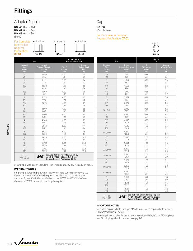
SizeNo. 40, 42, 43
Adapter Nipple (sw)
Nominal Size
inches mm
Actual outside Diameter
inches mm
e to e inches
mm
Approx. Weight each
lbs. kg
3/4 1.050 3.00 0.320 26.9 76 0.1
1 1.315 3.00 0.425 33.7 76 0.2
1 1/4 1.660 4.00 0.832 42.4 102 0.4
1 1/2 1.900 4.00 0.940 48.3 102 0.4
2 2.375 4.00 1.250 60.3 102 0.5
2 1/2 2.875 4.00 1.965 73.0 102 0.9
3 3.500 4.00 2.580 88.9 102 1.1
3 1/2 4.000 4.00 2.190 101.6 102 0.9
4 4.500 6.00 5.5100 114.3 152 2.5
5 5.563 6.00 7.4125 141.3 152 3.4
6 6.625 6.00 9.5150 168.3 152 4.3
8 8.625 6.00 14.2200 219.1 152 6.4
10 10.750 8.00 27.0250 273.0 203 12.2
12 12.750 8.00 33.0300 323.9 203 15.0
14 – 24 350 – 600
See AgS Roll groove Fittings, pg. 5-2; for 14 – 24"/350 – 600 mm cut groove Systems Request publication 07.01
# Available with British Standard Pipe Threads, specify “BSP” clearly on order.
IMPORTANT NOTES: For pump package nipples with 1 ½"/40 mm hole cut to receive Style 923 Vic-Let or Style 924 Vic-O-Well request special No. 40, 42 or 43 nipples and specify No. 40-H, 42-H or 43-H on order. NOTE: 4 – 12"/100 – 300 mm diameter – 8"/200 mm minimum length required.
SizeNo. 60
cap
Nominal Size
inches mm
Actual outside Diameter
inches mm
t thickness
inches mm
Approx. Weight each
lbs. kg
3/4 1.050 0.88 0.220 26.9 22 0.1
1 1.315 0.88 0.325 33.7 22 0.1
1 1/4 1.660 0.88 0.332 42.4 22 0.1
1 1/2 1.900 0.88 0.540 48.3 22 0.2
2 2.375 0.88 0.650 60.3 22 0.3
2 1/2 2.875 0.88 1.065 73.0 22 0.5
76.1 mm 3.000 0.88 1.276.1 22 0.5
3 3.500 0.88 1.280 88.9 22 0.5
3 1/2 4.000 0.88 2.590 101.6 22 1.1
4 4.500 1.00 2.5100 114.3 25 1.1
108.0 mm 4.250 1.00 2.3108.0 25 1.0
4 1/2 5.000 1.00 2.5120 127.0 25 1.1
5 5.563 1.00 4.6125 141.3 25 2.1
133.0 mm 5.250 1.00 4.5133.0 25 2.0
139.7 mm 5.500 1.00 4.5139.7 25 2.0
6 6.625 1.00 6.1150 168.3 25 2.8
159.0 mm 6.250 1.00 6.8159.0 25 3.1
165.1 mm 6.500 1.00 7.3165.1 25 3.3
8 8.625 1.19 13.1200 219.1 30 5.9
10 10.750 1.25 21.0250 273.0 32 9.5
12 12.750 1.25 35.6 300 323.9 32 16.2
14 – 24 350 – 600
See AgS Roll groove Fittings, pg. 5-2; for 14 – 24"/350 – 600 mm cut groove Systems Request publication 07.01
IMPORTANT NOTES: Steel dish caps available through 24"/600 mm. No. 60 cap available tapped. Contact Victaulic for details.No. 60 cap is not suitable for use in vacuum service with Style 72 or 750 couplings. No. 61 bull plugs should be used, see pg. 2-8.
™TM
™TM
TE to E E to EE to E
AdapterNippleNo. 40 Grv.×Thd.No. 42 Grv.×Bev.No. 43 Grv.×Grv.(Steel)
ForCompleteInformation Request Publication 07.01 No. 42 No. 43No. 40# No. 60
CapNo. 60 (DuctileIron)
ForCompleteInformationRequestPublication07.01
WWW.victAulic.coM2-11
FittingsFi
ttiN
gS

Size
No. 41 ANSi 125
Flange Adapter Nipple
No. 45F and No. 45R ANSi 150
Flange Adapter Nipple
No. 46F and No. 46R ANSi 300
Flange Adapter Nipple
Nominal Size
inches mm
Actual outside Diameter
inches mm
e to e inches
mm
Approx. Weight each
lbs. kg
e to e inches
mm
Approx. Weight each
lbs. kg
e to e inches
mm
Approx. Weight each
lbs. kg
3/4 1.050 3.00 2.3 3.00 2.3 3.00 3.320 26.9 76 1.0 76 1.0 76 1.5
1 1.315 3.00 2.5 3.00 2.7 3.00 3.925 33.7 76 1.1 76 1.2 76 1.8
1 1/4 1.660 4.00 3.0 4.00 3.3 4.00 4.832 42.4 102 1.4 102 1.5 102 2.2
1 1/2 1.900 4.00 3.5 4.00 3.9 4.00 6.940 48.3 102 1.6 102 1.8 102 3.1
2 2.375 4.00 5.5 4.00 6.2 4.00 8.250 60.3 102 2.5 102 2.8 102 3.7
2 1/2 2.875 4.00 8.0 4.00 9.9 4.00 11.965 73.0 102 3.6 102 4.5 102 5.4
3 3.500 4.00 9.5 4.00 11.4 4.00 16.580 88.9 102 4.3 102 5.2 102 7.5
3 1/2 4.000 4.00 12.0 4.00 15.1 4.00 20.190 101.6 102 5.4 102 6.8 102 9.1
4 4.500 6.00 16.7 6.00 18.4 6.00 27.4100 114.3 152 7.6 152 8.3 152 12.4
5 5.563 6.00 21.5 6.00 21.3 6.00 35.3125 141.3 152 9.8 152 9.7 152 16.0
6 6.625 6.00 26.5 6.00 27.5 6.00 47.5150 168.3 152 12.0 152 12.5 152 21.5
8 8.625 6.00 39.0 6.00 41.3 6.00 70.3200 219.1 152 17.7 152 18.8 152 31.9
10 10.750 8.00 57.0 8.00 59.8 8.00 100.8250 273.0 203 25.9 203 27.1 203 45.7
12 12.750 8.00 41.0 8.00 88.2 8.00 146.2300 323.9 203 18.6 203 40.0 203 66.3
14 – 24 350 – 600 See AgS Roll groove Fittings, pg. 5-2; for 14 – 24"/350 – 600 mm cut groove Systems Request publication 07.01
IMPORTANT NOTES: Flanged adapter nipples are supplied with standard rolled grooves. Standard cut grooves or machining for rubber lining are optionally available. Contact Victaulic for details.
™TM
E to E E to EE to E E to E E to E
FlangedAdapterNippleNo. 41 ANSIClass125(CastIron)No. 45F ANSIClass150FlatFace(Steel)No. 45R ANSIClass150RaisedFace(Steel)No. 46F ANSIClass300FlatFace(Steel)No. 46R ANSIClass300RaisedFace(Steel)
ForCompleteInformation RequestPublication07.01
No. 45F No. 45RNo. 41 No. 46F No. 46R
WWW.victAulic.coM 2-12
FittingsFittiN
gS

SizeNo. 53, 54 and 55
Swaged Nipples
Nominal Size
inches mm
e to e inches
mm
Approx. Weight each
lbs. kg
2 × 1 6.50 2.050 25 165 0.9
1 1/4 6.50 2.032 165 0.9
1 1/2 6.50 2.040 165 0.9
2 1/2 × 1 7.00 3.065 25 178 1.4
1 1/4 7.00 3.032 178 1.4
1 1/2 7.00 3.040 178 1.4
2 7.00 3.050 178 1.4
3 × 1 8.00 4.580 25 203 2.0
1 1/4 8.00 4.532 203 2.0
1 1/2 8.00 4.440 203 2.0
2 8.00 4.550 203 2.0
2 1/2 8.00 4.565 203 2.0
3 1/2 × 3 8.00 6.890 80 203 3.1
4 × 1 9.00 7.5100 25 229 3.4
1 1/4 9.00 7.532 229 3.4
1 1/2 9.00 7.540 229 3.4
2 9.00 7.550 229 3.4
+ Contact Victaulic for details.
SizeNo. 53, 54 and 55
Swaged Nipples
Nominal Size
inches mm
e to e inches
mm
Approx. Weight each
lbs. kg
4 × 2 1/2 9.00 7.5100 65 229 3.4
3 9.00 7.580 229 3.4
3 1/2 9.00 7.590 229 3.4
5 × 2 11.00 11.5125 50 279 5.2
3 11.00 11.380 279 5.1
4 11.00 11.5100 279 5.2
6 × 1 12.00 17.0150 25 305 7.7
1 1/4 12.00 17.032 305 7.7
1 1/2 12.00 17.240 305 7.8
2 12.00 17.450 305 7.9
2 1/2 12.00 17.465 305 7.9
3 12.00 17.480 305 7.9
3 1/2 12.00 17.490 305 7.9
4 12.00 17.5100 305 7.9
4 1/2 12.00 17.5120 305 7.9
5 12.00 17.5125 305 7.9
8 × 6 + 20.0 200 150 9.1
E to E E to E E to E
No. 53 No. 54 No. 55
SwagedNippleNo. 53 Grv.×Grv.No. 54 Grv.×Thd.No. 55 Thd.×Grv.(Steel)
ForCompleteInformationRequestPublication07.01
WWW.victAulic.coM2-13
FittingsFi
ttiN
gS

SizeNo. 80
Female threaded Adapter
Nominal Size
inches mm
Actual outside Diameter
inches mm
e to e inches
mm
Approx. Weight each
lbs. kg
3/4 1.050 2.00 1.020 26.9 51 0.5
1 1.315 2.06 1.025 33.7 52 0.5
1 1/4 1.660 2.31 (sw) 1.532 42.4 59 0.7
1 1/2 1.900 2.31 (sw) 1.540 48.3 59 0.7
2 2.375 2.50 1.450 60.3 64 0.6
2 1/2 2.875 2.75 1.565 73.0 70 0.7
3 3.500 2.75 2.980 88.9 70 1.3
4 4.500 3.25 4.5100 114.3 83 2.0
# Ductile iron except those marked (sw) which are segmentally welded steel.
IMPORTANT NOTE: Available with British Standard Pipe threads, specify “BSP” clearly on order.
SizeNo. 48
Hose Nipple
Nominal Size
inches mm
Actual outside Diameter
inches mm
e to e inches
mm
Approx. Weight each
lbs. kg
3/4 1.050 3.12 0.320 26.9 79 0.1
1 1.315 3.38 0.425 33.7 86 0.2
1 1/4 1.660 3.88 0.632 42.4 98 0.3
1 1/2 1.900 3.88 0.840 48.3 98 0.4
2 2.375 4.50 1.150 60.3 114 0.5
2 1/2 2.875 5.38 2.065 73.0 137 0.9
3 3.500 5.75 3.280 88.9 146 1.5
4 4.500 7.00 4.9100 114.3 178 2.2
5 5.563 8.75 8.0125 141.3 222 3.6
6 6.625 10.12 14.3150 168.3 257 6.5
8 8.625 11.88 24.7200 219.1 302 11.2
10 10.750 12.50 40.1250 273.0 318 18.2
12 12.750 14.50 62.0300 323.9 368 28.1
E to E
L
E to E
No. 80 No. 48
FemaleThreadedAdapterNo. 80 (DuctileIron#)
ForCompleteInformation RequestPublication07.01
HoseNippleNo. 48 (SegmentallyWeldedSteel)
ForCompleteInformationRequestPublication07.01
WWW.victAulic.coM 2-14
FittingsFittiN
gS

SizeNo. 50
concentric ReducerNo. 51
eccentric Reducer
Nominal Size
inches mm
e to e inches
mm
Approx. Weight each
lbs. kg
e to e inches
mm
Approx. Weight each
lbs. kg
1 1/4 × 3/4 + 1.9 — —32 20 0.9
1 + 1.9 — —25 0.9
1 1/2 × 3/4 + 1.4 — — 40 20 0.6
1 2.50* 0.8 8.50(sw) 4.525 64 0.4 216 2.0
1 1/4 2.50* 1.0 — —32 64 0.5
2 × 3/4 2.50* 0.9 9.00(sw) 2.050 20 64 0.3 229 0.9
1 2.50* 0.7 9.00(sw) 2.325 64 0.3 229 1.0
1 1/4 2.50* 1.2 9.00(sw) 4.632 64 0.5 229 2.1
1 1/2 2.50* 1.0 3.50 4.640 64 0.5 89 2.1
2 1/2 † × 3/4 + 1.3 + 3.365 20 0.6 1.5
1 2.50 3.6 9.50(sw) 3.525 64 1.5 241 1.6
1 1/4 2.50* (sw) 3.3 3.50 +32 64 1.5 89
1 1/2 2.50* 3.6 9.50(sw) 3.740 64 1.6 241 1.72 2.50 3.9 9.50(sw) 4.3
50 64 1.8 241 2.03 × 3/4 + 1.5 + 4.5
80 20 0.7 2.0
1 2.50* 1.3 9.50(sw) 4.825 64 0.6 241 2.2
1 1/4 2.50 3.0 + 4.832 64 1.4 2.2
1 1/2 2.50* 5.1 9.50(sw) 5.140 64 2.3 241 2.3
2 2.50* 1.6 3.50 6.050 64 0.7 89 2.7
2 1/2 2.50* 1.8 3.50 7.065 64 0.8 89 3.2
76.1 2.50 2.1 — —64 1.0
3 1/2 × 3 2.50 2.0 9.50(sw) 7.090 80 64 0.9 241 3.2
4 × 1 3.00* 3.0 13.00(sw) 6.5100 25 76 1.4 330 2.9
1 1/4 + 4.6 — —32 2.1
1 1/2 3.00 6.9 10.00(sw) 8.140 76 3.1 254 3.7
2 3.00* 2.4 4.00 3.350 76 1.1 102 1.5
2 1/2 3.00* 2.7 4.00 3.465 76 1.2 102 1.5
3 3.00* 3.2 4.00 3.580 76 1.4 102 1.6
3 1/2 3.00 2.9 10.00(sw) 8.090 76 1.3 254 3.6
SizeNo. 50
concentric ReducerNo. 51
eccentric Reducer
Nominal Size
inches mm
e to e inches
mm
Approx. Weight each
lbs. kg
e to e inches
mm
Approx. Weight each
lbs. kg
5 × 2 11.00(sw) 9.0 11.00(sw) 5.2125 50 279 4.1 279 2.4
2 1/2 4.00 11.0 11.00(sw) 10.865 102 5.0 279 4.9
3 4.00 5.5 11.00(sw) 11.180 102 2.5 279 5.0
4 3.50 4.3 5.00 12.0100 89 1.9 127 5.4
6 † × 1 4.00* 5.0 11.50(sw) 14.5150 25 102 2.3 292 6.6
1 1/2 + 5.5 + +40 2.5
2 4.00* 6.6 11.50(sw) 14.550 102 3.0 292 6.6
2 1/2 4.00* 6.4 11.50(sw) 14.265 102 2.9 292 6.4
3 4.00* 6.4 5.50 15.080 102 2.9 140 6.8
4 4.00 6.5 5.50 17.0100 102 2.9 140 7.7
5 4.00 6.4 5.50 17.0125 102 2.9 140 7.7
8 × 2 1/2 16.00 7.9 12.00(sw) 26.1200 65 406 3.6 305 11.8
3 5.00 9.3 12.00(sw) 22.080 127 4.2 305 10.0
4 5.00 10.4 12.00(sw) 23.0100 127 4.8 305 10.4
5 5.00 11.6 12.00(sw) 23.0125 127 5.2 305 10.4
6 5.00 11.9 6.00 24.0150 127 5.4 152 10.9
10 × 4 6.00 19.7 13.00(sw) 32.0250 100 152 8.9 330 14.5
5 + 34.3 + 34.6125 15.6 15.7
6 6.00 20.0 13.00(sw) 36.9150 152 9.1 330 16.7
8 6.00 22.0 7.00 21.6200 152 10.0 178 9.8
12 × 4 + 44.0 14.00(sw) 48.0300 100 20.0 356 21.8
6 7.00 24.6 14.00(sw) 50.0150 178 11.2 356 22.7
8 7.00 52.0 14.00(sw) 53.5200 178 23.6 356 24.3
10 7.00 39.0 14.00(sw) 57.0250 178 17.7 356 25.9
14 – 24 350 – 600
See AgS Roll groove Fittings, pg. 5-2; for 14 – 24"/350 – 600 mm cut groove Systems Request publication 07.01
+ Contact Victaulic for details. * Available with male threaded small end No. 52. # Ductile Iron except those marked (sw) which are segmentally welded steel.† Available in 76.1 mm and 165.1 mm sizes to these dimensions.
IMPORTANT NOTE: Steel eccentric reducers available through 30"/750 mm, contact Victaulic.
No. 50 No. 51
™TM
Concentric/EccentricReducerNo. 50 ConcentricNo. 51 Eccentric(DuctileIron#)
ForCompleteInformation RequestPublication07.01
E to EE
to E
WWW.victAulic.coM2-15
FittingsFi
ttiN
gS

SizeNo. 52
Small threaded ReducerNo. 52F
Small threaded Reducer (bSpt)
Nominal Size
inches mm
e to e inches
mm
Approx. Weight each
lbs. kg
e to e inches
mm
Approx. Weight each
lbs. kg
1 1/2 × 1 2.50 0.8 — —40 25 64 0.4
1 1/4 2.50 0.9 — —32 64 0.4
2 × 3/4 2.50 0.9 — —50 20 64 0.4
1 2.50 0.7 — —25 64 0.3
1 1/4 2.50 1.2 — —32 64 0.5
1 1/2 2.50 1.0 — —40 64 0.5
2 1/2 × 1 1.0 1.0 — —65 25 0.5 0.5
1 1/4 2.50 (sw) 1.2 — —32 64 0.5
1 1/2 2.50 (sw) 1.3 — —40 64 0.6
2 2.50 1.4 — —50 64 0.6
76.1 † × 48.3 63.5 0.8 63.5 0.8
60.0 — — 63.5 0.9
3 × 3/4 + (sw) 1.5 — —80 20 0.7
1 2.50 1.3 — —25 64 0.6
1 1/4 2.50 1.4 — —32 64 0.6
1 1/2 2.50 (sw) 1.5 — —40 64 0.7
2 2.50 1.5 — —50 64 0.7
2 1/2 2.50 2.4 — —65 64 1.1
88.9 † × 42.4 63.5 0.9 63.5 0.8
48.3 63.5 0.9 63.5 0.9
60.0 — — 63.5 0.9
4×
1 3.00 2.3— —
100 25 76 1.01 1/2 3.00 2.5 — —40 76 1.1
2 3.00 2.6 — —50 76 1.2
2 1/2 3.00 2.6 — —65 76 1.2
3 3.00 2.5 — —80 76 1.1
SizeNo. 52
Small threaded ReducerNo. 52F
Small threaded Reducer (bSpt)
Nominal Size
inches mm
e to e inches
mm
Approx. Weight each
lbs. kg
e to e inches
mm
Approx. Weight each
lbs. kg
108.0 † × 42.4 76.2 1.3 76.2 1.3
48.3 76.2 1.3 76.2 1.4
60.0 — — 76.2 1.4
114.3 † × 42.4 76.2 1.3 76.2 1.3
48.3 76.2 1.3 76.2 1.3
60.0 — — 76.2 1.4
5 × 4 + (sw) 4.5 — —125 100 2.0
133.0 † × 60.0 — — 114.3 2.2
139.0 † × 60.0 — — 114.3 2.3
6 × 1 4.00 5.5 — —150 25 102 2.5
2 4.00 5.7 — —50 102 2.6
2 1/2 4.00 5.8 — —65 102 2.6
3 4.00 5.8 — —80 102 2.6
4 + (sw) 6.5 — —100 2.9
5 + (sw) 17.5 — —125 7.9
159.0 † × 42.4 114.3 2.2 114.3 2.5
48.3 114.3 2.2 114.3 2.5
60.0 — — 114.3 2.6
165.1 † × 42.4 101.6 2.4 101.6 2.9
48.3 101.6 2.6 101.6 3.0
60.0 — — 101.6 3.0
8 × 2 + (sw) 1.5 — —200 50 0.7
+ Contact Victaulic for details. # Ductile iron except those marked (sw) which are segmentally welded steel.† Available in metric sizes only.
Eto E
Eto E
SmallThreadedReducerNo. 52 No. 52F(BSPT)(DuctileIron#)
ForCompleteInformation RequestPublication07.01
No. 52 No. 52F
WWW.victAulic.coM 2-16
FittingsFittiN
gS

www.victaulic.com3-1
valvesva
lve
s
Designed for a wide variety of applications, Victaulic valves are engineered and manufactured for dependable, trouble-free performance, superior flow control and durable, long-lasting reliability.
Victaulic offers a full complement of butterfly, check, ball, triple service, circuit balancing and plug valves in a variety of wear-resistant materials and coatings to satisfy your specific piping application requirements.
Advanced Groove System
Check ValvesVic-Check valves are available in several configurations. A spring-assisted, single disc design is used on Series 716 check valves, which can be installed in the horizontal or vertical position. The Series 779 Venturi check valve allows for calibrated flow measurement and easily connects to Vic-300 MasterSeal butterfly valves or Series 377 Vic-Plug valves for triple service assemblies. Also available are swing check valves (ductile or stainless) for oil field applications.
Circuit Balancing ValvesTA circuit balancing valves, provided by Victaulic, offer a reliable, efficient and cost effective method of balancing and measuring all system flow rates. Full throttling range is achieved by 4, 8, 12, or 16 full turns of the handwheel, enabling a precise setting. The result is a high degree of accurate adjustment and precise system balancing.
TA circuit balancing valves, provided by Victaulic, are offered in a variety of end configurations and sizes for a variety of heating and cooling applications. A line of automatic flow control valves and accessories is also available.
Ball ValvesThe Vic-Ball® valve is a high-pressure, standard-port ball valve with grooved ends. Its internal design has been streamlined to provide excellent flow characteristics, and comes available in ductile iron and stainless steel versions. A three-port diverter ball for redirecting flow 90° left or right is available for carbon steel or stainless steel piping systems. Vic-Ball valves are sized 1½ – 6"/40 – 150 mm depending on body construction type. A ¼ – 2"/10 – 50 mm threaded brass ball valve is also available for a variety of services.
Butterfly ValvesVictaulic butterfly valves deliver excellent performance characteristics, including low torque, high flow, dead-end service, and bi-directional flow capability to full rated pressure. Available in sizes from 1½ – 24"/40 – 600 mm, our butterfly valves are offered in a variety of housing, disc and seat seal configurations, including bodies constructed of durable ductile iron, stainless steel, and bronze with EPDM, nitrile, or fluoroelastomer seat materials.
All butterfly valves are available with manual handles, gear operators or automated configurations.
For 14 – 24"/350 – 600 mm piping systems Victaulic offers Advanced Groove System (AGS) butterfly and check valves, see pg. 5-1.
™TM

www.victaulic.com 3-2
valvesva
lves
Valve Type Building services industrial water and
wastewater mining oil Field Plumbing
ButterFly valves • • • • • •
check valves • • • • •
Ball valves • • • • • •
circuit Balancing valves • • •
Plug valves • •
triPle service valves • •
Valve Application Guide
Plug ValvesMade of ductile iron in a variety of coatings, Series 365 Vic-Plug™ valves are the lightest, most easily installed eccentric plug valves on the market today. The round port design with welded-in nickel seat provides reliable, long-lasting service. Available in 3 – 12"/80 – 300 mm, 175 psi/1200 kPa, and 14 – 18"/350 – 450 mm, 150 psi/1035 kPa.
Series 377 Vic-Plug balancing valves are the only eccentric grooved end plug valves on the market made specifically for throttling services, and are available in 3 – 6"/80 – 150 mm sizes for systems pressure rated up to 175 psi/1200 kPa.
ButterFly valves
3-3 Vic-300 MasterSeal®
3-6 Series 700 8-13 Series 763 Stainless Steel 11-9 Series 608 Copper
check valves
3-7 Series 716 3-8 Series 779 3-9 Series 712 3-9 Series 713 13-17 Series 317
Plug valves
3-10 Series 377 13-15 Series 365
Ball valves
3-11 Series 721 3-11 Series 722 3-12 Series 726
circuit Balancing
3-15 TA Series 786 3-15 TA Series 787 3-16 TA Series 788 3-16 TA Series 789 3-17 Series 78U 3-17 Series 78Y 3-18 TA Series 793 3-18 TA Series 794 3-19 TA Accessories
triPle service valves
3-5 Butterfly/Check Combo 3-5 Plug/Check Combo
Triple Service ValvesThe Victaulic tri-service valve assembly consists (shipped as individual components) of a standard Victaulic butterfly or Vic-Plug valve and a check valve. This combination provides shut-off, throttling with positive mechanical memory and non-slam check service in one unit.
The Series 779 check valve features accurate flow measurement capabilities plus spring assisted closing in a high flow design. The venturi-like inlet is drilled, tapped and plugged, ready to receive the flow measuring taps (included).
Products
1-1 Couplings
2-1 Fittings
3-1 valves
4-1 Accessories
5-1 Advanced Groove System
6-1 Hole Cut Piping System
7-1 Plain End Piping System
8-1 Grooved System for Stainless Steel Pipe
9-1 Pressfit System for Stainless Steel Pipe
10-1 Plain End Piping System for HDPE Pipe
11-1 Grooved Copper
12-1 PermaLynx System for Copper Tube
13-1 Grooved AWWA Ductile Iron Pipe
14-1 Victaulic Depend-O-Lok®
System
15-1 Aquamine Reusable PVC Products
16-1 Gaskets
17-1 Pipe Preparation Tools
18-1 Product Index
19-1 Piping Software

www.victaulic.com3-3
valv
es
size @ dimensionsapprox.
weight each
nominal size
inches mm
actual outside dia.
inches mm
a inches
mm
B inches
mm
c inches
mm
d inches
mm
e inches
mm
F inches
mm
g inches
mm
h inches
mm
J inches
mm
m inches
mm
n inches
mm
P inches
mm
r-r inches
mm
s inches
mm
t-r inches
mm
u inches
mm
Z inches
mm
Bare lbs. kg
lever lbs. kg
2 2.375 3.21 3.25 1.44 — — 1.81 3.81 2.17 0.13 0.88 0.32 0.43 — — 7.10 1.67 — 3.5 6.050 60.3 81.5 82.6 36.6 46.0 96.8 55.2 3.3 22.4 8.0 11.0 180.3 42.4 1.6 2.7
2 1/2 2.875 3.77 4.00 1.77 — — 2.10 4.25 2.17 0.13 0.88 0.32 0.43 — — 7.10 1.67 — 5.0 7.565 73.0 95.8 101.6 45.0 53.3 108.0 55.2 3.3 22.4 8.0 11.0 180.3 42.4 2.3 3.4
76.1 mm 3.000 3.77 4.00 1.77 — — 2.10 4.25 2.17 0.13 0.88 0.32 0.43 — — 7.10 1.67 — 5.0 7.576.1 95.8 101.6 45.0 53.3 108.0 55.2 3.3 22.4 8.0 11.0 180.3 42.4 2.3 3.4
3 3.500 3.77 4.50 1.77 — — 2.35 4.50 2.17 0.13 0.88 0.32 0.43 — — 7.10 1.67 — 6.0 8.580 88.9 95.8 114.3 45.0 59.7 114.3 55.2 3.3 22.4 8.0 11.0 180.3 42.4 2.7 3.9
4 4.500 4.63 5.50 2.18 — — 2.88 5.25 2.17 0.13 0.89 0.43 0.59 — — 8.60 1.74 — 9.3 11.8100 114.3 117.6 139.7 55.4 73.2 133.4 55.2 3.3 22.6 11.0 15.0 218.4 44.2 4.2 5.4
108.0 mm † 4.250 4.63 5.50 2.18 — — 2.88 5.25 2.17 0.13 0.89 0.43 0.59 — — 8.60 1.74 — 9.3 11.8108.0 117.6 139.7 55.4 73.2 133.4 55.2 3.3 22.6 11.0 15.0 218.4 44.2 4.2 5.4
5 5.563 5.88 6.30 2.18 — — 3.34 6.25 2.17 0.13 1.12 0.50 0.75 — — 12.10 1.74 — 16.8 20.0125 141.3 149.4 160.0 55.4 84.8 158.8 55.2 3.3 28.5 12.7 19.1 307.3 44.2 7.6 9.1
133.0 mm † 5.250 5.88 6.30 2.18 — — 3.34 6.25 2.17 0.13 1.12 0.50 0.75 — — 12.10 1.74 — 16.8 20.0133.0 149.4 160.0 55.4 84.8 158.8 55.2 3.3 28.5 12.7 19.1 307.3 44.2 7.6 9.1
139.7 mm 5.500 5.88 6.30 2.18 — — 3.34 6.25 2.17 0.13 1.12 0.50 0.75 — — 12.10 1.74 — 16.8 20.0139.7 149.4 160.0 55.4 84.8 158.8 55.2 3.3 28.5 12.7 19.1 307.3 44.2 7.6 9.1
6 6.625 5.88 7.30 2.33 0.42 — 3.83 6.75 2.17 0.13 1.12 0.50 0.75 — — 12.10 1.74 — 20.0 23.2150 168.3 149.4 185.4 59.2 10.6 97.3 171.5 55.2 3.3 28.5 12.7 19.1 307.3 44.2 9.1 10.5
159.0 mm † 6.250 5.88 7.30 2.33 0.42 — 3.83 6.75 2.17 0.13 1.12 0.50 0.75 — — 12.10 1.74 — 20.0 23.2159.0 149.4 185.4 59.2 10.6 97.3 171.5 55.2 3.3 28.5 12.7 19.1 307.3 44.2 9.1 10.5
165.1 mm 6.500 5.88 7.30 2.33 0.42 — 3.83 6.75 2.17 0.13 1.12 0.50 0.75 — — 12.10 1.74 — 20.0 23.2165.1 149.4 185.4 59.2 10.6 97.3 171.5 55.2 3.3 28.5 12.7 19.1 307.3 44.2 9.1 10.5
8 8.625 5.33 10.00 2.33 1.47 0.80 5.00 8.00 2.17 0.13 1.30 — 0.88 14.00 1.51 — — — 34.3 37.5200 219.1 135.4 254.0 59.2 37.4 20.3 127.0 203.2 55.2 3.3 33.0 22.2 355.6 38.4 15.6 17.0
10 10.750 6.40 12.25 3.00 1.81 1.41 6.13 9.75 2.76 0.13 2.25 — 1.25 11.66 4.50 — — 7.50 72.0 84.0250 273.0 162.6 311.2 76.2 45.9 35.8 155.7 247.7 70.1 3.3 57.2 31.8 296.2 114.3 190.5 32.7 38.1
12 12.750 6.50 14.25 3.00 2.80 2.30 7.13 10.75 2.76 0.13 2.24 — 1.25 11.66 4.50 — — 7.50 88.0 100.0300 323.9 165.1 362.0 76.2 71.0 58.4 181.1 273.1 70.1 3.3 56.9 31.8 296.2 114.3 190.5 39.9 45.4
14 – 24 350 – 600 see style vic-300 masterseal ags Butterfly valve, pg. 5-12, request Publication 20.06
@ See pg. 3-4 for flow coefficient.
† Contact Victaulic for availability.
IMPORTANT NOTE: 2 – 8"/50 – 200 mm sizes are ISO Flange Designation F07; 10"/250 mm and 12"/300 mm sizes are ISO Flange Designation F10.
Vic-300® MasterSealTM Butterfly ValveFor Complete Information Request Publication 08.20
• Pressureenhancedrubberseatwithinthevalve body seals equally on both sides of the valve
• Stembearingsandpressureenhancedrubberseat keeps torque consistent over the life of the valve
• StandardISOmountingflangeforactuation
• 10positionhandleisinfinitelyvariable,padlockableandincludes memory stop.
• Fullbi-directionalshut-offanddeadendservicecapabilities to the full pressure rated up to 300 psi/2065 kPa
• Sizesfrom2–12"/50–300 mm
Bare valve tyPical 2 –
12"/50 – 300 mm siZes
valve with lever lock and memory stoP tyPical For 8"/200 mm siZes only
valve with 10-Position handle tyPical
2 – 6"/50 – 150 mm siZes
valve with lever lock and memory stoP tyPical 10 – 12"/250 – 300 mm siZes
valves – Butterfly valves
S
R-R
E
SHUT
OPE
N
U
T-R
A
P M
J
N
G
F
ABC
H
N
ST U H
OP
N
S H U T
E
D E
S
Z
R - R
(20” extended)
™TM

www.victaulic.com 3-4
valve
s
size dimensionsapprox.
weight eachFlow
coefficient@ (Fully open)
cv valueskv values
nominal size
inches mm
actual outside dia.
inches mm
a inches
mm
c inches
mm
e inches
mm
t inches
mm
u inches
mm
v inches
mm
w inches
mm
X inches
mm
y inches
mm
lbs. kg
2 2.375 3.21 1.44 — 1.58 4.43 6.84 1.75 3.64 3.94 6.0 11550 60.3 81.5 36.6 40.1 112.5 173.7 44.5 92.5 100.1 2.7 99.5
2 1/2 2.875 3.77 1.77 — 1.58 4.43 7.28 1.75 3.64 3.94 7.5 26065 73.0 95.8 45.0 40.1 112.5 184.9 44.5 92.5 100.1 3.4 224.9
76.1 mm 3.000 3.77 1.77 — 1.58 4.43 7.28 1.75 3.64 3.94 7.5 26076.1 95.8 45.0 40.1 112.5 184.9 44.5 92.5 100.1 3.4 224.9
3 3.500 3.77 1.77 — 1.58 4.43 7.53 1.75 3.64 3.94 8.5 44080 88.9 95.8 45.0 40.1 112.5 191.3 44.5 92.5 100.1 3.9 380.6
4 4.500 4.63 2.18 — 1.58 4.43 8.28 1.75 3.64 3.94 11.8 820100 114.3 117.6 55.4 40.1 112.5 210.3 44.5 92.5 100.1 5.4 709.3
108.0 mm † 4.250 4.63 2.18 — 1.58 4.43 8.28 1.75 3.64 3.94 11.8 820108.0 117.6 55.4 40.1 112.5 210.3 44.5 92.5 100.1 5.4 709.3
5 5.563 5.88 2.18 — 1.97 4.84 9.81 2.28 4.43 4.92 20.8 1200125 141.3 149.4 55.4 50.0 122.9 249.2 57.9 112.5 125.0 9.4 1038.0
133.0 mm † 5.525 5.88 2.18 — 1.97 4.84 9.81 2.28 4.43 4.92 20.8 1200133.0 149.4 55.4 50.0 122.9 249.2 57.9 112.5 125.0 9.4 1038.0
139.7 mm 5.500 5.88 2.18 — 1.97 4.84 9.81 2.28 4.43 4.92 20.8 1200139.7 149.4 55.4 50.0 122.9 249.2 57.9 112.5 125.0 9.4 1038.0
6 6.625 5.88 2.33 — 1.97 4.84 10.31 2.28 4.43 4.92 24.0 1800150 168.3 149.4 59.2 50.0 122.9 261.9 57.9 112.5 125.0 10.9 1557.0
159.0 mm † 6.250 5.88 2.33 — 1.97 4.84 10.31 2.28 4.43 4.92 24.0 1800159.0 149.4 59.2 50.0 122.9 261.9 57.9 112.5 125.0 10.9 1557.0
165.1 mm 6.500 5.88 2.33 — 1.97 4.84 10.31 2.28 4.43 4.92 24.0 1800165.1 149.4 59.2 50.0 122.9 261.9 57.9 112.5 125.0 10.9 1557.0
8 8.625 5.33 2.33 0.80 1.97 4.84 11.56 2.28 4.43 4.92 38.3 3400200 219.1 135.4 59.2 20.3 50.0 122.9 293.6 57.9 112.5 125.0 17.4 2941.0
10 10.750 6.40 3.00 1.41 2.88 7.76 15.13 3.25 6.30 7.87 81.5 5800250 273.0 162.6 76.2 35.8 73.2 197.1 384.3 82.6 160.0 199.9 39.0 5017.0
12 12.750 6.50 3.00 2.30 2.88 7.76 16.13 3.25 6.30 7.87 97.5 9000300 323.9 165.1 76.2 58.4 73.2 197.1 409.7 82.6 160.0 199.9 44.2 7785.0
14 – 24 350 – 600 see style vic-300 masterseal ags Butterfly valve, pg. 5-12, request Publication 20.06
@ CV/KV values for flow of water at +60°F/16°C with valve fully open.
† Contact Victaulic for availability.
IMPORTANT NOTE: 2 – 8"/50 – 200 mm sizes are ISO Flange Designation F07; 10"/250 mm and 12"/300 mm sizes are ISO Flange Designation F10.
size dimensionsapprox.
weight each
nominal size
inches mm
sprocket size
chain wheel size (dia.) inches
mm
a inches
mm
lbs. kg
2 – 4 0 4.00 4.63 2.050 – 100 10 118 0.9
5 – 8 1 5.75 6.38 4.0125 – 200 146 162 1.8
10 – 12 2 9.00 10.50 10.0250 – 300 229 267 4.5
IMPORTANT NOTES: Chain wheels are mounted to the gear operator hand wheels. Sprocket rim and guide arms are made of cast aluminum and chain is galvanized steel.Always specify length of chain required. For insulation and locking device, contact Victaulic for details.
™TM
Vic-300 MasterSeal Butterfly Valvewith gear oPerator
For Complete Information Request Publication 08.20
chain wheel and guide For gear oPerated ButterFly valves
valve with gear oPerator handle tyPical 2 – 6"/50 – 165.1 mm siZes
valve with gear oPerator handle tyPical 8 – 12"/200 – 300 mm siZes
valves – Butterfly valves
A
XW
V
Y
UT
EE
Y
V
X
CA
WU T

www.victaulic.com3-5
valv
es
triPle service ButterFly/check valve assemBly
size dimensionsapprox.
weight each
actual outside
diameter inches
mm
center to topnominal
size inches
mm
handle inches
mm
gear inches
mm
center to Bottom
inches mm
end to end
inches mm
manual handle
lbs. kg
gear operator
lbs. kg
2 1/2 2.875 5.62 6.72 2.13‡ 7.75 11.6 12.765 73.0 143 170 54 197 5.3 5.8
3 3.500 5.62 7.02 2.50‡ 8.12 13.5 14.680 88.9 143 178 64 206 6.1 6.6
4 4.500 7.62 8.08 4.00 14.38 37.0 40.1100 114.3 193 205 102 365 16.8 18.2
5 5.563 8.12 8.60 4.62 16.50 52.0 55.0125 141.3 206 218 117 419 23.6 25.0
6 6.625 8.62 10.58 5.00 17.50 69.0 72.0150 168.3 219 269 127 444 31.3 32.7
8 8.625 10.50 12.50 6.12 19.50 125.0 125.0200 219.1 267 318 155 495 56.7 56.7
10 10.750 — 14.05 7.18 23.50 — 187.0250 273.0 357 182 597 84.8
12 12.750 — 15.37 8.12 26.12 — 260.0300 323.9 390 206 663 117.9
‡ Based on Style 77 couplings. When using Style 07 dimensions are 1.94"/49 mm for 2 ½"/65 mm size and 2.25"/57 mm for 3"/80 mm size.
triPle service Plug/check valve assemBly
size dimensionsapprox.
weight each
awwa nominal
size inches
mm
awwa outside
diameter inches
mm
center to top
handle inches
mm
gear inches
mm
center to Bottom
inches mm
end to end
inches mm
manual handle
lbs. kg
gear operator
lbs. kg
3 3.96 8.25 12.38 3.75 12.25 40.0 50.080 100.6 210 315 95 311 18.1 22.7
4 4.80 8.75 12.87 4.44 18.62 60.0 70.0100 121.9 222 327 113 473 27.2 31.8
6 6.90 10.00 13.75 5.56 22.00 110.0 130.0150 175.3 254 349 141 559 49.9 59.0
8 9.05 — 17.10 6.87 25.50 180.0 210.0200 229.9 434 175 648 81.6 95.3
10 11.10 — 22.63 8.00 30.00 — 307.0250 281.9 575 203 762 139.3
12 13.20 — 24.50 9.50 33.50 — 412.0300 335.3 622 241 851 186.9
IMPORTANT NOTE:For connecting Vic-Plug valve to Vic-check valve or IPS steel pipe (3 – 12"/80 – 300 mm), refer to Style 307 Transition coupling in 23.03.
Triple Service Valve AssemblyFor Complete Information Request Publication 08.09
• Victaulictri-servicevalvesprovide shut-off, throttling and non-slam check service in a single assembly
• Series779checkvalve features a venturi-like inlet that is drilled, tapped, and plugged to receive flow- measuring taps
• The779checkvalvecan be combined with either the Vic-300 MasterSeal butterfly valve or the Series 377 Vic-Plug balancing valve
• For2½–3"/65–80mm configurations use a Series 716 check valve
• Bothconfigurationsare available with memory stop
• Workingpressuresforthe 2½ – 12"/65 – 300 mm butterfly/check combination are 300 psi/2065 kPa and 175 psi/1200 kPa for the 3 – 12"/80 – 300 mm plug/check combination
tyPical 2½ – 3"/65 – 80 mm siZes
Vic-300 MasterSeal butterfly valve and
Series 716 Vic-Check valve and Style 07 coupling
tyPical 4 – 12"/ 100 – 300 mm siZes
Vic-300 MasterSeal gear operator butterfly valve and Series 712 or 779 Vic-Check valve and Style 07 coupling
tyPical 3"/80 mm siZe
Series 377 Vic-Plug with manual handle,
Series 716 Vic-Check valve, and Style 307 coupling
tyPical 4 – 12"/ 100 – 300 mm siZes
Series 377 Vic-Plug with gear operator,
Series 779 Vic-Check valve, and Style 307 coupling
valves – triple service valves
R
C to TopC to
Bottom
E to E
C toBottom
E to ESEAT END
R
3" Typical Series 377Vic-Plug with manual handle,Series 716 Vic-Check Valve,and Series 307 Coupling
C to Top
R
C toBottom
E to ESEAT END
4 - 12" Typical Series 377Vic-Plug with Gear Operator,Series 779 Vic-Check Valve,and Series 307 Coupling
R
C to Top
imPortant note: Assembly required with either style 07 Zero-Flex rigid couplings or style 77 stAndArd Flexible couplings.
C to Top
C to Bottom
E to E

www.victaulic.com 3-6
valve
s
standard ProFile BFv
size dimensionsapprox.
wgt. each
nominal size
inches mm
actual outside dia.
inches mm a B d g k
lbs. kg
1 1/2 1.900 3.63 3.38 1.63 5.50 4.44 2.840 48.3 92.2 85.9 41.4 139.7 112.8 1.3
2 2.375 4.06 3.19 1.87 5.50 4.71 3.350 60.3 103.1 81.0 47.5 139.7 119.6 1.5
2 1/2 2.875 4.87 3.81 2.50 7.00 5.31 6.465 73.0 123.7 96.8 63.5 177.8 134.9 2.9
3 3.500 5.62 3.81 2.75 7.00 5.62 6.880 88.9 142.7 96.8 69.9 177.8 142.7 3.1
4 4.500 7.00 4.56 3.50 9.00 6.69 12.1100 114.3 177.8 115.8 88.9 228.6 179.9 5.5
5 5.563 8.50 5.81 4.00 12.00 8.25 26.1125 141.3 215.9 147.6 101.6 304.8 209.6 11.8
6 6.625 9.50 5.81 4.50 12.00 8.78 32.5150 168.3 241.3 147.6 114.3 304.8 223.0 14.7
165.1 mm 6.500 9.50 5.81 4.50 12.00 8.78 30.5165.1 241.3 147.6 114.3 304.8 223.0 13.8
Butterfly Valveseries 700
For Complete Information Request Publication 08.05
• Designedforbubble-tightshut-off for pressure rated up to 200 psi/1400 kPa
• Narrowdiscdesignforlowpressure drop performance
• Self-centeringforpositiveshut-off
• AvailablewithEPDMfor water services to +230°F/+110°C
• Nitrileforoilservicesto180°F/+82°C liners
• Bodyisfullyrubberlined,standard disc is aluminum bronze (also available in 316 stainless steel)
• Lockablefeaturesizes 1½ – 6"/40 – 150 mm and 165.1 mm
valves – Butterfly valves
1½ – 6"/40 – 150 mm siZes (tyPical)
A
K
B
D
G
A
K
B
D
G

www.victaulic.com3-7
valv
es
size dimensions approx.
wgt. each Flow
coefficient@ (Fully open)
cv valueskv values
nominal size
inches mm
actual outside
diameter inches
mm
a end to end
inches mm
B overall width inches
mm
c inches
mm
d inches
mm
e inches
mm
J inches
mm
k inches
mm
P inches
mm
r inches
mmlbs. kg
2 1/2 2.875 3.88 4.25 3.60 — — — — — — 3.6 14065 73.0 99 108 91 1.6 121.1
76.1 mm 3.000 3.88 4.25 3.60 — — — — — — 3.6 14076.1 99 108 91 1.6 121.1
3 3.500 4.25 5.06 4.19 — — — — — — 4.5 25080 88.9 108 129 106 2.0 216.3
4 4.500 9.63 6.00 3.90 2.75 3.50 2.00 4.50 3.50 3.35 16.0 390100 114.3 245 152 99 70 89 51 114 89 85 7.3 337.4
5 5.563 10.50 6.80 4.50 4.17 4.17 2.15 5.88 4.08 4.02 20.0 700125 141.3 267 173 114 106 106 55 149 104 102 9.1 605.5
139.7 mm 5.500 10.50 6.80 4.50 4.17 4.17 2.15 5.88 4.08 4.02 27.0 700139.7 267 173 114 106 106 55 149 104 102 12.3 605.5
6 6.625 11.50 8.00 5.00 4.50 4.50 2.38 6.67 4.73 3.89 28.0 1000150 168.3 292 203 127 114 114 61 169 120 99 12.7 865.0
165.1 mm 6.500 11.50 8.00 5.00 4.50 4.50 2.38 6.67 4.73 3.89 28.0 1000165.1 292 203 127 114 114 61 169 120 99 12.7 865.0
8 8.625 14.00 9.88 6.10 5.05 5.65 2.15 8.75 5.70 5.75 40.0 1800200 219.1 356 251 155 128 144 55 222 145 146 18.1 1157.0
10 10.750 17.00 12.00 7.10 5.96 6.69 2.15 10.92 6.93 — 100.0 3000250 273.0 432 305 180 151 170 55 277 176 45.4 2595.0
12 12.750 19.50 14.00 8.10 6.91 7.64 2.51 12.81 7.93 — 140.0 4200300 323.9 495 356 206 176 194 64 325 201 63.5 3633.0
14 – 24 see ags series w715 check valve, pg. 5-11350 – 600
@ CV/KV values for flow of water at +60°F/16°C with valve fully open.
IMPORTANT NOTES: Placement of check valves too close to sources of unstable flow will shorten the life of the valve and potentially may damage the system. To extend valve life, valves should be installed a reasonable distance downstream from pumps, elbows, expanders, reducers or other similar devices. Sound piping practices dictate a minimum of five (5) times the pipe diameter for general use. Distances between three (3) and five (5) diameters are allowable provided the flow velocity is less than eight (8) ft. per second (2.4 mps). Distances less than three (3) diameters are not recommended and will violate the Victaulic product warranty.
Vic Check Valveseries 716
For Complete Information Request Publication 08.08
• Utilizesspring-assisted,single-disc design
• Achievesaleak-freesealwith as little as 5 ft./1.5 m of head
• Installedinhorizontalandvertical positions (upward flow only)
• Vic-Checkvalvescombinehigh pressure capabilities with low pressure drop performance
• Thegroovedenddesign permits fast, easy installation
• Drainsareprovidedbothupstream and downstream of the disc
• Everyvalvefactorytested to its working pressure rated up to 300 psi/2065 kPa
• Sizesfrom 2½ – 12"/65 – 300 mm
• AGSSeriesW715checkvalve available for sizes 14 – 24"/350 – 600 mm, see pg. 5-10
tyPical 2½ – 3"/65 – 80 mm siZes tyPical 4 – 8"/100 – 200 mm siZes
1 ½" NPT Upstream drain (optional)2 ½" NPT downstream drain (optional)3 2" NPT drain (optional)
tyPical 10 – 12"/250 – 300 mm siZes
1 ½" NPT Upstream drain (optional)2 ½" NPT downstream drain (optional)
tyPical 4 – 12"/100 – 300 mm siZes
tyPical 2½ – 3"/65 – 80 mm siZes
valves – check valves
C
A BR
C
E
B
D
JK
A
P
2
2
1
1
3
3
½" NPT Upstream Drain (Optional)½" NPT Downstream Drain (Optional)2" NPT (Drain Optional)
BK
J2 1
C
ED
A
P
™TM

www.victaulic.com 3-8
valve
s
size dimensions approx.
wgt. eachFlow
coefficient@ (Fully open)
cv valueskv values
nominal size
inches mm
actual outside
diameter inches
mm
a end to end
inches mm
B inches
mm
c inches
mm
d inches
mm
e inches
mm
F inches
mm
g inches
mm
k inches
mm
P inches
mmlbs. kg
4† 4.500 9.63 5.88 3.88 2.75 3.50 1.50 2.38 4.50 3.50 16.0 390100 114.3 245 149 99 70 89 38 60 114 89 7.3 337.4
5† 5.563 10.50 6.75 4.50 4.25 4.25 1.65 2.38 5.88 4.08 20.0 700125 141.3 267 171 114 108 108 42 60 149 104 9.1 605.5
139.7mm† 5.500 10.50 6.75 4.50 4.25 4.25 1.65 2.38 5.88 4.08 20.0 700139.7 267 171 114 108 108 42 60 149 104 9.1 605.5
6† 6.625 11.50 8.00 5.00 4.50 4.50 1.58 2.68 6.68 4.75 28.0 1000150 168.3 292 203 127 114 114 40 68 170 121 12.7 865.0
165.1mm† 6.500 11.50 8.00 5.00 4.50 4.50 1.58 2.68 6.68 4.75 28.0 1000165.1 292 203 127 114 114 40 68 170 121 12.7 865.0
8* 8.625 14.00 9.88 6.06 5.06 5.68 1.75 3.25 8.88 5.75 40.0 1800200 219.1 356 251 154 129 144 44 83 226 146 18.1 1557.0
10* 10.750 17.00 12.00 7.12 6.00 6.68 1.82 3.94 10.94 6.94 100.0 3000250 273.0 432 305 181 152 170 46 100 278 176 45.4 2595.0
12* 12.750 19.50 14.00 8.06 6.91 7.68 1.82 3.32 12.82 7.93 140.0 4200300 323.9 495 356 205 176 195 46 84 326 201 63.5 3633.0
† Port “L” located 45° off center line of valve body.* Both ports on center line of valve body.@ CV/KV values for flow of water at +60°F/16°C with valve fully open.
Venturi Check Valveseries 779
For Complete Information Request Publication 08.10
• CAD-designedhydrodynamicinlet profile provides a natural venturi as part of the valve
• Inletisdrilled,tapped,andplugged, ready to receive the flow kit (optional in Canada)
• Venturiprovidesmuch greater measurement accuracy, valve turbulence and interference across the valve seat is negligible
• Twintapsonbothsides provide positioning of measurement outlets for convenient meter connection and accurate flow measure-ment independent of the style of throttling valve or the position of the throttling element (ball, plug, disc, etc.)
• Allsizescanbeinstalled in horizontal and vertical positions (upward flow only)
• Providesleak-freesealingunder conditions as low as 5 ft./1.5 m of head pressure
• Everyvalveisfactory tested and pressure rated up to 300 psi/2065 kPa
• Sizesfrom 4 – 12"/100 – 300 mm
tyPical 4"/100 mm siZes tyPical 5 – 6"/125 – 165.1 mm siZes tyPical 8 – 12"/200 – 300 mm siZes
valves – check valves
R
E
B
D
K
P
GF
C
A
45
Port “L”
R
E
B
D
K
P
GF
C
A
45
Port “L”
R
KB
A
P
ED
C
GF
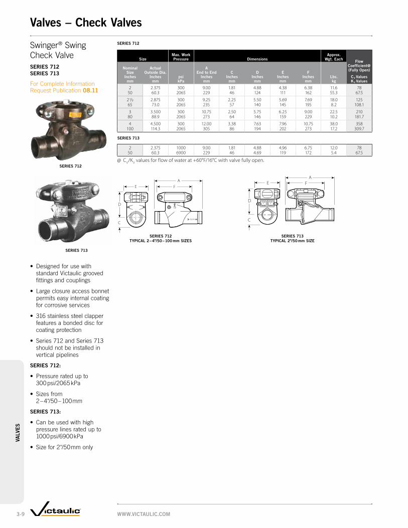
www.victaulic.com3-9
valv
es
series 712
sizemax. work Pressure dimensions
approx. wgt. each Flow
coefficient@ (Fully open)
cv valueskv values
nominal size
inches mm
actual outside dia.
inches mm
psi kPa
a end to end
inches mm
cinches
mm
dinches
mm
einches
mm
Finches
mmlbs. kg
2 2.375 300 9.00 1.81 4.88 4.38 6.38 11.6 7850 60.3 2065 229 46 124 111 162 55.3 67.5
2 1/2 2.875 300 9.25 2.25 5.50 5.69 7.69 18.0 12565 73.0 2065 235 57 140 145 195 8.2 108.1
3 3.500 300 10.75 2.50 5.75 6.25 9.00 22.5 21080 88.9 2065 273 64 146 159 229 10.2 181.7
4 4.500 300 12.00 3.38 7.63 7.96 10.75 38.0 358100 114.3 2065 305 86 194 202 273 17.2 309.7
series 713
2 2.375 1000 9.00 1.81 4.88 4.96 6.75 12.0 7850 60.3 6900 229 46 4.69 119 172 5.4 67.5
@ CV/KV values for flow of water at +60°F/16°C with valve fully open.
Swinger® SwingCheck Valveseries 712 series 713
For Complete Information Request Publication 08.11
• Designedforusewith standard Victaulic grooved fittings and couplings
• Largeclosureaccessbonnetpermits easy internal coating for corrosive services
• 316stainlesssteelclapperfeatures a bonded disc for coating protection
• Series712andSeries713should not be installed in vertical pipelines
series 712:
• Pressureratedupto 300 psi/2065 kPa
• Sizesfrom 2 – 4"/50 – 100 mm
series 713:
• Canbeusedwithhigh pressure lines rated up to 1000 psi/6900 kPa
• Sizefor2"/50 mm only
series 712
series 712 tyPical 2 – 4"/50 – 100 mm siZes
series 713
Grade TGasket
Grade TGasket
D
C
EA
F
series 713 tyPical 2"/50 mm siZe
valves – check valves
FA
E
D
C

www.victaulic.com 3-10
valve
s
gear oPerator dimensions
gear oper. dimensions
turns to close
approx. wgt. each
style no.
J inches
mm
l inches
mm
n dia.
inches mm
o inches
mm
P inches
mm
Q inches
mm
r dia.
inches mm
s inches
mm
t inches
mm
u dia.
inches mm no.
lbs. kg
MX 4.76 2.07 6.00 4.00 1.13 1.30 0.63 4.00 1.95 0.19 7.5 7.5121 53 152 102 29 33 16 102 50 5 3.4
MZ 5.50 2.62 10.00 5.00 1.25 1.30 0.63 4.50 2.36 0.19 7.5 15.0140 67 250 127 32 33 16 114 60 5 6.8
MV 7.25 3.29 18.00 9.00 1.62 2.25 0.88 6.00 2.63 0.25 7.8 20.0184 84 457 229 41 57 22 152 67 6 9.1
MA 8.24 3.55 18.00 10.00 1.75 2.25 0.88 7.00 3.38 0.25 7.8 33.0209 90 457 254 45 57 22 178 86 6 15.0
MC 11.12 4.03 18.00 10.38 1.87 2.25 1.00 7.38 5.38 0.25 18 68.0283 102 457 264 48 57 25 188 137 6 30.8
valve dimensions
size dimensions approx.
wgt. eachFlow
coefficient@ (Fully open)
cv valueskv values
awwa nominal
size inches
mm
awwa outside
diameter inches
mm
a end to end
inches mm
c inches
mm
d inches
mm
F inches
mm
g inches
mm
h inches
mm
k inches (mm)
m inches
mm
v inches (mm)
valve with gear
operator lbs. kg
valve with lever
handle lbs. kg
3* 3.96 8.00 3.75 4.25 6.56 — 4.00 2.00 4.00 18.50 32.0 32.0 60080 100.6 203 95 108 167 102 51 102 470 14.5 14.5 519.0
4* 4.80 9.00 4.44 4.75 7.74 — 4.50 2.00 4.00 18.50 42.0 39.0 1040100 121.9 229 113 121 197 114 51 102 470 19.1 17.7 899.6
6* 6.90 10.50 5.50 7.50 10.32 — 5.25 2.00 — 18.50 80.0 74.0 2100150 175.3 267 140 191 262 133 51 470 36.3 33.6 1816.5
8 9.05 11.50 6.87 10.80 12.30 16.38 5.75 — — — 120.0 — 3850200 229.9 292 175 274 312 416 145 55.0 3330.3
10 11.10 13.00 8.00 12.00 14.78 18.75 6.50 — — — 185.0 — 5500250 281.9 330 203 305 375 476 165 84.0 4757.5
12 13.20 14.00 9.50 13.75 17.00 21.00 7.00 — — — 240.0 — 8400300 335.3 356 241 349 432 533 178 109.0 7266.0
* 3"/80 mm, 4"/100 mm, 6"/150 mm valves do not include side support lugs.@ CV/KV values for flow of water at +60°F/16°C with valve fully open.
IMPORTANT NOTE: Gear operators can be installed in various positions, contact Victaulic for details.
tyPical 3 – 6"/80 – 150 mm siZes tyPical 8 – 12"/200 – 300 mm siZes
Vic-Plug Balancing Valveseries 377
For Complete Information Request Publication 08.12
• Onlyeccentricgroovedendplug valve made specifically for throttling services
• Castofductileironand coated with alkyd enamel
• Eccentricdesignassuresshut-off sealing up to 175 psi/1200 kPa on 3 – 12"/80 – 300 mm
• For3–12"/80–300 mm systems Victaulic Style 307 Transition couplings are available to directly connect Vic-Plug valves to grooved end steel and other IPS pipe – refer to Publication 23.03 for details
valve with lever handle tyPical 3 – 6"/80 – 150 mm siZes
valve with gear oPerator tyPical 8 – 12"/200 – 300 mm siZes
valve with gear oPerator tyPical 3 – 6"/80 – 150 mm siZes
valves – Plug valves
OPEN
SHUT
QS
TJ
R Dia.
NDia.
P
L
U Dia.
O
TOP VIEW
NDia.
R Dia.
L
P
J
T
OS
Q
U Dia.
TOP VIEW
AH
D
C
FG
F
SEAT END
H A
K SQUARE
C
B
V
D
SEAT END
M
D
C
AFH

www.victaulic.com3-11
valv
es
size dimensionsapprox.
weight each Flow coefficient@ (Fully open)
cv valueskv values
nominal size
inches mm
actual outside dia.
inches mm
a inches
mm
B inches
mm
c inches
mm
F inches
mmlbs. kg
1/4 0.540 1.54 0.77 1.03 1.65 0.2 78 13.7 39 20 26 42 0.09 6.1
3/8 0.675 1.77 0.88 1.28 3.07 0.3 710 17.1 45 22 33 78 0.14 6.1
1/2 * 0.084 2.13 1.06 1.33 3.07 0.4 1015 21.3 54 27 34 78 0.18 8.7
3/4 * 1.050 2.44 1.22 1.79 3.78 0.7 2520 26.7 62 31 45 96 0.32 21.6
1 * 1.315 2.95 1.48 1.95 3.78 1.0 3725 33.4 75 37 50 96 0.45 32.0
1 1/4 * 1.660 3.31 1.65 2.17 3.78 1.5 5032 42.2 84 42 55 96 0.68 43.3
1 1/2 * 1.900 3.66 1.83 2.68 5.43 2.1 8740 48.3 93 46 68 138 0.95 75.3
2 * 2.375 4.21 2.11 2.89 5.43 2.4 11050 60.3 107 53 73 138 1.09 95.2
@ CV/KV values for flow of water at +60°F/16°C with valve fully open.* Valve sizes ½"/15 mm and above are UL Listed at 175 psi/1200 kPa and FM Approved at 600 psi/4135 kPa
for ½"/15 mm and ¾"/20 mm sizes and 500 psi/3450 kPa for 1 – 2"/25 – 50 mm sizes.
Brass Body Ball Valveseries 722
For Complete Information Request Publication 08.15
• Standardport,female threaded end ball valve
• Constructedfrom forged brass
• Pressureratedupto 600 psi/4135 kPa WOG service
• Sizesfrom ¼ – 2"/8 – 50 mm
tyPical For all siZes
valves – Ball valves
C
2" 600 WOG
AB
F
size dimensions – inches/mmapprox.
weight each
nominal size
inches mm
actual outside dia.
inches mm
end to end a
height B c
diameter d e
F
lbs. kg
4 * 4.500 8.25 6.92 4.50 6.00 5.21 16.13 32.4114.3 114.3 210 176 114 152 132 410 14.7
6 6.625 10.10 9.14 5.30 8.00 7.26 28.13 75.0168.3 168.3 257 232 135 203 184 715 34.0
Vic® Ball Valvesseries 721
For Complete Information Request Publication 08.14
• Streamlineddesignprovidesexcellent flow characteristics
• Standardport,end-entryvalve designed for 800 psi/5515 kPa WOG service
• DuctileIronvalvebodyandend cap
• Suppliedstandardwith manual handles; pinned handle extensions available
• ReinforcedTetrafluoroethylene (TFE) seal rated to +450°F/+232°F
• Sizes4-6”/100-150mm
E
AC Dia. D
B
F

www.victaulic.com 3-12
valve
s
size dimensionsapprox.
wgt each Flow coefficient@ (Fully open)
cv valueskv values
nominal size
inches mm
actual out. dia. inches
mm
a inches
mm
B inches
mm
c inches
mm
d inches
mm
da inches
mm
e inches
mm
F inches
mm
h inches
mm
J inches
mm
k inches
mm
l inches
mmlbs. kg
1 1/2 1.900 5.12 2.00 2.36 1.25 1.50 1.78 1.90 3.00 0.28 0.56 6.97 4.4 13040 48.3 130 51 60 32 38 45 48 76 7 14 177 2.0 112.5
2 2.375 5.50 2.64 2.48 1.50 2.00 2.25 2.38 3.31 0.34 0.56 6.97 6.5 18050 60.3 140 67 63 38 51 57 60 84 9 14 177 3.0 155.7
2 1/2 2.875 6.25 3.03 2.80 1.97 2.50 2.72 2.88 4.00 0.34 0.56 9.84 10.4 34065 73.0 159 77 71 50 64 69 73 102 9 14 250 4.7 294.1
3 3.500 6.56 3.50 3.15 2.50 3.00 3.34 3.50 4.53 0.34 0.56 9.84 14.9 60080 88.9 167 89 80 64 76 85 89 115 9 14 250 6.8 519.0
4 4.500 8.25 — 3.35 2.99 4.00 4.33 4.52 5.48 0.34 0.61 15.67 41.5 650100 114.3 210 85 76 102 111 115 139 9 15 398 18.9 562.3
6 6.625 10.10 — 4.53 4.00 6.00 6.46 6.64 6.48 0.34 0.61 18.07 78.5 800150 168.3 257 115 102 152 164 169 165 9 15 459 35.7 692.0
@ CV/KV values for flow of water at +60°F/16°C with valve fully open.
Vic-Ball Valve series 726
For Complete Information Request Publication 08.23
• High-pressurestandardportball valve with grooved ends
• Two-piece,end-entryvalve
• Featuresfloatingballforlower torque requirements
• NACE-MR-01-75compliant
• Pressureratedupto 1000 psi/6900 kPa in sizes 1½ – 3"/40 – 80 mm
• Pressureratedupto 800 psi/5515 kPa for sizes 4 – 6"/100 – 150 mm
• Sizesfrom 1½ – 6"/40 – 150 mm
tyPical 1½ – 3"/40 – 80 mm siZes
tyPical 4 – 6"/100 – 150 mm siZes
valves – Ball valves
H
B
L
CA
FEDA
JK
D
H
FEDAD
L
AC
KJ

www.victaulic.com3-13
valv
es
size dimensionsapprox.
wgt. each Flow coefficient@ (Fully open)
cv valueskv values
nominal size
inches mm
actual outside dia.
inches mm
m inches
mm
n inches
mm
o inches
mm
P inches
mm
Q inches
mm
r inches
mmlbs. kg
1 1/2 1.900 6.03 4.29 1.58 3.94 2.64 1.75 7.1 13040 48.3 153 109 40 100 92 44 3.2 112.5
2 2.375 6.30 4.29 1.58 3.94 2.64 1.75 9.1 18050 60.3 160 109 40 100 92 44 4.1 155.7
2 1/2 2.875 7.43 4.65 1.97 4.92 4.43 2.28 12.9 34065 73.0 189 118 50 125 112 58 5.9 294.1
76.1 mm 3.000 7.43 4.65 1.97 4.92 4.43 2.28 12.9 34076.1 189 118 50 125 112 58 5.9 294.1
3 3.500 7.94 4.65 1.97 4.92 4.43 2.28 20.0 60080 88.9 202 118 50 125 112 58 9.1 519.0
4 4.500 9.95 4.65 1.97 4.92 4.43 2.28 44.7 650100 114.3 253 118 50 125 112 58 20.3 562.3
6 6.625 11.02 4.65 1.97 4.92 4.43 2.28 89.0 800150 168.3 280 118 50 125 112 58 40.3 692.0
165.1 mm 6.500 11.02 4.65 1.97 4.92 4.43 2.28 89.0 800165.1 280 118 50 125 112 58 40.3 692.0
@ CV/KV values for flow of water at +60°F/16°C with valve fully open.
Vic-Ball Valve (cont'd)
series 726 with gear oPerator
For Complete Information Request Publication 08.23
tyPical 1½ – 3"/40 – 80 mm siZes
tyPical 4 – 6"/100 – 150 mm siZes
valves – Ball valves
M
OR NQ
P
M
P
N OQ R

www.victaulic.com 3-14
valve
s
Balancing Valves• Reliable,simple,
and cost effective
• Fullthrottlingrangeisachieved by 4, 8, 12, or 16 full turns
• Servicegovernedbythe connecting coupling gasket ratings for grooved and flanged valves
• Pressureratedupto300 psi/2065 kPa for temperature ratings of +250°F/+120°C and –22°F/-30°C
comParison oF throttling characteristics
• Thiscurveillustratestheadvantageofthefour(4) turn adjustment available with TA balancing valves ½ – 2"/15 – 50 mm, valves 2½"/65 mm and larger have 8, 12, or 16 turns
• A90°fullyopentoclosedvalverequires just a 12° change in adjustment to equal 30% change in flow
• A360°fullyopentoclosedvalvewouldrequire96° change in adjustment to equal the same 30% change in the flow measurement
• TAbalancingvalveswouldrequire a 408° change in adjustment to equal the same 30% change in flow
Balancing Valve Flanged Endta series 788, Pg. 3-15
Balancing Valve Grooved Endta series 789, Pg. 3-15
degrees oF valve stem rotation
Pe
rc
en
tag
e o
F Fl
ow
Balancing Valve Solder Endta series 786, Pg. 3-15
valves – circuit Balancing valves
1440
10
20
30
60
50
40
70
80
90
100
Tour & Andersson MULTI-TURN VALVE
90 Turn Valve 360 Turn Valve
180
0 60 360 720 1080
12 96
408
Union Port Fittingseries 78u, Pg. 3-16
Strainer/Ball Valve Combinationseries 78y, Pg. 3-17

www.victaulic.com3-15
valv
es
valve selection guide
sizeta series 786 solder end (300 psi/2065 kPa)
Balancing valveta series 787 nPt (Female) threaded end
(300 psi/2065 kPa) Balancing valve
nominal size
inches mm
actual outside diameter
inches mm
minimum Flow gPm lPm
nominal Flow gPm lPm
maximum Flow gPm lPm
minimum Flow gPm lPm
nominal Flow gPm lPm
maximum Flow gPm lPm
1/2 0.840 0.13 2.7 8.6 0.13 2.7 8.615 21.3 0.49 10.2 32.6 0.49 10.2 32.6
3/4 1.050 0.39 6.2 20.0 0.39 6.2 20.020 26.7 1.48 23.5 75.7 1.48 23.5 75.7
1 1.315 0.45 9.4 30.0 0.45 9.4 30.025 33.7 1.70 35.6 113.6 1.70 35.6 113.6
1 1/4 1.660 0.87 15.0 48.0 0.87 15.0 48.032 42.4 3.29 56.8 181.7 3.29 56.8 181.7
1 1/2 1.900 1.30 21.0 66.0 1.30 21.0 66.040 48.3 4.92 79.5 249.8 4.92 79.5 249.8
2 2.375 2.00 36.0 110.0 2.00 36.0 110.050 60.3 7.57 136.3 416.4 7.57 136.3 416.4
IMPORTANT NOTES: Balancing valves should be sized in relation to the GPM flows (and not in relation to pipeline size). The Minimum Flow is calculated from the minimum open setting of the valve and a minimum pressure drop 1 Ft. WG (= 3 kPa). The Nominal Flow is calculated from the maximum open setting of the valve and the minimum recommended pressure drop, 2 Ft. WG (= 6 kPa). The Maximum Flow is calculated from the maximum open setting of the valve and the maximum pressure drop, 20 Ft. WG (= 60 kPa). A computer program, TA-Select, is available from Tour & Andersson for calculation of pre-setting values and other applications.
MEASuRINg AccuRAcy: The hand wheel zero position is calibrated and must not be changed. Valves have an accuracy of flow measurement of 2% to 3%* when used within their recommended flow range and installed in accordance with the figure below. * For the most accurate results, a Series 737 TA CBI-II should be used. However, any differential pressure meter may be used.
Balancing Valveta series 786 Solder Endta series 787 Female Threaded End
For Complete Information Request Publication 08.16
tyPical ½ – 2"/15 – 50 mm
siZes
tyPical ½ – 2"/15 – 50 mm
siZes
valves – circuit Balancing valves
A
B
Drain Kit(Optional)
A
B
2 D 10 D2 D 5 D
Pump
2 D 10 D2 D 5 D
Pump
sizeta series 786 solder end (300 psi/2065 kPa)
Balancing valveta series 787 nPt (Female) threaded end
(300 psi/2065 kPa) Balancing valve
nominal size
inches mm
actual outside diameter
inches mm
a end to end
inches mm
B center to top
inches mm
approx. weight each
lbs. kg
a end to end
inches mm
B center to top
inches mm
approx. weight each
lbs. kg
1/2 0.840 3.50 4.00 1.4 3.50 4.00 1.515 21.3 89 102 0.6 89 102 0.7
3/4 1.050 3.81 4.00 1.4 3.81 4.00 1.620 26.7 97 102 0.6 97 102 0.7
1 1.315 4.31 4.50 1.9 4.31 4.50 2.025 33.7 110 114 0.9 110 114 0.9
1 1/4 1.660 4.88 4.31 2.4 4.88 4.31 2.632 42.4 124 110 1.1 124 110 1.2
1 1/2 1.900 5.13 4.75 3.1 5.13 4.75 3.340 48.3 130 121 1.4 130 121 1.5
2 2.375 6.13 4.75 4.5 6.13 4.75 5.050 60.3 156 121 2.0 156 121 2.3
tyPical 2½ – 12"/65 – 300 mm
siZes
tyPical 2½ – 12"/65 – 300 mm
siZes
A
B
A
B
Balancing Valveta series 788 Flanged Endta series 789 Grooved End
For Complete Information Request Publication 08.16
sizeta series 788 Flange end (250 psi/1720 kPa)
Balancing valveta series 789 groove end (350 psi/2400 kPa)
Balancing valve
nominal size
inches mm
actual outside diameter
inches mm
a end to end
inches mm
B height inches
mm
approx. weight each
lbs. kg
a end to end
inches mm
B height inches
mm
approx. weight each
lbs. kg
2 1/2 2.875 11.38 8.00 24.0 11.38 8.00 14.065 73.0 289 203 10.9 289 203 6.4
3 3.500 12.25 8.63 31.0 12.25 8.63 20.080 88.9 311 219 14.1 311 219 9.1
4 4.500 13.75 9.44 43.0 13.75 9.44 31.0100 114.3 350 240 19.6 350 240 14.1
5 5.563 15.75 10.88 62.0 15.75 10.88 50.0125 141.3 400 276 28.5 400 276 22.7
6 6.625 18.88 11.25 82.0 18.88 11.25 69.0150 168.3 480 286 37.5 480 286 31.3
8 8.625 23.63 17.00 168.0 23.63 17.00 140.0200 219.1 600 432 76.5 600 432 63.7
10 10.750 28.75 17.75 270.0 28.75 17.75 202.0250 273.0 730 451 122.9 730 451 91.9
12 12.750 33.50 19.00 360.0 33.50 19.00 280.0300 323.9 851 483 163.9 851 483 127.4

www.victaulic.com 3-16
valve
s
valve selection guide
sizeta series 788 Flange end (250 psi/1720 kPa)
Balancing valveta series 789 groove end (350 psi/2400 kPa)
Balancing valve
nominal size
inches mm
actual outside diameter
inches mm
minimum Flow gPm lPm
nominal Flow gPm lPm
maximum Flow gPm lPm
minimum Flow gPm lPm
nominal Flow gPm lPm
maximum Flow gPm lPm
2 1/2 2.875 1.40 92.0 290.0 1.40 92.0 290.065 73.0 5.30 348.2 1097.7 5.30 348.2 1097.7
3 3.500 1.50 130.0 410.0 1.50 130.0 410.080 88.9 5.68 492.1 1551.9 5.68 492.1 1551.9
4 4.500 1.90 200.0 650.0 1.90 200.0 650.0100 114.3 7.19 757.0 2460.3 7.19 757.0 2460.3
5 5.563 4.20 320.0 1020.0 4.20 320.0 1020.0125 141.3 15.90 1211.2 3860.7 15.90 1211.2 3860.7
6 6.625 5.00 450.0 1430.0 5.00 450.0 1430.0150 168.3 18.93 1703.3 5412.6 18.93 1703.3 5412.6
8 8.625 30.00 820.0 2600.0 30.00 820.0 2600.0200 219.1 113.55 3103.7 9841.0 113.55 3103.7 9841.0
10 10.750 70.00 1280.0 4040.0 70.00 1280.0 4040.0250 273.0 264.95 4844.4 15291.4 264.95 4844.4 15291.4
12 12.750 115.00 1550.0 4950.0 115.00 1550.0 4950.0300 323.9 435.28 5866.8 18735.8 435.28 5866.8 18735.8
IMPORTANT NOTES: (SEE Pg. 3-16 fOR MEASuRINg AccuRAcy) Balancing valves should be sized in relation to the GPM flows (and not in relation to pipeline size). The Minimum Flow is calculated from the minimum open setting of the valve and a minimum pressure drop 1 Ft. WG (= 3 kPa). The Nominal Flow is calculated from the maximum open setting of the valve and the minimum recommended pressure drop, 2 Ft. WG (= 6 kPa). The Maximum Flow is calculated from the maximum open setting of the valve and the maximum pressure drop, 20 Ft. WG (= 60 kPa). A computer program, TA-Select, is available from Tour & Andersson for calculation of pre-setting values and other applications.
valves – circuit Balancing valves
The Series 78U Union Port Fitting provides a simplified, quality terminal hookup for i nstallation at coil outlet. The Series 78U features a port section equipped standard with a manual air vent port on top allowing for optimal positioning at coil outlet and effective venting together with a pressure/temperature port on the side. The Series 78U is equipped with an EPDM o-ring.
Rated up to 400 psi/2758 kPa and 250°F/121°C.
size
inlet nominal
size inches/mm
outlet nominal
size inches/mm
a inches
mm
B inches
mm
c inches
mm
approx. weight each
lbs. kg
½ x ½ 3.5 0.8 1.6 0.615 15 89 19 39 0.28
¾ x ½ 3.7 0.9 2.2 1.0
15 94 23 56 0.45
20¾ 3.58 1.43 1.80 0.9520 90 36 46 0.40
1 x ¾ 4.1 1.0 2.4 1.2
20 104 25 60 0.56
251 3.65 1.66 2.13 1.2
25 93 42 54 0.50
11/4x 1 4.3 1.2 2.9 2.8
25 109 30 74 1.28
3211/4 4.24 2.08 2.58 2.132 108 53 66 1.00
1½x 11/4 4.4 1.3 3.5 3.5
32 112 32 88 1.57
401½ 4.39 2.26 3.21 2.940 112 57 82 1.30
2x 1½ 4.6 1.7 3.9 5.9
40 116 43 99 2.66
502 4.6 2.56 3.54 3.9
50 116 65 90 1.70
notesDimensions based on F x M connections and will vary with mixed connections.All weights and dimensions are subject to minor changes.
Port 1
Port 2
C
A
B
inlet outlet
Balancing Valveseries 78u
For Complete Information, Request Publication 08.16.
Balancing Valveta series 788 Flanged Endta series 789 Grooved End
For Complete Information Request Publication 08.16
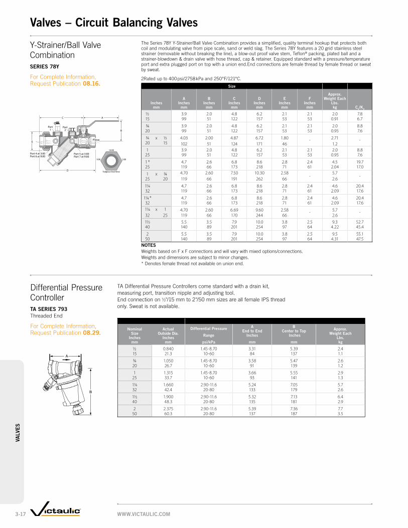
www.victaulic.com3-17
valv
es
valves – circuit Balancing valves
Differential Pressure Controllerta series 793 Threaded End
For Complete Information, Request Publication 08.29.
Y-Strainer/Ball Valve Combinationseries 78y
For Complete Information, Request Publication 08.16.
The Series 78Y Y-Strainer/Ball Valve Combination provides a simplified, quality terminal hookup that protects both coil and modulating valve from pipe scale, sand or weld slag. The Series 78Y features a 20 grid stainless steel strainer (removable without breaking the line), a blow-out proof valve stem, Teflon® packing, plated ball and a strainer-blowdown & drain valve with hose thread, cap & retainer. Equipped standard with a pressure/temperature port and extra plugged port on top with a union end.End connections are female thread by female thread or sweat by sweat.
2Rated up to 400 psi/2758 kPa and 250°F/121°C.
size
inches
mm
a inches
mm
B inches
mm
c inches
mm
d inches
mm
e inches
mm
F inches
mm
approx. weight each
lbs. kg cv/kv
½ 3.9 2.0 4.8 6.2 2.1 2.1 2.0 7.815 99 51 122 157 53 53 0.91 6.7
¾ 3.9 2.0 4.8 6.2 2.1 2.1 2.0 8.820 99 51 122 157 53 53 0.95 7.6
¾ x ½ 4.03 2.00 4.87 6.72 1.80 - 2.71 -20 15 102 51 124 171 46 1.21 3.9 2.0 4.8 6.2 2.1 2.1 2.0 8.8
25 99 51 122 157 53 53 0.95 7.6
1 * 4.7 2.6 6.8 8.6 2.8 2.4 4.5 19.725 119 66 173 218 71 61 2.04 17.0
1 x ¾ 4.70 2.60 7.50 10.30 2.58-
5.7-25 20 119 66 191 262 66 2.6
11/4 4.7 2.6 6.8 8.6 2.8 2.4 4.6 20.432 119 66 173 218 71 61 2.09 17.6
11/4 * 4.7 2.6 6.8 8.6 2.8 2.4 4.6 20.432 119 66 173 218 71 61 2.09 17.611/4 x 1 4.70 2.60 6.69 9.60 2.58 - 5.7 -32 25 119 66 170 244 66 2.61½ 5.5 3.5 7.9 10.0 3.8 2.5 9.3 52.740 140 89 201 254 97 64 4.22 45.4
2 5.5 3.5 7.9 10.0 3.8 2.5 9.5 55.150 140 89 201 254 97 64 4.31 47.5
notesWeights based on F x F connections and will vary with mixed options/connections.Weights and dimensions are subject to minor changes.* Denotes female thread not available on union end.
B
E
D
Port1
Port2
Port 5 at 3:00Port 7 at 9:00
Port 4 at 3:00Port 6 at 9:00
AC
12:00
3:009:00
Tailpiece End View
Flow
size ta series 793 (threaded)
nominal size
inches mm
actual outside dia.
inches mm
differential Pressure
range
psi/kPa
a end to end
inches
mm
B center to top
inches
mm
approx. weight each
lbs. kg
½ 0.840 1.45-8.70 3.31 5.39 2.415 21.3 10-60 84 137 1.1
¾ 1.050 1.45-8.70 3.58 5.47 2.620 26.7 10-60 91 139 1.2
1 1.315 1.45-8.70 3.66 5.55 2.925 33.7 10-60 93 141 1.3
11/4 1.660 2.90-11.6 5.24 7.05 5.732 42.4 20-80 133 179 2.6
1½ 1.900 2.90-11.6 5.32 7.13 6.440 48.3 20-80 135 181 2.9
2 2.375 2.90-11.6 5.39 7.36 7.750 60.3 20-80 137 187 3.5
A
B
TA Differential Pressure Controllers come standard with a drain kit, measuring port, transition nipple and adjusting tool. End connection on ½"/15 mm to 2"/50 mm sizes are all female IPS thread only. Sweat is not available.
size series 794 (Flanged)
nominal size
inches mm
actual outside dia.
inches mm
differential Pressure
range
psi/kPa
a end to end
inches
mm
B center to top
inches
mm
approx. weight each
lbs. kg
2½ 2.875 2.90-11.6 11.42 16.3 46.365 73.0 20-80 290 414 21
3 3.500 2.90-11.6 12.21 17.17 52.980 88.9 20-80 310 436 24
4 4.500 2.90-11.6 13.78 18.11 72.8100 114.3 20-80 350 460 33

www.victaulic.com 3-18
valve
svalves – circuit Balancing valves
Differential Pressure Controllerta series 794 Flanged End
For Complete Information, Request Publication 08.29.
TA Pressure Differential Controllers come standard with a drain kit, measuring port, transition nipple and adjusting tool. EndconnectionsareANSIflangesonly,groovedendsarenotavailable.
B
A
dpl (psi)
2.9 4.4 5.8 7.3 8.7 10.2 11.6Inches qmin qnom qmax qmin qnom qmax qmin qnom qmax qmin qnom qmax qmin qnom qmax qmin qnom qmax qmin qnom qmax
0.8 11.7 16.6 1.0 14.4 20.4 1.2 16.6 23.5 1.3 18.6 26.3 1.4 20.3 28.7 1.5 22.0 31.1 1.6 23.4 33.21.2 17.6 25.0 1.5 21.6 30.8 1.8 24.8 35.3 2.0 27.9 39.6 2.2 30.4 43.3 2.3 32.9 46.8 2.5 35.1 49.92.3 33.2 47.6 2.9 40.9 58.6 3.3 46.9 67.3 3.7 52.6 75.5 4.1 57.4 82.4 4.4 62.2 89.3 4.7 66.3 95.2
size
1¼
1½
2
valve selection guide ta series 793
English Measurements in Pounds per Square Inch and Gallons per Minute
dpl (psi)
1.5 2.9 4.4 5.8 7.3 8.7Inches qmin qnom qmax qmin qnom qmax qmin qnom qmax qmin qnom qmax qmin qnom qmax qmin qnom qmax
0.1 1.4 2.0 0.1 2.0 2.7 0.2 2.4 3.4 0.2 2.8 3.9 0.2 3.1 4.3 0.2 3.4 4.7 0.2 3.1 4.3 0.3 4.3 6.0 0.4 5.3 7.4 0.4 6.1 8.6 0.5 6.8 9.6 0.5 7.4 10.5 0.4 5.3 7.7 0.5 7.4 10.7 0.7 9.1 13.2 0.8 10.5 15.2 0.9 11.8 17.0 0.9 12.8 18.6
size
½
¾
1
dpl (psi)
2.9 4.4 5.8 7.3 8.7 10.2 11.6Inches qmin qnom qmax qmin qnom qmax qmin qnom qmax qmin qnom qmax qmin qnom qmax qmin qnom qmax qmin qnom qmax
2.7 48.8 70.2 3.4 60.1 86.5 3.9 69.0 99.3 4.3 77.4 111.4 4.7 84.5 121.6 5.1 91.5 131.7 5.5 97.5 140.54.3 74.1 107.3 5.3 91.3 132.2 6.1 104.8 151.7 6.8 117.6 170.2 7.4 128.4 185.9 8.0 139.0 201.2 8.6 148.3 214.68.6 150.2 214.6 10.6 185.0 264.3 12.1 212.4 303.5 13.6 238.3 340.5 14.9 260.2 371.7 16.1 281.7 402.5 17.2 300.4 429.2
size
dpl (psi)
5.8 7.3 8.7 10.2 11.6 13.1 14.5Inches qmin qnom qmax qmin qnom qmax qmin qnom qmax qmin qnom qmax qmin qnom qmax qmin qnom qmax qmin qnom qmax
2½ 3.9 69.0 99.3 4.3 77.4 111.4 4.7 84.5 121.6 5.1 91.5 131.7 5.5 97.5 140.5 5.8 103.7 149.3 6.1 109.1 157.0 3 6.1 104.8 151.7 6.8 117.6 170.2 7.4 128.4 185.9 8.0 139.0 201.2 8.6 148.3 214.6 9.1 157.6 228.1 9.6 165.8 239.9 12.1 212.4 303.5 13.6 238.3 340.5 14.9 260.2 371.7 16.1 281.7 402.5 17.2 300.4 429.2 18.2 319.3 456.1 19.2 335.9 479.9
size
dpl (psi)
16.0 17.4 18.9 20.3 21.8 23.2Inches qmin qnom qmax qmin qnom qmax qmin qnom qmax qmin qnom qmax qmin qnom qmax qmin qnom qmax
2½ 6.4 114.6 165.0 6.7 119.5 172.0 7.0 124.5 179.3 7.2 129.0 185.8 7.5 133.7 192.6 7.7 138.0 198.6 3 10.1 174.1 252.0 10.5 181.6 262.8 11.0 189.3 273.9 11.4 196.1 283.9 11.8 203.3 294.2 12.1 209.7 303.5 20.2 352.9 504.1 21.0 368.0 525.7 21.9 383.5 547.9 22.7 397.4 567.8 23.5 411.9 588.4 24.3 424.9 607.0
4
2½
3
4
4
valve selection guide
English Measurements in Pounds per Square Inch and Gallons per Minute (Spring Option 1)
English Measurements in Pounds per Square Inch and Gallons per Minute (Spring Option 2)
size
size ta series 793 (threaded)
nominal size
inches mm
actual outside dia.
inches mm
differential Pressure
range
psi/kPa
a end to end
inches
mm
B center to top
inches
mm
approx. weight each
lbs. kg
2½ 2.875 2.90-11.6 11.42 16.3 46.365 73.0 20-80 290 414 21
3 3.500 2.90-11.6 12.21 17.17 52.980 88.9 20-80 310 436 24
4 4.500 2.90-11.6 13.78 18.11 72.8100 114.3 20-80 350 460 33

www.victaulic.com3-19
valvesva
lve
s
Link Differential Pressure Sensorta series 736
For Complete Information Request Publication 08.16
• Providesconnectionbetweenabuilding’sheatingand coolingcircuitsandbuilding’smonitoringsystem(BMS)
• Continuouslymeasurestheflowanddifferentialpressurethrough and across the TA balancing valves
• Measurementprobesprovidedfordirectconnection to the measurement points on all TA Series 786, 787, 788, and 789 circuit balancing valves
Drain Kitta series 786-dk
For Complete Information Request Publication 08.16
• Aseparatedrainkitwitha¾"/20 mm connection is available for Series 786 and Series 787 valves
• Kitmustbefieldmounted
Portable Differential Pressure Meterta series 738 Flanged End (250 psi/1720 kPa)
For Complete Information Request Publication 08.16
• TASeries738portabledifferentialpressuremeterisan accurate device for measuring differential pressure in Tour & Andersson circuit balancing valves
• Usingthebalancingwheelsuppliedwiththemeter, the measured pressure differential can be converted to a flow measurement
• TASeries738canbeusedonsystemsuptothefullrated working pressure of the Tour & Andersson valves (or up to 500 psi/3450 kPa on other devices)
• Unitsaresuppliedinaprotectivecaseincluding a balancing wheel, adapter fittings and valve
• Whenusingtheportabledifferentialpressuremeter on other valves, contact Victaulic
Hand-held Circuit Balancing Instrumentta series 737
For Complete Information Request Publication 08.16
• Series737 CBI-II meter is a hand-held computer balancinginstrument programmed for use with Tour & Andersson balancing valves to obtain direct reading of flow and differential pressures
• Thisinstrumentconsistsofanelectronicdifferential pressure gauge and a microcomputer
• Measuredvaluescanbesavedintheunitbefore transferring the information to a PC for printing out a commissioning report of for creating a permanent record

www.victaulic.com 3-20
valvesva
lves
CMI Pressure Differential Meterta series 73m
TA CMI is a computer programmed measuring instrument. It is a handheld instrument for measuring differential pressure, temperature and flow through balancing valves in hydronic systems. It consists of a sensor unit and an instrument unit that has been programmed with the TA valve characteristics, which makes it possible to take a direct reading of flow differential pressures.
TA Select III Computer ProgramTA Select III helps you choose the right balancing valve, taking the desired flow rate and pressure drop into consideration. The software will advise the correct combination of valve, handwheel position and pipe size to correctly balance the system. A sophisticated viscosity correction procedure displays the density, viscosity, specific heat and freezing point of fluids such as glycols and brines. It also shows the true value of flows in the valves.
The program will also size the pipe, generate Cv values for the ATC valves and give pre-set information for all the TA valves on the project.
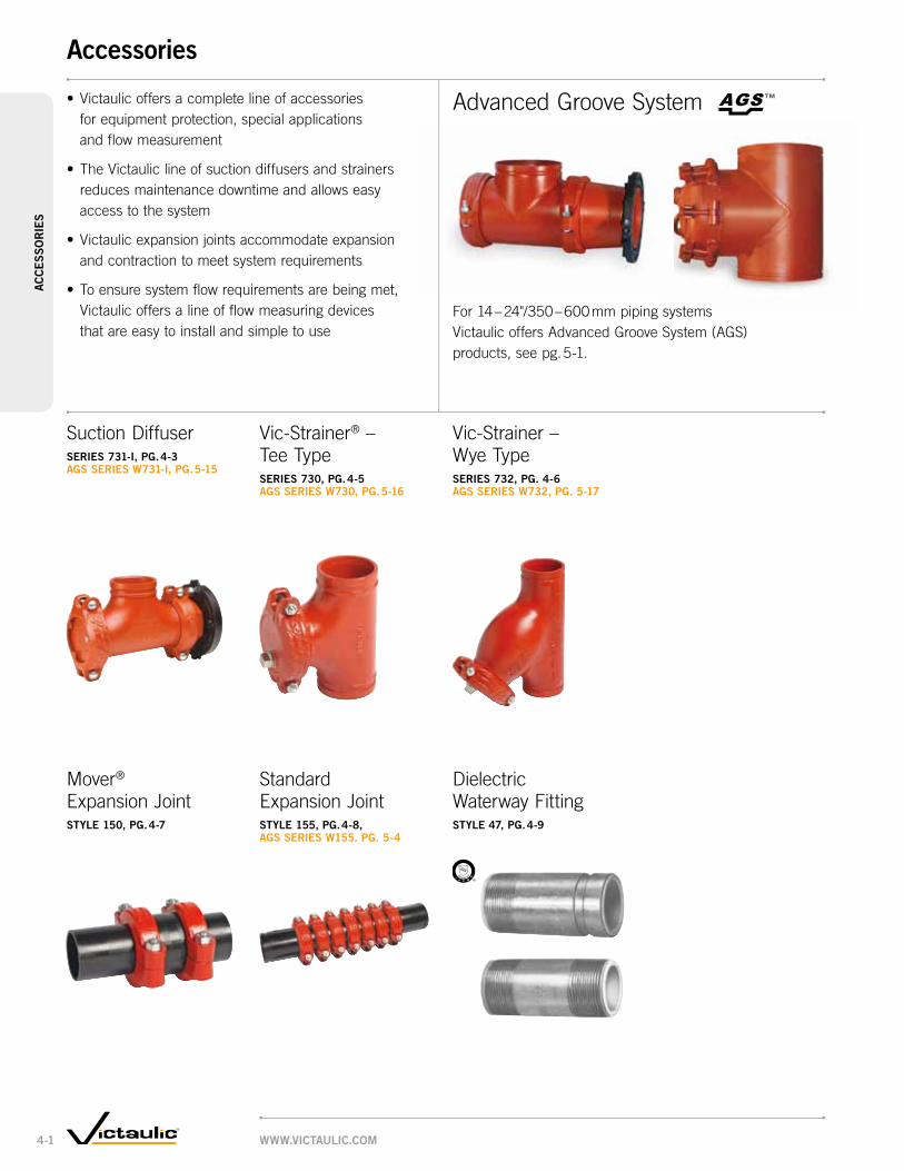
™TM
Suction DiffuserSerieS 731-i, pg. 4-3 AgS SerieS W731-i, pg. 5-15
• Victaulicoffersacompletelineofaccessories forequipmentprotection,specialapplications andflowmeasurement
• TheVictauliclineofsuctiondiffusersandstrainers reducesmaintenancedowntimeandallowseasy accesstothesystem
• Victaulicexpansionjointsaccommodateexpansion andcontractiontomeetsystemrequirements
• Toensuresystemflowrequirementsarebeingmet,Victaulicoffersalineofflowmeasuringdevices thatareeasytoinstallandsimpletouse
Vic-Strainer® –TeeTypeSerieS 730, pg. 4-5 AgS SerieS W730, pg. 5-16
Vic-Strainer– WyeTypeSerieS 732, pg. 4-6 AgS SerieS W732, pg. 5-17
Mover® ExpansionJointStyle 150, pg. 4-7
Standard ExpansionJointStyle 155, pg. 4-8, AgS SerieS W155. pg. 5-4
Dielectric WaterwayFittingStyle 47, pg. 4-9
AdvancedGrooveSystem
For14–24"/350–600mmpipingsystems VictaulicoffersAdvancedGrooveSystem(AGS) products,seepg.5-1.
WWW.victAulic.com4-1
AccessoriesAc
ce
SS
or
ieS

Faster,easiermaintenanceVictaulicgroovedaccessoriesallowfast,easymaintenanceofthesystem byreducingdowntime.Simplyremoveonenutandbolt,thentheclosure capandbasket.Inamatterofminutesthebasketcanbecleanedand reinstalledsothesystemisquicklybackinservice.
Remove one nut and bolt to access the system
Remove coupling and closure cap Remove basket, clean, then reinstall
note:Always read and understand operating instructions before attempting installation or system maintenance.
warning:Depressurize and drain the piping system before attempting to install, remove, or adjust any Victaulic piping products.
productS
1-1 Couplings
2-1 Fittings
3-1 Valves
4-1 Accessories
5-1 AdvancedGrooveSystem
6-1 HoleCutPipingSystem
7-1 PlainEndPipingSystem
8-1 GroovedSystemforStainlessSteelPipe
9-1 PressfitSystemfor StainlessSteelPipe
10-1 PlainEndPipingSystem forHDPEPipe
11-1 GroovedCopper
12-1 PermaLynxSystem forCopperTube
13-1 GroovedAWWA DuctileIronPipe
14-1 VictaulicDepend-O-Lok®
System
15-1 AquamineReusable PVCProducts
16-1 Gaskets
17-1 PipePreparationTools
18-1 ProductIndex
19-1 PipingSoftware
WWW.victAulic.com 4-2
AccessoriesAc
ce
SS
or
ieS

Size dimensions inches/mmApprox.
Wgt. each
System Side
(inlet) ×
System Side
(outlet)
d
inches
mm c-e1 c-e2 † clr c-o l oAl oAWlbs. kg
76.1mm ×2 – 6.81 12.0 6.81 1.01 3.32 12.25 6.75 23.0
60.3 – 173 305 173 26 84 311 171 10.4
3 × 2 4.25 – 12.0 6.81 1.01 3.32 12.25 6.75 18.088.9 60.3 108 – 305 173 26 84 311 171 8.2
2 1/2 4.25 – 12.0 6.81 1.01 3.32 12.25 6.75 22.073 108 – 305 173 26 84 311 172 10.0
76.1 mm 4.25 – 12.0 6.81 1.01 3.32 12.25 8.20 20.0108 – 305 173 26 84 311 208 9.1
3 – 8.13 14.0 8.13 1.34 3.97 14.50 8.29 39.088.9 – 207 356 207 34 101 368 211 17.7
4 × 2 – 7.31 12.0 6.81 1.01 3.32 12.25 6.75 25.0114.3 60.3 – 186 305 173 26 84 311 171 11.3
2 1/2 – 7.31 12.0 6.81 1.01 3.32 12.25 7.87 28.073 – 186 305 173 26 84 311 200 12.7
76.1 mm – 7.31 12.0 6.81 1.01 3.32 12.25 8.20 26.0– 186 305 173 26 84 311 208 11.8
3 5.00 – 14.0 8.13 1.34 3.97 14.50 8.29 34.088.9 127 – 356 207 34 101 368 211 15.4
4 – 9.13 16.0 9.13 1.87 4.75 16.00 9.87 61.0114.3 – 232 406 232 48 121 406 251 27.7
139.7 × 76.1 – 8.81 12.0 6.81 1.01 3.32 12.25 8.20 27.0– 224 305 173 26 84 311 208 12.2
3 – 9.63 14.0 8.13 1.34 3.97 14.50 8.29 43.088.9 – 245 356 207 34 101 368 211 19.5
4 5.50 – 16.0 9.13 1.87 4.71 16.00 9.87 51.0114.3 140 – 406 232 48 120 406 251 23.1
139.7 – 10.63 18.0 10.63 2.36 5.25 18.00 10.78 80.0– 270 457 257 60 133 457 274 36.3
5 × 3 – 8.63 14.0 8.13 1.34 3.97 14.50 8.29 43.088.9 – 219 356 207 34 101 368 211 19.5
4 5.50 – 16.0 9.13 1.87 4.75 16.00 9.87 50.0114.3 140 – 406 232 48 121 406 251 22.7
5 – 10.63 18.0 10.63 2.36 5.25 18.50 10.90 80.0141.3 – 270 475 270 60 133 470 277 36.3
OAW
C - O
CLR
OAL
L
C-E1
C-E2
D
System Side(Inlet)
Pump Side(Outlet)
Suction DiffuserSerieS 731-i
ForCompleteInformation RequestPublication09.71
• Providesoptimumflow conditionsattheinletside ofthepump
• Equippedwitharemovablestrainerandfinemeshsleeve
• Pipesupportbossesprovidedtoaidinproperalignment
• Plugisprovidedtoallow easydrainingofthesystem
• Simpleremovalofclosurecouplingspeedscleaning andmaintenance
• Pressureratedupto 300psi/2065kPa
• Sizesfrom2"/60.3mm x76.1mmthrough12×12"/300×300mm
WWW.victAulic.com4-3
AccessoriesAc
ce
SS
or
ieS

Size dimensions inches/mmApprox.
Wgt. each
System Side
(inlet) ×
System Side
(outlet)
d
inches
mm c-e1 c-e2 † clr c-o l oAl oAWlbs. kg
165.1 × 3 – 9.13 14.0 8.13 1.34 3.97 14.50 8.30 46.088.9 – 232 356 207 34 101 368 211 20.9
4 – 9.63 16.0 9.13 1.87 4.75 16.00 9.87 64.0114.3 – 245 406 232 48 121 406 251 29.0
139.7 6.50 – 18.0 10.63 2.36 5.25 18.50 10.78 64.0165 – 457 270 60 133 470 274 29.0
6 × 3 – 9.13 14.0 8.13 1.34 3.97 14.50 8.29 46.0168.3 88.9 – 232 356 207 34 101 368 211 20.9
4 – 9.63 16.0 9.13 1.87 4.75 16.00 9.87 63.0114.3 – 245 406 232 48 121 406 251 28.6
139.7 6.50 – 18.0 10.63 2.36 5.25 18.50 10.78 66.0165 – 475 270 60 133 470 274 29.9
5 6.50 – 18.0 10.63 2.36 5.25 18.50 10.90 66.0141.3 165 – 475 270 60 133 470 277 29.9
6 – 12.88 22.0 12.88 3.27 6.60 22.25 11.90 142.0168.3 – 327 559 327 83 168 565 302 64.4
8 × 139.7 – 11.63 18.0 10.63 2.36 5.25 18.50 10.78 86.0– 295 475 270 60 133 470 274 39.0
5 – 11.63 18.0 10.63 2.36 5.25 18.50 10.90 86.0141.3 – 295 475 270 60 133 470 277 39.0
165.1 7.75 – 22.0 12.88 3.27 6.60 22.25 11.92 116.0197 – 559 327 83 168 565 303 52.6
6 7.75 – 22.0 12.88 3.27 6.60 22.25 11.90 116.0168.3 197 – 559 327 83 168 565 302 52.6
8 – 15.13 25.0 15.13 4.23 7.96 26.00 14.50 280.0219.1 – 384 635 384 107 202 656 368 127.0
10 × 165.1 – 13.88 22.0 12.88 3.27 6.60 22.25 11.92 152.0273.0 – 353 559 327 83 168 565 302 69.0
6 – 13.88 22.0 12.88 3.27 6.60 22.25 11.90 152.0168.3 – 353 559 327 83 168 565 302 69.0
8 9.00 – 25.0 15.13 4.23 7.96 26.00 14.50 224.0219.1 229 – 635 384 107 202 656 368 101.6
10 – 17.13 28.0 17.13 5.32 8.93 29.00 17.25 373.0273.0 – 435 711 435 135 227 737 432 169.2
12 × 8 – 16.13 25.0 15.13 4.23 7.96 26.00 14.50 316.0323.9 219.1 – 410 635 384 107 202 656 368 143.3
10 10.00 – 28.0 17.13 5.32 8.93 29.00 17.25 303.0273.0 254 – 711 435 135 227 737 432 183.3
12 – 24.13 35.0 24.13 5.88 9.95 37.5 20.25 561.0323.9 – 613 889 613 149 253 953 514 254.5
14 – 24 350 – 600 See AgS Series W731-i, pg.5-15.
Suction DiffuserSerieS 731-i
ForCompleteInformation RequestPublication09.71
• Providesoptimumflow conditionsattheinletside ofthepump
• Equippedwitharemovablestrainerandfinemeshsleeve
• Pipesupportbossesprovidedtoaidinproperalignment
• Plugisprovidedtoallow easydrainingofthesystem
• Simpleremovalofclosurecouplingspeedscleaning andmaintenance
• Pressureratedupto 300psi/2065kPa
• Sizesfrom2"/60.3mm x76.1mmthrough12×12"/300×300mm
™TM
WWW.victAulic.com 4-4
AccessoriesAc
ce
SS
or
ieS
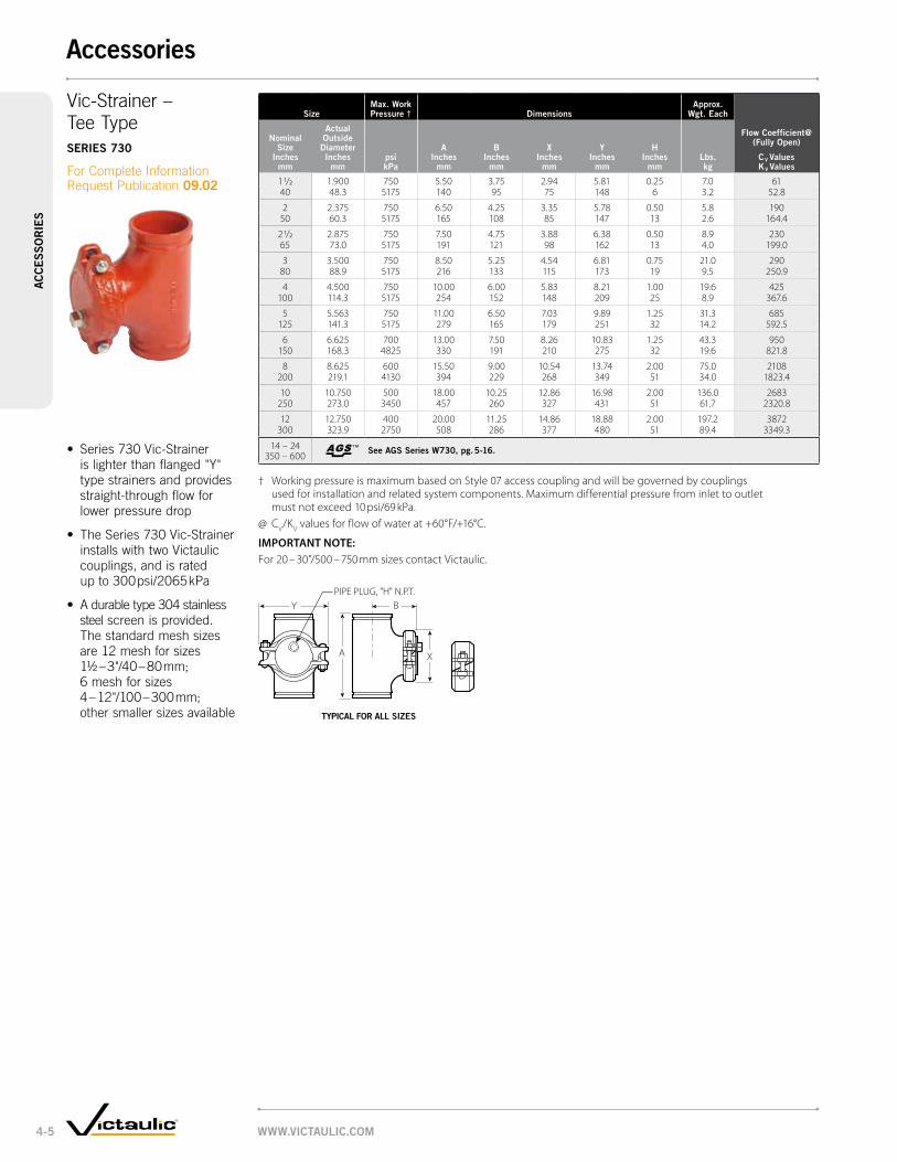
Sizemax. Work pressure † dimensions
Approx. Wgt. each
Flow coefficient@ (Fully open)
cv valuesKv values
Nominal Size
inches mm
Actual outside
diameter inches
mmpsi kpa
A inches
mm
B inches
mm
X inches
mm
y inches
mm
H inches
mm
lbs. kg
1 1/2 1.900 750 5.50 3.75 2.94 5.81 0.25 7.0 6140 48.3 5175 140 95 75 148 6 3.2 52.8
2 2.375 750 6.50 4.25 3.35 5.78 0.50 5.8 19050 60.3 5175 165 108 85 147 13 2.6 164.4
2 1/2 2.875 750 7.50 4.75 3.88 6.38 0.50 8.9 23065 73.0 5175 191 121 98 162 13 4.0 199.0
3 3.500 750 8.50 5.25 4.54 6.81 0.75 21.0 29080 88.9 5175 216 133 115 173 19 9.5 250.9
4 4.500 750 10.00 6.00 5.83 8.21 1.00 19.6 425100 114.3 5175 254 152 148 209 25 8.9 367.6
5 5.563 750 11.00 6.50 7.03 9.89 1.25 31.3 685125 141.3 5175 279 165 179 251 32 14.2 592.5
6 6.625 700 13.00 7.50 8.26 10.83 1.25 43.3 950150 168.3 4825 330 191 210 275 32 19.6 821.8
8 8.625 600 15.50 9.00 10.54 13.74 2.00 75.0 2108200 219.1 4130 394 229 268 349 51 34.0 1823.4
10 10.750 500 18.00 10.25 12.86 16.98 2.00 136.0 2683250 273.0 3450 457 260 327 431 51 61.7 2320.8
12 12.750 400 20.00 11.25 14.86 18.88 2.00 197.2 3872300 323.9 2750 508 286 377 480 51 89.4 3349.3
14 – 24 350 – 600 See AgS Series W730, pg. 5-16.
† Working pressure is maximum based on Style 07 access coupling and will be governed by couplings used for installation and related system components. Maximum differential pressure from inlet to outlet must not exceed 10 psi/69 kPa.
@ CV/KV values for flow of water at +60°F/+16°C.
important note:For 20 – 30"/500 – 750 mm sizes contact Victaulic.
™TM
A
B
X
YPIPE PLUG, "H" N.P.T.
Vic-Strainer– TeeTypeSerieS 730
ForCompleteInformation RequestPublication09.02
• Series730Vic-Strainerislighterthanflanged"Y"typestrainersandprovidesstraight-throughflowforlowerpressuredrop
• TheSeries730Vic-StrainerinstallswithtwoVictauliccouplings,andisrated upto300 psi/2065 kPa
• Adurabletype304stainlesssteelscreenisprovided. Thestandardmeshsizes are12meshforsizes 1½–3"/40–80 mm;6meshforsizes 4–12"/100–300 mm;othersmallersizesavailable typicAl For All SizeS
WWW.victAulic.com4-5
AccessoriesAc
ce
SS
or
ieS

Size
max. Work
press.† dimensions
Approx. Wgt. each
Flow coefficient@
cv valuesKv values
Nominal Size
inches mm
Actual outside
diameter inches
mmpsi kpa
A end to end
inches mm
B inches
mm
c inches
mm
d inches
mm
e inches
mm
F inches
mm
g* inches
mm
H inches
mm
lbs. kg
2 2.375 300 9.75 7.00 2.75 7.54 8.54 3.50 5.25 0.50 10.0 7250 60.3 2065 248 178 70 192 217 89 133 13 4.5 62.3
2 1/2 2.875 300 10.75 7.75 3.00 8.32 9.32 4.13 5.81 0.50 14.0 11165 73.0 2065 273 197 76 211 237 105 148 13 6.4 96.0
76.1 mm 3.000 300 10.75 7.75 3.00 8.32 9.32 4.13 5.81 0.50 14.0 11176.1 2065 273 197 76 211 237 105 148 13 6.4 96.0
3 3.500 300 11.75 8.50 3.25 9.08 10.14 4.75 6.63 0.75 20.0 16480 88.9 2065 299 216 83 231 258 121 168 19 9.1 141.9
4 4.500 300 14.25 10.50 3.75 11.06 12.36 6.25 7.94 1.00 32.0 285100 114.3 2065 362 267 95 281 314 159 202 25 14.5 246.5
5 5.563 300 16.50 12.50 4.00 13.00 14.36 7.88 9.50 1.00 50.0 410125 141.3 2065 419 318 102 330 365 200 241 25 22.7 354.7
139.7 mm 5.500 300 16.50 12.50 4.00 13.00 14.36 7.88 9.50 1.00 50.0 410139.7 2065 419 318 102 330 365 200 241 25 22.7 354.7
6 6.625 300 18.50 14.00 4.50 14.44 16.06 9.25 10.50 1.25 72.0 597150 168.3 2065 470 356 114 367 408 235 267 32 32.7 516.4
165.1 mm 6.500 300 18.50 14.00 4.50 14.44 16.06 9.25 10.50 1.25 72.0 597165.1 2065 470 356 114 367 408 235 267 32 32.7 516.4
8 8.625 300 24.00 18.00 6.00 18.38 20.50 12.38 13.19 1.50 125.0 1000200 219.1 2065 610 457 152 467 521 315 335 38 56.7 865.0
10 10.750 300 27.00 21.00 6.00 22.00 23.82 14.25 15.92 2.00 205.0 1800250 273.0 2065 686 533 152 559 605 362 404 51 93.0 1557.0
12 12.750 300 30.00 24.50 5.50 24.75 27.37 17.00 18.23 2.00 280.0 2800300 323.9 2065 762 622 140 629 695 432 463 51 127.0 2422.2
14 – 24 350 – 600 See AgS Series W732, pg. 5-17.
† Working pressure is maximum and will be governed by couplings used for installation and related system components. Maximum differential pressure from inlet to outlet must not exceed 10 psi/69 kPa.
* Dimensions will vary depending upon coupling orientation.@ CV/KV values for flow of water at +60°F/+16°C.
A
B
D
F
PIPE PLUG, "H" N.P.T."G" DIA.
E
C
Vic-Strainer– WyeTypeSerieS 732
ForCompleteInformation RequestPublication09.03
• Providesstraightthroughflowforlowerpressuredrop
• InstallswithtwoVictauliccouplings
• Durabletype304stainlesssteelperforatedbasket
• Pressureratedupto 300psi/2065kPa
• Sizesfrom 2–12"/50–300mm
typicAl For All SizeS
™TM
WWW.victAulic.com 4-6
AccessoriesAc
ce
SS
or
ieS

Sizemax. Work pressure dimensions
Approx. Wgt. each
Actual outside
diameter inches
mmpsi kpa
maximum Available movement
inches mm
X Height inches
mm
y Width inches
mm
length zNominal
Size inches
mm
minimuminches
mm
maximum inches
mmlbs. kg
2 2.375 350 3.00 3.38 5.50 11.88 14.88 15.950 60.3 2410 76.2 86 139 302 378 7.2
76.1 mm 3.000 350 3.00 4.38 6.75 12.13 15.13 38.076.1 2410 76.2 111 171 308 384 17.2
3 3.500 350 3.00 4.75 7.25 12.13 15.13 25.680 88.9 2410 76.2 121 184 308 384 11.6
4 4.500 350 3.00 6.25 9.00 14.13 17.13 39.6100 114.3 2410 76.2 159 229 359 435 18.0
5 5.563 350 3.00 7.12 10.75 14.13 17.13 55.0125 141.3 2410 76.2 181 273 359 435 24.9
139.7 mm 5.500 350 3.00 6.25 9.00 14.13 17.13 56.0139.7 2410 76.2 159 229 359 435 25.4
6 6.625 350 3.00 8.63 12.00 16.00 19.00 75.0150 168.3 2410 76.2 219 305 406 483 34.0
165.1 mm 6.500 350 3.00 8.63 12.00 16.00 19.00 75.0165.1 2410 76.2 219 305 406 483 34.0
X
Y
Z min.Z max.
Mover ExpansionJointStyle 150
ForCompleteInformation RequestPublication09.04
ExpansionJointInstallationForCompleteInformationRequestPublication09.06
• Slip-typeexpansionjoint
• Upto3/80 mmaxialendmovement
• Permitseasyadjustmentspriortoinstallationto accommodateexpansion,contractionorboth
• Serviceupto+230°F/+110°C
• Pressureratedupto 350 psi/2400 kPadependingontypeofcouplinginstalled
• Sizesfrom 2–6"/50–150mm
Forproperexpansionjointoperation,thepipingsystem mustbesectionedintoindividualstraightpiperunswith suitableanchorinstallations.Withineachpipesection, properlyspacedalignmentguidesandweightsupport devicesarealsonecessarytopermitfreeaxialpipemovement. Refertoinstallationinstructionssuppliedwitheachunit.
Wheneverpossible,theexpansionjointshouldbelocated adjacenttoananchorwithinfour(4)pipediameters. Thefirstandsecondalignmentguidesontheopposite sideoftheexpansionjointshouldbelocatedatmaximum distancesoffour(4)andfourteen(14)pipediameters, respectively.Additionalintermediateguidesshouldbe placed.Ifexpansionjointcannotbelocatedadjacent toananchor,installguidesonbothsidesoftheunit.
Inaddition,wherelonglength,lowpressureapplications mayrequirefewintermediatealignmentguides,thepipe weight,includinganyliquidcontents,mustbeadequately supported.(Forrecommendedspacingforawatersystem requestpublication26.01)
Wheninstalledtheexpansionjointcanprovidecompensation for3"/80 mmofaxialpipemovement.Expansionjointmaybesettocompensateforpipeexpansion,contraction, orsomecombination.Themovementcausedbyinstallation atatemperatureotherthantheminimumormaximum operationtemperatureshouldalsobeaccountedfor. Refertoinstallationinstructionssuppliedwitheachunit, orcontactVictaulicforrecommendations.
typicAl For All SizeS
WWW.victAulic.com4-7
AccessoriesAc
ce
SS
or
ieS

Standard units †
Size Style dimensionsApprox.
Wgt. each
Actual outside
diameter inches
mmcoupling
Style
l - length (ref.) §X
Height inches
mm
y Width inches
mm
total movement capability
inches mm
lbs. kg
Nominal Size
inches mm
compressed inches
mm
expanded inches
mm
3/4 1.050 77 26.25 28.13 2.13 3.63 1.88 17.020 26.7 667 715 54 92 48 7.7
1 1.315 77 26.25 28.13 2.38 3.88 1.88 20.025 33.7 667 715 61 99 48 9.1
1 1/4 1.660 77 28.25 30.13 2.63 4.63 1.88 28.032 42.4 718 765 67 118 48 12.7
1 1/2 1.900 77 28.25 30.13 3.00 5.00 1.88 31.040 48.3 718 765 76 127 48 14.1
2 2.375 75 28.25 30.13 3.50 5.13 1.88 27.050 60.3 718 765 89 130 48 12.2
2 1/2 2.875 75 28.25 30.13 4.00 5.88 1.88 36.065 73.0 718 765 102 149 48 16.3
3 3.500 75 28.25 30.13 4.63 6.75 1.88 46.080 88.9 718 765 118 172 48 20.9
3 1/2 4.000 75 28.25 30.13 5.25 7.38 1.88 54.090 101.6 718 765 133 188 48 24.5
4 4.500 75 26.25 28.00 5.88 8.00 1.75 54.0100 114.3 667 711 149 203 45 24.5
5 5.563 75 26.25 28.00 7.00 10.18 1.75 72.0125 141.3 667 711 178 259 45 32.7
6 6.625 75 26.25 28.00 8.13 11.00 1.75 90.0150 168.3 667 711 207 279 45 40.8
8 8.625 75 28.50 30.25 10.38 14.00 1.75 150.0200 219.1 724 768 264 356 45 68.0
10 10.750 77 32.50 34.25 13.50 16.75 1.75 320.0250 273.0 826 870 343 426 45 145.2
12 12.750 77 32.50 34.25 15.50 19.00 1.75 373.0300 323.9 826 870 394 483 45 169.2
14 – 24 350 – 600 See AgS Series W155, pg.5-4.
L
Y
X
L
Y
X
Standard ExpansionJointStyle 155
ForCompleteInformation RequestPublication09.05
The ties holding the couplings in position must be removed after installation
typicAl ¾ – 3½/20 – 90 mm SizeS typicAl 4 – 12"/100 – 300 mm SizeS
• Combinationofcouplings andshortnipplesjoined intandem
• Maybeusedasflexible connectors;buttheywillnotsimultaneouslyprovidefullexpansionandfulldeflection
• Jointsinstalledhorizontallyrequireindependentsupporttopreventdeflection,thatwillreduceavailableexpansion
• Sizesfrom ¾–12"/20–300mm
† Contact Victaulic for performance requirements not listed above.§ Dimensions may vary slightly due to tolerances.
important note:For Performance Data refer to 06.05 for Style 75 and 06.04 for Style 77.14 – 24"/350 – 600 mm sizes available in the Advanced Grooved System. Contact Victaulic for details.
™TM
WWW.victAulic.com 4-8
AccessoriesAc
ce
SS
or
ieS

Size Style 47-gt grooved × threaded Style 47-tt threaded × threaded
Nominal Size
inches mm
Actual outside dia.
inches mm
max. Working pressure
psi kpa
end to end
inches mm
Approx. Wgt. each
lbs. kg
max. Working pressure
psi kpa
end to end
inches mm
Approx. Wgt. each
lbs. kg
1/2 0.840 — — — 300 3.00 0.215 21.3 2065 76 0.1
3/4 1.050 — — — 300 3.00 0.220 26.7 2065 76 0.1
1 1.315 300 4.00 0.3 300 4.00 0.325 33.7 2065 102 0.2 2065 102 0.2
1 1/4 1.660 300 4.00 0.6 300 4.00 0.632 42.4 2065 102 0.3 2065 102 0.3
1 1/2 1.900 300 4.00 0.8 300 4.00 0.840 48.3 2065 102 0.3 2065 102 0.3
2 2.375 300 4.00 1.0 300 4.00 1.050 60.3 2065 102 0.5 2065 102 0.5
2 1/2 2.875 300 6.00 1.6 300 6.00 1.665 73.0 2065 152 0.7 2065 152 0.7
3 3.500 300 6.00 2.0 300 6.00 2.080 88.9 2065 152 0.9 2065 152 0.9
3 1/2 4.000 300 6.00 2.3 300 6.00 2.390 101.6 2065 152 1.1 2065 152 1.1
4 4.500 300 6.00 4.5 300 6.00 4.5100 114.3 2065 152 2.0 2065 152 2.0
E to E E to E
Dielectric WaterwayFittingStyle 47
ForCompleteInformation RequestPublication09.07
•Clearflow*dielectric waterwayfittingsutilize aninertnon-corrosive thermoplasticliningthat isNSF/FDAlisted
•Thethermoplasticlininginsulatestheinsideofthewaterwaytherebyinhibitingformationoflocalgalvaniccellcorrosionthatoccursbetweendissimilarmetals inthepresenceofwater
•Designedforcontinuous useattemperatures upto+230°F/+110°C
•Style47-GT(grv.×thd.) andTT(thd.×thd.)NSFListedinaccordancewithANSI/NSF61forupto180°F/82°Cpotable waterservice
•Pressureratedupto 300 psi/2065 kPa
•Sizesfrom ½–8"/15–200mm
* ClearFlow is a registered trademark of Perfection Corp.
Style 47-gt grv. × tHd.
Style 47-tt tHd. × tHd.
WWW.victAulic.com4-9
AccessoriesAc
ce
SS
or
ieS

Sizemaximum Working
pressure dimensionsApprox.
Weight eachActual outside diameter
Nominal Size
inches mm
Steel (ipS) inches
mm
copper (ctS) inches
mmpsi kpa
end to end
inches mm
lbs. kg
2 2.375 2.125 300 4.19 1.350 60.3 54.0 2065 106 0.6
2 1/2 2.875 2.625 300 6.19 3.365 73.0 66.7 2065 157 1.5
3 3.500 3.125 300 6.19 4.580 88.9 79.4 2065 157 2.0
4 4.500 4.125 300 6.19 5.8100 114.3 104.8 2065 157 2.6
5 5.563 5.125 300 6.19 7.8125 141.3 130.2 2065 157 3.5
6 6.625 6.125 300 6.19 10.1150 168.3 155.6 2065 157 4.6
8 8.625 8.125 300 6.19 15.0200 219.1 206.4 2065 157 6.8
E to E
Dielectric WaterwayFittingStyle 47
ForCompleteInformation RequestPublication09.07
•Clearflow*dielectric waterwayfittingsutilize aninertnon-corrosive thermoplasticliningthat isNSF/FDAlisted
•Thethermoplasticlininginsulatestheinsideofthewaterwaytherebyinhibitingformationoflocalgalvaniccellcorrosionthatoccursbetweendissimilarmetals inthepresenceofwater
•Designedforcontinuous useattemperatures upto+230°F/+110°C
•Style47-GG(grv.×grv.) isUL-Listedandclassified inaccordancewith ANSI/NSF61upto180°F/82°Cforpotable waterservice
•Pressureratedupto 300 psi/2065 kPa
•Sizesfrom 2–8"/50–200mm
* ClearFlow is a registered trademark of Perfection Corp.
Style 47-gg grv. × grv.grooved eNd Steel to grooved copper trANSitioN
WWW.victAulic.com 4-10
AccessoriesAc
ce
SS
or
ieS

™TM
Expansion JointStyle W155, PG. 5-4
Rigid CouplingStyle W07, PG. 5-3
Vic-300® MasterSealTM
AGS Butterfly ValvePG. 5-11, 12
Flexible CouplingStyle W77, PG. 5-3
AGS Vic-Flange® AdapterStyle W741, PG. 5-5
Triple Service Valve AssemblyPG. 5-14
Dual Disc Vic Check ValveSerieS W715, PG. 5-11
Vic-Strainer – Tee TypeSerieS W730, PG. 5-16
Wye Type Vic-Strainer ®Style W732, PG. 5-17
Suction DiffuserSerieS W731-i, PG. 5-15
Victaulic offers Advanced Groove System (AGS) couplings for systems 14-60"/350-1525mm) and a full range of 14-14"/350-600mm AGS fittings, valves and accessories – making AGS a comprehensive solution for large diameter piping. Because the AGS coupling system provides great strength and dependability in addition to speed, it’s an excellent choice over welding. Other advantages AGS joints provide over welded joints include no flame, superior seismic-shock resistance and a union at every joint for easy adjustment, system maintenance or system expansion.
Couplings
Valves
Accessories
Rigid Coupling for Stainless Steel PipeStyle W89, PG. 5-4
WWW.victaulic.com5-1
advanced Groove Systema
dva
nced
Gr
oo
ve S
ySte
m

™TM
VICTAULIC
No.W11
VICTAULIC
No.W10
VICTAULICNo.W20
VICTAULIC
No.W11
VICTAULIC
No.W10
VICTAULICNo.W35
VIC
TAU
LIC
No.
W30
VICTAULICNo.W25
VICTAULIC
No.W33
VIC
TAU
LIC
No.
W30
-R
VICTAULICNo.W50
VICTAULICNo.W51
VICTAULIC
No.W60
Wider gasket delivers more contact area for superior sealing
Deeper, wider wedge shape groove for strong,
dependable joints
Wider housing profile for greater end load capability
A complete piping system, for sizes 14 – 24"/350 – 600 mm
Fittings
90° Elbowno. W10, PG. 5-6
45° Elbowno. W11, PG. 5-6
22 ½° Elbowno. W12, PG. 5-6
90° 1½ D Long Radius Elbowno. W100, PG. 5-6
45° 1½ D Long Radius Elbowno. W110, PG. 5-6
True Wyeno. W33, PG. 5-6
Reducing Teeno. W25, PG. 5-7
Teeno. W20, PG. 5-6
45º Lateralno. W30, PG. 5-8
45° Reducing Lateralno. W30-r, PG. 5-8
Adapter Nipple AGS Grv. × Bev.no. W42, PG. 5-9
Adapter Nipple AGS Grv. × AGS Grv.no. W43, PG. 5-9
Adapter Nipple*AGS Grv. × Non-AGS Grv.no. W49, PG. 5-9
Flanged Adapter Nippleno. W45r, PG. 5-9
Concentric Reducerno. W50, PG. 5-10
Capno. W60, PG. 5-9
Eccentric Reducerno. W51, PG. 5-10
11 ¼º Elbowno. W13, PG. 5-6
Crossno. W35, PG. 5-6
* ANSI/AWWA C606 Grooved and Shouldered Joints
ProductS
1-1 Couplings
2-1 Fittings
3-1 Valves
4-1 Accessories
5-1 advanced Groove System
6-1 Hole Cut Piping System
7-1 Plain End Piping System
8-1 Grooved System for Stainless Steel Pipe
9-1 Pressfit System for Stainless Steel Pipe
10-1 Plain End Piping System for HDPE Pipe
11-1 Grooved Copper
12-1 PermaLynx System for Copper Tube
13-1 Grooved AWWA Ductile Iron Pipe
14-1 Victaulic Depend-O-Lok®
System
15-1 Aquamine Reusable PVC Products
16-1 Gaskets
17-1 Pipe Preparation Tools
18-1 Product Index
19-1 Piping Software
WWW.victaulic.com 5-2
advanced Groove Systema
dva
nced
Gr
oo
ve SyS
tem

Sizemax. Work
Pressure* psi/kPamax. end
load* lbs./nallow. Pipe end Sep.†
Bolt/nut no - Size dimensions - inches/mm
approx. Wgt. each
nominal Size
inches mm
actual outside dia.
inches mm Std. Wall
light Wall ‡ Std. Wall light Wall
inches mm inches X y Z
lbs. kg
14 14.000 350 § 350 § 55800 55800 0.25 2 - 1 x 5 1/2 15.87 20.59 4.75 48.9350 355.6 2500 2500 248310 248310 6.4 403 523 121 22.2
16 16.000 350 § 350 § 72885 72885 0.25 2 - 1 x 5 1/2 18.12 23.51 4.75 60.8400 406.4 2500 2500 324338 324338 6.4 460 597 121 27.6
18 18.000 350 § 350 § 92245 92245 0.25 2 - 1 x 5 1/2 20.22 25.53 4.75 71.2450 457.0 2500 2500 410490 410490 6.4 514 648 121 32.3
20 20.000 350 § 350 § 113880 113880 0.25 2 - 1 1/8 x 5 1/2 22.44 27.13 4.75 81.7500 508.0 2500 2500 506766 506766 6.4 570 389 121 37.1
24 24.000 350 § 225 § 163990 104955 0.25 2 - 1 1/8 x 5 1/2 26.64 32.31 4.75 116.2600 610.0 2500 1600 729756 467050 6.4 677 821 121 52.7
* Working Pressure and End Load are total, from all internal and external loads, based on standard weight (ANSI) steel pipe, AGS roll grooved in accordance with Victaulic specifications. Contact Victaulic for performance on other pipe.
§ Pressure ratings have been rounded for global use. Actual maximum work-ing pressure for lightwall in 14-20"/350-500mm sizes is 363 psi/2500kPa; 24"/600mm is 232 psi/1600kPa and standard wall 14-24"/350-500mm sizes is 363 psi/2500kPa.
WARNING: FOR ONE TIME FIELD TEST ONLY, the Maximum Joint Working Pressure may be increased to 1 ½ times the figures shown.
‡ Lightwall 14"/350mm=.22"/5.6mm; 16-24"/400-600mm=0.25"/6.35 mm# For field installation only on roll grooved pipe. Style W07 AGS couplings
are essentially rigid and do not permit expansion/contraction.
important notes:Metric thread size bolts are available (color coded gold) for all coupling sizes upon request. Contact Victaulic for details.Style W07 AGS couplings must not be used to join PVC pipe.
Sizemax. Work
Pressure* psi/kPamax. end
load* lbs./nallow. Pipe end Sep.†
Bolt/nut no - Size dimensions - inches/mm
approx. Wgt. each
nominal Size
inches mm
actual outside dia.
inches mm Std. Wall
light Wall ‡ Std. Wall light Wall
inches mm inches X y Z
lbs. kg
14 14.000 350 § 350 § 55800 55800 0.13 - 0.31 2 - 1 x 5 1/2 16.00 20.59 4.50 47.5350 355.6 2500 2500 248310 248310 3.3 - 7.9 406 523 114 21.5
16 16.000 350 § 350 § 72885 72885 0.13 - 0.31 2 - 1 x 5 1/2 18.18 23.51 4.50 57.8400 406.4 2500 2500 324338 324338 3.3 - 7.9 462 597 114 26.2
18 18.000 350 § 350 § 92245 92245 0.13 - 0.31 2 - 1 x 5 1/2 20.36 25.46 4.50 65.0450 457.2 2500 2500 410490 410490 3.3 - 7.9 517 647 114 29.5
20 20.000 350 § 350 § 113880 113880 0.13 - 0.31 2 - 1 1/8 x 5 1/2 22.56 27.13 4.50 82.3500 508.0 2500 2500 506766 506766 3.3 - 7.9 573 389 114 37.3
24 24.000 350 § 225 § 163990 104955 0.13 - 0.31 2 - 1 1/8 x 5 1/2 26.88 32.31 4.50 106.8600 609.6 2500 1600 729756 467050 3.3 - 7.9 683 821 114 48.4
* Working Pressure and End Load are total, from all internal and external loads, based on standard weight (ANSI) steel pipe, AGS roll grooved in accordance with Victaulic specifications. Contact Victaulic for performance on other pipe.
§ Pressure ratings have been rounded for global use. Actual maximum working pressure for lightwall in 14-20"/350-500mm sizes is 363 psi/2500 kPa; 24"/600mm is 232 psi/1600 kPa and standard all 14-24"/350-500mm sizes is 363psi/2500kPa. WARNING: FOR ONE TIME FIELD TEST ONLY, the Maximum Joint Working
Pressure may be increased to 1 ½ times the figures shown.† Allowable Pipe End Separation figures show the maximum nominal
range of movement available at each joint for AGS roll grooved pipe. These figures are maximums; for design and installation purposes these figures should be reduced by 25%. Refer to General Notes on pg. 15.
important notes:Metric thread size bolts are available (color coded gold) for all coupling sizes upon request. Contact Victaulic for details.Style W77 AGS couplings must not be used to join PVC pipe.
™TM
Y Z
X
Y Z
X
Rigid CouplingStyle W07
For Complete Information Request Publication 20.02
Flexible CouplingStyle W77
For Complete Information Request Publication 20.03
• StyleW07isthefirst two-piece, flat pad, metal-to-metal rigid coupling in this size range
• Supportandhanging requirements correspond to ASME B31.1 Power Piping code and ASME B31.9 Building Services code
• Pressureratedupto 350 psi/2400 kPa
• StyleW77istheonly flexible two-piece housing for this size range on the market today
• StyleW77provideslimitedlinear angular movement to accommodate thermal pipe growth, vibration attenu-ation, seismic and other design considerations that require flexibility
• Pressureratedupto 350 psi/2400 kPa
tyPical for all SiZeS
tyPical for all SiZeS
WWW.victaulic.com5-3
ad
van
ced
Gr
oo
ve S
ySte
madvanced Groove System – couplings

Size Schedule 10Sallow. Pipe end Sep.†
Bolt/nut no - Size dimensions
approx. Wgt. each
nominal Size
inches mm
actual outside dia.
inches mm
max. Work. Pressure*
psi kPa
max. end load* lbs. n
inches mm inches
X inches
mm
y inches
mm
Z inches
mm lbs. kg
14 14.000 300 46200 0.25 2 - 1 1/8 x 5 1/2 16.50 21.38 4.81 65.0350 355.6 2065 205590 6.4 419 543 122 29.5
16 16.000 300 60320 0.25 2 - 1 1/8 x 5 1/2 18.88 23.50 4.81 80.0400 406.4 2065 268424 6.4 480 597 122 36.4
18 18.000 300 76350 0.25 2 - 1 1/8 x 5 1/2 21.00 25.63 4.81 93.0450 457.0 2065 339758 6.4 533 651 122 42.3
20 20.000 300 94250 0.25 2 - 1 1/8 x 5 1/2 23.75 27.63 4.81 114.0500 508.0 2065 419413 6.4 603 702 122 51.8
24 24.000 300 135700 0.25 2 - 1 1/8 x 5 1/2 30.00 32.00 4.81 182.0600 610.0 2065 603865 6.4 762 813 122 82.6
* Working Pressure and End Load are total, from all internal and external loads, based on stainless steel pipe, AGS roll grooved in accordance with Victaulic specifications. “RWX” rolls must be used for Schedule 10S. Contact Victaulic for performance on other pipe.
WARNING: FOR ONE TIME FIELD TEST ONLY, the Maximum Joint Working Pressure may be increased to 1 ½ times the figures shown.
† For field installation only on roll grooved pipe. Style W89 AGS couplings are essentially rigid and do not permit expansion/contraction.
important notes:Metric thread size bolts are available (color coded gold) for all coupling sizes upon request. Contact Victaulic for details.
™TM
Y Z
X
Rigid Coupling for Stainless Steel PipeStyle W89
For Complete Information Request Publication 20.15
• Pressureratedupto 300 psi/2065 kPa
• StyleW89RigidCouplinggreatly reduces linear or angular movement where rigid joint is required
tyPical for all SiZeS
Size Style dimensions – inches/mmapprox.
Wgt. each
nominal Size
inches mm
actual outside dia.
inches mm coupling Style
l – length (ref.) §X
Heighty
Width
total minimum movement capability
lbs. kgcompressed expanded
14 14.000 W77 30.00 31.75 16.63 20.00 1.75 423.0350 355.6 762 807 422 508 45 191.9
16 16.000 W77 30.00 31.75 19.00 22.38 1.75 500.0400 406.4 762 807 483 569 45 226.8
18 18.000 W77 30.00 28.00 21.25 24.38 1.75 632.0450 457.0 762 31.75 540 619 45 286.7
20 20.000 W77 30.00 31.75 23.63 27.50 1.75 800.0500 508.0 762 807 600 699 45 362.9
24 24.000 W77 30.00 31.75 27.63 31.38 1.75 840.0600 610.0 762 807 702 797 45 381.0
Expansion JointStyle W155
For Complete Information Request Publication 20.12
• Combinationofcouplingsand short nipples joined in tandem
• Nipplesareprecisely grooved to provide full linear allowance at each joint
• Maybeusedasflexible connectors, but will not simultaneously provide full expansion and full deflection
• Expansionjointsinstalled horizontally require independent support to prevent deflection that will reduce the available expansion
• Sizesfrom14-24”/ 350-600mm
L
tyPical for SiZeS 14-16”/350-600mm
Y
X
WWW.victaulic.com 5-4
ad
van
ced
Gr
oo
ve SyS
temadvanced Groove System – couplings
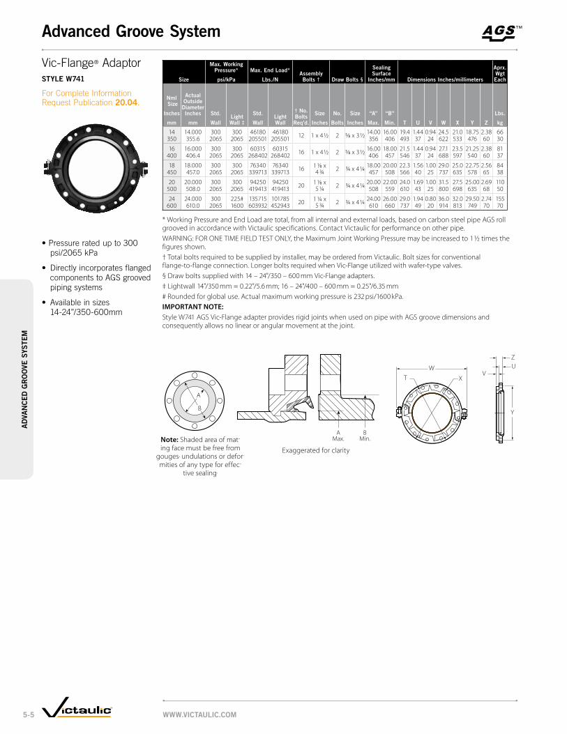
™TM
Size
max. Working Pressure*
psi/kPa
max. end load*
lbs./nassembly Bolts † draw Bolts §
Sealing Surface
inches/mm dimensions inches/millimeters
aprx. Wgt each
nml Size
inches
mm
actual outside
diameter inches
mm
Std.
Walllight Wall ‡
Std.
Walllight Wall
† no. Bolts req’d.
Size
inches
no.
Bolts
Size
inches
“a”
max.
“B”
min. t u v W X y Z
lbs.
kg
14 14.000 300 300 46180 46180 12 1 x 4 ½ 2 5/8 x 3 ½ 14.00 16.00 19.4 1.44 0.94 24.5 21.0 18.75 2.38 66350 355.6 2065 2065 205501 205501 356 406 493 37 24 622 533 476 60 30
16 16.000 300 300 60315 60315 16 1 x 4 ½ 2 5/8 x 3 ½ 16.00 18.00 21.5 1.44 0.94 27.1 23.5 21.25 2.38 81400 406.4 2065 2065 268402 268402 406 457 546 37 24 688 597 540 60 37
18 18.000 300 300 76340 76340 16 1 1/8 x 4 3/4 2 3/4 x 4 1/4 18.00 20.00 22.3 1.56 1.00 29.0 25.0 22.75 2.56 84
450 457.0 2065 2065 339713 339713 457 508 566 40 25 737 635 578 65 38
20 20.000 300 300 94250 94250 20 1 1/8 x 5 1/4 2 3/4 x 4 1/4 20.00 22.00 24.0 1.69 1.00 31.5 27.5 25.00 2.69 110
500 508.0 2065 2065 419413 419413 508 559 610 43 25 800 698 635 68 50
24 24.000 300 225# 135715 101785 20 1 1/4 x 5 3/4 2 3/4 x 4 1/4 24.00 26.00 29.0 1.94 0.80 36.0 32.0 29.50 2.74 155
600 610.0 2065 1600 603932 452943 610 660 737 49 20 914 813 749 70 70
* Working Pressure and End Load are total, from all internal and external loads, based on carbon steel pipe AGS roll grooved in accordance with Victaulic specifications. Contact Victaulic for performance on other pipe.WARNING: FOR ONE TIME FIELD TEST ONLY, the Maximum Joint Working Pressure may be increased to 1 ½ times the figures shown.† Total bolts required to be supplied by installer, may be ordered from Victaulic. Bolt sizes for conventional flange-to-flange connection. Longer bolts required when Vic-Flange utilized with wafer-type valves.§ Draw bolts supplied with 14 – 24"/350 – 600 mm Vic-Flange adapters.‡ Lightwall 14"/350 mm = 0.22"/5.6 mm; 16 – 24"/400 – 600 mm = 0.25"/6.35 mm# Rounded for global use. Actual maximum working pressure is 232 psi/1600 kPa.important note:Style W741 AGS Vic-Flange adapter provides rigid joints when used on pipe with AGS groove dimensions and consequently allows no linear or angular movement at the joint.
Y
V
ZU
TW
X
note: Shaded area of mating face must be free from
gouges, undulations or deformities of any type for effec
tive sealing.
AMax.
BMin.
Exaggerated for clarity
Y
V
ZU
TW
X
A
BW
Vic-Flange® AdaptorStyle W741
For Complete Information Request Publication 20.04.
•Pressureratedupto300 psi/2065 kPa
• Directlyincorporatesflangedcomponents to AGS grooved piping systems
• Availableinsizes14-24”/350-600mm
WWW.victaulic.com5-5
advanced Groove Systema
dva
nced
Gr
oo
ve S
ySte
m

Sizeno. W10
90º elbowno. W11
45º elbowno. W12
22½° elbow (sw)no. W13
11¼° elbow (sw)no. W100 †*
90° long radius elbow (S)no. W110 †*
45° long radius elbow (S)
nominal Size
inches mm
actual outside dia.
inches mm
c to e inches
mm
approx. Wgt. each
lbs. kg
c to e inches
mm
approx. Wgt. each
lbs. kg
c to e inches
mm
approx. Wgt. each
lbs. kg
c to e inches
mm
approx. Wgt. each
lbs. kg
c to e inches
mm
approx. Wgt. each
lbs. kg
c to e inches
mm
approx. Wgt. each
lbs. kg
14 14.000 14.00 150.8 5.80 63.0 5.00 46.0 3.50 32.0 21.00 158.0 8.75 83.0350 355.6 355.6 68.4 147 28.7 127 20.9 89 14.5 533 71.7 222 37.6
16 16.000 16.00 184.3 6.63 93.8 5.00 52.1 4.00 42.0 24.00 204.3 10.00 101.0400 406.4 406.4 83.6 168 42.5 127 23.6 102 19.1 610 92.7 254 45.8
18 18.000 18.00 272.3 7.46 129.0 5.50 65.0 4.50 53.2 27.00 260.0 11.25 127.0450 457.0 457.0 123.5 189 58.5 140 29.5 114 24.1 686 118.0 286 57.6
20 20.000 20.00 312.0 8.28 165.3 6.00 78.6 5.00 65.0 30.00 328.5 12.50 167.0500 508.0 508.0 141.5 210 75.0 152 36.0 127 29.5 762 149.0 318 75.7
24 24.000 24.00 559.8 9.94 264.5 7.00 110.3 6.00 94.5 36.00 490.0 15.00 244.8600 610.0 610.0 253.9 252 120.0 178 50.0 152 42.9 914 222.3 381 110.1
# Ductile iron except those marked (sw) which are segmentally welded steel or (S) which are steel.† For the U.S. 14"/350 mm, 16"/400 mm, 18"/450 mm, 20"/500 mm, 24"/600 mm elbows (90°, 45°)
are 1 ½ D long radius forged steel elbows No. W100 and No. W110.* Available for special order.
Sizeno. W20
teeno. W35 cross (sw)
no. W33 true Wye (sw)
nominal Size
inches mm
actual outside diameter
inches mm
c to e inches
mm
approx. Weight each
lbs. kg
c to e inches
mm
approx. Weight each
lbs. kg
c to le inches
mm
c to Se inches
mm
approx. Weight each
lbs. kg
14 14.000 11.00 102.0 11.00 121.0 11.00 7.50 98.0350 355.6 279 46.3 279 54.9 279 191 44.4
16 16.000 12.00 123.5 12.00 146.4 12.00 8.00 119.3400 406.4 305 56.0 305 66.4 305 203 54.1
18 18.000 13.50 281.0 13.50 185.4 13.50 8.50 148.3450 457.0 343 127.5 343 84.1 343 216 67.3
20 20.000 15.00 350.0 15.00 229.1 15.00 9.00 180.4500 508.0 381 158.7 381 103.9 381 229 81.8
24 24.000 17.00 503.7 17.00 298.7 17.00 10.00 238.3600 610.0 432 228.5 432 135.5 432 254 108.1
# Ductile iron except those marked with (sw) which are segmentally welded.
™TM
C to EC to E
VICTAULIC
No.W100
Cto E
C to E
VICTAULIC
No.W110
C toE
VICTAULICNo.W35
C to E
VICTAULIC
No.W33
C toLE
C toSE
VICTAULIC
No.W10C
to E
C to E
VICTAULIC
No.W11
C toE
VICTAULICNo.W20
no. W10 no. W11 no. W12 no. W13 no. W100 no. W110
Elbowsno. W10 90º Elbowno. W11 45º Elbowno. W12 22½º Elbowno. W13 11¼º Elbowno. W100 90º Long Radiusno. W110 45º Long Radius(Ductile Iron#)
Request Publication 20.05
no. W20 no. W35 no. W33
Tees, Crosses and Wyesno. W20 Tee no. W35 Crossno. W33 True Wye(Ductile Iron#)
For Complete Information Request Publication 20.05
WWW.victaulic.com 5-6
ad
van
ced
Gr
oo
ve SyS
temadvanced Groove System – fittings

Sizeno. W25
reducing teeapprox.
Weight each
nominal Size
inches mm
c to le inches
mm
c to Se inches
mm
lbs. kg
14 × 14 × 6 11.00 9.38 101.4350 350 150 279 238 46.0
8 11.00 9.75 102.5200 279 248 46.5
10 11.00 10.12 105.1250 279 257 47.7
12 11.00 10.62 108.1300 279 270 49.0
16 × 16 × 6 12.00 10.38 126.2400 400 150 305 264 57.2
8 12.00 10.75 127.4200 305 273 57.8
10 12.00 11.12 129.8250 305 282 58.9
12 12.00 11.62 132.5300 305 295 60.1
14 12.00 12.00 134.6350 305 305 61.1
18 × 18 × 6 13.50 11.38 160.0450 450 150 343 289 72.6
8 13.50 11.75 161.0200 343 298 73.0
10 13.50 12.12 163.1250 343 308 74.0
12 13.50 12.62 165.6300 343 321 75.1
14 13.50 13.00 167.6350 343 330 76.0
16 13.50 13.00 168.2400 343 330 76.3
* Cast fitting available. Contact Victaulic for details.
important note: Outlets 12"/300 mm and smaller will be provided with standard Victaulic roll or cut grooves, suitable for use with standard Victaulic grooved couplings in that size range.
Sizeno. W25
reducing teeapprox.
Weight each
nominal Size
inches mm
c to le inches
mm
c to Se inches
mm
lbs. kg
20 × 20 × 6 15.00 12.38 197.0500 500 150 381 314 89.5
8 15.00 12.75 198.5200 381 324 90.0
10 15.00 13.12 200.5250 381 333 90.9
12 15.00 13.62 202.9300 381 346 92.0
14 * 15.00 14.00 204.7350 381 356 92.9
16 * 15.00 14.00 205.0400 381 356 93.0
18 15.00 14.50 208.4450 381 368 94.5
24 × 24 × 6 17.00 14.38 260.9600 600 150 432 365 122.0
8 17.00 14.75 270.0200 432 375 123.0
10 17.00 15.12 271.7250 432 384 123.2
12 17.00 15.62 273.8300 432 397 124.2
14 17.00 16.00 275.4350 432 406 125.0
16 17.00 16.00 275.4400 432 406 125.0
18 17.00 16.50 278.1450 432 419 127.1
20 17.00 17.00 282.1500 432 432 128.0
™TM
VICTAULICNo.W25
C toSE
C toLE
Reducing Teeno. W25 (Segmentally Welded Steel)
For Complete Information Request Publication 20.05
no. W25
WWW.victaulic.com5-7
ad
van
ced
Gr
oo
ve S
ySte
madvanced Groove System – fittings

Sizeno. W30-r
reducing lateral
nominal Size
inches mm
c to le inches
mm
c to Se inches
mm
approx. Weight each
lbs. kg
14 × 14 × 4 26.50 7.50 175.9350 350 100 673 191 79.8
6 26.50 7.50 185.9150 673 191 84.3
8 26.50 7.50 195.0200 673 191 88.4
10 26.50 7.50 204.4250 673 191 92.7
12 26.50 7.50 213.3300 673 191 96.8
16 × 16 × 6 29.00 8.00 226.4400 400 150 737 203 102.7
8 29.00 8.00 236.0200 737 203 107.1
10 29.00 8.00 246.0250 737 203 111.6
12 29.00 8.00 255.1300 737 203 115.7
14 29.00 8.00 260.9350 737 203 118.4
18 × 18 × 6 32.00 8.50 274.8450 450 150 813 216 214.6
8 32.00 8.50 285.3200 813 216 129.4
12 32.00 8.50 306.2300 813 216 138.9
14 32.00 8.50 312.4350 813 216 141.7
16 32.00 8.50 322.4400 813 216 146.2
20 × 20 × 12 35.00 9.00 362.1500 500 300 889 229 164.3
14 35.00 9.00 368.7350 889 229 167.2
16 35.00 9.00 379.4400 889 229 172.1
24 × 24 × 16 40.00 10.00 494.9600 600 400 1016 254 224.5
20 40.00 10.00 517.7600 1016 254 254.8
important note: Outlets 12"/300 mm and smaller will be provided with standard Victaulic roll or cut groove, suitable for use with standard Victaulic grooved couplings in that size range.
Sizeno. W30
45º lateral
nominal Size
inches mm
actual outside diameter
inches mm
c to le inches
mm
c to Se inches
mm
approx. Weight each
lbs. kg
14 14.000 26.50 7.50 219.1350 355.6 673 191 99.4
16 16.000 29.00 8.00 270.5400 406.4 737 203 122.7
18 18.000 32.00 8.50 332.7450 457.0 813 216 150.9
20 20.000 35.00 9.00 401.3500 508.0 889 229 182.0
24 24.000 40.00 10.00 541.3600 610.0 1016 254 245.5
™TM
VIC
TAU
LIC
No.
W30
C toLE
C toSE
C to LE
C toLE
C toSE
C to LE
VIC
TAU
LIC
No.
W30
-R
45° Lateralno. W30 (Segmentally Welded Steel)
For Complete Information Request Publication 20.05
45º Reducing Lateralno. W30-r (Segmentally Welded Steel)
For Complete Information Request Publication 20.05
no. W30 no. W30-r
WWW.victaulic.com 5-8
ad
van
ced
Gr
oo
ve SyS
temadvanced Groove System – fittings

Sizeno. W60
cap
nominal Size
inches mm
actual outside diameter
inches mm
t thickness
inches mm
approx. Weight each
lbs. kg
14 14.000 6.50 33.2350 355.6 165 15.1
16 16.000 7.00 41.2400 406.4 178 18.7
18 18.000 8.00 54.6450 457.0 203 24.8
20 20.000 9.00 67.5500 508.0 229 30.6
24 24.000 10.50 96.0600 610.0 267 43.5
Sizeno. W42, W43, W49 adapter nipple (sw)
nominal Size
inches mm
actual outside diameter
inches mm
e to e inches
mm
approx. Weight each
lbs. kg
14 14.000 8.00 36.0350 355.6 203 16.3
16 16.000 8.00 42.0400 406.4 203 19.1
18 18.000 8.00 47.0450 457.0 203 21.3
20 20.000 8.00 52.0500 508.0 203 23.6
24 24.000 8.00 63.0600 610.0 203 28.6
Sizeno. W45r
flanged adapter nipple
nominal Size
inches mm
actual outside diameter
inches mm
e to e inches
mm
approx. Weight each
lbs. kg
14 14.000 8.00 122.0350 355.6 203 55.3
16 16.000 8.00 136.0400 406.4 203 61.7
18 18.000 8.00 168.0450 457.0 203 76.2
20 20.000 8.00 208.0500 508.0 203 94.3
24 24.000 8.00 274.0600 610.0 203 124.3
™TM
VICTAULIC
No.W60
T
E to E E to E E to E
E to E
Adapter Nippleno. W42 AGS Grv. × Bev.no. W43 AGS Grv. × AGS Grv.no. W49 AGS Grv. × Non-AGS Grv.(Steel)
Request Publication 20.05
Cap no. W60 (Steel)
For Complete Information Request Publication 20.05
Flanged Adapter Nippleno. W45r ANSI Class 150 Raised Face (Steel)
For Complete Information Request Publication 20.05
no. W42 no. W43 no. W49
no. W60
no. W45r
WWW.victaulic.com5-9
ad
van
ced
Gr
oo
ve S
ySte
madvanced Groove System – fittings

Sizeno. W50
concentric reducerno. W51
eccentric reducer
nominal Size
inches mm
e to e inches
mm
approx. Weight each
lbs. kg
e to e inches
mm
approx. Weight each
lbs. kg
14 × 6 13.00 68.0 13.00 68.0350 150 330 30.8 330 30.8
8 13.00 70.0 13.00 70.0200 330 31.8 330 31.8
10 13.00 72.0 13.00 72.0250 330 32.7 330 32.7
12 13.00 74.0 13.00 74.0300 330 33.6 330 33.6
16 × 8 14.00 88.0 14.00 88.0400 200 356 39.9 356 39.9
10 13.00 91.0 13.00 91.0250 330 41.3 330 41.3
12 14.00 93.0 14.00 93.0300 356 42.2 356 42.2
14 14.00 95.0 14.00 95.0350 356 43.1 356 43.1
18 × 14 15.00 112.0 15.00 112.0450 350 381 50.8 381 50.8
16 15.00 115.0 15.00 115.0400 381 52.2 381 52.2
18 15.00 118.0 15.00 118.0450 381 53.5 381 53.5
20 15.00 121.1 15.00 121.1500 381 54.9 381 54.9
† Some fitting sizes are available in cast ductile iron. Contact Victaulic for details.
important note: Outlets 12"/300 mm and smaller will be provided with standard Victaulic roll or cut grooves, suitable for use with standard Victaulic grooved couplings in that size range.
Sizeno. W50
concentric reducerno. W51
eccentric reducer
nominal Size
inches mm
e to e inches
mm
approx. Weight each
lbs. kg
e to e inches
mm
approx. Weight each
lbs. kg
20 × 12 20.00 160.0 20.00 160.0500 300 508 72.6 508 72.6
14 20.00 164.0 20.00 164.0350 508 74.4 508 74.4
16 20.00 168.0 20.00 168.0400 508 76.2 508 76.2
18 20.00 172.0 20.00 172.0450 508 78.0 508 78.0
24 × 16 20.00 198.0 20.00 198.0600 400 508 89.9 508 89.9
18 20.00 200.0 20.00 200.0450 508 90.7 508 90.7
20 20.00 204.0 20.00 204.0500 508 92.5 508 92.5
™TM
VICTAULICNo.W50
Eto E
VICTAULICNo.W51E to E
Concentric/Eccentric Reducerno. W50 Concentricno. W51 Eccentric(Steel †)
For Complete Information Request Publication 20.05
no. W50 no. W51
WWW.victaulic.com 5-10
ad
van
ced
Gr
oo
ve SyS
temadvanced Groove System – fittings

Size dimensions approx.
Weight eachflow coefficient@
(fully open)
cv valuesKv values
nominal Size
inches mm
actual outside diameter
inches mm
a end to end
inches mm
B
inches mm
c inches
mmlbs. kg
14 14.000 10.75 16.93 14.38 140.0 6000350 355.6 273 430 366 64.0 5190.0
16 16.000 12.00 19.88 16.38 160.0 8300400 406.4 305 505 416 73.0 7179.5
18 18.000 14.25 21.54 18.38 180.0 10500450 457.0 362 547 467 82.0 9082.5
20 20.000 14.50 24.75 20.38 200.0 13800500 508.0 368 628 518 91.0 11937.0
24 24.000 15.50 28.81 24.38 240.0 20500600 610.0 394 732 620 109.0 17732.5
@ CV/KV values for flow of water at +60°F/+16°C with valve fully open.
™TM
C
A
B
tyPical for all SiZeS
Dual Disc Vic Check ValveSerieS W715
For Complete Information Request Publication 20.08
• Canbeinstalledinboth horizontal or vertical “flowup”positions
• Constructedofrugged ductile iron, the valve features an EPDM seat bonded to the body and a 304 stainless steel disc and shaft
• Utilizesaspring-assisted,dual disc design that achieves drop tight sealing over the full 230 psi/16 Bar pressure rating
• Sizesfrom 14 – 24"/350 – 600 mm
WWW.victaulic.com5-11
ad
van
ced
Gr
oo
ve S
ySte
madvanced Groove System – valves
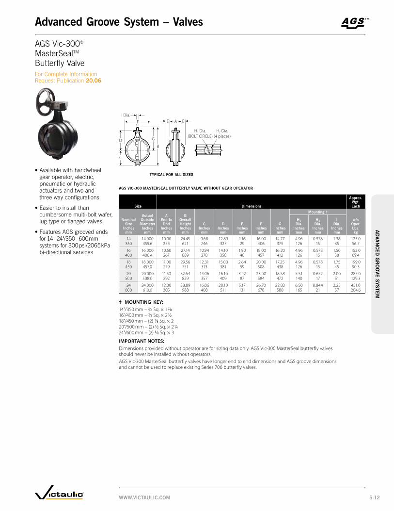
aGS vic-300 maSterSeal Butterfly valve WitHout Gear oPerator
Size dimensions
approx. Wgt. each
actual outside
diameter inches
mm
a end to end
inches mm
B overall Height inches
mm
mounting †
nominal Size
inches mm
c inches
mm
d inches
mm
e inches
mm
f inches
mm
G inches
mm
H1 dia.
inches mm
H2 dia.
inches mm
i dia.
inches mm
w/o oper. lbs. kg
14 14.000 10.00 24.45 9.68 12.89 1.16 16.00 14.77 4.96 0.578 1.38 125.0350 355.6 254 621 246 327 29 406 375 126 15 35 56.7
16 16.000 10.50 27.14 10.94 14.10 1.90 18.00 16.20 4.96 0.578 1.50 153.0400 406.4 267 689 278 358 48 457 412 126 15 38 69.4
18 18.000 11.00 29.56 12.31 15.00 2.64 20.00 17.25 4.96 0.578 1.75 199.0450 457.0 279 751 313 381 59 508 438 126 15 45 90.3
20 20.000 11.50 32.64 14.06 16.10 3.42 23.00 18.58 5.51 0.672 2.00 285.0500 508.0 292 829 357 409 87 584 472 140 17 51 129.3
24 24.000 12.00 38.89 16.06 20.10 5.17 26.70 22.83 6.50 0.844 2.25 451.0600 610.0 305 988 408 511 131 678 580 165 21 57 204.6
† mounting Key: 14"/350 mm – 3/8 Sq. × 1 7/816"/400 mm – 3/8 Sq. × 2 1/218"/450 mm – (2) 3/8 Sq. × 220"/500 mm – (2) 1/2 Sq. × 2 1/424"/600 mm – (2) 5/8 Sq. × 3
important notes: Dimensions provided without operator are for sizing data only. AGS Vic-300 MasterSeal butterfly valves should never be installed without operators.AGS Vic-300 MasterSeal butterfly valves have longer end to end dimensions and AGS groove dimensions and cannot be used to replace existing Series 706 butterfly valves.
™TM
C
F
G
B
E A E
H1 Dia.(BOLT CIRCLE)
H2 Dia.(4 places)
I Dia.
D
AGS Vic-300® MasterSealTM Butterfly ValveFor Complete Information Request Publication 20.06
•Availablewithhandwheelgear operator, electric, pneumatic or hydraulic actuators and two and three way configurations
•Easiertoinstallthan cumbersome multi-bolt wafer, lug type or flanged valves
•FeaturesAGSgroovedendsfor 14 – 24"/350 – 600 mm systems for 300 psi/2065 kPa bi-directional services
tyPical for all SiZeS
WWW.victaulic.com 5-12
ad
van
ced
Gr
oo
ve SyS
temadvanced Groove System – valves

aGS vic-300 maSterSeal Butterfly valve WitH Gear oPerator
Size dimensions
approx. Wgt. each
flow coefficient@ (fully open)
cv valuesKv values
actual outside
diameter inches
mm
a end to end
inches mm
B overall Height inches
mm
Handwheel chain Wheel
nominal Size
inches mm
c inches
mm
d inches
mm
f inches
mm
G inches
mm
K inches
mm
n1
dia.inches
mm
o1
inches mm
n2
dia.inches
mm
o2
inches mm
t inches
mm
no. turns
to close
lbs. kg
14 14.000 10.00 26.17 9.68 12.89 16.00 14.54 7.87 19.70 12.86 21.50 16.00 3.02 9.5 156.0 9360350 355.6 254 665 246 327 406 367 200 500 327 546 406 77 70.8 8096.4
16 16.000 10.50 29.00 10.94 14.10 18.00 15.99 8.66 19.70 14.34 21.50 17.47 3.38 13.75 201.0 12400400 406.4 267 737 278 358 457 406 220 500 364 546 444 86 91.2 10726.0
18 18.000 11.00 32.17 12.31 15.00 20.00 17.17 11.22 27.60 15.55 30.00 18.68 4.38 21 269.5 15900450 457.0 279 817 313 381 508 436 285 700 395 762 474 111 122.2 13753.5
20 20.000 11.50 36.23 14.06 16.10 23.00 18.27 11.22 27.60 18.43 30.00 21.60 5.38 52 384.2 19800500 508.0 292 920 357 409 584 464 285 700 468 762 549 137 174.3 17127.0
24 24.000 12.00 42.41 16.06 20.10 26.70 22.42 14.57 27.60 20.51 30.00 23.60 5.38 79.25 605.0 28900600 610.0 305 1017 408 511 678 569 370 700 521 762 599 137 274.4 24998.5
@ CV/KV values for flow of water at +60°F/+16°C with valve fully open.
™TM
A
O1
K
T N1
Dia.N2
Dia.
O2
D
C
F
G
B
tyPical for all SiZeS
AGS Vic-300® MasterSealTM Butterfly ValveFor Complete Information Request Publication 20.06
WWW.victaulic.com5-13
ad
van
ced
Gr
oo
ve S
ySte
madvanced Groove System

™TM
dimenSionS
valve Size dimensions – inches/millimeters
approx. assembly Wgt.
lbs/kg
nominal diameter
inches/mm
actual outside
diameterinches/mm
ainches/mm
Binches/mm
cinches/mm
dinches/mm
14 14 29.25 14.50 19.75 24.50 430350 355.6 743.0 368.3 501.7 622.3 195.0
16 16 31.00 16.00 19.75 25.88 525400 406.4 787.4 406.4 501.7 657.4 238.1
18 18 33.75 17.13 27.63 31.00 639450 457.2 857.3 435.1 701.8 787.4 289.9
20 20 34.50 18.25 27.63 32.13 799500 508.0 876.3 463.6 701.8 816.1 362.4
24 24 36.00 22.50 27.63 36.25 1140600 609.6 914.4 571.5 701.8 920.8 517.1
aGS tri-Service Butterfly/cHecK valve comBination
B
A
C
D
Style W07 AGS Rigid Coupling*
Series W715 AGS Check Valve
Series W761 AGS Vic 300 Butterfly Valve
FLOWStyle W07 AGS Rigid Coupling*
Victaulic No. 43 Nipple or a spool piece provided by contractor
14 – 24"/350 – 600mm tyPical WitH SerieS W761 aGS vic-300 Butterfly valveS and SerieS W715 aGS vic-cHecK valveS
Triple Service Valve AssemblyFor Complete Information Request Publication 20.18
• AssemblyoftheSeries W761 AGS Vic-300 butterfly valve and Series W715 AGS Vic-Check valve
• Providesshut-off, throttling with positive mechanical memory and non-slam check service in one unit.
• Availableinsizes 14-24”/350-600mm
• Pressureratedupto 232psi/1600kPa.
WWW.victaulic.com 5-14
advanced Groove Systema
dva
nced
Gr
oo
ve SyS
tem

Size dimensions inches/mmapprox.
Wgt. eachSystem
Side inlet
×Pump Side
outlet
d
nominal Size inches
mm c-e1 c-e2 clr c-o l oal oaWlbs. kg
14 × 10 – 23.13 28.00 17.13 5.32 8.93 29.00 17.25 410.0350 250 – 588 711 435 135 227 737 438 186.0
12 11.00 – 35.00 24.13 588 9.95 37.50 20.25 434.0300 279 – 889 613 149 253 953 514 196.9
14 – 26.13 39.00 26.13 6.88 11.03 40.56 24.50 711.0350 – 664 991 664 175 280 1030 622 322.5
16 × 12 – 26.13 35.00 24.13 5.88 9.95 37.50 17.25 583.0400 300 – 664 889 613 149 253 953 438 264.5
14 12.00 – 39.00 26.13 6.88 11.03 40.56 24.50 551.0350 305 – 991 664 175 280 1030 622 249.9
18 × 16 13.50 – 43.00 28.63 7.88 12.14 44.50 27.13 678.0450 400 343 – 10.92 727 200 308 1130 689 307.5
24 × 24 17.00 – 55.00 37.13 10.88 15.63 54.25 13.50 1102.0600 600 432 – 13.97 943 276 397 1378 800 499.9
™TM
14" – 24" SIZES
OAW
C - O
CLR
OAL
L
C-E1
C-E2
D
System Side(Inlet)
Pump Side(Outlet)
† Pump side flange ANSI Class 150.
important note: Maximum differential pressure from inlet to outlet must not exceed 10 psi/69 kPa.
Suction DiffuserSerieS W731-i
For Complete Information Request Publication 20.13
•SeriesW731-Iprovides optimum flow conditions at the inlet side of the pump
•Bossesareprovidedoneitherside for pressure measurement
•Couplingsecuresclosurecapgreatly reducing down time for maintenance
•Pressureratedupto 300 psi/2065 kPa
advanced Groove System
WWW.victaulic.com5-15
ad
van
ced
Gr
oo
ve S
ySte
m

recommended minimum clearance required to remove Strainer Basket
nominal Size
inches mm
actual outside diameter inches
mm
c Strainer Basket clearance†
dimensions inches
mm
14 14.000 30.00350 355.6 762
16 16.000 32.00400 406.4 813
18 18.000 35.00450 457.0 889
20 20.000 38.00500 508.0 965
24 24.000 44.00600 610.0 1118
† Measurement is from the center line to the top of the basket during removal.
Sizemax. Work Pressure dimensions
approx. Wgt. each
flow coefficient@ (fully open)
cv valuesKv values
nominal Size
inches mm
actual outside
diameter inches
mmpsi kPa
a inches
mm
B inches
mm
X* inches
mm
y* inches
mm
H
n.P.t. inches
mm
lbs. kg
14 14.000 300 22.00 17.75 12.25 17.70 2.00 300.0 5050350 355.6 2065 559 451 311 450 51 136.1 4368.3
16 16.000 300 24.00 18.75 13.75 20.50 2.00 350.0 8000400 406.4 2065 610 476 349 521 51 158.8 6920.0
18 18.000 300 31.00 23.25 15.25 23.30 2.00 400.0 10540450 457.0 2065 787 591 387 592 51 181.4 9117.1
20 20.000 300 34.50 25.88 16.94 25.50 2.00 565.0 11960500 508.0 2065 876 657 430 648 51 256.3 10345.4
24 24.000 300 40.00 30.13 19.94 28.30 2.00 830.0 17222600 610.0 2065 1016 765 506 719 51 376.5 14897.0
@ CV/KV values for flow of water at +60°F/+16°C.* See minimum clearance requirement table below.
important note:Maximum differential pressure from inlet to outlet must not exceed 10 psi/69 kPa.
™TM
Y
B
X
A
PIPE PLUG, H N.P.T.
C
tyPical for all SiZeS
Vic-Strainer – Tee TypeSerieS W730
For Complete Information Request Publication 20.11
•SeriesW730providesstraight-through flow for low pressure drop
•Accesscappermits easy cleaning
•Pressureratedupto 300 psi/2065 kPa
Recommended Minimum Clearance Required to Remove Diffuser Basket
advanced Groove System
WWW.victaulic.com 5-16
ad
van
ced
Gr
oo
ve SyS
tem

Sizemax. Work Pressure dimensions – inches/mm
approx. Wgt. each
nominal Size
inches/mm
actual outside
diameter inches/
mmpsi kPa
end to end
a B c d e f G H JK
“taP” l mlbs. kg
14 14.00 300 34.00 25.93 8.07 25.27 29.13 18.15 20.592 NPT
7.09 1/4" NPT
3.35 7.87 425350 355.60 2065 863.6 658.6 205 641.8 739.8 461 523.0 180 85 200.0 192.816 16.00 300 37.00 27.35 9.65 27.15 30.70 20.47 23.51
2 NPT7.87 1/4"
NPT3.74 8.88 600
400 406.40 2065 939.8 694.8 245 689.5 779.8 520 597.2 200 95 225.5 272.218 18.00 300 40.51 30.27 10.24 29.94 33.61 23.39 25.53
2 NPT7.87 1/4"
NPT3.74 9.88 800
450 457.20 2065 1028.9 768.9 260 760.5 853.8 594 648.5 200 95 251.0 362.9
#Working pressure is maximum and will be governed by couplings used for installation and related system components. Maximum differential pressure from inlet to outlet must not exceed 10 psi/69 kPa.*Dimensions will vary depending upon coupling orientation.
1 2 3 4 5 6 7 8 9 10 11 12 13 14 15 16
THE
MA
STER
CO
PY O
F TH
IS D
OCU
MEN
T RE
SID
ES IN
VIC
TAU
LIC
COM
PAN
Y O
F A
MER
ICA
'S E
NG
INEE
RIN
G D
ESIG
N D
OCU
MEN
T M
AN
AG
EMEN
T SY
STEM
. IN
PRI
NTE
D O
R EL
ECTR
ON
IC F
ORM
, TH
E D
ISTR
IBU
TIO
N A
ND
CO
NTR
OL
IS T
HE
RESP
ON
SIBI
LITY
OF
THE
HO
LDER
, IN
ACC
ORD
AN
CE W
ITH
TH
EIR
INTE
RNA
L PR
OCE
DU
RES.
B
A
C
D
E
F
G
H
I
J
K
THIRD ANGLEPROJECTION
DRAWN
DATE
SCALE
TITLE
DWG NO. REV
SUBMITTAL,STRAINER ASSEMBLY,
14"/355,6mm THRU 24"/610mm, STYLE 732 / W732AY
NONE
S-140-732-001 ADO NOT SCALE DRAWING SIZE SHEETD 1 OF 1
REV CCD DESCRIPTION APPRBY
23JUL2007
DATE
CONFIDENTIAL TRADE SECRET
THE INFORMATION CONTAINED HEREIN IS A TRADE SECRET AND THE CONFIDENTIAL PROPERTY OFVICTAULIC COMPANY OF AMERICA. ANY UNAUTHORIZED USE, REPRODUCTION, MODIFICATION,
DESTRUCTION, DISCLOSURE, OR TRANSFER TO ELECTRONIC OR OTHER MEDIA OR THEFT MAY RESULTIN DISCIPLINARY ACTION, PROSECUTION OR THE RECOVERY OF DAMAGES. ALL COPIES ARE TO BE
PERMANENTLY DESTROYED OR RETURNED TO VICTAULIC AFTER USE.
WORLD HEADQUARTERSP.O. BOX 31
EASTON, PA 18044-0031R
SIZE
14/355,6
16/406,4
18/457
A B C D E F G
34.00 [863.6]
37.00 [939.8]
40.51 [1028.9]
25.93 [658.6]
27.35 [694.8]
30.27 [768.9]
8.07 [205.0]
9.65 [245.0]
10.24 [260.0]
25.27 [641.8]
27.15 [689.5]
29.94 [760.5]
29.13 [739.8]
30.70 [779.8]
33.61 [853.8]
18.15 [461.0]
20.47 [520.0]
23.39 [594.0]
20.59 [523.0]
23.51 [597.2]
25.53 [648.5]
H
2 NPT
E
F
G
H "PIPE PLUG"
CBA
J
D
K "TAP"
J
ALTERNATE END DETAILSTANDARD GROOVE
7.09 [180.0]
7.87 [200.0]
7.87 [200.0]
K TAP
STANDARD GROOVE PERVICTAULIC SPECIFICATION
1/4" NPT
1/4" NPT
1/4" NPT
L L
M
L M
3.35 [85]
3.74 [95]
3.74 [95]
GSTYLEWO7
STYLEO7
19.89 [505.2]
21.84 [554.7]
23.89 [606.8]
2 NPT
2 NPT
STRAINER BASKET MATERIAL
2mm THK. 304 S.S.PERFORATED METAL,
Ø4mm PERFORATIONS ON6mm CENTERS, 40% OPEN AREA
7.87 [200.0]
8.88 [225.5]
9.88 [251.0]
FOR SUBMITTALUSE ONLY
A RELEASED FOR SUBMITTAL 20546 SAWAY
200725JUL
™TM
Wye Type Vic-Strainer®
Style W732
For Complete Information Request Publication 20.19.
• Providesstraightthrough flow for lower pressure drop
• Accesscapprovideseasy cleaning
• Pressureratedupto300 psi/2065 kPA
• Availableinsizes 14-18”/350-450mm
Pipe Size
“c” Strainer Basket minimum clearance
dimensions inches/mm
nominal diameter
inches/mm
actual outside diameter inches/mm Series W732
14
350
14.000
355.6
30.00
762
16
400
16.000
406.4
32.00
813
18
450
18.000
457.0
35.00
889
MiniMuM ClearanCe requireMents For reMoval oF suCtion DiFFuser Baskets
C
Series 732 Wye-Type Vic-StrainersTypical 2 – 12-inch/60.3 – 323.9-mm Sizes
WWW.victaulic.com5-17
advanced Groove Systema
dva
nced
Gr
oo
ve S
ySte
m

Mechanical-T Bolted Branch OutletStyle 622, pg. 11-5
Mechanical-T Bolted Branch CrossesStyle 622, pg. 11-5
Mechanical-T® Bolted Branch OutletStyle 920 and Style 920n grooved outlet, pg. 6-2
• Victaulic developed the concept of a fast, easy mid-pipe outlet that would not require welding
• Gaskets are molded to conform to the O.D. of the pipe and are of a pressure responsive design
• Request publication 11.01
• Victaulic hole cut products are mounted to the pipe using either a locating collar (Style 920 and 920N) or a toe and heel (Style 923/924), and provide a smooth flow area
Mechanical-T Bolted Branch OutletStyle 920 and Style 920n Female threaded outlet, pg. 6-2
Mechanical-T Bolted Branch OutletStyle 920 CroSS, pg. 6-4
Vic-Let™
Strapless OutletStyle 923, pg. 6-5
Vic-O-Well™ Strapless Thermometer OutletStyle 924, pg. 6-6
Hole Cutting ToolsThe Vic-Tap is perfect for applications where systems cannot be shut down to add branch connections. Capable of tapping into steel pipe systems under pressures up to 500 psi/3450 kPa Vic-Tap automatically reduces the piping coupon avoiding possible damage to equipment in the pipe line, see pg. 17-11.
produCtS
1-1 Couplings
2-1 Fittings
3-1 Valves
4-1 Accessories
5-1 Advanced Groove System
6-1 hole Cut piping System
7-1 Plain End Piping System
8-1 Grooved System for Stainless Steel Pipe
9-1 Pressfit System for Stainless Steel Pipe
10-1 Plain End Piping System for HDPE Pipe
11-1 Grooved Copper
12-1 PermaLynx System for Copper Tube
13-1 Grooved AWWA Ductile Iron Pipe
14-1 Victaulic Depend-O-Lok®
System
15-1 Aquamine Reusable PVC Products
16-1 Gaskets
17-1 Pipe Preparation Tools
18-1 Product Index
19-1 Piping Software
www.viCtauliC.Com 6-1
hole Cut piping Systemh
ole
Cu
t piping
SyStem

SizeStyleno.
max. workpressure @ dimensions
approx. weight each
run × Branchnominal Size
inches mm
920or
920npsikpa
holediameter
+0.13-0.00
t **inches
mm
v ‡ # threaded
inches mm
v ‡groovedinches
mm
winches
mm
yinches
mm
Zinches
mm
Femalethreaded
lbs. kg
groovedlbs. kg
2 × 1/2 (a) ¤ 920N 400 1.50 2.00 2.53 — 1.61 5.35 2.75 3.1 —50 15 2750 38.1 51 64 41 136 70 1.5
3/4 (a) ¤ 920N 400 1.50 1.97 2.53 — 1.61 5.35 2.75 3.1 —20 2750 38.1 50 64 41 136 70 1.5
1 (a) ¤ 920N 400 1.50 1.85 2.53 — 1.61 5.35 2.75 3.0 —25 2750 38.1 47 64 41 136 70 1.4
1 1/4 (a) † ¤ 920N 400 1.75 2.05 2.75 3.00 1.61 5.35 3.00 3.5 3.232 2750 44.5 52 70 76 41 136 76 1.7 1.5
1 1/2 (a) † ¤ 920N 400 1.75 2.03 2.75 3.12 1.61 5.35 3.25 3.6 3.240 2750 44.5 52 70 79 41 136 83 1.7 1.5
2 1/2 × 1/2 (a) § ¤ 920N 400 1.50 2.21 2.74 — 91.82 5.64 2.75 3.0 —65 15 2750 38.1 56 70 46 143 70 1.4
3/4 (a) § ¤ 920N 400 1.50 2.18 2.74 — 1.82 5.64 2.75 3.0 —20 2750 38.1 55 70 46 143 70 1.4
1 (a) § ¤ 920N 400 1.50 2.06 2.74 — 1.82 5.64 2.75 2.9 —25 2750 38.1 52 70 46 143 70 1.4
1 1/4 † (a) ¤ 920N 400 1.75 2.30 3.00 3.25 1.82 6.29 3.00 3.5 3.232 2750 44.5 58 76 83 46 160 76 1.7 1.5
1 1/2 † (a) ¤ 920N 400 2.00 2.28 3.00 3.25 1.82 6.26 3.25 3.6 3.340 2750 50.8 58 76 83 46 159 83 1.7 1.6
76.1 × 1/2 (a) 920N 300 1.50 2.22 2.75 — 2.25 6.46 3.18 3.9 —15 2065 38.1 56 70 57 164 81 1.8
3/4 (a) 920N 300 1.50 2.19 2.75 — 2.25 6.46 3.18 3.9 —20 2065 38.1 56 70 57 164 81 1.8
1 (a) 920N 300 1.50 2.07 2.75 — 2.25 6.46 3.18 3.8 —25 2065 38.1 53 70 57 164 81 1.7
1 1/4 (a) ¤ 920N 400 1.75 2.30 3.00 3.31 1.92 6.29 3.00 3.5 3.232 2750 44.5 58 76 84 49 160 76 1.6 1.5
1 1/2 (a) ¤ 920N 400 2.00 2.28 3.00 3.31 1.92 6.29 3.25 3.5 3.340 2750 50.8 58 76 84 49 160 83 1.6 1.5
3 × 1/2 (a) ¤ 920N 400 1.50 2.52 3.05 — 2.28 6.15 2.75 3.4 —80 15 2750 38.1 64 78 58 156 70 1.6
3/4 (a) ¤ 920N 400 1.50 2.49 3.05 — 2.28 6.15 2.75 3.4 —20 2750 38.1 63 78 58 156 70 1.6
1 (a) ¤ 920N 400 1.50 2.38 3.06 — 2.28 6.15 2.75 3.3 —25 2750 38.1 61 78 58 156 70 1.6
1 1/4 (a) † ¤ 920N 400 1.75 2.55 3.25 3.56 2.28 6.15 3.00 3.8 3.732 (b) 2750 44.5 65 83 90 58 156 76 1.8 1.8
1 1/2 (a) † ¤ 920N 400 2.00 2.78 3.50 3.56 2.28 6.15 3.25 4.1 3.840 (b) 2750 50.8 71 89 90 58 156 83 1.9 1.8
2 (a) ¤ 920N 400 2.50 2.75 3.50 3.56 2.28 6.75 3.88 4.9 4.650 2750 63.5 70 89 90 58 172 99 2.3 2.1
3 1/2 × 2 920N 400 2.50 — — 3.75 2.44 6.72 3.88 — 3.890 50 2750 63.5 95 62 171 99 1.8
4 × 1/2 (a) ¤ 920N 400 1.50 3.03 3.56 — 2.69 7.01 2.75 3.7 —100 15 2750 38.1 77 90 68 178 70 1.8
3/4 (a) ¤ 920N 400 1.50 3.00 3.56 — 2.69 7.01 2.75 3.7 —20 2750 38.1 76 90 68 178 70 1.8
1 (a) ¤ 920N 400 1.50 2.88 3.56 — 2.69 7.01 2.75 3.6 —25 2750 38.1 73 90 68 178 70 1.8
1 1/4 (a) † ¤ 920N 400 1.75 3.08 3.78 4.00 2.69 7.01 3.00 4.0 3.632 (b) 2750 44.5 78 96 102 68 178 76 1.9 1.8
1 1/2 (a) † ¤ 920N 400 2.00 3.28 4.00 4.00 2.69 7.01 3.25 4.2 3.940 (b) 2750 50.8 83 102 102 68 178 83 2.0 1.9
2 (a) † ¤ 920N 400 2.50 3.25 4.00 4.00 2.69 7.01 3.88 5.0 4.650 2750 63.5 83 102 102 68 178 99 2.3 2.1
2 1/2 (a) † 920 400 2.75 2.88 4.00 ¤ 4.00 2.69 7.34 4.63 5.8 5.065 2750 69.9 73 102 102 68 186 118 2.6 2.3
76.1 mm 920 400 2.75 — — 4.00 2.69 7.34 4.63 — 6.42750 69.9 102 68 186 118 2.9
3 (a) † 920 400 3.50 3.31 4.50 ¤ 4.12 2.69 7.73 5.12 8.4 6.480 2750 88.9 84 114 105 68 196 130 3.8 2.9
taBle Continued on pg. 6-3, See FootnoteS on pg. 6-5
Y
V
W
Z
Y
TV
W
Z
VNIIPO
VNIIPO
Mechanical-T Bolted Branch OutletStyle 920/920n Grooved/Female Threaded Outlet
For Complete Information Request Publication 11.02
grooved outlet
Female threaded outlet
Important notes: Style 920 and Style 920N housings cannot be mated to one another to achieve cross connections.
• Provide a direct branch connection at any location where a hole can be cut in the pipe
• A pressure responsive gasket provides the seal
• Pressure rated up to 400 psi/2750 kPa
• Sizes from 2 × ½"/50 × 15 mm through 8 × 4"/200 × 100 mm
www.viCtauliC.Com6-2
hole Cut piping Systemh
ole
Cu
t pi
pin
g S
ySte
m

SizeStyleno.
max. workpressure @ dimensions
approx. weight each
run × Branchnominal Size
inches mm
920or
920npsikpa
holediameter
+0.13 -0.00
t **inches
mm
v ‡ #threaded inches
mm
v ‡groovedinches
mm
winches
mm
yinches
mm
Zinches
mm
Femalethreaded
lbs. kg
groovedlbs. kg
taBle Continued From pg. 5-2
108.0 × 1 1/4 (a) ¤ 920N 400 1.75 3.08 3.78 — 2.63 7.64 3.05 5.0 —32 2750 44.5 78 96 67 194 78 2.3
1 1/2 (a) ¤ 920N 400 2.00 3.28 4.00 — 2.63 7.64 3.25 5.0 —40 2750 50.8 83 102 67 194 83 2.3
2 (a) 920N 400 2.50 3.25 4.00 — 2.63 7.64 4.00 4.0 —50 2750 63.5 83 102 67 194 102 1.9
76.1 mm 920 400 2.75 2.88 4.00 4.00 2.63 7.64 4.29 8.0 —2750 69.9 73 102 102 67 194 109 3.6
3 (a) 920 400 3.50 3.31 4.50 — 2.63 7.63 4.88 6.8 6.580 2750 88.9 84 114 67 194 124 3.1 3.0
5 × 1 1/2 (a) † 920 400 2.00 4.03 4.75 4.75 3.16 9.70 3.69 7.4 7.6125 40 2750 50.8 102 121 121 80 246 94 3.4 3.4
2 (a) † 920 400 2.50 4.00 4.75 4.75 3.16 9.70 4.38 8.2 8.050 2750 63.5 102 121 121 80 246 111 3.7 3.6
2 1/2 (a) † 920 400 2.75 3.63 4.75 4.75 3.16 9.70 4.63 8.3 7.965 2750 69.9 92 121 121 80 246 118 3.8 3.6
76.1 mm ¤ 920 400 2.75 — — 4.75 3.16 9.70 4.63 — 8.02750 69.9 121 80 246 118 3.6
3 (a) † 920 400 3.50 3.81 5.00 4.63 3.16 9.70 5.31 8.4 8.880 2750 88.9 97 127 118 80 246 135 3.8 4.0
133.0 × 2 920N 400 2.50 3.75 4.50 — 3.17 8.00 3.88 8.0 —50 2750 63.5 95 114 81 203 99 3.6
3 920 400 3.50 3.81 5.00 — 3.00 9.46 5.31 8.0 —80 2750 88.9 97 127 76 240 135 3.6
139.7 × 1 1/2 † 920N 400 2.00 3.78 4.50 — 3.30 8.23 3.25 7.0 —40 2750 50.8 96 114 84 209 83 3.2
2 † 920N 400 2.50 3.75 4.50 — 3.30 8.23 3.88 9.0 —50 2750 63.5 95 114 84 209 99 4.1
76.1 mm 920 400 2.75 3.63 4.75 — 3.13 9.85 4.63 8.8 —2750 69.9 92 121 80 250 118 4.0
76.1 mm 920 400 3.50 — — 4.63 3.16 9.70 5.31 — 11.02750 88.9 118 80 246 135 5.0
3 920 400 3.50 3.81 5.00 4.63 3.16 9.85 5.38 14.0 14.288.9 2750 88.9 96.80 127 118 80 250 137 6.4 6.4
6 × 1 1/4 (a) 920N 400 1.75 4.43 — — 3.79 9.15 3.25 — 4.8150 32 (b) 2750 44.5 112 96 232 83 2.2
1 1/2 (a) † ¤ 920N 400 2.00 4.40 5.13 5.13 3.79 9.15 3.25 5.4 5.140 (b) 2750 50.8 112 130 130 96 232 83 2.4 2.3
2 (a) † ¤ 920N 400 2.50 4.38 5.13 5.13 3.79 9.15 3.88 6.0 5.650 2750 63.5 111 130 130 96 232 99 2.7 2.5
2 1/2 (a) † 920 400 2.75 4.01 5.13 5.12 3.69 10.51 4.63 8.3 7.665 2750 69.9 110 130 130 94 267 118 3.8 3.4
76.1 mm ¤ 920 400 2.75 — — 5.21 3.69 10.51 4.63 — 8.42750 69.9 132 94 267 118 3.8
3 (a) † 920 300 3.50 4.31 5.50 ¤ 5.13 3.69 10.51 5.31 9.9 8.480 2065 88.9 110 140 130 94 267 135 4.5 3.8
4 (a) † ¤ 920 300 4.50 3.81 5.75 5.38 3.69 10.51 6.25 10.1 10.1100 2065 114.3 97 146 137 94 267 159 4.6 4.6
159.0 × 1 1/4 920N 400 1.75 4.43 5.13 — 3.63 9.40 3.25 9.0 8.732 2750 44.5 113 130 92 239 83 4.1 4.0
1 1/2 (a) 920N 400 2.00 4.41 5.13 — 3.63 9.40 3.25 7.8 —40 2750 50.8 112 130 92 239 83 3.5
2 (a) 920N 400 2.50 4.38 5.13 — 3.63 9.40 3.88 8.0 —50 2750 63.5 111 130 92 239 99 3.6
76.1 mm 920 400 2.75 4.38 5.50 5.13 3.63 9.40 4.63 9.5 9.52750 69.9 111 140 130 92 239 118 4.3 4.3
3 920 400 3.50 4.31 5.50 5.13 3.63 9.40 5.31 8.1 14.080 2750 88.9 110 140 130 92 239 135 3.7 6.4
108.1 mm 920 400 4.50 — — 5.38 3.63 9.40 6.12 — 10.02750 114.3 137 92 239 155 4.5
4 920 400 4.50 3.81 5.75 — 3.63 9.40 6.25 18.0 —100 2750 114.3 96.80 146 92 239 159 8.2
165.1 × 1 920N 400 1.50 3.88 4.56 — 3.79 9.34 2.75 8.0 —25 2750 38.1 99 116 96 237 70 3.6
1 1/4 ¤ 920N 400 1.75 4.43 5.13 — 3.79 9.34 3.25 8.4 —32 2750 44.5 113 130 96 237 83 3.8
1 1/2 (a) † 920N 400 2.00 4.41 5.13 — 3.79 9.34 3.25 8.4 —40 2750 50.8 112 130 96 237 83 3.8taBle Continued on pg. 6-4, See FootnoteS on pg. 6-5
Y
V
W
Z
Y
TV
W
Z
VNIIPO
VNIIPO
Mechanical-T Bolted Branch Outlet (cont'd)
Style 920/920n Grooved/Female Threaded Outlet
For Complete Information Request Publication 11.02
grooved outlet
Female threaded outlet
Important notes: Style 920 and Style 920N housings cannot be mated to one another to achieve cross connections.
• Provide a direct branch connection at any location where a hole can be cut in the pipe
• A pressure responsive gasket provides the seal
• Pressure rated up to 400 psi/2750 kPa
• Sizes from 2 × ½"/50 × 15 mm through 8 × 4"/200 × 100 mm
www.viCtauliC.Com 6-3
hole Cut piping Systemh
ole
Cu
t piping
SyStem

SizeStyleno.
max. workpressure @ dimensions
approx. weight each
run × Branchnominal Size
inches mm
920or
920npsikpa
holediameter
+0.13 -0.00
t **inches
mm
v ‡ #threaded inches
mm
v ‡groovedinches
mm
winches
mm
yinches
mm
Zinches
mm
Femalethreaded
lbs. kg
groovedlbs. kg
taBle Continued From pg. 5-3
165.1 × 2 (a) † 920N 400 2.50 4.38 5.13 ¤ — 3.79 9.34 3.88 8.5 —50 2750 63.5 111 130 96 237 99 3.9
2 1/2 † ¤ 920 400 2.75 4.01 5.13 — 3.63 10.51 4.63 8.6 7.665 2750 69.9 110 130 92 267 118 3.9 3.4
76.1 mm 920 400 2.75 4.01 5.13 5.21 ¤ 3.63 10.51 4.63 8.6 7.62750 69.9 110 130 132 92 267 118 3.9 3.4
3 (a) †* 920 400 3.50 4.31 5.50 5.13 ¤ 3.63 10.51 5.31 10.2 8.480 2750 88.9 110 140 130 92 267 135 4.6 3.8
4 (a) † ¤ 920 400 4.50 3.81 5.75 5.38 3.63 10.51 6.25 10.5 8.4100 2750 114.3 97 146 137 92 267 159 4.8 3.8
8 × 2 (a) † 920 400 2.75 5.44 6.19 6.25 ¤ 4.81 12.42 4.50 11.6 11.6200 50 2750 69.9 138 157 159 122 316 114 5.3 5.3
2 1/2 (a) † 920 400 2.75 5.07 6.19 6.19 4.81 12.42 4.50 11.6 11.665 2750 69.9 129 157 157 122 316 114 5.3 5.3
76.1 mm ¤ 920 400 2.75 — — 6.25 4.81 12.42 4.56 — 11.62750 69.9 159 122 316 116 5.3
3 (a) † ¤ 920 300 3.50 5.31 6.50 6.50 4.81 12.42 5.31 12.6 11.680 2065 88.9 135 165 165 122 316 135 5.7 5.3
4 (a) † ¤ 920 300 4.50 4.81 6.75 6.38 4.81 12.42 6.25 15.3 12.5100 2065 114.3 122 171 162 122 316 159 6.9 5.7
** Center of run to engaged pipe end, female threaded outlet only (dimensions approximate).† Available with grooved or female threaded outlet. Specify choice on order.‡ Center of run to end of fitting.# Female threaded outlets are available to NPT and BSPT specifications.@ These pressure ratings are general guidelines. Please consult Publication 10.01 for specific pressure ratings
by type of pipe.(a) British Standard female pipe threaded outlet is available as listed. Specify “BSPT” clearly on order.(b) For 76.1 mm threaded outlet, specify 21/2" BSPT clearly on order.§ VdS approved for fire protection services.¤ LPCB approved for fire protection services.* Approved for use in China by Tianjin Approvals Company.
Y
V
W
Z
Y
TV
W
Z
VNIIPO
VNIIPO
Mechanical-T Bolted Branch Outlet (cont'd)
Style 920/920n Grooved/Female Threaded Outlet
For Complete Information Request Publication 11.02
grooved outlet
Female threaded outlet
Important notes: Style 920 and Style 920N housings cannot be mated to one another to achieve cross connections.
• Provide a direct branch connection at any location where a hole can be cut in the pipe
• A pressure responsive gasket provides the seal
• Pressure rated up to 400 psi/2750 kPa
• Sizes from 2 × ½"/50 × 15 mm through 8 × 4"/200 × 100 mm
Mechanical-T Bolted Branch OutletStyle 920 CroSS
For Complete Information Request Publication 11.03
Mechanical-T Cross assemblies can be achieved with the use of two Style 920 or 920N of the same run size and the same or differing outlet size. Most sizes of Mechanical-T are available with either grooved or female threaded outlets. Your choice must be specified on each order.
note: Style 920 and Style 920n housings cannot be mated to achieve cross connections.
www.viCtauliC.Com6-4
hole Cut piping Systemh
ole
Cu
t pi
pin
g S
ySte
m

Sizemax. work pressure dimensions
approx. weight each
run × Branch nominal Size
inches mm
hole dimensions vic-let dimensions
psi * kpa
hole Saw Size inches
mm
max. perm. dia. inches
mm
t ** inches
mm
X inches
mm
y *** inches
mm
lbs. kg
4 – 8 × 1/2 300 1.50 1.56 2.47 3.00 3.09 1.9100 – 200 15 2065 38.1 39.6 63 76 78 0.9
3/4 300 1.50 1.56 2.44 3.00 3.09 1.620 2065 38.1 39.6 62 76 78 0.7
10 – larger × 1/2 300 1.50 1.56 2.47 3.00 3.00 1.9250 – larger 15 2065 38.1 39.6 63 76 76 0.9
3/4 300 1.50 1.56 2.44 3.00 3.00 1.6 20 2065 38.1 39.6 62 76 76 0.7
* On schedule 40 pipe 4 – 8"/100 – 200 mm and Schedule 10 – 40 for sizes 10"/250 mm and larger. Minimum 0.165"/4.2 mm, maximum 0.375"/9.5 mm wall thickness on large pipe or flat plate. Pressure rating is for Vic-Let outlet only, pipe used must also be rated at this pressure or higher. Pressure rating is 200 psi/1375 kPa for standard wall aluminum pipe.
** Inside wall of run to engaged pipe end.*** Width of collar is as supplied, width assembled changes due to collar deformation at assembly.
Important notes:Flow Data: Flow area equivalent to 3/4"/20 mm pipe. Accepts 7⁄16"/11 mm diameter probe.Warning: Always depressurize system and drain before disassembly.Due to deformation of the collar, Vic-Let outlet should not be re-used after initial installation.
XT
Y
TX
Y
Vic-Let Strapless OutletStyle 923
For Complete Information Request Publication 11.05
typiCal 4 – 8"/100 – 200 mm ipS SiZeS
typiCal 10"/250 mm and larger SiZeS
typiCal 4 – 8"/100 – 200 mm ipS SiZeS typiCal 10"/250 mm and larger SiZeS
• Fast, easy pipe outlet eliminates the need for welded outlets
• Pressure rated up to 300 psi/2065 kPa
• Standard wall pipe steel pipe for sizes 4 – 8"/100 – 200 mm and Schedules 10 – 40 steel pipe for sizes 10"/250 mm and larger
www.viCtauliC.Com 6-5
hole Cut piping Systemh
ole
Cu
t piping
SyStem

Sizemax. work pressure dimensions
approx. weight each
run × Branch nominal Size
inches mm
hole dimensions vic-o-well dimensions
psi* kpa
hole Saw Size inches
mm
max. perm. dia. inches
mm
t** inches
mm
X inches
mm
y*** inches
mm
lbs. kg
4 – 8 for 6" Stem † 300 1.50 1.56 3.00 7.09 3.09 2.4100 – 200 for 150 mm Stem 2065 38.1 39.6 76 180 78 1.1
10 – larger for 6" Stem † 300 1.50 1.56 3.00 7.09 3.09 2.3250 – larger for 150 mm Stem 2065 38.1 39.6 76 180 78 1.0
* On schedule 40 pipe 4 – 8"/100 – 200 mm and Schedule 10 – 40 for sizes 10"/250 mm and larger. Minimum 0.165"/4.2 mm, maximum 0.375"/9.5 mm wall thickness on large pipe or flat plate. Pressure rating is for Vic-O-Well outlet only, pipe used must also be rated at this pressure or higher. Pressure rating is 200 psi/1375kPa for standard wall aluminum pipe.
** Inside wall of run to end of probe.*** Width of collar is as supplied, width assembled changes due to collar deformation at assembly. † 11/4" outlet - 11/4 - NEF18-2B
Important notes: Flow Data: Flow characteristics for Vic-O-Well Style 924 are superior to standard welded or threaded outlets of equivalent branch sizes.Warning: Always depressurize system and drain before disassembly.Due to deformation of the collar, Vic-o-Well thermometer should not be re-used after initial installation.
X
T
Y
X
T
Y
Vic-O-Well Strapless Thermometer OutletStyle 924
For Complete Information Request Publication 11.06
typiCal 4 – 8"/ 100 – 200 mm ipS SiZeS
typiCal 10"/250 mm and larger SiZeS
typiCal 4 – 8"/100 – 200 mm ipS SiZeS typiCal 10"/250 mm and larger SiZeS
• Fast, easy connection combining features of thermowell and strapless mechanical outlet
• Main body is machined internally to standard thread well dimension 1¼"/32mm outlet – 1¼ – NEF18 – 2B
• Eliminates the need for welded outlets
• Ideal for a variety of industrial glass thermometers with a 6/150 mm nominal bulb length
• Provides 2½"/65 mmfor insulation and lagging
• Pressure rated up to 300 psi/2065 kPa on steel pipe
• Sizes from 4 – 8"/ 100 – 200 mm through 10"/250 mm and larger
www.viCtauliC.Com6-6
hole Cut piping Systemh
ole
Cu
t pi
pin
g S
ySte
m

www.viCtauliC.Com 6-7
ho
le C
ut pipin
g SyS
tem

Exaggerated for clarity
Exaggerated for clarity
Exaggerated for clarity
Exaggerated for clarity
Housing
gripping teetH
reliable and leak-free
• Pressureresponsivegasketdesignsealsunderpressureorvacuum
• Standardgasketscovermostservices
• Specialgasketsavailableformanychemicalservices
union at every joint
• Permitseasyaccesstoexistinglines
• Removalofonlytwocouplingspermitsremovalofpipe,valvesorequipment
• Permitsrotationofpipe
jaws conform to pipe
• Roust-A-Boutjawsarecircumferentiallycurvedtomatchpipecontour
• Providegreaterpipecontactforpositivegrip
• Pinnedintohousingtopreventlossbeforeinstallation
roust-a-bout jaws rigid to grip pipe
• Setatrightangletothepipeforgrippingefficiency
Roust-A-Bout®Couplingstyle 99, pg. 7-3
TheVictaulicplainendpipingmethodisidealformaintenanceandrepairsaswellasnewsystemssuchasroofdrains,slurries,tailingsandoilfieldservices.Roust-A-BoutcouplingsandplainendfittingsareULandULCListedforfireprotectionservices.
Victaulicplainendcouplingsareprimarilydesignedforuseonstandardweightsteelpipe(Schedule40),butmaybeusedonlightwallsteelorothermetallicpipesuchasaluminumorstainlesssteel.Theyarenotintendedforuseonplasticpipe,plastic-coatedpipeorbrittlepipe,suchasasbestoscementorcastiron.Noraretheyintendedforuseonpipewithasurfacehardnessgreaterthan150Brinell.
All illustrations shown are exaggerated
for clarity
www.victaulic.com7-1
plain end piping systempla
in e
nd
pip
ing
sys
tem

sizetangent length
nominal size
inches mm
actual outside dia.
inches mm
t minimum
inches mm
1 1/2 1.900 1.5040 48.3 38
2 2.375 1.7550 60.3 45
2 1/2 2.875 1.7565 73.0 45
3 3.500 1.7580 88.9 45
3 1/2 4.000 1.7590 101.6 45
4 4.500 2.00100 114.3 51
5 5.563 2.13125 141.3 54
sizetangent length
nominal size
inches mm
actual outside dia.
inches mm
t minimum
inches mm
165.1 mm 6.500 2.13165.1 54
6 6.625 2.13150 168.3 54
8 8.625 2.25200 219.1 57
10 1.750 2.25250 273.0 57
12 12.750 2.25300 323.9 57
14 14.000 2.25350 355.6 57
16 16.000 2.25400 406.4 57T
TT
T
PlainEndFittingsRequiredTangentLength
Fittings
90°ElbowSeg.WeldedSteelno. 10p, pg. 7-4
45°ElbowSeg.WeldedSteelno. 11p, pg. 7-4
Teeno. 20p, pg. 7-5
Crossno. 35p, pg. 7-5
TrueWyeno. 33p, pg. 7-5
45°Lateralno. 30p, pg. 7-6
ReducingTeeno. 25p, pg. 7-6
SteelBullPlugno. 61p, pg. 7-5
SwagedNippleno. 53p, pg. 7-7
AdapterNipplePlainEnd×Bev.no. 42p, pg. 7-8
• Usecharttotherighttofigureouttangentlength
• ForusewithStyle99Roust-A-Boutcouplings
• Withplainendorbeveledendpipe
• Castofductileironandfinishedwithadipcoatofenamel
• RequestPublication14.04
AdapterNipplePlainEnd×Thd.no. 40p, pg. 7-8
AdapterNipplePlainEnd×Grv.no. 43p, pg. 7-8
products
1-1 Couplings
2-1 Fittings
3-1 Valves
4-1 Accessories
5-1 AdvancedGrooveSystem
6-1 HoleCutPipingSystem
7-1 plain end piping system
8-1 GroovedSystemforStainlessSteelPipe
9-1 PressfitSystemforStainlessSteelPipe
10-1 PlainEndPipingSystemforHDPEPipe
11-1 GroovedCopper
12-1 PermaLynxSystem forCopperTube
13-1 GroovedAWWA DuctileIronPipe
14-1 VictaulicDepend-O-Lok®
System
15-1 AquamineReusablePVCProducts
16-1 Gaskets
17-1 PipePreparationTools
18-1 ProductIndex
19-1 PipingSoftware
www.victaulic.com 7-2
plain end piping systempla
in en
d pipin
g sys
tem

sizemax. work pressure*
max. end load* dimensions
approx. weight each
nominal size
inches mm
actual outside dia.
inches mm
psi kpa
lbs. kg
X inches
mm
y inches
mm
Z inches
mmlbs. kg
1 1.315 600 800 2.56 4.25 2.25 1.725 33.7 4130 3560 65 108 57 0.8
1 1/2 1.900 750 2100 3.25 5.50 2.88 3.640 48.3 5175 9345 83 140 73 1.6
2 2.375 750 3300 3.75 6.75 3.38 5.350 60.3 5175 14685 95 171 86 2.4
2 1/2 2.875 600 3890 4.25 7.13 3.38 5.765 73.0 4130 17310 108 181 86 2.5
76.1 mm 3.000 400 2825 4.69 6.25 2.75 4.476.1 2700 12500 119 159 70 2.0
3 3.500 600 5770 5.00 8.50 3.38 8.780 88.9 4130 25676 127 216 86 3.9
3 1/2 4.000 500 6280 5.50 9.25 3.63 10.690 101.6 3450 27946 140 235 92 4.8
4 4.500 450 7155 6.13 10.00 4.00 12.8100 114.3 3100 31840 156 254 102 5.8
5 5.563 350 8500 7.25 11.38 4.38 17.3125 141.3 2400 37825 184 289 111 7.8
139.7 mm 5.500 250 5940 7.80 10.75 3.19 9.0139.7 1700 26440 200 260 81 4.1
6 6.625 300 10340 850 13.38 4.38 23.2150 168.3 2065 46013 216 340 111 10.5
165.1 mm 6.500 300 9955 8.38 13.25 4.38 22.2165.1 2065 44300 213 337 111 10.1
8 8.625 250 14600 10.88 14.38 5.00 37.2200 219.1 1700 64970 276 365 127 16.9
10 10.750 250 22700 13.38 16.38 5.00 48.2250 273.0 1700 101015 340 416 127 21.9
12 12.750 250 31900 15.50 19.63 5.13 60.0300 323.9 1700 141955 394 499 130 27.2
14 14.000 200 30800 16.75 20.75 5.38 89.0350 355.6 1400 137060 425 527 137 40.4
16 16.000 150 30200 19.00 22.63 5.38 105.0400 406.4 1000 134390 483 575 137 47.6
18 18.000 150 38200 21.00 23.50 5.38 125.0450 457.0 1000 169990 533 597 137 56.7
* Working Pressure and End Load are total, from all internal and external loads, based on coupling properly assembled, with bolts fully torqued to listed specifications, on plain end or beveled end standard weight (ANSI) steel pipe and Victaulic plain end fittings. Couplings are designed to be used with plain end pipe and Victaulic plain end fittings only.
Y Z
X
Y Z
X
ZY
X
Roust-A-BoutCouplingstyle 99
ForCompleteInformationRequestPublication14.02
typical 1 – 6"/25 – 150 mm siZes typical 8 – 12"/200 – 300 mm siZes typical 14 – 18"/350 – 450 mm siZes
•Specificallydesignedforplainendsteelandstainlesssteelpipe
•Grippingteethprovideastrongcomponentforjoiningplainandbeveledend(includingSchedule80steelpipe)
•Nottobeusedonplasticpipe,pipewithbrittlelinings,castorductileironpipenoranypipewithasurfacehardnessgreaterthan150Brinell
•Pressureratedupto750psi/5175kPa
•Sizesfrom1–18"/25–450mm
www.victaulic.com7-3
pla
in e
nd
pip
ing
sys
tem
plain end piping system – couplings

sizeno. 10p
90° elbowno. 11p
45º elbow
nominal size
inches mm
actual outside dia.
inches mm
c to e inches
mm
approx. wgt. each
lbs. kg
c to e inches
mm
approx. wgt. each
lbs. kg
1 1.315 2.25 (d) 0.6 1.75 (d) 0.625 33.7 57 0.3 44 0.3
1 1/2 1.900 4.00 1.4 2.88 1.040 48.3 102 0.6 73 0.5
2 2.375 4.75 2.9 3.13 1.450 60.3 121 1.3 80 0.6
2 1/2 2.875 5.50 3.9 3.50 2.365 73.0 140 1.8 89 1.0
3 3.500 6.25 6.15 3.75 4.380 88.9 159 2.8 95 2.0
3 1/2 4.000 7.00 7.0 4.00 5.590 101.6 178 3.2 102 2.5
4 4.500 7.75 9.9 4.25 7.0100 114.3 197 4.5 108 3.2
5 5.563 9.50 (d) 20.4 5.13 18.0125 141.3 241 9.3 130 8.2
6 6.625 6.50 (d) 20.4 3.50 (d) 11.9150 168.3 165 9.3 89 5.4
8 8.625 10.00 42.0 6.00 28.5200 219.1 254 19.1 152 12.9
10 10.750 11.50 50.0 6.50 41.0250 273.0 292 22.7 165 18.6
12 12.750 13.50 156.0 7.00 57.8300 323.9 343 70.8 178 26.2
# Segmentally welded steel except those marked (d) which are ductile iron.
C to E
CtoE
no. 11p (sw)no. 10p (sw)
Elbowno. 10p 90ºElbowno. 11p 45ºElbow(Segmentallyweldedsteel#)
ForCompleteInformationRequestPublication14.04
www.victaulic.com 7-4
pla
in en
d pipin
g sys
templain end piping system – fittings

sizeno. 20p
teeno. 35p
crossno. 33p true wye
no. 61p steel bull plug
nominal size
inches mm
actual outside dia.
inches mm
c to e inches
mm
approx. wgt. each
lbs. kg
c to e inches
mm
approx. wgt. each
lbs. kg
c to le inches
mm
c to se inches
mm
approx. wgt. each
lbs. kg
e to e inches
mm
approx. wgt. each
lbs. kg
1 1.315 2.25 (d) 1.0 3.25 1.7 3.25 2.25 1.1 3.00 0.725 33.7 57 0.5 83 0.8 83 57 0.5 76 0.3
1 1/2 1.900 2.75 1.7 4.00 3.5 4.00 2.75 1.8 3.50 1.240 48.3 70 0.8 102 1.6 102 70 0.8 89 0.5
2 2.375 3.25 3.0 4.25 5.2 4.25 2.75 2.9 4.00 2.050 60.3 83 1.4 108 2.4 108 70 1.3 102 0.9
2 1/2 2.875 3.75 6.8 4.75 5.4 4.75 3.00 9.0 5.00 3.065 73.0 95 3.1 121 2.4 121 76 4.1 127 1.4
3 3.500 4.25 9.0 5.13 8.5 5.13 3.25 8.5 6.00 4.580 88.9 108 4.1 130 3.9 130 83 3.9 152 2.0
3 1/2 4.000 5.50 12.5 5.50 9.0 5.50 3.50 10.0 6.50 6.090 101.6 140 5.7 140 4.1 140 89 4.5 165 2.7
4 4.500 5.00 (d) 11.9 5.88 10.8 5.88 3.75 14.0 7.00 7.5100 114.3 127 5.4 149 4.9 149 95 6.4 178 3.4
5 5.563 6.88 17.1 6.88 20.0 6.88 4.00 21.6 8.50 11.5125 141.3 175 7.8 175 9.1 175 102 9.8 216 5.2
6 6.625 6.50 (d) 29.5 7.63 30.0 7.63 4.50 31.2 10.00 17.0150 168.3 165 13.3 194 13.6 194 114 14.2 254 7.7
8 8.625 10.00 71.5 10.00 66.4 10.00 6.00 36.0 11.00 29.0200 219.1 254 32.4 254 30.1 254 152 16.3 279 13.2
10 10.750 11.50 116.0 11.50 103.0 11.50 6.50 52.0 13.00 48.0250 273.0 292 52.6 292 46.7 292 165 23.6 330 21.8
12 12.750 13.50 120.0 13.50 158.0 13.50 7.00 81.2 14.00 60.0300 323.9 343 54.4 343 71.7 343 178 36.8 356 27.2
# Segmentally welded steel except those marked (d) which are ductile iron.
C to EC to LE
C toSE
C to E
E to E
Tee,Cross,TrueWye,andBullPlugno. 20p Teeno. 35p Crossno. 33p TrueWyeno. 61p BullPlug(Segmentallyweldedsteel#)
ForCompleteInformationRequestPublication14.04
no. 20p no. 35p no. 61pno. 33p
www.victaulic.com7-5
pla
in e
nd
pip
ing
sys
tem
plain end piping system – fittings

sizeno. 30p
45º lateral
nominal size
inches mm
actual outside diameter
inches mm
c to le inches
mm
c to se inches
mm
approx. weight each
lbs. kg
1 1.315 5.00 2.25 3.525 33.7 127 57 1.6
1 1/2 1.900 6.25 2.75 3.540 48.3 159 70 1.6
2 2.375 7.25 2.75 5.150 60.3 184 70 2.3
2 1/2 2.875 7.75 3.00 9.365 73.0 197 76 4.2
3 3.500 8.75 3.25 12.880 88.9 222 83 5.8
3 1/2 4.000 10.00 3.50 20.090 101.6 254 89 9.1
4 4.500 10.75 3.75 19.0100 114.3 263 95 8.6
5 5.563 12.75 4.00 30.0125 141.3 324 102 13.6
6 6.625 14.00 4.50 43.3150 168.3 356 114 19.6
8 8.625 18.00 6.00 92.0200 219.1 457 152 41.7
10 10.750 20.75 6.50 106.0250 273.0 527 165 48.1
12 12.750 24.50 7.00 167.0300 323.9 622 178 75.8
sizeno. 25p
reducing tee
nominal size
inches mm
c to e inches
mm
approx. weight each
lbs. kg
1 1/2 × 1 1/2 × 1 4.00 2.240 40 25 102 1.0
2 × 2 × 1 4.25 2.950 50 25 108 1.3
1 1/2 4.25 3.140 108 1.4
3 × 3 × 1 5.13 6.780 80 25 130 3.0
1 1/2 5.13 6.940 130 3.1
2 5.13 7.150 130 3.2
4 × 4 × 1 5.88 10.9100 100 25 149 4.9
1 1/2 5.88 11.140 149 5.0
2 5.88 11.350 149 5.1
2 1/2 5.88 11.665 149 5.3
3 5.88 11.980 149 5.4
6 × 6 × 2 7.63 24.7150 150 50 194 11.2
3 7.63 25.480 194 11.5
4 7.63 26.2100 194 11.9
8 × 8 × 2 10.00 42.0200 200 50 254 15.2
3 10.00 44.080 254 20.0
4 10.00 46.0100 254 20.9
5 10.00 48.0125 254 21.8
6 10.00 50.0150 254 22.7
10 × 10 × 4 11.50 74.0250 250 100 292 33.6
6 11.50 78.0150 292 35.4
8 11.50 86.0200 292 39.0
12 × 12 × 6 13.50 112.0300 300 150 343 50.8
8 13.50 118.0200 343 53.5
10 13.50 130.0250 343 59.0
C to E
C toLE
C toSE
ReducingTeeno. 25p (DuctileIron)
ForCompleteInformationRequestPublication14.04
no. 25p
45°Lateralno. 30p (SegmentallyWeldedSteel)
ForCompleteInformationRequestPublication14.04
no. 30p
www.victaulic.com 7-6
pla
in en
d pipin
g sys
templain end piping system – fittings
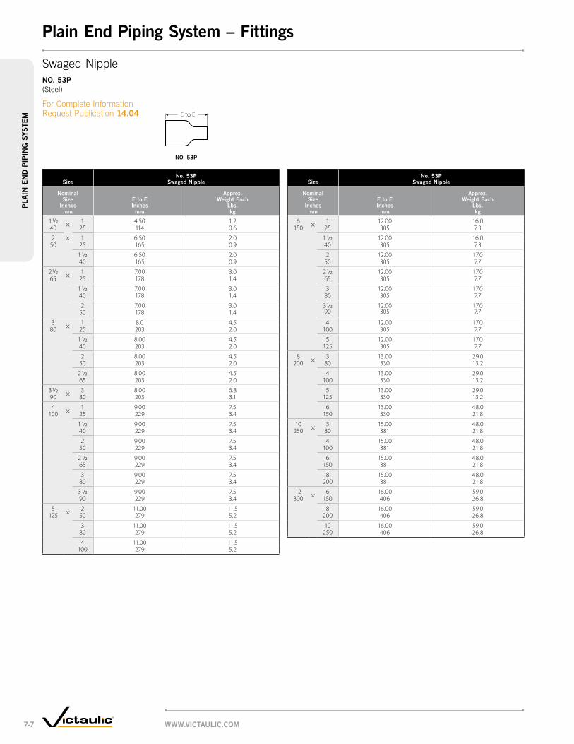
sizeno. 53p
swaged nipple
nominal size
inches mm
e to e inches
mm
approx. weight each
lbs. kg
6 × 1 12.00 16.0150 25 305 7.3
1 1/2 12.00 16.040 305 7.3
2 12.00 17.050 305 7.7
2 1/2 12.00 17.065 305 7.7
3 12.00 17.080 305 7.7
3 1/2 12.00 17.090 305 7.7
4 12.00 17.0100 305 7.7
5 12.00 17.0125 305 7.7
8 × 3 13.00 29.0200 80 330 13.2
4 13.00 29.0100 330 13.2
5 13.00 29.0125 330 13.2
6 13.00 48.0150 330 21.8
10 × 3 15.00 48.0250 80 381 21.8
4 15.00 48.0100 381 21.8
6 15.00 48.0150 381 21.8
8 15.00 48.0200 381 21.8
12 × 6 16.00 59.0300 150 406 26.8
8 16.00 59.0200 406 26.8
10 16.00 59.0250 406 26.8
sizeno. 53p
swaged nipple
nominal size
inches mm
e to e inches
mm
approx. weight each
lbs. kg
1 1/2 × 1 4.50 1.240 25 114 0.6
2 × 1 6.50 2.050 25 165 0.9
1 1/2 6.50 2.040 165 0.9
2 1/2 × 1 7.00 3.065 25 178 1.4
1 1/2 7.00 3.040 178 1.4
2 7.00 3.050 178 1.4
3 × 1 8.0 4.580 25 203 2.0
1 1/2 8.00 4.540 203 2.0
2 8.00 4.550 203 2.0
2 1/2 8.00 4.565 203 2.0
3 1/2 × 3 8.00 6.890 80 203 3.1
4 × 1 9.00 7.5100 25 229 3.4
1 1/2 9.00 7.540 229 3.4
2 9.00 7.550 229 3.4
2 1/2 9.00 7.565 229 3.4
3 9.00 7.580 229 3.4
3 1/2 9.00 7.590 229 3.4
5 × 2 11.00 11.5125 50 279 5.2
3 11.00 11.580 279 5.2
4 11.00 11.5100 279 5.2
E to E
SwagedNippleno. 53p (Steel)
ForCompleteInformationRequestPublication14.04
no. 53p
www.victaulic.com7-7
pla
in e
nd
pip
ing
sys
tem
plain end piping system – fittings

size dimensionsapprox.
weight each
nominal size
inches mm
actual outside diameter
inches mm
e to e inches
mm
lbs. kg
1 1.315 3.00 0.925 33.7 76 0.4
1 1/2 1.900 4.00 0.940 48.3 102 0.4
2 2.375 4.00 1.250 60.3 102 0.5
2 1/2 2.875 4.00 1.965 73.0 102 0.9
3 3.500 4.00 2.580 88.9 102 1.1
4 4.500 6.00 5.4100 114.3 152 2.5
6 6.625 6.00 9.4150 168.3 152 4.3
E to E E to EE to E
AdapterNippleno. 40p PlainEnd×Thd.no. 42p PlainEnd×Bev.no. 43p PlainEnd×Grv.(Steel)
ForCompleteInformationRequestPublication14.04
no. 40p no. 42p no. 43p
www.victaulic.com 7-8
pla
in en
d pipin
g sys
templain end piping system – fittings

Rigid CouplingStyle 489, pg. 8-3
Rigid Coupling Style 89, pg. 8-4 AgS Style w89, pg. 5-4
Flexible CouplingStyle 77S, pg. 8-5
Flexible CouplingStyle 475, pg. 8-6
• Fast, easy and reliable method for joining Sch. 5S, 10S or 40S stainless pipe
• Fittings are supplied with grooves, ready to install
• Couplings available for rigid or flexible joints
Couplings
Vic-Flange Adapter ANSI Class 150Style 441, pg. 8-7
www.victAulic.com8-1
grooved System for Stainless Steel pipeg
ro
ove
d S
ySte
m f
or
StA
inle
SS
Ste
el p
ipe
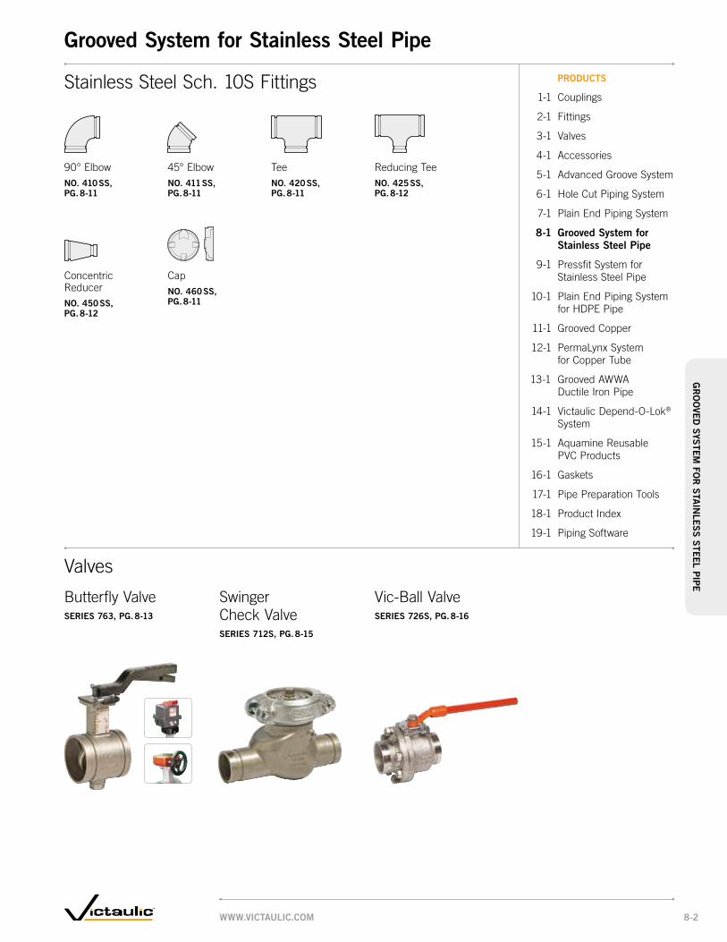
Butterfly ValveSerieS 763, pg. 8-13
Swinger Check ValveSerieS 712S, pg. 8-15
Vic-Ball ValveSerieS 726S, pg. 8-16
Stainless Steel Sch. 10S Fittings
Valves
90° Elbowno. 410 SS, pg. 8-11
Teeno. 420 SS, pg. 8-11
45° Elbowno. 411 SS, pg. 8-11
Reducing Teeno. 425 SS, pg. 8-12
Concentric Reducerno. 450 SS, pg. 8-12
Capno. 460 SS, pg. 8-11
productS
1-1 Couplings
2-1 Fittings
3-1 Valves
4-1 Accessories
5-1 Advanced Groove System
6-1 Hole Cut Piping System
7-1 Plain End Piping System
8-1 grooved System for Stainless Steel pipe
9-1 Pressfit System for Stainless Steel Pipe
10-1 Plain End Piping System for HDPE Pipe
11-1 Grooved Copper
12-1 PermaLynx System for Copper Tube
13-1 Grooved AWWA Ductile Iron Pipe
14-1 Victaulic Depend-O-Lok®
System
15-1 Aquamine Reusable PVC Products
16-1 Gaskets
17-1 Pipe Preparation Tools
18-1 Product Index
19-1 Piping Software
www.victAulic.com 8-2
grooved System for Stainless Steel pipeg
ro
oved
SyStem
for
StA
inle
SS
Steel pip
e

Sizemax. end load *
Allow. pipe end Sep. * dimensions
Approx. wgt. each
nominal Size
inches mm
Actual outside dia.
inches mm
lbs. n
inches mm
X inches
mm
y inches
mm
Z inches
mm lbs. kg
Schedule 40S
Schedule 40††
Schedule 10S
Schedule 5S
1 1/2 1.900 1700 – 850 570 0.05 2.86 4.42 1.84 1.640 48.3 7565 – 3783 2537 1.3 73 118 47 0.7
2 2.375 2660 – 1330 890 0.05 3.34 5.19 1.86 1.650 60.3 11837 – 5919 3961 1.3 85 132 47 0.7
2 1/2 2.875 3900 – 1950 1300 0.05 3.92 5.62 1.86 1.965 73.0 17355 – 8678 5785 1.3 100 143 47 0.9
76.1 mm 3.000 4240 – 2120 1415 0.05 4.02 5.72 1.86 2.076.1 18868 – 9434 6297 1.3 102 145 47 0.9
3 3.500 5775 – 2890 1925 0.05 4.54 6.78 1.86 2.880 88.9 25699 – 12861 8566 1.3 115 172 47 1.3
4 4.500 9540 – 4775 3180 0.19 5.77 7.90 2.07 4.0100 114.3 42453 – 21249 14151 4.8 147 201 53 1.8
139.7 mm 5.500 14250 1200†† 7130 4750 0.25 7.07 11.13 2.38 12.0139.7 63413 8273 31729 21138 6.4 180 283 60 5.5
6 6.625 20680 41370†† 10340 6895 0.25 8.16 12.68 2.50 15.5150 168.3 92026 184030 46015 30685 6.4 207 321 64 7.0
165.1 mm 6.500 19910 1200†† 9955 6640 0.25 8.16 12.68 2.50 15.5165.1 88600 8273 44300 29548 6.4 207 321 64 7.0
8 8.625 35055 70110†† 17530 11685 0.25 10.63 15.00 2.75 24.0200 219.1 155995 311870 78010 52000 6.4 270 381 70 10.9
216.3 mm 8.515 34175 – 17090 11390 0.25 10.63 15.00 2.75 24.0216.3 152079 – 76051 50686 6.4 270 381 70 10.9
10 10.750 54460 108920†† 27230 18150 0.25 13.09 17.25 3.00 33.0250 273.0 242345 484500 121175 80770 6.4 332 438 76 15.0
267.4 mm 10.528 52230 – 26115 17410 0.25 13.09 17.25 3.00 33.0267.4 232424 – 116212 77475 6.4 332 438 76 15.0
12 12.750 76605 153210†† 38300 25535 0.25 15.13 19.13 3.13 40.0300 323.9 340890 681520 170435 113630 6.4 384 486 80 18.1
318.5 mm 12.539 74100 – 37050 24700 0.25 15.13 19.13 3.13 40.0318.5 329745 – 164873 109915 6.4 384 486 80 18.1
* Refer to General Notes on pg. 1-4.†† Cut grooved, sch. 40S duplex pipe
Y Z
X
Y
X
Z
Rigid CouplingStyle 489
For Complete Information Request Publication 17.25
• CF8M stainless steel for corrosion resistance and strength
• Provides an essentially rigid joint
• Pressure rated up to 1200psi/4136kPa for Schedule 40S duplex or super duplex, 600 psi/4136 kPa for Schedule 40S, 300 psi/2065 kPa for Schedule 10S, and 200 psi/1375 kPa for Schedule 5S; For specific pressure ratings by size and schedule, please refer to Publication 17.25
• Sizes from 1½ – 12"/40 – 300 mm typicAl 6 – 12"/139.7 – 300 mm SiZeStypicAl 1½ – 4"/40 – 100 mm SiZeS
www.victAulic.com8-3
gr
oo
ved
SyS
tem
fo
r S
tAin
leS
S S
teel
pip
egrooved System for Stainless Steel pipe – couplings

Sizemax. end load *
Allow. pipe end Sep. * dimensions
Approx. wgt.
nominal Size
inches mm
Actual outside dia.
inches mm
lbs. n
inches mm
X inches
mm
y inches
mm
Z inches
mm lbs. kg
Schedule 40S
Schedule 40S
duplex †Schedule
10SSchedule
5S
2 2.375 3320 5320 1330 890 0.14 3.50 6.68 2.00 3.150 60.3 14774 23676 5919 3961 3.6 89 168 51 1.4
2 1/2 2.875 4875 7800 1950 1300 0.14 4.13 7.13 2.00 4.065 73.0 21694 34712 8678 5785 3.6 105 181 51 1.8
76.1 mm 3.000 5300 8480 2120 1415 0.14 4.13 7.25 2.00 4.176.1 23585 37736 9434 6297 3.6 105 184 51 1.9
3 3.500 7215 11560 2890 1925 0.14 4.75 7.75 2.00 4.380 88.9 32107 51444 12861 8566 3.6 121 197 51 2.0
4 4.500 11930 19100 4775 3180 0.25 6.00 9.63 2.13 7.5100 114.3 53089 84996 21249 14151 6.4 152 245 54 3.4
139.7 mm 5.500 17820 28520 7130 4750 0.25 7.13 10.63 2.38 12.5139.7 79299 126916 31729 21138 6.4 181 270 60 5.7
6 6.625 25850 39820 10340 6895 0.25 8.63 12.68 2.50 16.0150 168.3 115035 177200 46015 30685 6.4 219 321 64 7.3
165.1 mm 6.500 24890 41360 9955 6640 0.25 8.63 12.68 2.38 15.8165.1 110761 184060 44300 29548 6.4 219 321 60 7.2
8 8.625 35055 68360 17530 11685 0.25 11.00 15.00 2.75 26.1200 219.1 155995 304204 78010 52000 6.4 279 381 70 11.8
216.3 mm 8.515 34175 70100 17090 11390 0.25 11.00 15.00 2.63 25.2216.3 152079 311940 76051 50686 6.4 279 381 67 11.4
10 10.750 54460 104460 27230 18150 0.25 13.50 17.25 3.00 32.8250 273.0 242345 464848 121175 80770 6.4 343 438 76 14.9
267.4 mm 10.528 52230 108900 26115 17410 0.25 13.38 17.00 2.75 32.5267.4 232424 484600 116212 77475 6.4 340 432 700 14.7
12 12.750 76605 148200 38300 25535 0.25 15.63 19.63 2.88 46.0300 323.9 340890 659492 170435 113630 6.4 397 499 73 20.9
318.5 mm 12.539 74100 153200 37050 24700 0.25 15.63 19.63 2.88 42.0318.5 329745 681740 164873 109915 6.4 397 499 73 19.1
14 – 24 350 – 600 See Style w89, pg. 5-4, request publication 20.15
* Refer to General Notes on pg. 1-4. † Cut grooved, Standard Wall or Schedule 40S stainless steel duplex pipe
Y Z
X
™TM
Rigid CouplingStyle 89
For Complete Information Request Publication 17.24
• Heavy-duty, galvanized ductile iron housing designed for use specifically with stainless steel systems
• Wider housing key than standard coupling
• Provides an essentially rigid joint
• Pressure rated up to 1200 psi/8273 kPA for Schedule 40S duplex or Standard Wall, 750 psi/5175 kPa for Schedule 40S, 300 psi/2065 kPa for Schedule 10S, and 200 psi/1375 kPa for Schedule 5S; For specific pressure ratings by size and schedule, please refer to Publication 17.24
• Sizes from 2 – 12"/50 – 300 mm typicAl for All SiZeS
www.victAulic.com 8-4
gr
oo
ved SyS
tem fo
r S
tAin
leS
S S
teel pipe
grooved System for Stainless Steel pipe – couplings

Sizemax perm. end load
Allow. pipe end Sep. * dimensions
Approx. wgt. each
nominal Size
inches mm
Actual outside dia.
inches mm
lbs. / n
inches mm
X inches
mm
y inches
mm
Z inches
mm lbs. kg
Schedule 40S
Schedule 40††
Schedule 10S
Schedule 5S
3/4 1.050 650 – 430 280 0 – 0.06 2.08 3.89 1.70 1.220 26.9 2893 – 1915 1245 0 – 1.6 53 99 43 0.6
1 ‡ 1.315 1000 1600 680 440 0 – 0.06 2.54 4.50 1.66 1.825 33.7 4450 7120 3025 1960 0 – 1.6 65 114 42 0.8
1 1/4 ‡ 1.660 1600 2500 1080 700 0 – 0.06 2.87 4.79 1.76 2.032 42.4 7120 11120 4805 3115 0 – 1.6 73 122 45 0.9
1 1/2 ‡ 1.900 2100 3400 1415 920 0 – 0.06 3.24 4.80 1.76 2.240 48.3 9345 15120 6295 4095 0 – 1.6 82 122 45 1.0
2 ‡ 2.375 3300 5300 2215 1440 0 – 0.06 3.70 5.33 1.84 2.650 60.3 14685 23757 9855 6408 0 – 1.6 94 135 47 1.2
2 1/2 ‡ 2.875 4900 7700 3245 2110 0 – 0.06 4.20 5.79 1.84 3.065 73.0 21805 34250 14440 9390 0 – 1.6 107 147 47 1.4
3 ‡ 3.500 7200 11500 3850 2405 0 – 0.06 4.83 6.99 1.84 4.180 88.9 32040 51150 17133 10702 0 – 1.6 123 178 47 1.9
4 ‡ 4.500 6360 19000 5565 3580 0 – 0.13 5.93 9.00 2.06 6.8100 114.3 28302 84500 24764 15931 0 – 3.2 151 229 52 3.1
6 6.625 10340 – 6900 4300 0 – 0.13 8.30 11.06 2.06 8.5150 168.3 46013 – 30705 19135 0 – 3.2 211 281 52 3.9
8 8.625 17525 – 7300 4380 0 – 0.13 11.38 14.74 2.44 23.5200 219.1 77896 – 32485 19491 0 – 3.2 229 374 62 10.7
10 10.750 27225 – 6810 4540 0 – 0.13 13.50 17.33 2.63 33.0250 273.0 121151 – 30305 20203 0 – 3.2 343 440 67 15.0
12 12.750 38300 – 15960 9575 0 – 0.13 15.50 19.15 2.56 35.0300 323.9 170435 – 71022 42609 0 – 3.2 394 486 65 15.9
14 † 14.000 30800 – 15400 10000 0 – 0.13 16.56 20.44 2.81 37.0350 355.6 137060 – 68530 44500 0 – 3.2 421 519 71 16.8
16 † 16.000 25130 – 9050 7040 0 – 0.13 18.94 22.52 2.94 53.0400 406.4 111829 – 40273 31328 0 – 3.2 481 572 75 24.0
18 † 18.000 25450 – 10180 7635 0 – 0.13 21.25 24.62 3.06 62.0450 457.0 113253 – 45301 33976 0 – 3.2 540 625 78 25.0
* Refer to General Notes on pg. 1-4. ‡ Sizes 1-4"/25-100mm come standard in CE8MN duplex stainless steel. 3/4"/20mm, 6-18"/150-450mm come standard in CF8M Type 316 Stainless Steel.† Not for use with AGS (Advance Groove System) products. †† Cut grooved, sch. 40S duplex.
X
Y Z
Z
X
Y
Flexible CouplingStyle 77S
For Complete Information Request Publication 17.03
• CE8MN duplex stainless steel or CF8M Type 316 stainless steel for corrosion resistance and strength
• Provides rugged, flexible mechanical joint for grooved stainless steel piping systems
• Pressure dependent on pipe size and wall thickness
• Pressure rated up to 1200psi/8273kPa on cut grooved Schedule 40S Duplex, 750 psi/5175 kPa for Schedule 40S, 500 psi/3445 kPa for Schedule 10S, and 325 psi/2240 kPa for Schedule 5S; For specific pressure ratings by size and schedule, please refer to Publication 17.03
• Sizes from ¾ – 18"/20 – 450 mm
typicAl ¾ – 14"/20 – 350 mm SiZeS typicAl 16 – 18"/400 – 450 mm SiZeS
www.victAulic.com8-5
gr
oo
ved
SyS
tem
fo
r S
tAin
leS
S S
teel
pip
egrooved System for Stainless Steel pipe – couplings

Sizemax. end load *
Allow. pipe end Sep. * dimensions
Approx. wgt. each
nominal Size
inches mm
Actual outside dia.
inches mm
lbs. n
inches mm
X inches
mm
y inches
mm
Z inches
mm lbs. kg
Schedule 40S
Schedule 10S
Schedule 5S
1 1.315 1020 680 440 0 – 0.06 2.45 4.36 1.63 1.625 33.7 4539 3026 1958 0 – 1.6 62 111 41 0.7
1 1/4 1.660 1625 1080 700 0 – 0.06 2.84 4.67 1.72 2.432 42.4 7231 4806 3115 0 – 1.6 72 119 44 1.1
1 1/2 1.900 2125 1415 920 0 – 0.06 3.22 4.74 1.72 2.640 48.3 9456 6295 4094 0 – 1.6 82 120 44 1.2
2 2.375 2215 1550 1000 0 – 0.06 3.30 5.03 1.80 1.750 60.3 9857 6898 4450 0 – 1.6 84 128 46 0.8
2 1/2 2.875 3250 2275 1460 0 – 0.06 3.88 5.59 1.80 1.965 73.0 14463 10124 6497 0 – 1.6 99 142 46 0.9
76.1 mm 3.000 3535 2475 1590 0 – 0.06 4.00 5.73 1.80 2.076.1 15731 11014 7076 0 – 1.6 102 146 46 0.9
3 3.500 4810 3370 2170 0 – 0.06 4.50 6.67 1.80 2.980 88.9 21405 14997 9657 0 – 1.6 114 169 46 1.3
4 4.500 5170 4775 3180 0 – 0.13 5.75 7.96 2.00 4.2100 114.3 23007 21250 14150 0 – 3.2 146 202 51 1.9
139.7 mm 5.500 4750 4750 2970 0 – 0.13 6.81 8.97 2.00 4.9139.7 21138 21138 13217 0 – 3.2 173 228 51 2.2
165.1 mm ‡ 6.500 6640 6640 4150 0 – 0.13 7.87 10.53 2.00 6.8165.1 29550 29550 18470 0 – 3.2 200 268 51 3.1
* Refer to General Notes on pg. 1-4.‡ Denotes JIS pipe size.
ZY
X
Flexible CouplingStyle 475
For Complete Information Request Publication 17.14
• CF8M stainless steel for corrosion resistance and strength
• Flexible system accommodates expansion/contraction/deflection
• Pressure rated up to 750 psi/5175 kPa for Schedule 40S, 500 psi/3447 kPa for Schedule 10S, and 325 psi/2240 kPa for Schedule 5S; For specific pressure ratings by size and schedule, please refer to Publication 17.14
• Sizes from 1 – 4"/25 – 165.1 mm
typicAl for All SiZeS
www.victAulic.com 8-6
gr
oo
ved SyS
tem fo
r S
tAin
leS
S S
teel pipe
grooved System for Stainless Steel pipe – couplings
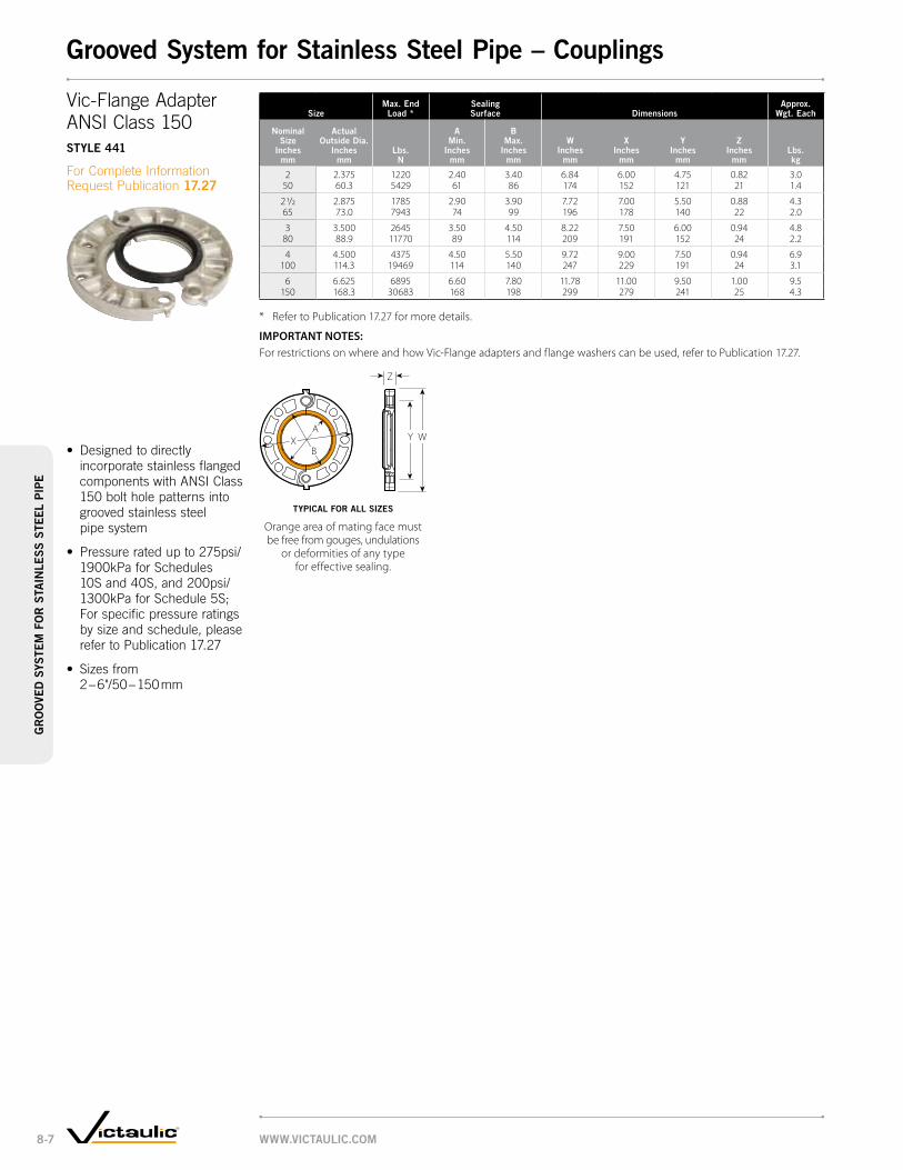
Sizemax. end load *
Sealing Surface dimensions
Approx. wgt. each
nominal Size
inches mm
Actual outside dia.
inches mm
lbs. n
A min.
inches mm
B max.
inches mm
w inches
mm
X inches
mm
y inches
mm
Z inches
mm lbs. kg
2 2.375 1220 2.40 3.40 6.84 6.00 4.75 0.82 3.050 60.3 5429 61 86 174 152 121 21 1.4
2 1/2 2.875 1785 2.90 3.90 7.72 7.00 5.50 0.88 4.365 73.0 7943 74 99 196 178 140 22 2.0
3 3.500 2645 3.50 4.50 8.22 7.50 6.00 0.94 4.880 88.9 11770 89 114 209 191 152 24 2.2
4 4.500 4375 4.50 5.50 9.72 9.00 7.50 0.94 6.9 100 114.3 19469 114 140 247 229 191 24 3.1
6 6.625 6895 6.60 7.80 11.78 11.00 9.50 1.00 9.5150 168.3 30683 168 198 299 279 241 25 4.3
* Refer to Publication 17.27 for more details.
IMPORTANT NOTES: For restrictions on where and how Vic-Flange adapters and flange washers can be used, refer to Publication 17.27.
B
A
Z
Y WX
Vic-Flange Adapter ANSI Class 150Style 441
For Complete Information Request Publication 17.27
• Designed to directly incorporate stainless flanged components with ANSI Class 150 bolt hole patterns into grooved stainless steel pipe system
• Pressure rated up to 275psi/1900kPa for Schedules 10S and 40S, and 200psi/1300kPa for Schedule 5S; For specific pressure ratings by size and schedule, please refer to Publication 17.27
• Sizes from 2 – 6"/50 – 150 mm
typicAl for All SiZeS
Orange area of mating face must be free from gouges, undulations
or deformities of any type for effective sealing.
www.victAulic.com8-7
gr
oo
ved
SyS
tem
fo
r S
tAin
leS
S S
teel
pip
egrooved System for Stainless Steel pipe – couplings
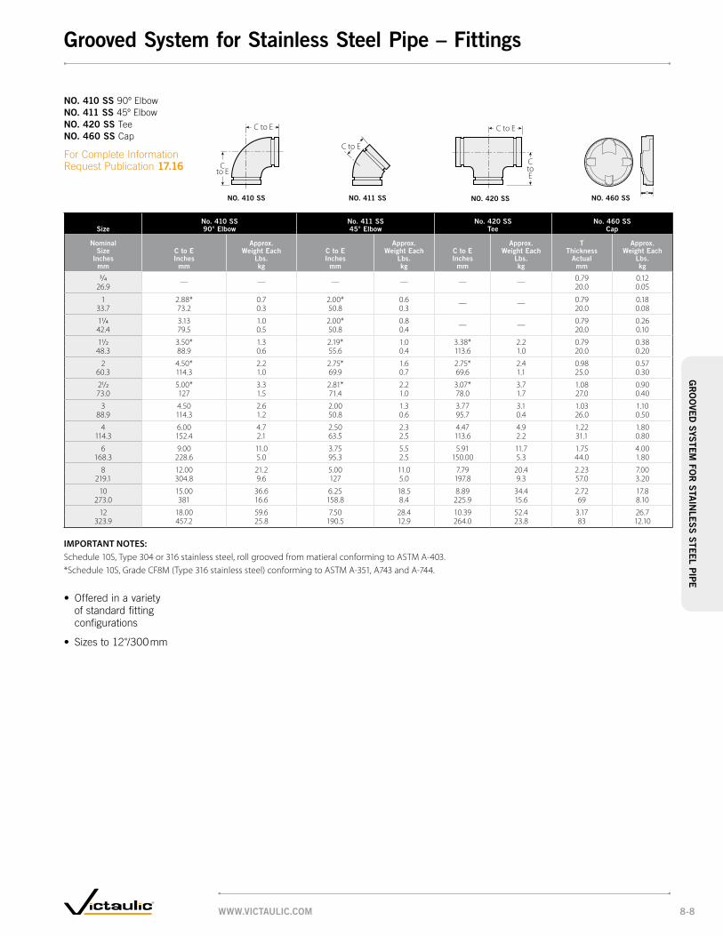
Sizeno. 410 SS 90° elbow
no. 411 SS 45° elbow
no. 420 SS tee
no. 460 SS cap
nominal Size
inches mm
c to e inches
mm
Approx. weight each
lbs. kg
c to e inches
mm
Approx. weight each
lbs. kg
c to e inches
mm
Approx. weight each
lbs. kg
t thickness
Actual mm
Approx. weight each
lbs. kg
3/4 — — — — — — 0.79 0.1226.9 20.0 0.05
1 2.88* 0.7 2.00* 0.6 — — 0.79 0.1833.7 73.2 0.3 50.8 0.3 20.0 0.08
11/4 3.13 1.0 2.00* 0.8 — — 0.79 0.2642.4 79.5 0.5 50.8 0.4 20.0 0.10
11/2 3.50* 1.3 2.19* 1.0 3.38* 2.2 0.79 0.3848.3 88.9 0.6 55.6 0.4 113.6 1.0 20.0 0.20
2 4.50* 2.2 2.75* 1.6 2.75* 2.4 0.98 0.5760.3 114.3 1.0 69.9 0.7 69.6 1.1 25.0 0.30
21/2 5.00* 3.3 2.81* 2.2 3.07* 3.7 1.08 0.9073.0 127 1.5 71.4 1.0 78.0 1.7 27.0 0.40
3 4.50 2.6 2.00 1.3 3.77 3.1 1.03 1.1088.9 114.3 1.2 50.8 0.6 95.7 0.4 26.0 0.50
4 6.00 4.7 2.50 2.3 4.47 4.9 1.22 1.80114.3 152.4 2.1 63.5 2.5 113.6 2.2 31.1 0.80
6 9.00 11.0 3.75 5.5 5.91 11.7 1.75 4.00168.3 228.6 5.0 95.3 2.5 150.00 5.3 44.0 1.80
8 12.00 21.2 5.00 11.0 7.79 20.4 2.23 7.00219.1 304.8 9.6 127 5.0 197.8 9.3 57.0 3.20
10 15.00 36.6 6.25 18.5 8.89 34.4 2.72 17.8273.0 381 16.6 158.8 8.4 225.9 15.6 69 8.10
12 18.00 59.6 7.50 28.4 10.39 52.4 3.17 26.7323.9 457.2 25.8 190.5 12.9 264.0 23.8 83 12.10
IMPORTANT NOTES:Schedule 10S, Type 304 or 316 stainless steel, roll grooved from matieral conforming to ASTM A-403.*Schedule 10S, Grade CF8M (Type 316 stainless steel) conforming to ASTM A-351, A743 and A-744.
C to E
Cto E
C to E
C to E
CtoE
no. 410 SS 90º Elbowno. 411 SS 45º Elbowno. 420 SS Teeno. 460 SS Cap
For Complete Information Request Publication 17.16
no. 410 SS no. 411 SS no. 420 SS no. 460 SS
• Offered in a variety of standard fitting configurations
• Sizes to 12"/300 mm
T
www.victAulic.com 8-8
grooved System for Stainless Steel pipe – fittingsg
ro
oved
SyStem
for
StA
inle
SS
Steel pip
e

Sizeno. 425 SS
reducing tee
nominal Size
inches mm
c to e run
inches mm
c to e Branch inches
mm
Approx. weight each
lbs. kg
2 × 2 × 1 1/2 2.75 2.75 2.050 50 40 70.0 70.0 0.9
2 1/2 × 2 1/2 × 2 3.07 3.07 2.465 65 50 77.9 77.9 1.1
3 × 3 × 2 1/2 3.77 3.23 3.180 80 65 95.7 82.0 1.4
4 × 4 × 3 4.47 3.88 4.9100 100 80 113.5 98.5 2.2
6 × 6 × 3 5.91 4.88 8.8150 150 80 150.0 123.9 4.0
4 5.91 5.12 9.5100 150.0 130.0 4.3
8 × 8 × 4 7.79 6.31 18.1200 200 100 197.8 160.2 8.2
6 7.79 6.62 18.5150 197.8 168.1 8.4
10 × 10 × 6 8.89 7.70 28.2250 250 150 225.8 195.5 12.8
8 8.89 8.59 31.3200 225.8 218.1 14.2
12 × 12 × 8 10.39 9.51 40.1300 300 200 263.9 241.5 18.2
10 10.39 9.89 47.6250 263.9 251.2 21.6
IMPORTANT NOTE:No. 425 SS is manufactured from material conforming to ASTM A-403 Schedule 10S 304L or 316L.
Sizeno. 450 SS
concentric reducer
nominal Size
inches mm
e to e inches
mm
Approx. weight each
lbs. kg
2 × 1 1/2 5.00 2.550 40 127 1.1
2 1/2 × 2 5.00 1.165 50 127 0 .49
3 × 2 1/2 5.00 1.580 65 127 0.7
4 × 3 5.00 2.0100 80 127 0.9
6 × 3 5.50 6.9150 80 139.7 3.1
4 5.50 7.0100 139.7 3.2
8 × 4 (sw) 6.00 4.2200 100 152.4 1.9
6 6.00 7.0150 152.4 3.2
10 × 6 (sw) 7.00 18.0250 150 177.8 8.2
8 (sw) 7.00 19.6200 177.8 8.9
12 × 8 (sw) 8.00 26.4300 200 203.2 12.0
10 (sw) 8.00 28.4250 203.2 12.9
IMPORTANT NOTE:Schedule 10S, Type 304 or 316 stainless steel, roll grooved from matieral con-forming to ASTM A-403.
*Schedule 10S, Grade CF8M (Type 316 stainless steel) conforming to ASTM A-351, A743 and A-744.
(sw) Segmentally welded, not CR class fitting. Exception is 8"x4" concentric reducers which are CR class.
E to E
C to EOR
Cto
EOB
no. 450 SS
For Complete Information Request Publication 17.16
no. 450 SS
no. 425 SS
For Complete Information Request Publication 17.16
no. 425 SS
www.victAulic.com8-9
gr
oo
ved
SyS
tem
fo
r S
tAin
leS
S S
teel
pip
egrooved System for Stainless Steel pipe – fittings

BAre vAlve And with lever lock hAndle
Size dimensionsApprox.
wgt. eachflow coefficient@
(fully open)
cv valuesk v values
nominal Size
inches mm
Actual out. dia. inches
mm
A inches
mm
B inches
mm
c inches
mm
d inches
mm
e inches
mm
f inches
mm
p inches
mm
Q inches
mm
r inches
mm
S inches
mm
t inches
mm
u inches
mm
v inches
mm
w inches
mm
Bare valve lbs. kg
lever handle
lbs. kg
2 2.375 3.20 2.37 2.09 4.17 2.38 8.51 0.34 2.76 1.25 0.31 0.43 2.48 2.65 — 3.5 4.7 11050 60.3 81 60 53 106 60 216 9 70 32 8 11 63 67 1.6 2.1 95.2
2 1/2 2.875 3.77 3.00 2.47 4.38 2.38 8.51 0.34 2.76 1.25 0.31 0.43 2.48 2.65 — 4.5 5.7 20065 73.0 96 76 63 111 60 216 9 70 31 8 11 63 67 2.0 2.6 173.0
76.1 mm 3.000 3.77 3.00 2.47 4.38 2.38 8.51 0.34 2.76 1.25 0.31 0.43 2.48 2.65 — 4.5 5.7 20076.1 96 76 63 111 60 216 9 70 31 8 11 63 67 2.0 2.6 173.0
3 3.500 3.77 3.50 2.60 4.97 2.38 8.51 0.34 2.76 1.23 0.31 0.43 2.48 2.65 — 5.0 6.2 25080 88.9 96 89 66 126 60 216 9 70 31 8 11 63 67 2.3 2.8 216.3
4 4.500 4.64 4.52 3.14 5.33 2.38 8.51 0.34 2.76 1.23 0.43 0.63 2.47 2.65 — 9.0 10.2 600100 114.3 118 115 80 135 60 216 9 70 31 11 16 63 67 4.1 4.6 519.0
6 6.625 5.88 6.64 4.76 7.25 1.37 12.01 0.43 4.02 1.37 0.50 0.75 3.51 3.85 — 26.0 28.4 1400150 168.3 149 169 121 184 35 305 11 102 35 13 19 89 98 11.8 12.9 1211.0
165.1 mm 6.500 5.88 6.64 4.76 7.25 1.37 12.01 0.43 4.02 1.37 0.50 0.75 3.51 3.85 — 26.0 28.4 1400165.1 149 169 121 184 35 305 11 102 35 13 19 89 98 11.8 12.9 1211.0
8 8.625 5.32 9.75 5.73 8.57 1.37 12.01 0.43 4.02 1.37 0.75 1.00 3.40 3.85 1.24 41.0 43.4 3400200 219.1 135 248 145 218 35 305 11 102 35 19 25 86 98 32 18.6 19.7 2941.0
10 10.750 6.40 12.10 7.05 10.09 — — 0.53 4.92 2.13 — 1.25 4.62 4.77 1.72 65.0 — 5500250 273.0 163 307 179 256 13 125 54 32 117 121 44 29.5 4757.5
@ CV /KV values for flow of water at +60°F/+16°C with valve fully open.
U
S
W W
R
V
D
C
A B
F
E
T
Enlarged Mounting Flange10 - 12"(Valve Shown Closed)
.312
1.074
Enlarged Mounting Flange2 - 8"(Valve Shown Closed)
U
Q
T
V
SP (4x)
Butterfly ValveSerieS 763
For Complete Information Request Publication 17.23
• Stainless steel body with cast neck to accommodate insulation requirements
• ISO top flange will accept mounting of all major manual and power operators
• Seat options include EPDM, nitrile, fluoroelastomer, and lubricated nitrile (air and gas services only)
• Disc is stainless steel and provides bubble-tight shut-off at full rated pressure and temperature
• Pressure rates 300 psi/2065 kPa bi-directional and dead-end service
• Sizes from 2 – 10"/50 – 250 mm
enlArged mounting flAnge typicAl 2 – 8"/50 – 200 mm SiZeS
(vAlve Shown cloSed)
enlArged mounting flAnge typicAl 10"/250 mm SiZeS
(vAlve Shown cloSed)
SerieS 763 Butterfly vAlve BAre typicAl for All SiZeS
SerieS 763 Butterfly vAlve with lever lock hAndle
typicAl for All SiZeS
SerieS 763 with lever hAndle
SerieS 763 with power ActuAtor
SerieS 763 with geAr operAtor
grooved System for Stainless Steel pipe – valves
www.victAulic.com 8-10
gr
oo
ved SyS
tem fo
r S
tAin
leS
S S
teel pipe
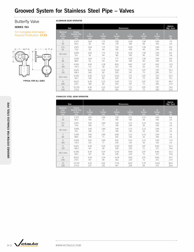
StAinleSS Steel geAr operAtor
Size dimensionsApprox.
wgt. each
nominal Size
inches mm
Actual outside dia.
inches mm
g inches
mm
h inches
mm
k inches
mm
l inches
mm
m inches
mm
n inches
mmlbs. kg
2 2.375 3.93 2.80 7.28 5.13 2.22 3.94 6.450 60.3 100 71 185 130 56 100 2.0
2 1/2 2.875 3.93 2.80 7.49 5.13 2.22 3.94 7.465 73.0 100 71 190 130 56 100 3.4
76.1 mm 3.000 3.93 2.80 7.49 5.13 2.22 3.94 7.476.1 100 71 190 130 56 100 3.4
3 3.500 3.93 2.80 8.08 5.13 2.22 3.94 7.980 88.9 100 71 205 130 56 100 3.6
4 4.500 4.92 2.80 9.42 5.32 2.22 5.90 11.9100 114.3 125 71 239 135 56 150 5.4
6 6.625 6.59 3.54 12.92 9.00 2.97 8.46 32.2150 168.3 167 90 328 229 75 215 14.6
165.1 mm 6.500 6.59 3.54 12.92 9.00 2.97 8.46 32.2165.1 167 90 328 229 75 215 14.6
8 8.625 6.59 3.54 14.24 9.00 2.97 8.46 47.2200 219.1 167 90 362 229 75 215 21.4
10 10.750 9.33 4.02 17.76 8.03 3.70 12.40 80.4250 273.0 237 102 451 204 94 315 36.6
Aluminum geAr operAtor
Size dimensionsApprox.
wgt. each
nominal Size
inches mm
Actual outside dia.
inches mm
g inches
mm
h inches
mm
k inches
mm
l inches
mm
m inches
mm
n inches
mmlbs. kg
2 2.375 2.64 1.75 7.00 4.29 1.58 3.94 7.450 60.3 92 44 178 109 40 100 3.4
2 1/2 2.875 2.64 1.75 7.18 4.29 1.58 3.94 8.465 73.0 92 44 182 109 40 100 3.8
76.1 mm 3.000 2.64 1.75 7.18 4.29 1.58 3.94 8.476.1 92 44 182 109 40 100 3.8
3 3.500 2.64 1.75 7.77 4.29 1.58 3.94 8.980 88.9 92 44 197 109 40 100 4.0
4 4.500 4.43 2.28 8.93 4.65 1.97 4.92 12.9100 114.3 112 58 227 118 50 125 5.9
6 6.625 6.30 3.25 12.62 7.75 2.87 7.87 33.2150 168.3 160 82 320 197 73 200 15.1
165.1 mm 6.500 6.30 3.25 12.62 7.75 2.87 7.87 33.2165.1 160 82 320 197 73 200 15.1
8 8.625 6.30 3.25 13.95 7.75 2.87 7.87 48.2200 219.1 160 82 354 197 73 200 21.9
10 10.750 6.30 3.25 15.47 7.75 2.87 7.87 74.0250 273.0 160 82 393 197 73 200 33.6
G H
K
L M
N
Butterfly Valve SerieS 763
For Complete Information Request Publication 17.23
typicAl for All SiZeS
www.victAulic.com8-11
gr
oo
ved
SyS
tem
fo
r S
tAin
leS
S S
teel
pip
egrooved System for Stainless Steel pipe – valves
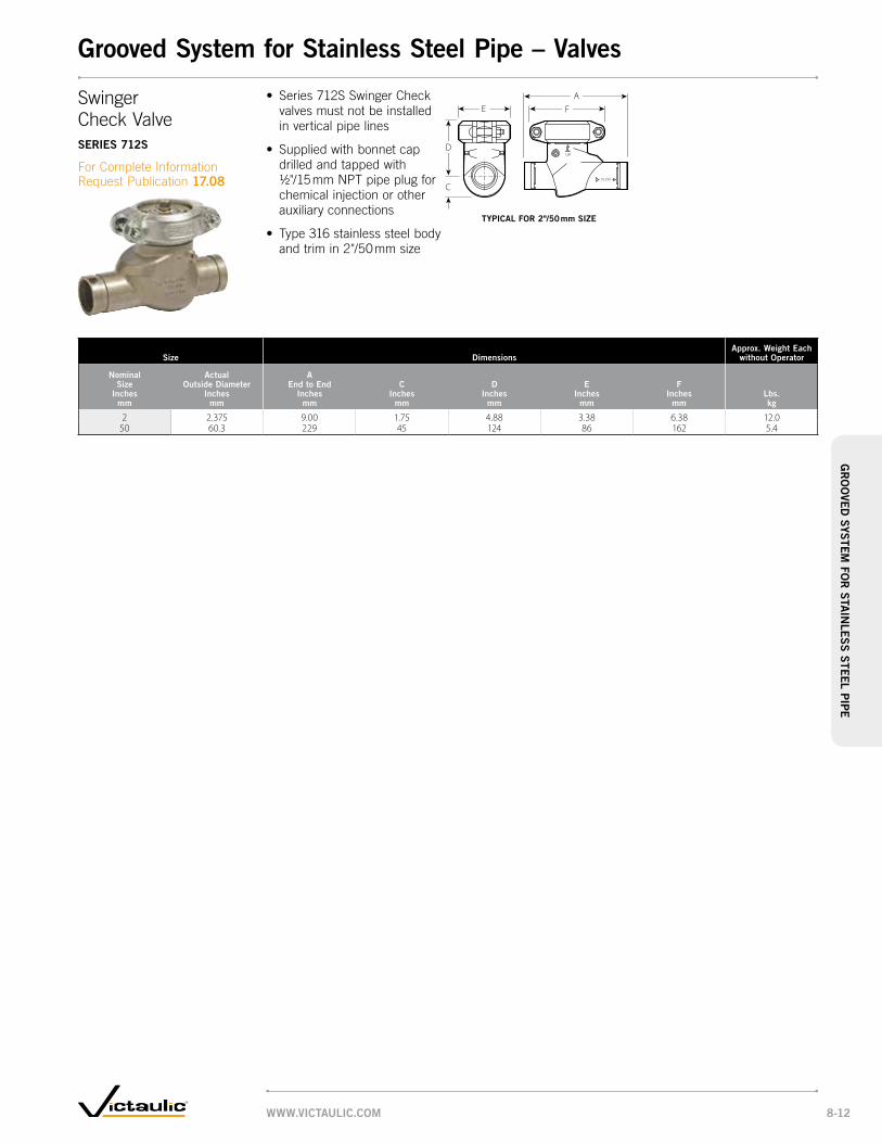
Size dimensionsApprox. weight each
without operator
nominal Size
inches mm
Actual outside diameter
inches mm
A end to end
inches mm
c inches
mm
d inches
mm
e inches
mm
f inches
mmlbs. kg
2 2.375 9.00 1.75 4.88 3.38 6.38 12.050 60.3 229 45 124 86 162 5.4
FA
E
D
C
Swinger Check ValveSerieS 712S
For Complete Information Request Publication 17.08
• Series 712S Swinger Check valves must not be installed in vertical pipe lines
• Supplied with bonnet cap drilled and tapped with ½"/15 mm NPT pipe plug for chemical injection or other auxiliary connections
• Type 316 stainless steel body and trim in 2"/50 mm size
typicAl for 2"/50 mm SiZe
grooved System for Stainless Steel pipe – valves
www.victAulic.com 8-12
gr
oo
ved SyS
tem fo
r S
tAin
leS
S S
teel pipe

Size dimensionsApprox.
wgt. each flow coefficient@ (fully open)
cv valuesk v values
nominal Size
inches mm
Actual out. dia. inches
mm
A inches
mm
B inches
mm
c inches
mm
d inches
mm
dA inches
mm
e inches
mm
f inches
mm
h inches
mm
J inches
mm
k inches
mm
l inches
mmlbs. kg
1 1/2 1.900 5.12 2.00 2.36 1.25 1.50 1.78 1.90 3.00 0.28 0.56 6.97 4.7 13040 48.3 130 51 60 32 38 45 48 76 7 14 177 2.1 112.5
2 2.375 5.50 2.64 2.48 1.50 2.00 2.25 2.38 3.31 0.34 0.56 6.97 7.5 18050 60.3 140 67 63 38 51 57 60 84 9 14 177 3.4 155.7
2 1/2 2.875 6.25 3.03 2.80 1.97 2.50 2.72 2.88 4.00 0.34 0.56 9.84 11.5 34065 73.0 159 77 71 50 64 69 73 102 9 14 250 5.2 294.1
3 3.500 6.56 3.50 3.15 2.50 3.00 3.34 3.50 4.53 0.34 0.56 9.84 17.3 60080 88.9 167 89 80 64 76 85 89 115 9 14 250 7.8 519.0
4 4.500 8.25 — 3.35 2.99 4.00 4.33 4.52 5.48 0.34 0.61 15.67 44.0 650100 114.3 210 85 76 102 111 115 139 9 15 398 20.5 562.3
6 6.625 10.10 — 4.53 4.00 6.00 6.46 6.64 6.48 0.34 0.61 18.07 82.0 800150 168.3 257 115 102 152 164 169 165 9 15 459 37.3 692.0
@ CV /KV values for flow of water at +60°F/+16°C with valve fully open.
H
FEDAD
L
AC
KJ
H
B
L
CA
FEDA
JK
D
Vic-Ball ValveSerieS 726S
For Complete Information Request Publication 17.22
• High-pressure standard port ball valve with grooved ends
• Two-piece, end-entry features floating ball for lower torque requirements
• NACE compliant
• Streamline internal design provides excellent flow characteristics
• Valve features stainless steel ball and stem
• Pressure rated up to 1000 psi/6900 kPa for sizes 1½ – 3"/40 – 80 mm
• Pressure rated up to 800 psi/5515 kPa for sizes 4 – 6"/100 – 150 mm
• Sizes from 1½ – 6"/40 – 150 mm
typicAl 4"/100 mm And 6"/150 mm SiZeS
typicAl 1½ – 3"/40 – 80 mm SiZeS
www.victAulic.com8-13
gr
oo
ved
SyS
tem
fo
r S
tAin
leS
S S
teel
pip
egrooved System for Stainless Steel pipe – valves

www.victAulic.com 8-14
gr
oo
ved SyS
tem fo
r S
tAin
leS
S S
teel pipe

Standard Coupling, pg. 9-4
Slip Coupling, pg. 9-4
90º Elbow, pg. 9-5
Short Tangent 90º Elbow, pg. 9-5
45º Elbow, pg. 9-5
Tee, pg. 9-6
Tee with Thd. Branch, pg. 9-6
Pr
es
sfi
t 304 style 597 style 590 style 586 style 591 style 592 style 588
316 style 507 style 508 style 570 style 568 style 571 style 572 style 578
Tee with Reducing Branch, pg. 9-7
Male Adapter, pg. 9-7
Female Thd. Adapter, pg. 9-8
Weld Adapter, pg. 9-8
Threaded Union, pg. 9-8
Grooved End Union, pg. 9-9
Flange Adapter, pg. 9-9
Pr
es
sfi
t 304 style 593 style 596 style 599 style 561 style 584 style 547 style 595
316 style 573 style 576 style 579 style 585 style 548 style 575
Van Stone Flange Adapter, pg. 9-9
Transition Nipple, pg. 9-10
Reducer Insert, pg. 9-10
Concentric Reducer, pg. 9-10
Ball Valve, pgs. 9-11, 12
Pr
es
sfi
t 304 style 565 style 587 style 582 style 594 style 589
316 style 566 style 577 style 583 style 574 style 569
The Pressfit system is a small diameter, quick-connect piping system solution that delivers speed, economy and reliability to building owners, contractors, and specifying engineers.
Pressfit delivers real on-the-job pipe joining advantages to fitters and installers – benefits that you won’t find in standard threaded, welded or flanged systems.
The Pressfit system is ideal for a wide variety of process and utility applications requiring the corrosion-resistant properties of stainless steel. Pressfit integrates well with larger stainless steel piping systems, especially those designed with our grooved end products.
Product Line
www.victaulic.com9-1
Pressfit system for stainless steel PipePr
es
sfit
sys
tem
fo
r s
tain
les
s s
teel
PiP
e
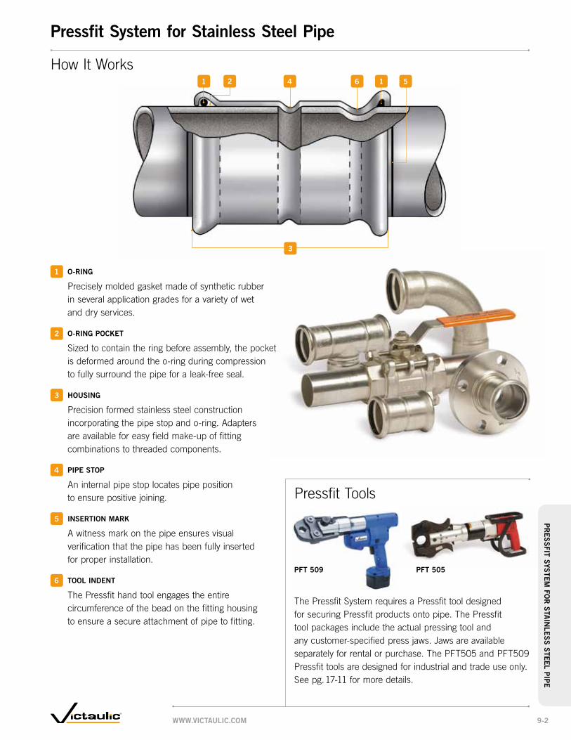
Pft 509 Pft 505
o-ring
Precisely molded gasket made of synthetic rubber in several application grades for a variety of wet and dry services.
o-ring Pocket
Sized to contain the ring before assembly, the pocket is deformed around the o-ring during compression to fully surround the pipe for a leak-free seal.
Housing
Precision formed stainless steel construction incorporating the pipe stop and o-ring. Adapters are available for easy field make-up of fitting combinations to threaded components.
PiPe stoP
An internal pipe stop locates pipe position to ensure positive joining.
insertion mark
A witness mark on the pipe ensures visual verification that the pipe has been fully inserted for proper installation.
tool indent
The Pressfit hand tool engages the entire circumference of the bead on the fitting housing to ensure a secure attachment of pipe to fitting.
How It Works 2 1
3
4 5 6
1
2
1
Pressfit Tools
3
4
5
6
The Pressfit System requires a Pressfit tool designed for securing Pressfit products onto pipe. The Pressfit tool packages include the actual pressing tool and any customer-specified press jaws. Jaws are available separately for rental or purchase. The PFT505 and PFT509 Pressfit tools are designed for industrial and trade use only. See pg. 17-11 for more details.
www.victaulic.com 9-2
Pressfit system for stainless steel PipePr
es
sfit system
for
sta
inle
ss
steel PiP
e

Stainless Steel Pipe System – Performance• Available for Type 304
or Type 316 stainless steel systems
• Full range of couplings, fittings and valves
• Handheld tools used to join pipe in seconds
• Up to four times faster than stainless steel socket weld systems
Vic-Press 304
temPerature (ºf/ºc)
Pr
es
sur
e (
psi/
kPa)
Vic-Press 316
temPerature (ºf/ºc)
Pr
es
sur
e (
psi/kP
a)
• UL classified in accordance with ANSI/NSF 61 for cold +86°F/+30°C and hot +180°F/+82°C potable water service
• Meets hanging requirements of ASME B31.1, B31.3 and B31.9
• Request Publication 18.01 for Type 316 or 18.02 for Type 304
• Pressure rated up to 300 psi/2065 kPa in all sizes
• Sizes from ½ – 2"/ 15 – 50 mm Schedule 5 stainless steel piping is fast, easy, clean and reliable method for joining
Products
1-1 Couplings
2-1 Fittings
3-1 Valves
4-1 Accessories
5-1 Advanced Groove System
6-1 Hole Cut Piping System
7-1 Plain End Piping System
8-1 Grooved System for Stainless Steel Pipe
9-1 Pressfit system for stainless steel Pipe
10-1 Plain End Piping System for HDPE Pipe
11-1 Grooved Copper
12-1 PermaLynx System for Copper Tube
13-1 Grooved AWWA Ductile Iron Pipe
14-1 Victaulic Depend-O-Lok®
System
15-1 Aquamine Reusable PVC Products
16-1 Gaskets
17-1 Pipe Preparation Tools
18-1 Product Index
19-1 Piping Software
www.victaulic.com9-3
Pressfit system for stainless steel PipePr
es
sfit
sys
tem
fo
r s
tain
les
s s
teel
PiP
e

size dimensionsapprox.
weight each
nominal size
inches mm
actual outside diameter
inches mm
e to e inches
mm
u takeout inches
mmlbs. kg
1/2 0.840 2.00 0.35 0.115 21.3 51 9 0.1
3/4 1.050 2.17 0.28 0.220 26.7 55 7 0.1
1 1.315 2.44 0.39 0.225 33.7 62 10 0.1
1 1/2 1.900 3.15 0.32 0.540 48.3 80 8 0.2
2 2.375 3.94 0.33 0.750 60.3 100 8 0.3
standard couPling
Pr
es
sfi
t 304 style 597 Request Publication 18.02
316 style 507 Request Publication 18.01
size dimensionsapprox.
weight each
nominal size
inches mm
actual outside diameter
inches mm
e to e inches
mm
i min. tube insert
inches mm
lbs. kg
1/2 0.840 3.31 1.00 0.115 21.3 84 25 0.1
3/4 1.050 3.54 1.00 0.220 26.7 90 25 0.1
1 1.315 3.94 1.00 0.325 33.7 100 25 0.1
1 1/2 1.900 4.72 1.00 0.640 48.3 120 25 0.3
2 2.375 5.51 1.25 0.950 60.3 140 32 0.4
sliP couPling
Pr
es
sfi
t
316 style 508 Request Publication 18.01
UE to E
E to EI
min.I
min.
P (3)
P (1) P (2)
P
F
M
T
L
G
= Pressfit
= Female Pipe Thread
= Male Pipe Thread
= Plain End
= Flanged
= Grooved
END TYPE CODE
Standard Couplingstyle 597 (P × P)style 507 (P × P)
Slip Couplingstyle 508 (P × P)
Dimensional Information
Products in the Vic-Press 304/316 System have unique center-to-end or end-to-end dimensions which incorporate specific, uniform “takeout” dimensions for easy fabrication calculations.
Use of threaded products employing special features such as probes, escutcheon cups, etc., should be checked to be certain the thread standard and length of insertion are compatible with fitting dimensions. Failure to verify dimensional suitability in advance may result in difficulties in assembly.
style 597 & 507 style 508
www.victaulic.com 9-4
Pressfit system for stainless steel PipePr
es
sfit system
for
sta
inle
ss
steel PiP
e

sizestyle 590 & 570
90° elbowstyle 586 & 568
short tangent 90° elbowstyle 591 & 571
45° elbow
nominal size
inches mm
actual outside diameter
inches mm
c to Pe inches
mm
u takeout inches
mm
approx. weight each
lbs. kg
c to Pe inches
mm
u takeout inches
mm
approx. weight each
lbs. kg
c to Pe inches
mm
u takeout inches
mm
approx. weight each
lbs. kg
1/2 0.840 2.67 1.88 0.3 — — — 1.65 0.82 0.215 21.3 68 48 0.1 42 21 0.1
3/4 1.050 3.43 2.48 0.4 2.83 1.88 0.3 2.44 1.50 0.320 26.7 87 63 0.2 72 48 0.2 62 38 0.1
1 1.315 4.33 3.31 0.6 3.36 2.34 0.5 3.11 2.09 0.525 33.7 110 84 0.3 85 59 0.2 79 53 0.2
1 1/2 1.900 6.73 5.32 1.4 4.60 3.19 1.0 5.00 3.59 1.340 48.3 171 135 0.6 117 81 0.5 127 91 0.6
2 2.375 8.19 6.38 2.3 5.71 3.90 1.5 6.02 4.22 2.050 60.3 208 162 1.0 145 99 0.7 153 107 0.9
90° elbow
Pr
es
sfi
t 304 style 590 Request Publication 18.02
316 style 570 Request Publication 18.01
sHort tangent 90° elbow
Pr
es
sfi
t 304 style 586 Request Publication 18.02
316 style 568 Request Publication 18.01
45° elbow
Pr
es
sfi
t 304 style 591 Request Publication 18.02
316 style 571 Request Publication 18.01
UC to PE
C to PEU
CtoPE
U
Elbowsstyle 590 90º Elbow (P × P) style 570 90º Elbow (P × P)style 586 Short Tangent 90º Elbow (P × P)style 568 Short Tangent 90º Elbow (P × P)style 591 45º Elbow (P × P)style 571 45º Elbow (P × P)
style 586 & 568style 590 & 570 style 591 & 571
www.victaulic.com9-5
Pressfit system for stainless steel PipePr
es
sfit
sys
tem
fo
r s
tain
les
s s
teel
PiP
e

size dimensionsapprox.
wgt. each
nominal size
inches mm
c to Pe inches
mm
u1
inches mm
c to eob inches
mm
u2
inches mm
lbs. kg
1/2 × 1/2 × 1/2 1.50 1.35 1.50 0.97 0.215 15 15 38 34 38 25 0.1
3/4 × 3/4 × 1/2 1.89 1.89 1.64 1.11 0.320 20 15 48 48 42 28 0.2
3/4 1.89 1.89 1.71 1.16 0.420 48 48 43 29 0.2
1 × 1 × 1/2 2.11 2.17 1.78 1.25 0.425 25 15 54 55 45 32 0.2
3/4 2.11 2.17 1.85 1.30 0.520 54 55 47 33 0.2
1 2.11 2.17 2.02 1.34 0.625 54 55 51 34 0.3
1 1/2 × 1 1/2 × 1/2 2.76 2.69 2.07 1.54 0.840 40 15 70 68 53 39 0.4
3/4 2.76 2.69 2.14 1.59 0.920 70 68 54 40 0.4
1 2.76 2.69 2.31 1.63 0.925 70 68 59 40 0.4
2 × 2 × 1/2 3.39 3.16 2.31 1.78 1.250 50 15 86 80 59 45 0.5
3/4 3.39 3.16 2.38 1.83 1.320 86 80 60 46 0.6
1 3.39 3.16 2.55 1.87 1.325 86 80 65 48 0.6
tee witH tHreaded brancH
Pr
es
sfi
t 304 style 588 Request Publication 18.02
316 style 578 Request Publication 18.01
size dimensionsapprox.
wgt. each
nominal size
inches mm
actual outside dia.
inches mm
c to Pe inches
mm
u1
inches mm
c to eob inches
mm
u2
inches mm
lbs. kg
1/2 0.840 1.40 1.04 1.60 0.72 0.215 21.3 36 26 41 18 0.1
3/4 1.050 1.89 1.89 1.89 0.95 0.320 26.7 48 48 48 24 0.1
1 1.315 2.11 2.17 2.15 1.13 0.425 33.7 54 55 55 29 0.2
1 1/2 1.900 2.76 2.69 2.80 1.39 0.940 48.3 70 68 71 35 0.4
2 2.375 3.39 3.17 3.62 1.81 1.450 60.3 86 81 92 46 0.6
tee
Pr
es
sfi
t 304 style 592 Request Publication 18.02
316 style 572 Request Publication 18.01
* Length of effective thread.
U2
C to PE
Cto
EOB
U1 U1
Cto
EOBU2
*
C to PE
Teestyle 592 (P × P × P)style 572 (P × P × P)
Tee with Threaded Branchstyle 588 (P × P × F)style 578 (P × P × F)
style 592 & 572 style 588 & 578
www.victaulic.com 9-6
Pressfit system for stainless steel PipePr
es
sfit system
for
sta
inle
ss
steel PiP
e

size dimensionsapprox.
weight each
nominal size
inches mm
c to Pe inches
mm
u1
inches mm
c to eob inches
mm
u2
inches mm
lbs. kg
3/4 × 3/4 × 1/2 1.90 1.91 2.10 1.27 0.320 20 15 48 48 53 32 0.1
1 × 1 × 1/2 2.10 2.15 2.30 1.47 0.325 25 15 53 55 58 37 0.1
3/4 2.11 2.17 2.03 1.09 0.420 54 55 52 28 0.2
1 1/2 × 1 1/2 × 1/2 2.76 2.69 2.60 1.77 0.640 40 15 70 68 66 45 0.3
3/4 2.76 2.69 2.32 1.68 0.720 70 68 59 43 0.3
1 2.76 2.69 2.44 1.42 0.825 70 68 62 36 0.4
2 × 2 × 1/2 3.39 3.17 2.80 1.97 1.250 50 15 86 81 71 50 0.5
3/4 3.39 3.17 2.56 1.62 1.320 86 81 65 41 0.6
1 3.39 3.17 2.68 1.66 1.125 86 81 68 42 0.5
1 1/2 3.39 3.17 3.03 1.62 1.340 86 81 77 41 0.6
tee witH reducing brancH †
Pr
es
sfi
t 304 style 593 Request Publication 18.02
316 style 573 Request Publication 18.01
† Available with female threaded outlet. Contact Victaulic.
size dimensionsapprox.
weight each
nominal size
inches mm
e to e inches
mm
u takeout inches
mm
il insert. length
inches mm
lbs. kg
1/2 × 1/2 3.68 2.32 0.83 0.215 15 93 59 21 0.1
3/4 × 1/2 3.22 1.75 0.95 0.320 15 82 44 24 0.1
3/4 3.72 2.22 0.95 0.320 94 56 24 0.1
1 3.22 1.60 0.95 0.425 82 41 24 0.2
1 × 3/4 3.34 1.77 1.02 0.425 20 85 45 26 0.1
1 4.02 2.32 1.02 0.425 102 59 26 0.2
1 1/2 × 3/4 3.69 1.73 1.42 0.640 20 94 44 36 0.3
1 1/2 4.40 2.27 1.42 0.740 112 58 36 0.3
2 × 2 5.03 2.46 1.81 1.050 50 128 62 46 0.5
male tHreaded adaPter
Pr
es
sfi
t 304 style 596 Request Publication 18.02
316 style 576 Request Publication 18.01
* Length of effective thread.
Cto
EOB U2
C to PEU1
E to EIL *U
Tee with Reducing Branchstyle 593 (P × P × P)style 573 (P × P × P)
style 593 & 573
Male Threaded Adapterstyle 596 (P × M)style 576 (P × M)
style 596 & 576
www.victaulic.com9-7
Pressfit system for stainless steel PipePr
es
sfit
sys
tem
fo
r s
tain
les
s s
teel
PiP
e

size dimensionsapprox.
weight each
nominal size
inches mm
actual outside diameter
inches mm
e to e inches
mm
u takeout inches
mmlbs. kg
1/2 0.840 7.02 5.27 2.8015 21.3 178 134 1.3
3/4 1.050 7.14 5.14 3.5020 26.7 181 131 1.6
1 1.315 7.26 5.26 3.8025 33.7 184 134 1.7
1 1/2 1.900 8.44 5.44 5.4040 48.3 214 138 2.4
2 2.375 8.38 4.67 6.1050 60.3 213 119 2.8
tHreaded union
Pr
es
sfi
t 304 style 584 Request Publication 18.02
316 style 585 Request Publication 18.01
size dimensionsapprox.
weight each
nominal size
inches mm
e to e inches
mm
u takeout inches
mm
il insert. length
inches mm
lbs. kg
1/2 × 1/2 2.15 0.79 0.83 0.215 15 55 20 21 0.1
3/4 × 1/2 2.20 0.71 0.95 0.220 15 56 18 24 0.1
3/4 2.20 0.79 0.95 0.220 56 20 24 0.1
1 × 1/2 2.30 0.75 1.02 0.425 15 58 19 26 0.2
3/4 2.30 0.73 1.02 0.320 58 19 26 0.1
1 2.40 0.75 1.02 0.425 61 19 26 0.2
1 1/2 × 1 2.96 0.92 1.42 0.840 25 75 23 36 0.4
1 1/4 2.96 0.87 1.42 0.632 75 22 36 0.3
1 1/2 2.96 0.87 1.42 0.840 75 22 36 0.4
2 × 1 1/4 3.75 1.27 1.81 0.950 32 95 32 46 0.4
1 1/2 3.75 1.27 1.81 1.140 95 32 46 0.5
2 3.75 1.27 1.81 1.050 95 32 46 0.5
female tHreaded adaPter
Pr
es
sfi
t 304 style 599 Request Publication 18.02
316 style 579 Request Publication 18.01
size dimensionsapprox.
weight each
nominal size
inches mm
e to e inches
mm
u takeout inches
mm
il insert. length
inches mm
lbs. kg
1/2 × 1/2 3.68 2.85 0.83 0.215 15 93 72 21 0.1
3/4 × 3/4 3.72 2.77 0.95 0.320 20 94 70 24 0.1
1 × 1 4.02 3.00 1.02 0.425 25 102 76 26 0.2
1 1/2 × 1 1/2 4.40 2.98 1.42 0.740 40 112 76 36 0.3
2 × 2 5.03 3.22 1.81 1.050 50 128 82 46 0.5
weld adaPter
Pr
es
sfi
t
304 style 561 Request Publication 18.02
* Length of effective thread.
E to EUIL *
E to EU
E to EUIL
Female Threaded Adapterstyle 599 (P × F)style 579 (P × F)
style 599 & 579
Weld Adapterstyle 561 (P × T)
style 561
Threaded Unionstyle 584 (P × P)style 585 (P × P)
style 584 & 585
www.victaulic.com 9-8
Pressfit system for stainless steel PipePr
es
sfit system
for
sta
inle
ss
steel PiP
e

size dimensionsapprox.
weight each
nominal size
inches mm
actual outside diameter
inches mm
e to e inches
mmlbs. kg
1/2 0.840 3.12 3.0015 21.3 79 1.4
3/4 1.050 3.17 3.3020 26.7 81 1.5
1 1.315 3.28 3.6025 33.7 83 1.6
1 1/2 1.900 3.64 5.0040 48.3 93 2.3
2 2.375 4.73 5.9050 60.3 120 2.7
van stone flange adaPter †
Pr
es
sfi
t 304 style 565 Request Publication 18.02
316 style 566 Request Publication 18.01
† Available with carbon steel (standard) or 316 stainless steel (optional) back-up flange. Specify choice on order.
size dimensionsapprox.
weight each
nominal size
inches mm
actual out. dia. inches mm
u takeout inches
mm
w inches
mm
X inches
mm
y inches
mm
Z inches
mmlbs. kg
1/2 0.840 2.34 1.38 2.38 3.50 3.22 2.315 21.3 59 35 60 89 82 1.1
3/4 1.050 2.27 1.69 2.75 3.88 3.22 1.720 26.7 58 43 70 99 82 0.8
1 1.315 2.27 2.00 3.12 4.25 3.29 2.225 33.7 58 51 79 108 84 1.0
1 1/2 1.900 2.07 2.88 3.88 5.00 3.48 3.640 48.3 53 73 99 127 88 1.6
2 2.375 1.80 3.62 4.75 6.00 3.60 5.450 60.3 46 92 121 152 92 2.4
flange adaPter
Pr
es
sfi
t 304 style 595 Request Publication 18.02
316 style 575 Request Publication 18.01
U
X
Z
W Y
E to E
InsertionMark
Flange Adapterstyle 595 (P × L)style 575 (P × L)
Van Stone Flange Adapterstyle 565 (P × L)style 566 (P × L)
Grooved End Unionstyle 547 style 548
Request Publication 06.02 for Style 77 Flexible Joint Request Publication 06.04 for Style 07 Rigid Joint Request Publication 17.03/17.14 for Style 77S/475 Flexible Joints Request Publication 17.25 for Style 489 Rigid Joints
Pr
es
sfi
t 304 style 547 Request Publication 18.02
316 style 548 Request Publication 18.01
• Style 547/548 grooved end union can be formed with two Style 577 transition nipples and a variety of grooved end couplings with varied gaskets to meet service requirements
• Standard ductile iron couplings request Style 77 for flexible joints or Style 07 for rigid joints
• Where external corrosion is a concern request Style 77S/475 for flexible joints or Style 489 for rigid joints
style 595 & 575
style 565 & 566
www.victaulic.com9-9
Pressfit system for stainless steel PipePr
es
sfit
sys
tem
fo
r s
tain
les
s s
teel
PiP
e

size dimensionsapprox.
weight each
nominal size
inches mm
e to e inches
mm
u takeout inches
mm
il insertion length
inches mm
lbs. kg
1 × 3/4 2.95 0.98 0.95 0.225 20 75 25 24 0.1
2 × 1 1/2 4.33 1.11 1.42 0.650 40 110 28 36 0.3
reducer insert
Pr
es
sfi
t 304 style 582 Request Publication 18.02
316 style 583 Request Publication 18.01
size dimensionsapprox.
weight each
nominal size
inches mm
actual outside diameter
inches mm
e to e inches
mm
l1
minimum inches
mmlbs. kg
3/4 1.050 4.00 1.00 0.220 26.7 102 25 0.1
1 1.315 4.00 1.00 0.325 33.7 102 25 0.1
1 1/2 1.900 4.00 1.50 0.440 48.3 102 38 0.2
2 2.375 4.00 1.88 0.550 60.3 102 48 0.2
transition niPPle
Pr
es
sfi
t 304 style 587 Request Publication 18.02
316 style 577 Request Publication 18.01
size dimensionsapprox.
weight each
nominal size
inches mm
e to e inches
mm
l1
minimum inches
mm
l2
minimum inches
mmlbs. kg
3/4 × 1/2 3.50 1.00 0.88 0.220 15 89 25 22 0.1
1 × 1/2 3.56 1.03 0.88 0.225 15 90 26 22 0.1
3/4 3.56 1.03 1.00 0.220 90 26 25 0.1
1 1/2 × 1/2 4.25 1.44 0.88 0.340 15 108 37 22 0.1
3/4 4.25 1.44 1.00 0.420 108 37 25 0.2
1 4.25 1.44 1.03 0.425 108 37 26 0.2
2 × 1/2 5.00 1.81 0.88 0.650 15 127 46 22 0.3
3/4 5.00 1.81 1.00 0.620 127 46 25 0.3
1 5.00 1.81 1.03 0.625 127 46 26 0.3
1 1/2 5.00 1.81 1.44 0.740 127 46 37 0.3
concentric reducer
Pr
es
sfi
t 304 style 594 Request Publication 18.02
316 style 574 Request Publication 18.01
E to E
InsertionMark
L1 E to EL1 L2
InsertionMark
E to EU IL
Transition Nipplestyle 587 (G × T)style 577 (G × T)
style 587 & 577
Concentric Reducerstyle 594 (T × T)style 574 (T × T)
style 594 & 574
Reducer Insertstyle 582 (T × P)style 583 (T × P)
style 582 & 583
www.victaulic.com 9-10
Pressfit system for stainless steel PipePr
es
sfit system
for
sta
inle
ss
steel PiP
e
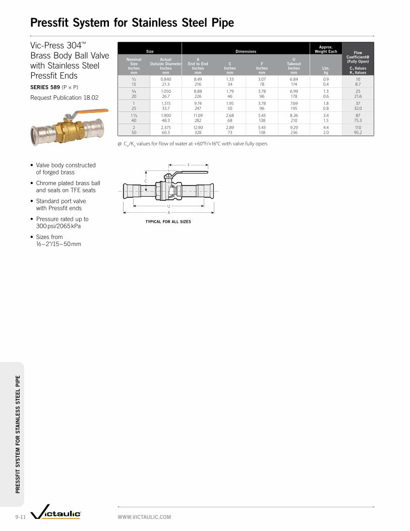
size dimensionsapprox.
weight each flow coefficient@ (fully open)
cv valueskv values
nominal size
inches mm
actual outside diameter
inches mm
a end to end
inches mm
c inches
mm
f inches
mm
u takeout inches
mmlbs. kg
1/2 0.840 8.49 1.33 3.07 6.84 0.9 1015 21.3 216 34 78 174 0.4 8.7
3/4 1.050 8.88 1.79 3.78 6.99 1.3 2520 26.7 226 46 96 178 0.6 21.6
1 1.315 9.74 1.95 3.78 7.69 1.8 3725 33.7 247 50 96 195 0.8 32.0
1 1/2 1.900 11.09 2.68 5.43 8.26 3.4 8740 48.3 282 68 138 210 1.5 75.3
2 2.375 12.90 2.89 5.43 9.29 4.4 11050 60.3 328 73 138 236 2.0 95.2
@ CV/KV values for flow of water at +60°F/+16°C with valve fully open.
C
F
AU
Vic-Press 304™
Brass Body Ball Valve with Stainless Steel Pressfit Endsseries 589 (P × P)
Request Publication 18.02
• Valve body constructed of forged brass
• Chrome plated brass ball and seals on TFE seats
• Standard port valve with Pressfit ends
• Pressure rated up to 300 psi/2065 kPa
• Sizes from ½ – 2"/15 – 50 mm
tyPical for all siZes
www.victaulic.com9-11
Pressfit system for stainless steel PipePr
es
sfit
sys
tem
fo
r s
tain
les
s s
teel
PiP
e

rePair kits and rePlacement Parts for series 569 ball valve
size repair kit replacement ball
nominal size
inches mm
actual outside diameter
inches mm Part no. Part no.
1/2 0.840 K-004-569-001 K-004-569-00015 21.3
3/4 1.050 K-006-569-001 K-006-569-00020 26.7
1 1.315 K-010-569-001 K-010-569-00025 33.7
1 1/2 1.900 K-014-569-001 K-014-569-00040 48.3
2 2.375 K-020-569-001 K-020-569-00050 60.3
size dimensionsapprox.
weight each
nominal size
inches mm
actual outside diameter
inches mm
a end to end
inches mm
b inches
mm
c inches
mm
e inches
mmlbs. kg
1/2* 0.840 7.98 2.36 0.88 5.12 1.515 21.3 200.0 59.9 22.4 130.0 0.7
3/4 1.050 8.57 2.52 1.00 5.12 2.420 26.7 217.2 64.0 25.4 130.0 1.1
1 1.315 8.89 2.80 1.00 6.50 3.625 33.7 225.8 71.1 25.4 165.1 1.6
1 1/2 1.900 11.20 3.39 1.50 7.48 6.940 48.3 284.5 86.1 38.1 190.0 3.1
2 2.375 12.52 3.74 1.88 7.48 9.550 60.3 318.0 95.0 47.8 190.0 4.3
* ½"/15 mm only available in plain end × plain end.
Important note:For dimensions and weights with gear operator contact Victaulic.
DO
NO
T TR
IM
DO
NO
T TRIM
E
B
A
C
E
B
A
DO
NO
T TR
IM
E
B
A
C
Vic-Press 316™
Type 316 Stainless Steel Ball Valveseries 569
Request Publication 18.01
• Body and trim constructed of rugged Type 316 (CF8M) stainless steel with PTFE seats
• Blow-out proof stem self-adjusting floating ball
• Full-port design minimizes pressure drop for flow efficiency
• Three-piece swing-out design permits easy in-line maintenance
• Pressure rated up to 300 psi/2065 kPa with plain ends
• Pressure rated up to 400 psi/2750 kPa with grooved ends
• Sizes from ½ – 2"/15 – 50 mm
• Repair Kits and replacement parts are available for the Series 569 valve
• The Repair Kit consists of two seats, two gaskets, one stem seal, and one thrust washer, all made of PTFE. A replacement ball of CF8M stainless steel is also available
• For replacement stem information, contact Victaulic
Plain end × Plain end grooved × grooved
Plain end × grooved
www.victaulic.com 9-12
Pressfit system for stainless steel PipePr
es
sfit system
for
sta
inle
ss
steel PiP
e

Size Dimensions
Nominal Size
Inches mm
Actual Outside
Diameter Inches
mm
Outside Diameter Maximum Out of
Round Tol.* Inches
mm
Size Inches
mm
Tol.* Inches
mm
2 2.375 2.375 ± 0.016 ± 0.04050 60.3 60.3 0.406 1.016
3 3.500 3.500 ± 0.016 ± 0.04080 88.9 88.9 0.406 1.016
4 4.500 4.500 ± 0.020 ± 0.040100 114.3 114.3 0.508 1.016
5 5.563 5.563 ± 0.025 ± 0.050125 141.3 141.3 0.635 1.270
6 6.625 6.625 ± 0.030 ± 0.050150 168.3 168.3 0.762 1.270
8 8.625 8.625 ± 0.039 ± 0.075200 219.1 219.1 0.990 1.905
Size Dimensions
Nominal Size
Inches mm
Actual Outside
Diameter Inches
mm
Outside Diameter Maximum Out of
Round Tol.* Inches
mm
Size Inches
mm
Tol.* Inches
mm
10 10.750 10.750 ± 0.048 ± 0.075250 273.0 273.0 1.219 1.905
12 12.750 12.750 ± 0.057 ± 0.075300 323.9 323.9 1.448 1.905
14 † 14.000 14.000 ± 0.063 ± 0.075350 355.6 355.6 1.600 1.905
16 16.000 16.000 ± 0.072 §400 406.4 406.4 1.830
18 18.000 18.000 ± 0.081 §450 457.0 457.0 2.060
20 20.000 20.000 ± 0.090 §500 508.0 508.0 2.290
* At ambient temperatures.§ See pipe manufacturer for maximum out
of round tolerance.† Contact Victaulic for special bolt/nut requirements.
Exaggerated for clarity
CouplingSTyle 995, pg. 10-2
• VictaulicHDPEproductshaveintegralrowsofgrippingteeththatbiteintotheentirecircumferenceoftheHDPEpipe
• Eliminatestheneedforspecialheatfusion,solventjoiningorspecialadapters
• Victaulicproductsareratedtotheworkingpressureofthepipe
• Fast,easiestwaytomechanicallyjoinHDPEpipeatwallthicknessesfromSDR32.5to7.3
• Sizesfrom2–20"/50–500mm
•Uptoseventimesfasterthanfusionwelding
TransitionCoupling–HDPEtoSteelSTyle 997, pg. 10-3
Vic-FlangeAdapterANSIClass150STyle 994, pg. 10-4
HDPEPipeDimensions
Important notes:Victaulic HDPE products are not intended for use on PVC pipe or other materials Victaulic lubricant should NOT be used with HDPE pipe
exAggeRATeD fOR clARITy
pRODucTS
1-1 Couplings
2-1 Fittings
3-1 Valves
4-1 Accessories
5-1 AdvancedGrooveSystem
6-1 HoleCutPipingSystem
7-1 PlainEndPipingSystem
8-1 GroovedSystemforStainlessSteelPipe
9-1 PressfitSystemforStainlessSteelPipe
10-1 plain end piping System for HDpe pipe
11-1 GroovedCopper
12-1 PermaLynxSystem forCopperTube
13-1 GroovedAWWA DuctileIronPipe
14-1 VictaulicDepend-O-Lok®
System
15-1 AquamineReusablePVCProducts
16-1 Gaskets
17-1 PipePreparationTools
18-1 ProductIndex
19-1 PipingSoftware
www.vIcTAulIc.cOM10-1
plain end piping System for HDpe pipeplA
IN e
ND
pIp
INg
SyS
TeM
fO
R H
Dpe
pIp
e

Size DimensionsApprox.
weight each
Nominal Size
Inches mm
Actual Outside Diameter
Inches mm
x Inches
mm
y Inches
mm
Z Inches
mmlbs. kg
2 2.375 3.69 5.94 3.63 3.550 60.3 94 151 92 1.6
3 3.500 4.63 7.00 4.56 7.780 88.9 118 178 116 3.5
90 † 90.9 116 178 116 3.4
110 † 111.0 145 202 146 5.3
4 4.500 5.88 8.13 5.81 11.6100 114.3 149 207 148 5.3
140 † 141.3 176 250 149 6.8
5 5.563 6.94 9.88 5.88 15.0125 141.3 176 251 149 6.8
160 † 161.5 195 268 149 7.3
6 6.625 8.00 10.88 5.88 16.4150 168.3 203 276 149 7.4
200 † 201.8 259 336 152 9.7
8 8.625 10.19 13.25 6.00 24.9200 219.1 259 377 152 11.3
225 † 227.1 265 345 152 10.9
250 † 252.3 314 402 165 17.0
10 10.750 12.38 15.88 6.50 37.4250 273.0 314 403 165 17.0
280 † 282.6 321 408 165 17.6
315 † 317.9 356 448 178 20.7
12 12.750 14.38 18.00 7.00 49.0300 323.9 365 457 178 22.2
14 14.000 16.25 19.88 8.58 81.0350 355.6 413 505 218 36.7
355 † 358.2 414 525 218 36.7
400 † 403.6 465 605 229 45.5
16 16.000 18.30 23.88 9.00 100.0400 406.4 465 607 229 45.5
450 † 453.8 516 650 241 57.7
18 18.000 20.30 25.63 9.50 127.0450 457.0 516 651 241 57.7
500 † 504.0 566 699 254 64.5
20 20.000 22.30 27.44 10.00 142.0500 508.0 566 697 254 64.5
† Available in metric sizes only.
Y Z
X
Y Z
X
CouplingSTyle 995
ForCompleteInformationRequestPublication19.02
TypIcAl 3 – 12"/80 – 300 mm SIZeS(2"/50 mm HAS ONe bOlT peR SIDe)
TypIcAl 14 – 20"/350 – 500 mm SIZeS
• SharpgrippingteethonbothhousingsidesgripintooutsidediameterofHDPEpipe
• Designpermitsdirectjoiningwithoutfusingequipment
•Uptoseventimesfaster thanfusionwelding
• Nospecialpipepreparation required
• Sizesfrom2–20"/50–500mm
www.vIcTAulIc.cOM 10-2
plain end piping System for HDpe pipeplA
IN eN
D pIpIN
g SyS
TeM fO
R H
Dpe
pIpe

Size DimensionsApprox.
weight each
Nominal Size
Inches mm
Actual Outside Diameter
Inches mm
x Inches
mm
y Inches
mm
Z Inches
mmlbs. kg
2 2.375 3.31 5.22 2.78 3.050 60.3 84 133 71 1.4
3 3.500 4.38 6.99 3.20 6.680 88.9 111 178 81 3.0
4 4.500 5.68 8.25 3.90 8.7100 114.3 144 210 99 4.0
5 5.563 6.75 9.77 3.97 11.5125 141.3 172 248 101 5.2
6 6.625 7.84 11.25 4.00 14.8150 168.3 199 286 102 6.7
8 8.625 10.18 13.96 4.16 21.7200 219.1 259 355 106 9.8
10 10.750 12.63 16.81 4.56 34.3250 273.0 321 427 116 15.6
12 12.750 14.58 18.76 4.85 37.5300 323.9 370 477 123 17.0
Exaggerated for clarity
GroovedIPS Side
Plain EndHDPE Side
Y
X
ZY Z
X
TransitionCoupling–HDPEtoSteelSTyle 997
ForCompleteInformationRequestPublication19.03
• FastestandeasiestwaytojoinplainendHDPEpipetogroovedIPSpipe,valves,andfittings
• DesignedforusewithHDPEwithpipewallthicknessfromSDR32.5to7.3
• Groovedsidehasconven-tionalkeysectiontoengagestandardrollorcutgroovedIPSpipeofsamesizeasmatingHDPEpipe
• Uptoseventimesfasterthan fusionwelding
• Nospecialpipepreparation required
• Sizesfrom2–12"/50–300mm
TypIcAl 2"/50 mm SIZe TypIcAl 3 – 12"/80 – 300 mm SIZeS
exAggeRATeD fOR clARITy
www.vIcTAulIc.cOM10-3
plain end piping System for HDpe pipeplA
IN e
ND
pIp
INg
SyS
TeM
fO
R H
Dpe
pIp
e

SizeSealing
Surface* DimensionsApprox.
weight each
Nominal Size
Inches mm
Actual Outside Diameter
Inches mm
A Minimum
Inches mm
b Maximum
Inches mm
x Inches
mm
Z Inches
mmlbs. kg
4 4.500 4.50 5.78 9.00 3.38 12.5100 114.3 114 147 229 86 5.7
6 6.625 6.63 7.97 11.00 4.00 17.3150 168.3 168 202 279 102 7.8
8 8.625 8.63 10.00 13.50 4.50 30.8200 219.1 220 254 343 114 14.0
* Minimum/maximum sealing surface on mating flange must be available for proper gasket seating. Entire area must be flat. Heavy serrated (phonograph record) finishes are not acceptable. When used with rubber seated wafer butterfly valves, a flat metal adapter plate is needed.
A
BX
Z
Vic-FlangeAdapterANSIClass150STyle 994
ForCompleteInformationRequestPublication19.04
• PermitsdirectconnectionofANSIClass125and150flangedcomponentsintoHDPEsystems
• Uptoseventimesfasterthan fusionwelding
• Nospecialpipepreparation required
• Sizesfrom4–8"/100–200mm
TypIcAl fOR All SIZeS
Orange area of mating face must be free from gouges, undulations
or deformities of any type for effective sealing.
www.vIcTAulIc.cOM 10-4
plain end piping System for HDpe pipeplA
IN eN
D pIpIN
g SyS
TeM fO
R H
Dpe
pIpe

• Cold formed system eliminates the need for soldering or brazing
• Full line of couplings, fittings and valves for systems rated to 300 psi/2065 kPa
• Line of roll grooving tools available for on-site grooving
• Copper connection system joins 2 – 8"/ 50 – 200 mm Type K, L, M, or DWV copper
Rigid CouplingStyle 606, pg. 11-4
Vic-Flange AdapterStyle 641, pg. 11-4
Couplings
Mechanical-T Bolted Branch OutletStyle 622, pg. 11-5
Mechanical-T Bolted Branch CrossesStyle 622, pg. 11-5
QuickVic® Rigid CouplingStyle 607, pg. 11-3
productS
1-1 Couplings
2-1 Fittings
3-1 Valves
4-1 Accessories
5-1 Advanced Groove System
6-1 Hole Cut Piping System
7-1 Plain End Piping System
8-1 Grooved System for Stainless Steel Pipe
9-1 Pressfit System for Stainless Steel Pipe
10-1 Plain End Piping System for HDPE Pipe
11-1 grooved copper
12-1 PermaLynx System for Copper Tube
13-1 Grooved AWWA Ductile Iron Pipe
14-1 Victaulic Depend-O-Lok®
System
15-1 Aquamine Reusable PVC Products
16-1 Gaskets
17-1 Pipe Preparation Tools
18-1 Product Index
19-1 Piping Software
Butterfly ValveSerieS 608, pg.11-9
Valves
www.victaulic.com11-1
grooved copperg
ro
ove
d c
op
per

Fittings
90° ElbowNo. 610, pg. 11-6
45° ElbowNo. 611, pg. 11-6
TeeNo. 620, pg. 11-6
Reducing Tee Grv. × Grv. × Grv.No. 625, pg. 11-8
Reducing Tee Grv. × Grv. × CupNo. 626, pg. 11-8
Concentric Reducer Grv. × Grv.No. 650, pg. 11-7
Concentric Reducer Grv. × CupNo. 652, pg. 11-7
CapNo. 660, pg. 11-6
Sizetype "K"
aStm B-88type "l"
aStm B-88type "m"
aStm B-88dwv
aStm B-306
Nominal inches actual mm
wall thick. inches
mm
max. Joint working press.
psi kpa
max. permis.
end load lbs. N
wall thick. inches
mm
max. Joint working press.
psi kpa
max. permis.
end load lbs. N
wall thick. inches
mm
max. Joint working press.
psi kpa
max. permis.
end load lbs. N
wall thick. inches
mm
max. Joint working press.
psi kpa
max. permis.
end load lbs. N
2 0.083 300 1,065 0.070 300 1,065 0.058 250 890 0.042 100 35454.0 2.1 2065 4740 1.8 2065 4740 1.5 1725 3960 1.1 690 1576
2 1/2 0.095 300 1,625 0.080 300 1,625 0.065 250 1,350 — — —66.7 2.4 2065 7230 2.0 2065 7230 1.7 1725 6010
3 0.109 300 2,300 0.090 300 2,300 0.072 250 1,415 0.045 100 76579.4 2.8 2065 10235 2.3 2065 10235 1.8 1725 6300 1.1 690 3405
4 0.134 300 4,005 0.110 300 4,005 0.095 250 3,340 0.058 100 1,335104.8 3.4 2065 17825 2.8 2065 17825 2.4 1725 14865 1.5 690 5940
5 0.160 300 6,190 0.125 300 6,190 0.109 20 4,125 0.072 100 2,060130.2 4.1 2065 27550 3.2 2065 27550 2.8 1375 18360 1.8 690 9170
6 0.192 300 8,840 0.140 300 8,840 0.122 200 5,890 0.083 100 2,945155.6 4.9 2065 39340 3.6 2065 39340 3.1 1375 26210 2.1 690 13105
8 0.271 300 15,550 0.200 300 15,550 0.170 200 10,370 0.109 100 5,180206.4 6.9 2065 69200 5.1 2065 69200 4.3 1375 46,100 2.8 690 23000
Working Pressure and End Load are total, from all internal and external loads, based on the indicated type of copper tubing, standard roll grooved in accordance with Victaulic specifications.
Important note: For one time field test only, the Maximum Joint Working Pressure may be increased to 1½ times the figures shown.WARNING: Depressurize and drain the piping system before attempting to install, remove, or adjust any Victaulic piping products.
Performance
The Victaulic copper connection system has been thoroughly tested on Types K, L, M, and DWV copper tubing. Victaulic products are routinely tested to failure in unrestrained hydrostatic and flexure tests. Using our normal minimum 3-to-1 safety factor, these tests provided regular verification of the product working pressures. The ratings in this table apply to all copper connection products for the indicated types of tubing.
grooved copper – couplings
www.victaulic.com 11-2
gr
oo
ved c
op
per
grooved copper

Size
allow. pipe endSep. †
@ Bolt/NutNo. – Size dimensions – inches/mm
aprx.wgt. ea.
tuBiNgNominalinches
actual mminches
mminches
mm
pre-assembled(installation-ready
condition) Joint assembledlbs.kgX y X y Z
2 0.16 2 – 3/8 x 2 ½ 3.63 5.50 3.38 5.50 2.00 1.954.0 4 92 138 86 138 51 0.9
2 ½ 0.16 2 – 3/8 x 2 ½ 4.19 6.00 3.94 6.00 2.00 2.266.7 4 106 152 100 152 51 1.0
3 0.16 2 – ½ x 3 4.75 7.00 4.50 7.00 2.00 3.079.4 4 121 178 114 178 51 1.4
4 0.16 2 – ½ x 3 5.63 8.00 5.38 8.00 2.00 3.6104.8 4 143 203 137 203 51 1.6
5 0.16 6.63 9.63 6.38 9.63 2.00 5.2130.2 4
2 – 5/8 x 3 1/41.68 245 163 245 51 2.4
6 0.162 – 5/8 x 3 1/4
7.75 10.63 7.50 10.63 2.00 5.8155.6 4 197 270 191 270 51 2.6
8 0.16 9.88 12.75 9.63 12.75 2.00 7.7206.4 4
2 – 5/8 x 4251 324 245 324 51 3.5
† The allowable pipe separation dimension shown is for system layout purposes only. Style 607 QuickVic rigid couplings for copper are considered rigid connections and will not accommodate expansion or contraction of the piping system.@ Number of bolts required equals number of housing segments.WARNING: Depressurize and drain the piping system before attempting to install, remove or adjust any Victaulic piping products.
QuickVic® Rigid CouplingStyle 607
For Complete Information Request Publication 22.13
• Installation-ready design
• Eliminates brazing and soldering
• Angled-pad design creates a rigid joint
• Pressure rated up to 300 psi/2065kPa
• Sizes from 2-4”/50-100mm to fit copper tubing (CTS)
X
ZY
STYLE 607 PRE-ASSEMBLED(INSTALLATION-READY CONDITION)
X
ZY
STYLE 607 JOINT ASSEMBLED
www.victaulic.com11-3
gr
oo
ved
co
pper
grooved copper – couplings

Size Sealing Surface dimensionsapprox.
weight each Nominal inches actual mm
a maximum
inches mm
B minimum
inches mm
w inches
mm
X inches
mm
y inches
mm
Z inches
mmlbs. kg
2 2.13 3.20 6.88 6.00 4.75 0.78 3.854.0 54 81 175 152 121 20 1.7
2 1/2 2.63 3.91 7.88 7.00 5.50 0.88 4.766.7 67 99 200 178 140 22 2.1
3 3.13 4.53 8.44 7.50 6.00 0.94 5.479.4 80 115 214 191 152 24 2.5
4 4.13 5.53 9.94 9.00 7.50 0.94 7.7104.8 105 140 253 229 191 24 3.5
5 5.13 6.71 11.00 10.00 8.50 1.00 9.3130.2 130 170 279 254 216 25 4.2
6 6.13 7.78 12.00 11.00 9.50 1.00 10.3155.6 156 198 305 279 241 25 4.7
Important note:Style 641 Vic-Flange adapters for copper tubing provide rigid joints when used on copper tubing that is roll grooved to Victaulic dimensions and consequently allow no linear or angular movement at the joint.For restrictions on where and how Vic-Flange adapters and flange washers can be used, refer to Publication 22.03.
Sizeallow pipe end Sep. # dimensions
approx. weight each
Nominal inches actual mm
inches mm
X inches
mm
y inches
mm
Z inches
mmlbs. kg
2 0.06 3.17 4.86 1.75 1.554.0 1.5 81 123 45 0.7
2 1/2 0.06 3.67 5.34 1.75 2.066.7 1.5 93 136 45 0.9
3 0.06 4.17 6.50 1.75 2.279.4 1.5 106 165 45 1.0
4 0.06 5.17 7.34 1.75 3.2104.8 1.5 131 186 45 1.5
5 0.06 6.23 9.21 1.75 4.9130.2 1.5 158 234 45 2.2
6 0.06 7.20 10.13 1.75 5.7155.6 1.5 183 257 45 2.6
8 0.06 9.40 12.42 1.88 7.2206.4 1.5 239 315 48 3.3
# For field installation only. Style 606 is essentially rigid and does not permit expansion/contraction.
X
Y Z
Rigid CouplingStyle 606
For Complete Information Request Publication 22.02
• Eliminates brazing or soldering
• Unique patented angled- pad creates a rigid joint
• Available for: – British Standard (BS) Request publication 22.08 – DIN Standard (DIN) Request publication 22.09 – Australian Standard (AS) Request publication 22.10
• Pressure rated up to 300 psi/2065 kPa
• Sizes from 2 – 8"/54 – 206.4 mm to fit copper tubing (CTS)
typical for all SiZeS
B
A
Z
Y WX
• Direct connection from flanged components to grooved copper tubing
• Integral tabs ease handling
• For 2 – 6"/54.0 – 155.6 mm K, L, M, or DWV tubing
Vic-Flange AdapterStyle 641
For Complete Information Request Publication 22.03
typical for all SiZeS Orange area of mating face must
be free from gouges, undulations or deformities of any type
for effective sealing.
www.victaulic.com 11-4
gr
oo
ved c
op
per
grooved copper – couplings

Size dimensionsapprox.
weight each
run × Branch Nominal Size
inches mm
Hole diameter
+0.13 -0.00
t ** inches
mm
v ‡ thd.
inches mm
w inches
mm
y inches
mm
Z inches
mmlbs. kg
2½ × ¾ 1.50 2.05 2.61 1.73 5.90 2.75 3.165 20 38 52 66 44 150 70 1.4
1 1.50 1.93 2.61 1.73 5.90 2.75 3.225 38 49 66 44 150 70 1.5
1½ 2.00 2.15 2.87 1.73 6.06 3.38 4.140 51 55 73 44 154 86 1.9
3 × ¾ 1.50 2.30 2.86 2.09 6.30 2.75 3.480 20 38 58 73 53 160 70 1.5
1 1.50 2.19 2.87 2.09 6.30 2.75 3.625 38 56 73 53 160 70 1.6
1½ 2.00 2.59 3.31 2.09 6.30 3.38 4.540 51 66 84 53 160 86 2.0
4 × ¾ 1.50 2.81 3.37 2.50 7.25 2.75 3.3100 20 38 71 86 64 184 70 1.7
1 1.50 2.69 3.37 2.50 7.25 2.75 4.025 38 68 86 64 184 70 1.8
1½ 2.00 3.09 3.81 2.50 7.25 3.38 5.040 51 79 97 64 184 86 2.3
** Center of run to engaged pipe end, female threaded outlet only (dimensions approximate).‡ Center of run to end of fitting.
Y
TV
W
Z
Mechanical-T Bolted Branch OutletStyle 622
For Complete Information Request Publication 22.12
Mechanical-T Bolted Branch CrossesStyle 622
For Complete Information Request Publication 22.12
• Combination of upper housings from Style 622 Mechanical-T
• Available in sizes from 2½ – 4"/65 – 100 mm
• Working pressure equivalent to Style 622 Mechanical-T
www.victaulic.com11-5
gr
oo
ved
co
pper
grooved copper

SizeNo. 610
90° elbowNo. 611
45° elbowNo. 620
teeNo. 660
cap
Nominal inches actual mm
c to e inches
mm
approx. weight each
lbs. kg
c to e inches
mm
approx. weight each
lbs. kg
c to e inches
mm
approx. weight each
lbs. kg
t inches
mm
approx. weight each
lbs. kg
2 2.91 0.9 2.19 0.8 2.69 1.1 c 0.96 1.2 c54.0 74 0.4 56 0.4 62 0.5 24 0.5
2 1/2 3.31 1.3 2.31 1.1 3.20 1.8 c 0.96 1.4 c66.7 84 0.6 59 0.5 81 0.8 24 0.6
3 3.81 4.1 c 2.59 1.6 3.52 3.2 c 0.96 1.4 c79.4 97 1.9 66 0.7 89 1.5 24 0.6
4 4.75 6.7 c 3.19 3.4 4.25 6.1 c 0.96 2.4 c104.8 121 3.0 81 1.5 108 2.8 24 1.1
5 5.94 15.0 c 3.25 10.0 c 5.94 18.5 c 0.96 3.5 c130.2 151 6.8 83 4.5 151 8.4 24 1.6
6 6.94 20.0 c 3.63 13.0 c 6.94 25.5 c 0.96 4.2 c155.6 176 9.1 92 5.9 176 11.6 24 1.9
8 7.75 26.0 c 4.25 15.6 c 7.75 45.0 c — —206.4 197 11.8 108 7.1 197 20.4
c = Bronze casting; all others, drawn copper.
C to E
Cto E
C to E
C to E
CtoE
T
Elbows, Tee and CapNo. 610 90° ElbowNo. 611 45° ElbowNo. 620 TeeNo. 660 Cap
For Complete Information Request Publication 22.04
• Full flow standard radius copper fittings are supplied as either roll grooved wrought copper or bronze castings
• Designed for installation into copper systems using either a Style 606 coupling or Style 641 Vic-Flange adapter
• Pressures rates up to 300 psi/2065 kPa
• Sizes from 2 – 8"/54.0 – 206.4 mm
No. 610 No. 611 No. 620 No. 660
www.victaulic.com 11-6
gr
oo
ved c
op
per
grooved copper – fittings

SizeNo. 650
grv. × grv.No. 652
grv. × cup
Nominal inches actual mm
e to e inches
mm
approx. wgt. each
lbs. kg
e to e inches
mm
cup inches
mm
approx. wgt. each
lbs. kg
2 × 1 — — 2.70 0.91 0.5054.0 28.6 69 23 0.2
1 1/4 — — 3.00 0.97 0.4534.9 76 25 0.2
1 1/2 — — 2.94 1.09 0.4541.3 75 28 0.2
2 1/2 × 1 — — 3.25 0.91 0.7866.7 28.6 83 23 0.4
1 1/4 — — 3.52 0.97 0.6034.9 89 25 0.3
1 1/2 — — 3.45 1.09 0.6541.3 88 28 0.3
2 3.29 1.00 3.30 1.34 0.6554.0 83 0.5 84 34 0.3
3 × 1 1/2 — — 3.68 1.09 1.0679.4 41.3 93 28 0.5
2 2.50 0.95 c 4.10 1.34 0.9954.0 64 0.4 104 34 0.5
2 1/2 2.50 0.92 — — —66.7 64 0.4
4 × 2 4.75 1.65 c 4.75 1.34 1.95104.8 54.0 121 0.8 121 34 0.9
2 1/2 3.00 1.95 c — — —66.7 76 0.9
3 3.00 2.02 — — —79.4 76 0.9
5 × 3 3.88 6.30 c — — —130.2 79.4 99 2.9
4 3.38 6.30 c — — —104.8 86 2.9
6 × 3 4.38 6.40 c — — —155.6 79.4 111 2.9
4 3.88 6.50 c — — —104.8 99 2.9
5 3.38 6.70 c — — —130.2 86 3.0
8 × 6 5.00 10.0 c — — —206.4 155.6 127 4.5
c = Bronze casting; all others, drawn copper.
E to E
E to ECup
Concentric ReducerNo. 650 Grv. × Grv.No. 652 Grv. × Cup
No. 650
No. 652
www.victaulic.com11-7
gr
oo
ved
co
pper
grooved copper – fittings

Size No. 625 grv. × grv. × grv.
No. 626 grv. × grv. × cup
Nominal inches
actual
mm
c to e
inches
mm
c to B
inches
mm
approx. wgt.
lbs.
kg
c to e
inches
mm
c to B
inches
mm
cup
inches
mm
approx. wgt.
lbs.
kg
2 × 2 × ¾ — — — 2.20 1.98 0.75 0.7554.0 54.0 22.5 56 50 19 0.3
1 — — — 2.33 2.20 0.91 0.8128.6 59 56 23 0.4
1 1/4 — — — 2.48 2.35 0.97 0.8534.9 63 60 25 0.4
1 ½ — — — 2.55 2.28 1.09 0.8741.3 65 58 28 0.4
2½ × 2½ × ¾ — — — 2.26 2.23 0.75 1.0066.7 66.7 22.5 57 57 19 0.5
1 — — — 2.40 2.40 0.91 1.1728.6 61 61 23 0.5
1 1/4 — — — 2.52 2.57 0.97 1.2334.9 64 65 25 0.5
1 ½ — — — 2.70 2.68 1.09 1.3241.3 69 68 28 0.6
2 3.28 3.38 1.58 — — — —54.0 83 86 0.7
3 × 3 × ¾ — — — 2.41 2.56 0.75 1.4079.4 79.4 22.5 61 65 19 0.6
1 — — — 2.54 2.79 0.91 1.4528.6 65 71 23 0.7
1 1/4 — — — 2.63 2.89 0.97 1.7434.9 67 73 25 0.8
1 ½ — — — 2.85 3.00 1.09 1.7441.3 73 76 28 0.8
2 3.00 3.38 2.14 c — — — —54.0 76 86 1.0
2 ½ 3.25 3.50 2.43 c — — — —66.7 83 89 1.1
4 × 4 × ¾ — — — 3.04 2.97 0.75 2.75104.8 104.8 22.5 77 75 19 1.2
1 — — — 31.0 3.22 0.91 2.8622.5 79 82 23 1.3
1 1/4 — — — 3.25 3.47 0.97 3.0334.9 83 88 25 1.4
1 ½ — — — 3.35 3.65 1.09 3.1641.3 85 93 28 1.4
2 3.66 4.13 5.25 c — — — —54.0 93 105 2.4
2 ½ 3.94 4.06 5.75 c — — — —66.7 100 103 2.6
3 4.19 4.16 6.25 c — — — —79.4 106 106 2.8
5 × 5 × 3 3.75 4.63 5.41 c — — — —130.2 130.2 79.4 95 118 2.5
4 4.25 4.56 8.75 c — — — —104.8 108 116 4.0
6 × 6 × 2 ½ 3.63 5.13 6.66 c — — — —155.6 155.6 66.7 92 130 3.0
3 3.69 5.19 8.12 c — — — —79.4 94 132 3.7
4 4.19 5.13 9.75 c — — — —104.8 106 130 4.4
5 4.69 5.19 11.25 c — — — —130.2 119 132 5.1
c = Bronze casting; all others, drawn copper.
Reducing TeeNo. 625 Grv. × Grv. × Grv.No. 626 Grv. × Grv. × Cup
C to E
CtoE
C to E
Cup
CtoB
No. 625
No. 626
www.victaulic.com 11-8
gr
oo
ved c
op
per
grooved copper – fittings

Size dimensionsapprox.
wgt. each flow coefficient@ (fully open)
cv valuesKv values
Nominal inches actual mm
a end to end
inches mm
B inches
mm
c inches
mm
d inches
mm
e inches
mm
f inches
mm
g inches
mm
H inches
mm
w/o oper. lbs. kg
2 1/2 3.77 6.12 1.81 3.02 — 2.63 2.25 2.31 4.4 32566.7 96 155 46 77 67 57 59 2.0 281.1
3 3.77 6.58 2.06 3.33 0.08 3.13 2.54 2.31 5.1 48079.4 96 167 52 85 2 79 65 59 2.3 415.2
4 4.63 9.25 2.75 5.15 0.13 4.13 3.19 2.82 10.5 600104.8 118 235 70 131 3 105 81 72 4.8 519.0
5 5.88 10.13 3.12 5.67 0.50 5.13 3.75 4.00 14.0 1150130.2 149 257 79 144 13 130 95 102 6.4 994.8
6 5.88 11.15 3.62 6.25 1.00 6.13 4.16 4.00 19.0 1850155.6 149 283 92 159 25 156 106 102 8.6 1600.3
@ CV/KV values for flow of water at +60°F/+16°C with a fully open valve.
Important note:All Series 608 butterfly valves are bronze castings.
C
D BG
EF
HA
C
DB
G
F EA
H
BD
C
G
F EA
H
Butterfly ValveSerieS 608
For Complete Information Request Publication 22.05
• Dead end service provided to full working pressure in both directions
• Pressure rated up to 300 psi/2065 kPa bubble-tight shut-off
• Sizes from 2½ – 6"/ 66.7 – 155.6 mm CTS
typical 2½ – 3"/66.7 – 79.4 mm SiZeS typical 4 – 5"/104.8 – 130.2 mm SiZeS
typical 6"/155.6 mm SiZeS
www.victaulic.com11-9
gr
oo
ved
co
pper
grooved copper – valves

www.victaulic.com 11-10
gr
oo
ved c
op
per
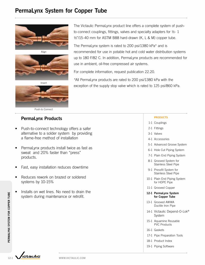
Align
Insert
Push-to Connect
The Victaulic PermaLynx product line offers a complete system of push-
to-connect couplings, fittings, valves and specialty adapters for ½- 1
½”/15-40 mm for ASTM B88 hard-drawn (K, L & M) copper tube.
The PermaLynx system is rated to 200 psi/1380 kPa* and is
recommended for use in potable hot and cold water distribution systems
up to 180 F/82 C. In addition, PermaLynx products are recommended for
use in ambient, oil-free compressed air systems.
For complete information, request publication 22.20.
*All PermaLynx products are rated to 200 psi/1380 kPa with the
exception of the supply stop valve which is rated to 125 psi/860 kPa.
PermaLynx Products
• Push-to-connecttechnologyoffersasafer alternative to a solder system by providing a flame-free method of installation
• PermaLynxproductsinstalltwiceasfastas sweat and 20% faster than “press” products.
• Fast,easyinstallationreducesdowntime
• Reducesreworkonbrazedorsoldered systems by 10-15%
• Installsonwetlines.Noneedtodrainthe system during maintenance or retrofit.
Products
1-1 Couplings
2-1 Fittings
3-1 Valves
4-1 Accessories
5-1 Advanced Groove System
6-1 Hole Cut Piping System
7-1 Plain End Piping System
8-1 Grooved System for Stainless Steel Pipe
9-1 Pressfit System for Stainless Steel Pipe
10-1 Plain End Piping System for HDPE Pipe
11-1 Grooved Copper
12-1 PermaLynx system for copper tube
13-1 Grooved AWWA Ductile Iron Pipe
14-1 Victaulic Depend-O-Lok®
System
15-1 AquamineReusable PVC Products
16-1 Gaskets
17-1 Pipe Preparation Tools
18-1 Product Index
19-1 Piping Software
www.victauLic.com12-1
Per
ma
Lyn
x sy
ste
m f
or
co
PPer
tu
be
PermaLynx system for copper tube

Illustrations exaggerated for clarity
Rigid Radius cut gRoove cement lined pipe
flexible Radius cut gRoove glass lined
Elbows
• VictaulicgroovedpipingcomponentsareavailableforuseonAWWAC-606Class53pipeorheavier
• Fastest,easiestmethodforjoiningAWWAsizepipe-75%fewerboltsthanflanging
• FlushSeal®gasketspecificallydesignedtosealonductileironpipesurfacesprovidestriple-sealtopromoteleak-freeserviceforthelifeofthesystem
• Requestpublication23.01
• Pressureratedupto500psi/3450kPa
• Sizesfrom3–36"/80–900mm
Grooves can be cut into the pipe to provide a rigid or flexible
connection as needed.
90°LongRadiusElbowno. 100-c, pg. 13-7
45°Elbowno. 11-c, pg. 13-7
11¼ºElbowno. 13-c, pg. 13-7
90°ReducingElbowno. 10-cR, pg. 13-11
LongRadiusBaseElbowno. 100-cb, pg. 13-13
90°LongRadiusReducingElbowno. 100-cR, pg. 13-11
BullheadTeeno. 21-c, pg. 13-8
ReducingTeeno. 25-c, pg. 13-9
ReducingCrossno. 35-cR, pg. 13-9
BaseTeeno. 20-cb, pg. 13-13
TrueWyeno. 33-c, pg. 13-8
ReducingBaseTeeno. 25-cb, pg. 13-13
Crossno. 35-c, pg. 13-8
45°Lateralno. 30-c, pg. 13-8
45°ReducingLateralno. 30-cR, pg. 13-9
22½°Elbowno. 12-c, pg. 13-7
BaseElbowno. 10-cb, pg. 13-13
Teeno. 20-c, pg. 13-8
Capno. 60-c, pg. 13-8
Tees,Crosses,Wyes,andLaterals
Pipe and fittings can be coated for abrasive services.
90°Elbowno. 10-c, pg. 13-7
www.victaulic.com 13-1
gR
oo
ved aw
wa
du
ctile
iRo
n pip
egrooved awwa ductile iron pipe

gaskets for grooved end ductile/cast pipe of awwa dimensions
gradetemperature
Range compound color code
general service Recommendations*
S -20°F to +180°F -29°C to +82°C Nitrile Red
Stripe
Specially compounded to conform to ductile pipe surfaces. Recommended for petroleum products, air with oil vapors, vegetable and mineral oils within the specified temperature range; except hot dry air over +140°F/60°C and water over +150°F/66°C. Not recommended for hot water services.
M -20°F to +200°F -29°C to +93°C
Halogenated Butyl
Brown Stripe
Specially compounded to conform to ductile pipe surfaces. Recommended for water service within the specified temperature range plus a variety of dilute acids, oil-free air and many chemical services. Not recommended for petroleum services.
L -30°F to +350°F -34°C to +177°C Silicone Red
GasketRecommended for dry heat, air without hydrocarbons to +350°F/177°C and certain chemical services.
* Refer to Victaulic Gasket Selection Guide (Request 05.01) for specific service recommendations.Services listed are Gasket Service Recommendations only. It should be noted that there are services for which these gaskets are not recommended. Reference should always be made to the latest Victaulic Gasket Selection Guide for specific gasket service recommendations and for a listing of services which are not recommended.
pRoducts
1-1 Couplings
2-1 Fittings
3-1 Valves
4-1 Accessories
5-1 AdvancedGrooveSystem
6-1 HoleCutPipingSystem
7-1 PlainEndPipingSystem
8-1 GroovedSystemforStainlessSteelPipe
9-1 PressfitSystemforStainlessSteelPipe
10-1 PlainEndPipingSystemforHDPEPipe
11-1 GroovedCopper
12-1 PermaLynxSystem forCopperTube
13-1 grooved awwa ductile iron pipe
14-1 VictaulicDepend-O-Lok®
System
15-1 AquamineReusablePVCProducts
16-1 Gaskets
17-1 Pipe Preparation Tools
18-1 ProductIndex
19-1 PipingSoftware
TransitionCoupling–AWWAtoIPSstyle 307, pg. 13-5
Couplingstyle 31, pg. 13-3
Vic-FlangeAdapterstyle 341, 13-4
Couplings
TeeSideOutletno. 20-cs, pg. 13-14
ConcentricReducerno. 50-c, pg. 13-11
EccentricReducerno. 51-c, pg. 13-11
90°Flareno. 10-cf, pg. 13-14
90°LongRadiusFlareno. 100-cf, pg. 13-14
90°SideOutletno. 10-cs, pg. 13-14
StraightFlareno. 43-cf, pg. 13-14
Reducers FlaredandOutletFittings
CheckValveseRies 317, pg. 13-17
Vic-PlugValveseRies 365, pg. 13-15
Valves
www.victaulic.com13-2
gR
oo
ved
aw
wa
du
cti
le i
Ro
n p
ipe
grooved awwa ductile iron pipe

sizemax. working
pressure *max. end load *
allow. pipe end sep. * dimensions
approx. weight each
nominal size
inches mm
actual outside dia.
inches mm
psi kpa
lbs. n
inches mm
x inches
mm
y inches
mm
Z inches
mm
lbs. kg
3 3.960 500 6200 0 – 0.09 5.50 7.63 2.13 4.880 100.6 3450 27590 0 – 2.4 140 194 54 2.2
4 4.800 500 9000 0 – 0.09 6.25 9.20 2.09 7.5100 121.9 3450 40050 0 – 2.4 159 234 53 3.4
6 6.900 400 14950 0 – 0.09 8.28 11.19 2.22 9.4150 175.3 2750 66528 0 – 2.4 210 284 56 4.3
8 9.050 400 25600 0 – 0.09 10.74 14.33 2.59 16.5200 229.9 2750 113920 0 – 2.4 273 364 66 7.5
10 11.100 350 33850 0 – 0.16 12.84 16.44 2.75 22.5250 281.9 2410 150632 0 – 4.0 326 418 70 10.2
12 13.200 350 47900 0 – 0.16 15.27 19.16 2.75 30.0300 335.3 2410 21150 0 – 4.0 388 487 70 14.0
14 15.300 250 45950 0 – 0.16 17.21 21.96 2.75 40.8350 388.6 1725 204470 0 – 4.0 437 558 70 18.5
16 17.400 250 59400 0 – 0.25 19.90 23.96 3.50 61.3400 442.0 1725 264330 0 – 6.4 505 609 89 27.8
18‡ 19.500 250 74650 0 – 0.25 22.03 26.33 3.50 80.0450 495.3 1725 332190 0 – 6.4 560 669 89 36.3
20 21.600 150 54900 0 – 0.25 24.13 28.69 3.50 76.0500 548.6 1035 244305 0 – 6.4 613 729 89 34.5
24 25.800 150 78400 0 – 0.25 28.31 33.06 3.50 104.0600 655.3 1035 34880 0 – 6.4 719 840 89 47.2
30 32.000 150 120570 0 – 0.47 35.02 39.39 4.38 162.0750 812.8 1035 536530 0 – 11.9 890 1001 111 73.5
36 38.300 150 172815 0 – 0.47 41.56 46.04 4.44 200.0900 972.8 1035 769030 0 – 11.9 1056 1169 113 90.7
* Refer to General Notes on pg. 1-4.‡ For Class 53 pipe rating is 150 psi/1035 kPa.
X
Y Z
X
Y ZY Z
X
Couplingstyle 31
ForCompleteInformationRequestPublication23.02
• Canprovidearigidorflexiblejointdependingongrooveposition
• Reducesnumberofboltsbyupto75%
• Pressureratedupto500psi/3450kPa
• Sizesfrom3–36"/80–900mm
typical 3 – 12"/80 – 300 mm siZes typical 14 – 20"/350 – 500 mm siZes typical 24 – 36"/600 – 900 mm siZes
www.victaulic.com 13-3
gR
oo
ved aw
wa
du
ctile
iRo
n pip
egrooved awwa ductile iron pipe – couplings

sizemax. work pressure *
max. end load * sealing surface dimensions
approx. weight each
nominal size
inches mm
actual outside dia.
inches mm
psi kpa
lbs. n
a maximum
inches mm
b minimum
inches mm
w inches
mm
x inches
mm
y inches
mm
Z inches
mm
lbs. kg
3 3.9600 250 3100 3.96 4.94 8.44 7.50 6.00 0.94 5.480 100.6 1725 13795 101 125 214 191 152 24 2.4
4 4.800 250 4500 4.80 5.88 9.94 9.00 7.50 0.94 8.2100 121.9 1725 20025 122 149 252 229 191 24 3.7
6 6.900 250 9300 6.90 8.00 12.00 11.00 9.50 1.00 12.0150 175.3 1725 41385 175 203 305 279 241 25 5.4
8 9.050 250 16000 9.05 10.13 14.63 13.50 11.75 1.13 17.4200 229.9 1725 71200 230 257 372 343 298 29 7.9
10 11.100 250 23700 11.10 12.50 17.13 16.00 14.25 1.19 24.6250 281.9 1725 105465 282 318 435 406 362 30 11.2
12 13.200 250 34000 13.20 14.75 20.13 19.00 17.00 1.25 34.4300 335.3 1725 151300 335 375 511 483 432 32 15.6
14 15.300 200 36700 15.30 16.38 24.63 21.00 18.75 1.50 55.0350 388.6 1375 163315 389 416 626 533 476 38 25.0
16 17.400 150 35600 17.40 18.38 27.25 23.50 21.25 1.88 80.0400 442.0 1035 158420 442 467 692 597 540 48 36.3
18 19.500 150 44700 19.50 20.00 29.13 25.00 22.75 2.25 95.0450 495.3 1035 198915 495 508 740 635 578 57 43.1
20 21.600 150 54900 21.60 22.50 31.63 27.50 25.00 2.38 115.0500 548.6 1035 244305 549 572 803 699 635 61 52.2
24 25.800 150 78400 25.80 27.75 36.13 32.00 29.50 2.50 150.0600 655.3 1035 348880 655 705 918 813 749 64 68.0
* Refer to Publication 23.04 for more details.
Important note:Style 341 requires sufficient clearance behind groove to permit proper assembly.For restrictions on where and how Vic-Flange adapters and flange washers can be used, refer to Publication 23.04.
W
Z
YB
AX
B
A
Z
Y WX
Vic-FlangeAdapterstyle 341
ForCompleteInformationRequestPublication23.04
• Directconnectionofflangedcomponentsintoaradiusgrooved(toAWWAC-606standards)castorductileironpipesystem
• Providerigidjointonrigidradiusgroovedductilepipe
• Allowlimitedmovementonflexibleradiusgroovedductileironpipe
• Pressureratedupto250psi/1725kPa
• Sizesfrom3–12"/80–300mmhingedforeasyhandlingwithintegraltabs
• Sizesfrom14–24"/350–600mmcastinfouridenticalsegmentswhichareinterconnectedasassemblyiscompleted
typical 3 – 12"/80 – 300 mm siZes
Orange area of mating face must be free from gouges, undulations
or deformities of any type for effective sealing.
typical 14 – 24"/350 – 600 mm siZes
Orange area of mating face must be free from gouges, undulations
or deformities of any type for effective sealing.
www.victaulic.com13-4
gR
oo
ved
aw
wa
du
cti
le i
Ro
n p
ipe
grooved awwa ductile iron pipe – couplings

sizemating pipe actual size
max. work pressure *
max. end load *
fixed end pipe sep.*† dimensions
approx. wgt. each
nominal size
inches mm
actual outside dia.
inches mm
ips steel
inches mm
awwa ductile inches
mmpsi kpa
lbs. kg
inches mm
x inches
mm
y inches
mm
Z inches
mmlbs. kg
3 3.960 3.500 3.960 500 4810 0.03 5.50 7.38 2.07 6.080 100.6 88.9 100.6 3450 21405 1 140 187 53 2.7
4 4.800 4.500 4.800 500 7950 0.06 6.38 9.00 2.19 8.0100 121.9 114.3 121.9 3450 35377 2 162 229 56 3.6
6 6.900 6.625 6.900 400 13780 0.06 8.44 11.13 2.31 9.0150 175.3 168.3 175.3 2750 61321 2 214 283 59 4.1
8 9.050 8.625 9.050 400 23370 0.03 11.00 13.88 2.63 18.0200 229.9 219.1 229.9 2750 103997 1 279 353 67 8.2
10 11.100 10.750 11.100 350 31760 0.03 13.13 16.50 2.63 22.0250 281.9 273.0 281.9 2410 141332 1 334 419 67 10.0
12 13.200 12.750 13.200 350 44680 0.03 15.38 18.94 2.63 31.0300 335.3 323.9 335.3 2410 198826 1 391 481 67 14.1
† For field installation only. Style 307 transition couplings are essentially rigid and do not permit expansion/contraction.
* Refer to General Notes on pg. 1-4.
Y
X
Z
TransitionCouplingstyle 307 TransitionforgroovedAWWAductileirontogroovedIPSsteel.
ForCompleteInformationRequestPublication23.03
• DirectsinglecouplingconnectionforgroovedendIPSsteelpipe,valvesorfittingstogroovedendAWWAductileironpipe,valvesorfittingsofthesamenominalsize
• Pressureratedupto500psi/3450kPa
• Sizesfrom3–12"/80–300mm
typical foR all siZes
www.victaulic.com 13-5
gR
oo
ved aw
wa
du
ctile
iRo
n pip
egrooved awwa ductile iron pipe – couplings

KL
M
N
R
S
T
EH
G
F
R
S
T
Y
M
K
NT
R
Y
G
E
F T
R
EG
F
R K M
N
R
R
S
T
L
MN
K
R
S
T
H
EF
G
VY
T
R
KMN
VY
T
R
E GF
S
HG
FJE
L
M
NKP
X Y Z
T S R
F G H
Z Y X
R S TN M K
MN
KR
S
TG F
ER
S
T
EG
HFT R
KM
NLR T F H
G
KNM
E HG
F
L KM
N
AWWAFittingsForCompleteInformationRequestPublication23.05
• AWWAsizefittingsaresuppliedwithrigidradiusgroovesinaccordancewithANSI/AWWAC-606
• FittingsconformtoANSI21.10/AWWAC-110forcenter-to-enddimensionsandAWWAC-153orANSI21.10/AWWAC-110forwallthicknesses
• Availablewithawidevarietyofcoatingsandlinings
• VictauliccansupplytappedfittingsonordertoANSIB16.1dimensionlocations;specifyfittingsize,taplocationbyletter(asshownbelowandtapsize–NPTdimensions)onorder
• Pressureratedupto350psi/2400kPa
• Sizesfrom3–36"/80–900mm
TappedFittings
45° lateRal – stRaight & Reducing
90° elbow – stRaight siZe
90° base elbow – stRaight & Reducing
tee – stRaight siZes
90° elbow Reducing siZes
90° elbow
cRoss – stRaight siZe
eccentRic ReduceR
45° elbow base fittings
base tee concentRic ReduceR
tRue wye
Elbows Tees,Crosses,Wyes,andLaterals
Reducers
www.victaulic.com13-6
gR
oo
ved
aw
wa
du
cti
le i
Ro
n p
ipe
grooved awwa ductile iron pipe – fittings

sizeno. 100-c
90º long Radius elbowno. 10-c 90º elbow
no. 11-c 45° elbow
no. 12-c 22½° elbow
no. 13-c 11¼° elbow
nominal size
inches mm
actual outside dia.
inches mm
c to e inches
mm
approx. weight each
lbs kg
c to e inches
mm
approx. weight each
lbs. kg
c to e inches
mm
approx. weight each
lbs. kg
c to e inches
mm
approx. weight each
lbs. kg
c to e inches
mm
approx. weight each
lbs. kg
3 3.960 7.75 19.3 5.50 8.6 3.00 5.8 3.00 12.5 3.00 9.080 100.6 197 8.8 140 3.9 76 2.6 76 5.7 76 4.1
4 4.800 9.00 28.0 6.50 12.0 4.00 8.4 4.00 11.5 4.00 11.5100 121.9 229 12.7 165 5.4 102 3.8 102 5.2 102 5.2
6 6.900 11.50 55.0 8.00 22.0 5.00 15.0 5.00 25.0 5.00 21.5150 175.3 292 25.0 203 10.0 127 6.8 127 11.3 127 9.8
8 9.050 14.00 83.0 9.00 38.0 5.50 28.8 5.50 39.5 5.50 39.0200 229.9 356 37.7 229 17.2 140 13.1 140 17.9 140 17.7
10 11.100 16.50 160.0 11.00 76.0 6.50 43.3 6.50 67.0 6.50 77.0250 281.9 419 72.6 279 34.5 165 19.6 165 30.4 165 34.9
12 13.200 19.00 210.0 12.00 92.0 7.50 72.0 7.50 108.0 7.50 120.0300 335.3 483 95.3 305 41.7 191 032.7 191 49.0 191 54.4
14 15.300 21.50 261.0 14.00 174.0 7.50 104.0 7.50 92.0 7.50 101.0350 388.6 546 118.4 356 78.9 191 47.2 191 41.7 191 45.8
16 17.400 24.00 337.0 15.00 239.0 8.00 142.0 8.00 112.0 8.00 121.0400 442.0 610 152.9 381 108.4 203 64.4 203 50.8 203 54.9
18 19.500 26.50 451.0 16.50 328.0 8.50 186.0 8.50 145.0 8.50 146.0450 495.3 673 204.6 419 148.8 216 84.4 216 65.8 216 66.2
20 21.600 29.00 588.0 18.00 413.0 9.50 246.0 9.50 200.0 9.50 202.0500 548.6 737 266.7 457 187.3 241 111.6 241 90.7 241 91.6
24 25.800 34.00 909.0 22.00 668.0 11.00 414.0 11.00 282.0 11.00 284.0600 655.3 864 412.3 559 303.0 279 187.8 279 127.9 279 128.8
30 32.000 41.50 2136.0 25.00 1002.0 15.00 720.0 15.00 681.0 15.00 699.0750 762.0 1054 968.9 635 454.4 381 326.6 381 308.9 381 317.1
36 38.300 49.00 3120.0 28.00 1608.0 18.00 1152.0 18.00 975.0 18.00 1124.0900 914.4 1245 1415.2 711 729.4 457 522.6 457 442.3 457 509.8
C to E
C to E
Cto E
C to EC to E
C to E
no. 100-c no. 10-c no. 11-c no. 12-c no. 13-c
Elbowsno. 100-c 90ºLongRadiusElbowno. 10-c 90ºElbowno. 11-c 45ºElbowno. 12-c 22½ºElbowno. 13-c 11¼ºElbow
ForCompleteInformationRequestPublication23.05
www.victaulic.com 13-7
gR
oo
ved aw
wa
du
ctile
iRo
n pip
egrooved awwa ductile iron pipe – fittings

sizeno. 20-c
teeno. 33-c true wye
no. 35-c cross
no. 30-c 45° lateral
no. 60-c cap†
nominal size
inches mm
actual outside dia.
inches mm
c to e inches
mm
approx. wgt. each
lbs. kg
c to le inches
mm
c to se inches
mm
approx. wgt. each
lbs. kg
c to e inches
mm
approx. wgt. each
lbs. kg
c to le inches
mm
c to se inches
mm
approx. wgt. each
lbs. kg
t thickness
inches mm
approx. wgt. each
lbs. kg
3 3.960 5.50 14.2 3.00 3.00 25.00 5.50 24.0 10.00 3.00 28.0 1.22 3.080 100.6 140 6.4 140 76 635 140 10.9 254 76 12.7 31 1.4
4 4.800 6.50 19.0 6.50 3.00 55.0 6.50 40.0 12.00 3.00 38.4 1.16 5.0100 121.9 165 8.6 165 76 25.0 165 18.1 305 76 12.7 29 2.3
6 6.900 8.00 34.0 8.00 3.50 90.0 8.00 71.0 14.50 3.50 67.0 1.16 9.0150 175.3 203 15.4 203 89 40.8 203 32.2 368 89 30.4 29 4.1
8 9.050 9.00 59.0 9.00 4.50 140.0 9.00 106.0 17.50 4.50 120.0 1.34 16.0200 229.9 229 26.8 229 114 63.5 229 48.1 445 114 54.4 34 7.3
10 11.100 11.00 111.0 11.00 5.00 220.0 11.00 225.0 20.50 5.00 215.0 1.53 37.2250 281.9 279 50.4 279 127 99.8 279 102.1 521 127 97.5 39 16.9
12 13.200 12.00 136.0 12.00 5.50 315.0 12.00 310.0 24.50 5.50 346.0 1.53 52.0300 335.3 305 61.7 305 140 142.9 305 140.6 622 140 157.0 39 23.6
14 15.300 14.00 262.0 14.00 6.00 + 14.00 307.0 27.00 6.00 492.0 2.75* 55.0350 388.6 356 118.8 356 152 356 139.3 686 152 223.2 70 25.0
16 17.400 15.00 304.0 15.00 6.50 + 15.00 426.0 30.00 6.50 696.0 2.75* 68.0400 442.0 381 137.9 381 165 381 193.2 762 165 315.7 70 30.9
18 19.500 16.50 408.0 16.50 7.00 + 16.50 567.0 32.00 7.00 870.0 2.75* 90.0450 495.3 419 185.1 419 178 419 254.9 813 178 394.6 70 40.8
20 21.600 18.00 552.0 18.00 8.00 + 18.00 717.0 35.00 8.00 1103.0 2.75* 110.0500 548.6 457 250.4 457 203 457 325.2 889 203 500.3 70 50.0
24 25.800 22.00 980.0 22.00 9.00 + 22.00 1177.0 40.50 9.00 1746.0 2.75* 165.0600 655.3 559 444.5 559 229 559 533.9 1029 229 792.0 70 74.8
30 32.000 25.00 1552.0 25.00 10.00 + 25.00 1366.0 49.00 10.00 3280.0 4.00* 300.0750 762.0 635 704.0 635 254 635 619.6 1245 254 1487.8 102 136.1
36 38.300 28.00 2050.0 28.00 15.25 + 28.00 1885.0 56.00 15.25 5020.0 4.00* 536.0900 914.4 711 929.9 711 387 711 855.0 1422 387 2277.1 102 243.1
* Dish caps.+ Contact Victaulic for details.† Caps from ½ – 3"/15 – 80 mm tap sizes.
size dimensionsapprox.
weight each
nominal size
inches mm
c to eoR inches
mm
c to eob inches
mm
lbs. kg
4 × 4 × 6 + + 47.0100 100 150 21.3
6 × 6 × 8 8.00 8.00 79.0150 150 200 203 203 35.8
8 × 8 × 10 11.00 11.00 164.0200 200 250 279 279 74.4
10 × 10 × 12 + + 226.0250 250 300 102.5
+ Contact Victaulic for details.
C to E
CtoE
C to LE
C toSE
C to E
C to LE
C toSE
C toLE
T
C toEOB
C toEOR
Tee,TrueWye,Cross,Lateral,andCapno. 20-c Teeno. 33-c TrueWyeno. 35-c Crossno. 30-c 45ºLateralno. 60-c Cap
ForCompleteInformationRequestPublication23.05
no. 21-c
BullheadTeeno. 21-c
ForCompleteInformationRequestPublication23.05
no. 20-c no. 33-c no. 35-c no. 30-c no. 60-c
www.victaulic.com13-8
gR
oo
ved
aw
wa
du
cti
le i
Ro
n p
ipe
grooved awwa ductile iron pipe – fittings

sizeno. 25-c
Reducing teeno. 35-cR
Reducing crossno. 30-cR
45° Reducing lateral
nominal size
inches mm
c to eoR inches
mm
c to eob inches
mm
approx. weight each
lbs. kg
h inches
mm
J
inches mm
approx. weight each
lbs. kg
c to le inches
mm
c to se inches
mm
approx. weight each
lbs. kg
4 × 3 6.50 6.50 26.4 6.50 6.50 22.0 12.00 3.00 45.0100 80 165 165 12.0 165 165 10.0 305 76 20.4
6 × 3 8.00 8.00 30.0 8.00 8.00 46.0 14.50 3.50 74.0150 80 203 203 13.6 203 203 20.9 368 89 33.6
4 8.00 8.00 34.0 8.00 8.00 38.0 14.50 3.50 80.0100 203 203 15.4 203 203 17.2 368 89 36.3
8 × 3 9.00 9.00 + — — — — — —200 80 229 229
4 9.00 9.00 78.0 9.00 9.00 76.0 17.50 4.50 125.0100 229 229 35.4 229 229 34.5 445 114 56.7
6 9.00 9.00 80.0 9.00 9.00 59.0 17.50 4.50 140.0150 229 229 36.3 229 229 26.8 445 114 63.5
10 × 4 11.00 11.00 120.0 11.00 11.00 120.0 20.50 5.00 204.0250 100 279 279 54.4 279 279 54.4 521 127 92.5
6 11.00 11.00 128.0 11.00 11.00 114.0 20.50 5.00 212.0150 279 279 58.1 279 279 51.7 521 127 96.2
8 11.00 11.00 130.0 11.00 11.00 123.0 20.50 5.00 236.0200 279 279 59.0 279 279 56.8 521 127 107.1
12 × 4 12.00 12.00 112.0 12.00 12.00 174.0 24.50 5.50 290.0300 100 305 305 50.8 305 305 78.9 622 140 131.5
6 12.00 12.00 180.0 12.00 12.00 130.0 24.50 5.50 302.0150 305 305 81.7 305 305 59.0 622 140 137.0
8 12.00 12.00 186.0 12.00 12.00 139.0 24.50 5.50 324.0200 305 305 84.4 305 305 63.1 622 140 147.0
10 12.00 12.00 192.0 12.00 12.00 154.0 24.50 5.50 356.0250 305 305 87.1 305 305 69.9 622 140 161.5
14 × 6 14.00 14.00 238.0 14.00 14.00 215.0 27.00 6.00 330.0350 150 356 356 108.0 356 356 97.5 686 152 149.7
8 14.00 14.00 241.0 14.00 14.00 221.0 27.00 6.00 346.0200 356 356 109.3 356 356 100.3 686 152 156.9
10 14.00 14.00 258.0 14.00 14.00 235.0 27.00 6.00 540.0250 356 356 114.8 356 356 106.6 686 152 244.9
12 14.00 14.00 267.0 14.00 14.00 244.0 27.00 6.00 625.0300 356 356 121.1 356 356 110.7 686 152 283.5
16 × 6 15.00 15.00 288.0 15.00 15.00 266.0 30.00 6.50 570.0400 150 381 381 130.6 381 381 120.7 762 165 258.6
8 15.00 15.00 315.0 15.00 15.00 276.0 30.00 6.50 585.0200 381 381 142.9 381 381 125.2 762 165 265.4
10 15.00 15.00 319.0 15.00 15.00 291.0 30.00 6.50 630.0250 381 381 144.7 381 381 132.0 762 165 285.8
12 15.00 15.00 330.0 15.00 15.00 305.0 30.00 6.50 650.0300 381 381 149.7 381 381 138.4 762 165 294.8
14 15.00 15.00 341.0 15.00 15.00 280.0 30.00 6.50 692.0350 381 381 154.7 381 381 127.0 762 165 313.9
18 × 8 13.00 15.50 326.0 15.50 13.00 272.0 + + +450 200 330 394 147.9 394 330 123.4
10 13.00 15.50 332.0 15.50 13.00 277.0 32.00 7.00 765.0250 330 394 150.6 394 330 125.6 813 178 347.0
12 13.00 15.50 339.0 15.50 13.00 291.0 32.00 7.00 800.0300 330 394 153.8 394 330 132.0 813 178 362.9
14 16.50 16.50 441.0 16.50 16.50 361.0 32.00 7.00 865.0350 419 419 200.0 419 419 163.7 813 178 392.4
16 16.50 16.50 453.0 16.50 16.50 367.0 32.00 7.00 895.0400 419 419 205.5 419 419 166.5 813 178 406.0
table continued on pg. 13-10
+ Contact Victaulic for details.IMportaNt Note: Non-standard reducing cross sizes are available. Contact Victaulic for details.
C to EOR
Cto
EOB
C toLE
C toSE
C to LE
J
J
HH
no. 25-c no. 30-cRno. 35-cR
ReducingFittingsno. 25-c ReducingTeeno. 35-cR ReducingCrossno. 30-cR 45ºReducingLateral
ForCompleteInformationRequestPublication23.05
www.victaulic.com 13-9
gR
oo
ved aw
wa
du
ctile
iRo
n pip
egrooved awwa ductile iron pipe – fittings

sizeno. 25-c
Reducing teeno. 35-cR
Reducing crossno. 30-cR
45° Reducing lateral
nominal size
inches mm
c to eoR inches
mm
c to eob inches
mm
approx. weight each
lbs. kg
h inches
mm
J
inches mm
approx. weight each
lbs. kg
c to le inches
mm
c to se inches
mm
approx. weight each
lbs. kg
table continued fRom pg. 13-9
20 × 6 14.00 17.00 + — — — — — —500 150 356 432
8 14.00 17.00 412.0 17.00 14.00 343.0 — — —200 356 432 186.9 432 356 155.6
10 14.00 17.00 419.0 17.00 14.00 343.0 + + +250 356 432 190.1 432 356 155.6
12 14.00 17.00 426.0 17.00 14.00 357.0 35.00 8.00 1000.0300 356 432 193.2 432 356 161.9 889 203 453.6
14 14.00 17.00 443.0 17.00 14.00 327.0 35.00 8.00 1062.0350 356 432 201.0 432 356 148.3 889 203 481.7
16 18.00 18.00 571.0 18.00 18.00 458.0 35.00 8.00 1105.0400 457 457 259.0 457 457 207.7 889 203 501.2
18 18.00 18.00 584.0 18.00 18.00 469.0 35.00 8.00 1150.0450 457 457 264.9 457 457 212.7 889 203 521.6
24 × 6 15.00 19.00 + — — — — — —600 150 381 483
8 15.00 19.00 + + + + + + +200 381 483
10 15.00 19.00 + + + + + + +250 381 483
12 15.00 19.00 593.0 15.00 19.00 475.0 + + +300 381 483 269.0 381 483 215.5
14 15.00 19.00 610.0 15.00 19.00 450.0 40.50 9.00 1510.0350 381 483 276.7 381 483 204.1 1029 229 684.9
16 15.00 19.00 620.0 15.00 19.00 446.0 40.50 9.00 1580.0400 381 483 281.2 381 483 202.3 1029 229 716.7
18 22.00 22.00 918.0 22.00 22.00 782.0 40.50 9.00 1306.0450 559 559 416.4 559 559 354.7 1029 229 592.4
20 22.00 22.00 937.0 22.00 22.00 788.0 40.50 9.00 1705.0500 559 559 425.0 559 559 357.4 1029 229 773.4
30 × 6 18.00 23.00 + — — — — — —750 150 457 584
8 18.00 23.00 + + + + + + +200 457 584
10 18.00 23.00 + + + + + + +250 457 584
12 18.00 23.00 1175.0 18.00 23.00 888.0 49.00 10.00 2178.0300 457 584 533.0 457 584 402.8 1245 254 987.9
14 18.00 23.00 1250.0 18.00 23.00 853.0 49.00 10.00 2208.0350 457 584 567.0 457 584 386.9 1245 254 1001.5
16 18.00 23.00 1437.0 18.00 23.00 843.0 49.00 10.00 2248.0400 457 584 651.0 457 584 382.4 1245 254 1019.7
18 18.00 23.00 1450.0 18.00 23.00 839.0 49.00 10.00 2294.0450 457 584 657.7 457 584 380.6 1245 254 1040.6
20 18.00 23.00 1462.0 18.00 23.00 835.0 49.00 10.00 2339.0500 457 584 663.2 457 584 378.8 1245 254 1061.0
24 25.00 25.00 1475.0 25.00 25.00 1304.0 49.00 10.00 2451.0600 635 635 669.1 635 635 591.5 1245 254 1111.8
36 × 8 20.00 26.00 + + + + + + +900 200 508 660
10 20.00 26.00 + + + + + + +250 508 660
12 20.00 26.00 + 20.00 26.00 1262.0 + + +300 508 660 508 660 572.4
14 20.00 26.00 + 20.00 26.00 1222.0 + 15.25 +350 508 660 508 660 554.3 387
16 20.00 26.00 + 20.00 26.00 1213.0 54.00 15.25 3493.0400 508 660 508 660 550.2 1372 387 1584.4
18 20.00 26.00 + 20.00 26.00 1204.0 54.00 15.25 3533.0450 508 660 508 660 546.1 1372 387 1602.6
20 20.00 26.00 + 20.00 26.00 1190.0 54.00 15.25 3574.0500 508 660 508 660 539.8 1372 387 1621.2
24 20.00 26.00 + 20.00 26.00 1163.0 54.00 15.25 3675.0600 508 660 508 660 527.5 1372 387 1667.0
30 28.00 28.00 + 28.00 28.00 1865.0 56.00 15.25 3879.0750 711 711 711 711 846.0 1422 387 1759.5
+ Contact Victaulic for details.IMportaNt NoteS: For 30"/750 mm sizes and larger contact Victaulic for details.Non-standard reducing cross sizes are available. Contact Victaulic for details.
C to EOR
Cto
EOB
C toLE
C toSE
C to LE
J
J
HH
ReducingFittings(cont'd)
no. 25-c ReducingTeeno. 35-cR ReducingCrossno. 30-cR 45ºReducingLateral
ForCompleteInformationRequestPublication23.05
no. 25-c
no. 30-cR
no. 35-cR
www.victaulic.com13-10
gR
oo
ved
aw
wa
du
cti
le i
Ro
n p
ipe
grooved awwa ductile iron pipe – fittings

sizeno. 50-c
concentric Reducerno. 51-c
eccentric Reducerno. 10-cR
90° Reducing elbowno. 100-cR
90° long Radius Red. el.
nominal size
inches mm
e to e inches
mm
approx. weight each
lbs. kg
e to e inches
mm
approx. weight each
lbs. kg
c to e inches
mm
approx. weight each
lbs. kg
c to e inches
mm
approx. weight each
lbs. kg
4 × 3 7.00 10.0 7.00 12.0 6.50 17.0 9.00 20.0100 80 178 4.5 178 5.4 165 7.7 229 8.1
6 × 3 9.00 15.0 9.00 20.0 8.00 28.5 11.50 36.0150 80 229 6.8 229 9.1 203 12.9 292 16.3
4 9.00 16.5 9.00 25.0 8.00 29.6 11.50 40.0100 229 7.5 229 11.3 203 13.4 292 18.1
8 × 3 11.00 33.0 11.00 + — — — —200 80 279 15.0 2794 11.00 28.0 11.00 35.0 9.00 46.5 14.00 60.0
100 279 12.7 279 15.9 229 21.1 356 27.26 11.00 34.0 11.00 44.0 9.00 48.5 14.00 71.0
150 279 15.4 279 20.0 229 22.0 356 32.210 × 4 12.00 42.0 12.00 54.0 11.00 68.0 16.50 90.0
250 100 305 19.1 305 24.5 279 30.8 419 40.86 12.00 46.0 12.00 60.0 11.00 77.0 16.50 106.0
150 305 20.9 305 27.2 279 34.9 419 48.18 12.00 50.0 12.00 70.0 11.00 88.0 16.50 121.0
200 305 22.7 305 31.8 279 39.9 419 54.912 × 4 14.00 60.0 14.00 82.0 12.00 + + +300 100 356 27.2 356 37.2 305
6 14.00 70.0 14.00 84.0 12.00 110.0 19.00 143.0150 356 31.8 356 38.1 305 49.9 483 64.9
8 14.00 74.0 14.00 91.0 12.00 126.0 19.00 163.0200 356 33.6 356 41.3 305 57.2 483 73.910 14.00 84.0 14.00 110.0 12.00 150.0 19.00 188.0
250 356 38.1 356 49.9 305 68.0 483 85.314 × 6 16.00 89.0 16.00 104.0 14.00 + + +350 150 406 40.4 406 47.2 356
8 16.00 102.0 16.00 121.0 14.00 135.0 21.50 183.0200 406 46.3 406 54.9 356 61.2 546 83.010 16.00 112.0 16.00 135.0 14.00 170.0 21.50 213.0
250 406 50.8 406 61.2 356 77.1 546 96.612 16.00 126.0 16.00 150.0 14.00 195.0 21.50 240.0
300 406 57.4 406 68.0 356 88.5 546 108.916 × 6 18.00 11.0 18.00 140.0 — — + +400 150 457 49.9 457 63.5
8 18.00 122.0 18.00 160.0 15.00 + 24.00 228.0200 457 55.3 457 72.6 381 610 103.410 18.00 135.0 18.00 168.0 15.00 195.0 24.00 263.0
250 457 61.2 457 76.2 381 88.5 610 119.312 18.00 146.0 18.00 190.0 15.00 240.0 24.00 295.0
300 457 66.2 457 86.2 381 108.9 610 133.814 18.00 173.0 18.00 210.0 15.00 280.0 24.00 290.0
350 457 78.5 457 95.3 381 127.0 610 131.518 × 8 19.00 148.0 19.00 180.0 16.50 + — — 450 200 483 67.1 483 81.6 419
10 19.00 158.0 19.00 215.0 16.50 + 26.50 +250 483 71.1 483 97.5 419 67312 19.00 173.0 19.00 215.0 16.50 305.0 26.50 336.0
300 483 78.5) 483 97.5 419 138.3 673 152.414 19.00 200.0 19.00 230.0 16.50 345.0 26.50 355.0
350 483 90.7 483 104.3 419 156.5 673 161.016 19.00 220.0 19.00 275.0 16.50 360.0 26.50 386.0
400 483 100.0 483 124.7 419 163.3 673 175.1table continued on pg. 13-12
+ Contact Victaulic for details.
Important note:For 30"/750 mm sizes and larger contact Victaulic for details.
E to E E to E
C to E
C to E
ReducersandReducingElbowsno. 50-c ConcentricReducerno. 51-c EccentricReducerno. 10-cR 90ºReducingElbowno. 100-cR 90ºLongRadiusReducingElbow
ForCompleteInformationRequestPublication23.05 no. 50-c no. 51-c no. 10-cR no. 100-cR
www.victaulic.com 13-11
gR
oo
ved aw
wa
du
ctile
iRo
n pip
egrooved awwa ductile iron pipe – fittings

sizeno. 50-c
concentric Reducerno. 51-c
eccentric Reducerno. 10-cR
90° Reducing elbowno. 100-cR
90° long Radius Red. el.
nominal size
inches mm
e to e inches
mm
approx. weight each
lbs. kg
e to e inches
mm
approx. weight each
lbs. kg
c to e inches
mm
approx. weight each
lbs. kg
c to e inches
mm
approx. weight each
lbs. kg
table continued fRom pg. 13-11
20 × 8 20.00 173.0 20.00 + — — — —500 200 508 78.5 508
10 20.00 182.0 20.00 215.0 18.00 + 29.00 +250 508 82.6 508 97.5 457 737
12 20.00 201.0 20.00 250.0 18.00 365.0 29.00 +300 508 91.2 508 113.4 457 165.6 737
14 20.00 230.0 20.00 270.0 18.00 405.0 29.00 +350 508 104.3 508 122.5 457 183.7 737
16 20.00 251.0 20.00 300.0 18.00 440.0 29.00 466.0400 508 113.9 508 136.1 457 199.6 737 211.4
18 20.00 275.0 20.00 320.0 18.00 485.0 29.00 507.0450 508 124.7 508 145.2 457 220.0 737 230.0
24 ×
8 24.00 610
257.0 116.6
24.00 610
300.0 136.1 + + + +600 200
10 24.00 610
274.0 124.3
24.00 610
300.0 136.1 + + + +250
12 24.00 293.0 24.00 395.0 22.00 590.0 34.00 +300 610 132.9 610 179.2 559 267.6 864
14 24.00 331.0 24.00 425.0 22.00 630.0 34.00 +350 610 150.1 610 192.8 559 285.8 864
16 24.00 358.0 24.00 455.0 22.00 690.0 34.00 658.0400 610 162.4 610 206.4 559 313.0 864 298.5
18 24.00 386.0 24.00 465.0 22.00 735.0 34.00 +450 610 175.1 610 210.9 559 333.4 864
20 24.00 418.0 24.00 525.0 22.00 815.0 34.00 759.0500 610 189.6 610 238.1 559 369.7 864 344.3
30 × 8 + + + + + + — —750 200
10 + + + + + + — —250
12 30.00 + 30.00 + + + — —300 762 762
14 30.00 + 30.00 + 25.00 + — —350 762 762 635.0
16 30.00 + 30.00 + 25.00 + 41.50 +400 762 762 635.0 1054
18 30.00 + 30.00 + 25.00 + 41.50 +450 762 762 635.0 1054
20 30.00 + 30.00 + 25.00 + 41.50 +500 762 762 635.0 1054
24 30.00 + 30.00 + 25.00 1170.0 41.50 +600 762 762 635.0 530.7 1054
36 × 8 + + + + + + — —900 200
10 + + + + + + — —250
12 + + + + + + — —300
14 36.00 + 36.00 + + + — —350 914 914
16 36.00 + 36.00 + + + — —400 914 914
18 36.00 + 36.00 + + + — —450 914 914
20 36.00 1280.0 36.00 + + + 49.00 +500 914 580.6 914 1245
24 36.00 1370.0 36.00 + + + 49.00 +600 914 621.4 914 1245
30 36.00 1450.0 36.00 + + + 49.00 +750 914 657.7 914 1245
+ Contact Victaulic for details.
Important note:For 30"/750 mm sizes and larger contact Victaulic for details.
E to E
E to E
C to E
C to E
ReducersandReducingElbows(cont'd)
no. 50-c ConcentricReducerno. 51-c EccentricReducerno. 10-cR 90ºReducingElbowno. 100-cR 90ºLongRadiusReducingElbow
ForCompleteInformationRequestPublication23.05
no. 50-c
no. 51-c
no. 10-cR
no. 100-cR
www.victaulic.com13-12
gR
oo
ved
aw
wa
du
cti
le i
Ro
n p
ipe
grooved awwa ductile iron pipe – fittings

size dimensionsapprox.
weight each
nominal size
inches mm
actual outside dia.
inches mm
R inches
mm
u inches
mm
t inches
mm
s inches
mm
w inches
mm
no. 10-cb base elbow
lbs. kg
no. 20-cb base tee
lbs. kg
no. 100-cb lR base elbow
lbs. kg
no. 25-cb Red. base tee
lbs. kg
3 3.960 4.88 0.50 0.56 5.00 3.88 19.0 19.0 – +80 100.6 124 13 14 127 99 8.6 8.6
4 4.800 5.50 0.50 0.62 6.00 4.75 23.6 26.0 – +100 121.9 140 13 16 152 121 10.7 11.8
6 6.900 7.00 0.62 0.69 7.00 5.50 42.0 50.0 – +150 175.3 178 16 18 178 140 19.1 22.7
8 9.050 8.38 0.88 0.94 9.00 7.50 75.0 92.0 – +200 229.9 213 22 24 229 191 34.0 41.7
10 11.100 9.75 0.88 0.94 9.00 7.50 114.0 125.0 – +250 281.9 248 22 24 229 191 51.7 56.7
12 13.200 11.25 1.00 1.00 11.00 9.50 152.0 183.0 – +300 335.3 286 25 25 279 241 69.0 83.0
14 15.300 12.50 1.00 1.00 11.00 9.50 – – 340.0 +350 388.6 318 25 25 279 241 154.2
16 17.400 13.75 1.00 1.00 11.00 9.50 – – 425.0 +400 442.0 349 25 25 279 241 192.8
18 19.500 15.00 1.12 1.12 13.50 11.75 – – 591.0 +450 495.3 381 29 29 343 299 268.1
20 21.600 16.00 1.12 1.12 13.50 11.75 – – 717.0 +500 548.6 406 29 29 343 299 325.2
24 25.800 18.50 1.12 1.12 13.50 11.75 – – 1056.0 +600 655.3 470 29 29 343 299 479.0
+ 90° reducing elbows are available with a base. Contact Victaulic for details.
Important notes:Bolt hole template shown for round base is the same as for the flange of the supporting pipe size, except using only four holes in all cases so placed as to straddle center lines. The bases of these fittings are intended for support in compression and are not to be used for anchors or supports in tension or sheer.Grooved end base 90° elbows (#X-90 CDI) and base tees (#X-CDI) are available with dimensions to ANSI B16.1.Side base fittings are available. Contact Victaulic for details.
S
R
T
U
S
RU
T S
W
STU
R
STU
R
BaseFittingsno. 10-cb BaseElbowno. 20-cb BaseTeeno. 25-cb ReducingBaseTeeno. 100-cb LongRadiusBaseTee
ForCompleteInformationRequestPublication23.05
no. 10-cb no. 20-cb Round baseno. 25-cb no. 100-cb
www.victaulic.com 13-13
gR
oo
ved aw
wa
du
ctile
iRo
n pip
egrooved awwa ductile iron pipe – fittings

sizeno. 10-cf 90° flare
no. 100-cf 90° long Radius flare
no. 43-cf straight flare
no. 10-cs* 90° side outlet
no. 20-cs* tee side outlet
nominal size
inches mm
actual outside dia.
inches mm
c to e inches
mm
c to f inches
mm
approx. wgt. each
lbs. kg
c to e inches
mm
c to f inches
mm
approx. wgt. each
lbs. kg
e to e inches
mm
approx. wgt. each
lbs. kg
c to e inches
mm
approx. wgt. each
lbs. kg
c to e inches
mm
approx. wgt. each
lbs. kg
3 3.960 5.50 9.00 18.0 7.75 11.25 23.0 8.00 13.0 5.50 13.0 5.50 28.080 100.6 140 229 8.2 197 286 10.4 203 5.9 140 5.9 140 12.7
4 4.800 6.50 9.50 35.0 9.00 12.50 42.0 8.00 17.0 6.50 30.0 6.50 42.0100 121.9 165 241 15.9 229 318 19.1 203 7.7 165 13.6 165 19.1
6 6.900 8.00 11.50 70.0 11.50 15.00 68.0 8.00 23.0 8.00 58.0 8.00 85.0150 175.3 203 292 31.8 292 381 30.9 203 10.4 203 26.3 203 38.6
8 9.050 9.00 13.50 120.0 14.00 18.50 118.0 10.00 43.0 9.00 90.0 9.00 114.0200 229.9 229 343 54.4 356 470 53.5 254 19.5 229 40.8 229 51.7
10 11.100 11.00 16.50 157.0 16.50 22.50 188.0 10.00 58.0 11.00 124.0 11.00 219.0250 281.9 279 419 71.2 419 572 85.3 254 26.3 279 56.3 279 99.3
12 13.200 12.00 18.50 190.0 19.00 25.50 275.0 12.00 100.0 12.00 170.0 12.00 295.0300 335.3 305 470 86.2 483 648 124.7 305 45.4 305 77.1 305 133.8
14 15.300 14.00 21.50 235.0 21.50 29.00 325.0 12.00 90.0 14.00 + + +350 388.6 356 546 106.6 546 737 147.4 305 40.8 356
16 17.400 15.00 23.00 300.0 24.00 32.00 435.0 16.00 145.0 15.00 + + +400 442.0 381 584 136.1 610 813 197.3 406 65.8 381
18 19.500 16.50 25.00 391.0 26.50 35.00 571.0 16.00 205.0 16.50 + + +450 495.3 419 635 177.4 673 889 259.0 406 93.0 419
20 21.600 18.00 27.00 496.0 29.00 38.00 731.0 18.00 221.0 18.00 + + +500 548.6 457 686 255.0 737 965 331.6 457 100.3 457
24 25.800 22.00 32.50 808.0 34.00 44.50 1642.0 18.00 293.0 22.00 + + +600 655.3 559 826 366.5 864 1130 744.8 457 132.9 559
30 32.000 + + + + + + 24.00 567.0 + + + +750 762.0 610 257.2
36 38.300 + + + + + + 24.00 736.0 + + + +900 914.4 610 333.9
+ Contact Victaulic for details.* Reducing side outlet 90° Elbows, Tees, and Crosses are available. Contact Victaulic for details.
C to E
CtoF
C to E
CtoF E
toE
C to E C to E
FlaredandOutletFittingsno. 10-cf 90ºFlareno. 100-cf 90ºLongRadiusFlareno. 43-cf StraightFlareno. 10-cs 90ºSideOutletno. 20-cs TeeSideOutlet
ForCompleteInformationRequestPublication23.05
no. 10-cf no. 100-cf no. 43-cf no. 10-cs* no. 20-cs*
www.victaulic.com13-14
gR
oo
ved
aw
wa
du
cti
le i
Ro
n p
ipe
grooved awwa ductile iron pipe – fittings
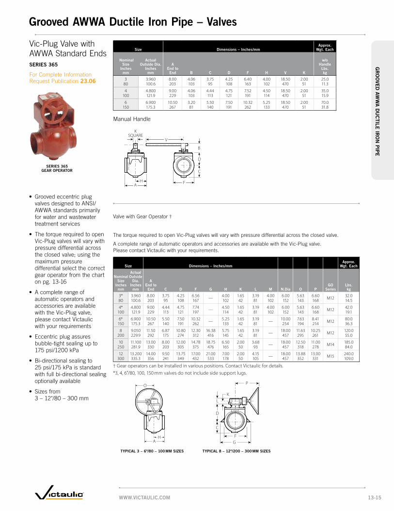
ValvewithGearOperator†
ThetorquerequiredtoopenVic-Plugvalveswillvarywithpressuredifferentialacrosstheclosedvalve.
AcompleterangeofautomaticoperatorsandaccessoriesareavailablewiththeVic-Plugvalve.PleasecontactVictaulicwithyourrequirements.
size dimensions – inches/mmapprox.
wgt. each
nominal size
inches mm
actual outside
dia. inches
mm
a end to end c d f g h K l m n.dia o p
go series
lbs. kg
3* 3.960 8.00 3.75 4.25 6.56 — 4.00 1.65 3.19 4.00 6.00 5.63 6.60 M12 32.080 100.6 203 95 108 167 102 42 81 102 152 143 168 14.5
4* 4.800 9.00 4.44 4.75 7.74 — 4.50 1.65 3.19 4.00 6.00 5.63 6.60 M12 42.0100 121.9 229 113 121 197 114 42 81 102 152 143 168 19.1
6* 6.900 10.50 5.50 7.50 10.32 — 5.25 1.65 3.19 — 10.00 7.63 8.41 M12 80.0150 175.3 267 140 191 262 133 42 81 254 194 214 36.3
8 9.050 11.50 6.87 10.80 12.30 16.38 5.75 1.65 3.19 — 18.00 11.63 10.25 M12 120.0200 229.9 292 175 274 312 416 145 42 81 457 295 261 55.0
10 11.100 13.00 8.00 12.00 14.78 18.75 6.50 2.00 3.68 — 18.00 12.50 11.00 M14 185.0250 281.9 330 203 305 375 476 165 50 93 457 318 278 84.0
12 13.200 14.00 9.50 13.75 17.00 21.00 7.00 2.00 4.15 — 18.00 13.88 13.00 M15 240.0300 335.3 356 241 349 432 533 178 50 105 457 352 331 109.0
† Gear operators can be installed in various positions. Contact Victaulic for details.*3, 4, 6"/80, 100, 150 mm valves do not include side support lugs.
ManualHandle
SEAT END
FHA
C
B
V
D
KSQUARE
size dimensions – inches/mmapprox.
wgt. each
nominal size
inches mm
actual outside dia.
inches mm
a end to end b c d f h v K
w/o handle
lbs. kg
3 3.960 8.00 4.06 3.75 4.25 6.40 4.00 18.50 2.00 25.080 100.6 203 103 95 108 163 102 470 51 11.3
4 4.800 9.00 4.06 4.44 4.75 7.52 4.50 18.50 2.00 35.0100 121.9 229 103 113 121 191 114 470 51 15.9
6 6.900 10.50 3.20 5.50 7.50 10.32 5.25 18.50 2.00 70.0150 175.3 267 81 140 191 262 133 470 51 31.8
SEAT END
M
D
C
FH
NDia. L
K
O P
A
typical 3 – 6"/80 – 100 mm siZes
A
O
H
D
C
FG
P
NDia.L
K
typical 8 – 12"/200 – 300 mm siZes
Vic-PlugValvewithAWWAStandardEndsseRies 365
ForCompleteInformationRequestPublication23.06
seRies 365 geaR opeRatoR
• GroovedeccentricplugvalvesdesignedtoANSI/AWWAstandardsprimarilyforwaterandwastewatertreatmentservices
• ThetorquerequiredtoopenVic-Plugvalveswillvarywithpressuredifferentialacrosstheclosedvalve;usingthemaximumpressuredifferentialselectthecorrectgearoperatorfromthechartonpg.13-16
• AcompleterangeofautomaticoperatorsandaccessoriesareavailablewiththeVic-Plugvalve,pleasecontactVictaulicwithyourrequirements
• Eccentricplugassuresbubble-tightsealingupto175psi/1200kPa
• Bi-directionalsealingto25psi/175kPaisstandardwithfullbi-directionalsealingoptionallyavailable
• Sizesfrom3–12"/80–300mm
www.victaulic.com 13-15
gR
oo
ved aw
wa
du
ctile
iRo
n pip
egrooved awwa ductile iron pipe – valves

option 1 horizontal orientation vertical orientation
Bare Yes Yes
Lever with Weight Yes Yes 2
Lever with Spring Yes Yes
Lever with Adjustable Spring 3 and Air Cushion Yes Yes
Important notes: 1 Valves supplied without air cushions are subject to slamming.2 For proper operation in vertical orientation, lever must be rotated 90°.3 All valves supplied with an air cushion will also be supplied with the adjustable spring.
This is not the same spring provided with the non-air cushion options.• Fieldretrofitkitsareavailable• Excessivepackingnuttightnessmayimpederateofclapperclosure• Valvesaresuppliedwithoutpressuretapsanddrains;Uponordering,pleasespecifyiftaps
or drains are required, refer to publication 23.09 for more details
ImportantInstallationConsiderations
CheckValveseRies 317
ForCompleteInformationRequestPublication23.09
• GroovedendAWWAcheckvalve
• ThebodyconformstoAWWAC-508standardend-to-enddimensions
• GroovedendsconformtoANSI/AWWAC-606rigidgroovespecifications
• AllowseasyinstallationwithjusttwoVictauliccouplings
• Variousaccessoriesavailable;lever,counter-weight,leverandspring,andadjustableaircushions
• Pressureratedupto175psi/1200kPa
• Sizesfrom3–12"/80–300mm
seRies 317 aiR cushion
seRies 317 spRing and leveR seRies 317 weight and leveR
www.victaulic.com13-16
gR
oo
ved
aw
wa
du
cti
le i
Ro
n p
ipe
grooved awwa ductile iron pipe – valves

size dimensions
approx. weight each*
accessory Kits approx. weight
nominal size
inches mm
actual outside
dia. inches
mm
a inches
mm
b inches
mm
c inches
mm
d inches
mm
e inches
mm
f inches
mm
g inches
mm
h inches
mm
J inches
mm
K inches
mm
l inches
mm
m inches
mm
n inches
mm
R inches
mm
s inches
mm
bare valve lbs. kg
spring & lever
lbs. kg
weight & lever
lbs. kg
air cushion
lbs. kg
3 3.960 9.50 3.28 10.13 3.87 7.74 7.05 13.56 13.22 8.00 11.28 14.65 14.07 7.30 6.82 9.50 50.0 4.0 7.0 15.080 100.6 241 83 257 98 197 179 344 336 203 287 372 357 185 173 241 22.7 1.8 3.2 6.8
4 4.800 11.50 4.05 11.38 4.62 9.24 7.80 13.93 13.91 8.75 10.74 15.03 14.74 8.05 7.54 11.74 70.0 4.0 7.0 15.0100 121.9 292 103 289 117 235 198 354 353 222 273 382 374 204 192 298 31.8 1.8 3.2 6.8
6 6.900 14.00 4.98 14.43 5.68 11.36 8.86 14.50 15.26 9.81 9.47 15.59 16.07 9.11 8.60 14.57 120.0 4.0 7.0 15.0150 175.3 356 126 367 144 289 225 368 388 249 241 396 408 231 218 370 54.4 1.8 3.2 6.8
8 9.050 19.50 6.12 18.14 7.15 14.30 11.34 20.25 21.37 12.65 12.74 21.52 22.21 11.64 10.37 17.94 225.0 8.0 17.0 34.0200 229.9 495 155 461 182 363 288 514 543 321 324 547 564 296 263 456 102.1 3.6 7.7 15.4
10 11.100 22.00 7.38 20.90 8.28 16.56 12.48 20.39 22.61 13.78 11.51 21.65 23.45 12.77 11.50 20.42 350.0 8.0 17.0 34.0250 281.9 559 187 531 210 421 317 518 574 350 292 550 596 324 292 519 158.8 3.6 7.7 15.4
12 13.200 26.00 8.60 27.04 9.62 19.24 13.81 21.00 24.00 15.12 10.13 22.27 24.83 14.11 12.84 23.05 460.0 8.0 17.0 34.0300 335.3 660 218 687 244 489 351 533 610 384 257 566 631 358 326 585 217.7 3.6 7.7 15.4
* Weights listed above are for the bare valve. Accessory kit weights are listed separately in right hand columns.
Important note:Valve may be installed horizontally or vertically. See table on pg. 13-17 for approved usage of accessory options.
B
C
F
AED
S
H
GR
F
M
LN
K
H
GJ
CheckValveseRies 317
ForCompleteInformationRequestPublication23.09
seRies 317 baRe seRies 317 spRing and leveR
seRies 317 weight and leveRseRies 317 aiR cushion with adJustable spRing
www.victaulic.com 13-17
gR
oo
ved aw
wa
du
ctile
iRo
n pip
egrooved awwa ductile iron pipe – valves

Victaulic Depend-O-Lok Couplings
The Victaulic Depend-O-Lok joining system represents a new generation of technologically advanced couplings. Victaulic Depend-O-Lok couplings are designed, manu-factured and tested to meet or exceed the performance requirements of your system.
The design of Victaulic Depend-O-Lok couplings allows for out-of-round pipe – making it easier to install than competitive joining methods. Couplings can be designed to meet almost any application or service criteria.
FluidMaster/ AirMaster
Expansion Joint
• Providesareliable,economicalalternative to traditional bolted sleeve-type couplings
• Availableinavarietyofstylesto meet specific application requirements, including:
Bolted Split-Sleeve Flexible CouplingUnrestrained, flexible bubble-tight joints (E × E)
RequestPublication60.10
Bolted Split-Sleeve Restrained Flexible CouplingFully restrained pipe joints without external harnessing (F × F)
RequestPublication60.11
Bolted Split-Sleeve Expansion CouplingsPipejointsthatprovide for thermal expansion and contraction (F × E)
RequestPublication 60.12
• Designedtoprovidefullyrestrained joints for air and fluid-conveying pipelines
• Shoulderedcouplings that are designed to operate at design pressures of the system
• Meetorexceedthe performance standards setforthinAWWAC-606
• Completelineof expansion joints
Request publication 60.15
• Offerssolutionsfor accommodating thermal expansion and contraction of pipelines
• Productsinclude:
OmniFlex Stainless Steel Bellows-Type Expansion JointsCan also accommodate lateral movement
Depend-O-Lok Bolted Split-Sleeve Expansion Couplings Accommodates expansion/ contraction up to 6½"/165.1mm
PRODuCTS
1-1 Couplings
2-1 Fittings
3-1 Valves
4-1 Accessories
5-1 AdvancedGrooveSystem
6-1 HoleCutPipingSystem
7-1 PlainEndPipingSystem
8-1 GroovedSystemforStainlessSteelPipe
9-1 PressfitSystemforStainlessSteelPipe
10-1 PlainEndPipingSystemforHDPEPipe
11-1 GroovedCopper
12-1 PermaLynxSystem for Copper Tube
13-1 GroovedAWWA DuctileIronPipe
14-1 Victaulic Depend-O-Lok System
15-1 AquamineReusable PVCProducts
16-1 Gaskets
17-1 PipePreparationTools
18-1 ProductIndex
19-1 PipingSoftware
Victaulic Depend-O-Lok System
www.ViCTauLiC.COm14-1
ViC
Tau
LiC
DEPEn
D-O
-LO
k S
ySTE
m

Aquamine Reusable PVCProducts
Introducing the Aquamine system. Aquamine is acompletelineofhighimpactresistant,reusablePVC pipe, fittings, valves and specialty items. Because of its superior strength and flexibility as well as other critically important features, Aquamine has become one of the leading products in its field, consistently providing the competitive edge in efficiency and productivity.
For Complete Information RequestPublication 50.01
• Syntheticrubbero-ring provides chemical resistance for a wide range of services
• HighimpactresistantPVCpipe and coupling provide strong piping components
• Splineassemblycombinesmaximum strength by engaging into grooves in both the coupling and the pipe
• Thickenedpipeend provides joint reinforcement and security
• Lightweight,reusabledesignmakes Aquamine ideal for a wide variety of water services
COuPLing gROOVE
O-Ring SEaL
LOCking SPLinE
imPaCT-RESiSTanT PVC PiPE
aqu
am
inE
REu
Sa
BLE
PVC
PR
OD
uC
TSaquamine Reusable PVC Products
www.ViCTauLiC.COm 15-1

Size Dimensions weight
nominal Size inches mm SDR
Press. Rating psi/kpa
Pipe O.D. in./mm
minimum wall in./mm
Per Ft. Lbs.kg
2 17 250 1724
2.375 60.3
0.140 3.56
0.69 0.3
50 21 200 1379
2.375 60.3
0.113 2.88
0.57 0.3
317 250
17243.500 88.9
0.206 5.21
1.46 0.7
8021 200
13793.500 88.9
0.167 4.24
1.19 0.5
4
12.4 350 2413
4.500 114.3
0.383 9.22
2.96 1.3
17 250 1724
4.500 114.3
0.285 6.73
2.40 1.1
100 21 200 1379
4.500 114.3
0.173 4.39
1.60 0.7
28 160 1103
4.500 114.3
0.173 4.39
1.60 0.7
6
12.4 350 2413
6.625 168.3
0.534 13.56
6.42 2.9
17 250 1724
6.625 168.3
0.390 9.91
5.20 2.4
150 21 200 1379
6.625 168.3
0.316 8.03
4.26 1.9
28 160 1103
6.625 168.3
0.255 6.48
3.46 1.6
8
12.4 350 2413
8.625 219.1
0.696 17.88
11.03 5.0
17 250 1724
8.625 219.1
0.508 12.90
8.81 4.0
20021 200
13798.625 219.1
0.410 10.41
7.21 3.3
28 160 1103
8.625 219.1
0.332 8.43
5.91 2.7
1026 160
110310.750 273.1
0.413 10.49
9.20 4.2250
1226 160
110312.750 323.9
0.490 12.45
12.98 5.9300
*Pressureratingoftheseitemsarelimitedbythepressureratingofthecoupling.
AquaminePipewithCoupling STyLE 2900
For Complete Information, RequestPublication 50.01.
• Aquaminepipesoldin 20ft.lengthswithone coupling included
•Ratedupto350psi/2413kPa
•Availableinsizes2-12”/50- 300mm
20 Ft.
OD
Min. Wall
Size Dimensions
weight
nominal Size inches mm
Press. Rating psi/kpa
L inches mm
O.D. mm
Lbs. kg
2 250 5.25 3.20 0.950 1724 133.35 81.28 0.43 250 7.25 4.38 1.9
80 1724 184.15 111.25 0.94 250 8.25 5.47 3.1
100 1724 209.55 138.94 1.44 HP 350 8.25 6.00 5.0100 2413 209.55 152.40 2.3
6 250 8.25 7.84 5.6150 1724 209.55 199.14 2.56 HP 350 8.25 8.72 10.5150 2413 209.55 221.49 4.8
8 200 9.50 10.19 11.1200 1379 241.30 258.83 5.0
8 250 9.50 10.19 11.1200 1724 241.30 258.83 5.08 HP 350 9.50 10.75 15.2200 241‘3 241.30 273.05 6.910 160 12.00 12.44 18.0
250 1103 304.80 315.98 8.212 160 12.00 14.65 24.2
300 1103 304.80 372.11 11.0
Aqua Link Coupling (ALF x ALF) nO. 2904
For Complete Information, RequestPublication 50.01.
OD
L
aqu
am
inE
REu
Sa
BLE
PVC
PR
OD
uC
TSaquamine Reusable PVC Products
www.ViCTauLiC.COm15-2

AquaLink90°Elbow(ALM x ALM) STyLE 2910
For Complete Information, RequestPublication 50.01.
Aqua Link 45°Elbow (ALM x ALM)nO. 2912
For Complete Information, RequestPublication50.01.
AquaGrooveEnd Cap (ALM) nO. 2915
For Complete Information, RequestPublication 50.01.
Size Dimensions
weight
nominal Size inches mm
Press. Rating psi/kpa
L inches mm
O.D. mm
Lbs. kg
2 250 8.00 2.375 1.850 1724 203.20 60.33 0.83 250 10.88 3.500 4.6
80 1724 276.35 88.90 2.14 250 12.38 4.500 8.0
100 1724 314.45 114.30 3.66 250 15.63 6.625 19.6
150 1724 397.00 168.28 8.98 200 18.00 8.625 34.4
200 1379 457.20 219.08 15.610 160 25.10 10.750 57.2
250 1103 637.54 273.05 25.912 160 25.70 12.750 83.9
300 1103 652.78 323.85 38.1
Size Dimensions
weight
nominal Size inches mm
Press. Rating psi/kpa
L inches mm
O.D. mm
Lbs. kg
2 250 7.75 2.375 1.750 1724 196.85 60.33 0.83 250 9.75 3.500 3.9
80 1724 247.65 88.90 1.84 250 11.75 4.500 7.0
100 1724 298.45 114.30 3.26 250 13.00 6.625 16.4
150 1724 330.20 168.28 7.48 200 15.00 8.625 28.7
200 1379 381.00 219.08 13.010 160 18.30 10.750 47.4
250 1103 464.82 273.05 21.512 160 18.75 12.750 72.7
300 1103 476.25 323.85 33.0
Size Dimensions
weight
nominal Size inches mm
Press. Rating psi/kpa
L inches mm
O.D. mm
Lbs. kg
2 250 7.50 2.375 1.050 1724 190.5 60.33 0.53 250 10.00 3.500 2.2
80 1724 254.0 88.90 1.04 250 11.00 4.500 3.7
100 1724 279.4 114.30 1.76 250 14.00 6.625 8.5
150 1724 355.6 168.28 3.98 200 17.50 8.625 15.5
200 1379 444.5 219.08 7.010 160 18.50 10.750 22.4
250 1103 469.9 273.05 10.212 160 19.50 12.750 32.0
300 1103 495.3 323.85 14.5
OD
L
L
OD
L
OD
L
L
aqu
am
inE
REu
Sa
BLE
PVC
PR
OD
uC
TSaquamine Reusable PVC Products
www.ViCTauLiC.COm 15-3

AquaGroovexFlangeTransition(ALMxFLG)nO. 2916
For Complete Information, RequestPublication50.01.
Aqua Link Tee (ALM x ALM x ALM) nO. 2917
For Complete Information, RequestPublication50.01.
Aqua Link Reducing Tee (ALM x ALM x ALM) nO. 2918
For Complete Information, RequestPublication50.01.
Size Dimensions
weight
nominal Size inches mm
Press. Rating psi/kpa
L inches mm
O.D. mm
Lbs. kg
2 150 7.25 2.375 1.550 1034 184,15 60,33 0,7
3 150 9.25 3.500 3.280 1034 234,95 88,90 1,5
4 150 10.25 4.500 5.2100 1034 260,35 114,30 2,4
6 150 12.25 6.625 10.0150 1034 311,15 168,28 4,5
8 150 13.88 8.625 16.0200 1034 352,55 219,08 7,3
10 150 16.50 10.750 25.5250 1034 419,10 273,05 11,6
12 150 16.50 12.750 37.9300 1034 419,10 323,85 17,2
Size Dimensions
weight
nominal Size inches mm
Press. Rating psi/kpa
L inches mm
O.D. mm
Lbs. kg
2 250 16.50 2.375 2.650 1724 419,10 60,33 1,23 250 21.50 3.500 6.5
80 1724 546,10 88,90 2,9
4 250 24.75 4.500 10.5100 1724 628,65 114,30 4,8
6 250 31.00 6.625 27.1150 1724 787,40 168,28 12,3
8 200 36.25 8.625 27.8200 1379 920,75 219,08 12,610 160 45.38 10.750 42.6
250 1103 1152,65 273,05 19,312 160 45.00 12.750 60.0
300 1103 1143,00 323,85 27,2
Size Dimensions
weight
nominal Size inches mm
Press. Rating psi/kpa
L inches mm
O.D. mm
Lbs. kg
3X
3X
2 250 7.50 2.375 1.080 80 50 1724 190.5 60.33 0.54
X4
X3 250 10.00 3.500 2.2
100 100 80 1724 254.0 88.90 1.0
X4 250 11.00 4.500 3.7
100 1724 279.4 114.30 1.76
X 6
X6 250 14.00 6.625 8.5
150 150 150 1724 355.6 168.28 3.9
X8 200 17.50 8.625 15.5
200 1379 444.5 219.08 7.0
X10 160 18.50 10.750 22.4
250 1103 469.9 273.05 10.28
X8
X12 160 19.50 12.750 32.0
200 200 300 1103 495.3 323.85 14.5
X12 160 19.50 12.750 32.0
300 1103 495.3 323.85 14.5
ODN
ODR
L
H
OD
L
OD
OD
L
H
aqu
am
inE
REu
Sa
BLE
PVC
PR
OD
uC
TSaquamine Reusable PVC Products
www.ViCTauLiC.COm15-4

Aquamine Formed Outlet Fitting nOS. 2937, 2938 anD 2939
For Complete Information, RequestPublication50.01.
Aquamine® Butterfly Valve For Complete Information, RequestPublication50.01.
Size
maximum working Pressure – PSi/kPa
nominal Size inches mm
L inches mm
O.D. inches mm
Style 2937 Style 2938 Style 2939
1” nPT Tap 11/2” nPT 2” nPT Tap
2 7.25 2.375 250 – –50 184,15 60,33 1725 – –3 9.25 3.500 250 250 –
80 234,95 88,90 1725 1725 –4 10.25 4.500 250 250 250
100 260,35 114,30 1725 1725 172512 16.50 12.750 250 250 250
300 419,10 323,85 1725 1725 1725 NOTE: The pressure ratings noted above are based upon the capability of the female threaded socket. If a plastic threaded pipe nipple is used,theratingwillbebaseduponvaluescitedinASTM-D1785forSchedule80threadedpipenipples.
Size Dimensions
weight
nominal Size inches mm
actualSize
End toEnda
OverallHeight
B C D ELbs. kg
2 2.375 7.20 5.47 1.88 4.06 3.59 3.350 60.3 183 139 48 103 91 1.53 3.500 10.61 7.12 2.76 5.63 4.37 6.0
80 88.9 269 181 70 143 111 2.74 4.500 12.00 10.15 3.50 7.00 6.65 14.0
100 114.3 305 258 89 178 169 6.46 6.625 12.50 12.65 4.50 9.50 8.65 28.0
150 168.3 318 321 114 241 220 12.7
L
O.D.
• Ratedfor250psi/1735kPa to provide reliable, leak-free, dead-end service
•Availableinsizes2-6”/50- 150mm
• ValveconsistsofPVCbody, external ductile iron upper andlowerhousings,Grade “T”nitrilecoateddisc, bronzeupperandlower bushings and two-position handle.
D
B
A
C
E
aqu
am
inE
REu
Sa
BLE
PVC
PR
OD
uC
TSaquamine Reusable PVC Products
www.ViCTauLiC.COm 15-5

AquaminePlainEndPipeCouplingSTyLE 2970
For Complete Information, RequestPublication50.01.
AquaminePlain-EndPVCtoGroovedTransition Coupling STyLE 2972
For Complete Information, RequestPublication50.01.
SizeDimensions
inches/millimeters
weight
nominal Size inches mm
Press. Rating psi/kpa X y Z
Bolt/nutno. – Sizeinches
Lbs. kg
2 2.375 3.64 5.94 3.622 – 1/2 X 21/2
3.550 60.3 92 151 92 1.6
3 3.500 4.58 6.95 4.564 – 1/2 X 23/4
7.780 88.9 116 177 116 3.5
4 4.500 5.88 8.09 5.784 – 1/2 X 23/4
11.6100 114.3 149 205 147 5.3
6 6.625 8.00 10.84 5.884 – 5/8 X 31/4
16.4150 168.3 203 275 149 7.4
8 8.625 10.19 13.22 6.004 – 5/8 X 31/4
24.9200 219.1 259 336 152 11.3
*Working pressure and End Load are total, from all internal and external loads, based on proper coupling assembly with bolts pads metal-to-metal, on AquaminePVCpipe.Couplingsaredesignedtobeusedwithplainendpipe. Metricthreadsizebolts(plated)areavailable(colorcoded)forallcouplingsizesuponrequest.ContactAquaminefordetails. WARNING:PipingsystemsmustalwaysbedepressurizedanddrainedbeforeattemptingdisassemblyandremovalofanyAquaminepipingproducts.
SizeDimensions
inches/millimeters Bolt Data
nominal Size inches mm
actual Outside Diameter
inches mm X y Z quantitySize
inches
2 2.375 3.31 5.22 2.782 3/8 X 250 60.3 84 133 71
3 3.500 4.38 6.99 3.204 1/2 X 23/480 88.9 111 178 81
4 4.500 5.68 8.25 3.904 1/2 X 23/4100 114.3 144 210 99
6 6.625 7.84 11.25 4.004 5/8 X 3Z\v150 168.3 199 286 102
8 8.625 10.18 13.96 4.164 5/8 X 31/2200 219.1 259 355 106
• Requiresnopipe preparation, solvent or cure time
• Ruggedductileironwith patented, specially formed integral gripping teeth which engage into the pipe to secure it as the bolts are tightened metal-to-metal
• Availableinsizes2-8”/50- 200mm
• Providesbolted,mechanical assembly for plain-end steel pipes, valves and fittings
• JoinshortersectionsofPVC pipe without having to use special adaptors
• Availableinsizes2-8”/50- 200mm
Y Z
X
Y
X
Z Y Z
X
aqu
am
inE
REu
Sa
BLE
PVC
PR
OD
uC
TSaquamine Reusable PVC Products
www.ViCTauLiC.COm15-6

AquaminePlain-EndPVCtoHDPETransition Coupling STyLE 2971
For Complete Information, RequestPublication50.01.
• Nosolventorcuretimes
• Providesbolted,mechanical assemblyofplain-endPVC pipetoplain-endHDPEpipe without special adaptors.
• Availableinsizes2-8”/50- 200mm
Y Z
X
SizeDimensions
inches/millimeters
weight
nominal Size inches mm
Press. Rating psi/kpa X y Z
Bolt/nutno. – Sizeinches
Lbs. kg
2 2.375 3.64 5.94 3.622 – 1/2 X 21/2
3.550 60,3 92 151 92 1,63 3.500 4.58 6.95 4.56
4 – 1/2 X 23/4
7.780 88,9 116 177 116 3,54 4.500 5.88 8.09 5.78
4 – 1/2 X 23/4
11.6100 114,3 149 205 147 5,3
6 6.625 8.00 10.84 5.884 – 5/8 X 3Z\v
16.4150 168,3 203 275 149 7,4
8 8.625 10.19 13.22 6.004 – 5/8 X 3Z\v
24.9200 219,1 259 336 152 11,3
(2”/50 mm size has one bolt per side.)
aqu
am
inE
REu
Sa
BLE
PVC
PR
OD
uC
TSaquamine Reusable PVC Products
www.ViCTauLiC.COm 15-7

unpressed pressed
Grooved Copper Tubing with FlushSeal Gasket
Standard
Victaulic gaskets are designed to provide life-of-the-system service in a wide variety of applications. Gasket materials are available to meet most piping applications. For a list of service recommendations by gasket type see pg. 16-5.
For Complete Information request publication 05.01.
Outlet
Reducing Vic-Flange
FlushSeal
Mechanical-T
Plain End
EndSeal
AWWA FlushSeal IPS to AWWA Transition
Plain End Piping System for HDPE Pipe
Gasket StylesIllustratIons ExaggEratEd for clarIty
Advanced Groove System (AGS)
Pressfit Piping System for Stainless Steel
QuickVicInstallation-Ready
www.vIctaulIc.com16-1
gasketsg
ask
Ets

Products
1-1 Couplings
2-1 Fittings
3-1 Valves
4-1 Accessories
5-1 Advanced Groove System
6-1 Hole Cut Piping System
7-1 Plain End Piping System
8-1 Grooved System for Stainless Steel Pipe
9-1 Pressfit System for Stainless Steel Pipe
10-1 Plain End Piping System for HDPE Pipe
11-1 Grooved Copper
12-1 PermaLynx System for Copper Tube
13-1 Grooved AWWA Ductile Iron Pipe
14-1 Victaulic Depend-O-Lok®
System
15-1 Aquamine Reusable PVC Products
16-1 gaskets
17-1 Pipe Preparation Tools
18-1 Product Index
19-1 Piping Software
Gasket/O-ring DataTo assure the maximum life for the service intended, proper gasket selection and specification in ordering is essential. Many factors must be considered in determining the optimum gasket/o-ring for a specific service. The foremost consideration is temperature, along with concentration of product, duration of service and continuity of service. Temperatures beyond the recommended limits have a degrading effect on the polymer. Therefore, there is a direct relationship between temperature, continuity of service and gasket life.
Services listed are General Service Recommendations only. It should be noted that there are services for which these gaskets/o-rings are not recommended. Reference should always be made to the latest Victaulic Gasket Selection Guide (publication 05.01) for specific service recommendations and for a listing of services which are not recommended.
Gasket recommendations apply only to Victaulic gaskets and o-rings. Recommendations for a particular service do not necessarily imply compatibility of the coupling housing, related fittings or other components for the same service.
Victaulic gaskets are clearly marked as part of the mold with the gasket size, style and compound for easy identification.
Gasket MaterialsWhen Victaulic couplings were first developed, natural rubber compounds were used. As elastomer technology advanced, superior gasket materials became available and were added to the Victaulic line. This allows Victaulic to presently offer a variety of synthetic rubber gaskets to provide the option of selecting Victaulic products for the widest variety of applications. For most water applications the Victaulic Grade “E” EPDM (ethylene propylene diene monomer) gasket compound is recommended. Victaulic Grade “E” material has premium performance properties with respect to aging and resistance to heat and hot water. Heat aging tests at +250°F/+121°C conducted on this material show essentially no change in physical properties. This situation is further enhanced when this rubber is subjected to an essentially non-oxidative environment such as a gasket in a water piping system. For example, aging tests in a nonoxidative atmosphere show essentially no change in physical properties of this material even when tested at temperatures up to +350°F/+177°C.
Since water has no deteriorating effect on the elastomer, temperature is the only limiting factor to be considered in determining the life expectancy of the elastomer in water service. The superior performance of the Grade “E” elastomer permits its use for hot water service up to +230°F/+110°C. The Grade “E” gasket is superior to previous gasket materials by all performance barometers, including high and low temperature limits, tensile strength, chemical resistance and shelf life.
www.vIctaulIc.com 16-2
gasketsg
ask
Ets

Gasket Performance The sealing efficiency of Victaulic gaskets is such that the gasket forms an initial seal as it is stretched over the pipe ends. Upon placement of the housing around the gasket and into the grooves, the gasket is positioned. As the housing segments are tightened, the resilient elastomeric gasket conforms to the internal cavity of the housing and is further compressed, enhancing the gasket’s seal against the pipe. The Victaulic gasket is pressure responsive.
The combination of these characteristics creates a permanent, leak-tight triple seal on a variety of piping materials including carbon steel, ductile iron, stainless steel, aluminum, PVC, cast iron and copper. Line pressure serves to strengthen the seal through the combination of normal gasket resilience, housing reinforcement and the action of pressure downward on the lips.
vacuum service – The Victaulic gasket design seals equally well under pressure or vacuum. Vacuum creates a pressure differential between the inside and outside of the piping system. The resulting increased force from the external pressure has the same seal enhancement effect as internal pressure. For continuous vacuum service greater than ten inches of mercury, we recommend the use of molded Victaulic FlushSeal gaskets or Victaulic standard gaskets with a metal ring liner, both available from your Victaulic distributor. The FlushSeal feature and the metal liner both prevent distortion of the gasket due to the pulling action of a high vacuum at the center of the gasket. Either molded FlushSeal gaskets or gaskets with metal liners are recommended on strong vacuums and are suitable for applications wherein vacuum conditions are anticipated to a maximum value of 29.9 of mercury.
ansI/nsf 61 standard – ANSI/NSF 61 is a National Standard that was developed to establish minimum requirements for the control of potential adverse human health effects from products which contact drinking water. Its primary focus is on contaminants or impurities which may be imparted indirectly to drinking water. Materials that do not come in direct contact with the potable water do not require evaluation. The classification categories for pipe and related products and joining and sealing materials, as established by ANSI/NSF 61 are “cold”, which is limited to +86°F/+30°C maximum and “hot” which is limited to +180°F/+82°C maximum. These categories were established by the maximum ambient distribution temperature of unheated water for “cold” and a temperature well in excess of a scalding temperature for “hot” domestic water. The following list represents the current classifications on our products:
EPdm “E” gaskets: UL classified in accordance with ANSI/NSF 61 for cold +86°F/+30°C and hot +180°F/+82°C potable water service.
Halogenated Butyl “m” gaskets: UL classified in accordance with ANSI/NSF 61 for cold +86°F/+30°C potable water service.
PPs coating: The PPS (Polyphenylene Sulfide blend) coating applied to our Vic-300 MasterSeal and Style W761 AGS butterfly valves is UL classified in accordance with ANSI/NSF 61 for cold +180°F/+30°C and hot +180°F/+82°C potable water service.
unIquE c-sHaPEd gaskEt forms a trIPlE sEal
sEals BEtwEEn tHE PIPE Ends and tHE groovE
surroundEd, rEInforcEd and slIgHtly comPrEssEd By tHE HousIng
sEal Is EnHancEd By PrEssurE or vacuum In tHE lInE
www.vIctaulIc.com16-3
gasketsg
ask
Ets

size number of gaskets
nominal size
Inches mm Per tube Per quart
2 55 40050
3 36 27080
4 26 200100
6 17 125150
8 13 100200
10 11 80250
12 8 60300
14 7 50350
16 6 45400
18 5 35450
20 4 30500
24 3 20600
Gasket Lubricant Thorough lubrication of the gasket exterior including the lips and/or pipe ends and housing interiors, is essential to prevent pinching the gasket. Lubrication assists proper gasket installation. Use Victaulic Lubricant for installation. Other compatible material, such as silicone and others may be used on Grades “E” or “L” gaskets. Lubricant is available in 4 ½ ounce tubes. Victaulic Lubricant is also available in 32 ounce containers.
Important note: Victaulic Lubricant is not recommended for use with high-density polyethylene (HDPE) pipe.
always usE luBrIcant for ProPEr couPlIng assEmBly.
vic-Press 304 and vic-Press 316 couplings and fittings: UL classified in accordance with ANSI/NSF 61 for cold +86°F/+30°C and hot +180°F/+82°C potable water service with “E”, “T” or “O” o-rings.
vic-Press 304 and vic-Press 316 Pipe: UL classified in accordance with ANSI/NSF 61 for cold +86°F/+30°C and hot +180°F/+82°C potable water service. In addition to the above, the standard black asphalt coating used on our cement lined AWWA size fittings is NSF 61 Listed. As the coating is the only material that comes in contact with the water, NSF 61 compliant coatings are commercially available and may be applied to our products.
For more details about Victaulic gasket construction and testing, request publication 05.01.
Gasket Performance
www.vIctaulIc.com 16-4
gasketsg
ask
Ets

gradetemperature
range compoundcolor code general service recommendations *
E –30˚F to 230˚F–34° C to +110° C EPDM Green
Stripe
Recommended for hot water service within the specifiedtemperature range plus a variety of dilute acids,oil-free air and many chemical services. UL classifiedin accordance with ANSI/NSF 61 for cold +86°F/+30°Cand hot +180°F/+82°C potable water service.NOT RECOMMENDED FOR PETROLEUM SERVICES.
EHP@ –30°F to +250°F–34°C to +120°C EPDM Red
Stripe
Recommended for hot water service within the specified temperature range. UL classified in accordance with ANSI/NSF 61 for cold +86°F/+30°C and hot +180°F/+82°C potable water service. NOT RECOMMENDED FOR PETROLEUM SERVICES.
T –20˚F to +180˚F–29° C to +82° C Nitrile Orange
Stripe
Recommended for petroleum products, hydrocarbons, air with oil vapors, vegetable and mineral oils within the specified temperature range; not recommended for hot dry air over +140°F/+60°C and water over +150°F/+66°C.NOT RECOMMENDED FOR HOT WATER SERVICES.
E†
(Type A)Ambient EPDM Violet
Stripe
Applicable for wet and dry (oil-free air) sprinklerservices only. For dry services, Victaulic continues torecommend the use of FlushSeal® gaskets.NOT RECOMMENDED FOR HOT WATER SERVICES.
† Vic-Plus pre-lubricated gasket.* For specific chemical and temperature compatibility, refer to the Gasket Selection and ChemicalServices sections. The information shown defines general ranges for all compatible fluids. @ The Grade EHP gasket is only available on QuickVic couplings.
gradetemperature
range compoundcolor code general service recommendations *
M2 -40°F to +160°F Epichlorohydrin White Stripe
Specially compounded to provide superior service for common aromatic fuels at low temperatures. Also suitable for certain ambient temperature water services.-40°C to +71°C
V -30°F to +180°F Neoprene Yellow Stripe
Recommended for hot lubricating oils and certain chemicals. Good oxidation resistance. Will not support combustion.
-34°C to +82°C
O +20°F to +300°F Fluoroelastomer Blue Stripe
Recommended for many oxidizing acids, petroleum oils, halogenated hydrocarbons, lubricants, hydraulic fluids, organic liquids and air with hydrocarbons to +300°F/+149°C. NOT RECOMMENDED FOR HOT WATER SERVICES.-7°C to +149°C
L -30°F to +350°F Silicone Red Gasket
Recommended for dry heat, air without hydrocarbons to +350°F/+177°C and certain chemical services.
-34°C to +177°C
A +20°F to +180°F White Nitrile
White Gasket
No carbon black content. May be used for food. Meets FDA requirements. Conforms to CFR Title 21 Part 177.2600. Not recommended for hot water services over +150°F/+66°C or for hot, dry air over +140°F/+60°C. NOT RECOMMENDED FOR HOT WATER SERVICES.
-7°C to +82°C
T EndSeal
-20°F to +150°F -29°C to +66°C
NitrileNo
External Identification
Specially compounded with excellent oil resistance and a high modulus for resistance to extrusion. Temperature range –20°F/-29°C to +150°F/+66°C. Recommended for petroleum products, air with oil vapors, vegetable and mineral oils within the specified temperature range. Not recommended for hot water services over +150°F/+66°C or for hot, dry air over +140°F/+60°C. For maximum gasket life under pressure extremes, temperature should be limited to +120°F/+49°C.
EG –30°F to +230°F –34°C to +110°C
EPDMDouble Green Stripes
Recommended for hot water service within the specified temperature range plus a variety of dilute acids, oil-free air and many chemical services. DVGW, KTW, ÖVGW, and SVGW approved for W534, EN681-1 Type WA cold potable water service up to +122°F/+50°C. NOT RECOMMENDED FOR PETROLEUM SERVICES
EF -30°F to +104°F -34°C to +40°C
EPDM Green "X"
Recommended for potable water service within the specified temperature range plus a variety of dilute acids, oil-free air and many chemical services. French ACS (Crecep) approved for EN681-1 Type WA cold potable water service. NOT RECOMMENDED FOR PETROLEUM SERVICES
EW -30°F to +203°F -34°C to +110°C
EPDM Green "W"
Recommended for hot water service within the specified temperature range plus a variety of dilute acids, oil-free air and many chemical services. WRAS- approved material to BS 6920 for cold and hot potable water service up to +149°F /+65°C NOT RECOMMENDED FOR PETROLEUM SERVICES
Gasket Selection Guide
warnIng to assure maximum life for the service intended, proper gasket selection and specification in ordering is essential. failure to select the proper rubber compound may result in personal injury or property damage, improper installation, joint leakage or joint failure.
Standard GasketsIPs
Special GasketsIPs
www.vIctaulIc.com16-5
gasketsg
ask
Ets

rating code key
G Good
C Conditional (Submit analysis of materials to Victaulic for positive recommendations)
NR Not Recommended (See pg. 16-8 for complete listing)
FOR SERVICES NOT LISTED CONTACT VICTAULIC FOR RECOMMENDATIONS. Gasket recommendations apply only to Victaulic gaskets. Recommendation for a particular service does not necessarily imply compatibility of the coupling housing, related fittings or other components for the same service. These recommendations do not apply to rubber lined valves.
gradetemperature
range compoundcolor code general service recommendations *
S -20°F to +180°F Nitrile Red Stripe
Specially compounded to conform to ductile pipe surfaces. Recommended for petroleum products, air with oil vapors, vegetable and mineral oils within the specified temperature range; except hot dry air over +140°F/+60°C and water over +150°F/+66°C.
NOT RECOMMENDED FOR HOT WATER SERVICES.-29°C to +82°F
M -20°F to +200°F -29°C to +93°C
Halogenated Butyl
Brown Stripe
Recommended for water service within the specified temperature range plus a variety of dilute acids, oil-free air and many chemical services. Readily conforms to ductile pipe surfaces. UL classified in accordance with ANSI/NSF 61 for cold +86°F /+30°C potable water service.
NOT RECOMMENDED FOR PETROLEUM SERVICES.
FOR SERVICES NOT LISTED CONTACT VICTAULIC FOR RECOMMENDATIONS. * Gasket recommendations apply only to Victaulic gaskets. Recommendation for a particular service
does not necessarily imply compatibility of the coupling housing, related fittings or other components for the same service. These recommendations do not apply to rubber lined valves.
Gasket Selection Chemical compositions are listed in alphabetical order. Unless otherwise noted, temperatures are ambient. For chemicals or combinations not listed contact Victaulic for recommendations. DO NOT ASSUME THAT A SERVICE SIMILAR TO THE ONE LISTED CAN BE ACCOMMODATED WITH THE SAME GASKET.
The data and recommendations presented are based upon the best information available resulting from our field experience and laboratory testing by our own Engineering Department. In addition, we have incorporated the recommendations supplied by prime producers of basic copolymer materials and information furnished by leading molders of rubber products.
The information presented in this guide is general in scope and should be used only with this full knowledge and understanding. In unusual, critical or severe services, full information should be referred to Victaulic.
Where possible, materials should be subjected to simulated service conditions to determine their suitability for the service intended. Furthermore, it should not be concluded that, in instances where a gasket is not affected by several substances used alone, their combination will have no reaction on the gasket. Caution should be exercised with explosive, inflammable or toxic fluids. All gasket recommendations are based on pressure and temperature limitations published by Victaulic. Borderline services always should be verified by Victaulic.
Where two gaskets are shown under Gasket Grade, both are acceptable under normal conditions for the service listed.
AWWA and Transition Couplings
www.vIctaulIc.com 16-6
gasketsg
ask
Ets
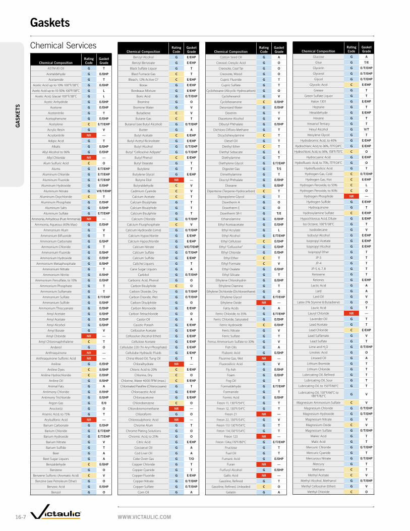
chemical compositionrating code
gasket grade
ASTM #3 Oil G T
Acetaldehyde G E/EHP
Acetamide G T
Acetic Acid up to 10% 100°F/38°C G E/EHP
Acetic Acid up to 10-50% 100°F/38°C G L
Acetic Acid, Glacial 100°F/38°C G L
Acetic Anhydride G E/EHP
Acetone G E/EHP
Acetonitrile G T
Acetophenone G E/EHP
Acetylene C E/T/EHP
Acrylic Resin G V
Acrylonitrile NR —
Adipic Acid G T
Alkalis G E/EHP
Allyl Alcohol to 96% G E/EHP
Allyl Chloride NR —
Alum Sulfuric Acid C O
Alums G E/T/EHP
Aluminum Chloride G E/T/EHP
Aluminum Fluoride G E/T/EHP
Aluminum Hydroxide G E/EHP
Aluminum Nitrate G V/E/T/EHP
Aluminum Oxychloride C T
Aluminum Phosphate G E/EHP
Aluminum Salts G E/EHP
Aluminum Sulfate G E/T/EHP
Ammonia, Anhydrous (Pure Ammonia) NR —
Ammonia, Aqueous (40% Max) G E/EHP
Ammonium Alum G V
Ammonium Bifluoride G T
Ammonium Carbonate G E/EHP
Ammonium Chloride G T
Ammonium Fluoride G E/EHP
Ammonium Hydroxide G E/EHP
Ammonium Metaphosphate G E/EHP
Ammonium Nitrate G T
Ammonium Nitrite G E/EHP
Ammonium Persulfate, to 10% G E/EHP
Ammonium Phosphate G T
Ammonium Sulfamate G T
Ammonium Sulfate G E/T/EHP
Ammonium Sulfide G E/EHP
Ammonium Thiocyanate G E/EHP
Amyl Acetate G E/EHP
Amyl Acetate G E/EHP
Amyl Alcohol G E/EHP
Amyl Borate G V
Amyl Chloride NR —
Amyl Chloronaphthalene C T
Anderol G O
Anthraquinone NR —
Anthraquinone Sulfonic Acid NR —
Aniline G E/EHP
Aniline Dyes C E/EHP
Aniline Hydrochloride C E/EHP
Aniline Oil G E/EHP
Animal Fats G A
Antimony Chloride G E/EHP
Antimony Trichloride G E/EHP
Argon Gas G E/0
Aroclor(s) G O
Arsenic Acid, to 75% G T
Arylsulfonic Acid NR —
Barium Carbonate G E/EHP
Barium Chloride G E/T/EHP
Barium Hydroxide G E/T/EHP
Barium Nitrate G V
Barium Sulfide G T
Beer G A
Beet Sugar Liquors G A
Benzaldehyde C E/EHP
Benzene G O
Benzene Sulfonic (Aromatic Acid) C V
Benzine (see Petroleum Ether) G O
Benzoic Acid G E/EHP
Benzol G O
chemical compositionrating code
gasket grade
Benzyl Alcohol G E/EHP
Benzyl Benzoate G E/EHP
Black Sulfate Liquor G T
Blast Furnace Gas C T
Bleach, 12% Active Cl2 C E/EHP
Borax G E/EHP
Bordeaux Mixture G E/EHP
Boric Acid G E/T/EHP
Bromine G O
Bromine Water G V
Butadiene C V
Butane Gas C T
Butanol (see Butyl Alcohol) G E/T/EHP
Butter G A
Butyl Acetate C E/EHP
Butyl Acetyl Ricinoleate G E/EHP
Butyl Alcohol G E/T/EHP
Butyl “Cellosolve Adipate” G E/T/EHP
Butyl Phenol C E/EHP
Butyl Stearate G T
Butylene G T
Butylene Glycol G E/EHP
Butyne Diol NR —
Butyraldehyde C V
Cadmium Cyanide C V
Calcium Acetate C T
Calcium Bisulphate G T
Calcium Bisulphide G T
Calcium Bisulphite G T
Calcium Chloride G E/T/EHP
Calcium Fluophosphate C V
Calcium Hydroxide (Lime) G E/T/EHP
Calcium Hypochlorite G E/EHP
Calcium Hypochloride G E/EHP
Calcium Nitrate G V/E/T/EHP
Calcium Sulfate G E/T/EHP
Calcium Sulfide G E/EHP
Caliche Liquors G T
Cane Sugar Liquors G A
Carbitol G E/T/EHP
Carbonic Acid, Phenol G O
Carbon Bisulphide C O
Carbon Dioxide, Dry G E/T/EHP
Carbon Dioxide, Wet G E/T/EHP
Carbon Disulphide G O
Carbon Monoxide G E/EHP
Carbon Tetrachloride G O
Castor Oil G A
Caustic Potash G E/EHP
Cellosolve Acetate G E/EHP
Cellosolve (Alcohol Ether) G E/EHP
Cellulose Acetate G E/EHP
Cellulube 220 (Tri-Aryl-Phosphate) G E/EHP
Cellulube Hydraulic Fluids G E/EHP
China Wood Oil, Tung Oil G T
Chloralhydrate NR —
Chloric Acid to 20% C E/EHP
Chlorine, Dry C O
Chlorine, Water 4000 PPM (max.) C E/EHP
Chlorinated Parafine (Chlorocosane) G T
Chloroacetic Acid G E/EHP
Chloroacetone G E/EHP
Chlorobenzene C O
Chlorobromomethane NR —
Chloroform G O
Chlorosulphonic Acid NR —
Chrome Alum G T
Chrome Plating Solutions G O
Chromic Acid, to 25% G O
Citric Acid G E/EHP
Cocoanut Oil G A
Cod Liver Oil G A
Coke Oven Gas G T/O
Copper Chloride G T
Copper Cyanide G T
Copper Fluoride G E/EHP
Copper Nitrate G E/T/EHP
Copper Sulfate G E/T/EHP
Corn Oil G A
chemical compositionrating code
gasket grade
Cotton Seed Oil G A
Creosol, Cresylic Acid G O
Creosote, Coal Tar G O
Creosote, Wood G O
Cupric Fluoride G T
Cupric Sulfate G T
Cyclohexane (Alicyclic Hydrocarbon) G O
Cyclohexanol G V
Cyclohexanone C E/EHP
Deionized Water G E/EHP
Dextrim G T
Diacetone Alcohol G V
Dibutyl Phthalate G E/EHP
Dichloro Difloro Methane G T
Dicyclohexylamine C T
Diesel Oil G T
Diethyl Ether C T
Diethyl Sebacate G E
Diethylamine G T
Diethylene Glycol G E/T/EHP
Digester Gas G T/S
Dimethylamine G T
Dioctyl Phthalate G E/EHP
Dioxane G E/EHP
Dipentene (Terpene-Hydrocarbon) C T
Dipropylene Glycol G T
Dowtherm A G O
Dowtherm E G O
Dowtherm SR-1 G T/E
Ethanolamine G E/EHP
Ethyl Acetoacetate G E/EHP
Ethyl Acrylate G L
Ethyl Alcohol G E/T/EHP
Ethyl Cellulose C E/EHP
Ethyl “Cellusolve” G E/EHP
Ethyl Chloride G E/EHP
Ethyl Ether C T
Ethyl Formate C V
Ethyl Oxalate G E/EHP
Ethyl Silicate G T
Ethylene Chlorohydrin G E/EHP
Ethylene Diamine G T
Ethylene Dichloride (Dichloroethane) G O
Ethylene Glycol G E/T/EHP
Ethylene Oxide NR —
Fatty Acids G A
Ferric Chloride, to 35% G E/T/EHP
Ferric Chloride, Saturated G E/EHP
Ferric Hydroxide C E/EHP
Ferric Nitrate G V
Ferric Sulfate G T
Ferrus Ammonium Sulfate to 30% G V
Fish Oils G A
Fluboric Acid G E/EHP
Fluorine Gas, Wet NR —
Fluorosilicic Acid G V
Fly Ash G E/EHP
Foam G E/EHP
Fog Oil G T
Formaldehyde G E/T/EHP
Formanide G T
Formic Acid G E/EHP
Freon 11, 130°F/54°C G T
Freon 12, 130°F/54°C G T
Freon 21 NR —
Freon 22, 130°F/54°C G V
Freon 113 130°F/54°C G T
Freon 114,130°F/54°C G T
Freon 123 NR —
Freon 134a,176°F/80°C G E/T/EHP
Fructose G T
Fuel Oil G T
Fumaric Acid G E/EHP
Furan NR —
Furfuryl Alcohol G E/EHP
Gallic Acid NR —
Gasoline, Refined G T
Gasoline, Refined, Unleaded C O
Gelatin G A
chemical compositionrating code
gasket grade
Glucose G A
Glue G T/E
Glycerin G E/T/EHP
Glycerol G E/T/EHP
Glycol G E/T/EHP
Glycolic Acid C E/EHP
Grease G T
Green Sulfate Liquor G T
Halon 1301 G E/EHP
Heptane G T
Hexaldehyde G E/EHP
Hexane G T
Hexanol Tertiary G T
Hexyl Alcohol G V/T
Hexylene Glycol G T
Hydrobromic Acid, to 40% G E/EHP
Hydrochloric Acid, to 36%, 75°F/24°C G E/EHP
Hydrochloric Acid, to 36%, 158°F/70°C C O
Hydrocyanic Acid G E/EHP
Hydrofluoric Acid, to 75%, 75°F/24°C G O
Hydrofluosilicic Acid G T
Hydrogen Gas, Cold C E/T/EHP
Hydrogen Gas, Hot C E/EHP
Hydrogen Peroxide, to 50% C L
Hydrogen Peroxide, to 90% C O
Hydrogen Phosphide NR —
Hydrogen Sulfide G E/EHP
Hydroquinone G T
Hydroxylamine Sulfate C E/EHP
Hypochlorous Acid, Dilute G E/EHP
Iso Octane, 100°F/38°C G T
Isododecane G V
Isobutyl Alcohol G E/EHP
Isopropyl Acetate G E/EHP
Isopropyl Alcohol G E/EHP
Isopropyl Ether G T
JP-3 G T
JP-4 G T
JP-5, 6, 7, 8 G T
Kerosene G T
Ketones G E/EHP
Lactic Acid G A
Lard G A
Lard Oil G V
Latex (1% Styrene & Butadiene) G O
Lauric Acid G T
Lauryl Chloride NR —
Lavender Oil G T
Lead Acetate G T
Lead Chloride C E/EHP
Lead Sulfamate G V
Lead Sulfate G T
Lime and H2O G E/T/EHP
Linoleic Acid G O
Linseed Oil G A
Lithium Bromide G T
Lithium Chloride G T
Lubricating Oil, Refined G T
Lubricating Oil, Sour G T
Lubricating Oil, to 150°F/66°C G T
Lubricating Oil, 150°F/66°C to 180°F/82°C G V
Magnesium Ammonium Sulfate C V
Magnesium Chloride G E/T/EHP
Magnesium Hydroxide G E/T/EHP
Magnesium Nitrate G V
Magnesium Oxide C V
Magnesium Sulfate G E/T/EHP
Maleic Acid G T
Malic Acid G T
Mercuric Chloride G E/T/EHP
Mercuric Cyanide G T
Mercurous Nitrate G E/T/EHP
Mercury G T
Methane C T
Methyl Acetate C V
Methyl Alcohol, Methanol G E/T/EHP
Methyl Cellosolve (Ether) G V
Methyl Chloride C O
Chemical Services
www.vIctaulIc.com16-7
gasketsg
ask
Ets

chemical compositionrating code
gasket grade
Methyl Cyclopentane C V
Methyl Ethyl Ketone C E/EHP
Methyl Isobutyl Carbinol G E/EHP
Methyl Isobutyl Ketone NR —
Methylene Chloride C O
Methylene Dichloride 100°F/38°C G O
MIL-L7808 G O
MIL-05606 G O
MIL-08515 G O
Milk G A
Mineral Oils G T
Naptha, 160°F/71°C G O
Napthalene NR —
Napthenic Acid C T
Natural Gas C T
Nevoil G E/EHP
Nickel Acetate to 10%, 100°F/38°C G V
Nickel Ammonium Sulfate G V
Nickel Chloride G E/T/EHP
Nickel Nitrate G V
Nickel Plating Solution 125°F/52°C G E/EHP
Nickel Sulfate G E/T/EHP
Nicotine C V
Nicotine Acid C V
Nitric Acid to 10%, 75°F/24°C G E/EHP
Nitric Acid, 10-50%, 75°F/24°C G O
Nitric Acid, 50-86%, 75°F/24°C C O
Nitric Acid, Red Fuming C O
Nitrocellulose G V
Nitroethane C E/EHP
Nitromethane G E/EHP
Nitrous Oxide G E/EHP
Octyl Alcohol G V
Oil, Crude Sour G T
Oil, Motor G T
Oleic Acid G T
Olive Oil G A
Oronite 8200 Silicate Ester Fluid G O
Orthodichlorobenzene G O
OS-45 Silicate Ester Fluid G O
OS-45-1 G O
Oxalic Acid G E/EHP
Oxygen, Cold † C E/EHP
Ozone (100 ppm) G E/EHP
Palmitic Acid G T
Peanut Oil G A
Pentane G T
Perchloroethylene G O
Perchloric Acid NR —
Petroleum Ether (see Benzene) G O
Petroleum Oils G T
Phenol (Carbolic Acid) G O
Phenylhydrazine C E/EHP
Phenylhydrazine Hydrochloride C E/EHP
Phosphate Ester G E/EHP
Phosphoric Acid, to 50%, 70°F/21°C G E/EHP
Phosphoric Acid, to 85%, 200°F/93°C G O
Photographic Solutions G T
Phthalic Anhydride G E/EHP
Picric Acid, Molten G V
Plating Solutions (gold, brass, cadmium, copper, lead, silver, nickel, tin, zinc) G V
Polybutene G TPolyvinyl Acetate, Solid
(In Liquid State is 50% solution of Methanol or 60% solution of H2O)
G E/EHP
Potassium Alum G E/T/EHP
Potassium Bicarbonate G E/T/EHP
Potassium Bichromate G T/E
Potassium Borate G E/EHP
Potassium Bromate G E/EHP
Potassium Bromide G E/T/EHP
Potassium Carbonate G E/T/EHP
Potassium Chlorate G E/EHP
Potassium Chloride G T
Potassium Chromate G T
Potassium Cyanide G E/T/EHP
Potassium Dichromate G E/EHP
Potassium Ferricyanide G E/EHP
chemical compositionrating code
gasket grade
Potassium Ferrocyanide G E/EHP
Potassium Fluoride G E/EHP
Potassium Hydroxide G T
Potassium Iodide G V
Potassium Nitrate G T
Potassium Perborate G E/EHP
Potassium Perchlorate G T
Potassium Permanganate, Saturated to 10% G E/EHP
Potassium Permaganate, Saturate 10-25% G E/EHP
Potassium Persulfate G T
Potassium Phosphate G V
Potassium Silicate G V/E/T/EHP
Potassium Sulfate G T
Potassium Thiosulfate G V
Prestone G T
Propane Gas C T
Propanol G E/EHP
Propargyl Alcohol G E/EHP
Propyl Acetate C V
Propyl Alcohol G T
Propylene Dichloride C L
Propylene Glycol G E/EHP
Pydraul F - 9 and 150 NR —
Pyranol 1467 G T
Pyranol 1476 G T
Pyroguard “C” G T
Pyroguard “D” G T
Pyroguard 55 G E/EHP
Pyrrole G E/EHP
Rapeseed Oil G A
Ref. Fuel (70 ISO Octane, 30 Toluene) G T
Rosin Oil G V/T
Salicylic Acid G E/EHP
Secondary Butyl Alcohol G T
Sewage G E/T/EHP
Silver Cyanide C V
Silver Nitrate G E/EHP
Silver Plating Solution C V
Silver Sulfate G E/EHP
Skydrol, 200°F/93°C G L
Skydrol 500 Phosphate Ester C E/EHP
Soap Solutions G E/T/EHP
Soda Ash, Sodium Carbonate G E/T/EHP
Sodium Acetate G E/EHP
Sodium Alum G T
Sodium Benzoate G E/T/EHP
Sodium Bicarbonate G E/T/EHP
Sodium Bisulfate G E/T/EHP
Sodium Bisulfite (Black Liquor) G E/T/EHP
Sodium Bromide G E/T/EHP
Sodium Carbonate G E/T/EHP
Sodium Chlorate G E/EHP
Sodium Chloride G E/T/EHP
Sodium Cyanide G E/T/EHP
Sodium Dichromate, to 20% G E/T/EHP
Sodium Ferricyanide G E/T/EHP
Sodium Ferrocyanide G E/T/EHP
Sodium Fluoride G E/T/EHP
Sodium Hydro Sulfide G T
Sodium Hydroxide to 50% G E/EHP
Sodium Hypochlorite, to 20% G E/EHP
Sodium Metaphosphate G T
Sodium Nitrate G E/EHP
Sodium Nitrite G E/T/EHP
Sodium Perborate G E/EHP
Sodium Peroxide G E/EHP
Sodium Phosphate, Dibasic G T
Sodium Phosphate, Monobasic G T
Sodium Phosphate, Tribasic G T
Sodium Silicate G T
Sodium Sulfate G E/T/EHP
Sodium Sulfide G T
Sodium Sulfite Solution, to 20% G T
Sodium Thiosulfate, “Hypo” G T
Sohovis 47 G T
Sohovis 78 G T
Solvasol #1 G T
chemical compositionrating code
gasket grade
Solvasol #2 G T
Solvasol #3 G T
Solvasol #73 C T
Solvasol #74 NR —
Soybean Oil G A
Spindle Oil G T
Stannic Chloride G T
Stannous Chyoride, to 15% G T
Starch G T
Steam NR —
Stearic Acid G T
Stoddard Solvent G T
Styrene G O
Sucrose Solutions G A
Sulfonic Acid G E/EHP
Sulphite Acid Liquor G E/EHP
Sulfur G V/E
Sulfur Chloride G O
Sulfur Dioxide, Dry C E/T/EHP
Sulfur Dioxide, Liquid G E/EHP
Sulfur Trioxide, Dry G O
Sulfuric Acid, to 25%, 150°F/66°C G E/EHP
Sulfuric Acid, 25-50%, 200°F/93°C G O
Sulfuric Acid, 50-95%, 150°F/66°C G O
Sulfuric Acid, Fuming C O
Sulfuric Acid, Oleum C O
Sulfurous Acid G O
Tall Oil C T
Tannic Acid, All Conc. G V
Tanning Liquors (50 g. alum. solution, 50 g. dichromate solution) G T
Tartaric Acid G E/EHP
Terpineol G V
Tertiary Butyl Alcohol G V/E/T/EHP
Tetrabutyl Titanate G E/EHP
Tetrachloroethylene G O
Tetrahydrofuran NR —
Tetralin NR —
Thionyl Chloride C T
Terpineol C T
Thiopene NR —
Titanium Tetrachloride G O
Toluene, 30% G T
Transmission Fluid, Type A G O
Triacetin G T
Trichloroethane G O
Trichloroethylene, to 200°F/93°C G O
Tricresyl Phosphate G E/EHP
Triethanolamine G E/T/EHP
Trisodium Phosphate G E/EHP
Tung Oil G T
Turbo Oil #15 Diester Lubricant G O
Turpentine C T
Urea G T
Vegetable Oils G A
Vinegar G A
Vinyl Acetate G E/EHP
Vi-Pex G T
Water, to 150°F/66°C G E/T/M/S
Water, to 200°F/93°C G E/M
Water, to 230°F/110°C G E/EHP
Water, Acid Mine G E/T/EHP
Water, Bromine G V
Water, Chlorine C E/M
Water, Deionized G E/M
Water, Seawater G E/EHP
Water, Waste G E/T/M/S
Whiskey G A
White Liquor G E/EHP
Wood Oil G T
Xylene C O
Zinc Chloride, to 50% G E/EHP
Zinc Nitrate G E/EHP
Zinc Sulfate G E/T/EHP
chemical composition rating code
Acrylonitrile NR
Allyl Chloride NR
Amyl Chloride NR
Anthraquinone NR
Anthraquinone Sulfonic Acid NR
Arylsulfonic Acid NR
Butyne Diol NR
Chloralhydrate NR
Chlorobromomethane NR
Chlorosulphonic Acid NR
Ethylene Oxide NR
Fluorine Gas Wet NR
Freon 21 NR
Furan NR
Gallic Acid NR
Hydrogen Phosphide NR
Lauryl Chloride NR
Methyl Isobutyl Ketone NR
Napthalene NR
Perchloric Acid NR
Pydraul F -9 and F - 150 NR
Solvasol #74 NR
Steam NR
Tetra Hydrofuran NR
Tetralin NR
Thiophene NR
Water and Air Services
rating code
gasket grade
Air, Temp. –30°F to +230°F/ –34°C to +110°C (no oil vapors)
G E
Dry Air, Temp. +230°F to +350°F/+110°C to +177°C
(no oil or water vapors)G L
Air, Oil Vapor, Temp. 0°F to +150°F/ –18°C to 66°C
G T
Air, Oil Vapor, Temp. +150°F to +300°F/+66°C to +149°C
G O
Water, Temp. to +150°F/+66°C G E/T/M/S
Water, Temp. to +200°F/+93°C G E/M
Water, Temp. to +230°F/+110°C* G E
Water, Temp. to +250°F/+120°C G EHP
Water, Acid Mine G E/T
Water, Bromine G V
Water, Chlorine C E/M
Water, Deionized G E/M
Water, Seawater G E
Water, Waste G E/T/M/S
* Recommended for water only. Not recommended for steam service, except where couplings are accessible for frequent gasket replacement. NOTE: The Grade “EHP” gasket can be used on all chemical, water and air services suitable for Grade “E” gaskets.
rating code rating code key
G Good
C Conditional
NR Not Recommended
Services Not RecommendedThe services listed below have been tested and are NOT RECOMMENDED with any of the presently available gasket materials. Services not shown as recommended or not recommend-ed should be submitted to Victaulic for specific recommendations.
www.vIctaulIc.com 16-8
gasketsg
ask
Ets

Pipe
Upper Roll
Lower(Drive)
Roll
A B
Pipe
HydraulicForce
A B
DepthStop
PipeStop
ToolBit
Inner Roll
PipeBA
Field PortableVE12, pg. 17-3 VE26, pg. 17-3 VE46, pg. 17-3 VE226, pg. 17-3
Plant/Shop FabricationVE268, pg. 17-5 VE414MC, pg. 17-5 VE436MC, pg. 17-5 VE450FSD, pg. 17-5
Field ManualVg28gD, pg. 17-8 Vg824, pg. 17-8 Vg828, pg. 17-8
Field MotorizedVg412, pg. 17-9 ViC-grooVEr, pg. 17-9
Plastic GrooversVpg26, pg. 17-9 Vpg824, pg. 17-9
Roll Groovers
Cut Groovers
pFT505, pg. 17-11 pFT509, pg. 17-11
See pg. 9-1 for the complete line of Pressfit products.
Pressfit Tools
Roll Groove
Cut Groove
Roll groove shown on Schedule 40 steel pipe.
The small dimple created on interior pipe wall does
not significantly hinder pressure or flow.
Vic-Easy tools cold form groove into pipe – maintains dimensions
Roll grooving removes no metal from pipe
Cut groove removes less metal than threading
Vic-Adjustable tools provide proper groove dimensions
Cut groove shown on Schedule 80 carbon pipe.
The groove created removes less metal
than threading. CaST/DuCTilE iron pipE
STainlESS STEEl pipE
Field FabricationVE270FSD, pg. 17-4 VE272SFS, pg. 17-4 VE416FS/VE416FSD, pg. 17-4 VE106, pg. 17-4
• Fast, clean and easy method for joining Schedule 5 Type 304/316 stainless steel pipe
• Available for wide variety of services based on o-ring capabilities
• Meets hanging requirements of ASME B31.1, B31.3 and B31.9
• Only approved Pressfit 304/316 pipe should be used with Pressfit 304/316 stainless steel products
• Electronically or battery operated hand-held pressing tool
www.ViCTauliC.CoM17-1
pipe preparationpi
pE
pr
Epa
raT
ion

Power DriveVpD752, pg. 17-13 VE224 powEr DriVE kiT, pg. 17-13
Power Mulepg. 17-13
Pipe Diameter Tapepg. 17-14
proDuCTS
1-1 Couplings
2-1 Fittings
3-1 Valves
4-1 Accessories
5-1 Advanced Groove System
6-1 Hole Cut Piping System
7-1 Plain End Piping System
8-1 Grooved System for Stainless Steel Pipe
9-1 Pressfit System for Stainless Steel Pipe
10-1 Plain End Piping System for HDPE Pipe
11-1 Grooved Copper
12-1 PermaLynx System for Copper Tube
13-1 Grooved AWWA Ductile Iron Pipe
14-1 Victaulic Depend-O-Lok System
15-1 Aquamine Reusable PVC Products
16-1 Gaskets
17-1 pipe preparation Tools
18-1 Product Index
19-1 Piping Software
AccessoriesAdjustable Pipe StandsVapS112, pg. 17-13 VapS224, pg. 17-14
Hole CuttingHCT908, pg. 17-11 VHCT900, pg. 17-11 ViC-Tap® ii, pg. 17-11
Cutting ToolsPipe CuttingVCT1, pg. 17-12 VCT2, pg. 17-12
Pipe CoatingsTo maintain the published performance levels with respect to maximum rated working pressure and end load, the maximum coating thickness on our couplings should not exceed 10 mils/0.010". If additional protection is required, the coating thickness may be increased on the external surfaces of the coupling key, shoulder, gasket pocket or bolt pad mating surfaces. In addition, the coating thickness on the pipe ends should not exceed 10 mils. Specifically, the gasket seating surface and the entire groove should have coating thickness limited to 10 mils.
Exceeding the maximum thickness on either the pipe end or coupling surfaces mentioned above will decrease the performance capabilities of the pipe joints.
www.ViCTauliC.CoM 17-2
pipe preparationpip
E p
rEpa
raTio
n

Field PortableFor Complete Information Request Publication 24.01
VE12 grooVE in-plaCE
• For manual grooving of Schedule 5, 10 and 40 steel; stainless steel; aluminum and PVC pipe• Enhanced tracking rolls allow bi-directional grooving• Roll grooves ¾ – 2"/20 – 50 mm pipe †
power requirements: Noneweight: 17 lbs./8 kg
VE12
VE26 grooVE in-plaCE
• Repair and retrofit existing lightwall steel, Schedule 40 steel, stainless steel, PVC, and aluminum
• Patented enhanced tracking rolls allow bi-directional grooving• Model VE26C handles copper tubing (CTS) Types K, L, M
and DWV plus British, DIN, and Australian Standard copper• Model VE26SS grooves Schedule 5 and 10 stainless steel• Optional power drive adapter kit available to alternately
groove pipe using a Ridgid* 300 power drive or VPD752• Roll grooves 2 – 6"/50 – 150 mm pipe †
power requirements: Noneweight: 22 lbs./10 kg
VE26
VE46 grooVE in-plaCE
• Designed for manually roll grooving Schedule 40 steel, aluminum, stainless steel and PVC pipe and Schedule 80 PVC pipe
• Patented enhanced tracking rolls allow bi-directional grooving and helps to hold the tool on the pipe end during the roll grooving process
• Optional power drive adapter kit available to alternately groove pipe using a Ridgid* 300 power drive or VPD752
• Roll grooves 3½ – 6"/9 – 150 mm pipe †
power requirements: None weight: 28 lbs./13 kg
VE46
VE226 porTablE grooVEr
• Mounts to a Victaulic VPD752 or Ridgid* 300 power drive• Optional alternate bases available• Tool is operated using a standard 3⁄8/9.5 mm square ratchet
drive (not included)• Available in six models for steel (and other IPS) pipe, copper
tubing and stainless steel• Roll grooves ¾ – 6"/20 – 150 mm pipe †
Drive requirements: Fits Victaulic VPD752 or Ridgid 300 power drives. Optional bases for Ridgid* 535, 1224, 1822, and Oster 310 available. Contact Victaulic for others.weight: 37 lbs./17 kg
VE226
† Refer to Roll Grooving Tool Ratings chart on pgs. 17-6, 17-7 * Ridgid is a registered trademark of the Ridge Tool Company
VE26/46 Power Drive Kit
VE226 Power Drive Kit
The VE26/46 power drive kit is available to allow both tools to be directly mounted to either a Victaulic VPD752 or Ridgid* 300 Power Drive.
The VE226 Power Drive Kit is available to allow the VE226 to be directly mounted to a Ridgid* 700 power drive
www.ViCTauliC.CoM17-3
pipE
pr
Epa
raT
ion
pipe preparation – roll grooving Tools
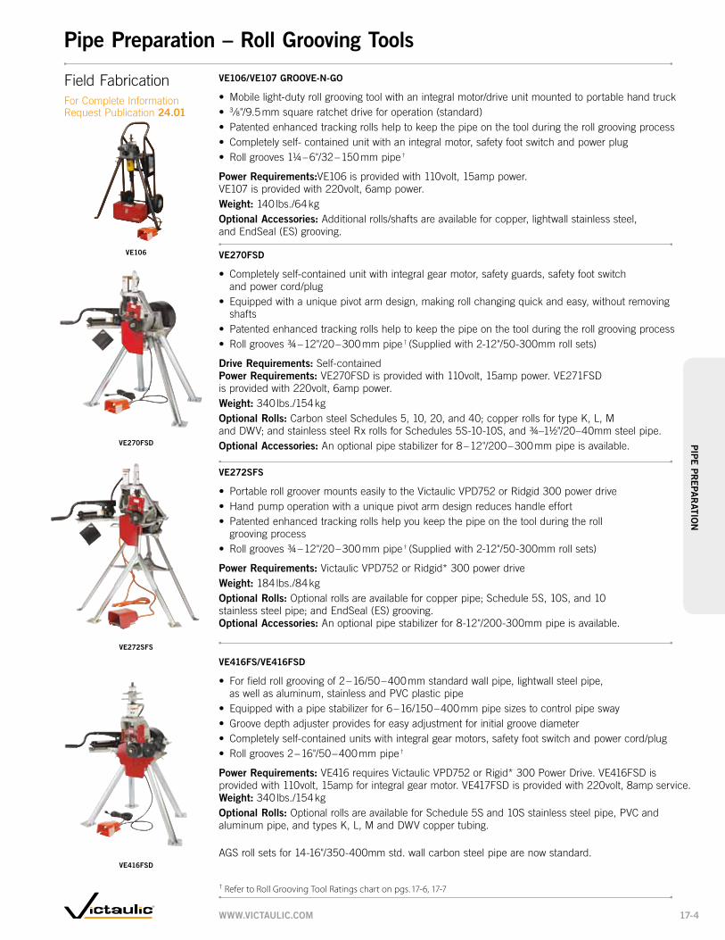
VE416FS/VE416FSD
• For field roll grooving of 2 – 16/50 – 400 mm standard wall pipe, lightwall steel pipe, as well as aluminum, stainless and PVC plastic pipe
• Equipped with a pipe stabilizer for 6 – 16/150 – 400 mm pipe sizes to control pipe sway• Groove depth adjuster provides for easy adjustment for initial groove diameter• Completely self-contained units with integral gear motors, safety foot switch and power cord/plug• Roll grooves 2 – 16"/50 – 400 mm pipe †
power requirements: VE416 requires Victaulic VPD752 or Rigid* 300 Power Drive. VE416FSD is provided with 110volt, 15amp for integral gear motor. VE417FSD is provided with 220volt, 8amp service.weight: 340 lbs./154 kgoptional rolls: Optional rolls are available for Schedule 5S and 10S stainless steel pipe, PVC and aluminum pipe, and types K, L, M and DWV copper tubing.
AGS roll sets for 14-16"/350-400mm std. wall carbon steel pipe are now standard.
VE272SFS
• Portable roll groover mounts easily to the Victaulic VPD752 or Ridgid 300 power drive• Hand pump operation with a unique pivot arm design reduces handle effort• Patented enhanced tracking rolls help you keep the pipe on the tool during the roll
grooving process• Roll grooves ¾ – 12"/20 – 300 mm pipe † (Supplied with 2-12"/50-300mm roll sets)
power requirements: Victaulic VPD752 or Ridgid* 300 power driveweight: 184 lbs./84 kgoptional rolls: Optional rolls are available for copper pipe; Schedule 5S, 10S, and 10 stainless steel pipe; and EndSeal (ES) grooving. optional accessories: An optional pipe stabilizer for 8-12"/200-300mm pipe is available.
VE272SFS
VE416FSD
VE270FSD
• Completely self-contained unit with integral gear motor, safety guards, safety foot switch and power cord/plug
• Equipped with a unique pivot arm design, making roll changing quick and easy, without removing shafts
• Patented enhanced tracking rolls help to keep the pipe on the tool during the roll grooving process• Roll grooves ¾ – 12"/20 – 300 mm pipe † (Supplied with 2-12"/50-300mm roll sets)
Drive requirements: Self-containedpower requirements: VE270FSD is provided with 110volt, 15amp power. VE271FSD is provided with 220volt, 6amp power.weight: 340 lbs./154 kgoptional rolls: Carbon steel Schedules 5, 10, 20, and 40; copper rolls for type K, L, M and DWV; and stainless steel Rx rolls for Schedules 5S-10-10S, and ¾–1½"/20–40mm steel pipe.optional accessories: An optional pipe stabilizer for 8 – 12"/200 – 300 mm pipe is available.VE270FSD
Field FabricationFor Complete Information Request Publication 24.01
VE106/VE107 grooVE-n-go
• Mobile light-duty roll grooving tool with an integral motor/drive unit mounted to portable hand truck• 3 ⁄8"/9.5 mm square ratchet drive for operation (standard)• Patented enhanced tracking rolls help to keep the pipe on the tool during the roll grooving process• Completely self- contained unit with an integral motor, safety foot switch and power plug• Roll grooves 1¼ – 6"/32 – 150 mm pipe †
power requirements:VE106 is provided with 110volt, 15amp power. VE107 is provided with 220volt, 6amp power.weight: 140 lbs./64 kgoptional accessories: Additional rolls/shafts are available for copper, lightwall stainless steel, and EndSeal (ES) grooving.
VE106
† Refer to Roll Grooving Tool Ratings chart on pgs. 17-6, 17-7
www.ViCTauliC.CoM 17-4
pipE
pr
Epa
raTio
npipe preparation – roll grooving Tools

Plant/Shop FabricationFor Complete Information
Request Publication 24.01
VE414MC
• Designed for fabrication shop roll grooving Schedule 5, 10, and standard wall carbon steel pipe, standard wall stainless steel pipe, Schedule 40, 80 PVC pipe, and standard wall aluminum pipe
• Unique roll design, making roll changing quick and easy, without removing main shafts• Patented enhanced tracking rolls help to keep the pipe on the tool during the roll grooving process• The tool comes equipped with pipe stabilizers to provide smooth grooving operation• Roll grooves 2 – 16"/50 – 400 mm pipe † (Supplied with 2-12"/50-300mm original rolls and 14-16"/350-400mm AGS rolls)Drive requirements: Self-containedweight: 735 lbs./333 kgoptional rolls: Optional rolls are available for Schedule 10S stainless steel pipe PVC and aluminum pipe and type K, L, M and DWV copper tubing. AGS roll sets for 14-16"/350-400mm Schedule 10 through .500"/12.7mm wall carbon steel pipe are now standard.optional accessories: The tool can also be supplied in various voltages, contact Victaulic for details.
VE436MC
• Fully automated shop tool for roll grooving standard wall (.375"/9.5 mm wall maximum) pipe• The fully-motorized, semi-automatic, electro-hydraulic tool comes complete with safety guards
and safety foot switch• Patented enhanced tracking rolls help to keep the pipe on the tool during the roll grooving process• Roll grooves 4 – 36"/100 – 900 mm pipe † (26-36/650-950mm roll kit optional)
power requirements: 220/440 volt, 3 phase, 60 Hz (shipped wired for 220 volt unless otherwise specified). Contact Victaulic for details. weight: 1500 lbs./680 kgoptional rolls: Optional rolls are available for Schedule 5S and 10S stainless steel pipe, PVC and aluminum pipe, and types K, L, M and DWV copper tubing. AGS roll sets for 14 – 16"/350 – 400 mm Schedule 10 through .500"/12.7 mm wall carbon steel pipe are now standard.
VE268
• Designed for fabrication shop roll grooving• The fully-motorized, semi-automatic, electrohydraulic tool comes complete with safety guards
and safety foot switch• Equipped with a unique pivot arm design, making roll changes quick and easy,
without removing shafts• Patented enhanced tracking rolls help to keep the pipe on the tool during the roll grooving process• Roll grooves ¾ – 12"/20 – 300 mm pipe † (¾–1½"/20–32mm rolls are optional)Drive requirements: Self-containedweight: 735 lbs./333 kgoptional rolls: Optional rolls are available for carbon steel Schedules 5, 10, and 40; copper rollsfor type K, L, M and DWV; and stainless steel Rx rolls for Schedules 5S, 10, and 10S, and ¾–1½/20–40mm steel pipe. optional accessories: An optional pipe stabilizer for 8 – 12"/200 – 300 mm pipe is available and is suggested for grooving 8"/206.4mm copper tubing.
VE268
VE414MC
VE436MC
† Refer to Roll Grooving Tool Ratings chart on pgs. 17-6, 17-7
VE450FSD• Designed for field roll grooving of 4 – 24"/100 – 600 mm pipe• Tool is supplied with roll sets for grooving 4 – 12"/100 – 300 mm original groove and 14 – 24"/350 – 600 mm AGS groove on carbon steel pipe• Patented enhanced tracking rolls help to keep the pipe on the tool during the roll grooving process, and quick change upper roll design• Features: – Lifting point to move the tool using a crane – Frame can accept most fork lifts – On board storage for tool accessories
power requirements: VE450FSD is a self-contained unit with two 220 volt, single phase 50/60 hz, 20 amp integral gear motors to handle heavier loads, safety foot switch and power cord/plugweight: 825 lbs./374 kgoptional rolls: Optional rolls are available for 14 – 24/350 – 600 mm carbon steel original groove; 4 – 12/100 – 400 mm lightwall stainless steel original groove; 14 – 24/350 – 600 mm lightwall stainless steel AGS groove; and 4 – 12/100 – 400 mm EndSeal (ES) groove.
VE450FSD
www.ViCTauliC.CoM17-5
pipE
pr
Epa
raT
ion
pipe preparation – roll grooving Tools

Tool Model
pipe Material
pipe Size/Schedule inches/mm
¾ 20
1 25
1¼ 32
1½ 40
2 50
2½ 65
3 80
3½ 90
4 100
4½ 120
5 125
6 150
8 200
10 250
12 300
14 350
16 400
VE12
Steel 5, 10 5 – 40
Stainless 40S only
Aluminum † 5, 10 5 – 40
PVC Plastic 40
VE26SSteel 5 – 40 5, 10
Stainless 40S only
VE26PAluminum † 5 – 40 5, 10
PVC Plastic 40
VE26C Copper K, L, M, DWV Copper Rolls ‡
VE26SS Lt. Wall SS 5S, 10S Rx Rolls #
VE46Steel 5 – 40
Stainless 40S only
VE46PAluminum † 5 – 40
PVC Plastic 40 40, 80
VE226SSteel 5 – 40 5, 10
Stainless 40S only
VE226PAluminum † 5 – 40 5, 10
PVC Plastic 40, 80 40
VE226B
Steel 5 – 40
Stainless 40S only
Aluminum † 5 – 40
PVC Plastic 40 40, 80
VE226MSteel 5 – 40 5, 10
Stainless 40S only
VE226C Copper K, L, M, DWV Copper Rolls ‡
VE226BSS Lt. Wall SS 5S, 10S Rx Rolls #
VE226MSS Lt. Wall SS 5S, 10S Rx Rolls #
VE106
Steel 5 – 40 Standard Rolls §
Stainless 40S Standard Rolls §
Lt. Wall SS 5S, 10S Rx Rolls #
Copper K, L, M, DWV Copper Rolls ‡
VE272SFS
Steel 5 – 40S Standard Rolls § 5 – 20 Std.
Stainless 40S Standard Rolls §
Lt. Wall SS 5S, 10S Rx Rolls #
Aluminum † 5 – 40 RP Rolls ◊ 5 – 20 RP ◊
PVC Plastic 40 RP Rolls ◊ 40, 80 RP Rolls ◊ 40 RP ◊
Copper K, L, M, DWV Copper Rolls ‡
VE270FSD
Steel 5 – 40S Standard Rolls § 5 – 20 Std.
Stainless 40S Standard Rolls §
Lt. Wall SS 5S, 10S Rx Rolls #
Aluminum † 5 – 40 RP Rolls ◊ 5 – 20 RP ◊
PVC Plastic 40 RP Rolls ◊ 40, 80 RP Rolls ◊ 40 RP ◊
Copper K, L, M, DWV Copper Rolls ‡
TablE ConTinuED on pg. 17-7
# Rx Rolls – "Rx" is the Victaulic part code designator for grooving roll sets specifically designed for roll grooving lightwall stainless steel pipe.† 6061-T4 or 6063-T4 alloy must be used.‡ Alternate units are available for European Standard (EN) 1057 and Australian Standard Copper.§ Standard Rolls – This is the Victaulic designation for grooving roll sets used primary for steel pipe. Also used for Schedule 40S stainless steel pipe.◊ RP Rolls – “RP” is the Victaulic part code designator for grooving roll sets specifically designed for roll grooving PVC plastic pipe and aluminum pipe.
Vic-Easy® Roll Grooving Tool Ratings(MaxiMuM CapaCiTy)
Victaulic Vic-Easy roll grooving tools are designed to cold form grooves into the specified pipe to meet ANSI/AWWA C-606 standards and the groove dimensions specified in Victaulic Groove Specifications for each type of pipe.These tools are designed for roll grooving pipe. To accomplish this function requires some dexterity and mechanical skills, as well as sound safety habits. Although this tool is manufactured for safe dependable operation, it is impossible to anticipate those combinations of circumstances which could result in an accident. The operator is cautioned to always practice “Safety First” during each phase of use, including setup and maintenance of these units.Read and understand the Tool Operating and Maintenance Instruction Manual provided with each tool before operating or performing maintenance on tools. Become familiar with the tool’s operations, applications and limitations. Be particularly aware of its specific hazards.
Important notES:• pVC grades that can be grooved –
PVC Type I Grade I – PVC 1120; PVC Type I Grade II – PVC 1220; PVC Type II Grade I – PVC 2116.
• Copper/nickel pipe – contact Victaulic for details.
Note: Vic-Easy tools and rolls shown on this chart will produce grooves in accordance with Victaulic Roll Groove Dimension charts and to ANSI/AWWA C-606 standards.
VE436MC
• Fully automated shop tool for roll grooving standard wall (.375"/9.5 mm wall maximum) pipe• The fully-motorized, semi-automatic, electro-hydraulic tool comes complete with safety guards
and safety foot switch• Patented enhanced tracking rolls help to keep the pipe on the tool during the roll grooving process• Roll grooves 4 – 36"/100 – 900 mm pipe † (26-36/650-950mm roll kit optional)
power requirements: 220/440 volt, 3 phase, 60 Hz (shipped wired for 220 volt unless otherwise specified). Contact Victaulic for details. weight: 1500 lbs./680 kgoptional rolls: Optional rolls are available for Schedule 5S and 10S stainless steel pipe, PVC and aluminum pipe, and types K, L, M and DWV copper tubing. AGS roll sets for 14 – 16"/350 – 400 mm Schedule 10 through .500"/12.7 mm wall carbon steel pipe are now standard.
www.ViCTauliC.CoM 17-6
pipE
pr
Epa
raTio
npipe preparation – roll grooving
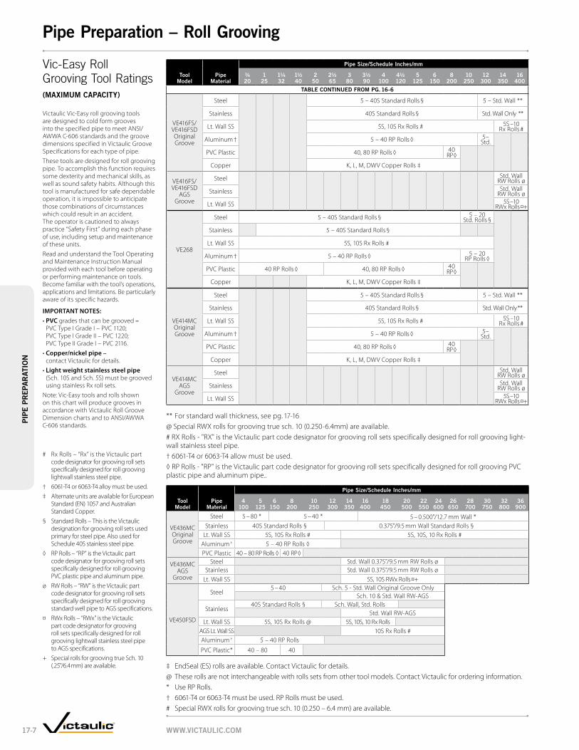
Tool Model
pipe Material
pipe Size/Schedule inches/mm
¾ 20
1 25
1¼ 32
1½ 40
2 50
2½ 65
3 80
3½ 90
4 100
4½ 120
5 125
6 150
8 200
10 250
12 300
14 350
16 400
TablE ConTinuED FroM pg. 16-6
VE416FS/VE416FSD Original Groove
Steel 5 – 40S Standard Rolls § 5 – Std. Wall **
Stainless 40S Standard Rolls § Std. Wall Only **
Lt. Wall SS 5S, 10S Rx Rolls # 5S –10 Rx Rolls #
Aluminum † 5 – 40 RP Rolls ◊ 5– Std.
PVC Plastic 40, 80 RP Rolls ◊ 40 RP ◊
Copper K, L, M, DWV Copper Rolls ‡
VE416FS/VE416FSD
AGS Groove
Steel Std. Wall RW Rolls ø
Stainless Std. Wall RW Rolls ø
Lt. Wall SS 5S –10 RWx Rolls ¤+
VE268
Steel 5 – 40S Standard Rolls § 5 – 20 Std. Rolls §
Stainless 5 – 40S Standard Rolls §
Lt. Wall SS 5S, 10S Rx Rolls #
Aluminum † 5 – 40 RP Rolls ◊ 5 – 20 RP Rolls ◊
PVC Plastic 40 RP Rolls ◊ 40, 80 RP Rolls ◊ 40 RP ◊
Copper K, L, M, DWV Copper Rolls ‡
VE414MC Original Groove
Steel 5 – 40S Standard Rolls § 5 – Std. Wall **
Stainless 40S Standard Rolls § Std. Wall Only **
Lt. Wall SS 5S, 10S Rx Rolls # 5S –10 Rx Rolls #
Aluminum † 5 – 40 RP Rolls ◊ 5– Std.
PVC Plastic 40, 80 RP Rolls ◊ 40 RP ◊
Copper K, L, M, DWV Copper Rolls ‡
VE414MC AGS
Groove
Steel Std. Wall RW Rolls ø
Stainless Std. Wall RW Rolls ø
Lt. Wall SS 5S –10 RWx Rolls ¤+
** For standard wall thickness, see pg. 17-16 @ Special RWX rolls for grooving true sch. 10 (0.250-6.4mm) are available.# RX Rolls - "RX" is the Victaulic part code designator for grooving roll sets specifically designed for roll grooving light-wall stainless steel pipe.† 6061-T4 or 6063-T4 allow must be used.◊ RP Rolls - "RP" is the Victaulic part code designator for grooving roll sets specifically designed for roll grooving PVC plastic pipe and aluminum pipe..
Tool Model
pipe Material
pipe Size/Schedule inches/mm
4 100
5 125
6 150
8 200
10 250
12 300
14 350
16 400
18 450
20 500
22 550
24 600
26 650
28 700
30 750
32 800
36 900
VE436MC Original Groove
Steel 5 – 80 * 5 – 40 * 5 – 0.500"/12.7 mm Wall *Stainless 40S Standard Rolls § 0.375"/9.5 mm Wall Standard Rolls §
Lt. Wall SS 5S, 10S Rx Rolls # 5S, 10S, 10 Rx Rolls #Aluminum † 5 – 40 RP Rolls ◊PVC Plastic 40 – 80 RP Rolls ◊ 40 RP ◊
VE436MC AGS
Groove
Steel Std. Wall 0.375"/9.5 mm RW Rolls øStainless Std. Wall 0.375"/9.5 mm RW Rolls ø
Lt. Wall SS 5S, 10S RWx Rolls ¤+
VE450FSD
Steel5 – 40 Sch. 5 - Std. Wall Original Groove Only
Sch. 10 & Std. Wall RW-AGS
Stainless40S Standard Rolls § Sch. Wall, Std. Rolls
Std. Wall RW-AGSLt. Wall SS 5S, 10S Rx Rolls @ 5S, 10S, 10 Rx Rolls
AGS Lt. Wall SS 10S Rx Rolls #Aluminum † 5 – 40 RP Rolls
PVC Plastic* 40 – 80 40
‡ EndSeal (ES) rolls are available. Contact Victaulic for details.@ These rolls are not interchangeable with rolls sets from other tool models. Contact Victaulic for ordering information.* Use RP Rolls.† 6061-T4 or 6063-T4 must be used. RP Rolls must be used.# Special RWX rolls for grooving true sch. 10 (0.250 – 6.4 mm) are available.
Vic-Easy Roll Grooving Tool Ratings(MaxiMuM CapaCiTy)
Victaulic Vic-Easy roll grooving tools are designed to cold form grooves into the specified pipe to meet ANSI/AWWA C-606 standards and the groove dimensions specified in Victaulic Groove Specifications for each type of pipe.These tools are designed for roll grooving pipe. To accomplish this function requires some dexterity and mechanical skills, as well as sound safety habits. Although this tool is manufactured for safe dependable operation, it is impossible to anticipate those combinations of circumstances which could result in an accident. The operator is cautioned to always practice “Safety First” during each phase of use, including setup and maintenance of these units.Read and understand the Tool Operating and Maintenance Instruction Manual provided with each tool before operating or performing maintenance on tools. Become familiar with the tool’s operations, applications and limitations. Be particularly aware of its specific hazards.
Important notES:• pVC grades that can be grooved –
PVC Type I Grade I – PVC 1120; PVC Type I Grade II – PVC 1220; PVC Type II Grade I – PVC 2116.
• Copper/nickel pipe – contact Victaulic for details.
• Light weight stainless steel pipe (Sch. 10S and Sch. 5S) must be grooved using stainless Rx roll sets.
Note: Vic-Easy tools and rolls shown on this chart will produce grooves in accordance with Victaulic Roll Groove Dimension charts and to ANSI/AWWA C-606 standards.
# Rx Rolls – “Rx” is the Victaulic part code designator for grooving roll sets specifically designed for roll grooving lightwall stainless steel pipe.
† 6061-T4 or 6063-T4 alloy must be used.‡ Alternate units are available for European
Standard (EN) 1057 and Australian Standard Copper.
§ Standard Rolls – This is the Victaulic designation for grooving roll sets used primary for steel pipe. Also used for Schedule 40S stainless steel pipe.
◊ RP Rolls – “RP” is the Victaulic part code designator for grooving roll sets specifically designed for roll grooving PVC plastic pipe and aluminum pipe.
ø RW Rolls – “RW” is the Victaulic part code designator for grooving roll sets specifically designed for roll grooving standard well pipe to AGS specifications.
¤ RWx Rolls – “RWx” is the Victaulic part code designator for grooving roll sets specifically designed for roll grooving lightwall stainless steel pipe to AGS specifications.
+ Special rolls for grooving true Sch. 10 (.25"/6.4 mm) are available.
www.ViCTauliC.CoM17-7
pipE
pr
Epa
raT
ion
pipe preparation – roll grooving

Field ManualFor Complete Information
Request Publication 24.01
Vg28gD
Vg824
Vg828
Vg824 ViC-aDjuSTablE
• Designed for cut grooving various metallic pipe materials
• The tool must be driven through its own integral gear box by an external power source at a maximum speed of 38 rpm
• Ideal for job site, fab shop or production cut grooving
• Cut grooves 8 - 24"/200-600mm pipe †
Drive requirements: External drive, minimum 1½ hp Drive Speed: 38 rpm maximumShipped Set For: Standard groove, 8 – 12"/200 – 300 mm steel pipeweight: 82 lbs./37.2 kg options: 8" standard tool bit – 0.437"/11 mm; 8 – 24"/200 – 650 mm standard tool bit – cast/ductile pipe; 22 – 24" standard tool bit – 0.563"/14 mm
Vg828 agS CuT grooVing Tool
• Designed for cut grooving .500”/12.7mm or heavier carbon steel pipe from 14 – 24”/350-600mm
• The tool must be driven through its own integral gear box by an external power source at a maxi-mum speed of 38 rpm
• Ideal for job site cut grooving
• Designed for AGS systems only
Drive requirements: External drive, minimum 1½ hp Drive Speed: 38 rpm maximumShipped Set For: 14-24”/355-609mm AGS cut grooves onlyweight: 125 lbs./56.7 kg
Vg28gD ViC-aDjuSTablE™
• Designed for fast, easy cut grooving of steel and other metallic IPS and ductile iron pipe
• A modified version (MRL) is available to groove and machine for rubber lining
• Cut grooves 2 - 8"/50-200mm pipe †
Drive requirements: External drive, minimum 1½ hp Drive Speed: 38 rpm maximumShipped Set For: Standard groove 4 – 6"/100 – 150 mm steel pipe. Contact Victaulic for ductile iron, MRL, and double groove requirements.weight: 37 lbs./17 kg
www.ViCTauliC.CoM 17-8
pipE
pr
Epa
raTio
npipe preparation – Cut grooving Tools
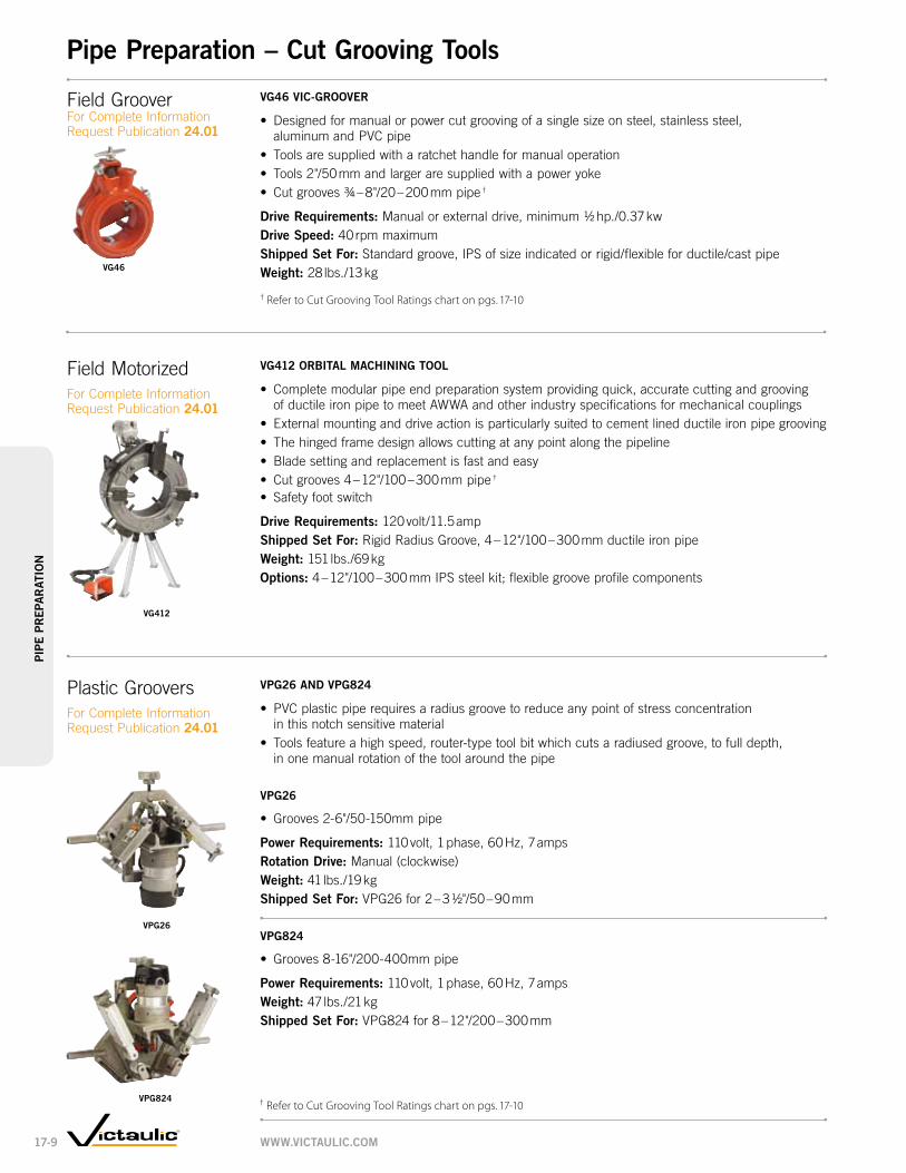
Plastic GrooversFor Complete Information Request Publication 24.01
Vpg26 anD Vpg824
• PVC plastic pipe requires a radius groove to reduce any point of stress concentration in this notch sensitive material
• Tools feature a high speed, router-type tool bit which cuts a radiused groove, to full depth, in one manual rotation of the tool around the pipe
Vpg26
• Grooves 2-6"/50-150mm pipe
power requirements: 110 volt, 1 phase, 60 Hz, 7 amps rotation Drive: Manual (clockwise) weight: 41 lbs./19 kgShipped Set For: VPG26 for 2 – 3 ½"/50 – 90 mm
Vpg824
• Grooves 8-16"/200-400mm pipe
power requirements: 110 volt, 1 phase, 60 Hz, 7 ampsweight: 47 lbs./21 kgShipped Set For: VPG824 for 8 – 12"/200 – 300 mm
Field MotorizedFor Complete Information Request Publication 24.01
Vg412 orbiTal MaCHining Tool
• Complete modular pipe end preparation system providing quick, accurate cutting and grooving of ductile iron pipe to meet AWWA and other industry specifications for mechanical couplings
• External mounting and drive action is particularly suited to cement lined ductile iron pipe grooving• The hinged frame design allows cutting at any point along the pipeline• Blade setting and replacement is fast and easy• Cut grooves 4 – 12"/100 – 300 mm pipe †
• Safety foot switch
Drive requirements: 120 volt/11.5 ampShipped Set For: Rigid Radius Groove, 4 – 12"/100 – 300 mm ductile iron pipeweight: 151 lbs./69 kgoptions: 4 – 12"/100 – 300 mm IPS steel kit; flexible groove profile components
Vpg26
Vpg824
Vg412
† Refer to Cut Grooving Tool Ratings chart on pgs. 17-10
Field Groover For Complete Information Request Publication 24.01
Vg46 ViC-grooVEr
• Designed for manual or power cut grooving of a single size on steel, stainless steel, aluminum and PVC pipe
• Tools are supplied with a ratchet handle for manual operation• Tools 2"/50 mm and larger are supplied with a power yoke• Cut grooves ¾ – 8"/20 – 200 mm pipe †
Drive requirements: Manual or external drive, minimum ½ hp./0.37 kwDrive Speed: 40 rpm maximumShipped Set For: Standard groove, IPS of size indicated or rigid/flexible for ductile/cast pipeweight: 28 lbs./13 kgVg46
† Refer to Cut Grooving Tool Ratings chart on pgs. 17-10
www.ViCTauliC.CoM17-9
pipE
pr
Epa
raT
ion
pipe preparation – Cut grooving Tools

Tool Model
pipe Material
pipe Size/Schedule inches/mm
¾ 20
1 25
1¼ 32
1½ 40
2 50
2½ 65
3 80
3½ 90
4 100
4½ 120
5 125
6 150
8 200
10 250
12 300
14 350
16 400
18 450
20 500
22 550
24 600
Vic-Groover Individually
Sized ¾ – 8"/
20 – 200 mm
Steel 40, 80
Stainless 40, 80
Aluminum 40, 80
PVC 40, 80
Vic-Groover Ductile Iron Class 53
Class 53
Class 53
VG28GD Adjustable
Groover
Steel 40, 80 40
Stainless 40, 80 40
Aluminum 40, 80 40
Ductile Iron Class 53
VG824 Adjustable
Groover
Steel 40, 80 Standard Wall 30, 40
Stainless Standard Wall, 30, 40
Aluminum Standard Wall, 30, 40
Ductile Iron Class 53
VG828 Cut
Grooving Tool
Steel .500-75"/12.7-19.05mm
VG412 Adjustable
Groover
Steel 40, 80 *
Ductile Iron Class 53
VPG26 PVC 40, 80 PVC
VPG824 PVC 40, 80 PVC
* Recommended for lined steel pipe only.
Vic-Groover® Cut Grooving Tool Ratings(CapaCiTy)
www.ViCTauliC.CoM 17-10
pipE
pr
Epa
raTio
npipe preparation – Cut grooving

Pressfit ToolFor Complete Information Request Publication 24.01
VHCT900
• Three-piece hole cutting tool designed to cut holes up to 3 ½"/90 mm in diameter for Mechanical-T, Vic-Let, and Vic-O-Well outlets
• Base unit clamps quickly onto the pipe in vertical, horizontal or overhead positions• Heavy-duty drill mounts to the alignment guides and a manual feed assembly provides
uniform pressure on the saw for maximum cutting efficiency
Capacity: 1–3½"/25–90mm holes for ½–3"/15–80mm Mechanical-T and Vic-Let connectionspower requirements: grounded 120 volt, 1 phase, 60 Hz, 10 amp electrical supply.(220 volt, 1 phase, 60 Hz, 5 amp available on request)weight: 36 lbs./16 kg accessories: Extended chain for 10 – 24"/250 – 600 mm pipe
ViC-Tap ii
• Hole cutting tool designed for use with Style 931 Vic-Tap II Mechanical-T unit for tapping into steel pipe systems under pressures up to 500 psi/3450 kPa
Capacity: Vic-Tap II 4 – 8"/100 – 200 mm Run × 2 ½"/65 mm (IPS) Outletpower requirements: 115 volt, 1 phase, 60 Hz, 7.5 ampweight:(A) Drill guide base 15 lbs./6.8 kg (B) Drill motor and feed assembly, total wgt. 16 lbs./7.3 kg (C) Style 931/Valve unit, 12 lb./5.4 kg – 15 lb./6.8 kg, depending upon size (4, 5, 6 and 8"/100, 125, 150 200mm available)Hole Size: 2 3⁄8"/60.5 mm
pFT505 – ElECTriC Tool
• The Pressfit System requires a Pressfit tool designed for securing Pressfit products onto pipe• Jaws are available separately for rental (with rental tool) or purchase• Pressfit tool is designed for industrial and trade use only
Capacity: ½ – 2"/15 – 50 mm IPS Schedule 5 steel and stainless steel pipepower requirements: 110 volt, 60 cycle, 6.5 ampaccessories: Pressing jaws in ½"/15 mm, ¾"/20 mm, 1"/25 mm, 1½"/40 mm and 2"/50 mm note: pFT505 and pFT509 components are not interchangeable
Hole Cutting ToolsFor Complete Information Request Publication 24.01
HCT908
• One-piece hole cutting tool designed to cut holes up to 4 ½"/120 mm in carbon and stainless steel pipe
• Allows for use of Mechanical-T, Vic-Let, and Vic-O-Well outlets
Capacity: 1–4½"/25–120mm holes for ½–4"/15–100mm Mechanical-T and Vic-Let connectionspower requirements: 110 volt, 1 phase, 60 Hz, 7.0 ampweight: 23 lbs./10 kg
HCT908
VHCT900
ViC-Tap ii
pFT505
pFT509
pFT509 – baTTEry Tool
• The Pressfit System requires a Pressfit tool designed for securing Pressfit products onto pipe• Tool packages include the actual pressing tool, two (2) batteries and a charger, carrying case, and ½, ¾, 1, and 1½" press jaws• Jaws are available separately for purchase • Pressfit tool is designed for industrial and trade use only • Pressfit tool is battery powered and requires a 12V battery charger
Capacity: ½ – 1" and 1½"/15 – 25 mm and 40 mm IPS Schedule 5 steel and stainless steel pipe note: pFT505 and pFT509 components are not interchangeable
www.ViCTauliC.CoM17-11
pipE
pr
Epa
raT
ion
pipe preparation – pressfit Tool/Hole Cutting Tools

Pipe Cutting ToolsFor Complete Information Request Publication 24.01
VCT1 Manual
• Lightweight and portable pipe cut-off tool handles 4 – 24"/100 – 600 mm pipe, up to 0.500/12.7 mm thick
• Worm gear drive crank handle provides smooth, manual travel, easy control and accurate cutting
Capacity: 4 – 24"/100 – 600 mmwall Thickness: 0.065 – 0.500"/1.65 – 12.7 mm (with tips supplied)Tips: Acetylene – 1 ea. #00, #0, #1weight: 22 lbs./10 kg
VCT2 auToMaTiC
• Rotation is powered by a small 120 VAC motor with SCR remote control• Unique distributor design has stainless steel insert which extends tip life, eases cleaning
and reduces backfire
Capacity: 6 – 24"/150 – 600 mm wall Thickness: 0.065 – 0.500"/1.65 – 12.7 mm (with tips supplied) Tips: Acetylene – 1 ea. #00, #0, #1Speed Control: SCR power required: 120 volt, 1 phase, 60 Hz, 15 ampMotor rating: 15 W 10,000 rpm weight: 33 lbs./15 kg accessories: Guide rail is sold separately. Recommended for pipe 12"/300 mm and above. Order Guide Rail D-600 for up to 24"/600 mm pipe (others available).
VCT1
VCT2
www.ViCTauliC.CoM 17-12
pipE
pr
Epa
raTio
npipe preparation – pipe Cutting Tools

Power DriveVpD752
For Complete Information Request Publication 24.01
Adjustable Pipe StandVapS112
For Complete Information Request Publication 24.01
• Designed for supporting pipe to be roll grooved• Four adjustable legged portable self-standing unit• Turnstile design allows pipe to be spun around for grooving of both pipe ends without
dismounting pipe from stand
Capacity: ¾ – 12"/20 – 300 mm IPS pipe load rating: 1075 lbs./490 kgVertical Stroke: 14½"/368 mm for adjusting rod, 8½"/216 mm leg adjustment, 23"/584 mmMinimum pipe Height from Floor: 23"/584 mm on 12"/300 mm pipe 21"/533 mm on 1"/25 mm pipeweight: 190 lbs./86 kgHandle Effort required to raise 1075 lbs./490 kg load: 50 lbs./23 kg maximum
• Can be used as the power drive unit for the VE226, VE26, VE46, VE416FS and VE272SFS roll grooving tools, provided the tool is equipped with the correct base plate and the VG1, VG28GD, and VG824 cut grooving tools with universal drive shaft
• Operated with a safety foot switch
Capacity: See appropriate toolpower requirements: 115 volts, 15 amp, 50/60 Hz (220 volt, 6 amp, 50/60 cycle optional)weight: 140 lbs./634 kg optional: Universal drive shaft
Power MuleFor Complete Information Request Publication 24.01
• Ideal drive for Victaulic individual Vic-Groover tools, VG28GD, VG824 and VG828• Heavy-duty, two-wheeled unit drives Victaulic cut grooving tools at the speed
and power necessary for accurate grooving• Power Mule is equipped with a Forward-Off-Reverse control and integral foot switch
Capacity: Victaulic individual Vic-Groover tools, VG28GD, VG26GD/MRL, VG824, VG824/MRLpower requirements: 115 volts, 15 amp, 50/60 cycle Full load Speed: 35 rpmweight: 190 lbs./86 kg
www.ViCTauliC.CoM17-13
pipE
pr
Epa
raT
ion
pipe preparation – accessories

Pipe Diameter Tape PT100AFor Complete Information Request Publication 24.01
• Designed specifically for supporting pipe to be roll grooved• Self-standing heavy-duty unit permits free pipe rotation and traversing on ball transfers• Ball transfers are mounted in a manner permitting use of pipe slings• Turnstile design allows pipe to be spun around for grooving of both pipe ends without
dismounting pipe from stand
Capacity: 2 – 24"/50 – 600 mm IPS pipe load rating: 1800 lbs./816 kgVertical Stroke: 23"/584 mmMinimum pipe Height from Floor: 13"/325 mm on 24"/600 mm IPS pipeMaximum pipe Height from Floor: 38"/965 mm on 2"/50 mm IPS pipeweight: 260 lbs./118 kg Handle Effort required to raise 1800 lbs./817 kg load: 50 lbs./23 kg maximum
Adjustable Pipe StandVapS224
For Complete Information Request Publication 24.01
* Ridgid is a registered trademark of the Ridge Tool Company
• Tape contains Go/No-Go markings on one side for use with ¾ – 24"/20 – 600 mm pipe in ANSI B36.19 and many ISO-4200 sizes and is marked in 1/100th of an inch increments on the other side.
• The Go/No-Go side can be used to check cut or roll grooved pipe conformance to Victaulic original and Machined for Rubber Lining (MRL) (¾ – 12"/20 – 300 mm) and Advanced Groove System (AGS) (14 – 24"/350 – 600 mm) groove diameter specifications.
• Tapes are notched on the lead end to allow proper overlap within the groove for more accurate measurement.
• The Go/No-Go side of the tape is not intended for use on sizes 76.1; 139.7; 165.1; 165.2; 216.3; 267.4; and 318.5 mm steel or stainless steel pipe sizes. For cast or ductile iron pipe sizes (up to 20"/500 mm), copper tube sizes, and the steel and stainless steel pipe sizes listed above, use the side of the tape marked in 0.01" increments. • The Go/No-Go pipe tape is a quick reference guide only. To ensure proper grooving dimensions, always refer to the I-100 Victaulic Field Installation Handbook or to the latest groove specifications publications located on www.victaulic.com.
• AGS/Go-No-Go pocket-sized steel tapes are available for taking circumferential measurements.
• Metric versions also available.
www.ViCTauliC.CoM 17-14
pipE
pr
Epa
raTio
npipe preparation – accessories

approxiMaTE grooVing TiME in MinuTES – STEEl pipE *
Size roll groovers – powered Cut groovers
nominal Size
inches mm 226
Vic-groover Vic-adjustable
272SFS 270FSD 268 416FSD 414MC 436MC power HandVg28gD power
Vg824 power
3/4 0.5 # — 0.2 0.2 — — — 0.5 1.5 — —20
1 0.6 # — 0.2 0.2 — — — 0.5 1.5 — —25
1 1/4 0.7 #@ — 0.2 0.2 — — — 0.7 2.0 — —32
1 1/2 0.8 #@ — 0.2 0.2 — — — 0.7 2.5 — —40
2 1.0 @≠ 0.3 0.3 0.3 0.3 0.2 — 1.0 3.0 1.0 —50
2 1/2 1.3 @≠ 0.3 0.3 0.3 0.3 0.2 — 1.2 3.8 1.3 —65
76.1 mm 1.3 @≠ 0.3 0.3 0.3 0.3 0.2 — 1.2 3.8 1.3 —
3 1.4 @≠ 0.4 0.4 0.4 0.4 0.2 — 1.4 4.5 1.5 —80
3 1/2 1.4 @≠ 0.4 0.4 0.4 0.4 0.2 — 1.7 5.5 2.0 —90
4 1.5 @≠ 0.5 0.4 0.5 0.5 0.2 0.2 1.9 7.0 2.5 —100
108.1 mm 1.5 @≠ 0.5 0.4 0.5 0.5 0.2 0.2 1.9 7.0 2.5 —
4 1/2 1.5 @≠ 0.8 0.6 0.6 0.6 0.2 0.2 2.3 8.0 2.8 —
5 1.6 @≠ 1.0 0.8 0.8 0.8 0.2 0.3 2.5 9.0 3.5 —125
133.0 mm 1.6 @≠ 1.0 0.8 0.8 0.8 0.2 0.3 2.5 9.0 3.5 —
139.7 mm 1.6 @≠ 1.0 0.8 0.8 0.8 0.2 0.3 2.5 9.0 3.5 —
6 1.8 @≠ 1.5 1.2 0.8 1.0 0.3 0.5 3.0 10.0 4.5 —150
159.0 mm 1.8 @≠ 1.5 1.2 0.8 1.0 0.3 0.5 3.0 10.0 4.5 —
165.1 mm 1.8 @≠ 1.5 1.2 0.8 1.0 0.3 0.5 3.0 10.0 4.5 —
8 — 1.7 1.5 0.9 1.7 0.4 0.8 4.0 15.0 5.0 5.0200
10 — 2.0 1.8 1.5 2.5 0.6 1.1 — — — 8.0250
12 — 2.5 2.3 1.8 3.5 0.7 1.4 — — — 10.0300
14 — — — — 7.4+ 3.6+ 3.6+ — — — 12.0350
16 — — — — 8.0+ 4.0+ 4.0+ — — — 16.0400
18 — — — — — — 4.6+ — — — 20.0450
20 — — — — — — 5.0+ — — — 23.0500
24 — — — — — — 6.0+ — — — 30.0600
30† — — — — — — 3.8 — — — —750
36† — — — — — — — — — — —900
# VE226B@ VE226S≠ VE226M* For roll groovers the times apply to the thickest pipe wall for which the tool is rated. See tool capacities.
For cut groovers, the times apply to standard wall steel pipe. For other materials and thicknesses contact Victaulic for details.
+ Times for roll grooving Advanced Groove System (AGS) pipe.† For 26"/650 mm, 28"/700 mm, 32"/800 mm and 42"/1050 mm grooving times contact Victaulic.
Grooving Times
Time for pipe preparation obviously depends on widely varied factors including productivity, location, type, hardness, and wall thick-ness of pipe. As a gauge for typical grooving times, the following chart was prepared to include grooving time with pipe in position and tool properly set for the size and depth of groove. Times will be extended when going from one size to another for roll changes, depth stop setting, trial grooving and other minor adjustments incidental to changing pipe sizes or initial set-up time prior to the first production groove.
www.ViCTauliC.CoM17-15
pipe preparationpi
pE
pr
Epa
raT
ion

STanDarD pipE wall THiCknESS (anSi b 36.10 anD b 36.19 For STainlESS STEEl pipE)
Size pipe wall Thickness
nominal Size
inches mm
actual outside Dia.
inches mm
Schedule 5S
inches mm
Schedule 5
inches mm
Schedule 10S
inches mm
Schedule 10
inches mm
Schedule 20
inches mm
Schedule 30
inches mm
Schedule 40
inches mm
Schedule Std.
inches mm
Schedule 80
inches mm
3/4 1.050 0.065 0.065 0.083 — — — 0.113 0.113 0.15420 26.9 1.65 1.65 2.11 2.87 2.87 3.91
1 1.315 0.065 0.065 0.109 — — — 0.133 0.133 0.17925 33.7 1.65 1.65 2.77 3.38 3.38 4.55
1 1/4 1.660 0.065 0.065 0.109 — — — 0.140 0.140 0.19132 42.4 1.65 1.65 2.77 3.56 3.56 4.85
1 1/2 1.900 0.065 0.065 0.109 — — — 0.145 0.145 0.20040 48.3 1.65 1.65 2.77 3.68 3.68 5.08
2 2.375 0.065 0.065 0.109 — — — 0.154 0.154 0.21850 60.3 1.65 1.65 2.77 3.91 3.91 5.54
2 1/2 2.875 0.083 0.083 0.120 — — — 0.203 0.203 0.27665 73.0 2.11 2.11 3.05 5.16 5.16 7.01
76.1 mm 3.000 0.083 0.083 0.120 — — — 0.216 0.216 0.30076.1 2.11 2.11 3.05 5.49 5.49 7.62
3 3.500 0.083 0.083 0.120 — — — 0.216 0.216 0.30080 88.9 2.11 2.11 3.05 5.49 5.49 7.62
3 1/2 4.000 0.083 0.083 0.120 — — — 0.226 0.226 0.31890 101.6 2.11 2.11 3.05 5.74 5.74 8.08
4 4.500 0.083 0.083 0.120 — — — 0.237 0.237 0.337100 114.3 2.11 2.11 3.05 6.02 6.02 8.56
108.1 mm 4.250 0.083 0.083 0.120 — — — 0.237 0.237 0.337108.1 2.11 2.11 3.05 6.02 6.02 8.56
4 1/2 5.000 0.083 0.083 0.120 — — — 0.237 0.237 0.337127.0 2.11 2.11 3.05 6.02 6.02 8.56
5 5.563 0.109 0.109 0.134 — — — 0.258 0.258 0.375125 141.3 2.77 2.77 3.40 6.55 6.55 9.53
133.0 mm 5.250 0.083 0.083 0.120 — — — 0.237 0.237 0.337133.0 2.11 2.11 3.05 6.02 6.02 8.56
139.7 mm 5.500 0.109 0.109 0.134 — — — 0.258 0.258 0.375139.7 2.77 2.77 3.40 6.55 6.55 9.53
6 6.625 0.109 0.109 0.134 — — — 0.280 0.280 0.432150 168.3 2.77 2.77 3.40 7.11 7.11 10.97
159.0 mm 6.250 0.109 0.109 0.134 — — — 0.280 0.280 0.432159.0 2.77 2.77 3.40 7.11 7.11 10.97
165.1 mm 6.500 0.109 0.109 0.134 — — — 0.280 0.280 0.432165.1 2.77 2.77 3.40 7.11 7.11 10.97
8 8.625 0.109 0.109 0.148 — 0.250 0.277 0.322 0.322 0.500200 219.1 2.77 2.77 3.76 6.35 7.04 8.18 8.18 12.70
10 10.750 0.134 0.134 0.165 — 0.250 0.307 0.365 0.365 0.594250 273.0 3.40 3.40 4.19 6.35 7.80 9.27 9.27 15.09
12 12.750 0.156 0.156 0.180 — 0.250 0.330 0.406 0.375 0.688300 323.8 3.96 3.96 4.57 6.35 8.38 10.31 9.53 17.48
14 14.000 0.156 — 0.188 0.250 0.312 0.375 0.438 0.375 0.750350 355.6 3.96 4.78 6.35 7.92 9.53 11.13 9.53 19.05
16 16.000 0.165 — 0.188 0.250 0.312 0.375 0.500 0.375 0.844400 406.4 4.19 4.78 6.35 7.92 9.53 12.70 9.53 21.44
18 18.000 0.165 — 0.188 0.250 0.312 0.438 0.562 0.375 0.938450 457.0 4.19 4.78 6.35 7.92 11.13 14.27 9.53 23.83
20 20.000 0.188 — 0.218 0.250 0.375 0.500 0.594 0.375 1.031500 508.0 4.78 5.54 6.35 9.53 12.70 15.09 9.53 26.19
24 24.000 0.218 — 0.250 0.250 0.375 0.562 0.688 0.375 1.219600 610.0 5.54 6.35 6.35 9.53 14.27 17.48 9.53 30.96
26 26.000 — — — 0.312 0.500 — — 0.375 —650 660.4 7.92 12.70 9.53
28 28.000 — — — 0.312 0.500 0.625 — 0.375 —700 711.0 7.92 12.70 15.88 9.53
30 30.000 0.250 — 0.312 0.312 0.500 0.625 — 0.375 —750 262.0 6.35 7.92 7.92 12.70 15.88 9.53
32 32.000 — — — 0.312 0.500 0.625 0.688 0.375 —800 813.0 7.92 12.70 15.88 17.48 9.53
36 36.000 — — — 0.312 0.500 0.625 0.750 0.375 —900 914.0 7.92 12.70 15.88 19.05 9.53
42 42.000 — — — — — — — 0.375 —1050 1067.0 9.53
Standard Pipe Wall Thickness
www.ViCTauliC.CoM 17-16
pipe preparationpip
E p
rEpa
raTio
n

STanDarD roll grooVE SpECiFiCaTionS – STEEl anD oTHEr ipS pipE @ †
1 2 3 4 5 6 7 8
nominal Size
inches mm
Dimensions – inches/mmpipe outside Diameter o.D. a
gasket Seat ± 0.03 ± 0.76
b grv. width
± 0.03 ± 0.76
groove Diameter C D groove Depth ref.
T Minimum
allow. wall Thk.
Maximum allow. Flare
DiameterbasicTolerance
+ – basic
Tol. +0.000 +0.00
3/4 1.050 +0.010 -0.010 0.625 0.281 0.938 -0.015 0.056 0.065 1.1520 26.9 +0.25 -0.25 15.88 7.14 23.83 -0.38 1.42 1.65 29.2
1 1.315 +0.013 -0.013 0.625 0.281 1.190 -0.015 0.063 0.065 1.4325 33.7 +0.33 -0.33 15.88 7.14 30.23 -0.38 1.60 1.65 36.3
1 1/4 1.660 +0.016 -0.016 0.625 0.281 1.535 -0.015 0.063 0.065 1.7732 42.4 +0.41 -0.41 15.88 7.14 38.99 -0.38 1.60 1.65 45.0
1 1/2 1.900 +0.019 -0.019 0.625 0.281 1.775 -0.015 0.063 0.065 2.0140 48.3 +0.48 -0.48 15.88 7.14 45.09 -0.38 1.60 1.65 51.1
2 2.375 +0.024 -0.024 0.625 0.344 2.250 -0.015 0.063 0.065 2.4850 60.3 +0.61 -0.61 15.88 8.74 57.15 -0.38 1.60 1.65 63.0
2 1/2 2.875 +0.029 -0.029 0.625 0.344 2.720 -0.018 0.078 0.083 2.9865 73.0 +0.74 -0.74 15.88 8.74 69.09 -0.46 1.98 2.11 75.7
76.1 mm 3.000 +0.030 -0.030 0.625 0.344 2.845 -0.018 0.078 0.083 3.1076.1 +0.76 -0.76 15.88 8.74 72.26 -0.46 1.98 2.11 78.7
3 3.500 +0.035 -0.031 0.625 0.344 3.344 -0.018 0.078 0.083 3.6080 88.9 +0.89 -0.79 15.88 8.74 84.94 -0.46 1.98 2.11 91.4
3 1/2 4.000 +0.040 -0.031 0.625 0.344 3.834 -0.020 0.083 0.083 4.1090 101.6 +1.02 -0.79 15.88 8.74 97.38 -0.51 2.11 2.11 104.1
4 4.500 +0.045 -0.031 0.625 0.344 4.334 -0.020 0.083 0.083 4.60100 114.3 +1.14 -0.79 15.88 8.74 110.08 -0.51 2.11 2.11 116.8
108.0 mm 4.250 +0.043 -0.031 0.625 0.344 4.084 -0.020 0.083 0.083 4.35108.0 +1.09 -0.79 15.88 8.74 103.73 -0.51 2.11 2.11 110.5
4 1/2 5.000 +0.050 -0.031 0.625 0.344 4.834 -0.020 0.083 0.095 5.10120 127.0 +1.27 -0.79 15.88 8.74 122.78 -0.51 2.11 2.41 129.5
5 5.563 +0.056 -0.031 0.625 0.344 5.395 -0.022 0.084 0.109 5.66125 141.3 +1.42 -0.79 15.88 8.74 137.03 -0.56 2.13 2.77 143.8
133.0 mm 5.250 +0.053 -0.031 0.625 0.344 5.084 -0.020 0.083 0.109 5.35133.0 +1.35 -0.79 15.88 8.74 129.13 -0.51 2.11 2.77 135.9
139.7 mm 5.500 +0.056 -0.031 0.625 0.344 5.334 -0.020 0.083 0.109 5.60139.7 +1.42 -0.79 15.88 8.74 135.48 -0.51 2.11 2.77 142.2
6 6.625 +0.063 -0.031 0.625 0.344 6.455 -0.022 0.085 0.109 6.73150 168.3 +1.60 -0.79 15.88 8.74 163.96 0.56 2.16 2.77 170.9
152.4 mm 6.000 +0.056 -0.031 0.625 0.344 5.830 -0.022 0.109 0.109 6.10152.4 +1.42 -0.79 15.88 8.74 148.08 -0.56 2.80 2.77 154.9
159.0 mm 6.250 +0.063 -0.031 0.625 0.344 6.032 -0.030 0.109 0.109 6.35159.0 +1.60 -0.79 15.88 8.74 153.21 -0.46 2.80 2.77 161.3
165.1 mm 6.500 +0.063 -0.031 0.625 0.344 6.330 -0.022 0.085 0.109 6.60165.1 +1.60 -0.79 15.88 8.74 160.78 -0.56 2.16 2.77 167.6
8 8.625 +0.063 -0.031 0.750 0.469 8.441 -0.025 0.092 0.109 8.80200 219.1 +1.60 -0.79 19.05 11.91 214.40 -0.64 2.34 2.77 223.5
203.2 mm 8.000 +0.063 -0.031 0.750 0.469 7.816 -0.025 0.092 0.109 8.17203.2 +1.60 -0.79 19.05 11.91 198.53 -0.64 2.34 2.77 207.5
10 10.750 +0.063 -0.031 0.750 0.469 10.562 -0.027 0.094 0.134 10.92250 273.0 +1.60 -0.79 19.05 11.91 268.28 -0.69 2.39 3.40 277.4
254.0 mm 10.000 +0.063 -0.031 0.750 0.469 9.812 -0.027 0.094 0.134 10.17254.0 +1.60 -0.79 19.05 11.91 249.23 -0.69 2.39 3.40 258.3
12 12.750 +0.063 -0.031 0.750 0.469 12.531 -0.030 0.109 0.156 12.92300 323.9 +1.60 -0.79 19.05 11.91 318.29 -0.76 2.77 3.96 328.2
304.8 mm 12.000 +0.063 -0.031 0.750 0.469 11.781 -0.030 0.109 0.156 12.17304.8 +1.60 -0.79 19.05 11.91 299.24 -0.76 2.77 3.96 309.1
14 – 24 350 – 600 See agS grooving Chart, pg. 17-19
@ Always refer to the I-100 handbook for current grooving specifications.† On roll grooved pipe, Allowable Pipe End Separation and Deflection from center line will be ½ values listed for cut
grooved pipe. # For non-AGS grooves in this size refer to the I-100 pocket handbook for current grooving specifications.
Important notES: For roll grooving pipe from 24 – 48"/600 – 1200 mm contact Victaulic.Coatings applied to the interior surfaces, including bolt pad mating surfaces, of our grooved and bolted plain end couplings should not exceed 0.010"/0.25 mm. Also, the coating thickness applied to the gasket seating surface and within the groove on the pipe exterior should not exceed 0.010"/0.25 mm.
GrooVE DImEnSIon notES: SEE pG. 17-18
A B
D
BT
COD
Exaggerated for Clarity
Groove Dimensionsroll grooVE SpECiFiCaTionS noTES
For Complete Information Request Publication 25.01
™TM
www.ViCTauliC.CoM17-17
pipe preparationpi
pE
pr
Epa
raT
ion

largE DiaMETEr roll grooVE SpECiFiCaTionS @
1 2 3 4 5 6 7 8
nominal Size
inches mm
Dimensions – inches/mm
pipe outside Diameter o.D.
a gasket Seat
+ 0.03 - 0.06 + 0.8 - 1.5
b grv. width
± 0.03 ± 0.76
C groove Diameter groove
Depth D
ref.
T Min. allow. wall
Thickness Max. allow. Flare Dia.basic
Tolerance + –
roll groove
Cut groove basic
Tol. +0.000 +0.00
roll groove
Cut groove
26 O.D. 26.00 +0.093 -0.031 1.75 0.625 0.625 25.50 -0.063 0.250 0.250 0.625 26.20650 660.4 +2.36 -0.79 45.45 15.88 15.88 647.7 -1.60 6.35 6.35 15.88 665.5
28 O.D. 28.00 +0.093 -0.031 1.75 0.625 0.625 27.50 -0.063 0.250 0.250 0.625 28.20700 711.0 +2.36 -0.79 45.45 15.88 15.88 698.50 -1.60 6.35 6.35 15.88 716.3
30 O.D. 30.00 +0.093 -0.031 1.75 0.625 0.625 29.50 -0.063 0.250 0.250 0.625 30.20750 762.0 +2.36 -0.79 45.45 15.88 15.88 749.30 -1.60 6.35 6.35 15.88 767.1
32 O.D. 32.00 +0.093 -0.031 1.75 0.625 0.625 31.50 -0.063 0.250 0.250 0.625 32.20800 813.0 +2.36 -0.79 45.45 15.88 15.88 800.10 -1.60 6.35 6.35 15.88 817.9
36 O.D. 36.00 +0.093 -0.031 1.75 0.625 0.625 35.50 -0.063 0.250 0.250 0.625 36.20900 914.0 +2.36 -0.79 45.45 15.88 15.88 901.70 -1.60 6.35 6.35 15.88 919.5
42 O.D. 42.00 +0.093 -0.031 2.00 0.625 0.625 41.50 -0.063 0.250 0.250 0.625 42.201050 1067.0 +2.36 -0.79 50.80 15.88 15.88 1054.10 -1.60 6.35 6.35 15.88 1071.8
@ Always refer to the I-100 handbook for current grooving specifications.
Important notES: For roll grooving pipe from 24 – 48"/600 – 1200 mm contact Victaulic.Coatings applied to the interior surfaces, including bolt pad mating surfaces, of our grooved and bolted plain end couplings should not exceed 0.010"/0.25 mm. Also, the coating thickness applied to the gasket seating surface and within the groove on the pipe exterior should not exceed 0.010"/0.25 mm.
GrooVE DImEnSIon notES:Column 1: nominal IpS pipe Size
Column 2: IpS pipe outside DiameterThe average pipe outside diameter must not vary from the specifications listed in the tables on the following pages. Maximum allowable pipe ovality should not vary by more than 1%. Greater variations between the major and minor diameters will result in difficult coupling assembly. For IPS pipe, the maximum allowable tolerance from square-cut pipe ends is 0.030"/0.8 mm for ¾ – 3 ½"/20 – 90 mm sizes; 0.045"/1.1 mm for 4 – 6"/100 – 150 mm sizes; and 0.060"/1.5 mm for 8"/200 mm and larger sizes. This is measured from the true square line. Any internal and external weld beads or seams must be ground flush to the pipe surface. The inside diameter of the pipe end must be cleaned to remove coarse scale, dirt, and other foreign material that might interfere with or damage grooving rolls.
Column 3: Gasket Seat “a” Dimension The “A” dimension, or the distance from the pipe end to the groove, identifies the gasket seating area. This area must be free from indentations, projections (including weld seams), and roll marks from the pipe end to the groove to ensure a leak-tight seal for the gasket. All oil, grease, and dirt must be removed.
Column 4: Groove Width “B” Dimension The “B” dimension, or groove width, controls expansion, contraction, and angular deflection of flexible couplings by the distance it is located from the pipe and its width in relation to the coupling housings’ “key” width.
Column 5: Groove outside Diameter “C” DimensionThe “C” dimension is the proper diameter at the base of the groove. This dimension must be within the diameter’s tolerance and concentric with the OD for proper coupling fit. The groove must be of uniform depth for the entire pipe circumference.
Column 6: Groove Depth “D” Dimension The “D” dimension is the normal depth of the groove and is a reference for a “trial groove” only. Variations in pipe OD affect this dimension and must be altered, if necessary, to keep the “C” dimension within tolerance. This groove must conform to the “C” dimension described above.
Column 7: minimum allowable Wall thickness “t” DimensionThe “T” dimension is the lightest grade (minimum, nominal wall thickness) of pipe that is suitable for cut or roll grooving. Pipe that is less than the minimum, nominal wall thickness for cut grooving may be roll grooved or adapted for Victaulic couplings by using Vic-Ring adapters. Vic-Ring adapters can be used in the following situations (contact Victaulic for details):• When the pipe is less than the minimum, nominal wall thickness suitable for roll grooving• When the pipe outside diameter is too large to roll or cut groove• When the pipe is used in abrasive services
Column 8: maximum allowable pipe-End Flare Diameter “F” Dimension (Standard roll Groove only)Maximum allowable pipe-end flare diameter is measured at the extreme pipe-end diameter.
A B
D
BT
COD
Exaggerated for Clarity
Groove Dimensionsroll grooVE SpECiFiCaTionS noTES
For Complete Information Request Publication 25.01
www.ViCTauliC.CoM 17-18
pipe preparationpip
E p
rEpa
raTio
n

STanDarD aDVanCED grooVE SySTEM (agS) roll grooVE SpECiFiCaTionS – Carbon STEEl
1 2 3 4 5 6 7
nominal Size
inches mm
Dimensions – inches/mm
pipe outside Diameter o.D. T Minimum
allow. wall Thk.
a gasket Seat
+ 0.031/-0.063 + 0.79/-1.60
b grv. width
ref.
C groove Diameter Maximum
allow. Flare
DiameterMaximum Minimum Maximum Minimum
14 14.094 13.969 0.375 1.500 0.455 13.500 13.455 14.23355.6 358.0 354.8 9.5 38.1 11.56 342.9 341.8 361.4
16 16.094 15.969 0.375 1.500 0.455 15.500 15.455 16.23406.4 408.8 405.6 9.5 38.1 11.56 393.7 392.6 412.2
18 18.094 17.969 0.375 1.500 0.455 17.500 17.455 18.23457.0 459.6 456.4 9.5 38.1 11.56 444.5 443.4 463.0
20 20.094 19.969 0.375 1.500 0.455 19.500 19.455 20.23508.0 510.4 507.2 9.5 38.1 11.56 495.3 494.2 513.8
24 24.094 23.969 0.375 1.500 0.455 23.500 23.455 24.23610.0 612.0 608.8 9.5 38.1 11.56 596.9 595.8 615.4
Important notES:Roll grooving removes no metal, cold forming a groove by the action of an upper male roll being forced into pipe as it is rotated by a lower female drive roll.Roll grooving pipe to AGS specifications enlarges the pipe length by approximately 1/8"/3.2 mm for each groove. For a pipe length with an AGS roll groove at each end, the pipe length will grow approximately ¼"/6.4 mm total. Therefore, the cut length should be adjusted to accommodate this growth. EXAMPLE: If you need a 24"/610 mm length of pipe that will contain an AGS roll groove at each end, cut the pipe to a length of 23¾"/603 mm to allow for this growth.Coatings applied to the interior surfaces, including bolt pad mating surfaces, of our grooved end couplings should not exceed 0.010"/0.25 mm. Also, the coating thickness applied to the gasket seating surface and within the groove on the pipe exterior should not exceed 0.010"/0.25 mm.
GrooVE DImEnSIon notES:Column 1: nominal IpS pipe Size (anSI B36.10); Basic metric pipe size (ISo 4200)
Column 2: outside DiameterThe outside diameter of roll grooved pipe shall not vary more than the limits listed (API 5L end tolerance). The maximum allowable tolerance from square cut ends is 0.063"/1.5 mm measured from a true square line.
Column 3: minimum nominal Wall thicknessThis is the minimum nominal wall thickness which may be roll grooved.
Column 4: Gasket SeatThe pipe surface shall be free from indentations, roll marks, and projections from the end of the pipe to the groove, to provide a leak-tight seat for the gasket. All loose paint, scale, dirt, chips, grease, and rust must be removed. Beveled carbon steel pipe may be used provided the wall thickness is standard wall (.375"/9.5 mm) and the bevel meets ASTM A53 and/or API 5L (30° +5°/–0°). Gasket seat “A” is measured from the end of the pipe.
Column 5: Groove WidthBottom of groove must be free of loose dirt, chips, rust and scale that may interfere with proper coupling assembly. Corners at bottom of groove must be radiused R .09 (R 2.3). Only Victaulic roll grooving tools may be used to groove pipe. Groove width and corner radii will be attained with properly maintained Victaulic tools.
Column 6: Groove DiameterThe groove must be of uniform depth for the entire pipe circumference. Groove must be maintained within the “C” diameter limits listed. Standard weight carbon steel pipe shall be prepared with Victaulic “RW” rolls.
Column 7: maximum allowable pipe End Flare DiameterDimension measured at the most extreme pipe end diameter, square cut or beveled.
Exaggerated for Clarity
OD C
B
A B T
Groove DimensionsaDVanCED grooVE SySTEM (agS) roll grooVE SpECiFiCaTionS noTES
For Complete Information Request Publication 25.09
warning
•VictaulicAGSproductsMuST noT be used on pipe that is prepared to standard groove dimensions.
•Whengroovingpipeforuse with agS products, Victaulic roll grooving tools must be equipped with special Victaulic agS roll sets made specifically for use with standard-weight pipe.
•Itiscriticaltomeasurethe groove Diameter “C” dimension, along with the gasket Seat “a” dimension and the Flare Diameter “F” dimension. These measurements must be within the specifications listed in this table above for proper joint performance.
Failure to follow these instructions could cause joint failure, resulting in serious personal injury and/or property damage.
www.ViCTauliC.CoM17-19
pipe preparationpi
pE
pr
Epa
raT
ion

CoppEr Tubing roll grooVE SpECiFiCaTionS @
1 2 3 4 5 6 7 8
nominal Size
inches mm
actual outer Diameter Dimensions – inches/mm
basic inches
mm
Tolerance inches
mm
a gasket Seat
± 0.03 ± 0,76
b grv. width
+0.03/-0.00 -0,76/-0,00
C grv. Diameter
+0/-0.020 +0/-0,5
D groove Depth ref.
T Minimum
allow. wall Thick.
Maximum allow. Flare
Diameter
2 2.125 ±0.002 0.610 0.300 2.209 0.048 DWV 2.22050 54.0 ±0.05 15.5 7.6 51.5 1.2 56.4
2 1/2 2.625 ±0.002 0.610 0.300 2.525 0.050 0.065 2.72065 66.7 ±0.05 15.5 7.6 64.1 1.2 (1.7) 69.1
3 3.125 ±0.002 0.610 0.300 3.025 0.050 DWV 3.22080 79.4 ±0.05 15.5 7.6 76.8 1.2 81.8
4 4.125 ±0.002 0.610 0.300 4.019 0.053 DWV 4.220100 104.8 ±0.05 15.5 7.6 102.1 1.4 107.2
5 5.125 ±0.002 0.610 0.300 4.999 0.053 DWV 5.220125 130.2 ±0.05 15.5 7.6 127.0 1.4 132.6
6 6.125 ±0.002 0.610 0.300 5.999 0.063 DWV 6.220150 155.6 ±0.05 15.5 7.6 152.3 1.6 158.0
8 8.125 ±0.002/-0.004 0.610 0.300 7.959 0.083 DWV 8.220200 206.4 ±0.05/-0.10 15.5 7.6 202.2 2.1 208.8
@ Always refer to the I-600 handbook for current grooving specifications.
GrooVE DImEnSIon notES:Column 1: nominal aStm B-88 drawn copper tubing size as indicated in the chart heading
Column 2: outside DiameterThe outside diameter of roll grooved tubing shall not vary more than the tolerance listed. The maximum allowable tolerance from square cut ends is 0.030"/0.8 mm for 2 – 3"/50 – 80 mm; 0.045"/1.1 mm for 4 – 6"/ 100 – 150 mm, measured from true square line.
Column 3: Gasket SeatThe tubing surface shall be free from indentations, roll marks, and projections from the end of the tubing to the groove, to provide a leak-tight seat for the gasket. All loose scales, dirt, chips and grease must be removed.
Column 4: Groove WidthBottom of groove to be free of loose dirt, chips and scale that may interfere with proper coupling assembly.
Column 5: Groove outside DiameterThe groove must be uniform depth for the entire tubing circumference. Groove must be maintained within the “C” diameter tolerance listed.
Column 6: Groove DepthFor reference only. Groove must conform to the groove diameter “C” listed.
Column 7: minimum allowable Wall thickness “t” DimensionASTM B-306 drain waste and vent (DWV) is minimum wall thickness copper tubing which may be roll grooved.
Column 8: maximum allowable End Flare DiameterMeasured at the most extreme tubing end diameter.
A B
OD C
B
D
T
Exaggerated for Clarity
Groove DimensionsCoppEr Tubing roll grooVE SpECiFiCaTionS noTES
For Complete Information Request Publication 25.06
www.ViCTauliC.CoM 17-20
pipe preparationpip
E p
rEpa
raTio
n

STanDarD CuT grooVE SpECiFiCaTionS – STEEl anD oTHEr ipS pipE @
1 2 3 4 5 6 7
nominal Size
inches mm
Dimensions – inches/mm
pipe outside Diameter o.D.a
gasket Seat ± 0.03 ± 0.76
b grv. width
± 0.03 ± 0.76
C groove Diameter
D groove Depth ref.
T Minimum
allow. wall
Thick.basicTolerance
+ – basic
Tol. +0.000 +0.00
3/4 1.050 +0.010 -0.010 0.625 0.313 0.938 -0.015 0.056 0.11320 26.9 +0.25 -0.25 15.88 7.95 23.83 -0.38 1.42 2.87
1 1.315 +0.013 -0.013 0.625 0.313 1.190 -0.015 0.063 0.13325 33.7 +0.33 -0.33 15.88 7.95 30.23 -0.38 1.60 3.38
1 1/4 1.660 +0.016 -0.016 0.625 0.313 1.535 -0.015 0.063 0.14032 42.4 +0.41 -0.41 15.88 7.95 38.99 -0.38 1.60 3.56
1 1/2 1.900 +0.019 -0.019 0.625 0.313 1.775 -0.015 0.063 0.14540 48.3 +0.48 -0.48 15.88 7.95 45.09 -0.38 1.60 3.68
2 2.375 +0.024 -0.024 0.625 0.313 2.250 -0.015 0.063 0.15450 60.3 +0.61 -0.61 15.88 7.95 57.15 -0.38 1.60 3.91
2 1/2 2.875 +0.029 -0.029 0.625 0.313 2.720 -0.018 0.078 0.18865 73.0 +0.74 -0.74 15.88 7.95 69.09 -0.46 1.98 4.76
76.1 mm 3.000 +0.030 -0.030 0.625 0.313 2.845 -0.018 0.078 0.18876.1 +0.76 -0.76 15.88 7.95 72.26 -0.46 1.98 4.78
3 3.500 +0.035 -0.031 0.625 0.313 3.344 -0.018 0.078 0.18880 88.9 +0.89 -0.79 15.88 7.95 84.94 -0.46 1.98 4.78
3 1/2 4.000 +0.040 -0.031 0.625 0.313 3.834 -0.020 0.083 0.18890 101.6 +1.02 -0.79 15.88 7.95 97.38 -0.51 2.11 4.78
4 4.500 +0.045 -0.031 0.625 0.375 4.334 -0.020 0.083 0.203100 114.3 +1.14 -0.79 15.88 9.53 110.08 -0.51 2.11 5.16
4 1/2 5.000 +0.050 -0.031 0.625 0.375 4.834 -0.020 0.083 0.203120 127.0 +1.27 -0.79 15.88 9.53 122.78 -0.51 2.11 5.16
5 5.563 +0.056 -0.031 0.625 0.375 5.395 -0.020 0.084 0.203125 141.3 +1.42 -0.79 15.88 9.53 137.03 -0.51 2.13 5.16
139.7 mm 5.500 +0.056 -0.031 0.625 0.375 5.334 -0.020 0.083 0.203139.7 +1.42 -0.79 15.88 9.53 135.48 -0.51 2.11 5.16
6 6.625 +0.063 -0.031 0.625 0.375 6.455 -0.022 0.085 0.219150 168.3 +1.60 -0.79 15.88 9.53 163.96 0.56 2.16 5.56
152.4 mm 6.000 +0.056 -0.031 0.625 0.375 5.830 -0.022 0.085 0.219152.4 +1.42 -0.79 15.88 9.53 148.08 -0.56 2.16 5.56
165.1 mm 6.500 +0.063 -0.031 0.625 0.375 6.330 -0.022 0.085 0.219165.1 +1.60 -0.79 15.88 9.53 160.78 -0.56 2.16 5.56
8 8.625 +0.063 -0.031 0.750 0.438 8.441 -0.025 0.092 0.238200 219.1 +1.60 -0.79 19.05 11.13 214.40 -0.64 2.34 6.05
203.2 mm 8.000 +0.063 -0.031 0.750 0.438 7.816 -0.022 0.092 0.238203.2 +1.60 -0.79 19.05 11.13 198.53 -0.56 2.34 6.05
10 10.750 +0.063 -0.031 0.750 0.500 10.562 -0.027 0.094 0.250250 273.0 +1.60 -0.79 19.05 12.70 268.28 -0.69 2.39 6.35
254.0 mm 10.000 +0.063 -0.031 0.750 0.500 9.812 -0.025 0.094 0.250254.0 +1.60 -0.79 19.05 12.70 249.23 -0.64 2.39 6.35
12 12.750 +0.063 -0.031 0.750 0.500 12.531 -0.030 0.109 0.279300 323.9 +1.60 -0.79 19.05 12.70 318.29 -0.76 2.77 7.09
304.8 mm 12.000 +0.063 -0.031 0.750 0.500 11.781 -0.027 0.109 0.279304.8 +1.60 -0.79 19.05 12.70 299.24 -0.69 2.77 7.09
14 14.000 +0.063 -0.031 0.938 0.500 13.781 -0.030 0.109 0.281350 355.6 +1.60 -0.79 23.83 12.70 350.04 -0.76 2.77 7.14
15 15.000 +0.063 -0.031 0.938 0.500 14.781 -0.030 0.109 0.312375 381.0 +1.60 -0.79 23.83 12.70 375.44 -0.76 2.77 7.92
16 16.000 +0.063 -0.031 0.938 0.500 15.781 -0.030 0.109 0.312400 406.4 +1.60 -0.79 23.83 12.70 400.84 -0.76 2.77 7.92
18 18.000 +0.063 -0.031 1.000 0.500 17.781 -0.030 0.109 0.312450 457.2 +1.60 -0.79 25.40 12.70 451.64 -0.76 2.77 7.92
20 20.000 +0.063 -0.031 1.000 0.500 19.781 -0.030 0.109 0.312500 508.0 +1.60 -0.79 25.40 12.70 502.44 -0.76 2.77 7.92
22 22.000 +0.063 -0.031 1.000 0.563* 21.656 -0.030 0.109 0.312550 559.0 +1.60 -0.79 25.40 14.30 550.06 -0.76 2.77 7.92
24 24.000 +0.063 -0.031 1.000 0.563* 23.656 -0.030 0.172 0.375600 610.0 +1.60 -0.79 25.40 14.30 600.86 -0.76 4.37 9.53
* 9/16"(0.562")/14 mm width groove is required in sizes 22 – 24"/550 – 600 mm in order to obtain the maximum allowable pipe end movement listed in Performance Data Charts. ½"/12 mm width groove will give ½ the maximum allowable shown for 22 – 24"/550 – 600 mm. For double groove tool bit information, contact Victaulic.
@ Always refer to the I-100 handbook for current grooving specifications.
A B
OD C
B
D
T
Exaggerated for Clarity
Groove DimensionsSTanDarD CuT grooVE SpECiFiCaTionS noTES
For Complete Information Request Publication 25.01
GrooVE DImEnSIon notES:Column 1: nominal IpS pipe Dize
Column 2: IpS outside Diameter The outside diameter of cut grooved pipe shall not vary more than the tolerance listed. For IPS pipe the maximum allowable tolerance from square cut ends to 0.030"/0.76 mm for ¾ – 3½"/20 – 90 mm; 0.045"/1.14 mm for 4 – 6"/100 – 150 mm; and 0.060"/1.5 mm for sizes 8"/200 mm O.D. and above measured from true square line.
Column 3: Gasket Seat The pipe surface shall be free from indentations, roll marks, and projections from the end of the pipe to the groove, to provide a leak-tight seal for the gasket. All loose paint, scale, dirt, chips, grease and rust must be removed. It continues to be Victaulic’s first recommendation that pipe be square cut. When using beveled pipe contact Victaulic for details. Square cut pipe must be used with FlushSeal and EndSeal gaskets. Gasket seat “A” is measured from the end of the pipe.
Column 4: Groove WidthThe bottom of groove to be free of loose dirt, chips, rust and scale that may interfere with proper coupling assembly. Maximum permissible radius at bottom of groove is .015"/.38 mm.
Column 5: Groove outside DiameterThe groove must be of uniform depth for the entire pipe circumference. Groove must be maintained within the “C” diameter tolerance listed.
Column 6: Groove DepthFor reference only. Groove must conform to the groove diameter “C” listed.
Column 7: minimum allowable Wall thicknessThis is the minimum wall thickness which may be cut grooved.
www.ViCTauliC.CoM17-21
pipe preparationpi
pE
pr
Epa
raT
ion

“ES” CuT grooVE SpECiFiCaTionS @
1 2 3 4 5 6 7
Size pipe outside Dia. inches
mm
Dimensions – inches/mm
nominal Size
inches mm
actual outside
Diameter inches
mm
gasket Seat a grv. width b groove Diameter CD
groove Depth ref.
T Minimum
allow. wall
Thick.Tolerance
+ – basic Tol. basic
Tol. +0.010 +0.25 basic
Tol. +0.000 +0.00
2 2.375 +0.024 -0.024 0.562 ±0.010 0.255 -0.005 2.250 -0.015 0.063 0.15450 60.3 +0.61 -0.61 14.27 ±0.25 6.48 -0.13 57.15 -0.38 1.60 3.91
2 1/2 2.875 +0.029 -0.029 0.562 ±0.010 0.255 -0.005 2.720 -0.018 0.078 0.18865 73.0 +0.74 -0.74 14.27 ±0.25 6.48 -0.13 69.09 -0.46 1.98 4.78
3 3.500 +0.035 -0.031 0.562 ±0.010 0.255 -0.005 3.344 -0.018 0.078 0.18880 88.9 +0.89 -0.79 14.27 ±0.25 6.48 -0.13 84.94 -0.46 1.98 4.78
4 4.500 +0.045 -0.031 0.605 ±0.015 0.305 -0.005 4.334 -0.020 0.083 0.203100 114.3 +1.14 -0.79 15.37 ±0.38 7.75 -0.13 110.08 -0.51 2.11 5.16
6 6.625 +0.063 -0.031 0.605 ±0.015 0.305 -0.005 6.455 -0.022 0.085 0.219150 168.3 +1.60 -0.79 15.37 ±0.38 7.75 -0.13 163.96 0.56 2.16 5.56
8 8.625 +0.063 -0.031 0.714 ±0.015 0.400 -0.010 8.441 -0.025 0.092 0.238200 219.1 +1.60 -0.79 18.14 ±0.38 10.16 -0.25 214.40 -0.64 2.34 6.05
10 10.750 +0.063 -0.031 0.714 ±0.015 0.400 -0.010 10.562 -0.027 0.094 0.250250 273.0 +1.60 -0.79 18.14 ±0.38 10.16 -0.25 268.28 -0.69 2.39 6.35
12 12.750 +0.063 -0.031 0.714 ±0.015 0.400 -0.010 12.531 -0.030 0.109 0.279300 323.9 +1.60 -0.79 18.14 ±0.38 10.16 -0.25 318.29 -0.76 2.77 7.09
@ Always refer to the I-100 handbook for current grooving specifications.
Important notES:Coatings applied to the interior surfaces, including bolt pad mating surfaces, of our grooved and bolted plain end couplings should not exceed 0.010"/0.25 mm, Also, the coating thickness applied to the gasket seating surface and within the groove on the pipe exterior should not exceed 0.010"/0.25 mm.
“ES” roll grooVE SpECiFiCaTionS @
1 2 3 4 5 6 7 8
Size pipe outside Dia. inches
mm
Dimensions – inches/mm
nominal Size
inches mm
actual out. Dia. inches
mm
gasket Seat a grv. width b groove Dia. CD
groove Depth ref.
T Minimum
allow. wall
Thick.
Maximum allow. Flare
DiameterTolerance
+ – basic Tol. basic
Tol. +0.000 +0.00 basic
Tol. +0.000 +0.00
2 2.375 +0.024 -0.024 0.572 -0.020 0.250 +0.015 2.250 -0.015 0.063 0.065 2.4850 60.3 +0.61 -0.61 14.43 ±0.51 6.35 +0.38 57.15 -0.38 1.60 1.65 63.0
2 1/2 2.875 +0.029 -0.029 0.572 -0.020 0.250 +0.015 2.720 -0.018 0.078 0.083 2.9865 73.0 +0.74 -0.74 14.53 ±0.51 6.35 +0.38 69.09 -0.46 1.98 2.11 75.7
3 3.500 +0.035 -0.031 0.572 -0.020 0.250 +0.015 3.344 -0.018 0.083 0.083 3.6080 88.9 +0.89 -0.79 14.53 ±0.51 6.35 +0.38 84.94 -0.46 2.11 2.11 91.4
4 4.500 +0.045 -0.031 0.610 -0.020 0.300 +0.020 4.334 -0.020 0.083 0.083 4.60100 114.3 +1.14 -0.79 15.49 ±0.51 7.62 +0.51 110.08 -0.51 2.11 2.11 116.8
6 6.625 +0.063 -0.031 0.610 -0.020 0.300 +0.020 6.455 -0.022 0.085 0.109 6.73150 168.3 +1.60 -0.79 15.49 ±0.51 7.62 +0.51 163.96 0.56 2.16 2.77 170.9
8 8.625 +0.063 -0.031 0.719 -0.020 0.390 +0.020 8.441 -0.025 0.092 0.109 8.80200 219.1 +1.60 -0.79 18.26 ±0.51 9.91 +0.51 214.40 -0.64 2.34 2.77 223.5
10 10.750 +0.063 -0.031 0.719 -0.020 0.390 +0.020 10.562 -0.027 0.094 0.134 10.92250 273.0 +1.60 -0.79 18.26 ±0.51 9.91 +0.51 268.28 -0.69 2.39 3.40 277.4
12 12.750 +0.063 -0.031 0.719 -0.020 0.390 +0.020 12.531 -0.030 0.109 0.156 12.92300 323.9 +1.60 -0.79 18.26 ±0.51 9.91 +0.51 318.29 -0.76 2.77 3.96 328.2
@ Always refer to the I-100 handbook for current grooving specifications.
Important notES:Coatings applied to the interior surfaces, including bolt pad mating surfaces, of our grooved and bolted plain end couplings should not exceed 0.010"/0.25 mm, Also, the coating thickness applied to the gasket seating surface and within the groove on the pipe exterior should not exceed 0.010"/0.25 mm.
A B
OD C
B
D
T
Exaggerated for Clarity
A B
D
B
T
COD
E
Groove Dimensions“ES” roll/CuT grooVE SpECiFiCaTionS noTES
For Complete Information Request Publication 25.02
GrooVE DImEnSIon notES:Column 1: nominal IpS pipe SizeNominal metric (ISO) pipe size.
Column 2: IpS outside DiameterMetric (ISO) outside diameter. The outside diameter of roll grooved pipe shall not vary more than the tolerance listed. For IPS pipe, the maximum allow-able tolerance from square cut ends is 0.030" for ¾ – 3½"/20 – 90 mm; 0.045" for 4 – 6"/100 – 150 mm; and 0.060" for sizes 203.2 mm and above measured from true square line. For (ISO) metric pipe, the maximum allowable tolerance from square cut ends is 0.76 mm for sizes 20 – 80 mm; 1.14 mm for sizes 100 – 150 mm; and 1.52 mm for sizes 200 mm and above, measured from the true square line.
Column 3: Gasket SeatThe pipe surface shall be free from indentations, roll marks, and projections from the end of the pipe to the groove, to provide a leak-tight seal for the gasket. All loose paint, scale, dirt, chips, grease and rust must be removed. Square cut pipe must be used with FlushSeal and EndSeal gaskets. Gasket seat “A” is measured from the end of the pipe.
Column 4: Groove Widthbottom of groove to be free of loose dirt, chips, rust and scale that may interfere with proper coupling assembly. Corners at bottom of roll groove must be radiused. For IPS pipe, 0.04R on 1½ – 12"/40 – 300 mm. For (ISO) metric pipe, 1.2R mm on 20 – 300 mm.
Column 5: Groove outside DiameterThe groove must be uniform depth for the entire pipe circumference. Groove must be maintained within the “C” diameter tolerance listed.
Column 6: Groove DepthFor reference only. Groove must conform to the groove diameter “C” listed.
Column 7: minimum allowable Wall thicknessThis is the minimum wall thickness which may be grooved.
Column 8: maximum allowable End Flare DiameterMeasured at the most extreme pipe end diameter square cut or beveled.
www.ViCTauliC.CoM 17-22
pipe preparationpip
E p
rEpa
raTio
n

FlExiblE raDiuS CuT grooVE SpECiFiCaTionS – DuCTilE iron pipE@
1 2 3 4 5 6 7
nominal Size
inches mm
pipe outside Diameter o.D. inches
mm
Dimensions – inches/mm
a gasket Seat
+0.000 -0.020
b groove width
+0.031 -0.016
C grv. Dia.
r radius
T Min. allow. wall Thick.
basicTolerance
+ – basicTol.
+0.000Cast iron
Ductile iron
3 3.96 +0.045 -0.045 0.750 0.375 3.723 -0.020 0.120 0.32 0.3180 100.6 +1.14 -1.14 19.05 9.53 94.56 -0.51 3.05 8.1 7.94 4.80 +0.045 -0.045 0.750 0.375 4.563 -0.020 0.120 0.35 0.32
100 121.9 +1.14 -1.14 19.05 9.53 115.90 -0.51 3.05 8.9 8.16 6.90 +0.060 -0.060 0.750 0.375 6.656 -0.020 0.120 0.38 0.34
150 175.3 +1.52 -1.52 19.05 9.53 169.06 -0.51 3.05 9.7 8.68 9.05 +0.060 -0.060 0.875 0.500 8.781 -0.025 0.145 0.41 0.36
200 229.9 +1.52 -1.52 22.23 12.70 223.04 -0.64 3.68 10.4 9.110 11.10 +0.060 -0.060 0.938 0.500 10.813 -0.025 0.145 0.44 0.38
250 281.9 +1.52 -1.52 23.83 12.70 274.65 -0.64 3.68 11.2 9.712 13.20 +0.060 -0.060 0.938 0.500 12.906 -0.030 0.145 0.48 0.40
300 335.3 +1.52 -1.52 23.83 12.70 327.81 -0.76 3.68 12.2 10.214 15.30 +0.050 -0.080 0.938 0.625 14.969 -0.030 0.165 0.55 0.42
350 388.6 +1.27 -2.03 23.83 15.88 380.21 -0.76 4.19 14.0 10.716 17.40 +0.050 -0.080 1.188 0.625 17.063 -0.030 0.165 0.58 0.43
400 442.0 +1.27 -2.03 30.18 15.88 433.40 -0.76 4.19 14.7 10.918 19.50 +0.050 -0.080 1.188 0.625 19.125 -0.030 0.185 0.63 0.44
450 495.3 +1.27 -2.03 30.18 15.88 485.78 -0.76 4.70 16.0 11.220 21.60 +0.050 -0.080 1.188 0.625 21.219 -0.030 0.185 0.67 0.45
500 548.6 +1.27 -2.03 30.18 15.88 538.96 -0.76 4.70 17.0 11.424 25.80 +0.050 -0.080 1.188 0.625 25.406 -0.030 0.185 0.73 0.47
600 655.3 +1.27 -2.03 30.18 15.88 645.31 -0.76 4.70 18.5 11.930 32.00 +0.080 -0.060 1.375 0.750 31.550 -0.035 0.215 0.92 0.51
750 812.8 +2.03 -1.52 34.93 19.05 801.37 -0.89 5.46 23.4 13.036 38.30 +0.080 -0.060 1.375 0.750 37.850 -0.035 0.215 1.02 0.58
900 972.8 +2.03 -1.52 34.93 19.05 961.39 -0.89 5.46 25.9 14.7
@ Always refer to the I-300 handbook for current grooving specifications.
Important notES:Victaulic groove specifications for cast pipe (gray and ductile) conform to requirements of ANSI/AWWA standard C-606 and CSA B242.For cast pipe, the groove is cut with a radius (“R” dimension) at the corners of the groove base to reduce stress concentration. Grooving dimensions are the same for any one pipe O.D. regardless of pipe class and pressure.Standard preparation is with a rigid radius groove. Flexible radius groove dimensions may be used to provide expansion/contraction or angular movement allowance at the joint.
GrooVE DImEnSIon notES: SEE pG. 17-24
A B
OD C
BR T
Exaggerated for clarity
Groove DimensionsFlExiblE raDiuS CuT grooVE SpECiFiCaTion noTES
For Complete Information Request Publication 25.05
www.ViCTauliC.CoM17-23
pipe preparationpi
pE
pr
Epa
raT
ion

rigiD raDiuS CuT grooVE SpECiFiCaTionS – DuCTilE iron pipE@
1 2 3 4 5 6 7
nominal Size
inches mm
pipe outside Diameter o.D. inches
mm
Dimensions – inches/mm
a gasket Seat
+0.000 -0.020
b groove width
+0.031 -0.016
C grv. Diameter
r radius
T Min. allow. wall Thick.
basicTolerance
+ – basicTol.
+0.000Cast iron
Ductile iron
3 3.96 +0.045 -0.045 0.840 0.375 3.723 -0.020 0.120 0.32 0.3180 100.6 +1.14 -1.14 21.34 9.5 94.56 -0.51 3.05 8.1 7.94 4.80 +0.045 -0.045 0.840 0.375 4.563 -0.020 0.120 0.35 0.32
100 121.9 +1.14 -1.14 21.34 9.53 115.90 -0.51 3.05 8.9 8.16 6.90 +0.060 -0.060 0.840 0.375 6.656 -0.020 0.120 0.38 0.34
150 175.3 +1.52 -1.52 21.34 9.53 169.06 -0.51 3.05 9.7 8.68 9.05 +0.060 -0.060 0.950 0.500 8.781 -0.025 0.145 0.41 0.36
200 229.9 +1.52 -1.52 24.13 12.70 223.04 -0.64 3.68 10.4 9.110 11.10 +0.060 -0.060 1.015 0.500 10.813 -0.025 0.145 0.44 0.38
250 281.9 +1.52 -1.52 25.78 12.70 274.65 -0.64 3.68 11.2 9.712 13.20 +0.060 -0.060 1.015 0.500 12.906 -0.030 0.145 0.48 0.40
300 335.3 +1.52 -1.52 25.78 12.70 327.81 -0.76 3.68 12.2 10.214 15.30 +0.050 -0.080 1.015 0.625 14.969 -0.030 0.165 0.55 0.42
350 388.6 +1.27 -2.03 25.78 15.88 380.21 -0.76 4.19 14.0 10.716 17.40 +0.050 -0.080 1.340 0.625 17.063 -0.030 0.165 0.58 0.43
400 442.0 +1.27 -2.03 34.04 15.88 433.40 -0.76 4.19 14.7 10.918 19.50 +0.050 -0.080 1.340 0.625 19.125 -0.030 0.185 0.63 0.44
450 495.3 +1.27 -2.03 34.04 15.88 485.78 -0.76 4.70 16.0 11.220 21.60 +0.050 -0.080 1.340 0.625 21.219 -0.030 0.185 0.67 0.45
500 548.6 +1.27 -2.03 34.04 15.88 538.96 -0.76 4.70 17.0 11.424 25.80 +0.050 -0.080 1.340 0.625 25.406 -0.030 0.185 0.73 0.47
600 655.3 +1.27 -2.03 34.04 15.88 645.31 -0.76 4.70 18.5 11.930 32.00 +0.080 -0.060 1.625 0.750 31.550 -0.035 0.215 0.92 0.51
750 812.8 +2.03 -1.52 41.28 19.05 801.37 -0.89 5.46 23.4 13.036 38.30 +0.080 -0.060 1.625 0.750 37.850 -0.035 0.215 1.02 0.58
900 972.8 +2.03 -1.52 41.28 19.05 961.39 -0.89 5.46 25.9 14.7
@ Always refer to the I-300 handbook for current grooving specifications.
Important notES:Victaulic groove specifications for cast pipe (gray and ductile) conform to requirements of ANSI/AWWA standard C-606 and CSA B242.For cast pipe, the groove is cut with a radius (“R” dimension) at the corners of the groove base to reduce stress concentration. Grooving dimensions are the same for any one pipe O.D. regardless of pipe class and pressure.Standard preparation is with a Rigid radius groove. Flexible radius groove dimensions may be used to provide expansion/contraction or angular movement allowance at the joint.
GrooVE DImEnSIon notES:Column 1: nominal aWWa pipe Size
Column 2 : aWWa pipe Size outside DiameterThe average pipe outside diameter must not vary from the specifications listed in the tables on the following pages. Maximum allowable pipe ovality should not vary by more than 1%. Greater variations between the major and minor diameters will result in difficult coupling assembly. For ductile iron pipe, the maximum allowable tolerance from square-cut pipe ends is 0.030"/0.8 mm for 3"/80 mm size; 0.045"/1.1 mm for 4 – 6"/100 – 150 mm sizes; and 0.060"/1.5 mm for sizes 8"/200 mm and larger sizes. This is measured from the true square line.
Column 3 : Gasket Seat “a” DimensionThe “A” dimension, or the distance from the pipe end to the groove, identifies the gasket seating area. This area must be smooth and free from indentations, projections, deep pits, and swells from the pipe end to the groove to provide a leak-tight seal for the gasket. All rust, loose scale, oil, grease, dirt, and cutting particles must be removed. Peened surfaces may require rework to provide a leak-tight seal for the gasket (refer to ANSI/AWWA C-606 or CSA B242).
Column 4: Groove Width “B” DimensionThe “B” dimension, or groove width, controls expansion and angular deflection by the distance it is located from the pipe and its width in relation to the housings’ “key” width.
Column 5: Groove Diameter “C” DimensionThe “C” dimension is the proper diameter at the base of the groove. This dimension must be within the diameter's tolerance and concentric with the O.D. for proper coupling fit. The groove must be of uniform depth for the entire pipe circumference.
Column 6: radius “r” DimensionThe “R” dimension is the radius necessary at the bottom of the groove to eliminate a point of stress concentration for cast pipe (gray and ductile).
Column 7: minimum allowable Wall thickness “t” DimensionThe “T” dimension is the minimum wall thickness that can be cut grooved. The tolerances must conform to Class 53 ANSI/AWWA C151/A21.51. Class 53 ductile iron pipe in sizes 18 – 36"/450 – 900 mm can be cut grooved. Contact Victaulic for details.
A B
OD C
BR T
Exaggerated for clarity
Groove DimensionsrigiD raDiuS CuT grooVE SpECiFiCaTion noTES
For Complete Information Request Publication 25.05
www.ViCTauliC.CoM 17-24
pipe preparationpip
E p
rEpa
raTio
n

Style No. Product Description Page No. Publ. No.
couPliNgS, PgS. 1-5 - 1-18
Style 107 Quick Vic Rigid Coupling 1-5 06.19
Style 07 Zero-Flex Rigid Coupling 1-6 06.02
Style 177 Quick Vic Flexible Coupling 1-7 06.02
Style HP-70 Rigid Coupling 1-17 06.12
Style 72 Outlet Coupling 1-15 06.10
Style 75 Flexible Coupling 1-9 06.05
Style 77 Standard Flexible Coupling 1-8 06.04
Style 78 Snap-Joint Coupling 1-14 06.09
Style 741 Vic-Flange Adapter ANSI Class 150 1-11 06.06
Style 743 Vic-Flange Adapter ANSI Class 300 1-12 06.06
Style 750 Reducing Coupling 1-13 06.08
Style 770 Large Diameter Pipe Coupling 1-10 06.03
Style 791 Vic-Boltless Coupling 1-16 06.11
Style 792 Vic-Boltless Assembly Tool 1-16 06.11
Style 808 High Pressure Coupling 1-18 06.11
eNDSeal couPliNg aND fittiNgS, PgS. 1-19 -1-20
Style HP-70ES EndSeal Coupling for Plastic Coated Pipe 1-19 06.13
No. 22-ES EndSeal Header Tee for Plastic Coated Pipe 1-20 07.03
No. 35-ES EndSeal Cross for Plastic Coated Pipe 1-20 07.03
No. 62-ES EndSeal 90° Elbow for Plastic Coated Pipel 1-20 07.03
No. 63-ES EndSeal 45° Elbow for Plastic Coated Pipe 1-20 07.03
No. 64-ES EndSeal Tee for Plastic Coated Pipe 1-20 07.03
fittiNgS, PgS. 2-1 - 2-16
Elbows
No. 10 90° Elbow 2-3 07.01
No. 10-DR Drain Elbow 2-4 10.05
No. 11 45° Elbow 2-3 07.01
No. 12 22½° Elbow 2-3 07.01
No. 13 11¼° Elbow 2-3 07.01
No. 18 90° Adapter Elbow 2-5 07.01
No. 19 45° Adapter Elbow 2-5 07.01
Tees, Crosses, Wyes, and Laterals
No. 20 Tee 2-6 07.01
No. 21 Bullhead Tee 2-8 07.01
No. 25 Reducing Tee 2-7,8 07.01
No. 27 Standpipe Tee 2-8 07.01
No. 29T Reducing Tee with Threaded Branch 2-7,8 07.01
No. 29M Tee with Threaded Branch 2-6 07.01
No. 30 45° Lateral 2-9 07.01
No. 30-R 45° Reducing Lateral 2-9 07.01
No. 32 Tee Wye 2-10 07.01
No. 32-R Reducing Tee Wye 2-10 07.01
No. 33 True Wye 2-6 07.01
No. 35 Cross 2-6 07.01
Adapters, Nipples, Caps, and Plugs
No. 40 Adapter Nipple – Grv. × Thd. 2-11 07.01
No. 41 Flange Adapter Nipple – ANSI Class 125 2-12 07.01
No. 42 Adapter Nipple – Grv. × Bev. 2-11 07.01
Style No. Product Description Page No. Publ. No.
No. 43 Adapter Nipple – Grv. × Grv. 2-11 07.01
No. 45R Raised Face Flange Adapter Nipple – ANSI Class 150 2-12 07.01
No. 45F Flat Faced Adapter Nipple 2-12 07.01
No. 46R Raised face Flange Adapter Nipple – ANSI Class 300 2-12 07.01
No. 48 Hose Nipple 2-14 07.01
Reducers
No. 50 Concentric Reducer 2-15 07.01
No. 51 Eccentric Reducer 2-15 07.01
No. 52 Small Threaded Reducer 2-16 07.01
fittiNgS, PgS. 2-1 - 2-16
No. 53 Swaged Nipple – Grv. × Grv. 2-13 07.01
No. 54 Swaged Nipple – Grv. × Thd. 2-13 07.01
No. 55 Swaged Nipple – Thd. × Grv. 2-13 07.01
No. 60 Cap 2-11 07.01
No. 61 Bull Plug 2-8 07.01
No. 80 Female Threaded Adapter 2-14 07.01
No. 100 90° 1 ½ D Long Radius Elbow 2-3 07.01
No. 100-3D 90° 1 ½ D Long Radius Elbow 2-4 07.01
No. 110 45° 3 D Long Radius Elbow 2-3 07.01
No. 110-3D 45° 3 D Long Radius Elbow 2-4 07.01
No. R-10F Reducing Base Elbow – Grv. × Flange 2-4 07.01
No. R-10G Reducing Base Elbow – Grv. × Grv. 2-4 07.01
ValVeS, PgS. 3-1 - 3-20
TA Series 73M TA CMI Pressure Differential Meter 3-20 08.16
Series 78U Union Port Fitting 3-16 08.16
Series 78Y Strainer/Ball Valve Combination 3-17 08.16
Series 377 Vic-Plug Balancing Valve 3-10 08.12
Series 700 Butterfly Valve 3-6 08.05
Series 712 Swinger Swing Check Valve – 300 psi/2065 kPa 3-9 08.11
Series 713 Swinger Swing Check Valve – 1000 psi/6900 kPa 3-9 08.11
Series 716 Vic-Check Valve 3-7 08.08
Series 721 Vic Ball Valve 3-11 08.14
Series 722 Brass Body Ball Valve 3-11 08.15
Series 726 Vic-Ball Valve 3-13 08.23
TA Series 736 TA Link Differential Pressure Sensor 3-19 08.16
TA Series 737 TA Hand Held Circuit Balancing Instrument 3-19 08.16
TA Series 738 TA Portable Differential Pressure Meter 3-19 08.16
Series 779 Venturi Check Valve 3-8 08.10
TA Series 786 Solder End 3-15 08.16
TA Series 786-DK TA Drain Kit 3-19 08.16
TA Series 787 TA NPT (Female) Threaded End Balancing Valve 3-16 08.16
TA Series 788 TA Flanged End Balancing Valve 3-15 08.16
TA Series 793 Threaded End 3-17 08.29
TA Series 794 Flanged End 3-18 08.29
TA Series 789 TA Groove End Balancing Valve 3-15 08.16
— TA Select III Computer Program 3-20 08.16
— Triple Service Valve Assembly 3-5 08.09
Vic-300 MS Vic-300 MasterSeal Butterfly Valve 3-3 08.20
www.Victaulic.com18-1
Product indexPr
oD
uc
t iN
De
x

Style No. Product Description Page No. Publ. No.
acceSSorieS, PgS. 4-1 - 4-10
No. 47 Dielectric Waterway Fitting 4-9 09.07
Series 730 Vic-Strainer – Tee Type 4-5 09.02
Series 731-I Suction Diffuser with ANSI Class 150 Flange 4-3 09.14
Series 732 Vic-Strainer – Wye Type 4-6 09.03
Style 150 Mover Expansion Joint 4-7 09.04
Style 155 Standard Expansion Joint 4-8 09.05
aDVaNceD grooVe SyStem (agS), PgS. 5-1 - 5-17
Style W07 Rigid Coupling 5-3 20.02
Style W77 Flexible Coupling 5-3 20.03
Style W89 Rigid Coupling 5-4 20.15
Style W741 Vic-Flange® Adaptor 5-5 20.04
Style W155 Expansion Joint 5-4 20.12
No. W10 90° Elbow 5-6 20.05
No. W11 45° Elbow 5-6 20.05
No. W12 22½° Elbow 5-6 20.05
No. W13 11¼° Elbow 5-6 20.05
No. W20 Tee 5-6 20.05
No. W25 Reducing Tee 5-7 20.05
No. W30 45° Lateral 5-8 20.05
No. W30-R 45° Reducing Lateral 5-8 20.05
No. W33 True Wye 5-6 20.05
No. W35 Cross 5-6 20.05
No. W42 Adapter Nipple – AGS Grv. × Bev. 5-9 20.05
No. W43 Adapter Nipple – AGS Grv. × AGS Grv. 5-9 20.05
No. W45-R Flange Adapter Nipple – ANSI Class 150 5-9 20.05
No. W49 Adapter Nipple – AGS Grv. × Non AGS Grv. 5-9 20.05
No. W50 Concentric Reducer 5-10 20.05
No. W51 Eccentric Reducer 5-10 20.05
No. W60 Cap 5-9 20.05
No. W100 90° 1 ½ D Long Radius Elbow 5-6 20.05
No. W110 45° 1 ½ D Long Radius Elbow 5-6 20.05
Vic-300 Masterseal AGS Butterfly Valve 5-12 20.06
Triple Service Valve Assembly 5-14 20.18
Series W715 Dual Disc Vic-Check Valve 5-11 20.08
Series W730 Vic-Strainer – Tee Type 5-16 20.11
Style W732 Wye Type Vic-Strainer 5-17 20.19
Series W731-I Suction Diffuser with ANSI Class 150 Flange 5-15 20.10
hole cut PiPiNg SyStem, PgS. 6-1 - 6-6
Style 920 Mechanical-T Bolted Branch Outlet 6-2 11.02
Style 920N Mechanical-T Bolted Branch Outlet 6-2 11.02
Style 923 Vic-Let Strapless Outlet 6-5 11.05
Style 924 Vic-O-Well Strapless Thermometer Outlet 6-6 11.06
PlaiN eND PiPiNg SyStem for Steel PiPe, PgS. 7-1 - 7-8
Style 99 Roust-A-Bout Coupling 7-3 14.02
No. 20P Tee 7-5 14.04
Style No. Product Description Page No. Publ. No.
No. 25P Reducing Tee 7-6 14.04
No. 30P 45º Lateral 7-6 14.04
No. 33P True Wye 7-5 14.04
No. 35P Cross 7-5 14.04
No. 40P Adapter Nipple – Plain End × Thd. 7-8 14.04
No. 42P Adapter Nipple – Plain End × Bev. 7-8 14.04
No. 43P Adapter Nipple – Plain End × Grv. 7-8 14.04
No. 53P Swaged Nipple 7-7 14.04
No. 61P Bull Plug 7-5 14.04
grooVeD SyStem for StaiNleSS Steel PiPe, PgS. 8-1 - 8-16
Style 77S Flexible Coupling 8-5 17.03
Style 89 Rigid Coupling 8-4 17.24
Style 441 Vic-Flange Adapter ANSI Class 150 8-7 17.27
Style 475 Flexible Coupling 8-6 17.12
Style 489 Rigid Coupling 8-3 17.25
No. 410 SS 90º Elbow 8-8 17.04
No. 411 SS 45º Elbow 8-8 17.04
No. 420 SS Tee 8-8 17.04
No. 425 SS Reducing Tee 8-9 17.04
No. 450 SS Concentric Reducer 8-9 17.04
No. 460 SS Cap 8-8 17.04
Series 712S Swinger Check Valve 8-12 17.08
Series 726S Vic-Ball Valve 8-13 17.22
Series 763 Butterfly Valve 8-10 17.23
PreSSfit SyStem for StaiNleSS Steel PiPe, PgS.9-1 - 9-12
PreSSfit SyStem 304
Series 589 Ball Valve 9-11 18.02
Style 547 Grooved End Union 9-9 18.02
Style 561 Weld Adapter 9-8 18.02
Style 565 Van Stone Flange Adapter 9-9 18.02
Style 582 Reducer Insert 9-10 18.02
Style 584 Threaded Union 9-8 18.02
Style 586 90° Short Tangent Elbow 9-5 18.02
Style 587 Transition Nipple 9-10 18.02
Style 588 Tee with Threaded Branch 9-6 18.02
Style 590 90° Elbow 9-5 18.02
Style 591 45° Elbow 9-5 18.02
Style 592 Tee 9-6 18.02
Style 593 Tee with Reducing Branch 9-7 18.02
Style 594 Concentric Reducer 9-10 18.02
Style 595 Flange Adapter 9-9 18.02
www.Victaulic.com 18-2
Product indexPr
oD
uc
t iND
ex

Style No. Product Description Page No. Publ. No.
Style 596 Male Adapter 9-7 18.02
Style 597 Standard Coupling 9-4 18.02
Style 599 Female Threaded Adapter 9-8 18.02
PreSSfit SyStem for StaiNleSS Steel PiPe, PgS. 9-1 - 9-12
PreSSfit SyStem 316
Series 569 Ball Valve 9-12 18.01
Style 507 Standard Coupling 9-4 18.01
Style 508 Slip Coupling 9-4 18.01
Style 548 Grooved End Union 9-9 18.01
Style 566 Lap Joint Flange Adapter 9-9 18.01
Style 568 90° Short Tangent Elbow 9-5 18.01
Style 570 90° Elbow 9-5 18.01
Style 571 45° Elbow 9-5 18.01
Style 572 Tee 9-6 18.01
Style 573 Tee with Reducing Branch 9-7 18.01
Style 574 Concentric Reducer 9-10 18.01
Style 575 Flange Adapter 9-9 18.01
Style 576 Male Adapter 9-7 18.01
Style 577 Transition Nipple 9-10 18.01
Style 578 Tee with Threaded Branch 9-6 18.01
Style 579 Female Threaded Adapter 9-8 18.01
Style 583 Reducer Insert 9-10 18.01
Style 585 Threaded Union 9-8 18.01
PlaiN eND PiPiNg SyStem for hDPe PiPe, PgS. 10-1 - 10-4
Style 994 Vic-Flange Adapter ANSI Class 150 10-4 19.04
Style 995 Coupling 10-2 19.02
Style 997 Transition Coupling – HDPE to Steel 10-3 19.03
grooVeD coPPer PiPiNg SyStem, PgS. 11-1 - 11-10
Style 606 Coupling 11-4 22.02
Style 607 QuickVic Rigid Coupling 11-3 22.13
Style 622 Mechanical-T Bolted Branch Outlet 11-5 22.12
Style 641 Vic-Flange Adapter 11-4 22.03
Series 608 Butterfly Valve 11-9 22.05
No. 610 90° Elbow 11-6 22.04
No. 611 45° Elbow 11-6 22.04
No. 620 Tee 11-6 22.04
No. 625 Reducing Tee – Grv. × Grv. × Grv. 11-8 22.04
No. 626 Reducing Tee – Grv. × Grv. × Cup 11-8 22.04
No. 650 Concentric Reducer – Grv. × Grv. 11-7 22.04
No. 652 Concentric Reducer – Grv. × Cup 11-7 22.04
No. 660 Cap 11-6 22.04
grooVeD awwa Ductile iroN PiPe, PgS. 13-1 - 13-18
Style 31 Coupling 13-3 23.02
Style 307 Transition Coupling – AWWA to IPS 13-5 23.03
Style 341 Vic-Flange Adapter 13-4 23.04
No. 10-C 90° Elbow 13-7 23.05
No. 10-CB Base Elbow 13-13 23.05
No. 10-CF 90° Flare 13-14 23.05
No. 10-CR 90° Reducing Elbow 13-11 23.05
Style No. Product Description Page No. Publ. No.
No. 10-CS 90° Side Outlet 13-14 23.05
No. 11-C 45° Elbow 13-7 23.05
No. 12-C 22½° Elbow 13-7 23.05
No. 13-C 11¼° Elbow 13-7 23.05
No. 20-C Tee 13-8 23.05
No. 20-CB Base Tee 13-13 23.05
No. 20-CS Tee Side Outlet 13-14 23.05
No. 21-C Bullhead Tee 13-8 23.05
No. 25-C Reducing Tee 13-9 23.05
No. 25-CB Reducing Base Tee 13-13 23.05
No. 30-C 45° Lateral 13-8 23.05
No. 30-CR 45° Reducing Lateral 13-9 23.05
No. 33-C True Wye 13-8 23.05
No. 35-C Cross 13-8 23.05
No. 35-CR Reducing Cross 13-9 23.05
No. 43-CF Straight Flare 13-14 23.05
No. 50-C Concentric Reducer 13-11 23.05
No. 51-C Eccentric Reducer 13-11 23.05
No. 60-C Cap 13-8 23.05
No. 100-C 90º Long Radius Elbow 13-7 23.05
No. 100-CB Base Elbow 13-13 23.05
No. 100-CF 90º Long Radius Flare 13-14 23.05
No. 100-CR 90º Long Radius Reducing Elbow 13-11 23.05
Series 317 Check Valve 13-16 23.09
Series 365 Vic-Plug Valve with AWWA Standard Ends 13-15 23.06
PiPe PreParatioN toolS, PgS. 17-1 - 17-24
roll grooViNg toolS
VE12 Groove In-Place – Steel 17-3 24.01
VE26 Groove In-Place 17-3 24.01
VE46 Groove In-Place 17-3 24.01
VE106 Groove-N-Go 17-4 24.01
VE226 Portable Roll Groover 17-3 24.01
VE270FSD Field Roll Groover 17-4 24.01
VE272SFS Field Roll Groover 17-4 24.01
VE268 Shop Roll Groover 17-5 24.01
VE414MC Vic-Easy Shop Roll Groover 17-5 24.01
VE416FSD Field Roll Groover 17-4 24.01
VE450FSD Shop Roll Groover 17-5 24.01
VE436MC Production Roll Groover 17-5 24.01
cut grooViNg toolS
VG46 Vic Groover 17-9 24.01
VG28GD Adjustable Cut Groover 17-8 24.01
VG824 Adjustable Cut Groover 17-8 24.01
VG828 AGS Cut Grooving Tool 17-8 24.01
VG412 Orbital Tool 17-9 24.01
VPG26 PVC Plastic Groover 17-9 24.01
VPG824 PVC Plastic Groover 17-9 24.01
www.Victaulic.com18-3
Product indexPr
oD
uc
t iN
De
x

Style No. Product Description Page No. Publ. No.
PreSSfit toolS
PFT505 Pressfit Tool 17-11 24.01
PFT509 Pressfit Tool 17-11 24.01
PiPe cuttiNg toolS
HCT908 Hole Cutting Tool 17-11 24.01
VHCT900 Vic Hole Cutting Tool 17-11 24.01
Vic-Tap II Hole Cutting Tool 17-11 24.01
VCT1 Cut-Off Tool – Manual 17-12 24.01
VCT2 Cut-Off Tool – Manual 17-12 24.01
acceSSorieS
VPD752 Power Drive 17-13 24.01
Power Mule Power Drive 17-13 24.01
VAPS112 Small Pipe Stand 17-13 24.01
VAPS224 Heavy Duty Pipe Stand 17-14 24.01
Pipe Tape Diameter Tape 17-14 24.01
We warrant all products to be free from defects in materials and workmanship under normal conditions of use and service. Our obligation under this warranty is limited to repairing or replacing at our option at our factory any product which shall within one year after delivery to original buyer be returned with transportation charges prepaid, and which our examination shall show to our satisfaction to have been defective.
THIS WARRANTY IS MADE EXPRESSLY IN LIEU OF ANY OTHER WARRANTIES, EXPRESS OR IMPLIED, INCLUDING ANY IMPLIED WARRANTY OF MERCHANTABILITY OR FITNESS FOR A PARTICULAR PURPOSE. THE BUYER’S SOLE AND EXCLUSIVE REMEDY SHALL BE FOR THE REPAIR OR REPLACEMENT OF DEFECTIVE PRODUCTS AS PROVIDED HEREIN. THE BUYER AGREES THAT NO OTHER REMEDY (INCLUDING, BUT NOT LIMITED TO, INCIDENTAL OR CONSEQUENTIAL DAMAGES FOR LOST PROFITS, LOST SALES, INJURY TO PERSON OR PROPERTY OR ANY OTHER INCIDENTAL OR CONSEQUENTIAL LOSS) SHALL BE AVAILABLE TO HIM.
Victaulic neither assumes nor authorizes any person to assume for it any other liability in connection with the sale of such products.
this warranty shall not apply to any product which has been subject to misuse, negligence or accident, which has been repaired or altered in any manner outside of Victaulic’s factory or which has been used in a manner contrary to Victaulic’s instructions or recommendations. Victaulic shall not be responsible for design errors due to inaccurate or incomplete information supplied by Buyer or its representatives. items purchased by Victaulic and resold will have the original equipment manufacturer's warranty extended to Victaulic customers.Effective August 4, 2008
All products shall be installed in accordance with current Victaulic installation/assembly instructions. Victaulic reserves the right to change product specifications, designs and standard equipment without notice and without incurring obligations.
www.Victaulic.com 18-4
Pr
oD
uc
t iND
ex
Product index warranty

SECTION 3
VIC/GUIDE-SP
EC
VICTAULIC PR
ODUCT SPECIF
ICATION FOR
USE WITH STA
INLESS STEEL
PIPE
3.0
IPS Grooved
Piping Syste
m
Victaulic gr
ooved mechan
ical pipe co
uplings, fit
tings, valve
s and other
grooved comp
onents may b
e used as a
proprietary
system and/o
r as an opti
on
to welding,
threading or
flanged met
hods. All g
rooved compo
nents shall
be
of one manuf
acturer Vict
aulic Compan
y of America
, and confor
m to local
code approva
l and/or as
listed by A
NSI-B-31.1,
B-31.3, B-31
.9, ASME,
UL/ULC, FM,
IAPMO or ICC
. Grooved e
nd product m
anufacturer
to be ISO-90
01
certified.
Grooved coup
lings shall
meet the req
uirements of
ASTM F-1476
.
3.1
Pipe/Grooved
(Standard/L
ightwall)
Stainless St
eel, ASTM A3
12 - Roll or
cut grooved
-ends as app
ropriate to
pipe materia
l, wall thic
kness, press
ures, size a
nd method of
joining.
Pipe ends to
be grooved
in accorda
nce with Vic
taulic curre
nt listed
standards co
nforming to
ANSI/AWWA C-
606.
3.2
Victaulic Me
chanical Cou
plings for J
oining Stain
less Steel P
ipe
Note: Where
design condi
tions requir
e use of non
-ferrous pip
ing material
s
for both int
erior and ex
terior pipin
g surfaces,
Victaulic st
ainless
steel coupli
ngs describe
d in VIC/GUI
DE-SPEC sec
tions 3.2.a
are to
be used.
3.2.a Mechan
ical Couplin
gs
Shall be Sty
le 489 Rigi
d Stainless
Steel and St
yle 89 Rigid
Ductile
Iron conform
ing to ASTM
A-395 Grade
65-45-15 and
ASTM A-536
Grade
65-45-12. S
tyles 475 an
d 77-S Flexi
ble Stainles
s Steel, typ
e 316,
conforming t
o ASTM A-351
, A-743, and
A-744 Grade
CF-8M. Refe
r to
current Vict
aulic litera
ture for pre
ssure rating
s for variou
s pipe
sizes and pi
pe schedules
.
3.2.b Mechan
ical Couplin
g Bolts and
Nuts
Shall
be Type 316
Stainless St
eel, oval ne
ck track bol
ts and heavy
hex nuts wit
h chemical a
nd physical
properties o
f ASTM A-193
, Grade
B8M, Class 2
or ASTM F-5
93, Group 2,
Condition C
W.
Note: Where
design condit
ions permit
and where only
interior piping
surfaces req
uire use of
non-ferrous
materials an
d where ferr
ous
materials ar
e acceptable
for externa
l piping sur
faces, coupl
ings and
flange adapt
ers describe
d in VIC/GUI
DE-SPEC sec
tions 2.2, 2
.3 and
3.3 are to b
e used.
3.3
Victaulic Fl
ange Adapter
s
3.3.a Vic-Fl
ange Style 4
41
2"-4"
(DN50-DN150)
for connec
tion to ANSI
class 125/1
50 flanged
components.
Cast of sta
inless steel
conforming
to ASTM A-35
1, A-743
and A-744.
For larger s
izes use the
Style 45S
Flanged Adap
ter
Nipple.
3.3.b Vic-Fl
ange® Style
741
2"-24" (DN50
-DN600) for
connection t
o ANSI class
125/150 fla
nged
components.
Cast of duc
tile iron co
nforming to
ASTM A-395,
grade
65-45-15, an
d ASTM A-536
, Grade 65-4
5-12. Refer
to current V
ictaulic
literature f
or pressure
ratings for
various pipe
sizes and
pipe
schedules.
SECTION 2
VIC/GUIDE-SPEC
VICTAULIC PRODUCT SPECIF
ICATION FOR USE WITH CAR
BON STEEL PIPE
(BLACK OR GALVANIZED)
2.0 IPS Grooved
Piping System
Victaulic grooved mech
anical pipe couplings,
fittings, valves and
other
grooved components may
be used as an option
to welding, threading
or
flanged methods. All
grooved components sha
ll be of one manufactu
rer
(Victaulic Company of America), and conform to local code approval.
Victaulic products are permitted and/or Listed/Approved by codes or
standards organizations
including but not limit
ed to: ASME (B31.1, 31.
3,
31.9), ASTM, ANSI/AWWA
(C-606), FM, IAPMO, I
nternational Code Counc
il
(IPC, IMC, IFC), NFPA, NSF,
UL, ULC, and VdS. Groov
ed end product
manufacturer to be ISO-9
001 certified. Grooved
couplings shall meet the
requirements of ASTM F-1
476.
2.1 Pipe/Grooved
(Standard/Lightwall)
Carbon Steel, A-53B/A-
106B - Roll or cut gro
oved-ends as appropria
te to
pipe material, wall th
ickness, pressures, si
ze and method of joini
ng.
Pipe ends to be groove
d in accordance with
Victaulic current list
ed
standards conforming to
ANSI/AWWA C-606.
2.2 Victaulic Me
chanical Couplings for J
oining Carbon Steel Pipe
Couplings shall be cas
t of ductile iron conf
orming to ASTM A-395,
grade
65-45-15, and ASTM A-536
, Grade 65-45-12
2.2.a Mechanical Couplin
gs
Mechanical couplings sha
ll be Victaulic Style 07
(Zero-Flex®) Rigid
coupling. Rigid coupl
ings shall be of the a
ngle pattern bolt pad
type, and shall provide
system support and hangi
ng requirements in
accordance with ANSI B
31.1, ANSI B31.4 and N
FPA 13. Style HP-70
Rigid coupling is for
use in high pressure s
ervice applications.
Victaulic Style 77 or 75 coupling shall be used where system
flexibility is desired.
Noise and vibration red
uction at mechanical
equipment connections is
achieved by installing
three style 77 or 75
flexible couplings near
the vibrations source.
2.2.b Reduci
ng Mechanical Couplings
Use Victaulic Style 750
reducing couplings for d
irect reduction on
2" (DN50) through 8" (DN
200) pipe runs.
2.2.c Snap-J
oint® Quick Disconnect M
echanical Coupling
Where indicated on dra
wings, use Victaulic S
tyle 78 Snap Joint®
couplings for quick disc
onnect requirements.
2.2.d Victau
lic Boltless Couplings
Where indicated on drawings, use Victaulic Style 791 boltless
couplings for tamper res
istant requirements.
2.2.e Outlet
Mechanical Coupling
Use Victaulic Style 72
outlet couplings on h
eader sizes 1-1/2"
(DN40) through 6" (DN1
50) for grooved or thr
eaded reduced outlet
sizes ½" (DN15) through
2" (DN50).
2.2.f Mechan
ical Coupling Bolts
Mechanical Coupling bo
lts shall be zinc plat
ed (ASTM B-633) heat
treated carbon steel tra
ck head conforming to ph
ysical properties of
ASTM A-183, minimum te
nsile strength 110,000
psi (758450 kPa) as
provided standard Vict
aulic. Optional Type
316 stainless steel
VIC/GUIDE-SPEC
VICTAULIC PRODUCT SPECIFICATION Introduction – This Victaulic product specification was developed as a guide for writing detailed piping specifications that address specific project requirements. Any references made regarding service applications, product usage, and installation practices, must be verified with the latest Victaulic product literature. Contact Victaulic for information regarding specific applications not addressed in this guide. CAUTION: USE VIC/GUIDE-SPEC FOR SELECTING AND SPECIFYING ONLY Victaulic
PRODUCTS. DUE TO UNIQUE Victaulic PRODUCT CHARACTERISTICS, Victaulic SPECIFICATIONS, NOTED HEREIN, ARE NOT INTERCHANGEABLE WITH OTHER GROOVED PRODUCTS. USE OF INCOMPATIBLE PRODUCTS MAY RESULT IN PERSONAL INJURY OR PROPERTY DAMAGE.
Notice: Victaulic Company of America maintains a continual policy of product
improvement and, therefore, reserves the right to change product specifications, designs and all data contained herein without notice and without incurring obligation.
The material presented in VIC/GUIDE-SPEC is intended as a reference guide for the utilization of Victaulic products and is not intended for design purposes.
Good piping practices should always prevail. Specific pressures, temperatures, external or internal loads, performance standards and tolerances must never be exceeded.
Many applications require recognition of special conditions, code requirements and use of safety factors. Qualified engineers must make these decisions and should refer to Victaulic Design Data and Gasket Selection (publications 26.01 and 05.01) available at no charge on request.
While every effort has been made to ensure its accuracy, Victaulic Company of America, its subsidiaries and affiliated companies, make no express or implied warranty of any kind respecting the information contained in VIC/GUIDE-SPEC or the materials referred to therein. Anyone making use of the information or material contained herein does so at his own risk and assumes any and all liability resulting from such use.
All grooved components (couplings, fittings, valves, gaskets, bolts, nuts) shall be of one manufacturer (Victaulic Company of America).
Vic-Blocks – designed specifically for AutoCAD users, Vic-Blocks 3D is a dimensionally accurate, three-dimensional block library that was developed to assist with Victaulic piping system layouts. It includes block symbols representing the main product line, drawn at full size.
Vic-BlocksBoth Vic-Blocks 2D and Vic-Blocks 3D are compatible with the AutoCad two- and three-dimensional library sys-tem. AutoCad is available free, to assist in drawing Victaulic couplings, fittings and valves. Demonstration modules are available for viewing on our website.
The Victaulic software solutions group helps to increase piping project productivity by offering free software packages to aid you in developing and drawing Victaulic piping systems. In addition, Victaulic components can now be found in many of the major third party software drawing packages listed below:
thirD Party Software
Aveva (Cadcentre) PDMS Bentley – AutoPlant Bentley – PlantSpace CEA Systems – Plant 4D Coade – CADWorx Pipe Hydratec – HydraCAD (Fire Protection) Intergraph PDS
find software online at www.victaulic.com/software
Demos of our software packages can be downloaded from our website or the complete software package can be ordered online in CD-ROM format. Visit our website to begin accessing our electronic services, or call 1-800-PICK-VIC.
Vic-Guide SpecVic-Guide Spec provides typical specifications for most Victaulic products. The data can be directly cut and pasted into your specifications. Vic-Guide Spec is available in PDF or Word format.
Vic-PDS Piping SpecsVic-PDS piping specs are a set of Integraph Plant Design System (PDS) piping specifications, allowing users to access and use Victaulic products in their PDS piping systems design.
Vic-CellsDesigned specifically for MicroStation users, Vic-Cells is a dimensionally accurate 2D compilation of cell libraries developed to assist with Victaulic piping system layouts.
Vic-PDMS Piping CatalogVic-PDMS Piping Catalogs is a set of Aveva (Cadcentre) plant design management system (PDMS) catalogs that allows users to access and use Victaulic products in their PDMS piping systems designs.
*AutoCad is a registered trademark of Autodesk
www.Victaulic.com19-1
Piping SoftwarePi
PiN
g S
oft
wa
re

19-2
Standing alongside every Victaulic product and mechanical piping system solution is a service and support team ready to assist you with your next project.
Our staff of experienced sales representatives, on-site training personnel and engineering professionals are a phone call away for help in facilitating the evaluation, planning and fulfillment of your piping system needs.
1-800-pick-VicFor immediate answers to your engineering or technical questions call 1-800-PICK-VIC (in the US only) or email [email protected] Monday through Thursday from 8:00 am to 7:30 pm EST/EDT and Friday from 8:00 am to 4:30 pm EST/EDT.
www.victaulic.comFor additional information about our products and services including a library of global projects to view, visit us on the web. From there you can easily access the most up-to-date product informa-tion organized by market and by product type.
piping. Systems. Solutions.World Class Service and Support
Value-added services
construction piping services (cps)our construction piping services group can help you make effective and efficient use of Victaulic piping systems through its estimating, project management and drawing package expertise and services. in the us cps can be reached at 1-610-559-3488 or by email at [email protected]. cps offers the following:
ValUe analySiS
analyzing contract drawings provided by you, cps will develop cost/pricing and cost comparison summaries of Victaulic systems versus welded, flanged, threaded and other mechanical pipe joining systems using current street prices for materials and recent labor times calculated from trade association standards.
projeCt management
cps can provide quotes for preparation of detailed piping drawings for fabrication and erection, including pipe routing layout; sectional views and isometric draw-ings; and cut sheets and bills of material. a cps project coordinator is assigned to begin tracking all the necessary documentation, including organizing the delivery of material according to your construction schedule.
Field SerViCe
Victaulic is the only mechanical piping systems manufacturer with 200+ factory-trained piping specialists worldwide to service your needs.
engineered prodUCtS
through our engineered products services, special attention is paid to projects that require special alloys, non-ferrous materials, special coatings or non-standard or special code applications. call us for an evaluation.
Worldwide leader in mechanical pipe joining solutions
piping. Systems. Solutions.
Welcome to Victaulic. the worldwide leader in mechanical pipe joining solutions. since pioneering grooved end technology for mechanical pipe joining in 1925, Victaulic has been providing customers the world over with innovative, reliable piping systems solutions for multiple applications and markets.
headquartered in the us with offices in canada, europe, the middle east, united kingdom, china and Belgium, Victaulic works closely with facility owners, engineers and contractors, in the installation of systems that compress schedules, reduce risk, improve productivity and facilitate system maintenance and expansion.
technology timelinesince 1925, Victaulic has been at the forefront of mechanical piping systems innovation with over 1,500 patents for piping related products.
1925Victaulic introduces the first grooved end coupling, the “Victory Joint”
1930 aWWa-size ductile iron system introduced
1946 first field-grade cut groovers brought to market
1957 Victaulic introduces roll grooving
1979first mechanical coupling for joining high density polyethylene (hdpe) pipe
1983 first angled-bolt pad rigid coupling introduced
1991 Victaulic introduces first small diameter ips-size pipe press connect system
2006Victaulic introduces installation-ready technology.

g-103Updated 6/2009
piping. Systems. Solutions.
g-103
Up
date
d 6
/20
09
general Catalog
Victaulic general C
atalog
Updated 6/2009 g-103 0798 reV nVictaulic is a registered trademark of Victaulic company. © 2009 Victaulic company. all rights reserVed.
www.victaulic.comthe Victaulic website is an information resource that can help you with your piping projects. among the many resources available at the site:
• fully searchable product and project databases • free product submittals • free product literature • piping software demos and modules • information on new product innovations • support services, and more...
VICTAULIC GLOBAL CONTACT INFORMATION
US & WORLD HEADQUARTERS
P.O. Box 31Easton, PA 18044-0031 USA
4901 Kesslersville RoadEaston, PA 18040 USA 1-800-PICK-VIC (+1-800-742-5842) (within North America) +1-610-559-3300 +1-610-250-8817 (fax) [email protected]
CANADA
123 Newkirk RoadRichmond Hill, ON L4C 3G5+1-905-884-7444+1-905-884-9774 (fax)[email protected]
www.victaulic.com
EUROPE
Prijkelstraat 369810 Nazareth, Belgium+32-9-381-15-00+32-9-380-44-38 (fax)[email protected]
MIDDLE EAST
P.O. Box 17683Unit XB 8Jebel Ali Free ZoneDubai United Arab Emirates+971-4-883-88-70+971-4-883-88-60 (fax)
ASIA
Unit 06-10, Floor 3A A Mansion 291 Fumin Road Shanghai, China 200031 +86-21-6170-1222+86-21-6170-1221 (fax)[email protected]
AUSTRALIA AND NEW ZEALAND
7 Chambers RoadUnit 1Altona North, VictoriaAustralia 3025
1-300-PIC-VIC(+1-300-742-842) (within Australia)+61-39392-4000+61-39399-9905 (fax)[email protected]
CENTRAL AND SOUTH AMERICA
P.O. Box 31Easton, PA 18044-0031 USA
4901 Kesslersville RoadEaston, PA 18040 USA
+1-610-559-3300+1-610-559-3608 (fax)[email protected]
UNITED KINGDOM
Units B1 & B2, SG1 Industrial ParkCockerell CloseGunnels Wood RoadStevenageHertfordshire, SG1 2NB (UK)+44-(0)-1438-310-690+44-(0)-1438-310-699 (fax)0124-60219 (direct to Ireland within the UK) [email protected]
WCAS-7RSH6G