VicRoads Final Drawing Presentation Guidelines Ver. 2.1 – July 2013 (Final) FDP Guidelines – Page 1 VicRoads Final Drawing Presentation Guidelines NOTE: Reference to any VicRoads or other documentation refers to the latest version as publicly available on the VicRoads website or other external source.

Welcome message from author
This document is posted to help you gain knowledge. Please leave a comment to let me know what you think about it! Share it to your friends and learn new things together.
Transcript
VicRoads Final Drawing Presentation Guidelines
Ver. 2.1 – July 2013 (Final) FDP Guidelines – Page 1
VicRoads
Final Drawing Presentation Guidelines
NOTE:
Reference to any VicRoads or other documentation refers to the latest version as publicly available on the VicRoads website or other external source.

VicRoads Final Drawing Presentation Guidelines
Ver. 2.1 – July 2013 (Final) FDP Guidelines – Page 2
VicRoads Final Drawing Presentation Guidelines
Update Record
Rev. No. Date Released
Section Updated Description of Revision
Approved By
Ver. 1.0
Jan 2011
First Edition Development of Final Drawing Presentation Guidelines
Principal Advisor - Road Design, Traffic & Standards
Ver. 2.0
Jan 2012
All Sections
All example drawings
Review & update of menu items, text, specifications, and example drawings
Principal Advisor - Road Design, Traffic & Standards
Ver. 2.1
July 2013 All Sections Review & update of
various menu items, text, specifications, and example drawings
Principal Advisor - Road Design, Traffic & Standards
COPYRIGHT © 2011 ROADS CORPORATION.
This document is copyright. No part of it can be used, amended or reproduced by any process without written permission of the Principal Road Design Engineer of the Roads Corporation Victoria.
ISBN 978-0-7311-9163-5
VRPIN 02675
This VicRoads Guideline has been developed by VicRoads Technical Services and authorised by the Executive Director – Policy and Programs.
The VicRoads Final Drawing Presentation Guidelines provides information for the production of design drawings to meet VicRoads requirements to be used on works financed wholly or in part by funds from VicRoads.
Although this publication is believed to be correct at the time of printing, VicRoads does not accept responsibility for any consequences arising from the information contained in it. People using the information should apply, and rely upon, their own skill and judgement to the particular issue which they are considering. The procedures set out will be amended from time to time as found necessary.

VicRoads Final Drawing Presentation Guidelines
Ver. 2.1 – July 2013 (Final) FDP Guidelines – Page 3
Table of Contents
Section 1 – Introduction ................................................................................................. 9
1.1 Introduction ........................................................................................................... 9
1.2 Final Drawing Planning ........................................................................................... 9
1.3 Degree of Accuracy on Drawings ............................................................................ 9
1.4 VicRoads Drawing Numbers .................................................................................. 10
1.5 Quality Assurance Certification ............................................................................. 10
1.6 VicRoads, Government and Other Logos ............................................................... 10
1.7 Preliminary or Unfinished Drawings ..................................................................... 10
1.8 Finished Drawings ................................................................................................ 11
1.9 Provision of Drawings to VicRoads ....................................................................... 11
1.10 Drafting Standards ............................................................................................... 11
1.11 Scale of Drawings ................................................................................................. 11
1.12 Text Fonts ............................................................................................................ 11
1.13 Printed Line and Text ‘Thickness’ ......................................................................... 12
1.14 Printed Text Heights/Scale Factors ...................................................................... 12
1.15 Colour Palette ....................................................................................................... 12
1.16 File Naming Convention for CADD files ................................................................. 13
1.17 MicroStation Reference File Attachments – Descriptions/Names ......................... 14
1.18 Use of MicroStation ‘Models’ ................................................................................. 15
1.19 Use of MicroStation ‘Live Nesting’ ........................................................................ 15
1.20 Cell Library ........................................................................................................... 15
Section 2 – CADD Reference Files ................................................................................. 17
2.1 General ................................................................................................................. 17 2.1.1 CADD Reference Files - Overview ......................................................................................................... 17 2.1.2 Text and Custom LineStyle Scale .......................................................................................................... 17 2.1.3 File naming convention for CADD files .................................................................................................... 17 2.1.4 Use of MicroStation ‘Models’ and ‘Live Nesting’ ......................................................................................... 17 2.1.5 Order of Reference Files ..................................................................................................................... 17
2.2 Existing Pavement Area ........................................................................................ 18 2.2.1 File Overview .................................................................................................................................. 18 2.2.2 Level Content .................................................................................................................................. 18
2.3 Pavement Type Limits .......................................................................................... 19 2.3.1 File Overview .................................................................................................................................. 19 2.3.2 Level Content .................................................................................................................................. 19
VicRoads Final Drawing Presentation Guidelines
Ver. 2.1 – July 2013 (Final) FDP Guidelines – Page 4
2.4 Existing Contour ................................................................................................... 20 2.4.1 File Overview .................................................................................................................................. 20 2.4.2 Level Content .................................................................................................................................. 20
2.5 Design Contour ..................................................................................................... 21 2.5.1 File Overview .................................................................................................................................. 21 2.5.2 Level Content .................................................................................................................................. 21
2.6 Functional Layout ................................................................................................. 22 2.6.1 File Overview .................................................................................................................................. 22 2.6.2 Level Content .................................................................................................................................. 22
2.7 Drainage Layout ................................................................................................... 24 2.7.1 File Overview .................................................................................................................................. 24 2.7.2 Level Content .................................................................................................................................. 24
2.8 Subsurface Drainage Layout ................................................................................. 25 2.8.1 File Overview .................................................................................................................................. 25 2.8.2 Level Content .................................................................................................................................. 25
2.9 Services ................................................................................................................ 26 2.9.1 File Overview .................................................................................................................................. 26 2.9.2 Level Overrides ............................................................................................................................... 26 2.9.3 Level Content .................................................................................................................................. 26
2.10 Survey Features ................................................................................................... 28 2.10.1 File Overview .................................................................................................................................. 28 2.10.2 Level Content .................................................................................................................................. 28 2.10.3 Level Overrides ............................................................................................................................... 28
2.11 Signs and Pavement Marking Layout .................................................................... 29 2.11.1 File Overview .................................................................................................................................. 29 2.11.2 Level Content .................................................................................................................................. 29
2.12 Street Lighting Layout .......................................................................................... 30 2.12.1 File Overview .................................................................................................................................. 30 2.12.2 Level Content .................................................................................................................................. 30
2.13 Vegetation Treatment ........................................................................................... 31 2.13.1 File Overview .................................................................................................................................. 31 2.13.2 Level Content .................................................................................................................................. 31
2.14 3D Linestring ........................................................................................................ 32 2.14.1 File Overview .................................................................................................................................. 32 2.14.2 Level Content .................................................................................................................................. 32
2.15 Design Working .................................................................................................... 33 2.15.1 File Overview .................................................................................................................................. 33 2.15.2 Level Content .................................................................................................................................. 33
Section 3 – Roadwork Drawings ................................................................................... 35
3.1 General Information & Notes ................................................................................ 35 3.1.1 Roadwork Drawings - Overview. ........................................................................................................... 35 3.1.2 File naming convention for CADD files .................................................................................................... 35 3.1.3 Use of MicroStation ‘Models’ and Live Nesting .......................................................................................... 35 3.1.4 Survey files & Survey CADD files .......................................................................................................... 35 3.1.5 Order of Reference Files..................................................................................................................... 35 3.1.6 VicRoads, Government and other logos .................................................................................................. 35

VicRoads Final Drawing Presentation Guidelines
Ver. 2.1 – July 2013 (Final) FDP Guidelines – Page 5
3.2 Corporate Titleblock ............................................................................................. 37 3.2.1 Titleblock Overview ........................................................................................................................... 37 3.2.2 Scale ............................................................................................................................................ 37 3.2.3 CADD File Structure .......................................................................................................................... 37 3.2.4 Models/Saved Views ......................................................................................................................... 37 3.2.5 Final Drawing Specifications. ............................................................................................................... 38 3.2.6 Consultant Logos ............................................................................................................................. 39 3.2.7 Titleblock information – Internal & External Users ....................................................................................... 39
3.3 Document Face Sheet ........................................................................................... 41 3.3.1 Drawing Overview ............................................................................................................................ 41 3.3.2 Scale ............................................................................................................................................ 41 3.3.3 Final Printed Plan ............................................................................................................................. 41 3.3.4 Final Drawing Specifications ................................................................................................................ 41
3.4 Locality Plan ......................................................................................................... 43 3.4.1 Drawing Overview ............................................................................................................................ 43 3.4.2 Scale ............................................................................................................................................ 43 3.4.3 Final Printed Plan ............................................................................................................................. 43 3.4.4 Final Drawing Specifications ................................................................................................................ 43 3.4.5 Reference File Listing ........................................................................................................................ 44 3.4.6 Example Drawing ............................................................................................................................. 44
3.5 Table of Contents .................................................................................................. 45 3.5.1 Table of Contents Overview ................................................................................................................. 45 3.5.2 Scale ............................................................................................................................................ 45 3.5.3 Final Printed Plan ............................................................................................................................. 45 3.5.4 Final Drawing Specifications ................................................................................................................ 45 3.5.5 Reference File Listing ........................................................................................................................ 45 3.5.6 Example Drawing ............................................................................................................................. 45
3.6 Typical Cross Sections .......................................................................................... 47 3.6.1 Drawing Overview ............................................................................................................................ 47 3.6.2 Scale & Presentation ......................................................................................................................... 47 3.6.3 Final Printed Plan ............................................................................................................................. 47 3.6.4 Final Drawing Specifications ................................................................................................................ 47 3.6.5 Reference File Listing ........................................................................................................................ 48 3.6.6 Example Drawing ............................................................................................................................. 48
3.7 Pavement Detail ................................................................................................... 49 3.7.1 Drawing Overview ............................................................................................................................ 49 3.7.2 Scale ............................................................................................................................................ 49 3.7.3 Presentation Options ......................................................................................................................... 49 3.7.4 Final Printed Plan ............................................................................................................................. 49 3.7.5 Final Drawing Specifications ................................................................................................................ 49 3.7.6 Example Drawing ............................................................................................................................. 50
3.8 Geometric ............................................................................................................. 51 3.8.1 Drawing Overview ............................................................................................................................ 51 3.8.2 Scale, Presentation and Chainage Intervals .............................................................................................. 51 3.8.3 Final Printed Plan ............................................................................................................................. 51 3.8.4 Final Drawing Specifications ................................................................................................................ 51 3.8.5 Reference File Listing ........................................................................................................................ 52 3.8.6 Example Drawing ............................................................................................................................. 52
3.9 Alignment Key Plan .............................................................................................. 53 3.9.1 Drawing Overview ............................................................................................................................ 53 3.9.2 Scale and Presentation ...................................................................................................................... 53 3.9.3 Use of MicroStation ‘Live Nesting’ ......................................................................................................... 53 3.9.4 Final Printed Plan ............................................................................................................................. 53 3.9.5 Final Drawing Specifications ................................................................................................................ 53 3.9.6 Reference File Listing ........................................................................................................................ 54 3.9.7 Example Drawing ............................................................................................................................. 54
3.10 Alignment Plan ..................................................................................................... 55
VicRoads Final Drawing Presentation Guidelines
Ver. 2.1 – July 2013 (Final) FDP Guidelines – Page 6
3.10.1 Drawing Overview ............................................................................................................................ 55 3.10.2 Presentation Options ......................................................................................................................... 55 3.10.3 Scale and Chainage Intervals ............................................................................................................... 55 3.10.4 Enhancement Details......................................................................................................................... 55 3.10.5 Use of MicroStation ‘Live Nesting’ ......................................................................................................... 56 3.10.6 Final Printed Plan ............................................................................................................................. 56 3.10.7 Final Drawing Specifications. ............................................................................................................... 57 3.10.8 Reference File Listing ........................................................................................................................ 58 3.10.9 Example Drawing ............................................................................................................................. 58
3.11 Drainage Plan ....................................................................................................... 59 3.11.1 Drawing Overview ............................................................................................................................ 59 3.11.2 Presentation Options ......................................................................................................................... 59 3.11.3 Scale and Chainage Intervals ............................................................................................................... 59 3.11.4 Enhancement Details. ........................................................................................................................ 59 3.11.5 Use of MicroStation ‘Live Nesting’ ......................................................................................................... 60 3.11.6 Final Printed Plan ............................................................................................................................. 60 3.11.7 Final Drawing Specifications ................................................................................................................ 60 3.11.8 Reference File Listing ........................................................................................................................ 62 3.11.9 Example Drawing ............................................................................................................................. 62
3.12 Drainage Longitudinal .......................................................................................... 63 3.12.1 Drawing Overview ............................................................................................................................ 63 3.12.2 Scale ............................................................................................................................................ 63 3.12.3 Enhancement Details......................................................................................................................... 63 3.12.4 Final Printed Plan ............................................................................................................................. 64 3.12.5 Final Drawing Specifications ................................................................................................................ 64 3.12.6 Reference File Listing ........................................................................................................................ 65 3.12.7 Example Drawing ............................................................................................................................. 65
3.13 Pavement Type Limits .......................................................................................... 67 3.13.1 Drawing Overview ............................................................................................................................ 67 3.13.2 Presentation Options ......................................................................................................................... 67 3.13.3 Scale and Chainage Intervals ............................................................................................................... 67 3.13.4 Enhancement Details......................................................................................................................... 67 3.13.5 Use of MicroStation ‘Live Nesting’ ......................................................................................................... 67 3.13.6 Final Printed Plan ............................................................................................................................. 67 3.13.7 Final Drawing Specifications. ............................................................................................................... 67 3.13.8 Reference File Listing ........................................................................................................................ 68 3.13.9 Example Drawing ............................................................................................................................. 68
3.14 Detail Plan ............................................................................................................ 69 3.14.1 Drawing Overview ............................................................................................................................ 69 3.14.2 Scale and Chainage Intervals ............................................................................................................... 69 3.14.3 Enhancement Details. ........................................................................................................................ 69 3.14.4 Final Printed Plan ............................................................................................................................. 69 3.14.5 Final Drawing Specifications ................................................................................................................ 69 3.14.6 Reference File Listing ........................................................................................................................ 71 3.14.7 Example Drawing ............................................................................................................................. 71
3.15 Lip Profiles ........................................................................................................... 73 3.15.1 Drawing Overview ............................................................................................................................ 73 3.15.2 Scale ............................................................................................................................................ 73 3.15.3 Enhancement Details......................................................................................................................... 73 3.15.4 Final Printed Plan ............................................................................................................................. 73 3.15.5 Final Drawing Specifications ................................................................................................................ 73 3.15.6 Reference File Listing ........................................................................................................................ 74 3.15.7 Example Drawing ............................................................................................................................. 74
3.16 Longitudinal Sections ........................................................................................... 75 3.16.1 Drawing Overview ............................................................................................................................ 75 3.16.2 Scale and Chainage Intervals. .............................................................................................................. 75 3.16.3 Enhancement Details. ........................................................................................................................ 75 3.16.4 Final Printed Plan ............................................................................................................................. 76 3.16.5 Final Drawing Specifications ................................................................................................................ 76 3.16.6 Reference File Listing ........................................................................................................................ 77 3.16.7 Example Drawing ............................................................................................................................. 77

VicRoads Final Drawing Presentation Guidelines
Ver. 2.1 – July 2013 (Final) FDP Guidelines – Page 7
3.17 Cross Sections ...................................................................................................... 79 3.17.1 Drawing Overview ............................................................................................................................ 79 3.17.2 Scale and Chainage Intervals ............................................................................................................... 79 3.17.3 Enhancement Details ......................................................................................................................... 79 3.17.4 Final Printed Plan ............................................................................................................................. 80 3.17.5 Final Drawing Specifications ................................................................................................................ 80 3.17.6 Reference File Listing ........................................................................................................................ 80 3.17.7 Example Drawing ............................................................................................................................. 80
3.18 Sign and Pavement Markings ................................................................................ 81 3.18.1 Drawing Overview ............................................................................................................................ 81 3.18.2 Scale and Presentation ...................................................................................................................... 81 3.18.3 Enhancement Details ......................................................................................................................... 81 3.18.4 Final Printed Plan ............................................................................................................................. 82 3.18.5 Final Drawing Specifications ................................................................................................................ 82 3.18.6 Reference File Listing ........................................................................................................................ 83 3.18.7 Example Drawing ............................................................................................................................. 83
3.19 Sign Face .............................................................................................................. 85 3.19.1 Drawing Overview ............................................................................................................................ 85 3.19.2 Scale ............................................................................................................................................ 85 3.19.3 Enhancement Details ......................................................................................................................... 85 3.19.4 Final Printed Plan ............................................................................................................................. 85 3.19.5 Final Drawing Specifications ................................................................................................................ 85 3.19.6 Reference File Listing ........................................................................................................................ 85 3.19.7 Example Drawing ............................................................................................................................. 85
3.20 Street Lighting ...................................................................................................... 87 3.20.1 Drawing Overview ............................................................................................................................ 87 3.20.2 Scale ............................................................................................................................................ 87 3.20.3 Enhancement Details. ........................................................................................................................ 87 3.20.4 Final Printed Plan ............................................................................................................................. 87 3.20.5 Presentation Options. ........................................................................................................................ 87 3.20.6 Street Lighting Drawing Specifications .................................................................................................... 87 3.20.7 Reference File Listing ........................................................................................................................ 88 3.20.8 Example Drawing ............................................................................................................................. 88
3.21 Traffic & Pedestrian Signal Plan ........................................................................... 89 3.21.1 Drawing Overview ............................................................................................................................ 89 3.21.2 Document Delivery ............................................................................................................................ 89 3.21.3 Document Verification ........................................................................................................................ 89 3.21.4 Drawing Size and Scale ..................................................................................................................... 89 3.21.5 Enhancement Details ......................................................................................................................... 89 3.21.6 Existing Conditions ........................................................................................................................... 90 3.21.7 New Roadwork Detail ........................................................................................................................ 90 3.21.8 Text .............................................................................................................................................. 90 3.21.9 CADD File Requirements .................................................................................................................... 91 3.21.10 Final Printed Plan ............................................................................................................................. 91 3.21.11 Final Drawing Specifications ................................................................................................................ 91 3.21.12 Reference File Listing ........................................................................................................................ 93 3.21.13 Example Drawing ............................................................................................................................. 93
3.22 Disability Discrimination Act (DDA) Compliance Plan ........................................... 95 3.22.1 Drawing Overview ............................................................................................................................ 95 3.22.2 Scale and Presentation ...................................................................................................................... 95 3.22.3 Referencing .................................................................................................................................... 95 3.22.4 LevelName Structure ......................................................................................................................... 95 3.22.5 Final Printed Plan ............................................................................................................................. 95 3.22.6 Final Drawing Specifications ................................................................................................................ 95 3.22.7 Reference File Listing ........................................................................................................................ 96 3.22.8 Example Drawing ............................................................................................................................. 96
Section 4 – Landscape Drawings .................................................................................. 97
4.1 Landscape General ............................................................................................... 97 4.1.1 Plan Overview ................................................................................................................................. 97 4.1.2 Limitations ...................................................................................................................................... 97

VicRoads Final Drawing Presentation Guidelines
Ver. 2.1 – July 2013 (Final) FDP Guidelines – Page 8
4.2 Landscape Introduction Drawings ........................................................................ 97 4.2.1 Face Sheet Overview ........................................................................................................................ 97 4.2.2 Table of Contents Overview ................................................................................................................. 97 4.2.3 Locality Plan Overview ....................................................................................................................... 97 4.2.4 Key Plan Overview ........................................................................................................................... 97 4.2.5 Landscape Introduction Drawing Specifications ......................................................................................... 97
4.3 Landscape Detail Drawings .................................................................................. 98 4.3.1 Landscape Detail Overview ................................................................................................................. 98 4.3.2 Landscape Detail Drawing Specifications ................................................................................................. 98
4.4 Landscape Master Planting Schedule .................................................................... 98 4.4.1 Master Planting Schedule Overview ....................................................................................................... 98 4.4.2 Enhancement Details......................................................................................................................... 98 4.4.3 Sample Landscape Master Planting Schedule ........................................................................................... 99
4.5 Landscape Planting Drawings and Planting Schedule ........................................... 99 4.5.1 Plan Overview ................................................................................................................................. 99 4.5.2 Planting Plan ................................................................................................................................... 99 4.5.3 Planting Schedule............................................................................................................................. 99 4.5.4 Reference Files and Related Information (typical) ....................................................................................... 99
Section 5 – Provision of “As Constructed” Drawings .................................................. 101
5.1 As Constructed Drawing Overview ..................................................................... 101
Section 6 – Bridge Drawings ...................................................................................... 103
Section 7 – VicRoads Standard Drawings (SD) ........................................................... 105
7.1 Standard Drawing (SD) Menu Detail ................................................................... 105 7.1.1 Drawing Overview .......................................................................................................................... 105 7.1.2 Scale .......................................................................................................................................... 105 7.1.3 Presentation Options ....................................................................................................................... 105 7.1.4 Final Printed Plan ........................................................................................................................... 105 7.1.5 Final Drawing Specifications .............................................................................................................. 105 7.1.6 Example Drawing ........................................................................................................................... 106
7.2 Updating VicRoads Standard Drawings – Works Instruction .............................. 107 7.2.1 Overview ..................................................................................................................................... 107 7.2.2 Purpose ....................................................................................................................................... 107 7.2.3 Instructions (for external users obtain relevant file/s from VicRoads) .............................................................. 107
Appendix A – VicRoads Custom Linestyles .................................................................. 109
Appendix B – File Types & Abbreviations .................................................................... 113

VicRoads Final Drawing Presentation Guidelines
Ver. 2.1 – July 2013 (Final) FDP Guidelines – Page 9
Section 1 – Introduction
1.1 Introduction This VicRoads Final Drawing Presentation Guideline (FDP Guideline) has been developed to establish a consistent approach in the preparation of roadwork drawings for VicRoads projects using Bentley Systems’ MicroStation application. The use of VicRoads configuration files for this application is assumed in the references below.
The digital CADD file required for storage in VicRoads systems is Bentley Systems’ MicroStation DGN format. Consultants who operate CADD applications other than Bentley Systems’ MicroStation must complete a translation of their data to deliver the required DGN format and associated file behaviour as part of delivering a design task to VicRoads.
Roadwork drawings may be created in a number of situations including concept, design only, design and construct or as-built.
Use of this FDP Guideline will typically be referred to in contracts entered into with VicRoads.
This section of the FDP Guideline outlines the process and requirements that need to be considered and/or followed to ensure a consistent, accurate and adequate standard product.
The following sections set out the requirements and standards for the various drawing types typically based on an A3 plan size, that address the following areas:
Drawing Overview – Overview of the drawing purpose.
Scale and Chainage Intervals – Criteria to be considered for the selection of drawing scales and chainage intervals, based on A3 drawing size and readability of details.
Enhancement Details – Guidelines covering the type of typical details to be included on the various drawings.
Drawing Specifications – CADD symbology and presentation standards to be adopted.
Presentation Options – Sample drawings illustrating the preferred presentation standards are provided as a guide.
Note 1: The sample drawings are provided as a guide to the drawing presentation standards required and must not be used for determining or interpreting survey, road, traffic or landscape design standards or practices.
Note 2: If an error is identified or a designer has a query on any of the information contained in this document, an email outlining the issue can be sent to [email protected].
1.2 Final Drawing Planning The plan order for a set of roadworks drawings may vary depending on the characteristics of the project and client requirements.
In some instances there may be opportunity to combine various drawing types on one sheet depending on the amount of information and readability. For example, the Face Sheet, Locality Plan and Table of Contents could be combined on one sheet. The file structure as set out in the drawing specification tables is still to be adopted.
1.3 Degree of Accuracy on Drawings The degree of accuracy represented on a drawing will depend on the design methodology adopted and the clients' requirements.
Design and set out details prepared using computer applications should have the following degree of accuracy:
all Chainages, reduced levels, offsets, dimensions, coordinates and other setting out details to within 0.005m
all bearings and angles within 5 seconds, if the observation distance is more than 30 metres
pavement quantities within 2 percent
VicRoads Final Drawing Presentation Guidelines
Ver. 2.1 – July 2013 (Final) FDP Guidelines – Page 10
earthwork quantities within 5 percent (accuracy of survey model not taken into account).
Note: Chainage measurements radiate from the Melbourne GPO coordinate.
The final drawings must be concise, unambiguous and consistent for use by engineering and construction personnel. The drawings should contain all the necessary data and details to allow a contractor to submit a realistic tender and later to set out and construct the project.
1.4 VicRoads Drawing Numbers VicRoads maintains a numerical drawing numbering system that is administered by VicRoads Corporate Plan Filing.
Consultants undertaking designs for VicRoads or its contractors will be provided with VicRoads drawing numbers by their VicRoads project manager/superintendent. On return to VicRoads those drawings, usually as PDF files and with the drawing number contained within the file name, will be stored in VicRoads Corporate systems.
Note 1: All official drawings are to be allocated a unique VicRoads drawing number.
Note 2: CADD files that are used as references in the production of drawings do not require a VicRoads Drawing Number. Refer to requirements outlined in Section 1.16.
1.5 Quality Assurance Certification A Quality Assurance Certification panel should be placed on all finished sets of plans, in most cases on the Table of Contents or the Face Sheet.
1.6 VicRoads, Government and Other Logos 1.6.1 VicRoads Logo The use and placement of the VicRoads logo should conform to VicRoads Guidelines. For further details on this or for a copy of the latest VicRoads logo, contact VicRoads Corporate Communications on [email protected].
The VicRoads Visual Identity Guidelines and VicRoads App Icon Guidelines may be referred to for further information. These documents are available by contacting VicRoads Corporate Communications on [email protected].
1.6.2 Government & Other Logos A Victorian Government and/or Federal Government logo may be placed on all finished sets of plans depending on project requirements e.g. shared funding arrangements, in most cases located on the Table of Contents or the Face Sheet.
A variety of logos may be found within the available VicRoads CADD environment, e.g.
Victorian Government Logo - vic1(c).tif
Federal Government Logo - Fedlogob.tif.
Refer to Section 3.2.6 for the requirements of Consultant logos and information.
It may be necessary to refer to the Victorian (or Federal) Government Branding Policy for further requirements in the use of Victorian (or Federal) Government logos, in particular for projects partially or wholly funded by the Victorian (or Federal) Government.
1.7 Preliminary or Unfinished Drawings During the development of a design, preliminary or unfinished drawings need to be provided to other business areas such as service authorities, regions, construction, etc., for comment. It is important that these drawing are:
assigned a drawing number
one of the labels as shown in Figure 1.1 is attached to the drawing, if the titleblock has not been signed.
A subsequent change to an unfinished or preliminary drawing that is to be redistributed should have the 'Date of Issue' changed to signify that the drawing has been modified. Figure 1.1 shows the Preliminary or Unfinished Drawing Labels that should be placed on these drawings.

VicRoads Final Drawing Presentation Guidelines
Ver. 2.1 – July 2013 (Final) FDP Guidelines – Page 11
The label cells shown below can be found in VicRoads cell library Misc Stickers.cel:
Preliminary Label – PRELIM
Unfinished Drawing Label - UNFIN.
Note: External organisation undertaking work for VicRoads and/or its Contractors may undertake variations of this process based on their own internal quality assurance procedures. It is important that the drawing clearly states if it is unfinished or preliminary or is actually a final “as constructed” during for recording.
Figure 1.1: Preliminary or Unfinished Drawing Labels
1.8 Finished Drawings Once a drawing has been finalised and approved the unfinished label is to be removed and the drawing signed and dated. Any versioning must also be identified in the appropriate location in the titleblock.
1.9 Provision of Drawings to VicRoads As defined within a VicRoads contract, after a contract or project is complete, the drawings and digital data must be forwarded to VicRoads Corporate Plan Filing for recording and archiving. Each drawing must be provided as a single file. Further details on this can be obtained from the VicRoads contract clauses and/or Section 5 – As Constructed Drawings of this guideline.
1.10 Drafting Standards Drafting shall generally conform to the following Australian Standards:
AS1100 Technical Drawing
AS1101 Graphical symbols for general engineering.
1.11 Scale of Drawings The criteria for selection of scale of drawings are specified in the relevant sections.
1.12 Text Fonts For any text placed in a file refer to the following standards for:
all text, unless otherwise specified - Font: ISOREC MicroStation Font Number: 27
tabulated text, unless otherwise specified - Font: ISOEQ MicroStation Font Number: 28
VicRoads Final Drawing Presentation Guidelines
Ver. 2.1 – July 2013 (Final) FDP Guidelines – Page 12
1.13 Printed Line and Text ‘Thickness’ Table 1.1 contains MicroStation ‘element weights’ (WT) for both line and text situations. The ‘weight’ number represents the required ‘thicknesses’ of both lines and text when printed.
Table 1.1: MicroStation element weight (WT)
Weight (WT)
Printed ‘Thickness’
(mm)
Weight (WT)
Printed ‘Thickness’
(mm) 0 0.18 6 1.4 1 0.25 7 2 2 0.35 8 4 3 0.5 9 6 4 0.7 10 8 5 1.0 11 10
1.14 Printed Text Heights/Scale Factors All text heights listed in the Drawing Specification Table in each section are based on printed A3 size drawings.
Scale factors will need to be applied to text heights (tx =) when printing plans other than 1:1000 as per the following table.
Scale
Printed text height 1:1000 1:500 1:250 1:200 1:100
1.8 mm 1.80 0.90 0.450 0.36 0.18
2.5 mm 2.50 1.25 0.500 0.50 0.25
3.5 mm 3.50 1.75 0.875 0.70 0.35
5.0 mm 5.00 2.50 1.200 1.00 0.50
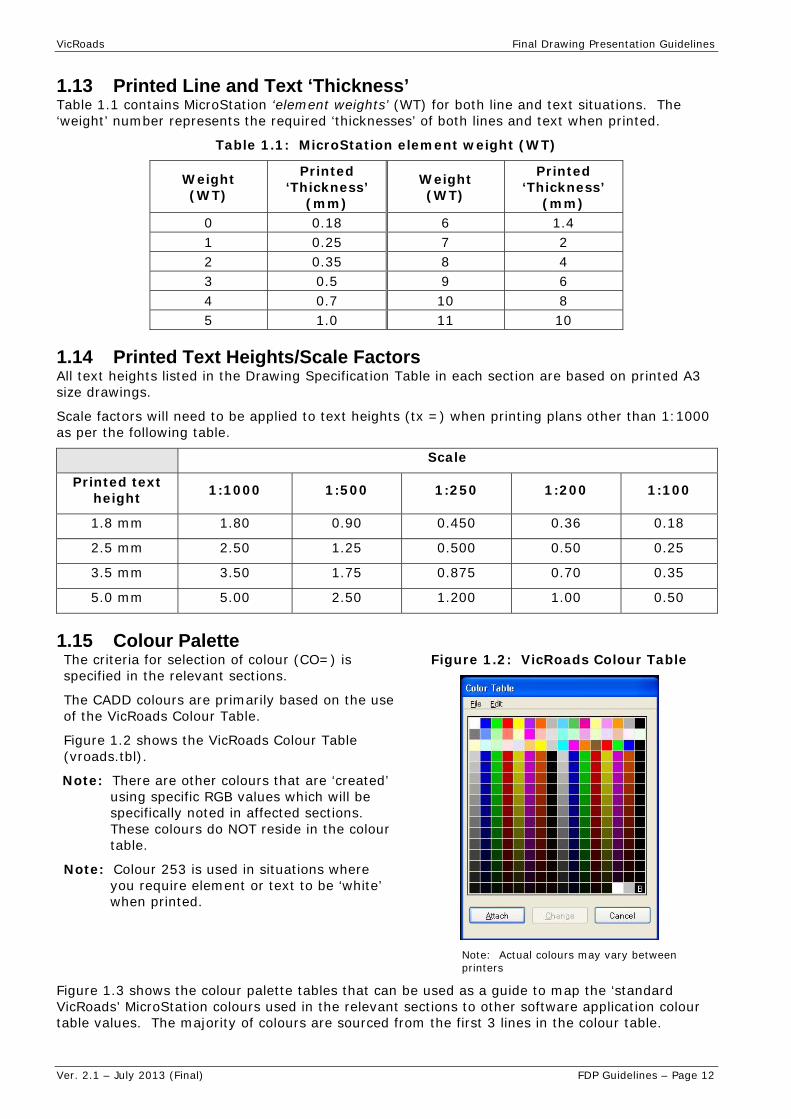
1.15 Colour Palette The criteria for selection of colour (CO=) is specified in the relevant sections.
The CADD colours are primarily based on the use of the VicRoads Colour Table.
Figure 1.2 shows the VicRoads Colour Table (vroads.tbl).
Note: There are other colours that are ‘created’ using specific RGB values which will be specifically noted in affected sections. These colours do NOT reside in the colour table.
Note: Colour 253 is used in situations where you require element or text to be ‘white’ when printed.
Figure 1.2: VicRoads Colour Table
Note: Actual colours may vary between printers
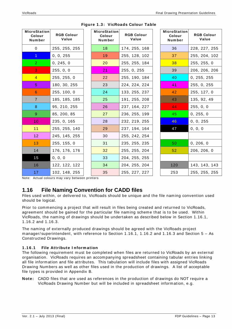
Figure 1.3 shows the colour palette tables that can be used as a guide to map the ‘standard VicRoads’ MicroStation colours used in the relevant sections to other software application colour table values. The majority of colours are sourced from the first 3 lines in the colour table.
VicRoads Final Drawing Presentation Guidelines
Ver. 2.1 – July 2013 (Final) FDP Guidelines – Page 13
Figure 1.3: VicRoads Colour Table
MicroStation Colour
Number RGB Colour
Value
0 255, 255, 255
1 0, 0, 255
2 0, 245, 0
3 255, 0, 0
4 255, 255, 0
5 180, 30, 255
6 255, 100, 0
7 185, 185, 185
8 95, 210, 255
9 85, 200, 85
10 235, 0, 165
11 255, 255, 140
12 245, 145, 255
13 255, 155, 0
14 176, 176, 176
15 0, 0, 0
16 122, 122, 122
17 102, 148, 255
MicroStation Colour
Number RGB Colour
Value
18 174, 255, 168
19 255, 128, 102
20 255, 255, 184
21 255, 0, 255
22 255, 190, 184
23 224, 224, 224
24 133, 255, 237
25 191, 255, 208
26 237, 164, 227
27 236, 255, 199
28 232, 219, 255
29 237, 194, 164
30 255, 242, 254
31 235, 255, 235
32 255, 255, 204
33 204, 255, 255
34 204, 255, 204
35 255, 227, 227
MicroStation Colour
Number RGB Colour
Value
36 228, 227, 255
37 255, 204, 102
38 255, 255, 0
39 206, 206, 206
40 0, 255, 255
41 255, 0, 255
42 255, 127, 0
43 135, 92, 49
44 255, 0, 0
45 0, 255, 0
46 0, 0, 255
47 0, 0, 0
50 0, 206, 0
52 206, 206, 0
120 143, 143, 143
253 255, 255, 255 Note: Actual colours may vary between printers
1.16 File Naming Convention for CADD files Files used within, or delivered to, VicRoads should be unique and the file naming convention used should be logical.
Prior to commencing a project that will result in files being created and returned to VicRoads, agreement should be gained for the particular file naming scheme that is to be used. Within VicRoads, the naming of drawings should be undertaken as described below in Section 1.16.1, 1.16.2 and 1.16.3.
The naming of externally produced drawings should be agreed with the VicRoads project manager/superintendent, with reference to Section 1.16.1, 1.16.2 and 1.16.3 and Section 5 – As Constructed Drawings.
1.16.1 File Attribute Information The following requirement must be completed when files are returned to VicRoads by an external organisation. VicRoads requires an accompanying spreadsheet containing tabular entries linking all file information and file attributes. This tabulation will include files with assigned VicRoads Drawing Numbers as well as other files used in the production of drawings. A list of acceptable file types is provided in Appendix B.
Note: CADD files that are used as references in the production of drawings do NOT require a VicRoads Drawing Number but will be included in spreadsheet information, e.g.

VicRoads Final Drawing Presentation Guidelines
Ver. 2.1 – July 2013 (Final) FDP Guidelines – Page 14
Filename Drawing Number File Type/Description
123-pd-a-ap-01.dgn 123456 Alignment Plan
223344.dgn 223344 Traffic Signal Plan
123-pd-a-fd-01.dgn Functional Design Base
44444-lis-a-fs-01.dgn Feature Survey
1.16.2 Internal VicRoads file naming example Areas within VicRoads typically use a CADD file name that is made up of various sections separated by hyphens, e.g. 5678-pd-a-ap-01.dgn, where:
5678 Unique number relating specifically to the job (mandatory field)
pd Reflects the work area (project design: pd, design west: dw etc – mandatory field)
a Optional value which identifies the sub-section of the project for example:
a General
b Hume Freeway main carriageways
c Railway Road Interchange (if this option is not required, the character is omitted.)
ap Specific to the type of CADD file – refer to Appendix B – Abbreviations: File Type (mandatory field)
01 Plan counter (mandatory field)
.dgn Extension of the file name reflects the type of file being created.
1.16.3 Naming Victorian Standard Signs The CADD filename for Signs is made up of characters and numbers to represent different signs.
Sign face drawings must be in accordance with AS/NZS 1743 Road Signs - Specifications or VicRoads’ Manual of Standard Drawings for Road Signs as appropriate.
The character “V” in the alphanumeric coding identifies the sign as a Victorian standard sign.
Signs without the letter "V" are Australian standard signs.
Note: All Victorian standard sign numbers are issued by VicRoads Technical Services - Road Standards & Traffic group.
1.17 MicroStation Reference File Attachments – Descriptions/Names When attaching reference files to master files, in MicroStation, care should be taken to include a meaningful ‘Description’ and ‘Logical Name’ during attachment.
Note: Logical names are also used by pen tables in some situations using a ‘wildcard’ approach, e.g. mono1.tbl uses a search criteria for serv* and surv*.
The following table should be used as a guide.
File Type Logical Name Description
Corporate Titleblock tb / tb1 / tb2 / etc
VicRoads Titleblock
Cadastral Base – Survey Accuracy
cad /cad1 / etc Surveyed Cadastral Title Base – (Title/Easement/Freeway boundaries etc based on survey)
Cadastral Base – Approximated
cad approx etc Approximated Cadastral title base – (Title/ Easement/Freeway boundaries etc based scaled plans)
VDP title information (Victorian Digital property base information)
cad approx etc VDP Title base - approx only

VicRoads Final Drawing Presentation Guidelines
Ver. 2.1 – July 2013 (Final) FDP Guidelines – Page 15
File Type Logical Name Description
Survey Feature Base surv / surv1 / etc Feature Survey Base – Nepean Hwy etc (Ground survey of existing features)
Survey Enhancement Base
serv / serv1 / etc Services – Nepean Hwy etc (typically for service information)
Functional Design Base func / func1 / etc Design Base 2D - Nepean Hwy etc (2D Design Base)
3D Linestrings des / des1 / etc Design Base 3D - Nepean Hwy etc (3D Design Base)
Sub Surface Drainage Base
ssd / ssd1 / etc Sub Surface Drainage details
Master Nested Survey surv master Master nested survey file
Master Nested Design des master Master nested design file
Existing Surface Contour contours exist Existing surface contours – interval
Design Surface Contour contours design Design surface contours – interval
Drainage Design Strategy drain Drainage Strategy
Pavement Type Limits pave / pave 1 / etc
Pavement Type Limits
1.18 Use of MicroStation ‘Models’ In general all master files and reference files will ONLY contain a ‘single’ default design model.
1.19 Use of MicroStation ‘Live Nesting’ In complex situations where multiple files exist for a particular reference group ‘live nesting’ may be used, e.g.:
a single empty ‘master survey reference file’ with multiple attached ‘individual’ survey DGNs.
a single empty ‘master design reference file’ with multiple attached ‘individual’ design DGNs.
However, use of ‘Live nesting’ is RESTRICTED to a depth of ‘one level’ ONLY.
1.20 Cell Library A Cell Library contains a set of special or common “drawings” that can be included in a design drawing, such as a pram crossing, standard signs, specific symbols to represent an item, pits, subsurface drain attributes (e.g. outlet, riser, etc), signs, north point or arrow, electrical conduit pits, etc for use in VicRoads drawings. They are particularly used for very common items to prevent inconsistencies in their “look” and efficiencies in design (i.e. not required to draw them every time).
The Cell Library is maintained by VicRoads Technical Services Design Systems. The Cell Library is updated at no more than six (6) monthly intervals or on earlier notification of changes to standards and guidelines.
Appendix A shows VicRoads custom styles referred to in Section 2 and Section 3.


VicRoads Final Drawing Presentation Guidelines
Ver. 2.1 – July 2013 (Final) FDP Guidelines – Page 17
Section 2 – CADD Reference Files
2.1 General
2.1.1 CADD Reference Files - Overview Most roadwork drawings generally use underlying reference files to create the total drawing content. Reference file type and content will be restricted to types defined in the following sections. The majority of the underlying reference files will contain graphics for the total length of a project but in some cases may be broken into major sections. There will be situations where ‘element symbology overrides’ will be required to suit final drawing presentation.
2.1.2 Text and Custom LineStyle Scale Generally all CADD reference files are created at ‘ground size’.
Any text placed, or custom linestyles used, will need to consider final plan scale of files utilising reference files.
2.1.3 File naming convention for CADD files Reference should be made to the file naming details located in Section 1.16.
2.1.4 Use of MicroStation ‘Models’ and ‘Live Nesting’ Refer to Section 1.18 and 1.19 for details on MicroStation Models and the use of ‘live nesting’.
2.1.5 Order of Reference Files When creating a final drawing, attaching the files in the order shown below will ensure that when the file is printed all detail will be visible:
Existing Pavement Area
Existing Contours
Services
Survey Features
Drainage Layout
Pavement Type Limits
Design Contour
Functional Layout
Subsurface Drainage Layout.

VicRoads Final Drawing Presentation Guidelines
Ver. 2.1 – July 2013 (Final) FDP Guidelines – Page 18
2.2 Existing Pavement Area
2.2.1 File Overview The Existing Pavement Area file (2D only) contains the existing roadway pavement derived from a feature survey as a ‘colour filled’ area.
2.2.2 Level Content
Description of Content Level Name CO LC WT Printed Text
Height (mm)/Font
Cell
Existing Pavement Area PAVEMENT_EXISTING 23 0 1

VicRoads Final Drawing Presentation Guidelines
Ver. 2.1 – July 2013 (Final) FDP Guidelines – Page 19
2.3 Pavement Type Limits
2.3.1 File Overview The Pavement Type Limits file (2D only) is generally created to contain different coloured shapes which are mapped to different pavement types for the scope of the new road works.
2.3.2 Level Content
Description of Content Level Name CO1 LC WT Printed Text
Height (mm)/Font
Cell Name
Design Pavement Types
PAVEMENT_TYPE1 28 0 1
PAVEMENT_TYPE2 29 0 1
PAVEMENT_TYPE3 38 0 1
PAVEMENT_TYPE4 33 0 1
PAVEMENT_TYPE5 34 0 1
PAVEMENT_TYPE6 35 0 1
PAVEMENT_TYPE7 36 0 1
PAVEMENT_TYPE8 37 0 1
PAVEMENT_TYPE9 41 0 1
PAVEMENT_TYPE10 43 0 1
Driveway PAVEMENT_DRIVEWAY 26 0 1
Median PAVEMENT_MEDIAN 24 0 1
Overlay PAVEMENT_OVERLAY 20 0 1
Path PAVEMENT_PATH 52 0 1
Pavement to be Removed PAVEMENT_REMOVE 61 0 1
Temporary Pavement PAVEMENT_TEMPORARY 38 0 1
Note 1: Design pavement type colours (shown below) are indicative only and may vary depending on final plan requirements. It may be necessary to change colour/s to avoid clashes or washout between Pavement Types.

VicRoads Final Drawing Presentation Guidelines
Ver. 2.1 – July 2013 (Final) FDP Guidelines – Page 20
2.4 Existing Contour
2.4.1 File Overview The Existing Contour file (3D only) contains existing contours. These are generally extracted from a survey model and re-annotated in such a manner that designers can analyse the fall and rise of the existing terrain. Major contours should be annotated.
2.4.2 Level Content
Description of Content Level Name CO LC WT Printed
Text Height (mm)/Font
Cell
Major Contours SURFACE_EXISTING_CONTOUR_MAJOR 43 0 1
Minor Contours SURFACE_EXISTING_CONTOUR_MINOR 37 0 1
Text Annotation SURFACE_EXISTING_CONTOUR_TEXT 43 0 1 1.8 / 27

VicRoads Final Drawing Presentation Guidelines
Ver. 2.1 – July 2013 (Final) FDP Guidelines – Page 21
2.5 Design Contour
2.5.1 File Overview The Design Contour file (3D only) contains design contours which have generally been extracted from a design model and are annotated in such a manner that designers can analyse the fall and rise of the design surface.
2.5.2 Level Content
Description of Content Level Name CO LC WT Printed
Text Height (mm)/Font
Cell Name
Major Contours SURFACE_DESIGN_CONTOUR_MAJOR
8 0 2
Minor Contours SURFACE_DESIGN_CONTOUR_MINOR
3 0 1
Text Annotation SURFACE_DESIGN_CONTOUR_TEXT
3 0 1 1.8 / 27

VicRoads Final Drawing Presentation Guidelines
Ver. 2.1 – July 2013 (Final) FDP Guidelines – Page 22
2.6 Functional Layout
2.6.1 File Overview Functional Layout file (2D only) generally evolves from the preliminary design concepts through to the final approved functional layout.
The file contains all roadway linear features along with any special treatments required.
Proposed road boundaries generally may be illustrated in this file for further discussions or approval.
Note: Usually all cadastral boundary information will generally be contained in a separate MicroStation file provided for reference by a survey group.
All curves will be drawn as arcs and will NOT be ‘stroked lines’.
Refer to the Section 2.14 3D Linestring information for details around further information regarding design features.
2.6.2 Level Content
Description of Content Level Name CO LC WT
Printed Text Height
(mm)/Font Cell Name
Safety Barrier - Concrete
SAFETY_BARRIER_CONCRETE 0 0 2
Safety Barrier – Guard Fence
SAFETY_BARRIER_GUARD_FENCE 0 guard
fence2 1
Safety Barrier – Wire Rope
SAFETY_BARRIER_WIRE_ROPE 0
wire road safety
barrier2 1
Bridge Deck BRIDGE_DECK 4 0 1
Centre of Bridge Abutment BRIDGE_ABUTMENT 7 7 0
Crown Line ROAD_CROWN_LINE 3 5 1
Driveways MISC_DRIVEWAY 3 0 1
Edge of Shoulder (sealed)
ROAD_SHOULDER_SEALED 0 0 2
Edge of Shoulder (unsealed)
ROAD_SHOULDER_UNSEALED 4 0 1
Edge of Traffic Lane (sealed)
ROAD_LANE_EDGE_SEALED 4 0 1
Edge of Traffic Lane (unsealed)
ROAD_LANE_EDGE_UNSEALED 0 0 2
Fences MISC_FENCE 0 fence1 2
Concrete Apron MISC_CONCRETE_APRON 0 0 2
Kerb and Channel - Lip KERB_LIP 8 0 2
Kerb and Channel - Back KERB_BACK 8 0 2
Kerb and Channel - Line KERB_LINE 7 0 0
Kerb and Channel – Temporary KERB_TEMPORARY 0 0 2
VicRoads Final Drawing Presentation Guidelines
Ver. 2.1 – July 2013 (Final) FDP Guidelines – Page 23
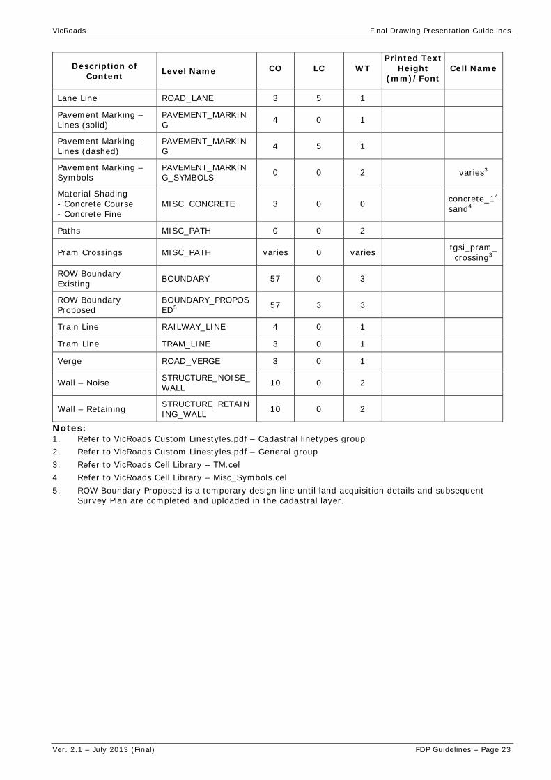
Description of Content Level Name CO LC WT
Printed Text Height
(mm)/Font Cell Name
Lane Line ROAD_LANE 3 5 1
Pavement Marking – Lines (solid)
PAVEMENT_MARKING 4 0 1
Pavement Marking – Lines (dashed)
PAVEMENT_MARKING 4 5 1
Pavement Marking – Symbols
PAVEMENT_MARKING_SYMBOLS 0 0 2 varies3
Material Shading - Concrete Course - Concrete Fine
MISC_CONCRETE 3 0 0 concrete_14
sand4
Paths MISC_PATH 0 0 2
Pram Crossings MISC_PATH varies 0 varies tgsi_pram_crossing3
ROW Boundary Existing BOUNDARY 57 0 3
ROW Boundary Proposed
BOUNDARY_PROPOSED5 57 3 3
Train Line RAILWAY_LINE 4 0 1
Tram Line TRAM_LINE 3 0 1
Verge ROAD_VERGE 3 0 1
Wall – Noise STRUCTURE_NOISE_WALL 10 0 2
Wall – Retaining STRUCTURE_RETAINING_WALL 10 0 2
Notes: 1. Refer to VicRoads Custom Linestyles.pdf – Cadastral linetypes group 2. Refer to VicRoads Custom Linestyles.pdf – General group 3. Refer to VicRoads Cell Library – TM.cel 4. Refer to VicRoads Cell Library – Misc_Symbols.cel 5. ROW Boundary Proposed is a temporary design line until land acquisition details and subsequent
Survey Plan are completed and uploaded in the cadastral layer.

VicRoads Final Drawing Presentation Guidelines
Ver. 2.1 – July 2013 (Final) FDP Guidelines – Page 24
2.7 Drainage Layout
2.7.1 File Overview A Drainage Layout file (2D or 3D) contains the final drainage layout of pipes, endwalls, beaching and pits.
2.7.2 Level Content
Description of Content Level Name CO LC WT
Printed Text Height
(mm)/Font
Cell Name 3
Beaching at Inlet/Outlet DRAINAGE_BEACHING 7 0 beaching_
drain2
Beached Catch Drain DRAINAGE_CATCH_DRAIN 4 catch drain
beached1 1
Grassed Catch Drain DRAINAGE_CATCH_DRAIN 4 catch drain
grassed1 1
Thatched Catch Drain DRAINAGE_CATCH_DRAIN 4 catch drain
thatched1 1
Culverts/Pipes DRAINAGE_PIPE 3 up to 1m1
1 1.0 to 1.5m1
Pits DRAINAGE_PIT 3 0 1 pit2
Endwalls DRAINAGE_ENDWALLS 0 0 2
Drainage Detail Text DRAINAGE_TEXT 4 0 1 1.8 / 27
Notes: 1. Refer to VicRoads Custom Linestyles.pdf – Drainage Group 2. Refer to VicRoads Cell Library – Road Design.cel 3. Refer to VicRoads Cell Library – Drainage.cel if using Storm and Sanitary software

VicRoads Final Drawing Presentation Guidelines
Ver. 2.1 – July 2013 (Final) FDP Guidelines – Page 25
2.8 Subsurface Drainage Layout
2.8.1 File Overview Subsurface 2D Drainage Layout file (2D) contains the pavement drain design and depending on the scope of the design could be part of the drainage strategy file.
2.8.2 Level Content
Description of Content Level Name CO LC WT Printed
Text Height (mm)/Font
Cell Name
Corrugated Sub-surface Pipe
DRAINAGE_SUB_SURFACE 40 corr pipe
pave drain1 1
Smooth Sub-surface Pipe DRAINAGE_SUB_SURFACE 40
smooth pipe pave
drain1 1
Sub-surface Transverse - Corrugated
DRAINAGE_SUB_SURFACE 40
corr pipe trans drain1
1
Sub-surface Transverse - Slotted
DRAINAGE_SUB_SURFACE 40 trans drain
slotted1 1
Sub-surface Transverse - Smooth
DRAINAGE_SUB_SURFACE 40 trans drain
not perf1 1
Sub-surface Pits - Flush Out Riser
DRAINAGE_SUB_SURFACE_FLUSHOUT_RISER
40 0 1 SSFL2
Sub-surface Pits - Drain Outlet
DRAINAGE_SUB_SURFACE_OUTLET 40 SSDO2
Sub-surface Pits - Drain Pit
DRAINAGE_SUB_SURFACE_PIT 40 SSDP2
Sub-surface Text DRAINAGE_SUB_SURFACE_TEXT 40 1 1.8 / 27
Notes: 1. Refer to VicRoads Custom Linestyles.pdf – Drainage Group 2. Refer to VicRoads Cell Library – Road Design.cel

VicRoads Final Drawing Presentation Guidelines
Ver. 2.1 – July 2013 (Final) FDP Guidelines – Page 26
2.9 Services
2.9.1 File Overview VicRoads Property Services – Survey and Declarations Section is responsible for survey standards, file content and LevelName structure.
Services information (3D) is provided by survey group as part of the feature survey enhancement details but can also be created as a standalone file relating to services information only.
Symbology standards are the same as those used by survey group to aid visual separation of information when symbology overrides are off.
As service proving information can also be included, within a services file, there is provision for proven service information within the LevelName structure, e.g.
UTILITY_PROVEN_GAS_UNDERGROUND – Service Proving - Gas Features - Underground
UTILITY_GAS_UNDERGROUND – Gas Features – Underground
Note: Service Proving For ‘service proving’ LevelName situations all symbology information is identical to existing services listed below but LevelName will include PROVEN as shown above and amended description as can be seen in LevelName listing provided in Section.
Services that are not proven are generally placed in a 2D plane at an elevation that is far removed from the potential vertical position of proven services.
Proven and unproven linework will NOT be joined but may share a common XY position, e.g. there will be no connecting ‘vertical line’.
2.9.2 Level Overrides All linework will have colour overrides set to colour 44 (red).
2.9.3 Level Content
Description of Content Level Name CO LC1 WT
Printed Text Height
(mm)/Font
Cell Name
Electricity
Overhead UTILITY_ELECTRICITY_OVERHEAD 4 electricity
overhead 0
Underground UTILITY_ELECTRICITY_UNDERGROUND 4 electricity
below ground 0
Services Text - Electricity
UTILITY_ELECTRICITY_TEXT 0 0 0 1.8 / 27
Gas
Aboveground UTILITY_GAS_OVERHEAD 9 gas line 0
Underground UTILITY_GAS_UNDERGROUND 9 gas below
ground 0
Services Text - Gas UTILITY_GAS_TEXT 0 0 0 1.8 / 27
Sewer
General UTILITY_SEWER_OVERHEAD 3 sewerage 0
Underground UTILITY_SEWER_UNDERGROUND 3 sewerage
below ground 0
Services Text - Sewer UTILITY_SEWER_TEXT 0 0 0 1.8 / 27

VicRoads Final Drawing Presentation Guidelines
Ver. 2.1 – July 2013 (Final) FDP Guidelines – Page 27
Description of Content Level Name CO LC1 WT
Printed Text Height
(mm)/Font
Cell Name
Communication
Aboveground UTILITY_COMMUNICATION_OVERHEAD 10 telecom line 0 1.8 / 27
Underground UTILITY_COMMUNICATION_UNDERGROUND 10 telecom below
ground 0
Aerial Wire to House
UTILITY_COMMUNICATION_OVERHEAD 7 0 0
Services Text - Communications
UTILITY_COMMUNICATION_TEXT 0 0 0 1.8 / 27
Unclassified
Utility Unclassified UTILITY_UNCLASSIFIED_OVERHEAD 7 7 0
Services Text - Unclassified
UTILITY_UNCLASSIFIED_TEXT 0 0 0 1.8 / 27
Water
Aboveground UTILITY_WATER_OVERHEAD 8 water above
ground 0
Underground UTILITY_WATER_UNDERGROUND 8 water below
ground 0
Services Text - Water UTILITY_WATER_TEXT 0 0 0 1.8 / 27
Note: 1. Refer to VicRoads Custom Linestyles.pdf – Utilities Group

VicRoads Final Drawing Presentation Guidelines
Ver. 2.1 – July 2013 (Final) FDP Guidelines – Page 28
2.10 Survey Features
2.10.1 File Overview VicRoads Property Services – Survey and Declarations Section is responsible for survey standards, file content and LevelName structure. The following information is based on those standards.
Survey feature files (3D) are normally provided by a survey group using VicRoads survey standards for presentation and data quality.
The feature survey file will normally only contain data captured in field survey.
Post survey ‘enhancements’ are contained in a separate file.
2.10.2 Level Content Refer to Property Services – Survey and Declarations Section for VicRoads standards.
2.10.3 Level Overrides All graphics will have colour overrides set to colour 18 (light green) with the following exceptions.
Features that relate to overland drainage will have colour overrides set to colour 17 (blue):
DRAINAGE_DRAIN
TOPOGRAPHIC_WATERCOURSE

VicRoads Final Drawing Presentation Guidelines
Ver. 2.1 – July 2013 (Final) FDP Guidelines – Page 29
2.11 Signs and Pavement Marking Layout
2.11.1 File Overview A Signs and Pavement (Line) Marking Layout (2D only) file contains the line marking, pavement markings and coloured area fills representing controlled lane usage.
This file may also contain sign locations for the scope of the new road works.
2.11.2 Level Content
Description of Content Level Name CO LC WT
Printed Text Height
(mm)/Font
Cell Name
Coloured Pavement – Bus Lane
PAVEMENT_MARKING_COLOUR_FILL 26 0 1
Coloured Pavement – Bike Lane
PAVEMENT_MARKING_COLOUR_FILL 34 0 1
Coloured Pavement – Pedestrian Crossing
PAVEMENT_MARKING_COLOUR_FILL 38 0 1
Pavement Marking Lines PAVEMENT_MARKING 0 varies1 1
Pavement Marking Symbols
PAVEMENT_MARKING_SYMBOLS 0 1 varies2
Post & Sign Symbol MISC_SIGNS 0 0 1 varies2
Notes: 1. Refer to VicRoads Custom Linestyles.pdf – Linemarking Group 2. Refer to VicRoads Cell Library – TM.cel
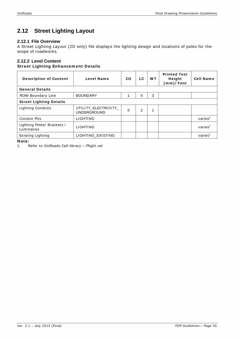
VicRoads Final Drawing Presentation Guidelines
Ver. 2.1 – July 2013 (Final) FDP Guidelines – Page 30
2.12 Street Lighting Layout
2.12.1 File Overview A Street Lighting Layout (2D only) file displays the lighting design and locations of poles for the scope of roadworks.
2.12.2 Level Content Street Lighting Enhancement Details
Description of Content Level Name CO LC WT Printed Text
Height (mm)/Font
Cell Name
General Details
ROW Boundary Line BOUNDARY 1 0 3
Street Lighting Details
Lighting Conduits UTILITY_ELECTRICITY_UNDERGROUND 0 2 1
Conduit Pits LIGHTING varies1
Lighting Poles/ Brackets / Luminaires LIGHTING varies1
Existing Lighting LIGHTING_EXISTING varies1 Note: 1. Refer to VicRoads Cell library – Plight.cel

VicRoads Final Drawing Presentation Guidelines
Ver. 2.1 – July 2013 (Final) FDP Guidelines – Page 31
2.13 Vegetation Treatment
2.13.1 File Overview A Vegetation Treatment file, typically 2D, summarises the individual status of existing trees in relationship to the scope of the new road works.
Significant trees are either colour coded to be retained and protected during construction or colour coded to be removed.
This file is optional depending on the number of trees affected in the zone of the new roadworks.
2.13.2 Level Content
Description of Content Level Name CO LC WT
Printed Text Height
(mm)/Font
Cell Name
Significant Trees VEGETATION_TREE 17 0 2
Trees to be Removed VEGETATION_TREE_REMOVAL 44 0 2

VicRoads Final Drawing Presentation Guidelines
Ver. 2.1 – July 2013 (Final) FDP Guidelines – Page 32
2.14 3D Linestring
2.14.1 File Overview A 3D Linestring file (3D only) contains roadway features generated as linestrings.
VicRoads uses Bentley Systems’ InRoads software for this purpose.
All elements listed in Section 2.6 – Functional Layout file, are included as well as the additional information shown below.
2.14.2 Level Content
Description of Content
Level Name CO LC WT Printed
Text Height (mm)/Font
Cell Name
Batter Tick Symbol EARTHWORKS_BATTER_TICKS 9 0 1
Batters EARTHWORKS_BATTER_TOE EARTHWORKS_BATTER_TOP
9 0 1
Safety Barrier – Concrete Shape Components
SAFETY_BARRIER_CONCRETE_HINGE SAFETY_BARRIER_CONCRETE_TOE SAFETY_BARRIER_CONCRETE_TOP SAFETY_BARRIER_CONCRETE_INTERFACE
10 10 10 10
0 0 0 0
2 2 2 2
Bench EARTHWORKS_BENCH 9 0 1
Drains DRAINAGE_MEDIAN_DRAIN DRAINAGE_V_DRAIN DRAINAGE_TABLE_DRAIN
12 0 0
Drainage Basins DRAINAGE_BASIN_RETARDING DRAINAGE_BASIN_SEDIMENT
6 0 1
Water Sensitive Road Design Elements DRAINAGE_WSRD_ELEMENT 6 0 1
Linework to Control Pavement Shape SURFACE_COMPONENT_BREAKLINE 7 0 0
Mound EARTHWORKS_MOUND_TOE EARTHWORKS_MOUND_TOP
9 0 1
Road Crown ROAD_CROWN 3 5 1
Surface/Model Exterior Boundary SURFACE_COMPONENT_EXTERIOR 5 0 4
Surface/Model Interior Boundary SURFACE_COMPONENT_INTERIOR 5 0 4
Concrete Apron MISC_CONCRETE_APRON 0 0 2
Verge ROAD_VERGE1 ROAD_VERGE2
3 0 1
Wall – Retaining
STRUCTURE_RETAINING_WALL_TOE STRUCTURE_RETAINING_WALL_TOP STRUCTURE_RETAINING_WALL_INTERFACE
10 10 10
0 0 0
2 2 2
Wall – Noise
STRUCTURE_NOISE_WALL_TOE STRUCTURE_NOISE_WALL_TOP STRUCTURE_NOISE_WALL_INTERFACE
10 10 10
0 0 0
2 2 2

VicRoads Final Drawing Presentation Guidelines
Ver. 2.1 – July 2013 (Final) FDP Guidelines – Page 33
2.15 Design Working
2.15.1 File Overview The Design Working File is an optional 3D file created during the design process to contain construction lines/sight lines and vehicle turning paths which influenced the final road works layout.
This file is NOT to be used as a reference file to produce ANY road works construction plans listed in Section 3.
This file may contain multiple models.
2.15.2 Level Content
Description of Content
Level Name CO LC WT Printed Text
Height (mm)/Font
Cell Name
Clear Zones (for Sight Lines) CHECK_CLEARZONE 53 0 2
Sight Line Notes CHECK_SIGHTLINE_TEXT 4 0 1 1.8/27
Vehicle Turning Path Notes CHECK_TURNING_PATH_TEXT 3 0 1 1.8/27
Sight Lines
CHECK_SIGHTLINE_50
CHECK_SIGHTLINE_60
CHECK_SIGHTLINE_70
CHECK_SIGHTLINE_800
CHECK_SIGHTLINE_90
CHECK_SIGHLINE_100
CHECK_SIGHTLINE_110
CHECK_SIGHTLINE_120
varies
0
0
0
0
0
0
0
0
1
1
1
1
1
1
1
1
Vehicle Turning Paths
CHECK_TURNING_PATH
CHECK_TURNING_PATH_BDOUBLE
CHECK_TURNING_PATH_BDOUBLE_QQ
CHECK_TURNING_PATH_BUS
CHECK_TURNING_PATH_BUS_ARTIC
CHECK_TURNING_PATH_CAR
CHECK_TURNING_PATH_SEMI_19
CHECK_TURNING_PATH_SEMI_26
CHECK_TURNING_PATH_TRUCK_8
CHECK_TURNING_PATH_12
CHECK_TURNING_PATH1 to CHECK_TURNING_PATH10
varies
0
0
0
0
0
0
0
0
0
0
0
0
0
0
0
0
0
0
0
0
0
0
0
0


VicRoads Final Drawing Presentation Guidelines
Ver. 2.1 – July 2013 (Final) FDP Guidelines – Page 35
Section 3 – Roadwork Drawings
3.1 General Information & Notes
3.1.1 Roadwork Drawings - Overview. Roadwork drawings will be created to suit the plan types listed in following sections.
With the exception of cross section plans, it is preferred that for longitudinal sections, drainage longitudinal sections, pavement details and typical cross sections all master DGN files will contain graphics for a single plan ONLY.
MicroStation DGN files will contain a single default model which will have accompanying reference files.
File structure will typically be created at ground size thereby enabling accurate measurements and coordinate interrogation to occur within the master file.
Note 1: The sample drawings are provided as an example of the drawing presentation standards required and must not be used for determining or interpreting survey, road, traffic or landscape design standards or practices.
Note 2: If an error is identified or a designer has a query on any of the information contained in this document, an email outlining the issue can be sent to [email protected].
3.1.2 File naming convention for CADD files Reference should be made to the file naming details located in Section 1.16.
3.1.3 Use of MicroStation ‘Models’ and Live Nesting Refer to Section 1.18 and Section 1.19 for details on MicroStation Models and the use of “live nesting”.
3.1.4 Survey files & Survey CADD files VicRoads Survey files MUST NOT be modified without prior agreement from VicRoads.
VicRoads Survey CADD files MUST NOT be renamed under any circumstances.
3.1.5 Order of Reference Files Refer to Section 2.1.5.
3.1.6 VicRoads, Government and other logos
VicRoads Logo The use and placement of the VicRoads logo should conform to VicRoads Guidelines. For further details on this or for a copy of the latest VicRoads logo, contact VicRoads Corporate Communications on [email protected].
The VicRoads Visual Identity Guidelines and VicRoads App Icon Guidelines may be referred to for further information. These documents are available by contacting VicRoads Corporate Communications on [email protected].
For further information on government and other logos refer to Section 1.6 – VicRoads, Government and Other Logos.


VicRoads Final Drawing Presentation Guidelines
Ver. 2.1 – July 2013 (Final) FDP Guidelines – Page 37
3.2 Corporate Titleblock
3.2.1 Titleblock Overview The VicRoads Corporate Titleblock is referenced into all roadwork drawings produced in Section 3 unless otherwise stated and shall NOT be amended or altered in any way.
The VicRoads Corporate Titleblock is amended and updated at various times so ensure the current file/version is attached when producing roadwork plans.
Note: Titleblocks are generally ‘scaled up’ to ground size conditions.
Plans are generally produced at A3 but the corporate titleblock also provides A1 and A0 options.
See Section 3.2.4 below for information on the use of ‘Saved Views’ when attaching titleblock to simplify access to correct level display.
3.2.2 Scale The titleblock attachment scale varies depending on the roadwork plan being produced.
Text heights will have to be modified to accommodate alternative scales to equal final required printed text height.
3.2.3 CADD File Structure The titleblock does not contain reference files with the exception of a single master reference to produce the VicRoads logo.
3.2.4 Models/Saved Views The titleblock contains individual models for A3, A1 and A0 attachment purposes.
Note: A0 and A1 sizes are typically for Traffic Signal plan usage only.
Each model has accompanying Saved Views to simplify task of accessing correct level display.
See the following details of Models/Saved Views.
A3 Model – Saved Views CAMBERWELL REGION ROAD titleblock + VicRoads Camberwell address
CAMBERWELL TRAFFIC TRAFFIC titleblock + VicRoads Camberwell address
GEOTECH Geotech Investigation titleblock + VicRoads Metro South East address
METRO NW REGION ROAD titleblock + VicRoads Metro North West address
METRO NW TRAFFIC TRAFFIC titleblock + VicRoads Metro North West address
METRO SE REGION ROAD titleblock + VicRoads Metro South East address
METRO SE TRAFFIC TRAFFIC titleblock + VicRoads Metro South East address
PLANNING AMENDMENT Planning and Investigation - Planning amendment
PLANNING CONCEPT Planning and Investigation - Concept plan
PLANNING CONCEPT (L) Planning and Investigation - Concept plan (Large legend)
VICROADS ONLY R ROAD titleblock - No addresses (for Consultant use)
VICROADS ONLY T TRAFFIC titleblock - No addresses (for Consultant use)
A1 Model – Saved Views (Typically Traffic Signal plan usage only) A1 CAMBERWELL TRAFFIC A1 TRAFFIC titleblock + VicRoads Camberwell address
A1 METRO NW TRAFFIC A1 TRAFFIC titleblock + VicRoads Metro North West address
A1 METRO SE TRAFFIC A1 TRAFFIC titleblock + VicRoads Metro South East address (for Consultant use)
A1 VICROADS ONLY T A1 TRAFFIC titleblock - No addresses

VicRoads Final Drawing Presentation Guidelines
Ver. 2.1 – July 2013 (Final) FDP Guidelines – Page 38
A0 Model – Saved Views (Typically Traffic Signal plan usage only) A0 CAMBERWELL TRAFFIC A0 TRAFFIC titleblock + VicRoads Camberwell address
A0 METRO NW TRAFFIC A0 TRAFFIC titleblock + VicRoads Metro North West address
A0 METRO SE TRAFFIC A0 TRAFFIC titleblock + VicRoads Metro South East address
A0 VICROADS ONLY TRAFFIC A0 TRAFFIC titleblock - No addresses (for Consultant use)
Note: ‘VICROADS ONLY’ saved views will typically be used by external contactors.
3.2.5 Final Drawing Specifications.
A3 Titleblock Parameter Drawing Specifications
Description of Content Level Name CO LC WT
Printed Text Height
(mm)/Font
Printed Line Thickness
(mm)
Amendments TEXT_TITLEBLOCK 2 0 1 1.2-1.8 / 27 0.25
Approved (via Signature Annotation Program) TEXT_TITLEBLOCK 2 0 1 1.8 / 27 0.25
Catalog & Project TEXT_TITLEBLOCK 2 0 1 1.8 / 27 0.25
Chainage Limits TEXT_TITLEBLOCK 0 0 2 2.5 / 27 0.35
Computer File TEXT_TITLEBLOCK 2 0 1 1.8 / 27 0.25
Consultant Logo^^ IMAGES
Contract No. / Sheet No. / Drawing No. TEXT_TITLEBLOCK 0 0 2 2.5 / 27 0.35
Detailed Description TEXT_TITLEBLOCK 0 0 2 2.5 / 27 0.35
File Type TEXT_TITLEBLOCK 0 0 2 2.5 / 27 0.35
General Notes/Refer TEXT_TITLEBLOCK 2 0 1 1.8 / 27 0.25
Municipality TEXT_TITLEBLOCK 2 0 1 1.8 / 27 0.25
Officer Name TEXT_TITLEBLOCK 2 0 1 1.8 / 27 0.25
Project Description TEXT_TITLEBLOCK 2 0 1 1.8 / 27 0.25
Road Name TEXT_TITLEBLOCK 0 0 2 2.5 / 65 0.35
Scale TEXT_TITLEBLOCK 2 0 1 1.8 / 27 0.25
Subsection TEXT_TITLEBLOCK 2 0 1 1.8 / 27 0.25
A0/A1 Titleblock Parameter Drawing Specifications - typical Traffic Signal plan only
Description of Content Level Name CO LC WT
Printed Text Height
(mm)/Font
Printed: Line Thickness
(mm)
Approved (via Signature Annotation Program)
TEXT_TITLEBLOCK 2 0 1 2.5 / 27 0.25
Amendments TEXT_TITLEBLOCK 2 0 2 2.5 / 27 0.25
Catalog & Project TEXT_TITLEBLOCK 2 0 1 2.5 / 27 0.25
Chainage Limits TEXT_TITLEBLOCK 0 0 2 5.0 / 27 0.35
Computer File TEXT_TITLEBLOCK 2 0 1 2.5 / 27 0.25
Contract No./Sheet No. /Drawing No.
TEXT_TITLEBLOCK 0 0 2 5.0 / 27 0.35
Detailed Description TEXT_TITLEBLOCK 0 0 2 5.0 / 27 0.35
File Type TEXT_TITLEBLOCK 0 0 2 5.0 / 27 0.35
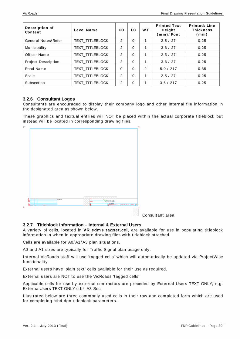
VicRoads Final Drawing Presentation Guidelines
Ver. 2.1 – July 2013 (Final) FDP Guidelines – Page 39
Description of Content Level Name CO LC WT
Printed Text Height
(mm)/Font
Printed: Line Thickness
(mm)
General Notes/Refer TEXT_TITLEBLOCK 2 0 1 2.5 / 27 0.25
Municipality TEXT_TITLEBLOCK 2 0 1 3.6 / 27 0.25
Officer Name TEXT_TITLEBLOCK 2 0 1 2.5 / 27 0.25
Project Description TEXT_TITLEBLOCK 2 0 1 3.6 / 27 0.25
Road Name TEXT_TITLEBLOCK 0 0 2 5.0 / 217 0.35
Scale TEXT_TITLEBLOCK 2 0 1 2.5 / 27 0.25
Subsection TEXT_TITLEBLOCK 2 0 1 3.6 / 217 0.25
3.2.6 Consultant Logos Consultants are encouraged to display their company logo and other internal file information in the designated area as shown below.
These graphics and textual entries will NOT be placed within the actual corporate titleblock but instead will be located in corresponding drawing files.
Consultant area
3.2.7 Titleblock information – Internal & External Users A variety of cells, located in VR edms tagset.cel, are available for use in populating titleblock information in when in appropriate drawing files with titleblock attached.
Cells are available for A0/A1/A3 plan situations.
A0 and A1 sizes are typically for Traffic Signal plan usage only.
Internal VicRoads staff will use ‘tagged cells’ which will automatically be updated via ProjectWise functionality.
External users have ‘plain text’ cells available for their use as required.
External users are NOT to use the VicRoads ‘tagged cells’
Applicable cells for use by external contractors are preceded by External Users TEXT ONLY, e.g. ExternalUsers TEXT ONLY ctb4 A3 Sec.
Illustrated below are three commonly used cells in their raw and completed form which are used for completing ctb4.dgn titleblock parameters.

VicRoads Final Drawing Presentation Guidelines
Ver. 2.1 – July 2013 (Final) FDP Guidelines – Page 40
RoadName ProjectDesc
RoadName ProjectDesc Municipal
RoadName ProjectDesc Subsec

VicRoads Final Drawing Presentation Guidelines
Ver. 2.1 – July 2013 (Final) FDP Guidelines – Page 41
3.3 Document Face Sheet
3.3.1 Drawing Overview The Document Face Sheet provides an easily identifiable cover that helps protect the document contents. The details contained on the Document Face Sheet should enable identification of the job, without the need to open the document set.
On smaller jobs the Face Sheet may be included with the Locality Plan drawing.
Note: When combined with the Locality Plan drawing, the file type is described as ‘Locality Face Sheet’ (LFS).
3.3.2 Scale The Document Face Sheet is not produced to any particular scale, but generally at 1:1000.
Text heights will have to be modified to accommodate alternative scales to equal final required printed text height.
3.3.3 Final Printed Plan The drawing is set-up for certain colours to be ‘resymbolised’ at ‘print time’.
The pen table to be used during final plan printing = mscol2.tbl.
Pen table contains colour mapping, text substitutions and printer thickness controls.
3.3.4 Final Drawing Specifications The drawing specification table is based on A3 size final drawings.
Document Face Sheet Specifications
Description of Content Level Name CO LC WT
Printed Text Height
(mm)/Font Cell Name
Border – External LINES 0 0 2
Border – Internal LINES 0 0 2
CADD File Details TEXT 3 0 1 1.8 / 68
Contract & Volume Number TEXT 0 0 2 5.0 / 67
Control Copy Text and Box CELLS 0 control_copy_no1
Project Description TEXT 1 0 3 7.0 / 67
Quality Endorsement Logo CELLS 0 DLCS H1
Title TEXT 1 0 3 7.0 / 67
VicRoads Logo TEXT 0 Image
Notes: 1. Refer to VicRoads Cell Library – Misc Sticker.cel


VicRoads Final Drawing Presentation Guidelines
Ver. 2.1 – July 2013 (Final) FDP Guidelines – Page 43
3.4 Locality Plan
3.4.1 Drawing Overview The purpose of the Locality Plan is to show contractors and/or consultants the site of the proposed works in relation to the surrounding areas and geographical features.
The presentation of the Locality Plan may vary depending on the size and complexity of the project.
On smaller jobs the Locality Plan may be included with the Face Sheet
Note: When combined with the Locality Plan drawing, the file type is described as ‘Locality Face Sheet’ (LFS).
3.4.2 Scale The scale of the Locality Plan varies depending on the size of the project and the extent of the surrounding area that needs to be shown.
Text heights will have to be modified to accommodate alternative scales to equal final required printed text height.
3.4.3 Final Printed Plan The drawing is set-up for certain colours to be ‘resymbolised’ at ‘print time’.
The pen table to be used during final plan printing = mscol2.tbl.
Pen table contains colour mapping, text substitutions and printer thickness controls.
3.4.4 Final Drawing Specifications The drawing specification table is based on A3 size final drawings output.
Locality Plan Specifications
Description of Content Level Name CO LC WT
Printed Text Height
(mm)/Font Cell Name
Alignment Stations (where applicable)
GEOMETRIC_HORIZONTAL_ALIGNMENT_1_TEXT to GEOMETRIC_HORIZONTAL_ALIGNMENT_4_TEXT
8 0 2 2.5 / 27
Existing Road Network & Shared User Pathway ROAD 18 0 1
Existing Road Network Text TEXT_ROADNAMES 18 0 1 1.8 / 27
Major Road ROAD 0 0 2
Major Road Names TEXT_ROADNAMES 0 0 2 2.5 / 27
Melways/VicRoads Reference TEXT 3 0 1 1.8 / 27
Municipal Boundaries BOUNDARY_CADASTRAL_MUNICIPAL 18 6 1
Municipal Names BOUNDARY_CADASTRAL_MUNICIPAL_TEXT 18 0 1 3.5 / 114
North Point north1
Places of Interest TEXT 0 0 1 1.8 / 27
Railway RAILWAY_LINE 18 0 1
Railway Names TEXT_RAILNAMES 18 0 1 1.8 / 27
River and Creek Names TEXT_RIVERNAMES 40 0 1 1.8 / 27

VicRoads Final Drawing Presentation Guidelines
Ver. 2.1 – July 2013 (Final) FDP Guidelines – Page 44
Description of Content Level Name CO LC WT
Printed Text Height
(mm)/Font Cell Name
Rivers and Creeks TOPOGRAPHIC_WATERCOURSE 40 0 1
Dam Area Fill TOPOGRAPHIC_WATER 24 0 0
Site of Works TEXT 0 0 1 3.5 / 27
Site of Works - Extent of the Works TEXT 1 0 3
To/From Directional Linework and Text TEXT 7 0 1 1.8 / 27
Township Names TEXT 18 0 1 2.5 / 27
Notes: 1. Refer to VicRoads Cell Library – Misc Stickers.cel
3.4.5 Reference File Listing
Reference Files Printed Colour Comments
VicRoads Corporate Titleblock Black Road Graphics in Masterfile
3.4.6 Example Drawing For an example of this type of drawing, refer to the VicRoads FDP – Example Drawings (July 2013) document:
Sheet No. 1

VicRoads Final Drawing Presentation Guidelines
Ver. 2.1 – July 2013 (Final) FDP Guidelines – Page 45
3.5 Table of Contents
3.5.1 Table of Contents Overview The Table of Contents contains a summary index, e.g. excel spreadsheet, listing all relevant final drawings included in a contract, including their computer file name and the VicRoads allocated Drawing Number.
Where an imported spreadsheet is used to create the Table of Contents the printed text size height must be as close as possible to that specified in the specifications in Section 3.5.4. In addition to this information a listing of all MicroStation reference files with a clear description is also to be included on the Table of Contents.
It is used as an easy guide to referencing a particular final plan of interest to a relevant sheet number and VicRoads drawing number. It also contains a listing of all final plans in sequential order of sheet number followed by the VicRoads drawing number and description. It will be divided into various drawing types and sections and is generally drawn 1:1000.
3.5.2 Scale Scale is listed as 'NOT TO SCALE' in the titleblock.
Text heights will have to be modified to accommodate alternative scales to equal final required printed text height.
3.5.3 Final Printed Plan The drawing is set-up for certain colours to be ‘resymbolised’ at ‘print time’.
The pen table to be used during final plan printing = mono1.tbl.
Pen table contains colour mapping, text substitutions and printer thickness controls.
3.5.4 Final Drawing Specifications The drawing specification table is based on A3 size final drawing output.
Table of Contents Specifications
Description of Content Level Name CO LC WT Printed Text
Height (mm)/Font
Cell
Descriptions TEXT 3 0 1 1.8 / 28
Drawing Numbers TEXT 3 0 1 1.8 / 28
Sheet Numbers TEXT 3 0 1 1.8 / 28
Titles TEXT 0 0 1 2.5 / 65
3.5.5 Reference File Listing
Reference Files Override Colour
Printed Colour Comments
VicRoads Corporate Titleblock black
3.5.6 Example Drawing For an example of this type of drawing, refer to the VicRoads FDP – Example Drawings (July 2013) document:
Sheet No. 2
Sheet No. 3

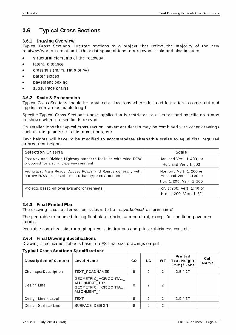
VicRoads Final Drawing Presentation Guidelines
Ver. 2.1 – July 2013 (Final) FDP Guidelines – Page 47
3.6 Typical Cross Sections
3.6.1 Drawing Overview Typical Cross Sections illustrate sections of a project that reflect the majority of the new roadway/works in relation to the existing conditions to a relevant scale and also include:
structural elements of the roadway. lateral distance crossfalls (m/m, ratio or %) batter slopes pavement boxing subsurface drains
3.6.2 Scale & Presentation Typical Cross Sections should be provided at locations where the road formation is consistent and applies over a reasonable length.
Specific Typical Cross Sections whose application is restricted to a limited and specific area may be shown when the section is relevant.
On smaller jobs the typical cross section, pavement details may be combined with other drawings such as the geometric, table of contents, etc.
Text heights will have to be modified to accommodate alternative scales to equal final required printed text height.
Selection Criteria Scale Freeway and Divided Highway standard facilities with wide ROW proposed for a rural type environment.
Hor. and Vert. 1:400, or Hor. and Vert. 1:500
Highways, Main Roads, Access Roads and Ramps generally with narrow ROW proposed for an urban type environment.
Hor. and Vert. 1:200 or Hor. and Vert. 1:100 or Hor. 1:200, Vert. 1:100
Projects based on overlays and/or resheets. Hor. 1:200, Vert. 1:40 or Hor. 1:200, Vert. 1:20
3.6.3 Final Printed Plan The drawing is set-up for certain colours to be ‘resymbolised’ at ‘print time’.
The pen table to be used during final plan printing = mono1.tbl, except for condition pavement details.
Pen table contains colour mapping, text substitutions and printer thickness controls.
3.6.4 Final Drawing Specifications Drawing specification table is based on A3 final size drawings output.
Typical Cross Sections Specifications
Description of Content Level Name CO LC WT Printed
Text Height (mm)/Font
Cell Name
Chainage/Description TEXT_ROADNAMES 8 0 2 2.5 / 27
Design Line
GEOMETRIC_HORIZONTAL_ALIGNMENT_1 to GEOMETRIC_HORIZONTAL_ALIGNMENT_4
8 7 2
Design Line - Label TEXT 8 0 2 2.5 / 27
Design Surface Line SURFACE_DESIGN 8 0 2

VicRoads Final Drawing Presentation Guidelines
Ver. 2.1 – July 2013 (Final) FDP Guidelines – Page 48
Description of Content Level Name CO LC WT Printed
Text Height (mm)/Font
Cell Name
Dimension Text TEXT 4 0 1 1.8 / 27
Existing Pavement PAVEMENT_EXISTING 7 Road Xsect Hatch1
0
Existing Surface Line SURFACE_EXISTING 2 5 1
Fence Boundary MISC_FENCE fence2
General Text TEXT 3 0 1 1.8 / 27
Guard Fence (Left & Right)
SAFETY_BARRIER_GUARD_FENCE
guard_fence_L2
guard_fence_R2
Kerbs KERB kerbs2 (varies)
Leader Lines & Linework TEXT 3 0 1
Noise Wall Boundary STRUCTURE_NOISE_WALL NB2
Pavement Boxing PAVEMENT_BOXING 0 0 2
PSR Boundary BOUNDARY PSR2
ROW Boundary BOUNDARY ROW2
Subsurface Drain DRAINAGE_SUB_SURFACE SDRAIN2
Safety Barrier (WRSB) SAFETY_BARRIER_WIRE_ROPE WRSB2
Notes: 1. Refer to VicRoads Custom Linestyles.PDF – General Group 2. Refer to VicRoads Cell Library – Road Design.cel
3.6.5 Reference File Listing
Reference Files Override Colour
Printed Colour Comments
VicRoads Corporate Titleblock Black
3.6.6 Example Drawing For an example of this type of drawing, refer to the VicRoads FDP – Example Drawings (July 2013) document:
Sheet No. 4
Sheet No. 5

VicRoads Final Drawing Presentation Guidelines
Ver. 2.1 – July 2013 (Final) FDP Guidelines – Page 49
3.7 Pavement Detail
3.7.1 Drawing Overview The Pavement Detail drawing provides the pavement structure and materials, and may include the location of kerb and channel, subsurface and surface drainage.
3.7.2 Scale The Pavement Detail drawings are not usually drawn to any nominal scale, but should be visually proportional with the drawing scale being specified as 'Drawn to Scale'. Where there is a need to provide more than one pavement detail a constant nominal scale should be adopted for visual consistency between drawings. Text heights will have to be modified to accommodate alternative scales to equal final required printed text height.
3.7.3 Presentation Options The presentation of the Pavement Details will vary depending on the size and the complexity of the project. For complex or involved pavement types for the scope of the roadwork, a separate ‘Pavement Type Limits’ drawing produced. The Pavement Detail Plan will contain a legend showing colours which represent different pavement designs for the scope of the roadwork which are cross referenced to a ‘Pavement Type Limits’ drawing.On smaller projects the typical cross section and pavement details may be combined with other drawings such as the geometric, table of contents, etc. Note: Refer to Section 2.3 – Pavement Type Limits File for information relating to colours used. The Pavement Type colours are indicative only and will vary depending on final plan requirements. It may be necessary to change colours to avoid clashes between Pavement Types.
Note: Colours used are indicative only and may be changed to avoid clashes or fade out between Pavement Types.
3.7.4 Final Printed Plan The drawing is set-up for certain colours to be ‘resymbolised’ at ‘print time’. The pen table to be used during final plan printing = mscol2.tbl or mono1.tbl. Pen table contains colour mapping, text substitutions and printer thickness controls.
3.7.5 Final Drawing Specifications Drawing specification table is based on A3 final size drawings output.
Pavement Detail Specifications Description of Content Level Name CO LC WT
Printed Text Height
(mm)/Font Cell Name
Design Surface Line SURFACE_DESIGN 8 0 2
Dimension Lines TEXT 2 0 1 1.8 / 27
Existing Pavement PAVEMENT_EXISTING 7 Road Xsect Hatch1
0
General Text TEXT 3 0 1 1.8 / 27
Kerbs KERB varies2
Pavement Detail Boxes TEXT varies 0 1
Pavement Heading Text TEXT 8 0 2 2.5 / 27
Pavement Layers Lines PAVEMENT_LAYERS 4 0/2 1
Pavement Listing Text TEXT 3 0 1 1.8 / 27
Section Title Text TEXT 0 0 2 2.5 / 27
Notes: 1. Refer to VicRoads Custom Linestyles.PDF – General Group 2. Refer to VicRoads Cell Library – Road Design.cel
VicRoads Final Drawing Presentation Guidelines
Ver. 2.1 – July 2013 (Final) FDP Guidelines – Page 50
3.7.6 Example Drawing For an example of this type of drawing, refer to the VicRoads FDP – Example Drawings (July 2013) document:
Sheet No. 6
Sheet No. 7
Sheet No. 8
Sheet No. 9

VicRoads Final Drawing Presentation Guidelines
Ver. 2.1 – July 2013 (Final) FDP Guidelines – Page 51
3.8 Geometric
3.8.1 Drawing Overview Geometric drawings provide the following information:
a baseline (datum) for the location and setting out of construction works
the relationship between the design line and other design lines
coordinated survey control symbols - Point name, Easting, Northing, RL, Point Description.
3.8.2 Scale, Presentation and Chainage Intervals Geometric Drawings are always drawn to a suitable scale and never moved off their coordinate base, e.g. Freeways 1:5000, Other Roads 1:2500.
The length of design line illustrated is dependent on the amount of geometric information that is required to specify the design line or proportion of the line shown on the drawing. Curve information is to be placed in an IP box, left aligned, with a pointer arrow used to locate point on drawing.
Survey control points which were initially used or referenced to during the feature survey are listed in a tabulated manner, e.g. Point name, Easting, Northing, Reduced Level (RL), Point Description. Point name and symbols should also be placed on to the drawing.
Text heights will have to be modified to accommodate alternative scales to equal final required printed text height.
Chainage intervals for cross sections should match the Longitudinal Section Drawing interval and chainage.
Selection Criteria Chainage Interval
Ramps with loops 10m
Rural type environment 10m - 20m
Urban type environment 10m
3.8.3 Final Printed Plan The drawing is set-up for certain colours to be ‘resymbolised’ at ‘print time’.
The pen table to be used during final plan printing = mono1.tbl.
Pen table contains colour mapping, text substitutions and printer thickness controls.
3.8.4 Final Drawing Specifications The details set out in the drawing specifications table has been based on A3 size final plans output.
Geometric Specifications
Description of Content Level Name CO LC WT
Printed Text Height (mm)/Font
Cell Name
Chainages
GEOMETRIC_HORIZONTAL_ALIGNMENT_1_TEXT to GEOMETRIC_HORIZONTAL_ALIGNMENT_4_TEXT
8 0 2 2.5 / 27
Curve Numbers TEXT 3 0 1 1.8 / 27
Curve & Spiral Details TEXT 3 0 1 1.8 / 28
Design Line – Major
GEOMETRIC_HORIZONTAL_ALIGNMENT_1 to GEOMETRIC_HORIZONTAL_ALIGNMENT_4
8 7 2
Design Line – Label TEXT 8 0 2 2.5 / 27

VicRoads Final Drawing Presentation Guidelines
Ver. 2.1 – July 2013 (Final) FDP Guidelines – Page 52
Description of Content Level Name CO LC WT
Printed Text Height (mm)/Font
Cell Name
Geometric Tangent Line GEOMETRIC_TANGENT 3 0 1
Road – Minor ROAD_MINOR 2 0 1
Event Point Chainage GEOMETRIC_HORIZONTAL_ALIGNMENT_1_TEXT 4 0 1 2.5 / 27
General Text TEXT 3 0 1 1.8 / 27
Geometric Heading Text TEXT 8 0 2 2.5 / 27
Geometric Listing Text TEXT 3 0 1 1.8 / 28
IP Box TEXT IPbox2
IP Box Details TEXT 3 0 1 1.8 / 27
IP Box with Curve Details TEXT IP_curve_b
ox2
North Point TEXT north1
Road Names TEXT_ROADNAMES 3 0 1 1.8/ 27
Survey Control Heading TEXT 8 0 2 2.5/ 27
Survey Control Listing TEXT 3 0 1 1.8 / 28
Survey Control Points & Text SURVEY_MARK 3 0 1 1.8 / 27
Notes: 1. Refer to VicRoads Cell Library – Misc Sticker.cel 2. Refer to VicRoads Cell Library – Road Design.cel
3.8.5 Reference File Listing
Reference Files Override Colour
Printed Colour Comments
VicRoads Corporate Titleblock black
3.8.6 Example Drawing For an example of this type of drawing, refer to the VicRoads FDP – Example Drawings (July 2013) document:
Sheet No. 10
Sheet No. 11
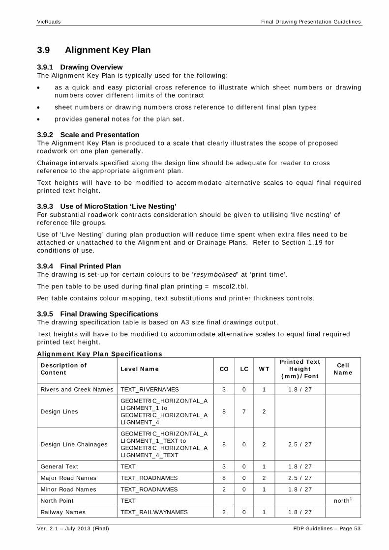
VicRoads Final Drawing Presentation Guidelines
Ver. 2.1 – July 2013 (Final) FDP Guidelines – Page 53
3.9 Alignment Key Plan
3.9.1 Drawing Overview The Alignment Key Plan is typically used for the following:
as a quick and easy pictorial cross reference to illustrate which sheet numbers or drawing numbers cover different limits of the contract
sheet numbers or drawing numbers cross reference to different final plan types
provides general notes for the plan set.
3.9.2 Scale and Presentation The Alignment Key Plan is produced to a scale that clearly illustrates the scope of proposed roadwork on one plan generally.
Chainage intervals specified along the design line should be adequate for reader to cross reference to the appropriate alignment plan.
Text heights will have to be modified to accommodate alternative scales to equal final required printed text height.
3.9.3 Use of MicroStation ‘Live Nesting’ For substantial roadwork contracts consideration should be given to utilising ‘live nesting’ of reference file groups.
Use of ‘Live Nesting’ during plan production will reduce time spent when extra files need to be attached or unattached to the Alignment and or Drainage Plans. Refer to Section 1.19 for conditions of use.
3.9.4 Final Printed Plan The drawing is set-up for certain colours to be ‘resymbolised’ at ‘print time’.
The pen table to be used during final plan printing = mscol2.tbl.
Pen table contains colour mapping, text substitutions and printer thickness controls.
3.9.5 Final Drawing Specifications The drawing specification table is based on A3 size final drawings output.
Text heights will have to be modified to accommodate alternative scales to equal final required printed text height.
Alignment Key Plan Specifications Description of Content Level Name CO LC WT
Printed Text Height
(mm)/Font
Cell Name
Rivers and Creek Names TEXT_RIVERNAMES 3 0 1 1.8 / 27
Design Lines
GEOMETRIC_HORIZONTAL_ALIGNMENT_1 to GEOMETRIC_HORIZONTAL_ALIGNMENT_4
8 7 2
Design Line Chainages
GEOMETRIC_HORIZONTAL_ALIGNMENT_1_TEXT to GEOMETRIC_HORIZONTAL_ALIGNMENT_4_TEXT
8 0 2 2.5 / 27
General Text TEXT 3 0 1 1.8 / 27
Major Road Names TEXT_ROADNAMES 8 0 2 2.5 / 27
Minor Road Names TEXT_ROADNAMES 2 0 1 1.8 / 27
North Point TEXT north1
Railway Names TEXT_RAILWAYNAMES 2 0 1 1.8 / 27

VicRoads Final Drawing Presentation Guidelines
Ver. 2.1 – July 2013 (Final) FDP Guidelines – Page 54
Description of Content Level Name CO LC WT
Printed Text Height
(mm)/Font
Cell Name
To/From Directional TEXT 2 0 1 1.8 / 27
Titleblock Key Shape TEXT_LIMIT & TEXT 10.0 / 151 TBSHAPE_CTB4
Note: 1. Refer to VicRoads Cell Library – Misc Sticker.cel
3.9.6 Reference File Listing
Reference Files Override Colour
Printed Colour Comments
Engineering Feature Survey (FS) 18 9
17 40 Strings representing invert of water features
Engineering Cadastral Base (CB) 43 43
Existing Pavement Area 23
Roadway Functional Layout black
Row 57 Weight = 2
Title Boundary 43 43
VicRoads Corporate Titleblock black
3.9.7 Example Drawing For an example of this type of drawing, refer to the VicRoads FDP – Example Drawings (July 2013) document:
Sheet No. 12

VicRoads Final Drawing Presentation Guidelines
Ver. 2.1 – July 2013 (Final) FDP Guidelines – Page 55
3.10 Alignment Plan
3.10.1 Drawing Overview Alignment Plan drawings are used for the following:
location and set out of the road alignment
identification and location of existing features that are to be retained, relocated or removed
identification and location of special construction treatment and works
staging of construction works
extraction of quantities.
Note: All plans should contain more than ¾ of an intersection on the page for clarity purposes. Intersections should never have a match line through them.
3.10.2 Presentation Options When the scope of the proposed construction is complex or involved it is recommended that a separate Alignment Plan is produced.
When the scope of the proposed construction is not complex it is possible that an Alignment Plan could be combined with the Drainage Plan which includes subsurface drainage design.
When combining the alignment, drainage and subsurface design details on the Alignment Plan consideration needs to be given to the readability of the plan and ideally a minimum scale 1:500 is adopted.
3.10.3 Scale and Chainage Intervals Text heights will have to be modified to accommodate alternative suitable scales to equal final required printed text height.
The guidelines for the selection of scales for Alignment Plans are set out in the following table.
Alignment Plans Selection Criteria Scale
Rural type environment, where details are sparse and the alignment is straight forward. 1:2000
Rural and urban type environment, where there are some construction constraints and the alignment is straight forward. 1:1000
Urban type environment where the alignment is complex and details are important. 1:500
Chainage intervals
Chainage intervals specified along the design line may vary depending on the type of the roadwork. Use the options below as a guide:
rural chainage intervals specified along the design line should annotate every 100m and salient points and display every 20m.
urban chainage intervals specified along the design line should annotate every 20m and salient points and display every 10m.
Note: Chainage measurement radiate east and west from the Melbourne GPO coordinate.
3.10.4 Enhancement Details The following details and reference notes are typically used:
bridge works and reference notes
critical dimensions and clearances
design line chainages and salient points

VicRoads Final Drawing Presentation Guidelines
Ver. 2.1 – July 2013 (Final) FDP Guidelines – Page 56
environmental sensitive areas including notes on treatment and preservation requirements
footpaths, bicycle paths details, notes
kerb and channel transition location
limits of works
noise mounds and fences, and associated notes
pavement transition details
rehabilitation treatment and/or notes
special treatments or requirements.
Construction Alignment Plans should be set up so that the chainages can be read in the direction of increasing value from left to right irrespective of the orientation of the North Point.
Ramp chainages are to increase in the same direction as the freeway chainage.
The grid co-ordinates should be arranged so that they are read in the direction of increasing value irrespective of the orientation of the North Point and at a spacing as defined below:
Scale Spacing
1:2000 100m
1:1000 100m
1:500 50m
Detail/Setout Enhancements
Particular attention must be given to providing information necessary to setout the project. This information needs to be concise and unambiguous.
There is often a need to provide a separate setting out detail drawing for areas such as intersections, interchanges etc.
Typical setting out details included on alignment plans when provided are:
contours
construction set out details for kerb and channel
kerb and channel salient points and radii
surface treatments.
Note: For small projects this information may be shown on a Combined Alignment Detail Plan.
Drainage and Subsurface Enhancements
When combining drainage and subsurface design details on the Alignment Plan refer to the relevant sections as a guide to typical enhancements that are required to be on the plan.
3.10.5 Use of MicroStation ‘Live Nesting’ For substantial roadwork contracts consideration should be given to utilising ‘Live Nesting’ of reference file groups.
Use of ‘Live Nesting’ during plan production will reduce time spent when extra files need to be attached or unattached to the Alignment and or Drainage Plans. Refer to Section 1.19 for conditions of use.
3.10.6 Final Printed Plan The drawing is set-up for certain colours to be ‘resymbolised’ at ‘print time’.
The pen table to be used during final plan printing = mscol2.tbl.
Pen table contains colour mapping, text substitutions and printer thickness controls.
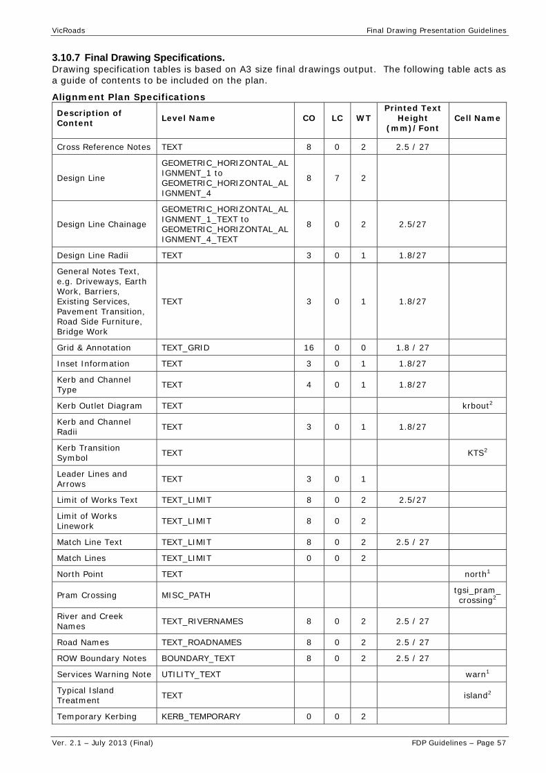
VicRoads Final Drawing Presentation Guidelines
Ver. 2.1 – July 2013 (Final) FDP Guidelines – Page 57
3.10.7 Final Drawing Specifications. Drawing specification tables is based on A3 size final drawings output. The following table acts as a guide of contents to be included on the plan.
Alignment Plan Specifications Description of Content Level Name CO LC WT
Printed Text Height
(mm)/Font Cell Name
Cross Reference Notes TEXT 8 0 2 2.5 / 27
Design Line
GEOMETRIC_HORIZONTAL_ALIGNMENT_1 to GEOMETRIC_HORIZONTAL_ALIGNMENT_4
8 7 2
Design Line Chainage
GEOMETRIC_HORIZONTAL_ALIGNMENT_1_TEXT to GEOMETRIC_HORIZONTAL_ALIGNMENT_4_TEXT
8 0 2 2.5/27
Design Line Radii TEXT 3 0 1 1.8/27
General Notes Text, e.g. Driveways, Earth Work, Barriers, Existing Services, Pavement Transition, Road Side Furniture, Bridge Work
TEXT 3 0 1 1.8/27
Grid & Annotation TEXT_GRID 16 0 0 1.8 / 27
Inset Information TEXT 3 0 1 1.8/27
Kerb and Channel Type TEXT 4 0 1 1.8/27
Kerb Outlet Diagram TEXT krbout2
Kerb and Channel Radii TEXT 3 0 1 1.8/27
Kerb Transition Symbol TEXT KTS2
Leader Lines and Arrows TEXT 3 0 1
Limit of Works Text TEXT_LIMIT 8 0 2 2.5/27
Limit of Works Linework TEXT_LIMIT 8 0 2
Match Line Text TEXT_LIMIT 8 0 2 2.5 / 27
Match Lines TEXT_LIMIT 0 0 2
North Point TEXT north1
Pram Crossing MISC_PATH tgsi_pram_crossing2
River and Creek Names TEXT_RIVERNAMES 8 0 2 2.5 / 27
Road Names TEXT_ROADNAMES 8 0 2 2.5 / 27
ROW Boundary Notes BOUNDARY_TEXT 8 0 2 2.5 / 27
Services Warning Note UTILITY_TEXT warn1
Typical Island Treatment TEXT island2
Temporary Kerbing KERB_TEMPORARY 0 0 2
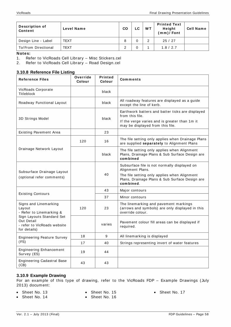
VicRoads Final Drawing Presentation Guidelines
Ver. 2.1 – July 2013 (Final) FDP Guidelines – Page 58
Description of Content Level Name CO LC WT
Printed Text Height
(mm)/Font Cell Name
Design Line - Label TEXT 8 0 2 25 / 27
To/From Directional TEXT 2 0 1 1.8 / 2.7
Notes: 1. Refer to VicRoads Cell Library – Misc Stickers.cel 2. Refer to VicRoads Cell Library – Road Design.cel
3.10.8 Reference File Listing
Reference Files Override Colour
Printed Colour Comments
VicRoads Corporate Titleblock black
Roadway Functional Layout black All roadway features are displayed as a guide except the line of kerb.
3D Strings Model black
Earthwork batters and batter ticks are displayed from this file. If the verge varies and is greater than 1m it may be displayed from this file.
Existing Pavement Area 23
Drainage Network Layout
120 16 The file setting only applies when Drainage Plans are supplied separately to Alignment Plans
black The file setting only applies when Alignment Plans, Drainage Plans & Sub Surface Design are combined
Subsurface Drainage Layout (optional refer comments)
40
Subsurface file is not normally displayed on Alignment Plans. The file setting only applies when Alignment Plans, Drainage Plans & Sub Surface Design are combined.
Existing Contours 43 Major contours
37 Minor contours
Signs and Linemarking Layout - Refer to Linemarking & Sign Layouts Standard Set Out Detail - refer to VicRoads website for details)
120 23 The linemarking and pavement markings (arrows and symbols) are only displayed in this override colour.
varies Pavement colour fill areas can be displayed if required.
Engineering Feature Survey (FS)
18 9 All linemarking is displayed
17 40 Strings representing invert of water features
Engineering Enhancement Survey (ES) 19 44
Engineering Cadastral Base (CB) 43 43
3.10.9 Example Drawing For an example of this type of drawing, refer to the VicRoads FDP – Example Drawings (July 2013) document:
Sheet No. 13 Sheet No. 14
Sheet No. 15 Sheet No. 16
Sheet No. 17
VicRoads Final Drawing Presentation Guidelines
Ver. 2.1 – July 2013 (Final) FDP Guidelines – Page 59
3.11 Drainage Plan
3.11.1 Drawing Overview Drainage Plan drawings are used for the following:
extraction of quantities
identification and location of existing drainage to be retained, removed or modified
identification and location of special drainage treatment and works
location and set out of drainage network and/or cross culverts
project specific contract drawings
staging of construction works.
3.11.2 Presentation Options When the scope of the proposed construction is complex or involved it is recommended that a separate Drainage Plan, including the subsurface design, is produced in conjunction with the Alignment Plan.
When a Drainage Plan, including subsurface design, is provided separately to the Alignment Plan, the scales should be consistent.
When the scope of the proposed construction is not complex it is possible that Drainage Plan, including subsurface design, could be combined with the Alignment Plan. Any combination of the plans should not compromise the readability of the plan.
3.11.3 Scale and Chainage Intervals The guidelines for selecting scales for Drainage Plan drawings are set out in the following table.
Drainage Plan Scale Selection Criteria Scale
Rural type environment, where details are sparse and the alignment is straight forward. 1:2000
Rural and urban type environment, where there are some construction constraints and the alignment is straight forward. 1:1000
Urban type environment where the alignment is complex and details are important. 1:500
Chainage Intervals
Chainage intervals specified along the design line may vary depending on the type of the roadwork.
Use the options below as a guide:
rural chainage intervals specified along the design line should annotate every 100m and salient points and display every 20m.
urban chainage intervals specified along the design line should annotate every 20m and salient points and display every 10m.
3.11.4 Enhancement Details. The drawing should be concise and unambiguous and provide sufficient information to distinguish between the existing and proposed enabling the drainage system to be positioned.
General enhancements include:
design line chainages and salient points
limits of works
Typical drainage information includes:
a pit numbering system

VicRoads Final Drawing Presentation Guidelines
Ver. 2.1 – July 2013 (Final) FDP Guidelines – Page 60
direction of flow
pipe sizes text
pipe outlet treatments
earthwork drain types and treatments including the offset distance, invert level at chainages where there is a change in offset and/or grading, or at inlets and /outlets near culverts
construction notes.
Typical subsurface drainage information includes:
sub-surface drainage legend
pipe grading
chainage and invert levels of flush out riser and outlets when independently graded
construction and installation notes and references.
Where the drainage set out details are provided on a separate drawing to the drainage plan both drawings should be cross referenced to each other for clarity.
Drainage plans should be set up so that the chainages can be read in the direction of increasing value from left to right irrespective of the orientation of the North Point.
Ramp chainages are to increase in the same direction as the freeway chainages.
The grid co-ordinates should be arranged so that they are read in the direction of increasing value irrespective of the orientation of the North Point. The grid spacing should be:
Note: For chainage & alignment plan (combined) scale = 1:500
Scale Spacing
1:2000 100m
1:1000 100m
1:500 50m
3.11.5 Use of MicroStation ‘Live Nesting’ For substantial roadwork contracts consideration should be given to utilising ‘live nesting’ of reference file groups:
Use of ‘Live Nesting’ during plan production will reduce time spent when extra files need to be attached or unattached to the Alignment and or Drainage Plans. Refer to Section 1.19 for conditions of use.
3.11.6 Final Printed Plan The drawing is set-up for certain colours to be ‘resymbolised’ at ‘print time’.
The pen table to be used during final plan printing = mscol2.tbl
Pen table contains colour mapping, text substitutions and printer thickness controls
3.11.7 Final Drawing Specifications Drawing specification tables have been based on A3 size final drawings output.
The following table acts as a guide of contents to be included on the plan.

VicRoads Final Drawing Presentation Guidelines
Ver. 2.1 – July 2013 (Final) FDP Guidelines – Page 61
Drainage Plan Specifications
Description of Content Level Name CO3 LC WT Printed Text
Height (mm)/Font
Cell Name
All Notes DRAINAGE_TEXT 3 0 1 1.8 / 27
Cross Reference Notes TEXT 3 0 1 1.8 / 27
Culvert/Pipes Sizes DRAINAGE_TEXT 4 0 1 1.8 / 27
Design Line
GEOMETRIC_HORIZONTAL_ALIGNMENT_1 to GEOMETRIC_HORIZONTAL_ALIGNMENT_4
8 7 2
Design Line Chainages
GEOMETRIC_HORIZONTAL_ALIGNMENT_1_TEXT to GEOMETRIC_HORIZONTAL_ALIGNMENT_4_TEXT
8 0 2 2.5 / 27
Drain Type Text A, B, Catch, etc DRAINAGE_TEXT 2 0 1 1.8 / 27
Grid & Annotation TEXT_GRID 16 0 0 1.8 / 27
Inset Information TEXT 3 0 1 1.8 / 27
Limit of Works Text TEXT_LIMIT 8 0 2 2.5 / 27
Limit of Works Linework TEXT_LIMIT 8 0 2
Match Line Text TEXT_LIMIT 8 0 2 2.5 / 27
Match Lines TEXT_LIMIT 0 0 2
North Point TEXT north1
Notes on Existing Services UTILITY_TEXT 3 0 1 1.8 / 27
Pit Number Box & Text DRAINAGE_STRUCTURE_NUMBER 1.8 pitnum2
River and Creek Names TEXT_RIVERNAMES 8 0 2 2.5 / 27
Road Names TEXT_ROADNAMES 8 0 2 2.5 / 27
ROW Boundary Notes BOUNDARY_TEXT 8 0 2 2.5 / 27
Services Warning Note UTILITY_TEXT warn1
Pit Schedule Table TEXT 1.8 / 28 psched2
Sub-surface Drain Legend DRAINAGE_TEXT ssdleg1 (varies)
To/From Directional Text and Linework TEXT 2 0 1 1.8 / 27
Subsurface Invert Levels/ Drain DRAINAGE_TEXT 40 0 1 1.8 / 27
Notes: 1. Refer to VicRoads Cell Library – Misc Stickers.cel 2. Refer to VicRoads Cell Library – Road Design.cel 3. Care must be taken between Screen Colour and Printed Colour and will be dependent on
the program used to produce the Drainage Plans.

VicRoads Final Drawing Presentation Guidelines
Ver. 2.1 – July 2013 (Final) FDP Guidelines – Page 62
3.11.8 Reference File Listing
Reference Files Override Colour
Printed Colour Comments
VicRoads Corporate Titleblock black
Roadway Functional Layout 16 16 All roadway features are displayed as a guide except the line of kerb.
3D Strings Model 16 16
Earthwork batters and batter ticks are displayed from this file. If the verge varies and is greater than 1m it may be displayed from this file.
Existing Pavement Area 23
Drainage Network Layout black The file setting when Drainage Plans are supplied separately to Alignment Plans
Subsurface Drainage Layout 40
Existing Contours 43 Major contours
37 Minor contours
Design Contours / Land Forming black
Signs and Linemarking Layout 16 16 All linemarking is displayed
Engineering Feature Survey (FS) 18 9
17 40 Strings representing invert of water features
Engineering Enhancement Survey (ES) 19 44
Engineering Cadastral Base (CB) 43 43
3.11.9 Example Drawing For an example of this type of drawing, refer to the VicRoads FDP – Example Drawings (July 2013) document:
Sheet No. 18

VicRoads Final Drawing Presentation Guidelines
Ver. 2.1 – July 2013 (Final) FDP Guidelines – Page 63
3.12 Drainage Longitudinal
3.12.1 Drawing Overview Drainage Longitudinal drawings are used for the following:
extraction of quantities
identification of existing pits or pipes that are to be retained
identification and location of special construction treatment and works
location and set out of pit and pipes
staging of construction works.
3.12.2 Scale Drainage Longitudinal drawings are drawn at a scale exaggeration of 5:1 and the nominal scale being Horizontal 1:1000 and Vertical 1:200 or Horizontal 1:500 and Vertical 1:100.
Text heights will have to be modified to accommodate alternative scales to equal final required printed text height.
3.12.3 Enhancement Details The following detail and reference notes are typically shown on the drainage longitudinal section.
critical service details including levels and approximate location
drainage outlet details including names of rivers and creeks
highway, roads and ramps names
pipes / culvert details and classification
surface treatment including pavement boxing depth, beaching, etc
pit schedules may be included or placed on a separate sheet
outlet structures.
3.12.3.1 Pipe / Culvert Details Pipe/Culvert details are to be placed under the relevant section of the pipe shown on the drainage longitudinal.
The typical details to be specified are:
inlet/outlet levels (3 decimal places)
size/diameter and class
number of cells
length (centre to centre - 3 decimal places)
pipe slope (% - 3 decimal places)
special treatment notes
construction details, such protection of shallow pipes during construction.
The outlet and inlet invert levels are taken at the centre of the pit shaft and are specified under the relevant pipe section of the drainage longitudinal. The inlet and outlet level for culvert endwall and wingwall is the set out point at the outer face of the wall.
The length of a pipe is measured from the centre of the pit shaft to the centre of pit shaft taking into consideration (i) horizontal curves and (ii) the slope of the pipe. A culvert length is adjusted to unit lengths of 1.22m or 2.44m or as per manufactures specifications.
The specific pipe slope needs to be sufficiently accurate so that field staff can calculate the stated pipe invert level using the pipe length and slope. As a general rule the pipe slope needs to be specified to three figures.
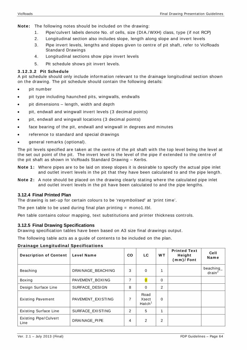
VicRoads Final Drawing Presentation Guidelines
Ver. 2.1 – July 2013 (Final) FDP Guidelines – Page 64
Note: The following notes should be included on the drawing: 1. Pipe/culvert labels denote No. of cells, size (DIA./WXH) class, type (if not RCP) 2. Longitudinal section also includes slope, length along slope and invert levels 3. Pipe invert levels, lengths and slopes given to centre of pit shaft, refer to VicRoads
Standard Drawings 4. Longitudinal sections show pipe invert levels
5. Pit schedule shows pit invert levels.
3.12.3.2 Pit Schedule A pit schedule should only include information relevant to the drainage longitudinal section shown on the drawing. The pit schedule should contain the following details:
pit number
pit type including haunched pits, wingwalls, endwalls
pit dimensions – length, width and depth
pit, endwall and wingwall invert levels (3 decimal points)
pit, endwall and wingwall locations (3 decimal points)
face bearing of the pit, endwall and wingwall in degrees and minutes
reference to standard and special drawings
general remarks (optional).
The pit levels specified are taken at the centre of the pit shaft with the top level being the level at the set out point of the pit. The invert level is the level of the pipe if extended to the centre of the pit shaft as shown in VicRoads Standard Drawing – Kerbs.
Note 1: Where pipes are to be laid on steep slopes it is desirable to specify the actual pipe inlet and outlet invert levels in the pit that they have been calculated to and the pipe length.
Note 2: A note should be placed on the drawing clearly stating where the calculated pipe inlet and outlet invert levels in the pit have been calculated to and the pipe lengths.
3.12.4 Final Printed Plan The drawing is set-up for certain colours to be ‘resymbolised’ at ‘print time’.
The pen table to be used during final plan printing = mono1.tbl.
Pen table contains colour mapping, text substitutions and printer thickness controls.
3.12.5 Final Drawing Specifications Drawing specification tables have been based on A3 size final drawings output.
The following table acts as a guide of contents to be included on the plan.
Drainage Longitudinal Specifications
Description of Content Level Name CO LC WT Printed Text
Height (mm)/Font
Cell Name
Beaching DRAINAGE_BEACHING 3 0 1 beaching_drain2
Boxing PAVEMENT_BOXING 7 0 0
Design Surface Line SURFACE_DESIGN 8 0 2
Existing Pavement PAVEMENT_EXISTING 7 Road Xsect Hatch1
0
Existing Surface Line SURFACE_EXISTING 2 5 1
Existing Pipe/Culvert Line DRAINAGE_PIPE 4 2 2

VicRoads Final Drawing Presentation Guidelines
Ver. 2.1 – July 2013 (Final) FDP Guidelines – Page 65
Description of Content Level Name CO LC WT Printed Text
Height (mm)/Font
Cell Name
Pipe/Culvert Line DRAINAGE_PIPE 4 0 2
Existing Pit Lines DRAINAGE_PIT 5 2 3
New Pit Lines DRAINAGE_PITS 5 0 3
Pit Number Box & Text DRAINAGE_STRUCTURE_NUMBER 1.8 / 27 pitnum2
Pit Leader Lines DRAINAGE_STRUCTURE_NUMBER 3 0 1
General Text TEXT 3 0 1
Pit Schedule Table TEXT 3 0 1 1.8 / 28 psched2
Invert/Outlet Levels DRAINAGE_TEXT 4 0 1 1.8 / 27
Pipe/Culvert Size, Grade, Length DRAINAGE_TEXT 4 0 1 1.8 / 27
Utility Services
UTILITY_GAS_UNDERGROUND UTILITY_ELECTRICITY_UNDERGROUND UTILITY_SEWER_UNDERGROUND UTILITY_WATER_UNDERGROUND
2 2 1
Utility Text UTILITY_TEXT 2 0 1 1.8 / 27
Notes: 1. Refer to VicRoads Custom Linestyles.pdf – General Group 2. Refer to VicRoads Cell Library – Road Design.cel
3.12.6 Reference File Listing
Reference Files Override Colour Printed Colour Comments
VicRoads Corporate Titleblock black
3.12.7 Example Drawing For an example of this type of drawing, refer to the VicRoads FDP – Example Drawings (July 2013) document:
Sheet No. 19
Sheet No. 20
Sheet No. 21


VicRoads Final Drawing Presentation Guidelines
Ver. 2.1 – July 2013 (Final) FDP Guidelines – Page 67
3.13 Pavement Type Limits
3.13.1 Drawing Overview Pavement Type Limits drawings are used for the following:
identification and location of different pavement types and treatment works
staging of construction works
extraction of quantities.
3.13.2 Presentation Options When the Pavement Detail Drawing is insufficient to describe complex or involved pavement types for the scope of the roadwork involved it is recommended that a separate Pavement Type Limits drawing is produced.
3.13.3 Scale and Chainage Intervals Generally, when provided, the selected scale for Pavement Type Limits drawings should be consistent with the Alignment Plans.
Text heights will have to be modified to accommodate alternative scales to equal final required printed text height.
Chainage intervals specified along the design line may vary depending on the type of the roadwork. Use the options below as a guide.
rural chainage intervals specified along the design line should annotate every 100m and salient points and display every 20m.
urban chainage intervals specified along the design line should annotate every 20m and salient points and display every 10m.
3.13.4 Enhancement Details The following details and reference notes are typically used on this type of drawing:
limits of works
special treatments or requirements
pavement rehabilitation treatment notes
pavement transition details
footpaths, bicycle paths pavement, notes
design line chainages.
Plans should be set up so that the chainages can be read in the direction of increasing value from left to right irrespective of the orientation of the North Point.
3.13.5 Use of MicroStation ‘Live Nesting’ For substantial roadwork contracts consideration should be given to utilising ‘live nesting’ of reference file groups.
Use of ‘Live Nesting’ during plan production will reduce time spent when extra files need to be attached or unattached to the Alignment and/or Drainage Plans, refer to Section 1.19 for conditions of use.
3.13.6 Final Printed Plan The pen table to be used during final plan printing = mscol2.tbl.
3.13.7 Final Drawing Specifications. Drawing specification tables is based on A3 size final drawings output.
The following table acts as a guide of contents to be included on the plan.

VicRoads Final Drawing Presentation Guidelines
Ver. 2.1 – July 2013 (Final) FDP Guidelines – Page 68
Pavement Type Limits Specifications
Description of Content Level Name CO LC WT Printed
Text Height (mm)/Font
Cell Name
Design Line
GEOMETRIC_HORIZONTAL_ALIGNMENT_1 to GEOMETRIC_HORIZONTAL_ALIGNMENT_4
8 7 2
Design Line Chainage
GEOMETRIC_HORIZONTAL_ALIGNMENT_1_TEXT to GEOMETRIC_HORIZONTAL_ALIGNMENT_4_TEXT
8 0 2 2.5 / 27
Grid & Annotation TEXT_GRID 16 0 0 1.8 / 27
Limit of Works Linework TEXT_LIMIT 8 0 2
Limit of Works Text TEXT_LIMIT 8 0 2 2.5 / 27
Match Line Text TEXT_LIMIT 8 0 2 2.5 / 27
Match Lines TEXT_LIMIT 0 0 2
North Point TEXT north1
Notes on Existing Services UTILITY_TEXT 3 0 1 1.8 / 27
Pavement Notes TEXT 3 0 1 1.8 / 27
Pavement Type Legend TEXT 4 0 1 1.8 / 27
River & Creek Names TEXT_RIVERNAMES 3 0 1 2.5 / 27
Road Names TEXT_ROADNAMES 8 0 2 2.5 / 27
To/From Directional Text & Linework TEXT 2 0 1 1.8 / 27
Design Line - Label TEXT 8 0 2 2.5 / 27
Notes: 1. Refer to VicRoads Cell library – Misc Stickers.cel
3.13.8 Reference File Listing
Reference Files Override Colour
Printed Colour Comments
VicRoads Corporate Titleblock black
Roadway Functional Layout black
Pavement Type Limit Plan varies
Existing Pavement Area 23
Engineering Feature Survey (FS) 18 9
17 40 Strings representing invert of water features
Engineering Enhancement Survey (ES) Optional File 19 44
Engineering Cadastral Base (CB) 43 43
3.13.9 Example Drawing For an example of this type of drawing, refer to the VicRoads FDP – Example Drawings (July 2013) document:
Sheet No. 22
Sheet No. 23

VicRoads Final Drawing Presentation Guidelines
Ver. 2.1 – July 2013 (Final) FDP Guidelines – Page 69
3.14 Detail Plan
3.14.1 Drawing Overview Detail Plan drawings are used for the following:
extraction of quantities
identification and location of special construction treatment and works
location and set out of the road alignment
project specific contract drawings
staging of construction works.
3.14.2 Scale and Chainage Intervals The guidelines for the selection of scales for Detail Plan are set out in the table below:
Detail Plans Selection Criteria Scale
Environment where set out and construction requires comprehensive information/details. 1:500
Environment where details are important to the design and construction outcome. 1:250
The 1:250 scale is used for inserts in A3 drawings, or as the nominal scale suitable for A1 final drawings. Where an A1 size drawing is required, the A3 standards are applied and the A1 drawing be created through the plotting process, e.g. plotted at twice the scale.
The chainage intervals specified along the design line should be every 20m and at the salient points.
3.14.3 Enhancement Details. Particular attention must be given to providing information necessary to set out the project. This information needs to be concise and unambiguous.
Typical setting out details includes:
location and size of conduits kerb and channel salient points and radii contours construction set out details for kerb and channel surface treatments.
3.14.4 Final Printed Plan The drawing is set-up for certain colours to be ‘resymbolised’ at ‘print time’.
The pen table to be used during final plan printing = mono1.tbl.
Pen table contains colour mapping, text substitutions and printer thickness controls.
3.14.5 Final Drawing Specifications Drawing specification tables have been based on A3 size final drawings output.
Text heights will have to be modified to accommodate alternative scales to equal final required printed text height.

VicRoads Final Drawing Presentation Guidelines
Ver. 2.1 – July 2013 (Final) FDP Guidelines – Page 70
Detail Plan Specifications
Description of Content Level Name CO LC WT Printed Text
Height (mm)/Font
Cell Name
General Details
Cross Reference Notes TEXT 8 0 2 2.5 / 27
Grid & Annotation TEXT_GRID 16 0 0 1.8 / 27
North Point TEXT north1
River & Creek Names TEXT_RIVERNAMES 8 0 2 2.5 / 27
Road Names TEXT_ROADNAMES 8 0 2 2.5 / 27
To/From Directional Text & Linework TEXT 2 0 1 1.8 / 27
Construction Details
Design Line
GEOMETRIC_HORIZONTAL_ALIGNMENT_1 to GEOMETRIC_HORIZONTAL_ALIGNMENT_4
8 7 2
Design Line Chainage
GEOMETRIC_HORIZONTAL_ALIGNMENT_1_TEXT to GEOMETRIC_HORIZONTAL_ALIGNMENT_4_TEXT
8 0 2 2.5 / 27
Limit of Works Linework TEXT_LIMIT 8 0 2
Limit of Works Text TEXT_LIMIT 8 0 2 2.5 / 27
Setout Diagram SOARC
Design Major Contours SURFACE_DESIGN_CONTOUR_MAJOR 8 0 2
Design Minor Contours SURFACE_DESIGN_CONTOUR_MINOR 3 0 1
Design Contour Text SURFACE_DESIGN_CONTOUR_TEXT 3 0 1 1.8 / 27
Design Line - Label TEXT 8 0 2 2.5 / 27
Kerb and Channel Details
Kerb and Channel Type TEXT 4 0 1 1.8 / 27
Kerb and Channel Radii TEXT 3 0 1 1.8 / 27
Salient Point Circle & Text TEXT_SETOUT_DETAIL 1.8 / 27
setout_point_in_circle_18_d
ouble2 setout_point_in_circle_18_tri
ple2
Temporary Kerbing KERB_TEMPORARY 0 0 2
Kerb Transition Symbol TEXT KTS2
Kerb Outlet Diagram TEXT KRBout2
Match Lines TEXT_LIMIT 0 0 2
Set Out Table
Figures/Text TEXT 3 0 1 1.8 / 28
Table Line TEXT 3 0 1

VicRoads Final Drawing Presentation Guidelines
Ver. 2.1 – July 2013 (Final) FDP Guidelines – Page 71
Notes: 1. Refer to VicRoads Cell Library – Misc Stickers.cel 2. Refer to VicRoads Cell Library – Road Design.cel 3. Refer to VicRoads Cell Library – Misc Symbols.cel 4. Refer to VicRoads Cell Library – TM.cel
3.14.6 Reference File Listing
Reference Files Override Colour
Printed Colour Comments
VicRoads Corporate Titleblock black
Roadway Functional Layout black All roadway features are displayed as a guide except the line of kerb.
Drainage Network Layout black Display pits only
Engineering Feature Survey (FS) 18 9
17 40 Strings representing invert of water features
Engineering Enhancement Survey (ES) 19 44
Engineering Cadastral Base (CB) 43 43
Existing Contours 16/23 16/23
3.14.7 Example Drawing For an example of this type of drawing, refer to the VicRoads FDP – Example Drawings (July 2013) document:
Sheet No. 24
Sheet No. 25
Sheet No. 26


VicRoads Final Drawing Presentation Guidelines
Ver. 2.1 – July 2013 (Final) FDP Guidelines – Page 73
3.15 Lip Profiles
3.15.1 Drawing Overview Lip Profiles drawings are used for the following:
to show the lip of the kerb and channel in areas not adequately covered by the cross sections, e.g. traffic islands, kerb returns, etc
locate the high and low points, and respective reduced levels
extraction of reduced levels for intermediate setting out points
confirmation of setting out details and checks on contours
extraction of kerb and channel quantities
an overview of the kerb profile shape
starting point - the starting and end point where possible should be at an even design line chainage.
3.15.2 Scale Lip Profiles are drawn with a scale exaggeration of 25:1 and the nominal scale being Horizontal 1:500 and Vertical 1:20.
An alternative scale exaggeration of 50:1 with nominal scale being Horizontal 1:400 and Vertical 1:8 can be adopted for small projects where contours of the final surface are not provided. This allows field personnel to interpret the levels to within 5mm directly from the drawing
Text heights will have to be modified to accommodate alternative scales to equal final required printed text height.
3.15.3 Enhancement Details The following details and reference notes are typically used on the Lip Profiles:
chainage and reduced levels at high and low grading point particularly when the grading is flat
kerb type and where applicable the transition point location between kerbs
drainage pit and kerb opening locations
additional information such as chainage and reduce level at mid and quarter ordinates points may be required along a large radius where the grading is variable.
Kerb and channel profiles are typically required in areas where the channel grading is variable and the cross section intervals are inadequate to establish kerb levels, for example, within intersections, traffic islands, large tapers, etc
Depending on the number of profile drawings and the complexity of the detail alignment plans it may be desirable to:
group all the lip profile sheets in one section
arrange the drawing sheets so that the lip profile drawing and the corresponding detail plan are adjacent to each other
combine the setting out details ant the lip profiles on the same drawing sheet.
3.15.4 Final Printed Plan The drawing is set-up for certain colours to be ‘resymbolised’ at ‘print time’.
The pen table to be used during final plan printing = mono1.tbl.
Pen table contains colour mapping, text substitutions and printer thickness controls.
3.15.5 Final Drawing Specifications Drawing specification tables is based on A3 size final drawings output.

VicRoads Final Drawing Presentation Guidelines
Ver. 2.1 – July 2013 (Final) FDP Guidelines – Page 74
The following table acts as a guide of contents to be included on the plan.
Lip Profiles Specifications
Description of Content Level Name CO LC WT Printed
Text Height (mm)/Font
Cell Name
Axis Linework SECTIONS 4 0 1
Axis Text SECTIONS 4 0 1 1.8 / 27
Chainage & Reduced Levels Listing SECTIONS 4 0 1 1.8 / 27
Lip Profile Grading SURFACE_DESIGN 8 0 2
Lip Profile - Label TEXT 8 0 2 2.5 / 27
Reduced Level Grid SECTIONS 7 2 0
Salient Point Circle & Text TEXT_SETOUT_DETAIL 1.8 / 27
setout_point_in_circle_18_double1
setout_point_in_circle_18_triple1
Salient Point Leader Line TEXT 7 0 0
Sub Headings e.g. Kerb Chainage, Design Surface
SECTIONS 4 0 1 1.8 / 27
Notes: 1. Refer to VicRoads Cell Library – Road Design.cel
3.15.6 Reference File Listing
Reference Files Override Colour
Printed Colour Comments
VicRoads Corporate Titleblock black
3.15.7 Example Drawing For an example of this type of drawing, refer to the VicRoads FDP – Example Drawings (July 2013) document:
Sheet No. 27
Sheet No. 28

VicRoads Final Drawing Presentation Guidelines
Ver. 2.1 – July 2013 (Final) FDP Guidelines – Page 75
3.16 Longitudinal Sections
3.16.1 Drawing Overview The Longitudinal Section drawings are used to represent the vertical geometry of the roadway.
Longitudinal details combined with the crossfall information are used by the surveyors and constructors in various programs to obtain cut and fill values for both earthworks and pavement construction.
3.16.2 Scale and Chainage Intervals. The guidelines for the selection of longitudinal sections are set out in the table below, incorporating a standard scale ratio of 10:1.
Longitudinal Sections
Selection Criteria Scale
Freeway and Divided Highway standard facilities proposed for a rural type environment
Horz. 1:5000, Vert. 1:500 or Hor. 1:4000, Vert. 1:400
Highway, Main roads, Access Roads and Freeway Ramps proposed for a urban type environment
Horz. 1:2000, Vert. 1:200 or Horz. 1:1000, Vert. 1:100
Short lengths of Access Roads or Urban Roads Horz. 1:1000, Vert. 1:100 or Horz. 1:500, Vert. 1:50
Chainage intervals for longitudinal section drawings should match the cross section interval and chainage. The table below sets out the guidelines for selection.
Longitudinal Sections
Selection Criteria Chainage Interval
Rural Type Environment - 10m interval maybe required for the auto grade
20m or 10m
Urban Type Environment 10m
Ramps 10m Text heights will have to be modified to accommodate alternative scales to equal final required printed text height.
3.16.3 Enhancement Details. The following details and reference notes are typically used on the longitudinal sections:
existing and proposed bridge structures including start and end chainage, depth and critical clearance of structure
existing and proposed major culverts
critical service details including type, level and approximate location
the centre line of creeks and rivers including flood levels and their names
the centre line/design line of cross roads, ramps and their names
the centre line of railway tracks and their service names
the centre line of major services
label work constructed by others
cross hatching of existing pavement
must include K values.

VicRoads Final Drawing Presentation Guidelines
Ver. 2.1 – July 2013 (Final) FDP Guidelines – Page 76
3.16.4 Final Printed Plan The drawing is set-up for certain colours to be ‘resymbolised’ at ‘print time’. The pen table to be used during final plan printing = mono1.tbl. The pen table contains colour mapping, text substitutions and printer thickness controls.
3.16.5 Final Drawing Specifications Drawing specification tables are based on A3 size final drawings output.
The following table acts as a guide of contents to be included on the plan.
Longitudinal Sections Specifications
Description of Content Level Name CO LC WT Printed
Text Height (mm)/Font
Cell Name
Axis Linework SECTIONS 4 0 1
Axis Text SECTIONS 4 0 1 1.8 / 27
Axis Ticks SECTIONS 3 0 1
Cross Road Design Line TEXT 4 7 1
Cross Road Text TEXT 3 0 1 1.8 / 27
Design Gradeline
GEOMETRIC_VERTICAL_ALIGNMENT_1 to GEOMETRIC_VERTICAL_ALIGNMENT_4
8 0 2
Design Surface SURFACE_DESIGN 8 0 2
General Text TEXT 3 0 1 1.8 / 27
Leader Lines TEXT 4 0 1 1.8 / 27
Existing Pavement PAVEMENT_EXISTING 7 Road Xsect Hatch1
0
Existing Surface Line SURFACE_EXIST 2 3 1
Intersection Triangles & Salient Marks
GEOMETRIC_VERTICAL_ALIGNMENT_1 to GEOMETRIC_VERTICAL_ALIGNMENT_4
2 0 1
Intersection Point Text
GEOMETRIC_VERTICAL_ALIGNMENT_1_TEXT to GEOMETRIC_VERTICAL_ALIGNMENT_4_TEXT
4 0 1 1.8 / 27
Length of Curve, K Value & Salient Point Text
GEOMETRIC_VERTICAL_ALIGNMENT_1 to GEOMETRIC_VERTICAL_ALIGNMENT_4
4 0 1 1.8 / 27
Grade Text
GEOMETRIC_VERTICAL_ALIGNMENT_1_TEXT to GEOMETRIC_VERTICAL_ALIGNMENT_4_TEXT
4 0 1 1.8 / 27
Reduced Level Grid SECTIONS 7 2 0
Sub-headings, e.g. Chainage, Gradeline, Existing Surface TEXT 4 0 1 1.8 / 27
Other Surfaces SURFACE_1 to SURFACE_4 161 5 2 Notes:
1. Refer to VicRoads Custom Linestyles.pdf – General Group
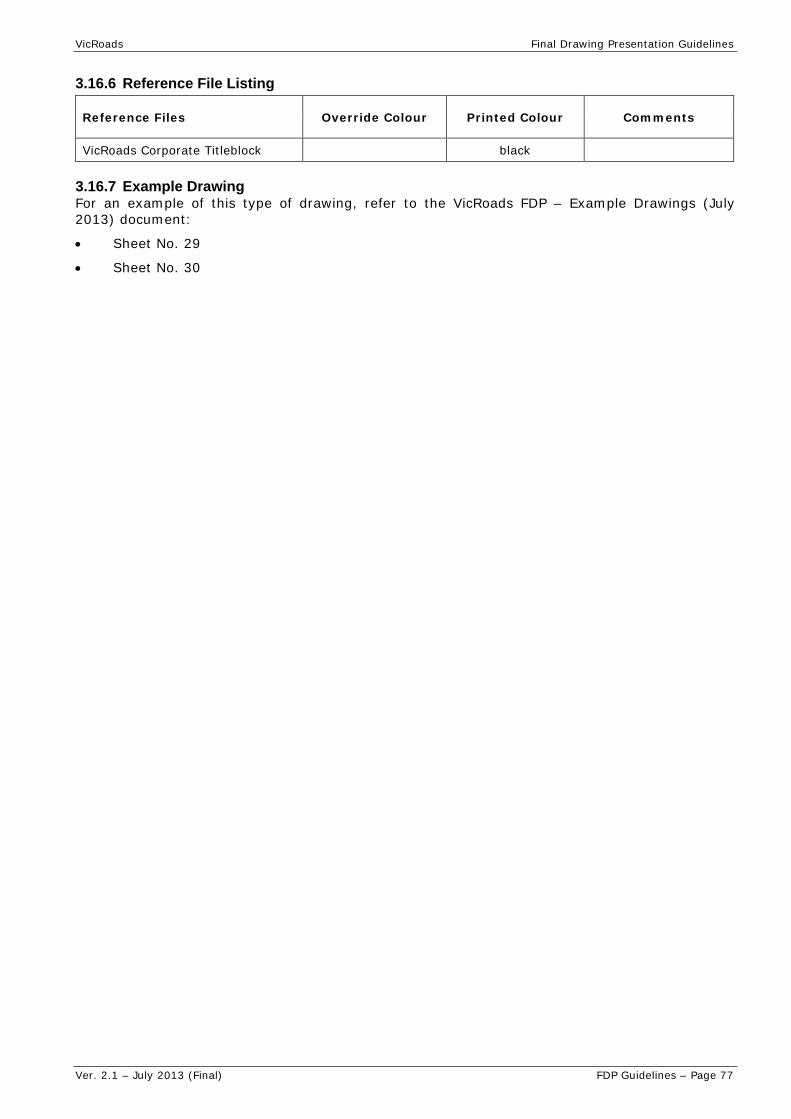
VicRoads Final Drawing Presentation Guidelines
Ver. 2.1 – July 2013 (Final) FDP Guidelines – Page 77
3.16.6 Reference File Listing
Reference Files Override Colour Printed Colour Comments
VicRoads Corporate Titleblock black
3.16.7 Example Drawing For an example of this type of drawing, refer to the VicRoads FDP – Example Drawings (July 2013) document:
Sheet No. 29
Sheet No. 30

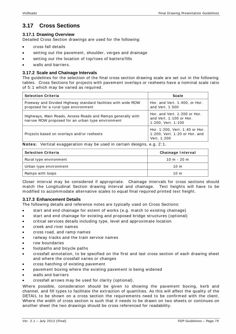
VicRoads Final Drawing Presentation Guidelines
Ver. 2.1 – July 2013 (Final) FDP Guidelines – Page 79
3.17 Cross Sections
3.17.1 Drawing Overview Detailed Cross Section drawings are used for the following:
cross fall details setting out the pavement, shoulder, verges and drainage setting out the location of top/toes of batters/fills walls and barriers.
3.17.2 Scale and Chainage Intervals The guidelines for the selection of the final cross section drawing scale are set out in the following tables. Cross Sections for projects with pavement overlays or resheets have a nominal scale ratio of 5:1 which may be varied as required.
Selection Criteria Scale
Freeway and Divided Highway standard facilities with wide ROW proposed for a rural type environment
Hor. and Vert. 1:400, or Hor. and Vert. 1:500
Highways, Main Roads, Access Roads and Ramps generally with narrow ROW proposed for an urban type environment
Hor. and Vert. 1:200 or Hor. and Vert. 1:100 or Hor. 1:200, Vert. 1:100
Projects based on overlays and/or resheets Hor. 1:200, Vert. 1:40 or Hor. 1:200, Vert. 1:20 or Hor. and Vert. 1:200
Notes: Vertical exaggeration may be used in certain designs, e.g. 2:1.
Selection Criteria Chainage Interval
Rural type environment 10 m - 20 m
Urban type environment 10 m
Ramps with loops 10 m
Closer interval may be considered if appropriate. Chainage intervals for cross sections should match the Longitudinal Section drawing interval and chainage. Text heights will have to be modified to accommodate alternative scales to equal final required printed text height.
3.17.3 Enhancement Details The following details and reference notes are typically used on Cross Sections: start and end chainage for extent of works (e.g. match to existing chainage) start and end chainage for existing and proposed bridge structures (optional) critical services details including type, level and approximate location creek and river names cross road, and ramp names railway tracks and the train service names row boundaries footpaths and bicycle paths crossfall annotation, to be specified on the first and last cross section of each drawing sheet
and where the crossfall varies or changes cross hatching of existing pavement pavement boxing where the existing pavement is being widened walls and barriers crossfall arrows may be used for clarity (optional). Where possible, consideration should be given to showing the pavement boxing, kerb and channel, and fill types to facilitate the extraction of quantities. As this will affect the quality of the DETAIL to be shown on a cross section the requirements need to be confirmed with the client. Where the width of cross section is such that it needs to be drawn on two sheets or continues on another sheet the two drawings should be cross referenced for readability.

VicRoads Final Drawing Presentation Guidelines
Ver. 2.1 – July 2013 (Final) FDP Guidelines – Page 80
3.17.4 Final Printed Plan The drawing is set-up for certain colours to be ‘resymbolised’ at ‘print time’. The pen table to be used during final plan printing = mono1.tbl. The pen table contains colour mapping, text substitutions and printer thickness controls.
3.17.5 Final Drawing Specifications Drawing specification tables are based on A3 size final drawings output. The following table acts as a guide of contents to be included on the plan.
Cross Sections Specifications
Description of Content Level Name CO LC WT Printed
Text Height (mm)/Font
Cell Name
Boxing PAVEMENT_BOXING 7 Road Xsect
Shape2 1
Existing Surface Line SURFACE_EXISTING 2 5 1
Existing Pavement PAVEMENT_EXISTING 7 Road Xsect Hatch1
0
Proposed Surface Line SURFACE_DESIGN 8 0 2
Pavement Boxing PAVEMENT_BOXING 0 0 2
Crossfall / Slope TEXT 4 0 1 1.8/27
Fence MISC_FENCE fence2
Kerbs KERB varies1
Leader Lines TEXT 3 0 1
Noise Barrier STRUCTURE_NOISE_WALL NB2
Offsets and reduced levels TEXT 4 0 1 1.8/27
PSR Boundary & Text BOUNDARY PSR2
ROW Boundary & Text BOUNDARY ROW2
Cross Section Axis Details
Axis Linework SECTIONS 4 0 1
Axis Text SECTIONS 4 0 1 1.8/27
Axis Ticks SECTIONS 3 0 1
Chainage SECTIONS 8 0 2 2.5/27
Enhancement Detail Descriptions
Feature Linework TEXT 4 0 0
Leader Lines TEXT 4 0 0
Text TEXT 3 0 1 1.8/27 Notes: 1. Refer to VicRoads Custom Linestyles.pdf – General Group 2. Refer to VicRoads Cell Library – Road Design.cel
3.17.6 Reference File Listing
Reference Files Override Colour
Printed Colour Comments
VicRoads Corporate Titleblock black
3.17.7 Example Drawing For an example of this type of drawing, refer to the VicRoads FDP – Example Drawings (July 2013) document: Sheet No. 31 Sheet No. 32 Sheet No. 33

VicRoads Final Drawing Presentation Guidelines
Ver. 2.1 – July 2013 (Final) FDP Guidelines – Page 81
3.18 Sign and Pavement Markings
3.18.1 Drawing Overview Sign and Pavement (Line) Markings drawings are used for the following:
location and type of Pavement marking to be used
sign codes and manufacturing sizes for signs, e.g. G2-V1A
ultimate sign layout to be shown i.e. all new signs and any existing signs that are to be retained. Image of project specific existing signs may be inserted
dimension of lane widths, shoulder widths, set out points, etc.
As an aid to plan clarity it is recommended that all existing conditions that have been replaced in project works be ‘masked out’ of final printed plan.
Use of masking should be discussed and confirmed prior to delivery of plans.
3.18.2 Scale and Presentation When a Signs and Pavement Marking drawing is provided the scales should be consistent with the Alignment Plan.
The guidelines for the selection of scales for Signs and Pavement Marking drawings are set out in the following table.
Selection Criteria Scale
Environment where details are sparse and the installation of Signs and Pavement Marking is straight forward 1:1000
Environment where the detail is complex, e.g. intersections 1:500
Chainage intervals specified along the design line may vary depending on the type of the roadwork. Use the options below as a guide:
rural chainage intervals specified along the design line should annotate every 100m and salient points and display every 20m.
urban chainage intervals specified along the design line should annotate every 20m and salient points and display every 10m.
Text heights will have to be modified to accommodate alternative scales to equal final required printed text height.
3.18.3 Enhancement Details The following details and reference notes are typically used on Signs and Pavement Marking drawings:
sign location and orientation including existing signs that are to be retained
special treatment requirements
notes on the location and types of signs
refer to standard details in the VicRoads Traffic Engineering Manual (TEM) Volume 2 or other relevant manuals
proposed DDA treatments may be located on a separate plan. Refer to VicRoads RDNs and TEM regarding DDA requirements. DDA requirements may also be included on traffic signal plans. For bus stop requirements refer to DOT.
limits of Work, etc
chainages and chainage ticks
assembly no. may be identified if a Sign & Post Schedule is included, if requested.

VicRoads Final Drawing Presentation Guidelines
Ver. 2.1 – July 2013 (Final) FDP Guidelines – Page 82
3.18.4 Final Printed Plan Drawing set-up is considered as WYSIWYG.
The pen table to be used during final plan printing = std.tbl.
Pen table contains text substitutions and printer thickness controls.
3.18.5 Final Drawing Specifications The drawing specification table is based on A3 size final drawings output.
The following table acts as a guide of contents to be included on the plan.
Sign and Pavement Marking Specifications
Description of Content Level Name CO LC WT
Printed Text Height
(mm)/Font Cell Name
General Details
Cross Reference Notes TEXT 0 0 2 2.5 / 27
Design Line - Chainages GEOMETRIC_HORIZONTAL_ALIGNMENT_1_TEXT
8 0 2 2.5 / 27
General Text TEXT 0 0 1 1.8 / 27
Match Lines TEXT_LIMIT 0 0 2
Match Line Text TEXT_LIMIT 0 0 2 2.5 / 27
North Point north1
Road Names TEXT_ROADNAMES 0 0 2 2.5 / 27
Services Warning Note warn1
To/From Directional Text TEXT 2 0 1 1.8 / 27
Limit of Works Linework TEXT_LIMIT 0 0 2
Limit of Works Text TEXT_LIMIT 0 0 2 2.5 / 27
Pavement Marking Details
Dimension Details TEXT 0 0 1 1.8 / 27
Salient Point Text & Circle
setout_point_in_circle_18
_double2
Table Line TEXT 0 0 1
Figures/Text TEXT 0 0 1 1.8 / 28
Sign Details
Existing Sign Image SIGNS Image
New Sign Face Panel SIGNS Coloured 0 1 various3
Sign Numbers TEXT 0 0 0 1.8 / 27
Sign Symbols SIGNS 0 0 1 various3
Notes: 1. Refer to VicRoads Cell Library – Misc Stickers.cel 2. Refer to VicRoads Cell Library – Road Design.cel 3. Refer to VicRoads Cell Library – TM.cel

VicRoads Final Drawing Presentation Guidelines
Ver. 2.1 – July 2013 (Final) FDP Guidelines – Page 83
3.18.6 Reference File Listing
Reference Files Override Colour
WT Override
Printed Colour Comments
VicRoads Corporate Titleblock black
Roadway Functional Layout - Line of Kerb
8 7
8 7
Roadway features to be displayed are those that may impact on the location of signs and may include: lip, line and back of kerb, barriers, etc
Pavement Marking Layout black
Drainage Network Layout 8 8 Only pits are displayed
Engineering Feature Survey (FS) 9 9 This file is clip masked to the limits of the
proposed works as necessary
Notes:
3.18.7 Example Drawing For an example of this type of drawing, refer to the VicRoads FDP – Example Drawings (July 2013) document:
Sheet No. 34


VicRoads Final Drawing Presentation Guidelines
Ver. 2.1 – July 2013 (Final) FDP Guidelines – Page 85
3.19 Sign Face
3.19.1 Drawing Overview Sign Face drawings are used in conjunction with the VICROADS "Standard Specification for Roadworks Section 860 Manufacture of Road Signs" by the sign manufacturers for:
estimating purposes
identification of the types of materials to be used for the construction of the sign
setting out of the sign face design information.
VicRoads requires the use of “GuidSIGN_V4” for the development of a sign. When transferring a sign to a VicRoads titleblock, the titleblock should be scaled to correspond with the sign size. All dimensions and specifications required for a sign are contained with “GuidSIGN_V4”.
3.19.2 Scale Scale of these drawings may be varied to provide sufficient clarity and for the deciphering of the dimensioning details.
3.19.3 Enhancement Details The following details and references notes are typically used for Sign Face drawings:
the letter height and series, e.g. 140 DM, 140 EM, 140 EMod, etc. dimensioning from the left hand edge of sign and the letter spacing tables reference drawings colour and class of retro-reflective material sign type all details to be displayed on the manufactured sign are to be shown, together with all
relevant dimensioning.
Sign face drawings must be in accordance with AS/NZS 1743 Road Signs - Specifications or VicRoads’ Manual of Standard Drawings for Road Signs as appropriate.
3.19.4 Final Printed Plan Drawing set-up is considered as WYSIWYG. The pen table to be used during final plan printing = std.tbl. Pen table contains colour mapping, text substitutions and printer thickness controls.
3.19.5 Final Drawing Specifications Drawing specification tables are based on A3 size final drawings output, e.g. 1:1000. The following table acts as a guide of contents to be included on the plan, not supplied by “GuidSIGN_V4”.
Sign Face Specifications
Description of Content Level Name CO LC WT
Printed Text Height
(mm)/Font Cell Name
Dimensioning TEXT 0 0 1 1.8 / 27
General Text TEXT 0 0 1 1.8 / 27
3.19.6 Reference File Listing
Reference Files Override Colour
Printed Colour Comments
VicRoads Corporate Titleblock 0 black
3.19.7 Example Drawing For an example of this type of drawing, refer to the VicRoads FDP – Example Drawings (July 2013) document:
Sheet No. 35


VicRoads Final Drawing Presentation Guidelines
Ver. 2.1 – July 2013 (Final) FDP Guidelines – Page 87
3.20 Street Lighting 3.20.1 Drawing Overview VicRoads Street Lighting drawings are used for freeway lighting schemes and arterial road lighting schemes which are owned and operated by VicRoads.
VicRoads Street Lighting Drawings show:
locations, numbers and types of poles and luminaries
electrical details including point(s) of supply
limits of schemes
In accordance with VicRoads policy, new lighting on arterial roads is to be installed as distributor-operated. The only exception is where there are only a few new lights which would end up being surrounded by VicRoads-owned lights. Design drawings for distributor-operated schemes must meet the standards of the relevant Distribution Company (i.e. VESI standards). A sample drawing is included in this section for information.
3.20.2 Scale The guidelines for the selection of scales for lighting layout drawings are set out in the following table.
Selection Criteria Scale
Environment where details are sparse and lighting design is straightforward 1:1000
Intersection environment where details are sparse and lighting design is straight forward
1:500
3.20.3 Enhancement Details. The following details are typically used on Street Lighting drawings: re-order in order of importance?
bracket outreach (where not noted in titleblock) bridge abutments clearance to overhead lines as appropriate electrical circuit design limits of lighting scheme luminaries details pit and conduit layout point(s) of supply, distribution box(es) pole locations and types, e.g. JUP, slipbase, impact absorbing public transport details, e.g. tram stops and bus stops safety barriers survey features.
3.20.4 Final Printed Plan Drawing set-up is considered as WYSIWYG. The pen table to be used during final plan printing = std.tbl. Pen table contains colour mapping, text substitutions and printer thickness controls.
3.20.5 Presentation Options. The presentation of Street Lighting drawings for major projects and minor projects is:
street lighting design black survey/existing conditions green services red roadway design blue
3.20.6 Street Lighting Drawing Specifications Drawing specification tables are based on A3 size final drawings output. Text heights will have to be modified to accommodate alternative scales to equal final required printed text height.

VicRoads Final Drawing Presentation Guidelines
Ver. 2.1 – July 2013 (Final) FDP Guidelines – Page 88
The following table acts as a guide of contents to be included on the plan.
Street Lighting Details
Description of Content Level Name CO LC WT Printed
Text Height (mm)/Font
Cell Name
General Details
General Text TEXT 0 0 1 1.8 / 27
Match Lines TEXT_LIMIT 0 0 2
Match Line Text TEXT_LIMIT 0 0 2 2.5 / 27
North Point north1
Road Names TEXT_ROADNAMES 0 0 2 2.5
ROW Boundary Line BOUNDARY 1 0 3
Services Warning Note warn1
Grid and Annotation TEXT_GRID 16 0 0 1.8 / 27
ROW Boundary proposed BOUNDARY_PROPOSED 1 3 3
To/From Directional TEXT 0 0 1 1.8 / 27
Design Line GEOMETRIC_HORIZONTAL_ALIGNMENT_1 to GEOMETRIC_HORIZONTAL_ALIGNMENT_4
Design Line Chainages GEOMETRIC_HORIZONTAL_ALIGNMENT_1_TEXT to GEOMETRIC_HORIZONTAL_ALIGNMENT_4_TEXT
Legend
Street Lighting Details
Bracket length TEXT 0 0 1 1.8
Pole Number 0 0 1 1.8
setout_point_in_circle_18_double2
Pole Type 0 0 1 1.8 Notes: 1. Refer to VicRoads Cell library – Misc Stickers.cel 2. Refer to VicRoads Cell library – Road Design.cel
3.20.7 Reference File Listing
Reference Files Override Colour
Printed Colour Comment
Additional Design Information Supplied by Others (e.g. PTC, Consultants, Municipalities, Service Authorities)
Corporate Titleblock File black
Engineering Cadastral Base (CB) 43 43
Engineering Enhancement Survey (ES) 3 red Override weights: 2 for overhead electricity otherwise 0
Engineering Feature Survey (FS) 9 9 Override weight: 0
Lighting Layout Black/green Design /Existing
Roadway Functional Layout 8 8 Display only relevant features
3.20.8 Example Drawing For an example of this type of drawing, refer to the VicRoads FDP – Example Drawings (July 2013) document:
Sheet No. 36

VicRoads Final Drawing Presentation Guidelines
Ver. 2.1 – July 2013 (Final) FDP Guidelines – Page 89
3.21 Traffic & Pedestrian Signal Plan
3.21.1 Drawing Overview A Traffic or Pedestrian Signal Plan drawing within VicRoads have a unique purpose and structure when compared to other plan types. These drawings are typically considered and treated as ‘living documents’ which are primarily ‘self contained’ in respect to their content.
Drawings are stored within the VicRoads Document Management Systems and are typically subject to revision over time.
This Guideline is the only agreed format and standard for new traffic and pedestrian signal plans created for VicRoads and any deviations will not be accepted.
When remodelling an existing signalised site already in MicroStation CADD format, the existing drawing number and titleblock shall remain and a new version, e.g. A, B, C, etc, issued for that plan. The plan shall be prepared in accordance with the existing CADD and presentation format of such plan, whereby basic colour presentation comprises of cyan base information, black for proposed works and red for services. Where the existing presentation format varies from that mentioned within this situation, the Consultant shall refer to the Superintendent (who will seek advice from the relevant VicRoads Technical Services team) for further instruction regarding plan presentation format prior to submitting the quotation.
For existing manual hand drawn plans, where a CADD format is not available or the base information is not adequate, the site shall be re-surveyed, a new drawing number issued and the new plan format and standards requirements shall apply.
The Standard Sign numbers (#1 - #14) are reserved and not to be used for other sign identification. When identifying signs other than 1-14 you will begin numbering from #15 onwards.
3.21.2 Document Delivery Provision of a complying DGN and PDF is now part of the requirements to be met prior to commissioning of traffic and pedestrian signals. Contractors should provide a copy of the master drawing (DGN) and a single ‘text searchable’ PDF per plan.
The DGN and PDF files will be named according to the issued VicRoads Drawing Number, e.g. 456745.dgn / 456745.pdf. Site number MUST be included within the documents.
3.21.3 Document Verification Contractors may, by agreement, seek feedback on CADD compliance when preliminary comments on design are requested from VicRoads. MicroStation DGNs should be provided for that purpose. General comments on presentation format ONLY can be sought with the provision of a PDF.
Note: Plan is not to be versioned prior to initial construction.
3.21.4 Drawing Size and Scale Text heights will have to be modified to accommodate alternative scales to equal final required printed text height.
The sheet size and scale adopted for the Traffic or Pedestrian Signal plans will vary depending on the nature and complexity of the project with plans drawn at A3 (1:500) or A1 (1:250) accordingly.
Confirm size and scale requirements with client prior to commencement of drawing.
3.21.5 Enhancement Details The following details and reference notes are typically used on Traffic and Pedestrian Signal Drawings, as relevant:
installation / remodel notes
pedestal type and number (signal hardware)
conduit pits, conduit runs, detector loops and detector pits
phasing and lantern configuration diagrams
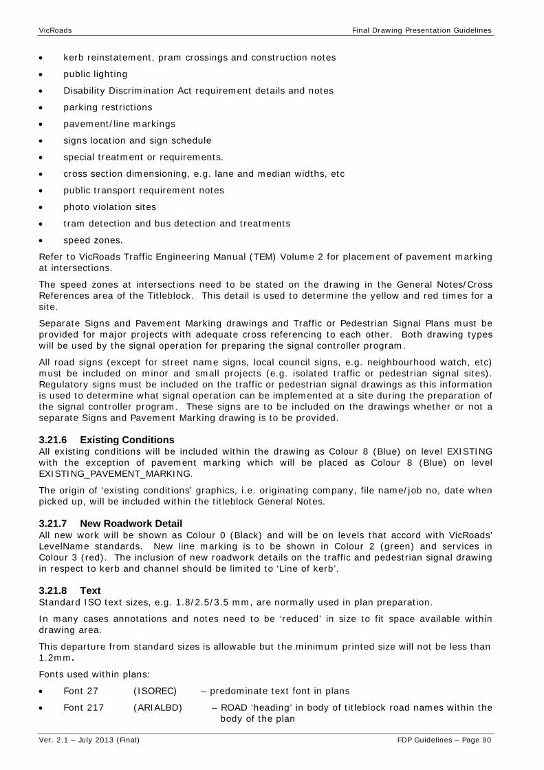
VicRoads Final Drawing Presentation Guidelines
Ver. 2.1 – July 2013 (Final) FDP Guidelines – Page 90
kerb reinstatement, pram crossings and construction notes
public lighting
Disability Discrimination Act requirement details and notes
parking restrictions
pavement/line markings
signs location and sign schedule
special treatment or requirements.
cross section dimensioning, e.g. lane and median widths, etc
public transport requirement notes
photo violation sites
tram detection and bus detection and treatments
speed zones.
Refer to VicRoads Traffic Engineering Manual (TEM) Volume 2 for placement of pavement marking at intersections.
The speed zones at intersections need to be stated on the drawing in the General Notes/Cross References area of the Titleblock. This detail is used to determine the yellow and red times for a site.
Separate Signs and Pavement Marking drawings and Traffic or Pedestrian Signal Plans must be provided for major projects with adequate cross referencing to each other. Both drawing types will be used by the signal operation for preparing the signal controller program.
All road signs (except for street name signs, local council signs, e.g. neighbourhood watch, etc) must be included on minor and small projects (e.g. isolated traffic or pedestrian signal sites). Regulatory signs must be included on the traffic or pedestrian signal drawings as this information is used to determine what signal operation can be implemented at a site during the preparation of the signal controller program. These signs are to be included on the drawings whether or not a separate Signs and Pavement Marking drawing is to be provided.
3.21.6 Existing Conditions All existing conditions will be included within the drawing as Colour 8 (Blue) on level EXISTING with the exception of pavement marking which will be placed as Colour 8 (Blue) on level EXISTING_PAVEMENT_MARKING.
The origin of ‘existing conditions’ graphics, i.e. originating company, file name/job no, date when picked up, will be included within the titleblock General Notes.
3.21.7 New Roadwork Detail All new work will be shown as Colour 0 (Black) and will be on levels that accord with VicRoads’ LevelName standards. New line marking is to be shown in Colour 2 (green) and services in Colour 3 (red). The inclusion of new roadwork details on the traffic and pedestrian signal drawing in respect to kerb and channel should be limited to ‘Line of kerb’.
3.21.8 Text Standard ISO text sizes, e.g. 1.8/2.5/3.5 mm, are normally used in plan preparation.
In many cases annotations and notes need to be ‘reduced’ in size to fit space available within drawing area.
This departure from standard sizes is allowable but the minimum printed size will not be less than 1.2mm.
Fonts used within plans:
Font 27 (ISOREC) – predominate text font in plans
Font 217 (ARIALBD) – ROAD ‘heading’ in body of titleblock road names within the body of the plan

VicRoads Final Drawing Presentation Guidelines
Ver. 2.1 – July 2013 (Final) FDP Guidelines – Page 91
TrueTypeFont (GILL SANS MT) – used/contained in a selection of Parking and Clearway ‘SIGNS’ to more closely represent ‘number styles’.
3.21.9 CADD File Requirements Format:
Bentley Systems’ MicroStation DGN is the only format accepted by VicRoads
DGNs will be created using a VicRoads MicroStation ‘seed file’.
Use of Models:
DGNs will contain a single 2D model for all plan content
only ONE plan per model/dgn
use of multiple models is NOT permitted.
Referencing:
there will be no ‘external reference files’ used with the exception of the VicRoads Corporate Titleblock.
TitleBlock:
the current VicRoads Corporate Titleblock will be attached as a reference file using appropriate/required ‘format size’ and ‘Saved View’
the titleblock will be scaled up to the relevant sheet size, e.g. 1 to 1
there are to be NO alterations made to the VicRoads Corporate Titleblock whatsoever
external provider company logos and ‘their internal file naming details’ are to be placed within the ‘master file’.
Symbology Overrides:
all elements will be placed within the DGN with defined symbology.
Symbology Overrides should not be used with the exception of the VicRoads Corporate Titleblock.
LevelName Structure:
all elements placed in master file will be located on defined VicRoads LevelNames
Linemarking:
only VicRoads Custom LineStyles are to be used.
3.21.10 Final Printed Plan Drawing set-up is considered as WYSIWYG. The pen table to be used during final plan printing = std.tbl. Pen table contains text substitutions and printer thickness controls.
3.21.11 Final Drawing Specifications Drawing specification tables include A1/A0 and A3 size final drawing output. The following table acts as a guide of contents to be included on the plan.

VicRoads Final Drawing Presentation Guidelines
Ver. 2.1 – July 2013 (Final) FDP Guidelines – Page 92
Traffic & Pedestrian Signal Plan Specifications
Description of Content Level Name CO LC WT Printed Text
Height (mm)/Font
Cell Name
All graphics representing existing conditions that were formerly sourced from a ground survey or other
EXISTING 8
varies
1
varies
1
All new Paths and DDA requirements MISC_PATH 0 0 1 various3
Any proposed drainage graphics representing pipes, etc
DRAINAGE_PIPE 3 0
Sign ‘Symbols’ and actual Sign Graphics SIGNS various3
Existing Line/Pavement Markings
EXISTING_PAVEMENT_MARKING 8 varies1
Lighting Features MISC_LIGHTING 0 1 various3
New Design ‘Line of Kerb’ KERB_LINE 0 0 2
New Proposed Line/Pavement Markings PAVEMENT_MARKING 2 varies1
Signal/Pedestrian Lanterns, Controller, Distribution Box, 'Push Buttons', etc
TRAFFIC_SIGNAL 0 1 various3
Traffic Detector Pad/Loop
TRAFFIC_DETECTION_LOOP 0 1 various3
Traffic Signal Conduits Existing EXISTING 8 2 1 various3
Traffic Signal Conduits Proposed TRAFFIC_CONDUIT 0 2 1 various3
Traffic Light Phasing Existing TRAFFIC_PHASING 8 varies 1 various3
Traffic Light Phasing Proposed TRAFFIC_PHASING 0 varies 1 various3
Lantern Schedule Existing TRAFFIC_SIGNAL 8 varies 1 various3
Lantern Schedule Proposed TRAFFIC_SIGNAL 0 varies 1 various3
Traffic Signal Pits TRAFFIC_PIT 0 varies 1 various3
Installation Notes Heading TEXT 0 0 1 Installatio
ns_Notes
Lantern Heading TRAFFIC_SIGNAL 0 0 1 Lantern
Phasing Heading TRAFFIC_PHASING 0 0 1 Phasing
Remodel Notes & Heading TEXT 0 0 1 Remodel_
Notes
Sign Schedule Heading SIGNS 0 0 1 Sign_Schedule
Pedestal Number TRAFFIC_SIGNAL 0 0 1 setout_point_in_circle_18_double3

VicRoads Final Drawing Presentation Guidelines
Ver. 2.1 – July 2013 (Final) FDP Guidelines – Page 93
Description of Content Level Name CO LC WT Printed Text
Height (mm)/Font
Cell Name
General TEXT:
General Text TEXT 0 0 1 1.8 / 27 (A3)
2.5 / 27 (A0/A1)
North Arrow north1
Reference Corner Text TEXT 0 0 2 1.8 / 27 (A3)
2.5 / 27 (A0/A1)
Property Text TEXT 0 0 2 1.8 / 27 (A3)
2.5 / 27 (A0/A1)
Road Names TEXT_ROADNAME 0 0 0 2.5 / 217 (A3)
5.0 / 217 (A0/A1)
UTILITIES
Communication Lines - Overhead
UTILITY_COMMUNICATION_OVERHEAD 3 varies4 0
Communication Lines - Underground
UTILITY_COMMUNICATION_UNDERGROUND 3 varies4 0
Existing Drainage DRAINAGE_UNDERGROUND 3 drainag
e line 0
Gas Features - Underground
UTILITY_GAS_UNDERGROUND 3 varies4 0
Gas Features - Various UTILITY_GAS 3 varies4 0
Specific notes that relate to Gas Services UTILITY_GAS_TEXT 3 0 0
1.8 / 27 (A3) 2.5 / 27 (A0/A1)
Specific notes that relate to Telecommunication Services
UTILITY_COMMUNICATION_TEXT 3 0 0
1.8 / 27 (A3) 2.5 / 27 (A0/A1)
Services Warning Sticker UTILITY_TEXT 3 0 1 warn2
Signal Hardware Note TEXT 3 0 1 TRAF_5002
Notes: 1. Refer to VicRoads Custom Linestyles.pdf – Line marking group 2. Refer to VicRoads Cell Library – Misc Stickers.cel 3. Refer to VicRoads Cell Library – TM.cel 4. Refer to VicRoads Custom Linestyles.pdf – Utilities/Services group
3.21.12 Reference File Listing
Reference Files Override Colour
Printed Colour Comments
VicRoads corporate titleblock 0 black
3.21.13 Example Drawing For an example of this type of drawing, refer to the VicRoads FDP – Example Drawings (July 2013) document:
Drawing No. 269687
Drawing No. 269687A


VicRoads Final Drawing Presentation Guidelines
Ver. 2.1 – July 2013 (Final) FDP Guidelines – Page 95
3.22 Disability Discrimination Act (DDA) Compliance Plan
3.22.1 Drawing Overview A Disability Discrimination Act (DDA) Compliance Plan drawing is typically used for the following:
the installation of Warning and Directional Tactile Ground Surface Indicators (TGSIs)
the construction of Pram Crossings and Footway Connections as specified.
The installation of Warning and Directional TGSIs and construction of Pram Crossings are to be in accordance with AS1428.
3.22.2 Scale and Presentation The Disability Discrimination Act (DDA) Compliance Plan is produced to a scale that clearly illustrates the scope of proposed works on one plan.
The sheet size and scale adopted for the Disability Discrimination Act (DDA) Compliance Plan should be drawn at A3 (1:250) or A1 (1:125) accordingly.
3.22.3 Referencing The Disability Discrimination Act (DDA) Compliance Plan will reference in the relevant Traffic Signal Plan, Alignment Plan, Signs and Line Marking or Design Plan showing the base information and services accordingly together with VicRoads Corporate TitleBlock.
Redundant level information in the base reference file is to be turned off to produce the Disability Discrimination Act (DDA) Compliance Plan base information. The Master file will be enhanced in accordance with final drawing presentation.
3.22.4 LevelName Structure All elements placed in the master file will be located on defined VicRoads LevelNames
3.22.5 Final Printed Plan Drawing set-up is considered as WYSIWYG. The pen table to be used during final plan printing = std.tbl. Pen table contains text substitutions and printer thickness controls.
3.22.6 Final Drawing Specifications The drawing specification table is based on A3 (1:250) size final drawings output. Text heights will have to be modified to accommodate alternative scales to equal final required printed text height.
Alignment Key Plan Specifications Description of Content Level Name CO LC WT
Printed Text Height
(mm)/Font Cell Name
All new Paths and DDA requirements MISC_PATH 0 0 1 various2
General Text TEXT 0 0 1 1.8 / 27 (A3)
2.5 / 27 (A0/A1)
Road Names TEXT_ROADNAMES 0 0 1 1.8/ 217 (A3)
2.5 / 217 (A0/A1)
North Point TEXT north1
Property Names TEXT 8 0 1 1.8 / 27 (A3)
2.5 / 27 (A0/A1)
Services Warning Note warn1
Signal Hardware Note TRAF_5001
Notes: 1. Refer to VicRoads Cell Library – Misc Stickers.cel 2. Refer to VicRoads Cell Library – TM.cel

VicRoads Final Drawing Presentation Guidelines
Ver. 2.1 – July 2013 (Final) FDP Guidelines – Page 96
3.22.7 Reference File Listing
Reference Files Override Colour
Printed Colour Comments
VicRoads Corporate Titleblock 0 0
Traffic Signal Plan – Base 8 8
Traffic Signal Plan – Pavement Markings 2 2
3.22.8 Example Drawing For an example of this type of drawing, refer to the VicRoads FDP – Example Drawings (July 2013) document:
Drawing No. 269689
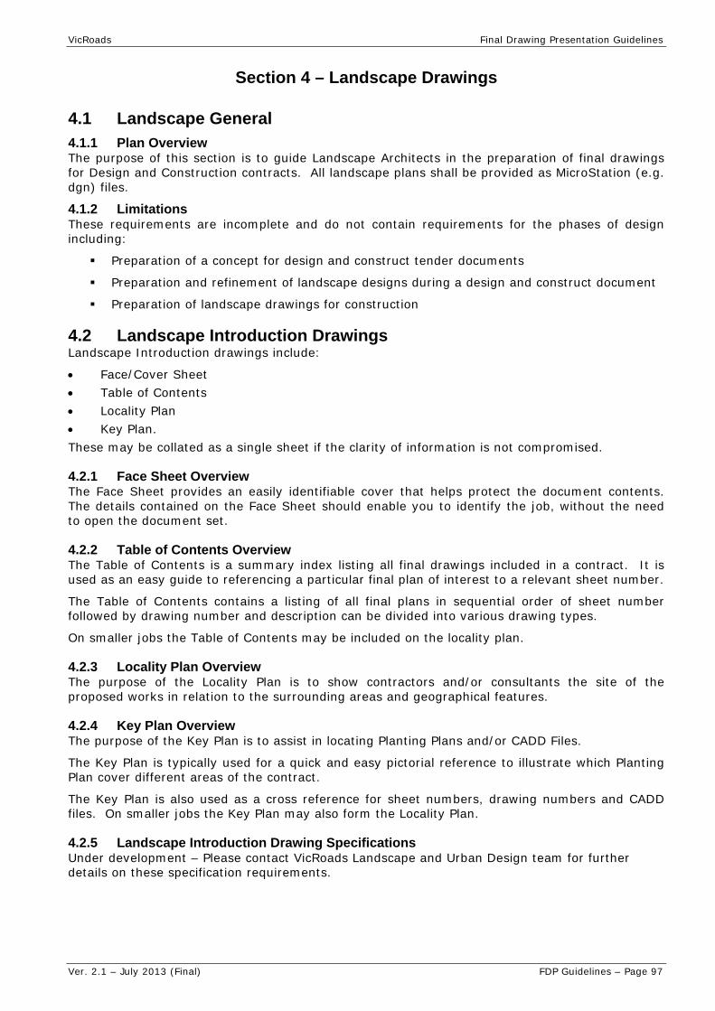
VicRoads Final Drawing Presentation Guidelines
Ver. 2.1 – July 2013 (Final) FDP Guidelines – Page 97
Section 4 – Landscape Drawings
4.1 Landscape General 4.1.1 Plan Overview The purpose of this section is to guide Landscape Architects in the preparation of final drawings for Design and Construction contracts. All landscape plans shall be provided as MicroStation (e.g. dgn) files.
4.1.2 Limitations These requirements are incomplete and do not contain requirements for the phases of design including:
Preparation of a concept for design and construct tender documents
Preparation and refinement of landscape designs during a design and construct document
Preparation of landscape drawings for construction
4.2 Landscape Introduction Drawings Landscape Introduction drawings include:
Face/Cover Sheet Table of Contents Locality Plan Key Plan. These may be collated as a single sheet if the clarity of information is not compromised.
4.2.1 Face Sheet Overview The Face Sheet provides an easily identifiable cover that helps protect the document contents. The details contained on the Face Sheet should enable you to identify the job, without the need to open the document set.
4.2.2 Table of Contents Overview The Table of Contents is a summary index listing all final drawings included in a contract. It is used as an easy guide to referencing a particular final plan of interest to a relevant sheet number.
The Table of Contents contains a listing of all final plans in sequential order of sheet number followed by drawing number and description can be divided into various drawing types.
On smaller jobs the Table of Contents may be included on the locality plan.
4.2.3 Locality Plan Overview The purpose of the Locality Plan is to show contractors and/or consultants the site of the proposed works in relation to the surrounding areas and geographical features.
4.2.4 Key Plan Overview The purpose of the Key Plan is to assist in locating Planting Plans and/or CADD Files.
The Key Plan is typically used for a quick and easy pictorial reference to illustrate which Planting Plan cover different areas of the contract.
The Key Plan is also used as a cross reference for sheet numbers, drawing numbers and CADD files. On smaller jobs the Key Plan may also form the Locality Plan.
4.2.5 Landscape Introduction Drawing Specifications Under development – Please contact VicRoads Landscape and Urban Design team for further details on these specification requirements.
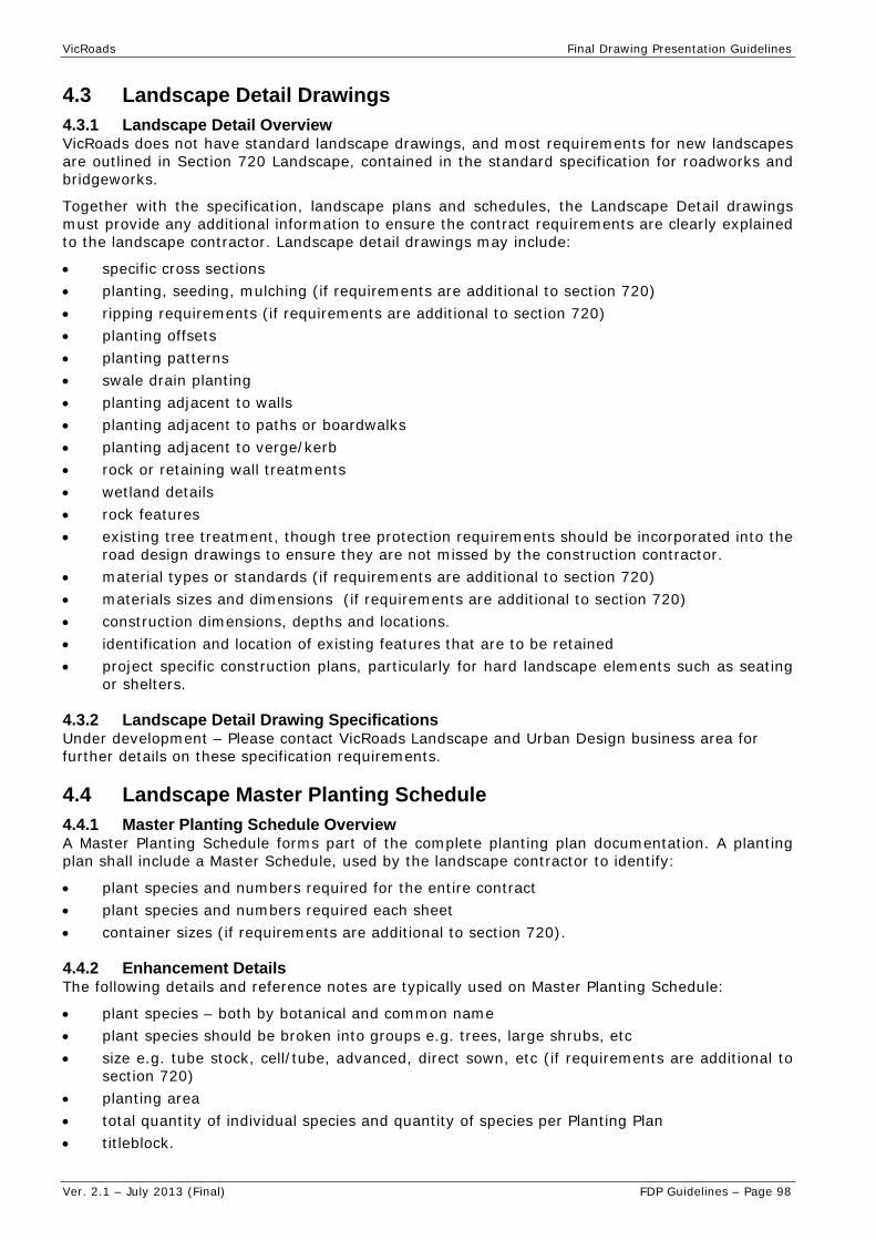
VicRoads Final Drawing Presentation Guidelines
Ver. 2.1 – July 2013 (Final) FDP Guidelines – Page 98
4.3 Landscape Detail Drawings 4.3.1 Landscape Detail Overview VicRoads does not have standard landscape drawings, and most requirements for new landscapes are outlined in Section 720 Landscape, contained in the standard specification for roadworks and bridgeworks.
Together with the specification, landscape plans and schedules, the Landscape Detail drawings must provide any additional information to ensure the contract requirements are clearly explained to the landscape contractor. Landscape detail drawings may include:
specific cross sections planting, seeding, mulching (if requirements are additional to section 720) ripping requirements (if requirements are additional to section 720) planting offsets planting patterns swale drain planting planting adjacent to walls planting adjacent to paths or boardwalks planting adjacent to verge/kerb rock or retaining wall treatments wetland details rock features existing tree treatment, though tree protection requirements should be incorporated into the
road design drawings to ensure they are not missed by the construction contractor. material types or standards (if requirements are additional to section 720) materials sizes and dimensions (if requirements are additional to section 720) construction dimensions, depths and locations. identification and location of existing features that are to be retained project specific construction plans, particularly for hard landscape elements such as seating
or shelters.
4.3.2 Landscape Detail Drawing Specifications Under development – Please contact VicRoads Landscape and Urban Design business area for further details on these specification requirements.
4.4 Landscape Master Planting Schedule 4.4.1 Master Planting Schedule Overview A Master Planting Schedule forms part of the complete planting plan documentation. A planting plan shall include a Master Schedule, used by the landscape contractor to identify:
plant species and numbers required for the entire contract plant species and numbers required each sheet container sizes (if requirements are additional to section 720).
4.4.2 Enhancement Details The following details and reference notes are typically used on Master Planting Schedule:
plant species – both by botanical and common name plant species should be broken into groups e.g. trees, large shrubs, etc size e.g. tube stock, cell/tube, advanced, direct sown, etc (if requirements are additional to
section 720) planting area total quantity of individual species and quantity of species per Planting Plan titleblock.

VicRoads Final Drawing Presentation Guidelines
Ver. 2.1 – July 2013 (Final) FDP Guidelines – Page 99
4.4.3 Sample Landscape Master Planting Schedule Please contact VicRoads Landscape and Urban Design for further information on the preparation or examples of planting schedules.
4.5 Landscape Planting Drawings and Planting Schedule 4.5.1 Plan Overview Planting Plans and Planting Schedules form part of the complete planting documentation. A planting plan should be accompanied by a planting schedule which is used by the landscape contractor for the following:
4.5.2 Planting Plan The planting plant shall include: set out of planting sites and ground preparation. Area measurements should be adjusted to
reflect slope rather than being measured as a horizontal surface. location and set out of plants and mulching street or other furniture e.g. seating, bins, shelters etc. paving, surfacing, patterning and other features such as art/sculpture identification and location of existing features that are to be retained, and new features to
be added existing vegetation to be protected or removed identification of planting requirements, through links to the planting schedule staging and extent of construction works location of landscape handwork and construction works, e.g. paves, walls, swale drains a legend for all elements. The legend may also be repeated on the planting schedule to
improve the clarity of the drawings.
4.5.3 Planting Schedule For small or simple projects, individual planting schedules may be incorporated in the master plan (i.e. avoiding the need for a planting schedule sheet for each plan sheet) or onto the planting plan itself if legibility is not compromised. The planting schedule shall include: plant species – by both botanical and common names plant species should be broken into groups e.g. trees, large shrubs, etc plant numbers per sheet, by species, by planting area, by mix type and by sheet a simple denotation if a species is indigenous to the site (and subject to genetic
requirements for indigenous plant supply) species of plants in plant mixes spacing or density of plants container sizes (if requirements are additional to section 720) area of mulch required for each planting area or planting type.
4.5.4 Reference Files and Related Information (typical) The following files are an integral part of the drawing, and are typically attached as reference files. The following information must be incorporated into plans:
Title block Road information including the alignment, chainage, road safety barriers, kerbs, shoulders,
verges, batters, lighting and cameras involved in monitoring the freeway network. Road drainage Shared paths and public transport facilities Noise Walls Landscape earth forming details Survey feature (refer to ??? for road design drawings)

VicRoads Final Drawing Presentation Guidelines
Ver. 2.1 – July 2013 (Final) FDP Guidelines – Page 100
Survey of above and below ground services (such as gas, oil, power, communications, sewerage, water, drainage)
Cadastral base and right of way information Fencing Survey photogrammetry (if available) Existing contours

VicRoads Final Drawing Presentation Guidelines
Ver. 2.1 – July 2013 (Final) FDP Guidelines – Page 101
Section 5 – Provision of “As Constructed” Drawings
5.1 As Constructed Drawing Overview The purpose of “As Constructed” drawings is to reflect the "as built" conditions including any changes made to the design during construction.
“As Constructed” drawings are required for the following reasons:
to assist in answering general public enquiries
to ensure prompt action may be taken in the event of emergencies
to provide base information for any future work
to assist staff to undertake routine maintenance.
For Records Management in accordance with the VicRoads Specification Contract documentation, Section 1130, a complete set of “As Constructed” drawings shall be supplied as per contract specification when a project is finalised. The level of detail to be shown on As-Constructed drawings shall be in accordance with VicRoads Final Drawing Presentation guidelines.
All drawings shall be provided in both hardcopy and PDF formats.
For D&C contracts PDF files provided to VicRoads for As-Constructed Drawings shall meet the following requirements:
PDF files shall be compliant with Acrobat 6 (PDF 1.5)
A list of all ‘As-Constructed’ drawings and documents shall be provided on a spreadsheet in accordance with the following requirements:
PDF/A and four hardcopy sets of all drawings (A3 size) and other documents;
a CD ROM containing a complete set of the above drawings scanned in uncompressed PDF/A format at a minimum scan resolution of 300 dots per inch and with file names corresponding to the VicRoads supplied Drawing Number with a .PDF extension;
a CD ROM containing copies of the Alignment Design Files; the Existing Ground Survey File; computer aided design drafting (CADD) drawings and associated reference files with file names corresponding to the VicRoads supplied Drawing Numbers in Bentley MicroStation DGN format.
CD ROM media shall be:
compliant with ISO9660 and in accordance with the requirements of VicRoads Final Drawing Presentation Guidelines;
include a Table of Contents (full index of all drawings and documents) file detailing the content of the CD; and
be labelled with the Contractor’s Name, Contract Number, Project Name and Description, Road Name and Section, date and description of content.
When project drawings are provide to VicRoads they should be supplied with a spreadsheet listing all drawings and the following attributes:
Attribute Name Max Field Width Field Type
VicRoads Drawing Number 7 Numeric
File name 10 Character
Revision number 1 Alpha
Description 254 Character
Drawing type 3 Character
Information about common acceptable abbreviations and terminology is provided in Appendix B.


VicRoads Final Drawing Presentation Guidelines
Ver. 2.1 – July 2013 (Final) FDP Guidelines – Page 103
Section 6 – Bridge Drawings
Section 6 - Bridge Drawings has been removed.
Refer to the Austroads Guide to Bridge Technology – Part 5 and the VicRoads Supplement to Austroads Guide to Bridge Technology – Section 4, available on VicRoads website, for details on Bridge Drawing Presentation.


VicRoads Final Drawing Presentation Guidelines
Ver. 2.1 – July 2013 (Final) FDP Guidelines – Page 105
Section 7 – VicRoads Standard Drawings (SD)
7.1 Standard Drawing (SD) Menu Detail
7.1.1 Drawing Overview A Standard Drawing (SD) provides practitioners with specific details regarding components of road constructions and associated detail, e.g. kerb, pits, guard fence & barriers, culverts, etc.
7.1.2 Scale A Standard Drawing (SD) MUST be 'Drawn to Scale' at A3 size, and that scale in millimeters (mm) or meters (m) identified on the title block.
A suitable scale needs to be selected based on the information to be placed on the drawing, e.g. 1:1000 or 1: 250, etc.
In some limited circumstances further detail may be identified and highlighted on a SD, but this must be clearly labelled with “Not to Scale” or another scale shown.
7.1.3 Presentation Options The presentation of a Standard Drawing (SD) will vary depending on the size and the complexity of the details to be drawn. Preference is given to not overcrowding a SD but splitting it into two or more SDs if required. Only similar component detail should be placed on a single separate SD.
7.1.4 Final Printed Plan A drawing is set-up for certain colours to be ‘resymbolised’ at ‘print time’. The pen table to be used during final plan printing = mono1.tbl (black & white). Pen table contains colour mapping, text substitutions and printer thickness controls.
7.1.5 Final Drawing Specifications Drawing specification table is based on A3 final size drawings output.
Must use the SD titleblock.
Standard Drawing (SD) Detail Specifications Description of Content Level Name CO LC WT
Printed Text Height
(mm)/Font Cell Name
Group Description & SD No. (Line 1)
TEXT_TITLEBLOCK 0 0 2 2.5 / 217
Detailed Description - Line 2 (& Line 3 if reqd)
TEXT_TITLEBLOCK 0 0 2 2.5 / 27
Amendments TEXT_TITLEBLOCK 2 0 1 1.8 / 27
Approved TEXT_TITLEBLOCK 2 0 1 1.8 / 27
SD Number TEXT_TITLEBLOCK 0 0 2 2.5 / 27
Scale TEXT_TITLEBLOCK 2 0 1 1.8 / 27
Issue No. TEXT_TITLEBLOCK 0 0 2 2.5 / 27
VicRoads Drawing No. TEXT_TITLEBLOCK 2 0 1 1.8 / 27
References & Notes TEXT 2 0 1 1.8 / 27
Dimensioning Text DIMENSIONING 4 0 1 1.8 / 27
Heading Text TEXT 8 0 2 2.5 / 27
General Text TEXT 3 0 1 1.8 / 27
Place Note TEXT 3 0 1 1.8 / 27
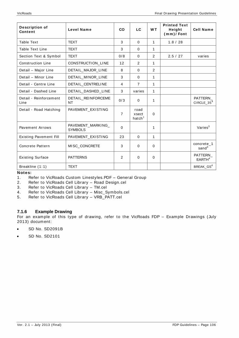
VicRoads Final Drawing Presentation Guidelines
Ver. 2.1 – July 2013 (Final) FDP Guidelines – Page 106
Description of Content Level Name CO LC WT
Printed Text Height
(mm)/Font Cell Name
Table Text TEXT 3 0 1 1.8 / 28
Table Text Line TEXT 3 0 1
Section Text & Symbol TEXT 0/8 0 2 2.5 / 27 varies
Construction Line CONSTRUCTION_LINE 12 2 1
Detail – Major Line DETAIL_MAJOR_LINE 8 0 2
Detail – Minor Line DETAIL_MINOR_LINE 3 0 1
Detail - Centre Line DETAIL_CENTRELINE 4 7 1
Detail - Dashed Line DETAIL_DASHED_LINE 3 varies 1
Detail - Reinforcement Line
DETAIL_REINFORCEMENT 0/3 0 1 PATTERN_
CIRCLE_354
Detail - Road Hatching PAVEMENT_EXISTING 7
road xsect hatch1
0
Pavement Arrows PAVEMENT_MARKING_SYMBOLS 0 1 Varies3
Existing Pavement Fill PAVEMENT_EXISTING 23 0 1
Concrete Pattern MISC_CONCRETE 3 0 0 concrete_1sand4
Existing Surface PATTERNS 2 0 0 PATTERN_EARTH4
Breakline (1:1) TEXT BREAK_GS4
Notes: 1. Refer to VicRoads Custom Linestyles.PDF – General Group 2. Refer to VicRoads Cell Library – Road Design.cel 3. Refer to VicRoads Cell Library – TM.cel 4. Refer to VicRoads Cell Library – Misc_Symbols.cel 5. Refer to VicRoads Cell Library – VRB_PATT.cel
7.1.6 Example Drawing For an example of this type of drawing, refer to the VicRoads FDP – Example Drawings (July 2013) document:
SD No. SD2091B
SD No. SD2101

VicRoads Final Drawing Presentation Guidelines
Ver. 2.1 – July 2013 (Final) FDP Guidelines – Page 107
7.2 Updating VicRoads Standard Drawings – Works Instruction
7.2.1 Overview Standard Drawings (SD) are reviewed and updated as necessary to ensure the content is current. Typical modifications include comment from industry and general referenced information, such as Australian Standards, other SD, VR Specifications, VicRoads logo and or title block changes.
A number of tools have been developed to help maintain consistency when updating SD:
A SD CADD menu is available Works instructions to assist in locating source files and workflow
7.2.2 Purpose The purpose of this works instruction is to:
Outline the workflow to be undertaken when updating a VicRoads Standard Drawing Assist in initiating new SD and the naming and saving to the correct location.
7.2.3 Instructions (for external users obtain relevant file/s from VicRoads) 1 New Standard Drawing (SD):
All new SD should be drawn from scratch. Do not copy old SD into a new file as the level, colour, line styles and scale will not comply with the current standards.
1.1. Find the location for SD in ProjectWise ® and locate the appropriate sub-folder.
pw:\\VRPCADCAM03.roads.vic.gov.au:cad_edms\Documents\VICROADS_DOC\RS&T\Standard Drawings for Roadworks\Std Drawings\[sub-folder] (Internal only).
1.2. The SD must be produced in a 2D file created using the SD specific seed file. pw:\\VRPCADCAM03.roads.vic.gov.au:cad_edms\Documents\VICROADS_DOC\AAA_CADD_Config\SEED_FULL_LEVELNAMES\StandardDrawingSeed_2D (Internal only).
2 Saving:
2.1. New SD will be assigned a SD number and a VicRoads Drawing number.
2.2. All modifications to compiled SD are modified with a version letter. If the existing SD has a version letter, the modified file is saved with the next version letter. (ProjectWise ® version control retains a copy of the previous file.)
3 Drawing:
3.1. The content of the SD shall be drawn to scale at 1 to 1.
3.2. The SD title block shall be referenced into the SD file at an appropriate scale.
pw:\\VRPCADCAM03.roads.vic.gov.au:cad_edms\Documents\VICROADS_DOC\AAA_CADD_Config\REF\Stdtb1.dgn (Internal only).
3.3. Where additional clarity is required, specific detail from the 1 to 1 drawing can be referenced in at a smaller scale.
3.4. All dimensions and text shall be placed at the title block scale.
3.5. The SD tag set shall be used to populate the Title Sheet data.
Notes Do not use models within standard drawings.
Standard drawings must be readable when printed at A3.
SD - drawing numbers have been pre allocated; they are locked in ProjectWise ®.
VicRoads Drawing No’s. VicRoads Drawing No’s are only to be added after the SD has received final approval and a signature applied.


VicRoads Final Drawing Presentation Guidelines
Ver. 2.1 – July 2013 (Final) FDP Guidelines – Page 109
Appendix A – VicRoads Custom Linestyles

Boundary Fence
Open Concrete Drain
Design Line
Trans Drain Slotted
Corr Pipe Pave Drn
Smooth Pipe Pave Drn
Catch Drain Grassed
Catch Drain Thatched
Catch Drain Beached
Drainage Pipe 1m
Drainage Pipe 1.5m
Road Xsect Hatch
Road Xsect Shape
Gas Line
Sewerage
Telecom Line
Electricity Overhead
Guard Rail
Guard Fence
Gas Below Ground
Electricity Below Ground
Sewerage Below Ground
PM&RM Connection
Crown Boundary
Parish Boundary
Lot Boundary
Traverse Line
Rd Align Not Surveyed
Fence
Brick Above
Brick Below
Township Boundary
County Boundary
Municipal Boundary
Kerb Lined
Forest Boundary
Kerb
National Park Boundary
Vegn Grp Trees/Shrubs
Plantation Orchard
Boundary Line
Corr Pipe Trans Drn
(VicRoads Gas Line)
(VicRoads Sewerage Line)
(VicRoads Telecom Line)
(VicRoads Water Above Ground)
(VicRoads Electricity Line - Overhead)
(VicRoads Guard Rail)
(VicRoads Gas Below Ground)
(VicRoads Electricity Below Ground)
(VicRoads Telecom Below Ground)
(VicRoads Sewerage Below Ground)
(VicRoads Water Below Ground)
(VicRoads Boundary Fence)
(VicRoads Guard Fence)
(VicRoads Open Concrete Drain)
(VicRoads Design Line)
(VicRoads Corr Pipe Transverse Drain)
(Smooth Transverse Drain Not Perforated)
(VicRoads Corrugated Pipe Pave’t drain)
(VicRoads Smooth Pipe Pave’t Drain)
(VicRoads Catch Drain Beached)
(VicRoads Drainage Pipe up to 1m Dia)
(VicRoads Drainage Pipe 1 to 1.5m dia)
(VIc Roads Road Cross Section Hatching 1mm)
(VicRoads Road Cross Section Shape 1mm)
(VicRoads PM & RM Connection (CS))
(VicRoads Easement and Road C’tion (CS))
(VicRoads County Boundary (CS))
(VicRoads Parish Boundary (CS))
(VicRoads Lot Boundary (CS))
(VicRoads Traverse Line (CS))
(VicRoads Road Align’t NOT Surveyed (CS))
(VicRoads Fence (CS))
(VicRoads Brick Above (CS))
(VicRoads Brick Below (CS))
(VicRoads Township Boundary (CS))
(VicRoads Municipal Boundary (CS))
(VicRoads Kerb - Top or Back of Kerb (CS))
(VicRoads Kerb Lined (CS))
(VicRoads Forest Boundary (CS))
(VicRoads National Park Boundary (CS))
(VicRoads Plantation Orchard (ES))
(VicRoads Veg’n Group Trees/Shrubs (ES))
(VicRoads Boundary Line (ES))
(VicRoads Catch Drain Grassed)
(VicRoads Catch Drain Thatched)
Drainage Line (VicRoads Drainage Line)
E’ment & Road Conn
Abandoned Service
Railway - Abandoned Track
Railway - Multi Track
Railway - Single Track
Oil Above Ground
Oil Below Ground
Wire Rope Safety Barrier
Crown Section Boundary
(VicRoads Abandoned Service)
(VicRoads Oil Above Ground)
(Vicroads Oil Below Ground)
(VicRoads Wire Rope)
(VicRoads Smooth Transverse Drain - Slotted)
(VicRoads Railway - Abandoned)
(VicRoads Railway - Multi Track)
(VicRoads Railway - Single Track)
CUSTOM LINESTYLES AT 1 :1000 (vr_lines_v8.rsc)
Page 1 of 3
Vic
Roads_
Custo
m_
Line_Styles.d
gn
3/08/2011
9:4
3:4
9
AM
Engineering Survey and
Photogrammetry
Fence on Freeway (VicRoads Fence on Freeway Boundary (CS))
(VicRoads Fence on Title Boundary (CS))
Cadastral LinetypesUtilities/ServicesGeneral
Drainage
(VicRoads Crown Allotment Boundary (CS))
(VicRoads Crown Section Boundary (CS))
Kerb and Channel (VicRoads Kerb - Top or Back of Kerb (CS))*
Trans Drain Not Perf
**
**
Fence on Title
Fence on Title - Solid (VicRoads Fence on Title (Solid) Boundary (CS))
As At : 1st June 2010
* No longer used
** Superceded by ’Fence on Title - Solid’
Telecom Below Ground
Water Above Ground
Water Below Ground

Std Lane 100 wide
Std Cont 100 wide
Rev Sep 100 wide
Part Time Bus/Trans
Fwy & Spec use lane
Statcon
Roundabout
Oneway 12 Bkn Lane
Oneway 24 Bkn Lane
Oneway Rev 12 RRPM
Oneway Rev 24 RRPM
Twoway 12 Bkn Sep RRPM
Twoway 24 Bkn Sep RRPM
Oneway 6 RRPM
Oneway 12 RRPM
Oneway 20 RRPM
Oneway 24 RRPM
Twoway 6 RRPM
Twoway 12 RRPM
Twoway 24 RRPM
Fwy 12 lane on ramps
Fwy 20 lane thru carr
Std tram lane line
Sep Bars Type A
Sep Bars Type B
Full Time Tram lane
Oneway 40 RRPM
Oneway 48 RRPM
Twoway 48 RRPM
Barrier-Single Separation-100
Barrier-Single Separation-150
Controlled Intersection-Stop
Edge Line-Normal/Parking Control
Pedestrian Crossing-Zebra
Rail Crossing-Give Way
Turn Line-Solid
CUSTOM LINESTYLES AT 1 :1000 (vr_lmark_v8.rsc)
Page 2 of 3
Barrier-Two Way
Barrier-One Way
Continuity-Freeway and Special
Continuity-Standard
Continuity-Statcon
Controlled Intersection-Give Way
Controlled Intersection-R’about
Vic
Roads_
Custo
m_
Line_Styles.d
gn
3/08/20119:4
3:5
2
AM
Edge-One Way 7m RRPM
Edge-One Way 6m RRPM
Edge-One Way 12m RRPM
Edge-One Way 20m RRPM
Edge-One Way 24m RRPM
Edge-One Way 40m RRPM
Edge-One Way 48m RRPM
Barrier-One Way 12m RRPM
Barrier-One Way 24m RRPM
Barrier-Two Way 12m RRPM
Barrier-Two Way 24m RRPM
Edge-Profiled
Stop Line (VicRoads 600 Wide Solid)
(VicRoads 100 Wide-Solid-Twoway 12m RRPM)
(VicRoads 100 Wide 3m/9m Twoway 12m RRPM)
Tram-Full Time-One Way 4m RRPM (VicRoads Tram-Full Time-Oneway 4m RRPM)
Tram-Part Time (VicRoads 100 Wide Solid)
Tram-Part Time-Broken (VicRoads 100 Wide 6m/6m)
(VicRoads 100 Wide Solid)
(VicRoads 100 Wide 0.6m/0.6m)Turn Line-Broken
Edge-One Way 6m RRPM (RHS)
Edge-One Way 7m RRPM (RHS)
Edge-One Way 12m RRPM (RHS)
Edge-One Way 20m RRPM (RHS)
Edge-One Way 24m RRPM (RHS)
Edge-One Way 40m RRPM (RHS)
Edge-One Way 48m RRPM (RHS)
Edge-150 Wide (VicRoads 150 Wide Solid)
(VicRoads 100 Wide Solid)
(VicRoads 150 Wide Solid for Oneway 6m RRPM)
(VicRoads 150 Wide Solid for Oneway 7m RRPM)
(VicRoads 150 Wide Solid for Oneway 12m RRPM)
(VicRoads 150 Wide Solid for Oneway 20m RRPM)
(VicRoads 150 Wide Solid for Oneway 24m RRPM)
(VicRoads 150 Wide Solid for Oneway 40m RRPM)
(VicRoads 150 Wide Solid for Oneway 48m RRPM)
(VicRoads 150 Wide Solid for Oneway 12m RRPM)
Separation-2Way 12m RRPM
Separation-2Way 24m RRPM
Separation-Two Lane Two Way
Separation-Reversible
Separation-Special Use-100
Separation-Special Use-150
Pedestrian Crosswalk
Lane-Continuous-Arterial/Local
Lane-Continuous-Fwy/Commuter
Lane-Special-100 Roundabout
Lane-Special-150 Roundabout
Lane-Standard
Lane-OneWay 6m RRPM
Lane-OneWay 12m RRPM-Urban Ramp
Lane-OneWay 12m RRPM-MedianTurn
Lane-OneWay 20m RRPM
Lane-OneWay 24m RRPM
Lane-OneWay 12m RRPM-Entry/Exit
Lane-OneWay 12m RRPM-Turn
Lane-OneWay 12m RRPM-Rural Ramp
(VicRoads 300 Wide Solid)
(VicRoads 400 Wide 0.6m/0.6m)
(VicRoads 300 Wide 0.6m/0.6m)
(VicRoads 150 Wide 0.6m/0.6m)
(VicRoads 150 Wide 1m/3m)
(VicRoads 100 Wide 1m/3m)
(VicRoads Barrier-Twoway-Twoway 24m RRPM)
(VicRoads Barrier-Twoway-Twoway 12m RRPM)
(VicRoads 100 Wide Solid + 100 Wide 3m/9m)
(VicRoads 2 x 100 Wide Solid)
(VicRoads 100 Wide Solid)
(VicRoads 150 Wide Solid)
(VicRoads Barrier-Combination 12m RRPM)
(VicRoads Barrier-Combination 24m RRPM)
(VicRoads Ped Crossing-Zebra)
(VicRoads 150 Wide Solid)
(VicRoads 100 Wide 6m/6m)
(VicRoads 100 Wide 9m/1m)
(VicRoads 150 Wide 9m/3m)
(VicRoads 600 Wide 0.6m/0.6m)
(VicRoads 100 Wide 3m/9m)
(VicRoads 100 Wide 3m/9m 24m Twoway RRPM)
(VicRoads 100 Wide-Solid-Twoway 24m RRPM)Separation-2Way 24m RRPM-Solid
Separation-2Way 12m RRPM-Solid
(VicRoads Twoway 24 Bkn Sep RRPM)
(VicRoads Twoway 48 RRPM)
Line Marking (Superseded)- pre Feb 2004
Barrier-Single Separation-100 12m RRPM
Barrier-Single Separation-100 6m RRPM
Barrier-Single Separation-100 24m RRPM
(VicRoads Barrier - Single Separation 6m Twoway RRPM)
(VicRoads Barrier - Single Separation 12m Twoway RRPM)
(VicRoads Barrier - Single Separation 24m Twoway RRPM)
Lane-OneWay 6m RRPM (RHS)
(VicRoads 150 Wide Solid)
(VicRoads 100 Wide Solid)
(VicRoads 100 Wide Solid Oneway 6m RRPM)
(VicRoads 100 Wide 3m/9m 12m Oneway RRPM)
(VicRoads 100 Wide Solid Oneway 12m RRPM)
(VicRoads 150 Wide Solid for Oneway 12m RRPM)
(VicRoads Twoway Median Turn)
(VicRoads Oneway 12m RRPM with Dots)
(VicRoads Oneway 20m RRPM with Dots)
(VicRoads 100 Wide 3m/9m 24m Oneway RRPM)
(VicRoads 100 Wide 9m/3m)
(VicRoads 150 Wide 9m/3m)
(VicRoads 100 Wide 3m/9m)
(VicRoads Std Lane Line 100mm wide)
(VicRoads Std Cont Line 100mm wide)
(VicRoads Rev Separatn Line 100 wide)
(VicRoads Part-Time Bus/Trans lane 150 wide)
(VicRoads Fwy & Special use cont lane 150wide)
(VicRoads Statcon cont line 300x600x600)
(VicRoads Roundabout 400x600x600)
(VicRoads Oneway 12 RRPM Broken lane line)
(VicRoads Oneway 24 RRPM broken lane)
(VicRoads Oneway Rev 12 RRPM lane)
(VicRoads Oneway Rev 24 RRPM lane)
(VicRoads Twoway 12 Bkn Sep RRPM)
(VicRoads Oneway 6 RRPM)
(VicRoads Oneway 12 RRPM)
(VicRoads Oneway 20 RRPM Fwy)
(VicRoads Oneway 24 RRPM Fwy)
(VicRoads Oneway 40 RRPM)
(VicRoads Oneway 48 RRPM)
(VicRoads Twoway 6 RRPM Fwy)
(VicRoads Twoway 12 RRPM Fwy)
(VicRoads Twoway 24 RRPM Fwy)
(VicRoads Fwy 12 lane on ramps)
(VicRoads Fwy 20 lane thru carriage)
(VicRoads Std Tram lane Line)
(VicRoads Sep Bars Type A at 4m CRS)
(VicRoads Sep Bars type B at 4m CRS)
(VicRoads Full Time Tram lane line)
Separation-Special Use-80 (VicRoads 80 Wide 1m/7m)
Barrier-Single Separation-80 (VicRoads 80 Wide Solid)
Line Marking
(VicRoads 100 Wide 1m/2m)Lane-Special-100 Bicycle(Indicative use - Gaps vary) (Indicative use - Gaps vary)
As At : 1st June 2010
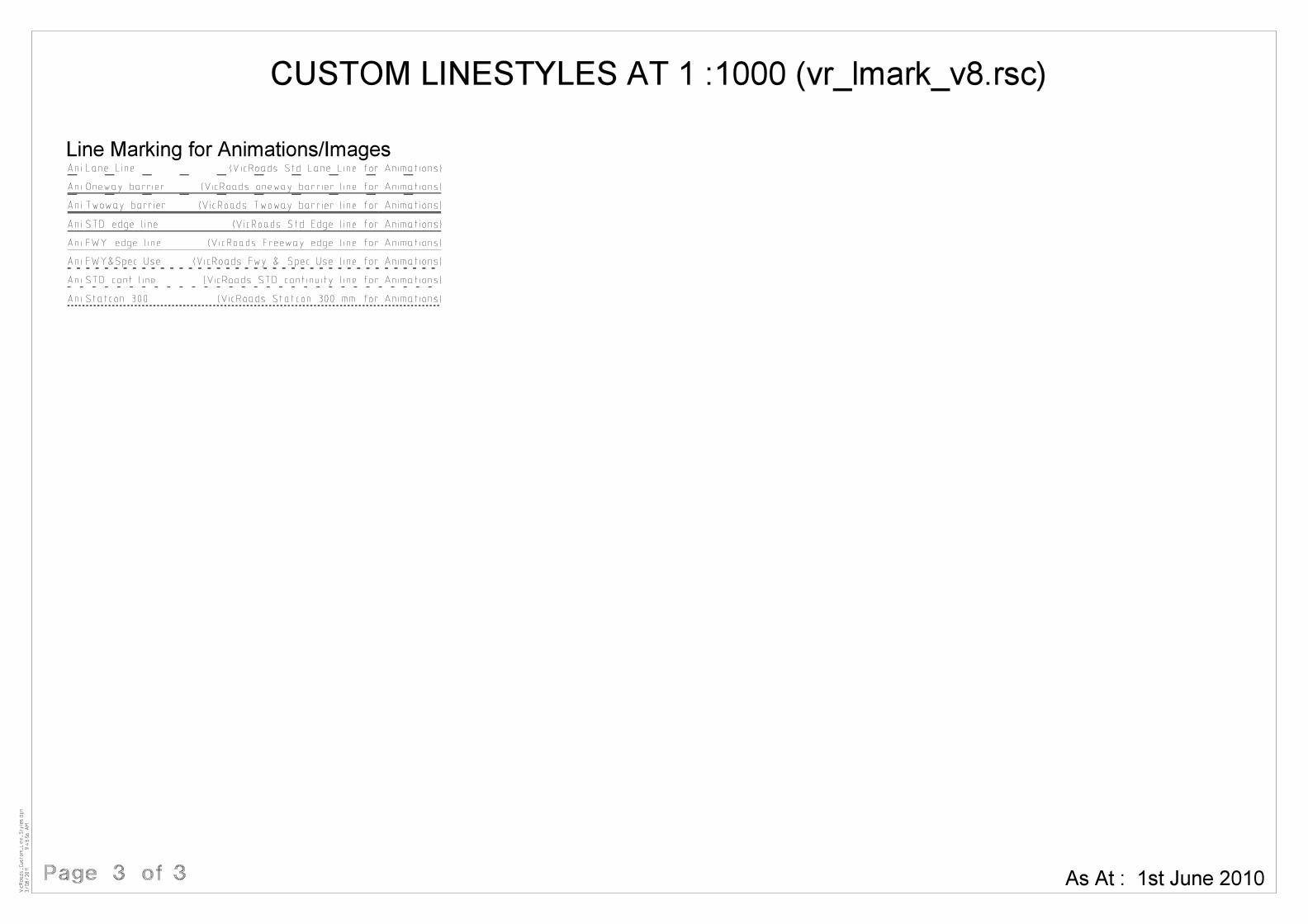
Ani Oneway barrier
Ani Twoway barrier
Ani STD edge line
Ani FWY edge line
Ani Lane Line (VicRoads Std Lane Line for Animations)
(VicRoads oneway barrier line for Animations)
(VicRoads Twoway barrier line for Animations)
(VicRoads Std Edge line for Animations)
(VicRoads Freeway edge line for Animations)
Line Marking for Animations/Images
Ani STD cont line
(VicRoads Fwy & Spec Use line for Animations)
(VicRoads STD continuity line for Animations)
(VicRoads Statcon 300 mm for Animations)Ani Statcon 300
Ani FWY&Spec Use
CUSTOM LINESTYLES AT 1 :1000 (vr_lmark_v8.rsc)
Page 3 of 3
3/08/2011
9:4
3:5
6
AM
Vic
Roads_
Custo
m_
Line_Styles.d
gn
As At : 1st June 2010

VicRoads Final Drawing Presentation Guidelines
Ver. 2.1 – July 2013 (Final) FDP Guidelines – Page 113
Appendix B – File Types & Abbreviations
The following is a list of common File Types and standard terminology abbreviations that may be used in VicRoads Drawings.
Note: Some historical abbreviations are still in use. This has resulted in a duplication of abbreviations in some cases for differing terms. If it is unclear which term is being referred to, the term should be written in full or placed in a note on the drawing.
File Types Term Abbreviation Term Abbreviation
3D Line Strings 3DS Abstract of Field Records FR Abutment AB Abutment Concrete ABC Abutment Reinforcement ABR Acquisition/Disposal SP Alignment & DL ADL Alignment Plan AP Alignments and Geometrics AG Approach Slabs AS Architectural Drawing AD Arterial Road Strategy ARS Barriers BAR Base (not TSL, study areas, etc) BAS Bearing Plate/Bearing BE Bicycle Facility Plan BFP Bike Path/Shared User Path BFP Bridge Detail Drawing BDD Bridge Preliminary Drawing BPD Bridge Site Plan BSP Bridge Standard Drawing BSD Building Detail Plan BDP Cadastral Base CB Collision Diagram COL Concept Plan CPS Construction Set Out SO Construction Standards DES Contour Plan CP Contours and Drainage CD Contract Specific CON Control Survey CS Cross Sections CS Culvert CUL D&C Documentation DCD DDA Compliance Plan DDA Deck Overlay OV Declaration Survey DP Design and Construction Standards DES Design Information DI Detail Plan DP Display Plan DSP Drainage Alignments & Longitudinals ADL Drainage Longitudinal DL Electrical Drawing E
Endpost EP External Computer Files EXT Face Sheet FS Fauna Crossing FX Feature Survey FS Feature Survey Enhancement ES Final Plan FP Foundation Layout FL Freeway Ramp Signals FRS Functional Design FD Functional Layout FD Gazettal GP General Arrangement GA Geometric Plan GP Geometry File ALG Geotechnical Drawing GTD Image Backgrounds and Mosaics IMG Incident Management IM InRoads Roadway Libraries RWL InRoads Storm & Sanitary Database SDB InRoads Template Libraries TML Key Plan KP Land Acquisition LA Landscape Assessment Plan LAP Landscape Concept Plan LCP Linemarking Plan LMP Lip Profiles LIP List of Abbreviations LOA Locality and Face Sheet LFS Locality Plan LP Longitudinal Section LS Master Schedule MS Melbourne Road Network MRN Ministerial Approval MA Miscellaneous Drawing MD Miscellaneous (LI&S) MS Monitoring MN Noise Attenuation NA Organisation Chart OC Overlay OV Pavement Details PD Pavement Type Limits Plan PTL Pedestrian Crossing PX Pedestrian Operated Signals POS

VicRoads Final Drawing Presentation Guidelines
Ver. 2.1 – July 2013 (Final) FDP Guidelines – Page 114
Permanent Mark Sketch PM Phase Selection Diagram PSD Photogrammetry PH Photogrammetry Base Information PBI Pier PI Pile PIL Planning Report PR Planning Scheme / Amendment PA / PSA Planting Plan PP Planting Schedule PS PRC Documentation PRC Preliminary Alignment PA Program Plan PRP Project Plan Set Book PBK Quantities Q Railing RA Record of Reestablishment RE Reference File RF Reinforced Concrete Pile RCP Reinforcement Standards and Shapes SS1 Report RPT Right of Way (ROW) Plan RP Roundabout RBT Route Control Strategy RCS Safe Maintenance Review SMR Services Plan - Exist and New SER Set Out Detail SOD Sign Face Drawing SFD Signs and Gantry SIG Signs and Linemarking Plan SLP Special Drawing SPD Standard Drawings STD Street Lighting Plan SLT Subdivision Act - Plan of Consolidation PC Subdivision Act - Plan of Easement CE Subdivision Act - Plan of Subdivision PS Subsurface Drainage SSD Superelevation Diagram SD Superstructure SST Surface SRF Survey Information SI Table of Contents TOC TCS & Pavement Details TPD Tender Verification TV Test Site Location Plan TLP Test Site Locations - Longitudinal TLL Title Plan TP Traffic Management Plan TMP Traffic Signal Plan TSP Traffic Studies TS Traffic Survey Data Drawing TSD Tram/Bus Route Treatment TBR Tslab Mk A TSA Tslab Mk B TSB Tslab Reinforcement TSR Typical Cross Section TCS
Typical Cross Sections & Pavement Details TPD Unknown Type UNK User Drawing Set UDS Vegetation - Tree and Lower Storey VEG Weed Management WM Wetlands and Drainage LWT Wingwall WW
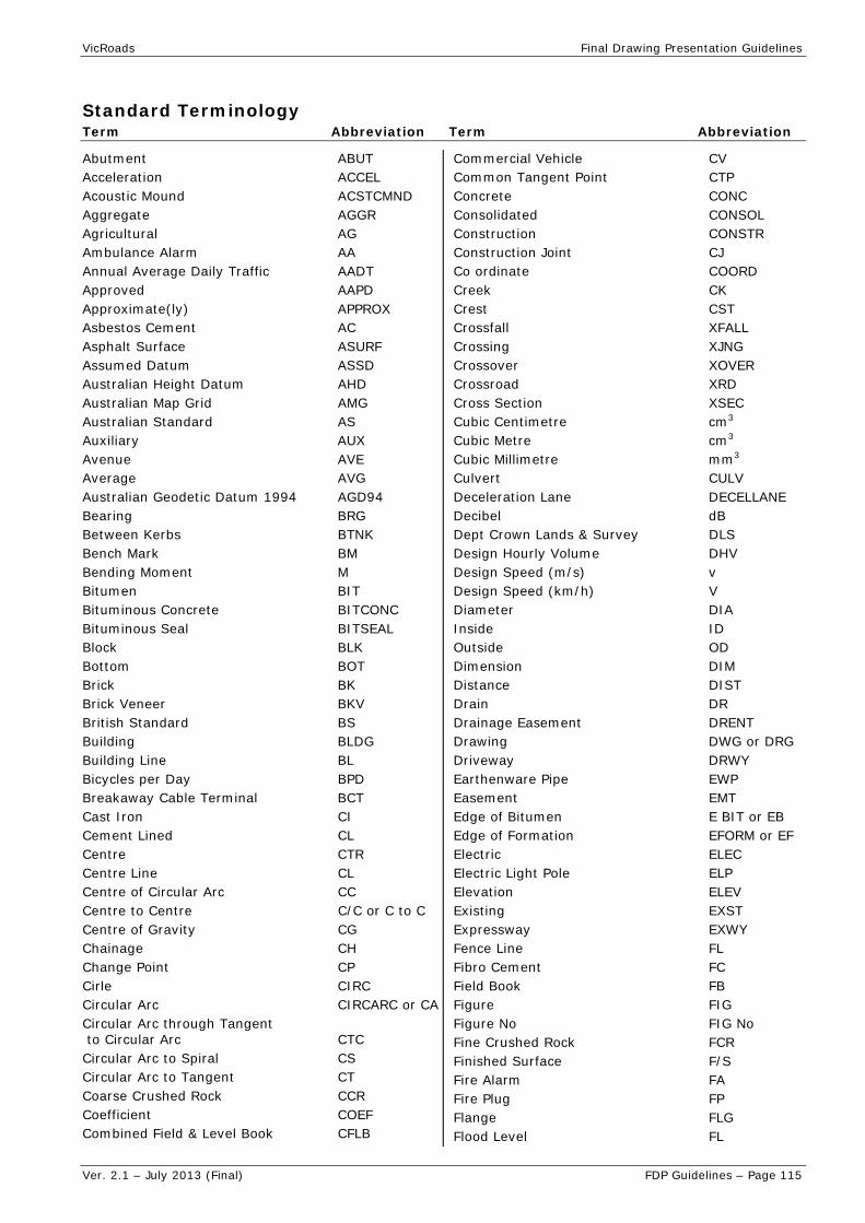
VicRoads Final Drawing Presentation Guidelines
Ver. 2.1 – July 2013 (Final) FDP Guidelines – Page 115
Standard Terminology Term Abbreviation Term Abbreviation
Abutment ABUT Acceleration ACCEL Acoustic Mound ACSTCMND Aggregate AGGR Agricultural AG Ambulance Alarm AA Annual Average Daily Traffic AADT Approved AAPD Approximate(ly) APPROX Asbestos Cement AC Asphalt Surface ASURF Assumed Datum ASSD Australian Height Datum AHD Australian Map Grid AMG Australian Standard AS Auxiliary AUX Avenue AVE Average AVG Australian Geodetic Datum 1994 AGD94 Bearing BRG Between Kerbs BTNK Bench Mark BM Bending Moment M Bitumen BIT Bituminous Concrete BITCONC Bituminous Seal BITSEAL Block BLK Bottom BOT Brick BK Brick Veneer BKV British Standard BS Building BLDG Building Line BL Bicycles per Day BPD Breakaway Cable Terminal BCT Cast Iron CI Cement Lined CL Centre CTR Centre Line CL Centre of Circular Arc CC Centre to Centre C/C or C to C Centre of Gravity CG Chainage CH Change Point CP Cirle CIRC Circular Arc CIRCARC or CA Circular Arc through Tangent to Circular Arc CTC Circular Arc to Spiral CS Circular Arc to Tangent CT Coarse Crushed Rock CCR Coefficient COEF Combined Field & Level Book CFLB
Commercial Vehicle CV Common Tangent Point CTP Concrete CONC Consolidated CONSOL Construction CONSTR Construction Joint CJ Co ordinate COORD Creek CK Crest CST Crossfall XFALL Crossing XJNG Crossover XOVER Crossroad XRD Cross Section XSEC Cubic Centimetre cm3 Cubic Metre cm3 Cubic Millimetre mm3 Culvert CULV Deceleration Lane DECELLANE Decibel dB Dept Crown Lands & Survey DLS Design Hourly Volume DHV Design Speed (m/s) v Design Speed (km/h) V Diameter DIA Inside ID Outside OD Dimension DIM Distance DIST Drain DR Drainage Easement DRENT Drawing DWG or DRG Driveway DRWY Earthenware Pipe EWP Easement EMT Edge of Bitumen E BIT or EB Edge of Formation EFORM or EF Electric ELEC Electric Light Pole ELP Elevation ELEV Existing EXST Expressway EXWY Fence Line FL Fibro Cement FC Field Book FB Figure FIG Figure No FIG No Fine Crushed Rock FCR Finished Surface F/S Fire Alarm FA Fire Plug FP Flange FLG Flood Level FL

VicRoads Final Drawing Presentation Guidelines
Ver. 2.1 – July 2013 (Final) FDP Guidelines – Page 116
Footpath F/P Freeway FWY Full Supply Level FSL Galvanise (d) GALV Galvanised Iron GALVI or GI Gram g Grid GD Ground Level GL Guard Rail GR Guide Post Widening GPW Heavy Duty HD Hectare ha Height HT or HGT High Pressure HP High Tensile Steel HTS High Voltage HV Highway HWY High Water Mark HWM Horizontal HORIZ Hour h Initial Treatment Prime & Seal ITPS Irrigation IRR Inspection Opening 10 Intermediate INTER Internal INT International System of Unit SI Intersection Point IP Invert INV Invert Level IL Junction Pit JP Kerb K Kerb and Channel KC Kerb Line K/L Kerb Dried KD No Kilogram kg Kilometre km Kilometre per Hour km/h Kilopascal kPa Kilovolt kV Landing LDG Left Hand / Left Hand Side LH / LHS Length LG Level LEV Level Book LB Level Crossing LXING Linear LIN Liquefied Petroleum LPET Litre L Lodged Plan LP Longitudinal LONG Low Point LP Low Pressure LP Low Voltage LV Low Water Mark LWM Manhole MH Map Grid Australia MGA Material MATL
Maximum MAXL Mean Sea Level MSL Mega Pascal MPa Metre m Mild Steel MS Millilitre ml Millimetre mm Minimum MIN Miscellaneous MISC Mounting MTG Municipal MUN Natural Surface NS Negative NEG New Peg & Trench NPT Nominal Size NS Not to Scale NTS Number No New Jersey NJ Obvert OBV Old Peg & Trench OPT Outside Diameter OD Overall OA Overhead OH Pavement PAVT Pedestrian/Crossing PED/XING Permanent PERM Permanent Survey Marking PSM Pillar Hydrant PH Plate PL Post & Rail P&R Post & Wire P&W Quantity QTY Radian Rad Radius RAD Railway RLY Reduced Level RL Reference REF Reference Mark RM Reference Peg RP Reinforced (-ing) REINF Reinforced Concrete RC Reinforced Concrete Box RCBOX Reinforced Concrete Pipe RCP Required REQD Reserve (d) RES Right / Right Hand Side R / RHS Right of Way ROW River RIV Road RD Schedule SCHED Secant Distance S Section SECT Service Road SERVRD Sewer SEW Sewerage & Drainage Easement SEW & DR EMT Shift Distance P Shoulder SHLD

VicRoads Final Drawing Presentation Guidelines
Ver. 2.1 – July 2013 (Final) FDP Guidelines – Page 117
Side Entry Pit SEP Specification SPEC Spiral to Circular Arc SC Spiral through Tangent to Circle STC Spiral through Tangent to Spiral STS Square Centimetre cm2 Square Kilometre km2 Square Metre m2 Square millimetre mm2 Stabilised STAB Stadia Book SB Standard STD Station STA Steel STL Stop Valve SV Street ST Structure STR Subdivision SUBDIV Surface (ing) SURF Survey Plan SP Tangent Distance T Tangent to Circular Arc TC Tangent Point TP Tangent to Spiral TS Temporary Bench Mark TBM Tonne t Transition TRAN Traverse TRAV Trigonometric Meridian TRIG MER Trigonometric Station TRIG STA True Meridian TRUE MER Typical TYP Underground UG Vehicles per Day/per Hour VPD / VPH Vertical VERT Vertical Curve VC Volume VOL Waterhole WH Water Level WL Weatherboard WB Weight WT Wide (Width)/ing W Wire (s) WI
Related Documents


