Vickers ® 3-Way Cartridge Valves with Spool Position Feedback Type CVU-**-EPQ; Sizes 32 and 50 Flow Rates up to 750 L/min (200 USgpm) Maximum Pressure: 315 bar (4500 psi) This product has been designed and tested to meet specific standards outlined in the European Electromagnetic Compatibility Dir ective (EMC) 89/336/EEC, amended by 91/263/EEC, 92/31/EEC and 93/68/EEC, article 5. For instructions on installation requirements to achieve effective p rotection levels, see this leaflet and the Installation Wiring Practices for Vickers ® Electronic Products leaflet 2468. Wiring practices relevant to this Directive are indicated by Electromagnetic Compatibility (EMC).

Welcome message from author
This document is posted to help you gain knowledge. Please leave a comment to let me know what you think about it! Share it to your friends and learn new things together.
Transcript

Vickers ®
3-Way Cartridge Valves with Spool Position Feedback
Type CVU-**-EPQ; Sizes 32 and 50Flow Rates up to 750 L/min (200 USgpm)Maximum Pressure: 315 bar (4500 psi)
This product has been designed and tested to meet speci�c standards outlined in the European Electromagnetic Compatibility Directive (EMC) 89/336/EEC,amended by 91/263/EEC, 92/31/EEC and 93/68/EEC, article 5. For instructions on installation requirements to achieve e�ective protection levels, see thislea�et and the Installation Wiring Practices for Vickers® Electronic Products lea�et 2468. Wiring practices relevant to this Directive are indicated by Electromagnetic Compatibility (EMC).
3-Way Cartridge Valves with Spool Position Feedback
2
Contents
General Description and Functional Symbols Page 3System Components for Flow Control Mode Page 4System Components for p/Q Mode Page 4
Model Codes: CVU-**-EPQ Cartridge valve and KBSDG4V-3...EN83 pilot valve Page 5
CVU-**-EPQ Cartridge Valve:Operating Data Page 6Performance Data:
Pressure Gain and Signal/Flow Rate function Page 7Frequency Response Page 8
Installation Dimensions Page 9
Pocket Machining details for CVU-32-EPQ1 Pages 10 & 11
Pocket Machining details for CVU-50-EPQ2 Pages 12 & 13
KBSDG4V-3...EN83 Pilot Valve:Installation Dimensions Page 14Integrated Electronics: Block Diagram Page 15Integrated Electronics: Wiring Connections Page 16
Application Data Page 17

3-Way Cartridge Valves with Spool Position Feedback
3
This catalog presents the 3-port cartridge valve,type CVU-**-EPQ, as the primary functionalelement in two types of system:1. Flow controland2. p/Q, pressure and flow control.
The hydraulically operated CVU-**-EPQ valve mustbe controlled by a separate proportional-solenoid-operated pilot valve, for which recommendationsare included in the catalog. The size 3 pilot valve isavailable with integral control electronics, valvetype KBSDG4V-3, allowing direct connection withthe user's control system.
The 3-way function provides fully controllablethrottling action between service port “A” and eitherinlet port “P” or outlet port “T” according to spoolposition, with a closed transient. In the normalcondition (i.e. no hydraulic pilot pressure) the spoolis biased by the integral spring to give the flow path“A” to “T”: this may be referred to as the “failsafe”condition.
These valves are intended for use in open andclosed-loop control systems, and the publishedperformance data herein is applicable only whenthey are used in such systems with the appropriateVickers® pilot valve and associated electronics.
Closed-Loop Pressure Control
The zero overlap condition of the main spoolenables the EPQ valve to be used in a pressurecontrol mode, with the control loop being closed bya pressure transducer sensing pressure in theoutlet port “A”.
Single/Double Pilot Control
Model Type EPQ1
The controlling hydraulic pressure from port “A” ofthe remote pilot valve is connected to the full areaat the top of the spool via connection “X” in themounting interface. Spool position is thendetermined by the relationship between the input(demand) signal and the LVDT feedback position.
Model Type EPQ2
In addition to the pilot connection via port “X”, port“B” of the pilot valve is connected to the spoolannulus area via a second pilot port, “B”, in the 3-way cartridge. Thus the spool is actively controlledin both directions of travel by pilot pressure.
Mounting Face and Pocket Dimensions
The EPQ series 3-port cartridge valves are basedon the general design concepts of 2-port cartridgevalves to ISO 7368 (DIN 24342). That is, they havethe same manifold surface mounting interface, butdiffer in having deeper pocket recesses toaccommodate the longer, 3-way spool. Further-more, these pockets vary according to whether theselected model is single or double-pilot operated,see “Single/Double Pilot Control” below. Full detailsof pocket machining dimensions are given in thiscatalogue.
General DescriptionCVU-**-EPQ
Functional Symbols
CVU-**-EPQ22222Double pilot operation
CVU-**-EPQ11111Single pilot operation
A PT
X
A PT
X
B

3-Way Cartridge Valves with Spool Position Feedback
4
Flow Control Mode
System Components
For p/Q Mode
.tnemegnarrasihtrofderiuqerstnenopmoc/stinu®srekciV.gniredronehwdeificepsyletarapesebdluohsmetihcaE
).ylbmessaenorofsi"deriuqerytitnauQ"ehT(
.onmetI noitacificepS deriuqerytQylbmessarep
23ezisroF12
01-83-9-1QPE-23-UVC38NE-*1-***-42-L69-3-V4GDSBK
11
05ezisroF12
01-57-9-2QPE-05-UVC38NE-*1-***-04-L69-3-V4GDSBK
11
sezisllaroF3 275133-20 1
X
B
A
T
P
A
P
T
Demand
4-pin connector7-pin connector
1
3
2 Pilot valve.See pages 14, 15 & 16
CableSee page 9
.tnemegnarrasihtrofderiuqerstnenopmoc/stinu®srekciV.gniredronehwdeificepsyletarapesebdluohsmetihcaE
).ylbmessaenorofsi"deriuqerytitnauQ"ehT(
.onmetI noitacificepS deriuqerytQylbmessarep
23ezisroF12
01-83-9-1QPE-23-UVC38NE-*1-***-42-L69-3-V4GDSBK
11
05ezisroF12
01-57-9-2QPE-05-UVC38NE-*1-***-04-L69-3-V4GDSBK
11
sezisllaroF34
275133-2002-A-102-DIP-AHE �
11
� .A7242BG.ongolatacetarapeseeS
The single pilot version, -EPQ1- is shown. The pilotand control recommendations apply equally to thedouble piloted version, -EPQ2-.
X
B
A
T
P
A
P
T
4-pin connector7-pinconnector
1
3
2 Pilot valve.See pages 14, 15 & 16
CableSee page 9
4 PID controller module.
Pressure transducer (not supplied by Eaton):Output options for controller module compatibility:0 to 10V, 4 to 20 mA.
Qp

3-Way Cartridge Valves with Spool Position Feedback
5
Model Codes
4 Servo Controlled 3-Way Valve
5 Pilot Operation
Applicable to size 32 only:1 - Single pilot operationApplicable to size 50 only:2 - Double pilot operation
6 Mounting Bolts
9 - Metric mounting bolts supplied.
7 Flow Rating
Code EPQ Flow rating:Size L/min USgpm
38 - 32 380 10075 - 50 750 200
8 Design Number
Installation dimensions unchanged for designnumbers 10 to 19 inclusive.
Pilot Valve (with Integral Electronics)
1 Seal Material
F3 - VitonOmit for Nitrile rubber
2 Cartridge Valve Unit
3 Nominal Size
Mounting face (i.e. not pocket) identified as for 2-port cartridge to ISO 7368 (DIN 24342).
32 - 09 (NG32)50 - 11 (NG50)
(F3-)CVU- **- EPQ *- 9- ** - 1*
1 2 5 6 7 83 4
KBSDG4V-3-96L-**-***-H7-1*- EN83
15 1912 18
18 Design number, 10 series
Installation dimensions unchanged for designnumbers 10 to 19 inclusive.
19 Special Features
EN83 - 1. The integral electronics are optimizedfor use with the -EPQ*- valve, and2. The addition and location of a 4-pinsocket for the primary feedbackconnection.
Warning
Valves with integral amplifiers are suppliedwith or without the metal 7-pin plug.To ensure that the EMC rating and IP67 rating areachieved:1. The Vickers® plug, part no. 934939, must becorrectly fitted. The plug retaining nut must betightened with a torque of 2,0 Nm (1.5 lbf ft) toeffect a proper seal.2. The securing nuts of the co-axial 4-pinconnector cable must be correctly fitted andtightened with a torque of 0,5 Nm (0.4 lbf ft).
The specification of these valves is fixed except forthe customer's choice of the 7-pin plug connectionas set out below. See 15
A full description of the model code features can befound in catalog 5071.02/EN/0797/A, (positions 15and 18 conform to this catalog).
12 Rated flow at 70 bar (1000 psi) loop �ppressure drop (for precise details of ratings referto catalog 5071.02/EN/0797/A)
24 - Specify for use with CVU-32-EPQ*40 - Specify for use with CVU-50-EPQ*
15 Electrical connection
PC7 - 7-pin connector without plugPE7 - 7-pin electrical plug with mating halfPH7 - As PE7 but with pin “C” used for enable
signalPR7 - As PC7 but with pin “C” used
for enable signal
3-Way Cartridge Valves with Spool Position Feedback
6
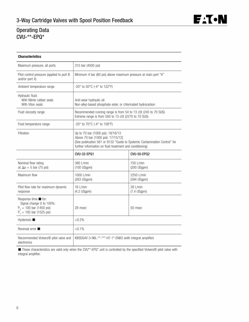
Operating DataCVU-**-EPQ*
scitsiretcarahC
stroplla,erusserpmumixaM )isp0054(rab513
Btropotdeilppa(erusserplortnoctoliP)Xtropro/dna
"A"tropniamtaerusserpmumixamevoba)isp06(rab4muminiM
egnarerutarepmettneibmA )F°221ot°4-(C°05ot°02-
:diulfciluardyHslaesrebburelirtiNhtiW
slaesnotiVhtiW.liociluardyhraew-itnA
nobracordyhdetanirolhcro,retseetahpsohpdesab-lykla-noN
egnarytisocsivdiulF )SUS07ot542(tSc31ot45morfsiegnargninnurdednemmoceR)SUS07ot0722(tSc31ot005morfsiegnaremertxE
egnarerutarepmetdiulF )F°851ot°4-(C°07ot°02-
noitartliF 31/61/81:)isp0001(rab07otpU[21/51/71:)isp0001(rab07evobA
rof"lortnoCnoitanimatnoCcimetsySotediuG"2319ro165noitacilbupeeS()gninoitidnocdnatnemtaertdiulfnonoitamrofnirehtruf
1QPE-23-UVC 2QPE-05-UVC
gnitarwolflanimoNta � )isp57(rab5=p
nim/L083)mpgSU001(
nim/L057)mpgSU002(
wolfmumixaM nim/L0001)mpgSU362(
nim/L0522)mpgSU495(
cimanydmumixamrofetarwolftoliPesnopser
nim/L61)mpgSU2.4(
nim/L82)mpgSU4.7(
emitesnopseR � :rof:%001ot0egnahclangiS
PS
)isp0541(rab001=P
P)isp5251(rab501=
cesm82 cesm05
siseretsyH � %2.0<
rorrelasreveR � %1.0<
dnaevlavtolip®srekciVdednemmoceRscinortcele
)reifilpmalargetnihtiw(38NE-*1-7H-***-**-L69-3-V4GDSBK
� htiwevlavtolip®srekciVdeificepsehtybdellortnocsitinu*QPE-**UVCehtnehwylnodilaverascitsiretcarahcesehT.reifilpmalargetni

3-Way Cartridge Valves with Spool Position Feedback
7
0 2 4-2-4
100
90807060
5040
30
20
10
PA % PS
V
06 8 10-6-8-10
Spool Stroke from Null (% of max.)
0
100
8060
40
20
-20-40
-60
-80
-100
Q (%))
-100 100
0
Command Signal (% of max.)
-20-40-80
-60 2040
6080
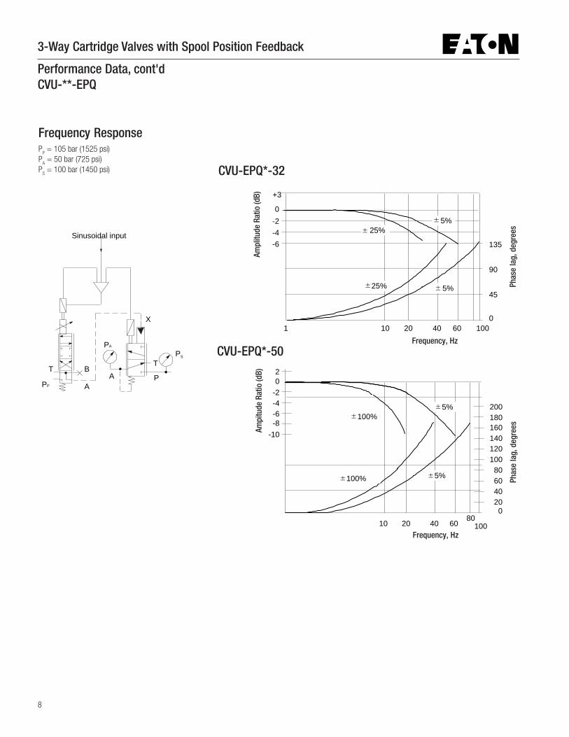
Performance DataCVU-**-EPQ
Pressure Gain Flow Rate/Signal Function
A P
TB
A
T
P
X
PS
PA
P � A
A � T
3-Way Cartridge Valves with Spool Position Feedback
8
Frequency ResponseP
P = 105 bar (1525 psi)
PA = 50 bar (725 psi)
PS = 100 bar (1450 psi)
Performance Data, cont'dCVU-**-EPQ
A P
TB
A
T
X
PS
PA
PP
Sinusoidal input
20406080
100120140160180200
0
10080
10 20 40 60
-10-8-6-4-2
20
100%
100% 5%
5%
45
90
135
010010 20 40 60
-6-4-2
+3
0
25%
25% 5%
5%
1
CVU-EPQ*-50
Ampl
itude
Rat
io (d
B)
Phas
e la
g, d
egre
es
Ampi
tude
Rat
io (d
B)
Phas
e la
g, d
egre
es
CVU-EPQ*-32
±±
±±
±±
± ±
Frequency, Hz
Frequency, Hz

3-Way Cartridge Valves with Spool Position Feedback
9
Required to connect KBSDG4V-3 pilotvalve (with integrated electronics):
Connector Cable, 300mm (12�)
Part no. 02-331572; (plug molded oneach end), to be ordered separately.
Cartridge dimensions below this faceconform to dimensional requirementsof pockets as shown on pages 10,11, 12 and 13.
For details of equivalent inch/UNCbolts see pages 11 and 13.
�
�
Approx. 300 (12)
D toremove valve
E bolts supplied
A
B
C
D
Orientation pin2 bolt holes (at opposite corners) are thru-tapped G thread to facilitate use of jacking bolts when extracting cover from manifold.
9 (0.35) for plug removal
M12 thread
2 (0.1)
H
Mounting surface J
noisnemiD 23eziS 05eziS
ABCD
stlobE �)tffbl(mNeuqrottloB
daerhtGH
)0.4(201)4.2(06
)74.5(931)14.9(932
05x61Mx4)012(582
02M)6.2(56
)5.5(041)4.2(06
)25.6(6,561)0.31(5,03307x02Mx4
)924(08542M
)26.2(5,66
Installation Dimensions in mm (inches)CVU-32/50-EPQ*
3rd angleprojection

3-Way Cartridge Valves with Spool Position Feedback
10
15
A
15
15
VAU
d1
d2
YRmax
YRmax
YRmax
ZRmax
ZRmax
ZRmax
d3
d4
t10
t4
t3 t1
t11
d5
d5
t6
t7t8
t2
P
T
A
ZRmax
U A
U A
t9
t12
Insert Cavity DimensionsCVU-32-EPQ1, mm (inches)
� The radial orientation of ports “P” and “T” aboutthe center line of the pocket is not critical to theperformance of CVU-**-EPQ* valves.
X b
x3
y1
x4
y2
x2 x1
a min.
Datum point
g1 dia. x g
2 deep
(for orientation pinfitted in cover)
Port X:d
7
4 holes tapped d6 by t
5
minimum depth full thread
a min.
Note that top mounting face, including location andsizing of mounting bolts and port X, conforms toISO 7368 and DIN 24342 (standards for 2-portcartridge valves). The pocket geometry is unique to3-port valves.

3-Way Cartridge Valves with Spool Position Feedback
11
noisnemiD *QPE-23-UVC
a )20.4(201
b � )14.4(211
d1
.aid )2263.2/0463.2(000,06/030,06
d2
.aid )382.2/582.2(000,85/030,85
d3
.aid )561.2/661.2(000,55/030,85
d4
.xam.aid )01.1(82
d5
.xam.aid )20.1(62
d6
daerht � 61M
d7
.xam.aid )513.0(8
g1
lanimon.aid )632.0(6
g2
.nim )513.0(8
t1
)007.1/427.1(2,34/8,34
t2
)811.0(3
t3
Y(.nimxamR) )3.1(33
t4
)890.0(5,2
t5
htped.nim � )49.0(42
t6
)81.1(03
t7
Y(.nimxamR) )3.2(5,85
t8
)533.3/853.3(7,48/3,58
t9
)1.0(5,2
t01
)339.3/149.3(9,99/1,001
t11
)18.2(5,17
t21
)15.0(31
U )2100.0(50,0
V )400.0(10,0
x1
� )873.1(53
x2� )632.0(6
x3
� )657.2(07
x4
� )907.0(81
y1
� )83.1(53
y2� )657.2(07
YxamR
)sehcniorcim023(norcim8
ZxamR
)sehcniorcim005(norcim5,21
� Minimum space required for slip-in valve(insert) & cover. Also minimum centerline tocenterline distance for two identical cavities in amanifold block.
� For customers wishing to use UNC mountingbolts, recommendations for thread size and tappingdepths are given in the following table.
� Dimensional tolerance is ± 0,2 (0.008).
sgnippaTevitanretlArofsnoitadnemmoceRstloBgnitnuoMCNUrof
noisnemiD ledoM
d6
daerht 11-"8/5
t5
htped.nim )83.1(53

3-Way Cartridge Valves with Spool Position Feedback
12
Insert Cavity Dimensions; CVU-50-EPQ2, mm (inches)
a min.
X b
x3
y1
x4
y2
x2 x1
a min.
Datum point
Port X:d9
g1 dia. x g
2 deep
(for orientation pinfitted in cover)
4 holes tapped d8 by t
14
minimum depth full thread
d5
d4 U A
t4
t5
t7
t8
AV
t12
V
t11
t1
t9
15
ZRmax
15
ZRmax
15
ZRmax15
ZRmax
15
ZRmaxAd1
U AYRmax
t2
t3
t6 t10
t13
d3 U A
YRmax
YRmax
d2
YRmax
d6
d6
d7
P
T
A
YRmax
R0.05 (.002 rad)
Note that top mounting face, including location andsizing of mounting bolts and port X, conforms toISO 7368 and DIN 24342 (standards for 2-portcartridge valves). The pocket geometry is unique to3-port valves.
� The radial orientation of ports “P” and “T” aboutthe center line of the pocket is not critical to theperformance of CVU-**-EPQ* valves.

3-Way Cartridge Valves with Spool Position Feedback
13
� Minimum space required for slip-in valve(insert) & cover. Also minimum centerline tocenterline distance for two identical cavities in amanifold block.
� For customers wishing to use UNC mountingbolts, recommendations for thread size and tappingdepths are given in the following table.
� Dimensional tolerance is ± 0,2 (.008).
sgnippaTevitanretlArofsnoitadnemmoceRstloBgnitnuoMCNUrof
noisnemiD ledoM
d6
daerht 01-"4/3
t5
htped.nim )75.1(04
noisnemiD *QPE-05-UVC
a )15.5(041
b � )19.5(051
d1
.aid )3345.3/545.3(000,09/530,09
d2
)484.3/684.3(005,88/535,88
d3
.aid )524.3/724.3(000,78/530,78
d4
.aid )776.2/876.2(000,86/030,86
d5
xam.aid )37.1(44
d6
.xam.aid )35.1(93
d7
.xam.aid )042.0(01,6
d8
daerht � 02M
d9
.xam.aid )493.0(01
g1
lanimon.aid )513.0(8
g2
.nim )513.0(8
t1
)816.5/146.5(7,241/3,341
t2
Y(.nimxamRd:
4) )17.0(81
t3
)314.3/374.3(7,68/3,78
t4
Y(.nimxamRd:
3) )751.1(04
t5
)6.2(66
t6
Y(.nimxamR
)1d: )38.0(12
t7
)890.0(5,2
t8
)751.0(4
t9
)38.0(12
t01
)241.1(92
t11
Y(.nimxamRd:
2) )6.2(66
t21
)8.4(221
t31
)294.6/005.6(9,461/0,561
t41
)81.1(03
U )200.0(50,0
V )4000.0(10,0
x1
� )969.1(05
x2� )513.0(8
x3� )739.3(001
x4� )787.0(02
y1� )969.1(05
y2� )739.3(001
YxamR
)sehcniorcim023(norcim8
ZxamR
)sehcniorcim005(norcim5,21

3-Way Cartridge Valves with Spool Position Feedback
14
F
A G
B
C
D
E
7-pin plug connections
View of pins of fixed half.
4-pin plug connections
1
2 3
4
Pin 1 SignalPin 2 +15 VPin 3 0 VPin 4 Not used
View on LVDT
Installation Dimensions in mm (inches)Pilot Valve with Integral ElectronicsKBSDG4V-3...EN83
This drawing provides dimensions and informationnecessary to install this valve.For full comprehensive data on the valve refer tocatalog 5071.02/EN/1197/A.
niP noitpircseD
ABCCDEFG
)+(evitisopylppusrewoPV0rewoP
)7EP&7CP(V0rotinoM/dnammoC)7RP&7HP(elbaneevlaV
tupnignitrevni-non-)+(langisdnammoCtupnignitrevni-)–(langisdnammoC
tuptuorotinoMdnuorgevitcetorP
� Mounting surface seals supplied.“Mounting surface conforms to ISO 4401, size 03 (ANSI/B93.7M, size 03).“Mounting surface dimensions and details of Vickers subplates can be found in catalog C-2335.
3rd angleprojection
21(0.83)
116(4.57)
X X
X X
151 (5.94)
227 (8.93)
13,75 (0.54)
48 (1.89)
Port ALC
Port BLC
4-pin socket
Amplifier and solenoid assemblymay be rotated 90° as shown byremoving 4 screws shown X.Re-torque to 7-9 Nm (6-7 lbf ft)
7-pin connector plug.See below for connection details.Air bleed screw:
Socket Head Cap Screw.Torque to 2,5-3,0 Nm (2.0-2.5 lbf ft)
This product has been designed and tested to meet specific standards outlined in the European Electromagnetic Compatibility Directive (EMC) 89/336/EEC,amended by 91/263/EEC, 92/31/EEC and 93/68/EEC, article 5. For instructions on installation requirements to achieve effective protection levels, see thisleaflet and the Installation Wiring Practices for Vickers® Electronic Products leaflet 2468. Wiring practices relevant to this Directive are indicated by Electromagnetic Compatibility (EMC).
3-Way Cartridge Valves with Spool Position Feedback
15
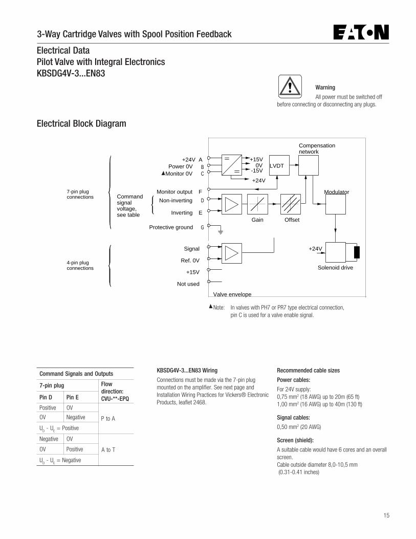
Electrical DataPilot Valve with Integral ElectronicsKBSDG4V-3...EN83
Electrical Block Diagram
KBSDG4V-3...EN83 Wiring
Connections must be made via the 7-pin plugmounted on the amplifier. See next page andInstallation Wiring Practices for Vickers® ElectronicProducts, leaflet 2468.
Recommended cable sizes
Power cables:
For 24V supply:0,75 mm2 (18 AWG) up to 20m (65 ft)1,00 mm2 (16 AWG) up to 40m (130 ft)
Signal cables:
0,50 mm2 (20 AWG)
Screen (shield):
A suitable cable would have 6 cores and an overallscreen.Cable outside diameter 8,0-10,5 mm (0.31-0.41 inches)
stuptuOdnaslangiSdnammoC
gulpnip-7 wolF:noitcerid
QPE-**-UVCDniP EniP
evitisoP VO
AotPVO evitageN
UD
U-E
evitisoP=
evitageN VO
TotAVO evitisoP
UD
U-E
evitageN=
Warning
All power must be switched offbefore connecting or disconnecting any plugs.
Offset
Modulator
Solenoid drive
Valve envelope
7-pin plug connections
+24V AB
D
E
F
G
Power 0V Monitor 0V
Protective ground
Non-inverting
Inverting
Commandsignalvoltage,see table
Compensation network
+15V0V
-15V
+24V
LVDTC
Monitor output
+24V
Gain
4-pin plug connections
Signal
Ref. 0V
+15V
Not used
Note: In valves with PH7 or PR7 type electrical connection,pin C is used for a valve enable signal.

3-Way Cartridge Valves with Spool Position Feedback
16
0V must be connected to ground
0V
User Panel
Power Supply
Demand Signal
SpoolPosition Monitor
+24V
10V
Valve must be connected toground viasubplate
Connector shell
Outer Screen
AB
D or E
0V
0V
C
Drain Wire
Inner Screen
E or D
G
F
Enable Signal
+8.5Vto 36V
0V
Pilot valve modelKBSDG4V-3..PR7/PH7..EN83
Output
+/-
Electrical DataPilot Valve with Integral ElectronicsKBSDG4V-3....EN83
Wiring Connections
Wiring Connections for Valves with “Enable” Feature
� Note:In applications where the valve must conform toEuropean RFI/EMC regulations, the outer screen(shield) must be connected to the outer shell of the7-pin connector, and the valve body must befastened to the earth ground. Proper earthgrounding practices must be observed in this case,as any differences in command source and valveground potentials will result in a screen (shield)ground loop.
Warning
Electromagnetic Compatibility (EMC)It is necessary to ensure that the valve is wired up as above. For effective protection the user electrical cabinet, the valve subplate or manifold and
the cable screens should be connected to efficient ground points. The metal 7-pin connector part no. 934939 should be used for the integral amplifier.In all cases both valve and cable should be kept as far away as possible from any sources of electromagnetic radiation such as cables carrying heavy current,relays and certain kinds of portable radio transmitters, etc. Difficult environments could mean that extra screening may be necessary to avoid the interference.It is important to connect the 0V lines as shown above. The multi-core cable should have at least two screens to separate the demand signal and monitor outputfrom the power lines.The enable line to pin C should be outside the screen which contains the demand signal cables.
� Spool position monitor voltage (pin F) will bereferenced to the KB valve local ground. A “localground” (pin C) is provided on PC7/PE7 versions foroptional use by differential input customer suppliedelectronics.
Warning
Do not ground pin C.
If the local ground (pin C) is not usedfor differential monitor electronics, do not use.Read monitor pin F with respect to ground.
Output
User Panel
Power Supply
Demand Signal
SpoolPosition Monitor
0V must be connected to ground
Enclosure
+24V0V
+/-10V Valve must be connectedto groundvia subplate
Connector shell
Outer Screen
A
B
D or E0V
0V
C
Drain Wire
Inner Screen
G
F
�
Pilot valve modelKBSDG4V-3..PC7/PE7..EN83
3-Way Cartridge Valves with Spool Position Feedback
17
InstallationThe proportional valves in this catalog can bemounted in any attitude.
For the KBSDG4V-3 pilot valve it may be necessaryin certain demanding applications, to ensure thatthe solenoid is kept full of hydraulic fluid. Goodinstallation practice dictates that the tank port andany drain port are piped so as to keep the valvesfull of fluid once the system start-up has beencompleted.
Mounting Bolt KitsFor CVU-**-EPQ
Metric bolts are supplied with all models.
For K(B)SDG4V-3
BK02-156493M (metric)BK590716 (inch)If not using Vickers recommended bolt kits, boltsused should be to ISO 898, 12.9 or better.
Seal KitsFor CVU-**-EPQ:
Standard nitrile rubber seals:CVU-32-EPQ1 .................................... 02-350905CVU-50-EPQ2 .................................... 02-358138Viton seals:F3-CVU-32-EPQ1 ............................... 02-350906F3-CVU-50-EPQ2 ............................... 02-358139
For pilot valve:
KBSDG4V-3-1* .................................. 02-332693
Plugs7-pin plug:KBSDG4V-3....EN83;7-pin plug:KBSDG4V-3....EN83;7-pin plug:KBSDG4V-3....EN83;7-pin plug:KBSDG4V-3....EN83;7-pin plug:KBSDG4V-3....EN83;7-pin plug (metal) ................................... 934939*(Recommended plug for EMC and IP67 protection)7-pin plug (plastic) ...................................694534(For use only where EMC and IP67 protection is notrequired)
Note:Note:Note:Note:Note: An alternative metal connector which givesEMC protection rating is available from ITT-Cannon,part number CA02-COM-E-14S-A7-S. For IP ratingconsult the manufacturer.
* Plug 934939 is fitted to the pilot valve when“PE7” or “PR7” is specified at Model Code position15.
4-pin plug, KBSDG4V-3...EN834-pin plug, KBSDG4V-3...EN834-pin plug, KBSDG4V-3...EN834-pin plug, KBSDG4V-3...EN834-pin plug, KBSDG4V-3...EN83and CVU-**-EPQ:and CVU-**-EPQ:and CVU-**-EPQ:and CVU-**-EPQ:and CVU-**-EPQ:The molded-on plug(s) of the connecting cablecorrectly fitted and tightened gives EMC and IP67protection.
Service InformationThe products from this range are preset at thefactory for optimum performance; disassemblingcritical items would destroy these settings. It istherefore recommended that should anymechanical or electronic repair be necessary theyshould be returned to the nearest Vickers repaircenter. The products will be refurbished asnecessary and retested to specification beforereturn.
Field repair is restricted to the replacement of theseals.
Note:Note:Note:Note:Note: Customers are strongly advised not toattempt to disassemble any of the electronics,feedback devices or solenoid assemblies installedin these valves.
Application Data
Fluid CleanlinessProper fluid condition is essential for long andsatisfactory life of hydraulic components andsystems. Hydraulic fluid must have the correctbalance of cleanliness, materials and additives forprotection against wear of components, elevatedviscosity and inclusion of air.
Recommendations on contamination controlmethods and the selection of products to controlfluid condition are included in publication 9132 or561, “Guide to Systemic Contamination Control”.The book also includes information on the conceptof “ProActive Maintenance”. The followingrecommendations are based on ISO cleanlinesslevels at 2 µm, 5 µm and 15 µm.
For products in this catalog the recommendedlevels are:0 to 70 bar (1000 psi) .......................... 18/16/1316/1316/1316/1316/1370+ bar (1000+ psi) ............................ 17/15/1215/1215/1215/1215/12
Vickers® products, as any components, willoperate with apparent satisfaction in fluids withhigher cleanliness codes than those described.Other manufacturers will often recommend levelsabove those specified.
Experience has shown, however, that“life of anyhydraulic components is shortened in fluids withhigher cleanliness codes than those listed above.These codes have been proven to provide a longtrouble-free service life for the products shown,regardless of the manufacturer.
Hydraulic FluidsMaterials and seals used in the K(B)SDG4V-3valves are compatible with antiwear hydraulic oils,and with non-alkyl-based phosphate esters.
Standard (nitrile rubber) seals in the CVU-**-EPQcartridge valves are suitable for use only withantiwear hydraulic oils. When fitted with Viton seals(specifiy “F3-” in Model Code 1 ), these valvesare suitable for use with non-alkyl-basedphosphate esters.
The fluid extreme operating viscosity range is 500to 13 cSt (2270 to 70 SUS) but the recommendedrunning range is 54 to 13 cSt (245 to 70 SUS). Forfurther technical information about fluids see“Technical Information” leaflet B-920 or I-286S.

© 2009 Eaton CorporationAll Rights ReservedPrinted in USADocument No. V-VLSP-MC001-ESupersedes 11-05-0002 EN 1000March 2009
EatonFluid Power GroupHydraulics Group USA14615 Lone Oak RoadEden Prairie, MN 55344USATel: 952-937-9800Fax: 952-294-7722www.eaton.com/hydraulics
EatonFluid Power GroupHydraulics Group EuropeRoute de la Longeraie 71110 MorgesSwitzerlandTel: +41 (0) 21 811 4600Fax: +41 (0) 21 811 4601
EatonFluid Power GroupHydraulics Group Asia Pacific 11th Floor Hong Kong New World Tower 300 Huaihai Zhong Road Shanghai 200021 China Tel: 86-21-6387-9988 Fax: 86-21-6335-3912
Related Documents