Vibration from Underground Railways: Considering Piled Foundations and Twin Tunnels Kirsty Alison Kuo King’s College University of Cambridge A dissertation submitted for the degree of Doctor of Philosophy September 2010

Welcome message from author
This document is posted to help you gain knowledge. Please leave a comment to let me know what you think about it! Share it to your friends and learn new things together.
Transcript

Vibration from Underground
Railways: Considering Piled
Foundations and Twin Tunnels
Kirsty Alison Kuo
King’s College
University of Cambridge
A dissertation submitted for the degree of
Doctor of Philosophy
September 2010


To Matthew, Mum and Dad ...
i

Acknowledgements
I would like to thank Dr Hugh Hunt for providing me with the opportunity to under-
take this project, and for his continual support and enthusiasm throughout the course
of this research. He has provided me with many, varied opportunities to further my
understanding of the field of dynamics and vibration, for which I am most grateful.
My sincere thanks goes to Dr Mohammed Hussein of Nottingham University for his
assistance in understanding the Pipe-in-Pipe model, and his guidance on the formulation
of the two-tunnel model. Mohammed patiently answered many questions, and provided
insightful suggestions while reviewing aspects of this work. I would also like to express
my appreciation to Dr James Talbot for the use of his boundary-element model for piles,
and for the discussions we had on the direction of my work on piled foundations.
The collaborative efforts of the Structural Mechanics Group at Katholieke Univer-
siteit Leuven, led by Professor Geert Degrande, have been instrumental in the validation
of the pile models presented in this dissertation. In particular, I would like to acknowl-
edge the modelling work done by Dr Stijn Francois and Mr Pieter Coulier. It has been
a pleasure to work with them.
This research is primarily funded by the generous support of the General Sir John
Monash Foundation of Australia. In particular I would like to thank past-CEO Mr Ken
Crompton, present-CEO Dr Peter Binks, the Board of Directors and the sponsors who
support these awards.
I would also like to thank King’s College for their provision of a Studentship to
supplement my funding. King’s College has also provided a pleasant environment for
me to live in, for which I am most grateful.
Finally, I would like to thank my husband Matthew, my best friend, with whom I am
privileged to share my life. Thank you for your willingness to answer my geotechnical
questions, discuss the directions of this research, edit my work and support me in the
writing of this dissertation. But most of all, thank you for your love.
To God be the glory, as it is by Him and through Him that all things are accom-
plished.
I declare that, except for commonly understood and accepted ideas or where specific
reference has been made to the work of others, this dissertation is the result of my own
work and includes nothing which is the outcome of work done in collaboration. This
dissertation is approximately 61,000 words in length and contains 89 figures.
ii

Preface
Most engineering courses on vibration begin with a mass on a spring,
and then move on to continuous systems such as strings, columns and
membranes. These simple systems provide students with a good un-
derstanding of the fundamentals of vibration theory, and the physical
behaviour of such systems is represented by using well-known equations.
However, many vibration problems do not involve such simple sys-
tems. In the past, to solve these problems, engineers would turn to
experimental investigations, or would construct simple models that could capture the
essential physical behaviour and yet be solved using the available computational tech-
niques. Nowadays, many engineers use commercial software packages that make use
of powerful numerical methods such as finite-element or boundary-element methods as
their primary tool in constructing models. The difficulty that may arise from the use of
such software (that is specially designed to have a user-friendly interface) is that many
practitioners lack an awareness of the limitations of these numerical models, and the
uncertainty that may be present in the results is often poorly understood. For many
complex systems there is no other method of calculating the vibration results, which
means that critical engineering decisions may be based on essentially unvalidated results.
This dissertation aims to address this state of affairs by demon-
strating that the vibration of a complex system can be accurately
modelled using relatively simple techniques, and that such a model
provides a complementary solution that can be used in conjunction
with numerical formulations. The advantages of this approach are
clear: reduced processing times allow for a quicker design process;
the transparency of the solution minimises the occurrence of ‘unknown’ assumptions;
and the use of simple models may even enable the modelling of some complex systems
that are currently beyond modern numerical computational capabilities. These advan-
tages, when augmented by the versatility and strength of numerical methods, provide a
comprehensive framework for addressing vibration problems.
iii

Abstract
Accurate predictions of ground-borne vibration levels in the vicinity of an underground
railway are greatly sought after in modern urban centers. Yet the complexity involved in
simulating the underground environment means that it is necessary to make simplifying
assumptions about this system. One such commonly made assumption is to ignore
the effects of nearby embedded structures such as piled foundations and neighbouring
tunnels.
Through the formulation of computationally efficient mathematical models, this dis-
sertation examines the dynamic behaviour of these two particular types of structures.
The effect of the dynamic behaviour of these structures on the ground-borne vibration
generated by an underground railway is considered.
The modelling of piled foundations begins with consideration of a single pile embed-
ded in a linear, viscoelastic halfspace. Two approaches are pursued: the modification
of an existing plane-strain pile model; and the development of a fully three-dimensional
model formulated in the wavenumber domain. Methods for adapting models of infinite
structures to simulate finite systems using mirror-imaging techniques are described.
The interaction between two neighbouring piles is considered using the method of join-
ing subsystems, and these results are extended to formulate models for pile groups.
The mathematical model is validated against existing numerical solutions and is found
to be both accurate and efficient. A building model and a model for the pile cap are
developed, and are attached to the piled foundation. A case study is used to illustrate
a procedure for assessing the vibration performance of pile groups subject to vibration
generated by an underground railway.
The two-tunnel model uses the superposition of displacement fields to produce a fully
coupled model of two infinitely long tunnels embedded in a homogeneous, viscoelastic
fullspace. The significance of the interactions occurring between the two tunnels is
quantified by calculating the insertion gains that result from the existence of a second
tunnel. The results show that a high degree of inaccuracy exists in any underground-
railway vibration prediction model that includes only one of the two tunnels present.
iv

Contents
1 Literature Review 11.1 The Problem of Ground-Borne Vibration . . . . . . . . . . . . . . . . . . 2
1.1.1 Sources of Ground-Borne Vibration . . . . . . . . . . . . . . . . . 21.1.2 Response of Buildings . . . . . . . . . . . . . . . . . . . . . . . . 51.1.3 Human Response to Vibration and Re-radiated Noise . . . . . . . 8
1.2 Methods of Reducing Ground-Borne Vibration . . . . . . . . . . . . . . . 101.2.1 Isolation of the Source . . . . . . . . . . . . . . . . . . . . . . . . 101.2.2 Disruption of the Transmission Path . . . . . . . . . . . . . . . . 111.2.3 Isolation of the Building . . . . . . . . . . . . . . . . . . . . . . . 131.2.4 Vibration-Performance Measures . . . . . . . . . . . . . . . . . . 13
1.3 Modelling of Vibration from Underground Railways . . . . . . . . . . . . 161.3.1 Wave Propagation through the Soil . . . . . . . . . . . . . . . . . 161.3.2 Factors that Influence Vibration from Underground Railways . . . 181.3.3 Large-Scale Models of Vibration from Underground Railways . . . 19
1.4 Directions of the Research . . . . . . . . . . . . . . . . . . . . . . . . . . 251.5 Piled-Foundation Design . . . . . . . . . . . . . . . . . . . . . . . . . . . 261.6 Piled-Foundation Dynamics . . . . . . . . . . . . . . . . . . . . . . . . . 27
1.6.1 Modelling Single-Pile Dynamics . . . . . . . . . . . . . . . . . . . 271.6.2 Modelling Pile-Group Dynamics . . . . . . . . . . . . . . . . . . . 311.6.3 Experimental Investigations into Pile Dynamics . . . . . . . . . . 36
1.7 Twin-Tunnel Dynamics . . . . . . . . . . . . . . . . . . . . . . . . . . . . 381.7.1 Modelling Twin-Tunnel Dynamics . . . . . . . . . . . . . . . . . . 381.7.2 Experimental Investigations into Twin-Tunnel Dynamics . . . . . 40
1.8 Conclusions . . . . . . . . . . . . . . . . . . . . . . . . . . . . . . . . . . 411.8.1 Objectives of the Research . . . . . . . . . . . . . . . . . . . . . . 421.8.2 Outline of the Dissertation . . . . . . . . . . . . . . . . . . . . . . 43
2 Development of a Single-Pile Model 452.1 The Plane-Strain Case . . . . . . . . . . . . . . . . . . . . . . . . . . . . 46
2.1.1 Novak’s Model . . . . . . . . . . . . . . . . . . . . . . . . . . . . 462.1.2 Novak’s Model subject to an Incident Wavefield . . . . . . . . . . 51
2.2 A Three-Dimensional Model . . . . . . . . . . . . . . . . . . . . . . . . . 532.2.1 Axial Vibration of an Infinite Pile . . . . . . . . . . . . . . . . . . 542.2.2 Lateral Vibration of an Infinite Pile . . . . . . . . . . . . . . . . . 572.2.3 Axial Vibration of a Finite Pile . . . . . . . . . . . . . . . . . . . 582.2.4 Lateral Vibration of a Finite Pile . . . . . . . . . . . . . . . . . . 612.2.5 Incident Wavefields . . . . . . . . . . . . . . . . . . . . . . . . . . 67
2.3 Validation and Comparison of Models . . . . . . . . . . . . . . . . . . . . 682.3.1 The Infinite Pile . . . . . . . . . . . . . . . . . . . . . . . . . . . 702.3.2 The Finite Pile . . . . . . . . . . . . . . . . . . . . . . . . . . . . 72
v

2.3.3 The Pile subject to an Incident Wavefield . . . . . . . . . . . . . 842.4 Conclusions . . . . . . . . . . . . . . . . . . . . . . . . . . . . . . . . . . 97
3 Multiple-Pile Models 993.1 Modelling Two Finite-Length Piles . . . . . . . . . . . . . . . . . . . . . 1013.2 Validation of the Two-Pile Model . . . . . . . . . . . . . . . . . . . . . . 1033.3 Modelling a Pile Group subject to an Incident Wavefield . . . . . . . . . 1093.4 Modelling a Piled Building subject to an Incident Wavefield . . . . . . . 114
3.4.1 Modelling a Building . . . . . . . . . . . . . . . . . . . . . . . . . 1143.4.2 Modelling a Pile Cap . . . . . . . . . . . . . . . . . . . . . . . . . 1163.4.3 Results for the Piled Building . . . . . . . . . . . . . . . . . . . . 119
3.5 Case Study: Evaluating Two Foundation Designs . . . . . . . . . . . . . 1223.6 Conclusions . . . . . . . . . . . . . . . . . . . . . . . . . . . . . . . . . . 124
4 A Two-Tunnel Model 1274.1 Modelling a Single Tunnel . . . . . . . . . . . . . . . . . . . . . . . . . . 1284.2 Modelling Two Tunnels . . . . . . . . . . . . . . . . . . . . . . . . . . . . 133
4.2.1 Dynamic Train Forces . . . . . . . . . . . . . . . . . . . . . . . . 1344.2.2 Dynamic Cavity Forces . . . . . . . . . . . . . . . . . . . . . . . . 1374.2.3 Superposition of Displacement Fields . . . . . . . . . . . . . . . . 1374.2.4 Calculating Stresses around a Virtual Surface . . . . . . . . . . . 1394.2.5 Solving the System of Equations . . . . . . . . . . . . . . . . . . . 141
4.3 Results and Discussion . . . . . . . . . . . . . . . . . . . . . . . . . . . . 1454.3.1 Insertion-Gain Results . . . . . . . . . . . . . . . . . . . . . . . . 151
4.4 Conclusions . . . . . . . . . . . . . . . . . . . . . . . . . . . . . . . . . . 158
5 Conclusions 1595.1 Introduction . . . . . . . . . . . . . . . . . . . . . . . . . . . . . . . . . . 159
5.1.1 The Effect of Piled Foundations and Twin Tunnels on Ground-Borne Vibration . . . . . . . . . . . . . . . . . . . . . . . . . . . . 160
5.1.2 The Vibration Performance of Embedded-Structure Designs . . . 1615.1.3 The Best Design Practice . . . . . . . . . . . . . . . . . . . . . . 162
5.2 Recommendations for Future Work . . . . . . . . . . . . . . . . . . . . . 163
References 165
Appendices
A Method of Joining Subsystems 179
B Coefficient Matrices for a Cylindrical Shell and an Elastic Continuum183
C The Mirror-Image Method 187
D Method for Calculating Maximum Displacement Magnitude 191
vi
List of Figures
1.1 The time history of the ground acceleration when a train passes at 120km/hr (reproduced from Heckl et al. [56]). Upper curve: distance fromthe centre of the track is 3m; lower curve: distance from the centre of thetrack is 32m . . . . . . . . . . . . . . . . . . . . . . . . . . . . . . . . . . 6
1.2 An open trench located near a railway (reproduced from Di Mino et al.[33]) . . . . . . . . . . . . . . . . . . . . . . . . . . . . . . . . . . . . . . 11
1.3 Distribution of waves produced by the vibration of a circular footing ona homogeneous, isotropic, elastic halfspace (reproduced from Woods [186]) 18
1.4 The single-bore and twin-bore tunnel designs considered using the wavenum-ber FE-BE model (reproduced from Sheng et al. [161]) . . . . . . . . . . 24
1.5 The finite/infinite-element mesh for a halfspace (reproduced from Yang& Hung [190]) . . . . . . . . . . . . . . . . . . . . . . . . . . . . . . . . . 24
1.6 The finite-element mesh (reproduced from Ju [81]) . . . . . . . . . . . . . 351.7 The finite-element mesh of the bridge and foundations (reproduced from
Ju [81]) . . . . . . . . . . . . . . . . . . . . . . . . . . . . . . . . . . . . 351.8 The elevated bridge subject to a train of speed v: (a) schematic; (b)
simplified model (reproduced from Wu & Yang [187]) . . . . . . . . . . . 36
2.1 Novak’s plane-strain representation of a pile . . . . . . . . . . . . . . . . 472.2 Discretisation of the pile into N equally-spaced segments (N = 10 in this
case), with N + 1 nodes for application of forces and displacements . . . 522.3 The two separate subsystems that are joined together to obtain a pile-
railway model . . . . . . . . . . . . . . . . . . . . . . . . . . . . . . . . . 522.4 Cylindrical modes of a thin-walled cylinder: (a) in-plane flexural ring
modes, corresponding to radial deformations Ur cos nθ; (b) in-plane ex-tensional ring modes, corresponding to tangential deformations Uθ sin nθ;and (c) out-of-plane flexural ring modes, corresponding to longitudinaldeformations Uz cos nθ. The crosses mark the point θ = 0 on the unde-formed ring, and the circles in (b) mark the additional nodal points onthe ring’s circumference (reproduced from Forrest [41]) . . . . . . . . . . 54
2.5 (a) Infinite column with load 2P at z = 0; (b) semi-infinite column withend loading P ; (c) infinite column with load P ∗ at z = −L and z = L;and (d) semi-infinite column with load P ∗ at z = L . . . . . . . . . . . . 60
2.6 Infinite beam loaded with force P . Shown from top to bottom: schematicof the loaded beam; displacement w; rotation θ = dw
dz; moment M =
−EI d2wdz2 ; and shear force F = −EI d3w
dz3 . . . . . . . . . . . . . . . . . . . 622.7 Infinite beam loaded with moment M0. Shown from top to bottom:
schematic of the loaded beam; displacement w; rotation θ = dwdz
; mo-
ment M = −EI d2wdz2 ; and shear force F = −EI d3w
dz3 . . . . . . . . . . . . . 63
vii

2.8 (a) Infinite beam loaded with mirror-image forces P acting in the samedirection; and (b) infinite beam loaded with mirror-image forces P actingin opposite directions . . . . . . . . . . . . . . . . . . . . . . . . . . . . . 64
2.9 (a) Infinite beam loaded with force 2P at z = 0; (b) semi-infinite beamloaded with force P and rotation-constrained at z = 0; (c) infinite beamloaded with forces F and moments M at z = −L and z = L; (d) semi-infinite beam loaded with force F and moment M at z = L; and (e) finitebeam loaded with force P and rotation-constrained at z = 0 . . . . . . . 66
2.10 The magnitude and phase of the axial driving-point response of an infinitepile . . . . . . . . . . . . . . . . . . . . . . . . . . . . . . . . . . . . . . . 71
2.11 The magnitude and phase of the lateral driving-point response of an in-finite pile . . . . . . . . . . . . . . . . . . . . . . . . . . . . . . . . . . . 71
2.12 The axial response of a pile subject to a unit harmonic excitation in thez-direction . . . . . . . . . . . . . . . . . . . . . . . . . . . . . . . . . . . 73
2.13 The lateral response of a pile (with zero rotation at the pile head) subjectto a unit harmonic excitation in the w-direction . . . . . . . . . . . . . . 73
2.14 The normalised, real, axial displacement of a pile u(z)u(0)
as a function of pile
length and dimensionless frequency . . . . . . . . . . . . . . . . . . . . . 75
2.15 The normalised, real, lateral displacement of a pile w(z)w(0)
as a function of
pile length and dimensionless frequency . . . . . . . . . . . . . . . . . . . 752.16 Real (left) and imaginary (right) parts of the vertical farfield displace-
ments on the surface of the halfspace (z = 0m) at distance 5m (top);10m (middle); and 20m (bottom) from a pile undergoing excitation inthe z-direction . . . . . . . . . . . . . . . . . . . . . . . . . . . . . . . . . 77
2.17 Real (left) and imaginary (right) parts of the horizontal farfield displace-ments on the surface of the halfspace (z = 0m) at distance 5m (top);10m (middle); and 20m (bottom) from a pile undergoing excitation inthe z-direction . . . . . . . . . . . . . . . . . . . . . . . . . . . . . . . . . 78
2.18 Real (left) and imaginary (right) parts of the vertical farfield displace-ments on the surface of the halfspace (z = 0m) at distance 5m (top);10m (middle); and 20m (bottom) from a pile undergoing excitation inthe w-direction . . . . . . . . . . . . . . . . . . . . . . . . . . . . . . . . 79
2.19 Real (left) and imaginary (right) parts of the horizontal farfield displace-ments on the surface of the halfspace (z = 0m) at distance 5m (top);10m (middle); and 20m (bottom) from a pile undergoing excitation inthe w-direction . . . . . . . . . . . . . . . . . . . . . . . . . . . . . . . . 80
2.20 Net power flow through a single pile subject to axial pile-head excitation,plotted as a function of dimensionless frequency . . . . . . . . . . . . . . 82
2.21 Net power flow through a single pile subject to lateral pile-head excitation,plotted as a function of dimensionless frequency . . . . . . . . . . . . . . 82
2.22 Power flow as a percentage of the total power output [%] through the skinof a single pile subject to axial pile-head excitation, plotted as a functionof dimensionless frequency . . . . . . . . . . . . . . . . . . . . . . . . . . 83
2.23 Power flow as a percentage of the total power output [%] through theskin of a single pile subject to lateral pile-head excitation, plotted as afunction of dimensionless frequency . . . . . . . . . . . . . . . . . . . . . 83
2.24 (a) Axial, and (b) lateral pile-head response of a single pile subject to anincident wavefield consisting of varying numbers of input points . . . . . 87
2.25 The vertical response of a single pile subject to an incident wavefieldgenerated using the PiP software . . . . . . . . . . . . . . . . . . . . . . 88
viii

2.26 The horizontal response of a single pile subject to an incident wavefieldgenerated using the PiP software . . . . . . . . . . . . . . . . . . . . . . 88
2.27 The real axial displacement [m] of the incident wavefield as a function ofpile length L = 20m and frequency . . . . . . . . . . . . . . . . . . . . . 89
2.28 The real axial displacement [m] of a pile subject to the incident wavefieldas a function of pile length L = 20m and frequency . . . . . . . . . . . . 89
2.29 The real lateral displacement [m] of the incident wavefield as a functionof pile length L = 20m and frequency . . . . . . . . . . . . . . . . . . . . 90
2.30 The real lateral displacement [m] of a pile subject to the incident wavefieldas a function of pile length L = 20m and frequency . . . . . . . . . . . . 90
2.31 The real axial displacement [m] of the incident wavefield as a function ofpile length L = 5m and frequency . . . . . . . . . . . . . . . . . . . . . . 91
2.32 The real axial displacement [m] of a pile subject to the incident wavefieldas a function of pile length L = 5m and frequency . . . . . . . . . . . . . 91
2.33 The real lateral displacement [m] of the incident wavefield as a functionof pile length L = 5m and frequency . . . . . . . . . . . . . . . . . . . . 92
2.34 The real lateral displacement [m] of a pile subject to the incident wavefieldas a function of pile length L = 5m and frequency . . . . . . . . . . . . . 92
2.35 The real axial displacement [m] of the incident wavefield as a function ofpile length L = 60m and frequency . . . . . . . . . . . . . . . . . . . . . 93
2.36 The real axial displacement [m] of a pile subject to the incident wavefieldas a function of pile length L = 60m and frequency . . . . . . . . . . . . 93
2.37 The real lateral displacement [m] of the incident wavefield as a functionof pile length L = 60m and frequency . . . . . . . . . . . . . . . . . . . . 94
2.38 The real lateral displacement [m] of a pile subject to the incident wavefieldas a function of pile length L = 60m and frequency . . . . . . . . . . . . 94
2.39 The net power flow [W/m] through a single pile subject to an incidentwavefield generated using the PiP software . . . . . . . . . . . . . . . . . 95
2.40 The power flow [W/m] due to axial vibration for a single pile subject toan incident wavefield generated using the PiP software . . . . . . . . . . 96
2.41 The power flow [W/m] due to lateral vibration for a single pile subjectto an incident wavefield generated using the PiP software . . . . . . . . . 96
3.1 The two separate subsystems which are joined together to form a two-pilesystem . . . . . . . . . . . . . . . . . . . . . . . . . . . . . . . . . . . . . 101
3.2 The two separate subsystems used for the three-dimensional model (withapplied axial forces) which are joined together to form a two-pile system 103
3.3 Real part (left), and imaginary part (right) of the axial response of a finitepile at horizontal distances s = 4a (top), s = 10a (middle) and s = 20a(bottom) from a finite single pile undergoing harmonic axial excitation . 106
3.4 Real part (left), and imaginary part (right) of the lateral response at 0◦
of a finite pile at horizontal distances s = 4a (top), s = 10a (middle) ands = 20a (bottom) from a finite single pile undergoing harmonic lateralexcitation . . . . . . . . . . . . . . . . . . . . . . . . . . . . . . . . . . . 107
3.5 Real part (left), and imaginary part (right) of the lateral response at 90◦
of a finite pile at horizontal distances s = 4a (top), s = 10a (middle) ands = 20a (bottom) from a finite single pile undergoing harmonic lateralexcitation . . . . . . . . . . . . . . . . . . . . . . . . . . . . . . . . . . . 108
3.6 The vertical response of an outer pile in a four-pile row subject to anincident wavefield generated using the PiP software . . . . . . . . . . . . 111
ix

3.7 The horizontal response of an outer pile in a four-pile row subject to anincident wavefield generated using the PiP software . . . . . . . . . . . . 111
3.8 The vertical response of an inner pile in a four-pile row subject to anincident wavefield generated using the PiP software . . . . . . . . . . . . 112
3.9 The horizontal response of an inner pile in a four-pile row subject to anincident wavefield generated using the PiP software . . . . . . . . . . . . 112
3.10 The vertical response of a pile in a two-pile row subject to an incidentwavefield generated using the PiP software . . . . . . . . . . . . . . . . . 113
3.11 The horizontal response of a pile in a two-pile row subject to an incidentwavefield generated using the PiP software . . . . . . . . . . . . . . . . . 113
3.12 The definition of pile-head displacements for (a) a piled foundation; and(b) a piled building . . . . . . . . . . . . . . . . . . . . . . . . . . . . . . 117
3.13 The definition of pile-head displacements for (a) a piled foundation; and(b) a piled raft foundation with attached building . . . . . . . . . . . . . 118
3.14 The pile-cap model, consisting of two layers of beams/columns . . . . . . 1193.15 The vertical response of an outer pile in a four-pile row attached to a pile
cap and building, and subject to an incident wavefield generated usingthe PiP software . . . . . . . . . . . . . . . . . . . . . . . . . . . . . . . 120
3.16 The horizontal response of an outer pile in a four-pile row attached toa pile cap and building, and subject to an incident wavefield generatedusing the PiP software . . . . . . . . . . . . . . . . . . . . . . . . . . . . 120
3.17 The vertical response of an inner pile in a four-pile row attached to a pilecap and building, and subject to an incident wavefield generated usingthe PiP software . . . . . . . . . . . . . . . . . . . . . . . . . . . . . . . 121
3.18 The horizontal response of an inner pile in a four-pile row attached toa pile cap and building, and subject to an incident wavefield generatedusing the PiP software . . . . . . . . . . . . . . . . . . . . . . . . . . . . 121
3.19 Foundation dimensions for two pile-group designs: (a) a nine-pile group;and (b) a sixteen-pile group. All dimensions are given in [m]. Not to scale 123
3.20 The power flows entering a building for the two pile-group configurations 124
4.1 The coordinate system used for the infinitely long, thin-walled cylindershowing: (a) the cylindrical coordinate system; (b) the correspondingdisplacement components; and (c) the corresponding traction components 130
4.2 The two tunnels and their associated coordinate systems . . . . . . . . . 1334.3 A unit, harmonic point load acting on the invert of tunnel 1 in the radial
direction . . . . . . . . . . . . . . . . . . . . . . . . . . . . . . . . . . . . 1354.4 A free-body diagram showing the tractions resulting from the dynamic
train forces, P1 and P2, and the traction resulting from the dynamiccavity forces, Q1 and Q2. The net applied load per unit area acting oneach of the two tunnels is equal to the difference between the tractionsresulting from the dynamic train forces and the tractions resulting fromthe dynamic cavity forces . . . . . . . . . . . . . . . . . . . . . . . . . . . 137
4.5 The tractions resulting from the dynamic cavity forces, Q1 and Q2, arewritten as the sum of two contributions: those traction vectors acting ona single cavity, F1 and F2; and those traction vectors representing themotion induced by the neighbouring cavity, G1 and G2 . . . . . . . . . . 138
4.6 The displacements of the two-tunnel system are equal to the displace-ments of the two-cavity system and equal to the displacements of the twotunnels, by compatibility of displacements . . . . . . . . . . . . . . . . . 142
x

4.7 The displacements of the two-cavity system are written as the sum oftwo contributions: those displacements resulting from the loads acting ona single cavity; and those displacements resulting from the interactionsbetween the two cavities . . . . . . . . . . . . . . . . . . . . . . . . . . . 143
4.8 Convergence plot showing: (a) the vertical; and (b) the horizontal, dis-placements at 100Hz at s = 6m in a twin-tunnel system . . . . . . . . . . 147
4.9 A symmetric loading distribution: vertical displacements (dBref[1m]) re-sulting from two radial point loads acting on the tunnel base . . . . . . . 148
4.10 A symmetric loading distribution: horizontal displacements (dBref[1m])resulting from two tangential point loads acting on the tunnel base . . . 148
4.11 A symmetric loading distribution: horizontal displacements (dBref[1m])resulting from two radial point loads acting on the tunnel wall . . . . . . 149
4.12 The vertical displacement field (dBref[1m]) produced at 60Hz by a unit,vertical point force applied to a tunnel invert, calculated using a single-tunnel model . . . . . . . . . . . . . . . . . . . . . . . . . . . . . . . . . 150
4.13 The vertical displacement field (dBref[1m]) produced at 60Hz by a unit,vertical point force applied to a tunnel invert, calculated using a twin-tunnel model . . . . . . . . . . . . . . . . . . . . . . . . . . . . . . . . . 150
4.14 The insertion gain (dB) represents the difference between the verticaldisplacement fields produced at 60Hz by the single-tunnel model and thetwin-tunnel model . . . . . . . . . . . . . . . . . . . . . . . . . . . . . . . 151
4.15 Insertion gains as a function of frequency and position for side-by-sidetunnels (left), and piggy-back tunnels (right) . . . . . . . . . . . . . . . . 153
4.16 Insertion gains as a function of angle α and position, calculated at 20Hzand 60Hz . . . . . . . . . . . . . . . . . . . . . . . . . . . . . . . . . . . 155
4.17 Single-tunnel displacements (dBref[1m]), calculated at 20Hz and 60Hz . . 1564.18 Insertion gains as a function of position and tunnel thickness, calculated
at 20Hz and 60Hz . . . . . . . . . . . . . . . . . . . . . . . . . . . . . . . 157
A.1 Diagrammatic representation of the method of joining subsystems: (a)two separate subsystems which are joined together to form the compositesystem (b) . . . . . . . . . . . . . . . . . . . . . . . . . . . . . . . . . . . 181
C.1 (a) Fixed-free column of length L; (b) free-free column of length 2L,loaded to create a zero-displacement boundary condition; (c) free-freecolumn of length L; and (d) free-free column of length 2L, loaded tocreate a zero-stress boundary condition . . . . . . . . . . . . . . . . . . . 189
xi

xii

List of Tables
1.1 Major features of the three types of waves that propagate through ahomogeneous halfspace . . . . . . . . . . . . . . . . . . . . . . . . . . . . 17
2.1 Pile and soil parameters used for calculating the results of the single-pilemodels . . . . . . . . . . . . . . . . . . . . . . . . . . . . . . . . . . . . . 69
2.2 Pile, soil and tunnel parameters used for calculating the results of theincident-wavefield models . . . . . . . . . . . . . . . . . . . . . . . . . . . 85
3.1 Pile and soil parameters used for calculating the results of the two-pilemodels . . . . . . . . . . . . . . . . . . . . . . . . . . . . . . . . . . . . . 104
3.2 Pile-group parameters used for calculating the results of the pile-groupmodels . . . . . . . . . . . . . . . . . . . . . . . . . . . . . . . . . . . . . 110
4.1 Parameter values used for the two-tunnel model . . . . . . . . . . . . . . 146
xiii

xiv

Chapter 1
Literature Review
On October 5, 2007, the £16 billion Crossrail Project was launched in London. This
project will create a railway joining Maidenhead in the west with Essex in the east,
and includes new twin tunnels passing under the central London area. These tunnels
will pass underneath a number of vibration-sensitive sites, such as the Grand Central
Sound Studios (an internationally renowned sound recording studio) and the Barbican
Theatre. Of the 191 vibration-sensitive premises along the route, 101 are built on piled
foundations, with the minimum pile-tunnel distance being less than 50m [163]. Both
the occupants of these buildings and the railway developers are relying on engineers to
predict the vibration levels resulting from the underground railway. Will it be possible
for engineers to predict accurately the vibration levels in this railway, or in any other
new or existing underground railway around the world? If not, can the prediction
uncertainties and inaccuracies be quantified? The aim of this dissertation is to contribute
answers to these questions.
This literature review begins with a general introduction to the problem of ground-
borne vibration, including the major sources of ground-borne vibration and the ways in
which both humans and structures respond to this excitation. The methods of reducing
ground-borne vibration from underground railways are discussed, and several large-
scale models of vibration from underground railways are introduced. This part of the
literature review culminates with a description of the directions of this research. The
later sections of the literature review examine in more detail the design and modelling of
the piled-foundation and twin-tunnel structures that are the focus of this dissertation.
To conclude, the primary objectives of this research are presented, and the subjects of
the proceeding chapters are outlined.
1

1.1 The Problem of Ground-Borne Vibration
The problem of ground-borne vibration is generally not one of structural integrity, but
rather one of environmental disturbance. This problem has become increasingly preva-
lent over the past century with increasing industrialisation, and as homes and offices are
located in ever closer proximity to sources of ground-borne vibration. The transmission
of ground-borne vibration through structural foundations and into buildings often re-
sults in the production of re-radiated noise. This is an undesirable and annoying effect
for occupants, making ground-borne vibration a particularly important issue for ur-
ban developers. Furthermore, the day-to-day operation of vibration-sensitive premises,
such as recording studios, concert halls, operating theatres and micro-manufacturing
facilities, can be significantly affected by low levels of ground-borne vibration.
1.1.1 Sources of Ground-Borne Vibration
There are many sources of ground-borne vibration, including those below the ground,
such as earthquakes and underground railways, and those at the surface, such as roads
and construction activities. As this dissertation is primarily concerned with the trans-
mission of vibration from the ground via structural foundations into buildings, sources
of vibration within the building itself, such as air conditioners, banging doors and heavy
footfalls, are not considered here.
The five primary sources of ground-borne vibration are presented here, with a brief
discussion on the vibration levels produced by each.
Machine foundation vibration There are two types of machines that produce
ground-borne vibration: those that create low-frequency, harmonically varying forces;
and those that create impulsive forces. Harmonically varying forces result from rotating
out-of-balance masses, which can be found in reciprocating engines, compressors and re-
ciprocating presses. Impulsive loadings are produced by machinery such as guillotines,
forging hammers and hydraulic presses. Some of these processes involve extremely large
forces, and the vibration of the ground in the vicinity of such machinery is substantial
as the majority of the impact energy is dissipated in the foundation and the underlying
soil [132].
Whilst the level of vibration from machine foundations is not insignificant, this
source of ground-borne vibration is usually not an issue of primary concern to the
general public, as this kind of machinery is generally found in a fixed location within an
industrial zone.
2

Construction activities Ground-borne vibration produced by construction activities
can have an adverse effect on the environment and local residents, and in some cases can
be of a magnitude large enough to result in damage to nearby property. There are five
major sources of ground-borne vibration during construction: pile driving; compaction;
tunnelling; excavation; and blasting. Of these activities, blasting produces the highest
levels of vibration, and for this reason much research has been undertaken into this area
and reliable prediction models for blasting exist [59]. Subsurface construction works
(tunnelling, excavation and blasting) produce higher levels of ground-borne vibration
than surface construction works.
Earthquakes Most earthquakes occur when the built-up shear stresses occurring
along a geological fault exceed the frictional resistance across the fault. The two sides
of the fault slip past each other, releasing large amounts of strain energy and gener-
ating pressure and shear waves. These waves propagate through the bedrock and the
soil layers and along the ground surface, where damage is often sustained by founda-
tions, buildings and other structures. The frequency range of interest in earthquake
engineering is 0-10Hz.
Extensive research has been undertaken in earthquake engineering, driven by the
catastrophic consequences (in terms of loss of life, structural damage and economic
expense) of these events. Of particular importance in this area is the nonlinear behaviour
of soils, which becomes significant when the shear strains exceed 10−4, as is often the case
during large-magnitude earthquakes [47]. Examples of nonlinear soil behaviour include
slippage and gapping at soil-foundation interfaces, liquefaction of soils and hyperbolic
stress-strain relationships. These effects have received much attention recently [37, 76,
105].
Roads The passage of vehicles over a road surface produces random, dynamic tyre
forces due to the interaction between the rough road surface and the vehicle tyres. These
dynamic forces are transmitted to the ground, resulting in ground-borne vibration. The
passing of heavy goods vehicles is the principle source of vibration from road traffic
[176].
The magnitude and frequency content of the vibration spectra produced by road
traffic has been shown to be strongly dependent on the type of road surface [63] and the
soil conditions [176]. Features such as speed humps and road cushions can also produce
high levels of vibration that propagate into nearby buildings.
3

Railways The primary environmental impact from trains running both above and
below the ground surface is ground-borne vibration. Rising fuel prices, urban congestion
and population growth are all increasing the demand for the construction of rail networks
within cities. The construction of these underground rail networks is bringing homes
and offices into closer proximity to this vibration source than ever before.
Parametric excitation, an important mechanism of ground-borne vibration, occurs
due to variation in the stiffness of the support system observed by the train. The most
common example of this phenomenon is the passage of the wheel over the sleepers,
resulting in the sleeper-passing frequency. Other examples include variations in the bal-
last stiffness and variations in the mechanical properties of the ground [56]. When the
sleeper-passing frequency coincides with the total vehicle-on-track resonance, a maxi-
mum in the ground response is observed [28]. The passage of train bogies over sleepers
can also result in longitudinal waves being formed in the surface profile of the track [55].
In this way, parametric excitation contributes to rail roughness, another mechanism of
vibration generation.
Roughness or unevenness at the wheel-rail interface induces a relative displacement
between the wheel and the rail, which can propagate through the rail, sleepers and
ballast and into the ground as vibration. According to Nielsen [125], if an initial railhead
irregularity is present in the system due to manufacturing or re-grinding of the rail,
then the passage of the train over this roughness creates fluctuating creepages, contact
forces, and contact patch dimensions. These fluctuations remove rail material due to
wear, thus exacerbating the original roughness. The surface roughness observed by
Thompson & Jones [168] has amplitudes from 1 to 50µm and wavelengths of 5-200mm,
corresponding to a mid- to high- frequency range of vibration. The wheel contact
length of 10-15mm acts as a filter on wavelengths shorter than the wheel contact length,
thus high frequencies are strongly attenuated. High levels of roughness can result in
nonlinearities, such as the loss of contact between the wheel and the rail, and the
resulting impact upon re-connection.
There is another vibration mechanism that results from the interaction of the train
with the rails: the wheel-passing frequency. This mechanism arises when successive
axles of the train pass by a fixed observation point. An observer experiences a peak
in the ground-borne vibration when a wheel is at the point closest to the observer; a
trough occurs when the point closest to the observer is located between the two axles.
This is a quasi-static effect as it can be modelled using the train static force (acting
through the axles) moving along the track at the velocity of the train [65]. The wheel-
passing frequency for a European Intercity train travelling at 200km/hr is in the range
of 18-20Hz [6]. An experimental study by Auersch [6] shows that while the passage of
4

static axle loads is important in the localised region surrounding the track, this effect
drops off rapidly with distance.
One of the least common mechanisms of ground-borne vibration from railways is
the generation of a Mach cone, which occurs when the train moves forward at a speed
greater than one of the wave speeds in the ground. The speeds of shear and Rayleigh
waves (the two slowest-moving waves in the ground) are usually much higher than the
fastest-moving trains. However, at a particular site near Gothenburg in Sweden the
shear-wave speed in the soil (40ms−1) is exceeded by the train speed of 55ms−1 and
excessive vibration is experienced. Several investigations into this phenomenon have
been conducted by Ekevid et al. [36], Kaynia et al. [91] and Madshus & Kaynia [110].
With the trends in railway-network development tending towards higher-speed trains,
this mechanism of ground-borne vibration may become more of a concern in the future.
As it currently rarely occurs, and then only in highly localised areas, the railway model
used in this dissertation focuses on the other mechanisms of vibration generation from
railways.
The peak vibrations generated by railways typically lie in the frequency range of
1-80Hz, the region comparable to the wheel/track resonance [56]. Analysis of the time
history of acceleration measured in the ground when a train passes, shown in Figure
1.1, reveals the primary mechanisms by which ground-borne vibration is generated.
The upper curve of Figure 1.1 shows that the vibration measured at a close distance
to the track primarily originates from the wheel/rail contact area. The sleeper-passing
frequency and the wheel-passing frequency are observed to occur in most of the train
vibration spectra analysed by Heckl et al. [56].
Strong vibration also occurs when the wheel passes over a gap or other surface
irregularity in the rail (such as track crossovers and turnouts) or when the wheel has
a partially flat surface. In these circumstances the vibration amplitude increases with
increasing train speed and with decreasing wheel radius [56].
1.1.2 Response of Buildings
The response of buildings to dynamic excitation depends on both the response charac-
teristics of the buildings and foundations (natural frequencies, mode shapes, damping)
and the spectral content of the excitation [73]. The existence of cracks in a building
in the vicinity of a vibration source does not imply that this structural damage has
resulted from the vibration source: cracking may be due to any number of factors,
including settlement, material creep, natural ageing and occupational loads [73].
A feature of ground-borne vibration is the erratic way in which some buildings are
5

Fig. 1.1 The time history of the ground acceleration when a train passes at 120km/hr (reproduced from Heckl et al. [56]). Upper curve: distance from thecentre of the track is 3m; lower curve: distance from the centre of the track is32m
6

affected by vibration, but neighbouring buildings are not. This can be explained by
an observation: in order for a building/foundation mode to be excited, the relevant
frequency must be present in the ground vibration, and the wavelength in the ground
must be properly matched to the building/foundation dimensions [29]. The strains
imposed in a building/foundation tend to be greater when the spectral content of the
excitation is predominantly made up of lower frequencies [73].
The response of the building is also influenced by the geology of the area, the type
and depth of the foundation of the building, the design and construction of the building,
and even the arrangement of furniture within the building [29]. Generally, vibration with
a high peak particle velocity acting on a building sited on hard ground induces the same
magnitude of strain levels in the building as vibration of a lower peak particle velocity
acting on a building sited on softer ground.
Watts & Krylov [177] observe that the amplitude and attenuation with distance of
ground-borne, vehicle-induced vibration depends critically on the soil composition. In
particular, it is the shear modulus of the ground that determines the magnitude of the
vibration produced: a low shear modulus (soft soil) produces relatively large responses,
whereas a high shear modulus (rock) produces little vibration. Watts & Krylov propose
that soil layering would increase the magnitude of ground-borne vibration levels, as
reflections from the layer interfaces would lead to lower rates of attenuation. However,
in the discussion by Hood et al. [60] on the procedure developed for modelling the
environmental impact of the Channel Tunnel Rail Link, the authors conclude from the
available data for re-radiated noise that differences in soil layering do not have a major
influence on the propagation of vibration.
Settlement or loss of bearing capacity may result when ground-borne vibration is
transmitted through foundations on poor soils [73]. Factors influencing this phenomenon
include: the particle size of the soil; soil uniformity; compaction; degree of saturation;
internal stress state; peak multiaxial acceleration level; and duration of the vibration. In
the extreme circumstance of high-magnitude excitation of a weak soil, the soil exhibits
nonlinear behaviour and may undergo liquefaction [73].
The position of maximum vibration in a building is not always at the foundation:
the response of the building may amplify the vibration such that the highest floor of the
building has a greater magnitude of displacement than the foundation [73]. The lower
floor levels are dominated by vertical vibration, whilst horizontal vibration becomes
more significant at higher floor levels [109]. Due to the complex construction of a multi-
storey building, the response of the building is difficult to predict beyond the most
fundamental modes, so vibration measurement is usually the most economical method
of determining a building’s response.
7

Re-radiated noise occurs when ground-borne vibration excites building surfaces such
as walls, floors and ceilings, and the vibration is transmitted to the air inside the building
in the form of audible sound. A well-recognised example of high-frequency, re-radiated
noise is the ‘clinking’ of wineglasses on a mantelpiece during an earthquake. However,
re-radiated noise usually occurs at lower frequencies (between 16 and 250Hz), and is
heard as a low, rumbling noise [60].
1.1.3 Human Response to Vibration and Re-radiated Noise
Numerous studies have been conducted into the response of humans to vibration and
re-radiated noise. A study by Knall [93] shows that noise from road traffic, aircraft,
industry and neighbours may cause more annoyance and disturbance to residents than
railway noise. As this dissertation is concerned with the effects of underground railways,
the following discussion will focus on railway noise alone.
The main concern of residents experiencing vibration and re-radiated noise from
railways is the possibility of damage caused to the building. However, there are two
orders of magnitude separating the threshold of human perception of vibration and the
onset of building damage [59]. The most common, annoying aspects of railway noise
and vibration are interruption of concentration, disturbance of sleep, and, in particu-
lar, interference with speech and communication [140]. The response of residents to
vibration and re-radiated noise has been shown to depend not only on the level of the
noise, but also on non-acoustic factors such as their attitude towards the railway, the
neighbourhood environment and their sensitivity to noise [93].
There are more than a dozen indicators that have been proposed as measures of the
annoyance of those subject to noise and vibration. One of the most widely-accepted
indicators is the equivalent continuous sound pressure level LAeq, defined as
LAeq = 10 log10
(
1
T
∫ T
0
p2A
p20
dt
)
(1.1)
where T is the time period, p0 is the reference sound pressure of 20 µPa and pA is the
instantaneous sound pressure measured using an A-weighting frequency filter. The A-
weighting filter is used on the sound pressure value to simulate the response of humans
to pure sounds: in particular, humans are less responsive to sounds of low frequency, so
the A-weighting filter reduces the measured sound pressure value. In a study by Crocker
[26], LAeq is shown to correlate well with the psychological effects of noise. The World
Health Organisation recommends that the equivalent continuous sound pressure level
experienced outdoors during daytime should not exceed 55dB [26].
8

Howarth & Griffin [61], Vadillo et al. [171], Hood et al. [60] Ohrstrom [140], Knall
[93] and Aasvang et al. [1] conduct studies into the effects of railway noise and vibration
on humans. A summary of the relevant results is presented here.
Two experiments by Howarth & Griffin [61] show that human annoyance to railway-
induced building vibration depends on both the frequency of train passes, and the
magnitude of the vibration produced by the trains. The results suggest that neither the
age nor the gender of subjects is a significant parameter.
A field study is conducted by Vadillo et al. [171] with the aim of determining an
acceptable level of low-frequency, re-radiated noise within a residence. Residents exposed
to maximum (1 second) levels below 32dB(A) do not complain about the presence of
the train, even though they could sometimes feel vibration from the passing train. All
residents exposed to maximum levels above 42dB(A) complain strongly about noise and
vibration levels, with the vibration being the most annoying effect of the passing train.
Varied responses are obtained when residents were exposed to maximum levels between
32-42dB(A).
A survey of 565 households on the perception of noise and vibration is conducted by
Knall [93]. Seventy-eight percent of residents state that they were ‘considerably’ affected
by noise, whereas only 57% are ‘considerably’ affected by vibration. Forty percent of
residents identify damage to their property perceived to be due to the vibration caused
by the railway. Knall [93] suggests that it is the proportion of train passes exceeding
the perception threshold for vibration that has more affect on annoyance level than the
frequency of train passes.
A survey of Swedish residents conducted by Ohrstrom [140] supports the finding by
Vadillo et al. that the vibration, rather than the noise, is the more disturbing factor for
the resident. Ohrstrom suggests a suitable environmental guideline for areas subject to
both railway noise and railway vibration is a 10dB(A) lower noise level than those areas
subject to only railway noise.
Aasvang [1] applies statistical analysis techniques to the results of a survey of resi-
dents living out of sight of railway traffic, to minimise the influence of air-borne noise
on the results. Three percent of participants report sleep disturbance due to re-radiated
railway noise, and the factors having the most effect on the annoyance of residents are
their age, the noise level, the number of train passes, and the presence of sound-insulated
windows in the dwelling. In general, Aasvang finds good agreement with the results of
the study by Vadillo et al.. However, he attributes a slightly higher level of resident
annoyance to the presence of trains during the night.
These studies highlight the difficulty in measuring the disturbance caused by railways
and setting appropriate guidelines for acceptable levels of noise and vibration. Human
9

perception of noise and vibration is highly subjective, and in many cases people have
difficulty in distinguishing the two. However, this disturbance remains an important
issue for the modern urban environment.
1.2 Methods of Reducing Ground-Borne Vibration
The analysis of noise and vibration in buildings due to ground-borne vibration is an
involved problem, as there are usually many possible vibration sources in the vicinity of
a building. There are also an infinite number of transmission paths into the building,
and a variety of mechanisms by which the vibrational energy is dissipated once inside
the building. This means that there are a number of ways in which a ground-borne
vibration problem can be addressed: isolation of the vibration source; disruption of
the transmission path; and isolation of the building itself. After investigating these
three categories of vibration-reducing techniques, some standard measures of vibration
performance are explained.
1.2.1 Isolation of the Source
Isolation of the source (the railway) has the advantage of controlling the mechanism
by which ground-borne vibration is generated, thereby reducing the incident vibration
field for any nearby structures. The most common methods used to isolate the source
involve targeting the mechanisms of ground-borne vibration generation in railways. Rail
welding, rail grinding and wheel truing can be used to eliminate rail and wheel surface
irregularities [166]. Slip-slide detectors on bogies reduce the occurrence of wheel flats
[178], and the maintenance of the track/slab assembly prevents track settlement and
deterioration of crossings [166]. Softening of the vehicle suspension stiffness and modifi-
cation of the unsprung mass reduces vibration due to the bounce and wheel-hop modes
[57]. Other methods of isolating the source aim to reduce the noise and vibration trans-
mission into the ground. These include the use of rubber pads between the rails, base
plates and sleepers [166], and floating slab track.
Floating slab track involves mounting the track/slab assembly on rubber bearings
or steel springs. It is generally regarded as the most effective method of vibration
isolation of the source for underground railways. Hussein [65] assesses the effectiveness
of floating slab track using power-flow methods and shows that attenuation has a strong
dependence on the floating-slab-track frequency and the excitation frequency. Other
suggestions for isolation include increasing the tunnel depth, the use of extra heavy
tunnel structures and resilient wheels [178].
10

1.2.2 Disruption of the Transmission Path
Some common vibration countermeasures that involve disruption of the transmission
path include the construction of open trenches, in-filled trenches, wave-impeding blocks
(WIBs) and pile rows. An example of an open trench is shown in Figure 1.2. These
barriers diffract the surface waves radiated from the railway and reduce their amplitude.
Fig. 1.2 An open trench located near a railway (repro-duced from Di Mino et al. [33])
A study on the effectiveness of open trenches, in-filled trenches and a WIB in reducing
rail-induced, ground-borne vibration is conducted by Hung et al. [62] using a 2.5D
finite/infinite-element approach. Their findings show that open trenches are the most
effective method of isolating the vibrations induced by the static and dynamic moving
loads produced by trains. The WIB is seen to be effective only in isolating vibrations
with wavelengths comparable to the dimensions of the WIB itself. Yang and Hung
[188] determine the optimal parameter values for these three barriers in isolating the
train-induced vibrations.
In order for a trench to achieve reasonable attenuation levels, the trench must have
a depth of an order comparable to that of the surface wavelength. Due to soil stability
and water-table level considerations, limits exist on the depth to which a trench can
be excavated. Hence, the attenuation of ground-borne vibration by trenches is only
effective for moderate- to high- frequency vibrations. The trench depth requirement
prevents trenches from being used in practice for rail-induced, ground-borne vibration
problems.
Pile rows have some distinct advantages over trenches for vibration isolation: there
is no limit on the depth to which they can be driven; they can be arranged in any
11

possible geometry to create a wave barrier; they do not disturb the ground surface; and
the design technology for foundation piles can be applied to the design of pile rows.
Liao and Sangrey [101] investigate the use of piles as isolation barriers for ground-
borne vibration. They propose an isolation barrier consisting of a row of cylindrical
piles, which scatter and diffract the propagating Rayleigh (R) waves. Their experiments
using a shallow water tank show that the scattering of R waves by rows of piles is a
feasible method of foundation isolation. The level of isolation achieved, however, is
strongly dependent upon the soil-pile material properties; piles that are acoustically
softer than the soil provide higher levels of attenuation.
Kattis et al. [83, 84] conduct further investigations into pile-row isolation barriers. A
three-dimensional, boundary-element (BE) formulation in the frequency domain is used
to model both the pile and the soil domains [84]. The vibration source is a vertical,
harmonically varying force acting on the halfspace surface some distance from the pile
row. They conclude that although piles and trenches screen waves in the same manner,
trenches are more effective than piles as isolation barriers. The effectiveness of the pile
row is dependent upon the spacing, length, depth and width of the piles, and independent
of the cross-sectional shape of the piles. In a further paper by the same authors [83],
the pile row is replaced by an effective trench to reduce the modelling complexity. Open
trenches or piles are found to be more effective than concrete-filled trenches.
Other models of pile-row isolation barriers include those by Tsai et al. [170] and
Gao et al. [46], who develop models using three-dimensional BE methods and Green’s
functions, respectively. Hildebrand [58] and Lane et al. [99] apply pile-row models to
the lime cement columns used to mitigate problematic vibrations from surface railway
tracks in Sweden. Two situations are examined: installation of the pile row directly
beneath the track; and installation of the pile row some distance from the track. There
is little difference between the two situations in the farfield; however, the pile row directly
beneath the track provides better near-field vibration attenuation.
The installation of pile rows does not appear to be a commonly used solution to the
problem of vibration from underground railways. This is primarily because the cost of
installation of pile rows on the scale required for an urban rail network, such as the
London Underground, would be prohibitive compared to the cost of more commonly
used vibration-isolation techniques. To date, there is no evidence of research into the
engineering of foundation piles for minimising vibration transmission into buildings.
12

1.2.3 Isolation of the Building
There are a number of methods that can be employed to reduce the vibration levels in
buildings. Some of these methods can be used to mitigate vibration problems that arise
post-construction. Damping treatments (such as free-layer damping and constrained-
layer damping) can be applied to resonant floors or walls, and tuned vibration absorbers
can be installed to attenuate specific resonant frequencies. Localised stiffening or mass
addition can be used to move structural resonances away from the excitation frequency.
Furniture designs can be selected so that they do not resonate at the excitation frequen-
cies, and sensitive equipment can be moved near to the walls, where the vibration levels
are likely to be lower than at the centre of the floor.
Other methods, such as base isolation or a box-in-box design, should be incorporated
during the design stage of the building due to the considerable expense of retro-fitting.
Base isolation involves the installation of steel springs or rubber bearings between the
building and its foundation to isolate the building from the motion of the ground. The
isolation system is defined by its isolation frequency, usually between 5 and 15 Hz,
with a lower isolation frequency generally indicating more effective isolation. Cryer [27]
investigates the effectiveness of base isolation using a two-dimensional, infinite build-
ing model. He concludes that the building vibration levels are strongly influenced by
the natural frequency of the base-isolation system, yet are relatively insensitive to the
damping in the isolation material. Talbot [166] develops a generic computational model
of a two-dimensional, portal-frame model of a building coupled to a three-dimensional,
boundary-element model of a piled foundation via isolation bearings. He agrees with
the findings of Cryer, and also notes that modelling of piled foundations is crucial to
predicting accurately the base-isolation efficiency.
The box-in-box technique provides a high level of vibration isolation to a particu-
lar part of a building, such as a concert hall, recording studio or cinema. It involves
mounting a room on isolation bearings in order to isolate it from the rest of the building
structure. No solid bridges, such as services, can exist between the internal room and
the rest of the building structure. Two examples of recent use of the box-in-box tech-
nique are King’s Place in London [145], and the Tokyo International Forum [87], both
major concert venues.
1.2.4 Vibration-Performance Measures
In this dissertation, vibration-performance measures are required to assess the perfor-
mance of various foundation designs. Transfer functions and dynamic impedance are
often used to characterise the vibration performance of foundations [30, 116, 119, 128];
13

however, while these measures are useful for comparing the dynamic behaviour of mod-
els, they have little value in determining the levels of vibration attenuation provided
by different foundation designs. There is no standard measure available for the com-
parison of foundation designs, so three methods are adopted from the assessment of
base-isolation systems.
Insertion gain Insertion gain (IG) is a measure of the benefit gained by inserting
a vibration neutraliser into the system of interest. For example, it is used to measure
the attenuation achieved when an isolation bearing is installed into a building. It is a
particularly useful measure for the engineer who wishes to evaluate the merits of alter-
native vibration-isolation techniques; however, it is not an easily measurable quantity
in practice, due to the difficulties in conducting measurements both before and after in-
stallation of the vibration isolator. Insertion gain is usually expressed in decibels (dB),
using
IG = 20 log10
(
xisol(ω)
xunisol(ω)
)
, (1.2)
where xisol(ω) and xunisol(ω) are the response of the system in the frequency (ω) domain
in the isolated and unisolated condition, respectively. Due to the linear system assump-
tion, the response may be expressed as a displacement, velocity or acceleration. Insertion
gain can only be used for vibration in one direction; a different measure, namely power
flow, is needed to remove the directional component of the vibration from the analysis.
Power flow Power-flow techniques can be applied to structures in order to identify
the dominant vibration-transmission paths and the optimum position of a vibration neu-
traliser. Power-flow techniques are particularly useful in obtaining an overall assessment
of the levels of vibration entering a structure as they remove the directional component
of the vibration from the analysis.
Power-flow methods can be applied to various structures: Langley [100] analyses the
power flows through a finite beam foundation and a grillage; and Talbot [166] calculates
the power flows into a building with and without base isolation. Goyder and White
[48, 49, 50] study the power flows through beam and plate foundations from isolated
and unisolated machines.
For structures undergoing time-harmonic motion, the mean power flow P is expressed
as the mean dissipative power, where for a structural element with one degree-of-freedom
P = −1
2ℜ(iωuF ⋆). (1.3)
14

The displacement of the element is u, and F ⋆ is the complex conjugate of the force F
acting on the element. For a structural element with more than one degree-of-freedom,
the mean power flow is the sum of the power flows from each degree-of-freedom. For
example, for an element with two translational and one rotational degree-of-freedom,
the mean power flow is written as
P = −1
2ℜ(iω(uF ⋆ + vS⋆ + θQ⋆)), (1.4)
where u, v and θ are the generalised displacements, and F ⋆, S⋆, and Q⋆ are the complex
conjugates of the corresponding generalised forces.
Power-flow insertion gain is used by Talbot [166] as an effective means of assessing
base-isolation performance. He proposes the power-flow insertion gain as a single mea-
sure of assessing isolation performance, as the total mean power flow entering a building
(assuming no internal sources) drives all internal structural vibration and re-radiated
noise. Power-flow insertion gain (PFIG) is defined as
PFIG = 10 log10
(
Pisol
Punisol
)
, (1.5)
where Pisol and Punisol are the total mean power flows entering a building in the isolated
and unisolated cases respectively.
RMS vibration level The final proposed measure of vibration levels provides a
method of averaging the response over a range of frequencies. This is particularly useful
for comparing structure designs, as the level of attenuation provided by a design is often
highly dependent on frequency. The root mean square (RMS) or quadratic mean can
be used to average the magnitude of a varying quantity. For underground railways, the
varying quantity of interest is the velocity at a given point. The RMS velocity vRMS is
written as
vRMS =
√
1
ωf − ωi
∫ ωf
ωi
|v(ω)|2 dω, (1.6)
where v(ω) is the velocity at a given point as a function of frequency, and ωi and ωf are
the lower and upper values of the frequency range to be included in the RMS average,
respectively.
Other vibration-performance measures include peak particle velocity (PPV), vibra-
tion dose value (VDV), peak component particle velocity and dynamic magnification.
Further details on these measures can be found in the relevant British Standard [74].
15

1.3 Modelling of Vibration from Underground Rail-
ways
The number of parameters involved in describing the underground environment makes
the formulation of a comprehensive model of vibration from underground railways a
virtually impossible task. For this reason, the modelling to-date either focuses on aspects
of the vibration generation and propagation problems, for example wheel-rail interaction
and Green’s functions for vibration propagation in multi-layered soil, or on a simplified,
large-scale underground environment. This section begins with an explanation of the
way in which waves propagate through the soil. Next, an overview of some of the
factors that are known to influence vibration from underground railways is presented,
before the details of a number of the currently available large-scale models are examined.
Particular attention is paid to the assumptions that are inherent in these models, and
any work that has been done to quantify these assumptions.
1.3.1 Wave Propagation through the Soil
An understanding of the propagation of vibration through the soil is fundamental to
modelling vibration generated by underground railways. The assumption of a homoge-
neous, isotropic, viscoelastic halfspace through which waves are propagating is used in
many models, and is thus the system of interest.
A surface vibration source will generate three types of waves: Rayleigh waves, shear
(S) waves and pressure (P) waves. Millar and Pursey [118] show that for a vertically
oscillating circular disc on the surface of a homogeneous, isotropic, elastic halfspace
the partition of energy is 67% Rayleigh waves, 26% S waves and 7% P waves. A buried
vibration source generates S waves and P waves, and Rayleigh waves are generated when
P waves or vertically polarised S waves are reflected at the free surface. The relative
energy contribution of these Rayleigh waves is insignificant unless the vibration source
is buried at a shallow depth [52].
The major features of the three wave types are summarised in Table 1.1 and illus-
trated in Figure 1.3. Stoneley and Love waves also exist, but arise only in layered media.
The horizontal and vertical amplitude of the Rayleigh wave decays exponentially with
the coordinate normal to the surface. In the farfield, the Rayleigh wave amplitude de-
cays with distance along the free surface with a rate inversely proportional to the square
root of the surface distance. The body waves in the medium (S and P waves) decay in
amplitude at a rate inversely proportional to the spherical distance from the source.
As the wave propagates through the bulk medium, attenuation occurs due to two
16

Table 1.1 Major features of the three types of waves that propagate through ahomogeneous halfspace
Wave Type Name Speed Region of travel Particle motion
relative to propa-
gation direction
Surface Rayleigh Slow Along surface,to depth of onewavelength
Retrograde ellipse
Transversebody
Shear (S wave);Secondary;Distortional;Equivoluminal
Intermediate Within bulkmedium
Perpendicular;may be polarisedin a particulardirection
Longitudinalbody
Pressure (Pwave); Primary;Dilatational;Compression;Irrotational
Fast Within bulkmedium
Parallel
damping mechanisms: radiation (or geometric) damping; and material damping. Ra-
diation damping is frequency independent, and results from the spreading of the wave
energy over a larger area as the wavefront propagates away from a source. As Rayleigh
waves are confined to the surface region, they are least affected by radiation damping.
Material damping results from the frictional energy dissipation that occurs when a wave
passes through the medium, creating cyclic stresses.
In the modelling of soil-structure interaction (SSI) in seismic engineering, it is com-
monly assumed that waves are attenuated by radiation damping, and not by material
damping [4]. There is no agreement in seismic-engineering literature in relation to the
importance of material damping: see Ambrosini [4] for further discussion. Experimental
results of resonant column tests show that material damping in soils has a hysteretic
nature [150]. Ambrosini [4] conducts an investigation into the effect of material damping
on the seismic response of buildings using a lumped-parameter model. The correspon-
dence principle is used to model hysteretic, frequency-independent material damping by
replacing the shear modulus of elasticity of the soil with a corresponding complex term.
The results show that material damping should be included in SSI models due to the
effect it has on the displacement of the structure.
A hysteretic, frequency-independent type of material damping (similar to that used
by Ambrosini) is commonly used in the dynamic analysis of foundations [127, 128, 129,
138]. The presence of viscoelastic damping behaviour is observed in the experimental
work carried out by Hunt [63]. To account for the material damping, Hunt proposes a
method in which all energy dissipation due to material damping in the soil is assumed
17

Fig. 1.3 Distribution of waves produced by the vibration of a circularfooting on a homogeneous, isotropic, elastic halfspace (reproduced fromWoods [186])
to occur through shear motion, described by the shear modulus G, with no losses in
volumetric expansion, described by the bulk modulus K. This can be modelled using
Biot’s correspondence principle [13]:
G∗ = G(1 + iηG) (1.7)
and
K∗ = K, (1.8)
where G∗ is the complex shear modulus, K∗ is the complex bulk modulus and ηG is the
shear loss factor. The other soil parameters, such as Poisson’s ratio, can be obtained
using the standard elastic relations. This type of frequency-independent, hysteretic
damping is used in many underground railway models, and will also be used in the soil
models in this dissertation.
1.3.2 Factors that Influence Vibration from Underground Rail-
ways
A study by Kurzweil [98] identifies a number of factors that influence the magnitude
and frequency of the ground-borne vibration produced by underground railways. These
18

include: train speed; axle load; carbody suspension; the presence of resilient wheels;
the unsprung mass; wheel and rail conditions; the presence of resilient rail fasteners
(including resiliently supported ties); the presence of floating slab track; ballast depth;
the presence of ballast mats; and the tunnel construction. As mentioned in Section
1.1.2, soil layering can also affect the transmission of vibration from the underground
railway to the ground surface.
1.3.3 Large-Scale Models of Vibration from Underground Rail-
ways
For more than one-hundred years researchers have been formulating models of train-
induced vibration. The early models consider only discrete parts of the system, for ex-
ample, Winkler’s track model consists of a single infinite beam supported on an elastic
foundation [179]. With the advent of modern computer technology, models considering
multiple elements of the system have been developed. However, even with current mod-
elling technology, simplifying assumptions are needed. These simplifications are often
decided based on available computational power or engineering intuition, and in many
cases the inaccuracy introduced by these simplifying assumptions remains unquantified.
In the past decade, the trend in the literature is towards the development of numer-
ical models, such as finite-element models or coupled finite-element, boundary-element
(FE-BE) models. Finite-element models of the soil require transmitting boundary condi-
tions to correctly simulate wave propagation and prevent reflections at mesh boundaries.
The approximate boundary conditions that may be used must be placed in the farfield,
resulting in significant computational requirements, especially at high frequencies where
fine meshes are required [160]. By coupling finite-element and boundary-element mod-
elling methods together (FE-BE), limitations in the use of either method can be over-
come. Boundary elements are well suited to the analysis of infinite media. However,
when boundary elements are applied to thin structures such as tunnels both faces of the
structure must be discretised, and numerical problems result. Hence a coupled approach,
using finite elements for the tunnel and boundary elements for the soil, is preferred.
Although two-dimensional models offer reasonable qualitative results and computa-
tion times 1000-2000 times shorter than three-dimensional models [5], they are unsuit-
able for predicting underground-railway vibration as they can neither account for wave
propagation along the track nor accurately simulate the radiation damping of the soil
[51]. Three-dimensional modelling has hugely expensive computational requirements;
hence the current trend is towards numerical methods that utilise the invariance in the
tunnel’s longitudinal-axis direction.
19

The proceeding section begins with an exposition of the Pipe-in-Pipe model, before
introducing three numerical, underground-railway vibration models. The numerical
models are: a coupled, periodic FE-BE model; a coupled, wavenumber (or two-and-
a-half-dimensional) FE-BE model; and a finite/infinite-element model. These models
are chosen on account of the thoroughness with which the vibration problem is treated
and the efforts that are made to reduce computational demands. None of the models
discussed here include piled foundations, and only the coupled, wavenumber FE-BE
model considers twin tunnels.
The reader is also referred to the literature reviews by Forrest [41] and Hussein [65]
for a detailed discussion of other models of vibration from underground and surface
trains.
1.3.3.1 The Pipe-in-Pipe Model
The Pipe-in-Pipe (PiP) model is a well established tool for predicting vibration from
underground railways. The primary advantage of PiP over other more detailed models,
such as those using boundary-element methods, is the reduced processing time. In order
to ensure that PiP is an effective tool that can be used in the field or in the design office,
the processing time is kept below one minute for moderate computer specifications.
The Pipe-in-Pipe model has its origins in the work of Kopke [94] on the vibration
of buried pipelines. In this work the inner cylinder, the pipeline itself, is modelled
using thin-shell theory, while the outer cylinder of infinite outer diameter represents the
surrounding soil. This model is first used for underground railways by Hunt and May
[64], who calculate soil responses around a simply loaded, infinitely long railway tunnel.
Forrest [41] and Forrest & Hunt [42, 43] extend this model by incorporating floating
slab track into the railway-tunnel model using periodic structure theory. In order to
assess the performance of the floating slab track, a set of axles is coupled to the track,
which is itself coupled to the tunnel via a single line of slab bearings. The roughness
excitation of the moving train is simulated using a random, white-noise input under
each axle mass.
The PiP software is developed by Hussein [65] and Hussein & Hunt [68, 69, 70],
following work on a more comprehensive model of the train-track-tunnel system. Hussein
[65] incorporates the response of a continuous slab subject to an oscillating moving
load, and a discontinuous slab subject to both an oscillating moving load and a two
degree-of-freedom model of a quarter of a train. He improves on the work of Forrest
by considering both the radial and tangential loads transmitted to the tunnel wall from
the track (Forrest considers only radial loads), and also considers a number of different
20
arrangements of the slab bearings.
The PiP model is validated against the coupled, periodic FE-BE approach developed
by Gupta et al. [51]. Both models show agreement in the frequency-domain response
of a tunnel embedded in a homogeneous fullspace. It is recognised that PiP is lim-
ited to certain scenarios by its inherent assumptions, which include a circular tunnel
cross-section, isotropic and homogeneous soil properties and a linear soil response. An
indication of the sensitivity of the PiP model to these assumptions can be found in the
work of Gupta et al. [51]. They conduct a parametric study using both the PiP model
and the coupled, periodic FE-BE approach. Parameters including soil shear modulus,
soil material damping ratio, soil saturation, tunnel depth, tunnel structure and tunnel
geometry are considered.
A later version of PiP incorporates the ElastoDynamics Toolbox (EDT) developed
at the Katholieke Universiteit Leuven (KUL) [156]. This toolbox calculates the Green’s
functions for a variety of three-dimensional spaces, and using this toolbox, horizontal
layers, rigid bedrock and a halfspace surface are incorporated into PiP [72]. The coupling
of the EDT and the PiP model is carried out by using PiP to determine a set of fictitious
forces acting in the soil, at the position of the tunnel, which simulate the vibration levels
at the tunnel-soil interface. These fictitious forces are the input for the EDT, which
calculates surface vibration levels by multiplying the fictitious forces and the Green’s
function of the halfspace. This formulation is based on the assumption that the tunnel
nearfield vibration is not influenced by the free surface or a layer interface (that is, the
tunnel is located sufficiently far from the free surface or from a layer interface). Use of
the EDT increases the computation time of the PiP model, but the running time and
computational requirements are still significantly less than those required by a coupled
FE-BE approach.
An additional development is the use of an analytical solution by Tadeu et al. [164]
for the Green’s functions of a harmonic line load buried in a homogeneous, three-
dimensional halfspace. This formulation is incorporated in the same way as the EDT,
and results in a decreased running time when calculating the horizontal and longitudinal
components of the response in a halfspace. Further research topics for the PiP model
include the effect of inclined soil layers, twin-track tunnels, non-circular tunnels and
curved tracks [10, 79].
21
1.3.3.2 A Coupled, Periodic Finite-Element-Boundary-Element (FE-BE)
Model
The coupled, periodic FE-BE model presented here has been developed by KUL, in
collaboration with Ecole Centrale Paris, and the details of this model are found in Gupta
et al. [51]. This model has its origins in a prediction model by Lombaert, Degrande
& Cloteau [102, 103] for road-traffic-induced vibration. This model is adapted for rail
vibration by Cloteau et al. [22, 23, 104].
The model is based on an assumption of periodicity in the longitudinal direction
along the tunnel axis. Using this assumption, it is only necessary to model one periodic
unit of the structure (the reference cell), which is repeated in the longitudinal direction
using the Floquet transformation. The reference cell consists of two subdomains: the
tunnel, modelled using a FE formulation, and the soil, modelled using BE methods.
The Craig-Brampton substructuring method is used to separate the modes of the track
and the tunnel, thus allowing alternative track configurations to be considered without
requiring recomputation of the soil impedance. Validation of the coupled, periodic FE-
BE model is carried out by comparison with the PiP model for the simple case of an
invariant tunnel in a fullspace.
This model not only allows for alternative track configurations, but also affords
freedom in the shape of the tunnel, the presence of rigid bedrock, and the layering
of the halfspace. The computational requirements increase with the complexity of the
surrounding soil structure, but by making use of periodicity the model still offers a sig-
nificant improvement over fully three-dimensional tunnel models. Although this model
has not yet been used to investigate twin tunnels, it is conceivable that the formulation
could be extended to include an additional tunnel in the reference cell. However, from
a computational point of view this may result in excessive runtimes.
The coupled, periodic FE-BE model gives accurate predictions of vibration from
underground railways, and can be used to consider tunnels with a complex geometry
and inhomogeneous soils. However, due to long computation times, it cannot easily be
used as a design tool.
1.3.3.3 A Wavenumber FE-BE Model
Details of the wavenumber FE-BE model developed at the Institute of Sound and Vi-
bration Research, Southampton, are provided by Sheng et al. [160, 161]. This method
involves discretisation of a cross-sectional plane, with finite elements used for the tun-
nel/track structure and boundary elements used for the soil free surface and layers. The
FE and BE domains are first coupled together, and then the global equations solved for
22

a discrete wavenumber. This process is repeated until the response has been obtained
at a sufficient number of wavenumbers to allow calculation of the actual response using
an inverse Fourier transformation.
The advantage of this method is that by making use of the longitudinal invariance
the computation time is at most half of that needed for a fully three-dimensional model.
One of the problems that does arise through the use of the wavenumber FE-BE model
is the presence of singularities in the global boundary-element equation matrices for
elements including a collocation node. This required the authors to devise an alternative
integration method to the 10-point Gauss-Legendre quadrature scheme that is used for
elements excluding the collocation point. Errors can also arise from the truncation of
the ground surface and horizontal layers to form a BE model. This was overcome by
the creation of ‘edge elements’ at the termination of the boundary.
Validation of the model is carried out in two stages: firstly, the BE model is validated
against the response of a homogeneous halfspace subjected to an embedded, vertical
point load, calculated using a semi-analytical method. Secondly, the coupled FE-BE
model is validated against the response of an infinitely long tunnel embedded in a
homogeneous halfspace, calculated using a model that is analytical in the wavenumber
domain. In Sheng et al. [160] this wavenumber FE-BE model is used to compare the
two tunnel designs shown in Figure 1.4: a large, single-bore, double-track tunnel; and a
pair of single, twin-track tunnels. The two tunnels are taken as having the same depth-
of-railhead, and one tunnel is subject to a unit vertical load. It is shown that the single
tunnel generally produces significantly higher surface vibration levels. The scattering
effect of the unloaded tunnel is seen to be significant at frequencies where the shear
wavelengths are greater than half the distance between the two tunnels. The response
of an underground railway with railpads is also computed by the same authors [161].
1.3.3.4 A Finite/Infinite-Element Model
The model for soil vibrations from underground railways developed by Yang and Hung
[190] is based on a 2.5D finite/infinite-element approach formulated by the same authors
[189]. This approach converts conventional plane-strain elements with two degrees-of-
freedom (DOFs) per node to 2.5D finite elements by the addition of an extra DOF to
account for the out-of-plane wave transmission. The near field is simulated using these
2.5D finite elements, while the farfield is simulated using infinite elements. An example
mesh is shown in Figure 1.5.
The method is validated by comparison with the analytical solutions for a harmonic
load moving at constant speed on a viscoelastic halfspace. Good agreement is observed
23

Fig. 1.4 The single-bore and twin-bore tunnel designs consideredusing the wavenumber FE-BE model (reproduced from Sheng etal. [161])
Fig. 1.5 The finite/infinite-element mesh for a half-space (reproduced from Yang & Hung [190])
in the subsonic, transonic and supersonic cases. The steady-state response of an elas-
tic, infinite space and halfspace subject to a vertical, buried point load travelling at a
constant, subsonic speed also agrees well with the theoretical solution.
A parametric study of a train moving through a tunnel embedded in a halfspace
considers the effect of various train, soil and tunnel properties on the vibration of the
ground surface. For dynamic moving loads, this study shows that the train speed does
not influence the ground-surface velocity. The ground-surface vibration decreases with
increasing soil stiffness and tunnel depth, but is not affected by the thickness of the
tunnel lining.
24

1.4 Directions of the Research
The propagation of ground-borne vibration from underground railways can be disturbing
and irritating to those working and living in the vicinity of a railway tunnel. While these
vibrations may not be significant enough to result in structural damage, their effect on
the health of occupants and the day-to-day operation of vibration-sensitive premises is
recognised as an important environmental issue. There is therefore a strong demand
for accurate, user-friendly models that can be used by railway and property designers
to predict underground-railway vibration levels based on train, track, tunnel, soil and
building parameters.
The number of parameters involved in describing the underground environment
makes the formulation of a comprehensive model a virtually impossible task. For this
reason, the modelling to date focuses either on aspects of the vibration generation and
propagation problems, or on a simplified, large-scale underground environment. In con-
sidering the latter, the simplifications made in modelling the underground environment
are often decided based on available computational power or engineering intuition. These
simplifications can be classed into three broad categories: soil characteristics; train/track
geometry; and embedded structures. In many cases the inaccuracy introduced by these
simplifying assumptions remains unquantified. These inaccuracies are thought to be the
primary reason why current predictive models for vibration from underground railways
show significant variation from measurements of real systems.
The presence of embedded structures such as piled foundations and neighbouring
tunnels are often ignored in predictive models. Yet the proximity of these structures to
underground railways suggests that they could play a significant role in the transmis-
sion of ground-borne vibration. Questions remain unanswered as to the effect of these
structures on the vibration levels in the soil. For example, how do the length, diameter,
and number of piles affect the surface vibration levels? Does a neighbouring tunnel have
any effect on the vibration levels in the farfield? This dissertation focuses on these two
structure types. Through the formulation of accurate models of both piled foundations
and twin tunnels, these questions are examined. A comprehensive model of piled foun-
dations subject to vibration from underground railways is developed, and the inaccuracy
introduced by disregarding the presence of a neighbouring tunnel is quantified.
The following sections of this literature review examine existing dynamic models for
piled foundations and twin tunnels.
25

1.5 Piled-Foundation Design
The foundation of a building is “that part of the structure in direct contact with the
ground and which transmits the load of the structure to the ground” (p.38, Tomlinson
[169]). There are four major classes of foundation: pad foundations; strip foundations;
raft foundations; and bearing piles. The type of foundation to be used is largely de-
termined by the forces acting on the foundation and the environment within which the
design is set. For example, bearing piles are commonly used to support structures that
must resist uplift loads or lateral forces, or to support those structures which are sited
over water. Bearing piles may also be required when shallow foundation designs (pad,
strip or raft foundations) are insufficient in accommodating large static loads due to
excessive settlements and/or bearing capacity failures. Within the category of bearing
piles, there are two possible load-carrying pile designs: end-bearing (or point-bearing)
piles; and friction (or cohesion/floating) piles. End-bearing piles are driven through the
soft, upper layers of soil until they come to rest on firm material, such as limestone,
slate or granite. The carrying capacity of such a pile is derived primarily from the pen-
etration resistance of the material at the toe of the pile [2]. Friction piles penetrate soft
soil layers, and transmit loads through the soil by skin friction.
The design of a foundation begins with a thorough site investigation. Information
is collected on many aspects, including the site topography and geology, the location of
buried services, the presence of chemical and biological contaminants, previous history
and use of the site, availability and quality of local construction materials, and the
ground-water and soil-strata records. While much of this information is obtained from
a general reconnaissance of the site, detailed sub-surface information (such as bedrock
and groundwater depths) is obtained though the drilling of boreholes.
The procedure for designing foundations is called the limit-state design procedure,
and is given in Eurocode 7: Geotechnical Design [75]. In this code a number of limit
states must not be exceeded. These include the ultimate limit state, the serviceability
limit states, and the durability limit state. The ultimate limit state ensures avoidance
of the risk of collapse or failure that would endanger people; the serviceability limit
states ensure that the appearance or useful life of the structure is not damaged through
deformations or deflections; and the durability limit state ensures that the structure and
foundation can resist attack by substances in the ground or in the environment which
could cause weakening or exceeding of the ultimate and serviceability limit states.
To achieve this, many design situations relating to the forces acting on the foun-
dations and the surrounding environment are studied. Two such design situations are
directly relevant to this dissertation: the movements and accelerations caused by earth-
26

quakes, explosions, vibrations and dynamic loads; and the effect of the new structure
on existing structures or services. However, it is shown in Section 1.1 that vibration
from underground railways seldom affects structural integrity, and is therefore not a
primary consideration when designing a foundation using the limit-state design proce-
dure. When piled foundations and underground railways are in close proximity, it is
expected that the design of the piled foundation will have a significant influence on
the transmission of ground-borne vibration into buildings. There is no evidence in the
current foundation design codes that piled foundation designs are optimised for minimal
vibration transmission.
1.6 Piled-Foundation Dynamics
The dynamic response of piled foundations has received much attention over the past 30
years, primarily from the research areas of seismic engineering, pile driving and machine-
foundation design. This section consists of three parts: a review of single-pile models;
a review of multiple-pile models; and a review of experimental investigations into pile
dynamics.
1.6.1 Modelling Single-Pile Dynamics
The single pile is the fundamental unit for understanding the dynamic response of piled
foundations. This section presents the main features of the most cited single-pile models
in chronological order. Particular attention is given to the assumptions governing each
model, and the procedures used to validate the models. As the earliest models of piles are
extensions of models for embedded footings, this section begins with a brief description
of some footing models.
The first dynamic foundation models are those for the dynamic response of footings
resting on the ground, such as those developed by Luco & Westmann [108] and Veletsos
& Wei [172]. These models are based on the steady-state response of a rigid disc resting
on an elastic halfspace, formulated by Bycroft [16].
Models for embedded footings have been published by Beredugo & Novak [12] and
Novak & Beredugo [134]. These models are based on an approximate analytical approach
formulated by Baranov [9], which assumes that the soil overlying the footing base is
composed of a series of infinitesimally thin, independent, horizontal layers. This means
that wave energy can only be propagated in a horizontal direction (the plane-strain
case), thus for vertical footing motion only shear waves can propagate from the footing.
It is this same approximate analytical approach that is used in Novak’s landmark
27

paper on the dynamic response of a single pile [130], an early example of a model that
includes radiation damping effects. The tip of the pile is embedded in rigid bedrock, and
the soil around the pile is made up of an infinite number of infinitesimally thin, horizontal
layers, perfectly bonded to the pile. The pile itself is modelled as an elastic column
or Euler-Bernoulli beam, and the soil reactions are incorporated into the differential
equation of the pile harmonic motion in the horizontal, vertical and rotational directions.
The solution of this formulation shows that while piles can be used to eliminate or reduce
permanent settlement in soil, they cannot eliminate vibration, and dynamic analysis is
thus essential for piles subject to dynamic loadings.
Given this need for accurate models of pile dynamics, researchers set about solving
the elastic-continuum problem to include wave propagation in all directions, rather
than just the plane-strain case. Nogami and Novak [128] evaluate the vertical motion
of an elastic soil layer overlying rigid bedrock, and use the result to incorporate the
resistance of the soil to deformation into the differential equation of the pile harmonic
motion in the vertical direction. By solving this equation they obtain the vibration
characteristics of end-bearing piles, which are compared to Novak’s model [130]. For
slender piles, soft soils and frequencies higher than the first resonance of the layer, the
plane-strain assumption models pile behaviour very well. Later papers by the same
authors [129, 138] use the same method to evaluate the response of end-bearing piles in
horizontal vibration. Comparison with Novak [130] again shows reasonable agreement
for slender piles and higher frequencies.
Following the experimental results of Novak and Grigg [137] (see Section 1.6.3),
Novak considers the vertical response of floating piles by assuming that the pile tip rests
on a halfspace [131]. The reaction at the pile tip is obtained using Bycroft’s solution
for a circular disc resting on an elastic halfspace [16]. The results show that the tip
condition is particularly important for weak soils, and that the agreement between this
model and the experimental results of Novak and Grigg [137] improves when the pile is
modelled as a floating pile rather than an end-bearing pile.
Novak and Aboul-Ella [133] create a pile model in horizontally layered media. The
soil reactions are derived in Novak et al. [139] and result from the harmonic motion of a
cylindrical body embedded in a viscoelastic continuum that is limited to the plane-strain
case. The pile is modelled as a series of finite elements each with length equal to the
thickness of the layer within which they are embedded. This theory is compared to the
experimental results in Novak & Grigg [137], and gives good agreement. The results
of this model are presented in a later paper [135] in the form of tables and charts of
dimensionless stiffness constants.
Kuhlemeyer [96] is credited with the first rigorous, numerical solution to the single-
28

pile problem: an axisymmetric finite-element (FE) analysis of static and dynamic, lat-
erally loaded, floating piles using energy-absorbing boundaries. This model is compared
with Novak’s model [130] and indicates that the Novak solution tends to overestimate
the imaginary part of the compliance relative to that predicted by the FE solution. To
assess the vertical vibration of floating piles, Kuhlemeyer formulates an analytical pile
model that has an energy-absorbing boundary applied directly to the pile surface [97].
This is done by adopting the assumption for vertical motion used by Novak in [130]: that
pure shear waves transmit all energy away from the pile through the soil. To satisfy this
assumption, Kuhlemeyer uses the axisymmetric equations of motion presented by Waas
[173] to solve the case of a rigid, infinitely long pile. This model is adapted to the case
of a finite-length pile by the addition of a damper that simulates the propagation of a P
wave in the soil away from the pile tip. This ‘lumped mass (LM) model’ shows less than
5% error when compared to Novak’s model for floating piles [131]. Comparison of the
LM model with the solution from the finite-element method that is used by Kuhlemeyer
in [96] shows excellent agreement for a pile/soil Young’s modulus ratio of 100, but poor
agreement at high frequencies for higher ratios. Kuhlemeyer concludes that for wood
or concrete piles either the LM model or Novak’s model accurately represents vertically
loaded, floating piles.
Flores-Berrones and Whitman [40] use a Winkler soil model to analyse the seismic
response of an end-bearing pile with a mass attached at the pile head. Both material
and geometric damping is neglected in this model.
Krishnan et al. [95] use a FE model to analyse the dynamic response of a laterally
loaded, free-head, end-bearing pile embedded in a soil deposit with a linearly increasing
Young’s modulus. The finite-element formulation consists of a finite cylindrical region,
discretised using toroidal finite elements, joined to a semi-infinite farfield that uses a
‘consistent’ boundary matrix to absorb the energy of outward spreading waves. A similar
approach is used in Velez et al. [105] for the analysis of constrained-head, end-bearing
piles.
Chow [20] uses the soil reactions calculated by Novak [130] to derive element matrices
for a finite-element analysis of piles. Comparison with Novak’s results [131, 133, 135]
shows excellent agreement.
Sen et al. [157] present a boundary-element formulation for the dynamic response
of single piles and pile groups. Green’s functions for a periodic point force in an infinite
solid, together with the mirror-image method for simulating a halfspace, are used to
model the soil as a homogeneous, hysteretic, elastic halfspace. The pile is modelled as a
beam/column structure with excitation at the pile head, and equilibrium and compati-
bility conditions are used to solve for the response. Comparison with Kuhlemeyer’s work
29

[96, 97] shows good agreement in the real part of the response, but the model predicts a
more damped system, possibly due to the energy-absorbing boundaries in Kuhlemeyer’s
model being less than 100% effective. Comparison with Kaynia and Kausel [89] (see
Section 1.6.2) shows good agreement when the pile inertia is omitted: Sen et al. suggest
that the pile inertia is not accounted for in the model by Kaynia and Kausel. Sen et al.
[158] also develop a model for piles and pile groups in inhomogeneous soils using a similar
method. The soil is modelled as a hysteretic, layered medium, using an explicit solution
for Green’s functions for dynamic loads in the interior of a layered stratum developed by
Kausel [85]. The inhomogeneity in the soil is represented by Young’s modulus increasing
linearly with depth. Comparisons with static and dynamic solutions again show good
agreement.
Wolf [180, 181] develops the Green’s function for a cone model, based on the response
of a loaded, rigid, massless, circular disk to a harmonically varying force. When this disc
is resting on the surface of a homogeneous halfspace, the halfspace underneath the disc
is modelled as a truncated, semi-infinite rod with a cross-sectional area varying as in a
cone. The cone aspect ratio is determined by equating the static stiffness of the cone to
that of a disc on a halfspace. Plane cross-sections are assumed to remain plane, and the
outward propagation of waves from the disc through the infinite halfspace is enforced
by allowing the waves to travel away from the disc only. To extend this model to a
fullspace, a double cone is considered, where the waves can propagate both above and
below the disc. Dynamic interaction factors are used to model the interaction between
neighbouring piles, and comparison of the double-cone model with the solution for a 3x3
floating pile group by Kaynia and Kausel [89] shows very good agreement, particularly
in the vertical direction. This approach is extended by Jaya and Prasad [77] to include
a layered soil medium.
Three papers written by Rajapakse and Shah [151, 152, 153] derive the Green’s
functions for the harmonic motion of an elastic bar embedded in an elastic halfspace.
A numerical solution scheme based on Lagrange’s equations of motion and the discreti-
sation technique is used to solve these equations. Impedance values are calculated for
various bar properties, but no comparison with other models in the literature is offered.
Mamoon and Banerjee [115, 116] use a hybrid boundary-element formulation to ob-
tain the response of single piles subject to incident seismic waves. The piles are repre-
sented by compressible beam/column elements and the soil by a hysteretic, viscoelastic
halfspace. The Green’s function that is used in this model is that for a dynamic point
force in the interior of a semi-infinite solid, developed in Banerjee and Mamoon [8]. The
incident wavefield consists of shear and pressure waves with amplitude constant with
soil depth.
30

Nonlinear effects have been introduced into pile models in recent times. These include
poroelastic soils [76, 106, 111, 175] and separation around the pile head [11, 37, 112].
These models use BE and FE formulations to provide an accurate illustration of the
behaviour of piles during seismic excitation. Due to the computational expense of these
models and their limited application to the linear conditions assumed in the case of
vibration from underground railways, it is suggested that the reader refer to these papers
for a detailed description of nonlinear methods.
Summary The linear models for single piles can be classified into three broad groups,
listed here in order of increasing computation time, which generally corresponds to in-
creasing solution accuracy. The ‘dynamic Winkler foundation’ approach determines the
spring characteristics of the soil by considering outward propagating waves under hor-
izontal plane-strain conditions. Analytical elastic-continuum-type formulations involve
integration (direct or through boundary-element type discretisation) of the equations
for displacements due to a subsurface point load, disc or other element acting within a
halfspace. Dynamic finite-element formulations use axisymmetric or three-dimensional
elements and special energy-absorbing boundaries to simulate the effect of outward
spreading waves.
1.6.2 Modelling Pile-Group Dynamics
In most circumstances the spacing between the piles present in a pile group is small,
and the pile-soil-pile interaction (PSPI) must be taken into account when considering
the dynamic response of the pile group. This section considers the methods that have
been employed to account for this interaction.
1.6.2.1 Inertial Interaction
In 1971, Poulos [146] introduced the concept of the superposition method for describing
the static displacement of a pile group as a function of the static displacement of a
single pile carrying the same load as a single pile in the group. This method superposes
the interaction between two piles at a time, under the assumption that the presence
of the other piles does not affect the motion of the two piles under consideration. The
‘interaction factor’ expresses the displacement of a pile as a function of the motion of
the loaded, neighbouring pile.
Novak and Grigg [137] apply the interaction-factor method to the dynamic behaviour
of pile groups, assuming that all piles carry the same pile-head load and that the dy-
namic behaviour of a pile group at low frequencies can be approximated using the inertial
31

interaction factors for static displacement. This theory is compared with experimental
results, and predicts the general character of the response very well. Later studies
by Sheta and Novak [162], Wolf and Von Arx [183] and Nogami [126] show a strong
frequency-dependence of the (inertial) dynamic response, resulting in considerable dif-
ferences between the dynamic and static group effects. As a result of this research, static
interaction factors are seldom used for predicting the dynamic behaviour of pile groups.
Instead, methods are developed for calculating frequency-dependent interaction factors.
Kaynia and Kausel [89] investigate the inertial interaction between piles in a group
using a BE formulation based on the Green’s functions for buried, dynamic barrel loads.
The results show a strong frequency-dependence of the dynamic response, as a result
of constructive and destructive interference taking place between various piles in the
group. The results of the superposition method are compared with those obtained from
a full three-dimensional analysis and are found to be in good agreement. In the static
case the largest portion of the load is always carried by corner piles, while the piles
closest to the centre carry the smallest portion. For the dynamic case, however, the
forces carried by the piles at some frequencies increase towards the center of the group.
Nogami [127] develops an approach where a pile group is replaced by a single pile for
calculation of the pile-head flexibility matrix. A Winkler model with the model param-
eters defined from a plane-strain condition is used to calculate the pile-head flexibility
of a single, isolated pile. Using this result, the interactions between each pair of piles is
approximated. Provided that both piles are identical and subjected to identical loads at
the pile head, Nogami shows that the pile-head flexibility matrix for the two-pile group
can be computed from that of the single, isolated pile.
Various numerical methods are used to model inertial pile-soil-pile interaction in pile
groups. These include the computationally intensive method by Kaynia and Kausel [90]
that involves the numerical evaluation of Green’s functions for layered media, combined
with an analytical solution for the dynamic response of piles. Other publications that
use numerical methods to evaluate Green’s functions include Roesset [155], Sen et al.
[157], Waas and Hartmann [174] and Wolf and Von Arx [183]. A more recent model is
a coupled BE (soil) - FE (pile) model by Padron et al. [142].
Approximate and closed-form procedures for calculating inertial interaction factors
continue to be proposed, as they offer a more practical and less computationally intensive
approach to this problem. Dobry and Gazetas [34] derive an approximate dynamic in-
teraction factor for piles in a homogeneous halfspace using cylindrical wave-propagation
equations. Mylonakes and Gazetas [121] use a dynamic Winkler foundation for the pile-
soil interface. By considering the wavefield originating from a pile and being diffracted
by a neighbouring pile, they obtain frequency-dependent interaction factors as closed-
32

form solutions. Cairo et al. [17, 18] calculate the interaction factors for vertically loaded
pile groups embedded in layered soils using the closed-form stiffness matrices derived in
Kausel and Roesset [86]. Soil flexibility matrices are summed, based on the simplifying
assumption that the interaction forces are the same for all piles in a group. This is
strictly only valid for pile groups axisymmetrically arranged in a ring and symmetrical
groups consisting of two to four piles. However, this technique gives reasonable agree-
ment with more rigorous theoretical solutions and with field test results of large-scale
pile groups.
Talbot [166] uses a three-dimensional BE model of a single pile together with periodic
structure theory to model an infinitely long row of piles. The single pile model uses a
constant-element BE formulation and a four-element discretisation of the pile’s circular
circumference. Comparison with the static pile-head compliance results of Poulos and
Davis [149] and the dynamic results of Kuhlemeyer [96, 97] and Sen et al. [157] show
reasonable agreement. Due to computational limitations, Talbot avoids adding extra
piles to the soil mesh and instead modifies the single-pile model to take the form of
a repeating unit. An infinite number of these repeating units are joined to a single,
central, loaded unit using periodic structure theory. In this way the PSPI is inherently
accounted for. This model is validated by comparing the results of the single-pile model
to a periodic model that has a single, central loaded pile joined to an infinite series of
repeating soil units: good agreement is seen. Talbot connects the infinite row of piles
to base-isolation and a portal frame model to investigate the response of a base-isolated
building. He notes the importance of modelling both the building and the foundation,
and shows that neglecting the inertial PSPI can lead to an overprediction of up to 7dB
of the base-isolation efficiency.
1.6.2.2 Kinematic Interaction
Makris & Gazetas [114] apply the superposition method to the response of a pile group
subject to seismic excitation. Using an approximate analytical approach based on a
Winkler foundation and simple wave-spreading equations, they calculate the response
of the piles to harmonic, vertically incident shear waves. The displacement of each pile
is calculated as the sum of four components: the seismic displacement of the single pile;
the kinematic interaction effects; the inertial displacement of the single pile (due to
forces acting on the pile cap); and the inertial interaction effects. The interaction effects
between the seismically loaded piles are observed to be very small, and the authors
propose that such interaction can be neglected. A later paper by Makris & Badoni
[113] considers the seismic response of a pile group to oblique-shear and Rayleigh waves.
33

Using a similar analytical approach to that used by Makris & Gazetas [114], the authors
again conclude that the PSPI for seismically loaded piles is small and can be neglected.
The analytical method developed in these papers is also used to evaluate soil-pile-bridge
seismic interaction [122] and pile groups in layered soils [121].
Other methods for evaluating the response of seismically loaded pile groups include
finite-element modelling [182, 184] and boundary-element modelling [92, 115, 116]. More
recent models include: a FE model by Javan et al. [76] that incorporates nonlinear
effects, such as elasto-plastic behaviour of soils and pore-water pressure gradients, in an
earthquake-response analysis; a hidden variables model by Taherzadeh et al. [165]; and
a FE model that uses a Winkler-type medium for the soil and elastodynamic Green’s
functions for calculating PSPI [32].
1.6.2.3 Pile and Railway Models
There are several examples of models that consider the interaction of railways and
piled foundations. In all cases these models consider above-ground railways, and piled
foundations that are either supporting the railway or are installed as vibration-reducing
measures.
Ju [81] uses finite-element analysis to model a high-speed train travelling along a
bridge that is located near a building, as shown in Figure 1.6. The bridge is mounted on
piled piers, as shown in Figure 1.7, and three vibration-isolation measures are considered:
a retaining wall; piled foundations; and soil improvement. The results show that of the
three isolation measures, both the piled foundations and the soil improvement reduce
the vertical vibration levels, but only the soil improvement reduces horizontal vibration
levels.
A semi-analytical approach to the ground vibration induced by trains moving over
elevated bridges is presented by Wu & Yang [187]. Figure 1.8(a) shows the elevated
bridge system, and Figure 1.8(b) shows the simplified model. The piers and foundations
are represented as rigid bodies, and the pile-soil system is represented by stiffness Kp
and damping Cp coefficients, derived by assuming a frequency-independent pile response
and static inertial interaction factors. The response of the soil is represented using the
stiffness Ks and damping Cs coefficients, and only vertical vibration is considered.
Lu et al. [107] investigates the isolation of vibration due to moving loads, using pile
rows embedded in a poroelastic halfspace. The influence of the pile on the poroelastic
halfspace is modelled using Green’s functions for a circular patch load, and the free-
wavefield solution of the moving load is used to calculate the halfspace displacements
in the absence of the pile. The pile itself is modelled as an elastic bar and is coupled to
34

Fig. 1.6 The finite-element mesh (reproduced from Ju [81])
Fig. 1.7 The finite-element mesh of the bridge and foundations (re-produced from Ju [81])
the halfspace through the compatibility of vertical strains. The resulting equations are
solved using numerical techniques. Reduction of the poroelastic medium to an elastic
medium shows excellent agreement with the average vibration isolation calculated for a
ten-pile row by Kattis et al. [83]. The authors conclude that longer pile lengths have
a better vibration-isolation effect than shorter piles, and that better vibration isolation
can be obtained with a smaller net spacing between neighbouring piles.
In concluding the discussion on the dynamic pile-group models, it is noted that in
all the literature surveyed by the author of this dissertation, the pile cap, when included
in the model, is modelled as a rigid body.
35

Fig. 1.8 The elevated bridge subject to a train of speed v: (a)schematic; (b) simplified model (reproduced from Wu & Yang [187])
1.6.3 Experimental Investigations into Pile Dynamics
Several experimental investigations into pile dynamics, on both a small and a full scale,
have been undertaken. An overview of the experimental methods and findings are
presented here.
Novak and Grigg [137] conduct dynamic experiments in the field with individual
floating piles and pile groups. The size of the piles is limited to less than 10cm in
diameter due to the force and frequency range of the mechanical oscillator attached to
the pile head. Comparison of the results with Novak’s theory for end-bearing piles [130]
shows that the theory predicts the general character of the response very well for single
piles. Experimental results also show that the response of the pile group cannot be
obtained from the sum of the responses of individual piles, as the displacement of one
pile contributes to the displacements of the other piles. The motion of the pile tip has a
more profound effect on the vertical response of the pile than on the horizontal response
of the pile.
36

El Sharnouby and Novak [38] conduct dynamic experiments in the field with a group
of 102 closely-spaced piles. These piles are connected to a reinforced-concrete cap which
is excited using a mechanical oscillator. As the piles are too small to drive into the
ground, a large hole is dug and backfilled with a specially designed mixture around the
piles. Comparison of the results with the static interaction factors by Poulos [146, 147,
148], the dynamic interaction factors by Kaynia and Kausel [89], and direct dynamic
analysis by Waas and Hartman [174] is carried out by Novak and El Sharnouby in
[136]. Whilst the static interaction factor provides a good estimate of the measured
group stiffness in vertical vibration, the agreement is poor in horizontal vibration. With
minor adjustments the dynamic interaction factors provide a reasonable estimate of
the vertical and horizontal response, as does the direct dynamic analysis, although it
has a tendency to overestimate the damping. The authors propose an equivalent pier
concept, where the pile group is replaced by a single equivalent pier (a composite pile)
with cross-sectional properties calculated in a way similar to reinforced concrete, as the
piles act as ‘reinforcement’ in the bulk soil. This method shows the best agreement of
those examined, but again has a tendency to overestimate the damping.
Han and Novak [53] conduct dynamic experiments on large-scale model piles subject
to strong horizontal and vertical vibration, with the aim of evaluating the extent to
which the linear theory assumption is applicable. A 3.38m pile is placed into a hole and
backfilled using compacted sand before excitation of the order of up to 0.8-0.9g is applied
to the pile head. Nonlinear behaviour is observed at large amplitude excitations; how-
ever, it is shown that a careful choice of soil parameters for a linear theoretical model can
achieve good agreement between theory and experiment. Weakening of the soil around
the pile occurs under repeated loadings, resulting in changes in the dynamic response
of the pile. The presence of an interface between the backfill and the surrounding soil
has little effect on the pile stiffness, but a profound effect on the radiation damping.
Nevertheless, the effect of the changes in radiation damping is not as significant as the
separation which occurs between the pile and the soil under repeated loadings.
Boominathan and Ayothiraman [14] simulate an elastic halfspace using a clay-filled
steel basket in a logarithmic arc spiral shape. Model piles with various lengths are
driven into the halfspace and subject to harmonic lateral vibrations with a magnitude
of 7-30N and frequency from 2-50Hz. The short, rigid piles behave linearly, even at high
magnitudes of the applied force, but the long, flexible piles behave linearly only at low
magnitudes of the applied force. No comparison with theory is presented.
The same authors conduct lateral dynamic load tests on 33 different piles at petro-
chemical complexes in India. These piles are of various types: driven precast concrete;
driven cast-in-situ concrete; and bored cast-in-situ concrete; ranging in length from 11m
37

to 30m. No consideration is given to group effects when the authors perform calcula-
tions for comparison with the experimental results. Good agreement between theory
and experiment is observed in stiff clay and dense sand sites, however soft clay and
loose sand sites offer poorer agreement. The relative contributions of soil nonlinearity
and group effects to these results are not clear.
1.7 Twin-Tunnel Dynamics
Many underground railway lines around the world, including those in London, Copen-
hagen, Taipai, Bangkok and Washington D.C. consist of twin tunnels: one for the
outbound direction; and one for the inbound direction. In most cases these tunnels are
side-by-side, but occasionally, such as in the case of the Chungho Line in Taipai, the
tunnels are piggy-back, with one on top of the other [15]. Whilst it is possible to incor-
porate both the inbound and outbound railway lines into one large tunnel, this results
in a larger volume of excavated material and more involved construction techniques
than those required for twin tunnels [54]. For these reasons, the twin-tunnel design is
preferred.
The design of tunnels is an involved task, and there are several different approaches
which can be used to calculate the static stresses and strains that arise during and post
construction. The nonlinear behaviour of soil means that analytical and closed-form
solutions cannot be considered as anything but elementary tools to aid in the under-
standing of tunnel behaviour. For this reason, bedded beam models, finite-element
methods and finite-difference methods are the preferred methods of mathematical anal-
ysis. There are many examples of these types of models in the literature for static
tunnel behaviour [3, 19, 21, 24, 82, 124, 143]. In recent decades observational methods,
in which the design is influenced by observations made during tunnel construction, have
become increasingly popular. One such method which is now often used is the New
Austrian Tunnelling Method (NATM) [39]. NATM involves the use of sprayed concrete
as an initial support to the excavation. The deformations and the load carried by this
support are carefully monitored and the results are used to prescribe the excavation
sequence and validate the design of the permanent lining, which is installed at a later
date.
1.7.1 Modelling Twin-Tunnel Dynamics
As with piled foundations, the majority of models for the dynamic behaviour of twin
tunnels are found in the field of earthquake engineering. The sole example of a twin-
38

tunnel model for underground railways is the wavenumber FE-BE model discussed in
Section 1.3.3. For this reason, this section will focus solely on the dynamic models of
twin tunnels (lined cavities) subject to seismic excitation. The reader is advised that
many more models exist for the mutual interaction of twin voids or inclusions with
wavefields.
The seismic modelling of twin-tunnel dynamics has its origins in the mutual inter-
action of multiple obstacles with wavefields, a topic which has been discussed in the
literature for over a century and is of interest to many disciplines, including acoustics,
electromagnetics and quantum mechanics. This problem is resolved using numerical or
analytical methods. The numerical methods include the finite-difference method, the
finite-element method and the boundary-element method, all of which can be used to
analyse arbitrary-shaped tunnels. The analytical method is the wave function expan-
sion method, described in [144], which expresses the total displacement wavefield as the
superposition of the incident, reflected and diffracted wavefields. The seismic waves are
assumed to be plane waves, and are expressed as potentials.
An early approximate analytical method was developed by Fotieva [45] for calculating
the stresses acting on the twin-tunnel linings during an earthquake. This model was
followed by the first model for twin tunnels subject to SH waves, developed by Balendra
[7] using the wave function expansion method and the mirror-image technique.
Using a two-dimensional FE formulation, Okumura et al. [141] investigate the dy-
namic behaviour of twin tunnels and a single tunnel to incident SV waves. The degree
of interaction between the tunnels is dependent on the tunnel separation distance and
the shear-wave velocity of the soil, but not on the tunnel depth. When the tunnels are
separated by a distance greater than twice the tunnel diameters, the interaction effects
become negligible.
Moore and Guan [120] are the first to develop a three-dimensional, semi-analytical
model of a pair of lined, cylindrical cavities subject to seismic excitation. In this model
the response of each tunnel is considered separately, and then the method of succes-
sive reflections is applied to account for the interaction between them. This method
of successive reflections involves repeated calculations of the response of a tunnel to
the incident wave produced by the neighbouring tunnel until the solution converges.
This method was first proposed by Thiruvenkatachar & Viswanathan [167] and is only
suitable as an approximation for long-wavelength frequencies where the wavelength is
large compared to the diameter of the cavity. This assumption is valid when considering
seismic waves, which have a frequency range of 0-10Hz. However, the frequency range
of railway vibration stretches up to 80Hz, making this kind of assumption unfeasible for
underground-railway vibration. The halfspace surface is created using the mirror-image
39

method: a total of four tunnels in an infinite medium are modelled, as the twin tunnels
and the incident wavefield are mirrored about the halfspace surface. The results are
compared with the two-dimensional model of Balendra [7], and it is shown that there
is a significant difference in the response of a three-dimensional model when compared
to a two-dimensional model. The results from the two-dimensional model are generally
more conservative. The response of the tunnels depends on the spacing of the tunnels,
the incident angle of the seismic wave and the ratio of the stiffness of the tunnel lining
to the soil. A comparison of a fullspace model with a halfspace model shows that the
tunnel-halfspace interactions are negligible when the tunnel embedment depth is greater
than the tunnel diameter.
A model for twin tunnels subject to incident, plane, SV waves is developed by Jian-
wen et al. [78], again using the wave function expansion method, which is referred to in
this paper as the Fourier-Bessel series expansion method. The surface of the halfspace
is simulated using a large, circular model, for which it is been shown that if the circle
is large enough, the result converges to the exact solution of a halfspace. The model is
verified by showing that the surface displacements tend towards those of the case of a
single tunnel when the distance between the two tunnels approaches infinity. Results
show that the interaction between the two tunnels significantly amplifies the surface dis-
placements, and that the interaction between the two tunnels decreases with increasing
separation distance, as is expected.
Another three-dimensional model is developed by Hasheminejad & Avazmohammadi
[54], which is unique in that the soil medium is treated as a poroelastic medium using
the Biot model and imperfect bonding can exist between the tunnel liner and the sur-
rounding soil medium. The tunnels are modelled as parallel cylinders of arbitrary size,
and the model can be extended to pipelines with the addition of fluid inside the tun-
nels. The resulting model represents the incident, plane, P and SV wavefields by scalar
potentials, and requires “immense” computation times. Hence the calculated results for
the stresses induced in the tunnel linings are limited to the frequency range of 0-3Hz.
1.7.2 Experimental Investigations into Twin-Tunnel Dynamics
One of the most extensive experimental investigations into the vibration of twin tunnels
was commissioned in 2004 during the design of the GLC/NLC X-band linear collider
[159]. This was a collaborative project to build a linear particle accelerator on a site in
California (work on this project has now ceased). The collider construction consists of
twin tunnels, one housing the beam and the other housing equipment, which includes
vibration sources such as a klystron modulator and a water chiller. As beam stability is
40

essential to the operation of this collider, experimental and numerical investigations into
the transmission and isolation of vibration from both the neighbouring tunnel and above-
ground sources are conducted. The experimental investigation is conducted in twin
tunnels of the Los Angeles Metro, chosen for their similarities in geometry and geology
to the proposed design. This investigation involves measurement of the displacements
of one tunnel due to impulsive excitation in the neighbouring tunnel. To confirm these
results, simulations of the system are carried out using SASSI, a commercial program
for solving dynamic soil-structure interaction problems. The lack of both further details
about this model and the parameters used to calculate the transmissibility results makes
any model comparisons impossible.
Another series of vibration measurements that include the effects of interaction be-
tween twin tunnels are those measured on the ground surface near the Bakerloo line
in London by Degrande et al. [31]. Whilst such results are useful for comparison with
large-scale predictive models of underground railway vibration, little information on the
interaction between tunnels can be obtained from such measurements.
1.8 Conclusions
The propagation of ground-borne vibration from machine foundations, construction ac-
tivities, earthquakes, roads and railways into nearby buildings can cause structural-
integrity problems and environmental disturbance. Vibration from underground rail-
ways seldom causes structural damage, but is disturbing to occupants as it interferes
with speech and communication, interrupts concentration, and disturbs sleep. Modifi-
cations to the vibration source, transmission path, and building design can reduce the
level of vibration in the building. One such modification is the installation of pile rows
to scatter and diffract the propagating waves.
During the design phase, the parameters for both piled foundations and railway tun-
nels are chosen to withstand the static stresses and strains produced during and post-
excavation. These static stresses and strains are determined based on an understand-
ing of the design loads and the existing ground conditions. Currently, however, little
consideration is given to the design of foundations and twin tunnels to withstand dy-
namic stresses and strains, such as the low-frequency, small-strain incoming wave fields
produced by underground railways. This raises the question: can the designs of such
structures be optimised to eliminate the need for costly vibration-isolation measures,
while at the same time ensuring structural integrity?
Experimental investigations into the dynamic response of various foundation and
41
tunnel geometries require measurements to be made before and after the construction
of the embedded structures. This is time-consuming and expensive at both the large-
scale and small-scale levels. Also, the experimental results are specific to the building,
rail network and soil conditions, making it difficult to compare designs and draw general
conclusions. This suggests that mathematical modelling is the most efficient method of
investigating these types of structures.
Existing pile models account for the dynamic behaviour of a pile or a pile group in
response to pile-head loadings, incident seismic waves or above-ground moving loads.
No model exists for the dynamic response of a pile or a pile group in response to vi-
bration from underground railways, and there is also little evidence in the literature
of any type of dynamic model which accounts for the vibration interaction between
neighbouring railway tunnels. This is because of the complexity of these problems, in
particular the many factors that must be considered in the modelling of the generation
and transmission of vibration from underground trains. A comprehensive model based
on numerical techniques such as BE or FE methods is computationally expensive and
beyond the capacity of the standard office desktop computer. For this reason, a more
user-friendly approach is to seek semi-analytical solutions that have minimal compu-
tational requirements. These solutions provide property developers, railway designers
and geotechnical engineers with the tools to evaluate various foundation and railway
designs. This approach forms the fundamental modelling philosophy that underpins the
research presented in this dissertation.
1.8.1 Objectives of the Research
The primary objective of this research is to develop computational models for the vi-
bration response of piled foundations and neighbouring tunnels. These generic models
accept a variety of material and geometric parameters, thereby supporting the modelling
of specific case studies. In keeping with the philosophy of the Pipe-in-Pipe model, these
models seek to capture the essential dynamic behaviour of the system whilst requiring
minimal computation times. All computational modelling is undertaken with programs
written specifically for this dissertation, using the Matlab technical computing software
[117].
The models are formulated in the frequency domain, and all variables, unless other-
wise stated, are defined in the frequency domain and represented using complex notation.
All loadings are considered to be time-harmonic and steady-state.
The main applications of these piled-foundation and two-tunnel models are: to de-
termine the effect of these embedded structures on ground-borne vibration; to evaluate
42

objectively the vibration performance of piled-foundation and twin-tunnel designs; and
to establish the best design practice. In doing this, it is necessary to develop: an un-
derstanding of the soil-structure interaction associated with piles and tunnels, that is,
how the presence of the structures alters the ground-borne wavefield; a comprehensive
model of a piled foundations, including the interactions between neighbouring piles; and
a comprehensive model of a two-tunnel system; as well as to determine appropriate
methods of evaluating the vibration performance of piles and twin tunnels.
1.8.2 Outline of the Dissertation
This dissertation falls into three main sections: a single-pile model, multiple-pile models,
and a two-tunnel model.
The subject of Chapter 2 is the systematic development and validation of a single-pile
model. A simplified model considering only the plane-strain case is outlined and adapted
for excitation from incident wavefields. A fully three-dimensional model is developed
using an elastic continuum for the soil and a column or Euler-Bernoulli beam for the
pile. These models are validated using an existing boundary-element model. Results
are computed for the response, both at the pile head and in the farfield for pile-head
loadings and incident wavefields. Conclusions are drawn regarding the accuracy and the
suitability of each single-pile model.
The single-pile model is extended in Chapter 3 to consider pile groups and the at-
tachment of buildings and pile caps. The method of joining subsystems is used to
calculate pile-soil-pile interactions, and the results are compared to those obtained us-
ing a boundary-element model and the dynamic stiffness method. The pile groups are
incorporated into the underground railway model and methods for simulating an at-
tached building and a pile cap are outlined. The chapter concludes with a case study
of two piled-foundation designs that have identical static bearing capacities but vary in
their dynamic response.
Chapter 4 presents a unique model for two tunnels embedded in a homogeneous,
viscoelastic soil. The vibration response of this two-tunnel system is calculated using
the superposition of two displacement fields: one resulting from the tractions acting
on the invert of a single tunnel, and the other resulting from the interactions between
the two tunnels. By apportioning the displacement fields in this way, it is only ever
necessary to consider a single-tunnel system. This chapter begins by outlining the
single-tunnel model, and then describes how this model can be extended to account for
the interactions between the tunnels. The results of the two-tunnel model are verified
for model correctness by considering the symmetry of the displacement distributions
43

produced by a number of symmetric and antisymmetric force distributions. Vibration
fields are analysed over a range of frequencies, tunnel orientations and tunnel geometries.
To conclude, the significance of the interactions between two tunnels is quantified.
Based on the models presented in this dissertation, overall conclusions and recom-
mendations for future work are presented in Chapter 5.
44

Chapter 2
Development of a Single-Pile Model
Numerical solutions of dynamic piled-foundation models, such as those based on the
boundary-element method (BEM) or the finite-element method (FEM), generally offer
robustness. However, these methods often have excessive formulation and computation
times, making them unsuitable for evaluating design changes. For this reason, in this
chapter a model is sought which captures the essential dynamic behaviour of the soil
and foundation whilst requiring a minimal number of system parameters and an under-
five-minute runtime. In formulating this model, simplifying assumptions regarding the
linearity of the system are made.
The wavefield produced by an underground railway consists of low strain levels, for
which it has been shown experimentally that the assumption of linear soil behaviour
is justified [35]. Hence the models presented in this dissertation are based upon the
treatment of the soil as a linear, elastic continuum. Nonlinear effects associated with high
strain levels, such as slippage and gapping at soil-foundation interfaces, liquefaction of
soils and hyperbolic stress-strain relationships, are not caused by the wavefield produced
by the passage of trains through underground railways. Nonlinear effects resulting in
long-term ground movements, such as consolidation, swelling, and rigid-body movement,
are commonly observed to occur after tunnel excavation, especially in low-permeability
soils [185]. These movements are a result of the pore pressures in the soil approaching a
new equilibrium, and are therefore not considered in this study of harmonic forces. The
soil in this dissertation is modelled as a homogeneous continuum, and the presence of
soil layers and rigid bedrock is neglected. The absence of a firm substratum is consistent
with the modelling of floating piles, and with the London geological formation.
Material damping is included in the piles, and the soil model includes both radiation
and material damping. In both cases the material damping is included using a frequency-
independent, hysteretic damping ratio.
45

The consideration of a single pile embedded in a halfspace is the first stage in the
development of a comprehensive model for foundations subject to underground-railway
vibration. In this chapter, two single-pile models are considered: a model for the plane-
strain case and a fully three-dimensional model. Two types of loading are considered: an
inertial loading resulting from a harmonic force applied at the pile head; and a kinematic
loading resulting from an incident wavefield. Equations for both types of loadings are
presented, and the models are validated by comparison with models derived using more
complex numerical methods.
2.1 The Plane-Strain Case
When confronted with a complex three-dimensional system, in many cases a good ap-
proximation to the dynamic behaviour of the system is obtained with a two-dimensional
model. This is the approach adopted by Novak [130, 134] in order to formulate an ap-
proximate solution for a single pile embedded in an elastic halfspace. In this section,
Novak’s model is extended to include underground-railway vibration. Novak’s model
assumes that the soil is made up of an infinite number of infinitesimally thin, indepen-
dent, horizontal, elastic layers that extend to infinity. Compatibility between adjacent
layers is only satisfied very far from the pile, and at the pile, where a perfect bond exists
between the pile and the soil. This corresponds to the plane-strain case. The motion of
the pile and the soil is limited to either the vertical or the horizontal plane, depending
on the direction of excitation. This approach results in a closed-form solution for the
dynamic soil reaction per unit length of the pile.
2.1.1 Novak’s Model
The pile is modelled as a column in axial vibration or an Euler-Bernoulli beam in lateral
vibration, and is embedded in the infinitesimal soil layers, as shown in Figure 2.1. The
pile is subject to a time-harmonic varying force F acting at some distance z1 from the pile
head. This force can either act in the axial (z) direction, or the lateral (y) direction,
causing displacements u(z) or w(z), respectively. The axial and lateral directions of
motion are decoupled, therefore a force acting in the axial direction does not result in
pile displacements in the lateral direction, and vice versa.
Using the approximate analytical approach formulated by Baranov [9], Novak derives
the soil reactions for each layer. For axial vibration, the dynamic vertical soil reaction
Nz can be written as
Nz = GSzu(z), (2.1)
46

Fig. 2.1 Novak’s plane-strain represen-tation of a pile
where G is the soil shear modulus; u(z) is the axial displacement of the pile at depth z;
Sz = 2πa0J1(a0)J0(a0) + Y1(a0)Y0(a0)
J20 (a0) + Y 2
0 (a0)+
4i
J20 (a0) + Y 2
0 (a0); (2.2)
and a0 is the dimensionless frequency parameter, given by
a0 = aω
√
ρ
G. (2.3)
J0(a0) and J1(a0) are Bessel functions of the first kind of order zero and one, respectively;
Y0(a0) and Y1(a0) are Bessel functions of the second kind; ρ is the soil density; a is the
pile radius; and ω is the angular frequency of interest.
For lateral vibration, the dynamic horizontal soil reaction Ny can be written as
Ny = GSyw(z), (2.4)
where the lateral displacement of the pile at height z is w(z); and
Sy = 2πa0
1√qH
(2)2 (a0)H
(2)1 (x0) + H
(2)1 (x0)H
(2)1 (a0)
H(2)0 (a0)H
(2)2 (x0) + H
(2)0 (x0)H
(2)2 (a0)
. (2.5)
47
H(2)0 (a0) and H
(2)1 (a0) are Hankel functions of the second kind;
q =1 − 2ν
2(1 − ν); (2.6)
ν is the Poisson’s ratio of the soil; and
x0 =√
qa0. (2.7)
The pile end conditions are selected to model the essential dynamic behaviour of a
floating pile: free end conditions are used in axial vibration, and also in lateral vibration
when the piles are to be attached directly to the building. For the case of a piled raft
foundation, the pile in lateral vibration is assumed to be constrained against rotation
at the pile head. A discussion of the validity of this assumption can be found in Section
2.2.4. The dynamic soil reactions are directly incorporated into the differential equations
of motion. For axial motion, pile behaviour is governed by the equation
m′∂2u
∂t2− EA
∂2u
∂z2+ Nz = 0, (2.8)
and for lateral motion, pile behaviour is governed by the equation
m′∂2w
∂t2+ EI
∂4w
∂z4+ Ny = 0. (2.9)
The mass per unit length of the pile is m′, A is the cross-sectional area, E is the Young’s
modulus, and I is the second moment of area. When a harmonic excitation F is applied
in the z-direction at some point z1 along the free-free column, the solution to Eq. 2.8 is
u(z)
F=
(− cos αz1 − sin αz1 tan αL) cos αz
EAα tan αL0 ≤ z ≤ z1
− cos αz1 cos αz
EAα tan αL− cos αz1 sin αz
EAαz1 ≤ z ≤ L,
(2.10)
where L is the length of the pile, and
α2 =m′ω2 − GSz
EA. (2.11)
When a harmonic excitation F in the y-direction is applied at some point z1 along
48

the beam, the solution to Eq. 2.9 is
w(z)
F=
{
A1eβz + B1e
iβz + C1e−βz + D1e
−iβz 0 ≤ z ≤ z1
A2eβz + B2e
iβz + C2e−βz + D2e
−iβz z1 ≤ z ≤ L,(2.12)
where
β4 =m′ω2 − GSy
EI. (2.13)
The eight coefficients in Eq. 2.12 are determined by solution of the matrix equation,
which results from substitution of the relevant boundary conditions. For a free-free
beam, the boundary conditions are
w(z = z−1 ) − w(z = z+1 ) = 0
(
δwδz
)
z=z−1
−(
δwδz
)
z=z+
1
= 0(
δ2wδ2z
)
z=0= 0
(
δ3wδ3z
)
z=0= 0
(
δ2wδ2z
)
z=L= 0
(
δ3wδ3z
)
z=L= 0
(
δ2wδ2z
)
z=z+
1
−(
δ2wδ2z
)
z=z−1
= 0(
δ3wδ3z
)
z=z+
1
−(
δ3wδ3z
)
z=z−1
= 1EI
,
(2.14)
resulting in the equation
eβz1 eiβz1 e−βz1 e−iβz1 −eβz1 −eiβz1 −e−βz1 −e−iβz1
eβz1 ieiβz1 −e−βz1 −ie−iβz1 −eβz1 −ieiβz1 e−βz1 ie−iβz1
1 −1 1 −1 0 0 0 0
1 −i −1 i 0 0 0 0
0 0 0 0 eβL −eiβL e−βL −e−iβL
0 0 0 0 eβL −ieiβL −e−βL ie−iβL
eβz1 −eiβz1 e−βz1 −e−iβz1 −eβz1 eiβz1 −e−βz1 e−iβz1
eβz1 −ieiβz1 −e−βz1 ie−iβz1 −eβz1 ieiβz1 e−βz1 −ie−iβz1
A1
B1
C1
D1
A2
B2
C2
D2
=
0
0
0
0
0
0
0−1
β3EI
.
(2.15)
For a beam that is constrained against rotation at z = 0 and has a free end at z = L,
49

the boundary conditions are
w(z = z−1 ) − w(z = z+1 ) = 0
(
δwδz
)
z=z−1
−(
δwδz
)
z=z+
1
= 0(
δwδz
)
z=0= 0
(
δ3wδ3z
)
z=0= 0
(
δ2wδ2z
)
z=L= 0
(
δ3wδ3z
)
z=L= 0
(
δ2wδ2z
)
z=z+
1
−(
δ2wδ2z
)
z=z−1
= 0(
δ3wδ3z
)
z=z+
1
−(
δ3wδ3z
)
z=z−1
= 1EI
,
(2.16)
resulting in the equation
eβz1 eiβz1 e−βz1 e−iβz1 −eβz1 −eiβz1 −e−βz1 −e−iβz1
eβz1 ieiβz1 −e−βz1 −ie−iβz1 −eβz1 −ieiβz1 e−βz1 ie−iβz1
1 i −1 −i 0 0 0 0
1 −i −1 i 0 0 0 0
0 0 0 0 eβL −eiβL e−βL −e−iβL
0 0 0 0 eβL −ieiβL −e−βL ie−iβL
eβz1 −eiβz1 e−βz1 −e−iβz1 −eβz1 eiβz1 −e−βz1 e−iβz1
eβz1 −ieiβz1 −e−βz1 ie−iβz1 −eβz1 ieiβz1 e−βz1 −ie−iβz1
A1
B1
C1
D1
A2
B2
C2
D2
=
0
0
0
0
0
0
0−1
β3EI
.
(2.17)
The approximate farfield soil response due to the excitation of the pile results from
application of the plane-strain assumption to the radiation of energy from the pile.
For axial vibration, only cylindrical SV waves are emitted from the pile, and these
waves propagate with the soil shear-wave speed cs in the radial horizontal direction.
All cylindrical waves emanate simultaneously from all points along the pile length and
that the waves spread out in phase to form a cylindrical wave front. Based on this,
the vertical soil displacement at a given depth us(s, z) is expressed as a function of the
vertical pile displacement at the same depth u(z) by
us(s, z) = u(z)
√
a
se−2βsω s
cs e−iω scs , (2.18)
where s is the radial distance from the pile to the point of interest and βs is the hysteretic
material damping ratio for shear waves in the soil.
For lateral vibration, cylindrical P waves are emitted from the pile, propagating with
50
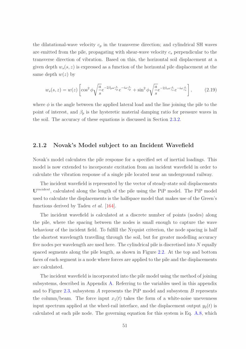
the dilatational-wave velocity cp in the transverse direction; and cylindrical SH waves
are emitted from the pile, propagating with shear-wave velocity cs perpendicular to the
transverse direction of vibration. Based on this, the horizontal soil displacement at a
given depth ws(s, z) is expressed as a function of the horizontal pile displacement at the
same depth w(z) by
ws(s, z) = w(z)
[
cos2 φ
√
a
se−2βpω s
cp e−iω s
cp + sin2 φ
√
a
se−2βsω s
cs e−iω scs
]
, (2.19)
where φ is the angle between the applied lateral load and the line joining the pile to the
point of interest, and βp is the hysteretic material damping ratio for pressure waves in
the soil. The accuracy of these equations is discussed in Section 2.3.2.
2.1.2 Novak’s Model subject to an Incident Wavefield
Novak’s model calculates the pile response for a specified set of inertial loadings. This
model is now extended to incorporate excitation from an incident wavefield in order to
calculate the vibration response of a single pile located near an underground railway.
The incident wavefield is represented by the vector of steady-state soil displacements
Uincident, calculated along the length of the pile using the PiP model. The PiP model
used to calculate the displacements is the halfspace model that makes use of the Green’s
functions derived by Tadeu et al. [164].
The incident wavefield is calculated at a discrete number of points (nodes) along
the pile, where the spacing between the nodes is small enough to capture the wave
behaviour of the incident field. To fulfill the Nyquist criterion, the node spacing is half
the shortest wavelength travelling through the soil, but for greater modelling accuracy
five nodes per wavelength are used here. The cylindrical pile is discretised into N equally
spaced segments along the pile length, as shown in Figure 2.2. At the top and bottom
faces of each segment is a node where forces are applied to the pile and the displacements
are calculated.
The incident wavefield is incorporated into the pile model using the method of joining
subsystems, described in Appendix A. Referring to the variables used in this appendix
and to Figure 2.3, subsystem A represents the PiP model and subsystem B represents
the column/beam. The force input x1(t) takes the form of a white-noise unevenness
input spectrum applied at the wheel-rail interface, and the displacement output y2(t) is
calculated at each pile node. The governing equation for this system is Eq. A.8, which
51
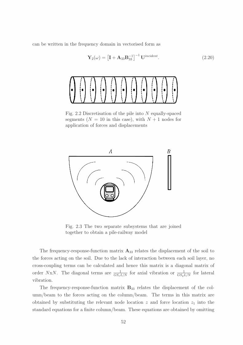
can be written in the frequency domain in vectorised form as
Y2(ω) =[
I + A33B−133
]−1Uincident. (2.20)
Fig. 2.2 Discretisation of the pile into N equally-spacedsegments (N = 10 in this case), with N + 1 nodes forapplication of forces and displacements
Fig. 2.3 The two separate subsystems that are joinedtogether to obtain a pile-railway model
The frequency-response-function matrix A33 relates the displacement of the soil to
the forces acting on the soil. Due to the lack of interaction between each soil layer, no
cross-coupling terms can be calculated and hence this matrix is a diagonal matrix of
order NxN . The diagonal terms are 1GSzL/N
for axial vibration or 1GSyL/N
for lateral
vibration.
The frequency-response-function matrix B33 relates the displacement of the col-
umn/beam to the forces acting on the column/beam. The terms in this matrix are
obtained by substituting the relevant node location z and force location z1 into the
standard equations for a finite column/beam. These equations are obtained by omitting
52

the soil reaction terms GSz and GSy from the definitions of α and β given in Eqs. 2.11
and 2.13.
2.2 A Three-Dimensional Model
The Novak model is a computationally efficient model of a single pile; however, it as-
sumes plane-strain conditions and it uses simplifying assumptions to obtain equations for
calculating soil displacements in the farfield. Later in this chapter it will be shown that
the plane-strain assumption and the approximate wave-spreading equations presented
in Section 2.1.1 do not provide an accurate means of accounting for soil behaviour. For
this reason, and because no computationally efficient, three-dimensional model exists in
the literature, a novel single-pile model is developed.
The PiP model consists of two cylinders: the outer cylinder representing the soil is
modelled as an elastic continuum with an infinite outer radius and an inner radius equal
to the outer radius of the tunnel. The tunnel is modelled as a thin-walled cylinder. This
configuration is not solely applicable to a tunnel, but can also be used to represent other
infinitely long embedded objects, such as pipelines. The PiP model is computationally
efficient, three-dimensional, and has been shown to accurately model soil behaviour [51].
For these reasons, the novel single-pile model is obtained by adapting the PiP model of
a tunnel embedded in a fullspace.
There are two major differences between the PiP model and a three-dimensional
(3D), single-pile model. Firstly, the tunnel in the PiP model is modelled by a thin-
walled cylinder with many cylindrical modes of deformation, as shown in Figure 2.4
and discussed further in Chapter 4. Piles, however, generally have a solid, circular
cross-section. As the stiffness of the pile is far greater than that of the soil, the pile’s
displacement does not vary significantly across the cross-section of the pile. This means
that it is only necessary to consider the n = 0 out-of-plane flexural mode for axial pile
vibration and the n = 1 in-plane flexural mode for lateral pile vibration. The motion
of the pile can therefore be represented by a column in axial vibration or an Euler-
Bernoulli beam in lateral vibration. Whilst this model may neglect small amounts
of cross-coupling between different vibration directions, it is expected that the overall
behaviour of the pile can be sufficiently captured using these one-dimensional models
for axial and lateral vibration. Secondly, the tunnel in the PiP model is infinitely long,
whereas the pile has a finite length. If the PiP model is to be adapted for modelling
a pile, methods for reducing an infinitely long model to a finite-length model must be
formulated. These methods are detailed in Sections 2.2.3 & 2.2.4.
53

Fig. 2.4 Cylindrical modes of a thin-walled cylinder: (a) in-plane flexural ringmodes, corresponding to radial deformations Ur cos nθ; (b) in-plane exten-sional ring modes, corresponding to tangential deformations Uθ sin nθ; and (c)out-of-plane flexural ring modes, corresponding to longitudinal deformationsUz cos nθ. The crosses mark the point θ = 0 on the undeformed ring, andthe circles in (b) mark the additional nodal points on the ring’s circumference(reproduced from Forrest [41])
In the proceeding sections, the PiP model is adapted to model an infinitely long pile
embedded in soil and undergoing axial and lateral vibration. The full derivation of the
relevant elastic-continuum equations is found in Forrest [41].
2.2.1 Axial Vibration of an Infinite Pile
Consider an infinite column of radius a, defined by right-handed cylindrical coordinates
(r, θ, z), that is undergoing axial vibration and embedded in an infinite, elastic con-
tinuum. The displacement of the column at any given distance z along the column is
invariant through the cross-section, thus the displacement of the column at any point
is defined solely by the displacement in the z-direction: Uz. The tilde indicates that
the variable is defined in the wavenumber (ξ) domain, and the capitalisation indicates
that the variable is defined in the frequency domain. The pile displacements in the
tangential and radial directions, Uθ and Ur, respectively, are zero (Poisson effects are
54

neglected). The column is assumed to be perfectly welded to the continuum at the
column-continuum interface, so the displacement on the inner surface of the elastic con-
tinuum is also defined only by Uz. The elastic-continuum equations presented in Forrest
[41] are used to obtain the stresses {Trr, Trθ, Trz}T acting at the outer surface of the
column due to some arbitrary imposed displacement distribution Uz:
Trr
Trθ
Trz
= [T∞]r=a [U∞]−1r=a
0
0
1
Uz, (2.21)
where the elements of the matrices [T∞] and [U∞] are given in Appendix B.
The magnitude of the stress in the rθ direction is zero, and the magnitude of the
stress in the rr direction is negligible, therefore this stress is ignored. The force per unit
length Frz arising from the stress Trz acting on the column in the axial (z) direction at the
column-continuum interface is obtained by integrating over the column circumference:
Frz =
∫ 2π
0
Trzadθ = 2πaTrz. (2.22)
The force per unit length acting on the column at the column-continuum interface
Frz is now related to the displacement distribution imposed at the column-continuum
interface Uz by a function of ξ, the longitudinal wavenumber. This function of ξ rep-
resents the vertical stiffness per unit length of the elastic continuum, Kz(ξ), and the
relationship can be written as
Frz = 2πa[
0 0 1]
[T∞]r=a [U∞]−1r=a
0
0
1
Uz = −Kz(ξ)Uz. (2.23)
The elastic continuum (the soil) is represented by this stiffness function, which can
be evaluated numerically using the above matrix equations. It should be noted that this
stiffness function is not constant, but rather represents a function in the wavenumber
domain. The soil should not be considered to be an equivalent elastic (Winkler) foun-
dation, as this results in the nonhomogeneous column-on-elastic-foundation equation
−EA∂2uz
∂z2+ k(z)uz + m′∂
2uz
∂t2= δ(z), (2.24)
where the term δ(z) represents a unit, harmonic excitation applied at z = 0. The Fourier
transformation of this column-on-elastic-foundation equation requires a convolution as
55
both k(z) and uz are functions of z. The pile should instead be considered as being
subject to a resulting force distribution frz(z) imposed on the pile by the soil, where
frz(z) is the Fourier transformation pair of Frz(z). This force distribution has already
been expressed and evaluated as a function of Uz in the wavenumber domain (Eq. 2.23),
thus avoiding the solving of a nonhomogeneous equation.
The force imposed by the soil on the pile is equal and opposite to the force imposed
by the pile on the soil, and the displacement of the pile is equal to the displacement of
the soil at the pile-soil interface. Using the standard equation for the axial vibration of
an infinite column with Young’s modulus E, cross-sectional area A and mass per unit
length m′, the equation of this system is
−EA∂2uz
∂z2+ m′∂
2uz
∂t2= δ(z) + frz(z). (2.25)
Application of the Fourier transformation, substitution of Eq. 2.23 and rearrangement
of the resulting equation gives the displacement of the pile subject to a unit loading in
the wavenumber domain as
Uz(ξ) =1
EAξ2 + Kz(ξ) − m′ω2. (2.26)
The displacement of the pile in the space domain is obtained by application of an inverse
Fourier transformation, defined here as
uz(z) =1
2π
∫ ∞
−∞Uz(ξ)e
iξzdξ. (2.27)
The displacements{
Ur, Uθ, Uz
}T
r=Rat some radius R elsewhere in the soil can be
calculated using
Ur
Uθ
Uz
r=R
= [U∞]r=R [U∞]−1r=a
0
0
Uz
r=a
. (2.28)
The displacements in space and time{
ur(z, t) uθ(z, t) uz(z, t)}T
of a point in
the soil are obtained by applying an inverse Fourier transformation to the wavenumber-
domain displacements{
Ur, Uθ, Uz
}T
. These displacements are given by
ur(z, t)
uθ(z, t)
uz(z, t)
=1
2π
∫ ∞
−∞
Ur
0
Uz
eiξzdξeiωt. (2.29)
56
2.2.2 Lateral Vibration of an Infinite Pile
Consider an infinite beam of radius a undergoing lateral vibration (n = 1) and embedded
in an infinite, elastic continuum. The lateral displacement of the beam is invariant
through the cross-section, thus the displacement of the beam is a function of the radial
and tangential components of the displacement: Ur cos θ and Uθ sin θ, respectively. For
some arbitrary imposed lateral displacement of the beam W in the outwards radial
direction at θ = 0, it can be written that
Ur = −Uθ = W . (2.30)
There is no displacement in the Uz direction, and the beam is assumed to be perfectly
welded to the elastic continuum at the beam-continuum interface. The magnitudes of
the stresses at the outer surface of the beam of radius a are
Trr
Trθ
Trz
= [T∞]r=a [U∞]−1r=a
1
−1
0
W . (2.31)
The magnitude of the stress in the rz direction is negligible. The stress in the lateral
(y) direction Try at a given value of θ is written as the vector summation of the stresses
in the radial (Trr cos θ) and tangential (Trθ sin θ) directions:
Try = Trr cos2 θ − Trθ sin2 θ. (2.32)
The force per unit length Fry arising from the lateral stress acting at the beam-
continuum interface is obtained by integrating over the beam circumference:
Fry =
∫ 2π
0
(Trr cos2 θ − Trθ sin2 θ)adθ = πa(Trr − Trθ). (2.33)
Thus the force per unit length acting on the beam at the beam-continuum interface Fry
is related to the displacement distribution imposed at the beam-continuum interface W
by a function of ξ. This function of ξ represents the horizontal stiffness per unit length
of the elastic continuum, Ky(ξ), and is calculated from
Fry = πa[
1 −1 0]
[T∞]r=a [U∞]−1r=a
1
−1
0
W = −Ky(ξ)W . (2.34)
57

Following a similar procedure to that for the column, but now using the Euler-
Bernoulli equation for the lateral vibration of an infinite beam with second moment of
area I, the governing equation of this system is
EI∂4w
∂z4+ m′∂
2w
∂t2= δ(z) + fry(z). (2.35)
Application of the Fourier transformation, substitution of Eq. 2.34 and rearrange-
ment of the resulting equation gives the displacement of the pile in the wavenumber
domain as
W (ξ) =1
EIξ4 + Ky(ξ) − m′ω2. (2.36)
The displacements{
Ur, Uθ, Uz
}T
r=Rat some radius R elsewhere in the soil can be
calculated using
Ur
Uθ
Uz
r=R
= [U∞]r=R [U∞]−1r=a
W
−W
0
r=a
. (2.37)
The displacements in space{
ur(z, t) uθ(z, t) uz(z, t)}T
are obtained by applying
an inverse Fourier transformation to the wavenumber-domain displacements{
Ur, Uθ, Uz
}T
.
These displacements are given by
ur(z, t)
uθ(z, t)
uz(z, t)
=1
2π
∫ ∞
−∞
Ur cos θ
Uθ sin θ
Uz cos θ
eiξzdξeiωt. (2.38)
2.2.3 Axial Vibration of a Finite Pile
The introduction of a boundary into an infinite system involves the simulation of end
conditions, which can be achieved by applying scaled forces and moments to the system.
For the case of a single pile undergoing axial vibration, the mirror-image method can
be used to simulate zero-force and zero-displacement conditions, which correspond to
free and fixed ends, respectively. The mirror-image method is illustrated using finite
columns in Appendix C.
This section outlines the application of the mirror-image method to simulate the
response of a single, finite-length pile using the superposition of axial forces on a single,
infinite pile. It is noted in Section 2.2.1 that, when considered in the space domain,
the model of an infinite pile undergoing axial vibration results in a nonhomogeneous
58
differential equation. The solving of this equation is avoided by considering the problem
in the wavenumber domain. As the application of the mirror-image method to piles is
best illustrated using equations of motion determined in the space domain, this section
begins by ignoring the soil and considering only an infinite column undergoing axial
vibration. It is later shown how this method can be extended to include the soil.
Before presenting the equations, an important stipulation regarding the mirror-image
method must be made. Whilst it will be shown that exact solutions can be obtained
using the mirror-image method on columns or beams, when this method is applied to
systems with three-dimensional stress states, errors do arise. This is because the mirror-
image method does not produce a stress field which completely satisfies the traction-free
boundary conditions at the free surface. For example, when mirror-image vertical forces
are applied, the vertical stress at the simulated free surface is zero due to symmetry,
but there exists some residual shear stress at the simulated free surface, as the shear
stresses do not cancel by symmetry. Similarly, when mirror-image lateral forces are
applied, the shear stress at the simulated free surface is zero due to symmetry, but there
exists some residual vertical stress at the simulated free surface [157]. Given that in
this dissertation the systems to which the mirror-image method is being applied are
assumed to be decoupled in the vertical and horizontal directions, it is estimated that
the magnitude of the error introduced by using this method is small. However, it is
recognised that this error may become significant when displacements perpendicular to
the primary direction of excitation are calculated on the simulated free surface. The
magnitude of this error is investigated in Section 2.3.
Consider the infinite column shown in Figure 2.5(a). This column is reduced to a har-
monically excited, semi-infinite column by applying twice the force P to a mirror-image
plane. The resulting semi-infinite system, shown in Figure 2.5(b), has the governing
equation
Y1(z) =−Pie−iαz
EAα, (2.39)
where
α = +
√
ρω2
E. (2.40)
The stress σ at a distance L from the free end of the semi-infinite column is defined
as
σ = E
(
dY1
dz
)
z=L
=−Pe−iαL
A. (2.41)
In order to create a free end condition at z = L, and thus simulate a column of
finite length L, it is necessary to apply an equal and opposite stress to the column at
z = L. To do this, two equal forces P ∗ are applied to the infinite column at z = −L and
59

z = L, respectively, as shown in Figure 2.5(c). These two forces simulate a semi-infinite
column with a force P ∗ acting at z = L. The governing equation for this system, shown
in Figure 2.5(d), is
Y2(z) =−P ∗i (eiαz + e−iαz)
EAα (eiαL − e−iαL), (2.42)
and the stress produced by this force at z = L is
σ = E
(
dY2
dz
)
z=L
=P ∗
A. (2.43)
Fig. 2.5 (a) Infinite column with load 2P at z = 0; (b) semi-infinitecolumn with end loading P ; (c) infinite column with load P ∗ at z = −L
and z = L; and (d) semi-infinite column with load P ∗ at z = L
In order for this stress to be the equal and opposite of that produced by the original
load P (Eq. 2.41), the force equilibrium statement
P ∗ = Pe−iαL (2.44)
must be fulfilled.
Superposing the displacements due to the original load, Y1, and the displacements
due to the loads acting at z = L and z = −L, Y2, gives the response
Y1(z) + Y2(z) =−Pi
(
e−iα2Leiαz + e−iαz)
EAα (1 − e−iα2L), (2.45)
which is the governing equation for a free-free finite column of length L subject to
excitation P at z = 0. This demonstrates the application of the mirror-image method
to infinite systems in order to simulate the response of a finite system.
60

Extension of this procedure to the infinite cylinder-soil system results in the approx-
imate axial driving-point response of a finite pile. The procedure is outlined below.
1. Calculate the response of the column-soil system using Eq. 2.26, when twice the
unit force is applied to the column at z = 0.
2. Use Eq. 2.29 to transform this response into the space domain, then calculate the
force EAdudz
at z = L.
3. Apply scaled mirror-image forces P ∗x = −EA
(
dudz
)
z=Lto the column at z = L
and z = −L, both acting in the same direction, and calculate the response of the
column-soil system in the z-domain using Eq. 2.26 & 2.29.
4. Superimpose the displacement response calculated in Step 2 and the displacement
response from the mirror-image forces.
2.2.4 Lateral Vibration of a Finite Pile
An end condition for an Euler-Bernoulli beam undergoing lateral vibration requires the
specification of two boundary conditions. For example, a free end is characterised by
zero shear force and zero moment acting on the end; a pinned end is characterised by
zero displacement of the end and zero moment acting on the end; and a fixed end is
characterised by zero displacement and zero rotation of the end. There are four param-
eters of interest for Euler-Bernoulli beams undergoing lateral vibration: displacement
w, rotation dwdz
, moment −EI d2wdz2 , and shear force −EI d3w
dz3 . The sign convention used
here defines the positive direction of the shearing force as acting upwards on the left
of the elemental section, and the positive direction of the moment on the left of the
elemental section as acting clockwise. Figures 2.6 & 2.7 show the variation of these four
parameters for two cases: a shear force is applied to an infinite beam; and a moment is
applied to an infinite beam.
When using the mirror-image method, only two of the four parameters can be set
to known values at any given position. To demonstrate this, consider the infinite beam
shown in Figure 2.8(a), where a shear force P applied at z = L has been mirror imaged
about the z = 0 plane. As both forces are acting in the same direction, the parameters
that are odd functions (rotation and shear force) will sum to zero at z = 0, whereas the
parameters that are even functions (displacement and moment) will not sum to zero at
z = 0. Now consider the infinite beam shown in Figure 2.8(b), where the forces are
acting in opposite directions. In this case the even functions will sum to zero at z = 0
whereas the odd functions will not sum to zero at z = 0. When moments acting in the
61

Fig. 2.6 Infinite beam loaded withforce P . Shown from top to bottom:schematic of the loaded beam; displace-ment w; rotation θ = dw
dz; moment M =
−EI d2wdz2 ; and shear force F = −EI d3w
dz3
same direction are applied to the infinite beam, the parameters that are odd functions
(displacement and moment) will sum to zero at z = 0, whereas the even functions
(rotation and shear force) will not sum to zero at z = 0. When these moments act in
opposite directions, the rotation and shear force will sum to zero at z = 0, whereas the
displacement and moment will not.
Two important observations result from this. Firstly, the creation of a free or fixed
end on an infinite beam requires the application of both mirror-image shear forces and
moments. Secondly, in order to ensure a parameter is equal to zero at the mirror-image
plane, the sign of one, and only one, of the mirror-image shear forces must be opposite
to the sign of one of the mirror-image moments. For example, to produce zero rotation
at z = 0, both the shear forces must act in the same direction, whereas the moments
must act in opposite directions.
This section outlines a procedure for simulating a finite beam with known force P
applied at one end, and a free end at z = L, from an infinite beam. The infinite beam
is reduced to a semi-infinite beam with shear force P and zero rotation at the end by
62
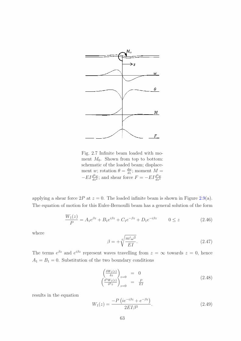
Fig. 2.7 Infinite beam loaded with mo-ment M0. Shown from top to bottom:schematic of the loaded beam; displace-ment w; rotation θ = dw
dz; moment M =
−EI d2wdz2 ; and shear force F = −EI d3w
dz3
applying a shear force 2P at z = 0. The loaded infinite beam is shown in Figure 2.9(a).
The equation of motion for this Euler-Bernoulli beam has a general solution of the form
W1(z)
P= A1e
βz + B1eiβz + C1e
−βz + D1e−iβz 0 ≤ z (2.46)
where
β = +4
√
m′ω2
EI. (2.47)
The terms eβz and eiβz represent waves travelling from z = ∞ towards z = 0, hence
A1 = B1 = 0. Substitution of the two boundary conditions
(
δW1(z)δz
)
z=0= 0
(
δ3W1(z)δ3z
)
z=0= P
EI
(2.48)
results in the equation
W1(z) =−P
(
ie−iβz + e−βz)
2EIβ3. (2.49)
63

Fig. 2.8 (a) Infinite beam loaded with mirror-image forces P acting in the samedirection; and (b) infinite beam loaded with mirror-image forces P acting in oppositedirections
This is also the equation of motion as for the system shown in Figure 2.9(b). In producing
the load P at the end of the semi-infinite beam, the beam is constrained to have zero
rotation at the end, meaning that this end is not by definition ‘free’. To allow free
rotation of this end, it is necessary to apply a moment at z = 0. This moment would
produce an additional force acting at the end. Thus, to obtain a free end, the magnitude
of the forces and moments applied to the infinite beam must be suitably scaled to
produce a net force of P and a net moment of zero acting on the end of the semi-
infinite beam. This method is straightforward to implement when considering a simple,
continuous system such as the Euler-Bernoulli beam. However, when the displacements
of a more complex system are being evaluated at discrete points, as is the case for
the three-dimensional pile model, the calculation of the second and third derivatives
corresponding to the moment and force, respectively, introduces a high level of numerical
error in the area of the applied loadings. For this reason, a force (and no moment) is
applied to the infinite beam at z = 0 such that there is no rotation at z = 0. This is a
reasonable assumption as many piled foundations have the piles rigidly connected to a
pile cap. This connection impedes pile-head rotation due to the large mass of the pile
cap. The neglecting of the rotational component of motion is further justified by the
results of Talbot’s model [166]. For an infinite pile row connected to an infinite building,
the rotational motion represents the smallest contribution to the mean power flowing
into the building of the three components of motion (vertical, horizontal and rotational)
that are considered. The size of this contribution generally varies between ±5%.
To create a free end at z = L, it is first necessary to determine the moment and the
force acting at z = L on the semi-infinite beam. These are obtained by differentiating
the equation of motion, Eq. 2.49. The moment is written as
−EI
(
d2W
dz2
)
z=L
=P
(
−ie−iβL + e−βL)
2β, (2.50)
64

and the shear force is written as
−EI
(
d3W
dz3
)
z=L
=P
(
−e−iβL − e−βL)
2. (2.51)
Mirror-image moments and forces are then applied to the infinite beam to create
zero net moment and zero net force at z = L. The direction of the forces and moments
are chosen to preserve the zero-rotation condition at z = 0, and to ensure that no
additional force is applied at z = 0. Thus both the forces act in the same direction,
and the moments act in opposite directions, as shown in Figure 2.9(c). The equation of
motion for this system is
W2(z) =−F
(
ie−iβ(z+L) + e−β(z+L) + ieiβ(z−L) + eβ(z−L))
4EIβ3
+M
(
e−iβ(z+L) − e−β(z+L) + eiβ(z−L) − eβ(z−L))
4EIβ2.
(2.52)
Setting the forces and moments at z = L to be equal and opposite to those on the
semi-infinite beam (Eq. 2.50 & 2.51) results in
P(
ie−iβL − e−βL)
2β=
F(
−ie−iβ2L + e−β2L − i + 1)
4β
− M(
e−iβL + e−βL + 2)
4
(2.53)
and
P(
e−iβL + e−βL)
2=
F(
−e−iβ2L − e−β2L + 2)
4
− Mβ(
−ie−iβ2L − e−β2L + i + 1)
4.
(2.54)
These two equations are solved simultaneously to determine values for F and M . Sub-
stitution of these values into Eq. 2.52 gives the equation of motion for the system shown
in Figure 2.9(d), which, when summed with the equation of motion for the semi-infinite
beam shown in Figure 2.9(b), gives the equation of motion of the finite beam shown in
Figure 2.9(e).
65

Fig. 2.9 (a) Infinite beam loaded with force 2P at z = 0; (b) semi-infinite beam loaded with force P and rotation-constrained at z = 0;(c) infinite beam loaded with forces F and moments M at z = −L andz = L; (d) semi-infinite beam loaded with force F and moment M atz = L; and (e) finite beam loaded with force P and rotation-constrainedat z = 0
Extension of this procedure to the infinite beam-soil system results in the approxi-
mate lateral driving-point response of a finite pile. The procedure is outlined below.
1. Apply twice the unit force to the infinite beam, and calculate the response of the
beam-soil system using Equation 2.36.
2. Transform this response into the space domain using Equation 2.38, and calcu-
late the moment −EI d2wdz2 and shear force −EI d3w
dz3 distributions along the beam.
Obtain the shear force and moment at z = L.
3. Apply unit, mirror-image forces acting in the same direction at z = L and z = −L
to the beam, and calculate the response of the beam-soil system in the space
domain using Eq. 2.36 and the inverse Fourier transformation.
4. Calculate the response of the beam-soil system in the space domain to unit, mirror-
image moments acting in opposite directions at z = L and z = −L. Note that it
66
is not necessary to apply the moments directly to the beam, as it can be observed
from Figures 2.6 & 2.7 that the response of the system to a unit moment is the
derivative of the response of the system (in the space domain) to a unit force.
5. Calculate the resulting moment and force at z = L due to the mirror-image forces,
and calculate the resulting moment and force at z = L due to the mirror-image
moments. Scale the mirror-image moments and forces such that the net moment
and the net force produced at z = L are equal and opposite to those moments and
forces obtained in Step 2.
6. Superimpose the displacement responses due to the unit force from Step 1, and
the mirror-image forces and moments from Step 5.
2.2.5 Incident Wavefields
As with Novak’s model, the incident wavefield generated by the PiP model is incorpo-
rated into the three-dimensional model using the method of joining subsystems. How-
ever, as the three-dimensional model represents an infinite system discretised in the
wavenumber domain, the coupling equation for this system (Eq. A.8) is written in
vectorised form in the wavenumber domain, rather than the space domain, as
Y2(ω) =[
I + A33B−1
33
]−1
Uincident
. (2.55)
The frequency-response-function matrix A33 relates the displacements at the cylin-
drical void to the forces acting on the cylindrical void. This has already been determined
in the form of the vertical or horizontal soil stiffness of the elastic continuum. Hence in
axial vibration
A33 =1
Kz(ξ), (2.56)
and in lateral vibration
A33 =1
Ky(ξ). (2.57)
The frequency-response-function matrix B33 relates the displacement of the col-
umn/beam to the forces acting on the column/beam. This is given by the equation
for an infinite column in the wavenumber domain, written as
B33 =1
EAξ2 − m′ω2; (2.58)
67

or an infinite beam in the wavenumber domain, written as
B33 =1
EIξ4 − m′ω2. (2.59)
The incident wavefield, Uincident
, is required in the wavenumber domain, however
the output from the PiP model is given at a series of discrete points in the space do-
main. The transformation from the space domain to the wavenumber domain involves
a discrete Fourier transformation, calculated numerically at a sufficiently large number
of discrete points to capture all of the displacement response. The number of discrete
points required in the PiP model for conversion from the wavenumber domain to the
space domain without any loss of dynamic behaviour is N = 2048. The calculation of
the incident wavefield at every one of 1024 points along the length of the semi-infinite
pile represents a considerable computational investment, limiting the efficiency of the
formulation. Hence it is preferable to calculate the incident wavefield at a sufficient
number of points in the space domain to represent accurately the wavefield whilst main-
taining computational efficiency. Due to the damping influence of the soil, it is expected
that those points at a considerable distance from the finite-pile region will have little
influence on the response of the finite pile. For this reason, the response of the finite
pile subjected to an incident wavefield can be determined using a reduced number of
points in the space domain. This is discussed further in Section 2.3.3.
Substitution of the frequency-response-function matrices and the incident wavefield
into Eq. 2.55 determines the displacement of the semi-infinite pile subject to an incident
wavefield. The mirror-image method in Sections 2.2.3 & 2.2.4 is then used to convert
the semi-infinite pile to a finite pile.
2.3 Validation and Comparison of Models
The single-pile model is an idealised system; therefore, validation of the numerical mod-
els derived above cannot easily be achieved by comparison with experimental results.
Instead, the numerical models that are derived in this chapter are compared with the
output of a more complex numerical method, namely a boundary-element method. The
frequency range of interest for underground-railway vibration is 1-80Hz; therefore results
will be presented for this frequency range. For models which include only piles and no
railway, the results are presented in terms of dimensionless frequency: a0 = ωacs
.
The model presented for comparison is a boundary-element model (BEM) developed
by Talbot [166] and furthered by Coulier [25]. This model incorporates the vertical,
68
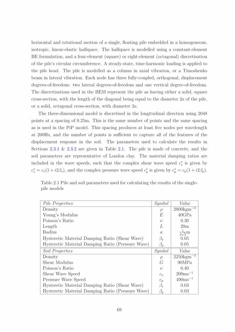
horizontal and rotational motion of a single, floating pile embedded in a homogeneous,
isotropic, linear-elastic halfspace. The halfspace is modelled using a constant-element
BE formulation, and a four-element (square) or eight-element (octagonal) discretisation
of the pile’s circular circumference. A steady-state, time-harmonic loading is applied to
the pile head. The pile is modelled as a column in axial vibration, or a Timoshenko
beam in lateral vibration. Each node has three fully-coupled, orthogonal, displacement
degrees-of-freedom: two lateral degrees-of-freedom and one vertical degree-of-freedom.
The discretisations used in the BEM represent the pile as having either a solid, square
cross-section, with the length of the diagonal being equal to the diameter 2a of the pile,
or a solid, octagonal cross-section, with diameter 2a.
The three-dimensional model is discretised in the longitudinal direction using 2048
points at a spacing of 0.25m. This is the same number of points and the same spacing
as is used in the PiP model. This spacing produces at least five nodes per wavelength
at 200Hz, and the number of points is sufficient to capture all of the features of the
displacement response in the soil. The parameters used to calculate the results in
Sections 2.3.1 & 2.3.2 are given in Table 2.1. The pile is made of concrete, and the
soil parameters are representative of London clay. The material damping ratios are
included in the wave speeds, such that the complex shear wave speed c∗s is given by
c∗s = cs(1 + i2βs), and the complex pressure wave speed c∗p is given by c∗p = cp(1 + i2βp).
Table 2.1 Pile and soil parameters used for calculating the results of the single-pile models
Pile Properties Symbol ValueDensity ρ 2800kgm−3
Young’s Modulus E 40GPaPoisson’s Ratio ν 0.30Length L 20mRadius a 1
2√
2m
Hysteretic Material Damping Ratio (Shear Wave) βs 0.05Hysteretic Material Damping Ratio (Pressure Wave) βp 0.05
Soil Properties Symbol ValueDensity ρ 2250kgm−3
Shear Modulus G 90MPaPoisson’s Ratio ν 0.40Shear Wave Speed cs 200ms−1
Pressure Wave Speed cp 490ms−1
Hysteretic Material Damping Ratio (Shear Wave) βs 0.03Hysteretic Material Damping Ratio (Pressure Wave) βp 0.03
69

2.3.1 The Infinite Pile
The validation of the three-dimensional model begins with consideration of the infinitely
long pile in axial or lateral vibration. The equations for the infinite pile, presented in
Sections 2.2.1 and 2.2.2, are compared to a modified version of the BEM. To simulate
an infinitely long pile, the free surface has been removed from the BEM and the pile has
been extended to a length that is sufficient to model the behaviour of the infinite pile.
Further details of this work are presented in Coulier [25]. Two sets of results using the
BEM are calculated: a pile of length L = 40m with an octagonal cross-section; and a
pile of length L = 100m with a square cross-section.
The response of the infinite pile as a function of non-dimensional frequency a0 = ωacs
is presented in Figures 2.10 and 2.11. The frequency range shown in these figures
corresponds to 0-80Hz. In both of these figures the magnitude and the phase for the
driving-point response are calculated. The response of the infinitely long pile in both
axial and lateral vibration varies smoothly with frequency. No resonant peaks are ob-
served in the response, as is expected for an infinitely long structure with a rigid cross
section.
The phase of the driving-point response of a pile will approach zero as the frequency
tends to zero, as the static driving-point response is purely real. A phase artefact, due
to the use of the correspondence principle for material damping, exists in the models
near zero frequency. The phase of the response approaches a number close to, but not
equal to, zero.
The agreement between the three-dimensional model and the BEM improves when
the length of the BE pile increases and when the pile’s circular cross-section is repre-
sented by an octagon rather than a square. It is expected that the addition of more
boundary elements around the pile circumference would further improve the agreement
between the two models.
70

0 0.1 0.2 0.3 0.4 0.5 0.6 0.7 0.8−200
−195
−190
−185
a0=ω a/c
s
|u(0
)| d
Bre
f[1m
/N]
0 0.1 0.2 0.3 0.4 0.5 0.6 0.7 0.8
−60
−40
−20
0
a0=ω a/c
s
∠u(
0) [°
]
3DBEM SquareBEM Octagon
Fig. 2.10 The magnitude and phase of the axial driving-point response of aninfinite pile
0 0.1 0.2 0.3 0.4 0.5 0.6 0.7 0.8−190
−185
−180
−175
a0=ω a/c
s
|w(0
)| d
Bre
f[1m
/N]
0 0.1 0.2 0.3 0.4 0.5 0.6 0.7 0.8
−60
−40
−20
0
a0=ω a/c
s
∠w
(0)
[°]
3DBEM SquareBEM Octagon
Fig. 2.11 The magnitude and phase of the lateral driving-point response of aninfinite pile
71

2.3.2 The Finite Pile
The response of a finite pile as a function of frequency is presented in Figures 2.12 and
2.13. In these figures, the results for Novak’s model, the three-dimensional model and
the BEM with square and octagonal cross-sections are presented.
The response of the finite pile in both axial and lateral vibration varies smoothly
with frequency. A column with the same dimensions, material properties and boundary
conditions of the finite pile has the first two natural frequencies at 0Hz and 94.5Hz. A
beam with the same dimensions, material properties and boundary conditions of the
finite pile has the first seven natural frequencies at 0Hz, 1.5Hz, 8.0Hz, 19.8Hz, 36.9Hz,
59.2Hz and 86.8Hz. None of these beam or column resonances are observed, which
implies that the soil has a strong damping effect on the pile.
In both axial and lateral vibration, the phase of the driving-point response calculated
using Novak’s model does not approach zero as the frequency tends to zero. This is
because the soil reactions are poorly-defined at very low frequencies. A phase artefact
due to the material damping coefficient is again observed in the 3D and BE models at
very low frequencies.
In axial vibration, the agreement between the four models is very good, with less
than 2dB and 10◦ variation existing over the frequency range of 80Hz. The agreement
between the three-dimensional model and the BEM improves when the pile’s circular
cross-section is represented by an octagon rather than a square.
In lateral vibration, there is very good agreement (2dB, 5◦ variation) between the
three-dimensional model and the BEM over the frequency range of 0-80Hz. Again, the
octagonal cross-section BEM provides better agreement than the square cross-section
BEM.
For the lateral driving-point response, Novak’s model shows poor agreement with
the three-dimensional model and the BEM. The variation between Novak’s model and
the other models ranges between 10dB at low frequencies to 4dB at higher frequencies.
The Novak model consistently overestimates the response of the pile in lateral vibration.
In particular, the imaginary part of the compliance has been overestimated, as is also
observed by Kuhlemeyer [96]. This error in Novak’s model is due to the inaccuracy
introduced by the plane-strain assumption. Plane-strain conditions imply that the pile
is infinitely long in the z-direction, which is a reasonable assumption when the longest
wavelength in the pile is short compared to the displacement variation along the length of
the finite pile. To investigate the accuracy of the plane-strain assumption, Figures 2.14
& 2.15 show the real part of the displacement of the pile as a function of distance along
the pile, and dimensionless frequency a0 for axial and lateral vibration, respectively. The
72

0 0.1 0.2 0.3 0.4 0.5 0.6 0.7 0.8−195
−190
−185
−180
a0=ωa/c
s
|u(0
)| d
Bre
f[1m
/N]
0 0.1 0.2 0.3 0.4 0.5 0.6 0.7 0.8
−60
−40
−20
0
a0=ωa/c
s
∠u(
0) [°
]
Novak3DBEM SquareBEM Octagon
Fig. 2.12 The axial response of a pile subject to a unit harmonic excitation inthe z-direction
0 0.1 0.2 0.3 0.4 0.5 0.6 0.7 0.8−180
−175
−170
−165
a0=ωa/c
s
|w(0
)| d
Bre
f[1m
/N]
0 0.1 0.2 0.3 0.4 0.5 0.6 0.7 0.8
−60
−40
−20
0
a0=ωa/c
s
∠w
(0)
[°]
Novak3DBEM SquareBEM Octagon
Fig. 2.13 The lateral response of a pile (with zero rotation at the pile head)subject to a unit harmonic excitation in the w-direction
73

displacements are normalised with respect to the real part of the pile-head displacement,
and the shading scale on the right of these figures indicates this normalised coefficient. A
coefficient of one represents a real displacement equal to the real pile-head displacement.
The results shown in these figures are generated using the 3D model.
Figures 2.14 & 2.15 show a fundamental difference in the behaviour of piles in axial
and in lateral vibration. In axial vibration, at any given frequency, the displacement of
the pile is seen to be relatively invariant with length, with the displacement magnitude
decaying along the length of the pile. As the displacement variation along the length
of the pile is small, the plane-strain assumption is valid. Hence good agreement is seen
between the models in Figure 2.12 at every frequency except the lowest frequencies
(a0 < 0.03) within this range. In lateral vibration, the pile exhibits more localised de-
formations, with a steep decline in displacement magnitude near the pile head, and with
displacement oscillations along the length of the pile. Within the frequency range of 1-
80Hz, the longest wavelength in the pile is larger than the rate of displacement variation;
hence the plane-strain assumption provides a poor representation of pile behaviour. At
higher frequencies, the wavelength decreases and the plane-strain assumption models
the lateral pile behaviour more accurately. This is observed when the lateral driving-
point response is calculated at frequencies above 400Hz using the Novak and 3D models:
the variation between the two models is less than 1dB. The displacement behaviour of
the piles in axial and lateral vibration is explained by considering the geometry of the
pile. The pile is a slender cylinder, which is stiffer in axial compression than in lateral
bending.
74

Fig. 2.14 The normalised, real, axial displacement of a pile u(z)u(0)
as a functionof pile length and dimensionless frequency
Fig. 2.15 The normalised, real, lateral displacement of a pile w(z)w(0)
as a functionof pile length and dimensionless frequency
75

2.3.2.1 The Farfield Response
To further investigate the response of a single pile to pile-head excitation, the farfield
response is calculated on the free surface at distances of 5m, 10m and 20m from the pile.
Results at other depths are not available for comparison because the discretisation of
the soil in the BE model only allows displacements to be calculated at the free surface
and along the pile-soil interface. Figures 2.16 to 2.19 show the real and imaginary parts
of the vertical and horizontal displacements as a function of frequency when the pile
is excited by a vertical or horizontal pile-head load. The results of the Novak, the
three-dimensional and the BE models are shown.
For the case of the vertical farfield response when a vertical force is applied to the
pile head (Figure 2.16), all three models show good agreement in both the real and
imaginary part over the designated frequency range.
Novak’s model assumes that only SV waves propagate from a pile in axial vibration,
and only P and SH waves propagate from a pile in lateral vibration. These assump-
tions imply that farfield displacements are only produced in the direction of the pile’s
vibration. Hence, as is seen in Figures 2.17 and 2.18 for Novak’s model, the horizontal
farfield response is zero when a vertical force is applied to the pile head, and the vertical
farfield response is zero when a horizontal force is applied to the pile head.
The three-dimensional model shows only moderate agreement with the BEM in
Figures 2.17 and 2.18. The observed deviations are due to the error present in the
three-dimensional model, resulting from the use of the mirror-image method. This error
is discussed in Section 2.2.3, and is believed to be the primary cause of the deviation
encountered in these figures. This error only occurs in the farfield, and not on the pile
itself. The overall inaccuracy introduced into the calculated farfield displacements by
the use of the mirror-image method, when considering a pile subject to an incident
wavefield, is expected to be moderately small. This is because the farfield response in
any given direction is dominated by the displacements generated by the response of the
pile in that same direction, and not by the cross-coupling effects.
Novak’s model shows large deviations from the other models in Figure 2.19, which
shows the horizontal farfield response when a horizontal force is applied to the pile
head. This is due to two sources of error: firstly, the inaccuracy due to the plane-strain
assumption; and secondly, the inaccuracies present in the wave-spreading equation (Eq.
2.19), due to the assumption that only P and SH waves are propagated in the farfield.
For all response directions, the agreement between the three-dimensional model
and the BEM is good at low non-dimensional frequencies (a0 < 0.2), but as the non-
dimensional frequency increases, greater deviations are observed. This may be due to:
76

the deviation in the lateral driving-point response observed in Figures 2.12 & 2.13; error
introduced by use of the mirror-image method; and/or the constant-element discretisa-
tion used in the BEM.
0 0.2 0.4 0.6 0.8−2
−1
0
1
2x 10
−10
a0=ωa/c
s
ℜ(u
(0))
[m/N
]
0 0.2 0.4 0.6 0.8−2
−1
0
1
2x 10
−10
a0=ωa/c
s
ℑ(u
(0))
[m/N
]
0 0.2 0.4 0.6 0.8−2
−1
0
1
2x 10
−10
a0=ωa/c
s
ℜ(u
(0))
[m/N
]
0 0.2 0.4 0.6 0.8−2
−1
0
1
2x 10
−10
a0=ωa/c
s
ℑ(u
(0))
[m/N
]
0 0.2 0.4 0.6 0.8−2
−1
0
1
2x 10
−10
a0=ωa/c
s
ℜ(u
(0))
[m/N
]
0 0.2 0.4 0.6 0.8−2
−1
0
1
2x 10
−10
a0=ωa/c
s
ℑ(u
(0))
[m/N
]
Novak3DBEM SquareBEM Octagon
5m
10m
20m 20m
10m
5m
Fig. 2.16 Real (left) and imaginary (right) parts of the vertical farfield dis-placements on the surface of the halfspace (z = 0m) at distance 5m (top);10m (middle); and 20m (bottom) from a pile undergoing excitation in thez-direction
77

0 0.2 0.4 0.6 0.8−2
−1
0
1
2x 10
−10
a0=ωa/c
s
ℜ(w
(0))
[m/N
]
0 0.2 0.4 0.6 0.8−2
−1
0
1
2x 10
−10
a0=ωa/c
s
ℑ(w
(0))
[m/N
]
0 0.2 0.4 0.6 0.8−2
−1
0
1
2x 10
−10
a0=ωa/c
s
ℜ(w
(0))
[m/N
]
0 0.2 0.4 0.6 0.8−2
−1
0
1
2x 10
−10
a0=ωa/c
s
ℑ(w
(0))
[m/N
]
0 0.2 0.4 0.6 0.8−2
−1
0
1
2x 10
−10
a0=ωa/c
s
ℜ(w
(0))
[m/N
]
0 0.2 0.4 0.6 0.8−2
−1
0
1
2x 10
−10
a0=ωa/c
s
ℑ(w
(0))
[m/N
]
Novak3DBEM SquareBEM Octagon
5m
10m
20m 20m
10m
5m
Fig. 2.17 Real (left) and imaginary (right) parts of the horizontal farfield dis-placements on the surface of the halfspace (z = 0m) at distance 5m (top);10m (middle); and 20m (bottom) from a pile undergoing excitation in thez-direction
78

0 0.2 0.4 0.6 0.8−2
−1
0
1
2x 10
−10
a0=ωa/c
s
ℜ(u
(0))
[m/N
]
0 0.2 0.4 0.6 0.8−2
−1
0
1
2x 10
−10
a0=ωa/c
s
ℑ(u
(0))
[m/N
]
0 0.2 0.4 0.6 0.8−2
−1
0
1
2x 10
−10
a0=ωa/c
s
ℜ(u
(0))
[m/N
]
0 0.2 0.4 0.6 0.8−2
−1
0
1
2x 10
−10
a0=ωa/c
s
ℑ(u
(0))
[m/N
]
0 0.2 0.4 0.6 0.8−2
−1
0
1
2x 10
−10
a0=ωa/c
s
ℜ(u
(0))
[m/N
]
0 0.2 0.4 0.6 0.8−2
−1
0
1
2x 10
−10
a0=ωa/c
s
ℑ(u
(0))
[m/N
]
Novak3DBEM SquareBEM Octagon
5m
10m
20m
5m
10m
20m
Fig. 2.18 Real (left) and imaginary (right) parts of the vertical farfield dis-placements on the surface of the halfspace (z = 0m) at distance 5m (top);10m (middle); and 20m (bottom) from a pile undergoing excitation in thew-direction
79

0 0.2 0.4 0.6 0.8−2
−1
0
1
2x 10
−10
a0=ωa/c
s
ℜ(w
(0))
[m/N
]
0 0.2 0.4 0.6 0.8−2
−1
0
1
2x 10
−10
a0=ωa/c
s
ℑ(w
(0))
[m/N
]
0 0.2 0.4 0.6 0.8−2
−1
0
1
2x 10
−10
a0=ωa/c
s
ℜ(w
(0))
[m/N
]
0 0.2 0.4 0.6 0.8−2
−1
0
1
2x 10
−10
a0=ωa/c
s
ℑ(w
(0))
[m/N
]
0 0.2 0.4 0.6 0.8−2
−1
0
1
2x 10
−10
a0=ωa/c
s
ℜ(w
(0))
[m/N
]
0 0.2 0.4 0.6 0.8−2
−1
0
1
2x 10
−10
a0=ωa/c
s
ℑ(w
(0))
[m/N
]
Novak3DBEM SquareBEM Octagon
5m 5m
10m 10m
20m 20m
Fig. 2.19 Real (left) and imaginary (right) parts of the horizontal farfield dis-placements on the surface of the halfspace (z = 0m) at distance 5m (top);10m (middle); and 20m (bottom) from a pile undergoing excitation in thew-direction
80

2.3.2.2 Power Flow in a Single Pile
By analysing the power flow in a single pile, it is possible to determine the critical
positions where energy enters and exits the pile, thus allowing the design of effective
vibration-isolation systems. Power-flow methods also provide a useful check for un-
damped vibration models, as the mean power input must equal the mean power output
at any frequency.
For the Novak and the three-dimensional models, the displacements and forces are
calculated at a series of equally spaced nodes along the central pile axis. Applying the
mean power-flow equation to these nodes calculates the power flowing through the pile
cross-section. The mean power flow through the pile skin is thus given as the difference
in the mean power flows of two adjacent nodes. For the BEM, nodes exist on each of the
pile-skin faces, and hence application of the mean power-flow equation to one of these
nodes calculates the mean power flow through the pile-skin face.
For any undamped structure, the total mean power flow around the system boundary
must be equal to zero in order to satisfy conservation of energy requirements. For the
driving-point response of a single pile subject to a unit force, the mean input power flow
Pin is represented by the imaginary part of the driving-point response, and the mean
output power flow Pout is calculated by summing the mean power flow contributions over
all remaining nodes. Figures 2.20 and 2.21 show the mean input and output power flows
for the axial and lateral pile-head excitation of a single pile with no material damping.
Results are calculated for all three models.
As is expected for the undamped pile, these plots show that for all three models
the mean input power flow is equal to the mean output power flow over a range of
frequencies. For axial pile-head excitation, very little deviation is seen between the
three models over the frequency range. For lateral pile-head excitation, the Novak
model consistently overpredicts the power flows, but there is good agreement in the
three-dimensional and BE models. This overprediction is due to the inability of the
Novak model to accurately model pile behaviour in lateral vibration, as is observed in
Figure 2.13, the lateral driving-point response.
Figures 2.22 and 2.23 show the power outflow through the skin of a damped pile
undergoing axial and lateral excitation, respectively, and calculated using the 3D model.
These two plots reveal some trends in the behaviour of piles under axial and lateral
loadings. It can be seen that the power entering the pile by an axial loading is dissipated
along the whole length of the pile, with the maximum power outflow (15%) occurring
near the point of application of the load, and the magnitude of power outflow decreasing
with distance along the pile. The rate of decrease of the power outflow with distance
81

0 0.1 0.2 0.3 0.4 0.5 0.6 0.7 0.8−120
−110
−100
−90
−80
−70
−60
a0=ωa/c
s
Pow
er F
low
(dB
ref[1
W])
Novak Pin
3D Pin
BEM Square Pin
BEM Octagon Pin
Novak Pout
3D Pout
BEM Square Pout
BEM Octagon Pout
Fig. 2.20 Net power flow through a single pile subject to axial pile-head exci-tation, plotted as a function of dimensionless frequency
0 0.1 0.2 0.3 0.4 0.5 0.6 0.7 0.8−120
−110
−100
−90
−80
−70
−60
a0=ωa/c
s
Pow
er F
low
(dB
ref[1
W])
Novak Pin
3D Pin
BEM Square Pin
BEM Octagon Pin
Novak Pout
3D Pout
BEM Square Pout
BEM Octagon Pout
Fig. 2.21 Net power flow through a single pile subject to lateral pile-headexcitation, plotted as a function of dimensionless frequency
82

Fig. 2.22 Power flow as a percentage of the total power output [%] through theskin of a single pile subject to axial pile-head excitation, plotted as a functionof dimensionless frequency
Fig. 2.23 Power flow as a percentage of the total power output [%] throughthe skin of a single pile subject to lateral pile-head excitation, plotted as afunction of dimensionless frequency
83

along the pile is seen to be dependent on frequency. This is in contrast with Figure 2.23,
where it can be seen that the power entering the pile by a lateral loading is dissipated
in a highly localised region near the point of application of the load. Very little power
outflow occurs along the remaining length of the pile, and this behaviour is independent
of frequency. These power-flow distributions are expected, as the stiffness of a slender
cylinder like a pile is higher in compression than bending. This means that quasi-uniform
displacements and shear stresses will be produced along the length of a pile undergoing
axial excitation, whereas a pile undergoing lateral excitation will exhibit more localised
deformation and stresses.
2.3.3 The Pile subject to an Incident Wavefield
The validation and comparison of the single-pile model concludes by considering the pile-
head response of a single pile embedded near an underground railway. The computation
of these results involves the use of the PiP model, and the methods for calculating
the response of a single pile subject to an incident wavefield. The parameters used
to calculate these results are the PiP model default parameters, which are partially
reproduced in Table 2.2. Train, rail, railpad and slab parameters can be found in Jones
et al. [80].
Before calculating these results, it is first necessary to examine the convergence of
the three-dimensional model. As mentioned in Section 2.2.5, the use of 1024 points
to represent the incident wavefield along the longitudinal pile axis is a considerable
computational expense. For this reason, a solution with reasonable accuracy that makes
use of fewer points in the longitudinal direction is sought. The convergence process is
illustrated in Figure 2.24, which shows the graph of the real and imaginary parts of the
pile-head response of a single pile subject to an incident wavefield. Both the axial and
lateral responses are shown, and the 20m-long pile is located 10m from the longitudinal
axis of the tunnel. These figures show the results for a frequency range of 1-80Hz.
From Figure 2.24 it can be seen that the dynamic behaviour of the pile is modelled
with comparable accuracy to the solution obtained using 1024 points by using just
121 points. The distance covered by these points corresponds to 1.5 pile lengths. The
solution obtained using 81 points, which covers a distance equal to the length of the pile,
shows considerable deviation from the 1024-point solution. Thus when using the three-
dimensional model to represent a pile subject to an incident wavefield, it is recommended
that the wavefield be represented by a series of points stretching over a distance of 1.5
pile lengths. For very short piles (L ≤ 5m) this guideline is insufficient, and further
convergence testing is required to maintain sufficiently accurate results.
84

Table 2.2 Pile, soil and tunnel parameters used for calculating the results ofthe incident-wavefield models
Pile Properties Symbol ValueDensity ρ 2500kgm−3
Young’s Modulus E 30GPaPoisson’s Ratio ν 0.25Length L 20mRadius a 1
2√
2m
Hysteretic Material Damping Ratio (Shear Wave) βs 0.00Hysteretic Material Damping Ratio (Pressure Wave) βp 0.00
Soil Properties Symbol ValueDensity ρ 2000kgm−3
Shear Modulus G 191MPaPoisson’s Ratio ν 0.44Shear Wave Speed cS 309ms−1
Pressure Wave Speed cP 944.1ms−1
Hysteretic Material Damping Ratio (Shear Wave) βS 0.03Hysteretic Material Damping Ratio (Pressure Wave) βP 0.03
Tunnel Properties Symbol ValueDensity ρ 2500kgm−3
Shear Modulus G 19.2GPaPoisson’s Ratio ν 0.30Hysteretic Material Damping Ratio (Shear Wave) βS 0.00Hysteretic Material Damping Ratio (Pressure Wave) βP 0.00Depth 25m
Figures 2.25 & 2.26 present the pile-head response, in the axial and lateral directions,
respectively, for a single, 20m-long pile located 10m from the longitudinal axis of the
tunnel and subject to an incident wavefield. The greenfield displacements (when no
piles are present) are also shown in these figures. The Novak model shows considerable
deviation from the BE and 3D models for the axial response. Whilst the shape of the
Novak-model response approximately matches these two models, this deviation ranges
up to 20dB in localised regions. The agreement between the Novak model and the BE
and 3D models is good for the lateral response.
Very good agreement is observed between the BEM and the 3D model for both the
axial and lateral response. Over the entire frequency range, the maximum deviation
that occurs is 5dB in axial vibration and 2.5dB in lateral vibration. In axial vibration,
the 3D model generally provides a more conservative estimate than the BEM for the
amount of vibration attenuation achieved. The phase of all three models agrees well in
85

both axial and lateral vibration.
Figures 2.28 & 2.30 show the real part of the displacement of a pile, calculated
using the 3D model, as a function of the distance along the pile and frequency for
axial and lateral vibration, respectively. For comparison, the real part of the greenfield
displacements (when no piles are present) are shown in Figures 2.27 & 2.29. The shading
scale on the right of these figures indicates the magnitude of the real displacements.
From these figures it is observed that the addition of a pile has a much greater effect
on the axial vibration levels than the lateral vibration levels, although the greenfield vi-
bration levels for these two directions of vibration are of similar orders of magnitude. As
seen in Figure 2.25, the addition of a pile attenuates the greenfield axial vibration levels,
with the amount of attenuation increasing with increasing frequency. The wavelength
of the shear wave is equal to the length of the pile at 15Hz. The maximum attenuation
is seen to occur at frequencies where the wavelength of the shear wave is shorter than,
or of a similar order to, the length of the pile. This finding correlates with diffraction
theory, which predicts that the most pronounced changes to a wavefield occur when the
wavefield encounters objects which have a size of the order of the wavelength of the field.
The stiffening effect of the pile results in the attenuation of the greenfield vibrations.
The pile is not completely rigid, as the deformed shape of the pile shows some similarity
to the greenfield soil displacements.
In lateral vibration, the addition of the pile is seen to increase the vibration level at
higher frequencies marginally. The flexibility of the pile in lateral vibration results in
negligible deviation of the deformed shape of the pile from the greenfield soil displace-
ments.
To further qualify the behaviour of piles in axial and lateral vibration, Figures 2.31
to 2.38 present the real part of the greenfield displacements and the real part of the pile
displacements, calculated using the 3D model, as a function of the distance along the
pile and frequency. The location of the pile remains the same as the pile length is varied
from 5m to 60m. From these figures it is concluded that the generalised behaviour of
the pile is not dependent upon the pile length.
86

−1.5 −1 −0.5 0 0.5 1 1.5
x 10−4
−1.5
−1
−0.5
0
0.5
1
1.5x 10
−4
ℜ {u(0)} [m]
ℑ{u
(0)}
[m]
1024 points161 points121 points81 points
(a)
−1.5 −1 −0.5 0 0.5 1 1.5
x 10−4
−1.5
−1
−0.5
0
0.5
1
1.5x 10
−4
ℜ {w(0)} [m]
ℑ{w
(0)}
[m]
1024 points161 points121 points81 points
(b)
Fig. 2.24 (a) Axial, and (b) lateral pile-head response of a single pile subjectto an incident wavefield consisting of varying numbers of input points
87
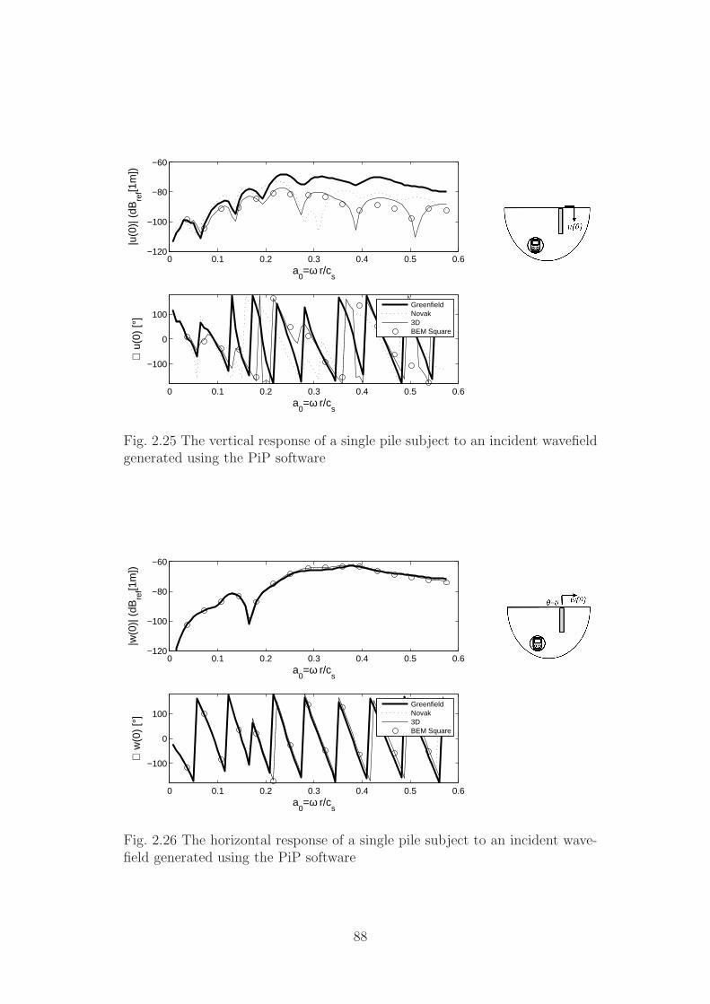
0 0.1 0.2 0.3 0.4 0.5 0.6−120
−100
−80
−60
a0=ω r/c
s
|u(0
)| (
dBre
f[1m
])
0 0.1 0.2 0.3 0.4 0.5 0.6
−100
0
100
a0=ω r/c
s
∠ u
(0)
[°]
GreenfieldNovak3DBEM Square
Fig. 2.25 The vertical response of a single pile subject to an incident wavefieldgenerated using the PiP software
0 0.1 0.2 0.3 0.4 0.5 0.6−120
−100
−80
−60
a0=ω r/c
s
|w(0
)| (
dBre
f[1m
])
0 0.1 0.2 0.3 0.4 0.5 0.6
−100
0
100
a0=ω r/c
s
∠ w
(0)
[°]
GreenfieldNovak3DBEM Square
Fig. 2.26 The horizontal response of a single pile subject to an incident wave-field generated using the PiP software
88

Fig. 2.27 The real axial displacement [m] of the incident wavefield as a functionof pile length L = 20m and frequency
Fig. 2.28 The real axial displacement [m] of a pile subject to the incidentwavefield as a function of pile length L = 20m and frequency
89

Fig. 2.29 The real lateral displacement [m] of the incident wavefield as a func-tion of pile length L = 20m and frequency
Fig. 2.30 The real lateral displacement [m] of a pile subject to the incidentwavefield as a function of pile length L = 20m and frequency
90

Fig. 2.31 The real axial displacement [m] of the incident wavefield as a functionof pile length L = 5m and frequency
Fig. 2.32 The real axial displacement [m] of a pile subject to the incidentwavefield as a function of pile length L = 5m and frequency
91
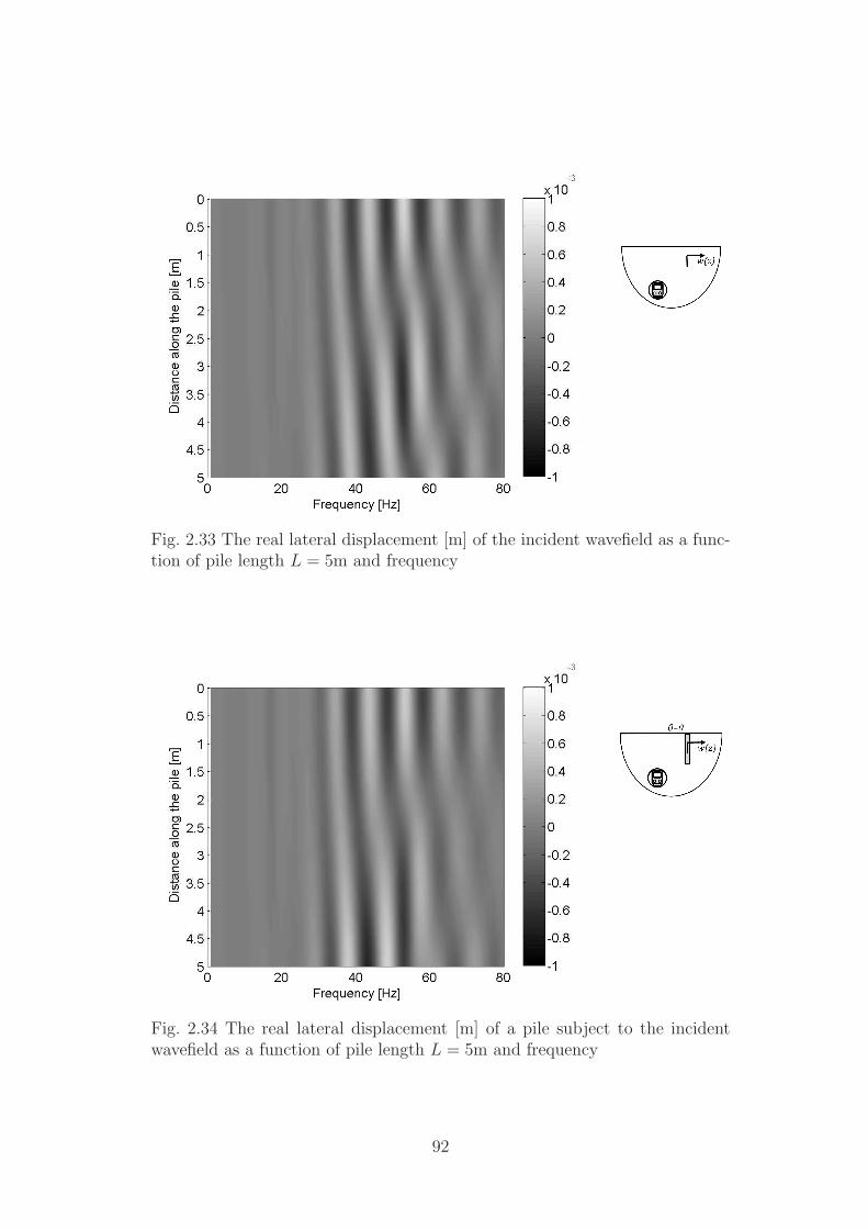
Fig. 2.33 The real lateral displacement [m] of the incident wavefield as a func-tion of pile length L = 5m and frequency
Fig. 2.34 The real lateral displacement [m] of a pile subject to the incidentwavefield as a function of pile length L = 5m and frequency
92

Fig. 2.35 The real axial displacement [m] of the incident wavefield as a functionof pile length L = 60m and frequency
Fig. 2.36 The real axial displacement [m] of a pile subject to the incidentwavefield as a function of pile length L = 60m and frequency
93

Fig. 2.37 The real lateral displacement [m] of the incident wavefield as a func-tion of pile length L = 60m and frequency
Fig. 2.38 The real lateral displacement [m] of a pile subject to the incidentwavefield as a function of pile length L = 60m and frequency
94

2.3.3.1 Power Flow through a Pile subject to an Incident Wavefield
Figure 2.39 shows the mean power flow through the skin of the single pile subject to an
incident wavefield, plotted as a function of frequency. Both the power flows attributed to
the axial and the lateral directions are included. The power flows due to displacements
and forces in the longitudinal direction of the tunnel are not considered as they are
insignificant. The sign convention used here denotes power outflows as positive.
Fig. 2.39 The net power flow [W/m] through a single pile subject to an incidentwavefield generated using the PiP software
The magnitude of the power flows are small at frequencies less than 25Hz, resulting
in relatively uniform shading in this region. This is due to the displacements and forces
along the length of the pile being several orders of magnitude smaller in this frequency
range than at higher frequencies. These small displacements can be seen, for example,
in the pile-head response in Figures 2.25 & 2.26.
At frequencies higher than 25Hz, the regions of maximum power flow are localised
and highly dependent on frequency. As a broad generalisation, for this pile geometry the
power enters the pile in the pile-tip region and is dissipated along the length of the pile.
The power flows due to the separate axial and lateral vibration directions are shown in
Figures 2.40 & 2.41, respectively. The lateral power flows are again observed to exhibit
more localised behaviour than the axial power flows. The relative contributions of the
two vibration directions to the net power flow are of similar magnitude: neither the
axial or lateral vibration directions dominate the net power flow from a pile.
95
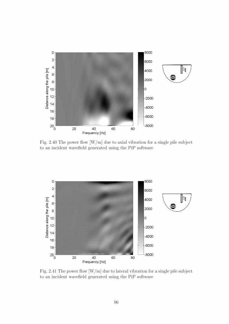
Fig. 2.40 The power flow [W/m] due to axial vibration for a single pile subjectto an incident wavefield generated using the PiP software
Fig. 2.41 The power flow [W/m] due to lateral vibration for a single pile subjectto an incident wavefield generated using the PiP software
96

2.4 Conclusions
In this chapter, two computationally efficient pile models are developed. The well-known
Novak model for the plane-strain case is adapted to calculate farfield displacements
and incorporate incident wavefields; and the formulation of a novel, three-dimensional
model is outlined. Comparison with existing published models shows that the three-
dimensional model is a good representation of purely axial or lateral pile behaviour, and
the plane-strain assumption renders the Novak model ineffective in certain situations.
The most notable of these are the lateral, pile-head, driving-point response, the farfield
displacements and the response of a pile to an incident wavefield. The use of the mirror-
image method in the three-dimensional model to reduce the infinitely long pile to a
finite pile results in some error in calculating the farfield displacements, due to failure
of the boundary conditions at the free surface. The overall inaccuracy introduced into
the farfield displacements due to this error is expected to be moderately small.
Analysis of the displacement of a single pile subject to a pile-head load highlights the
differences in axial and lateral vibration behaviour; the pile is stiffer in compression than
bending, resulting in an axial displacement distribution that is relatively invariant with
length, and a lateral displacement distribution that shows localised variation with length.
This behaviour dominates the response of a single pile to an incident wavefield generated
by an underground railway. The axial stiffness of the pile results in a significant reduction
of the greenfield axial vibrations at frequencies above those where the wavelength of the
shear wave is equal to the length of the pile. The lateral flexibility of the pile results
in the pile deforming with the incident wavefield, and therefore the greenfield lateral
vibration levels are not significantly altered. Comparison with a boundary-element
model verifies the accuracy and efficiency of the three-dimensional model.
The next chapter extends the single-pile models to consider the interaction between
neighbouring piles and the response of a pile-building model.
97

98
Chapter 3
Multiple-Pile Models
The application of a single-pile model to real-life situations is limited, as structural
foundations generally consist of pile groups. The response of a pile group cannot simply
be represented as the sum of the responses of a number of single piles, because the
vibration of one pile will influence the vibration of surrounding piles. This effect is
known as pile-soil-pile interaction (PSPI), and the level of interaction between piles
becomes more significant as the distance separating the piles decreases.
It is possible to calculate the response of a pile group by creating a fully-coupled
model which includes each pile and therefore inherently accounts for the interactions
between them. Examples of this include models by Kaynia [88] and Coulier [25]. The
difficulty with this approach is that it requires the formulation of a new model for every
new pile-group arrangement, and the number of elements required when using BE or
FE models quickly exceeds available computational capacities. For this reason, many
researchers prefer to consider the response of a single pile within a pile group to be the
sum of two components: the response of the single pile considered individually; and the
response of the single pile due to interactions with neighbouring piles, the PSPI.
The PSPI component of the response of the single pile consists of two components:
direct fields; and reflected fields. The number of reflections from neighbouring piles re-
quired to model system behaviour accurately is dependent upon the damping properties
of the medium and the pile spacing. As soil is a highly-damped medium, it is proposed
that it is sufficient to include only those fields propagated directly from neighbouring
piles in the PSPI component. These direct fields are calculated without regard for in-
termediate piles. This is known as the ‘superposition method’, because it is proposed
by Poulos [149] that the PSPI component of the response of a pile within a pile group
can be well-estimated by superposing the effect of each neighbouring pile. Whilst this
method is only strictly valid for linear systems, it is also used by researchers for moder-
99

ately nonlinear systems in the field of earthquake engineering [122]. The superposition
method is used to calculate PSPI in pile groups subject to inertial and/or kinematic
loadings. Experimental measurements and comparisons with fully-coupled models show
that the use of the superposition method is valid for inertial loadings, with the accuracy
of this method improving as the pile-spacing increases, as is expected [88].
To calculate the overall response of a pile group it is necessary to know the response
of one pile due to the excitation of a neighbouring pile. For pile groups subject to
inertial loadings (loads acting on the pile heads), this information is contained within
the inertial interaction factor α, which is defined by Kaynia [88] as
α =additional dynamic head deflection of pile 2 caused by pile 1
static head deflection of pile 1 (considered individually). (3.1)
This interaction factor is calculated by applying a point force to the pile head of pile
1, determining the pile-head response of pile 2 due to the excitation of pile 1, and then
dividing this response by the static response of a single pile (considered individually)
subject to the same point force applied to the pile head.
For kinematic loadings (loads produced by an incident wavefield), the interaction
between two neighbouring piles is proportional to the difference between the displace-
ment of the loaded pile and the freefield excitation. This is due to the fact that the
response of a pile group subject to an incident wavefield can be written as the super-
position of the response of every individual pile to the incident wavefield and the PSPI,
which occurs in the absence of the incident wavefield. For example, in Section 2.3.3 it
is shown that a pile subject to an incident wavefield generated from an underground
railway is flexible in the lateral direction, with the displacement of the loaded pile closely
following the displacement of the incident wavefield. The interaction between this pile
and a neighbouring pile is negligible, as the PSPI resulting from the difference between
the displacement of the loaded pile and the incident wavefield is negligible. There is
no definition of an interaction factor for kinematic loadings, as the pile displacement is
strongly dependent upon the nature of the incident field.
This chapter adopts the superposition method for calculating PSPI, and a method
for calculating the interaction between two neighbouring piles is presented in Section
3.1. This method is based upon the method of joining subsystems. The interaction
factors generated using the two-pile model are validated against results published for two
existing two-pile models. The models are then extended to consider pile groups subject
to vibration from underground railways. This chapter concludes with the development
of a model of a piled building, and a case study to demonstrate how this model can be
used to evaluate the response of a building to vibration from underground railways.
100

3.1 Modelling Two Finite-Length Piles
Following a similar method to that used to couple a single pile to an incident wavefield,
the method of joining subsystems is used to couple a second pile to the existing single-pile
model. The two subsystems are illustrated in Figure 3.1: subsystem A is represented
by a loaded, finite-length pile, and subsystem B is represented by a column or an
Euler-Bernoulli beam to be coupled at a distance s from the pile in subsystem A. The
displacement output Y2(ω) is to be calculated at each node along the length of the
pile represented by subsystem B. The incident wavefield, Uincident, represents the soil
displacements at distance s from the pile in subsystem A. The governing equation of
the coupled system in the space domain is
Y2(ω) =[
I + A33B−133
]−1Uincident. (3.2)
The equivalent equation formulated in the wavenumber domain is
Y2(ω) =[
I + A33B−1
33
]−1
Uincident
. (3.3)
The matrices A33, B33, A33 and B33 are the same as those used in Sections 2.1.2 and
2.2.5 for the Novak model and the three-dimensional model, respectively.
Fig. 3.1 The two separate subsystems whichare joined together to form a two-pile system
When calculating the response of a single pile subjected to an incident wavefield, the
incident wavefield is calculated using the PiP model. When calculating the interaction
between two neighbouring piles, the incident wavefield is produced by the loaded, single
pile. The methods for calculating the incident wavefield using the Novak model and the
three-dimensional model are detailed below.
101
Novak’s model For the Novak model, this incident wavefield is obtained by propagat-
ing the displacement response of the loaded single pile. The displacement propagation
is achieved using the wave-spreading equations given in Equations 2.18 & 2.19.
The three-dimensional model The three-dimensional model requires the incident
wavefield, Uincident
, to be calculated at some distance s from the pile axis in the
wavenumber domain. This can be accomplished using the wave-spreading equations
given in Eqs. 2.28 & 2.37. These equations determine the displacements in the wavenum-
ber domain, at some radius R from the wavenumber-domain displacements at the soil-
pile interface.
As subsystem A represents a single, loaded, finite pile embedded in a halfspace, the
displacements of the single pile that are to be transformed into the wavenumber domain
are those obtained after the mirror-image method has been applied to the single pile.
However, it should be noted that it is not just those displacements along the length of the
finite pile that are transformed into the wavenumber domain. The infinite limits of the
Fourier transformation require the input of those displacements along the whole length
of the infinite pile. To illustrate this, Figure 3.2(a) shows the two ‘infinite’ subsystems
which are joined together. The equivalent ‘finite’ representation of these subsystems for
the case of axial vibration is shown in Figure 3.2(b). The finite pile in subsystem A is
represented in Figure 3.2(b) as an infinite pile that has been cut at z = L. This is a
more accurate representation of the physical system, as the mirror-image method does
not remove the lower portion of the pile when a free end is created. This representation
is also effective in conveying the notion that displacements are known along the length
of this ‘infinite’ pile even though the pile is essentially modelled as being finite in length.
Thus the method used to simulate a finite-length, two-pile model is:
1. Create a finite pile and calculate the displacements along the pile. For inertial
excitation, use the method detailed in Section 2.2.3 for axial vibration, or Section
2.2.4 for lateral vibration. For a kinematic loading, calculate the displacement
of the pile subject to the incident wavefield using the method in Section 2.2.5.
Propagate the pile displacements to the location of pile 2 by substituting R = s
into Equations 2.28 & 2.37.
2. Attach pile 2 using the method of joining subsystems. The displacements propa-
gated from pile 1 represent those produced in a halfspace, therefore pile 2, although
represented by the equation for an infinite column/beam, will represent a semi-
infinite pile embedded in a halfspace when it has been coupled to subsystem A.
102

(a) Subsystem A is represented by the infinitepile with applied axial excitation and scaledmirror-image forces; subsystem B is repre-sented by an infinite column
(b) The equivalent subsystem representation:subsystem A consists of a finite pile with ap-plied axial pile-head excitation; subsystem B
consists of a semi-infinite column
Fig. 3.2 The two separate subsystems used for the three-dimensional model (withapplied axial forces) which are joined together to form a two-pile system
3. Convert semi-infinite pile 2 to a finite pile using the mirror-image method detailed
in Section 2.2.3 for axial vibration, or Section 2.2.4 for lateral vibration.
It is expected that the application of the mirror-image forces and moments in Step 3 will
result in the radiation of some additional displacement to pile 1, and thus introduce some
inaccuracies into the model. However, the magnitude of these inaccuracies is expected
to be small, and to decrease with increasing pile separation distance.
3.2 Validation of the Two-Pile Model
The inertial interaction factors calculated using the Novak and the three-dimensional
models are presented in this section. Three different pile-separation distances are used:
s = 4a, s = 10a, and s = 20a. The results are compared with those obtained by Kaynia
using a dynamic stiffness matrix (DSM) formulation [88], and those obtained by Coulier
using an extended form of Talbot’s boundary-element model [25].
The Kaynia model assumes that the soil medium is a viscoelastic halfspace, the piles
are made of a linear, elastic material, and the piles are perfectly bonded to the soil.
The pile is discretised into segments, and the force distributions at the pile-soil interface
are modelled using piecewise-constant barrel loads and circular loads. Displacements at
103
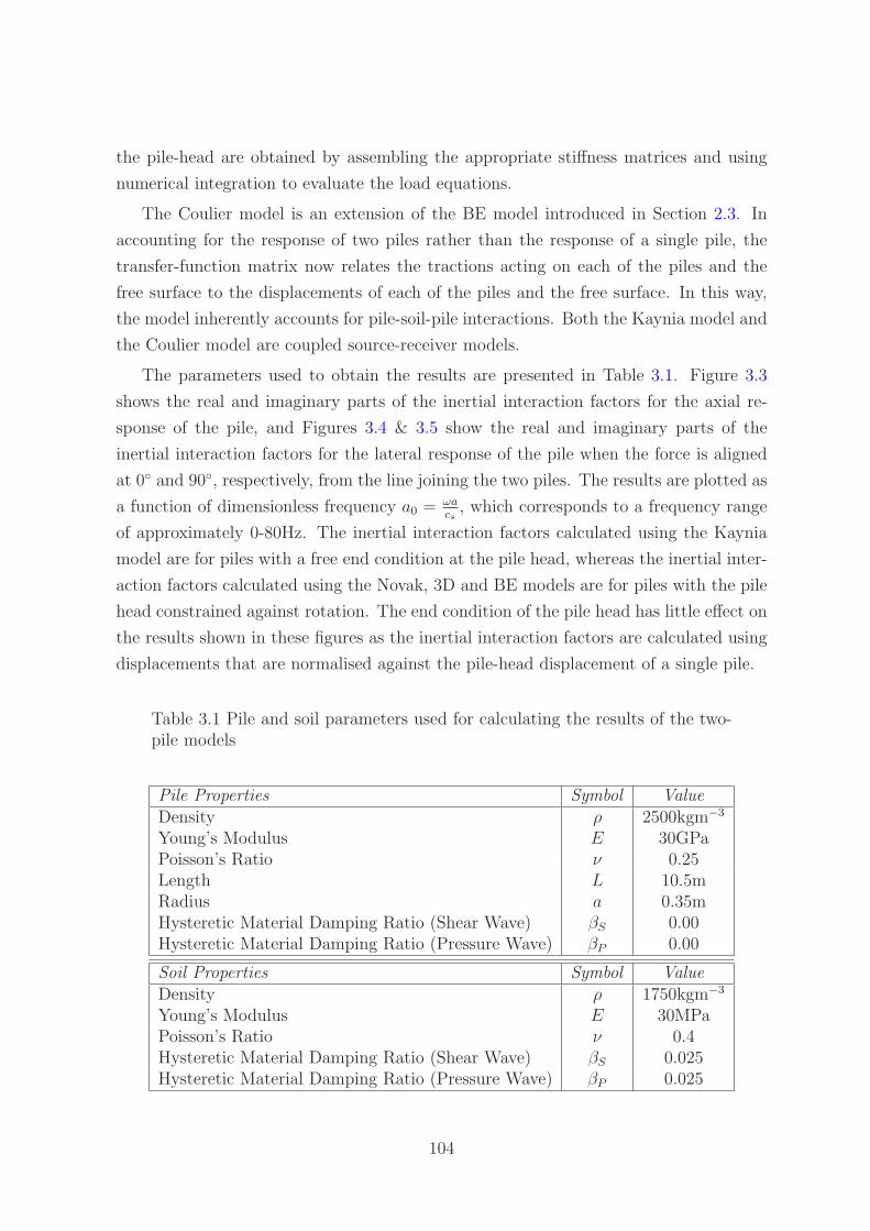
the pile-head are obtained by assembling the appropriate stiffness matrices and using
numerical integration to evaluate the load equations.
The Coulier model is an extension of the BE model introduced in Section 2.3. In
accounting for the response of two piles rather than the response of a single pile, the
transfer-function matrix now relates the tractions acting on each of the piles and the
free surface to the displacements of each of the piles and the free surface. In this way,
the model inherently accounts for pile-soil-pile interactions. Both the Kaynia model and
the Coulier model are coupled source-receiver models.
The parameters used to obtain the results are presented in Table 3.1. Figure 3.3
shows the real and imaginary parts of the inertial interaction factors for the axial re-
sponse of the pile, and Figures 3.4 & 3.5 show the real and imaginary parts of the
inertial interaction factors for the lateral response of the pile when the force is aligned
at 0◦ and 90◦, respectively, from the line joining the two piles. The results are plotted as
a function of dimensionless frequency a0 = ωacs
, which corresponds to a frequency range
of approximately 0-80Hz. The inertial interaction factors calculated using the Kaynia
model are for piles with a free end condition at the pile head, whereas the inertial inter-
action factors calculated using the Novak, 3D and BE models are for piles with the pile
head constrained against rotation. The end condition of the pile head has little effect on
the results shown in these figures as the inertial interaction factors are calculated using
displacements that are normalised against the pile-head displacement of a single pile.
Table 3.1 Pile and soil parameters used for calculating the results of the two-pile models
Pile Properties Symbol ValueDensity ρ 2500kgm−3
Young’s Modulus E 30GPaPoisson’s Ratio ν 0.25Length L 10.5mRadius a 0.35mHysteretic Material Damping Ratio (Shear Wave) βS 0.00Hysteretic Material Damping Ratio (Pressure Wave) βP 0.00
Soil Properties Symbol ValueDensity ρ 1750kgm−3
Young’s Modulus E 30MPaPoisson’s Ratio ν 0.4Hysteretic Material Damping Ratio (Shear Wave) βS 0.025Hysteretic Material Damping Ratio (Pressure Wave) βP 0.025
104
For both the axial and the lateral interaction factors, the Novak model generally
provides a conservative result when compared to the other models. This is due to
inaccuracy in the static value of the response of a single pile (seen in Figures 2.12 &
2.13) and the approximate nature of the wave-spreading equations. The gradient of the
real part of the Novak interaction factors changes significantly as a0 → 0, similar to the
behaviour observed in the pile-head driving-point response in Figure 2.13. This trend
is also observed in the imaginary part in the case of lateral vibration. Compared with
the three-dimensional model, the Novak model does not accurately represent inertial
pile-soil-pile interactions.
The three-dimensional model generally compares well with the results obtained us-
ing the DSM formulation and the BE method. As the distance between the two piles
increases, there is no significant change in the amount of variation observed between
the models, two of which represent coupled source-receiver models (DSM, BEM), and
two of which represent uncoupled source-receiver models (Novak, 3D). This implies that
there is no great inaccuracy introduced into the Novak model or the three-dimensional
model at these separation distances through the use of the method of joining subsys-
tems. Nevertheless, the inherent accuracy of the method of using interaction factors to
model pile-soil-pile interactions in a pile group increases as the pile-separation distance
increases.
The magnitude of the deviation between the DSM formulation, the BEM and the
three-dimensional model is of a similar scale. Yet to compute the same set of results,
the three-dimensional model requires a runtime of less than one second, compared to
minutes or hours for the DSM formulation or the BEM. This represents a significant
improvement in the modelling of pile-soil-pile interactions.
105

0 0.2 0.4 0.6−0.5
0
0.5
a0=ωa/c
s
ℜ(α
aa)
0 0.2 0.4 0.6−0.5
0
0.5
a0=ωa/c
s
ℜ(α
aa)
0 0.2 0.4 0.6−0.5
0
0.5
a0=ωa/c
s
ℜ(α
aa)
0 0.2 0.4 0.6−0.5
0
0.5
a0=ωa/c
s
ℜ(α
aa)
0 0.2 0.4 0.6−0.5
0
0.5
a0=ωa/c
s
ℜ(α
aa)
0 0.2 0.4 0.6−0.5
0
0.5
a0=ωa/c
s
ℜ(α
aa)
Novak3DBEM SquareBEM OctagonDSM
s=4a s=4a
s=10a s=10a
s=20a s=20a
Fig. 3.3 Real part (left), and imaginary part (right) of the axial response of afinite pile at horizontal distances s = 4a (top), s = 10a (middle) and s = 20a(bottom) from a finite single pile undergoing harmonic axial excitation
106

0 0.2 0.4 0.6−0.5
0
0.5
a0=ωa/c
s
ℜ(α
ll,0°)
0 0.2 0.4 0.6−0.5
0
0.5
a0=ωa/c
s
ℜ(α
ll,0°)
0 0.2 0.4 0.6−0.5
0
0.5
a0=ωa/c
s
ℜ(α
ll,0°)
0 0.2 0.4 0.6−0.5
0
0.5
a0=ωa/c
s
ℜ(α
ll,0°)
0 0.2 0.4 0.6−0.5
0
0.5
a0=ωa/c
s
ℜ(α
ll,0°)
0 0.2 0.4 0.6−0.5
0
0.5
a0=ωa/c
s
ℜ(α
ll,0°)
Novak3DBEM SquareBEM OctagonDSM
s=4a s=4a
s=10a s=10a
s=20a s=20a
Fig. 3.4 Real part (left), and imaginary part (right) of the lateral responseat 0◦ of a finite pile at horizontal distances s = 4a (top), s = 10a (middle)and s = 20a (bottom) from a finite single pile undergoing harmonic lateralexcitation
107

0 0.2 0.4 0.6−0.5
0
0.5
a0=ωa/c
s
ℜ(α
ll,90
°)
0 0.2 0.4 0.6−0.5
0
0.5
a0=ωa/c
s
ℜ(α
ll,90
°)
0 0.2 0.4 0.6−0.5
0
0.5
a0=ωa/c
s
ℜ(α
ll,90
°)
0 0.2 0.4 0.6−0.5
0
0.5
a0=ωa/c
s
ℜ(α
ll,90
°)
0 0.2 0.4 0.6−0.5
0
0.5
a0=ωa/c
s
ℜ(α
ll,90
°)
0 0.2 0.4 0.6−0.5
0
0.5
a0=ωa/c
s
ℜ(α
ll,90
°)
Novak3DBEM SquareBEM OctagonDSM
s=4a s=4a
s=10a s=10a
s=20a s=20a
Fig. 3.5 Real part (left), and imaginary part (right) of the lateral responseat 90◦ of a finite pile at horizontal distances s = 4a (top), s = 10a (middle)and s = 20a (bottom) from a finite single pile undergoing harmonic lateralexcitation
108
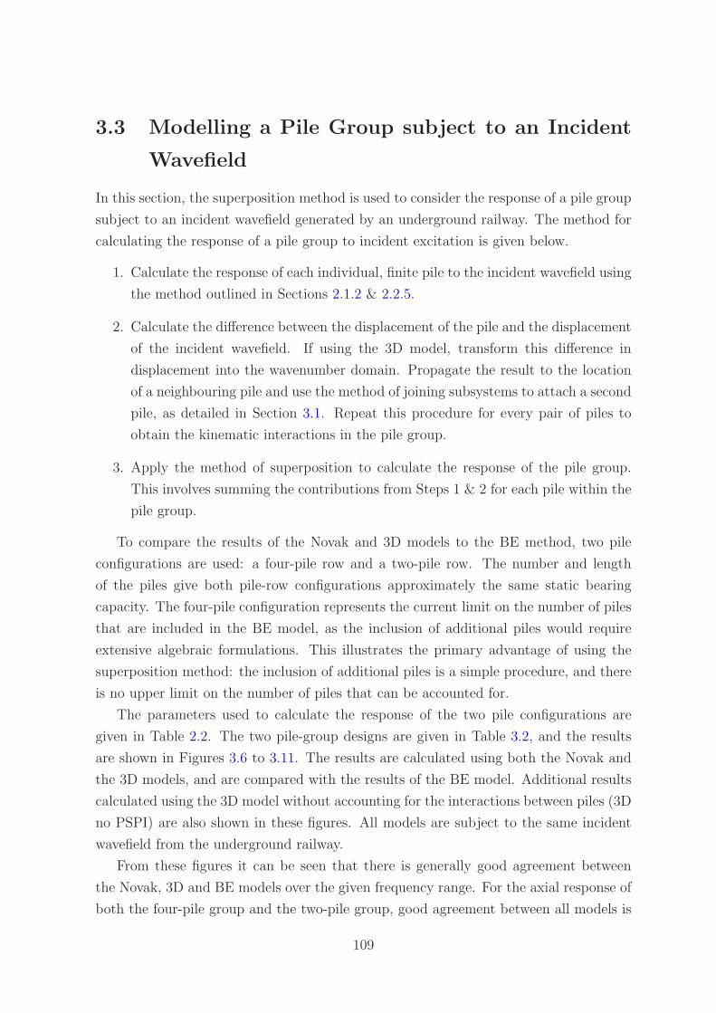
3.3 Modelling a Pile Group subject to an Incident
Wavefield
In this section, the superposition method is used to consider the response of a pile group
subject to an incident wavefield generated by an underground railway. The method for
calculating the response of a pile group to incident excitation is given below.
1. Calculate the response of each individual, finite pile to the incident wavefield using
the method outlined in Sections 2.1.2 & 2.2.5.
2. Calculate the difference between the displacement of the pile and the displacement
of the incident wavefield. If using the 3D model, transform this difference in
displacement into the wavenumber domain. Propagate the result to the location
of a neighbouring pile and use the method of joining subsystems to attach a second
pile, as detailed in Section 3.1. Repeat this procedure for every pair of piles to
obtain the kinematic interactions in the pile group.
3. Apply the method of superposition to calculate the response of the pile group.
This involves summing the contributions from Steps 1 & 2 for each pile within the
pile group.
To compare the results of the Novak and 3D models to the BE method, two pile
configurations are used: a four-pile row and a two-pile row. The number and length
of the piles give both pile-row configurations approximately the same static bearing
capacity. The four-pile configuration represents the current limit on the number of piles
that are included in the BE model, as the inclusion of additional piles would require
extensive algebraic formulations. This illustrates the primary advantage of using the
superposition method: the inclusion of additional piles is a simple procedure, and there
is no upper limit on the number of piles that can be accounted for.
The parameters used to calculate the response of the two pile configurations are
given in Table 2.2. The two pile-group designs are given in Table 3.2, and the results
are shown in Figures 3.6 to 3.11. The results are calculated using both the Novak and
the 3D models, and are compared with the results of the BE model. Additional results
calculated using the 3D model without accounting for the interactions between piles (3D
no PSPI) are also shown in these figures. All models are subject to the same incident
wavefield from the underground railway.
From these figures it can be seen that there is generally good agreement between
the Novak, 3D and BE models over the given frequency range. For the axial response of
both the four-pile group and the two-pile group, good agreement between all models is
109

Table 3.2 Pile-group parameters used for calcu-lating the results of the pile-group models
Four-Pile-Group Properties Symbol ValueLength L 5mSeparation Distance s 1.5m
Two-Pile-Group Properties Symbol ValueLength L 10mSeparation Distance s 3.0m
observed at frequencies less than 30Hz. Above this frequency, deviations of up to 10dB
are observed. For the lateral response, the agreement between the 3D and BEM is good,
with the Novak model deviating by up to 3dB at frequencies above 50Hz.
Little deviation is observed between the 3D model that includes PSPI and the 3D
model that does not include PSPI. In some cases, such as in Figure 3.8 at 60-80Hz,
the 3D model that does not include PSPI shows better agreement with the BEM. From
this it is concluded that the superposition method does not provide a comprehensive
representation of the interactions occurring in this pile group. Further investigation is
required to determine whether the superposition-method error is specific to this group of
(closely-spaced) piles, or whether this error applies to all pile groups subject to vibration
from an underground railway. One known source of error in the superposition method
applicable to all pile groups is a shadowing effect resulting from wave scattering of
intermediate piles, described by Coulier [25].
The kinematic interaction effects in these pile groups subject to an incident wavefield
generated by an underground railway are small. A similar observation is made by
Makris & Gazetas [114] during their investigation into the lateral response of pile groups
to vertically propagating seismic S waves, and Makris & Badoni [113] during their
investigation into the seismic response of pile groups to Rayleigh and obliquely incident
SH waves.
In order to compare the dynamic response of the two different pile-group configura-
tions, a suitable measure for the vibration response of the foundation must be identified.
The use of displacement magnitudes in Figures 3.6 to 3.11 does not provide a clear in-
dication of which foundation configuration transmits the greatest amount of vibrational
energy into a building. For this reason, the foundation model is extended in Section
3.4 to consider the addition of a simplified building model to the piled foundation, and
power-flow techniques are used to evaluate two foundation configurations.
110

0 10 20 30 40 50 60 70 80−120
−100
−80
−60
Frequency [Hz]
|u(0
)| d
Bre
f[1m
]
0 10 20 30 40 50 60 70 80
−100
0
100
Frequency [Hz]
∠u(
0) [°
]
GreenfieldNovak3D3D no PSPIBEM Square
Fig. 3.6 The vertical response of an outer pile in a four-pile row subject to anincident wavefield generated using the PiP software
0 10 20 30 40 50 60 70 80−120
−100
−80
−60
Frequency [Hz]
|w(0
)| d
Bre
f[1m
]
0 10 20 30 40 50 60 70 80
−100
0
100
Frequency [Hz]
∠w
(0)
[°]
GreenfieldNovak3D3D no PSPIBEM Square
Fig. 3.7 The horizontal response of an outer pile in a four-pile row subject toan incident wavefield generated using the PiP software
111

0 10 20 30 40 50 60 70 80−120
−100
−80
−60
Frequency [Hz]
|u(0
)| d
Bre
f[1m
]
0 10 20 30 40 50 60 70 80
−100
0
100
Frequency [Hz]
∠u(
0) [°
]
GreenfieldNovak3D3D no PSPIBEM Square
Fig. 3.8 The vertical response of an inner pile in a four-pile row subject to anincident wavefield generated using the PiP software
0 10 20 30 40 50 60 70 80−120
−100
−80
−60
Frequency [Hz]
|w(0
)| d
Bre
f[1m
]
0 10 20 30 40 50 60 70 80
−100
0
100
Frequency [Hz]
∠w
(0)
[°]
GreenfieldNovak3D3D no PSPIBEM Square
Fig. 3.9 The horizontal response of an inner pile in a four-pile row subject toan incident wavefield generated using the PiP software
112

0 10 20 30 40 50 60 70 80−120
−100
−80
−60
Frequency [Hz]
|u(0
)| d
Bre
f[1m
]
0 10 20 30 40 50 60 70 80
−100
0
100
Frequency [Hz]
∠u(
0) [°
]
GreenfieldNovak3D3D no PSPIBEM Square
Fig. 3.10 The vertical response of a pile in a two-pile row subject to an incidentwavefield generated using the PiP software
0 10 20 30 40 50 60 70 80−120
−100
−80
−60
Frequency [Hz]
|w(0
)| d
Bre
f[1m
]
0 10 20 30 40 50 60 70 80
−100
0
100
Frequency [Hz]
∠w
(0)
[°]
GreenfieldNovak3D3D no PSPIBEM Square
Fig. 3.11 The horizontal response of a pile in a two-pile row subject to anincident wavefield generated using the PiP software
113

3.4 Modelling a Piled Building subject to an Inci-
dent Wavefield
When considering dynamic models of buildings, a range of approaches is possible. Cryer
[27] provides an overview of these approaches, which vary in complexity from the sim-
ple analytical model of a mass on a spring to more complex numerical methods and
statistical energy analysis. In keeping with the design tool philosophy that underpins
this dissertation, the building model introduced in this section is that of a semi-infinite
column or a semi-infinite Euler beam. This model is chosen for a number of reasons.
Firstly, the use of an analytical model is expected to offer both efficient computation
times and reasonable accuracy. Secondly, the infinite column or beam is a generic model
that improves on the simple, analytical, mass-on-a-spring model by accounting for the
essential compression and bending behaviour of a tall building. Finally, the infinite col-
umn or beam provides a good representation of the dissipative nature of a building, as
vibrational energy is radiated away from the foundation, and the resonances associated
with finite models are avoided.
In this section, the attachment of the building, in the form of a semi-infinite column
or beam, to the pile head is presented. It is also shown how a finite beam or column
can be used to represent the pile cap, joining the pile heads and the building.
3.4.1 Modelling a Building
It is a straightforward exercise to show that the mechanical driving-point impedance of
a semi-infinite column Zu is given by
Zu =F
iωU0
=√
m′EA (3.4)
where U0 is the axial driving-point displacement, F is the axial force, m′ is the mass
per unit length, E is Young’s Modulus and A is the cross-sectional area of the column.
This relationship is obtained by substituting z = 0 into Eq. 2.39.
For a semi-infinite beam, both shear forces T and bending moments M can produce
bending waves in the beam, thus both must be taken into account when considering
beam behaviour. The lateral driving-point velocity W0 can be written as
W0 = iωW0 =1
Zb
T +1
W ′b
M (3.5)
114

and the rotational driving-point velocity θ0 can be written as
θ0 = iωθ0 =1
W ′b
T +1
Wb
M. (3.6)
The shear force impedance Zb is given by
Zb =1
2m′cB(1 + i), (3.7)
the bending moment impedance Wb is given by
Wb =1
2m′cB
1 − i
ω
√
m′
EI
, (3.8)
and the coupled shear-bending impedance W ′b is given by
W ′b = −
√EIm′. (3.9)
The bending-wave velocity in the beam is cB, where
cB =
√ω
(
m′
EI
)1/4(3.10)
and I is the second moment of area.
Applying the constraint of zero rotation at the pile head (θ0 = 0) to Equation
3.6, then substituting the resulting expression into Equation 3.5 gives the relationship
between the lateral driving-point velocity and the shear force, written as
W0 = iωW0 =1
Zw
T =
(
1
Zb
− Wb
(W ′b)
2
)
T. (3.11)
Now that the relationships between the driving-point displacement of the semi-
infinite column/beam and the force acting on the end of the semi-infinite column/beam
are determined, the building model is attached to the pile heads. For the case of axial
vibration of the pile, a semi-infinite column is attached to the pile head, and for the
case of lateral vibration of the pile, a semi-infinite beam is attached to the pile head.
Referring to Figure 3.12, which shows two identical piles undergoing axial vibration, the
relationship between the driving-point displacements of the semi-infinite columns (Ub1,
Ub2) and the forces acting on the ends of the semi-infinite columns (Fp1, Fp2) can be
115

written as{
Ub1
Ub2
}
=
[
1iωZu
0
0 1iωZu
]{
−Fp1
−Fp2
}
. (3.12)
The equation for the displacement of the pile heads is given by
{
Ub1
Ub2
}
=
[
H11 H12
H12 H11
]{
Fp1
Fp2
}
+
{
Up1
Up2
}
, (3.13)
where Up1 and Up2 are the displacements at pile heads 1 & 2, respectively, for the piled
foundation subject to vibration from an underground railway; H11 is the driving-point
response of a single pile; and H12 is the pile-head displacement of pile 1 when a unit
force is applied to the pile head of pile 2.
Rearrangement of these two equations results in the governing equation for the piled
building model:
{
Ub1
Ub2
}
=
[I] +
[
H11 H12
H12 H11
] [
1iωZu
0
0 1iωZu
]−1
−1{
Up1
Up2
}
, (3.14)
where [I] is the identity matrix. This equation can be extended to account for more
than two piles, and non-identical piles.
Using a similar method, the equation for lateral vibration of two identical piles is
given by{
Wb1
Wb2
}
=
[I] +
[
H11 H12
H12 H11
][
1iωZw
0
0 1iωZw
]−1
−1{
Wp1
Wp2
}
(3.15)
where the variables Wb1, Wb2, H11, H12, Wp1 & Wp2 are the lateral analogues of those
variables defined in Equation 3.14.
3.4.2 Modelling a Pile Cap
The pile cap generally takes the form of a large concrete slab joining the pile heads. In
seismic models the pile cap is considered as a rigid body, an assumption that is only
valid at very low frequencies. For vibration from underground railways, a more accurate
simulation of the pile cap is achieved by considering pile-cap deformations. For a simple
pile row in axial or lateral vibration, the pile cap is modelled as a finite Euler beam
or column, respectively. The pile cap is a structure with free-free boundary conditions,
subject to external forces from the pile heads and, if a building is attached, external
forces from the semi-infinite columns or beams. The standard linear theory for finite
116

Fig. 3.12 The definition of pile-head displacementsfor (a) a piled foundation; and (b) a piled building
beams or columns can be used to generate transfer-function matrices relating forces
acting on the pile cap to displacements at the pile-head locations. For example, the
dynamic behaviour of the finite free-free Euler beam, which is used to model a pile cap
attached to a pile row undergoing axial vibration, is given by Equations 2.12 & 2.15.
Similarly, the dynamic behaviour of the finite free-free column, which is used to model
a pile cap attached to a pile row undergoing lateral vibration, is given by Equation 2.10.
The method of joining subsystems is used to attach the pile cap to the piled foun-
dation by replacing the building-impedance matrix in Equations 3.14 & 3.15 with the
pile-cap transfer matrix. For the case where the pile cap is subject to external forces
from both the pile heads and the semi-infinite columns or beams, the standard linear
theory for finite beams or columns is used to relate the net force acting on the pile cap
to displacements at the pile-head locations. For the two-pile configuration shown in
Figure 3.13, the transfer matrix [W] of the beam representing the pile cap is given by
{
Ub1
Ub2
}
= [W]
{
−Fp1 − Fd1
−Fp2 − Fd2
}
. (3.16)
From Section 3.4.1, the transfer function of the building model is given by
{
Ub1
Ub2
}
=
[
1iωZu
0
0 1iωZu
]{
Fd1
Fd2
}
, (3.17)
117

and the transfer matrix of the piled foundation is
{
Ub1
Ub2
}
=
[
H11 H12
H12 H11
]{
Fp1
Fp2
}
+
{
Up1
Up2
}
. (3.18)
Rearrangement of these Equations 3.16, 3.17 & 3.18 results in the governing equation
for the piled raft foundation with attached building shown in Figure 3.13. This equation
is written as
{
Ub1
Ub2
}
=
[I] +
[
H11 H12
H12 H11
]
[W]−1 +
[
1iωZw
0
0 1iωZw
]−1
−1{
Up1
Up2
}
, (3.19)
and can be re-written in generalised matrix form as
Ub =[
[I] + [H][
[W]−1 + [Z]−1]]−1Up. (3.20)
A similar equation can be written for piles in lateral vibration.
Fig. 3.13 The definition of pile-head displacementsfor (a) a piled foundation; and (b) a piled raftfoundation with attached building
For a three-dimensional pile-group arrangement, the pile cap is best represented by
a rectangular, isotropic plate joining each of the pile heads. Whilst the differential
118

equation of motion for such a plate is well-known, no analytical solution exists for the
free-free-free-free boundary condition. A finite-element approach would be required to
determine the numerical solution [123]. The pile cap is instead simulated using two
layers of beams/columns: one layer joins the pile heads lying in the plane perpendicular
to the tunnel’s longitudinal axis, and the other layer joins the pile heads lying in the
plane parallel to the tunnel’s longitudinal axis. The pile cap for a sixteen-pile group is
shown in Figure 3.14.
Fig. 3.14 The pile-cap model,consisting of two layers ofbeams/columns
The second layer of beams/columns are incorporated into the pile cap model using a
similar analysis to that detailed earlier in this section. The governing equation, written
in the same generalised form as Equation 3.20, is
Ub =[
[I] + [H][
[W1]−1 + [W2]
−1 + [Z]−1]]−1Up, (3.21)
where [W1] and [W2] are the transfer matrices for the two layers of beams/columns.
3.4.3 Results for the Piled Building
In this section, the building and pile-cap models are attached to the four-pile row con-
sidered in Section 3.3. The pile cap has dimensions 5.5x2x0.3m and is made of concrete
with material properties equal to those of the piles. The infinite columns/beams repre-
senting the building have the same material properties and radii as the piles. The results
for the piled building (referred to as ‘3D Piled Building’) are calculated using the 3D
model and are presented in Figures 3.15 to 3.18. Also presented in these figures are the
pile-head displacements of the foundation with no building or pile cap attached (referred
119

to as ‘3D Piles’), and the displacements of the piled building when the kinematic-PSPI
components have been neglected (referred to as ‘3D Piled Building no k-PSPI’).
0 10 20 30 40 50 60 70 80−120
−100
−80
−60
Frequency [Hz]
|u(0
)| d
Bre
f[1m
]
0 10 20 30 40 50 60 70 80
−100
0
100
Frequency [Hz]
∠u(
0) [°
]
Greenfield3D Piles3D Piled Building3D Piled Building no k−PSPI
Fig. 3.15 The vertical response of an outer pile in a four-pile row attached toa pile cap and building, and subject to an incident wavefield generated usingthe PiP software
0 10 20 30 40 50 60 70 80−120
−100
−80
−60
Frequency [Hz]
|w(0
)| d
Bre
f[1m
]
0 10 20 30 40 50 60 70 80
−100
0
100
Frequency [Hz]
∠w
(0)
[°]
Greenfield3D Piles3D Piled Building3D Piled Building no k−PSPI
Fig. 3.16 The horizontal response of an outer pile in a four-pile row attached toa pile cap and building, and subject to an incident wavefield generated usingthe PiP software
120

0 10 20 30 40 50 60 70 80−120
−100
−80
−60
Frequency [Hz]
|u(0
)| d
Bre
f[1m
]
0 10 20 30 40 50 60 70 80
−100
0
100
Frequency [Hz]
∠u(
0) [°
]
Greenfield3D Piles3D Piled Building3D Piled Building no k−PSPI
Fig. 3.17 The vertical response of an inner pile in a four-pile row attached toa pile cap and building, and subject to an incident wavefield generated usingthe PiP software
0 10 20 30 40 50 60 70 80−120
−100
−80
−60
Frequency [Hz]
|w(0
)| d
Bre
f[1m
]
0 10 20 30 40 50 60 70 80
−100
0
100
Frequency [Hz]
∠w
(0)
[°]
Greenfield3D Piles3D Piled Building3D Piled Building no k−PSPI
Fig. 3.18 The horizontal response of an inner pile in a four-pile row attached toa pile cap and building, and subject to an incident wavefield generated usingthe PiP software
121

From these figures it is apparent that for this pile group the addition of a pile cap
and a building has a significant constraining effect on the horizontal pile-head response,
resulting in frequency-independent attenuation of approximately 15dB. This is because
the antisymmetric nature of the horizontal incident wavefield generated by the under-
ground railway results in antisymmetric, horizontal, pile-row displacements which are
resisted by the stiffness of the pile cap. This constraining effect would not be as pro-
nounced if the pile group were not located directly above the tunnel, as the displacements
of all the piles in such a group would be in the same direction, resulting in horizontal
rigid-body motion of the pile cap. The addition of a pile cap and a building has a
less-pronounced effect on the vertical pile-head response. This is because the vertical
incident wavefield generated by the underground railway results in symmetric, vertical,
pile-row displacements, and the pile cap is thus excited in vertical rigid-body motion.
The effect of neglecting the kinematic PSPI is again observed to be small.
3.5 Case Study: Evaluating Two Foundation De-
signs
A virtual case study is now presented in which the dynamic response of two friction-pile
foundation designs is evaluated. The foundation designs are chosen to resist the total
static load of a generic five-storey building.
For a given ground condition, the number and size of piles in a pile-group foundation
is largely determined by the total static load from the building (Q) to be resisted by
the foundation. It is beyond the scope of this dissertation to include a discussion of the
many other factors which can govern the design of piled foundations. The interested
reader is referred to design handbooks such as Tomlinson [169] and Eurocode 7 [75] for
further details on pile design. Each of the N piles in the pile group provides resistance
in the form of shaft capacity Qs and base capacity Qb, where the total load from the
building is given as
Q = N(Qs + Qb). (3.22)
The shaft capacity is proportional to the shaft area of the pile, written as
Qs = 2πaLqs, (3.23)
and the base capacity is likewise proportional to the base area of the pile, written as
Qb = πa2qb. (3.24)
122

The pile radius is a, L is the pile length, and qs and qb depend on the soil conditions.
In this study typical values for clay are used: 12.5kPa and 87.5kPa, respectively.
Using these formulae, two foundation designs are proposed for a generic, five-storey
building with a net load of 4000kN: a nine-pile group, and a sixteen-pile group. Di-
mensions are given in Figure 3.19, and a safety factor of 2 is applied. The material
parameters for the pile cap and the building models are the same as for those of the
piles. Apart from those parameters specified in Figure 3.19, all other parameters are
given in Table 2.2. The centre of each pile group is located 10m from the longitudinal
axis of the railway tunnel, and the tunnel axis is located 20m below the ground surface.
A semi-infinite beam or column is attached to the pile cap at each of the pile-head
locations to simulate a building.
Fig. 3.19 Foundation dimensions for two pile-group designs: (a) a nine-pile group; and(b) a sixteen-pile group. All dimensions are given in [m]. Not to scale
The results of this modelling are presented in Figure 3.20 in terms of the net power
flow entering the building. From this figure it can be seen that the sixteen-pile group
results in greater vibrational-energy transmission into the building, of the order of 6dB
over the frequency range of 40-60Hz. Considering the simplifying assumptions that are
involved in producing this result, 6dB represents a small margin. From a geotechnical
perspective, the preferred pile design of those that meet the design criteria is generally
that which involves the fewest piles. This case study shows that no significant advantage
in terms of vibration attenuation has been attained by using a foundation with a greater
number of piles. Thus, the designer can recommend the nine-pile foundation.
For both the nine-pile and sixteen-pile foundation designs, the horizontal component
dominates the power flow into the building. This is in contrast with the response of
the four-pile row examined in Section 3.4.3; for this pile row the vertical component
dominates the pile-group response. This illustrates the variability that is present in the
response of pile groups to underground-railway vibration, and highlights the need for
123
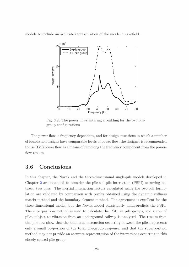
models to include an accurate representation of the incident wavefield.
0 10 20 30 40 50 60 70 800
5
10
15x 10
4
Frequency [Hz]
Pow
er F
low
[W]
9−pile group16−pile group
Fig. 3.20 The power flows entering a building for the two pile-group configurations
The power flow is frequency-dependent, and for design situations in which a number
of foundation designs have comparable levels of power flow, the designer is recommended
to use RMS power flow as a means of removing the frequency component from the power-
flow results.
3.6 Conclusions
In this chapter, the Novak and the three-dimensional single-pile models developed in
Chapter 2 are extended to consider the pile-soil-pile interaction (PSPI) occurring be-
tween two piles. The inertial interaction factors calculated using the two-pile formu-
lation are validated by comparison with results obtained using the dynamic stiffness
matrix method and the boundary-element method. The agreement is excellent for the
three-dimensional model, but the Novak model consistently underpredicts the PSPI.
The superposition method is used to calculate the PSPI in pile groups, and a row of
piles subject to vibration from an underground railway is analysed. The results from
this pile row show that the kinematic interaction occurring between the piles represents
only a small proportion of the total pile-group response, and that the superposition
method may not provide an accurate representation of the interactions occurring in this
closely-spaced pile group.
124

Methods are proposed for modelling a building as a collection of semi-infinite columns
or beams, and for modelling a pile cap as a series of finite columns or beams. The
method of joining subsystems is used to attach the pile cap and the building to the
piled foundation. To conclude this chapter, a case study of two piled foundations with
equal static bearing capacity is presented. By using power-flow techniques to calculate
the vibrational energy entering the building, it is demonstrated that the nine-pile group
provides better vibration attenuation than the sixteen-pile group.
This concludes the study of piled foundations subject to underground-railway vibra-
tion. The next chapter considers the effects of neighbouring tunnels.
125

126

Chapter 4
A Two-Tunnel Model
Many underground railway lines around the world, including those in London, Copen-
hagen, Taipei, Bangkok and Washington D.C. consist of two tunnels of identical con-
struction, known as ‘twin tunnels’: one for the outbound direction; and one for the
inbound direction. In most cases these tunnels are located side by side, but occasionally,
such as in the case of the Chungho Line in Taipei, the tunnels are piggy-back, with one
on top of the other [15]. Twin tunnels also exist at intermediate orientations. Numerical
models and scale models of twin tunnels exist in the literature [3, 21, 24, 82, 124, 143]
for the purposes of determining the static stresses and strains produced during and
post- excavation. To date, the only evidence in the literature of a dynamic model which
accounts for the vibration interaction between neighbouring tunnels is the wavenumber
FE-BE model [160] discussed in Section 1.3.3.3. This model compares the response of a
large, single-bore, double-track tunnel with the response of a pair of single, twin-track
tunnels embedded in an elastic halfspace.
This chapter describes the formulation of a novel solution for two parallel tunnels of
circular cross-section embedded in a homogeneous, elastic soil. This two-tunnel system
can be used to represent both a twin-tunnel railway line, and a single tunnel with buried
services located nearby. The two-tunnel model is an extension of the single-tunnel (PiP)
model developed by Forrest & Hunt [43, 44] and furthered by Hussein & Hunt [70, 71].
Whilst various single-tunnel models exist, this model is unique in that it is a 2.5D
model, and therefore more accurate than a simple 2D approach. Furthermore, it does
not require the excessive computation times associated with FE and BE approaches. For
example, the runtime of the single-tunnel model on a personal computer of moderate
specifications is less than one minute. To run the equivalent scenario using a coupled
FE-BE model takes 17 hours using one processor of a high-performance cluster [66].
This short process runtime is achieved through the modelling of the tunnel lining as
127

an infinitely long, thin-walled cylinder and the modelling of the soil as an infinite,
elastic medium. The thin-walled cylinder is modelled using a simplification of Volmir’s
linear equations for a general, thin shell, and the soil is modelled as an infinite, elastic
continuum in cylindrical coordinates with an inner radius equal to the radius of the thin-
walled cylinder, and an outer radius of infinity. Both the stresses and the displacements
of the tunnel and the soil are described using two sets of Fourier series components:
one for symmetric contributions; and one for antisymmetric contributions, for a limited
number of modeshapes. This single-tunnel model is an efficient and accurate method for
calculating vibration from underground railways [51]. Methods exist for adapting this
model to obtain vibration predictions in a homogeneous or layered halfspace without a
significant loss of computational efficiency [67]. These same methods can be applied to
the two-tunnel model described here.
This chapter is divided into three sections. The single-tunnel model is presented
in Section 4.1 to provide an introduction to the modelling of two tunnels, presented in
Section 4.2. Section 4.3 contains the results and discussion of the two-tunnel model,
and the conclusions are presented in Section 4.4.
4.1 Modelling a Single Tunnel
The purpose of this section is to present the analytical background of the dynamic
single-tunnel model developed by Forrest & Hunt [43, 44] and furthered by Hussein &
Hunt [70, 71]. This model consists of the tunnel, represented by a thin-walled cylinder
made of linear, elastic, homogeneous, isotropic material. The soil is modelled as a three-
dimensional, homogeneous, isotropic, elastic solid in the form of a thick-walled cylinder
with an infinite outer radius. This model is invariant in the longitudinal direction, thus
allowing the formulation of equations in the longitudinal-wavenumber (ξ) domain, as
well as in the frequency domain. The modelling of Forrest & Hunt and Hussein & Hunt
also allows for components such as floating slab track, rail pads and rails to be added to
the model. The analytical details of these components are not included here, as it is the
tunnel-soil model that is central to the content of this chapter. Instead, in this chapter
the dynamic train forces act directly on the tunnel invert. Any force that is applied
to the circular tunnel invert is periodic, and can thus be represented using a Fourier
series involving the linear sum of sine and cosine components. These sine and cosine
components give rise to two types of loading conditions: those which are distributed
symmetrically about one of the tunnel’s axes of symmetry in the cross-sectional plane,
and those which are distributed antisymmetrically about the same axis of symmetry.
128

These two loading conditions are referred to here as the ‘symmetric’ and ‘antisymmetric’
loading cases, respectively. As both the tunnel and the soil are axisymmetric, the
symmetry of the loading condition also extends to the displacements and stresses in the
soil. For example, a sinusoidal force acting on the tunnel invert will result in a sinusoidal
distribution of soil displacements. This feature allows for separate computation of the
soil displacements due to each of the two loading conditions, resulting in a significant
reduction in the computation times. The total soil displacements are then expressed as
the sum of the displacements due to each of these two loading conditions.
Consider the tunnel, represented by the thin-walled cylinder shown in Figure 4.1,
which is undergoing modal displacements{
Urn, Uθn, Uzn
}T
at the mean radius (R) of
the cylinder in the radial, tangential and longitudinal directions, respectively. These
displacements are the result of applied loads per unit area{
Qrn, Qθn, Qzn
}T
acting on
the thin-walled cylinder in the radial, tangential and longitudinal directions, respec-
tively. As the tunnel is represented as an infinitely-long, cylindrical shell, both the
loading and the displacement of the tunnel can be written as a linear combination of
components which are harmonic in time t and space z. The space-harmonic varia-
tion of the loading and the displacement is captured by defining the components in
the longitudinal-wavenumber domain, represented by the term eiξz. The time-harmonic
variation of the loading and the displacement is captured by defining the components
in the frequency domain, represented by the term eiωt. The subscript n represents the
modenumber, and the tilde on the uppercase coefficients indicates that they are in the
longitudinal-wavenumber domain. The uppercase coefficient indicates that the variable
is defined in the frequency domain.
The symmetric, harmonic, displacement components are of the form
ur(z, t) = U1rn cos nθei(ωt+ξz)
uθ(z, t) = U1θn sin nθei(ωt+ξz)
uz(z, t) = U1zn cos nθei(ωt+ξz),
(4.1)
where the superscript 1 represents the symmetric case.
The antisymmetric, harmonic, displacement components are of the form
ur(z, t) = U2rn sin nθei(ωt+ξz)
uθ(z, t) = U2θn cos nθei(ωt+ξz)
uz(z, t) = U2zn sin nθei(ωt+ξz),
(4.2)
where the superscript 2 represents the antisymmetric case.
129

Fig. 4.1 The coordinate system used for the infinitely long, thin-walled cylindershowing: (a) the cylindrical coordinate system; (b) the corresponding displace-ment components; and (c) the corresponding traction components
Similarly, the symmetric, harmonic loading components are of the form
qr(z, t) = Q1rn cos nθei(ωt+ξz)
qθ(z, t) = Q1θn sin nθei(ωt+ξz)
qz(z, t) = Q1zn cos nθei(ωt+ξz),
(4.3)
and the antisymmetric, harmonic loading components are of the form
qr(z, t) = Q2rn sin nθei(ωt+ξz)
qθ(z, t) = Q2θn cos nθei(ωt+ξz)
qz(z, t) = Q2zn sin nθei(ωt+ξz).
(4.4)
As this is a thin-walled cylinder, the stresses and the displacements are assumed to
be unchanging through the thickness of the cylinder. The expression for the motion of
this cylinder is derived using a simplification of Volmir’s linear equations for a general
130
thin shell [43, 44], and is written as
Urn
Uθn
Uzn
= [AE]−1r=R
Qrn
Qθn
Qzn
, (4.5)
where the elements of the matrix [AE] are given in Appendix B. The signs of the
elements in the matrix [AE] are determined by the symmetry of the loading condition,
and hence this equation, together with the equations below, must be replicated using
the appropriate matrix elements in order to calculate the displacements arising from
both the symmetric and antisymmetric loading conditions.
A similar expression can be obtained for the soil, represented by a thick-walled
cylinder with inner radius R and infinite outer radius. This expression relates the modal
displacements of the inner surface of the soil cylinder{
Urn, Uθn, Uzn
}T
to the tractions
acting on the inner surface of the soil cylinder{
Trn, Tθn, Tzn
}T
. This expression is
obtained by solving the wave equation describing motion within an elastic medium, the
derivation for which can be found in Forrest & Hunt [43, 44]. The expression for the
motion of the thick-walled cylinder is given by
Urn
Uθn
Uzn
= [U]r=R [Tr]−1r=R
Trn
Tθn
Tzn
, (4.6)
where [Tr] is the top half of the 6x3 matrix [T], and the elements of the matrices [U]
and [T] are given in Appendix B.
More generally, it can be written that at a radius Rf in the thick-walled cylinder the
soil displacements are given by
Urn
Uθn
Uzn
r=Rf
= [U]r=Rf
B
Br
Bz
, (4.7)
131

and the six components of the stress tensor are given by
Trrn
Trθn
Trzn
Tθθn
Tθzn
Tzzn
r=Rf
= [T]r=Rf
B
Br
Bz
. (4.8)
where {B,Br, Bz}T is a coefficient vector determined from boundary conditions.
There are three boundary conditions: the tractions on the inside of the uncoupled
tunnel are equal to the tractions{
Prn, Pθn, Pzn
}T
resulting from the applied train loads;
the displacements at the interface of the tunnel and the soil continuum are compatible;
and the tractions acting on the outside of the tunnel are equal and opposite to the
tractions acting on the inside of the soil cavity. These boundary conditions are used
to couple the thin-walled cylinder to the soil. The modal displacement components{
Urn, Uθn, Uzn
}T
r=Rat the tunnel-soil interface of the coupled system are then given by
Urn
Uθn
Uzn
r=R
= [U]r=R
B
Br
Bz
, (4.9)
where
B
Br
Bz
= ([AE]r=R[U]r=R + [Tr]r=R)−1
Prn
Pθn
Pzn
. (4.10)
The displacements in space and time {ur(z, t), uθ(z, t), uz(z, t)}T are obtained by
applying an inverse Fourier transformation to the wavenumber-domain displacements{
Urn, Uθn, Uzn
}T
. For the symmetric loading case
ur(z, t)
uθ(z, t)
uz(z, t)
=1
2π
∞∫
−∞
∞∑
n=0
Urn cos nθ
Uθn sin nθ
Uzn cos nθ
eiξzdξeiωt, (4.11)
132

and for the antisymmetric loading case
ur(z, t)
uθ(z, t)
uz(z, t)
=1
2π
∞∫
−∞
∞∑
n=0
Urn sin nθ
Uθn cos nθ
Uzn sin nθ
eiξzdξeiωt. (4.12)
When the above method is implemented in a mathematical routine, the wavenum-
ber integral in these expressions, and all those in the following sections that contain
the wavenumber integral, are evaluated numerically using the inverse Discrete Fourier
transformation. The number and spacing of the discrete wavenumbers are selected to
ensure that the Nyquist criterion is satisfied and the maximum wavenumber is large
enough to capture all the broad wavenumber information.
4.2 Modelling Two Tunnels
Consider two tunnels with circular cross-sections, of mean radius R1 and R2 and thick-
ness h1 and h2, respectively. The tunnels are separated by a distance c, with tunnel 2
located at an angle α from tunnel 1. Each tunnel has its own set of material parameters
such as density and Young’s modulus. In the case of twin tunnels, R1 = R2, h1 = h2 and
only one set of material parameters is needed to define both tunnels. Two right-handed,
cylindrical coordinate systems, centred on each tunnel, are defined: (r, θ, z), oriented
clockwise on tunnel 1; and (s, φ, z), oriented clockwise on tunnel 2. This configuration
is illustrated in Figure 4.2.
Fig. 4.2 The two tunnels and their associated coordinate systems
133
4.2.1 Dynamic Train Forces
Each of the tunnels is subject to a set of known, dynamic train forces acting directly
on the tunnel invert. These known, dynamic train forces result in traction vectors P1
and P2, where the subscript indicates that the traction vectors act on the inverts of
tunnel 1 and tunnel 2, respectively. The traction vectors have three components, acting
in the directions of the coordinate axes. Using Fourier decomposition, these traction
components can be expressed as a combination of two loading cases: symmetric; and
antisymmetric, denoted by the superscripts 1 and 2 respectively, and also a combination
of N modeshapes, where the subscript n is used to denote the nth modeshape. Thus
the known traction vectors acting on the inside of tunnel 1 are P1
1n and P2
1n, and can
be written as
P1
1n =N
∑
n=0
P 1rn cos nθ
P 1θn sin nθ
P 1zn cos nθ
ei(ωt+ξz)
P2
1n =N
∑
n=0
P 2rn sin nθ
P 2θn cos nθ
P 2zn sin nθ
ei(ωt+ξz).
(4.13)
Similarly, the known traction vectors acting on the inside of tunnel 2 are P1
2n and P2
2n,
and can be written as
P1
2n =N
∑
n=0
P 1sn cos nφ
P 1φn sin nφ
P 1zn cos nφ
ei(ωt+ξz)
P2
2n =N
∑
n=0
P 2sn sin nφ
P 2φn cos nφ
P 2zn sin nφ
ei(ωt+ξz).
(4.14)
To illustrate how a known dynamic load can be written in this form, consider a unit,
harmonic point load acting on the invert of tunnel 1 at θ = π2, z = 0 in the radial
direction, as shown in Figure 4.3.
134

Fig. 4.3 A unit, harmonic point load actingon the invert of tunnel 1 in the radial direc-tion
The traction vector produced by this force can be written in the space and frequency
domains as
Pr
Pθ
Pz
=
δ(θ−π2)δ(z)
R1eiωt
0
0
, (4.15)
where δ(θ − π2) and δ(z) are Dirac delta functions. The traction components produced
by this point load must be decomposed into a function of the N space-harmonic com-
ponents. This is done by considering the circumferential variation of the load, which is
represented by the term δ(θ − π2). This term can be expressed as a linear combination
of symmetric and antisymmetric ring modes by means of Fourier series decomposition:
δ(θ − π2) = a0 +
∞∑
n=1
(an cos nθ + bn sin nθ) ,
with a0 = 12π
π∫
−π
δ(θ − π2)dθ = 1
2π;
an = 1π
π∫
−π
δ(θ − π2) cos nθdθ =
0 n is odd
(−1)n2
πn is even;
and bn = 1π
π∫
−π
δ(θ − π2) sin nθdθ =
(−1)n−1
2
πn is odd
0 n is even.
(4.16)
The longitudinal variation of the load is then represented by the term δ(z), which
135

can be expressed in the wavenumber domain using the Fourier transformation
∞∫
−∞
δ(z)e−iξzdz = 1 for all ξ. (4.17)
The definition of the Fourier transformation used here puts the factor 12π
in the inverse
transformation.
Substituting the expressions for the circumferential and longitudinal variation of the
load into Equation 4.15 results in
Pr = 12π
∞∫
−∞
(
12πR1
+ 1πR1
∞∑
n=2,4,6,...
(−1)n2 cos nθ + . . .
. . . 1πR1
∞∑
n=1,3,5,...
(−1)n−1
2 sin nθ
)
eiξzdξeiωt;
Pθ = 0;
and Pz = 0.
(4.18)
Hence the traction vector P1 resulting from the unit point load can be written in the
form of Equation 4.13, where
P 1rn
P 1θn
P 1zn
=
12πR1
n = 0
0 n = 1, 3, 5, ...
1πR1
(−1)n2 n = 2, 4, 6, ...
0
0
,
and
P 2rn
P 2θn
P 2zn
=
0 n is even
1πR1
(−1)n−1
2 n is odd
0
0
.
(4.19)
136

4.2.2 Dynamic Cavity Forces
Using the equations for a thin-walled cylinder, the net applied load per unit area acting
on each of the two tunnels can be expressed as a function of the tunnel displacements:
U1−tt and U2−tt for tunnel 1 and tunnel 2, respectively. The net applied load per unit
area acting on each of the two tunnels is equal to the difference between the tractions
resulting from the dynamic train forces, P1 and P2, and the tractions resulting from
the dynamic cavity forces, Q1 and Q2. This is illustrated in Figure 4.4. The equations
for the two tunnels are
P1
1n − Q1
1n = [AE]r=R1U
1
1n−tt
P2
1n − Q2
1n = [AE]r=R1U
2
1n−tt
P1
2n − Q1
2n = [AE]r=R2U
1
2n−tt
P2
2n − Q2
2n = [AE]r=R2U
2
2n−tt.
(4.20)
Fig. 4.4 A free-body diagram showing the tractions resulting from the dynamic trainforces, P1 and P2, and the traction resulting from the dynamic cavity forces, Q1 andQ2. The net applied load per unit area acting on each of the two tunnels is equal tothe difference between the tractions resulting from the dynamic train forces and thetractions resulting from the dynamic cavity forces
4.2.3 Superposition of Displacement Fields
The vibration response of the two-cavity system can be written as the superposition
of two displacement fields. One displacement field is the result of forces acting on a
single cavity (similar to a direct field), while the other displacement field is the result
of the interactions between the two cavities (similar to a scattered field). Hence, the
tractions resulting from the dynamic cavity forces are written as the sum of two contri-
137

butions: those traction vectors acting on a single cavity, F1 and F2; and those traction
vectors representing the motion induced by the neighbouring cavity, G1 and G2. This
is illustrated in Figure 4.5, and expressed in
Q1
1n = F1
1n + G1
1n
Q2
1n = F2
1n + G2
1n
Q1
2n = F1
2n + G1
2n
Q2
2n = F2
2n + G2
2n.
(4.21)
Fig. 4.5 The tractions resulting from the dynamic cavity forces, Q1 and Q2, are writtenas the sum of two contributions: those traction vectors acting on a single cavity, F1 andF2; and those traction vectors representing the motion induced by the neighbouringcavity, G1 and G2
These traction vectors include components for every coordinate direction, every mod-
enumber n, every wavenumber ξ, and every frequency. To solve these equations, the
interaction terms G1 and G2 are expressed in terms of the variables F1 and F2. This is
done by writing the traction vectors representing the motion induced by the neighbour-
ing cavity as a function of the traction vectors acting directly on the neighbouring cavity.
To calculate the traction vectors representing the motion induced by the neighbouring
cavity, the equations for a single-cavity model are used to determine the stresses around
the virtual surface of the neighbouring cavity. Thus to calculate G2, the traction vector
F1 is applied to cavity 1, and the soil-continuum equations are used to calculate the
resulting stresses around the virtual surface of cavity 2. The soil-continuum equations
are then used to transform these stresses into the equivalent traction vector (G2) acting
on cavity 2. The advantage of this method is that by apportioning the known traction
vectors in this way, it is only ever necessary to consider a single-cavity system at any
time. The traction vector G1 is likewise calculated by applying F2 to cavity 2, using the
138

soil-continuum equations to calculate the resulting stresses around the virtual surface of
cavity 1, and then transforming these stresses into the equivalent traction vector (G1)
acting on cavity 1. The details of this method are presented in Section 4.2.4.
4.2.4 Calculating Stresses around a Virtual Surface
It should be noted that the following formulation is for the calculation of the traction
vector G2 resulting from the traction vector F1 that is applied to cavity 1. To obtain
the traction vector G1, the same formulation can be used by substituting F2 for F1.
The equations of the soil continuum are used to calculate the stresses resulting from
the traction vector F1 at a point on the virtual surface of cavity 2, for each modenumber
n. The stresses are calculated at a radial distance Rf from cavity 1, which corresponds
to a radial distance R2 from cavity 2, using
T 1rrn
T 1rθn
T 1rzn
T 1θθn
T 1θzn
T 1zzn
r=Rf
= [T]r=Rf[Tr]
−1r=R1
F 1rn
F 1θn
F 1zn
. (4.22)
The total stresses at the point (Rf , Θf , 0), which corresponds to the point (R2, Φf , 0)
on cavity 2, is calculated by combining the stress contributions from each modenumber:
Trr
Trθ
Trz
Tθθ
Tθz
Tzz
(Rf ,Θf ,0)
=N
∑
n=0
T 1rrn cos nΘf
T 1rθn sin nΘf
T 1rzn cos nΘf
T 1θθn cos nΘf
T 1θzn sin nΘf
T 1zzn cos nΘf
. (4.23)
The stresses that are calculated using Equation 4.23 are defined in the (r, θ, z) direc-
tions, and are now converted to the (s, φ, z) directions to obtain compatibility with the
cavity 2 coordinate system. The equations for converting stresses between the (r, θ, z)
and (s, φ, z) coordinate systems are obtained by considering vector geometry, and are
139

written as
Tss = −Trr sin2(Ψ) + Trθ sin(Ψ) cos(Ψ) − Tθθ cos2(Ψ)
Tsφ = −Trr sin(Ψ) cos(Ψ) + Trθ(cos2(Ψ) − sin2(Ψ)) + Tθθ sin(Ψ) cos(Ψ)
Tsz = −Trz sin(Ψ) + Tθz cos(Ψ),
(4.24)
where Ψ = Φf − Θf − 3π2
.
These equations are assembled into a 3x6 transformation matrix, denoted [A], such
that
Tss
Tsφ
Tsz
(R2,Φf ,0)
= [A]
Trr
Trθ
Trz
Tθθ
Tθz
Tzz
(Rf ,Θf ,0)
, (4.25)
where [A] is given by
[A] =
− sin2(Ψ) 2 sin(Ψ) cos(Ψ) 0 − cos2(Ψ) 0 0
− sin(Ψ) cos(Ψ) cos2(Ψ) − sin2(Ψ) 0 sin(Ψ) cos(Ψ) 0 0
0 0 − sin(Ψ) 0 cos(Ψ) 0
.
(4.26)
At this stage, the stresses in the (s, φ, z) directions are calculated as a function of F1
1
at a single point (R2, Φf , 0) on the virtual surface of cavity 2. It is necessary to calculate
these stresses at a series of M evenly spaced points around the virtual surface of cavity 2.
This is achieved by substituting into Equations 4.22-4.25 the radial distance Rf , which
varies between limits 〈c−R2, c+R2〉, and the angles Θf and Φf , which vary accordingly.
Once the series of M stresses are determined, Fourier decomposition is used to partition
the stresses into those contributions due to the symmetric and antisymmetric loading
cases, and the n modenumbers. These stress contributions represent the stress state
that is induced by the action of the traction vector G2 on a real cavity. Hence the
components of the traction vector G2 due to F1
1 are given by
G1sn
G2φn
G1zn
n=0
= 12π
π∫
−π
Tss
Tsφ
Tsz
dφ = 12π
M∑
m=1
Tss(m)
Tsφ(m)
Tsz(m)
∆φ
G1sn
G2φn
G1zn
n≥1
= 1π
π∫
−π
Tss
Tsφ
Tsz
cos nφdφ = 1π
M∑
m=1
Tss(m)
Tsφ(m)
Tsz(m)
cos nφ∆φ,
(4.27)
140
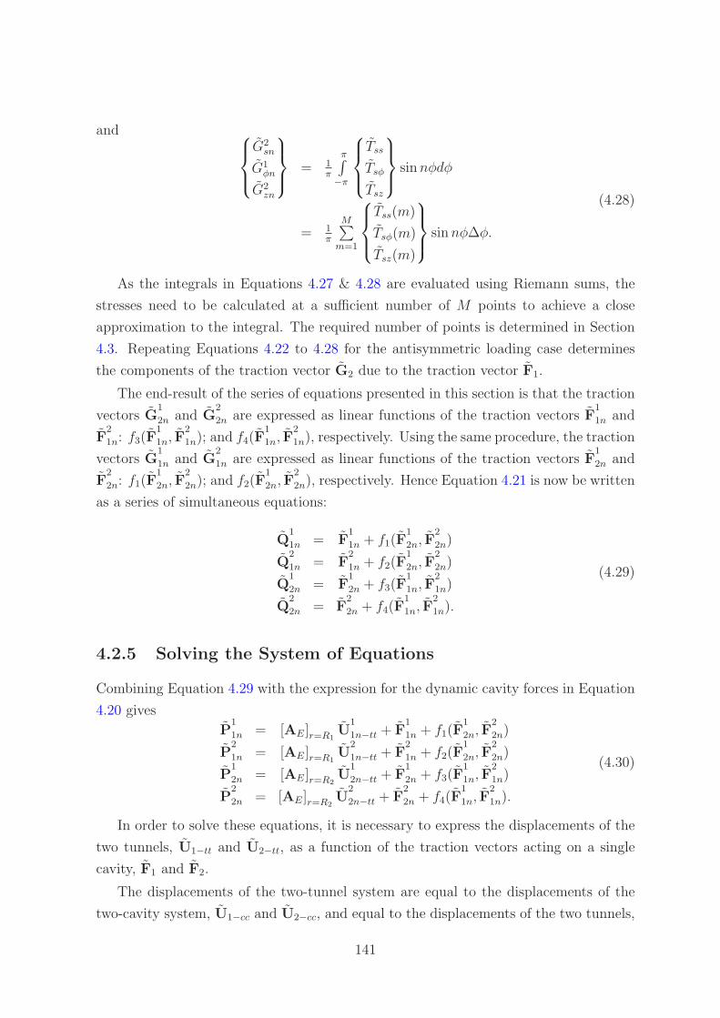
and
G2sn
G1φn
G2zn
= 1π
π∫
−π
Tss
Tsφ
Tsz
sin nφdφ
= 1π
M∑
m=1
Tss(m)
Tsφ(m)
Tsz(m)
sin nφ∆φ.
(4.28)
As the integrals in Equations 4.27 & 4.28 are evaluated using Riemann sums, the
stresses need to be calculated at a sufficient number of M points to achieve a close
approximation to the integral. The required number of points is determined in Section
4.3. Repeating Equations 4.22 to 4.28 for the antisymmetric loading case determines
the components of the traction vector G2 due to the traction vector F1.
The end-result of the series of equations presented in this section is that the traction
vectors G1
2n and G2
2n are expressed as linear functions of the traction vectors F1
1n and
F2
1n: f3(F1
1n, F2
1n); and f4(F1
1n, F2
1n), respectively. Using the same procedure, the traction
vectors G1
1n and G2
1n are expressed as linear functions of the traction vectors F1
2n and
F2
2n: f1(F1
2n, F2
2n); and f2(F1
2n, F2
2n), respectively. Hence Equation 4.21 is now be written
as a series of simultaneous equations:
Q1
1n = F1
1n + f1(F1
2n, F2
2n)
Q2
1n = F2
1n + f2(F1
2n, F2
2n)
Q1
2n = F1
2n + f3(F1
1n, F2
1n)
Q2
2n = F2
2n + f4(F1
1n, F2
1n).
(4.29)
4.2.5 Solving the System of Equations
Combining Equation 4.29 with the expression for the dynamic cavity forces in Equation
4.20 gives
P1
1n = [AE]r=R1U
1
1n−tt + F1
1n + f1(F1
2n, F2
2n)
P2
1n = [AE]r=R1U
2
1n−tt + F2
1n + f2(F1
2n, F2
2n)
P1
2n = [AE]r=R2U
1
2n−tt + F1
2n + f3(F1
1n, F2
1n)
P2
2n = [AE]r=R2U
2
2n−tt + F2
2n + f4(F1
1n, F2
1n).
(4.30)
In order to solve these equations, it is necessary to express the displacements of the
two tunnels, U1−tt and U2−tt, as a function of the traction vectors acting on a single
cavity, F1 and F2.
The displacements of the two-tunnel system are equal to the displacements of the
two-cavity system, U1−cc and U2−cc, and equal to the displacements of the two tunnels,
141

U1−tt and U2−tt, by compatibility of displacements. This is illustrated in Figure 4.6,
and expressed in
U1
1n−tt = U1
1n−cc
U2
1n−tt = U2
1n−cc
U1
2n−tt = U1
2n−cc
U2
2n−tt = U2
2n−cc.
(4.31)
Fig. 4.6 The displacements of the two-tunnel system are equal to the displacements of thetwo-cavity system and equal to the displacements of the two tunnels, by compatibilityof displacements
As in Section 4.2.3, the principle of superposition can be used to write the displace-
ments of the two-cavity system as the sum of those displacements resulting from the
traction vectors F1 and F2 acting on a single cavity, and those displacements resulting
from the interactions between the two cavities. This is illustrated in Figure 4.7, and
expressed in
U1−cc = U1−sc + U1−nc
U2−cc = U2−sc + U2−nc,(4.32)
where U1−sc and U2−sc are the displacements resulting from traction vectors acting on a
single cavity, and U1−nc and U2−nc are the displacements resulting from the interactions
between the two cavities.
Considering the displacements of cavity 2, the displacement contribution U2−sc is
calculated by applying traction vector F2 to a single cavity model:
Usn
Uφn
Uzn
2−sc
= [U]r=R2[Tr]
−1r=R2
Fsn
Fφn
Fzn
. (4.33)
The displacement contribution representing the motion induced by the neighbouring
142

Fig. 4.7 The displacements of the two-cavity system are written as the sum of twocontributions: those displacements resulting from the loads acting on a single cavity;and those displacements resulting from the interactions between the two cavities
cavity, U2−nc, is obtained by calculating the displacements on the virtual surface of
cavity 2 that result from the application of the traction vector F1 on cavity 1. Following
a similar procedure to that detailed in Section 4.2.4 for calculating the stresses around
a virtual surface, the displacements around the virtual surface are calculated at a radial
distance Rf from cavity 1, which corresponds to a radial distance R2 from cavity 2,
using
U1rn
U1θn
U1zn
r=Rf
= [U]r=Rf[Tr]
−1r=R1
F 1rn
F 1θn
F 1zn
. (4.34)
The total displacement at the point (Rf , Θf , 0), which corresponds to the point (R2, Φf , 0)
on cavity 2, is calculated by combining the displacement contributions from each mod-
enumber:
Ur
Uθ
Uz
(Rf ,Θf ,0)
=N
∑
n=0
U1rn cos nΘf
U1θn sin nΘf
U1zn cos nΘf
. (4.35)
The displacements are now converted to the (s, φ, z) directions to obtain compati-
bility with the cavity 2 coordinate system. The equations for converting displacements
between the (r, θ, z) and (s, φ, z) coordinate systems are obtained by considering vector
geometry, and are assembled into a 3x3 transformation matrix, denoted [A], such that
Us
Uφ
Uz
(R2,Φf ,0)
= [A]
Ur
Uθ
Uz
(Rf ,Θf ,0)
, (4.36)
143

where [A] is given by
[A] =
cos(Θf − Φf )) − sin(Θf − Φf ) 0
sin(Θf − Φf ) cos(Θf − Φf ) 0
0 0 1
. (4.37)
After calculating the displacements at a series of M evenly spaced points around
the virtual surface of cavity 2, following the same procedure as in Section 4.2.4, Fourier
decomposition is used to partition the displacements into those contributions due to the
symmetric and antisymmetric loading cases, and the n modenumbers. These displace-
ment contributions represent the displacements resulting from the interactions between
the two cavities due to F1
1, U2−nc, and are given by
U1sn
U2φn
U1zn
2(n=0)−nc
= 12π
π∫
−π
Us
Uφ
Uz
dφ = 12π
M∑
m=1
Us(m)
Uφ(m)
Uz(m)
∆φ
U1sn
U2φn
U1zn
2(n≥1)−nc
= 1π
π∫
−π
Us
Uφ
Uz
cos nφdφ = 1π
M∑
m=1
Us(m)
Uφ(m)
Uz(m)
cos nφ∆φ,
(4.38)
and
U2sn
U1φn
U2zn
2−nc
= 1π
π∫
−π
Us
Uφ
Uz
sin nφdφ
= 1π
M∑
m=1
Us(m)
Uφ(m)
Uz(m)
sin nφ∆φ.
(4.39)
Repeating Equations 4.34 to 4.39 for the antisymmetric loading case determines the
components of U2−nc due to F2
1.
The displacements on cavity 2 resulting from the interactions between the two
cavities are now expressed as linear functions of the traction vectors F1
1n and F2
1n:
g3(F1
1n, F2
1n); and g4(F1
1n, F2
1n), respectively. Using the same procedure, the displace-
ments on cavity 1 resulting from the interactions between the two cavities are expressed
as linear functions of the traction vectors F1
2n and F2
2n: g1(F1
2n, F2
2n); and g2(F1
2n, F2
2n),
respectively. Hence the displacements of the two tunnels are represented by a series of
144

equations:
U1
1n−tt = [U]r=R1[Tr]
−1r=R1
F1
1n + g1(F1
2n, F2
2n)
U2
1n−tt = [U]r=R1[Tr]
−1r=R1
F2
1n + g2(F1
2n, F2
2n)
U1
2n−tt = [U]r=R2[Tr]
−1r=R2
F1
2n + g3(F1
1n, F2
1n)
U2
2n−tt = [U]r=R2[Tr]
−1r=R2
F2
2n + g3(F1
1n, F2
1n).
(4.40)
Substituting this into Equation 4.30 results in
P1
1n = [AE]r=R1([U]r=R1
[Tr]−1r=R1
F1
1n + g1
(
F1
2n, F2
2n))
+ F1
1n + f1(F1
2n, F2
2n)
P2
1n = [AE]r=R1([U]r=R1
[Tr]−1r=R1
F2
1n + g2
(
F1
2n, F2
2n))
+ F2
1n + f2(F1
2n, F2
2n)
P1
2n = [AE]r=R2([U]r=R2
[Tr]−1r=R2
F1
2n + g3
(
F1
1n, F2
1n))
+ F1
2n + f3(F1
1n, F2
1n)
P2
2n = [AE]r=R2([U]r=R2
[Tr]−1r=R2
F2
2n + g4
(
F1
1n, F2
1n))
+ F2
2n + f4(F1
1n, F2
1n).
(4.41)
The solution of these simultaneous equations is found using the blockwise inversion
technique. This solution represents the traction vectors F1 and F2 applied to the single-
cavity models in order to replicate the displacement field produced by the known traction
vectors P1 and P2, which are applied to the two-tunnel model. The displacement field
of the two-tunnel model is thus the superposition of the displacement field produced by
the traction vector F1 acting on cavity 1 in a single-cavity model, and the displacement
field produced by the traction vector F2 acting on cavity 2 in a single-cavity model.
4.3 Results and Discussion
The above equations are implemented in Matlab, and the displacement fields are pre-
sented in terms of the vertical or horizontal displacements, always in terms of dBref[1m].
Unless otherwise specified, the tunnel and soil parameters used to calculate the results
are shown in Table 4.1.
It is necessary to determine the number of circular modenumbers (N) and points
around the virtual cavity surface (M) required to capture the dynamic behaviour of
the system. Figure 4.8 shows the vertical and horizontal displacements calculated at
s = 6m and −90◦ < φ < 90◦ for twin, side-by-side tunnels at a frequency of 100Hz. The
excitation is a unit, harmonic, radial point load applied to the invert of the right-hand
tunnel. Results are calculated for the first 9, 10, 11, 12 and 13 circular modenumbers,
with M = 200. Convergence is achieved by using the first 13 modenumbers.
Using the value N = 13, the number of points around the virtual tunnel surface is
varied by multiples of N . In order to satisfy the Nyquist criterion, M must be at least
double the value of N . Increasing the number of points beyond N = 4M results in no
145

Table 4.1 Parameter values used for the two-tunnel model
Tunnel Properties Symbol ValueDensity ρ 2500kgm−3
Young’s Modulus E 50GPaPoisson’s Ratio ν 0.30Tunnel Separation Distance c 10mTunnel Separation Angle α π
2
Radius R1 = R2 3mThickness h1 = h2 0.25m
Soil Properties Symbol ValueLame’s First Parameter λ 360MPaLame’s Second Parameter µ 90MPaDensity ρ 2250kgm−3
Shear Modulus Damping Ratio ηG 0.06
change in the displacements, hence N = 13 and M = 52 are used to calculate the results
presented in this section.
The correctness of the numerical implementation of the above equations can be
verified by considering a number of loading cases that are known to produce symmetric
results. These are calculated for twin tunnels at an arbitrary frequency of 60Hz and are
shown in Figures 4.9 to 4.11. The arrows shown in these figures, and those following,
indicate a unit, harmonic point load acting in the indicated direction at the point of
intersection with the tunnel invert. The displacement field is calculated over a 30mx30m
area located in the plane of these loads. Figure 4.9 shows the vertical displacement field
for two radial point loads acting on the tunnel base, and as expected, the displacement
field is symmetric about x = −5. Figure 4.10 shows the horizontal displacement field
for two tangential point loads acting on the tunnel base. This displacement field is
symmetric about x = −5 and has zero horizontal displacements along this line. Figure
4.11 shows the horizontal displacement field for two radial point loads acting on the
tunnel wall. As expected, this displacement field is symmetric about x = −5 and y = 0,
and has zero horizontal displacements along the line x = −5. Due to the nature of the
shading function used to produce these figures, very slight, localised shading variations
may be observed when inspecting the symmetry of each plot. However, this does not
compromise the overall symmetry of the plots, nor challenge the correctness of the
numerical implementation.
146

−260 −250 −240 −230 −220 −210 −200
−80
−60
−40
−20
0
20
40
60
80
Ang
le φ
[°]
Displacement Magnitude dBref
[1m]
N=9
N=10
N=11
N=12
N=13
(a) 100Hz vertical displacement
−250 −245 −240 −235 −230 −225 −220 −215 −210
−80
−60
−40
−20
0
20
40
60
80
Ang
le φ
[°]
Displacement Magnitude dBref
[1m]
N=9
N=10
N=11
N=12
N=13
(b) 100Hz horizontal displacement
Fig. 4.8 Convergence plot showing: (a) the vertical; and (b)the horizontal, displacements at 100Hz at s = 6m in a twin-tunnel system
147

Fig. 4.9 A symmetric loading distribution: vertical displace-ments (dBref[1m]) resulting from two radial point loads actingon the tunnel base
Fig. 4.10 A symmetric loading distribution: horizontal dis-placements (dBref[1m]) resulting from two tangential pointloads acting on the tunnel base
148
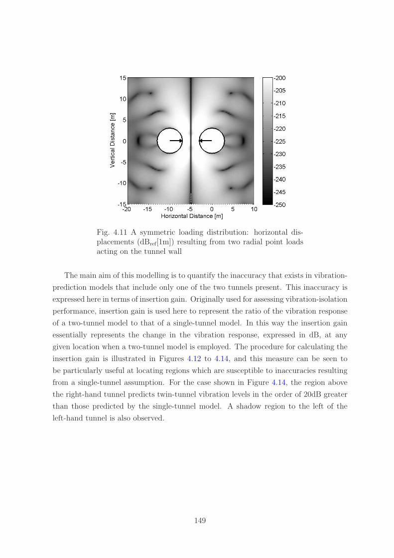
Fig. 4.11 A symmetric loading distribution: horizontal dis-placements (dBref[1m]) resulting from two radial point loadsacting on the tunnel wall
The main aim of this modelling is to quantify the inaccuracy that exists in vibration-
prediction models that include only one of the two tunnels present. This inaccuracy is
expressed here in terms of insertion gain. Originally used for assessing vibration-isolation
performance, insertion gain is used here to represent the ratio of the vibration response
of a two-tunnel model to that of a single-tunnel model. In this way the insertion gain
essentially represents the change in the vibration response, expressed in dB, at any
given location when a two-tunnel model is employed. The procedure for calculating the
insertion gain is illustrated in Figures 4.12 to 4.14, and this measure can be seen to
be particularly useful at locating regions which are susceptible to inaccuracies resulting
from a single-tunnel assumption. For the case shown in Figure 4.14, the region above
the right-hand tunnel predicts twin-tunnel vibration levels in the order of 20dB greater
than those predicted by the single-tunnel model. A shadow region to the left of the
left-hand tunnel is also observed.
149

Fig. 4.12 The vertical displacement field (dBref[1m]) producedat 60Hz by a unit, vertical point force applied to a tunnelinvert, calculated using a single-tunnel model
Fig. 4.13 The vertical displacement field (dBref[1m]) producedat 60Hz by a unit, vertical point force applied to a tunnelinvert, calculated using a twin-tunnel model
150

Fig. 4.14 The insertion gain (dB) represents the differencebetween the vertical displacement fields produced at 60Hz bythe single-tunnel model and the twin-tunnel model
4.3.1 Insertion-Gain Results
As vibration predictions are commonly made at the ground surface, it is useful to focus
this discussion on the region directly above the twin tunnels. The two-tunnel model
presented in this chapter is that for a fullspace, and this model can be used as the basis of
a two-tunnel model in a layered or homogeneous halfspace. The layered or homogeneous
halfspace is incorporated using the fictitious-force method detailed in Hussein et al.
[67]. Previous investigations into underground-railway models have shown that when
the tunnel is at a depth of two tunnel diameters or more, the vibrations calculated
at an equivalent surface location using a fullspace model are approximately 6dB less
than those calculated using a halfspace model [80]. It is also acknowledged that soil
inhomogeneities, such as layering, permeability, and the presence of bedrock, can have
a significant influence on the accuracy of vibration predictions. For this reason, the
results presented here are not purported to be accurate vibration predictions, but rather
a quantification of one type of inaccuracy that can be present in vibration predictions.
In the following figures, the vibration response as a function of frequency, tunnel
orientation and tunnel thickness is investigated. In each case, a unit, harmonic point
load is applied radially to the base of tunnel 1. This loading can be easily extended to
represent a line load by the use of superposition. Tunnel 1 represents the right-hand
151

tunnel in the case of side-by-side tunnels, or the lower tunnel in the case of piggy-back
tunnels. One of the defining characteristics of the two-tunnel model is the absence
of the cylindrical symmetry of the single-tunnel model. For a single-tunnel model, a
symmetric loading condition gives rise to purely symmetric soil displacements and stress
distributions, and an antisymmetric loading condition gives rise to purely antisymmetric
soil displacements and stress distributions. This is not the case for the two-tunnel model.
Due to the symmetry of the loading of the single-tunnel model, seen in Figure 4.12, a
line of zero horizontal displacements is produced at x = 0 for this model. This means
that any insertion-gain results for the two-tunnel model presented in terms of horizontal
displacements show a line of infinite insertion gain at x = 0. For this reason, the
insertion gains are presented not only for vertical and horizontal displacements, but also
for displacement magnitudes. To obtain the displacement-magnitude insertion gain, the
maximum value of the displacement magnitude is calculated for both the two-tunnel
model and the single-tunnel model using the method detailed in Appendix D. The
displacement-magnitude insertion gain, although not commonly used to characterise
displacement fields, is useful here as it provides a clearer indication of the vibration
hot-spots than either the vertical or horizontal displacements.
Figure 4.15 presents the insertion gain for the two most commonly used twin-tunnel
orientations: side-by-side; and piggy-back, as a function of frequency and horizontal
position along a horizontal line located 15m above the centre of tunnel 1. In both cases
a unit, harmonic point load has been applied radially to the base of tunnel 1. For the
side-by-side tunnels, the insertion gain is seen to be highly dependent on both frequency
and measurement position. There is no apparent trend in the distribution, which is due
to the scattering effect of the second tunnel. For the piggy-back tunnels, it can be seen
that the maximum-negative insertion gains occur in the region stretching directly above
the tunnel invert. At low frequencies, the maximum insertion gains occur in a series of
bands centred on x = 0. This series of bands transitions into a more irregular pattern
at around 80Hz: the frequency at which the wavelength of the pressure wave is equal to
the tunnel diameter. This suggests that at low frequencies very little diffraction of the
pressure wave occurs, whereas at frequencies greater than that at which the wavelength
matches the tunnel diameter, pressure-wave diffraction dominates the response.
Figure 4.16 presents the displacement-magnitude insertion gains at 20Hz and 60Hz,
calculated as a function of the angle α, where α is the angle of tunnel 2 measured from
tunnel 1. The loading is again a unit, harmonic point load applied radially to the base
of tunnel 1. A number of vertical lines of large insertion gain can be seen in this figure.
For example, at 60Hz the vertical-displacement insertion gain (Figure 4.16(b)) has three
such lines located at x = −18m, x = −3m, and x = 3m. By examining the displacement
152

(a) Vertical displacement (b) Vertical displacement
(c) Horizontal displacement (d) Horizontal displacement
(e) Displacement magnitude (f) Displacement magnitude
Fig. 4.15 Insertion gains as a function of frequency and position for side-by-sidetunnels (left), and piggy-back tunnels (right)
153

fields of the single-tunnel model shown in Figure 4.17, the location of these lines can be
seen to correspond with the troughs in the response calculated using the single-tunnel
model. Thus the addition of the twin tunnel has effectively smoothed the single-tunnel
displacement field to create a more uniform response. At both frequencies, the largest-
negative insertion gains generally occur at angles greater than 100◦. Three additional
lines are plotted on these graphs: the solid line indicates the location of the measuring
point lying on the line joining the centres of the two tunnels, while the dashed lines
on either side indicate the locations of the measuring points lying on the lines joining
the extreme edges of the two tunnels. Hence the region enclosed by the dashed lines
indicates measuring points lying in the shadow of tunnel 2, as observed from tunnel
1. The overall trend in this region is large, negative insertion gains. Large, negative
insertion gains are also observed on either side of this region, indicating that the second
tunnel acts to shield nearby regions from vibrational energy. Apart from this trend, the
insertion gains are again seen to be highly dependent on frequency and measurement
position.
The final figure presented here, Figure 4.18, shows the vertical-displacement insertion
gains for twin tunnels of varying invert thickness h. At low frequencies, such as at 20Hz
shown in Figure 4.18(a), there is little separation between the insertion-gain curves and
hence the tunnel thickness has little influence on the general shape of the insertion gain
versus position plot. Although at the frequency of 20Hz the trend suggests that the
thinner tunnel produces the lower insertion-gain level, this trend is not observed for all
low frequencies. For example, at 10Hz it is the thicker tunnel that produces the lower
insertion-gain level, and at 15Hz the tunnel thickness that produces the lower insertion-
gain level varies with horizontal distance. At frequencies above approximately 40Hz, the
tunnel thickness has a stronger influence on the general shape of the insertion gain versus
position plot, and there is no consistent trend observed in the thickness of the tunnels
and the level of insertion gain. For example, at 60Hz, shown in Figure 4.18(b), there
is greater than 10dB variation in the insertion gains at given measurement positions.
Hence it can be again concluded that the vibration response is highly dependent upon
both frequency and position.
154

(a) 20Hz vertical displacement (b) 60Hz vertical displacement
(c) 20Hz horizontal displacement (d) 60Hz horizontal displacement
(e) 20Hz displacement magnitude (f) 60Hz displacement magnitude
Fig. 4.16 Insertion gains as a function of angle α and position, calculated at 20Hzand 60Hz
155
−20 −15 −10 −5 0 5 10−260
−255
−250
−245
−240
−235
−230
−225
−220
−215
−210D
ispl
acem
ent d
Bre
f[1m
]
Horizontal Distance [m]
VerticalHorizontalMagnitude
(a) 20Hz
−20 −15 −10 −5 0 5 10−260
−255
−250
−245
−240
−235
−230
−225
−220
−215
−210
Dis
plac
emen
t dB
ref[1
m]
Horizontal Distance [m]
VerticalHorizontalMagnitude
(b) 60Hz
Fig. 4.17 Single-tunnel displacements (dBref[1m]), calculatedat 20Hz and 60Hz
156

−20 −15 −10 −5 0 5 10−20
−15
−10
−5
0
5
10
15
20
Horizontal Distance [m]
Inse
rtio
n G
ain
dB
h=0.2m
h=0.25m
h=0.3m
(a) 20Hz vertical displacement
−20 −15 −10 −5 0 5 10−20
−15
−10
−5
0
5
10
15
20
Horizontal Distance [m]
Inse
rtio
n G
ain
dB
h=0.2m
h=0.25m
h=0.3m
(b) 60Hz vertical displacement
Fig. 4.18 Insertion gains as a function of position and tunnelthickness, calculated at 20Hz and 60Hz
157
4.4 Conclusions
This chapter presents the formulation of a unique model for underground-railway vibra-
tion that includes the interaction between neighbouring tunnels. Each of these tunnels
is subject to both known, dynamic train forces and dynamic cavity forces. The net
forces acting on the tunnels are written as the sum of those tractions acting on the
invert of a single tunnel, and those tractions that represent the motion induced by the
neighbouring tunnel. By apportioning the tractions in this way, the vibration response
of a two-tunnel system is written as a linear combination of displacement fields pro-
duced by a single-tunnel system. Using Fourier decomposition, forces are partitioned
into symmetric and antisymmetric modenumber components to minimise computation
times.
Analysis of the vibration fields produced over a range of frequencies, tunnel orien-
tations and tunnel geometries is conducted. It is observed that the interaction between
neighbouring tunnels is highly significant, at times in the order of 20dB. This demon-
strates that a high degree of inaccuracy exists in any surface vibration-prediction model
that includes only one of the two tunnels present. The results of this modelling also
indicate that the presence of other underground inclusions, such as buried services, can
have a significant effect on the ground-borne vibration field. It is recommended that all
future models predicting vibration levels from underground railways include the inter-
action between neighbouring tunnels.
158

Chapter 5
Conclusions
This dissertation details the formulation of a number of mathematical models that can
be used to assess the behaviour of two types of embedded structures: piled foundations;
and twin tunnels, when subject to ground-borne vibration generated by an underground
railway. In this chapter, the main findings of this research are summarised and general
conclusions on the use and applicability of the mathematical models are drawn. Based
on this and the experience gained by the author during the course of this research, a
number of topics for further research are proposed.
5.1 Introduction
In Chapter 1, two important areas of research are identified: the effect of piled foun-
dations; and the effect of neighbouring tunnels, on ground-borne vibrations generated
by an underground railway. Neither area receives proper attention in the literature.
For example, extensive research is conducted on the response of piled foundations to
earthquake loadings, but only a few models of an above-ground railway seated on a pile
row exist. For the case of twin tunnels, much research focuses on determining the static
stresses and strains encountered during and post- construction, but only one dynamic
model comparing the behaviour of a twin-tunnel model and a double-track, single-tunnel
model exists.
The primary aim of the research presented in this dissertation, as stated in Section
1.8.1, is to develop computational models for the vibration response of piled foundations
and neighbouring tunnels. The main applications of these models are: to determine the
effect of piled foundations and twin tunnels on ground-borne vibration; to evaluate
objectively the vibration performance of piled foundation and twin-tunnel designs; and
to establish the best design practice. Each of these applications are reviewed here in
turn, and the contribution of this research toward the fulfilment of these aims is assessed.
159
5.1.1 The Effect of Piled Foundations and Twin Tunnels on
Ground-Borne Vibration
Chapter 2 addresses the development of a single-pile model, the starting point for any
pile-group model. Two approaches are considered. Firstly, an existing plane-strain
model by Novak [130, 134] is modified to include an incident wavefield and allow for
calculation of farfield displacements. Secondly, the elastic-continuum equations used in
the PiP model are coupled to the equations for an infinite column or an Euler beam to
obtain a model for an infinitely long pile in the wavenumber domain. Using mirror-image
techniques, a method for adapting this model to simulate a finite-length pile embedded
in a halfspace is developed, and a computationally efficient approach to incorporating
the incident wavefield from an underground railway is established.
Validation of the plane-strain and three-dimensional single-pile models is achieved by
comparing the pile-head, driving-point response generated by these models against the
response calculated by an existing boundary-element (BE) model. Whilst the agreement
in axial vibration is good, the plane-strain assumption is shown to be invalid for lateral
vibration in the frequency range of interest: 1-80Hz.
The response of a single pile to underground-railway vibration is calculated. In
axial vibration, the single pile has a significant stiffening effect on the soil, resulting in
reduced surface-displacement levels. The amount of vibration attenuation is observed
to increase with increasing frequency. However, for the case of lateral vibration, the
single pile marginally increases the vibration level at higher frequencies. Analysis of the
power flows through the pile skin indicate that the power entering a pile by a vertical
loading is dissipated along the whole length of the pile, whereas the power entering the
pile by a lateral loading is dissipated in a highly localised region near the location of
power inflow. This behaviour is expected for a slender cylinder like a pile, because the
stiffness of the cylinder is higher in axial compression than in bending.
The pile models are extended in Chapter 3 to consider pile-soil-pile interactions
within a pile group. The superposition method is chosen as an efficient means of calcu-
lating the direct-field component of the PSPI, and a model for calculating the interaction
between two neighbouring piles is formulated based on the method of joining subsys-
tems. The inertial interaction factors generated using the two-pile models are validated
against a BE model and a dynamic stiffness matrix formulation by Kaynia [88]. The
Novak model does not accurately represent pile-soil-pile interactions, however, the three-
dimensional model compares well with the results obtained using the numerical methods.
A model for evaluating the response of a pile group subject to an incident wavefield is
developed, and comparison of the results with the three-dimensional and BE models
160

again shows good agreement. The kinematic interaction effects in the pile group subject
to an incident wavefield are small, and it is concluded that the superposition method
does not provide a comprehensive representation of the interactions occurring in this
particular pile group. The chapter concludes with the development of a model for a piled
building, and a case study to demonstrate how this model can be used together with
power-flow techniques to evaluate the dynamic response of different foundation designs.
The effect of twin tunnels on ground-borne vibration is addressed in Chapter 4.
The superposition of two displacement fields, the direct field and the scattered field, is
used to formulate a fully-coupled model for two infinitely long tunnels in a fullspace.
Comparison of this twin-tunnel model with the single-tunnel model reveals the effect of
the neighbouring tunnel on the propagated vibrations. The second tunnel deflects the
vibration field from the first tunnel, creating a shadow region behind the second tunnel
and regions of significant insertion gain in the farfield. Whilst these trends are observed
over a range of frequencies, tunnel orientations and tunnel thickness, the location of the
maximum insertion gains are highly variable and dependent on all the aforementioned
factors. The maximum insertion gains are commonly in the order of 20dB, indicating
that a high degree of inaccuracy exists in any vibration-prediction model that considers
the presence of only one tunnel.
5.1.2 The Vibration Performance of Embedded-Structure De-
signs
The mathematical models developed in this dissertation provide a means of evaluating
the vibration performance of embedded structures. For both piled foundations and twin
tunnels, the vibration performance of the system has been shown to be highly depen-
dent on factors such as frequency, soil parameters and system geometry. For this reason,
no generalisations on system design are offered here, but instead, the engineering prac-
titioner is recommended to use these mathematical models to evaluate specific design
cases.
The model of a piled building subject to a wavefield generated by an underground
railway provides a useful means of evaluating the dynamic behaviour of piled foundation
designs. More generally, the piled-building model may also be used to evaluate the
dynamic behaviour of a foundation with some form of excitation at the pile heads,
for example, a piled building with rotating equipment mounted in the basement. The
models of piled foundations developed in this dissertation are shown to be both accurate
and computationally efficient.
The twin-tunnel model is not specifically a vibration-prediction model due to the
161

fullspace formulation and the lack of consideration of other underground features. How-
ever, it provides useful insights into the deflection of a wavefield by a second tunnel.
This model can therefore be used to evaluate various features of the tunnel design and
approximate the magnitude of the error present in a single-tunnel model.
One of the difficulties involved in evaluating the vibration performance of these
embedded structures is the choice of an appropriate vibration-performance measure.
For piled foundations, displacement magnitude at the pile heads provides a measure of
how the vibration level differs from that of greenfield conditions. Whilst this is useful
for observing trends in pile behaviour, the frequency, direction and position dependence
of displacement magnitudes does not provide a clear quantification of the vibration
performance of various foundation designs. For this reason, power-flow techniques are
recommended. Mean power flow provides a single measure to represent the vibrational-
energy contributions from all piles and all vibration directions. Should the engineering
practitioner wish to eliminate the frequency variation in the response, RMS power flow
can be used to provide a single, real number to represent the foundation response.
The use of insertion gain provides an excellent measure for comparing the results of
the twin-tunnel model with the single-tunnel model. However, some anomalous results
are shown to be present due to lines of symmetry in the single-tunnel model.
5.1.3 The Best Design Practice
Retrofits involving the most effective vibration-isolation measures, such as floating slab
track or base isolation, are expensive undertakings. The preferred practice is to assess
the need for these isolation measures during the design stage. This requires the availabil-
ity of well-validated, accurate and computationally efficient vibration-prediction tools.
At present, the available prediction tools are only in the early stages of fulfilling this
requirement. This dissertation represents a contribution towards improved model vali-
dation, accuracy and efficiency.
The twin-tunnel model has highlighted the scope for inaccuracies in prediction mod-
els. Simplifying assumptions about the underground and above-ground environment
cannot be made without some recognition of an associated error, and efforts should
be made to quantify the magnitude of this error before presenting final vibration pre-
dictions. An increased awareness of the sources of uncertainty in vibration-prediction
models and the vibration-related consequences of design choices would benefit both en-
gineering practitioners (particularly railway and building designers) and the affected
public. This would contribute towards the establishment of better design practices and
continued dialogue throughout all stages of the design procedure.
162

5.2 Recommendations for Future Work
The models outlined in this dissertation provide a useful and efficient means of assessing
the vibration performance of piled foundations and twin tunnels. These models repre-
sent a valuable contribution towards the field of underground-railway research, as they
provide a much-needed method for assessing generic design situations. There are several
specific design situations that could be assessed by extending these models, and scope
exists for further investigation of the main assumptions used in the modelling presented
in this dissertation. Possible future developments are outlined below.
Further investigation of the errors introduced by the mirror-image method could be
achieved by calculating the displacements at varying depths within the soil. The method
for calculating these displacements using the three-dimensional model is straightforward.
However, to obtain comparative results using the BE model requires meshing of the
relevant region. Investigation of other pile-to-soil stiffness ratios would also further
evaluate the robustness of the three-dimensional pile model.
One of the main assumptions implicit in the use of the method of joining subsystems
is the uncoupling of the source and receiver. The validity of this assumption is evaluated
for the joining of the piles to the incident wavefield and the pile-soil-pile interactions
by comparison with the fully-coupled BE and DSM models. Good agreement is seen
when the piles are joined to the incident wavefield, but this method does not provide a
comprehensive representation of PSPI. The validity of this assumption in relation to the
joining of the pile cap and the building to the pile group has not been assessed. Further
investigation of uncoupled/coupled source-receiver models could provide useful insight
not only for the modelling of the underground-railway environment, but also for other
complex vibration systems.
As mentioned in Section 4.3.1, methods exist for adapting the twin-tunnel model to
simulate twin tunnels embedded in a homogeneous or layered halfspace. The implemen-
tation of these methods is not expected to significantly alter the conclusions obtained
using the twin-tunnel model presented in this dissertation. However, it is recognised that
engineering practitioners may prefer to use a halfspace model rather than a fullspace
model. For this reason, a model of twin tunnels embedded in a halfspace would be a
useful tool.
In a congested underground environment, railway lines frequently cross over, which
can result in two twin-tunnel systems in close proximity. It is proposed that the twin-
tunnel model described in this dissertation may be extended to include additional neigh-
bouring tunnels. Through the use of a transformation of the wavenumber components,
non-parallel tunnels may also be accounted for. This extension of the twin-tunnel model
163

would also allow the incorporation of buried services near the tunnels.
Further developments of the foundation model presented in this dissertation include:
the incorporation of base-isolation bearings between the piles and the building; the
formulation of a more-detailed finite building model that may be attached to a finite
pile group; and the investigation of other types of foundation, such as raft or strip
foundations. Furthermore, the incorporation of varying soil properties, such as soil
layers, anisotropic soil stiffness and pore pressures, into the piled-foundation and two-
tunnel models would further improve the robustness of a prediction model.
Although this dissertation and much other research on the vibration from under-
ground railways solely consider the modelling of the system, experimental measurements
taken both below- and above- ground would be beneficial in validating these models and
obtaining further insights into underground-railway vibration. Field-testing opportuni-
ties should be explored wherever possible, and the use of scale models or centrifuge
testing could also provide a useful route for validation.
On a final note, it is recommended that underground-railway researchers and prac-
titioners continue to collaborate by publishing their findings and allowing their models
and data to be available for use in cross-validation.
164
References
[1] G. M. Aasvang, B. Engdahl, and K. Rothschild. Annoyance and self-reportedsleep disturbances due to structurally radiated noise from railway tunnels. AppliedAcoustics, 68(9):970–981, 2007.
[2] A. Abebe and I.G.N. Smith. Pile foundation design: a student guide, 2005.
[3] T. I. Addenbrooke and D. M. Potts. Twin tunnel construction - ground move-ments and lining behaviour. In R. J. Mair and R. N. Taylor, editors, GeotechnicalAspects of Underground Construction in Soft Ground, pages 441–446, London,1996. Taylor and Francis.
[4] R. D. Ambrosini. Material damping vs. radiation damping in soil-structure inter-action analysis. Computers and Geotechnics, 33(2):86–92, 2006.
[5] L. Andersen and C. J. C. Jones. Coupled boundary and finite element analysisof vibration from railway tunnels - a comparison of two- and three-dimensionalmodels. Journal of Sound and Vibration, 293(3-5):611–625, 2006.
[6] L. Auersch. The excitation of ground vibration by rail traffic: theory of vehicle-track-soil interaction and measurements on high-speed lines. Journal of Soundand Vibration, 284(1-2):103–132, 2005.
[7] T. Balendra. Dynamic interaction of twin tunnels. In A.P. Boresi and K.P. Chong,editors, Engineering Mechanics in Civil Engineering: Proceedings of the FifthEngineering Mechanics Division Specialty Conference, volume 1, pages 368–371,Laramie, 1984. American Society of Civil Engineers.
[8] P. K. Banerjee and S. M. Mamoon. A fundamental solution due to a periodicpoint force in the interior of an elastic half-space. Earthquake Engineering andStructural Dynamics, 19(1):91–105, 1990.
[9] V. A. Baranov. On the calculation of excited vibrations of an embedded founda-tion. Voprosy Dynamiki Prochnocti, 14:195–209, 1967.
[10] M. Beckers. Incorporating geometric features into the PiP model for subwayinduced vibrations. Master’s thesis, Katholieke Universiteit Leuven, 2010.
[11] K. J. Bentley and M. H. El Naggar. Numerical analysis of kinematic response ofsingle piles. Canadian Geotechnical Journal, 37(6):1368–1382, 2000.
[12] Y. Beredugo and M. Novak. Coupled horizontal and rocking vibration of embeddedfootings. Canadian Geotechnical Journal, 9(4):477–497, 1972.
165

[13] M. A. Biot. Dynamics of viscoelastic anisotropic media. In Proceedings of theFourth Midwestern Conference on Solid Mechanics, Publication No. 129. Engi-neering Experiment Station, Purdue University, Lafayette, 1955.
[14] A. Boominathan and R. Ayothiraman. Dynamic behaviour of laterally loadedmodel piles in clay. Proceedings of the Institution of Civil Engineers-GeotechnicalEngineering, 158(4):207–215, 2005.
[15] H. Bretz. Challenges in tunnel engineering in southeast asia. Tunnel Construction,1998.
[16] G. N. Bycroft. Forced vibrations of a rigid circular plate on a semi-infinite elasticspace and on an elastic stratum. Philosophical Transactions of the Royal Societyof London A - Mathematical and Physical Sciences, 248(948):327–368, 1956.
[17] R. Cairo, E. Conte, and G. Dente. Analysis of pile groups under vertical harmonicvibration. Computers and Geotechnics, 32(7):545–554, 2005.
[18] R. Cairo, E. Conte, and G. Dente. Interaction factors for the analysis of pilegroups in layered soils. Journal of Geotechnical and Geoenvironmental Engineer-ing, 131(4):525–528, 2005.
[19] F. H. Chehade and I. Shahrour. Numerical analysis of the interaction betweentwin-tunnels: Influence of the relative position and construction procedure. Tun-nelling and Underground Space Technology, 23(2):210–214, 2008.
[20] Y. K. Chow. Analysis of dynamic behavior of piles. International Journal forNumerical and Analytical Methods in Geomechanics, 9(4):383–390, 1985.
[21] B. L. Chu, S. C. Hsu, Y. L. Chang, and Y. S. Lin. Mechanical behavior of a twin-tunnel in multi-layered formations. Tunnelling and Underground Space Technology,22(3):351–362, 2007.
[22] D. Clouteau, M. Arnst, T. M. Al-Hussaini, and G. Degrande. Freefield vibrationsdue to dynamic loading on a tunnel embedded in a stratified medium. Journal ofSound and Vibration, 283(1-2):173–199, 2005.
[23] D. Clouteau, G. Degrande, and G. Lombaert. Numerical modelling of trafficinduced vibrations. Meccanica, 36(4):401–420, 2001.
[24] M. L. Cooper, D. N. Chapman, and C. D. F. Rogers. Prediction of settlementin existing tunnel caused by the second of twin tunnels. Transportation ResearchRecord: Journal of the Transportation Research Board, 1814:103–112, 2002.
[25] P. Coulier. The vibration response of piled foundations to inertial and undergroundrailway induced loadings. Master’s thesis, Katholieke Universiteit Leuven, 2010.
[26] M. Crocker, editor. Handbook of noise and vibration control. Wiley, Hoboken,2007.
[27] D. Cryer. Modeling of vibration in buildings with application to base isolation.PhD thesis, University of Cambridge, 1994.
[28] T. M. Dawn. Ground vibrations from heavy freight trains. Journal of Sound andVibration, 87(2):351–356, 1983.
166

[29] T. M. Dawn and C. G. Stanworth. Ground vibrations from passing trains. Journalof Sound and Vibration, 66(3):355–362, 1979.
[30] F. C. P. De Barros and J. Luco. Discrete models for vertical vibrations of surfaceand embedded foundations. Earthquake Engineering and Structural Dynamics,19:289–303, 1990.
[31] G. Degrande, M. Schevenels, P. Chatterjee, W. Van de Velde, P. Holscher, V. Hop-man, A. Wang, and N. Dadkah. Vibrations due to a test train at variable speedsin a deep bored tunnel embedded in London clay. Journal of Sound and Vibration,293(3-5):626–644, 2006.
[32] F. Dezi, S. Carbonari, and G. Leoni. A model for the 3D kinematic interactionanalysis of pile groups in layered soils. Earthquake Engineering and StructuralDynamics, 38:1281–1305, 2009.
[33] G. Di Mino, M. Giunta, and C. Di Liberto. Assessing the open trenches in screen-ing railway ground-borne vibrations by means of an artificial neural network. Ad-vances in Acoustics and Vibration, 2009:1–12, 2009.
[34] R Dobry and G. Gazetas. Simple method for dynamic stiffness and damping offloating pile groups. Geotechnique, 38(4):557–574, 1988.
[35] H. R. Dou and P. M. Byrne. Dynamic response of single piles and soil pile inter-action. Canadian Geotechnical Journal, 33(1):80–96, 1996.
[36] T. Ekevid, M. X. D. Li, and N. E. Wiberg. Adaptive FEA of wave propagationinduced by high-speed trains. Computers and Structures, 79(29-30):2693–2704,2001.
[37] M. H. El Naggar and K. J. Bentley. Dynamic analysis for laterally loaded pilesand dynamic p-y curves. Canadian Geotechnical Journal, 37(6):1166–1183, 2000.
[38] B. Elsharnouby and M. Novak. Dynamic experiments with group of piles. Journalof Geotechnical Engineering, Proceedings of the American Society of Civil Engi-neers, 110(6):719–737, 1984.
[39] Institute of Civil Engineers. Sprayed concrete linings (NATM) for tunnels in softground. ICE design and practice guides. Thomas Telford, 1996.
[40] R. Flores-Berrones and R. Whitman. Seismic response of end-bearing piles. Jour-nal of the Geotechnical Engineering Division, Proceedings of the American Societyof Civil Engineers, 108(GT4):554–569, 1982.
[41] J. A. Forrest. Modelling of ground vibration from underground railways. PhDthesis, University of Cambridge, 1999.
[42] J. A. Forrest and H. E. M. Hunt. Ground vibration due to trains in undergroundrailway tunnels. In Proceedings of the 6th International Congress on Sound andVibration, Copenhagen, Denmark, 1999.
[43] J. A. Forrest and H. E. M. Hunt. Ground vibration generated by trains in under-ground tunnels. Journal of Sound and Vibration, 294(4-5):706–736, 2006.
167

[44] J. A. Forrest and H. E. M. Hunt. A three-dimensional tunnel model for calculationof train-induced ground vibration. Journal of Sound and Vibration, 294(4-5):678–705, 2006.
[45] N.N. Fotieva. Calculation of the linings of two closely spaced circular tunnels forseismic effects. Soil Mechanics and Foundation Engineering, 15(3):186–193, 1978.
[46] G. Y. Gao, Z. Y. Li, C. Qiu, and Z. Q. Yue. Three-dimensional analysis of rowsof piles as passive barriers for ground vibration isolation. Soil Dynamics andEarthquake Engineering, 26(11):1015–1027, 2006.
[47] G. Gazetas. Soil dynamics: an overview. In P. K. Banerjee and R. Butterfield, ed-itors, Dynamic behaviour of foundations and buried structures, volume 3. ElsevierApplied Science, London, 1987.
[48] H. G. D. Goyder and R. G. White. Vibrational power flow from machines intobuilt-up structures. 1. Introduction and approximate analyses of beam and plate-like foundations. Journal of Sound and Vibration, 68(1):59–75, 1980.
[49] H. G. D. Goyder and R. G. White. Vibrational power flow from machines intobuilt-up structures. 2. Wave-propagation and power flow in beam-stiffened plates.Journal of Sound and Vibration, 68(1):77–96, 1980.
[50] H. G. D. Goyder and R. G. White. Vibrational power flow from machines intobuilt-up structures. 3. Power flow through isolation systems. Journal of Soundand Vibration, 68(1):97–117, 1980.
[51] S. Gupta, M. F. M. Hussein, G. Degrande, H. E. M. Hunt, and D. Clouteau. Acomparison of two numerical models for the prediction of vibrations from under-ground railway traffic. Soil Dynamics and Earthquake Engineering, 27(7):608–624,2007.
[52] T. G. Gutowski and C. L. Dym. Propagation of ground vibration - review. Journalof Sound and Vibration, 49(2):179–193, 1976.
[53] Y. C. Han and M. Novak. Dynamic behavior of single piles under strong harmonicexcitation. Canadian Geotechnical Journal, 25(3):523–534, 1988.
[54] S. M. Hasheminejad and R. Avazmohammadi. Dynamic stress concentrations inlined twin tunnels within fluid-saturated soil. Journal of Engineering Mechanics,Proceedings of the American Society of Civil Engineers, 134(7):542–554, 2008.
[55] H. M. Hawari and M. H. Murray. Effects of train characteristics on the rate ofdeterioration of track roughness. Journal of Engineering Mechanics, Proceedingsof the American Society of Civil Engineers, 134(3):234–239, 2008.
[56] M. Heckl, G. Hauck, and R. Wettschureck. Structure-borne sound and vibrationfrom rail traffic. Journal of Sound and Vibration, 193(1):175–184, 1996.
[57] R. Hildebrand. Countermeasures against railway ground and track vibrations. PhDthesis, Royal Institute of Technology, 2001.
[58] R. Hildebrand. Asymptotic analysis of hard wave barriers in soil. Soil Dynamicsand Earthquake Engineering, 23(2):143–158, 2003.
168

[59] D. M. Hiller and V. S. Hope. Groundborne vibration generated by mechanized con-struction activities. Proceedings of the Institution of Civil Engineers-GeotechnicalEngineering, 131(4):223–232, 1998.
[60] R. A. Hood, R. J. Greer, M. Breslin, and P. R. Williams. The calculation andassessment of ground-borne noise and perceptible vibration from trains in tunnels.Journal of Sound and Vibration, 193(1):215–225, 1996.
[61] H. V. C. Howarth and M. J. Griffin. Human response to simulated intermittentrailway-induced building vibration. Journal of Sound and Vibration, 120(2):413–420, 1988.
[62] H. H. Hung, Y. B. Yang, and D. W. Chang. Wave barriers for reduction oftrain-induced vibrations in soils. Journal of Geotechnical and GeoenvironmentalEngineering, 130(12):1283–1291, 2004.
[63] H. E. M. Hunt. Measurement and modelling of traffic-induced ground vibration.PhD thesis, University of Cambridge, 1988.
[64] H. E. M. Hunt and J. E. May. Vibration generated by underground railwaytrains. In Proceedings of the 5th International Congress on Sound and Vibration,Adelaide, Australia, 1997.
[65] M. F. M. Hussein. Vibration from underground railways. PhD thesis, Universityof Cambridge, 2004.
[66] M. F. M. Hussein, S. Gupta, H. E. M. Hunt, G. Degrande, and J. P. Talbot. Acomputationally efficient model for calculating vibration from a railway tunnelembedded in a half space [in press]. Journal of Sound and Vibration, 2010.
[67] M. F. M. Hussein, S. Gupta, H. E. M. Hunt, G. Degrande, and J.P. Talbot. Anefficient model for calculating vibration from a railway tunnel buried in a half-space. In Proceedings of the 14th International Confress on Sound and Vibration,Cairns, Australia, 2006.
[68] M. F. M. Hussein and H. E. M. Hunt. Modelling of floating-slab tracks withcontinuous slabs under oscillating moving loads. Journal of Sound and Vibration,297(1-2):37–54, 2006.
[69] M. F. M. Hussein and H. E. M. Hunt. A power flow method for evaluating vibrationfrom underground railways. Journal of Sound and Vibration, 293(3-5):667–679,2006.
[70] M. F. M. Hussein and H. E. M. Hunt. A numerical model for calculating vibrationfrom a railway tunnel embedded in a full-space. Journal of Sound and Vibration,305(3):401–431, 2007.
[71] M. F. M. Hussein and H. E. M. Hunt. A numerical model for calculating vibrationdue to a harmonic moving load on a floating-slab track with discontinuous slabsin an underground railway tunnel. Journal of Sound and Vibration, 321(1-2):363–374, 2009.
169

[72] M. F. M. Hussein, H. E. M. Hunt, L. Rikse, S. Gupta, G. Degrande, J. P. Talbot,S. Francois, and M. Schevenels. Using the PiP model for fast calculation of vi-bration from a railway tunnel in a multi-layered half-space. In 9th InternationalWorkshop on Railway Noise, volume 1, pages 136–142, Munich, Germany, 2007.Springer.
[73] British Standards Institution. Evaluation and measurement for vibration in build-ings, 1990.
[74] British Standards Institution. Evaluation and measurement for vibration in build-ings, 1993.
[75] British Standards Institution. Eurocode 7. Geotechnical design, 1997.
[76] M. R. M. Javan, A. Noorzad, and M. L. Namin. Three-dimensional nonlinearfinite element analysis of pile groups in saturated porous media using a new trans-mitting boundary. International Journal for Numerical and Analytical Methodsin Geomechanics, 32(6):681–699, 2008.
[77] K. P. Jaya and A. M. Prasad. Dynamic behaviour of pile foundations in layeredsoil medium using cone frustums. Geotechnique, 54(6):399–414, 2004.
[78] L. Jianwen, Z. Hao, and V. W. Lee. A series solution for surface motion amplifica-tion due to underground twin tunnels: incident SV waves. Earthquake Engineeringand Engineering Vibration, 2(2):289–298, 2003.
[79] S. Jones and H. E. M. Hunt. Effect of inclined soil layers on vibration fromunderground railways. In Proceedings of the International Conference on Noiseand Vibration Engineering, Leuven, 2008.
[80] S. Jones, M. F. M. Hussein, and H. E. M. Hunt. Use of PiP to investigate theeffect of a free surface on ground vibration produced by underground railways.Acoustics Australia, 38(1):20–24, 2010.
[81] S. H. Ju. Finite element analysis of structure-borne vibration from high-speedtrain. Soil Dynamics and Earthquake Engineering, 27:259–273, 2007.
[82] M. Karakus, A. Ozsan, and H. Basarir. Finite element analysis for the twin metrotunnel constructed in Ankara Clay, Turkey. Bulletin of Engineering Geology andthe Environment, 66(1):71–79, 2007.
[83] S. E. Kattis, D. Polyzos, and D. E. Beskos. Modelling of pile wave barriers byeffective trenches and their screening effectiveness. Soil Dynamics and EarthquakeEngineering, 18(1):1–10, 1999.
[84] S. E. Kattis, D. Polyzos, and D. E. Beskos. Vibration isolation by a row of pilesusing a 3-D frequency domain BEM. International Journal for Numerical Methodsin Engineering, 46(5):713–728, 1999.
[85] E. Kausel and R. Peek. Dynamic loads in the interior of a layered stratum - anexplicit solution. Bulletin of the Seismological Society of America, 72(5):1459–1481, 1982.
170

[86] E. Kausel and J. M. Roesset. Stiffness matrices for layered soils. Bulletin of theSeismological Society of America, 71(6):1743–1761, 1981.
[87] F. Kawakami, T. Kobayashi, C. Jaffe, M. Holden, and R. Cooper. Sound andvibration control for the Tokyo International Forum. Journal of the AcousticalSociety of America, 103(5):2994, 1998.
[88] A. M. Kaynia. Dynamic stiffness and seismic response of pile groups. PhD thesis,Massachusetts Institute of Technology, 1982.
[89] A. M. Kaynia and E Kausel. Dynamic behaviour of pile groups. In Proceedings ofthe 2nd International Conference on Numerical Methods in Offshore Piling, pages509–532, Austin, 1982.
[90] A. M. Kaynia and E Kausel. Dynamics of piles and pile groups in layered soilmedia. Soil Dynamics and Earthquake Engineering, 10(8):386–401, 1991.
[91] A. M. Kaynia, C. Madshus, and P. Zackrisson. Ground vibration from high-speedtrains: prediction and countermeasure. Journal of Geotechnical and Geoenviron-mental Engineering, 126(6):531–537, 2000.
[92] A. M. Kaynia and M Novak. Response of piles and pile groups to travelling SHwaves. Earthquake Engineering and Structural Dynamics, 21:303–318, 1992.
[93] V. Knall. Railway noise and vibration: effects and criteria. Journal of Sound andVibration, 193(1):9–20, 1996.
[94] U. Kopke. Transverse vibration of buried pipelines due to internal excitation at apoint. Journal of Process Mechanical Engineering, Proceedings of the Institutionof Mechanical Engineers, 207(E1):41–58, 1993.
[95] R. Krishnan, G. Gazetas, and A. Velez. Static and dynamic lateral deflection ofpiles in non-homogeneous soil stratum. Geotechnique, 33(3):307–325, 1983.
[96] R. Kuhlemeyer. Static and dynamic laterally loaded floating piles. Journal of theGeotechnical Engineering Division, Proceedings of the American Society of CivilEngineers, 105(GT2):289–304, 1979.
[97] R. Kuhlemeyer. Vertical vibration of piles. Journal of the Geotechnical EngineeringDivision, Proceedings of the American Society of Civil Engineers, 105(GT2):273–287, 1979.
[98] L. G. Kurzweil. Ground-born noise and vibration from underground rail systems.Journal of Sound and Vibration, 66(3):363–370, 1979.
[99] H. Lane, S. Berg, and M. Larsson. Finite element calculations of rail vibrationcountermeasures. Vehicle System Dynamics, 45(6):565–581, 2007.
[100] R. S. Langley. Analysis of power flow in beams and frameworks using the direct-dynamic stiffness method. Journal of Sound and Vibration, 136(3):439–452, 1990.
[101] S. Liao and D. A. Sangrey. Use of piles as isolation barriers. Journal of theGeotechnical Engineering Division, Proceedings of the American Society of CivilEngineers, 104(9):1139–1152, 1978.
171

[102] G. Lombaert and G. Degrande. Experimental validation of a numerical predictionmodel for free field traffic induced vibrations by in situ experiments. Soil Dynamicsand Earthquake Engineering, 21(6):485–497, 2001.
[103] G. Lombaert, G. Degrande, and D. Clouteau. Numerical modelling of free fieldtraffic-induced vibrations. Soil Dynamics and Earthquake Engineering, 19(7):473–488, 2000.
[104] G. Lombaert, G. Degrande, J. Kogut, and S. Francois. The experimental validationof a numerical model for the prediction of railway induced vibrations. Journal ofSound and Vibration, 297(3-5):512–535, 2006.
[105] F. Lopez-Caballero, A. Modaressi, F. Razavi, and H. Modaressi. Nonlinear numer-ical method for earthquake site response analysis i - elastoplastic cyclic model andparameter identification strategy. Bulletin of Earthquake Engineering, 5(3):303–323, 2007.
[106] J. F. Lu, D. S. Jeng, and W. D. Nie. Dynamic response of a pile embeddedin a porous medium subjected to plane SH waves. Computers and Geotechnics,33(8):404–418, 2006.
[107] J. F. Lu, B. Xu, and J. H. Wang. Numerical analysis of isolation of the vibrationdue to moving loads using pile rows. Journal of Sound and Vibration, 2008 (InPress).
[108] J. Luco and R. Westmann. Dynamic response of circular footings. Journal ofthe Engineering Mechanics Division, Proceedings of the American Society of CivilEngineers, 97(EM5):1381–1395, 1971.
[109] C. Madshus, B. Bessason, and L. Harvik. Prediction model for low frequencyvibration from high speed railways on soft ground. Journal of Sound and Vibration,193(1):195–203, 1996.
[110] C. Madshus and A. M. Kaynia. High-speed railway lines on soft ground: Dynamicbehaviour at critical train speed. Journal of Sound and Vibration, 231(3):689–701,2000.
[111] O. Maeso, J. J. Aznarez, and F. Garcia. Dynamic impedances of piles and groupsof piles in saturated soils. Computers and Structures, 83(10-11):769–782, 2005.
[112] B. K. Maheshwari and H. Watanabe. Nonlinear dynamic behavior of pile foun-dations: Effects of separation at the soil-pile interface. Soils and Foundations,46(4):437–448, 2006.
[113] N. Makris and D. Badoni. Seismic response of pile groups under oblique-shearand Rayleigh waves. Earthquake Engineering and Structural Dynamics, 24:517–532, 1995.
[114] N. Makris and G. Gazetas. Dynamic pile-soil-pile interaction. part ii: lateral andseismic response. Earthquake Engineering and Structural Dynamics, 21:145–162,1992.
172

[115] S. M. Mamoon and S. Ahmad. Seismic response of piles to obliquely incident SH-waves, SV-waves, and P-waves. Journal of Geotechnical Engineering, Proceedingsof the American Society of Civil Engineers, 116(2):186–204, 1990.
[116] S. M. Mamoon and P. K. Banerjee. Response of piles and pile groups to travelingSH-waves. Earthquake Engineering and Structural Dynamics, 19(4):597–610, 1990.
[117] MathWorks. Matlab, 2007.
[118] G. F. Miller and H. Pursey. On the partition of energy between elastic waves in asemi-infinite solid. Proceedings of the Royal Society of London A - Mathematicaland Physical Sciences, 233:55–59, 1955.
[119] K. Miura, A. M. Kaynia, K. Masuda, E. Kitamura, and Y. Seto. Dynamic behav-ior of pile foundations in homogeneous and nonhomogeneous media. EarthquakeEngineering and Structural Dynamics, 23(2):183–192, 1994.
[120] I. D. Moore and F. Guan. Three-dimensional dynamic response of lined tunnelsdue to incident seismic waves. Earthquake Engineering and Structural Dynamics,25(4):357–369, 1996.
[121] G. Mylonakis and G. Gazetas. Vertical vibration and additional distress of groupedpiles in layered soil. Soils and Foundations, 38(1):1–14, 1998.
[122] G. Mylonakis, A. Nikolaou, and G. Gazetas. Soil-pile-bridge seismic interaction:kinematic and inertial effects. part i: soft soil. Earthquake Engineering and Struc-tural Dynamics, 26(3):337–359, 1997.
[123] D. E. Newland. Mechanical vibration analysis and computation. Dover, Harlow,2006.
[124] C. W. W. Ng, K. M. Lee, and D. K. W. Tang. Three-dimensional numerical inves-tigations of new Austrian tunnelling method (NATM) twin tunnel interactions.Canadian Geotechnical Journal, 41(3):523–539, 2004.
[125] J. C. O. Nielsen, R. Lunden, A. Johansson, and T. Vernersson. Train-track in-teraction and mechanisms of irregular wear on wheel and rail surfaces. VehicleSystem Dynamics, 40(1-3):3–54, 2003.
[126] T. Nogami. Dynamic group effect of multiple piles under vertical vibration. InProceedings of the American Society of Civil Engineers Engineering MechanicsDivision Specialty Conference, pages 750–754, Austin, Texas, 1979.
[127] T. Nogami. Flexural responses of grouped piles under dynamic loading. Earth-quake Engineering and Structural Dynamics, 13(3):321–336, 1985.
[128] T. Nogami and M. Novak. Soil-pile interaction in vertical vibration. EarthquakeEngineering and Structural Dynamics, 4(3):277–293, 1976.
[129] T. Nogami and M. Novak. Resistance of soil to a horizontally vibrating pile.Earthquake Engineering and Structural Dynamics, 5(3):249–261, 1977.
[130] M. Novak. Dynamic stiffness and damping of piles. Canadian Geotechnical Jour-nal, 11:574–598, 1974.
173

[131] M. Novak. Vertical vibration of floating piles. Journal of the EngineeringMechanics Division, Proceedings of the American Society of Civil Engineers,103(EM1):153–168, 1977.
[132] M. Novak. Foundations for shock-producing machines. Canadian GeotechnicalJournal, 20(1):141–158, 1983.
[133] M. Novak and F. Aboul-Ella. Impedence functions of piles in layered media. Jour-nal of the Engineering Mechanics Division, Proceedings of the American Societyof Civil Engineers, 104(EM6):643–661, 1978.
[134] M. Novak and Y. Beredugo. Vertical vibration of embedded footings. Journal ofthe Soil Mechanics and Foundations Division, Proceedings of the American Societyof Civil Engineers, 98(SM12):1291–1310, 1972.
[135] M. Novak and B. El Sharnouby. Stiffness constants of single piles. Journal ofGeotechnical Engineering, Proceedings of the American Society of Civil Engineers,109(7):961–974, 1983.
[136] M. Novak and B. El Sharnouby. Evaluation of dynamic experiments on pile group.Journal of Geotechnical Engineering, Proceedings of the American Society of CivilEngineers, 110(6):738–756, 1984.
[137] M. Novak and R. Grigg. Dynamic experiments with small pile foundations. Cana-dian Geotechnical Journal, 13:372–385, 1976.
[138] M. Novak and T. Nogami. Soil-pile interaction in horizontal vibration. EarthquakeEngineering and Structural Dynamics, 5(3):263–281, 1977.
[139] M. Novak, T. Nogami, and F. Aboul-Ella. Dynamic soil reactions for plane straincase. Journal of the Engineering Mechanics Division, Proceedings of the AmericanSociety of Civil Engineers, 104(EM4):953–959, 1978.
[140] E. Ohrstrom. Effects of exposure to railway noise - a comparison between areaswith and without vibration. Journal of Sound and Vibration, 205(4):555–560,1997.
[141] T. Okumura, N. Takewaki, K. Shimizu, and K. Fukutake. Dynamic response oftwin circular tunnels during earthquakes. Technical Report 840, National Instituteof Standards and Technology, US Department of Commerce, 1992.
[142] L. A. Padron, J. J. Aznarez, and O. Maeso. BEM-FEM coupling model for thedynamic analysis of piles and pile groups. Engineering Analysis with BoundaryElements, 31(6):473–484, 2007.
[143] E. A. Palma, A. C. Zingano, J. C. Koppe, and J. Costa. Displacements estimatedue to twin tunnel excavation under low overburden. In J. Bartak, I. Hrdina,G. Romancov, and J. Zlamal, editors, Underground Space - the 4th Dimension ofMetropolises, Vols 1-3, Proceedings and Monographs in Engineering, Water andEarth Sciences, pages 635–638. Taylor and Francis, London, 2007.
[144] Y-H. Pao and C-C. Mow. Diffraction of elastic waves and dynamic stress concen-trations. Rand Corporation research study. Crane, New York, 1973.
174

[145] Kings Place. Kings place. http://www.kingsplace.co.uk/, 2008.
[146] H. Poulos. Behavior of laterally loaded piles: II-pile groups. Journal of the SoilMechanics and Foundations Division, Proceedings of the American Society of CivilEngineers, 97(SM5):733–751, 1971.
[147] H. Poulos. Lateral load deflection prediction for pile groups. Journal of theGeotechnical Engineering Division, Proceedings of the American Society of CivilEngineers, GT1:19–34, 1975.
[148] H. Poulos. Group factors for pile-deflection estimation. Journal of the GeotechnicalEngineering Division, Proceedings of the American Society of Civil Engineers,GT12:1489–1509, 1979.
[149] H. Poulos and E. H. Davis. Pile foundation analysis and design. John Wiley andsons, New York, 1980.
[150] B. Prange. Parameters affecting damping properties. In B. Prange, editor, Pro-ceedings of Dynamical Methods in Soil and Rock Mechanics 1: Dynamic Responseand Wave Propagation in Soils, volume 1, pages 61–78, Karlsruhe, 1977. Balkema.
[151] R. K. N. D. Rajapakse and A. H. Shah. On the lateral harmonic motion of anelastic bar embedded in an elastic half-space. International Journal of Solids andStructures, 23(2):287–303, 1987.
[152] R. K. N. D. Rajapakse and A. H. Shah. On the longitudinal harmonic motion ofan elastic bar embedded in an elastic half-space. International Journal of Solidsand Structures, 23(2):267–285, 1987.
[153] R. K. N. D. Rajapakse, A. H. Shah, and S. K. Datta. Torsional vibrations ofelastic foundations embedded in an elastic half-space. Earthquake Engineeringand Structural Dynamics, 15(3):279–297, 1987.
[154] L. Rikse. Modelling of subway induced vibrations using the pipe-in-pipe model.Master’s thesis, Katholieke Universiteit Leuven, 2007.
[155] J. Roesset. Dynamic stiffness of pile groups. In Pile Foundations, pages 263–286.ASCE, New York, 1984.
[156] M. Schevenels, S. Francois, and G. Degrande. EDT: Elastodynamic toolbox forMatlab. http://www.kuleuven.be/bwm/edt/index.html, 2008.
[157] R. Sen, T. G. Davies, and P. K. Banerjee. Dynamic analysis of piles and pilegroups embedded in homogeneous soils. Earthquake Engineering and StructuralDynamics, 13(1):53–65, 1985.
[158] R. Sen, E. Kausel, and P. K. Banerjee. Dynamic analysis of piles and pile groupsembedded in non-homogenous soils. International Journal for Numerical and An-alytical Methods in Geomechanics, 9(6):507–524, 1985.
[159] A. Seryi, F. Asiri, F. Le Pimpec, T. Tauchi, K. Fujii, and H. Yamaoka. Vibrationalstability of GLC/NLC linear collider: status and R&D plans, 2004.
175

[160] X. Sheng, C. J. C. Jones, and D. J. Thompson. Modelling ground vibrationfrom railways using wavenumber finite- and boundary-element methods. Proceed-ings of the Royal Society A - Mathematical Physical and Engineering Sciences,461(2059):2043–2070, 2005.
[161] X. Sheng, C. J. C. Jones, and D. J. Thompson. Prediction of ground vibrationfrom trains using the wavenumber finite and boundary element methods. Journalof Sound and Vibration, 293(3-5):575–586, 2006.
[162] M. Sheta and M. Novak. Vertical vibration of pile groups. Journal of the Geotech-nical Engineering Division, Proceedings of the American Society of Civil Engi-neers, 108(GT4):570–590, 1982.
[163] Grand Central Sound Studios. Personal communication, 2008.
[164] A. Tadeu, J. Antonio, and L. Godinho. Green’s function for two-and-a-half di-mensional elastodynamic problems in a half-space. Computational Mechanics,27:484–491, 2001.
[165] R. Taherzadeh, D. Clouteau, and R. Cottereau. Simple formulas for the dy-namic stiffness of pile groups. Earthquake Engineering and Structural Dynamics,38:1665–1685, 2009.
[166] J. P. Talbot. On the performance of base-isolated buildings: a generic model. PhDthesis, University of Cambridge, 2001.
[167] V.R. Thiruvenkatachar and K. Viswanathan. Dynamic response of an elastichalf-space to time-dependent surface tractions over an embedded spherical cav-ity. Proceedings of the Royal Society A - Mathematical Physical and EngineeringSciences, 287(1411):549–567, 1965.
[168] D. J. Thompson and C. J. C. Jones. A review of the modelling of wheel/rail noisegeneration. Journal of Sound and Vibration, 231(3):519–536, 2000.
[169] M. J. Tomlinson. Foundation design and construction. Prentice Hall, Harlow, 7thedition, 2001.
[170] P. H. Tsai, Z. Y. Feng, and T. L. Jen. Three-dimensional analysis of the screen-ing effectiveness of hollow pile barriers for foundation-induced vertical vibration.Computers and Geotechnics, 35(3):489–499, 2008.
[171] E. G. Vadillo, J. Herreros, and J. G. Walker. Subjective reaction to structurallyradiated sound from underground railways: field results. Journal of Sound andVibration, 193(1):65–74, 1996.
[172] A. Veletsos and Y. Wei. Lateral and rocking vibration of footings. Journal of theSoil Mechanics and Foundations Division, Proceedings of the American Society ofCivil Engineers, 97(SM9):1227–1248, 1971.
[173] G. Waas. Analysis method for footing vibrations through layered media. PhDthesis, University of California, 1972.
[174] G. Waas and H. G. Hartmann. Analysis of pile foundations under dynamic loads.In Structural Mechanics Reactor Technology, Paris, 1981.
176

[175] J. H. Wang, X. L. Zhou, and J. F. Lu. Dynamic response of pile groups embeddedin a poroelastic medium. Soil Dynamics and Earthquake Engineering, 23(3):235–242, 2003.
[176] G. R. Watts. The generation and propagation of vibration in various soils producedby the dynamic loading of road pavements. Journal of Sound and Vibration,156(2):191–206, 1992.
[177] G. R. Watts and V. V. Krylov. Ground-borne vibration generated by vehiclescrossing road humps and speed control cushions. Applied Acoustics, 59(3):221–236, 2000.
[178] G. P. Wilson, H. J. Saurenman, and J. T. Nelson. Control of ground-borne noiseand vibration. Journal of Sound and Vibration, 87(2):339–350, 1983.
[179] E. Winkler. Die Lehre von der Elasticitaet und Festigkeit. Dominicus, Prague,1867.
[180] J. P. Wolf. Foundation vibration analysis using simple physical models. Prentice-Hall, London, 1994.
[181] J. P. Wolf, J. W. Meek, and C. Song, editors. Cone models for a pile foundation.Piles under dynamic loads. GT Div. ASCE, New York, 1992.
[182] J. P. Wolf and G. A. Von Arx. Horizontally traveling waves in a group of piles tak-ing pile-soil-pile interaction into account. Earthquake Engineering and StructuralDynamics, 10:225–237, 1978.
[183] J. P. Wolf and G. A. Von Arx. Impedance functions of a group of verticalpiles. In Proceedings of the American Society of Civil Engineers Specialty Confer-ence on Earthquake Engineering and Soil Dynamics, volume 2, pages 1024–1041,Pasadena, CA, 1978.
[184] J. P. Wolf, G. A. Von Arx, F. C. P. de Barros, and M. Kakubo. Seismic anal-ysis of the pile foundation of the reactor building of the NPP Angra 2. NuclearEngineering Design, 65:329–341, 1981.
[185] J. Wongsaroj, K. Soga, and R. J. Mair. Modelling of long-term ground responseto tunnelling under St James’s Park, London. Geotechnique, 57(1):75–90, 2007.
[186] R. Woods. Screening of surface waves in soils. Journal of the Soil Mechanics andFoundations Division, Proceedings of the American Society of Civil Engineers,SM4:951–979, 1968.
[187] Y-S. Wu and Y-B. Yang. A semi-analytical appproach for analyzing ground vibra-tions caused by trains moving over elevated bridges. Soil Dynamics and EarthquakeEngineering, 24:949–962, 2004.
[188] Y. B. Yang and H. H. Hung. A parametric study of wave barriers for reduc-tion of train-induced vibrations. International Journal for Numerical Methods inEngineering, 40(20):3729–3747, 1997.
[189] Y. B. Yang and H. H. Hung. A 2.5D finite/infinite element approach for mod-elling visco-elastic bodies subjected to moving loads. International Journal forNumerical Methods in Engineering, 51:1317–1336, 2001.
177

[190] Y. B. Yang and H. H. Hung. Soil vibrations caused by underground moving trains.Journal of Geotechnical and Geoenvironmental Engineering, 134(11):1633–1644,2008.
178
Appendix A
Method of Joining Subsystems
The following explanation has been adapted from Newland [123]. The composite sys-
tem produced using this method represents an uncoupled source-receiver model. This
gives a good approximation of the dynamic behaviour of the system when the distance
separating the source and the receiver is large compared to the longest wavelength in
the soil.
Consider the two subsystems A and B, shown in Figure A.1(a), which are to be
joined together as shown in Figure A.1(b). The subsystem A is subject to a force input
x1(t) at position 1, and the displacement output y2(t) is to be calculated at position 2.
The two subsystems are to be coupled together at point 3, and at this point there exists
the input forces x3A(t) and x3B(t), both acting in the same direction, and the output
displacements y3A(t) and y3B(t), both acting in the same direction. The deflection of
subsystem B results in a force on subsystem A in the reference direction, and vice versa.
The frequency-response functions of subsystem A are given by
{
Y2(ω)
Y3A(ω)
}
=
[
A21(ω) A23(ω)
A31(ω) A33(ω)
]{
X1(ω)
X3A(ω)
}
, (A.1)
and the frequency-response function of subsystem B is given by
Y3B(ω) = B33(ω)X3B(ω). (A.2)
After the subsystems have been coupled together, the input and output of the com-
posite system are denoted by x3(t) and y3(t), respectively. To satisfy geometric com-
patibility conditions, the displacement of the subsystems at position 3 are equal. This
can be written as
y3(t) = y3A(t) = y3B(t). (A.3)
179

To satisfy force equilibrium conditions, the forces acting on the subsystems sum to the
force acting on the composite system, written as
x3(t) = x3A(t) + x3B(t). (A.4)
Substitution of these conditions results in the governing equations of the composite
system:{
Y2(ω)
Y3(ω)
}
=
[
A21A33−A23A31+A21B33
A33+B33
A23B33
A33+B33
A31B33
A33+B33
A33B33
A33+B33
] {
X1(ω)
X3(ω)
}
. (A.5)
In many cases there is no net force acting on the composite system at position 3.
This means that x3(t) = 0, and therefore x3A and x3B are equal and opposite. In this
case the governing equation of the system is
{
Y2(ω)
Y3(ω)
}
=
[
A21A33−A23A31+A21B33
A33+B33
A31B33
A33+B33
]
{
X1(ω)}
. (A.6)
Furthermore, in some instances there is no net force acting on the composite system
at position 3, and the displacement output y2(t) is located at position 3. In this case
the governing equation of the system is
Y2(ω) =A31B33
A33 + B33
X1(ω), (A.7)
which can also be written as
Y2(ω) =[
I + A33B−133
]−1A31X1(ω), (A.8)
where I is the identity element.
180

Fig. A.1 Diagrammatic representation of the method of joining subsystems:(a) two separate subsystems which are joined together to form the compositesystem (b)
181

182

Appendix B
Coefficient Matrices for a
Cylindrical Shell and an Elastic
Continuum
In the equations below, α2 = ξ2 − ω2
c2P
, β2 = ξ2 − ω2
c2S
, and In and Kn are modified Bessel
functions of the first and second kinds, respectively, of order n. Lame’s elastic constants
are λ and µ. The speed of the pressure and shear waves in the medium are cP and cS,
respectively. The angular frequency is ω, and ξ is the longitudinal wavenumber.
The matrix [AE], used to determine the displacement components of the thin-walled
cylinder, can be written as
[AE] =Eh
−r(1 − ν2)[A] , (B.1)
where r is the radius of the cylinder and h is its thickness. The cylinder material is
defined by Young’s modulus E, Poisson’s ratio ν and density ρ. The elements used to
construct the matrix [A] are:
a11 = ρr(1−ν2)E
ω2 − rξ2 − (1−ν)2r
n2 − (1−ν)2r
h2
12r2 n2
a12 = (1+ν)2
iξn
a13 = −νiξ + h2
12(iξ)3 + h2
12r2
(1−ν)2
iξn2
a21 = − (1+ν)2
iξn
a22 = ρr(1−ν2)E
ω2 − r(1−ν)2
ξ2 − 1rn2 − r(1−ν)
2h2
4r2 ξ2
a23 = 1rn + h2
12(3−ν)
2rξ2n
a31 = νiξ − h2
12(iξ)3 − h2
12r2
(1−ν)2
iξn2
a32 = 1rn + h2
12r(3−ν)
2ξ2n
a33 = ρr(1−ν2)E
ω2 − h2
12
(
rξ4 + 2rξ2n2 + 1
r3 n4)
− 1r
+ h2
6r3 n2 − h2
12r3 .
(B.2)
183

For a symmetric loading, the matrix [A] is given by
[A] =
−a33 a32 a31
a23 −a22 −a21
a13 −a12 −a11
. (B.3)
For an antisymmetric loading, the matrix [A] is given by
[A] =
−a33 −a32 a31
−a23 −a22 a21
a13 a12 −a11
. (B.4)
The elements used to construct the matrix [U] are:
u12 = nrKn(αr) − αKn+1(αr)
u14 = iξKn+1(βr)
u16 = nrKn(βr)
u22 = −nrKn(αr)
u24 = iξKn+1(βr)
u26 = −nrKn(βr) + βKn+1(βr)
u32 = iξKn(αr)
u34 = βKn(βr)
u36 = 0.
(B.5)
For a symmetric loading, the matrix [U] is given by
[U] =
u12 u14 u16
u22 u24 u26
u32 u34 u36
. (B.6)
For an antisymmetric loading, the matrix [U] is given by
[U] =
u12 −u14 −u16
−u22 u24 u26
u32 −u34 u36
. (B.7)
184

The elements used to construct the matrix [T] are:
t12 =(
2µn2−nr2 − λξ2 + (λ + 2µ)α2
)
Kn(αr) + 2µαrKn+1(αr)
t14 = −2µiξβKn(βr) − 2µiξ n+1r
Kn+1(βr)
t16 = 2µn2−nr2 Kn(βr) − 2µn
rβKn+1(βr)
t22 = −2µn2−nr2 Kn(αr) + 2µn
rαKn+1(αr)
t24 = −µiξβKn(βr) − 2µiξ n+1r
Kn+1(βr)
t26 =(
−2µn2−nr2 − µβ2
)
Kn(βr) − 2µβrKn+1(βr)
t32 = 2µiξ nrKn(αr) − 2µiξαKn+1(αr)
t34 = µnrβKn(βr) − µ(ξ2 + β2)Kn+1(βr)
t36 = µiξ nrKn(βr)
t42 =(
−2µn2−nr2 + λ(α2 − ξ2)
)
Kn(αr) − 2µαrKn+1(αr)
t44 = 2µiξ n+1r
Kn+1(βr)
t46 = −2µn2−nr2 Kn(βr) + 2µn
rβKn+1(βr)
t52 = −2µiξ nrKn(αr)
t54 = −µnrβKn(βr) − µξ2Kn+1(βr)
t56 = −µiξ nrKn(βr) + µiξβKn+1(βr)
t62 = (λα2 − (λ + 2µ)ξ2)Kn(αr)
t64 = 2µiξβKn(βr)
t66 = 0.
(B.8)
For a symmetric loading, the matrix [T] is given by
[T] =
t12 t14 t16
t22 t24 t26
t32 t34 t36
t42 t44 t46
t52 t54 t56
t62 t64 t66
. (B.9)
185

For an antisymmetric loading, the matrix [T] is given by
[T] =
t12 −t14 −t16
−t22 t24 t26
t32 −t34 −t36
t42 −t44 −t46
−t52 t54 t56
t62 −t64 −t66
. (B.10)
186

Appendix C
The Mirror-Image Method
The mirror-image method is used by Wolf [180] and Rikse [154] to introduce a boundary
into a system. This boundary can be one of two types: a free surface (normal stresses
are zero); or a fixed surface (normal displacements are zero). The type of boundary is
determined by the direction of the mirror-image force, as will be demonstrated below.
The mirror-image method is best illustrated through example: consider a fixed-
free column of length L, cross-sectional area A, density ρ and Young’s modulus E,
experiencing harmonic excitation P at its free end, as illustrated in Figure C.1(a). The
equation of motion Y1(z) for this column is
Y1(z) =P
(
eiαz + e−iαzeiα2L)
iEAα (eiα2L + 1), (C.1)
where
α2 =ρω2
E. (C.2)
The displacements of this system can be calculated using the system shown in Figure
C.1(b): the column and the applied load are mirrored about the clamped end. The
equation of motion Y2(z) for the free-free column of length 2L loaded with harmonic
force P at the left end is
Y2(z) =−P
(
e−iα4Leiαz + e−iαz)
iEAα (e−iα4L − 1). (C.3)
The equation of motion Y3(z) for the free-free column of length 2L loaded with harmonic
force −P at the right end is
Y3(z) =−P (eiαz + e−iαz)
iEAα (eiα2L − e−iα2L). (C.4)
187
The superposition of these two equations of motion gives the equation of motion,
Equation C.1, for the fixed-free column shown in Figure C.1(a). For this simple system
it is instinctive that the displacement at the mirror surface produced by the original
force is equal and opposite to that produced by the mirror-image force, thus the net
displacement from the superposition of these two forces is zero.
Similarly, the displacements of a free-free column undergoing harmonic excitation P
at one end (shown in Figure C.1(c)) are simulated by the system shown in Figure C.1(d):
the column is mirrored about the far end, and the mirror-image force is in the same
direction as the original force. The equation of motion Y4(z) for the free-free column of
length L is
Y4(z) =−P
(
e−iαz + eiαze−iα2L)
iEAα (e−iα2L − 1). (C.5)
The equation of motion Y2(z) for the free-free column of length 2L, loaded with harmonic
force P at the left end, is given in Equation C.3 above, and the equation of motion for
the free-free column of length 2L, loaded with harmonic force P at the right end, Y5(z),
is
Y5(z) =P (eiαz + e−iαz)
iEAα (eiα2L − e−iα2L). (C.6)
The superposition of Y2(z) and Y5(z) gives the equation of motion, Equation C.5,
for the fixed-free column shown in Figure C.1(c). Again, for this simple system it is
instinctive that the stress produced at the mirror surface by the force on the left is
equal and opposite to that produced by the mirror-image force, thus the net stress from
the superposition of these two forces is zero at the mirror surface.
188

Fig. C.1 (a) Fixed-free column of length L; (b) free-free column of length 2L,loaded to create a zero-displacement boundary condition; (c) free-free columnof length L; and (d) free-free column of length 2L, loaded to create a zero-stressboundary condition
189

190

Appendix D
Method for Calculating Maximum
Displacement Magnitude
The displacements in the vertical and horizontal directions, u and w respectively, are
harmonic with respect to time and represented by complex numbers. These displace-
ments can therefore be written as
u = ux sin(ωt + φx)
w = wy sin(ωt + φy),(D.1)
where ux = |u|, wy = |w|, φx = arctan(ℑ(u)ℜ(u)
) and φy = arctan(ℑ(w)ℜ(w)
). The displacement
magnitude uR can be calculated using:
u2R = u2 + w2
= u2x sin2(ωt + φx) + w2
y sin2(ωt + φy)
= u2x [sin(ωt)cosφx + cos(ωt) sin φx]
2 + w2y [sin(ωt) cos φy + cos(ωt) sin φy]
2
=[
u2x cos2 φx + w2
y cos2 φy
]
sin2(ωt) +[
u2x sin2 φx + w2
y sin2 φy
]
cos2(ωt) + . . .[
u2x
2sin(2φx) +
w2y
2sin(2φy)
]
sin(2ωt)
=[
u2x cos2 φx + w2
y cos2 φy
] [
12− 1
2cos(2ωt)
]
+ . . .[
u2x sin2 φx + w2
y sin2 φy
] [
12
+ 12cos(2ωt)
]
+ . . .[
u2x
2sin(2φx) +
w2y
2sin(2φy)
]
sin(2ωt)
= 12
[
u2x sin(2φx) + w2
y sin(2φy)]
sin(2ωt) − . . .
12
[
u2x cos(2φx) + w2
y cos(2φy)]
cos(2ωt) + u2x
2+
w2y
2
(D.2)
The maximum value of the displacement magnitude, uRmax, is then given by:
u2Rmax = 1
2
√
u4x + w4
y + 2u2xw
2y cos(2φy − 2φx) + u2
x
2+
w2y
2. (D.3)
191

In the case that φx = φy, that is, the horizontal and vertical displacement vectors
are perpendicular, this expression simplifies to
u2Rmax = u2
x + w2y, (D.4)
which is consistent with Pythagorus’ theorem.
192
Related Documents