Vibration Free Stirling Cryogenic Cooler for High Definition Microscopy S.V. Riabzev 1 , A.M. Veprik 1 , H.S. Vilenchik 1 , N. Pundak 1 , and E. Castiel 2 1 Ricor Cryogenic and Vacuum Systems, En Harod Ihud, 18960 Israel 2 National Instruments, 2 Hashlosha St. Bet-Madanes, Tel Aviv, 67060 Israel ABSTRACT The widening use of the “dry-cooling” technology, that is replacing the traditional use of present liquid nitrogen facilities in high-resolution and the inherently need for vibration sensitive instru- mentation, such as Scanning Electronic Microscopes, Helium Ion Microscopes, Superconductive Quantum Interference Devices, etc. have motivated further R&D activity towards developing vi- bration-free closed cycle mechanical refrigerators. The authors successfully adapted the low vibra- tion standard of the Ricor model K535-LV Stirling cryogenic refrigerator for use in vibration-sensi- tive nano-resolution electronic microscopy. The objective has been achieved by preliminary pas- sive mechanical counterbalancing of a large portion of the low frequency vibration export followed by an active feed-forward multi-axis control of residual wideband vibration. The attainable perfor- mance of the ultra-low vibration linear Stirling cryogenic refrigerator of the Ricor model K535-ULV was evaluated through the full-scale experimentation. INTRODUCTION The wide use of the novel sophisticated instrumentation relying on cryogenically cooled com- ponents, such as Scanning Electronic Microscopes, Helium Ion Microscopes 1 , Superconductive Quantum Interference Devices, etc. motivates the eventual replacement of the traditionally used liquid nitrogen (LN 2 ) by the “dry cooling” technology. Such a transition implies the ultimate use of a closed cycle mechanical refrigeration engine with advantages of simplified logistics, handling, cost effectiveness and ability of maintaining the payload well below the traditional 77 K which is the temperature of LN 2 boiling at normal conditions. The known disadvantage of “dry cooling”, however, is that available Commercial off-The-Shelf (COTS) mechanical refrigerators inevitably produce vibration interference, spoiling the imagery performance. Among the refrigerators capable of delivering the required cooling capacity available are Stirling, Gifford-McMahon and pulse tube cryogenic engines. Unfortunately none of these, even the estab- lished vibration free pulse tubes 2,3 , might be used “as is” with the above vibration-sensitive instru- mentation: the residual vibration export is still not adequate to the angstrom resolution. In order to attenuate the vibration transferred to a sensitive element down to a quasi-background levels typical for the LN 2 technology, efforts are not spared towards further quieting a cryogenic cooler, development of customized vibration control interfacing, suppression of structural resonances in the tool 4 , etc. 569

Welcome message from author
This document is posted to help you gain knowledge. Please leave a comment to let me know what you think about it! Share it to your friends and learn new things together.
Transcript
Vibration Free Stirling CryogenicCooler for High DefinitionMicroscopy
S.V. Riabzev1, A.M. Veprik1, H.S. Vilenchik1, N. Pundak1, and E. Castiel2
1Ricor Cryogenic and Vacuum Systems, En Harod Ihud, 18960 Israel2National Instruments, 2 Hashlosha St. Bet-Madanes, Tel Aviv, 67060 Israel
ABSTRACT
The widening use of the “dry-cooling” technology, that is replacing the traditional use of present
liquid nitrogen facilities in high-resolution and the inherently need for vibration sensitive instru-
mentation, such as Scanning Electronic Microscopes, Helium Ion Microscopes, Superconductive
Quantum Interference Devices, etc. have motivated further R&D activity towards developing vi-
bration-free closed cycle mechanical refrigerators. The authors successfully adapted the low vibra-
tion standard of the Ricor model K535-LV Stirling cryogenic refrigerator for use in vibration-sensi-
tive nano-resolution electronic microscopy. The objective has been achieved by preliminary pas-
sive mechanical counterbalancing of a large portion of the low frequency vibration export followed
by an active feed-forward multi-axis control of residual wideband vibration. The attainable perfor-
mance of the ultra-low vibration linear Stirling cryogenic refrigerator of the Ricor model K535-ULV
was evaluated through the full-scale experimentation.
INTRODUCTION
The wide use of the novel sophisticated instrumentation relying on cryogenically cooled com-
ponents, such as Scanning Electronic Microscopes, Helium Ion Microscopes1, Superconductive
Quantum Interference Devices, etc. motivates the eventual replacement of the traditionally used
liquid nitrogen (LN2) by the “dry cooling” technology. Such a transition implies the ultimate use of
a closed cycle mechanical refrigeration engine with advantages of simplified logistics, handling,
cost effectiveness and ability of maintaining the payload well below the traditional 77 K which is
the temperature of LN2
boiling at normal conditions. The known disadvantage of “dry cooling”,
however, is that available Commercial off-The-Shelf (COTS) mechanical refrigerators inevitably
produce vibration interference, spoiling the imagery performance.
Among the refrigerators capable of delivering the required cooling capacity available are Stirling,
Gifford-McMahon and pulse tube cryogenic engines. Unfortunately none of these, even the estab-
lished vibration free pulse tubes2,3, might be used “as is” with the above vibration-sensitive instru-
mentation: the residual vibration export is still not adequate to the angstrom resolution. In order to
attenuate the vibration transferred to a sensitive element down to a quasi-background levels typical for
the LN2 technology, efforts are not spared towards further quieting a cryogenic cooler, development of
customized vibration control interfacing, suppression of structural resonances in the tool4, etc.
569
Stirling refrigerators typically comprised of a dual-piston linear compressor and a pneumati-
cally driven expander. The reciprocating motion of the compressor’s pistons provides the required
pressure pulses and mass flow of the working agent (typically helium) for a cold head. Inside the
cold head, a resonating single-mass displacer-regenerator shuttles the working agent from the cold
side to the hot side of the refrigerator. To produce a useful cooling effect5,6, the above movable
displacer-regenerator is supported inside the cold head by an appropriate arrangement of pneumatic
and mechanical springs. The displacer and the springs form a single-degree-of-freedom (SDOF)
vibratory system with properties to resonate with the desired stroke and optimal phase lag, relative
to the pressure pulses arriving from the above compressor.
For low vibration export, the above linear dual-piston compressor comprises a pair of back-to-
back pistons resonantly driven by the linear “moving magnet” motors and arranged to slide inside the
tightly machined in-line cylinder liners. This simplest approach became prevalent across the industry
and is used by the vast majority of the cryogenic refrigerator manufacturers. This method, although
producing moderate vibration export, due to the obvious dissimilarity of the opposite compressors
(different wearing, friction factors, spring constants, clearance sealing, strength of permanent mag-
nets, etc.) does not allow for making vibration-free cryogenic engines as needed in the above demand-
ing applications. Moreover, most of those asymmetry factors are runtime-dependent, thus, for a differ-
ent reasons, a dual-piston compressor eventually looses the original in-factory balance.
Although the mass and motion magnitude of the single-mass displacer-regenerator, reciprocat-
ing inside the cold head, is less than these of the compressors, the exported vibration produced by
the cold head appears to be higher. It comprises a considerable fundamental frequency component,
along with smaller higher-order harmonics.
Recently, the authors7 reported on the successful fabrication and testing of the passive
counterbalancer of the pneumatically driven expander. This component is comprised of the auxiliary
mass mounted in-line with the moving displacer-regenerator-plunger assembly, whereas the above
mass is placed inside the cold head rear cover and flexibly connected to the stationary cold head rear
cover using the primary set of mechanical springs and is driven mechanically by the displacer through
the secondary mechanical spring. From experimentation, as compared to the case of unbalanced ex-
pander, the 150-fold suppression of the vibration export at driving frequency has been attained over
the entire range of the working conditions without compromising the cryocooler weight and compact-
ness. In spite of the fact that such a counterbalancer is aimed at suppressing the vibration export at the
driving frequency, particular improvement has been also obtained over the high frequency range.
Although, the vibration export produced by the low vibration Ricor K535-LV “Microstar”
refrigerator is low. It is still not adequate for the above-mentioned vibration sensitive instrumenta-
tion. Its adaptation to the “dry cooling” capability requires further quieting and relies on the recent
advances in real-time microcontrollers delivering new capabilities for the active vibration control.
In this paper, the authors disclose the recent successful effort towards developing an ultra-low
vibration cryogenic engine suitable for the above demanding instrumentation.
DESIGN OF LOW VIBRATION CRYOCOOLER
The design of the low vibration cryogenic cooler relies on the dual-piston compressor arrange-
ment and passive counterbalancing of the pneumatically driven single-mass displacer-regenerator.
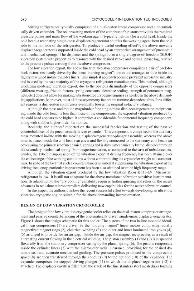
Figure 1 shows the design schematic for this cooler. The pistons of the two in-line mounted identi-
cal linear compressors (1) are driven by the “moving magnet” linear motors comprising radially
magnetized magnet rings (2), electrical winding (3) and outer and inner laminated iron yokes (4),
(5) arranged to provide for an air gap. Inside the air gap, the magnet reciprocates as a result of
alternating current flowing in the electrical winding. The piston assembly (1) and (2) is suspended
flexurally from the stationary compressor casing by the planar spring (6). The pistons reciprocate
inside the cylinder liners (7) with the micrometer radial clearance, providing for the desired dy-
namic seal and accurate mechanical guiding. The pressure pulses produced in the compression
space (8) are then transferred through the conduits (9) to the hot end (10) of the expander. The
expander comprises the stepped driving plunger (11) to which the displacer-regenerator (12) is
attached. The displacer cavity is filled with the stack of the fine stainless steel mesh disks forming
570 cryocooler integration tecHnologieS
the regenerative heat exchanger. The movable assembly (11) and (12) is suspended flexurally from
the stationary cooler casing by the planar spring (13) and reciprocates inside the bushing (14). The
internal bores of the bushing are matched to accommodate the driving plunger with the small radial
clearance, thus providing for the desired seal. The axis of the cold finger (15) is aligned to the
bushing to provide for an accurate mechanical guide and smooth reciprocal motion of the above
expander assembly under the pressure pulses arriving from the compressor. The gas is transferred
from the hot space to the regenerator inlet (16) of the expander through the conduits (17). The
appropriate phase lag between the gas pressure oscillation in the expansion space and displacer-
regenerator motion yields the desired cooling effect. The counterbalancer mass (18) is connected to
the displacer using a planar spring (19) and is supported flexurally from the stationary casing by a
flexural bearing formed by two planar springs (20). For reliability, compactness, linearity and low
damping these auxiliary flexurals are flat diaphragm-type springs manufactured of the full-hard-
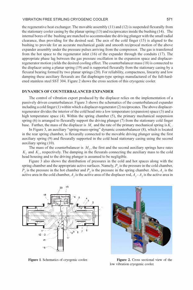
ened stainless steel SST 304. Figure 2 shows the cross section of this cryogenic cooler.
DYNAMICS OF COUNTERBALANCED EXPANDER
The control of vibration export produced by the displacer relies on the implementation of a
passively driven counterbalancer. Figure 3 shows the schematics of the counterbalanced expander
including a cold finger (1) within which a displacer-regenerator (2) reciprocates. The above displacer-
regenerator divides the interior of the cold head into a low temperature (expansion) space (3) and a
high temperature space (4). Within the spring chamber (5), the primary mechanical suspension
spring (6) is arranged to flexurally support the driving plunger (7) from the stationary cold finger
base. Further, the mass of the displacer is 1
M and the rate of the primary mechanical spring is1
K .
In Figure 3, an auxiliary “spring-mass-spring” dynamic counterbalancer (8), which is located
in the rear spring chamber, is flexurally connected to the movable driving plunger using the first
auxiliary spring (9) and flexurally supported in the cold head stationary casing using the second
auxiliary spring (10).
The mass of the counterbalancer is 2
M , the first and the second auxiliary springs have rates
2K and
3K , respectively. The damping in the flexurals connecting the auxiliary mass to the cold
head housing and to the driving plunger is assumed to be negligible.
Figure 3 also shows the distribution of pressures in the cold and hot spaces along with the
spring chamber and the appropriate active surfaces. Namely, P1 is the pressure in the cold chamber,
P2 is the pressure in the hot chamber and P
3 is the pressure in the spring chamber. Also, A
1 is the
active area in the cold chamber, A2 is the active area of the displacer rod, A
1 - A
2 is the active area in
Figure 1. Schematics of cryogenic cooler. Figure 2. Cross sectional view of the
low vibration cryogenic cooler.
571vibration free Stirling cryogenic cooler
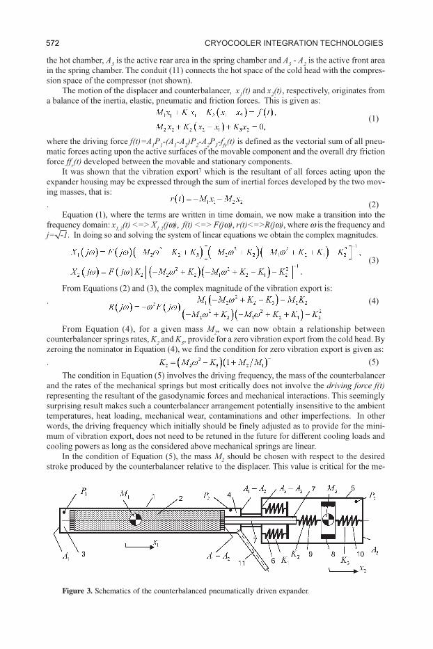
the hot chamber, A3 is the active rear area in the spring chamber and A
3 - A
2 is the active front area
in the spring chamber. The conduit (11) connects the hot space of the cold head with the compres-
sion space of the compressor (not shown).
The motion of the displacer and counterbalancer, x1(t) and x
2(t), respectively, originates from
a balance of the inertia, elastic, pneumatic and friction forces. This is given as:
(1)
where the driving force f(t)=A1P1-(A
1-A2)P2-A2P3-ffr(t) is defined as the vectorial sum of all pneu-
matic forces acting upon the active surfaces of the movable component and the overall dry friction
force ffr(t) developed between the movable and stationary components.
It was shown that the vibration export7 which is the resultant of all forces acting upon the
expander housing may be expressed through the sum of inertial forces developed by the two mov-
ing masses, that is:
. (2)
Equation (1), where the terms are written in time domain, we now make a transition into the
frequency domain: x1,2
(t) <=> X1,2
(jω), f(t) <=> F(jω), r(t)<=>R(jω), where ω is the frequency and
j=‰-1. In doing so and solving the system of linear equations we obtain the complex magnitudes.
(3)
From Equations (2) and (3), the complex magnitude of the vibration export is:
. (4)
From Equation (4), for a given mass M2, we can now obtain a relationship between
counterbalancer springs rates, K2 and K
3, provide for a zero vibration export from the cold head. By
zeroing the nominator in Equation (4), we find the condition for zero vibration export is given as:
. (5)
The condition in Equation (5) involves the driving frequency, the mass of the counterbalancer
and the rates of the mechanical springs but most critically does not involve the driving force f(t)
representing the resultant of the gasodynamic forces and mechanical interactions. This seemingly
surprising result makes such a counterbalancer arrangement potentially insensitive to the ambient
temperatures, heat loading, mechanical wear, contaminations and other imperfections. In other
words, the driving frequency which initially should be finely adjusted as to provide for the mini-
mum of vibration export, does not need to be retuned in the future for different cooling loads and
cooling powers as long as the considered above mechanical springs are linear.
In the condition of Equation (5), the mass M2 should be chosen with respect to the desired
stroke produced by the counterbalancer relative to the displacer. This value is critical for the me-
Figure 3. Schematics of the counterbalanced pneumatically driven expander.
572 cryocooler integration tecHnologieS
chanical design of the first auxiliary spring. From Equation (5), the spring rate for the first auxiliary
spring, K2, is a function of the chosen masses of displacer and counterbalancer, driving frequency
and the spring rate of the secondary auxiliary spring K3.
At this point in time, we note that the above dual-mass displacer must not only be counterbal-
anced, but must also be capable of producing the same cooling effect at the same power consumption
as compared to the single-mass design. We now turn our attention to determine the value of a spring
rate, K3, which yields the same magnitude and phase of the displacer oscillation as in the single-mass
case. Let us assume that such a value does exist. This leads to an assumption that the displacer magni-
tude, phase, pressure and temperature distribution along the regenerator are identical to those in the
above considered case of a single-mass displacer, the analytical solution X(jω) which may be ob-
tained from the first expression of Equation (3) by fixing M2 = 0 and K
3 = 0. This is represented by:
(6)
We are able to find this value by equating X(jw)=X1(jw). In doing so, using Equations (3) and
(6), we find the required additional condition as:
(7)
which ensures that the above two motions are similar, both in terms of magnitude and phase. Equations (5) and
(7) may be used for estimating the spring rates for the first and the second auxiliary springs, K2 and K
3, at given
masses of the displacer, M1, counterbalancer, M
2, and driving frequency ω
d. Finally, the solution yields.
(8)
Designing the counterbalancer with the spring rates given by Equation (8) at a given M2 yields
not only zero vibration export at the driving frequency, but also the same cooling capacity at the
same power consumed by the compressor.
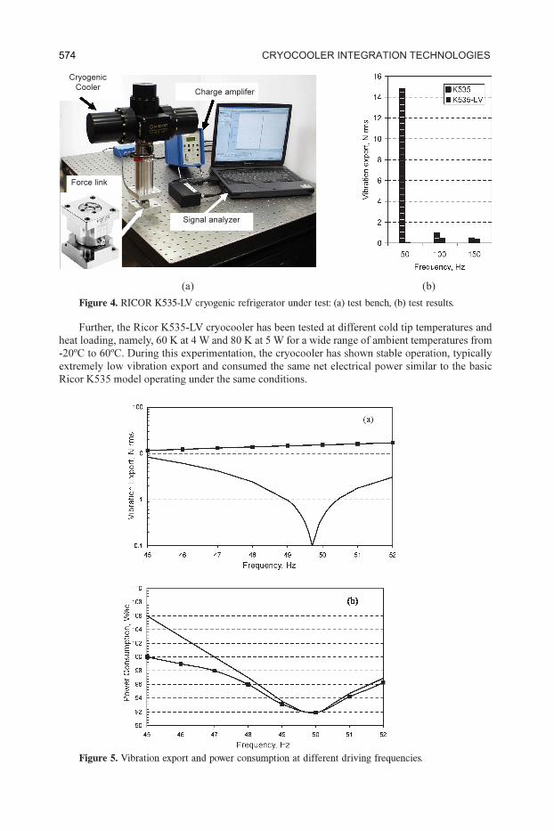
EXPERIMENTATION ON LOW VIBRATION CRYOCOOLER
Figure 4 shows the Ricor K535-LV (low vibration) refrigerator being mounted upon a Newport
vibration isolated table using the Kistler Type 9347B force link during the vibration export test.
Figure 4 also shows a Kistler Type 5010 charge amplifier and Data Physics ACE signal analyzer
occupying the PCMCIA II slot of the dedicated notebook.
In the experiment, the heat load of 12 W at a reject temperature of 320 K was applied to the
expander’s cold tip, which has been stabilized at 120 K. Further, by fine tuning the driving fre-
quency, the minimal vibration export of 0.1 Nrms has been achieved at 49.7 Hz (the nominal fre-
quency is 50 Hz). The net power consumption under these conditions is 92 W. It is worth noting
that, under the same conditions the standard Ricor K535 cryocooler produced vibration export the
magnitude of which was 14.8 Nrms and net power consumption in this case was 92 W. Therefore, a
150-fold vibration export reduction was achieved without an increase in the power consumption
while maintaining practically the same bulk in the cryogenic cooler. This result strongly supports
the results of the analytical prediction. The performance of such a purely passive vibration cancel-
lation is comparable with that delivered by the active system. Figure 4b shows superimposed
spectra of the vibration export by Ricor K535-LV and Ricor K535 cryogenic coolers working under
the same conditions. From Figure 4b, the higher order harmonics undergo particular attenuation.
Figure 5 shows dependencies of the vibration export at a driving frequency (a) and a power
consumption (b) of the basic Ricor K535 (marked by n) and modified Ricor K535-LV coolers
(unmarked line) on the driving frequency.
From Figure 5a, the level of vibration export of the modified cooler measured in the displacer
direction shows a deep notch in the vicinity of the nominal driving frequency of 50 Hz and reaches
the lowest value of 0.1 Nrms at the driving frequency of 49.7 Hz. It is worth noting that in the entire
frequency range considered the vibration export from the modified cooler is significantly lower
when compared with that of the basic cooler. From Figure 5b, the electrical power consumed by the
cooler has a well-pronounced minimum at the nominal driving frequency of 50 Hz and reaches the
lowest value of 92 W at the nominal driving frequency.
573vibration free Stirling cryogenic cooler
Further, the Ricor K535-LV cryocooler has been tested at different cold tip temperatures and
heat loading, namely, 60 K at 4 W and 80 K at 5 W for a wide range of ambient temperatures from
-20ºC to 60ºC. During this experimentation, the cryocooler has shown stable operation, typically
extremely low vibration export and consumed the same net electrical power similar to the basic
Ricor K535 model operating under the same conditions.
Figure 4. RICOR K535-LV cryogenic refrigerator under test: (a) test bench, (b) test results.
(a)
Figure 5. Vibration export and power consumption at different driving frequencies.
(b)
Cryogenic
CoolerCharge amplifer
Signal analyzer
Force link
574 cryocooler integration tecHnologieS
ACTIVE VIBRATION CONTROL OF REFRIGERATOR
Active cancellation of vibration export produced by the dual-piston compressor relies on using
one of the compressors, designated as a “Slave” with the purpose of counterbalancing the other,
labeled as the “Master". This is achieved by measuring the vibration of the refrigerator housing in
a compressors direction using an accelerometer and supplying the “Slave” motor with an additional
composite multi-tonal corrective voltage, consisting of harmonics of the driving frequency, whose
magnitudes and phases are dynamically (real-time) adjusted for the purpose of maintaining the
magnitudes of appropriate harmonics of the measured vibration applied at the lowest possible lev-
els.8-11 It is important to note that the purpose of accuracy and insensitivity to external disturbances
such as shock, vibration, EMI, the spectral analysis of the measured vibration relies on the hetero-
dyne filtering using the reference digital signals produced by the controller.
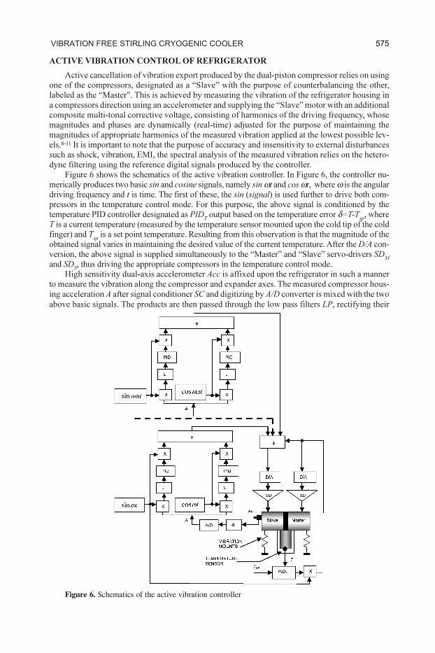
Figure 6 shows the schematics of the active vibration controller. In Figure 6, the controller nu-
merically produces two basic sin and cosine signals, namely sin ωt and cos ωt, where ω is the angular
driving frequency and t is time. The first of these, the sin (signal) is used further to drive both com-
pressors in the temperature control mode. For this purpose, the above signal is conditioned by the
temperature PID controller designated as PIDT output based on the temperature error δ=T-T
sp, where
T is a current temperature (measured by the temperature sensor mounted upon the cold tip of the cold
finger) and Tsp
is a set point temperature. Resulting from this observation is that the magnitude of the
obtained signal varies in maintaining the desired value of the current temperature. After the D/A con-
version, the above signal is supplied simultaneously to the “Master” and “Slave” servo-drivers SDM
and SDS, thus driving the appropriate compressors in the temperature control mode.
High sensitivity dual-axis accelerometer Acc is affixed upon the refrigerator in such a manner
to measure the vibration along the compressor and expander axes. The measured compressor hous-
ing acceleration A after signal conditioner SC and digitizing by A/D converter is mixed with the two
above basic signals. The products are then passed through the low pass filters LP, rectifying their
Figure 6. Schematics of the active vibration controller
575vibration free Stirling cryogenic cooler
averaged values which appear to be proportional to the magnitude of sin and cosin components of
the fundamental component of the compressor’s acceleration. Those rectified signals are then sup-
plied to the PID controllers, the outputs of which, after mixing with the above basic sin and cosin
signals, summation and D/A conversion are supplied to the “Slave” servo driver. The above control-
lers are tuned in such a manner to minimize the above vibration components which eventually
delivers cancellation of the compressor vibration at the fundamental frequency.
Similarly, higher-order harmonic components may be controlled. In Figure 6, the controller is
limited by suppressing the n harmonics. This number is defined by the initial vibration export,
application requirements and available resources provided by the controller hardware.
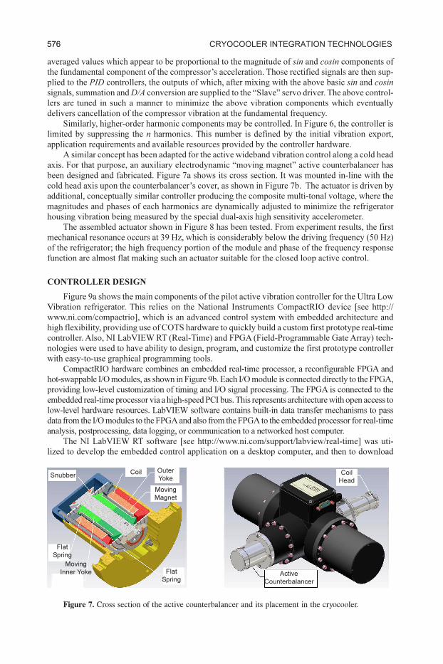
A similar concept has been adapted for the active wideband vibration control along a cold head
axis. For that purpose, an auxiliary electrodynamic “moving magnet” active counterbalancer has
been designed and fabricated. Figure 7a shows its cross section. It was mounted in-line with the
cold head axis upon the counterbalancer’s cover, as shown in Figure 7b. The actuator is driven by
additional, conceptually similar controller producing the composite multi-tonal voltage, where the
magnitudes and phases of each harmonics are dynamically adjusted to minimize the refrigerator
housing vibration being measured by the special dual-axis high sensitivity accelerometer.
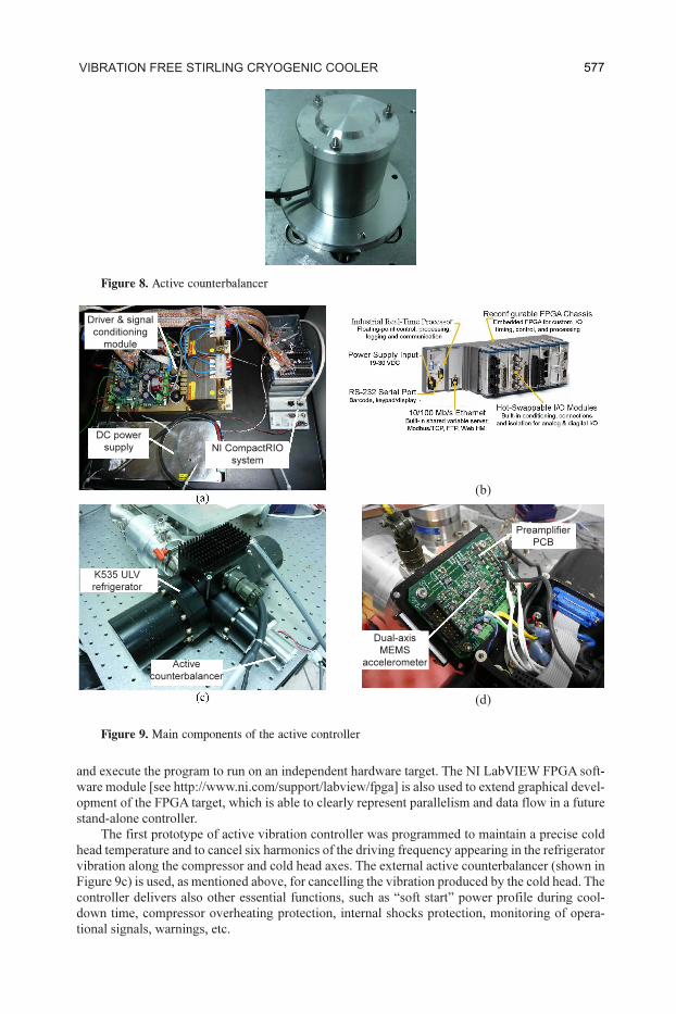
The assembled actuator shown in Figure 8 has been tested. From experiment results, the first
mechanical resonance occurs at 39 Hz, which is considerably below the driving frequency (50 Hz)
of the refrigerator; the high frequency portion of the module and phase of the frequency response
function are almost flat making such an actuator suitable for the closed loop active control.
CONTROLLER DESIGN
Figure 9a shows the main components of the pilot active vibration controller for the Ultra Low
Vibration refrigerator. This relies on the National Instruments CompactRIO device [see http://
www.ni.com/compactrio], which is an advanced control system with embedded architecture and
high flexibility, providing use of COTS hardware to quickly build a custom first prototype real-time
controller. Also, NI LabVIEW RT (Real-Time) and FPGA (Field-Programmable Gate Array) tech-
nologies were used to have ability to design, program, and customize the first prototype controller
with easy-to-use graphical programming tools.
CompactRIO hardware combines an embedded real-time processor, a reconfigurable FPGA and
hot-swappable I/O modules, as shown in Figure 9b. Each I/O module is connected directly to the FPGA,
providing low-level customization of timing and I/O signal processing. The FPGA is connected to the
embedded real-time processor via a high-speed PCI bus. This represents architecture with open access to
low-level hardware resources. LabVIEW software contains built-in data transfer mechanisms to pass
data from the I/O modules to the FPGA and also from the FPGA to the embedded processor for real-time
analysis, postprocessing, data logging, or communication to a networked host computer.
The NI LabVIEW RT software [see http://www.ni.com/support/labview/real-time] was uti-
lized to develop the embedded control application on a desktop computer, and then to download
Figure 7. Cross section of the active counterbalancer and its placement in the cryocooler.
Snubber
Flat
Spring
Moving
Inner Yoke Flat
Spring
Moving
Magnet
Outer
YokeCoil Coil
Head
Active
Counterbalancer
576 cryocooler integration tecHnologieS
and execute the program to run on an independent hardware target. The NI LabVIEW FPGA soft-
ware module [see http://www.ni.com/support/labview/fpga] is also used to extend graphical devel-
opment of the FPGA target, which is able to clearly represent parallelism and data flow in a future
stand-alone controller.
The first prototype of active vibration controller was programmed to maintain a precise cold
head temperature and to cancel six harmonics of the driving frequency appearing in the refrigerator
vibration along the compressor and cold head axes. The external active counterbalancer (shown in
Figure 9c) is used, as mentioned above, for cancelling the vibration produced by the cold head. The
controller delivers also other essential functions, such as “soft start” power profile during cool-
down time, compressor overheating protection, internal shocks protection, monitoring of opera-
tional signals, warnings, etc.
Figure 8. Active counterbalancer
Figure 9. Main components of the active controller
(b)
(d)
Driver & signal
conditioning
module
DC power
supply NI CompactRIO
system
K535 ULV
refrigerator
Active
counterbalancer
Dual-axis
MEMS
accelerometer
Preamplifier
PCB
577vibration free Stirling cryogenic cooler
Also, a dual-axis precision MEMS accelerometer (Analog Device, model ADXL203) is mounted
upon the preamplifier PCB (shown in Figure 9d) and provides both compressor and cold head
controllers with error signals representing the residual vibration along the two relevant axes.
ATTAINED PERFORMANCE
The first prototype of the active vibration controller has been tested with the RICOR K535-LV
refrigerator at full-power mode, in order to evaluate its capability of canceling multi-tonal vibration
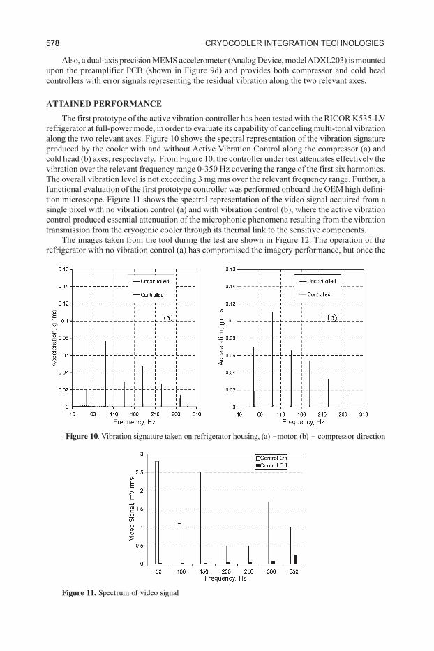
along the two relevant axes. Figure 10 shows the spectral representation of the vibration signature
produced by the cooler with and without Active Vibration Control along the compressor (a) and
cold head (b) axes, respectively. From Figure 10, the controller under test attenuates effectively the
vibration over the relevant frequency range 0-350 Hz covering the range of the first six harmonics.
The overall vibration level is not exceeding 3 mg rms over the relevant frequency range. Further, a
functional evaluation of the first prototype controller was performed onboard the OEM high defini-
tion microscope. Figure 11 shows the spectral representation of the video signal acquired from a
single pixel with no vibration control (a) and with vibration control (b), where the active vibration
control produced essential attenuation of the microphonic phenomena resulting from the vibration
transmission from the cryogenic cooler through its thermal link to the sensitive components.
The images taken from the tool during the test are shown in Figure 12. The operation of the
refrigerator with no vibration control (a) has compromised the imagery performance, but once the
Figure 10. Vibration signature taken on refrigerator housing, (a) –motor, (b) – compressor direction
Figure 11. Spectrum of video signal
578 cryocooler integration tecHnologieS
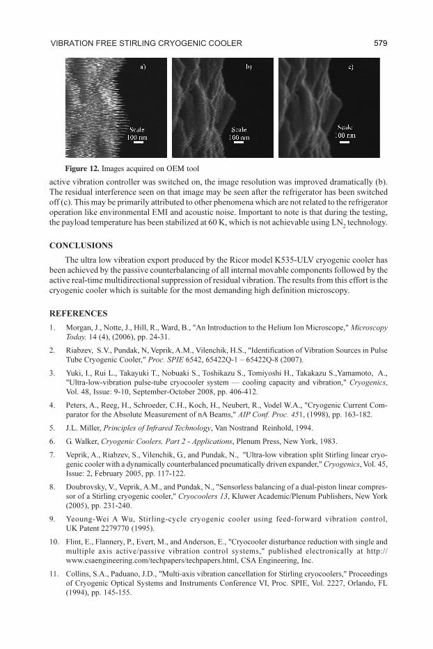
active vibration controller was switched on, the image resolution was improved dramatically (b).
The residual interference seen on that image may be seen after the refrigerator has been switched
off (c). This may be primarily attributed to other phenomena which are not related to the refrigerator
operation like environmental EMI and acoustic noise. Important to note is that during the testing,
the payload temperature has been stabilized at 60 K, which is not achievable using LN2 technology.
CONCLUSIONS
The ultra low vibration export produced by the Ricor model K535-ULV cryogenic cooler has
been achieved by the passive counterbalancing of all internal movable components followed by the
active real-time multidirectional suppression of residual vibration. The results from this effort is the
cryogenic cooler which is suitable for the most demanding high definition microscopy.
REFERENCES
1. Morgan, J., Notte, J., Hill, R., Ward, B., "An Introduction to the Helium Ion Microscope," Microscopy
Today, 14 (4), (2006), pp. 24-31.
2. Riabzev, S.V., Pundak, N, Veprik, A.M., Vilenchik, H.S., "Identification of Vibration Sources in Pulse
Tube Cryogenic Cooler," Proc. SPIE 6542, 65422Q-1 – 65422Q-8 (2007).
3. Yuki, I., Rui L., Takayuki T., Nobuaki S., Toshikazu S., Tomiyoshi H., Takakazu S.,Yamamoto, A.,
"Ultra-low-vibration pulse-tube cryocooler system — cooling capacity and vibration," Cryogenics,
Vol. 48, Issue: 9-10, September-October 2008, pp. 406-412.
4. Peters, A., Reeg, H., Schroeder, C.H., Koch, H., Neubert, R., Vodel W.A., "Cryogenic Current Com-
parator for the Absolute Measurement of nA Beams," AIP Conf. Proc. 451, (1998), pp. 163-182.
5. J.L. Miller, Principles of Infrared Technology, Van Nostrand Reinhold, 1994.
6. G. Walker, Cryogenic Coolers, Part 2 - Applications, Plenum Press, New York, 1983.
7. Veprik, A., Riabzev, S., Vilenchik, G., and Pundak, N., "Ultra-low vibration split Stirling linear cryo-
genic cooler with a dynamically counterbalanced pneumatically driven expander," Cryogenics, Vol. 45,
Issue: 2, February 2005, pp. 117-122.
8. Doubrovsky, V., Veprik, A.M., and Pundak, N., "Sensorless balancing of a dual-piston linear compres-
sor of a Stirling cryogenic cooler," Cryocoolers 13, Kluwer Academic/Plenum Publishers, New York
(2005), pp. 231-240.
9. Yeoung-Wei A Wu, Stirling-cycle cryogenic cooler using feed-forward vibration control,
UK Patent 2279770 (1995).
10. Flint, E., Flannery, P., Evert, M., and Anderson, E., "Cryocooler disturbance reduction with single and
multiple axis active/passive vibration control systems," published electronically at http://
www.csaengineering.com/techpapers/techpapers.html, CSA Engineering, Inc.
11. Collins, S.A., Paduano, J.D., "Multi-axis vibration cancellation for Stirling cryocoolers," Proceedings
of Cryogenic Optical Systems and Instruments Conference VI, Proc. SPIE, Vol. 2227, Orlando, FL
(1994), pp. 145-155.
Figure 12. Images acquired on OEM tool
579vibration free Stirling cryogenic cooler
Related Documents