Vibration Control Type 663 English Manual ¤ Vibration Velocity ( ¤ 2 Relay-Switching Outputs (Adjustable) ¤ Analogue Current Output: 4...20 mA ¤ Frequency Range: 10 Hz...1000 Hz mm/s, rms) 1 Hz...1000 Hz * The hardware, the vibration control Type 663, was tested using Exida's FMEDA. The results of the FMEDA meet the criteria according to SIL2, SIL3 and PL-d. ** In determining the safety function, using the safety key figures in accordance with the standards mentioned under item 4 in the safety manual, the relay contacts of the vibration control Type 663 were explicitly evaluated and taken into account. The current output 4...20 mA is not configured in a safety-relevant manner. * **

Welcome message from author
This document is posted to help you gain knowledge. Please leave a comment to let me know what you think about it! Share it to your friends and learn new things together.
Transcript
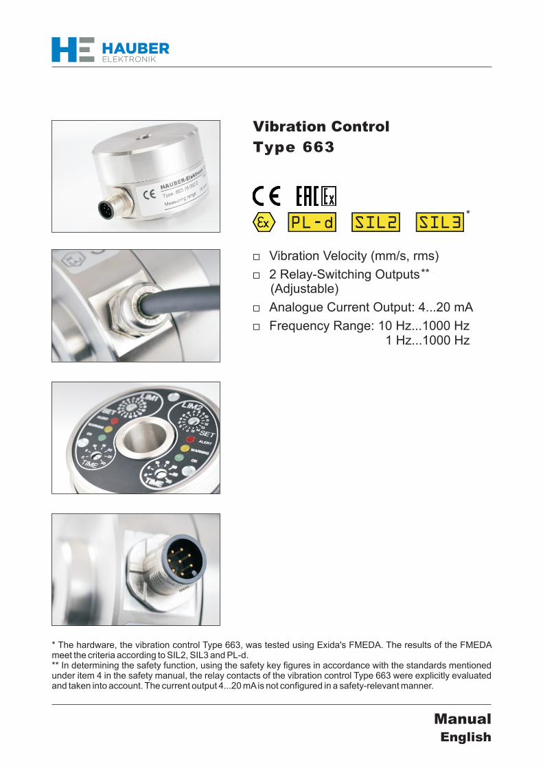
Vibration Control
Type 663
English
Manual
Vibration Velocity (
2 Relay-Switching Outputs (Adjustable)
Analogue Current Output 420 mA
Frequency Range 10 Hz1000 Hz
mms rms)
1 Hz1000 Hz
The hardware the vibration control Type 663 was tested using Exidas FMEDA The results of the FMEDA meet the criteria according to SIL2 SIL3 and PL-d In determining the safety function using the safety key figures in accordance with the standards mentioned under item 4 in the safety manual the relay contacts of the vibration control Type 663 were explicitly evaluated and taken into account The current output 420 mA is not configured in a safety-relevant manner
AttentionBefore commissioning the product you must have read and understood
the instruction manual in its entirety
HAUBER-Elektronik GmbH
Should any question arise please contact
HAUBER-Elektronik GmbHFabrikstraszlige 6D-72622 NuertingenGermanyPhone +49 (0) 7022 21750-0Fax +49 (0) 7022 21750-50infohauber-elektronikdewwwhauber-elektronikde
Instruction Manual
Issue 01022016
Vibration Control Type 663StandardZone-1-21Zone-2-22
1 Safety Information 4
2 Instruction Manual Scope 5
3 Vibration Control Type 663 5
4 Intended Use 5
5 Safety Level 5
6 Documents and Certificates 5
7 Responsibility for Safe Operation Disclaimer 6
8 Fields of Application 6
9 Scope of Delivery 6
10 Electrical Data 7
11 Mechanical Data 9
12 Connections 10
13 Functional Description 11
14 Limit Value Adjustment 12
15 Self-Test 12
16 Mounting and Dismounting 13
161 Fastening on the Mounting Surface 13
162 Zone-2-22mdashFastening Safety Clip Protective Cover 14
163 Anti-tamper protection 15
17 Installation and Commissioning 15
18 Maintenance and Repairs 16
19 Grounding Concepts to Avoid Ground Loops 17
20 Order code 18
HAUBER-Elektronik GmbH
3
Contents
Standard Zone-1-21 Zone-2-22
HAUBER-Elektronik GmbH
1 Safety Information
General Information
The safety instructions serve to protect persons and objects from damage and danger that may arise from misuse incorrect operation or other incorrect handling of devices especially in potentially explosive atmospheres Therefore read the instruction manual carefully before working with or commissioning the product Ensure that the instruction manual is accessible to the operating personnel at all times
Before commissioning or otherwise working with the product please check wether all the documents are available in their entirety If some documents are missing or if further copies are required they can be obtained in different languages
This is a state-of-the-art product Nevertheless there are a number of residual risks This means that incorrect handling misuse or operation and maintenance by insufficiently trained personnel may cause hazards in the product which may themselves lead to bodily machine or system hazards Everyone at the operating company who is concerned with installing operating or maintaining the product has to have read and understood the instruction manualOnly instructed sufficiently trained and authorised personnel are allowed to mount dismount install or repair this product
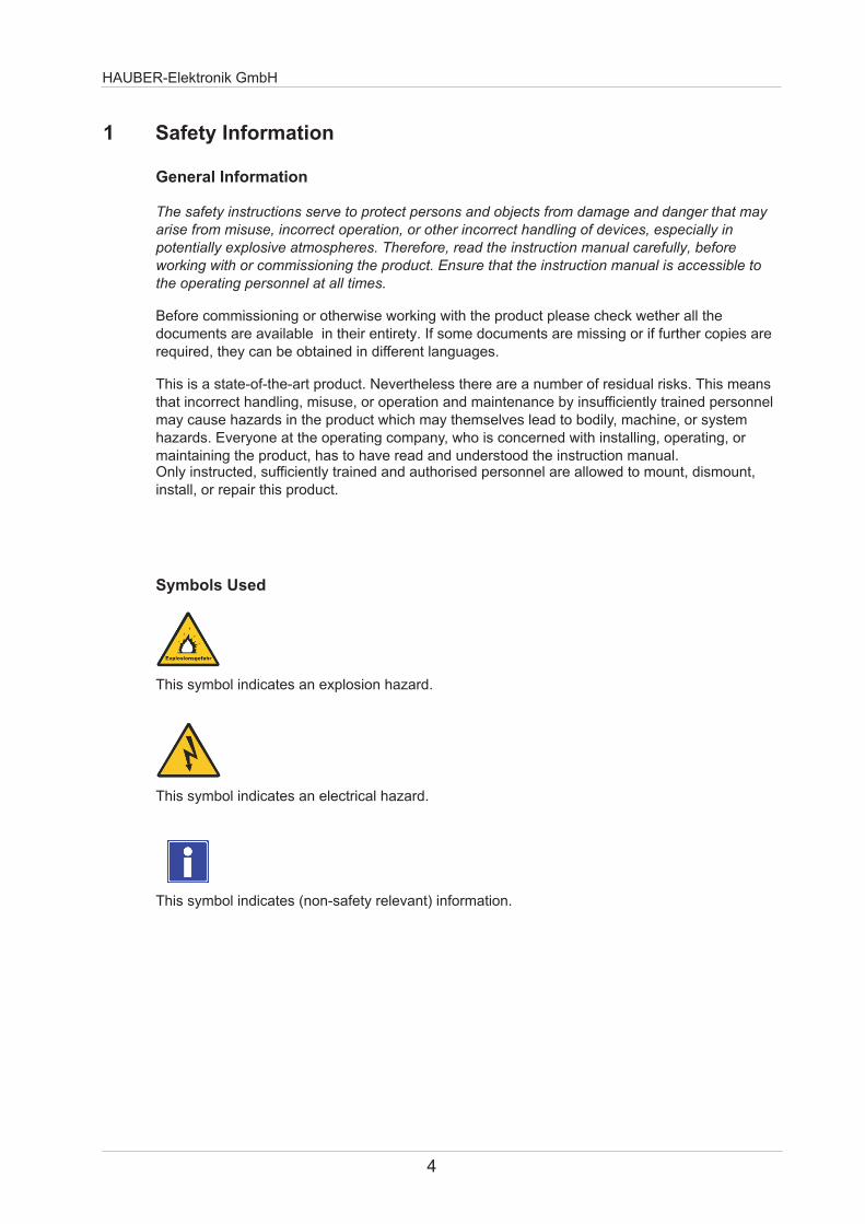
This symbol indicates an explosion hazard
Symbols Used
This symbol indicates an electrical hazard
This symbol indicates (non-safety relevant) information
4
HAUBER-Elektronik GmbH
5
2 Instruction Manual Scope
The present instruction manual of Vibration Control Type 663 is applicable for the models Standard Zone-1-21 and Zone-2-22The functionality of these models is identical In addition they have certifications and labellings allowing their operation in potentially explosive atmospheres (see Sect 7 Operation Areas)
3 Vibration Control Type 663
5 Safety Level
The hardware vibration control Type 663 was tested using Exidas FMEDA The results of the FMEDA meet the criteria according to SIL2 SIL3 and PL-d
For more information refer to the safety manual
4 Intended Use
Type 663 is used to protect machines and mechanical equipment against undue mechanical vibrations Its use is only allowed within the specifications as per the data sheet and exclusively for measuring mechanical vibrations Main areas of application Industrial fans ventilators blowers electric motors pumps centrifuges seperators generators turbines and similar oscillation mechanical equipment
Please see for the following documents and certificates for Type 663
EC Declaration of Conformity Safety manual SIL2 Safety manual SIL3 Declaration of conformity ATEX zones 2 und 22 no LU 15 ATEX 0131X EC-type examination certificate ATEX zones 1 und 21 no SNCH 09 ATEX 4380
wwwhauber-elektronikde
6 Documents and Certificates
Vibration Control Type 663 is used for measuring and monitoring the bearing vibration of machines as per DIN ISO 10816 It offers the following features
bull Two limit values and two associated delays are seperately adjustablebull The two relay outputs signal if the adjusted limit values are exceeded This can be used to generate a pre- and a main alarmbull Measurement parameter The root mean square (rms) of the vibration velocity (mms)bull Analogue current output Interference-free direct current from 420 mA proportional to the vibration amplitudebull Cable break on the control cable can be detected by a donwstream evaluation unit Value of the direct current signal lt 35 mA
In determining the safety function using the safety key figures in accordance with the standards mentioned under item 4 in the safety manual the relay contacts of the vibration control Type 663 were explicitly evaluated and taken into account The current output 420 mA is not configured in a safety-relevant manner
Available Supplies
bull Allocable Mating Connector for Assembly M12 8-Pin
bull Connection Cable M12 Socket 8-Pin 025 mm2
L= 2 m 5 m or 10 m
bull EMC Adapter
bull Vibration Control Type 663
bull Allen Screw M8 x 20 mm
bull Spring Washer M8
bull Instruction Manual
Standard
bull Vibration Control Type 663
bull Protective Cover for M12 Connector
bull Safety Clip
bull Allen Screw M8 x 20 mm
bull Spring Washer M8
bull Instruction Manual
bull Vibration Control Type 663
Integrated Cable L= 2 5 10 25 m or on request
bull Allen Screw M8 x 20 mm
bull Spring Washer M8
bull Instruction Manual
Zone-2-22
Zone-1-21
9 Scope of Delivery
8 Fields of Application
6
HAUBER-Elektronik GmbH
The correct layout of the electrical connections with regard to explosion protection directions and correct commissioning is the sole responsibility of the system ownerIf the owner commissions a subcontractor to build the system the system cannot be commissioned unless the subcontractor has submitted an installation certificate as prove of the correct nature of the installation in accordance with applicable regulationsThe owner must inform the relevant authorities about initial commissioning of explosion-protected systems or system parts as well as about re-commissioning following major modifications or maintenance work
7 Responsibility for Safe Operation Disclaimer
Model Application Fields Labelling
II 2 G Ex d IIC T4 Gb
II 2 D Ex tb IIIC T120 degC Db
II 3 G Ex d nA IIC T4 Gc
II 3 D Ex tc IIIC T120 degC Dc
Non-explosive
atmospheresStandard
Potentially explosive
atmospheres zones 1
and 21
Potentially explosive
atmospheres zones 2
and 22
Zone-1-21
Zone-2-22
The hardware ie vibration control Type 663 was tested using Exidas FMEDA The results of the FMEDA meet the criteria according to SIL2 SIL3 and PL-d
HAUBER-Elektronik GmbH
7
10 Electrical Data
Only unscrew the housing cover if Type 663 is disconnected from the mains or if the atmosphere is non-explosive Otherwise there is an explosion hazard from sparking when operating ATEX-certified Type 663 in potentially explosive atmospheres
8163264
128256
10 Hz1000 Hz1 Hz 1000 Hz
Prior to commissioning protect the mains using a microfuse 160 mA breaking capacity C)
Type 663 (medium time lag
Measuring ranges 0 mms0 mms0 mms0 mms0 mms0 mms
Measuring accuracy plusmn 5
Transverse sensitivity lt 5
Frequency range (standard)
(optionally)
Output signals 1 x 420 mA
2 x relay contact ( pre- and main alarm)
Relay switching load 1A 30V DC
Voltage supply 24V DC plusmn10
Power input (max) 80 mA
Ambient temperature -30degC+60degC
Operating temperature range -30degC+85degC (meas head temp at fastening)
Burdenload (max) 500 Ugrave The burden comprises the resistance of the evaluation unit the specific line resistance and the transition resistances
Fusing Microfuse (medium time lag 160 mA breaking capacity C)
Automatically As soon as the vibration values fall below the limitvalues the relays automatically re-energise
bull Each Type 663 has one of the listed measuring ranges
bull Further measuring ranges on request
bull Please indicate the measuring range in your order
HAUBER-Elektronik GmbH
Arbeitsbereich interner Sensorbaustein
0
20
40
60
80
100
120
140
160
180
200
0 100 200 300 400 500 600 700 800 900 1000
Frequenz (Hz)
Sc
hw
ing
ge
sc
hw
ind
igk
eit
(m
ms
)
Operating Range
Operating Range of Vibration Control Type 663
Reading example
Frequency Max measurable(Hz) vibration velocity 100 160 400 40 1000 18
The operating range is independent of the measuring range The diagram shows that the vibration velocity amplitude decreases as the frequency increases
Vib
rati
on
Velo
cit
y (
mm
s)
Frequency (Hz)
Frequency Response 10 Hz1000 Hz
-40
-35
-30
-25
-20
-15
-10
-5
0
5
1 10 100 1000 10000 Hz
dB
Frequency Response 1 Hz1000 Hz
-40
-35
-30
-25
-20
-15
-10
-5
0
5
01 10 100 1000 10000 100000 Hz
dB
8
Housing material V2A stainless steel material no 14305
M12 connector material CuZn (brass) nickel plated
Cable gland V2A stainless steel
Fastening Allen screw M8 x 20 mmThread pitch 125 mm
Weight approx 500 g
IP code IP 67
Mounting Ground housing using M8fastening (see Sect16)
HAUBER-Elektronik GmbH
9
11 Mechanical Data
Housing Dimensions and Direction of Measurement
Standard Zone-2-22 Zone-1-21
Note Direction of measurement = direction of fastening
30
M12 Connector
Connection Cable
Direction of Measurement
Cable Gland
Direction of Measurement
Measures in mm
Housing Dimensions and Direction of Measurement Standard Zone-2-22
Housing Dimensions and Direction of Measurement Zone-1-21
HAUBER-Elektronik GmbH
10
Connection Plan for All 3 Models
12 Connections
Note The connection plan shows the alarm condition andor the currentless condition Relay 1 and 2 are dropped out (see p 11 for more information on operating conditions)
Connection Cable Socket(Supplies)
M12 Connector
2
3
4
7 8
56
1
M12 Connector 8-pinSee connection plan for pin allocation
Connection cable socket M12 8-pin 025 mmsup2 See connection plan for pin allocation
Standard Zone-2-22 Zone-1-21
Connection Cable
PUR sheathed cable Oslash approx 65 mm 8 -pin 025 mmsup2 See connection plan for pin allocation
Evaluation Unit
Type 663Pin 1 whitePin 2 brown
Pin 3 green
Pin 4 yellow
Pin 5 grey
Self-Checkswitch
Relay 2
Relay 1
Evaluation of the 420 mA current signal using an ammeter or PLC
Pin 6 pinkPin 7 bluePin 8 red
1
2
3
4
5
6
7
8
WH
BN
GN
YE
GY
PK
BU
RD
ALARMWARNING
OK
HAUBER-Elektronik GmbH
13 Functional Description
Type 663 has two limit values LIM1 and LIM2 with their respective lag times which can all be adjusted separatelyRelay outputs 1 and 2 signal if the adjusted limit value has been exceeded by dropping out the respective relay contact If the limit value is then undercut relay outputs 1 and 2 will also signal this by automatically re-energisingIn addition Type 663 has an analogue current output This delivers a direct current of 420 mA proportional to the vibration amplitude
User Interface Channels LIM1 and LIM2mdashControls and LED Indicators
Operating Conditions Channels LIM1 and LIM2
SET Turn-SwitchLimit Value in 15 Steps(Table Limit Value page 12)
TIME PotentiometerLag Time VariablyAdjustable 030 sec
mdashredmdashyellowmdashgreen
Operating Condition Measurement Relay LED Indicator
OK lt= Limit Value Energised OK
WARNINGgt Limit Value
Lag Time RunningEnergised WARNING+OK
ALARMgt Limit Value
Lag Time ExpiredDropped Out ALARM
Only unscrew the housing cover if Type 663 is disconnected from the mains or if the atmosphere is non-explosive Otherwise there is an explosion hazard from sparking when operating ATEX-certified Type 663 in potentially explosive stmospheres
11
Measuring range eg
Set turn-switch pos
Limit value
HAUBER-Elektronik GmbH
12
15 Self-Test
Example Limit value adjustment
14 Limit Value Adjustment
032 mms
16 mms
8
0 0 0 0 0 0 0
1 05 1 2 4 8 16
2 1 2 4 8 16 32
3 15 3 6 12 24 48
4 2 4 8 16 32 64
5 25 5 10 20 40 80
6 3 6 12 24 48 96
7 35 7 14 28 56 112
8 4 8 16 32 64 128
9 45 9 18 36 72 144
10 5 10 20 40 80 160
11 55 11 22 44 88 176
12 6 12 24 48 96 192
13 65 13 26 52 104 208
14 7 14 28 56 112 224
15 75 15 30 60 120 240
SET
Turn-Switch
Position
Limit Value
Range
0hellip8 mms
Range
0hellip16 mms
Range
0hellip32 mms
Range
0hellip64 mms
Range
0hellip128 mms
Range
0hellip256 mms
The self-test is to verify the correct functioning of the vibration control Therefore a test signal is applied to pin 4 of the control The test signal simulates a vibration amplitude exceeding the maximum limit value This will trigger the controls alarm condition
Test signal a Direct current 24 V DC orb Square wave signal 24 V DC 05 Hz
Initial state Normal operation
Self-test start bull Apply the test signal to pin 4agrave The output current signal increases up to ~23 mAagrave After lt 35 s the alarm relays drop out
If one or both alarm relays fail to drop out this indicates a fault
bull Remove the test signalagrave After a further lt 60 s the output current signal has returned to to 4 mA or its actual value
End self-test
Final state Normal operation
Duration approx 95 s
bull Test signal a is only available for production no 75478 or later
HAUBER-Elektronik GmbH
16 Mounting and Dismounting
Only authorised experts who are familiar with the safety instructions for handling electrical components are allowed to perform mounting or dismounting work on or using this control For handling ATEX-certified controls within potentially explosive atmospheres the expert also has to be familiar with the safety instructions relevant there
Requirements
Mounting surface clean and flat ie free from paint rust etc
Threaded hole on the mounting surface Depth 15 mm Thread M8
Unscrew housing cover from housing base
Allen key SW8
Use Allen screw and spring washer to friction-lock the control on the mounting surface
Allen key SW6
Slightly fasten housing cover to housing base by hand(Avoid jamming the thread) Tighten housing cover using a tightening torque = 5 Nm
Torque wrench SW8
Workflow
1
2
3
Allen key SW6 SW8 Torque wrench SW8 Allen screw M8x20 Spring washer for M8
Tools and materials
Note To prevent any cold-welding between housing cover and housing base the control is delivered with a fitting lubricant for stainless steel connections applied to its thread
Before mounting or dismounting disconnect the control from the mains Ensure that disconnected plug connections are always de-energised Otherwise there is an explosion hazard from sparking when operating ATEX-certified Type 663 in potentially explosive atmospheres
Ground the control housing via the fastening ie the machine earth or a seperate earth conductor (PE)
161 Fastening on the Mounting Surface
Fastening on the mounting surface
Mounting Surface
zu
5 Nm
Tightening housing cover using a torque wrench
13
HAUBER-Elektronik GmbH
Shell Half Arrow and Eye
Sign
Fastened Safety Clip
Protective Cover Fastened Protective Cover
Safety Clip
Fully insert the connection cable socket into the M12 connector(Pay attention to the code cam position)
162 Zone-2-22mdashFastening Safety Clip Protective Cover
1 Disconnect th control from the mains2 Separate both shell halves of the fuse clip using a screw driver3 Use the M12 connector to firmly close the protective cover
1
2
3
Tightly fasten the lock-nut of the connection cable socket by hand
Mount the safety clip to avoid accidental disconnection of the plug connection1 Place both shell halves of the safety clip around the plug connection2 Press both shell halves of the safety clip together by hand until the
catch lock engages3 Place the arrow connected to both shell halves around the cable then thread
it through the eye on the other end so that the notice sign is legiblealongside the cable
Fastening Protective Cover
Fastening Safety Clip
Disassemble the safety clip and fasten the protective cover
Always operate model Zone-2-22 with the safety clip to avoid accidental disconnection of the plug connection Otherwise there is an explosion hazard from sparking when operating this control in potentially explosive atmospheres
Fasten the protective cover using the M12 connector after disconnecting the plug connection
14
HAUBER-Elektronik GmbH
15
17 Installation and Commissioning
Only authorised experts who are familiar with the safety instructions for handling electrical components are allowed to install or commission this control For handling ATEX-certified controls within potentially explosive atmospheres the expert also has to be familiar with the safety instructions relevant there
Ensure the housing cover is properly fastened prior to commissioning (tightening torque = 5 Nm) Otherwise there is an explosion hazard from sparking when operating ATEX-certified Type 663 in potentially explosive atmospheres
Prior to commissioning Type 663 protect the mains with a microfuse (medium time lag 160 mA breaking capacity C)
Protect the connection cable and possible extension cables from electrical influences or mechanical damage Ensure to stricly follow local regulations and directives
Check the self-test during commissioning
The SEALED seal label indicates that it is not permissible to open the casing cover
After the system operator has assembled the casing cover the seal label is attached to the side so that it covers the casing parting line
Any attempt to tamper with the casing will destroy the label and makes the attempted tampering visible to the system operator
163 Anti-tamper protection
Attaching the seal label
Seal label
Attaching the seal label
HAUBER-Elektronik GmbH
16
18 Maintenance and Repairs
Note Type 663 and its models are maintenance free
Error Table
Only authorised experts who are familiar with the safety instructions for handling electrical components are allowed to repair this control For handling ATEX-certified controls within potentially explosive atmospheres the expert also has to be familiar with the safety instructions relevant there
Disconnect Type 663 from the mains prior to performing repair or cleaning work Ensure that disconnected plug connections are always de-energised Otherwise there is an explosion hazard from sparking when operating ATEX-certified Type 663 in potentially explosive atmospheres
Immediately replace defective connection cables from sparking when operating ATEX-certified Type 663 in potentially explosive atmospheres
Otherwise there is an explosion hazard
If the control is defective replace it in its entirety
Error Cause Countermeasure
No measured value (420 mA)No power supply Check power supply andor connection cable
Connection cable interrupted Replace connection cable
Defective fuse Replace fuse
Wrong connection cable polarity Correct connection cable polarity
Defective control Replace control
Relay fails to switch Limit value incorrectly adjusted Correctly adjust limit value
No power supply Check power supply andor connection cable
Connection cable interrupted Replace connection cable
Defective fuse Replace fuse
Wrong connection cable polarity Correct connection cable polarity
Defective control Replace control
Incorrect reading Control mounting not friction-locked Friction-lock control
Control mounting at wrong position Mount control at correct position
EMC issues See Sect 19 Grounding Concepts
HAUBER-Elektronik GmbH
17
19 Grounding Concepts to Avoid Ground Loops
Ground loops are among the most frequent problems in measurement setups with sensitive sensor technology They arise through unwanted potential differences inside the current circuit between sensor and evaluation unit As a countermeasure we recommend our Standard Grounding Concept or depending on your application our Alternative Grounding Concept
Alternative Grounding Concept
In the Alternative Grounding Concept the shield of the sensor cable is connected to the sensor housing (dotted circle) The sensor housing is uncoupled from the machine ground via an EMC adapter (black)
Machine Evaluation Unit
+24V 420mA
Sensor Cable
Machine
+24V 420mA
Sensor Cable
Evaluation eg AmmeterPLC
Unit
Standard Grounding Concept
In the Standard Grounding Concept the shield of the sensor cable is not connected to the sensor housing (dotted circle) The potential applied to the sensor housing and the machine ground is identical
Maschine Ground
Maschine Ground
SensorHousing
EMC Adapter
Please indicate in your order if you wish to use the Alternative Grounding ConceptWe will then offer you the respective sensor cable and EMC adapter
Evaluation Unit
Evaluation eg AmmeterPLC
Unit
Shield
ShieldSensor
Housing
FB
663 = Monitoring SIL2 420 mA ~ mms rms + free limit values
32 = 32 mms rms64 = 64 mms rms128 = 128 mms rms
8 = 8 mms rms16 = 16 mms rms
No1 = ATEX zone 1212 = ATEX zone 222
0 = ATEX
0 = 101000 Hz1 = 11000 Hz
Standard design0 =
connector1 = 20 m integrated cable2 = 50 m integrated cable3 = 100 m integrated cable
0 = M12
ExampleType 663160000
Vibration monitoring type 663Measurement range 16 mms rmsFrequency range 101000 HzNo ATEXWith M12 plug-in connectionNo special design = Standard
C D EA
20 Order code
HAUBER-Elektronik GmbH
18
A = HAUBER type
B = Measurement range
C = ATEX
D = Frequency range
E = Connectorcable
F = Special design
ExampleType 663641130
Vibration monitoring type 663Measuring range 64 mms rms Frequency range 11000 Hz ATEX zone 121With integrated cable 100 mNo special design = Standard
- Seite1
- Seite2
- Seite3
- Seite4
- Seite5
- Seite6
- Seite7
- Seite8
- Seite9
- Seite10
- Seite11
- Seite12
- Seite13
- Seite14
- Seite15
- Seite16
- Seite17
- Seite18
-
AttentionBefore commissioning the product you must have read and understood
the instruction manual in its entirety
HAUBER-Elektronik GmbH
Should any question arise please contact
HAUBER-Elektronik GmbHFabrikstraszlige 6D-72622 NuertingenGermanyPhone +49 (0) 7022 21750-0Fax +49 (0) 7022 21750-50infohauber-elektronikdewwwhauber-elektronikde
Instruction Manual
Issue 01022016
Vibration Control Type 663StandardZone-1-21Zone-2-22
1 Safety Information 4
2 Instruction Manual Scope 5
3 Vibration Control Type 663 5
4 Intended Use 5
5 Safety Level 5
6 Documents and Certificates 5
7 Responsibility for Safe Operation Disclaimer 6
8 Fields of Application 6
9 Scope of Delivery 6
10 Electrical Data 7
11 Mechanical Data 9
12 Connections 10
13 Functional Description 11
14 Limit Value Adjustment 12
15 Self-Test 12
16 Mounting and Dismounting 13
161 Fastening on the Mounting Surface 13
162 Zone-2-22mdashFastening Safety Clip Protective Cover 14
163 Anti-tamper protection 15
17 Installation and Commissioning 15
18 Maintenance and Repairs 16
19 Grounding Concepts to Avoid Ground Loops 17
20 Order code 18
HAUBER-Elektronik GmbH
3
Contents
Standard Zone-1-21 Zone-2-22
HAUBER-Elektronik GmbH
1 Safety Information
General Information
The safety instructions serve to protect persons and objects from damage and danger that may arise from misuse incorrect operation or other incorrect handling of devices especially in potentially explosive atmospheres Therefore read the instruction manual carefully before working with or commissioning the product Ensure that the instruction manual is accessible to the operating personnel at all times
Before commissioning or otherwise working with the product please check wether all the documents are available in their entirety If some documents are missing or if further copies are required they can be obtained in different languages
This is a state-of-the-art product Nevertheless there are a number of residual risks This means that incorrect handling misuse or operation and maintenance by insufficiently trained personnel may cause hazards in the product which may themselves lead to bodily machine or system hazards Everyone at the operating company who is concerned with installing operating or maintaining the product has to have read and understood the instruction manualOnly instructed sufficiently trained and authorised personnel are allowed to mount dismount install or repair this product
This symbol indicates an explosion hazard
Symbols Used
This symbol indicates an electrical hazard
This symbol indicates (non-safety relevant) information
4
HAUBER-Elektronik GmbH
5
2 Instruction Manual Scope
The present instruction manual of Vibration Control Type 663 is applicable for the models Standard Zone-1-21 and Zone-2-22The functionality of these models is identical In addition they have certifications and labellings allowing their operation in potentially explosive atmospheres (see Sect 7 Operation Areas)
3 Vibration Control Type 663
5 Safety Level
The hardware vibration control Type 663 was tested using Exidas FMEDA The results of the FMEDA meet the criteria according to SIL2 SIL3 and PL-d
For more information refer to the safety manual
4 Intended Use
Type 663 is used to protect machines and mechanical equipment against undue mechanical vibrations Its use is only allowed within the specifications as per the data sheet and exclusively for measuring mechanical vibrations Main areas of application Industrial fans ventilators blowers electric motors pumps centrifuges seperators generators turbines and similar oscillation mechanical equipment
Please see for the following documents and certificates for Type 663
EC Declaration of Conformity Safety manual SIL2 Safety manual SIL3 Declaration of conformity ATEX zones 2 und 22 no LU 15 ATEX 0131X EC-type examination certificate ATEX zones 1 und 21 no SNCH 09 ATEX 4380
wwwhauber-elektronikde
6 Documents and Certificates
Vibration Control Type 663 is used for measuring and monitoring the bearing vibration of machines as per DIN ISO 10816 It offers the following features
bull Two limit values and two associated delays are seperately adjustablebull The two relay outputs signal if the adjusted limit values are exceeded This can be used to generate a pre- and a main alarmbull Measurement parameter The root mean square (rms) of the vibration velocity (mms)bull Analogue current output Interference-free direct current from 420 mA proportional to the vibration amplitudebull Cable break on the control cable can be detected by a donwstream evaluation unit Value of the direct current signal lt 35 mA
In determining the safety function using the safety key figures in accordance with the standards mentioned under item 4 in the safety manual the relay contacts of the vibration control Type 663 were explicitly evaluated and taken into account The current output 420 mA is not configured in a safety-relevant manner
Available Supplies
bull Allocable Mating Connector for Assembly M12 8-Pin
bull Connection Cable M12 Socket 8-Pin 025 mm2
L= 2 m 5 m or 10 m
bull EMC Adapter
bull Vibration Control Type 663
bull Allen Screw M8 x 20 mm
bull Spring Washer M8
bull Instruction Manual
Standard
bull Vibration Control Type 663
bull Protective Cover for M12 Connector
bull Safety Clip
bull Allen Screw M8 x 20 mm
bull Spring Washer M8
bull Instruction Manual
bull Vibration Control Type 663
Integrated Cable L= 2 5 10 25 m or on request
bull Allen Screw M8 x 20 mm
bull Spring Washer M8
bull Instruction Manual
Zone-2-22
Zone-1-21
9 Scope of Delivery
8 Fields of Application
6
HAUBER-Elektronik GmbH
The correct layout of the electrical connections with regard to explosion protection directions and correct commissioning is the sole responsibility of the system ownerIf the owner commissions a subcontractor to build the system the system cannot be commissioned unless the subcontractor has submitted an installation certificate as prove of the correct nature of the installation in accordance with applicable regulationsThe owner must inform the relevant authorities about initial commissioning of explosion-protected systems or system parts as well as about re-commissioning following major modifications or maintenance work
7 Responsibility for Safe Operation Disclaimer
Model Application Fields Labelling
II 2 G Ex d IIC T4 Gb
II 2 D Ex tb IIIC T120 degC Db
II 3 G Ex d nA IIC T4 Gc
II 3 D Ex tc IIIC T120 degC Dc
Non-explosive
atmospheresStandard
Potentially explosive
atmospheres zones 1
and 21
Potentially explosive
atmospheres zones 2
and 22
Zone-1-21
Zone-2-22
The hardware ie vibration control Type 663 was tested using Exidas FMEDA The results of the FMEDA meet the criteria according to SIL2 SIL3 and PL-d
HAUBER-Elektronik GmbH
7
10 Electrical Data
Only unscrew the housing cover if Type 663 is disconnected from the mains or if the atmosphere is non-explosive Otherwise there is an explosion hazard from sparking when operating ATEX-certified Type 663 in potentially explosive atmospheres
8163264
128256
10 Hz1000 Hz1 Hz 1000 Hz
Prior to commissioning protect the mains using a microfuse 160 mA breaking capacity C)
Type 663 (medium time lag
Measuring ranges 0 mms0 mms0 mms0 mms0 mms0 mms
Measuring accuracy plusmn 5
Transverse sensitivity lt 5
Frequency range (standard)
(optionally)
Output signals 1 x 420 mA
2 x relay contact ( pre- and main alarm)
Relay switching load 1A 30V DC
Voltage supply 24V DC plusmn10
Power input (max) 80 mA
Ambient temperature -30degC+60degC
Operating temperature range -30degC+85degC (meas head temp at fastening)
Burdenload (max) 500 Ugrave The burden comprises the resistance of the evaluation unit the specific line resistance and the transition resistances
Fusing Microfuse (medium time lag 160 mA breaking capacity C)
Automatically As soon as the vibration values fall below the limitvalues the relays automatically re-energise
bull Each Type 663 has one of the listed measuring ranges
bull Further measuring ranges on request
bull Please indicate the measuring range in your order
HAUBER-Elektronik GmbH
Arbeitsbereich interner Sensorbaustein
0
20
40
60
80
100
120
140
160
180
200
0 100 200 300 400 500 600 700 800 900 1000
Frequenz (Hz)
Sc
hw
ing
ge
sc
hw
ind
igk
eit
(m
ms
)
Operating Range
Operating Range of Vibration Control Type 663
Reading example
Frequency Max measurable(Hz) vibration velocity 100 160 400 40 1000 18
The operating range is independent of the measuring range The diagram shows that the vibration velocity amplitude decreases as the frequency increases
Vib
rati
on
Velo
cit
y (
mm
s)
Frequency (Hz)
Frequency Response 10 Hz1000 Hz
-40
-35
-30
-25
-20
-15
-10
-5
0
5
1 10 100 1000 10000 Hz
dB
Frequency Response 1 Hz1000 Hz
-40
-35
-30
-25
-20
-15
-10
-5
0
5
01 10 100 1000 10000 100000 Hz
dB
8
Housing material V2A stainless steel material no 14305
M12 connector material CuZn (brass) nickel plated
Cable gland V2A stainless steel
Fastening Allen screw M8 x 20 mmThread pitch 125 mm
Weight approx 500 g
IP code IP 67
Mounting Ground housing using M8fastening (see Sect16)
HAUBER-Elektronik GmbH
9
11 Mechanical Data
Housing Dimensions and Direction of Measurement
Standard Zone-2-22 Zone-1-21
Note Direction of measurement = direction of fastening
30
M12 Connector
Connection Cable
Direction of Measurement
Cable Gland
Direction of Measurement
Measures in mm
Housing Dimensions and Direction of Measurement Standard Zone-2-22
Housing Dimensions and Direction of Measurement Zone-1-21
HAUBER-Elektronik GmbH
10
Connection Plan for All 3 Models
12 Connections
Note The connection plan shows the alarm condition andor the currentless condition Relay 1 and 2 are dropped out (see p 11 for more information on operating conditions)
Connection Cable Socket(Supplies)
M12 Connector
2
3
4
7 8
56
1
M12 Connector 8-pinSee connection plan for pin allocation
Connection cable socket M12 8-pin 025 mmsup2 See connection plan for pin allocation
Standard Zone-2-22 Zone-1-21
Connection Cable
PUR sheathed cable Oslash approx 65 mm 8 -pin 025 mmsup2 See connection plan for pin allocation
Evaluation Unit
Type 663Pin 1 whitePin 2 brown
Pin 3 green
Pin 4 yellow
Pin 5 grey
Self-Checkswitch
Relay 2
Relay 1
Evaluation of the 420 mA current signal using an ammeter or PLC
Pin 6 pinkPin 7 bluePin 8 red
1
2
3
4
5
6
7
8
WH
BN
GN
YE
GY
PK
BU
RD
ALARMWARNING
OK
HAUBER-Elektronik GmbH
13 Functional Description
Type 663 has two limit values LIM1 and LIM2 with their respective lag times which can all be adjusted separatelyRelay outputs 1 and 2 signal if the adjusted limit value has been exceeded by dropping out the respective relay contact If the limit value is then undercut relay outputs 1 and 2 will also signal this by automatically re-energisingIn addition Type 663 has an analogue current output This delivers a direct current of 420 mA proportional to the vibration amplitude
User Interface Channels LIM1 and LIM2mdashControls and LED Indicators
Operating Conditions Channels LIM1 and LIM2
SET Turn-SwitchLimit Value in 15 Steps(Table Limit Value page 12)
TIME PotentiometerLag Time VariablyAdjustable 030 sec
mdashredmdashyellowmdashgreen
Operating Condition Measurement Relay LED Indicator
OK lt= Limit Value Energised OK
WARNINGgt Limit Value
Lag Time RunningEnergised WARNING+OK
ALARMgt Limit Value
Lag Time ExpiredDropped Out ALARM
Only unscrew the housing cover if Type 663 is disconnected from the mains or if the atmosphere is non-explosive Otherwise there is an explosion hazard from sparking when operating ATEX-certified Type 663 in potentially explosive stmospheres
11
Measuring range eg
Set turn-switch pos
Limit value
HAUBER-Elektronik GmbH
12
15 Self-Test
Example Limit value adjustment
14 Limit Value Adjustment
032 mms
16 mms
8
0 0 0 0 0 0 0
1 05 1 2 4 8 16
2 1 2 4 8 16 32
3 15 3 6 12 24 48
4 2 4 8 16 32 64
5 25 5 10 20 40 80
6 3 6 12 24 48 96
7 35 7 14 28 56 112
8 4 8 16 32 64 128
9 45 9 18 36 72 144
10 5 10 20 40 80 160
11 55 11 22 44 88 176
12 6 12 24 48 96 192
13 65 13 26 52 104 208
14 7 14 28 56 112 224
15 75 15 30 60 120 240
SET
Turn-Switch
Position
Limit Value
Range
0hellip8 mms
Range
0hellip16 mms
Range
0hellip32 mms
Range
0hellip64 mms
Range
0hellip128 mms
Range
0hellip256 mms
The self-test is to verify the correct functioning of the vibration control Therefore a test signal is applied to pin 4 of the control The test signal simulates a vibration amplitude exceeding the maximum limit value This will trigger the controls alarm condition
Test signal a Direct current 24 V DC orb Square wave signal 24 V DC 05 Hz
Initial state Normal operation
Self-test start bull Apply the test signal to pin 4agrave The output current signal increases up to ~23 mAagrave After lt 35 s the alarm relays drop out
If one or both alarm relays fail to drop out this indicates a fault
bull Remove the test signalagrave After a further lt 60 s the output current signal has returned to to 4 mA or its actual value
End self-test
Final state Normal operation
Duration approx 95 s
bull Test signal a is only available for production no 75478 or later
HAUBER-Elektronik GmbH
16 Mounting and Dismounting
Only authorised experts who are familiar with the safety instructions for handling electrical components are allowed to perform mounting or dismounting work on or using this control For handling ATEX-certified controls within potentially explosive atmospheres the expert also has to be familiar with the safety instructions relevant there
Requirements
Mounting surface clean and flat ie free from paint rust etc
Threaded hole on the mounting surface Depth 15 mm Thread M8
Unscrew housing cover from housing base
Allen key SW8
Use Allen screw and spring washer to friction-lock the control on the mounting surface
Allen key SW6
Slightly fasten housing cover to housing base by hand(Avoid jamming the thread) Tighten housing cover using a tightening torque = 5 Nm
Torque wrench SW8
Workflow
1
2
3
Allen key SW6 SW8 Torque wrench SW8 Allen screw M8x20 Spring washer for M8
Tools and materials
Note To prevent any cold-welding between housing cover and housing base the control is delivered with a fitting lubricant for stainless steel connections applied to its thread
Before mounting or dismounting disconnect the control from the mains Ensure that disconnected plug connections are always de-energised Otherwise there is an explosion hazard from sparking when operating ATEX-certified Type 663 in potentially explosive atmospheres
Ground the control housing via the fastening ie the machine earth or a seperate earth conductor (PE)
161 Fastening on the Mounting Surface
Fastening on the mounting surface
Mounting Surface
zu
5 Nm
Tightening housing cover using a torque wrench
13
HAUBER-Elektronik GmbH
Shell Half Arrow and Eye
Sign
Fastened Safety Clip
Protective Cover Fastened Protective Cover
Safety Clip
Fully insert the connection cable socket into the M12 connector(Pay attention to the code cam position)
162 Zone-2-22mdashFastening Safety Clip Protective Cover
1 Disconnect th control from the mains2 Separate both shell halves of the fuse clip using a screw driver3 Use the M12 connector to firmly close the protective cover
1
2
3
Tightly fasten the lock-nut of the connection cable socket by hand
Mount the safety clip to avoid accidental disconnection of the plug connection1 Place both shell halves of the safety clip around the plug connection2 Press both shell halves of the safety clip together by hand until the
catch lock engages3 Place the arrow connected to both shell halves around the cable then thread
it through the eye on the other end so that the notice sign is legiblealongside the cable
Fastening Protective Cover
Fastening Safety Clip
Disassemble the safety clip and fasten the protective cover
Always operate model Zone-2-22 with the safety clip to avoid accidental disconnection of the plug connection Otherwise there is an explosion hazard from sparking when operating this control in potentially explosive atmospheres
Fasten the protective cover using the M12 connector after disconnecting the plug connection
14
HAUBER-Elektronik GmbH
15
17 Installation and Commissioning
Only authorised experts who are familiar with the safety instructions for handling electrical components are allowed to install or commission this control For handling ATEX-certified controls within potentially explosive atmospheres the expert also has to be familiar with the safety instructions relevant there
Ensure the housing cover is properly fastened prior to commissioning (tightening torque = 5 Nm) Otherwise there is an explosion hazard from sparking when operating ATEX-certified Type 663 in potentially explosive atmospheres
Prior to commissioning Type 663 protect the mains with a microfuse (medium time lag 160 mA breaking capacity C)
Protect the connection cable and possible extension cables from electrical influences or mechanical damage Ensure to stricly follow local regulations and directives
Check the self-test during commissioning
The SEALED seal label indicates that it is not permissible to open the casing cover
After the system operator has assembled the casing cover the seal label is attached to the side so that it covers the casing parting line
Any attempt to tamper with the casing will destroy the label and makes the attempted tampering visible to the system operator
163 Anti-tamper protection
Attaching the seal label
Seal label
Attaching the seal label
HAUBER-Elektronik GmbH
16
18 Maintenance and Repairs
Note Type 663 and its models are maintenance free
Error Table
Only authorised experts who are familiar with the safety instructions for handling electrical components are allowed to repair this control For handling ATEX-certified controls within potentially explosive atmospheres the expert also has to be familiar with the safety instructions relevant there
Disconnect Type 663 from the mains prior to performing repair or cleaning work Ensure that disconnected plug connections are always de-energised Otherwise there is an explosion hazard from sparking when operating ATEX-certified Type 663 in potentially explosive atmospheres
Immediately replace defective connection cables from sparking when operating ATEX-certified Type 663 in potentially explosive atmospheres
Otherwise there is an explosion hazard
If the control is defective replace it in its entirety
Error Cause Countermeasure
No measured value (420 mA)No power supply Check power supply andor connection cable
Connection cable interrupted Replace connection cable
Defective fuse Replace fuse
Wrong connection cable polarity Correct connection cable polarity
Defective control Replace control
Relay fails to switch Limit value incorrectly adjusted Correctly adjust limit value
No power supply Check power supply andor connection cable
Connection cable interrupted Replace connection cable
Defective fuse Replace fuse
Wrong connection cable polarity Correct connection cable polarity
Defective control Replace control
Incorrect reading Control mounting not friction-locked Friction-lock control
Control mounting at wrong position Mount control at correct position
EMC issues See Sect 19 Grounding Concepts
HAUBER-Elektronik GmbH
17
19 Grounding Concepts to Avoid Ground Loops
Ground loops are among the most frequent problems in measurement setups with sensitive sensor technology They arise through unwanted potential differences inside the current circuit between sensor and evaluation unit As a countermeasure we recommend our Standard Grounding Concept or depending on your application our Alternative Grounding Concept
Alternative Grounding Concept
In the Alternative Grounding Concept the shield of the sensor cable is connected to the sensor housing (dotted circle) The sensor housing is uncoupled from the machine ground via an EMC adapter (black)
Machine Evaluation Unit
+24V 420mA
Sensor Cable
Machine
+24V 420mA
Sensor Cable
Evaluation eg AmmeterPLC
Unit
Standard Grounding Concept
In the Standard Grounding Concept the shield of the sensor cable is not connected to the sensor housing (dotted circle) The potential applied to the sensor housing and the machine ground is identical
Maschine Ground
Maschine Ground
SensorHousing
EMC Adapter
Please indicate in your order if you wish to use the Alternative Grounding ConceptWe will then offer you the respective sensor cable and EMC adapter
Evaluation Unit
Evaluation eg AmmeterPLC
Unit
Shield
ShieldSensor
Housing
FB
663 = Monitoring SIL2 420 mA ~ mms rms + free limit values
32 = 32 mms rms64 = 64 mms rms128 = 128 mms rms
8 = 8 mms rms16 = 16 mms rms
No1 = ATEX zone 1212 = ATEX zone 222
0 = ATEX
0 = 101000 Hz1 = 11000 Hz
Standard design0 =
connector1 = 20 m integrated cable2 = 50 m integrated cable3 = 100 m integrated cable
0 = M12
ExampleType 663160000
Vibration monitoring type 663Measurement range 16 mms rmsFrequency range 101000 HzNo ATEXWith M12 plug-in connectionNo special design = Standard
C D EA
20 Order code
HAUBER-Elektronik GmbH
18
A = HAUBER type
B = Measurement range
C = ATEX
D = Frequency range
E = Connectorcable
F = Special design
ExampleType 663641130
Vibration monitoring type 663Measuring range 64 mms rms Frequency range 11000 Hz ATEX zone 121With integrated cable 100 mNo special design = Standard
- Seite1
- Seite2
- Seite3
- Seite4
- Seite5
- Seite6
- Seite7
- Seite8
- Seite9
- Seite10
- Seite11
- Seite12
- Seite13
- Seite14
- Seite15
- Seite16
- Seite17
- Seite18
-
HAUBER-Elektronik GmbH
5
2 Instruction Manual Scope
The present instruction manual of Vibration Control Type 663 is applicable for the models Standard Zone-1-21 and Zone-2-22The functionality of these models is identical In addition they have certifications and labellings allowing their operation in potentially explosive atmospheres (see Sect 7 Operation Areas)
3 Vibration Control Type 663
5 Safety Level
The hardware vibration control Type 663 was tested using Exidas FMEDA The results of the FMEDA meet the criteria according to SIL2 SIL3 and PL-d
For more information refer to the safety manual
4 Intended Use
Type 663 is used to protect machines and mechanical equipment against undue mechanical vibrations Its use is only allowed within the specifications as per the data sheet and exclusively for measuring mechanical vibrations Main areas of application Industrial fans ventilators blowers electric motors pumps centrifuges seperators generators turbines and similar oscillation mechanical equipment
Please see for the following documents and certificates for Type 663
EC Declaration of Conformity Safety manual SIL2 Safety manual SIL3 Declaration of conformity ATEX zones 2 und 22 no LU 15 ATEX 0131X EC-type examination certificate ATEX zones 1 und 21 no SNCH 09 ATEX 4380
wwwhauber-elektronikde
6 Documents and Certificates
Vibration Control Type 663 is used for measuring and monitoring the bearing vibration of machines as per DIN ISO 10816 It offers the following features
bull Two limit values and two associated delays are seperately adjustablebull The two relay outputs signal if the adjusted limit values are exceeded This can be used to generate a pre- and a main alarmbull Measurement parameter The root mean square (rms) of the vibration velocity (mms)bull Analogue current output Interference-free direct current from 420 mA proportional to the vibration amplitudebull Cable break on the control cable can be detected by a donwstream evaluation unit Value of the direct current signal lt 35 mA
In determining the safety function using the safety key figures in accordance with the standards mentioned under item 4 in the safety manual the relay contacts of the vibration control Type 663 were explicitly evaluated and taken into account The current output 420 mA is not configured in a safety-relevant manner
Available Supplies
bull Allocable Mating Connector for Assembly M12 8-Pin
bull Connection Cable M12 Socket 8-Pin 025 mm2
L= 2 m 5 m or 10 m
bull EMC Adapter
bull Vibration Control Type 663
bull Allen Screw M8 x 20 mm
bull Spring Washer M8
bull Instruction Manual
Standard
bull Vibration Control Type 663
bull Protective Cover for M12 Connector
bull Safety Clip
bull Allen Screw M8 x 20 mm
bull Spring Washer M8
bull Instruction Manual
bull Vibration Control Type 663
Integrated Cable L= 2 5 10 25 m or on request
bull Allen Screw M8 x 20 mm
bull Spring Washer M8
bull Instruction Manual
Zone-2-22
Zone-1-21
9 Scope of Delivery
8 Fields of Application
6
HAUBER-Elektronik GmbH
The correct layout of the electrical connections with regard to explosion protection directions and correct commissioning is the sole responsibility of the system ownerIf the owner commissions a subcontractor to build the system the system cannot be commissioned unless the subcontractor has submitted an installation certificate as prove of the correct nature of the installation in accordance with applicable regulationsThe owner must inform the relevant authorities about initial commissioning of explosion-protected systems or system parts as well as about re-commissioning following major modifications or maintenance work
7 Responsibility for Safe Operation Disclaimer
Model Application Fields Labelling
II 2 G Ex d IIC T4 Gb
II 2 D Ex tb IIIC T120 degC Db
II 3 G Ex d nA IIC T4 Gc
II 3 D Ex tc IIIC T120 degC Dc
Non-explosive
atmospheresStandard
Potentially explosive
atmospheres zones 1
and 21
Potentially explosive
atmospheres zones 2
and 22
Zone-1-21
Zone-2-22
The hardware ie vibration control Type 663 was tested using Exidas FMEDA The results of the FMEDA meet the criteria according to SIL2 SIL3 and PL-d
HAUBER-Elektronik GmbH
7
10 Electrical Data
Only unscrew the housing cover if Type 663 is disconnected from the mains or if the atmosphere is non-explosive Otherwise there is an explosion hazard from sparking when operating ATEX-certified Type 663 in potentially explosive atmospheres
8163264
128256
10 Hz1000 Hz1 Hz 1000 Hz
Prior to commissioning protect the mains using a microfuse 160 mA breaking capacity C)
Type 663 (medium time lag
Measuring ranges 0 mms0 mms0 mms0 mms0 mms0 mms
Measuring accuracy plusmn 5
Transverse sensitivity lt 5
Frequency range (standard)
(optionally)
Output signals 1 x 420 mA
2 x relay contact ( pre- and main alarm)
Relay switching load 1A 30V DC
Voltage supply 24V DC plusmn10
Power input (max) 80 mA
Ambient temperature -30degC+60degC
Operating temperature range -30degC+85degC (meas head temp at fastening)
Burdenload (max) 500 Ugrave The burden comprises the resistance of the evaluation unit the specific line resistance and the transition resistances
Fusing Microfuse (medium time lag 160 mA breaking capacity C)
Automatically As soon as the vibration values fall below the limitvalues the relays automatically re-energise
bull Each Type 663 has one of the listed measuring ranges
bull Further measuring ranges on request
bull Please indicate the measuring range in your order
HAUBER-Elektronik GmbH
Arbeitsbereich interner Sensorbaustein
0
20
40
60
80
100
120
140
160
180
200
0 100 200 300 400 500 600 700 800 900 1000
Frequenz (Hz)
Sc
hw
ing
ge
sc
hw
ind
igk
eit
(m
ms
)
Operating Range
Operating Range of Vibration Control Type 663
Reading example
Frequency Max measurable(Hz) vibration velocity 100 160 400 40 1000 18
The operating range is independent of the measuring range The diagram shows that the vibration velocity amplitude decreases as the frequency increases
Vib
rati
on
Velo
cit
y (
mm
s)
Frequency (Hz)
Frequency Response 10 Hz1000 Hz
-40
-35
-30
-25
-20
-15
-10
-5
0
5
1 10 100 1000 10000 Hz
dB
Frequency Response 1 Hz1000 Hz
-40
-35
-30
-25
-20
-15
-10
-5
0
5
01 10 100 1000 10000 100000 Hz
dB
8
Housing material V2A stainless steel material no 14305
M12 connector material CuZn (brass) nickel plated
Cable gland V2A stainless steel
Fastening Allen screw M8 x 20 mmThread pitch 125 mm
Weight approx 500 g
IP code IP 67
Mounting Ground housing using M8fastening (see Sect16)
HAUBER-Elektronik GmbH
9
11 Mechanical Data
Housing Dimensions and Direction of Measurement
Standard Zone-2-22 Zone-1-21
Note Direction of measurement = direction of fastening
30
M12 Connector
Connection Cable
Direction of Measurement
Cable Gland
Direction of Measurement
Measures in mm
Housing Dimensions and Direction of Measurement Standard Zone-2-22
Housing Dimensions and Direction of Measurement Zone-1-21
HAUBER-Elektronik GmbH
10
Connection Plan for All 3 Models
12 Connections
Note The connection plan shows the alarm condition andor the currentless condition Relay 1 and 2 are dropped out (see p 11 for more information on operating conditions)
Connection Cable Socket(Supplies)
M12 Connector
2
3
4
7 8
56
1
M12 Connector 8-pinSee connection plan for pin allocation
Connection cable socket M12 8-pin 025 mmsup2 See connection plan for pin allocation
Standard Zone-2-22 Zone-1-21
Connection Cable
PUR sheathed cable Oslash approx 65 mm 8 -pin 025 mmsup2 See connection plan for pin allocation
Evaluation Unit
Type 663Pin 1 whitePin 2 brown
Pin 3 green
Pin 4 yellow
Pin 5 grey
Self-Checkswitch
Relay 2
Relay 1
Evaluation of the 420 mA current signal using an ammeter or PLC
Pin 6 pinkPin 7 bluePin 8 red
1
2
3
4
5
6
7
8
WH
BN
GN
YE
GY
PK
BU
RD
ALARMWARNING
OK
HAUBER-Elektronik GmbH
13 Functional Description
Type 663 has two limit values LIM1 and LIM2 with their respective lag times which can all be adjusted separatelyRelay outputs 1 and 2 signal if the adjusted limit value has been exceeded by dropping out the respective relay contact If the limit value is then undercut relay outputs 1 and 2 will also signal this by automatically re-energisingIn addition Type 663 has an analogue current output This delivers a direct current of 420 mA proportional to the vibration amplitude
User Interface Channels LIM1 and LIM2mdashControls and LED Indicators
Operating Conditions Channels LIM1 and LIM2
SET Turn-SwitchLimit Value in 15 Steps(Table Limit Value page 12)
TIME PotentiometerLag Time VariablyAdjustable 030 sec
mdashredmdashyellowmdashgreen
Operating Condition Measurement Relay LED Indicator
OK lt= Limit Value Energised OK
WARNINGgt Limit Value
Lag Time RunningEnergised WARNING+OK
ALARMgt Limit Value
Lag Time ExpiredDropped Out ALARM
Only unscrew the housing cover if Type 663 is disconnected from the mains or if the atmosphere is non-explosive Otherwise there is an explosion hazard from sparking when operating ATEX-certified Type 663 in potentially explosive stmospheres
11
Measuring range eg
Set turn-switch pos
Limit value
HAUBER-Elektronik GmbH
12
15 Self-Test
Example Limit value adjustment
14 Limit Value Adjustment
032 mms
16 mms
8
0 0 0 0 0 0 0
1 05 1 2 4 8 16
2 1 2 4 8 16 32
3 15 3 6 12 24 48
4 2 4 8 16 32 64
5 25 5 10 20 40 80
6 3 6 12 24 48 96
7 35 7 14 28 56 112
8 4 8 16 32 64 128
9 45 9 18 36 72 144
10 5 10 20 40 80 160
11 55 11 22 44 88 176
12 6 12 24 48 96 192
13 65 13 26 52 104 208
14 7 14 28 56 112 224
15 75 15 30 60 120 240
SET
Turn-Switch
Position
Limit Value
Range
0hellip8 mms
Range
0hellip16 mms
Range
0hellip32 mms
Range
0hellip64 mms
Range
0hellip128 mms
Range
0hellip256 mms
The self-test is to verify the correct functioning of the vibration control Therefore a test signal is applied to pin 4 of the control The test signal simulates a vibration amplitude exceeding the maximum limit value This will trigger the controls alarm condition
Test signal a Direct current 24 V DC orb Square wave signal 24 V DC 05 Hz
Initial state Normal operation
Self-test start bull Apply the test signal to pin 4agrave The output current signal increases up to ~23 mAagrave After lt 35 s the alarm relays drop out
If one or both alarm relays fail to drop out this indicates a fault
bull Remove the test signalagrave After a further lt 60 s the output current signal has returned to to 4 mA or its actual value
End self-test
Final state Normal operation
Duration approx 95 s
bull Test signal a is only available for production no 75478 or later
HAUBER-Elektronik GmbH
16 Mounting and Dismounting
Only authorised experts who are familiar with the safety instructions for handling electrical components are allowed to perform mounting or dismounting work on or using this control For handling ATEX-certified controls within potentially explosive atmospheres the expert also has to be familiar with the safety instructions relevant there
Requirements
Mounting surface clean and flat ie free from paint rust etc
Threaded hole on the mounting surface Depth 15 mm Thread M8
Unscrew housing cover from housing base
Allen key SW8
Use Allen screw and spring washer to friction-lock the control on the mounting surface
Allen key SW6
Slightly fasten housing cover to housing base by hand(Avoid jamming the thread) Tighten housing cover using a tightening torque = 5 Nm
Torque wrench SW8
Workflow
1
2
3
Allen key SW6 SW8 Torque wrench SW8 Allen screw M8x20 Spring washer for M8
Tools and materials
Note To prevent any cold-welding between housing cover and housing base the control is delivered with a fitting lubricant for stainless steel connections applied to its thread
Before mounting or dismounting disconnect the control from the mains Ensure that disconnected plug connections are always de-energised Otherwise there is an explosion hazard from sparking when operating ATEX-certified Type 663 in potentially explosive atmospheres
Ground the control housing via the fastening ie the machine earth or a seperate earth conductor (PE)
161 Fastening on the Mounting Surface
Fastening on the mounting surface
Mounting Surface
zu
5 Nm
Tightening housing cover using a torque wrench
13
HAUBER-Elektronik GmbH
Shell Half Arrow and Eye
Sign
Fastened Safety Clip
Protective Cover Fastened Protective Cover
Safety Clip
Fully insert the connection cable socket into the M12 connector(Pay attention to the code cam position)
162 Zone-2-22mdashFastening Safety Clip Protective Cover
1 Disconnect th control from the mains2 Separate both shell halves of the fuse clip using a screw driver3 Use the M12 connector to firmly close the protective cover
1
2
3
Tightly fasten the lock-nut of the connection cable socket by hand
Mount the safety clip to avoid accidental disconnection of the plug connection1 Place both shell halves of the safety clip around the plug connection2 Press both shell halves of the safety clip together by hand until the
catch lock engages3 Place the arrow connected to both shell halves around the cable then thread
it through the eye on the other end so that the notice sign is legiblealongside the cable
Fastening Protective Cover
Fastening Safety Clip
Disassemble the safety clip and fasten the protective cover
Always operate model Zone-2-22 with the safety clip to avoid accidental disconnection of the plug connection Otherwise there is an explosion hazard from sparking when operating this control in potentially explosive atmospheres
Fasten the protective cover using the M12 connector after disconnecting the plug connection
14
HAUBER-Elektronik GmbH
15
17 Installation and Commissioning
Only authorised experts who are familiar with the safety instructions for handling electrical components are allowed to install or commission this control For handling ATEX-certified controls within potentially explosive atmospheres the expert also has to be familiar with the safety instructions relevant there
Ensure the housing cover is properly fastened prior to commissioning (tightening torque = 5 Nm) Otherwise there is an explosion hazard from sparking when operating ATEX-certified Type 663 in potentially explosive atmospheres
Prior to commissioning Type 663 protect the mains with a microfuse (medium time lag 160 mA breaking capacity C)
Protect the connection cable and possible extension cables from electrical influences or mechanical damage Ensure to stricly follow local regulations and directives
Check the self-test during commissioning
The SEALED seal label indicates that it is not permissible to open the casing cover
After the system operator has assembled the casing cover the seal label is attached to the side so that it covers the casing parting line
Any attempt to tamper with the casing will destroy the label and makes the attempted tampering visible to the system operator
163 Anti-tamper protection
Attaching the seal label
Seal label
Attaching the seal label
HAUBER-Elektronik GmbH
16
18 Maintenance and Repairs
Note Type 663 and its models are maintenance free
Error Table
Only authorised experts who are familiar with the safety instructions for handling electrical components are allowed to repair this control For handling ATEX-certified controls within potentially explosive atmospheres the expert also has to be familiar with the safety instructions relevant there
Disconnect Type 663 from the mains prior to performing repair or cleaning work Ensure that disconnected plug connections are always de-energised Otherwise there is an explosion hazard from sparking when operating ATEX-certified Type 663 in potentially explosive atmospheres
Immediately replace defective connection cables from sparking when operating ATEX-certified Type 663 in potentially explosive atmospheres
Otherwise there is an explosion hazard
If the control is defective replace it in its entirety
Error Cause Countermeasure
No measured value (420 mA)No power supply Check power supply andor connection cable
Connection cable interrupted Replace connection cable
Defective fuse Replace fuse
Wrong connection cable polarity Correct connection cable polarity
Defective control Replace control
Relay fails to switch Limit value incorrectly adjusted Correctly adjust limit value
No power supply Check power supply andor connection cable
Connection cable interrupted Replace connection cable
Defective fuse Replace fuse
Wrong connection cable polarity Correct connection cable polarity
Defective control Replace control
Incorrect reading Control mounting not friction-locked Friction-lock control
Control mounting at wrong position Mount control at correct position
EMC issues See Sect 19 Grounding Concepts
HAUBER-Elektronik GmbH
17
19 Grounding Concepts to Avoid Ground Loops
Ground loops are among the most frequent problems in measurement setups with sensitive sensor technology They arise through unwanted potential differences inside the current circuit between sensor and evaluation unit As a countermeasure we recommend our Standard Grounding Concept or depending on your application our Alternative Grounding Concept
Alternative Grounding Concept
In the Alternative Grounding Concept the shield of the sensor cable is connected to the sensor housing (dotted circle) The sensor housing is uncoupled from the machine ground via an EMC adapter (black)
Machine Evaluation Unit
+24V 420mA
Sensor Cable
Machine
+24V 420mA
Sensor Cable
Evaluation eg AmmeterPLC
Unit
Standard Grounding Concept
In the Standard Grounding Concept the shield of the sensor cable is not connected to the sensor housing (dotted circle) The potential applied to the sensor housing and the machine ground is identical
Maschine Ground
Maschine Ground
SensorHousing
EMC Adapter
Please indicate in your order if you wish to use the Alternative Grounding ConceptWe will then offer you the respective sensor cable and EMC adapter
Evaluation Unit
Evaluation eg AmmeterPLC
Unit
Shield
ShieldSensor
Housing
FB
663 = Monitoring SIL2 420 mA ~ mms rms + free limit values
32 = 32 mms rms64 = 64 mms rms128 = 128 mms rms
8 = 8 mms rms16 = 16 mms rms
No1 = ATEX zone 1212 = ATEX zone 222
0 = ATEX
0 = 101000 Hz1 = 11000 Hz
Standard design0 =
connector1 = 20 m integrated cable2 = 50 m integrated cable3 = 100 m integrated cable
0 = M12
ExampleType 663160000
Vibration monitoring type 663Measurement range 16 mms rmsFrequency range 101000 HzNo ATEXWith M12 plug-in connectionNo special design = Standard
C D EA
20 Order code
HAUBER-Elektronik GmbH
18
A = HAUBER type
B = Measurement range
C = ATEX
D = Frequency range
E = Connectorcable
F = Special design
ExampleType 663641130
Vibration monitoring type 663Measuring range 64 mms rms Frequency range 11000 Hz ATEX zone 121With integrated cable 100 mNo special design = Standard
- Seite1
- Seite2
- Seite3
- Seite4
- Seite5
- Seite6
- Seite7
- Seite8
- Seite9
- Seite10
- Seite11
- Seite12
- Seite13
- Seite14
- Seite15
- Seite16
- Seite17
- Seite18
-
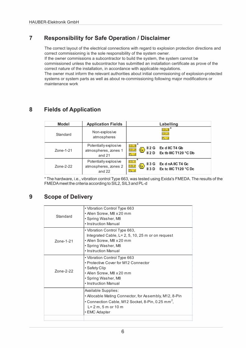
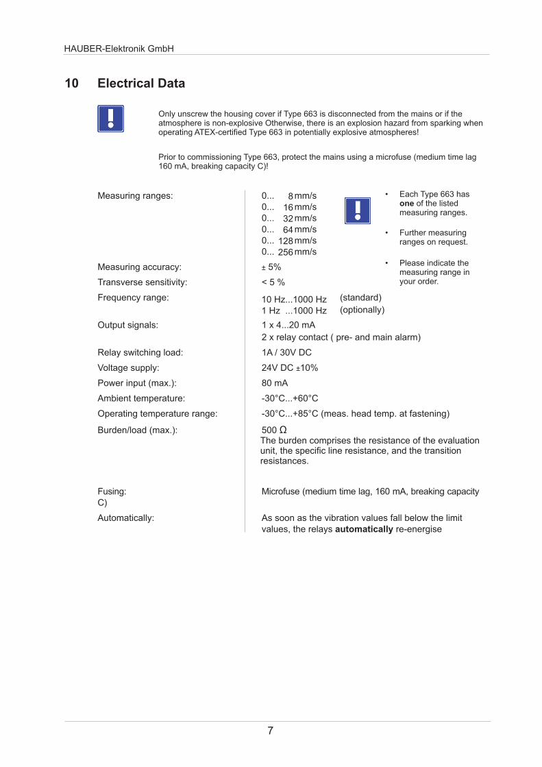
HAUBER-Elektronik GmbH
7
10 Electrical Data
Only unscrew the housing cover if Type 663 is disconnected from the mains or if the atmosphere is non-explosive Otherwise there is an explosion hazard from sparking when operating ATEX-certified Type 663 in potentially explosive atmospheres
8163264
128256
10 Hz1000 Hz1 Hz 1000 Hz
Prior to commissioning protect the mains using a microfuse 160 mA breaking capacity C)
Type 663 (medium time lag
Measuring ranges 0 mms0 mms0 mms0 mms0 mms0 mms
Measuring accuracy plusmn 5
Transverse sensitivity lt 5
Frequency range (standard)
(optionally)
Output signals 1 x 420 mA
2 x relay contact ( pre- and main alarm)
Relay switching load 1A 30V DC
Voltage supply 24V DC plusmn10
Power input (max) 80 mA
Ambient temperature -30degC+60degC
Operating temperature range -30degC+85degC (meas head temp at fastening)
Burdenload (max) 500 Ugrave The burden comprises the resistance of the evaluation unit the specific line resistance and the transition resistances
Fusing Microfuse (medium time lag 160 mA breaking capacity C)
Automatically As soon as the vibration values fall below the limitvalues the relays automatically re-energise
bull Each Type 663 has one of the listed measuring ranges
bull Further measuring ranges on request
bull Please indicate the measuring range in your order
HAUBER-Elektronik GmbH
Arbeitsbereich interner Sensorbaustein
0
20
40
60
80
100
120
140
160
180
200
0 100 200 300 400 500 600 700 800 900 1000
Frequenz (Hz)
Sc
hw
ing
ge
sc
hw
ind
igk
eit
(m
ms
)
Operating Range
Operating Range of Vibration Control Type 663
Reading example
Frequency Max measurable(Hz) vibration velocity 100 160 400 40 1000 18
The operating range is independent of the measuring range The diagram shows that the vibration velocity amplitude decreases as the frequency increases
Vib
rati
on
Velo
cit
y (
mm
s)
Frequency (Hz)
Frequency Response 10 Hz1000 Hz
-40
-35
-30
-25
-20
-15
-10
-5
0
5
1 10 100 1000 10000 Hz
dB
Frequency Response 1 Hz1000 Hz
-40
-35
-30
-25
-20
-15
-10
-5
0
5
01 10 100 1000 10000 100000 Hz
dB
8
Housing material V2A stainless steel material no 14305
M12 connector material CuZn (brass) nickel plated
Cable gland V2A stainless steel
Fastening Allen screw M8 x 20 mmThread pitch 125 mm
Weight approx 500 g
IP code IP 67
Mounting Ground housing using M8fastening (see Sect16)
HAUBER-Elektronik GmbH
9
11 Mechanical Data
Housing Dimensions and Direction of Measurement
Standard Zone-2-22 Zone-1-21
Note Direction of measurement = direction of fastening
30
M12 Connector
Connection Cable
Direction of Measurement
Cable Gland
Direction of Measurement
Measures in mm
Housing Dimensions and Direction of Measurement Standard Zone-2-22
Housing Dimensions and Direction of Measurement Zone-1-21
HAUBER-Elektronik GmbH
10
Connection Plan for All 3 Models
12 Connections
Note The connection plan shows the alarm condition andor the currentless condition Relay 1 and 2 are dropped out (see p 11 for more information on operating conditions)
Connection Cable Socket(Supplies)
M12 Connector
2
3
4
7 8
56
1
M12 Connector 8-pinSee connection plan for pin allocation
Connection cable socket M12 8-pin 025 mmsup2 See connection plan for pin allocation
Standard Zone-2-22 Zone-1-21
Connection Cable
PUR sheathed cable Oslash approx 65 mm 8 -pin 025 mmsup2 See connection plan for pin allocation
Evaluation Unit
Type 663Pin 1 whitePin 2 brown
Pin 3 green
Pin 4 yellow
Pin 5 grey
Self-Checkswitch
Relay 2
Relay 1
Evaluation of the 420 mA current signal using an ammeter or PLC
Pin 6 pinkPin 7 bluePin 8 red
1
2
3
4
5
6
7
8
WH
BN
GN
YE
GY
PK
BU
RD
ALARMWARNING
OK
HAUBER-Elektronik GmbH
13 Functional Description
Type 663 has two limit values LIM1 and LIM2 with their respective lag times which can all be adjusted separatelyRelay outputs 1 and 2 signal if the adjusted limit value has been exceeded by dropping out the respective relay contact If the limit value is then undercut relay outputs 1 and 2 will also signal this by automatically re-energisingIn addition Type 663 has an analogue current output This delivers a direct current of 420 mA proportional to the vibration amplitude
User Interface Channels LIM1 and LIM2mdashControls and LED Indicators
Operating Conditions Channels LIM1 and LIM2
SET Turn-SwitchLimit Value in 15 Steps(Table Limit Value page 12)
TIME PotentiometerLag Time VariablyAdjustable 030 sec
mdashredmdashyellowmdashgreen
Operating Condition Measurement Relay LED Indicator
OK lt= Limit Value Energised OK
WARNINGgt Limit Value
Lag Time RunningEnergised WARNING+OK
ALARMgt Limit Value
Lag Time ExpiredDropped Out ALARM
Only unscrew the housing cover if Type 663 is disconnected from the mains or if the atmosphere is non-explosive Otherwise there is an explosion hazard from sparking when operating ATEX-certified Type 663 in potentially explosive stmospheres
11
Measuring range eg
Set turn-switch pos
Limit value
HAUBER-Elektronik GmbH
12
15 Self-Test
Example Limit value adjustment
14 Limit Value Adjustment
032 mms
16 mms
8
0 0 0 0 0 0 0
1 05 1 2 4 8 16
2 1 2 4 8 16 32
3 15 3 6 12 24 48
4 2 4 8 16 32 64
5 25 5 10 20 40 80
6 3 6 12 24 48 96
7 35 7 14 28 56 112
8 4 8 16 32 64 128
9 45 9 18 36 72 144
10 5 10 20 40 80 160
11 55 11 22 44 88 176
12 6 12 24 48 96 192
13 65 13 26 52 104 208
14 7 14 28 56 112 224
15 75 15 30 60 120 240
SET
Turn-Switch
Position
Limit Value
Range
0hellip8 mms
Range
0hellip16 mms
Range
0hellip32 mms
Range
0hellip64 mms
Range
0hellip128 mms
Range
0hellip256 mms
The self-test is to verify the correct functioning of the vibration control Therefore a test signal is applied to pin 4 of the control The test signal simulates a vibration amplitude exceeding the maximum limit value This will trigger the controls alarm condition
Test signal a Direct current 24 V DC orb Square wave signal 24 V DC 05 Hz
Initial state Normal operation
Self-test start bull Apply the test signal to pin 4agrave The output current signal increases up to ~23 mAagrave After lt 35 s the alarm relays drop out
If one or both alarm relays fail to drop out this indicates a fault
bull Remove the test signalagrave After a further lt 60 s the output current signal has returned to to 4 mA or its actual value
End self-test
Final state Normal operation
Duration approx 95 s
bull Test signal a is only available for production no 75478 or later
HAUBER-Elektronik GmbH
16 Mounting and Dismounting
Only authorised experts who are familiar with the safety instructions for handling electrical components are allowed to perform mounting or dismounting work on or using this control For handling ATEX-certified controls within potentially explosive atmospheres the expert also has to be familiar with the safety instructions relevant there
Requirements
Mounting surface clean and flat ie free from paint rust etc
Threaded hole on the mounting surface Depth 15 mm Thread M8
Unscrew housing cover from housing base
Allen key SW8
Use Allen screw and spring washer to friction-lock the control on the mounting surface
Allen key SW6
Slightly fasten housing cover to housing base by hand(Avoid jamming the thread) Tighten housing cover using a tightening torque = 5 Nm
Torque wrench SW8
Workflow
1
2
3
Allen key SW6 SW8 Torque wrench SW8 Allen screw M8x20 Spring washer for M8
Tools and materials
Note To prevent any cold-welding between housing cover and housing base the control is delivered with a fitting lubricant for stainless steel connections applied to its thread
Before mounting or dismounting disconnect the control from the mains Ensure that disconnected plug connections are always de-energised Otherwise there is an explosion hazard from sparking when operating ATEX-certified Type 663 in potentially explosive atmospheres
Ground the control housing via the fastening ie the machine earth or a seperate earth conductor (PE)
161 Fastening on the Mounting Surface
Fastening on the mounting surface
Mounting Surface
zu
5 Nm
Tightening housing cover using a torque wrench
13
HAUBER-Elektronik GmbH
Shell Half Arrow and Eye
Sign
Fastened Safety Clip
Protective Cover Fastened Protective Cover
Safety Clip
Fully insert the connection cable socket into the M12 connector(Pay attention to the code cam position)
162 Zone-2-22mdashFastening Safety Clip Protective Cover
1 Disconnect th control from the mains2 Separate both shell halves of the fuse clip using a screw driver3 Use the M12 connector to firmly close the protective cover
1
2
3
Tightly fasten the lock-nut of the connection cable socket by hand
Mount the safety clip to avoid accidental disconnection of the plug connection1 Place both shell halves of the safety clip around the plug connection2 Press both shell halves of the safety clip together by hand until the
catch lock engages3 Place the arrow connected to both shell halves around the cable then thread
it through the eye on the other end so that the notice sign is legiblealongside the cable
Fastening Protective Cover
Fastening Safety Clip
Disassemble the safety clip and fasten the protective cover
Always operate model Zone-2-22 with the safety clip to avoid accidental disconnection of the plug connection Otherwise there is an explosion hazard from sparking when operating this control in potentially explosive atmospheres
Fasten the protective cover using the M12 connector after disconnecting the plug connection
14
HAUBER-Elektronik GmbH
15
17 Installation and Commissioning
Only authorised experts who are familiar with the safety instructions for handling electrical components are allowed to install or commission this control For handling ATEX-certified controls within potentially explosive atmospheres the expert also has to be familiar with the safety instructions relevant there
Ensure the housing cover is properly fastened prior to commissioning (tightening torque = 5 Nm) Otherwise there is an explosion hazard from sparking when operating ATEX-certified Type 663 in potentially explosive atmospheres
Prior to commissioning Type 663 protect the mains with a microfuse (medium time lag 160 mA breaking capacity C)
Protect the connection cable and possible extension cables from electrical influences or mechanical damage Ensure to stricly follow local regulations and directives
Check the self-test during commissioning
The SEALED seal label indicates that it is not permissible to open the casing cover
After the system operator has assembled the casing cover the seal label is attached to the side so that it covers the casing parting line
Any attempt to tamper with the casing will destroy the label and makes the attempted tampering visible to the system operator
163 Anti-tamper protection
Attaching the seal label
Seal label
Attaching the seal label
HAUBER-Elektronik GmbH
16
18 Maintenance and Repairs
Note Type 663 and its models are maintenance free
Error Table
Only authorised experts who are familiar with the safety instructions for handling electrical components are allowed to repair this control For handling ATEX-certified controls within potentially explosive atmospheres the expert also has to be familiar with the safety instructions relevant there
Disconnect Type 663 from the mains prior to performing repair or cleaning work Ensure that disconnected plug connections are always de-energised Otherwise there is an explosion hazard from sparking when operating ATEX-certified Type 663 in potentially explosive atmospheres
Immediately replace defective connection cables from sparking when operating ATEX-certified Type 663 in potentially explosive atmospheres
Otherwise there is an explosion hazard
If the control is defective replace it in its entirety
Error Cause Countermeasure
No measured value (420 mA)No power supply Check power supply andor connection cable
Connection cable interrupted Replace connection cable
Defective fuse Replace fuse
Wrong connection cable polarity Correct connection cable polarity
Defective control Replace control
Relay fails to switch Limit value incorrectly adjusted Correctly adjust limit value
No power supply Check power supply andor connection cable
Connection cable interrupted Replace connection cable
Defective fuse Replace fuse
Wrong connection cable polarity Correct connection cable polarity
Defective control Replace control
Incorrect reading Control mounting not friction-locked Friction-lock control
Control mounting at wrong position Mount control at correct position
EMC issues See Sect 19 Grounding Concepts
HAUBER-Elektronik GmbH
17
19 Grounding Concepts to Avoid Ground Loops
Ground loops are among the most frequent problems in measurement setups with sensitive sensor technology They arise through unwanted potential differences inside the current circuit between sensor and evaluation unit As a countermeasure we recommend our Standard Grounding Concept or depending on your application our Alternative Grounding Concept
Alternative Grounding Concept
In the Alternative Grounding Concept the shield of the sensor cable is connected to the sensor housing (dotted circle) The sensor housing is uncoupled from the machine ground via an EMC adapter (black)
Machine Evaluation Unit
+24V 420mA
Sensor Cable
Machine
+24V 420mA
Sensor Cable
Evaluation eg AmmeterPLC
Unit
Standard Grounding Concept
In the Standard Grounding Concept the shield of the sensor cable is not connected to the sensor housing (dotted circle) The potential applied to the sensor housing and the machine ground is identical
Maschine Ground
Maschine Ground
SensorHousing
EMC Adapter
Please indicate in your order if you wish to use the Alternative Grounding ConceptWe will then offer you the respective sensor cable and EMC adapter
Evaluation Unit
Evaluation eg AmmeterPLC
Unit
Shield
ShieldSensor
Housing
FB
663 = Monitoring SIL2 420 mA ~ mms rms + free limit values
32 = 32 mms rms64 = 64 mms rms128 = 128 mms rms
8 = 8 mms rms16 = 16 mms rms
No1 = ATEX zone 1212 = ATEX zone 222
0 = ATEX
0 = 101000 Hz1 = 11000 Hz
Standard design0 =
connector1 = 20 m integrated cable2 = 50 m integrated cable3 = 100 m integrated cable
0 = M12
ExampleType 663160000
Vibration monitoring type 663Measurement range 16 mms rmsFrequency range 101000 HzNo ATEXWith M12 plug-in connectionNo special design = Standard
C D EA
20 Order code
HAUBER-Elektronik GmbH
18
A = HAUBER type
B = Measurement range
C = ATEX
D = Frequency range
E = Connectorcable
F = Special design
ExampleType 663641130
Vibration monitoring type 663Measuring range 64 mms rms Frequency range 11000 Hz ATEX zone 121With integrated cable 100 mNo special design = Standard
- Seite1
- Seite2
- Seite3
- Seite4
- Seite5
- Seite6
- Seite7
- Seite8
- Seite9
- Seite10
- Seite11
- Seite12
- Seite13
- Seite14
- Seite15
- Seite16
- Seite17
- Seite18
-
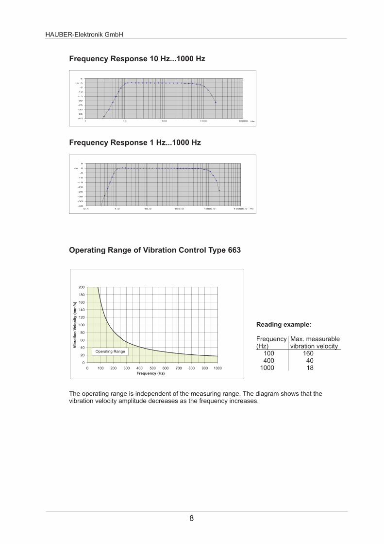
HAUBER-Elektronik GmbH
Arbeitsbereich interner Sensorbaustein
0
20
40
60
80
100
120
140
160
180
200
0 100 200 300 400 500 600 700 800 900 1000
Frequenz (Hz)
Sc
hw
ing
ge
sc
hw
ind
igk
eit
(m
ms
)
Operating Range
Operating Range of Vibration Control Type 663
Reading example
Frequency Max measurable(Hz) vibration velocity 100 160 400 40 1000 18
The operating range is independent of the measuring range The diagram shows that the vibration velocity amplitude decreases as the frequency increases
Vib
rati
on
Velo
cit
y (
mm
s)
Frequency (Hz)
Frequency Response 10 Hz1000 Hz
-40
-35
-30
-25
-20
-15
-10
-5
0
5
1 10 100 1000 10000 Hz
dB
Frequency Response 1 Hz1000 Hz
-40
-35
-30
-25
-20
-15
-10
-5
0
5
01 10 100 1000 10000 100000 Hz
dB
8
Housing material V2A stainless steel material no 14305
M12 connector material CuZn (brass) nickel plated
Cable gland V2A stainless steel
Fastening Allen screw M8 x 20 mmThread pitch 125 mm
Weight approx 500 g
IP code IP 67
Mounting Ground housing using M8fastening (see Sect16)
HAUBER-Elektronik GmbH
9
11 Mechanical Data
Housing Dimensions and Direction of Measurement
Standard Zone-2-22 Zone-1-21
Note Direction of measurement = direction of fastening
30
M12 Connector
Connection Cable
Direction of Measurement
Cable Gland
Direction of Measurement
Measures in mm
Housing Dimensions and Direction of Measurement Standard Zone-2-22
Housing Dimensions and Direction of Measurement Zone-1-21
HAUBER-Elektronik GmbH
10
Connection Plan for All 3 Models
12 Connections
Note The connection plan shows the alarm condition andor the currentless condition Relay 1 and 2 are dropped out (see p 11 for more information on operating conditions)
Connection Cable Socket(Supplies)
M12 Connector
2
3
4
7 8
56
1
M12 Connector 8-pinSee connection plan for pin allocation
Connection cable socket M12 8-pin 025 mmsup2 See connection plan for pin allocation
Standard Zone-2-22 Zone-1-21
Connection Cable
PUR sheathed cable Oslash approx 65 mm 8 -pin 025 mmsup2 See connection plan for pin allocation
Evaluation Unit
Type 663Pin 1 whitePin 2 brown
Pin 3 green
Pin 4 yellow
Pin 5 grey
Self-Checkswitch
Relay 2
Relay 1
Evaluation of the 420 mA current signal using an ammeter or PLC
Pin 6 pinkPin 7 bluePin 8 red
1
2
3
4
5
6
7
8
WH
BN
GN
YE
GY
PK
BU
RD
ALARMWARNING
OK
HAUBER-Elektronik GmbH
13 Functional Description
Type 663 has two limit values LIM1 and LIM2 with their respective lag times which can all be adjusted separatelyRelay outputs 1 and 2 signal if the adjusted limit value has been exceeded by dropping out the respective relay contact If the limit value is then undercut relay outputs 1 and 2 will also signal this by automatically re-energisingIn addition Type 663 has an analogue current output This delivers a direct current of 420 mA proportional to the vibration amplitude
User Interface Channels LIM1 and LIM2mdashControls and LED Indicators
Operating Conditions Channels LIM1 and LIM2
SET Turn-SwitchLimit Value in 15 Steps(Table Limit Value page 12)
TIME PotentiometerLag Time VariablyAdjustable 030 sec
mdashredmdashyellowmdashgreen
Operating Condition Measurement Relay LED Indicator
OK lt= Limit Value Energised OK
WARNINGgt Limit Value
Lag Time RunningEnergised WARNING+OK
ALARMgt Limit Value
Lag Time ExpiredDropped Out ALARM
Only unscrew the housing cover if Type 663 is disconnected from the mains or if the atmosphere is non-explosive Otherwise there is an explosion hazard from sparking when operating ATEX-certified Type 663 in potentially explosive stmospheres
11
Measuring range eg
Set turn-switch pos
Limit value
HAUBER-Elektronik GmbH
12
15 Self-Test
Example Limit value adjustment
14 Limit Value Adjustment
032 mms
16 mms
8
0 0 0 0 0 0 0
1 05 1 2 4 8 16
2 1 2 4 8 16 32
3 15 3 6 12 24 48
4 2 4 8 16 32 64
5 25 5 10 20 40 80
6 3 6 12 24 48 96
7 35 7 14 28 56 112
8 4 8 16 32 64 128
9 45 9 18 36 72 144
10 5 10 20 40 80 160
11 55 11 22 44 88 176
12 6 12 24 48 96 192
13 65 13 26 52 104 208
14 7 14 28 56 112 224
15 75 15 30 60 120 240
SET
Turn-Switch
Position
Limit Value
Range
0hellip8 mms
Range
0hellip16 mms
Range
0hellip32 mms
Range
0hellip64 mms
Range
0hellip128 mms
Range
0hellip256 mms
The self-test is to verify the correct functioning of the vibration control Therefore a test signal is applied to pin 4 of the control The test signal simulates a vibration amplitude exceeding the maximum limit value This will trigger the controls alarm condition
Test signal a Direct current 24 V DC orb Square wave signal 24 V DC 05 Hz
Initial state Normal operation
Self-test start bull Apply the test signal to pin 4agrave The output current signal increases up to ~23 mAagrave After lt 35 s the alarm relays drop out
If one or both alarm relays fail to drop out this indicates a fault
bull Remove the test signalagrave After a further lt 60 s the output current signal has returned to to 4 mA or its actual value
End self-test
Final state Normal operation
Duration approx 95 s
bull Test signal a is only available for production no 75478 or later
HAUBER-Elektronik GmbH
16 Mounting and Dismounting
Only authorised experts who are familiar with the safety instructions for handling electrical components are allowed to perform mounting or dismounting work on or using this control For handling ATEX-certified controls within potentially explosive atmospheres the expert also has to be familiar with the safety instructions relevant there
Requirements
Mounting surface clean and flat ie free from paint rust etc
Threaded hole on the mounting surface Depth 15 mm Thread M8
Unscrew housing cover from housing base
Allen key SW8
Use Allen screw and spring washer to friction-lock the control on the mounting surface
Allen key SW6
Slightly fasten housing cover to housing base by hand(Avoid jamming the thread) Tighten housing cover using a tightening torque = 5 Nm
Torque wrench SW8
Workflow
1
2
3
Allen key SW6 SW8 Torque wrench SW8 Allen screw M8x20 Spring washer for M8
Tools and materials
Note To prevent any cold-welding between housing cover and housing base the control is delivered with a fitting lubricant for stainless steel connections applied to its thread
Before mounting or dismounting disconnect the control from the mains Ensure that disconnected plug connections are always de-energised Otherwise there is an explosion hazard from sparking when operating ATEX-certified Type 663 in potentially explosive atmospheres
Ground the control housing via the fastening ie the machine earth or a seperate earth conductor (PE)
161 Fastening on the Mounting Surface
Fastening on the mounting surface
Mounting Surface
zu
5 Nm
Tightening housing cover using a torque wrench
13
HAUBER-Elektronik GmbH
Shell Half Arrow and Eye
Sign
Fastened Safety Clip
Protective Cover Fastened Protective Cover
Safety Clip
Fully insert the connection cable socket into the M12 connector(Pay attention to the code cam position)
162 Zone-2-22mdashFastening Safety Clip Protective Cover
1 Disconnect th control from the mains2 Separate both shell halves of the fuse clip using a screw driver3 Use the M12 connector to firmly close the protective cover
1
2
3
Tightly fasten the lock-nut of the connection cable socket by hand
Mount the safety clip to avoid accidental disconnection of the plug connection1 Place both shell halves of the safety clip around the plug connection2 Press both shell halves of the safety clip together by hand until the
catch lock engages3 Place the arrow connected to both shell halves around the cable then thread
it through the eye on the other end so that the notice sign is legiblealongside the cable
Fastening Protective Cover
Fastening Safety Clip
Disassemble the safety clip and fasten the protective cover
Always operate model Zone-2-22 with the safety clip to avoid accidental disconnection of the plug connection Otherwise there is an explosion hazard from sparking when operating this control in potentially explosive atmospheres
Fasten the protective cover using the M12 connector after disconnecting the plug connection
14
HAUBER-Elektronik GmbH
15
17 Installation and Commissioning
Only authorised experts who are familiar with the safety instructions for handling electrical components are allowed to install or commission this control For handling ATEX-certified controls within potentially explosive atmospheres the expert also has to be familiar with the safety instructions relevant there
Ensure the housing cover is properly fastened prior to commissioning (tightening torque = 5 Nm) Otherwise there is an explosion hazard from sparking when operating ATEX-certified Type 663 in potentially explosive atmospheres
Prior to commissioning Type 663 protect the mains with a microfuse (medium time lag 160 mA breaking capacity C)
Protect the connection cable and possible extension cables from electrical influences or mechanical damage Ensure to stricly follow local regulations and directives
Check the self-test during commissioning
The SEALED seal label indicates that it is not permissible to open the casing cover
After the system operator has assembled the casing cover the seal label is attached to the side so that it covers the casing parting line
Any attempt to tamper with the casing will destroy the label and makes the attempted tampering visible to the system operator
163 Anti-tamper protection
Attaching the seal label
Seal label
Attaching the seal label
HAUBER-Elektronik GmbH
16
18 Maintenance and Repairs
Note Type 663 and its models are maintenance free
Error Table
Only authorised experts who are familiar with the safety instructions for handling electrical components are allowed to repair this control For handling ATEX-certified controls within potentially explosive atmospheres the expert also has to be familiar with the safety instructions relevant there
Disconnect Type 663 from the mains prior to performing repair or cleaning work Ensure that disconnected plug connections are always de-energised Otherwise there is an explosion hazard from sparking when operating ATEX-certified Type 663 in potentially explosive atmospheres
Immediately replace defective connection cables from sparking when operating ATEX-certified Type 663 in potentially explosive atmospheres
Otherwise there is an explosion hazard
If the control is defective replace it in its entirety
Error Cause Countermeasure
No measured value (420 mA)No power supply Check power supply andor connection cable
Connection cable interrupted Replace connection cable
Defective fuse Replace fuse
Wrong connection cable polarity Correct connection cable polarity
Defective control Replace control
Relay fails to switch Limit value incorrectly adjusted Correctly adjust limit value
No power supply Check power supply andor connection cable
Connection cable interrupted Replace connection cable
Defective fuse Replace fuse
Wrong connection cable polarity Correct connection cable polarity
Defective control Replace control
Incorrect reading Control mounting not friction-locked Friction-lock control
Control mounting at wrong position Mount control at correct position
EMC issues See Sect 19 Grounding Concepts
HAUBER-Elektronik GmbH
17
19 Grounding Concepts to Avoid Ground Loops
Ground loops are among the most frequent problems in measurement setups with sensitive sensor technology They arise through unwanted potential differences inside the current circuit between sensor and evaluation unit As a countermeasure we recommend our Standard Grounding Concept or depending on your application our Alternative Grounding Concept
Alternative Grounding Concept
In the Alternative Grounding Concept the shield of the sensor cable is connected to the sensor housing (dotted circle) The sensor housing is uncoupled from the machine ground via an EMC adapter (black)
Machine Evaluation Unit
+24V 420mA
Sensor Cable
Machine
+24V 420mA
Sensor Cable
Evaluation eg AmmeterPLC
Unit
Standard Grounding Concept
In the Standard Grounding Concept the shield of the sensor cable is not connected to the sensor housing (dotted circle) The potential applied to the sensor housing and the machine ground is identical
Maschine Ground
Maschine Ground
SensorHousing
EMC Adapter
Please indicate in your order if you wish to use the Alternative Grounding ConceptWe will then offer you the respective sensor cable and EMC adapter
Evaluation Unit
Evaluation eg AmmeterPLC
Unit
Shield
ShieldSensor
Housing
FB
663 = Monitoring SIL2 420 mA ~ mms rms + free limit values
32 = 32 mms rms64 = 64 mms rms128 = 128 mms rms
8 = 8 mms rms16 = 16 mms rms
No1 = ATEX zone 1212 = ATEX zone 222
0 = ATEX
0 = 101000 Hz1 = 11000 Hz
Standard design0 =
connector1 = 20 m integrated cable2 = 50 m integrated cable3 = 100 m integrated cable
0 = M12
ExampleType 663160000
Vibration monitoring type 663Measurement range 16 mms rmsFrequency range 101000 HzNo ATEXWith M12 plug-in connectionNo special design = Standard
C D EA
20 Order code
HAUBER-Elektronik GmbH
18
A = HAUBER type
B = Measurement range
C = ATEX
D = Frequency range
E = Connectorcable
F = Special design
ExampleType 663641130
Vibration monitoring type 663Measuring range 64 mms rms Frequency range 11000 Hz ATEX zone 121With integrated cable 100 mNo special design = Standard
- Seite1
- Seite2
- Seite3
- Seite4
- Seite5
- Seite6
- Seite7
- Seite8
- Seite9
- Seite10
- Seite11
- Seite12
- Seite13
- Seite14
- Seite15
- Seite16
- Seite17
- Seite18
-
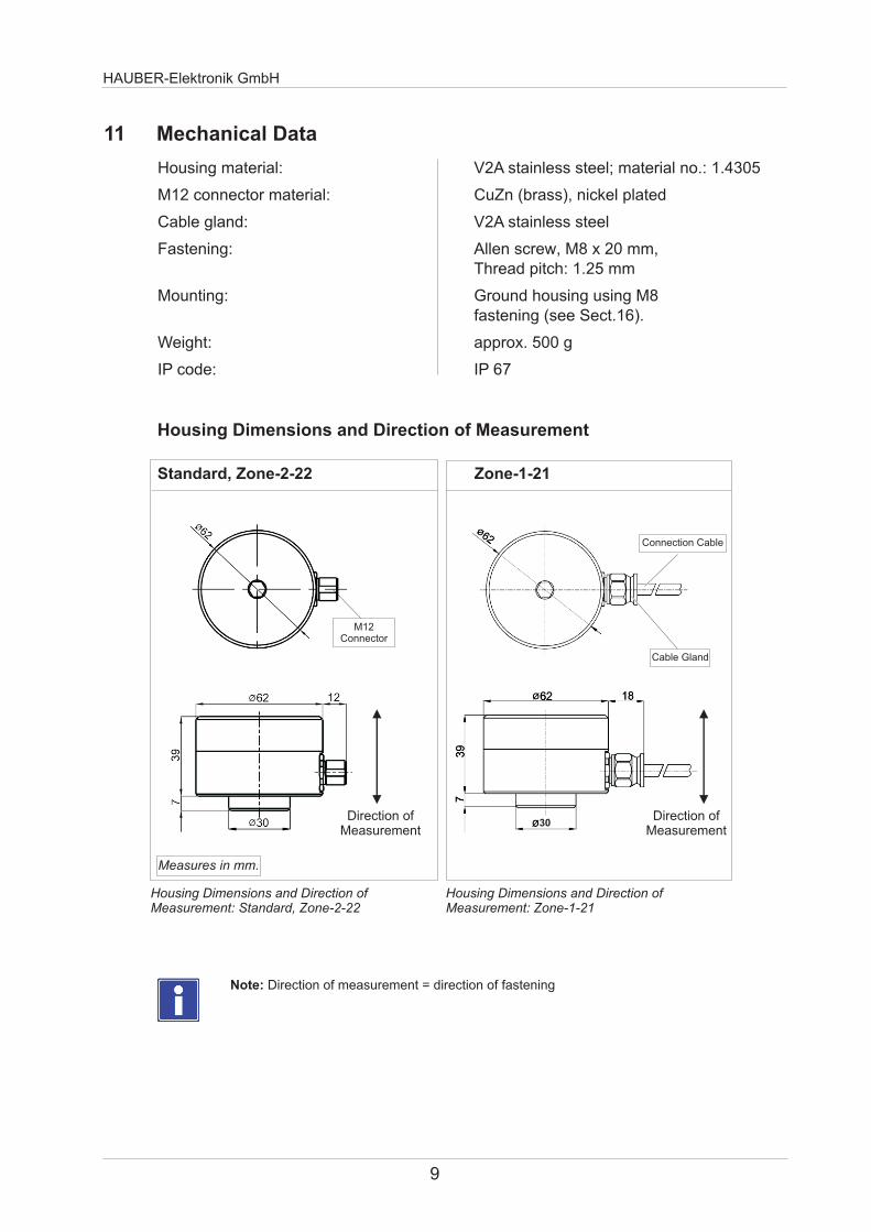
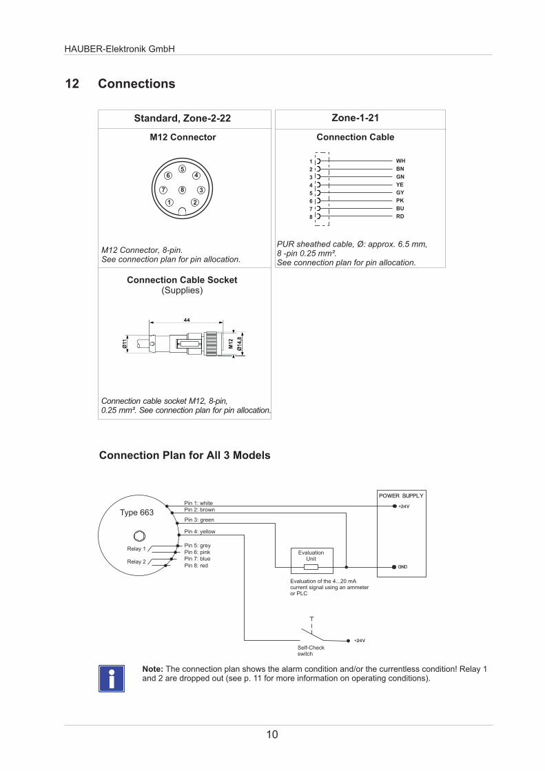
HAUBER-Elektronik GmbH
10
Connection Plan for All 3 Models
12 Connections
Note The connection plan shows the alarm condition andor the currentless condition Relay 1 and 2 are dropped out (see p 11 for more information on operating conditions)
Connection Cable Socket(Supplies)
M12 Connector
2
3
4
7 8
56
1
M12 Connector 8-pinSee connection plan for pin allocation
Connection cable socket M12 8-pin 025 mmsup2 See connection plan for pin allocation
Standard Zone-2-22 Zone-1-21
Connection Cable
PUR sheathed cable Oslash approx 65 mm 8 -pin 025 mmsup2 See connection plan for pin allocation
Evaluation Unit
Type 663Pin 1 whitePin 2 brown
Pin 3 green
Pin 4 yellow
Pin 5 grey
Self-Checkswitch
Relay 2
Relay 1
Evaluation of the 420 mA current signal using an ammeter or PLC
Pin 6 pinkPin 7 bluePin 8 red
1
2
3
4
5
6
7
8
WH
BN
GN
YE
GY
PK
BU
RD
ALARMWARNING
OK
HAUBER-Elektronik GmbH
13 Functional Description
Type 663 has two limit values LIM1 and LIM2 with their respective lag times which can all be adjusted separatelyRelay outputs 1 and 2 signal if the adjusted limit value has been exceeded by dropping out the respective relay contact If the limit value is then undercut relay outputs 1 and 2 will also signal this by automatically re-energisingIn addition Type 663 has an analogue current output This delivers a direct current of 420 mA proportional to the vibration amplitude
User Interface Channels LIM1 and LIM2mdashControls and LED Indicators
Operating Conditions Channels LIM1 and LIM2
SET Turn-SwitchLimit Value in 15 Steps(Table Limit Value page 12)
TIME PotentiometerLag Time VariablyAdjustable 030 sec
mdashredmdashyellowmdashgreen
Operating Condition Measurement Relay LED Indicator
OK lt= Limit Value Energised OK
WARNINGgt Limit Value
Lag Time RunningEnergised WARNING+OK
ALARMgt Limit Value
Lag Time ExpiredDropped Out ALARM
Only unscrew the housing cover if Type 663 is disconnected from the mains or if the atmosphere is non-explosive Otherwise there is an explosion hazard from sparking when operating ATEX-certified Type 663 in potentially explosive stmospheres
11
Measuring range eg
Set turn-switch pos
Limit value
HAUBER-Elektronik GmbH
12
15 Self-Test
Example Limit value adjustment
14 Limit Value Adjustment
032 mms
16 mms
8
0 0 0 0 0 0 0
1 05 1 2 4 8 16
2 1 2 4 8 16 32
3 15 3 6 12 24 48
4 2 4 8 16 32 64
5 25 5 10 20 40 80
6 3 6 12 24 48 96
7 35 7 14 28 56 112
8 4 8 16 32 64 128
9 45 9 18 36 72 144
10 5 10 20 40 80 160
11 55 11 22 44 88 176
12 6 12 24 48 96 192
13 65 13 26 52 104 208
14 7 14 28 56 112 224
15 75 15 30 60 120 240
SET
Turn-Switch
Position
Limit Value
Range
0hellip8 mms
Range
0hellip16 mms
Range
0hellip32 mms
Range
0hellip64 mms
Range
0hellip128 mms
Range
0hellip256 mms
The self-test is to verify the correct functioning of the vibration control Therefore a test signal is applied to pin 4 of the control The test signal simulates a vibration amplitude exceeding the maximum limit value This will trigger the controls alarm condition
Test signal a Direct current 24 V DC orb Square wave signal 24 V DC 05 Hz
Initial state Normal operation
Self-test start bull Apply the test signal to pin 4agrave The output current signal increases up to ~23 mAagrave After lt 35 s the alarm relays drop out
If one or both alarm relays fail to drop out this indicates a fault
bull Remove the test signalagrave After a further lt 60 s the output current signal has returned to to 4 mA or its actual value
End self-test
Final state Normal operation
Duration approx 95 s
bull Test signal a is only available for production no 75478 or later
HAUBER-Elektronik GmbH
16 Mounting and Dismounting
Only authorised experts who are familiar with the safety instructions for handling electrical components are allowed to perform mounting or dismounting work on or using this control For handling ATEX-certified controls within potentially explosive atmospheres the expert also has to be familiar with the safety instructions relevant there
Requirements
Mounting surface clean and flat ie free from paint rust etc
Threaded hole on the mounting surface Depth 15 mm Thread M8
Unscrew housing cover from housing base
Allen key SW8
Use Allen screw and spring washer to friction-lock the control on the mounting surface
Allen key SW6
Slightly fasten housing cover to housing base by hand(Avoid jamming the thread) Tighten housing cover using a tightening torque = 5 Nm
Torque wrench SW8
Workflow
1
2
3
Allen key SW6 SW8 Torque wrench SW8 Allen screw M8x20 Spring washer for M8
Tools and materials
Note To prevent any cold-welding between housing cover and housing base the control is delivered with a fitting lubricant for stainless steel connections applied to its thread
Before mounting or dismounting disconnect the control from the mains Ensure that disconnected plug connections are always de-energised Otherwise there is an explosion hazard from sparking when operating ATEX-certified Type 663 in potentially explosive atmospheres
Ground the control housing via the fastening ie the machine earth or a seperate earth conductor (PE)
161 Fastening on the Mounting Surface
Fastening on the mounting surface
Mounting Surface
zu
5 Nm
Tightening housing cover using a torque wrench
13
HAUBER-Elektronik GmbH
Shell Half Arrow and Eye
Sign
Fastened Safety Clip
Protective Cover Fastened Protective Cover
Safety Clip
Fully insert the connection cable socket into the M12 connector(Pay attention to the code cam position)
162 Zone-2-22mdashFastening Safety Clip Protective Cover
1 Disconnect th control from the mains2 Separate both shell halves of the fuse clip using a screw driver3 Use the M12 connector to firmly close the protective cover
1
2
3
Tightly fasten the lock-nut of the connection cable socket by hand
Mount the safety clip to avoid accidental disconnection of the plug connection1 Place both shell halves of the safety clip around the plug connection2 Press both shell halves of the safety clip together by hand until the
catch lock engages3 Place the arrow connected to both shell halves around the cable then thread
it through the eye on the other end so that the notice sign is legiblealongside the cable
Fastening Protective Cover
Fastening Safety Clip
Disassemble the safety clip and fasten the protective cover
Always operate model Zone-2-22 with the safety clip to avoid accidental disconnection of the plug connection Otherwise there is an explosion hazard from sparking when operating this control in potentially explosive atmospheres
Fasten the protective cover using the M12 connector after disconnecting the plug connection
14
HAUBER-Elektronik GmbH
15
17 Installation and Commissioning
Only authorised experts who are familiar with the safety instructions for handling electrical components are allowed to install or commission this control For handling ATEX-certified controls within potentially explosive atmospheres the expert also has to be familiar with the safety instructions relevant there
Ensure the housing cover is properly fastened prior to commissioning (tightening torque = 5 Nm) Otherwise there is an explosion hazard from sparking when operating ATEX-certified Type 663 in potentially explosive atmospheres
Prior to commissioning Type 663 protect the mains with a microfuse (medium time lag 160 mA breaking capacity C)
Protect the connection cable and possible extension cables from electrical influences or mechanical damage Ensure to stricly follow local regulations and directives
Check the self-test during commissioning
The SEALED seal label indicates that it is not permissible to open the casing cover
After the system operator has assembled the casing cover the seal label is attached to the side so that it covers the casing parting line
Any attempt to tamper with the casing will destroy the label and makes the attempted tampering visible to the system operator
163 Anti-tamper protection
Attaching the seal label
Seal label
Attaching the seal label
HAUBER-Elektronik GmbH
16
18 Maintenance and Repairs
Note Type 663 and its models are maintenance free
Error Table
Only authorised experts who are familiar with the safety instructions for handling electrical components are allowed to repair this control For handling ATEX-certified controls within potentially explosive atmospheres the expert also has to be familiar with the safety instructions relevant there
Disconnect Type 663 from the mains prior to performing repair or cleaning work Ensure that disconnected plug connections are always de-energised Otherwise there is an explosion hazard from sparking when operating ATEX-certified Type 663 in potentially explosive atmospheres
Immediately replace defective connection cables from sparking when operating ATEX-certified Type 663 in potentially explosive atmospheres
Otherwise there is an explosion hazard
If the control is defective replace it in its entirety
Error Cause Countermeasure
No measured value (420 mA)No power supply Check power supply andor connection cable
Connection cable interrupted Replace connection cable
Defective fuse Replace fuse
Wrong connection cable polarity Correct connection cable polarity
Defective control Replace control
Relay fails to switch Limit value incorrectly adjusted Correctly adjust limit value
No power supply Check power supply andor connection cable
Connection cable interrupted Replace connection cable
Defective fuse Replace fuse
Wrong connection cable polarity Correct connection cable polarity
Defective control Replace control
Incorrect reading Control mounting not friction-locked Friction-lock control
Control mounting at wrong position Mount control at correct position
EMC issues See Sect 19 Grounding Concepts
HAUBER-Elektronik GmbH
17
19 Grounding Concepts to Avoid Ground Loops
Ground loops are among the most frequent problems in measurement setups with sensitive sensor technology They arise through unwanted potential differences inside the current circuit between sensor and evaluation unit As a countermeasure we recommend our Standard Grounding Concept or depending on your application our Alternative Grounding Concept
Alternative Grounding Concept
In the Alternative Grounding Concept the shield of the sensor cable is connected to the sensor housing (dotted circle) The sensor housing is uncoupled from the machine ground via an EMC adapter (black)
Machine Evaluation Unit
+24V 420mA
Sensor Cable
Machine
+24V 420mA
Sensor Cable
Evaluation eg AmmeterPLC
Unit
Standard Grounding Concept
In the Standard Grounding Concept the shield of the sensor cable is not connected to the sensor housing (dotted circle) The potential applied to the sensor housing and the machine ground is identical
Maschine Ground
Maschine Ground
SensorHousing
EMC Adapter
Please indicate in your order if you wish to use the Alternative Grounding ConceptWe will then offer you the respective sensor cable and EMC adapter
Evaluation Unit
Evaluation eg AmmeterPLC
Unit
Shield
ShieldSensor
Housing
FB
663 = Monitoring SIL2 420 mA ~ mms rms + free limit values
32 = 32 mms rms64 = 64 mms rms128 = 128 mms rms
8 = 8 mms rms16 = 16 mms rms
No1 = ATEX zone 1212 = ATEX zone 222
0 = ATEX
0 = 101000 Hz1 = 11000 Hz
Standard design0 =
connector1 = 20 m integrated cable2 = 50 m integrated cable3 = 100 m integrated cable
0 = M12
ExampleType 663160000
Vibration monitoring type 663Measurement range 16 mms rmsFrequency range 101000 HzNo ATEXWith M12 plug-in connectionNo special design = Standard
C D EA
20 Order code
HAUBER-Elektronik GmbH
18
A = HAUBER type
B = Measurement range
C = ATEX
D = Frequency range
E = Connectorcable
F = Special design
ExampleType 663641130
Vibration monitoring type 663Measuring range 64 mms rms Frequency range 11000 Hz ATEX zone 121With integrated cable 100 mNo special design = Standard
- Seite1
- Seite2
- Seite3
- Seite4
- Seite5
- Seite6
- Seite7
- Seite8
- Seite9
- Seite10
- Seite11
- Seite12
- Seite13
- Seite14
- Seite15
- Seite16
- Seite17
- Seite18
-
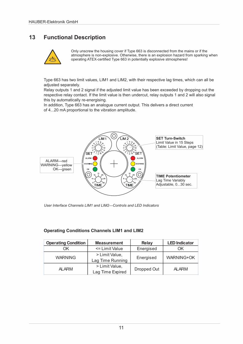
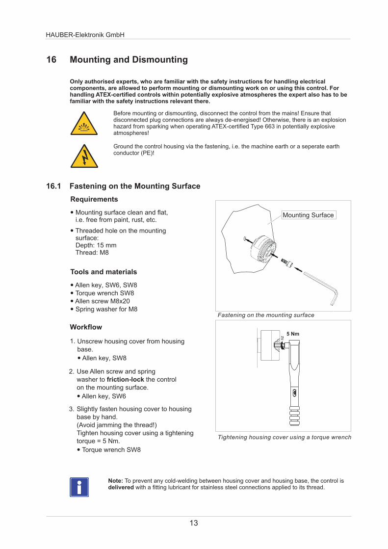
HAUBER-Elektronik GmbH
16 Mounting and Dismounting
Only authorised experts who are familiar with the safety instructions for handling electrical components are allowed to perform mounting or dismounting work on or using this control For handling ATEX-certified controls within potentially explosive atmospheres the expert also has to be familiar with the safety instructions relevant there
Requirements
Mounting surface clean and flat ie free from paint rust etc
Threaded hole on the mounting surface Depth 15 mm Thread M8
Unscrew housing cover from housing base
Allen key SW8
Use Allen screw and spring washer to friction-lock the control on the mounting surface
Allen key SW6
Slightly fasten housing cover to housing base by hand(Avoid jamming the thread) Tighten housing cover using a tightening torque = 5 Nm
Torque wrench SW8
Workflow
1
2
3
Allen key SW6 SW8 Torque wrench SW8 Allen screw M8x20 Spring washer for M8
Tools and materials
Note To prevent any cold-welding between housing cover and housing base the control is delivered with a fitting lubricant for stainless steel connections applied to its thread
Before mounting or dismounting disconnect the control from the mains Ensure that disconnected plug connections are always de-energised Otherwise there is an explosion hazard from sparking when operating ATEX-certified Type 663 in potentially explosive atmospheres
Ground the control housing via the fastening ie the machine earth or a seperate earth conductor (PE)
161 Fastening on the Mounting Surface
Fastening on the mounting surface
Mounting Surface
zu
5 Nm
Tightening housing cover using a torque wrench
13
HAUBER-Elektronik GmbH
Shell Half Arrow and Eye
Sign
Fastened Safety Clip
Protective Cover Fastened Protective Cover
Safety Clip
Fully insert the connection cable socket into the M12 connector(Pay attention to the code cam position)
162 Zone-2-22mdashFastening Safety Clip Protective Cover
1 Disconnect th control from the mains2 Separate both shell halves of the fuse clip using a screw driver3 Use the M12 connector to firmly close the protective cover
1
2
3
Tightly fasten the lock-nut of the connection cable socket by hand
Mount the safety clip to avoid accidental disconnection of the plug connection1 Place both shell halves of the safety clip around the plug connection2 Press both shell halves of the safety clip together by hand until the
catch lock engages3 Place the arrow connected to both shell halves around the cable then thread
it through the eye on the other end so that the notice sign is legiblealongside the cable
Fastening Protective Cover
Fastening Safety Clip
Disassemble the safety clip and fasten the protective cover
Always operate model Zone-2-22 with the safety clip to avoid accidental disconnection of the plug connection Otherwise there is an explosion hazard from sparking when operating this control in potentially explosive atmospheres
Fasten the protective cover using the M12 connector after disconnecting the plug connection
14
HAUBER-Elektronik GmbH
15
17 Installation and Commissioning
Only authorised experts who are familiar with the safety instructions for handling electrical components are allowed to install or commission this control For handling ATEX-certified controls within potentially explosive atmospheres the expert also has to be familiar with the safety instructions relevant there
Ensure the housing cover is properly fastened prior to commissioning (tightening torque = 5 Nm) Otherwise there is an explosion hazard from sparking when operating ATEX-certified Type 663 in potentially explosive atmospheres
Prior to commissioning Type 663 protect the mains with a microfuse (medium time lag 160 mA breaking capacity C)
Protect the connection cable and possible extension cables from electrical influences or mechanical damage Ensure to stricly follow local regulations and directives
Check the self-test during commissioning
The SEALED seal label indicates that it is not permissible to open the casing cover
After the system operator has assembled the casing cover the seal label is attached to the side so that it covers the casing parting line
Any attempt to tamper with the casing will destroy the label and makes the attempted tampering visible to the system operator
163 Anti-tamper protection
Attaching the seal label
Seal label
Attaching the seal label
HAUBER-Elektronik GmbH
16
18 Maintenance and Repairs
Note Type 663 and its models are maintenance free
Error Table
Only authorised experts who are familiar with the safety instructions for handling electrical components are allowed to repair this control For handling ATEX-certified controls within potentially explosive atmospheres the expert also has to be familiar with the safety instructions relevant there
Disconnect Type 663 from the mains prior to performing repair or cleaning work Ensure that disconnected plug connections are always de-energised Otherwise there is an explosion hazard from sparking when operating ATEX-certified Type 663 in potentially explosive atmospheres
Immediately replace defective connection cables from sparking when operating ATEX-certified Type 663 in potentially explosive atmospheres
Otherwise there is an explosion hazard
If the control is defective replace it in its entirety
Error Cause Countermeasure
No measured value (420 mA)No power supply Check power supply andor connection cable
Connection cable interrupted Replace connection cable
Defective fuse Replace fuse
Wrong connection cable polarity Correct connection cable polarity
Defective control Replace control
Relay fails to switch Limit value incorrectly adjusted Correctly adjust limit value
No power supply Check power supply andor connection cable
Connection cable interrupted Replace connection cable
Defective fuse Replace fuse
Wrong connection cable polarity Correct connection cable polarity
Defective control Replace control
Incorrect reading Control mounting not friction-locked Friction-lock control
Control mounting at wrong position Mount control at correct position
EMC issues See Sect 19 Grounding Concepts
HAUBER-Elektronik GmbH
17
19 Grounding Concepts to Avoid Ground Loops
Ground loops are among the most frequent problems in measurement setups with sensitive sensor technology They arise through unwanted potential differences inside the current circuit between sensor and evaluation unit As a countermeasure we recommend our Standard Grounding Concept or depending on your application our Alternative Grounding Concept
Alternative Grounding Concept
In the Alternative Grounding Concept the shield of the sensor cable is connected to the sensor housing (dotted circle) The sensor housing is uncoupled from the machine ground via an EMC adapter (black)
Machine Evaluation Unit
+24V 420mA
Sensor Cable
Machine
+24V 420mA
Sensor Cable
Evaluation eg AmmeterPLC
Unit
Standard Grounding Concept
In the Standard Grounding Concept the shield of the sensor cable is not connected to the sensor housing (dotted circle) The potential applied to the sensor housing and the machine ground is identical
Maschine Ground
Maschine Ground
SensorHousing
EMC Adapter
Please indicate in your order if you wish to use the Alternative Grounding ConceptWe will then offer you the respective sensor cable and EMC adapter
Evaluation Unit
Evaluation eg AmmeterPLC
Unit
Shield
ShieldSensor
Housing
FB
663 = Monitoring SIL2 420 mA ~ mms rms + free limit values
32 = 32 mms rms64 = 64 mms rms128 = 128 mms rms
8 = 8 mms rms16 = 16 mms rms
No1 = ATEX zone 1212 = ATEX zone 222
0 = ATEX
0 = 101000 Hz1 = 11000 Hz
Standard design0 =
connector1 = 20 m integrated cable2 = 50 m integrated cable3 = 100 m integrated cable
0 = M12
ExampleType 663160000
Vibration monitoring type 663Measurement range 16 mms rmsFrequency range 101000 HzNo ATEXWith M12 plug-in connectionNo special design = Standard
C D EA
20 Order code
HAUBER-Elektronik GmbH
18
A = HAUBER type
B = Measurement range
C = ATEX
D = Frequency range
E = Connectorcable
F = Special design
ExampleType 663641130
Vibration monitoring type 663Measuring range 64 mms rms Frequency range 11000 Hz ATEX zone 121With integrated cable 100 mNo special design = Standard
- Seite1
- Seite2
- Seite3
- Seite4
- Seite5
- Seite6
- Seite7
- Seite8
- Seite9
- Seite10
- Seite11
- Seite12
- Seite13
- Seite14
- Seite15
- Seite16
- Seite17
- Seite18
-
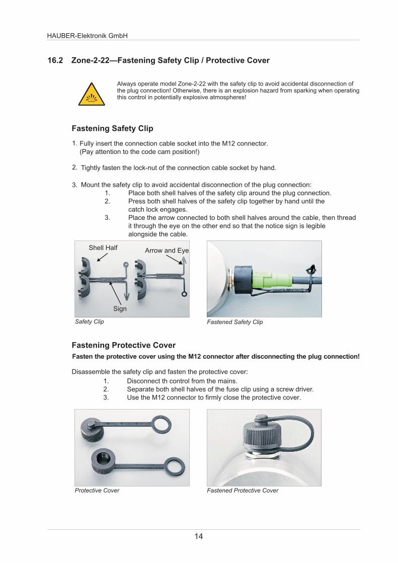
HAUBER-Elektronik GmbH
15
17 Installation and Commissioning
Only authorised experts who are familiar with the safety instructions for handling electrical components are allowed to install or commission this control For handling ATEX-certified controls within potentially explosive atmospheres the expert also has to be familiar with the safety instructions relevant there
Ensure the housing cover is properly fastened prior to commissioning (tightening torque = 5 Nm) Otherwise there is an explosion hazard from sparking when operating ATEX-certified Type 663 in potentially explosive atmospheres
Prior to commissioning Type 663 protect the mains with a microfuse (medium time lag 160 mA breaking capacity C)
Protect the connection cable and possible extension cables from electrical influences or mechanical damage Ensure to stricly follow local regulations and directives
Check the self-test during commissioning
The SEALED seal label indicates that it is not permissible to open the casing cover
After the system operator has assembled the casing cover the seal label is attached to the side so that it covers the casing parting line
Any attempt to tamper with the casing will destroy the label and makes the attempted tampering visible to the system operator
163 Anti-tamper protection
Attaching the seal label
Seal label
Attaching the seal label
HAUBER-Elektronik GmbH
16
18 Maintenance and Repairs
Note Type 663 and its models are maintenance free
Error Table
Only authorised experts who are familiar with the safety instructions for handling electrical components are allowed to repair this control For handling ATEX-certified controls within potentially explosive atmospheres the expert also has to be familiar with the safety instructions relevant there
Disconnect Type 663 from the mains prior to performing repair or cleaning work Ensure that disconnected plug connections are always de-energised Otherwise there is an explosion hazard from sparking when operating ATEX-certified Type 663 in potentially explosive atmospheres
Immediately replace defective connection cables from sparking when operating ATEX-certified Type 663 in potentially explosive atmospheres
Otherwise there is an explosion hazard
If the control is defective replace it in its entirety
Error Cause Countermeasure
No measured value (420 mA)No power supply Check power supply andor connection cable
Connection cable interrupted Replace connection cable
Defective fuse Replace fuse
Wrong connection cable polarity Correct connection cable polarity
Defective control Replace control
Relay fails to switch Limit value incorrectly adjusted Correctly adjust limit value
No power supply Check power supply andor connection cable
Connection cable interrupted Replace connection cable
Defective fuse Replace fuse
Wrong connection cable polarity Correct connection cable polarity
Defective control Replace control
Incorrect reading Control mounting not friction-locked Friction-lock control
Control mounting at wrong position Mount control at correct position
EMC issues See Sect 19 Grounding Concepts
HAUBER-Elektronik GmbH
17
19 Grounding Concepts to Avoid Ground Loops
Ground loops are among the most frequent problems in measurement setups with sensitive sensor technology They arise through unwanted potential differences inside the current circuit between sensor and evaluation unit As a countermeasure we recommend our Standard Grounding Concept or depending on your application our Alternative Grounding Concept
Alternative Grounding Concept
In the Alternative Grounding Concept the shield of the sensor cable is connected to the sensor housing (dotted circle) The sensor housing is uncoupled from the machine ground via an EMC adapter (black)
Machine Evaluation Unit
+24V 420mA
Sensor Cable
Machine
+24V 420mA
Sensor Cable
Evaluation eg AmmeterPLC
Unit
Standard Grounding Concept
In the Standard Grounding Concept the shield of the sensor cable is not connected to the sensor housing (dotted circle) The potential applied to the sensor housing and the machine ground is identical
Maschine Ground
Maschine Ground
SensorHousing
EMC Adapter
Please indicate in your order if you wish to use the Alternative Grounding ConceptWe will then offer you the respective sensor cable and EMC adapter
Evaluation Unit
Evaluation eg AmmeterPLC
Unit
Shield
ShieldSensor
Housing
FB
663 = Monitoring SIL2 420 mA ~ mms rms + free limit values
32 = 32 mms rms64 = 64 mms rms128 = 128 mms rms
8 = 8 mms rms16 = 16 mms rms
No1 = ATEX zone 1212 = ATEX zone 222
0 = ATEX
0 = 101000 Hz1 = 11000 Hz
Standard design0 =
connector1 = 20 m integrated cable2 = 50 m integrated cable3 = 100 m integrated cable
0 = M12
ExampleType 663160000
Vibration monitoring type 663Measurement range 16 mms rmsFrequency range 101000 HzNo ATEXWith M12 plug-in connectionNo special design = Standard
C D EA
20 Order code
HAUBER-Elektronik GmbH
18
A = HAUBER type
B = Measurement range
C = ATEX
D = Frequency range
E = Connectorcable
F = Special design
ExampleType 663641130
Vibration monitoring type 663Measuring range 64 mms rms Frequency range 11000 Hz ATEX zone 121With integrated cable 100 mNo special design = Standard
- Seite1
- Seite2
- Seite3
- Seite4
- Seite5
- Seite6
- Seite7
- Seite8
- Seite9
- Seite10
- Seite11
- Seite12
- Seite13
- Seite14
- Seite15
- Seite16
- Seite17
- Seite18
-
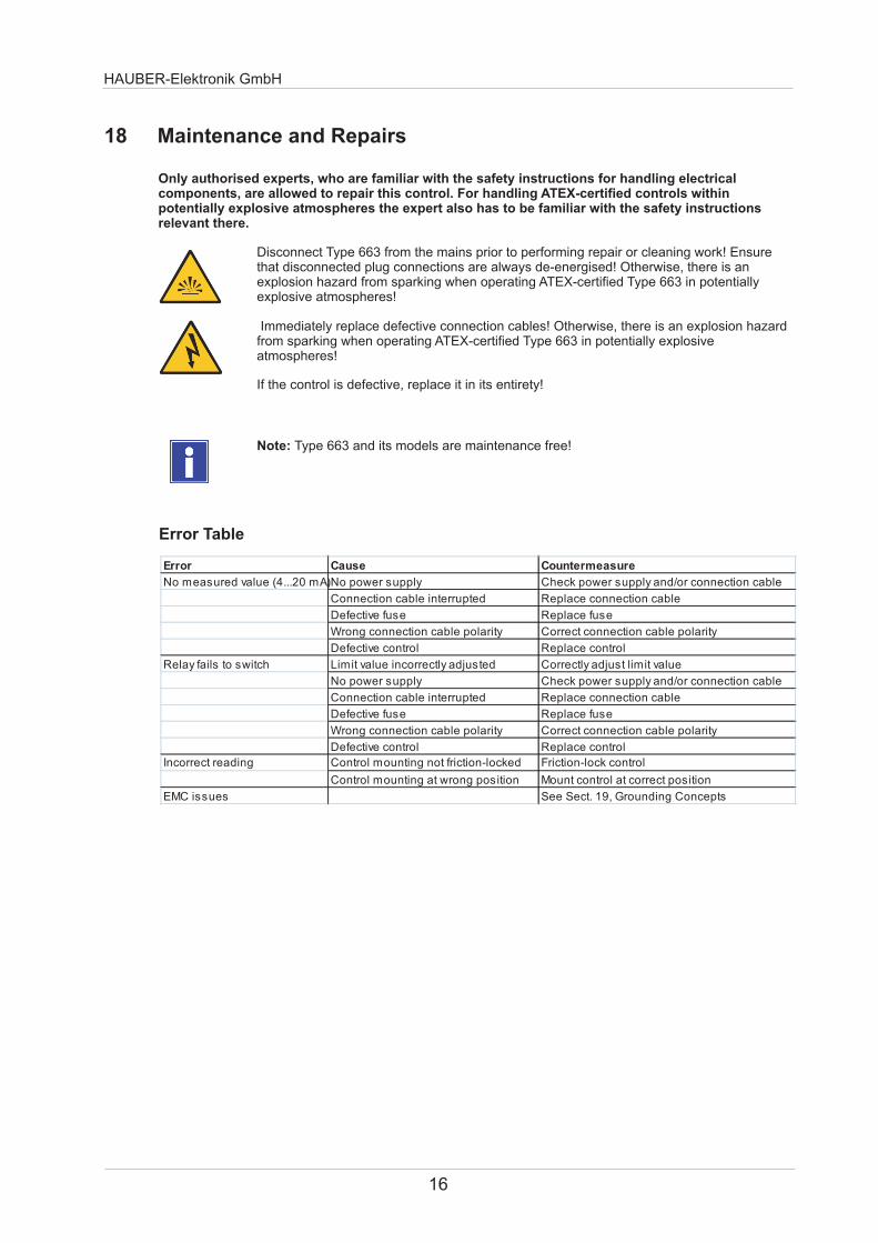
HAUBER-Elektronik GmbH
16
18 Maintenance and Repairs
Note Type 663 and its models are maintenance free
Error Table
Only authorised experts who are familiar with the safety instructions for handling electrical components are allowed to repair this control For handling ATEX-certified controls within potentially explosive atmospheres the expert also has to be familiar with the safety instructions relevant there
Disconnect Type 663 from the mains prior to performing repair or cleaning work Ensure that disconnected plug connections are always de-energised Otherwise there is an explosion hazard from sparking when operating ATEX-certified Type 663 in potentially explosive atmospheres
Immediately replace defective connection cables from sparking when operating ATEX-certified Type 663 in potentially explosive atmospheres
Otherwise there is an explosion hazard
If the control is defective replace it in its entirety
Error Cause Countermeasure
No measured value (420 mA)No power supply Check power supply andor connection cable
Connection cable interrupted Replace connection cable
Defective fuse Replace fuse
Wrong connection cable polarity Correct connection cable polarity
Defective control Replace control
Relay fails to switch Limit value incorrectly adjusted Correctly adjust limit value
No power supply Check power supply andor connection cable
Connection cable interrupted Replace connection cable
Defective fuse Replace fuse
Wrong connection cable polarity Correct connection cable polarity
Defective control Replace control
Incorrect reading Control mounting not friction-locked Friction-lock control
Control mounting at wrong position Mount control at correct position
EMC issues See Sect 19 Grounding Concepts
HAUBER-Elektronik GmbH
17
19 Grounding Concepts to Avoid Ground Loops
Ground loops are among the most frequent problems in measurement setups with sensitive sensor technology They arise through unwanted potential differences inside the current circuit between sensor and evaluation unit As a countermeasure we recommend our Standard Grounding Concept or depending on your application our Alternative Grounding Concept
Alternative Grounding Concept
In the Alternative Grounding Concept the shield of the sensor cable is connected to the sensor housing (dotted circle) The sensor housing is uncoupled from the machine ground via an EMC adapter (black)
Machine Evaluation Unit
+24V 420mA
Sensor Cable
Machine
+24V 420mA
Sensor Cable
Evaluation eg AmmeterPLC
Unit
Standard Grounding Concept
In the Standard Grounding Concept the shield of the sensor cable is not connected to the sensor housing (dotted circle) The potential applied to the sensor housing and the machine ground is identical
Maschine Ground
Maschine Ground
SensorHousing
EMC Adapter
Please indicate in your order if you wish to use the Alternative Grounding ConceptWe will then offer you the respective sensor cable and EMC adapter
Evaluation Unit
Evaluation eg AmmeterPLC
Unit
Shield
ShieldSensor
Housing
FB
663 = Monitoring SIL2 420 mA ~ mms rms + free limit values
32 = 32 mms rms64 = 64 mms rms128 = 128 mms rms
8 = 8 mms rms16 = 16 mms rms
No1 = ATEX zone 1212 = ATEX zone 222
0 = ATEX
0 = 101000 Hz1 = 11000 Hz
Standard design0 =
connector1 = 20 m integrated cable2 = 50 m integrated cable3 = 100 m integrated cable
0 = M12
ExampleType 663160000
Vibration monitoring type 663Measurement range 16 mms rmsFrequency range 101000 HzNo ATEXWith M12 plug-in connectionNo special design = Standard
C D EA
20 Order code
HAUBER-Elektronik GmbH
18
A = HAUBER type
B = Measurement range
C = ATEX
D = Frequency range
E = Connectorcable
F = Special design
ExampleType 663641130
Vibration monitoring type 663Measuring range 64 mms rms Frequency range 11000 Hz ATEX zone 121With integrated cable 100 mNo special design = Standard
- Seite1
- Seite2
- Seite3
- Seite4
- Seite5
- Seite6
- Seite7
- Seite8
- Seite9
- Seite10
- Seite11
- Seite12
- Seite13
- Seite14
- Seite15
- Seite16
- Seite17
- Seite18
-
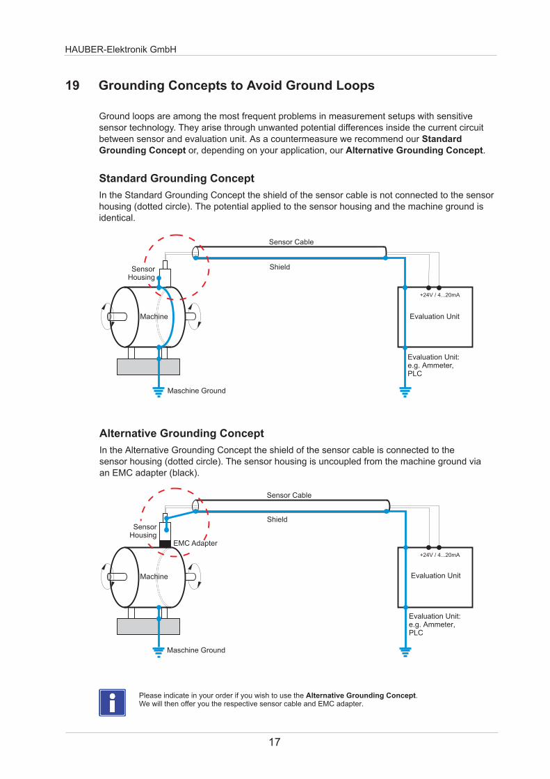
HAUBER-Elektronik GmbH
17
19 Grounding Concepts to Avoid Ground Loops
Ground loops are among the most frequent problems in measurement setups with sensitive sensor technology They arise through unwanted potential differences inside the current circuit between sensor and evaluation unit As a countermeasure we recommend our Standard Grounding Concept or depending on your application our Alternative Grounding Concept
Alternative Grounding Concept
In the Alternative Grounding Concept the shield of the sensor cable is connected to the sensor housing (dotted circle) The sensor housing is uncoupled from the machine ground via an EMC adapter (black)
Machine Evaluation Unit
+24V 420mA
Sensor Cable
Machine
+24V 420mA
Sensor Cable
Evaluation eg AmmeterPLC
Unit
Standard Grounding Concept
In the Standard Grounding Concept the shield of the sensor cable is not connected to the sensor housing (dotted circle) The potential applied to the sensor housing and the machine ground is identical
Maschine Ground
Maschine Ground
SensorHousing
EMC Adapter
Please indicate in your order if you wish to use the Alternative Grounding ConceptWe will then offer you the respective sensor cable and EMC adapter
Evaluation Unit
Evaluation eg AmmeterPLC
Unit
Shield
ShieldSensor
Housing
FB
663 = Monitoring SIL2 420 mA ~ mms rms + free limit values
32 = 32 mms rms64 = 64 mms rms128 = 128 mms rms
8 = 8 mms rms16 = 16 mms rms
No1 = ATEX zone 1212 = ATEX zone 222
0 = ATEX
0 = 101000 Hz1 = 11000 Hz
Standard design0 =
connector1 = 20 m integrated cable2 = 50 m integrated cable3 = 100 m integrated cable
0 = M12
ExampleType 663160000
Vibration monitoring type 663Measurement range 16 mms rmsFrequency range 101000 HzNo ATEXWith M12 plug-in connectionNo special design = Standard
C D EA
20 Order code
HAUBER-Elektronik GmbH
18
A = HAUBER type
B = Measurement range
C = ATEX
D = Frequency range
E = Connectorcable
F = Special design
ExampleType 663641130
Vibration monitoring type 663Measuring range 64 mms rms Frequency range 11000 Hz ATEX zone 121With integrated cable 100 mNo special design = Standard
- Seite1
- Seite2
- Seite3
- Seite4
- Seite5
- Seite6
- Seite7
- Seite8
- Seite9
- Seite10
- Seite11
- Seite12
- Seite13
- Seite14
- Seite15
- Seite16
- Seite17
- Seite18
-
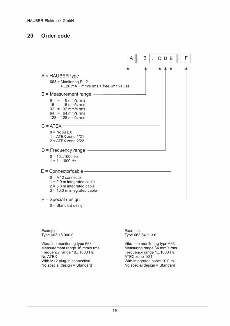
Related Documents


